Arduino ESP8266 WiFi Shield

This is a common ESP8266 Arduino shield with the following markings:
WiFi 2.4 GHz802.11 b/g/n
Designed inBeijingP.R.China
Moer info $ techsupport Please goto elecshop.ml
Arduino ESP8266 WiFiShield Version 1.0by WangTongze
The voltage switching circuitry on this shield doesn't work properly as itarrives, so you'll have to modify it slightly if you intend it to work asa shield (withSW1 andSW2 set toON).
The DIP switches are:
| Switch | Function |
|---|
| SW1 | Connect ESP8266 TX to pin D0 |
| SW2 | Connect ESP8266 RX to pin D1 |
| SW3 | Enable bootloader mode |
| SW4 | Use DFU LED to show serial activity (?) |
Power is drawn from the5v pin (notVin) so if connecting toPixl.jsensure thatVin and5V are shorted on the solder jumperunless you plan to power the shield separately.
Using as-is
- Ensure
SW1 andSW2 areOFF - Connect a jumper lead from the
TXD pin onDebug Port toD0 on the Arduino header - Connect a jumper lead from the
RXD pin onDebug Port toD1 on the Arduino header
Rewiring
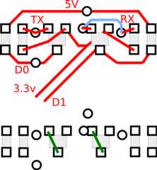

- Unsolder all the surface mount components to theright-hand side of the ESP8266
- Short across the two transistor outlines from the right pad to the bottom-left pad
- Ensure
SW1 andSW2 areON TXD andRXD should now be available onD0 andD1 at 3.3v levels
Pixl.js
If connecting to Pixl.js you should be aware that when if Pixl.jsdetects aconnection onD0 at boot, it'll start usingSerial1as a console device rather than the LCD.
To avoid this you'll need to explicitly set the console back to the LCD at boottime:
function onInit() { Terminal.setConsole();}
Software
Client
To connect to a WiFi access point.
var WIFI_NAME = "WiFi_Name";var WIFI_PASS = "WPA2_Key";var wifi;function getPage() { require("http").get("http://www.pur3.co.uk/hello.txt", function(res) { console.log("Response: ",res); res.on('data', function(d) { console.log("--->"+d); }); });}function go() { Serial1.setup(115200,{rx:D0,tx:D1}); wifi = require("ESP8266WiFi_0v25").connect(Serial1, function(err) { if (err) throw err; console.log("Connecting to WiFi"); wifi.connect(WIFI_NAME, WIFI_PASS, function(err) { if (err) throw err; console.log("Connected"); // Now you can do something, like an HTTP request getPage(); }); });}
Access point
To set up as an access point calledESP123 with passwordHelloWorldthat serves up a webpage on address192.168.4.1:
var wifi;function pageHandler(req, res) { res.writeHead(200); res.end("Hello World");}function go() { Serial1.setup(115200,{rx:D0,tx:D1}); wifi = require("ESP8266WiFi_0v25").connect(Serial1, function(err) { if (err) throw err; console.log("Connecting to WiFi"); wifi.createAP("ESP123","HelloWorld",5,"wpa2_psk", function(err) { if (err) throw err; console.log("Connected!"); require("http").createServer(pageHandler).listen(80); }); });}
Seethe ESP8266 page for more information on how touse the ESP8266, and theInternet page for more examplesof things you can do on Espruino with an Internet connection.
Buying
- eBay - theboards mentioned on this page are the ones with the red DIP switch on.
