WO2025141723A1 - Control method, information processing device, communication terminal, and battery rental service support system - Google Patents
Control method, information processing device, communication terminal, and battery rental service support systemDownload PDFInfo
- Publication number
- WO2025141723A1 WO2025141723A1PCT/JP2023/046762JP2023046762WWO2025141723A1WO 2025141723 A1WO2025141723 A1WO 2025141723A1JP 2023046762 WJP2023046762 WJP 2023046762WWO 2025141723 A1WO2025141723 A1WO 2025141723A1
- Authority
- WO
- WIPO (PCT)
- Prior art keywords
- battery
- user
- rental
- information
- suction device
- Prior art date
- Legal status (The legal status is an assumption and is not a legal conclusion. Google has not performed a legal analysis and makes no representation as to the accuracy of the status listed.)
- Pending
Links
Images


Classifications
- G—PHYSICS
- G06—COMPUTING OR CALCULATING; COUNTING
- G06Q—INFORMATION AND COMMUNICATION TECHNOLOGY [ICT] SPECIALLY ADAPTED FOR ADMINISTRATIVE, COMMERCIAL, FINANCIAL, MANAGERIAL OR SUPERVISORY PURPOSES; SYSTEMS OR METHODS SPECIALLY ADAPTED FOR ADMINISTRATIVE, COMMERCIAL, FINANCIAL, MANAGERIAL OR SUPERVISORY PURPOSES, NOT OTHERWISE PROVIDED FOR
- G06Q50/00—Information and communication technology [ICT] specially adapted for implementation of business processes of specific business sectors, e.g. utilities or tourism
- G06Q50/10—Services
Definitions
- This disclosurerelates to a control method, an information processing device, a communication terminal, and a battery rental service support system.
- aerosol generating devicesthat generate aerosols containing flavor components and deliver the generated aerosols to a user.
- Such aerosol generating devicestypically generate aerosols by supplying power to a heating unit, which is an electrical resistance or induction heater, and heating an aerosol source with the heating unit.
- patent documents 1 to 5disclose technology that allows users to replace the battery in this type of aerosol generating device.
- the present disclosureprovides a control method, an information processing device, a communication terminal, and a battery rental service support system that can support a battery rental service that rents out batteries used in an aerosol generating device to users.
- a method for controlling a computer that supports a battery rental service that rents out to a user a battery used in an aerosol generating device that is configured to have a detachable battery and generates an aerosol using power from the attached batterycomprising: The computer, a first step of acquiring an identification of the user's aerosol generating device; A second step of identifying a type of battery compatible with the aerosol generating device of the user based on the identification information acquired in the first step; a third step of searching for a service providing location that rents out batteries of a type compatible with the aerosol generating device of the user identified in the second step by referring to a memory unit that stores information indicating the type of battery available for rental at each service providing location that rents out batteries; and a fourth step of presenting information indicating the service providing location searched for in the third step to the user. It is a control method.
- An information processing devicethat supports a battery rental service for renting a battery used in an aerosol generating device that is configured to have a detachable battery and generates aerosol using power from the attached battery to a user, comprising: The information processing device includes: Obtaining an identification of the user's aerosol generating device; Identifying a type of battery compatible with the aerosol generating device of the user based on the acquired identification information; A storage unit stores information indicating the type of battery available for rental at each service location that rents out batteries, and searches for a service location that rents out a battery of the type that is compatible with the identified aerosol generation device of the user; presenting information indicating the searched service providing locations to the user; A control unit that performs processing, It is an information processing device.
- An information processing devicethat supports a battery rental service that rents out to a user a battery used in an aerosol generation device that is configured to have a detachable battery and generates aerosol using the power of the attached battery, and a communication terminal that is capable of communicating with the aerosol generation device of the user,
- the communication terminalincludes: Acquire identification information of the aerosol generation device from the aerosol generation device of the user; Transmitting the acquired identification information to the information processing device; receiving information from the information processing device indicating a service providing location where a battery of a type compatible with the aerosol generating device of the user searched for by the information processing device based on the transmitted identification information is available for rental; presenting the received information indicating the service providing location to the user;
- a control unitthat performs processing, It is a communications terminal.
- Another aspect of the present disclosureis a method for controlling a communication terminal according to the present invention, comprising: This is a battery rental service support system.
- the store terminal 300_iis configured to allow the battery 11 to be attached and detached.
- the store terminal 300_iis fitted with a battery 11 that is available for loan at the store STi in which the store terminal 300_i is installed.
- a user Ucan borrow the battery 11 by removing the battery 11 from the store terminal 300_i.
- the user Ucan also return the borrowed battery 11 by attaching it to the store terminal 300_i.
- An example of the configuration of the store terminal 300_iwill be described later with reference to FIG. 4.
- the control unit 116Afunctions as an arithmetic processing unit and a control unit, and controls the overall operation of the suction device 100A in accordance with programs stored in the memory unit 114A, etc.
- the control unit 116Acontrols the power supply from the power supply unit 111A to each component (e.g., the heating unit 121A described below), and the charging of the power supply unit 111A (i.e., the battery 11) using power received from an external power source.
- the control unit 116Ais equipped with, for example, an RTC (Real-Time Clock) that keeps track of real time.
- RTCReal-Time Clock
- the heating unit 121Amay be configured to generate aerosols by vibration or induction heating.
- the suction device 100Aincludes a vibration unit as the heating unit 121A.
- the vibration unitis configured, for example, of a plate-shaped member containing piezoelectric ceramics that functions as an ultrasonic vibrator.
- the aerosol source guided to the surface of the vibration unit by the liquid guide unit 122is atomized by ultrasonic waves generated by the vibration of the vibration unit, and an aerosol is generated.
- the air flow path 180is a flow path for air inhaled by the user U.
- the air flow path 180has a tubular structure with an air inlet hole 181, which is the entrance of air into the air flow path 180, and an air outlet hole 182, which is the exit of air from the air flow path 180, at both ends.
- the liquid guide section 122is arranged on the upstream side (the side closer to the air inlet hole 181), and the flavor source 131 is arranged on the downstream side (the side closer to the air outlet hole 182).
- the mouthpiece 124is a member that is held by the user U in the mouth when inhaling.
- An air outlet hole 182is arranged in the mouthpiece 124.
- the configuration of the suction device 100Ais not limited to the above, and various configurations such as those exemplified below are possible.
- the inhalation device 100Amay further include a flavor source heating unit (not shown) that heats the flavor source 131.
- the flavor source heating unitis, for example, configured in a film shape and arranged to cover the outer periphery of the flavor source 131.
- the flavor source heating unitgenerates heat when power is supplied from the power supply unit 111A, and heats the flavor source 131 from the outer periphery.
- the flavor source heating unitmay be, for example, configured in a blade shape, and may pierce the flavor source 131 to heat the flavor source 131 from the inside.
- the flavor source heating unitmay also be configured to heat the flavor source 131 by vibration or induction heating.
- Fig. 3is a schematic diagram showing a second configuration example of the suction device 100.
- the suction device 100B of this configuration exampleincludes a power supply unit 111B, a sensor unit 112B, a notification unit 113B, a storage unit 114B, a communication unit 115B, a control unit 116B, a heating unit 121B, a storage unit 140, and a heat insulating unit 144.
- the storage section 140has an internal space 141 and holds the stick-shaped substrate 150 while storing a part of the stick-shaped substrate 150 in the internal space 141.
- the storage section 140has an opening 142 that connects the internal space 141 to the outside and stores the stick-shaped substrate 150 inserted into the internal space 141 through the opening 142.
- the storage section 140is a cylindrical body with the opening 142 and the bottom 143 as the bottom surface, and defines a columnar internal space 141.
- An air flow path that supplies air to the internal space 141is connected to the storage section 140.
- An air inlet holewhich is an air inlet to the air flow path, is arranged, for example, on the side of the suction device 100.
- An air outlet holewhich is an air outlet from the air flow path to the internal space 141, is arranged, for example, on the bottom 143.
- the stick-type substrate 150When the stick-type substrate 150 is held in the storage portion 140, at least a portion of the substrate portion 151 is stored in the internal space 141, and at least a portion of the mouthpiece portion 152 protrudes from the opening 142.
- the user Uholds the suction mouth portion 152 protruding from the opening 142 in their mouth and inhales, air flows into the internal space 141 via an air flow path (not shown) and reaches the mouth of the user U together with the aerosol generated from the base portion 151.
- the heating section 121Bis configured as a film heater with conductive tracks made of heating resistors that have a correlation between electrical resistance and temperature, and is arranged to cover the outer periphery of the storage section 140.
- the heating section 121Bgenerates heat, the substrate section 151 of the stick-shaped substrate 150 is heated from the outer periphery, and an aerosol is generated.
- the heating resistor of the heating section 121Bcan be the same as the heating resistor of the heating section 121A described above.
- the insulating section 144prevents heat transfer from the heating section 121B to other components.
- the insulating section 144is made of a vacuum insulating material or an aerogel insulating material.
- the configuration of the suction device 100Bis not limited to the above, and various configurations such as those shown below are possible.
- the heating section 121Bmay be configured in a blade shape and disposed so as to protrude from the bottom 143 of the storage section 140 into the internal space 141. In that case, the blade-shaped heating section 121B is inserted into the substrate section 151 of the stick-shaped substrate 150 and heats the substrate section 151 of the stick-shaped substrate 150 from the inside. As another example, the heating section 121B may be disposed so as to cover the bottom 143 of the storage section 140. Furthermore, the heating section 121B may be configured as a combination of two or more of a first heating section that covers the outer periphery of the storage section 140, a blade-shaped second heating section, and a third heating section that covers the bottom 143 of the storage section 140.
- the storage unit 140may include an opening/closing mechanism, such as a hinge, that opens and closes a portion of the outer shell that forms the internal space 141. The storage unit 140 may then open and close the outer shell to accommodate the stick-shaped substrate 150 inserted into the internal space 141 while clamping it.
- the heating unit 121Bmay be provided at the clamping location in the storage unit 140, and may heat the stick-shaped substrate 150 while pressing it.
- the means for atomizing the aerosol sourceis not limited to heating by the heating unit 121B.
- the means for atomizing the aerosol sourcemay be induction heating.
- the suction device 100Bhas at least an electromagnetic induction source such as a coil that generates a magnetic field, instead of the heating unit 121B.
- a susceptor that generates heat by induction heatingmay be provided in the suction device 100B, or may be included in the stick-shaped substrate 150.
- the suction device 100Bmay further include the heating unit 121A, the liquid guide unit 122, the liquid storage unit 123, and the air flow path 180 according to the first configuration example, and the air flow path 180 may supply air to the internal space 141.
- the mixed fluid of the aerosol and air generated by the heating unit 121Aflows into the internal space 141 and is further mixed with the aerosol generated by the heating unit 121B, and reaches the oral cavity of the user U.
- the suction device 100A and the suction device 100B described abovewill be referred to as the "suction device 100" without distinction.
- the power supply unit 111A and the power supply unit 111Bwill be referred to as the "power supply unit 111”
- the sensor unit 112A and the sensor unit 112Bwill be referred to as the “sensor unit 112”
- the notification unit 113A and the notification unit 113Bwill be referred to as the “notification unit 113”
- the memory unit 114A and the memory unit 114Bwill be referred to as the “memory unit 114”
- the communication unit 115A and the communication unit 115Bwill be referred to as the "communication unit 115”
- the control unit 116A and the control unit 116Bwill be referred to as the “control unit 116”
- the heating unit 121A and the heating unit 121Bwill be referred to as the "heating unit 121".
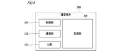
- Fig. 4is a schematic diagram showing an example of the configuration of the communication terminal 200.
- the communication terminal 200includes, for example, a control unit 201, a communication unit 202, a UI (user interface) unit 203, and a storage unit 205.
- the control unit 201functions as an arithmetic processing unit and a control unit, and controls the overall operation of the communication terminal 200 in accordance with various programs.
- the control unit 201is realized, for example, by an electronic circuit including a CPU, etc.
- the communication unit 202is a communication interface capable of performing communication conforming to any wired or wireless communication standard under the control of the control unit 201.
- Such communication standardsmay include standards using the Internet, cellular communication, Wi-Fi, Bluetooth, BLE, NFC, or LPWA.
- the communication unit 202communicates with the server 400 via a network NET such as the Internet or cellular communication according to the control of the control unit 201.
- the communication unit 202also communicates with the suction device 100 or the store terminal 300_i via short-range wireless communication such as Bluetooth or NFC according to the control of the control unit 201.
- the UI unit 203includes an input device that accepts information input from the user U, and an output device that outputs (e.g., presents) various information to the user U.
- the input device of the UI unit 203outputs the accepted information (in other words, input information) to the control unit 201.
- the output device of the UI unit 203outputs various information under the control of the control unit 201.
- the UI unit 203is configured by a touch panel that combines a display device (e.g., a liquid crystal display or an organic EL display) that displays images and a pointing device, but is not limited to this.
- the UI unit 203may be provided with a display device and an input device provided separately.
- the UI unit 203may also include a sound output device that outputs sound, a vibration device that vibrates, etc.
- the memory unit 205stores various information (e.g., programs and data) for the operation of the communication terminal 200, and is provided in a state in which the information can be referenced by the control unit 201.
- the memory unit 205may be configured, for example, from a non-volatile storage medium such as a flash memory.
- the memory unit 205may further include a RAM (Random Access Memory) that is used as a work area when a CPU or the like that realizes the control unit 201 performs various processes.
- RAMRandom Access Memory
- the control unit 301functions as an arithmetic processing device and a control device, and controls the overall operation of the store terminal 300_i in accordance with various programs.
- the control unit 301is realized, for example, by an electronic circuit including a CPU, etc.
- the communication unit 302is a communication interface capable of performing communication conforming to any wired or wireless communication standard under the control of the control unit 301.
- Such communication standardsmay include standards using the Internet, cellular communication, Wi-Fi, Bluetooth, BLE, NFC, or LPWA.
- the communication unit 302communicates with the server 400 via a network NET such as the Internet or cellular communication, in accordance with the control of the control unit 301.
- the communication unit 302also communicates with the communication terminal 200 via short-range wireless communication such as Bluetooth or NFC, in accordance with the control of the control unit 301.
- the UI unit 303includes an input device that accepts information input from a user (e.g., user U) and an output device that outputs various information to the user.
- the input device of the UI unit 303outputs the accepted information (in other words, input information) to the control unit 301.
- the output device of the UI unit 303outputs various information according to the control of the control unit 301.
- the UI unit 303may also be configured with a touch panel, similar to the UI unit 203.
- the UI unit 303may be provided with a display device and an input device separately.
- the battery storage unit 304is configured to be able to store, for example, multiple batteries 11 and to store each battery 11 independently.
- the battery storage unit 304has, for example, multiple storage spaces, each capable of storing one battery 11.
- Each storage spaceis provided with a door with a locking mechanism that operates according to the control of the control unit 301.
- the door of one storage spaceis unlocked by the control unit 301, the user U can open the door and remove the battery 11 stored in one storage space (i.e., borrow the battery 11).
- the door of the storage spaceis locked, it is difficult for the user U to remove the battery 11 stored in that storage space.
- each storage spaceis provided with a terminal electrically connected to the battery 11 stored in that storage space.
- the store terminal 300_ican, for example, supply power (i.e., charge) to the battery 11 stored in each storage space via this terminal.
- the store terminal 300_i(more specifically, the control unit 301) can, for example, communicate with a battery IC provided in the battery 11 stored in each storage space via this terminal, thereby storing predetermined information (for example, usage restriction information described later) in the memory unit 11a of the battery 11 stored in each storage space and acquiring the information stored in the memory unit 11a.
- the store terminal 300_i and the battery storage unit 304do not have to be configured as an integrated unit, and may be configured as separate entities. In this case, the store terminal 300_i may communicate with another device that has a battery storage unit 304 to charge the battery 11 stored in the other device, store specific information in the memory unit 11a of the battery 11, and obtain information stored in the memory unit 11a.
- the storage unit 305stores various information (e.g., programs and data) for the operation of the store terminal 300_i, and is provided in a state in which the information can be referenced by the control unit 301.
- the storage unit 305may be configured, for example, from a non-volatile storage medium such as a flash memory.
- the storage unit 305may further include a RAM that is used as a work area when a CPU or the like that realizes the control unit 301 performs various processes.
- the communication unit 402is a communication interface capable of performing communication conforming to any wired or wireless communication standard under the control of the control unit 401.
- Such communication standardsmay include standards using the Internet, cellular communication, and Wi-Fi.
- the communication unit 402performs communication with the communication terminal 200 or the store terminal 300_i via a network NET such as the Internet or cellular communication under the control of the control unit 401.
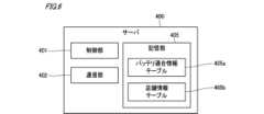
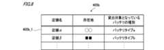
- FIG. 8is a diagram showing an example of a store information table 405b stored in the storage unit 405.
- the store information table 405bis configured to include, for example, for each store that rents out batteries 11 (for example, stores ST1 to STn shown in FIG. 1), information indicating the type of battery 11 available for rental at that store and the location of that store (hereinafter also referred to as "location information").
- the control unit 116issues a notification urging the user to return the battery 11. In this way, in the unlikely event that a battery 11 that is not compatible with the suction device 100 is lent to the user U, the control unit 116 can urge the user U to return the battery 11.
- control unit 116may determine whether the remaining charge of the battery 11 is equal to or greater than a predetermined value, and if it determines that the remaining charge of the battery 11 is less than the predetermined value, may issue a predetermined notification via the notification unit 113. In this way, in the unlikely event that a battery 11 with a low remaining charge is lent to the user U, the user U can be prompted to take appropriate action.
- the control unit 116may issue a notification urging the user to return the battery 11. In this way, if a battery 11 with a low remaining charge is lent to a user U, the user U can be urged to return the battery 11. Similarly, if the health level of the battery 11 attached to the suction device 100 is less than a predetermined value, the control unit 116 may issue a notification urging the user to return the battery 11. In this way, if a battery 11 with a low health level is lent to a user U, the user U can be urged to return the battery 11.
- the control unit 116may perform processing to invalidate the payment made when the battery 11 was rented out.
- the control unit 116may transmit a payment invalidation request from the suction device 100 to the server 400 via the communication terminal 200 or the store terminal 300_i to invalidate the payment made when the battery 11 was rented out.
- control unit 116may not only acquire the usage restriction information stored in the memory unit 11a of the battery 11 attached to the suction device 100, but may also store specified information in the memory unit 11a.
- FIG. 13is a diagram showing a first example of a method for determining the type of battery 11 attached to the suction device 100.
- the battery 11generates an electromotive force E [V] and has an internal resistance r [ ⁇ ].
- the internal resistance r [ ⁇ ]may differ depending on the type of battery 11. Therefore, by obtaining the value of the internal resistance r [ ⁇ ] of the battery 11 attached to the suction device 100, it is possible to determine the type of the battery 11.
- the terminal voltage and the current flowing between the terminals of the battery 11 attached to the suction device 100are measured by the sensor unit 112 or the like, the internal resistance r [ ⁇ ] is derived based on the measured terminal voltage value and current value, and the type of the battery 11 is determined based on the derived internal resistance r [ ⁇ ].
- the electromotive force E [V] of the battery 11can be obtained by measuring the terminal voltage V [V] with the current I [A] set to zero. That is, the electromotive force E [V] of the battery 11 can be obtained by measuring the terminal voltage V [V] when the circuit is open.
- the internal resistance r [ ⁇ ] of the battery 11can be obtained by substituting the terminal voltage V [V] and current I [A] obtained by measurement into equation (2).
- the memory unit 114stores information indicating the internal resistance r [ ⁇ ] of each type of battery 11 in advance.
- the control unit 116refers to the information stored in the memory unit 114 and derives the type of battery 11 corresponding to the obtained value of internal resistance r [ ⁇ ] as the type of battery 11 attached to the suction device 100.
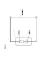
- FIG. 14is a diagram showing a second example of a method for determining the type of the battery 11 attached to the suction device 100. As shown in Fig. 14, in this example, the battery 11 is provided with an identification resistor R2 having an electric resistance value according to the type of the battery 11.
- the battery 11generates an electromotive force E [V] and has an internal resistance r [ ⁇ ]. Furthermore, the battery 11 is provided with an identification resistor R2 having a different electrical resistance value for each type of battery 11, and the voltage drop across this identification resistor R2 causes the potential difference across the identification resistor R2 to be an identification voltage V2 [V] (where identification voltage V2 ⁇ terminal voltage V). In other words, the identification voltage V2 [V] has a different value for each type of battery 11.
- the value of the identification voltage V2 [V] of the battery 11 attached to the suction device 100is measured by the sensor unit 112 or the like, and the type of the battery 11 is determined based on the measured identification voltage V2. More specifically, in this example, the memory unit 114 stores in advance information indicating the value of the identification voltage V2 [V] for each type of battery 11. The control unit 116 then refers to the information stored in the memory unit 114 and derives the type of battery 11 corresponding to the measured value of the identification voltage V2 [V] as the type of the battery 11 attached to the suction device 100. This makes it possible to determine the type of battery 11 at low cost and simply, without the need to provide the suction device 100 with a separate component or the like used only for determining the type of battery 11.
- the battery 11may be provided with an identification member having an identifier for identifying the type of the battery 11.
- the identification memberfor example, a barcode or two-dimensional code determined for each type of battery 11, or an IC tag or an RFID (Radio Frequency Identification) tag in which information capable of identifying the type of the battery 11 is written can be used.
- the suction device 100may be provided with a sensor or the like for reading the identifier of the attached battery 11, and the control unit 116 may determine the type of the attached battery 11 based on the identifier read by the sensor.
- the user Umay input information indicating the type of battery 11 attached to the suction device 100 into the communication terminal 200, the communication terminal 200 may transmit this information to the suction device 100, and the control unit 116 may determine the type of the attached battery 11 based on the information that the suction device 100 receives from the communication terminal 200. The control unit 116 may also determine the type of the attached battery 11 based on the information indicating the type of battery 11 that the user U input to the suction device 100.
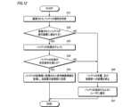
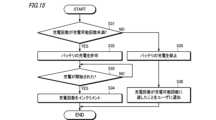
- Processing when connecting to external power supply> 15is a flowchart showing an example of the process when an external power source is connected, which is performed by the control unit 116 of the suction device 100.
- the trigger that is the condition for the control unit 116 to perform this process when an external power source is connectedcan be, for example, the connection of the suction device 100 to the external power source.
- the control unit 116performs this process when an external power source is connected, for example, in response to detecting the connection of the suction device 100 to the external power source.
- the control unit 116first determines whether the number of times the battery 11 attached to the suction device 100 has been charged in the suction device 100 is less than the number of times it can be charged indicated by the usage restriction information stored in the memory unit 114 (step S31).
- control unit 116determines that the number of charges is less than the number of times that the battery can be charged (step S31: YES)
- the control unit 116permits the suction device 100 to charge the battery 11 using the power received from the external power source (step S32). As a result, for example, if the battery 11 is not fully charged, charging of the battery 11 will begin.
- control unit 116waits for charging of the battery 11 to start (step S33: NO loop), and when charging of the battery 11 starts (step S33: YES), it increments the number of times charging has been performed (step S34) and ends the process when an external power source is connected. Note that information indicating the number of times charging has been performed counted by the control unit 116 is stored in the memory unit 114, for example.
- control unit 116determines that the number of charges is not less than the number of possible charges, i.e., that the number of charges has reached the number of possible charges (step S31: NO), it prohibits the suction device 100 from charging the battery 11 (step S35). In other words, in this case, the control unit 116 does not permit the suction device 100 to charge the battery 11. As a result, in this case, charging of the battery 11 is not performed.
- control unit 116notifies the user U that the number of times the battery has been charged has reached the number of times that the battery can be charged via the notification unit 113 (step S36), and ends the process when connected to an external power source.
- control unit 116notifies the user U that the number of times the battery has been charged has reached the number of times that the battery can be charged by making the light-emitting device included in the notification unit 113 emit light in a predetermined light-emitting manner (e.g., a predetermined light-emitting color).
- control unit 116may notify the user U that the number of times the battery has been charged has reached the number of times that the battery can be charged by making the display device included in the notification unit 113 display a predetermined message (e.g., a message such as "The number of times the battery has been charged has reached the number of times that the battery can be charged").
- control unit 116may notify the user U that the number of times the battery has been charged has reached the number of times that the battery can be charged by making the vibration device included in the notification unit 113 vibrate in a predetermined vibration manner (e.g., a predetermined vibration pattern).
- control unit 116controls the charging of the battery 11 by the suction device 100 based on, for example, the number of times that the battery 11 can be charged indicated by the usage restriction information acquired from the battery 11 attached to the suction device 100 and the number of times that the battery 11 has been charged in the suction device 100. This makes it possible to appropriately control the charging of the battery 11 by the suction device 100, taking into account the number of times that the battery 11 attached to the suction device 100 can be charged.
- the control unit 116allows the suction device 100 to charge the battery 11. As a result, in the suction device 100 to which the battery 11 that has not been charged yet is attached, the user U can charge the battery 11 as necessary. On the other hand, if the number of times it has been charged has reached the number of times it can be charged, the control unit 116 prohibits the suction device 100 from charging the battery 11. This makes it possible to prevent the suction device 100 from charging the battery 11 that exceeds the number of times it can be charged.
- control unit 116may start charging the battery 11 with power received from the external power source in response to the suction device 100 being connected to the external power source. This allows the battery 11, which has not been charged the maximum number of times it can be charged, to be charged simply by connecting the suction device 100 to the external power source, improving convenience for the user U compared to a case in which other operations are required in addition to connection to the external power source.
- the control unit 116may notify the user U that the number of times that the battery has been charged has reached the maximum number of times that it can be charged, via the notification unit 113. In this way, when the battery 11 is not charged because the number of times that the battery has been charged has reached the maximum number of times that it can be charged, the user U can understand the reason, and it is possible to prevent the user U from mistakenly thinking that the suction device 100 has broken down.
- the user Ucan use the suction device 100 and can, for example, cause the suction device 100 to generate an aerosol.
- the trigger that serves as a condition for the control unit 116 to perform this rental period notification processis not particularly limited, and can be, for example, detection of a predetermined operation on the suction device 100.
- the predetermined operationcan be, for example, an operation by the user U to use the suction device 100, more specifically, an operation to cause the suction device 100 to generate an aerosol.
- the above-mentioned predetermined operationcan be an operation that is a condition for starting heating by the heating unit 121.
- the above-mentioned predetermined operationcan be an operation that is assumed to cause the stick-shaped substrate 150 to be inserted into the storage unit 140, more specifically, an operation of opening a lid that opens and closes the opening 142.
- the operation of opening the lid that opens and closes the opening 142can be detected, for example, by a sensor (for example, a motion sensor or a Hall sensor) provided on the lid or on the case that constitutes the outer shell of the suction device 100.
- the control unit 116in the rental period notification process, the control unit 116, for example, first determines whether the rental period has been exceeded (step S41). In the process of step S41, the control unit 116 determines that the rental period has been exceeded if the current time obtained by the RTC or the like possessed by the control unit 116 is later than the rental end time of the rental period indicated by the usage restriction information stored in the memory unit 114. On the other hand, the control unit 116 determines that the rental period has not been exceeded if the current time is earlier than the rental end time.
- control unit 116determines that the rental period has expired (step S41: YES), it prohibits the suction device 100 from charging the battery 11 and from supplying power from the battery 11 to the heating unit 121 (step S42).
- the control unit 116notifies the user U that the rental period has expired via the notification unit 113 (step S43), and ends the rental period notification process.
- the control unit 116notifies the user U that the rental period has expired by causing the light-emitting device included in the notification unit 113 to emit light in a predetermined first light-emitting mode (e.g., blinking red).
- the control unit 116may notify the user U that the rental period has expired by causing the display device included in the notification unit 113 to display a predetermined message (e.g., a message such as "The rental period has expired")
- control unit 116determines that the rental period has not expired (step S41: NO), it calculates the remaining period, which is the period remaining from the current time to the rental end time (step S44).
- control unit 116determines whether the remaining period calculated by the processing of step S44 is equal to or greater than a predetermined period (e.g., 24 hours) (step S45).
- This predetermined periodcan be determined arbitrarily by, for example, the manufacturer of the suction device 100.
- control unit 116determines that the remaining period is equal to or greater than the predetermined period (step S45: YES), it notifies the user U that the remaining period is equal to or greater than the predetermined period via the notification unit 113 (step S46), and ends the rental period notification process.
- the control unit 116notifies the user U that the remaining period is longer than a predetermined period by causing the light-emitting device included in the notification unit 113 to emit light in a predetermined second light-emitting mode (e.g., blue light emission color).
- the control unit 116may notify the user U that the remaining period is longer than a predetermined period by causing a display device included in the notification unit 113 to display a predetermined message (e.g., a message such as "The remaining period is longer than 24 hours").
- the control unit 116may notify the user U that the remaining period is longer than a predetermined period by causing a vibration device included in the notification unit 113 to vibrate in a first vibration mode or not vibrate at all.
- control unit 116determines that the rental period has expired, it prohibits not only the supply of power from the battery 11 to the heating unit 121 but also the charging of the battery 11 by the suction device 100, but this is not limited to the above.
- control unit 116determines that the rental period has expired, it may prohibit only the supply of power from the battery 11 to the heating unit 121.
- control unit 116controls the operation of the suction device 100 based on, for example, whether the rental period indicated by the usage restriction information acquired from the battery 11 attached to the suction device 100 has been exceeded. This makes it possible to appropriately control the operation of the suction device 100, taking into account the rental period set for the battery 11 attached to the suction device 100.
- the control unit 116permits the supply of power from the battery 11 to the heating unit 121. This allows the user U to inhale aerosols using the suction device 100 equipped with a battery 11 that has not expired.
- the control unit 116prohibits the supply of power from the battery 11 to the heating unit 121. This makes it possible to prevent the suction device 100 equipped with a battery 11 that has expired from being used for the purpose of inhaling aerosols. This makes it possible to encourage the prompt return of a battery 11 that has expired from the rental period.
- control unit 116may also prohibit the suction device 100 from charging the battery 11. In this way, if the battery 11 runs out of power after the rental period has expired, it becomes difficult to use the suction device 100 for purposes other than inhaling aerosols. This makes it possible to further prevent the use of the suction device 100 equipped with a battery 11 that has expired, and to encourage the prompt return of the battery 11 that has expired.
- control unit 116may notify the user U of the expiration of the rental period via the notification unit 113. In this way, it is possible to notify the user U of the expiration of the rental period and encourage the user U to promptly return the battery 11 that has expired.
- control method described in this embodimentcan be realized by executing a prepared program (control program) on a computer.
- This control programis stored in a computer-readable storage medium, for example, and is executed by reading it from the storage medium.
- This control programmay also be provided in a form stored in a non-volatile (non-transient) storage medium such as a flash memory, or provided via a network NET such as the Internet.
- the computer that executes the above control programis the server 400 (e.g., the CPU that constitutes the control unit 401), but this is not limited to this.
- the computer that executes the control programmay be the store terminal 300_i.
- the information processing device disclosed hereinis realized by the server 400, but the information processing device may also be realized by the store terminal 300_i.
- user Ufor example, goes to any store STi, communicates between his/her own communication terminal 200 and the store terminal 300_i of the store STi, and transmits a rental use request from the communication terminal 200 to the store terminal 300_i.
- the store terminal 300_i that receives the rental use requestfunctions as an information processing device of the present disclosure, and, for example, identifies the type of battery 11 that is compatible with user U's suction device 100.
- a battery 11 that is compatible with user U's suction device 100is stored in the battery storage section 304 of the store terminal 300_i, for example, via the UI section 303, etc., presents to user U that a battery 11 that is compatible with user U's suction device 100 is available for rental at the store terminal 300_i (i.e., the store STi in which the store STi is installed).
- the store terminal 300_ipresents to the user U, for example, via the UI unit 303, information indicating rental stores that are located near the store STi where the device is installed.
- the user Umay go to, for example, any store STi, communicate with the store terminal 300_i of the store STi, and transmit suction device identification information from the suction device 100 to the store terminal 300_i.
- the store terminal 300_i that receives the suction device identification informationfunctions as an information processing device of the present disclosure, and, for example, identifies the type of battery 11 that is compatible with the suction device 100 of the user U.
- the store terminal 300_ipresents to the user U that a battery 11 that is compatible with the suction device 100 of the user U is available for rental at the store terminal (i.e., the store STi in which the store STi is installed).
- the store terminal 300_ipresents to the user U, for example, via the UI unit 303, information indicating rental stores that are located near the store STi where the device is installed.
- the user Umay operate the UI unit 303 of the store terminal 300_i of the store STi he or she visits to input various information required to borrow the battery 11 into the store terminal 300_i, thereby being able to receive the loan of the battery 11 from the store terminal 300_i.
- the suction device 100may notify the communication terminal 200 of this fact. Then, when the rental period of the battery 11 attached to the suction device 100 has expired, that is, when the battery 11 has not been returned even after the rental end time has passed, the communication terminal 200 may send a payment request for the late fee to the server 400.
- the server 400 that receives the payment request for the late feemay, for example, settle the late fee according to the period by which the rental period of the battery 11 has expired (the so-called "late period").
- the communication terminal 200may request the server 400 to extend the rental period and make a payment for the extension based on the input of the user U. Then, when the rental period is extended, the communication terminal 200 may transmit new usage restriction information including information about the extended rental period to the suction device 100, and the control unit 116 of the suction device 100 may thereafter control the operation of the suction device 100 based on this new usage restriction information.
- a control method for a computer(server 400, store terminals 300_1 to 300_n) that supports a battery rental service for renting out to a user a battery used in an aerosol generation device (inhalation device 100, 100A, 100B) that is configured to detachably mount a battery (battery 11) and generates an aerosol using the power of the attached battery, comprising: The computer, A first step (step S6) of acquiring identification information of the user's aerosol generating device; A second step (step S6) of identifying a type of battery compatible with the aerosol generating device of the user based on the identification information acquired in the first step; A third step (step S6) of searching for a service providing location where a battery of a type compatible with the aerosol generating device of the user identified in the second step is available for rental, by referring to a memory unit (memory unit 405) that stores information (battery compatibility information table 405a) indicating the type of battery available for rental at each service providing location (store ST1 to STn)
- the usercan be guided to service locations where batteries of a type compatible with the user's aerosol generating device are available for rental, thereby assisting the user in using the battery rental service. This improves convenience for users who wish to use the battery rental service.
- the userby presenting the user with the type of battery that is compatible with the user's aerosol generating device, the user can know the type of battery that is compatible with his or her own aerosol generating device, which makes it possible to prevent the user from accidentally borrowing a battery of the wrong type.
- the storage unitfurther stores information indicating a location of the service providing location for each of the service providing locations;
- the computerThe first step further includes acquiring location information of the user;
- a service providing location located within a predetermined range from the useris selected from among service providing locations that have batteries of a type compatible with the aerosol generating device of the user as rental targets based on the acquired location information,
- information indicating the selected service providing locationis presented to the user. Control methods.
- batteries of a type compatible with the user's aerosol generating deviceare available for rental, and the user can be guided to a service location that is close to the user in terms of distance, thereby helping the user to use the battery rental service. Therefore, it is possible to improve convenience for users who wish to use the battery rental service.
- the storage unitfurther stores information indicating a location of the service providing location for each of the service providing locations;
- the computerThe first step further includes acquiring location information of a point designated by the user;
- a service providing location located within a predetermined range from the pointis selected from among service providing locations that have batteries of a type compatible with the aerosol generating device of the user as rental targets, based on the acquired location information;
- information indicating the selected service providing locationis presented to the user. Control methods.
- batteries of a type compatible with the user's aerosol generating deviceare available for rental, and the user can be guided to a service location that is close to the user's desired location in terms of distance, thereby helping the user to use the battery rental service. Therefore, it is possible to improve convenience for users who wish to use the battery rental service.
- the control methodaccording to any one of (1) to (4),
- the computeris configured to be able to communicate with terminals (store terminals 300_1 to 300_n) installed in each of the service providing locations,
- the computer, A processfurther includes a fifth step (step S10) of transmitting rental information regarding the battery rental by the user to a terminal (store terminal 300_i) installed at a service providing location selected by the user. Control methods.
- a terminal installed at a service location selected by a userperform processing to prepare for lending a battery to the user.
- the rental informationincludes information indicating a rental period of the battery by the user and/or information indicating the number of times the battery can be charged by the user. Control methods.
- the rental period of the battery by the user and/or the number of times the battery can be charged by the usercan be notified to a terminal installed at a service provision location selected by the user.
- the rental informationis transmitted to the terminal communicably connected to the battery to be rented at the service provision location selected by the user, and information based on the rental information is stored in a storage unit (storage unit 11a) of one of the batteries via the terminal. Control methods.
- the control method according to (8)The computer, The first step further includes acquiring information indicating a usage history of the aerosol generating device of the user, In the fourth step, the recommendation information based on the information indicating the usage history acquired in the first step is presented to the user. Control methods.
- step S17The control method according to any one of (1) to (9), The computer, When the battery is lent to the user, a sixth step (step S17) of making a payment for the lent is performed. Control methods.
- An information processing device(server 400, store terminals 300_1 to 300_n) that supports a battery rental service for renting out to a user a battery used in an aerosol generating device (inhalation device 100, 100A, 100B) that is configured to detachably mount a battery (battery 11) and generates an aerosol using the power of the attached battery
- the information processing deviceincludes: Obtaining an identification of the user's aerosol generating device; Identifying a type of battery compatible with the aerosol generating device of the user based on the acquired identification information;
- a storage unitstores information indicating the type of battery available for rental at each service location that rents out batteries, and searches for a service location that rents out a battery of the type that is compatible with the identified aerosol generation device of the user; presenting information indicating the searched service providing locations to the user;
- a control unit(control unit 401, 301) that performs processing is provided.
- Information processing deviceincludes: Obtaining an identification of the user's aerosol generating device;
- the usercan be guided to service locations where batteries of a type compatible with the user's aerosol generating device are available for rental, thereby assisting the user in using the battery rental service. Therefore, the convenience of users who wish to use the battery rental service can be improved.
- An information processing device(server 400, store terminals 300_1 to 300_n) that supports a battery rental service for lending a battery to a user for use in an aerosol generation device (inhalation device 100, 100A, 100B) that is configured to detachably mount a battery (battery 11) and generates an aerosol using the power of the attached battery, and a communication terminal (communication terminal 200) that is capable of communicating with the aerosol generation device of the user,
- the communication terminalincludes: Acquire identification information of the aerosol generation device from the aerosol generation device of the user; Transmitting the acquired identification information to the information processing device; receiving information from the information processing device indicating a service providing location where a battery of a type compatible with the aerosol generating device of the user searched for by the information processing device based on the transmitted identification information is available for rental; presenting the received information indicating the service providing location to the user;
- a control unit(control unit 201) that performs processing. Communications terminal.
- the usercan be guided to service locations where batteries of a type compatible with the user's aerosol generating device are available for rental, thereby assisting the user in using the battery rental service. Therefore, the convenience of users who wish to use the battery rental service can be improved.
- Battery rental support system11 Battery 100, 100A, 100B Suction device (aerosol generating device) 200 Communication terminal 201 Control unit 300_1 to 300_n Store terminal (computer, terminal, information processing device) 301 Control unit 400 Server (computer, information processing device) 401 Control unit ST1 to STn Store (service providing location)
Landscapes
- Business, Economics & Management (AREA)
- Tourism & Hospitality (AREA)
- Health & Medical Sciences (AREA)
- Economics (AREA)
- General Health & Medical Sciences (AREA)
- Human Resources & Organizations (AREA)
- Marketing (AREA)
- Primary Health Care (AREA)
- Strategic Management (AREA)
- Physics & Mathematics (AREA)
- General Business, Economics & Management (AREA)
- General Physics & Mathematics (AREA)
- Engineering & Computer Science (AREA)
- Theoretical Computer Science (AREA)
- Charge And Discharge Circuits For Batteries Or The Like (AREA)
Abstract
Description
Translated fromJapanese本開示は、制御方法、情報処理装置、通信端末、及びバッテリレンタルサービス支援システムに関する。This disclosure relates to a control method, an information processing device, a communication terminal, and a battery rental service support system.
従来から、例えば、香味成分が付与されたエアロゾルを生成し、生成したエアロゾルをユーザに送達するエアロゾル生成装置が知られている。このようなエアロゾル生成装置は、典型的には、電気抵抗式又は誘導加熱式のヒータである加熱部へ電力を供給することで、加熱部によりエアロゾル源を加熱してエアロゾルを生成する。 Conventionally, for example, aerosol generating devices are known that generate aerosols containing flavor components and deliver the generated aerosols to a user. Such aerosol generating devices typically generate aerosols by supplying power to a heating unit, which is an electrical resistance or induction heater, and heating an aerosol source with the heating unit.
下記特許文献1~5には、この種のエアロゾル生成装置において、ユーザがバッテリを交換できるようにした技術が開示されている。The following
エアロゾル生成装置の分野においてバッテリの着脱可能となった場合、例えば、コンビニエンスストア等の店舗において、エアロゾル生成装置のユーザへバッテリを貸し出すバッテリレンタルサービスが展開されることも想定される。しかしながら、従来技術にあっては、このようなバッテリレンタルサービスを支援できる技術について十分に検討されていない。If batteries become removable in the field of aerosol generating devices, it is expected that battery rental services will be developed in stores such as convenience stores, where batteries will be loaned to users of aerosol generating devices. However, in the prior art, technology that can support such battery rental services has not been fully considered.
本開示は、エアロゾル生成装置において使用されるバッテリをユーザへ貸し出すバッテリレンタルサービスを支援可能な制御方法、情報処理装置、通信端末、及びバッテリレンタルサービス支援システムを提供する。The present disclosure provides a control method, an information processing device, a communication terminal, and a battery rental service support system that can support a battery rental service that rents out batteries used in an aerosol generating device to users.
本開示の一態様は、
バッテリを着脱可能に構成され且つ装着されたバッテリの電力を使用してエアロゾルを生成するエアロゾル生成装置において使用されるバッテリをユーザへ貸し出すバッテリレンタルサービスを支援するコンピュータの制御方法であって、
前記コンピュータが、
前記ユーザのエアロゾル生成装置の識別情報を取得する第1ステップと、
前記第1ステップにより取得された識別情報に基づき、前記ユーザのエアロゾル生成装置に適合するバッテリの種別を特定する第2ステップと、
バッテリの貸し出しを行っているサービス提供場所ごとに当該サービス提供場所において貸出対象となっているバッテリの種別を示す情報を記憶する記憶部を参照して、前記第2ステップにより特定された前記ユーザのエアロゾル生成装置に適合する種別のバッテリが貸出対象となっているサービス提供場所を検索する第3ステップと、
前記第3ステップにより検索されたサービス提供場所を示す情報を前記ユーザに提示する第4ステップと、を含む処理を行う、
制御方法である。One aspect of the present disclosure is
A method for controlling a computer that supports a battery rental service that rents out to a user a battery used in an aerosol generating device that is configured to have a detachable battery and generates an aerosol using power from the attached battery, comprising:
The computer,
a first step of acquiring an identification of the user's aerosol generating device;
A second step of identifying a type of battery compatible with the aerosol generating device of the user based on the identification information acquired in the first step;
a third step of searching for a service providing location that rents out batteries of a type compatible with the aerosol generating device of the user identified in the second step by referring to a memory unit that stores information indicating the type of battery available for rental at each service providing location that rents out batteries;
and a fourth step of presenting information indicating the service providing location searched for in the third step to the user.
It is a control method.
また、本開示の他の一態様は、
バッテリを着脱可能に構成され且つ装着されたバッテリの電力を使用してエアロゾルを生成するエアロゾル生成装置において使用されるバッテリをユーザへ貸し出すバッテリレンタルサービスを支援する情報処理装置であって、
前記情報処理装置は、
前記ユーザのエアロゾル生成装置の識別情報を取得し、
取得した前記識別情報に基づき、前記ユーザのエアロゾル生成装置に適合するバッテリの種別を特定し、
バッテリの貸し出しを行っているサービス提供場所ごとに当該サービス提供場所において貸出対象となっているバッテリの種別を示す情報を記憶する記憶部を参照して、特定した前記ユーザのエアロゾル生成装置に適合する種別のバッテリが貸出対象となっているサービス提供場所を検索し、
検索された前記サービス提供場所を示す情報を前記ユーザに提示する、
処理を行う制御部を備える、
情報処理装置である。Another aspect of the present disclosure is
An information processing device that supports a battery rental service for renting a battery used in an aerosol generating device that is configured to have a detachable battery and generates aerosol using power from the attached battery to a user, comprising:
The information processing device includes:
Obtaining an identification of the user's aerosol generating device;
Identifying a type of battery compatible with the aerosol generating device of the user based on the acquired identification information;
A storage unit stores information indicating the type of battery available for rental at each service location that rents out batteries, and searches for a service location that rents out a battery of the type that is compatible with the identified aerosol generation device of the user;
presenting information indicating the searched service providing locations to the user;
A control unit that performs processing,
It is an information processing device.
また、本開示の他の一態様は、
バッテリを着脱可能に構成され且つ装着されたバッテリの電力を使用してエアロゾルを生成するエアロゾル生成装置において使用されるバッテリをユーザへ貸し出すバッテリレンタルサービスを支援する情報処理装置、及び、前記ユーザのエアロゾル生成装置と通信可能な通信端末であって、
前記通信端末は、
前記ユーザのエアロゾル生成装置から当該エアロゾル生成装置の識別情報を取得し、
取得した前記識別情報を前記情報処理装置へ送信し、
送信した前記識別情報に基づき前記情報処理装置により検索された前記ユーザのエアロゾル生成装置に適合する種別のバッテリが貸出対象となっているサービス提供場所を示す情報を前記情報処理装置から受信し、
受信した前記サービス提供場所を示す情報を前記ユーザに提示する、
処理を行う制御部を備える、
通信端末である。Another aspect of the present disclosure is
An information processing device that supports a battery rental service that rents out to a user a battery used in an aerosol generation device that is configured to have a detachable battery and generates aerosol using the power of the attached battery, and a communication terminal that is capable of communicating with the aerosol generation device of the user,
The communication terminal includes:
Acquire identification information of the aerosol generation device from the aerosol generation device of the user;
Transmitting the acquired identification information to the information processing device;
receiving information from the information processing device indicating a service providing location where a battery of a type compatible with the aerosol generating device of the user searched for by the information processing device based on the transmitted identification information is available for rental;
presenting the received information indicating the service providing location to the user;
A control unit that performs processing,
It is a communications terminal.
また、本開示の他の一態様は、上記の情報処理装置と、上記の通信端末と、を含んで構成される、
バッテリレンタルサービス支援システムである。Another aspect of the present disclosure is a method for controlling a communication terminal according to the present invention, comprising:
This is a battery rental service support system.
本開示によれば、エアロゾル生成装置において使用されるバッテリをユーザへ貸し出すバッテリレンタルサービスを支援可能な制御方法、情報処理装置、通信端末、及びバッテリレンタルサービス支援システムを提供できる。The present disclosure provides a control method, an information processing device, a communication terminal, and a battery rental service support system that can support a battery rental service that rents out batteries to users for use in an aerosol generating device.
以下、本開示の一実施形態について、図面を参照しながら詳細に説明する。図面は、符号の向きに見るものとする。なお、以下の実施形態に記載する特徴のすべてが必須のものとは限らない。また、以下の実施形態に記載する複数の特徴のうち2以上の特徴を任意に組み合わせることも可能である。以下では、同一又は類似の要素には同一又は類似の符号を付して、その説明を適宜省略又は簡略化することがある。Below, one embodiment of the present disclosure will be described in detail with reference to the drawings. The drawings should be viewed in the direction of the reference symbols. Note that not all of the features described in the following embodiment are necessarily essential. It is also possible to arbitrarily combine two or more of the features described in the following embodiment. Below, identical or similar elements are denoted with identical or similar reference symbols, and their descriptions may be omitted or simplified as appropriate.
[1.バッテリレンタル支援システム]
図1は、本実施形態のバッテリレンタル支援システム10の一例を示す図である。図1に示すバッテリレンタル支援システム10は、エアロゾルを生成するエアロゾル生成装置の一例である吸引装置100において使用されるバッテリ11を、吸引装置100のユーザUへ貸し出すバッテリレンタルサービスを支援するシステムである。このようなバッテリレンタルサービスは、例えば、吸引装置100の製造者によって提供され得る。[1. Battery rental support system]
Fig. 1 is a diagram showing an example of a battery
バッテリ11は、例えば、ニッケル水素充電池、又はリチウムイオン充電電池等の二次電池を主体に構成された充電式バッテリである。また、バッテリ11は、例えば、フラッシュメモリ等の不揮発性の記憶媒体により構成された記憶部11aを備えている。記憶部11aには、後述する使用制限情報が記憶され得る。さらに、バッテリ11は、当該バッテリ11内の動作全般を制御する制御部としてのマイクロプロセッサ等(以下、「バッテリIC」とも称する)を備えていてもよい。
図1に示すように、バッテリレンタル支援システム10は、例えば、吸引装置100のユーザUが使用する通信端末200と、ユーザUへのバッテリ11の貸し出しを行っているサービス提供場所である店舗ST1~STnのそれぞれに設置された店舗端末300_1~300_n(ここで、nは1よりも大きい自然数)と、通信端末200及び店舗端末300_1~300_nのそれぞれとネットワークNETを介して通信可能なサーバ400と、を含んで構成される。ネットワークNETは、例えば、インターネット、セルラー通信網、又はWAN(Wide Area Network)等である。As shown in FIG. 1, the battery
以下では、店舗ST1~STnの中の任意の店舗を「店舗STi」とも称し、店舗STiに設置された店舗端末を「店舗端末300_i」とも称する。店舗STiは、例えば、コンビニエンスストア、たばこ取扱店、又は飲食店(例えば喫茶店)等である。他の一例として、店舗STiは、公共の喫煙所等であってもよい。Hereinafter, any store among stores ST1 to STn will be referred to as "store STi", and the store terminal installed in store STi will be referred to as "store terminal 300_i". Store STi is, for example, a convenience store, a tobacco store, or a restaurant (e.g., a coffee shop). As another example, store STi may be a public smoking area, etc.
吸引装置100は、ユーザにより吸引される物質を生成する装置である。以下では、吸引装置100により生成される物質がエアロゾルであるものとして説明するが、これに限られず、例えば、吸引装置100により生成される物質は気体であってもよい。The
吸引装置100は、バッテリ11を着脱可能に構成され、バッテリ11の電力を使用してエアロゾルを生成する。詳細は後述するが、例えば、吸引装置100は、エアロゾル源を加熱する加熱部(例えば、図2に示す加熱部121A、又は図3に示す加熱部121B)を含んで構成され、装着されたバッテリ11の電力を加熱部に供給することでエアロゾル源を加熱し、エアロゾルを生成する。The
ところで、吸引装置100としては、例えば、図2を用いて後述する吸引装置100A、及び図3を用いて後述する吸引装置100Bといったように複数の種別が存在し得る。吸引装置100の製造者が様々な種別の吸引装置100を用意することで、ユーザUが自身の嗜好に合った種別の吸引装置100を選択することが可能となる。Incidentally, there may be multiple types of
様々な種別の吸引装置100が存在する場合、吸引装置100の種別ごとに消費電力や筐体の大きさ等が異なるため、吸引装置100の種別ごとに適合するバッテリ11の種別が異なるといったことが起こり得る。このため、例えば、ユーザUがバッテリレンタルサービスを利用する際に、ユーザUの吸引装置100に適合しない種別のバッテリ11をユーザUへ貸し出してしまうのを抑制可能な仕組みが望まれる。When there are various types of
通信端末200は、例えば、ユーザUが使用するスマートフォン、タブレット端末、パーソナルコンピュータ、又はウェアラブル端末等のコンピュータである。ユーザUの吸引装置100と通信端末200とは、例えば、ユーザUが吸引装置100及び/又は通信端末200に対して所定操作を行うことで、互いに紐付けられる。The
通信端末200は、吸引装置100、店舗端末300_i、及びサーバ400のそれぞれと通信することにより、これらとの間で所定の情報(データ)の授受が可能である。例えば、通信端末200とサーバ400との通信は、ネットワークNETを介して行われる。他方、通信端末200と、吸引装置100又は店舗端末300_iとの間の通信には、例えば、Wi-Fi(登録商標)、Bluetooth(登録商標)、BLE(Bluetooth Low Energy(登録商標))、NFC(Near Field Communication)、又はLPWA(Low Power Wide Area)等が用いられ得る。また、通信端末200と、吸引装置100又は店舗端末300_iとの間の通信も、ネットワークNETを介して行われ得るようにしてもよい。The
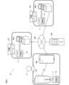
店舗端末300_iは、バッテリ11を着脱可能に構成される。店舗端末300_iには、当該店舗端末300_iが設置された店舗STiにおいて貸出対象とされたバッテリ11が装着される。そして、ユーザUは、店舗端末300_iからバッテリ11を取り外すことで、当該バッテリ11を借りることができる。また、ユーザUは、借りたバッテリ11を店舗端末300_iに装着することで、当該バッテリ11を返却することができる。店舗端末300_iの構成例については、図4を用いて後述する。The store terminal 300_i is configured to allow the
サーバ400は、本開示における情報処理装置の一例であり、バッテリレンタルサービスのサービス提供者(例えば、吸引装置100の製造者)によって管理されるコンピュータである。サーバ400は、クラウドコンピューティングサービスにおいて実現される仮想的なサーバ(クラウドサーバ)であってもよいし、1個の装置として実現された物理的なサーバであってもよい。サーバ400の構成例については図5を用いて後述する。The
[2.吸引装置の構成例]
<2-1.吸引装置の第1構成例>
図2は、吸引装置100の第1構成例を模式的に示す模式図である。図2に示すように、本構成例の吸引装置100Aは、電源ユニット110、カートリッジ120、及び香味付与カートリッジ130を含んで構成される。電源ユニット110は、電源部111A、センサ部112A、通知部113A、記憶部114A、通信部115A、及び制御部116Aを含んで構成される。カートリッジ120は、加熱部121A、液誘導部122、及び液貯蔵部123を含んで構成される。香味付与カートリッジ130は、香味源131、及びマウスピース124を含んで構成される。カートリッジ120及び香味付与カートリッジ130には、空気流路180が形成される。[2. Configuration example of suction device]
<2-1. First configuration example of suction device>
Fig. 2 is a schematic diagram showing a first configuration example of the
電源部111Aは、電力を蓄積する。そして、電源部111Aは、制御部116Aによる制御に基づいて、吸引装置100Aの各構成要素に電力を供給する。また、電源部111Aは、外部電源から受け付けた電力によって充電可能に構成されてもよい。外部電源は、例えば、ACアダプタ(AC:Alternating Current)、モバイルチャージャ、又はPC(Personal Computer)等である。電源部111Aは、例えば、吸引装置100Aに装着されたバッテリ11によって実現される。The
センサ部112Aは、吸引装置100Aに関する各種情報を取得する。センサ部112Aは、例えば、コンデンサマイクロホン等の圧力センサ、流量センサ、又は温度センサ等により構成され、ユーザUによる吸引に伴う値を取得する。The
一例として、センサ部112Aには、ユーザUの吸引により生じた吸引装置100A内の圧力(以下、「内圧」とも称する)の変化を検出する圧力センサ(「パフセンサ」とも称される)が含まれ得る。他の一例として、センサ部112Aには、ユーザUの吸引により生じた流量(以下、単に「流量」とも称する)を検出する流量センサが含まれてもよい。他の一例として、センサ部112Aには、加熱部121A又は加熱部121A周辺の温度を検出する温度センサ(「パフサーミスタ」とも称される)が含まれてもよい。As one example, the
また、センサ部112Aには、ユーザUの操作を検出する操作検出部が含まれてもよい。言い換えると、センサ部112Aは、ユーザUからの情報の入力を受け付ける入力部としても機能してもよい。この場合、センサ部112Aは、操作ボタン、操作スイッチ、モーションセンサ、又はホールセンサ等を含んで構成されてもよい。The
通知部113Aは、情報をユーザUに通知する。通知部113Aは、例えば、発光する発光装置、画像を表示する表示装置、音を出力する音出力装置、又は振動する振動装置等により構成され得る。ここで、発光装置は、例えば、LED(Light-Emitting Diode)等の発光素子と、この発光素子を発光させる駆動回路等によって実現することができる。また、表示装置は、例えば、液晶ディスプレイ、又はOLEDディスプレイ(OLED:Organic Light Emitting Diode)とすることができる。音出力装置は、例えば、スピーカとすることができる。振動装置は、例えば、モータと、このモータの回転軸に取り付けられた偏心錘とを含んで構成されるバイブレータとすることができる。The
記憶部114Aは、吸引装置100Aの動作のための各種情報(例えば、プログラムやデータ)を記憶する。記憶部114Aは、例えば、フラッシュメモリ等の不揮発性の記憶媒体により構成され得る。The
通信部115Aは、有線又は無線の任意の通信規格に準拠した通信を行うことが可能な通信インタフェースである。かかる通信規格としては、例えば、Wi-Fi、Bluetooth、BLE、NFC、又はLPWAを用いる規格等が採用され得る。例えば、通信部115Aは、制御部116Aによる制御に従って、BluetoothやNFC等の近距離無線通信を介し、通信端末200との間で通信を行う。The
制御部116Aは、演算処理装置及び制御装置として機能し、記憶部114A等に記憶されたプログラムに従って吸引装置100A内の動作全般を制御する。例えば、制御部116Aは、電源部111Aから各構成要素(例えば後述する加熱部121A)への給電や、外部電源から受け付けた電力による電源部111A(すなわちバッテリ11)の充電を制御する。さらに、本実施形態では、制御部116Aは、例えば、実時間を計時するRTC(Real-Time Clock)を備えている。The
制御部116Aは、例えば、CPU(Central Processing Unit)、又はマイクロプロセッサ(「MCU(Micro Controller Unit)」とも称される)といったIC(Integrated Circuit)を含む電子回路によって実現される。また、制御部116Aは、1つのICによって構成されてもよいし、2以上のICによって構成されてもよい。The
液貯蔵部123は、エアロゾル源を貯蔵する。エアロゾル源が霧化されることで、エアロゾルが生成される。エアロゾル源は、例えば、グリセリン及びプロピレングリコール等の多価アルコール、又は水等の液体である。エアロゾル源は、たばこ由来又は非たばこ由来の香味成分を含んでいてもよい。吸引装置100Aがネブライザ等の医療用吸入器である場合、エアロゾル源は、薬剤を含んでもよい。The
液誘導部122は、液貯蔵部123に貯蔵された液体であるエアロゾル源を、液貯蔵部123から誘導し、保持する。液誘導部122は、例えば、ガラス繊維等の繊維素材又は多孔質状のセラミック等の多孔質状素材を撚って形成されるウィックである。その場合、液貯蔵部123に貯蔵されたエアロゾル源は、ウィックの毛細管効果により誘導される。The
加熱部121Aは、例えば、エアロゾル源を加熱することで、エアロゾル源を霧化してエアロゾルを生成する。加熱部121Aは、コイル状、フィルム状又はブレード状等の任意の形状に、金属又はポリイミド等の任意の素材で構成される。図2に示した例では、加熱部121Aは、ニクロム又はステンレス鋼といった発熱抵抗体を巻回したコイルとして構成され、液誘導部122に巻き付けられる。加熱部121Aが発熱すると、液誘導部122に保持されたエアロゾル源が加熱されて霧化され、エアロゾルが生成される。加熱部121Aは、電源部111Aから給電されると発熱する。The
一例として、電源部111Aから加熱部121Aへの給電は、ユーザUが吸引を開始したこと、及び/又は所定の情報が入力されたことが、センサ部112Aにより検出された場合に行われ得る。そして、ユーザUが吸引を終了したこと、及び/又は所定の情報が入力されたことが、センサ部112Aにより検出された場合に、加熱部121Aへの給電は停止され得る。As one example, power supply from
なお、加熱部121Aは、振動又は誘導加熱により、エアロゾルの生成を行うように構成されてもよい。振動によりエアロゾルの生成が行われるようにした場合、吸引装置100Aは、加熱部121Aとしての振動部を備える。振動部は、例えば、超音波振動子として機能する圧電セラミックスを含む板状の部材により構成される。そして、振動部が振動すると、液誘導部122により振動部の表面に誘導されたエアロゾル源が、振動部による振動に伴って発生した超音波により霧化され、エアロゾルが生成される。The
また、誘導加熱によりエアロゾルの生成が行われるようにした場合、吸引装置100Aは、加熱部121Aとしてのサセプタ及び電磁誘導源を備える。サセプタは、金属等の導電性の素材により構成され、電磁誘導により発熱する。また、サセプタは、液誘導部122に近接して配置される。一例として、サセプタは、金属製の導線により構成され、液誘導部122に巻き付けられる。電磁誘導源は、電磁誘導によりサセプタを発熱させる。電磁誘導源は、例えば、コイル状の導線により構成され、電源部111Aから交流電流が供給されると、磁界を発生させる。磁界が発生すると、サセプタにおいて渦電流が発生して、ジュール熱が発生する。そして、かかるジュール熱により液誘導部122に保持されたエアロゾル源が加熱されて霧化され、エアロゾルが生成される。When the aerosol is generated by induction heating, the
香味源131は、エアロゾルに香味成分を付与するための構成要素である。香味源131は、たばこ由来又は非たばこ由来の香味成分を含む。例えば、香味源131は、刻みたばこ又はたばこ原料を、粒状、シート状、又は粉末状に成形した加工物等の、たばこ由来のものであってもよい。また、香味源131は、たばこ以外の植物(例えばミント及びハーブ等)から作られた、非たばこ由来のものを含んでいてもよい。一例として、香味源131は、メントール等の香料成分を含んでいてもよい。また、香味源131は、スティック型の部材であってもよい。吸引装置100Aが医療用吸入器である場合、香味源131は、患者が吸入するための薬剤を含んでもよい。なお、香味源131は固体に限られるものではなく、例えば、グリセリン及びプロピレングリコール等の多価アルコール、並びに水等の香味成分含む液体であってもよい。また、香味源131は、カプセル等の容器の内部に配置されてもよい。The
空気流路180は、ユーザUに吸引される空気の流路である。空気流路180は、空気流路180内への空気の入り口である空気流入孔181と、空気流路180からの空気の出口である空気流出孔182と、を両端とする管状構造を有する。空気流路180の途中には、上流側(空気流入孔181に近い側)に液誘導部122が配置され、下流側(空気流出孔182に近い側)に香味源131が配置される。ユーザUによる吸引に伴い空気流入孔181から流入した空気は、加熱部121Aにより生成されたエアロゾルと混合され、矢印190に示すように、香味源131を通過して空気流出孔182へ輸送される。エアロゾルと空気との混合流体が香味源131を通過する際には、香味源131に含まれる香味成分がエアロゾルに付与される。The
マウスピース124は、吸引の際にユーザUに咥えられる部材である。マウスピース124には、空気流出孔182が配置される。ユーザUは、マウスピース124を咥えて吸引することで、エアロゾルと空気との混合流体を口腔内へ取り込むことができる。The
以上、吸引装置100Aの構成例を説明した。もちろん吸引装置100Aの構成は上記に限定されず、以下に例示する多様な構成をとり得る。The above describes an example of the configuration of the
一例として、吸引装置100Aは、香味付与カートリッジ130を含んでいなくてもよい。その場合、カートリッジ120にマウスピース124が設けられる。As an example, the
他の一例として、吸引装置100Aは、香味源131を加熱する香味源加熱部(不図示)をさらに含んでもよい。香味源加熱部は、例えば、フィルム状に構成され、香味源131の外周を覆うように配置される。そして、香味源加熱部は、電源部111Aの電力が供給されることにより発熱して、香味源131を外周から加熱する。なお、香味源加熱部は、例えば、ブレード状に構成され、香味源131に突き刺さり、当該香味源131を内部から加熱してもよい。また、香味源加熱部は、振動又は誘導加熱により、香味源131の加熱を行うように構成されてもよい。このような香味源加熱部を設けることにより、香味源加熱部を設けない場合に比べて、香味源131の温度を高めることができ、エアロゾルに付与される香味成分量を増加させることが可能となる。As another example, the
また、他の一例として、吸引装置100Aは、複数種類のエアロゾル源を含んでいてもよい。複数種類のエアロゾル源から生成された複数種類のエアロゾルが空気流路180内で混合され化学反応を起こすことで、さらに他の種類のエアロゾルが生成されてもよい。As another example, the
また、エアロゾル源を霧化する手段は、加熱部121Aによる加熱に限定されない。例えば、エアロゾル源を霧化する手段は、振動霧化、又は誘導加熱であってもよい。Furthermore, the means for atomizing the aerosol source is not limited to heating by the
<2-2.吸引装置の第2構成例>
図3は、吸引装置100の第2構成例を模式的に示す模式図である。図3に示すように、本構成例の吸引装置100Bは、電源部111B、センサ部112B、通知部113B、記憶部114B、通信部115B、制御部116B、加熱部121B、収容部140、及び断熱部144を含んで構成される。<2-2. Second Configuration Example of Suction Device>
Fig. 3 is a schematic diagram showing a second configuration example of the
電源部111B、センサ部112B、通知部113B、記憶部114B、通信部115B、及び制御部116Bの各々は、前述した吸引装置100Aに含まれる対応する構成要素と実質的に同一である。Each of the
収容部140は、内部空間141を有し、内部空間141にスティック型基材150の一部を収容しながらスティック型基材150を保持する。収容部140は、内部空間141を外部に連通する開口142を有し、開口142から内部空間141に挿入されたスティック型基材150を収容する。例えば、収容部140は、開口142及び底部143を底面とする筒状体であり、柱状の内部空間141を画定する。収容部140には、内部空間141に空気を供給する空気流路が接続される。空気流路への空気の入口である空気流入孔は、例えば、吸引装置100の側面に配置される。空気流路から内部空間141への空気の出口である空気流出孔は、例えば、底部143に配置される。The
スティック型基材150は、基材部151、及び吸口部152を含む。基材部151は、エアロゾル源を含む。エアロゾル源は、たばこ由来又は非たばこ由来の香味成分を含む。吸引装置100Bがネブライザ等の医療用吸入器である場合、エアロゾル源は、薬剤を含んでもよい。エアロゾル源は、例えば、たばこ由来又は非たばこ由来の香味成分を含む、グリセリン及びプロピレングリコール等の多価アルコール、並びに水等の液体であってもよく、たばこ由来又は非たばこ由来の香味成分を含む固体であってもよい。スティック型基材150が収容部140に保持された状態において、基材部151の少なくとも一部は内部空間141に収容され、吸口部152の少なくとも一部は開口142から突出する。そして、開口142から突出した吸口部152をユーザUが咥えて吸引すると、図示しない空気流路を経由して内部空間141に空気が流入し、基材部151から発生するエアロゾルと共にユーザUの口内に到達する。The stick-
図3に示した例では、加熱部121Bは、電気抵抗値と温度とに相関を持つ発熱抵抗体による導電トラックを張り巡らせたフィルムヒータとして構成され、収容部140の外周を覆うように配置される。そして、加熱部121Bが発熱すると、スティック型基材150の基材部151が外周から加熱され、エアロゾルが生成される。なお、加熱部121Bの発熱抵抗体としては、前述した加熱部121Aの発熱抵抗体と同様のものを用いることができる。In the example shown in FIG. 3, the
断熱部144は、加熱部121Bから他の構成要素への伝熱を防止する。例えば、断熱部144は、真空断熱材、又はエアロゲル断熱材等により構成される。The insulating
以上、吸引装置100Bの構成例を説明した。もちろん吸引装置100Bの構成は上記に限定されず、以下に例示する多様な構成をとり得る。The above describes an example of the configuration of the
一例として、加熱部121Bは、ブレード状に構成され、収容部140の底部143から内部空間141に突出するように配置されてもよい。その場合、ブレード状の加熱部121Bは、スティック型基材150の基材部151に挿入され、スティック型基材150の基材部151を内部から加熱する。他の一例として、加熱部121Bは、収容部140の底部143を覆うように配置されてもよい。また、加熱部121Bは、収容部140の外周を覆う第1の加熱部、ブレード状の第2の加熱部、及び収容部140の底部143を覆う第3の加熱部のうち、2以上の組み合わせとして構成されてもよい。As one example, the
他の一例として、収容部140は、内部空間141を形成する外殻の一部を開閉する、ヒンジ等の開閉機構を含んでいてもよい。そして、収容部140は、外殻を開閉することで、内部空間141に挿入されたスティック型基材150を挟持しながら収容してもよい。その場合、加熱部121Bは、収容部140における当該挟持箇所に設けられ、スティック型基材150を押圧しながら加熱してもよい。As another example, the
また、エアロゾル源を霧化する手段は、加熱部121Bによる加熱に限定されない。例えば、エアロゾル源を霧化する手段は、誘導加熱であってもよい。その場合、吸引装置100Bは、加熱部121Bの代わりに、磁場を発生させるコイル等の電磁誘導源を少なくとも有する。誘導加熱により発熱するサセプタは、吸引装置100Bに設けられていてもよいし、スティック型基材150に含まれていてもよい。Furthermore, the means for atomizing the aerosol source is not limited to heating by the
また、吸引装置100Bは、第1構成例に係る加熱部121A、液誘導部122、液貯蔵部123、及び空気流路180をさらに含んでいてもよく、空気流路180が内部空間141に空気を供給してもよい。この場合、加熱部121Aにより生成されたエアロゾルと空気との混合流体は、内部空間141に流入して加熱部121Bにより生成されたエアロゾルとさらに混合され、ユーザUの口腔内に到達する。The
なお、以下では、前述した吸引装置100Aと吸引装置100Bとを区別せずに「吸引装置100」とも称する。同様に、電源部111A及び電源部111Bを「電源部111」、センサ部112A及びセンサ部112Bを「センサ部112」、通知部113A及び通知部113Bを「通知部113」、記憶部114A及び記憶部114Bを「記憶部114」、通信部115A及び通信部115Bを「通信部115」、制御部116A及び制御部116Bを「制御部116」、加熱部121A及び加熱部121Bを「加熱部121」、とそれぞれ称することがある。In the following, the
[3.通信端末の構成例]
図4は、通信端末200の構成例を模式的に示す模式図である。図4に示すように、通信端末200は、例えば、制御部201、通信部202、UI(ユーザインタフェース)部203、及び記憶部205を含んで構成される。[3. Example of the configuration of a communication terminal]
Fig. 4 is a schematic diagram showing an example of the configuration of the
制御部201は、演算処理装置及び制御装置として機能し、各種プログラムに従って通信端末200の動作全般を制御する。制御部201は、例えば、CPU等を含む電子回路によって実現される。The
通信部202は、制御部201による制御に従って、有線又は無線の任意の通信規格に準拠した通信を行うことが可能な通信インタフェースである。かかる通信規格としては、インターネット、セルラー通信、Wi-Fi、Bluetooth、BLE、NFC、又はLPWAを用いる規格等が採用され得る。The
例えば、通信部202は、制御部201による制御に従って、インターネットやセルラー通信等のネットワークNETを介し、サーバ400との間で通信を行う。また、通信部202は、制御部201による制御に従って、BluetoothやNFC等の近距離無線通信を介し、吸引装置100又は店舗端末300_iとの間で通信を行う。For example, the
UI部203は、ユーザUからの情報の入力を受け付ける入力装置と、ユーザUに対して各種情報を出力(例えば提示)する出力装置とを含む。UI部203の入力装置は、受け付けた情報(言い換えると、入力された情報)を制御部201へ出力する。UI部203の出力装置は、制御部201による制御に従って各種情報を出力する。本実施形態では、画像を表示する表示装置(例えば、液晶ディスプレイ又は有機ELディスプレイ)とポインティングデバイスとを組み合わせたタッチパネルによりUI部203が構成されているものとするが、これに限られない。例えば、UI部203は、表示装置と入力装置とが別体として設けられていてもよい。また、UI部203は、音を出力する音出力装置、又は振動する振動装置等をさらに含んでいてもよい。The
記憶部205は、通信端末200の動作のための各種情報(例えばプログラムやデータ)を記憶し、当該情報を制御部201が参照可能な状態で設けられる。記憶部205は、例えば、フラッシュメモリ等の不揮発性の記憶媒体により構成され得る。また、記憶部205は、制御部201を実現するCPU等が各種処理を行う際にワークエリアとして使用されるRAM(Random Access Memory)をさらに含んでいてもよい。The
[4.店舗端末の構成例]
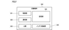
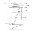
図5は、店舗端末300_iの構成例を模式的に示す模式図である。図5に示すように、店舗端末300_iは、例えば、制御部301、通信部302、UI部303、バッテリ収容部304、及び記憶部305を含んで構成される。[4. Example of store terminal configuration]
5 is a schematic diagram showing an example of the configuration of the store terminal 300_i. As shown in FIG. 5, the store terminal 300_i includes, for example, a
制御部301は、演算処理装置及び制御装置として機能し、各種プログラムに従って店舗端末300_iの動作全般を制御する。制御部301は、例えば、CPU等を含む電子回路によって実現される。The
通信部302は、制御部301による制御に従って、有線又は無線の任意の通信規格に準拠した通信を行うことが可能な通信インタフェースである。かかる通信規格としては、インターネット、セルラー通信、Wi-Fi、Bluetooth、BLE、NFC、又はLPWAを用いる規格等が採用され得る。The
例えば、通信部302は、制御部301による制御に従って、インターネットやセルラー通信等のネットワークNETを介し、サーバ400との間で通信を行う。また、通信部302は、制御部301による制御に従って、BluetoothやNFC等の近距離無線通信を介し、通信端末200との間で通信を行う。For example, the
UI部303は、ユーザ(例えばユーザU)からの情報の入力を受け付ける入力装置と、ユーザに対して各種情報を出力する出力装置とを含む。UI部303の入力装置は、受け付けた情報(言い換えると、入力された情報)を制御部301へ出力する。UI部303の出力装置は、制御部301による制御に従って各種情報を出力する。例えば、UI部303も、UI部203と同様にタッチパネルにより構成され得る。また、UI部303は、表示装置と入力装置とが別体として設けられていてもよい。The
バッテリ収容部304は、例えば、複数のバッテリ11を収容可能、且つ各バッテリ11をそれぞれ独立して収容可能に構成される。一例として、本実施形態では、バッテリ収容部304は、例えば、それぞれが1つのバッテリ11を収容可能な収容スペースを複数有する。各収容スペースには、それぞれ、制御部301の制御に従って動作するロック機構付きの扉が設けられている。そして、一の収容スペースの扉のロックが制御部301により解除されると、ユーザUは、その扉を開放して一の収容スペースに収容されたバッテリ11を取り出す(すなわち、当該バッテリ11を借りる)ことができる。他方、収容スペースの扉がロックされているときは、当該収容スペースに収容されたバッテリ11をユーザUが取り出すことは困難である。The
また、各収容スペースには、それぞれ、当該収容スペースに収容されたバッテリ11と電気的に接続される端子が設けられている。店舗端末300_iは、この端子を介して、例えば、各収容スペースに収容されたバッテリ11に給電(すなわち充電)することができる。さらに、店舗端末300_i(より具体的には制御部301)は、例えば、この端子を介して、各収容スペースに収容されたバッテリ11が備えるバッテリICと通信することで、各収容スペースに収容されたバッテリ11の記憶部11aに所定の情報(例えば、後述する使用制限情報)を記憶させたり、当該記憶部11aに記憶された情報を取得したりすることもできる。Furthermore, each storage space is provided with a terminal electrically connected to the
なお、店舗端末300_iとバッテリ収容部304とは一体的に構成されていなくてもよく、別体として構成されてもよい。この場合、店舗端末300_iは、バッテリ収容部304を備える他の装置と通信することで、当該他の装置に収容されたバッテリ11を充電させたり、当該バッテリ11の記憶部11aに所定の情報を記憶させたり、当該記憶部11aに記憶された情報を取得したりすればよい。The store terminal 300_i and the
記憶部305は、店舗端末300_iの動作のための各種情報(例えば、プログラムやデータ)を記憶し、当該情報を制御部301が参照可能な状態で設けられる。記憶部305は、例えば、フラッシュメモリ等の不揮発性の記憶媒体により構成され得る。また、記憶部305は、制御部301を実現するCPU等が各種処理を行う際にワークエリアとして使用されるRAMをさらに含んでいてもよい。The
[5.サーバの構成例]
図6は、サーバ400の構成例を模式的に示す模式図である。図6に示すように、サーバ400は、例えば、制御部401、通信部402、及び記憶部405を含んで構成される。[5. Server configuration example]
Fig. 6 is a schematic diagram showing an example of the configuration of the
制御部401は、演算処理装置及び制御装置として機能し、各種プログラムに従ってサーバ400の動作全般を制御する。制御部401は、例えば、CPU等を含む電子回路によって実現される。The
通信部402は、制御部401による制御に従って、有線又は無線の任意の通信規格に準拠した通信を行うことが可能な通信インタフェースである。かかる通信規格としては、インターネット、セルラー通信、Wi-Fiを用いる規格等が採用され得る。例えば、通信部402は、制御部401による制御に従って、インターネットやセルラー通信等のネットワークNETを介し、通信端末200又は店舗端末300_iとの間で通信を行う。The
記憶部405は、サーバ400の動作のための各種情報(例えば、プログラムやデータ)を記憶し、当該情報を制御部401が参照可能な状態で設けられる。記憶部405は、例えば、ハードディスク又はフラッシュメモリ等の不揮発性の記憶媒体により構成され得る。また、記憶部405は、制御部401を実現するCPU等が各種処理を行う際にワークエリアとして使用されるRAMをさらに含んでいてもよい。The
本実施形態では、記憶部405には、例えば、バッテリ適合情報テーブル405aや店舗情報テーブル405bといった情報が記憶されている。以下、バッテリ適合情報テーブル405a及び店舗情報テーブル405bの一例について説明する。In this embodiment, the
図7は、記憶部405が記憶するバッテリ適合情報テーブル405aの一例を示す図である。図7に示すように、バッテリ適合情報テーブル405aは、例えば、吸引装置100の種別ごとに適合するバッテリ11の種別を示す情報を含んで構成される。FIG. 7 is a diagram showing an example of a battery compatibility information table 405a stored in the
例えば、図7に示すバッテリ適合情報テーブル405aは、「機種A」という種別の吸引装置100(例えば、図2に示した吸引装置100A)と、「バッテリタイプa」という種別のバッテリ11とを対応付けた情報405a_1を有する。この情報405a_1は、「機種A」という種別の吸引装置100には、「バッテリタイプa」という種別のバッテリ11が適合することをあらわしている。For example, the battery compatibility information table 405a shown in FIG. 7 has information 405a_1 that associates an
図8は、記憶部405が記憶する店舗情報テーブル405bの一例を示す図である。図8に示すように、店舗情報テーブル405bは、例えば、バッテリ11の貸し出しを行っている店舗(例えば、図1に示した店舗ST1~STn)ごとに、当該店舗において貸出対象となっているバッテリ11の種別と、当該店舗の所在地とを示す情報(以下、「所在地情報」とも称する)を含んで構成される。FIG. 8 is a diagram showing an example of a store information table 405b stored in the
例えば、図8に示す店舗情報テーブル405bは、「店舗α」という店舗(例えば、図1に示した店舗ST1)と、所在地「〇〇」と、「バッテリタイプa」というバッテリ11の種別とを対応付けた情報405b_1を有する。この情報405b_1は、バッテリ11の貸し出しを行っている一店舗である「店舗α」は、所在地が「〇〇」であり、「バッテリタイプa」という種別のバッテリ11の貸し出しを行っていること(言い換えると、「店舗α」の店舗端末300_iには、「バッテリタイプa」という種別のバッテリ11が収容されていること)をあらわしている。For example, the store information table 405b shown in FIG. 8 has information 405b_1 that associates a store called "Store α" (for example, store ST1 shown in FIG. 1) with a location "XX" and a type of
[6.バッテリレンタル支援システム10の動作例]
図9は、バッテリレンタル支援システム10の動作例を示すシーケンス図である。図9に示すように、ユーザUの吸引装置100は、吸引装置識別情報をユーザUの通信端末200へ送信する(ステップS1)。吸引装置識別情報を受信した通信端末200は、当該吸引装置識別情報を記憶部205に記憶する(ステップS2)。6. Operational Example of Battery
Fig. 9 is a sequence diagram showing an example of the operation of the battery
ここで、吸引装置識別情報は、ユーザUの吸引装置100の種別を特定可能な情報を含み、例えば、吸引装置100の個体を識別可能な情報とすることができる。吸引装置100が吸引装置識別情報を送信するタイミングは、例えば、ユーザUが吸引装置100及び/又は通信端末200に対して所定操作を行うことにより、吸引装置100と通信端末200との紐付けが行われたタイミングとすることができるが、これに限られず、吸引装置100の製造者が任意に定めてよい。Here, the suction device identification information includes information capable of identifying the type of
また、吸引装置100は、使用履歴情報を通信端末200へ送信する(ステップS3)。使用履歴情報を受信した通信端末200は、当該使用履歴情報を記憶部205に記憶する(ステップS4)。The
ここで、使用履歴情報は、ユーザUの吸引装置100の使用履歴をあらわす情報であり、例えば、吸引装置100を用いた喫煙が行われた時期を特定可能な情報を含む。一例として、使用履歴情報は、過去の所定期間において吸引装置100を用いて行われた喫煙の開始時刻及び終了時刻を示す情報とすることができる。Here, the usage history information is information that represents the usage history of the
吸引装置100が使用履歴情報を送信するタイミングは、例えば、毎週日曜日の00時00分といったように吸引装置100の製造者によりあらかじめ設定されたタイミングとすることができるが、これに限られず、ユーザUにより吸引装置100及び/又は通信端末200に対して所定操作が行われたタイミング等であってもよい。また、吸引装置100は、ステップS1の吸引装置識別情報の送信に合わせて使用履歴情報も送信するようにしてもよい。The timing at which the
そして、通信端末200は、ユーザUによる所定操作を受け付けると、バッテリレンタルサービス利用要求(以下、単に「レンタル利用要求」とも称する)をサーバ400へ送信する(ステップS5)。Then, when the
ここで、レンタル利用要求は、ステップS2の処理により記憶された吸引装置識別情報、言い換えると、ユーザUの吸引装置100から取得された吸引装置識別情報を含む情報である。一例として、本実施形態では、レンタル利用要求には、吸引装置識別情報に加えて、ステップS3の処理により記憶された使用履歴情報と、今回のレンタル利用要求送信時における通信端末200の位置(すなわちユーザUの位置)を示す位置情報と、が含まれているものとする。なお、レンタル利用要求に含まれる位置情報は、通信端末200の位置に代えて、ユーザにより指定された地点の位置を示す情報としてもよい。Here, the rental use request is information including the suction device identification information stored by the processing of step S2, in other words, the suction device identification information acquired from the
このように、ユーザUの位置又はユーザにより指定された地点の位置の位置情報を含むレンタル利用要求がサーバ400へ送信されることで、ユーザUの位置又はユーザにより指定された地点の位置を考慮した処理をサーバ400が行うことが可能となる。また、吸引装置100の使用履歴情報を含むレンタル利用要求がサーバ400へ送信されることで、ユーザUによる吸引装置100の使用履歴(言い換えると、使用傾向)を考慮した処理をサーバ400が行うことが可能となる。In this way, a rental use request including location information of the user U's location or the location of a point specified by the user is sent to the
次に、サーバ400は、通信端末200から送信されたレンタル利用要求を受信することで当該レンタル利用要求に含まれた情報を取得し、当該情報に基づき、ユーザUに提示するレンタル可能店舗の選定とレコメンド情報の設定を行う(ステップS6)。Next, the
レンタル可能店舗の選定の一例について詳述すると、サーバ400は、まず、記憶部405に記憶されたバッテリ適合情報テーブル405aを参照して、受信したレンタル利用要求の吸引装置識別情報に基づき、ユーザUの吸引装置100に適合するバッテリ11の種別を特定する。例えば、受信したレンタル利用要求の吸引装置識別情報が「機種A」を示すものであった場合、サーバ400は、図7に示したバッテリ適合情報テーブル405aを参照することで、ユーザUの吸引装置100に適合するバッテリ11の種別として「バッテリタイプa」を特定する。To go into detail about an example of selecting a rental store, the
次に、サーバ400は、記憶部405に記憶された店舗情報テーブル405bを参照して、ユーザUの吸引装置100に適合するバッテリ11の貸し出しを行っている店舗STiを検索する。例えば、ユーザUの吸引装置100に適合するバッテリ11の種別が「バッテリタイプa」と特定されたとする。この場合、サーバ400は、図8に示した店舗情報テーブル405bを参照することで、「バッテリタイプa」のバッテリ11の貸し出しを行っている店舗STiとして「店舗α」等を検索する。Next, the
次に、サーバ400は、受信したレンタル利用要求の位置情報と、店舗情報テーブル405bにおける各店舗の所在地情報とに基づき、例えば、ユーザUの吸引装置100に適合するバッテリ11の貸し出しを行っている店舗STiとして検索された店舗の中から、ユーザU(言い換えると、通信端末200)から所定範囲内(例えば、半径1[km]以内)に位置する店舗を、レンタル可能店舗として選定する。レンタル可能店舗としての要件を満たす店舗が複数存在する場合、サーバ400は、例えば、これら複数の店舗をレンタル可能店舗として選定する。Next, based on the location information of the received rental request and the location information of each store in the store information table 405b, the
なお、受信したレンタル利用要求の位置情報が、ユーザUにより指定された地点の位置を示す情報であった場合、サーバ400は、ユーザUの吸引装置100に適合するバッテリ11の貸し出しを行っている店舗STiとして検索された店舗の中から、ユーザUにより指定された地点から所定範囲内(例えば、半径1[km]以内)に位置する店舗を、レンタル可能店舗として選定すればよい。If the location information of the received rental use request indicates the location of the point specified by user U,
また、レコメンド情報の設定の一例について詳述すると、サーバ400は、まず、受信したレンタル利用要求の使用履歴情報に基づき、ユーザUの1日あたりの喫煙回数を特定する。一例として、サーバ400は、直近の1週間に含まれる各日において吸引装置100を用いた喫煙がそれぞれ何回行われているかを使用履歴情報から特定し、これらの平均値を、ユーザUの1日あたりの喫煙回数として特定する。To go into more detail about an example of setting recommendation information, the
次に、サーバ400は、ユーザUの1日あたりの喫煙回数に基づき、1日あたりの充電回数を導出する。例えば、吸引装置100においては、バッテリ11が満充電状態とされてから20回の喫煙が行われると、バッテリ11が空の状態になるものとする。そして、ユーザUの1日あたりの喫煙回数が20回であったとする。この場合、バッテリ11を1日1回充電すれば、ユーザUの1日あたりの喫煙回数分の喫煙を行えることとなる。したがって、この場合、サーバ400は、1日あたりの充電回数を「1回」と導出する。Next, the
他方、ユーザUの1日あたりの喫煙回数が40回であったとする。この場合、バッテリ11を1日2回充電しなければ、ユーザUの1日あたりの喫煙回数分の喫煙を行えないこととなる。したがって、この場合、サーバ400は、1日あたりの充電回数を「2回」と導出する。On the other hand, suppose that user U smokes 40 times per day. In this case, unless the
このようにレンタル可能店舗の選定とレコメンド情報の設定を行ったサーバ400は、レンタル可能店舗を示す情報とレコメンド情報とを含むレンタル支援情報をユーザUの通信端末200(すなわち、レンタル利用要求元)へ送信することで、当該レンタル支援情報をユーザUに提示させる(ステップS7)。After selecting the stores where rental items are available and setting the recommendation information in this manner, the
また、レンタル支援情報には、ステップS6の処理により特定されたユーザUの吸引装置100に適合するバッテリ11の種別を示す情報が含まれていてもよい。このようにすれば、通信端末200が、ユーザUの吸引装置100に適合するバッテリ11の種別を示す情報をユーザUに提示することが可能となる。そして、ユーザUの吸引装置100に適合するバッテリ11の種別をユーザUに提示することで、ユーザUが自身の吸引装置100に適合するバッテリ11の種別を把握できるため、他の種別のバッテリ11を誤って借りてしまうといった事態が発生するのを抑制することが可能となる。The rental assistance information may also include information indicating the type of
一例として、本実施形態では、レンタル支援情報を受信した通信端末200は、例えば、図10を用いて後述するレンタル店舗選択画面1000と、図11を用いて後述するレンタル詳細設定画面1100とをUI部203に表示させることで、レンタル可能店舗を示す情報、レコメンド情報、及びユーザUの吸引装置100に適合するバッテリ11の種別を示す情報をユーザUに提示する。As an example, in this embodiment, the
そして、通信端末200は、例えば、レンタル店舗選択画面1000とレンタル詳細設定画面1100とを介して、ユーザUがバッテリ11を借りることを希望する店舗STi(以下、「レンタル店舗」とも称する)の選択と、ユーザUによるバッテリ11のレンタルについての詳細設定を受け付ける(ステップS8)。一例として、本実施形態では、ステップS8の処理により、通信端末200は、ユーザUによるレンタル店舗の選択結果と、ユーザUによるバッテリ11のレンタル期間と、ユーザUによるバッテリ11の充電可能回数とを受け付ける。Then, the
そして、通信端末200は、ユーザUによるバッテリ11のレンタルに関するレンタル情報をサーバ400へ送信する(ステップS9)。レンタル情報は、例えば、ステップS8の処理結果として得られた情報とすることができる。一例として、本実施形態では、このレンタル情報には、レンタル店舗、ユーザUによるバッテリ11のレンタル期間、及びユーザUによるバッテリ11の充電可能回数のそれぞれを示す情報が含まれる。ここで、レンタル期間を示す情報は、少なくとも当該レンタル期間の終了時刻を示す情報を含む。さらに、本実施形態では、レンタル情報には、ユーザUの通信端末200の個体を識別可能な通信端末識別情報も含まれるものとする。Then, the
レンタル情報を受信したサーバ400は、当該レンタル情報に基づきレンタル店舗である店舗STiを特定し、当該店舗STiの店舗端末300_iへレンタル情報を送信する(ステップS10)。これにより、サーバ400は、ユーザUによるバッテリ11のレンタル期間及び充電可能回数と、ユーザUの通信端末200の通信端末識別情報とを、レンタル店舗である店舗STiに設置された店舗端末300_iに通知することができる。The
レンタル情報を受信した店舗端末300_iは、当該レンタル情報を記憶部305に記憶するとともに、バッテリ収容部304に収容されたバッテリ11のうちの一のバッテリ11に貸し出し準備設定を行う(ステップS11)。ステップS11の処理において、店舗端末300_iは、例えば、一のバッテリ11にレンタル情報を基づく情報を記憶させたり、必要に応じて一のバッテリ11の充電を行ったりする。The store terminal 300_i that has received the rental information stores the rental information in the
一例として、本実施形態では、店舗端末300_iは、ステップS11の処理により、レンタル情報を基づく使用制限情報を一のバッテリ11に記憶部11aに記憶させる。ここで、使用制限情報は、例えば、ユーザUによるバッテリ11のレンタル期間と充電可能回数とのそれぞれを示す情報とすることができる。このような使用制限情報をバッテリ11の記憶部11aに記憶させることにより、当該バッテリ11が装着されたユーザUの吸引装置100が、ユーザUによるバッテリ11のレンタル期間や充電可能回数を考慮した制御を行うことが可能となる。As an example, in this embodiment, the store terminal 300_i stores usage restriction information based on rental information in the
その後、ユーザUは、レンタル店舗である店舗STiに赴き、自身の通信端末200と店舗STiの店舗端末300_iとを通信させ、通信端末200から店舗端末300_iへ所定の認証情報を送信させる(ステップS12)。そして、認証情報を受信した店舗端末300_iは、認証処理を行う(ステップS13)。Then, the user U goes to the store STi, which is a rental store, and causes his/her
ここで、認証情報は、例えば、通信端末識別情報を含む情報とすることができる。この場合、店舗端末300_iは、記憶部305に記憶されたレンタル情報に含まれる通信端末識別情報と、受信した認証情報の通信端末識別情報とが一致する場合に認証成功とし、バッテリ11の貸し出しを行う(ステップS14)。ステップS14の処理において、店舗端末300_iは、ステップS11の処理により貸し出し準備設定を行った一のバッテリ11を収容する収容スペースの扉のロックを解除することにより、当該バッテリ11の貸し出しを行う。The authentication information may include, for example, communication terminal identification information. In this case, if the communication terminal identification information included in the rental information stored in the
また、店舗端末300_iは、例えば、バッテリ11の貸し出しを行う前に、UI部303等を介して、レンタル情報をユーザUに提示することでその内容(例えば、レンタル期間や充電可能回数)をユーザUに確認させてもよい。そして、UI部303等を介して、内容に誤りがない旨の操作をユーザUから受け付けた場合に、バッテリ11の貸し出しを行うようにしてもよい。In addition, the store terminal 300_i may, for example, before lending out the
他方、店舗端末300_iは、記憶部305に記憶されたレンタル情報に含まれる通信端末識別情報と、受信した認証情報の通信端末識別情報とが一致しない場合には、認証失敗とする。この場合、店舗端末300_iは、ステップS14の処理を行わない。On the other hand, if the communication terminal identification information included in the rental information stored in the
ステップS14の処理が行われた場合に限り、ユーザUは、バッテリ11を店舗端末300_iから取り外して吸引装置100に装着することが可能となる。そして、吸引装置100は、バッテリ11が装着されると、バッテリ装着時処理を行う(ステップS15)。バッテリ装着時処理の詳細については後述するため、ここでの説明を省略する。Only when the processing of step S14 has been performed can the user U remove the
また、店舗端末300_iは、バッテリ11が店舗端末300_iから取り外されたことに応じて(すなわち、バッテリ11がユーザUに貸し出されたことに応じて)、サーバ400へ決済要求を送信する(ステップS16)。In addition, the store terminal 300_i transmits a payment request to the
決済要求を受信したサーバ400は、今回のユーザUによるバッテリ11のレンタル期間及び充電可能回数に応じたレンタル金額を決済する(言い換えると、レンタル金額をユーザUに請求する)決済処理を行う(ステップS17)。レンタル金額は、例えば、レンタル期間が長いほど高くなり、また、充電可能回数が多いほど高くなるように、バッテリレンタルサービスのサービス提供者(例えば、吸引装置100の製造者)によってあらかじめ定められる。The
以上に説明したように、サーバ400(例えば、制御部401)は、ユーザUの吸引装置100の吸引装置識別情報を取得し、当該吸引装置識別情報に基づきユーザUの吸引装置100に適合するバッテリ11の種別を特定し、店舗情報テーブル405bを参照してユーザUの吸引装置100に適合する種別のバッテリ11が貸出対象となっている店舗STiを検索し、検索された店舗STiを示す情報をユーザUに提示する。これにより、ユーザUの吸引装置100に適合する種別のバッテリ11が貸出対象となっている店舗STiをユーザUに案内することができ、ユーザUがバッテリレンタルサービスを利用するのを支援することができる。したがって、バッテリレンタルサービスの利用を希望するユーザUの利便性の向上を図れる。As described above, the server 400 (e.g., the control unit 401) acquires the suction device identification information of the user U's
また、サーバ400は、ユーザUの位置情報を取得し、当該位置情報に基づきユーザUの吸引装置100に適合する種別のバッテリ11が貸出対象となっている店舗STiの中から、ユーザUから所定範囲内に位置する店舗STiを選定し、選定された店舗STiを示す情報をユーザUに提示してもよい。このようにすれば、ユーザUの吸引装置100に適合する種別のバッテリ11が貸出対象となっており、且つ距離的にユーザUに近い店舗STiをユーザUに案内することができ、ユーザUがバッテリレンタルサービスを利用するのを支援することができる。したがって、バッテリレンタルサービスの利用を希望するユーザUの利便性の向上を図れる。The
他の一例として、サーバ400は、ユーザUにより指定された地点の位置情報を取得し、当該位置情報に基づきユーザUの吸引装置100に適合する種別のバッテリ11が貸出対象となっている店舗STiの中から、ユーザUにより指定された地点から所定範囲内に位置する店舗STiを選定し、選定された店舗STiを示す情報をユーザUに提示してもよい。このようにすれば、ユーザUの吸引装置100に適合する種別のバッテリ11が貸出対象となっており、且つ距離的にユーザUが所望する地点に近い店舗STiをユーザUに案内することができ、ユーザUがバッテリレンタルサービスを利用するのを支援することができる。したがって、バッテリレンタルサービスの利用を希望するユーザUの利便性の向上を図れる。As another example, the
また、サーバ400は、例えば、ユーザUによりレンタル店舗として選択された店舗STiに設置された店舗端末300_iへ、ユーザUによるバッテリ11のレンタルに関するレンタル情報を送信する。これにより、サーバ400は、ユーザUにより選択された店舗STiに設置された店舗端末300_iに、ユーザUへのバッテリ11の貸し出しに備えた処理を行わせることが可能となる。The
より具体的には、レンタル情報は、例えば、ユーザUによるバッテリ11のレンタル期間、及びユーザUによるバッテリ11の充電可能回数を示す情報を含む。これにより、サーバ400は、ユーザUによるバッテリ11のレンタル期間及び充電可能回数を、レンタル店舗である店舗STiに設置された店舗端末300_iに通知することができる。More specifically, the rental information includes, for example, information indicating the rental period of the
そして、サーバ400は、このようなレンタル情報を、ユーザUにより選択された店舗STiに設置された店舗端末300_iへ送信することで、当該店舗端末300_iを介して、当該店舗STiにおいて買出対象となっているバッテリ11の中の一のバッテリ11が有する記憶部11aに前述した使用制限情報を記憶させる。これにより、当該使用制限情報を記憶するバッテリ11が装着されたユーザUの吸引装置100が、ユーザUによるバッテリ11のレンタル期間や充電可能回数を考慮した制御を行うことを可能とする。Then, the
また、サーバ400は、ユーザUによるバッテリ11のレンタルに関するレコメンド情報をユーザUに提示するようにしてもよい。このようにすれば、ユーザUによるバッテリレンタルサービスの利用をより促すことができる。The
一例として、サーバ400は、ユーザUの吸引装置100の使用履歴情報を取得し、当該使用履歴情報に基づくレコメンド情報をユーザUに提示する。このようにすれば、ユーザUの吸引装置100の使用傾向を考慮したレコメンド情報をユーザUに提示することが可能となり、ユーザUによるバッテリレンタルサービスの利用をより促すことができる。なお、レコメンド情報は、使用履歴情報に基づくものでなくてもよく、例えば、バッテリレンタルサービスのサービス提供者(例えば、吸引装置100の製造者)があらかじめ定めた情報等であってもよい。As an example, the
また、サーバ400は、ユーザUへのバッテリ11の貸し出しが行われた場合に、当該貸し出しに関する決済を行うようにしてもよい。このようにすれば、ユーザUへのバッテリ11の貸し出しに伴う対価を、自動的にユーザUに対して請求することが可能となる。なお、当該決済に際し、サーバ400は、例えば、あらかじめ登録されたユーザUのクレジットカードのカード会社のサーバ等に所定の金額(レンタル金額)の取引があった旨の情報を送信すればよい。Furthermore, when the
一例として、サーバ400は、ユーザUへのバッテリ11の貸し出しが行われた場合に、当該貸し出しに関する決済として、ユーザUによるバッテリ11のレンタル期間や充電可能回数に応じた金額を決済する。このようにすれば、ユーザUによるバッテリ11のレンタル期間や充電可能回数を考慮した適切な対価(レンタル金額)を、自動的にユーザUに対して請求することが可能となる。As an example, when the
また、通信端末200は、ユーザUの吸引装置100から吸引装置識別情報を取得し、当該吸引装置識別情報をサーバ400へ送信し、当該吸引装置識別情報に基づきサーバ400により検索されたユーザUの吸引装置100に適合する種別のバッテリ11が貸出対象となっている店舗STiを示す情報をサーバ400から受信し、受信した店舗STiを示す情報をユーザUに提示する。これにより、ユーザUの吸引装置100に適合する種別のバッテリ11が貸出対象となっている店舗STiをユーザUに案内することができ、ユーザUがバッテリレンタルサービスを利用するのを支援することができる。したがって、バッテリレンタルサービスの利用を希望するユーザUの利便性の向上を図れる。The
[7.レンタル店舗選択画面の一例]
図10は、レンタル支援情報を受信した通信端末200がUI部203に表示するレンタル店舗選択画面1000の一例を示す図である。[7. Example of rental store selection screen]
FIG. 10 is a diagram showing an example of a rental
図10に示すように、レンタル店舗選択画面1000は、例えば、ユーザUの吸引装置100に適合するバッテリ11の種別を示すメッセージ1010と、レンタル店舗の選択を促すメッセージ1020と、所定範囲の地図をあらわす地図画像1030と、を含む。As shown in FIG. 10, the rental
図10に示す例では、ユーザUの吸引装置100に適合するバッテリ11の種別を示すメッセージ1010として、「お客様の吸引装置に適合するバッテリは、バッテリタイプaです。」といったメッセージが表示されている。これは、図9に示したステップS6の処理により、ユーザUの吸引装置100に適合するバッテリ11の種別が「バッテリタイプa」と特定されたためである。In the example shown in FIG. 10, a message such as "The battery that is suitable for your suction device is battery type a" is displayed as
また、図10に示す例では、地図画像1030は、ユーザU(言い換えると、通信端末200)から所定範囲内の地図をあらわしている。そして、地図画像1030において、ユーザUが位置する地点に対応する箇所には、現在位置アイコン1031が表示されている。In the example shown in FIG. 10, the
また、地図画像1030において、各レンタル可能店舗の所在地に対応する箇所には、レンタル可能店舗アイコン1032が表示される。これにより、レンタル可能店舗が地図画像1030上で強調表示され、ユーザUは、各レンタル可能店舗の所在地を直感的且つ容易に把握することができる。そして、ユーザUは、現在位置アイコン1031が示すユーザUの位置と、各レンタル可能店舗アイコン1032が示すレンタル可能店舗の位置との位置関係を考慮して、レンタル店舗を選択することができる。In addition, on the
図10に示す例では、「店舗α」及び「店舗γ」がレンタル可能店舗としてレンタル可能店舗アイコン1032により強調表示されている。この場合、ユーザUは、例えば、「店舗α」に対応するレンタル可能店舗アイコン1032をタップすることで、「店舗α」をレンタル店舗として選択することができる。In the example shown in FIG. 10, "Store α" and "Store γ" are highlighted by the
[8.レンタル詳細設定画面の一例]
図11は、レンタル支援情報を受信した通信端末200がUI部203に表示するレンタル詳細設定画面1100の一例を示す図である。このレンタル詳細設定画面1100は、例えば、図10に示したレンタル店舗選択画面1000においていずれかのレンタル可能店舗がレンタル店舗として選択されることにより表示される。[8. Example of rental details setting screen]
11 is a diagram showing an example of a rental
図11に示すように、レンタル詳細設定画面1100は、例えば、レンタル期間の設定に用いられるレンタル期間設定欄1110と、充電可能回数の設定に用いられる充電可能回数設定欄1120と、レンタル期間設定欄1110及び充電可能回数設定欄1120を用いて設定されたレンタル期間及び充電可能回数を確定させる決定ボタン1150と、を含む。As shown in FIG. 11, the rental
図11に示す例において、レンタル期間設定欄1110には、「1日」ボタン1111と、「3日」ボタン1112と、「1週間」ボタン1113と、レンタル開始日/終了日入力ボタン1114と、が設けられている。In the example shown in FIG. 11, the rental
この場合、ユーザUは、例えば、「1日」ボタン1111をタップすれば、レンタル期間を「今日から1日」と設定することができる。この場合には、例えば、翌日の23時59分59秒がレンタル期間の終了時刻(以下、「レンタル終了時刻」とも称する)となる。また、ユーザUは、「3日」ボタン1112をタップすれば、レンタル期間を「今日から3日」と設定することができる。この場合には、例えば、今日から3日後の23時59分59秒がレンタル終了時刻となる。In this case, user U can set the rental period to "1 day from today" by tapping the "1 day"
図11に示す例では、「3日」ボタン1112がタップ(すなわち選択)されたため、当該ボタンが選択中であることを示すように、他のボタンとは異なる色で強調表示されている。In the example shown in FIG. 11, the "3rd"
また、ユーザUは、レンタル期間設定欄1110のレンタル開始日/終了日入力ボタン1114をタップすれば、任意の日付をレンタル開始日及びレンタル終了日として入力することが可能となり、所望のレンタル期間を設定することができる。この場合には、例えば、入力されたレンタル終了日の23時59分59秒がレンタル終了時刻となる。Also, by tapping the rental start date/end
図11に示す例において、充電可能回数設定欄1120には、「1回/1日」ボタン1121と、「2回/1日」ボタン1122と、「3回/1日」ボタン1123と、が設けられている。これらの各ボタンには、例えば、レンタル期間設定欄1110にて選択中のボタンに対応する充電可能回数が表示される。In the example shown in FIG. 11, the chargeable
より具体的には、図11に示す例では、レンタル期間設定欄1110にて「3日」ボタン1112が選択されているため、「1回/1日」ボタン1121には「3回」、「2回/1日」ボタン1122には「6回」、「3回/1日」ボタン1122には「9回」、といった充電可能回数がそれぞれ表示されている。More specifically, in the example shown in FIG. 11, the "3 days"
この場合、ユーザUは、例えば、「1回/1日」ボタン1121をタップすれば、充電可能回数を「3回」と設定することができる。また、ユーザUは、「2回/1日」ボタン1122をタップすれば、充電可能回数を「6回」と設定することができる。In this case, for example, user U can set the number of times that charging is possible to "3 times" by tapping the "1 time/day"
図11に示す例では、「2回/1日」ボタン1122がタップ(すなわち選択)されたため、当該ボタンが選択中であることを示すように、他のボタンとは異なる色で強調表示されている。In the example shown in FIG. 11, the "2 times/day"
また、充電可能回数設定欄1120には、例えば、充電可能回数入力ボタン1124がさらに設けられる。ユーザUは、例えば、充電可能回数入力ボタン1124をタップすれば、任意の回数を充電可能回数として入力することが可能となり、所望の充電可能回数を設定することができる。Furthermore, the chargeable number of
また、レンタル詳細設定画面1100には、例えば、レンタル支援情報に含まれるレコメンド情報に基づくレコメンド1130も表示される。より具体的には、図11に示す例では、レコメンド1130として、「お客様には、2回/1日の充電可能回数を設定することをおすすめします。」といったメッセージが表示されている。これは、図9に示したステップS6の処理により、ユーザUの1日あたりの充電回数が「2回」と導出されたためである。このようなユーザUによる吸引装置100の使用傾向に合ったレコメンド1130をユーザUに提示することで、ユーザUは自身の使用傾向に合った充電可能回数を容易に設定することが可能となり、ユーザUの利便性が向上する。The rental
ユーザUがレンタル詳細設定画面1100の決定ボタン1150をタップすると、レンタル期間設定欄1110及び充電可能回数設定欄1120を用いて設定されたレンタル期間及び充電可能回数を示す情報を含むレンタル情報が、通信端末200からサーバ400へ送信される(図9に示したステップS9を参照)。When user U taps the
さらに、レンタル詳細設定画面1100には、図11に示すように、レンタル金額表示欄1140が設けられてもよい。この場合、レンタル金額表示欄1140には、例えば、レンタル期間設定欄1110及び充電可能回数設定欄1120を用いて設定されたレンタル期間及び充電可能回数に応じたレンタル金額が表示される。このようなレンタル金額表示欄1140を設けることで、ユーザUが直ちにレンタル金額を把握することが可能となり、ユーザUの利便性が向上する。Furthermore, the rental
[9.吸引装置の動作例]
次に、吸引装置100の動作例について説明する。[9. Operational Example of Suction Device]
Next, an example of the operation of the
<9-1.バッテリ装着時処理>
図12は、吸引装置100の制御部116が行うバッテリ装着時処理の一例を示すフローチャートである。制御部116がこのバッテリ装着時処理を行う条件となるトリガは、例えば、吸引装置100にバッテリ11が装着されることとすることができる。言い換えると、制御部116は、例えば、吸引装置100へのバッテリ11の装着を検知したことに応じて、このバッテリ装着時処理を行う。<9-1. Battery installation process>
12 is a flowchart showing an example of a battery attachment process performed by the control unit 116 of the
図12に示すように、バッテリ装着時処理において、制御部116は、例えば、まず、吸引装置100に装着されたバッテリ11の種別を判別する(ステップS21)。装着されたバッテリ11の種別の判別方法の具体例については後述するため、ここでの説明を省略する。As shown in FIG. 12, in the battery attachment process, the control unit 116, for example, first determines the type of the
次に、制御部116は、ステップS21の処理により得られた判別結果に基づき、装着されたバッテリ11が吸引装置100に適合するか否かを判断する(ステップS22)。例えば、吸引装置100の記憶部114には、自装置に適合するバッテリ11の種別を示す情報があらかじめ記憶されている。ステップS22の処理において、制御部116は、記憶部114に記憶された情報を参照して、装着されたバッテリ11が吸引装置100に適合するか否かを判断する。Then, the control unit 116 determines whether the attached
制御部116は、装着されたバッテリ11が吸引装置100に適合すると判断した場合(ステップS22:YES)、装着されたバッテリ11の状態をチェックし(ステップS23)、そのチェック結果に基づきバッテリ11の状態が所定条件を満たすか否かを判断する(ステップS24)。If the control unit 116 determines that the attached
一例として、制御部116は、ステップS23の処理ではバッテリ11の残量(例えば、SOC(State Of Charge))をチェックし、ステップS24の処理ではバッテリ11の残量が所定値以上であるか否かを判断する。このようにすれば、万一、残量の少ないバッテリ11がユーザUに貸し出されてしまった場合に、後述するステップS27の処理等を実行することが可能となり、適切な対応をとるようにユーザUを促せる。As an example, the control unit 116 checks the remaining charge (e.g., SOC (State Of Charge)) of the
他の一例として、制御部116は、ステップS23の処理ではバッテリ11の健全度(例えば、SOH(State of Health))をチェックし、ステップS24の処理ではバッテリ11の健全度が所定値以上であるか否かを判断してもよい。このようにすれば、万一、健全度が低いバッテリ11がユーザUに貸し出されてしまった場合に、後述するステップS27の処理等を実行することが可能となり、適切な対応をとるようにユーザUを促せる。As another example, the control unit 116 may check the state of health (e.g., SOH (State of Health)) of the
制御部116は、バッテリ11の状態が所定条件を満たすと判断した場合(ステップS24:YES)、装着されたバッテリ11の記憶部11aに記憶された使用制限情報を取得し、当該使用制限情報を吸引装置100の記憶部114に記憶させて(ステップS25)、バッテリ装着時処理を終了する。制御部116がバッテリ11の記憶部11aに直接アクセス可能な場合は、ステップS25の処理において、制御部116は、記憶部11aに直接アクセスして使用制限情報を取得すればよい。他の一例として、制御部116は、記憶部11aにアクセス可能な他のIC(例えばバッテリIC)を介して、バッテリ11の記憶部11aに記憶された使用制限情報を取得してもよい。When the control unit 116 determines that the state of the
また、制御部116は、装着されたバッテリ11が吸引装置100に適合しないと判断した場合(ステップS22:NO)、吸引装置100によるバッテリ11の充電、及びバッテリ11から加熱部121への給電(言い換えると、吸引装置100によるエアロゾルの生成)を禁止する(ステップS26)。If the control unit 116 determines that the attached
そして、制御部116は、吸引装置100の通知部113を介して、装着されたバッテリ11を取り外して返却するようにユーザUに通知して(ステップS27)、バッテリ装着時処理を終了する。一例として、制御部116は、通知部113に含まれる発光装置を所定の発光態様で発光させる(例えば、赤色で点滅させる)ことで、バッテリ11を返却するようにユーザUに通知する。他の一例として、制御部116は、通知部113に含まれる表示装置に所定のメッセージ(例えば、「バッテリに問題があります。速やかに取り外して返却してください」といったメッセージ)を表示させることで、バッテリ11を返却するようにユーザUに通知してもよい。Then, the control unit 116 notifies the user U via the notification unit 113 of the
また、制御部116は、装着されたバッテリ11の状態が所定条件を満たさないと判断した場合、言い換えると、例えば、バッテリ11の残量又は健全度が閾値未満と判断した場合も(ステップS24:NO)、前述したステップS26及びステップS27の処理を行って、バッテリ装着時処理を終了する。In addition, if the control unit 116 determines that the state of the attached
以上に説明したように、制御部116は、例えば、吸引装置100にバッテリ11が装着された場合に、当該バッテリ11の記憶部11aに記憶された使用制限情報を取得する。これにより、以降、吸引装置100に装着されたバッテリ11から取得された使用制限情報に基づき、吸引装置100の動作を制御することが可能となる。したがって、バッテリ11を着脱可能に構成された吸引装置100において、バッテリ11が交換されたとしても、交換後のバッテリ11の吸引装置100における充放電を適切に制御することが可能となる。As described above, for example, when the
また、制御部116は、例えば、吸引装置100にバッテリ11が装着された場合に、当該バッテリ11が吸引装置100に適合するか否かを判断し、当該バッテリ11が吸引装置100に適合しないと判断した場合には通知部113を介して所定の通知を行ってもよい。これにより、万一、吸引装置100に適合しないバッテリ11がユーザUに貸し出されてしまった場合に、適切な対応をとるようにユーザUを促せる。In addition, for example, when the
一例として、制御部116は、吸引装置100に装着されたバッテリ11が吸引装置100に適合しないものであった場合には、当該バッテリ11の返却を促す通知を行う。これにより、万一、吸引装置100に適合しないバッテリ11がユーザUに貸し出されてしまった場合に、そのバッテリ11を返却するようにユーザUを促せる。As an example, if the
また、制御部116は、例えば、吸引装置100にバッテリ11が装着された場合に、当該バッテリ11の残量が所定値以上であるか否かを判断し、当該バッテリ11の残量が所定値未満と判断した場合には通知部113を介して所定の通知を行ってもよい。このようにすれば、万一、残量の少ないバッテリ11がユーザUに貸し出されてしまった場合に、適切な対応をとるようにユーザUを促せる。In addition, for example, when the
一例として、制御部116は、吸引装置100に装着されたバッテリ11の残量が所定値未満であった場合には、当該バッテリ11の返却を促す通知を行ってもよい。このようにすれば、万一、残量の少ないバッテリ11がユーザUに貸し出されてしまった場合には、そのバッテリ11を返却するようにユーザUを促せる。同様に、制御部116は、吸引装置100に装着されたバッテリ11の健全度が所定値未満であった場合には、当該バッテリ11の返却を促す通知を行ってもよい。このようにすれば、万一、健全度が低いバッテリ11がユーザUに貸し出されてしまった場合には、そのバッテリ11を返却するようにユーザUを促せる。As an example, if the remaining charge of the
また、制御部116は、例えば、吸引装置100に装着されたバッテリ11が吸引装置100に適合しないものであったり、吸引装置100に装着されたバッテリ11の状態が所定条件を満たさなかったりして、当該バッテリ11の返却が行われた場合には、当該バッテリ11が貸し出された際に行われた決済を無効化する処理を行ってもよい。一例として、この場合、制御部116は、吸引装置100から通信端末200又は店舗端末300_iを介してサーバ400へ、当該バッテリ11が貸し出された際に行われた決済を無効化する決済無効要求を送信すればよい。In addition, when the
また、本実施形態では、吸引装置100に装着されたバッテリ11が吸引装置100に適合しないものであった場合には、吸引装置100によるバッテリ11の充電、及びバッテリ11から加熱部121への給電が禁止されるようになっている。これにより、吸引装置100において、適合しないバッテリ11の充放電が行われるのを抑制し、安全性の向上を図れる。In addition, in this embodiment, if the
さらに、制御部116は、吸引装置100に装着されたバッテリ11の記憶部11aに記憶された使用制限情報を取得するだけでなく、当該記憶部11aに所定の情報を記憶させるようにしてもよい。Furthermore, the control unit 116 may not only acquire the usage restriction information stored in the
より具体的には、制御部116は、例えば、吸引装置100に装着されたバッテリ11の記憶部11aに、吸引装置100における当該バッテリ11の使用履歴を示す情報を記憶させるようにしてもよい。一例として、この場合、吸引装置100に装着されたバッテリ11の吸引装置100における充放電回数を示す情報を、使用履歴を示す情報として記憶させるようにしてもよい。このようにすれば、バッテリ11が返却された際に、店舗端末300がバッテリ11の記憶部11aに記憶された情報を参照して、当該バッテリ11における充電又は放電の積算回数が所定回数に達していれば、当該バッテリ11を今後は貸出対象とはしないようにするといった処理を行うことが可能になる。More specifically, the control unit 116 may, for example, store information indicating the usage history of the
すなわち、制御部116がバッテリ11の記憶部11aに当該バッテリ11の吸引装置100における使用履歴を示す情報を記憶させるようにすることで、当該記憶部11aを参照可能な他のコンピュータに、当該バッテリ11の吸引装置100における使用履歴を把握させ、当該使用履歴を踏まえた処理を行うことを可能にする。In other words, the control unit 116 stores information indicating the usage history of the
<9-2.装着されたバッテリの種別の判別方法の第1例>
次に、吸引装置100に装着されたバッテリ11の種別の判別方法について説明する。以下では、装着されたバッテリ11の種別の判別方法の第1例及び第2例について具体的に説明するが、これらの方法に限られず、装着されたバッテリ11の種別の判別には他の方法を用いてもよい。<9-2. First example of method for determining the type of installed battery>
Next, a method for determining the type of the
図13は、吸引装置100に装着されたバッテリ11の種別の判別方法の第1例を示す図である。図13に示すように、バッテリ11は、起電力E[V]を発生させるとともに、内部抵抗r[Ω]を有する。内部抵抗r[Ω]は、バッテリ11の種別によって異なり得る。したがって、吸引装置100に装着されたバッテリ11の内部抵抗r[Ω]の値を取得することによって、当該バッテリ11の種別を判別することができる。FIG. 13 is a diagram showing a first example of a method for determining the type of
そこで、本例では、吸引装置100に装着されたバッテリ11の端子間電圧及び端子間を流れる電流をセンサ部112等により測定し、測定された端子間電圧値及び電流値に基づき内部抵抗r[Ω]を導出し、導出された内部抵抗r[Ω]に基づきバッテリ11の種別を判別する。In this example, the terminal voltage and the current flowing between the terminals of the
具体的に説明すると、図13において、バッテリ11の端子間電圧をV[V]、バッテリ11の端子間を流れる電流をI[A]とすると、次の(1)式が成り立つ。
E[V]=r[Ω]・I[A]+V[V] ・・・(1)More specifically, in FIG. 13, if the terminal voltage of the
E[V]=r[Ω]・I[A]+V[V]...(1)
(1)式を変形すると、次の(2)式となる。
V[V]=E[V]-r[Ω]・I[A] ・・・(2)Transforming equation (1) gives the following equation (2).
V[V]=E[V]-r[Ω]・I[A]...(2)
バッテリ11の起電力E[V]は、電流I[A]の値をゼロとして、端子間電圧V[V]を測定した値によって取得することができる。すなわち、バッテリ11の起電力E[V]は、開回路時の端子間電圧V[V]を測定することによって取得することができる。また、測定により取得した端子間電圧V[V]及び電流I[A]の値を(2)式に代入することによって、バッテリ11の内部抵抗r[Ω]の値を求めることができる。そして、本例では、記憶部114には、例えば、バッテリ11の種別ごとの内部抵抗r[Ω]の値を示す情報があらかじめ記憶されている。そして、制御部116は、記憶部114に記憶された情報を参照し、取得した内部抵抗r[Ω]の値に対応するバッテリ11の種別を、吸引装置100に装着されたバッテリ11の種別として導出する。The electromotive force E [V] of the
以上に説明したように、制御部116は、例えば、吸引装置100に装着されたバッテリ11の端子間電圧に基づき、当該バッテリ11が吸引装置100に適合するか否かを判断する。より具体的には、制御部116は、例えば、吸引装置100に装着されたバッテリ11の端子間電圧に基づきバッテリ11の内部抵抗rを求め、その内部抵抗rに基づきバッテリ11の種別を判別する。これにより、バッテリ11の種別を判別するためだけに用いられる部品等を吸引装置100に別途設ける必要がなく、低コスト且つ簡素にバッテリ11の種別を判別することが可能となる。As described above, the control unit 116 determines whether the
<9-3.装着されたバッテリの種別の判別方法の第2例>
図14は、吸引装置100に装着されたバッテリ11の種別の判別方法の第2例を示す図である。図14に示すように、本例において、バッテリ11には、当該バッテリ11の種別に応じた電気抵抗値を有する識別抵抗R2が設けられている。<9-3. Second example of method for determining type of installed battery>
Fig. 14 is a diagram showing a second example of a method for determining the type of the
図14に示すように、バッテリ11は、起電力E[V]を発生させるとともに、内部抵抗r[Ω]を有する。さらに、バッテリ11には、バッテリ11の種別ごとに異なる電気抵抗値を有する識別抵抗R2が設けられており、この識別抵抗R2による電圧降下によって識別抵抗R2の両端の電位差は識別電圧V2[V](ただし識別電圧V2<端子間電圧V)となる。すなわち、識別電圧V2[V]は、バッテリ11の種別ごとに異なる値をとる。As shown in FIG. 14, the
そこで、本例では、吸引装置100に装着されたバッテリ11における識別電圧V2[V]の値をセンサ部112等により測定し、測定された識別電圧V2に基づきバッテリ11の種別を判別する。より具体的には、本例では、記憶部114には、例えば、バッテリ11の種別ごとの識別電圧V2[V]の値を示す情報があらかじめ記憶されている。そして、制御部116は、記憶部114に記憶された情報を参照し、測定された識別電圧V2[V]の値に対応するバッテリ11の種別を、吸引装置100に装着されたバッテリ11の種別として導出する。これにより、バッテリ11の種別を判別するためだけに用いられる部品等を吸引装置100に別途設ける必要がなく、低コスト且つ簡素にバッテリ11の種別を判別することが可能となる。In this example, the value of the identification voltage V2 [V] of the
<9-4.装着されたバッテリの種別の判別方法の他の例>
他の例として、例えば、バッテリ11の種別を識別する識別子を有する識別部材がバッテリ11に設けられていてもよい。この識別子(言い換えると識別部材)としては、例えば、バッテリ11の種別別に定められたバーコードや2次元コード、バッテリ11の種別を識別可能な情報が書き込まれたICタグやRFID(Radio Frequency Identification)タグ等を用いることができる。そして、この場合、吸引装置100には、装着されたバッテリ11の識別子を読み取るセンサ等が設けられ、制御部116は、このセンサにより読み取られた識別子に基づき、装着されたバッテリ11の種別を判別すればよい。<9-4. Other examples of methods for determining the type of installed battery>
As another example, the
さらに他の例として、ユーザUが吸引装置100に装着したバッテリ11の種別を示す情報を通信端末200に入力し、通信端末200がこの情報を吸引装置100へ送信し、制御部116は、吸引装置100が通信端末200から受信した情報に基づき、装着されたバッテリ11の種別を判別するようにしてもよい。また、制御部116は、ユーザUが吸引装置100に入力したバッテリ11の種別を示す情報に基づき、装着されたバッテリ11の種別を判別するようにしてもよい。As yet another example, the user U may input information indicating the type of
<9-5.外部電源接続時処理>
図15は、吸引装置100の制御部116が行う外部電源接続時処理の一例を示すフローチャートである。制御部116がこの外部電源接続時処理を行う条件となるトリガは、例えば、吸引装置100と外部電源とが接続されることとすることができる。言い換えると、制御部116は、例えば、吸引装置100と外部電源との接続を検知したことに応じて、この外部電源接続時処理を行う。<9-5. Processing when connecting to external power supply>
15 is a flowchart showing an example of the process when an external power source is connected, which is performed by the control unit 116 of the
図15に示すように、外部電源接続時処理において、制御部116は、例えば、まず、吸引装置100に装着されているバッテリ11が吸引装置100において充電された回数である充電回数が、記憶部114に記憶された使用制限情報が示す充電可能回数未満であるか否かを判断する(ステップS31)。As shown in FIG. 15, in the process when an external power source is connected, the control unit 116, for example, first determines whether the number of times the
制御部116は、充電回数が充電可能回数未満と判断した場合(ステップS31:YES)、吸引装置100が外部電源から受け付けた電力によるバッテリ11の充電を許可する(ステップS32)。これにより、例えば、バッテリ11が満充電状態でなければ、バッテリ11の充電が開始されることとなる。If the control unit 116 determines that the number of charges is less than the number of times that the battery can be charged (step S31: YES), the control unit 116 permits the
次に、制御部116は、バッテリ11の充電が開始されるのを待ち(ステップS33:NOのループ)、バッテリ11の充電が開始されると(ステップS33:YES)、充電回数をインクリメントして(ステップS34)、外部電源接続時処理を終了する。なお、制御部116によって計数された充電回数を示す情報は、例えば、記憶部114に記憶される。Then, the control unit 116 waits for charging of the
また、制御部116は、充電回数が充電可能回数未満でない、すなわち、充電回数が充電可能回数に達したと判断した場合(ステップS31:NO)、吸引装置100によるバッテリ11の充電を禁止する(ステップS35)。言い換えると、この場合、制御部116は、吸引装置100によるバッテリ11の充電を許可しない。これにより、この場合には、バッテリ11の充電は行われないこととなる。Furthermore, if the control unit 116 determines that the number of charges is not less than the number of possible charges, i.e., that the number of charges has reached the number of possible charges (step S31: NO), it prohibits the
次に、制御部116は、通知部113を介して、充電回数が充電可能回数に達したことをユーザUに通知して(ステップS36)、外部電源接続時処理を終了する。一例として、制御部116は、通知部113に含まれる発光装置を所定の発光態様(例えば所定の発光色)で発光させることで、充電回数が充電可能回数に達したことをユーザUに通知する。他の一例として、制御部116は、通知部113に含まれる表示装置に所定のメッセージ(例えば「充電回数が充電可能回数に達しました」といったメッセージ)を表示させることで、充電回数が充電可能回数に達したことをユーザUに通知してもよい。さらに他の一例として、制御部116は、通知部113に含まれる振動装置を所定の振動態様(例えば所定の振動パターン)で振動させることで、充電回数が充電可能回数に達したことをユーザUに通知してもよい。Next, the control unit 116 notifies the user U that the number of times the battery has been charged has reached the number of times that the battery can be charged via the notification unit 113 (step S36), and ends the process when connected to an external power source. As one example, the control unit 116 notifies the user U that the number of times the battery has been charged has reached the number of times that the battery can be charged by making the light-emitting device included in the notification unit 113 emit light in a predetermined light-emitting manner (e.g., a predetermined light-emitting color). As another example, the control unit 116 may notify the user U that the number of times the battery has been charged has reached the number of times that the battery can be charged by making the display device included in the notification unit 113 display a predetermined message (e.g., a message such as "The number of times the battery has been charged has reached the number of times that the battery can be charged"). As yet another example, the control unit 116 may notify the user U that the number of times the battery has been charged has reached the number of times that the battery can be charged by making the vibration device included in the notification unit 113 vibrate in a predetermined vibration manner (e.g., a predetermined vibration pattern).
以上に説明したように、制御部116は、例えば、吸引装置100に装着されたバッテリ11から取得された使用制限情報が示す充電可能回数と、そのバッテリ11が吸引装置100において充電された充電回数とに基づき、吸引装置100によるそのバッテリ11の充電を制御する。これにより、吸引装置100に装着されたバッテリ11に設定された充電可能回数を考慮して、吸引装置100によるそのバッテリ11の充電を適切に制御することが可能となる。As described above, the control unit 116 controls the charging of the
より具体的には、例えば、充電回数が充電可能回数に達していない場合、制御部116は、吸引装置100によるバッテリ11の充電を許可する。これにより、充電回数が充電可能回数に達していないバッテリ11が装着された吸引装置100では、ユーザUは、必要に応じてバッテリ11を充電することができる。他方、充電回数が充電可能回数に達した場合、制御部116は、吸引装置100によるバッテリ11の充電を禁止する。これにより、充電可能回数を超えるバッテリ11の充電が吸引装置100により行われてしまうのを防止することができる。したがって、充電回数が充電可能回数に達したバッテリ11がその後も長らく吸引装置100において使用されてしまうのを抑制し、充電回数が充電可能回数に達したバッテリ11の交換を促すことができる。特に、本実施形態のように、バッテリ11がユーザUに対して貸し出されたものであれば、充電回数が充電可能回数に達したバッテリ11の速やかな返却を促すことが可能となる。More specifically, for example, if the number of times the
また、充電回数が充電可能回数に達していない場合、制御部116は、吸引装置100が外部電源と接続されたことに応じて当該外部電源から受け付けた電力によるバッテリ11の充電を開始させるようにしてもよい。これにより、充電回数が充電可能回数に達していないバッテリ11については、吸引装置100を外部電源と接続するだけで充電することができ、外部電源との接続に加えて他の操作も必要とした場合に比べてユーザUの利便性の向上を図れる。In addition, if the number of times the battery has been charged has not reached the maximum number of times it can be charged, the control unit 116 may start charging the
また、充電回数が充電可能回数に達した場合、制御部116は、通知部113を介して、充電回数が充電可能回数に達したことをユーザUに通知してもよい。このようにすれば、充電回数が充電可能回数に達したことによりバッテリ11の充電が行われなかった場合に、ユーザUはその理由を把握することが可能となり、吸引装置100が故障したとユーザUに勘違いさせてしまうのを抑制することが可能となる。また、本実施形態のように、バッテリ11がユーザUに対して貸し出されたものであれば、充電回数が充電可能回数に達したことをユーザUに知らせることで、充電回数が充電可能回数に達したバッテリ11の速やかな返却を促すことが可能となる。In addition, when the number of times the battery has been charged reaches the maximum number of times that it can be charged, the control unit 116 may notify the user U that the number of times that the battery has been charged has reached the maximum number of times that it can be charged, via the notification unit 113. In this way, when the
また、本実施形態では、充電回数が充電可能回数に達した場合であっても、バッテリ11から加熱部121への給電については禁止されないようになっている。このため、充電回数が充電可能回数に達した後も、レンタル期間内であり且つバッテリ11に電力が残っている場合には、ユーザUは、吸引装置100を使用することができ、例えば、吸引装置100にエアロゾルを生成させることができる。In addition, in this embodiment, even if the number of charges reaches the maximum number of charges possible, the supply of power from the
<9-6.レンタル期間通知処理>
図16は、吸引装置100の制御部116が行うレンタル期間通知処理の一例を示すフローチャートである。制御部116がこのレンタル期間通知処理を行う条件となるトリガは、特に限定されないが、例えば、吸引装置100に対する所定操作の検出とすることができる。ここで、所定操作は、例えば、ユーザUが吸引装置100を使用しようとする操作、より具体的には、吸引装置100にエアロゾルを生成させるための操作とすることができる。<9-6. Rental Period Notification Processing>
16 is a flowchart showing an example of a rental period notification process performed by the control unit 116 of the
一例として、上記の所定操作は、加熱部121による加熱を開始させる条件となる操作とすることができる。他の一例として、上記の所定操作は、スティック型基材150が収容部140に挿入されると想定される操作、より具体的には、開口142を開閉する蓋を開ける操作としてもよい。なお、開口142を開閉する蓋を開ける操作は、例えば、当該蓋、又は吸引装置100の外殻を構成するケースに設けられたセンサ(例えば、モーションセンサやホールセンサ)により検出することができる。As one example, the above-mentioned predetermined operation can be an operation that is a condition for starting heating by the heating unit 121. As another example, the above-mentioned predetermined operation can be an operation that is assumed to cause the stick-shaped
図16に示すように、レンタル期間通知処理において、制御部116は、例えば、まず、レンタル期間を超過したか否かを判断する(ステップS41)。ステップS41の処理において、制御部116は、例えば、制御部116が有するRTC等により得られた現在時刻が、記憶部114に記憶された使用制限情報が示すレンタル期間のレンタル終了時刻よりも後の時刻であれば、レンタル期間を超過したと判断する。他方、制御部116は、現在時刻がレンタル終了時刻よりも前の時刻であれば、レンタル期間を超過していないと判断する。As shown in FIG. 16, in the rental period notification process, the control unit 116, for example, first determines whether the rental period has been exceeded (step S41). In the process of step S41, the control unit 116 determines that the rental period has been exceeded if the current time obtained by the RTC or the like possessed by the control unit 116 is later than the rental end time of the rental period indicated by the usage restriction information stored in the memory unit 114. On the other hand, the control unit 116 determines that the rental period has not been exceeded if the current time is earlier than the rental end time.
制御部116は、レンタル期間を超過したと判断した場合(ステップS41:YES)、吸引装置100によるバッテリ11の充電、及びバッテリ11から加熱部121への給電を禁止する(ステップS42)。If the control unit 116 determines that the rental period has expired (step S41: YES), it prohibits the
そして、制御部116は、通知部113を介して、レンタル期間を超過したことをユーザUに通知して(ステップS43)、レンタル期間通知処理を終了する。一例として、制御部116は、通知部113に含まれる発光装置を所定の第1発光態様で発光させる(例えば、赤色で点滅させる)ことで、レンタル期間を超過したことをユーザUに通知する。他の一例として、制御部116は、通知部113に含まれる表示装置に所定のメッセージ(例えば、「レンタル期間を超過しました」といったメッセージ)を表示させることで、レンタル期間を超過したことをユーザUに通知してもよい。Then, the control unit 116 notifies the user U that the rental period has expired via the notification unit 113 (step S43), and ends the rental period notification process. As one example, the control unit 116 notifies the user U that the rental period has expired by causing the light-emitting device included in the notification unit 113 to emit light in a predetermined first light-emitting mode (e.g., blinking red). As another example, the control unit 116 may notify the user U that the rental period has expired by causing the display device included in the notification unit 113 to display a predetermined message (e.g., a message such as "The rental period has expired")
他方、制御部116は、レンタル期間を超過していないと判断した場合(ステップS41:NO)、現在時刻からレンタル終了時刻までの残りの期間である残余期間を算出する(ステップS44)。On the other hand, if the control unit 116 determines that the rental period has not expired (step S41: NO), it calculates the remaining period, which is the period remaining from the current time to the rental end time (step S44).
そして、制御部116は、ステップS44の処理により算出された残余期間が所定期間(例えば24時間)以上であるか否かを判断する(ステップS45)。この所定期間は、例えば、吸引装置100の製造者が任意に定めることができる。Then, the control unit 116 determines whether the remaining period calculated by the processing of step S44 is equal to or greater than a predetermined period (e.g., 24 hours) (step S45). This predetermined period can be determined arbitrarily by, for example, the manufacturer of the
制御部116は、残余期間が所定期間以上であると判断した場合(ステップS45:YES)、通知部113を介して、残余期間が所定期間以上であることをユーザUに通知して(ステップS46)、レンタル期間通知処理を終了する。If the control unit 116 determines that the remaining period is equal to or greater than the predetermined period (step S45: YES), it notifies the user U that the remaining period is equal to or greater than the predetermined period via the notification unit 113 (step S46), and ends the rental period notification process.
一例として、制御部116は、通知部113に含まれる発光装置を所定の第2発光態様(例えば青色の発光色)で発光させることで、残余期間が所定期間以上であることをユーザUに通知する。他の一例として、制御部116は、通知部113に含まれる表示装置に所定のメッセージ(例えば「残余期間は24時間以上です」といったメッセージ)を表示させることで、残余期間が所定期間以上であることをユーザUに通知してもよい。さらに他の一例として、制御部116は、通知部113に含まれる振動装置を第1振動態様で振動させる又は敢えて振動させないようにすることで、残余期間が所定期間以上であることをユーザUに通知してもよい。As one example, the control unit 116 notifies the user U that the remaining period is longer than a predetermined period by causing the light-emitting device included in the notification unit 113 to emit light in a predetermined second light-emitting mode (e.g., blue light emission color). As another example, the control unit 116 may notify the user U that the remaining period is longer than a predetermined period by causing a display device included in the notification unit 113 to display a predetermined message (e.g., a message such as "The remaining period is longer than 24 hours"). As yet another example, the control unit 116 may notify the user U that the remaining period is longer than a predetermined period by causing a vibration device included in the notification unit 113 to vibrate in a first vibration mode or not vibrate at all.
また、制御部116は、残余期間が所定期間未満であると判断した場合(ステップS45:NO)、通知部113を介して、残余期間が所定期間未満であることをユーザUに通知して(ステップS47)、レンタル期間通知処理を終了する。If the control unit 116 determines that the remaining period is less than the predetermined period (step S45: NO), it notifies the user U via the notification unit 113 that the remaining period is less than the predetermined period (step S47), and ends the rental period notification process.
一例として、制御部116は、通知部113に含まれる発光装置を所定の第3発光態様(例えば黄色の発光色)で発光させることで、残余期間が所定期間未満であることをユーザUに通知する。他の一例として、制御部116は、通知部113に含まれる表示装置に所定のメッセージ(例えば「残余期間が24時間未満となりました」といったメッセージ)を表示させることで、残余期間が所定期間未満であることをユーザUに通知してもよい。さらに他の一例として、制御部116は、通知部113に含まれる振動装置を第2振動態様で振動させることで、残余期間が所定期間未満であることをユーザUに通知してもよい。As one example, the control unit 116 notifies the user U that the remaining period is less than the predetermined period by causing the light-emitting device included in the notification unit 113 to emit light in a predetermined third light-emitting mode (e.g., a yellow light-emitting color). As another example, the control unit 116 may notify the user U that the remaining period is less than the predetermined period by causing the display device included in the notification unit 113 to display a predetermined message (e.g., a message such as "The remaining period is less than 24 hours"). As yet another example, the control unit 116 may notify the user U that the remaining period is less than the predetermined period by causing the vibration device included in the notification unit 113 to vibrate in the second vibration mode.
なお、ここで説明した例では、制御部116は、レンタル期間を超過したと判断した場合に、バッテリ11から加熱部121への給電に加えて、吸引装置100によるバッテリ11の充電も禁止するようにしたが、これに限られない。例えば、制御部116は、レンタル期間を超過したと判断した場合に、バッテリ11から加熱部121への給電のみを禁止するようにしてもよい。In the example described here, when the control unit 116 determines that the rental period has expired, it prohibits not only the supply of power from the
以上に説明したように、制御部116は、例えば、吸引装置100に装着されたバッテリ11から取得された使用制限情報が示すレンタル期間を超過したか否かに基づき、吸引装置100の動作を制御する。これにより、吸引装置100に装着されたバッテリ11に設定されたレンタル期間を考慮して、吸引装置100の動作を適切に制御することが可能となる。As described above, the control unit 116 controls the operation of the
より具体的には、例えば、レンタル期間を超過していない場合、制御部116は、バッテリ11から加熱部121への給電を許可する。これにより、レンタル期間を超過していないバッテリ11が装着された吸引装置100を使用して、ユーザUはエアロゾルを吸引することができる。他方、レンタル期間を超過した場合、制御部116は、バッテリ11から加熱部121への給電を禁止する。これにより、レンタル期間を超過したバッテリ11が装着された吸引装置100が、エアロゾルを吸引するという用途で使用されるのを抑制することができる。したがって、レンタル期間を超過したバッテリ11の速やかな返却を促すことが可能となる。More specifically, for example, if the rental period has not expired, the control unit 116 permits the supply of power from the
また、レンタル期間を超過した場合、制御部116は、さらに、吸引装置100によるバッテリ11の充電も禁止するようにしてもよい。このようにすれば、レンタル期間の超過後にバッテリ11の残量がなくなると、エアロゾルを吸引する以外の用途でも吸引装置100を使用することが困難になる。したがって、レンタル期間を超過したバッテリ11が装着された吸引装置100が使用されるのを一層抑制でき、レンタル期間を超過したバッテリ11の速やかな返却を促すことが可能となる。Furthermore, when the rental period has expired, the control unit 116 may also prohibit the
また、レンタル期間を超過した場合、制御部116は、通知部113を介して、レンタル期間が超過したことをユーザUに通知してもよい。このようにすれば、レンタル期間が超過したことをユーザUに知らせて、レンタル期間を超過したバッテリ11の速やかな返却を促すことが可能となる。Furthermore, if the rental period has expired, the control unit 116 may notify the user U of the expiration of the rental period via the notification unit 113. In this way, it is possible to notify the user U of the expiration of the rental period and encourage the user U to promptly return the
また、レンタル期間を超過していない場合、制御部116は、通知部113を介して、レンタル期間の残余期間をユーザUに通知してもよい。このようにすれば、レンタル期間の残余期間をユーザUに知らせることができ、利便性の向上を図れる。一例として、制御部116は、残余期間が所定期間以上である場合には、第1通知を行うことで残余期間が所定期間以上であることをユーザUに通知し、残余期間が所定時間未満である場合には、第1通知とは異なる第2通知を行うことで残余期間が所定期間未満であることをユーザUに通知するようにしてもよい。Also, if the rental period has not expired, the control unit 116 may notify the user U of the remaining rental period via the notification unit 113. In this way, the user U can be informed of the remaining rental period, improving convenience. As an example, if the remaining period is equal to or greater than a predetermined period, the control unit 116 may notify the user U that the remaining period is equal to or greater than the predetermined period by issuing a first notification, and if the remaining period is less than the predetermined period, may notify the user U that the remaining period is less than the predetermined period by issuing a second notification different from the first notification.
以上、図面を参照しながら各種の実施形態について説明したが、本開示はかかる例に限定されないことはいうまでもない。当業者であれば、請求の範囲に記載された範疇内において、各種の変更例又は修正例に想到し得ることは明らかであり、それらについても当然に本開示の技術的範囲に属するものと了解される。Although various embodiments have been described above with reference to the drawings, it goes without saying that the present disclosure is not limited to such examples. It is clear that a person skilled in the art could conceive of various modified or revised examples within the scope of the claims, and it is understood that these also naturally fall within the technical scope of the present disclosure.
また、本実施形態で説明した制御方法は、あらかじめ用意されたプログラム(制御プログラム)をコンピュータで実行することにより実現できる。本制御プログラムは、例えば、コンピュータが読み取り可能な記憶媒体に記憶され、記憶媒体から読み出されることによって実行される。また、本制御プログラムは、フラッシュメモリ等の不揮発性(非一過性)の記憶媒体に記憶された形で提供されてもよいし、インターネット等のネットワークNETを介して提供されてもよい。The control method described in this embodiment can be realized by executing a prepared program (control program) on a computer. This control program is stored in a computer-readable storage medium, for example, and is executed by reading it from the storage medium. This control program may also be provided in a form stored in a non-volatile (non-transient) storage medium such as a flash memory, or provided via a network NET such as the Internet.
また、本実施形態では、上記の制御プログラムを実行するコンピュータをサーバ400(例えば制御部401を構成するCPU)としたが、これに限られない。例えば、本制御プログラムを実行するコンピュータは、店舗端末300_iであってもよい。言い換えると、前述した実施形態では、本開示の情報処理装置をサーバ400によって実現したが、当該情報処理装置は店舗端末300_iによって実現されてもよい。In addition, in this embodiment, the computer that executes the above control program is the server 400 (e.g., the CPU that constitutes the control unit 401), but this is not limited to this. For example, the computer that executes the control program may be the store terminal 300_i. In other words, in the above-mentioned embodiment, the information processing device disclosed herein is realized by the
より具体的には、ユーザUは、例えば、任意の店舗STiに赴き、自身の通信端末200と当該店舗STiの店舗端末300_iとを通信させ、通信端末200から店舗端末300_iへレンタル利用要求を送信させる。レンタル利用要求を受信した店舗端末300_iは、本開示の情報処理装置として機能し、例えば、ユーザUの吸引装置100に適合するバッテリ11の種別を特定する。そして、ユーザUの吸引装置100に適合するバッテリ11が自装置のバッテリ収容部304に収容されている場合、店舗端末300_iは、例えば、UI部303等を介して、自装置(すなわち自装置が設置された店舗STi)にてユーザUの吸引装置100に適合するバッテリ11を貸し出し可能である旨をユーザUに提示する。他方、ユーザUの吸引装置100に適合するバッテリ11が自装置のバッテリ収容部304に収容されていない場合、店舗端末300_iは、例えば、UI部303等を介して、自装置が設置された店舗STiの近隣に存在するレンタル可能店舗を示す情報をユーザUに提示する。More specifically, user U, for example, goes to any store STi, communicates between his/her
他の一例として、ユーザUは、例えば、任意の店舗STiに赴き、自身の吸引装置100と当該店舗STiの店舗端末300_iとを通信させ、吸引装置100から店舗端末300_iへ吸引装置識別情報を送信させるようにしてもよい。この場合、吸引装置識別情報を受信した店舗端末300_iは、本開示の情報処理装置として機能し、例えば、ユーザUの吸引装置100に適合するバッテリ11の種別を特定する。そして、ユーザUの吸引装置100に適合するバッテリ11が自装置のバッテリ収容部304に収容されている場合、店舗端末300_iは、例えば、UI部303等を介して、自装置(すなわち自装置が設置された店舗STi)にてユーザUの吸引装置100に適合するバッテリ11を貸し出し可能である旨をユーザUに提示する。他方、ユーザUの吸引装置100に適合するバッテリ11が自装置のバッテリ収容部304に収容されていない場合、店舗端末300_iは、例えば、UI部303等を介して、自装置が設置された店舗STiの近隣に存在するレンタル可能店舗を示す情報をユーザUに提示する。As another example, the user U may go to, for example, any store STi, communicate with the store terminal 300_i of the store STi, and transmit suction device identification information from the
さらに、他の一例として、ユーザUが、赴いた店舗STiの店舗端末300_iのUI部303を操作して、バッテリ11を借りるために必要な各種情報を店舗端末300_iへ入力することで、当該店舗端末300_iによるバッテリ11の貸し出しを受けられるようにしてもよい。Furthermore, as another example, the user U may operate the
また、吸引装置100は、装着されたバッテリ11のレンタル期間が超過した場合に、その旨を通信端末200へ通知してもよい。そして、通信端末200は、吸引装置100に装着されたバッテリ11のレンタル期間が超過した場合、すなわち、レンタル終了時刻を過ぎてもバッテリ11が返却されていない場合に、延滞料金についての決済要求をサーバ400へ送信してもよい。そして、この場合、延滞料金についての決済要求を受信したサーバ400は、例えば、バッテリ11のレンタル期間が超過している期間(いわゆる「延滞期間」)に応じた延滞料金を決済するようにしてもよい。Furthermore, when the rental period of the attached
また、通信端末200は、ユーザUの入力に基づいて、レンタル期間の延長及び当該延長にかかる決済をサーバ400に要求するようにしてもよい。そして、通信端末200は、レンタル期間が延長された場合には、延長後のレンタル期間に関する情報を含む新たな使用制限情報を吸引装置100へ送信し、吸引装置100の制御部116は、以降、この新たな使用制限情報に基づいて吸引装置100の動作を制御するようにしてもよい。Furthermore, the
本明細書等には少なくとも以下の事項が記載されている。なお、括弧内には、上記した実施形態において対応する構成要素等を示しているが、これに限定されるものではない。This specification describes at least the following items. Note that the corresponding components in the above-mentioned embodiment are shown in parentheses, but are not limited to these.
(1) バッテリ(バッテリ11)を着脱可能に構成され且つ装着されたバッテリの電力を使用してエアロゾルを生成するエアロゾル生成装置(吸引装置100、100A、100B)において使用されるバッテリをユーザへ貸し出すバッテリレンタルサービスを支援するコンピュータ(サーバ400、店舗端末300_1~300_n)の制御方法であって、
前記コンピュータが、
前記ユーザのエアロゾル生成装置の識別情報を取得する第1ステップ(ステップS6)と、
前記第1ステップにより取得された識別情報に基づき、前記ユーザのエアロゾル生成装置に適合するバッテリの種別を特定する第2ステップ(ステップS6)と、
バッテリの貸し出しを行っているサービス提供場所(店舗ST1~STn)ごとに当該サービス提供場所において貸出対象となっているバッテリの種別を示す情報(バッテリ適合情報テーブル405a)を記憶する記憶部(記憶部405)を参照して、前記第2ステップにより特定された前記ユーザのエアロゾル生成装置に適合する種別のバッテリが貸出対象となっているサービス提供場所を検索する第3ステップ(ステップS6)と、
前記第3ステップにより検索されたサービス提供場所を示す情報を前記ユーザに提示する第4ステップ(ステップS7)と、を含む処理を行う、
制御方法。(1) A control method for a computer (
The computer,
A first step (step S6) of acquiring identification information of the user's aerosol generating device;
A second step (step S6) of identifying a type of battery compatible with the aerosol generating device of the user based on the identification information acquired in the first step;
A third step (step S6) of searching for a service providing location where a battery of a type compatible with the aerosol generating device of the user identified in the second step is available for rental, by referring to a memory unit (memory unit 405) that stores information (battery compatibility information table 405a) indicating the type of battery available for rental at each service providing location (store ST1 to STn) that rents out batteries;
and a fourth step (step S7) of presenting information indicating the service providing location searched for in the third step to the user.
Control methods.
(1)によれば、ユーザのエアロゾル生成装置に適合する種別のバッテリが貸出対象となっているサービス提供場所をユーザに案内することができ、ユーザがバッテリレンタルサービスを利用するのを支援することができる。したがって、バッテリレンタルサービスの利用を希望するユーザの利便性の向上を図れる。According to (1), the user can be guided to service locations where batteries of a type compatible with the user's aerosol generating device are available for rental, thereby assisting the user in using the battery rental service. This improves convenience for users who wish to use the battery rental service.
(2) (1)に記載の制御方法であって、
前記コンピュータが、
前記第4ステップでは、さらに、前記ユーザのエアロゾル生成装置に適合するバッテリの種別を示す情報を前記ユーザに提示する、
制御方法。(2) The control method according to (1),
The computer,
The fourth step further includes presenting to the user information indicating a type of battery compatible with the aerosol generating device of the user.
Control methods.
(2)によれば、ユーザのエアロゾル生成装置に適合するバッテリの種別をユーザに提示することで、ユーザが自身のエアロゾル生成装置に適合するバッテリの種別を把握できるため、他の種別のバッテリを誤って借りてしまうといった事態が発生するのを抑制することが可能となる。According to (2), by presenting the user with the type of battery that is compatible with the user's aerosol generating device, the user can know the type of battery that is compatible with his or her own aerosol generating device, which makes it possible to prevent the user from accidentally borrowing a battery of the wrong type.
(3) (1)又は(2)に記載の制御方法であって、
前記記憶部は、さらに、前記サービス提供場所ごとに当該サービス提供場所の所在地を示す情報を記憶し、
前記コンピュータが、
前記第1ステップでは、さらに、前記ユーザの位置情報を取得し、
前記第3ステップでは、さらに、前記記憶部を参照して、取得された前記位置情報に基づき、前記ユーザのエアロゾル生成装置に適合する種別のバッテリが貸出対象となっているサービス提供場所の中から、前記ユーザから所定範囲内に位置するサービス提供場所を選定し、
前記第4ステップでは、選定された前記サービス提供場所を示す情報を前記ユーザに提示する、
制御方法。(3) The control method according to (1) or (2),
The storage unit further stores information indicating a location of the service providing location for each of the service providing locations;
The computer,
The first step further includes acquiring location information of the user;
In the third step, further, by referring to the storage unit, a service providing location located within a predetermined range from the user is selected from among service providing locations that have batteries of a type compatible with the aerosol generating device of the user as rental targets based on the acquired location information,
In the fourth step, information indicating the selected service providing location is presented to the user.
Control methods.
(3)によれば、ユーザのエアロゾル生成装置に適合する種別のバッテリが貸出対象となっており、且つ距離的にユーザに近いサービス提供場所をユーザに案内することができ、ユーザがバッテリレンタルサービスを利用するのを支援することができる。したがって、バッテリレンタルサービスの利用を希望するユーザの利便性の向上を図れる。According to (3), batteries of a type compatible with the user's aerosol generating device are available for rental, and the user can be guided to a service location that is close to the user in terms of distance, thereby helping the user to use the battery rental service. Therefore, it is possible to improve convenience for users who wish to use the battery rental service.
(4) (1)又は(2)に記載の制御方法であって、
前記記憶部は、さらに、前記サービス提供場所ごとに当該サービス提供場所の所在地を示す情報を記憶し、
前記コンピュータが、
前記第1ステップでは、さらに、前記ユーザにより指定された地点の位置情報を取得し、
前記第3ステップでは、さらに、取得された前記位置情報に基づき、前記ユーザのエアロゾル生成装置に適合する種別のバッテリが貸出対象となっているサービス提供場所の中から、前記地点から所定範囲内に位置するサービス提供場所を選定し、
前記第4ステップでは、選定された前記サービス提供場所を示す情報を前記ユーザに提示する、
制御方法。(4) The control method according to (1) or (2),
The storage unit further stores information indicating a location of the service providing location for each of the service providing locations;
The computer,
The first step further includes acquiring location information of a point designated by the user;
In the third step, a service providing location located within a predetermined range from the point is selected from among service providing locations that have batteries of a type compatible with the aerosol generating device of the user as rental targets, based on the acquired location information;
In the fourth step, information indicating the selected service providing location is presented to the user.
Control methods.
(4)によれば、ユーザのエアロゾル生成装置に適合する種別のバッテリが貸出対象となっており、且つ距離的にユーザが所望する地点に近いサービス提供場所をユーザに案内することができ、ユーザがバッテリレンタルサービスを利用するのを支援することができる。したがって、バッテリレンタルサービスの利用を希望するユーザの利便性の向上を図れる。According to (4), batteries of a type compatible with the user's aerosol generating device are available for rental, and the user can be guided to a service location that is close to the user's desired location in terms of distance, thereby helping the user to use the battery rental service. Therefore, it is possible to improve convenience for users who wish to use the battery rental service.
(5) (1)から(4)のいずれかに記載の制御方法であって、
前記コンピュータは、前記サービス提供場所のそれぞれに設置された端末(店舗端末300_1~300_n)と通信可能に構成され、
前記コンピュータが、
前記ユーザにより選択されたサービス提供場所に設置された端末(店舗端末300_i)へ、前記ユーザによるバッテリのレンタルに関するレンタル情報を送信する第5ステップ(ステップS10)、をさらに含む処理を行う、
制御方法。(5) The control method according to any one of (1) to (4),
The computer is configured to be able to communicate with terminals (store terminals 300_1 to 300_n) installed in each of the service providing locations,
The computer,
A process further includes a fifth step (step S10) of transmitting rental information regarding the battery rental by the user to a terminal (store terminal 300_i) installed at a service providing location selected by the user.
Control methods.
(5)によれば、ユーザにより選択されたサービス提供場所に設置された端末に、ユーザへのバッテリの貸し出しに備えた処理を行わせることが可能となる。According to (5), it is possible to have a terminal installed at a service location selected by a user perform processing to prepare for lending a battery to the user.
(6) (5)に記載の制御方法であって、
前記レンタル情報は、前記ユーザによるバッテリのレンタル期間、及び/又は、前記ユーザによるバッテリの充電可能回数を示す情報を含む、
制御方法。(6) The control method according to (5),
The rental information includes information indicating a rental period of the battery by the user and/or information indicating the number of times the battery can be charged by the user.
Control methods.
(6)によれば、ユーザによるバッテリのレンタル期間、及び/又は、ユーザによるバッテリの充電可能回数を、ユーザにより選択されたサービス提供場所に設置された端末に通知することができる。According to (6), the rental period of the battery by the user and/or the number of times the battery can be charged by the user can be notified to a terminal installed at a service provision location selected by the user.
(7) (6)に記載の制御方法であって、
前記コンピュータが、
前記第5ステップでは、前記ユーザにより選択されたサービス提供場所において貸出対象となっているバッテリと通信可能に接続された前記端末へ前記レンタル情報を送信することで、当該端末を介して、前記バッテリの中の一のバッテリが有する記憶部(記憶部11a)に、前記レンタル情報に基づく情報を記憶させる、
制御方法。(7) The control method according to (6),
The computer,
In the fifth step, the rental information is transmitted to the terminal communicably connected to the battery to be rented at the service provision location selected by the user, and information based on the rental information is stored in a storage unit (
Control methods.
(7)によれば、レンタル情報に基づく情報を記憶するバッテリが装着されたユーザのエアロゾル生成装置が、ユーザによるバッテリのレンタル期間及び/又は充電可能回数を考慮した制御を行うことを可能とする。According to (7), a user's aerosol generating device equipped with a battery that stores information based on rental information can perform control that takes into account the rental period and/or number of times the battery can be charged by the user.
(8) (1)から(6)のいずれかに記載の制御方法であって、
前記コンピュータが、
前記第4ステップでは、さらに、前記ユーザによるバッテリのレンタルに関するレコメンド情報を前記ユーザに提示する、
制御方法。(8) The control method according to any one of (1) to (6),
The computer,
The fourth step further comprises presenting recommendation information regarding a battery rental by the user to the user.
Control methods.
(8)によれば、ユーザによるバッテリレンタルサービスの利用をより促すことができる。(8) can further encourage users to use the battery rental service.
(9) (8)に記載の制御方法であって、
前記コンピュータが、
前記第1ステップでは、さらに、前記ユーザのエアロゾル生成装置の使用履歴を示す情報を取得し、
前記第4ステップでは、前記第1ステップにより取得された前記使用履歴を示す情報に基づく前記レコメンド情報を前記ユーザに提示する、
制御方法。(9) The control method according to (8),
The computer,
The first step further includes acquiring information indicating a usage history of the aerosol generating device of the user,
In the fourth step, the recommendation information based on the information indicating the usage history acquired in the first step is presented to the user.
Control methods.
(9)によれば、ユーザのエアロゾル生成装置の使用傾向を考慮したレコメンド情報をユーザに提示することが可能となり、ユーザによるバッテリレンタルサービスの利用をより促すことができる。According to (9), it is possible to present users with recommendation information that takes into account their tendency to use aerosol generating devices, thereby encouraging users to further use the battery rental service.
(10) (1)から(9)のいずれかに記載の制御方法であって、
前記コンピュータが、
前記ユーザへのバッテリの貸し出しが行われた場合に、当該貸し出しに関する決済を行う第6ステップ(ステップS17)、をさらに含む処理を行う、
制御方法。(10) The control method according to any one of (1) to (9),
The computer,
When the battery is lent to the user, a sixth step (step S17) of making a payment for the lent is performed.
Control methods.
(10)によれば、ユーザへのバッテリの貸し出しに伴う対価を、自動的にユーザに対して請求することが可能となる。According to (10), it is possible to automatically charge the user for the fee associated with lending the battery to the user.
(11) (10)に記載の制御方法であって、
前記コンピュータが、
前記第6ステップでは、前記貸し出しに関する決済として、前記ユーザによるバッテリのレンタル期間、及び/又は、前記ユーザによるバッテリの充電可能回数に応じた金額を決済する、
制御方法。(11) The control method according to (10),
The computer,
In the sixth step, as a payment for the rental, an amount according to a rental period of the battery by the user and/or a number of times the battery can be charged by the user is paid.
Control methods.
(11)によれば、ユーザによるバッテリのレンタル期間及び/又は充電可能回数を考慮した適切な対価を、自動的にユーザに対して請求することが可能となる。According to (11), it is possible to automatically charge the user an appropriate fee that takes into account the rental period of the battery and/or the number of times it can be charged.
(12) バッテリ(バッテリ11)を着脱可能に構成され且つ装着されたバッテリの電力を使用してエアロゾルを生成するエアロゾル生成装置(吸引装置100、100A、100B)において使用されるバッテリをユーザへ貸し出すバッテリレンタルサービスを支援する情報処理装置(サーバ400、店舗端末300_1~300_n)であって、
前記情報処理装置は、
前記ユーザのエアロゾル生成装置の識別情報を取得し、
取得した前記識別情報に基づき、前記ユーザのエアロゾル生成装置に適合するバッテリの種別を特定し、
バッテリの貸し出しを行っているサービス提供場所ごとに当該サービス提供場所において貸出対象となっているバッテリの種別を示す情報を記憶する記憶部を参照して、特定した前記ユーザのエアロゾル生成装置に適合する種別のバッテリが貸出対象となっているサービス提供場所を検索し、
検索された前記サービス提供場所を示す情報を前記ユーザに提示する、
処理を行う制御部(制御部401、301)を備える、
情報処理装置。(12) An information processing device (
The information processing device includes:
Obtaining an identification of the user's aerosol generating device;
Identifying a type of battery compatible with the aerosol generating device of the user based on the acquired identification information;
A storage unit stores information indicating the type of battery available for rental at each service location that rents out batteries, and searches for a service location that rents out a battery of the type that is compatible with the identified aerosol generation device of the user;
presenting information indicating the searched service providing locations to the user;
A control unit (
Information processing device.
(12)によれば、ユーザのエアロゾル生成装置に適合する種別のバッテリが貸出対象となっているサービス提供場所をユーザに案内することができ、ユーザがバッテリレンタルサービスを利用するのを支援することができる。したがって、バッテリレンタルサービスの利用を希望するユーザの利便性の向上を図れる。According to (12), the user can be guided to service locations where batteries of a type compatible with the user's aerosol generating device are available for rental, thereby assisting the user in using the battery rental service. Therefore, the convenience of users who wish to use the battery rental service can be improved.
(13) バッテリ(バッテリ11)を着脱可能に構成され且つ装着されたバッテリの電力を使用してエアロゾルを生成するエアロゾル生成装置(吸引装置100、100A、100B)において使用されるバッテリをユーザへ貸し出すバッテリレンタルサービスを支援する情報処理装置(サーバ400、店舗端末300_1~300_n)、及び、前記ユーザのエアロゾル生成装置と通信可能な通信端末(通信端末200)であって、
前記通信端末は、
前記ユーザのエアロゾル生成装置から当該エアロゾル生成装置の識別情報を取得し、
取得した前記識別情報を前記情報処理装置へ送信し、
送信した前記識別情報に基づき前記情報処理装置により検索された前記ユーザのエアロゾル生成装置に適合する種別のバッテリが貸出対象となっているサービス提供場所を示す情報を前記情報処理装置から受信し、
受信した前記サービス提供場所を示す情報を前記ユーザに提示する、
処理を行う制御部(制御部201)を備える、
通信端末。(13) An information processing device (
The communication terminal includes:
Acquire identification information of the aerosol generation device from the aerosol generation device of the user;
Transmitting the acquired identification information to the information processing device;
receiving information from the information processing device indicating a service providing location where a battery of a type compatible with the aerosol generating device of the user searched for by the information processing device based on the transmitted identification information is available for rental;
presenting the received information indicating the service providing location to the user;
A control unit (control unit 201) that performs processing.
Communications terminal.
(13)によれば、ユーザのエアロゾル生成装置に適合する種別のバッテリが貸出対象となっているサービス提供場所をユーザに案内することができ、ユーザがバッテリレンタルサービスを利用するのを支援することができる。したがって、バッテリレンタルサービスの利用を希望するユーザの利便性の向上を図れる。According to (13), the user can be guided to service locations where batteries of a type compatible with the user's aerosol generating device are available for rental, thereby assisting the user in using the battery rental service. Therefore, the convenience of users who wish to use the battery rental service can be improved.
(14) (12)に記載の情報処理装置と、(13)に記載の通信端末と、を含んで構成される、
バッテリレンタルサービス支援システム。(14) An information processing device according to (12) and a communication terminal according to (13),
Battery rental service support system.
(14)によれば、ユーザのエアロゾル生成装置に適合する種別のバッテリが貸出対象となっているサービス提供場所をユーザに案内することができ、ユーザがバッテリレンタルサービスを利用するのを支援することができる。したがって、バッテリレンタルサービスの利用を希望するユーザの利便性の向上を図れる。According to (14), the user can be guided to service locations where batteries of a type compatible with the user's aerosol generating device are available for rental, thereby assisting the user in using the battery rental service. Therefore, the convenience of users who wish to use the battery rental service can be improved.
10 バッテリレンタル支援システム
11 バッテリ
100、100A、100B 吸引装置(エアロゾル生成装置)
200 通信端末
201 制御部
300_1~300_n 店舗端末(コンピュータ、端末、情報処理装置)
301 制御部
400 サーバ(コンピュータ、情報処理装置)
401 制御部
ST1~STn 店舗(サービス提供場所)10 Battery
200
401 Control unit ST1 to STn Store (service providing location)
Claims (14)
Translated fromJapanese前記コンピュータが、
前記ユーザのエアロゾル生成装置の識別情報を取得する第1ステップと、
前記第1ステップにより取得された識別情報に基づき、前記ユーザのエアロゾル生成装置に適合するバッテリの種別を特定する第2ステップと、
バッテリの貸し出しを行っているサービス提供場所ごとに当該サービス提供場所において貸出対象となっているバッテリの種別を示す情報を記憶する記憶部を参照して、前記第2ステップにより特定された前記ユーザのエアロゾル生成装置に適合する種別のバッテリが貸出対象となっているサービス提供場所を検索する第3ステップと、
前記第3ステップにより検索されたサービス提供場所を示す情報を前記ユーザに提示する第4ステップと、を含む処理を行う、
制御方法。A method for controlling a computer that supports a battery rental service that rents out to a user a battery used in an aerosol generating device that is configured to have a detachable battery and generates an aerosol using power from the attached battery, comprising:
The computer,
a first step of acquiring an identification of the user's aerosol generating device;
A second step of identifying a type of battery compatible with the aerosol generating device of the user based on the identification information acquired in the first step;
a third step of searching for a service providing location that rents out batteries of a type compatible with the aerosol generating device of the user identified in the second step by referring to a memory unit that stores information indicating the type of battery available for rental at each service providing location that rents out batteries;
and a fourth step of presenting information indicating the service providing location searched for in the third step to the user.
Control methods.
前記コンピュータが、
前記第4ステップでは、さらに、前記ユーザのエアロゾル生成装置に適合するバッテリの種別を示す情報を前記ユーザに提示する、
制御方法。2. The control method according to claim 1,
The computer,
The fourth step further includes presenting to the user information indicating a type of battery compatible with the aerosol generating device of the user.
Control methods.
前記記憶部は、さらに、前記サービス提供場所ごとに当該サービス提供場所の所在地を示す情報を記憶し、
前記コンピュータが、
前記第1ステップでは、さらに、前記ユーザの位置情報を取得し、
前記第3ステップでは、さらに、前記記憶部を参照して、取得された前記位置情報に基づき、前記ユーザのエアロゾル生成装置に適合する種別のバッテリが貸出対象となっているサービス提供場所の中から、前記ユーザから所定範囲内に位置するサービス提供場所を選定し、
前記第4ステップでは、選定された前記サービス提供場所を示す情報を前記ユーザに提示する、
制御方法。3. The control method according to claim 1 or 2,
The storage unit further stores information indicating a location of the service providing location for each of the service providing locations;
The computer,
The first step further includes acquiring location information of the user;
In the third step, further, by referring to the storage unit, a service providing location located within a predetermined range from the user is selected from among service providing locations that have batteries of a type compatible with the aerosol generating device of the user as rental targets based on the acquired location information,
In the fourth step, information indicating the selected service providing location is presented to the user.
Control methods.
前記記憶部は、さらに、前記サービス提供場所ごとに当該サービス提供場所の所在地を示す情報を記憶し、
前記コンピュータが、
前記第1ステップでは、さらに、前記ユーザにより指定された地点の位置情報を取得し、
前記第3ステップでは、さらに、取得された前記位置情報に基づき、前記ユーザのエアロゾル生成装置に適合する種別のバッテリが貸出対象となっているサービス提供場所の中から、前記地点から所定範囲内に位置するサービス提供場所を選定し、
前記第4ステップでは、選定された前記サービス提供場所を示す情報を前記ユーザに提示する、
制御方法。3. The control method according to claim 1 or 2,
The storage unit further stores information indicating a location of the service providing location for each of the service providing locations;
The computer,
The first step further includes acquiring location information of a point designated by the user;
In the third step, a service providing location located within a predetermined range from the point is selected from among service providing locations that have batteries of a type compatible with the aerosol generating device of the user as rental targets, based on the acquired location information;
In the fourth step, information indicating the selected service providing location is presented to the user.
Control methods.
前記コンピュータは、前記サービス提供場所のそれぞれに設置された端末と通信可能に構成され、
前記コンピュータが、
前記ユーザにより選択されたサービス提供場所に設置された端末へ、前記ユーザによるバッテリのレンタルに関するレンタル情報を送信する第5ステップ、をさらに含む処理を行う、
制御方法。5. A control method according to claim 1, further comprising:
the computer is configured to be able to communicate with a terminal installed in each of the service providing locations;
The computer,
A fifth step of transmitting rental information regarding the rental of the battery by the user to a terminal installed at a service providing location selected by the user.
Control methods.
前記レンタル情報は、前記ユーザによるバッテリのレンタル期間、及び/又は、前記ユーザによるバッテリの充電可能回数を示す情報を含む、
制御方法。6. The control method according to claim 5,
The rental information includes information indicating a rental period of the battery by the user and/or information indicating the number of times the battery can be charged by the user.
Control methods.
前記コンピュータが、
前記第5ステップでは、前記ユーザにより選択されたサービス提供場所において貸出対象となっているバッテリと通信可能に接続された前記端末へ前記レンタル情報を送信することで、当該端末を介して、前記バッテリの中の一のバッテリが有する記憶部に、前記レンタル情報に基づく情報を記憶させる、
制御方法。7. The control method according to claim 6,
The computer,
In the fifth step, the rental information is transmitted to the terminal communicably connected to the battery to be rented at the service provision location selected by the user, and information based on the rental information is stored in a storage unit of one of the batteries via the terminal.
Control methods.
前記コンピュータが、
前記第4ステップでは、さらに、前記ユーザによるバッテリのレンタルに関するレコメンド情報を前記ユーザに提示する、
制御方法。A control method according to any one of claims 1 to 6, comprising:
The computer,
The fourth step further comprises presenting recommendation information regarding a battery rental by the user to the user.
Control methods.
前記コンピュータが、
前記第1ステップでは、さらに、前記ユーザのエアロゾル生成装置の使用履歴を示す情報を取得し、
前記第4ステップでは、前記第1ステップにより取得された前記使用履歴を示す情報に基づく前記レコメンド情報を前記ユーザに提示する、
制御方法。9. The control method according to claim 8,
The computer,
The first step further includes acquiring information indicating a usage history of the aerosol generating device of the user,
In the fourth step, the recommendation information based on the information indicating the usage history acquired in the first step is presented to the user.
Control methods.
前記コンピュータが、
前記ユーザへのバッテリの貸し出しが行われた場合に、当該貸し出しに関する決済を行う第6ステップ、をさらに含む処理を行う、
制御方法。A control method according to any one of claims 1 to 9, comprising:
The computer,
a sixth step of performing a settlement for the battery loan to the user when the battery is loaned to the user;
Control methods.
前記コンピュータが、
前記第6ステップでは、前記貸し出しに関する決済として、前記ユーザによるバッテリのレンタル期間、及び/又は、前記ユーザによるバッテリの充電可能回数に応じた金額を決済する、
制御方法。11. The control method according to claim 10,
The computer,
In the sixth step, as a payment for the rental, an amount according to a rental period of the battery by the user and/or a number of times the battery can be charged by the user is paid.
Control methods.
前記情報処理装置は、
前記ユーザのエアロゾル生成装置の識別情報を取得し、
取得した前記識別情報に基づき、前記ユーザのエアロゾル生成装置に適合するバッテリの種別を特定し、
バッテリの貸し出しを行っているサービス提供場所ごとに当該サービス提供場所において貸出対象となっているバッテリの種別を示す情報を記憶する記憶部を参照して、特定した前記ユーザのエアロゾル生成装置に適合する種別のバッテリが貸出対象となっているサービス提供場所を検索し、
検索された前記サービス提供場所を示す情報を前記ユーザに提示する、
処理を行う制御部を備える、
情報処理装置。An information processing device that supports a battery rental service for renting a battery used in an aerosol generating device that is configured to have a detachable battery and generates aerosol using power from the attached battery to a user, comprising:
The information processing device includes:
Obtaining an identification of the user's aerosol generating device;
Identifying a type of battery compatible with the aerosol generating device of the user based on the acquired identification information;
A storage unit stores information indicating the type of battery available for rental at each service location that rents out batteries, and searches for a service location that rents out a battery of the type that is compatible with the identified aerosol generation device of the user;
presenting information indicating the searched service providing locations to the user;
A control unit that performs processing,
Information processing device.
前記通信端末は、
前記ユーザのエアロゾル生成装置から当該エアロゾル生成装置の識別情報を取得し、
取得した前記識別情報を前記情報処理装置へ送信し、
送信した前記識別情報に基づき前記情報処理装置により検索された前記ユーザのエアロゾル生成装置に適合する種別のバッテリが貸出対象となっているサービス提供場所を示す情報を前記情報処理装置から受信し、
受信した前記サービス提供場所を示す情報を前記ユーザに提示する、
処理を行う制御部を備える、
通信端末。An information processing device that supports a battery rental service that rents out to a user a battery used in an aerosol generation device that is configured to have a detachable battery and generates aerosol using the power of the attached battery, and a communication terminal that is capable of communicating with the aerosol generation device of the user,
The communication terminal includes:
Acquire identification information of the aerosol generation device from the aerosol generation device of the user;
Transmitting the acquired identification information to the information processing device;
receiving information from the information processing device indicating a service providing location where a battery of a type compatible with the aerosol generating device of the user searched for by the information processing device based on the transmitted identification information is available for rental;
presenting the received information indicating the service providing location to the user;
A control unit that performs processing,
Communications terminal.
バッテリレンタルサービス支援システム。The information processing device according to claim 12 and the communication terminal according to claim 13,
Battery rental service support system.
Priority Applications (1)
| Application Number | Priority Date | Filing Date | Title |
|---|---|---|---|
| PCT/JP2023/046762WO2025141723A1 (en) | 2023-12-26 | 2023-12-26 | Control method, information processing device, communication terminal, and battery rental service support system |
Applications Claiming Priority (1)
| Application Number | Priority Date | Filing Date | Title |
|---|---|---|---|
| PCT/JP2023/046762WO2025141723A1 (en) | 2023-12-26 | 2023-12-26 | Control method, information processing device, communication terminal, and battery rental service support system |
Publications (1)
| Publication Number | Publication Date |
|---|---|
| WO2025141723A1true WO2025141723A1 (en) | 2025-07-03 |
Family
ID=96217424
Family Applications (1)
| Application Number | Title | Priority Date | Filing Date |
|---|---|---|---|
| PCT/JP2023/046762PendingWO2025141723A1 (en) | 2023-12-26 | 2023-12-26 | Control method, information processing device, communication terminal, and battery rental service support system |
Country Status (1)
| Country | Link |
|---|---|
| WO (1) | WO2025141723A1 (en) |
Citations (5)
| Publication number | Priority date | Publication date | Assignee | Title |
|---|---|---|---|---|
| JP2014209359A (en)* | 2009-12-03 | 2014-11-06 | 日本電気株式会社 | Battery rental system server, method, program, and portable electronic apparatus |
| CN107373765A (en)* | 2017-08-15 | 2017-11-24 | 深圳葆威道科技有限公司 | A kind of new flue-cured tobacco electronic cigarette |
| CN208480616U (en)* | 2018-06-12 | 2019-02-12 | 绿烟实业(深圳)有限公司 | The smoking set of replaceable battery |
| CN110912973A (en)* | 2019-11-11 | 2020-03-24 | 深圳市云充吧科技有限公司 | Mobile power supply information reminding method |
| CN111476631A (en)* | 2020-03-31 | 2020-07-31 | 深圳街电科技有限公司 | Mobile power supply discharging method, server, leasing equipment and mobile power supply |
- 2023
- 2023-12-26WOPCT/JP2023/046762patent/WO2025141723A1/enactivePending
Patent Citations (5)
| Publication number | Priority date | Publication date | Assignee | Title |
|---|---|---|---|---|
| JP2014209359A (en)* | 2009-12-03 | 2014-11-06 | 日本電気株式会社 | Battery rental system server, method, program, and portable electronic apparatus |
| CN107373765A (en)* | 2017-08-15 | 2017-11-24 | 深圳葆威道科技有限公司 | A kind of new flue-cured tobacco electronic cigarette |
| CN208480616U (en)* | 2018-06-12 | 2019-02-12 | 绿烟实业(深圳)有限公司 | The smoking set of replaceable battery |
| CN110912973A (en)* | 2019-11-11 | 2020-03-24 | 深圳市云充吧科技有限公司 | Mobile power supply information reminding method |
| CN111476631A (en)* | 2020-03-31 | 2020-07-31 | 深圳街电科技有限公司 | Mobile power supply discharging method, server, leasing equipment and mobile power supply |
Similar Documents
| Publication | Publication Date | Title |
|---|---|---|
| US20230263236A1 (en) | Charging Accessory Device for an Aerosol Delivery Device and Related System, Method, Apparatus, and Computer Program Product for Providing Interactive Services for Aerosol Delivery Devices | |
| JP7633266B2 (en) | Suction device, control method, and program | |
| EP4079177A1 (en) | Control device, control method, and program | |
| JP7685067B2 (en) | Notification control device for aerosol generation device, notification control method for aerosol generation device, and control program for aerosol generation device | |
| WO2025141723A1 (en) | Control method, information processing device, communication terminal, and battery rental service support system | |
| WO2025141726A1 (en) | Aerosol generation device | |
| WO2021106199A1 (en) | Suction device, terminal device, information processing method, and program | |
| JP7579349B2 (en) | SYSTEM, TERMINAL DEVICE, CONTROL METHOD, AND PROGRAM | |
| JP7529803B2 (en) | CONTROL METHOD, ASPIRATION APPARATUS, TERMINAL DEVICE, AND PROGRAM | |
| JP7544833B2 (en) | Vending system, suction device, selling terminal, and selling method | |
| JP7590460B2 (en) | Terminal device and program | |
| EP4018856A1 (en) | Terminal device, suction device, information processing method, and program | |
| JP7701436B2 (en) | Control device, terminal device and information processing method | |
| WO2025126385A1 (en) | Control device, control method, and program | |
| JP7529899B2 (en) | Control device, terminal device and information processing method | |
| JP7358626B2 (en) | Information processing device, information processing method, and information processing program | |
| JP7355845B2 (en) | Control device, control method, and program | |
| JP7689589B2 (en) | Control device, suction device, and control method | |
| WO2025126381A1 (en) | Control device and terminal device | |
| WO2023105614A1 (en) | Information processing apparatus, terminal device, and information processing method | |
| EP4039110A1 (en) | Control device, control method, and program | |
| WO2025126394A1 (en) | Power supply unit for aerosol generating device | |
| WO2025126392A1 (en) | Power supply unit for aerosol generating device | |
| WO2025126391A1 (en) | Power supply unit for aerosol generating device | |
| JP2025157516A (en) | Information processing device, information processing system, information processing terminal, information processing method and program |
Legal Events
| Date | Code | Title | Description |
|---|---|---|---|
| 121 | Ep: the epo has been informed by wipo that ep was designated in this application | Ref document number:23963076 Country of ref document:EP Kind code of ref document:A1 |