WO2025126401A1 - Power supply unit for aerosol generating device - Google Patents
Power supply unit for aerosol generating deviceDownload PDFInfo
- Publication number
- WO2025126401A1 WO2025126401A1PCT/JP2023/044718JP2023044718WWO2025126401A1WO 2025126401 A1WO2025126401 A1WO 2025126401A1JP 2023044718 WJP2023044718 WJP 2023044718WWO 2025126401 A1WO2025126401 A1WO 2025126401A1
- Authority
- WO
- WIPO (PCT)
- Prior art keywords
- power supply
- supply unit
- connection portion
- aerosol
- unit
- Prior art date
- Legal status (The legal status is an assumption and is not a legal conclusion. Google has not performed a legal analysis and makes no representation as to the accuracy of the status listed.)
- Pending
Links
Images


Classifications
- A—HUMAN NECESSITIES
- A24—TOBACCO; CIGARS; CIGARETTES; SIMULATED SMOKING DEVICES; SMOKERS' REQUISITES
- A24F—SMOKERS' REQUISITES; MATCH BOXES; SIMULATED SMOKING DEVICES
- A24F40/00—Electrically operated smoking devices; Component parts thereof; Manufacture thereof; Maintenance or testing thereof; Charging means specially adapted therefor
- A24F40/65—Devices with integrated communication means, e.g. wireless communication means
Definitions
- the present disclosurerelates to a power supply unit of an aerosol generating device that generates an aerosol by heating an aerosol source.
- aerosol generating devicesthat generate aerosols containing flavor components and allow a user to inhale the generated aerosol.
- Such aerosol generating devicesinclude a heater for heating an aerosol source, a battery, a control unit for controlling the heating, a communication unit for communicating with an external device such as a smartphone, and the like, and these are housed in a portable housing.
- Patent Document 1describes an aerosol transmission device that includes a control component that controls the operation of at least one functional element of the aerosol delivery device based on a detected air flow through at least a portion of at least one storage section, and a communication interface that is coupled to the control component and configured to enable wireless communication.
- the present disclosureprovides a power supply unit for an aerosol generating device that can be made compact while maintaining or improving the performance of various functions.
- the power supply unit 111Astores power.
- the power supply unit 111Asupplies power to each component of the suction device 100A based on the control of the control unit 116A.
- the power supply unit 111Amay be configured, for example, by a rechargeable battery such as a lithium ion secondary battery.
- the sensor unit 112Aacquires various information related to the suction device 100A.
- the sensor unit 112Ais configured with a pressure sensor such as a condenser microphone, a flow sensor, or a temperature sensor, and acquires values associated with suction by the user.
- the sensor unit 112Ais configured with an input device such as a button or switch that accepts information input from the user.
- the storage unit 114Astores various information for the operation of the suction device 100A.
- the storage unit 114Ais configured, for example, with a non-volatile storage medium such as a flash memory.
- the liquid storage unit 123stores the aerosol source.
- the aerosol sourceis atomized to generate an aerosol.
- the aerosol sourceis, for example, a liquid such as a polyhydric alcohol such as glycerin and propylene glycol, or water.
- the aerosol sourcemay contain tobacco-derived or non-tobacco-derived flavor components.
- the aerosol sourcemay contain a medicine.
- the liquid guide section 122guides and holds the aerosol source, which is a liquid stored in the liquid storage section 123, from the liquid storage section 123.
- the liquid guide section 122is, for example, a wick formed by twisting a fiber material such as glass fiber or a porous material such as porous ceramic. In this case, the aerosol source stored in the liquid storage section 123 is guided by the capillary effect of the wick.
- the heating unit 121Agenerates aerosol by heating the aerosol source and atomizing the aerosol source.
- the heating unit 121Ais configured as a coil and is wound around the liquid guide unit 122.
- the heating unit 121Agenerates heat, the aerosol source held in the liquid guide unit 122 is heated and atomized, and an aerosol is generated.
- the heating unit 121Agenerates heat when power is supplied from the power supply unit 111A.
- the sensor unit 112Adetects that the user has started inhaling and/or that predetermined information has been input, power may be supplied to the heating unit 121A.
- the sensor unit 112Adetects that the user has stopped inhaling and/or that predetermined information has been input, power supply to the heating unit 121A may be stopped.
- the inhalation action of the user on the inhalation device 100Acan be detected, for example, based on the pressure (internal pressure) inside the inhalation device 100A detected by a puff sensor exceeding a predetermined threshold.
- the flavor source 131is a component for imparting flavor components to the aerosol.
- the flavor source 131may contain tobacco-derived or non-tobacco-derived flavor components.
- the air flow path 180is a flow path for air inhaled by the user.
- the air flow path 180has a tubular structure with an air inlet hole 181, which is an entrance of air into the air flow path 180, and an air outlet hole 182, which is an exit of air from the air flow path 180, at both ends.
- the liquid guide section 122is arranged on the upstream side (the side closer to the air inlet hole 181), and the flavor source 131 is arranged on the downstream side (the side closer to the air outlet hole 182).
- the air flowing in from the air inlet hole 181 as the user inhalesis mixed with the aerosol generated by the heating section 121A, and as shown by the arrow 190, is transported through the flavor source 131 to the air outlet hole 182.
- the flavor components contained in the flavor source 131are imparted to the aerosol.
- the mouthpiece 124is a member that is held by the user when inhaling.
- An air outlet hole 182is arranged in the mouthpiece 124.
- the configuration of the suction device 100Ais not limited to the above, and various configurations such as those exemplified below are possible.
- the inhalation device 100Amay not include a flavoring cartridge 130.
- the cartridge 120is provided with a mouthpiece 124.
- the suction device 100Amay include multiple types of aerosol sources. Multiple types of aerosols generated from the multiple types of aerosol sources may be mixed in the air flow path 180 and undergo a chemical reaction to generate further types of aerosols.
- the means for atomizing the aerosol sourceis not limited to heating by the heating unit 121A.
- the means for atomizing the aerosol sourcemay be vibration atomization or induction heating.
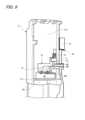
- FIG. 2is a schematic diagram showing a second configuration example of the suction device.
- the suction device 100B according to this configuration exampleincludes a power supply unit 111B, a sensor unit 112B, a notification unit 113B, a memory unit 114B, a communication unit 115B, a control unit 116B, a heating unit 121B, a storage unit 140, and a heat insulating unit 144.
- the power supply unit 110 that stores the power supply unit 111A and the heating unit 121Aare separate bodies, but in the suction device 100B according to the second configuration example, the power supply unit 111B and the heating unit 121B are integrated. That is, the suction device 100B according to the second configuration example can also be said to be a power supply unit 110B with a built-in heating unit.
- Each of the power supply unit 111B, the sensor unit 112B, the notification unit 113B, the memory unit 114B, the communication unit 115B, and the control unit 116Bis substantially the same as the corresponding components included in the suction device 100A according to the first configuration example.
- the storage section 140has an internal space 141 and holds the stick-shaped substrate 150 while storing a part of the stick-shaped substrate 150 in the internal space 141.
- the storage section 140has an opening 142 that connects the internal space 141 to the outside and stores the stick-shaped substrate 150 inserted into the internal space 141 through the opening 142.
- the storage section 140is a cylindrical body with the opening 142 and the bottom 143 as the bottom surface, and defines a columnar internal space 141.
- An air flow path that supplies air to the internal space 141is connected to the storage section 140.
- An air inlet holewhich is an air inlet to the air flow path, is arranged, for example, on the side of the suction device 100.
- An air outlet holewhich is an air outlet from the air flow path to the internal space 141, is arranged, for example, on the bottom 143.
- the stick-type substrate 150includes a substrate portion 151 and a mouthpiece portion 152.
- the substrate portion 151includes an aerosol source.
- the aerosol sourceincludes a flavor component derived from tobacco or non-tobacco.
- the aerosol sourcemay include a medicine.
- the aerosol sourcemay be, for example, a liquid such as a polyhydric alcohol such as glycerin and propylene glycol, and water, which includes a flavor component derived from tobacco or non-tobacco, or may be a solid containing a flavor component derived from tobacco or non-tobacco.
- the stick-type substrate 150When the stick-type substrate 150 is held in the storage portion 140, at least a part of the substrate portion 151 is stored in the internal space 141, and at least a part of the mouthpiece portion 152 protrudes from the opening 142.
- the heating section 121Bis configured in a film shape and is arranged to cover the outer periphery of the storage section 140.
- the heating section 121Bgenerates heat, the substrate section 151 of the stick-shaped substrate 150 is heated from the outer periphery, and an aerosol is generated.
- the insulating section 144prevents heat transfer from the heating section 121B to other components.
- the insulating section 144is made of a vacuum insulating material or an aerogel insulating material.
- the configuration of the suction device 100Bis not limited to the above, and various configurations such as those shown below are possible.
- the heating section 121Bmay be configured in a blade shape and disposed so as to protrude from the bottom 143 of the storage section 140 into the internal space 141. In that case, the blade-shaped heating section 121B is inserted into the substrate section 151 of the stick-shaped substrate 150 and heats the substrate section 151 of the stick-shaped substrate 150 from the inside. As another example, the heating section 121B may be disposed so as to cover the bottom 143 of the storage section 140. Furthermore, the heating section 121B may be configured as a combination of two or more of a first heating section that covers the outer periphery of the storage section 140, a blade-shaped second heating section, and a third heating section that covers the bottom 143 of the storage section 140.
- the suction device 100Bmay further include the heating unit 121A, the liquid guide unit 122, the liquid storage unit 123, and the air flow path 180 according to the first configuration example, and the air flow path 180 may supply air to the internal space 141.
- the mixed fluid of the aerosol and air generated by the heating unit 121Aflows into the internal space 141 and is further mixed with the aerosol generated by the heating unit 121B, and reaches the user's oral cavity.
- suction device 100A and the suction device 100B described abovewill be referred to as “suction device 100" without distinction
- the power supply unit 110A and the power supply unit 110Bwill be referred to as “power supply unit 110” without distinction.
- the power supply units 111A and 111Bwill be referred to as “power supply unit 111", the sensor units 112A and 112B as “sensor unit 112”, the notification units 113A and 113B as “notification unit 113”, the memory units 114A and 114B as “memory unit 114”, the communication units 115A and 115B as “communication unit 115”, the control units 116A and 116B as “control unit 116”, and the heating units 121A and 121B as “heating unit 121".
- the insertion/removal direction of the stick-type substrate 150 with respect to the suction device 100is defined as the up-down direction
- the sliding movement direction of the shutter 12 described lateris defined as the front-rear direction
- the direction perpendicular to the up-down direction and the front-rear directionis defined as the left-right direction.
- the frontis defined as Fr
- the rearis defined as Rr
- the left sideis defined as L
- the right sideis defined as R
- the topis defined as U
- the bottomis defined as D.
- FIG. 3is a front view of the appearance of the suction device 100.
- the suction device 100has an overall rounded rectangular parallelepiped shape and is long in the vertical direction. For example, a user holds the suction device 100 in one hand while touching the surface of the suction device 100 with the fingertips.
- the shape of the suction device 100is not limited to a rectangular parallelepiped shape and can be any shape.
- the suction device 100comprises a housing 10 that forms the external appearance of the suction device 100, and an internal unit 20 that is housed in the housing 10.
- the top surface of the housing 10is provided with an opening 11 through which the stick-shaped substrate 150 (see FIG. 2) is inserted and removed, and a shutter 12 that can slide back and forth.
- the opening 11is connected to a storage section 140 that stores the stick-shaped substrate 150.
- the shutter 12selectively takes an open state that opens the opening 11 to allow the stick-shaped substrate 150 to be inserted and removed, and a closed state that closes the opening 11.
- a USB (Universal Serial Bus) connector 13is provided on the underside of the housing 10.
- the USB connector 13has a terminal (e.g., a VBUS terminal) that accepts power from an external power source.
- the USB connector 13is a receptacle into which a mating plug can be inserted, for example a USB Type-C shaped receptacle.
- the front surface of the housing 10is provided with an operation unit 14 and a light-emitting unit 15, each of which is connected to a main board 50 (described later).
- the operation unit 14is disposed below the light-emitting unit 15.
- the operation unit 14is a button-type switch that can be operated by the user, and is an input device that accepts information input from the user. For example, when the user presses the operation unit 14, the MCU (Micro Controller Unit) 1 and the heating unit 121, which will be described later, are started up.
- MCUMicro Controller Unit
- the light-emitting unit 15has a light-emitting element such as an LED (Light Emitting Diode).
- a plurality of light-emitting elementsare provided and configured to be capable of emitting light in a plurality of light colors.
- the light-emitting unit 15is an example of the notification unit 113, and emits light in a predetermined light emission pattern in response to a command from the MCU 1 to notify the user of predetermined information.
- the predetermined light emission patterncan be, for example, a pattern in which light is emitted in different light colors depending on the predetermined information, but is not limited to this, and may be, for example, a pattern of strong or weak lighting intensity or a lighting pattern (for example, blinking at a predetermined time interval).
- the predetermined informationis, for example, operational information indicating whether the power of the suction device 100 is on or not.
- the internal unit 20includes a chassis 21, a main board 50, a power supply unit 111, a power supply FPC (Flexible Printed Circuits) 101, a heater assembly 30, a vibration device 60, a main FPC 70, and a number of temperature sensors 66 to 68.
- FPCFlexible Printed Circuits
- the chassis 21has a power supply arrangement section 22 in which the power supply unit 111 is arranged, a board arrangement section 23 in which the main board 50 is arranged, a heater arrangement section 24 in which the heater assembly 30 is arranged, and a USB connector arrangement section 25 in which the USB connector 13 is arranged.
- the board placement section 23is provided on a vertical wall section 21d that stands upward from the upper wall section 21c of the power supply placement section 22.
- the board placement section 23is provided on one side of the vertical wall section 21d in the front-to-rear direction, and the main board 50 is fixed to the board placement section 23 by a bracket 27.
- the USB connector placement section 25extends downward from the bottom wall section 21a of the power supply placement section 22.
- the power supply connection part 51is provided at the right end part in the lower region of the main board 50, and has a positive electrode side connection part 51a and a negative electrode side connection part 51b.
- the power supply connection part 51is electrically connected to the power supply part 111 via the power supply FPC 101.
- the main FPC connection part 52is provided at the left end part in the approximate vertical center area of the main board 50.
- the main FPC 70is connected to the main FPC connection part 52 from the front.
- the MCU1, charging IC 81, and heating element 82are mounted on the back surface 502 of the main board 50.
- the MCU1functions as the control unit 116 described above and controls the heating of the heating unit 121.
- the charging IC 81performs charging control to supply power from an external power source (not shown) input via the USB connector 13 to the power supply unit 111, and supplies the power of the power supply unit 111 to electronic components of the main board 50.
- the heating element 82includes a step-up DC/DC converter, switching elements, etc., and boosts the power supplied from the power supply unit 111 to generate power to be supplied to the heating unit 121.
- the MCU1is provided in the upper region of the main board 50.
- the charging IC 81 and heating element 82are provided in the approximately central region in the vertical direction of the main board 50.
- a communication unit 115which is a communication interface capable of wireless communication with external devices such as a smartphone, is mounted on the rear surface 502 of the main board 50.
- the communication unit 115is configured by incorporating some components such as the antenna 5 inside the MCU 1, but is not limited to this and may be provided independently of the MCU 1. The structure of the antenna 5 and the vicinity of the antenna 5 will be described later.
- a heater connection portion 57 to which the heating portion 121 of the heater assembly 30 is connectedis provided on the rear surface 502 of the main substrate 50.
- the heater connection portion 57is provided in the lower region of the main substrate 50.
- the heater assembly 30includes a heating section 121, a housing section 140, and a heat insulating section 144.
- the heating section 121is, for example, a film heater, and is wound around the outer periphery of the housing section 140.
- the heating section 121is provided with a connection section 32 that extends from the bottom and is connected to the heater connection section 57 of the main board 50. As shown in FIG. 10, the connection section 32 is connected to the heater connection section 57 through a through hole 26 provided in the bottom of the vertical wall section 21d.
- the heater assembly 30is provided with a stick guide 31.
- the stick guide 31is provided on the upper part of the heater assembly 30, and guides the stick-shaped substrate 150 into the storage section 140.
- the stick guide 31is a cylindrical member and constitutes a part of the storage section 140.
- the heater assembly 30is also provided with a heater temperature sensor 66 capable of detecting the temperature of the heating section 121.
- the heater temperature sensor 66is, for example, a thermistor, and an output corresponding to the electrical resistance value is input to the MCU 1.
- the main FPC 70is a flexible circuit board that has flexibility.
- the main FPC 70is formed long in the vertical direction, and connects the various components of the power supply unit 110 to the main board 50.
- the main FPC 70has a high degree of freedom in placement within the housing 10 compared to a rigid circuit board, allowing the power supply unit 110 to be made smaller.
- the main FPC 70extends in the vertical direction, which is the longitudinal direction of the housing 10, from the position where the main board 50 and heater assembly 30 are arranged to the position where the power supply unit 111 and USB connector 13 are arranged. With this configuration, the main FPC 70 is formed long in the longitudinal direction of the housing 10.
- the main FPC 70is provided on the left side of the chassis 21 and has a long main body portion 71 extending in the vertical direction, a board connection portion 72 connected to the main board 50, a USB connector connection portion 73 to which the USB connector 13 is connected, a housing temperature sensor connection portion 74 to which a housing temperature sensor 67 that detects the temperature of the housing 10 is connected, a heater temperature sensor connection portion 75 to which a heater temperature sensor 66 is connected, a vibration device connection portion 76 to which the vibration device 60 is connected, and a power supply temperature sensor connection portion 77 to which a power supply temperature sensor 68 is connected.
- Each of the connections 72 to 77may be directly connected to a target component, or may be indirectly connected via, for example, a lead wire.
- the main FPC 70is composed of two layers, with the layer exposed on the front surface (the layer closest to the housing 10) being the first conductive layer L1 (also referred to as the L1 layer) and the layer exposed on the back surface being the second conductive layer L2 (also referred to as the L2 layer).
- the main FPC 70has multiple conductive patterns 703-707 formed thereon, and the USB connector connection portion 73, the housing temperature sensor connection portion 74, the heater temperature sensor connection portion 75, the vibration device connection portion 76, and the power supply temperature sensor connection portion 77 are electrically connected to the board connection portion 72 via the conductive patterns 703-707.
- the conductive patterns 703-707are formed, for example, by etching the conductive foil (e.g., copper foil) of the main FPC 70 while leaving only the necessary areas, or by applying the necessary conductive foil.
- the main FPC 70is also provided with a ground pattern 700 (also indicated as “GND” in the figure) that is connected to a ground provided in the power supply unit 110 and has the same potential as the reference potential (ground potential) of the power supply unit 110.
- the ground pattern 700is formed over a wide area across the entire area of the main FPC 70 in the vertical direction, which is the longitudinal direction of the housing 10.
- the board connection portion 72is provided at the upper end of the main FPC 70 and is connected to the main FPC connection portion 52 of the main board 50.
- the board connection portion 72is a portion that extends forward from the upper end of the main body portion 71, and is configured by being bent along the left side portion and surface 501 of the main board 50 (see Figures 4 and 10).
- the USB connector connection portion 73is provided at the lower end of the main FPC 70, and the USB connector 13 is mounted thereon. Specifically, the USB connector connection portion 73 is formed at the lower end portion of the main body portion 71, and is configured by being bent along the bottom wall portion 21a of the chassis 21 and the USB connector arrangement portion 25.
- the housing temperature sensor connection part 74is provided at the upper end part of the main FPC 70, and has the housing temperature sensor 67 mounted thereon.
- the housing temperature sensor 67is, for example, a thermistor, and an output corresponding to the electrical resistance value is input to the MCU 1.
- the housing temperature sensor 67is provided close to the inner surface of the housing 10, and detects the temperature of the housing 10.
- the housing temperature sensor connection part 74is provided on the opposite side of the main body part 71 to the board connection part 72.
- the housing temperature sensor connection part 74is connected to the board connection part 72 via a conductive pattern 704 formed on the L2 layer of the main FPC 70.
- the heater temperature sensor connection portion 75is provided at a branch portion 78 that branches off from the main body portion 71 at a position below the board connection portion 72.
- the branch portion 78is configured by bending from the main body portion 71 along the standing wall portion 21d from the left side of the chassis 21, and is disposed between the standing wall portion 21d and the main board 50 when the main board 50 is attached to the chassis 21 (see Fig. 10).
- the branch portion 78is provided at a position where the heater assembly 30 and the main board 50 are disposed in the vertical direction, that is, at a position where it overlaps with the heater assembly 30 and the main board 50 when the power supply unit 110 is viewed from the front.
- the lead wire 66a of the heater temperature sensor 66is connected to the heater temperature sensor connection portion 75.
- the lead wire 66a of the heater temperature sensor 66extends from the heater assembly 30 and passes through a through hole 26 provided in the vertical wall portion 21d to be connected to the heater temperature sensor connection portion 75.
- the heater temperature sensor connection portion 75is provided at a position where the heater assembly 30 is disposed in the vertical direction, so that the lead wire 66a extending from the heater assembly 30 can be shortened.
- the heater temperature sensor connection part 75is connected to the board connection part 72 via a conductive pattern 705 formed on the L1 layer of the main FPC 70.
- the vibration device connection part 76like the heater temperature sensor connection part 75, is provided in the branch part 78, and the lead wire 61 of the vibration device 60 is connected to it.
- the vibration device connection part 76is located above the heater temperature sensor connection part 75 in the branch part 78.
- the vibration device connection portion 76is connected to the board connection portion 72 via a conductive pattern 706 formed on the L1 and L2 layers of the main FPC 70.
- the power supply temperature sensor connection section 77is provided at a position where the power supply section 111 is disposed in the vertical direction, and is equipped with a power supply temperature sensor 68.
- the power supply temperature sensor 68is, for example, a thermistor, and an output corresponding to the electrical resistance value is input to the MCU 1.
- the power supply temperature sensor connection part 77is connected to the board connection part 72 via a conductive pattern 707 formed on the L2 layer of the main FPC 70.
- the power supply temperature sensor 68is provided at the power supply temperature sensor connection section 77 with its longitudinal direction aligned along the axial direction (up and down direction) of the cylindrical power supply section 111. Specifically, the power supply temperature sensor 68 is provided at the power supply temperature sensor connection section 77 with its positive and negative terminals (not shown) aligned along the axial direction of the power supply section 111. This allows the power supply temperature sensor 68 and the power supply section 111 to be positioned close to each other regardless of the curvature of the power supply section 111, improving the temperature detection accuracy of the power supply section 111.
- the main FPC 70is provided with a USB connector connection portion 73, a housing temperature sensor connection portion 74, a heater temperature sensor connection portion 75, a vibration device connection portion 76, and a power supply temperature sensor connection portion 77, and the connections between these and the main board 50 are concentrated in one location (i.e., board connection portion 72).
- the power supply unit 110can be made smaller than if each of the temperature sensors 66-68 and the vibration device 60 were each individually connected to the main board 50.
- the USB connector connection portion 73, the housing temperature sensor connection portion 74, the heater temperature sensor connection portion 75, the vibration device connection portion 76, and the power supply temperature sensor connection portion 77 of the main FPC 70are provided with reinforcing plates 79a.
- the reinforcing plates 79aare provided on the L1 layer or the L2 layer of the main FPC 70.
- the reinforcing plates 79aare formed, for example, from polyimide.
- a reinforcing plate 79bis provided on the board connection portion 72 of the main FPC 70.
- the reinforcing plate 79bis provided on the L1 or L2 layer of the main FPC 70.
- the reinforcing plate 79bis made of, for example, stainless steel, and is stronger than the reinforcing plate 79a. This is because the board connection portion 72 is pressed against the main FPC connection portion 52 to connect the main FPC 70 to the main board 50 when assembling the power supply unit 110, and therefore needs to be strong.
- the main FPC 70also contributes to improving the communication function of the communication unit 115.
- the communication unit 115will be described in detail below with reference to Figures 6 and 11.
- the communication unit 115is a communication interface capable of wireless communication with external devices, as described above. As shown in FIG. 6, the communication unit 115 has an antenna 5.
- the antenna 5is, for example, a monopole antenna, and is electrically connected to a ground pattern 55 formed on the main board 50 and a ground pattern 700 formed on the main FPC 70 and connected to the ground pattern 55. Due to the image effect of the ground patterns 55 and 700, the length of the antenna 5 can be made approximately 1/4 of the resonant wavelength, allowing the power supply unit 110 to be made smaller.
- the antenna 5is a conductor provided on the main board 50, through which current supplied from a signal generator (not shown) flows and which radiates radio waves to the outside.
- the antenna 5is, for example, a pattern antenna, a chip antenna, or a wire antenna.
- the antenna 5may be provided on the main board 50 while being incorporated into the MCU 1, or it may be provided on the main board 50 separately from the MCU 1.
- the antenna 5is provided on the back surface 502 of the main board 50, at the left end closer to the main FPC 70 in the left-right direction.
- the antenna 5is also located above the main FPC connection part 52 in the up-down direction.
- the ground pattern 55is a portion of the ground pattern formed over a wide area of the main board 50 that is provided near the antenna 5.
- the ground pattern 55is provided, for example, in a position that overlaps the antenna 5.
- the ground pattern 55extends from the upper region of the main board 50 to the main FPC connection portion 52.
- the ground pattern 700 of the main FPC 70is connected to the ground pattern 55 of the main board 50 at the main FPC connection portion 52 and the board connection portion 72.
- a non-metallic region 56(region surrounded by a two-dot chain line in FIG. 6) where no metal is formed is provided near the antenna 5 on the main board 50.
- the non-metallic region 56is provided along the left edge of the upper region of the main board 50. No metal components such as electronic components are provided in the non-metallic region 56, and no conductive patterns are formed therein.
- the main FPC 70is disposed in a position where the main board 50 is not disposed between it and the antenna 5.
- the main FPC 70is disposed on the back surface 502 (rear side) of the main board 50 except for the board connection portion 72, and the antenna 5 is also disposed on the back surface 502 side of the main board 50.
- no electronic components mounted on the main board 50are disposed between the main FPC 70 and the antenna 5.
- the main board 50is not disposed between the main FPC 70 and the antenna 5, the main FPC 70 is disposed in close proximity to the antenna 5. Therefore, the ground pattern 700 formed on the main FPC 70 can be used as the ground for the antenna 5.
- the main FPC 70extends in the longitudinal direction of the housing 10, so that a sufficient area can be secured for the ground pattern 700. This improves the antenna efficiency of the antenna 5.
- the main board 50has an antenna 5 on the back surface 502 and a main FPC connection part 52 on the front surface 501, i.e., the main FPC connection part 52 and the antenna 5 are provided on different surfaces of the main board 50.
- the main FPC 70is configured to be bent from the board connection part 72 that connects to the main FPC connection part 52 toward the back surface 502 side (here, the rear side) of the main board 50, so that the main board 50 can be arranged so that it is not placed between the main FPC 70 and the antenna 5.
- the antenna 5 and the main FPC connection part 52may be provided on the same surface (e.g., the back surface 502) of the main board 50, and even in this case, it is sufficient that the main board 50 is not placed between the antenna 5 and the part of the main FPC 70 near the antenna 5.
- the antenna 5 and the main FPC connection portion 52 of the main board 50are provided on one end side (here, the left side) of the main board 50 in the left-right direction, so the antenna 5 and the main FPC 70 provided along the left side of the chassis 21 are positioned closer to each other, further improving the antenna efficiency of the antenna 5.
- the main FPC 70extends in the longitudinal direction (vertical direction) of the housing 10 from the position where the heater assembly 30 is arranged to the position where the power supply unit 111 is arranged. This allows the main FPC 70 to be formed long, and the area of the ground pattern 700 to be increased, which contributes to improving the antenna efficiency of the antenna 5.
- the rigid boardhas the antenna on a first surface (back surface 502) and a board connection portion (main FPC connection portion 52) between the flexible board and the rigid board on a second surface (front surface 501) opposite to the first surface,
- the flexible substrateis configured to be bent from the substrate connection portion toward the first surface.
- Power supply unit for the aerosol generatoris configured to be bent from the substrate connection portion toward the first surface.
Landscapes
- Engineering & Computer Science (AREA)
- Computer Networks & Wireless Communication (AREA)
- Cooling Or The Like Of Electrical Apparatus (AREA)
Abstract
Description
Translated fromJapanese本開示は、エアロゾル源を加熱してエアロゾルを生成するエアロゾル生成装置の電源ユニットに関する。The present disclosure relates to a power supply unit of an aerosol generating device that generates an aerosol by heating an aerosol source.
従来から、例えば、香味成分が付与されたエアロゾルを生成し、生成したエアロゾルをユーザが吸引可能とするエアロゾル生成装置が知られている。このようなエアロゾル生成装置は、エアロゾル源を加熱するためのヒータや、電池、加熱を制御する制御部、スマートフォン等の外部機器と通信する通信部等を備え、これらが持ち運びできる大きさの筐体の中に収容されている。 Conventionally, there have been known aerosol generating devices that generate aerosols containing flavor components and allow a user to inhale the generated aerosol. Such aerosol generating devices include a heater for heating an aerosol source, a battery, a control unit for controlling the heating, a communication unit for communicating with an external device such as a smartphone, and the like, and these are housed in a portable housing.
例えば、特許文献1には、少なくとも1つの収容部の少なくとも一部分を通る検出された空気の流れに基づいてエアロゾル送達デバイスの少なくとも1つの機能的要素の動作を制御する制御構成要素と、制御構成要素に連結され、無線通信を可能にするように構成された通信インタフェースと、を備えるエアロゾル伝達デバイスが記載されている。For example,
このようなエアロゾル生成装置においては、ユーザの持ち運びの利便性を鑑みて小型化を図りつつも、各種機能の性能を維持又は向上させることが要望されており、現在においても改善の余地がある。In such aerosol generating devices, there is a demand for miniaturization to make them easier for users to carry around, while maintaining or improving the performance of various functions, and there is still room for improvement.
本開示は、小型化を図りつつ、各種機能の性能を維持又は向上させることのできるエアロゾル生成装置の電源ユニットを提供する。The present disclosure provides a power supply unit for an aerosol generating device that can be made compact while maintaining or improving the performance of various functions.
本開示は、
エアロゾル源を加熱してエアロゾルを生成するエアロゾル生成装置の電源ユニットであって、
前記エアロゾル源を加熱する加熱部に電力を供給する電源と、
前記加熱部を制御する制御部が搭載されたリジッド基板と、
前記リジッド基板に設けられたアンテナを有し、外部機器と無線通信可能な通信部と、
前記リジッド基板に接続されたフレキシブル基板と、
前記電源、前記リジッド基板、前記通信部、及び前記フレキシブル基板を収容する筐体と、を備え、
前記アンテナは、前記リジッド基板及び前記フレキシブル基板に形成されたグランドに電気的に接続され、
前記フレキシブル基板は、前記アンテナとの間に前記リジッド基板が配置されない位置に配置され、前記筐体の長手方向に延在する。The present disclosure relates to
A power supply unit of an aerosol generating device for heating an aerosol source to generate an aerosol, comprising:
A power source that supplies power to a heating unit that heats the aerosol source;
a rigid substrate on which a control unit for controlling the heating unit is mounted;
a communication unit having an antenna provided on the rigid substrate and capable of wireless communication with an external device;
a flexible substrate connected to the rigid substrate;
a housing that accommodates the power supply, the rigid board, the communication unit, and the flexible board;
the antenna is electrically connected to grounds formed on the rigid substrate and the flexible substrate;
The flexible substrate is disposed at a position where the rigid substrate is not disposed between the flexible substrate and the antenna, and extends in the longitudinal direction of the housing.
本開示によれば、リジッド基板に接続されたフレキシブル基板をアンテナとして利用することで、小型化を図りつつ、アンテナのアンテナ効率を向上させることができる。According to the present disclosure, by using a flexible substrate connected to a rigid substrate as an antenna, it is possible to improve the antenna efficiency while achieving miniaturization.
以下、本開示のエアロゾル生成装置の電源ユニットの一実施形態を、図面を参照しながら詳細に説明する。以下に説明する実施形態は、本開示のエアロゾル生成装置を吸引装置に適用した場合の例である。なお、図面は、符号の向きに見るものとする。また、以下では、同一又は類似の要素には同一又は類似の符号を付して、その説明を適宜省略又は簡略化することがある。Below, one embodiment of the power supply unit of the aerosol generating device of the present disclosure will be described in detail with reference to the drawings. The embodiment described below is an example of the aerosol generating device of the present disclosure being applied to an inhalation device. The drawings should be viewed in the direction of the reference symbols. In the following, identical or similar elements will be given identical or similar reference symbols, and their description may be omitted or simplified as appropriate.
1.吸引装置の構成例
吸引装置は、ユーザにより吸引される物質を生成する装置である。以下では、吸引装置により生成される物質が、エアロゾルであるものとして説明する。他に、吸引装置により生成される物質は、気体であってもよい。1. Configuration Example of Inhalation Device The inhalation device is a device that generates a substance to be inhaled by a user. In the following, the substance generated by the inhalation device will be described as an aerosol. Alternatively, the substance generated by the inhalation device may be a gas.
1-1.第1の構成例
図1は、吸引装置の第1の構成例を模式的に示す模式図である。図1に示すように、本構成例に係る吸引装置100Aは、電源ユニット110、カートリッジ120、及び香味付与カートリッジ130を含む。電源ユニット110は、電源部111A、センサ部112A、通知部113A、記憶部114A、通信部115A、及び制御部116Aを含む。カートリッジ120は、加熱部121A、液誘導部122、及び液貯蔵部123を含む。香味付与カートリッジ130は、香味源131、及びマウスピース124を含む。カートリッジ120及び香味付与カートリッジ130には、空気流路180が形成される。1-1. First Configuration Example FIG. 1 is a schematic diagram showing a first configuration example of an inhalation device. As shown in FIG. 1, an
電源部111Aは、電力を蓄積する。そして、電源部111Aは、制御部116Aによる制御に基づいて、吸引装置100Aの各構成要素に電力を供給する。電源部111Aは、例えば、リチウムイオン二次電池等の充電式バッテリにより構成され得る。The
センサ部112Aは、吸引装置100Aに関する各種情報を取得する。一例として、センサ部112Aは、コンデンサマイクロホン等の圧力センサ、流量センサ又は温度センサ等により構成され、ユーザによる吸引に伴う値を取得する。他の一例として、センサ部112Aは、ボタン又はスイッチ等の、ユーザからの情報の入力を受け付ける入力装置により構成される。The
通知部113Aは、情報をユーザに通知する。通知部113Aがユーザに通知する情報は、例えば、電源部111Aの充電状態を示すSOC(State Of Charge)や、吸引時の予熱時間、吸引可能期間等の各種情報を含む。通知部113Aは、例えば、発光する発光装置、画像を表示する表示装置、音を出力する音出力装置、又は振動する振動装置等により構成される。The
記憶部114Aは、吸引装置100Aの動作のための各種情報を記憶する。記憶部114Aは、例えば、フラッシュメモリ等の不揮発性の記憶媒体により構成される。The
通信部115Aは、有線又は無線の任意の通信規格に準拠した通信を行うことが可能な通信インタフェースである。かかる通信規格としては、例えば、Wi-Fi(登録商標)、Bluetooth(登録商標)、BLE(Bluetooth Low Energy(登録商標))、NFC(Near Field Communication)、又はLPWA(Low Power Wide Area)を用いる規格等が採用され得る。The
制御部116Aは、演算処理装置及び制御装置として機能し、各種プログラムに従って吸引装置100A内の動作全般を制御する。制御部116Aは、例えばCPU(Central Processing Unit)、又はマイクロプロセッサ等の電子回路によって実現される。The
液貯蔵部123は、エアロゾル源を貯蔵する。エアロゾル源が霧化されることで、エアロゾルが生成される。エアロゾル源は、例えば、グリセリン及びプロピレングリコール等の多価アルコール、又は水等の液体である。エアロゾル源は、たばこ由来又は非たばこ由来の香味成分を含んでいてもよい。吸引装置100Aがネブライザ等の医療用吸入器である場合、エアロゾル源は、薬剤を含んでもよい。The
液誘導部122は、液貯蔵部123に貯蔵された液体であるエアロゾル源を、液貯蔵部123から誘導し、保持する。液誘導部122は、例えば、ガラス繊維等の繊維素材又は多孔質状のセラミック等の多孔質状素材を撚って形成されるウィックである。その場合、液貯蔵部123に貯蔵されたエアロゾル源は、ウィックの毛細管効果により誘導される。The
加熱部121Aは、エアロゾル源を加熱することで、エアロゾル源を霧化してエアロゾルを生成する。図1に示した例では、加熱部121Aは、コイルとして構成され、液誘導部122に巻き付けられる。加熱部121Aが発熱すると、液誘導部122に保持されたエアロゾル源が加熱されて霧化され、エアロゾルが生成される。加熱部121Aは、電源部111Aから給電されると発熱する。一例として、ユーザが吸引を開始したこと、及び/又は所定の情報が入力されたことが、センサ部112Aにより検出された場合に、加熱部121Aに給電されてもよい。そして、ユーザが吸引を終了したこと、及び/又は所定の情報が入力されたことが、センサ部112Aにより検出された場合に、加熱部121Aへの給電が停止されてもよい。なお、吸引装置100Aに対するユーザの吸引動作は、例えば、パフセンサにより検出される吸引装置100A内の圧力(内圧)が所定の閾値を超えることに基づき検出可能である。The
香味源131は、エアロゾルに香味成分を付与するための構成要素である。香味源131は、たばこ由来又は非たばこ由来の香味成分を含んでいてもよい。The
空気流路180は、ユーザに吸引される空気の流路である。空気流路180は、空気流路180内への空気の入り口である空気流入孔181と、空気流路180からの空気の出口である空気流出孔182と、を両端とする管状構造を有する。空気流路180の途中には、上流側(空気流入孔181に近い側)に液誘導部122が配置され、下流側(空気流出孔182に近い側)に香味源131が配置される。ユーザによる吸引に伴い空気流入孔181から流入した空気は、加熱部121Aにより生成されたエアロゾルと混合され、矢印190に示すように、香味源131を通過して空気流出孔182へ輸送される。エアロゾルと空気との混合流体が香味源131を通過する際には、香味源131に含まれる香味成分がエアロゾルに付与される。The
マウスピース124は、吸引の際にユーザに咥えられる部材である。マウスピース124には、空気流出孔182が配置される。ユーザは、マウスピース124を咥えて吸引することで、エアロゾルと空気との混合流体を口腔内へ取り込むことができる。The
以上、吸引装置100Aの構成例を説明した。もちろん吸引装置100Aの構成は上記に限定されず、以下に例示する多様な構成をとり得る。The above describes an example of the configuration of the
一例として、吸引装置100Aは、香味付与カートリッジ130を含んでいなくてもよい。その場合、カートリッジ120にマウスピース124が設けられる。As an example, the
他の一例として、吸引装置100Aは、複数種類のエアロゾル源を含んでいてもよい。複数種類のエアロゾル源から生成された複数種類のエアロゾルが空気流路180内で混合され化学反応を起こすことで、さらに他の種類のエアロゾルが生成されてもよい。As another example, the
また、エアロゾル源を霧化する手段は、加熱部121Aによる加熱に限定されない。例えば、エアロゾル源を霧化する手段は、振動霧化、又は誘導加熱であってもよい。Furthermore, the means for atomizing the aerosol source is not limited to heating by the
1-2.第2の構成例
図2は、吸引装置の第2の構成例を模式的に示す模式図である。図2に示すように、本構成例に係る吸引装置100Bは、電源部111B、センサ部112B、通知部113B、記憶部114B、通信部115B、制御部116B、加熱部121B、収容部140、及び断熱部144を含む。第1の構成例の吸引装置100Aは、電源部111Aを収容する電源ユニット110と加熱部121Aとが別体であったが、第2の構成例の吸引装置100Bは、電源部111Bと加熱部121Bとが一体である。即ち、第2の構成例の吸引装置100Bは、加熱部を内蔵した電源ユニット110Bとも言うことができる。1-2. Second Configuration Example FIG. 2 is a schematic diagram showing a second configuration example of the suction device. As shown in FIG. 2, the
電源部111B、センサ部112B、通知部113B、記憶部114B、通信部115B、及び制御部116Bの各々は、第1の構成例に係る吸引装置100Aに含まれる対応する構成要素と実質的に同一である。Each of the
収容部140は、内部空間141を有し、内部空間141にスティック型基材150の一部を収容しながらスティック型基材150を保持する。収容部140は、内部空間141を外部に連通する開口142を有し、開口142から内部空間141に挿入されたスティック型基材150を収容する。例えば、収容部140は、開口142及び底部143を底面とする筒状体であり、柱状の内部空間141を画定する。収容部140には、内部空間141に空気を供給する空気流路が接続される。空気流路への空気の入口である空気流入孔は、例えば、吸引装置100の側面に配置される。空気流路から内部空間141への空気の出口である空気流出孔は、例えば、底部143に配置される。The
スティック型基材150は、基材部151、及び吸口部152を含む。基材部151は、エアロゾル源を含む。エアロゾル源は、たばこ由来又は非たばこ由来の香味成分を含む。吸引装置100Bがネブライザ等の医療用吸入器である場合、エアロゾル源は、薬剤を含んでもよい。エアロゾル源は、例えば、たばこ由来又は非たばこ由来の香味成分を含む、グリセリン及びプロピレングリコール等の多価アルコール、並びに水等の液体であってもよく、たばこ由来又は非たばこ由来の香味成分を含む固体であってもよい。スティック型基材150が収容部140に保持された状態において、基材部151の少なくとも一部は内部空間141に収容され、吸口部152の少なくとも一部は開口142から突出する。そして、開口142から突出した吸口部152をユーザが咥えて吸引すると、図示しない空気流路を経由して内部空間141に空気が流入し、基材部151から発生するエアロゾルと共にユーザの口内に到達する。The stick-
図2に示した例では、加熱部121Bは、フィルム状に構成され、収容部140の外周を覆うように配置される。そして、加熱部121Bが発熱すると、スティック型基材150の基材部151が外周から加熱され、エアロゾルが生成される。In the example shown in FIG. 2, the
断熱部144は、加熱部121Bから他の構成要素への伝熱を防止する。例えば、断熱部144は、真空断熱材、又はエアロゲル断熱材等により構成される。The insulating
以上、吸引装置100Bの構成例を説明した。もちろん吸引装置100Bの構成は上記に限定されず、以下に例示する多様な構成をとり得る。The above describes an example of the configuration of the
一例として、加熱部121Bは、ブレード状に構成され、収容部140の底部143から内部空間141に突出するように配置されてもよい。その場合、ブレード状の加熱部121Bは、スティック型基材150の基材部151に挿入され、スティック型基材150の基材部151を内部から加熱する。他の一例として、加熱部121Bは、収容部140の底部143を覆うように配置されてもよい。また、加熱部121Bは、収容部140の外周を覆う第1の加熱部、ブレード状の第2の加熱部、及び収容部140の底部143を覆う第3の加熱部のうち、2以上の組み合わせとして構成されてもよい。As one example, the
他の一例として、収容部140は、内部空間141を形成する外殻の一部を開閉する、ヒンジ等の開閉機構を含んでいてもよい。そして、収容部140は、外殻を開閉することで、内部空間141に挿入されたスティック型基材150を挟持しながら収容してもよい。その場合、加熱部121Bは、収容部140における当該挟持箇所に設けられ、スティック型基材150を押圧しながら加熱してもよい。As another example, the
また、エアロゾル源を霧化する手段は、加熱部121Bによる加熱に限定されない。例えば、エアロゾル源を霧化する手段は、誘導加熱であってもよい。その場合、吸引装置100Bは、加熱部121Bの代わりに、磁場を発生させるコイル等の電磁誘導源を少なくとも有する。誘導加熱により発熱するサセプタは、吸引装置100Bに設けられていてもよいし、スティック型基材150に含まれていてもよい。Furthermore, the means for atomizing the aerosol source is not limited to heating by the
また、吸引装置100Bは、第1の構成例に係る加熱部121A、液誘導部122、液貯蔵部123、及び空気流路180をさらに含んでいてもよく、空気流路180が内部空間141に空気を供給してもよい。この場合、加熱部121Aにより生成されたエアロゾルと空気との混合流体は、内部空間141に流入して加熱部121Bにより生成されたエアロゾルとさらに混合され、ユーザの口腔内に到達する。The
なお、以下では、前述した吸引装置100Aと吸引装置100Bとを区別せずに「吸引装置100」とも称し、電源ユニット110Aと電源ユニット110Bとを区別せずに「電源ユニット110」とも称す。同様に、電源部111A、111Bを「電源部111」、センサ部112A、112Bを「センサ部112」、通知部113A、113Bを「通知部113」、記憶部114A、114Bを「記憶部114」、通信部115A、115Bを「通信部115」、制御部116A、116Bを「制御部116」、加熱部121A、121Bを「加熱部121」、とそれぞれ称することがある。Note that, hereinafter, the
2.吸引装置の構造的な構成例
続いて、吸引装置100(電源ユニット110)の構造的な構成例について説明する。以下では、説明の便宜上、吸引装置100に対するスティック型基材150の挿抜方向を上下方向、後述するシャッター12のスライド移動方向を前後方向、上下方向及び前後方向に直交する方向を左右方向と定義して説明する。また、図中に示すように、前方をFr、後方をRr、左側をL、右側をR、上方をU、下方をDとする。2. Structural Configuration Example of Suction Device Next, a structural configuration example of the suction device 100 (power supply unit 110) will be described. In the following, for convenience of explanation, the insertion/removal direction of the stick-
図3は、吸引装置100の外観正面図である。吸引装置100は、全体的に丸みを帯びた直方体形状を有し、上下方向に長く構成されている。ユーザは、例えば、指先を吸引装置100の表面に接触させながら、吸引装置100を片手で保持する。なお、吸引装置100の形状は直方体形状に限らず、任意の形状とすることができる。FIG. 3 is a front view of the appearance of the suction device 100. The suction device 100 has an overall rounded rectangular parallelepiped shape and is long in the vertical direction. For example, a user holds the suction device 100 in one hand while touching the surface of the suction device 100 with the fingertips. Note that the shape of the suction device 100 is not limited to a rectangular parallelepiped shape and can be any shape.
吸引装置100は、吸引装置100の外観を構成する筐体10と、筐体10に収容される内部ユニット20と、を備える。The suction device 100 comprises a
筐体10の上面には、スティック型基材150(図2参照)が挿抜される開口11と、前後方向にスライド移動可能なシャッター12とが設けられている。開口11は、スティック型基材150を収容する収容部140に連通する。シャッター12は、開口11を開放してスティック型基材150の挿抜を可能とする開状態と、開口11を閉塞する閉状態と、を選択的にとる。The top surface of the
筐体10の下面には、USB(Universal Serial Bus)コネクタ13が設けられている。USBコネクタ13は、外部電源からの電力を受け付ける端子(例えばVBUS端子)を備える。USBコネクタ13は、相手側となるプラグを挿入可能なレセプタクルであり、例えばUSB Type-C形状のレセプタクルである。A USB (Universal Serial Bus)
筐体10の前面には、それぞれ後述するメイン基板50に接続された操作部14及び発光部15が設けられている。操作部14は、発光部15の下方に配置されている。The front surface of the
操作部14は、ユーザが操作可能なボタン式のスイッチであり、ユーザからの情報の入力を受け付ける入力装置である。例えば、ユーザが操作部14を押下することにより、後述するMCU(Micro Controller Unit)1や加熱部121が起動する。The
発光部15は、例えばLED(Light Emitting Diode)のような発光素子を有する。発光素子は、複数設けられ、複数の発光色で発光可能に構成される。発光部15は、通知部113の一例であり、MCU1からの指令により所定の発光態様で発光して、ユーザに対して所定の情報の通知を行う。所定の発光態様は、例えば所定の情報に応じて異なる発光色で発光する態様とすることができるが、これに限られず、例えば、点灯強度の強弱や点灯パターン(例えば所定の時間間隔での点滅)等の態様であってもよい。また、所定の情報は、例えば、吸引装置100の電源がオンであるか否かを示す動作情報である。The light-emitting
次に、内部ユニット20について、図4~図11を参照して説明する。Next, the
図4に示すように、内部ユニット20は、シャーシ21と、メイン基板50と、電源部111と、電源FPC(Flexible printed circuits)101と、ヒータアセンブリ30と、振動装置60と、メインFPC70と、複数の温度センサ66~68と、を備える。As shown in FIG. 4, the
シャーシ21は、電源部111が配置される電源配置部22と、メイン基板50が配置される基板配置部23と、ヒータアセンブリ30が配置されるヒータ配置部24と、USBコネクタ13が配置されるUSBコネクタ配置部25と、を有する。The
電源配置部22は、側面の一部が切り欠かれた円筒形状、換言すると略半円筒形状を有する。電源配置部22は、底壁部21aと、円弧形状を有し底壁部21aから上方向に立設する側壁部21bと、側壁部21bの上端部に設けられた上壁部21cと、を有する。電源部111は、底壁部21a、側壁部21b、及び上壁部21cの下面により囲まれた空間に配置される。The power
基板配置部23は、電源配置部22の上壁部21cから上方向に立設する立壁部21dに設けられている。基板配置部23は、前後方向において立壁部21dの一方側に設けられており、メイン基板50は、ブラケット27により基板配置部23に固定される。The
ヒータ配置部24は、前後方向において立壁部21dの基板配置部23とは反対側に設けられている。ヒータ配置部24は、立壁部21dと、立壁部21dから前後方向に延びる左右一対の壁部21eと、上壁部21cの上面とにより囲まれた空間を有し、ヒータアセンブリ30は、この空間に配置される。The
USBコネクタ配置部25は、電源配置部22の底壁部21aから下方に延設されている。The USB
メイン基板50は、複数の電子部品(素子)が両面に搭載されたリジッド回路基板である。リジッド回路基板は、可撓性を有さず、一般的に、厚さが300μm~1600μmに設定される。メイン基板50には、例えば、MCU1、通信部115、充電IC(Integrated Circuit)81、加熱用素子82や、不図示の発光素子等が実装されている。以下の説明では、メイン基板50の面のうち立壁部21dと対向する面を裏面502とし、裏面502とは反対の面を表面501とする。The
図5に示すように、メイン基板50の表面501には、例えば、電源FPC101が接続される電源接続部51と、メインFPC70が接続されるメインFPC接続部52とが設けられている。As shown in FIG. 5, the
電源接続部51は、メイン基板50の下部領域における右端部に設けられており、正極側接続部51a及び負極側接続部51bを有する。電源接続部51は、電源FPC101を介して電源部111に電気的に接続される。The power
メインFPC接続部52は、メイン基板50の上下方向略中央領域における左端部に設けられている。メインFPC接続部52には、メインFPC70が前方から接続される。The main
図6に示すように、メイン基板50の裏面502には、例えば、MCU1、充電IC81、及び加熱用素子82が実装されている。MCU1は、前述した制御部116として機能し、加熱部121の加熱を制御する。充電IC81は、USBコネクタ13を介して入力される不図示の外部電源からの電力を電源部111へ供給する充電制御を行ったり、電源部111の電力をメイン基板50の電子部品等に対して供給したりする。加熱用素子82は、昇圧DC/DCコンバータやスイッチング素子等を含み、電源部111から供給される電力を昇圧して加熱部121に供給する電力を生成する。MCU1は、メイン基板50の上部領域に設けられている。充電IC81及び加熱用素子82は、メイン基板50の上下方向略中央領域に設けられている。As shown in FIG. 6, for example, the MCU1, charging
また、メイン基板50の裏面502には、スマートフォン等の外部機器と無線通信可能な通信インタフェースである通信部115が実装されている。通信部115は、例えばアンテナ5等の一部の部品がMCU1の内部に組み込まれて構成されるが、これに限られず、MCU1とは独立して設けられていてもよい。アンテナ5、及びアンテナ5近傍の構造については、後述する。Furthermore, a
また、メイン基板50の裏面502には、ヒータアセンブリ30の加熱部121が接続されるヒータ接続部57が設けられている。ヒータ接続部57は、メイン基板50の下部領域に設けられている。Also, a
図4に戻り、電源部111は、例えばリチウムイオン二次電池であり、円筒形状を有する。電源部111は、電源FPC101を介してメイン基板50の電源接続部51に電気的に接続される。電源部111には、正極タブ111a及び負極タブ111bが設けられている。電源FPC101は、電源部111の正極タブ111a及び負極タブ111bに接続され、且つ、メイン基板50の電源接続部51に接続される。電源部111から供給される電力は、電源FPC101に形成された導電パターンを通ってメイン基板50に伝送され、各部品へ供給される。Returning to FIG. 4, the
ヒータアセンブリ30は、加熱部121、収容部140、及び断熱部144を備える。加熱部121は、例えばフィルムヒータであり、収容部140の外周に巻回されている。加熱部121には、下部から延出し、メイン基板50のヒータ接続部57に接続される接続部32が設けられている。図10に示すように、接続部32は、立壁部21dの下部に設けられた貫通孔26を通ってヒータ接続部57に接続される。The
図4に示すように、ヒータアセンブリ30には、スティックガイド31が設けられている。スティックガイド31は、ヒータアセンブリ30の上部に設けられており、収容部140へスティック型基材150をガイドする。スティックガイド31は、筒形状の部材であり、収容部140の一部を構成する。As shown in FIG. 4, the
また、ヒータアセンブリ30には、加熱部121の温度を検出可能なヒータ温度センサ66が設けられている。ヒータ温度センサ66は、例えば、サーミスタであり、電気抵抗値に応じた出力がMCU1へ入力される。The
振動装置60は、例えば振動モータのような振動素子を含む。振動装置60は、電源部111の上面と上壁部21cとの間に配置されており、振動装置60のリード線61は、上方に向かって延出し、メインFPC70に接続される(図9参照)。振動装置60は、通知部113の一例であり、MCU1からの指令により所定の振動態様で振動して、ユーザに対して所定の情報の通知を行う。例えば、スティック型基材150の加熱開始時や加熱終了時に、振動装置60は所定の振動態様で振動し、加熱開始や加熱終了をユーザに通知する。The
メインFPC70は、可撓性を有するフレキシブル回路基板である。メインFPC70は、上下方向に長尺に形成されており、電源ユニット110が備える各種部品とメイン基板50とを接続する。メインFPC70はリジッド型の回路基板と比較して筐体10内における配置の自由度が高いので、電源ユニット110を小型化できる。The
本実施形態では、メインFPC70は、筐体10の長手方向である上下方向において、メイン基板50及びヒータアセンブリ30が配置された位置から電源部111及びUSBコネクタ13が配置された位置まで延在する。このような構成により、メインFPC70は筐体10の長手方向において長く形成されている。In this embodiment, the
メインFPC70は、シャーシ21の左側部に設けられ、上下方向に延在する長尺の本体部71と、メイン基板50に接続される基板接続部72と、USBコネクタ13が接続されるUSBコネクタ接続部73と、筐体10の温度を検出する筐体温度センサ67が接続される筐体温度センサ接続部74と、ヒータ温度センサ66が接続されるヒータ温度センサ接続部75と、振動装置60が接続される振動装置接続部76と、電源温度センサ68が接続される電源温度センサ接続部77と、を有する。なお、各接続部72~77には、対象となる部品が直接接続されてもよいし、例えばリード線等を介して間接的に接続されてもよい。The
図7及び図8に示すように、メインFPC70は2層で構成されており、表面に露出する層(筐体10に近い層)を第1導電層L1(L1層とも称す)とし、裏面に露出する層を第2導電層L2(L2層とも称す)とする。As shown in Figures 7 and 8, the
メインFPC70には、複数の導電パターン703~707が形成されており、導電パターン703~707を介してUSBコネクタ接続部73、筐体温度センサ接続部74、ヒータ温度センサ接続部75、振動装置接続部76、及び電源温度センサ接続部77が基板接続部72に電気的に接続される。導電パターン703~707は、例えば、メインFPC70の導電箔(例えば銅箔)の必要箇所を残してエッチングすることにより形成され、又は必要な導電箔を塗布することにより形成される。The
また、メインFPC70には、電源ユニット110に設けられたグランドに接続され、電源ユニット110の基準となる電位(グランド電位)と同電位となるグランドパターン700(図中「GND」とも表記する)が形成されている。グランドパターン700は、筐体10の長手方向である上下方向において、メインFPC70の全域に亘って広範囲に形成されている。The
基板接続部72は、メインFPC70の上端部に設けられ、メイン基板50のメインFPC接続部52に接続される。具体的には、基板接続部72は、本体部71の上端部から前方に延出した部分であり、メイン基板50の左側部及び表面501に沿って折り曲げられて構成される(図4及び図10参照)。The
USBコネクタ接続部73は、メインFPC70の下端部に設けられ、USBコネクタ13が搭載される。具体的には、USBコネクタ接続部73は、本体部71の下端部分に形成され、シャーシ21の底壁部21a及びUSBコネクタ配置部25に沿って折り曲げられて構成される。The USB
USBコネクタ接続部73は、メインFPC70のL1層及びL2層に形成された導電パターン703を介して基板接続部72に接続されている。導電パターン703は、USBコネクタ13に外部電源が接続されたときに外部電源からの電力をメイン基板50へ伝送する電源配線703aと、外部電源が接続されたときに信号の伝送を行う信号線703bと、を含む。電源配線703aは、複数の導電パターン703~707及び信号線703bの中で最も幅広に形成されており、抵抗値を小さくすることでUSBコネクタ接続部73から流れる電流による発熱量を抑制している。The USB
筐体温度センサ接続部74は、メインFPC70の上端部に設けられ、筐体温度センサ67が搭載される。筐体温度センサ67は、例えばサーミスタであり、電気抵抗値に応じた出力がMCU1へ入力される。筐体温度センサ67は、筐体10の内面に近接して設けられ、筐体10の温度を検出する。筐体温度センサ接続部74は、本体部71に対して基板接続部72とは反対側に設けられている。The housing temperature
筐体温度センサ接続部74は、メインFPC70のL2層に形成された導電パターン704を介して基板接続部72に接続されている。The housing temperature
ヒータ温度センサ接続部75は、基板接続部72の下方の位置において本体部71から分岐した分岐部78に設けられている。図4及び図9に示すように、分岐部78は、シャーシ21の左側部から立壁部21dに沿って本体部71から折り曲げられて構成され、シャーシ21にメイン基板50が取り付けられた状態で立壁部21dとメイン基板50との間に配置される(図10参照)。分岐部78は、上下方向においてヒータアセンブリ30及びメイン基板50が配置される位置に設けられており、即ち、電源ユニット110を前方から見たときにヒータアセンブリ30及びメイン基板50と重なる位置に設けられている。The heater temperature
ヒータ温度センサ接続部75には、ヒータ温度センサ66のリード線66aが接続される。ヒータ温度センサ66のリード線66aは、ヒータアセンブリ30から延出され、立壁部21dに設けられた貫通孔26を通ってヒータ温度センサ接続部75に接続される。ヒータ温度センサ接続部75は、上下方向においてヒータアセンブリ30が配置される位置に設けられているので、ヒータアセンブリ30から延出されるリード線66aを短くすることができる。The
ヒータ温度センサ接続部75は、メインFPC70のL1層に形成された導電パターン705を介して基板接続部72に接続されている。The heater temperature
振動装置接続部76は、ヒータ温度センサ接続部75と同様に、分岐部78に設けられており、振動装置60のリード線61が接続される。振動装置接続部76は、分岐部78において、ヒータ温度センサ接続部75よりも上方に位置する。The vibration
振動装置接続部76は、メインFPC70のL1層及びL2層に形成された導電パターン706を介して基板接続部72に接続されている。The vibration
電源温度センサ接続部77は、上下方向において電源部111が配置される位置に設けられており、電源温度センサ68が搭載される。電源温度センサ68は、例えばサーミスタであり、電気抵抗値に応じた出力がMCU1へ入力される。The power supply temperature
電源温度センサ接続部77は、メインFPC70のL2層に形成された導電パターン707を介して基板接続部72に接続されている。The power supply temperature
電源温度センサ68は、その長手方向が円筒形状の電源部111の軸方向(上下方向)に沿うようにして電源温度センサ接続部77に設けられている。具体的には、電源温度センサ68は、不図示の正極側端子及び負極側端子が電源部111の軸方向に沿うようにして電源温度センサ接続部77に設けられている。これにより、電源部111の曲率に関わらず電源温度センサ68と電源部111とを近づけて配置することができ、電源部111の温度検出精度を向上させることができる。The power
このように、メインFPC70には、USBコネクタ接続部73、筐体温度センサ接続部74、ヒータ温度センサ接続部75、振動装置接続部76、及び電源温度センサ接続部77が設けられており、これらとメイン基板50との接続箇所が一箇所(即ち基板接続部72)に集約されている。メインFPC70を設けることにより、各温度センサ66~68や振動装置60をそれぞれ個別にメイン基板50に接続する場合と比較して電源ユニット110を小型化することができる。In this way, the
また、図7に示すように、メインFPC70のUSBコネクタ接続部73、筐体温度センサ接続部74、ヒータ温度センサ接続部75、振動装置接続部76、及び電源温度センサ接続部77には、補強板79aが設けられている。補強板79aは、メインFPC70のL1層又はL2層に設けられる。補強板79aは、例えばポリイミドにより形成される。補強板79aを設けることにより、各接続部73~77の強度を高めることができる。Also, as shown in FIG. 7, the USB
メインFPC70の基板接続部72には、補強板79bが設けられている。補強板79bは、メインFPC70のL1層又はL2層に設けられる。補強板79bは、例えばステンレス鋼により形成され、補強板79aよりも強度が高い。これは、基板接続部72では、電源ユニット110の組み立て時、メインFPC70をメイン基板50に接続するためにメインFPC接続部52に対して基板接続部72を押し付けるので、その分強度が必要であるためである。A reinforcing
さらに、メインFPC70は、通信部115の通信機能の向上にも寄与している。以下、図6及び図11を参照して、通信部115について詳細を説明する。Furthermore, the
通信部115は、前述のとおり外部機器と無線通信可能な通信インタフェースである。図6に示すように、通信部115は、アンテナ5を有する。アンテナ5は、例えばモノポールアンテナであり、メイン基板50に形成されたグランドパターン55と、メインFPC70に形成され、グランドパターン55に接続されるグランドパターン700とに電気的に接続されている。グランドパターン55、700のイメージ効果によって、アンテナ5は共振波長の1/4程度の長さとすることができ、電源ユニット110の小型化を図ることができる。The
アンテナ5は、メイン基板50に設けられた導体であり、不図示の信号発生器から供給される電流が流れ、外部へ電波を放射する。アンテナ5は、例えば、パターンアンテナやチップアンテナ、ワイヤアンテナである。アンテナ5は、MCU1に組み込まれた状態でメイン基板50に設けられたものであってもよいし、MCU1とは別にメイン基板50に設けられたものであってもよい。The
アンテナ5は、メイン基板50の裏面502に設けられており、左右方向においてメインFPC70に近い側である左側端部に設けられている。また、アンテナ5は、上下方向において、メインFPC接続部52よりも上方に位置している。The
グランドパターン55は、メイン基板50に広範囲に亘って形成されたグランドパターンのうちアンテナ5の近傍に設けられた部分である。グランドパターン55は、例えばアンテナ5に重なる位置に設けられる。グランドパターン55は、メイン基板50の上部領域からメインFPC接続部52まで延在する。The
メインFPC70のグランドパターン700は、メインFPC接続部52及び基板接続部72において、メイン基板50のグランドパターン55に接続する。The
メイン基板50におけるアンテナ5の近傍には、金属が形成されない金属非形成領域56(図6中の二点鎖線で囲まれた領域)が設けられている。本実施形態では、金属非形成領域56は、メイン基板50の上部領域における左側端部に沿って設けられている。金属非形成領域56には、電子部品等の金属部品が設けられず、また、導電パターンも形成されていない。金属非形成領域56を設けることにより、アンテナ5と金属との間で電波の干渉が発生してアンテナ5の性能が低下することを抑制できる。A non-metallic region 56 (region surrounded by a two-dot chain line in FIG. 6) where no metal is formed is provided near the
図11に示すように、メインFPC70は、アンテナ5との間にメイン基板50が配置されない位置に配置されている。より詳しく説明すると、メインFPC70は、基板接続部72を除いてメイン基板50の裏面502側(後側)に配置されており、アンテナ5も、メイン基板50の裏面502側に配置されている。また、メインFPC70とアンテナ5との間には、メイン基板50に搭載された電子部品等も配置されていない。As shown in FIG. 11, the
メインFPC70とアンテナ5との間にメイン基板50が配置されないので、メインFPC70をアンテナ5とが近傍に配置される。よって、メインFPC70に形成されたグランドパターン700をアンテナ5のグランドとして利用できる。Since the
また、前述のとおり、メインFPC70は筐体10の長手方向に延在するので、グランドパターン700の面積を十分に確保することができる。よって、アンテナ5のアンテナ効率を向上させることができる。Also, as mentioned above, the
本実施形態では、メイン基板50には、裏面502にアンテナ5が設けられており、表面501にメインFPC接続部52が設けられており、即ち、メインFPC接続部52とアンテナ5とがメイン基板50の異なる面に設けられている。しかしながら、メインFPC70はメインFPC接続部52に接続する基板接続部72からメイン基板50の裏面502側(ここでは後側)に向かって折れ曲がって構成されているので、メインFPC70をアンテナ5との間にメイン基板50が配置されないように配置することができる。なお、本実施形態とは異なり、アンテナ5とメインFPC接続部52とがメイン基板50の同じ面(例えば裏面502)に設けられていてもよく、この場合においても、アンテナ5とメインFPC70のアンテナ5近傍部分との間にメイン基板50が配置されていなければよい。In this embodiment, the
また、アンテナ5及びメイン基板50のメインFPC接続部52は、左右方向におけるメイン基板50の一端側(ここでは左側)に設けられているので、アンテナ5とシャーシ21の左側部に沿って設けられたメインFPC70とがより近づけて配置され、アンテナ5のアンテナ効率をより向上させることができる。In addition, the
また、アンテナ5及びメイン基板50のメインFPC接続部52は、上下方向において互いにずれて設けられており、アンテナ5は、メインFPC接続部52に対して、メインFPC70がメインFPC接続部52から延在する下方向とは反対側の上側に設けられている。これにより、グランドパターン700の面積を十分に確保できる。The
また、筐体10の内部には、上下方向における上側にヒータアセンブリ30及びメイン基板50が配置され、下側に電源部111が配置されているので、筐体10は上下方向に長く形成される。In addition, inside the
そして、メインFPC70は、筐体10の長手方向(上下方向)においてヒータアセンブリ30が配置された位置から電源部111が配置された位置まで延在する。よって、メインFPC70を長く形成することができ、グランドパターン700の面積をより大きくすることができ、アンテナ5のアンテナ効率の向上に寄与する。The
以上、本発明の一実施形態について、図面を参照しながら説明したが、本発明は、かかる実施形態に限定されないことは言うまでもない。当業者であれば、請求の範囲に記載された範疇内において、各種の変更例又は修正例に想到し得ることは明らかであり、それらについても当然に本発明の技術的範囲に属するものと了解される。また、発明の趣旨を逸脱しない範囲において、前述した実施形態における各構成要素を任意に組み合わせてもよい。Although one embodiment of the present invention has been described above with reference to the drawings, it goes without saying that the present invention is not limited to such an embodiment. It is clear that a person skilled in the art can come up with various modified or revised examples within the scope of the claims, and it is understood that these also naturally fall within the technical scope of the present invention. Furthermore, the components in the above-described embodiment may be combined in any manner as long as it does not deviate from the spirit of the invention.
例えば、前述した実施形態では、メインFPC70は、基板接続部72に加えて、USBコネクタ接続部73と、筐体温度センサ接続部74と、ヒータ温度センサ接続部75と、振動装置接続部76と、電源温度センサ接続部77と、を有する構成であったが、これらの接続部の一部を有していなくてもよい。具体的には、メインFPC70は、基板接続部72と、接続部73~77のうち少なくとも一つと、を有する構成であってもよい。特に、メインFPC70をアンテナ5のグランドとして利用する場合、メインFPC70が筐体10の長手方向に延在して形成されていれば、前述のとおり、接続部73~77の一部を有していなくてもよい。一例をあげると、メインFPC70は、USBコネクタ接続部73を有していなくてもよい。For example, in the embodiment described above, the
また、例えば、メインFPC70は、前述したUSBコネクタ接続部73、筐体温度センサ接続部74、ヒータ温度センサ接続部75、振動装置接続部76、電源温度センサ接続部77以外にも、他の電子部品が接続される接続部を有していてもよい。例えば、メインFPC70は、LEDのような発光素子が接続される接続部や、操作部14としてのスイッチが接続される接続部等を有していてもよい。また、筐体10に対して不図示のパネルが磁石により着脱可能に取り付けられる場合、メインFPC70は、パネルを検出する磁気センサに接続する接続部を有していてもよい。Furthermore, for example, the
本明細書等には少なくとも以下の事項が記載されている。括弧内には、前述した実施形態において対応する構成要素等を一例として示しているが、これに限定されるものではない。This specification describes at least the following items. In parentheses, examples of corresponding components in the above-mentioned embodiment are shown, but the present invention is not limited to these.
(1) エアロゾル源を加熱してエアロゾルを生成するエアロゾル生成装置(吸引装置100)の電源ユニット(電源ユニット110)であって、
前記エアロゾル源を加熱する加熱部(加熱部121)に電力を供給する電源(電源部111)と、
前記加熱部を制御する制御部(MCU1)が搭載されたリジッド基板(メイン基板50)と、
前記リジッド基板に設けられたアンテナ(アンテナ5)を有し、外部機器と無線通信可能な通信部(通信部115)と、
前記リジッド基板に接続されたフレキシブル基板(メインFPC70)と、
前記電源、前記リジッド基板、前記通信部、及び前記フレキシブル基板を収容する筐体(筐体10)と、を備え、
前記アンテナは、前記リジッド基板及び前記フレキシブル基板に形成されたグランド(グランドパターン55、700)に電気的に接続され、
前記フレキシブル基板は、前記アンテナとの間に前記リジッド基板が配置されない位置に配置され、前記筐体の長手方向に延在する、
エアロゾル生成装置の電源ユニット。(1) A power supply unit (power supply unit 110) of an aerosol generating device (inhalation device 100) that generates an aerosol by heating an aerosol source,
A power source (power source unit 111) that supplies power to a heating unit (heating unit 121) that heats the aerosol source;
A rigid board (main board 50) on which a control unit (MCU1) for controlling the heating unit is mounted;
a communication unit (communication unit 115) having an antenna (antenna 5) provided on the rigid board and capable of wireless communication with an external device;
a flexible substrate (main FPC 70) connected to the rigid substrate;
a housing (housing 10) that houses the power supply, the rigid board, the communication unit, and the flexible board;
The antenna is electrically connected to grounds (
the flexible substrate is disposed at a position where the rigid substrate is not disposed between the flexible substrate and the antenna, and extends in a longitudinal direction of the housing;
Power supply unit for the aerosol generator.
(1)によれば、フレキシブル基板はアンテナとの間にリジッド基板が配置されない位置に配置されているので、アンテナとフレキシブル基板とを近づけて配置することができる。アンテナとフレキシブル基板とが互いに近くに配置され、フレキシブル基板にはアンテナが電気的に接続されるグランドパターンが形成されているので、フレキシブル基板をアンテナとして利用でき、電源ユニットの小型化を図ることができる。さらに、フレキシブル基板が筐体の長手方向に延在するので、グランドパターンの面積を十分に確保することができ、アンテナのアンテナ効率を向上させることができる。According to (1), the flexible board is positioned in a position where no rigid board is placed between it and the antenna, so the antenna and flexible board can be placed close to each other. Since the antenna and flexible board are placed close to each other and a ground pattern to which the antenna is electrically connected is formed on the flexible board, the flexible board can be used as an antenna and the power supply unit can be made smaller. Furthermore, since the flexible board extends in the longitudinal direction of the housing, a sufficient area can be secured for the ground pattern, and the antenna efficiency of the antenna can be improved.
(2) (1)に記載のエアロゾル生成装置の電源ユニットであって、
前記リジッド基板には、第1面(裏面502)に前記アンテナが設けられ、前記第1面とは反対側の第2面(表面501)に前記フレキシブル基板と前記リジッド基板との基板接続部(メインFPC接続部52)が設けられており、
前記フレキシブル基板は、前記基板接続部から前記第1面に向かって折れ曲がって構成されている、
エアロゾル生成装置の電源ユニット。(2) A power supply unit for the aerosol generating device according to (1),
The rigid board has the antenna on a first surface (back surface 502) and a board connection portion (main FPC connection portion 52) between the flexible board and the rigid board on a second surface (front surface 501) opposite to the first surface,
The flexible substrate is configured to be bent from the substrate connection portion toward the first surface.
Power supply unit for the aerosol generator.
(2)によれば、基板接続部とアンテナとがリジッド基板の異なる面に設けられている場合であっても、フレキシブル基板が基板接続部から第1面に向かって折れ曲がって構成されているので、アンテナとフレキシブル基板とを近づけて配置することができる。According to (2), even if the board connection portion and the antenna are provided on different surfaces of the rigid board, the flexible board is configured to be bent from the board connection portion toward the first surface, so the antenna and the flexible board can be positioned close to each other.
(3) (2)に記載のエアロゾル生成装置の電源ユニットであって、
前記アンテナ及び前記基板接続部は、前記筐体の前記長手方向と直交する方向における前記リジッド基板の一端側に設けられている、
エアロゾル生成装置の電源ユニット。(3) A power supply unit for the aerosol generating device according to (2),
the antenna and the board connection portion are provided on one end side of the rigid board in a direction perpendicular to the longitudinal direction of the housing;
Power supply unit for the aerosol generator.
(3)によれば、アンテナとフレキシブル基板とがより近づけて配置されるので、アンテナのアンテナ効率をより向上させることができる。According to (3), the antenna and the flexible substrate are positioned closer to each other, thereby further improving the antenna efficiency.
(4) (3)に記載のエアロゾル生成装置の電源ユニットであって、
前記アンテナ及び前記基板接続部は、前記筐体の前記長手方向において互いにずれて設けられ、
前記アンテナは、前記基板接続部に対して、前記フレキシブル基板が前記基板接続部から延在する方向とは反対側に設けられている、
エアロゾル生成装置の電源ユニット。(4) A power supply unit for the aerosol generating device according to (3),
the antenna and the board connection portion are provided offset from each other in the longitudinal direction of the housing,
the antenna is provided on a side opposite to a direction in which the flexible substrate extends from the substrate connection portion with respect to the substrate connection portion;
Power supply unit for the aerosol generator.
(4)によれば、アンテナは、基板接続部に対してフレキシブル基板が延在する方向とは反対側に設けられているので、グランドパターンの面積を十分に確保できる。According to (4), the antenna is provided on the opposite side of the substrate connection portion from the direction in which the flexible substrate extends, so that a sufficient area for the ground pattern can be secured.
(5) (1)から(4)のいずれかに記載のエアロゾル生成装置の電源ユニットであって、
前記筐体の内部には、前記長手方向における一端側に前記加熱部及び前記リジッド基板が配置され、他端側に前記電源が配置されている、
エアロゾル生成装置の電源ユニット。(5) A power supply unit for the aerosol generating device according to any one of (1) to (4),
Within the housing, the heating unit and the rigid board are disposed at one end in the longitudinal direction, and the power source is disposed at the other end.
Power supply unit for the aerosol generator.
(5)によれば、筐体内で容積を占める加熱部及び電源を長手方向に沿って設けるので、筐体を長手方向に長くできる。According to (5), the heating unit and power source, which occupy a volume within the housing, are arranged along the longitudinal direction, so that the housing can be made longer in the longitudinal direction.
(6) (5)に記載のエアロゾル生成装置の電源ユニットであって、
前記フレキシブル基板は、前記長手方向において前記加熱部が配置された位置から前記電源が配置された位置まで延在する、
エアロゾル生成装置の電源ユニット。(6) A power supply unit for the aerosol generating device according to (5),
The flexible substrate extends in the longitudinal direction from a position where the heating unit is disposed to a position where the power source is disposed.
Power supply unit for the aerosol generator.
(6)によれば、フレキシブル基板を長く形成することができ、アンテナのアンテナ効率をより向上させることができる。According to (6), the flexible substrate can be formed to be long, and the antenna efficiency of the antenna can be further improved.
(7) (6)に記載のエアロゾル生成装置の電源ユニットであって、
前記加熱部の温度を検出する第1温度センサ(ヒータ温度センサ66)をさらに備え、
前記フレキシブル基板には、前記長手方向において前記加熱部が配置された位置に、前記第1温度センサが接続される第1センサ接続部(ヒータ温度センサ接続部75)が設けられている、
エアロゾル生成装置の電源ユニット。(7) A power supply unit for the aerosol generating device according to (6),
A first temperature sensor (heater temperature sensor 66) is further provided to detect the temperature of the heating unit.
The flexible substrate is provided with a first sensor connection portion (heater temperature sensor connection portion 75) to which the first temperature sensor is connected at a position where the heating portion is arranged in the longitudinal direction.
Power supply unit for the aerosol generator.
(7)によれば、フレキシブル基板を介して加熱部の温度情報をリジッド基板へ伝送できる。According to (7), temperature information from the heating section can be transmitted to the rigid substrate via the flexible substrate.
(8) (6)又は(7)に記載のエアロゾル生成装置の電源ユニットであって、
前記電源の温度を検出する第2温度センサ(電源温度センサ68)をさらに備え、
前記フレキシブル基板には、前記長手方向において前記電源が配置された位置に、前記第2温度センサが接続される第2センサ接続部(電源温度センサ接続部77)が設けられている、
エアロゾル生成装置の電源ユニット。(8) A power supply unit for the aerosol generating device according to (6) or (7),
A second temperature sensor (power supply temperature sensor 68) is further provided to detect the temperature of the power supply.
The flexible substrate is provided with a second sensor connection portion (power supply temperature sensor connection portion 77) to which the second temperature sensor is connected at a position where the power supply is disposed in the longitudinal direction.
Power supply unit for the aerosol generator.
(8)によれば、フレキシブル基板を介して電源の温度情報をリジッド基板へ伝送できる。According to (8), temperature information from the power supply can be transmitted to the rigid board via the flexible board.
(9) (1)から(8)のいずれかに記載のエアロゾル生成装置の電源ユニットであって、
外部電源からの電力を前記電源へ供給可能な充電コネクタ(USBコネクタ13)をさらに備え、
前記フレキシブル基板には、前記充電コネクタに接続されるコネクタ接続部(USBコネクタ接続部73)が設けられている、
エアロゾル生成装置の電源ユニット。(9) A power supply unit for the aerosol generating device according to any one of (1) to (8),
The device further includes a charging connector (USB connector 13) capable of supplying power from an external power source to the power source;
The flexible board is provided with a connector connection portion (USB connector connection portion 73) to be connected to the charging connector.
Power supply unit for the aerosol generator.
(9)によれば、フレキシブル基板を介して外部電源からの電力を電源へ供給することができる。According to (9), power can be supplied from an external power source to the power supply via the flexible substrate.
(10) (1)から(9)のいずれかに記載のエアロゾル生成装置の電源ユニットであって、
前記フレキシブル基板には、前記電源ユニットに設けられる全ての温度センサが接続される複数のセンサ接続部(筐体温度センサ接続部74、ヒータ温度センサ接続部75、電源温度センサ接続部77)が設けられている、
エアロゾル生成装置の電源ユニット。(10) A power supply unit for the aerosol generating device according to any one of (1) to (9),
The flexible board is provided with a plurality of sensor connection parts (a housing temperature
Power supply unit for the aerosol generator.
(10)によれば、電源ユニットに設けられた全ての温度センサの温度情報を、一つのフレキシブル基板によりリジッド基板へ伝送できる。According to (10), the temperature information of all the temperature sensors installed in the power supply unit can be transmitted to the rigid board via a single flexible board.
(11) (1)から(10)のいずれかに記載のエアロゾル生成装置の電源ユニットであって、
振動により前記電源ユニットの状態を外部へ通知する振動装置(振動装置60)をさらに備え、
前記フレキシブル基板には、前記振動装置と接続する接続部(振動装置接続部76)が設けられている、
エアロゾル生成装置の電源ユニット。(11) A power supply unit for the aerosol generating device according to any one of (1) to (10),
Further, a vibration device (vibration device 60) is provided for notifying an outside of the state of the power supply unit by vibration,
The flexible substrate is provided with a connection portion (vibration device connection portion 76) for connection to the vibration device.
Power supply unit for the aerosol generator.
(11)によれば、フレキシブル基板を介してメイン基板から振動装置への動作指令を伝送できる。According to (11), operational commands can be transmitted from the main board to the vibration device via the flexible board.
(12) (1)から(11)のいずれかに記載のエアロゾル生成装置の電源ユニットであって、
前記フレキシブル基板には、前記リジッド基板との接続部が設けられた位置に第1補強部材(補強板79b)が設けられ、前記電源ユニットに設けられた他の部品との接続部が設けられた位置に第2補強部材(補強板79a)が設けられており、
前記第1補強部材は、前記第2補強部材よりも強度が高い、
エアロゾル生成装置の電源ユニット。(12) A power supply unit for the aerosol generating device according to any one of (1) to (11),
A first reinforcing member (reinforcing
The first reinforcing member has a strength greater than that of the second reinforcing member.
Power supply unit for the aerosol generator.
(12)によれば、フレキシブル基板には、リジッド基板との接続部に高い強度を有する第1補強部材を設けられているので、組付け時に圧力が加わりやすい基板同士の接続部を十分に補強できる。According to (12), the flexible substrate is provided with a first reinforcing member having high strength at the connection portion with the rigid substrate, so that the connection portion between the substrates, which is likely to be subjected to pressure during assembly, can be sufficiently reinforced.
1 MCU(制御部)
5 アンテナ
10 筐体
13 USBコネクタ(充電コネクタ)
50 メイン基板(リジッド基板)
501 表面(第2面)
502 裏面(第1面)
52 メインFPC接続部(基板接続部)
60 振動装置
66 ヒータ温度センサ(第1温度センサ)
68 電源温度センサ(第2温度センサ)
70 メインFPC(フレキシブル基板)
73 USBコネクタ接続部(コネクタ接続部)
74 筐体温度センサ接続部(センサ接続部)
75 ヒータ温度センサ接続部(第1センサ接続部、センサ接続部)
76 振動装置接続部(接続部)
77 電源温度センサ接続部(第2センサ接続部、センサ接続部)
79a 補強板(第2補強部材)
79b 補強板(第1補強部材)
100 吸引装置(エアロゾル生成装置)
110 電源ユニット
111 電源部(電源)
115 通信部
121 加熱部1 MCU (control unit)
5
50 Main board (rigid board)
501 Surface (second side)
502 Back side (first side)
52 Main FPC connection part (substrate connection part)
60
68 Power supply temperature sensor (second temperature sensor)
70 Main FPC (flexible circuit board)
73 USB connector connection part (connector connection part)
74 Housing temperature sensor connection part (sensor connection part)
75 heater temperature sensor connection part (first sensor connection part, sensor connection part)
76 Vibration device connection part (connection part)
77 Power supply temperature sensor connection part (second sensor connection part, sensor connection part)
79a Reinforcing plate (second reinforcing member)
79b Reinforcing plate (first reinforcing member)
100 Suction device (aerosol generating device)
110
115
Claims (12)
Translated fromJapanese前記エアロゾル源を加熱する加熱部に電力を供給する電源と、
前記加熱部を制御する制御部が搭載されたリジッド基板と、
前記リジッド基板に設けられたアンテナを有し、外部機器と無線通信可能な通信部と、
前記リジッド基板に接続されたフレキシブル基板と、
前記電源、前記リジッド基板、前記通信部、及び前記フレキシブル基板を収容する筐体と、を備え、
前記アンテナは、前記リジッド基板及び前記フレキシブル基板に形成されたグランドに電気的に接続され、
前記フレキシブル基板は、前記アンテナとの間に前記リジッド基板が配置されない位置に配置され、前記筐体の長手方向に延在する、
エアロゾル生成装置の電源ユニット。A power supply unit of an aerosol generating device for heating an aerosol source to generate an aerosol, comprising:
A power source that supplies power to a heating unit that heats the aerosol source;
a rigid substrate on which a control unit for controlling the heating unit is mounted;
a communication unit having an antenna provided on the rigid substrate and capable of wireless communication with an external device;
a flexible substrate connected to the rigid substrate;
a housing that accommodates the power supply, the rigid board, the communication unit, and the flexible board;
the antenna is electrically connected to grounds formed on the rigid substrate and the flexible substrate;
the flexible substrate is disposed at a position where the rigid substrate is not disposed between the flexible substrate and the antenna, and extends in a longitudinal direction of the housing;
Power supply unit for the aerosol generator.
前記リジッド基板には、第1面に前記アンテナが設けられ、前記第1面とは反対側の第2面に前記フレキシブル基板と前記リジッド基板との基板接続部が設けられており、
前記フレキシブル基板は、前記基板接続部から前記第1面に向かって折れ曲がって構成されている、
エアロゾル生成装置の電源ユニット。A power supply unit for the aerosol generating device according to claim 1,
the rigid substrate has a first surface on which the antenna is provided, and a second surface on the opposite side to the first surface on which a substrate connection portion between the flexible substrate and the rigid substrate is provided;
The flexible substrate is configured to be bent from the substrate connection portion toward the first surface.
Power supply unit for the aerosol generator.
前記アンテナ及び前記基板接続部は、前記筐体の前記長手方向と直交する方向における前記リジッド基板の一端側に設けられている、
エアロゾル生成装置の電源ユニット。A power supply unit for the aerosol generating device according to claim 2,
the antenna and the board connection portion are provided on one end side of the rigid board in a direction perpendicular to the longitudinal direction of the housing;
Power supply unit for the aerosol generator.
前記アンテナ及び前記基板接続部は、前記筐体の前記長手方向において互いにずれて設けられ、
前記アンテナは、前記基板接続部に対して、前記フレキシブル基板が前記基板接続部から延在する方向とは反対側に設けられている、
エアロゾル生成装置の電源ユニット。A power supply unit for the aerosol generating device according to claim 3,
the antenna and the board connection portion are provided offset from each other in the longitudinal direction of the housing,
the antenna is provided on a side opposite to a direction in which the flexible substrate extends from the substrate connection portion with respect to the substrate connection portion;
Power supply unit for the aerosol generator.
前記筐体の内部には、前記長手方向における一端側に前記加熱部及び前記リジッド基板が配置され、他端側に前記電源が配置されている、
エアロゾル生成装置の電源ユニット。A power supply unit for the aerosol generating device according to any one of claims 1 to 4,
Within the housing, the heating unit and the rigid board are disposed at one end in the longitudinal direction, and the power source is disposed at the other end.
Power supply unit for the aerosol generator.
前記フレキシブル基板は、前記長手方向において前記加熱部が配置された位置から前記電源が配置された位置まで延在する、
エアロゾル生成装置の電源ユニット。A power supply unit for the aerosol generating device according to claim 5,
The flexible substrate extends in the longitudinal direction from a position where the heating unit is disposed to a position where the power source is disposed.
Power supply unit for the aerosol generator.
前記加熱部の温度を検出する第1温度センサをさらに備え、
前記フレキシブル基板には、前記長手方向において前記加熱部が配置された位置に、前記第1温度センサが接続される第1センサ接続部が設けられている、
エアロゾル生成装置の電源ユニット。A power supply unit for the aerosol generating device according to claim 6,
A first temperature sensor is further provided to detect a temperature of the heating unit.
a first sensor connection portion to which the first temperature sensor is connected is provided on the flexible substrate at a position where the heating portion is disposed in the longitudinal direction;
Power supply unit for the aerosol generator.
前記電源の温度を検出する第2温度センサをさらに備え、
前記フレキシブル基板には、前記長手方向において前記電源が配置された位置に、前記第2温度センサが接続される第2センサ接続部が設けられている、
エアロゾル生成装置の電源ユニット。A power supply unit for the aerosol generating device according to claim 6 or 7,
a second temperature sensor for detecting a temperature of the power supply;
the flexible substrate is provided with a second sensor connection portion to which the second temperature sensor is connected at a position in the longitudinal direction where the power source is disposed;
Power supply unit for the aerosol generator.
外部電源からの電力を前記電源へ供給可能な充電コネクタをさらに備え、
前記フレキシブル基板には、前記充電コネクタに接続されるコネクタ接続部が設けられている、
エアロゾル生成装置の電源ユニット。A power supply unit for an aerosol generating device according to any one of claims 1 to 8,
a charging connector capable of supplying power from an external power source to the power source;
The flexible substrate is provided with a connector connection portion to be connected to the charging connector.
Power supply unit for the aerosol generator.
前記フレキシブル基板には、前記電源ユニットに設けられる全ての温度センサが接続される複数のセンサ接続部が設けられている、
エアロゾル生成装置の電源ユニット。A power supply unit for an aerosol generating device according to any one of claims 1 to 9,
the flexible substrate is provided with a plurality of sensor connection portions to which all of the temperature sensors provided in the power supply unit are connected;
Power supply unit for the aerosol generator.
振動により前記電源ユニットの状態を外部へ通知する振動装置をさらに備え、
前記フレキシブル基板には、前記振動装置と接続する接続部が設けられている、
エアロゾル生成装置の電源ユニット。A power supply unit for an aerosol generating device according to any one of claims 1 to 10,
a vibration device that notifies an outside party of a state of the power supply unit by vibration;
The flexible substrate is provided with a connection portion for connection to the vibration device.
Power supply unit for the aerosol generator.
前記フレキシブル基板には、前記リジッド基板との接続部が設けられた位置に第1補強部材が設けられ、前記電源ユニットに設けられた他の部品との接続部が設けられた位置に第2補強部材が設けられており、
前記第1補強部材は、前記第2補強部材よりも強度が高い、
エアロゾル生成装置の電源ユニット。A power supply unit for an aerosol generating device according to any one of claims 1 to 11,
a first reinforcing member is provided on the flexible board at a position where a connection portion with the rigid board is provided, and a second reinforcing member is provided on the flexible board at a position where a connection portion with another component provided on the power supply unit is provided;
The first reinforcing member has a strength greater than that of the second reinforcing member.
Power supply unit for the aerosol generator.
Priority Applications (1)
| Application Number | Priority Date | Filing Date | Title |
|---|---|---|---|
| PCT/JP2023/044718WO2025126401A1 (en) | 2023-12-13 | 2023-12-13 | Power supply unit for aerosol generating device |
Applications Claiming Priority (1)
| Application Number | Priority Date | Filing Date | Title |
|---|---|---|---|
| PCT/JP2023/044718WO2025126401A1 (en) | 2023-12-13 | 2023-12-13 | Power supply unit for aerosol generating device |
Publications (1)
| Publication Number | Publication Date |
|---|---|
| WO2025126401A1true WO2025126401A1 (en) | 2025-06-19 |
Family
ID=96056653
Family Applications (1)
| Application Number | Title | Priority Date | Filing Date |
|---|---|---|---|
| PCT/JP2023/044718PendingWO2025126401A1 (en) | 2023-12-13 | 2023-12-13 | Power supply unit for aerosol generating device |
Country Status (1)
| Country | Link |
|---|---|
| WO (1) | WO2025126401A1 (en) |
Citations (3)
| Publication number | Priority date | Publication date | Assignee | Title |
|---|---|---|---|---|
| JP2018514188A (en)* | 2015-03-04 | 2018-06-07 | アール・エイ・アイ・ストラテジック・ホールディングス・インコーポレイテッド | Antenna for aerosol delivery device |
| JP2020114200A (en)* | 2019-01-17 | 2020-07-30 | 日本たばこ産業株式会社 | Power supply unit for aerosol inhalers |
| WO2022239276A1 (en)* | 2021-05-10 | 2022-11-17 | 日本たばこ産業株式会社 | Power supply unit for aerosol generator |
- 2023
- 2023-12-13WOPCT/JP2023/044718patent/WO2025126401A1/enactivePending
Patent Citations (3)
| Publication number | Priority date | Publication date | Assignee | Title |
|---|---|---|---|---|
| JP2018514188A (en)* | 2015-03-04 | 2018-06-07 | アール・エイ・アイ・ストラテジック・ホールディングス・インコーポレイテッド | Antenna for aerosol delivery device |
| JP2020114200A (en)* | 2019-01-17 | 2020-07-30 | 日本たばこ産業株式会社 | Power supply unit for aerosol inhalers |
| WO2022239276A1 (en)* | 2021-05-10 | 2022-11-17 | 日本たばこ産業株式会社 | Power supply unit for aerosol generator |
Similar Documents
| Publication | Publication Date | Title |
|---|---|---|
| ES2836687T3 (en) | Electronic steam supply system | |
| ES2956035T3 (en) | Electronic steam supply system | |
| WO2025126401A1 (en) | Power supply unit for aerosol generating device | |
| WO2024127651A1 (en) | Power supply unit for aerosol-generating device, and aerosol-generating device | |
| KR20250115421A (en) | Power supply unit of an aerosol generating device and an aerosol generating device | |
| WO2024127650A1 (en) | Power source unit for aerosol generation device, and aerosol generation device | |
| WO2025126402A1 (en) | Power supply unit for aerosol generation device | |
| KR20250107912A (en) | Suction device, control method and program | |
| JP7692052B2 (en) | suction device | |
| WO2024201943A1 (en) | Power source unit for aerosol generation device, and aerosol generation device | |
| WO2024127656A1 (en) | Power supply unit for aerosol generation device, and aerosol generation device | |
| WO2024127654A1 (en) | Power supply unit for aerosol-generating device, and aerosol-generating device | |
| JP7717181B2 (en) | suction device | |
| CN120282722A (en) | Inhalation device, control method, and program | |
| CN120302907A (en) | Inhalation devices, control methods and procedures | |
| US20240324685A1 (en) | Power supply unit for aerosol generating device, aerosol generating device, and film heater | |
| US20240315339A1 (en) | Power source unit for aerosol generating device, and aerosol generating device | |
| WO2025134254A1 (en) | Suction device | |
| KR20130002328U (en) | Electricity supply unit for inhaling apparatus eyelashes curling unit connected to the electricity supply unit for inhaling apparatus and cellphone connecting unit connected to the electricity supply unit for inhaling apparatus |
Legal Events
| Date | Code | Title | Description |
|---|---|---|---|
| 121 | Ep: the epo has been informed by wipo that ep was designated in this application | Ref document number:23961467 Country of ref document:EP Kind code of ref document:A1 |