WO2025100818A1 - Robot arm, robot comprising robot arm and control method therefor - Google Patents
Robot arm, robot comprising robot arm and control method thereforDownload PDFInfo
- Publication number
- WO2025100818A1 WO2025100818A1PCT/KR2024/016563KR2024016563WWO2025100818A1WO 2025100818 A1WO2025100818 A1WO 2025100818A1KR 2024016563 WKR2024016563 WKR 2024016563WWO 2025100818 A1WO2025100818 A1WO 2025100818A1
- Authority
- WO
- WIPO (PCT)
- Prior art keywords
- robot
- slide
- tag
- robot arm
- housing
- Prior art date
- Legal status (The legal status is an assumption and is not a legal conclusion. Google has not performed a legal analysis and makes no representation as to the accuracy of the status listed.)
- Pending
Links
Images


Classifications
- B—PERFORMING OPERATIONS; TRANSPORTING
- B25—HAND TOOLS; PORTABLE POWER-DRIVEN TOOLS; MANIPULATORS
- B25J—MANIPULATORS; CHAMBERS PROVIDED WITH MANIPULATION DEVICES
- B25J11/00—Manipulators not otherwise provided for
- B—PERFORMING OPERATIONS; TRANSPORTING
- B25—HAND TOOLS; PORTABLE POWER-DRIVEN TOOLS; MANIPULATORS
- B25J—MANIPULATORS; CHAMBERS PROVIDED WITH MANIPULATION DEVICES
- B25J13/00—Controls for manipulators
- B25J13/08—Controls for manipulators by means of sensing devices, e.g. viewing or touching devices
- B—PERFORMING OPERATIONS; TRANSPORTING
- B25—HAND TOOLS; PORTABLE POWER-DRIVEN TOOLS; MANIPULATORS
- B25J—MANIPULATORS; CHAMBERS PROVIDED WITH MANIPULATION DEVICES
- B25J19/00—Accessories fitted to manipulators, e.g. for monitoring, for viewing; Safety devices combined with or specially adapted for use in connection with manipulators
- B25J19/02—Sensing devices
- B—PERFORMING OPERATIONS; TRANSPORTING
- B25—HAND TOOLS; PORTABLE POWER-DRIVEN TOOLS; MANIPULATORS
- B25J—MANIPULATORS; CHAMBERS PROVIDED WITH MANIPULATION DEVICES
- B25J5/00—Manipulators mounted on wheels or on carriages
- B—PERFORMING OPERATIONS; TRANSPORTING
- B25—HAND TOOLS; PORTABLE POWER-DRIVEN TOOLS; MANIPULATORS
- B25J—MANIPULATORS; CHAMBERS PROVIDED WITH MANIPULATION DEVICES
- B25J9/00—Programme-controlled manipulators
- B—PERFORMING OPERATIONS; TRANSPORTING
- B25—HAND TOOLS; PORTABLE POWER-DRIVEN TOOLS; MANIPULATORS
- B25J—MANIPULATORS; CHAMBERS PROVIDED WITH MANIPULATION DEVICES
- B25J9/00—Programme-controlled manipulators
- B25J9/02—Programme-controlled manipulators characterised by movement of the arms, e.g. cartesian coordinate type
- B—PERFORMING OPERATIONS; TRANSPORTING
- B25—HAND TOOLS; PORTABLE POWER-DRIVEN TOOLS; MANIPULATORS
- B25J—MANIPULATORS; CHAMBERS PROVIDED WITH MANIPULATION DEVICES
- B25J9/00—Programme-controlled manipulators
- B25J9/10—Programme-controlled manipulators characterised by positioning means for manipulator elements
- B25J9/12—Programme-controlled manipulators characterised by positioning means for manipulator elements electric
- B—PERFORMING OPERATIONS; TRANSPORTING
- B25—HAND TOOLS; PORTABLE POWER-DRIVEN TOOLS; MANIPULATORS
- B25J—MANIPULATORS; CHAMBERS PROVIDED WITH MANIPULATION DEVICES
- B25J9/00—Programme-controlled manipulators
- B25J9/16—Programme controls
- E—FIXED CONSTRUCTIONS
- E05—LOCKS; KEYS; WINDOW OR DOOR FITTINGS; SAFES
- E05F—DEVICES FOR MOVING WINGS INTO OPEN OR CLOSED POSITION; CHECKS FOR WINGS; WING FITTINGS NOT OTHERWISE PROVIDED FOR, CONCERNED WITH THE FUNCTIONING OF THE WING
- E05F15/00—Power-operated mechanisms for wings
- E05F15/70—Power-operated mechanisms for wings with automatic actuation
- G—PHYSICS
- G07—CHECKING-DEVICES
- G07C—TIME OR ATTENDANCE REGISTERS; REGISTERING OR INDICATING THE WORKING OF MACHINES; GENERATING RANDOM NUMBERS; VOTING OR LOTTERY APPARATUS; ARRANGEMENTS, SYSTEMS OR APPARATUS FOR CHECKING NOT PROVIDED FOR ELSEWHERE
- G07C9/00—Individual registration on entry or exit
Definitions
- the present disclosurerelates to a robot arm, a robot including the robot arm, and a control method thereof.
- robotsequipped with unmanned systems are being developed and distributed.
- Various robotsare used, such as cooking robots that cook ordered food instead of people, serving robots that perform food service, and delivery robots that deliver items to customers.
- these robotsIn order for these robots to enter and exit a building or move within a building, such as by getting on and off an elevator, they must operate a door opening and closing device to open and close the door.
- the operation method of the door opening deviceis different for each door installed in the building, a technology is required that allows the robot to perform the door opening operation according to the operation method of each door opening device.
- the door opening deviceis implemented as a push button
- the robotneeds to have the function to press the push button
- the door opening deviceis implemented as an RFID reader or NFC (Near Field Communication)
- the robotneeds to have the function to transmit identification (ID) information to the door opening device.
- IDidentification
- a robotincludes a main body, a robot arm mounted on the main body, and a processor controlling the robot arm to touch an external object located outside the main body.
- the robot armincludes a slide tag, a housing that accommodates the slide tag, and a driving unit that moves the slide tag so that the slide tag protrudes outside the housing under the control of the processor.
- a robot armincludes a housing having a rail having a constant incline therein, a slide tag that slides along the rail and has an identification chip for opening a door provided on one side thereof, a linear motor, and a driving cylinder that is connected to the slide tag by a movable pin (PIN) and moves reciprocally in a straight line by driving of the linear motor.
- the movable pinis movably connected between an end of the driving cylinder and the slide tag so that the slide tag can be driven in an inclined direction by the driving force of the driving cylinder.
- a method for controlling a robot including a robot armincludes, when the robot approaches an external object, a step of identifying a location of the external object, and a step of touching the external object by protruding a slide tag accommodated in the robot arm outward based on the identified location.
- the robot armincludes a rail that is curved to have a preset curvature, a housing that accommodates the slide tag on the rail, and a driving unit that moves the slide tag so that the slide tag slides along the rail and protrudes outward from the housing.
- FIG. 1is a drawing for explaining the configuration of a robot according to various embodiments of the present disclosure.
- FIG. 2is a drawing for explaining the operation of a robot according to various embodiments of the present disclosure.
- FIG. 3is a block diagram showing the configuration of a robot according to various embodiments of the present disclosure.
- FIGS. 4 and 5are perspective views illustrating the configuration of a robot arm according to various embodiments of the present disclosure.
- FIG. 6is a cross-sectional view illustrating the configuration of a slide tag according to various embodiments of the present disclosure.
- FIG. 7is a drawing for explaining the operation of a cap according to various embodiments of the disclosure.
- FIG. 8is a flowchart for explaining a method for controlling a robot according to various embodiments of the present disclosure.
- each of the phrases “A or B”, “at least one of A and B”, “at least one of A or B”, “A, B, or C”, “at least one of A, B, and C”, and “at least one of A, B, or C”can include any one of the items listed together in that phrase, or all possible combinations of them.
- a componente.g., a first component
- another componente.g., a second component
- the componentcan be connected to the other component directly (e.g., wired), wirelessly, or through a third component.
- FIG. 1is a drawing for explaining the configuration of a robot according to various embodiments of the present disclosure
- FIG. 2is a drawing for explaining the operation of a robot according to various embodiments of the present disclosure.
- a robotmay be a device that can drive without being directly controlled by a person.
- the robot (100)may be referred to in various ways, such as an autonomous driving device, an autonomous mobile robot (AMR), an automated guided vehicle (AGV), an unmanned ground vehicle (UGV), etc., but is described as a robot (100) in the present disclosure.
- the robot (100)may be implemented as various types of robots that drive through space and perform necessary tasks, such as a cleaning robot, a serving robot, a mobile projector, an industrial robot, a guide robot, a delivery robot, etc., depending on its usage method or purpose.
- the door opening/closing deviceoperates under the control of a central server
- the robot (100)transmits a signal for opening/closing the door (10) or elevator floor information to the central server
- the corresponding door opening/closing deviceoperates under the control of the central server, and the robot (100) can enter/exit the building or move within the building through the open door (10).
- the robot (100)must open/close the door (10) by directly performing physical or electrical means according to the operation method of each door opening/closing device.
- the door opening/closing deviceis implemented as a physical push button
- the robot (100)can perform an action of pressing the push button to open the door (10).
- the door opening/closing deviceis implemented as an electrical RFID reader (Radio Frequency Identification Reader) or NFC (Near Field Communication)
- the robot (100)can touch an RFID tag or identification card (ID Card) equipped with an identification chip to the door opening/closing device to open the door (10).
- the operation method of the door opening deviceis different for each building, and even for each door in the same building, the operation method of the door opening device installed is different, if the robot cannot operate both the physical door opening device, such as a push button, and the electrical door opening device, such as an RFID reader or NFC, the robot will not be able to move freely within the building.
- the area of the contact surface for touching the RFID tag or identification cardis narrow for the door opening device using the RFID reader or NFC method, it may be difficult for the robot to accurately adjust the position of the contact surface to touch the RFID tag or identification card.
- a robot (100)can open each door (10) by operating a door opening/closing device implemented in a physical or electrical manner.
- the robot (100)includes a main body (101), a robot arm (200) mounted on the main body (101), and a processor (110) that controls the robot arm (200) to touch an external object (20) located outside the main body (101).
- the external object (20)represents an object for the robot (100) to perform an action, such as a touch or push, using the robot arm (200).
- the external object (20)may include a push button, a bell, an RFID reader, NFC, and various sensors.
- the external object (20)may include a door opening/closing device that opens and closes the door (10).
- the door opening/closing deviceis placed on one side of the door (10) or a wall, and is operated by an external signal or physical pressurization to open and close the door (10).
- the external object (20)represents a door opening/closing device implemented as a push button
- the external objectrepresents a door opening/closing device implemented as an RFID reader (21).
- the external object (20)may be any object that can be manipulated and operated by the robot arm (200) depending on the purpose and function of the robot arm (200) mounted on the robot (100).
- the robot arm (200)includes a slide tag (210), a housing that accommodates the slide tag (210), and a driving unit that moves the slide tag (210) so that the slide tag (210) protrudes out of the housing under the control of the processor (110).
- the detailed configuration and operation of the robot arm (200)will be described again in the following section.
- Fig. 2the left drawing shows the state of the robot (100) before the robot (100) operates the robot arm (200), and the right drawing shows the state of the robot (100) after the robot arm (200) operates.
- the robot arm (200)can be accommodated inside the robot (100).
- the processor (110)can identify the location of the external object (20) and operate the robot arm (200).
- the external objectis implemented as an RFID reader (21) as shown in FIG. 2
- the processor (110)can control the driving unit to protrude the slide tag (210) to the outside of the robot (100).
- a recognition chip capable of transmitting identification information to the RFID reader (21)can be placed at the end of the slide tag (210).
- FIG. 3is a block diagram showing the configuration of a robot according to various embodiments of the present disclosure.
- the robot (100)may include a processor (110), a memory (120), a driving unit (130), at least one sensor (140), and a robot arm (200).
- the processor (110)is a component that is connected to each component of the robot (100) and controls the overall operation of the robot (100).
- the processor (110)may be implemented as a digital signal processor (DSP), a microprocessor, a GPU (Graphics Processing Unit), an AI (Artificial Intelligence) processor, or an NPU (Neural Processing Unit).
- DSPdigital signal processor
- the processor (110)is not limited thereto, and may include one or more of a central processing unit (CPU), an MCU (Micro Controller Unit), an MPU (Micro Processing Unit), a controller, an application processor (AP), a communication processor (CP), or an ARM processor, or may be defined by the corresponding term.
- the processor (110)may be implemented as a SoC (System on Chip), an LSI (Large Scale Integration) having a processing algorithm built in, or may be implemented in the form of an ASIC (Application Specific Integrated Circuit), or an FPGA (Field Programmable Gate Array).
- SoCSystem on Chip
- LSILarge Scale Integration
- ASICApplication Specific Integrated Circuit
- FPGAField Programmable Gate Array
- the memory (120)can store at least one command, data, program, etc. required for the operation of the robot (100).
- the memory (120)can store at least one of height information of an external object (20), map information of a building, and location information of a customer.
- the memory (120)can be implemented as at least one of a volatile memory (e.g., DRAM (dynamic RAM), SRAM (static RAM), SDRAM (synchronous dynamic RAM), etc.), a non-volatile memory (e.g., OTPROM (one time programmable ROM), PROM (programmable ROM), EPROM (erasable and programmable ROM), EEPROM (electrically erasable and programmable ROM), mask ROM, flash ROM, flash memory (e.g., NAND flash or NOR flash), a hard drive, or a solid state drive (SSD)).
- a volatile memorye.g., DRAM (dynamic RAM), SRAM (static RAM), SDRAM (synchronous dynamic RAM), etc.
- a non-volatile memorye.g., OTPROM (one time programmable ROM), PROM (programmable ROM), EPROM (erasable and programmable ROM), EEPROM (electrically erasable and programmable ROM), mask ROM, flash
- the memory (120)may be implemented as a single memory that stores data generated from various operations according to the present disclosure, but is not limited thereto, and the memory (120) may be implemented to include multiple memories that each store different types of data or each store data generated at different stages.
- the driving unit (130)is a component for driving the robot (100).
- the driving unit (130)may include one or more wheels, an axle, a motor, etc.
- the robot (100)may perform forward, backward, rotation, and direction change, etc.
- the processor (110)may control the driving unit (130) so that the robot (100) may drive according to a user's setting or a preset driving path. For example, if the robot (100) is a delivery robot that delivers goods to a customer, the processor (110) may set a driving path based on the customer's location information stored in the memory (120), and control the driving unit (130) so that the robot (100) may drive to the customer's location according to the preset driving path.
- At least one sensor (140)is configured to sense various pieces of information related to the operation of the robot (100).
- the at least one sensor (140)may include at least one of a distance sensor, a gyro sensor, an acceleration sensor, a gravity sensor, a geomagnetic sensor, an image sensor, and a 3D camera.
- the distance sensoris configured to sense a distance to an external object (20).
- the processor (110)may identify the distance to the external object (20) based on a sensing value of the distance sensor.
- the distance sensormay include at least one of an ultrasonic sensor, an infrared sensor, a laser sensor, an optical distance sensor, a RADAR sensor, a LIDAR sensor, a photodiode sensor, and a TOF (Time of Flight) sensor.
- an ultrasonic sensoremits ultrasonic waves toward the floor on which a robot (100) is driving, and receives ultrasonic waves that are reflected from the floor and returned to the ultrasonic sensor.
- the processor (110)can analyze the amount of ultrasonic waves reflected back, the intensity of the reflection, the spectrum, etc. to determine the material of the floor.
- the processor (110)can also calculate the distance to the external object (20) by using the time difference between the output time of the ultrasonic waves and the reception time.
- the lidar sensorcan rotate 360 degrees about the space where the robot (100) is located and irradiate the laser.
- the lidar sensorcan measure the distance to the object based on the time of reception, and can perform this distance measurement at various angles and directions to generate data information about the surrounding environment.
- the processor (110)can identify various information, such as location information about a space where the robot (100) is located, information about objects existing in the space, and information about a floor surface, based on the sensing value of at least one sensor (140).
- the processor (110)can control the operation of the robot (100) based on the various identified information. For example, the processor (110) can identify a distance to an external object (20) based on the sensing value of at least one sensor (140), and control the driving unit to protrude the slide tag (210) outward from the housing by a length corresponding to at least one of the identified distance and height information.
- the processor (110)can control the driving unit (130) to change the driving path of the robot (100). If the processor (110) identifies that a door (10) is located on the set driving path, the processor (110) can also control at least one sensor (140) to sense the location information of the door opening/closing device.
- the robot arm (200)is configured to touch an external object (20) located outside the main body (101) of the robot (100).
- the processor (110)can control the robot arm (200) to operate the door opening/closing device.
- FIGS. 4 and 5are perspective views illustrating the configuration of a robot arm according to various embodiments.
- the robot arm (200)may include a slide tag (210), a housing (220), a driving unit (230), a moving pin (240), a cap (250), a fixed spring (260), and a torsion string (270).
- the slide tag (210)is a configuration for touching or pushing an external object (20).
- the slide tag (210)may be expressed by various names such as a link, a finger, a frame, a shaft, a robot hand, a grip device, etc. depending on the function and purpose of use of the robot arm, but the following description will be based on the slide tag (210) for convenience of explanation.
- the slide tag (210)may be placed on a rail (221) and may be slid along the rail (221).
- the slide tag (210)may be located inside the housing (220) before the robot (100) operates the robot arm (200), and may protrude outside the housing (220) when the robot (100) operates the robot arm (200).
- a first buffer member (211) that cushions impact when in contact with an external object (20)may be arranged at the end of the slide tag (210).
- the slide tag (210)may be used in various ways depending on the purpose and function of the robot arm (200) mounted on the robot (100).
- the robot (100)may use the robot arm (200) for the purpose of touching the external object (20).
- the external object (20)is implemented as a physical structure such as a push button
- the robot (100)may use the robot arm (200) for the purpose of pushing the external object (20). In this case, if excessive force (overstroke) is continuously applied to the slide tag (210), the robot arm (200) may malfunction.
- the first buffer member (211)may be composed of a material capable of buffering impact applied to the slide tag (210).
- the first buffer member (211)may be composed of at least one of rubber, a spring, foam plastic, soft EPS, and EVA (synthetic rubber).
- one side of the slide tag (210)may further include an identification chip for transmitting identification information to an external object (20).
- the external object (20)is implemented as a door opening/closing device such as an RFID reader or NFC
- the robot (100)can open the door (10) by touching the slide tag (210) on which the identification chip is placed to the contact surface of the RFID reader or NFC.
- a wheel (212)may be included on one side of the slide tag (210).
- the wheel (212)may be placed on a rail (221) to reduce friction between the slide tag (210) and the rail (221) when the slide tag (210) slides along the rail (221).
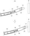
- the housing (220)may include a rail (221) having a constant incline therein.
- the housing (220)may include a rail (221) that is curved to have a preset curvature.
- the rail (221)may be arranged as a straight rail having a constant upward or downward incline inside the housing (220).
- the size of the installation space occupied inside the housing (220)may be larger than that of a rail (221) that is curved to have a preset curvature.
- the robot arm (200)can be installed in a smaller space than that of a structure such as a straight rail or a manipulator.
- the angle of the slide tag (210) protruding from the main body (101) of the robot (100)can be determined by at least one of the installation angle of the housing (220) arranged inside the main body (101) and the inclination angle of the rail (221). Information about the installation angle of the housing (220) and the inclination angle of the rail (221) can be stored in the memory (120).
- the processor (110)can adjust the protruding length of the slide tag (210) based on the information about the installation angle of the housing (220) and the inclination angle of the rail (221) stored in the memory (120).
- the processor (110)can determine the protrusion angle of the slide tag (210) based on the inclination angle of the rail (221).
- the processor (110)can determine the protrusion angle of the slide tag (210) based on the sum of the installation angle of the housing (220) and the inclination angle of the rail (221).
- the processor (110)can protrude the slide tag (210) to a preset length according to the inclination angle of the preset rail (221).
- the processor (110)can protrude the slide tag (210) to a preset length to touch or push the external object (20).
- the rail (221)can be implemented in a shape that is curved upward to have a preset curvature.
- the rail (221)can be implemented in a shape that is curved downward to have a preset curvature.
- the processor (110)can touch or push the external object (20) by protruding the slide tag (210) to a preset length. In this way, when the height of the external object (20) is arranged at a preset height, the processor (110) can identify the distance to the external object (20) and protrude the slide tag (210) by the identified distance to touch or push the external object (20).
- the processor (110)can adjust the protrusion length of the slide tag (210) based on the distance to the external object (20) and the height of the external object (20).
- the rail (221)may be implemented in a shape that is curved upward to have a preset curvature, or may be arranged as a straight rail with a constant upward incline.
- the processor (110)may adjust the protrusion length of the slide tag (210) based on the height of the external object (20).
- the processor (110)may calculate the protrusion length of the slide tag (210) that can reach the height of the external object (20) based on the preset incline angle of the rail (221), and may move the position of the robot (100) so that it can touch or push the external object (20) through the protrusion length of the slide tag (210).
- the processor (110)can touch or push an external object (20) by protruding the slide tag (210) by the calculated protrusion length.
- the rail (221)may be implemented in a shape that is curved downward to have a preset curvature, or may be arranged as a straight rail with a constant downward incline.
- the processor (110)may adjust the protrusion length of the slide tag (210) based on the height of the external object (20).
- the processor (110)may calculate the protrusion length of the slide tag (210) that can reach the height of the external object (20) based on the preset incline angle of the rail (221), and may move the position of the robot (100) so that it can touch or push the external object (20) through the protrusion length of the slide tag (210).
- the processor (110)can touch or push the external object (20) by protruding the slide tag (210) by the calculated protrusion length.
- the driving unit (230)can move the slide tag (210) so that the slide tag (210) protrudes outside the housing (220) under the control of the processor (110).
- the driving unit (230)can include a linear motor (231) and a driving cylinder (232).
- a linear motor (231)can generate a linear propulsive force.
- a magnetic forceis generated. If the generated magnetic force has the same polarity as a permanent magnet, a repulsive force is generated, and if the generated magnetic force and the permanent magnet have different polarities, an attractive force is generated.
- a linear motor (231)can move an object in a linear direction by utilizing this principle.
- an object moved by a linear motor (231)may be a driving cylinder (232).
- the driving cylinder (232)may reciprocate in a straight line by driving the linear motor (231).
- the processor (110)operates the linear motor (231)
- the driving cylinder (232)may move in a straight line and protrude the slide tag (210) out of the housing (220).
- the cap (250) covering the opening of the housing (220)may be pushed and opened.
- the processor (110)can control the linear motor (231) to touch or push the slide tag (210) to the external object (20).
- the processor (110)can control the linear motor (231) to move the slide tag (210) in the opposite direction to return it into the housing (220).
- the cap (250)can close to cover the opening of the housing (220).
- the robot arm (200)may include a movable pin (PIN) (240) connecting the drive cylinder (232) and the slide tag (210).
- the movable pin (240)may be movably connected between an end of the drive cylinder (232) and the slide tag (210) so that the slide tag (210) may be driven in an inclined direction by the driving force of the drive cylinder (232).
- the drive cylinder (232)moves in a straight direction
- the slide tag (210)slides along the rail (221) in an inclined direction, so that the moving angles of the drive cylinder (232) and the slide tag (210) change.
- the floating pin (240)can transfer the driving force of the driving cylinder (232) to the slide tag (210) by flowing in response to the difference in the direction of travel between the driving cylinder (232) and the slide tag (210).
- a cap (250)is hinge-coupled to an opening portion of a housing (220) through which a slide tag (210) protrudes, thereby opening the opening by protruding the slide tag (210) and covering the opening by returning the slide tag (210). Specifically, the cap (250) covers the opening of the housing (220) when the slide tag (210) is positioned inside the housing (220), and opens the opening of the housing (220) by being pushed by a first buffer member (211) arranged at an end of the slide tag (210) when the slide tag (210) protrudes.
- a protrusionmay be formed on the lower rear surface of the cap (250).
- a catch membermay be formed on one side of the slide tag (210). The protrusion and the catch member may be implemented at positions corresponding to each other. Specifically, after the cap (250) is opened while being pushed by the first buffer member (211), the slide tag (210) may be protruded and the protrusion may be caught on the catch member to maintain the open state of the cap (250).
- Figure 5is a perspective view of the robot arm (200) viewed from the opposite direction of Figure 4.
- the robot arm (200)may further include a fixed spring (260) for elastically connecting the housing (220) and the slide tag (210).
- a fixed spring (260)for elastically connecting the housing (220) and the slide tag (210).
- the fixed spring (260)may elastically support the slide tag (210) so that the slide tag (210) does not shake in the up-and-down or left-right directions when the slide tag (210) is positioned inside the housing (220) or protrudes outside the housing (220).
- the robot arm (200)may further include a torsion spring (270) arranged on one side of the housing (220).
- the torsion spring (270)is compressed by the opening of the cap (250), and when the slide tag (210) returns inside the housing (220), the cap (250) may provide a compressive force to cover the opening.
- the detailed configuration and operation of the torsion spring (270)will be described again in the following section.
- Fig. 6is a cross-sectional view for explaining the configuration of a slide tag according to various embodiments.
- the upper drawingis a drawing showing a state before the slide tag (210) touches an external object (20)
- the lower drawingis a drawing showing a state when the slide tag (210) touches an external object (20).
- the slide tag (210)may include a first slide member (214), a second slide member (215), and a second buffer member (216).
- a recognition chip (213)may be placed on the first slide member (214).
- the recognition chip (213)may be placed between the first slide member (214) and the first buffer member (211).
- the recognition chip (213)may include a memory for storing a unique code or identification information.
- the recognition chip (213) in the slide tag (210)may be implemented in the form of an RFID tag or an identification card (ID Card).
- the RFID tag or the identification card (ID Card)may further include an antenna for receiving a signal from the RFID reader and transmitting information stored in the recognition chip (213).
- the antennamay be implemented in a thin film form or a coil form and may transmit information stored in the recognition chip (213) to the RFID reader or receive a signal from the RFID reader.
- the antennamay be placed inside the first buffer member (211) and connected to the recognition chip (213).
- the recognition chip (213)may be transmitted to the RFID reader or a signal may be received from the RFID reader through the antenna placed inside the first buffer member (211).
- the RFID readercan transmit and receive signals to and from the recognition chip through the antenna of the RFID tag or the antenna connected to the recognition chip.
- the antenna built into the RFID tag or the antenna connected to the recognition chipreceives radio waves from the RFID reader.
- the recognition chipis activated through the received radio waves, signals information stored in the memory, and transmits the generated signal through the antenna.
- the RFID readercan receive the signal transmitted from the antenna connected to the recognition chip and identify the unique code or information stored in the recognition chip.
- the second slide member (215)may be connected to the driving member (230). As described above, the second slide member (215) may be movably connected to the driving cylinder (232) of the driving member (230) via the movable pin (240). The first slide member (214) and the second slide member (215) may be fitted together. In addition, a second buffer member (216) may be arranged between the first slide member (214) and the second slide member (215).
- the second buffer member (216)may be implemented with an elastic material to buffer an impact applied to the slide tag (210) from the external object (20) when the slide tag (210) touches the external object (20).
- the impact forcemay be buffered by the second buffer member (216) as the first slide member (214) moves backward.
- the slide tag (210)may restore the gap between the first slide member (214) and the second slide member (215) by using the energy accumulated by the deformation of the second buffer member (216).
- the second buffer member (216)may be composed of at least one of rubber, spring, foam plastic, soft EPS, and EVA (synthetic rubber).
- a first fixing member (217) for fixing the springmay be further included at an end of the second slide member (215).
- a support member (218) for supporting the elasticity of the springmay be further included at one side of the first slide member (214).
- Fig. 7is a drawing for explaining the operation of the cap according to various embodiments.
- the left drawingshows a state in which the cap (250) is closed
- the right drawingshows a state in which the cap (250) is opened by the protrusion of the slide tag (210).
- a torsion spring (270)may be arranged on one side of the housing (220).
- the torsion spring (270)may be arranged in an opening portion of the housing (220).
- FIG. 7shows a state where the torsion spring (270) is arranged on the outside of the opening of the housing (220).
- the torsion spring (270)may have any shape and position that can provide a compressive force for the cap (250) to cover the opening when the slide tag (210) returns to the inside of the housing (220).
- the torsion spring (270)may be arranged between the housing (270) and the cap (250) on the inside of the opening of the housing (220).
- a central axis (711) for fixing the center of the torsion spring (270)may be provided on one side of the housing (220).
- a second fixing member (712) for fixing the fixed side arm (271) of the torsion spring (270)may be provided on the other side of the housing (220).
- the cap (270)includes a cover member (251) for covering the opening of the housing (220) and a connecting member (252) connected to one side of the housing (200), and may be implemented in a shape in which the cover member (251) and the connecting member (252) are combined to have a preset angle.
- the cap (250)may be configured in a “ ⁇ ” shape.
- a first connecting protrusion (713) and a second connecting protrusion (714) for combining with the housing (220)may be provided on one side of the connecting member (252) of the cap (250).
- a first coupling groove (715) and a second coupling groove (716)may be formed at positions corresponding to the first coupling protrusion (713) and the second coupling protrusion (714), into which the first coupling protrusion (713) and the second coupling protrusion (714) are respectively fitted.
- the coupling protrusion and the coupling groovemay be implemented as a pair, or may be implemented as three or more pairs.
- the first coupling groove (715) and the second coupling groove (716)may be implemented in a curved shape with a preset curvature so that the first coupling protrusion (713) and the second coupling protrusion (714) can be movably coupled along the movement path of the connecting member (252) when the cap (250) is opened.
- the moving side arm (272) of the torsion spring (270)may be supported by at least one of the first coupling protrusion (713) and the second coupling protrusion (714).
- FIG. 7shows a state in which the moving side arm (272) of the torsion spring (270) is supported by the first coupling protrusion (713).
- the gap between the fixed arm (271) and the movable arm (272) of the torsion spring (270)can be narrowed and compressed when the cap (250) is opened.
- the second coupling protrusion (714)does not support the movable arm (272) of the torsion spring (270), but can be movably coupled to the housing (220) so that it can move stably without shaking when the cap (250) is opened.
- the torsion spring (270)is compressed when the cap (250) is opened, and when the slide tag (210) returns inside the housing (220), the compression force generated when the cap (250) is opened can be used to provide a restoring force for the cap (250) to cover the opening of the housing (220).
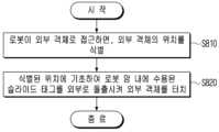
- FIG. 8is a flowchart for explaining a method for controlling a robot according to various embodiments of the present disclosure.
- the robotwhen the robot approaches an external object, the robot identifies the location of the external object (S810). If location information of the external object is stored in the robot, the robot can identify the location of the external object based on the stored location information. For example, when the robot moves within a building, the robot can store a building map indicating the location of a door. Alternatively, the robot can sense the location of the external object using at least one sensor.
- the at least one sensorcan include at least one of a distance sensor, a gyro sensor, an acceleration sensor, a gravity sensor, a geomagnetic sensor, an image sensor, and a 3D camera.
- the robottouches an external object by projecting a slide tag accommodated in the robot arm to the outside based on the identified location (S820).
- the robot armmay include a housing that accommodates the slide tag and a driving unit that moves the slide tag to project out of the housing.
- the housingincludes a rail that is curved to have a preset curvature and may accommodate the slide tag on the rail.
- the robotmay control the driving unit so that the slide tag slides along the rail and projects out of the housing.
- the robotcan identify the distance to the external object based on the location information or sensing information of the external object stored in the memory.
- the robotcan touch the external object by adjusting the protruding length of the slide tag accommodated in the robot arm according to the distance and height to the identified external object.
- the longer the protrusion length of the slide tagthe higher the height that the slide tag can touch.
- the robotcan move the position of the robot close to the external object and then protrude the slide tag a short distance to touch the external object.
- the robotcan move the position of the robot away from the external object and then protrude the slide tag a long distance to adjust the distance and height from the external object.
- the actuatorcan be controlled to move the slide tag into the housing.
- the capcan cover the opening of the housing.
- the robot armcan operate both a physical door opening/closing device such as a push button and an electrical door opening/closing device such as an RFID reader or NFC, and thus can move freely within various buildings.
- a physical door opening/closing devicesuch as a push button
- an electrical door opening/closing devicesuch as an RFID reader or NFC
- the robot arm according to various embodiments of the present disclosurethe robot including the robot arm, and the control method thereof have the effect of enabling installation of the robot arm in a narrow space while adjusting the touch height by the robot arm compared to a manipulator or the like.
- the robot arm according to various embodiments of the present disclosurecan simplify the structure by applying a single-axis method instead of a multi-axis method like a manipulator.
- the various embodiments described abovemay be implemented as software including instructions stored in a machine-readable storage media that can be read by a machine (e.g., a computer).
- the devicemay include a robot according to the disclosed embodiments as a device that calls instructions stored from the storage media and can operate according to the called instructions.
- the processormay directly or under the control of the processor use other components to perform a function corresponding to the instructions.
- the instructionsmay include codes generated or executed by a compiler or an interpreter.
- the machine-readable storage mediamay be provided in the form of a non-transitory storage media.
- 'non-transitory'means that the storage media does not include signals and is tangible, and does not distinguish between data being stored semi-permanently or temporarily in the storage media.
- the method according to the various embodiments described abovemay be provided as included in a computer program product.
- the computer program productmay be traded between sellers and buyers as a commodity.
- the computer program productmay be distributed in the form of a storage medium readable by a machine (e.g., compact disc read only memory (CD-ROM)) or online through an application store (e.g., Play StoreTM).
- a machinee.g., compact disc read only memory (CD-ROM)
- an application storee.g., Play StoreTM
- at least a part of the computer program productmay be temporarily stored or temporarily generated in a storage medium such as a memory of a manufacturer's server, a server of an application store, or a relay server.
- each of the componentsmay be composed of a single or multiple entities, and some of the corresponding sub-components described above may be omitted, or other sub-components may be further included in various embodiments.
- some of the componentse.g., modules or programs
Landscapes
- Engineering & Computer Science (AREA)
- Robotics (AREA)
- Mechanical Engineering (AREA)
- Physics & Mathematics (AREA)
- General Physics & Mathematics (AREA)
- Human Computer Interaction (AREA)
- Manipulator (AREA)
Abstract
Description
Translated fromKorean본 개시는 로봇 암, 그 로봇 암을 포함하는 로봇 및 그 제어 방법에 관한 것이다.The present disclosure relates to a robot arm, a robot including the robot arm, and a control method thereof.
로봇 기술의 발달에 힘입어 무인 시스템이 구비된 다양한 유형의 로봇(Robot)들이 개발 및 보급되고 있다. 사람을 대신하여 주문된 음식을 조리하는 조리 로봇, 음식의 서빙을 수행하는 서빙 로봇, 물건을 고객에게 배송하는 배송 로봇 등의 다양한 로봇들이 사용된다. 이러한 로봇이 건물을 출입하거나, 엘리베이터의 승하차 등을 통해 건물 내 이동을 하기 위해서는 도어 개폐 장치를 작동하여 도어(Door)의 개폐를 수행해야 한다.Thanks to the development of robot technology, various types of robots equipped with unmanned systems are being developed and distributed. Various robots are used, such as cooking robots that cook ordered food instead of people, serving robots that perform food service, and delivery robots that deliver items to customers. In order for these robots to enter and exit a building or move within a building, such as by getting on and off an elevator, they must operate a door opening and closing device to open and close the door.
하지만, 건물에 설치된 도어마다 도어 개폐 장치의 작동 방식이 다르기 때문에 로봇이 각 도어 개폐 장치의 작동 방식에 따라 도어의 개방 동작을 수행할 수 있는 기술이 요구된다. 예를 들어, 도어 개폐 장치가 푸쉬 버튼으로 구현되면, 로봇은 푸쉬 버튼을 누를 수 있는 기능이 필요하고, 도어 개폐 장치가 RFID 리더기(RFID Reader) 또는 NFC(Near Field Communication) 방식으로 구현되면, 로봇은 식별(ID) 정보를 도어 개폐 장치에 전송할 수 있는 기능이 요구된다.However, since the operation method of the door opening device is different for each door installed in the building, a technology is required that allows the robot to perform the door opening operation according to the operation method of each door opening device. For example, if the door opening device is implemented as a push button, the robot needs to have the function to press the push button, and if the door opening device is implemented as an RFID reader or NFC (Near Field Communication), the robot needs to have the function to transmit identification (ID) information to the door opening device.
본 개시에 따르면, 적어도 하나의 실시 예에 따른 로봇은 본체, 상기 본체에 탑재된 로봇 암, 상기 본체 외부에 위치한 외부 객체를 터치하도록 상기 로봇 암을 제어하는 프로세서를 포함한다. 상기 로봇 암은 슬라이드 태그, 상기 슬라이드 태그를 수용하는 하우징, 상기 프로세서의 제어에 따라 상기 슬라이드 태그가 상기 하우징 외부로 돌출되도록 상기 슬라이드 태그를 움직이는 구동부를 포함한다.According to the present disclosure, a robot according to at least one embodiment includes a main body, a robot arm mounted on the main body, and a processor controlling the robot arm to touch an external object located outside the main body. The robot arm includes a slide tag, a housing that accommodates the slide tag, and a driving unit that moves the slide tag so that the slide tag protrudes outside the housing under the control of the processor.
한편, 본 개시의 하나 이상의 실시 예에 따른 로봇 암은 내부에 일정한 경사를 갖는 레일(Rail)이 마련된 하우징, 상기 레일을 따라 슬라이딩 구동되고, 일측에는 도어를 개방하기 위한 인식 칩(Identification Chip)이 구비되는 슬라이드 태그, 리니어 모터 및 상기 슬라이드 태그에 유동 핀(PIN)으로 연결되고, 상기 리니어 모터의 구동에 의해 직선으로 왕복 운동하는 구동 실린더를 포함한다. 상기 유동 핀은 상기 구동 실린더의 구동력에 의해 상기 슬라이드 태그가 경사 방향으로 구동할 수 있도록 상기 구동 실린더의 단부와 상기 슬라이드 태그 사이에서 유동 가능하게 연결된다.Meanwhile, a robot arm according to one or more embodiments of the present disclosure includes a housing having a rail having a constant incline therein, a slide tag that slides along the rail and has an identification chip for opening a door provided on one side thereof, a linear motor, and a driving cylinder that is connected to the slide tag by a movable pin (PIN) and moves reciprocally in a straight line by driving of the linear motor. The movable pin is movably connected between an end of the driving cylinder and the slide tag so that the slide tag can be driven in an inclined direction by the driving force of the driving cylinder.
한편, 본 개시의 하나 이상의 실시 예에 따른 로봇 암을 포함하는 로봇의 제어 방법은 로봇이 외부 객체로 접근하면, 상기 외부 객체의 위치를 식별하는 단계, 식별된 위치에 기초하여 상기 로봇 암 내에 수용된 슬라이드 태그를 외부로 돌출시켜 상기 외부 객체를 터치하는 단계를 포함한다. 상기 로봇 암은 기 설정된 곡률을 가지도록 휘어진 레일을 포함하며 상기 레일 상에 상기 슬라이드 태그를 수용하는 하우징 및 상기 슬라이드 태그가 상기 레일을 따라 슬라이딩 되어 상기 하우징 외부로 돌출되도록 상기 슬라이드 태그를 움직이는 구동부를 포함한다.Meanwhile, a method for controlling a robot including a robot arm according to one or more embodiments of the present disclosure includes, when the robot approaches an external object, a step of identifying a location of the external object, and a step of touching the external object by protruding a slide tag accommodated in the robot arm outward based on the identified location. The robot arm includes a rail that is curved to have a preset curvature, a housing that accommodates the slide tag on the rail, and a driving unit that moves the slide tag so that the slide tag slides along the rail and protrudes outward from the housing.
도 1은 본 개시의 다양한 실시 예에 따른 로봇의 구성을 설명하기 위한 도면이다.FIG. 1 is a drawing for explaining the configuration of a robot according to various embodiments of the present disclosure.
도 2는 본 개시의 다양한 실시 예에 따른 로봇의 동작을 설명하기 위한 도면이다.FIG. 2 is a drawing for explaining the operation of a robot according to various embodiments of the present disclosure.
도 3은 본 개시의 다양한 실시 예에 따른 로봇의 구성을 나타내는 블록도 이다.FIG. 3 is a block diagram showing the configuration of a robot according to various embodiments of the present disclosure.
도 4 및 도 5는 본 개시의 다양한 실시 예에 따른 로봇 암의 구성을 설명하기 위한 사시도이다.FIGS. 4 and 5 are perspective views illustrating the configuration of a robot arm according to various embodiments of the present disclosure.
도 6은 본 개시의 다양한 실시 예에 따른 슬라이드 태그의 구성을 설명하기 위한 단면도이다.FIG. 6 is a cross-sectional view illustrating the configuration of a slide tag according to various embodiments of the present disclosure.
도 7은 개시의 다양한 실시 예에 따른 캡의 동작을 설명하기 위한 도면이다.FIG. 7 is a drawing for explaining the operation of a cap according to various embodiments of the disclosure.
도 8은 본 개시의 다양한 실시 예에 따른 로봇의 제어 방법을 설명하기 위한 흐름도이다.FIG. 8 is a flowchart for explaining a method for controlling a robot according to various embodiments of the present disclosure.
이하에서는 첨부 도면을 참조하여 본 개시를 상세히 설명한다.Hereinafter, the present disclosure will be described in detail with reference to the attached drawings.
본 문서의 다양한 실시 예들 및 이에 사용된 용어들은 본 문서에 기재된 기술적 특징들을 특정한 실시 예들로 한정하려는 것이 아니며, 해당 실시 예의 다양한 변경, 균등물, 또는 대체물을 포함하는 것으로 이해되어야 한다.It should be understood that the various embodiments of this document and the terminology used herein are not intended to limit the technical features described in this document to specific embodiments, but rather to encompass various modifications, equivalents, or substitutes of the embodiments.
도면의 설명과 관련하여, 유사한 또는 관련된 구성요소에 대해서는 유사한 참조 부호가 사용될 수 있다.In connection with the description of the drawings, similar reference numerals may be used for similar or related components.
아이템에 대응하는 명사의 단수형은 관련된 문맥상 명백하게 다르게 지시하지 않는 한, 상기 아이템 한 개 또는 복수 개를 포함할 수 있다.The singular form of a noun corresponding to an item may include one or more of said items, unless the context clearly indicates otherwise.
본 문서에서, "A 또는 B", "A 및 B 중 적어도 하나", "A 또는 B 중 적어도 하나", "A, B 또는 C", "A, B 및 C 중 적어도 하나", 및 "A, B, 또는 C 중 적어도 하나"와 같은 문구들 각각은 그 문구들 중 해당하는 문구에 함께 나열된 항목들 중 어느 하나, 또는 그들의 모든 가능한 조합을 포함할 수 있다.In this document, each of the phrases "A or B", "at least one of A and B", "at least one of A or B", "A, B, or C", "at least one of A, B, and C", and "at least one of A, B, or C" can include any one of the items listed together in that phrase, or all possible combinations of them.
"및/또는"이라는 용어는 복수의 관련된 기재된 구성요소들의 조합 또는 복수의 관련된 기재된 구성요소들 중의 어느 구성요소를 포함한다.The term "and/or" includes any combination of multiple related described elements or any one of multiple related described elements.
"제1", "제2", 또는 "첫째" 또는 "둘째"와 같은 용어들은 단순히 해당 구성요소를 다른 해당 구성요소와 구분하기 위해 사용될 수 있으며, 해당 구성요소들을 다른 측면(예: 중요성 또는 순서)에서 한정하지 않는다.Terms such as "first", "second", or "first" or "second" may be used merely to distinguish one component from another, and do not limit the components in any other respect (e.g., importance or order).
어떤(예: 제1) 구성요소가 다른(예: 제2) 구성요소에, "기능적으로" 또는 "통신적으로"라는 용어와 함께 또는 이런 용어 없이, "커플드" 또는 "커넥티드"라고 언급된 경우, 그것은 상기 어떤 구성요소가 상기 다른 구성요소에 직접적으로(예: 유선으로), 무선으로, 또는 제3 구성요소를 통하여 연결될 수 있다는 것을 의미한다.When a component (e.g., a first component) is referred to as being “coupled” or “connected” to another component (e.g., a second component), with or without the terms “functionally” or “communicatively,” it means that the component can be connected to the other component directly (e.g., wired), wirelessly, or through a third component.
"포함하다" 또는 "가지다"등의 용어는 본 문서에 기재된 특징, 숫자, 단계, 동작, 구성요소, 부품 또는 이들을 조합한 것이 존재함을 지정하려는 것이지, 하나 또는 그 이상의 다른 특징들이나 숫자, 단계, 동작, 구성요소, 부품 또는 이들을 조합한 것들의 존재 또는 부가 가능성을 미리 배제하지 않는다.The terms "include" or "have" and the like are intended to specify the presence of a feature, number, step, operation, component, part, or combination thereof described in this document, but do not exclude the presence or addition of one or more other features, numbers, steps, operations, components, parts, or combinations thereof.
어떤 구성요소가 다른 구성요소와 "연결", "결합", "지지" 또는 "접촉"되어 있다고 할 때, 이는 구성요소들이 직접적으로 연결, 결합, 지지 또는 접촉되는 경우뿐 아니라, 제3 구성요소를 통하여 간접적으로 연결, 결합, 지지 또는 접촉되는 경우를 포함한다.When a component is said to be “connected,” “coupled,” “supported,” or “contacted” with another component, this includes not only cases where the components are directly connected, coupled, supported, or in contact, but also cases where the components are indirectly connected, coupled, supported, or in contact through a third component.
어떤 구성요소가 다른 구성요소 "상에" 위치하고 있다고 할 때, 이는 어떤 구성요소가 다른 구성요소에 접해 있는 경우뿐 아니라 두 구성요소 사이에 또 다른 구성요소가 존재하는 경우도 포함한다.When we say that a component is "on" another component, this includes not only cases where the component is in contact with the other component, but also cases where there is another component between the two components.
이하 첨부된 도면들을 참조하여 본 개시의 일 실시 예를 보다 상세하게 설명한다.An embodiment of the present disclosure will be described in more detail with reference to the attached drawings below.
도 1은 본 개시의 다양한 실시 예에 따른 로봇의 구성을 설명하기 위한 도면이고, 도 2는 본 개시의 다양한 실시 예에 따른 로봇의 동작을 설명하기 위한 도면이다.FIG. 1 is a drawing for explaining the configuration of a robot according to various embodiments of the present disclosure, and FIG. 2 is a drawing for explaining the operation of a robot according to various embodiments of the present disclosure.
로봇이란 사람이 직접 조종하지 않는 상태에서 주행 가능한 장치가 될 수 있다. 로봇(100)은 자율 주행 장치, 자율 주행 로봇(AMR, Autonomous Mobile Robot), AGV(Automated Guided Vehicle), UGV(Unmanned Ground Vehicle) 등과 같이 다양하게 지칭할 수도 있으나, 본 개시에서는 로봇(100)으로 기재한다. 로봇(100)은 그 사용 방법이나 용도에 따라서 청소 로봇, 서빙 로봇, 이동형 프로젝터, 산업용 로봇, 가이드 로봇, 배송 로봇 등과 같이 공간을 주행하며 필요한 작업을 수행하는 다양한 종류의 로봇으로 구현될 수 있다.A robot may be a device that can drive without being directly controlled by a person. The robot (100) may be referred to in various ways, such as an autonomous driving device, an autonomous mobile robot (AMR), an automated guided vehicle (AGV), an unmanned ground vehicle (UGV), etc., but is described as a robot (100) in the present disclosure. The robot (100) may be implemented as various types of robots that drive through space and perform necessary tasks, such as a cleaning robot, a serving robot, a mobile projector, an industrial robot, a guide robot, a delivery robot, etc., depending on its usage method or purpose.
이 경우, 로봇(100)이 공간을 주행하며 필요한 작업을 수행하기 위해서는 공간과 공간 사이에 배치된 도어(Door)(10)를 통과해야 한다. 예를 들어, 로봇(100)이 건물 내로 진입하기 위해서는 건물 입구에 배치된 도어(Door)(10)를 통과해야 한다. 로봇(100)이 건물 내에 진입한 후에도 작업실 또는 사무실 내로 들어가기 위해서는 각 작업실 또는 사무실마다 설치된 도어(10)를 개방(Open)해야 한다.In this case, in order for the robot (100) to move through the space and perform the necessary work, it must pass through a door (10) placed between the spaces. For example, in order for the robot (100) to enter a building, it must pass through a door (10) placed at the entrance of the building. Even after the robot (100) enters the building, in order to enter a workroom or office, it must open a door (10) installed in each workroom or office.
중앙 서버의 통제에 의해 도어 개폐 장치가 작동되는 건물의 경우, 로봇(100)이 중앙 서버에 도어(10)의 개폐를 위한 신호(Signal) 또는 엘리베이터 층 정보를 전송하면, 중앙 서버의 제어에 의해 해당 도어 개폐 장치가 작동되고, 로봇(100)은 개방된 도어(10)를 통해 건물을 출입하거나 건물 내에서의 이동을 수행할 수 있다.In the case of a building where the door opening/closing device operates under the control of a central server, when the robot (100) transmits a signal for opening/closing the door (10) or elevator floor information to the central server, the corresponding door opening/closing device operates under the control of the central server, and the robot (100) can enter/exit the building or move within the building through the open door (10).
하지만, 도어(10)를 개폐하는 도어 개폐 장치가 개별적인 제어 방식에 의해 작동되는 건물의 경우, 로봇(100)은 각 도어 개폐 장치의 작동 방식에 따라 직접 물리적 또는 전기적 수단을 수행하여 도어(10)를 개폐해야 한다. 예를 들어, 도어 개폐 장치가 물리적 방식의 푸쉬 버튼(Push Button)으로 구현되면, 로봇(100)은 도어(10)를 개방(Open)하기 위해 푸쉬 버튼을 누르는 동작을 수행할 수 있다. 도어 개폐 장치가 전기적 방식의 RFID 리더기(Radio Frequency Identification Reader) 또는 NFC(Near Field Communication)로 구현되면, 로봇(100)은 도어(10)를 개방(Open)하기 위해 인식 칩(Identification Chip)이 구비된 RFID 태그 또는 식별 카드(ID Card)를 도어 개폐 장치에 터치할 수 있다.However, in the case of a building in which the door opening/closing device for opening/closing the door (10) is operated by an individual control method, the robot (100) must open/close the door (10) by directly performing physical or electrical means according to the operation method of each door opening/closing device. For example, if the door opening/closing device is implemented as a physical push button, the robot (100) can perform an action of pressing the push button to open the door (10). If the door opening/closing device is implemented as an electrical RFID reader (Radio Frequency Identification Reader) or NFC (Near Field Communication), the robot (100) can touch an RFID tag or identification card (ID Card) equipped with an identification chip to the door opening/closing device to open the door (10).
종래의 로봇은 각 도어 개폐 장치의 작동 방식에 따라 물리적 또는 전기적 수단을 수행하여 도어를 개폐하는 것이 용이하지 않았다. 예를 들어, 도어의 개폐를 위해 푸쉬 버튼을 작동할 수 있는 기능이 구비된 로봇은 RFID 리더기(RFID Reader) 또는 NFC(Near Field Communication) 방식의 도어 개폐 장치를 작동시키는 것은 어려웠다. 마찬가지로, RFID 리더기 방식의 도어 개폐 장치를 작동할 수 있는 기능이 구비된 로봇은 푸쉬 버튼을 작동시키는 것이 어려웠다.Conventional robots have not been able to open and close doors easily by performing physical or electrical means depending on the operation method of each door opening and closing device. For example, a robot equipped with a function to operate a push button to open and close a door has had difficulty operating a door opening and closing device using an RFID reader or NFC (Near Field Communication). Similarly, a robot equipped with a function to operate a door opening and closing device using an RFID reader has had difficulty operating a push button.
하지만, 건물마다 도어 개폐 장치의 작동 방식이 서로 다르고, 같은 건물에서도 각 도어마다 설치된 도어 개폐 장치의 작동 방식이 다르기 때문에, 로봇이 푸쉬 버튼과 같은 물리적 방식과 RFID 리더기(RFID Reader) 또는 NFC와 같은 전기적 방식의 도어 개폐 장치를 모두 작동시킬 수 없다면, 로봇은 건물 내에서 자유로운 이동을 할 수 없게 된다. 특히, RFID 리더기 또는 NFC 방식의 도어 개폐 장치는 RFID 태그 또는 식별 카드를 터치하기 위한 접촉면의 면적이 좁기 때문에 로봇이 접촉면의 위치를 정확하게 조절하여 RFID 태그 또는 식별 카드를 터치하는 것은 어려울 수 있다.However, since the operation method of the door opening device is different for each building, and even for each door in the same building, the operation method of the door opening device installed is different, if the robot cannot operate both the physical door opening device, such as a push button, and the electrical door opening device, such as an RFID reader or NFC, the robot will not be able to move freely within the building. In particular, since the area of the contact surface for touching the RFID tag or identification card is narrow for the door opening device using the RFID reader or NFC method, it may be difficult for the robot to accurately adjust the position of the contact surface to touch the RFID tag or identification card.
본 개시의 다양한 실시 예에 따른 로봇(100)은 물리적 또는 전기적 방식으로 구현된 도어 개폐 장치를 작동하여 각 도어(10)를 개방(Open)할 수 있다.A robot (100) according to various embodiments of the present disclosure can open each door (10) by operating a door opening/closing device implemented in a physical or electrical manner.
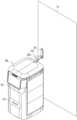
도 1을 참조하면, 로봇(100)은 본체(101), 본체(101)에 탑재된 로봇 암(200) 및 본체(101) 외부에 위치한 외부 객체(20)를 터치하도록 로봇 암(200)을 제어하는 프로세서(110)를 포함한다. 외부 객체(20)는 로봇(100)이 로봇 암(200)을 이용하여 터치(Touch) 또는 푸쉬(Push) 등의 동작을 수행하기 위한 대상체를 나타낸다. 예를 들어, 외부 객체(20)는 푸쉬 버튼(Push Button), 벨, RFID 리더기(RFID Reader), NFC 및 각종 센서 등을 포함할 수 있다.Referring to FIG. 1, the robot (100) includes a main body (101), a robot arm (200) mounted on the main body (101), and a processor (110) that controls the robot arm (200) to touch an external object (20) located outside the main body (101). The external object (20) represents an object for the robot (100) to perform an action, such as a touch or push, using the robot arm (200). For example, the external object (20) may include a push button, a bell, an RFID reader, NFC, and various sensors.
외부 객체(20)는 도어(10)를 개폐하는 도어 개폐 장치를 포함할 수도 있다. 도어 개폐 장치는 도어(10) 또는 벽체의 일측에 배치되고, 외부의 신호 또는 물리적 가압(pressurization)에 의해 작동되어 도어(10)를 개폐하는 장치를 나타낸다. 도 1에서 외부 객체(20)는 푸쉬 버튼(Push Button)으로 구현된 도어 개폐 장치를 나타내고, 도 2에서 외부 객체는 RFID 리더기(RFID Reader)(21)로 구현된 도어 개폐 장치를 나타낸다.The external object (20) may include a door opening/closing device that opens and closes the door (10). The door opening/closing device is placed on one side of the door (10) or a wall, and is operated by an external signal or physical pressurization to open and close the door (10). In Fig. 1, the external object (20) represents a door opening/closing device implemented as a push button, and in Fig. 2, the external object represents a door opening/closing device implemented as an RFID reader (21).
다만, 이에 한정되는 것은 아니며, 외부 객체(20)는 로봇(100)에 탑재된 로봇 암(200)의 용도 및 기능에 따라서 로봇 암(200)에 의해 조작 및 작동될 수 있는 어떠한 객체라도 무방하다.However, it is not limited thereto, and the external object (20) may be any object that can be manipulated and operated by the robot arm (200) depending on the purpose and function of the robot arm (200) mounted on the robot (100).
로봇 암(200)은 슬라이드 태그(210), 슬라이드 태그(210)를 수용하는 하우징, 프로세서(110)의 제어에 따라 슬라이드 태그(210)가 하우징 외부로 돌출되도록 슬라이드 태그(210)를 움직이는 구동부를 포함한다. 로봇 암(200)의 상세한 구성 및 동작에 대해서는 후술하는 부분에서 다시 설명한다.The robot arm (200) includes a slide tag (210), a housing that accommodates the slide tag (210), and a driving unit that moves the slide tag (210) so that the slide tag (210) protrudes out of the housing under the control of the processor (110). The detailed configuration and operation of the robot arm (200) will be described again in the following section.
도 2에서 좌측 도면은 로봇(100)이 로봇 암(200)을 작동하기 전의 로봇(100) 상태를 나타내고, 우측 도면은 로봇(100)이 로봇 암(200)을 작동한 상태를 나타낸다.In Fig. 2, the left drawing shows the state of the robot (100) before the robot (100) operates the robot arm (200), and the right drawing shows the state of the robot (100) after the robot arm (200) operates.
도 2를 참조하면, 로봇 암(200)은 로봇(100) 내부에 수용될 수 있다. 로봇(100)이 외부 객체(20)로 접근하면, 프로세서(110)는 외부 객체(20)의 위치를 식별하고, 로봇 암(200)을 작동시킬 수 있다. 예를 들어, 도 2와 같이 외부 객체가 RFID 리더기(RFID Reader)(21)로 구현된 경우, 로봇(100)이 RFID 리더기(21)가 설치된 도어(10)에 접근하면, 프로세서(110)는 슬라이드 태그(210)를 로봇(100)의 외부로 돌출되도록 구동부를 제어할 수 있다. 이 경우, 슬라이드 태그(210)의 단부에는 RFID 리더기(21)에 식별 정보를 전송할 수 있는 인식 칩이 배치될 수 있다.Referring to FIG. 2, the robot arm (200) can be accommodated inside the robot (100). When the robot (100) approaches an external object (20), the processor (110) can identify the location of the external object (20) and operate the robot arm (200). For example, when the external object is implemented as an RFID reader (21) as shown in FIG. 2, when the robot (100) approaches a door (10) in which the RFID reader (21) is installed, the processor (110) can control the driving unit to protrude the slide tag (210) to the outside of the robot (100). In this case, a recognition chip capable of transmitting identification information to the RFID reader (21) can be placed at the end of the slide tag (210).
도 3은 본 개시의 다양한 실시 예에 따른 로봇의 구성을 나타내는 블록도 이다.FIG. 3 is a block diagram showing the configuration of a robot according to various embodiments of the present disclosure.
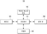
도 3을 참조하면, 로봇(100)은 프로세서(110), 메모리(120), 주행부(130), 적어도 하나의 센서(140) 및 로봇 암(200)을 포함할 수 있다.Referring to FIG. 3, the robot (100) may include a processor (110), a memory (120), a driving unit (130), at least one sensor (140), and a robot arm (200).
프로세서(110)는 로봇(100)의 각 구성과 연결되어 로봇(100)의 동작을 전반적으로 제어하기 위한 구성이다. 프로세서(110)는 디지털 시그널 프로세서(digital signal processor(DSP), 마이크로프로세서(microprocessor), GPU(Graphics Processing Unit), AI(Artificial Intelligence) 프로세서, NPU (Neural Processing Unit)로 구현될 수 있다. 다만, 이에 한정되는 것은 아니며, 중앙처리장치(central processing unit(CPU)), MCU(Micro Controller Unit), MPU(micro processing unit), 컨트롤러(controller), 애플리케이션 프로세서(application processor(AP)), 또는 커뮤니케이션 프로세서(communication processor(CP)), ARM 프로세서 중 하나 또는 그 이상을 포함하거나, 해당 용어로 정의될 수 있다. 또한, 프로세서(110)는 프로세싱 알고리즘이 내장된 SoC(System on Chip), LSI(large scale integration)로 구현될 수도 있고, ASIC(application specific integrated circuit), FPGA(Field Programmable gate array) 형태로 구현될 수도 있다.The processor (110) is a component that is connected to each component of the robot (100) and controls the overall operation of the robot (100). The processor (110) may be implemented as a digital signal processor (DSP), a microprocessor, a GPU (Graphics Processing Unit), an AI (Artificial Intelligence) processor, or an NPU (Neural Processing Unit). However, the processor (110) is not limited thereto, and may include one or more of a central processing unit (CPU), an MCU (Micro Controller Unit), an MPU (Micro Processing Unit), a controller, an application processor (AP), a communication processor (CP), or an ARM processor, or may be defined by the corresponding term. In addition, the processor (110) may be implemented as a SoC (System on Chip), an LSI (Large Scale Integration) having a processing algorithm built in, or may be implemented in the form of an ASIC (Application Specific Integrated Circuit), or an FPGA (Field Programmable Gate Array).
메모리(120)는 로봇(100)의 동작에 필요한 적어도 하나의 명령어, 데이터, 프로그램 등을 저장할 수 있다. 일 예로, 메모리(120)는 외부 객체(20)의 높이 정보, 건물의 맵 정보, 고객의 위치 정보 중 적어도 하나를 저장할 수 있다. 메모리(120)는 휘발성 메모리(예: DRAM(dynamic RAM), SRAM(static RAM), 또는 SDRAM(synchronous dynamic RAM) 등), 비휘발성 메모리(non-volatile Memory)(예: OTPROM(one time programmable ROM), PROM(programmable ROM), EPROM(erasable and programmable ROM), EEPROM(electrically erasable and programmable ROM), mask ROM, flash ROM, 플래시 메모리(예: NAND flash 또는 NOR flash 등), 하드 드라이브, 또는 솔리드 스테이트 드라이브(solid state drive(SSD)) 중 적어도 하나로 구현될 수 있다.The memory (120) can store at least one command, data, program, etc. required for the operation of the robot (100). For example, the memory (120) can store at least one of height information of an external object (20), map information of a building, and location information of a customer. The memory (120) can be implemented as at least one of a volatile memory (e.g., DRAM (dynamic RAM), SRAM (static RAM), SDRAM (synchronous dynamic RAM), etc.), a non-volatile memory (e.g., OTPROM (one time programmable ROM), PROM (programmable ROM), EPROM (erasable and programmable ROM), EEPROM (electrically erasable and programmable ROM), mask ROM, flash ROM, flash memory (e.g., NAND flash or NOR flash), a hard drive, or a solid state drive (SSD)).
메모리(120)는 본 개시에 따른 다양한 동작들에서 생성되는 데이터를 저장하는 단일 메모리로 구현될 수 있으나, 이에 한정되는 것은 아니며, 메모리(120)는 상이한 타입의 데이터를 각각 저장하거나, 상이한 단계에서 생성되는 데이터를 각각 저장하는 복수의 메모리를 포함하도록 구현될 수도 있다.The memory (120) may be implemented as a single memory that stores data generated from various operations according to the present disclosure, but is not limited thereto, and the memory (120) may be implemented to include multiple memories that each store different types of data or each store data generated at different stages.
주행부(130)는 로봇(100)을 주행시키기 위한 구성이다. 주행부(130)는 하나 이상의 바퀴와 축, 모터 등을 포함할 수 있다. 주행부(130)의 구동에 따라 로봇(100)은 전진, 후진, 회전 및 방향 전환 등을 수행할 수 있다. 프로세서(110)는 로봇(100)이 사용자의 설정이나 기 설정된 주행 경로에 따라 주행하도록 주행부(130)를 제어할 수 있다. 예를 들어, 로봇(100)이 물건을 고객에게 배송하는 배송 로봇이면, 프로세서(110)는 메모리(120)에 저장된 고객의 위치 정보에 기초하여 주행 경로를 설정하고, 설정된 주행 경로에 따라 고객의 위치까지 로봇(100)이 주행하도록 주행부(130)를 제어할 수 있다.The driving unit (130) is a component for driving the robot (100). The driving unit (130) may include one or more wheels, an axle, a motor, etc. Depending on the operation of the driving unit (130), the robot (100) may perform forward, backward, rotation, and direction change, etc. The processor (110) may control the driving unit (130) so that the robot (100) may drive according to a user's setting or a preset driving path. For example, if the robot (100) is a delivery robot that delivers goods to a customer, the processor (110) may set a driving path based on the customer's location information stored in the memory (120), and control the driving unit (130) so that the robot (100) may drive to the customer's location according to the preset driving path.
적어도 하나의 센서(140)는 로봇(100)의 동작과 관련하여 다양한 정보들을 센싱하기 위한 구성이다. 적어도 하나의 센서(140)는 거리 센서, 자이로 센서, 가속도 센서, 중력 센서, 지자기 센서, 이미지 센서, 3D 카메라 중 적어도 하나를 포함할 수 있다. 일 예로, 거리 센서는 외부 객체(20)와의 거리를 센싱하기 위한 구성이다. 프로세서(110)는 거리 센서의 센싱값에 기초하여 외부 객체(20)와의 거리를 식별할 수 있다. 거리 센서는 초음파 센서, 적외선 센서, 레이저 센서, 광학 거리 센서, 레이더(RADAR) 센서, 라이다 (LIDAR) 센서, 포토 다이오드 센서, TOF(Time of Flight) 센서 중 적어도 하나를 포함할 수 있다.At least one sensor (140) is configured to sense various pieces of information related to the operation of the robot (100). The at least one sensor (140) may include at least one of a distance sensor, a gyro sensor, an acceleration sensor, a gravity sensor, a geomagnetic sensor, an image sensor, and a 3D camera. As an example, the distance sensor is configured to sense a distance to an external object (20). The processor (110) may identify the distance to the external object (20) based on a sensing value of the distance sensor. The distance sensor may include at least one of an ultrasonic sensor, an infrared sensor, a laser sensor, an optical distance sensor, a RADAR sensor, a LIDAR sensor, a photodiode sensor, and a TOF (Time of Flight) sensor.
예를 들어, 초음파 센서는 로봇(100)이 주행하는 바닥면에 대해 초음파를 발사하고, 바닥에서 반사되어 다시 초음파 센서로 돌아오는 초음파를 수신한다. 프로세서(110)는 반사되어 돌아오는 초음파의 양, 반사 강도, 스펙트럼 등을 분석하여 바닥의 재질을 판단할 수 있다. 초음파 센서가 외부 객체(20)에 초음파를 발사하면, 프로세서(110)는 초음파의 출력 시간과 수신 시간 간의 시간차를 이용하여 외부 객체(20)와의 거리를 산출할 수도 있다.For example, an ultrasonic sensor emits ultrasonic waves toward the floor on which a robot (100) is driving, and receives ultrasonic waves that are reflected from the floor and returned to the ultrasonic sensor. The processor (110) can analyze the amount of ultrasonic waves reflected back, the intensity of the reflection, the spectrum, etc. to determine the material of the floor. When the ultrasonic sensor emits ultrasonic waves toward an external object (20), the processor (110) can also calculate the distance to the external object (20) by using the time difference between the output time of the ultrasonic waves and the reception time.
라이다 센서는 로봇(100)이 위치한 공간에 대해 360도 회전하며 레이저를 조사할 수 있다. 레이저가 로봇(100) 주변의 물체로부터 반사되어 다시 라이다 센서로 수신되면, 라이다 센서는 수신된 시간에 기초하여 물체와의 거리를 측정할 수 있고, 이러한 거리 측정을 여러 각도와 방향에서 수행하며 주변 환경의 데이터 정보를 생성할 수 있다.The lidar sensor can rotate 360 degrees about the space where the robot (100) is located and irradiate the laser. When the laser is reflected from an object around the robot (100) and received again by the lidar sensor, the lidar sensor can measure the distance to the object based on the time of reception, and can perform this distance measurement at various angles and directions to generate data information about the surrounding environment.
프로세서(110)는 적어도 하나의 센서(140)의 센싱 값에 기초하여 로봇(100)이 위치한 공간에 대한 위치 정보, 공간에 존재하는 사물들에 대한 정보, 바닥 면에 대한 정보 등 다양한 정보를 식별할 수 있다. 프로세서(110)는 식별된 다양한 정보에 기초하여 로봇(100)의 동작을 제어할 수 있다. 예를 들어, 프로세서(110)는 적어도 하나의 센서(140)의 센싱 값에 기초하여 외부 객체(20)와의 거리를 식별하며, 식별된 거리 및 높이 정보 중 적어도 하나에 대응되는 길이만큼 슬라이드 태그(210)를 하우징의 외측으로 돌출시키도록 구동부를 제어할 수 있다.The processor (110) can identify various information, such as location information about a space where the robot (100) is located, information about objects existing in the space, and information about a floor surface, based on the sensing value of at least one sensor (140). The processor (110) can control the operation of the robot (100) based on the various identified information. For example, the processor (110) can identify a distance to an external object (20) based on the sensing value of at least one sensor (140), and control the driving unit to protrude the slide tag (210) outward from the housing by a length corresponding to at least one of the identified distance and height information.
프로세서(110)는 적어도 하나의 센서(140)의 센싱 값에 기초하여 설정된 주행 경로 상에 이물질 또는 방해물이 존재하는 것으로 식별되면, 주행부(130)를 제어하여 로봇(100)의 주행 경로를 변경할 수 있다. 프로세서(110)는 설정된 주행 경로 상에 도어(10)가 위치하는 것으로 식별되면, 적어도 하나의 센서(140)를 제어하여 도어 개폐 장치의 위치 정보를 센싱할 수도 있다.If the processor (110) identifies that a foreign substance or an obstacle exists on the set driving path based on the sensing value of at least one sensor (140), the processor (110) can control the driving unit (130) to change the driving path of the robot (100). If the processor (110) identifies that a door (10) is located on the set driving path, the processor (110) can also control at least one sensor (140) to sense the location information of the door opening/closing device.
로봇 암(200)은 로봇(100)의 본체(101) 외부에 위치한 외부 객체(20)를 터치하기 위한 구성이다. 프로세서(110)는 로봇 암(200)을 제어하여 도어 개폐 장치를 작동시킬 수 있다. 로봇 암(200)의 상세한 구성 및 동작에 대해서는 아래의 도면을 참조하여 다시 설명한다.The robot arm (200) is configured to touch an external object (20) located outside the main body (101) of the robot (100). The processor (110) can control the robot arm (200) to operate the door opening/closing device. The detailed configuration and operation of the robot arm (200) will be described again with reference to the drawings below.
도 4 및 도 5는 다양한 실시 예에 따른 로봇 암의 구성을 설명하기 위한 사시도이다.FIGS. 4 and 5 are perspective views illustrating the configuration of a robot arm according to various embodiments.
도 4 및 도 5를 참조하면, 로봇 암(200)은 슬라이드 태그(210), 하우징(220), 구동부(230), 유동 핀(240), 캡(250), 고정 스프링(260) 및 토션 스트링(270)을 포함할 수 있다.Referring to FIGS. 4 and 5, the robot arm (200) may include a slide tag (210), a housing (220), a driving unit (230), a moving pin (240), a cap (250), a fixed spring (260), and a torsion string (270).
슬라이드 태그(210)는 외부 객체(20)를 터치 또는 푸쉬(Push)하기 위한 구성이다. 슬라이드 태그(210)는 로봇 암의 기능 및 사용 목적에 따라 링크(link), 핑거(finger), 프레임(frame), 샤프트(shaft), 로봇 핸드(robot hand), 그립 장치 등 다양한 명칭으로 표현될 수 있으나, 이하에서는 설명의 편의를 위해 슬라이드 태그(210)를 기준으로 설명한다. 슬라이드 태그(210)는 레일(221) 상에 배치되어 레일(221)을 따라 슬라이딩 구동될 수 있다. 슬라이드 태그(210)는 로봇(100)이 로봇 암(200)을 작동시키기 전에는 하우징(220) 내부에 위치하고, 로봇(100)이 로봇 암(200)을 작동시키면 하우징(220) 외부로 돌출될 수 있다.The slide tag (210) is a configuration for touching or pushing an external object (20). The slide tag (210) may be expressed by various names such as a link, a finger, a frame, a shaft, a robot hand, a grip device, etc. depending on the function and purpose of use of the robot arm, but the following description will be based on the slide tag (210) for convenience of explanation. The slide tag (210) may be placed on a rail (221) and may be slid along the rail (221). The slide tag (210) may be located inside the housing (220) before the robot (100) operates the robot arm (200), and may protrude outside the housing (220) when the robot (100) operates the robot arm (200).
슬라이드 태그(210)의 단부에는 외부 객체(20)와의 접촉 시 충격을 완화시키는 제1 완충 부재(211)가 배치될 수 있다. 슬라이드 태그(210)는 로봇(100)에 탑재된 로봇 암(200)의 용도 및 기능에 따라서 다양한 방법으로 사용될 수 있다. 예를 들어, 외부 객체(20)가 RFID(Radio Frequency Identification) 리더기 또는 NFC(Near Field Communication)등의 전기적 구조로 구현되면, 로봇(100)은 외부 객체(20)를 터치하는 용도로 로봇 암(200)을 사용할 수 있다. 하지만, 외부 객체(20)가 푸쉬 버튼과 같은 물리적 구조로 구현되면, 로봇(100)은 외부 객체(20)를 푸쉬(Push)하는 용도로 로봇 암(200)을 사용할 수 있다. 이 경우, 슬라이드 태그(210)에 과도한 힘(Over stroke)이 지속적으로 가해지면, 로봇 암(200)의 고장이 발생할 수 있다.A first buffer member (211) that cushions impact when in contact with an external object (20) may be arranged at the end of the slide tag (210). The slide tag (210) may be used in various ways depending on the purpose and function of the robot arm (200) mounted on the robot (100). For example, if the external object (20) is implemented as an electrical structure such as an RFID (Radio Frequency Identification) reader or NFC (Near Field Communication), the robot (100) may use the robot arm (200) for the purpose of touching the external object (20). However, if the external object (20) is implemented as a physical structure such as a push button, the robot (100) may use the robot arm (200) for the purpose of pushing the external object (20). In this case, if excessive force (overstroke) is continuously applied to the slide tag (210), the robot arm (200) may malfunction.
제1 완충 부재(211)는 슬라이드 태그(210)에 가해지는 충격을 완충시킬 수 있는 재질로 구성될 수 있다. 예를 들어, 제1 완충 부재(211)는 러버(Rubber), 스프링, 발포 플라스틱, 연질 EPS, EVA(합성고무) 중 적어도 하나로 구성될 수 있다.The first buffer member (211) may be composed of a material capable of buffering impact applied to the slide tag (210). For example, the first buffer member (211) may be composed of at least one of rubber, a spring, foam plastic, soft EPS, and EVA (synthetic rubber).
또한, 슬라이드 태그(210)의 일측에는 외부 객체(20)에 식별 정보를 전송하기 위한 인식 칩(Identification Chip)을 더 포함할 수 있다. 외부 객체(20)가 RFID 리더기 또는 NFC 등의 도어 개폐 장치로 구현되면, 로봇(100)은 인식 칩이 배치된 슬라이드 태그(210)를 RFID 리더기 또는 NFC의 접촉면에 터치하여 도어(10)를 개방시킬 수 있다.In addition, one side of the slide tag (210) may further include an identification chip for transmitting identification information to an external object (20). If the external object (20) is implemented as a door opening/closing device such as an RFID reader or NFC, the robot (100) can open the door (10) by touching the slide tag (210) on which the identification chip is placed to the contact surface of the RFID reader or NFC.
슬라이드 태그(210)의 일측에는 휠(Wheel)(212)이 포함될 수 있다. 휠(212)은 레일(221) 상에 배치되어 슬라이드 태그(210)가 레일(221)을 따라 슬라이딩 구동할 때 슬라이드 태그(210)와 레일(221) 간의 마찰력을 감소시킬 수 있다.A wheel (212) may be included on one side of the slide tag (210). The wheel (212) may be placed on a rail (221) to reduce friction between the slide tag (210) and the rail (221) when the slide tag (210) slides along the rail (221).
하우징(220)은 내부에 일정한 경사를 갖는 레일(Rail)(221)을 포함할 수 있다. 예를 들어, 하우징(220)은 기 설정된 곡률을 가지도록 휘어진 레일(221)을 포함할 수 있다. 다만, 이에 한정되는 것은 아니며, 레일(221)은 하우징(220)의 내부에서 상향 또는 하향으로 일정한 경사를 갖는 직선 레일로 배치될 수도 있다. 하지만, 상향 또는 하향으로 일정한 경사를 갖는 직선 레일의 경우, 기 설정된 곡률을 가지도록 휘어진 레일(221)에 비해 하우징(220)의 내부에서 차지하는 설치 공간의 크기가 더 커질 수 있다. 반면에, 기 설정된 곡률을 가지도록 휘어진 레일(221)을 하우징(220)에 배치하면, 직선 레일이나 매니퓰레이터(Manipulator) 등의 구조에 비해 작은 공간에 로봇 암(200)을 설치할 수 있는 장점이 있다.The housing (220) may include a rail (221) having a constant incline therein. For example, the housing (220) may include a rail (221) that is curved to have a preset curvature. However, the present invention is not limited thereto, and the rail (221) may be arranged as a straight rail having a constant upward or downward incline inside the housing (220). However, in the case of a straight rail having a constant upward or downward incline, the size of the installation space occupied inside the housing (220) may be larger than that of a rail (221) that is curved to have a preset curvature. On the other hand, if a rail (221) that is curved to have a preset curvature is arranged in the housing (220), there is an advantage in that the robot arm (200) can be installed in a smaller space than that of a structure such as a straight rail or a manipulator.
로봇(100)이 외부 객체(20)를 터치하기 위해 로봇 암(200)을 작동시킬 때, 로봇(100)의 본체(101)에서 돌출되는 슬라이드 태그(210)의 각도는 본체(101) 내부에 배치된 하우징(220)의 설치 각도 및 레일(221)의 경사 각도 중 적어도 하나에 의해 결정될 수 있다. 하우징(220)의 설치 각도 및 레일(221)의 경사 각도에 대한 정보는 메모리(120)에 저장될 수 있다. 프로세서(110)는 메모리(120)에 저장된 하우징(220)의 설치 각도 및 레일(221)의 경사 각도에 대한 정보에 기초하여 슬라이드 태그(210)의 돌출 길이를 조절할 수 있다.When the robot (100) operates the robot arm (200) to touch an external object (20), the angle of the slide tag (210) protruding from the main body (101) of the robot (100) can be determined by at least one of the installation angle of the housing (220) arranged inside the main body (101) and the inclination angle of the rail (221). Information about the installation angle of the housing (220) and the inclination angle of the rail (221) can be stored in the memory (120). The processor (110) can adjust the protruding length of the slide tag (210) based on the information about the installation angle of the housing (220) and the inclination angle of the rail (221) stored in the memory (120).
예를 들어, 외부 객체(20)의 높이가 서로 상이하게 배치되고, 로봇(100) 내에 배치되는 하우징(220)이 본체(101) 또는 지면과 평행한 각도로 배치되면, 프로세서(110)는 레일(221)의 경사 각도에 기초하여 슬라이드 태그(210)의 돌출 각도를 결정할 수 있다. 하지만, 하우징(220)이 본체(101) 내부에서 본체(101) 또는 지면과 일정한 경사를 갖도록 배치되면, 프로세서(110)는 하우징(220)의 설치 각도와 레일(221)의 경사 각도에 의한 합(Sum)에 기초하여 슬라이드 태그(210)의 돌출 각도를 결정할 수 있다.For example, if the heights of external objects (20) are arranged differently from each other and the housing (220) arranged inside the robot (100) is arranged at an angle parallel to the main body (101) or the ground, the processor (110) can determine the protrusion angle of the slide tag (210) based on the inclination angle of the rail (221). However, if the housing (220) is arranged inside the main body (101) to have a constant inclination with the main body (101) or the ground, the processor (110) can determine the protrusion angle of the slide tag (210) based on the sum of the installation angle of the housing (220) and the inclination angle of the rail (221).
이하에서는 설명의 편의를 위해 로봇(100) 내에 배치되는 하우징(220)이 본체(101) 또는 지면과 평행한 각도로 배치되는 경우를 기준으로 설명한다.For convenience of explanation, the following description is based on the case where the housing (220) placed within the robot (100) is placed at an angle parallel to the main body (101) or the ground.
건물 내에 설치된 외부 객체(20)의 높이가 기 설정된 높이에 배치되고, 로봇 암(200)이 외부 객체(20)의 높이에 대응되는 높이로 구현되면, 프로세서(110)는 기 설정된 레일(221)의 경사 각도에 따라 미리 정해진 길이로 슬라이드 태그(210)를 돌출시킬 수 있다. 예를 들어, 외부 객체(20)의 높이와 로봇 암(200)이 동일한 높이로 구현되고, 레일(221)이 본체(101) 또는 지면과 평행한 각도로 배치되면, 프로세서(110)는 기 설정된 길이로 슬라이드 태그(210)를 돌출시켜 외부 객체(20)를 터치 또는 푸쉬할 수 있다.When the height of the external object (20) installed in the building is arranged at a preset height and the robot arm (200) is implemented at a height corresponding to the height of the external object (20), the processor (110) can protrude the slide tag (210) to a preset length according to the inclination angle of the preset rail (221). For example, when the height of the external object (20) and the robot arm (200) are implemented at the same height and the rail (221) is arranged at an angle parallel to the main body (101) or the ground, the processor (110) can protrude the slide tag (210) to a preset length to touch or push the external object (20).
건물 내에 설치된 외부 객체(20)의 높이가 로봇 암(200)에 비해 상대적으로 높은 기 설정된 높이에 배치되면, 레일(221)은 기 설정된 곡률을 가지도록 상향으로 휘어진 형태로 구현될 수 있다. 마찬가지로, 외부 객체(20)의 높이가 로봇 암(200)에 비해 상대적으로 낮은 기 설정된 높이에 배치되면, 레일(221)은 기 설정된 곡률을 가지도록 하향으로 휘어진 형태로 구현될 수 있다. 이 경우, 프로세서(110)는 외부 객체(20)의 위치가 식별되면, 슬라이드 태그(210)를 기 설정된 길이로 돌출시켜 외부 객체(20)를 터치 또는 푸쉬할 수 있다. 이와 같이, 외부 객체(20)의 높이가 기 설정된 높이에 배치되면, 프로세서(110)는 외부 객체(20)와의 거리를 식별하고, 식별된 거리만큼 슬라이드 태그(210)를 돌출시켜 외부 객체(20)를 터치 또는 푸쉬할 수 있다.When the height of the external object (20) installed inside the building is arranged at a preset height that is relatively high compared to the robot arm (200), the rail (221) can be implemented in a shape that is curved upward to have a preset curvature. Similarly, when the height of the external object (20) is arranged at a preset height that is relatively low compared to the robot arm (200), the rail (221) can be implemented in a shape that is curved downward to have a preset curvature. In this case, when the position of the external object (20) is identified, the processor (110) can touch or push the external object (20) by protruding the slide tag (210) to a preset length. In this way, when the height of the external object (20) is arranged at a preset height, the processor (110) can identify the distance to the external object (20) and protrude the slide tag (210) by the identified distance to touch or push the external object (20).
하지만, 외부 객체(20)가 서로 상이한 높이로 배치되면, 프로세서(110)는 외부 객체(20)와의 거리와 외부 객체(20)의 높이에 기초하여 슬라이드 태그(210)의 돌출 길이를 조절할 수 있다.However, if the external objects (20) are arranged at different heights, the processor (110) can adjust the protrusion length of the slide tag (210) based on the distance to the external object (20) and the height of the external object (20).
예를 들어, 외부 객체(20)의 높이가 로봇 암(200)에 비해 상대적으로 높고, 서로 상이한 높이로 배치되면, 레일(221)은 기 설정된 곡률을 가지도록 상향으로 휘어진 형태로 구현되거나, 상향으로 일정한 경사를 갖는 직선 레일로 배치될 수 있다. 이 경우, 프로세서(110)는 외부 객체(20)의 위치가 식별되면, 외부 객체(20)의 높이에 기초하여 슬라이드 태그(210)의 돌출 길이를 조절할 수 있다. 구체적으로, 프로세서(110)는 기 설정된 레일(221)의 경사 각도에 기초하여 외부 객체(20)의 높이에 도달할 수 있는 슬라이드 태그(210)의 돌출 길이를 계산하고, 슬라이드 태그(210)의 돌출 길이를 통해 외부 객체(20)와 터치 또는 푸쉬할 수 있도록 로봇(100)의 위치를 이동시킬 수 있다. 로봇(100)의 위치가 적정 거리에 위치하면, 프로세서(110)는 슬라이드 태그(210)를 계산된 돌출 길이만큼 돌출시켜 외부 객체(20)를 터치 또는 푸쉬할 수 있다.For example, if the height of the external object (20) is relatively high compared to the robot arm (200) and is arranged at different heights, the rail (221) may be implemented in a shape that is curved upward to have a preset curvature, or may be arranged as a straight rail with a constant upward incline. In this case, when the position of the external object (20) is identified, the processor (110) may adjust the protrusion length of the slide tag (210) based on the height of the external object (20). Specifically, the processor (110) may calculate the protrusion length of the slide tag (210) that can reach the height of the external object (20) based on the preset incline angle of the rail (221), and may move the position of the robot (100) so that it can touch or push the external object (20) through the protrusion length of the slide tag (210). When the robot (100) is positioned at an appropriate distance, the processor (110) can touch or push an external object (20) by protruding the slide tag (210) by the calculated protrusion length.
외부 객체(20)의 높이가 로봇 암(200)에 비해 상대적으로 낮고, 서로 상이한 높이로 배치되면, 레일(221)은 기 설정된 곡률을 가지도록 하향으로 휘어진 형태로 구현되거나, 하향으로 일정한 경사를 갖는 직선 레일로 배치될 수 있다. 마찬가지로, 프로세서(110)는 외부 객체(20)의 위치가 식별되면, 외부 객체(20)의 높이에 기초하여 슬라이드 태그(210)의 돌출 길이를 조절할 수 있다. 구체적으로, 프로세서(110)는 기 설정된 레일(221)의 경사 각도에 기초하여 외부 객체(20)의 높이에 도달할 수 있는 슬라이드 태그(210)의 돌출 길이를 계산하고, 슬라이드 태그(210)의 돌출 길이를 통해 외부 객체(20)와 터치 또는 푸쉬할 수 있도록 로봇(100)의 위치를 이동시킬 수 있다. 로봇(100)의 위치가 슬라이드 태그(210)를 통해 터치할 수 있는 적정 거리에 위치하면, 프로세서(110)는 슬라이드 태그(210)를 계산된 돌출 길이만큼 돌출시켜 외부 객체(20)를 터치 또는 푸쉬할 수 있다.When the height of the external object (20) is relatively low compared to the robot arm (200) and is arranged at different heights, the rail (221) may be implemented in a shape that is curved downward to have a preset curvature, or may be arranged as a straight rail with a constant downward incline. Similarly, when the position of the external object (20) is identified, the processor (110) may adjust the protrusion length of the slide tag (210) based on the height of the external object (20). Specifically, the processor (110) may calculate the protrusion length of the slide tag (210) that can reach the height of the external object (20) based on the preset incline angle of the rail (221), and may move the position of the robot (100) so that it can touch or push the external object (20) through the protrusion length of the slide tag (210). When the position of the robot (100) is located at an appropriate distance that can be touched through the slide tag (210), the processor (110) can touch or push the external object (20) by protruding the slide tag (210) by the calculated protrusion length.
구동부(230)는 프로세서(110)의 제어에 따라 슬라이드 태그(210)가 하우징(220) 외부로 돌출되도록 슬라이드 태그(210)를 움직일 수 있다. 예를 들어, 구동부(230)는 리니어 모터(231) 및 구동 실린더(232)를 포함할 수 있다.The driving unit (230) can move the slide tag (210) so that the slide tag (210) protrudes outside the housing (220) under the control of the processor (110). For example, the driving unit (230) can include a linear motor (231) and a driving cylinder (232).
일반적인 모터가 회전형의 운동력을 발생시키는 것에 반해, 리니어 모터(Linear Motor)(231)는 직선 방향의 추진력을 발생시킬 수 있다. 모터에서 코일에 전류를 흘리면 자력이 발생하는데, 발생된 자력이 영구자석과 동일한 극성이면 반발력이 생성되고, 발생된 자력과 영구자석의 극성이 다르면 흡인력이 발생한다. 리니어 모터(231)는 이러한 원리를 이용하여 대상체를 직선 방향으로 움직일 수 있다.While a general motor generates a rotational motion, a linear motor (231) can generate a linear propulsive force. When current flows through a coil in the motor, a magnetic force is generated. If the generated magnetic force has the same polarity as a permanent magnet, a repulsive force is generated, and if the generated magnetic force and the permanent magnet have different polarities, an attractive force is generated. A linear motor (231) can move an object in a linear direction by utilizing this principle.
도 4와 같이, 리니어 모터(231)에 의해 움직이는 대상체는 구동 실린더(232)가 될 수 있다. 구동 실린더(232)는 리니어 모터(231)의 구동에 의해 직선으로 왕복운동할 수 있다. 구체적으로, 프로세서(110)가 리니어 모터(231)를 작동시키면, 구동 실린더(232)가 직선으로 움직이면서 슬라이드 태그(210)를 하우징(220) 외부로 돌출시킬 수 있다. 이때, 슬라이드 태그(210)가 돌출되면서 하우징(220)의 개구를 커버하고 있는 캡(250)이 밀리면서 개방될 수 있다.As shown in Fig. 4, an object moved by a linear motor (231) may be a driving cylinder (232). The driving cylinder (232) may reciprocate in a straight line by driving the linear motor (231). Specifically, when the processor (110) operates the linear motor (231), the driving cylinder (232) may move in a straight line and protrude the slide tag (210) out of the housing (220). At this time, as the slide tag (210) protrudes, the cap (250) covering the opening of the housing (220) may be pushed and opened.
프로세서(110)는 리니어 모터(231)를 제어하여 슬라이드 태그(210)를 외부 객체(20)에 터치 또는 푸쉬할 수 있다. 프로세서(110)는 슬라이드 태그(210)에 의한 외부 객체(20)의 터치 또는 푸쉬 동작이 완료되면, 리니어 모터(231)를 제어하여 슬라이드 태그(210)를 반대 방향으로 움직여 하우징(220) 내부로 복귀시킬 수 있다. 이 경우, 슬라이드 태그(210)가 하우징(220) 내부로 복귀하면, 캡(250)이 닫히면서 하우징(220)의 개구를 커버할 수 있다.The processor (110) can control the linear motor (231) to touch or push the slide tag (210) to the external object (20). When the touch or push operation of the external object (20) by the slide tag (210) is completed, the processor (110) can control the linear motor (231) to move the slide tag (210) in the opposite direction to return it into the housing (220). In this case, when the slide tag (210) returns into the housing (220), the cap (250) can close to cover the opening of the housing (220).
도 4에 따르면, 로봇 암(200)은 구동 실린더(232)와 슬라이드 태그(210)를 연결하는 유동 핀(PIN)(240)을 포함할 수 있다. 유동 핀(240)은 구동 실린더(232)의 구동력에 의해 슬라이드 태그(210)가 경사 방향으로 구동할 수 있도록 구동 실린더(232)의 단부와 슬라이드 태그(210) 사이에서 유동 가능하게 연결될 수 있다. 구체적으로, 구동 실린더(232)가 직선 방향으로 움직일 때, 슬라이드 태그(210)는 레일(221)을 따라 경사 방향으로 슬라이딩 구동하기 때문에 구동 실린더(232)와 슬라이드 태그(210)의 진행 방향 각도가 달라진다.According to FIG. 4, the robot arm (200) may include a movable pin (PIN) (240) connecting the drive cylinder (232) and the slide tag (210). The movable pin (240) may be movably connected between an end of the drive cylinder (232) and the slide tag (210) so that the slide tag (210) may be driven in an inclined direction by the driving force of the drive cylinder (232). Specifically, when the drive cylinder (232) moves in a straight direction, the slide tag (210) slides along the rail (221) in an inclined direction, so that the moving angles of the drive cylinder (232) and the slide tag (210) change.
유동 핀(240)은 구동 실린더(232)와 슬라이드 태그(210) 간의 진행 방향 각도 차이에 대응하여 유동하면서 구동 실린더(232)의 구동력을 슬라이드 태그(210)에 전달할 수 있다.The floating pin (240) can transfer the driving force of the driving cylinder (232) to the slide tag (210) by flowing in response to the difference in the direction of travel between the driving cylinder (232) and the slide tag (210).
캡(CAP)(250)은 슬라이드 태그(210)가 돌출되는 하우징(220)의 개구 부분에 힌지 결합되어, 슬라이드 태그(210)의 돌출에 의해 개구를 개방(Open)시키고, 슬라이드 태그(210)의 복귀에 의해 개구를 커버할 수 있다. 구체적으로, 캡(250)은 슬라이드 태그(210)가 하우징(220) 내부에 위치할 때는 하우징(220)의 개구를 커버하고, 슬라이드 태그(210)가 돌출될 때 슬라이드 태그(210)의 단부에 배치된 제1 완충 부재(211)에 의해 밀리면서 하우징(220)의 개구를 개방시킬 수 있다.A cap (250) is hinge-coupled to an opening portion of a housing (220) through which a slide tag (210) protrudes, thereby opening the opening by protruding the slide tag (210) and covering the opening by returning the slide tag (210). Specifically, the cap (250) covers the opening of the housing (220) when the slide tag (210) is positioned inside the housing (220), and opens the opening of the housing (220) by being pushed by a first buffer member (211) arranged at an end of the slide tag (210) when the slide tag (210) protrudes.
이 경우, 캡(250)의 후방 하부에는 돌기가 형성될 수 있다. 또한, 슬라이드 태그(210)의 일 면에는 걸림 부재가 형성될 수 있다. 돌기와 걸림 부재는 서로 대응되는 위치에 구현될 수 있다. 구체적으로, 제1 완충 부재(211)에 의해 밀리면서 캡(250)이 개방된 후, 슬라이드 태그(210)가 돌출된 상태에서 돌기가 걸림 부재에 걸려 캡(250)의 개방 상태를 유지시킬 수 있다.In this case, a protrusion may be formed on the lower rear surface of the cap (250). In addition, a catch member may be formed on one side of the slide tag (210). The protrusion and the catch member may be implemented at positions corresponding to each other. Specifically, after the cap (250) is opened while being pushed by the first buffer member (211), the slide tag (210) may be protruded and the protrusion may be caught on the catch member to maintain the open state of the cap (250).
도 5는 도 4의 반대 방향에서 로봇 암(200)을 바라본 사시도이다.Figure 5 is a perspective view of the robot arm (200) viewed from the opposite direction of Figure 4.
도 5에 따르면, 로봇 암(200)은 하우징(220)과 슬라이드 태그(210)를 탄력적으로 연결하기 위한 고정 스프링(260)을 더 포함할 수 있다. 슬라이드 태그(210)가 하우징(220) 내부에 위치하거나 하우징(220) 외부로 돌출될 때, 슬라이드 태그(210)는 로봇(100)의 움직임에 따라 흔들릴 수 있다. 고정 스프링(260)은 슬라이드 태그(210)를 탄력적으로 지지하여 슬라이드 태그(210)가 하우징(220) 내부에 위치하거나 하우징(220) 외부로 돌출될 때, 슬라이드 태그(210)가 상하 또는 좌우 방향으로 흔들리지 않도록 지지할 수 있다.According to FIG. 5, the robot arm (200) may further include a fixed spring (260) for elastically connecting the housing (220) and the slide tag (210). When the slide tag (210) is positioned inside the housing (220) or protrudes outside the housing (220), the slide tag (210) may shake according to the movement of the robot (100). The fixed spring (260) may elastically support the slide tag (210) so that the slide tag (210) does not shake in the up-and-down or left-right directions when the slide tag (210) is positioned inside the housing (220) or protrudes outside the housing (220).
도 4 및 도 5에 따르면, 로봇 암(200)은 하우징(220)의 일측에 배치되는 토션 스프링(Torsion spring)(270)을 더 포함할 수 있다. 토션 스프링(270)은 캡(250)의 개방에 의해 압축되고, 슬라이드 태그(210)가 하우징(220) 내부로 복귀하면 캡(250)이 개구를 커버하기 위한 압축력을 제공할 수 있다. 토션 스프링(270)의 상세한 구성 및 동작에 대해서는 후술하는 부분에서 다시 설명한다.According to FIGS. 4 and 5, the robot arm (200) may further include a torsion spring (270) arranged on one side of the housing (220). The torsion spring (270) is compressed by the opening of the cap (250), and when the slide tag (210) returns inside the housing (220), the cap (250) may provide a compressive force to cover the opening. The detailed configuration and operation of the torsion spring (270) will be described again in the following section.
도 6은 다양한 실시 예에 따른 슬라이드 태그의 구성을 설명하기 위한 단면도이다. 도 6에서 상부 도면은 슬라이드 태그(210)가 외부 객체(20)에 터치하기 전의 상태를 나타내는 도면이고, 하부 도면은 슬라이드 태그(210)가 외부 객체(20)에 터치된 상태를 나타내는 도면이다.Fig. 6 is a cross-sectional view for explaining the configuration of a slide tag according to various embodiments. In Fig. 6, the upper drawing is a drawing showing a state before the slide tag (210) touches an external object (20), and the lower drawing is a drawing showing a state when the slide tag (210) touches an external object (20).
도 6에 따르면, 슬라이드 태그(210)는 제1 슬라이드 부재(214), 제2 슬라이드 부재(215) 및 제2 완충 부재(216)를 포함할 수 있다. 제1 슬라이드 부재(214)에는 인식 칩(213)이 배치될 수 있다. 인식 칩(213)은 제1 슬라이드 부재(214)와 제1 완충 부재(211)의 사이에 배치될 수 있다. 또한, 인식 칩(213)에는 고유코드 또는 식별 정보를 저장하기 위한 메모리를 포함할 수 있다.According to FIG. 6, the slide tag (210) may include a first slide member (214), a second slide member (215), and a second buffer member (216). A recognition chip (213) may be placed on the first slide member (214). The recognition chip (213) may be placed between the first slide member (214) and the first buffer member (211). In addition, the recognition chip (213) may include a memory for storing a unique code or identification information.
예를 들어, 외부 객체(20)가 RFID 리더기로 구현되면, 슬라이드 태그(210)에서 인식 칩(213)은 RFID 태그 또는 식별 카드(ID Card)의 형태로 구현될 수 있다. 이 경우, RFID 태그 또는 식별 카드(ID Card)에는 RFID 리더기로부터 신호를 수신하고, 인식 칩(213)에 저장된 정보를 송신하기 위한 안테나를 더 포함할 수 있다. 안테나는 박막 형태 또는 코일 형태로 구현되어 RFID 리더기로 인식 칩(213)에 저장된 정보를 송신하거나, RFID 리더기로부터 신호를 수신할 수 있다.For example, if the external object (20) is implemented as an RFID reader, the recognition chip (213) in the slide tag (210) may be implemented in the form of an RFID tag or an identification card (ID Card). In this case, the RFID tag or the identification card (ID Card) may further include an antenna for receiving a signal from the RFID reader and transmitting information stored in the recognition chip (213). The antenna may be implemented in a thin film form or a coil form and may transmit information stored in the recognition chip (213) to the RFID reader or receive a signal from the RFID reader.
인식 칩(213)이 RFID 태그 또는 식별 카드(ID Card)의 형태로 구현되지 않는 경우, 안테나는 제1 완충 부재(211)의 내부에 배치되어 인식 칩(213)에 연결될 수도 있다. 예를 들어, 슬라이드 태그(210)가 RFID 리더기에 터치되면, 제1 완충 부재(211)의 내부에 배치된 안테나를 통해 인식 칩(213)에 저장된 정보를 RFID 리더기에 송신하거나, RFID 리더기로부터 신호를 수신할 수 있다.If the recognition chip (213) is not implemented in the form of an RFID tag or an identification card (ID Card), the antenna may be placed inside the first buffer member (211) and connected to the recognition chip (213). For example, when the slide tag (210) touches the RFID reader, the information stored in the recognition chip (213) may be transmitted to the RFID reader or a signal may be received from the RFID reader through the antenna placed inside the first buffer member (211).
한편, RFID 리더기는 RFID 태그의 안테나 또는 인식 칩에 연결된 안테나를 통해 인식 칩과 신호를 송수신할 수 있다. RFID 태그의 내부에 내장된 안테나 또는 인식 칩에 연결된 안테나가 RFID 리더기로부터 전파를 수신한다. 인식 칩은 수신된 전파를 통해 기동하여 메모리에 저장된 정보를 신호화하고, 생성된 신호를 안테나를 통해 발신한다. RFID 리더기는 인식 칩에 연결된 안테나로부터 발신된 신호를 수신하여 인식 칩에 저장된 고유코드 또는 정보를 식별할 수 있다.Meanwhile, the RFID reader can transmit and receive signals to and from the recognition chip through the antenna of the RFID tag or the antenna connected to the recognition chip. The antenna built into the RFID tag or the antenna connected to the recognition chip receives radio waves from the RFID reader. The recognition chip is activated through the received radio waves, signals information stored in the memory, and transmits the generated signal through the antenna. The RFID reader can receive the signal transmitted from the antenna connected to the recognition chip and identify the unique code or information stored in the recognition chip.
제2 슬라이드 부재(215)는 구동부(230)에 연결될 수 있다. 상술한 바와 같이, 제2 슬라이드 부재(215)는 유동 핀(240)을 통해 구동부(230)의 구동 실린더(232)에 유동 가능하게 연결될 수 있다. 제1 슬라이드 부재(214)와 제2 슬라이드 부재(215)는 끼움 결합될 수 있다. 또한, 제1 슬라이드 부재(214)와 제2 슬라이드 부재(215)의 사이에는 제2 완충 부재(216)가 배치될 수 있다.The second slide member (215) may be connected to the driving member (230). As described above, the second slide member (215) may be movably connected to the driving cylinder (232) of the driving member (230) via the movable pin (240). The first slide member (214) and the second slide member (215) may be fitted together. In addition, a second buffer member (216) may be arranged between the first slide member (214) and the second slide member (215).
제2 완충 부재(216)는 슬라이드 태그(210)가 외부 객체(20)에 터치할 때, 외부 객체(20)로부터 슬라이드 태그(210)에 가해지는 충격을 완충시키기 위해 신축성이 있는 재질로 구현될 수 있다. 슬라이드 태그(210)가 외부 객체(20)에 터치되면, 제1 슬라이드 부재(214)가 후진하면서 제2 완충 부재(216)에 의해 충격력이 완충될 수 있다. 외부 객체(20)로부터 슬라이드 태그(210)에 가해지는 힘이 제거된 후에, 슬라이드 태그(210)는 제2 완충 부재(216)의 변형에 의해 축적된 에너지를 이용하여 제1 슬라이드 부재(214)와 제2 슬라이드 부재(215)의 간격을 복원할 수 있다.The second buffer member (216) may be implemented with an elastic material to buffer an impact applied to the slide tag (210) from the external object (20) when the slide tag (210) touches the external object (20). When the slide tag (210) touches the external object (20), the impact force may be buffered by the second buffer member (216) as the first slide member (214) moves backward. After the force applied to the slide tag (210) from the external object (20) is removed, the slide tag (210) may restore the gap between the first slide member (214) and the second slide member (215) by using the energy accumulated by the deformation of the second buffer member (216).
제2 완충 부재(216)는 러버(Rubber), 스프링, 발포 플라스틱, 연질 EPS, EVA(합성고무) 중 적어도 하나로 구성될 수 있다. 예를 들어, 제2 완충 부재(216)가 스프링으로 구현되면, 제2 슬라이드 부재(215)의 단부에는 스프링을 고정하기 위한 제1 고정 부재(217)가 더 포함될 수 있다. 또한, 제1 슬라이드 부재(214)의 일측에는 스프링의 탄력을 지지하기 위한 지지 부재(218)가 더 포함될 수 있다.The second buffer member (216) may be composed of at least one of rubber, spring, foam plastic, soft EPS, and EVA (synthetic rubber). For example, if the second buffer member (216) is implemented as a spring, a first fixing member (217) for fixing the spring may be further included at an end of the second slide member (215). In addition, a support member (218) for supporting the elasticity of the spring may be further included at one side of the first slide member (214).
도 7은 다양한 실시 예에 따른 캡의 동작을 설명하기 위한 도면이다. 도 7에서 좌측 도면은 캡(250)이 닫힌 상태를 나타내고, 우측 도면은 슬라이드 태그(210)의 돌출에 의해 캡(250)이 열린 상태를 나타낸다.Fig. 7 is a drawing for explaining the operation of the cap according to various embodiments. In Fig. 7, the left drawing shows a state in which the cap (250) is closed, and the right drawing shows a state in which the cap (250) is opened by the protrusion of the slide tag (210).
도 7에 따르면, 토션 스프링(Torsion spring)(270)은 하우징(220)의 일측에 배치될 수 있다. 예를 들어, 토션 스프링(270)은 하우징(220)의 개구 부분에 배치될 수 있다. 도 7에서는 토션 스프링(270)이 하우징(220)의 개구 외측에 배치된 상태를 나타낸다. 다만, 이에 한정되는 것은 아니며, 토션 스프링(270)은 슬라이드 태그(210)가 하우징(220) 내부로 복귀할 때, 캡(250)이 개구를 커버하기 위한 압축력을 제공할 수 있는 어떠한 형태 및 위치라도 무방하다. 예를 들어, 토션 스프링(270)은 하우징(220)의 개구 내측에서 하우징(270)과 캡(250) 사이에 배치될 수도 있다.According to FIG. 7, a torsion spring (270) may be arranged on one side of the housing (220). For example, the torsion spring (270) may be arranged in an opening portion of the housing (220). FIG. 7 shows a state where the torsion spring (270) is arranged on the outside of the opening of the housing (220). However, it is not limited thereto, and the torsion spring (270) may have any shape and position that can provide a compressive force for the cap (250) to cover the opening when the slide tag (210) returns to the inside of the housing (220). For example, the torsion spring (270) may be arranged between the housing (270) and the cap (250) on the inside of the opening of the housing (220).
도 7의 좌측 도면에 도시된 바와 같이, 하우징(220)의 일측에는 토션 스프링(270)의 중심부를 고정하기 위한 중심축(711)이 구비될 수 있다. 하우징(220)의 타측에는 토션 스프링(270)의 고정측 암(271)을 고정하기 위한 제2 고정 부재(712)가 구비될 수 있다.As shown in the left drawing of Fig. 7, a central axis (711) for fixing the center of the torsion spring (270) may be provided on one side of the housing (220). A second fixing member (712) for fixing the fixed side arm (271) of the torsion spring (270) may be provided on the other side of the housing (220).
이 경우, 캡(270)은 하우징(220)의 개구를 커버하기 위한 커버 부재(251)와 하우징(200)의 일측에 연결되는 연결 부재(252)를 포함하고, 커버 부재(251)와 연결 부재(252)가 기 설정된 각도를 가지도록 결합된 형상으로 구현될 수 있다. 예를 들어, 캡(250)은 "기역자(ㄱ)" 형상으로 구성될 수 있다. 또한, 캡(250)의 연결 부재(252) 일측에는 하우징(220)과 결합하기 위한 제1 결합 돌기(713) 및 제2 결합 돌기(714)가 구비될 수 있다. 하우징(220)에서 제1 결합 돌기(713) 및 제2 결합 돌기(714)에 대응되는 위치에는 제1 결합 돌기(713) 및 제2 결합 돌기(714)가 각각 끼움 결합되는 제1 결합홈(715) 및 제2 결합홈(716)이 형성될 수 있다. 다만, 이에 한정되는 것은 아니며, 결합 돌기와 결합홈은 한 쌍으로 구현되거나, 세 쌍 이상으로 구현될 수도 있다.In this case, the cap (270) includes a cover member (251) for covering the opening of the housing (220) and a connecting member (252) connected to one side of the housing (200), and may be implemented in a shape in which the cover member (251) and the connecting member (252) are combined to have a preset angle. For example, the cap (250) may be configured in a “ㄱ” shape. In addition, a first connecting protrusion (713) and a second connecting protrusion (714) for combining with the housing (220) may be provided on one side of the connecting member (252) of the cap (250). In the housing (220), a first coupling groove (715) and a second coupling groove (716) may be formed at positions corresponding to the first coupling protrusion (713) and the second coupling protrusion (714), into which the first coupling protrusion (713) and the second coupling protrusion (714) are respectively fitted. However, this is not limited thereto, and the coupling protrusion and the coupling groove may be implemented as a pair, or may be implemented as three or more pairs.
제1 결합홈(715) 및 제2 결합홈(716)은 캡(250)이 개방될 때, 연결 부재(252)의 이동 경로에 따라 제1 결합 돌기(713) 및 제2 결합 돌기(714)가 이동 가능하게 결합될 수 있도록 기 설정된 곡률을 가지고 휘어진 형태로 구현될 수 있다. 토션 스프링(270)의 이동측 암(272)은 제1 결합 돌기(713) 및 제2 결합 돌기(714) 중 적어도 하나에 의해 지지될 수 있다. 예를 들어, 도 7은 토션 스프링(270)의 이동측 암(272)이 제1 결합 돌기(713)에 의해 지지되는 상태를 나타낸다. 토션 스프링(270)의 이동측 암(272)이 제1 결합 돌기(713)에 의해 지지되기 때문에, 캡(250)이 개방될 때 토션 스프링(270)의 고정측 암(271)과 이동측 암(272)의 간격이 좁혀지면서 압축될 수 있다. 이 경우, 제2 결합 돌기(714)는 토션 스프링(270)의 이동측 암(272)을 지지하지는 않지만, 캡(250)이 개방될 때 흔들림 없이 안정적으로 움직일 수 있도록 하우징(220)에 이동 가능하게 결합될 수 있다.The first coupling groove (715) and the second coupling groove (716) may be implemented in a curved shape with a preset curvature so that the first coupling protrusion (713) and the second coupling protrusion (714) can be movably coupled along the movement path of the connecting member (252) when the cap (250) is opened. The moving side arm (272) of the torsion spring (270) may be supported by at least one of the first coupling protrusion (713) and the second coupling protrusion (714). For example, FIG. 7 shows a state in which the moving side arm (272) of the torsion spring (270) is supported by the first coupling protrusion (713). Since the movable arm (272) of the torsion spring (270) is supported by the first coupling protrusion (713), the gap between the fixed arm (271) and the movable arm (272) of the torsion spring (270) can be narrowed and compressed when the cap (250) is opened. In this case, the second coupling protrusion (714) does not support the movable arm (272) of the torsion spring (270), but can be movably coupled to the housing (220) so that it can move stably without shaking when the cap (250) is opened.
토션 스프링(270)은 캡(250)이 개방되면 압축되고, 슬라이드 태그(210)가 하우징(220) 내부로 복귀하면, 캡(250)이 개방될 때 생성된 압축력을 이용하여 캡(250)이 하우징(220)의 개구를 커버하기 위한 복원력을 제공할 수 있다.The torsion spring (270) is compressed when the cap (250) is opened, and when the slide tag (210) returns inside the housing (220), the compression force generated when the cap (250) is opened can be used to provide a restoring force for the cap (250) to cover the opening of the housing (220).
도 8은 본 개시의 다양한 실시 예에 따른 로봇의 제어 방법을 설명하기 위한 흐름도이다.FIG. 8 is a flowchart for explaining a method for controlling a robot according to various embodiments of the present disclosure.
도 8에 따르면, 로봇이 외부 객체로 접근하면, 로봇은 외부 객체의 위치를 식별한다(S810). 외부 객체의 위치 정보가 로봇에 저장되어 있다면, 로봇은 저장된 위치 정보에 기초하여 외부 객체의 위치를 식별할 수 있다. 예를 들어, 로봇이 건물 내에서 이동하는 경우, 로봇은 도어의 위치를 나타내는 건물 맵을 저장할 수 있다. 또는, 로봇은 적어도 하나의 센서를 이용하여 외부 객체의 위치를 센싱할 수도 있다. 이 경우, 적어도 하나의 센서는 거리 센서, 자이로 센서, 가속도 센서, 중력 센서, 지자기 센서, 이미지 센서, 3D 카메라 중 적어도 하나를 포함할 수 있다.According to FIG. 8, when the robot approaches an external object, the robot identifies the location of the external object (S810). If location information of the external object is stored in the robot, the robot can identify the location of the external object based on the stored location information. For example, when the robot moves within a building, the robot can store a building map indicating the location of a door. Alternatively, the robot can sense the location of the external object using at least one sensor. In this case, the at least one sensor can include at least one of a distance sensor, a gyro sensor, an acceleration sensor, a gravity sensor, a geomagnetic sensor, an image sensor, and a 3D camera.
로봇은 식별된 위치에 기초하여 로봇 암 내에 수용된 슬라이드 태그를 외부로 돌출시켜 외부 객체를 터치한다(S820). 이 경우, 로봇 암은 슬라이드 태그를 수용하는 하우징 및 하우징 외부로 돌출되도록 슬라이드 태그를 움직이는 구동부를 포함할 수 있다. 하우징은 기 설정된 곡률을 가지도록 휘어진 레일을 포함하며, 레일 상에 슬라이드 태그를 수용할 수 있다. 로봇은 슬라이드 태그가 레일을 따라 슬라이딩 되어 하우징 외부로 돌출되도록 구동부를 제어할 수 있다.The robot touches an external object by projecting a slide tag accommodated in the robot arm to the outside based on the identified location (S820). In this case, the robot arm may include a housing that accommodates the slide tag and a driving unit that moves the slide tag to project out of the housing. The housing includes a rail that is curved to have a preset curvature and may accommodate the slide tag on the rail. The robot may control the driving unit so that the slide tag slides along the rail and projects out of the housing.
로봇은 외부 객체의 위치가 식별되면, 메모리에 저장된 외부 객체의 위치 정보 또는 센싱 정보에 기초하여 외부 객체와의 거리를 식별할 수 있다. 로봇은 식별된 외부 객체와의 거리 및 높이에 따라 로봇 암 내에 수용된 슬라이드 태그의 돌출 길이를 조절하여 외부 객체를 터치할 수 있다.When the location of the external object is identified, the robot can identify the distance to the external object based on the location information or sensing information of the external object stored in the memory. The robot can touch the external object by adjusting the protruding length of the slide tag accommodated in the robot arm according to the distance and height to the identified external object.
슬라이드 태그를 수용하는 레일이 기 설정된 곡률을 가지고 배치되기 때문에, 슬라이드 태그의 돌출 길이가 길수록 슬라이드 태그가 터치할 수 있는 높이가 증가한다. 예를 들어, 로봇은 외부 객체의 높이가 로봇 암의 높이와 동일하면, 로봇의 위치를 외부 객체에 근접하도록 이동시킨 후, 슬라이드 태그를 짧은 거리로 돌출시켜 외부 객체를 터치할 수 있다. 외부 객체의 높이가 로봇 암의 높이보다 상대적으로 높은 위치에 있다면, 로봇은 로봇의 위치를 외부 객체로부터 멀어지도록 이동시킨 후, 슬라이드 태그를 길게 돌출시켜 외부 객체와의 거리 및 높이를 조절할 수 있다.Since the rail that accommodates the slide tag is arranged with a preset curvature, the longer the protrusion length of the slide tag, the higher the height that the slide tag can touch. For example, if the height of the external object is the same as the height of the robot arm, the robot can move the position of the robot close to the external object and then protrude the slide tag a short distance to touch the external object. If the height of the external object is relatively higher than the height of the robot arm, the robot can move the position of the robot away from the external object and then protrude the slide tag a long distance to adjust the distance and height from the external object.
로봇은 슬라이드 태그에 의한 외부 객체의 터치가 완료되면, 슬라이드 태그를 하우징 내부로 이동하도록 구동부를 제어할 수 있다. 이 경우, 슬라이드 태그가 하우징 내부로 복귀하면, 캡이 하우징의 개구를 커버할 수 있다.When the robot completes touching an external object by the slide tag, the actuator can be controlled to move the slide tag into the housing. In this case, when the slide tag returns to the inside of the housing, the cap can cover the opening of the housing.
이로 인해, 본 개시의 다양한 실시 예에 따른 로봇 암, 그 로봇 암을 포함하는 로봇 및 그 제어 방법은 푸쉬 버튼과 같은 물리적 방식과 RFID 리더기(RFID Reader) 또는 NFC와 같은 전기적 방식의 도어 개폐 장치를 모두 작동시킬 수 있기 때문에 다양한 건물 내에서 자유로운 이동이 가능한다.Due to this, the robot arm according to various embodiments of the present disclosure, the robot including the robot arm, and the control method thereof can operate both a physical door opening/closing device such as a push button and an electrical door opening/closing device such as an RFID reader or NFC, and thus can move freely within various buildings.
또한, 본 개시의 다양한 실시 예에 따른 로봇 암, 그 로봇 암을 포함하는 로봇 및 그 제어 방법은 매니퓰레이터(Manipulator) 등과 비교하여 협소한 공간에서도 로봇 암의 설치가 가능하면서 로봇 암에 의한 터치 높이를 조절하는 것이 가능한 효과가 있다. 또한, 본 개시의 다양한 실시 예에 따른 로봇 암은 매니퓰레이터(Manipulator)와 같은 다축 방식이 아니라 단축 방식을 적용하여 구조를 단순화할 수 있다.In addition, the robot arm according to various embodiments of the present disclosure, the robot including the robot arm, and the control method thereof have the effect of enabling installation of the robot arm in a narrow space while adjusting the touch height by the robot arm compared to a manipulator or the like. In addition, the robot arm according to various embodiments of the present disclosure can simplify the structure by applying a single-axis method instead of a multi-axis method like a manipulator.
한편, 본 개시의 실시 예에 따르면, 이상에서 설명된 다양한 실시 예들은 기기(machine)(예: 컴퓨터)로 읽을 수 있는 저장 매체(machine-readable storage media)에 저장된 명령어를 포함하는 소프트웨어로 구현될 수 있다. 기기는, 저장 매체로부터 저장된 명령어를 호출하고, 호출된 명령어에 따라 동작이 가능한 장치로서, 개시된 실시 예들에 따른 로봇을 포함할 수 있다. 명령이 프로세서에 의해 실행될 경우, 프로세서가 직접, 또는 프로세서의 제어 하에 다른 구성요소들을 이용하여 명령에 해당하는 기능을 수행할 수 있다. 명령은 컴파일러 또는 인터프리터에 의해 생성 또는 실행되는 코드를 포함할 수 있다. 기기로 읽을 수 있는 저장 매체는, 비일시적(non-transitory) 저장매체의 형태로 제공될 수 있다. 여기서, '비일시적'은 저장매체가 신호(signal)를 포함하지 않으며 실재(tangible)한다는 것을 의미할 뿐 데이터가 저장매체에 반영구적 또는 임시적으로 저장됨을 구분하지 않는다.Meanwhile, according to an embodiment of the present disclosure, the various embodiments described above may be implemented as software including instructions stored in a machine-readable storage media that can be read by a machine (e.g., a computer). The device may include a robot according to the disclosed embodiments as a device that calls instructions stored from the storage media and can operate according to the called instructions. When the instructions are executed by the processor, the processor may directly or under the control of the processor use other components to perform a function corresponding to the instructions. The instructions may include codes generated or executed by a compiler or an interpreter. The machine-readable storage media may be provided in the form of a non-transitory storage media. Here, 'non-transitory' means that the storage media does not include signals and is tangible, and does not distinguish between data being stored semi-permanently or temporarily in the storage media.
또한, 본 개시의 일 실시 예에 따르면, 이상에서 설명된 다양한 실시 예들에 따른 방법은 컴퓨터 프로그램 제품(computer program product)에 포함되어 제공될 수 있다. 컴퓨터 프로그램 제품은 상품으로서 판매자 및 구매자 간에 거래될 수 있다. 컴퓨터 프로그램 제품은 기기로 읽을 수 있는 저장 매체(예: compact disc read only memory (CD-ROM))의 형태로, 또는 애플리케이션 스토어(예: 플레이 스토어TM)를 통해 온라인으로 배포될 수 있다. 온라인 배포의 경우에, 컴퓨터 프로그램 제품의 적어도 일부는 제조사의 서버, 애플리케이션 스토어의 서버, 또는 중계 서버의 메모리와 같은 저장 매체에 적어도 일시 저장되거나, 임시적으로 생성될 수 있다.In addition, according to one embodiment of the present disclosure, the method according to the various embodiments described above may be provided as included in a computer program product. The computer program product may be traded between sellers and buyers as a commodity. The computer program product may be distributed in the form of a storage medium readable by a machine (e.g., compact disc read only memory (CD-ROM)) or online through an application store (e.g., Play StoreTM). In the case of online distribution, at least a part of the computer program product may be temporarily stored or temporarily generated in a storage medium such as a memory of a manufacturer's server, a server of an application store, or a relay server.
또한, 상술한 다양한 실시 예들에 따른 구성 요소(예: 모듈 또는 프로그램) 각각은 단수 또는 복수의 개체로 구성될 수 있으며, 전술한 해당 서브 구성 요소들 중 일부 서브 구성 요소가 생략되거나, 또는 다른 서브 구성 요소가 다양한 실시 예에 더 포함될 수 있다. 대체적으로 또는 추가적으로, 일부 구성 요소들(예: 모듈 또는 프로그램)은 하나의 개체로 통합되어, 통합되기 이전의 각각의 해당 구성 요소에 의해 수행되는 기능을 동일 또는 유사하게 수행할 수 있다. 다양한 실시 예들에 따른, 모듈, 프로그램 또는 다른 구성 요소에 의해 수행되는 동작들은 순차적, 병렬적, 반복적 또는 휴리스틱하게 실행되거나, 적어도 일부 동작이 다른 순서로 실행되거나, 생략되거나, 또는 다른 동작이 추가될 수 있다.In addition, each of the components (e.g., modules or programs) according to the various embodiments described above may be composed of a single or multiple entities, and some of the corresponding sub-components described above may be omitted, or other sub-components may be further included in various embodiments. Alternatively or additionally, some of the components (e.g., modules or programs) may be integrated into a single entity, which may perform the same or similar functions performed by each of the corresponding components prior to integration. Operations performed by modules, programs or other components according to various embodiments may be executed sequentially, in parallel, iteratively or heuristically, or at least some of the operations may be executed in a different order, omitted, or other operations may be added.
이상에서는 본 개시의 바람직한 실시 예에 대하여 도시하고 설명하였지만, 본 개시는 상술한 특정의 실시 예에 한정되지 아니하며, 청구범위에서 청구하는 본 개시의 요지를 벗어남이 없이 당해 개시에 속하는 기술분야에서 통상의 지식을 가진 자에 의해 다양한 변형실시가 가능한 것은 물론이고, 이러한 변형실시들은 본 개시의 기술적 사상이나 전망으로부터 개별적으로 이해되어져서는 안될 것이다.Although the preferred embodiments of the present disclosure have been illustrated and described above, the present disclosure is not limited to the specific embodiments described above, and various modifications may be made by a person skilled in the art to which the present disclosure pertains without departing from the gist of the present disclosure as claimed in the claims, and such modifications should not be individually understood from the technical idea or prospect of the present disclosure.
Claims (15)
Translated fromKoreanApplications Claiming Priority (4)
| Application Number | Priority Date | Filing Date | Title |
|---|---|---|---|
| KR20230152864 | 2023-11-07 | ||
| KR10-2023-0152864 | 2023-11-07 | ||
| KR1020240021639AKR20250067677A (en) | 2023-11-07 | 2024-02-15 | Robot arm, robot including the robot arm and control method thereof |
| KR10-2024-0021639 | 2024-02-15 |
Publications (1)
| Publication Number | Publication Date |
|---|---|
| WO2025100818A1true WO2025100818A1 (en) | 2025-05-15 |
Family
ID=95696355
Family Applications (1)
| Application Number | Title | Priority Date | Filing Date |
|---|---|---|---|
| PCT/KR2024/016563PendingWO2025100818A1 (en) | 2023-11-07 | 2024-10-28 | Robot arm, robot comprising robot arm and control method therefor |
Country Status (1)
| Country | Link |
|---|---|
| WO (1) | WO2025100818A1 (en) |
Citations (5)
| Publication number | Priority date | Publication date | Assignee | Title |
|---|---|---|---|---|
| KR20120071739A (en)* | 2010-12-23 | 2012-07-03 | 한국전자통신연구원 | Mobile robot device and door control device and door opening and closing method |
| JP2013082013A (en)* | 2011-10-06 | 2013-05-09 | Nippon Signal Co Ltd:The | Charging system of self-propelled apparatus |
| US20210232154A1 (en)* | 2017-12-30 | 2021-07-29 | Telescent Inc. | Automated physical network management system utilizing high resolution rfid, optical scans and mobile robotic actuator |
| US20210339399A1 (en)* | 2020-04-29 | 2021-11-04 | Cobalt Robotics Inc. | Mobile robot for elevator interactions |
| US20210373573A1 (en)* | 2018-05-15 | 2021-12-02 | Minimax Gmbh & Co. Kg | Fire Protection Robot, System Comprising the Fire Protection Robot, and Method for Using the Same |
- 2024
- 2024-10-28WOPCT/KR2024/016563patent/WO2025100818A1/enactivePending
Patent Citations (5)
| Publication number | Priority date | Publication date | Assignee | Title |
|---|---|---|---|---|
| KR20120071739A (en)* | 2010-12-23 | 2012-07-03 | 한국전자통신연구원 | Mobile robot device and door control device and door opening and closing method |
| JP2013082013A (en)* | 2011-10-06 | 2013-05-09 | Nippon Signal Co Ltd:The | Charging system of self-propelled apparatus |
| US20210232154A1 (en)* | 2017-12-30 | 2021-07-29 | Telescent Inc. | Automated physical network management system utilizing high resolution rfid, optical scans and mobile robotic actuator |
| US20210373573A1 (en)* | 2018-05-15 | 2021-12-02 | Minimax Gmbh & Co. Kg | Fire Protection Robot, System Comprising the Fire Protection Robot, and Method for Using the Same |
| US20210339399A1 (en)* | 2020-04-29 | 2021-11-04 | Cobalt Robotics Inc. | Mobile robot for elevator interactions |
Similar Documents
| Publication | Publication Date | Title |
|---|---|---|
| US20220185625A1 (en) | Camera-based sensing devices for performing offline machine learning inference and computer vision | |
| US11250272B1 (en) | Generation of image gallery for acquisition of group data | |
| KR102839303B1 (en) | Loading module and delivery robot equipped with same | |
| US11112807B1 (en) | Method for determining self-driving vehicle behavior models, a self-driving vehicle, and a method of navigating a self-driving vehicle | |
| US11330951B2 (en) | Robot cleaner and method of operating the same | |
| KR20200119405A (en) | Cleaning robot and controlling method thereof, cleaning robot charging system | |
| CA3073920A1 (en) | Collision detection, estimation, and avoidance | |
| KR102674119B1 (en) | Method of redefining position of robot using artificial intelligence and robot of implementing thereof | |
| KR102063150B1 (en) | Method of performing interpersonal behavior by identifying a person and robot implementing thereof | |
| US20210272225A1 (en) | Mobile correctional facility robots | |
| US20120146906A1 (en) | Promotable intelligent display device and promoting method thereof | |
| CN112437932A (en) | System for determining group associations between users | |
| WO2022123528A1 (en) | Pet care system, pet care robot and method for controlling pet care robot | |
| US11959733B2 (en) | Mobile correctional facility robots | |
| WO2020090842A1 (en) | Mobile body, control method for mobile body, and program | |
| Koyama et al. | Integrated control of a multiple-degree-of-freedom hand and arm using a reactive architecture based on high-speed proximity sensing | |
| KR20190104933A (en) | Inventory management robot | |
| WO2020256172A1 (en) | Robotic cart | |
| WO2025100818A1 (en) | Robot arm, robot comprising robot arm and control method therefor | |
| KR20250067677A (en) | Robot arm, robot including the robot arm and control method thereof | |
| Dhianeswar et al. | Smart trolley with automatic master follower and billing system | |
| Zobel et al. | Mobsy: Integration of vision and dialogue in service robots | |
| US20230398696A1 (en) | Motion guidance and natural language commands based robotic systems | |
| Tomatis et al. | Design and system integration for the expo. 02 robot | |
| KR102138480B1 (en) | Square guide robot with fine dust removal |
Legal Events
| Date | Code | Title | Description |
|---|---|---|---|
| 121 | Ep: the epo has been informed by wipo that ep was designated in this application | Ref document number:24889006 Country of ref document:EP Kind code of ref document:A1 |