WO2025089013A1 - Phase difference map generation device and generation method, image data acquisition device, focus control method, training method, and phase difference map generator - Google Patents
Phase difference map generation device and generation method, image data acquisition device, focus control method, training method, and phase difference map generatorDownload PDFInfo
- Publication number
- WO2025089013A1 WO2025089013A1PCT/JP2024/035602JP2024035602WWO2025089013A1WO 2025089013 A1WO2025089013 A1WO 2025089013A1JP 2024035602 WJP2024035602 WJP 2024035602WWO 2025089013 A1WO2025089013 A1WO 2025089013A1
- Authority
- WO
- WIPO (PCT)
- Prior art keywords
- phase difference
- image data
- difference image
- difference map
- phase
- Prior art date
- Legal status (The legal status is an assumption and is not a legal conclusion. Google has not performed a legal analysis and makes no representation as to the accuracy of the status listed.)
- Pending
Links
Images


Classifications
- G—PHYSICS
- G02—OPTICS
- G02B—OPTICAL ELEMENTS, SYSTEMS OR APPARATUS
- G02B7/00—Mountings, adjusting means, or light-tight connections, for optical elements
- G02B7/28—Systems for automatic generation of focusing signals
- G—PHYSICS
- G02—OPTICS
- G02B—OPTICAL ELEMENTS, SYSTEMS OR APPARATUS
- G02B7/00—Mountings, adjusting means, or light-tight connections, for optical elements
- G02B7/28—Systems for automatic generation of focusing signals
- G02B7/34—Systems for automatic generation of focusing signals using different areas in a pupil plane
- G—PHYSICS
- G03—PHOTOGRAPHY; CINEMATOGRAPHY; ANALOGOUS TECHNIQUES USING WAVES OTHER THAN OPTICAL WAVES; ELECTROGRAPHY; HOLOGRAPHY
- G03B—APPARATUS OR ARRANGEMENTS FOR TAKING PHOTOGRAPHS OR FOR PROJECTING OR VIEWING THEM; APPARATUS OR ARRANGEMENTS EMPLOYING ANALOGOUS TECHNIQUES USING WAVES OTHER THAN OPTICAL WAVES; ACCESSORIES THEREFOR
- G03B13/00—Viewfinders; Focusing aids for cameras; Means for focusing for cameras; Autofocus systems for cameras
- G03B13/32—Means for focusing
- G03B13/34—Power focusing
- G03B13/36—Autofocus systems
- H—ELECTRICITY
- H04—ELECTRIC COMMUNICATION TECHNIQUE
- H04N—PICTORIAL COMMUNICATION, e.g. TELEVISION
- H04N23/00—Cameras or camera modules comprising electronic image sensors; Control thereof
- H04N23/60—Control of cameras or camera modules
- H04N23/67—Focus control based on electronic image sensor signals
Definitions
- the present inventionrelates to a phase difference map generating device and method, an image data acquisition device, a focus control method, a learning method, and a phase difference map generator, and in particular to technology for handling phase difference image data.
- Patent Document 1describes a technology for estimating distance information from the defocus blur of a captured image.
- One embodiment of the technology disclosed hereinprovides a phase difference map generating device and method, an image data acquisition device, a focus control method, a learning method, and a phase difference map generator.
- the phase difference map generating deviceis a phase difference map generating device including a processor, the processor acquires at least first phase difference image data and second phase difference image data from an image data acquisition unit including a single optical system and an imaging element having phase difference pixels, performs preprocessing on the first phase difference image data and the second phase difference image data to acquire first corrected image data and second corrected image data, and generates a phase difference map from the first corrected image data and the second corrected image data that maps the amount of phase difference and the direction of phase shift between the first phase difference image data and the second phase difference image data, the preprocessing being processing based on the characteristics of the processing for generating the phase difference map.
- the "phase difference image data” and the "corrected image data”are data distributed in two dimensions, and can be handled in the same way as normal images. Note that although these image data are not intended to be displayed or viewed as images, they may be processed as necessary and displayed in the same way as normal images, and viewed by the user. Furthermore, the "single optical system” is, for example, a monocular optical system, and the “image data acquisition unit” can be configured in the same way as a normal optical system.
- phase difference image datamay be acquired, and a phase difference map may be generated from the three or more types of phase difference image data.
- the phase difference map generating devicemay be realized as a device that acquires phase difference image data, etc. from an external device and generates a phase difference map, or may be realized as a processor part of an image data acquisition device or an imaging device that has an image data acquisition unit.
- the pre-processingis a process for reducing the difference in image quality between the first phase difference image data and the second phase difference image data.
- the processoracquires image data generated from a signal output by a phase difference pixel having one side of the light receiving section shielded from light as first phase difference image data, and acquires image data generated from a signal output by a phase difference pixel having the other side of the light receiving section shielded from light as second phase difference image data.
- the phase difference map generating deviceis any one of the first to third aspects, in which the processor performs different processing on the first phase difference image data and the second phase difference image data in the preprocessing.
- the processorperforms pre-processing on the first phase difference image data and the second phase difference image data, the processing having at least one different content and degree.
- the processor of the third aspectperforms pre-processing to eliminate non-uniformity within the angle of view of the image data caused by the shading method.
- the processoracquires data acquisition conditions for the first phase difference image data and the second phase difference image data, and performs pre-processing according to the data acquisition conditions.
- the "data acquisition conditions"are conditions equivalent to the imaging conditions when capturing a normal image.
- the processorin pre-processing, enlarges the size of the image indicated by the first phase difference image data and the size of the image indicated by the second phase difference image data according to the data acquisition conditions, and generates the first corrected image data and the second corrected image data from the enlarged first phase difference image data and second phase difference image data.
- the phase difference map generating deviceis any one of the first to eighth aspects, in which the processor performs preprocessing on at least one of the resolution, noise, gradation, and image structure.
- the ninth aspectspecifies the content of the preprocessing in detail.
- the phase difference map generating deviceis any one of the first to ninth aspects, in which the processor extracts corresponding points between the first corrected image data and the second corrected image data, which are at the same position of the same object in real space, and generates a phase difference map by mapping the amount of phase difference and the direction of phase shift for the corresponding points.
- the processorextracts a first feature point that is a feature point of the first corrected image data and a second feature point that is a feature point of the second corrected image data, extracts corresponding points from the first feature point and the second feature point, and generates a phase difference map by mapping the amount of phase difference and the direction of phase shift for the corresponding points.
- the phase difference map generating deviceis any one of the first to eleventh aspects, in which the processor generates the phase difference map using a phase difference map generator constructed by machine learning.
- the phase difference map generating deviceis the twelfth aspect, in which the phase difference map generator is a trained model constructed by providing the first phase difference image data and the second phase difference image data, and distance information corresponding to the first phase difference image data and the second phase difference image data, as training data, to a neural network and allowing the neural network to learn.
- the distance informationis correct data during training, and may be the distance itself or other information corresponding to the distance.
- the phase difference map generating deviceis the 13th aspect, in which the phase difference map generator is constructed by learning using first phase difference image data and second phase difference image data acquired under at least one identical data acquisition condition.
- the learning cost(preparation of learning data and correct answer data, learning time, etc.) increases.
- the learning costis suppressed by using for learning the first phase difference image data and the second phase difference image data acquired under at least one of the same data acquisition conditions.
- the first phase difference image data and the second phase difference image data acquired under all of the same data acquisition conditionsmay also be used for learning. Note that it is preferable to determine "to what extent the data acquisition conditions should be made the same (to what extent the data acquisition conditions should be aligned)" taking into consideration the accuracy of generating the phase difference map and the learning cost.
- the phase difference map generating deviceis the 14th aspect, in which the data acquisition conditions for the first phase difference image data and the data acquisition conditions for the second phase difference image data are the same in at least one of the focal length of the optical system, the aperture value of the optical system, the shutter speed, and the focal distance.
- the phase difference map generating deviceis any one of the first to 15th aspects, in which the processor uses the phase difference map to determine a focus position according to the data acquisition conditions of the first phase difference image data and the second phase difference image data.
- the processordetermines the focus position based on the distribution of the phase difference amount in the focus area set in the phase difference map.
- the processorconverts the phase difference amount of the phase difference map into distance information in the optical axis direction, thereby generating distance image data composed of distance information.
- the "distance image data”is data in which distance information is distributed two-dimensionally, and can be handled in the same way as a normal image, similar to the above-mentioned "phase difference image data” and "corrected image data.” Note that although the distance image data is not intended to be displayed or viewed as an image, it may be displayed in the same way as a normal image, or after undergoing necessary processing, and viewed by the user.
- the processorgenerates, as distance image data, at least one of a defocus map in which the amount of phase difference is converted into a defocus amount as distance information, and a distance map in which the amount of defocus is converted into a subject distance as distance information.
- the processorperforms post-processing on the phase difference map according to the data acquisition conditions of the first phase difference image data and the second phase difference image data to generate distance image data.
- the processorperforms post-processing while taking into consideration at least one of the following as data acquisition conditions: ray angle information of the first phase difference image data and the second phase difference image data, position information of the focus lens of the optical system used to acquire the first phase difference image data and the second phase difference image data, and the optical characteristics of the optical system.
- the image data acquisition deviceincludes the phase difference map generating device according to the 16th or 17th aspect, an image data acquisition unit, and a drive unit that drives a single optical system, and the processor performs focus control to drive the single optical system to a focus position using the drive unit.
- the image data acquisition deviceis the 22nd aspect, in which the image sensor is provided with color pixels in which one of a number of optical filters that transmit light of at least a portion of different wavelength bands is arranged.
- the phase difference map generating methodis a phase difference map generating method executed by a phase difference map generating device having a processor, in which the processor acquires at least first phase difference image data and second phase difference image data from an image data acquisition unit having a single optical system and an imaging element having phase difference pixels, performs preprocessing on the first phase difference image data and the second phase difference image data to acquire first corrected image data and second corrected image data, and generates a phase difference map from the first corrected image data and the second corrected image data that maps the amount of phase difference and the direction of phase shift between the first phase difference image data and the second phase difference image data, and the preprocessing is processing based on the characteristics of the processing for generating the phase difference map.
- the phase difference map generating method according to the twenty-fourth aspectmay have a configuration corresponding to the phase difference map generating device according to the second to twenty-first aspects.
- a phase difference map generating programthat causes a computer to execute the phase difference map generating method according to these aspects, and a non-transitory, tangible recording medium on which computer-readable code for such a phase difference map generating program is recorded can also be cited as aspects of the present invention.
- the focus control methodis a focus control method executed by an image data acquisition device including a processor, an image sensor having a single optical system and phase difference pixels, an image data acquisition unit that acquires first phase difference image data and second phase difference image data of a subject, and a drive unit that drives the image data acquisition unit, in which the processor acquires the first phase difference image data and the second phase difference image data of the subject using the image data acquisition unit, performs preprocessing on the first phase difference image data and the second phase difference image data to acquire first corrected image data and second corrected image data, generates a phase difference map from the first corrected image data and the second corrected image data that maps the amount of phase difference and the direction of phase shift between the first phase difference image data and the second phase difference image data, determines a focus position according to the data acquisition conditions of the first phase difference image data and the second phase difference image data using the phase difference map, and performs focus control by driving the single optical system to the focus position using the drive unit, and the preprocessing is processing based on the characteristics of the processing for
- a focusing control programthat causes a computer to execute the focusing control method according to the twenty-fifth aspect, and a non-transitory, tangible recording medium that records computer-readable code of such a focusing control program, can also be cited as aspects of the present invention.
- the learning method according to the 26th aspectconstructs a phase difference map generator that outputs a phase difference map that maps the amount of phase difference and the direction of phase shift between the first phase difference image data and the second phase difference image data when the first phase difference image data and the second phase difference image data are input by providing the first phase difference image data and the second phase difference image data of a subject acquired by an image data acquisition unit having a single optical system and an imaging element having phase difference pixels as learning data and training the neural network.
- the phase difference map generator constructed by the learning method according to the 26th aspectis a trained model.
- the 26th aspectinformation based on the result of actually measuring the distance from the image data acquisition device that acquires the first phase difference image data and the second phase difference image data to the subject is provided as distance information.
- the information providedmay be the distance itself, or other information corresponding to the distance.
- the phase difference map generator of the 28th aspectis a phase difference map generator constructed by the learning method described in the 26th or 27th aspect.
- the phase difference map generator of the 28th aspectis a trained model.
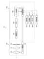
- FIG. 1is a diagram showing the configuration of an imaging apparatus according to the first embodiment.
- FIG. 2is a diagram showing the configuration of the image processing unit.
- FIG. 3is a diagram showing an example of a pixel arrangement in an image sensor.
- FIG. 4is a diagram showing an example of the configuration of each pixel.
- FIG. 5is a diagram showing an example in which phase difference pixels are arranged two-dimensionally.
- FIG. 6is a diagram showing an example in which all pixels of the image sensor are phase difference pixels.
- FIG. 7is a diagram showing the relationship between the amount of phase difference and the focus deviation.
- FIG. 8is a diagram showing the state of focus control based on a phase difference image.
- FIG. 9is a diagram showing the effect of defocus on a color image and a phase difference pixel.
- FIG. 9is a diagram showing the effect of defocus on a color image and a phase difference pixel.
- FIG. 10is a diagram conceptually showing how a phase difference map is generated.
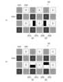
- FIG. 11is a diagram showing an example of a phase difference image before pre-processing.
- FIG. 12is a diagram showing an example of a phase contrast image after preprocessing.
- FIG. 13is a diagram illustrating an example of a layer configuration of a convolutional neural network (CNN).
- FIG. 14is a diagram showing the state of convolution by a filter.
- FIG. 15is a diagram showing how the phase difference is calculated from the preprocessed phase difference image.
- FIG. 16is a diagram showing an example of a phase difference map for a single subject (point light source).
- FIG. 17is a diagram showing the configuration of an image processing unit in an imaging device according to the second embodiment.
- FIG. 18is a diagram showing how distance image data is generated from a phase difference map in the second embodiment.
- FIG. 19is a diagram showing the state of post-processing in the second embodiment.
- FIG. 20is a
- distance estimation and phase difference map generation using monocular phase difference imagesIn recent years, distance estimation technology has evolved in various fields. In such distance estimation, normal distance estimation using a monocular optical system (single optical system) is a simple distance measurement method because it can acquire a distance image from one image, but since it is not a physical distance measurement, it estimates depth even with a flat image. In addition, distance estimation using a compound eye optical system generally uses two cameras to capture images, and distance estimation can be performed with high accuracy using the parallax of each image, but it is not a simple distance measurement method because it requires accurate calibration of the relationship between the positions and imaging directions of the two cameras.
- distance estimation using multiple images captured by moving a monocular optical systemrequires accurate calibration of the relationship between the positions and imaging directions of the cameras as in the case of a compound eye optical system, and since it is not possible to capture the necessary images simultaneously, there are situations in which distance estimation is difficult, such as when the subject is moving.
- phase difference map generating device and phase difference map generating methodimage data acquisition device, focus control method, learning method, and phase difference map generator according to the present invention are described below.
- Imaging device 10is a diagram showing the configuration of an imaging device 10 (imaging device, image data acquisition device) according to the first embodiment.
- the imaging device 10is composed of an interchangeable lens 100 (single optical system, monocular optical system, image data acquisition section) and an imaging device body 200 (image data acquisition section), and forms a subject image (optical image) on an imaging element 202 using a photographing lens including a zoom lens 102 (described later).
- the interchangeable lens 100 and the imaging device body 200can be attached and detached via a mount (not shown).
- the interchangeable lens 100includes a zoom lens 102, a focus lens 104, an aperture 106, and a lens driver 110.
- the lens driver 110drives the zoom lens 102 and the focus lens 104 forward and backward in response to a command from an image processor 210 (optical system driver 230 in FIG. 2) to perform zoom (optical zoom) adjustment and focus adjustment.
- the zoom adjustment and focus adjustmentmay be performed in response to a command from the image processor 210, or in response to a zoom operation and a focus operation (rotation of a zoom ring and a focus ring, not shown, etc.) performed by a user.
- the lens driver 110also controls the aperture 106 in response to a command from the image processor 210 to adjust the exposure. Meanwhile, information such as the positions of the zoom lens 102 and the focus lens 104 and the aperture of the aperture 106 is input to the image processor 210.
- the interchangeable lens 100has an optical axis L.
- the imaging device body 200includes an imaging element 202 (imaging element), an AFE (AFE: Analog Front End) 204, an A/D converter 206 (A/D: Analog to Digital, imaging unit), an image processing unit 210, an operation unit 260, a recording unit 270, and a monitor 280.
- the imaging device body 200may include a shutter (not shown) for blocking light incident on the imaging element 202. When a shutter is included, it is preferable that the shutter speed is variable.
- the image sensor 202has a light receiving surface on which a large number of light receiving elements are arranged in a two-dimensional matrix.
- the light receiving surface of the image sensor 202is provided with color pixels and phase difference pixels, and it is possible to obtain a color image and a phase difference image (phase difference image data) of the subject. Then, the subject light that has passed through the zoom lens 102, the focus lens 104, and the aperture 106 is focused on the light receiving surface of the image sensor 202 and converted into an electrical signal by each light receiving element.
- CMOSComplementary Metal-Oxide Semiconductor
- CCDCharge-Coupled Device
- the AFE 204performs noise removal and amplification of the analog image signal output from the image sensor 202, and the A/D converter 206 converts the captured analog image signal into a digital image signal with a range of gradations.
- the image processing unit 210includes a processor 220, a ROM 240 (Read Only Memory), and a RAM 250 (Random Access Memory).
- the processor 220includes an image acquisition unit 222, a preprocessing unit 224, a learning control unit 226, a phase difference map generator 228, an optical system driving unit 230, an output control unit 234, and an external input/output unit 236. Details of the processing by these functions will be described later.
- the processor 220is composed of various processors and electrical circuits, such as a CPU (Central Processing Unit), a GPU (Graphics Processing Unit), an FPGA (Field Programmable Gate Array), and a PLD (Programmable Logic Device).
- processors and electrical circuitsexecute software (programs)
- the code readable by the computere.g., the various processors and electrical circuits that constitute the processor, and/or a combination thereof
- the softwarereferences the software.
- the software stored in the non-transient and tangible recording mediumincludes various programs according to the present invention (programs that cause a computer to execute the phase difference map generating method, focus control method, and learning method according to the present invention) and data used in executing them.
- the codemay be recorded in a non-transient and tangible recording medium such as a flash ROM or an EEPROM (Electronically Erasable and Programmable Read Only Memory). Note that this "non-transient and tangible recording medium" does not include non-tangible recording media such as carrier signals or propagation signals themselves.
- RAM 250is used as a temporary storage area or working area.
- the operation unit 260has a release button, operation buttons, dials, switches, etc. (not shown), and allows a user to perform various operations such as obtaining a color image and a phase difference image (phase difference image data), learning a phase difference map generator, generating a phase difference map and a distance image, and outputting the results.
- the monitor 280may be configured as a touch panel type device, and this device may be used as the operation unit 260.
- the operation unit 260may also include a microphone and a speaker (not shown).
- the monitor 280(display device) is composed of a touch panel type liquid crystal display panel, and can display normal moving images, still images, phase difference image data, corrected image data, phase difference maps, distance image data, etc.
- the monitor 280can be placed on the back side, top side, etc. of the imaging device main body 200.
- the recording unit 270(recording unit) is composed of non-transient and tangible recording media such as various types of magneto-optical recording media, semiconductor memories, etc., and their control circuits, and records phase difference image data, correction image data, phase difference maps, distance image data, etc.
- Data acquired from the external device 300may be recorded in the recording unit 270.
- the data recorded in the recording unit 270can be displayed on the monitor 280 or output to the external device 300 in response to a user's instruction via the operation unit 260, or automatically without a user's instruction.
- the recording medium used in the recording unit 270may be of a type that can be attached to and detached from the imaging device main body 200, such as various memory cards.
- An external device 300can be connected to the imaging device 10 to input and output information. The connection may be made by wired or short-distance wireless communication, or via a network.
- Various display devices and recording devicescan be used as the external device 300, and an imaging device other than the imaging device 10 may be used as the external device 300.
- a vehicle, a moving object, or the likemay be used as the external device 300, and data output from the imaging device 10 (normal moving images, still images, phase difference maps, and distance image data) may be used to control the devices of the vehicle, the moving object, or the like (for example, focusing control, securing a distance between vehicles, course control, collision prevention, and avoidance of dangerous objects).
- FIG. 3is a diagram showing an example of pixel arrangement in the image sensor 202 (a state in which the light receiving surface of the image sensor 202 is viewed from the subject side), and FIG. 4 is a diagram showing an example of the configuration of each pixel.
- the image sensor 202includes phase difference pixels and color pixels.
- the image sensor 202includes color pixels 202R, 202G, and 202B (color pixels), and color filters (optical filters) that transmit red, green, and blue light are arranged in these color pixels, respectively. These color filters constitute "a plurality of optical filters that transmit light of at least a part of different wavelength bands.” Note that the pixel arrangement in FIG.
- the image processing unit 210can generate a color image (RGB image) using signals output from these color pixels.
- color pixels 202R, 202G, and 202Bmay be referred to as "R pixel, G pixel, and B pixel,” respectively.
- microlensesare provided in the color pixels and phase difference pixels (not shown in FIG. 3, see FIG. 4).
- the image sensor 202includes phase difference pixels 201 and 203 (phase difference pixels).
- the phase difference pixel 201has an opening 201A on the right side (left side in the figure) of the pixel to function as a light receiving unit, and the left side of the pixel (right side in the figure; one side of the light receiving unit) is shielded by a mask 201B.
- the phase difference pixel 203has an opening 203A on the left side (right side in the figure) of the pixel to function as a light receiving unit, and the right side of the pixel (left side in the figure; the other side of the light receiving unit) is shielded by a mask 203B.
- the image acquisition unit 222(processor) can acquire image data generated from a signal output by the phase difference pixel 201 as first phase difference image data, and acquire image data generated from a signal output by the phase difference pixel 203 as second phase difference image data.
- phase difference pixel 201has an opening 201D on the upper side (upper side in the figure) of the pixel to function as a light receiving unit, and the lower side of the pixel (lower side in the figure; one side of the light receiving unit) is shielded by a mask 201C.
- the phase difference pixel 203has an opening 203D on the lower side (lower side in the figure) of the pixel to function as a light receiving unit, and the upper side of the pixel (upper side in the figure; the other side of the light receiving unit) is shielded by a mask 203C.
- the image acquisition unit 222(processor) can acquire image data generated from the signal output by the phase difference pixel 201 as first phase difference image data, and acquire image data generated from the signal output by the phase difference pixel 203 as second phase difference image data.
- phase difference pixelsare arranged at the positions of the G pixels, but the phase difference pixels may be arranged at the positions of the R pixels or the B pixels. Also, in the example of FIG. 3, no color filters are arranged at the phase difference pixels, but color filters may be arranged at the phase difference pixels.
- FIG. 4is a diagram showing the configuration of a color pixel and a phase difference pixel.
- a color pixelincludes a microlens ML and a photodiode PD (color filters are not shown).
- a phase difference pixelincludes a microlens ML, a photodiode PD, and a mask 202A.
- the position of the mask 202Acan be left/right or up/down.
- the position, shape, and size of the mask 202Acan be set according to the position, shape, and size of the pupil to be directed.
- FIG. 5is a diagram showing an example of a two-dimensional arrangement of phase difference pixels.
- the phase difference pixels 202X divided into left and right parts as shown in part (a) of FIG. 3 and the phase difference pixels 202Y divided into top and bottom parts as shown in part (b) of FIG. 3are arranged in orthogonal directions, and the phase difference pixels are arranged two-dimensionally as a whole.
- FIG. 5shows one row of the phase difference pixels 202X and one row of the phase difference pixels 202Y, in order to generate a highly accurate phase difference map, it is preferable to arrange the phase difference pixels in the vertical and horizontal directions over the entire surface of the image sensor 202. If it is not necessary to obtain a color image, all the pixels of the image sensor 202 may be phase difference pixels.
- the signal at that positioncan be found by an interpolation calculation using the signals of the surrounding pixels.
- FIG. 6is a diagram showing an example in which all pixels of the image sensor 202 are phase difference pixels.
- the light receiving portion (photodiode PD in FIG. 4) of the phase difference pixel 207is divided in the left-right direction to form phase difference pixels 207-1 and phase difference pixels 207-2.
- a phase difference imagephase difference image data
- a normal imagecan be generated by adding the signals of the phase difference pixels 207-1 and 207-2.
- phase difference pixels 207-1 and 207-2since color filters are arranged on the phase difference pixels 207-1 and 207-2, a color image can be generated whether the pixel is divided and used as a phase difference pixel or used as one pixel.
- FIG. 6shows an example in which the phase difference pixel is divided in the left-right direction, but the phase difference pixel may be divided in the up-down direction as described above with respect to FIG. 3. Then, by two-dimensionally arranging the pixels divided in the left-right direction and the pixels divided in the up-down direction, a highly accurate phase difference map can be generated.
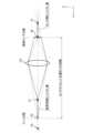
- FIG. 7is a conceptual diagram showing the relationship between the amount of phase difference and the defocus.
- FIG. 7is a diagram showing the state in which the optical system of the interchangeable lens 100 is viewed from a direction perpendicular to the optical axis L, and the lens 101 virtually shows a lens included in the optical system. In this state, assuming that light from a subject (point light source) present at point P0 is imaged at point S0 (the position where the imaging surface of the imaging sensor is present), light from a subject present at point P1 on the -Z side of point S0 is imaged at point S1 on the -Z side of point S0.
- point S0the position where the imaging surface of the imaging sensor is present
- the light flux from point P1has a spread (shift) in the ⁇ X direction on the imaging surface.
- the amount of shift in the ⁇ X directioncorresponds to the amount of phase difference
- the direction of the shiftcorresponds to the direction of the phase shift.
- the amount of phase difference and the direction of the phase shiftare mapped as a phase difference map.
- light from a subject present at point P2 on the +Z side of point P0forms an image on the +Z side of point S0, and the direction of phase shift is opposite to that of the subject present at point P1 (see the description of FIG. 8).
- the focus shift in the ⁇ Z directioncorresponds to distance information, and can be mapped as distance image data, as described later in the second embodiment.
- FIG. 8is a diagram showing the state of focus control (focusing) based on a phase difference image (light shielding mask is omitted). Parts (a) to (c) of FIG. 8 respectively show the so-called “back focus” (a state where the focal point is behind the light receiving surface), “just focus” (a state where the focal point is focused on the target position and is on the light receiving surface), and “front focus” (a state where the focal point is in front of the light receiving surface). Note that “just” in “just focus” is an abbreviation of "just” and “pin” is an abbreviation of "pint”, and "just focus” can be expressed in English as “just-focused” or "in perfect focus”. As shown in FIG.
- the driving direction of the focus lens 104is determined based on the direction of the phase shift described above with reference to Figures 7 and 8, and the focus lens 104 is driven so that the amount of phase shift becomes zero, thereby enabling focusing on the target subject.
- FIG. 9is a diagram showing the effect of focus deviation in a color image and a phase difference image.
- the subjectis a point light source located at the center of the angle of view.
- Parts (a) to (c) of FIG. 9respectively show a color image, a phase difference image 1 (for example, a left viewpoint image), and a phase difference image 2 (for example, a right viewpoint image).
- the image on the right side of the figureis the above-mentioned "back focus”
- the image on the left side of the figureis the "front focus”
- the image in the center of the figureis the "jaspin”.
- the blur of the subject imageincreases.
- the direction of deviation in the phase difference images 1 and 2is opposite, and the direction of deviation is also opposite between the "front focus” and the “back focus”.
- the blur of the subject image in the phase difference imagebecomes zero, and the two subject images overlap.
- [Generation of Phase Difference Map by Phase Difference Map Generator] 10is a diagram conceptually illustrating the generation of a phase difference map.
- the image acquisition unit 222acquires the phase difference images 1 and 2 (first phase difference image data, second phase difference image data) via the interchangeable lens 100, the image sensor 202, etc.
- the preprocessing unit 224performs preprocessing on the first phase difference image data and the second phase difference image data to acquire the first corrected image data and the second corrected image data.
- the phase difference map generator 228(processor) generates a phase difference map that maps the phase difference amount and the phase shift direction between the first phase difference image data and the second phase difference image data from the first corrected image data and the second corrected image data obtained by the preprocessing.
- a monocular phase difference optical systemcan generate a phase difference map and perform simple and highly accurate distance measurement.
- the phase difference imageis affected by the characteristics of the optical system and the imaging sensor (imaging element) used for shooting, and it is difficult to estimate the distance directly from the parallax image.
- the imaging sensorimaging element
- the optical system and imaging conditionschange over a wide range, it is possible that the conditions at the time of learning differ from the actual conditions, and in such a case, highly accurate distance measurement is difficult. Therefore, by performing preprocessing according to the characteristics of the optical system and the imaging sensor at the time of shooting, it is possible to estimate the distance with high accuracy regardless of the optical system and shooting conditions.
- pre-processingis a process based on the characteristics of the process for generating a phase difference map, and as described below, can include a process for absorbing the difference between the acquisition conditions of the learning phase difference image data and the acquisition conditions of the actual phase difference image data, and a process for reducing the difference between the image quality of the first phase difference image data and the image quality of the second phase difference image data. It is preferable to perform at least one of these processes.
- FIG. 11 and 12are conceptual diagrams for explaining pre-processing. Specifically, FIG. 11 shows phase difference images 900 and 902 (first and second phase difference image data; left phase difference image and right phase difference image) before pre-processing, and FIG. 12 shows phase difference images 900A and 902A (first and second corrected image data) after pre-processing.
- phase difference image dataactual image data used for generating a phase difference map
- the brightness distributionis not uniform in the phase difference images 900 and 902 before pre-processing.
- the difference in brightness within the phase-contrast images and between the phase-contrast imagesis small, resulting in a large difference between the training images and the images that will actually be used. For this reason, it is preferable to make the brightness uniform in pre-processing and absorb the effects of differences between the images used during training and the actual images.
- This preprocessingmakes it easier to detect corresponding points between images, and allows for the generation of a phase difference map and distance image data based on the phase difference map with high accuracy.
- the processingis preferably performed on at least one of resolution, noise, gradation, and image structure.
- gradationmay include brightness and contrast
- image structuremay include contrast, sharpness, distortion, and shading.
- the image acquisition unit 222 and the preprocessing unit 224preferably acquire data acquisition conditions for the first phase difference image data and the second phase difference image data, and perform preprocessing according to the data acquisition conditions.
- the aperture value (F-number)can be acquired as the data acquisition condition, and the size of the phase difference image (first and second corrected image data) input to the phase difference map generator 228 can be enlarged according to the aperture value.
- the phase difference map generator 228reduces the phase difference amount according to the enlargement rate of the image size when generating the final phase difference map.
- the preprocessing unit 224may perform different preprocessing on the first phase-contrast image data and the second phase-contrast image data. Specifically, the preprocessing unit 224 may perform processing on these phase-contrast image data that differs in at least one of content and degree. Such preprocessing makes it possible to generate a phase-contrast map with high accuracy, taking into account differences in image quality of the phase-contrast images caused by the characteristics of the optical system (various aberrations, etc.). Note that the preprocessing unit 224 may determine the content and degree of the preprocessing in response to a user operation via the operation unit 260, or may automatically determine the content and degree of the preprocessing independent of a user operation.
- the phase difference map generator 228is a phase difference map generator constructed by a machine learning algorithm.
- the phase difference map generator 228can be constructed by providing a neural network with the first and second phase difference image data and distance information (ground truth data) corresponding to these phase difference images as learning data and having the neural network learn the data.
- Examples of such neural networksinclude a convolutional neural network (CNN), a deep neural network (DNN), a recurrent neural network (RNN), and an autoencoder.
- FIG. 13is a diagram showing an example of a layer configuration of a convolutional neural network (CNN).
- the CNN 562includes an input layer 562A, an intermediate layer 562B, and an output layer 562C.
- the input layer 562Ainputs the preprocessed phase difference image (first corrected image data, second corrected image data) and outputs features.
- the intermediate layer 562Bincludes a convolution layer 564 and a pooling layer 565, and inputs the features output by the input layer 562A to calculate other features.
- These layershave a structure in which multiple "nodes" are connected by "edges", and hold multiple weight parameters. The values of the weight parameters change as learning progresses.
- the CNN 562may include a fully connected layer 566 as in the example shown in part (b) of FIG. 13.
- the layer configuration of the CNN 562is not limited to the case where the convolutional layer 564 and the pooling layer 565 are repeated one by one, but may include any layer (for example, the convolutional layer 564) in a series of multiple layers. Also, the fully connected layer 566 may be included in a series of multiple layers.
- the intermediate layer 562Bcalculates features by convolution and pooling.
- the convolution performed in the convolution layer 564is a process of acquiring a feature map by convolution using a filter, and plays a role in extracting features such as edge extraction from an image.
- the convolution using this filtergenerates a "feature map" of one channel (one sheet) for one filter.
- the size of the "feature map”is downscaled by convolution, and becomes smaller as convolution is performed in each layer.
- the pooling process performed in the pooling layer 565is a process of reducing (or enlarging) the feature map output by the convolution to create a new feature map, and plays a role in providing robustness so that the extracted features are not affected by translation or the like.
- the intermediate layer 562Bcan be composed of one or more layers that perform these processes.
- FIG. 14is a diagram showing the state of convolution by a filter in the intermediate layer 562B.
- a convolution operationis performed between an image set (a learning image set during learning, and a measurement image set when performing distance measurement) consisting of a plurality of phase difference images and a filter F 1.
- the image setis composed of images having an image size of, for example, H in height and W in width.
- a two-dimensional filter of, for example, (3 ⁇ 3)can be used as the filter F 1 to be convoluted with this image set.
- a three-dimensional filterof, for example, (3 ⁇ 3 ⁇ 3) can be used.
- a "feature map" of one channel (one sheet)is generated for one filter F 1 .
- the size of the filterdoes not need to be linked to the number of channels in the image, and the number of channels can be determined freely. Also, the number of filters can be determined depending on the number of channels in the next layer.
- the image setWhen inputting two phase difference images generated by the output of phase difference pixels not provided with color filters as in FIG. 3 above, the image set will be two channels (one channel x two; the first and second phase difference images are paired). In this case, one channel each for the left and right may be input and merged midway through the network, or the two channels may be overlapped from the beginning and input.
- the image setWhen inputting color phase difference images based on the output of phase difference pixels provided with color filters, the image set will be composed of 2 x 3 channel images (the first and second phase difference images x 3 (R (red), G (green), B (blue))).
- the second to nth convolutional layersperform convolutional operations using filters F 2 to F n .
- the size of the "feature map" in the nth convolutional layeris smaller than that of the "feature map" in the second convolutional layer because it has been downscaled by the previous convolutional layers or pooling layers.
- low-level feature extraction(edge extraction, etc.) is performed in the convolutional layers closer to the input side, while higher-level feature extraction (extraction of features related to the shape, structure, etc. of the object; in other words, extraction of feature points and detection of corresponding points) is performed closer to the output side.
- upscalingis performed in the latter convolutional layers, and the final convolutional layer obtains a "feature map" of the same size as the input image set.
- upscalingis not essential since it is sufficient to output positional information.
- the intermediate layer 562Bmay include a layer that performs batch normalization in addition to the convolution layer 564 and the pooling layer 565.
- the batch normalization processnormalizes the distribution of data in units of mini-batches when learning, and plays a role in "speeding up learning,” “reducing dependency on initial values,” “suppressing overlearning,” etc.
- the output layer 562Cis a layer that calculates the phase difference amount and phase shift direction of corresponding points (corresponding feature points between phase difference images) in the phase difference image (corrected image) input to the CNN 562 based on the feature map output from the intermediate layer 562B, and outputs the result.
- a phase difference mapcan be generated by mapping the phase difference amount and phase shift direction for a large number of corresponding points.
- a cost feature volumeis constructed by linking or correlating while moving one of the left and right feature maps relative to the other, and this cost feature volume is converted into a cost volume by a three-dimensional convolution operation, and then a phase difference map can be generated by a soft-argmin operation or the like.
- the learning control unit 226can construct a phase difference map generator 228 (phase difference map generator) by providing phase difference images (a pair of first and second phase difference images) and distance information (distance image data) as ground truth data as learning data to a neural network such as the CNN 562. That is, the phase difference map generator 228 is a trained model constructed by the learning method according to the present invention.
- the processor 220does not need to have a learning control unit 226.
- phase difference image data acquisition conditionsWhen acquiring phase difference image data for learning, it is preferable to align the acquisition conditions for the first and second phase difference image data. Specifically, it is preferable to acquire the first and second phase difference images under at least one data acquisition condition that is the same, and construct the phase difference map generator 228 by learning using these phase difference image data.
- This "data acquisition condition"corresponds to the imaging condition in normal imaging, and specifically, it is preferable that at least one of the focal length of the optical system, the aperture value of the optical system, the shutter speed, and the focal distance is the same. Since the imaging device 10 according to the first embodiment can acquire phase difference images using a single optical system and an imaging element having phase difference pixels, it is easy to align these data acquisition conditions between phase difference images.
- phase difference map and distance informationif there is a difference in the data acquisition conditions when acquiring the first and second phase difference image data, or if there is a difference between the "data acquisition conditions when acquiring image data for learning" and the "data acquisition conditions when acquiring image data to be used for actual measurement", the effects of these differences can be absorbed by the pre-processing described above.
- the left and right phase difference imagesthey may be used for learning with the difference, or they may be used for learning after eliminating the difference in brightness by performing pre-processing to change the state of FIG. 11 to the state of FIG. 12.
- phase difference images for learningmay be acquired using a device other than a "device equipped with a single optical system and phase difference pixels" (for example, an imaging device equipped with a compound eye optical system or multiple imaging devices).
- a device other than a "device equipped with a single optical system and phase difference pixels"for example, an imaging device equipped with a compound eye optical system or multiple imaging devices.
- it is not necessary to use phase difference images for learningand normal images may be used as long as the difference between left and right viewpoint images can be learned.
- phase difference image dataWhen acquiring phase difference image data for learning, the same subject is imaged while changing the shooting distance under a determined data acquisition condition (imaging condition).
- the focal position (focus distance)can be fixed.
- the acquisition conditions (number of "determined data acquisition conditions") of the phase difference image data used for learningmay be one or more sets, and it is possible to generate highly accurate phase difference map and distance image data by learning using a large number of image data acquired under a plurality of sets of conditions (for example, conditions with different focal length, aperture, focal length, etc.).
- the phase difference map generating devicemay include "multiple phase difference map generators with different data acquisition conditions assumed during learning", and the processor may switch between the multiple phase difference map generators depending on the data acquisition conditions when actually acquiring the phase difference image data.
- the learning costtime required for preparation of learning data and learning, etc.
- the effects of differences between the data acquisition conditions during learning and the data acquisition conditions during actual measurementare absorbed by pre-processing, so high-precision measurements are possible even with only one or a small number of sets of data acquisition conditions.
- the distance information(distance image data; corresponding to the distance from the imaging device to the subject) as the correct answer data can be the result of actual measurement using Lidar (Light Detection and Ranging, or Laser Imaging Detection and Ranging).
- LiDARis a technology that measures the distance to an object and the shape of the object from the result of irradiating the object with laser light and receiving the reflected light, and may be a TOF method (TOF: Time of Flight) using a pulsed laser light or a FMCW method (FMCW: Frequency-Modulated Continuous Wave) using a continuous wave laser light.
- the imaging device 10 according to the first embodimentcan generate a phase difference map using the method described above.
- phase difference map generatoris not limited to the aspect of using two phase difference images, and three or more phase difference images may be used. For example, as described above with reference to FIG.
- phase difference imagesare generated from the output of phase difference pixels divided in the left-right direction and the up-down direction, and the four phase difference images are input to a neural network to learn, thereby constructing a "phase difference map generator that generates a phase difference map from four phase difference images.”
- the image setis four channels (when no color filter is provided in the phase difference pixels).
- FIG. 15is a diagram showing how the phase difference is calculated from the preprocessed phase difference image.
- a corresponding point CP1first feature point, corresponding point
- a corresponding point CP2second feature point, corresponding point
- These corresponding pointsare feature points of the subject in FIG. 15, and are corresponding points between the phase difference image 900A and the phase difference image 902A, and indicate the same position of the same object in real space.
- phase difference map generator 228(processor) generates a phase difference map by mapping and outputting the phase difference amount (corresponding to the distance D1 in the example of FIG. 15) and the phase shift direction (left and right direction in FIG. 15) for a large number of corresponding points (including the corresponding points CP1 and CP2).
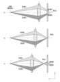
- Fig. 16shows an example of a phase difference map (map perpendicular to the optical axis) for a single subject (point light source).
- the diagram on the leftshows a "front focus” state
- the diagram in the middleshows a "just focus” state
- the diagram on the rightshows a "back focus” state.
- the size of the subject image spreadindicates the amount of phase difference
- the darkness of the subject imageindicates the direction of the phase difference (lighter colors correspond to a "front focus” state, and darker colors correspond to a "back focus” state). Since a real subject can be thought of as a collection of multiple point light sources with different distances and brightness, an actual phase difference map will be multiple maps like those in Fig. 16 superimposed on top of each other.
- FIG. 16shows an example of a two-dimensional display of the phase difference map
- the processor 220can display the phase difference map three-dimensionally. For example, when the phase difference is negative (in FIG. 16, the blur is close to white), it is displayed at a point below the horizontal plane, and when the phase difference is positive (in FIG. 16, the blur is close to dark color), it is displayed at a point above the horizontal plane, thereby forming a three-dimensional surface as the entire field.
- the processor 220Amay simultaneously perform two-dimensional display and three-dimensional display of the phase difference map, or may switch between them.
- FIG. 16shows the direction of the phase difference in shades of a single color (black and white), multiple colors (for example, purple on the front side and red on the back side) may be assigned to the direction of the phase difference for display.
- the generated phase difference mapcan be recorded, displayed, output externally, etc. by the output control unit 234 and the external input/output unit 236 (processor).
- Second EmbodimentA second embodiment of the present invention will be described.
- the configuration and processing related to the generation of the phase difference mapare the same as those in the first embodiment, so the same reference numerals are used for the configurations similar to those in the first embodiment, and detailed descriptions are omitted.
- the second embodimentdiffers from the first embodiment in that distance image data is generated from the phase difference map by post-processing.
- FIG. 17is a diagram showing the configuration of an image processing unit 210A (processor) in an imaging device according to the second embodiment.
- the image processing unit 210Adiffers from the image processing unit 210 according to the first embodiment in that the processor 220A includes a post-processing unit 232.
- FIG. 18is a diagram showing how distance image data is generated from a phase difference map in the second embodiment.
- the processing up to the generation of the phase difference mapis the same as in the first embodiment.
- the post-processing unit 232(processor) converts the phase difference amount of the phase difference map into distance information in the optical axis direction, thereby generating distance image data composed of distance information.
- FIG. 19is a diagram showing the state of post-processing in the second embodiment (the state of calculating distance information from the phase difference amount).
- the post-processing unit 232converts the phase difference amount into a "defocus amount (imaging side)" using data acquisition conditions such as light angle information of the first and second phase difference image data. This defocus amount is the defocus amount as distance information.
- the post-processing unit 232can perform post-processing by taking into consideration at least one of the following data acquisition conditions: ray angle information of the first and second phase difference image data, position information of the focus lens 104 (focus lens) of the optical system (interchangeable lens 100 in the second embodiment) used to acquire the first and second phase difference image data, and optical characteristics of the interchangeable lens 100 (optical system).
- the post-processing unit 232may determine which condition to consider for post-processing in response to a user instruction via the operation unit 260, or may determine the condition regardless of the user instruction.
- the post-processing unit 232may take into consideration the characteristics of the subject when determining the data acquisition conditions to be considered in post-processing.
- this defocus amountcorresponds to a shift of X times the depth of field on the object side.
- This shift on the object sideis the "defocus amount (object side)” in part (a) of FIG. 19, and is the defocus amount as distance information.
- the post-processing unit 232can add the above-mentioned "defocus amount (object side)” to this distance to calculate the distance to the object (subject distance as distance information obtained by converting the defocus amount). Note that it is preferable that the post-processing unit 232 take into account the optical aberration of the interchangeable lens 100 (optical system) when converting the defocus amount between the imaging side and the object side.
- the post-processing unit 232can generate at least one of a "defocus map that maps the defocus amount” and a "distance map that maps the subject distance” as distance image data. Which one to generate may be determined according to a user instruction via the operation unit 260, or may be determined independently of the user's instruction.
- the output control unit 234 and the external input/output unit 236can record, display, externally output, etc., the generated distance image data.
- FIG. 20is a diagram showing an example of distance image data (map of the optical axis direction) generated by the above-mentioned method (subject is a point light source).
- the size of the blurcorresponds to the distance between the focus position and the object, and the intensity of the blur corresponds to the deviation from the focus position (light blur corresponds to "fore-focus” and dark blur corresponds to "back-focus”).
- the example in FIG. 20is the above-mentioned "defocus map that maps the amount of defocus as one form of distance image data.”
- the processor 220Acan display the defocus map and/or the distance map in three dimensions. For example, when the distance is closer to the focus position (the side closer to the imaging device 10; in FIG. 20, the blur is closer to white), the distance is displayed as a point below the horizontal plane, and when the distance is farther from the focus position (the side farther from the imaging device 10; in FIG. 20, the blur is closer to dark colors), the distance is displayed as a point above the horizontal plane, thereby forming a three-dimensional surface as a whole object field.
- the processor 220Amay simultaneously perform two-dimensional and three-dimensional display of the defocus map and/or the distance map, or may switch between them. Also, in FIG. 20, the deviation from the focus position is shown in a single shade of color (black and white), but multiple colors (for example, purple for the near side and red for the far side) according to the direction of deviation may be assigned and displayed.
- the phase difference mapis generated using a machine learning technique, but in the present invention, a technique other than machine learning may be used to generate the phase difference map.
- the phase difference mapcan be generated by repeating corresponding point detection and phase difference calculation by normal image processing.
- Imaging device100 Interchangeable lens 101 Lens 102 Zoom lens 104 Focus lens 110 Lens driving unit 200 Imaging device body 201 Phase difference pixel 201A Opening 201B Mask 201C Mask 201D Opening 202 Imaging element 202A Mask 202B Color pixel 202G Color pixel 202R Color pixel 202X Phase difference pixel 202Y Phase difference pixel 203 Phase difference pixel 203A Opening 203B Mask 203C Mask 203D Opening 206 A/D converter 207 Phase difference pixel 207-1 Phase difference pixel 207-2 Phase difference pixel 210 Image processing unit 210A Image processing unit 220 Processor 220A Processor 222 Image acquisition unit 224 Preprocessing unit 226 Learning control unit 228 Phase difference map generator 230 Optical system driving unit 232 Post-processing unit 234 Output control unit 236 External input/output unit 260 Operation unit 270 Recording unit 280 Monitor 300 External device 562A Input layer 562B Hidden layer 562C Output layer 564 Convolution layer 565 Pooling layer 566 Fully connected layer
Landscapes
- Physics & Mathematics (AREA)
- General Physics & Mathematics (AREA)
- Optics & Photonics (AREA)
- Engineering & Computer Science (AREA)
- Multimedia (AREA)
- Signal Processing (AREA)
- Studio Devices (AREA)
Abstract
Description
Translated fromJapanese本発明は、位相差マップ生成装置及び生成方法、画像データ取得装置、合焦制御方法、学習方法、及び位相差マップ生成器に関し、特に位相差画像データを扱う技術に関する。The present invention relates to a phase difference map generating device and method, an image data acquisition device, a focus control method, a learning method, and a phase difference map generator, and in particular to technology for handling phase difference image data.
画像データを扱う技術に関し、例えば特許文献1には、撮影画像のデフォーカスぼけから距離情報を推定する技術が記載されている。Regarding technology for handling image data, for example,
本開示の技術に係る一つの実施形態は、位相差マップ生成装置及び生成方法、画像データ取得装置、合焦制御方法、学習方法、及び位相差マップ生成器を提供する。One embodiment of the technology disclosed herein provides a phase difference map generating device and method, an image data acquisition device, a focus control method, a learning method, and a phase difference map generator.
本発明の第1の態様に係る位相差マップ生成装置は、プロセッサを備える位相差マップ生成装置であって、プロセッサは、単一の光学系と位相差画素を有する撮像素子とを備える画像データ取得部から少なくとも第1位相差画像データと第2位相差画像データを取得し、第1位相差画像データ及び第2位相差画像データに対し前処理を行って第1補正画像データ及び第2補正画像データを取得し、第1補正画像データ及び第2補正画像データから、第1位相差画像データと第2位相差画像データとの間の位相差量及び位相ずれの方向をマップ化した位相差マップを生成し、前処理は位相差マップを生成する処理の特性に基づいた処理である。The phase difference map generating device according to the first aspect of the present invention is a phase difference map generating device including a processor, the processor acquires at least first phase difference image data and second phase difference image data from an image data acquisition unit including a single optical system and an imaging element having phase difference pixels, performs preprocessing on the first phase difference image data and the second phase difference image data to acquire first corrected image data and second corrected image data, and generates a phase difference map from the first corrected image data and the second corrected image data that maps the amount of phase difference and the direction of phase shift between the first phase difference image data and the second phase difference image data, the preprocessing being processing based on the characteristics of the processing for generating the phase difference map.
第1の態様において、「位相差画像データ」及び「補正画像データ」は2次元に分布するデータであり、通常の画像と同様に取り扱うことができる。なお、これら画像データは画像としての表示や閲覧を目的とするものではないが、必要な加工を施して通常の画像と同様に表示し、ユーザに閲覧させてもよい。また、「単一の光学系」は例えば単眼光学系であり、「画像データ取得部」は通常の光学系と同様に構成することができる。In the first aspect, the "phase difference image data" and the "corrected image data" are data distributed in two dimensions, and can be handled in the same way as normal images. Note that although these image data are not intended to be displayed or viewed as images, they may be processed as necessary and displayed in the same way as normal images, and viewed by the user. Furthermore, the "single optical system" is, for example, a monocular optical system, and the "image data acquisition unit" can be configured in the same way as a normal optical system.
なお第1の態様及び以下の各態様において、3種類以上の位相差画像データを取得し、それら3種類以上の位相差画像データから位相差マップを生成してもよい。In the first aspect and each of the following aspects, three or more types of phase difference image data may be acquired, and a phase difference map may be generated from the three or more types of phase difference image data.
なお、第1の態様に係る位相差マップ生成装置は、外部装置から位相差画像データ等を取得して位相差マップを生成する装置として実現してもよいし、画像データ取得部を備える画像データ取得装置や撮像装置のプロセッサ部分として実現してもよい。The phase difference map generating device according to the first aspect may be realized as a device that acquires phase difference image data, etc. from an external device and generates a phase difference map, or may be realized as a processor part of an image data acquisition device or an imaging device that has an image data acquisition unit.
本発明の第2の態様に係る位相差マップ生成装置は第1の態様において、前処理は、第1位相差画像データの画質と第2位相差画像データの画質との差を低減する処理である。In the phase difference map generating device according to the second aspect of the present invention, in the first aspect, the pre-processing is a process for reducing the difference in image quality between the first phase difference image data and the second phase difference image data.
第3の態様に係る位相差マップ生成装置は第1または第2の態様において、プロセッサは、受光部の一方の側が遮光された位相差画素が出力する信号から生成された画像データを第1位相差画像データとして取得し、受光部の他方の側が遮光された位相差画素が出力する信号から生成された画像データを第2位相差画像データとして取得する。In the phase difference map generating device according to the third aspect, in the first or second aspect, the processor acquires image data generated from a signal output by a phase difference pixel having one side of the light receiving section shielded from light as first phase difference image data, and acquires image data generated from a signal output by a phase difference pixel having the other side of the light receiving section shielded from light as second phase difference image data.
第4の態様に係る位相差マップ生成装置は第1から第3の態様のいずれか1つにおいて、プロセッサは、前処理において、第1位相差画像データ及び第2位相差画像データに対して、それぞれ異なる処理を施す。The phase difference map generating device according to the fourth aspect is any one of the first to third aspects, in which the processor performs different processing on the first phase difference image data and the second phase difference image data in the preprocessing.
第5の態様に係る位相差マップ生成装置は第4の態様において、プロセッサは、前処理において、第1位相差画像データ及び第2位相差画像データに対して、内容と程度とのうち少なくとも一方が異なる処理を施す。In the fourth aspect of the phase difference map generating device according to the fifth aspect, the processor performs pre-processing on the first phase difference image data and the second phase difference image data, the processing having at least one different content and degree.
第6の態様に係る位相差マップ生成装置は第3の態様において、プロセッサは、前処理として、遮光の手法に起因する画像データの画角内不均一性を解消するための処理を施す。In the sixth aspect of the phase difference map generating device, the processor of the third aspect performs pre-processing to eliminate non-uniformity within the angle of view of the image data caused by the shading method.
第7の態様に係る位相差マップ生成装置は第1から第6の態様のいずれか1つにおいて、プロセッサは、第1位相差画像データ及び第2位相差画像データのデータ取得条件を取得し、データ取得条件に応じた前処理を行う。第7の態様及び以下の各態様において、「データ取得条件」は通常の画像を撮像する際の撮像条件に相当する条件である。In the phase difference map generating device according to the seventh aspect, in any one of the first to sixth aspects, the processor acquires data acquisition conditions for the first phase difference image data and the second phase difference image data, and performs pre-processing according to the data acquisition conditions. In the seventh aspect and each of the following aspects, the "data acquisition conditions" are conditions equivalent to the imaging conditions when capturing a normal image.
第8の態様に係る位相差マップ生成装置は第7の態様において、プロセッサは、前処理において、データ取得条件に応じて第1位相差画像データが示す画像のサイズ及び第2位相差画像データが示す画像のサイズを拡大し、拡大した第1位相差画像データ及び第2位相差画像データから第1補正画像データ及び第2補正画像データを生成する。In the seventh aspect of the phase difference map generating device according to the eighth aspect, in pre-processing, the processor enlarges the size of the image indicated by the first phase difference image data and the size of the image indicated by the second phase difference image data according to the data acquisition conditions, and generates the first corrected image data and the second corrected image data from the enlarged first phase difference image data and second phase difference image data.
第9の態様に係る位相差マップ生成装置は第1から第8の態様のいずれか1つにおいて、プロセッサは、解像感、ノイズ、階調、像構造のうち少なくとも1つについて前処理を行う。第9の態様は、前処理の内容を具体的に規定するものである。The phase difference map generating device according to the ninth aspect is any one of the first to eighth aspects, in which the processor performs preprocessing on at least one of the resolution, noise, gradation, and image structure. The ninth aspect specifies the content of the preprocessing in detail.
第10の態様に係る位相差マップ生成装置は第1から第9の態様のいずれか1つにおいて、プロセッサは、第1補正画像データと第2補正画像データとの間の対応点であって、現実空間における同じ物体の同じ位置である対応点を抽出し、対応点についての位相差量及び位相ずれの方向をマップ化して位相差マップを生成する。The phase difference map generating device according to the tenth aspect is any one of the first to ninth aspects, in which the processor extracts corresponding points between the first corrected image data and the second corrected image data, which are at the same position of the same object in real space, and generates a phase difference map by mapping the amount of phase difference and the direction of phase shift for the corresponding points.
第11の態様に係る位相差マップ生成装置は第10の態様において、プロセッサは、第1補正画像データの特徴点である第1特徴点と第2補正画像データの特徴点である第2特徴点とを抽出し、第1特徴点と第2特徴点とから対応点を抽出し、対応点についての位相差量及び位相ずれの方向をマップ化して位相差マップを生成する。In the phase difference map generating device according to the eleventh aspect, in the tenth aspect, the processor extracts a first feature point that is a feature point of the first corrected image data and a second feature point that is a feature point of the second corrected image data, extracts corresponding points from the first feature point and the second feature point, and generates a phase difference map by mapping the amount of phase difference and the direction of phase shift for the corresponding points.
第12の態様に係る位相差マップ生成装置は第1から第11の態様のいずれか1つにおいて、プロセッサは、機械学習により構築された位相差マップ生成器を用いて位相差マップを生成する。The phase difference map generating device according to the twelfth aspect is any one of the first to eleventh aspects, in which the processor generates the phase difference map using a phase difference map generator constructed by machine learning.
第13の態様に係る位相差マップ生成装置は第12の態様において、位相差マップ生成器は、ニューラルネットワークに、第1位相差画像データ及び第2位相差画像データと、第1位相差画像データ及び第2位相差画像データに対応する距離情報とを学習データとして与えて学習させることにより構築された学習済みモデルである。第13の態様において、距離情報は学習の際の正解データであり、距離そのものでもよいし、距離に対応する他の情報でもよい。The phase difference map generating device according to the thirteenth aspect is the twelfth aspect, in which the phase difference map generator is a trained model constructed by providing the first phase difference image data and the second phase difference image data, and distance information corresponding to the first phase difference image data and the second phase difference image data, as training data, to a neural network and allowing the neural network to learn. In the thirteenth aspect, the distance information is correct data during training, and may be the distance itself or other information corresponding to the distance.
第14の態様に係る位相差マップ生成装置は、第13の態様において、位相差マップ生成器は、少なくとも1つのデータ取得条件が同じ状態で取得された第1位相差画像データ及び第2位相差画像データを用いた学習により構築されている。The phase difference map generating device according to the 14th aspect is the 13th aspect, in which the phase difference map generator is constructed by learning using first phase difference image data and second phase difference image data acquired under at least one identical data acquisition condition.
学習において想定するデータ取得条件の数が多くなると位相差マップを高精度に生成することが可能になるが、一方では学習コスト(学習データや正解データの準備、学習時間等)が増加する。このような観点から、第14の態様では、少なくとも1つのデータ取得条件が同じ状態で取得された第1位相差画像データ及び第2位相差画像データを学習に用いることで、学習コストを抑制している。全てのデータ取得条件が同じ状態で取得した第1位相差画像データと第2位相差画像データを学習に用いてもよい。なお、位相差マップの生成精度及び学習コストを考慮して、「データ取得条件をどの程度同じ状態にするか(データ取得条件をどの程度揃えるか)」を決めることが好ましい。Increasing the number of data acquisition conditions assumed in learning makes it possible to generate a phase difference map with high accuracy, but on the other hand, the learning cost (preparation of learning data and correct answer data, learning time, etc.) increases. From this perspective, in the fourteenth aspect, the learning cost is suppressed by using for learning the first phase difference image data and the second phase difference image data acquired under at least one of the same data acquisition conditions. The first phase difference image data and the second phase difference image data acquired under all of the same data acquisition conditions may also be used for learning. Note that it is preferable to determine "to what extent the data acquisition conditions should be made the same (to what extent the data acquisition conditions should be aligned)" taking into consideration the accuracy of generating the phase difference map and the learning cost.
第15の態様に係る位相差マップ生成装置は第14の態様において、第1位相差画像データのデータ取得条件と、第2位相差画像データのデータ取得条件とでは、光学系の焦点距離、光学系の絞り値、シャッタースピード、及び合焦距離のうち少なくとも1つが同じである。The phase difference map generating device according to the fifteenth aspect is the 14th aspect, in which the data acquisition conditions for the first phase difference image data and the data acquisition conditions for the second phase difference image data are the same in at least one of the focal length of the optical system, the aperture value of the optical system, the shutter speed, and the focal distance.
第16の態様に係る位相差マップ生成装置は第1から第15の態様のいずれか1つにおいて、プロセッサは、位相差マップを用いて、第1位相差画像データ及び第2位相差画像データのデータ取得条件に応じた合焦位置を決定する。The phase difference map generating device according to the 16th aspect is any one of the first to 15th aspects, in which the processor uses the phase difference map to determine a focus position according to the data acquisition conditions of the first phase difference image data and the second phase difference image data.
第17の態様に係る位相差マップ生成装置は第16の態様において、プロセッサは、位相差マップに設定された合焦領域における位相差量の分布に基づいて合焦位置を決定する。In the phase difference map generating device according to the seventeenth aspect, in the sixteenth aspect, the processor determines the focus position based on the distribution of the phase difference amount in the focus area set in the phase difference map.
第18の態様に係る位相差マップ生成装置は第1から第17の態様のいずれか1つにおいて、プロセッサは、位相差マップの位相差量を光軸方向の距離情報に変換することにより、距離情報で構成される距離画像データを生成する。第18の態様及び以下の態様において、「距離画像データ」は距離情報が2次元状に分布したデータであり、上述した「位相差画像データ」及び「補正画像データ」と同様に、通常の画像と同様に取り扱うことができる。なお、距離画像データは画像としての表示や閲覧を目的とするものではないが、通常の画像と同様に、あるいは必要な加工を施して表示し、ユーザに閲覧させてもよい。In the phase difference map generating device according to the 18th aspect, in any one of the first to 17th aspects, the processor converts the phase difference amount of the phase difference map into distance information in the optical axis direction, thereby generating distance image data composed of distance information. In the 18th aspect and the following aspects, the "distance image data" is data in which distance information is distributed two-dimensionally, and can be handled in the same way as a normal image, similar to the above-mentioned "phase difference image data" and "corrected image data." Note that although the distance image data is not intended to be displayed or viewed as an image, it may be displayed in the same way as a normal image, or after undergoing necessary processing, and viewed by the user.
第19の態様に係る位相差マップ生成装置は第18の態様において、プロセッサは、距離画像データとして、位相差量を距離情報としてのデフォーカス量に変換したデフォーカスマップと、デフォーカス量を距離情報としての被写体距離に変換した距離マップとのうち少なくとも一方を生成する。In the phase difference map generating device according to the 19th aspect, in the 18th aspect, the processor generates, as distance image data, at least one of a defocus map in which the amount of phase difference is converted into a defocus amount as distance information, and a distance map in which the amount of defocus is converted into a subject distance as distance information.
第20の態様に係る位相差マップ生成装置は第19の態様において、プロセッサは、位相差マップに対して、第1位相差画像データ及び第2位相差画像データのデータ取得条件に応じた後処理を施して距離画像データを生成する。In the 19th aspect of the phase difference map generating device according to the 20th aspect, the processor performs post-processing on the phase difference map according to the data acquisition conditions of the first phase difference image data and the second phase difference image data to generate distance image data.
第21の態様に係る位相差マップ生成装置は第20の態様において、プロセッサは、後処理において、第1位相差画像データ及び第2位相差画像データの光線角度情報と、第1位相差画像データ及び第2位相差画像データの取得に用いられた光学系が有するフォーカスレンズの位置情報と、光学系の光学特性と、のうち少なくとも1つをデータ取得条件として考慮して後処理を施す。In the phase difference map generating device according to the 21st aspect, in the 20th aspect, the processor performs post-processing while taking into consideration at least one of the following as data acquisition conditions: ray angle information of the first phase difference image data and the second phase difference image data, position information of the focus lens of the optical system used to acquire the first phase difference image data and the second phase difference image data, and the optical characteristics of the optical system.
第22の態様に係る画像データ取得装置は、第16または第17の態様に記載の位相差マップ生成装置と、画像データ取得部と、単一の光学系を駆動する駆動部と、を備え、プロセッサは、単一の光学系を駆動部により合焦位置に駆動する合焦制御を行う。The image data acquisition device according to the 22nd aspect includes the phase difference map generating device according to the 16th or 17th aspect, an image data acquisition unit, and a drive unit that drives a single optical system, and the processor performs focus control to drive the single optical system to a focus position using the drive unit.
第23の態様に係る画像データ取得装置は第22の態様において、撮像素子は、少なくとも一部が異なる波長帯域の光を透過させる複数の光学フィルタの内いずれかが配置されたカラー画素を備える。The image data acquisition device according to the 23rd aspect is the 22nd aspect, in which the image sensor is provided with color pixels in which one of a number of optical filters that transmit light of at least a portion of different wavelength bands is arranged.
第24の態様に係る位相差マップ生成方法は、プロセッサを備える位相差マップ生成装置により実行される位相差マップ生成方法であって、プロセッサは、単一の光学系と位相差画素を有する撮像素子とを備える画像データ取得部から少なくとも第1位相差画像データと第2位相差画像データを取得し、第1位相差画像データ及び第2位相差画像データに対し前処理を行って第1補正画像データ及び第2補正画像データを取得し、第1補正画像データ及び第2補正画像データから、第1位相差画像データと第2位相差画像データとの間の位相差量及び位相ずれの方向をマップ化した位相差マップを生成し、前処理は位相差マップを生成する処理の特性に基づいた処理である。The phase difference map generating method according to the 24th aspect is a phase difference map generating method executed by a phase difference map generating device having a processor, in which the processor acquires at least first phase difference image data and second phase difference image data from an image data acquisition unit having a single optical system and an imaging element having phase difference pixels, performs preprocessing on the first phase difference image data and the second phase difference image data to acquire first corrected image data and second corrected image data, and generates a phase difference map from the first corrected image data and the second corrected image data that maps the amount of phase difference and the direction of phase shift between the first phase difference image data and the second phase difference image data, and the preprocessing is processing based on the characteristics of the processing for generating the phase difference map.
なお、第24の態様に係る位相差マップ生成方法は、第2から第21の態様に係る位相差マップ生成装置に対応する構成を備えていてもよい。また、これら態様の位相差マップ生成方法をコンピュータに実行させる位相差マップ生成プログラム、及び斯かる位相差マップ生成プログラムのコンピュータ読み取り可能なコードを記録した非一時的かつ有体の記録媒体も、本発明の態様として挙げることができる。The phase difference map generating method according to the twenty-fourth aspect may have a configuration corresponding to the phase difference map generating device according to the second to twenty-first aspects. In addition, a phase difference map generating program that causes a computer to execute the phase difference map generating method according to these aspects, and a non-transitory, tangible recording medium on which computer-readable code for such a phase difference map generating program is recorded can also be cited as aspects of the present invention.
第25の態様に係る合焦制御方法は、プロセッサと、単一の光学系と位相差画素を有する撮像素子とを備え、被写体の第1位相差画像データ及び第2位相差画像データを取得する画像データ取得部と、画像データ取得部を駆動する駆動部と、を備える画像データ取得装置により実行される合焦制御方法であって、プロセッサは、画像データ取得部により被写体の第1位相差画像データ及び第2位相差画像データを取得し、第1位相差画像データ及び第2位相差画像データに対し前処理を行って第1補正画像データ及び第2補正画像データを取得し、第1補正画像データ及び第2補正画像データから、第1位相差画像データと第2位相差画像データとの間の位相差量及び位相ずれの方向をマップ化した位相差マップを生成し、位相差マップを用いて、第1位相差画像データ及び第2位相差画像データのデータ取得条件に応じた合焦位置を決定し、単一の光学系を駆動部により合焦位置に駆動する合焦制御を行い、前処理は位相差マップを生成する処理の特性に基づいた処理である。The focus control method according to the 25th aspect is a focus control method executed by an image data acquisition device including a processor, an image sensor having a single optical system and phase difference pixels, an image data acquisition unit that acquires first phase difference image data and second phase difference image data of a subject, and a drive unit that drives the image data acquisition unit, in which the processor acquires the first phase difference image data and the second phase difference image data of the subject using the image data acquisition unit, performs preprocessing on the first phase difference image data and the second phase difference image data to acquire first corrected image data and second corrected image data, generates a phase difference map from the first corrected image data and the second corrected image data that maps the amount of phase difference and the direction of phase shift between the first phase difference image data and the second phase difference image data, determines a focus position according to the data acquisition conditions of the first phase difference image data and the second phase difference image data using the phase difference map, and performs focus control by driving the single optical system to the focus position using the drive unit, and the preprocessing is processing based on the characteristics of the processing for generating the phase difference map.
なお、第25の態様に係る合焦制御方法をコンピュータに実行させる合焦制御プログラム、及び斯かる合焦制御プログラムのコンピュータ読み取り可能なコードを記録した非一時的かつ有体の記録媒体も、本発明の態様として挙げることができる。In addition, a focusing control program that causes a computer to execute the focusing control method according to the twenty-fifth aspect, and a non-transitory, tangible recording medium that records computer-readable code of such a focusing control program, can also be cited as aspects of the present invention.
第26の態様に係る学習方法は、ニューラルネットワークに、単一の光学系と位相差画素を有する撮像素子とを備える画像データ取得部により取得した、被写体の第1位相差画像データ及び第2位相差画像データと、第1位相差画像データ及び第2位相差画像データに対応する距離情報とを学習データとして与えて学習させることにより、第1位相差画像データ及び第2位相差画像データを入力すると、第1位相差画像データと第2位相差画像データとの間の位相差量及び位相ずれの方向をマップ化した位相差マップを出力する位相差マップ生成器を構築する。第26の態様に係る学習方法により構築される位相差マップ生成器は、学習済みモデルである。The learning method according to the 26th aspect constructs a phase difference map generator that outputs a phase difference map that maps the amount of phase difference and the direction of phase shift between the first phase difference image data and the second phase difference image data when the first phase difference image data and the second phase difference image data are input by providing the first phase difference image data and the second phase difference image data of a subject acquired by an image data acquisition unit having a single optical system and an imaging element having phase difference pixels as learning data and training the neural network. The phase difference map generator constructed by the learning method according to the 26th aspect is a trained model.
第27の態様に係る学習方法は第26の態様において、距離情報として、第1位相差画像データ及び第2位相差画像データを取得する画像データ取得装置から被写体までの距離を実測した結果に基づく情報を与える。第27の態様において与える情報は、距離そのものでもよいし、距離に対応する他の情報でもよい。In the learning method according to the 27th aspect, in the 26th aspect, information based on the result of actually measuring the distance from the image data acquisition device that acquires the first phase difference image data and the second phase difference image data to the subject is provided as distance information. In the 27th aspect, the information provided may be the distance itself, or other information corresponding to the distance.
第28の態様に係る位相差マップ生成器は、第26または第27の態様に記載の学習方法により構築された位相差マップ生成器である。第28の態様に係る位相差マップ生成器は、学習済みモデルである。The phase difference map generator of the 28th aspect is a phase difference map generator constructed by the learning method described in the 26th or 27th aspect. The phase difference map generator of the 28th aspect is a trained model.
[単眼位相差画像を用いた距離推定及び位相差マップの生成]
近年、様々な分野で距離推定技術が進化してきた。このような距離推定において、単眼光学系(単一の光学系)による通常の距離推定は1枚の画像から距離画像を取得することが出来るため簡便な測距手段ではあるが、物理的な測距ではないため平面の画像でも奥行きを推定してしまう。また複眼光学系による距離推定は、一般に2つのカメラを用いて撮影し、それぞれの画像の視差により、高精度に距離推定が可能だが、2つのカメラの位置や撮像方向の関係を正確にキャリブレーションする必要があり、簡便な測距手段ではない。また単眼光学系を移動させて撮像した複数の画像を用いる距離推定では、複眼光学系の場合と同様にカメラの位置や撮像方向の関係を正確にキャリブレーションする必要があるのに加えて、必要な画像を同時に撮像することができないため、被写体が移動している場合等、距離推定が困難な状況が存在する。[Distance estimation and phase difference map generation using monocular phase difference images]
In recent years, distance estimation technology has evolved in various fields. In such distance estimation, normal distance estimation using a monocular optical system (single optical system) is a simple distance measurement method because it can acquire a distance image from one image, but since it is not a physical distance measurement, it estimates depth even with a flat image. In addition, distance estimation using a compound eye optical system generally uses two cameras to capture images, and distance estimation can be performed with high accuracy using the parallax of each image, but it is not a simple distance measurement method because it requires accurate calibration of the relationship between the positions and imaging directions of the two cameras. In addition, distance estimation using multiple images captured by moving a monocular optical system requires accurate calibration of the relationship between the positions and imaging directions of the cameras as in the case of a compound eye optical system, and since it is not possible to capture the necessary images simultaneously, there are situations in which distance estimation is difficult, such as when the subject is moving.
本願発明者は斯かる事情に鑑みて鋭意検討を進め、「単眼光学系で取得した位相差画像を用いることで、単眼光学系でありながら瞳分割により複眼光学系のように視差(位相差)による距離推定が可能となり、簡便かつ高精度な測距が可能となる」及び「距離推定の過程で位相差画像から位相差マップを生成し、撮像装置の制御等に利用することができる」との知見を得た。本発明は斯かる知見に基づき創作されたものであり、以下、本発明に係る位相差マップ生成装置及び位相差マップ生成方法、画像データ取得装置、合焦制御方法、学習方法、及び位相差マップ生成器の具体的態様を説明する。The inventors of the present application have conducted intensive research in light of these circumstances, and have discovered that "using a phase difference image acquired with a monocular optical system makes it possible to estimate distance using parallax (phase difference) like a compound eye optical system by dividing the pupil, even though the optical system is monocular, and thus enables simple and highly accurate distance measurement" and that "a phase difference map can be generated from the phase difference image during the distance estimation process and used for controlling the imaging device, etc." The present invention has been created based on these findings, and specific aspects of the phase difference map generating device and phase difference map generating method, image data acquisition device, focus control method, learning method, and phase difference map generator according to the present invention are described below.
[第1の実施形態]
[撮像装置の全体構成]
図1は第1の実施形態に係る撮像装置10(撮像装置、画像データ取得装置)の構成を示す図である。撮像装置10は交換レンズ100(単一の光学系、単眼光学系、画像データ取得部)及び撮像装置本体200(画像データ取得部)により構成され、後述するズームレンズ102を含む撮影レンズにより撮像素子202に被写体像(光学像)を結像させる。交換レンズ100と撮像装置本体200とは、図示せぬマウントを介して装着及び取り外しすることができる。[First embodiment]
[Overall configuration of imaging device]
1 is a diagram showing the configuration of an imaging device 10 (imaging device, image data acquisition device) according to the first embodiment. The
[交換レンズの構成]
交換レンズ100は、ズームレンズ102と、フォーカスレンズ104と、絞り106と、レンズ駆動部110とを備える。レンズ駆動部110は、画像処理部210(図2の光学系駆動部230)からの指令に応じてズームレンズ102、フォーカスレンズ104を進退駆動してズーム(光学ズーム)調整、フォーカス調整を行う。ズーム調整及びフォーカス調整は、画像処理部210からの指令に応じて行う他に、ユーザが行ったズーム操作、フォーカス操作(図示せぬズームリング、フォーカスリングの回動等)に応じて行ってもよい。また、レンズ駆動部110は画像処理部210からの指令に応じて絞り106を制御し、露出を調整する。一方、ズームレンズ102及びフォーカスレンズ104の位置、絞り106の開放度等の情報が画像処理部210に入力される。なお、交換レンズ100は光軸Lを有する。[Interchangeable lens configuration]
The
[撮像装置本体の構成]
撮像装置本体200は、撮像素子202(撮像素子)、AFE204(AFE:Analog Front End)、A/D変換器206(A/D:Analog to Digital、撮影部)、画像処理部210、操作部260、記録部270、及びモニタ280を備える。撮像装置本体200は、撮像素子202に入射する光を遮光するためのシャッター(不図示)を有していてもよい。シャッターを備える場合、シャッタースピードが可変であることが好ましい。[Configuration of the imaging device body]
The
撮像素子202は、多数の受光素子が2次元マトリクス状に配列された受光面を備える。撮像素子202の受光面にはカラー画素及び位相差画素が設けられており、被写体のカラー画像及び位相差画像(位相差画像データ)を取得することができる。そして、ズームレンズ102、フォーカスレンズ104、及び絞り106を透過した被写体光が撮像素子202の受光面上に結像され、各受光素子によって電気信号に変換される。撮像素子202の詳細な構成及び画像データの取得については後述する。なお、撮像素子202としては、CMOS(Complementary Metal-Oxide Semiconductor)、CCD(Charge-Coupled Device)等の様々な光電変換素子を用いることができる。The
AFE204は撮像素子202から出力されるアナログ画像信号のノイズ除去、増幅等を行い、A/D変換器206は、取り込んだアナログ画像信号を階調幅があるデジタル画像信号に変換する。The
[画像処理部の構成]
図2は、画像処理部210の構成を示す図である。画像処理部210は、プロセッサ220(プロセッサ)と、ROM240(ROM:Read Only Memory)と、RAM250(RAM:Random Access Memory)と、を備える。プロセッサ220は、画像取得部222と、前処理部224と、学習制御部226と、位相差マップ生成器228と、光学系駆動部230と、出力制御部234と、外部入出力部236と、を有する。これらの機能による処理の詳細は後述する。[Configuration of image processing unit]
2 is a diagram showing the configuration of the
プロセッサ220は、例えば、CPU(Central Processing Unit)、GPU(Graphics Processing Unit)、FPGA(Field Programmable Gate Array)、PLD(Programmable Logic Device)等の各種のプロセッサや電気回路で構成される。これらのプロセッサや電気回路がソフトウェア(プログラム)を実行する際は、実行するソフトウェアのコンピュータ(例えば、プロセッサを構成する各種のプロセッサや電気回路、及び/またはそれらの組み合わせ)で読み取り可能なコードをROM240等の非一時的かつ有体の記録媒体に記憶しておき、コンピュータがそのソフトウェアを参照する。The
非一時的かつ有体の記録媒体に記憶しておくソフトウェアは、本発明に係る各種のプログラム(本発明に係る位相差マップ生成方法、合焦制御方法、及び学習方法をコンピュータに実行させるプログラム)、及びその実行に際して用いられるデータを含む。ROM240ではなく、フラッシュROMやEEPROM(Electronically Erasable and Programmable Read Only Memory)等の非一時的かつ有体の記録媒体にコードを記録してもよい。なお、この「非一時的かつ有体の記録媒体」は、搬送波信号や伝播信号そのもののような非有体の記録媒体を含まない。ソフトウェアを用いた処理の際には、一時的記憶領域あるいは作業領域としてRAM250が用いられる。The software stored in the non-transient and tangible recording medium includes various programs according to the present invention (programs that cause a computer to execute the phase difference map generating method, focus control method, and learning method according to the present invention) and data used in executing them. Instead of
[操作部及びモニタの構成]
操作部260は図示せぬレリーズボタン、操作用ボタン、ダイヤル、スイッチ等を有し、ユーザはカラー画像及び位相差画像(位相差画像データ)の取得、位相差マップ生成器の学習、位相差マップや距離画像の生成、これら結果の出力等、各種の操作を行うことができる。なお、モニタ280をタッチパネル型のデバイスにより構成し、このデバイスを操作部260として使用してもよい。また、操作部260は図示せぬマイクやスピーカーを備えていてもよい。[Configuration of operation unit and monitor]
The
モニタ280(表示装置)はタッチパネル型の液晶表示パネルにより構成され、通常の動画像や静止画像、位相差画像データ、補正画像データ、位相差マップ、距離画像データ等を表示することができる。モニタ280は撮像装置本体200の背面側、天面側等に配置することができる。The monitor 280 (display device) is composed of a touch panel type liquid crystal display panel, and can display normal moving images, still images, phase difference image data, corrected image data, phase difference maps, distance image data, etc. The
[記録部の構成]
記録部270(記録部)は各種の光磁気記録媒体、半導体メモリ、等の非一時的かつ有体の記録媒体及びその制御回路により構成され、位相差画像データ、補正画像データ、位相差マップ、距離画像データ等が記録される。外部機器300から取得したデータを記録部270に記録してもよい。記録部270に記録されたデータは、操作部260を介したユーザの指示に応じて、またはユーザの指示によらずに自動的に、モニタ280に表示したり外部機器300に出力したりすることができる。記録部270で用いる記録媒体は、各種メモリカードのように撮像装置本体200に対し着脱できるタイプでもよい。[Configuration of the recording unit]
The recording unit 270 (recording unit) is composed of non-transient and tangible recording media such as various types of magneto-optical recording media, semiconductor memories, etc., and their control circuits, and records phase difference image data, correction image data, phase difference maps, distance image data, etc. Data acquired from the
[外部機器]
撮像装置10に対して外部機器300を接続して情報の入出力を行うことができる。接続は有線や近距離無線通信により行ってもよいし、ネットワークを介して行ってもよい。外部機器300としては各種の表示装置や記録装置を用いることができ、撮像装置10以外の撮像装置を外部機器300として用いてもよい。また、車両や移動体等を外部機器300として用いて、撮像装置10から出力されるデータ(通常の動画像や静止画像、位相差マップや距離画像データ)をそれら車両や移動体等の機器の制御(例えば合焦制御、車間距離確保、進路制御、衝突防止、危険物回避)に用いてもよい。[External Device]
An
[撮像素子の構成]
[画素配置の例(その1)]
図3は撮像素子202における画素配置の例(撮像素子202の受光面を被写体側から見た状態)を示す図であり、図4は各画素の構成例を示す図である。図3に示すように、撮像素子202は位相差画素及びカラー画素を備える。図3の例では、撮像素子202はカラー画素202R,202G,202B(カラー画素)を備え、これらカラー画素にはそれぞれ赤色、緑色、青色の光を透過させるカラーフィルタ(光学フィルタ)が配置される。これらカラーフィルタは、「少なくとも一部が異なる波長帯域の光を透過させる複数の光学フィルタ」を構成する。なお図3では画素配列がベイヤ配列であるが、斜めベイヤ配列(ダブルベイヤ配列)、X-Trans(登録商標)、クアッドベイヤ配列等、他の配列でもよい。画像処理部210(プロセッサ220)は、これらカラー画素から出力される信号により、カラー画像(RGB画像)を生成することができる。[Configuration of image sensor]
[Pixel layout example (part 1)]
FIG. 3 is a diagram showing an example of pixel arrangement in the image sensor 202 (a state in which the light receiving surface of the
なお、以下ではカラー画素202R,202G,202Bをそれぞれ「R画素、G画素、B画素」と記載する場合がある。また、カラー画素及び位相差画素にはマイクロレンズが設けられる(図3では不図示、図4を参照)。Note that below, the
[位相差画素の配置(間欠的配置)]
図3の(a)部分に示すように、撮像素子202は位相差画素201,203(位相差画素)を備える。位相差画素201は、画素の右側(図に向かって左側)に開口201Aが設けられて受光部として機能し、画素の左側(図に向かって右側;受光部の一方の側)がマスク201Bにより遮光されている。一方、位相差画素203は、画素の左側(図に向かって右側)に開口203Aが設けられて受光部として機能し、画素の右側(図に向かって左側;受光部の他方の側)がマスク203Bにより遮光されている。画像取得部222(プロセッサ)は、位相差画素201が出力する信号から生成された画像データを第1位相差画像データとして取得し、位相差画素203が出力する信号から生成された画像データを第2位相差画像データとして取得することができる。[Arrangement of Phase Difference Pixels (Intermittent Arrangement)]
As shown in the (a) portion of FIG. 3, the
図3の(a)部分は1つの画素を左右方向に分割及び遮光する場合の例であるが、同図の(b)部分に示すように、上下方向に分割及び遮光してもよい。(b)部分に示す例では、位相差画素201は、画素の上側(図に向かって上側)に開口201Dが設けられて受光部として機能し、画素の下側(図に向かって下側;受光部の一方の側)がマスク201Cにより遮光されている。一方、位相差画素203は、画素の下側(図に向かって下側)に開口203Dが設けられて受光部として機能し、画素の上側(図に向かって上側;受光部の他方の側)がマスク203Cにより遮光されている。この場合、画像取得部222(プロセッサ)は、位相差画素201が出力する信号から生成された画像データを第1位相差画像データとして取得し、位相差画素203が出力する信号から生成された画像データを第2位相差画像データとして取得することができる。3A is an example of a case where one pixel is divided and shielded in the left-right direction, but as shown in FIG. 3B, it may be divided and shielded in the up-down direction. In the example shown in FIG. 3B, the
なお図3の例ではG画素の位置に位相差画素を配置しているが、R画素やB画素の位置に位相差画素を配置してもよい。また、図3の例では位相差画素にはカラーフィルタは配置されていないが、位相差画素にカラーフィルタを配置してもよい。In the example of FIG. 3, the phase difference pixels are arranged at the positions of the G pixels, but the phase difference pixels may be arranged at the positions of the R pixels or the B pixels. Also, in the example of FIG. 3, no color filters are arranged at the phase difference pixels, but color filters may be arranged at the phase difference pixels.
図4は、カラー画素及び位相差画素の構成を示す図である。図4の(a)部分に示すように、カラー画素はマイクロレンズMLとフォトダイオードPDを備える(カラーフィルタは不図示)。一方位相差画素は、図4の(b)部分に示すように、マイクロレンズMLとフォトダイオードPDと、マスク202Aとを備える。図3について上述したように、マスク202Aの位置は左右または上下とすることができる。マスク202Aの位置、形状、及び大きさは、指向する瞳の位置、形状、及び大きさに応じて設定することができる。FIG. 4 is a diagram showing the configuration of a color pixel and a phase difference pixel. As shown in part (a) of FIG. 4, a color pixel includes a microlens ML and a photodiode PD (color filters are not shown). On the other hand, as shown in part (b) of FIG. 4, a phase difference pixel includes a microlens ML, a photodiode PD, and a
図5は、位相差画素を2次元配列した例を示す図である。同図に示す例では、図3の(a)部分に示すように左右分割された位相差画素202Xと、図3の(b)部分に示すように上下分割された位相差画素202Yとが直交する方向に配列されて、位相差画素全体として2次元状に配列されている。図5では位相差画素202Xと位相差画素202Yとを一列ずつ示しているが、高精度な位相差マップを生成するためには、撮像素子202の全面に亘って、縦方向及び横方向に位相差画素を配列することが好ましい。カラー画像を取得する必要がない場合は、撮像素子202の全画素を位相差画素としてもよい。FIG. 5 is a diagram showing an example of a two-dimensional arrangement of phase difference pixels. In the example shown in the figure, the
なお、位相差画素を配置することによりカラー画素が配置できない画素位置については、その位置における信号は、周辺の画素における信号を用いた補間演算により求める事ができる。In addition, for pixel positions where a color pixel cannot be placed due to the placement of a phase difference pixel, the signal at that position can be found by an interpolation calculation using the signals of the surrounding pixels.
[位相差画素(全面配置)]
図6は、撮像素子202の全画素を位相差画素とした例を示す図である。図6の例では、位相差画素207は受光部(図4のフォトダイオードPD)が左右方向に分割されて、位相差画素207-1と位相差画素207-2を形成している。これら位相差画素207-1及び位相差画素207-2の信号を個別に取り出すことにより、マスクで遮光する場合と同様に位相差画像(位相差画像データ)を生成することができる。また、位相差画像を取得する必要がない場合は、位相差画素207-1及び位相差画素207-2の信号を加算することにより、通常の画像を生成することができる。また、位相差画素207-1及び位相差画素207-2にはカラーフィルタが配置されているので、画素を分割して位相差画素として用いる場合においても、1画素として用いる場合においても、カラー画像を生成することができる。なお、図6では位相差画素を左右方向に分割した場合の例を示しているが、図3について上述したのと同様に、位相差画素を上下方向に分割してもよい。そして左右方向に分割した画素と上下方向に分割した画素とを2次元配列することにより、高精度な位相差マップを生成することができる。[Phase detection pixels (all-surface arrangement)]
FIG. 6 is a diagram showing an example in which all pixels of the
[位相差量とピントずれとの関係]
図7は位相差量とピントズレとの関係を示す概念図である。図7は、交換レンズ100の光学系を光軸Lと直交する方向から見た状態を示す図であり、レンズ101は光学系に含まれるレンズを仮想的に示す。この状態において、点P0に存在する被写体(点光源)からの光が点S0(撮像センサの撮像面が存在する位置)に結像するものと仮定すると、点S0より-Z側の点P1に存在する被写体からの光は、点S0より-Z側の点S1に結像する。この際、点P1からの光束(図中に実線で表示)は撮像面上で±X方向に広がり(ずれ)を有している。この±X方向のずれの量が位相差量に対応し、ずれの方向が位相ずれの方向に対応する。本発明においては、詳細を後述するように、この位相差量及び位相ずれの方向が位相差マップとしてマップ化される。なお、点P0より+Z側の点P2に存在する被写体からの光は点S0よりも+Z側に結像し、点P1に存在する被写体とは位相ずれの方向が逆になる(図8に関する説明を参照)。[Relationship between phase difference and focus error]
FIG. 7 is a conceptual diagram showing the relationship between the amount of phase difference and the defocus. FIG. 7 is a diagram showing the state in which the optical system of the
なお、±Z方向のピントずれ(ずれ量及びずれの方向)は距離情報に対応し、第2の実施形態において後述するように、距離画像データとしてマップ化することができる。Note that the focus shift in the ±Z direction (the amount of shift and the direction of the shift) corresponds to distance information, and can be mapped as distance image data, as described later in the second embodiment.
[位相差画像に基づく合焦制御]
図8は、位相差画像に基づく合焦制御(ピント合わせ)の様子を示す図である(遮光マスクは図示を省略している)。図8の(a)部分~(c)部分はそれぞれ、いわゆる「後ピン」(焦点が受光面より後に存在する状態)、「ジャスピン」(目標位置に合焦し焦点が受光面上に存在する状態)、「前ピン」(焦点が受光面より前に存在する状態)の状態を示す。なお「ジャスピン」の「ジャス」は“ジャスト(just)”、「ピン」は“ピント(pint)”の略語であり、「ジャスピン」は英語で“just-focused”や“in perfect focus”などと表現することができる。図8に示すように、「後ピン」の場合と「前ピン」の場合とでは、レンズの+X側を透過する光束Aと-X側を透過する光束Bとのずれの方向(位相ずれの方向)が逆になる。「後ピン」の場合と「前ピン」の場合の位相差量は、それぞれ「ずれd」と「ずれd’」である。[Focus control based on phase difference images]
FIG. 8 is a diagram showing the state of focus control (focusing) based on a phase difference image (light shielding mask is omitted). Parts (a) to (c) of FIG. 8 respectively show the so-called "back focus" (a state where the focal point is behind the light receiving surface), "just focus" (a state where the focal point is focused on the target position and is on the light receiving surface), and "front focus" (a state where the focal point is in front of the light receiving surface). Note that "just" in "just focus" is an abbreviation of "just" and "pin" is an abbreviation of "pint", and "just focus" can be expressed in English as "just-focused" or "in perfect focus". As shown in FIG. 8, in the case of "back focus" and the case of "front focus", the direction of deviation (direction of phase deviation) between the light beam A passing through the +X side of the lens and the light beam B passing through the -X side is opposite. The phase difference amounts in the cases of "back focus" and "front focus" are "deviation d" and "deviation d'", respectively.
第1の実施形態に係る撮像装置10では、図7及び図8について上述した位相ずれの方向に基づいてフォーカスレンズ104の駆動方向を決定し、位相ずれの量がゼロになるようにフォーカスレンズ104を駆動することにより、目標被写体に合焦させることができる。In the
[カラー画像及び位相差画像におけるピントずれの影響]
図9は、カラー画像及び位相差画像におけるピントずれの影響を示す図である。なお被写体は、画角の中央に存在する点光源である。図9の(a)部分~(c)部分は、それぞれカラー画像、位相差画像1(例えば、左視点画像)、位相差画像2(例えば、右視点画像)を示す。図9では、図の右側の画像ほど上述した「後ピン」であり、図の左側の画像ほど「前ピン」であり、図の中央の画像は「ジャスピン」である。合焦状態が「ジャスピン」からずれるにつれて、被写体像のぼけが大きくなる。また、図7,8について上述したように、位相差画像においては、位相差画像1,2でのずれの方向は逆であり、また「前ピン」と「後ピン」とでもずれの方向が逆になる。「ジャスピン」では位相差画像における被写体像のぼけがゼロになり、かつ2つの被写体像が重なっている。[Effects of out-of-focus on color and phase contrast images]
FIG. 9 is a diagram showing the effect of focus deviation in a color image and a phase difference image. The subject is a point light source located at the center of the angle of view. Parts (a) to (c) of FIG. 9 respectively show a color image, a phase difference image 1 (for example, a left viewpoint image), and a phase difference image 2 (for example, a right viewpoint image). In FIG. 9, the image on the right side of the figure is the above-mentioned "back focus", the image on the left side of the figure is the "front focus", and the image in the center of the figure is the "jaspin". As the focus state deviates from the "jaspin", the blur of the subject image increases. Also, as described above with respect to FIGS. 7 and 8, in the phase difference image, the direction of deviation in the
[位相差マップ生成器による位相差マップの生成]
図10は、位相差マップ生成の様子を概念的に示す図である。画像取得部222(プロセッサ)は交換レンズ100、撮像素子202等を介して位相差画像1,2(第1位相差画像データ、第2位相差画像データ)を取得し、前処理部224(プロセッサ)は、第1位相差画像データ及び第2位相差画像データに対し前処理を行って第1補正画像データ及び第2補正画像データを取得する。そして位相差マップ生成器228(プロセッサ)は、前処理により得られた第1補正画像データ及び第2補正画像データから、第1位相差画像データと第2位相差画像データとの間の位相差量及び位相ずれの方向をマップ化した位相差マップを生成する。[Generation of Phase Difference Map by Phase Difference Map Generator]
10 is a diagram conceptually illustrating the generation of a phase difference map. The image acquisition unit 222 (processor) acquires the
[前処理]
上述のように、本発明によれば単眼位相差光学系により位相差マップの生成や簡便かつ高精度な測距が可能となる。ただし、位相差画像は撮影に使用する光学系や撮像センサ(撮像素子)の特性の影響を受け、視差画像からダイレクトに距離を推定することは困難である。光学系や撮像センサの特性まで含めて学習させることで、距離推定まで可能になるが、レンズ交換式のデジタルカメラなど多数のレンズの装着が想定され光学系や撮像条件が広い範囲で変化する状況では学習の際の条件と実際の条件が異なることも考えられ、このような場合は高精度な測距は困難である。そこで、撮影時の光学系の特性および撮像センサの特性に応じた前処理を実施することで、どのような光学系や撮影条件であっても高精度に距離推定が可能となる。[Pretreatment]
As described above, according to the present invention, a monocular phase difference optical system can generate a phase difference map and perform simple and highly accurate distance measurement. However, the phase difference image is affected by the characteristics of the optical system and the imaging sensor (imaging element) used for shooting, and it is difficult to estimate the distance directly from the parallax image. By learning the characteristics of the optical system and the imaging sensor, it is possible to estimate the distance. However, in a situation where a large number of lenses are attached, such as in a lens-interchangeable digital camera, and the optical system and imaging conditions change over a wide range, it is possible that the conditions at the time of learning differ from the actual conditions, and in such a case, highly accurate distance measurement is difficult. Therefore, by performing preprocessing according to the characteristics of the optical system and the imaging sensor at the time of shooting, it is possible to estimate the distance with high accuracy regardless of the optical system and shooting conditions.
上述した「前処理」は、位相差マップを生成する処理の特性に基づいた処理であり、以下に説明するように、学習用の位相差画像データの取得条件と実際の位相差画像データの取得条件との違いを吸収する処理や、第1位相差画像データの画質と第2位相差画像データの画質との差を低減する処理を行うことができる。これら処理のうち少なくとも一方を行うことが好ましい。The above-mentioned "pre-processing" is a process based on the characteristics of the process for generating a phase difference map, and as described below, can include a process for absorbing the difference between the acquisition conditions of the learning phase difference image data and the acquisition conditions of the actual phase difference image data, and a process for reducing the difference between the image quality of the first phase difference image data and the image quality of the second phase difference image data. It is preferable to perform at least one of these processes.
[前処理の例]
図11,12は前処理を説明するための概念図である。具体的には、図11は前処理を行う前の位相差画像900,902(第1,第2位相差画像データ;左位相差画像、右位相差画像)であり、図12は前処理を行った状態の位相差画像900A,902A(第1,第2補正画像データ)である。上述のように遮光用のマスクを配置した位相差画素により位相差画像データ(位相差マップ生成に用いる実際の画像データ)を取得する場合(図3,4等について上述)、前処理を行う前の位相差画像900,902内では明るさの分布が一様ではないため、位相差画像900A,902Aに示すように、左右の位相差画像(左右の視点画像)の明るさを揃える処理(遮光の手法に起因する画像データの画角内不均一性を解消するための処理)を行うことが好ましい。[Example of pre-processing]
11 and 12 are conceptual diagrams for explaining pre-processing. Specifically, FIG. 11 shows phase difference images 900 and 902 (first and second phase difference image data; left phase difference image and right phase difference image) before pre-processing, and FIG. 12 shows
また、上述した構成の単眼位相差光学系以外の光学系で学習用画像を取得する場合(例えば、複眼光学系を用いる場合や単眼光学系で複数回の撮像を行う場合)は位相差画像内での明るさの違い、及び位相差画像間で明るさの違いが少ないため、学習用の画像と実際に使用する画像との相違が大きくなる。このため、前処理で明るさを揃え、学習時の画像と実際の画像との違いによる影響を吸収することが好ましい。In addition, when acquiring training images using an optical system other than the monocular phase-contrast optical system configured as described above (for example, when using a compound-eye optical system or when capturing images multiple times using a monocular optical system), the difference in brightness within the phase-contrast images and between the phase-contrast images is small, resulting in a large difference between the training images and the images that will actually be used. For this reason, it is preferable to make the brightness uniform in pre-processing and absorb the effects of differences between the images used during training and the actual images.
このような前処理により、画像間の対応点の検出が容易になり、位相差マップ及び位相差マップに基づく距離画像データを高精度に生成することができる。This preprocessing makes it easier to detect corresponding points between images, and allows for the generation of a phase difference map and distance image data based on the phase difference map with high accuracy.
なお前処理は、解像感、ノイズ、階調、像構造のうち少なくとも1つについて行うことが好ましい。ここで「階調」は明るさ及びコントラストを含んでいてよく、「像構造」はコントラスト、シャープネス、ディストション、及びシェーディングを含んでいてよい。The processing is preferably performed on at least one of resolution, noise, gradation, and image structure. Here, "gradation" may include brightness and contrast, and "image structure" may include contrast, sharpness, distortion, and shading.
また、第1の実施形態において、画像取得部222及び前処理部224(プロセッサ)は第1位相差画像データ及び第2位相差画像データのデータ取得条件を取得し、データ取得条件に応じた前処理を行うことが好ましい。例えば、データ取得条件として絞り値(F値)を取得し、位相差マップ生成器228に入力する位相差画像(第1,第2補正画像データ)のサイズを絞り値に応じて拡大することができる。具体的には、F値が大きくなると左右の光線が近づいて行き位相差量が小さくなっていくので、F値が大きい場合は画像のサイズを大きくして画像上(見た目)の位相差も大きくすることにより、位相差を良好に検出することができる。なお、この処理により位相差量が大きく検出されるので、位相差マップ生成器228(プロセッサ)は、最終的な位相差マップを生成する際に、画像サイズの拡大率に応じて位相差量を小さくすることが好ましい。In the first embodiment, the
また、第1の実施形態において、前処理部224(プロセッサ)は第1位相差画像データ及び第2位相差画像データに対してそれぞれ異なる前処理を施してもよい。具体的には、前処理部224はこれら位相差画像データに対し内容と程度とのうち少なくとも一方が異なる処理を施してもよい。このような前処理により、光学系の特性(各種の収差等)に起因する位相差画像の画質の違いを考慮して位相差マップを高精度に生成することができる。なお、前処理部224は、操作部260を介したユーザの操作に応じて前処理の内容および程度を決定してもよいし、ユーザの操作に依らずに自動的に決定してもよい。In addition, in the first embodiment, the preprocessing unit 224 (processor) may perform different preprocessing on the first phase-contrast image data and the second phase-contrast image data. Specifically, the
[機械学習による位相差マップ生成器の構築]
第1の実施形態において、位相差マップ生成器228は、機械学習のアルゴリズムにより構築された位相差マップ生成器である。具体的には、位相差マップ生成器228は、ニューラルネットワークに、第1,第2位相差画像データと、これら位相差画像に対応する距離情報(正解データ)とを学習データとして与えて学習させることにより構築することができる。このようなニューラルネットワークには、例えば畳み込みニューラルネットワーク(CNN:Convolutional Neural Network)、ディープニューラルネットワーク(DNN:Deep Neural Network)、リカレントニューラルネットワーク(RNN:Recurrent Neural Network)、オートエンコーダ(Autoencoder)が含まれる。[Construction of a phase difference map generator using machine learning]
In the first embodiment, the phase
[CNNの層構成の例]
図13は畳み込みニューラルネットワーク(CNN)の層構成の例を示す図である。図13の(a)部分に示す例では、CNN562は入力層562Aと、中間層562Bと、出力層562Cとを含む。入力層562Aは前処理後の位相差画像(第1補正画像データ、第2補正画像データ)を入力して特徴量を出力する。中間層562Bは畳み込み層564及びプーリング層565を含み、入力層562Aが出力する特徴量を入力して他の特徴量を算出する。これらの層は複数の「ノード」が「エッジ」で結ばれた構造となっており、複数の重みパラメータを保持している。重みパラメータの値は、学習が進むにつれて変化していく。CNN562は、図13の(b)部分に示す例のように全結合層566を含んでいてもよい。CNN562の層構成は畳み込み層564とプーリング層565とが1つずつ繰り返される場合に限らず、いずれかの層(例えば、畳み込み層564)が複数連続して含まれていてもよい。また、全結合層566が複数連続して含まれていてもよい。[Example of CNN layer configuration]
FIG. 13 is a diagram showing an example of a layer configuration of a convolutional neural network (CNN). In the example shown in part (a) of FIG. 13, the
[中間層における処理]
中間層562Bは、畳み込み演算及びプーリング処理によって特徴量を算出する。畳み込み層564で行われる畳み込み演算はフィルタを使用した畳み込み演算により特徴マップを取得する処理であり、画像からのエッジ抽出等の特徴抽出の役割を担う。このフィルタを用いた畳み込み演算により、1つのフィルタに対して1チャンネル(1枚)の「特徴マップ」が生成される。「特徴マップ」のサイズは、畳み込みによりダウンスケーリングされ、各層で畳み込みが行われるにつれて小さくなって行く。プーリング層565で行われるプーリング処理は畳み込み演算により出力された特徴マップを縮小(または拡大)して新たな特徴マップとする処理であり、抽出された特徴が、平行移動などによる影響を受けないようにロバスト性を与える役割を担う。中間層562Bは、これらの処理を行う1または複数の層により構成することができる。[Processing in the middle layer]
The
図14は、中間層562Bにおける、フィルタによる畳み込みの様子を示す図である。中間層562Bの最初(1番目)の畳み込み層では、複数の位相差画像により構成される画像セット(学習時は学習用画像セット、距離計測を行う時は計測用画像セット)とフィルタF1との畳み込み演算が行われる。画像セットは、例えば縦がH、横がWの画像サイズを有する画像により構成される。このような画像の場合、この画像セットと畳み込み演算されるフィルタF1として、例えば(3×3)の2次元フィルタを用いることができる。また、縦がH、横がW、奥行きがDの画像の場合、例えば(3×3×3)の3次元フィルタを用いることができる。このフィルタF1を用いた畳み込み演算により、1つのフィルタF1に対して1チャンネル(1枚)の「特徴マップ」が生成される。FIG. 14 is a diagram showing the state of convolution by a filter in the
なお、フィルタのサイズは画像のチャンネル数とリンクさせる必要はなく、チャンネル数は自由に決めることができる。また、次の層のチャンネル数に応じてフィルタの枚数を決めることができる。The size of the filter does not need to be linked to the number of channels in the image, and the number of channels can be determined freely. Also, the number of filters can be determined depending on the number of channels in the next layer.
なお、上述した図3のようにカラーフィルタが配設されていない位相差画素の出力により生成される2つの位相差画像を入力する場合、画像セットは2チャンネル(1チャンネル×2;第1,第2位相差画像をペアとする)となる。この場合、左右それぞれ1チャンネルずつ入力してネットワークの途中で合流させてもよいし、最初から重ねて2チャンネルで入力してもよい。また、カラーフィルタが配設された位相差画素の出力に基づくカラー位相差画像を入力する場合、画像セットは2×3チャンネル(第1,第2位相差画像×3(R(赤色),G(緑色),B(青色))の画像により構成される。When inputting two phase difference images generated by the output of phase difference pixels not provided with color filters as in FIG. 3 above, the image set will be two channels (one channel x two; the first and second phase difference images are paired). In this case, one channel each for the left and right may be input and merged midway through the network, or the two channels may be overlapped from the beginning and input. When inputting color phase difference images based on the output of phase difference pixels provided with color filters, the image set will be composed of 2 x 3 channel images (the first and second phase difference images x 3 (R (red), G (green), B (blue))).
1番目の畳み込み層と同様に、2番目からn番目の畳み込み層ではフィルタF2~Fnを用いた畳み込み演算が行われる。n番目の畳み込み層における「特徴マップ」のサイズが、2番目の畳み込み層における「特徴マップ」のサイズよりも小さくなっているのは、前段までの畳み込み層またはプーリング層によりダウンスケーリングされているからである。Similar to the first convolutional layer, the second to nth convolutional layers perform convolutional operations using filters F2 to Fn . The size of the "feature map" in the nth convolutional layer is smaller than that of the "feature map" in the second convolutional layer because it has been downscaled by the previous convolutional layers or pooling layers.
中間層562Bの層のうち、入力側に近い畳み込み層では低次の特徴抽出(エッジの抽出等)が行われ、出力側に近づくにつれて高次の特徴抽出(対象物の形状、構造等に関する特徴の抽出;即ち特徴点の抽出及び対応点の検出)が行われる。なお、計測等を目的としてセグメンテーションを行う場合は後半部分の畳み込み層でアップスケーリングされ、最後の畳み込み層では、入力した画像セットと同じサイズの「特徴マップ」が得られる。一方、物体検出を行う場合は位置情報を出力すればよいのでアップスケーリングは必須ではない。Among the layers in
なお、中間層562Bは畳み込み層564及びプーリング層565の他にバッチノーマライゼーションを行う層を含んでいてもよい。バッチノーマライゼーション処理は学習を行う際のミニバッチを単位としてデータの分布を正規化する処理であり、「学習を速く進行させる」、「初期値への依存性を下げる」、「過学習を抑制する」等の役割を担う。In addition, the
[出力層における処理]
出力層562Cは、中間層562Bから出力された特徴マップに基づき、CNN562に入力された位相差画像(補正画像)における対応点(位相差画像間で対応する特徴点)の位相差量及び位相ずれの方向を算出してその結果を出力する層である。多数の対応点についての位相差量及び位相ずれの方向をマップ化することで、位相差マップを生成することができる。出力層では、例えば左右の特徴マップのうち一方を他方に対し移動させながら連結または相関計算することでコスト特徴ボリュームを構築し、このコスト特徴ボリュームを3次元畳み込み演算によりコストボリュームに変換した後で、soft-argmin演算等により位相差マップを生成することができる。[Processing in the output layer]
The
上述した構成のCNN562を用いる場合、学習の過程において、出力層562Cが出力する結果と画像セットに対する正解データとしての距離画像データ(距離情報)とを比較して損失(誤差)を計算し、損失が小さくなるように中間層562Bにおける重みパラメータを出力側の層から入力側の層に向けて更新していく処理(誤差逆伝播)を行うことが好ましい。When using a
[ニューラルネットワークの学習方法]
第1の実施形態では、学習制御部226(プロセッサ)が、CNN562等のニューラルネットワークに、位相差画像(第1,第2位相差画像のペア)及び正解データとしての距離情報(距離画像データ)を学習データとして与えて学習させることにより、位相差マップ生成器228(位相差マップ生成器)を構築することができる。即ち位相差マップ生成器228は、本発明に係る学習方法により構築された学習済みモデルである。[Neural network training method]
In the first embodiment, the learning control unit 226 (processor) can construct a phase difference map generator 228 (phase difference map generator) by providing phase difference images (a pair of first and second phase difference images) and distance information (distance image data) as ground truth data as learning data to a neural network such as the
なお、撮像装置10以外の装置で学習済みモデルを構築し、構築されたモデル(重みパラメータの値等を含む)を移植して位相差マップ生成器228として用いることも可能である。このような学習済みモデルを用いる場合は、プロセッサ220が学習制御部226を有していなくてもよい。It is also possible to construct a trained model using a device other than the
[画像データ取得条件の同一性]
学習用の位相差画像データを取得する際は、第1,第2位相差画像データで取得条件を揃えることが好ましい。具体的には、少なくとも1つのデータ取得条件が同じ状態で第1,第2位相差画像を取得し、これら位相差画像データを用いた学習により位相差マップ生成器228を構築することが好ましい。この「データ取得条件」は通常の撮像における撮像条件に対応し、具体的には、光学系の焦点距離、光学系の絞り値、シャッタースピード、及び合焦距離のうち少なくとも1つが同じであることが好ましい。第1の実施形態に係る撮像装置10は、単一の光学系と位相差画素を有する撮像素子とにより位相差画像を取得できるので、位相差画像間でこれらのデータ取得条件を揃えることが容易である。[Uniformity of image data acquisition conditions]
When acquiring phase difference image data for learning, it is preferable to align the acquisition conditions for the first and second phase difference image data. Specifically, it is preferable to acquire the first and second phase difference images under at least one data acquisition condition that is the same, and construct the phase
なお、位相差マップ及び距離情報の生成において、第1,第2位相差画像データを取得する際のデータ取得条件に相違がある場合や、「学習用の画像データを取得する際のデータ取得条件」と「実際の計測に用いる画像データを取得する際のデータ取得条件」に相違がある場合、それら相違による影響は上述の前処理で吸収することができる。なお、左右の位相差画像に明るさの違いがある場合、違いがある状態で学習に用いてもよいし、図11の状態を図12の状態にするような前処理をして明るさの違いをなくした上で学習に用いてもよい。In the generation of the phase difference map and distance information, if there is a difference in the data acquisition conditions when acquiring the first and second phase difference image data, or if there is a difference between the "data acquisition conditions when acquiring image data for learning" and the "data acquisition conditions when acquiring image data to be used for actual measurement", the effects of these differences can be absorbed by the pre-processing described above. In addition, if there is a difference in brightness between the left and right phase difference images, they may be used for learning with the difference, or they may be used for learning after eliminating the difference in brightness by performing pre-processing to change the state of FIG. 11 to the state of FIG. 12.
また、本発明では「単一の光学系と位相差画素を備える装置」以外の装置(例えば、複眼光学系を備える撮像装置や複数の撮像装置)で学習用の位相差画像を取得してもよい。この場合、撮像装置のキャリブレーション誤差や光学特性の相違による影響を前処理で吸収することが好ましい。また、必ずしも位相差画像を用いて学習しなければならないわけではなく、左右の視点画像の差が学習できれば通常の画像を用いてもよい。In addition, in the present invention, phase difference images for learning may be acquired using a device other than a "device equipped with a single optical system and phase difference pixels" (for example, an imaging device equipped with a compound eye optical system or multiple imaging devices). In this case, it is preferable to absorb the effects of calibration errors and differences in optical characteristics of the imaging device through pre-processing. Also, it is not necessary to use phase difference images for learning, and normal images may be used as long as the difference between left and right viewpoint images can be learned.
[学習用位相差画像データのデータ取得条件]
学習用の位相差画像データを取得する際は、決められたデータ取得条件(撮像条件)において、撮影距離を変えながら同じ被写体を撮像する。ピント位置(合焦距離)は固定することができる。なお、学習に用いる位相差画像データの取得条件(「決められたデータ取得条件」の数)は1組でも複数組でもよく、複数組の条件(例えば、焦点距離、絞り、合焦距離等が異なる条件)で取得した多数の画像データを用いて学習することで高精度な位相差マップや距離画像データを生成することが可能となる。また、本発明において、位相差マップ生成装置が「学習の際に想定したデータ取得条件が異なる複数の位相差マップ生成器」を備え、実際に位相差画像データを取得する際のデータ取得条件に応じて、プロセッサがそれら複数の位相差マップ生成器を切り替えてもよい。しかしながら、データ取得条件の組数が多くなると学習コスト(学習用データの準備や学習に要する時間等)が増加してしまう。したがって、位相差マップや距離画像データに要求される精度と許容される学習コストの双方を考慮した上でデータ取得条件の数を決定することが好ましい。[Data acquisition conditions for learning phase difference image data]
When acquiring phase difference image data for learning, the same subject is imaged while changing the shooting distance under a determined data acquisition condition (imaging condition). The focal position (focus distance) can be fixed. The acquisition conditions (number of "determined data acquisition conditions") of the phase difference image data used for learning may be one or more sets, and it is possible to generate highly accurate phase difference map and distance image data by learning using a large number of image data acquired under a plurality of sets of conditions (for example, conditions with different focal length, aperture, focal length, etc.). In addition, in the present invention, the phase difference map generating device may include "multiple phase difference map generators with different data acquisition conditions assumed during learning", and the processor may switch between the multiple phase difference map generators depending on the data acquisition conditions when actually acquiring the phase difference image data. However, as the number of sets of data acquisition conditions increases, the learning cost (time required for preparation of learning data and learning, etc.) increases. Therefore, it is preferable to determine the number of data acquisition conditions after considering both the accuracy required for the phase difference map and distance image data and the allowable learning cost.
なお、本発明では学習の際のデータ取得条件と実際の計測の際のデータ取得条件との相違による影響を前処理で吸収するので、データ取得条件の組数が1つあるいは少数でも、高精度な計測が可能である。In addition, in this invention, the effects of differences between the data acquisition conditions during learning and the data acquisition conditions during actual measurement are absorbed by pre-processing, so high-precision measurements are possible even with only one or a small number of sets of data acquisition conditions.
[正解データとしての距離情報の取得]
なお、学習用データにおいて、正解データとしての距離情報(距離画像データ;撮像装置から被写体までの距離に対応)は、Lidar(Light Detection and Ranging、あるいはLaser Imaging Detection and Ranging)等により実測した結果を用いることができる。LiDARは対象物にレーザ光を照射してその反射光を受光した結果から対象物との距離や対象物の形状を測定する技術であり、パルス状のレーザ光を用いるTOF方式(TOF:Time of Flight)でもよいし、連続波のレーザ光を用いるFMCW方式(FMCW:Frequency-Modulated Continuous Wave)でもよい。[Acquisition of distance information as correct answer data]
In the learning data, the distance information (distance image data; corresponding to the distance from the imaging device to the subject) as the correct answer data can be the result of actual measurement using Lidar (Light Detection and Ranging, or Laser Imaging Detection and Ranging). LiDAR is a technology that measures the distance to an object and the shape of the object from the result of irradiating the object with laser light and receiving the reflected light, and may be a TOF method (TOF: Time of Flight) using a pulsed laser light or a FMCW method (FMCW: Frequency-Modulated Continuous Wave) using a continuous wave laser light.
第1の実施形態に係る撮像装置10では、上述した手法により位相差マップを生成することができる。The
[多数の位相差画像を用いた位相差マップ生成器の構築]
なお第1の実施形態では、主として、ニューラルネットワークに2つの位相差画像を入力して学習させ、2つの位相差画像から位相差マップを生成する態様について説明している。しかしながら本発明において、位相差マップ生成器は2つの位相差画像を用いる態様に限定されるものではなく、3つ以上の位相差画像を用いてもよい。例えば、図3について上述したように、左右方向及び上下方向に分割した位相差画素の出力から4つの位相差画像を生成し、それら4つの位相差画像をニューラルネットワークに入力して学習させ、「4つの位相差画像から位相差マップを生成する位相差マップ生成器」を構築することができる。なおこの場合(4つの位相差画像を用いる場合)、画像セットは4チャンネル(位相差画素にカラーフィルタが配設されていない場合)となる。[Construction of a phase difference map generator using multiple phase difference images]
In the first embodiment, two phase difference images are mainly input to a neural network to learn, and a phase difference map is generated from the two phase difference images. However, in the present invention, the phase difference map generator is not limited to the aspect of using two phase difference images, and three or more phase difference images may be used. For example, as described above with reference to FIG. 3, four phase difference images are generated from the output of phase difference pixels divided in the left-right direction and the up-down direction, and the four phase difference images are input to a neural network to learn, thereby constructing a "phase difference map generator that generates a phase difference map from four phase difference images." In this case (when four phase difference images are used), the image set is four channels (when no color filter is provided in the phase difference pixels).
[位相差マップの生成及び出力]
図15は、前処理後の位相差画像から位相差を計算する様子を示す図である。図15の例では、前処理後の位相差画像900A,902A(第1,第2補正画像データ;図12の例と同じ)において対応点CP1(第1特徴点、対応点)及び対応点CP2(第2特徴点、対応点)が検出されている。これら対応点は図15における被写体の特徴点であり、また位相差画像900Aと位相差画像902Aとの間の対応点であって、現実空間における同じ物体の同じ位置を示す。そして、位相差マップ生成器228(プロセッサ)は、多数の対応点(対応点CP1,CP2を含む)についての位相差量(図15の例では距離D1に相当)及び位相ずれの方向(図15の左右方向)をマップ化して出力することで、位相差マップを生成する。[Generation and output of phase difference map]
FIG. 15 is a diagram showing how the phase difference is calculated from the preprocessed phase difference image. In the example of FIG. 15, a corresponding point CP1 (first feature point, corresponding point) and a corresponding point CP2 (second feature point, corresponding point) are detected in the preprocessed
図16は、単一の被写体(点光源)についての位相差マップ(光軸に垂直な方向のマップ)の例を示す図である。左側の図ほど「前ピン」の状態であり、中央の図は「ジャスピン」の状態であり、右側の図ほど「後ピン」の状態である。これらの図において、被写体像の広がり(ぼけ)の大きさは位相差量を示し、被写体像の濃淡は位相差の方向を示す(淡色なほど「前ピン」の状態に対応し、濃色なほど「後ピン」の状態に対応する)。現実の被写体は距離や明るさ等が異なる複数の点光源の集まりと考えることができるので、実際の位相差マップは図16のようなマップを複数重ね合わせた状態になる。Fig. 16 shows an example of a phase difference map (map perpendicular to the optical axis) for a single subject (point light source). The diagram on the left shows a "front focus" state, the diagram in the middle shows a "just focus" state, and the diagram on the right shows a "back focus" state. In these diagrams, the size of the subject image spread (blur) indicates the amount of phase difference, and the darkness of the subject image indicates the direction of the phase difference (lighter colors correspond to a "front focus" state, and darker colors correspond to a "back focus" state). Since a real subject can be thought of as a collection of multiple point light sources with different distances and brightness, an actual phase difference map will be multiple maps like those in Fig. 16 superimposed on top of each other.
なお、図16では位相差マップを2次元表示した場合の例を示しているが、プロセッサ220は位相差マップを3次元表示することができる。例えば、位相差がマイナス(図16において、ぼけが白色に近い状態)の場合は水平面から下の点で表示し、位相差がプラス(図16において、ぼけが濃色に近い状態)の場合は水平面から上の点で表示することにより、被写界全体として3次元の面を構成することができる。プロセッサ220Aは、位相差マップの2次元表示と3次元表示とを同時に行ってもよいし、切り替えて行ってもよい。また、図16では位相差の方向を単一色の濃淡(白黒)で示しているが、位相差の方向に複数色(例えば、手前側が紫で奥側が赤)を割り当てて表示してもよい。Note that while FIG. 16 shows an example of a two-dimensional display of the phase difference map, the
なお生成した位相差マップは、出力制御部234や外部入出力部236(プロセッサ)により、記録、表示、外部出力等を行うことができる。The generated phase difference map can be recorded, displayed, output externally, etc. by the
[位相差マップを用いた合焦制御]
光学系駆動部230(プロセッサ、駆動部)は、上述の手法により生成された位相差マップを用いて、第1,第2位相差画像データのデータ取得条件に応じた合焦位置を決定し、交換レンズ100のフォーカスレンズ104(単一の光学系)を、レンズ駆動部110(駆動部)を介して合焦位置に駆動する合焦制御を行うことができる。なお、光学系駆動部230は、位相差マップに合焦領域を設定し、その合焦領域における位相差量の分布に基づいて合焦位置を決定してもよい。合焦領域の位置や数、形状は特に限定されず、1つでもよいし複数でもよい。また、合焦領域を設ける位置や大きさを可変にし、特定の被写体(例えば、人物その他の指定された被写体)が存在する領域を合焦領域として設定してもよい。[Focus control using phase difference map]
The optical system driving unit 230 (processor, driving unit) can use the phase difference map generated by the above-mentioned method to determine a focus position according to the data acquisition conditions of the first and second phase difference image data, and perform focusing control to drive the focus lens 104 (single optical system) of the
[第2の実施形態]
本発明の第2の実施形態について説明する。第2の実施形態において、位相差マップの生成に係る構成及び処理は第1の実施形態と同じなので、第1の実施形態と同様の構成には同一の参照符号を付し、詳細な説明を省略する。第2の実施形態は、位相差マップから後処理により距離画像データを生成する点において第1の実施形態と異なる。Second Embodiment
A second embodiment of the present invention will be described. In the second embodiment, the configuration and processing related to the generation of the phase difference map are the same as those in the first embodiment, so the same reference numerals are used for the configurations similar to those in the first embodiment, and detailed descriptions are omitted. The second embodiment differs from the first embodiment in that distance image data is generated from the phase difference map by post-processing.
図17は、第2の実施形態に係る撮像装置における画像処理部210A(プロセッサ)の構成を示す図である。画像処理部210Aは、プロセッサ220Aが後処理部232を備える点において、第1の実施形態に係る画像処理部210と異なる。FIG. 17 is a diagram showing the configuration of an image processing unit 210A (processor) in an imaging device according to the second embodiment. The image processing unit 210A differs from the
図18は、第2の実施形態において位相差マップから距離画像データを生成する様子を示す図である。位相差マップ生成までの処理は、第1の実施形態と同じである。第2の実施形態においては、後処理部232(プロセッサ)が位相差マップの位相差量を光軸方向の距離情報に変換することにより、距離情報で構成される距離画像データを生成する。FIG. 18 is a diagram showing how distance image data is generated from a phase difference map in the second embodiment. The processing up to the generation of the phase difference map is the same as in the first embodiment. In the second embodiment, the post-processing unit 232 (processor) converts the phase difference amount of the phase difference map into distance information in the optical axis direction, thereby generating distance image data composed of distance information.
図19は、第2の実施形態における後処理の様子(位相差量から距離情報を算出する様子)を示す図である。図19の(b)部分に示すように、後処理部232は、第1,第2位相差画像データの光線角度情報等のデータ取得条件を利用して、位相差量を「デフォーカス量(結像側)」に変換する。このデフォーカス量は、距離情報としてのデフォーカス量である。FIG. 19 is a diagram showing the state of post-processing in the second embodiment (the state of calculating distance information from the phase difference amount). As shown in part (b) of FIG. 19, the
なお後処理部232は、第1,第2位相差画像データの光線角度情報と、第1,第2位相差画像データの取得に用いられた光学系(第2の実施形態では、交換レンズ100)が有するフォーカスレンズ104(フォーカスレンズ)の位置情報と、交換レンズ100(光学系)の光学特性と、のうち少なくとも1つをデータ取得条件として考慮して、後処理を施すことができる。後処理部232は、いずれの条件を考慮して後処理を施すかを、操作部260を介したユーザの指示に応じて決定してもよいし、ユーザの指示によらずに決定してもよい。後処理部232は、後処理において考慮するデータ取得条件を決定するに際して、被写体の特性を考慮してもよい。The
「デフォーカス量(結像側)」が焦点深度のX倍である場合、このデフォーカス量は、物体側では被写界深度のX倍のずれに相当する。この物体側でのずれが、図19の(a)部分における「デフォーカス量(物体側)」であり、距離情報としてのデフォーカス量である。現在のフォーカス位置からピント位置までの距離が分かるので、後処理部232は、この距離に上述の「デフォーカス量(物体側)」を加えて、物体までの距離(デフォーカス量を変換して得られた、距離情報としての被写体距離)を算出することができる。なお後処理部232は、結像側と物体側のデフォーカス量の変換において、交換レンズ100(光学系)の光学的な収差を考慮することが好ましい。When the "defocus amount (imaging side)" is X times the focal depth, this defocus amount corresponds to a shift of X times the depth of field on the object side. This shift on the object side is the "defocus amount (object side)" in part (a) of FIG. 19, and is the defocus amount as distance information. Since the distance from the current focus position to the focal position is known, the
後処理部232は、距離画像データとして、「デフォーカス量をマップ化したデフォーカスマップ」と、「被写体距離をマップ化した距離マップ」とのうち少なくとも一方を生成することができる。いずれを生成するかを、操作部260を介したユーザの指示に応じて決定してもよいし、ユーザの指示によらずに決定してもよい。なお出力制御部234や外部入出力部236(プロセッサ)は、生成した距離画像データについて、記録、表示、外部出力等を行うことができる。The
図20は、上述の手法により生成した距離画像データ(光軸方向のマップ)の例を示す図(被写体は点光源)である。ぼけの大きさがピント位置と物体との距離に対応し、ぼけの濃淡がピント位置とのずれ(淡いぼけが「前ピン」、濃いぼけが「後ピン」)に対応する。なお、図20の例は上述した「距離画像データの一態様としての、デフォーカス量をマップ化したデフォーカスマップ」である。FIG. 20 is a diagram showing an example of distance image data (map of the optical axis direction) generated by the above-mentioned method (subject is a point light source). The size of the blur corresponds to the distance between the focus position and the object, and the intensity of the blur corresponds to the deviation from the focus position (light blur corresponds to "fore-focus" and dark blur corresponds to "back-focus"). Note that the example in FIG. 20 is the above-mentioned "defocus map that maps the amount of defocus as one form of distance image data."
なお、図20はデフォーカスマップを2次元表示した場合の例を示しているが、図16について上述したのと同様に、プロセッサ220Aは、デフォーカスマップ及び/または距離マップを3次元表示することができる。例えば、距離がピント位置より手前側(撮像装置10に近い側;図20において、ぼけが白色に近い状態)の場合は水平面から下の点で表示し、距離がピント位置より奥側(撮像装置10から遠い側;図20において、ぼけが濃色に近い状態)の場合は水平面から上の点で表示することにより、被写界全体として3次元の面を構成することができる。プロセッサ220Aは、デフォーカスマップ及び/または距離マップの2次元表示と3次元表示とを同時に行ってもよいし、切り替えて行ってもよい。また、図20ではピント位置からのずれを単一色の濃淡(白黒)で示しているが、ずれの方向に応じた複数色(例えば、手前側が紫で奥側が赤)を割り当てて表示してもよい。20 shows an example of a defocus map displayed in two dimensions, but as described above with respect to FIG. 16, the processor 220A can display the defocus map and/or the distance map in three dimensions. For example, when the distance is closer to the focus position (the side closer to the
[その他]
上述した第1,第2の実施形態では機械学習の手法を用いて位相差マップを生成しているが、本発明において、位相差マップの生成に機械学習以外の手法を用いてもよい。例えば通常の画像処理により対応点検出と位相差算出を繰り返すことで、位相差マップを生成することができる。[others]
In the first and second embodiments described above, the phase difference map is generated using a machine learning technique, but in the present invention, a technique other than machine learning may be used to generate the phase difference map. For example, the phase difference map can be generated by repeating corresponding point detection and phase difference calculation by normal image processing.
以上で本発明の実施形態について説明してきたが、本発明は上述した態様に限定されず、種々の変形が可能である。The above describes an embodiment of the present invention, but the present invention is not limited to the above-mentioned aspects and various modifications are possible.
10 撮像装置
100 交換レンズ
101 レンズ
102 ズームレンズ
104 フォーカスレンズ
110 レンズ駆動部
200 撮像装置本体
201 位相差画素
201A 開口
201B マスク
201C マスク
201D 開口
202 撮像素子
202A マスク
202B カラー画素
202G カラー画素
202R カラー画素
202X 位相差画素
202Y 位相差画素
203 位相差画素
203A 開口
203B マスク
203C マスク
203D 開口
206 A/D変換器
207 位相差画素
207-1 位相差画素
207-2 位相差画素
210 画像処理部
210A 画像処理部
220 プロセッサ
220A プロセッサ
222 画像取得部
224 前処理部
226 学習制御部
228 位相差マップ生成器
230 光学系駆動部
232 後処理部
234 出力制御部
236 外部入出力部
260 操作部
270 記録部
280 モニタ
300 外部機器
562A 入力層
562B 中間層
562C 出力層
564 畳み込み層
565 プーリング層
566 全結合層
900 位相差画像
900A 位相差画像
902 位相差画像
902A 位相差画像
d ずれ
d’ ずれ
F1 フィルタ
F2 フィルタ10
Claims (28)
Translated fromJapanese前記プロセッサは、
単一の光学系と位相差画素を有する撮像素子とを備える画像データ取得部から少なくとも第1位相差画像データと第2位相差画像データを取得し、
前記第1位相差画像データ及び前記第2位相差画像データに対し前処理を行って第1補正画像データ及び第2補正画像データを取得し、
前記第1補正画像データ及び前記第2補正画像データから、前記第1位相差画像データと前記第2位相差画像データとの間の位相差量及び位相ずれの方向をマップ化した位相差マップを生成し、
前記前処理は前記位相差マップを生成する処理の特性に基づいた処理である位相差マップ生成装置。1. A phase difference map generating apparatus comprising a processor,
The processor,
At least first phase difference image data and second phase difference image data are acquired from an image data acquisition unit including a single optical system and an imaging element having a phase difference pixel;
performing pre-processing on the first phase difference image data and the second phase difference image data to obtain first corrected image data and second corrected image data;
generating a phase difference map that maps a phase difference amount and a phase shift direction between the first phase difference image data and the second phase difference image data from the first corrected image data and the second corrected image data;
The phase difference map generating device, wherein the pre-processing is processing based on characteristics of processing for generating the phase difference map.
受光部の一方の側が遮光された前記位相差画素が出力する信号から生成された画像データを前記第1位相差画像データとして取得し、
前記受光部の他方の側が遮光された前記位相差画素が出力する信号から生成された画像データを前記第2位相差画像データとして取得する請求項1または2に記載の位相差マップ生成装置。The processor,
Acquire image data generated from a signal output from the phase difference pixel in which one side of a light receiving unit is shielded, as the first phase difference image data;
The phase difference map generating device according to claim 1 or 2, wherein image data generated from a signal output from the phase difference pixel in which the other side of the light receiving section is shielded from light is acquired as the second phase difference image data.
前記第1位相差画像データ及び前記第2位相差画像データに対して、それぞれ異なる処理を施す請求項1または2に記載の位相差マップ生成装置。The processor, in the preprocessing,
The phase difference map generating device according to claim 1 or 2, wherein different processes are performed on the first phase difference image data and the second phase difference image data.
前記第1位相差画像データ及び前記第2位相差画像データに対して、内容と程度とのうち少なくとも一方が異なる処理を施す請求項4に記載の位相差マップ生成装置。The processor, in the preprocessing,
The phase difference map generating device according to claim 4 , wherein the first phase difference image data and the second phase difference image data are subjected to processing that differs in at least one of content and degree.
前記第1位相差画像データ及び前記第2位相差画像データのデータ取得条件を取得し、
前記データ取得条件に応じた前記前処理を行う請求項1または2に記載の位相差マップ生成装置。The processor,
acquiring data acquisition conditions for the first phase difference image data and the second phase difference image data;
The phase difference map generating device according to claim 1 , wherein the pre-processing is performed in accordance with the data acquisition conditions.
前記前処理において、前記データ取得条件に応じて前記第1位相差画像データが示す画像のサイズ及び前記第2位相差画像データが示す画像のサイズを拡大し、
前記拡大した前記第1位相差画像データ及び前記第2位相差画像データから前記第1補正画像データ及び前記第2補正画像データを生成する請求項7に記載の位相差マップ生成装置。The processor,
In the pre-processing, a size of an image represented by the first phase difference image data and a size of an image represented by the second phase difference image data are enlarged according to the data acquisition conditions;
The phase difference map generating device according to claim 7 , wherein the first corrected image data and the second corrected image data are generated from the enlarged first phase difference image data and the enlarged second phase difference image data.
前記第1補正画像データと前記第2補正画像データとの間の対応点であって、現実空間における同じ物体の同じ位置である対応点を抽出し、
前記対応点についての位相差量及び位相ずれの方向をマップ化して前記位相差マップを生成する請求項1または2に記載の位相差マップ生成装置。The processor,
extracting corresponding points between the first corrected image data and the second corrected image data, the corresponding points being at the same positions of the same object in real space;
The phase difference map generating device according to claim 1 or 2, wherein the phase difference map is generated by mapping the phase difference amounts and phase shift directions for the corresponding points.
前記第1補正画像データの特徴点である第1特徴点と前記第2補正画像データの特徴点である第2特徴点とを抽出し、
前記第1特徴点と前記第2特徴点とから前記対応点を抽出し、
前記対応点についての位相差量及び位相ずれの方向をマップ化して前記位相差マップを生成する請求項10に記載の位相差マップ生成装置。The processor,
extracting a first feature point that is a feature point of the first corrected image data and a second feature point that is a feature point of the second corrected image data;
extracting the corresponding points from the first feature points and the second feature points;
The phase difference map generating device according to claim 10 , wherein the phase difference map is generated by mapping the phase difference amounts and phase shift directions for the corresponding points.
前記位相差量を前記距離情報としてのデフォーカス量に変換したデフォーカスマップと、前記デフォーカス量を前記距離情報としての被写体距離に変換した距離マップとのうち少なくとも一方を生成する請求項18に記載の位相差マップ生成装置。The processor obtains the range image data by
The phase difference map generating device according to claim 18, generating at least one of a defocus map in which the phase difference amount is converted into a defocus amount as the distance information, and a distance map in which the defocus amount is converted into a subject distance as the distance information.
前記第1位相差画像データ及び前記第2位相差画像データの光線角度情報と、前記第1位相差画像データ及び前記第2位相差画像データの取得に用いられた光学系が有するフォーカスレンズの位置情報と、前記光学系の光学特性と、のうち少なくとも1つを前記データ取得条件として考慮して前記後処理を施す請求項20に記載の位相差マップ生成装置。In the post-processing, the processor
21. The phase difference map generating device according to claim 20, wherein the post-processing is performed taking into consideration at least one of ray angle information of the first phase difference image data and the second phase difference image data, position information of a focus lens of an optical system used to acquire the first phase difference image data and the second phase difference image data, and optical characteristics of the optical system as the data acquisition conditions.
前記画像データ取得部と、
前記単一の光学系を駆動する駆動部と、
を備え、
前記プロセッサは、前記単一の光学系を前記駆動部により前記合焦位置に駆動する合焦制御を行う画像データ取得装置。A phase difference map generating device according to claim 16,
The image data acquisition unit;
A drive unit that drives the single optical system;
Equipped with
The processor is an image data acquisition device that performs focusing control to drive the single optical system to the in-focus position using the driving unit.
前記プロセッサは、
単一の光学系と位相差画素を有する撮像素子とを備える画像データ取得部から少なくとも第1位相差画像データと第2位相差画像データを取得し、
前記第1位相差画像データ及び前記第2位相差画像データに対し前処理を行って第1補正画像データ及び第2補正画像データを取得し、
前記第1補正画像データ及び前記第2補正画像データから、前記第1位相差画像データと前記第2位相差画像データとの間の位相差量及び位相ずれの方向をマップ化した位相差マップを生成し、
前記前処理は前記位相差マップを生成する処理の特性に基づいた処理である位相差マップ生成方法。A phase difference map generating method executed by a phase difference map generating device having a processor, comprising:
The processor,
At least the first phase difference image data and the second phase difference image data are acquired from an image data acquisition unit including a single optical system and an imaging element having a phase difference pixel;
performing pre-processing on the first phase difference image data and the second phase difference image data to obtain first corrected image data and second corrected image data;
generating a phase difference map that maps a phase difference amount and a phase shift direction between the first phase difference image data and the second phase difference image data from the first corrected image data and the second corrected image data;
The phase difference map generating method, wherein the pre-processing is processing based on characteristics of a processing for generating the phase difference map.
単一の光学系と位相差画素を有する撮像素子とを備え、被写体の第1位相差画像データ及び第2位相差画像データを取得する画像データ取得部と、
前記画像データ取得部を駆動する駆動部と、
を備える画像データ取得装置により実行される合焦制御方法であって、
前記プロセッサは、
前記画像データ取得部により前記被写体の第1位相差画像データ及び第2位相差画像データを取得し、
前記第1位相差画像データ及び前記第2位相差画像データに対し前処理を行って第1補正画像データ及び第2補正画像データを取得し、
前記第1補正画像データ及び前記第2補正画像データから、前記第1位相差画像データと前記第2位相差画像データとの間の位相差量及び位相ずれの方向をマップ化した位相差マップを生成し、
前記位相差マップを用いて、前記第1位相差画像データ及び前記第2位相差画像データのデータ取得条件に応じた合焦位置を決定し、
前記単一の光学系を前記駆動部により前記合焦位置に駆動する合焦制御を行い、前記前処理は前記位相差マップを生成する処理の特性に基づいた処理である合焦制御方法。A processor;
an image data acquisition unit that includes an image sensor having a single optical system and a phase difference pixel, and that acquires first phase difference image data and second phase difference image data of a subject;
A drive unit that drives the image data acquisition unit;
A focusing control method executed by an image data acquisition device comprising:
The processor,
acquiring first phase-difference image data and second phase-difference image data of the object by the image data acquisition unit;
performing pre-processing on the first phase difference image data and the second phase difference image data to obtain first corrected image data and second corrected image data;
generating a phase difference map that maps a phase difference amount and a phase shift direction between the first phase difference image data and the second phase difference image data from the first corrected image data and the second corrected image data;
determining a focus position according to a data acquisition condition of the first phase difference image data and the second phase difference image data using the phase difference map;
A focusing control method in which focusing control is performed to drive the single optical system to the in-focus position by the driving unit, and the pre-processing is processing based on characteristics of processing for generating the phase difference map.
前記第1位相差画像データ及び前記第2位相差画像データを入力すると、前記第1位相差画像データと前記第2位相差画像データとの間の位相差量及び位相ずれの方向をマップ化した位相差マップを出力する位相差マップ生成器を構築する学習方法。The neural network is provided with first phase-difference image data and second phase-difference image data of a subject acquired by an image data acquisition unit having a single optical system and an image sensor having phase-difference pixels, and distance information corresponding to the first phase-difference image data and the second phase-difference image data, as learning data, to learn the neural network.
A learning method for constructing a phase difference map generator that, when the first phase difference image data and the second phase difference image data are input, outputs a phase difference map that maps the amount of phase difference and the direction of phase shift between the first phase difference image data and the second phase difference image data.
Applications Claiming Priority (2)
| Application Number | Priority Date | Filing Date | Title |
|---|---|---|---|
| JP2023-183553 | 2023-10-25 | ||
| JP2023183553 | 2023-10-25 |
Publications (1)
| Publication Number | Publication Date |
|---|---|
| WO2025089013A1true WO2025089013A1 (en) | 2025-05-01 |
Family
ID=95515554
Family Applications (1)
| Application Number | Title | Priority Date | Filing Date |
|---|---|---|---|
| PCT/JP2024/035602PendingWO2025089013A1 (en) | 2023-10-25 | 2024-10-04 | Phase difference map generation device and generation method, image data acquisition device, focus control method, training method, and phase difference map generator |
Country Status (1)
| Country | Link |
|---|---|
| WO (1) | WO2025089013A1 (en) |
Citations (6)
| Publication number | Priority date | Publication date | Assignee | Title |
|---|---|---|---|---|
| JP2014026062A (en)* | 2012-07-26 | 2014-02-06 | Sony Corp | Imaging apparatus and imaging method |
| WO2014069228A1 (en)* | 2012-11-05 | 2014-05-08 | 富士フイルム株式会社 | Image processing device, imaging device, image processing method, and program |
| JP2018013624A (en)* | 2016-07-21 | 2018-01-25 | リコーイメージング株式会社 | Focus detection device, focus detection method and imaging device |
| US20230007197A1 (en)* | 2021-07-02 | 2023-01-05 | Samsung Electronics Co., Ltd. | Electronic device and method for controlling the same |
| WO2023053674A1 (en)* | 2021-09-30 | 2023-04-06 | 富士フイルム株式会社 | Detection method, imaging device, and program |
| JP2023088223A (en)* | 2021-12-14 | 2023-06-26 | キヤノン株式会社 | Imaging device and its control method |
- 2024
- 2024-10-04WOPCT/JP2024/035602patent/WO2025089013A1/enactivePending
Patent Citations (6)
| Publication number | Priority date | Publication date | Assignee | Title |
|---|---|---|---|---|
| JP2014026062A (en)* | 2012-07-26 | 2014-02-06 | Sony Corp | Imaging apparatus and imaging method |
| WO2014069228A1 (en)* | 2012-11-05 | 2014-05-08 | 富士フイルム株式会社 | Image processing device, imaging device, image processing method, and program |
| JP2018013624A (en)* | 2016-07-21 | 2018-01-25 | リコーイメージング株式会社 | Focus detection device, focus detection method and imaging device |
| US20230007197A1 (en)* | 2021-07-02 | 2023-01-05 | Samsung Electronics Co., Ltd. | Electronic device and method for controlling the same |
| WO2023053674A1 (en)* | 2021-09-30 | 2023-04-06 | 富士フイルム株式会社 | Detection method, imaging device, and program |
| JP2023088223A (en)* | 2021-12-14 | 2023-06-26 | キヤノン株式会社 | Imaging device and its control method |
Similar Documents
| Publication | Publication Date | Title |
|---|---|---|
| US10015472B2 (en) | Image processing using distance information | |
| CN107465866B (en) | Image processing apparatus and method, imaging apparatus, and computer-readable storage medium | |
| JP5901246B2 (en) | Imaging device | |
| JP5374862B2 (en) | Focus detection apparatus and imaging apparatus | |
| JP2012215785A (en) | Solid-state image sensor and image capturing apparatus | |
| JP2020088689A (en) | Image processing apparatus, imaging apparatus, and image processing method | |
| JP2022132320A (en) | Image pick-up device and imaging apparatus | |
| JP2013190734A (en) | Focus detection device and imaging device | |
| JP6700986B2 (en) | Image processing device, imaging device, image processing method, and program | |
| JP2022031322A (en) | Image sensor | |
| JP5850648B2 (en) | Imaging device | |
| US11889186B2 (en) | Focus detection device, focus detection method, and image capture apparatus | |
| JP2015194736A (en) | Imaging apparatus and control method thereof | |
| JP6285683B2 (en) | Imaging apparatus and control method thereof | |
| JP6614057B2 (en) | Focus detection apparatus, focus detection method, and photographing apparatus | |
| JP2015210285A (en) | Imaging device, manufacturing method of the same, program thereof and recording medium | |
| JP7057090B2 (en) | Distance measuring device and distance measuring method | |
| WO2025089013A1 (en) | Phase difference map generation device and generation method, image data acquisition device, focus control method, training method, and phase difference map generator | |
| JP7730687B2 (en) | Imaging device | |
| JP5610005B2 (en) | Imaging device | |
| JP6493444B2 (en) | Imaging device | |
| JP2016133595A (en) | Controller, imaging device, control method, program, and storage medium | |
| JP6136364B2 (en) | Defocus amount detection device and camera | |
| JP7583551B2 (en) | Imaging device | |
| JP6270601B2 (en) | Imaging apparatus, control method therefor, and imaging system |
Legal Events
| Date | Code | Title | Description |
|---|---|---|---|
| 121 | Ep: the epo has been informed by wipo that ep was designated in this application | Ref document number:24882130 Country of ref document:EP Kind code of ref document:A1 |