WO2025070411A1 - Medical equipment, infusion pump, cartridge, and program - Google Patents
Medical equipment, infusion pump, cartridge, and programDownload PDFInfo
- Publication number
- WO2025070411A1 WO2025070411A1PCT/JP2024/033974JP2024033974WWO2025070411A1WO 2025070411 A1WO2025070411 A1WO 2025070411A1JP 2024033974 WJP2024033974 WJP 2024033974WWO 2025070411 A1WO2025070411 A1WO 2025070411A1
- Authority
- WO
- WIPO (PCT)
- Prior art keywords
- cartridge
- infusion
- type
- identification
- image
- Prior art date
- Legal status (The legal status is an assumption and is not a legal conclusion. Google has not performed a legal analysis and makes no representation as to the accuracy of the status listed.)
- Pending
Links
Images


Classifications
- A—HUMAN NECESSITIES
- A61—MEDICAL OR VETERINARY SCIENCE; HYGIENE
- A61M—DEVICES FOR INTRODUCING MEDIA INTO, OR ONTO, THE BODY; DEVICES FOR TRANSDUCING BODY MEDIA OR FOR TAKING MEDIA FROM THE BODY; DEVICES FOR PRODUCING OR ENDING SLEEP OR STUPOR
- A61M5/00—Devices for bringing media into the body in a subcutaneous, intra-vascular or intramuscular way; Accessories therefor, e.g. filling or cleaning devices, arm-rests
- A61M5/14—Infusion devices, e.g. infusing by gravity; Blood infusion; Accessories therefor
- A61M5/142—Pressure infusion, e.g. using pumps
Definitions
- This disclosurerelates to medical devices, infusion pumps, cartridges, and programs.
- An infusion pumpis a device that delivers infusion fluids, such as medicinal fluids, into a patient's body via an infusion tube. With a cartridge filled with infusion fluid attached to the pump body, the infusion pump delivers the infusion fluid into the patient's body by driving the pump body.
- infusion pumpsoperate by switching administration modes depending on the type of cartridge. For this reason, infusion pumps must correctly identify the type of cartridge. Correct identification of the type of cartridge is also required in other types of medical devices that use replacement cartridges attached to the device body, such as blood glucose meters that use disposable measuring tips.
- Patent document 1describes technology related to cartridges that allow the printer body to identify the type of ink.
- the purpose of this disclosureis to make it possible to identify the type of cartridge installed in a medical device.
- a medical devicecomprises: (1) acquiring an image captured by an imaging unit, the image including the shape of an identification portion of a cartridge to be mounted in a device body; Analyzing the captured image to determine the type of the cartridge. It has a control unit.
- the control unitoutputs the determined type of cartridge.
- control unitis an image captured by the imaging unit after the cartridge is mounted in the apparatus main body is acquired as the captured image;
- the image captured by the imaging unit after the cartridge is mountedis analyzed to determine the type of the mounted cartridge.
- the control unitanalyzes the distribution of light intensity shown in the acquired captured image to determine the type of the cartridge.
- the control unitis acquiring an image of the cartridge that indicates the identification portion based on the presence or absence of a plurality of identification pieces as the captured image;
- the captured imageis analyzed to determine the type of the cartridge that indicates the identification portion based on the presence or absence of the plurality of identification pieces.
- the control unitdetects the presence or absence of the plurality of identification pieces based on at least one of the rising and falling edges of a light intensity signal indicated by the acquired captured image, and determines the type of the cartridge indicating the identification portion.
- the control unitdetermines the type of the cartridge that indicates the identification portion based on the presence or absence of a plurality of members having a textured surface as the plurality of identification pieces.
- the control unitdetermines the type of cartridge that indicates the identification portion based on the presence or absence of multiple components that have a surface at an angle such that reflected light output from an light-emitting unit provided in the imaging unit is directed to a light-receiving unit provided in the imaging unit, as the multiple identification pieces.
- an infusion pumpcomprises: (9) acquiring an image captured by an imaging unit, the image including the shape of an identification portion of an infusion cartridge to be attached to the pump body; Analyzing the captured image to determine the type of the infusion cartridge. It has a control unit.
- the control unitIn the infusion pump of (9), the control unit outputs the determined type of the infusion cartridge.
- the cartridgecomprises: (11) It is provided with an identification part that is attached to the device body and used to identify the type based on its shape.
- a programincludes: (12) For medical devices that operate by mounting a cartridge, acquiring an image captured by an imaging unit, the image including the shape of an identification portion of the cartridge; A step of analyzing the captured image to determine the type of the cartridge; outputting the determined type of cartridge; Execute the command.
- FIG. 1is a front view showing an example of the configuration of an infusion pump according to an embodiment.
- FIG. FIG. 2is a perspective view showing an example of the configuration of an infusion cartridge.
- 11A and 11Bare diagrams illustrating an example of a configuration for imaging the shape of an identification part in an infusion cartridge.
- 3is an enlarged view of an imaged portion of the infusion cartridge of FIG. 2.
- FIG. 4is a diagram illustrating an identification portion of the infusion cartridge.
- FIG. 4is a diagram illustrating an identification portion of the infusion cartridge.
- FIG. 4is a diagram illustrating an identification portion of the infusion cartridge.
- FIG. 13is a diagram showing an example of a captured image including an identification portion of an infusion cartridge.
- FIG. 6Bis a diagram for explaining a process of analyzing the captured image of FIG. 6A.
- FIG. 13is a diagram showing an example of a captured image including an identification portion of an infusion cartridge.
- FIG. 6Dis a diagram illustrating a process for analyzing the captured image of FIG. 6C.
- 10is a flowchart showing an example of the operation of the infusion pump.
- FIG. 4is a diagram illustrating an identification portion of the infusion cartridge.
- FIG. 4is a diagram illustrating an identification portion of the infusion cartridge.
- FIG. 4is a diagram illustrating an identification portion of the infusion cartridge.
- FIG. 2is a diagram illustrating a schematic diagram of a light path in a recognition portion.
- FIG. 9Bis a diagram showing an example of an image captured by the configuration of FIG. 9A.
- FIG. 2is a diagram illustrating a schematic diagram of a light path in a recognition portion.
- FIG. 9Dis a diagram showing an example of an image
- FIG. 1is a front view showing an example of the configuration of an infusion pump 1 as a medical device according to one embodiment.
- the infusion pump 1includes a pump body 10 and an infusion cartridge 20.
- the pump body 10includes a detection unit 11, a liquid delivery unit 12, a display unit 13, an operation unit 14, and a processing unit 15 (see FIG. 3).
- the infusion pump 1 shown in FIG. 1may be used as, for example, a PCA (Patient Controlled Analgesia) pump, but the application is not particularly limited.
- the infusion pump 1 of this embodimentis a PCA pump in which the pump body 10 can be reused by replacing the disposable infusion cartridge 20.
- the infusion pump 1is not limited to a PCA pump.
- the infusion pump 1may be a general infusion pump, a syringe pump, a nutrition pump, a blood pump, or an insulin pump.
- the general infusion pumpis, for example, a pump that does not include an infusion cartridge 20 and delivers an infusion in an infusion bag by pressing an infusion tube 30 connected to an infusion bag outside the pump.
- the infusion pump 1obtains an image including the shape of the identification part of the infusion cartridge 20 by the detection unit 11, and analyzes the image to determine the type of the infusion cartridge 20. Therefore, the infusion pump 1 can accurately determine the type of the infusion cartridge 20, perform infusion control according to the type, and issue an alarm if an incorrect infusion cartridge 20 is attached.
- the infusion pump 1may determine the type of the infusion cartridge 20 based on the shape of the identification part reflected in the image used for various purposes such as detection of blockages and air bubbles in the infusion tube 30, confirmation of the attachment of the infusion cartridge 20, and flow rate correction based on the tube diameter. Therefore, the infusion pump 1 according to this embodiment can be implemented in a medical device equipped with an imaging device for obtaining images used for such purposes without adding any special device.
- the front of the pump body 10is provided with a display unit 13 that displays various information, and an operation unit 14 with an array of operation switches.
- the display unit 13displays, for example, the result of determining the type of the infusion cartridge 20, the infusion speed, and the cumulative dose.
- the display unit 13may be, for example, a liquid crystal screen with a touch panel for setting the infusion speed, etc.
- the operation switches of the operation unit 14may be, for example, a fast-forward switch that allows infusion at a higher infusion speed (mL/h) than the set infusion speed while pressed by the user, a start switch that starts infusion when pressed, a stop switch that forcibly stops infusion when pressed, and a power switch for instructing the power supply of the pump body 10 to be turned on/off.
- the operation unit 14may be provided with other operation switches instead of or in addition to these switches.
- the infusion unit 12sandwiches the infusion tube 30 of the infusion cartridge 20 between itself and the tube receiving portion 24 (see FIG. 2) of the infusion cartridge 20 to send the infusion in the infusion tube 30 from the upstream side of the flow path to the downstream side of the flow path.
- the infusion unit 12includes a plurality of fingers 121 and a drive unit for driving each finger 121.
- the plurality of fingers 121are disposed on the side of the pump body 10 opposite the tube receiving portion 24 located on the side of the infusion cartridge 20.
- the plurality of fingers 121are arranged along the extension direction (x direction) of the infusion tube 30. Each finger 121 is driven by the drive unit so as to move back and forth in the direction opposite the tube receiving portion 24 of the infusion cartridge 20 (z direction).
- the drive unitmay have a configuration in which, for example, the power of a motor is converted into the reciprocating movement of each finger 121 in the z direction by a mechanical part such as a cam.
- a mechanical partsuch as a cam.
- the drive unitdrives the fingers 121 so that the compressed portion of the infusion tube 30 moves sequentially from the upstream side of the flow path to the downstream side of the flow path in the extension direction (x direction) of the infusion tube 30.
- the infusion tube 30is compressed and closed sequentially from the upstream side of the flow path to the downstream side of the flow path, and performs a peristaltic movement. Therefore, the infusion in the infusion tube 30 can be sent from the upstream side of the flow path to the downstream side of the flow path.
- the detection unit 11which serves as an imaging unit, captures an image of the shape of the infusion cartridge 20, including the identification portion, together with the light guide unit 21 of the infusion cartridge 20, to obtain a captured image.
- the captured imageis used to obtain information regarding the type of infusion cartridge 20, etc.
- the processing unit 15controls the operation of each component of the pump body 10.
- the processing unit 15includes a control unit 151 and a storage unit 152. The configurations and operations of the detection unit 11 and processing unit 15 will be described in detail below with reference to FIG. 3.
- the pump body 10is not limited to the configuration of this embodiment.
- the pump body 10may include, in addition to the power supply unit, detection unit 11, infusion unit 12, display unit 13, operation unit 14, and processing unit 15, for example, an air bubble detection sensor unit, an occlusion sensor unit, and a notification unit using an alarm or the like.
- the pump body 10may include components other than those described above, or may be replaced with components having equivalent functions.
- the infusion unit 12presses the infusion tube 30 with multiple fingers 121, but the infusion unit 12 may have a configuration different from the fingers 121 as long as it is capable of sending out the infusion in the infusion tube 30.
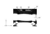
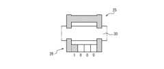
- FIG. 2is a perspective view showing an example of the configuration of the infusion cartridge 20 of FIG. 1.
- the infusion cartridge 20includes a light guiding section 21, a storage section 22, a filling port 23, and a tube receiving section 24.
- the light guiding section 21forms an optical path when the detection section 11 captures an image of the shape of the identification portion of the infusion cartridge 20.
- the configuration and operation of the light guiding section 21will be described in detail later with reference to FIG. 3.
- An infusion tube 30 that supplies infusion liquid from inside an infusion bagis attached to the infusion cartridge 20. However, instead of this, the infusion tube 30 may be attached directly to the infusion bag.
- the storage section 22stores an infusion bag filled with infusion liquid.
- the filling port 23, the tube receiving section 24, and the infusion tube 30are provided on the side of the storage section 22 facing the pump body 10 when the infusion cartridge 20 is attached to the pump body 10.
- the filling port 23is connected to the infusion bag stored inside the storage section 22, and the infusion tube 30 is connected from the outside of the storage section 22.
- the tube receiving section 24holds the infusion tube 30 by sandwiching it between the pump body 10 and the tube receiving section 24.
- the tube receiving section 24may include, for example, a groove into which the infusion tube 30 is fitted. With this configuration, the infusion liquid in the infusion bag stored in the storage section 22 can be sent to the outside via the infusion tube 30.
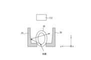
- FIG. 3is a schematic diagram showing a configuration for capturing an image of the shape of the identification portion of the infusion cartridge 20 in the infusion pump 1 of FIG. 1. The captured image is used to determine the type of the infusion cartridge 20.
- the detection unit 11includes a light-emitting unit 111 and a light-receiving unit 112.
- the light-guiding unit 21includes a light-guiding plate 211.
- the light emitting unit 111emits an imaging light beam L having a specific wavelength toward the light guiding unit 21.
- the light beam L emitted from the light emitting unit 111is reflected by the light guiding plate 211 of the light guiding unit 21, passes through the infusion tube 30, which is the subject, and forms an image on the light receiving unit 112.
- the light receiving unit 112is a camera (two-dimensional sensor) and performs photoelectric conversion on the light beam L imaged on the light receiving unit 112 to form a captured image.
- the light receiving unit 112may be configured, for example, by a CMOS (Complementary Metal-Oxide Semiconductor) image sensor or a CCD (Charge Coupled Device) image sensor.
- CMOSComplementary Metal-Oxide Semiconductor
- CCDCharge Coupled Device
- the light emitting unit 111can emit light of any wavelength as the light beam L, but may emit infrared light, for example.
- the light receiving unit 112may be configured with a two-dimensional sensor capable of detecting a specific wavelength of the light beam L, such as the wavelength of infrared light.
- the light guide plate 211may be configured with a material having a refractive index such that most of the light beam L incident from the light emitting unit 111 is reflected at the interfaces 211a and 211b.
- the light guide plate 211may be configured with, for example, polycarbonate or acrylic.
- the detection unit 11 and the light guide unit 21may be used to detect the diameter of the infusion tube 30, blockage of the infusion tube 30, air bubbles in the infusion flowing through the infusion tube 30, and the installation of the infusion cartridge 20, in addition to determining the type of the infusion cartridge 20.
- By detecting blockage of the infusion tube 30 and determining the type of the infusion cartridge 20 using the same configurationit is possible to prevent the infusion pump 1 from becoming complicated and large in size, and to prevent a significant increase in manufacturing costs.
- the infusion pump 1may also automatically determine the type of the infusion cartridge 20. This prevents the user's operation from becoming complicated and the measurement time from increasing significantly.
- the infusion pump 1captures an image of the shape of the identification part in the infusion cartridge 20 using the detection unit 11 and the light guide unit 21, but the configuration for capturing such an image is not limited to the configuration shown in the drawing.
- the infusion pump 1may be provided with an image capture device in either the pump body 10 or the infusion cartridge 20.
- the operation of the light emitting unit 111 and the light receiving unit 112 included in the detection unit 11is controlled by the control unit 151 of the processing unit 15.
- the control unit 151is one or more processors.
- the control unit 151is realized by a dedicated processor specialized for processing such as sending infusion into the patient's body and inputting and outputting information between the control unit 151 and the user, but may also be realized by a general-purpose processor such as a CPU (Central Processing Unit).
- the control unit 151may include one or more dedicated circuits, or one or more processors in the control unit 151 may be replaced with one or more dedicated circuits.
- the dedicated circuitsare, for example, FPGAs (Field-Programmable Gate Arrays) or ASICs (Application Specific Integrated Circuits).
- the control unit 151controls each part of the pump body 10 to execute information processing related to the operation of the infusion pump 1.
- the memory unit 152includes any memory module including, for example, a RAM (Random Access Memory) and a ROM (Read-Only Memory).
- the memory unit 152stores any information used in the operation of the infusion pump 1.
- the memory unit 152may store various programs such as a system program and an application program, as well as information regarding the infusion flow rate and various data such as captured images of the infusion tube 30.
- FIG. 4is an enlarged view of the imaged portion of the infusion cartridge 20 in FIG. 2.
- the infusion tube 30is fixed between the walls 25, 26.
- the infusion pump 1uses the shapes of the walls 25, 26 as identification portions for identifying the type of the infusion cartridge 20. That is, the infusion pump 1 obtains an image including the walls 25, 26 by the detection unit 11, and determines the type of the infusion cartridge 20 based on the image. As mentioned above, the image may also be used to detect blockages and air bubbles in the infusion tube 30, the tube diameter of the infusion tube 30, and the attachment of the infusion tube 30.
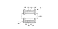
- FIGS. 5A to 5Care diagrams illustrating the identification portion of the infusion cartridge 20.
- the shape of the wall 25is used as the identification portion of the infusion cartridge 20, but as will be described later with reference to FIG. 8A to FIG. 8C, the identification portion of the infusion cartridge 20 is not limited to the shape of the wall 25.
- the wall 25is divided into four regions of identification pieces 251 to 254, and the information on the presence or absence of the four identification pieces 251 to 254 is used as identification information for the infusion cartridge 20. That is, the infusion pump 1 uses the presence or absence of the identification pieces 251 to 254 as 4-bit information, with the presence of an identification piece being "1" and the absence being "0".
- the type of infusion cartridge 20may be identified by such information. For example, there are known types of infusions, such as those for intravenous injection (IV) and those for epidural anesthesia (Epi). The identification portion of the infusion cartridge 20 may indicate these types.
- the wall 25has identification pieces 252 and 254, but does not have identification pieces 251 and 253.
- the identification information of the infusion cartridge 20 shown in FIG. 5Bis "0101" ("5" in decimal).
- the wall 25has identification pieces 251, 253, and 254, but does not have identification piece 252.
- the identification information of the infusion cartridge 20 shown in FIG. 5Cis "1011" ("11" in decimal).
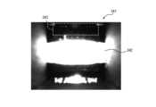
- Figure 6Ais a diagram showing an example of a captured image including an identification portion of the infusion cartridge 20.
- Figure 6Bis a diagram explaining the process of analyzing the captured image of Figure 6A.
- Figure 6Cis a diagram showing an example of a captured image including an identification portion of the infusion cartridge 20.
- Figure 6Dis a diagram explaining the process of analyzing the captured image of Figure 6C.
- FIG. 6Ashows a captured image 301 including the shape of the identification portion of the infusion cartridge 20 shown in FIG. 5B.
- the captured image 301includes an image 302 showing the infusion tube 30.
- An area 303shows the range in which the wall 25 is reflected.
- images 304 and 305 corresponding to the presence of the identification pieces 252 and 254are displayed within the area 303.
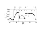
- the infusion pump 1analyzes the area 303 in the captured image 301 to obtain identification information for identifying the type of the infusion cartridge 20. For example, for each X coordinate (position of a pixel in the X direction) in the area 303, the infusion pump 1 calculates the sum of the light intensity (e.g., luminance or brightness) of each pixel in the Y-axis direction in the area 303 that corresponds to that X coordinate as the "sum of brightness,” and obtains the identification information based on the change in the sum of brightness in the X direction.
- the light intensitye.g., luminance or brightness
- FIG. 6Bshows an example of a graph 311 showing the change in brightness sum in the X direction obtained from the captured image 301 in FIG. 6A.
- the horizontal axisshows the X coordinate.
- the vertical axisshows the magnitude of the brightness sum in the Y axis direction.
- points 312show the measured value of the brightness sum in the Y axis direction for each X coordinate in the region 303.
- Graph 311is a line graph in which points 312 showing the measured brightness sum at each X coordinate are connected by a line.
- the brightness in the region 303 where the wall 25 existsmay vary depending on the condition inside the infusion tube 30.
- Conditions inside the infusion tube 30 that may affect the brightnessinclude, for example, the presence or absence of infusion in the infusion tube 30, the transparency of the infusion, the presence or absence of blockage, and the tube diameter of the infusion tube 30. Therefore, the infusion pump 1 does not compare the absolute value of the brightness sum with a threshold value, but determines the shape of the wall 25 based on the change in the brightness sum in the X direction.
- the infusion pump 1refers to the brightness sums in region 303, starting from the smallest X coordinate, and determines whether the difference between the brightness sum at an X coordinate that is a fixed distance M away from the X coordinate of interest in the increasing direction of the X coordinate is greater than a fixed value A. If the difference between the brightness sum at the X coordinate of interest and the brightness sum at an X coordinate that is a fixed distance M away from that X coordinate is greater than a fixed value A, the infusion pump 1 detects a rise or fall of a signal at the X coordinate of interest. The infusion pump 1 determines that the presence or absence of the identification pieces 251-254 has switched at the X coordinate where such a rise or fall of a signal was detected.
- the infusion pump 1determines whether I[n] - I[n+M] > A or I[n+M] - I[n] > A is true. If I[n] - I[n+M] > A is true, the infusion pump 1 detects a falling edge of the signal at the nth X coordinate. If I[n+M] - I[n] > A is true, the infusion pump 1 detects a rising edge of the signal at the nth X coordinate. Based on the distribution of the rising and falling edges of such signals, the infusion pump 1 obtains identification information for identifying the type of the infusion cartridge 20.
- lines 201 and 203indicate the rising of the signal.
- Lines 202 and 204indicate the falling of the signal.
- the infusion pump 1detects that the identification piece has switched from a non-existent state (i.e., bit "0") to a present state (i.e., bit "1") at the X coordinate where the rising of the signal is detected.
- the infusion pump 1detects that the identification piece has switched from a present state (i.e., bit "1") to a non-existent state (i.e., bit "0”) at the X coordinate where the falling of the signal is detected. Therefore, in the example of FIG. 6B, the bit switches from “0” to "1" around line 201 indicating the rising.
- the bitswitches from “1” to "0" around line 202 indicating the falling.
- the infusion pump 1has a preset correspondence between the value of the X coordinate and the boundary positions of identification pieces 251 to 254. Therefore, the infusion pump 1 can detect the identification information "0101" of the infusion cartridge 20 from the shape of the graph 311.
- FIG. 6Cshows a captured image 321 including the shape of the identification portion of the infusion cartridge 20 shown in FIG. 5C.
- the captured image 321includes an image 322 showing the infusion tube 30.
- Area 323shows the range in which the wall 25 is reflected.
- images 324 and 325 corresponding to the presence of identification pieces 251, 253, and 254are displayed within area 323.
- FIG. 6Dshows an example of a graph 331 showing the change in brightness sum in the X direction obtained from the captured image 321 in FIG. 6C.
- the horizontal axisshows the X coordinate.
- the vertical axisshows the magnitude of the brightness sum in the Y axis direction.
- points 332show the measured value of the brightness sum in the Y axis direction for each X coordinate in region 323.
- Graph 331is a line graph in which points 332 showing the measured value of the brightness sum for each X coordinate are connected by a line.
- the infusion pump 1detects the identification information "1011" of the infusion cartridge 20 based on the distribution of these lines 221-224 and the correspondence between the X-coordinate value and the boundary positions of the identification pieces 251-254, which is set in advance.
- a common constant value Ais used as the threshold for detecting the rising edge of a signal and the threshold for detecting the falling edge of a signal, but the threshold for detecting the rising edge of a signal and the threshold for detecting the falling edge of a signal may be different values.
- the infusion pump 1determines that multiple bits "1" are present in succession. Similarly, when multiple identification pieces are not present in succession, the infusion pump 1 determines that multiple bits "0" are present in succession. However, the infusion pump 1 may determine that a single bit "1” is present when multiple identification pieces are present in succession in this way. Similarly, the infusion pump 1 may determine that a single bit "0" is present when multiple identification pieces are not present in succession in this way. With this configuration, the infusion pump 1 can obtain the identification information of the infusion cartridge 20 without referring to the correspondence between the value of the X coordinate and the position of the boundary between the identification pieces 251 to 254.
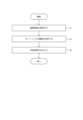
- FIG. 7is a flowchart showing an example of the operation of the infusion pump 1.
- the operation of the infusion pump 1 described with reference to FIG. 7may correspond to one of the control methods of the infusion pump 1.
- the operation of each step in FIG. 7may be executed based on the control by the control unit 151 of the pump body 10.
- step S1 of FIG. 7the control unit 151 acquires an image captured by the detection unit 11, the image including the shape of the identification portion of the infusion cartridge 20 attached to the pump body 10.
- step S2the control unit 151 analyzes the captured image acquired in step S1 and determines the type of infusion cartridge 20.
- step S3the control unit 151 outputs the type of the infusion cartridge 20 determined in step S2.
- the control unit 151may output the type of the infusion cartridge 20 to the memory unit 152 for storage.
- the control unit 151may output the type of the infusion cartridge 20 to the display unit 13, and display an image that allows the type of the infusion cartridge 20 to be identified.
- step S3the control unit 151 ends the processing of the flowchart in FIG. 7.
- the infusion pump 1acquires an image captured by the detection unit 11, the image including the shape of the identification portion of the infusion cartridge 20 attached to the pump body 10.
- the infusion pump 1analyzes the acquired image to determine the type of the infusion cartridge 20.
- the infusion pump 1outputs the determined type of the infusion cartridge 20.
- the infusion pump 1determines the type of the infusion cartridge 20 based on the image including the shape of the identification portion of the infusion cartridge 20, and therefore can correctly identify the type of the attached infusion cartridge 20 without providing a special device. Therefore, the infusion pump 1 can issue an alarm when an infusion cartridge 20 containing an incorrect infusion is attached, and can control the operation according to the type of the attached infusion cartridge 20.
- the infusion pump 1identifies the type of cartridge
- the type of medical deviceis not limited to the infusion pump 1.
- the configuration according to this embodimentmay also be implemented in other types of medical devices in which a replacement cartridge is attached to the device body, such as a blood glucose meter in which a disposable measuring tip is attached.
- the infusion pump 1may also acquire an image captured by the detection unit 11 after the infusion cartridge 20 is attached to the pump body 10 as a captured image, and analyze the captured image captured after the infusion cartridge 20 is attached to determine the type of the infusion cartridge 20. In this way, by determining the type of the infusion cartridge 20 using the captured image captured after the infusion cartridge 20 is attached, the infusion pump 1 can correctly identify the type of the attached infusion cartridge 20.
- the infusion pump 1may also analyze the distribution of light intensity (e.g., luminance or brightness) shown in the captured image to determine the type of cartridge. Therefore, the infusion pump 1 can correctly identify the type of the attached infusion cartridge 20 based on the distribution of light intensity shown in the captured image.
- light intensitye.g., luminance or brightness
- the infusion pump 1may also acquire, as a captured image, an image of the infusion cartridge 20 that indicates the identification part based on the presence or absence of multiple identification pieces 251-254.
- the infusion pump 1may analyze the acquired captured image to determine the type of infusion cartridge 20 that indicates the identification part based on the presence or absence of multiple identification pieces 251-254. In this way, the infusion pump 1 determines the type of infusion cartridge 20 based on the presence or absence of multiple identification pieces 251-254, and therefore is able to correctly identify the type of the attached infusion cartridge 20 without providing a special device.
- FIGS 5A to 5Ca case was described in which multiple identification pieces 251 to 254 are provided on the wall 25, and the presence or absence of these identification pieces 251 to 254 indicates the identification portion, but the identification portion of the infusion cartridge 20 is not limited to the shape of the wall 25.
- Figures 8A to 8Care diagrams explaining the identification portion of the infusion cartridge 20.
- not only wall 25 but also wall 26is divided into four regions of identification pieces 261-264.
- the presence or absence of eight identification pieces 251-254, 261-264provides identification information for identifying the infusion cartridge 20.
- the infusion pump 1uses the presence or absence of the identification pieces 251-254, 261-264 as 8-bit information, with the presence of an identification piece being represented as "1" and the absence being represented as "0.”
- wall 25has identification pieces 252 and 254, but does not have identification pieces 251 and 253.
- Wall 26has identification pieces 262 and 263, but does not have identification pieces 261 and 264.
- the identification information of the infusion cartridge 20 shown in FIG. 8Bis "01010110" ("86" in decimal).
- a configuration capable of displaying 8 bits of informationallows the type of infusion cartridge 20 to be identified in more detail than when 4 bits of information are displayed using the identification pieces 251-254.
- the identification portioncan indicate not only a rough classification of the infusion, but also detailed specific information about the infusion, the dosage of the infusion, and usage information, etc.
- the wall 25may not be used as an identification portion, and only the wall 26 may be divided into four identification pieces 261-264 to provide identification information. Furthermore, a portion of the infusion cartridge 20 other than the walls 25 and 26 may be provided with a shape according to the type of infusion cartridge 20 to provide identification information.
- the infusion pump 1may detect the presence or absence of multiple identification pieces based on at least one of the rising and falling edges of the light intensity signal shown in the captured image, and determine the type of cartridge indicating the identification portion. In this way, by acquiring identification information based on the change in light intensity rather than the absolute value of light intensity, the infusion pump 1 can accurately determine the type of cartridge regardless of the presence or absence of infusion in the infusion tube 30, the transparency of the infusion, the presence or absence of blockage, differences in tube diameter, etc.
- the infusion pump 1may also determine the type of infusion cartridge 20 that indicates the identification portion based on the presence or absence of multiple members with a textured surface as the multiple identification pieces. Alternatively, the infusion pump 1 may determine the type of infusion cartridge 20 that indicates the identification portion based on the presence or absence of multiple members with a surface at an angle such that the reflected light of the light output from the light-emitting unit 111 is guided to the light-receiving unit 112 as the multiple identification pieces. Such a configuration will be described with reference to Figures 9A to 9D.
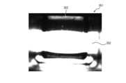
- FIG. 9Ais a schematic diagram showing the light path at the identification portion.
- FIG. 9Ashows an example in which the light output from the light-emitting unit 111 and guided via the light guide plate 211 is reflected off the wall 25 and does not reach the light-receiving unit 112. In such a case, even if the captured image is analyzed, it is difficult to detect the presence or absence of the identification pieces 251-254 on the wall 25.
- FIG. 9Bis a diagram showing an example of an image 341 captured by the configuration of FIG. 9A.
- an image 342 showing the infusion tube 30can be clearly recognized.
- the area 343 where the wall 25 should be presentis entirely dark, making it difficult to detect the presence or absence of the identification pieces 251-254.
- FIG. 9Cis a schematic diagram showing the light path at the identification portion.
- the surface of the wall 25 in FIG. 9Cis textured by embossing or the like, and the surface is roughly processed. Therefore, light that reaches the surface of the wall 25 is diffusely reflected, and the reflected light is likely to reach the light receiving unit 112.
- the surface of the wall 25is set at an angle that makes it easy for the reflected light from the wall 25 to be guided to the light receiving unit 112, depending on the light transmitting area of the light guide plate 211 and the positional relationship of the light receiving unit 112. The light reflected from the surface of the wall 25 is likely to reach the light receiving unit 112.
- FIG. 9Dis a diagram showing an example of an image 351 captured by the configuration of FIG. 9C.
- the captured image 351not only the image 342 showing the infusion tube 30 but also the image 353 of the wall 25 can be clearly recognized. Therefore, with this configuration, the presence or absence of the identification pieces 251-254 can be recognized more accurately, and the type of cartridge can be accurately determined.
- the configuration and operation of the infusion pump 1may be distributed among multiple devices such as computers that can communicate with each other.
Landscapes
- Health & Medical Sciences (AREA)
- Vascular Medicine (AREA)
- Engineering & Computer Science (AREA)
- Anesthesiology (AREA)
- Biomedical Technology (AREA)
- Heart & Thoracic Surgery (AREA)
- Hematology (AREA)
- Life Sciences & Earth Sciences (AREA)
- Animal Behavior & Ethology (AREA)
- General Health & Medical Sciences (AREA)
- Public Health (AREA)
- Veterinary Medicine (AREA)
- Infusion, Injection, And Reservoir Apparatuses (AREA)
Abstract
Description
Translated fromJapanese本開示は、医療機器、輸液ポンプ、カートリッジ、及び、プログラムに関する。This disclosure relates to medical devices, infusion pumps, cartridges, and programs.
輸液ポンプは、輸液チューブを介して、薬液等の輸液を患者の体内へ送り出す装置である。輸液ポンプは、輸液が充填されたカートリッジがポンプ本体に装着された状態において、ポンプ本体が駆動することにより、輸液を患者の体内へ送り出す。このような輸液ポンプに用いられるカートリッジには多数の種類がある。輸液ポンプは、カートリッジの種類に応じて投与モードを切り替えて動作する。そのため、輸液ポンプは、カートリッジの種類を正しく識別する必要がある。使い捨ての測定用チップを装着して使用する血糖計のように、装置本体に交換用のカートリッジを装着して使用する他の種類の医療機器においても、カートリッジの種類を正しく識別する必要がある。An infusion pump is a device that delivers infusion fluids, such as medicinal fluids, into a patient's body via an infusion tube. With a cartridge filled with infusion fluid attached to the pump body, the infusion pump delivers the infusion fluid into the patient's body by driving the pump body. There are many types of cartridges used in such infusion pumps. Infusion pumps operate by switching administration modes depending on the type of cartridge. For this reason, infusion pumps must correctly identify the type of cartridge. Correct identification of the type of cartridge is also required in other types of medical devices that use replacement cartridges attached to the device body, such as blood glucose meters that use disposable measuring tips.
特許文献1には、プリンタ本体がインクの種類を識別可能なカートリッジに関する技術が記載されている。
医療機器においては、装置本体に装着されたカートリッジの種類を非接触で正しく識別できることは、医療機器装置本体に求められる防水性、及び、構成の簡素化の観点から望ましい。In medical devices, being able to correctly identify the type of cartridge attached to the device body without contact is desirable from the standpoint of waterproofing required of the medical device body and simplifying the configuration.
本開示の目的は、医療機器において装着されたカートリッジの種類を識別可能とすることである。The purpose of this disclosure is to make it possible to identify the type of cartridge installed in a medical device.
本開示によれば、医療機器は、
(1)装置本体に装着されるカートリッジにおける識別部位の形状を含む、撮像部により撮像された撮像画像を取得し、
取得した前記撮像画像を解析して、前記カートリッジの種類を判定する、
制御部を備える。According to the present disclosure, a medical device comprises:
(1) acquiring an image captured by an imaging unit, the image including the shape of an identification portion of a cartridge to be mounted in a device body;
Analyzing the captured image to determine the type of the cartridge.
It has a control unit.
(2)(1)の医療機器において、
前記制御部は、前記判定したカートリッジの種類を出力する。(2) In the case of medical devices under (1),
The control unit outputs the determined type of cartridge.
(3)(1)又は(2)の医療機器において、
前記制御部は、
前記装置本体に前記カートリッジが装着された後に前記撮像部により撮像された画像を前記撮像画像として取得し、
前記カートリッジが装着された後に前記撮像部により撮像された前記撮像画像を解析して、前記装着された前記カートリッジの種類を判定する。(3) In the case of medical devices as described in (1) or (2),
The control unit is
an image captured by the imaging unit after the cartridge is mounted in the apparatus main body is acquired as the captured image;
The image captured by the imaging unit after the cartridge is mounted is analyzed to determine the type of the mounted cartridge.
(4)(1)から(3)のいずれかの医療機器において、
前記制御部は、取得した前記撮像画像により示される光強度の分布を解析して、前記カートリッジの種類を判定する。(4) In any of the medical devices listed in (1) to (3),
The control unit analyzes the distribution of light intensity shown in the acquired captured image to determine the type of the cartridge.
(5)(1)から(4)のいずれかの医療機器において、
前記制御部は、
複数の識別片の有無により前記識別部位を示す前記カートリッジの画像を前記撮像画像として取得し、
取得した前記撮像画像を解析して、前記複数の識別片の有無により前記識別部位を示す前記カートリッジの種類を判定する。(5) In any of the medical devices listed in (1) to (4),
The control unit is
acquiring an image of the cartridge that indicates the identification portion based on the presence or absence of a plurality of identification pieces as the captured image;
The captured image is analyzed to determine the type of the cartridge that indicates the identification portion based on the presence or absence of the plurality of identification pieces.
(6)(5)の医療機器において、
前記制御部は、取得した前記撮像画像により示される光強度の信号の立上り及び立下りの少なくともいずれかに基づき、前記複数の識別片の有無を検出して、前記識別部位を示す前記カートリッジの種類を判定する。(6) In the case of medical devices under (5),
The control unit detects the presence or absence of the plurality of identification pieces based on at least one of the rising and falling edges of a light intensity signal indicated by the acquired captured image, and determines the type of the cartridge indicating the identification portion.
(7)(5)又は(6)の医療機器において、
前記制御部は、前記複数の識別片として、表面に凹凸加工がなされた複数の部材の有無により前記識別部位を示す前記カートリッジの種類を判定する。(7) In the case of medical devices as set forth in (5) or (6),
The control unit determines the type of the cartridge that indicates the identification portion based on the presence or absence of a plurality of members having a textured surface as the plurality of identification pieces.
(8)(5)から(7)のいずれかの医療機器において、
前記制御部は、前記複数の識別片として、前記撮像部が備える発光部から出力された光の反射光が、前記撮像部が備える受光部へ導かれる角度の表面を有する複数の部材の有無により前記識別部位を示す前記カートリッジの種類を判定する。(8) In any of the medical devices listed in (5) to (7),
The control unit determines the type of cartridge that indicates the identification portion based on the presence or absence of multiple components that have a surface at an angle such that reflected light output from an light-emitting unit provided in the imaging unit is directed to a light-receiving unit provided in the imaging unit, as the multiple identification pieces.
本開示によれば、輸液ポンプは、
(9)ポンプ本体に装着される輸液カートリッジにおける識別部位の形状を含む、撮像部により撮像された撮像画像を取得し、
取得した前記撮像画像を解析して、前記輸液カートリッジの種類を判定する、
制御部を備える。According to the present disclosure, an infusion pump comprises:
(9) acquiring an image captured by an imaging unit, the image including the shape of an identification portion of an infusion cartridge to be attached to the pump body;
Analyzing the captured image to determine the type of the infusion cartridge.
It has a control unit.
(10)(9)の輸液ポンプにおいて、
前記制御部は、前記判定した輸液カートリッジの種類を出力する。(10) In the infusion pump of (9),
The control unit outputs the determined type of the infusion cartridge.
本開示によれば、カートリッジは、
(11)装置本体に装着して使用される、形状により種類を識別する識別部位を備える。According to the present disclosure, the cartridge comprises:
(11) It is provided with an identification part that is attached to the device body and used to identify the type based on its shape.
本開示によれば、プログラムは、
(12)カートリッジを装着して動作する医療機器に、
前記カートリッジにおける識別部位の形状を含む、撮像部により撮像された撮像画像を取得する手順と、
取得した前記撮像画像を解析して、前記カートリッジの種類を判定する手順と、
前記判定したカートリッジの種類を出力する手順と、
を実行させる。According to the present disclosure, a program includes:
(12) For medical devices that operate by mounting a cartridge,
acquiring an image captured by an imaging unit, the image including the shape of an identification portion of the cartridge;
A step of analyzing the captured image to determine the type of the cartridge;
outputting the determined type of cartridge;
Execute the command.
本開示の一実施形態によれば、医療機器において装着されたカートリッジの種類を識別することができる。According to one embodiment of the present disclosure, it is possible to identify the type of cartridge installed in a medical device.
以下、本開示の一実施形態について、図面を参照して説明する。各図面中、同一の構成又は機能を有する部分には、同一の符号を付している。本実施形態の説明において、同一の部分については、重複する説明を適宜省略又は簡略化する場合がある。Below, one embodiment of the present disclosure will be described with reference to the drawings. In each drawing, parts having the same configuration or function are given the same reference numerals. In the description of this embodiment, duplicate descriptions of the same parts may be omitted or simplified as appropriate.
(輸液ポンプの構成)
図1は、一実施形態に係る医療機器としての輸液ポンプ1の構成例を示す正面図である。図1に示すように、輸液ポンプ1は、ポンプ本体10、及び、輸液カートリッジ20を備える。ポンプ本体10は、検出部11、送液部12、表示部13、操作部14、及び、処理部15(図3参照)を備える。図1に示す輸液ポンプ1は、例えばPCA(Patient Controlled Analgesia)ポンプとして使用してもよいが、用途は特に限定されない。本実施形態の輸液ポンプ1は、一例として、使い捨ての輸液カートリッジ20を取り替えることで、ポンプ本体10を再使用することができるPCAポンプである。輸液ポンプ1は、PCAポンプに限られない。輸液ポンプ1は、一般的な輸液ポンプ、シリンジポンプ、栄養ポンプ、血液ポンプ、又は、インスリンポンプであってもよい。一般的な輸液ポンプとは、例えば、輸液カートリッジ20を備えず、ポンプ外の輸液バッグに接続された輸液チューブ30を押圧して輸液バッグ内の輸液を送液するポンプである。(Configuration of infusion pump)
FIG. 1 is a front view showing an example of the configuration of an
輸液ポンプ1は、輸液カートリッジ20の識別部位の形状を含む撮像画像を検出部11により取得し、撮像画像を解析して輸液カートリッジ20の種類を判定する。したがって、輸液ポンプ1によれば、輸液カートリッジ20の種類を正確に判別して、その種類に応じた送液制御を行ったり、誤った輸液カートリッジ20が装着された場合にアラームを通知したりすることが可能である。輸液ポンプ1は、輸液チューブ30内の閉塞及び気泡等の検出、輸液カートリッジ20の装着確認、並びに、チューブ径に基づく流量補正等の種々の目的に使用される撮像画像に映り込んだ識別部位の形状に基づき、輸液カートリッジ20の種類を判定してもよい。したがって、本実施形態に係る輸液ポンプ1は、このような目的で使用される撮像画像を取得する撮像装置を備えた医療機器において、特別な装置を追加することなく実施することが可能である。The
図1に示すように、ポンプ本体10の正面には、各種情報が表示される表示部13、及び、操作スイッチ類が配列された操作部14が配置されている。表示部13は、例えば、輸液カートリッジ20の種類の判定結果、送液速度、及び、積算投与量等を表示する。表示部13は、例えば、送液速度等を設定するタッチパネル付きの液晶画面であってもよい。操作部14の操作スイッチは、例えば、ユーザにより押圧されている間、設定された送液速度(mL/h)よりも高い送液速度での送液が可能となる早送りスイッチ、押圧されることで送液が開始される開始スイッチ、押圧されることで送液が強制停止される停止スイッチ、及び、ポンプ本体10の電源のON/OFFを指示するための電源スイッチ等としてもよい。ただし、操作部14は、これらのスイッチに代えて、又は、これらのスイッチに加えて、他の操作スイッチを備えてもよい。As shown in FIG. 1, the front of the
送液部12は、装着される輸液カートリッジ20の管受け部24(図2参照)との間で、輸液カートリッジ20の輸液チューブ30を挟み込み、輸液チューブ30内の輸液を流路上流側から流路下流側に送り出す。送液部12は、複数のフィンガ121、及び、各フィンガ121を駆動する駆動部を備える。複数のフィンガ121は、輸液カートリッジ20の側面に位置する管受け部24と対向する、ポンプ本体10の側面に配置されている。複数のフィンガ121は、輸液チューブ30の延在方向(x方向)に沿って配列されている。各フィンガ121は、輸液カートリッジ20の管受け部24との対向方向(z方向)に往復移動するように、駆動部により駆動される。駆動部は、例えば、モーターの動力をカム等の機械的部品により各フィンガ121のz方向の往復移動に変換する構成を有してもよい。各フィンガ121が輸液カートリッジ20に近接するように移動することで、輸液チューブ30は、各フィンガ121と管受け部24との間に挟み込まれる。これにより、輸液チューブ30は圧閉される。駆動部は、輸液チューブ30の延在方向(x方向)において、流路上流側から流路下流側に向かって輸液チューブ30の圧閉箇所が順次移動するようにフィンガ121を駆動する。これにより、輸液チューブ30は、流路上流側から流路下流側に向かって順次圧閉され、蠕動運動する。そのため、輸液チューブ30内の輸液を流路上流側から流路下流側に向かって送り出すことができる。The
撮像部としての検出部11は、輸液カートリッジ20の導光部21とともに、輸液カートリッジ20の識別部位を含む形状を撮像して、撮像画像を取得する。撮像画像は、輸液カートリッジ20の種類等に関する情報を取得するために用いられる。処理部15は、ポンプ本体10の各構成要素の動作を制御する。処理部15は、制御部151及び記憶部152を備える。検出部11及び処理部15の構成及び動作の詳細は、図3を参照して後述する。The
ポンプ本体10は、本実施形態の構成に限定されない。ポンプ本体10は、他の輸液ポンプと同様に、電源部、検出部11、送液部12、表示部13、操作部14、処理部15以外にも、例えば、気泡検出センサ部、閉塞センサ部、及び、アラーム等による報知部等を備えてもよい。ポンプ本体10は、上述した構成要素とは別の構成要素を備えてもよく、同等の機能を有する構成要素に代わられてもよい。また、上述のように、本実施形態の例では、送液部12は、複数のフィンガ121により輸液チューブ30を押圧するが、送液部12は、輸液チューブ30内の輸液を送り出すことが可能であれば、フィンガ121とは異なる構成を備えてもよい。The
図2は、図1の輸液カートリッジ20の構成例を示す斜視図である。輸液カートリッジ20は、導光部21、収容部22、充填口23、及び、管受け部24を備える。導光部21は、検出部11が輸液カートリッジ20における識別部位の形状を撮像する際の光路を形成する。導光部21の構成及び、作用の詳細は、図3を参照して後述する。輸液カートリッジ20には、輸液バッグの内部から輸液を供給する輸液チューブ30が取り付けられている。ただし、これに代えて、輸液チューブ30は、輸液バッグに直接取り付けられてもよい。FIG. 2 is a perspective view showing an example of the configuration of the
収容部22は、輸液が充填された輸液バッグを内部に収容する。充填口23、管受け部24、及び、輸液チューブ30は、輸液カートリッジ20がポンプ本体10に装着された場合に、収容部22の、ポンプ本体10と対向する側に設けられる。充填口23は、収容部22の内部に収容された輸液バッグと接続され、収容部22の外側から輸液チューブ30が接続される。管受け部24は、ポンプ本体10との間で輸液チューブ30を挟み込んで輸液チューブ30を保持する。管受け部24は、例えば、輸液チューブ30を嵌め込む溝を含んでもよい。このような構成により、収容部22に収容された輸液バッグ内の輸液が輸液チューブ30を介して外部に送液可能になる。The
図3は、図1の輸液ポンプ1において、輸液カートリッジ20における識別部位の形状を撮像するための構成を模式的に示す図である。撮像画像は、輸液カートリッジ20の種類を判定するために用いられる。図3に示すように、検出部11は、発光部111、及び、受光部112を備える。導光部21は、導光板211を備える。FIG. 3 is a schematic diagram showing a configuration for capturing an image of the shape of the identification portion of the
発光部111は、特定の波長を有する撮像用の光束Lを導光部21へ向けて出射する。発光部111から出射された光束Lは、導光部21の導光板211において反射し、被写体である輸液チューブ30を通過して、受光部112において結像する。受光部112は、カメラ(2次元センサ)であり、受光部112上に結像した光束Lを光電変換して、撮像画像を形成する。受光部112は、例えば、CMOS(Complementary Metal-Oxide Semiconductor)イメージセンサ、又は、CCD(Charge Coupled Device)イメージセンサ等により構成してもよい。The
輸液カートリッジ20における識別部位の形状を撮像する際に、発光部111は、光束Lとして任意の波長の光を出射することができるが、例えば、赤外光を出射してもよい。受光部112は、例えば、赤外光の波長等の、光束Lの特定の波長を検出可能な2次元センサにより構成されてもよい。可視光ではなく赤外光を用いて撮像することで、輸液ポンプ1を使用する室内の照明光等が受光部112に到達しても、撮像画像が乱れることを抑制することができる。さらに、赤外光の光エネルギーは低いため、赤外光を用いることで、輸液への影響を抑制することができるとともに、光が装置外に漏れても人の目に感知されることを防ぐことができる。導光板211は、発光部111から入射された光束Lの大部分が、界面211a、211bにおいて反射するような屈折率を有するような材料により構成してもよい。導光板211は、例えば、ポリカーボネート、又は、アクリル等により構成してもよい。When imaging the shape of the identification portion of the
検出部11及び導光部21は、輸液カートリッジ20の種類の判定の他、輸液チューブ30の径、輸液チューブ30の閉塞、輸液チューブ30を流れる輸液内の気泡、及び、輸液カートリッジ20の装着等を検出するためにも用いられてよい。輸液チューブ30の閉塞等の検出、及び、輸液カートリッジ20の種類の判定を同一の構成により行うことで、輸液ポンプ1の装置構成が複雑化及び大型化したり、製造コストが著しく増大したりすることを防ぐことができる。また、輸液ポンプ1は、輸液カートリッジ20の種類の判定を自動的に行ってもよい。これにより、ユーザの操作が煩雑化したり、測定時間が著しく増大したりすることを防ぐことができる。本実施形態では、輸液ポンプ1は、検出部11及び導光部21により、輸液カートリッジ20における識別部位の形状を撮像するが、このような撮像を行うための構成は図面に示した構成に限られない。例えば、輸液ポンプ1は、撮像するための装置を、ポンプ本体10及び輸液カートリッジ20のいずれか一方に備えてもよい。The
検出部11に含まれる発光部111及び受光部112の動作は、処理部15の制御部151により制御される。制御部151は、1つ以上のプロセッサである。制御部151は輸液を患者の体内に送り出したり、ユーザとの間で情報を入出力したりする処理に特化した専用プロセッサにより実現されるが、CPU(Central Processing Unit)等の汎用プロセッサにより実現されてもよい。制御部151には、1つ以上の専用回路が含まれてもよいし、あるいは、制御部151において、1つ以上のプロセッサを1つ以上の専用回路に置き換えてもよい。専用回路は、例えば、FPGA(Field-Programmable Gate Array)又はASIC(Application Specific Integrated Circuit)である。制御部151は、ポンプ本体10の各部を制御して、輸液ポンプ1の動作に関わる情報処理を実行する。The operation of the
記憶部152は、例えばRAM(Random Access Memory)及びROM(Read-Only Memory)を含む任意の記憶モジュールを含む。記憶部152は、輸液ポンプ1の動作に用いられる任意の情報を記憶する。例えば、記憶部152は、システムプログラム、及び、アプリケーションプログラム等の各種プログラム、並びに、輸液の流量に関する情報、及び、輸液チューブ30の撮像画像等の各種データ等を記憶してもよい。The
図4は、図2の輸液カートリッジ20の撮像箇所を拡大して示す図である。図4において、輸液チューブ30は、壁25、26の間に固定されている。本実施形態において、輸液ポンプ1は、壁25、26の形状を輸液カートリッジ20の種類を識別するための識別部位として利用する。すなわち、輸液ポンプ1は、壁25、26を含む撮像画像を検出部11により取得し、その撮像画像に基づき輸液カートリッジ20の種類を判定する。撮像画像は、輸液チューブ30内の閉塞及び気泡、輸液チューブ30のチューブ径、並びに、輸液チューブ30の装着等を検出するためにも用いてよいことは、前述のとおりである。FIG. 4 is an enlarged view of the imaged portion of the
図5A~図5Cは、輸液カートリッジ20の識別部位を説明する図である。以下、壁25の形状を輸液カートリッジ20の識別部位として利用する例を説明するが、図8A~図8Cを参照して後述するように、輸液カートリッジ20の識別部位は壁25の形状に限られない。FIGS. 5A to 5C are diagrams illustrating the identification portion of the
図5A~図5Cにおいて、壁25は4つの識別片251~254の領域に分割され、4つの識別片251~254の有無の情報は、輸液カートリッジ20の識別情報として利用される。すなわち、輸液ポンプ1は、識別片が存在することを「1」、存在しないことを「0」として、識別片251~254の有無を4ビットの情報として利用する。輸液カートリッジ20の種類は、このような情報により、特定されてもよい。例えば、輸液には、静脈内投与(IV:Intravenous injection)用、及び、硬膜外麻酔(Epi:Epidural anesthesia)用等の種類が知られている。輸液カートリッジ20の識別部位は、このような種類の別を示してもよい。In Figures 5A to 5C, the
例えば、図5Bにおいて、壁25には、識別片252、254が存在するが、識別片251、253は存在しない。この場合、図5Bにより示される輸液カートリッジ20の識別情報は、「0101」(10進数で「5」)となる。図5Cにおいて、壁25には、識別片251、253、254が存在するが、識別片252は存在しない。この場合、図5Cにより示される輸液カートリッジ20の識別情報は、「1011」(10進数で「11」)となる。For example, in FIG. 5B, the
このような壁25の形状を輸液カートリッジ20の識別部位として利用した場合における、撮像画像の解析に基づく識別情報の取得の詳細について、図6A~図6Dを参照して説明する。図6Aは、輸液カートリッジ20の識別部位を含む撮像画像の一例を示す図である。図6Bは、図6Aの撮像画像を解析する処理を説明する図である。図6Cは、輸液カートリッジ20の識別部位を含む撮像画像の一例を示す図である。図6Dは、図6Cの撮像画像を解析する処理を説明する図である。Details of obtaining identification information based on analysis of a captured image when such a shape of the
図6Aは、図5Bにより示される輸液カートリッジ20における識別部位の形状を含む撮像画像301を示している。図6Aにおいて、撮像画像301には、輸液チューブ30を示す画像302が含まれる。領域303は、壁25が映り込む範囲を示す。図6Aの例において、領域303内には、識別片252、254の存在に対応する画像304、305が表示されている。FIG. 6A shows a captured
輸液ポンプ1は、撮像画像301内の領域303を解析して、輸液カートリッジ20の種類を識別するための識別情報を取得する。例えば、輸液ポンプ1は、領域303におけるX座標(X方向の画素の位置)ごとに、そのX座標に該当する領域303内のY軸方向各画素の光強度(例えば、輝度又は明るさ)の総和を「明るさ和」として算出し、明るさ和のX方向における変化に基づき識別情報を取得する。The
図6Bは、図6Aの撮像画像301から取得される、明るさ和のX方向における変化を示すグラフ311の一例を示している。図6Bにおいて、横軸はX座標を示す。縦軸はY軸方向の明るさ和の大きさを示す。図6Bにおいて、点312は、領域303におけるX座標ごとのY軸方向の明るさ和の測定値を示す。グラフ311は、各X座標における明るさ和の測定値を示す点312を線で連結した折れ線グラフである。FIG. 6B shows an example of a
壁25が存在する領域303における明るさは、輸液チューブ30内の状態により変動し得る。このような明るさに影響を及ぼし得る輸液チューブ30内の状態には、例えば、輸液チューブ30内における輸液の有無、輸液の透明度、閉塞の有無、及び、輸液チューブ30のチューブ径等があり得る。そこで、輸液ポンプ1は、明るさ和の絶対値を閾値と比較するのではなく、明るさ和のX方向における変化に基づき壁25の形状を判定する。The brightness in the
具体的には、輸液ポンプ1は、領域303において小さいX座標から順に明るさ和を参照し、注目しているX座標から一定距離MだけX座標の増加方向に離れたX座標における明るさ和との差分が一定値Aよりも大きいか否かを判定する。輸液ポンプ1は、注目しているX座標における明るさ和と、そのX座標から一定距離Mだけ離れたX座標における明るさ和との差分が一定値Aよりも大きい場合、注目しているX座標において信号の立上がり、又は、立下りを検出する。輸液ポンプ1は、このような信号の立上り又は立下りが検出されたX座標において、識別片251~254の有無が切り替わったと判定する。Specifically, the
例えば、注目しているX座標が左からn番目(n=1、2、3、・・・)のX座標であり、そのX座標の明るさ和をI[n]とする。この場合、輸液ポンプ1は、I[n]-I[n+M]>A、又は、I[n+M]-I[n]>Aが成立するか否かを判定する。輸液ポンプ1は、I[n]-I[n+M]>Aが成立する場合、n番目のX座標において信号の立下りを検出する。輸液ポンプ1は、I[n+M]-I[n]>Aが成立する場合、n番目のX座標において信号の立上りを検出する。輸液ポンプ1は、このような信号の立上り及び立下りの分布に基づき、輸液カートリッジ20の種類を識別するための識別情報を取得する。For example, the X coordinate of interest is the nth (n=1, 2, 3, ...) X coordinate from the left, and the sum of the brightnesses of the X coordinates is I[n]. In this case, the
例えば、図6Bでは、直線201、203は信号の立上りを示す。直線202、204は信号の立下りを示す。輸液ポンプ1は、信号の立上りが検出されたX座標において、識別片が存在しない状態(すなわち、ビット「0」)から存在する状態(すなわち、ビット「1」)へ切り替わったことを検出する。輸液ポンプ1は、信号の立下りが検出されたX座標において、識別片が存在する状態(すなわち、ビット「1」)から存在しない状態(すなわち、ビット「0」)へ切り替わったことを検出する。したがって、図6Bの例では、立上りを示す直線201の前後でビット「0」からビット「1」へ切り替わる。立下りを示す直線202の前後でビット「1」からビット「0」へ切り替わる。輸液ポンプ1には、X座標の値と識別片251~254の境界の位置との対応関係が予め設定されている。そのため、輸液ポンプ1は、グラフ311の形状から、輸液カートリッジ20の識別情報「0101」を検出することができる。For example, in FIG. 6B,
図6Cは、図5Cにより示される輸液カートリッジ20における識別部位の形状を含む撮像画像321を示している。図6Cにおいて、撮像画像321には、輸液チューブ30を示す画像322が含まれる。領域323は、壁25が映り込む範囲を示す。図6Cの例において、領域323内には、識別片251、253、254の存在に対応する画像324、325が表示されている。FIG. 6C shows a captured
図6Dは、図6Cの撮像画像321から取得される、明るさ和のX方向における変化を示すグラフ331の一例を示している。図6Dにおいて、横軸はX座標を示す。縦軸はY軸方向の明るさ和の大きさを示す。図6Dにおいて、点332は、領域323におけるX座標ごとのY軸方向の明るさ和の測定値を示す。グラフ331は、各X座標における明るさ和の測定値を示す点332を線で連結した折れ線グラフである。FIG. 6D shows an example of a
図6Dの例では、直線221及び直線223の位置において信号の立上りが検出され、直線222及び直線224の位置において信号の立下りが検出されている。輸液ポンプ1は、これらの直線221~224の分布と、予め設定されている、X座標の値と識別片251~254の境界の位置との対応関係とに基づき、輸液カートリッジ20の識別情報「1011」を検出する。In the example of FIG. 6D, rising edges of the signal are detected at the positions of
上述した例においては、信号の立上りを検出するための閾値、及び、信号の立下りを検出するための閾値として、共通の一定値Aを用いる場合を説明したが、信号の立上りを検出するための閾値と、信号の立下りを検出するための閾値とは異なる値でもよい。In the above example, a common constant value A is used as the threshold for detecting the rising edge of a signal and the threshold for detecting the falling edge of a signal, but the threshold for detecting the rising edge of a signal and the threshold for detecting the falling edge of a signal may be different values.
また、本実施形態において、輸液ポンプ1は、図5Cのように複数の識別片が連続して存在する場合、複数のビット「1」が連続していると判定する。同様に、輸液ポンプ1は、複数の識別片が連続して存在しない場合、複数のビット「0」が連続していると判定する。しかし、輸液ポンプ1は、このように複数の識別片が連続して存在する場合、一つのビット「1」が存在すると判定してもよい。同様に、輸液ポンプ1は、このように複数の識別片が連続して存在しない場合、一つのビット「0」が存在すると判定してもよい。このような構成によれば、輸液ポンプ1は、X座標の値と識別片251~254の境界の位置との対応関係を参照せずに、輸液カートリッジ20の識別情報を取得することが可能である。In addition, in this embodiment, when multiple identification pieces are present in succession as shown in FIG. 5C, the
図7は、輸液ポンプ1の動作例を示すフローチャートである。図7を参照して説明する輸液ポンプ1の動作は輸液ポンプ1の制御方法の一つに相当してもよい。図7の各ステップの動作は、ポンプ本体10の制御部151による制御に基づき実行されてもよい。FIG. 7 is a flowchart showing an example of the operation of the
図7のステップS1において、制御部151は、ポンプ本体10に装着された輸液カートリッジ20における識別部位の形状を含む、検出部11により撮像された撮像画像を取得する。In step S1 of FIG. 7, the
ステップS2において、制御部151は、ステップS1で取得した撮像画像を解析して、輸液カートリッジ20の種類を判定する。In step S2, the
ステップS3において、制御部151は、ステップS2で判定された輸液カートリッジ20の種類を出力する。例えば、制御部151は、輸液カートリッジ20の種類を記憶部152に出力して記憶させてもよい。あるいは、制御部151は、輸液カートリッジ20の種類を表示部13に出力して、輸液カートリッジ20の種類を判別可能な画像を表示させてもよい。In step S3, the
ステップS3の処理を終えると、制御部151は、図7のフローチャートの処理を終了する。When step S3 is completed, the
以上のように、本実施形態に係る輸液ポンプ1は、ポンプ本体10に装着される輸液カートリッジ20における識別部位の形状を含む、検出部11により撮像された撮像画像を取得する。輸液ポンプ1は、取得した撮像画像を解析して、輸液カートリッジ20の種類を判定する。輸液ポンプ1は、判定した輸液カートリッジ20の種類を出力する。このように、輸液ポンプ1は、輸液カートリッジ20における識別部位の形状を含む撮像画像に基づき輸液カートリッジ20の種類を判定するため、特別な装置を設けることなく、装着された輸液カートリッジ20の種類を正しく識別することが可能である。よって、輸液ポンプ1は、誤った輸液の輸液カートリッジ20が装着された場合にアラームを通知したり、装着された輸液カートリッジ20の種類に応じた動作制御をしたりすることが可能となる。As described above, the
本実施形態では、医療機器の一例として、輸液ポンプ1がカートリッジの種類を識別する例を説明したが、医療機器の種類は、輸液ポンプ1に限られない。例えば、使い捨ての測定用チップを装着して使用する血糖計のように、装置本体に交換用のカートリッジを装着して使用する他の種類の医療機器においても、本実施形態に係る構成を実施してもよい。In this embodiment, an example of a medical device in which the
また、輸液ポンプ1は、ポンプ本体10に輸液カートリッジ20が装着された後に検出部11により撮像された画像を撮像画像として取得し、輸液カートリッジ20が装着された後に撮像された撮像画像を解析して、輸液カートリッジ20の種類を判定してもよい。このように、輸液カートリッジ20の装着後に撮像された撮像画像を用いて輸液カートリッジ20の種類を判定することで、輸液ポンプ1は、装着された輸液カートリッジ20の種類を正しく識別することが可能である。The
また、輸液ポンプ1は、取得した撮像画像により示される光強度(例えば、輝度又は明るさ)の分布を解析して、カートリッジの種類を判定してもよい。したがって、輸液ポンプ1は、撮像画像により示される光強度の分布に基づき、装着された輸液カートリッジ20の種類を正しく識別することが可能である。The
また、輸液ポンプ1は、複数の識別片251~254の有無により識別部位を示す輸液カートリッジ20の画像を撮像画像として取得してもよい。輸液ポンプ1は、取得した撮像画像を解析して、複数の識別片251~254の有無により識別部位を示す輸液カートリッジ20の種類を判定してもよい。このように、輸液ポンプ1は、複数の識別片251~254の有無に基づき輸液カートリッジ20の種類を判定するため、特別な装置を設けることなく、装着された輸液カートリッジ20の種類を正しく識別することが可能である。The
図5A~図5Cを参照した例では、壁25に複数の識別片251~254が設けられ、これらの識別片251~254の有無により識別部位を示す場合を説明したが、輸液カートリッジ20の識別部位は壁25の形状に限られない。図8A~図8Cは、輸液カートリッジ20の識別部位を説明する図である。In the example shown in Figures 5A to 5C, a case was described in which
図8A及び図8Bの例においては、壁25だけでなく、壁26も4つの識別片261~264の領域に分割されている。図8A及び図8Bの例においては、8つの識別片251~254、261~264の有無により、輸液カートリッジ20を識別するための識別情報を提供する。このような構成において、輸液ポンプ1は、識別片が存在することを「1」、存在しないことを「0」として、識別片251~254、261~264の有無を8ビットの情報として利用する。In the example of Figures 8A and 8B, not only wall 25 but also wall 26 is divided into four regions of identification pieces 261-264. In the example of Figures 8A and 8B, the presence or absence of eight identification pieces 251-254, 261-264 provides identification information for identifying the
例えば、図8Bにおいて、壁25には、識別片252、254が存在するが、識別片251、253は存在しない。壁26には、識別片262、263が存在するが、識別片261、264は存在しない。この場合、図8Bにより示される輸液カートリッジ20の識別情報は、「01010110」(10進数で「86」)となる。For example, in FIG. 8B,
図8A及び図8Bの例のように、8ビットの情報を表示することが可能な構成によれば、識別片251~254を用いて4ビットの情報を示す場合よりも、輸液カートリッジ20の種類をより詳細に特定することができる。例えば、識別部位は、輸液の大まかな分類だけでなく、輸液の詳細な特定情報、輸液の用量、及び、用法等の情報を示すことができる。As in the examples of Figures 8A and 8B, a configuration capable of displaying 8 bits of information allows the type of
また、図8Cのように、壁25は識別部位として用いず、壁26のみを4つの識別片261~264の領域に分割して、識別情報を提供するようにしてもよい。さらに、輸液カートリッジ20の壁25、26以外の部位に、輸液カートリッジ20の種類に応じた形状を設けるようにして、識別情報を提供するようにしてもよい。Also, as shown in FIG. 8C, the
また、図6A~図6Dを参照して説明したように、輸液ポンプ1は、取得した撮像画像により示される光強度の信号の立上り及び立下りの少なくともいずれかに基づき、複数の識別片の有無を検出して、識別部位を示すカートリッジの種類を判定してもよい。このように、光強度の絶対値ではなく、光強度の変化に基づき識別情報を取得することで、輸液ポンプ1は、輸液チューブ30内の輸液の有無、輸液の透明度、閉塞の有無、及び、チューブ径の相違等にかかわらず、カートリッジの種類を正確に判定することができる。Also, as described with reference to Figures 6A to 6D, the
また、輸液ポンプ1は、複数の識別片として、表面に凹凸加工がなされた複数の部材の有無により識別部位を示す輸液カートリッジ20の種類を判定してもよい。あるいは、輸液ポンプ1は、複数の識別片として、発光部111から出力された光の反射光が、受光部112へ導かれる角度の表面を有する複数の部材の有無により識別部位を示す輸液カートリッジ20の種類を判定してもよい。このような構成について、図9A~図9Dを参照して説明する。The
図9Aは、識別部位における光路を模式的に示す図である。図9Aは、発光部111から出力され、導光板211を経由して導かれた光の、壁25における反射光が受光部112へ到達しない例を示している。このような場合、撮像画像を解析しても、壁25における識別片251~254の有無を検出することは困難である。FIG. 9A is a schematic diagram showing the light path at the identification portion. FIG. 9A shows an example in which the light output from the light-emitting
図9Bは、図9Aの構成による撮像画像341の一例を示す図である。撮像画像341においては、輸液チューブ30を示す画像342は明確に認識できる。しかし、壁25が存在するはずの領域343では全体が暗く、識別片251~254の有無を検出することが困難である。FIG. 9B is a diagram showing an example of an
そこで、壁25の表面に凹凸加工を施したり、壁25の角度を工夫したりして、壁25における反射光が受光部112にて検出しやすくなるようにしてもよい。図9Cは、識別部位における光路を模式的に示す図である。図9Cの壁25の表面は、シボ加工等により凹凸加工がなされており、表面が荒く加工されている。そのため、壁25の表面に到達した光は乱反射し、受光部112へ反射光が到達しやすい。また、壁25の表面は、導光板211における光の伝達可能領域及び受光部112の位置関係等に応じて、壁25からの反射光が受光部112へ導かれやすい角度に設定されている。壁25の表面で反射した光は受光部112へ到達しやすくなる。Therefore, the surface of the
図9Dは、図9Cの構成による撮像画像351の一例を示す図である。撮像画像351においては、輸液チューブ30を示す画像342だけでなく、壁25の画像353も明確に認識することができる。したがって、このような構成によれば、識別片251~254の有無をより正確に認識することができ、カートリッジの種類を正確に判定することが可能である。FIG. 9D is a diagram showing an example of an
本開示は上述の実施形態に限定されない。例えば、ブロック図に記載の複数のブロックは統合されてもよいし、又は一つのブロックは分割されてもよい。フローチャートに記載の複数のステップは、記述に従って時系列に実行する代わりに、各ステップを実行する装置の処理能力に応じて、又は必要に応じて、並列的に又は異なる順序で実行されてもよい。その他、本開示の趣旨を逸脱しない範囲での変更が可能である。The present disclosure is not limited to the above-described embodiments. For example, multiple blocks shown in the block diagram may be integrated, or one block may be divided. Multiple steps shown in the flowchart may be executed in parallel or in a different order depending on the processing capacity of the device executing each step, or as needed, instead of being executed chronologically as described. Other modifications are possible without departing from the spirit of the present disclosure.
また、例えば、輸液ポンプ1の構成及び動作を、互いに通信可能な複数のコンピュータ等の装置に分散させてもよい。Also, for example, the configuration and operation of the
1 輸液ポンプ
10 ポンプ本体
11 検出部
111 発光部
112 受光部
12 送液部
121 フィンガ
13 表示部
14 操作部
15 処理部
151 制御部
152 記憶部
20 輸液カートリッジ
21 導光部
211 導光板
22 収容部
23 充填口
24 管受け部
25、26 壁
251~254 識別片
261~264 識別片
30 輸液チューブ
201~204 直線
221~224 直線
301 撮像画像
302、304、305 画像
303 領域
311 グラフ
312 点
321 撮像画像
322、324、325 画像
323 領域
331 グラフ
332 点
341 撮像画像
342 画像
343 領域
351 撮像画像
352、353 画像1
Claims (12)
Translated fromJapanese取得した前記撮像画像を解析して、前記カートリッジの種類を判定する、
制御部を備える、医療機器。acquiring an image captured by an imaging unit, the image including the shape of an identification portion of a cartridge to be mounted in the device body;
Analyzing the captured image to determine the type of the cartridge.
A medical device having a control unit.
前記装置本体に前記カートリッジが装着された後に前記撮像部により撮像された画像を前記撮像画像として取得し、
前記カートリッジが装着された後に前記撮像部により撮像された前記撮像画像を解析して、前記装着された前記カートリッジの種類を判定する、
請求項1に記載の医療機器。The control unit is
an image captured by the imaging unit after the cartridge is mounted in the apparatus main body is acquired as the captured image;
analyzing the captured image captured by the imaging unit after the cartridge is mounted, and determining the type of the mounted cartridge;
2. The medical device of claim 1.
複数の識別片の有無により前記識別部位を示す前記カートリッジの画像を前記撮像画像として取得し、
取得した前記撮像画像を解析して、前記複数の識別片の有無により前記識別部位を示す前記カートリッジの種類を判定する、
請求項1に記載の医療機器。The control unit is
acquiring an image of the cartridge that indicates the identification portion based on the presence or absence of a plurality of identification pieces as the captured image;
analyzing the captured image to determine the type of the cartridge that indicates the identification portion based on the presence or absence of the plurality of identification pieces;
2. The medical device of claim 1.
取得した前記撮像画像を解析して、前記輸液カートリッジの種類を判定する、
制御部を備える、輸液ポンプ。Acquiring an image captured by an imaging unit, the image including the shape of an identification portion of an infusion cartridge to be attached to the pump body;
Analyzing the captured image to determine the type of the infusion cartridge.
An infusion pump having a control unit.
前記カートリッジにおける識別部位の形状を含む、撮像部により撮像された撮像画像を取得する手順と、
取得した前記撮像画像を解析して、前記カートリッジの種類を判定する手順と、
前記判定したカートリッジの種類を出力する手順と、
を実行させるプログラム。For medical devices that operate by attaching cartridges,
acquiring an image captured by an imaging unit, the image including the shape of an identification portion of the cartridge;
A step of analyzing the captured image to determine the type of the cartridge;
outputting the determined type of cartridge;
A program that executes the following.
Applications Claiming Priority (2)
| Application Number | Priority Date | Filing Date | Title |
|---|---|---|---|
| JP2023161659 | 2023-09-25 | ||
| JP2023-161659 | 2023-09-25 |
Publications (1)
| Publication Number | Publication Date |
|---|---|
| WO2025070411A1true WO2025070411A1 (en) | 2025-04-03 |
Family
ID=95203620
Family Applications (1)
| Application Number | Title | Priority Date | Filing Date |
|---|---|---|---|
| PCT/JP2024/033974PendingWO2025070411A1 (en) | 2023-09-25 | 2024-09-24 | Medical equipment, infusion pump, cartridge, and program |
Country Status (1)
| Country | Link |
|---|---|
| WO (1) | WO2025070411A1 (en) |
Citations (4)
| Publication number | Priority date | Publication date | Assignee | Title |
|---|---|---|---|---|
| JPH09511931A (en)* | 1994-04-15 | 1997-12-02 | シムス デルテック,インコーポレイテッド | Cassette identification system and method for drug pump |
| JP2005533568A (en)* | 2002-07-24 | 2005-11-10 | デカ・プロダクツ・リミテッド・パートナーシップ | Optical deflection sensor for injection devices. |
| JP2014049063A (en)* | 2012-09-04 | 2014-03-17 | Casio Comput Co Ltd | Three-dimensional code reading method and three-dimensional code reading device |
| JP2020511211A (en)* | 2017-02-28 | 2020-04-16 | バイエル・ヘルスケア・エルエルシーBayer HealthCare LLC | Identification tag reading system |
- 2024
- 2024-09-24WOPCT/JP2024/033974patent/WO2025070411A1/enactivePending
Patent Citations (4)
| Publication number | Priority date | Publication date | Assignee | Title |
|---|---|---|---|---|
| JPH09511931A (en)* | 1994-04-15 | 1997-12-02 | シムス デルテック,インコーポレイテッド | Cassette identification system and method for drug pump |
| JP2005533568A (en)* | 2002-07-24 | 2005-11-10 | デカ・プロダクツ・リミテッド・パートナーシップ | Optical deflection sensor for injection devices. |
| JP2014049063A (en)* | 2012-09-04 | 2014-03-17 | Casio Comput Co Ltd | Three-dimensional code reading method and three-dimensional code reading device |
| JP2020511211A (en)* | 2017-02-28 | 2020-04-16 | バイエル・ヘルスケア・エルエルシーBayer HealthCare LLC | Identification tag reading system |
Similar Documents
| Publication | Publication Date | Title |
|---|---|---|
| JP6409122B2 (en) | Detection system for determining the position of a plunger in a fluid container | |
| JP6902058B2 (en) | Sensor device for attachment to drug delivery device | |
| TWI442914B (en) | System and method of non-invasive continuous level sensing | |
| KR101535690B1 (en) | Fingerprint sensing device | |
| JP4286019B2 (en) | Chemical injection system | |
| KR101851264B1 (en) | System and Method for a Virtual Multi-touch Mouse and Stylus Apparatus | |
| JP6419781B2 (en) | Sensor device with OLED | |
| CN103596608B (en) | Leak detection sensor and chemical liquid injection system | |
| US9292109B2 (en) | Interactive input system and pen tool therefor | |
| KR101809678B1 (en) | Touchscreen device and method for controlling the same and display apparatus | |
| KR20120058594A (en) | Interactive input system with improved signal-to-noise ratio (snr) and image capture method | |
| KR20110005738A (en) | Lighting assembly for interactive input system and interactive input system | |
| EA030280B1 (en) | DEVICE FOR MANAGING THE FLOW OF THE FLOWING MEDIUM | |
| KR20050039780A (en) | A system for measuring the flow rate of ringer solution using a mehtod of image signal processing | |
| US20230004256A1 (en) | Detection device and infusion pump | |
| KR20130049562A (en) | Method and system for recognizing touch point, and display apparatus | |
| KR101727229B1 (en) | Measuring apparatus for the flow rate of ringer solution | |
| CN100512893C (en) | Chemical liquid infuser | |
| JP4229688B2 (en) | Leak detection device | |
| WO2025070411A1 (en) | Medical equipment, infusion pump, cartridge, and program | |
| JP7720759B2 (en) | Infusion pump and method for controlling infusion pump | |
| US20200338263A1 (en) | Automated Medical Infusion Device and Method with Improved Accuracy and Safety Characteristics and MRI-Safe Capability | |
| TWI450156B (en) | Optical imaging device and imaging processing method for optical imaging device | |
| KR20130136313A (en) | Touch screen system using touch pen and touch recognition metod thereof | |
| TWI436048B (en) | Optics detecting apparatus |
Legal Events
| Date | Code | Title | Description |
|---|---|---|---|
| 121 | Ep: the epo has been informed by wipo that ep was designated in this application | Ref document number:24872201 Country of ref document:EP Kind code of ref document:A1 |