Attorney Docket No.106477-286870 Transmission Date: September 18, 2024 IPN: CSP420X(PCT) MULTILAYERED MULTIFUNCTIONAL HEAT-RETENTION MATERIAL Cross Reference to Related Application [0001] This application claims the priority benefit of US Provisional Application No. 63/539,062, filed September 18, 2023. The entire content of the above application is hereby incorporated herein by reference in its entirety. Technical Field [0002] This disclosure relates generally to a base material, such as a fabric, for body gear and other goods having designed performance characteristics, and in particular to technical gear, such as garments, that use heat-retention elements coupled to a base material to restrict heat transmission to the environment from/through the base material, and additionally trap solar radiation and convert it to heat that is directed toward the interior of the base material and/or toward the wearer of the garment. Background [0003] Insulating heat-reflective materials typically take the form of a base material onto which a unitary metallic film or a discrete pattern of metallic elements are glued or otherwise attached. The insulating heat-reflective material is used as the interior surface of a garment, such as a jacket. The metallic film or patterned heat reflective elements are arranged on the interior surface, for example an inward facing surface, of the garment to reflect the body heat of the wearer back to the interior, or body side of the garment, thereby retaining body-generated heat and keeping the garment wearer warm in colder conditions. While these materials do provide increased heat retention, there is a continued need for new materials that provide better heat retention. Brief Description of the Drawings 1 106477\286869\SJP\46474239.1 Attorney Docket No.106477-286870 Transmission Date: September 18, 2024 IPN: CSP420X(PCT) [0004] Embodiments will be readily understood by the following detailed description in conjunction with the accompanying drawings. Embodiments are illustrated by way of example and not by way of limitation in the figures of the accompanying drawings. [0005] Figure 1 is a schematic drawing of a heat-retention element as coupled to a base material. [0006] Figure 2 is a graph of spectral power versus wavelength for solar radiation at the earth’s surface, from the American Society for Testing and Materials (ASTM) G173. [0007] Figure 3 is a graph of spectral power versus wavelength for thermal radiation emitted by a blackbody surface at typical surface temperatures, as given by a Planck distribution. [0008] Figure 4 shows the experimental set-up to thermally image and measure the temperature of a hotplate painted with a black polymeric coating, and a metal plate placed on its surface. The infrared (IR) thermal imaging camera measures the radiosity (i.e., the total amount of energy emitted, reflected, and transmitted) from an object, which is then converted by the camera software into an apparent temperature using Planck’s distribution for thermal radiation. The apparent temperature reading is only accurate when the user inputs the correct emissivity, or thermal emittance, of the object being measured into the camera’s operating settings. Alternatively, an object held at a known actual temperature can be measured with an IR camera using an emittance setting of 1 (i.e., a perfect or ‘blackbody’ emitter); in this scenario, the degree to which the apparent temperature measured by the camera matches the actual temperature is an indicator of that object’s thermal emittance. [0009] Figure 5 illustrates results obtained from the thermal imaging set-up shown in Figure 4. [0010] Figure 6 illustrates the thermal emittance versus wavelength for three different heat-retention elements: silver, heat-retention elements of the present disclosure (e.g., black metallized), and black polymeric. The percentages are weighted average emittances, ^.̅ [0011] Figure 7 illustrates the solar absorptance versus wavelength for three different heat-retention elements: silver, heat-retention elements of the present disclosure (e.g., black metallized), and black polymeric. The percentages are weighted average absorptances, ^^. [0012] Figure 8 is a digital image of an embodiment in which heat-retention elements of the present disclosure (e.g., black metallized) have been applied to a fabric surface. 2 106477\286869\SJP\46474239.1 Attorney Docket No.106477-286870 Transmission Date: September 18, 2024 IPN: CSP420X(PCT) [0013] Figure 9 illustrates the thermal emittance versus wavelength for two different fabrics: black base fabric, and the same black base fabric onto which heat-retention elements of the present disclosure (e.g., black metallized) are coupled and cover 55% of the surface. The percentages are weighted average emittances, ^.̅ [0014] Figure 10 illustrates the solar absorptance versus wavelength for two different fabrics: black base fabric, and the same black base fabric onto which heat-retention elements of the present disclosure (e.g., black metallized) are coupled and cover 55% of the surface. The percentages are weighted average absorptances, ^^. [0015] Figures 11A-11B depict a schematic model (Figure 11A) and thermal resistance network (Figure 11B) developed to determine effect of material and environmental parameters on the relative importance of thermal emittance and solar absorptance for a textile fabric in retaining heat. [0016] Figure 12 illustrates the heat-to-skin versus fraction of solar energy reaching fabric determined from thermal modeling of three different textile fabrics: black base fabric, the same black base fabric with 50% silver heat-retention elements on the outermost surface, and the same black base fabric with 50% heat-retention elements of the present disclosure on the outermost surface. The fixed material and environmental parameters are shown at the top of the plot. [0017] Figure 13 illustrates a schematic set-up of an experiment conducted to determine heat trapped by a fabric. [0018] Figure 14 is a graph of the data collected using the experimental set-up shown in Figure 13. [0019] Figures 15A - 15H illustrate examples of discontinuous patterned heat-retention elements disposed on the exterior facing surface of a base fabric, in accordance with various embodiments. [0020] Figures 16A - 16F illustrate examples of patterned heat-retention elements disposed on the exterior facing surface of a base fabric, in accordance with various embodiments. [0021] Figure 17 illustrates an outerwear embodiment including a solar-transmitting shell fabric, a solar-transmitting insulation layer, and a solar-absorbing lining fabric, in accordance with various embodiments. [0022] Figure 18 is a detail view of the solar-transmitting shell fabric of Figure 17. 3 106477\286869\SJP\46474239.1 Attorney Docket No.106477-286870 Transmission Date: September 18, 2024 IPN: CSP420X(PCT) [0023] Figure 19 is a detail view of the solar-absorbing lining fabric of Figure 17. [0024] Figures 20A-20D illustrate four different lofted material constructions used for testing purposes. [0025] Figure 21 illustrates various layered material constructions and an experimental setup to measure thermal performance under sunlight; solar transmittance (τsolar) of the shell fabrics and sheet insulation are also included. [0026] Figure 22 illustrates thermal performance of four 3-layer material constructions (shell fabric-sheet insulation-lining fabric) exposed to 1000 W/m
2 sunlight in a 0°C environment; a 11.5-mm-thick 60-g/m
2 polyester sheet insulation layer was used for all four material constructions. Detailed Description of Disclosed Embodiments [0027] In the following detailed description, reference is made to the accompanying drawings which form a part hereof, and in which are shown by way of illustration embodiments that may be practiced. It is to be understood that other embodiments may be utilized and structural or logical changes may be made without departing from the scope. Therefore, the following detailed description is not to be taken in a limiting sense, and the scope of embodiments is defined by the appended claims and their equivalents. [0028] Various operations may be described as multiple discrete operations in turn, in a manner that may be helpful in understanding embodiments; however, the order of description should not be construed to imply that these operations are order dependent. [0029] The description may use perspective-based descriptions such as up/down, back/front, and top/bottom. Such descriptions are merely used to facilitate the discussion and are not intended to restrict the application of disclosed embodiments. [0030] The terms “coupled” and “connected,” along with their derivatives, may be used. It should be understood that these terms are not intended as synonyms for each other. Rather, in particular embodiments, “connected” may be used to indicate that two or more elements are in direct physical contact with each other. “Coupled” may mean that two or more elements are in direct physical contact. However, “coupled” may also mean that two or more elements are not in direct contact with each other, but yet still cooperate or interact with each other. 4 106477\286869\SJP\46474239.1 Attorney Docket No.106477-286870 Transmission Date: September 18, 2024 IPN: CSP420X(PCT) [0031] For the purposes of the description, a phrase in the form “A/B” or in the form “A and/or B” means (A), (B), or (A and B). For the purposes of the description, a phrase in the form “at least one of A, B, and C” means (A), (B), (C), (A and B), (A and C), (B and C), or (A, B and C). For the purposes of the description, a phrase in the form “(A)B” means (B) or (AB) that is, A is an optional element. [0032] The description may use the terms “embodiment” or “embodiments,” which may each refer to one or more of the same or different embodiments. Furthermore, the terms “comprising,” “including,” “having,” and the like, as used with respect to embodiments, are synonymous. [0033] Omni-Heat™ reflective materials work by reflecting thermal radiation back to the body. Materials that are important for this performance are metals including but not limited to aluminum, silver, and gold. In addition to exhibiting high reflectance in the 2.5 to 40 micron wavelength range, these materials also exhibit low emittance in the same wavelength range. In other words, these materials exhibit high thermal reflectance and low thermal emittance. [0034] Examination of the mathematics for the major modes of heat transfer - conduction, convection, and radiation - reveals that one term is common for all three: ∆T, which is the temperature difference between the material losing heat and the material/environment gaining heat. These equations are shown below. ^
^^^^^^^^^^= ℎ^^^^− ^^^ ^1^ =
^ − [0035] With reference to the above equations, q
convection is heat transfer due to convection, where h is the convection heat transfer coefficient, Ts is the surface temperature, and Ta is the ambient temperature; qconduction is heat transfer due to conduction, where k is thermal conductivity, A is the cross-sectional area through which conduction is occurring, T
1 is the temperature of the object losing heat, and T
2 is the temperature of the object receiving heat; and qradiation is heat transfer due to radiation, where σ is the Boltzmann constant, ε is the weighted 5 106477\286869\SJP\46474239.1 Attorney Docket No.106477-286870 Transmission Date: September 18, 2024 IPN: CSP420X(PCT) average thermal emittance, A is the surface area, T
1 is the temperature of the surface, and T
2 is the temperature of the object or environment receiving heat. [0036] Consider the scenario in which the environmental ambient temperature is lower than body temperature. Since apparel and footwear materials are worn next to the body, and because there is some conductive heat transfer between the body and the material worn over it, then the temperature difference (∆T) between the body and the adjacent material is typically smaller than the ∆T between the outermost material layer and the environment. Thus, under certain conditions, such as when the (∆T) between the outermost material layer and the environment is large, material modifications made to restrict the heat transfer to the environment can have a larger effect on total heat retention than modifications made to restrict heat transfer between the body and the innermost or adjacent material layer. [0037] In an embodiment, materials with low thermal emittance, such as metals, can be applied to the outermost material layer to restrict radiant heat transfer from or through the base material to the environment and provide for apparel and footwear with enhanced heat retention. Thus, aluminum can be used for this purpose. However, aluminum may oxidize and abrade when exposed to the environment and during use on the outermost layer of a garment. The thermal emittance of the surface of a material is its effectiveness in emitting energy as thermal radiation. Quantitatively, thermal emittance is the ratio of the thermal radiation emitted by a surface to the radiation that would be emitted by an ideal blackbody surface at the same temperature as given by the Stefan–Boltzmann law. The ratio varies from 0 to 1 (e.g., 100%), where the surface of a perfect blackbody radiator would have an emittance of 1 while a surface that solely reflects thermal radiation from its surroundings would have an emittance of 0. [0038] In other embodiments, a low thermal emittance layer may be present on an inward facing surface, such as the innermost facing surface of the base layer or liner. Such an inner layer may be provided in addition to, or instead of, a low thermal emittance material on the outermost material surface. [0039] A protective polymer layer on top of a metal surface, such as aluminum, can protect the metal surface and prevent oxidation and abrasion. Unfortunately, polymer coatings have high thermal emittances, which negates the effect of placing a metal having a low thermal emittance on the exterior of a garment for the purpose of minimizing radiant heat losses to the 6 106477\286869\SJP\46474239.1 Attorney Docket No.106477-286870 Transmission Date: September 18, 2024 IPN: CSP420X(PCT) surroundings and thereby increasing heat retention in the garment. The conventional wisdom in view of these observations would be to place the metallic elements in the interior of the garment as is the case in garments that use the Omni-Heat™ Reflective technology. [0040] However, in an embodiment, the inventors herein disclose a multilayered construction of metal (e.g., aluminum) with a polymeric overlayer, which together provide a multilayered heat-retention element that surprisingly exhibits low thermal emittance as compared to the base materials used in garment construction. As detailed in the Examples below, testing of this multilayered construction revealed, surprisingly, that this multilayered heat-retention element provides weighted average emittances of around 0.1 (e.g. 10%) (emittance scales from 0 to 1, so 0.1 is a low value), for example 0.07-0.13 (e.g., 7%-13%). These heat-retention elements were coupled to the outside of different base fabrics and tested using standard hotplate methods. Even at 30% surface coverage, the heat-retention elements increased thermal resistance of the different base fabrics by 20 to 67% (see Table 1), which is significant and surprising. [0041] Furthermore, by adding a colorant to the protective polymeric overlayer, absorption of solar radiation can occur and enhance the heat-retention capabilities of the multilayered elements. As used herein, the term “colorant” means a substance that is added to change the color of a material, such as a high solar absorptance layer, for example a polymeric overlayer. Most colorants can be classified as dyes or pigments, or containing some combination of these. For example, a black colorant may result in maximum solar absorptance (e.g., absorptance of energy at wavelengths between 0.3 and 2.5 µm) so that the heat-retention elements provide, when applied to the exterior surface of a garment, significantly enhanced heat retention properties when sunlight is present, as direct or scattered sunlight. At 55% surface coverage, the heat-retention elements increased thermal resistance of different base fabrics by 15 to 73% (see Table 2), which is significant and surprising. [0042] In certain embodiments, a colorant may be added to a solar absorptance layer, such as a polymer, in an amount of 3-10 wt%, such as about 5-8 wt%, of the layer. [0043] Furthermore, as the results shown in Figure 14 demonstrate, the heat-retention elements may function, surprisingly, as solar collectors that absorb more heat, conduct it into the base fabric to which they are coupled and to the underlying insulation, and hold this heat longer than a base fabric with a similar solar absorptance. 7 106477\286869\SJP\46474239.1 Attorney Docket No.106477-286870 Transmission Date: September 18, 2024 IPN: CSP420X(PCT) [0044] In other embodiments, as discussed in more detail below, functions of the heat- retention elements may be provided by various elements, which may be present on different surfaces, or on/between different layers, of a garment. [0045] Because black colorants are typically emissive, a person of ordinary skill in the art might expect that increased absorptance might be offset by the increased thermal emittance (e.g., emittance at wavelengths between 5 and 40 µm) of the black colorant. However, surprisingly, testing has revealed that this is not the case. Even with a black colorant in the polymeric overlayer, a heat-retention element still reduces the overall average thermal emittance of a base fabric, leading to increased heat retention. [0046] In another embodiment, a photochromic colorant can be used in the polymeric overlayer that turns from clear to colored, such as black, when the sun is shining to achieve both maximized low emittance when the sun is not shining, and maximized solar absorptance when the sun is shining. Photochromic colorants may be classified as P-type or T-type. P-type photochromic colorant systems may be switched in each direction with different wavelengths of light. P-type systems change color when irradiated with a specific wavelength range, then remain in this state after a removal of the stimulus. It is only when they are subjected to light of a different set of wavelengths that they return to their original color. Alternatively, T-type behavior is exhibited if light is able to drive the change in just one direction. T-type systems may fade back to their original state, through a thermal back-reaction, when they are no longer exposed to the light source. Reversibility is an important aspect of both types of photochromism, for example light-sensitive materials that undergo changes of an irreversible nature may not be considered photochromic. Real-world colorants may not always match the strict definitions of the two types of behavior described above, but most are readily categorized. Examples of T-type colorants of the present disclosure may include but are not limited to spiropyrans, spirooxazines, and napthopyrans, among others. Examples of P-type colorants of the present disclosure may include but are not limited to diarylethenes and fugides, among others. [0047] Referring to Figure 1, the disclosed heat-retention material 10 includes a base fabric 20 having an externally facing surface 12 (e.g., outward facing surface with respect to the body of a wearer of the material), and an internally facing surface 13 (e.g., inward facing surface with respect to the body of a wearer of the material), that can have one or more performance characteristics. Disclosed herein, internally facing surface 13 may be understood to be closer to a 8 106477\286869\SJP\46474239.1 Attorney Docket No.106477-286870 Transmission Date: September 18, 2024 IPN: CSP420X(PCT) body of a wearer of heat-retention material 10 as compared to externally facing surface 12. Coupled to the externally facing surface 12 of the base fabric are a plurality of heat-retention elements 15, wherein the placement and spacing of the plurality of heat-retention elements leaves a portion of the base fabric uncovered and enables the base material to retain at least partial performance of the performance characteristic. These heat-retention elements 15 have been specifically developed as herein disclosed to provide heat-retention material 10, such as a fabric, with high solar absorptance at wavelengths between 0.3 and 2.5 µm and yet low thermal emittance at wavelengths ranging from 5 and 40 µm, such that it is able to retain heat and absorb solar radiation to provide a better heat-retention material 10 than a base fabric 20 in the absence of the heat-retention elements 15. [0048] In embodiments, each heat-retention element 15 has a low thermal emittance layer 16. In embodiments, the low thermal emittance layer 16 of the heat-retention elements 15 are a discontinuous array of a foil, such as a metallic foil (e.g., malleable metals including but not limited to aluminum, copper, tin, silver and gold), which in specific embodiments is an aluminum foil. In addition to the low thermal emittance layer 16, the heat-retention elements 15 include a high solar absorptance layer 18 located on the outermost surface of the heat-retention element 15, for example over the top of the outward facing surface of the low thermal emittance layer 16. For reference, “outward facing” is exemplified by the direction shown by arrow 21 at Figure 1. The heat-retention elements 15 may include additional layers such as a release layer, an adhesive layer, a protective layer against abrasion and oxidation and the like, however layer thicknesses must remain sufficiently small that the weighted average emittance of a fabric onto which the heat-retention elements are coupled to the exterior surface does not increase back to the level of the fabric itself. In embodiments, the heat-retention elements 15 exhibit weighted average thermal emittances of 0.1 to 0.85 (e.g., 10%-85%), preferably less than 0.7, and most preferably less than 0.5. In embodiments, the heat-retention material 10 onto which the heat- retention elements 15 are coupled to the exterior surface exhibit weighted average thermal emittances less than 0.9 (e.g., 90%), preferably less than 0.7 (e.g., 70%), and most preferably less than 0.5 (e.g., 50%). In embodiments, the heat-retention material 10 has an emittance that is between about 10% and about 80%, such as about 15 - 65%, about 30 - 80%, about 10 - 50%, 30 - 70%, or about 40 - 60%. Thus, as discussed herein, a low thermal emittance layer refers to a layer (e.g., low thermal emittance layer 16) that renders a heat-retention element (e.g., heat- 9 106477\286869\SJP\46474239.1 Attorney Docket No.106477-286870 Transmission Date: September 18, 2024 IPN: CSP420X(PCT) retention element 15) with a weighted average thermal emittance of 0.1 to 0.85, preferably less than 0.7, most preferably less than 0.5, and/or which renders a heat retention material (e.g., heat retention material 10) with a weighted average thermal emittance less than 0.9, preferably less than 0.7, most preferably less than 0.5. [0049] In embodiments, the heat-retention elements 15 exhibit weighted average solar absorptances of at least 50% (e.g., 0.5), such as greater than 50%, greater than 55% (e.g., 0.55), greater that 60% (e.g., 0.60), greater than 65% (e.g., 0.65), greater than 70% (e.g., 0.70), greater than 75% (e.g., 0.75), greater that 80% (e.g., 0.80), greater than 85% (e.g., 0.85), or even greater than 90% (e.g., 0.90) solar absorptance. In embodiments, the heat-retention material 10 onto which the heat-retention elements 15 are coupled to the exterior surface exhibit weighted average solar absorptances of at least 50%, such as greater than 50%, greater than 55%, greater that 60%, greater than 65%, greater than 70%, greater than 75%, greater that 80%, greater than 85%, or even greater than 90% weighted average solar absorptance. Absorptance, as herein discussed, refers to a fraction of absorbed light to incident light, hence absorptance scales from 0 to 1, where a value of 1 implies all incident light is absorbed. Further, a high solar absorptance layer as herein disclosed is a layer (e.g., high solar absorptance layer 18) that renders a heat-retention element (e.g., heat-retention elements 15) with a weighted average solar absorptance of at least 0.5, or at least 0.55, or at least 0.6, or at least 0.65, or at least 0.7, or at least 0.75, or at least 0.80, or at least 0.85, or at least 0.90 and/or which renders a heat retention material (e.g., heat retention material 10) with a weighted average solar absorptance of at least 0.5, or at least 0.55, or at least 0.6, or at least 0.65, or at least 0.7, or at least 0.75, or at least 0.80, or at least 0.85, or at least 0.90. [0050] In embodiments, the heat-retention elements 15 are relatively small, such as dots that are 0.1 to 10 mm in diameter, and are arranged discontinuously on the base fabric 20, so as not to unduly interfere with the performance characteristics of the base fabric 20. Thus, in various embodiments, a base fabric 20, for example for body gear, is disclosed that may use a plurality of heat-retention elements 15 coupled to the base fabric 20, such as the outward facing surface of the outermost layer of a garment. In an embodiment, a discontinuous pattern of heat- retention elements 15 manages body heat by absorbing solar radiation while mitigating the emission of radiant heat back to the environment from or through the surface of the outermost layer of a garment. 10 106477\286869\SJP\46474239.1 Attorney Docket No.106477-286870 Transmission Date: September 18, 2024 IPN: CSP420X(PCT) [0051] In embodiments, a plurality of heat-retention elements 15 are disposed on the base fabric 20 in a generally discontinuous array, whereby some of the base fabric 20 is exposed between adjacent heat-retention elements 15. In various embodiments, the heat-retention elements 15 may be arranged in an array of separate elements, whereas in other embodiments, discussed at greater length below, the heat-retention elements 15 may be arranged in an interconnected pattern. In some embodiments, heat-retention elements 15 may take the form of a solid shape or closed loop member, such as a circle, square, hexagon, or other shape, including an irregular shape. In other embodiments, the discontinuous pattern of heat-retention elements 15 may take the form of a lattice, grid, or other interconnected pattern. [0052] Generally, a sufficient surface area of the surface of the base fabric on which the heat-retention elements are disposed should be exposed to provide the desired base fabric performance characteristic or function (e.g., stretch, drape, texture, breathability, moisture vapor transfer, air permeability, and/or wicking). For example, if there is too little exposed base fabric, properties such as moisture vapor transfer and/or air permeability may suffer, and even disproportionately to the percentage of coverage. As used herein, the term “surface coverage area” refers to a measurement taken from a unit cell, for example, a unit cell can be a region that includes a plurality of heat-retention elements. In an example, a unit cell is at least a 1 inch by 1 inch unit cell at a given point in the fabric of the discontinuous array of heat-retention elements and does not necessarily correspond to the percentage of the entire garment covered by heat- retention elements, for example a 1 inch by 1 inch unit cell (25.4 mm by 25.4 mm unit cell), a 2 inch by 2 inch unit cell (50.8 mm by 50.8 mm unit cell), a 3 inch by 3 inch unit cell (76.2 mm by 76.2 mm unit cell) and the like. In an example, a unit cell may be the entire exterior surface of a material measured from seam to seam on a given garment. [0053] In embodiments, the heat-retention elements 15 cover a sufficient surface area of the outward facing surface of base fabric 20 to generate the desired degree of heat retention (e.g., mitigation of heat emission or absorption of solar radiation, for example, when exposed to direct or even indirect sunlight, or both mitigation of heat emission and absorption of solar radiation). A sufficient area of outward facing surface of base fabric 20 may be exposed to provide, or maintain, the desired base fabric performance characteristic or function (e.g., breathability, moisture vapor or air permeability, or wicking). In various embodiments, heat-retention elements 15 may cover a sufficient surface area of the base fabric 20 to achieve the desired degree of heat 11 106477\286869\SJP\46474239.1 Attorney Docket No.106477-286870 Transmission Date: September 18, 2024 IPN: CSP420X(PCT) retention, for example, having a surface coverage area of the heat-retention elements 15 of about 5 - 95%, about 10 - 90%, about 20 - 80%, 30 - 70%, 40 - 60% or even about 55% in various embodiments, for example in specific unit cell, such as a 1 inch by 1 inch unit cell (25.4 mm by 25.4 mm unit cell). In a given article or even a portion of the article, the surface area coverage by the heat-retention elements may be consistent or it may vary within or across regions of the article. [0054] In embodiments, individual heat-retention elements are about 1 mm in diameter although larger and smaller sizes are contemplated. In embodiments, the individual heat- retention elements are in the range from about 0.1 mm in diameter to about 10.0 mm in diameter, such as about 0.1, 0.5, 1.0, 1.5, 2.0, 2.5, 3.0, 3.5, 4.0, 4.5, 5.0, 5.5, 6.0, 6.5, 7.0, 7.5, 8.0, 8.5, 9.0, 9.5, or 10.0 mm in diameter or any value or range within. In embodiments, the individual heat- retention elements in a specific region are spaced apart by about 0.1 to about 10.0 mm, such as about 0.1, 0.5, 1.0, 1.5, 2.0, 2.5, 3.0, 3.5, 4.0, 4.5, 5.0, 5.5, 6.0, 6.5, 7.0, 7.5, 8.0, 8.5, 9.0, 9.5, or 10.0 mm or any value or range within. As used herein, the diameter is the average distance from the center of the heat-retention elements regardless of shape, for example the geometric center of a heat-retention element, such as the center of a circle, triangle, square, polygon, or even an irregular shape. One of ordinary skill in the art is capable of determining the geometric center of a shape. [0055] In embodiments, a low thermal emittance layer of the individual heat-retention elements comprise or consist of a metal foil, for example an aluminum foil, that has a thickness in the range from about 5 nm to about 100 nm thick, such as about 5, 6, 7, 8, 9, 10, 11, 12, 13, 14, 15, 16, 17, 18, 19, 20, 21, 22, 23, 24, 25, 26, 27, 28, 29, 30, 31, 32, 33, 34, 35, 36, 37, 38, 39, 40, 41, 42, 43, 44, 45, 46, 47, 48, 49, 50, 51, 52, 53, 54, 55, 56, 57, 58, 59, 60, 61, 62, 63, 64, 65, 66, 67, 68, 69, 70, 71, 72, 73, 74, 75, 76, 77, 78, 79, 80, 81, 82, 83, 84, 85, 86, 87, 88, 89, 90, 91, 92, 93, 94, 95, 96, 97, 98, 99, or 100 nm thick, or any value or subrange within contemplated. [0056] In embodiments, a high solar absorptance layer is a polymer or mixture of polymers having a thickness in the range from about 0.1 µm to about 10.0 µm thick, such as about 0.1, 0.2, 0.3, 0.4, 0.5, 0.6, 0.7, 0.8, 0.9, 1.0, 1.1, 1.2, 1.3, 1.4, 1.5, 1.6, 1.7, 1.8, 1.9, 2.0, 2.5, 3.0, 3.5, 4.0, 4.5, 5.0, 5.5, 6.0, 6.5, 7.0, 7.5, 8.0, 8.5, 9.0, 9.5, or 10.0 µm thick, or any value or subrange are also contemplated. Examples of polymers relevant to the present disclosure may include but are not limited to polyethylene, polypropylene, polystyrene, 12 106477\286869\SJP\46474239.1 Attorney Docket No.106477-286870 Transmission Date: September 18, 2024 IPN: CSP420X(PCT) poly(tetrafluoroethylene), polyisobutylene, polyacrylonitrile, polybutadiene, poly(vinyl chloride), poly(methyl acrylate), poly(methyl methacrylate), polybutadiene, polychloroprene, poly(cis-1,4-isoprene), poly(trans-1,4-isoprene), polyurethane, polyester, polyamide, polyether, polyolefin, polyacrylate, poly(3-hydroxybutyric acid) (PHB), poly[(R)-3-hydroxybutyrate-co- (R)-3-hydroxyvalerate] (PHBV), 3-hydroxybutyrate and 3-hydroxyhexanoate (PHBH), poly- lactic acid (PLA), cellulose, chitin, lacquer and natural rubber, among others, or copolymers or combinations thereof. [0057] In embodiments, a high solar absorptance layer includes a colorant, such as a colorant that aids in the absorption of solar energy. In one example, the colorant is a black colorant. In certain examples, the high solar absorptance layer is present only on the exterior surface of the heat-retention elements. In other examples, the high solar absorptance layer can cover, at least partially, portions of the base fabric that do not have the individual heat-retention elements coupled thereto, for example as a coating over both the low thermal emittance layer and the base fabric. [0058] In an embodiment, the heat-retention elements are disposed on the exterior surface of the body gear and/or outermost facing surface of a base fabric such that they are exposed to the environment, which may allow the heat-retention elements, for example, to mitigate radiant heat emission to the environment and absorb solar radiation, while allowing the base fabric to adequately perform its desired functions. In some embodiments, the heat-retention elements may perform these functions without adversely affecting the drape, feel, or other properties of the base fabric. In accordance with various embodiments, the base fabric may be a part of any form of body gear, bodywear, blankets, tents, rain flys, sleeping bags, or any material or apparatus where heat retention is desired. Bodywear, as used herein, includes anything worn on the body, such as, but not limited to, athletic wear such as compression garments, t-shirts, shorts, tights, sleeves, headbands and the like, outerwear, such as jackets, pants, leggings, shirts, gloves, hats, and the like, and footwear. [0059] In various embodiments, the heat-retention elements may be disposed on a base fabric having one or more desired properties or characteristics. In some embodiments, the base fabric may have other desirable attributes, such as abrasion resistance, anti-static properties, anti- microbial activity, water repellence, flame repellence, hydrophilicity, hydrophobicity, wind resistance, solar protection, SPF protection, resiliency, stain resistance, wrinkle resistance, and 13 106477\286869\SJP\46474239.1 Attorney Docket No.106477-286870 Transmission Date: September 18, 2024 IPN: CSP420X(PCT) the like. In other embodiments, the separations between heat-retention elements help allow the exterior facing surface of a base fabric to have a desired drape, look, and/or texture. Suitable base fabrics may include nylon, polyester, polypropylene, rayon, cotton, spandex, wool, silk, fleece, or a blend thereof, or any other material having a desired look, feel, weight, thickness, weave, construction, texture, or other desired property. In various embodiments, allowing a designated percentage of the base fabric to remain uncovered by the multilayered multifunctional heat-retention elements may allow that portion of the base fabric to perform the desired functions. [0060] In various embodiments, a single layer of base fabric 20 may be used comprising the base fabric 20 including an exterior facing surface upon which the heat-retention elements 15 are disposed, whereas other embodiments may use multiple layers of fabric, including a layer of the base fabric 20, coupled to one or more other layers, where the base fabric 20 is the exterior layer with an exterior facing surface upon which the heat-retention elements 15 are disposed, for example overlying insulating layers to form a lofted-material construction. In certain embodiments, the individual heat-retention elements 15 are individually coupled, such as glued, and/or bonded to the base fabric. In certain embodiments, the heat-retention elements 15 are directly coupled to the base fabric. [0061] In various embodiments, the heat-retention elements may be permanently coupled to the base fabric in a variety of ways, including, but not limited to gluing, heat pressing, printing, or stitching. In some embodiments, the heat-retention elements may be coupled to the base fabric by frequency welding, such as by radio or ultrasonic welding. In some embodiments, the heat-retention elements may be coupled to the base fabric using gravure printing. In some specific, non-limiting examples, the gravure printing process may use an engraved roller running in an adhesive bath, which fills the engraved dots or lines of the roller with the adhesive material (e.g., the adhesive that will bond the heat-retention elements to the base fabric). The excess adhesive on the roller may be wiped off using a blade, and the adhesive may then be deposited onto the foil containing the heat-retention material on a carrier material as it passes between the engraved roller and a pressure roller. The heat-retention material is positioned on the carrier material such that the high solar absorptance layer is closer to the carrier material than the low thermal emittance layer, and the adhesive is applied to the surface opposite from the carrier material. In various embodiments, the gravure printing process may include direct gravure, 14 106477\286869\SJP\46474239.1 Attorney Docket No.106477-286870 Transmission Date: September 18, 2024 IPN: CSP420X(PCT) reverse gravure, or differential offset gravure, and in various embodiments, the adhesive weight may be controlled by the percent of solids, the gravure volume, the pattern depth, and/or the speed of the gravure cylinder. Following application of the adhesive by gravure printing to the foil, a substrate (e.g., the base fabric 20) is laminated to the adhesive-containing foil. The laminate is then pressed and cured in a continuous process, after which the carrier material is peeled off to leave heat-retention elements 15 on the substrate in a pattern consistent with the pattern engraved on the gravure roller. [0062] In various embodiments, the heat-retention elements may be applied in a pattern or a continuous or discontinuous array. For example, as illustrated in Figures 15A -15H, the heat- retention elements may take the form of an array of discrete solid or closed loop members, adhered or otherwise secured to the base fabric in a desired pattern. Such a configuration has been found to provide insulation to the user while still allowing the base fabric to perform desired properties (e.g., breathe and stretch). In various embodiments, such discontinuous, discrete, separate heat-retention elements may take the form of circles, triangles, squares, pentagons, hexagons, octagons, stars, crosses, crescents, ovals, or any other suitable shape. [0063] Although the embodiments illustrated in Figures 15A – 15H show the heat- retention elements as separate, discrete elements, in some alternate embodiments, some or all of the heat-retention elements may be arranged such that they are in connection with one another or former larger elements, such as stripes, wavy lines, or a matrix/lattice pattern or any other pattern that permits partial coverage of the base fabric. For example, as illustrated in Figures 16A – 16F, the configuration of the heat-retention elements disposed on a base fabric may be in the form of a variety of partially or completely connected elements, and the pattern may combine both discontinuous elements (such as those illustrated in Figures 15A – 15H) and interconnected geometrical patterns (such as those illustrated in Figures 16A – 16F). In various embodiments, the pattern of heat-retention elements may be symmetrical, ordered, random, and/or asymmetrical. Further, as discussed below, the pattern of heat-retention elements may be disposed on the base fabric at strategic locations to improve the performance of bodywear. In various embodiments, the size and/or spacing of the heat-retention elements may also be varied in different areas of the bodywear to balance the need for enhanced insulation properties in certain regions while preserving the functionality of the base fabric. 15 106477\286869\SJP\46474239.1 Attorney Docket No.106477-286870 Transmission Date: September 18, 2024 IPN: CSP420X(PCT) [0064] In various embodiments, the placement, pattern, and/or coverage ratio of the heat- retention elements may vary. Of course, the coverage locations and ratios can change depending on the type of garment. In some embodiments, the degree of coverage by the heat-retention elements may vary in a gradual fashion over the entire garment as needed. In various embodiments, the pattern of heat-retention elements may be symmetrical, ordered, random, and/or asymmetrical. Further, as discussed below, the pattern of heat-retention elements may be disposed on a surface of a base fabric at strategic locations to improve the performance of the body wear. In various embodiments, the size of the heat-retention elements may also be varied to balance the need for enhanced insulation properties and to preserve the functionality of the base fabric. [0065] In various embodiments, the heat-retention material described herein may have superior heat-retention characteristics as compared to other materials that lack the heat-retention material herein disclosed. [0066] ASTM G173 provides the solar spectrum at the earth’s surface. The fraction of total solar power in the UV region is 3.2% (UVA and UVB, 0.28 – 0.38 μm), 53.4% in the visible region (0.38 – 0.78 µm), and 43.4% in the near IR region (0.78 – 3.0 μm). Effectively all solar energy is contained in wavelengths < 2.5 μm (see Figure 2). [0067] A Planck distribution provides the radiation emitted by a blackbody surface at a given absolute temperature (see Figure 3): at typical surface temperatures (0-70°C), peak emission is at ~10 μm. Surface emission is much less intense, but far broader than solar irradiation. At nominal skin temperature (35°C), ca. 95% of the emitted energy by a blackbody is contained within the spectral region 5 ≤ # ≤ 40 μm. [0068] Thermal emittance, or emissivity is a measure of an object’s ability to emit radiant thermal energy. Values of emittance vary between 0 and 1. Metals tend to exhibit low thermal emittances and high thermal reflectances. Polymers tend to exhibit high thermal emittances and low thermal reflectances. [0069] For a given object, its measured emittance depends on the material characteristics of its surface. In fact, it is common practice to increase the emittance of a metal object by painting it black, because paint is a polymeric coating and black colorants typically absorb and emit more infrared thermal radiation than other colorants. This is demonstrated by the test shown in Figure 4. A metal plate 401 was placed on a hotplate 405 that was painted black to create a 16 106477\286869\SJP\46474239.1 Attorney Docket No.106477-286870 Transmission Date: September 18, 2024 IPN: CSP420X(PCT) high-emittance surface. A piece of high-emittance black electrical tape 406 (tape is a polymeric film with an adhesive layer) was placed on top of the metal plate 401. This set-up was imaged using an infrared (IR) thermal imaging camera 410 on a stand 412, which directly measures radiosity, which is generally proportional to thermal emittance. This radiosity is converted into temperature using the camera internal software according to Planck’s distribution and the results are typically reported as temperatures, or apparent temperatures. For a given emittance setting on the IR camera, the thermal emittance of objects maintained at the same actual temperature will be proportional to their apparent temperature as measured by the camera. The hotplate was set to around 37 °C and a thermal image was measured. Thermocouples were used to ensure the temperatures of the hotplate (refer to arrow 415) and metal plate (refer to arrow 418) were approximately 37 °C (see Figure 4). [0070] The results of this test are shown in Figure 5. An artefact region 502 is masked that is due to the reflection of the thermal camera (e.g., camera 410 at Figure 4) on the metal plate 401 (note in Figure 4 how the camera sits directly above the metal plate). The painted black hotplate 405 (corresponding to Box 2405a) appears with an apparent temperature of 36.5 °C, which is consistent with the actual temperature measured using the thermocouple. In contrast, the metal plate 401 (corresponding to Box 1401a) appears with an apparent temperature of 22.4 °C, which is much lower than the actual temperature measured using the thermocouple, indicating that the metal plate emits less radiant thermal energy than the black painted region. Thus, when the outermost surface of an object is metallic, the object is expected to exhibit low thermal emittance and retain more heat, as opposed to losing thermal energy via radiation to its surroundings. This is further demonstrated in Figure 5 by placement of a small strip of black electrical tape 406, which is a thin polymeric film with an underlying adhesive layer, onto the metal plate 401. The apparent temperature of the black electrical tape (corresponding to Box 3 406a) is 36.8 °C, which is also consistent with the actual temperature of the metal plate measured using the thermocouple. When the outermost surface of an object is polymeric, the object is expected to exhibit high thermal emittance, which leads to larger radiative heat losses. [0071] As shown in Figures 6, 7, 9, and 10, heat-retention elements (Figure 6 and Figure 7) and heat-retention elements coupled to fabric surfaces (Figure 9 and Figure 10) were tested to measure thermal emittance and solar absorptance. Spectral measurements in the solar range, constituting the ultraviolet, visible, and near IR (UV/Vis/NIR) wavelength range (0.25 < λ < 2.5 17 106477\286869\SJP\46474239.1 Attorney Docket No.106477-286870 Transmission Date: September 18, 2024 IPN: CSP420X(PCT) µm), were conducted using a Laboratory Portable SpectroReflectometer (LPSR) 300 spectrophotometer, in general accordance with ASTM E903. Spectral measurements from 2.5 – 40 μm, constituting the mid IR (MIR) thermal range, were conducted using a Nicolet iS50 Fourier-transform infrared (FTIR) spectrophotometer with a Pike Upward MID integrating sphere, in general accordance with ASTM E408. The average spot size for each measurement: rectangular spot ca. 7.6 mm × 2 mm for UV/Vis/NIR (0.25 − 2.5 µm); elliptical spot ca. 8.5 mm × 7.5 mm for MIR (2.5 − 40 µm). In both instruments, the measurement spot size was determined to be sufficiently large relative to the heat-retention elements when applied to a fabric surface that the measurement represented an average of the spectral response for the multi- material (i.e., fibers and elements) fabric surface. This was verified by considering the deviation between measurements from three samples taken in different positions in each instrument. Heat- retention elements were measured on card stock. [0072] Reflectance and transmittance measurements were conducted. Since energy conservation dictates that reflectance (ρ(λ)) + transmittance (τ(λ)) + absorptance (α(λ)) = 1, the absorptance of an object can be calculated from its measured spectral reflectance and transmittance. By Kirchoff’s law, spectral emittance (ε(λ)) is equal to the spectral absorptance (α(λ)). The fabrics and card stock are nominally opaque (i.e., $ = 0) for 5 ≤ λ ≤ 40 %m; therefore α(λ) = 1 − &(λ), = ε (λ). The weighted average thermal emittance can be calculated: ) ^^#^ ∙ +^#^ ∙ ^# ^̅ = ^4^ ) +^#^ ∙ ^# where G
^λ
^ is the Planck blackbody distribution at 35 °C. The weighted average solar absorptance can be calculated: ) ^^#^ ∙ +^#^ ∙ ^# ^^ = ^5^ ) +^#^ ∙ ^# where G
^λ
^ is the solar spectrum given by ASTM G173. 18 106477\286869\SJP\46474239.1 Attorney Docket No.106477-286870 Transmission Date: September 18, 2024 IPN: CSP420X(PCT) [0073] Referring to Figures 6, 7, 9, and 10, the samples comprising heat-retention elements in which a thin black polymeric layer is the outermost layer overlying a thin metallic layer lead to lower thermal emittance than a purely black polymeric heat-retention element. This was an unexpected and surprising result. [0074] Specifically, Figure 6 depicts thermal emittance versus wavelength of various heat retention elements, including a silver heat-retention element (line 605) (e.g., where the high solar absorptance layer lacks a colorant), a heat-retention element of the present disclosure (line 610), and a black polymeric heat-retention element (line 615) (e.g., pure black polymeric heat- retention element lacking metal). In the example shown at Figure 6, the heat-retention element (line 610) comprised a black metallic heat-retention element. Specifically, the low emittance layer (e.g., low emittance layer 16 at Figure 1) comprised a metal and the high solar absorptance layer (e.g., high solar absorptance layer 18 at Figure 1) comprised a black colorant in a polymeric overlayer. The silver heat-retention element (line 605) exhibited a weighted average thermal emittance of 10.3%, the black metallic heat-retention element (line 610) exhibited a weighted average thermal emittance of 53.8%, and the black polymeric heat-retention element (line 615) exhibited a weighted average thermal emittance of 91.3%. [0075] Figure 7 depicts solar absorptance versus wavelength of the various heat-retention elements discussed above with regard to Figure 6, including the silver heat-retention elements (line 705), heat-retention element (line 710) and black polymeric heat-retention element (line 715). Similar to that discussed above with regard to Figure 6, the heat-retention element comprised a black metallic heat-retention element. The silver heat-retention element (line 705) exhibited a weighted average absorptance of 17.1%, the heat-retention element (line 710) exhibited a weighted average absorptance of 91.5%, and the black polymeric heat-retention element (line 715) exhibited a weighted average thermal emittance of 93.5%. [0076] Figure 9 illustrates the thermal emittance versus wavelength for two different fabrics: a black base fabric (line 905) and the same black base fabric onto which heat-retention elements of the present disclosure (line 910) are coupled and which cover 55% of the surface. With reference to Figure 9, the heat-retention elements comprised a black metallic heat-retention element, similar to that discussed above with regard to Figure 6 and Figure 7. The black base fabric (line 905) lacking the heat-retention elements exhibited a weighted average emittance of 19 106477\286869\SJP\46474239.1 Attorney Docket No.106477-286870 Transmission Date: September 18, 2024 IPN: CSP420X(PCT) 93.5%. The black base fabric onto which heat-retention elements (line 910) were coupled exhibited a weighted average emittance of 68.3%. [0077] Figure 10 illustrates the solar absorptance versus wavelength for the two different fabrics discussed above with regard to Figure 9, specifically, the black base fabric (line 1005) and the same black base fabric onto which heat-retention elements of the present disclosure are coupled (line 1010) and cover 55% of the surface. The black base fabric (line 1005) lacking the heat-retention elements exhibited a weighted average absorptance of 91.9%. The black base fabric onto which heat-retention elements (line 1010) were coupled exhibited a weighted average absorptance of 92.0%. [0078] Thermal resistance was measured using a standard hotplate method in general accordance with ASTM F-1868, Part A: Dry Heat Transport, under the following conditions: Tplate = 35 °C, Tambient = 20 °C, relative humidity = 65%, and air velocity = 1 m/s. Results for six different fabrics with silver foil laminated to the fabric surface are shown in Table 1. For each fabric, the thermal resistance is significantly greater when the silver foil is on the outermost surface of the fabric, facing away from the heat source. The thermal resistance is also greater, for a given fabric, when the silver foil surface coverage is greater. Weight Thermal Thermal Thermal
E) laminated to the fabric surface showing increase with HME facing up, away from the heat source. 20 106477\286869\SJP\46474239.1 Attorney Docket No.106477-286870 Transmission Date: September 18, 2024 IPN: CSP420X(PCT) Weight Thermal Thermal Thermal (gsm) resistance resistance resistance laminated to the
way from the heat source. Solar fraction incident on fabric surface is zero. [0079] Heat-retention elements of the present disclosure on a fabric in which a thin polymeric layer (e.g., thin black polymeric layer) is the outermost layer leads to increased heat retention. This is an unexpected and surprising result. In addition to leading to increased heat retention over the base fabric when there is no incident solar radiation, further results indicate even more increased heat retention when solar radiation adds to the heat load due to absorptance by the black outerlayer and conduction into the heat-retention material. [0080] A thermal model (Figure 11A) and thermal resistance network (Figure 11B) were developed to determine the effect of material and environmental parameters on the relative importance of thermal emittance and solar absorptance for a textile fabric in retaining heat. The variable parameters in the model include the following: fabric surface thermal emittance, fabric surface solar absorptance, fabric thermal resistance, air gap between fabric and skin, ambient temperature, incident solar fraction (i.e., the percentage of the sun’s radiant energy that reaches the surface of the garment), air velocity, and activity level. Some results of the thermal modeling are shown in Figure 12 as heat-to-skin versus fraction of solar energy reaching fabric for three different fabrics: black base fabric (line 1205), the same black base fabric with 50% silver heat- retention elements on the outermost surface (line 1210), and the same black base fabric with 50% black heat-retention elements of the present disclosure on the outermost surface (line 1215). At zero solar fraction reaching the fabric, the fabric with silver heat-retention elements on the outermost surface retains the most heat. This is consistent with the thermal resistance measurements (see Table 1). However, for solar fractions above about 3% (depicted illustratively 21 106477\286869\SJP\46474239.1 Attorney Docket No.106477-286870 Transmission Date: September 18, 2024 IPN: CSP420X(PCT) by arrow 1220), the fabric with the black heat-retention elements on the outermost surface retains the most heat. Throughout the entire solar fraction range, from no sunlight at all to maximum sunlight, the fabric with the black heat-retention elements on the outermost surface retains more heat than the black fabric alone. This is consistent with the low emittance, high solar absorptance multifunctional nature of the heat-retention elements, and consistent with thermal resistance measurements (see Table 2 and Figure 12). [0081] Figure 13 illustrates a schematic set-up of an experiment conducted to determine heat trapped by a black base fabric and the same black base fabric onto which heat-retention elements (HMEs, depicted as black dots at Figure 13) are coupled and cover 55% of the surface. The two fabrics are placed side-by-side on top of two layers of fibrous insulation (80 gsm per layer). Thermocouples (tc) were placed under each fabric (tc
a and tc
b), and between the two layers of insulation (tcc and tcd). The hot plate was set near core body temperature (37 °C) and the entire set-up was placed in a cold room at 4 °C. A Sunlite ENH 250-watt/MR16 clear bulb, designated by the sun in the schematic and used to simulate solar radiation, was placed about 23 cm above the fabric surfaces. [0082] Figure 14 is a graph of the data collected using the experimental set-up shown in Figure 13. Before exposure to simulated solar radiation, steady-state temperatures are higher under the base fabric with heat-management elements (HMEs) (referred to elsewhere as heat- retention elements) even within the insulation layers, than the steady-state temperatures under the same base fabric without HMEs. This result demonstrates that more heat is trapped under the fabric with HMEs. After the turning the light on to simulate exposure to solar radiation, the temperatures rise higher under the base fabric with HMEs, even within the insulation layers, than they do under the same base fabric without HMEs. Furthermore, after the light is turned off, the heat absorbed and conducted into the fabric/insulation stack is held longer under the base fabric with HMEs, even within the insulation layers, than the heat absorbed and conducted under the same base fabric without HMEs. This was a surprising result in light of the fact that the solar absorptance values for the black HMEs and black fabric are approximately the same. These results reveal that the HMEs function, surprisingly, as solar collectors that absorb more heat, conduct it into the material, and hold it longer than a base fabric characterized by a similar solar absorptance. 22 106477\286869\SJP\46474239.1 Attorney Docket No.106477-286870 Transmission Date: September 18, 2024 IPN: CSP420X(PCT) [0083] Thus, discussed herein in an embodiment is a heat-retention material, comprising a base fabric having an externally facing surface and an internally facing surface, and a plurality of heat-retention elements coupled to the externally facing surface of the base material. In an example, each of the plurality of heat-retention elements may comprise a low thermal emittance layer, and a high solar absorptance layer, wherein the heat-retention material has a weighted average thermal emittance of less than 0.8. [0084] In another embodiment, an article of bodywear comprises a heat-retention material, the heat-retention material having a base fabric having an externally facing surface and an internally facing surface, and a plurality of heat-retention elements coupled to the externally facing surface of the base material. In such an example, each of the plurality of heat-retention elements may comprise a low thermal emittance layer, and a high solar absorptance layer, wherein the heat-retention material has a weighted average thermal emittance of less than 0.8. [0085] In yet another embodiment, a method of making a heat-retention material comprises selecting a base fabric having an externally facing surface and an internally facing surface, and coupling one or more heat-retention elements to the externally facing surface of the base fabric. In such an example, each of the one or more heat-retention elements may comprise a low thermal emittance layer, and a high solar absorptance layer. [0086] While the embodiments above generally disclose a structure with a base material and a plurality of heat-retention elements disposed on the externally facing surface of the material, in other embodiments, one or more of the layers of the heat-retention elements can be disposed on other surfaces of the heat-retention material or to other locations within a garment containing the heat-retention elements. [0087] In some embodiments, the heat-retention material may be provided under a solar- transmitting material. [0088] In some embodiments, the heat-retention material may be provided under a solar- transmitting material and a solar-transmitting insulation layer. Such embodiments, called lofted material constructions, may be used and aspects of other embodiments herein may be used to achieve enhanced solar heat gain. [0089] Lofted material constructions are those intended for insulating applications. They are thicker than typical woven or knit fabrics, and may be composed of one or more material layers. For example, a typical lofted material construction used in outerwear is one that consists 23 106477\286869\SJP\46474239.1 Attorney Docket No.106477-286870 Transmission Date: September 18, 2024 IPN: CSP420X(PCT) of a lining fabric, insulation layer, and shell fabric. Another example is a fleece, which consists of float yarns and tie yarns, in which the float yarns are napped to create a pile on either one or both sides of the “base” or ground knit fabric. [0090] For typical lofted material constructions used in outerwear, due to their thickness and high air content, heat gain by the wearer via absorption of solar radiation at the shell-fabric surface may be limited because the high air content of the insulation layer restricts heat conduction from the outside surface inward toward the body. Indeed, solar energy that is absorbed into the outer shell fabric may be lost via conduction, convection, and radiation to the environment, while simultaneously being conducted and radiated inward toward the body. The balance of the heat transfer in these two opposing directions determines the magnitude of the solar heat gain. [0091] As such, in various embodiments herein, there are provided lofted material constructions that, surprisingly, absorb solar radiation significantly better than typical, normal lofted fabric constructions, leading to higher solar heat gain and more heat for the wearer. This higher solar heat gain has been accomplished with lofted material constructions comprised of stacked layers in which the underlying layers are more solar absorbing than typical underlying layers, and the overlying layers exhibit some degree of solar-radiation transmittance (τ). [0092] In an outerwear/garment embodiment as shown in Figure 17, a suitable construction comprises a solar-transmitting shell fabric 1702, a solar-transmitting insulation layer 1704, and a solar-absorbing lining fabric 1706. [0093] For a given shell fabric and insulation layer with some degree of solar transmittance, replacing the lining fabric with a lining fabric that exhibits greater solar absorptance increases solar heat gain. A suitable embodiment includes a lining fabric onto which is coupled a discontinuous array of heat-retention elements, such as those described above, that exhibit high solar absorptance (α) at wavelengths between 0.3 and 2.5 µm and low thermal emittance at wavelengths between 5 and 40 µm, such that the lining fabric is able to absorb solar radiation and retain heat to provide a warmer heat-retention material than the same base fabric in the absence of the discontinuous array of heat-retention elements. [0094] Embodiments herein may provide a net heating benefit referred to as enhanced solar heat gain (ESHG). 24 106477\286869\SJP\46474239.1 Attorney Docket No.106477-286870 Transmission Date: September 18, 2024 IPN: CSP420X(PCT) [0095] In an embodiment, the heat-retention elements are disposed on the outermost surface of the lining fabric (facing away from the body of the wearer when worn). In an alternative embodiment, the heat-retention elements are disposed on the innermost surface of the lining fabric (facing toward the body of the wearer when worn). [0096] Figure 18 is a detail view of solar-transmitting shell fabric 1702. As shown, solar- transmitting shell fabric 1702 has an externally facing surface 1707 (as described previously with respect to other embodiments), which forms the outermost (outward facing) surface of the outerwear of Figure 17. The term “outward facing” is exemplified by the direction shown by arrow 21. In addition, solar-transmitting shell fabric 1702 has an inward facing surface 1708 configured to be in contact with solar-transmitting insulation layer 1704 (see Figure 17). [0097] Solar-transmitting fabric 1702 may be constructed from one or more layers, provided that the one or more layers transmit (allow passage of) a sufficient amount of solar radiation. The transmittance for the solar-transmitting fabric 1702 must be greater than 0, and the greater the transmittance, the greater the solar heat gain near the body. At 0 °C on a moderately sunny day (600 W/m
2), a shell fabric overlying 60 gsm polyester sheet insulation with estimated solar transmittance around 50% should exhibit a transmittance of at least 20%. At -20 °C, the shell transmittance should be at least 40%. Thus, in certain embodiments herein, a suitable range of solar radiation transmittance of the solar-transmitting fabric would be at least 20-40%. [0098] In embodiments, the solar-transmitting fabric may be constructed from one or more of the following materials: nylon, polyester, polypropylene, rayon, cotton, spandex, wool, silk, fleece, or a blend thereof, or any other material having a desired look, feel, weight, thickness, construction, or texture, coupled with sufficient solar-transmitting capability. [0099] Solar-transmitting insulation layer 1704 may be constructed from one or more of the following materials: polyester, nylon, cotton, silk, wool, down, faux/synthetic down, milkweed, or a blend thereof or any other material that provides for trapped air, in the form of sheet, feathers, loose fibers, nonwoven, baffled, or any other form that allows for a lofted air- trapping layer while limiting material migration coupled with sufficient solar-transmitting capability. A suitable range of thicknesses for the solar-transmitting insulation layer is less than or equal to 20 mm for typical sheet-insulation densities of 40 to 200 gsm, or less than or equal to thicknesses greater than 35 mm for insulation densities greater than 200 gsm, such as 300 gsm. 25 106477\286869\SJP\46474239.1 Attorney Docket No.106477-286870 Transmission Date: September 18, 2024 IPN: CSP420X(PCT) Thus, in certain embodiments herein, a suitable range of thicknesses for the solar-transmitting insulation layer would be less than or equal to 20-35 mm. [00100] In various embodiments, the material and thickness of the solar-transmitting insulation layer 1704 may be selected to maximize the amount of solar-radiation transmittance, while maintaining a sufficient insulation effect from the layer. This can be accomplished by using a translucent or light-colored insulation. There are heat-retention benefits gained by using a translucent or light-colored insulation, such as white, to permit the maximum transmission through the insulation. The use of any pigments or dyes in the insulation, in particular dark pigments such as black, whether naturally occurring or specifically added, may reduce the solar heat gain under the lining material. [00101] Figure 19 is a detail view of the solar-absorbing lining fabric 1706. As shown, solar-absorbing lining fabric 1706 includes a lining fabric 1710 having an outward facing surface 1712 and an inward facing surface 1713. Outward facing surface 1712 is configured to face the direction of the outside environment when worn, and is configured to be in contact with solar- transmitting insulation layer 1704. Inward facing surface 1713 is configured to be the innermost surface of a garment, when worn, directed toward a wearer. Solar-absorbing lining fabric 1706 also includes heat-retention elements 15, as discussed above, including a low thermal emittance layer 16 and a high solar absorptance layer 18. [00102] While Figure 19 shows the heat-retention elements on the outward facing surface 1712 of the lining fabric, it should be understood that the heat-retention elements could be on the inward facing surface 1713 of the lining fabric. [00103] In embodiments, lining fabric 1710 may be constructed from one or more of the following materials: nylon, polyester, polypropylene, rayon, cotton, spandex, wool, silk, fleece, or a blend thereof, or any other material having a desired look, feel, weight, thickness, construction, or texture. There may be further heat-retention benefits gained by using a lining fabric that is black, or another dark color, as compared to a white lining fabric. [00104] To test the above-described arrangements, an experimental apparatus was designed and built including a thermocouple on top of a flat white sample bed above which was positioned a solar lamp (bulb to bed surface = 39 cm). The solar lamp was a Sunlite Projector Lamp from Sunshine Lighting (ENH 250W/MR16/120V/CL/GY5.3). Three different materials were used: (A) black woven fabric (0.08-mm thick, 78 gsm, 90% polyester, 10% elastane), (B) 26 106477\286869\SJP\46474239.1 Attorney Docket No.106477-286870 Transmission Date: September 18, 2024 IPN: CSP420X(PCT) the same black woven fabric but with high-α heat-retention elements applied to the surface in a discrete pattern at 50% surface coverage (0.1-mm thick, 87 gsm), and (C) 100-gsm polyester sheet insulation (about 15-mm thick). [00105] The solar transmission through each of the individual materials was estimated separately by placing a solar power meter (TES Electrical Electronic Corp. TES-132) under each material. The solar transmission was (A) 480 W/m
2, (B) 220 W/m
2 (heat-retention elements facing the lamp) and (C) 560 W/m
2. The solar power with no material between the solar lamp and the meter was set to 1100 W/m
2. Thus, the insulation transmits the most solar radiation, and the black woven fabric with high-α heat-retention elements facing outward absorbs the most solar radiation. [00106] The three materials (A, B, and C) were stacked to create four different lofted material constructions, described in order from innermost (i.e, nearest the skin) to outermost (i.e, nearest the environment) material: (1) B with high-α heat-retention elements facing inward – C – A, (2) B with high-α heat-retention elements facing outward – C – A, (2) A – C - B with high-α heat-retention elements facing outward, (3) A – C – B with high-α heat-retention elements facing outward, and (4) A – C – B with high-α heat-retention elements facing inward. The four different lofted material constructions, shown in Figures 20A-20D, were placed on the sample bed, providing a bulb-to-surface distance of about 24 cm. [00107] After the solar lamp was switched on, the temperature under the lofted material constructions was measured versus time for at least 10 minutes to reach thermal equilibrium with room temperature (~25 °C). The maximum temperature at steady state was noted and is shown in Table 3. 27 106477\286869\SJP\46474239.1 Attorney Docket No.106477-286870 Transmission Date: September 18, 2024 IPN: CSP420X(PCT) Lofted Material Construction Maximum Temperature under 1100 W/m
2 Solar Irradiation (°C)

[00108] The highest solar heat gain (82 °C) is attained when the material with high-α heat-retention elements facing outward is used as the innermost layer, or lining. This is surprising because solar energy must transmit through a black shell fabric and 15-mm of insulation before reaching the solar-absorbing lining. [00109] The next-highest solar heat gain (77 °C) is attained when the material with high-α heat-retention elements facing outward is used as the outermost layer, or shell fabric. [00110] The data reveal that the high-α heat-retention elements, at only 50% surface coverage, are surprisingly effective at converting a standard solar-absorbing material (black woven fabric) into one that absorbs more solar radiation. When the heat-retention elements face outward, the maximum temperature is greater than when they face inward for the same set of materials stacked in the same order: 82 °C versus 71 °C, and 77 °C versus 64 °C. The solar transmission data, which show that the high-α heat-retention elements reduce the solar transmission of a black woven fabric from 480 W/m
2 to 220 W/m
2, are another indication of the effectiveness of the heat-retention elements at increasing solar absorption. [00111] As illustrated in various embodiments, solar gain increases with increasing solar absorptivity of the lining and increasing solar transmissivity of the shell and insulation layers. Changing the lining from a typical black woven fabric to a woven fabric with high-α heat- retention elements facing outward increases the steady-state maximum temperature under solar irradiation by at least 20 °C. Conversely, increasing the insulation thickness and weight from 40 28 106477\286869\SJP\46474239.1 Attorney Docket No.106477-286870 Transmission Date: September 18, 2024 IPN: CSP420X(PCT) to 60 to 100 gsm decreases the solar transmissivity, but has zero to small effect on the steady- state maximum temperature under solar irradiation. These results are shown in Table 4. Sheet Insulation Woven Shell Steady-State Maximum Woven Solar W i ht S l r Tr n mi i n Temperature (°C) of 3- r

Table 4. Effect of Lining and Insulation Solar Transmissivity on the Steady-State Maximum Temperature of 3-Layer Stack under Solar Irradiation. [00112] To further illustrate aspects of the embodiments herein, a standard outerwear construction was tested consisting of a black polyester woven lining, black polyester woven shell fabric, and polyester sheet insulation of 60 or 100 gsm. Table 5 shows that the steady-state maximum temperature under solar irradiation of 1100 W/m
2 is 62 °C and 60 °C, respectively. [00113] The steady-state maximum temperature under solar irradiation increases between 17 and 18 °C when a standard black shell fabric with a solar transmission of 420 W/m
2 is replaced with a shell fabric with a solar transmission of 860 W/m
2. [00114] Similarly, the steady-state maximum temperature under solar irradiation increases between 15 and 16 °C when a standard black lining fabric is replaced with a lining fabric with high-α heat-retention elements at 50% surface coverage. [00115] Surprisingly, when both standard black lining and shell fabrics are replaced with a high-solar-absorptivity lining fabric and a high-solar-transmissivity shell fabric, respectively, the steady-state maximum temperature under solar irradiation increases between 39 and 41 °C. These values are more than twice the increases that occur when one layer alone is substituted, suggesting a synergistic effect of increasing solar transmission through the shell fabric coupled with increasing solar absorptivity for the lining fabric. The solar gain of the lofted material 29 106477\286869\SJP\46474239.1 Attorney Docket No.106477-286870 Transmission Date: September 18, 2024 IPN: CSP420X(PCT) construction is enhanced in a surprising manner, and the enhancement is not a simple linear combination of increasing the solar transmissivity of the shell fabric and increasing the solar absorptivity of the lining fabric. Sheet Insulation Woven Shell Steady-State Increase Maximum due to e r al

Table 5. Steady-State Maximum Temperature of a Standard Outerwear Construction under Solar Irradiation and the Effect of Increasing Solar Transmissivity of the Shell and Solar Absorptivity of the Lining [00116] To further test embodiments herein, an experimental apparatus was assembled including a thermoelectric plate [ThermoElectric Cooling America Corp (TECA), AHP- 1200CPV High Capacity/Cool/Heat Plate ECN003] with an RTD probe (TECA, 100 ohm 6” x 1/8 dia), a solar simulator (Sci-Sun-150), and a heat flux sensor (FluxTeq PHFS-01) attached to a data logger (GRAPHTEC GL240). Two different lofted material constructions were prepared by stacking polyester woven shell fabrics and polyester woven liners using the same 60-gsm polyester sheet insulation (approximately 11.5-mm thick): (1) standard outerwear construction, and (2) enhanced-solar-heat-gain (ESHG) outerwear construction. The standard construction consisted of a black shell (70 gsm, 0.1-mm thick) and a black lining (70 gsm, 0.08-mm thick). The ESHG construction consisted of a grey translucent shell (36 gsm, 0.04-mm thick) and high- 30 106477\286869\SJP\46474239.1 Attorney Docket No.106477-286870 Transmission Date: September 18, 2024 IPN: CSP420X(PCT) solar-absorptivity light grey lining (40 gsm, 0.07-mm thick, 50% surface coverage of high-solar- absorptivity heat-retention elements). [00117] Experiments were conducted in an environmental chamber at 0 °C in which the thermoelectric plate was set to hold 33 °C to mimic skin temperature and the solar simulator intensity at the material stack surface was set to 1000 W/m
2. Each layer of the material constructions was at least 12” square to minimize heat loss through the edges. The heat-flux sensor (1” square) was centered on top of the thermoelectric plate and the sample stacks were centered on top of the heat-flux sensor on the plate. Thermal tape was used on top of the heat- flux sensor to ensure thermal contact with the lining fabric. Results are shown in Table 6 for the two lofted materials constructions under two different wind conditions. Skin Heat Flux (W/m
2) W
ind Velocit (m/s) Enhanced-Solar-Heat-Gain nd

. [00118] The steady-state skin heat flux is a measure of how much heat flows toward the skin. Under both wind (4 m/s) and no wind (< 0.5 m/s), the enhanced-solar-heat-gain lofted material construction exhibited higher skin heat flux than the standard construction. In fact, at 4 m/s wind, the skin heat flux for the standard construction was negative, which means that under these conditions at steady-state, heat is constantly being lost from the skin. In other words, a standard black jacket with 60-gsm sheet insulation will lose heat at 0 °C, even in sunlight. On the other hand, the ESHG construction will gain heat at 0 °C under the same conditions. [00119] As the sunlight intensity decreases, the solar heat gain decreases. When the solar heat gain decreases sufficiently, the skin heat flux moves from positive to negative. This solar irradiance value can be estimated for a given set of material properties and environmental conditions using thermal modeling. This is the value below which a given lofted material construction (i.e., the jacket) begins to lose heat under the given conditions. 31 106477\286869\SJP\46474239.1 Attorney Docket No.106477-286870 Transmission Date: September 18, 2024 IPN: CSP420X(PCT) [00120] The relationship between skin heat flux and solar irradiance is approximately linear. Using the material properties shown in Table 7, the skin heat flux was modeled for varying solar irradiance under the environmental conditions used in the testing of the ESHG material construction described above. The solar irradiance at which the skin heat flux transitions from net cooling to net heating was estimated. These results are shown in Table 8. Thermal Layer Conductivity
Solar Optical Properties*Mid-IR Optical P
ro erties* Table 7. Properties of the Layers used in the Enhanced-Solar-Heat-Gain Lofted Material Construction Estimated Solar Irradiance Wind Velocit (m/s) (W/m
2) below which Skin Heat eat Flux moves to Negative
or t e n ance - o ar- eat- a n o te ater a onstruct on at C. [00121] The results show that more sunlight is needed to maintain net positive skin heat flux under windy conditions, consistent with expectations. [00122] Using the same approach with thermal modeling, the minimum shell transmittance can be estimated above which the skin heat flux is positive. Results are shown in Table 9 for three different sunlight intensities at two different temperatures under no-wind conditions (< 0.5 m/s). 32 106477\286869\SJP\46474239.1 Attorney Docket No.106477-286870 Transmission Date: September 18, 2024 IPN: CSP420X(PCT) T
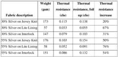
emperature (°C)Solar Irradiance Minimum Shell Transmittance for Positive (
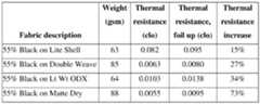
W/m2) Skin Heat Flux for
[00123] A shell fabric with a transmittance of at least 0.56 will allow sufficient solar transmission into the ESHG material construction to provide net positive heat flux toward the skin at 0 °C under solar irradiances greater than 300 W/m
2. The ESHG material construction described in prior examples has a shell solar transmittance of 0.51, and it was tested at 0 °C and 1000 W/m
2 and found to provide net positive heat flux toward the skin. The modeling results shown in Table 9 are consistent with the test results. The model also indicates that the ESHG construction described above will provide net positive skin heat flux at 0 °C and lower sunlight intensities of 600 W/m
2, and also at -20 °C for sunlight intensities of at least 600 W/m
2 and greater. [00124] A further experiment was conducted to evaluate the impact of the lining fabric selected for the layered material construction. [00125] Various layered material constructions were designed that allowed for transmission of a meaningful amount of sunlight through the outer layers for absorption at the innermost layer, closest to the skin, to generate a local solar heating effect. Each material construction consisted of an outermost shell fabric, a middle insulation layer, and an innermost (i.e., skin side) lining fabric. In total, four different material constructions were assembled by stacking commercially available synthetic woven fabrics using the same polyester sheet insulation (60-g/m
2, 11.5-mm thick). Three were made using a translucent grey fabric (36 g/m
2, 0.04-mm thick) as the shell and one of three linings: a white fabric (70 g/m
2, 0.08-mm thick), a black fabric (70 g/m
2, 0.08-mm thick), and a light grey fabric (40 g/m
2, 0.07-mm thick) with a patterned print of heat-retention elements at 50% surface coverage. The heat-retention elements are multilayered and engineered to exhibit both high solar absorptivity and low thermal 33 106477\286869\SJP\46474239.1 Attorney Docket No.106477-286870 Transmission Date: September 18, 2024 IPN: CSP420X(PCT) emissivity. The resulting engineered lining enhances solar absorption while minimizing re- emission heat losses. A fourth material construction was made to represent standard outerwear using a more opaque black shell fabric (70 g/m
2, 0.1-mm thick) and the same black lining fabric and sheet insulation described above. [00126] The thermal performance of the material constructions was examined under 1000 W/m
2 of solar irradiance. The experimental setup and the individual fabric layers are presented in Figure 21. [00127] The measured skin heat fluxes for the four different layered material constructions exposed to 1000 W/m
2 of solar irradiance at 0°C are presented in Figure 22. Although all samples possess similar thermal resistance to conduction and convection due primarily to the sheet insulation layer, the more opaque black shell sample exhibited the lowest skin heat flux (71 W/m
2). In other words, this material construction provides the lowest solar heat gain due to the
lower solar transmittance of its shell fabric (τ
solar = 20%). For the material constructions with the translucent shell (τsolar = 43%), the white (low solar absorption) lining performed the worst (118 W/m2 net heat flux toward the skin) followed by the black lining (144 W/m
2) and the patterned lining (220 W/m
2). [00128] The material construction with the more opaque shell fabric exhibited the lowest solar heat gain because more solar energy was blocked at the outermost surface. Heat absorbed at this location can readily escape into the cold environment. The greater solar heat gain for the fabric stack with the patterned lining was due to the combination of a solar-transmitting shell and insulation layer with a lining fabric engineered to exhibit greater solar absorptance. Solar energy was thus absorbed and trapped closer to the skin and an almost 3x increase in net skin heat flux was observed. These results might be considered counterintuitive since black is typically viewed as the warmest color in sunlight so outerwear with black shell fabrics might be expected to be warmer in the sun. However, the important concept illustrated here is the importance of the depth at which the sunlight is absorbed. By designing material constructions that enhance sunlight transmission through outer insulating layers, solar energy can be absorbed closer to the body thereby enhancing solar heat gain. [00129] Although certain embodiments have been illustrated and described herein, it will be appreciated by those of ordinary skill in the art that a wide variety of alternate and/or 34 106477\286869\SJP\46474239.1 Attorney Docket No.106477-286870 Transmission Date: September 18, 2024 IPN: CSP420X(PCT) equivalent embodiments or implementations calculated to achieve the same purposes may be substituted for the embodiments shown and described without departing from the scope. Those with skill in the art will readily appreciate that embodiments may be implemented in a very wide variety of ways. This application is intended to cover any adaptations or variations of the embodiments discussed herein. Therefore, it is manifestly intended that embodiments be limited only by the claims and the equivalents thereof. 35 106477\286869\SJP\46474239.1
 = ^ − [0035] With reference to the above equations, qconvection is heat transfer due to convection, where h is the convection heat transfer coefficient, Ts is the surface temperature, and Ta is the ambient temperature; qconduction is heat transfer due to conduction, where k is thermal conductivity, A is the cross-sectional area through which conduction is occurring, T1 is the temperature of the object losing heat, and T2 is the temperature of the object receiving heat; and qradiation is heat transfer due to radiation, where σ is the Boltzmann constant, ε is the weighted 5 106477\286869\SJP\46474239.1 Attorney Docket No.106477-286870 Transmission Date: September 18, 2024 IPN: CSP420X(PCT) average thermal emittance, A is the surface area, T1 is the temperature of the surface, and T2 is the temperature of the object or environment receiving heat. [0036] Consider the scenario in which the environmental ambient temperature is lower than body temperature. Since apparel and footwear materials are worn next to the body, and because there is some conductive heat transfer between the body and the material worn over it, then the temperature difference (∆T) between the body and the adjacent material is typically smaller than the ∆T between the outermost material layer and the environment. Thus, under certain conditions, such as when the (∆T) between the outermost material layer and the environment is large, material modifications made to restrict the heat transfer to the environment can have a larger effect on total heat retention than modifications made to restrict heat transfer between the body and the innermost or adjacent material layer. [0037] In an embodiment, materials with low thermal emittance, such as metals, can be applied to the outermost material layer to restrict radiant heat transfer from or through the base material to the environment and provide for apparel and footwear with enhanced heat retention. Thus, aluminum can be used for this purpose. However, aluminum may oxidize and abrade when exposed to the environment and during use on the outermost layer of a garment. The thermal emittance of the surface of a material is its effectiveness in emitting energy as thermal radiation. Quantitatively, thermal emittance is the ratio of the thermal radiation emitted by a surface to the radiation that would be emitted by an ideal blackbody surface at the same temperature as given by the Stefan–Boltzmann law. The ratio varies from 0 to 1 (e.g., 100%), where the surface of a perfect blackbody radiator would have an emittance of 1 while a surface that solely reflects thermal radiation from its surroundings would have an emittance of 0. [0038] In other embodiments, a low thermal emittance layer may be present on an inward facing surface, such as the innermost facing surface of the base layer or liner. Such an inner layer may be provided in addition to, or instead of, a low thermal emittance material on the outermost material surface. [0039] A protective polymer layer on top of a metal surface, such as aluminum, can protect the metal surface and prevent oxidation and abrasion. Unfortunately, polymer coatings have high thermal emittances, which negates the effect of placing a metal having a low thermal emittance on the exterior of a garment for the purpose of minimizing radiant heat losses to the 6 106477\286869\SJP\46474239.1 Attorney Docket No.106477-286870 Transmission Date: September 18, 2024 IPN: CSP420X(PCT) surroundings and thereby increasing heat retention in the garment. The conventional wisdom in view of these observations would be to place the metallic elements in the interior of the garment as is the case in garments that use the Omni-Heat™ Reflective technology. [0040] However, in an embodiment, the inventors herein disclose a multilayered construction of metal (e.g., aluminum) with a polymeric overlayer, which together provide a multilayered heat-retention element that surprisingly exhibits low thermal emittance as compared to the base materials used in garment construction. As detailed in the Examples below, testing of this multilayered construction revealed, surprisingly, that this multilayered heat-retention element provides weighted average emittances of around 0.1 (e.g. 10%) (emittance scales from 0 to 1, so 0.1 is a low value), for example 0.07-0.13 (e.g., 7%-13%). These heat-retention elements were coupled to the outside of different base fabrics and tested using standard hotplate methods. Even at 30% surface coverage, the heat-retention elements increased thermal resistance of the different base fabrics by 20 to 67% (see Table 1), which is significant and surprising. [0041] Furthermore, by adding a colorant to the protective polymeric overlayer, absorption of solar radiation can occur and enhance the heat-retention capabilities of the multilayered elements. As used herein, the term “colorant” means a substance that is added to change the color of a material, such as a high solar absorptance layer, for example a polymeric overlayer. Most colorants can be classified as dyes or pigments, or containing some combination of these. For example, a black colorant may result in maximum solar absorptance (e.g., absorptance of energy at wavelengths between 0.3 and 2.5 µm) so that the heat-retention elements provide, when applied to the exterior surface of a garment, significantly enhanced heat retention properties when sunlight is present, as direct or scattered sunlight. At 55% surface coverage, the heat-retention elements increased thermal resistance of different base fabrics by 15 to 73% (see Table 2), which is significant and surprising. [0042] In certain embodiments, a colorant may be added to a solar absorptance layer, such as a polymer, in an amount of 3-10 wt%, such as about 5-8 wt%, of the layer. [0043] Furthermore, as the results shown in Figure 14 demonstrate, the heat-retention elements may function, surprisingly, as solar collectors that absorb more heat, conduct it into the base fabric to which they are coupled and to the underlying insulation, and hold this heat longer than a base fabric with a similar solar absorptance. 7 106477\286869\SJP\46474239.1 Attorney Docket No.106477-286870 Transmission Date: September 18, 2024 IPN: CSP420X(PCT) [0044] In other embodiments, as discussed in more detail below, functions of the heat- retention elements may be provided by various elements, which may be present on different surfaces, or on/between different layers, of a garment. [0045] Because black colorants are typically emissive, a person of ordinary skill in the art might expect that increased absorptance might be offset by the increased thermal emittance (e.g., emittance at wavelengths between 5 and 40 µm) of the black colorant. However, surprisingly, testing has revealed that this is not the case. Even with a black colorant in the polymeric overlayer, a heat-retention element still reduces the overall average thermal emittance of a base fabric, leading to increased heat retention. [0046] In another embodiment, a photochromic colorant can be used in the polymeric overlayer that turns from clear to colored, such as black, when the sun is shining to achieve both maximized low emittance when the sun is not shining, and maximized solar absorptance when the sun is shining. Photochromic colorants may be classified as P-type or T-type. P-type photochromic colorant systems may be switched in each direction with different wavelengths of light. P-type systems change color when irradiated with a specific wavelength range, then remain in this state after a removal of the stimulus. It is only when they are subjected to light of a different set of wavelengths that they return to their original color. Alternatively, T-type behavior is exhibited if light is able to drive the change in just one direction. T-type systems may fade back to their original state, through a thermal back-reaction, when they are no longer exposed to the light source. Reversibility is an important aspect of both types of photochromism, for example light-sensitive materials that undergo changes of an irreversible nature may not be considered photochromic. Real-world colorants may not always match the strict definitions of the two types of behavior described above, but most are readily categorized. Examples of T-type colorants of the present disclosure may include but are not limited to spiropyrans, spirooxazines, and napthopyrans, among others. Examples of P-type colorants of the present disclosure may include but are not limited to diarylethenes and fugides, among others. [0047] Referring to Figure 1, the disclosed heat-retention material 10 includes a base fabric 20 having an externally facing surface 12 (e.g., outward facing surface with respect to the body of a wearer of the material), and an internally facing surface 13 (e.g., inward facing surface with respect to the body of a wearer of the material), that can have one or more performance characteristics. Disclosed herein, internally facing surface 13 may be understood to be closer to a 8 106477\286869\SJP\46474239.1 Attorney Docket No.106477-286870 Transmission Date: September 18, 2024 IPN: CSP420X(PCT) body of a wearer of heat-retention material 10 as compared to externally facing surface 12. Coupled to the externally facing surface 12 of the base fabric are a plurality of heat-retention elements 15, wherein the placement and spacing of the plurality of heat-retention elements leaves a portion of the base fabric uncovered and enables the base material to retain at least partial performance of the performance characteristic. These heat-retention elements 15 have been specifically developed as herein disclosed to provide heat-retention material 10, such as a fabric, with high solar absorptance at wavelengths between 0.3 and 2.5 µm and yet low thermal emittance at wavelengths ranging from 5 and 40 µm, such that it is able to retain heat and absorb solar radiation to provide a better heat-retention material 10 than a base fabric 20 in the absence of the heat-retention elements 15. [0048] In embodiments, each heat-retention element 15 has a low thermal emittance layer 16. In embodiments, the low thermal emittance layer 16 of the heat-retention elements 15 are a discontinuous array of a foil, such as a metallic foil (e.g., malleable metals including but not limited to aluminum, copper, tin, silver and gold), which in specific embodiments is an aluminum foil. In addition to the low thermal emittance layer 16, the heat-retention elements 15 include a high solar absorptance layer 18 located on the outermost surface of the heat-retention element 15, for example over the top of the outward facing surface of the low thermal emittance layer 16. For reference, “outward facing” is exemplified by the direction shown by arrow 21 at Figure 1. The heat-retention elements 15 may include additional layers such as a release layer, an adhesive layer, a protective layer against abrasion and oxidation and the like, however layer thicknesses must remain sufficiently small that the weighted average emittance of a fabric onto which the heat-retention elements are coupled to the exterior surface does not increase back to the level of the fabric itself. In embodiments, the heat-retention elements 15 exhibit weighted average thermal emittances of 0.1 to 0.85 (e.g., 10%-85%), preferably less than 0.7, and most preferably less than 0.5. In embodiments, the heat-retention material 10 onto which the heat- retention elements 15 are coupled to the exterior surface exhibit weighted average thermal emittances less than 0.9 (e.g., 90%), preferably less than 0.7 (e.g., 70%), and most preferably less than 0.5 (e.g., 50%). In embodiments, the heat-retention material 10 has an emittance that is between about 10% and about 80%, such as about 15 - 65%, about 30 - 80%, about 10 - 50%, 30 - 70%, or about 40 - 60%. Thus, as discussed herein, a low thermal emittance layer refers to a layer (e.g., low thermal emittance layer 16) that renders a heat-retention element (e.g., heat- 9 106477\286869\SJP\46474239.1 Attorney Docket No.106477-286870 Transmission Date: September 18, 2024 IPN: CSP420X(PCT) retention element 15) with a weighted average thermal emittance of 0.1 to 0.85, preferably less than 0.7, most preferably less than 0.5, and/or which renders a heat retention material (e.g., heat retention material 10) with a weighted average thermal emittance less than 0.9, preferably less than 0.7, most preferably less than 0.5. [0049] In embodiments, the heat-retention elements 15 exhibit weighted average solar absorptances of at least 50% (e.g., 0.5), such as greater than 50%, greater than 55% (e.g., 0.55), greater that 60% (e.g., 0.60), greater than 65% (e.g., 0.65), greater than 70% (e.g., 0.70), greater than 75% (e.g., 0.75), greater that 80% (e.g., 0.80), greater than 85% (e.g., 0.85), or even greater than 90% (e.g., 0.90) solar absorptance. In embodiments, the heat-retention material 10 onto which the heat-retention elements 15 are coupled to the exterior surface exhibit weighted average solar absorptances of at least 50%, such as greater than 50%, greater than 55%, greater that 60%, greater than 65%, greater than 70%, greater than 75%, greater that 80%, greater than 85%, or even greater than 90% weighted average solar absorptance. Absorptance, as herein discussed, refers to a fraction of absorbed light to incident light, hence absorptance scales from 0 to 1, where a value of 1 implies all incident light is absorbed. Further, a high solar absorptance layer as herein disclosed is a layer (e.g., high solar absorptance layer 18) that renders a heat-retention element (e.g., heat-retention elements 15) with a weighted average solar absorptance of at least 0.5, or at least 0.55, or at least 0.6, or at least 0.65, or at least 0.7, or at least 0.75, or at least 0.80, or at least 0.85, or at least 0.90 and/or which renders a heat retention material (e.g., heat retention material 10) with a weighted average solar absorptance of at least 0.5, or at least 0.55, or at least 0.6, or at least 0.65, or at least 0.7, or at least 0.75, or at least 0.80, or at least 0.85, or at least 0.90. [0050] In embodiments, the heat-retention elements 15 are relatively small, such as dots that are 0.1 to 10 mm in diameter, and are arranged discontinuously on the base fabric 20, so as not to unduly interfere with the performance characteristics of the base fabric 20. Thus, in various embodiments, a base fabric 20, for example for body gear, is disclosed that may use a plurality of heat-retention elements 15 coupled to the base fabric 20, such as the outward facing surface of the outermost layer of a garment. In an embodiment, a discontinuous pattern of heat- retention elements 15 manages body heat by absorbing solar radiation while mitigating the emission of radiant heat back to the environment from or through the surface of the outermost layer of a garment. 10 106477\286869\SJP\46474239.1 Attorney Docket No.106477-286870 Transmission Date: September 18, 2024 IPN: CSP420X(PCT) [0051] In embodiments, a plurality of heat-retention elements 15 are disposed on the base fabric 20 in a generally discontinuous array, whereby some of the base fabric 20 is exposed between adjacent heat-retention elements 15. In various embodiments, the heat-retention elements 15 may be arranged in an array of separate elements, whereas in other embodiments, discussed at greater length below, the heat-retention elements 15 may be arranged in an interconnected pattern. In some embodiments, heat-retention elements 15 may take the form of a solid shape or closed loop member, such as a circle, square, hexagon, or other shape, including an irregular shape. In other embodiments, the discontinuous pattern of heat-retention elements 15 may take the form of a lattice, grid, or other interconnected pattern. [0052] Generally, a sufficient surface area of the surface of the base fabric on which the heat-retention elements are disposed should be exposed to provide the desired base fabric performance characteristic or function (e.g., stretch, drape, texture, breathability, moisture vapor transfer, air permeability, and/or wicking). For example, if there is too little exposed base fabric, properties such as moisture vapor transfer and/or air permeability may suffer, and even disproportionately to the percentage of coverage. As used herein, the term “surface coverage area” refers to a measurement taken from a unit cell, for example, a unit cell can be a region that includes a plurality of heat-retention elements. In an example, a unit cell is at least a 1 inch by 1 inch unit cell at a given point in the fabric of the discontinuous array of heat-retention elements and does not necessarily correspond to the percentage of the entire garment covered by heat- retention elements, for example a 1 inch by 1 inch unit cell (25.4 mm by 25.4 mm unit cell), a 2 inch by 2 inch unit cell (50.8 mm by 50.8 mm unit cell), a 3 inch by 3 inch unit cell (76.2 mm by 76.2 mm unit cell) and the like. In an example, a unit cell may be the entire exterior surface of a material measured from seam to seam on a given garment. [0053] In embodiments, the heat-retention elements 15 cover a sufficient surface area of the outward facing surface of base fabric 20 to generate the desired degree of heat retention (e.g., mitigation of heat emission or absorption of solar radiation, for example, when exposed to direct or even indirect sunlight, or both mitigation of heat emission and absorption of solar radiation). A sufficient area of outward facing surface of base fabric 20 may be exposed to provide, or maintain, the desired base fabric performance characteristic or function (e.g., breathability, moisture vapor or air permeability, or wicking). In various embodiments, heat-retention elements 15 may cover a sufficient surface area of the base fabric 20 to achieve the desired degree of heat 11 106477\286869\SJP\46474239.1 Attorney Docket No.106477-286870 Transmission Date: September 18, 2024 IPN: CSP420X(PCT) retention, for example, having a surface coverage area of the heat-retention elements 15 of about 5 - 95%, about 10 - 90%, about 20 - 80%, 30 - 70%, 40 - 60% or even about 55% in various embodiments, for example in specific unit cell, such as a 1 inch by 1 inch unit cell (25.4 mm by 25.4 mm unit cell). In a given article or even a portion of the article, the surface area coverage by the heat-retention elements may be consistent or it may vary within or across regions of the article. [0054] In embodiments, individual heat-retention elements are about 1 mm in diameter although larger and smaller sizes are contemplated. In embodiments, the individual heat- retention elements are in the range from about 0.1 mm in diameter to about 10.0 mm in diameter, such as about 0.1, 0.5, 1.0, 1.5, 2.0, 2.5, 3.0, 3.5, 4.0, 4.5, 5.0, 5.5, 6.0, 6.5, 7.0, 7.5, 8.0, 8.5, 9.0, 9.5, or 10.0 mm in diameter or any value or range within. In embodiments, the individual heat- retention elements in a specific region are spaced apart by about 0.1 to about 10.0 mm, such as about 0.1, 0.5, 1.0, 1.5, 2.0, 2.5, 3.0, 3.5, 4.0, 4.5, 5.0, 5.5, 6.0, 6.5, 7.0, 7.5, 8.0, 8.5, 9.0, 9.5, or 10.0 mm or any value or range within. As used herein, the diameter is the average distance from the center of the heat-retention elements regardless of shape, for example the geometric center of a heat-retention element, such as the center of a circle, triangle, square, polygon, or even an irregular shape. One of ordinary skill in the art is capable of determining the geometric center of a shape. [0055] In embodiments, a low thermal emittance layer of the individual heat-retention elements comprise or consist of a metal foil, for example an aluminum foil, that has a thickness in the range from about 5 nm to about 100 nm thick, such as about 5, 6, 7, 8, 9, 10, 11, 12, 13, 14, 15, 16, 17, 18, 19, 20, 21, 22, 23, 24, 25, 26, 27, 28, 29, 30, 31, 32, 33, 34, 35, 36, 37, 38, 39, 40, 41, 42, 43, 44, 45, 46, 47, 48, 49, 50, 51, 52, 53, 54, 55, 56, 57, 58, 59, 60, 61, 62, 63, 64, 65, 66, 67, 68, 69, 70, 71, 72, 73, 74, 75, 76, 77, 78, 79, 80, 81, 82, 83, 84, 85, 86, 87, 88, 89, 90, 91, 92, 93, 94, 95, 96, 97, 98, 99, or 100 nm thick, or any value or subrange within contemplated. [0056] In embodiments, a high solar absorptance layer is a polymer or mixture of polymers having a thickness in the range from about 0.1 µm to about 10.0 µm thick, such as about 0.1, 0.2, 0.3, 0.4, 0.5, 0.6, 0.7, 0.8, 0.9, 1.0, 1.1, 1.2, 1.3, 1.4, 1.5, 1.6, 1.7, 1.8, 1.9, 2.0, 2.5, 3.0, 3.5, 4.0, 4.5, 5.0, 5.5, 6.0, 6.5, 7.0, 7.5, 8.0, 8.5, 9.0, 9.5, or 10.0 µm thick, or any value or subrange are also contemplated. Examples of polymers relevant to the present disclosure may include but are not limited to polyethylene, polypropylene, polystyrene, 12 106477\286869\SJP\46474239.1 Attorney Docket No.106477-286870 Transmission Date: September 18, 2024 IPN: CSP420X(PCT) poly(tetrafluoroethylene), polyisobutylene, polyacrylonitrile, polybutadiene, poly(vinyl chloride), poly(methyl acrylate), poly(methyl methacrylate), polybutadiene, polychloroprene, poly(cis-1,4-isoprene), poly(trans-1,4-isoprene), polyurethane, polyester, polyamide, polyether, polyolefin, polyacrylate, poly(3-hydroxybutyric acid) (PHB), poly[(R)-3-hydroxybutyrate-co- (R)-3-hydroxyvalerate] (PHBV), 3-hydroxybutyrate and 3-hydroxyhexanoate (PHBH), poly- lactic acid (PLA), cellulose, chitin, lacquer and natural rubber, among others, or copolymers or combinations thereof. [0057] In embodiments, a high solar absorptance layer includes a colorant, such as a colorant that aids in the absorption of solar energy. In one example, the colorant is a black colorant. In certain examples, the high solar absorptance layer is present only on the exterior surface of the heat-retention elements. In other examples, the high solar absorptance layer can cover, at least partially, portions of the base fabric that do not have the individual heat-retention elements coupled thereto, for example as a coating over both the low thermal emittance layer and the base fabric. [0058] In an embodiment, the heat-retention elements are disposed on the exterior surface of the body gear and/or outermost facing surface of a base fabric such that they are exposed to the environment, which may allow the heat-retention elements, for example, to mitigate radiant heat emission to the environment and absorb solar radiation, while allowing the base fabric to adequately perform its desired functions. In some embodiments, the heat-retention elements may perform these functions without adversely affecting the drape, feel, or other properties of the base fabric. In accordance with various embodiments, the base fabric may be a part of any form of body gear, bodywear, blankets, tents, rain flys, sleeping bags, or any material or apparatus where heat retention is desired. Bodywear, as used herein, includes anything worn on the body, such as, but not limited to, athletic wear such as compression garments, t-shirts, shorts, tights, sleeves, headbands and the like, outerwear, such as jackets, pants, leggings, shirts, gloves, hats, and the like, and footwear. [0059] In various embodiments, the heat-retention elements may be disposed on a base fabric having one or more desired properties or characteristics. In some embodiments, the base fabric may have other desirable attributes, such as abrasion resistance, anti-static properties, anti- microbial activity, water repellence, flame repellence, hydrophilicity, hydrophobicity, wind resistance, solar protection, SPF protection, resiliency, stain resistance, wrinkle resistance, and 13 106477\286869\SJP\46474239.1 Attorney Docket No.106477-286870 Transmission Date: September 18, 2024 IPN: CSP420X(PCT) the like. In other embodiments, the separations between heat-retention elements help allow the exterior facing surface of a base fabric to have a desired drape, look, and/or texture. Suitable base fabrics may include nylon, polyester, polypropylene, rayon, cotton, spandex, wool, silk, fleece, or a blend thereof, or any other material having a desired look, feel, weight, thickness, weave, construction, texture, or other desired property. In various embodiments, allowing a designated percentage of the base fabric to remain uncovered by the multilayered multifunctional heat-retention elements may allow that portion of the base fabric to perform the desired functions. [0060] In various embodiments, a single layer of base fabric 20 may be used comprising the base fabric 20 including an exterior facing surface upon which the heat-retention elements 15 are disposed, whereas other embodiments may use multiple layers of fabric, including a layer of the base fabric 20, coupled to one or more other layers, where the base fabric 20 is the exterior layer with an exterior facing surface upon which the heat-retention elements 15 are disposed, for example overlying insulating layers to form a lofted-material construction. In certain embodiments, the individual heat-retention elements 15 are individually coupled, such as glued, and/or bonded to the base fabric. In certain embodiments, the heat-retention elements 15 are directly coupled to the base fabric. [0061] In various embodiments, the heat-retention elements may be permanently coupled to the base fabric in a variety of ways, including, but not limited to gluing, heat pressing, printing, or stitching. In some embodiments, the heat-retention elements may be coupled to the base fabric by frequency welding, such as by radio or ultrasonic welding. In some embodiments, the heat-retention elements may be coupled to the base fabric using gravure printing. In some specific, non-limiting examples, the gravure printing process may use an engraved roller running in an adhesive bath, which fills the engraved dots or lines of the roller with the adhesive material (e.g., the adhesive that will bond the heat-retention elements to the base fabric). The excess adhesive on the roller may be wiped off using a blade, and the adhesive may then be deposited onto the foil containing the heat-retention material on a carrier material as it passes between the engraved roller and a pressure roller. The heat-retention material is positioned on the carrier material such that the high solar absorptance layer is closer to the carrier material than the low thermal emittance layer, and the adhesive is applied to the surface opposite from the carrier material. In various embodiments, the gravure printing process may include direct gravure, 14 106477\286869\SJP\46474239.1 Attorney Docket No.106477-286870 Transmission Date: September 18, 2024 IPN: CSP420X(PCT) reverse gravure, or differential offset gravure, and in various embodiments, the adhesive weight may be controlled by the percent of solids, the gravure volume, the pattern depth, and/or the speed of the gravure cylinder. Following application of the adhesive by gravure printing to the foil, a substrate (e.g., the base fabric 20) is laminated to the adhesive-containing foil. The laminate is then pressed and cured in a continuous process, after which the carrier material is peeled off to leave heat-retention elements 15 on the substrate in a pattern consistent with the pattern engraved on the gravure roller. [0062] In various embodiments, the heat-retention elements may be applied in a pattern or a continuous or discontinuous array. For example, as illustrated in Figures 15A -15H, the heat- retention elements may take the form of an array of discrete solid or closed loop members, adhered or otherwise secured to the base fabric in a desired pattern. Such a configuration has been found to provide insulation to the user while still allowing the base fabric to perform desired properties (e.g., breathe and stretch). In various embodiments, such discontinuous, discrete, separate heat-retention elements may take the form of circles, triangles, squares, pentagons, hexagons, octagons, stars, crosses, crescents, ovals, or any other suitable shape. [0063] Although the embodiments illustrated in Figures 15A – 15H show the heat- retention elements as separate, discrete elements, in some alternate embodiments, some or all of the heat-retention elements may be arranged such that they are in connection with one another or former larger elements, such as stripes, wavy lines, or a matrix/lattice pattern or any other pattern that permits partial coverage of the base fabric. For example, as illustrated in Figures 16A – 16F, the configuration of the heat-retention elements disposed on a base fabric may be in the form of a variety of partially or completely connected elements, and the pattern may combine both discontinuous elements (such as those illustrated in Figures 15A – 15H) and interconnected geometrical patterns (such as those illustrated in Figures 16A – 16F). In various embodiments, the pattern of heat-retention elements may be symmetrical, ordered, random, and/or asymmetrical. Further, as discussed below, the pattern of heat-retention elements may be disposed on the base fabric at strategic locations to improve the performance of bodywear. In various embodiments, the size and/or spacing of the heat-retention elements may also be varied in different areas of the bodywear to balance the need for enhanced insulation properties in certain regions while preserving the functionality of the base fabric. 15 106477\286869\SJP\46474239.1 Attorney Docket No.106477-286870 Transmission Date: September 18, 2024 IPN: CSP420X(PCT) [0064] In various embodiments, the placement, pattern, and/or coverage ratio of the heat- retention elements may vary. Of course, the coverage locations and ratios can change depending on the type of garment. In some embodiments, the degree of coverage by the heat-retention elements may vary in a gradual fashion over the entire garment as needed. In various embodiments, the pattern of heat-retention elements may be symmetrical, ordered, random, and/or asymmetrical. Further, as discussed below, the pattern of heat-retention elements may be disposed on a surface of a base fabric at strategic locations to improve the performance of the body wear. In various embodiments, the size of the heat-retention elements may also be varied to balance the need for enhanced insulation properties and to preserve the functionality of the base fabric. [0065] In various embodiments, the heat-retention material described herein may have superior heat-retention characteristics as compared to other materials that lack the heat-retention material herein disclosed. [0066] ASTM G173 provides the solar spectrum at the earth’s surface. The fraction of total solar power in the UV region is 3.2% (UVA and UVB, 0.28 – 0.38 μm), 53.4% in the visible region (0.38 – 0.78 µm), and 43.4% in the near IR region (0.78 – 3.0 μm). Effectively all solar energy is contained in wavelengths < 2.5 μm (see Figure 2). [0067] A Planck distribution provides the radiation emitted by a blackbody surface at a given absolute temperature (see Figure 3): at typical surface temperatures (0-70°C), peak emission is at ~10 μm. Surface emission is much less intense, but far broader than solar irradiation. At nominal skin temperature (35°C), ca. 95% of the emitted energy by a blackbody is contained within the spectral region 5 ≤ # ≤ 40 μm. [0068] Thermal emittance, or emissivity is a measure of an object’s ability to emit radiant thermal energy. Values of emittance vary between 0 and 1. Metals tend to exhibit low thermal emittances and high thermal reflectances. Polymers tend to exhibit high thermal emittances and low thermal reflectances. [0069] For a given object, its measured emittance depends on the material characteristics of its surface. In fact, it is common practice to increase the emittance of a metal object by painting it black, because paint is a polymeric coating and black colorants typically absorb and emit more infrared thermal radiation than other colorants. This is demonstrated by the test shown in Figure 4. A metal plate 401 was placed on a hotplate 405 that was painted black to create a 16 106477\286869\SJP\46474239.1 Attorney Docket No.106477-286870 Transmission Date: September 18, 2024 IPN: CSP420X(PCT) high-emittance surface. A piece of high-emittance black electrical tape 406 (tape is a polymeric film with an adhesive layer) was placed on top of the metal plate 401. This set-up was imaged using an infrared (IR) thermal imaging camera 410 on a stand 412, which directly measures radiosity, which is generally proportional to thermal emittance. This radiosity is converted into temperature using the camera internal software according to Planck’s distribution and the results are typically reported as temperatures, or apparent temperatures. For a given emittance setting on the IR camera, the thermal emittance of objects maintained at the same actual temperature will be proportional to their apparent temperature as measured by the camera. The hotplate was set to around 37 °C and a thermal image was measured. Thermocouples were used to ensure the temperatures of the hotplate (refer to arrow 415) and metal plate (refer to arrow 418) were approximately 37 °C (see Figure 4). [0070] The results of this test are shown in Figure 5. An artefact region 502 is masked that is due to the reflection of the thermal camera (e.g., camera 410 at Figure 4) on the metal plate 401 (note in Figure 4 how the camera sits directly above the metal plate). The painted black hotplate 405 (corresponding to Box 2405a) appears with an apparent temperature of 36.5 °C, which is consistent with the actual temperature measured using the thermocouple. In contrast, the metal plate 401 (corresponding to Box 1401a) appears with an apparent temperature of 22.4 °C, which is much lower than the actual temperature measured using the thermocouple, indicating that the metal plate emits less radiant thermal energy than the black painted region. Thus, when the outermost surface of an object is metallic, the object is expected to exhibit low thermal emittance and retain more heat, as opposed to losing thermal energy via radiation to its surroundings. This is further demonstrated in Figure 5 by placement of a small strip of black electrical tape 406, which is a thin polymeric film with an underlying adhesive layer, onto the metal plate 401. The apparent temperature of the black electrical tape (corresponding to Box 3 406a) is 36.8 °C, which is also consistent with the actual temperature of the metal plate measured using the thermocouple. When the outermost surface of an object is polymeric, the object is expected to exhibit high thermal emittance, which leads to larger radiative heat losses. [0071] As shown in Figures 6, 7, 9, and 10, heat-retention elements (Figure 6 and Figure 7) and heat-retention elements coupled to fabric surfaces (Figure 9 and Figure 10) were tested to measure thermal emittance and solar absorptance. Spectral measurements in the solar range, constituting the ultraviolet, visible, and near IR (UV/Vis/NIR) wavelength range (0.25 < λ < 2.5 17 106477\286869\SJP\46474239.1 Attorney Docket No.106477-286870 Transmission Date: September 18, 2024 IPN: CSP420X(PCT) µm), were conducted using a Laboratory Portable SpectroReflectometer (LPSR) 300 spectrophotometer, in general accordance with ASTM E903. Spectral measurements from 2.5 – 40 μm, constituting the mid IR (MIR) thermal range, were conducted using a Nicolet iS50 Fourier-transform infrared (FTIR) spectrophotometer with a Pike Upward MID integrating sphere, in general accordance with ASTM E408. The average spot size for each measurement: rectangular spot ca. 7.6 mm × 2 mm for UV/Vis/NIR (0.25 − 2.5 µm); elliptical spot ca. 8.5 mm × 7.5 mm for MIR (2.5 − 40 µm). In both instruments, the measurement spot size was determined to be sufficiently large relative to the heat-retention elements when applied to a fabric surface that the measurement represented an average of the spectral response for the multi- material (i.e., fibers and elements) fabric surface. This was verified by considering the deviation between measurements from three samples taken in different positions in each instrument. Heat- retention elements were measured on card stock. [0072] Reflectance and transmittance measurements were conducted. Since energy conservation dictates that reflectance (ρ(λ)) + transmittance (τ(λ)) + absorptance (α(λ)) = 1, the absorptance of an object can be calculated from its measured spectral reflectance and transmittance. By Kirchoff’s law, spectral emittance (ε(λ)) is equal to the spectral absorptance (α(λ)). The fabrics and card stock are nominally opaque (i.e., $ = 0) for 5 ≤ λ ≤ 40 %m; therefore α(λ) = 1 − &(λ), = ε (λ). The weighted average thermal emittance can be calculated: ) ^^#^ ∙ +^#^ ∙ ^# ^̅ = ^4^ ) +^#^ ∙ ^# where G^λ^ is the Planck blackbody distribution at 35 °C. The weighted average solar absorptance can be calculated: ) ^^#^ ∙ +^#^ ∙ ^# ^^ = ^5^ ) +^#^ ∙ ^# where G^λ^ is the solar spectrum given by ASTM G173. 18 106477\286869\SJP\46474239.1 Attorney Docket No.106477-286870 Transmission Date: September 18, 2024 IPN: CSP420X(PCT) [0073] Referring to Figures 6, 7, 9, and 10, the samples comprising heat-retention elements in which a thin black polymeric layer is the outermost layer overlying a thin metallic layer lead to lower thermal emittance than a purely black polymeric heat-retention element. This was an unexpected and surprising result. [0074] Specifically, Figure 6 depicts thermal emittance versus wavelength of various heat retention elements, including a silver heat-retention element (line 605) (e.g., where the high solar absorptance layer lacks a colorant), a heat-retention element of the present disclosure (line 610), and a black polymeric heat-retention element (line 615) (e.g., pure black polymeric heat- retention element lacking metal). In the example shown at Figure 6, the heat-retention element (line 610) comprised a black metallic heat-retention element. Specifically, the low emittance layer (e.g., low emittance layer 16 at Figure 1) comprised a metal and the high solar absorptance layer (e.g., high solar absorptance layer 18 at Figure 1) comprised a black colorant in a polymeric overlayer. The silver heat-retention element (line 605) exhibited a weighted average thermal emittance of 10.3%, the black metallic heat-retention element (line 610) exhibited a weighted average thermal emittance of 53.8%, and the black polymeric heat-retention element (line 615) exhibited a weighted average thermal emittance of 91.3%. [0075] Figure 7 depicts solar absorptance versus wavelength of the various heat-retention elements discussed above with regard to Figure 6, including the silver heat-retention elements (line 705), heat-retention element (line 710) and black polymeric heat-retention element (line 715). Similar to that discussed above with regard to Figure 6, the heat-retention element comprised a black metallic heat-retention element. The silver heat-retention element (line 705) exhibited a weighted average absorptance of 17.1%, the heat-retention element (line 710) exhibited a weighted average absorptance of 91.5%, and the black polymeric heat-retention element (line 715) exhibited a weighted average thermal emittance of 93.5%. [0076] Figure 9 illustrates the thermal emittance versus wavelength for two different fabrics: a black base fabric (line 905) and the same black base fabric onto which heat-retention elements of the present disclosure (line 910) are coupled and which cover 55% of the surface. With reference to Figure 9, the heat-retention elements comprised a black metallic heat-retention element, similar to that discussed above with regard to Figure 6 and Figure 7. The black base fabric (line 905) lacking the heat-retention elements exhibited a weighted average emittance of 19 106477\286869\SJP\46474239.1 Attorney Docket No.106477-286870 Transmission Date: September 18, 2024 IPN: CSP420X(PCT) 93.5%. The black base fabric onto which heat-retention elements (line 910) were coupled exhibited a weighted average emittance of 68.3%. [0077] Figure 10 illustrates the solar absorptance versus wavelength for the two different fabrics discussed above with regard to Figure 9, specifically, the black base fabric (line 1005) and the same black base fabric onto which heat-retention elements of the present disclosure are coupled (line 1010) and cover 55% of the surface. The black base fabric (line 1005) lacking the heat-retention elements exhibited a weighted average absorptance of 91.9%. The black base fabric onto which heat-retention elements (line 1010) were coupled exhibited a weighted average absorptance of 92.0%. [0078] Thermal resistance was measured using a standard hotplate method in general accordance with ASTM F-1868, Part A: Dry Heat Transport, under the following conditions: Tplate = 35 °C, Tambient = 20 °C, relative humidity = 65%, and air velocity = 1 m/s. Results for six different fabrics with silver foil laminated to the fabric surface are shown in Table 1. For each fabric, the thermal resistance is significantly greater when the silver foil is on the outermost surface of the fabric, facing away from the heat source. The thermal resistance is also greater, for a given fabric, when the silver foil surface coverage is greater. Weight Thermal Thermal Thermal
 Table 7. Properties of the Layers used in the Enhanced-Solar-Heat-Gain Lofted Material Construction Estimated Solar Irradiance Wind Velocit (m/s) (W/m2) below which Skin Heat eat Flux moves to Negative
 or t e n ance - o ar- eat- a n o te ater a onstruct on at C. [00121] The results show that more sunlight is needed to maintain net positive skin heat flux under windy conditions, consistent with expectations. [00122] Using the same approach with thermal modeling, the minimum shell transmittance can be estimated above which the skin heat flux is positive. Results are shown in Table 9 for three different sunlight intensities at two different temperatures under no-wind conditions (< 0.5 m/s). 32 106477\286869\SJP\46474239.1 Attorney Docket No.106477-286870 Transmission Date: September 18, 2024 IPN: CSP420X(PCT) Temperature (°C)Solar Irradiance Minimum Shell Transmittance for Positive (W/m2) Skin Heat Flux for
 [00123] A shell fabric with a transmittance of at least 0.56 will allow sufficient solar transmission into the ESHG material construction to provide net positive heat flux toward the skin at 0 °C under solar irradiances greater than 300 W/m2. The ESHG material construction described in prior examples has a shell solar transmittance of 0.51, and it was tested at 0 °C and 1000 W/m2 and found to provide net positive heat flux toward the skin. The modeling results shown in Table 9 are consistent with the test results. The model also indicates that the ESHG construction described above will provide net positive skin heat flux at 0 °C and lower sunlight intensities of 600 W/m2, and also at -20 °C for sunlight intensities of at least 600 W/m2 and greater. [00124] A further experiment was conducted to evaluate the impact of the lining fabric selected for the layered material construction. [00125] Various layered material constructions were designed that allowed for transmission of a meaningful amount of sunlight through the outer layers for absorption at the innermost layer, closest to the skin, to generate a local solar heating effect. Each material construction consisted of an outermost shell fabric, a middle insulation layer, and an innermost (i.e., skin side) lining fabric. In total, four different material constructions were assembled by stacking commercially available synthetic woven fabrics using the same polyester sheet insulation (60-g/m2, 11.5-mm thick). Three were made using a translucent grey fabric (36 g/m2, 0.04-mm thick) as the shell and one of three linings: a white fabric (70 g/m2, 0.08-mm thick), a black fabric (70 g/m2, 0.08-mm thick), and a light grey fabric (40 g/m2, 0.07-mm thick) with a patterned print of heat-retention elements at 50% surface coverage. The heat-retention elements are multilayered and engineered to exhibit both high solar absorptivity and low thermal 33 106477\286869\SJP\46474239.1 Attorney Docket No.106477-286870 Transmission Date: September 18, 2024 IPN: CSP420X(PCT) emissivity. The resulting engineered lining enhances solar absorption while minimizing re- emission heat losses. A fourth material construction was made to represent standard outerwear using a more opaque black shell fabric (70 g/m2, 0.1-mm thick) and the same black lining fabric and sheet insulation described above. [00126] The thermal performance of the material constructions was examined under 1000 W/m2 of solar irradiance. The experimental setup and the individual fabric layers are presented in Figure 21. [00127] The measured skin heat fluxes for the four different layered material constructions exposed to 1000 W/m2 of solar irradiance at 0°C are presented in Figure 22. Although all samples possess similar thermal resistance to conduction and convection due primarily to the sheet insulation layer, the more opaque black shell sample exhibited the lowest skin heat flux (71 W/m2). In other words, this material construction provides the lowest solar heat gain due to thelower solar transmittance of its shell fabric (τsolar = 20%). For the material constructions with the translucent shell (τsolar = 43%), the white (low solar absorption) lining performed the worst (118 W/m2 net heat flux toward the skin) followed by the black lining (144 W/m2) and the patterned lining (220 W/m2). [00128] The material construction with the more opaque shell fabric exhibited the lowest solar heat gain because more solar energy was blocked at the outermost surface. Heat absorbed at this location can readily escape into the cold environment. The greater solar heat gain for the fabric stack with the patterned lining was due to the combination of a solar-transmitting shell and insulation layer with a lining fabric engineered to exhibit greater solar absorptance. Solar energy was thus absorbed and trapped closer to the skin and an almost 3x increase in net skin heat flux was observed. These results might be considered counterintuitive since black is typically viewed as the warmest color in sunlight so outerwear with black shell fabrics might be expected to be warmer in the sun. However, the important concept illustrated here is the importance of the depth at which the sunlight is absorbed. By designing material constructions that enhance sunlight transmission through outer insulating layers, solar energy can be absorbed closer to the body thereby enhancing solar heat gain. [00129] Although certain embodiments have been illustrated and described herein, it will be appreciated by those of ordinary skill in the art that a wide variety of alternate and/or 34 106477\286869\SJP\46474239.1 Attorney Docket No.106477-286870 Transmission Date: September 18, 2024 IPN: CSP420X(PCT) equivalent embodiments or implementations calculated to achieve the same purposes may be substituted for the embodiments shown and described without departing from the scope. Those with skill in the art will readily appreciate that embodiments may be implemented in a very wide variety of ways. This application is intended to cover any adaptations or variations of the embodiments discussed herein. Therefore, it is manifestly intended that embodiments be limited only by the claims and the equivalents thereof. 35 106477\286869\SJP\46474239.1


