WO2025048479A1 - Regulator-integrated drip chamber having locking device and infusion set comprising same - Google Patents
Regulator-integrated drip chamber having locking device and infusion set comprising sameDownload PDFInfo
- Publication number
- WO2025048479A1 WO2025048479A1PCT/KR2024/012832KR2024012832WWO2025048479A1WO 2025048479 A1WO2025048479 A1WO 2025048479A1KR 2024012832 WKR2024012832 WKR 2024012832WWO 2025048479 A1WO2025048479 A1WO 2025048479A1
- Authority
- WO
- WIPO (PCT)
- Prior art keywords
- supply
- locking device
- regulator
- drip chamber
- body part
- Prior art date
- Legal status (The legal status is an assumption and is not a legal conclusion. Google has not performed a legal analysis and makes no representation as to the accuracy of the status listed.)
- Pending
Links
Images


Classifications
- A—HUMAN NECESSITIES
- A61—MEDICAL OR VETERINARY SCIENCE; HYGIENE
- A61M—DEVICES FOR INTRODUCING MEDIA INTO, OR ONTO, THE BODY; DEVICES FOR TRANSDUCING BODY MEDIA OR FOR TAKING MEDIA FROM THE BODY; DEVICES FOR PRODUCING OR ENDING SLEEP OR STUPOR
- A61M5/00—Devices for bringing media into the body in a subcutaneous, intra-vascular or intramuscular way; Accessories therefor, e.g. filling or cleaning devices, arm-rests
- A61M5/14—Infusion devices, e.g. infusing by gravity; Blood infusion; Accessories therefor
- A61M5/142—Pressure infusion, e.g. using pumps
- A—HUMAN NECESSITIES
- A61—MEDICAL OR VETERINARY SCIENCE; HYGIENE
- A61M—DEVICES FOR INTRODUCING MEDIA INTO, OR ONTO, THE BODY; DEVICES FOR TRANSDUCING BODY MEDIA OR FOR TAKING MEDIA FROM THE BODY; DEVICES FOR PRODUCING OR ENDING SLEEP OR STUPOR
- A61M5/00—Devices for bringing media into the body in a subcutaneous, intra-vascular or intramuscular way; Accessories therefor, e.g. filling or cleaning devices, arm-rests
- A61M5/14—Infusion devices, e.g. infusing by gravity; Blood infusion; Accessories therefor
- A61M5/165—Filtering accessories, e.g. blood filters, filters for infusion liquids
- A—HUMAN NECESSITIES
- A61—MEDICAL OR VETERINARY SCIENCE; HYGIENE
- A61M—DEVICES FOR INTRODUCING MEDIA INTO, OR ONTO, THE BODY; DEVICES FOR TRANSDUCING BODY MEDIA OR FOR TAKING MEDIA FROM THE BODY; DEVICES FOR PRODUCING OR ENDING SLEEP OR STUPOR
- A61M5/00—Devices for bringing media into the body in a subcutaneous, intra-vascular or intramuscular way; Accessories therefor, e.g. filling or cleaning devices, arm-rests
- A61M5/14—Infusion devices, e.g. infusing by gravity; Blood infusion; Accessories therefor
- A61M5/168—Means for controlling media flow to the body or for metering media to the body, e.g. drip meters, counters ; Monitoring media flow to the body
- A—HUMAN NECESSITIES
- A61—MEDICAL OR VETERINARY SCIENCE; HYGIENE
- A61M—DEVICES FOR INTRODUCING MEDIA INTO, OR ONTO, THE BODY; DEVICES FOR TRANSDUCING BODY MEDIA OR FOR TAKING MEDIA FROM THE BODY; DEVICES FOR PRODUCING OR ENDING SLEEP OR STUPOR
- A61M5/00—Devices for bringing media into the body in a subcutaneous, intra-vascular or intramuscular way; Accessories therefor, e.g. filling or cleaning devices, arm-rests
- A61M5/36—Devices for bringing media into the body in a subcutaneous, intra-vascular or intramuscular way; Accessories therefor, e.g. filling or cleaning devices, arm-rests with means for eliminating or preventing injection or infusion of air into body
- A61M5/38—Devices for bringing media into the body in a subcutaneous, intra-vascular or intramuscular way; Accessories therefor, e.g. filling or cleaning devices, arm-rests with means for eliminating or preventing injection or infusion of air into body using hydrophilic or hydrophobic filters
- A—HUMAN NECESSITIES
- A61—MEDICAL OR VETERINARY SCIENCE; HYGIENE
- A61M—DEVICES FOR INTRODUCING MEDIA INTO, OR ONTO, THE BODY; DEVICES FOR TRANSDUCING BODY MEDIA OR FOR TAKING MEDIA FROM THE BODY; DEVICES FOR PRODUCING OR ENDING SLEEP OR STUPOR
- A61M5/00—Devices for bringing media into the body in a subcutaneous, intra-vascular or intramuscular way; Accessories therefor, e.g. filling or cleaning devices, arm-rests
- A61M5/36—Devices for bringing media into the body in a subcutaneous, intra-vascular or intramuscular way; Accessories therefor, e.g. filling or cleaning devices, arm-rests with means for eliminating or preventing injection or infusion of air into body
- A61M5/40—Devices for bringing media into the body in a subcutaneous, intra-vascular or intramuscular way; Accessories therefor, e.g. filling or cleaning devices, arm-rests with means for eliminating or preventing injection or infusion of air into body using low-level float-valve to cut off media flow from reservoir
Definitions
- the present inventionrelates to a regulator-integrated drip chamber having a locking device and an infusion set including the same.
- An IV setis a type of medical device used to inject IV fluid into the human body for medical purposes.
- a typical IV setis composed of an IV bag, a drip chamber for draining the IV from the IV bag, a supply hose (tube) connected to the drip chamber, an IV regulator for controlling the amount of IV passing through the supply tube, and a catheter inserted into a patient's blood vessel.
- Figure 1is a schematic diagram of a typical sap set.
- the drip chamberincludes a body part in which a certain amount of fluid is stored, an inlet for introducing fluid into the drip chamber through a spike inserted into the fluid bag, and an outlet for discharging the fluid stored in the drip chamber through a supply hose.
- intravenous fluid administrationWhen administering intravenous fluid to a patient using a conventional intravenous set as described above, once all the intravenous fluid has been administered to the patient, the intravenous bag must be replaced immediately, or the intravenous fluid administration must be terminated and the catheter must be removed from the patient's blood vessel.
- Patent Registration No. 10-0792805(January 2, 2008) introduces a wireless liquid level detection device including a magnetic float that floats according to the level of the liquid filled in the drip chamber of the IV set, at least two magnetic proximity switches that are installed at a certain interval outside the drip and output an on/off signal according to the position of the float, and an interface connector that electrically connects the signal output terminal of the magnetic proximity switches to an emergency call system or alarm unit provided in a hospital.
- the floating member of this conventional technologyhas a structure that makes it difficult to accurately close the discharge hole of the drip chamber because it floats on the sap level.
- a regulator for controlling the amount of fluid suppliedis provided integrally with the drip chamber rather than on one side of the supply hose, thereby forming a more compact fluid chamber, and providing a regulator-integrated drip chamber with a locking device and an infusion set including the same, which can achieve convenience in assembling and arranging the infusion set.
- the purposeis to provide a regulator-integrated drip chamber with a locking device and an infusion set including the same, which can prevent the risk of the regulator being malfunctioning by a patient, a guardian, or another person when supplying an infusion, by providing a locking device to the regulator.
- the purposeis to provide a regulator-integrated drip chamber with a locking device and an infusion set including the same, which can detect the amount of fluid supplied and the supply speed by installing a flow rate measuring unit composed of an optical sensor or the like in a drip chamber, and control a flow rate control unit so that the fluid is supplied at the set supply amount and supply speed.
- the purposeis to provide a regulator-integrated drip chamber with a locking device and an infusion set including the same, which can determine the amount of fluid remaining in the drip chamber to the catheter by including a water level sensor, monitor the amount of fluid supplied from the infusion bag and the amount of fluid actually supplied to the patient based on the remaining amount, and control the actual amount of fluid injected so that it corresponds to the set amount supplied.
- the first object of the present inventionis to provide a drip chamber connected to an intravenous fluid bag and supplying the intravenous fluid of the intravenous fluid bag, comprising: a body part having a lower part connected to the intravenous fluid bag and having a discharge hole and a supply hose connected thereto, wherein the body part is integrally connected to one side of the lower part of the body part and controls the flow rate of the intravenous fluid supplied from the body part to the supply hose; and a filter member provided on one side of the lower part of the body part; wherein the regulator is characterized by having an upper body part, a lower body part, a gasket interposed between the upper body part and the lower body part, and a locking device restricting or releasing rotation of the lower body part, and a regulator-integrated drip chamber having a locking device.
- the upper body partis integrally connected to one side of the lower part of the body part, has a discharge hole formed on one side of the lower surface, and a central rotation axis protruding downward from the center of the lower surface, and the lower body part is provided with a rotation axis introduction groove into which the central rotation axis is inserted, and a supply hole formed on one side of the upper surface, and the supply amount of the sap is controlled as the lower body part rotates about the central rotation axis.
- the locking devicemay include an insertion groove formed at the lower end of the central rotation shaft, a locking device body that is disposed between the central rotation shaft and the rotation shaft introduction groove and has a lower hole and internal screw threads formed on an inner surface, a central member that is disposed in the lower hole and has a catch end whose outer screw threads are screw-connected with the internal screw threads, and a tightening turning part for rotating the central member, wherein in the locking mode, the upper end of the central member is forcefully fitted into the insertion groove by the operation of the tightening turning part, thereby limiting the rotation of the lower body part.
- a screw threadis formed on the outer surface of the lower side of the central rotation shaft
- the rotation shaft introduction grooveis configured in a tubular shape with cut sections formed so as to be spaced apart from each other in the circumferential direction
- the central rotation shaftis penetratedly coupled to the rotation shaft introduction groove so that the screw thread is drawn out to the lower side
- the locking deviceincludes a body coupled to the lower side of the central rotation shaft through an internal screw thread, and a tightening turning part connected to the lower end of the body to rotate the body, and in the locking mode, the rotation introduction groove is pressurized and compressed by the operation of the tightening turning part to limit the rotation of the lower body part.
- the flow rate measuring unitincludes a flow rate measuring unit installed on one side of the body part to detect sap droplets passing through the body part and measure the amount of sap supplied; a floating member floating on the sap stored in the body part and closing the discharge hole when the supply of sap to the supply hose is completed; and a supply flow rate calculating unit that receives the measured value and calculates the supply flow rate and the total amount supplied based on the cycle of the sap droplets or the number of sap droplets supplied during a specific cycle; and the flow rate measuring unit may be characterized in that it is configured with at least one of an optical sensor, an infrared sensor, and a laser sensor and measures the supplied sap droplets.
- the second object of the present inventioncan be achieved by an infusion set including an infusion bag, a drip chamber according to the first object mentioned above, a supply hose, and a catheter, wherein the infusion set includes a management server having a flow rate control unit provided on one side of the supply hose to control the supply flow rate; and a supply flow rate calculation unit that receives a measured value from a flow rate measurement unit and calculates the supply flow rate and the total amount supplied based on the cycle of the infusion droplets or the number of infusion droplets supplied during a specific cycle; and a regulator-integrated drip chamber with a locking device.
- the infusion setincludes a management server having a flow rate control unit provided on one side of the supply hose to control the supply flow rate; and a supply flow rate calculation unit that receives a measured value from a flow rate measurement unit and calculates the supply flow rate and the total amount supplied based on the cycle of the infusion droplets or the number of infusion droplets supplied during a specific cycle; and a regulator-integrated
- a setting unitthat sets the amount of sap supply and the supply speed
- a control unitthat controls the flow rate control unit based on the measured value and the set supply speed, and controls the flow rate control unit to stop the sap supply when the total amount of sap supply reaches the set supply amount.
- the control unitincludes a level sensor for measuring the fluid level within the drip chamber; and a residual fluid calculation unit for calculating the remaining fluid amount up to the drip chamber, supply hose, and catheter tip according to the fluid level of the drip chamber; and the control unit may be characterized in that it controls the flow rate control unit to stop the fluid supply when the value obtained by subtracting the remaining fluid amount from the total supply amount reaches the set supply amount.
- a regulator for controlling the amount of infusion suppliedis provided integrally with the drip chamber rather than on one side of a supply hose, thereby enabling a more compact infusion chamber to be configured, and achieving convenience in assembling and arranging the infusion set.
- the regulator-integrated drip chamber with a locking devicesince the regulator is provided with a locking device, there is an effect of preventing the risk of the regulator being malfunctioning by a patient, a guardian, or another person when supplying the infusion.
- a flow rate measuring unit including an optical sensor, etc.is installed in the drip chamber to detect the amount of infusion fluid supplied and the supply speed, and a flow rate control unit can be controlled so that the infusion fluid is supplied at the set supply amount and supply speed.
- the amount of fluid remaining from the drip chamber to the catheteris determined by including a water level sensor, and the amount of fluid supplied from the infusion bag and the amount of fluid actually supplied to the patient are monitored based on the remaining amount, and the actual amount of fluid injection can be controlled so that it corresponds to the set supply amount.
- the effects obtainable from the present inventionare not limited to the effects mentioned above, and other effects not mentioned can be clearly understood by a person having ordinary skill in the technical field to which the present invention belongs from the description below.
- Figure 1is a schematic diagram of a typical sap set.
- Figure 2is a front view of a regulator-integrated drip chamber according to an embodiment of the present invention (chamber cover type).
- Figure 3is a front view (spike type) of a regulator-integrated drip chamber according to an embodiment of the present invention.
- Figure 4is a front view of a regulator-integrated drip chamber having a flow rate measuring unit according to an embodiment of the present invention (chamber cover type).
- Figures 5 and 6are front views of a regulator-integrated drip chamber having a flow rate measuring unit and a floating member according to an embodiment of the present invention (chamber cover type).
- Figure 7is a front view of a regulator-integrated drip chamber having a flow rate measuring unit, a water level sensor, and a floating member according to an embodiment of the present invention (chamber cover type).
- Figure 8is a cross-sectional view of a regulator-integrated drip chamber having a locking device according to the first embodiment of the present invention.
- Figure 9is a cross-sectional view of Figure 9 with the lower body portion excluded.
- Fig. 10is an enlarged view of the locking device portion in Fig. 8.
- Figure 11is a cross-sectional view of a locking device body according to the first embodiment of the present invention, a cross-sectional view of a central member of a locking member, a cross-sectional view of a locking member lever, and a plan view.
- Figure 12is a cross-sectional view of a locking device in release mode according to the first embodiment of the present invention.
- Figure 13is a cross-sectional view of a locking device in locking mode according to the first embodiment of the present invention.
- Figures 14 and 15are perspective views, front views, and a second embodiment of a regulator according to the present invention.
- Figures 20 and 21are a perspective view and a front view of the upper body of a regulator according to the second embodiment of the present invention.
- Figures 22 and 23are perspective views and plan views of a gasket of a regulator according to a second embodiment of the present invention.
- Figures 24 and 25are perspective views, front views, and bottom views of the lower body part of a regulator according to the second embodiment of the present invention.
- Figures 27 and 28are perspective views and plan views of a locking device according to a second embodiment of the present invention.
- Figure 29is a partial cross-sectional view of the locking device side in the release mode according to the second embodiment of the present invention.
- Figure 30is a partial cross-sectional view of the locking device side in the locking mode according to the second embodiment of the present invention.
- Figure 31is a block diagram of an infusion set including a regulator-integrated drip chamber according to an embodiment of the present invention.
- Figure 32is a block diagram showing the signal flow of a control unit according to an embodiment of the present invention.
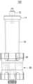
- Fig. 2illustrates a front view (chamber cover type) of a regulator-integrated drip chamber according to an embodiment of the present invention.
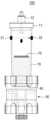
- Fig. 3illustrates a front view (spike type) of a regulator-integrated drip chamber according to an embodiment of the present invention.
- the drip chamberis connected to an infusion bag to supply the infusion bag's infusion fluid, and as shown in FIG. 3, it can be seen that it can be configured in a spike type having an infusion hole (22), an air hole (23), an air filter (24), and a vent cap (25), and as shown in FIG. 2, in a cover type having a chamber cover (11) and a connection connector (12) connected to the infusion bag.
- the cover typewill be described as an example.
- the scope of the rightsis not limited to such a type.
- the body part (10) of the drip chamber (100)is connected to a fluid bag (1) so that the fluid stored in the fluid bag is supplied internally in the form of droplets, and has a lower part provided with a discharge hole and to which a supply hose (2) is connected.
- the drip chamber (100)is characterized by including a regulator (50) that is integrally connected to one side of the lower part of the body part (10) and controls the flow rate of the liquid supplied from the body part (10) to the supply hose (2).
- the drip chamber (100)is equipped with a filter member on one side of the lower inner portion of the body (10) to filter foreign substances, etc., and this filter member (40) may be configured to be made of a hydrophilic membrane to prevent gas (air) from flowing into the supply hose.
- a regulator (50)may be configured to include an upper body part (51) and a lower body part (55) that can rotate around the upper body part (51).
- the upper body part (51)is integrally connected to the lower side of the body part (10) of the drip chamber (100), and has a discharge hole (52) formed on one side of the lower surface, and a central rotation axis (53) protruding downward from the center of the lower surface.
- a filter member (40)is installed inside the upper body part to prevent foreign substances and air injection for the safety of the patient.
- the lower body part (55)is provided with a rotation shaft introduction groove (57) into which a central rotation shaft (53) is inserted, and a supply hole (56) formed on one side of the upper surface. Accordingly, the amount of sap supplied can be adjusted as the lower body part (55) rotates about the central rotation shaft (53).
- an insertion grooveis formed on the outer surface of one side of the lower portion of the rotation center axis (53) of the upper body part (51), and a catch (58) is formed on the outer surface of the lower portion of the lower protrusion tube to form a rotation axis introduction groove of the lower body part (55).
- the lower protrusion tube connected to the lower body part (55)can serve as a locking device to prevent separation of the upper body part (51) and the lower body part (55) by holding the center of the rotation center axis (53) of the upper body part (51).
- a gasket (59) made of siliconeis placed in the space between the contact surfaces of the upper body part (51) and the lower body part (55), so that the upper body part (51) and the lower body part (55) can rotate smoothly around the central axis and prevent water leakage.
- the regulator (50)may be configured to include a locking device (60) that limits the rotation of the lower body part (55).
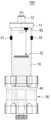
- Fig. 4is a front view (chamber cover type) of a regulator-integrated drip chamber having a flow rate measuring unit according to an embodiment of the present invention.
- Figs. 5 and 6are front views (chamber cover type) of a regulator-integrated drip chamber having a flow rate measuring unit and a floating member according to an embodiment of the present invention.
- the drip chamber (100)may be configured to include a flow rate measuring unit (30) installed on one side of the body part (10) to detect droplets of fluid passing through the body part (10) and measure the amount of fluid supplied.
- the floating member (70)floats on the sap stored in the body part (10) and is configured to close the discharge hole (62) when the sap supply to the supply hose (2) is completed.
- the flow rate measuring unit (30)may be composed of a light sensor, an infrared sensor, a laser sensor, etc., and may be composed of a light emitting unit (31) that irradiates light, etc., and a light receiving unit (32) that receives reflected light. Falling sap drops are detected through this sensor, and the supply flow rate calculation unit (33) receives this measurement value and calculates the supply flow rate and the total amount supplied based on the period of the sap drops or the number of sap drops supplied during a specific period.
- FIG. 7is a front view (chamber cover type) of a regulator-integrated drip chamber having a flow rate measuring unit, a water level sensor, and a floating member according to an embodiment of the present invention.
- the drip chamber (100)may further include a water level sensor (90) that measures the liquid level within the drip chamber.
- the floating member (70)can perform the function of a reflector. Therefore, the water level sensor can be configured to measure the water level within the drip chamber (100) based on the position of the floating member (70).
- the management server (110)may be configured to include a residual fluid calculation unit (91) that calculates the amount of residual fluid up to the tip of the drip chamber (100), supply hose (2), and catheter (3) according to the water level of the drip chamber (100).
- a residual fluid calculation unit (91)that calculates the amount of residual fluid up to the tip of the drip chamber (100), supply hose (2), and catheter (3) according to the water level of the drip chamber (100).
- control unit (120)controls the flow rate control unit (80) to stop the fluid supply when the value obtained by subtracting the residual fluid amount calculated by the residual fluid calculation unit (91) from the total supply amount calculated by the supply flow rate calculation unit (33) reaches the set supply amount.
- the control unit (120)controls the fluid supply to be stopped through the flow control unit (80) when the set supply amount based on this amount of fluid actually supplied to the patient reaches the amount of fluid actually supplied to the patient.
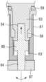
- Fig. 8is a cross-sectional view of a regulator-integrated drip chamber having a locking device according to the first embodiment of the present invention.
- Fig. 9is a cross-sectional view of Fig. 9 with the lower body portion removed.
- Fig. 10is an enlarged view of the locking device portion of Fig. 8.
- Fig. 11illustrates a cross-sectional view of a locking device body, a cross-sectional view of a central member of a locking member, a cross-sectional view of a locking member lever, and a plan view according to a first embodiment of the present invention.
- FIG. 12is a cross-sectional view of a locking device in unlocking mode according to a first embodiment of the present invention
- FIG. 13is a cross-sectional view of a locking device in locking mode according to an embodiment of the present invention.
- the regulator (50)can be configured to include a locking device (60) that limits the rotation of the lower body part (55).
- a locking devicemay be configured to include a locking device body (61) having an internal screw thread (63), and a central member (64) connected to a lever and having a catch (65) screw-connected with the internal screw thread (63).
- an insertion groove (54)is formed at the bottom of the central rotation axis (53) of the upper body (51) of the regulator (50).
- the locking device body (61)is placed between the central rotation shaft (53) and the rotation shaft introduction groove (57), and has a lower hole (62) and an internal screw thread (63) formed on the inner surface.
- the central member (64)is mounted in the lower hole (62) and is configured to have a catch (65) in which the screw threads (66) on the outer surface are screw-connected with the internal screw threads (63). In addition, it includes a lever (67) for rotating the central member.
- the upper part of the central member (64)is spaced from the upper surface of the insertion groove (54) of the central rotation axis (53), so that the lower body part (55) can rotate without restriction.
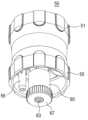
- Figures 14 and 15illustrate perspective views and front views of a regulator according to a second embodiment of the present invention.
- a regulator according to a second embodiment of the present inventionhas a form in which an upper body part (51) and a lower body part (55) are combined, as in the first embodiment, and a gasket (59) is interposed between the upper body part (51) and the lower body part (55).
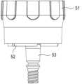
- FIG. 20 and FIG. 21are a perspective view and a front view of the upper body portion of a regulator according to a second embodiment of the present invention.
- FIG. 22 and FIG. 23illustrate a perspective view and a plan view of a gasket of a regulator according to a second embodiment of the present invention.
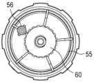
- Figures 24 and 25illustrate a perspective view, a front view, and a bottom view of the lower body portion of a regulator according to a second embodiment of the present invention.
- Figures 27 and 28illustrate a perspective view and a plan view of a locking device according to a second embodiment of the present invention.
- a discharge hole (52)is formed in the upper body part (51), and a central rotation shaft (53) protruding toward the lower side of the lower surface is connected.
- screw threadsare formed on the lower outer surface of this central rotation shaft (53). As described later, the screw threads of this central rotation shaft (53) are screw-connected with the internal screw threads (63) of the locking device (60).
- the lower body part (55)is joined with the upper body part (51) in a state where the gasket shown in FIGS. 22 and 23 is placed between them, as shown in FIGS. 24 to 26. As described later, the lower body part (55) can rotate in the release mode to adjust the opening/closing and opening ratio of the discharge hole (52), and the rotation is restricted in the lock mode.
- a supply hole (56)is formed in the lower body part (55), and a rotation shaft introduction groove (57) is provided in the center through which the central rotation shaft (53) of the upper body part (51) passes.
- a plurality of vertical cut portions (7) spaced apart from each other in the circumferential directionare formed in the rotational shaft introduction groove (57). Accordingly, as described later, when the locking device is moved upward by screw rotation in the locking mode, the separation space of the cut portions is reduced, and the rotational shaft introduction groove (57) is compressed, thereby restricting the rotation of the lower body part (55).
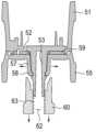
- FIG. 29illustrates a partial cross-sectional view of the locking device side in the release mode according to the second embodiment of the present invention
- FIG. 30illustrates a partial cross-sectional view of the locking device side in the locking mode according to the second embodiment of the present invention.
- the engaging protrusion (58) of the rotation shaft introduction groove (57) and the rotation center axis (51)are spaced apart, so that the lower body part (55) is not restrained and can rotate around the rotation center axis (51).
- FIG. 31is a block diagram of an infusion set including a regulator-integrated drip chamber having a locking device according to an embodiment of the present invention.
- FIG. 32is a block diagram showing a signal flow of a control unit according to an embodiment of the present invention.
- the sap set (200)may include a flow rate control unit (80) provided on one side of the supply hose (2) to control the supply flow rate.
- control unit (120)controls the flow rate control unit (80) to stop the sap supply when the total sap supply amount reaches the set supply amount.
- the drip chamber (100)may further include a level sensor (90) that measures the fluid level within the drip chamber.
- the management server (110)may include a residual fluid calculation unit (91) that calculates the amount of residual fluid up to the tip of the drip chamber (100), supply hose (2), and catheter (3) according to the fluid level of the drip chamber (100).
- control unit (120)controls the flow rate control unit to stop the fluid supply when the value obtained by subtracting the residual fluid amount calculated in the residual fluid calculation unit (91) from the total supply amount calculated in the supply flow rate calculation unit (33) reaches the set supply amount.
- the control unit (120)controls the fluid supply to be stopped through the flow control unit (80) when the set supply amount based on this amount of fluid actually supplied to the patient reaches the amount of fluid actually supplied to the patient.
Landscapes
- Health & Medical Sciences (AREA)
- Vascular Medicine (AREA)
- Engineering & Computer Science (AREA)
- Anesthesiology (AREA)
- Biomedical Technology (AREA)
- Heart & Thoracic Surgery (AREA)
- Hematology (AREA)
- Life Sciences & Earth Sciences (AREA)
- Animal Behavior & Ethology (AREA)
- General Health & Medical Sciences (AREA)
- Public Health (AREA)
- Veterinary Medicine (AREA)
- Emergency Medicine (AREA)
- Infusion, Injection, And Reservoir Apparatuses (AREA)
- Physics & Mathematics (AREA)
- Fluid Mechanics (AREA)
Abstract
Description
Translated fromKorean본 발명은 잠금장치를 갖는 레귤레이터 일체형 점적챔버 및 그 이를 포함한 수액세트에 관한 것이다.The present invention relates to a regulator-integrated drip chamber having a locking device and an infusion set including the same.
수액세트는 의료적 목적으로 수액(輸液)을 인체에 주입하기 위해서 사용하는 의료용구의 일종이다. 일반적인 수액세트의 구성은, 수액백과, 상기 수액백으로부터 수액을 배액하는 점적챔버과, 상기 점적챔버에 연결되는 공급호스(튜브)와, 상기 공급튜브를 통과하는 수액의 양을 조절하는 수액조절기와, 환자의 혈관에 삽입되는 카테터 등을 포함하여 구성된다.An IV set is a type of medical device used to inject IV fluid into the human body for medical purposes. A typical IV set is composed of an IV bag, a drip chamber for draining the IV from the IV bag, a supply hose (tube) connected to the drip chamber, an IV regulator for controlling the amount of IV passing through the supply tube, and a catheter inserted into a patient's blood vessel.
도 1은 통상의 수액세트의 모식도를 도시한 것이다.Figure 1 is a schematic diagram of a typical sap set.
그리고 상기 점적챔버는 일정량의 수액이 저류하는 몸체부와, 상기 수액백에 삽입된 스파이크를 통해서 점적챔버로 수액을 유입하는 유입구와, 상기 점적챔버에 저장된 수액을 공급호스로 배출하는 배출구를 포함한다.And the drip chamber includes a body part in which a certain amount of fluid is stored, an inlet for introducing fluid into the drip chamber through a spike inserted into the fluid bag, and an outlet for discharging the fluid stored in the drip chamber through a supply hose.
상기와 같은 종래의 수액세트를 이용하여 환자에게 수액을 투여할 경우, 수액이 모두 환자에게 투입되고 나면즉시 상기 수액백을 교체하거나, 수액 투여를 종료하고 환자의 혈관으로부터 카테터를 제거해야 한다.When administering intravenous fluid to a patient using a conventional intravenous set as described above, once all the intravenous fluid has been administered to the patient, the intravenous bag must be replaced immediately, or the intravenous fluid administration must be terminated and the catheter must be removed from the patient's blood vessel.
만일, 수액세트 내부에 수액이 고갈된 상태를 방치하면, 공급튜브를 통해서 환자의 혈관 속으로 공기가 유입되거나, 압력 차이에 의해 혈액이 공급튜브를 타고 역류하는 위험한 상황이 발생하기 때문이다.If the IV set is left in a depleted state, there is a risk of air flowing into the patient's blood vessels through the supply tube, or blood flowing backwards through the supply tube due to pressure differences.
따라서 종래의 수액세트는 의사나 간호사 또는 보호자가 상기 수액백이나 점적챔버에 저장되어 있는 수액의 잔량을 수시로 확인해야 하는 불편이 있었다.Therefore, conventional IV sets had the inconvenience of requiring doctors, nurses, or guardians to frequently check the remaining amount of IV fluid stored in the IV bag or drip chamber.
이러한 문제점을 해결하기 위하여 국내 등록특허 제10-1027081호(2011년 03월 29일) 등에서는, 수액세트의 점적챔버 내부에 수액 위에 뜰 수 있는 무게와 크기를 가지는 부력볼을 배치하여 상기 점적챔버의 내부의 수액이 모두 배액되면 상기 부력볼이 하강하여 수액 배출구를 차단하도록 구성된 혈액 역류 방지장치가 소개되어 있다.In order to solve these problems, domestic patent registration No. 10-1027081 (March 29, 2011) and other documents introduce a blood backflow prevention device configured to place a buoyancy ball having a weight and size that can float on the fluid inside the drip chamber of an infusion set, and when all the fluid inside the drip chamber is drained, the buoyancy ball descends to block the fluid discharge port.
또한, 등록특허 제10-0792805호(2008년 01월 02일)에는, 수액세트의 점적챔버에 채워진 수액의 수위에 따라 부유하는 자기형 플로트와, 상기 점적과의 외부에 일정 간격으로 설치되며, 상기 플로트의 위치에 따라 온/오프 신호를 출력하는 적어도 2개 이상의 자기형 근접 스위치, 그리고 상기 자기형 근접 스위치의 신호 출력단을 병원내에 구비된 비상 호출 시스템 또는 경보부와 전기적으로 연결하는 인터페이스 커넥터를 포함하는 무전원 액위감지장치가 소개되어 있다.In addition, Patent Registration No. 10-0792805 (January 2, 2008) introduces a wireless liquid level detection device including a magnetic float that floats according to the level of the liquid filled in the drip chamber of the IV set, at least two magnetic proximity switches that are installed at a certain interval outside the drip and output an on/off signal according to the position of the float, and an interface connector that electrically connects the signal output terminal of the magnetic proximity switches to an emergency call system or alarm unit provided in a hospital.
그러나 이러한 종래기술의 플로팅 부재는 수액 수위에 부유되어 있어 정확하게 점적챔버의 토출홀을 폐쇄시키기 어려운 구조를 가지고 있다.However, the floating member of this conventional technology has a structure that makes it difficult to accurately close the discharge hole of the drip chamber because it floats on the sap level.
이러한 종래기술들은 수액백에서 수액공급이 완료된 경우를 알 수 있을 뿐, 수액백에서 설정된 공급량 만큼 정확하게 환자에게 수액을 공급할 수 있는 수단과 과제에 대해서는 언급하고 있지 않다.These conventional technologies only allow for the determination of completion of intravenous fluid supply from an intravenous bag, but do not mention any means or tasks for accurately supplying the set amount of intravenous fluid to a patient from the intravenous bag.
따라서 본 발명은 상기와 같은 종래의 문제점을 해결하기 위하여 안출된 것으로서, 본 발명의 실시예에 따르면, 수액 공급양을 조절하기 위한 레귤레이터가 공급호스 일측이 아닌 점적챔버와 일체로 구비되어 보다 컴팩트한 수액챔버를 구성할 수 있고, 수액세트의 조립과 배치의 편의성을 달성할 수 있는, 잠금장치를 갖는 레귤레이터 일체형 점적챔버 및 그 이를 포함한 수액세트를 제공하는데 그 목적이 있다.Accordingly, the present invention has been made to solve the above-mentioned conventional problems, and according to an embodiment of the present invention, a regulator for controlling the amount of fluid supplied is provided integrally with the drip chamber rather than on one side of the supply hose, thereby forming a more compact fluid chamber, and providing a regulator-integrated drip chamber with a locking device and an infusion set including the same, which can achieve convenience in assembling and arranging the infusion set.
본 발명의 실시예에 따르면, 레귤레이터에 잠금장치가 구비되게 됨으로서 수액 공급시, 환자나 보호자, 타인 등에 의해 레귤레이터가 오작동되게 되는 위험을 방지할 수 있는, 잠금장치를 갖는 레귤레이터 일체형 점적챔버 및 그 이를 포함한 수액세트를 제공하는데 그 목적이 있다.According to an embodiment of the present invention, the purpose is to provide a regulator-integrated drip chamber with a locking device and an infusion set including the same, which can prevent the risk of the regulator being malfunctioning by a patient, a guardian, or another person when supplying an infusion, by providing a locking device to the regulator.
그리고 본 발명의 실시예에 따르면, 점적챔버에 광센서 등으로 구성된 유량측정부를 설치하여 공급된 수액양과, 공급속도를 파악하고, 설정된 공급량과, 공급속도로 수액이 공급되도록 유량조절부를 제어할 수 있는, 잠금장치를 갖는 레귤레이터 일체형 점적챔버 및 그 이를 포함한 수액세트를 제공하는데 그 목적이 있다.And, according to an embodiment of the present invention, the purpose is to provide a regulator-integrated drip chamber with a locking device and an infusion set including the same, which can detect the amount of fluid supplied and the supply speed by installing a flow rate measuring unit composed of an optical sensor or the like in a drip chamber, and control a flow rate control unit so that the fluid is supplied at the set supply amount and supply speed.
또한 본 발명의 실시예에 따르면, 수위센서를 포함하여 점적챔버에서 카테터까지 잔존하는 수액량을 판단하여, 수액백에서 공급된 수액량과, 잔존량을 기반으로 하여 실제 환자에게 공급된 수액량을 모니터링하고, 실제 수액 주사량이 설정된 공급량에 대응될 수 있도록 제어할 수 있는, 잠금장치를 갖는 레귤레이터 일체형 점적챔버 및 그 이를 포함한 수액세트를 제공하는데 그 목적이 있다.In addition, according to an embodiment of the present invention, the purpose is to provide a regulator-integrated drip chamber with a locking device and an infusion set including the same, which can determine the amount of fluid remaining in the drip chamber to the catheter by including a water level sensor, monitor the amount of fluid supplied from the infusion bag and the amount of fluid actually supplied to the patient based on the remaining amount, and control the actual amount of fluid injected so that it corresponds to the set amount supplied.
한편, 본 발명에서 이루고자 하는 기술적 과제들은 이상에서 언급한 기술적 과제들로 제한되지 않으며, 언급하지 않은 또 다른 기술적 과제들은 아래의 기재로부터 본 발명이 속하는 기술분야에서 통상의 지식을 가진 자에게 명확하게 이해될 수 있을 것이다.Meanwhile, the technical problems to be achieved in the present invention are not limited to the technical problems mentioned above, and other technical problems not mentioned can be clearly understood by a person having ordinary knowledge in the technical field to which the present invention belongs from the description below.
본 발명의 제1목적은 수액백과 연결되어 수액백의 수액이 공급되는 점적챔버로서, 수액백에 연결되어 상기 수액백에 저장된 수액이 내부로 물방울 형태로 공급되며, 토출홀이 마련되고 공급호스가 연결되는 하단부를 갖는 몸체부; 및 상기 몸체부 하부 일측에 일체로 결합되어 상기 몸체부에서 공급호스로 공급되는 수액의 유량을 조절하는 레귤레이터; 및 상기 몸체부 하단 내부 일측에 구비되는 필터부재;를 포함하고, 상기 레귤레이터는, 상단몸체부와, 하단몸체부, 상기 상단몸체부와 상기 하단몸체부 사이에 게재되는 가스켓, 및 상기 하단몸체부의 회동을 제한 또는 해제하는 잠금장치를 갖는 것을 특징으로 하는 잠금장치를 갖는 레귤레이터 일체형 점적챔버로서 달성될 수 있다.The first object of the present invention is to provide a drip chamber connected to an intravenous fluid bag and supplying the intravenous fluid of the intravenous fluid bag, comprising: a body part having a lower part connected to the intravenous fluid bag and having a discharge hole and a supply hose connected thereto, wherein the body part is integrally connected to one side of the lower part of the body part and controls the flow rate of the intravenous fluid supplied from the body part to the supply hose; and a filter member provided on one side of the lower part of the body part; wherein the regulator is characterized by having an upper body part, a lower body part, a gasket interposed between the upper body part and the lower body part, and a locking device restricting or releasing rotation of the lower body part, and a regulator-integrated drip chamber having a locking device.
그리고 상기 상단몸체부는, 상기 몸체부 하부 일측에 일체로 결합되며, 하단면 일측에 형성되는 배출공과, 상기 하단면 중앙에서 하부측으로 돌출된 중심회전축을 갖고, 상기 하단몸체부는, 상기 중심회전축이 삽입되는 회전축 도입홈과, 상단면 일측에 형성되는 공급공이 구비되며, 상기 하단몸체부가 상기 중심회전축으로 회전되면서 상기 수액의 공급량이 조절되는 것을 특징으로 할 수 있다.And the upper body part is integrally connected to one side of the lower part of the body part, has a discharge hole formed on one side of the lower surface, and a central rotation axis protruding downward from the center of the lower surface, and the lower body part is provided with a rotation axis introduction groove into which the central rotation axis is inserted, and a supply hole formed on one side of the upper surface, and the supply amount of the sap is controlled as the lower body part rotates about the central rotation axis.
또한 상기 잠금장치는, 상기 중심회전축 하단에 형성되는 삽입홈, 상기 중심회전축과 상기 회전축 도입홈 사이에 게재되며 하단홀와 내면에 내부나사산이 형성되는 잠금장치 몸체, 상기 하단홀에 게재되며 외면의 나사산이 상기 내부나사산과 나사결합되는 걸림단을 갖는 중심부재, 및 상기 중심부재를 회전시키기 위한 조임돌림부를 포함하여, 잠금모드시, 상기 조임돌림부의 작동에 의해 상기 중심부재 상단이 상기 삽입홈에 억지끼움되어 상기 하단몸체부의 회동을 제한하는 것을 특징으로 할 수 있다.In addition, the locking device may include an insertion groove formed at the lower end of the central rotation shaft, a locking device body that is disposed between the central rotation shaft and the rotation shaft introduction groove and has a lower hole and internal screw threads formed on an inner surface, a central member that is disposed in the lower hole and has a catch end whose outer screw threads are screw-connected with the internal screw threads, and a tightening turning part for rotating the central member, wherein in the locking mode, the upper end of the central member is forcefully fitted into the insertion groove by the operation of the tightening turning part, thereby limiting the rotation of the lower body part.
또한 상기 중심회전축의 하부측 외면에 나사산이 형성되며, 상기 회전축 도입홈은, 원주방향으로 서로 이격되어 배치되는 절개부가 형성된 관형태로 구성되며, 상기 중심회전축은 상기 나사산이 하부측에 도출되도록 상기 회전축 도입홈에 관통 결합되고, 상기 잠금장치는, 내부나사산을 통해 상기 중심회전축의 하부측에 결합되는 몸체와, 상기 몸체 하단부 끝단에 연결되어 상기 몸체를 회전시키기 위한 조임돌림부를 포함하여, 잠금모드시, 상기 조임돌림부의 작동에 의해 상기 회전도입홈을 가압, 압축시켜 상기 하단몸체부의 회동을 제한하는 것을 특징으로 할 수 있다.In addition, a screw thread is formed on the outer surface of the lower side of the central rotation shaft, and the rotation shaft introduction groove is configured in a tubular shape with cut sections formed so as to be spaced apart from each other in the circumferential direction, the central rotation shaft is penetratedly coupled to the rotation shaft introduction groove so that the screw thread is drawn out to the lower side, and the locking device includes a body coupled to the lower side of the central rotation shaft through an internal screw thread, and a tightening turning part connected to the lower end of the body to rotate the body, and in the locking mode, the rotation introduction groove is pressurized and compressed by the operation of the tightening turning part to limit the rotation of the lower body part.
그리고 상기 몸체부 일측에 설치되어 상기 몸체부로 통과되는 수액방울을 감지하여 공급되는 수액량을 측정하는 유량측정부; 상기 몸체부에 저장된 수액에 부유되며, 공급호스로의 수액공급이 완료되면 상기 토출홀을 폐쇄시키는 플로팅부재; 및 상기 측정값을 전송받아 수액방울의 주기 또는, 특정주기 동안 공급된 수액방울의 개수를 기반으로 공급유량과, 공급된 총량을 연산하는 공급유량연산부;를 포함하고, 상기 유량측정부는, 광센서, 적외선센서, 레이저센서 중 적어도 어느 하나로 구성되어, 공급되는 수액방울을 측정하는 것을 특징으로 할 수 있다.And it includes a flow rate measuring unit installed on one side of the body part to detect sap droplets passing through the body part and measure the amount of sap supplied; a floating member floating on the sap stored in the body part and closing the discharge hole when the supply of sap to the supply hose is completed; and a supply flow rate calculating unit that receives the measured value and calculates the supply flow rate and the total amount supplied based on the cycle of the sap droplets or the number of sap droplets supplied during a specific cycle; and the flow rate measuring unit may be characterized in that it is configured with at least one of an optical sensor, an infrared sensor, and a laser sensor and measures the supplied sap droplets.
본 발명의 제2목적은 수액백, 앞서 언급한 제 1목적에 따른 점적챔버, 공급호스, 카테터를 갖는 수액세트로서, 상기 공급호스 일측에 구비되어 공급유량을 조절하는 유량조절유닛; 및 유량측정부에서 측정된 측정값을 전송받아 수액방울의 주기 또는, 특정주기 동안 공급된 수액방울의 개수를 기반으로 공급유량과, 공급된 총량을 연산하는 공급유량연산부를 갖는 관리서버;를 포함하는 것을 특징으로 하는 잠금장치를 갖는 레귤레이터 일체형 점적챔버를 포함한 수액세트로서 달성될 수 있다.The second object of the present invention can be achieved by an infusion set including an infusion bag, a drip chamber according to the first object mentioned above, a supply hose, and a catheter, wherein the infusion set includes a management server having a flow rate control unit provided on one side of the supply hose to control the supply flow rate; and a supply flow rate calculation unit that receives a measured value from a flow rate measurement unit and calculates the supply flow rate and the total amount supplied based on the cycle of the infusion droplets or the number of infusion droplets supplied during a specific cycle; and a regulator-integrated drip chamber with a locking device.
그리고 수액 공급량, 공급속도를 설정하는 설정부; 및 상기 측정값과, 설정된 공급속도를 기반으로 상기 유량조절유닛을 제어하고, 수액 총공급량이 설정된 공급량에 도달하면 수액공급을 중단시키도록 유량조절유닛을 제어하는 제어부;를 포함하는 것을 특징으로 할 수 있다.And it can be characterized by including a setting unit that sets the amount of sap supply and the supply speed; and a control unit that controls the flow rate control unit based on the measured value and the set supply speed, and controls the flow rate control unit to stop the sap supply when the total amount of sap supply reaches the set supply amount.
또한 상기 점적챔버 내의 수액 수위를 측정하는 수위센서; 및 점적챔버의 수위에 따른 점적챔버, 공급호스, 카테터 끝단까지의 잔존 수액량을 연산하는 잔존수액연산부;를 포함하고, 상기 제어부는 상기 총공급량에서 상기 잔존수액량을 뺀 값이 상기 설정된 공급량에 도달하면 수액공급을 중단시키도록 유량조절유닛을 제어하는 것을 특징으로 할 수 있다.In addition, it includes a level sensor for measuring the fluid level within the drip chamber; and a residual fluid calculation unit for calculating the remaining fluid amount up to the drip chamber, supply hose, and catheter tip according to the fluid level of the drip chamber; and the control unit may be characterized in that it controls the flow rate control unit to stop the fluid supply when the value obtained by subtracting the remaining fluid amount from the total supply amount reaches the set supply amount.
본 발명의 실시예에 따른 잠금장치를 갖는 레귤레이터 일체형 점적챔버 및 그 이를 포함한 수액세트를에 따르면, 수액 공급양을 조절하기 위한 레귤레이터가 공급호스 일측이 아닌 점적챔버와 일체로 구비되어 보다 컴팩트한 수액챔버를 구성할 수 있고, 수액세트의 조립과 배치의 편의성을 달성할 수 있는 효과를 갖는다.According to a regulator-integrated drip chamber with a locking device according to an embodiment of the present invention and an infusion set including the same, a regulator for controlling the amount of infusion supplied is provided integrally with the drip chamber rather than on one side of a supply hose, thereby enabling a more compact infusion chamber to be configured, and achieving convenience in assembling and arranging the infusion set.
본 발명의 실시예에 따른 잠금장치를 갖는 레귤레이터 일체형 점적챔버 및 그 이를 포함한 수액세트를에 따르면, 레귤레이터에 잠금장치가 구비되게 됨으로서 수액 공급시, 환자나 보호자, 타인 등에 의해 레귤레이터가 오작동되게 되는 위험을 방지할 수 있는 효과를 갖는다.According to the regulator-integrated drip chamber with a locking device according to an embodiment of the present invention and the infusion set including the same, since the regulator is provided with a locking device, there is an effect of preventing the risk of the regulator being malfunctioning by a patient, a guardian, or another person when supplying the infusion.
그리고 본 발명의 실시예에 따른 잠금장치를 갖는 레귤레이터 일체형 점적챔버 및 그 이를 포함한 수액세트를에 따르면, 점적챔버에 광센서 등으로 구성된 유량측정부를 설치하여 공급된 수액양과, 공급속도를 파악하고, 설정된 공급량과, 공급속도로 수액이 공급되도록 유량조절부를 제어할 수 있는 효과를 갖는다.And according to the regulator-integrated drip chamber with a locking device according to an embodiment of the present invention and the infusion set including the same, a flow rate measuring unit including an optical sensor, etc. is installed in the drip chamber to detect the amount of infusion fluid supplied and the supply speed, and a flow rate control unit can be controlled so that the infusion fluid is supplied at the set supply amount and supply speed.
또한 본 발명의 실시예에 따른 잠금장치를 갖는 레귤레이터 일체형 점적챔버 및 그 이를 포함한 수액세트를에 따르면, 수위센서를 포함하여 점적챔버에서 카테터까지 잔존하는 수액량을 판단하여, 수액백에서 공급된 수액량과, 잔존량을 기반으로 하여 실제 환자에게 공급된 수액량을 모니터링하고, 실제 수액 주사량이 설정된 공급량에 대응될 수 있도록 제어할 수 있는 효과를 갖는다.In addition, according to the regulator-integrated drip chamber with a locking device according to an embodiment of the present invention and the infusion set including the same, the amount of fluid remaining from the drip chamber to the catheter is determined by including a water level sensor, and the amount of fluid supplied from the infusion bag and the amount of fluid actually supplied to the patient are monitored based on the remaining amount, and the actual amount of fluid injection can be controlled so that it corresponds to the set supply amount.
한편, 본 발명에서 얻을 수 있는 효과는 이상에서 언급한 효과들로 제한되지 않으며, 언급하지 않은 또 다른 효과들은 아래의 기재로부터 본 발명이 속하는 기술분야에서 통상의 지식을 가진 자에게 명확하게 이해될 수 있을 것이다.Meanwhile, the effects obtainable from the present invention are not limited to the effects mentioned above, and other effects not mentioned can be clearly understood by a person having ordinary skill in the technical field to which the present invention belongs from the description below.
본 명세서에 첨부되는 다음의 도면들은 본 발명의 바람직한 실시예를 예시하는 것이며, 발명의 상세한 설명과 함께 본 발명의 기술적 사상을 더욱 이해시키는 역할을 하는 것이므로, 본 발명은 그러한 도면에 기재된 사항에만 한정되어 해석 되어서는 아니 된다.The following drawings attached to this specification illustrate preferred embodiments of the present invention and, together with the detailed description of the invention, serve to further understand the technical idea of the present invention; therefore, the present invention should not be interpreted as being limited to matters described in such drawings.
도 1은 통상의 수액세트의 모식도,Figure 1 is a schematic diagram of a typical sap set.
도 2는 본 발명의 실시예에 따른 레귤레이터 일체형 점적챔버의 정면도(챔버 커버형),Figure 2 is a front view of a regulator-integrated drip chamber according to an embodiment of the present invention (chamber cover type).
도 3은 본 발명의 실시예에 따른 레귤레이터 일체형 점적챔버의 정면도(스파이크형),Figure 3 is a front view (spike type) of a regulator-integrated drip chamber according to an embodiment of the present invention.
도 4는 본 발명의 실시예에 따른 유량측정부를 갖는 레귤레이터 일체형 점적챔버의 정면도(챔버 커버형),Figure 4 is a front view of a regulator-integrated drip chamber having a flow rate measuring unit according to an embodiment of the present invention (chamber cover type).
도 5 및 도 6는 본 발명의 실시예에 따른 유량측정부와 플로팅부재를 갖는 레귤레이터 일체형 점적챔버의 정면도(챔버 커버형),Figures 5 and 6 are front views of a regulator-integrated drip chamber having a flow rate measuring unit and a floating member according to an embodiment of the present invention (chamber cover type).
도 7은 본 발명의 실시예에 따른 유량측정부와 수위센서와 플로팅부재를 갖는 레귤레이터 일체형 점적챔버의 정면도(챔버 커버형),Figure 7 is a front view of a regulator-integrated drip chamber having a flow rate measuring unit, a water level sensor, and a floating member according to an embodiment of the present invention (chamber cover type).
도 8는 본 발명의 제1실시예에 따른 잠금장치를 갖는 레귤레이터 일체형 점적챔버의 단면도,Figure 8 is a cross-sectional view of a regulator-integrated drip chamber having a locking device according to the first embodiment of the present invention.
도 9는 도 9에서 하단몸체부가 제외된 상태의 단면도,Figure 9 is a cross-sectional view of Figure 9 with the lower body portion excluded.
도 10은 도 8에서 잠금장치 부분의 확대도,Fig. 10 is an enlarged view of the locking device portion in Fig. 8.
도 11는 본 발명의 제1실시예에 따른 잠금장치 몸체 단면도, 잠금부재 중심부재 단면도, 잠금부재 레버 단면도, 평면도,Figure 11 is a cross-sectional view of a locking device body according to the first embodiment of the present invention, a cross-sectional view of a central member of a locking member, a cross-sectional view of a locking member lever, and a plan view.
도 12는 본 발명의 제1실시예에 따른 해제모드시 잠금장치 단면도,Figure 12 is a cross-sectional view of a locking device in release mode according to the first embodiment of the present invention.
도 13는 본 발명의 제1실시예에 따른 잠금모드시 잠금장치 단면도,Figure 13 is a cross-sectional view of a locking device in locking mode according to the first embodiment of the present invention.
도 14 내지 도 15는 본 발명의 제2실시예에 따른 레귤레이터의 사시도, 정면도,Figures 14 and 15 are perspective views, front views, and a second embodiment of a regulator according to the present invention.
도 20 및 도 21는 본 발명의 제2실시예에 따른 레귤레이터의 상단몸체부의 사시도와, 정면도,Figures 20 and 21 are a perspective view and a front view of the upper body of a regulator according to the second embodiment of the present invention.
도 22 및 도 23는 본 발명의 제2실시예에 따른 레귤레이터의 가스켓의 사시도, 평면도,Figures 22 and 23 are perspective views and plan views of a gasket of a regulator according to a second embodiment of the present invention.
도 24 내지 도 25는 본 발명의 제2실시예에 따른 레귤레이터의 하단몸체부의 사시도, 정면도, 저면도,Figures 24 and 25 are perspective views, front views, and bottom views of the lower body part of a regulator according to the second embodiment of the present invention.
도 27 및 도 28는 본 발명의 제2실시예에 따른 잠금장치의 사시도, 평면도,Figures 27 and 28 are perspective views and plan views of a locking device according to a second embodiment of the present invention.
도 29는 본 발명이 제2실시예에 따른 해제모드시 잠금장치 측의 부분 단면도,Figure 29 is a partial cross-sectional view of the locking device side in the release mode according to the second embodiment of the present invention.
도 30는 본 발명이 제2실시예에 따른 잠금모드시 잠금장치 측의 부분 단면도,Figure 30 is a partial cross-sectional view of the locking device side in the locking mode according to the second embodiment of the present invention.
도 31은 본 발명의 실시예에 따른 레귤레이터 일체형 점적챔버를 포함한 수액세트의 블록도Figure 31 is a block diagram of an infusion set including a regulator-integrated drip chamber according to an embodiment of the present invention.
도 32은 본 발명의 실시예에 따른 제어부의 신호흐름을 나타낸 블록도를 도시한 것이다.Figure 32 is a block diagram showing the signal flow of a control unit according to an embodiment of the present invention.
이하에서는 본 발명의 실시예에 따른 레귤레이터 일체형 점적챔버의 구성 및 기능에 대해 설명하도록 한다.Below, the configuration and function of a regulator-integrated drip chamber according to an embodiment of the present invention will be described.
먼저, 도 2는 본 발명의 실시예에 따른 레귤레이터 일체형 점적챔버의 정면도(챔버 커버형)를 도시한 것이다. 그리고 도 3은 본 발명의 실시예에 따른 레귤레이터 일체형 점적챔버의 정면도(스파이크형)를 도시한 것이다.First, Fig. 2 illustrates a front view (chamber cover type) of a regulator-integrated drip chamber according to an embodiment of the present invention. And Fig. 3 illustrates a front view (spike type) of a regulator-integrated drip chamber according to an embodiment of the present invention.
본 발명의 실시예에 따른 점적챔버는, 수액백과 연결되어 수액백의 수액이 공급되는 것으로서, 도 3에 도시된 바와 같이, 수액공(22), 공기공(23), 공기필터(24), 벤트캡(25)을 갖는 스파이크 타입과, 도 2에 도시된 바와 같이, 챔버커버(11)와 수액백과 연결되는 연결커넥터(12)를 갖는 커버 형태로 구성될 수 있음을 알 수 있다. 이하에서는 커버형을 예를 들어 설명하도록 한다. 다만 이러한 형태로 권리범위가 제한되는 것은 아니다.According to an embodiment of the present invention, the drip chamber is connected to an infusion bag to supply the infusion bag's infusion fluid, and as shown in FIG. 3, it can be seen that it can be configured in a spike type having an infusion hole (22), an air hole (23), an air filter (24), and a vent cap (25), and as shown in FIG. 2, in a cover type having a chamber cover (11) and a connection connector (12) connected to the infusion bag. Hereinafter, the cover type will be described as an example. However, the scope of the rights is not limited to such a type.
점적챔버(100)의 몸체부(10)는 수액백(1)에 연결되어 상기 수액백에 저장된 수액이 내부로 물방울 형태로 공급되며, 토출홀이 마련되고 공급호스(2)가 연결되는 하단부를 갖는다.The body part (10) of the drip chamber (100) is connected to a fluid bag (1) so that the fluid stored in the fluid bag is supplied internally in the form of droplets, and has a lower part provided with a discharge hole and to which a supply hose (2) is connected.
그리고 본 발명의 실시예에 따른 점적챔버(100)는 몸체부(10) 하부 일측에 일체로 결합되어 몸체부(10)에서 공급호스(2)로 공급되는 수액의 유량을 조절하는 레귤레이터(50)를 포함하는 것을 특징으로 한다.And the drip chamber (100) according to the embodiment of the present invention is characterized by including a regulator (50) that is integrally connected to one side of the lower part of the body part (10) and controls the flow rate of the liquid supplied from the body part (10) to the supply hose (2).
또한 본 발명의 실시예에 따른 점적챔버(100)는 몸체부(10) 하단 내부 일측에 필터부재가 구비되어 이물질 등을 여과할 수 있으며, 이러한 필터부재(40)는 친수성 멤브레인으로 구성되어 기체(공기)가 공급호스로 유입되는 것을 방지하도록 구성될 수 있다.In addition, the drip chamber (100) according to the embodiment of the present invention is equipped with a filter member on one side of the lower inner portion of the body (10) to filter foreign substances, etc., and this filter member (40) may be configured to be made of a hydrophilic membrane to prevent gas (air) from flowing into the supply hose.
본 발명의 실시예에 따른 레귤레이터(50)는 상단몸체부(51)와, 상기 상단몸체부(51)를 기준으로 회동될 수 있는 하단몸체부(55)를 포함하여 구성될 수 있다.A regulator (50) according to an embodiment of the present invention may be configured to include an upper body part (51) and a lower body part (55) that can rotate around the upper body part (51).
상단몸체부(51)는 점적챔버(100)의 몸체부(10) 하부 일측에 일체로 결합되며, 하단면 일측에 형성되는 배출공(52)과, 하단면 중앙에서 하부측으로 돌출된 중심회전축(53)을 갖는다. 또한 상단몸체부의 내부에는 환자의 안전을 위하여 이물질과 공기주입방지를 위한 필터부재(40)가 장착되어 진다.The upper body part (51) is integrally connected to the lower side of the body part (10) of the drip chamber (100), and has a discharge hole (52) formed on one side of the lower surface, and a central rotation axis (53) protruding downward from the center of the lower surface. In addition, a filter member (40) is installed inside the upper body part to prevent foreign substances and air injection for the safety of the patient.
또한 하단몸체부(55)는 중심회전축(53)이 삽입되는 회전축 도입홈(57)과, 상단면 일측에 형성되는 공급공(56)이 구비된다. 따라서 하단몸체부(55)가 중심회전축(53)으로 회전되면서 수액의 공급량이 조절될 수 있다.In addition, the lower body part (55) is provided with a rotation shaft introduction groove (57) into which a central rotation shaft (53) is inserted, and a supply hole (56) formed on one side of the upper surface. Accordingly, the amount of sap supplied can be adjusted as the lower body part (55) rotates about the central rotation shaft (53).
또한 상단몸체부(51)의 회전중심축(53)의 하단 일측 외면에 삽입홈이 형성되며 하단몸체부(55)의 회전축도입홈을 형성하기 위한 하부 돌출관의 하부 외면에 걸림턱(58)이 형성되어 진다. 따라서 하단몸체부(55)에 연결된 하부돌출관이 상단몸체부(51)의 회전중심축(53)의 중심을 잡아주면서 상단몸체부(51)와 하단몸체부(55)의 분리가 없도록 락장치 역할이 가능해 진다.In addition, an insertion groove is formed on the outer surface of one side of the lower portion of the rotation center axis (53) of the upper body part (51), and a catch (58) is formed on the outer surface of the lower portion of the lower protrusion tube to form a rotation axis introduction groove of the lower body part (55). Accordingly, the lower protrusion tube connected to the lower body part (55) can serve as a locking device to prevent separation of the upper body part (51) and the lower body part (55) by holding the center of the rotation center axis (53) of the upper body part (51).
그리고 상단몸체부(51)와 하단몸체부(55)의 접촉면 사이 공간에 실리콘 재질의 가스켓(59)이 게재되어 상단몸체부(51)와 하단몸체부55)가 중심축을 기준으로 원활한 돌림과 누수방지가 가능해진다.And, a gasket (59) made of silicone is placed in the space between the contact surfaces of the upper body part (51) and the lower body part (55), so that the upper body part (51) and the lower body part (55) can rotate smoothly around the central axis and prevent water leakage.
그리고 후에 상세히 설명되는 바와 같이, 본 발명의 실시예에 따른 레귤레이터(50)는 하단몸체부(55)의 회동을 제한하는 잠금장치(60)를 포함하여 구성될 수 있다.And as will be described in detail later, the regulator (50) according to an embodiment of the present invention may be configured to include a locking device (60) that limits the rotation of the lower body part (55).
도 4는 본 발명의 실시예에 따른 유량측정부를 갖는 레귤레이터 일체형 점적챔버의 정면도(챔버 커버형)를 도시한 것이다. 그리고 도 5 및 도 6는 본 발명의 실시예에 따른 유량측정부와 플로팅부재를 갖는 레귤레이터 일체형 점적챔버의 정면도(챔버 커버형)를 도시한 것이다.Fig. 4 is a front view (chamber cover type) of a regulator-integrated drip chamber having a flow rate measuring unit according to an embodiment of the present invention. And Figs. 5 and 6 are front views (chamber cover type) of a regulator-integrated drip chamber having a flow rate measuring unit and a floating member according to an embodiment of the present invention.
본 발명의 실시예에 따른 점적챔버(100)은 몸체부(10) 일측에 설치되어 몸체부(10)로 통과되는 수액방울을 감지하여 공급되는 수액량을 측정하는 유량측정부(30)를 포함하여 구성될 수 있다.The drip chamber (100) according to an embodiment of the present invention may be configured to include a flow rate measuring unit (30) installed on one side of the body part (10) to detect droplets of fluid passing through the body part (10) and measure the amount of fluid supplied.
또한 플로팅부재(70)는 몸체부(10)에 저장된 수액에 부유되며, 공급호스(2)로의 수액공급이 완료되면 토출홀(62)을 폐쇄시키도록 구성된다.In addition, the floating member (70) floats on the sap stored in the body part (10) and is configured to close the discharge hole (62) when the sap supply to the supply hose (2) is completed.
본 발명의 실시예에 따른 유량측정부(30)는 광센서, 적외선센서, 레이저센서 등으로 구성될 수 있으며, 광 등을 조사하는 발광부(31)와 반사된 광을 수광하는 수광부(32)를 포함하여 구성될 수 있다. 이러한 센서를 통해 떨어지는 수액방울을 감지하며, 공급유량연산부(33)는 이러한 측정값을 전송받아 수액방울의 주기 또는, 특정주기 동안 공급된 수액방울의 개수를 기반으로 공급유량과, 공급된 총량을 연산하게 된다.The flow rate measuring unit (30) according to an embodiment of the present invention may be composed of a light sensor, an infrared sensor, a laser sensor, etc., and may be composed of a light emitting unit (31) that irradiates light, etc., and a light receiving unit (32) that receives reflected light. Falling sap drops are detected through this sensor, and the supply flow rate calculation unit (33) receives this measurement value and calculates the supply flow rate and the total amount supplied based on the period of the sap drops or the number of sap drops supplied during a specific period.
도 7은 본 발명의 실시예에 따른 유량측정부와 수위센서와 플로팅부재를 갖는 레귤레이터 일체형 점적챔버의 정면도(챔버 커버형)를 도시한 것이다.FIG. 7 is a front view (chamber cover type) of a regulator-integrated drip chamber having a flow rate measuring unit, a water level sensor, and a floating member according to an embodiment of the present invention.
또한 도 7에 도시된 바와 같이, 본 발명의 실시예에 따른 점적챔버(100)에는, 점적챔버 내의 수액 수위를 측정하는 수위센서(90)를 더 포함하여 구성될 수 있다.In addition, as illustrated in FIG. 7, the drip chamber (100) according to the embodiment of the present invention may further include a water level sensor (90) that measures the liquid level within the drip chamber.
이때 플로팅부재(70)는 반사판의 기능을 수행할 수 있다. 따라서 수위센서는 플로팅부재(70)의 위치를 기반으로 점적챔버(100) 내의 수위를 측정하도록 구성될 수 있다.At this time, the floating member (70) can perform the function of a reflector. Therefore, the water level sensor can be configured to measure the water level within the drip chamber (100) based on the position of the floating member (70).
그리고 수위가 설정된 범위 미만이 되는 경우 알림데이터가 송출되도록 구성될 수 있다.And it can be configured to send out notification data when the water level falls below a set range.
또한 후에 설명되는 바와 같이, 관리서버(110)에는 점적챔버(100)의 수위에 따른 점적챔버(100), 공급호스(2), 카테터(3) 끝단까지의 잔존 수액량을 연산하는 잔존수액연산부(91)를 포함하여 구성될 수 있다.In addition, as described later, the management server (110) may be configured to include a residual fluid calculation unit (91) that calculates the amount of residual fluid up to the tip of the drip chamber (100), supply hose (2), and catheter (3) according to the water level of the drip chamber (100).
따라서 제어부(120)는 공급유량연산부(33)에서 연산된 총공급량에서 잔존수액연산부(91)에서 연산된 잔존수액량을 뺀 값이 설정된 공급량에 도달하면 수액공급을 중단시키도록 유량조절유닛(80)을 제어하게 된다.Accordingly, the control unit (120) controls the flow rate control unit (80) to stop the fluid supply when the value obtained by subtracting the residual fluid amount calculated by the residual fluid calculation unit (91) from the total supply amount calculated by the supply flow rate calculation unit (33) reaches the set supply amount.
즉, 공급호스(2)의 길이와 내경 등에 대한 정보와, 공급호스의 사이즈에 따른 잔존 수액 양이 입력되어 있고, 수위센서(90)에서 점적챔버(100) 내의 수위값을 알면 실시간으로 카테터 부터 점적챔버 내에 잔존하고 있는 수액의 유량을 연산할 수 있다.That is, information about the length and inner diameter of the supply hose (2), the amount of remaining fluid according to the size of the supply hose, etc. are input, and if the water level value in the drip chamber (100) is known from the water level sensor (90), the flow rate of the fluid remaining in the drip chamber from the catheter can be calculated in real time.
수액백(1)에서 점적챔버(100)로 공급된 총 공급유량에서 이러한 잔존 수액양을 빼면, 실제 환자에게 공급된 수액의 양을 연산할 수 있고, 제어부(120)는 이러한 실제 환자에게 공급된 수액의 양을 기반으로 설정된 공급량이 실제 환자에게 공급된 수액의 양에 도달하는 경우 유량제어유닛(80)을 통해 수액공급이 중단되도록 제어하게 된다.By subtracting this remaining amount of fluid from the total amount of fluid supplied from the infusion bag (1) to the drip chamber (100), the amount of fluid actually supplied to the patient can be calculated, and the control unit (120) controls the fluid supply to be stopped through the flow control unit (80) when the set supply amount based on this amount of fluid actually supplied to the patient reaches the amount of fluid actually supplied to the patient.
도 8는 본 발명의 제1실시예에 따른 잠금장치를 갖는 레귤레이터 일체형 점적챔버의 단면도를 도시한 것이다. 그리고 도 9는 도 9에서 하단몸체부가 제외된 상태의 단면도를 도시한 것이다. 도 10은 도 8에서 잠금장치 부분의 확대도를 도시한 것이다.Fig. 8 is a cross-sectional view of a regulator-integrated drip chamber having a locking device according to the first embodiment of the present invention. Fig. 9 is a cross-sectional view of Fig. 9 with the lower body portion removed. Fig. 10 is an enlarged view of the locking device portion of Fig. 8.
그리고 도 11는 본 발명의 제1실시예에 따른 잠금장치 몸체 단면도, 잠금부재 중심부재 단면도, 잠금부재 레버 단면도, 평면도를 도시한 것이다.And Fig. 11 illustrates a cross-sectional view of a locking device body, a cross-sectional view of a central member of a locking member, a cross-sectional view of a locking member lever, and a plan view according to a first embodiment of the present invention.
또한 도 12는 본 발명의 제1실시예에 따른 해제모드시 잠금장치 단면도, 도 13는 본 발명의 실시예에 따른 잠금모드시 잠금장치 단면도를 도시한 것이다.In addition, FIG. 12 is a cross-sectional view of a locking device in unlocking mode according to a first embodiment of the present invention, and FIG. 13 is a cross-sectional view of a locking device in locking mode according to an embodiment of the present invention.
도 8, 도 9 및 도 10, 도 11, 및 도 12 및 도 13에 도시된 바와 같이, 레귤레이터(50)는 하단몸체부(55)의 회동을 제한하는 잠금장치(60)를 포함하여 구성될 수 있음을 알 수 있다.As shown in FIGS. 8, 9, and 10, 11, and 12 and 13, it can be seen that the regulator (50) can be configured to include a locking device (60) that limits the rotation of the lower body part (55).
본 발명의 제1실시예에 따른 잠금장치는, 내부나사산(63)을 갖는 잠금장치 몸체(61)와, 레버와 연결되며 걸림단(65)이 내부나사산(63)과 나사결합되는 중심부재(64)를 포함하여 구성될 수 있다.A locking device according to a first embodiment of the present invention may be configured to include a locking device body (61) having an internal screw thread (63), and a central member (64) connected to a lever and having a catch (65) screw-connected with the internal screw thread (63).
먼저, 레귤레이터(50)의 상단몸체부(51)의 중심회전축(53) 하단에는 삽입홈(54)이 형성된다.First, an insertion groove (54) is formed at the bottom of the central rotation axis (53) of the upper body (51) of the regulator (50).
잠금장치 몸체(61)는, 중심회전축(53)과 회전축 도입홈(57) 사이에 게재되며 하단홀(62)와 내면에 내부나사산(63)이 형성된다.The locking device body (61) is placed between the central rotation shaft (53) and the rotation shaft introduction groove (57), and has a lower hole (62) and an internal screw thread (63) formed on the inner surface.
중심부재(64)는 하단홀(62)에 게재되며 외면의 나사산(66)이 내부나사산(63)과 나사결합되는 걸림단(65)을 갖도록 구성된다. 그리고 이러한 중심부재를 회전시키기 위한 레버(67)를 포함한다.The central member (64) is mounted in the lower hole (62) and is configured to have a catch (65) in which the screw threads (66) on the outer surface are screw-connected with the internal screw threads (63). In addition, it includes a lever (67) for rotating the central member.
따라서 해제모드시에는 도 12에 도시된 바와 같이, 중심부재(64)의 상단이 중심회전축(53)의 삽입홈(54)의 상면과 이격되어 있어 제한없이 하단몸체부(55)의 회동이 가능하다.Therefore, in the release mode, as shown in Fig. 12, the upper part of the central member (64) is spaced from the upper surface of the insertion groove (54) of the central rotation axis (53), so that the lower body part (55) can rotate without restriction.
잠금모드시, 레버의 작동, 회전시키게 되면, 도 13에 도시된 바와 같이, 중심부재(64)가 나사에 의해 회전되면서 상부측으로 이동되게 됨을 알 수 있다. 따라서 중심부재(64) 상단이 삽입홈(54)에 억지끼움되어 하단몸체부(55)의 회동을 제한하게 된다.In the locked mode, when the lever is operated and rotated, as shown in Fig. 13, it can be seen that the central member (64) is rotated by the screw and moves upward. Accordingly, the upper part of the central member (64) is forcibly fitted into the insertion groove (54), thereby restricting the rotation of the lower body part (55).
이하에서는 본 발명의 제2실시예에 따른 레귤레이터와 잠금장치의 구성, 및 기능에 대해 설명하도록 한다.Below, the configuration and function of a regulator and a locking device according to the second embodiment of the present invention will be described.
도 14 내지 도 15는 본 발명의 제2실시예에 따른 레귤레이터의 사시도, 정면도를 도시한 것이다.Figures 14 and 15 illustrate perspective views and front views of a regulator according to a second embodiment of the present invention.
본 발명의 제2실시예에 따른 레귤레이터는 제1실시예에서와 같이, 상단몸체부(51)와, 하단몸체부(55)가 결합된 형태를 갖는다, 그리고 상단몸체부(51)와 하단몸체부(55) 사이에 가스켓(59)이 게재된 상태로 결합되게 된다.A regulator according to a second embodiment of the present invention has a form in which an upper body part (51) and a lower body part (55) are combined, as in the first embodiment, and a gasket (59) is interposed between the upper body part (51) and the lower body part (55).
도 20 및 도 21는 본 발명의 제2실시예에 따른 레귤레이터의 상단몸체부의 사시도와, 정면도를 도시한 것이다.FIG. 20 and FIG. 21 are a perspective view and a front view of the upper body portion of a regulator according to a second embodiment of the present invention.
도 22 및 도 23는 본 발명의 제2실시예에 따른 레귤레이터의 가스켓의 사시도, 평면도를 도시한 것이다.FIG. 22 and FIG. 23 illustrate a perspective view and a plan view of a gasket of a regulator according to a second embodiment of the present invention.
도 24 내지 도 25는 본 발명의 제2실시예에 따른 레귤레이터의 하단몸체부의 사시도, 정면도, 저면도를 도시한 것이다.Figures 24 and 25 illustrate a perspective view, a front view, and a bottom view of the lower body portion of a regulator according to a second embodiment of the present invention.
도 27 및 도 28는 본 발명의 제2실시예에 따른 잠금장치의 사시도, 평면도를 도시한 것이다.Figures 27 and 28 illustrate a perspective view and a plan view of a locking device according to a second embodiment of the present invention.
도 20 및 도 21에 도시된 바와 같이, 상단몸체부(51)에는 배출공(52)이 형성되며, 하단면 하부측으로 돌출되는 중심회전축(53)이 연결되어 진다.As shown in FIG. 20 and FIG. 21, a discharge hole (52) is formed in the upper body part (51), and a central rotation shaft (53) protruding toward the lower side of the lower surface is connected.
그리고 이러한 중심회전축(53)의 하단 외면에는 나사산이 형성되어 진다. 후에 설명되는 바와 같이, 이러한 중심회전축(53)의 나사산은 잠금장치(60)의 내부나사산(63)과 나사결합되게 된다.And, screw threads are formed on the lower outer surface of this central rotation shaft (53). As described later, the screw threads of this central rotation shaft (53) are screw-connected with the internal screw threads (63) of the locking device (60).
그리고 하단몸체부(55)는 도 24 내지 도 26에 도시된 바와 같이, 상단몸체부(51) 사이에서 도 22 및 도 23에 도시된 가스켓이 게재된 상태에서 결합되어 진다. 후에 설명되는 바와 같이, 하단몸체부(55)는 해제모드시에는 회동이 가능하여 배출공(52)의 개폐 및 개구비를 조절할 수 있으며, 잠금모드시에는 회동이 제한되게 된다.And the lower body part (55) is joined with the upper body part (51) in a state where the gasket shown in FIGS. 22 and 23 is placed between them, as shown in FIGS. 24 to 26. As described later, the lower body part (55) can rotate in the release mode to adjust the opening/closing and opening ratio of the discharge hole (52), and the rotation is restricted in the lock mode.
하단몸체부(55) 에는 공급공(56)이 형성되며, 중앙에는 상단몸체부(51)의 중심회전축(53)이 관통되는 회전축 도입홈(57)이 구비된다.A supply hole (56) is formed in the lower body part (55), and a rotation shaft introduction groove (57) is provided in the center through which the central rotation shaft (53) of the upper body part (51) passes.
상단몸체부(51)와 하단몸체부(55) 조립시, 중심회전축(53)이 회전축 도입홈(57)을 관통하게 되며, 조립 상태에서 회전축 도입홈(57)의 나사산은 하부측으로 도출되게 된다. 그리고 이러한 나사산으로 후에 설명되는 잠금장치가 나사결합되게 된다.When assembling the upper body part (51) and the lower body part (55), the central rotation shaft (53) passes through the rotation shaft introduction groove (57), and in the assembled state, the screw thread of the rotation shaft introduction groove (57) is directed downward. Then, the locking device described later is screwed into this screw thread.
또한 이러한 회전축 도입홈(57)에는 원주방향으로 서로 이격된 세로방향의 복수의 절개부(7)가 형성된다. 따라서 후에 설명되는 바와 같이, 잠금모드에서 잠금장치를 나사회전시켜 상부측으로 이동시키게 되면 절개부의 이격공간이 감소되어 회전축 도입홈(57)이 압축되면서 하단몸체부(55)의 회동을 제한하게 된다.In addition, a plurality of vertical cut portions (7) spaced apart from each other in the circumferential direction are formed in the rotational shaft introduction groove (57). Accordingly, as described later, when the locking device is moved upward by screw rotation in the locking mode, the separation space of the cut portions is reduced, and the rotational shaft introduction groove (57) is compressed, thereby restricting the rotation of the lower body part (55).
보다 구체적으로 도 29는 본 발명이 제2실시예에 따른 해제모드시 잠금장치 측의 부분 단면도를 도시한 것이고, 도 30는 본 발명이 제2실시예에 따른 잠금모드시 잠금장치 측의 부분 단면도를 도시한 것이다.More specifically, FIG. 29 illustrates a partial cross-sectional view of the locking device side in the release mode according to the second embodiment of the present invention, and FIG. 30 illustrates a partial cross-sectional view of the locking device side in the locking mode according to the second embodiment of the present invention.
도 29 및 도 30에 도시된 바와 같이, 상단몸체부(51)와 하단몸체부(52) 조립된 상태에서 나사산이 형성된 회전중심축(51)은 회전축 도입홈(57)에 관통되게 되며, 관통된 상태에서 하단에 나사산이 노출된 상태를 갖게 되며, 이러한 노출된 나나산에 잠금장치(60)의 내부나사산(63)이 나사결합되게 됨을 알 수 있다.As shown in FIGS. 29 and 30, when the upper body part (51) and the lower body part (52) are assembled, the rotation center shaft (51) with screw threads is inserted into the rotation shaft introduction groove (57), and in the inserted state, the screw threads are exposed at the bottom, and it can be seen that the internal screw threads (63) of the locking device (60) are screw-connected to these exposed screw threads.
해제모드시 도 29에 도시된 바와 같이, 회전축 도입홈(57)의 걸림턱(58)과, 회전중심축(51)과는 이격된 상태가 되어 하단몸체부(55)가 구속되지 않고, 회전중심축(51)을 기준으로 회동가능한 상태임을 알 수 있다.As shown in Fig. 29 in the release mode, the engaging protrusion (58) of the rotation shaft introduction groove (57) and the rotation center axis (51) are spaced apart, so that the lower body part (55) is not restrained and can rotate around the rotation center axis (51).
그리고 잠금모드시, 도 30에 도시된 바와 같이, 사용자 또는 전자동에 의해 잠금장치(60)의 돌림조임부(67)를 돌려 잠금장치를 상부측으로 이동시키게 되면 잠금장치(60)의 상단이 회전축 도입홈(57)의 걸림턱(58)에 접촉되게 되며 더욱 회전시키게 되면 회전축 도입홈(57)이 가압, 압축되면서 회전중심축과 억지결합되게 된다. 즉, 회전축 도입홈(57)에는 앞서 언급한 바와 같이, 복수의 절개부(7)가 형성되어 잠금장치(60)의 가압에 의해 압축되면서 회전중심축(53)에 억지 결합되게 되며 이러한 상태에서는 하단몸체부(55)의 회동이 제한되게 된다.And in the lock mode, as shown in FIG. 30, when the user or the electronic device turns the rotating part (67) of the locking device (60) to move the locking device upward, the upper part of the locking device (60) comes into contact with the engaging step (58) of the rotation shaft introduction groove (57), and when it is further rotated, the rotation shaft introduction groove (57) is pressed and compressed to be forcibly connected to the rotation center shaft. That is, as mentioned above, a plurality of cut portions (7) are formed in the rotation shaft introduction groove (57), and when compressed by the pressurization of the locking device (60), it is forcibly connected to the rotation center shaft (53), and in this state, the rotation of the lower body part (55) is restricted.
도 31은 본 발명의 실시예에 따른 잠금장치를 갖는 레귤레이터 일체형 점적챔버를 포함한 수액세트의 블록도를 도시한 것이다. 그리고 도 32는 본 발명의 실시예에 따른 제어부의 신호흐름을 나타낸 블록도를 도시한 것이다.FIG. 31 is a block diagram of an infusion set including a regulator-integrated drip chamber having a locking device according to an embodiment of the present invention. FIG. 32 is a block diagram showing a signal flow of a control unit according to an embodiment of the present invention.
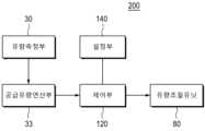
본 발명의 실시예에 따른 수액세트(200)는 공급호스(2) 일측에 구비되어 공급유량을 조절하는 유량조절유닛(80)을 포함할 수 있다. 수The sap set (200) according to the embodiment of the present invention may include a flow rate control unit (80) provided on one side of the supply hose (2) to control the supply flow rate.
그리고 관리서버(110)에는 유량측정부(30)에서 측정된 측정값을 전송받아 수액방울의 주기 또는, 특정주기 동안 공급된 수액방울의 개수를 기반으로 공급유량과, 공급된 총량을 연산하는 공급유량연산부(33)를 포함하여 구성될 수 있다. 그리고 설정부는 수액 공급량, 공급속도를 설정하도록 구성되며, 제어부는 이러한 공급유량연산부(33)에서 연산된 측정값과, 설정부(140)에서 설정된 공급속도를 기반으로 유량조절유닛(80)을 제어할 수 있다.And the management server (110) may be configured to include a supply flow rate calculation unit (33) that receives the measured value from the flow rate measurement unit (30) and calculates the supply flow rate and the total amount supplied based on the cycle of the sap droplets or the number of sap drops supplied during a specific cycle. And the setting unit is configured to set the sap supply amount and the supply speed, and the control unit can control the flow rate control unit (80) based on the measured value calculated by the supply flow rate calculation unit (33) and the supply speed set by the setting unit (140).
그리고 제어부(120)는 수액 총공급량이 설정된 공급량에 도달하면 수액공급을 중단시키도록 유량조절유닛(80)을 제어하게 된다.And the control unit (120) controls the flow rate control unit (80) to stop the sap supply when the total sap supply amount reaches the set supply amount.
또한 도 7에 도시된 바와 같이, 본 발명의 실시예에 따른 점적챔버(100)에는, 점적챔버 내의 수액 수위를 측정하는 수위센서(90)를 더 포함하여 구성될 수 있다. 이러한 또한 관리서버(110)에는 점적챔버(100)의 수위에 따른 점적챔버(100), 공급호스(2), 카테터(3) 끝단까지의 잔존 수액량을 연산하는 잔존수액연산부(91)를 포함하여 구성될 수 있다.In addition, as illustrated in FIG. 7, the drip chamber (100) according to the embodiment of the present invention may further include a level sensor (90) that measures the fluid level within the drip chamber. In addition, the management server (110) may include a residual fluid calculation unit (91) that calculates the amount of residual fluid up to the tip of the drip chamber (100), supply hose (2), and catheter (3) according to the fluid level of the drip chamber (100).
따라서 제어부(120)는 공급유량연산부(33)에서 연산된 총공급량에서 잔존수액연산부(91)에서 연산된 잔존수액량을 뺀 값이 설정된 공급량에 도달하면 수액공급을 중단시키도록 유량조절유닛을 제어하게 된다.Accordingly, the control unit (120) controls the flow rate control unit to stop the fluid supply when the value obtained by subtracting the residual fluid amount calculated in the residual fluid calculation unit (91) from the total supply amount calculated in the supply flow rate calculation unit (33) reaches the set supply amount.
즉, 공급호스(2)의 길이와 내경 등에 대한 정보와, 공급호스의 사이즈에 따른 잔존 수액 양이 입력되어 있고, 수위센서(90)에서 점적챔버(100) 내의 수위값을 알면 실시간으로 카테터 부터 점적챔버 내에 잔존하고 있는 수액의 유량을 연산할 수 있다.That is, information about the length and inner diameter of the supply hose (2), the amount of remaining fluid according to the size of the supply hose, etc. are input, and if the water level value in the drip chamber (100) is known from the water level sensor (90), the flow rate of the fluid remaining in the drip chamber from the catheter can be calculated in real time.
수액백(1)에서 점적챔버(100)로 공급된 총 공급유량에서 이러한 잔존 수액양을 빼면, 실제 환자에게 공급된 수액의 양을 연산할 수 있고, 제어부(120)는 이러한 실제 환자에게 공급된 수액의 양을 기반으로 설정된 공급량이 실제 환자에게 공급된 수액의 양에 도달하는 경우 유량제어유닛(80)을 통해 수액공급이 중단되도록 제어하게 된다.By subtracting this remaining amount of fluid from the total amount of fluid supplied from the infusion bag (1) to the drip chamber (100), the amount of fluid actually supplied to the patient can be calculated, and the control unit (120) controls the fluid supply to be stopped through the flow control unit (80) when the set supply amount based on this amount of fluid actually supplied to the patient reaches the amount of fluid actually supplied to the patient.
Claims (7)
Translated fromKoreanPriority Applications (1)
| Application Number | Priority Date | Filing Date | Title |
|---|---|---|---|
| CN202480005212.0ACN120379708A (en) | 2023-08-31 | 2024-08-28 | Regulator-integrated drip chamber with locking device and infusion set including same |
Applications Claiming Priority (2)
| Application Number | Priority Date | Filing Date | Title |
|---|---|---|---|
| KR1020230115196AKR102692339B1 (en) | 2023-08-31 | 2023-08-31 | Regulatorintegrated drip chamber with locking device and infusion set including the same |
| KR10-2023-0115196 | 2023-08-31 |
Publications (1)
| Publication Number | Publication Date |
|---|---|
| WO2025048479A1true WO2025048479A1 (en) | 2025-03-06 |
Family
ID=92378841
Family Applications (1)
| Application Number | Title | Priority Date | Filing Date |
|---|---|---|---|
| PCT/KR2024/012832PendingWO2025048479A1 (en) | 2023-08-31 | 2024-08-28 | Regulator-integrated drip chamber having locking device and infusion set comprising same |
Country Status (3)
| Country | Link |
|---|---|
| KR (1) | KR102692339B1 (en) |
| CN (1) | CN120379708A (en) |
| WO (1) | WO2025048479A1 (en) |
Families Citing this family (1)
| Publication number | Priority date | Publication date | Assignee | Title |
|---|---|---|---|---|
| KR102692339B1 (en)* | 2023-08-31 | 2024-08-07 | (주)메딕프로코리아 | Regulatorintegrated drip chamber with locking device and infusion set including the same |
Citations (6)
| Publication number | Priority date | Publication date | Assignee | Title |
|---|---|---|---|---|
| KR101027081B1 (en)* | 2009-08-18 | 2011-04-05 | 김우진 | Blood backflow prevention device of infusion set |
| US20110218501A1 (en)* | 2010-03-04 | 2011-09-08 | Hsien-Tsung Wang | Automatic intravenous fluid flow control device |
| KR101837519B1 (en)* | 2017-12-22 | 2018-03-13 | (주)메디라인액티브코리아 | Flow regulator for medical infusion set |
| KR20210109157A (en)* | 2020-02-27 | 2021-09-06 | 성원메디칼 주식회사 | Flow rate regulator for intravenous fluid therapy capable of smart type monitoring |
| KR20230112192A (en)* | 2022-01-19 | 2023-07-27 | 동국대학교 산학협력단 | Infusion rate measurement system and method using droplet recognition in mobile device |
| KR102692339B1 (en)* | 2023-08-31 | 2024-08-07 | (주)메딕프로코리아 | Regulatorintegrated drip chamber with locking device and infusion set including the same |
Family Cites Families (1)
| Publication number | Priority date | Publication date | Assignee | Title |
|---|---|---|---|---|
| KR100792805B1 (en) | 2007-01-24 | 2008-01-14 | 사단법인 삼성생명공익재단삼성서울병원 | Liquid level detector of the fluid dosing set |
- 2023
- 2023-08-31KRKR1020230115196Apatent/KR102692339B1/enactiveActive
- 2024
- 2024-08-28CNCN202480005212.0Apatent/CN120379708A/enactivePending
- 2024-08-28WOPCT/KR2024/012832patent/WO2025048479A1/enactivePending
Patent Citations (6)
| Publication number | Priority date | Publication date | Assignee | Title |
|---|---|---|---|---|
| KR101027081B1 (en)* | 2009-08-18 | 2011-04-05 | 김우진 | Blood backflow prevention device of infusion set |
| US20110218501A1 (en)* | 2010-03-04 | 2011-09-08 | Hsien-Tsung Wang | Automatic intravenous fluid flow control device |
| KR101837519B1 (en)* | 2017-12-22 | 2018-03-13 | (주)메디라인액티브코리아 | Flow regulator for medical infusion set |
| KR20210109157A (en)* | 2020-02-27 | 2021-09-06 | 성원메디칼 주식회사 | Flow rate regulator for intravenous fluid therapy capable of smart type monitoring |
| KR20230112192A (en)* | 2022-01-19 | 2023-07-27 | 동국대학교 산학협력단 | Infusion rate measurement system and method using droplet recognition in mobile device |
| KR102692339B1 (en)* | 2023-08-31 | 2024-08-07 | (주)메딕프로코리아 | Regulatorintegrated drip chamber with locking device and infusion set including the same |
Also Published As
| Publication number | Publication date |
|---|---|
| KR102692339B1 (en) | 2024-08-07 |
| CN120379708A (en) | 2025-07-25 |
Similar Documents
| Publication | Publication Date | Title |
|---|---|---|
| WO2025048479A1 (en) | Regulator-integrated drip chamber having locking device and infusion set comprising same | |
| CA2024425C (en) | Automatic tubing lock for ultrasonic sensor interface | |
| CA2142598A1 (en) | Apparatus for monitoring infusion | |
| WO2018048100A1 (en) | Liquid medicine injection device | |
| CN205649494U (en) | Bladder pressure measurement | |
| WO2021187707A1 (en) | Flow rate control regulator for fluid infusion | |
| WO2022225208A1 (en) | Syringe-type microneedle | |
| CN111467638A (en) | An intelligent oxygen therapy oxygen generator with blood oxygen saturation control function | |
| WO2019139392A1 (en) | Automated pharmaceutical pressure injector | |
| WO2011139113A2 (en) | Method for managing history of liquid medicine injections | |
| CN119587822A (en) | An intelligent monitoring oxygen inhaler controlled by a touch screen | |
| CN107184339A (en) | One kind nursing warning device | |
| WO2025143652A1 (en) | Iot smart regulator system having photosensor and drip container | |
| US6511434B1 (en) | Blood-pressure transducer assembly | |
| WO2025143651A1 (en) | Injection speed measurement device for ict smart regulator having photosensor drip container | |
| WO2015037928A1 (en) | Multi-directional valve | |
| WO2013165094A1 (en) | Device for supplying medical liquid, having improved structure | |
| WO2011031052A2 (en) | Apparatus for precisely regulating a liquid medicine injection dose | |
| WO2021137499A2 (en) | Device for determining removability of foley catheter | |
| CN2613269Y (en) | Pressure infusion apparatus for medical use | |
| WO2015020374A1 (en) | Micro cylinder pump and micro pumping device using same | |
| WO2024117756A1 (en) | Negative pressure therapy device and method for controlling same | |
| WO2020180080A1 (en) | Drug mixing device, drug mixing kit comprising same, and method for manufacturing same | |
| WO2020180081A1 (en) | Drug mixing kit syringe, drug mixing kit, and manufacturing method therefor | |
| KR20250021215A (en) | Regulatorintegrated drip chamber and infusion set including the same |
Legal Events
| Date | Code | Title | Description |
|---|---|---|---|
| 121 | Ep: the epo has been informed by wipo that ep was designated in this application | Ref document number:24860399 Country of ref document:EP Kind code of ref document:A1 | |
| WWE | Wipo information: entry into national phase | Ref document number:202480005212.0 Country of ref document:CN | |
| WWP | Wipo information: published in national office | Ref document number:202480005212.0 Country of ref document:CN |