WO2025046901A1 - Vehicle control device - Google Patents
Vehicle control deviceDownload PDFInfo
- Publication number
- WO2025046901A1 WO2025046901A1PCT/JP2023/032049JP2023032049WWO2025046901A1WO 2025046901 A1WO2025046901 A1WO 2025046901A1JP 2023032049 WJP2023032049 WJP 2023032049WWO 2025046901 A1WO2025046901 A1WO 2025046901A1
- Authority
- WO
- WIPO (PCT)
- Prior art keywords
- vehicle
- force
- control
- angular velocity
- suspension
- Prior art date
- Legal status (The legal status is an assumption and is not a legal conclusion. Google has not performed a legal analysis and makes no representation as to the accuracy of the status listed.)
- Pending
Links
Images


Classifications
- B—PERFORMING OPERATIONS; TRANSPORTING
- B60—VEHICLES IN GENERAL
- B60W—CONJOINT CONTROL OF VEHICLE SUB-UNITS OF DIFFERENT TYPE OR DIFFERENT FUNCTION; CONTROL SYSTEMS SPECIALLY ADAPTED FOR HYBRID VEHICLES; ROAD VEHICLE DRIVE CONTROL SYSTEMS FOR PURPOSES NOT RELATED TO THE CONTROL OF A PARTICULAR SUB-UNIT
- B60W10/00—Conjoint control of vehicle sub-units of different type or different function
- B60W10/04—Conjoint control of vehicle sub-units of different type or different function including control of propulsion units
- B—PERFORMING OPERATIONS; TRANSPORTING
- B60—VEHICLES IN GENERAL
- B60W—CONJOINT CONTROL OF VEHICLE SUB-UNITS OF DIFFERENT TYPE OR DIFFERENT FUNCTION; CONTROL SYSTEMS SPECIALLY ADAPTED FOR HYBRID VEHICLES; ROAD VEHICLE DRIVE CONTROL SYSTEMS FOR PURPOSES NOT RELATED TO THE CONTROL OF A PARTICULAR SUB-UNIT
- B60W10/00—Conjoint control of vehicle sub-units of different type or different function
- B60W10/18—Conjoint control of vehicle sub-units of different type or different function including control of braking systems
- B60W10/184—Conjoint control of vehicle sub-units of different type or different function including control of braking systems with wheel brakes
- B—PERFORMING OPERATIONS; TRANSPORTING
- B60—VEHICLES IN GENERAL
- B60W—CONJOINT CONTROL OF VEHICLE SUB-UNITS OF DIFFERENT TYPE OR DIFFERENT FUNCTION; CONTROL SYSTEMS SPECIALLY ADAPTED FOR HYBRID VEHICLES; ROAD VEHICLE DRIVE CONTROL SYSTEMS FOR PURPOSES NOT RELATED TO THE CONTROL OF A PARTICULAR SUB-UNIT
- B60W10/00—Conjoint control of vehicle sub-units of different type or different function
- B60W10/22—Conjoint control of vehicle sub-units of different type or different function including control of suspension systems
- B—PERFORMING OPERATIONS; TRANSPORTING
- B62—LAND VEHICLES FOR TRAVELLING OTHERWISE THAN ON RAILS
- B62J—CYCLE SADDLES OR SEATS; AUXILIARY DEVICES OR ACCESSORIES SPECIALLY ADAPTED TO CYCLES AND NOT OTHERWISE PROVIDED FOR, e.g. ARTICLE CARRIERS OR CYCLE PROTECTORS
- B62J45/00—Electrical equipment arrangements specially adapted for use as accessories on cycles, not otherwise provided for
- B62J45/40—Sensor arrangements; Mounting thereof
- B62J45/41—Sensor arrangements; Mounting thereof characterised by the type of sensor
- B62J45/413—Rotation sensors
- B—PERFORMING OPERATIONS; TRANSPORTING
- B62—LAND VEHICLES FOR TRAVELLING OTHERWISE THAN ON RAILS
- B62K—CYCLES; CYCLE FRAMES; CYCLE STEERING DEVICES; RIDER-OPERATED TERMINAL CONTROLS SPECIALLY ADAPTED FOR CYCLES; CYCLE AXLE SUSPENSIONS; CYCLE SIDE-CARS, FORECARS, OR THE LIKE
- B62K25/00—Axle suspensions
- B62K25/04—Axle suspensions for mounting axles resiliently on cycle frame or fork
- B62K25/12—Axle suspensions for mounting axles resiliently on cycle frame or fork with rocking arm pivoted on each fork leg
- B62K25/14—Axle suspensions for mounting axles resiliently on cycle frame or fork with rocking arm pivoted on each fork leg with single arm on each fork leg
- B62K25/20—Axle suspensions for mounting axles resiliently on cycle frame or fork with rocking arm pivoted on each fork leg with single arm on each fork leg for rear wheel
Definitions
- the present inventionrelates to a vehicle control device for controlling the running of a vehicle or the movement of the vehicle body.
- the vehicle posture(the distance and angle above the spring relative to the road surface) can change due to disturbances such as the driver's or rider's acceleration/deceleration operations, the rider's weight shift, and the unevenness of the road surface on which the vehicle is traveling.
- the springis suspended by a suspension, and the above-mentioned changes in vehicle posture are damped by the suspension, and the vehicle is usually set up so that it does not provide an uncomfortable ride.
- Patent Document 1discloses a technology relating to control for correcting the driving torque of a vehicle so as to suppress sprung vibration based on a motion model.
- Patent Document 2discloses a technology for controlling the wheel brakes of a vehicle depending on the pitching angle of the vehicle body.
- Patent Document 3discloses a technology for correcting the driving torque or braking torque based on an estimation of the sprung behavior when the vehicle accelerates or decelerates.
- Patent Document 4discloses a technology for controlling the vehicle posture by operating the swing arm of the vehicle body with the reaction force of the driving torque or braking torque.
- JP 2010-106817A JP 2021-008751 A JP 2013-122104 A JP 2004-306733 A
- Adjusting only one of the control forces for vehicle travelfor example the drive torque or the braking torque, i.e., using the techniques disclosed in the above-mentioned Patent Documents 1 to 4, does not sufficiently suppress changes in vehicle posture; in other words, it is desirable to improve the ride comfort when adjusting the control forces.
- One object of the present inventionis to provide a vehicle control device capable of improving ride comfort when the vehicle attitude changes due to an external disturbance.
- a vehicle control deviceincludes: a driving control force adjustment unit that adjusts a driving control force of a vehicle having a suspension system including a swing arm connecting tires and a vehicle body; and a vehicle motion determination unit that determines a motion of the vehicle; The motion determined by the vehicle motion determination unit is suppressed by using a force acting on the swing arm when a driving force and a braking force are generated in the vehicle by the driving control force adjustment unit within a specified control period.
- both the driving force and the braking forceare applied to the swing arm within a specified control period, suppressing the movement of the vehicle and improving ride comfort.
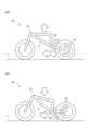
- FIGS. 1A and 1Bare schematic diagrams of a motorcycle, and FIGS. 1A and 1B are explanatory diagrams of the forces acting on a spring when only a driving torque and a braking torque are generated, respectively.
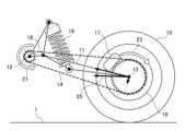
- FIG. 2is a diagram illustrating a reaction force acting on a swing arm when a driving torque and a braking torque are generated simultaneously (or substantially simultaneously).
- FIG. 3shows a schematic configuration diagram of the vehicle control device.
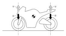
- FIG. 4shows a conceptual diagram of skyhook control.
- FIG. 5shows a concept of the sprung mass pitch angular velocity suppression control.
- FIG. 6shows a concept of the unsprung pitch angular velocity suppression control relative to the sprung portion.
- FIG. 7(A)shows an explanatory diagram of another example configuration of the braking section of FIG. 3, and FIG. 7(B) shows an explanatory diagram of the force acting on a spring when only braking torque is generated in a motorcycle having the braking section of FIG. 7(A).
- FIGs 1(A) and 1(B)show schematic diagrams of a vehicle (typically a motorcycle), and when only a driving force, such as a driving torque 21, that controls the running or acceleration of the vehicle 10 is generated, as shown in Patent Document 4, a reaction force 22 of the driving torque acts on the swing arm 11, causing the spring 31 to lift (see Figure 1(A)).
- a driving forcesuch as a driving torque 21, that controls the running or acceleration of the vehicle 10
- a reaction force 22 of the driving torqueacts on the swing arm 11, causing the spring 31 to lift (see Figure 1(A)).
- a braking forcesuch as a braking torque 23, that controls the running or deceleration of the vehicle 10 is generated
- a reaction force 24 of the braking torqueacts on the swing arm 11, causing the spring 31 to be pressed against the road surface 1 (see Figure 1(B)).
- the drive shaft 12corresponds to the output of a drive source (not shown) such as an engine of the vehicle 10, and the drive shaft 12 rotates (counterclockwise in FIG. 2) when the driver accelerates the vehicle 10 by operating, for example, an accelerator (not shown).
- the rotation of the drive shaft 12is transmitted to the rear wheel 15 by a drive force transmission member including, for example, a chain 14.
- a brake pedalnot shown
- the rotation of the rear wheel 15is suppressed.
- the method of transmitting the drive forceis not limited to a chain type, and may be a belt type, a shaft type, or the like.
- one end (upper end) of the suspension 19(cushion unit including a suspension spring and a damping section) is connected to the vehicle body or the spring, while the other end (lower end) of the suspension 19 is connected to a swing arm 11.
- the swing arm 11, which supports the rear wheel 15,is supported by a pivot 18 supported by the vehicle frame 2 (see FIG. 1(A) and FIG. 1(B)).
- the pivot 18is inserted into the front end of the swing arm 11, which connects the tire of the rear wheel 15 to the vehicle body including the vehicle frame 2, and the swing arm 11 can swing up and down around the pivot 18.
- the rear wheel 15is supported by an axle 13 provided at the rear end of the swing arm 11.
- a suspension system including the suspension 19 and swing arm 11may refer to a swing arm suspension.
- the structure of the swing arm 11 and its attachment to the vehicle bodyare well known, and therefore will not be described in this specification.
- JP 2022-157856 Adiscloses a cast swing arm. Note that, like this cast swing arm, the brake caliper 17 can be fixed to the rear end side of the swing arm 11.
- the vehicle geometry in FIG. 2is typical, and when the driving torque 21 balances with the braking torque 23, the suspension 19 (spring portion) extends.
- FIG. 3shows a schematic diagram of the vehicle control device.
- the vehicle control device 50includes a driving control force adjustment unit 55 that adjusts the driving control force of the vehicle 10, typically either the driving force or the braking force, and a vehicle motion determination unit 52 that determines the motion of the vehicle 10.
- the vehicle control device 50an ECU (Electronic Control Unit).
- the sensor group 40has multiple sensors, and the sensor values detected by each sensor are input to the vehicle control device 50.
- the sensor group 40has an accelerator position sensor (not shown) that detects the accelerator operation amount or opening degree.
- the driving force control unit 53can output a driving force control amount to the driving unit 61 so that the driving unit 61 generates a driving force according to the driver's intention.
- the sensor group 40can detect a sensor value (e.g., sprung vertical acceleration) representing the posture of the vehicle 10 using, for example, an acceleration sensor (not shown), and the vehicle motion determination unit 52 can determine, for example, whether the absolute value of the sprung vertical acceleration is equal to or greater than a threshold value, in other words, whether the ride is uncomfortable.
- a sensor valuee.g., sprung vertical acceleration
- the sensor group 40 or multiple sensors in FIG. 3are typically provided outside the vehicle control device 50, but at least one sensor of the sensor group 40 may be built into the vehicle control device 50.
- the vehicle motion determination unit 52can instruct or control the driving control force adjustment unit 55, for example, to reduce the absolute value of the sprung vertical acceleration or to improve ride comfort.
- the driving control force adjustment unit 55(typically, the braking force addition unit 57) inputs the driving force control amount output from the driving force control unit 53 to the driving unit 61, and can output an adjustment control amount or a braking force addition amount to the braking unit 62 so that the driving force of the driving unit 61 corresponding to the driving force control amount balances with the braking force of the braking unit 62 within a specified control target period.
- the vehicle control device 50can improve ride comfort by, for example, simultaneously applying both a driving force according to the driver's will and a braking force against the driver's will (the driving force is automatically adjusted by the driving control force adjustment unit 55) to the swing arm 11 to suppress the movement of the vehicle 10.
- the driving control force adjustment unit 55adjusts the control force (e.g., the driving force, e.g., the braking force) at an appropriate timing. In other words, while a specified amount of accelerator operation or a specified opening degree is detected, the driving control force adjustment unit 55 does not always output an adjusted control amount or an additional amount of braking force to the braking unit 62. Specifically, the driving control force adjustment unit 55 allows adjustment of the control force against the will of the driver of the vehicle 10 within a specified control target period, but does not adjust the control force against the will of the driver outside the specified control target period.
- the control forcee.g., the driving force, e.g., the braking force
- the driving control force adjustment unit 55adjusts the control force at the necessary timing to improve ride comfort.
- the vehicle control device 50includes a damping force control unit 71 that controls the damping force of the damping unit 72 that damps the vibration of the suspension spring of the suspension 19.
- a damping force control unit 71controls the damping force of the damping unit 72 that damps the vibration of the suspension spring of the suspension 19.
- the damping force control unit 71can be equipped with, for example, the well-known skyhook control, and the damping force control unit 71 determines the amount of damping force control based on, for example, the vertical acceleration above the spring, and operates an actuator (not shown) of the damping unit 72.
- the damping force control unit 71adds or subtracts the damping force control amount so that the absolute value of the sprung vertical velocity on the rear wheel 15 side becomes smaller.
- the vehicle motion determination unit 52may, for example, estimate the amount of expansion and contraction (stroke amount) of the suspension 19 based on the sprung vertical acceleration, and when the sprung vertical velocity indicates an upward direction and the suspension 19 indicates an extension process, the damping force control unit 71 can increase the damping force control amount so that the damping force of the damping unit 72 increases (first timing).
- the damping force control unit 71can decrease the damping force control amount so that the damping force of the damping unit 72 decreases (second timing).
- the damping force control unit 71can decrease the damping force control amount so that the damping force of the damping unit 72 decreases (third timing).
- the damping force control unit 71can increase the damping force control amount so as to increase the damping force of the damping unit 72 (fourth timing).
- the vehicle motion determination unit 52 or the damping force control unit 71may input the stroke amount of the suspension 19 and determine whether the suspension 19 is in the extension or compression process. Alternatively, if the sensor group 40 detects sprung vertical acceleration and, for example, unsprung vertical acceleration, the vehicle motion determination unit 52 or the damping force control unit 71 may calculate the stroke amount of the suspension 19 based on the sprung vertical acceleration and the unsprung vertical acceleration.
- the damping force control unit 71can increase or decrease the damping force of the damping unit 72, but there is room for further improvement in ride comfort. That is, when the sprung vertical speed indicates a downward direction, the braking force application unit 57 generates a driving force control amount so that the driving force of the drive unit 61 balances with the braking force of the brake unit 62, and the lower end of the suspension spring of the suspension 19 extends via the swing arm 11. In this way, at the timing (third and fourth timing) when the sprung vertical speed is downward, the braking force via the braking force application unit 57 adjusts or offsets the driving force of the drive unit 61, causing the swing arm 11 to extend the suspension 19, thereby further improving ride comfort.
- the braking force application unit 57 or the driving control force adjustment unit 55can determine the driving force control amount or the control force adjustment amount by itself, regardless of the presence or absence of the damping force control unit 71, so as to improve ride comfort by suppressing the sprung vertical motion.
- the vehicle control device 50may include a driver intention determination unit 51, which can determine whether or not the driver has operated the accelerator, brake pedal, etc.
- the driver intention determination unit 51can output sense values from the sensor group 40 according to the driver's operation to the driving force control unit 53 and the braking force control unit 54.
- the vehicle control device 50may also output other sense values (for example, the speed of the vehicle 10 based on a wheel speed sensor, etc.) to the driving force control unit 53 and the braking force control unit 54.
- FIG. 4shows a conceptual diagram of skyhook control.
- the vehicle control device 50 or damping force control unit 71can determine the vertical speed of the front and rear axles (axles 13) above the springs (body including the body frame 2, etc.) and control the damping force of the damping unit 72 so that the vertical speed becomes smaller.
- the vehicle control device 50 or damping force control unit 71 in FIG. 3can determine the damping force control amount for each suspension.
- the braking force control unit 54can output a braking force control amount to the braking unit 62 so that the braking unit 62 generates a braking force according to the driver's intention.
- the vehicle motion determination unit 52can instruct or control the driving control force adjustment unit 55, for example, so that the absolute value of the sprung vertical acceleration is small or the ride comfort is improved.
- the driving control force adjustment unit 55(typically, the driving force addition unit 56) can input the braking force control amount output from the braking force control unit 54 to the braking unit 62, and output an adjustment control amount or a driving force addition amount to the driving unit 61 so that the braking force of the braking unit 62 corresponding to the braking force control amount is balanced with the driving force of the driving unit 61.
- the vehicle control device 50can improve ride comfort by, for example, simultaneously applying to the swing arm 11 both a braking force that conforms to the driver's will and a driving force that goes against the driver's will (the braking force is automatically adjusted by the driving control force adjustment unit 55) to suppress the movement of the vehicle 10.
- the vehicle control device 50may further include adders 58 and 59.
- the travel control force adjustment unit 55may operate the driving force application unit 56 and the braking force application unit 57 simultaneously by making them independent of each other.
- the driving force and braking forcemay be input and compared, and only one of the driving force application unit 56 or the braking force application unit 57 may be operated so that they are balanced.
- FIG. 5shows a conceptual diagram of skyhook control (sprung pitch angular velocity suppression control) in a broad sense.
- the vehicle control device 50 or the damping force control unit 71can control the damping force of the damping unit 72 so that the sprung pitch angular velocity becomes smaller.
- the vehicle motion determination unit 52can determine whether, for example, the sprung pitch angular velocity detected by the sensor group 40 is in the nose dive direction or the wheelie direction.
- the vehicle motion determination unit 52can further determine whether the front wheel suspension is in the compression process or the extension process, and whether the rear wheel 15 suspension 19 is in the compression process or the extension process.
- the damping force control unit 71can increase the damping force control amount so that the damping force of the damping unit 72 increases (5th timing).
- the damping force control unit 71can decrease the damping force control amount so that the damping force of the damping unit 72 decreases (6th timing).
- the damping force control unit 71can decrease the damping force control amount so that the damping force of the damping unit 72 decreases (7th timing).
- the damping force control unit 71can increase the damping force control amount so that the damping force of the damping unit 72 increases (8th timing).
- the damping force control unit 71can increase or decrease the damping force of the damping unit 72, but there is room for further improvement in ride comfort. That is, when the sprung pitch angular velocity indicates a wheelie direction, the braking force application unit 57 generates a driving force control amount so that the driving force of the drive unit 61 balances with the braking force of the brake unit 62, and the lower end of the suspension spring of the suspension 19 extends via the swing arm 11.
- the braking force via the braking force application unit 57adjusts or offsets the driving force of the drive unit 61, causing the swing arm 11 to extend the suspension 19, thereby further improving ride comfort.
- the braking force application unit 57 or the driving control force adjustment unit 55can determine the driving force control amount or the control force adjustment amount by itself, regardless of the presence or absence of the damping force control unit 71, so as to improve ride comfort by suppressing the sprung pitch motion.
- FIG. 6shows a conceptual diagram of skyhook control in a broad sense (control to suppress the pitch angular velocity of the unsprung part relative to the sprung part).
- the vehicle control device 50 or the damping force control unit 71can control the damping force of the damping unit 72 so that the pitch angular velocity of the unsprung part (axle 13, rear wheel 15, etc.) relative to the sprung part is small.
- the vehicle motion determination unit 52can determine whether the unsprung pitch angular velocity relative to the sprung part based on the stroke amount of the front wheel suspension and the rear wheel 15 suspension 19 is in the nose dive direction or the wheelie direction.
- the vehicle motion determination unit 52can further determine whether the front wheel suspension is in the compression process or the extension process, and whether the rear wheel 15 suspension 19 is in the compression process or the extension process.
- the damping force control unit 71can decrease the damping force control amount so that the damping force of the damping unit 72 decreases (9th timing).
- the damping force control unit 71can increase the damping force control amount so that the damping force of the damping unit 72 increases (10th timing).
- the damping force control unit 71can increase the damping force control amount so that the damping force of the damping unit 72 increases (11th timing).
- the damping force control unit 71can reduce the damping force control amount so that the damping force of the damping unit 72 decreases (12th timing).
- the damping force control unit 71can increase or decrease the damping force of the damping unit 72, but there is room for further improvement in ride comfort. That is, when the unsprung pitch angular velocity indicates a wheelie direction, the braking force application unit 57 generates a driving force control amount so that the driving force of the drive unit 61 balances with the braking force of the brake unit 62, and the lower end of the suspension spring of the suspension 19 extends via the swing arm 11.
- the braking force via the braking force application unit 57adjusts or offsets the driving force of the drive unit 61, causing the swing arm 11 to extend the suspension 19, thereby further improving ride comfort.
- the braking force application unit 57 or the driving control force adjustment unit 55can determine the driving force control amount or the control force adjustment amount by itself, regardless of the presence or absence of the damping force control unit 71, so as to improve ride comfort by suppressing the unsprung pitch motion.
- the damping force control unit 71may arbitrarily combine each operation example, in other words, a gain or ratio may be determined for each operation to obtain a damping force control amount corresponding to the final or combined damping force.
- a damping force control amount or a damping force depending on the speed of the vehicle 10 based on, for example, a wheel speed sensormay be determined.
- the method of determining the damping forcemay adopt any method, such as that disclosed in the pamphlet of International Publication No. 2020/129202.
- the driving control force adjustment unit 55may arbitrarily combine each operation example, in other words, a gain or ratio may be determined for each operation to obtain an adjustment control amount corresponding to the final or combined adjustment force.
- the driving control force adjustment unit 55can adjust the control force at the timing when the sprung pitch angular velocity is in the wheelie direction and the unsprung pitch angular velocity is in the nose dive direction (the 11th and 12th timings within the 7th and 8th timings). In other words, the driving control force adjustment unit 55 does not adjust the control force at the timing when the sprung pitch angular velocity is in the wheelie direction and the unsprung pitch angular velocity is in the wheelie direction (the 9th and 10th timings within the 7th and 8th timings).
- the driveroperates the accelerator to accelerate the vehicle 10 while the vehicle 10 is traveling on a flat road surface, it is possible to suppress only the pitch motion generated by the unevenness of the road surface 1.
- the vehicle motion determination unit 52can estimate or determine the bank angle of the vehicle 10 based on, for example, the sprung roll angular velocity detected by the sensor group 40 and the speed of the vehicle 10 based on, for example, a wheel speed sensor. The larger the bank angle is, the weaker the adjustment by the driving control force adjustment unit 55 can be, and the turning of the vehicle 10 can be prioritized.
- the bank angleindicates how much the vehicle 10 is leaning toward the road surface 1, and when the vehicle 10 is traveling in a straight line and the vehicle body 10 is in a straight state, the bank angle is set to zero.
- the bank anglecan also be detected or calculated using a known method.
- FIG. 7(A)shows an explanatory diagram of another example of the configuration of the braking unit 62.
- the braking unit 62 in FIG. 3is configured to have the brake caliper 17 in FIG. 2.
- the braking unit 62 in FIG. 3may be configured to have the brake caliper 17a (first caliper or main caliper) and brake caliper 17b (second caliper or sub caliper) in FIG. 7.
- the configuration of the vehicle control device in FIG. 3can be changed so that the brake caliper 17a is controlled by the braking force control unit 54 and the brake caliper 17b is controlled by the braking force application unit 57.
- caliper 17afor normal control
- sub caliper 17bfor attitude control
- sub caliper 17bfor attitude control
- the brake caliper 17bis connected to the vehicle body via the torque rod 9.
- one end (upper end) of the torque rod 9is connected to the vehicle body, while the other end (lower end) of the torque rod 9 is connected to the brake caliper 17b.
- the connection point (position) between the torque rod 9 and the vehicle bodyis located above the connection point (position) between the suspension 19 and the vehicle body, based on the height direction of the vehicle 10, and rearward based on the traveling direction of the vehicle 10.
- the force acting on the brake caliper 17bis in a direction that sinks the spring onto the road surface 1, that is, the braking force adding unit 57 generates a driving force control amount, and the upper end of the suspension spring of the suspension 19 is compressed via the torque rod 9 and the swing arm 11.
- FIG. 7(A)The vehicle geometry in FIG. 7(A) is not typical, but rather novel. Therefore, for example, in a special vehicle geometry as shown in FIG. 7(A), when the brake caliper 17b operates, the spring 31 is pulled down (see FIG. 7(B)). In other words, the reaction force 24 of the braking torque acts on the swing arm 11 via the torque rod 9, compressing the suspension 19 (spring portion).
- the suspension 19 (spring portion)can be expanded when the driving torque 21 and the braking torque 23 are generated simultaneously.
- the suspension 19 (spring portion)can be compressed when the braking torque 23 is generated by the brake caliper 17b.
- the suspension 19 (spring portion)can be compressed preferably when the driving torque 21 and the braking torque 23 are generated simultaneously.
- the suspension 19 (spring portion)can be compressed more preferably when the driving torque 21 is balanced with the braking torque 23.
- the suspension 19 (spring portion)can be expanded within a predetermined control period to suppress vehicle motion or improve ride comfort.
- the suspension 19 (spring portion)can be compressed within a predetermined control period to suppress vehicle motion or improve ride comfort.
- the specified control periodis, for example, the timing (first and second timings) when the sprung vertical velocity is upward so that the absolute value of the sprung vertical velocity on the rear wheel 15 side becomes smaller, and at such timings, for example, the braking force of the brake caliper 17b via the braking force application unit 57 adjusts or cancels the driving force of the drive unit 61, causing the swing arm 11 to compress the suspension 19, thereby further improving the ride comfort.
- the specified control periodis, for example, the timing (fifth and sixth timings) when the sprung pitch angular velocity is in the nose dive direction so that the sprung pitch angular velocity is small, and at such timings, for example, the braking force of the brake caliper 17b via the braking force application unit 57 adjusts or cancels the driving force of the drive unit 61, causing the swing arm 11 to compress the suspension 19, thereby further improving the ride comfort.
- the specified control periodis, for example, the timing (11th and 12th timings) when the unsprung pitch angular velocity is in the nose dive direction so that the unsprung pitch angular velocity relative to the sprung angular velocity is small, and at such timings, for example, the braking force of the brake caliper 17b via the braking force application unit 57 adjusts or cancels the driving force of the drive unit 61, causing the swing arm 11 to compress the suspension 19, thereby further improving the ride comfort.
- the vehicle motion determination unit 52can estimate or determine the bank angle of the vehicle 10, and the larger the bank angle is, the weaker the adjustment by the driving control force adjustment unit 55 can be made to give priority to turning the vehicle 10.
- the driving force and braking forceare generated, for example, simultaneously in the vehicle 10 by the driving control force adjustment unit 55 within a specified control period.
- simultaneousis a concept that includes not only completely simultaneous, but also substantially simultaneous.
- Completely simultaneousmeans that the driving force and braking force are always generated at some or all of a specific timing within the specified control period, in other words, the time when the driving force is not zero overlaps with the time when the braking force is not zero.
- Substantially simultaneousmeans that the driving force and braking force are generated alternately at some or all of a specific timing within the specified control period, in other words, for example, the specified delay period from the time when the driving force becomes zero when the braking force is zero to the time when the braking force is no longer zero is less than 0.1 seconds.
- the specified delay periodis preferably less than 0.05 seconds, more preferably less than 0.03 seconds, and even more preferably less than 0.001 seconds.
- the driving force and the braking forcemay each vary periodically, and may be constituted, for example, by a pulse train. When the duty ratio is, for example, 0.25 or 25%, the driving force and the braking force may be zero. However, if the specified delay period is short, in other words, a delay occurs in the transmission of the driving force due to a driving force transmission member such as the chain 14, and a braking force is generated within that delay, the driving force can be substantially balanced with the braking force (the average value or integral value of both within the specified control period can be made equal).
- the driving control force adjustment unit 55generates an adjustment control amount when the driver operates the accelerator, brake pedal, etc.
- the driving control force adjustment unit 55may generate an adjustment control amount when there is no driver operation at all.
- the driving control force adjustment unit 55may generate an additional driving force amount and an additional braking force amount simultaneously (including substantially simultaneously) during a specified control period.
- the angle of the swing arm 11can be changed without changing the speed of the vehicle 10.
Landscapes
- Engineering & Computer Science (AREA)
- Mechanical Engineering (AREA)
- Chemical & Material Sciences (AREA)
- Combustion & Propulsion (AREA)
- Transportation (AREA)
- Axle Suspensions And Sidecars For Cycles (AREA)
- Control Of Driving Devices And Active Controlling Of Vehicle (AREA)
- Vehicle Body Suspensions (AREA)
Abstract
Description
Translated fromJapanese本発明は、車両の走行又は車体の運動を制御するための車両用制御装置等に関する。The present invention relates to a vehicle control device for controlling the running of a vehicle or the movement of the vehicle body.
車両、例えば自動二輪車等の鞍乗り型車両において、車両姿勢(路面に対するバネ上の距離や角度)は、ドライバ又はライダの加減速操作、ライダの体重移動、車両が走行する路面の凹凸等の外乱によって変化し得る。一般的に、バネ上は、サスペンションによって懸架され、上記の車両姿勢の変化は、サスペンションにより減衰され、また、通常、不快な乗り心地にならないように車両がセッティングされている。In a vehicle, such as a saddle-type vehicle such as a motorcycle, the vehicle posture (the distance and angle above the spring relative to the road surface) can change due to disturbances such as the driver's or rider's acceleration/deceleration operations, the rider's weight shift, and the unevenness of the road surface on which the vehicle is traveling. Generally, the spring is suspended by a suspension, and the above-mentioned changes in vehicle posture are damped by the suspension, and the vehicle is usually set up so that it does not provide an uncomfortable ride.
例えば特許文献1には、運動モデルに基づいてバネ上振動を抑制するように、車両の駆動トルクを補正する制御に関する技術が開示されている。また、例えば特許文献2には、車体のピッチング角に依存して車両のホイールブレーキが制御される技術が開示されている。また、例えば特許文献3には、車両の加速又は減速時にバネ上挙動の推定に基づき駆動トルク又は制動トルクを補正する技術が開示されている。また、例えば特許文献4には、駆動トルク又は制動トルクの反力で車体のスイングアームを動作させて、車体姿勢を制御する技術が開示されている。For example,
車両の走行の制御力、例えば、駆動トルク及び制動トルクのうち何れか一方のみを調整するだけでは、即ち、上記の特許文献1~4に開示の技術を用いても、車両姿勢の変化の抑制が不十分であり、言い換えれば、制御力を調整する際の乗り心地を改善することが望まれている。 Adjusting only one of the control forces for vehicle travel, for example the drive torque or the braking torque, i.e., using the techniques disclosed in the above-mentioned
本発明の1つの目的は、車両姿勢が外乱によって変化する際の乗り心地を改善可能である車両用制御装置を提供することである。本発明の他の目的は、以下に例示する態様及び最良の実施形態、並びに添付の図面を参照することによって、当業者に明らかになるであろう。One object of the present invention is to provide a vehicle control device capable of improving ride comfort when the vehicle attitude changes due to an external disturbance. Other objects of the present invention will become apparent to those skilled in the art by referring to the following exemplary aspects and best modes, as well as the accompanying drawings.
以下に、本発明の概要を容易に理解するために、本発明に従う態様を例示する。Below, we will provide examples of embodiments of the present invention to facilitate an understanding of the overview of the present invention.
本発明に従う態様において、車両用制御装置は、タイヤと車体とをつなぐスイングアームを含むサスペンションシステムを有する車両の走行の制御力を調整する走行制御力調整部と、前記車両の運動を判定する車両運動判定部と、を含み、
前記走行制御力調整部によって駆動力と制動力を所定の制御対象期間内に前記車両に発生させた際に前記スイングアームに作用する力を用いて、前記車両運動判定部によって判定された前記運動を抑制する。In an aspect according to the present invention, a vehicle control device includes: a driving control force adjustment unit that adjusts a driving control force of a vehicle having a suspension system including a swing arm connecting tires and a vehicle body; and a vehicle motion determination unit that determines a motion of the vehicle;
The motion determined by the vehicle motion determination unit is suppressed by using a force acting on the swing arm when a driving force and a braking force are generated in the vehicle by the driving control force adjustment unit within a specified control period.
上記態様によれば、駆動力及び制動力の双方を所定の制御対象期間内にスイングアームに作用させて、車両の運動を抑制することにより、乗り心地を向上させることができる。According to the above aspect, both the driving force and the braking force are applied to the swing arm within a specified control period, suppressing the movement of the vehicle and improving ride comfort.
当業者は、例示した本発明に従う態様が、本発明の精神を逸脱することなく、さらに変更され得ることを容易に理解できるであろう。Those skilled in the art will readily understand that the exemplified embodiments of the present invention may be further modified without departing from the spirit of the present invention.
以下に説明する最良の実施形態は、本発明を容易に理解するために用いられている。従って、当業者は、本発明が、以下に説明される実施形態によって不当に限定されないことを留意すべきである。The best mode for carrying out the invention described below is used to facilitate understanding of the invention. Therefore, those skilled in the art should be aware that the invention is not unduly limited by the mode for carrying out the invention described below.
図1(A)及び図1(B)は、車両(典型的には自動二輪車)の概略構成図を示し、車両10の走行又は加速を制御する駆動力例えば駆動トルク21のみが発生する時には、特許文献4にも示されるように、スイングアーム11に駆動トルクの反力22が作用してバネ上31が持ち上がる(図1(A)参照)。他方、車両10の走行又は減速を制御する制動力例えば制動トルク23のみが発生する時には、スイングアーム11に制動トルクの反力24が作用してバネ上31が路面1に押し付けられる(図1(B)参照)。Figures 1(A) and 1(B) show schematic diagrams of a vehicle (typically a motorcycle), and when only a driving force, such as a driving
図2は、駆動トルク21及び制動トルク23が同時に発生する際に、駆動軸12とアクスル13との間に設けられたスイングアーム11に作用する反力の説明図を示す。図2において、駆動軸12は、車両10のエンジン等の駆動源(図示せず)の出力に対応し、ドライバが例えばアクセル(図示せず)を操作して車両10を加速させる時に駆動軸12が回転(図2において半時計回り方向)する。駆動軸12の回転は、例えばチェーン14等を含む駆動力伝達部材によって後輪15に伝達される。他方、ドライバが例えばブレーキペダル(図示せず)を操作して車両10を減速させる時に後輪15の回転(図2において半時計回り方向)が抑制される。なお、駆動力の伝達方式は、チェーン型に限定されず、ベルト型、シャフト型等であってもよい。2 is an explanatory diagram of the reaction force acting on the
後輪15及びブレーキディスク16がアクスル13(車軸)を中心に回転する間、ブレーキキャリパ17がブレーキディスク16を挟み込む時、制動トルク23が発生する。ここで、駆動トルク21が制動トルク23と釣り合うように制御することで、車両10の速度を変化させることなく、スイングアーム11の角度(車両姿勢)を変化させることができる。具体的には、車両ジオメトリによって、アクスル13において、スイングアーム11に作用する力25は、ピボット18に向かう力とそれに垂直で路面1側に向かう力とに分力され、駆動トルク21が制動トルク23と釣り合う状態でも、結果として、後輪15を下側に押し込む力が残り、また、サスペンション19(バネ部分)が伸長する。When the
図2において、サスペンション19(懸架バネ及び減衰部を含むクッションユニット)の一端(上端)は、車体又はバネ上に接続される一方、サスペンション19の他端(下端)は、スイングアーム11に接続される。後輪15を支持するスイングアーム11は、車体フレーム2(図1(A)及び図1(B)参照)に支持されるピボット18に支持される。後輪15のタイヤと車体フレーム2を含む車体とをつなぐスイングアーム11の前端部には、ピボット18が挿通され、スイングアーム11は、ピボット18を中心に上下に揺動可能である。後輪15は、スイングアーム11の後端部に設けられるアクスル13に支持される。In FIG. 2, one end (upper end) of the suspension 19 (cushion unit including a suspension spring and a damping section) is connected to the vehicle body or the spring, while the other end (lower end) of the
当業者は、サスペンション19及びスイングアーム11等を含むサスペンションシステムをスイングアーム式サスペンションと呼ぶことができる。スイングアーム11の構造及び車体への取付は、周知であるので、本明細書では、その説明を省略するが、例えば特開2022-157856号公報には、鋳造スイングアームが開示されている。なお、この鋳造スイングアームのように、ブレーキキャリパ17は、スイングアーム11の後端部側に、固定することができる。また、図2の車両ジオメトリは、一般的であり、駆動トルク21が制動トルク23と釣り合う時に、サスペンション19(バネ部分)が伸長する。Those skilled in the art may refer to a suspension system including the
図3は、車両用制御装置の概略構成図を示す。図3に示されるように、車両用制御装置50は、車両10の走行の制御力、典型的には、駆動力又は制動力の何れか一方を調整する走行制御力調整部55と、車両10の運動を判定する車両運動判定部52と、を含む。当業者は、車両用制御装置50をECU(Electronic Control Unit)と呼ぶことができる。図3において、センサ群40は、複数のセンサを有し、各センサで検知されたセンサ値が車両用制御装置50に入力される。1例として、センサ群40は、アクセルの操作量又は開度を検知するアクセルポジションセンサ(図示せず)を有する。ドライバがアクセルを操作して車両10を加速させる時に、駆動力制御部53は、ドライバの意思に応じた駆動力を駆動部61に発生させるように、駆動力制御量を駆動部61に出力することができる。FIG. 3 shows a schematic diagram of the vehicle control device. As shown in FIG. 3, the
センサ群40は、例えば加速度センサ(図示せず)で車両10の姿勢を表すセンサ値(例えば、バネ上上下加速度)を検知することができ、車両運動判定部52は、例えばバネ上上下加速度の絶対値が閾値以上であるか否かを判定することができ、言い換えれば、乗り心地が悪いか否かを判定することができる。図3のセンサ群40又は複数のセンサは、典型的には、車両用制御装置50の外部に設けているが、センサ群40のうち少なくとも1つのセンサが車両用制御装置50に内蔵されてもよい。The
車両運動判定部52は、例えばバネ上上下加速度の絶対値が小さくように、あるいは、乗り心地が向上するように、走行制御力調整部55を指示又は制御することができる。走行制御力調整部55(典型的には、制動力付加部57)は、駆動力制御部53から駆動部61に出力される駆動力制御量を入力し、駆動力制御量に対応する駆動部61の駆動力が所定の制御対象期間内に制動部62の制動力と釣り合うように、調整制御量又は制動力追加量を制動部62に出力することができる。The vehicle
車両用制御装置50は、例えばドライバの意思に従う駆動力及びドライバの意思に反する(走行制御力調整部55によって自動的に駆動力を調整する)制動力の双方を例えば同時にスイングアーム11に作用させて、車両10の運動を抑制することにより、乗り心地を向上させることができる。The
走行制御力調整部55は、適切なタイミングで制御力を(例えば制動力で例えば駆動力を)調整する。言い換えれば、アクセルの所定の操作量又は所定の開度が検知される間、常に、走行制御力調整部55は、調整制御量又は制動力追加量を制動部62に出力するものではない。具体的には、走行制御力調整部55は、所定の制御対象期間内では車両10のドライバの意思に反する制御力の調整を許容するが、所定の制御対象期間外ではドライバの意思に反する制御力の調整を行わない。The driving control
つまり、アクセルの所定の操作量又は所定の開度が検知される間、乗り心地が向上するように、必要なタイミングで、走行制御力調整部55は、制御力を調整すればよい。In other words, while a specified amount of accelerator operation or a specified opening degree is detected, the driving control
好ましくは、車両用制御装置50は、サスペンション19の懸架バネの振動を減衰する減衰部72の減衰力を制御する減衰力制御部71を含む。言い換えれば、サスペンション19の減衰部72の減衰力が電子的に制御できない場合、車両用制御装置50は、減衰力制御部71を含まない。減衰力制御部71は、例えば周知のスカイフック制御を具備することができ、減衰力制御部71は、例えばバネ上上下加速度に基づき減衰力制御量を決定し、減衰部72のアクチュエータ(図示せず)を作動させる。Preferably, the
減衰力制御部71は、例えば後輪15側のバネ上上下速度の絶対値が小さくなるように、減衰力制御量を加減算する。具体的には、車両運動判定部52は、例えばバネ上上下加速度に基づきサスペンション19の伸縮量(ストローク量)を推定してもよく、バネ上上下速度が上方向を示し、且つ、サスペンション19が伸長工程を示す時に、減衰力制御部71は、減衰部72の減衰力が上がるように減衰力制御量を増加することができる(第1タイミング)。あるいは、バネ上上下速度が上方向を示し、且つ、サスペンション19が圧縮工程を示す時に、減衰力制御部71は、減衰部72の減衰力が下がるように減衰力制御量を減少することができる(第2タイミング)。あるいは、バネ上上下速度が下方向を示し、且つ、サスペンション19が伸長工程を示す時に、減衰力制御部71は、減衰部72の減衰力が下がるように減衰力制御量を減少することができる(第3タイミング)。あるいは、バネ上上下速度が下方向を示し、且つ、サスペンション19が圧縮工程を示す時に、減衰力制御部71は、減衰部72の減衰力が上げるように減衰力制御量を増加することができる(第4タイミング)。The damping
なお、サスペンション19が例えばストロークセンサを有する場合、車両運動判定部52又は減衰力制御部71は、サスペンション19のストローク量を入力して、サスペンション19が伸長工程又は圧縮工程であるか否かを判定してもよい。代替的に、センサ群40は、バネ上上下加速度及び例えばバネ下上下加速度を検知する場合、車両運動判定部52又は減衰力制御部71は、バネ上上下加速度及びバネ下上下加速度に基づきサスペンション19のストローク量を算出してもよい。If the
ところで、バネ上上下速度が下方向を示す時に、減衰力制御部71は、減衰部72の減衰力を増減させることができるが、乗り心地を更に改善する余地がある。すなわち、バネ上上下速度が下方向を示す時に、駆動部61の駆動力が制動部62の制動力と釣り合うように、制動力付加部57が駆動力制御量を生成することで、サスペンション19の懸架バネの下端がスイングアーム11を介して伸長する。このように、バネ上上下速度が下方向であるタイミング(第3及び第4タイミング)で、制動力付加部57を介した制動力が駆動部61の駆動力を調整又は相殺して、スイングアーム11がサスペンション19を伸長させ、乗り心地を更に改善することができる。もちろん、制動力付加部57又は走行制御力調整部55は、それ自身で、減衰力制御部71の有無に拘わらず、バネ上上下運動の抑制によって乗り心地を向上させるように、駆動力制御量又は制御力調整量を決定することができる。When the sprung vertical speed indicates a downward direction, the damping
図3において、車両用制御装置50は、ドライバ意思判定部51を含んでもよく、ドライバ意思判定部51は、ドライバによるアクセル、ブレーキペダル等の操作の有無を判定することができる。ドライバ意思判定部51は、ドライバの操作に応じたセンサ群40からのセンス値を駆動力制御部53及び制動力制御部54に出力することができる。また、車両用制御装置50は、他のセンス値(例えば車輪速センサ等に基づく車両10の速度)を駆動力制御部53及び制動力制御部54に出力してもよい。In FIG. 3, the
図4は、スカイフック制御の概念図を示す。図4(矢印U及び矢印Dは、それぞれ、上方向及び下方向を示す)において、車両用制御装置50又は減衰力制御部71は、前輪軸及び後輪軸(アクスル13)のバネ上(車体フレーム2を含む車体等)の上下速度を求め、その上下速度が小さくなるように、減衰部72の減衰力を制御することができる。言い換えれば、車両10が後輪15側のサスペンション19だけでなく、前輪側のサスペンションも有する場合、図3の車両用制御装置50又は減衰力制御部71は、サスペンション毎に減衰力制御量を決定することができる。FIG. 4 shows a conceptual diagram of skyhook control. In FIG. 4 (arrows U and D indicate the upward and downward directions, respectively), the
また、図3において、ドライバが例えばブレーキペダル(図示せず)を操作して車両10を減速させる時に、制動力制御部54は、ドライバの意思に応じた制動力を制動部62に発生させるように、制動力制御量を制動部62に出力することができる。車両運動判定部52は、例えばバネ上上下加速度の絶対値が小さくように、あるいは、乗り心地が向上するように、走行制御力調整部55を指示又は制御することができる。走行制御力調整部55(典型的には、駆動力付加部56)は、制動力制御部54から制動部62に出力される制動力制御量を入力し、制動力制御量に対応する制動部62の制動力が駆動部61の駆動力と釣り合うように、調整制御量又は駆動力追加量を駆動部61に出力することができる。3, when the driver operates the brake pedal (not shown) to decelerate the
車両用制御装置50は、例えばドライバの意思に従う制動力及びドライバの意思に反する(走行制御力調整部55によって自動的に制動力を調整する)駆動力の双方を同時にスイングアーム11に作用させて、車両10の運動を抑制することにより、乗り心地を向上させることができる。The
図3において、車両用制御装置50は、加算部58,59を更に含んでもよい。言い換えれば、ドライバがアクセル及びブレーキペダルを同時に操作して、車両10の走行を指示する時に、走行制御力調整部55は、駆動力付加部56及び制動力付加部57を互いに独立させて駆動力付加部56及び制動力付加部57を同時に作動させてもよい。代替的に、ドライバがアクセル及びブレーキペダルを同時に操作して、車両10の走行を指示する時に、駆動力及び制動力を入力し、比較し、両者が釣り合うように、駆動力付加部56又は制動力付加部57の何れか一方のみを作動させてもよい。In FIG. 3, the
図5は、広義のスカイフック制御(バネ上ピッチ角速度抑制制御)の概念図を示す。図5(矢印UN及び矢印UWは、それぞれ、ノーズダイブ方向及びウィリー方向を示す)において、車両用制御装置50又は減衰力制御部71は、バネ上ピッチ角速度が小さくなるように、減衰部72の減衰力を制御することができる。具体的には、車両運動判定部52は、センサ群40によって検知された例えばバネ上ピッチ角速度がノーズダイブ方向又はウィリー方向であるか否かを判定することができる。好ましくは、車両運動判定部52は、前輪側のサスペンションが圧縮工程又は伸長工程であるか否か、及び、後輪15側のサスペンション19が圧縮工程又は伸長工程であるか否かを更に判定することができる。FIG. 5 shows a conceptual diagram of skyhook control (sprung pitch angular velocity suppression control) in a broad sense. In FIG. 5 (arrows UN and UW indicate the nose dive direction and wheelie direction, respectively), the
バネ上ピッチ角速度がノーズダイブ方向を示し、前輪側のサスペンションが圧縮工程を示し、且つ、サスペンション19が伸長工程を示す時に、減衰力制御部71は、減衰部72の減衰力が上がるように減衰力制御量を増加することができる(第5タイミング)。あるいは、バネ上ピッチ角速度がノーズダイブ方向を示し、前輪側のサスペンションが伸長工程を示し、且つ、サスペンション19が圧縮工程を示す時に、減衰力制御部71は、減衰部72の減衰力が下がるように減衰力制御量を減少することができる(第6タイミング)。あるいは、バネ上ピッチ角速度がウィリー方向を示し、前輪側のサスペンションが圧縮工程を示し、且つ、サスペンション19が伸長工程を示す時に、減衰力制御部71は、減衰部72の減衰力が下がるように減衰力制御量を減少することができる(第7タイミング)。あるいは、バネ上ピッチ角速度がウィリー方向を示し、前輪側のサスペンションが伸長工程を示し、且つ、サスペンション19が圧縮工程を示す時に、減衰力制御部71は、減衰部72の減衰力が上がるように減衰力制御量を増加することができる(第8タイミング)。When the sprung pitch angular velocity indicates the nose dive direction, the front wheel suspension indicates a compression process, and the
ところで、バネ上ピッチ角速度がウィリー方向を示す時に、減衰力制御部71は、減衰部72の減衰力を増減させることができるが、乗り心地を更に改善する余地がある。すなわち、バネ上ピッチ角速度がウィリー方向を示す時に、駆動部61の駆動力が制動部62の制動力と釣り合うように、制動力付加部57が駆動力制御量を生成することで、サスペンション19の懸架バネの下端がスイングアーム11を介して伸長する。このように、バネ上ピッチ角速度がウィリー方向であるタイミング(第7及び第8タイミング)で、制動力付加部57を介した制動力が駆動部61の駆動力を調整又は相殺して、スイングアーム11がサスペンション19を伸長させ、乗り心地を更に改善することができる。もちろん、制動力付加部57又は走行制御力調整部55は、それ自身で、減衰力制御部71の有無に拘わらず、バネ上ピッチ運動の抑制によって乗り心地を向上させるように、駆動力制御量又は制御力調整量を決定することができる。When the sprung pitch angular velocity indicates a wheelie direction, the damping
図6は、広義のスカイフック制御(バネ上に対するバネ下ピッチ角速度抑制制御)の概念図を示す。図6(矢印DN及び矢印DWは、それぞれ、ノーズダイブ方向及びウィリー方向を示す)において、車両用制御装置50又は減衰力制御部71は、バネ上に対するバネ下(アクスル13、後輪15等)のピッチ角速度が小さくなるように、減衰部72の減衰力を制御することができる。具体的には、車両運動判定部52は、例えば前輪側のサスペンション及び後輪15側のサスペンション19のストローク量に基づくバネ上に対するバネ下ピッチ角速度がノーズダイブ方向又はウィリー方向であるか否かを判定することができる。好ましくは、車両運動判定部52は、前輪側のサスペンションが圧縮工程又は伸長工程であるか否か、及び、後輪15側のサスペンション19が圧縮工程又は伸長工程であるか否かを更に判定することができる。FIG. 6 shows a conceptual diagram of skyhook control in a broad sense (control to suppress the pitch angular velocity of the unsprung part relative to the sprung part). In FIG. 6 (arrows DN and DW indicate the nose dive direction and the wheelie direction, respectively), the
バネ下ピッチ角速度がウィリー方向を示し、前輪側のサスペンションが圧縮工程を示し、且つ、サスペンション19が伸長工程を示す時に、減衰力制御部71は、減衰部72の減衰力が下がるように減衰力制御量を減少することができる(第9タイミング)。あるいは、バネ下ピッチ角速度がウィリー方向を示し、前輪側のサスペンションが伸長工程を示し、且つ、サスペンション19が圧縮工程を示す時に、減衰力制御部71は、減衰部72の減衰力が上がるように減衰力制御量を増加することができる(第10タイミング)。あるいは、バネ下ピッチ角速度がノーズダイブ方向を示し、前輪側のサスペンションが圧縮工程を示し、且つ、サスペンション19が伸長工程を示す時に、減衰力制御部71は、減衰部72の減衰力が上がるように減衰力制御量を増加することができる(第11タイミング)。あるいは、バネ下ピッチ角速度がノーズダイブ方向を示し、前輪側のサスペンションが伸長工程を示し、且つ、サスペンション19が圧縮工程を示す時に、減衰力制御部71は、減衰部72の減衰力が下がるように減衰力制御量を減少することができる(第12タイミング)。When the unsprung pitch angular velocity indicates the wheelie direction, the front wheel suspension indicates a compression process, and the
ところで、バネ下ピッチ角速度がウィリー方向を示す時に、減衰力制御部71は、減衰部72の減衰力を増減させることができるが、乗り心地を更に改善する余地がある。すなわち、バネ下ピッチ角速度がウィリー方向を示す時に、駆動部61の駆動力が制動部62の制動力と釣り合うように、制動力付加部57が駆動力制御量を生成することで、サスペンション19の懸架バネの下端がスイングアーム11を介して伸長する。このように、バネ下ピッチ角速度がウィリー方向であるタイミング(第9及び第10タイミング)で、制動力付加部57を介した制動力が駆動部61の駆動力を調整又は相殺して、スイングアーム11がサスペンション19を伸長させ、乗り心地を更に改善することができる。もちろん、制動力付加部57又は走行制御力調整部55は、それ自身で、減衰力制御部71の有無に拘わらず、バネ下ピッチ運動の抑制によって乗り心地を向上させるように、駆動力制御量又は制御力調整量を決定することができる。When the unsprung pitch angular velocity indicates a wheelie direction, the damping
図4、図5及び図6を用いて、減衰力制御部71の3つの動作例(減衰力の3つの制御例)を説明したが、減衰力制御部71は、各動作例を任意に組み合わせてもよく、言い換えれば、動作毎にゲイン又は割合を定めて、最終的な又は合成後の減衰力に対応する減衰力制御量を求めることができる。また、例えば車輪速センサ等に基づく車両10の速度に依存する減衰力制御量又は減衰力が決定されてもよい。減衰力の決定方法は、例えば国際公開第2020/129202号パンフレットに開示されたものなど、任意の手法を採用してもよい。同様に、走行制御力調整部55は、各動作例を任意に組み合わせてもよく、言い換えれば、動作毎にゲイン又は割合を定めて、最終的な又は合成後の調整力に対応する調整制御量を求めることができる。Three operation examples (three control examples of damping force) of the damping
例えば、図5及び図6の2つの動作例を組み合わせる時に、走行制御力調整部55は、バネ上ピッチ角速度がウィリー方向であり、且つ、バネ下ピッチ角速度がノーズダイブ方向であるタイミング(第7及び第8タイミング内の第11及び第12タイミング)で、制御力を調整することができる。言い換えれば、走行制御力調整部55は、バネ上ピッチ角速度がウィリー方向であり、且つ、バネ下ピッチ角速度がウィリー方向であるタイミング(第7及び第8タイミング内の第9及び第10タイミング)で、制御力を調整しない。このような調整によって、例えば平坦な路面を車両10が走行する状態で、ドライバがアクセルを操作して車両10を加速する時に、路面1の凹凸によって発生したピッチ運動のみを抑制することができる。For example, when combining the two operation examples of FIG. 5 and FIG. 6, the driving control
また、例えば、図4又は図5の動作例において、車両10が旋回する状態で、所定の制御対象期間は、バネ上上下速度が下方向であり、又は、バネ上ピッチ角速度がウィリー方向である。ここで、車両運動判定部52は、センサ群40によって検知された例えばバネ上ロール角速度と例えば車輪速センサ等に基づく車両10の速度とに基づく車両10のバンク角を推定又は判定することができる。バンク角が大きい程、走行制御力調整部55による調整を弱めて、車両10の旋回を優先させることができる。バンク角は、車両10がどのくらい路面1に向かって倒れているのかを表し、車両10が直線走行する時に車体10が真っ直ぐである状態で、バンク角は、ゼロとする。また、バンク角は、周知の手法で、検知又は算出することができる。Also, for example, in the operation example of FIG. 4 or FIG. 5, when the
図7(A)は、制動部62の他の構成例の説明図を示す。図3の制動部62は、図2のブレーキキャリパ17を有するように構成されている。図3の制動部62は、図7のブレーキキャリパ17a(第1キャリパ又はメインキャリパ)とブレーキキャリパ17b(第2キャリパ又はサブキャリパ)とを有するように構成されてもよい。また、ブレーキキャリパ17aは、制動力制御部54によって制御され、ブレーキキャリパ17bは、制動力付加部57によって制御されるように、図3の車両用制御装置の構成を変更することができる。言い換えれば、図2のブレーキキャリパ17は、通常制御用のメインキャリパ(パブレーキキャリパ17a)と姿勢制御用のサブキャリパ(ブレーキキャリパ17b)とに分割され、あるいは、姿勢制御用のサブキャリパ(ブレーキキャリパ17b)を更に有することができる。FIG. 7(A) shows an explanatory diagram of another example of the configuration of the
図7(A)において、ブレーキキャリパ17bは、トルクロッド9を介して、車体に接続されている。言い換えれば、トルクロッド9の一端(上端)は、車体に接続される一方、トルクロッド9の他端(下端)は、ブレーキキャリパ17bに接続される。また、トルクロッド9と車体との接続点(位置)は、サスペンション19と車体との接続点(位置)と比較として、車両10の高さ方向を基準にして上方に、車両10の進行方向を基準にして後方に、配置されている。ブレーキキャリパ17bが作動する時に、ブレーキキャリパ17bに作用する力は、バネ上を路面1に沈める方向に、即ち、制動力付加部57が駆動力制御量を生成することで、サスペンション19の懸架バネの上端がトルクロッド9及びスイングアーム11を介して圧縮する。In FIG. 7(A), the
図7(A)の車両ジオメトリは、一般的ではなく、新規である。従って、例えば図7(A)に示すような特別な車両ジオメトリでは、ブレーキキャリパ17bが作動する時に、バネ上31が引き下げられる(図7(B)参照)。すなわち、スイングアーム11に制動トルクの反力24がトルクロッド9を介して作用して、サスペンション19(バネ部分)が圧縮する。The vehicle geometry in FIG. 7(A) is not typical, but rather novel. Therefore, for example, in a special vehicle geometry as shown in FIG. 7(A), when the
先の実施形態(図2の車両ジオメトリ)では、駆動トルク21及び制動トルク23が同時に発生する際に、サスペンション19(バネ部分)を伸長させることができる。図7(A)の車両ジオメトリでは、ブレーキキャリパ17bによる制動トルク23が発生する際に、サスペンション19(バネ部分)を圧縮させることができる。さらに、図7(A)の車両ジオメトリでは、好ましくは、駆動トルク21及び制動トルク23が同時に発生する際に、サスペンション19(バネ部分)を圧縮させることができる。加えて、図7(A)の車両ジオメトリでは、さらに好ましくは、駆動トルク21が制動トルク23と釣り合う際に、サスペンション19(バネ部分)を圧縮させることができる。In the previous embodiment (vehicle geometry in FIG. 2), the suspension 19 (spring portion) can be expanded when the driving
先の実施形態(図2の車両ジオメトリ)では、車両の運動を抑制する又は乗り心地を向上させるために、所定の制御対象期間内にサスペンション19(バネ部分)を伸長させることができる。図7(A)の車両ジオメトリでは、車両の運動を抑制する又は乗り心地を向上させるために、所定の制御対象期間内にサスペンション19(バネ部分)を圧縮させることができる。In the previous embodiment (vehicle geometry in FIG. 2), the suspension 19 (spring portion) can be expanded within a predetermined control period to suppress vehicle motion or improve ride comfort. In the vehicle geometry in FIG. 7(A), the suspension 19 (spring portion) can be compressed within a predetermined control period to suppress vehicle motion or improve ride comfort.
具体的には、図7(A)の車両ジオメトリでは、図4の動作例において、所定の制御対象期間は、例えば後輪15側のバネ上上下速度の絶対値が小さくなるように、バネ上上下速度が上方向であるタイミング(第1及び第2タイミング)であり、このようなタイミングで、例えば制動力付加部57を介したブレーキキャリパ17bの制動力が駆動部61の駆動力を調整又は相殺して、スイングアーム11がサスペンション19を圧縮させ、乗り心地を更に改善することができる。Specifically, in the vehicle geometry of FIG. 7(A), in the operation example of FIG. 4, the specified control period is, for example, the timing (first and second timings) when the sprung vertical velocity is upward so that the absolute value of the sprung vertical velocity on the
あるいは、図7(A)の車両ジオメトリでは、図5の動作例において、所定の制御対象期間は、例えばバネ上ピッチ角速度が小さくなるように、バネ上ピッチ角速度がノーズダイブ方向であるタイミング(第5及び第6タイミング)であり、このようなタイミングで、例えば制動力付加部57を介したブレーキキャリパ17bの制動力が駆動部61の駆動力を調整又は相殺して、スイングアーム11がサスペンション19を圧縮させ、乗り心地を更に改善することができる。Alternatively, in the vehicle geometry of FIG. 7(A), in the operation example of FIG. 5, the specified control period is, for example, the timing (fifth and sixth timings) when the sprung pitch angular velocity is in the nose dive direction so that the sprung pitch angular velocity is small, and at such timings, for example, the braking force of the
あるいは、図7(A)の車両ジオメトリでは、図6の動作例において、所定の制御対象期間は、例えばバネ上に対するバネ下ピッチ角速度が小さくなるように、バネ下ピッチ角速度がノーズダイブ方向であるタイミング(第11及び第12タイミング)であり、このようなタイミングで、例えば制動力付加部57を介したブレーキキャリパ17bの制動力が駆動部61の駆動力を調整又は相殺して、スイングアーム11がサスペンション19を圧縮させ、乗り心地を更に改善することができる。Alternatively, in the vehicle geometry of FIG. 7(A), in the operation example of FIG. 6, the specified control period is, for example, the timing (11th and 12th timings) when the unsprung pitch angular velocity is in the nose dive direction so that the unsprung pitch angular velocity relative to the sprung angular velocity is small, and at such timings, for example, the braking force of the
あるいは、図7(A)の車両ジオメトリでは、図5及び図6の組み合わせた動作例において、所定の制御対象期間は、例えばバネ上ピッチ角速度及びバネ下ピッチ角速度が小さくなるように、バネ上ピッチ角速度がノーズダイブ方向であり、且つ、バネ下ピッチ角速度がウィリー方向であるタイミング(第5及び第6タイミング内の第9及び第10タイミング)であり、このようなタイミングで、例えば制動力付加部57を介したブレーキキャリパ17bの制動力が駆動部61の駆動力を調整又は相殺して、スイングアーム11がサスペンション19を圧縮させ、乗り心地を更に改善することができる。Alternatively, in the vehicle geometry of FIG. 7(A), in the combined operation example of FIG. 5 and FIG. 6, the specified control period is, for example, the timing (the ninth and tenth timings within the fifth and sixth timings) when the sprung pitch angular velocity is in the nose dive direction and the unsprung pitch angular velocity is in the wheelie direction so that the sprung pitch angular velocity and the unsprung pitch angular velocity are small, and at such timings, for example, the braking force of the
あるいは、図7(A)の車両ジオメトリでは、図4又は図5の動作例において、車両10が旋回する状態で、所定の制御対象期間は、バネ上上下速度が上方向であり、又は、バネ上ピッチ角速度がノーズダイブ方向である。ここで、車両運動判定部52は、車両10のバンク角を推定又は判定することができ、バンク角が大きい程、走行制御力調整部55による調整を弱めて、車両10の旋回を優先させることができる。Alternatively, in the vehicle geometry of FIG. 7(A), in the operation example of FIG. 4 or FIG. 5, when the
以上の実施形態において、走行制御力調整部55によって駆動力と制動力を所定の制御対象期間内に例えば同時に車両10に発生させる。ここで、同時とは、完全な同時だけでなく、実質的同時も含む概念である。完全な同時とは、所定の制御対象期間内の特定のタイミングの一部又は全部で駆動力と制動力とが常に発生し、言い換えれば、駆動力がゼロでない時刻と制動力がゼロでない時刻とが重複する。実質的同時とは、所定の制御対象期間内の特定のタイミングの一部又は全部で駆動力と制動力とが交互に発生し、言い換えれば、例えば制動力がゼロである時に駆動力がゼロになった時刻から、制動力がゼロでなくなった時刻までの所定の遅延期間が、0.1秒未満である。In the above embodiment, the driving force and braking force are generated, for example, simultaneously in the
所定の遅延期間は、好ましくは、0.05秒未満であり、更に好ましくは、0.03秒未満であり、より一層好ましくは、0.001秒未満である。駆動力及び制動力のそれぞれは、周期的に変動してもよく、例えばパルス列で構成されてもよい。デューティ比が例えば0.25又は25%である時に、駆動力及び制動力がゼロであることもあり得る。ただし、所定の遅延期間が短い場合、言い換えれば、チェーン14等の駆動力伝達部材によって駆動力の伝達に遅延が生じるので、その遅延内で制動力が発生していれば、駆動力が制動力と実施的に釣り合う(所定の制御対象期間内での両者の平均値又は積分値を等しくする)ことができる。The specified delay period is preferably less than 0.05 seconds, more preferably less than 0.03 seconds, and even more preferably less than 0.001 seconds. The driving force and the braking force may each vary periodically, and may be constituted, for example, by a pulse train. When the duty ratio is, for example, 0.25 or 25%, the driving force and the braking force may be zero. However, if the specified delay period is short, in other words, a delay occurs in the transmission of the driving force due to a driving force transmission member such as the
また、以上の実施形態において、ドライバによるアクセル、ブレーキペダル等の操作の有った時に、走行制御力調整部55は、調整制御量を生成する。しかしながら、ドライバの操作がまったく無い時に、走行制御力調整部55は、調整制御量を生成してもよい。具体的には、ドライバがアクセルもブレーキペダルも何も操作しない時に、所定の制御対象期間において、走行制御力調整部55は、駆動力追加量及び制動力追加量を同時(実質的同時も含む)に生成してもよい。駆動力追加量が制動力追加量に釣り合う時に、車両10の速度を変化させることなく、スイングアーム11の角度(車両姿勢)を変化させることができる。In addition, in the above embodiment, the driving control
本発明は、上述の例示的な実施形態に限定されず、また、当業者は、上述の例示的な実施形態を特許請求の範囲に含まれる範囲まで、容易に変更することができるであろう。The present invention is not limited to the exemplary embodiments described above, and a person skilled in the art could easily modify the exemplary embodiments described above to the extent that they fall within the scope of the claims.
1…路面、2…車体フレーム、9…トルクロッド、10…車両、11…スイングアーム、12…駆動軸、13…アクスル、14…チェーン、15…後輪、16…ブレーキディスク、17,17a,17b…ブレーキキャリパ、18…ピボット、19…サスペンション、21…駆動トルク、22…反力、23…制動トルク、24…反力、25…力、31…バネ上、40…センサ群、50…車両用制御装置、51…ドライバ意思判定部、52…車両運動判定部、53…駆動力制御部、54…制動力制御部、55…走行制御力調整部、56…駆動力付加部、57…制動力付加部、58,59…加算部、61…駆動部、62…制動部、71…減衰力制御部、72…減衰部。1...road surface, 2...vehicle frame, 9...torque rod, 10...vehicle, 11...swing arm, 12...drive shaft, 13...axle, 14...chain, 15...rear wheel, 16...brake disc, 17, 17a, 17b...brake caliper, 18...pivot, 19...suspension, 21...drive torque, 22...reaction force, 23...braking torque, 24...reaction force, 25...force, 31...sprung mass, 40...sensor group, 50...vehicle control device, 51...driver intention determination unit, 52...vehicle motion determination unit, 53...drive force control unit, 54...braking force control unit, 55...driving control force adjustment unit, 56...drive force addition unit, 57...braking force addition unit, 58, 59...addition unit, 61...drive unit, 62...braking unit, 71...damping force control unit, 72...damping unit.
Claims (12)
Translated fromJapanese前記車両の運動を判定する車両運動判定部と、
を含み、
前記走行制御力調整部によって駆動力と制動力を所定の制御対象期間内に前記車両に発生させた際に前記スイングアームに作用する力を用いて、前記車両運動判定部によって判定された前記運動を抑制する、
車両用制御装置。a driving control force adjustment unit that adjusts a driving control force of a vehicle having a suspension system including a swing arm connecting a tire and a vehicle body;
A vehicle motion determination unit that determines the motion of the vehicle;
Including,
suppressing the motion determined by the vehicle motion determination unit using a force acting on the swing arm when a driving force and a braking force are generated in the vehicle by the driving control force adjustment unit within a predetermined control period;
Vehicle control device.
請求項1に記載の車両用制御装置。the driving control force adjustment unit generates the driving force and the braking force simultaneously to the vehicle within the predetermined control period;
The vehicle control device according to claim 1 .
前記所定の制御対象期間は、前記バネ上上下速度が下方向であるタイミングであり、
前記走行制御力調整部は、前記タイミングで、前記制御力を調整して、前記サスペンションを伸長させる、
請求項1に記載の車両用制御装置。The motion of the vehicle is a vertical velocity of a rear wheel spring,
the predetermined control period is a timing when the sprung vertical velocity is in a downward direction,
The driving control force adjustment unit adjusts the control force at the timing to extend the suspension.
The vehicle control device according to claim 1 .
前記所定の制御対象期間は、前記バネ上ピッチ角速度がウィリー方向であるタイミングであり、
前記走行制御力調整部は、前記タイミングで、前記制御力を調整して、前記サスペンションを伸長させる、
請求項1に記載の車両用制御装置。the motion of the vehicle is a sprung pitch angular velocity;
the predetermined control period is a time period during which the sprung pitch angular velocity is in a wheelie direction,
The driving control force adjustment unit adjusts the control force at the timing to extend the suspension.
The vehicle control device according to claim 1 .
前記所定の制御対象期間は、前記バネ下ピッチ角速度がウィリー方向であるタイミングであり、
前記走行制御力調整部は、前記タイミングで、前記制御力を調整して、前記サスペンションを伸長させる、
請求項1に記載の車両用制御装置。the motion of the vehicle is an unsprung pitch angular velocity relative to a sprung one;
the predetermined control period is a time period when the unsprung pitch angular velocity is in a wheelie direction,
The driving control force adjustment unit adjusts the control force at the timing to extend the suspension.
The vehicle control device according to claim 1 .
前記所定の制御対象期間は、前記バネ上ピッチ角速度がウィリー方向であり、且つ、前記バネ下ピッチ角速度がノーズダイブ方向であるタイミングであり、
前記走行制御力調整部は、前記タイミングで、前記制御力を調整して、前記サスペンションを伸長させる、
請求項1に記載の車両用制御装置。the motion of the vehicle is a sprung pitch angular velocity and an unsprung pitch angular velocity;
the predetermined control period is a time when the sprung pitch angular velocity is in a wheelie direction and the unsprung pitch angular velocity is in a nosedive direction,
The driving control force adjustment unit adjusts the control force at the timing to extend the suspension.
The vehicle control device according to claim 1 .
前記走行制御力調整部は、前記バンク角が大きい程、前記制御力の調整を弱めて、前記サスペンションを伸長させる、
請求項3又は4に記載の車両用制御装置。The vehicle motion determination unit further determines a bank angle of the vehicle,
the travel control force adjustment unit weakens the adjustment of the control force as the bank angle increases, and extends the suspension;
The vehicle control device according to claim 3 or 4.
前記所定の制御対象期間は、前記バネ上上下速度が上方向であるタイミングであり、
前記走行制御力調整部は、前記タイミングで、前記制御力を調整して、前記サスペンションを圧縮させる、
請求項1に記載の車両用制御装置。The motion of the vehicle is a vertical velocity of a rear wheel spring,
the predetermined control period is a timing when the sprung vertical velocity is in an upward direction,
The driving control force adjustment unit adjusts the control force at the timing to compress the suspension.
The vehicle control device according to claim 1 .
前記所定の制御対象期間は、前記バネ上ピッチ角速度がノーズダイブ方向であるタイミングであり、
前記走行制御力調整部は、前記タイミングで、前記制御力を調整して、前記サスペンションを圧縮させる、
請求項1に記載の車両用制御装置。the motion of the vehicle is a sprung pitch angular velocity;
the predetermined control period is a time when the sprung pitch angular velocity is in a nose dive direction,
The driving control force adjustment unit adjusts the control force at the timing to compress the suspension.
The vehicle control device according to claim 1 .
前記所定の制御対象期間は、前記バネ下ピッチ角速度がノーズダイブ方向であるタイミングであり、
前記走行制御力調整部は、前記タイミングで、前記制御力を調整して、前記サスペンションを圧縮させる、
請求項1に記載の車両用制御装置。the motion of the vehicle is an unsprung pitch angular velocity relative to a sprung one;
the predetermined control period is a timing when the unsprung pitch angular velocity is in a nose dive direction,
The driving control force adjustment unit adjusts the control force at the timing to compress the suspension.
The vehicle control device according to claim 1 .
前記所定の制御対象期間は、前記バネ上ピッチ角速度がノーズダイブ方向であり、且つ、前記バネ下ピッチ角速度がウィリー方向であるタイミングであり、
前記走行制御力調整部は、前記タイミングで、前記制御力を調整して、前記サスペンションを圧縮させる、
請求項1に記載の車両用制御装置。the motion of the vehicle is a sprung pitch angular velocity and an unsprung pitch angular velocity;
the predetermined control period is a timing when the sprung pitch angular velocity is in a nosedive direction and the unsprung pitch angular velocity is in a wheelie direction,
The driving control force adjustment unit adjusts the control force at the timing to compress the suspension.
The vehicle control device according to claim 1 .
前記走行制御力調整部は、前記バンク角が大きい程、前記制御力の調整を弱めて、前記サスペンションを圧縮させる、
請求項8又は9に記載の車両用制御装置。The vehicle motion determination unit further determines a bank angle of the vehicle,
the travel control force adjustment unit weakens the adjustment of the control force as the bank angle increases, thereby compressing the suspension;
The vehicle control device according to claim 8 or 9.
Priority Applications (2)
| Application Number | Priority Date | Filing Date | Title |
|---|---|---|---|
| JP2023553276AJP7451830B1 (en) | 2023-09-01 | 2023-09-01 | Vehicle control device |
| PCT/JP2023/032049WO2025046901A1 (en) | 2023-09-01 | 2023-09-01 | Vehicle control device |
Applications Claiming Priority (1)
| Application Number | Priority Date | Filing Date | Title |
|---|---|---|---|
| PCT/JP2023/032049WO2025046901A1 (en) | 2023-09-01 | 2023-09-01 | Vehicle control device |
Publications (1)
| Publication Number | Publication Date |
|---|---|
| WO2025046901A1true WO2025046901A1 (en) | 2025-03-06 |
Family
ID=90273341
Family Applications (1)
| Application Number | Title | Priority Date | Filing Date |
|---|---|---|---|
| PCT/JP2023/032049PendingWO2025046901A1 (en) | 2023-09-01 | 2023-09-01 | Vehicle control device |
Country Status (2)
| Country | Link |
|---|---|
| JP (1) | JP7451830B1 (en) |
| WO (1) | WO2025046901A1 (en) |
Citations (5)
| Publication number | Priority date | Publication date | Assignee | Title |
|---|---|---|---|---|
| JP2009286364A (en)* | 2008-05-30 | 2009-12-10 | Honda Motor Co Ltd | Rear structure of vehicle |
| JP2014080184A (en)* | 2012-09-27 | 2014-05-08 | Kayaba Ind Co Ltd | Damper control device |
| JP2018075903A (en)* | 2016-11-08 | 2018-05-17 | 川崎重工業株式会社 | Vehicle control apparatus, motorcycle and suspension control method therefor |
| WO2019130743A1 (en)* | 2017-12-28 | 2019-07-04 | 本田技研工業株式会社 | Brake device for saddle-type vehicles |
| US20220177066A1 (en)* | 2020-12-04 | 2022-06-09 | Robert Bosch Gmbh | Suspension Pre-Load Management System |
- 2023
- 2023-09-01WOPCT/JP2023/032049patent/WO2025046901A1/enactivePending
- 2023-09-01JPJP2023553276Apatent/JP7451830B1/enactiveActive
Patent Citations (5)
| Publication number | Priority date | Publication date | Assignee | Title |
|---|---|---|---|---|
| JP2009286364A (en)* | 2008-05-30 | 2009-12-10 | Honda Motor Co Ltd | Rear structure of vehicle |
| JP2014080184A (en)* | 2012-09-27 | 2014-05-08 | Kayaba Ind Co Ltd | Damper control device |
| JP2018075903A (en)* | 2016-11-08 | 2018-05-17 | 川崎重工業株式会社 | Vehicle control apparatus, motorcycle and suspension control method therefor |
| WO2019130743A1 (en)* | 2017-12-28 | 2019-07-04 | 本田技研工業株式会社 | Brake device for saddle-type vehicles |
| US20220177066A1 (en)* | 2020-12-04 | 2022-06-09 | Robert Bosch Gmbh | Suspension Pre-Load Management System |
Also Published As
| Publication number | Publication date |
|---|---|
| JP7451830B1 (en) | 2024-03-18 |
| JPWO2025046901A1 (en) | 2025-03-06 |
Similar Documents
| Publication | Publication Date | Title |
|---|---|---|
| US7788011B2 (en) | Braking and drive force control apparatus for a vehicle | |
| US9120469B2 (en) | Vehicle behavior control apparatus | |
| JP5540894B2 (en) | Vehicle vibration suppression control device | |
| US8364345B2 (en) | Vehicle driving operation support apparatus/process and cooperation control | |
| JP5056367B2 (en) | Vehicle vibration suppression control device | |
| US9114683B2 (en) | Vehicle control device and method | |
| US8489300B2 (en) | Vibration control apparatus for automotive vehicle | |
| KR102733403B1 (en) | Vehicle motion control device | |
| JP2015058914A (en) | Suspension device | |
| US11524684B2 (en) | Vehicle control device for an adaptive variable suspension | |
| JPH09175137A (en) | Vehicle suspension | |
| US12017497B2 (en) | Vehicle control device | |
| JP2009173089A (en) | Vehicle control device | |
| JP4839778B2 (en) | Vehicle control device | |
| JP7451830B1 (en) | Vehicle control device | |
| US11932226B2 (en) | Control system and control method | |
| JP2013241075A (en) | Suspension control device | |
| JP7095970B2 (en) | Vehicle control unit | |
| JP2003063473A (en) | Car body attitude regulating device for automobile | |
| CN216761378U (en) | Motor vehicle and vehicle body attitude adjusting system based on magnetorheological damper | |
| JP6003523B2 (en) | Vehicle behavior control apparatus and vehicle behavior control method | |
| JP5571510B2 (en) | Suspension control device | |
| KR100648811B1 (en) | How to control an active geometry controlled suspension system | |
| WO2025088394A1 (en) | Control apparatus, vehicle, and control method | |
| WO2023120580A1 (en) | Tilting vehicle |
Legal Events
| Date | Code | Title | Description |
|---|---|---|---|
| ENP | Entry into the national phase | Ref document number:2023553276 Country of ref document:JP Kind code of ref document:A | |
| 121 | Ep: the epo has been informed by wipo that ep was designated in this application | Ref document number:23950842 Country of ref document:EP Kind code of ref document:A1 |