WO2025033994A1 - Optical system and camera module - Google Patents
Optical system and camera moduleDownload PDFInfo
- Publication number
- WO2025033994A1 WO2025033994A1PCT/KR2024/011737KR2024011737WWO2025033994A1WO 2025033994 A1WO2025033994 A1WO 2025033994A1KR 2024011737 WKR2024011737 WKR 2024011737WWO 2025033994 A1WO2025033994 A1WO 2025033994A1
- Authority
- WO
- WIPO (PCT)
- Prior art keywords
- lens
- lens group
- lenses
- optical axis
- optical system
- Prior art date
- Legal status (The legal status is an assumption and is not a legal conclusion. Google has not performed a legal analysis and makes no representation as to the accuracy of the status listed.)
- Pending
Links
Images


Classifications
- G—PHYSICS
- G02—OPTICS
- G02B—OPTICAL ELEMENTS, SYSTEMS OR APPARATUS
- G02B15/00—Optical objectives with means for varying the magnification
- G02B15/14—Optical objectives with means for varying the magnification by axial movement of one or more lenses or groups of lenses relative to the image plane for continuously varying the equivalent focal length of the objective
- G02B15/144—Optical objectives with means for varying the magnification by axial movement of one or more lenses or groups of lenses relative to the image plane for continuously varying the equivalent focal length of the objective having four groups only
- G02B15/1445—Optical objectives with means for varying the magnification by axial movement of one or more lenses or groups of lenses relative to the image plane for continuously varying the equivalent focal length of the objective having four groups only the first group being negative
- G02B15/144511—Optical objectives with means for varying the magnification by axial movement of one or more lenses or groups of lenses relative to the image plane for continuously varying the equivalent focal length of the objective having four groups only the first group being negative arranged -+-+
- G—PHYSICS
- G02—OPTICS
- G02B—OPTICAL ELEMENTS, SYSTEMS OR APPARATUS
- G02B13/00—Optical objectives specially designed for the purposes specified below
- G—PHYSICS
- G02—OPTICS
- G02B—OPTICAL ELEMENTS, SYSTEMS OR APPARATUS
- G02B13/00—Optical objectives specially designed for the purposes specified below
- G02B13/001—Miniaturised objectives for electronic devices, e.g. portable telephones, webcams, PDAs, small digital cameras
- G02B13/0015—Miniaturised objectives for electronic devices, e.g. portable telephones, webcams, PDAs, small digital cameras characterised by the lens design
- G02B13/002—Miniaturised objectives for electronic devices, e.g. portable telephones, webcams, PDAs, small digital cameras characterised by the lens design having at least one aspherical surface
- G02B13/0045—Miniaturised objectives for electronic devices, e.g. portable telephones, webcams, PDAs, small digital cameras characterised by the lens design having at least one aspherical surface having five or more lenses
- G—PHYSICS
- G02—OPTICS
- G02B—OPTICAL ELEMENTS, SYSTEMS OR APPARATUS
- G02B15/00—Optical objectives with means for varying the magnification
- G02B15/14—Optical objectives with means for varying the magnification by axial movement of one or more lenses or groups of lenses relative to the image plane for continuously varying the equivalent focal length of the objective
- G—PHYSICS
- G03—PHOTOGRAPHY; CINEMATOGRAPHY; ANALOGOUS TECHNIQUES USING WAVES OTHER THAN OPTICAL WAVES; ELECTROGRAPHY; HOLOGRAPHY
- G03B—APPARATUS OR ARRANGEMENTS FOR TAKING PHOTOGRAPHS OR FOR PROJECTING OR VIEWING THEM; APPARATUS OR ARRANGEMENTS EMPLOYING ANALOGOUS TECHNIQUES USING WAVES OTHER THAN OPTICAL WAVES; ACCESSORIES THEREFOR
- G03B9/00—Exposure-making shutters; Diaphragms
- G03B9/02—Diaphragms
- H—ELECTRICITY
- H04—ELECTRIC COMMUNICATION TECHNIQUE
- H04N—PICTORIAL COMMUNICATION, e.g. TELEVISION
- H04N23/00—Cameras or camera modules comprising electronic image sensors; Control thereof
- H04N23/50—Constructional details
- H04N23/55—Optical parts specially adapted for electronic image sensors; Mounting thereof
Definitions
- the present inventionrelates to an optical system for improved optical performance and a camera module including the same.
- the camera moduleperforms the function of capturing an object and saving it as an image or video, and is mounted in various applications.
- the camera moduleis manufactured in an ultra-small size and is applied to portable devices such as smartphones, tablet PCs, and laptops, as well as drones and vehicles, providing various functions.
- the optical system of the camera modulemay include an imaging lens that forms an image, and an image sensor that converts the formed image into an electrical signal.
- the camera modulemay perform an autofocus (AF) function that automatically adjusts the gap between the image sensor and the imaging lens to align the focal length of the lens, and may perform a zooming function of zooming up or zooming out to capture a distant object by increasing or decreasing the magnification through a zoom lens.
- the camera moduleadopts an image stabilization (IS) technology to correct or prevent shaking of the image caused by the movement of the camera due to an unstable fixed device or the movement of the user.
- ISimage stabilization
- the most important element for a camera module to obtain an imageis the imaging lens that forms the image.
- interest in high resolutionhas been increasing, and research on an optical system including multiple lenses is being conducted to implement this.
- researchis being conducted using multiple imaging lenses with positive (+) or negative (-) power to implement high resolution.
- multiple imaging lenseswith positive (+) or negative (-) power to implement high resolution.
- the overall length, height, etc.may increase due to the thickness, interval, size, etc. of the multiple lenses, and thus there is a problem that the overall size of the module including the multiple lenses increases.
- the size of the image sensoris increasing.
- the TTL (Total track length) of the optical system including multiple lensesalso increases, which causes a problem in that the thickness of the camera, mobile terminal, etc. including the optical system also increases.
- the position of at least one lens or a lens group including at least one lenscan be controlled to perform functions such as zoom and autofocus (AF).
- AFzoom and autofocus
- the lens or the lens groupperforms the function, the amount of movement of the lens or the lens group can increase exponentially. Accordingly, the optical system has a problem in that a lot of energy may be required for the movement of the lens or the lens group, and a large volume is required in consideration of the amount of movement.
- aberration characteristicsdeteriorate due to the movement of the lens or the lens group.
- optical characteristicsdeteriorate at a specific magnification when performing the zoom and autofocus (AF) functions. Therefore, a new optical system capable of solving the above-described problems is required.
- the embodiment of the inventionseeks to provide an optical system having improved optical characteristics.
- the embodimentseeks to provide an optical system and a camera module capable of photographing at various magnifications.
- the embodimentseeks to provide an optical system and a camera module having improved aberration characteristics at various magnifications.
- the embodimentseeks to provide an optical system and a camera module that can be implemented in a small and compact manner.
- a camera moduleincludes a first lens group adjacent to an object and having negative power; a second lens group arranged on a sensor side of the first lens group; a third lens group arranged on a sensor side of the second lens group; and a fourth lens group arranged on the sensor side of the third lens group and having negative power, wherein the second and third lens groups move along optical axes of lenses in the first to fourth lens groups to perform a zoom magnification from a wide mode to a tele mode, and the number of lenses in at least one of the second and third lens groups is greater than the number of lenses in the fourth lens group, an optical axis distance of the second lens group is greater than an optical axis distance of the first lens group, and the fourth lens group may include a lens having a largest effective length among effective lengths of lenses in the first to fourth lens groups.
- the maximum movement distance of the second or third lens group according to the zoom magnificationis Max_mMd13, and can satisfy the mathematical expression: 1 mm ⁇ Max_mMd13 ⁇ 7 mm.
- the minimum optical axis distance between the first lens group and the second lens group according to the tele modeis Md3_DG12, and can satisfy the mathematical expression: 0.5 mm ⁇ Md3_DG12 ⁇ 1.5 mm.
- the lens closest to the object in the first lens groupmay have positive power and a convex meniscus shape toward the object.
- the lens closest to the image sensormay have positive power and a biconvex shape.
- the lens closest to the image sensormay be a lens having the maximum effective length among the first to fourth lens groups.
- the seventh lensmay be made of glass.
- the first lensmay have a spherical shape and may be made of glass.
- the number of lenses of the first lens groupis the same as the number of lenses of the second and third lens groups, and each of the first to third lens groups may include lenses having powers of opposite signs.
- the lensmay include a reflective member arranged on an object side of the first lens group, and the lens closest to the image sensor may have shapes in which effective lengths in first and second directions orthogonal to the optical axis are different.
- a camera modulecomprises: a first lens group having first and second lenses sequentially arranged toward an image sensor on an object side, the first lens group having negative power; a second lens group arranged on a sensor side of the first lens group; a third lens group arranged on a sensor side of the second lens group; And a fourth lens group having a final lens arranged between the third lens group and the image sensor, and having positive power, wherein the second and third lens groups move along the optical axes of the lenses in the first to fourth lens groups to perform a zoom magnification from a wide mode to a tele mode, wherein the object-side surface of the first lens has a convex shape on the optical axis, and the absolute value of the radius of curvature of the sensor-side surface of the first lens is larger than the radius of curvature of the object-side surface of the first lens, the first and fourth lens groups are fixed in position on the optical axis, the number of lenses in the second and third lens groups is smaller than the number of lenses in the
- the refractive index of the first lensis Nd1
- the Abbe numberis Vd1
- the refractive index of the last lensis Ndn
- the Abbe numberis Vdn
- the mathematical formulas: Nd1*Vd1 ⁇ 50, Ndn*Vdn ⁇ 50can be satisfied.
- the first lensincludes a reflective member arranged on an object side, and at least one of the first lens and the last lens can have shapes in which effective lengths in first and second directions orthogonal to the optical axis are different.
- the second lens groupcan include a third lens and a fourth lens having powers of opposite signs
- the third lens groupcan include a fifth lens and a sixth lens having powers of opposite signs
- the fourth lens groupcan include a seventh lens.
- the first lensmay have a meniscus shape convex toward the object on the optical axis
- the second lensmay have a concave shape on both sides on the optical axis
- the object-side lens of the second lens groupmay have a convex shape on both sides
- the seventh lensmay have a convex shape on both sides on the optical axis.
- the total focal length in the wide modeis FMd1
- the total focal length in the tele modeis FMd3, and half of the diagonal length of the image sensor is ImgH
- the mathematical expressions: 2 ⁇ FMd1 / ImgH ⁇ 6, 6 ⁇ FMd3 / ImgH ⁇ 12can be satisfied.
- An aperture arranged on a periphery between the first and second lens groupsis included, and an optical axis distance from the aperture to the surface of the image sensor in the wide mode is SD1, and an optical axis distance from the object-side surface of the first lens to the surface of the image sensor is TTL, and the mathematical expression: 0.5 ⁇ SD1 / TTL ⁇ 1 can be satisfied.
- An F number of the optical system in the tele modeis Md3_Fno, and the condition: Md3_Fno ⁇ 5 can be satisfied.
- the effective length of the lenses arranged in the second and third lens groupsmay be smaller than the diagonal length of the image sensor.
- a camera modulecomprises: a reflective member reflecting a second optical axis of incident light to a first optical axis; a first lens group disposed on an emission side of the reflective member and having negative (-) power; a second lens group disposed on a sensor side of the first lens group and having positive (+) power; a third lens group disposed on a sensor side of the second lens group and having negative (-) power; a fourth lens group disposed on a sensor side of the third lens group and having negative (+) power; a first driving member moving the second lens group along the first optical axis; And a second driving member for moving the third lens group along the first optical axis, wherein the second and third lens groups move along the first optical axes of the lenses in the first to fourth lens groups to perform a zoom magnification from a wide mode to a tele mode, and the total number of lenses in the first to fourth lens groups is 6 or more, the refractive index of the first lens closest to the object and the nth lens
- the optical system and camera module according to the embodimentcan have various magnifications and can have excellent optical characteristics when providing various magnifications.
- the embodimentcan have various magnifications by controlling the movement distance of each of the moving lens groups and can provide an autofocus (AF) function for the subject.
- the optical system and camera module according to the embodimentcan have a plurality of lens groups correct aberration characteristics or mutually complement aberration characteristics that change due to movement. Accordingly, the optical system according to the embodiment can minimize or prevent changes in chromatic aberration and changes in aberration characteristics that occur when the magnification changes.
- the optical system and camera modulecan control the effective focal length (EFL) by moving only some lens groups among a plurality of lens groups, and can minimize the moving distance of the moving lens group. Accordingly, the optical system can reduce the moving distance of the moving lens group according to a change in the operation mode, and can minimize the power consumption required when the lens group is moved.
- the optical systemcan have at least one lens included in the fixed group and the moving group have a non-circular shape. Accordingly, the optical system can reduce the height of the optical system while maintaining optical performance, and can secure a space in which the lens group arranged between the plurality of lens groups is structurally arranged.
- the optical system and camera module according to the embodimentcan adjust the magnification by moving a lens group other than the first lens group adjacent to the subject among the plurality of lens groups. Accordingly, the optical system can have a constant TTL value even when the lens group is moved according to the change in magnification. Accordingly, the optical system and the camera module including the same can be provided with a slimmer structure.
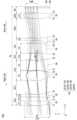
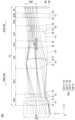
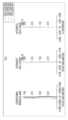
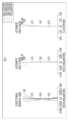
- FIG. 1is a configuration diagram of an optical system and a camera module having the same according to a first embodiment of the invention.
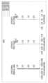
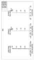
- Fig. 2is an example of operation of the first mode of the optical system of Fig. 1.
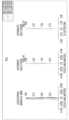
- Figure 3is an example of operation in the third mode in the optical system of Figures 1 and 2.
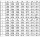
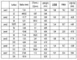
- Figure 4is a table of lens data of an optical system according to a first embodiment of the invention.
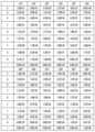
- FIG. 5is a table showing aspherical coefficients of lenses of an optical system according to the first embodiment of the invention.
- FIG. 6is a graph of diffraction MTF in an optical system of wide, mid, and tele modes according to a first embodiment of the invention.
- Fig. 7is a graph showing the aberration characteristics in the optical system of the first mode of Fig. 2.
- Figure 8is a graph showing the aberration characteristics in the optical system of the second mode (Mid mode) of Figure 1.
- Figure 9is a graph showing the aberration characteristics in the optical system of the third mode (tele mode) of Figure 3.
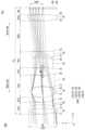
- FIG. 10is a configuration diagram of an optical system and a camera module having the same according to a second embodiment of the invention.
- Fig. 11is an example of operation of the first mode of the optical system of Fig. 10.
- Fig. 12is an example of operation of the third mode in the optical system of Figs. 10 and 11.
- Fig. 13is a table of lens data of an optical system according to a second embodiment of the invention.
- Fig. 14is a table showing aspherical coefficients of lenses of an optical system according to a second embodiment of the invention.
- FIG. 15is a graph of diffraction MTF in an optical system of wide, mid, and tele modes according to a second embodiment of the invention.
- Fig. 16is a graph showing the aberration characteristics in the optical system of the first mode of Fig. 11.
- Figure 17is a graph showing the aberration characteristics in the optical system of the second mode (Mid mode) of Figure 10.
- Fig. 18is a graph showing the aberration characteristics in the optical system of the third mode (tele mode) of Fig. 12.
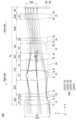
- FIG. 19is a configuration diagram of an optical system and a camera module having the same according to a third embodiment of the invention.
- Fig. 20is an example of a change in the first mode of the optical system of Fig. 19.
- Fig. 21is an example of a change in the third mode in the optical system of Figs. 19 and 20.
- Fig. 22is a table of lens data of an optical system according to a third embodiment of the invention.
- Figure 23is a table showing aspherical coefficients of lenses of an optical system according to a third embodiment of the invention.
- FIG. 24is a graph of diffraction MTF in an optical system of wide, mid, and tele modes according to a third embodiment of the invention.
- Fig. 25is a graph showing the aberration characteristics in the optical system of the first mode of Fig. 20.
- Figure 26is a graph showing the aberration characteristics in the optical system of the second mode (Mid mode) of Figure 19.
- Fig. 27is a graph showing the aberration characteristics in the optical system of the third mode (tele mode) of Fig. 21.
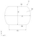
- FIG. 28is a plan view showing an example of a lens having a cut shape in an optical system according to the first to third embodiments of the invention.
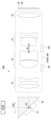
- FIG. 29is an example of a cross-sectional side view of an optical system and a camera module having a reflective member in the first, second and third embodiments of the invention.
- FIG. 30is a drawing illustrating a camera module according to embodiments of the invention applied to a mobile terminal.
- a componentwhen it is described that a component is 'connected', 'coupled', or 'connected' to another component, it may include not only cases where the component is directly connected, coupled, or connected to the other component, but also cases where the component is 'connected', 'coupled', or 'connected' by another component between the component and the other component.
- each componentis formed or arranged "above or below”, above or below includes not only the case where the two components are in direct contact with each other, but also the case where one or more other components are formed or arranged between the two components.
- itwhen expressed as "above or below", it can include the meaning of the downward direction as well as the upward direction based on one component.
- the convex surface of the lensmay mean that the lens surface in the area corresponding to the optical axis or the paraxial area has a convex shape based on the optical axis
- the concave surface of the lensmay mean that the lens surface in the area corresponding to the optical axis or the paraxial area has a concave shape
- the "object-side surface”may mean the surface of the lens facing the object side based on the optical axis
- the “sensor-side surface”may mean the surface of the lens facing the imaging surface (image sensor) based on the optical axis.
- the center thickness of the lensmay mean the thickness of the lens in the optical axis direction.
- the vertical directionmay mean the direction perpendicular to the optical axis
- the end of the lens or lens surfacemay mean the end of the effective area of the lens through which incident light passes.
- the size of the effective diameter of the lens surfacemay have a measurement error of up to ⁇ 0.4 mm depending on the measurement method, etc.
- the optical system (1000)may include a plurality of lens groups.
- the plurality of lens groupsmay include at least three lens groups.
- the plurality of lens groupsinclude first to fourth lens groups (LG1 to LG4).
- Each of the plurality of lens groupsincludes at least one lens.
- the first to fourth lens groups (LG1 to LG4)may be sequentially arranged along the optical axis (OA) from an object toward the image sensor (300).
- the optical system (1000)may include n lenses, where the nth lens may be the last lens, and the (n-1)th lens may be the lens closest to the last lens.
- the nis an integer greater than or equal to 6, for example, 6 to 9.
- the lenses in the optical system (1000)may be defined as lens units (100, 100A, 100B).
- At least two lens groupsmay be fixed groups having fixed positions, and at least two lens groups may be variable groups having variable positions.
- a first lens group (LG1) adjacent to an object and a fourth lens group (LG4) adjacent to an image sensor (300)may be fixed groups, and at least one lens group (LG2, LG3) between the first and fourth lens groups (LG1, LG4) may be a variable group having variable positions.
- the variable groupmay be reciprocally moved in the optical axis direction.
- the optical system (1000)may provide a continuous zoom optical system having a wide mode, a middle mode, and a tele mode.
- the second lens group (LG2)is arranged between the first lens group (LG1) and the third lens group (LG3) and may be moved for a zoom magnification.
- the third lens group (LG3)is arranged between the second lens group (LG2) and the third lens group (LG3) and can be moved for focusing.
- the moving distance of the lens groups to be movedis set to less than 7 mm at the most, so as to reduce power consumption of the driving member.
- the optical axis distance (DG12) between the first and second lens groups (LG1, LG2)is set to be 0.5 mm or more, for example, 0.8 mm, so as to reduce the moving distance of the second and third lens groups (LG2, LG3) and provide a high-magnification optical system.
- the number of lenses of each of the first lens group (LG1) and the second lens group (LG2)may be the same as or different from each other.
- the number of lenses of the first lens group (LG1)may be the same as the number of lenses of the second lens group (LG2).
- the number of lenses of each of the second lens group (LG2) and the third lens group (LG3)may be the same as or different from each other, and may be, for example, 2 or less.
- the number of lenses of the third lens group (LG3)may be the same as the number of lenses of the second lens group (LG2).
- the number of lenses of the fourth lens group (LG4)may be less than the number of lenses of each of the second lens group (LG2) and the third lens group (LG3), and may be, for example, 1.
- the number of lenses of the first lens group (LG1)may be twice or more than the number of lenses of the fourth lens group (LG4).
- At least one or all of the lenses of the first to fourth lens groupsmay be made of a plastic material.
- the lenses in the movable lens groups (LG2, LG3)may be arranged of a plastic material to prevent an increase in power consumption of the driving member.
- each of the movable lens groups (LG2, LG3)may include a plastic lens and a glass lens.
- the lens closest to the object among the lenses of the fixed lens group (LG1)may be made of glass.
- the lens in the lens group closest to the image sensormay be made of glass.
- At least one or all of the lens surfaces of the lenses of the first to fourth lens groupsmay have an aspherical shape on the optical axis, or the lens surfaces of at least one lens may have a spherical shape.
- the lenses having the above aspherical surfacecan prevent spherical aberration within the optical system (1000), and since aberration does not occur even when the effective diameter increases, miniaturization and weight reduction of the camera module can be possible.
- the above aspherical lenscan be made of glass mold or plastic material.
- the above spherical lenscan be made of glass material.
- the power of the first lens group (LG1)may have a sign opposite to that of the power of the second lens group (LG2).
- the power of the first lens group (LG1)may be negative, and the power of the second lens group (LG2) may be positive.
- the power of the third lens group (LG3)may have a sign opposite to that of the power of the fourth lens group (LG4).
- the power of the third lens group (LG3)may be negative, and the power of the fourth lens group (LG4) may be positive.
- the number of lenses having positive power among the lenses in the optical system (10000)may be greater than the number of lenses having negative power.
- the focal length of the first lens group (LG1)is FLG1
- the focal length of the second lens group (LG2)is FLG2
- the condition of FLG2 ⁇ ⁇ FLG1 ⁇can be satisfied.
- the focal length of the third lens group (LG3)is FLG3
- the focal length of the fourth lens group (LG4)is FLG4, and the condition of ⁇ FLG3 ⁇ ⁇ FLG4 can be satisfied.
- the absolute values of the focal lengths of the first and fourth lens groups (LG1, LG4) whose positions are fixedcan be greater than the absolute values of the focal lengths of the second and third lens groups (LG2, LG3).
- FLG1, FLG3 ⁇ 0, and FLG2, FLG4 > 0can be satisfied.
- the optical system (1000)can adjust the angle of view (FOV) by the power of each of the first to fourth lens groups (LG1-LG4).
- the first lens (101, 111, 121) closest to the object and the second lens (102, 112, 122) closest to the second lens group (LG2)may have refractive powers with opposite signs. Accordingly, the first lens group (LG1) may complement chromatic aberrations caused by the plurality of lenses included in the first lens group (LG1). For example, the first lens (101, 111, 121) may have positive power, and the second lens (102, 112, 122) may have negative power.
- the Abbe number (LG1_Vd3) of the last lens of the first lens group (LG1)may satisfy the following condition: LG1_Vd2 ⁇ 35, for example, 20 ⁇ LG1_Vd2 ⁇ 35.
- the first lens group (LG1)can disperse the incident light to the periphery of the second lens group (LG2).
- the sensor-side surface (S4) of the lens closest to the second lens group (LG2) within the first lens group (LG1)can have a concave shape on the optical axis. Accordingly, the concave sensor-side surface (S4) of the first lens group (LG1) can refract light toward the moving second lens group (LG2), thereby reducing the loss of light traveling to the second lens group (LG2) in the area between the first and second lens groups (LG1, LG2).
- the Abbe number (LG2_Vd1) of a lens close to the first lens group (LG1) in the second lens group (LG2)can satisfy the following condition: 35 ⁇ LG2_Vd1, for example, 35 ⁇ LG2_Vd1 ⁇ 65.
- the second lens group (LG2)can refract incident light in the optical axis direction of the third lens group (LG3).
- At least two lenses in the second lens group (LG2)can have powers of opposite signs. Accordingly, the second lens group (LG2) can mutually compensate for chromatic aberration caused by a plurality of lenses included in the second lens group (LG2).
- the condition: ⁇ LG2_Vd1-LG2_Vd2 ⁇ > 20can be satisfied, and when the condition is satisfied, the change in chromatic aberration due to magnification adjustment (zooming) can be minimized.
- At least two lenses in the third lens group (LG3)can have powers of the same sign.
- the Abbe numbers of at least two lenses in the third lens group (LG3)are LG3_Vd1 and LG3_Vd2
- the condition: ⁇ LG3_Vd1 - LG3_Vd2 ⁇ > 20can be satisfied, and when the condition is satisfied, the change in chromatic aberration due to aberration correction can be minimized.
- the power of the third lens group (LG3)can have a negative value, and thus the influence on the focusing direction can be adjusted.
- Each of the first to fourth lens groups (LG1-LG4)can have at least one lens with a positive power, and thus the influence of aberration can be reduced.
- the refractive index (LG4_Nd) of the lenses in the fourth lens group (LG4)can satisfy the following condition: 1.6 ⁇ LG4_Nd1, for example, 1.6 ⁇ LG4_Nd1 ⁇ 1.8.
- the lenses of the fourth lens group (LG4)can refract incident light toward the center and periphery of the image sensor (300).
- the fourth lens group (LG4)can perform a role of controlling a chief ray angle (CRA).
- the optical system (1000) according to the embodimentcan have a CRA of less than about 20 degrees, and can correct the chief ray angle (CRA) of light incident on the image sensor (300) to be close to 0 degrees.
- CRAchief ray angle
- a lens having a maximum Abbe numbercan be positioned in the second and third lens groups (LG2, LG3).
- the average refractive index of the lenses of the first and fourth lens groups (LG1, LG4)can be greater than 1.6
- the average refractive index of the lenses of the second and third lens groups (LG2, LG3)can be less than or equal to 1.6.
- the lens having the maximum Abbe numbercan reduce chromatic dispersion, and the lens having a refractive index greater than 1.6 can increase chromatic dispersion of incident light.
- Each of the lenses of the optical system (1000)may include an effective region and an ineffective region.
- the effective regionmay be a region through which light incident on each of the lenses passes.
- the effective regionmay be defined as an effective region or effective diameter through which the incident light is refracted to implement optical characteristics.
- the ineffective regionmay be arranged around the periphery of the effective region.
- the ineffective regionmay be a region through which effective light is not incident from the plurality of lenses.
- the ineffective regionmay be a region unrelated to the optical characteristics.
- an end of the ineffective regionmay be a region fixed to a lens barrel (not shown) that accommodates the lens.
- the average of the effective lengths of the object-side and sensor-side surfaces of each lens of the lens unit (100, 100A, 100B)may be provided as 7 mm or less, for example, in the range of 4 mm to 7 mm.
- the average of the effective lengthsmay be the average of the effective lengths of the object-side and sensor-side surfaces of each lens.
- the effective lengthmay be the maximum length when the object-side and sensor-side surfaces have different lengths in the first and second directions perpendicular to the optical axis.
- the lens having the largest effective length in the lens unit (100, 100A, 100B)may be the last lens.
- the effective length of the last lens (106, 116, 126)may be greater than the effective length of the first lens (101, 111, 121).
- the maximum effective length of the object-side surface (S1) of the first lens (101, 111, 121)may be smaller than the maximum effective length of the sensor-side surface (S6) of the last lens (103, 113, 123).
- the first lens (101, 111, 121)may be provided to be larger than the effective lengths of the other lenses except for the last lens, thereby preventing a decrease in the amount of incident light.
- the effective lengths of the first lens closest to the object and the last lenscan satisfy the following conditions.
- CA11is the effective length of the object-side surface of the first lens
- CAn2is the effective length of the sensor-side surface of the last nth lens. If these conditions are satisfied, the total optical length (TTL: Total top length) can be reduced. TTL is the optical axis length from the center of the object-side surface of the first lens (101, 111, 121) to the surface of the image sensor (300).
- At least one or two or more lenses in the optical system (1000)may have different effective lengths (C1, C2) in the first direction (X) and the second direction (Y) orthogonal to the optical axis (OA).
- the first and second directions (X, Y)may be orthogonal to each other.
- the lens (L1) having different effective lengths (C1, C2) in the first and second directions (X, Y)may have a non-circular shape or a cut shape, and for example, the effective length (C2) in the first direction (X) may be smaller than the effective length (C1) in the second direction (Y).
- the first direction (X)may be a direction orthogonal to the thickness direction or the display surface of a device equipped with a camera module, for example, a portable terminal. At least one or both of the object-side and sensor-side surfaces (S21) of the lens (L1) may have a non-circular shape, and the length (C12) of both sides (CS1, CS2) in the first direction (X) may be less than the maximum effective length (C1).
- At least one of the lenses of the first lens group (LG1)may have different effective lengths on the object-side surface and/or the sensor-side surface, and the effective length in the first direction (X) may be less than the effective length in the second direction (Y).
- At least one of the lenses of the second lens group (LG2)may have different effective lengths on the object-side surface and/or the sensor-side surface, and the effective length in the first direction (X) may be less than the effective length in the second direction (Y).
- the seventh lens (107, 117, 127) of the fourth lens group (LG4)may have different effective lengths on the object-side surface and/or the sensor-side surface, and the effective length in the first direction (X) may be less than the effective length in the second direction (Y).
- the seventh lens (107, 117, 127) having the largest effective lengthmay have an effective length in the second direction (Y) that is longer than the effective length in the first direction (X).
- the first lens (101, 111, 121)may have an effective length in the second direction (Y) that is longer than the effective length in the first direction (X).
- the value of the formula in the effective length of the object-side surface or the sensor-side surface of the m-th lensis less than 0.55, it is difficult to manufacture the object-side surface or the sensor-side surface of the m-th lens into a non-circular shape and it is difficult to control the distribution of the incident light, and when it exceeds 0.98, the size reduction in the second direction of the optical system may be minimal.
- the optical system (1000)can have improved assembly properties by non-circular lens(es) and can have a mechanically stable shape.
- the optical system (1000)can significantly reduce the moving distance of a moving lens group and provide various magnifications.
- the lenses having a large effective length in the second direction (Y)are provided in a shape in which both sides in the second direction (Y) are cut, the height or thickness of the optical system (1000) and the camera module in the second direction (Y) can be reduced. Accordingly, an increase in the thickness of a device having a slim optical system (1000) and a camera module can be suppressed.
- the TTL(Total top length) can be more than 4 times the ImgH, and preferably, the condition of 4 ⁇ TTL/ImgH ⁇ 15 or 6 ⁇ TTL/ImgH ⁇ 11 can be satisfied.
- ImgHis 1/2 of the maximum diagonal length of the effective area of the image sensor (300).
- the effective focal length (EFL)is more than 10 mm and the diagonal angle of view (FOV) is less than 45 degrees, so that it can be provided as a zoom optical system of a portable terminal. Accordingly, the optical system (1000) can provide a high-resolution and high-magnification zoom optical system of three or more lens groups.
- the number of lenses having an effective length greater than the maximum effective length of the image sensor (300) within the lens unit (100, 100A, 100B)can be less than 50%, for example, in the range of 10% to 40%.
- the effective length of the lens closest to the object side within the lens unit (100, 100A, 100B)may be shorter than the effective length of the lens closest to the image sensor (300).
- the optical system (1000)may include an aperture (ST).
- the aperture (ST)may adjust the amount of light incident on the optical system (1000).
- the aperture (ST)may be arranged between any two lenses in the lens unit (100, 100A, 100B). In the lenses arranged between the object and the aperture (ST), the effective diameter of the lenses tends to decrease from the object side to the aperture (ST).
- the aperture (ST)may be arranged on the periphery between the first lens group (LG1) and the second lens group (LG2).
- the effective lengths of the lenses arranged on the object side of the aperture (ST) and the lenses arranged on the sensor sidemay be smaller than the diagonal length of the image sensor (300). Accordingly, the brightness of the optical system may be controlled.
- the optical system (1000)can control the incident light to compensate for the deterioration of optical characteristics due to resolution and temperature change, and improve chromatic aberration control characteristics.
- the effective length of each lensis the average of the effective lengths of the object-side surface and the sensor-side surface in the second direction (Y).
- the above aperture (ST)can be arranged at a set position.
- the aperture (ST)can be arranged around the object-side surface or the sensor-side surface of one of the lenses of the second lens group (LG2).
- the aperture (ST)can be arranged around the object-side surface of the second lens group (LG2).
- the aperture (ST)can be arranged around the sensor-side surface of the first lens group (LG1).
- the aperture (ST)can have a portion coated on at least one selected lens surface functioning as an aperture.
- the object-side surface or the sensor-side surface of one lens selected from the lenses of the optical system (1000)can function as an aperture for controlling the amount of light.
- the optical axis distance between the above aperture (ST) and the image sensor (300)is SD, and the value of the SD may vary depending on the operating mode, for example, wide mode, middle mode, and tele mode.
- the first lens group (LG1) and the second lens group (LG2)may have a set interval (DG12).
- the optical axis interval (DG12) between the first lens group (LG1) and the second lens group (LG2)may be the optical axis interval between the sensor-side surface of a lens closest to the sensor among the lenses in the first lens group (LG1) and the object-side surface of a lens closest to the object among the lenses in the second lens group (LG2).
- the optical axis interval (DG12) between the first lens group (LG1) and the second lens group (LG2)may be at least 0.5 mm or more. That is, in the tele mode, 0.5 mm ⁇ DG12 may be satisfied.
- two surfaces facing each othermay have a concave shape on the optical axis (OA) for the sensor side of the first lens group (LG1) and a convex shape for the object side surface of the second lens group (LG2).
- the first lens group (LG1) and the second lens group (LG2)may refract light emitted through the sensor side surface of the first lens group (LG1) to the object side surface of the second lens group (LG2) depending on the operation mode.
- the sensor side surface of the first lens group (LG1)may have a convex shape on the optical axis (OA) and the object side surface of the second lens group (LG2) may have a concave shape.
- the sum of the central thicknesses of the lenses of the lens units (100, 100A, 100B) of the embodimentis ⁇ CT and may be 14 mm or less, for example, in the range of 8 mm to 14 mm or in the range of 9 mm to 12 mm.
- the sum of the central intervals between the lenses on the optical axis (OA)is ⁇ CG and may be 8 mm or more, for example, in the range of 8 mm to 14 mm, and may be larger than the sum of the central thicknesses of the lenses.
- the condition: ⁇ CT ⁇ ⁇ CGmay be satisfied.
- the optical system (1000) or camera modulemay include an image sensor (300).
- the image sensor (300)may detect light and convert it into an electrical signal.
- the image sensor (300)may detect light that has sequentially passed through the lens unit (100, 100A, 100B).
- the image sensor (300)may include an element capable of detecting incident light, such as a CCD (Charge Coupled Device) or a CMOS (Complementary Metal Oxide Semiconductor).
- the optical system (1000) or camera modulemay include an optical filter (500).
- the optical filter (500)may be disposed between the fourth lens group (LG4) and the image sensor (300).
- the optical filter (500)may be disposed between the lens closest to the sensor side among the lenses of the lens unit (100, 100A, 100B) and the image sensor (300).
- the optical system (100, 100A, 100B)may be disposed between the last lens and the image sensor (300).
- a cover glass(not shown) is disposed between the optical filter (500) and the image sensor (300), and may protect an upper portion of the image sensor (192) and prevent a decrease in the reliability of the image sensor (192). The cover glass may be removed.
- the optical filter (500)may include an infrared filter or an infrared cut-off filter (IR cut-off).
- the optical filter (500)may allow light of a set wavelength band to pass through and filter light of a different wavelength band.
- the optical filter (500)may block radiant heat emitted from external light from being transmitted to the image sensor (300).
- the optical filter (500)may allow visible light to pass through and reflect infrared light.
- the optical system (1000)may further include a reflective member (400) for changing the path of light as shown in FIG. 29.
- the reflective member (400)may be implemented as a prism or reflective mirror that reflects the incident light of the first lens group (LG1) toward the lenses.
- FIGS. 1 to 9are drawings of an optical system according to a first embodiment.
- an optical system (1000) according to the first embodimentmay include a plurality of lens groups, for example, may include first to fourth lens groups (LG1, LG2, LG3, LG4).
- the first to fourth lens groups (LG1, LG2, LG3, LG4)may include lens groups having fixed positions and movable lens groups.
- the first lens group (LG1) and the fourth lens group (LG4)are lens groups having fixed positions
- the second lens group (LG2) and the third lens group (LG3)are lens groups having variable positions.
- the second lens group (LG2)is arranged between the first lens group (LG1) and the third lens group (LG3), and the third lens group (LG3) can be arranged between the second lens group (LG2) and the fourth lens group (LG4).
- the first lens group (LG1)refracts incident light toward the second lens group (LG2)
- the second lens group (LG2)moves along the optical axis (OA) and changes a zoom magnification (focal length)
- the third lens group (LG3)moves along the optical axis (OA) and can adjust a focal position on an image surface of an image sensor (300).
- the absolute value of the focal length of the first lens group (LG1)may be greater than the absolute value of the focal lengths of the second and third lens groups (LG2, LG3).
- the absolute value of the focal length of the first lens group (LG1)may be at least twice the focal length of the second lens group (LG2). Accordingly, the first lens group (LG1) may disperse the incident light.
- the difference in the focal lengths of the second lens group (LG2) and the third lens group (LG3)may be 5 mm or less.
- the focal length of the fourth lens group (LG4)may be less than the absolute value of the focal length of the first lens group (LG1) and greater than the absolute value of the focal length of the third lens group (LG3).
- the power of the first and third lens groups (LG1, LG3)can have negative power
- the power of the second and fourth lenses (LG2, LG4)can have positive power.
- the lens unit (100)may include the first to seventh lenses (101-107).
- the first to seventh lenses (101-107) and the image sensor (300)may be sequentially arranged along the optical axis (OA) of the optical system (1000).
- the number of lenses of the first lens group (LG1)may include at least two lenses for adjusting the amount of incident light, power, and chromatic aberration, and may include, for example, the first and second lenses (101, 102).
- the second lens group (LG2)may include two or fewer lenses and include third and fourth lenses (103, 104), the third lens group (LG3) may include fifth and sixth lenses (105, 106), and the fourth lens group (LG4) may include the seventh lens (107).
- the focal lengths of the first to fourth lens groups (LG1-LG4)are defined as FLG1, FLG2, FLG3, and FLG4, the following conditions can be satisfied.
- the optical system (1000)can provide various magnifications by moving the lens groups.
- the seventh lens (107) of the fourth lens group (LG4)can control the incident angle of the chief ray to refract the light parallel to the optical axis so that it is incident toward the image sensor (300).
- the first and second lenses (101, 102)can correct aberrations since they have powers of opposite signs (+, -), and the third and fourth lenses (103, 104) can correct aberrations since they have powers of opposite signs (+, -).
- the fifth and sixth lenses (105, 106)can correct aberrations since they have powers of opposite signs (+, -).
- the center spacing between the first and second lenses (101, 102)may be a fixed spacing depending on the operation mode described below.
- the center spacing between the first and second lenses (101, 102)may not change depending on the operation mode and may have a constant spacing.
- the center spacing between the lensesmay mean the optical axis spacing between adjacent lenses.
- the third and fourth lenses (103, 104)may have a set interval.
- the center interval between adjacent lenses (104, 105)may be a fixed interval according to an operation mode to be described later.
- the fifth and sixth lenses (105, 106)may have a set interval.
- the center interval between the fifth and sixth lenses (105, 106)may be constant without changing even when the operation mode to be described later changes.
- the optical axis interval (BFL) between the seventh lens (107) and the image sensor (300)may be constant without changing depending on the operation mode.
- the seventh lens (107)has a set interval with the image sensor (300) or/and the optical filter (500), and may have a fixed interval without changing depending on the operation mode.
- the first lens (101)may have positive (+) power on the optical axis (OA).
- the first lens (101)may include a plastic or glass material, and may be, for example, a plastic material.
- the first lens (101)may include a first surface (S1) on the object side and a second surface (S2) on the sensor side.
- the first surface (S1)may have a convex shape on the optical axis (OA), and the second surface (S2) may have a convex shape. That is, the first lens (101) may have a convex shape on both sides on the optical axis (OA). Alternatively, the first lens (101) may have a convex meniscus shape toward the object.
- the first surface (S1)may have a concave shape
- the second surface (S2)may have a convex shape.
- At least one or both of the first surface (S1) and the second surface (S2)may be aspherical
- the conic constant (K) and the aspherical coefficients (A-I) of the 4th to 20th orders of the first and second surfaces (S1, S2)may be represented by L1S1 and L1S2 in FIG. 5.
- the maximum effective length of the first lens (101)may be the second largest among the lenses. That is, the effective length of the first surface (S1) of the first lens (101) in the major axis direction or the second direction (Y) may be greater than the average of the effective lengths of the object-side surfaces and the sensor-side surfaces of the second to sixth lenses (102-106). Accordingly, the first lens (101) may improve optical aberrations or control incident light.
- the first surface (S1) and the second surface (S2)may be provided without a critical point from the optical axis to the end of the effective area.
- the second lens (102)may have positive (+) or negative (-) power on the optical axis (OA), for example, may have negative power.
- the second lens (102)may include a plastic or glass material, for example, may be a plastic material.
- the second lens (102)may include a third surface (S3) on the object side and a fourth surface (S4) on the sensor side, and the third surface (S3) on the optical axis may have a concave shape, and the fourth surface (S4) may have a concave shape.
- the second lens (102)may have a concave shape on both sides. Alternatively, the second lens (102) may have a convex meniscus shape toward the object.
- the third surface (S3)may have a convex shape
- the fourth surface (S4)may have a convex shape
- the third surface (S3)may have a concave shape
- the fourth surface (S4)may have a convex shape.
- At least one or both of the third surface (S3) and the fourth surface (S4) of the second lens (102)may be aspherical, and the conic constant (K) and the aspherical coefficient (AI) may be represented by L2S1 and L2S2 of FIG. 5.
- the third surface (S3) and the fourth surface (S4)may be provided without critical points from the optical axis to the ends of the effective areas.
- the third lens (103)may have power of the same sign as the power of the first lens (101) on the optical axis (OA). That is, the third lens (103) may have positive power.
- the third lens (103)may include a plastic or glass material, and may be, for example, a plastic material.
- the third lens (103)may include a fifth surface (S5) on the object side and a sixth surface (S6) on the sensor side.
- the fifth surface (S5)may have a convex shape on the optical axis (OA), and the sixth surface (S6) may have a convex shape.
- the third lens (103)may have a convex shape on both sides.
- the fifth surface (S5)may have a convex shape
- the sixth surface (S6)may have a concave shape.
- At least one or both of the fifth surface (S5) and the sixth surface (S6) of the third lens (103)may be aspherical.
- the conic constant (K) and the aspherical coefficient (AI) of the fifth and sixth surfaces (S5, S6)may be represented by L3S1 and L3S2 of FIG. 5.
- the fifth surface (S5) and the sixth surface (S6)may be provided without critical points from the optical axis to the end of the effective area, or the sixth surface (S6) may have critical points at the edge portion.
- the second lens (102)can compensate for chromatic aberration occurring in the first lens (101).
- the refractive index of the first lens (101)is arranged to be greater than the refractive index of the second lens (102), so as to disperse the incident light. Accordingly, since the first lens group (LG1) controls the dispersion of the light provided to the second lens group (LG2), an increase in the lens size of the second lens group (LG2) can be suppressed.
- the change in the center distance (DG12) between the first and second lens groups (LG1, LG2)can be set according to the operating mode by the radius of curvature of the fourth surface (S4) of the second lens (102).
- the fourth lens (104)may have negative (+) power on the optical axis (OA).
- the fourth lens (104)may include a plastic or glass material, for example, may be a plastic material, and may have a refractive index of less than 1.6.
- the fourth lens (104)includes a seventh surface (S7) on the object side and an eighth surface (S8) on the sensor side, and the seventh surface (S7) may have a convex shape on the optical axis, and the eighth surface (S8) may have a convex shape. That is, the fourth lens (104) may have a convex shape on both sides on the optical axis (OA).
- the seventh surface (S7)may be convex on the optical axis (OA), and the eighth surface (S8) may be concave on the optical axis (OA).
- At least one or both of the seventh surface (S7) and the eighth surface (S8) of the fourth lens (104)may be aspherical.
- the conic constant (K) and the aspherical coefficient (AI) of the seventh and eighth surfaces (S7, S8)may be represented by L4S1 and L4S2 of Fig. 5.
- the seventh surface (S7) and the eighth surface (S8)may be provided without critical points from the optical axis to the ends of the effective areas.
- the third lens (103)may have a convex shape on both sides, and the fourth lens (104) may have a concave shape on both sides.
- the center thickness (CT3) of the third lens (103)may be thicker than the edge thickness.
- the center thickness of the fourth lens (104)may be thinner than the edge thickness. Accordingly, the gap between the sixth and seventh surfaces (S8, S9) may be reduced by the convex sixth surface (S8) of the third lens (103) and the concave seventh surface (S7) of the fourth lens (104).
- the Abbe number (Vd3) of the third lens (103)may be greater than the Abbe numbers of the first and second lenses (101, 102) and the fourth and fifth lenses (104, 105).
- the difference in Abbe numbers between the third lens (103) and the fourth lens (104)may be greater than 20 or greater than 25. Accordingly, the second lens group (LG2) can minimize changes in chromatic aberration caused by a change in position according to a change in the operation mode.
- the fifth lens (105)may have positive (+) or negative (-) power on the optical axis (OA).
- the fifth lens (105)may have positive power and a sign opposite to the power of the fourth lens (104).
- the fifth lens (105)may include a plastic or glass material, and may be, for example, a plastic material.
- the fifth lens (105)may include a ninth surface (S9) on the object side and a tenth surface (S10) on the sensor side.
- the ninth surface (S9)may have a concave shape on the optical axis (OA), and the tenth surface (S10) may have a convex shape. That is, the fifth lens (105) may have a convex meniscus shape toward the sensor side on the optical axis (OA).
- the fifth lens (105)may have a concave shape on both sides.
- the fifth lens (105)may have a convex shape toward the object.
- At least one or both of the ninth surface (S9) and the tenth surface (S10)may be aspherical.
- the conic constant (K) and the aspherical coefficient (AI) of the ninth and tenth surfaces (S9, S10)may be represented by L5S1 and L5S2 of FIG. 5.
- the ninth surface (S9) and the tenth surface (S10) of the fifth lens (105)may be provided without a critical point from the optical axis to the end of the effective area.
- the sixth lens (106)may have positive (+) or negative (-) power on the optical axis (OA), for example, may have negative power.
- the sixth lens (106)may include a plastic or glass material, for example, may be a plastic material.
- the sixth lens (106)may include an eleventh surface (S11) on the object side and a twelfth surface (S12) on the sensor side.
- the eleventh surface (S11)may have a concave shape on the optical axis (OA), and the twelfth surface (S12) may have a convex shape. That is, the sixth lens (106) may have a convex meniscus shape toward the sensor side on the optical axis (OA).
- the eleventh surface (S11)may have a convex shape on the optical axis (OA), and the twelfth surface (S12) may have a convex shape on the optical axis (OA).
- the eleventh surface (S11)may have a concave shape in the optical axis (OA)
- the twelfth surface (S12)may have a concave shape in the optical axis (OA).
- the eleventh surface (S11)may have a convex shape in the optical axis (OA)
- the twelfth surface (S12)may have a concave shape in the optical axis (OA).
- At least one or both of the eleventh surface (S11) and the twelfth surface (S12) of the sixth lens (106)may be aspherical.
- the aspherical coefficient (A-I) and the conic constant (K) of the eleventh and twelfth surfaces (S11, S12)may be represented by L6S1 and L6S2 in FIG. 5.
- the above eleventh surface (S11) and the above twelfth surface (S12)can be provided without a critical point from the optical axis to the end of the effective area.
- the seventh lens (107)may have positive (+) or negative (-) power on the optical axis (OA), and may have positive power.
- the power of the seventh lens (107)has a sign opposite to that of the power of the sixth lens (106), so as to improve chromatic aberration.
- the seventh lens (107)may include a plastic or glass material, and may be, for example, a plastic material.
- the seventh lens (107)may include a 13th surface (S13) on the object side and a 14th surface (S14) on the sensor side.
- the 13th surface (S13)may have a convex shape on the optical axis (OA), and the 14th surface (S14) may have a convex shape.
- the seventh lens (107)may have a convex shape on both sides on the optical axis (OA).
- the 13th surface (S13)may have a concave shape and the 14th surface (S14) may have a convex shape.
- the 13th surface (S13)may have a concave shape and the 14th surface (S14) may have a concave shape in the optical axis (OA).
- the 13th surface (S13)may have a convex shape and the 14th surface (S14) may have a concave shape.
- At least one or both of the 13th surface (S13) and the 14th surface (S12) of the seventh lens (107)may be aspherical.
- the aspherical coefficient (A-I) and the conic constant (K) of the 13th and 14th surfaces (S13, S14)may be represented by L7S1 and L7S2 of FIG. 5.
- the 13th surface (S13) and the 14th surface (S14)may be provided without a critical point from the optical axis to the end of the effective area.
- the 13th surface (S13) or/and the 14th surface (S14) of the seventh lens (107)may have a critical point between the optical axis and the end of the effective area, and the critical point is a point where the trend of the Sag value changes. That is, the critical point is a point where the Sag value increases and then decreases on the lens surface, or a point where the Sag value decreases and then increases.
- the above Sag valueis the optical axis distance between the straight line perpendicular to the center of each lens surface and the lens surface, and the Sag value has a positive value at a position located closer to the sensor than the center of each lens surface, and a negative value at a position located closer to the object than the center of each lens surface.
- the absolute value difference of the curvature radii between the object-side surface and the sensor-side surface of the third to seventh lenses (103, 104, 105, and 106)may be 10 mm or less, for example, 6 mm or less. Since the difference in the curvature radii between the object-side surface and the sensor-side surface of these movable lenses is not set to be large, it is possible to predict a change in the optical path, and to suppress an increase in the size of the lenses.
- the absolute value difference in the curvature radii between the object-side surface and the sensor-side surface of the first lens (101)is the largest, the incident light can be dispersed, and since the difference in the curvature radii between the object-side surface and the sensor-side surface of the last lens (107) is the smallest, it is possible to refract light parallel to the entire area of the image sensor (300).
- the sixth lens (106) and the seventh lens (107)have powers of opposite signs, and the Abbe number difference may be greater than 20, for example, greater than 30, in which case chromatic aberration may be controlled. Accordingly, the third lens group (LG3) may minimize chromatic aberration changes caused by positions that change according to mode changes and may perform an achromatic function.
- the seventh lens (107)may set the difference between the absolute value of the radius of curvature of the 13th surface (S13) and the absolute value of the radius of curvature of the 14th surface (S14) to be less than or equal to 1.5 mm, thereby refracting incident light parallel to the surface of the image sensor (300).
- the effective length of the seventh lens (107)may be provided longer than the effective length of the sixth lens (106), thereby refracting incident light to the periphery of the image sensor (300).
- At least one of the first lens (101) and the seventh lens (107)may have a non-circular shape in which the effective lengths in the first direction (X) and the second direction (Y) are different from each other.
- the fourth lens group (LG4)may perform a function of controlling a chief ray angle (CRA).
- the CRA of the optical system (1000) according to the embodimentmay be less than about 20 degrees
- the seventh lens (107) of the fourth lens group (LG4)may correct the chief ray angle (CRA) of light incident on the image sensor (300) according to each operation mode.
- the camera modulecan move at least one or all of the second and third lens groups (LG2, LG3) among the plurality of lens groups (LG1, LG2, LG3, LG4) included in the optical system (1000) toward the object side or the sensor side along the optical axis (OA).
- the camera modulecan include a driving member (DM1, DM2) connected to the optical system (1000).
- the driving members (DM1, DM2)include at least one or a plurality of first driving members (DM1) arranged on the outside of the second lens group (LG2) and at least one or a plurality of second driving members (DM2) arranged on the outside of the third lens group (LG3), and can move each of them in the direction of the optical axis (OA) depending on the operation mode.
- the above operation modemay include a first mode moving at a first magnification as shown in FIG. 2, a third mode operating at a second magnification different from the first magnification as shown in FIG. 3. At this time, the second magnification may be greater than the first magnification.
- the operation modemay include a second mode having a magnification between the first and third modes as shown in FIG. 1.
- the first magnificationmay be the lowest magnification of the optical system (1000)
- the second magnificationmay be the highest magnification of the optical system (1000).
- the first modemay be a wide mode
- the second modemay be a middle mode
- the third modemay be a tele mode.
- the driving members (DM1, DM2)can move (M1, M2) each of the second and third lens groups (LG2, LG3) or operate them in an initial mode according to one operation mode selected from the first to third modes.
- each of the plurality of driving members (DM1, DM2)is connected to the second lens group (LG2) and the third lens group (LG3), and can move each of the second lens group (LG2) and the third lens group (LG3) according to the operation mode.
- the initial modemay be any one of the first, second, and third modes, for example, the second mode or the middle mode.
- each of the second lens group (LG2) and the third lens group (LG3)may be positioned at a position defined as a first position (Position 1).
- each of the second lens group (LG2) and the third lens group (LG3)may be positioned at a second position (Position 2) defined as closer to the object than the first position.
- each of the second lens group (LG2) and the third lens group (LG3)may be positioned at a third position (Position 3) defined as closer to the sensor than the first position.
- the first positionmay be an area between the second and third positions.
- the first position at which the second lens group (LG2) is positioned in the first modemay be an area between the second and third positions at which the second lens group (LG2) is positioned in the second and third modes.
- the first position at which the third lens group (LG3) is positioned in the first modemay be an area between the second and third positions at which the third lens group (LG3) is positioned in the second and third modes.
- at least one of the second lens group (LG2) and the third lens group (LG3)may move along the optical axis, and the first and fourth lens groups (LG1, LG4) may be arranged at fixed positions.
- the second lens group (LG2)may move (M1), and the first and fourth lens groups (LG1, LG4) may be arranged at fixed positions.
- the third lens group (LG3)can move (M1), and the first and fourth lens groups (LG1, LG4) can be arranged at fixed positions.
- the first to fourth lens groups (LG1, LG2, LG3, LG4)can have a set interval from adjacent lens groups.
- the optical system (1000)can have a constant TTL (Total track length) and BFL according to the operation mode, and the effective focal length and magnification of the optical system (1000) can be controlled by controlling the positions of some lens groups.
- the center thickness of each of the first to seventh lenses (101-107)is CT1-CT7
- the Abbe numberis Vd1-Vd7
- the refractive indexis Nd1-Nd7
- the average of the second direction (Y) or the maximum effective lengthcan be defined as CA1-CA7.
- the effective length (CA1) of the first lens (101)is the second longest among the lenses, and the effective length (CA5) of the fifth lens (105) is the shortest among the lenses.
- the effective length (CA1) of the first lens (101)may be 5 mm or more.
- the effective lengths (CA5, CA6) of the fifth and sixth lenses (105, 106)may be less than 5 mm.
- the absolute value difference in the radius of curvature between the 13th surface (S13) and the 14th surface (S14) of the seventh lens (107)may be the smallest among the differences in the radius of curvature (absolute value) between the object-side surface and the sensor-side surface of each lens, and may be, for example, 1.5 mm or less or 1 mm or less.
- the absolute value difference in the radius of curvature between the eleventh surface (S11) and the twelfth surface (S12) of the sixth lens (106)may be 3 mm or less, for example, in the range of 1.5 mm to 3 mm. Since the center thickness (CT6) of the sixth lens (106) is less than 2 mm and the difference in the radius of curvature (absolute value) of both sides is provided small, light can be guided to the seventh lens (107) without significantly changing the path of the incident light.
- the focal length (F5) of the fifth lens (105)may be the largest among the lenses, and the difference (absolute value) in the focal length between adjacent two lenses may be the largest in the fifth and sixth lenses (105, 106), and the difference (absolute value) in the focal lengths of the second and third lenses (102, 103) may be the smallest.
- the focal lengths of the first to seventh lenses (101-107)may be defined as F1-F7, and may satisfy the following conditions.
- At least one of the center thicknesses (CT3, CT4, CT5) of the third, fourth, and fifth lenses (103, 104, and 105)may be the thickest among the center thicknesses of the lenses, for example, 2 mm or more, and the center thickness (CT5) of the fifth lens (105) may be the largest.
- At least one of the center thicknesses (CT2, CT6) of the second and sixth lenses (102, 106)may be the thinnest among the center thicknesses of the lenses, so that the light path can be adjusted according to the positional movement of the second and third lens groups (LG2, LG3).
- the radius of curvature of the first to fourth surfaces (S1, S2, S3, S4) of the first and second lenses (101, 102)is set to 5 mm or more, so as not to significantly change the refractive angle of the incident light, and can be guided to the fourth lens (104) through the third lens (103).
- the central thicknesses (CT3, CT4) of the third and fourth lenses (103, 104) of the second lens group (LG2)may each be greater than the sum of the central thicknesses (CT1, CT2) of the first and second lenses (101, 102).
- the sum of the central thicknesses (CT3, CT4) of the third and fourth lenses (103, 104) of the second lens group (LG2)may be greater than the sum of the central thicknesses (CT6, CT7) of the sixth and seventh lenses (106, 107). Accordingly, the second lens group (LG2) can guide light incident through the first lens group (LG1) to the effective area of the third lens group (LG3).
- the optical axis spacing between the first and second lens groups (LG1, LG2)is DG12
- the optical axis spacing between the second and third lens groups (LG2, LG3)is DG23
- the optical axis spacing between the third and fourth lens groups (LG3, LG4)is DG34, and each of these may be at least 0.5 mm or more and at most 8 mm or less depending on the change in magnification of the operation modes.
- the optical axis spacing (DG12) between the first and second lens groups (LG1, LG2)may be at least 0.5 mm, for example, in the range of 0.5 mm to 7 mm.
- the optical axis spacing (DG23) between the second and third lens groups (LG2, LG3)may be at least 1 mm, for example, in the range of 1 mm to 3 mm.
- the optical axis spacing (DG34) between the third and fourth lens groups (LG3, LG4)may be 0.8 mm or more, for example, in the range of 0.8 mm to 8 mm.
- DG12, DG23, in the second mode, DG12, DG34, and in the third mode, DG23, DG34may be greater than the BFL.
- the BFLis the optical axis distance from the sensor side of the fourth lens group (LG4) or the seventh lens (107) to the surface of the image sensor (300).
- the maximum movement distance of the second and third lens groupsis Max_mMd13, and can satisfy Max_mMd13 ⁇ 5.7 mm, and preferably, 4 mm ⁇ Max_mMd13 ⁇ 5.5 mm. Accordingly, the maximum movement distance for zoom magnification can be reduced, thereby reducing power consumption of the driving member.
- the F number of the optical system (1000)provides a brightness of 5 or less, and the F number may be in the range of 2.2 to 5.
- the aperturemay be located between the first lens group (LG1) and the second lens group (LG2), and may be arranged, for example, around the fifth surface (S5) of the third lens (103).
- Table 1 and FIG. 4show items of the mathematical formulas described above in the optical system (1000) of the first embodiment, including the total track length (TTL) (mm), back focal length (BFL), effective focal length (F) (mm), focal length of each lens group, ImgH (mm), effective length (mm), center thickness (CT) of each lens, center gap (CG) between two adjacent lenses, TD (mm) which is an optical axis distance from the first surface (S1) to the fourteenth surface (S14), focal lengths (F1, F2, F3, F4, F5, F6, F7) (mm) of each of the first to seventh lenses, diagonal angle of view (FOV) (Degree), F number, etc.
- TTLtotal track length
- BFLback focal length
- Feffective focal length
- CTcenter thickness
- CGcenter gap
- TDwhich is an optical axis distance from the first surface (S1) to the fourteenth surface (S14)
- Example 1Example 1 FLG1 (mm) -24.790 TD (mm) 20.82 FLG2 (mm) 6.850 ImgH (mm) 2.8 FLG3 (mm) -6.14 TTL (mm) 22.320 FLG4 (mm) 10.770 BFL (mm) 1.500
- Table 2can represent the effective focal length (F), field of view (FOV), F number, entrance pupil size (EPD), SD, and center spacing (DG12, DG23, DG34) between adjacent lens groups according to the first to third modes in the optical system according to the first embodiment.
- SDis the optical axis distance from the position of the aperture to the image sensor.
- Example 1 Mode 1 Second mode 3rd mode F(mm) 12.65 18.95 25.25 DG12 (mm) 5.780 3.120 0.930 DLG23 (mm) 2.000 1.590 1.650 DG34 (mm) 1.330 4.400 6.530 EPD (EPD1/EPD2/EPD3) 4.49 4.96 5.44 Fno (Fno1/Fno2/Fno3) 2.800 3.800 4.600 FOV (degrees) 25 17 13 SD 12.54 15.20 17.38
- the optical system according to the first embodimentcan have MTF characteristics according to the first, second, and third modes (wide, mid, tele mode).
- FIG. 6is a graph of diffraction MTF characteristics of the optical system (1000) operating in the first to third modes, and it can be seen that the change in the position of defocusing according to the operating mode is not large.
- FIGS. 7 to 9are graphs measuring spherical aberration (Longitudinal Spherical Aberration), astigmatic field curves, and distortion from left to right in aberration graphs of an optical system according to the first embodiment.
- the X-axismay represent a focal length (mm) and a distortion degree (%)
- the Y-axismay represent the height of the image.
- the graph for spherical aberrationis a graph for light in wavelength bands of about 435 nm, about 486 nm, about 546 nm, about 587 nm, and about 656 nm
- the graphs for astigmatism and distortionare graphs for light in wavelength bands of 546 nm.
- FIGS. 10 to 18are drawings showing an optical system and a camera module according to a second embodiment.
- an optical system (1000) according to the second embodimentmay include a lens unit (100A) having first to fourth lens groups (LG1, LG2, LG3, LG4).
- the first lens group (LG1) and the fourth lens group (LG4)are lens groups having fixed positions
- the second lens group (LG2) and the third lens group (LG3)are lens groups having variable positions.
- the absolute value of the focal length of the first lens group (LG1)may be greater than the absolute values of the focal lengths of the second, third, and fourth lens groups (LG2, LG3, and LG4).
- the absolute value of the focal length of the first lens group (LG1)may be at least twice the focal length of the second lens group (LG2).
- the focal length of the second lens group (LG2)may be smaller than the focal length of the fourth lens group (LG4).
- the focal length of the fourth lens group (LG4)may be greater than the absolute value of the focal length of the third lens group (LG3).
- the absolute value of the difference in the focal lengths of the second and third lens groups (LG2, LG3)may be 5 mm or less.
- the above first and third lens groups (LG1, LG3)can have negative power on the optical axis
- the above second and fourth lens groups (LG2, LG4)can have positive power on the optical axis.
- the above lens unit (100A)may include the first to seventh lenses (111-117).
- the first to seventh lenses (111-117) and the image sensor (300)may be sequentially arranged along the optical axis (OA) of the optical system (1000).
- the first lens group (LG1)may include the first and second lenses (111, 112).
- the second lens group (LG2)may include the third and fourth lenses (113, 114), the third lens group (LG3) may include the fifth and sixth lenses (115, 116), and the fourth lens group (LG4) may include the seventh lens (117).
- the focal lengths of the first to fourth lens groups (LG1-LG4)can satisfy the following conditions.
- the optical system (1000)can provide various magnifications by moving the lens groups.
- the seventh lens (117)can control the incident angle of the principal ray to refract the light parallel to the optical axis so that it is incident toward the image sensor (300).
- the first and second lenses (111, 112)can correct aberrations since they have powers of opposite signs (+, -), and the third and fourth lenses (113, 114) can correct aberrations since they have powers of opposite signs (+, -).
- the fifth and sixth lenses (115, 116)can correct aberrations since they have powers of opposite signs (+, -).
- the first, second, fifth, and seventh lenses (111, 112, 115, 117)can have positive (+) powers in the optical axis (OA).
- the second, fourth, and sixth lenses (112, 114, 116)can have negative (-) powers in the optical axis (OA).
- the materials of the first to sixth lenses (111-116) and the material of the seventh lens (117)may be different from each other.
- the first to sixth lenses (111-116)may have an aspherical shape, and the seventh lens (117) may have a spherical shape.
- the material of the first to sixth lenses (111-116)may be a plastic material, and the seventh lens (117) may be a glass material.
- the first surface (S1) of the first lens (111)may have a convex shape
- the second surface (S2)may have a concave shape
- the radius of curvature of the second surface (S2)may be larger than the radius of curvature of the first surface (S1), for example, 10 times or more or 20 times or more than the radius of curvature of the first surface (S1).
- the average of the radii of curvature of the first and second surfaces (S1, S2) of the first lens (111)may be larger than the average of the absolute values of the radii of curvature of the lenses.
- the maximum effective length of the first lens (111)may be the second largest among the lenses.
- the effective length of the first surface (S1) of the first lens (111)may be larger than the average of the effective lengths of the object-side surfaces and the sensor-side surfaces of the second to sixth lenses (112-116).
- the maximum effective length of the first lens (111)may be the largest among lenses made of plastic material.
- the second surface (S2) of the first lens (111)may have at least one critical point in the area from the optical axis to the end of the effective area.
- the third surface (S3) of the second lens (112)may have a concave shape
- the fourth surface (S4)may have a concave shape.
- the absolute value of the radius of curvature of the third surface (S3) on the optical axismay be greater than the radius of curvature of the fourth surface (S4).
- the difference in the radii of curvature (absolute values) between the third and fourth surfaces (S3, S4)may be 6 mm or less.
- the fifth surface (S5) of the third lens (114)may have a convex shape
- the sixth surface (S6)may have a convex shape.
- the seventh surface (S7) of the fourth lens (114)may have a concave shape, and the eighth surface (S8) may have a concave shape.
- the ninth surface (S9) of the fifth lens (115)may have a concave shape, and the tenth surface (S10) may have a convex shape.
- the eleventh surface (S11) of the sixth lens (116)may have a concave shape, and the twelfth surface (S12) may have a concave shape.
- the first to twelfth surfaces (S1-S12)are aspherical, and the conic constant (K) and the aspherical coefficients (A-I) from the 4th to the 20th can be expressed as shown in FIG. 14.
- the 13th surface (S13) of the seventh lens (117)may have a convex shape
- the 14th surface (S14)may have a convex shape.
- the seventh lens (117)has a convex shape on both sides, and may refract incident light into parallel light toward the image sensor (300).
- the 13th and 14th surfaces (S13, S14) of the seventh lens (117)are spherical, and the average of the absolute values of the radii of curvature of the 13th and 14th surfaces (S13, S14) may be the second largest.
- the absolute value difference of the curvature radii between the object-side surface and the sensor-side surface of the third to sixth lenses (113, 114, 115, 116)may be 10 mm or less. Since the difference in the curvature radii between the object-side surface and the sensor-side surface of these movable lenses is not set to be large, a change in the optical path can be predicted and an increase in the size of the lenses can be suppressed.
- the first lens (111)has the largest absolute value difference in the curvature radii between the object-side surface and the sensor-side surface, it can increase the amount of incident light and refract it into the effective area of the second lens (102).
- the refractive index of the seventh lens (117)may be the largest among the lenses.
- the difference in the absolute values of the focal lengths of the first to seventh lenses (111-117)may be 17 mm or less.
- the effective length (CA1) of the first lens (111)is the second longest among the lenses, and the effective length (CA5) of the fifth lens (115) is the shortest among the lenses.
- the effective length (CA1) of the first lens (111)may be 5 mm or more.
- the effective lengths (CA5, CA6) of the fifth and sixth lenses (115, 116)may be less than 5 mm.
- the center thickness (CT6) of the sixth lens (116)is less than 2 mm, and the difference in the radius of curvature (absolute value) of both sides is provided small, so that light can be guided to the seventh lens (117) without significantly changing the path of the incident light.
- the focal length (F5) of the fifth lens (115)may be the largest among the lenses, and the difference (absolute value) in the focal length between adjacent two lenses may be the largest in the fifth and sixth lenses (115, 116), and the difference (absolute value) in the focal lengths of the second and third lenses (112, 113) may be the smallest.
- the focal lengths of the first to seventh lenses (111-117)may satisfy the following conditions.
- At least one of the central thicknesses (CT3, CT5) of the third and fifth lenses (113, 115)may be the thickest among the central thicknesses of the lenses, for example, 2 mm or more, and the central thickness (CT5) of the fifth lens (115) may be the largest.
- At least one of the central thicknesses (CT2, CT6) of the second and sixth lenses (112, 116)may be the thinnest among the central thicknesses of the lenses, so that the optical path can be adjusted according to the positional movement of the second and third lens groups (LG2, LG3).
- the central thicknesses (CT3, CT4) of the third and fourth lenses (113, 114) of the second lens group (LG2)may each be greater than the sum of the central thicknesses (CT1, CT2) of the first and second lenses (111, 112).
- the sum of the central thicknesses (CT3, CT4) of the third and fourth lenses (113, 114) of the second lens group (LG2)may be greater than the sum of the central thicknesses (CT6, CT7) of the sixth and seventh lenses (116, 117). Accordingly, the second lens group (LG2) can guide light incident through the first lens group (LG1) to the effective area of the third lens group (LG3).
- Each of the optical axis spacing (DG12) between the first and second lens groups (LG1, LG2), the optical axis spacing (DG23) between the second and third lens groups (LG2, LG3), and the optical axis spacing (DG34) between the third and fourth lens groups (LG3, LG4)may be at least 0.5 mm and at most 8 mm depending on the change in magnification of the operating modes.
- the optical axis spacing (DG12) between the first and second lens groups (LG1, LG2)may be at least 0.5 mm, for example, in the range of 0.5 mm to 7 mm.
- the optical axis spacing (DG23) between the second and third lens groups (LG2, LG3)may be at least 1 mm, for example, in the range of 1 mm to 3 mm.
- the optical axis spacing (DG34) between the third and fourth lens groups (LG3, LG4)may be 0.8 mm or more, for example, in the range of 0.8 mm to 8 mm.
- DG12 and DG23in the second mode, DG12, DG23, DG34, and in the third mode, DG23 and DG34 may be larger than the BFL.
- the maximum movement distance (Max_mMd13) of the second and third lens groups (LG2, LG3) in the first, second, and third modesmay satisfy 4 mm ⁇ Max_mMd13 ⁇ 5.5 mm. Accordingly, the maximum movement distance for the zoom magnification can be reduced, thereby reducing the power consumption of the driving member.
- the F number of the optical system (1000)provides a brightness of 5 or less, and the F number may be in the range of 2.2 to 5.
- the aperturemay be located between the first lens group (LG1) and the second lens group (LG2), and may be arranged, for example, around the fifth surface (S5) of the third lens (113).
- Table 3 and FIG. 13show items of the mathematical formulas described above in the optical system (1000) of the second embodiment, including the total track length (TTL) (mm), back focal length (BFL), effective focal length (F) (mm), focal length of each lens group, ImgH (mm), effective length (mm), center thickness (CT) of each lens, center gap (CG) between two adjacent lenses, TD (mm) which is an optical axis distance from the first surface (S1) to the fourteenth surface (S14), focal lengths (F1, F2, F3, F4, F5, F6, F7) (mm) of each of the first to seventh lenses, diagonal angle of view (FOV) (Degree), F number, etc.
- TTLtotal track length
- BFLback focal length
- Feffective focal length
- CTcenter thickness
- CGcenter gap
- TDwhich is an optical axis distance from the first surface (S1) to the fourteenth surface (S14)
- Example 2Example 2 FLG1 (mm) -23.850 TD (mm) 20.82 FLG2 (mm) 6.990 ImgH (mm) 5.6 FLG3 (mm) -6.75 TTL (mm) 22.320 FLG4 (mm) 9.940 BFL (mm) 1.500
- Table 4can represent the effective focal length (F), field of view (FOV), F number, entrance pupil size (EPD), SD, and center spacing (DG12, DG23, DG34) between adjacent lens groups according to the first to third modes in the optical system according to the second embodiment.
- SDis the optical axis distance from the position of the aperture to the image sensor.
- Example 2 Mode 1 Second mode 3rd mode F(mm) 12.65 18.95 25.25 DG12 (mm) 5.750 3.080 0.900 DLG23 (mm) 2.290 1.850 1.950 DG34 (mm) 1.620 4.730 6.820 EPD (EPD1/EPD2/EPD3) 4.49 4.96 5.44 Fno (Fno1/Fno2/Fno3) 2.800 3.800 4.600 FOV (degrees) 25 17 13 SD 12.54 15.20 17.38
- the optical system according to the second embodimentmay have MTF characteristics according to the first, second, and third modes (Wide, Mid, Tele mode).
- FIG. 15is a graph of diffraction MTF characteristics of the optical system (1000) operating in the first to third modes, and it can be seen that the change in the position of defocusing according to the operation mode is not large.
- FIGS. 16 to 18are graphs measuring spherical aberration (Longitudinal Spherical Aberration), astigmatic field curves, and distortion from the left to the right in aberration graphs of the optical system according to the second embodiment.
- spherical aberrationLongitudinal Spherical Aberration
- the X-axismay represent a focal length (mm) and a distortion degree (%)
- the Y-axismay represent the height of the image.
- the graph for spherical aberrationis a graph for light in the wavelength bands of about 435 nm, about 486 nm, about 546 nm, about 587 nm, and about 656 nm
- the graph for astigmatism and distortionis a graph for light in the wavelength band of 546 nm.
- FIGS. 19 to 27are drawings for explaining an optical system and a camera module having the same according to a third embodiment.
- the same configuration as the first embodimentmay include the configuration and description of the first embodiment.
- an optical system (1000) according to the third embodimentmay include a lens unit (100B) having first to fourth lens groups (LG1, LG2, LG3, LG4).
- the first lens group (LG1) and the fourth lens group (LG4)are lens groups having fixed positions
- the second lens group (LG2) and the third lens group (LG3)are lens groups having variable positions.
- the absolute value of the focal length of the first lens group (LG1)may be greater than the absolute values of the focal lengths of the second, third, and fourth lens groups (LG2, LG3, and LG4).
- the absolute value of the focal length of the first lens group (LG1)may be at least twice the focal length of the second lens group (LG2).
- the focal length of the second lens group (LG2)may be smaller than the focal length of the fourth lens group (LG4) and greater than the absolute value of the focal length of the third lens group (LG3).
- the focal length of the fourth lens group (LG4)may be greater than the absolute value of the focal length of the third lens group (LG3).
- the absolute value of the difference in the focal lengths of the second and third lens groups (LG2, LG3)may be 5 mm or less.
- the above first and third lens groups (LG1, LG3)can have negative power on the optical axis
- the above second and fourth lens groups (LG2, LG4)can have positive power on the optical axis.
- the above lens unit (100B)may include the first to seventh lenses (121-127).
- the first to seventh lenses (121-127) and the image sensor (300)may be sequentially arranged along the optical axis (OA) of the optical system (1000).
- the first lens group (LG1)may include the first and second lenses (121, 122).
- the second lens group (LG2)may include the third and fourth lenses (123, 124), the third lens group (LG3) may include the fifth and sixth lenses (125, 126), and the fourth lens group (LG4) may include the seventh lens (127).
- the focal lengths of the first to fourth lens groups (LG1-LG4)can satisfy the following conditions.
- the optical system (1000)can provide various magnifications by moving the lens groups.
- the seventh lens (127)can control the incident angle of the principal ray to refract the light parallel to the optical axis so that it is incident toward the image sensor (300).
- the first and second lenses (121, 122)can correct aberrations because they have powers of opposite signs (+, -), and the third and fourth lenses (123, 124) can correct aberrations because they have powers of opposite signs (+, -).
- the fifth and sixth lenses (125, 126)can correct aberrations because they have powers of opposite signs (+, -).
- the first, second, fifth, and seventh lenses (121, 122, 125, and 127)can have positive (+) powers in the optical axis (OA).
- the second, fourth, and sixth lenses (122, 124, and 126)can have negative (-) powers in the optical axis (OA).
- the material of the first lens (127) and the material of the second to seventh lenses (122-127)may be different from each other.
- the second to seventh lenses (122-127)may have an aspherical shape and the first lens (121) may have a spherical shape.
- the material of the second to seventh lenses (122-127)may be a plastic material and the first lens (121) may be a glass material. Since the first lens (121) is provided in a spherical shape of a glass material, it is possible to prevent optical characteristics from being deteriorated due to heat and suppress surface damage.
- the first surface (S1) of the first lens (121)may have a convex shape
- the second surface (S2)may have a concave shape
- the radius of curvature of the second surface (S2)may be larger than the radius of curvature of the first surface (S1), for example, three or four times larger than the radius of curvature of the first surface (S1).
- the average of the radii of curvature of the first and second surfaces (S1, S2) of the first lens (121)may be larger than the average of the absolute values of the radii of curvature of the lenses.
- the first and second surfaces (S1, S2) of the first lens (121)may have a spherical shape.
- the maximum effective length of the first lens (121)may be the second largest among the lenses.
- the effective length of the first surface (S1) of the first lens (121)may be greater than the average of the effective lengths of the object-side surfaces and the sensor-side surfaces of the second to sixth lenses (122-126).
- the maximum effective length of the seventh lens (127)may be the largest among the lenses, or may be the largest among the lenses made of plastic material.
- the third surface (S3) of the second lens (122)may have a concave shape
- the fourth surface (S4)may have a concave shape.
- the absolute value of the radius of curvature of the third surface (S3) on the optical axismay be smaller than the radius of curvature of the fourth surface (S4).
- the difference in the radii of curvature (absolute values) between the third and fourth surfaces (S3, S4)may be 4 mm or less.
- the fifth surface (S5) of the third lens (124)may have a convex shape
- the sixth surface (S6)may have a convex shape.
- the seventh surface (S7) of the fourth lens (124)may have a concave shape, and the eighth surface (S8) may have a concave shape.
- the ninth surface (S9) of the fifth lens (125)may have a concave shape, and the tenth surface (S10) may have a convex shape.
- the eleventh surface (S11) of the sixth lens (126)may have a concave shape, and the twelfth surface (S12) may have a concave shape.
- the thirteenth surface (S13) of the seventh lens (127)may have a convex shape, and the fourteenth surface (S14) may have a convex shape.
- the seventh lens (127)has a convex shape on both sides, and may refract incident light into parallel light toward the image sensor (300).
- the average of the absolute values of the radii of curvature of the 13th and 14th surfaces (S13, S14) of the seventh lens (127)may be the second largest among the lenses.
- the third to fourteenth surfaces (S3-S14)are aspherical, and the conic constant (K) and the aspherical coefficients (A-I) from the 4th to the 20th can be expressed as shown in Fig. 23.
- the absolute value difference of the curvature radii between the object-side surface and the sensor-side surface of the third to sixth lensesmay be 10 mm or less. Since the difference in the curvature radii between the object-side surface and the sensor-side surface of these movable lenses is not set to be large, a change in the optical path can be predicted and an increase in the size of the lenses can be suppressed. In addition, since the absolute value difference in the curvature radii between the object-side surface and the sensor-side surface of the first lens (121) is the largest, the amount of incident light can be increased and refracted into the effective area of the second lens (122).
- the refractive index of at least one or all of the first, fifth, and seventh lenses (121, 125, 127)may be greater than the refractive indexes of the other lenses.
- the difference in the absolute values of the focal lengths of the first to seventh lenses (121-127)may be 23 mm or less.
- the effective length (CA1) of the first lens (121)is the second longest among the lenses, and the effective length (CA5) of the fifth lens (125) is the shortest among the lenses.
- the effective length (CA1) of the first lens (121)may be 5 mm or more.
- the effective lengths (CA5, CA6) of the fifth and sixth lenses (125, 126)may be less than 5 mm.
- the center thickness (CT6) of the sixth lens (126)is less than 2 mm, and the difference in the radius of curvature (absolute value) of both sides is provided small, so that light can be guided to the seventh lens (127) without significantly changing the path of the incident light.
- the focal length (F5) of the fifth lens (125)may be the largest among the lenses, and the difference (absolute value) in the focal length between adjacent two lenses may be the largest between the fifth and sixth lenses (125, 126), and the difference (absolute value) in the focal lengths of the second and third lenses (122, 123) may be the smallest.
- the focal lengths of the first to seventh lenses (121-127)may satisfy the following conditions.
- At least one of the central thicknesses (CT3, CT5) of the third and fifth lenses (123, 125)may be the thickest among the central thicknesses of the lenses, for example, 2 mm or more.
- At least one of the central thicknesses (CT2, CT6) of the second and sixth lenses (122, 126)may be the thinnest among the central thicknesses of the lenses, so that an optical path can be adjusted according to the positional movement of the second and third lens groups (LG2, LG3).
- Each of the central thicknesses (CT3, CT4) of the third and fourth lenses (123, 124) of the second lens group (LG2)may be greater than the sum of the central thicknesses (CT1, CT2) of the first and second lenses (121, 122).
- the sum of the central thicknesses (CT3) of the third lenses (123, 124) of the second lens group (LG2)may be greater than the sum of the central thicknesses (CT6, CT7) of the sixth and seventh lenses (126, 127). Accordingly, the second lens group (LG2) can guide the light incident through the first lens group (LG1) to the effective area of the third lens group (LG3).
- Each of the optical axis spacing (DG12) between the first and second lens groups (LG1, LG2), the optical axis spacing (DG23) between the second and third lens groups (LG2, LG3), and the optical axis spacing (DG34) between the third and fourth lens groups (LG3, LG4)may be at least 0.5 mm and at most 8 mm depending on the change in magnification of the operating modes.
- the optical axis spacing (DG12) between the first and second lens groups (LG1, LG2)may be at least 0.5 mm, for example, in the range of 0.5 mm to 7 mm.
- the optical axis spacing (DG23) between the second and third lens groups (LG2, LG3)may be at least 1 mm, for example, in the range of 1 mm to 3 mm.
- the optical axis spacing (DG34) between the third and fourth lens groups (LG3, LG4)may be 0.8 mm or more, for example, in the range of 0.8 mm to 8 mm.
- DG12 and DG23in the second mode, DG12, DG23, DG34, and in the third mode, DG23 and DG34 may be larger than the BFL.
- the maximum movement distance (Max_mMd13) of the second and third lens groups (LG2, LG3) in the first, second, and third modesmay satisfy 4 mm ⁇ Max_mMd13 ⁇ 5.5 mm. Accordingly, the maximum movement distance for the zoom magnification can be reduced, thereby reducing the power consumption of the driving member.
- the F number of the optical system (1000)provides a brightness of 5 or less, and the F number may be in the range of 2.2 to 5.
- the aperturemay be located between the first lens group (LG1) and the second lens group (LG2), and may be arranged, for example, around the fifth surface (S5) of the third lens (123).
- Table 5 and FIG. 22show items of the mathematical formulas described above in the optical system (1000) of the third embodiment, including the total track length (TTL) (mm), back focal length (BFL), effective focal length (F) (mm), focal length of each lens group, ImgH (mm), effective length (mm), center thickness (CT) of each lens, center gap (CG) between two adjacent lenses, optical axis distance TD (mm) from the first surface (S1) to the fourteenth surface (S14), focal lengths (F1, F2, F3, F4, F5, F6, F7) (mm) of each of the first to seventh lenses, diagonal angle of view (FOV) (Degree), F number, etc.
- TTLtotal track length
- BFLback focal length
- Feffective focal length
- CTcenter thickness
- CGcenter gap
- TDoptical axis distance TD (mm) from the first surface (S1) to the fourteenth surface (S14)
- Example 3 itemExample 3 FLG1 (mm) -25.150 TD (mm) 20.82 FLG2 (mm) 6.940 ImgH (mm) 5.6 FLG3 (mm) -6.12 TTL (mm) 22.320 FLG4 (mm) 10.240 BFL (mm) 1.500
- Table 6can represent the effective focal length (F), field of view (FOV), F number, entrance pupil size (EPD), SD, and center spacing (DG12, DG23, DG34) between adjacent lens groups according to the first to third modes in the optical system according to the third embodiment.
- SDis the optical axis distance from the position of the aperture to the image sensor.
- Example 3 Mode 1 Second mode 3rd mode F(mm) 12.65 22.32 22.32 DG12 (mm) 5.690 3.040 0.860 DLG23 (mm) 2.010 1.620 1.700 DG34 (mm) 1.240 4.280 6.380 EPD (EPD1/EPD2/EPD3) 4.49 4.96 5.44 Fno (Fno1/Fno2/Fno3) 2.800 3.800 4.600 FOV (degrees) 25 17 13 SD 12.54 15.20 17.38
- the optical system according to the third embodimentmay have MTF characteristics according to the first, second, and third modes (Wide, Mid, Tele mode).
- FIG. 24is a graph of diffraction MTF characteristics of the optical system (1000) operating in the first to third modes, and it can be seen that the change in the position of defocusing according to the operation mode is not large.
- FIGS. 25 to 27are graphs measuring spherical aberration (Longitudinal Spherical Aberration), astigmatic field curves, and distortion from left to right in aberration graphs of the optical system according to the third embodiment.
- spherical aberrationLongitudinal Spherical Aberration
- the X-axismay represent a focal length (mm) and a degree of distortion (%)
- the Y-axismay represent the height of the image.
- the graph for spherical aberrationis a graph for light in the wavelength bands of about 435 nm, about 486 nm, about 546 nm, about 587 nm, and about 656 nm
- the graph for astigmatism and distortionis a graph for light in the wavelength band of 546 nm.
- the optical system (1000) according to the first to third embodimentscan satisfy at least one or two or more of the mathematical equations described below. Accordingly, the optical system (1000) according to the first to third embodiments can effectively correct aberrations that change according to a change in the operation mode.
- the optical system (1000)can adjust the zoom magnification for a subject at various magnifications and can have a slim and compact structure.
- the optical axis spacing between adjacent two lensescan be defined as CG1-CG7 from the spacing between the first and second lenses to the spacing between the seventh and eighth lenses.
- the effective lengths of the object-side surface and the sensor-side surface of the first lens (101) to the major axis effective lengths of the object-side surface and the sensor-side surface of the seventh lens (107)can be defined as CA11, CA12 to CA81, CA82.
- the units of the thickness, spacing, and effective diameter valuesare mm.
- the effective lengthincludes a circular or non-circular shape of the lens surface, and can be defined as the major axis effective length or the maximum effective length when the lens has a partially circular shape.
- nLG2refers to the number of lenses included in the second lens group (LG2).
- nLG1, nLG2, nLG3 > nLG4can be established.
- nrefers to the number of lenses.
- CA1is the average of the maximum effective lengths of the object-side surface and the sensor-side surface of the first lens (101, 111, 121)
- CA7is the average of the maximum effective lengths of the object-side surface and the sensor-side surface of the seventh lens (107, 117, 127).
- TTLcan be reduced.
- 0.8 ⁇ CA1 / CA7 ⁇ 0.9can be satisfied.
- CA11is an average of the maximum effective lengths of the object-side faces of the first lens (101, 111, 121), and CA72 is an average of the maximum effective lengths of the sensor-side faces of the seventh lens (107, 117, 127).
- 0.8 ⁇ CA11 / CA72 ⁇ 0.9can be satisfied.
- EPDEntrance Pupil Diameter
- the center thickness (CT1) of the first lens (101, 111, 121)may be smaller than the center thickness (CT3) of the third lens (103, 113, 123), and when this is satisfied, the aberration characteristic in the optical system (1000) may be improved.
- CT3center thickness
- the third lens (103, 113, 123)has a center thickness (CT3) of 2 mm or more and a convex shape on both sides, so that the third lens can improve the light incident efficiency of the first lens group (LG1) and refract the light into the effective area of the fifth lens having the smallest effective length.
- the central thickness of the first lens (101, 111, 121)may be smaller than the central thickness (CT4) of the fourth lens (104, 114, 124), and when this is satisfied, the optical system (1000) may improve aberration characteristics.
- CT4central thickness
- 0.2 ⁇ CT1 / CT4 ⁇ 0.8may be satisfied. Since the central thickness (CT4) of the fourth lens (104, 114, 124) is 1.5 mm or thicker and has a concave shape on both sides, the central gap between the third and fourth lenses may be further reduced.
- L1R1is the radius of curvature of the object-side surface of the first lens (101, 111, 121), and L2R1 is the radius of curvature of the object-side surface of the second lens.
- the optical systemsatisfies mathematical expression 4
- the amount of incident lightcan be increased, and for example, the incidence efficiency of reflected light in the entire area of the reflective member (400 in FIG. 29) can be improved.
- FLG1is the effective focal length (EFL) of the first lens group (LG1) and can have a value less than 0.
- FLG1is the composite focal length of the first and second lenses.
- CRAChoef Ray Angle
- the incident angle of the chief raymay be less than 20 degrees at most, and may be, for example, less than 15 degrees.
- the first modemay be a wide mode
- the second modemay be a middle mode
- the third modemay be a tele mode.
- DLG1is the optical axis distance of the first lens group (LG1), for example, the optical axis distance from the center of the object-side surface of the first lens (101, 111, 121) to the center of the sensor-side surface of the second lens (102, 112, 122).
- DLG1means the distance (mm) in the optical axis (OA) of the first surface (S1) of the first lens (101, 111, 121) and the fourth surface (S4) of the second lens (102, 112, 122).
- TTLTotal track length
- TTLTotal track length
- the optical system (1000)has a relatively small TTL and can secure a peripheral light ratio.
- Mathematical expression 8may further include the following mathematical expression.
- DLG2is the optical axis distance of the second lens group (LG2), and is the distance from the center of the object-side surface of the third lens (103, 113, 123) to the center of the sensor-side surface of the fourth lens (104, 114, 124).
- DLG3is the optical axis distance of the third lens group (LG3), and is the distance from the center of the object-side surface of the fifth lens (106, 116, 126) to the center of the sensor-side surface of the sixth lens (106, 116, 126).
- EPD3means the size of the entrance pupil (EPD) of the optical system (1000) when operating in the third mode, i.e., the Tele mode.
- the optical system (1000)can secure a bright image when operating in the third mode, and may be a minimum condition for securing an F number of 5 or less in the Tele mode.
- 3 ⁇ TTL / EPD3 ⁇ 5can be satisfied.
- EPD1is the size of the entrance pupil of the optical system in the first mode (Wide)
- EPD2is the size of the entrance pupil of the optical system in the second mode (Middle).
- CT_Maxis the thickest thickness among the central thicknesses of the lenses
- CT_Minis the thinnest thickness among the central thicknesses of the lenses. If mathematical expression 10 is satisfied, the optical system aberration characteristics can be improved. Preferably, 4 ⁇ CT_Max / CT_Min ⁇ 5.5 can be satisfied.
- CA_Maxis the largest effective length or the effective length in the major axis direction among each lens surface
- CA_Minis the smallest effective diameter among each lens surface.
- ⁇ CGis the sum of the center spacings between adjacent lenses, and the sum of the center spacings according to the change of the first to third modes can be constant.
- the movement distance of the second and third lens groups (LG2, LG3) and the center spacing between adjacent lenses within each lens groupcan be set according to each mode.
- 0.4 ⁇ ⁇ CG /TTL ⁇ 0.7can be satisfied.
- DLG1is the optical axis distance of the first lens group (LG1)
- DLG2is the optical axis distance of the second lens group (LG2).
- DLG2is the optical axis distance of the second lens group (LG2)
- DLG3is the optical axis distance of the third lens group (LG3).
- 1 ⁇ DLG2 / DLG3 ⁇ 1.5can be satisfied.
- the CG2is the optical axis distance between the first lens (101, 111, 121) and the second lens (102, 112, 122).
- the optical system (1000)satisfies mathematical expression 15, the optical system (1000) has a relatively small TTL and can have improved optical characteristics by controlling stray light incident on the first lens group (LG1).
- 0 ⁇ CG2 / TTL ⁇ 0.1can be satisfied.
- Mathematical expression 16sets the sum of the optical axis distances of TTL and each of the second and third lens groups (LG2, LG3), and when the optical system (1000) satisfies Mathematical Expression 16, the optical system (1000) has a relatively small TTL and can improve chromatic aberration characteristics. Preferably, 2.5 ⁇ TTL / (DLG2+DLG3) ⁇ 3.5 can be satisfied.
- Vd2denotes the Abbe number of the second lens (102, 112, 122)
- Vd3denotes the Abbe number of the third lens (103, 113, 123).
- the optical system (1000)can improve chromatic aberration characteristics.
- Vd2 ⁇ Vd3is satisfied, and 45 ⁇ Vd3 can be satisfied.
- Vd7denotes the Abbe number of the seventh lens
- Vd6denotes the Abbe number of the sixth lens.
- the optical system (1000)can improve chromatic aberration characteristics.
- Vd7 ⁇ Vd6is satisfied, and 45 ⁇ Vd6 can be satisfied.
- Nd1means the refractive index of the first lens (101, 111, 121) at the d-line.
- the optical system (1000) according to the embodimentsatisfies mathematical expression 19
- the incident lightcan be dispersed, and the effective area of the lens arranged on the sensor side more than the first lens (101, 111, 121) can be secured.
- 1.65 ⁇ Nd1can be satisfied.
- the refractive indices of the above-mentioned second, fifth, and seventh lensesmay be greater than 1.6.
- the number of lenses having a refractive index of 1.60 or greater in the lens sectionmay be three or more, for example, four.
- the product of the Abbe number of the first lens (101, 111, and 121) and the Abbe number and refractive index of the seventh lens (107, 117, and 127)is as follows.
- Condition 1Nd1*Vd1 ⁇ 50
- Condition 2Nd7*Vd7 ⁇ 50
- L1R1denotes a radius of curvature of the object-side first surface (S1) of the first lens (101, 111, 121)
- L2R2denotes a radius of curvature of the sensor-side fourth surface (S4) of the second lens (102, 112, 122).
- the optical system (1000)can control stray light incident on the first lens group (LG1).
- 1 ⁇ L1R1 / L2R2 ⁇ 1.3can be satisfied. Since the second lens (102, 112, 122) has a concave sensor-side surface on the optical axis, an increase in the effective diameter of the third lens (103, 113, 123) can be suppressed.
- L1R1denotes a radius of curvature of the object-side first surface (S1) of the first lens (101, 111, 121), and L3R1 denotes a radius of curvature of the object-side fifth surface (S5) of the fourth lens (103, 113, 123).
- the optical system (1000)can have good optical performance at various magnifications. Preferably, 1.5 ⁇ L1R1 / L3R1 ⁇ 2.5 can be satisfied.
- L2R2denotes a radius of curvature of the fourth surface (S4) on the sensor side of the second lens (102, 112, 122).
- the optical system (1000)can have good optical performance in the periphery of the field of view (FOV) when operating at various magnifications of at least three modes.
- FOVfield of view
- the third lens (103, 113, 123)is a lens closest to the first lens group (LG1) in the second lens group (LG2), has a biconvex shape on the optical axis, and can have positive power. Accordingly, the gap between the convex sensor-side surface of the third lens (103, 113, 123) and the concave object-side surface of the fourth lens (104, 114, 124) can be tightly closed.
- L7R2represents the radius of curvature of the sensor-side 14th surface (S14) of the seventh lens (107, 117, 127).
- the optical system (1000)satisfies mathematical expression 23
- the radius of curvature of the sensor-side surface of the last lenscan be set.
- the central thickness of the first lens(101, 111, 121) can be reduced by the small radius of curvature of the object-side surface of the first lens, and the central thickness of the seventh lens can be increased by the large radius of curvature of the object-side surface of the seventh lens, so that light incident by the seventh lens can be refracted toward the image sensor (300) in an almost parallel manner.
- Md12_mLG2means the difference in the center spacing (unit: mm) after the movement of the second lens group (LG2) when changing from the second mode to the first mode or from the first mode to the second mode.
- the Md12_mLG2represents the movement distance of the second lens group (LG2) in the first and second modes, and means the difference value between the optical axis spacing between the first and second lens groups (LG1, LG2) in the first mode and the optical axis spacing between the first and second lens groups (LG1, LG2) in the second mode.
- the optical system (1000)When the optical system (1000) satisfies mathematical expression 24, the optical system (1000) can minimize the movement distance of the second lens group (LG2) when the magnification is changed, and thus the optical system (1000) can have a slim structure. In addition, since the movement distance can be minimized when controlling the position of the second lens group (LG2), improved power consumption characteristics can be achieved. Preferably, 0 ⁇ Md12_mLG2 / TTL ⁇ 0.2 can be satisfied.
- Md23_mLG2means a difference in the center spacing (unit: mm) after movement of the second lens group (LG2) when operating from the second mode to the third mode, or from the third mode to the second mode.
- Md23_mLG2means a difference value between the optical axis spacing between the first and second lens groups (LG1, LG2) in the second mode and the optical axis spacing between the first and second lens groups (LG1, LG2) in the third mode.
- the maximum movement distance of the second lens group (LG2)may be greater than the maximum movement distance of the third lens group (LG3).
- the optical system (1000)can minimize the movement distance of the second lens group (LG2) when the magnification is changed, so that the optical system (1000) can have a slim structure.
- the movement distancecan be minimized when controlling the position of the second lens group (LG2), improved power consumption characteristics can be achieved.
- 0.1 ⁇ Md23_mLG2 / TTL ⁇ 0.2can be satisfied.
- the condition of Md12_mLG2 ⁇ Md23_mLG2can be satisfied.
- Mathematical expression 26can set the movement distance of the second lens group (LG2) and the optical axis distance of the second lens group (LG2).
- the optical system (1000)satisfies Mathematical Expression 26
- the optical system (1000)can minimize the movement distance of the second lens group (LG2) when the magnification is changed, so that the optical system (1000) can have a slim structure.
- the movement distancecan be minimized when controlling the position of the second lens group (LG2), it can have improved power consumption characteristics.
- 0.4 ⁇ Md12_mLG2 / DLG2 ⁇ 0.75can be satisfied.
- Md23_mLG3means the difference in center spacing after movement of the third lens group (LG3) when changing from the second mode to the third mode, or from the third mode to the second mode.
- the optical system (1000)satisfies mathematical expression 27, the optical system (1000) can minimize the movement distance of the third lens group (LG3) when the magnification is changed, so that the optical system (1000) can have a slim structure.
- the movement distancecan be minimized when controlling the position of the third lens group (LG3), it can have improved power consumption characteristics.
- 0.4 ⁇ Md23_mLG3 / DLG3 ⁇ 0.8can be satisfied.
- Md23_mLG3means the difference in the center spacing (unit: mm) after the movement of the third lens group (LG3) when operating from the second mode to the third mode, or from the third mode to the second mode.
- Md23_mLG3means the difference value between the optical axis spacing between the second and third lens groups (LG2, LG3) in the second mode and the optical axis spacing between the second and third lens groups (LG2, LG3) in the third mode.
- Mathematical expression 26can set the movement distance of the third lens group (LG3) and the optical axis distance of the third lens group (LG3).
- the optical system (1000)satisfies Mathematical Expression 26
- the optical system (1000)can minimize the movement distance of the third lens group (LG3) when the magnification is changed, so that the optical system (1000) can have a slim structure.
- the movement distancecan be minimized when controlling the position of the third lens group (LG3), it can have improved power consumption characteristics.
- 1.2 ⁇ Md12_mLG3 / DLG3 ⁇ 2can be satisfied.
- Md1(DG12/DG23)represents a ratio between the center spacing (DG12) between the first and second lens groups in the first mode and the center spacing (DG23) between the second and third lens groups.
- the optical system (1000)may have improved optical characteristics at the first magnification.
- the optical system (1000)may have improved aberration characteristics at the first magnification and may improve optical performance at the center and periphery of the field of view (FOV).
- FOVfield of view
- 2 ⁇ Md1(DG12/DG23) ⁇ 3.3may be satisfied.
- Md3(DG12/DG23)represents a ratio between the center spacing (DG12) between the first and second lens groups in the third mode and the center spacing (DG23) between the second and third lens groups.
- the optical system (1000)can have improved optical characteristics at the second magnification.
- the optical system (1000)can have improved aberration characteristics at the second magnification and improve optical performance at the periphery of the field of view (FOV).
- FOVfield of view
- 0.3 ⁇ Md3(DG12/DG23) ⁇ 0.7can be satisfied.
- Md_CG_Maxis the maximum center spacing between adjacent lenses when the second and third lens groups (LG2, LG3) move according to the first to third modes
- Md_CG_Minis the minimum center spacing between adjacent lenses.
- Max_mMd13represents the maximum movement distance when the second and third lens groups move from the first mode to the third mode or from the third mode to the first mode.
- Max_mLG2is the maximum movement distance of the second lens group (LG2).
- Max_Mlg3is the maximum movement distance of the third lens group (LG3).
- Md3_DG12is the center spacing between the first and second lens groups when in the third mode.
- the optical systemsatisfies mathematical expression 36
- the center spacing between the first and second lens groups (LG1, LG2)is spaced apart by 0.5 mm or more, thereby reducing power consumption of the driving member and suppressing light loss.
- 0.5 mm ⁇ Md3_DG12 ⁇ 1 mmcan be satisfied.
- LG1_Vd2is the Abbe number of the second lens in the first lens group, for example, the Abbe number of the second lens.
- LG3_Vd1is the Abbe number of the first lens of the third lens group, for example, the Abbe number of the fifth lens.
- LG4_Nd1is the refractive index of the lens of the fourth lens group, for example, the refractive index of the seventh lens.
- the chromatic dispersioncan be adjusted to cover a BFL of less than 3 mm so that light can be irradiated to the entire area of the image sensor (300).
- Aver_Vdis the average of the Abbe numbers of the first to seventh lenses.
- the optical system (1000)can have improved aberration characteristics and resolution.
- 25 ⁇ Aver_Vd ⁇ 35can be satisfied.
- Aver_Ndis the average of the refractive indices of the first to seventh lenses.
- the optical system (1000)can have improved aberration characteristics and resolution.
- 1.6 ⁇ Aver_Nd ⁇ 1.67can be satisfied.
- ⁇ Vdmeans the sum of the Abbe numbers of each of the plurality of lenses.
- ⁇ Ndmeans the sum of the refractive indices of each of the plurality of lenses.
- mathematical expression 41-1can satisfy 17 ⁇ ⁇ Vd / ⁇ Nd ⁇ 25.
- FLG1represents an effective focal length (EFL) of the first lens group (LG1)
- FLG2represents an effective focal length of the second lens group (LG2).
- FLG2is a composite focal length of the fourth and fifth lenses. If mathematical expression 42 is satisfied, the size of the optical system, for example, the total track length (TTL), can be reduced.
- FLG2 > 0is satisfied.
- FLG3is a composite focal length of the sixth and seventh lenses, and FLG3 ⁇ 0 can be satisfied, and the condition ⁇ FLG1 ⁇ > ⁇ FLG4 ⁇ > FLG2 can be satisfied.
- FLG4is a focal length of the fourth lens group or the seventh lens.
- FMd1is the effective focal length of the optical system in the first mode
- FMd3is the effective focal length of the optical system in the third mode.
- 1.5 ⁇ FMd3 / FMd1 ⁇ 2.5can be satisfied.
- FMd2is an effective focal length of the optical system in the second mode (Middle), and EPD2 means the size of the entrance pupil of the optical system (1000) in the second mode.
- EPD2means the size of the entrance pupil of the optical system (1000) in the second mode.
- the optical system (1000)can secure a bright image when operating in the second mode.
- 3 ⁇ FMd2 / EPD2 ⁇ 5can be satisfied.
- FMd1is an effective focal length of the optical system in the first mode (Wide)
- EPD1means the size of the entrance pupil of the optical system (1000) when operating in the first mode.
- the optical system (1000)can secure a bright image when operating in the first mode.
- 2 ⁇ FMd1 / EPD1 ⁇ 3.5can be satisfied.
- FMd1, FMd2, and FMd3represent the effective focal lengths of the optical system in the first, second, and third modes.
- the effective focal length in the third modemay be the largest, and the effective focal length in the first mode may be the smallest.
- Mathematical expression 47can adjust TTL by comparing the effective focal length in TTL and the second mode. Preferably, 1 ⁇ TTL / FMd2 ⁇ 1.5 can be satisfied.
- Mathematical expression 47can adjust TTL by comparing the effective focal length in TTL and the first mode. Preferably, 1.5 ⁇ TTL / FMd1 ⁇ 2 can be satisfied.
- CA_Maxmeans the largest effective length (CA) among the lens surfaces of the plurality of lenses included in the optical system (1000).
- ImgHis the distance from the 0 field area of the image surface center of the image sensor (300) overlapping with the optical axis (OA) to the 1.0 field area of the image sensor (300).
- the ImgHmeans 1/2 of the maximum diagonal length of the effective area of the image sensor (300).
- CA1-CA7are the averages of the maximum effective lengths of the object-side and sensor-side surfaces of the first to seventh lenses, respectively.
- the optical system (1000)When the optical system (1000) satisfies mathematical expression 39, the optical system (1000) can have a smaller TTL, so that the optical system (1000) can be provided in a slim and compact manner. Preferably, it can be in the range of 6 ⁇ TTL / ImgH ⁇ 10.
- the optical system (1000)When the optical system (1000) according to the embodiment satisfies the mathematical expression 51, it is possible to secure a BFL required for a high-pixel (e.g., 48 Mega or more) or 2-inch or larger image sensor.
- the optical system (1000)when the optical system (1000) satisfies the mathematical expression 51, the optical system (1000) can operate at various magnifications while maintaining TTL, and can have excellent optical characteristics at the center and periphery of the field of view (FOV).
- the effective focal length of the first modecan be set according to the effective length of the image sensor.
- 4 ⁇ FMd1/ImgH ⁇ 5can be satisfied.
- the effective focal length of the third modecan be set according to the effective length of the image sensor.
- 7 ⁇ FMd3/ImgH ⁇ 11can be satisfied.
- Mathematical expression 56can set half of the diagonal length of the image sensor (300) and provide the size of the image sensor of the zoom magnification optical system.
- Mathematical expression 54can preferably satisfy 2.40 mm ⁇ ImgH ⁇ 4 mm.
- Fis a range of the minimum effective focal length and the maximum effective focal length according to the first to third modes, and preferably satisfies 10 mm ⁇ F ⁇ 32 mm.
- TTLTotal track length means the distance from the center of the first surface (S1) of the first lens (101, 111, 121) to the surface of the image sensor (300) on the optical axis (OA).
- TTLTotal track length
- a zoom magnification optical systemcan be provided.
- 15 mm ⁇ TTL ⁇ 28 mmcan be satisfied.
- EPD1, EPD2, and EPD3represent the range of the incident pupil of the optical system (1000) according to the first to third modes.
- FOVField of view
- FOV1is the angle of view in the first mode
- FOV2is the angle of view in the second mode
- FOV3represents the angle of view in the third mode, and can be set in the order of the angles of wide, middle, and tele modes depending on the operation mode.
- 10° ⁇ FOV ⁇ 30°can be satisfied.
- TDis the optical axis distance from the center of the object-side surface of the first lens to the center of the sensor-side surface of the seventh lens.
- the size of TDcan be set relative to TTL.
- SD1is the optical axis distance from the position of the aperture to the surface of the image sensor when in the first mode (Wide mode).
- the optical systemsatisfies mathematical expression 60, the amount of light passing between the lenses can be controlled by setting the position of the aperture.
- SD2is the optical axis distance from the position of the aperture to the surface of the image sensor in the second mode (Middle mode).
- SD3is the optical axis distance from the position of the aperture to the surface of the image sensor in the third mode (Tele mode).
- the range according to the maximum distance change of the aperturecan be set, thereby controlling the amount of light from wide mode to tele mode.
- the optical axis distance (BFL) between the last lens and the image sensorcan be set, and the TTL can be reduced.
- 10 ⁇ TD / BFL ⁇ 20can be satisfied.
- the optical axis distance (BFL) between the last lens and the image sensorcan be set narrowly, and the TTL can be reduced.
- the distance between the optical filter (500) and the image sensor (300)can be reduced.
- 1 m ⁇ BFL ⁇ 3 mmcan be satisfied.
- Md3_Fnois the F number of the optical system in the third mode. If the optical system satisfies mathematical expression 66, it can provide a bright optical system.
- CA7yis an average of the effective lengths of the object-side surface and the sensor-side surface of the second direction (Y) of the seventh lens (107, 117, 127)
- CA7xis an average of the effective lengths of the object-side surface and the sensor-side surface of the first direction (X) of the first lens (107, 117, 127).
- CA1yis an average of the effective lengths of the object-side surface and the sensor-side surface of the second direction (Y) of the first lens (101, 111, 121)
- CA1xis an average of the effective lengths of the object-side surface and the sensor-side surface of the first direction (X) of the first lens (101, 111, 121).
- CA71x, CA71yare effective lengths of the object-side surface of the seventh lens (107, 117, 127) in the first and second directions (X, Y), and CA72x, CA72y are effective lengths of the sensor-side surface of the seventh lens (107, 117, 127) in the first and second directions (X, Y).
- the length or area of the object-side surface of the seventh lenscan be set to be equal to or greater than the length or area of the sensor-side surface.
- Zmay represent Sag, which may represent a distance in the direction of the optical axis from an arbitrary position on the aspherical surface to a vertex of the aspherical surface.
- Ymay represent a distance in a direction perpendicular to the optical axis from an arbitrary position on the aspherical surface to the optical axis.
- cmay represent the curvature of the lens, and K may represent the conic constant.
- A, B, C, D, E, and Fmay represent aspheric constants from the 4th to the 14th.
- the optical system (1000) according to the embodimentcan satisfy at least one of the mathematical expressions 1 to 68 described above. Accordingly, the optical system (1000) and the camera module can have improved optical characteristics.
- the optical system (1000)satisfies at least one or two or more mathematical expressions of the mathematical expressions 1 to 68 described above, it can effectively correct optical characteristic degradation such as chromatic aberration, vignetting, diffraction effect, and degradation of image quality in the periphery caused by movement of the lens group.
- the optical system (1000) according to the embodimentcan significantly reduce the movement distance of the lens group and provide an autofocus (AF) function for various magnifications with excellent power consumption characteristics.
- AFautofocus
- the optical system (1000)satisfies at least one or two of the mathematical expressions 1 to 68, it can have improved assembly properties and a mechanically stable shape, and is provided with a slim structure, so that the optical system (1000) and a camera module including the same can have a compact structure.
- Tables 7 and 8are results for the mathematical expressions 1 to 68 described above in the optical system (1000) of the embodiment. Referring to Table 7, it can be seen that the optical system (1000) satisfies at least one, two or more, or three or more of the mathematical expressions 1 to 34. In detail, it can be seen that the optical system (1000) according to the embodiment satisfies all of the mathematical expressions 1 to 34. Accordingly, the optical system (1000) can have good optical performance at the center and periphery of the field of view (FOV) and can have excellent optical characteristics.
- FOVfield of view
- Example 2Example 3 1 nLG2 > 1 2 2 2 2 0.75 ⁇ CA1 / CA7 ⁇ 0.98 0.857 0.849 0.84 3 0 ⁇ CT1 / CT3 ⁇ 1 0.455 0.441 0.431 4 0 ⁇ CT1 / CT4 ⁇ 1 0.441 0.562 0.546 5 L1R1*L2R1 ⁇ 0 content content content 6 FLG1 ⁇ 0 -24.790 -23.85 -25.15 7 0 ⁇ CRA ⁇ 20 content content content content 8 (TTL/DLG1) > 3.5 8.928 9.223 8.267 9 2 ⁇ TTL / EPD3 ⁇ 7 4.103 4.103 4.103 10 2 ⁇ CT_Max/CT_Min ⁇ 6 4.540 4.635 4.377 11 1 ⁇ CA_Max/CA_Min ⁇ 3 1.646 1.666 1.699 12 0.3 ⁇ ⁇ CG /TTL ⁇ 0.8 0.483 0.5 0.486 13 0.25 ⁇ D
- the optical system (1000)satisfies at least one, two or more, or three or more of mathematical expressions 35 to 68.
- the optical system (1000) according to the embodimentsatisfies all of the mathematical expressions 35 to 68. Accordingly, the optical system (1000) can have good optical performance at the center and periphery of the field of view (FOV) and can have excellent optical characteristics.
- Example 2Example 3 36 0.5 ⁇ Md3_DG12 0.930 0.9 0.86 37 LG1_Vd2 ⁇ 35 -6.220 -6.28 -6.19 38 LG3_Vd1 ⁇ 35 19.200 19.2 19.2 39 LG4_Nd > 1.6 1.68 1.81 1.68 40 20 ⁇ Aver_Vd ⁇ 50 30.914 31.8 30.914 41 1.5 ⁇ Aver_Nd ⁇ 1.8 1.630 1.649 1.63 42 2 ⁇ ⁇ FLG1 / FLG2 ⁇ ⁇ 4 3.619 3.412 3.624 43 1 ⁇ FMd3 / FMd1 ⁇ 3 1.996 1.996 1.764 44 2 ⁇ FMd2 / EPD2 ⁇ 6 3.821 3.821 4.5 45 1 ⁇ FMd1 / EPD1 ⁇ 4 2.817 2.817 2.817 2.817 46 FMd1 ⁇ FMd2 ⁇ FMd3 content content content content 47 0.8 ⁇ TTL / FMd2 ⁇ 2 1.178
- a camera moduleincludes an optical system (1000) disclosed above, and the optical system (1000) may include a reflective member (400) facing a subject or an object, a lens unit (100, 100A, 100B) having a plurality of lens groups (LG1-LG4), and an image sensor (300).
- the camera modulemay include a first driving member (DM1) that drives a second lens group (LG2) and a second driving member (DM2) that drives a third lens group (LG3).
- the reflective member (400)may be disposed on a path of light reflected on the subject.
- the reflective member (400)may be disposed closer to the subject than the lens unit (100, 100A, 100B). That is, the reflective member (400), the lens unit (100, 100A, 100B) and the image sensor (300) can be arranged in the order from the subject side to the upper side.
- the above reflective member (400)can change the path of light incident from the outside.
- the reflective member (400)can include a right-angled prism.
- the reflective member (400)can reflect the path of the second optical axis direction (OA2) incident on the camera module (1000) at a 90-degree angle and change it to the first optical axis direction (OA2).
- the reflective member (400)can be rotated or tilted to adjust the path of light reflected on the subject.
- the reflective member (400)can reflect light incident on the reflective member (400) in the second direction (OA2) and change the path of the light to the optical axis direction (OA1) in which the plurality of lenses of the lens units (100, 100A, 100B) are arranged.
- the above camera moduleincludes the reflective member (400), it can be applied to a folded camera capable of reducing the thickness of the camera module.
- the camera moduleis arranged parallel to the surface of the mobile terminal and can change light incident in a vertical second optical axis direction (OA2) into a first optical axis direction (OA1) parallel to the surface of the mobile terminal.
- OA2vertical second optical axis direction
- OA1first optical axis direction
- the camera module (1000) including the lens unit (100, 100A, 100B)can have a low height in the direction perpendicular to the surface of the mobile terminal, and thus can have a thinner thickness within the mobile terminal, and thus the thickness of the device can also be thinner.
- the third driving member (410)may be connected to the reflective member (400).
- the third driving member (410)may include at least one actuator.
- the third driving member (410)may include at least one of a VCM (Voice Coil Motor), a piezoelectric device, a shape memory alloy, and a MEMS device as an actuator.
- the third driving member (410)may move the reflective member (400) using the driving force of the actuator.
- the third driving member (410)may control tilt of the reflective member (400) about the first axis or the second axis.
- the third driving member (410)may control tilt of the reflective member (400) about the second direction (Z-axis direction) as the rotation axis.
- the third driving member (410)can tilt-control the reflection member (400) about the rotation axis in the third direction (OA1, Z-axis direction). Accordingly, the camera module can compensate for shaking.
- the sensing unitincludes a sensing unit (not shown) that detects the shaking of the camera module, and the sensing unit can detect rotation and position changes applied to the camera module.
- the sensing unitcan include at least one of a sensor that detects a change in angular velocity, for example, a gyro sensor, and an acceleration sensor that detects a change in acceleration.
- the above camera modulecan control the movement of the reflective member (400) by a control signal.
- information about the shakingsuch as the degree of rotation and position change of the sensors, can be detected, and compensation for the shaking can be performed.
- the camera module according to the embodimentcan operate in wide mode, middle mode, and tele mode by the first and second driving members (DM1, DM2), and can effectively compensate for shaking due to rotation and shaking due to position change when photographing a subject. Therefore, the camera module can have improved optical characteristics.
- FIG. 30is a drawing showing a camera module disclosed in an embodiment applied to a mobile terminal.
- the mobile terminal (1)may include the camera module (10) disclosed in the embodiment on the rear side.
- the mobile terminal (1)may include the camera module disclosed in the embodiment on the front side.
- the camera module (10)may include an image capturing function.
- the camera module (10)may include at least one of an auto focus, a zoom function, and an OIS function.
- the camera module (10)may process a still image or a moving image frame obtained by the image sensor (300) in a shooting mode or a video call mode.
- the processed image framemay be displayed on a display unit (not shown) of the mobile terminal (1) and may be stored in a memory (not shown).
- the camera modulemay be further arranged on the front side of the mobile terminal (1).
- the camera module (10)may include a first camera module (10A) and a second camera module (10B).
- at least one of the first camera module (10A) and the second camera module (10B)may include the optical system (1000) described above.
- the camera module (10)may have a slim structure and may capture a subject at various magnifications.
- the mobile terminal (1)may further include an auto-focus device (31).
- the auto-focus device (31)may include an auto-focus function using a laser.
- the auto-focus device (31)may be mainly used under conditions in which the auto-focus function using the image of the camera module (10) deteriorates, for example, at a close range of 10 m or less or in a dark environment.
- the auto-focus device (31)may include a light-emitting unit including a vertical cavity surface-emitting laser (VCSEL) semiconductor element, and a light-receiving unit that converts light energy into electrical energy, such as a photodiode.
- VCSELvertical cavity surface-emitting laser
- the above mobile terminal (1)may further include a flash module (33).
- the flash module (33)may include a light-emitting element that emits light therein.
- the flash module (33)may emit light in a visible light wavelength band.
- the flash module (33)may emit white light or light of a color similar to white.
- the embodimentis not limited thereto, and the flash module (33) may emit light of various colors.
- the flash module (33)may be operated by the operation of the camera of the mobile terminal or by the control of the user.
Landscapes
- Physics & Mathematics (AREA)
- General Physics & Mathematics (AREA)
- Optics & Photonics (AREA)
- Engineering & Computer Science (AREA)
- Multimedia (AREA)
- Signal Processing (AREA)
- Lenses (AREA)
Abstract
Description
Translated fromKorean실시예는 향상된 광학 성능을 위한 광학계 및 이를 포함하는 카메라 모듈에 대한 것이다.The present invention relates to an optical system for improved optical performance and a camera module including the same.
카메라 모듈은 객체를 촬영하여 이미지 또는 동영상으로 저장하는 기능을 수행하며 다양한 어플리케이션에 장착되고 있다. 특히 카메라 모듈은 초소형으로 제작되어 스마트폰, 태블릿 PC, 노트북 등의 휴대용 디바이스뿐만 아니라 드론, 차량 등에 적용되어 다양한 기능을 제공하고 있다. 예를 들어, 카메라 모듈의 광학계는 상(image)를 결상하는 촬상 렌즈, 결상된 상을 전기적 신호로 변환하는 이미지 센서를 포함할 수 있다. 이때, 상기 카메라 모듈은 이미지 센서와 촬상 렌즈 사이의 간격을 자동 조절하여 렌즈의 초점거리를 정렬하는 오토포커스(autofocus, AF) 기능을 수행할 수 있고, 줌 렌즈(zoom lens)를 통해 원거리의 객체의 배율을 증가 또는 감소시켜 촬영하는 줌 업(zoom up) 또는 줌 아웃(zoom out)의 주밍(zooming) 기능을 수행할 수 있다. 또한, 카메라 모듈은 영상 흔들림 방지(image stabilization, IS)기술을 채용하여 불안정한 고정장치 혹은 사용자의 움직임에 기인한 카메라의 움직임으로 인한 영상의 흔들림을 보정하거나 방지하는 기술이 채용되고 있다.The camera module performs the function of capturing an object and saving it as an image or video, and is mounted in various applications. In particular, the camera module is manufactured in an ultra-small size and is applied to portable devices such as smartphones, tablet PCs, and laptops, as well as drones and vehicles, providing various functions. For example, the optical system of the camera module may include an imaging lens that forms an image, and an image sensor that converts the formed image into an electrical signal. At this time, the camera module may perform an autofocus (AF) function that automatically adjusts the gap between the image sensor and the imaging lens to align the focal length of the lens, and may perform a zooming function of zooming up or zooming out to capture a distant object by increasing or decreasing the magnification through a zoom lens. In addition, the camera module adopts an image stabilization (IS) technology to correct or prevent shaking of the image caused by the movement of the camera due to an unstable fixed device or the movement of the user.
카메라 모듈이 상(image)을 얻기 위해 가장 중요한 요소는 상(image)을 결상하는 촬상 렌즈이다. 최근 고해상도에 대한 관심이 높아지고 있으며, 이를 구현하기 위해 복수의 렌즈를 포함하는 광학계에 대한 연구가 진행되고 있다. 예를 들어, 고해상도 구현을 위해 양(+)의 파워 또는 음(-)의 파워를 가지는 복수의 촬상 렌즈를 이용한 연구가 진행되고 있다. 그러나, 복수의 렌즈를 포함할 경우 우수한 광학적 특성, 수차 특성을 도출하기 어려운 문제점이 있다. 또한, 복수의 렌즈를 포함할 경우, 상기 복수의 렌즈의 두께, 간격, 크기 등에 의해 전체 길이, 높이 등이 증가할 수 있고, 이로 인해 상기 복수의 렌즈를 포함하는 모듈의 전체 크기가 증가하는 문제가 있다.The most important element for a camera module to obtain an image is the imaging lens that forms the image. Recently, interest in high resolution has been increasing, and research on an optical system including multiple lenses is being conducted to implement this. For example, research is being conducted using multiple imaging lenses with positive (+) or negative (-) power to implement high resolution. However, when multiple lenses are included, there is a problem that it is difficult to derive excellent optical characteristics and aberration characteristics. In addition, when multiple lenses are included, the overall length, height, etc. may increase due to the thickness, interval, size, etc. of the multiple lenses, and thus there is a problem that the overall size of the module including the multiple lenses increases.
고해상도 및 고화질의 이미지의 구현을 위해 이미지 센서의 크기가 증가하고 있다. 그러나, 이미지 센서의 크기가 증가할 경우 복수의 렌즈를 포함하는 광학계의 TTL(Total track length) 또한 증가하며, 이로 인해 상기 광학계를 포함하는 카메라, 이동 단말기 등의 두께 역시 증가하는 문제가 있다.In order to implement high-resolution and high-quality images, the size of the image sensor is increasing. However, as the size of the image sensor increases, the TTL (Total track length) of the optical system including multiple lenses also increases, which causes a problem in that the thickness of the camera, mobile terminal, etc. including the optical system also increases.
상기 광학계가 복수의 렌즈를 포함할 경우, 적어도 하나의 렌즈 또는 적어도 하나의 렌즈를 포함하는 렌즈군의 위치를 제어하여 줌(zoom), 오토포커스(AF) 기능 등을 수행할 수 있다. 그러나, 상기 렌즈 또는 상기 렌즈군이 상기 기능을 수행할 경우, 상기 렌즈 또는 상기 렌즈군의 이동량이 기하급수적으로 증가할 수 있다. 이에 따라, 상기 광학계는 상기 렌즈 또는 상기 렌즈군의 이동을 위한 많은 에너지가 요구될 수 있고, 이동량을 고려하여 큰 부피가 요구되는 문제점이 있다. 또한, 상기 렌즈 또는 상기 렌즈군의 이동 시 상기 이동에 따른 수차 특성이 저하되는 문제가 있다. 이에 따라, 줌(zoom), 오토포커스(AF) 기능 수행 시 특정 배율에서 광학 특성이 저하되는 문제가 있다. 따라서, 상술한 문제를 해결할 수 있는 새로운 광학계가 요구된다.When the optical system includes a plurality of lenses, the position of at least one lens or a lens group including at least one lens can be controlled to perform functions such as zoom and autofocus (AF). However, when the lens or the lens group performs the function, the amount of movement of the lens or the lens group can increase exponentially. Accordingly, the optical system has a problem in that a lot of energy may be required for the movement of the lens or the lens group, and a large volume is required in consideration of the amount of movement. In addition, there is a problem in that aberration characteristics deteriorate due to the movement of the lens or the lens group. Accordingly, there is a problem in that optical characteristics deteriorate at a specific magnification when performing the zoom and autofocus (AF) functions. Therefore, a new optical system capable of solving the above-described problems is required.
발명의 실시예는 광학 특성이 향상된 광학계를 제공하고자 한다. 실시예는 다양한 배율로 촬영할 수 있는 광학계 및 카메라 모듈을 제공하고자 한다. 실시예는 다양한 배율에서 향상된 수차 특성을 가지는 광학계 및 카메라 모듈을 제공하고자 한다. 실시예는 작고 컴팩트(compact)하게 구현할 수 있는 광학계 및 카메라 모듈을 제공하고자 한다.The embodiment of the invention seeks to provide an optical system having improved optical characteristics. The embodiment seeks to provide an optical system and a camera module capable of photographing at various magnifications. The embodiment seeks to provide an optical system and a camera module having improved aberration characteristics at various magnifications. The embodiment seeks to provide an optical system and a camera module that can be implemented in a small and compact manner.
발명의 실시예에 따른 카메라 모듈은 물체에 인접하며 음(-)의 파워를 갖는 제1 렌즈 군; 상기 제1 렌즈 군의 센서 측에 배치된 제2 렌즈 군; 상기 제2 렌즈 군의 센서 측에 배치된 제3 렌즈 군; 및 상기 제3 렌즈 군의 센서 측에 배치되며 음(-)의 파워를 갖는 제4 렌즈 군을 포함하며, 상기 제2 및 제3 렌즈 군은 상기 제1 내지 제4 렌즈 군 내의 렌즈들의 광축을 따라 이동하여 와이드 모드에서 텔레 모드로 줌 배율을 수행하고, 상기 제2 및 제3 렌즈 군 중 적어도 하나의 렌즈 매수는 상기 제4 렌즈 군의 렌즈 매수보다 많고, 상기 제2 렌즈 군의 광축 거리는 상기 제1 렌즈 군의 광축 거리보다 크며, 상기 제4 렌즈 군은 상기 제1 내지 제4 렌즈 군 내의 렌즈들의 유효 길이들 중에서 가장 큰 유효 길이를 갖는 렌즈를 포함할 수 있다.A camera module according to an embodiment of the invention includes a first lens group adjacent to an object and having negative power; a second lens group arranged on a sensor side of the first lens group; a third lens group arranged on a sensor side of the second lens group; and a fourth lens group arranged on the sensor side of the third lens group and having negative power, wherein the second and third lens groups move along optical axes of lenses in the first to fourth lens groups to perform a zoom magnification from a wide mode to a tele mode, and the number of lenses in at least one of the second and third lens groups is greater than the number of lenses in the fourth lens group, an optical axis distance of the second lens group is greater than an optical axis distance of the first lens group, and the fourth lens group may include a lens having a largest effective length among effective lengths of lenses in the first to fourth lens groups.
발명의 실시 예에 의하면, 상기 줌 배율에 따른 상기 제2 또는 제3 렌즈 군의 최대 이동 거리는 Max_mMd13이며, 수학식: 1mm < Max_mMd13 < 7mm를 만족할 수 있다. 상기 텔레 모드에 따른 상기 제1 렌즈 군과 상기 제2 렌즈 군 사이의 최소 광축 간격은 Md3_DG12이며, 수학식: 0.5mm ≤ Md3_DG12 < 1.5mm을 만족할 수 있다.According to an embodiment of the invention, the maximum movement distance of the second or third lens group according to the zoom magnification is Max_mMd13, and can satisfy the mathematical expression: 1 mm < Max_mMd13 < 7 mm. The minimum optical axis distance between the first lens group and the second lens group according to the tele mode is Md3_DG12, and can satisfy the mathematical expression: 0.5 mm ≤ Md3_DG12 < 1.5 mm.
발명의 실시 예에 의하면, 상기 제1 렌즈 군에서 물체에 가장 인접한 렌즈는 양의 파워를 갖고, 물체를 향해 볼록한 메니스커스 형상을 가질 수 있다.According to an embodiment of the invention, the lens closest to the object in the first lens group may have positive power and a convex meniscus shape toward the object.
상기 제7 렌즈 군에서 이미지 센서에 가장 인접한 렌즈는 양의 파워를 갖고, 양면이 볼록한 형상을 가질 수 있다. 상기 이미지 센서에 가장 인접한 렌즈는 상기 제1 내지 제4 렌즈 군 중에서 최대 유효 길이를 갖는 렌즈일 수 있다. 상기 제7 렌즈는 유리 재질일 수 있다. 상기 제1 렌즈는 구면 형상을 갖고 유리 재질일 수 있다.In the seventh lens group, the lens closest to the image sensor may have positive power and a biconvex shape. The lens closest to the image sensor may be a lens having the maximum effective length among the first to fourth lens groups. The seventh lens may be made of glass. The first lens may have a spherical shape and may be made of glass.
발명의 실시 예에 의하면, 상기 제1 렌즈 군의 렌즈 매수는 상기 제2 및 제3 렌즈 군의 렌즈매수와 동일하며, 상기 제1 내지 제3 렌즈 군 각각은 서로 반대되는 부호의 파워를 갖는 렌즈들을 포함할 수 있다. 상기 제1 렌즈 군의 물체 측에 배치된 반사 부재를 포함하며, 상기 이미지 센서에 가장 인접한 렌즈는 광축과 직교하는 제1,2방향의 유효 길이가 다른 형상을 가질 수 있다.According to an embodiment of the invention, the number of lenses of the first lens group is the same as the number of lenses of the second and third lens groups, and each of the first to third lens groups may include lenses having powers of opposite signs. The lens may include a reflective member arranged on an object side of the first lens group, and the lens closest to the image sensor may have shapes in which effective lengths in first and second directions orthogonal to the optical axis are different.
발명의 실시 예에 따른 카메라 모듈은 물체측에 이미지 센서를 향해 순차적으로 배치된 제1 및 제2 렌즈를 갖고, 음의 파워를 갖는 제1 렌즈 군; 상기 제1 렌즈 군의 센서 측에 배치된 제2 렌즈 군; 상기 제2 렌즈 군의 센서 측에 배치된는 제3 렌즈 군; 및 상기 제3 렌즈 군과 상기 이미지 센서 사이에 배치된 마지막 렌즈를 갖고, 양의 파워를 갖는 제4 렌즈 군을 포함하며, 상기 제2 및 제3 렌즈 군은 상기 제1 내지 제4 렌즈 군 내의 렌즈들의 광축을 따라 이동하여 와이드 모드에서 텔레 모드로 줌 배율을 수행하고, 상기 제1 렌즈는 물체측 면은 광축 상에서 볼록한 형상을 가지며, 상기 제1 렌즈의 센서측 면의 곡률 반경의 절대 값은 상기 제1 렌즈의 물체측 면의 곡률 반경보다 크며, 상기 제1 및 제4 렌즈 군은 광축 상에서 위치 고정되며, 상기 제2 및 제3 렌즈 군의 렌즈 매수는 상기 제4 렌즈 군의 렌즈 매수보다 작으며, 상기 제1 내지 제4 렌즈 군들의 광축 거리 중에서 상기 제2 렌즈 군의 광축 거리가 가장 크며, 상기 제1 내지 제4 렌즈 군의 광축 거리는 각 렌즈 군 내에 배치된 물체측 렌즈에서 센서측 렌즈까지의 광축 방향의 거리이며, 상기 제1 렌즈의 유효 길이는 마지막 렌즈의 유효 길이보다 작고, 상기 제2 및 제3 렌즈 군 내의 렌즈들의 유효 길이보다 클 수 있다.A camera module according to an embodiment of the invention comprises: a first lens group having first and second lenses sequentially arranged toward an image sensor on an object side, the first lens group having negative power; a second lens group arranged on a sensor side of the first lens group; a third lens group arranged on a sensor side of the second lens group; And a fourth lens group having a final lens arranged between the third lens group and the image sensor, and having positive power, wherein the second and third lens groups move along the optical axes of the lenses in the first to fourth lens groups to perform a zoom magnification from a wide mode to a tele mode, wherein the object-side surface of the first lens has a convex shape on the optical axis, and the absolute value of the radius of curvature of the sensor-side surface of the first lens is larger than the radius of curvature of the object-side surface of the first lens, the first and fourth lens groups are fixed in position on the optical axis, the number of lenses in the second and third lens groups is smaller than the number of lenses in the fourth lens group, and among the optical axis distances of the first to fourth lens groups, the optical axis distance of the second lens group is the largest, and the optical axis distance of the first to fourth lens groups is the distance in the optical axis direction from the object-side lens to the sensor-side lens arranged in each lens group, and the effective length of the first lens is smaller than the effective length of the final lens, and It may be greater than the effective length of the lenses.
발명의 실시 예에 의하면, 상기 제1 렌즈의 굴절률은 Nd1이며, 아베수는 Vd1이며, 상기 마지막 렌즈의 굴절률은 Ndn이며, 아베수는 Vdn이며, 수학식: Nd1*Vd1 < 50, Ndn*Vdn < 50를 만족할 수 있다. 상기 제1 렌즈의 물체 측에 배치된 반사 부재를 포함하며, 상기 제1 렌즈와 마지막 렌즈 중 적어도 하나는 광축과 직교하는 제1,2방향의 유효 길이가 다른 형상을 가질 수 있다. 상기 제2 렌즈 군은 서로 반대되는 부호의 파워를 갖는 제3 렌즈 및 제4 렌즈를 포함하며, 상기 제3 렌즈 군은 서로 반대되는 부호의 파워를 갖는 제5 렌즈 및 제6 렌즈를 포함하며, 상기 제4 렌즈 군은 제7 렌즈를 포함할 수 있다. 상기 제1 렌즈는 광축 상에서 물체를 향해 볼록한 메니스커스 형상을 갖고, 상기 제2 렌즈는 광축 상에서 양면이 오목한 형상을 갖고, 상기 제2 렌즈 군의 물체측 렌즈는 양면이 볼록한 형상을 갖고, 상기 제7 렌즈는 광축 상에서 양면이 볼록한 형상을 가질 수 있다.According to an embodiment of the invention, the refractive index of the first lens is Nd1, the Abbe number is Vd1, the refractive index of the last lens is Ndn, the Abbe number is Vdn, and the mathematical formulas: Nd1*Vd1 < 50, Ndn*Vdn < 50 can be satisfied. The first lens includes a reflective member arranged on an object side, and at least one of the first lens and the last lens can have shapes in which effective lengths in first and second directions orthogonal to the optical axis are different. The second lens group can include a third lens and a fourth lens having powers of opposite signs, the third lens group can include a fifth lens and a sixth lens having powers of opposite signs, and the fourth lens group can include a seventh lens. The first lens may have a meniscus shape convex toward the object on the optical axis, the second lens may have a concave shape on both sides on the optical axis, the object-side lens of the second lens group may have a convex shape on both sides, and the seventh lens may have a convex shape on both sides on the optical axis.
발명의 실시 예에 의하면, 상기 와이드 모드에서의 전체 초점 거리는 FMd1이며, 상기 텔레 모드에서의 전체 초점 거리는 FMd3이며, 상기 이미지 센서의 대각 길이의 1/2은 ImgH이며, 수학식: 2 < FMd1/ImgH < 6, 6 < FMd3/ImgH < 12을 만족할 수 있다. 상기 제1,2 렌즈 군 사이의 둘레에 배치된 조리개를 포함하며, 상기 와이드 모드에서 상기 조리개에서 이미지 센서의 표면까지의 광축 거리는 SD1이며, 상기 제1 렌즈의 물체측 면에서 이미지 센서의 표면까지의 광축 거리는 TTL이며, 수학식: 0.5 < SD1 / TTL < 1을 만족할 수 있다. 상기 텔레 모드에서 광학계의 F 넘버는 Md3_Fno이며, 조건: Md3_Fno ≤5을 만족할 수 있다.According to an embodiment of the invention, the total focal length in the wide mode is FMd1, the total focal length in the tele mode is FMd3, and half of the diagonal length of the image sensor is ImgH, and the mathematical expressions: 2 < FMd1 / ImgH < 6, 6 < FMd3 / ImgH < 12 can be satisfied. An aperture arranged on a periphery between the first and second lens groups is included, and an optical axis distance from the aperture to the surface of the image sensor in the wide mode is SD1, and an optical axis distance from the object-side surface of the first lens to the surface of the image sensor is TTL, and the mathematical expression: 0.5 < SD1 / TTL < 1 can be satisfied. An F number of the optical system in the tele mode is Md3_Fno, and the condition: Md3_Fno ≤ 5 can be satisfied.
상기 제2 및 제3 렌즈 군 내에 배치된 렌즈들의 유효 길이는 상기 이미지 센서의 대각 길이보다 작을 수 있다.The effective length of the lenses arranged in the second and third lens groups may be smaller than the diagonal length of the image sensor.
발명의 실시 예에 따른 카메라 모듈은 입사되는 광의 제2 광축을 제1 광축으로 반사시키는 반사 부재; 상기 반사부재의 출사 측에 배치되며 음(-)의 파워를 갖는 제1 렌즈 군; 상기 제1 렌즈 군의 센서 측에 배치되며 양(+)의 파워를 갖는 제2 렌즈 군; 상기 제2 렌즈 군의 센서 측에 배치되며 음(-)의 파워를 갖는 제3 렌즈 군; 상기 제3 렌즈 군의 센서 측에 배치되며 음(+)의 파워를 갖는 제4 렌즈 군; 상기 제2 렌즈 군을 제1 광축을 따라 이동시키는 제1 구동 부재; 및 상기 제3 렌즈 군을 제1 광축을 따라 이동시키는 제2 구동부재를 포함하며, 상기 제2 및 제3 렌즈 군은 상기 제1 내지 제4 렌즈 군 내의 렌즈들의 제1 광축을 따라 이동하여 와이드 모드에서 텔레 모드로 줌 배율을 수행하고, 상기 제1 내지 제4 렌즈 군의 전체 렌즈 매수는 6매 이상이며, 물체에 가장 가까운 제1 렌즈와 이미지 센서에 가장 가까운 n번째 렌즈의 굴절률은 1.6 초과이며, 상기 n번째 렌즈는 상기 제1 내지 제4 렌즈 군의 렌즈들 중 가장 큰 유효 길이를 가지며, 상기 줌 배율에 따른 상기 제2 렌즈 군의 최대 이동 거리는 Max_mLG2이며, 상기 줌 배율에 따른 상기 제3 렌즈 군의 최대 이동 거리는 Max_mLG3이며, 상기 제1 렌즈 군의 물체측 제1 렌즈부터 이미지 센서의 표면까지의 광축 거리는 TTL이며, 상기 이미지 센서의 대각 길이의 1/2은 ImgH이며, 수학식: 5 < TTL / Max_mLG2 < 5.6, 5.2 < TTL / Max_mLG3 < 5.8, 5 < TTL / ImgH < 12을 만족할 수 있다.According to an embodiment of the invention, a camera module comprises: a reflective member reflecting a second optical axis of incident light to a first optical axis; a first lens group disposed on an emission side of the reflective member and having negative (-) power; a second lens group disposed on a sensor side of the first lens group and having positive (+) power; a third lens group disposed on a sensor side of the second lens group and having negative (-) power; a fourth lens group disposed on a sensor side of the third lens group and having negative (+) power; a first driving member moving the second lens group along the first optical axis; And a second driving member for moving the third lens group along the first optical axis, wherein the second and third lens groups move along the first optical axes of the lenses in the first to fourth lens groups to perform a zoom magnification from a wide mode to a tele mode, and the total number of lenses in the first to fourth lens groups is 6 or more, the refractive index of the first lens closest to the object and the nth lens closest to the image sensor are greater than 1.6, and the nth lens has the largest effective length among the lenses in the first to fourth lens groups, and the maximum movement distance of the second lens group according to the zoom magnification is Max_mLG2, and the maximum movement distance of the third lens group according to the zoom magnification is Max_mLG3, and the optical axis distance from the object-side first lens of the first lens group to the surface of the image sensor is TTL, and 1/2 of the diagonal length of the image sensor is ImgH, and mathematical expression: 5 < TTL / Max_mLG2 < 5.6, 5.2 It can satisfy < TTL / Max_mLG3 < 5.8, 5 < TTL / ImgH < 12.
실시예에 따른 광학계 및 카메라 모듈은 다양한 배율을 가지며 다양한 배율 제공 시 우수한 광학 특성을 가질 수 있다. 자세하게, 실시예는 이동하는 렌즈군들 각각의 이동 거리를 제어하여 다양한 배율을 가질 수 있고 피사체에 대한 오토포커스(AF) 기능을 제공할 수 있다. 실시예에 따른 광학계 및 카메라 모듈은 복수의 렌즈군이 수차 특성을 보정하거나, 이동에 의해 변화하는 수차 특성을 상호 보완할 수 있다. 이에 따라, 실시예에 따른 광학계는 배율 변화 시 발생하는 색수차 변화, 수차 특성 변화를 최소화 또는 방지할 수 있다.The optical system and camera module according to the embodiment can have various magnifications and can have excellent optical characteristics when providing various magnifications. In detail, the embodiment can have various magnifications by controlling the movement distance of each of the moving lens groups and can provide an autofocus (AF) function for the subject. The optical system and camera module according to the embodiment can have a plurality of lens groups correct aberration characteristics or mutually complement aberration characteristics that change due to movement. Accordingly, the optical system according to the embodiment can minimize or prevent changes in chromatic aberration and changes in aberration characteristics that occur when the magnification changes.
실시예에 따른 광학계 및 카메라 모듈은 복수의 렌즈군 중 일부 렌즈군 만을 이동시켜 유효 초점 거리(EFL)를 제어하며, 이동하는 렌즈군의 이동 거리를 최소화할 수 있다. 이에 따라, 상기 광학계는 동작 모드 변경에 따라 이동하는 렌즈군의 이동 거리를 감소시킬 수 있고, 렌즈군 이동 시 요구되는 전력 소모를 최소화할 수 있다. 상기 광학계는 고정군 및 이동군에 포함된 적어도 하나의 렌즈가 비원형 형상을 가질 수 있다. 이에 따라, 상기 광학계는 광학 성능을 유지하면서 광학계의 높이를 감소시킬 수 있고, 복수의 렌즈군들 사이에 배치되는 렌즈군이 구조적으로 배치되는 공간을 확보할 수 있다.The optical system and camera module according to the embodiment can control the effective focal length (EFL) by moving only some lens groups among a plurality of lens groups, and can minimize the moving distance of the moving lens group. Accordingly, the optical system can reduce the moving distance of the moving lens group according to a change in the operation mode, and can minimize the power consumption required when the lens group is moved. The optical system can have at least one lens included in the fixed group and the moving group have a non-circular shape. Accordingly, the optical system can reduce the height of the optical system while maintaining optical performance, and can secure a space in which the lens group arranged between the plurality of lens groups is structurally arranged.
실시예에 따른 광학계 및 카메라 모듈은 복수의 렌즈군 중 피사체와 인접한 제1 렌즈군이 아닌 다른 렌즈군을 이동시켜 배율을 조정할 수 있다. 이에 따라, 상기 광학계는 배율 변화에 따른 렌즈군의 이동에도 일정한 TTL값을 가질 수 있다. 따라서, 상기 광학계 및 이를 포함하는 카메라 모듈은 보다 슬림한 구조로 제공될 수 있다.The optical system and camera module according to the embodiment can adjust the magnification by moving a lens group other than the first lens group adjacent to the subject among the plurality of lens groups. Accordingly, the optical system can have a constant TTL value even when the lens group is moved according to the change in magnification. Accordingly, the optical system and the camera module including the same can be provided with a slimmer structure.
도 1은 발명의 제1 실시 예에 따른 광학계 및 이를 갖는 카메라 모듈의 구성도이다.FIG. 1 is a configuration diagram of an optical system and a camera module having the same according to a first embodiment of the invention.
도 2는 도 1의 광학계의 제1 모드의 동작 예이다.Fig. 2 is an example of operation of the first mode of the optical system of Fig. 1.
도 3은 도 1,2의 광학계에서 제3 모드의 동작 예이다.Figure 3 is an example of operation in the third mode in the optical system of Figures 1 and 2.
도 4는 발명의 제1 실시 예에 따른 광학계의 렌즈 데이터의 표이다.Figure 4 is a table of lens data of an optical system according to a first embodiment of the invention.
도 5는 발명의 제1 실시 예에 따른 광학계의 렌즈들의 비구면 계수를 나타낸 표이다.FIG. 5 is a table showing aspherical coefficients of lenses of an optical system according to the first embodiment of the invention.
도 6은 발명의 제1 실시 예에 따른 와이드(Wide), 미들(Mid), 텔레(tele) Mode의 광학계에서 회절 MTF(Diffraction MTF)에 대한 그래프이다.FIG. 6 is a graph of diffraction MTF in an optical system of wide, mid, and tele modes according to a first embodiment of the invention.
도 7은 도 2의 제1 모드의 광학계에서 수차 특성을 나타낸 그래프이다.Fig. 7 is a graph showing the aberration characteristics in the optical system of the first mode of Fig. 2.
도 8은 도 1의 제2 모드(Mid mode)의 광학계에서 수차 특성을 나타낸 그래프이다.Figure 8 is a graph showing the aberration characteristics in the optical system of the second mode (Mid mode) of Figure 1.
도 9는 도 3의 제3 모드(tele mode)의 광학계에서 수차 특성을 나타낸 그래프이다.Figure 9 is a graph showing the aberration characteristics in the optical system of the third mode (tele mode) of Figure 3.
도 10은 발명의 제2 실시 예에 따른 광학계 및 이를 갖는 카메라 모듈의 구성도이다.FIG. 10 is a configuration diagram of an optical system and a camera module having the same according to a second embodiment of the invention.
도 11은 도 10의 광학계의 제1 모드의 동작 예이다.Fig. 11 is an example of operation of the first mode of the optical system of Fig. 10.
도 12는 도 10,11의 광학계에서 제3 모드의 동작 예이다.Fig. 12 is an example of operation of the third mode in the optical system of Figs. 10 and 11.
도 13은 발명의 제2 실시 예에 따른 광학계의 렌즈 데이터의 표이다.Fig. 13 is a table of lens data of an optical system according to a second embodiment of the invention.
도 14는 발명의 제2 실시 예에 따른 광학계의 렌즈들의 비구면 계수를 나타낸 표이다.Fig. 14 is a table showing aspherical coefficients of lenses of an optical system according to a second embodiment of the invention.
도 15은 발명의 제2 실시 예에 따른 와이드(Wide), 미들(Mid), 텔레(tele) Mode의 광학계에서 회절 MTF(Diffraction MTF)에 대한 그래프이다.FIG. 15 is a graph of diffraction MTF in an optical system of wide, mid, and tele modes according to a second embodiment of the invention.
도 16은 도 11의 제1 모드의 광학계에서 수차 특성을 나타낸 그래프이다.Fig. 16 is a graph showing the aberration characteristics in the optical system of the first mode of Fig. 11.
도 17은 도 10의 제2 모드(Mid mode)의 광학계에서 수차 특성을 나타낸 그래프이다.Figure 17 is a graph showing the aberration characteristics in the optical system of the second mode (Mid mode) of Figure 10.
도 18은 도 12의 제3 모드(tele mode)의 광학계에서 수차 특성을 나타낸 그래프이다.Fig. 18 is a graph showing the aberration characteristics in the optical system of the third mode (tele mode) of Fig. 12.
도 19는 발명의 제3 실시 예에 따른 광학계 및 이를 갖는 카메라 모듈의 구성도이다.FIG. 19 is a configuration diagram of an optical system and a camera module having the same according to a third embodiment of the invention.
도 20은 도 19의 광학계의 제1 모드의 변경 예이다.Fig. 20 is an example of a change in the first mode of the optical system of Fig. 19.
도 21은 도 19,20의 광학계에서 제3 모드의 변경 예이다.Fig. 21 is an example of a change in the third mode in the optical system of Figs. 19 and 20.
도 22는 발명의 제3 실시 예에 따른 광학계의 렌즈 데이터의 표이다.Fig. 22 is a table of lens data of an optical system according to a third embodiment of the invention.
도 23은 발명의 제3 실시 예에 따른 광학계의 렌즈들의 비구면 계수를 나타낸 표이다.Figure 23 is a table showing aspherical coefficients of lenses of an optical system according to a third embodiment of the invention.
도 24는 발명의 제3 실시 예에 따른 와이드(Wide), 미들(Mid), 텔레(tele) Mode의 광학계에서 회절 MTF(Diffraction MTF)에 대한 그래프이다.FIG. 24 is a graph of diffraction MTF in an optical system of wide, mid, and tele modes according to a third embodiment of the invention.
도 25는 도 20의 제1 모드의 광학계에서 수차 특성을 나타낸 그래프이다.Fig. 25 is a graph showing the aberration characteristics in the optical system of the first mode of Fig. 20.
도 26은 도 19의 제2 모드(Mid mode)의 광학계에서 수차 특성을 나타낸 그래프이다.Figure 26 is a graph showing the aberration characteristics in the optical system of the second mode (Mid mode) of Figure 19.
도 27은 도 21의 제3 모드(tele mode)의 광학계에서 수차 특성을 나타낸 그래프이다.Fig. 27 is a graph showing the aberration characteristics in the optical system of the third mode (tele mode) of Fig. 21.
도 28은 발명의 제1 내지 제3 실시 예에 따른 광학계 내에서 디컷 형상을 갖는 렌즈의 예를 나타낸 평면도이다.FIG. 28 is a plan view showing an example of a lens having a cut shape in an optical system according to the first to third embodiments of the invention.
도 29는 발명의 제1,2,3 실시 예의 광학계 및 카메라 모듈 내에 반사 부재를 갖는 측 단면도의 예이다.FIG. 29 is an example of a cross-sectional side view of an optical system and a camera module having a reflective member in the first, second and third embodiments of the invention.
도 30은 발명의 실시예들에 따른 카메라 모듈이 이동 단말기에 적용된 것을 도시한 도면이다.FIG. 30 is a drawing illustrating a camera module according to embodiments of the invention applied to a mobile terminal.
이하, 첨부된 도면을 참조하여 본 발명의 바람직한 실시예를 상세히 설명한다. 다만, 본 발명의 기술 사상은 설명되는 일부 실시예에 한정되는 것이 아니라 서로 다른 다양한 형태로 구현될 수 있고, 본 발명의 기술 사상 범위 내에서라면, 실시예들간 그 구성 요소들 중 하나 이상을 선택적으로 결합, 치환하여 사용할 수 있다. 또한, 본 발명의 실시예에서 사용되는 용어(기술 및 과학적 용어를 포함)는, 명백하게 특별히 정의되어 기술되지 않는 한, 본 발명이 속하는 기술분야에서 통상의 지식을 가진 자에게 일반적으로 이해될 수 있는 의미로 해석될 수 있으며, 사전에 정의된 용어와 같이 일반적으로 사용되는 용어들은 관련 기술의 문맥상의 의미를 고려하여 그 의미를 해석할 수 있을 것이다. 본 발명의 실시예에서 사용된 용어는 실시예들을 설명하기 위한 것이며 본 발명을 제한하고자 하는 것은 아니다.Hereinafter, preferred embodiments of the present invention will be described in detail with reference to the attached drawings. However, the technical idea of the present invention is not limited to some of the embodiments described, but may be implemented in various different forms, and one or more of the components among the embodiments may be selectively combined or substituted and used within the scope of the technical idea of the present invention. In addition, terms (including technical and scientific terms) used in the embodiments of the present invention may be interpreted as having a meaning that can be generally understood by a person having ordinary skill in the technical field to which the present invention belongs, unless explicitly and specifically defined and described, and terms that are commonly used, such as terms defined in a dictionary, may be interpreted in consideration of the contextual meaning of the related technology. The terms used in the embodiments of the present invention are for the purpose of describing the embodiments and are not intended to limit the present invention.
본 명세서에서, 단수형은 문구에서 특별히 언급하지 않는 한 복수형도 포함할 수 있고, "A 및(와) B, C중 적어도 하나(또는 한 개 이상)"로 기재되는 경우 A, B, C로 조합할 수 있는 모든 조합 중 하나 이상을 포함할 수 있다. 또한, 본 발명의 실시예의 구성 요소를 설명하는 데 있어서, 제1, 제2, A, B, (a), (b) 등의 용어를 사용할 수 있다. 이러한 용어는 그 구성 요소를 다른 구성 요소와 구별하기 위한 것일 뿐, 그 용어에 의해 해당 구성 요소의 본질이나 차례 또는 순서 등으로 한정되지 않는다. 그리고, 어떤 구성 요소가 다른 구성요소에 '연결', '결합' 또는 '접속'된다고 기재된 경우, 그 구성 요소는 그 다른 구성요소에 직접적으로 연결, 결합 또는 접속되는 경우 뿐만 아니라, 그 구성 요소와 그 다른 구성요소 사이에 있는 또 다른 구성 요소로 인해 '연결', '결합' 또는 '접속'되는 경우도 포함할 수 있다. 명세서에서 각 구성 요소의 " 상(위) 또는 하(아래)"에 형성 또는 배치되는 것으로 기재되는 경우, 상(위) 또는 하(아래)는 두 개의 구성 요소들이 서로 직접 접촉되는 경우 뿐만 아니라 하나 이상의 또 다른 구성 요소가 두 개의 구성 요소들 사이에 형성 또는 배치되는 경우도 포함한다. 또한 "상(위) 또는 하(아래)"으로 표현되는 경우 하나의 구성 요소를 기준으로 위쪽 방향 뿐만 아니라 아래쪽 방향의 의미도 포함할 수 있다.In this specification, the singular may also include the plural unless specifically stated otherwise in the phrase, and when it is described as "A and (or) at least one (or more) of B, C", it may include one or more of all combinations that can be combined with A, B, C. In addition, in describing components of embodiments of the present invention, terms such as first, second, A, B, (a), (b), etc. may be used. These terms are only intended to distinguish the components from other components, and are not limited by the nature, order, or sequence of the components by the terms. In addition, when it is described that a component is 'connected', 'coupled', or 'connected' to another component, it may include not only cases where the component is directly connected, coupled, or connected to the other component, but also cases where the component is 'connected', 'coupled', or 'connected' by another component between the component and the other component. When it is described in the specification that each component is formed or arranged "above or below", above or below includes not only the case where the two components are in direct contact with each other, but also the case where one or more other components are formed or arranged between the two components. In addition, when expressed as "above or below", it can include the meaning of the downward direction as well as the upward direction based on one component.
명세서에서 렌즈의 면이 볼록하다는 것은 광축을 기준으로 광축과 대응되는 영역 또는 근축 영역의 렌즈 면이 볼록한 형상을 가지는 것을 의미할 수 있고, 렌즈의 면이 오목하다는 것은 광축과 대응되는 영역 또는 근축 영역의 렌즈 면이 오목한 형상을 가지는 것을 의미할 수 있다. 또한, "물체 측 면"은 광축을 기준으로 물체 측을 향하는 렌즈의 면을 의미할 수 있고, "센서 측 면"은 광축을 기준으로 촬상면(이미지 센서)을 향하는 렌즈의 면을 의미할 수 있다. 또한, 상기 렌즈의 중심 두께는 광축에서 상기 렌즈의 광축 방향 두께를 의미할 수 있다. 또한, 수직 방향은 광축과 수직인 방향을 의미할 수 있고, 렌즈 또는 렌즈면의 끝단은 입사된 광이 통과하는 렌즈의 유효 영역의 끝단을 의미할 수 있다. 또한, 렌즈면의 유효경의 크기는 측정 방법 등에 따라 최대 ±0.4mm 정도의 측정 오차를 가질 수 있다.In the specification, the convex surface of the lens may mean that the lens surface in the area corresponding to the optical axis or the paraxial area has a convex shape based on the optical axis, and the concave surface of the lens may mean that the lens surface in the area corresponding to the optical axis or the paraxial area has a concave shape. In addition, the "object-side surface" may mean the surface of the lens facing the object side based on the optical axis, and the "sensor-side surface" may mean the surface of the lens facing the imaging surface (image sensor) based on the optical axis. In addition, the center thickness of the lens may mean the thickness of the lens in the optical axis direction. In addition, the vertical direction may mean the direction perpendicular to the optical axis, and the end of the lens or lens surface may mean the end of the effective area of the lens through which incident light passes. In addition, the size of the effective diameter of the lens surface may have a measurement error of up to ±0.4 mm depending on the measurement method, etc.
도 1, 도 10 및 도 19와 같이, 발명의 실시예에 따른 광학계(1000)는 복수의 렌즈 군을 포함할 수 있다. 상기 복수의 렌즈 군은 적어도 3개의 렌즈 군을 포함할 수 있다. 상기 복수의 렌즈 군은 제1 내지 제4 렌즈 군(LG1-LG4)을 포함한다. 상기 복수의 렌즈 군 각각은 적어도 하나의 렌즈를 포함한다. 상기 제1 내지 제4 렌즈 군(LG1-LG4)은 물체로부터 이미지 센서(300)를 향해 광축(OA)을 따라 순차적으로 배치될 수 있다. 상기 광학계(1000)는 n개의 렌즈를 포함할 수 있으며, n 번째 렌즈는 마지막 렌즈이며, n-1번째 렌즈는 마지막 렌즈에 가장 인접한 렌즈일 수 있다. 상기 n은 6 이상의 정수이며, 예컨대 6 내지 9일 수 있다. 상기 광학계(1000) 내에서 렌즈들은 렌즈부(100,100A,100B)로 정의할 수 있다.As shown in FIG. 1, FIG. 10, and FIG. 19, the optical system (1000) according to the embodiment of the invention may include a plurality of lens groups. The plurality of lens groups may include at least three lens groups. The plurality of lens groups include first to fourth lens groups (LG1 to LG4). Each of the plurality of lens groups includes at least one lens. The first to fourth lens groups (LG1 to LG4) may be sequentially arranged along the optical axis (OA) from an object toward the image sensor (300). The optical system (1000) may include n lenses, where the nth lens may be the last lens, and the (n-1)th lens may be the lens closest to the last lens. The n is an integer greater than or equal to 6, for example, 6 to 9. The lenses in the optical system (1000) may be defined as lens units (100, 100A, 100B).
상기 복수의 렌즈 군 중에서 적어도 두 렌즈 군은 위치가 고정된 고정 군이며, 적어도 두 렌즈 군은 위치가 가변되는 가변 군일 수 있다. 예컨대, 물체에 인접한 제1 렌즈 군(LG1)과 이미지 센서(300)에 인접한 제4 렌즈 군(LG4)은 고정 군이며, 상기 제1,4 렌즈 군(LG1,LG4) 사이의 적어도 한 렌즈 군(LG2,LG3)은 위치가 가변되는 가변 군일 수 있다. 여기서, 상기 가변 군은 광축 방향으로 왕복 이동될 수 있다. 상기 이동되는 렌즈 군에 의해 광학계(1000)는 와이드(Wide) 모드, 미들(Middle) 모드, 및 텔레(Tele) 모드를 갖는 연속형 줌 광학계를 제공할 수 있다. 상기 제2 렌즈 군(LG2)은 상기 제 1렌즈 군(LG1)과 상기 제3 렌즈 군(LG3) 사이에 배치되며, 줌 배율을 위해 이동될 수 있다. 상기 제3 렌즈 군(LG3)은 상기 제2 렌즈 군(LG2)와 상기 제3 렌즈 군(LG3) 사이에 배치되며, 포커싱을 위해 이동될 수 있다. 상기 이동되는 렌즈 군들의 이동 거리는 최대 7mm 미만으로 설정해 주어, 구동부재의 소비 전력을 줄여줄 수 있다. 또한 텔레 모드일 때, 제1,2렌즈 군(LG1,LG2) 사이의 광축 간격(DG12)을 0.5mm 이상 예컨대, 0.8mm 초과되도록 하여, 제2,3렌즈 군(LG2,LG3)의 이동 거리를 줄여주고 고배율의 광학계로 제공할 수 있다.Among the plurality of lens groups, at least two lens groups may be fixed groups having fixed positions, and at least two lens groups may be variable groups having variable positions. For example, a first lens group (LG1) adjacent to an object and a fourth lens group (LG4) adjacent to an image sensor (300) may be fixed groups, and at least one lens group (LG2, LG3) between the first and fourth lens groups (LG1, LG4) may be a variable group having variable positions. Here, the variable group may be reciprocally moved in the optical axis direction. By the lens groups being moved, the optical system (1000) may provide a continuous zoom optical system having a wide mode, a middle mode, and a tele mode. The second lens group (LG2) is arranged between the first lens group (LG1) and the third lens group (LG3) and may be moved for a zoom magnification. The third lens group (LG3) is arranged between the second lens group (LG2) and the third lens group (LG3) and can be moved for focusing. The moving distance of the lens groups to be moved is set to less than 7 mm at the most, so as to reduce power consumption of the driving member. In addition, in the tele mode, the optical axis distance (DG12) between the first and second lens groups (LG1, LG2) is set to be 0.5 mm or more, for example, 0.8 mm, so as to reduce the moving distance of the second and third lens groups (LG2, LG3) and provide a high-magnification optical system.
상기 제1 렌즈군(LG1) 및 제2 렌즈군(LG2) 각각의 렌즈 매수는 서로 같거나 달를 수 있다. 예컨대, 상기 제1 렌즈 군(LG1)의 렌즈 매수는 상기 제2 렌즈 군(LG2)의 렌즈 매수와 같을 수 있다. 상기 제2 렌즈군(LG2) 및 제3 렌즈군(LG3) 각각의 렌즈 매수는 서로 같거나 다를 수 있으며, 예컨대 2장 이하일 수 있다. 예컨대, 상기 제3 렌즈 군(LG3)의 렌즈 매수는 상기 제2 렌즈 군(LG2)의 렌즈 매수와 동일할 수 있다. 상기 제4 렌즈군(LG4)의 렌즈 매수는 상기 제2 렌즈군(LG2) 및 제3 렌즈군(LG3) 각각의 렌즈 매수보다 작을 수 있으며, 예컨대 1장일 수 있다. 상기 제1 렌즈 군(LG1)의 렌즈 매수는 상기 제4 렌즈 군(LG4)의 렌즈 매수의 2배 이상일 수 있다. 이러한 렌즈 매수들의 적층에 의해 와이드 모드, 미들 모드, 및 텔레 모드의 광학계를 제공할 수 있고, 또한 동작 모드에 따라 F 넘버가 2.2 내지 5 범위의 밝은 광학계를 제공할 수 있다.The number of lenses of each of the first lens group (LG1) and the second lens group (LG2) may be the same as or different from each other. For example, the number of lenses of the first lens group (LG1) may be the same as the number of lenses of the second lens group (LG2). The number of lenses of each of the second lens group (LG2) and the third lens group (LG3) may be the same as or different from each other, and may be, for example, 2 or less. For example, the number of lenses of the third lens group (LG3) may be the same as the number of lenses of the second lens group (LG2). The number of lenses of the fourth lens group (LG4) may be less than the number of lenses of each of the second lens group (LG2) and the third lens group (LG3), and may be, for example, 1. The number of lenses of the first lens group (LG1) may be twice or more than the number of lenses of the fourth lens group (LG4). By stacking these lens elements, it is possible to provide optical systems in wide mode, middle mode, and tele mode, and also to provide bright optical systems with F numbers in the range of 2.2 to 5 depending on the operating mode.
상기 제1 내지 제4 렌즈 군(LG1-LG4)의 렌즈들 중 적어도 하나 또는 모두는 플라스틱 재질일 수 있다. 또한 상기 이동되는 렌즈 군(LG2,LG3) 내의 렌즈들은 플라스틱 재질로 배치하여, 구동부재의 소비 전력의 증가를 방지할 수 있다. 다른 예로서, 상기 이동되는 렌즈 군(LG2,LG3) 각각은 플라스틱 렌즈와 유리 렌즈를 포함할 수 있다. 다른 예로서, 위치 고정되는 렌즈 군(LG1)의 렌즈 중에서 물체에 가장 인접한 렌즈는 유리 재질일 수 있다. 다른 예로서, 이미지 센서에 가장 인접한 렌즈 군 내의 렌즈는 유리 재질일 수 있다. 상기 제1 내지 제4 렌즈 군(LG1-LG4)의 렌즈들의 렌즈 면 중 적어도 하나 또는 모두는 광축 상에서 비구면 형상을 가지거나, 적어도 한 렌즈의 렌즈 면들은 구면을 가질 수 있다. 상기 비구면을 갖는 렌즈들은 광학계(1000) 내에서 구면 수차를 방지할 수 있으며, 유효경을 증가하더라도 수차가 발생되지 않으므로 카메라 모듈의 소형화 및 경량화가 가능할 수 있다. 상기 비구면 렌즈는 글라스 몰드 또는 플라스틱 재질일 수 있다. 상기 구면 렌즈는 유리 재질일 수 있다.At least one or all of the lenses of the first to fourth lens groups (LG1 to LG4) may be made of a plastic material. In addition, the lenses in the movable lens groups (LG2, LG3) may be arranged of a plastic material to prevent an increase in power consumption of the driving member. As another example, each of the movable lens groups (LG2, LG3) may include a plastic lens and a glass lens. As another example, the lens closest to the object among the lenses of the fixed lens group (LG1) may be made of glass. As another example, the lens in the lens group closest to the image sensor may be made of glass. At least one or all of the lens surfaces of the lenses of the first to fourth lens groups (LG1 to LG4) may have an aspherical shape on the optical axis, or the lens surfaces of at least one lens may have a spherical shape. The lenses having the above aspherical surface can prevent spherical aberration within the optical system (1000), and since aberration does not occur even when the effective diameter increases, miniaturization and weight reduction of the camera module can be possible. The above aspherical lens can be made of glass mold or plastic material. The above spherical lens can be made of glass material.
상기 제1 렌즈 군(LG1)의 파워는 상기 제2 렌즈 군(LG2)의 파워와 반대의 부호를 가질 수 있다. 상기 제1 렌즈 군(LG1)의 파워는 음이며, 상기 제2 렌즈 군(LG2)의 파워는 양일 수 있다. 상기 제3 렌즈 군(LG3)의 파워는 상기 제4 렌즈 군(LG4)의 파워와 반대의 부호를 가질 수 있다. 상기 제3 렌즈 군(LG3)의 파워는 음이며, 상기 제4 렌즈 군(LG4)의 파워는 양일 수 있다. 상기 광학계(10000) 내의 렌즈들 중 양의 파워를 갖는 렌즈 매수는 음의 파워를 갖는 렌즈 매수보다 많을 수 있다.The power of the first lens group (LG1) may have a sign opposite to that of the power of the second lens group (LG2). The power of the first lens group (LG1) may be negative, and the power of the second lens group (LG2) may be positive. The power of the third lens group (LG3) may have a sign opposite to that of the power of the fourth lens group (LG4). The power of the third lens group (LG3) may be negative, and the power of the fourth lens group (LG4) may be positive. The number of lenses having positive power among the lenses in the optical system (10000) may be greater than the number of lenses having negative power.
상기 제1 렌즈 군(LG1)의 초점거리는 FLG1이고, 제2 렌즈 군(LG2)의 초점거리는 FLG2이며, FLG2 < │FLG1│의 조건을 만족할 수 있다. 상기 제3 렌즈 군(LG3)의 초점거리는 FLG3이고, 제4 렌즈 군(LG4)의 초점거리는 FLG4이며, │FLG3│ < FLG4의 조건을 만족할 수 있다. 위치가 고정된 제1,4 렌즈 군(LG1,LG4)의 초점 거리의 절대 값은 제2,3렌즈 군(LG2,LG3)의 초점 거리의 절대 값보다 클 수 있다. 여기서, FLG1, FLG3 < 0이고, FLG2, FLG4 > 0을 만족할 수 있다. 상기 광학계(1000)는 상기 제1 내지 제4 렌즈 군(LG1-LG4) 각각의 파워에 의해 화각(FOV)을 조절할 수 있다.The focal length of the first lens group (LG1) is FLG1, the focal length of the second lens group (LG2) is FLG2, and the condition of FLG2 < │FLG1│ can be satisfied. The focal length of the third lens group (LG3) is FLG3, and the focal length of the fourth lens group (LG4) is FLG4, and the condition of │FLG3│ < FLG4 can be satisfied. The absolute values of the focal lengths of the first and fourth lens groups (LG1, LG4) whose positions are fixed can be greater than the absolute values of the focal lengths of the second and third lens groups (LG2, LG3). Here, FLG1, FLG3 < 0, and FLG2, FLG4 > 0 can be satisfied. The optical system (1000) can adjust the angle of view (FOV) by the power of each of the first to fourth lens groups (LG1-LG4).
상기 제1 렌즈 군(LG1) 내에서 물체에 가장 가까운 제1 렌즈(101,111,121)와 상기 제2 렌즈 군(LG2)에 가장 인접한 제2 렌즈(102,112,122)는 서로 반대의 부호를 갖는 굴절력을 가질 수 있다. 이에 따라, 상기 제1 렌즈군(LG1)은 상기 제1 렌즈군(LG1)에 포함된 복수의 렌즈들에 의해 발생하는 색수차를 상호 보완할 수 있다. 예컨대 제1 렌즈(101,111,121)는 양의 파워이고, 제2 렌즈(102,112,122)는 음의 파워일 수 있다. 여기서, 제1 렌즈 군(LG1)의 마지막 렌즈의 아베수(LG1_Vd3)는 하기 조건: LG1_Vd2 < 35을 만족할 수 있으며, 예컨대, 20 < LG1_Vd2 < 35일 수 있다. 이러한 조건에 의해 제1 렌즈 군(LG1)은 입사되는 광을 제2 렌즈 군(LG2)의 주변부까지 분산시켜 줄 수 있다. 또한 상기 제1 렌즈 군(LG1) 내에서 상기 제2 렌즈 군(LG2)에 가장 인접한 렌즈의 센서측 면(S4)은 광축 상에서 오목한 형상을 가질 수 있다. 이에 따라 상기 제1 렌즈 군(LG1)의 오목한 센서측 면(S4)은 이동하는 제2 렌즈 군(LG2)으로 광을 굴절시켜 줄 수 있어, 제1,2 렌즈군(LG1,LG2) 사이의 영역에서 상기 제2 렌즈 군(LG2)으로 진행하는 광의 손실을 줄여줄 수 있다.In the first lens group (LG1), the first lens (101, 111, 121) closest to the object and the second lens (102, 112, 122) closest to the second lens group (LG2) may have refractive powers with opposite signs. Accordingly, the first lens group (LG1) may complement chromatic aberrations caused by the plurality of lenses included in the first lens group (LG1). For example, the first lens (101, 111, 121) may have positive power, and the second lens (102, 112, 122) may have negative power. Here, the Abbe number (LG1_Vd3) of the last lens of the first lens group (LG1) may satisfy the following condition: LG1_Vd2 < 35, for example, 20 < LG1_Vd2 < 35. Under these conditions, the first lens group (LG1) can disperse the incident light to the periphery of the second lens group (LG2). In addition, the sensor-side surface (S4) of the lens closest to the second lens group (LG2) within the first lens group (LG1) can have a concave shape on the optical axis. Accordingly, the concave sensor-side surface (S4) of the first lens group (LG1) can refract light toward the moving second lens group (LG2), thereby reducing the loss of light traveling to the second lens group (LG2) in the area between the first and second lens groups (LG1, LG2).
상기 제2 렌즈군(LG2) 내에서 제1 렌즈군(LG1)에 가까운 렌즈의 아베수(LG2_Vd1)는 하기 조건: 35 < LG2_Vd1을 만족할 수 있으며, 예컨대, 35 < LG2_Vd1 < 65일 수 있다. 이러한 조건에 의해 제2 렌즈 군(LG2)은 입사되는 광을 제3 렌즈 군(LG3)의 광축 방향으로 굴절시켜 줄 수 있다. 상기 제2 렌즈군(LG2) 내의 적어도 두 렌즈는 서로 반대되는 부호의 파워를 가질 수 있다. 이에 따라, 상기 제2 렌즈군(LG2)은 상기 제2 렌즈군(LG2)에 포함된 복수의 렌즈들에 의해 발생하는 색수차를 상호 보완할 수 있다. 상기 제2 렌즈군(LG2) 내의 적어도 두 렌즈의 아베수가 LG2_Vd1, LG2_Vd2인 경우, 조건: │LG2_Vd1-LG2_Vd2│ > 20을 만족할 수 있으며, 상기 조건을 만족할 경우 배율 조절(Zooming)에 따른 색 수차 변화를 최소화할 수 있다.The Abbe number (LG2_Vd1) of a lens close to the first lens group (LG1) in the second lens group (LG2) can satisfy the following condition: 35 < LG2_Vd1, for example, 35 < LG2_Vd1 < 65. According to this condition, the second lens group (LG2) can refract incident light in the optical axis direction of the third lens group (LG3). At least two lenses in the second lens group (LG2) can have powers of opposite signs. Accordingly, the second lens group (LG2) can mutually compensate for chromatic aberration caused by a plurality of lenses included in the second lens group (LG2). When the Abbe numbers of at least two lenses in the second lens group (LG2) are LG2_Vd1 and LG2_Vd2, the condition: │LG2_Vd1-LG2_Vd2│ > 20 can be satisfied, and when the condition is satisfied, the change in chromatic aberration due to magnification adjustment (zooming) can be minimized.
상기 제3 렌즈군(LG3) 내의 적어도 두 렌즈는 서로 동일한 부호의 파워를 가질 수 있다. 상기 제3 렌즈군(LG3) 내의 적어도 두 렌즈의 아베수가 LG3_Vd1, LG3_Vd2인 경우, 조건: │LG3_Vd1 - LG3_Vd2│ > 20을 만족할 수 있으며, 상기 조건을 만족할 경우 수차 보정에 따른 색 수차의 변화를 최소화할 수 있다. 또한 제3 렌즈군(LG3)의 파워는 음의 값을 가질 수 있으며, 이에 따라 포커싱 방향에 영향을 조절할 수 있다. 상기 제1 내지 제4 렌즈 군(LG1-LG4) 각각은 렌즈들 중 적어도 하나는 양의 파워를 가질 수 있어, 수차 영향을 줄여줄 수 있다.At least two lenses in the third lens group (LG3) can have powers of the same sign. When the Abbe numbers of at least two lenses in the third lens group (LG3) are LG3_Vd1 and LG3_Vd2, the condition: │LG3_Vd1 - LG3_Vd2│ > 20 can be satisfied, and when the condition is satisfied, the change in chromatic aberration due to aberration correction can be minimized. In addition, the power of the third lens group (LG3) can have a negative value, and thus the influence on the focusing direction can be adjusted. Each of the first to fourth lens groups (LG1-LG4) can have at least one lens with a positive power, and thus the influence of aberration can be reduced.
상기 제4 렌즈 군(LG4) 내의 렌즈의 굴절률(LG4_Nd)는 하기 조건: 1.6 < LG4_Nd1을 만족할 수 있으며, 예컨대, 1.6 < LG4_Nd1 < 1.8일 수 있다. 이러한 조건에 의해 제4 렌즈 군(LG4)의 렌즈는 입사되는 광을 이미지 센서(300))의 중심부 및 주변부로 굴절시켜 줄 수 있다. 상기 제4 렌즈군(LG4)은 주광선 입사각(Chief Ray Angle, CRA)을 제어하는 역할을 수행할 수 있다. 자세하게, 실시예에 따른 광학계(1000)는 CRA가 약 20도(degree) 미만일 수 있고, 상기 이미지 센서(300)에 입사되는 광의 주광선 입사각(Chief Ray Angle, CRA)이 0도에 가까워지도록 보정할 수 있다. 상기 광학계(1000) 내의 렌즈들의 굴절률 합은 ∑Nd이며, 아베수 합은 ∑Vd일 경우, 하기 조건을 만족할 수 있다.The refractive index (LG4_Nd) of the lenses in the fourth lens group (LG4) can satisfy the following condition: 1.6 < LG4_Nd1, for example, 1.6 < LG4_Nd1 < 1.8. According to this condition, the lenses of the fourth lens group (LG4) can refract incident light toward the center and periphery of the image sensor (300). The fourth lens group (LG4) can perform a role of controlling a chief ray angle (CRA). In detail, the optical system (1000) according to the embodiment can have a CRA of less than about 20 degrees, and can correct the chief ray angle (CRA) of light incident on the image sensor (300) to be close to 0 degrees. When the sum of the refractive indices of the lenses in the above optical system (1000) is ∑Nd and the sum of the Abbe numbers is ∑Vd, the following conditions can be satisfied.
조건 1: 8 < ∑Nd < 12Condition 1: 8 < ∑Nd < 12
조건 2: 200 < ∑Vd < 260Condition 2: 200 < ∑Vd < 260
상기 광학계(1000) 내 렌즈들의 굴절률과 아베수를 조절하여, 수차를 조절할 수 있다. 상기 광학계(1000)의 렌즈들 중에서 최대 아베수(Abbe number)를 갖는 렌즈는 제2,3 렌즈군(LG2,LG3)에 위치할 수 있다. 상기 광학계(1000)의 렌즈들 중에서 제1,4 렌즈 군(LG1,LG4)의 렌즈들의 굴절률 평균은 1.6 초과이며, 제2,3렌즈 군(LG2,LG3)의 렌즈들의 굴절률 평균은 1.6 이하일 수 있다. 상기 최대 아베수를 갖는 렌즈에 의해 색 분산을 감소시켜 줄 수 있고, 1.6 초과의 굴절률을 갖는 렌즈는 입사되는 광의 색 분산을 증가시켜 줄 수 있다.By adjusting the refractive index and Abbe number of the lenses in the optical system (1000), aberration can be controlled. Among the lenses of the optical system (1000), a lens having a maximum Abbe number can be positioned in the second and third lens groups (LG2, LG3). Among the lenses of the optical system (1000), the average refractive index of the lenses of the first and fourth lens groups (LG1, LG4) can be greater than 1.6, and the average refractive index of the lenses of the second and third lens groups (LG2, LG3) can be less than or equal to 1.6. The lens having the maximum Abbe number can reduce chromatic dispersion, and the lens having a refractive index greater than 1.6 can increase chromatic dispersion of incident light.
상기 광학계(1000)의 렌즈들 각각은 유효 영역 및 비유효 영역을 포함할 수 있다. 상기 유효 영역은 상기 렌즈들 각각에 입사된 광이 통과하는 영역일 수 있다. 즉, 상기 유효 영역은 입사된 광이 굴절되어 광학 특성을 구현하는 유효한 영역 또는 유효경으로 정의될 수 있다. 상기 비유효 영역은 상기 유효 영역의 둘레에 배치될 수 있다. 상기 비유효 영역은 상기 복수의 렌즈들에서 유효한 광이 입사되지 않는 영역일 수 있다. 즉, 상기 비유효 영역은 상기 광학 특성과 무관한 영역일 수 있다. 또한, 상기 비유효 영역의 단부는 상기 렌즈를 수용하는 렌즈 배럴(미도시) 등에 고정되는 영역일 수 있다.Each of the lenses of the optical system (1000) may include an effective region and an ineffective region. The effective region may be a region through which light incident on each of the lenses passes. In other words, the effective region may be defined as an effective region or effective diameter through which the incident light is refracted to implement optical characteristics. The ineffective region may be arranged around the periphery of the effective region. The ineffective region may be a region through which effective light is not incident from the plurality of lenses. In other words, the ineffective region may be a region unrelated to the optical characteristics. In addition, an end of the ineffective region may be a region fixed to a lens barrel (not shown) that accommodates the lens.
상기 렌즈부(100,100A,100B)의 각 렌즈의 물체측 면과 센서측 면들의 유효 길이의 평균은 7mm 이하 예컨대, 4mm 내지 7mm 범위로 제공할 수 있다. 여기서, 유효 길이의 평균은 각 렌즈의 물체측 면과 센서측 면의 유효 길이의 평균일 수 있다. 여기서, 상기 유효 길이는 물체측 면과 센서측 면이 광축에 직교하는 제1,2 방향의 길이가 다른 경우, 최대 길이일 수 있다. 상기 렌즈부(100,100A,100B) 내에서 가장 큰 유효 길이를 갖는 렌즈는 마지막 렌즈일 수 있다. 예컨대, 마지막 렌즈(106,116,126)의 유효 길이는 제1 렌즈(101,111,121)의 유효 길이보다 클 수 있다. 상기 제1 렌즈(101,111,121)의 물체측 면(S1)의 최대 유효 길이는 마지막 렌즈(103,113,123)의 센서측 면(S6)의 최대 유효 길이보다 작을 수 있다. 또한 제1 렌즈(101,111,121)는 마지막 렌즈를 제외한 다른 렌즈들의 유효 길이보다 크게 제공되어, 입사 광량의 저하를 방지할 수 있다.The average of the effective lengths of the object-side and sensor-side surfaces of each lens of the lens unit (100, 100A, 100B) may be provided as 7 mm or less, for example, in the range of 4 mm to 7 mm. Here, the average of the effective lengths may be the average of the effective lengths of the object-side and sensor-side surfaces of each lens. Here, the effective length may be the maximum length when the object-side and sensor-side surfaces have different lengths in the first and second directions perpendicular to the optical axis. The lens having the largest effective length in the lens unit (100, 100A, 100B) may be the last lens. For example, the effective length of the last lens (106, 116, 126) may be greater than the effective length of the first lens (101, 111, 121). The maximum effective length of the object-side surface (S1) of the first lens (101, 111, 121) may be smaller than the maximum effective length of the sensor-side surface (S6) of the last lens (103, 113, 123). In addition, the first lens (101, 111, 121) may be provided to be larger than the effective lengths of the other lenses except for the last lens, thereby preventing a decrease in the amount of incident light.
물체에 가장 가까운 제1 렌즈와 마지막 렌즈의 유효 길이는 하기 조건을 만족할 수 있다.The effective lengths of the first lens closest to the object and the last lens can satisfy the following conditions.
조건: 0.75 < CA11/CAn2 < 0.95Condition: 0.75 < CA11/CAn2 < 0.95
CA11은 상기 제1 렌즈의 물체측 면의 유효 길이이며, CAn2은 마지막 n번째 렌즈의 센서측 면의 유효 길이다. 이러한 조건을 만족할 경우, 전체 광학 길이(TTL: Total top length)을 줄여줄 수 있다. TTL은 제1 렌즈(101,111,121)의 물체측 면의 중심에서 이미지 센서(300)의 표면까지의 광축 길이이다.CA11 is the effective length of the object-side surface of the first lens, and CAn2 is the effective length of the sensor-side surface of the last nth lens. If these conditions are satisfied, the total optical length (TTL: Total top length) can be reduced. TTL is the optical axis length from the center of the object-side surface of the first lens (101, 111, 121) to the surface of the image sensor (300).
도 28과 같이, 상기 광학계(1000) 내의 렌즈들 중 적어도 하나 또는 2매 이상은 광축(OA)에 직교하는 제1 방향(X) 및 제2 방향(Y)의 유효 길이(C1,C2)가 서로 다를 수 있다. 상기 제1,2방향(X,Y)는 서로 직교할 수 있다. 상기 제1,2 방향(X,Y)의 유효 길이(C1,C2)가 다른 렌즈(L1)는 비원형 형상 또는 디컷 형상일 수 있으며, 예컨대 상기 제1 방향(X)의 유효 길이(C2)는 제2 방향(Y)의 유효 길이(C1)보다 작을 수 있다. 상기 제1 방향(X)은 카메라 모듈이 탑재된 장치 예컨대, 휴대용 단말기의 두께 방향 또는 디스플레이 표면과 직교하는 방향일 수 있다. 이러한 렌즈(L1)의 물체측 및 센서측 면(S21) 중 적어도 하나 또는 모두는 비원형 형상을 가질 수 있으며, 제1 방향(X)의 양측(CS1,CS2)의 길이(C12)는 최대 유효 길이(C1)보다는 작을 수 있다.As illustrated in FIG. 28, at least one or two or more lenses in the optical system (1000) may have different effective lengths (C1, C2) in the first direction (X) and the second direction (Y) orthogonal to the optical axis (OA). The first and second directions (X, Y) may be orthogonal to each other. The lens (L1) having different effective lengths (C1, C2) in the first and second directions (X, Y) may have a non-circular shape or a cut shape, and for example, the effective length (C2) in the first direction (X) may be smaller than the effective length (C1) in the second direction (Y). The first direction (X) may be a direction orthogonal to the thickness direction or the display surface of a device equipped with a camera module, for example, a portable terminal. At least one or both of the object-side and sensor-side surfaces (S21) of the lens (L1) may have a non-circular shape, and the length (C12) of both sides (CS1, CS2) in the first direction (X) may be less than the maximum effective length (C1).
상기 제1 렌즈군(LG1)의 렌즈들 중 적어도 하나는 물체측 면 또는/및 센서측 면의 유효 길이가 서로 다를 수 있으며, 제1 방향(X)의 유효 길이가 제2 방향(Y)의 유효 길이보다 작을 수 있다. 상기 제2 렌즈군(LG2)의 렌즈들 중 적어도 하나는 물체측 면 또는/및 센서측 면의 유효 길이가 서로 다를 수 있으며, 제1 방향(X)의 유효 길이가 제2 방향(Y)의 유효 길이보다 작을 수 있다. 상기 제4 렌즈군(LG4)의 제7 렌즈(107,117,127)는 물체측 면 또는/및 센서측 면의 유효 길이가 서로 다를 수 있으며, 제1 방향(X)의 유효 길이가 제2 방향(Y)의 유효 길이보다 작을 수 있다. 상세하게, 렌즈부(100,100A,100B) 내의 렌즈들 중 가장 큰 유효 길이를 갖는 제7 렌즈(107,117,127)는 제2 방향(Y)의 유효 길이가 제1 방향(X)의 유효 길이보다 클 수 있다. 상기 제1 렌즈(101,111,121)는 제2 방향(Y)의 유효 길이가 제1 방향(X)의 유효 길이보다 클 수 있다.At least one of the lenses of the first lens group (LG1) may have different effective lengths on the object-side surface and/or the sensor-side surface, and the effective length in the first direction (X) may be less than the effective length in the second direction (Y). At least one of the lenses of the second lens group (LG2) may have different effective lengths on the object-side surface and/or the sensor-side surface, and the effective length in the first direction (X) may be less than the effective length in the second direction (Y). The seventh lens (107, 117, 127) of the fourth lens group (LG4) may have different effective lengths on the object-side surface and/or the sensor-side surface, and the effective length in the first direction (X) may be less than the effective length in the second direction (Y). In detail, among the lenses in the lens unit (100, 100A, 100B), the seventh lens (107, 117, 127) having the largest effective length may have an effective length in the second direction (Y) that is longer than the effective length in the first direction (X). The first lens (101, 111, 121) may have an effective length in the second direction (Y) that is longer than the effective length in the first direction (X).
m번째 렌즈의 물체측 면(S1)의 제1,2방향(X,Y)의 길이가 다를 경우, 제2 방향(Y)의 최대 유효 길이는 CAm1y이고, 제2방향(X)의 최소 유효 길이는 CAm1x라고 할 경우, 수식: 0.55 < CAm1x / CAm1y < 0.98의 조건을 만족할 수 있으며, 상기 m은 1,8일 수 있다. m번째 렌즈의 센서측 면(CAm2)의 제1,2방향(X,Y)의 길이가 다를 경우, 제2 방향(Y)의 최대 유효 길이는 CAm2y이고, 제1방향(X)의 최소 유효 길이는 CAm2x라고 할 경우, 수식: 0.55 < CAm2x / CAm2y < 0.98의 조건을 만족할 수 있으며, 상기 m은 1,8일 수 있다. m번째 렌즈의 물체측 면 또는 센서측 면의 유효 길이에서 수식의 값이 0.55 미만인 경우, m번째 렌즈의 물체 측면 또는 센서측 면에 대해 비 원형으로 제조하기 어렵고 입사된 광의 분포 제어가 어렵고, 0.98 초과인 경우 광학계의 제2 방향의 크기 감소가 미미할 수 있다. 최대 유효 길이를 갖는 적어도 두 렌즈의 물체측 면과 센서측 면의 제1 방향(X)의 최대 유효 길이를 상기 범위로 제한해 주어, 카메라 모듈이 장착된 휴대 단말기의 두께 증가를 방지할 수 있다.When the lengths of the first and second directions (X, Y) of the object-side surface (S1) of the m-th lens are different, the maximum effective length in the second direction (Y) is CAm1y, and the minimum effective length in the second direction (X) is CAm1x, then the condition of the mathematical formula: 0.55 < CAm1x / CAm1y < 0.98 can be satisfied, and m can be 1.8. When the lengths of the first and second directions (X, Y) of the sensor-side surface (CAm2) of the m-th lens are different, the maximum effective length in the second direction (Y) is CAm2y, and the minimum effective length in the first direction (X) is CAm2x, then the condition of the mathematical formula: 0.55 < CAm2x / CAm2y < 0.98 can be satisfied, and m can be 1.8. When the value of the formula in the effective length of the object-side surface or the sensor-side surface of the m-th lens is less than 0.55, it is difficult to manufacture the object-side surface or the sensor-side surface of the m-th lens into a non-circular shape and it is difficult to control the distribution of the incident light, and when it exceeds 0.98, the size reduction in the second direction of the optical system may be minimal. By limiting the maximum effective length of the object-side surface and the sensor-side surface of at least two lenses having the maximum effective length to the above range, an increase in the thickness of a mobile terminal equipped with a camera module can be prevented.
실시예에 따른 광학계(1000)는 비원형 렌즈(들)에 의해 향상된 조립성을 가지며 기구적으로 안정적인 형태를 가질 수 있다. 또한, 상기 광학계(1000)는 이동하는 렌즈군의 이동 거리를 현저히 감소시키며 다양한 배율을 제공할 수 있다. 또한 제2 방향(Y)의 유효 길이가 큰 렌즈들에 대해 제2 방향(Y)의 양측을 커팅한 형상으로 제공하므로, 광학계(1000) 및 카메라 모듈의 제2 방향(Y)의 높이 또는 두께를 줄여줄 수 있다. 이에 따라 슬림한 광학계(1000) 및 카메라 모듈을 갖는 장치의 두께 증가를 억제할 수 있다.The optical system (1000) according to the embodiment can have improved assembly properties by non-circular lens(es) and can have a mechanically stable shape. In addition, the optical system (1000) can significantly reduce the moving distance of a moving lens group and provide various magnifications. In addition, since the lenses having a large effective length in the second direction (Y) are provided in a shape in which both sides in the second direction (Y) are cut, the height or thickness of the optical system (1000) and the camera module in the second direction (Y) can be reduced. Accordingly, an increase in the thickness of a device having a slim optical system (1000) and a camera module can be suppressed.
상기 광학계(1000) 내에서 TTL(Total top length)는 ImgH 보다 4배 초과일 수 있으며, 바람직하게, 4 < TTL/ImgH < 15 또는 6 < TTL/ImgH < 11의 조건을 만족할 수 있다. ImgH는 상기 이미지 센서(300)의 유효한 영역의 최대 대각 길이의 1/2이다. 상기 광학계(1000) 내에서 유효 초점 거리(EFL)는 10mm 초과 및 대각 화각(FOV)은 45도 미만으로 제공하여, 휴대 단말기의 줌 광학계로 제공할 수 있다. 이에 따라, 상기 광학계(1000)는 3 렌즈 군 이상의 고해상도 및 고배율의 줌 광학계를 제공할 수 있다. 상기 렌즈부(100,100A,100B) 내에서 이미지 센서(300)의 최대 유효 길이보다 큰 유효 길이를 갖는 렌즈 매수는 50% 미만이며, 예컨대, 10% 내지 40% 범위일 수 있다. 렌즈부(100,100A,100B) 내에서 물체측에 가장 가까운 렌즈의 유효 길이는 상기 이미지 센서(300)에 가장 가까운 렌즈의 유효 길이 보다 작을 수 있다.Within the optical system (1000), the TTL (Total top length) can be more than 4 times the ImgH, and preferably, the condition of 4 < TTL/ImgH < 15 or 6 < TTL/ImgH < 11 can be satisfied. ImgH is 1/2 of the maximum diagonal length of the effective area of the image sensor (300). Within the optical system (1000), the effective focal length (EFL) is more than 10 mm and the diagonal angle of view (FOV) is less than 45 degrees, so that it can be provided as a zoom optical system of a portable terminal. Accordingly, the optical system (1000) can provide a high-resolution and high-magnification zoom optical system of three or more lens groups. The number of lenses having an effective length greater than the maximum effective length of the image sensor (300) within the lens unit (100, 100A, 100B) can be less than 50%, for example, in the range of 10% to 40%. The effective length of the lens closest to the object side within the lens unit (100, 100A, 100B) may be shorter than the effective length of the lens closest to the image sensor (300).
실시예에 따른 광학계(1000)는 조리개(ST)를 포함할 수 있다. 상기 조리개(ST)는 상기 광학계(1000)에 입사되는 광량을 조절할 수 있다. 상기 조리개(ST)는 렌즈부(100,100A,100B) 내의 어느 두 렌즈 사이에 배치될 수 있다. 물체와 상기 조리개(ST) 사이에 배치되는 렌즈들에 있어서, 물체측에서 상기 조리개(ST)로 갈수록 상기 렌즈의 유효경은 작아지는 경향이 있다. 조리개(ST)는 제1 렌즈 군(LG1)과 제2 렌즈 군(LG2) 사이의 둘레에 배치될 수 있다. 상기 조리개(ST)의 물체 측에 배치된 렌즈와 센서측에 배치된 렌즈의 유효 길이는 상기 이미지 센서(300)의 대각 길이보다 작을 수 있다. 이에 따라 광학계의 밝기를 제어할 수 있다. 상기 각 렌즈들의 유효경 크기를 제어함으로써, 상기 광학계(1000)는 입사하는 광을 제어하여 해상력, 온도 변화에 따른 광학 특성 저하를 보상할 수 있으며, 색수차 제어 특성을 개선시킬 수 있다. 여기서, 상기 각 렌즈의 유효 길이는 제2 방향(Y)의 물체측 면과 센서측 면의 유효 길이의 평균이다.The optical system (1000) according to the embodiment may include an aperture (ST). The aperture (ST) may adjust the amount of light incident on the optical system (1000). The aperture (ST) may be arranged between any two lenses in the lens unit (100, 100A, 100B). In the lenses arranged between the object and the aperture (ST), the effective diameter of the lenses tends to decrease from the object side to the aperture (ST). The aperture (ST) may be arranged on the periphery between the first lens group (LG1) and the second lens group (LG2). The effective lengths of the lenses arranged on the object side of the aperture (ST) and the lenses arranged on the sensor side may be smaller than the diagonal length of the image sensor (300). Accordingly, the brightness of the optical system may be controlled. By controlling the effective diameter size of each of the above lenses, the optical system (1000) can control the incident light to compensate for the deterioration of optical characteristics due to resolution and temperature change, and improve chromatic aberration control characteristics. Here, the effective length of each lens is the average of the effective lengths of the object-side surface and the sensor-side surface in the second direction (Y).
상기 조리개(ST)는 설정된 위치에 배치될 수 있다. 상기 조리개(ST)는 상기 제2 렌즈군(LG2)의 렌즈들 중 어느 한 렌즈의 물체측 면 또는 센서 측 면의 둘레에 배치될 수 있다. 예를 들어, 상기 조리개(ST)는 상기 제2 렌즈군(LG2)의 물체측 면의 둘레에 배치될 수 있다. 다른 예로서, 상기 조리개(ST)는 상기 제1 렌즈군(LG1)의 센서측 면의 둘레에 배치될 수 있다. 상기 조리개(ST)는 상기 선택되는 적어도 하나의 렌즈 면에 코팅된 부분이 조리개 역할을 수행할 수 있다. 자세하게, 상기 광학계(1000)의 렌즈들 중 선택되는 하나의 렌즈의 물체 측 면 또는 센서 측 면은 광량을 조절하는 조리개 역할을 수행할 수 있다.The above aperture (ST) can be arranged at a set position. The aperture (ST) can be arranged around the object-side surface or the sensor-side surface of one of the lenses of the second lens group (LG2). For example, the aperture (ST) can be arranged around the object-side surface of the second lens group (LG2). As another example, the aperture (ST) can be arranged around the sensor-side surface of the first lens group (LG1). The aperture (ST) can have a portion coated on at least one selected lens surface functioning as an aperture. In detail, the object-side surface or the sensor-side surface of one lens selected from the lenses of the optical system (1000) can function as an aperture for controlling the amount of light.
상기 조리개(ST)와 이미지 센서(300) 사이의 광축 거리는 SD이며, 상기 SD의 값은 동작 모드 예컨대, 와이드 모드, 미들 모드, 텔레 모드에 따라 달라질 수 있다.The optical axis distance between the above aperture (ST) and the image sensor (300) is SD, and the value of the SD may vary depending on the operating mode, for example, wide mode, middle mode, and tele mode.
광축(OA) 상에서 상기 제1 렌즈군(LG1) 및 상기 제2 렌즈군(LG2)은 설정된 간격(DG12)을 가질 수 있다. 상기 제1 렌즈군(LG1) 및 상기 제2 렌즈군(LG2) 사이의 광축 간격(DG12)은 상기 제1 렌즈군(LG1) 내의 렌즈 중에서 센서 측에 가장 가까운 렌즈의 센서 측 면과 상기 제2 렌즈군(LG2) 내의 렌즈 중에서 물체에 가장 가까운 렌즈의 물체 측 면 사이의 광축 간격일 수 있다. 상기 제1 렌즈군(LG1) 및 상기 제2 렌즈군(LG2) 사이의 광축 간격(DG12)은 최소 0.5mm 이상일 수 있다. 즉, 텔레 모드일 때, 0.5mm ≤ DG12을 만족할 수 있다. 여기서, 상기 제1 렌즈군(LG1)과 상기 제2 렌즈군(LG2)의 렌즈 면들 중에서 서로 마주하는 두 면으로서, 광축(OA) 상에서 제1 렌즈군(LG1)의 센서측 면은 오목하고 제2 렌즈군(LG2)의 물체측 면은 볼록한 형상을 가질 수 있다. 상기 제1 렌즈군(LG1)과 상기 제2 렌즈군(LG2)은 동작 모드에 따라 상기 제1 렌즈군(LG1)의 센서측 면을 통해 출사된 광은 상기 제2 렌즈 군(LG2)의 물체측 면으로 굴절시켜 줄 수 있다. 이와 다르게, 상기 광축(OA) 상에서 제1 렌즈군(LG1)의 센서측 면은 볼록하고 제2 렌즈군(LG2)의 물체측 면은 오목한 형상을 가질 수 있다.On the optical axis (OA), the first lens group (LG1) and the second lens group (LG2) may have a set interval (DG12). The optical axis interval (DG12) between the first lens group (LG1) and the second lens group (LG2) may be the optical axis interval between the sensor-side surface of a lens closest to the sensor among the lenses in the first lens group (LG1) and the object-side surface of a lens closest to the object among the lenses in the second lens group (LG2). The optical axis interval (DG12) between the first lens group (LG1) and the second lens group (LG2) may be at least 0.5 mm or more. That is, in the tele mode, 0.5 mm ≤ DG12 may be satisfied. Here, among the lens surfaces of the first lens group (LG1) and the second lens group (LG2), two surfaces facing each other may have a concave shape on the optical axis (OA) for the sensor side of the first lens group (LG1) and a convex shape for the object side surface of the second lens group (LG2). The first lens group (LG1) and the second lens group (LG2) may refract light emitted through the sensor side surface of the first lens group (LG1) to the object side surface of the second lens group (LG2) depending on the operation mode. Alternatively, the sensor side surface of the first lens group (LG1) may have a convex shape on the optical axis (OA) and the object side surface of the second lens group (LG2) may have a concave shape.
실시예의 렌즈부(100,100A,100B)의 렌즈들의 중심 두께 합은 ∑CT이며, 14mm 이하 예컨대, 8mm 내지 14mm 범위 또는 9mm 내지 12mm 범위일 수 있다. 광축(OA) 상에서 렌즈들 사이의 중심 간격들의 합은 ∑CG이며, 8mm 이상 예컨대, 8mm 내지 14mm 범위이고 상기 렌즈의 중심 두께 합보다 클 수 있다. 예를 들면, 조건: ∑CT < ∑CG을 만족할 수 있다. 이러한 렌즈들 사이의 중심 간격들을 렌즈들의 중심 두께보다 크게 할 경우, 이동 군의 렌즈 무게를 줄여줄 수 있고, 구동부재의 소비 전력의 증가를 방지할 수 있다.The sum of the central thicknesses of the lenses of the lens units (100, 100A, 100B) of the embodiment is ∑CT and may be 14 mm or less, for example, in the range of 8 mm to 14 mm or in the range of 9 mm to 12 mm. The sum of the central intervals between the lenses on the optical axis (OA) is ∑CG and may be 8 mm or more, for example, in the range of 8 mm to 14 mm, and may be larger than the sum of the central thicknesses of the lenses. For example, the condition: ∑CT < ∑CG may be satisfied. When the central intervals between the lenses are made larger than the central thicknesses of the lenses, the weight of the lenses of the moving group can be reduced, and an increase in power consumption of the driving member can be prevented.
상기 광학계(1000) 또는 카메라 모듈은 이미지 센서(300)를 포함할 수 있다. 상기 이미지 센서(300)는 광을 감지하고 전기적 신호로 변환할 수 있다. 상기 이미지 센서(300)는 상기 렌즈부(100,100A,100B)을 순차적으로 통과한 광을 감지할 수 있다. 상기 이미지 센서(300)는 CCD(Charge Coupled Device) 또는 CMOS(Complementary Metal Oxide Semiconductor) 등 입사되는 광을 감지할 수 있는 소자를 포함할 수 있다.The optical system (1000) or camera module may include an image sensor (300). The image sensor (300) may detect light and convert it into an electrical signal. The image sensor (300) may detect light that has sequentially passed through the lens unit (100, 100A, 100B). The image sensor (300) may include an element capable of detecting incident light, such as a CCD (Charge Coupled Device) or a CMOS (Complementary Metal Oxide Semiconductor).
상기 광학계(1000) 또는 카메라 모듈은 광학 필터(500)를 포함할 수 있다. 상기 광학 필터(500)는 상기 제4 렌즈 군(LG4)과 상기 이미지 센서(300) 사이에 배치될 수 있다. 상기 광학 필터(500)는 상기 렌즈부(100,100A,100B)의 렌즈들 중 센서 측에 가장 가까운 렌즈와 상기 이미지 센서(300) 사이에 배치될 수 있다. 예를 들어, 상기 광학계(100,100A,100B)는 마지막 렌즈와 상기 이미지 센서(300) 사이에 배치될 수 있다. 커버 글라스(미도시)는 상기 광학 필터(500)와 상기 이미지 센서(300) 사이에 배치되며, 상기 이미지 센서(192)의 상부를 보호하며 이미지 센서(192)의 신뢰성 저하를 방지할 수 있다. 상기 커버 글라스는 제거될 수 있다. 상기 광학 필터(500)는 적외선 필터 또는 적외선 컷 오프 필터(IR cut-off)를 포함할 수 있다. 상기 광학 필터(500)는 설정된 파장 대역의 광을 통과시키고, 이와 다른 파장 대역의 광을 필터링할 수 있다. 상기 광학 필터(500)가 적외선 필터를 포함할 경우 외부 광으로부터 방출되는 복사열이 상기 이미지 센서(300)에 전달되는 것을 차단할 수 있다. 또한, 상기 광학 필터(500)는 가시광선을 투과할 수 있고 적외선을 반사할 수 있다.The optical system (1000) or camera module may include an optical filter (500). The optical filter (500) may be disposed between the fourth lens group (LG4) and the image sensor (300). The optical filter (500) may be disposed between the lens closest to the sensor side among the lenses of the lens unit (100, 100A, 100B) and the image sensor (300). For example, the optical system (100, 100A, 100B) may be disposed between the last lens and the image sensor (300). A cover glass (not shown) is disposed between the optical filter (500) and the image sensor (300), and may protect an upper portion of the image sensor (192) and prevent a decrease in the reliability of the image sensor (192). The cover glass may be removed. The optical filter (500) may include an infrared filter or an infrared cut-off filter (IR cut-off). The optical filter (500) may allow light of a set wavelength band to pass through and filter light of a different wavelength band. When the optical filter (500) includes an infrared filter, it may block radiant heat emitted from external light from being transmitted to the image sensor (300). In addition, the optical filter (500) may allow visible light to pass through and reflect infrared light.
실시 예에 따른 광학계(1000)는 도 29과 같이 광의 경로를 변경하기 위한 반사 부재(400)를 더 포함할 수 있다. 상기 반사부재(400)는 제1 렌즈 군(LG1)의 입사 광을 렌즈들 방향으로 반사하는 프리즘 또는 반사 미러로 구현될 수 있다. 이하, 각 실시 예에 따른 광학계를 상세하게 설명하기로 한다.The optical system (1000) according to the embodiment may further include a reflective member (400) for changing the path of light as shown in FIG. 29. The reflective member (400) may be implemented as a prism or reflective mirror that reflects the incident light of the first lens group (LG1) toward the lenses. Hereinafter, the optical system according to each embodiment will be described in detail.
<제1 실시 예><First embodiment>
도 1 내지 도 9는 제1실시 에에 따른 광학계에 대한 도면들이다. 도 1 내지 도 5를 참조하면, 제1 실시예에 따른 광학계(1000)는 복수의 렌즈군을 포함할 수 있으며, 예컨대 제1 내지 제4 렌즈 군(LG1,LG2,LG3,LG4)을 포함할 수 있다. 상기 제1 내지 제4 렌즈 군(LG1,LG2,LG3,LG4)은 위치가 고정된 렌즈 군들과 이동 가능한 렌즈군들을 구비할 수 있다. 상기 제1 렌즈 군(LG1)과 상기 제4 렌즈 군(LG4)은 위치가 고정된 렌즈 군이며, 상기 제2 렌즈 군(LG2)과 제3 렌즈 군(LG3)은 위치가 가변되는 렌즈 군이다. 상기 제2 렌즈 군(LG2)은 상기 제1 렌즈 군(LG1)과 상기 제3 렌즈 군(LG3) 사이에 배치되며, 상기 제3 렌즈 군(LG3)은 제2 렌즈 군(LG2)과 제4 렌즈 군(LG4) 사이에 배치될 수 있다. 상기 제1 렌즈군(LG1)은 입사되는 광을 제2 렌즈 군(LG2)을 향해 굴절하며, 상기 제2 렌즈군(LG2)은 광축(OA)을 따라 이동되며 줌 배율(초점 거리)를 변경시켜 주며, 상기 제3 렌즈군(LG3)은 광축(OA)을 따라 이동되며 이미지 센서(300)의 상면 상의 초점 위치를 조정시켜 줄 수 있다.FIGS. 1 to 9 are drawings of an optical system according to a first embodiment. Referring to FIGS. 1 to 5, an optical system (1000) according to the first embodiment may include a plurality of lens groups, for example, may include first to fourth lens groups (LG1, LG2, LG3, LG4). The first to fourth lens groups (LG1, LG2, LG3, LG4) may include lens groups having fixed positions and movable lens groups. The first lens group (LG1) and the fourth lens group (LG4) are lens groups having fixed positions, and the second lens group (LG2) and the third lens group (LG3) are lens groups having variable positions. The second lens group (LG2) is arranged between the first lens group (LG1) and the third lens group (LG3), and the third lens group (LG3) can be arranged between the second lens group (LG2) and the fourth lens group (LG4). The first lens group (LG1) refracts incident light toward the second lens group (LG2), the second lens group (LG2) moves along the optical axis (OA) and changes a zoom magnification (focal length), and the third lens group (LG3) moves along the optical axis (OA) and can adjust a focal position on an image surface of an image sensor (300).
상기 제1 렌즈 군(LG1)의 초점거리의 절대 값은 상기 제2, 3렌즈 군(LG2,LG3)의 초점거리의 절대 값보다 클 수 있다. 예컨대, 상기 제1 렌즈 군(LG1)의 초점거리의 절대 값은 상기 제2 렌즈 군(LG2)의 초점거리보다 2배 이상일 수 있다. 이에 따라 상기 제1 렌즈 군(LG1)은 입사되는 광을 분산시켜 줄 수 있다. 상기 제2 렌즈 군(LG2)의 초점 거리와 상기 제3 렌즈 군(LG3)은 초점 거리의 차이는 5mm 이하일 수 있다. 상기 제4 렌즈 군(LG4)의 초점 거리는 제1 렌즈 군(LG1)의 초점 거리의 절대 값보다 작을 수 있고 상기 제3 렌즈군(LG3)의 초점 거리의 절대 값보다 클 수 있다. 상기 제1,3 렌즈 군(LG1,LG3)의 파워는 음의 파워를 갖고, 제2,4 렌즈(LG2,LG4)의 파워는 양의 파워를 가질 수 있다.The absolute value of the focal length of the first lens group (LG1) may be greater than the absolute value of the focal lengths of the second and third lens groups (LG2, LG3). For example, the absolute value of the focal length of the first lens group (LG1) may be at least twice the focal length of the second lens group (LG2). Accordingly, the first lens group (LG1) may disperse the incident light. The difference in the focal lengths of the second lens group (LG2) and the third lens group (LG3) may be 5 mm or less. The focal length of the fourth lens group (LG4) may be less than the absolute value of the focal length of the first lens group (LG1) and greater than the absolute value of the focal length of the third lens group (LG3). The power of the first and third lens groups (LG1, LG3) can have negative power, and the power of the second and fourth lenses (LG2, LG4) can have positive power.
상기 렌즈부(100)는 상기 제1 내지 제7 렌즈(101-107)를 포함할 수 있다. 상기 제1 내지 제7 렌즈(101-107) 및 상기 이미지 센서(300)는 상기 광학계(1000)의 광축(OA)을 따라 순차적으로 배치될 수 있다. 상기 제1 렌즈군(LG1)의 렌즈 매수는 입사 광량, 파워, 및 색수차 조절을 위해 적어도 2매의 렌즈를 포함할 수 있으며, 예컨대 제1, 2 렌즈(101,102)를 포함할 수 있다. 상기 제2 렌즈군(LG2)은 2매 이하이며, 제3,4 렌즈(103,104)를 포함하며, 상기 제3 렌즈 군(LG3)은 제5,6 렌즈(105,106)를 포함하며, 제4 렌즈 군(LG4)은 제7 렌즈(107)를 포함할 수 있다. 상기 제1 내지 제4 렌즈군(LG1-LG4)의 초점 거리는 FLG1,FLG2, FLG3,FLG4로 정의할 때, 하기 조건을 만족할 수 있다.The lens unit (100) may include the first to seventh lenses (101-107). The first to seventh lenses (101-107) and the image sensor (300) may be sequentially arranged along the optical axis (OA) of the optical system (1000). The number of lenses of the first lens group (LG1) may include at least two lenses for adjusting the amount of incident light, power, and chromatic aberration, and may include, for example, the first and second lenses (101, 102). The second lens group (LG2) may include two or fewer lenses and include third and fourth lenses (103, 104), the third lens group (LG3) may include fifth and sixth lenses (105, 106), and the fourth lens group (LG4) may include the seventh lens (107). When the focal lengths of the first to fourth lens groups (LG1-LG4) are defined as FLG1, FLG2, FLG3, and FLG4, the following conditions can be satisfied.
조건1: FLG2*2 ≤ │FLG1│ < FLG2*5Condition 1: FLG2*2 ≤ │FLG1│ < FLG2*5
조건2: FLG2 -│FLG3│ < FLG4 - FLG2Condition 2: FLG2 -│FLG3│ < FLG4 - FLG2
조건3: FLG4 < │FLG1│Condition 3: FLG4 < │FLG1│
조건4: FLG4 < (│FLG3│ + FLG2) < │FLG1│Condition 4: FLG4 < (│FLG3│ + FLG2) < │FLG1│
상기 제1 렌즈군(LG1)은 위치 고정되고, 상기 제2 렌즈군(LG2) 및 상기 제3 렌즈군(LG3)은 광축(OA) 방향으로 이동 가능하므로, 상기 광학계(1000)는 렌즈 군들의 이동으로 다양한 배율을 제공할 수 있다. 또한 제4 렌즈군(LG4)의 제7 렌즈(107)는 주광선의 입사각을 제어하여 이미지 센서(300)를 향해 광축에 평행한 광들이 입사되도록 굴절시켜 줄 수 있다.Since the first lens group (LG1) is fixed in position and the second lens group (LG2) and the third lens group (LG3) are movable in the direction of the optical axis (OA), the optical system (1000) can provide various magnifications by moving the lens groups. In addition, the seventh lens (107) of the fourth lens group (LG4) can control the incident angle of the chief ray to refract the light parallel to the optical axis so that it is incident toward the image sensor (300).
상기 제1 및 제2 렌즈(101,102)은 서로 반대되는 부호(+,-)의 파워를 가짐에 따라 수차를 보정해 줄 수 있고, 상기 제3,4 렌즈(103,104)은 서로 반대되는 부호(+,-)의 파워를 가짐에 따라 수차를 보정해 줄 수 있다. 상기 제5,6 렌즈(105,106)은 서로 반대되는 부호(+,-)의 파워를 가짐에 따라 수차를 보정해 줄 수 있다. 상기 제1,2 렌즈(101,102) 사이의 중심 간격은 후술할 동작 모드에 따라 고정된 간격일 수 있다. 예를 들어, 제1, 2렌즈(101,102) 사이의 중심 간격은 동작 모드에 따라 변화되지 않고 일정한 간격을 가질 수 있다. 여기서, 상기 렌즈들 사이 중심 간격은 인접한 렌즈들 사이의 광축 간격을 의미할 수 있다.The first and second lenses (101, 102) can correct aberrations since they have powers of opposite signs (+, -), and the third and fourth lenses (103, 104) can correct aberrations since they have powers of opposite signs (+, -). The fifth and sixth lenses (105, 106) can correct aberrations since they have powers of opposite signs (+, -). The center spacing between the first and second lenses (101, 102) may be a fixed spacing depending on the operation mode described below. For example, the center spacing between the first and second lenses (101, 102) may not change depending on the operation mode and may have a constant spacing. Here, the center spacing between the lenses may mean the optical axis spacing between adjacent lenses.
상기 제3,4 렌즈(103,104)는 설정된 간격을 가질 수 있다. 자세하게, 인접한 렌즈(104,105) 사이의 중심 간격은 후술할 동작 모드에 따라 고정된 간격일 수 있다. 상기 제5,6 렌즈(105,106)는 설정된 간격을 가질 수 있다. 자세하게, 상기 제5,6 렌즈(105,106) 사이의 중심 간격은 후술할 동작 모드가 변화하여도 변화하지 않고 일정할 수 있다. 상기 제7 렌즈(107)와 이미지 센서(300) 사이의 광축 간격(BFL)은 동작 모드에 따라 변화하지 않고 일정할 수 있다. 상기 제7 렌즈(107)는 이미지 센서(300) 또는/및 광학 필터(500)와 설정된 간격을 가지며, 동작 모드에 따라 변화되지 않고 고정된 간격을 가질 수 있다.The third and fourth lenses (103, 104) may have a set interval. In detail, the center interval between adjacent lenses (104, 105) may be a fixed interval according to an operation mode to be described later. The fifth and sixth lenses (105, 106) may have a set interval. In detail, the center interval between the fifth and sixth lenses (105, 106) may be constant without changing even when the operation mode to be described later changes. The optical axis interval (BFL) between the seventh lens (107) and the image sensor (300) may be constant without changing depending on the operation mode. The seventh lens (107) has a set interval with the image sensor (300) or/and the optical filter (500), and may have a fixed interval without changing depending on the operation mode.
상기 제1 렌즈(101)는 광축(OA)에서 양(+)의 파워를 가질 수 있다. 상기 제1 렌즈(101)는 플라스틱 또는 글라스(glass) 재질을 포함할 수 있으며, 예컨대 플라스틱 재질일 수 있다. 상기 제1 렌즈(101)는 물체 측 제1 면(S1) 및 센서 측 제2 면(S2)을 포함할 수 있다. 광축(OA) 상에서 상기 제1 면(S1)은 볼록한 형상을 가질 수 있고, 상기 제2 면(S2)은 볼록한 형상을 가질 수 있다. 즉, 상기 제1 렌즈(101)는 광축(OA) 상에서 양면이 볼록한 형상을 가질 수 있다. 이와 다르게, 상기 제1 렌즈(101)는 물체를 향해 볼록한 메니스커스 형상을 가질 수 있다. 이와 다르게, 상기 제1 면(S1)은 오목한 형상일 수 있으며, 제2 면(S2)이 볼록한 형상을 가질 수 있다. 상기 제1 면(S1) 및 상기 제2 면(S2) 중 적어도 하나 또는 모두는 비구면일 수 있으며, 상기 제1, 2면(S1,S2)의 코닉 상수(K)와 4차부터 20차까지의 비구면 계수(A-I)는 도 5의 L1S1, L1S2로 나타낼 수 있다.The first lens (101) may have positive (+) power on the optical axis (OA). The first lens (101) may include a plastic or glass material, and may be, for example, a plastic material. The first lens (101) may include a first surface (S1) on the object side and a second surface (S2) on the sensor side. The first surface (S1) may have a convex shape on the optical axis (OA), and the second surface (S2) may have a convex shape. That is, the first lens (101) may have a convex shape on both sides on the optical axis (OA). Alternatively, the first lens (101) may have a convex meniscus shape toward the object. Alternatively, the first surface (S1) may have a concave shape, and the second surface (S2) may have a convex shape. At least one or both of the first surface (S1) and the second surface (S2) may be aspherical, and the conic constant (K) and the aspherical coefficients (A-I) of the 4th to 20th orders of the first and second surfaces (S1, S2) may be represented by L1S1 and L1S2 in FIG. 5.
상기 제1 렌즈(101)의 최대 유효 길이는 렌즈들 중에서 두 번째로 클 수 있다. 즉, 장축 방향 또는 제2 방향(Y)으로 상기 제1 렌즈(101)의 제1 면(S1)의 유효 길이는 상기 제2 내지 제6 렌즈(102-106)들의 물체측 면과 센서측 면의 유효 길이의 평균보다 클 수 있다. 이에 따라 제1 렌즈(101)는 광 수차 개선 또는 입사 광선을 제어할 수 있다. 상기 제1 면(S1) 및 상기 제2 면(S2)은 광축에서 유효 영역의 끝단까지 임계점 없이 제공될 수 있다.The maximum effective length of the first lens (101) may be the second largest among the lenses. That is, the effective length of the first surface (S1) of the first lens (101) in the major axis direction or the second direction (Y) may be greater than the average of the effective lengths of the object-side surfaces and the sensor-side surfaces of the second to sixth lenses (102-106). Accordingly, the first lens (101) may improve optical aberrations or control incident light. The first surface (S1) and the second surface (S2) may be provided without a critical point from the optical axis to the end of the effective area.
상기 제2 렌즈(102)는 광축(OA)에서 양(+) 또는 음(-)의 파워를 가질 수 있으며, 예컨대 음의 파워를 가질 수 있다. 상기 제2 렌즈(102)는 플라스틱 또는 글라스(glass) 재질을 포함할 수 있으며, 예컨대 플라스틱 재질일 수 있다. 상기 제2 렌즈(102)는 물체 측 제3 면(S3) 및 센서 측 제4 면(S4)을 포함할 수 있으며, 광축 상에서 상기 제3 면(S3)은 오목한 형상을 가질 수 있고, 상기 제4 면(S4)은 오목한 형상을 가질 수 있다. 상기 제2 렌즈(102)는 양면이 오목한 형상을 가질 수 있다. 이와 다르게, 상기 제2 렌즈(102)는 물체를 향해 볼록한 메니스커스 형상을 가질 수 있다. 이와 다르게, 상기 제3 면(S3)은 볼록한 형상을 가질 수 있고, 상기 제4 면(S4)은 볼록한 형상을 가질 수 있다. 이와 다르게, 상기 제3 면(S3)은 오목한 형상을 가질 수 있고, 상기 제4 면(S4)은 볼록한 형상을 가질 수 있다. 상기 제2 렌즈(102)의 제3 면(S3) 및 상기 제4 면(S4) 중 적어도 하나 또는 모두는 비구면일 수 있으며, 코닉 상수(K) 및 비구면 계수(A-I)는 도 5의 L2S1, L2S2로 나타낼 수 있다. 상기 제3 면(S3) 및 상기 제4 면(S4)은 광축에서 유효 영역의 끝단까지 임계점 없이 제공될 수 있다.The second lens (102) may have positive (+) or negative (-) power on the optical axis (OA), for example, may have negative power. The second lens (102) may include a plastic or glass material, for example, may be a plastic material. The second lens (102) may include a third surface (S3) on the object side and a fourth surface (S4) on the sensor side, and the third surface (S3) on the optical axis may have a concave shape, and the fourth surface (S4) may have a concave shape. The second lens (102) may have a concave shape on both sides. Alternatively, the second lens (102) may have a convex meniscus shape toward the object. Alternatively, the third surface (S3) may have a convex shape, and the fourth surface (S4) may have a convex shape. Alternatively, the third surface (S3) may have a concave shape, and the fourth surface (S4) may have a convex shape. At least one or both of the third surface (S3) and the fourth surface (S4) of the second lens (102) may be aspherical, and the conic constant (K) and the aspherical coefficient (AI) may be represented by L2S1 and L2S2 of FIG. 5. The third surface (S3) and the fourth surface (S4) may be provided without critical points from the optical axis to the ends of the effective areas.
상기 제3 렌즈(103)는 광축(OA)에서 상기 제1 렌즈(101)의 파워와 동일한 부호의 파워를 가질 수 있다. 즉, 상기 제3 렌즈(103)는 양의 파워를 가질 수 있다. 상기 제3 렌즈(103)은 플라스틱 또는 글라스(glass) 재질을 포함할 수 있으며, 예컨대 플라스틱 재질일 수 있다. 상기 제3 렌즈(103)는 물체 측 제5 면(S5) 및 센서 측 제6 면(S6)을 포함할 수 있다. 광축(OA) 상에서 상기 제5 면(S5)은 볼록한 형상을 가질 수 있고, 상기 제6 면(S6)은 볼록한 형상을 가질 수 있다. 상기 제3 렌즈(103)는 양면이 볼록한 형상을 가질 수 있다. 이와 다르게, 상기 제5 면(S5)은 볼록한 형상을 가질 수 있고, 상기 제6 면(S6)은 오목한 형상을 가질 수 있다. 상기 제3 렌즈(103)의 제5 면(S5) 및 상기 제6 면(S6) 중 적어도 하나 또는 모두는 비구면일 수 있다. 상기 제5, 6면(S5,S6)의 코닉 상수(K) 및 비구면 계수(A-I)는 도 5의 L3S1, L3S2로 나타낼 수 있다. 상기 제5 면(S5) 및 상기 제6 면(S6)은 광축에서 유효 영역의 끝단까지 임계점 없이 제공되거나, 제6 면(S6)이 에지 부분에 임계점을 가질 수 있다.The third lens (103) may have power of the same sign as the power of the first lens (101) on the optical axis (OA). That is, the third lens (103) may have positive power. The third lens (103) may include a plastic or glass material, and may be, for example, a plastic material. The third lens (103) may include a fifth surface (S5) on the object side and a sixth surface (S6) on the sensor side. The fifth surface (S5) may have a convex shape on the optical axis (OA), and the sixth surface (S6) may have a convex shape. The third lens (103) may have a convex shape on both sides. Alternatively, the fifth surface (S5) may have a convex shape, and the sixth surface (S6) may have a concave shape. At least one or both of the fifth surface (S5) and the sixth surface (S6) of the third lens (103) may be aspherical. The conic constant (K) and the aspherical coefficient (AI) of the fifth and sixth surfaces (S5, S6) may be represented by L3S1 and L3S2 of FIG. 5. The fifth surface (S5) and the sixth surface (S6) may be provided without critical points from the optical axis to the end of the effective area, or the sixth surface (S6) may have critical points at the edge portion.
상기 제2 렌즈(102)는 제1 렌즈(101)에서 발생하는 색수차를 보상할 수 있다. 상기 제1 렌즈(101)의 굴절률은 제2 렌즈(102)의 굴절률 보다 크게 배치되어, 입사된 광을 분산시켜 줄 수 있다. 이에 따라, 상기 제1 렌즈군(LG1)이 상기 제2 렌즈군(LG2)에 제공되는 광의 분산을 제어하므로, 상기 제2 렌즈군(LG2)의 렌즈 크기의 증가를 억제시켜 줄 수 있다. 상기 제2 렌즈(102)의 제4 면(S4)의 곡률 반경에 의해 동작 모드에 따라 상기 제1,2 렌즈 군(LG1,LG2) 사이의 중심 간격(DG12)의 변화를 설정해 줄 수 있다.The second lens (102) can compensate for chromatic aberration occurring in the first lens (101). The refractive index of the first lens (101) is arranged to be greater than the refractive index of the second lens (102), so as to disperse the incident light. Accordingly, since the first lens group (LG1) controls the dispersion of the light provided to the second lens group (LG2), an increase in the lens size of the second lens group (LG2) can be suppressed. The change in the center distance (DG12) between the first and second lens groups (LG1, LG2) can be set according to the operating mode by the radius of curvature of the fourth surface (S4) of the second lens (102).
상기 제4 렌즈(104)는 광축(OA)에서 음(+)의 파워를 가질 수 있다. 상기 제4 렌즈(104)는 플라스틱 또는 글라스 재질을 포함할 수 있으며, 예컨대 플라스틱 재질이며, 1.6 미만의 굴절률을 가질 수 있다. 상기 제4 렌즈(104)는 물체 측 제7 면(S7) 및 센서 측 제8 면(S8)을 포함하며, 광축 상에서 상기 제7 면(S7)은 볼록한 형상을 가질 수 있고, 상기 제8 면(S8)은 볼록한 형상을 가질 수 있다. 즉, 상기 제4 렌즈(104)는 광축(OA) 상에서 양 측으로 볼록한 형상을 가질 수 있다. 이와 다르게, 상기 제7 면(S7)은 광축(OA)에서 볼록할 수 있고, 상기 제8 면(S8)은 광축(OA)에서 오목할 수 있다. 상기 제4 렌즈(104)의 제7 면(S7) 및 상기 제8 면(S8) 중 적어도 하나 또는 모두는 비구면일 수 있다. 상기 제7, 8면(S7,S8)의 코닉 상수(K) 및 비구면 계수(A-I)는 도 5의 L4S1, L4S2로 나타낼 수 있다. 상기 제7 면(S7) 및 상기 제8 면(S8)은 광축에서 유효 영역의 끝단까지 임계점 없이 제공될 수 있다.The fourth lens (104) may have negative (+) power on the optical axis (OA). The fourth lens (104) may include a plastic or glass material, for example, may be a plastic material, and may have a refractive index of less than 1.6. The fourth lens (104) includes a seventh surface (S7) on the object side and an eighth surface (S8) on the sensor side, and the seventh surface (S7) may have a convex shape on the optical axis, and the eighth surface (S8) may have a convex shape. That is, the fourth lens (104) may have a convex shape on both sides on the optical axis (OA). Alternatively, the seventh surface (S7) may be convex on the optical axis (OA), and the eighth surface (S8) may be concave on the optical axis (OA). At least one or both of the seventh surface (S7) and the eighth surface (S8) of the fourth lens (104) may be aspherical. The conic constant (K) and the aspherical coefficient (AI) of the seventh and eighth surfaces (S7, S8) may be represented by L4S1 and L4S2 of Fig. 5. The seventh surface (S7) and the eighth surface (S8) may be provided without critical points from the optical axis to the ends of the effective areas.
상기 제3 렌즈(103)는 양면이 볼록한 형상이며, 상기 제4 렌즈(104)는 양면이 오목한 형상일 수 있다. 상기 제3 렌즈(103)의 중심 두께(CT3)는 에지 두께보다 두꺼울 수 있다. 상기 제4 렌즈(104)의 중심 두께는 에지 두께보다 얇을 수 있다. 이에 따라 상기 제3 렌즈(103)의 볼록한 제 6면(S8)과 상기 제4 렌즈(104)의 오목한 제7면(S7)에 의해 제6,7면(S8,S9) 사이의 간격은 줄어들 수 있다. 상기 제3 렌즈(103)의 아베수(Vd3)는 상기 제1,2 렌즈(101,102) 및 제4,5 렌즈(104,105)의 아베수보다 클 수 있다. 상기 제3 렌즈(103)와 상기 제4 렌즈(104)의 아베수 차이는 20 초과 또는 25 이상일 수 있다. 이에 따라, 상기 제2 렌즈군(LG2)은 동작 모드의 변경에 따라 변화하는 위치에 의해 발생하는 색수차 변화를 최소화할 수 있다.The third lens (103) may have a convex shape on both sides, and the fourth lens (104) may have a concave shape on both sides. The center thickness (CT3) of the third lens (103) may be thicker than the edge thickness. The center thickness of the fourth lens (104) may be thinner than the edge thickness. Accordingly, the gap between the sixth and seventh surfaces (S8, S9) may be reduced by the convex sixth surface (S8) of the third lens (103) and the concave seventh surface (S7) of the fourth lens (104). The Abbe number (Vd3) of the third lens (103) may be greater than the Abbe numbers of the first and second lenses (101, 102) and the fourth and fifth lenses (104, 105). The difference in Abbe numbers between the third lens (103) and the fourth lens (104) may be greater than 20 or greater than 25. Accordingly, the second lens group (LG2) can minimize changes in chromatic aberration caused by a change in position according to a change in the operation mode.
상기 제5 렌즈(105)는 광축(OA)에서 양(+) 또는 음(-)의 파워를 가질 수 있다. 상기 제5 렌즈(105)는 양의 파워를 있으며, 상기 제4 렌즈(104)의 파워와 반대되는 부호를 가질 수 있다. 상기 제5 렌즈(105)는 플라스틱 또는 글라스 재질을 포함할 수 있으며, 예컨대 플라스틱 재질일 수 있다. 상기 제5 렌즈(105)는 물체 측 제9 면(S9) 및 센서 측 제10 면(S10)을 포함할 수 있다. 광축(OA) 상에서 상기 제9 면(S9)은 오목한 형상을 가질 수 있고, 상기 제10 면(S10)은 볼록한 형상을 가질 수 있다. 즉, 상기 제5 렌즈(105)는 광축(OA) 상에서 센서측을 향해 볼록한 메니스커스 형상을 가질 수 있다. 이와 다르게, 상기 제5 렌즈(105)는 양면이 오목한 형상을 가질 수 있다. 이와 다르게, 상기 제5 렌즈(105)는 물체를 향해 볼록한 형상을 가질 수 있다. 상기 제9 면(S9) 및 상기 제10 면(S10) 중 적어도 하나 또는 모두는 비구면일 수 있다. 상기 제9, 10면(S9,S10)의 코닉 상수(K) 및 비구면 계수(A-I)는 도 5의 L5S1, L5S2로 나타낼 수 있다. 상기 제5 렌즈(105)의 제9 면(S9) 및 제10 면(S10)은 광축에서 유효 영역의 끝단까지 임계점 없이 제공될 수 있다.The fifth lens (105) may have positive (+) or negative (-) power on the optical axis (OA). The fifth lens (105) may have positive power and a sign opposite to the power of the fourth lens (104). The fifth lens (105) may include a plastic or glass material, and may be, for example, a plastic material. The fifth lens (105) may include a ninth surface (S9) on the object side and a tenth surface (S10) on the sensor side. The ninth surface (S9) may have a concave shape on the optical axis (OA), and the tenth surface (S10) may have a convex shape. That is, the fifth lens (105) may have a convex meniscus shape toward the sensor side on the optical axis (OA). Alternatively, the fifth lens (105) may have a concave shape on both sides. In contrast, the fifth lens (105) may have a convex shape toward the object. At least one or both of the ninth surface (S9) and the tenth surface (S10) may be aspherical. The conic constant (K) and the aspherical coefficient (AI) of the ninth and tenth surfaces (S9, S10) may be represented by L5S1 and L5S2 of FIG. 5. The ninth surface (S9) and the tenth surface (S10) of the fifth lens (105) may be provided without a critical point from the optical axis to the end of the effective area.
상기 제6 렌즈(106)는 광축(OA)에서 양(+) 또는 음(-)의 파워를 가질 수 있으며, 예컨대 음의 파워를 가질 수 있다. 상기 제6 렌즈(106)는 플라스틱 또는 글라스 재질을 포함할 수 있으며, 예컨대 플라스틱 재질일 수 있다. 상기 제6 렌즈(106)는 물체 측 제11 면(S11) 및 센서 측 제12 면(S12)을 포함할 수 있다. 광축(OA) 상에서 상기 제11 면(S11)은 오목한 형상을 가질 수 있고, 상기 제12 면(S12)은 볼록한 형상을 가질 수 있다. 즉, 상기 제6 렌즈(106)는 광축(OA)에서 센서측을 향해 볼록한 메니스커스 형상을 가질 수 있다. 이와 다르게, 상기 제11 면(S11)은 광축(OA)에서 볼록한 형상을 가질 수 있고, 상기 제12 면(S12)은 광축(OA)에서 볼록한 형상을 가질 수 있다. 이와 다르게, 상기 제11 면(S11)은 광축(OA)에서 오목한 형상을 가질 수 있고, 상기 제12 면(S12)은 광축(OA)에서 오목한 형상을 가질 수 있다. 이와 다르게, 상기 제11 면(S11)은 광축(OA)에서 볼록한 형상을 가질 수 있고, 상기 제12 면(S12)은 광축(OA)에서 오목한 형상을 가질 수 있다. 상기 제6 렌즈(106)의 상기 제11 면(S11) 및 상기 제12 면(S12) 중 적어도 하나 또는 모두는 비구면일 수 있다. 상기 제11, 12면(S11,S12)의 비구면 계수(A-I) 및 코닉 상수(K)는 도 5의 L6S1, L6S2로 나타낼 수 있다. 상기 제11 면(S11) 및 상기 제12 면(S12)은 광축에서 유효 영역의 끝단까지 임계점 없이 제공될 수 있다.The sixth lens (106) may have positive (+) or negative (-) power on the optical axis (OA), for example, may have negative power. The sixth lens (106) may include a plastic or glass material, for example, may be a plastic material. The sixth lens (106) may include an eleventh surface (S11) on the object side and a twelfth surface (S12) on the sensor side. The eleventh surface (S11) may have a concave shape on the optical axis (OA), and the twelfth surface (S12) may have a convex shape. That is, the sixth lens (106) may have a convex meniscus shape toward the sensor side on the optical axis (OA). Alternatively, the eleventh surface (S11) may have a convex shape on the optical axis (OA), and the twelfth surface (S12) may have a convex shape on the optical axis (OA). Alternatively, the eleventh surface (S11) may have a concave shape in the optical axis (OA), and the twelfth surface (S12) may have a concave shape in the optical axis (OA). Alternatively, the eleventh surface (S11) may have a convex shape in the optical axis (OA), and the twelfth surface (S12) may have a concave shape in the optical axis (OA). At least one or both of the eleventh surface (S11) and the twelfth surface (S12) of the sixth lens (106) may be aspherical. The aspherical coefficient (A-I) and the conic constant (K) of the eleventh and twelfth surfaces (S11, S12) may be represented by L6S1 and L6S2 in FIG. 5. The above eleventh surface (S11) and the above twelfth surface (S12) can be provided without a critical point from the optical axis to the end of the effective area.
상기 제7 렌즈(107)는 광축(OA)에서 양(+) 또는 음(-)의 파워를 가질 수 있으며, 양의 파워를 가질 수 있다. 상기 제7 렌즈(107)의 파워는 상기 제6 렌즈(106)의 파워의 부호와 반대의 부호를 가지고 있어, 색 수차를 개선할 수 있다. 상기 제7 렌즈(107)는 플라스틱 또는 글라스 재질을 포함할 수 있으며, 예컨대 플라스틱 재질일 수 있다. 상기 제7 렌즈(107)는 물체 측 제13 면(S13) 및 센서 측 제14 면(S14)을 포함할 수 있다. 광축(OA) 상에서 상기 제13 면(S13)은 볼록한 형상을 가질 수 있고, 상기 제14 면(S14)은 볼록한 형상을 가질 수 있다. 즉, 상기 제7 렌즈(107)는 광축(OA) 상에서 양면이 볼록한 형상을 가질 수 있다. 다른 예로서, 상기 제13 면(S13)은 오목한 형상을 가질 수 있고, 상기 제14 면(S14)은 볼록한 형상을 가질 수 있다. 이와 다르게, 상기 제13 면(S13)은 오목한 형상을 가질 수 있고, 상기 제14 면(S14)은 광축(OA)에서 오목한 형상을 가질 수 있다. 이와 다르게, 상기 제13 면(S13)은 볼록한 형상을 가질 수 있고, 상기 제14 면(S14)은 오목한 형상을 가질 수 있다.The seventh lens (107) may have positive (+) or negative (-) power on the optical axis (OA), and may have positive power. The power of the seventh lens (107) has a sign opposite to that of the power of the sixth lens (106), so as to improve chromatic aberration. The seventh lens (107) may include a plastic or glass material, and may be, for example, a plastic material. The seventh lens (107) may include a 13th surface (S13) on the object side and a 14th surface (S14) on the sensor side. The 13th surface (S13) may have a convex shape on the optical axis (OA), and the 14th surface (S14) may have a convex shape. That is, the seventh lens (107) may have a convex shape on both sides on the optical axis (OA). As another example, the 13th surface (S13) may have a concave shape and the 14th surface (S14) may have a convex shape. Alternatively, the 13th surface (S13) may have a concave shape and the 14th surface (S14) may have a concave shape in the optical axis (OA). Alternatively, the 13th surface (S13) may have a convex shape and the 14th surface (S14) may have a concave shape.
상기 제7 렌즈(107)의 상기 제13 면(S13) 및 상기 제14 면(S12) 중 적어도 하나 또는 모두는 비구면일 수 있다. 상기 제13, 14면(S13,S14)의 비구면 계수(A-I) 및 코닉 상수(K)는 도 5의 L7S1, L7S2로 나타낼 수 있다. 상기 제13 면(S13) 및 상기 제14 면(S14)은 광축에서 유효 영역의 끝단까지 임계점 없이 제공될 수 있다. 다른 예로서, 상기 제7 렌즈(107)의 제13 면(S13) 또는/및 제14 면(S14)은 광축과 유효 영역의 끝단 사이에 임계점을 가질 수 있으며, 상기 임계점(Critical point)은 Sag 값의 경향이 바뀌는 지점이다. 즉, 임계점은 렌즈 면에서 Sag 값이 증가하다 감소하는 지점 혹은 Sag 값이 감소하다가 증가하는 지점이다. 상기 Sag 값은 각 렌즈 면의 중심과 직교하는 직선과 상기 렌즈 면 사이의 광축 거리이며, Sag 값은 각 렌즈 면의 중심보다 센서 측에 위치한 위치는 양의 값을 가지며, 각 렌즈 면의 중심보다 물체측에 위치한 위치는 음의 값을 갖는다. 상기 제3 내지 제7 렌즈(103,104,105,106)의 물체측 면과 센서측 면 간의 곡률 반경들 각각의 절대 값 차이는 10mm 이하 예컨대, 6mm 이하일 수 있다. 이러한 이동 가능한 렌즈들의 물체측 면과 센서측 면의 곡률 반경 차이를 크게 설정하지 않고 있어, 광 경로의 변화를 예측할 수 있고, 렌즈들의 사이즈 증가를 억제할 수 있다. 또한 제1 렌즈(101)의 물체측 면과 센서측 면의 곡률 반경의 절대 값 차이가 가장 커서, 입사 광을 분산시켜 줄 수 있고, 마지막 렌즈(107)의 물체측 면과 센서측 면의 곡률 반경의 차이가 가장 적게 하여, 이미지 센서(300)의 전 영역에 평행한 광으로 굴절시켜 줄 수 있다.At least one or both of the 13th surface (S13) and the 14th surface (S12) of the seventh lens (107) may be aspherical. The aspherical coefficient (A-I) and the conic constant (K) of the 13th and 14th surfaces (S13, S14) may be represented by L7S1 and L7S2 of FIG. 5. The 13th surface (S13) and the 14th surface (S14) may be provided without a critical point from the optical axis to the end of the effective area. As another example, the 13th surface (S13) or/and the 14th surface (S14) of the seventh lens (107) may have a critical point between the optical axis and the end of the effective area, and the critical point is a point where the trend of the Sag value changes. That is, the critical point is a point where the Sag value increases and then decreases on the lens surface, or a point where the Sag value decreases and then increases. The above Sag value is the optical axis distance between the straight line perpendicular to the center of each lens surface and the lens surface, and the Sag value has a positive value at a position located closer to the sensor than the center of each lens surface, and a negative value at a position located closer to the object than the center of each lens surface. The absolute value difference of the curvature radii between the object-side surface and the sensor-side surface of the third to seventh lenses (103, 104, 105, and 106) may be 10 mm or less, for example, 6 mm or less. Since the difference in the curvature radii between the object-side surface and the sensor-side surface of these movable lenses is not set to be large, it is possible to predict a change in the optical path, and to suppress an increase in the size of the lenses. In addition, since the absolute value difference in the curvature radii between the object-side surface and the sensor-side surface of the first lens (101) is the largest, the incident light can be dispersed, and since the difference in the curvature radii between the object-side surface and the sensor-side surface of the last lens (107) is the smallest, it is possible to refract light parallel to the entire area of the image sensor (300).
상기 제6 렌즈(106)와 제7 렌즈(107)는 서로 반대되는 부호의 파워를 갖고, 아베수 차이가 20 초과 예컨대, 30 이상일 수 있으며, 이 경우, 색 수차를 조절할 수 있다. 이에 따라, 상기 제3 렌즈군(LG3)은 모드 변경에 따라 변화하는 위치에 의해 발생하는 색수차 변화를 최소화하며 색지움(achromatic) 역할을 수행할 수 있다. 상기 제7 렌즈(107)은 제13 면(S13)의 곡률 반경의 절대 값과 제14 면(S14)의 곡률 반경의 절대 값 간의 차이가 1.5mm 이하로 작게 설정하여, 입사되는 광을 이미지 센서(300)의 표면으로 평행하게 굴절시켜 줄 수 있다. 이러한 상기 제7 렌즈(107)의 유효 길이는 제6 렌즈(106)의 유효 길이보다 길게 제공해 주어, 입사되는 광을 이미지 센서(300)의 주변부까지 굴절시켜 줄 수 있다.The sixth lens (106) and the seventh lens (107) have powers of opposite signs, and the Abbe number difference may be greater than 20, for example, greater than 30, in which case chromatic aberration may be controlled. Accordingly, the third lens group (LG3) may minimize chromatic aberration changes caused by positions that change according to mode changes and may perform an achromatic function. The seventh lens (107) may set the difference between the absolute value of the radius of curvature of the 13th surface (S13) and the absolute value of the radius of curvature of the 14th surface (S14) to be less than or equal to 1.5 mm, thereby refracting incident light parallel to the surface of the image sensor (300). The effective length of the seventh lens (107) may be provided longer than the effective length of the sixth lens (106), thereby refracting incident light to the periphery of the image sensor (300).
상기 제1 렌즈(101) 및 상기 제7 렌즈(107) 중 적어도 하나는 제1 방향(X)과 제2 방향(Y)의 유효 길이가 서로 다른 비 원형 형상일 수 있다. 상기 제4 렌즈군(LG4)은 주광선 입사각(Chief Ray Angle, CRA)을 제어하는 역할을 수행할 수 있다. 자세하게, 실시예에 따른 광학계(1000)의 CRA는 약 20도(degree) 미만일 수 있고, 상기 제4 렌즈군(LG4)의 제7 렌즈(107)는 상기 이미지 센서(300)에 입사되는 광의 주광선 입사각(Chief Ray Angle, CRA)을 각 동작 모드에 따라 보정할 수 있다.At least one of the first lens (101) and the seventh lens (107) may have a non-circular shape in which the effective lengths in the first direction (X) and the second direction (Y) are different from each other. The fourth lens group (LG4) may perform a function of controlling a chief ray angle (CRA). In detail, the CRA of the optical system (1000) according to the embodiment may be less than about 20 degrees, and the seventh lens (107) of the fourth lens group (LG4) may correct the chief ray angle (CRA) of light incident on the image sensor (300) according to each operation mode.
카메라 모듈은 상기 광학계(1000)에 포함된 복수의 렌즈군(LG1,LG2,LG3,LG4) 중 제2 및 제3 렌즈군(LG2,LG3) 중 적어도 하나 또는 모두를 광축(OA)을 따라 물체측 또는 센서측으로 이동시켜 줄 수 있다. 도 29과 같이, 상기 카메라 모듈은 상기 광학계(1000)과 연결된 구동 부재(DM1,DM2)를 포함할 수 있다. 상기 구동 부재(DM1,DM2)는 제2 렌즈군(LG2)의 외측에 배치된 적어도 하나 또는 복수의 제1 구동부재(DM1)과 제3 렌즈군(LG3)의 외측에 배치된 적어도 하나 또는 복수의 제2 구동부재(DM2)를 포함하며, 동작 모드에 따라 광축(OA) 방향으로 각각 이동시켜 줄 수 있다. 상기 동작 모드는 도 2와 같이 제1 배율로 이동하는 제1 모드, 도 3과 같이 상기 제1 배율과 다른 제2 배율로 동작하는 제3 모드를 포함할 수 있다. 이때, 상기 제2 배율은 상기 제1 배율보다 클 수 있다. 또한, 상기 동작 모드는 도 1과 같이 상기 제1 및 제3 모드 사이의 배율을 갖는 제2 모드를 포함할 수 있다. 여기서, 상기 제1 배율은 상기 광학계(1000)의 최저 배율일 수 있고, 상기 제2 배율은 상기 광학계(1000)의 최고 배율일 수 있다. 상기 제1모드는 와이드(wide) 모드이며, 제2모드는 미들(middle) 모드이며, 제3 모드는 텔레(tele) 모드일 수 있다.The camera module can move at least one or all of the second and third lens groups (LG2, LG3) among the plurality of lens groups (LG1, LG2, LG3, LG4) included in the optical system (1000) toward the object side or the sensor side along the optical axis (OA). As shown in FIG. 29, the camera module can include a driving member (DM1, DM2) connected to the optical system (1000). The driving members (DM1, DM2) include at least one or a plurality of first driving members (DM1) arranged on the outside of the second lens group (LG2) and at least one or a plurality of second driving members (DM2) arranged on the outside of the third lens group (LG3), and can move each of them in the direction of the optical axis (OA) depending on the operation mode. The above operation mode may include a first mode moving at a first magnification as shown in FIG. 2, a third mode operating at a second magnification different from the first magnification as shown in FIG. 3. At this time, the second magnification may be greater than the first magnification. In addition, the operation mode may include a second mode having a magnification between the first and third modes as shown in FIG. 1. Here, the first magnification may be the lowest magnification of the optical system (1000), and the second magnification may be the highest magnification of the optical system (1000). The first mode may be a wide mode, the second mode may be a middle mode, and the third mode may be a tele mode.
도 29과 같이, 상기 구동 부재(DM1,DM2)는 상기 제1 내지 제3 모드 중 선택되는 하나의 동작 모드 따라 제2,3 렌즈군(LG2,LG3) 각각을 이동(M1,M2)시키거나 초기 모드로 동작시킬 수 있다. 자세하게, 복수의 구동 부재(DM1,DM2) 각각은 상기 제2 렌즈군(LG2) 및 상기 제3 렌즈군(LG3)과 연결되며, 동작 모드에 따라 상기 제2 렌즈군(LG2) 및 상기 제3 렌즈군(LG3) 각각을 이동시켜 줄 수 있다. 상기 초기 모드는 제1,2,3모드 중 어느 하나일 수 있으며, 예컨대 제2 모드 또는 미들 모드일 수 있다. 예를 들어, 상기 제1 모드에서 상기 제2 렌즈군(LG2) 및 상기 제3 렌즈군(LG3) 각각은 제1 위치(Position 1)로 정의하는 곳에 위치할 수 있다. 상기 제2 모드에서 상기 제2 렌즈군(LG2) 및 상기 제3 렌즈군(LG3) 각각은 상기 제1 위치보다 물체에 인접한 제2 위치(Position 2)로 정의하는 곳에 위치할 수 있다. 상기 제3 모드에서 상기 제2 렌즈군(LG2) 및 상기 제3 렌즈군(LG3) 각각은 상기 제1 위치보다 센서측에 더 인접한 제3 위치(Position 3)로 정의하는 곳에 위치할 수 있다. 상기 제1 위치는 상기 제2 및 제3 위치 사이 영역일 수 있다.As illustrated in FIG. 29, the driving members (DM1, DM2) can move (M1, M2) each of the second and third lens groups (LG2, LG3) or operate them in an initial mode according to one operation mode selected from the first to third modes. In detail, each of the plurality of driving members (DM1, DM2) is connected to the second lens group (LG2) and the third lens group (LG3), and can move each of the second lens group (LG2) and the third lens group (LG3) according to the operation mode. The initial mode may be any one of the first, second, and third modes, for example, the second mode or the middle mode. For example, in the first mode, each of the second lens group (LG2) and the third lens group (LG3) may be positioned at a position defined as a first position (Position 1). In the second mode, each of the second lens group (LG2) and the third lens group (LG3) may be positioned at a second position (Position 2) defined as closer to the object than the first position. In the third mode, each of the second lens group (LG2) and the third lens group (LG3) may be positioned at a third position (Position 3) defined as closer to the sensor than the first position. The first position may be an area between the second and third positions.
상기 제2 렌즈군(LG2)이 상기 제1 모드에서 위치하는 제1 위치는, 상기 제2 및 제3 모드에서 상기 제2 렌즈군(LG2)이 위치한 상기 제2 및 제3 위치 사이의 영역일 수 있다. 상기 제3 렌즈군(LG3)이 상기 제1 모드에서 위치한 제1 위치는 상기 제2 및 제3 모드에서 상기 제3 렌즈군(LG3)이 위치한 상기 제2 및 제3 위치 사이의 영역일 수 있다. 동작 모드에 따라 상기 제2 렌즈군(LG2) 및 상기 제3 렌즈군(LG3) 중 적어도 하나는 광축을 따라 이동할 수 있고, 상기 제1,4 렌즈군(LG1,LG4)은 고정된 위치에 배치될 수 있다. 동작 모드에 따라 상기 제2 렌즈군(LG2)은 이동(M1)할 수 있고, 상기 제1,4 렌즈군(LG1,LG4)은 고정된 위치에 배치될 수 있다. 동작 모드에 따라 상기 제3 렌즈군(LG3)은 이동(M1)할 수 있고, 상기 제1,4 렌즈군(LG1,LG4)은 고정된 위치에 배치될 수 있다. 동작 모드에 따른 상기 제1 위치, 상기 제2 위치 및 상기 제3 위치 각각에서 상기 제1 내지 제4 렌즈군(LG1,LG2,LG3,LG4)은 인접한 렌즈군과 설정된 간격을 가질 수 있다. 이에 따라, 상기 광학계(1000)는 동작 모드에 따라 일정한 TTL(Total track length) 및 BFL을 가질 수 있으며, 일부 렌즈군의 위치를 제어하여 상기 광학계(1000)의 유효 초점 거리 및 배율을 제어할 수 있다. 설명의 편의를 위해, 상기 제1 내지 제7 렌즈(101-107) 각각의 중심 두께는 CT1-CT7이며, 아베수는 Vd1-Vd7이며, 굴절률은 Nd1-Nd7이며, 제2 방향(Y) 또는 최대 유효 길이의 평균은 CA1-CA7로 정의할 수 있다.The first position at which the second lens group (LG2) is positioned in the first mode may be an area between the second and third positions at which the second lens group (LG2) is positioned in the second and third modes. The first position at which the third lens group (LG3) is positioned in the first mode may be an area between the second and third positions at which the third lens group (LG3) is positioned in the second and third modes. Depending on the operation mode, at least one of the second lens group (LG2) and the third lens group (LG3) may move along the optical axis, and the first and fourth lens groups (LG1, LG4) may be arranged at fixed positions. Depending on the operation mode, the second lens group (LG2) may move (M1), and the first and fourth lens groups (LG1, LG4) may be arranged at fixed positions. Depending on the operation mode, the third lens group (LG3) can move (M1), and the first and fourth lens groups (LG1, LG4) can be arranged at fixed positions. In each of the first position, the second position, and the third position according to the operation mode, the first to fourth lens groups (LG1, LG2, LG3, LG4) can have a set interval from adjacent lens groups. Accordingly, the optical system (1000) can have a constant TTL (Total track length) and BFL according to the operation mode, and the effective focal length and magnification of the optical system (1000) can be controlled by controlling the positions of some lens groups. For convenience of explanation, the center thickness of each of the first to seventh lenses (101-107) is CT1-CT7, the Abbe number is Vd1-Vd7, the refractive index is Nd1-Nd7, and the average of the second direction (Y) or the maximum effective length can be defined as CA1-CA7.
상기 제1 렌즈(101)의 유효 길이(CA1)는 렌즈들 중에서 두 번째로 길고, 상기 제5 렌즈(105)의 유효 길이(CA5)는 렌즈들 중에서 최소이다. 상기 제1 렌즈(101)의 유효 길이(CA1)는 5mm 이상일 수 있다. 상기 제5,6 렌즈(105,106)의 유효 길이(CA5,CA6)는 5mm 미만일 수 있다. 상기 제7 렌즈(107)의 제13 면(S13)과 제14 면(S14) 간의 곡률 반경의 절대 값 차이는 각 렌즈의 물체측 면과 센서측 면의 곡률 반경(절대 값) 차이 중에서 가장 작을 수 있으며, 예컨대 1.5mm 이하 또는 1mm 이하일 수 있다. 상기 제6 렌즈(106)의 제11 면(S11)과 제12 면(S12) 간의 곡률 반경의 절대 값 차이는 3mm 이하 예컨대, 예컨대 1.5mm 내지 3mm 범위일 수 있다. 상기 제6 렌즈(106)의 중심 두께(CT6)은 2mm 미만의 두께를 갖고 양면의 곡률 반경(절대 값) 차이가 작게 제공되므로, 입사되는 광의 경로 변화를 크게 주지 않고 제7 렌즈(107)로 광을 가이드할 수 있다.The effective length (CA1) of the first lens (101) is the second longest among the lenses, and the effective length (CA5) of the fifth lens (105) is the shortest among the lenses. The effective length (CA1) of the first lens (101) may be 5 mm or more. The effective lengths (CA5, CA6) of the fifth and sixth lenses (105, 106) may be less than 5 mm. The absolute value difference in the radius of curvature between the 13th surface (S13) and the 14th surface (S14) of the seventh lens (107) may be the smallest among the differences in the radius of curvature (absolute value) between the object-side surface and the sensor-side surface of each lens, and may be, for example, 1.5 mm or less or 1 mm or less. The absolute value difference in the radius of curvature between the eleventh surface (S11) and the twelfth surface (S12) of the sixth lens (106) may be 3 mm or less, for example, in the range of 1.5 mm to 3 mm. Since the center thickness (CT6) of the sixth lens (106) is less than 2 mm and the difference in the radius of curvature (absolute value) of both sides is provided small, light can be guided to the seventh lens (107) without significantly changing the path of the incident light.
초점 거리의 절대 값에서 상기 제5 렌즈(105)의 초점 거리(F5)는 렌즈들 중에서 가장 클 수 있으며, 인접한 두 렌즈 사이의 초점 거리의 차이(절대 값)은 제5,6 렌즈(105,106)의 차이가 가장 크고, 제2, 3 렌즈(102,103)의 초점 거리의 차이(절대 값)가 가장 작을 수 있다. 제1 내지 제7 렌즈(101-107)의 초점 거리는 F1-F7로 정의할 수 있으며, 하기 조건을 만족할 수 있다.In the absolute value of the focal length, the focal length (F5) of the fifth lens (105) may be the largest among the lenses, and the difference (absolute value) in the focal length between adjacent two lenses may be the largest in the fifth and sixth lenses (105, 106), and the difference (absolute value) in the focal lengths of the second and third lenses (102, 103) may be the smallest. The focal lengths of the first to seventh lenses (101-107) may be defined as F1-F7, and may satisfy the following conditions.
조건1: │F2│ < F1 < │F2│*3Condition 1: │F2│ < F1 < │F2│*3
조건2: 0 < (│F2│ - F3) ≤ (│F4│- F3) < 6mmCondition 2: 0 < (│F2│ - F3) ≤ (│F4│- F3) < 6mm
조건3: │F6│ < F7 < F5Condition 3: │F6│ < F7 < F5
조건4: (│F2│ + F3 + │F4│) < F5Condition 4: (│F2│ + F3 + │F4│) < F5
상기 제3,4,5 렌즈(103,104,105)의 중심 두께(CT3,CT4,CT5) 중 적어도 하나는 렌즈들의 중심 두께 중에서 가장 두꺼울 수 있으며, 예컨대 2mm 이상이며, 제5 렌즈(105)의 중심 두께(CT5)가 가장 클 수 있다. 상기 제2,6 렌즈(102,106)의 중심 두께(CT2,CT6) 중 적어도 하나는 렌즈들의 중심 두께 중에서 가장 얇을 수 있어, 제2,3 렌즈 군(LG2,LG3)의 위치 이동에 따른 광 경로를 조절할 수 있다. 상기 제1,2 렌즈(101,102)의 제1 내지 제4 면(S1,S2,S3,S4)의 곡률 반경은 5mm 이상으로 설정해 주어, 입사되는 광의 굴절각의 변화를 크게 주지 않을 수 있고, 상기 제3 렌즈(103)를 통해 제4 렌즈(104)로 가이드할 수 있다.At least one of the center thicknesses (CT3, CT4, CT5) of the third, fourth, and fifth lenses (103, 104, and 105) may be the thickest among the center thicknesses of the lenses, for example, 2 mm or more, and the center thickness (CT5) of the fifth lens (105) may be the largest. At least one of the center thicknesses (CT2, CT6) of the second and sixth lenses (102, 106) may be the thinnest among the center thicknesses of the lenses, so that the light path can be adjusted according to the positional movement of the second and third lens groups (LG2, LG3). The radius of curvature of the first to fourth surfaces (S1, S2, S3, S4) of the first and second lenses (101, 102) is set to 5 mm or more, so as not to significantly change the refractive angle of the incident light, and can be guided to the fourth lens (104) through the third lens (103).
상기 제2 렌즈 군(LG2)의 제3,4 렌즈(103,104)의 중심 두께(CT3,CT4) 각각은 상기 제1,2 렌즈(101,102)의 중심 두께(CT1,CT2)의 합보다 클 수 있다. 상기 제2 렌즈 군(LG2)의 제3,4 렌즈(103,104)의 중심 두께(CT3,CT4)의 합은 상기 제6,7렌즈(106,107)의 중심 두께(CT6,CT7)의 합보다 클 수 있다. 이에 따라 제2 렌즈 군(LG2)은 상기 제1 렌즈 군(LG1)을 통해 입사된 광을 제3 렌즈 군(LG3)의 유효 영역으로 가이드할 수 있다.The central thicknesses (CT3, CT4) of the third and fourth lenses (103, 104) of the second lens group (LG2) may each be greater than the sum of the central thicknesses (CT1, CT2) of the first and second lenses (101, 102). The sum of the central thicknesses (CT3, CT4) of the third and fourth lenses (103, 104) of the second lens group (LG2) may be greater than the sum of the central thicknesses (CT6, CT7) of the sixth and seventh lenses (106, 107). Accordingly, the second lens group (LG2) can guide light incident through the first lens group (LG1) to the effective area of the third lens group (LG3).
상기 제1,2 렌즈 군(LG1,LG2) 사이의 광축 간격은 DG12이며, 상기 제2,3 렌즈 군(LG2,LG3) 사이의 광축 간격은 DG23이고, 및 상기 제3,4 렌즈 군(LG3,LG4) 사이의 광축 간격은 DG34이며, 이들 각각은 동작 모드들의 배율 변화에 따라 최소 0.5mm 이상이며 최대 8mm 이하일 수 있다. 상세하게, 상기 제1,2 렌즈 군(LG1,LG2) 사이의 광축 간격(DG12)은 0.5mm 이상, 예컨대 0.5mm 내지 7mm 범위일 수 있다. 상기 제2,3 렌즈 군(LG2,LG3) 사이의 광축 간격(DG23)은 1mm 이상, 예컨대 1mm 내지 3mm 범위일 수 있다. 상기 제3,4 렌즈 군(LG3,LG4) 사이의 광축 간격(DG34)은 0.8mm 이상, 예컨대 0.8mm 내지 8mm 범위일 수 있다.The optical axis spacing between the first and second lens groups (LG1, LG2) is DG12, the optical axis spacing between the second and third lens groups (LG2, LG3) is DG23, and the optical axis spacing between the third and fourth lens groups (LG3, LG4) is DG34, and each of these may be at least 0.5 mm or more and at most 8 mm or less depending on the change in magnification of the operation modes. Specifically, the optical axis spacing (DG12) between the first and second lens groups (LG1, LG2) may be at least 0.5 mm, for example, in the range of 0.5 mm to 7 mm. The optical axis spacing (DG23) between the second and third lens groups (LG2, LG3) may be at least 1 mm, for example, in the range of 1 mm to 3 mm. The optical axis spacing (DG34) between the third and fourth lens groups (LG3, LG4) may be 0.8 mm or more, for example, in the range of 0.8 mm to 8 mm.
제1,2,3 모드에서 DG12, DG23, DG34의 관계는 다음과 같다.The relationship between DG12, DG23, and DG34 in
제1 모드(Wide): DG34 < DG23 < DG12Mode 1 (Wide): DG34 < DG23 < DG12
제2 모드(MID): DG23 < DG12 < DG34Mode 2 (MID): DG23 < DG12 < DG34
제3 모드(Tele): DG12 < DG23 < DG34Mode 3 (Tele): DG12 < DG23 < DG34
상기 제1 모드에서 DG12, DG23, 제2 모드에서 DG12, DG34, 제3 모드에서 DG23, DG34는 BFL보다 클 수 있다. 여기서, BFL은 제4 렌즈 군(LG4) 또는 제7 렌즈(107)의 센서측 면에서 이미지 센서(300)의 표면까지의 광축 거리이다.In the above first mode, DG12, DG23, in the second mode, DG12, DG34, and in the third mode, DG23, DG34 may be greater than the BFL. Here, the BFL is the optical axis distance from the sensor side of the fourth lens group (LG4) or the seventh lens (107) to the surface of the image sensor (300).
상기 제1,2,3 모드에서 상기 제2,3 렌즈 군(LG2,LG3)의 최대 이동 거리는 Max_mMd13이며, Max_mMd13 < 5.7mm를 만족할 수 있으며, 바람직하게, 4mm < Max_mMd13 ≤ 5.5mm를 만족할 수 있다. 이에 따라 줌 배율을 위한 최대 이동 거리를 줄여 주어, 구동 부재의 소비 전력을 줄여줄 수 있다.In the above first, second, and third modes, the maximum movement distance of the second and third lens groups (LG2, LG3) is Max_mMd13, and can satisfy Max_mMd13 < 5.7 mm, and preferably, 4 mm < Max_mMd13 ≤ 5.5 mm. Accordingly, the maximum movement distance for zoom magnification can be reduced, thereby reducing power consumption of the driving member.
동작 모드에 따라 상기 광학계(1000)의 F 넘버는 5이하의 밝기를 제공하며, F 넘버는 2.2 내지 5범위일 수 있다. 상기 조리개는 제1 렌즈 군(LG1)과 상기 제2 렌즈 군(LG2) 사이에 위치할 수 있으며, 예컨대 제3 렌즈(103)의 제5 면(S5)의 둘레에 배치될 수 있다.Depending on the operating mode, the F number of the optical system (1000) provides a brightness of 5 or less, and the F number may be in the range of 2.2 to 5. The aperture may be located between the first lens group (LG1) and the second lens group (LG2), and may be arranged, for example, around the fifth surface (S5) of the third lens (103).
표 1 및 도 4는 제1 실시 예의 광학계(1000)에서 상술한 수학식들의 항목에 대한 것으로, 상기 광학계(1000)의 TTL(Total track length)(mm), BFL(Back focal length), 유효초점 거리(F)(mm), 각 렌즈 군의 초점 거리, ImgH(mm), 유효 길이(mm), 각 렌즈의 중심 두께(CT), 인접한 두 렌즈 사이의 중심 간격(CG), 제1 면(S1)에서 제14 면(S14)까지의 광축 거리인 TD(mm), 상기 제1 내지 제7 렌즈들 각각의 초점 거리(F1,F2,F3,F4,F5,F6,F7)(mm), 대각 화각(FOV)(Degree), F 넘버 등에 대한 것이다.Table 1 and FIG. 4 show items of the mathematical formulas described above in the optical system (1000) of the first embodiment, including the total track length (TTL) (mm), back focal length (BFL), effective focal length (F) (mm), focal length of each lens group, ImgH (mm), effective length (mm), center thickness (CT) of each lens, center gap (CG) between two adjacent lenses, TD (mm) which is an optical axis distance from the first surface (S1) to the fourteenth surface (S14), focal lengths (F1, F2, F3, F4, F5, F6, F7) (mm) of each of the first to seventh lenses, diagonal angle of view (FOV) (Degree), F number, etc.
표 2는 제1실시 예에 따른 광학계에서 제1 내지 제3 모드에 따른 유효 초점 거리(F), 화각(FOV), F 넘버, 입사동 크기(EPD), SD, 인접한 렌즈군 사이의 중심 간격(DG12,DG23,DG34)를 나타낼 수 있다. SD는 조리개의 위치에서 이미지 센서까지의 광축 거리이다.Table 2 can represent the effective focal length (F), field of view (FOV), F number, entrance pupil size (EPD), SD, and center spacing (DG12, DG23, DG34) between adjacent lens groups according to the first to third modes in the optical system according to the first embodiment. SD is the optical axis distance from the position of the aperture to the image sensor.
도 6과 같이, 제1실시 예에 따른 광학계는 상기 제1,2,3 모드(Wide, mid, tele mode)에 따른 MTF 특성을 가질 수 있다. 자세하게, 도 6은 상기 제1 내지 제3 모드로 동작하는 광학계(1000)의 회절(Diffraction) MTF 특성에 대한 그래프이며, 동작 모드에 따른 디포커싱의 위치 변화는 크지 않음을 알 수 있다.As shown in FIG. 6, the optical system according to the first embodiment can have MTF characteristics according to the first, second, and third modes (wide, mid, tele mode). In detail, FIG. 6 is a graph of diffraction MTF characteristics of the optical system (1000) operating in the first to third modes, and it can be seen that the change in the position of defocusing according to the operating mode is not large.
도 7 내지 도 9은 제1 실시 예에 따른 광학계의 수차 그래프에서 좌측에서 우측 방향으로 구면 수차(Longitudinal Spherical Aberration), 비점 수차(Astigmatic Field Curves), 왜곡 수차(Distortion)를 측정한 그래프이다. 도 7 내지 도 9에서, X축은 초점 거리(mm) 및 왜곡도(%)를 나타낼 수 있고, Y축은 이미지의 높이(height)를 의미할 수 있다. 또한, 구면 수차에 대한 그래프는 약 435nm, 약 486nm, 약 546nm, 약 587nm, 약 656nm 파장 대역의 광에 대한 그래프이며, 비점 수차 및 왜곡 수차에 대한 그래프는 546nm 파장 대역의 광에 대한 그래프이다. 수차도에서는 각 곡선들이 Y축에 근접할 수록 수차 보정 기능이 좋은 것으로 해석할 수 있으며, 동작 모드(Wide, Mid, Tele mode)에 따른 수차 변화는 크지 않음을 알 수 있다.FIGS. 7 to 9 are graphs measuring spherical aberration (Longitudinal Spherical Aberration), astigmatic field curves, and distortion from left to right in aberration graphs of an optical system according to the first embodiment. In FIGS. 7 to 9, the X-axis may represent a focal length (mm) and a distortion degree (%), and the Y-axis may represent the height of the image. In addition, the graph for spherical aberration is a graph for light in wavelength bands of about 435 nm, about 486 nm, about 546 nm, about 587 nm, and about 656 nm, and the graphs for astigmatism and distortion are graphs for light in wavelength bands of 546 nm. In the aberration diagrams, it can be interpreted that the closer each curve is to the Y-axis, the better the aberration correction function, and it can be seen that the aberration change according to the operation mode (Wide, Mid, Tele mode) is not large.
<제2실시 예><Second embodiment>
도 10 내지 도 18은 제2실시 예에 따른 광학계 및 카메라 모듈을 나타낸 도면들이다. 제2실시 예에 따른 구성을 설명함에 있어서, 제1 실시 예와 동일한 구성은 제1실시 예의 구성 및 설명을 포함할 수 있다. 도 10 내지 도 14를 참조하면, 제2 실시예에 따른 광학계(1000)는 제1 내지 제4 렌즈 군(LG1,LG2,LG3,LG4)를 갖는 렌즈부(100A)를 포함할 수 있다. 상기 제1 렌즈 군(LG1)과 상기 제4 렌즈 군(LG4)은 위치가 고정된 렌즈 군이며, 상기 제2 렌즈 군(LG2)과 제3 렌즈 군(LG3)은 위치가 가변되는 렌즈 군이다.FIGS. 10 to 18 are drawings showing an optical system and a camera module according to a second embodiment. When describing a configuration according to the second embodiment, the same configuration as the first embodiment may include the configuration and description of the first embodiment. Referring to FIGS. 10 to 14, an optical system (1000) according to the second embodiment may include a lens unit (100A) having first to fourth lens groups (LG1, LG2, LG3, LG4). The first lens group (LG1) and the fourth lens group (LG4) are lens groups having fixed positions, and the second lens group (LG2) and the third lens group (LG3) are lens groups having variable positions.
상기 제1 렌즈 군(LG1)의 초점거리의 절대 값은 상기 제2,3,4렌즈 군(LG2,LG3,LG4)의 초점거리의 절대 값보다 클 수 있다. 예컨대, 상기 제1 렌즈 군(LG1)의 초점거리의 절대 값은 상기 제2 렌즈 군(LG2)의 초점거리보다 2배 이상일 수 있다. 상기 제2 렌즈 군(LG2)의 초점 거리는 상기 제4 렌즈 군(LG4)의 초점 거리보다 작을 수 있다. 상기 제4 렌즈 군(LG4)의 초점 거리는 제3 렌즈 군(LG3)의 초점 거리의 절대 값보다 클 수 있다. 상기 제2,3 렌즈군(LG2,LG3)의 초점 거리의 차이의 절대 값은 5mm 이하일 수 있다. 상기 제1,3 렌즈 군(LG1,LG3)은 광축 상에서 음의 파워를 갖고, 상기 제2,4 렌즈 군(LG2,LG4)은 광축 상에서 양의 파워를 가질 수 있다.The absolute value of the focal length of the first lens group (LG1) may be greater than the absolute values of the focal lengths of the second, third, and fourth lens groups (LG2, LG3, and LG4). For example, the absolute value of the focal length of the first lens group (LG1) may be at least twice the focal length of the second lens group (LG2). The focal length of the second lens group (LG2) may be smaller than the focal length of the fourth lens group (LG4). The focal length of the fourth lens group (LG4) may be greater than the absolute value of the focal length of the third lens group (LG3). The absolute value of the difference in the focal lengths of the second and third lens groups (LG2, LG3) may be 5 mm or less. The above first and third lens groups (LG1, LG3) can have negative power on the optical axis, and the above second and fourth lens groups (LG2, LG4) can have positive power on the optical axis.
상기 렌즈부(100A)는 상기 제1 내지 제7 렌즈(111-117)를 포함할 수 있다. 상기 제1 내지 제7 렌즈(111-117) 및 상기 이미지 센서(300)는 상기 광학계(1000)의 광축(OA)을 따라 순차적으로 배치될 수 있다. 상기 제1 렌즈군(LG1)은 제1, 2 렌즈(111,112)를 포함할 수 있다. 상기 제2 렌즈군(LG2)은 제3,4 렌즈(113,114)를 포함하며, 상기 제3 렌즈 군(LG3)은 제5,6 렌즈(115,116)를 포함하며, 제4 렌즈 군(LG4)은 제7 렌즈(117)를 포함할 수 있다.The above lens unit (100A) may include the first to seventh lenses (111-117). The first to seventh lenses (111-117) and the image sensor (300) may be sequentially arranged along the optical axis (OA) of the optical system (1000). The first lens group (LG1) may include the first and second lenses (111, 112). The second lens group (LG2) may include the third and fourth lenses (113, 114), the third lens group (LG3) may include the fifth and sixth lenses (115, 116), and the fourth lens group (LG4) may include the seventh lens (117).
상기 제1 내지 제4 렌즈군(LG1-LG4)의 초점 거리는 하기 조건을 만족할 수 있다.The focal lengths of the first to fourth lens groups (LG1-LG4) can satisfy the following conditions.
조건1: FLG2*2 ≤ │FLG1│ < FLG2*5Condition 1: FLG2*2 ≤ │FLG1│ < FLG2*5
조건2: FLG2 -│FLG3│ < FLG4 - FLG2Condition 2: FLG2 -│FLG3│ < FLG4 - FLG2
조건3: FLG4 < │FLG1│Condition 3: FLG4 < │FLG1│
조건4: FLG4 < (│FLG3│ + FLG2) < │FLG1│Condition 4: FLG4 < (│FLG3│ + FLG2) < │FLG1│
상기 제1,4 렌즈군(LG1,LG4)은 위치 고정되고, 상기 제2 렌즈군(LG2) 및 상기 제3 렌즈군(LG3)은 광축(OA) 방향으로 이동 가능하므로, 상기 광학계(1000)는 렌즈 군들의 이동으로 다양한 배율을 제공할 수 있다. 상기 제7 렌즈(117)는 주광선의 입사각을 제어하여 이미지 센서(300)를 향해 광축에 평행한 광들이 입사되도록 굴절시켜 줄 수 있다.Since the first and fourth lens groups (LG1, LG4) are fixed in position and the second lens group (LG2) and the third lens group (LG3) are movable in the direction of the optical axis (OA), the optical system (1000) can provide various magnifications by moving the lens groups. The seventh lens (117) can control the incident angle of the principal ray to refract the light parallel to the optical axis so that it is incident toward the image sensor (300).
상기 제1 및 제2 렌즈(111,112)은 서로 반대되는 부호(+,-)의 파워를 가짐에 따라 수차를 보정해 줄 수 있고, 상기 제3,4 렌즈(113,114)은 서로 반대되는 부호(+,-)의 파워를 가짐에 따라 수차를 보정해 줄 수 있다. 상기 제5,6 렌즈(115,116)은 서로 반대되는 부호(+,-)의 파워를 가짐에 따라 수차를 보정해 줄 수 있다. 상기 제1,2,5,7 렌즈(111,112,115,117)는 광축(OA)에서 양(+)의 파워를 가질 수 있다. 상기 제2,4,6 렌즈(112,114,116)는 광축(OA)에서 음(-)의 파워를 가질 수 있다. 상기 제1 내지 제6 렌즈(111-116)의 재질과 상기 제7 렌즈(117)의 재질은 서로 다를 수 있다. 상기 제1 내지 제6 렌즈(111-116)은 비구면 형상이며 상기 제7 렌즈(117)은 구면 형상일 수 있다. 상기 제1 내지 제6 렌즈(111-116)의 재질은 플라스틱 재질이며, 상기 제7 렌즈(117)은 유리 재질일 수 있다.The first and second lenses (111, 112) can correct aberrations since they have powers of opposite signs (+, -), and the third and fourth lenses (113, 114) can correct aberrations since they have powers of opposite signs (+, -). The fifth and sixth lenses (115, 116) can correct aberrations since they have powers of opposite signs (+, -). The first, second, fifth, and seventh lenses (111, 112, 115, 117) can have positive (+) powers in the optical axis (OA). The second, fourth, and sixth lenses (112, 114, 116) can have negative (-) powers in the optical axis (OA). The materials of the first to sixth lenses (111-116) and the material of the seventh lens (117) may be different from each other. The first to sixth lenses (111-116) may have an aspherical shape, and the seventh lens (117) may have a spherical shape. The material of the first to sixth lenses (111-116) may be a plastic material, and the seventh lens (117) may be a glass material.
광축 상에서 상기 제1 렌즈(111)의 제1 면(S1)은 볼록하고, 제2 면(S2)은 오목한 형상을 가질 수 있다. 광축 상에서 상기 제2 면(S2)의 곡률 반경은 제1 면(S1)의 곡률 반경보다 크고 예컨대, 제1 면(S1)의 곡률 반경의 10배 이상 또는 20배 이상일 수 있다. 또한 제1 렌즈(111)의 제1,2 면(S1,S2)의 곡률 반경의 평균은 렌즈들의 곡률 반경의 절대 값의 평균보다 클 수 있다. 상기 제1 렌즈(111)의 최대 유효 길이는 렌즈들 중에서 두 번째로 클 수 있다. 상기 제1 렌즈(111)의 제1 면(S1)의 유효 길이는 상기 제2 내지 제6 렌즈(112-116)들의 물체측 면과 센서측 면의 유효 길이의 평균보다 클 수 있다. 상기 제1 렌즈(111)의 최대 유효 길이는 플라스틱 재질의 렌즈들 중에서 가장 클 수 있다. 상기 제1 렌즈(111)의 제2 면(S2)은 광축에서 유효 영역의 끝단까지의 영역 중에서 적어도 하나의 임계점을 가질 수 있다.On the optical axis, the first surface (S1) of the first lens (111) may have a convex shape, and the second surface (S2) may have a concave shape. On the optical axis, the radius of curvature of the second surface (S2) may be larger than the radius of curvature of the first surface (S1), for example, 10 times or more or 20 times or more than the radius of curvature of the first surface (S1). In addition, the average of the radii of curvature of the first and second surfaces (S1, S2) of the first lens (111) may be larger than the average of the absolute values of the radii of curvature of the lenses. The maximum effective length of the first lens (111) may be the second largest among the lenses. The effective length of the first surface (S1) of the first lens (111) may be larger than the average of the effective lengths of the object-side surfaces and the sensor-side surfaces of the second to sixth lenses (112-116). The maximum effective length of the first lens (111) may be the largest among lenses made of plastic material. The second surface (S2) of the first lens (111) may have at least one critical point in the area from the optical axis to the end of the effective area.
광축 상에서 상기 제2 렌즈(112)의 제3 면(S3)은 오목하고, 제4 면(S4)은 오목한 형상을 가질 수 있다. 광축 상에서 제3 면(S3)의 곡률 반경의 절대 값은 제4 면(S4)의 곡률 반경보다 클 수 있다. 상기 제3,4 면(S3,S4)의 곡률 반경(절대 값) 차이는 6mm 이하일 수 있다. 광축(OA) 상에서 상기 제3 렌즈(114)의 제5 면(S5)은 볼록한 형상을 가질 수 있고, 상기 제6 면(S6)은 볼록한 형상을 가질 수 있다. 상기 제4 렌즈(114)의 제7 면(S7)은 오목한 형상을 가질 수 있고, 상기 제8 면(S8)은 오목한 형상을 가질 수 있다. 광축(OA) 상에서 상기 제5 렌즈(115)의 제9 면(S9)은 오목한 형상을 가질 수 있고, 상기 제10 면(S10)은 볼록한 형상을 가질 수 있다. 광축(OA) 상에서 상기 제6 렌즈(116)의 제11 면(S11)은 오목한 형상을 가질 수 있고, 상기 제12 면(S12)은 오목한 형상을 가질 수 있다. 상기 제1 내지 12면(S1-S12)은 비구면이며, 도 14과 같이 코닉 상수(K)와 4차부터 20차까지의 비구면 계수(A-I)는 나타낼 수 있다.On the optical axis, the third surface (S3) of the second lens (112) may have a concave shape, and the fourth surface (S4) may have a concave shape. The absolute value of the radius of curvature of the third surface (S3) on the optical axis may be greater than the radius of curvature of the fourth surface (S4). The difference in the radii of curvature (absolute values) between the third and fourth surfaces (S3, S4) may be 6 mm or less. On the optical axis (OA), the fifth surface (S5) of the third lens (114) may have a convex shape, and the sixth surface (S6) may have a convex shape. The seventh surface (S7) of the fourth lens (114) may have a concave shape, and the eighth surface (S8) may have a concave shape. On the optical axis (OA), the ninth surface (S9) of the fifth lens (115) may have a concave shape, and the tenth surface (S10) may have a convex shape. On the optical axis (OA), the eleventh surface (S11) of the sixth lens (116) may have a concave shape, and the twelfth surface (S12) may have a concave shape. The first to twelfth surfaces (S1-S12) are aspherical, and the conic constant (K) and the aspherical coefficients (A-I) from the 4th to the 20th can be expressed as shown in FIG. 14.
광축(OA) 상에서 상기 제7 렌즈(117)의 제13 면(S13)은 볼록한 형상을 가질 수 있고, 상기 제14 면(S14)은 볼록한 형상을 가질 수 있다. 상기 제7 렌즈(117)는 양면이 볼록한 형상을 갖고, 입사된 광을 평행한 광으로 이미지 센서(300)으로 굴절시켜 줄 수 있다. 상기 제7 렌즈(117)은 제13,14면(S13,S14)이 구면이며, 제13,14 면(S13,S14)의 곡률 반경의 절대 값의 평균은 두 번째로 클 수 있다.On the optical axis (OA), the 13th surface (S13) of the seventh lens (117) may have a convex shape, and the 14th surface (S14) may have a convex shape. The seventh lens (117) has a convex shape on both sides, and may refract incident light into parallel light toward the image sensor (300). The 13th and 14th surfaces (S13, S14) of the seventh lens (117) are spherical, and the average of the absolute values of the radii of curvature of the 13th and 14th surfaces (S13, S14) may be the second largest.
상기 제3 내지 제6 렌즈(113,114,115,116)의 물체측 면과 센서측 면 간의 곡률 반경들 각각의 절대 값 차이는 10mm 이하일 수 있다. 이러한 이동 가능한 렌즈들의 물체측 면과 센서측 면의 곡률 반경 차이를 크게 설정하지 않고 있어, 광 경로의 변화를 예측할 수 있고, 렌즈들의 사이즈 증가를 억제할 수 있다. 또한 제1 렌즈(111)는 물체측 면과 센서측 면의 곡률 반경의 절대 값 차이가 가장 커서, 입사 광량을 증가시켜 제2 렌즈(102)의 유효 영역으로 굴절시켜 줄 수 있다. 상기 제7 렌즈(117)의 굴절률은 렌즈들 중에서 가장 클 수 있다. 또한 상기 제1 내지 제7 렌즈(111-117)의 초점 거리의 절대 값들의 차이는 17mm 이하일 수 있다.The absolute value difference of the curvature radii between the object-side surface and the sensor-side surface of the third to sixth lenses (113, 114, 115, 116) may be 10 mm or less. Since the difference in the curvature radii between the object-side surface and the sensor-side surface of these movable lenses is not set to be large, a change in the optical path can be predicted and an increase in the size of the lenses can be suppressed. In addition, since the first lens (111) has the largest absolute value difference in the curvature radii between the object-side surface and the sensor-side surface, it can increase the amount of incident light and refract it into the effective area of the second lens (102). The refractive index of the seventh lens (117) may be the largest among the lenses. In addition, the difference in the absolute values of the focal lengths of the first to seventh lenses (111-117) may be 17 mm or less.
상기 제1 렌즈(111)의 유효 길이(CA1)는 렌즈들 중에서 두 번째로 길고, 상기 제5 렌즈(115)의 유효 길이(CA5)는 렌즈들 중에서 최소이다. 상기 제1 렌즈(111)의 유효 길이(CA1)는 5mm 이상일 수 있다. 상기 제5,6 렌즈(115,116)의 유효 길이(CA5,CA6)는 5mm 미만일 수 있다. 상기 제6 렌즈(116)의 중심 두께(CT6)은 2mm 미만의 두께를 갖고 양면의 곡률 반경(절대 값) 차이가 작게 제공되므로, 입사되는 광의 경로 변화를 크게 주지 않고 제7 렌즈(117)로 광을 가이드할 수 있다.The effective length (CA1) of the first lens (111) is the second longest among the lenses, and the effective length (CA5) of the fifth lens (115) is the shortest among the lenses. The effective length (CA1) of the first lens (111) may be 5 mm or more. The effective lengths (CA5, CA6) of the fifth and sixth lenses (115, 116) may be less than 5 mm. The center thickness (CT6) of the sixth lens (116) is less than 2 mm, and the difference in the radius of curvature (absolute value) of both sides is provided small, so that light can be guided to the seventh lens (117) without significantly changing the path of the incident light.
초점 거리의 절대 값에서 상기 제5 렌즈(115)의 초점 거리(F5)는 렌즈들 중에서 가장 클 수 있으며, 인접한 두 렌즈 사이의 초점 거리의 차이(절대 값)은 제5,6 렌즈(115,116)의 차이가 가장 크고, 제2, 3 렌즈(112,113)의 초점 거리의 차이(절대 값)가 가장 작을 수 있다. 상기 제1 내지 제7 렌즈(111-117)의 초점 거리는 하기 조건을 만족할 수 있다.In the absolute value of the focal length, the focal length (F5) of the fifth lens (115) may be the largest among the lenses, and the difference (absolute value) in the focal length between adjacent two lenses may be the largest in the fifth and sixth lenses (115, 116), and the difference (absolute value) in the focal lengths of the second and third lenses (112, 113) may be the smallest. The focal lengths of the first to seventh lenses (111-117) may satisfy the following conditions.
조건1: │F2│ < F1 < │F2│*3Condition 1: │F2│ < F1 < │F2│*3
조건2: 0 < (│F2│ - F3) ≤ (│F4│- F3) < 6mmCondition 2: 0 < (│F2│ - F3) ≤ (│F4│- F3) < 6mm
조건3: │F6│ < F7 < F5Condition 3: │F6│ < F7 < F5
조건4: (│F2│ + F3 + │F6│) < F5Condition 4: (│F2│ + F3 + │F6│) < F5
상기 제3,5 렌즈(113,115)의 중심 두께(CT3,CT5) 중 적어도 하나는 렌즈들의 중심 두께 중에서 가장 두꺼울 수 있으며, 예컨대 2mm 이상이며, 제5 렌즈(115)의 중심 두께(CT5)가 가장 클 수 있다. 상기 제2,6 렌즈(112,116)의 중심 두께(CT2,CT6) 중 적어도 하나는 렌즈들의 중심 두께 중에서 가장 얇을 수 있어, 제2,3 렌즈 군(LG2,LG3)의 위치 이동에 따른 광 경로를 조절할 수 있다.At least one of the central thicknesses (CT3, CT5) of the third and fifth lenses (113, 115) may be the thickest among the central thicknesses of the lenses, for example, 2 mm or more, and the central thickness (CT5) of the fifth lens (115) may be the largest. At least one of the central thicknesses (CT2, CT6) of the second and sixth lenses (112, 116) may be the thinnest among the central thicknesses of the lenses, so that the optical path can be adjusted according to the positional movement of the second and third lens groups (LG2, LG3).
상기 제2 렌즈 군(LG2)의 제3,4 렌즈(113,114)의 중심 두께(CT3,CT4) 각각은 상기 제1,2 렌즈(111,112)의 중심 두께(CT1,CT2)의 합보다 클 수 있다. 상기 제2 렌즈 군(LG2)의 제3,4 렌즈(113,114)의 중심 두께(CT3,CT4)의 합은 상기 제6,7렌즈(116,117)의 중심 두께(CT6,CT7)의 합보다 클 수 있다. 이에 따라 제2 렌즈 군(LG2)은 상기 제1 렌즈 군(LG1)을 통해 입사된 광을 제3 렌즈 군(LG3)의 유효 영역으로 가이드할 수 있다.The central thicknesses (CT3, CT4) of the third and fourth lenses (113, 114) of the second lens group (LG2) may each be greater than the sum of the central thicknesses (CT1, CT2) of the first and second lenses (111, 112). The sum of the central thicknesses (CT3, CT4) of the third and fourth lenses (113, 114) of the second lens group (LG2) may be greater than the sum of the central thicknesses (CT6, CT7) of the sixth and seventh lenses (116, 117). Accordingly, the second lens group (LG2) can guide light incident through the first lens group (LG1) to the effective area of the third lens group (LG3).
상기 제1,2 렌즈 군(LG1,LG2) 사이의 광축 간격(DG12), 상기 제2,3 렌즈 군(LG2,LG3) 사이의 광축 간격(DG23), 및 상기 제3,4 렌즈 군(LG3,LG4) 사이의 광축 간격(DG34) 각각은 동작 모드들의 배율 변화에 따라 최소 0.5mm 이상이며 최대 8mm 이하일 수 있다. 상세하게, 상기 제1,2 렌즈 군(LG1,LG2) 사이의 광축 간격(DG12)은 0.5mm 이상, 예컨대, 0.5mm 내지 7mm 범위일 수 있다. 상기 제2,3 렌즈 군(LG2,LG3) 사이의 광축 간격(DG23)은 1mm 이상, 예컨대, 1mm 내지 3mm 범위일 수 있다. 상기 제3,4 렌즈 군(LG3,LG4) 사이의 광축 간격(DG34)은 0.8mm 이상, 예컨대, 0.8mm 내지 8mm 범위일 수 있다. 상기 제1 모드에서 DG12, DG23, 제2 모드에서 DG12, DG23, DG34, 제3 모드에서 DG23, DG34는 BFL보다 클 수 있다. 상기 제1,2,3 모드에서 상기 제2,3 렌즈 군(LG2,LG3)의 최대 이동 거리(Max_mMd13)은 4mm < Max_mMd13 ≤ 5.5mm를 만족할 수 있다. 이에 따라 줌 배율을 위한 최대 이동 거리를 줄여 주어, 구동 부재의 소비 전력을 줄여줄 수 있다.Each of the optical axis spacing (DG12) between the first and second lens groups (LG1, LG2), the optical axis spacing (DG23) between the second and third lens groups (LG2, LG3), and the optical axis spacing (DG34) between the third and fourth lens groups (LG3, LG4) may be at least 0.5 mm and at most 8 mm depending on the change in magnification of the operating modes. Specifically, the optical axis spacing (DG12) between the first and second lens groups (LG1, LG2) may be at least 0.5 mm, for example, in the range of 0.5 mm to 7 mm. The optical axis spacing (DG23) between the second and third lens groups (LG2, LG3) may be at least 1 mm, for example, in the range of 1 mm to 3 mm. The optical axis spacing (DG34) between the third and fourth lens groups (LG3, LG4) may be 0.8 mm or more, for example, in the range of 0.8 mm to 8 mm. In the first mode, DG12 and DG23, in the second mode, DG12, DG23, DG34, and in the third mode, DG23 and DG34 may be larger than the BFL. The maximum movement distance (Max_mMd13) of the second and third lens groups (LG2, LG3) in the first, second, and third modes may satisfy 4 mm < Max_mMd13 ≤ 5.5 mm. Accordingly, the maximum movement distance for the zoom magnification can be reduced, thereby reducing the power consumption of the driving member.
동작 모드에 따라 상기 광학계(1000)의 F 넘버는 5 이하의 밝기를 제공하며, F 넘버는 2.2 내지 5 범위일 수 있다. 상기 조리개는 제1 렌즈 군(LG1)과 상기 제2 렌즈 군(LG2) 사이에 위치할 수 있으며, 예컨대 제3 렌즈(113)의 제5 면(S5)의 둘레에 배치될 수 있다.Depending on the operating mode, the F number of the optical system (1000) provides a brightness of 5 or less, and the F number may be in the range of 2.2 to 5. The aperture may be located between the first lens group (LG1) and the second lens group (LG2), and may be arranged, for example, around the fifth surface (S5) of the third lens (113).
표 3 및 도 13은 제2 실시 예의 광학계(1000)에서 상술한 수학식들의 항목에 대한 것으로, 상기 광학계(1000)의 TTL(Total track length)(mm), BFL(Back focal length), 유효초점 거리(F)(mm), 각 렌즈 군의 초점 거리, ImgH(mm), 유효 길이(mm), 각 렌즈의 중심 두께(CT), 인접한 두 렌즈 사이의 중심 간격(CG), 제1 면(S1)에서 제14 면(S14)까지의 광축 거리인 TD(mm), 상기 제1 내지 제7 렌즈들 각각의 초점 거리(F1,F2,F3,F4,F5,F6,F7)(mm), 대각 화각(FOV)(Degree), F 넘버 등에 대한 것이다.Table 3 and FIG. 13 show items of the mathematical formulas described above in the optical system (1000) of the second embodiment, including the total track length (TTL) (mm), back focal length (BFL), effective focal length (F) (mm), focal length of each lens group, ImgH (mm), effective length (mm), center thickness (CT) of each lens, center gap (CG) between two adjacent lenses, TD (mm) which is an optical axis distance from the first surface (S1) to the fourteenth surface (S14), focal lengths (F1, F2, F3, F4, F5, F6, F7) (mm) of each of the first to seventh lenses, diagonal angle of view (FOV) (Degree), F number, etc.
표 4는 제2 실시 예에 따른 광학계에서 제1 내지 제3 모드에 따른 유효 초점 거리(F), 화각(FOV), F 넘버, 입사동 크기(EPD), SD, 인접한 렌즈군 사이의 중심 간격(DG12,DG23,DG34)를 나타낼 수 있다. SD는 조리개의 위치에서 이미지 센서까지의 광축 거리이다.Table 4 can represent the effective focal length (F), field of view (FOV), F number, entrance pupil size (EPD), SD, and center spacing (DG12, DG23, DG34) between adjacent lens groups according to the first to third modes in the optical system according to the second embodiment. SD is the optical axis distance from the position of the aperture to the image sensor.
도 15와 같이, 제2 실시 예에 따른 광학계는 상기 제1,2,3 모드(Wide, mid, tele mode)에 따른 MTF 특성을 가질 수 있다. 자세하게, 도 15는 제1 내지 제3 모드로 동작하는 광학계(1000)의 회절(Diffraction) MTF 특성에 대한 그래프이며, 동작 모드에 따른 디포커싱의 위치 변화는 크지 않음을 알 수 있다. 도 16 내지 도 18은 제2 실시 예에 따른 광학계의 수차 그래프에서 좌측에서 우측 방향으로 구면 수차(Longitudinal Spherical Aberration), 비점 수차(Astigmatic Field Curves), 왜곡 수차(Distortion)를 측정한 그래프이다. 도 16 내지 도 18에서, X축은 초점 거리(mm) 및 왜곡도(%)를 나타낼 수 있고, Y축은 이미지의 높이(height)를 의미할 수 있다. 또한, 구면 수차에 대한 그래프는 약 435nm, 약 486nm, 약 546nm, 약 587nm, 약 656nm 파장 대역의 광에 대한 그래프이며, 비점 수차 및 왜곡 수차에 대한 그래프는 546nm 파장 대역의 광에 대한 그래프이다. 수차도에서는 각 곡선들이 Y축에 근접할 수록 수차 보정 기능이 좋은 것으로 해석할 수 있으며, 동작 모드(Wide, Mid, Tele mode)에 따른 수차 변화는 크지 않음을 알 수 있다.As shown in FIG. 15, the optical system according to the second embodiment may have MTF characteristics according to the first, second, and third modes (Wide, Mid, Tele mode). In detail, FIG. 15 is a graph of diffraction MTF characteristics of the optical system (1000) operating in the first to third modes, and it can be seen that the change in the position of defocusing according to the operation mode is not large. FIGS. 16 to 18 are graphs measuring spherical aberration (Longitudinal Spherical Aberration), astigmatic field curves, and distortion from the left to the right in aberration graphs of the optical system according to the second embodiment. In FIGS. 16 to 18, the X-axis may represent a focal length (mm) and a distortion degree (%), and the Y-axis may represent the height of the image. Also, the graph for spherical aberration is a graph for light in the wavelength bands of about 435 nm, about 486 nm, about 546 nm, about 587 nm, and about 656 nm, and the graph for astigmatism and distortion is a graph for light in the wavelength band of 546 nm. In the aberration diagram, it can be interpreted that the closer each curve is to the Y-axis, the better the aberration correction function, and it can be seen that the aberration change according to the operation mode (Wide, Mid, Tele mode) is not large.
<제3실시 예><Third embodiment>
도 19 내지 도 27은제3 실시 예에 따른 광학계 및 이를 갖는 카메라 모듈의 설명을 위한 도면들이다. 제3 실시 예에 따른 구성을 설명함에 있어서, 제1 실시 예와 동일한 구성은 제1실시 예의 구성 및 설명을 포함할 수 있다. 도 19 내지 도 23을 참조하면, 제3 실시예에 따른 광학계(1000)는 제1 내지 제4 렌즈 군(LG1,LG2,LG3,LG4)를 갖는 렌즈부(100B)를 포함할 수 있다. 상기 제1 렌즈 군(LG1)과 상기 제4 렌즈 군(LG4)은 위치가 고정된 렌즈 군이며, 상기 제2 렌즈 군(LG2)과 제3 렌즈 군(LG3)은 위치가 가변되는 렌즈 군이다.FIGS. 19 to 27 are drawings for explaining an optical system and a camera module having the same according to a third embodiment. When explaining a configuration according to the third embodiment, the same configuration as the first embodiment may include the configuration and description of the first embodiment. Referring to FIGS. 19 to 23, an optical system (1000) according to the third embodiment may include a lens unit (100B) having first to fourth lens groups (LG1, LG2, LG3, LG4). The first lens group (LG1) and the fourth lens group (LG4) are lens groups having fixed positions, and the second lens group (LG2) and the third lens group (LG3) are lens groups having variable positions.
상기 제1 렌즈 군(LG1)의 초점거리의 절대 값은 상기 제2,3,4렌즈 군(LG2,LG3,LG4)의 초점거리의 절대 값보다 클 수 있다. 예컨대, 상기 제1 렌즈 군(LG1)의 초점거리의 절대 값은 상기 제2 렌즈 군(LG2)의 초점거리보다 2배 이상일 수 있다. 상기 제2 렌즈 군(LG2)의 초점 거리는 상기 제4 렌즈 군(LG4)의 초점 거리보다 작고, 제3 렌즈군(LG3)의 초점 거리의 절대 값보다 클 수 있다. 상기 제4 렌즈 군(LG4)의 초점 거리는 제3 렌즈 군(LG3)의 초점 거리의 절대 값보다 클 수 있다. 상기 제2,3 렌즈군(LG2,LG3)의 초점 거리의 차이의 절대 값은 5mm 이하일 수 있다. 상기 제1,3 렌즈 군(LG1,LG3)은 광축 상에서 음의 파워를 갖고, 상기 제2,4 렌즈 군(LG2,LG4)은 광축 상에서 양의 파워를 가질 수 있다.The absolute value of the focal length of the first lens group (LG1) may be greater than the absolute values of the focal lengths of the second, third, and fourth lens groups (LG2, LG3, and LG4). For example, the absolute value of the focal length of the first lens group (LG1) may be at least twice the focal length of the second lens group (LG2). The focal length of the second lens group (LG2) may be smaller than the focal length of the fourth lens group (LG4) and greater than the absolute value of the focal length of the third lens group (LG3). The focal length of the fourth lens group (LG4) may be greater than the absolute value of the focal length of the third lens group (LG3). The absolute value of the difference in the focal lengths of the second and third lens groups (LG2, LG3) may be 5 mm or less. The above first and third lens groups (LG1, LG3) can have negative power on the optical axis, and the above second and fourth lens groups (LG2, LG4) can have positive power on the optical axis.
상기 렌즈부(100B)는 상기 제1 내지 제7 렌즈(121-127)를 포함할 수 있다. 상기 제1 내지 제7 렌즈(121-127) 및 상기 이미지 센서(300)는 상기 광학계(1000)의 광축(OA)을 따라 순차적으로 배치될 수 있다. 상기 제1 렌즈군(LG1)은 제1, 2 렌즈(121,122)를 포함할 수 있다. 상기 제2 렌즈군(LG2)은 제3,4 렌즈(123,124)를 포함하며, 상기 제3 렌즈 군(LG3)은 제5,6 렌즈(125,126)를 포함하며, 제4 렌즈 군(LG4)은 제7 렌즈(127)를 포함할 수 있다.The above lens unit (100B) may include the first to seventh lenses (121-127). The first to seventh lenses (121-127) and the image sensor (300) may be sequentially arranged along the optical axis (OA) of the optical system (1000). The first lens group (LG1) may include the first and second lenses (121, 122). The second lens group (LG2) may include the third and fourth lenses (123, 124), the third lens group (LG3) may include the fifth and sixth lenses (125, 126), and the fourth lens group (LG4) may include the seventh lens (127).
상기 제1 내지 제4 렌즈군(LG1-LG4)의 초점 거리는 하기 조건을 만족할 수 있다.The focal lengths of the first to fourth lens groups (LG1-LG4) can satisfy the following conditions.
조건1: FLG2*2 ≤ │FLG1│ < FLG2*5Condition 1: FLG2*2 ≤ │FLG1│ < FLG2*5
조건2: FLG2 -│FLG3│ < FLG4 - FLG2Condition 2: FLG2 -│FLG3│ < FLG4 - FLG2
조건3: FLG4 < │FLG1│Condition 3: FLG4 < │FLG1│
조건4: FLG4 < (│FLG3│ + FLG2) < │FLG1│Condition 4: FLG4 < (│FLG3│ + FLG2) < │FLG1│
상기 제1,4 렌즈군(LG1,LG4)은 위치 고정되고, 상기 제2 렌즈군(LG2) 및 상기 제3 렌즈군(LG3)은 광축(OA) 방향으로 이동 가능하므로, 상기 광학계(1000)는 렌즈 군들의 이동으로 다양한 배율을 제공할 수 있다. 상기 제7 렌즈(127)는 주광선의 입사각을 제어하여 이미지 센서(300)를 향해 광축에 평행한 광들이 입사되도록 굴절시켜 줄 수 있다.Since the first and fourth lens groups (LG1, LG4) are fixed in position and the second lens group (LG2) and the third lens group (LG3) are movable in the direction of the optical axis (OA), the optical system (1000) can provide various magnifications by moving the lens groups. The seventh lens (127) can control the incident angle of the principal ray to refract the light parallel to the optical axis so that it is incident toward the image sensor (300).
상기 제1 및 제2 렌즈(121,122)은 서로 반대되는 부호(+,-)의 파워를 가짐에 따라 수차를 보정해 줄 수 있고, 상기 제3,4 렌즈(123,124)은 서로 반대되는 부호(+,-)의 파워를 가짐에 따라 수차를 보정해 줄 수 있다. 상기 제5,6 렌즈(125,126)은 서로 반대되는 부호(+,-)의 파워를 가짐에 따라 수차를 보정해 줄 수 있다. 상기 제1,2,5,7 렌즈(121,122,125,127)는 광축(OA)에서 양(+)의 파워를 가질 수 있다. 상기 제2,4,6 렌즈(122,124,126)는 광축(OA)에서 음(-)의 파워를 가질 수 있다.The first and second lenses (121, 122) can correct aberrations because they have powers of opposite signs (+, -), and the third and fourth lenses (123, 124) can correct aberrations because they have powers of opposite signs (+, -). The fifth and sixth lenses (125, 126) can correct aberrations because they have powers of opposite signs (+, -). The first, second, fifth, and seventh lenses (121, 122, 125, and 127) can have positive (+) powers in the optical axis (OA). The second, fourth, and sixth lenses (122, 124, and 126) can have negative (-) powers in the optical axis (OA).
상기 제1 렌즈(127)의 재질과 상기 제2 내지 제7 렌즈(122-127)의 재질은 서로 다를 수 있다. 상기 제2 내지 제7 렌즈(122-127)은 비구면 형상이며 상기 제1 렌즈(121)은 구면 형상일 수 있다. 상기 제2 내지 제7 렌즈(122-127)의 재질은 플라스틱 재질이며, 상기 제1 렌즈(121)은 유리 재질일 수 있다. 상기 제1 렌즈(121)이 유리 재질의 구면 형상으로 제공되므로, 열에 의한 광학적 특성 저하를 방지할 수 있고, 표면 손상을 억제할 수 있다.The material of the first lens (127) and the material of the second to seventh lenses (122-127) may be different from each other. The second to seventh lenses (122-127) may have an aspherical shape and the first lens (121) may have a spherical shape. The material of the second to seventh lenses (122-127) may be a plastic material and the first lens (121) may be a glass material. Since the first lens (121) is provided in a spherical shape of a glass material, it is possible to prevent optical characteristics from being deteriorated due to heat and suppress surface damage.
광축 상에서 상기 제1 렌즈(121)의 제1 면(S1)은 볼록하고, 제2 면(S2)은 오목한 형상을 가질 수 있다. 광축 상에서 상기 제2 면(S2)의 곡률 반경은 제1 면(S1)의 곡률 반경보다 크고 예컨대, 제1 면(S1)의 곡률 반경의 3배 이상 또는 4배 이상일 수 있다. 또한 제1 렌즈(121)의 제1,2 면(S1,S2)의 곡률 반경의 평균은 렌즈들의 곡률 반경의 절대 값의 평균보다 클 수 있다. 상기 제1 렌즈(121)의 제1,2면(S1,S2)은 구면 형상을 가질 수 있다. 상기 제1 렌즈(121)의 최대 유효 길이는 렌즈들 중에서 두 번째로 클 수 있다. 상기 제1 렌즈(121)의 제1 면(S1)의 유효 길이는 상기 제2 내지 제6 렌즈(122-126)들의 물체측 면과 센서측 면의 유효 길이의 평균보다 클 수 있다. 상기 제7 렌즈(127)의 최대 유효 길이는 렌즈들 중에서 가장 클 수 있고, 또는 플라스틱 재질의 렌즈들 중에서 가장 클 수 있다.On the optical axis, the first surface (S1) of the first lens (121) may have a convex shape, and the second surface (S2) may have a concave shape. On the optical axis, the radius of curvature of the second surface (S2) may be larger than the radius of curvature of the first surface (S1), for example, three or four times larger than the radius of curvature of the first surface (S1). In addition, the average of the radii of curvature of the first and second surfaces (S1, S2) of the first lens (121) may be larger than the average of the absolute values of the radii of curvature of the lenses. The first and second surfaces (S1, S2) of the first lens (121) may have a spherical shape. The maximum effective length of the first lens (121) may be the second largest among the lenses. The effective length of the first surface (S1) of the first lens (121) may be greater than the average of the effective lengths of the object-side surfaces and the sensor-side surfaces of the second to sixth lenses (122-126). The maximum effective length of the seventh lens (127) may be the largest among the lenses, or may be the largest among the lenses made of plastic material.
광축 상에서 상기 제2 렌즈(122)의 제3 면(S3)은 오목하고, 제4 면(S4)은 오목한 형상을 가질 수 있다. 광축 상에서 제3 면(S3)의 곡률 반경의 절대 값은 제4 면(S4)의 곡률 반경보다 작을 수 있다. 상기 제3,4 면(S3,S4)의 곡률 반경(절대 값) 차이는 4mm 이하일 수 있다. 광축(OA) 상에서 상기 제3 렌즈(124)의 제5 면(S5)은 볼록한 형상을 가질 수 있고, 상기 제6 면(S6)은 볼록한 형상을 가질 수 있다. 상기 제4 렌즈(124)의 제7 면(S7)은 오목한 형상을 가질 수 있고, 상기 제8 면(S8)은 오목한 형상을 가질 수 있다. 광축(OA) 상에서 상기 제5 렌즈(125)의 제9 면(S9)은 오목한 형상을 가질 수 있고, 상기 제10 면(S10)은 볼록한 형상을 가질 수 있다. 광축(OA) 상에서 상기 제6 렌즈(126)의 제11 면(S11)은 오목한 형상을 가질 수 있고, 상기 제12 면(S12)은 오목한 형상을 가질 수 있다. 광축(OA) 상에서 상기 제7 렌즈(127)의 제13 면(S13)은 볼록한 형상을 가질 수 있고, 상기 제14 면(S14)은 볼록한 형상을 가질 수 있다. 상기 제7 렌즈(127)는 양면이 볼록한 형상을 갖고, 입사된 광을 평행한 광으로 이미지 센서(300)으로 굴절시켜 줄 수 있다. 상기 제7 렌즈(127)의 제13,14 면(S13,S14)의 곡률 반경의 절대 값의 평균은 렌즈들 중에서 두 번째로 클 수 있다. 상기 제3 내지 14면(S3-S14)은 비구면이며, 도 23과 같이 코닉 상수(K)와 4차부터 20차까지의 비구면 계수(A-I)는 나타낼 수 있다.On the optical axis, the third surface (S3) of the second lens (122) may have a concave shape, and the fourth surface (S4) may have a concave shape. The absolute value of the radius of curvature of the third surface (S3) on the optical axis may be smaller than the radius of curvature of the fourth surface (S4). The difference in the radii of curvature (absolute values) between the third and fourth surfaces (S3, S4) may be 4 mm or less. On the optical axis (OA), the fifth surface (S5) of the third lens (124) may have a convex shape, and the sixth surface (S6) may have a convex shape. The seventh surface (S7) of the fourth lens (124) may have a concave shape, and the eighth surface (S8) may have a concave shape. On the optical axis (OA), the ninth surface (S9) of the fifth lens (125) may have a concave shape, and the tenth surface (S10) may have a convex shape. On the optical axis (OA), the eleventh surface (S11) of the sixth lens (126) may have a concave shape, and the twelfth surface (S12) may have a concave shape. On the optical axis (OA), the thirteenth surface (S13) of the seventh lens (127) may have a convex shape, and the fourteenth surface (S14) may have a convex shape. The seventh lens (127) has a convex shape on both sides, and may refract incident light into parallel light toward the image sensor (300). The average of the absolute values of the radii of curvature of the 13th and 14th surfaces (S13, S14) of the seventh lens (127) may be the second largest among the lenses. The third to fourteenth surfaces (S3-S14) are aspherical, and the conic constant (K) and the aspherical coefficients (A-I) from the 4th to the 20th can be expressed as shown in Fig. 23.
상기 제3 내지 제6 렌즈(123,124,125,126)의 물체측 면과 센서측 면 간의 곡률 반경들 각각의 절대 값 차이는 10mm 이하일 수 있다. 이러한 이동 가능한 렌즈들의 물체측 면과 센서측 면의 곡률 반경 차이를 크게 설정하지 않고 있어, 광 경로의 변화를 예측할 수 있고, 렌즈들의 사이즈 증가를 억제할 수 있다. 또한 제1 렌즈(121)의 물체측 면과 센서측 면의 곡률 반경의 절대 값 차이가 가장 커서, 입사 광량을 증가시켜 제2 렌즈(122)의 유효 영역으로 굴절시켜 줄 수 있다. 상기 제1,5,7 렌즈(121,125,127) 중 적어도 하나 또는 모두의 굴절률은 다른 렌즈들의 굴절률보다 클 수 있다. 또한 상기 제1 내지 제7 렌즈(121-127)의 초점 거리의 절대 값들의 차이는 23mm 이하일 수 있다.The absolute value difference of the curvature radii between the object-side surface and the sensor-side surface of the third to sixth lenses (123, 124, 125, 126) may be 10 mm or less. Since the difference in the curvature radii between the object-side surface and the sensor-side surface of these movable lenses is not set to be large, a change in the optical path can be predicted and an increase in the size of the lenses can be suppressed. In addition, since the absolute value difference in the curvature radii between the object-side surface and the sensor-side surface of the first lens (121) is the largest, the amount of incident light can be increased and refracted into the effective area of the second lens (122). The refractive index of at least one or all of the first, fifth, and seventh lenses (121, 125, 127) may be greater than the refractive indexes of the other lenses. In addition, the difference in the absolute values of the focal lengths of the first to seventh lenses (121-127) may be 23 mm or less.
상기 제1 렌즈(121)의 유효 길이(CA1)는 렌즈들 중에서 두 번째로 길고, 상기 제5 렌즈(125)의 유효 길이(CA5)는 렌즈들 중에서 최소이다. 상기 제1 렌즈(121)의 유효 길이(CA1)는 5mm 이상일 수 있다. 상기 제5,6 렌즈(125,126)의 유효 길이(CA5,CA6)는 5mm 미만일 수 있다. 상기 제6 렌즈(126)의 중심 두께(CT6)은 2mm 미만의 두께를 갖고 양면의 곡률 반경(절대 값) 차이가 작게 제공되므로, 입사되는 광의 경로 변화를 크게 주지 않고 제7 렌즈(127)로 광을 가이드할 수 있다.The effective length (CA1) of the first lens (121) is the second longest among the lenses, and the effective length (CA5) of the fifth lens (125) is the shortest among the lenses. The effective length (CA1) of the first lens (121) may be 5 mm or more. The effective lengths (CA5, CA6) of the fifth and sixth lenses (125, 126) may be less than 5 mm. The center thickness (CT6) of the sixth lens (126) is less than 2 mm, and the difference in the radius of curvature (absolute value) of both sides is provided small, so that light can be guided to the seventh lens (127) without significantly changing the path of the incident light.
초점 거리의 절대 값에서 상기 제5 렌즈(125)의 초점 거리(F5)는 렌즈들 중에서 가장 클 수 있으며, 인접한 두 렌즈 사이의 초점 거리의 차이(절대 값)은 제5,6 렌즈(125,126)의 차이가 가장 크고, 제2, 3 렌즈(122,123)의 초점 거리의 차이(절대 값)가 가장 작을 수 있다. 상기 제1 내지 제7 렌즈(121-127)의 초점 거리는 하기 조건을 만족할 수 있다.In the absolute value of the focal length, the focal length (F5) of the fifth lens (125) may be the largest among the lenses, and the difference (absolute value) in the focal length between adjacent two lenses may be the largest between the fifth and sixth lenses (125, 126), and the difference (absolute value) in the focal lengths of the second and third lenses (122, 123) may be the smallest. The focal lengths of the first to seventh lenses (121-127) may satisfy the following conditions.
조건1: │F2│ < F1 < │F2│*3Condition 1: │F2│ < F1 < │F2│*3
조건2: 0 < (│F2│ - F3) ≤ (│F4│- F3) < 6mmCondition 2: 0 < (│F2│ - F3) ≤ (│F4│- F3) < 6mm
조건3: │F6│ < F7 < F5Condition 3: │F6│ < F7 < F5
조건4: (│F2│ + F3 + │F6│) < F5Condition 4: (│F2│ + F3 + │F6│) < F5
상기 제3,5 렌즈(123,125)의 중심 두께(CT3,CT5) 중 적어도 하나는 렌즈들의 중심 두께 중에서 가장 두꺼울 수 있으며, 예컨대 2mm 이상이다. 상기 제2,6 렌즈(122,126)의 중심 두께(CT2,CT6) 중 적어도 하나는 렌즈들의 중심 두께 중에서 가장 얇을 수 있어, 제2,3 렌즈 군(LG2,LG3)의 위치 이동에 따른 광 경로를 조절할 수 있다. 상기 제2 렌즈 군(LG2)의 제3,4 렌즈(123,124)의 중심 두께(CT3,CT4) 각각은 상기 제1,2 렌즈(121,122)의 중심 두께(CT1,CT2)의 합보다 클 수 있다. 상기 제2 렌즈 군(LG2)의 제3 렌즈(123,124)의 중심 두께(CT3)의 합은 상기 제6,7렌즈(126,127)의 중심 두께(CT6,CT7)의 합보다 클 수 있다. 이에 따라 제2 렌즈 군(LG2)은 상기 제1 렌즈 군(LG1)을 통해 입사된 광을 제3 렌즈 군(LG3)의 유효 영역으로 가이드할 수 있다.At least one of the central thicknesses (CT3, CT5) of the third and fifth lenses (123, 125) may be the thickest among the central thicknesses of the lenses, for example, 2 mm or more. At least one of the central thicknesses (CT2, CT6) of the second and sixth lenses (122, 126) may be the thinnest among the central thicknesses of the lenses, so that an optical path can be adjusted according to the positional movement of the second and third lens groups (LG2, LG3). Each of the central thicknesses (CT3, CT4) of the third and fourth lenses (123, 124) of the second lens group (LG2) may be greater than the sum of the central thicknesses (CT1, CT2) of the first and second lenses (121, 122). The sum of the central thicknesses (CT3) of the third lenses (123, 124) of the second lens group (LG2) may be greater than the sum of the central thicknesses (CT6, CT7) of the sixth and seventh lenses (126, 127). Accordingly, the second lens group (LG2) can guide the light incident through the first lens group (LG1) to the effective area of the third lens group (LG3).
상기 제1,2 렌즈 군(LG1,LG2) 사이의 광축 간격(DG12), 상기 제2,3 렌즈 군(LG2,LG3) 사이의 광축 간격(DG23), 및 상기 제3,4 렌즈 군(LG3,LG4) 사이의 광축 간격(DG34) 각각은 동작 모드들의 배율 변화에 따라 최소 0.5mm 이상이며 최대 8mm 이하일 수 있다. 상세하게, 상기 제1,2 렌즈 군(LG1,LG2) 사이의 광축 간격(DG12)은 0.5mm 이상, 예컨대, 0.5mm 내지 7mm 범위일 수 있다. 상기 제2,3 렌즈 군(LG2,LG3) 사이의 광축 간격(DG23)은 1mm 이상, 예컨대, 1mm 내지 3mm 범위일 수 있다. 상기 제3,4 렌즈 군(LG3,LG4) 사이의 광축 간격(DG34)은 0.8mm 이상, 예컨대, 0.8mm 내지 8mm 범위일 수 있다. 상기 제1 모드에서 DG12, DG23, 제2 모드에서 DG12, DG23, DG34, 제3 모드에서 DG23, DG34는 BFL보다 클 수 있다. 상기 제1,2,3 모드에서 상기 제2,3 렌즈 군(LG2,LG3)의 최대 이동 거리(Max_mMd13)은 4mm < Max_mMd13 ≤ 5.5mm를 만족할 수 있다. 이에 따라 줌 배율을 위한 최대 이동 거리를 줄여 주어, 구동 부재의 소비 전력을 줄여줄 수 있다.Each of the optical axis spacing (DG12) between the first and second lens groups (LG1, LG2), the optical axis spacing (DG23) between the second and third lens groups (LG2, LG3), and the optical axis spacing (DG34) between the third and fourth lens groups (LG3, LG4) may be at least 0.5 mm and at most 8 mm depending on the change in magnification of the operating modes. Specifically, the optical axis spacing (DG12) between the first and second lens groups (LG1, LG2) may be at least 0.5 mm, for example, in the range of 0.5 mm to 7 mm. The optical axis spacing (DG23) between the second and third lens groups (LG2, LG3) may be at least 1 mm, for example, in the range of 1 mm to 3 mm. The optical axis spacing (DG34) between the third and fourth lens groups (LG3, LG4) may be 0.8 mm or more, for example, in the range of 0.8 mm to 8 mm. In the first mode, DG12 and DG23, in the second mode, DG12, DG23, DG34, and in the third mode, DG23 and DG34 may be larger than the BFL. The maximum movement distance (Max_mMd13) of the second and third lens groups (LG2, LG3) in the first, second, and third modes may satisfy 4 mm < Max_mMd13 ≤ 5.5 mm. Accordingly, the maximum movement distance for the zoom magnification can be reduced, thereby reducing the power consumption of the driving member.
동작 모드에 따라 상기 광학계(1000)의 F 넘버는 5 이하의 밝기를 제공하며, F 넘버는 2.2 내지 5 범위일 수 있다. 상기 조리개는 제1 렌즈 군(LG1)과 상기 제2 렌즈 군(LG2) 사이에 위치할 수 있으며, 예컨대 제3 렌즈(123)의 제5 면(S5)의 둘레에 배치될 수 있다.Depending on the operating mode, the F number of the optical system (1000) provides a brightness of 5 or less, and the F number may be in the range of 2.2 to 5. The aperture may be located between the first lens group (LG1) and the second lens group (LG2), and may be arranged, for example, around the fifth surface (S5) of the third lens (123).
표 5 및 도 22는 제3 실시 예의 광학계(1000)에서 상술한 수학식들의 항목에 대한 것으로, 상기 광학계(1000)의 TTL(Total track length)(mm), BFL(Back focal length), 유효초점 거리(F)(mm), 각 렌즈 군의 초점 거리, ImgH(mm), 유효 길이(mm), 각 렌즈의 중심 두께(CT), 인접한 두 렌즈 사이의 중심 간격(CG), 제1 면(S1)에서 제14 면(S14)까지의 광축 거리인 TD(mm), 상기 제1 내지 제7 렌즈들 각각의 초점 거리(F1,F2,F3,F4,F5,F6,F7)(mm), 대각 화각(FOV)(Degree), F 넘버 등에 대한 것이다.Table 5 and FIG. 22 show items of the mathematical formulas described above in the optical system (1000) of the third embodiment, including the total track length (TTL) (mm), back focal length (BFL), effective focal length (F) (mm), focal length of each lens group, ImgH (mm), effective length (mm), center thickness (CT) of each lens, center gap (CG) between two adjacent lenses, optical axis distance TD (mm) from the first surface (S1) to the fourteenth surface (S14), focal lengths (F1, F2, F3, F4, F5, F6, F7) (mm) of each of the first to seventh lenses, diagonal angle of view (FOV) (Degree), F number, etc.
표 6은 제3 실시 예에 따른 광학계에서 제1 내지 제3 모드에 따른 유효 초점 거리(F), 화각(FOV), F 넘버, 입사동 크기(EPD), SD, 인접한 렌즈군 사이의 중심 간격(DG12,DG23,DG34)를 나타낼 수 있다. SD는 조리개의 위치에서 이미지 센서까지의 광축 거리이다.Table 6 can represent the effective focal length (F), field of view (FOV), F number, entrance pupil size (EPD), SD, and center spacing (DG12, DG23, DG34) between adjacent lens groups according to the first to third modes in the optical system according to the third embodiment. SD is the optical axis distance from the position of the aperture to the image sensor.
도 24와 같이, 제3 실시 예에 따른 광학계는 상기 제1,2,3 모드(Wide, mid, tele mode)에 따른 MTF 특성을 가질 수 있다. 자세하게, 도 24은 제1 내지 제3 모드로 동작하는 광학계(1000)의 회절(Diffraction) MTF 특성에 대한 그래프이며, 동작 모드에 따른 디포커싱의 위치 변화는 크지 않음을 알 수 있다. 도 25 내지 도 27은 제3 실시 예에 따른 광학계의 수차 그래프에서 좌측에서 우측 방향으로 구면 수차(Longitudinal Spherical Aberration), 비점 수차(Astigmatic Field Curves), 왜곡 수차(Distortion)를 측정한 그래프이다. 도 25 내지 도 27에서, X축은 초점 거리(mm) 및 왜곡도(%)를 나타낼 수 있고, Y축은 이미지의 높이(height)를 의미할 수 있다. 또한, 구면 수차에 대한 그래프는 약 435nm, 약 486nm, 약 546nm, 약 587nm, 약 656nm 파장 대역의 광에 대한 그래프이며, 비점 수차 및 왜곡 수차에 대한 그래프는 546nm 파장 대역의 광에 대한 그래프이다. 수차도에서는 각 곡선들이 Y축에 근접할 수록 수차 보정 기능이 좋은 것으로 해석할 수 있으며, 동작 모드(Wide, Mid, Tele mode)에 따른 수차 변화는 크지 않음을 알 수 있다.As shown in FIG. 24, the optical system according to the third embodiment may have MTF characteristics according to the first, second, and third modes (Wide, Mid, Tele mode). In detail, FIG. 24 is a graph of diffraction MTF characteristics of the optical system (1000) operating in the first to third modes, and it can be seen that the change in the position of defocusing according to the operation mode is not large. FIGS. 25 to 27 are graphs measuring spherical aberration (Longitudinal Spherical Aberration), astigmatic field curves, and distortion from left to right in aberration graphs of the optical system according to the third embodiment. In FIGS. 25 to 27, the X-axis may represent a focal length (mm) and a degree of distortion (%), and the Y-axis may represent the height of the image. Also, the graph for spherical aberration is a graph for light in the wavelength bands of about 435 nm, about 486 nm, about 546 nm, about 587 nm, and about 656 nm, and the graph for astigmatism and distortion is a graph for light in the wavelength band of 546 nm. In the aberration diagram, it can be interpreted that the closer each curve is to the Y-axis, the better the aberration correction function, and it can be seen that the aberration change according to the operation mode (Wide, Mid, Tele mode) is not large.
제1 내지 제3 실시예에 따른 광학계(1000)는 이하에서 설명되는 수학식들 중 적어도 하나 또는 둘 이상을 만족할 수 있다. 이에 따라, 제1 내지 제3 실시예에 따른 광학계(1000)는 동작 모드 변경에 따라 변화하는 수차를 효과적으로 보정할 수 있다. 광학계(1000)는 다양한 배율로 피사체에 대한 줌 배율을 조절할 수 있고, 슬림하고 컴팩트한 구조를 가질 수 있다.The optical system (1000) according to the first to third embodiments can satisfy at least one or two or more of the mathematical equations described below. Accordingly, the optical system (1000) according to the first to third embodiments can effectively correct aberrations that change according to a change in the operation mode. The optical system (1000) can adjust the zoom magnification for a subject at various magnifications and can have a slim and compact structure.
이하에서, 인접한 두 렌즈 간의 광축 간격은 제1,2렌즈 사이의 간격부터 제7,8 렌즈 사이의 간격까지 CG1-CG7로 정의할 수 있다. 제1 렌즈(101)의 물체측 면 및 센서측 면의 유효 길이부터 제7 렌즈(107)의 물체측 면 및 센서측 면의 장축 유효 길이들은 CA11, CA12부터 CA81, CA82로 정의할 수 있다. 상기 두께, 간격, 유효경 값의 단위는 mm이다. 또한 상기 유효 길이는 렌즈 면의 형상이 원형 또는 비원형 형상을 포함하며, 렌즈가 부분 원형 형상인 경우 장축 유효 길이 또는 최대 유효 길이로 정의할 수 있다.Hereinafter, the optical axis spacing between adjacent two lenses can be defined as CG1-CG7 from the spacing between the first and second lenses to the spacing between the seventh and eighth lenses. The effective lengths of the object-side surface and the sensor-side surface of the first lens (101) to the major axis effective lengths of the object-side surface and the sensor-side surface of the seventh lens (107) can be defined as CA11, CA12 to CA81, CA82. The units of the thickness, spacing, and effective diameter values are mm. In addition, the effective length includes a circular or non-circular shape of the lens surface, and can be defined as the major axis effective length or the maximum effective length when the lens has a partially circular shape.
[수학식 1] nLG2 > 1[Mathematical Formula 1] nLG2 > 1
수학식 1에서 nLG2은 상기 제2 렌즈군(LG2)에 포함된 렌즈 매수를 의미한다. 여기서, nLG1, nLG2, nLG3 > nLG4의 관계를 가질 수 있다. 여기서, n은 렌즈 매수이다.In
[수학식 2] 0.75 < CA1 / CA7 < 0.98[Mathematical Formula 2] 0.75 < CA1 / CA7 < 0.98
수학식 2에서 CA1는 상기 제1 렌즈(101,111,121)의 물체측 면과 센서측 면의 최대 유효 길이의 평균이며, CA7는 상기 제7 렌즈(107,117,127)의 물체측 면과 센서측 면의 최대 유효 길이의 평균이다. 수학식 2를 만족할 경우, TTL을 줄여줄 수 있다. 바람직하게, 0.8 < CA1 / CA7 < 0.9를 만족할 수 있다.In
[수학식 2-1] 0.75 < CA11 / CA72 < 0.98[Mathematical Formula 2-1] 0.75 < CA11 / CA72 < 0.98
수학식 2-1에서, CA11는 상기 제1 렌즈(101,111,121)의 물체측 면의 최대 유효 길이의 평균이며, CA72는 상기 제7 렌즈(107,117,127)의 센서측 면의 최대 유효 길이의 평균이다. 바람직하게, 0.8 < CA11 / CA72 < 0.9를 만족할 수 있다. 수학식 2, 2-1를 만족할 경우, 광학계 대비 높은 입사동 크기(EPD: Entrance Pupil Diameter, EPD)를 제공할 수 있다.In mathematical expression 2-1, CA11 is an average of the maximum effective lengths of the object-side faces of the first lens (101, 111, 121), and CA72 is an average of the maximum effective lengths of the sensor-side faces of the seventh lens (107, 117, 127). Preferably, 0.8 < CA11 / CA72 < 0.9 can be satisfied. When
[수학식 3] 0 < CT1 / CT3 < 1[Mathematical Formula 3] 0 < CT1 / CT3 < 1
수학식 3에서 상기 제1 렌즈(101,111,121)의 중심 두께(CT1)가 제3 렌즈(103,113,123)의 중심 두께(CT3)보다 작을 수 있으며, 이를 만족할 경우, 상기 광학계(1000)에서의 수차 특정을 개선할 수 있다. 바람직하게, 0.2 < CT1 / CT3 < 0.7를 만족할 수 있다. 상기 제3 렌즈(103,113,123)는 중심 두께(CT3)가 2mm 이상으로 두껍고 양면이 볼록한 형상을 갖고 있어, 상기 제3 렌즈는 상기 제1 렌즈 군(LG1)으로 입사되는 광의 입광 효율은 개선시키고, 가장 작은 유효 길이를 갖는 제5 렌즈의 유효 영역으로 광을 굴절시켜 줄 수 있다.In
[수학식 4] 0 < CT1 / CT4 < 1[Mathematical Formula 4] 0 < CT1 / CT4 < 1
수학식 4에서 제1 렌즈(101,111,121)의 중심 두께가 제4 렌즈(104,114,124)의 중심 두께(CT4)보다 작을 수 있으며, 이를 만족할 경우, 상기 광학계(1000)는 수차 특성을 개선할 수 있다. 바람직하게, 0.2 < CT1 / CT4 < 0.8를 만족할 수 있다. 상기 제4 렌즈(104,114,124)의 중심 두께(CT4)가 1.5mm 이상으로 두껍고 양면이 오목한 형상을 갖고 있어, 상기 제3,4 렌즈 사이의 중심 간격은 더 줄여줄 수 있다.In
[수학식 5] L1R1*L2R1 < 0[Mathematical Formula 5] L1R1*L2R1 < 0
L1R1은 제1 렌즈(101,111,121)의 물체측 면의 곡률 반경이고, L2R1는 제2 렌즈의 물체측 면의 곡률 반경이다. 광학계가 수학식 4를 만족할 경우, 입사 광량을 증가시켜 줄 수 있고, 예컨대 반사 부재(도 29의 400)의 전 영역에서 반사된 광들의 입사 효율을 개선시켜 줄 수 있다.L1R1 is the radius of curvature of the object-side surface of the first lens (101, 111, 121), and L2R1 is the radius of curvature of the object-side surface of the second lens. When the optical system satisfies
[수학식 6] FLG1 < 0[Mathematical expression 6] FLG1 < 0
수학식 6에서 FLG1은 제1 렌즈 군(LG1)의 유효 초점 거리(EFL)이며, 0보다 작은 값을 가질 수 있다. FLG1은 제1, 2 렌즈의 복합 초점 거리이다. 이러한 수학식 6을 만족할 경우, 광학계의 광 수차 즉, 제1 렌즈 군(LG1)의 광 수차를 개선시켜 줄 수 있다.In
[수학식 7] 1° < CRA < 20°[Mathematical Formula 7] 1° < CRA < 20°
수학식 7에서 CRA(Chief Ray Angle)는 주 광선 입사각으로서, 광학계에서 제1,2,3모드에 따라 주 광선의 입사각은 최대 20도 미만일 수 있으며, 예컨대 15도 이하일 수 있다. 상기 제1모드는 와이드(wide) 모드이며, 제2모드는 미들(Middle) 모드이며, 제3 모드는 텔레(tele) 모드일 수 있다. 수학식 6을 만족할 경우, 주변 광량비를 확보할 수 있다.In
[수학식 8] (TTL / DLG1) > 3.5[Mathematical expression 8] (TTL / DLG1) > 3.5
수학식 8에서 DLG1는 상기 제1 렌즈군(LG1)의 광축 거리이며, 예컨대 제1 렌즈(101,111,121)의 물체측 면의 중심에서 제2 렌즈(102,112,122)의 센서측 면의 중심까지의 광축 거리이다. 예를 들어, DLG1은 상기 제1 렌즈(101,111,121)의 제1 면(S1)과 상기 제2 렌즈(102,112,122)의 제4 면(S4)의 광축(OA)에서의 거리(mm)를 의미한다. TTL(Total track length)은 상기 제1 렌즈(101,111,121)의 물체 측 제1 면(S1)에서 상기 이미지 센서(300)의 상면까지의 광축(OA)에서의 거리(mm)를 의미한다. 광학계(1000)가 수학식 8를 만족할 경우, 상기 광학계(1000)는 상대적으로 작은 TTL을 가지며, 주변 광량비를 확보할 수 있다. 수학식 8은 하기 수학식을 더 포함할 수 있다.In
[수학식 8-1] (TTL / DLG1) < (TTL / DLG2)[Mathematical expression 8-1] (TTL / DLG1) < (TTL / DLG2)
[수학식 8-2] DLG3 < DLG2[Mathematical expression 8-2] DLG3 < DLG2
여기서, DLG2는 제2 렌즈 군(LG2)의 광축 거리이며, 제3 렌즈(103,113,123)의 물체측 면의 중심에서 제4 렌즈(104,114,124)의 센서측 면의 중심까지의 거리이다. DLG3는 제3 렌즈 군(LG3)의 광축 거리이며, 제5 렌즈(106,116,126)의 물체측 면의 중심에서 제6 렌즈(106,116,126)의 센서측 면의 중심까지의 거리이다.Here, DLG2 is the optical axis distance of the second lens group (LG2), and is the distance from the center of the object-side surface of the third lens (103, 113, 123) to the center of the sensor-side surface of the fourth lens (104, 114, 124). DLG3 is the optical axis distance of the third lens group (LG3), and is the distance from the center of the object-side surface of the fifth lens (106, 116, 126) to the center of the sensor-side surface of the sixth lens (106, 116, 126).
[수학식 9] 2 < TTL / EPD3 < 7[Mathematical Formula 9] 2 < TTL / EPD3 < 7
수학식 9에서 EPD3는 제3 모드 즉, Tele 모드로 동작 시 상기 광학계(1000)의 입사동의 크기(Entrance Pupil Diameter, EPD)를 의미한다. 광학계(1000)가 수학식 9을 만족할 경우, 상기 광학계(1000)는 상기 제3 모드의 동작 시 밝은 영상을 확보할 수 있으며, 텔레 모드에서 F 넘버를 5이하로 확보할 수 있기 위한 최소 조건일 수 있다. 바람직하게, 3 < TTL / EPD3 < 5를 만족할 수 있다.In
[수학식 9-1] 4 < TTL / EPD1 < 7[Mathematical Formula 9-1] 4 < TTL / EPD1 < 7
[수학식 9-2] 3.5 < TTL / EPD2 < 6.5[Math Formula 9-2] 3.5 < TTL / EPD2 < 6.5
수학식 9-1 내지 9-2에서 EPD1은 제1 모드(Wide)에서의 광학계의 입사동 크기이며, EPD2는 제2 모드(Middle)에서 광학계의 입사동 크기이다. 광학계는 상기 조건을 만족할 경우, 각 모드에 따라 밝은 영상을 확보할 수 있다.In mathematical expressions 9-1 and 9-2, EPD1 is the size of the entrance pupil of the optical system in the first mode (Wide), and EPD2 is the size of the entrance pupil of the optical system in the second mode (Middle). When the optical system satisfies the above conditions, it can secure a bright image according to each mode.
[수학식 10] 2 < CT_Max / CT_Min < 6[Mathematical Formula 10] 2 < CT_Max / CT_Min < 6
수학식 10에서 CT_Max는 렌즈들의 중심 두께 중 가장 두꺼운 두께이며, CT_Min는 렌즈들의 중심 두께 중 가장 얇은 두께이며, 수학식 10을 만족할 경우, 광학계 수차 특성을 개선시켜 줄 수 있다. 바람직하게, 4 < CT_Max / CT_Min < 5.5를 만족할 수 있다.In
[수학식 11] 1 < CA_Max / CA_Min < 3[Mathematical Formula 11] 1 < CA_Max / CA_Min < 3
수학식 11에서 CA_Max는 각 렌즈 면들 중에서 가장 큰 유효 길이 또는 장축 방향의 유효 길이이며, CA_Min는 각 렌즈 면들 중에서 가장 작은 유효경이며, 수학식 11를 만족할 경우, 광학계의 광학 성능을 유지하며, 슬림 또는 컴팩트 구조를 위한 카메라 모듈을 제공할 수 있다. 바람직하게, 1.2 < CA_Max / CA_Min < 1.8를 만족할 수 있다.In
[수학식 12] 0.3 < ΣCG /TTL < 0.8[Mathematical expression 12] 0.3 < ΣCG /TTL < 0.8
수학식 12에서 ΣCG는 인접한 렌즈들 사이의 중심 간격들의 합이며, 제1 내지 제3 모드의 변경에 따른 상기 중심 간격들의 합은 일정할 수 있다. 광학계가 수학식 12를 만족할 경우, 각 모드에 따라 제2,3 렌즈군(LG2,LG3)의 이동 거리와 각 렌즈 군 내에서의 인접한 렌즈들 사이의 중심 간격을 설정할 수 있다. 바람직하게, 0.4 < ΣCG /TTL < 0.7를 만족할 수 있다.In
[수학식 13] 0.25 < DLG1 / DLG2 < 0.8[Mathematical Formula 13] 0.25 < DLG1 / DLG2 < 0.8
수학식 13에서 DLG1은 상기 제1 렌즈군(LG1)의 광축 거리이며, DLG2는 상기 제2 렌즈군(LG2)의 광축 거리이다. 수학식 13에서 제1,2렌즈 군(LG1,LG2)의 광축 거리를 설정하여, TTL를 조절할 수 있다. 바람직하게, 0.4 < DLG1 / DLG2 < 0.65를 만족할 수 있다.In
[수학식 14] 0.5 < DLG2 / DLG3 < 2[Mathematical expression 14] 0.5 < DLG2 / DLG3 < 2
수학식 14에서 DLG2은 상기 제2 렌즈군(LG2)의 광축 거리이며, DLG3는 상기 제3 렌즈군(LG3)의 광축 거리이다. 바람직하게, 1 < DLG2 / DLG3 < 1.5를 만족할 수 있다. 실시예에 따른 광학계(1000)가 수학식 13 및 수학식 14 중 적어도 하나를 만족할 경우, 상대적으로 작은 TTL을 가지며 적어도 세 모드 변경에 따라 다양한 배율을 제공할 수 있다.In
[수학식 15] 0 < CG1 / TTL < 0.2[Mathematical expression 15] 0 < CG1 / TTL < 0.2
수학식 15에서 상기 CG2은 제1 렌즈(101,111,121)와 제2 렌즈(102,112,122)와 사이의 광축 간격이다. 광학계(1000)가 수학식 15를 만족할 경우, 상기 광학계(1000)는 상대적으로 작은 TTL을 가지며, 상기 제1 렌즈군(LG1)에 입사되는 미광(stray light)을 제어하여 향상된 광학 특성을 가질 수 있다. 바람직하게, 0 < CG2 / TTL < 0.1를 만족할 수 있다.In mathematical expression 15, the CG2 is the optical axis distance between the first lens (101, 111, 121) and the second lens (102, 112, 122). When the optical system (1000) satisfies mathematical expression 15, the optical system (1000) has a relatively small TTL and can have improved optical characteristics by controlling stray light incident on the first lens group (LG1). Preferably, 0 < CG2 / TTL < 0.1 can be satisfied.
[수학식 16] 2 < TTL / (DLG2+DLG3) < 5[Mathematical expression 16] 2 < TTL / (DLG2+DLG3) < 5
수학식 16은 TTL과 제2,3 렌즈 군(LG2,LG3) 각각의 광축 거리의 합을 설정하고 있으며, 광학계(1000)가 수학식 16을 만족할 경우, 상기 광학계(1000)는 상대적으로 작은 TTL을 가지며, 색수차 특성을 개선할 수 있다. 바람직하게, 2.5 < TTL / (DLG2+DLG3) < 3.5를 만족할 수 있다.Mathematical expression 16 sets the sum of the optical axis distances of TTL and each of the second and third lens groups (LG2, LG3), and when the optical system (1000) satisfies Mathematical Expression 16, the optical system (1000) has a relatively small TTL and can improve chromatic aberration characteristics. Preferably, 2.5 < TTL / (DLG2+DLG3) < 3.5 can be satisfied.
[수학식 17] 20 < |Vd2 - Vd3| < 70[Mathematical expression 17] 20 < |Vd2 - Vd3| < 70
수학식 17에서 Vd2는 상기 제2 렌즈(102,112,122)의 아베수(Abbe Number)를 의미하고, Vd3는 상기 제3 렌즈(103,113,123)의 아베수를 의미한다. 실시예에 따른 광학계(1000)가 상기 제2,3렌즈의 아베수 차이의 절대 값이 수학식 17을 만족할 경우, 상기 광학계(1000)는 색수차 특성을 개선할 수 있다. 바람직하게, Vd2 < Vd3를 만족하며, 45 < Vd3를 만족할 수 있다.In mathematical expression 17, Vd2 denotes the Abbe number of the second lens (102, 112, 122), and Vd3 denotes the Abbe number of the third lens (103, 113, 123). When the absolute value of the difference in Abbe numbers between the second and third lenses of the optical system (1000) according to the embodiment satisfies mathematical expression 17, the optical system (1000) can improve chromatic aberration characteristics. Preferably, Vd2 < Vd3 is satisfied, and 45 < Vd3 can be satisfied.
[수학식 18] 15 < |Vd6 - Vd7| < 60[Mathematical expression 18] 15 < |Vd6 - Vd7| < 60
수학식 18에서 Vd7는 상기 제7 렌즈의 아베수를 의미하고, Vd6은 상기 제6 렌즈의 아베수를 의미한다. 상기 제6,7렌즈의 아베수 차이의 절대 값이 수학식 18을 만족할 경우, 상기 광학계(1000)는 색수차 특성을 개선할 수 있다. 바람직하게, Vd7 < Vd6를 만족하며, 45 < Vd6를 만족할 수 있다.In mathematical expression 18, Vd7 denotes the Abbe number of the seventh lens, and Vd6 denotes the Abbe number of the sixth lens. When the absolute value of the difference in Abbe numbers between the sixth and seventh lenses satisfies mathematical expression 18, the optical system (1000) can improve chromatic aberration characteristics. Preferably, Vd7 < Vd6 is satisfied, and 45 < Vd6 can be satisfied.
[수학식 19] 1.6 < Nd1[Mathematical Formula 19] 1.6 < Nd1
수학식 19에서 Nd1는 상기 제1 렌즈(101,111,121)의 d-line에서의 굴절률을 의미한다. 실시예에 따른 광학계(1000)가 수학식 19를 만족할 경우, 입사되는 광을 분산시켜 줄 수 있고, 상기 제1 렌즈(101,111,121)보다 센서측에 배치되는 렌즈의 유효 영역 면적을 확보할 수 있다. 바람직하게, 1.65 ≤ Nd1를 만족할 수 있다.In mathematical expression 19, Nd1 means the refractive index of the first lens (101, 111, 121) at the d-line. When the optical system (1000) according to the embodiment satisfies mathematical expression 19, the incident light can be dispersed, and the effective area of the lens arranged on the sensor side more than the first lens (101, 111, 121) can be secured. Preferably, 1.65 ≤ Nd1 can be satisfied.
[수학식 19-1] 1.6 < Nd2[Mathematical Formula 19-1] 1.6 < Nd2
[수학식 19-2] 1.6 < Nd5[Mathematical expression 19-2] 1.6 < Nd5
[수학식 19-3] 1.6 < Nd7[Mathematical expression 19-3] 1.6 < Nd7
상기 제2,5,7렌즈의 굴절률은 1.6 초과일 수 있다. 상기 렌즈부 내에서 1.60 이상의 굴절률을 갖는 렌즈 매수는 3매 이상 예컨대, 4매일 수 있다. 여기서, 제1 렌즈(101,111,121)의 아베수와 제7 렌즈(107,117,127)의 아베수 및 굴절률의 곱은 다음과 같다.The refractive indices of the above-mentioned second, fifth, and seventh lenses may be greater than 1.6. The number of lenses having a refractive index of 1.60 or greater in the lens section may be three or more, for example, four. Here, the product of the Abbe number of the first lens (101, 111, and 121) and the Abbe number and refractive index of the seventh lens (107, 117, and 127) is as follows.
조건1: Nd1*Vd1 < 50조건2: Nd7*Vd7 < 50Condition 1: Nd1*Vd1 < 50 Condition 2: Nd7*Vd7 < 50
[수학식 20] 0.5 < L1R1 / L2R2 < 1.5[Mathematical expression 20] 0.5 < L1R1 / L2R2 < 1.5
수학식 20에서 L1R1은 상기 제1 렌즈(101,111,121)의 물체 측 제1 면(S1)의 곡률 반경을 의미하고, L2R2는 상기 제2 렌즈(102,112,122)의 센서 측 제4 면(S4)의 곡률 반경을 의미한다. 광학계(1000)가 수학식 20을 만족할 경우, 상기 광학계(1000)는 상기 제1 렌즈군(LG1)에 입사되는 미광(stray light)을 제어할 수 있다. 바람직하게, 1 < L1R1 / L2R2 < 1.3를 만족할 수 있다. 상기 제2 렌즈(102,112,122)가 광축 상에서 오목한 센서측 면을 갖고 있어, 상기 제3 렌즈(103,113,123)의 유효경이 증가되는 것을 억제할 수 있다.In mathematical expression 20, L1R1 denotes a radius of curvature of the object-side first surface (S1) of the first lens (101, 111, 121), and L2R2 denotes a radius of curvature of the sensor-side fourth surface (S4) of the second lens (102, 112, 122). When the optical system (1000) satisfies mathematical expression 20, the optical system (1000) can control stray light incident on the first lens group (LG1). Preferably, 1 < L1R1 / L2R2 < 1.3 can be satisfied. Since the second lens (102, 112, 122) has a concave sensor-side surface on the optical axis, an increase in the effective diameter of the third lens (103, 113, 123) can be suppressed.
[수학식 21] 1 < L1R1 / L3R1 < 3.5[Mathematical expression 21] 1 < L1R1 / L3R1 < 3.5
수학식 21에서 L1R1은 제1 렌즈(101,111,121)의 물체 측 제1 면(S1)의 곡률 반경을 의미하고, L3R1은 제4 렌즈(103,113,123)의 물체 측 제5 면(S5)의 곡률 반경을 의미한다. 실시예에 따른 광학계(1000)가 수학식 21을 만족할 경우, 상기 광학계(1000)는 다양한 배율에서 양호한 광학 성능을 가질 수 있다. 바람직하게, 1.5 < L1R1 / L3R1 < 2.5를 만족할 수 있다.In
[수학식 22] 1 < L2R2 / L3R1 < 3[Mathematical expression 22] 1 < L2R2 / L3R1 < 3
수학식 22에서 L2R2는 상기 제2 렌즈(102,112,122)의 센서 측 제4 면(S4)의 곡률 반경을 의미한다. 실시예에 따른 광학계(1000)가 수학식 22를 만족할 경우, 상기 광학계(1000)는 적어도 세 모드의 다양한 배율로 동작 시, 화각(FOV)의 주변부에서 양호한 광학 성능을 가질 수 있다. 바람직하게, 1.5 < L2R2 / L3R1 < 2.5를 만족할 수 있다. 상기 제3 렌즈(103,113,123)는 제2 렌즈 군(LG2) 내에서 제1 렌즈 군(LG1)에 가장 인접한 렌즈이며, 광축 상에서 양면이 볼록한 형상을 갖고, 양의 파워를 가질 수 있다. 이에 따라 상기 제3 렌즈(103,113,123)의 볼록한 센서측 면과 제4 렌즈(104,114,124)의 오목한 물체측 면 사이의 간격을 밀착시켜 줄 수 있다.In mathematical expression 22, L2R2 denotes a radius of curvature of the fourth surface (S4) on the sensor side of the second lens (102, 112, 122). When the optical system (1000) according to the embodiment satisfies mathematical expression 22, the optical system (1000) can have good optical performance in the periphery of the field of view (FOV) when operating at various magnifications of at least three modes. Preferably, 1.5 < L2R2 / L3R1 < 2.5 can be satisfied. The third lens (103, 113, 123) is a lens closest to the first lens group (LG1) in the second lens group (LG2), has a biconvex shape on the optical axis, and can have positive power. Accordingly, the gap between the convex sensor-side surface of the third lens (103, 113, 123) and the concave object-side surface of the fourth lens (104, 114, 124) can be tightly closed.
[수학식 23] -0.8 < L1R1/L7R2 < -0.3[Mathematical expression 23] -0.8 < L1R1/L7R2 < -0.3
수학식 23에서 L7R2는 상기 제7 렌즈(107,117,127)의 센서 측 제14 면(S14)의 곡률 반경을 의미한다. 광학계(1000)가 수학식 23을 만족할 경우, 마지막 렌즈의 센서측 면의 곡률 반경을 설정해 줄 수 있다.In mathematical expression 23, L7R2 represents the radius of curvature of the sensor-side 14th surface (S14) of the seventh lens (107, 117, 127). When the optical system (1000) satisfies mathematical expression 23, the radius of curvature of the sensor-side surface of the last lens can be set.
[수학식 23-1] 1 < │L7R1/L1R1│[Mathematical expression 23-1] 1 < │L7R1/L1R1│
수학식 23-1에서 제1 렌즈의 물체측 면의 작은 곡률 반경에 의해 제1 렌즈(101,111,121)의 중심 두께를 줄일 수 있고, 제7 렌즈의 물체측 면의 큰 곡률 반경에 의해 제7 렌즈의 중심 두께는 증가될 수 있고, 제7 렌즈에 의해 입사된 광이 거의 평행하게 이미지 센서(300)을 향해 굴절될 수 있다.In mathematical expression 23-1, the central thickness of the first lens (101, 111, 121) can be reduced by the small radius of curvature of the object-side surface of the first lens, and the central thickness of the seventh lens can be increased by the large radius of curvature of the object-side surface of the seventh lens, so that light incident by the seventh lens can be refracted toward the image sensor (300) in an almost parallel manner.
[수학식 24] 0 < Md12_mLG2 / TTL < 0.5[Mathematical expression 24] 0 < Md12_mLG2 / TTL < 0.5
수학식 24에서 Md12_mLG2는 제2 모드에서 제1 모드 또는 상기 제1 모드에서 상기 제2 모드로 변화할 경우, 상기 제2 렌즈군(LG2)의 이동 후 중심 간격 차이(단위, mm)를 의미한다. 자세하게, 상기 Md12_mLG2는 제1,2 모드에서 상기 제2 렌즈 군(LG2)의 이동 거리를 나타낸 것으로서, 상기 제1 모드에서의 상기 제1 및 제2 렌즈군(LG1, LG2) 사이의 광축 간격과 상기 제2 모드에서의 상기 제1 및 제2 렌즈군(LG1, LG2) 사이의 광축 간격 사이의 차이 값을 의미한다. 광학계(1000)가 수학식 24를 만족할 경우, 상기 광학계(1000)는 배율 변경 시 상기 제2 렌즈군(LG2)의 이동 거리를 최소화할 수 있어, 상기 광학계(1000)는 슬림한 구조를 가질 수 있다. 또한, 상기 제2 렌즈군(LG2)의 위치 제어 시 이동 거리를 최소화할 수 있어 향상된 소비 전력 특성을 가질 수 있다. 바람직하게, 0 < Md12_mLG2 / TTL < 0.2를 만족할 수 있다.In mathematical expression 24, Md12_mLG2 means the difference in the center spacing (unit: mm) after the movement of the second lens group (LG2) when changing from the second mode to the first mode or from the first mode to the second mode. In detail, the Md12_mLG2 represents the movement distance of the second lens group (LG2) in the first and second modes, and means the difference value between the optical axis spacing between the first and second lens groups (LG1, LG2) in the first mode and the optical axis spacing between the first and second lens groups (LG1, LG2) in the second mode. When the optical system (1000) satisfies mathematical expression 24, the optical system (1000) can minimize the movement distance of the second lens group (LG2) when the magnification is changed, and thus the optical system (1000) can have a slim structure. In addition, since the movement distance can be minimized when controlling the position of the second lens group (LG2), improved power consumption characteristics can be achieved. Preferably, 0 < Md12_mLG2 / TTL < 0.2 can be satisfied.
[수학식 25] 0 < Md23_mLG2 / TTL < 0.5[Mathematical expression 25] 0 < Md23_mLG2 / TTL < 0.5
수학식 25에서 Md23_mLG2는 상기 제2 모드에서 제3 모드로, 또는 상기 제3 모드에서 제2 모드로 동작할 경우, 상기 제2 렌즈군(LG2)의 이동 후 중심 간격 차이(단위, mm)를 의미한다. 자세하게, Md23_mLG2는 상기 제2 모드에서 상기 제1,2 렌즈군(LG1,LG2) 사이의 광축 간격과 상기 제3 모드에서 상기 제1,2 렌즈군(LG1, LG2) 사이의 광축 간격 사이의 차이 값을 의미한다. 상기 제2 렌즈 군(LG2)의 최대 이동 거리는 상기 제3 렌즈 군(LG3)의 최대 이동 거리보다 클 수 있다. 실시예에 따른 광학계(1000)가 수학식 25를 만족할 경우, 상기 광학계(1000)는 배율 변경 시 상기 제2 렌즈군(LG2)의 이동 거리를 최소화할 수 있어 상기 광학계(1000)는 슬림한 구조를 가질 수 있다. 또한, 상기 제2 렌즈군(LG2)의 위치 제어 시 이동 거리를 최소화할 수 있어 향상된 소비 전력 특성을 가질 수 있다. 0.1 < Md23_mLG2 / TTL < 0.2를 만족할 수 있다. 또한 Md12_mLG2 < Md23_mLG2의 조건을 만족할 수 있다.In mathematical expression 25, Md23_mLG2 means a difference in the center spacing (unit: mm) after movement of the second lens group (LG2) when operating from the second mode to the third mode, or from the third mode to the second mode. In detail, Md23_mLG2 means a difference value between the optical axis spacing between the first and second lens groups (LG1, LG2) in the second mode and the optical axis spacing between the first and second lens groups (LG1, LG2) in the third mode. The maximum movement distance of the second lens group (LG2) may be greater than the maximum movement distance of the third lens group (LG3). When the optical system (1000) according to the embodiment satisfies mathematical expression 25, the optical system (1000) can minimize the movement distance of the second lens group (LG2) when the magnification is changed, so that the optical system (1000) can have a slim structure. In addition, since the movement distance can be minimized when controlling the position of the second lens group (LG2), improved power consumption characteristics can be achieved. 0.1 < Md23_mLG2 / TTL < 0.2 can be satisfied. In addition, the condition of Md12_mLG2 < Md23_mLG2 can be satisfied.
[수학식 26] 0.3 < Md12_mLG2 / DLG2 < 1[Mathematical expression 26] 0.3 < Md12_mLG2 / DLG2 < 1
수학식 26은 제2 렌즈 군(LG2)의 이동 거리와 제2 렌즈 군(LG2)의 광축 거리를 설정할 수 있다. 광학계(1000)가 수학식 26을 만족할 경우, 상기 광학계(1000)는 배율 변경 시 상기 제2 렌즈군(LG2)의 이동 거리를 최소화할 수 있어 상기 광학계(1000)는 슬림한 구조를 가질 수 있다. 또한, 상기 제2 렌즈군(LG2)의 위치 제어 시 이동 거리를 최소화할 수 있어 향상된 소비 전력 특성을 가질 수 있다. 바람직하게, 0.4 < Md12_mLG2 / DLG2 < 0.75를 만족할 수 있다.Mathematical expression 26 can set the movement distance of the second lens group (LG2) and the optical axis distance of the second lens group (LG2). When the optical system (1000) satisfies Mathematical Expression 26, the optical system (1000) can minimize the movement distance of the second lens group (LG2) when the magnification is changed, so that the optical system (1000) can have a slim structure. In addition, since the movement distance can be minimized when controlling the position of the second lens group (LG2), it can have improved power consumption characteristics. Preferably, 0.4 < Md12_mLG2 / DLG2 < 0.75 can be satisfied.
[수학식 27] 0.3 < Md23_mLG3 / DLG3 < 0.9[Mathematical expression 27] 0.3 < Md23_mLG3 / DLG3 < 0.9
수학식 27에서 Md23_mLG3은 제2 모드에서 제3 모드로, 또는 상기 제3 모드에서 상기 제2 모드로 변화할 경우, 상기 제3 렌즈군(LG3)의 이동 후 중심 간격 차이를 의미한다. 광학계(1000)가 수학식 27을 만족할 경우, 상기 광학계(1000)는 배율 변경 시 상기 제3 렌즈군(LG3)의 이동 거리를 최소화할 수 있어 상기 광학계(1000)는 슬림한 구조를 가질 수 있다. 또한, 상기 제3 렌즈군(LG3)의 위치 제어 시 이동 거리를 최소화할 수 있어 향상된 소비 전력 특성을 가질 수 있다. 바람직하게, 0.4 < Md23_mLG3 / DLG3 < 0.8를 만족할 수 있다.In mathematical expression 27, Md23_mLG3 means the difference in center spacing after movement of the third lens group (LG3) when changing from the second mode to the third mode, or from the third mode to the second mode. When the optical system (1000) satisfies mathematical expression 27, the optical system (1000) can minimize the movement distance of the third lens group (LG3) when the magnification is changed, so that the optical system (1000) can have a slim structure. In addition, since the movement distance can be minimized when controlling the position of the third lens group (LG3), it can have improved power consumption characteristics. Preferably, 0.4 < Md23_mLG3 / DLG3 < 0.8 can be satisfied.
[수학식 28] 0 < Md23_mLG3 / TTL < 0.5[Mathematical expression 28] 0 < Md23_mLG3 / TTL < 0.5
수학식 25에서 Md23_mLG3는 상기 제2 모드에서 제3 모드로, 또는 상기 제3 모드에서 제2 모드로 동작할 경우, 상기 제3 렌즈군(LG3)의 이동 후 중심 간격 차이(단위, mm)를 의미한다. 자세하게, Md23_mLG3는 상기 제2 모드에서 상기 제2,3 렌즈군(LG2,LG3) 사이의 광축 간격과 상기 제3 모드에서 상기 제2,3 렌즈군(LG2, LG3) 사이의 광축 간격 사이의 차이 값을 의미한다. 광학계(1000)가 수학식 25를 만족할 경우, 상기 광학계(1000)는 배율 변경 시 상기 제3 렌즈군(LG3)의 이동 거리를 최소화할 수 있어 상기 광학계(1000)는 슬림한 구조를 가질 수 있다. 또한, 상기 제3 렌즈군(LG3)의 위치 제어 시 이동 거리를 최소화할 수 있어 향상된 소비 전력 특성을 가질 수 있다. 0 < Md23_mLG3 / TTL < 0.2를 만족할 수 있다.In mathematical expression 25, Md23_mLG3 means the difference in the center spacing (unit: mm) after the movement of the third lens group (LG3) when operating from the second mode to the third mode, or from the third mode to the second mode. In detail, Md23_mLG3 means the difference value between the optical axis spacing between the second and third lens groups (LG2, LG3) in the second mode and the optical axis spacing between the second and third lens groups (LG2, LG3) in the third mode. When the optical system (1000) satisfies mathematical expression 25, the optical system (1000) can minimize the movement distance of the third lens group (LG3) when the magnification is changed, and thus the optical system (1000) can have a slim structure. In addition, since the movement distance can be minimized when controlling the position of the third lens group (LG3), the optical system can have improved power consumption characteristics. It can satisfy 0 < Md23_mLG3 / TTL < 0.2.
[수학식 29] 1 < Md12_mLG3 / DLG3 < 3[Mathematical expression 29] 1 < Md12_mLG3 / DLG3 < 3
수학식 26은 제3 렌즈 군(LG3)의 이동 거리와 제3 렌즈 군(LG3)의 광축 거리를 설정할 수 있다. 광학계(1000)가 수학식 26을 만족할 경우, 상기 광학계(1000)는 배율 변경 시 상기 제3 렌즈군(LG3)의 이동 거리를 최소화할 수 있어 상기 광학계(1000)는 슬림한 구조를 가질 수 있다. 또한, 상기 제3 렌즈군(LG3)의 위치 제어 시 이동 거리를 최소화할 수 있어 향상된 소비 전력 특성을 가질 수 있다. 바람직하게, 1.2 < Md12_mLG3 / DLG3 < 2를 만족할 수 있다.Mathematical expression 26 can set the movement distance of the third lens group (LG3) and the optical axis distance of the third lens group (LG3). When the optical system (1000) satisfies Mathematical Expression 26, the optical system (1000) can minimize the movement distance of the third lens group (LG3) when the magnification is changed, so that the optical system (1000) can have a slim structure. In addition, since the movement distance can be minimized when controlling the position of the third lens group (LG3), it can have improved power consumption characteristics. Preferably, 1.2 < Md12_mLG3 / DLG3 < 2 can be satisfied.
[수학식 30] 1 < Md1(DG12/DG23) < 5[Mathematical expression 30] 1 < Md1(DG12/DG23) < 5
수학식 30에서 Md1(DG12/DG23)은 제1 모드에서의 제1,2 렌즈군 사이의 중심 간격(DG12)와 제2,3렌즈군 사이의 중심 간격(DG23) 사이의 비율을 나타낸 것이다. 실시예에 따른 광학계(1000)가 수학식 30을 만족할 경우, 상기 광학계(1000)는 제1 배율에서 향상된 광학 특성을 가질 수 있다. 자세하게, 상기 광학계(1000)는 상기 제1 배율에서 향상된 수차 특성을 가질 수 있고, 화각(FOV)의 중심부 및 주변부의 광학 성능을 개선할 수 있다. 바람직하게, 2 < Md1(DG12/DG23) < 3.3를 만족할 수 있다.In mathematical expression 30, Md1(DG12/DG23) represents a ratio between the center spacing (DG12) between the first and second lens groups in the first mode and the center spacing (DG23) between the second and third lens groups. When the optical system (1000) according to the embodiment satisfies mathematical expression 30, the optical system (1000) may have improved optical characteristics at the first magnification. In detail, the optical system (1000) may have improved aberration characteristics at the first magnification and may improve optical performance at the center and periphery of the field of view (FOV). Preferably, 2 < Md1(DG12/DG23) < 3.3 may be satisfied.
[수학식 31] 0.2 < Md3(DG12/DG23) < 0.9[Mathematical expression 31] 0.2 < Md3(DG12/DG23) < 0.9
수학식 31에서 Md3(DG12/DG23)은 제3 모드에서의 제1,2 렌즈군 사이의 중심 간격(DG12)와 제2,3렌즈군 사이의 중심 간격(DG23) 사이의 비율을 나타낸 것이다. 실시예에 따른 광학계(1000)가 수학식 31를 만족할 경우, 상기 광학계(1000)는 제2 배율에서 향상된 광학 특성을 가질 수 있다. 자세하게, 상기 광학계(1000)는 상기 제2 배율에서 향상된 수차 특성을 가지며 화각(FOV)의 주변부의 광학 성능을 개선할 수 있다. 바람직하게, 0.3 < Md3(DG12/DG23) < 0.7를 만족할 수 있다.In
[수학식 32] 2 < Md_CG_Max / Md_CG_Min < 8[Mathematical expression 32] 2 < Md_CG_Max / Md_CG_Min < 8
Md_CG_Max는 제1 내지 제3 모드에 따른 제2,3 렌즈 군(LG2,LG3)의 이동 시, 인접한 렌즈들 사이의 최대 중심 간격이며, Md_CG_Min는 인접한 렌즈들 사이의 최소 중심 간격이다. 수학식 32를 만족할 경우, 가변 렌즈군을 갖는 광학계에서의 렌즈들 사이의 중심 간격을 설정해 줄 수 있고, 이동 거리를 조절할 수 있다.Md_CG_Max is the maximum center spacing between adjacent lenses when the second and third lens groups (LG2, LG3) move according to the first to third modes, and Md_CG_Min is the minimum center spacing between adjacent lenses. When mathematical expression 32 is satisfied, the center spacing between lenses in an optical system having a variable lens group can be set, and the moving distance can be adjusted.
[수학식 33] 1mm < Max_mMd13 < 7mm[Mathematical expression 33] 1mm < Max_mMd13 < 7mm
Max_mMd13는 제1 모드에서 제3 모드 또는 제3 모드에서 제1 모드로 제2,3 렌즈 군이 이동할 때, 최대 이동 거리를 나타낸다. 광학계가 수학식 33를 만족할 경우, 구동부재의 소비 전력을 줄여줄 수 있다.Max_mMd13 represents the maximum movement distance when the second and third lens groups move from the first mode to the third mode or from the third mode to the first mode. When the optical system satisfies mathematical expression 33, the power consumption of the driving member can be reduced.
[수학식 34] 5 < TTL / Max_mLG2 < 5.6[Mathematical expression 34] 5 < TTL / Max_mLG2 < 5.6
Max_mLG2는 제2 렌즈 군(LG2)의 최대 이동 거리이다. 광학계가 수학식 34를 만족할 경우, TTL 대비 제2 렌즈 군(LG2)의 이동 거리에 따른 소비 전력을 줄여줄 수 있다.Max_mLG2 is the maximum movement distance of the second lens group (LG2). When the optical system satisfies mathematical expression 34, the power consumption according to the movement distance of the second lens group (LG2) can be reduced compared to TTL.
[수학식 35] 5.2 < TTL / Max_mLG3 < 5.8[Mathematical expression 35] 5.2 < TTL / Max_mLG3 < 5.8
Max_Mlg3는 제3 렌즈 군(LG3)의 최대 이동 거리이다. 광학계가 수학식 35를 만족할 경우, TTL 대비 제3 렌즈 군(LG3)의 이동 거리에 따른 소비 전력을 줄여줄 수 있다.Max_Mlg3 is the maximum movement distance of the third lens group (LG3). When the optical system satisfies mathematical expression 35, the power consumption according to the movement distance of the third lens group (LG3) can be reduced compared to TTL.
[수학식 36] 0.5mm ≤ Md3_DG12 < 1.5mm[Mathematical expression 36] 0.5mm ≤ Md3_DG12 < 1.5mm
Md3_DG12는 제3 모드일 때, 제1,2렌즈 군 사이의 중심 간격이다. 광학계가 수학식 36를 만족할 경우, 제1,2 렌즈 군(LG1,LG2)이 가장 가까운 중심 간격을 갖는 텔레 모드일 때, 제1,2렌즈 군(LG1,LG2) 사이의 중심 간격을 0.5mm 이상으로 이격되도록 하여, 구동 부재의 소비 전력을 줄여주고, 광 손실을 억제할 수 있다. 바람직하게, 0.5mm ≤ Md3_DG12 < 1mm를 만족할 수 있다.Md3_DG12 is the center spacing between the first and second lens groups when in the third mode. When the optical system satisfies mathematical expression 36, when the first and second lens groups (LG1, LG2) are in the tele mode with the closest center spacing, the center spacing between the first and second lens groups (LG1, LG2) is spaced apart by 0.5 mm or more, thereby reducing power consumption of the driving member and suppressing light loss. Preferably, 0.5 mm ≤ Md3_DG12 < 1 mm can be satisfied.
[수학식 37] LG1_Vd2 < 35[Mathematical expression 37] LG1_Vd2 < 35
LG1_Vd2는 제1 렌즈 군의 두 번째 렌즈의 아베수이며, 예컨대 제2 렌즈의 아베수이다. 광학계가 수학식 37를 만족할 경우, 수차 특성을 보정하거나 다른 렌즈 군의 이동에 의해 변화되는 수차 특성을 보정할 수 있다.LG1_Vd2 is the Abbe number of the second lens in the first lens group, for example, the Abbe number of the second lens. When the optical system satisfies mathematical expression 37, it is possible to correct aberration characteristics or to correct aberration characteristics that change due to movement of other lens groups.
[수학식 38] LG3_Vd1 < 35[Mathematical expression 38] LG3_Vd1 < 35
LG3_Vd1는 제3 렌즈 군의 첫 번째 렌즈의 아베수이며, 예컨대 제5 렌즈의 아베수이다. 광학계가 수학식 38을 만족할 경우, 제5,6 렌즈에 의해 발생되는 수차 특성을 보정할 수 있다.LG3_Vd1 is the Abbe number of the first lens of the third lens group, for example, the Abbe number of the fifth lens. When the optical system satisfies mathematical expression 38, the aberration characteristics caused by the fifth and sixth lenses can be corrected.
[수학식 39] LG4_Nd > 1.6[Mathematical expression 39] LG4_Nd > 1.6
LG4_Nd1는 제4 렌즈 군의 렌즈의 굴절률이며, 예컨대 제7 렌즈의 굴절률이다. 광학계가 수학식 39를 만족할 경우, 3mm 미만의 BFL를 커버할 수 있도록 색 분산을 조절하여 이미지 센서(300)의 전 영역으로 광을 조사할 수 있다.LG4_Nd1 is the refractive index of the lens of the fourth lens group, for example, the refractive index of the seventh lens. When the optical system satisfies mathematical expression 39, the chromatic dispersion can be adjusted to cover a BFL of less than 3 mm so that light can be irradiated to the entire area of the image sensor (300).
[수학식 40] 20 < Aver_Vd < 50[Mathematical expression 40] 20 < Aver_Vd < 50
수학식 40에서 Aver_Vd는 제1 내지 제7 렌즈의 아베수 평균이다. 광학계가 수학식 40을 만족할 경우, 상기 광학계(1000)는 향상된 수차 특성 및 해상력을 가질 수 있다. 바람직하게, 25 < Aver_Vd < 35를 만족할 수 있다.In mathematical expression 40, Aver_Vd is the average of the Abbe numbers of the first to seventh lenses. When the optical system satisfies mathematical expression 40, the optical system (1000) can have improved aberration characteristics and resolution. Preferably, 25 < Aver_Vd < 35 can be satisfied.
[수학식 41] 1.5 < Aver_Nd < 1.8[Mathematical expression 41] 1.5 < Aver_Nd < 1.8
수학식 40에서 Aver_Nd는 제1 내지 제7 렌즈의 굴절률 평균이다. 광학계가 수학식 41을 만족할 경우, 상기 광학계(1000)는 향상된 수차 특성 및 해상력을 가질 수 있다. 바람직하게, 1.6 < Aver_Nd < 1.67를 만족할 수 있다.In mathematical expression 40, Aver_Nd is the average of the refractive indices of the first to seventh lenses. When the optical system satisfies mathematical expression 41, the optical system (1000) can have improved aberration characteristics and resolution. Preferably, 1.6 < Aver_Nd < 1.67 can be satisfied.
[수학식 41-1] 10 < ΣVd / ΣNd < 30[Mathematical expression 41-1] 10 < ΣVd / ΣNd < 30
수학식 41-1에서 ΣVd는 상기 복수의 렌즈 각각의 아베수(Abbe number)의 합을 의미한다. ΣNd는 상기 복수의 렌즈 각각의 굴절률의 합을 의미한다. 실시예에 따른 광학계(1000)가 수학식 41-1을 만족할 경우, 상기 광학계(1000)는 향상된 수차 특성 및 해상력을 가질 수 있다. 바람직하게, 수학식 41-1는 17 < ΣVd /ΣNd < 25를 만족할 수 있다.In mathematical expression 41-1, ΣVd means the sum of the Abbe numbers of each of the plurality of lenses. ΣNd means the sum of the refractive indices of each of the plurality of lenses. When the optical system (1000) according to the embodiment satisfies mathematical expression 41-1, the optical system (1000) can have improved aberration characteristics and resolution. Preferably, mathematical expression 41-1 can satisfy 17 < ΣVd /ΣNd < 25.
[수학식 42] 2 < │ FLG1 / FLG2 │ < 4[Mathematical expression 42] 2 < │ FLG1 / FLG2 │ < 4
수학식 42에서 FLG1은 제1 렌즈 군(LG1)의 유효 초점 거리(EFL)이며, FLG2는 제2 렌즈 군(LG2)의 유효 초점 거리를 나타낸다. FLG2는 상기 제4,5 렌즈의 복합 초점 거리이다. 이러한 수학식 42를 만족할 경우, 광학계의 크기 축소, 예를 들어 TTL(total track length)를 줄여줄 수 있다. 바람직하게, FLG2 > 0을 만족한다. FLG3는 제6 및 제7 렌즈의 복합 초점 거리이며, FLG3 < 0이며, │FLG1│ >│FLG4│ > FLG2의 조건을 만족할 수 있다. FLG4는 제4 렌즈 군 또는 제7 렌즈의 초점 거리이다.In mathematical expression 42, FLG1 represents an effective focal length (EFL) of the first lens group (LG1), and FLG2 represents an effective focal length of the second lens group (LG2). FLG2 is a composite focal length of the fourth and fifth lenses. If mathematical expression 42 is satisfied, the size of the optical system, for example, the total track length (TTL), can be reduced. Preferably, FLG2 > 0 is satisfied. FLG3 is a composite focal length of the sixth and seventh lenses, and FLG3 < 0 can be satisfied, and the condition │FLG1│ >│FLG4│ > FLG2 can be satisfied. FLG4 is a focal length of the fourth lens group or the seventh lens.
[수학식 43] 1 < FMd3/ FMd1 < 3[Mathematical expression 43] 1 < FMd3/ FMd1 < 3
수학식 43에서 FMd1은 제1 모드에서의 광학계의 유효 초점 거리이며, FMd3는 제3 모드에서의 광학계의 유효 초점 거리이다. 바람직하게, 1.5 < FMd3 / FMd1 < 2.5을 만족할 수 있다. 광학계가 수학식 43을 만족할 경우, 제1,3모드에 따라 유효 초점 거리를 조절할 수 있다.In mathematical expression 43, FMd1 is the effective focal length of the optical system in the first mode, and FMd3 is the effective focal length of the optical system in the third mode. Preferably, 1.5 < FMd3 / FMd1 < 2.5 can be satisfied. When the optical system satisfies mathematical expression 43, the effective focal length can be adjusted according to the first and third modes.
[수학식 44] 2 < FMd2 / EPD2 < 6[Mathematical expression 44] 2 < FMd2 / EPD2 < 6
수학식 44에서 FMd2은 제2 모드(Middle)에서의 광학계의 유효 초점 거리이며, EPD2은 제2 모드에서의 상기 광학계(1000)의 입사동의 크기를 의미한다. 실시예에 따른 광학계(1000)가 수학식 44을 만족할 경우, 상기 광학계(1000)는 상기 제2 모드 동작 시 밝은 영상을 확보할 수 있다. 바람직하게, 3 < FMd2 / EPD2 < 5를 만족할 수 있다.In mathematical expression 44, FMd2 is an effective focal length of the optical system in the second mode (Middle), and EPD2 means the size of the entrance pupil of the optical system (1000) in the second mode. When the optical system (1000) according to the embodiment satisfies mathematical expression 44, the optical system (1000) can secure a bright image when operating in the second mode. Preferably, 3 < FMd2 / EPD2 < 5 can be satisfied.
[수학식 45] 1 < FMd1 / EPD1 < 4[Mathematical expression 45] 1 < FMd1 / EPD1 < 4
수학식 34에서 FMd1은 제1 모드(Wide)에서의 광학계의 유효 초점 거리이며, EPD1는 제1 모드 동작 시 상기 광학계(1000)의 입사동의 크기를 의미한다. 실시예에 따른 광학계(1000)가 수학식 45를 만족할 경우, 상기 광학계(1000)는 상기 제1 모드 동작 시 밝은 영상을 확보할 수 있다. 바람직하게, 2 < FMd1 / EPD1 < 3.5를 만족할 수 있다.In mathematical expression 34, FMd1 is an effective focal length of the optical system in the first mode (Wide), and EPD1 means the size of the entrance pupil of the optical system (1000) when operating in the first mode. When the optical system (1000) according to the embodiment satisfies mathematical expression 45, the optical system (1000) can secure a bright image when operating in the first mode. Preferably, 2 < FMd1 / EPD1 < 3.5 can be satisfied.
[수학식 46] FMd < FMd2 < FMd3[Mathematical expression 46] FMd < FMd2 < FMd3
수학식 46에서 FMd1, FMd2, FMd3은 제1,2,3 모드에서의 광학계의 유효 초점 거리를 의미한다. 제3 모드에서의 유효 초점 거리가 가장 크고, 제1 모드에서의 유효 초점 거리가 가장 작을 수 있다.In mathematical expression 46, FMd1, FMd2, and FMd3 represent the effective focal lengths of the optical system in the first, second, and third modes. The effective focal length in the third mode may be the largest, and the effective focal length in the first mode may be the smallest.
[수학식 47] 0.8 < TTL / FMd2 < 2[Mathematical expression 47] 0.8 < TTL / FMd2 < 2
수학식 47은 TTL과 제2 모드에서의 유효 초점 거리를 비교하여, TTL을 조절할 수 있다. 바람직하게, 1 ≤ TTL / FMd2 < 1.5를 만족할 수 있다.Mathematical expression 47 can adjust TTL by comparing the effective focal length in TTL and the second mode. Preferably, 1 ≤ TTL / FMd2 < 1.5 can be satisfied.
[수학식 48] 1 < TTL / FMd1 < 3[Mathematical expression 48] 1 < TTL / FMd1 < 3
수학식 47은 TTL과 제1 모드에서의 유효 초점 거리를 비교하여, TTL을 조절할 수 있다. 바람직하게, 1.5 < TTL / FMd1 < 2를 만족할 수 있다.Mathematical expression 47 can adjust TTL by comparing the effective focal length in TTL and the first mode. Preferably, 1.5 < TTL / FMd1 < 2 can be satisfied.
[수학식 49] 1 < CA_Max / ImgH < 3[Mathematical expression 49] 1 < CA_Max / ImgH < 3
수학식 49에서 CA_Max는 상기 광학계(1000)에 포함된 복수의 렌즈들의 렌즈면들 중 가장 큰 유효 길이(CA)를 의미한다. ImgH는 광축(OA)과 중첩되는 상기 이미지 센서(300)의 상면 중심 0 필드(filed) 영역에서 상기 이미지 센서(300)의 1.0 필드(field) 영역까지의 거리이다. 상기 ImgH는 상기 이미지 센서(300)의 유효 영역의 최대 대각 길이의 1/2을 의미한다. 실시예에 따른 광학계(1000)가 수학식 49를 만족할 경우, 상기 광학계(1000)는 슬림하고 컴팩트(compact)하게 제공될 수 있다. 또한, 상기 광학계(1000)는 고해상도 및 고화질을 구현할 수 있다. 상기 ImgH의 범위는 2mm 초과 예컨대, 2mm 내지 4mm 범위이다. 여기서, 상기 제1 내지 제7 렌즈(101-107)의 유효 길이(CA1-CA7)는 하기 조건을 만족할 수 있다.In mathematical expression 49, CA_Max means the largest effective length (CA) among the lens surfaces of the plurality of lenses included in the optical system (1000). ImgH is the distance from the 0 field area of the image surface center of the image sensor (300) overlapping with the optical axis (OA) to the 1.0 field area of the image sensor (300). The ImgH means 1/2 of the maximum diagonal length of the effective area of the image sensor (300). When the optical system (1000) according to the embodiment satisfies mathematical expression 49, the optical system (1000) can be provided in a slim and compact manner. In addition, the optical system (1000) can implement high resolution and high image quality. The range of the ImgH is more than 2 mm, for example, in the range of 2 mm to 4 mm. Here, the effective lengths (CA1-CA7) of the first to seventh lenses (101-107) can satisfy the following conditions.
조건 1 : CA6 < (Imgh*2) < CA7Condition 1: CA6 < (Imgh*2) < CA7
조건 2 : CA2 < (Imgh*2)Condition 2: CA2 < (Imgh*2)
조건 3 : CA2 < CA1Condition 3: CA2 < CA1
조건 4 : CA5 < CA4Condition 4: CA5 < CA4
CA1-CA7은 제1 내지 제7 렌즈 각각의 물체측 면과 센서측 면의 최대 유효 길이의 평균이다.CA1-CA7 are the averages of the maximum effective lengths of the object-side and sensor-side surfaces of the first to seventh lenses, respectively.
[수학식 50] 5 < TTL / ImgH < 12[Mathematical expression 50] 5 < TTL / ImgH < 12
광학계(1000)가 수학식 39을 만족할 경우, 상기 광학계(1000)는 보다 작은 TTL을 가질 수 있어 상기 광학계(1000)는 슬림하고 컴팩트하게 제공될 수 있다. 바람직하게, 6 < TTL / ImgH < 10 범위일 수 있다.When the optical system (1000) satisfies mathematical expression 39, the optical system (1000) can have a smaller TTL, so that the optical system (1000) can be provided in a slim and compact manner. Preferably, it can be in the range of 6 < TTL / ImgH < 10.
[수학식 51] 0 < BFL / ImgH < 1[Mathematical expression 51] 0 < BFL / ImgH < 1
실시예에 따른 광학계(1000)가 수학식 51을 만족할 경우, 고화소(예: 48Mega 이상) 또는 2인치(inch) 이상의 이미지 센서에 필요한 BFL을 확보할 수 있다. 또한, 상기 광학계(1000)가 수학식 51를 만족할 경우, 상기 광학계(1000)는 TTL을 유지하면서 다양한 배율로 동작할 수 있고, 화각(FOV)의 중심부 및 주변부에서 우수한 광학 특성을 가질 수 있다.When the optical system (1000) according to the embodiment satisfies the mathematical expression 51, it is possible to secure a BFL required for a high-pixel (e.g., 48 Mega or more) or 2-inch or larger image sensor. In addition, when the optical system (1000) satisfies the mathematical expression 51, the optical system (1000) can operate at various magnifications while maintaining TTL, and can have excellent optical characteristics at the center and periphery of the field of view (FOV).
[수학식 52] 2 < FMd1/ImgH < 6[Mathematical expression 52] 2 < FMd1/ImgH < 6
실시예에 따른 광학계(1000)가 수학식 52를 만족할 경우, 이미지 센서의 유효 길이에 따른 제1 모드의 유효 초점 거리를 설정할 수 있다. 바람직하게, 4 < FMd1/ImgH < 5을 만족할 수 있다.When the optical system (1000) according to the embodiment satisfies mathematical expression 52, the effective focal length of the first mode can be set according to the effective length of the image sensor. Preferably, 4 < FMd1/ImgH < 5 can be satisfied.
[수학식 53] 6 < FMd3/ImgH < 12[Mathematical expression 53] 6 < FMd3/ImgH < 12
실시예에 따른 광학계(1000)가 수학식 53을 만족할 경우, 이미지 센서의 유효 길이에 따른 제3 모드의 유효 초점 거리를 설정할 수 있다. 바람직하게, 7 < FMd3/ImgH < 11을 만족할 수 있다.When the optical system (1000) according to the embodiment satisfies mathematical expression 53, the effective focal length of the third mode can be set according to the effective length of the image sensor. Preferably, 7 < FMd3/ImgH < 11 can be satisfied.
[수학식 54] 2mm < ImgH[Mathematical expression 54] 2mm < ImgH
수학식 56는 이미지 센서(300)의 대각 길이의 1/2를 설정할 수 있으며, 줌 배율 광학계의 이미지 센서의 사이즈를 제공할 수 있다. 수학식 54는 바람직하게, 2.40mm < ImgH < 4mm를 만족할 수 있다.Mathematical expression 56 can set half of the diagonal length of the image sensor (300) and provide the size of the image sensor of the zoom magnification optical system. Mathematical expression 54 can preferably satisfy 2.40 mm < ImgH < 4 mm.
[수학식 55] 10mm < F < 40mm[Mathematical expression 55] 10mm < F < 40mm
F는 제1 내지 제3 모드에 따른 최저 유효 초점 거리 및 최대 유효 초점 거리의 범위이며, 바람직하게, 10mm < F < 32mm를 만족할 수 있다.F is a range of the minimum effective focal length and the maximum effective focal length according to the first to third modes, and preferably satisfies 10 mm < F < 32 mm.
[수학식 56] TTL < 30mm[Mathematical expression 56] TTL < 30mm
TTL(Total track length)은 상기 제1 렌즈(101,111,121)의 제1 면(S1)의 중심에서 상기 이미지 센서(300)의 표면까지의 광축(OA)에서의 거리를 의미한다. 수학식 55에서 TTL을 15mm 초과되도록 설정하여, 줌 배율 광학계를 제공할 수 있다. 바람직하게, 15mm < TTL < 28mm를 만족할 수 있다.TTL (Total track length) means the distance from the center of the first surface (S1) of the first lens (101, 111, 121) to the surface of the image sensor (300) on the optical axis (OA). In mathematical expression 55, by setting the TTL to exceed 15 mm, a zoom magnification optical system can be provided. Preferably, 15 mm < TTL < 28 mm can be satisfied.
[수학식 57] 3mm < EPD1 < EPD2 < EPD3 < 9mm[Mathematical expression 57] 3mm < EPD1 < EPD2 < EPD3 < 9mm
EPD1,EPD2,EPD3는 제1 내지 제3 모드에 따른 상기 광학계(1000)의 입사동의 범위를 나타낸다.EPD1, EPD2, and EPD3 represent the range of the incident pupil of the optical system (1000) according to the first to third modes.
[수학식 58] 8° < FOV3 < FOV2 < FOV1 < 45°[Mathematical expression 58] 8° < FOV3 < FOV2 < FOV1 < 45°
수학식 58에서 FOV(Field of view)는 상기 광학계(1000)의 대각 방향의 화각(Degree)을 의미하며, FOV1은 제1모드에서의 화각이며, FOV2은 제2 모드에서의 화각이며, FOV3은 제3 모드에서의 화각을 나타내며, 동작 모드에 따라 와이드, 미들 및 텔레 모드의 각도 순으로 설정할 수 있다. 바람직하게, 10° < FOV < 30°을 만족할 수 있다.In
[수학식 59] 0.5 < TD/TTL < 1[Mathematical expression 59] 0.5 < TD/TTL < 1
TD는 제1 렌즈의 물체측 면의 중심에서 제7 렌즈의 센서측 면의 중심까지의 광축 거리이다. 광학계가 수학식 59를 만족할 경우, TTL 대비 TD의 크기를 설정할 수 있다.TD is the optical axis distance from the center of the object-side surface of the first lens to the center of the sensor-side surface of the seventh lens. When the optical system satisfies
[수학식 60] 0.5 < SD1/TTL < 1[Mathematical expression 60] 0.5 < SD1/TTL < 1
SD1은 제1모드(Wide mode)일 때, 조리개의 위치에서 이미지 센서의 표면까지의 광축 거리이다. 광학계가 수학식 60을 만족할 경우, 조리개의 위치를 설정하여 렌즈들 사이로 진행하는 광량을 조절할 수 있다.SD1 is the optical axis distance from the position of the aperture to the surface of the image sensor when in the first mode (Wide mode). When the optical system satisfies mathematical expression 60, the amount of light passing between the lenses can be controlled by setting the position of the aperture.
[수학식 61] 10mm < SD1 < SD2 < SD3 < 25mm[Mathematical expression 61] 10mm < SD1 < SD2 < SD3 < 25mm
SD2은 제2 모드(Middle mode)일 때, 조리개의 위치에서 이미지 센서의 표면까지의 광축 거리이다. SD3은 제3 모드(Tele mode)일 때, 조리개의 위치에서 이미지 센서의 표면까지의 광축 거리이다. 광학계가 수학식 61을 만족할 경우, 각 모드에 따라 위치 가변되는 조리개에 의해 렌즈들 사이로 진행하는 광량을 조절할 수 있다.SD2 is the optical axis distance from the position of the aperture to the surface of the image sensor in the second mode (Middle mode). SD3 is the optical axis distance from the position of the aperture to the surface of the image sensor in the third mode (Tele mode). When the optical system satisfies mathematical expression 61, the amount of light passing between the lenses can be controlled by the aperture whose position is variable according to each mode.
[수학식 62] 1 < SD3/SD1 < 2[Mathematical expression 62] 1 < SD3/SD1 < 2
광학계가 수학식 62를 만족할 경우, 조리개의 최대 거리 변화에 따른 범위를 설정해 주어, 와이드 모드에서 텔레 모드까지의 광량을 조절할 수 있다.If the optical system satisfies mathematical expression 62, the range according to the maximum distance change of the aperture can be set, thereby controlling the amount of light from wide mode to tele mode.
[수학식 64] 10 < TD / BFL[Equation 64] 10 < TD / BFL
광학계가 수학식 64를 만족할 경우, 마지막 렌즈와 이미지 센서 사이의 광축 거리(BFL)를 설정할 수 있고, TTL를 줄여줄 수 있다. 바람직하게, 10 < TD / BFL < 20를 만족할 수 있다.When the optical system satisfies mathematical expression 64, the optical axis distance (BFL) between the last lens and the image sensor can be set, and the TTL can be reduced. Preferably, 10 < TD / BFL < 20 can be satisfied.
[수학식 65] 0.8mm < BFL < 3mm[Mathematical expression 65] 0.8mm < BFL < 3mm
광학계가 수학식 65를 만족할 경우, 마지막 렌즈와 이미지 센서 사이의 광축 거리(BFL)를 좁게 설정할 수 있고, TTL를 줄여줄 수 있다. 또한 광학 필터(500)와 이미지 센서(300) 사이의 거리를 줄여줄 수 있다. 바람직하게, 1m < BFL < 3mm를 만족할 수 있다.When the optical system satisfies mathematical expression 65, the optical axis distance (BFL) between the last lens and the image sensor can be set narrowly, and the TTL can be reduced. In addition, the distance between the optical filter (500) and the image sensor (300) can be reduced. Preferably, 1 m < BFL < 3 mm can be satisfied.
[수학식 66] Md3_Fno ≤ 5[Mathematical expression 66] Md3_Fno ≤ 5
Md3_Fno은 제3 모드에서의 광학계의 F 넘버이다. 광학계가 수학식 66을 만족할 경우, 밝은 광학계를 제공할 수 있다.Md3_Fno is the F number of the optical system in the third mode. If the optical system satisfies mathematical expression 66, it can provide a bright optical system.
[수학식 67] 0.55 < CA7x/CA7y < 0.9[Mathematical expression 67] 0.55 < CA7x/CA7y < 0.9
CA7y는 제7 렌즈(107,117,127)의 제2 방향(Y)의 물체측 면과 센서측 면의 유효 길이의 평균이며, CA7x는 제1 렌즈(107,117,127)의 제1 방향(X)의 물체측 면과 센서측 면의 유효 길이의 평균이다. 이러한 수학식 67를 만족할 경우, 렌즈부(100,100A,100B) 내에서 최대 유효 길이를 갖는 제7 렌즈의 제1 방향의 길이를 낮추어 주어, 제1 방향으로 슬림한 광학계 및 카메라 모듈을 제공할 수 있다.CA7y is an average of the effective lengths of the object-side surface and the sensor-side surface of the second direction (Y) of the seventh lens (107, 117, 127), and CA7x is an average of the effective lengths of the object-side surface and the sensor-side surface of the first direction (X) of the first lens (107, 117, 127). When this mathematical expression 67 is satisfied, the length of the seventh lens having the maximum effective length in the lens unit (100, 100A, 100B) in the first direction can be lowered, thereby providing a slim optical system and camera module in the first direction.
[수학식 67-1] 0.55 < CA1x/CA1y < 0.9[Mathematical Formula 67-1] 0.55 < CA1x/CA1y < 0.9
CA1y는 제1 렌즈(101,111,121)의 제2 방향(Y)의 물체측 면과 센서측 면의 유효 길이의 평균이며, CA1x는 제1 렌즈(101,111,121)의 제1 방향(X)의 물체측 면과 센서측 면의 유효 길이의 평균이다. 이러한 수학식 67를 만족할 경우, 제1 렌즈의 제1 방향의 길이를 낮추어 주어, 제1 방향으로 슬림한 광학계 및 카메라 모듈을 제공할 수 있다.CA1y is an average of the effective lengths of the object-side surface and the sensor-side surface of the second direction (Y) of the first lens (101, 111, 121), and CA1x is an average of the effective lengths of the object-side surface and the sensor-side surface of the first direction (X) of the first lens (101, 111, 121). When this mathematical expression 67 is satisfied, the length of the first lens in the first direction can be reduced, thereby providing a slim optical system and camera module in the first direction.
[수학식 68] (CA72x/CA72y) ≤ CA71x/CA71y)[Mathematical expression 68] (CA72x/CA72y) ≤ CA71x/CA71y)
CA71x, CA71y는 제7 렌즈(107,117,127)의 제1,2 방향(X,Y)의 물체측 면의 유효 길이이며, CA72x, CA72y는 제7 렌즈(107,117,127)의 제1,2 방향(X,Y)의 센서측 면의 유효 길이이다. 이러한 수학식 70를 만족할 경우, 제7 렌즈의 물체측 면의 길이 또는 면적이 센서측 면의 길이 또는 면적과 같거나 크게 설정될 수 있다.CA71x, CA71y are effective lengths of the object-side surface of the seventh lens (107, 117, 127) in the first and second directions (X, Y), and CA72x, CA72y are effective lengths of the sensor-side surface of the seventh lens (107, 117, 127) in the first and second directions (X, Y). When this mathematical expression 70 is satisfied, the length or area of the object-side surface of the seventh lens can be set to be equal to or greater than the length or area of the sensor-side surface.
[수학식 69][Mathematical expression 69]

수학식 69에서 Z는 Sag로 비구면 상의 임의의 위치로부터 상기 비구면의 정점까지의 광축 방향의 거리를 의미할 수 있다. 또한, Y는 비구면 상의 임의의 위치로부터 광축까지의 광축에 수직인 방향으로의 거리를 의미할 수 있다. 또한, c는 렌즈의 곡률을 의미할 수 있고, K는 코닉 상수를 의미할 수 있다. 또한, A, B, C, D, E, 및 F은 4차부터 14차까지의 비구면 계수(Aspheric constant)를 의미할 수 있다.In mathematical expression 69, Z may represent Sag, which may represent a distance in the direction of the optical axis from an arbitrary position on the aspherical surface to a vertex of the aspherical surface. In addition, Y may represent a distance in a direction perpendicular to the optical axis from an arbitrary position on the aspherical surface to the optical axis. In addition, c may represent the curvature of the lens, and K may represent the conic constant. In addition, A, B, C, D, E, and F may represent aspheric constants from the 4th to the 14th.
실시예에 따른 광학계(1000)는 상술한 수학식 1 내지 수학식 68 중 적어도 하나를 만족할 수 있다. 이에 따라, 상기 광학계(1000) 및 카메라 모듈은 향상된 광학 특성을 가질 수 있다. 자세하게, 상기 광학계(1000)가 상기 수학식 1 내지 수학식 68 중 적어도 하나 또는 둘 이상의 수학식을 만족함에 따라 렌즈군의 이동에 의해 발생하는 색수차, 비네팅(vignetting), 회절 효과, 주변부의 화질 저하 등의 광학 특성 저하를 효과적으로 보정할 수 있다. 그리고, 실시예에 따른 광학계(1000)는 렌즈군의 이동 거리를 현저히 감소시키며 우수한 소비 전력 특성으로 다양한 배율에 대한 오토포커스(AF) 기능을 제공할 수 있다.The optical system (1000) according to the embodiment can satisfy at least one of the
실시예에 따른 광학계(1000)가 상기 수학식 1 내지 수학식 68 중 적어도 하나 또는 둘 이상을 만족함에 따라 향상된 조립성을 가지며 기구적으로 안정적인 형태를 가질 수 있고, 슬림한 구조로 제공되어 상기 광학계(1000) 및 이를 포함하는 카메라 모듈은 컴팩트한 구조를 가질 수 있다.Since the optical system (1000) according to the embodiment satisfies at least one or two of the
표 7 및 표 8는 실시 예의 광학계(1000)에서 상술한 수학식 1 내지 수학식 68에 대한 결과 값에 대한 것이다. 표 7을 참조하면, 광학계(1000)는 수학식 1 내지 수학식 34 중 적어도 하나, 두 개 이상 또는 세 개 이상을 만족하는 것을 알 수 있다. 자세하게, 실시예에 따른 광학계(1000)는 상기 수학식 1 내지 수학식 34을 모두 만족하는 것을 알 수 있다. 이에 따라, 광학계(1000)는 화각(FOV)의 중심부와 주변부에서 양호한 광학 성능을 가질 수 있고 우수한 광학 특성을 가질 수 있다.Tables 7 and 8 are results for the
표 8을 참조하면, 광학계(1000)는 수학식 35 내지 수학식 68 중 적어도 하나, 두 개 이상 또는 세 개 이상을 만족하는 것을 알 수 있다. 자세하게, 실시예에 따른 광학계(1000)는 상기 수학식 35 내지 수학식 68을 모두 만족하는 것을 알 수 있다. 이에 따라, 광학계(1000)는 화각(FOV)의 중심부와 주변부에서 양호한 광학 성능을 가질 수 있고 우수한 광학 특성을 가질 수 있다.Referring to Table 8, it can be seen that the optical system (1000) satisfies at least one, two or more, or three or more of mathematical expressions 35 to 68. In detail, it can be seen that the optical system (1000) according to the embodiment satisfies all of the mathematical expressions 35 to 68. Accordingly, the optical system (1000) can have good optical performance at the center and periphery of the field of view (FOV) and can have excellent optical characteristics.
도 29을 참조하면, 카메라 모듈은 상기에 개시된 광학계(1000)을 포함하며, 상기 광학계(1000)는 피사체 또는 물체와 대면하는 반사 부재(400)와, 다수의 렌즈 군(LG1-LG4)를 갖는 렌즈부(100,100A,100B)와, 이미지 센서(300)을 포함할 수 있다. 상기 카메라 모듈은 제2 렌즈 군(LG2)을 구동시키는 제1 구동부재(DM1)과, 제3 렌즈 군(LG3)을 구동시키는 제2 구동부재(DM2)를 포함할 수 있다. 상기 반사 부재(400)는 상기 피사체에 반사된 광의 이동 경로 상에 배치될 수 있다. 상기 반사 부재(400)는 상기 렌즈부(100,100A,100B)보다 피사체와 인접하게 배치될 수 있다. 즉, 피사체 측으로부터 상 측 방향으로 상기 반사 부재(400), 상기 렌즈부(100,100A,100B) 및 상기 이미지 센서(300) 순서로 배치될 수 있다.Referring to FIG. 29, a camera module includes an optical system (1000) disclosed above, and the optical system (1000) may include a reflective member (400) facing a subject or an object, a lens unit (100, 100A, 100B) having a plurality of lens groups (LG1-LG4), and an image sensor (300). The camera module may include a first driving member (DM1) that drives a second lens group (LG2) and a second driving member (DM2) that drives a third lens group (LG3). The reflective member (400) may be disposed on a path of light reflected on the subject. The reflective member (400) may be disposed closer to the subject than the lens unit (100, 100A, 100B). That is, the reflective member (400), the lens unit (100, 100A, 100B) and the image sensor (300) can be arranged in the order from the subject side to the upper side.
상기 반사 부재(400)는 외부에서 입사된 광의 경로를 변경할 수 있다. 상기 반사 부재(400)는 직각 프리즘을 포함할 수 있다. 상기 반사 부재(400)가 직각 프리즘을 포함할 경우, 상기 반사 부재(400)는 상기 카메라 모듈(1000)에 입사되는 제2 광축 방향(OA2)의 경로를 90도 각도로 반사하여 제1 광축 방향(OA2)로 변경시켜 줄 수 있다. 상기 반사 부재(400)는 상기 피사체에 반사된 광 경로를 조정하기 위해 설정된 회전 또는 틸트될 수 있다. 예를 들어, 상기 반사 부재(400)는 상기 반사 부재(400)에 제2 방향(OA2)으로 입사된 광을 반사해 광의 경로를 상기 렌즈부(100,100A,100B)의 복수의 렌즈가 배치된 방향인 광축 방향(OA1)으로 변경할 수 있다.The above reflective member (400) can change the path of light incident from the outside. The reflective member (400) can include a right-angled prism. When the reflective member (400) includes a right-angled prism, the reflective member (400) can reflect the path of the second optical axis direction (OA2) incident on the camera module (1000) at a 90-degree angle and change it to the first optical axis direction (OA2). The reflective member (400) can be rotated or tilted to adjust the path of light reflected on the subject. For example, the reflective member (400) can reflect light incident on the reflective member (400) in the second direction (OA2) and change the path of the light to the optical axis direction (OA1) in which the plurality of lenses of the lens units (100, 100A, 100B) are arranged.
상기 카메라 모듈이 상기 반사 부재(400)를 포함할 경우, 카메라 모듈의 두께를 감소시킬 수 있는 폴디드(folded) 카메라에 적용할 수 있다. 상기 카메라 모듈은 휴대 단말기의 표면과 평행하게 배치되며, 수직한 제2 광축 방향(OA2)으로 입사된 광을 상기 휴대 단말기의 표면과 평행한 제1 광축 방향(OA1)으로 변화시킬 수 있다. 이에 따라, 상기 렌즈부(100,100A,100B)를 포함하는 카메라 모듈(1000)은 상기 휴대 단말기의 표면과 수직한 방향으로 낮은 높이를 가질 수 있어, 상기 휴대 단말기 내에서 보다 얇은 두께를 가질 수 있으며, 이로 인해 상기 기기의 두께 역시 보다 얇아질 수 있다.When the above camera module includes the reflective member (400), it can be applied to a folded camera capable of reducing the thickness of the camera module. The camera module is arranged parallel to the surface of the mobile terminal and can change light incident in a vertical second optical axis direction (OA2) into a first optical axis direction (OA1) parallel to the surface of the mobile terminal. Accordingly, the camera module (1000) including the lens unit (100, 100A, 100B) can have a low height in the direction perpendicular to the surface of the mobile terminal, and thus can have a thinner thickness within the mobile terminal, and thus the thickness of the device can also be thinner.
제3 구동부재(410)는 상기 반사 부재(400)와 연결될 수 있다. 상기 제3 구동부재(410)는 적어도 하나의 액추에이터(actuator)를 포함할 수 있다. 예를 들어, 상기 제3 구동부재(410)는 액추에이터로 VCM(Voice Coil Motor), 피에조 소자(Piezo-electric device), 형상 기억 합금, MEMS 소자 중 적어도 하나를 포함할 수 있다. 상기 제3 구동부재(410)는 상기 액추에이터의 구동력을 이용하여 상기 반사 부재(400)를 움직일 수 있다. 예를 들어, 상기 제3 구동부재(410)는 상기 반사 부재(400)를 제1 축 또는 제2 축으로 틸트 제어할 수 있다. 자세하게, 상기 제3 구동부재(410)는 상기 반사 부재(400)를 제2 방향(Z축 방향)을 회전축으로 틸트 제어할 수 있다. 또한, 상기 제3 구동부재(410)는 상기 반사 부재(400)를 제3 방향(OA1, Z축 방향)을 회전축으로 틸트 제어할 수 있다. 이에 따라, 상기 카메라 모듈은 흔들림을 보정할 수 있다.The third driving member (410) may be connected to the reflective member (400). The third driving member (410) may include at least one actuator. For example, the third driving member (410) may include at least one of a VCM (Voice Coil Motor), a piezoelectric device, a shape memory alloy, and a MEMS device as an actuator. The third driving member (410) may move the reflective member (400) using the driving force of the actuator. For example, the third driving member (410) may control tilt of the reflective member (400) about the first axis or the second axis. In detail, the third driving member (410) may control tilt of the reflective member (400) about the second direction (Z-axis direction) as the rotation axis. In addition, the third driving member (410) can tilt-control the reflection member (400) about the rotation axis in the third direction (OA1, Z-axis direction). Accordingly, the camera module can compensate for shaking.
상기 카메라 모듈의 흔들림을 감지하는 감지부(미도시)를 포함하며, 상기 감지부는 상기 카메라 모듈에 가해지는 회전, 위치 변화를 감지할 수 있다. 상기 감지부는 각속도 변화를 감지하는 센서, 일례로, 자이로 센서(gyro sensor)와, 가속도의 변화를 감지하는 가속도 센서(acceleration sensor) 중 적어도 하나를 포함할 수 있다.It includes a sensing unit (not shown) that detects the shaking of the camera module, and the sensing unit can detect rotation and position changes applied to the camera module. The sensing unit can include at least one of a sensor that detects a change in angular velocity, for example, a gyro sensor, and an acceleration sensor that detects a change in acceleration.
상기 카메라 모듈은 제어 신호에 의해 상기 반사 부재(400)의 움직임을 제어할 수 있다. 자세하게, 상기 카메라 모듈에 흔들림이 발생할 경우, 센서들의 회전 정도, 위치 변화 등의 흔들림에 대한 정보를 감지할 수 있고, 흔들림에 대한 보정을 진행할 수 있다. 이에 따라, 실시예에 따른 카메라 모듈은 제1,2구동 부재(DM1,DM2)에 의해 와이드 모드, 미들 모드 및 텔레 모드로 동작할 수 있고, 피사체를 촬영할 경우 회전에 의한 흔들림과 위치 변화에 따른 흔들림을 효과적으로 보정할 수 있다. 따라서, 상기 카메라 모듈은 향상된 광학 특성을 가질 수 있다.The above camera module can control the movement of the reflective member (400) by a control signal. In detail, when shaking occurs in the camera module, information about the shaking, such as the degree of rotation and position change of the sensors, can be detected, and compensation for the shaking can be performed. Accordingly, the camera module according to the embodiment can operate in wide mode, middle mode, and tele mode by the first and second driving members (DM1, DM2), and can effectively compensate for shaking due to rotation and shaking due to position change when photographing a subject. Therefore, the camera module can have improved optical characteristics.
도 30은 실시예에 개시된 카메라 모듈이 이동 단말기에 적용된 것을 도시한 도면이다. 도 30을 참조하면, 상기 이동 단말기(1)는 후면에 실시 예에 개시된 카메라 모듈(10)을 포함할 수 있다. 다른 예로서, 상기 이동 단말기(1)는 전면에 실시 예에 개시된 카메라 모듈을 포함할 수 있다. 상기 카메라 모듈(10)은 이미지 촬영 기능을 포함할 수 있다. 또한, 상기 카메라 모듈(10)은 자동 초점(Auto focus), 줌(zoom) 기능 및 OIS 기능 중 적어도 하나를 포함할 수 있다. 상기 카메라 모듈(10)은 촬영 모드 또는 화상 통화 모드에서 이미지 센서(300)에 의해 얻어지는 정지 영상 이미지 또는 동영상의 화상 프레임을 처리할 수 있다. 처리된 화상 프레임은 상기 이동 단말기(1)의 디스플레이부(미도시)에 표시될 수 있으며 메모리(미도시)에 저장될 수 있다. 또한, 도면에는 도시하지 않았지만 상기 이동 단말기(1)의 전면에도 상기 카메라 모듈이 더 배치될 수 있다. 예를 들어, 상기 카메라 모듈(10)은 제1 카메라 모듈(10A) 및 제2 카메라 모듈(10B)을 포함할 수 있다. 이때, 상기 제1 카메라 모듈(10A) 및 상기 제2 카메라 모듈(10B) 중 적어도 하나는 상술한 광학계(1000)를 포함할 수 있다. 이에 따라, 상기 카메라 모듈(10)은 슬림한 구조를 가질 수 있고, 다양한 배율로 피사체를 촬영할 수 있다. 상기 이동 단말기(1)는 자동 초점 장치(31)를 더 포함할 수 있다. 상기 자동 초점 장치(31)는 레이저를 이용한 자동 초점 기능을 포함할 수 있다. 상기 자동 초점 장치(31)는 상기 카메라 모듈(10)의 이미지를 이용한 자동 초점 기능이 저하되는 조건, 예컨대 10m 이하의 근접 또는 어두운 환경에서 주로 사용될 수 있다. 상기 자동 초점 장치(31)는 수직 캐비티 표면 방출 레이저(VCSEL) 반도체 소자를 포함하는 발광부와, 포토 다이오드와 같은 빛 에너지를 전기 에너지로 변환하는 수광부를 포함할 수 있다.FIG. 30 is a drawing showing a camera module disclosed in an embodiment applied to a mobile terminal. Referring to FIG. 30, the mobile terminal (1) may include the camera module (10) disclosed in the embodiment on the rear side. As another example, the mobile terminal (1) may include the camera module disclosed in the embodiment on the front side. The camera module (10) may include an image capturing function. In addition, the camera module (10) may include at least one of an auto focus, a zoom function, and an OIS function. The camera module (10) may process a still image or a moving image frame obtained by the image sensor (300) in a shooting mode or a video call mode. The processed image frame may be displayed on a display unit (not shown) of the mobile terminal (1) and may be stored in a memory (not shown). In addition, although not shown in the drawing, the camera module may be further arranged on the front side of the mobile terminal (1). For example, the camera module (10) may include a first camera module (10A) and a second camera module (10B). At this time, at least one of the first camera module (10A) and the second camera module (10B) may include the optical system (1000) described above. Accordingly, the camera module (10) may have a slim structure and may capture a subject at various magnifications. The mobile terminal (1) may further include an auto-focus device (31). The auto-focus device (31) may include an auto-focus function using a laser. The auto-focus device (31) may be mainly used under conditions in which the auto-focus function using the image of the camera module (10) deteriorates, for example, at a close range of 10 m or less or in a dark environment. The auto-focus device (31) may include a light-emitting unit including a vertical cavity surface-emitting laser (VCSEL) semiconductor element, and a light-receiving unit that converts light energy into electrical energy, such as a photodiode.
상기 이동 단말기(1)는 플래쉬 모듈(33)을 더 포함할 수 있다. 상기 플래쉬 모듈(33)은 내부에 광을 발광하는 발광소자를 포함할 수 있다. 상기 플래쉬 모듈(33)은 가시광 파장 대역의 광을 방출할 수 있다. 예를 들어, 상기 플래쉬 모듈(33)은 백색(white) 광 또는 백색과 유사한 색상의 광을 방출할 수 있다. 그러나, 실시예는 이에 제한하지 않으며 상기 플래쉬 모듈(33)은 다양한 색상의 광을 방출할 수 있다. 상기 플래쉬 모듈(33)은 이동 단말기의 카메라 작동 또는 사용자의 제어에 의해 작동될 수 있다.The above mobile terminal (1) may further include a flash module (33). The flash module (33) may include a light-emitting element that emits light therein. The flash module (33) may emit light in a visible light wavelength band. For example, the flash module (33) may emit white light or light of a color similar to white. However, the embodiment is not limited thereto, and the flash module (33) may emit light of various colors. The flash module (33) may be operated by the operation of the camera of the mobile terminal or by the control of the user.
이상에서 실시예들에 설명된 특징, 구조, 효과 등은 본 발명의 적어도 하나의 실시예에 포함되며, 반드시 하나의 실시예에만 한정되는 것은 아니다. 나아가, 각 실시예에서 예시된 특징, 구조, 효과 등은 실시예들이 속하는 분야의 통상의 지식을 가지는 자에 의해 다른 실시예들에 대해서도 조합 또는 변형되어 실시 가능하다. 따라서 이러한 조합과 변형에 관계된 내용들은 본 발명의 범위에 포함되는 것으로 해석되어야 할 것이다. 이상에서 실시예를 중심으로 설명하였으나 이는 단지 예시일 뿐 본 발명을 한정하는 것이 아니며, 본 발명이 속하는 분야의 통상의 지식을 가진 자라면 본 실시예의 본질적인 특성을 벗어나지 않는 범위에서 이상에 예시되지 않은 여러 가지의 변형과 응용이 가능함을 알 수 있을 것이다. 예를 들어, 실시예에 구체적으로 나타난 각 구성 요소는 변형하여 실시할 수 있는 것이다. 그리고 이러한 변형과 응용에 관계된 차이점들은 첨부된 청구 범위에서 규정하는 본 발명의 범위에 포함되는 것으로 해석되어야 할 것이다.The features, structures, effects, etc. described in the embodiments above are included in at least one embodiment of the present invention, and are not necessarily limited to one embodiment. Furthermore, the features, structures, effects, etc. illustrated in each embodiment can be combined or modified and implemented in other embodiments by a person having ordinary knowledge in the field to which the embodiments belong. Therefore, the contents related to such combinations and modifications should be interpreted as being included in the scope of the present invention. Although the embodiments have been described above, they are merely examples and do not limit the present invention, and a person having ordinary knowledge in the field to which the present invention belongs will understand that various modifications and applications not illustrated above are possible without departing from the essential characteristics of the embodiments. For example, each component specifically shown in the embodiments can be modified and implemented. And the differences related to such modifications and applications should be interpreted as being included in the scope of the present invention defined in the appended claims.
Claims (13)
Translated fromKoreanApplications Claiming Priority (2)
| Application Number | Priority Date | Filing Date | Title |
|---|---|---|---|
| KR1020230102967AKR20250021826A (en) | 2023-08-07 | 2023-08-07 | Optical system and camera module |
| KR10-2023-0102967 | 2023-08-07 |
Publications (1)
| Publication Number | Publication Date |
|---|---|
| WO2025033994A1true WO2025033994A1 (en) | 2025-02-13 |
Family
ID=94535012
Family Applications (1)
| Application Number | Title | Priority Date | Filing Date |
|---|---|---|---|
| PCT/KR2024/011737PendingWO2025033994A1 (en) | 2023-08-07 | 2024-08-07 | Optical system and camera module |
Country Status (2)
| Country | Link |
|---|---|
| KR (1) | KR20250021826A (en) |
| WO (1) | WO2025033994A1 (en) |
Citations (5)
| Publication number | Priority date | Publication date | Assignee | Title |
|---|---|---|---|---|
| KR20090067782A (en)* | 2007-12-21 | 2009-06-25 | 삼성전기주식회사 | High Definition Imaging Optical System |
| KR20130103144A (en)* | 2012-03-09 | 2013-09-23 | 삼성전자주식회사 | Zoom lens and photographing apparatus |
| KR20210129911A (en)* | 2020-04-21 | 2021-10-29 | 엘지이노텍 주식회사 | Optical system and camera module for comprising the same |
| KR20220045716A (en)* | 2020-10-06 | 2022-04-13 | 엘지이노텍 주식회사 | Optical system and camera module inclduing the same |
| KR20220132993A (en)* | 2021-03-24 | 2022-10-04 | 엘지이노텍 주식회사 | Optical system and camera module inclduing the same |
- 2023
- 2023-08-07KRKR1020230102967Apatent/KR20250021826A/enactivePending
- 2024
- 2024-08-07WOPCT/KR2024/011737patent/WO2025033994A1/enactivePending
Patent Citations (5)
| Publication number | Priority date | Publication date | Assignee | Title |
|---|---|---|---|---|
| KR20090067782A (en)* | 2007-12-21 | 2009-06-25 | 삼성전기주식회사 | High Definition Imaging Optical System |
| KR20130103144A (en)* | 2012-03-09 | 2013-09-23 | 삼성전자주식회사 | Zoom lens and photographing apparatus |
| KR20210129911A (en)* | 2020-04-21 | 2021-10-29 | 엘지이노텍 주식회사 | Optical system and camera module for comprising the same |
| KR20220045716A (en)* | 2020-10-06 | 2022-04-13 | 엘지이노텍 주식회사 | Optical system and camera module inclduing the same |
| KR20220132993A (en)* | 2021-03-24 | 2022-10-04 | 엘지이노텍 주식회사 | Optical system and camera module inclduing the same |
Also Published As
| Publication number | Publication date |
|---|---|
| KR20250021826A (en) | 2025-02-14 |
Similar Documents
| Publication | Publication Date | Title |
|---|---|---|
| WO2024162827A1 (en) | Optical system and camera module comprising same | |
| WO2023224455A1 (en) | Optical system and camera module comprising same | |
| WO2023224441A1 (en) | Optical system and camera module comprising same | |
| WO2023239159A1 (en) | Optical system and camera module comprising same | |
| WO2023239161A1 (en) | Optical system and camera module comprising same | |
| WO2025033994A1 (en) | Optical system and camera module | |
| WO2024242511A1 (en) | Optical system and camera module | |
| WO2025198285A1 (en) | Optical system and camera module | |
| WO2025206845A1 (en) | Optical system and camera module | |
| WO2025198292A1 (en) | Optical system and camera module | |
| WO2025206830A1 (en) | Optical system and camera module | |
| WO2025198415A1 (en) | Optical system and camera module | |
| WO2025206847A1 (en) | Optical system and camera module | |
| WO2024242510A1 (en) | Optical system and camera module | |
| WO2025206859A1 (en) | Optical system and camera module | |
| WO2025206858A1 (en) | Optical system and camera module | |
| WO2025100851A1 (en) | Optical system and camera module | |
| WO2024186070A1 (en) | Optical system and camera module | |
| WO2025206861A1 (en) | Optical system and camera module | |
| WO2024106964A1 (en) | Optical system and camera module | |
| WO2024155110A1 (en) | Optical system and camera module | |
| WO2024155107A1 (en) | Optical system and camera module | |
| WO2025058111A1 (en) | Optical system and camera module comprising same | |
| WO2023224440A1 (en) | Optical system and camera module comprising same | |
| WO2024155105A1 (en) | Optical system and camera module |
Legal Events
| Date | Code | Title | Description |
|---|---|---|---|
| 121 | Ep: the epo has been informed by wipo that ep was designated in this application | Ref document number:24852347 Country of ref document:EP Kind code of ref document:A1 |