WO2025033803A1 - Substrate processing device and substrate processing method - Google Patents
Substrate processing device and substrate processing methodDownload PDFInfo
- Publication number
- WO2025033803A1 WO2025033803A1PCT/KR2024/011059KR2024011059WWO2025033803A1WO 2025033803 A1WO2025033803 A1WO 2025033803A1KR 2024011059 WKR2024011059 WKR 2024011059WWO 2025033803 A1WO2025033803 A1WO 2025033803A1
- Authority
- WO
- WIPO (PCT)
- Prior art keywords
- fluid
- temperature
- substrate
- pedestal
- mixing
- Prior art date
- Legal status (The legal status is an assumption and is not a legal conclusion. Google has not performed a legal analysis and makes no representation as to the accuracy of the status listed.)
- Pending
Links
Images


Classifications
- H—ELECTRICITY
- H01—ELECTRIC ELEMENTS
- H01L—SEMICONDUCTOR DEVICES NOT COVERED BY CLASS H10
- H01L21/00—Processes or apparatus adapted for the manufacture or treatment of semiconductor or solid state devices or of parts thereof
- H01L21/67—Apparatus specially adapted for handling semiconductor or electric solid state devices during manufacture or treatment thereof; Apparatus specially adapted for handling wafers during manufacture or treatment of semiconductor or electric solid state devices or components ; Apparatus not specifically provided for elsewhere
- H01L21/67005—Apparatus not specifically provided for elsewhere
- H01L21/67011—Apparatus for manufacture or treatment
- H01L21/67017—Apparatus for fluid treatment
- F—MECHANICAL ENGINEERING; LIGHTING; HEATING; WEAPONS; BLASTING
- F16—ENGINEERING ELEMENTS AND UNITS; GENERAL MEASURES FOR PRODUCING AND MAINTAINING EFFECTIVE FUNCTIONING OF MACHINES OR INSTALLATIONS; THERMAL INSULATION IN GENERAL
- F16K—VALVES; TAPS; COCKS; ACTUATING-FLOATS; DEVICES FOR VENTING OR AERATING
- F16K11/00—Multiple-way valves, e.g. mixing valves; Pipe fittings incorporating such valves
- F16K11/02—Multiple-way valves, e.g. mixing valves; Pipe fittings incorporating such valves with all movable sealing faces moving as one unit
- H—ELECTRICITY
- H01—ELECTRIC ELEMENTS
- H01L—SEMICONDUCTOR DEVICES NOT COVERED BY CLASS H10
- H01L21/00—Processes or apparatus adapted for the manufacture or treatment of semiconductor or solid state devices or of parts thereof
- H01L21/67—Apparatus specially adapted for handling semiconductor or electric solid state devices during manufacture or treatment thereof; Apparatus specially adapted for handling wafers during manufacture or treatment of semiconductor or electric solid state devices or components ; Apparatus not specifically provided for elsewhere
- H01L21/67005—Apparatus not specifically provided for elsewhere
- H01L21/67011—Apparatus for manufacture or treatment
- H01L21/67098—Apparatus for thermal treatment
- H01L21/67109—Apparatus for thermal treatment mainly by convection
- H—ELECTRICITY
- H01—ELECTRIC ELEMENTS
- H01L—SEMICONDUCTOR DEVICES NOT COVERED BY CLASS H10
- H01L21/00—Processes or apparatus adapted for the manufacture or treatment of semiconductor or solid state devices or of parts thereof
- H01L21/67—Apparatus specially adapted for handling semiconductor or electric solid state devices during manufacture or treatment thereof; Apparatus specially adapted for handling wafers during manufacture or treatment of semiconductor or electric solid state devices or components ; Apparatus not specifically provided for elsewhere
- H01L21/67005—Apparatus not specifically provided for elsewhere
- H01L21/67242—Apparatus for monitoring, sorting or marking
- H01L21/67248—Temperature monitoring
- H—ELECTRICITY
- H01—ELECTRIC ELEMENTS
- H01L—SEMICONDUCTOR DEVICES NOT COVERED BY CLASS H10
- H01L21/00—Processes or apparatus adapted for the manufacture or treatment of semiconductor or solid state devices or of parts thereof
- H01L21/67—Apparatus specially adapted for handling semiconductor or electric solid state devices during manufacture or treatment thereof; Apparatus specially adapted for handling wafers during manufacture or treatment of semiconductor or electric solid state devices or components ; Apparatus not specifically provided for elsewhere
- H01L21/68—Apparatus specially adapted for handling semiconductor or electric solid state devices during manufacture or treatment thereof; Apparatus specially adapted for handling wafers during manufacture or treatment of semiconductor or electric solid state devices or components ; Apparatus not specifically provided for elsewhere for positioning, orientation or alignment
- H—ELECTRICITY
- H01—ELECTRIC ELEMENTS
- H01L—SEMICONDUCTOR DEVICES NOT COVERED BY CLASS H10
- H01L21/00—Processes or apparatus adapted for the manufacture or treatment of semiconductor or solid state devices or of parts thereof
- H01L21/67—Apparatus specially adapted for handling semiconductor or electric solid state devices during manufacture or treatment thereof; Apparatus specially adapted for handling wafers during manufacture or treatment of semiconductor or electric solid state devices or components ; Apparatus not specifically provided for elsewhere
- H01L21/683—Apparatus specially adapted for handling semiconductor or electric solid state devices during manufacture or treatment thereof; Apparatus specially adapted for handling wafers during manufacture or treatment of semiconductor or electric solid state devices or components ; Apparatus not specifically provided for elsewhere for supporting or gripping
Definitions
- the present inventionrelates to a substrate processing device and a substrate processing method.
- Semiconductor devicesare manufactured by continuously and repeatedly performing various unit processes such as deposition process, photo process, cleaning process, etching process, strip process, and ion implantation process on a substrate such as a wafer.
- the cleaning process, strip process, and etching processare processes for removing byproducts attached to the wafer or thin films formed on the wafer.
- the cleaning process, strip process, and etching processcan utilize plasma. Ions and/or radicals included in the plasma are supplied to the wafer, and the ions and/or radicals react with the byproducts or films on the wafer, thereby removing the byproducts and thin films from the wafer.
- a plasma device for processing a wafer using the plasma as described aboveincludes a process chamber and a pedestal for supporting a wafer within the process chamber.
- plasmais concentrated and generated in the central region of the process chamber.
- the process chambermay have structural asymmetry. For this reason, wafer processing by plasma within the process chamber may be performed differently for each region of the wafer. For example, the plasma processing rate for the central region of the wafer may be high, and the plasma processing rate for the edge region of the wafer may be low.
- the pedestal supporting the wafercontrols the temperature of the supported wafer so that the wafer can be processed uniformly by plasma. At this time, the temperature of each area of the pedestal can be controlled differently to compensate for the difference in plasma processing rates between the central area of the wafer and the edge area of the wafer.
- the pedestalincludes an edge channel corresponding to an edge region of the wafer and a center channel corresponding to a center region of the wafer, and the temperature of the coolant flowing in the edge channel and the temperature of the coolant flowing in the center channel can be different from each other to control the temperature of each region of the wafer differently.
- the coolant supplied to the center and edge filamentsis supplied by a chiller unit.
- the chiller unitsupplies coolants of different temperatures to the center and edge filaments, respectively.
- the filaments formed on the chiller unit and the pedestalare connected via a coolant supply line.
- the temperatures supplied to the center euro and edge euromust be controlled during the process as needed.
- the temperature of the coolant flowing in the center euromust be increased during the process.
- the chiller unitsupplies coolant having a high temperature to the center euro.
- the temperature of the coolantmay change while the coolant flows in the center euro from the chiller unit. Even if the temperature of the main coolant does not change, it takes time for the change in the temperature of the coolant to be reflected in the center euro.
- the plasma devicemay be provided with multiple process chambers in some cases.
- Each of the multiple process chambersis provided with at least one pedestal.
- a corresponding number of chiller unitsare required for each pedestal.
- the purpose of the present inventionis to provide a substrate processing device and a substrate processing method capable of effectively processing a substrate.
- an object of the present inventionis to provide a substrate processing device and a substrate processing method capable of shortening the time required for temperature control of a substrate.
- the present inventionaims to provide a substrate processing device and a substrate processing method capable of reducing the generation of particles in a line supplying fluid to a pedestal supporting a substrate.
- the present inventionaims to provide a substrate processing device and a substrate processing method that enable independent temperature control of a plurality of pedestals with a single chiller unit.
- the present inventionprovides a substrate processing apparatus.
- the substrate processing apparatusincludes a pedestal which supports a substrate and has a flow path formed through which a fluid for controlling a temperature of the substrate flows; and a chiller unit which supplies the fluid to the flow path, wherein the chiller unit may include a first fluid supply source which supplies a first fluid at a first temperature; a second fluid supply source which supplies a second fluid at a second temperature different from the first temperature; and a mixing valve which is installed downstream of the first fluid supply source and the second fluid supply source and upstream of the flow path, and which adjusts a mixing ratio of the first fluid and the second fluid in a mixed fluid, the mixed fluid being a fluid in which the first fluid and the second fluid are mixed.
- the plurality of eurosmay be provided, and the plurality of euros may include a first euro corresponding to a first region of the substrate supported on the pedestal; and a second euro corresponding to a second region of the substrate supported on the pedestal, the second euro being different from the first region.
- the first flow pathmay be formed at a position corresponding to an edge region of the substrate supported on the pedestal, and the second flow path may be formed at a position corresponding to a center region of the substrate supported on the pedestal.
- the mixing valveis provided in plural, and the plural mixing valves may include a first mixing valve for adjusting the mixing ratio of the first fluid and the second fluid of the first mixed fluid supplied to the first flow path; and a second mixing valve for adjusting the mixing ratio of the first fluid and the second fluid of the second mixed fluid supplied to the second flow path.
- the devicemay include a first mixing supply line positioned between the first mixing valve and the first flow path; and a second mixing supply line positioned between the second mixing valve and the second flow path.
- temperature sensors for measuring the temperatures of the first mixed fluid and the second mixed fluidmay be installed in the first mixed supply line and the second mixed supply line, respectively.
- the chiller unitincludes a first fluid supply line for supplying the first fluid from the first fluid supply source to the flow path, the first fluid supply line including: a first main supply line connected to the first fluid supply source; and a plurality of first branch supply lines branching from the first main supply line, the first branch supply lines being configured to supply the first fluid to the first mixed supply line and the second mixed supply line, respectively.
- the chiller unitincludes a first fluid return line for returning a fluid supplied to the flow path, the first fluid return line including: a first main return line connected to the first fluid supply source or the second fluid supply source; and a plurality of first branch return lines branching from the first main return line, the first branch return lines being respectively connected to the first flow path and the second flow path to return a fluid flowing in the first flow path and the second flow path to the first fluid supply source or the second fluid supply source.
- the mixing valvemay be installed at a position within a range of 20 to 40 cm from the pedestal.
- the devicemay include: a first fluid supply line connecting the first fluid supply source and the mixing valve; a second fluid supply line connecting the second fluid supply source and the mixing valve; a first bypass line connected to the first fluid supply line upstream of the mixing valve; and a second bypass line connected to the second fluid supply line upstream of the mixing valve.
- the devicefurther comprises a control unit, wherein the control unit is capable of controlling the chiller unit to open a bypass valve installed in the first bypass line or the second bypass line by adjusting the opening rate of the mixing valve.
- control unitcan control the chiller unit to open the bypass valve when the opening rate of the mixing valve is adjusted to a small degree.
- control unitcan control the chiller unit to open the bypass valve when adjusting the opening rate of the mixing valve, or before a set time for adjusting the opening rate of the mixing valve.
- the present inventionprovides a substrate processing apparatus.
- the substrate processing apparatusincludes a first processing unit which processes a substrate using plasma; a second processing unit which is arranged parallel to the first processing unit and processes the substrate using plasma; and a chiller unit which supplies a fluid for controlling a temperature of the substrate to the first processing unit and the second processing unit, wherein the first processing unit and the second processing unit each include a first pedestal and second pedestals which support the substrate and have a flow path formed through which a fluid for controlling the temperature of the substrate flows, and the chiller unit is configured to supply the fluid to the first pedestal and the second pedestal, wherein the first fluid supply source supplies a first fluid at a first temperature; a second fluid supply source supplies a second fluid at a second temperature different from the first temperature; And it may include a mixing valve installed downstream of the first fluid supply source and the second fluid supply source, installed upstream of the first pedestal and the second pedestal, and controlling the temperature of the mixed fluid by adjusting the mixing ratio of the first fluid and the second fluid of the mixed fluid supplied to the first pedestal
- the chiller unitmay include a mixing supply line provided between the mixing valve and the first pedestal or between the mixing valve and the second pedestal, through which the mixing fluid flows.
- the chiller unitfurther includes a temperature sensor for measuring a temperature of the mixed fluid flowing in the mixed supply line
- the devicefurther includes a control unit for controlling the chiller unit, wherein the control unit can control the chiller unit to change an opening rate of the mixing valve when a temperature value of the mixed fluid measured by the temperature sensor is different from a preset temperature value.
- the chiller unitincludes a first fluid supply line supplying the first fluid from the first fluid supply source to the first pedestal or the second pedestal; a second fluid supply line supplying the second fluid from the second fluid supply source to the first pedestal or the second pedestal; a first bypass line connected to the first fluid supply line and having a first bypass valve installed; and a second bypass line connected to the second fluid supply line and having a second bypass valve installed, wherein the control unit can control the chiller unit to open the first bypass valve or the second bypass valve when the opening rate of the mixing valve is changed.
- the set temperature valuemay be set based on pre-measured substrate processing data.
- the present inventionprovides a substrate processing method.
- the substrate processing methodsupports the substrate on a pedestal having a first flow path and a second flow path formed at a different location from the first flow path, and supplies a fluid to the first flow path and the second flow path to control the temperature of each region of the substrate, wherein the temperature of the fluid supplied to the first flow path and the second flow path can be controlled by mixing a first fluid at a first temperature and a second fluid at a second temperature different from the first temperature.
- the mixing ratio of the first fluid and the second fluidis controlled using a mixing valve, wherein the mixing valve includes a first flow rate control unit that controls the supply flow rate of the first fluid per unit time and a second flow rate control unit that controls the supply flow rate of the second fluid per unit time, and the mixing ratio of the first fluid and the second fluid can be adjusted according to the adjustment of the opening rates of the first flow rate control unit and the second flow rate control unit.
- a substratecan be effectively treated.
- the time required for temperature control of the substratecan be shortened.
- independent temperature control of multiple pedestalsis possible with one chiller unit.
- FIG. 1is a drawing showing a substrate processing device according to one embodiment of the present invention.
- FIG. 2is a flow chart showing a control method of a substrate processing device according to one embodiment of the present invention.
- Figure 3is a graph showing a first embodiment of the opening and closing timing of the bypass valve when adjusting the opening rate of the mixing valve.
- Figure 4is a graph showing a second embodiment of the opening and closing timing of the bypass valve when adjusting the opening rate of the mixing valve.
- Figure 5is a graph showing a third embodiment of the opening and closing timing of the bypass valve when adjusting the opening rate of the mixing valve.
- Figure 6is a graph showing a fourth embodiment of the opening and closing timing of the bypass valve when adjusting the opening rate of the mixing valve.
- first, second, third, etc.may be used herein to describe various elements, regions, layers, and/or sections, it should be understood that these elements, regions, layers, and/or sections should not be limited by these terms. These terms are used solely to distinguish one element, region, layer, or section from another element, region, layer, or section. Thus, a first element, a first region, a first layer, or a first section discussed below could also be referred to as a second element, a second region, a second layer, or a second section without departing from the teachings of the exemplary embodiments.
- spatially relative termsmay be used for convenience of description to describe an element or feature’s relationship to another element(s) or feature(s) as depicted in the drawings. It should be understood that spatially relative terms are intended to encompass other orientations of the device in use or operation, in addition to the orientation depicted in the drawings. For example, if the device in the drawings were flipped over, elements described as “below” or “below” other elements or features would then be oriented “above” the other elements or features. Thus, the term “below” can encompass both above and below orientations. The device can be oriented differently (rotated 90 degrees, or at a different orientation), and the spatially relative descriptive phrases used herein can be interpreted accordingly.
- the substrate to be processedis explained as an example of a wafer.
- a substrate processing deviceis described as an example of processing a substrate using plasma.
- FIG. 1is a drawing showing a substrate processing device according to one embodiment of the present invention.
- the substrate processing device (10)may include a first processing unit (100), a second processing unit (200), a chiller unit (300), and a control unit (400).
- the processing units (100, 200)can process a substrate (W).
- the first processing unit (100) and the second processing unit (200)can be arranged side by side.
- the first processing unit (100) and the second processing unit (200)can perform the same type of substrate processing process.
- a dry cleaning process and a dry etching processcan be performed in the first processing unit (100)
- a dry cleaning process and a dry etching processcan be performed in the second processing unit (200).
- a dry cleaning process and a dry etching processcan be performed in the first processing unit (100)
- a deposition processcan be performed in the second processing unit (200).
- the first processing unit (100)may include a first processing chamber (110), a first pedestal (120), a first diffusion chamber (130), a first reaction chamber (140), a first plasma source (150), a first gas supply line (160), a first baffle (170), and a first exhaust line (180).
- the first processing chamber (110)can define a processing space (112) in which a substrate (W) is processed.
- the first processing chamber (110)can have a barrel shape with an open top.
- the inner wall of the first processing chamber (110)can be coated with a material having excellent corrosion resistance to plasma, such as YF3 or Y2O3.
- the first pedestal (120)can support the substrate (W) in the processing space (112).
- the first pedestal (120)can have a support surface that supports the substrate (W).
- the first pedestal (120)can control the temperature of the substrate (W).
- the temperature of each region of the first pedestal (120)can be independently controlled. Accordingly, the first pedestal (120) can control the temperature of each region of the substrate (W).
- a first pedestal (120)may have a path (121, 122) formed thereon.
- the paths formed in the first pedestal (120)may include a first-first path (121) and a first-second path (122).
- the first-first path (121)may correspond to an edge region of a substrate (W) placed on the first pedestal (120).
- the first-first path (121)may overlap with an edge region of the substrate (W).
- the first-second path (122)may correspond to a central region of the substrate (W) placed on the first pedestal (120).
- the first-second path (122)may overlap with a central region of the substrate (W).
- the first-1 flow path (121)may be formed in the first pedestal (120) to have a larger radius than the first-2 flow path (122).
- One end of the first-1 flow path (121)may be a fluid inlet connected to a mixing supply line (370) described later.
- the other end of the first-1 flow path (121)may be a fluid discharge connected to a first fluid return line (340) described later.
- one end of the first-2 flow path (122)may be a fluid inlet, and the other end of the first-2 flow path (122) may be a fluid discharge.
- a first heat blocking member (123)may be provided inside the first pedestal (120).
- the first heat blocking member (123)may be a ring plate having a generally ring shape.
- the first heat blocking member (123)may be provided with a material having low thermal conductivity.
- the first heat blocking member (123)may be arranged between the first-1 flow path (121) and the first-2 flow path (122), and may block heat transfer between the first-1 flow path (121) and the first-2 flow path (122).
- the first diffusion chamber (130)may be arranged above the first processing chamber (110).
- the first diffusion chamber (130)may provide a first diffusion space (132).
- the first diffusion chamber (130)may be arranged below the first reaction chamber (140) described below.
- the first diffusion chamber (130)may diffuse plasma generated in the first reaction chamber (140) described below.
- the first diffusion space (132) provided by the first diffusion chamber (130)may have a lower diameter larger than the upper diameter.
- the plasma generated in the first reaction chamber (140)may be diffused while passing through the first diffusion space (132), and the diffused plasma may be uniformly transferred to the substrate (W).
- the first reaction chamber (140)may be placed above the first diffusion chamber (130).
- the first reaction chamber (140)may provide a first reaction space (142).
- a process gas supplied by a first gas supply line (160) described belowmay be excited into a plasma state by a first plasma source (150) described below.
- the first processing space (112), the first diffusion space (132), and the first reaction space (142) described abovecan be fluidly connected.
- the first plasma source (150)may include a first coil (151) and a first power source (152).
- the first coil (151)may be configured to surround the first reaction chamber (140).
- the first power source (152)may be a high-frequency power source.
- the first power source (152)may be an RF power source that applies RF (Radio Frequency) power to the first coil (151).
- the first power source (152)may be a source RF that excites a process gas supplied to the first reaction chamber (140) by the first gas supply line (160) described below into a plasma state.
- the first power source (152)applies high-frequency power to the first coil (151), and the first coil (151) may form a high-frequency electric field in the first reaction space (142). The high-frequency electric field may excite the process gas into a plasma state.
- the first gas supply line (160)can supply a process gas to the first reaction space (142).
- the type of the process gascan vary depending on the target to be removed from the substrate (W).
- the first gas supply line (160)can be connected to the upper portion of the first reaction chamber (140).
- the first gas supply line (160)can receive a process gas from the first gas supply source (161) and supply it to the first reaction space (142).
- the first exhaust line (180)can exhaust the first treatment space (112).
- the first exhaust line (180)can be connected to the lower part of the first treatment chamber (110).
- the first exhaust line (180)can exhaust the first treatment space (112) and control the pressure of the first treatment space (112).
- the first exhaust line (180)can be connected to a pressure reducing device (not shown) such as a pump.
- the second processing unit (200)may perform the same or similar structure/function as the first processing unit (100).
- the second processing unit (200)may include the same or similar configurations as the first processing unit (100).
- the second processing chamber (210), the second processing space (212), the second pedestal (220), the second-1 flow path (221), the second-2 flow path (222), the second heat blocking member (223), the second diffusion chamber (230), the second diffusion space (232), the second reaction chamber (240), the second reaction space (242), the second plasma source (250), the second coil (251), the second power source (252), the second gas supply line (260), the second gas supply source (261), the second baffle (270), the second hole (271), and the second exhaust line (280) of the first processing unit (100) described aboveare formed by the first processing chamber (110), the first processing space (112), the first pedestal (120), the first-1 flow path (121), Since the second processing unit (200) can perform the same or similar structure/function as the first-second euro (122), the first heat blocking member (123), the first diffusion chamber (130), the first diffusion space (132), the first reaction chamber (140), the first reaction space (142), the first plasma source (150), the first coil (151), the first power source (152), the first
- the chiller unit (300)can supply fluid to each of the first processing unit (100) and the second processing unit (200).
- the fluid supplied by the chiller unit (300)can be a coolant that controls the temperature of the first pedestal (120). Additionally, the fluid supplied by the chiller unit (300) can be a coolant that controls the temperature of the second pedestal (220).
- the chiller unit (300)may include a chiller (310), a first fluid supply line (320), a second fluid supply line (330), a first fluid return line (340), a second fluid return line (350), a plurality of mixing valves (360), a mixing supply line (370), a plurality of temperature sensors (380), and a bypass line (390).
- the coolant supplied through the chiller unit (300), supplied to the first and second processing units (100, 200), and then returned to the chiller unit (300)is referred to as a fluid.
- the fluid at the first temperature supplied by the first fluid supply source (311) of the chiller unit (300)is referred to as a first fluid.
- the fluid at the second temperature supplied by the second fluid supply source (312) of the chiller unit (300)is referred to as a second fluid.
- the fluid mixed through the mixing valve (360) and flowing into the mixing supply line (370)is referred to as a mixed fluid.
- the chiller (310)can supply a fluid.
- the chiller (310)can control the temperature of the fluid.
- the chiller (310)can control the temperature of the fluid supplied to the first processing unit (100) and the second processing unit (200).
- the chiller (310)can include a first fluid supply source (311) and a second fluid supply source (312).
- the first fluid supply source (311)can supply a first fluid having a first temperature.
- the second fluid supply source (312)can supply a second fluid having a second temperature that is different from the first temperature.
- the fluid supplied to the processing unit (100, 200)can be circulated and re-introduced through the first fluid supply source (311) and the second fluid supply source (312).
- the first fluid supply source (311) and the second fluid supply source (312)can adjust the temperature of the circulated and introduced fluid to the first temperature and the second temperature again.
- the first temperaturecan be a relatively low temperature
- the second temperaturecan be a higher temperature than the first temperature.
- the first fluidcan be a cold coolant
- the second fluidcan be a hot coolant.
- the first fluid supply line (320)can supply a fluid of a first temperature supplied from a first fluid supply source (311) to the mixing valve (360).
- the first fluid supply line (320)can include a first main supply line (321) and a first branch supply line (322).
- the first main supply line (321)can be connected to the first fluid supply source (311).
- the first branch supply line (322)can be branched from the first main supply line (321).
- a plurality of first branch supply lines (322)can be provided.
- the first branch supply line (322)can be connected to a first flow rate control unit of the mixing valve (360).
- the first quarter supply lines (322)can be connected to the first flow rate control units of the first mixing valve (361), the second mixing valve (362), the third mixing valve (363), and the fourth mixing valve (364) described below, respectively.
- the second fluid supply line (330)can supply a fluid of a second temperature supplied from a second fluid supply source (312) to the mixing valve (360).
- the second fluid supply line (330)can include a second main supply line (331) and a second branch supply line (332).
- the second main supply line (331)can be connected to the second fluid supply source (312).
- the second branch supply line (332)can be branched from the second main supply line (331).
- a plurality of second branch supply lines (332)can be provided.
- the second branch supply line (332)can be connected to a second flow rate control unit of the mixing valve (360).
- the second quarter supply lines (332)can be connected to the second flow rate control units of the first mixing valve (361), the second mixing valve (362), the third mixing valve (363), and the fourth mixing valve (364) described below, respectively.
- the mixing valve (360)can control the mixing ratio of the first fluid at the first temperature supplied by the first fluid supply source (311) and the second fluid at the second temperature supplied by the second fluid supply source (312).
- the mixing valve (360)can include a first flow rate control unit that controls the supply flow rate of the first fluid per unit time, and a second flow rate control unit that controls the supply flow rate of the second fluid per unit time.
- the first flow rate control unit and the second flow rate control unitcan be opening control mechanisms that can control the opening rate of a pipe and a channel provided by the pipe, respectively.
- the mixing valve (360)can have a mechanical structure similar to a faucet that can control the mixing ratio of cold water and hot water.
- the mixing valve (360)can adjust the mixing ratio of the first fluid and the second fluid, thereby controlling the temperature of the mixed fluid mixed in the mixing supply line (370) described later. For example, in order to lower the temperature of the mixed fluid, the supply flow rate per unit time of the first fluid can be increased (the opening rate of the channel provided by the first flow control unit can be increased), and/or the supply flow rate per unit time of the second fluid can be lowered (the opening rate of the channel provided by the second flow control unit can be lowered).
- the mixing valve (360)may be provided in multiples.
- the chiller unit (300)may include a first mixing valve (361) for controlling the temperature of the mixed fluid supplied to the 1-1 channel (121), a second mixing valve (362) for controlling the temperature of the mixed fluid supplied to the 1-2 channel (122), a third mixing valve (363) for controlling the temperature of the mixed fluid supplied to the 2-1 channel (221), and a fourth mixing valve (364) for controlling the temperature of the mixed fluid supplied to the 2-2 channel (222).
- the mixing valve (360)may be provided at a position adjacent to the first pedestal (120) or the second pedestal (220).
- the first mixing valve (361) and the second mixing valve (362)may be installed at a position within a range of 20 to 40 cm from the bottom of the first pedestal (120).
- the third mixing valve (363) and the fourth mixing valve (364)may be installed at a position within a range of 20 to 40 cm from the bottom of the second pedestal (220). Since the mixing valve (360) is installed at a position as close as possible to the first pedestal (120) or the second pedestal (220), the position where the first and second fluids are mixed becomes close to the first and second pedestals (120, 220), and thus, the length of the mixing supply line (370) described below may be minimized. This can minimize the problem of temperature change that may occur when the mixed fluid flows.
- the mixing supply line (370)may be a line in which the first fluid and the second fluid that have passed through the mixing valve (360) are mixed.
- the mixing supply line (370)may be a line in which the first and second fluids are mixed to produce a mixed fluid having a set temperature.
- the mixing supply line (370)may supply the mixed fluid to a path formed in the first and second pedestals (120, 220).
- the chiller unit (300)may include a plurality of mixing supply lines (370).
- the first mixing supply line (371)may supply the mixed fluid to the first-first path (121)
- the second mixing supply line (372)may supply the mixed fluid to the first-second path (122)
- the third mixing supply line (373)may supply the mixed fluid to the second-first path (221)
- the fourth mixing supply line (374)may supply the mixed fluid to the second-second path (222).
- first mixing supply line (371)may be connected to the first mixing valve (361)
- second mixing supply line (372)may be connected to the second mixing valve (362)
- third mixing supply line (373)may be connected to the third mixing valve (363)
- fourth mixing supply line (374)may be connected to the fourth mixing valve (364).
- a temperature sensor (380)may be installed in the mixing supply line (370).
- the temperature sensor (380)may measure the temperature of the mixed fluid flowing in the mixing supply line (370) in real time and transmit the measured temperature value to the control unit (400) described below.
- the temperature sensor (380)may be a TC (Thermo-Couple).
- the temperature sensors (380)may be provided in multiples.
- the chiller unit (300)may include a first temperature sensor (381) installed in the first mixing supply line (371), a second temperature sensor (382) installed in the second mixing supply line (372), a third temperature sensor (383) installed in the third mixing supply line (373), and a fourth temperature sensor (384) installed in the fourth mixing supply line (374).
- the first fluid return line (340)can return the fluid supplied to the first pedestal (120) to the chiller (310).
- the first fluid return line (340)can include a first main return line (341) and first branch return lines (342).
- the first main return line (341)can be connected to either the first fluid supply source (311) or the second fluid supply source (312).
- the first main return line (341)can be connected to the first fluid supply source (311).
- the first branch return lines (342)can be branched from the first main return line (341).
- the first branch return lines (342)can be connected to the other ends of the first-1 flow path (121) and the first-2 flow path (122), respectively.
- the second fluid return line (350)can return the fluid supplied to the second pedestal (220) to the chiller (310).
- the second fluid return line (350)can include a second main return line (351) and second branch return lines (352).
- the second main return line (351)can be connected to either the first fluid supply source (311) or the second fluid supply source (312).
- the second main return line (351)can be connected to the second fluid supply source (312).
- the second branch return lines (352)can be branched from the second main return line (351).
- the second branch return lines (352)can be connected to the other ends of the second-1 channel (221) and the second-2 channel (222), respectively.
- the bypass line (390)can bypass the fluid flowing upstream from the mixing valve (360) toward the first and second pedestals (120, 220).
- the bypass line (390)can be provided in multiple numbers.
- the chiller unit (300)can include a first bypass line (391) that is connected to the first main supply line (321) upstream from the mixing valves (360) and bypasses the first fluid flowing downstream of the first main supply line (321) to the upstream.
- the chiller unit (300)can include a second bypass line (392) that is connected to the second main supply line (331) upstream from the mixing valves (360) and bypasses the second fluid flowing downstream of the second main supply line (331) to the upstream.
- a first bypass valve (393) and a second bypass valve (394), which may be auto valves,may be installed in the first bypass line (391) and the second bypass line (392).
- the present inventionprovides a bypass line (390), and when the opening rate of the mixing valve (360) is adjusted, the valves installed in the bypass line (390) are opened.
- the shock caused by the fluidcan be reduced as the amount of the fluid flowing in the first and second branch supply lines (322, 332) is reduced. Accordingly, the occurrence of impurities in the first and second fluid supply lines (320, 330) can be minimized.
- the control unit (400)can control the components of the substrate processing device (10).
- the control unit (400)may be equipped with a process controller formed of a microprocessor (computer) that executes control of the components of the substrate processing device (10), a user interface formed of a keyboard through which an operator performs command input operations, etc. to manage the substrate processing device, a display that visually displays the operating status of the substrate processing device, and a memory unit in which a control program for executing processing executed in the substrate processing device (10) under the control of the process controller, or a program for executing processing in each component according to various data and processing conditions, i.e., a processing recipe, is stored.
- the user interface and the memory unitmay be connected to the process controller.
- the processing recipemay be stored in a storage medium among the memory units, and the storage medium may be a hard disk, a portable disk such as a CD-ROM or DVD, or a semiconductor memory such as a flash memory.
- control unit (400)can control the chiller (310), the mixing valve (360), and the bypass valve (393, 394).
- the control unit (400)can generate a signal for controlling the first temperature of the first fluid supplied by the first fluid supply source (311).
- the control unit (400)can generate a signal for controlling the second temperature of the second fluid supplied by the second fluid supply source (312).
- the control unit (400)can generate a signal for controlling the opening rates of the first and second flow rate control units of the mixing valve (360).
- the control unit (400)can generate a signal for controlling the opening/closing of the bypass valve (393, 394).
- the control unit (400)can learn pre-measurement data (PMP).
- the pre-measurement data (PMP)may be data regarding the processing uniformity of the substrate (W) according to the temperature of each area of the first and second pedestals (120).
- the pre-measurement data (PMP)may be process data measured in advance.
- the control unit (400)can learn the pre-measurement data (PMP).
- the control unit (400)can calculate and derive a set temperature according to time of the mixed fluid flowing in the first-1 flow path (121), the first-2 flow path (122), the second-2 flow path (222), and the second-2 flow path (222), which can implement the best substrate processing uniformity during the process using plasma.
- the control unit (400)can determine whether the temperature value measured by the temperature sensor (380) is equal to or different from a preset temperature value. If the temperature value of the mixed fluid measured by the temperature sensor (380) is different from the preset temperature value, the temperature of the mixed fluid can be controlled by adjusting the opening rate of the mixing valve (360), more specifically, the opening rates of the first and second flow rate control units of the mixing valve (360).
- FIG. 2is a flow chart showing a control method of a substrate processing device according to one embodiment of the present invention.
- step S10the control unit (400) adjusts the initial opening rate of the mixing valve (360).
- the initial opening ratemay be preset.
- step S20the temperature of the mixed fluid flowing in the mixed supply line (370) is monitored through the temperature sensor (380). At this time, if the monitored temperature does not fall within the set temperature range, step S30 is performed.
- step S30the bypass valve (393, 394) is opened.
- the bypass valve (393, 394) to be openedmay be a valve related to a fluid whose opening rate is adjusted in the mixing valve (360) and whose supply flow rate per unit time supplied to the mixing supply line (370) is changed.
- the opening rate of the first flow rate control part of the first mixing valve (361)is adjusted to be small in order to increase the temperature of the mixed fluid supplied to the first-first euro (121), the first bypass valve (393) can be opened.
- the opening rate of the second flow rate control part of the fourth mixing valve (364)is adjusted to be small in order to lower the temperature of the mixed fluid supplied to the second-second flow path (222), the second bypass valve (394) can be opened.
- Opening of the bypass valve (393, 394)can be performed when the opening rate of the mixing valve (360) is adjusted small, but is not limited thereto and can also be performed when the opening rate of the mixing valve (360) is adjusted large as needed.
- step S40after the bypass valve (393, 394) is opened, the opening rate of the mixing valve (360) is adjusted. This allows the temperature of the mixed fluid to reach the set temperature.
- step S50after the opening rate adjustment of the mixing valve (360) begins, the bypass valve (393, 394) can be closed.
- step S20After the temperature adjustment of the mixed fluid is completed, the process returns to step S20 and monitors the temperature of the mixed fluid. If the temperature of the mixed fluid does not fall within the set temperature range during monitoring, steps S30, S40, and S50 are sequentially performed again.
- the temperature control of the mixed fluidis terminated.
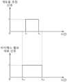
- opening rate adjustment signalwhen the opening rate adjustment signal is expressed as 1, it means that the opening rate of the mixing valve (360) is adjusted, and when the opening rate adjustment signal is expressed as 0, it means that the opening rate of the mixing valve (360) is not adjusted.
- bypass valve opening/closing signalwhen the bypass valve opening/closing signal is expressed as 1, it means that the bypass valve (393, 394) is opened, and when the bypass valve opening/closing signal is expressed as 0, it can mean that the bypass valve (393, 394) is closed.
- Fig. 3is a graph showing a first embodiment of the opening and closing timing of the bypass valve when adjusting the opening rate of the mixing valve.
- the opening of the bypass valve (393, 394)may be performed a set time before the opening rate adjustment timing of the mixing valve (360), and the closing of the bypass valve (393, 394) may be performed a set time before the opening rate adjustment end point of the mixing valve (360).
- Fig. 4is a graph showing a second embodiment of the opening and closing timing of the bypass valve when adjusting the opening rate of the mixing valve.
- the opening of the bypass valve (393, 394)can be performed together with the opening rate adjustment timing of the mixing valve (360), and the closing of the bypass valve (393, 394) can be performed together with the opening rate adjustment end point of the mixing valve (360).
- Fig. 5is a graph showing a third embodiment of the opening and closing timing of the bypass valve when adjusting the opening rate of the mixing valve.
- the opening of the bypass valve (393, 394)may be performed a set time before the opening rate adjustment timing of the mixing valve (360), and the closing of the bypass valve (393, 394) may be performed together with the end point of the opening rate adjustment of the mixing valve (360).
- Fig. 6is a graph showing a fourth embodiment of the opening and closing timing of the bypass valve when adjusting the opening rate of the mixing valve.
- the opening of the bypass valve (393, 394)may be performed a set time before the opening rate adjustment timing of the mixing valve (360), and the closing of the bypass valve (393, 394) may be performed a set time after the opening rate adjustment end point of the mixing valve (360).
- the opening of the bypass valves (393, 394)is to alleviate the impact of the fluid on the mixing valve (360) when the opening rate adjustment of the mixing valve (360) occurs. Therefore, it may be desirable for the opening of the bypass valves (393, 394) to occur simultaneously with the occurrence of the opening rate adjustment of the mixing valve (360) or before a set time before the occurrence of the opening rate adjustment.
Landscapes
- Engineering & Computer Science (AREA)
- Physics & Mathematics (AREA)
- Condensed Matter Physics & Semiconductors (AREA)
- General Physics & Mathematics (AREA)
- Manufacturing & Machinery (AREA)
- Computer Hardware Design (AREA)
- Microelectronics & Electronic Packaging (AREA)
- Power Engineering (AREA)
- General Engineering & Computer Science (AREA)
- Mechanical Engineering (AREA)
- Cleaning Or Drying Semiconductors (AREA)
- Drying Of Semiconductors (AREA)
Abstract
Description
Translated fromKorean본 발명은 기판 처리 장치 및 기판 처리 방법에 관한 것이다.The present invention relates to a substrate processing device and a substrate processing method.
반도체 소자는 웨이퍼 등의 기판에 증착 공정, 사진 공정, 세정 공정, 식각 공정, 스트립 공정, 이온 주입 공정 등 다양한 단위 공정들이 연속적, 그리고 반복적으로 수행되어 제조된다.Semiconductor devices are manufactured by continuously and repeatedly performing various unit processes such as deposition process, photo process, cleaning process, etching process, strip process, and ion implantation process on a substrate such as a wafer.
이 중 세정 공정, 스트립 공정 및 식각 공정은 웨이퍼 상에 부착된 부산물 혹은 웨이퍼 상에 형성된 박막을 제거하는 공정이다. 세정 공정, 스트립 공정 및 식각 공정에서는 플라즈마를 이용할 수 있다. 플라즈마에 포함되는 이온 및/또는 라디칼은 웨이퍼에 공급되고, 이온 및/또는 라디칼은 웨이퍼 상의 부산물 혹은 막과 반응하여, 부산물과 박막을 웨이퍼로부터 제거한다.Among these, the cleaning process, strip process, and etching process are processes for removing byproducts attached to the wafer or thin films formed on the wafer. The cleaning process, strip process, and etching process can utilize plasma. Ions and/or radicals included in the plasma are supplied to the wafer, and the ions and/or radicals react with the byproducts or films on the wafer, thereby removing the byproducts and thin films from the wafer.
위와 같은 플라즈마를 이용하여 웨이퍼를 처리하는 플라즈마 장치는 공정 챔버와, 공정 챔버 내에서 웨이퍼를 지지하는 페디스털을 포함한다. 일반적으로는 플라즈마가 공정 챔버의 중앙 영역에 집중되어 발생한다. 경우에 따라서는, 공정 챔버는 구조적 비대칭성을 가질 수 있다. 이러한 이유로 공정 챔버 내에서 플라즈마에 의한 웨이퍼 처리는 웨이퍼의 영역별로 다르게 이루어질 수 있다. 예를 들어, 웨이퍼의 중앙 영역에 대한 플라즈마 처리율은 높게 나타나고, 웨이퍼의 가장자리 영역에 대한 플라즈마 처리율은 낮게 나타날 수 있다.A plasma device for processing a wafer using the plasma as described above includes a process chamber and a pedestal for supporting a wafer within the process chamber. In general, plasma is concentrated and generated in the central region of the process chamber. In some cases, the process chamber may have structural asymmetry. For this reason, wafer processing by plasma within the process chamber may be performed differently for each region of the wafer. For example, the plasma processing rate for the central region of the wafer may be high, and the plasma processing rate for the edge region of the wafer may be low.
웨이퍼를 지지하는 페디스털은 플라즈마에 의한 웨이퍼 처리가 균일하게 이루어질 수 있도록 지지된 웨이퍼의 온도를 조절한다. 이때, 웨이퍼의 중앙 영역과 웨이퍼의 가장자리 영역 사이에 플라즈마 처리율이 서로 다른 것을 보완하기 위해 페디스털의 영역별 온도는 다르게 제어될 수 있다.The pedestal supporting the wafer controls the temperature of the supported wafer so that the wafer can be processed uniformly by plasma. At this time, the temperature of each area of the pedestal can be controlled differently to compensate for the difference in plasma processing rates between the central area of the wafer and the edge area of the wafer.
예를 들어, 페디스털은 웨이퍼의 가장자리 영역과 대응하는 에지 유로와 웨이퍼의 중앙 영역과 대응하는 센터 유로를 포함하고, 에지 유로에 흐르는 쿨런트의 온도와 센터 유로에 흐르는 쿨런트의 온도를 서로 다르게 하여 웨이퍼의 영역별 온도를 다르게 조절할 수 있다.For example, the pedestal includes an edge channel corresponding to an edge region of the wafer and a center channel corresponding to a center region of the wafer, and the temperature of the coolant flowing in the edge channel and the temperature of the coolant flowing in the center channel can be different from each other to control the temperature of each region of the wafer differently.
일반적으로는 센터 유로와 에지 유로에 공급되는 쿨런트는 칠러 유닛이 공급한다. 칠러 유닛은 센터 유로와 에지 유로에 각각 서로 다른 온도의 쿨런트를 공급한다. 칠러 유닛과 페디스털에 형성된 유로는 쿨런트 공급 라인을 통해 연결된다.Normally, the coolant supplied to the center and edge filaments is supplied by a chiller unit. The chiller unit supplies coolants of different temperatures to the center and edge filaments, respectively. The filaments formed on the chiller unit and the pedestal are connected via a coolant supply line.
그러나, 센터 유로와 에지 유로에 공급되는 온도는 필요에 따라 공정 도중 조절되어야 한다. 예를 들어, 공정 도중 센터 유로에 흐르는 쿨런트의 온도를 높여야 할 필요가 있다. 이 경우, 칠러 유닛에서는 온도가 높은 쿨런트를 센터 유로에 공급한다. 그러나, 칠러 유닛에서 쿨런트의 온도를 조절하더라도, 칠러 유닛에서 센터 유로에 쿨런트가 흐르는 동안 쿨런트의 온도가 달라질 수 있다. 가사 쿨런트의 온도가 달라지지 않더라도 쿨런트의 온도 변경이 센터 유로에 반영되기까지는 시간이 소요된다.However, the temperatures supplied to the center euro and edge euro must be controlled during the process as needed. For example, the temperature of the coolant flowing in the center euro must be increased during the process. In this case, the chiller unit supplies coolant having a high temperature to the center euro. However, even if the temperature of the coolant is controlled in the chiller unit, the temperature of the coolant may change while the coolant flows in the center euro from the chiller unit. Even if the temperature of the main coolant does not change, it takes time for the change in the temperature of the coolant to be reflected in the center euro.
칠러 유닛의 위치를 페디스털과 가까이 배치하는 방법도 고려할 수 있으나 칠러 유닛의 부피를 고려할 때, 칠러 유닛을 페디스털과 가까이 배치하는 것에는 한계가 존재한다.You can also consider arranging the chiller unit close to the pedestal, but considering the volume of the chiller unit, there is a limit to how close the chiller unit can be to the pedestal.
또한, 플라즈마 장치는 경우에 따라 복수의 공정 챔버를 구비할 수 있다. 복수의 공정 챔버에는 각각 페디스털이 적어도 하나 이상 제공된다. 이 경우, 페디스털 각각에 대한 온도 조절을 독립적으로 수행하기 위해서는 페디스털 각각에 대하여 대응하는 수의 칠러 유닛이 필요하다.In addition, the plasma device may be provided with multiple process chambers in some cases. Each of the multiple process chambers is provided with at least one pedestal. In this case, in order to independently perform temperature control for each pedestal, a corresponding number of chiller units are required for each pedestal.
본 발명은 기판을 효과적으로 처리할 수 있는 기판 처리 장치 및 기판 처리 방법을 제공하는 것을 일 목적으로 한다.The purpose of the present invention is to provide a substrate processing device and a substrate processing method capable of effectively processing a substrate.
또한, 본 발명은 기판의 온도 제어에 소요되는 시간을 단축할 수 있는 기판 처리 장치 및 기판 처리 방법을 제공하는 것을 일 목적으로 한다.In addition, an object of the present invention is to provide a substrate processing device and a substrate processing method capable of shortening the time required for temperature control of a substrate.
또한, 본 발명은 기판을 지지하는 페디스털로 유체를 공급하는 라인에서 파티클이 발생하는 것을 저감할 수 있는 기판 처리 장치 및 기판 처리 방법을 제공하는 것을 일 목적으로 한다.In addition, the present invention aims to provide a substrate processing device and a substrate processing method capable of reducing the generation of particles in a line supplying fluid to a pedestal supporting a substrate.
또한, 본 발명은 하나의 칠러 유닛으로 복수의 페디스털의 독립적인 온도 조절을 가능케하는 기판 처리 장치 및 기판 처리 방법을 제공하는 것을 일 목적으로 한다.In addition, the present invention aims to provide a substrate processing device and a substrate processing method that enable independent temperature control of a plurality of pedestals with a single chiller unit.
본 발명이 해결하고자 하는 과제가 상술한 과제로 한정되는 것은 아니며, 언급되지 아니한 과제들은 본 명세서 및 첨부된 도면으로부터 본 발명이 속하는 기술분야에서 통상의 지식을 가진 자에게 명확하게 이해될 수 있을 것이다.The problems to be solved by the present invention are not limited to the problems described above, and problems not mentioned can be clearly understood by a person having ordinary skill in the art to which the present invention belongs from this specification and the attached drawings.
본 발명은 기판 처리 장치를 제공한다. 기판 처리 장치는, 기판을 지지하고, 기판의 온도를 조절하기 위한 유체가 흐르는 유로가 형성된 페디스털; 및 상기 유로로 상기 유체를 공급하는 칠러 유닛을 포함하고, 상기 칠러 유닛은, 제1온도의 제1유체를 공급하는 제1유체 공급원; 상기 제1온도와 상이한 제2온도의 제2유체를 공급하는 제2유체 공급원; 및 상기 제1유체 공급원 및 상기 제2유체 공급원의 하류에 설치되고, 상기 유로보다 상류에 설치되고, 혼합 유체 - 상기 혼합 유체는 상기 제1유체 및 상기 제2유체가 혼합된 유체임 - 의 상기 제1유체와 상기 제2유체의 혼합 비율을 조정하는 혼합 밸브를 포함할 수 있다.The present invention provides a substrate processing apparatus. The substrate processing apparatus includes a pedestal which supports a substrate and has a flow path formed through which a fluid for controlling a temperature of the substrate flows; and a chiller unit which supplies the fluid to the flow path, wherein the chiller unit may include a first fluid supply source which supplies a first fluid at a first temperature; a second fluid supply source which supplies a second fluid at a second temperature different from the first temperature; and a mixing valve which is installed downstream of the first fluid supply source and the second fluid supply source and upstream of the flow path, and which adjusts a mixing ratio of the first fluid and the second fluid in a mixed fluid, the mixed fluid being a fluid in which the first fluid and the second fluid are mixed.
일 실시 예에 의하면, 상기 유로는 복수로 제공되고, 복수의 상기 유로는, 상기 페디스털에 지지된 기판의 제1영역과 대응하는 제1유로; 및 상기 페디스털에 지지된 기판의 상기 제1영역과 상이한 제2영역과 대응하는 제2유로를 포함할 수 있다.In one embodiment, the plurality of euros may be provided, and the plurality of euros may include a first euro corresponding to a first region of the substrate supported on the pedestal; and a second euro corresponding to a second region of the substrate supported on the pedestal, the second euro being different from the first region.
일 실시 예에 의하면, 상기 제1유로는 상기 페디스털에 지지된 기판의 가장자리 영역과 대응하는 위치에 형성되고, 상기 제2유로는 상기 페디스털에 지지된 기판의 중앙 영역과 대응하는 위치에 형성될 수 있다.In one embodiment, the first flow path may be formed at a position corresponding to an edge region of the substrate supported on the pedestal, and the second flow path may be formed at a position corresponding to a center region of the substrate supported on the pedestal.
일 실시 예에 의하면, 상기 혼합 밸브는 복수로 제공되고, 복수의 상기 혼합 밸브는, 상기 제1유로로 공급되는 제1혼합 유체의 상기 제1유체와 상기 제2유체의 혼합 비율을 조정하는 제1혼합 밸브; 및 상기 제2유로 공급되는 제2혼합 유체의 상기 제1유체와 상기 제2유체의 혼합 비율을 조정하는 제2혼합 밸브를 포함할 수 있다.In one embodiment, the mixing valve is provided in plural, and the plural mixing valves may include a first mixing valve for adjusting the mixing ratio of the first fluid and the second fluid of the first mixed fluid supplied to the first flow path; and a second mixing valve for adjusting the mixing ratio of the first fluid and the second fluid of the second mixed fluid supplied to the second flow path.
일 실시 예에 의하면, 상기 제1혼합 밸브와 상기 제1유로 사이에 위치하는 제1혼합 공급 라인; 및 상기 제2혼합 밸브와 상기 제2유로 사이에 위치하는 제2혼합 공급 라인을 포함할 수 있다.In one embodiment, the device may include a first mixing supply line positioned between the first mixing valve and the first flow path; and a second mixing supply line positioned between the second mixing valve and the second flow path.
일 실시 예에 의하면, 상기 제1혼합 공급 라인 및 상기 제2혼합 공급 라인에는 각각 상기 제1혼합 유체 및 상기 제2혼합 유체의 온도를 측정하는 온도 센서가 설치될 수 있다.According to one embodiment, temperature sensors for measuring the temperatures of the first mixed fluid and the second mixed fluid may be installed in the first mixed supply line and the second mixed supply line, respectively.
일 실시 예에 의하면, 상기 칠러 유닛은, 상기 제1유체 공급원으로부터 상기 제1유체를 상기 유로로 공급하는 제1유체 공급 라인을 포함하고, 상기 제1유체 공급 라인은, 상기 제1유체 공급원과 연결되는 제1메인 공급 라인; 및 상기 제1메인 공급 라인으로부터 분기되는 복수의 제1분기 공급 라인을 포함하고, 상기 제1분기 공급 라인들은 각각 상기 제1혼합 공급 라인 및 상기 제2혼합 공급 라인에 상기 제1유체를 공급하도록 구성될 수 있다.In one embodiment, the chiller unit includes a first fluid supply line for supplying the first fluid from the first fluid supply source to the flow path, the first fluid supply line including: a first main supply line connected to the first fluid supply source; and a plurality of first branch supply lines branching from the first main supply line, the first branch supply lines being configured to supply the first fluid to the first mixed supply line and the second mixed supply line, respectively.
일 실시 예에 의하면, 상기 칠러 유닛은, 상기 유로로 공급된 유체를 복귀시키는 제1유체 복귀 라인을 포함하고, 상기 제1유체 복귀 라인은, 상기 제1유체 공급원 또는 상기 제2유체 공급원과 연결되는 제1메인 복귀 라인; 및 상기 제1메인 복귀 라인으로부터 분기되는 복수의 제1분기 복귀 라인을 포함하고, 상기 제1분기 복귀 라인들은 각각 상기 제1유로 및 상기 제2유로와 연결되어 상기 제1유로 및 상기 제2유로에 흐르는 유체를 상기 제1유체 공급원 또는 상기 제2유체 공급원으로 복귀시킬 수 있다.In one embodiment, the chiller unit includes a first fluid return line for returning a fluid supplied to the flow path, the first fluid return line including: a first main return line connected to the first fluid supply source or the second fluid supply source; and a plurality of first branch return lines branching from the first main return line, the first branch return lines being respectively connected to the first flow path and the second flow path to return a fluid flowing in the first flow path and the second flow path to the first fluid supply source or the second fluid supply source.
일 실시 예에 의하면, 상기 혼합 밸브는, 상기 페디스털로부터 20 내지 40 cm 범위 내의 위치에 설치될 수 있다.In one embodiment, the mixing valve may be installed at a position within a range of 20 to 40 cm from the pedestal.
일 실시 예에 의하면, 상기 제1유체 공급원과 상기 혼합 밸브를 연결하는 제1유체 공급 라인; 상기 제2유체 공급원과 상기 혼합 밸브를 연결하는 제2유체 공급 라인; 상기 혼합 밸브보다 상류에서 상기 제1유체 공급 라인에 연결되는 제1바이패스 라인; 및 상기 혼합 밸브보다 상류에서 상기 제2유체 공급 라인에 연결되는 제2바이패스 라인을 포함할 수 있다.In one embodiment, the device may include: a first fluid supply line connecting the first fluid supply source and the mixing valve; a second fluid supply line connecting the second fluid supply source and the mixing valve; a first bypass line connected to the first fluid supply line upstream of the mixing valve; and a second bypass line connected to the second fluid supply line upstream of the mixing valve.
일 실시 예에 의하면, 상기 장치는, 제어 유닛을 더 포함하고, 상기 제어 유닛은, 상기 혼합 밸브의 개도율을 조정시 상기 제1바이패스 라인 또는 상기 제2바이패스 라인에 설치되는 바이패스 밸브를 개방하도록 상기 칠러 유닛을 제어할 수 있다.In one embodiment, the device further comprises a control unit, wherein the control unit is capable of controlling the chiller unit to open a bypass valve installed in the first bypass line or the second bypass line by adjusting the opening rate of the mixing valve.
일 실시 예에 의하면, 상기 제어 유닛은, 상기 혼합 밸브의 개도율을 작게 조정하는 경우 상기 바이패스 밸브를 개방하도록 상기 칠러 유닛을 제어할 수 있다.In one embodiment, the control unit can control the chiller unit to open the bypass valve when the opening rate of the mixing valve is adjusted to a small degree.
일 실시 예에 의하면, 상기 제어 유닛은, 상기 혼합 밸브의 개도율을 조정할 때, 혹은 상기 혼합 밸브의 개도율을 조정하기 설정 시간 이전에 상기 바이패스 밸브를 개방하도록 상기 칠러 유닛을 제어할 수 있다.In one embodiment, the control unit can control the chiller unit to open the bypass valve when adjusting the opening rate of the mixing valve, or before a set time for adjusting the opening rate of the mixing valve.
또한, 본 발명은 기판 처리 장치를 제공한다. 기판 처리 장치는, 플라즈마를 이용하여 기판을 처리하는 제1처리 유닛; 상기 제1처리 유닛과 나란히 배치되며, 플라즈마를 이용하여 기판을 처리하는 제2처리 유닛; 및 상기 제1처리 유닛 및 상기 제2처리 유닛으로 기판의 온도를 조절하기 위한 유체를 공급하는 칠러 유닛을 포함하고, 상기 제1처리 유닛, 그리고 상기 제2처리 유닛은 각각 기판을 지지하고 기판의 온도를 조절하기 위한 유체가 흐르는 유로가 형성된 제1페디스털, 그리고 제2페디스털들 포함하고, 상기 칠러 유닛은, 상기 제1페디스털, 그리고 상기 제2페디스털에 상기 유체를 공급하도록 구성되되, 제1온도의 제1유체를 공급하는 제1유체 공급원; 상기 제1온도와 상이한 제2온도의 제2유체를 공급하는 제2유체 공급원; 및 상기 제1유체 공급원 및 상기 제2유체 공급원의 하류에 설치되고, 상기 제1페디스털 및 상기 제2페디스털보다 상류에 설치되고, 상기 제1페디스털 또는 상기 제2페디스털로 공급되는 혼합 유체 - 상기 혼합 유체는 상기 제1유체 및 상기 제2유체가 혼합된 유체임 - 의 상기 제1유체와 상기 제2유체의 혼합 비율을 조정하여 상기 혼합 유체의 온도를 조절하는 혼합 밸브를 포함할 수 있다.In addition, the present invention provides a substrate processing apparatus. The substrate processing apparatus includes a first processing unit which processes a substrate using plasma; a second processing unit which is arranged parallel to the first processing unit and processes the substrate using plasma; and a chiller unit which supplies a fluid for controlling a temperature of the substrate to the first processing unit and the second processing unit, wherein the first processing unit and the second processing unit each include a first pedestal and second pedestals which support the substrate and have a flow path formed through which a fluid for controlling the temperature of the substrate flows, and the chiller unit is configured to supply the fluid to the first pedestal and the second pedestal, wherein the first fluid supply source supplies a first fluid at a first temperature; a second fluid supply source supplies a second fluid at a second temperature different from the first temperature; And it may include a mixing valve installed downstream of the first fluid supply source and the second fluid supply source, installed upstream of the first pedestal and the second pedestal, and controlling the temperature of the mixed fluid by adjusting the mixing ratio of the first fluid and the second fluid of the mixed fluid supplied to the first pedestal or the second pedestal, the mixed fluid being a fluid in which the first fluid and the second fluid are mixed.
일 실시 예에 의하면, 상기 칠러 유닛은, 상기 혼합 밸브, 그리고 상기 제1페디스털 사이 또는 상기 혼합 밸브, 그리고 상기 제2페디스털 사이에 제공되며 상기 혼합 유체가 흐르는 혼합 공급 라인을 포함할 수 있다.In one embodiment, the chiller unit may include a mixing supply line provided between the mixing valve and the first pedestal or between the mixing valve and the second pedestal, through which the mixing fluid flows.
일 실시 예에 의하면, 상기 칠러 유닛은, 상기 혼합 공급 라인에 흐르는 상기 혼합 유체의 온도를 측정하는 온도 센서를 더 포함하고, 상기 장치는, 상기 칠러 유닛을 제어하는 제어 유닛을 더 포함하되, 상기 제어 유닛은, 상기 온도 센서가 측정하는 상기 혼합 유체의 온도 값이 미리 설정된 설정 온도 값과 다른 경우 상기 혼합 밸브의 개도율을 변경하도록 상기 칠러 유닛을 제어할 수 있다.In one embodiment, the chiller unit further includes a temperature sensor for measuring a temperature of the mixed fluid flowing in the mixed supply line, and the device further includes a control unit for controlling the chiller unit, wherein the control unit can control the chiller unit to change an opening rate of the mixing valve when a temperature value of the mixed fluid measured by the temperature sensor is different from a preset temperature value.
일 실시 예에 의하면, 상기 칠러 유닛은, 상기 제1유체 공급원로부터 상기 제1페디스털 또는 상기 제2페디스털로 상기 제1유체를 공급하는 제1유체 공급 라인; 상기 제2유체 공급원로부터 상기 제1페디스털 또는 상기 제2페디스털로 상기 제2유체를 공급하는 제2유체 공급 라인; 상기 제1유체 공급 라인과 연결되며, 제1바이패스 밸브가 설치된 제1바이패스 라인; 및 상기 제2유체 공급 라인과 연결되며, 제2바이패스 밸브가 설치된 제2바이패스 라인을 포함하고, 상기 제어 유닛은, 상기 혼합 밸브의 개도율을 변경시, 상기 제1바이패스 밸브 또는 상기 제2바이패스 밸브를 개방하도록 상기 칠러 유닛을 제어할 수 있다.In one embodiment, the chiller unit includes a first fluid supply line supplying the first fluid from the first fluid supply source to the first pedestal or the second pedestal; a second fluid supply line supplying the second fluid from the second fluid supply source to the first pedestal or the second pedestal; a first bypass line connected to the first fluid supply line and having a first bypass valve installed; and a second bypass line connected to the second fluid supply line and having a second bypass valve installed, wherein the control unit can control the chiller unit to open the first bypass valve or the second bypass valve when the opening rate of the mixing valve is changed.
일 실시 예에 의하면, 상기 설정 온도 값은 미리 측정된 기판 처리 데이터에 근거하여 설정될 수 있다.In one embodiment, the set temperature value may be set based on pre-measured substrate processing data.
또한, 본 발명은 기판 처리 방법을 제공한다. 기판 처리 방법은, 제1유로 및 상기 제1유로와 상이한 위치에 형성되는 제2유로가 형성된 페디스털에 상기 기판을 지지하고, 상기 제1유로 및 상기 제2유로에 유체를 공급하여 상기 기판의 영역별 온도를 조절하되, 상기 제1유로 및 상기 제2유로에 공급되는 유체의 온도는 제1온도의 제1유체 및 상기 제1온도와 상이한 제2온도의 제2유체가 혼합되어 조절될 수 있다.In addition, the present invention provides a substrate processing method. The substrate processing method supports the substrate on a pedestal having a first flow path and a second flow path formed at a different location from the first flow path, and supplies a fluid to the first flow path and the second flow path to control the temperature of each region of the substrate, wherein the temperature of the fluid supplied to the first flow path and the second flow path can be controlled by mixing a first fluid at a first temperature and a second fluid at a second temperature different from the first temperature.
일 실시 예에 의하면, 상기 제1유체와 상기 제2유체의 혼합 비율은, 혼합 밸브를 이용하여 조절되되, 상기 혼합 밸브는, 상기 제1유체의 단위 시간당 공급 유량을 조절하는 제1유량 조절부 및 상기 제2유체의 단위 시간당 공급 유량을 조절하는 제2유량 조절부를 포함하고, 상기 제1유량 조절부 및 상기 제2유량 조절부의 개도율 조절에 따라 상기 제1유체와 상기 제2유체의 혼합 비율이 조정될 수 있다.According to one embodiment, the mixing ratio of the first fluid and the second fluid is controlled using a mixing valve, wherein the mixing valve includes a first flow rate control unit that controls the supply flow rate of the first fluid per unit time and a second flow rate control unit that controls the supply flow rate of the second fluid per unit time, and the mixing ratio of the first fluid and the second fluid can be adjusted according to the adjustment of the opening rates of the first flow rate control unit and the second flow rate control unit.
본 발명의 일 실시 예에 의하면, 기판을 효과적으로 처리할 수 있다.According to one embodiment of the present invention, a substrate can be effectively treated.
또한, 본 발명의 일 실시 예에 의하면, 기판의 온도 제어에 소요되는 시간을 단축할 수 있다.In addition, according to one embodiment of the present invention, the time required for temperature control of the substrate can be shortened.
또한, 본 발명의 일 실시 예에 의하면, 기판을 지지하는 페디스털로 유체를 공급하는 라인에서 파티클이 발생하는 것을 저감할 수 있다.In addition, according to one embodiment of the present invention, it is possible to reduce the generation of particles in a line that supplies fluid to a pedestal that supports a substrate.
또한, 본 발명의 일 실시 예에 의하면, 하나의 칠러 유닛으로 복수의 페디스털의 독립적인 온도 조절이 가능하다.Additionally, according to one embodiment of the present invention, independent temperature control of multiple pedestals is possible with one chiller unit.
본 발명의 효과가 상술한 효과들로 한정되는 것은 아니며, 언급되지 아니한 효과들은 본 명세서 및 첨부된 도면으로부터 본 발명이 속하는 기술분야에서 통상의 지식을 가진 자에게 명확히 이해될 수 있을 것이다.The effects of the present invention are not limited to the effects described above, and effects not mentioned can be clearly understood by a person skilled in the art from this specification and the attached drawings.
도 1은 본 발명의 일 실시 예에 따른 기판 처리 장치의 모습을 보여주는 도면이다.FIG. 1 is a drawing showing a substrate processing device according to one embodiment of the present invention.
도 2는 본 발명의 일 실시 예에 따른 기판 처리 장치의 제어 방법을 보여주는 플로우 차트이다.FIG. 2 is a flow chart showing a control method of a substrate processing device according to one embodiment of the present invention.
도 3은 혼합 밸브의 개도율 조절시, 바이패스 밸브의 개폐 시점의 제1 실시 예를 보여주는 그래프이다.Figure 3 is a graph showing a first embodiment of the opening and closing timing of the bypass valve when adjusting the opening rate of the mixing valve.
도 4는 혼합 밸브의 개도율 조절시, 바이패스 밸브의 개폐 시점의 제2 실시 예를 보여주는 그래프이다.Figure 4 is a graph showing a second embodiment of the opening and closing timing of the bypass valve when adjusting the opening rate of the mixing valve.
도 5는 혼합 밸브의 개도율 조절시, 바이패스 밸브의 개폐 시점의 제3 실시 예를 보여주는 그래프이다.Figure 5 is a graph showing a third embodiment of the opening and closing timing of the bypass valve when adjusting the opening rate of the mixing valve.
도 6은 혼합 밸브의 개도율 조절시, 바이패스 밸브의 개폐 시점의 제4 실시 예를 보여주는 그래프이다.Figure 6 is a graph showing a fourth embodiment of the opening and closing timing of the bypass valve when adjusting the opening rate of the mixing valve.
본 명세서의 비제한적인 실시예의 다양한 특징 및 이점은 첨부 도면과 함께 상세한 설명을 검토하면 더욱 명백해질 수 있다. 첨부된 도면은 단지 예시의 목적으로 제공되며 청구범위를 제한하는 것으로 해석되어서는 안된다. 첨부 도면은 명시적으로 언급되지 않는 한 축척에 맞게 그려진 것으로 간주되지 않는다. 명확성을 위해 도면의 다양한 치수는 과장되었을 수 있다.The various features and advantages of the non-limiting embodiments of the present disclosure will become more apparent upon review of the detailed description in conjunction with the accompanying drawings. The accompanying drawings are provided for illustrative purposes only and should not be construed as limiting the scope of the claims. The accompanying drawings are not to be considered to be drawn to scale unless expressly stated otherwise. Various dimensions in the drawings may be exaggerated for clarity.
예시적인 실시예는 첨부된 도면을 참조하여 이제 더 완전하게 설명될 것이다. 예시적인 실시예는 본 개시내용이 철저할 수 있도록 제공되며, 본 기술 분야에서 통상의 지식을 가진 자에게 그 범위를 충분히 전달할 것이다. 본 개시내용의 실시예에 대한 완전한 이해를 제공하기 위해, 특정 구성요소, 장치 및 방법의 예와 같은 다수의 특정 세부사항이 제시된다. 특정 세부사항이 이용될 필요가 없고, 예시적인 실시예가 많은 상이한 형태로 구현될 수 있고 둘 다 본 개시의 범위를 제한하는 것으로 해석되어서는 안 된다는 것이 당업자에게 명백할 것이다. 일부 예시적인 실시예에서, 공지된 프로세스, 공지된 장치 구조 및 공지된 기술은 상세하게 설명되지 않는다.The exemplary embodiments will now be described more fully with reference to the accompanying drawings. The exemplary embodiments are provided so that this disclosure will be thorough, and will fully convey the scope thereof to those skilled in the art. In order to provide a thorough understanding of the embodiments of the present disclosure, numerous specific details are set forth, such as examples of specific components, devices, and methods. It will be apparent to those skilled in the art that the specific details need not be utilized, and that the exemplary embodiments may be implemented in many different forms and that neither should be construed as limiting the scope of the present disclosure. In some exemplary embodiments, well-known processes, well-known device structures, and well-known techniques are not described in detail.
여기서 사용되는 용어는 단지 특정 예시적인 실시예들을 설명하기 위한 것이며, 예시적인 실시예들을 제한하기 위한 것이 아니다. 여기서 사용된 것과 같은, 단수 표현들 또는 단복수가 명시되지 않은 표현들은, 문맥상 명백하게 다르게 나타나지 않는 이상, 복수 표현들을 포함하는 것으로 의도된다. 용어, "포함한다", "포함하는", "구비하는", "가지는"은 개방형 의미이며 따라서 언급된 특징들, 구성들(integers), 단계들, 작동들, 요소들 및/또는 구성요소들의 존재를 특정하는 것이며, 하나 이상의 다른 특징들, 구성들, 단계들, 작동들, 요소들, 구성요소들 및/또는 이들 그룹의 존재 또는 추가를 배제하지 않는다. 본 명세서에서 방법 단계들, 프로세스들 및 작동들은, 수행하는 순서가 명시되지 않는 한, 논의되거나 설명된 특정 순서로 반드시 수행되는 것으로 해석되는 것은 아니다. 또한 추가적인 또는 대안적인 단계들이 선택될 수 있다.The terminology used herein is for the purpose of describing particular exemplary embodiments only and is not intended to be limiting of the exemplary embodiments. As used herein, the singular or non-plural terms are intended to include the plural terms, unless the context clearly indicates otherwise. The terms "comprises," "comprising," "having," and "having" are open-ended and thus specify the presence of the stated features, elements, steps, operations, elements, and/or components, but do not preclude the presence or addition of one or more other features, elements, steps, operations, elements, components, and/or groups thereof. The method steps, processes, and operations herein are not necessarily to be construed as being performed in the particular order discussed or described, unless the order is explicitly stated. Additionally, additional or alternative steps may be selected.
요소 또는 층이 다른 요소 또는 층 "상에", "연결된", "결합된", "부착된", "인접한" 또는 "덮는"으로 언급될 때, 이는 직접적으로 상기 다른 요소 또는 층 상에 있거나, 연결되거나, 결합되거나, 부착되거나, 인접하거나 또는 덮거나, 또는 중간 요소들 또는 층들이 존재할 수 있다. 반대로, 요소가 다른 요소 또는 층의 "직접적으로 상에", "직접적으로 연결된", 또는 "직접적으로 결합된"으로 언급될 때, 중간 요소들 또는 층들이 존재하지 않은 것으로 이해되어야 할 것이다. 명세서 전체에 걸쳐 동일 참조 부호는 동일 요소를 지칭한다. 본원발명에서 사용된 용어 "및/또는"은 열거된 항목들 중 하나 이상의 항목의 모든 조합들 및 부조합들을 포함한다.When an element or layer is referred to as being "on," "connected," "joined," "attached," "adjacent," or "covering" another element or layer, it can be directly on, connected, joined, attached, adjacent, or covering said other element or layer, or there may be intermediate elements or layers present. Conversely, when an element is referred to as being "directly on," "directly connected," or "directly coupled to" another element or layer, it should be understood that no intermediate elements or layers are present. Like reference numerals refer to like elements throughout. The term "and/or" as used herein includes all combinations and subcombinations of one or more of the listed items.
비록 제1, 제2, 제3 등의 용어들이 본원발명에서 다양한 요소들, 영역들, 층들, 및/또는 섹션들을 설명하기 위해 사용될 수 있으나, 이 요소들, 영역들, 층들, 및/또는 섹션들은 이들 용어들에 의해 제한되어서는 아니 되는 것으로 이해되어야 한다. 이들 용어는 어느 한 요소, 영역, 층, 또는 섹션을 단지 다른 요소, 영역, 층 또는 섹션과 구분하기 위해 사용된다. 따라서, 이하에서 논의되는 제1 요소, 제1 영역, 제1 층, 또는 제1 섹션은 예시적인 실시예들의 교시를 벗어나지 않고 제2 요소, 제2 영역, 제2 층, 또는 제2 섹션으로 지칭될 수 있다.Although the terms first, second, third, etc. may be used herein to describe various elements, regions, layers, and/or sections, it should be understood that these elements, regions, layers, and/or sections should not be limited by these terms. These terms are used solely to distinguish one element, region, layer, or section from another element, region, layer, or section. Thus, a first element, a first region, a first layer, or a first section discussed below could also be referred to as a second element, a second region, a second layer, or a second section without departing from the teachings of the exemplary embodiments.
공간적으로 상대적인 용어들(예를 들어, "아래에", "밑에", "하부", "위에", "상단" 등)은 도면에 도시된 바와 같이 하나의 요소 또는 특징과 다른 요소(들) 또는 특징(들)과의 관계를 설명하기 위해 설명의 편의를 위해 사용될 수 있다. 공간적으로 상대적인 용어는 도면에 도시된 배향뿐만 아니라 사용 또는 작동 중인 장치의 다른 배향들을 포함하도록 의도된다는 것으로 이해되어야 한다. 예를 들어, 도면 내의 상기 장치가 뒤집힌다면, 다른 요소들 또는 특징들의 "밑에" 또는 "아래에"로 설명된 요소들은 다른 요소들 또는 특징들의 "위에" 배향될 것이다. 따라서, 상기 "아래에" 용어는 위 및 아래의 배향을 모두 포함할 수 있다. 상기 장치는 다르게 배향될 수 있고(90도 회전되거나, 다른 배향으로), 본원발명에서 사용된 공간적으로 상대적인 설명어구는 그에 맞춰 해석될 수 있다.Spatially relative terms (e.g., “below,” “under,” “bottom,” “above,” “top,” etc.) may be used for convenience of description to describe an element or feature’s relationship to another element(s) or feature(s) as depicted in the drawings. It should be understood that spatially relative terms are intended to encompass other orientations of the device in use or operation, in addition to the orientation depicted in the drawings. For example, if the device in the drawings were flipped over, elements described as “below” or “below” other elements or features would then be oriented “above” the other elements or features. Thus, the term “below” can encompass both above and below orientations. The device can be oriented differently (rotated 90 degrees, or at a different orientation), and the spatially relative descriptive phrases used herein can be interpreted accordingly.
실시예들의 설명에서 "동일" 또는 "같은"이라는 용어를 사용할 경우, 약간의 부정확함이 존재할 수 있음을 이해해야 한다. 따라서, 한 요소 또는 값이 다른 요소 또는 값과 동일한 것으로 언급될 경우, 해당 요소 또는 값이 제조 또는 작동 오차 (예를 들어 ±10 %) 내의 다른 요소 또는 값과 동일하다는 것을 이해해야 한다When using the terms "same" or "same" in the description of embodiments, it should be understood that there may be some inaccuracy. Thus, when one element or value is referred to as being the same as another element or value, it should be understood that the element or value is the same as the other element or value within a manufacturing or operating tolerance (e.g., ±10%).
수치와 관련하여 본 명세서에서 "대략" 또는 "실질적으로"라는 단어를 사용하는 경우, 당해 수치는 언급된 수치의 제조 또는 작동 오차(예를 들어 ±10%)를 포함하는 것으로 이해되어야 한다. 또한 기하학적 형태와 관련하여 "일반적으로"와 "실질적으로"라는 단어를 사용할 경우 기하학적 형태의 정확성이 요구되지는 않지만 형태에 대한 자유(latitude)는 개시 범위 내에 있음을 이해해야 한다.When the words "approximately" or "substantially" are used in this specification with respect to a numerical value, it should be understood that the numerical value includes a manufacturing or operating tolerance (e.g., ±10%) of the stated value. Also, when the words "typically" and "substantially" are used with respect to a geometrical shape, it should be understood that geometrical accuracy is not required, but that latitude with respect to the shape is within the scope of the disclosure.
다르게 정의되지 않는 한, 본원발명에서 사용되는 모든 용어들(기술적 및 과학적 용어를 포함하는)은 예시적인 실시예들이 속하는 기술 분야에서 통상의 지식을 가진 자에 의해 일반적으로 이해되는 것과 동일한 의미를 가진다. 또한, 일반적으로 사용되는 사전에 정의된 용어들을 포함하여, 용어들은 관련 기술의 맥락에서 그 의미와 일치하는 의미를 갖는 것으로 해석되어야 하며, 본원발명에서 명시적으로 정의되지 않는 한, 이상적이거나 지나치게 공식적인 의미로 해석되지 않을 것으로 이해될 것이다.Unless otherwise defined, all terms (including technical and scientific terms) used in this disclosure have the same meaning as commonly understood by one of ordinary skill in the art to which the exemplary embodiments belong. In addition, terms, including terms defined in commonly used dictionaries, should be interpreted to have a meaning consistent with their meaning in the context of the relevant art, and will not be interpreted in an idealized or overly formal sense unless explicitly defined in this disclosure.
이하에서는, 피처리물인 기판은 웨이퍼인 것을 예로 들어 설명한다.In the following, the substrate to be processed is explained as an example of a wafer.
또한, 이하에서는, 기판 처리 장치가 플라즈마를 이용하여 기판을 처리하는 것을 예로 들어 설명한다.In addition, below, a substrate processing device is described as an example of processing a substrate using plasma.
또한, 이하에서는, 플라즈마를 이용하여 기판을 처리하는 공정은, 기판 상에 부착된 부산물을 제거하는 건식 세정 공정, 기판 상에 형성된 박막을 제거하는 건식 식각 공정 또는 건식 스트립 공정인 것을 예로 들어 설명한다.In addition, the process of treating a substrate using plasma is explained below as an example of a dry cleaning process for removing byproducts attached to the substrate, a dry etching process for removing a thin film formed on the substrate, or a dry strip process.
도 1은 본 발명의 일 실시 예에 따른 기판 처리 장치의 모습을 보여주는 도면이다.FIG. 1 is a drawing showing a substrate processing device according to one embodiment of the present invention.
도 1을 참조하면, 기판 처리 장치(10)는 제1처리 유닛(100), 제2처리 유닛(200), 칠러 유닛(300) 및 제어 유닛(400)을 포함할 수 있다.Referring to FIG. 1, the substrate processing device (10) may include a first processing unit (100), a second processing unit (200), a chiller unit (300), and a control unit (400).
처리 유닛(100, 200)은 기판(W)을 처리할 수 있다. 제1처리 유닛(100)과 제2처리 유닛(200)은 서로 나란히 배치될 수 있다. 제1처리 유닛(100)과 제2처리 유닛(200)은 동일한 종류의 기판 처리 공정을 수행할 수 있다. 예를 들어, 제1처리 유닛(100)에서는 건식 세정 공정 및 건식 식각 공정이 수행되고, 제2처리 유닛(200)에서도 건식 세정 공정 및 건식 식각 공정이 수행될 수 있다. 이와 달리, 제1처리 유닛(100)에서는 건식 세정 공정 및 건식 식각 공정이 수행되고, 제2처리 유닛(200)에서는 증착 공정이 수행될 수 있다.The processing units (100, 200) can process a substrate (W). The first processing unit (100) and the second processing unit (200) can be arranged side by side. The first processing unit (100) and the second processing unit (200) can perform the same type of substrate processing process. For example, a dry cleaning process and a dry etching process can be performed in the first processing unit (100), and a dry cleaning process and a dry etching process can be performed in the second processing unit (200). Alternatively, a dry cleaning process and a dry etching process can be performed in the first processing unit (100), and a deposition process can be performed in the second processing unit (200).
제1처리 유닛(100)은 제1처리 챔버(110), 제1페디스털(120), 제1확산 챔버(130), 제1반응 챔버(140), 제1플라즈마 소스(150), 제1가스 공급 라인(160), 제1배플(170), 그리고 제1배기 라인(180)을 포함할 수 있다.The first processing unit (100) may include a first processing chamber (110), a first pedestal (120), a first diffusion chamber (130), a first reaction chamber (140), a first plasma source (150), a first gas supply line (160), a first baffle (170), and a first exhaust line (180).
제1처리 챔버(110)는 기판(W)이 처리되는 처리 공간(112)을 정의할 수 있다. 제1처리 챔버(110)는 상부가 개방된 통 형상을 가질 수 있다. 제1처리 챔버(110)의 내벽은 플라즈마에 대해 내식성이 우수한 소재, 예컨대 YF3, Y2O3와 같은 소재로 코팅될 수 있다.The first processing chamber (110) can define a processing space (112) in which a substrate (W) is processed. The first processing chamber (110) can have a barrel shape with an open top. The inner wall of the first processing chamber (110) can be coated with a material having excellent corrosion resistance to plasma, such as YF3 or Y2O3.
제1페디스털(120)은 처리 공간(112)에서 기판(W)을 지지할 수 있다. 제1페디스털(120)은 기판(W)을 지지하는 지지면을 가질 수 있다. 제1페디스털(120)은 기판(W)의 온도를 조절할 수 있다. 제1페디스털(120)의 영역별 온도는 독립적으로 조절될 수 있다. 이에, 제1페디스털(120)은 기판(W)의 영역별 온도를 조절할 수 있다.The first pedestal (120) can support the substrate (W) in the processing space (112). The first pedestal (120) can have a support surface that supports the substrate (W). The first pedestal (120) can control the temperature of the substrate (W). The temperature of each region of the first pedestal (120) can be independently controlled. Accordingly, the first pedestal (120) can control the temperature of each region of the substrate (W).
제1페디스털(120)에는 유로(121, 122)가 형성될 수 있다. 제1페디스털(120)에 형성된 유로는 제1-1유로(121) 및 제1-2유로(122)를 포함할 수 있다. 제1-1유로(121)는 제1페디스털(120)에 놓이는 기판(W)의 가장자리 영역과 대응될 수 있다. 제1페디스털(120)을 위에서 아래를 향하는 방향으로 바라보았을 때, 제1-1유로(121)는 기판(W)의 가장자리 영역과 중첩될 수 있다. 제1-2유로(122)는 제1페디스털(120)에 놓이는 기판(W)의 중앙 영역과 대응될 수 있다. 제1페디스털(120)을 위에서 아래를 향하는 방향으로 바라보았을 때, 제1-2유로(122)는 기판(W)의 중앙 영역과 중첩될 수 있다.A first pedestal (120) may have a path (121, 122) formed thereon. The paths formed in the first pedestal (120) may include a first-first path (121) and a first-second path (122). The first-first path (121) may correspond to an edge region of a substrate (W) placed on the first pedestal (120). When the first pedestal (120) is viewed in a direction facing downward from above, the first-first path (121) may overlap with an edge region of the substrate (W). The first-second path (122) may correspond to a central region of the substrate (W) placed on the first pedestal (120). When the first pedestal (120) is viewed in a direction facing downward from above, the first-second path (122) may overlap with a central region of the substrate (W).
제1페디스털(120)을 위에서 아래를 향하는 방향으로 바라보았을 때, 제1-1유로(121)는 제1-2유로(122)보다 더 큰 반경을 가지도록 제1페디스털(120)에 형성될 수 있다. 제1-1유로(121)의 일단은 후술하는 혼합 공급 라인(370)과 연결되는 유체 유입단일 수 있다. 제1-1유로(121)의 타단은 후술하는 제1유체 복귀 라인(340)과 연결되는 유체 배출단일 수 있다. 이와 유사하게, 제1-2유로(122)의 일단은 유체 유입단, 제1-2유로(122)의 타단은 유체 배출단일 수 있다.When looking at the first pedestal (120) from above in a downward direction, the first-1 flow path (121) may be formed in the first pedestal (120) to have a larger radius than the first-2 flow path (122). One end of the first-1 flow path (121) may be a fluid inlet connected to a mixing supply line (370) described later. The other end of the first-1 flow path (121) may be a fluid discharge connected to a first fluid return line (340) described later. Similarly, one end of the first-2 flow path (122) may be a fluid inlet, and the other end of the first-2 flow path (122) may be a fluid discharge.
또한, 제1페디스털(120)의 내부에는 제1열 차단 부재(123)가 제공될 수 있다. 제1열 차단 부재(123)는 대체로 링 형상을 가지는 링 플레이트 일 수 있다. 제1열 차단 부재(123)는 열 전도율이 낮은 소재로 제공될 수 있다. 제1열 차단 부재(123)는 제1-1유로(121) 및 제1-2유로(122) 사이에 배치되어, 제1-1유로(121)와 제1-2유로(122) 사이의 열 전달을 차단할 수 있다.In addition, a first heat blocking member (123) may be provided inside the first pedestal (120). The first heat blocking member (123) may be a ring plate having a generally ring shape. The first heat blocking member (123) may be provided with a material having low thermal conductivity. The first heat blocking member (123) may be arranged between the first-1 flow path (121) and the first-2 flow path (122), and may block heat transfer between the first-1 flow path (121) and the first-2 flow path (122).
제1확산 챔버(130)는 제1처리 챔버(110)의 상측에 배치될 수 있다. 제1확산 챔버(130)는 제1확산 공간(132)을 제공할 수 있다. 제1확산 챔버(130)는 후술하는 제1반응 챔버(140)의 하측에 배치될 수 있다. 제1확산 챔버(130)는 후술하는 제1반응 챔버(140)에서 발생하는 플라즈마를 확산시킬 수 있다. 제1확산 챔버(130)가 제공하는 제1확산 공간(132)은 하부가 상부보다 더 큰 직경을 가질 수 있다. 제1반응 챔버(140)에서 발생된 플라즈마는 제1확산 공간(132)을 거치면서 확산되고, 확산된 상태의 플라즈마는 기판(W)에 균일하게 전달될 수 있다.The first diffusion chamber (130) may be arranged above the first processing chamber (110). The first diffusion chamber (130) may provide a first diffusion space (132). The first diffusion chamber (130) may be arranged below the first reaction chamber (140) described below. The first diffusion chamber (130) may diffuse plasma generated in the first reaction chamber (140) described below. The first diffusion space (132) provided by the first diffusion chamber (130) may have a lower diameter larger than the upper diameter. The plasma generated in the first reaction chamber (140) may be diffused while passing through the first diffusion space (132), and the diffused plasma may be uniformly transferred to the substrate (W).
제1반응 챔버(140)는 제1확산 챔버(130)의 상측에 배치될 수 있다. 제1반응 챔버(140)는 제1반응 공간(142)을 제공할 수 있다. 제1반응 공간(142)에서는 후술하는 제1가스 공급 라인(160)이 공급하는 공정 가스가 후술하는 제1플라즈마 소스(150)에 의해 플라즈마 상태로 여기될 수 있다.The first reaction chamber (140) may be placed above the first diffusion chamber (130). The first reaction chamber (140) may provide a first reaction space (142). In the first reaction space (142), a process gas supplied by a first gas supply line (160) described below may be excited into a plasma state by a first plasma source (150) described below.
상술한 제1처리 공간(112), 제1확산 공간(132) 및 제1반응 공간(142)은 유체 연통될 수 있다.The first processing space (112), the first diffusion space (132), and the first reaction space (142) described above can be fluidly connected.
제1플라즈마 소스(150)는 제1코일(151) 및 제1전원(152)을 포함할 수 있다. 제1코일(151)은 제1반응 챔버(140)를 감싸도록 구성될 수 있다. 제1전원(152)은 고주파 전원일 수 있다. 제1전원(152)은 RF(Radio Frequency) 전력을 제1코일(151)에 인가하는 알에프 전원일 수 있다. 제1전원(152)은 후술하는 제1가스 공급 라인(160)이 제1반응 챔버(140)로 공급하는 공정 가스를 플라즈마 상태로 여기하는 소스 RF(Source RF)일 수 있다. 제1전원(152)은 제1코일(151)에 고주파 전력을 인가하고, 제1코일(151)은 제1반응 공간(142)에 고주파 전계를 형성할 수 있다. 고주파 전계는 공정 가스를 플라즈마 상태로 여기할 수 있다.The first plasma source (150) may include a first coil (151) and a first power source (152). The first coil (151) may be configured to surround the first reaction chamber (140). The first power source (152) may be a high-frequency power source. The first power source (152) may be an RF power source that applies RF (Radio Frequency) power to the first coil (151). The first power source (152) may be a source RF that excites a process gas supplied to the first reaction chamber (140) by the first gas supply line (160) described below into a plasma state. The first power source (152) applies high-frequency power to the first coil (151), and the first coil (151) may form a high-frequency electric field in the first reaction space (142). The high-frequency electric field may excite the process gas into a plasma state.
제1가스 공급 라인(160)은 제1반응 공간(142)에 공정 가스를 공급할 수 있다. 공정 가스의 종류는 기판(W)으로부터 제거하고자 하는 제거 대상에 따라 달라질 수 있다. 제1가스 공급 라인(160)은 제1반응 챔버(140)의 상부에 연결될 수 있다. 제1가스 공급 라인(160)은 제1가스 공급원(161)으로부터 공정 가스를 전달받아 제1반응 공간(142)으로 공급할 수 있다.The first gas supply line (160) can supply a process gas to the first reaction space (142). The type of the process gas can vary depending on the target to be removed from the substrate (W). The first gas supply line (160) can be connected to the upper portion of the first reaction chamber (140). The first gas supply line (160) can receive a process gas from the first gas supply source (161) and supply it to the first reaction space (142).
제1배플(170)은 제1확산 공간(132)과 제1처리 공간(112) 사이에 배치될 수 있다. 제1배플(170)은 원판 형상을 가질 수 있다. 제1배플(170)에는 복수의 제1홀(171)들이 형성될 수 있다. 제1반응 공간(142)에서 생성된 플라즈마는 제1확산 공간(132), 그리고 제1홀(171)을 거쳐 제1처리 공간(112)으로 유입될 수 있다.The first baffle (170) may be placed between the first diffusion space (132) and the first treatment space (112). The first baffle (170) may have a disk shape. A plurality of first holes (171) may be formed in the first baffle (170). The plasma generated in the first reaction space (142) may flow into the first treatment space (112) through the first diffusion space (132) and the first holes (171).
제1배기 라인(180)은 제1처리 공간(112)을 배기할 수 있다. 제1배기 라인(180)은 제1처리 챔버(110)의 하부에 연결될 수 있다. 제1배기 라인(180)은 제1처리 공간(112)을 배기하여, 제1처리 공간(112)의 압력을 조절할 수 있다. 제1배기 라인(180)은 펌프와 같은 감압 기기(미도시)와 연결될 수 있다.The first exhaust line (180) can exhaust the first treatment space (112). The first exhaust line (180) can be connected to the lower part of the first treatment chamber (110). The first exhaust line (180) can exhaust the first treatment space (112) and control the pressure of the first treatment space (112). The first exhaust line (180) can be connected to a pressure reducing device (not shown) such as a pump.
제2처리 유닛(200)은 제1처리 유닛(100)과 동일 또는 유사한 구조/기능을 수행할 수 있다. 제2처리 유닛(200)은 제1처리 유닛(100)과 동일 또는 유사한 구성들을 포함할 수 있다.The second processing unit (200) may perform the same or similar structure/function as the first processing unit (100). The second processing unit (200) may include the same or similar configurations as the first processing unit (100).
제2처리 유닛(200)의 제2처리 챔버(210), 제2처리 공간(212), 제2페디스털(220), 제2-1유로(221), 제2-2유로(222), 제2열 차단 부재(223), 제2확산 챔버(230), 제2확산 공간(232), 제2반응 챔버(240), 제2반응 공간(242), 제2플라즈마 소스(250), 제2코일(251), 제2전원(252), 제2가스 공급 라인(260), 제2가스 공급원(261), 제2배플(270), 제2홀(271), 그리고 제2배기 라인(280)은 상술한 제1처리 유닛(100)의 제1처리 챔버(110), 제1처리 공간(112), 제1페디스털(120), 제1-1유로(121), 제1-2유로(122), 제1열 차단 부재(123), 제1확산 챔버(130), 제1확산 공간(132), 제1반응 챔버(140), 제1반응 공간(142), 제1플라즈마 소스(150), 제1코일(151), 제1전원(152), 제1가스 공급 라인(160), 제1가스 공급원(161), 제1배플(170), 제1홀(171), 그리고 제1배기 라인(180)과 동일 또는 유사한 구조/기능을 수행할 수 있으므로, 제2처리 유닛(200)에 대한 반복되는 설명은 생략한다.The second processing chamber (210), the second processing space (212), the second pedestal (220), the second-1 flow path (221), the second-2 flow path (222), the second heat blocking member (223), the second diffusion chamber (230), the second diffusion space (232), the second reaction chamber (240), the second reaction space (242), the second plasma source (250), the second coil (251), the second power source (252), the second gas supply line (260), the second gas supply source (261), the second baffle (270), the second hole (271), and the second exhaust line (280) of the first processing unit (100) described above are formed by the first processing chamber (110), the first processing space (112), the first pedestal (120), the first-1 flow path (121), Since the second processing unit (200) can perform the same or similar structure/function as the first-second euro (122), the first heat blocking member (123), the first diffusion chamber (130), the first diffusion space (132), the first reaction chamber (140), the first reaction space (142), the first plasma source (150), the first coil (151), the first power source (152), the first gas supply line (160), the first gas supply source (161), the first baffle (170), the first hole (171), and the first exhaust line (180), a repeated description thereof will be omitted.
칠러 유닛(300)은 제1처리 유닛(100), 그리고 제2처리 유닛(200) 각각에 대하여 유체를 공급할 수 있다. 칠러 유닛(300)이 공급하는 유체는 제1페디스털(120)의 온도를 조절하는 쿨런트일 수 있다. 또한, 칠러 유닛(300)이 공급하는 유체는 제2페디스털(220)의 온도를 조절하는 쿨런트일 수 있다.The chiller unit (300) can supply fluid to each of the first processing unit (100) and the second processing unit (200). The fluid supplied by the chiller unit (300) can be a coolant that controls the temperature of the first pedestal (120). Additionally, the fluid supplied by the chiller unit (300) can be a coolant that controls the temperature of the second pedestal (220).
칠러 유닛(300)은 칠러(310), 제1유체 공급 라인(320), 제2유체 공급 라인(330), 제1유체 복귀 라인(340), 제2유체 복귀 라인(350), 복수의 혼합 밸브(360), 혼합 공급 라인(370), 복수의 온도 센서(380) 및 바이패스 라인(390)을 포함할 수 있다.The chiller unit (300) may include a chiller (310), a first fluid supply line (320), a second fluid supply line (330), a first fluid return line (340), a second fluid return line (350), a plurality of mixing valves (360), a mixing supply line (370), a plurality of temperature sensors (380), and a bypass line (390).
이하에서는, 칠러 유닛(300)을 통해 공급되고, 제1,2처리 유닛(100, 200)에 공급된 후 칠러 유닛(300)으로 복귀하는 쿨런트를 유체라 한다. 칠러 유닛(300)의 제1유체 공급원(311)이 공급하는 제1온도의 유체를 제1유체라 한다. 칠러 유닛(300)의 제2유체 공급원(312)이 공급하는 제2온도의 유체를 제2유체라 한다. 혼합 밸브(360)를 통해 혼합되어 혼합 공급 라인(370)에 흐르는 유체를 혼합 유체라 한다.Hereinafter, the coolant supplied through the chiller unit (300), supplied to the first and second processing units (100, 200), and then returned to the chiller unit (300) is referred to as a fluid. The fluid at the first temperature supplied by the first fluid supply source (311) of the chiller unit (300) is referred to as a first fluid. The fluid at the second temperature supplied by the second fluid supply source (312) of the chiller unit (300) is referred to as a second fluid. The fluid mixed through the mixing valve (360) and flowing into the mixing supply line (370) is referred to as a mixed fluid.
칠러(310)는 유체를 공급할 수 있다. 칠러(310)는 유체의 온도를 조절할 수 있다. 칠러(310)는 제1처리 유닛(100) 및 제2처리 유닛(200)으로 공급되는 유체의 온도를 조절할 수 있다. 칠러(310)는 제1유체 공급원(311)과 제2유체 공급원(312)을 포함할 수 있다.The chiller (310) can supply a fluid. The chiller (310) can control the temperature of the fluid. The chiller (310) can control the temperature of the fluid supplied to the first processing unit (100) and the second processing unit (200). The chiller (310) can include a first fluid supply source (311) and a second fluid supply source (312).
제1유체 공급원(311)은 제1온도를 가지는 제1유체를 공급할 수 있다. 제2유체 공급원(312)은 제1온도와 상이한 온도인 제2온도를 가지는 제2유체를 공급할 수 있다. 제1유체 공급원(311)과 제2유체 공급원(312)으로는 처리 유닛(100, 200)으로 공급된 유체가 순환되어 다시 유입될 수 있다. 제1유체 공급원(311)과 제2유체 공급원(312)은 순환되어 유입된 유체의 온도를 다시 제1온도, 그리고 제2온도로 조절할 수 있다. 제1온도는 상대적으로 낮은 온도일 수 있고, 제2온도는 제1온도보다 높은 온도일 수 있다. 제1유체는 Cold 쿨런트일 수 있고, 제2유체는 Hot 쿨런트일 수 있다.The first fluid supply source (311) can supply a first fluid having a first temperature. The second fluid supply source (312) can supply a second fluid having a second temperature that is different from the first temperature. The fluid supplied to the processing unit (100, 200) can be circulated and re-introduced through the first fluid supply source (311) and the second fluid supply source (312). The first fluid supply source (311) and the second fluid supply source (312) can adjust the temperature of the circulated and introduced fluid to the first temperature and the second temperature again. The first temperature can be a relatively low temperature, and the second temperature can be a higher temperature than the first temperature. The first fluid can be a cold coolant, and the second fluid can be a hot coolant.
제1유체 공급 라인(320)은 제1유체 공급원(311)이 공급하는 제1온도의 유체를 혼합 밸브(360)로 공급할 수 있다. 제1유체 공급 라인(320)은 제1메인 공급 라인(321), 그리고 제1분기 공급 라인(322)을 포함할 수 있다. 제1메인 공급 라인(321)은 제1유체 공급원(311)과 연결될 수 있다. 제1분기 공급 라인(322)은 제1메인 공급 라인(321)으로부터 분기될 수 있다. 제1분기 공급 라인(322)은 복수 개가 제공될 수 있다. 제1분기 공급 라인(322)은 혼합 밸브(360)의 제1유량 조절부에 연결될 수 있다. 제1분기 공급 라인(322)들은 각각, 후술하는 제1혼합 밸브(361), 제2혼합 밸브(362), 제3혼합 밸브(363) 및 제4혼합 밸브(364)의 제1유량 조절부에 연결될 수 있다.The first fluid supply line (320) can supply a fluid of a first temperature supplied from a first fluid supply source (311) to the mixing valve (360). The first fluid supply line (320) can include a first main supply line (321) and a first branch supply line (322). The first main supply line (321) can be connected to the first fluid supply source (311). The first branch supply line (322) can be branched from the first main supply line (321). A plurality of first branch supply lines (322) can be provided. The first branch supply line (322) can be connected to a first flow rate control unit of the mixing valve (360). The first quarter supply lines (322) can be connected to the first flow rate control units of the first mixing valve (361), the second mixing valve (362), the third mixing valve (363), and the fourth mixing valve (364) described below, respectively.
제2유체 공급 라인(330)은 제2유체 공급원(312)이 공급하는 제2온도의 유체를 혼합 밸브(360)로 공급할 수 있다. 제2유체 공급 라인(330)은 제2메인 공급 라인(331), 그리고 제2분기 공급 라인(332)을 포함할 수 있다. 제2메인 공급 라인(331)은 제2유체 공급원(312)과 연결될 수 있다. 제2분기 공급 라인(332)은 제2메인 공급 라인(331)으로부터 분기될 수 있다. 제2분기 공급 라인(332)은 복수 개가 제공될 수 있다. 제2분기 공급 라인(332)은 혼합 밸브(360)의 제2유량 조절부에 연결될 수 있다. 제2분기 공급 라인(332)들은 각각, 후술하는 제1혼합 밸브(361), 제2혼합 밸브(362), 제3혼합 밸브(363) 및 제4혼합 밸브(364)의 제2유량 조절부에 연결될 수 있다.The second fluid supply line (330) can supply a fluid of a second temperature supplied from a second fluid supply source (312) to the mixing valve (360). The second fluid supply line (330) can include a second main supply line (331) and a second branch supply line (332). The second main supply line (331) can be connected to the second fluid supply source (312). The second branch supply line (332) can be branched from the second main supply line (331). A plurality of second branch supply lines (332) can be provided. The second branch supply line (332) can be connected to a second flow rate control unit of the mixing valve (360). The second quarter supply lines (332) can be connected to the second flow rate control units of the first mixing valve (361), the second mixing valve (362), the third mixing valve (363), and the fourth mixing valve (364) described below, respectively.
혼합 밸브(360)는 제1유체 공급원(311)이 공급하는 제1온도의 제1유체, 그리고 제2유체 공급원(312)이 공급하는 제2온도의 제2유체의 혼합 비율을 조절할 수 있다. 혼합 밸브(360)는 제1유체의 단위 시간당 공급 유량을 조절하는 제1유량 조절부, 그리고 제2유체의 단위 시간당 공급 유량을 조절하는 제2유량 조절부를 포함할 수 있다. 제1유량 조절부 및 제2유량 조절부는 각각 파이프 및 파이프가 제공하는 채널의 개도율을 조정할 수 있는 개도 조정 기구일 수 있다. 혼합 밸브(360)는 냉수와 온수의 혼합 비율을 조정할 수 있는 수도꼭지와 유사한 기계적 구조를 가질 수 있다.The mixing valve (360) can control the mixing ratio of the first fluid at the first temperature supplied by the first fluid supply source (311) and the second fluid at the second temperature supplied by the second fluid supply source (312). The mixing valve (360) can include a first flow rate control unit that controls the supply flow rate of the first fluid per unit time, and a second flow rate control unit that controls the supply flow rate of the second fluid per unit time. The first flow rate control unit and the second flow rate control unit can be opening control mechanisms that can control the opening rate of a pipe and a channel provided by the pipe, respectively. The mixing valve (360) can have a mechanical structure similar to a faucet that can control the mixing ratio of cold water and hot water.
혼합 밸브(360)는 제1유체 및 제2유체의 혼합 비율을 조절하여, 후술하는 혼합 공급 라인(370)에 혼합된 혼합 유체의 온도를 조정할 수 있다. 예를 들어, 혼합 유체의 온도를 낮추고자 하는 경우 제1유체의 단위 시간당 공급 유량을 높이거나(제1유량 조절부가 제공하는 채널의 개도율을 높이거나), 및/또는 제2유체의 단위 시간당 공급 유량을 낮출 수 있다(제2유량 조절부가 제공하는 채널의 개도율을 낮출 수 있다).The mixing valve (360) can adjust the mixing ratio of the first fluid and the second fluid, thereby controlling the temperature of the mixed fluid mixed in the mixing supply line (370) described later. For example, in order to lower the temperature of the mixed fluid, the supply flow rate per unit time of the first fluid can be increased (the opening rate of the channel provided by the first flow control unit can be increased), and/or the supply flow rate per unit time of the second fluid can be lowered (the opening rate of the channel provided by the second flow control unit can be lowered).
혼합 밸브(360)는 복수로 제공될 수 있다. 예를 들어, 칠러 유닛(300)은 제1-1유로(121)에 공급되는 혼합 유체의 온도를 조절하는 제1혼합 밸브(361), 제1-2유로(122)에 공급되는 혼합 유체의 온도를 조절하는 제2혼합 밸브(362), 제2-1유로(221)에 공급되는 혼합 유체의 온도를 조절하는 제3혼합 밸브(363), 그리고 제2-2유로(222)에 공급되는 혼합 유체의 온도를 조절하는 제4혼합 밸브(364)를 포함할 수 있다.The mixing valve (360) may be provided in multiples. For example, the chiller unit (300) may include a first mixing valve (361) for controlling the temperature of the mixed fluid supplied to the 1-1 channel (121), a second mixing valve (362) for controlling the temperature of the mixed fluid supplied to the 1-2 channel (122), a third mixing valve (363) for controlling the temperature of the mixed fluid supplied to the 2-1 channel (221), and a fourth mixing valve (364) for controlling the temperature of the mixed fluid supplied to the 2-2 channel (222).
혼합 밸브(360)는 제1페디스털(120) 또는 제2페디스털(220)과 인접한 위치에 제공될 수 있다. 예를 들어, 제1혼합 밸브(361) 및 제2혼합 밸브(362)는 제1페디스털(120)의 하단으로부터 20 내지 40 cm 범위 내의 위치에 설치될 수 있다. 제3혼합 밸브(363) 및 제4혼합 밸브(364)는 제2페디스털(220)의 하단으로부터 20 내지 40 cm 범위 내의 위치에 설치될 수 있다. 혼합 밸브(360)가 제1페디스털(120) 또는 제2페디스털(220)과 가급적 가까운 위치에 설치됨으로써, 제1,2유체가 혼합되는 위치가 제1, 2페디스털(120, 220)과 가까워지고, 이에, 후술하는 혼합 공급 라인(370)의 길이를 최소화 할 수 있다. 이에 혼합 유체가 유동하면서 발생할 수 있는 온도 변화의 문제를 최소화 할 수 있다.The mixing valve (360) may be provided at a position adjacent to the first pedestal (120) or the second pedestal (220). For example, the first mixing valve (361) and the second mixing valve (362) may be installed at a position within a range of 20 to 40 cm from the bottom of the first pedestal (120). The third mixing valve (363) and the fourth mixing valve (364) may be installed at a position within a range of 20 to 40 cm from the bottom of the second pedestal (220). Since the mixing valve (360) is installed at a position as close as possible to the first pedestal (120) or the second pedestal (220), the position where the first and second fluids are mixed becomes close to the first and second pedestals (120, 220), and thus, the length of the mixing supply line (370) described below may be minimized. This can minimize the problem of temperature change that may occur when the mixed fluid flows.
혼합 공급 라인(370)은 혼합 밸브(360)를 거친 제1유체 및 제2유체가 혼합되는 라인일 수 있다. 혼합 공급 라인(370)은 제1,2유체가 혼합되어 설정 온도의 혼합 유체가 제조되는 라인일 수 있다. 혼합 공급 라인(370)은 제1,2페디스털(120, 220)에 형성된 유로로 혼합 유체를 공급할 수 있다. 예를 들어, 칠러 유닛(300)은 복수의 혼합 공급 라인(370)을 포함할 수 있다. 예를 들어, 제1혼합 공급 라인(371)은 제1-1유로(121)에, 제2혼합 공급 라인(372)은 제1-2유로(122)에, 제3혼합 공급 라인(373)은 제2-1유로(221)에, 제4혼합 공급 라인(374)은 제2-2유로(222)에 혼합 유체를 공급할 수 있다.The mixing supply line (370) may be a line in which the first fluid and the second fluid that have passed through the mixing valve (360) are mixed. The mixing supply line (370) may be a line in which the first and second fluids are mixed to produce a mixed fluid having a set temperature. The mixing supply line (370) may supply the mixed fluid to a path formed in the first and second pedestals (120, 220). For example, the chiller unit (300) may include a plurality of mixing supply lines (370). For example, the first mixing supply line (371) may supply the mixed fluid to the first-first path (121), the second mixing supply line (372) may supply the mixed fluid to the first-second path (122), the third mixing supply line (373) may supply the mixed fluid to the second-first path (221), and the fourth mixing supply line (374) may supply the mixed fluid to the second-second path (222).
또한, 제1혼합 공급 라인(371)은 제1혼합 밸브(361)와 연결되고, 제2혼합 공급 라인(372)은 제2혼합 밸브(362)와 연결되고, 제3혼합 공급 라인(373)은 제3혼합 밸브(363)와 연결되고, 제4혼합 공급 라인(374)은 제4혼합 밸브(364)와 연결될 수 있다.In addition, the first mixing supply line (371) may be connected to the first mixing valve (361), the second mixing supply line (372) may be connected to the second mixing valve (362), the third mixing supply line (373) may be connected to the third mixing valve (363), and the fourth mixing supply line (374) may be connected to the fourth mixing valve (364).
또한, 혼합 공급 라인(370)에는 온도 센서(380)가 설치될 수 있다. 온도 센서(380)는 혼합 공급 라인(370)에 흐르는 혼합 유체의 온도를 실시간으로 측정하고, 측정된 온도 값을 후술하는 제어 유닛(400)으로 전송할 수 있다. 온도 센서(380)는 TC(Thermo-Couple)일 수 있다.In addition, a temperature sensor (380) may be installed in the mixing supply line (370). The temperature sensor (380) may measure the temperature of the mixed fluid flowing in the mixing supply line (370) in real time and transmit the measured temperature value to the control unit (400) described below. The temperature sensor (380) may be a TC (Thermo-Couple).
온도 센서(380)는 복수로 제공될 수 있다. 예를 들어, 칠러 유닛(300)은 제1혼합 공급 라인(371)에 설치되는 제1온도 센서(381), 제2혼합 공급 라인(372)에 설치되는 제2온도 센서(382), 제3혼합 공급 라인(373)에 설치되는 제3온도 센서(383), 제4혼합 공급 라인(374)에 설치되는 제4온도 센서(384)를 포함할 수 있다.The temperature sensors (380) may be provided in multiples. For example, the chiller unit (300) may include a first temperature sensor (381) installed in the first mixing supply line (371), a second temperature sensor (382) installed in the second mixing supply line (372), a third temperature sensor (383) installed in the third mixing supply line (373), and a fourth temperature sensor (384) installed in the fourth mixing supply line (374).
제1유체 복귀 라인(340)은 제1페디스털(120)에 공급된 유체를 칠러(310)로 복귀 시킬 수 있다. 제1유체 복귀 라인(340)은 제1메인 복귀 라인(341), 그리고 제1분기 복귀 라인(342)들을 포함할 수 있다. 제1메인 복귀 라인(341)은 제1유체 공급원(311) 또는 제2유체 공급원(312) 중 어느 하나와 연결될 수 있다. 예를 들어, 제1메인 복귀 라인(341)은 제1유체 공급원(311)과 연결될 수 있다. 제1분기 복귀 라인(342)들은 제1메인 복귀 라인(341)으로부터 분기될 수 있다. 제1분기 복귀 라인(342)들은 제1-1유로(121) 및 제1-2유로(122)의 타단에 각각 연결될 수 있다.The first fluid return line (340) can return the fluid supplied to the first pedestal (120) to the chiller (310). The first fluid return line (340) can include a first main return line (341) and first branch return lines (342). The first main return line (341) can be connected to either the first fluid supply source (311) or the second fluid supply source (312). For example, the first main return line (341) can be connected to the first fluid supply source (311). The first branch return lines (342) can be branched from the first main return line (341). The first branch return lines (342) can be connected to the other ends of the first-1 flow path (121) and the first-2 flow path (122), respectively.
제2유체 복귀 라인(350)은 제2페디스털(220)에 공급된 유체를 칠러(310)로 복귀 시킬 수 있다. 제2유체 복귀 라인(350)은 제2메인 복귀 라인(351), 그리고 제2분기 복귀 라인(352)들을 포함할 수 있다. 제2메인 복귀 라인(351)은 제1유체 공급원(311) 또는 제2유체 공급원(312) 중 어느 하나와 연결될 수 있다. 예를 들어, 제2메인 복귀 라인(351)은 제2유체 공급원(312)과 연결될 수 있다. 제2분기 복귀 라인(352)들은 제2메인 복귀 라인(351)으로부터 분기될 수 있다. 제2분기 복귀 라인(352)들은 제2-1유로(221) 및 제2-2유로(222)의 타단에 각각 연결될 수 있다.The second fluid return line (350) can return the fluid supplied to the second pedestal (220) to the chiller (310). The second fluid return line (350) can include a second main return line (351) and second branch return lines (352). The second main return line (351) can be connected to either the first fluid supply source (311) or the second fluid supply source (312). For example, the second main return line (351) can be connected to the second fluid supply source (312). The second branch return lines (352) can be branched from the second main return line (351). The second branch return lines (352) can be connected to the other ends of the second-1 channel (221) and the second-2 channel (222), respectively.
바이패스 라인(390)은 혼합 밸브(360)보다 상류에서 제1,2페디스털(120, 220)을 향해 흐르는 유체를 바이패스 시킬 수 있다. 바이패스 라인(390)은 복수로 제공될 수 있다. 예를 들어, 칠러 유닛(300)은 혼합 밸브(360)들보다 상류에서 제1메인 공급 라인(321)에 연결되고, 제1메인 공급 라인(321)의 하류에서 흐르는 제1유체를 상류로 바이패스 시키는 제1바이패스 라인(391)을 포함할 수 있다. 또한, 칠러 유닛(300)은 혼합 밸브(360)들보다 상류에서 제2메인 공급 라인(331)에 연결되고, 제2메인 공급 라인(331)의 하류에서 흐르는 제2유체를 상류로 바이패스 시키는 제2바이패스 라인(392)을 포함할 수 있다. 제1바이패스 라인(391), 그리고 제2바이패스 라인(392)에는 오토 밸브일 수 있는 제1바이패스 밸브(393) 및 제2바이패스 밸브(394)가 설치될 수 있다.The bypass line (390) can bypass the fluid flowing upstream from the mixing valve (360) toward the first and second pedestals (120, 220). The bypass line (390) can be provided in multiple numbers. For example, the chiller unit (300) can include a first bypass line (391) that is connected to the first main supply line (321) upstream from the mixing valves (360) and bypasses the first fluid flowing downstream of the first main supply line (321) to the upstream. In addition, the chiller unit (300) can include a second bypass line (392) that is connected to the second main supply line (331) upstream from the mixing valves (360) and bypasses the second fluid flowing downstream of the second main supply line (331) to the upstream. A first bypass valve (393) and a second bypass valve (394), which may be auto valves, may be installed in the first bypass line (391) and the second bypass line (392).
혼합 밸브(360)의 제1유량 조절부 및/또는 제2유량 조절부의 개도율이 조정시, 혼합 공급 라인(370)에 흐르는 유체의 유량이 변화하게 되면서, 혼합 밸브(360)에 유체에 의한 충격이 발생할 수 있다. 이러한 문제를 해소하기 위해 본원 발명은 바이패스 라인(390)을 구비하고, 혼합 밸브(360)의 개도율을 조정시 바이패스 라인(390)에 설치된 밸브들을 개방한다. 이 경우, 제1,2분기 공급 라인(322, 332)에 흐르는 유체의 양이 줄어들면서 상기 유체에 의한 충격을 저감할 수 있다. 이에, 제1,2유체 공급 라인(320, 330) 내에서 불순물이 발생하는 것을 최소화 할 수 있다.When the opening rate of the first flow control unit and/or the second flow control unit of the mixing valve (360) is adjusted, the flow rate of the fluid flowing in the mixing supply line (370) changes, and thus, a shock caused by the fluid may occur in the mixing valve (360). In order to solve this problem, the present invention provides a bypass line (390), and when the opening rate of the mixing valve (360) is adjusted, the valves installed in the bypass line (390) are opened. In this case, the shock caused by the fluid can be reduced as the amount of the fluid flowing in the first and second branch supply lines (322, 332) is reduced. Accordingly, the occurrence of impurities in the first and second fluid supply lines (320, 330) can be minimized.
제어 유닛(400)은 기판 처리 장치(10)가 가지는 구성들을 제어할 수 있다. 제어 유닛(400)은 기판 처리 장치(10)가 가지는 구성들의 제어를 실행하는 마이크로프로세서(컴퓨터)로 이루어지는 프로세스 컨트롤러와, 오퍼레이터가 기판 처리 장치를 관리하기 위해서 커맨드 입력 조작 등을 행하는 키보드나, 기판 처리 장치의 가동 상황을 가시화해서 표시하는 디스플레이 등으로 이루어지는 유저 인터페이스와, 기판 처리 장치(10)에서 실행되는 처리를 프로세스 컨트롤러의 제어로 실행하기 위한 제어 프로그램이나, 각종 데이터 및 처리 조건에 따라 각 구성부에 처리를 실행시키기 위한 프로그램, 즉 처리 레시피가 저장된 기억부를 구비할 수 있다. 또한, 유저 인터페이스 및 기억부는 프로세스 컨트롤러에 접속되어 있을 수 있다. 처리 레시피는 기억 부 중 기억 매체에 기억되어 있을 수 있고, 기억 매체는, 하드 디스크이어도 되고, CD-ROM, DVD 등의 가반성 디스크나, 플래시 메모리 등의 반도체 메모리 일 수도 있다.The control unit (400) can control the components of the substrate processing device (10). The control unit (400) may be equipped with a process controller formed of a microprocessor (computer) that executes control of the components of the substrate processing device (10), a user interface formed of a keyboard through which an operator performs command input operations, etc. to manage the substrate processing device, a display that visually displays the operating status of the substrate processing device, and a memory unit in which a control program for executing processing executed in the substrate processing device (10) under the control of the process controller, or a program for executing processing in each component according to various data and processing conditions, i.e., a processing recipe, is stored. In addition, the user interface and the memory unit may be connected to the process controller. The processing recipe may be stored in a storage medium among the memory units, and the storage medium may be a hard disk, a portable disk such as a CD-ROM or DVD, or a semiconductor memory such as a flash memory.
또한, 제어 유닛(400)은 칠러(310), 혼합 밸브(360) 및 바이패스 밸브(393, 394)을 제어할 수 있다. 제어 유닛(400)은 제1유체 공급원(311)이 공급하는 제1유체의 제1온도를 조절하는 신호를 발생시킬 수 있다. 제어 유닛(400)은 제2유체 공급원(312)이 공급하는 제2유체의 제2온도를 조절하는 신호를 발생시킬 수 있다. 제어 유닛(400)은 혼합 밸브(360)의 제1,2유량 조절부의 개도율을 조절할 수 있는 신호를 발생시킬 수 있다. 제어 유닛(400)은 바이패스 밸브(393, 394)의 개방/폐쇄를 제어할 수 있는 신호를 발생시킬 수 있다.In addition, the control unit (400) can control the chiller (310), the mixing valve (360), and the bypass valve (393, 394). The control unit (400) can generate a signal for controlling the first temperature of the first fluid supplied by the first fluid supply source (311). The control unit (400) can generate a signal for controlling the second temperature of the second fluid supplied by the second fluid supply source (312). The control unit (400) can generate a signal for controlling the opening rates of the first and second flow rate control units of the mixing valve (360). The control unit (400) can generate a signal for controlling the opening/closing of the bypass valve (393, 394).
제어 유닛(400)은 사전 측정 데이터(PMP)를 학습할 수 있다. 사전 측정 데이터(PMP)는 제1,2페디스털(120)의 영역별 온도에 따른 기판(W)의 처리 균일성에 관한 데이터일 수 있다. 사전 측정 데이터(PMP)는 사전에 측정된 공정 데이터일 수 있다. 제어 유닛(400)은 사전 측정 데이터(PMP)를 학습할 수 있다. 제어 유닛(400)은 플라즈마에 의한 공정 처리시 가장 우수한 기판 처리 균일성을 구현할 수 있는 제1-1유로(121), 제1-2유로(122), 제2-2유로(222), 제2-2유로(222)에 흐르는 혼합 유체의 시간에 따른 설정 온도를 연산 - 도출할 수 있다.The control unit (400) can learn pre-measurement data (PMP). The pre-measurement data (PMP) may be data regarding the processing uniformity of the substrate (W) according to the temperature of each area of the first and second pedestals (120). The pre-measurement data (PMP) may be process data measured in advance. The control unit (400) can learn the pre-measurement data (PMP). The control unit (400) can calculate and derive a set temperature according to time of the mixed fluid flowing in the first-1 flow path (121), the first-2 flow path (122), the second-2 flow path (222), and the second-2 flow path (222), which can implement the best substrate processing uniformity during the process using plasma.
제어 유닛(400)은 온도 센서(380)가 측정하는 온도 값이 미리 설정된 설정 온도 값과 같은지, 혹은 다른지를 판단할 수 있다. 온도 센서(380)가 측정하는 혼합 유체의 온도 값이 미리 설정된 온도 값과 다른 경우 혼합 밸브(360)의 개도율, 보다 상세하게는 혼합 밸브(360)의 제1,2유량 조절부의 개도율을 조정하여 혼합 유체의 온도를 조절할 수 있다.The control unit (400) can determine whether the temperature value measured by the temperature sensor (380) is equal to or different from a preset temperature value. If the temperature value of the mixed fluid measured by the temperature sensor (380) is different from the preset temperature value, the temperature of the mixed fluid can be controlled by adjusting the opening rate of the mixing valve (360), more specifically, the opening rates of the first and second flow rate control units of the mixing valve (360).
도 2는 본 발명의 일 실시 예에 따른 기판 처리 장치의 제어 방법을 보여주는 플로우 차트이다.FIG. 2 is a flow chart showing a control method of a substrate processing device according to one embodiment of the present invention.
도 1 및 도 2를 참조하면, 기판(W)에 대한 플라즈마 처리 공정을 시작하면,Referring to Figures 1 and 2, when the plasma treatment process for the substrate (W) is started,
스텝 S10에서는 제어 유닛(400)은 혼합 밸브(360)의 초기 개도율을 조정한다. 초기 개도율은 미리 설정되어 있을 수 있다.In step S10, the control unit (400) adjusts the initial opening rate of the mixing valve (360). The initial opening rate may be preset.
스텝 S20에서는 온도 센서(380)를 통해 혼합 공급 라인(370)에 흐르는 혼합 유체의 온도를 모니터링한다. 이때, 모니터링된 온도가 설정 온도 범위에 속하지 않는 경우, 스텝 S30가 수행된다.In step S20, the temperature of the mixed fluid flowing in the mixed supply line (370) is monitored through the temperature sensor (380). At this time, if the monitored temperature does not fall within the set temperature range, step S30 is performed.
스텝 S30에서는 바이패스 밸브(393, 394)를 개방한다. 개방되는 바이패스 밸브(393, 394)는 혼합 밸브(360)에서 개도율이 조정되어 혼합 공급 라인(370)에 공급되는 단위 시간당 공급 유량이 변경되는 유체와 관련된 밸브일 수 있다.In step S30, the bypass valve (393, 394) is opened. The bypass valve (393, 394) to be opened may be a valve related to a fluid whose opening rate is adjusted in the mixing valve (360) and whose supply flow rate per unit time supplied to the mixing supply line (370) is changed.
예를 들어, 제1-1유로(121)에 공급되는 혼합 유체의 온도를 높이기 위해 제1혼합 밸브(361)의 제1유량 조절부의 개도율을 작게 조정한다면, 제1바이패스 밸브(393)가 개방될 수 있다.For example, if the opening rate of the first flow rate control part of the first mixing valve (361) is adjusted to be small in order to increase the temperature of the mixed fluid supplied to the first-first euro (121), the first bypass valve (393) can be opened.
예를 들어, 제2-2유로(222)에 공급되는 혼합 유체의 온도를 낮추기 위해 제4혼합 밸브(364)의 제2유량 조절부의 개도율을 작게 조정한다면, 제2바이패스 밸브(394)가 개방될 수 있다.For example, if the opening rate of the second flow rate control part of the fourth mixing valve (364) is adjusted to be small in order to lower the temperature of the mixed fluid supplied to the second-second flow path (222), the second bypass valve (394) can be opened.
바이패스 밸브(393, 394)의 개방은 혼합 밸브(360)의 개도율이 작게 조정되는 경우 이루어질 수 있으나, 이에 한정되는 것은 아니고 필요에 따라 혼합 밸브(360)의 개도율이 크게 조정되는 경우에도 이루어질 수 있다.Opening of the bypass valve (393, 394) can be performed when the opening rate of the mixing valve (360) is adjusted small, but is not limited thereto and can also be performed when the opening rate of the mixing valve (360) is adjusted large as needed.
스텝 S40에서는 바이패스 밸브(393, 394)의 개방이 이루어진 이후, 혼합 밸브(360)의 개도율을 조정한다. 이를 통해 혼합 유체의 온도가 설정 온도에 이를 수 있다.In step S40, after the bypass valve (393, 394) is opened, the opening rate of the mixing valve (360) is adjusted. This allows the temperature of the mixed fluid to reach the set temperature.
스텝 S50에서는 혼합 밸브(360)의 개도율 조정이 시작된 이후, 바이패스 밸브(393, 394)는 폐쇄될 수 있다.In step S50, after the opening rate adjustment of the mixing valve (360) begins, the bypass valve (393, 394) can be closed.
혼합 유체의 온도 조정이 끝나면, 다시 스텝 S20으로 돌아가 혼합 유체의 온도를 모니터링한다. 모니터링 도중 혼합 유체의 온도가 설정 온도 범위에 속하지 않는 경우, 스텝 S30, S40, S50을 순차적으로 다시 수행한다.After the temperature adjustment of the mixed fluid is completed, the process returns to step S20 and monitors the temperature of the mixed fluid. If the temperature of the mixed fluid does not fall within the set temperature range during monitoring, steps S30, S40, and S50 are sequentially performed again.
플라즈마에 의한 기판(W) 처리가 완료되면 혼합 유체의 온도 제어는 종료된다.Once the substrate (W) treatment by plasma is completed, the temperature control of the mixed fluid is terminated.
이하에서는, 스텝 S30 및 스텝 S50가 수행되는 시점에 대하여 설명한다. 이하에서, 개도율 조정 신호를 1로 표현한 것은 혼합 밸브(360)의 개도율이 조정되는 것을 의미하고, 개도율 조정 신호를 0으로 표현한 것은 혼합 밸브(360)의 개도율 조정이 이루어지지 않는 것을 의미한다. 바이패스 밸브 개폐 신호를 1로 표현한 것은 바이패스 밸브(393, 394)가 개방된 것을 의미하고, 바이패스 밸브 개폐 신호를 0으로 표현한 것은 바이패스 밸브(393, 394)가 폐쇄된 것을 의미할 수 있다.Hereinafter, the timing at which steps S30 and S50 are performed will be described. Hereinafter, when the opening rate adjustment signal is expressed as 1, it means that the opening rate of the mixing valve (360) is adjusted, and when the opening rate adjustment signal is expressed as 0, it means that the opening rate of the mixing valve (360) is not adjusted. When the bypass valve opening/closing signal is expressed as 1, it means that the bypass valve (393, 394) is opened, and when the bypass valve opening/closing signal is expressed as 0, it can mean that the bypass valve (393, 394) is closed.
도 3은 혼합 밸브의 개도율 조절시, 바이패스 밸브의 개폐 시점의 제1 실시 예를 보여주는 그래프이다. 도 3을 참조하면, 바이패스 밸브(393, 394)의 개방은 혼합 밸브(360)의 개도율 조정 시점보다 설정 시간 이전에 이루어지고, 바이패스 밸브(393, 394)의 폐쇄는 혼합 밸브(360)의 개도율 조정 종점보다 설정 시간 이전에 이루어질 수 있다.Fig. 3 is a graph showing a first embodiment of the opening and closing timing of the bypass valve when adjusting the opening rate of the mixing valve. Referring to Fig. 3, the opening of the bypass valve (393, 394) may be performed a set time before the opening rate adjustment timing of the mixing valve (360), and the closing of the bypass valve (393, 394) may be performed a set time before the opening rate adjustment end point of the mixing valve (360).
도 4는 혼합 밸브의 개도율 조절시, 바이패스 밸브의 개폐 시점의 제2 실시 예를 보여주는 그래프이다. 도 4를 참조하면, 바이패스 밸브(393, 394)의 개방은 혼합 밸브(360)의 개도율 조정 시점과 함께 이루어지고, 바이패스 밸브(393, 394)의 폐쇄는 혼합 밸브(360)의 개도율 조정 종점과 함께 이루어질 수 있다.Fig. 4 is a graph showing a second embodiment of the opening and closing timing of the bypass valve when adjusting the opening rate of the mixing valve. Referring to Fig. 4, the opening of the bypass valve (393, 394) can be performed together with the opening rate adjustment timing of the mixing valve (360), and the closing of the bypass valve (393, 394) can be performed together with the opening rate adjustment end point of the mixing valve (360).
도 5는 혼합 밸브의 개도율 조절시, 바이패스 밸브의 개폐 시점의 제3 실시 예를 보여주는 그래프이다. 도 5를 참조하면, 바이패스 밸브(393, 394)의 개방은 혼합 밸브(360)의 개도율 조정 시점보다 설정 시간 이전에 이루어지고, 바이패스 밸브(393, 394)의 폐쇄는 혼합 밸브(360)의 개도율 조정 종점과 함께 이루어질 수 있다.Fig. 5 is a graph showing a third embodiment of the opening and closing timing of the bypass valve when adjusting the opening rate of the mixing valve. Referring to Fig. 5, the opening of the bypass valve (393, 394) may be performed a set time before the opening rate adjustment timing of the mixing valve (360), and the closing of the bypass valve (393, 394) may be performed together with the end point of the opening rate adjustment of the mixing valve (360).
도 6은 혼합 밸브의 개도율 조절시, 바이패스 밸브의 개폐 시점의 제4 실시 예를 보여주는 그래프이다. 도 6을 참조하면, 바이패스 밸브(393, 394)의 개방은 혼합 밸브(360)의 개도율 조정 시점보다 설정 시간 이전에 이루어지고, 바이패스 밸브(393, 394)의 폐쇄는 혼합 밸브(360)의 개도율 조정 종점보다 설정 시간 이후에 이루어질 수 있다.Fig. 6 is a graph showing a fourth embodiment of the opening and closing timing of the bypass valve when adjusting the opening rate of the mixing valve. Referring to Fig. 6, the opening of the bypass valve (393, 394) may be performed a set time before the opening rate adjustment timing of the mixing valve (360), and the closing of the bypass valve (393, 394) may be performed a set time after the opening rate adjustment end point of the mixing valve (360).
도 3 내지 도 6을 참조하면 알 수 있듯이, 바이패스 밸브(393, 394)의 개방은 혼합 밸브(360)의 개도율 조정이 발생하는 경우, 유체가 혼합 밸브(360)에 의한 충격을 완화하기 위한 것이다. 따라서, 바이패스 밸브(393, 394)의 개방은 혼합 밸브(360)의 개도율 조정이 발생과 동시 또는 개도율 조정이 발생하기 설정 시간 이전에 이루어지는 것이 바람직할 수 있다.As can be seen from FIGS. 3 to 6, the opening of the bypass valves (393, 394) is to alleviate the impact of the fluid on the mixing valve (360) when the opening rate adjustment of the mixing valve (360) occurs. Therefore, it may be desirable for the opening of the bypass valves (393, 394) to occur simultaneously with the occurrence of the opening rate adjustment of the mixing valve (360) or before a set time before the occurrence of the opening rate adjustment.
예시적인 실시예들이 여기에 개시되었으며, 다른 변형이 가능할 수 있음을 이해해야 한다. 특정 실시예의 개별 요소 또는 특징은 일반적으로 그 특정 실시예로 제한되지 않지만, 적용 가능한 경우, 특별히 도시되거나 설명되지 않더라도 상호 교환 가능하고 선택된 실시예에서 사용될 수 있다. 이러한 변형은 본 개시내용의 사상 및 범위를 벗어나는 것으로 간주되어서는 안 되며, 통상의 기술자에게 자명한 그러한 모든 변형은 다음 청구범위의 범위 내에 포함되도록 의도된다.It should be understood that while exemplary embodiments have been disclosed herein, other variations are possible. Individual elements or features of a particular embodiment are generally not limited to that particular embodiment, but, where applicable, are interchangeable and can be used in a selected embodiment, even if not specifically illustrated or described. Such variations are not to be considered as a departure from the spirit and scope of the present disclosure, and all such modifications apparent to those skilled in the art are intended to be included within the scope of the following claims.
Claims (20)
Translated fromKoreanApplications Claiming Priority (2)
| Application Number | Priority Date | Filing Date | Title |
|---|---|---|---|
| KR1020230104129AKR20250023090A (en) | 2023-08-09 | 2023-08-09 | Substrate processing apparatus and substrate processing method |
| KR10-2023-0104129 | 2023-08-09 |
Publications (1)
| Publication Number | Publication Date |
|---|---|
| WO2025033803A1true WO2025033803A1 (en) | 2025-02-13 |
Family
ID=94534130
Family Applications (1)
| Application Number | Title | Priority Date | Filing Date |
|---|---|---|---|
| PCT/KR2024/011059PendingWO2025033803A1 (en) | 2023-08-09 | 2024-07-29 | Substrate processing device and substrate processing method |
Country Status (3)
| Country | Link |
|---|---|
| KR (1) | KR20250023090A (en) |
| TW (1) | TW202514854A (en) |
| WO (1) | WO2025033803A1 (en) |
Citations (5)
| Publication number | Priority date | Publication date | Assignee | Title |
|---|---|---|---|---|
| KR100796980B1 (en)* | 2007-01-17 | 2008-01-22 | 피에스케이 주식회사 | Substrate Processing Apparatus and Method |
| KR20140089536A (en)* | 2011-11-15 | 2014-07-15 | 도쿄엘렉트론가부시키가이샤 | Temperature control system, semiconductor manufacturing device, and temperature control method |
| KR20170036629A (en)* | 2015-09-24 | 2017-04-03 | 도쿄엘렉트론가부시키가이샤 | Temperature adjustment apparatus and substrate processing apparatus |
| KR20180018325A (en)* | 2016-08-09 | 2018-02-21 | 램 리써치 코포레이션 | Suppressing interfacial reactions by varying wafer temperature throughout deposition |
| KR20210032302A (en)* | 2018-07-19 | 2021-03-24 | 도쿄엘렉트론가부시키가이샤 | Holder and electrode member |
- 2023
- 2023-08-09KRKR1020230104129Apatent/KR20250023090A/enactivePending
- 2024
- 2024-07-29WOPCT/KR2024/011059patent/WO2025033803A1/enactivePending
- 2024-08-08TWTW113129649Apatent/TW202514854A/enunknown
Patent Citations (5)
| Publication number | Priority date | Publication date | Assignee | Title |
|---|---|---|---|---|
| KR100796980B1 (en)* | 2007-01-17 | 2008-01-22 | 피에스케이 주식회사 | Substrate Processing Apparatus and Method |
| KR20140089536A (en)* | 2011-11-15 | 2014-07-15 | 도쿄엘렉트론가부시키가이샤 | Temperature control system, semiconductor manufacturing device, and temperature control method |
| KR20170036629A (en)* | 2015-09-24 | 2017-04-03 | 도쿄엘렉트론가부시키가이샤 | Temperature adjustment apparatus and substrate processing apparatus |
| KR20180018325A (en)* | 2016-08-09 | 2018-02-21 | 램 리써치 코포레이션 | Suppressing interfacial reactions by varying wafer temperature throughout deposition |
| KR20210032302A (en)* | 2018-07-19 | 2021-03-24 | 도쿄엘렉트론가부시키가이샤 | Holder and electrode member |
Also Published As
| Publication number | Publication date |
|---|---|
| KR20250023090A (en) | 2025-02-18 |
| TW202514854A (en) | 2025-04-01 |
Similar Documents
| Publication | Publication Date | Title |
|---|---|---|
| KR102222837B1 (en) | Rf-powered, temperature-controlled gas diffuser | |
| US8440049B2 (en) | Apparatus for etching high aspect ratio features | |
| US7802986B2 (en) | Thermal processing apparatus | |
| KR101095172B1 (en) | Side gas injector in the plasma reaction chamber | |
| US5177878A (en) | Apparatus and method for treating flat substrate under reduced pressure in the manufacture of electronic devices | |
| US20050092435A1 (en) | Processing device, electrode, electrode plate, and processing method | |
| US8048226B2 (en) | Method and system for improving deposition uniformity in a vapor deposition system | |
| WO2014098486A1 (en) | Substrate treatment apparatus, and method for controlling temperature of heater | |
| WO2013105730A1 (en) | Cooling type showerhead and substrate processing apparatus having same | |
| KR20110070826A (en) | Thermostatic Showerheads for High Temperature Operation | |
| KR20010083246A (en) | Heater for processing chamber | |
| TW200926334A (en) | Temperature control device for target substrate, temperature control method and plasma processing apparatus including same | |
| WO2015030457A1 (en) | Plasma apparatus for vapor phase etching and cleaning | |
| KR20090033247A (en) | Temperature control device and wafer temperature control method | |
| US20090321017A1 (en) | Plasma Processing Apparatus and Plasma Processing Method | |
| WO2020159091A1 (en) | Substrate drying chamber | |
| TW202133217A (en) | Gas supply system, substrate processing apparatus, and control method for gas supply system | |
| WO2025050974A1 (en) | Semiconductor process chamber and semiconductor process device | |
| WO2013191415A1 (en) | Substrate processing apparatus | |
| WO2025033803A1 (en) | Substrate processing device and substrate processing method | |
| WO2021025498A1 (en) | Gas inflow device and substrate processing device using same | |
| JP2002141287A (en) | Plasma processing equipment | |
| WO2023277623A1 (en) | Substrate processing apparatus and temperature control method using multi-zone heat transfer structure | |
| WO2022055313A1 (en) | Substrate processing apparatus and method for sensing leakage from processing chamber | |
| CN215299214U (en) | Electrostatic chuck and temperature control system of electrostatic chuck |
Legal Events
| Date | Code | Title | Description |
|---|---|---|---|
| 121 | Ep: the epo has been informed by wipo that ep was designated in this application | Ref document number:24852159 Country of ref document:EP Kind code of ref document:A1 |