WO2025028476A1 - Ball valve - Google Patents
Ball valveDownload PDFInfo
- Publication number
- WO2025028476A1 WO2025028476A1PCT/JP2024/026940JP2024026940WWO2025028476A1WO 2025028476 A1WO2025028476 A1WO 2025028476A1JP 2024026940 WJP2024026940 WJP 2024026940WWO 2025028476 A1WO2025028476 A1WO 2025028476A1
- Authority
- WO
- WIPO (PCT)
- Prior art keywords
- retainer
- seat
- ball
- ball seat
- outer diameter
- Prior art date
- Legal status (The legal status is an assumption and is not a legal conclusion. Google has not performed a legal analysis and makes no representation as to the accuracy of the status listed.)
- Pending
Links
Images


Classifications
- F—MECHANICAL ENGINEERING; LIGHTING; HEATING; WEAPONS; BLASTING
- F16—ENGINEERING ELEMENTS AND UNITS; GENERAL MEASURES FOR PRODUCING AND MAINTAINING EFFECTIVE FUNCTIONING OF MACHINES OR INSTALLATIONS; THERMAL INSULATION IN GENERAL
- F16K—VALVES; TAPS; COCKS; ACTUATING-FLOATS; DEVICES FOR VENTING OR AERATING
- F16K5/00—Plug valves; Taps or cocks comprising only cut-off apparatus having at least one of the sealing faces shaped as a more or less complete surface of a solid of revolution, the opening and closing movement being predominantly rotary
- F16K5/06—Plug valves; Taps or cocks comprising only cut-off apparatus having at least one of the sealing faces shaped as a more or less complete surface of a solid of revolution, the opening and closing movement being predominantly rotary with plugs having spherical surfaces; Packings therefor
Definitions
- the present inventionrelates to a ball valve, and in particular to a ball valve in which a ball seat is attached to a body via a seat retainer.
- a known example of a ball valve with this type of structureis the trunnion type ball valve.
- the ball seat that serves as the valve seatis attached to the body while being held by a seat retainer, and the seat retainer is resilient due to the elastic force of a spring, pressing the ball seat against the ball to seal the fluid.
- Trunnion type ball valves with this type of structureare capable of exhibiting high sealing performance and are particularly suitable for high-pressure fluids.
- Patent Document 1discloses a ball valve in which a seat with a locking portion that protrudes radially outward is fitted to the tip of a seat holder, which is a seat retainer, and the seat is clamped and fixed to the tip of the seat holder with a seat retaining ring that is screwed in place, and the locked portion formed on the seat retaining ring engages with the locking portion of the seat, preventing the seat from coming loose.
- the ball seat of a ball valveis a wear part, and is particularly susceptible to wear when the ball seat of a high-pressure trunnion valve is made of a resin material. For this reason, the ball seat may need to be replaced periodically. In such cases, replacing the entire seat holder to which the ball seat is attached would result in a large amount of waste, so it is desirable to replace only the ball seat. For this reason, for example, in the case of Patent Document 1, the seat can be removed from the seat retainer by removing the seat retainer by removing the seat retainer.
- the seat retaining ringmay damage the ball seat, and even if the ball seat is replaced with a new one, it may not be able to provide sufficient sealing performance.
- the ball seatis made of a resin material, the ball seat is more likely to be damaged.
- the screwed portion of the male and female threads and the outer diameter of the seat's locking portionare aligned in a straight line. This means that when attaching or detaching these, the female threads may interfere with the ball seat, causing the seat retaining ring to be installed at an angle to the seat holder, or resistance to screwing may increase, making the installation and removal process difficult.
- the present inventionwas developed to solve the above problems, and its purpose is to provide a ball valve that can prevent the ball seat from jumping out of the seat retainer, can be easily attached, detached, and replaced without damaging the ball seat, and has high sealing properties against high-pressure fluids after installation.
- the invention according to claim 1is a ball valve in which a seat retainer having a ball seat is disposed on one or both sides of a ball having a through hole in the body, the seat retainer being constituted by combining a first retainer and a second retainer, the outer diameter surface of the ball seat is exposed and attached to a seat attachment groove formed on the tip side of the first retainer, the outer diameter surface is held by the inner peripheral surface at the front of the second retainer, and a protruding portion protruding from the inner peripheral surface at the tip of the second retainer is engaged with the ball seat to prevent the ball seat from jumping out forward, the rear inner circumference of the second retainer and the outer circumference of the first retainer are fixed by a fixing portion, and the fixing portion is positioned on the outer diameter side of the outer diameter surface of the ball seat, so that the inner peripheral surface of the second retainer and the outer diameter surface of the ball seat do not interfere with each other when the first retainer and the second retainer are attached or detached.
- the invention of claim 2is a ball valve in which centering surfaces of the same diameter are provided at the combination position of the outer peripheral surface of the first retainer and the inner peripheral surface of the second retainer, and the centering surfaces are precisely aligned.
- the invention of claim 3is a ball valve in which a gap is provided between the outer diameter side rear end of the ball seat and the outer diameter side front end of the first retainer, and the gap is exposed to the outer diameter side when the second retainer is removed from the first retainer.
- the invention of claim 4is a ball valve in which a seat tapered surface is formed on the back side of the ball seat, inclining toward the ball, and a tapered surface is formed on the surface of the seat mounting groove that faces this seat tapered surface, and the taper angle of the tapered surface is made larger than the taper angle of the seat tapered surface, so that the ball seat is mounted in the seat mounting groove in a wedge shape and both form a linear seal portion within the seat mounting groove.
- the invention of claim 5is a ball valve in which the outer end of the seat tapered surface abuts partway on the forward inner circumferential surface of the second retainer, and the abutment surface where the tip surface of the first retainer abuts against the step surface between the fixed portion and the outer diameter surface extends toward the inner diameter side, forming a gap between the seat tapered surface and the abutment surface.
- the invention according to claim 6is a ball valve in which the fixing part is fixed by a screw connection between the female thread of the second retainer and the male thread of the first retainer.
- the ball seatis mounted in the seat mounting groove of the first retainer with the outer diameter surface exposed, and this outer diameter surface is held by the inner peripheral surface at the front end of the second retainer, and the protruding portion of the inner peripheral surface at the front end of the second retainer is engaged with the ball seat to prevent the ball seat from jumping out forward. Therefore, the ball seat can be mounted while preventing it from jumping out or coming off the seat retainer, and a high sealability is maintained even against high-pressure fluids by using such a ball seat mounting structure using a seat retainer.
- the rear inner circumference of the second retainer and the outer circumference of the first retainerare fixed with a fixing portion, and this fixing portion is positioned on the outer diameter side of the outer diameter of the ball seat, so that the inner peripheral surface of the second retainer and the outer diameter surface of the ball seat do not interfere with each other when the first retainer and the second retainer are attached or detached. Therefore, when the ball seat is attached, the ball seat can be easily attached, detached, and replaced without damaging the ball seat, and after attachment, it is possible to exhibit high sealability even against high-pressure fluids.
- the outer peripheral surface of the first retainer and the inner peripheral surface of the second retainerare provided with centering surfaces of the same diameter at the combination position of the outer peripheral surface of the first retainer and the inner peripheral surface of the second retainer, and since the centering surfaces are accurately aligned, the rear sides of the first retainer and the second retainer are fixed at their fixed positions, and the two can be attached in a state where they are aligned concentrically at these fixed positions.
- the ball seatcan be attached between the first retainer and the second retainer in a precisely positioned state, and this ball seat can be positioned accurately relative to the ball to ensure sealing.
- a gapis provided between the outer diameter side rear end of the ball seat and the outer diameter side front end of the first retainer, and the gap is exposed to the outer diameter side when the second retainer is removed from the first retainer.
- the outer diameter side rear end of the ball seat located in the gapcan be exposed along with the exposure of the outer peripheral surface of the ball seat that was held by the second retainer until then. This makes it possible to easily remove the ball seat from the seat mounting groove of the first retainer through this outer diameter side rear end portion.
- the ball seatcan be easily removed with a light force by applying force from the exposed part of the ball seat to the linear contact part between the ball seat and the first retainer by the principle of leverage, which provides excellent maintainability.
- the taper angle of the tapered surface of the seat mounting groove of the first retaineris made larger than the taper angle of the seat tapered surface of the ball seat, and the ball seat is mounted in the seat mounting groove in a wedge shape.
- the ball seatis pressed against the ball or when fluid pressure is applied from the front side, the ball seat is pressed into the seat mounting groove in a wedge shape, and a linear seal with a small contact area is formed between the tapered surfaces and the seat tapered surface, which have different inclination angles, improving the pressure at the time of contact and effectively suppressing leakage of fluid from between the rear of the ball seat and the seat mounting groove, i.e., so-called back leakage.
- the outer end of the seat tapered surfaceis abutted halfway against the forward inner peripheral surface of the second retainer, and the abutment surface with which the tip surface of the first retainer abuts is extended toward the inner diameter side with respect to the step surface between the fixing portion of the first and second retainers and the outer diameter surface of the ball seat, so that the forward side of the seat tapered surface protrudes forward from the tip surface of the first retainer, and a predetermined gap can be formed in the area of the seat tapered surface and the abutment surface.
- a gap of a predetermined sizecan be formed by making the tip surface of the first retainer and the seat tapered surface have a predetermined positional relationship, and when the second retainer is removed from the first retainer, a part of the seat tapered surface of the ball seat located in the gap can also be exposed along with the exposure of the outer peripheral surface of the ball seat that was held by the second retainer until then. This makes it possible to easily remove the ball seat from the seat mounting groove of the first retainer through the gap and the part exposed to the outside.
- the ball seatcan be easily removed with a light force by applying force from the exposed part of the ball seat to the linear contact part between the ball seat and the first retainer, using the principle of leverage, resulting in excellent maintainability.
- the fixing portionis fixed by a screw connection between the female thread of the second retainer and the male thread of the first retainer, and this fixing portion fixes the rear inner circumference of the second retainer and the outer circumference of the first retainer, so that the fixing portion is disposed on the secondary side of the ball seat relative to the cavity portion side of the valve, and contact of the fluid with the fixing portion can be avoided, improving corrosion resistance.
- a separate fixing membersuch as a bolt to fix the second retainer and the first retainer, or to treat this fixing member for corrosion resistance.
- the second retainercan be easily attached and detached with one touch by rotating it relative to the first retainer, and an increase in the number of parts can be suppressed.
- FIG. 2is a central vertical cross-sectional view showing a ball valve according to the present invention.
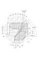
- FIG. 2is an enlarged cross-sectional view of part A in FIG.
- FIG. 3is a partially omitted enlarged schematic view of FIG. 2 .
- FIG. 4is a schematic exploded perspective view of a seat retainer and a ball seat.
- Figure 1shows a central vertical cross-sectional view of the ball valve of the present invention
- Figure 2shows an enlarged cross-sectional view of part A in Figure 1
- Figure 3shows an enlarged schematic view of Figure 2 with some parts omitted.
- valve body 1comprises a body 2, a ball 3, a seat retainer 4, a ball seat 5, a stem 6, and a coil spring 7, and is configured as a trunnion-type ball valve in which a seat retainer 4 having ball seats 5 on both sides of the ball 3 is disposed within the body 2.
- the valve body 1 of this embodimentis particularly suitable for use with high-pressure fluids of class (nominal pressure) 150 to 2500, more preferably class 150 to 1500, and the suitable bore size is 2 inches to 24 inches.
- the body 2has an annular body 10 and caps 11 attached to both sides (upstream and downstream) of the annular body 10, which are made of, for example, carbon steel or stainless steel.
- the annular body 10 and caps 11are fixed together with bolts and nuts 12 to form the body 2, and a flow path 13 is formed inside the body 2.
- a mounting recess 14 for mounting the seat retainer 4is formed on the side of the cap 11 opposite the ball 3.
- the ball 3is rotatably attached within the body 2 via a stem 6 consisting of an upper stem 6a and a lower stem 6b, and a seat retainer 4 having a ball seat 5 is disposed on both the upstream and downstream sides of the ball 3 via a mounting recess 14.
- the ball 3is made of stainless steel, for example, and has a through hole 3a that can communicate with the flow path 13.
- the ball seat 5is formed into a ring shape from a resin material such as PTFE (polytetrafluoroethylene), nylon, or PEEK (polyether ether ketone).
- a resin materialsuch as PTFE (polytetrafluoroethylene), nylon, or PEEK (polyether ether ketone).
- a ring-shaped seal surface 20 with an inclined or rounded cross section that can be sealed to the outer circumferential surface of the ball 3is provided, while on the outer circumferential side of the ball seat 5, a flat outer diameter surface 21 is formed into a ring shape.
- the seat retainer 4includes two retainer members, a first retainer 31 and a second retainer 32 having a function of a retainer ring, i.e., a function of mounting the ball seat 5 to the first retainer 31.
- the first retainer 31 and the second retainer 32are formed into a substantially cylindrical shape from a metal material such as carbon steel or stainless steel.
- the seat retainer 4is assembled together by fixing the rear inner periphery of the second retainer 32 and the outer periphery of the first retainer 31 with a fixing portion 33.
- the front (tip) side of the seat retainer 4is the side facing the ball 3
- the rear (rear end) side of the seat retainer 4is the end side opposite the front (tip).
- the fixing portion 33is provided on the seat retainer 4 so as to be located on the outer diameter side of the outer diameter surface 21 of the ball seat 5.
- This fixing portion 33consists of a female thread 34 formed on the inner circumference of the rear end side of the second retainer 32 and a male thread 35 formed on the outer circumference of the tip end of the first retainer 31, and the first retainer 31 and the second retainer 32 are fixed together by the threaded connection of the female thread 34 and the male thread 35, and the ball seat 5 is movably attached between them.
- a concave seat mounting groove 36 into which the ball seat 5 can be mountedis formed in an annular shape at the tip side of the first retainer 31 of the seat retainer 4, and a tapered surface 37 is formed on the surface of this seat mounting groove 36 that faces the seat tapered surface 22 of the ball seat 5 described above.
- the taper angle ⁇ 1 of this tapered surface 37 with respect to the flow path directionis set to be larger than the taper angle ⁇ 2 of the seat tapered surface 22 with respect to the flow path direction.
- a circular centering surface 40is provided at the position where the first retainer 31 is combined with the second retainer 32, specifically, behind the position of the male thread 35, so that the diameter is larger than that of the male thread 35.
- the outer peripheral surface of the tip side of the first retainer 31 and the inner peripheral surface 42 of the second retainer 32which will be described later, are both shaped to gradually expand or contract from the front, so that all cylindrical surfaces can be processed without changing the grip of each component during processing, making it easy to center each cylindrical surface.
- the centering surface 40is at the outermost diameter position, it can be visually observed from the rear of the tip side of the first retainer 31, and it can be confirmed whether the centering of the surface 40 is properly performed.
- the first retainer 31 and the second retainer 32can be combined in a state where they are accurately centered, so that the ball seat 5 can be fixed in an accurate position, and the sealing performance between the ball seat 5 and the ball 3 can be particularly good.
- the inner circumferential surface 41 of the second retainer 32has an annular inner circumferential surface 42 formed on the forward side where the ball seat 5 is attached, and a protrusion 43 for engaging with the ball seat 5 is formed on the tip of the inner circumferential surface 42 and protrudes toward the inner circumferential surface.
- a centering surface 44is provided that is larger in diameter than the female thread 34 and has approximately the same diameter as the centering surface 40 of the first retainer 31.
- the seat tapered surface 22 of the ball seat 5is fitted into the seat mounting groove 36 of the first retainer 31, and the ball seat 5 is mounted with its outer diameter surface 21 exposed to the outside from the seat mounting groove 36, and in this state, the second retainer 32 is assembled to the first retainer 31.
- the ball seat outer diameter surface 21is held by the leading inner circumferential surface 42 of the second retainer 32, and the protruding portion 43 protruding from the leading inner circumferential surface of the second retainer 32 is engaged with the front side of the ball seat 5 (the side facing the ball 3), preventing the ball seat 5 from jumping out forward.
- the clearance Cmay be formed, for example, with a length of about 0.5 to 1.2 mm in the flow path direction depending on the size of the valve.
- the rear inner circumference of the second retainer 32 and the outer circumference of the first retainer 31are fixed by a fixing portion 33 consisting of a female thread 34 and a male thread 35, and this fixing portion 33 is positioned on the outer diameter side of the outer diameter surface 21 of the ball seat 5. This prevents interference between the inner circumference surface 41 of the second retainer 32 and the outer diameter surface 21 of the ball seat 5 when attaching or detaching the first retainer 31 and the second retainer 32.
- a step surface 50is provided in a direction approximately perpendicular to the flow path 13 between the fixing portion 33 formed by the female thread 34 and male thread 35 and the outer diameter surface 21 of the ball seat 5.
- the first retainer 31has an abutment surface 53 on the tip surface side that abuts against the step surface 50, and this abutment surface 53 is provided so as to extend to the inner diameter side.
- the abutment surface 53is provided so as to be radially longer than the step surface 50, so that when the ball seat 5 is attached to the first retainer 31 and the second retainer 32, a gap S is provided between the outer diameter side rear end 60 of the ball seat 5 and the outer diameter side tip 61 of the first retainer 31. Then, when the second retainer 32 is removed from the first retainer 31, the gap S is exposed to the outer diameter side.
- a gap S of a predetermined sizeis formed in an annular shape in the area between the seat tapered surface 22 and the abutment surface 53.
- step surface 50 and the abutment surface 53abut against each other with their smooth surfaces, it is also possible to align the first retainer 31 and the second retainer 32 in the direction along the flow path 13.
- Thiscombined with the radial centering by the centering surface 40 described above, allows the assembly of the first retainer 31 and the second retainer 32 to be performed with extremely accurate alignment, so that even though the retainer that holds the ball seat 5 is divided into two, the ball seat 5 can be held accurately, making it possible to obtain a high level of sealing with the ball 3.
- the outer diameter surface 21 of the ball seat 5has a single or multiple communication grooves 55 that communicate with the cavity portion 51 provided in the valve body 1.
- three communication grooves 55are provided at equal intervals on the outer diameter surface 21.
- the integrated seat retainer 4is attached to the mounting recess 14 of the cap 11 through the coil spring 7 on the first retainer 31 side, and is assembled into the valve body 1 in a state where it is biased toward the ball 3 by the elastic force of the coil spring 7.
- the seat retainer 4is resiliently biased by the coil spring 7, and the sealing surface 20 of the ball seat 5 attached to the seat retainer 4 is pressed against the outer circumferential surface of the ball 3, ensuring sealing between the ball seat 5 and the ball 3 and preventing fluid leakage.
- valve body 1is configured with a seat retainer 4 having a ball seat 5 on both sides (first and secondary sides) of the ball 3, but the valve body 1 may also be configured with a seat retainer 4 having the aforementioned ball seat 5 on one side of the ball 3.
- the fixing portion 33may have a structure other than a screw connection using the female thread 34 and the male thread 35.
- the fixing portionmay be provided by an interlocking structure, and the first retainer 31 and the second retainer 32 may be fixed by this interlocking fixing portion.
- the gap Scan be provided between the outer diameter rear end 60 of the ball seat 5 and the outer diameter tip 61 of the first retainer 31, and by providing the ball seat 5 and the first retainer 31 in an appropriate combination structure, gaps S of various shapes can be provided between the outer diameter rear end 60 of the ball seat 5 and the outer diameter tip 61 of the first retainer 31.
- pressure equalizing holes 52 indicated by dashed two-dot lines which communicate with a cavity portion 51 provided in the valve body 1may be provided at a predetermined interval near the outer diameter side of the stepped surface 50 of the second retainer 32.
- a groove-like communicating portion 54 indicated by dashed two-dot lines which communicates from the inner diameter side to the outer diameter side of the abutment surface 53 of the first retainer 31 which abuts against the stepped surface 50 of the second retainer 32may be provided at a single or multiple locations, so that when the first retainer 31 and the second retainer 32 are combined, the pressure equalizing hole 52 of the second retainer 32 can be communicated with the above-mentioned gap S via the communicating portion 54. This also allows the gap S in the valve body 1 to communicate with the cavity portion 51 through the communication portion 54 and the pressure equalizing hole 52.
- an appropriate jigcan be inserted into the pressure equalizing hole 52 that is easiest to work on among the multiple pressure equalizing holes 52 provided in multiple locations, and the second retainer 32 can be easily attached and detached relative to the first retainer 31 by rotating the second retainer 32 using the jig. Furthermore, even if no pressure equalizing hole 52 is provided in this manner, it is possible to form a non-through jig hole 56, as shown in Figure 4, in the tip surface of second retainer 32 and use this to easily rotate second retainer 32 using a jig.
- taper angle ⁇ 1 of the taper surface 37is made larger than the angle ⁇ 2 of the seat taper surface 22, these taper angles ⁇ 1 and ⁇ 2 can be set arbitrarily.
- the distance from the center of the flow path 13 to the seal portion 38is long, when pressure is applied to the ball seat 5, the force acts too strongly and the ball seat 5 is likely to pop out, so it is better to keep the distance from the center of the flow path 13 to the seal portion 38 short.
- the ball seat 5is prevented from popping out by the protrusion 43 of the second retainer 32.
- the width of engagement of the protrusion 43 with the ball seat 5the better.
- the widthbe approximately 1/3 of the radial thickness of the ball seat 5.
- the valve body 1 in this embodimentis configured so that a protrusion 43 formed on the second retainer 32 engages with the front side of the ball seat 5 to prevent the ball seat 5 from jumping out forward, so that a ready-made ball seat can be used without special processing such as providing the ball seat 5 with a step for engaging with the second retainer 32, and after the ball seat 5 is attached to the seat retainer 4, it is possible to reliably prevent the ball seat 5 from jumping out or coming loose. Therefore, even when high-pressure fluid flows inside the valve body 1, it is possible to maintain the attached state of the ball seat 5 to the seat retainer 4 and ensure high sealing performance.
- the ball seat 5is pushed to the left (rearward) relative to the first retainer 31 by the force Fx. This causes the seat tapered surface 22 and the tapered surface 37 in the seal portion 38 to come into strong pressure contact, forming a linear seal point, which prevents fluid from leaking from the back side of the seat to the cavity portion 51.
- a force Fyis applied from the outer diameter surface 21 of the ball seat 5 in the direction of the forward inner circumferential surface 42 of the second retainer 32, but the outer diameter surface 21 and the forward inner circumferential surface 42 are in surface contact with each other, and the force from the ball seat 5 to the second retainer is not applied locally, so there is no risk of the vicinity of the outer diameter surface 21 of the ball seat 5 being scratched or damaged.
- the outer diameter surface 21 of the ball seat 5can be held by the front inner peripheral surface 42 of the second retainer 32 with a uniform peripheral surface that has no steps in the depth direction, so that the force in the Fy direction can be effectively received and twisting in the upper left direction that is likely to occur in the ball seat 5 can be suppressed, which is more effective in preventing the ball seat 5 from popping out and allows the ball seat 5 to be positioned more accurately.
- the fixing portion 33 that fixes the rear inner circumference of the second retainer 32 and the inner circumference of the first retainer 31is located on the outer diameter side of the outer diameter surface 21 of the ball seat 5, so that the inner circumference surface 41 of the second retainer 32 and the outer diameter surface 21 of the ball seat 5 do not interfere with each other when the first retainer 31 and the second retainer 32 are attached and detached, so there is no risk of the second retainer 32 scratching and damaging the area near the outer diameter surface 21 of the ball seat 5.
- Thismakes it possible to replace the ball seat 5 while maintaining this functionality, while ensuring high sealing performance by forming the ball seat 5 from a resin material. In this way, since it is necessary to replace only the ball seat 5 of the seat retainer 4 and there is no need to replace the first retainer 31 and the second retainer 32, it is also possible to reuse these first and second retainers 31 and 32.
- the inner peripheral surface 41 of the second retainer 32 and the outer diameter surface 21 of the ball seat 5are in radially offset positions, so when the second retainer 32 is screwed into the first retainer 31, the inner peripheral surface 41 (female thread 34) is prevented from coming into contact with the ball seat 5 and the second retainer 32 is prevented from being installed in an inclined state, and no unnecessary resistance is applied when screwing, resulting in excellent maintainability.
- the centering surface 40 of the first retainer 31 and the centering surface 44 of the second retainer 32come into close contact with each other, and these centering surfaces 40, 44 absorb the radial play caused by the engagement of the male thread 35 and the female thread 34, preventing radial misalignment and rattling, and allowing the first retainer 31 and the second retainer 32 to be integrated while being accurately centered. Therefore, the ball seat 5 attached to the seat retainer 4 can be positioned in a centered state with respect to the ball 3, and the ball seat 5 and ball 3 maintain their accurate contact position during the operation of the valve body 1 from closing to opening, providing excellent sealing properties.
- a seat retaineris made of a single member, so the holding portion of the ball seat is easy to form without misalignment.
- the ball seat 5is held by two members, the first retainer 31 and the second retainer 32, so that positioning of the ball seat 5 is not usually easy.
- the first retainer 31 and the second retainer 32can be accurately positioned by the centering surface 40 and the surface contact between the step surface 50 and the abutment surface 53, so that the ball seat 5 can also be held in the correct position.
- the ball seat 5is attached so as to be sandwiched between the first retainer 31 and the second retainer 32. As described above, this ball seat 5 is a ready-made part, and there is no need to process special shapes such as steps. When fluid pressure is applied, there is no risk of the force being concentrated on one part of the ball seat 5 as would be the case if a step or the like were provided. This prevents deformation or damage to the ball seat 5 and maintains the sealing properties, and also makes it easy to remove the ball seat 5 from the first retainer 31 and the second retainer 32.
- the tapered seat surface 22is formed on the back side of the ball seat 5, and the tapered surface 37 is formed on the seat mounting groove 36.
- the taper angle ⁇ 1 of the tapered surface 37is made larger than the taper angle ⁇ 2 of the seat tapered surface 22.
- the ball seat 5is mounted in the seat mounting groove 36 in a wedge shape, so that the ball seat 5 is firmly mounted to the first retainer 31 by a wedge action.
- the ball seat 5 and the first retainer 31form a linear seal portion 38 in the seat mounting groove 36, so that the surface pressure can be improved by this linear seal portion 38.
- the sealing pressure of the seal portion 38also increases, so that leakage of fluid from the back side of the ball seat 5, i.e., so-called back leakage, can be reliably prevented even for high-pressure fluids.
- the outer end 22a of the seat tapered surface 22is abutted halfway against the tip inner circumferential surface 42 of the second retainer 32, and the abutment surface 53 where the tip surface of the first retainer 31 abuts is extended toward the inner diameter side with respect to the step surface 50 between the fixing portion 33 and the outer diameter surface 21, forming a gap S in the area between the seat tapered surface 22 and the abutment surface 53, so that this gap S can be formed in a shape that widens toward the outer diameter.
- the gap Sis exposed to the outer diameter side when the second retainer 32 is removed from the first retainer 31, so that even if the ball seat 5 is pressed into the seat mounting groove 36 of the first retainer 31 by the fluid pressure, the second retainer 32 can be removed from the first retainer 31, and the ball seat 5 can be easily removed by easily hooking a fingertip or a tool on the part of the ball seat 5 exposed to the outside from the exposed gap S.
- the second retainer 32has a stepped surface 50, and the gap S is connected to the cavity portion 51 in the valve body 1. Therefore, even if pressure infiltrates the back side of the ball seat 5 from between the ball seat 5 and the second retainer 32 when the valve is fully open, the pressure in the gap S on the back side of the ball seat 5 can be kept equal to the pressure in the cavity portion 51. This prevents pressure from building up on the back side of the ball seat 5, and prevents the generation of a force in the pushing direction on the ball seat 5 due to the accumulation of this fluid pressure, reliably preventing the ball seat 5 from popping out.
- the fixing portion 33is fixed by a screw connection between the female thread 34 of the second retainer 32 and the male thread 35 of the first retainer 31. Therefore, by attaching the ball seat 5 to the second retainer 32 in a temporary attachment state and then attaching the first retainer 31 to the second retainer 32 by screw connection, the ball seat 5 can be positioned in a predetermined position relative to the seat retainer 4 and then accurately integrated.
Landscapes
- Engineering & Computer Science (AREA)
- General Engineering & Computer Science (AREA)
- Mechanical Engineering (AREA)
- Taps Or Cocks (AREA)
Abstract
Description
Translated fromJapanese本発明は、ボールバルブに関し、特に、シートリテーナを介してボールシートをボデーに装着する構造のボールバルブに関する。The present invention relates to a ball valve, and in particular to a ball valve in which a ball seat is attached to a body via a seat retainer.
この種の構造のボールバルブとして、例えば、トラニオン型ボールバルブが知られている。トラニオン型ボールバルブでは、弁座となるボールシートがシートリテーナに保持された状態でボデーに装着され、シートリテーナがスプリングの弾発力で弾発され、ボールシートがボールに押し付けられることにより、流体が封止されるようになっている。このような構造のトラニオン型ボールバルブは、高いシール性を発揮可能であり、特に、高圧流体に適している。A known example of a ball valve with this type of structure is the trunnion type ball valve. In a trunnion type ball valve, the ball seat that serves as the valve seat is attached to the body while being held by a seat retainer, and the seat retainer is resilient due to the elastic force of a spring, pressing the ball seat against the ball to seal the fluid. Trunnion type ball valves with this type of structure are capable of exhibiting high sealing performance and are particularly suitable for high-pressure fluids.
トラニオン型ボールバルブにおいて、上記のようにボールシートがシートリテーナに装着された構造であるときには、高圧流体により差圧が発生した場合などが原因で、ボールシートがシートリテーナから飛出したり外れたりする可能性がある。
これを防ぐため、例えば、特許文献1におけるボールバルブが開示されている。このボールバルブでは、シートリテーナであるシートホルダの先端部に半径方向外側に突出する係止部が形成されたシートを嵌装し、このシートを挟持して、シートホルダの先端部にシート抑えリングで螺合固定し、シート抑えリングに形成した被係止部をシートの係止部と係合して、シートの抜け止めを図ろうとするものである。In a trunnion type ball valve, when the ball seat is attached to the seat retainer as described above, there is a possibility that the ball seat may fly out or come off the seat retainer due to a pressure difference caused by high-pressure fluid, etc.
To prevent this, for example,
ところで、一般に、ボールバルブのボールシートは摩耗部品であり、特に、高圧用のトラニオンバルブのボールシートが樹脂材料で形成されている場合には消耗が進みやすい。このことから、ボールシートは定期的な交換が必要になることがあり、その場合、ボールシートが装着されたシートホルダ全体を交換すると無駄が大きくなるため、ボールシートのみを交換することが要望されている。そのため、例えば、特許文献1の場合には、シートリテーナからシート抑えリングを取外すことにより、シートリテーナからシートを外してこのシートを交換可能になっている。In general, the ball seat of a ball valve is a wear part, and is particularly susceptible to wear when the ball seat of a high-pressure trunnion valve is made of a resin material. For this reason, the ball seat may need to be replaced periodically. In such cases, replacing the entire seat holder to which the ball seat is attached would result in a large amount of waste, so it is desirable to replace only the ball seat. For this reason, for example, in the case of
しかしながら、特許文献1のボールバルブにおいては、係止部が半径方向に突出したシートをシートホルダに嵌装し、シートホルダに形成された雄ネジ部と、シート抑えリングの雌ネジ部とを螺合してこれらを固定するとき、シートホルダの後端側の内径は、シートの係止部の外径と略等しく設定された構造になっている。この構造から、シート抑えリングをシートホルダに着脱する際には、その雌ネジ部は、係止部を中心にシートに干渉しやすくなる。However, in the ball valve of
これにより、シートホルダとシート抑えリングとの着脱時に、シート抑えリングでボールシートを傷付ける可能性があり、新規のボールシートに交換した場合であっても十分なシール性能を発揮できない場合がある。特に、ボールシートが樹脂材料で形成されている場合、よりボールシートが傷付きやすくなる。As a result, when attaching or detaching the seat holder and the seat retaining ring, the seat retaining ring may damage the ball seat, and even if the ball seat is replaced with a new one, it may not be able to provide sufficient sealing performance. In particular, if the ball seat is made of a resin material, the ball seat is more likely to be damaged.
これに加えて、上記のように、シートホルダとシート抑えリングとの装着方向(軸方向)において、雄ネジ部と雌ネジ部とによる螺合部分と、シートの係止部の外径とが、直線上に並んだ状態であるため、これらの着脱時において、雌ネジ部がボールシートに干渉してシート抑えリングがシートホルダに対して傾いた状態で装着されたり、螺合時の抵抗が大きくなったりして、着脱作業が困難になる場合がある。In addition, as mentioned above, in the installation direction (axial direction) of the seat holder and seat retaining ring, the screwed portion of the male and female threads and the outer diameter of the seat's locking portion are aligned in a straight line. This means that when attaching or detaching these, the female threads may interfere with the ball seat, causing the seat retaining ring to be installed at an angle to the seat holder, or resistance to screwing may increase, making the installation and removal process difficult.
本発明は、上記の課題点を解決するために開発したものであり、その目的とするところは、ボールシートのシートリテーナからの飛出しを防止でき、ボールシートの装着時には、ボールシートを傷付けることなく簡便に着脱して交換でき、装着後には高圧流体に対しても高いシール性を発揮するボールバルブを提供することにある。The present invention was developed to solve the above problems, and its purpose is to provide a ball valve that can prevent the ball seat from jumping out of the seat retainer, can be easily attached, detached, and replaced without damaging the ball seat, and has high sealing properties against high-pressure fluids after installation.
上記目的を達成するため、請求項1に係る発明は、ボデー内に貫通孔を有するボールの一方又は双方にボールシートを有するシートリテーナを配設したボールバルブであって、シートリテーナは、第1リテーナと第2リテーナを組合わせて構成され、第1リテーナの先端側に形成したシート装着溝にボールシートの外径面を露出させた状態で装着し、外径面を第2リテーナの先方内周面で保持し、かつ第2リテーナの先端内周面に突出した突出部をボールシートに係止してボールシートの前方への飛出しを防止すると共に、第2リテーナの後方内周と第1リテーナの外周とを固定部で固定し、固定部をボールシートの外径面より外径側に位置させ、第1リテーナと第2リテーナを着脱する際に、第2リテーナの内周面とボールシートの外径面が干渉しないようにしたボールバルブである。In order to achieve the above object, the invention according to
請求項2に係る発明は、第1リテーナの外周面と第2リテーナの内周面との組み合わせ位置に、同一径のそれぞれの芯合せ面を設け、各芯合せ面で正確な芯合せをしたボールバルブである。The invention of
請求項3に係る発明は、ボールシートの外径側後端と第1リテーナの外径側先端との間に隙間を設け、第2リテーナを第1リテーナから取り外した際に当該隙間が外径側に露出するようにしたボールバルブである。The invention of
請求項4に係る発明は、ボールシートの背面側にボール側に向けて傾斜するシートテーパ面を形成し、このシートテーパ面と対向するシート装着溝の面にテーパ面を形成し、テーパ面のテーパ角度をシートテーパ面のテーパ角度より大きくしてボールシートがシート装着溝にくさび状に装着されると共に両者がシート装着溝内で線状のシール部を形成したボールバルブである。The invention of
請求項5に係る発明は、シートテーパ面の外端を第2リテーナの先方内周面の途中に当接させ、固定部と外径面との段差面に対して第1リテーナの先端面が当接する当接面を内径側に延出させてシートテーパ面と当接面の領域に隙間を形成したボールバルブである。The invention of
請求項6に係る発明は、固定部は、第2リテーナの雌ねじと第1リテーナの雄ねじとのねじ結合で固定したボールバルブである。The invention according to
請求項1に係る発明によると、第1リテーナのシート装着溝にボールシートの外径面を露出させた状態で装着し、この外径面を第2リテーナの先方内周面で保持し、かつ第2リテーナの先端内周面の突出部をボールシートに係止してボールシートの前方への飛出しを防止しているので、シートリテーナからの飛出しや外れたりすることを防ぎつつボールシートを装着でき、このようなシートリテーナを用いたボールシートの取付け構造によって高圧流体に対しても高いシール性を維持する。しかも、第2リテーナの後方内周と第1リテーナの外周とを固定部で固定し、この固定部をボールシートの外径よりも外径側に位置させ、第1リテーナと第2リテーナとの着脱時に、第2リテーナの内周面とボールシートの外径面とが干渉しないようにしているので、ボールシートの装着時には、ボールシートを傷付けることなく簡便にこのボールシートを着脱して交換でき、装着後には、高圧流体に対しても高いシール性を発揮することが可能となる。According to the invention of
請求項2に係る発明によると、第1リテーナの外周面と第2リテーナの内周面との組み合わせ位置に、同一径のそれぞれの芯合せ面を設け、各芯合せ面で正確な芯合せをしているので、これら第1リテーナと第2リテーナの後方側をこれらの固定位置とし、この固定位置で両者を同芯上に位置合わせした状態で取付けできる。これにより、これら第1リテーナと第2リテーナとの間にボールシートを正確に位置決めした状態で装着し、このボールシートをボールに対して正確な位置に配置してシール性を確保できる。According to the invention of
請求項3に係る発明によると、ボールシートの外径側後端と第1リテーナの外径側先端との間に隙間を設け、第2リテーナを第1リテーナから取り外した際に当該隙間が外径側に露出するようにしたことで、第1リテーナから第2リテーナを取外したときには、それまで第2リテーナに保持されていたボールシートの外周面の露出に伴って、隙間に位置していたボールシートの外径側後端も露出させることができる。これにより、この外径側後端部位を通して、ボールシートを第1リテーナのシート装着溝から容易に取り外し可能になる。さらには、ボールシートがシート装着溝にくさび状に嵌め込まれて強く固定されている場合であっても、ボールシートの露出部分からこのボールシートと第1リテーナとの線状の接触部分に対して力を加えることで、てこの原理により軽い力で簡単にボールシートを取外すことが可能となり、メンテナンス性に優れている。According to the invention of
請求項4に係る発明によると、第1リテーナのシート装着溝のテーパ面のテーパ角度を、ボールシートのシートテーパ面のテーパ角度より大きくしてボールシートをシート装着溝にくさび状に装着していることで、ボールシートがボールに押し付けられたり、前方側から流体圧が加わったりする際には、ボールシートがシート装着溝にくさび状に押し込まれ、これら傾斜角度の異なるテーパ面とシートテーパ面との間に接触面積の少ない線状のシール部を形成することで当接時の圧力を向上し、ボールシート後方とシート装着溝との間からの流体の漏れ、いわゆる背面漏れを効果的に抑制できる。According to the invention of
請求項5に係る発明によると、シートテーパ面の外端を第2リテーナの先方内周面の途中に当接させ、第1リテーナと第2リテーナとの固定部とボールシートの外径面との段差面に対して、第1リテーナの先端面が当接する当接面を内径側に延出させることにより、シートテーパ面の先方側を第1リテーナの先端面よりも先方に突出させて、シートテーパ面と当接面の領域に所定の隙間を形成できる。このように、第1リテーナの先端面とシートテーパ面とを所定の位置関係とすることで所定の大きさの隙間を形成でき、第1リテーナから第2リテーナを取外したときには、それまで第2リテーナに保持されていたボールシートの外周面の露出に伴って、隙間に位置していたボールシートのシートテーパ面の一部も露出させることができる。これにより、隙間や外部に露出した部分を通して、ボールシートを第1リテーナのシート装着溝から容易に取り外し可能になる。さらには、ボールシートがシート装着溝にくさび状に嵌め込まれて強く固定されている場合であっても、ボールシートの露出部分からこのボールシートと第1リテーナとの線状の接触部分に対して力を加えることで、てこの原理により軽い力で簡単にボールシートを取外すことが可能となり、メンテナンス性に優れている。According to the invention of
請求項6に係る発明によると、固定部は、第2リテーナの雌ねじと第1リテーナの雄ねじとのねじ結合で固定し、この固定部により第2リテーナの後方内周と第1リテーナの外周とを固定しているので、バルブのキャビティ部側に対して固定部をボールシートの二次側に配置し、固定部への流体の接触を回避して耐腐食性を向上できる。第2リテーナと第1リテーナとを固定するために別途ボルト等の固定部材を必要としたり、この固定部材への耐腐食性の処理を施したり必要がなく、複数のボルトで固定する場合などに比較して、第1リテーナに対して第2リテーナを回転させるようにしてワンタッチで簡便に着脱でき、部品点数の増加も抑えることができる。According to the invention of
以下に、本発明におけるボールバルブの一実施形態を図面に基づいて詳細に説明する。図1は、本発明のボールバルブの中央縦断面図、図2は、図1におけるA部拡大断面図、図3は、図2の一部省略拡大模式図を示している。Below, one embodiment of the ball valve of the present invention will be described in detail with reference to the drawings. Figure 1 shows a central vertical cross-sectional view of the ball valve of the present invention, Figure 2 shows an enlarged cross-sectional view of part A in Figure 1, and Figure 3 shows an enlarged schematic view of Figure 2 with some parts omitted.
図において、ボールバルブ(以下、バルブ本体1という)は、ボデー2、ボール3、シートリテーナ4、ボールシート5、ステム6、コイルスプリング7を備え、ボデー2内に、ボール3の双方にボールシート5を有するシートリテーナ4が配設された構造のトラニオン型ボールバルブの態様を成している。本実施形態のバルブ本体1は、特に、クラス(呼び圧力)150~2500、より好ましくはクラス150~1500の高圧流体用として用いる場合に適しており、また、口径としては2インチ~24インチが好適である。In the figure, the ball valve (hereafter referred to as valve body 1) comprises a
ボデー2は、環状ボデー10と、この環状ボデー10の両側(上下流側)に装着されるキャップ11とを有し、これらは、例えば炭素鋼やステンレス材料などにより設けられる。これら環状ボデー10とキャップ11とは、ボルトナット12によって一体に固着されてボデー2が構成され、このボデー2の内部に流路13が構成される。キャップ11におけるボール3との対向側には、シートリテーナ4装着用の装着凹部14が形成される。The
ボデー2内には、上ステム6a、下ステム6bからなるステム6を介してボール3が回動可能に取付けられ、このボール3の双方、すなわち上下流側には、ボールシート5を有するシートリテーナ4が装着凹部14を介して配設された構成になっている。ボール3は、例えばステンレス鋼を材料として形成され、流路13と連通可能な貫通孔3aを有している。The
ボールシート5は、例えばPTFE(ポリテトラフルオロエチレン)やナイロン、PEEK(ポリエーテルエーテルケトン)などの樹脂材料により環状に形成される。ボールシート5のボール3との当接側には、このボール3の外周面にシール可能な断面傾斜状、或は断面アール状の環状シール面20が設けられ、一方、ボールシート5の外周側には、フラット状の外径面21が環状に形成されている。The
ボールシート5の背面、すなわち、シートリテーナ4への装着側には、ボール3側に向けて傾斜する、換言すると、その後方が、後方に向かって外径側から内径側に向けて傾斜する、シートテーパ面22が環状に形成される。The back surface of the
図2~図4に示すように、シートリテーナ4は、第1リテーナ31と、リテーナリングの機能、すなわち第1リテーナ31にボールシート5を装着する機能を有する第2リテーナ32とからなる2つのリテーナ部材を備えている。これら第1リテーナ31、第2リテーナ32は、炭素鋼或はステンレス材料などの金属材料によって略円筒状に形成される。シートリテーナ4は、第2リテーナ32の後方内周と、第1リテーナ31の外周とが固定部33で固定されることで、一体に組合わせられる。
本実施形態において、シートリテーナ4の先方(先端)側とは、ボール3との対向側であり、シートリテーナ4の後方(後端)側とは、先端(先方)との他端側をいう。2 to 4, the
In this embodiment, the front (tip) side of the
固定部33は、ボールシート5の外径面21よりも外径側に位置するようにシートリテーナ4に設けられる。この固定部33は、第2リテーナ32の後端側内周に形成された雌ねじ34と、第1リテーナ31の先端外周に形成された雄ねじ35とからなり、これら雌ねじ34と雄ねじ35とによるねじ結合により、第1リテーナ31と第2リテーナ32とを固定し、これらの間にボールシート5が可動できる状態で装着されている。The
シートリテーナ4の第1リテーナ31の先端側には、ボールシート5を装着可能な凹状のシート装着溝36が環状に形成され、このシート装着溝36において、前述したボールシート5のシートテーパ面22と対向する面には、テーパ面37が形成されている。このテーパ面37の流路方向に対するテーパ角度θ1は、シートテーパ面22の流路方向に対するテーパ角度θ2よりも大きくなるように設けられる。これにより、ボールシート5のシートリテーナ4への装着時には、ボールシート5は、シート装着溝36に対してくさび状に装着され、これと共に、装着後には、シートテーパ面22とテーパ面37とが環状に線接触した状態となり、これによって、線状のシール部38が、ボールシート5と第2リテーナ32との間に環状に形成される。A concave
第1リテーナ31の外周面における第2リテーナ32との組み合わせ位置、具体的には、雄ねじ35の位置よりも後方側には、この雄ねじ35よりも拡径するように環状の芯合せ面40が設けられている。このように、第1リテーナ31の先端側の外周面、及び第2リテーナ32の後述する先方内周面42ともに、前方から段階的に拡径又は縮径する形状となっているため、加工の際には各部材を把持した状態で持ち変えることなく、全ての円筒面を加工することができ、各円筒面の芯合わせが容易となる。また、芯合せ面40が最外径位置になるので、第1リテーナ31の先端側の後方から目視でき、当該面40の芯合わせが正常になされているか、確認できる。これらにより、第1リテーナ31と第2リテーナ32を正確に芯合わせした状態で組み合わせることができるので、ボールシート5を正確な位置で固定することが可能となり、ボールシート5とボール3とのシール性が特に良好に得られるようになる。A circular centering
第2リテーナ32の内周面41において、ボールシート5取付け側となる先方側には、環状の先方内周面42が形成され、この先方内周面42の先端側にはボールシート5に係止するための突出部43が、内周側に向けて突出形成されている。The inner
第2リテーナ32の内周面における第1リテーナ31との組み合わせ位置、具体的には、雌ねじ34の位置よりも後端側には、この雌ねじ34よりも拡径するようにして、上記第1リテーナ31の芯合せ面40と略同一径の芯合せ面44が設けられる。At the position on the inner circumferential surface of the
雌ねじと34と雄ねじ35との螺合時には、略同一径である、第2リテーナ32の芯合せ面44と第1リテーナ31の芯合せ面40とが密接した状態となり、第2リテーナ32と第1リテーナ31とが、各芯合せ面44、40で正確な芯合せをした状態で組み込まれる。When the
前述した第1リテーナ31に、ボールシート5、第2リテーナ32を組み合わせるときには、第1リテーナ31のシート装着溝36にボールシート5のシートテーパ面22を嵌め込むようにして、ボールシート5の外径面21をシート装着溝36から外部に露出させた状態で装着し、この状態で、第1リテーナ31に第2リテーナ32を組み付けるようにする。その際、ボールシート外径面21を第2リテーナ32の先方内周面42で保持し、かつ第2リテーナ32の先端内周面に突出した突出部43を、ボールシート5の前面側(ボール3との対向側)に係止して、ボールシート5の前方への飛出しを防止する。When assembling the
組付け後のボールシート5と第1リテーナ31との間には、適宜の大きさのクリアランスCが設けられ、ボールシート5は、クリアランスCを介して流路方向に移動可能に設けられている。クリアランスCは、例えば、流路方向にバルブのサイズに応じて0.5~1.2mm程度の長さによって形成されているとよい。After assembly, an appropriate amount of clearance C is provided between the
この場合、第2リテーナ32の後方内周と、第1リテーナ31の外周とを、雌ねじ34と雄ねじ35とによる固定部33で固定し、この固定部33をボールシート5の外径面21より外径側に位置させている。これにより、第1リテーナ31と第2リテーナ32とを着脱する際に、第2リテーナ32の内周面41と前記ボールシート5の外径面21とが干渉しないようにしている。In this case, the rear inner circumference of the
ボールシート5のシートリテーナ4への装着後には、シートテーパ面22の外端22aが、第2リテーナ32の先方内周面42の途中に当接されるように設けられる。第2リテーナ32において、雌ねじ34と雄ねじ35とによる固定部33とボールシート5の外径面21との間には、流路13と略直交する方向に段差面50が設けられている。After the
第1リテーナ31には、前記の段差面50に対して当接する当接面53が先端面側に設けられ、この当接面53は、内径側に延出するように設けられる。このように、段差面50よりも当接面53が径方向に長くなるように設けられていることで、第1リテーナ31と第2リテーナ32に対してボールシート5を装着するときには、ボールシート5の外径側後端60と第1リテーナ31の外径側先端61との間に隙間Sを設けている。そして、第2リテーナ32を第1リテーナ31から取り外した際に、当該隙間Sが外径側に露出するようにしている。本実施形態では、シートテーパ面22と当接面53との間の領域に、所定の大きさの隙間Sが環状に形成される。The
また、段差面50と当接面53とが互いに平滑な面同士で突き当たることで、第1リテーナ31と第2リテーナ32との流路13に沿う方向の位置合わせも可能となる。これにより、上述した芯合せ面40による径方向の芯合わせと相まって、第1リテーナ31と第2リテーナ32の組立てが極めて正確に位置合わせされて行われるようになるため、ボールシート5を保持するリテーナが2つに分割されているにもかかわらず、ボールシート5を正確な維持で保持することができ、ボール3との高いシール性を得ることが可能となる。In addition, because the
ボールシート5の外径面21には、バルブ本体1内に設けられるキャビティ部51と連通する連通溝55が複数又は単数箇所に設けられ、本実施形態では、図4において、外径面21の3箇所に等間隔で設けられる。第1リテーナ31と第2リテーナ32とを組合わせたときには、この連通溝55が、上記隙間Sと連通され、これによって、バルブ本体1において、隙間Sは、キャビティ部51と連通されている。The
上記の一体化されたシートリテーナ4は、第1リテーナ31側がキャップ11の装着凹部14にコイルスプリング7を通して装着され、このコイルスプリング7の弾発力によりボール3側に付勢された状態でバルブ本体1に組み込まれる。
この構成により、バルブ本体1において、コイルスプリング7によりシートリテーナ4が弾発付勢され、シートリテーナ4に装着されたボールシート5のシール面20がボール3の外周面に圧接されて、これらボールシート5とボール3との封止性が確保されて、流体の漏れが防がれる。The
With this configuration, in the
なお、上記実施形態において、バルブ本体1は、ボール3の双方(一、二次側)にボールシート5を有するシートリテーナ4が配設された構成になっているが、バルブ本体1は、ボール3の一方に前述したボールシート5を有するシートリテーナ4が設けられた構成であってもよい。In the above embodiment, the
第1リテーナ31と第2リテーナ32との間にボールシート5を装着してシートリテーナ4を構成する態様であれば、固定部33は、雌ねじ34と雄ねじ35とによるねじ結合以外の構造であってもよく、例えば、固定部を嵌合構造によって設け、この嵌合による固定部により、第1リテーナ31と第2リテーナ32とを固定するようにしてもよい。If the
隙間Sは、ボールシート5の外径側後端60と第1リテーナ31の外径側先端61との間に設けるようにすればよく、これらボールシート5と第1リテーナ31とを適宜の組み合わせ構造に設けることで、ボールシート5の外径側後端60と第1リテーナ31の外径側先端61との間に各種形状の隙間Sを設けることもできる。The gap S can be provided between the outer diameter
これにより、上述したようなボールシート5の外径面21に設ける連通溝55に代えて、例えば、図2~図4に示すように、第2リテーナ32の段差面50の外径側付近に、バルブ本体1内に設けられるキャビティ部51と連通する二点鎖線で示した均圧穴52を、複数個所に所定間隔で貫通して設けるようにしてもよい。この場合、第2リテーナ32の段差面50に対して当接する第1リテーナ31の当接面53には、この当接面53の内径側から外径側まで連通する溝状の二点鎖線で示した連通部54を、複数又は単数箇所に設けることで、第1リテーナ31と第2リテーナ32を組み合わせた際に、第2リテーナ32の均圧穴52を、連通部54を介して上述した隙間Sと連通させることができる。これによっても、バルブ本体1において、隙間Sを、連通部54、均圧穴52を通してキャビティ部51と連通することができる。
なお、本実施形態では、説明の便宜上、キャビティ部51と隙間S(ボールシート5の背面)とを連通させる構造として、連通溝55(破線)を設ける場合と、均圧穴52及び連通部54(二点鎖線)を設ける場合との両方を同じ図中に示したが、実際には、これらの場合のうちいずれか一方のみ適用すればよい。2 to 4, instead of the communicating
In this embodiment, for ease of explanation, both the case where a communicating groove 55 (dashed line) is provided and the case where a
この場合、複数箇所に設けた均圧穴52のうち、作業のしやすい均圧穴52に適宜の治具を挿入し、第1リテーナ31に対して第2リテーナ32を、治具を用いて回転させることで容易に着脱することが可能となる。
また、このように均圧穴52を設けない場合でも、第2リテーナ32の先端面に、貫通させない図4に示す治具穴56を形成し、これを利用して治具による第2リテーナ32の回転を容易に行うことも可能である。In this case, an appropriate jig can be inserted into the
Furthermore, even if no
テーパ面37のテーパ角度θ1は、シートテーパ面22の角度θ2よりも大きくなるようにすれば、これらの各テーパ角度θ1、θ2は、任意に設定することができる。これにより、バルブ本体1の口径や流体圧の大きさなどに応じて、線状シール部38を径方向の任意の位置に設定することが可能となる。その際、流路13の中心からシール部38までの距離を長くすると、ボールシート5に圧力が加わるときにその力が大きく働いてボールシート5が飛び出しやすくなるため、流路13の中心からシール部38までの距離は短いほうがよい。
また、ボールシート5の飛び出しは、第2リテーナ32の突出部43によって防止されるが、この飛び出し防止効果を良好に得る観点からは、突出部43のボールシート5へのかかり幅は大きいほど良いが、ボール3の動作に干渉しないようにするため、ボールシート5の径方向の厚みの1/3程度とすることが好ましい。As long as the taper angle θ1 of the
In addition, the
次いで、本発明の上記実施形態におけるバルブ本体1の作用を説明する。
図1~図3において、本実施形態におけるバルブ本体1は、第2リテーナ32に形成した突出部43を、ボールシート5の前面側に係止してボールシート5の前方への飛出しを防止する構成としているので、ボールシート5に対して第2リテーナ32への係止用の段部等の特殊な加工を施すことなく既製のボールシートを使用でき、ボールシート5のシートリテーナ4への取付け後には、その飛出しや抜け出しを確実に防止できる。そのため、バルブ本体1内に高圧流体が流れる場合であっても、シートリテーナ4へのボールシート5の取付け状態を維持して高シール性を確保することが可能となる。Next, the operation of the
1 to 3, the
この場合、弁開時において、流路13側に流体圧が加わると、隙間Sからキャビティ部51側に流体が流れようとする。この流体圧やシール時の圧力により、図2、図3において、ボールシート5には、矢印に示すような左斜め上方向の力Fが働き、この力Fは、力Fx、力FyによるX方向とY方向のベクトルとして作用する。これは、ボールシート5のシールポイントに加わる力の例であり、その他ボールシート5の流体と接する全ての部位に流体圧が加わることになる。In this case, when fluid pressure is applied to the
前述したように、ボールシート5と第1リテーナ31との間には、クリアランスCが設けられているので、ボールシート5は、力Fxによって第1リテーナ31に対して左方向(奥方向)に押し込まれる。これによって、シール部38においてシートテーパ面22とテーパ面37とが強く圧接し、線状のシールポイントが構成されることで、シート背面側からキャビティ部51側への流体の漏れ出しが防がれる。As mentioned above, because there is a clearance C between the
このとき、ボールシート5の外径面21から第2リテーナ32の先方内周面42の方向に力Fyが加わるが、これら外径面21と先方内周面42とは面接触によって当接し、ボールシート5から第2リテーナに対して力が局所的に働くことがないため、ボールシート5の外径面21付近が傷付いたり破損したりするおそれがない。At this time, a force Fy is applied from the
また、このように、本実施形態によれば、ボールシート5の外径面21を、第2リテーナ32の先方内周面42によって、奥行方向に段差などが無い均一な周面によって保持することが可能となるので、Fy方向の力を良好に受けることができ、ボールシート5に生じやすい左上方向へのねじれも抑制可能となるため、ボールシート5の飛び出し防止に一層有利となるほか、ボールシート5がより正確に位置決めされるようになる。In addition, according to this embodiment, the
第2リテーナ32の後方内周と第1リテーナ31の内周とを固定する固定部33を、ボールシート5の外径面21よりも外径側に位置するように設け、第1リテーナ31と第2リテーナ32との着脱時に、第2リテーナ32の内周面41とボールシート5の外径面21とが干渉しないようにしているので、第2リテーナ32によってボールシート5の外径面21付近を傷つけてダメージを与えるおそれがない。これにより、ボールシート5を樹脂材料によって形成して高いシール性能を確保しつつ、この機能性を維持した状態でボールシート5を交換可能となる。このように、シートリテーナ4のボールシート5のみを交換し、第1リテーナ31と第2リテーナ32は交換する必要がないことから、これら第1、第2リテーナ31、32をそれぞれ再利用することもできる。The fixing
上記のように、第2リテーナ32の内周面41とボールシート5の外径面21とが径方向にずれた位置にあるため、第1リテーナ31への第2リテーナ32の螺子込み時には、その内周面41(雌ねじ34)がボールシート5に接触して第2リテーナ32が傾いた状態で装着されることを防止でき、螺合時に余計な抵抗が加わることもないため、メンテナンス性に優れている。As described above, the inner
第1リテーナ31と第2リテーナ32との固定時には、第1リテーナ31の芯合せ面40と、第2リテーナ32の芯合せ面44とが密接し、これらの芯合せ面40、44で、雄ねじ35と雌ねじ34との螺合による径方向のあそびを吸収し、径方向のずれやがたつきを防いだ状態で、第1リテーナ31と第2リテーナ32とを正確に芯合せしながら一体化できる。そのため、シートリテーナ4に装着したボールシート5を、ボール3に対して芯出しした状態で配置でき、バルブ本体1の弁閉から弁開までの動作において、ボールシート5とボール3との正確な当り位置を保持して優れたシール性を発揮する。When the
ボールバルブにおいて、ボール3とボールシート5との当たり位置が正確に規定されることは、確実なシール性を得るために重要であり、そのためには、ボールシートがシートリテーナ等において正確な位置に保持されていることが重要となる。通常、シートリテーナは単一の部材によって構成されるので、ボールシートの保持部はずれなく形成しやすい。本実施形態では、第1リテーナ31と第2リテーナ32という2部材によってボールシート5を保持しているので、通常であれば、ボールシート5の位置決めが容易ではない。これに対し、上述したように、本実施形態においては、芯合わせ面40、並びに、段差面50と当接面53との面当たりによって、第1リテーナ31と第2リテーナ32とが正確に位置決めできるので、ボールシート5も正しい位置にて保持可能となる。In a ball valve, it is important to accurately determine the contact position between the
第1リテーナ31と第2リテーナ32との間にボールシート5を挟むように取付けたボールシート5の装着構造であり、このボールシート5は、前述したように既製の部品を用いることで、段部等の特殊な形状を加工する必要もない。流体圧が加わった場合には、この流体圧によって段部等を設けた場合のようにボールシート5の一部分に集中して力が加わるおそれがないため、ボールシート5の変形や損傷を防いでシール性を維持できると共に、ボールシート5の第1リテーナ31、第2リテーナ32からの取り外しも容易である。The
ボールシート5の背面側にシートテーパ面22、シート装着溝36にテーパ面37をそれぞれ形成し、テーパ面37のテーパ角度θ1をシートテーパ面22のテーパ角度θ2より大きくし、ボールシート5をシート装着溝36にくさび状に装着しているので、ボールシート5を第1リテーナ31にくさび作用によって強固に装着し、これらボールシート5と第1リテーナ31とによってシート装着溝36内に線状のシール部38を形成しているので、この線状シール部38により面圧力を向上できる。しかも、流体圧の上昇に伴ってシール部38のシール圧力も向上するので、高圧流体に対しても、ボールシート5の背面側からの流体の漏れ、いわゆる裏漏れを確実に阻止できる。The tapered
シートテーパ面22の外端22aを第2リテーナ32の先方内周面42の途中に当接させ、固定部33と外径面21との段差面50に対して、第1リテーナ31の先端面が当接する当接面53を内径側に延出させて、シートテーパ面22と当接面53の領域に隙間Sを形成しているので、この隙間Sを外径に向かって広がった形状に設けることができる。このように、隙間Sを設けていることで、第2リテーナ32を第1リテーナ31から取り外した際に当該隙間Sが外径側に露出するようしており、これにより、流体圧により、ボールシート5が、第1リテーナ31のシート装着溝36に押し込まれた状態であっても、第1リテーナ31から第2リテーナ32を取り外し、露出した隙間Sからボールシート5の外部に露出した部分に指先や工具を容易に引っ掛けて、ボールシート5を簡便に取り外しできる。The
第2リテーナ32に段差面50を設け、隙間Sは、バルブ本体1内のキャビティ部51と連通させているので、バルブの全開時において、ボールシート5と第2リテーナ32との間からボールシート5の背面側に圧力が浸入した場合でも、ボールシート5背面側の隙間Sの圧力をキャビティ部51内の圧力と均等に確保でき、ボールシート5の背面側への圧力の蓄積を防いで、この流体圧の蓄積によるボールシート5への押出し方向への力の発生を防いで、ボールシート5の飛出しを確実に阻止できる。The
固定部33は、第2リテーナ32の雌ねじ34と、第1リテーナ31の雄ねじ35とのねじ結合で固定しているので、第2リテーナ32にボールシート5を仮着状態で装着し、第2リテーナ32に第1リテーナ31をねじ結合により装着することで、シートリテーナ4に対してボールシート5を所定位置に配置した状態で、これらを正確に一体化できる。The fixing
以上、本発明の実施の形態について詳述したが、本発明は、前記実施形態の記載に限定されるものではなく、本発明の特許請求の範囲に記載されている発明の精神を逸脱しない範囲で、種々の変更ができるものである。The above describes in detail the embodiments of the present invention, but the present invention is not limited to the above-described embodiments, and various modifications can be made without departing from the spirit of the invention as described in the claims of the present invention.
1 バルブ本体
2 ボデー
3 ボール
3a 貫通孔
4 シートリテーナ
5 ボールシート
21 ボールシートの外径面
22 シートテーパ面
22a シートテーパ面の外端
31 第1リテーナ
32 第2リテーナ
33 固定部
34 雌ねじ
35 雄ねじ
36 シート装着溝
37 テーパ面
38 シール部
40、44 芯合せ面
41 第2リテーナの内周面
42 第2リテーナの先方内周面
43 突出部
50 段差面
51 キャビティ部
52 均圧穴
53 当接面
54 連通部
60 外径側後端
61 外径側先端
S 隙間
θ1 テーパ面のテーパ角度
θ2 シートテーパ面のテーパ角度REFERENCE SIGNS
Claims (6)
Translated fromJapaneseApplications Claiming Priority (2)
| Application Number | Priority Date | Filing Date | Title |
|---|---|---|---|
| JP2023124414AJP2025020818A (en) | 2023-07-31 | 2023-07-31 | Ball valve |
| JP2023-124414 | 2023-07-31 |
Publications (1)
| Publication Number | Publication Date |
|---|---|
| WO2025028476A1true WO2025028476A1 (en) | 2025-02-06 |
Family
ID=94394644
Family Applications (1)
| Application Number | Title | Priority Date | Filing Date |
|---|---|---|---|
| PCT/JP2024/026940PendingWO2025028476A1 (en) | 2023-07-31 | 2024-07-29 | Ball valve |
Country Status (2)
| Country | Link |
|---|---|
| JP (1) | JP2025020818A (en) |
| WO (1) | WO2025028476A1 (en) |
Citations (2)
| Publication number | Priority date | Publication date | Assignee | Title |
|---|---|---|---|---|
| JP2007232019A (en)* | 2006-02-28 | 2007-09-13 | Kitz Corp | Ball valve |
| US20180045321A1 (en)* | 2016-08-11 | 2018-02-15 | Hs Valve Co., Ltd. | Ball valve with dual sealing structure |
- 2023
- 2023-07-31JPJP2023124414Apatent/JP2025020818A/enactivePending
- 2024
- 2024-07-29WOPCT/JP2024/026940patent/WO2025028476A1/enactivePending
Patent Citations (2)
| Publication number | Priority date | Publication date | Assignee | Title |
|---|---|---|---|---|
| JP2007232019A (en)* | 2006-02-28 | 2007-09-13 | Kitz Corp | Ball valve |
| US20180045321A1 (en)* | 2016-08-11 | 2018-02-15 | Hs Valve Co., Ltd. | Ball valve with dual sealing structure |
Also Published As
| Publication number | Publication date |
|---|---|
| JP2025020818A (en) | 2025-02-13 |
Similar Documents
| Publication | Publication Date | Title |
|---|---|---|
| US12435820B2 (en) | Push to connect conduit fitting assemblies and arrangements | |
| TWI527984B (en) | Fluid connector | |
| CN102939486B (en) | Ball valve seals with dynamic C-seal and static C-seal | |
| JP6385360B2 (en) | Split type mechanical seal | |
| US20050127669A1 (en) | Coupling apparatus | |
| JP5895330B2 (en) | Sealing structure for high pressure pipe joints | |
| CN108019419B (en) | Locking boot for a ball joint | |
| JP2016014468A (en) | High-pressure pipe joint and high-pressure valve | |
| US6890005B1 (en) | Self-centering tubular connection | |
| JP4064433B2 (en) | Wheel bearing device | |
| WO2025028476A1 (en) | Ball valve | |
| JP2010019298A (en) | Joint | |
| JP2007147011A (en) | Joint structure | |
| EP2466184B1 (en) | Method and apparatus for an expanding split bushing hole plug assembly | |
| JP7555097B2 (en) | Pipe Fittings | |
| JP5611028B2 (en) | Delivery pipe manufacturing method | |
| JP2009058134A (en) | Pipe joint structure and fluid pipe for pipe joint structure | |
| JP4540777B2 (en) | Fluid coupling | |
| KR101558308B1 (en) | Ball valve and method for manufacturing the same | |
| US20230250700A1 (en) | Composite swivel assembly | |
| EP4067718B1 (en) | Sealing device for bores of a heat exchanger | |
| JP7508086B2 (en) | Pipe Fittings | |
| JP7341469B2 (en) | Joint structure and how to assemble the joint structure | |
| WO2023150584A1 (en) | Composite swivel assembly | |
| JP5333718B2 (en) | Pipe fitting |
Legal Events
| Date | Code | Title | Description |
|---|---|---|---|
| 121 | Ep: the epo has been informed by wipo that ep was designated in this application | Ref document number:24849127 Country of ref document:EP Kind code of ref document:A1 | |
| DPE1 | Request for preliminary examination filed after expiration of 19th month from priority date (pct application filed from 20040101) |