WO2025028167A1 - Information processing device, information processing method, and program - Google Patents
Information processing device, information processing method, and programDownload PDFInfo
- Publication number
- WO2025028167A1 WO2025028167A1PCT/JP2024/024553JP2024024553WWO2025028167A1WO 2025028167 A1WO2025028167 A1WO 2025028167A1JP 2024024553 WJP2024024553 WJP 2024024553WWO 2025028167 A1WO2025028167 A1WO 2025028167A1
- Authority
- WO
- WIPO (PCT)
- Prior art keywords
- virtual
- user
- orientation
- information processing
- input
- Prior art date
- Legal status (The legal status is an assumption and is not a legal conclusion. Google has not performed a legal analysis and makes no representation as to the accuracy of the status listed.)
- Pending
Links
Images


Classifications
- G—PHYSICS
- G06—COMPUTING OR CALCULATING; COUNTING
- G06F—ELECTRIC DIGITAL DATA PROCESSING
- G06F3/00—Input arrangements for transferring data to be processed into a form capable of being handled by the computer; Output arrangements for transferring data from processing unit to output unit, e.g. interface arrangements
- G06F3/01—Input arrangements or combined input and output arrangements for interaction between user and computer
- G06F3/03—Arrangements for converting the position or the displacement of a member into a coded form
- G06F3/033—Pointing devices displaced or positioned by the user, e.g. mice, trackballs, pens or joysticks; Accessories therefor
- G06F3/0346—Pointing devices displaced or positioned by the user, e.g. mice, trackballs, pens or joysticks; Accessories therefor with detection of the device orientation or free movement in a 3D space, e.g. 3D mice, 6-DOF [six degrees of freedom] pointers using gyroscopes, accelerometers or tilt-sensors
- G—PHYSICS
- G06—COMPUTING OR CALCULATING; COUNTING
- G06F—ELECTRIC DIGITAL DATA PROCESSING
- G06F3/00—Input arrangements for transferring data to be processed into a form capable of being handled by the computer; Output arrangements for transferring data from processing unit to output unit, e.g. interface arrangements
- G06F3/01—Input arrangements or combined input and output arrangements for interaction between user and computer
- G06F3/048—Interaction techniques based on graphical user interfaces [GUI]
- G06F3/0481—Interaction techniques based on graphical user interfaces [GUI] based on specific properties of the displayed interaction object or a metaphor-based environment, e.g. interaction with desktop elements like windows or icons, or assisted by a cursor's changing behaviour or appearance
- G06F3/04815—Interaction with a metaphor-based environment or interaction object displayed as three-dimensional, e.g. changing the user viewpoint with respect to the environment or object
Definitions
- This technologyrelates to an information processing device, an information processing method, and a program, and in particular to an information processing device, an information processing method, and a program that enable input operations to be performed more conveniently using a virtual UI.
- Patent Document 1describes a technology for determining the position of a virtual keyboard based on the fingertip positions of at least three of the user's fingers in the initial state.
- the usercan, for example, use tactile cues from the keys to grasp the relative positions of the fingers and the keyboard and finely adjust the position of the fingers.
- tactile cues from the keysto grasp the relative positions of the fingers and the keyboard and finely adjust the position of the fingers.
- This technologywas developed in light of these circumstances, and makes it possible to perform input operations more conveniently using a virtual UI.
- An information processing deviceincludes a tracking unit that tracks a part of a user's body, and a control unit that controls the position and orientation in three-dimensional space of a virtual UI that accepts input operations on at least a part of the tracked part based on the tracking results of the part.
- an information processing devicetracks a part of a user's body and controls the position and orientation in three-dimensional space of a virtual UI for accepting input operations on at least a part of the tracked part based on the tracking results of the part.
- a programcauses a computer to execute a process of tracking a part of a user's body and controlling the position and orientation in three-dimensional space of a virtual UI for accepting input operations on at least a part of the tracked part based on the tracking results of the part.
- a part of a user's bodyis tracked, and the position and orientation in three-dimensional space of a virtual UI for accepting input operations on at least a part of the tracked part is controlled based on the tracking results of the part.
- FIG. 1is a diagram showing an HMD according to an embodiment of the present technology.
- FIG. 13is a diagram illustrating an example of an input posture.
- FIG. 2illustrates an example of a virtual keyboard.
- FIG. 1is a diagram showing an example of a keyboard surface.
- FIG. 13is a diagram for explaining an offset.
- FIG. 13is a diagram showing an example of a second reference plane.
- 1A to 1Care diagrams showing examples of a first reference plane, a second reference plane, and a keyboard surface during input.
- FIG. 2is a block diagram showing an example of a functional configuration of an HMD.
- FIG. 13is a diagram illustrating an example of a finger angle.
- 11is a flowchart illustrating a process performed by an information processing unit.
- FIG. 11is a flowchart illustrating a virtual keyboard control process.
- FIG. 13is a diagram showing an example of a keyboard surface calculated based on an input degree.
- 13A and 13Bare diagrams illustrating an example of weighted addition of the position and orientation of the keyboard surface during standby and the position and orientation of the keyboard surface during input.
- 11is a flowchart illustrating a virtual keyboard control process.
- FIG. 2is a block diagram showing an example of the hardware configuration of a computer.
- Patent Literature 1describes a technology for determining the position of a virtual keyboard based on the fingertip positions of at least three fingers of a user in an initial state.
- the userWhen performing input operations using a real keyboard, the user uses tactile stimuli such as the sensation of touching the surface or edges of the keys, the feeling of hitting the bottom of the keys, the unevenness that serves as a clue to the home position, and support from the wrist to grasp the relative positions of the keyboard and fingers, and finely adjust the position of the fingers.
- tactile stimulisuch as the sensation of touching the surface or edges of the keys, the feeling of hitting the bottom of the keys, the unevenness that serves as a clue to the home position, and support from the wrist to grasp the relative positions of the keyboard and fingers, and finely adjust the position of the fingers.
- tactile stimulisuch as the sensation of touching the surface or edges of the keys, the feeling of hitting the bottom of the keys, the unevenness that serves as a clue to the home position, and support from the wrist to grasp the relative positions of the keyboard and fingers, and finely adjust the position of the fingers.
- FIG. 1shows an HMD 1 according to one embodiment of the present technology.
- user U1wears HMD1 on his head.
- HMD1is configured as a display device equipped with, for example, a camera and a non-transparent display.
- a display deviceequipped with, for example, a camera and a non-transparent display.
- user U1cannot see the outside world because the field of view is blocked by the display and the housing, but can see the images displayed on the display.
- the display of the HMD1displays games, movies, web content, e-mails, etc.
- the HMD1accepts input operations by the user U1 via a virtual keyboard.
- the virtual keyboarddoes not exist in real space but is a virtually generated keyboard, for example a keyboard with multiple keys arranged in a QWERTY layout. With this technology, when the user moves their hands, the virtual keyboard moves to follow the user's hands.
- the HMD1uses a camera to track each part of the user U1's body, and calculates the position and orientation of the virtual keyboard in the virtual space based on the position (posture) of each part.
- the HMD1can identify the key pressed by user U1 based on the position of user U1's fingers and the position of the virtual keyboard.
- an input postureis a posture that indicates an intention to perform an input operation.
- the input postureis a posture in which both hands are extended forward with fingers resting on the keyboard.
- the posture of user U1may be determined to be an input posture.
- a captured image of a body part of user U1may be input to a learning model generated by machine learning or the like, and it may be determined whether user U1's posture is an input posture or not.
- Figure 3shows an example of a virtual keyboard.
- a virtual keyboard KL for the left handis displayed in a position near user U1's left hand HL
- a virtual keyboard KR for the right handis displayed in a position near user U1's right hand HR.
- the virtual keyboard KLis operated with the fingertips of each finger that is part of the left hand HL
- the virtual keyboard KRis operated with the fingertips of each finger that is part of the right hand HR.
- points indicating the position of the fingertips and bases of each finger and the wrist on the left hand HL and right hand HRare displayed. Note that it is not necessary to display the points indicating the position of the fingertips and bases of each finger and the wrist, or the virtual keyboards KL and KR.
- the userWhen performing input operations using a real integrated left-right keyboard, the user knows the relative positions of the left and right hands by resting the wrist on the keyboard or table to support the entire hand, or by receiving tactile stimulation when placing the fingertips on the keys.
- cluessuch as support by the wrist or tactile stimulation by the fingertips cannot be obtained, so it is preferable to display a split left-right keyboard as the virtual keyboard, which does not require the user to know the relative positions of the left and right hands.
- the input postureincludes an input standby state in which the user is not moving his/her fingers and is not performing an input operation, and an input state in which the user is moving his/her fingers and performing an input operation.
- the time when the user is in the input standby statewill be referred to as "standby time,” and the time when the user is in the input state will be referred to as "input time.”
- HMD1defines a keyboard surface that indicates the area where the virtual keyboard is located.
- Figure 4shows an example of a keyboard surface.
- a keyboard surface KP1L for the left handis defined based on a first reference plane PL1L including a point P1L indicating the position of the wrist of the left hand, a point P2L indicating the position of the tip of the index finger, and a point P3L indicating the position of the tip of the little finger.
- the keyboard surface KP1Lis defined so that the first reference plane PL1L and the keyboard surface KP1L have a predetermined positional relationship.
- the first reference plane PL1Lis moved a predetermined distance and tilted at a predetermined angle to define a certain range of area on the plane as the keyboard surface KP1L.
- the keyboard surface KP1Lmay be defined as an area on the same plane as the first reference plane PL1L.
- a plane including points indicating the positions of parts other than the wrist, the tip of the index finger, and the tip of the little fingermay be set as the first reference plane.
- the first reference planea plane including three points indicating the positions of the wrist, the tip of the index finger, and the tip of the little finger.
- the "F” key K2is placed at the position of the index fingertip (point P2L), and for example, the "A" key K1 is placed at the position of the little fingertip (point P3L).
- the positions of the keys on the virtual keyboard KLbased on the positions of the index finger and little finger tips during standby, it is possible to display a virtual keyboard KL that fits the size and shape of the user's hand.
- the keyboard surface KP1R for the right handis defined based on a first reference plane PL1R including point P1R indicating the position of the wrist of the right hand, point P2R indicating the position of the tip of the index finger, and point P3R indicating the position of the tip of the little finger.
- the "J" key K3is located at the position of the tip of the index finger (point P2R)
- the ";" key K4is located at the position of the tip of the little finger (point P3R).
- the position and orientation of the keyboard surfaceis controlled based on the first reference plane. Specifically, the position and orientation of the keyboard surface is controlled to follow the first reference plane.
- the HMD1After defining the keyboard surface, the HMD1 records an offset indicating the position and orientation relationship between the second reference plane PL2L, which is a plane corresponding to the back of the left hand (left palm), and the keyboard surface KP1L, as indicated by the white arrow in Figure 5.
- the position and orientation relationship between the second reference plane PL2L and the keyboard surface KP1Lis expressed, for example, by the relative position (distance) and relative orientation (angle) of the keyboard surface KP1L with respect to the second reference plane PL2L.
- the keyboard surface KP1Lis defined as an area on the same plane as the first reference plane PL1L.
- the position and orientation relationship indicated by the offsetincludes the position and orientation relationship between the second reference plane PL2L and the first reference plane PL1L, and the position and orientation relationship between the first reference plane PL1L and the keyboard surface KP1L.
- the offsetalso includes information indicating the size of the keyboard surface KP1L and information indicating the positions of the keys arranged on the keyboard surface KP1L.
- the offset indicating the position and orientation relationship between the second reference plane PL2R, which is the plane corresponding to the back of the right hand (palm), and the keyboard surface KP1Ris also recorded. Even if the virtual keyboard is not displayed, the keyboard surface is defined and the offset is recorded.
- FIG. 6shows an example of a second reference plane.
- the position and orientation of the keyboard surfaceis controlled based on the first reference plane, but during input, the position and orientation of the keyboard surface is controlled based on the second reference plane, not the first reference plane. Specifically, the position and orientation of the keyboard surface is controlled to follow the second reference plane.
- FIG. 7shows an example of the first reference plane, the second reference plane, and the keyboard surface during input.
- the HMD1calculates the keyboard surface KP1L so as to reproduce the position and orientation relationship between the second reference plane PL2L indicated by the offset recorded during standby and the keyboard surface KP1L, as shown by the white arrow in Figure 7. Specifically, the HMD1 moves the second reference plane PL2L by the distance indicated by the offset recorded during standby, and calculates an area of a specified range on the plane tilted by the angle indicated by the offset as the keyboard surface KP1L.
- the fingertips of each fingermove vigorously, causing the first reference plane PL1L to change vigorously as well. If the keyboard surface is controlled to follow the first reference plane PL1L, the keyboard surface will also change vigorously. Because the keyboard surface changes vigorously, it is difficult for the user to accurately press the desired key.
- the position and orientation of the keyboard surfaceis controlled so that it follows the second reference plane PL2L, which corresponds to the back of the hand, which moves less even when inputting, making it possible to stabilize the keyboard surface. Therefore, even if the position of the fingers changes when inputting, the user can accurately press the desired key, and even if the position of the hand changes when inputting, the user can continue to perform input operations.
- the information processing unit 11is composed of a body position acquisition unit 21, a state estimation unit 22, a keyboard surface definition unit 23, a recording unit 24, a keyboard position calculation unit 25, a drawing unit 26, and an input acquisition unit 27.
- the body position acquisition unit 21functions as a tracking unit that tracks parts of the user's body based on images captured by a camera provided in the HMD 1, and acquires the position and orientation of each part as a tracking result.
- the position and orientation of each part of the bodyis acquired, for example, as a parameter of six degrees of freedom (6DoF: 6 Degrees of Freedom).
- the body position acquisition unit 21supplies body information indicating the position and orientation of each part of the body to the state estimation unit 22, keyboard surface definition unit 23, keyboard position calculation unit 25, and input acquisition unit 27.
- the state estimation unit 22estimates the state of the user based on the physical information supplied from the body position acquisition unit 21. Specifically, the state estimation unit 22 estimates whether the user's posture is an input posture, whether the user is in an input state or an input standby state, etc.
- the state estimation unit 22estimates an input degree, which indicates numerically whether the user is in an input state or an input standby state, based on physical information.
- An input degree of 0indicates that the user is in an input standby state
- an input degree of 1indicates that the user is in an input state.
- the input degreeis estimated based on the angular velocity and angular acceleration of the finger angles, the relative position and relative velocity of the fingertips of each finger relative to the palm, etc.
- Figure 9shows examples of finger angles.
- the angle of a straight line connecting point P21which indicates the position of the tip of the index finger
- point P22which indicates the position of the base of the index finger
- the angle of a straight line connecting point P22 and point P23which indicates the position of the wrist
- the state estimation unit 22estimates the input degree value to be 0 (input standby state).
- the state estimation unit 22can also estimate the user's state by inputting physical information into a learning model generated by machine learning or the like.
- the usercan also indicate whether he or she is in an input state or an input standby state by making a gesture. For example, if the user moves their fingers vigorously or puts their hand forward, the state estimation unit 22 estimates that the user is in an input state. Also, for example, if the user's posture is such that the hand is held forward vertically, a so-called forward-following posture, the state estimation unit 22 estimates that the user is in a standby state, and if the user holds the palm down in that posture, the state estimation unit 22 estimates that the user is in an input state.
- the state estimation unit 22controls the keyboard surface definition unit 23 and the keyboard position calculation unit 25 based on the estimation result of the user's state. For example, when the user is in an input standby state, the state estimation unit 22 causes the keyboard surface definition unit 23 to define a keyboard surface. Also, when the user is in an input state, the state estimation unit 22 causes the keyboard position calculation unit 25 to calculate the position and orientation of the keyboard surface.
- the keyboard surface definition unit 23defines the keyboard surface based on the physical information provided by the body position acquisition unit 21, and causes the offset to be recorded in the recording unit 24.
- the recording unit 24records the offsets provided by the keyboard surface definition unit 23.
- the keyboard position calculation unit 25acquires an offset from the recording unit 24, and calculates the position and orientation of the keyboard surface based on the offset and the physical information supplied from the body position acquisition unit 21.
- the position and orientation of the keyboard surfaceis calculated as a parameter with, for example, six degrees of freedom.
- the keyboard position calculation unit 25generates keyboard data by placing a keyboard surface of the size indicated by the offset in the calculated position and orientation, and placing various keys on the keyboard surface at the key positions indicated by the offset.
- the keyboard position calculation unit 25supplies the keyboard data to the drawing unit 26 and the input acquisition unit 27.
- the keyboard surface definition unit 23 and the keyboard position calculation unit 25function as a control unit that controls the position and orientation of the virtual keyboard.
- the drawing unit 26draws an image so that the virtual keyboard appears to be present at the position on the keyboard surface calculated by the keyboard position calculation unit 25, and displays the image on the display provided in the HMD 1.
- the drawing unit 26may change the drawing method of the virtual keyboard based on the content of the input operation identified by the input acquisition unit 27. For example, the drawing unit 26 may draw the key pressed by the finger in a different color, or draw the pressed key by sinking it into the bottom side of the virtual keyboard.
- the input acquisition unit 27identifies the content of the input operation performed by the user based on the physical information supplied from the body position acquisition unit 21 and the keyboard data supplied from the keyboard position calculation unit 25. For example, when the position of a key on the virtual keyboard coincides with the position of the user's fingertip, the input acquisition unit 27 identifies that key as having been pressed.
- step S1the body position acquisition unit 21 tracks the user's body parts, such as the hands, based on the captured image taken by the camera provided in the HMD 1, and acquires the position and orientation of the hands.
- step S2the state estimation unit 22 determines whether the user's posture is an input posture based on the position and posture of the user's hand.
- step S2If it is determined in step S2 that the user's posture is not the input posture, the process returns to step S1, and hand tracking is repeated, for example, frame by frame, until the user's posture becomes the input posture.
- step S3the information processing unit 11 performs a virtual keyboard control process.
- the position and posture of the keyboard surfaceare calculated by the virtual keyboard control process, and keyboard data is generated. Details of the virtual keyboard control process will be described later with reference to FIG. 11.
- step S3After the virtual keyboard control process is performed in step S3, the process returns to step S1 and the subsequent processes are repeated.
- step S11the state estimation unit 22 determines whether the user is in an input standby state.
- step S12the keyboard surface definition unit 23 defines a keyboard surface based on the position and posture of the user's hands and records the offset. After that, the keyboard position calculation unit 25 generates keyboard data by arranging various keys on the keyboard surface defined by the keyboard surface definition unit 23.
- step S13the keyboard position calculation unit 25 calculates the position of the keyboard surface based on the offset recorded during standby and the position and orientation of the user's hands. After that, the keyboard position calculation unit 25 arranges the keyboard surface with the calculated position and orientation, and generates keyboard data by arranging various keys on the keyboard surface.
- step S12After the keyboard data is generated in step S12 or step S13, the process returns to step S3 in FIG. 10, and subsequent processes are performed.
- the hands as parts of the user's bodyare tracked, and the position and orientation of the virtual keyboard in three-dimensional space for accepting input operations with the hands and fingers is controlled based on the results of tracking the hands. Because the virtual keyboard moves to follow the hands, the user can perform input operations using the virtual keyboard with a feeling similar to that of using a real keyboard, without having to worry about the home position or make detailed adjustments to the position of their fingers.
- Modifications Example of calculating the position and orientation of the keyboard surface based on the degree of inputThe final position and orientation of the keyboard surface may be calculated by weighting and adding the position and orientation of the keyboard surface during standby and the position and orientation of the keyboard surface during input according to the degree of input.
- FIG. 12shows an example of the position and orientation of the keyboard surface calculated based on the input degree.
- the final keyboard surfaceis calculated as a surface obtained by blending the keyboard surface KP1L during standby and the keyboard surface KP1L during input.
- a keyboard surface obtained by blending the keyboard surface during standby and the keyboard surface during inputmay not follow some of the hand movements, and may be an indecisive surface with an unstable position and orientation. Therefore, the input degree may be set so that it is estimated discretely between values 0 and 1, and may be set so that the input degree value becomes 1 even if the fingers move only slightly, for example.
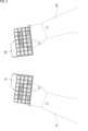
- Figure 13shows an example of weighted addition of the position and orientation of the keyboard surface during standby and during input.
- the position and orientation of the keyboard surface during inputis multiplied by the input degree as a weighting
- the position and orientation of the keyboard surface during standbyis multiplied by (1 - input degree) as a weighting.
- the weighted position and orientation of the keyboard surface during input and the position and orientation of the keyboard surface during standbyare added together to calculate the final position and orientation of the keyboard surface.
- step S21the information processing unit 11 calculates the position and orientation of the keyboard surface based on the degree of input.
- the keyboard surface definition unit 23defines the keyboard surface during standby in advance based on the positions of the user's fingers.
- the keyboard position calculation unit 25calculates the position and orientation of the keyboard surface during input based on the position and orientation of the user's hands.
- the keyboard position calculation unit 25adds the position and orientation of the keyboard surface during standby and the position and orientation of the keyboard surface during input with weighting according to the degree of input to calculate the final position and orientation of the keyboard surface.
- the position and orientation of the keyboard surface during input referred to hereis the position and orientation calculated based on the current second reference plane, regardless of whether the user is in an input standby state or an input state.
- step S22the keyboard position calculation unit 25 applies a stabilization filter, such as a low-pass filter, based on the amount of change in the position and orientation over time to the calculated position and orientation of the keyboard surface to calculate the position and orientation reflected in the keyboard data.
- a stabilization filtersuch as a low-pass filter
- step S23the drawing unit 26 draws an image so that a virtual keyboard appears to exist on the keyboard surface to which the stabilization filter has been applied, and displays the image on the display provided in the HMD 1.
- a stabilization filtermay be applied to the position and orientation of each keyboard surface.
- step S23After the image is displayed on the display in step S23, processing returns to step S3 in FIG. 10, and subsequent processing is performed.
- This technologycan be applied not only to HMDs where the user cannot see the outside world, but also to HMDs with VST (Video See Through) functionality and AR (Augmented Reality) glasses.
- VSTVideo See Through
- ARAugmented Reality
- Example of a method for tracking hands and fingersinstead of tracking the user's hands and fingers using a camera provided in the HMD 1, the HMD 1 can also track the user's hands and fingers using another camera installed in a position where it can track the user's hands and fingers.
- the HMD 1can also estimate the position and posture of the user's hands and fingers based on the results of myoelectric measurements taken with an electromyographic band worn on the user's wrist.
- the HMD 1can also track the user's hands and fingers using gloves worn by the user that are equipped with sensors that sense the posture of the hands and fingers.
- a curved surfacemay be defined as the keyboard surface instead of a flat surface.
- a virtual keyboardwhose shape and key arrangement are designed to fit the shape of the hand, such as an ergonomic keyboard, may be used. If the home position of the virtual keyboard is different from the home position of a normal keyboard, a plane including the positions of fingers other than the index finger and little finger may be set as the first reference plane.
- the virtual keyboardmay be a keyboard other than a QWERTY keyboard.
- the virtual keyboardmay be, for example, a keyboard with only a numeric keypad.
- the keyboard surfacemay be defined with a plane including the positions of the tips of the index finger, middle finger, and ring finger as the first reference plane.
- the HMD 1can also control the position and orientation of a virtual UI that appears in the air and is operated by pressing with the fingertips, based on the tracking results of the hands and other objects.
- the virtual UIcan also include, for example, scroll bars and piano keys.
- the usercan also select and indicate the fingers whose fingertip positions are to be referenced to find the first reference plane.
- the input acquisition unit 27can determine that the user has pressed the Ctrl, Alt, and Del keys based on the movements of each finger. For example, the input acquisition unit 27 inputs physical information into a learning model generated by machine learning or the like, and determines that the user has pressed the Ctrl, Alt, and Del keys.
- HMD1can also control the virtual keyboard so that it is fixed in place without following the hands.
- the input acquisition unit 27can more accurately identify the content of the user's input operation.
- Some or all of the estimation of the user's state by the state estimation unit 22, the definition of the keyboard surface by the keyboard surface definition unit 23, and the calculation of the position and orientation of the keyboard surface by the keyboard position calculation unit 25may be realized using a learning model generated by machine learning or the like.
- the above-described series of processescan be executed by hardware or software.
- the program constituting the softwareis installed from a program recording medium into a computer incorporated in dedicated hardware, or into a general-purpose personal computer, etc.
- FIG. 15is a block diagram showing an example of the hardware configuration of a computer that executes the above-mentioned series of processes using a program.
- CPUCentral Processing Unit
- ROMRead Only Memory
- RAMRandom Access Memory
- an input/output interface 505Connected to the input/output interface 505 are an input unit 506 consisting of a keyboard, mouse, etc., and an output unit 507 consisting of a display, speakers, etc. Also connected to the input/output interface 505 are a storage unit 508 consisting of a hard disk or non-volatile memory, a communication unit 509 consisting of a network interface, etc., and a drive 510 that drives removable media 511.
- the CPU 501loads a program stored in the storage unit 508 into the RAM 503 via the input/output interface 505 and the bus 504, and executes the program, thereby performing the above-mentioned series of processes.
- the programs executed by the CPU 501are provided, for example, by being recorded on removable media 511, or via a wired or wireless transmission medium such as a local area network, the Internet, or digital broadcasting, and are installed in the storage unit 508.
- the program executed by the computermay be a program in which processing is performed chronologically in the order described in this specification, or it may be a program in which processing is performed in parallel or at the required timing, such as when called.
- this technologycan be configured as cloud computing, in which a single function is shared and processed collaboratively by multiple devices over a network.
- each step described in the above flowchartcan be executed by a single device, or can be shared and executed by multiple devices.
- a single stepincludes multiple processes
- the processes included in that single stepcan be executed by a single device, or can be shared and executed by multiple devices.
- a tracking unitthat tracks a body part of a user; and a control unit that controls a position and orientation in a three-dimensional space of a virtual UI for accepting an input operation on at least a part of the tracked part based on a tracking result of the part.
- the information processing devicewherein the tracking unit tracks a hand as the part of the body.
- the control unitcontrols the position and orientation of the virtual UI based on a first reference plane including the position of the fingertips of the user's fingers when the user is in an input standby state in which the user is not performing the input operation.
- control unitcontrols the position and posture of the virtual UI based on a second reference plane corresponding to the back of the hand when the user is in an input state performing the input operation.
- second reference planeis a plane including the position of the base of the fingers and the position of the wrist.
- control unitrecords an offset indicating a position and orientation relationship between the second reference plane and the virtual UI when the user is in the input standby state.
- control unitcalculates a position and orientation of the virtual UI based on the first reference plane and a position and orientation of the virtual UI based on the second reference plane, weighted according to the input degree, to calculate a position and orientation to be reflected in the virtual UI.
- the virtual UIis a virtual keyboard on which a plurality of keys are arranged.
- the control unitarranges the keys at positions on the virtual keyboard based on a tracking result of the user's fingers when the device is in an input standby state in which the user is not performing the input operation.
- control unitcalculates a position and orientation to be reflected in the virtual UI by applying a filter based on a time-series change amount of the position and orientation of the virtual UI.
- control unitcontrols a size of the virtual UI based on a tracking result of the part when the user is in an input standby state in which the user is not performing the input operation.
- An information processing deviceTracking the user's body parts, An information processing method comprising: controlling a position and orientation in a three-dimensional space of a virtual UI for accepting an input operation performed by at least a part of the tracked part based on a tracking result of the part.
- On the computerTracking the user's body parts, A program for executing a process of controlling the position and orientation in a three-dimensional space of a virtual UI for accepting an input operation on at least a part of the tracked part based on a tracking result of the part.
Landscapes
- Engineering & Computer Science (AREA)
- General Engineering & Computer Science (AREA)
- Theoretical Computer Science (AREA)
- Human Computer Interaction (AREA)
- Physics & Mathematics (AREA)
- General Physics & Mathematics (AREA)
- Input From Keyboards Or The Like (AREA)
Abstract
Description
Translated fromJapanese本技術は、情報処理装置、情報処理方法、およびプログラムに関し、特に、仮想UIを用いてより好適に入力操作を行うことができるようにした情報処理装置、情報処理方法、およびプログラムに関する。This technology relates to an information processing device, an information processing method, and a program, and in particular to an information processing device, an information processing method, and a program that enable input operations to be performed more conveniently using a virtual UI.
近年、高精度な手指認識機能が搭載されたHMD(Head Mounted Display)が登場し、仮想キーボードなどの仮想のUI(User Interface)を用いて文字などの入力操作を行う技術の開発が活発になっている。例えば特許文献1には、初期状態におけるユーザの少なくとも3本の手指の指先位置に基づいて、仮想キーボードの位置を決定する技術が記載されている。In recent years, HMDs (Head Mounted Displays) equipped with highly accurate finger recognition functions have appeared, and there has been active development of technology for inputting characters and other operations using virtual UIs (User Interfaces) such as virtual keyboards. For example,
実物のキーボードを用いて入力操作を行う場合、ユーザは、例えばキーから得られる触覚刺激を手掛かりにして、手指とキーボードの位置関係を把握し、手指の位置を細かく調整する。仮想のキーボードを用いて入力操作を行う場合、手掛かりとなる触覚刺激を得られないため、ユーザにとっては、キーボードのサイズやキーの間隔がわかりにくく、手指の位置を細かく調整することが難しい。When performing input operations using a real keyboard, the user can, for example, use tactile cues from the keys to grasp the relative positions of the fingers and the keyboard and finely adjust the position of the fingers. When performing input operations using a virtual keyboard, as there are no tactile cues to provide, it is difficult for the user to grasp the size of the keyboard or the spacing between the keys, making it difficult to finely adjust the position of the fingers.
したがって、実物のキーボードを用いた場合と同程度の正確さまたは速さで、仮想キーボードを用いた入力操作を行うことが困難であった。As a result, it was difficult to perform input operations using a virtual keyboard with the same accuracy or speed as when using a real keyboard.
本技術はこのような状況に鑑みてなされたものであり、仮想UIを用いてより好適に入力操作を行うことができるようにするものである。This technology was developed in light of these circumstances, and makes it possible to perform input operations more conveniently using a virtual UI.
本技術の一側面の情報処理装置は、ユーザの身体の部位をトラッキングするトラッキング部と、トラッキングされている前記部位の少なくとも一部での入力操作を受け付けるための仮想UIの3次元空間内における位置姿勢を、前記部位のトラッキング結果に基づいて制御する制御部とを備える。An information processing device according to one aspect of the present technology includes a tracking unit that tracks a part of a user's body, and a control unit that controls the position and orientation in three-dimensional space of a virtual UI that accepts input operations on at least a part of the tracked part based on the tracking results of the part.
本技術の一側面の情報処理方法は、情報処理装置が、ユーザの身体の部位をトラッキングし、トラッキングされている前記部位の少なくとも一部での入力操作を受け付けるための仮想UIの3次元空間内における位置姿勢を、前記部位のトラッキング結果に基づいて制御する。In one aspect of the information processing method of the present technology, an information processing device tracks a part of a user's body and controls the position and orientation in three-dimensional space of a virtual UI for accepting input operations on at least a part of the tracked part based on the tracking results of the part.
本技術の一側面のプログラムは、コンピュータに、ユーザの身体の部位をトラッキングし、トラッキングされている前記部位の少なくとも一部での入力操作を受け付けるための仮想UIの3次元空間内における位置姿勢を、前記部位のトラッキング結果に基づいて制御する処理を実行させる。A program according to one aspect of the present technology causes a computer to execute a process of tracking a part of a user's body and controlling the position and orientation in three-dimensional space of a virtual UI for accepting input operations on at least a part of the tracked part based on the tracking results of the part.
本技術の一側面においては、ユーザの身体の部位がトラッキングされ、トラッキングされている前記部位の少なくとも一部での入力操作を受け付けるための仮想UIの3次元空間内における位置姿勢が、前記部位のトラッキング結果に基づいて制御される。In one aspect of this technology, a part of a user's body is tracked, and the position and orientation in three-dimensional space of a virtual UI for accepting input operations on at least a part of the tracked part is controlled based on the tracking results of the part.
以下、本技術を実施するための形態について説明する。説明は以下の順序で行う。
1.実施形態の概要
2.HMDの構成と動作
3.変形例Hereinafter, an embodiment of the present technology will be described in the following order.
1. Overview of the
<1.実施形態の概要>
近年、高精度な手指認識機能が搭載されたHMDが登場し、仮想キーボードを用いて文字などの入力操作を行う技術の開発が活発になっている。例えば特許文献1には、初期状態におけるユーザの少なくとも3本の手指の指先位置に基づいて、仮想キーボードの位置を決定する技術が記載されている。1. Overview of the embodiment
In recent years, HMDs equipped with highly accurate finger recognition functions have appeared, and technology for inputting characters and the like using a virtual keyboard has been actively developed. For example,
実物のキーボードを用いて入力操作を行う場合、ユーザは、例えば、キーの表面やエッジに触れている感覚、キーの底打ち感、ホームポジションの手掛かりとなる凹凸、手首による支えといった触覚刺激を手掛かりにして、キーボードと手指の位置関係を把握し、手指の位置を細かく調整する。仮想キーボードを用いて入力操作を行う場合、手掛かりとなる触覚刺激を得られないため、ユーザにとっては、キーボードのサイズやキーの間隔がわかりにくく、手指の位置を細かく調整することが難しい。When performing input operations using a real keyboard, the user uses tactile stimuli such as the sensation of touching the surface or edges of the keys, the feeling of hitting the bottom of the keys, the unevenness that serves as a clue to the home position, and support from the wrist to grasp the relative positions of the keyboard and fingers, and finely adjust the position of the fingers. When performing input operations using a virtual keyboard, as there are no tactile stimuli to serve as clues, it is difficult for the user to grasp the size of the keyboard or the spacing between the keys, making it difficult to finely adjust the position of the fingers.
したがって、実物のキーボードを用いる場合と同程度の正確さまたは速さで、仮想キーボードを用いた入力操作を行うことが困難であった。As a result, it was difficult to perform input operations using a virtual keyboard with the same accuracy or speed as when using a real keyboard.
本技術の一実施形態では、上記の点に着目して発想されたものであり、仮想キーボードを用いてより好適に入力操作を行うことが可能な技術を提案する。以下、本実施形態について詳細に説明する。One embodiment of the present technology was conceived with the above points in mind, and proposes a technology that allows input operations to be performed more conveniently using a virtual keyboard. This embodiment will be described in detail below.
図1は、本技術の一実施形態に係るHMD1を示す図である。FIG. 1 shows an HMD 1 according to one embodiment of the present technology.
図1に示すように、ユーザU1は、頭部にHMD1を装着する。As shown in Figure 1, user U1 wears HMD1 on his head.
HMD1は、例えばカメラと非透過型のディスプレイとを備えた表示デバイスとして構成される。HMD1を装着すると、ディスプレイおよび筐体により視界が遮られるため、ユーザU1は、外界を見ることはできないが、ディスプレイに表示された画像を見ることができる。HMD1 is configured as a display device equipped with, for example, a camera and a non-transparent display. When wearing HMD1, user U1 cannot see the outside world because the field of view is blocked by the display and the housing, but can see the images displayed on the display.
HMD1のディスプレイには、ゲーム、映画、Webコンテンツ、メールなどが表示される。ユーザU1が文字などの入力操作を行うことができるようにするため、HMD1は、仮想キーボードを介してユーザU1による操作の入力を受け付ける。仮想キーボードは、実空間に存在せず、仮想的に生成されたキーボードであり、例えばQWERTY配列で複数のキーが配置されたキーボードである。本技術では、ユーザが手を動かすと、仮想キーボードはユーザの手に追従して移動する。The display of the HMD1 displays games, movies, web content, e-mails, etc. In order to enable the user U1 to perform operations such as inputting characters, the HMD1 accepts input operations by the user U1 via a virtual keyboard. The virtual keyboard does not exist in real space but is a virtually generated keyboard, for example a keyboard with multiple keys arranged in a QWERTY layout. With this technology, when the user moves their hands, the virtual keyboard moves to follow the user's hands.
HMD1は、カメラを用いてユーザU1の身体の各部位をトラッキングし、各部位の位置(姿勢)に基づいて、仮想空間内における仮想キーボードの位置姿勢を算出する。HMD1は、ユーザU1の指の位置と仮想キーボードの位置とに基づいて、ユーザU1が押下したキーを特定できる。The HMD1 uses a camera to track each part of the user U1's body, and calculates the position and orientation of the virtual keyboard in the virtual space based on the position (posture) of each part. The HMD1 can identify the key pressed by user U1 based on the position of user U1's fingers and the position of the virtual keyboard.
図2乃至図7を参照して、HMD1が仮想キーボードの位置姿勢を算出する流れについて説明する。The flow of how the
図2に示すように、ユーザU1の姿勢が入力姿勢である場合、HMD1は、仮想キーボードをディスプレイに表示させる。入力姿勢は、入力操作を行う意思を示す姿勢である。図2においては、キーボード上に手指を載せるように、両手を前に出した姿勢が入力姿勢とされる。As shown in Figure 2, when the posture of user U1 is an input posture, the HMD1 displays a virtual keyboard on the display. An input posture is a posture that indicates an intention to perform an input operation. In Figure 2, the input posture is a posture in which both hands are extended forward with fingers resting on the keyboard.
なお、両手を前に出すジェスチャ以外のジェスチャを行った場合、ユーザU1の姿勢が入力姿勢であると判定されるようにしてもよい。機械学習などにより生成された学習モデルに、ユーザU1の身体の部位が撮影された撮影画像が入力されて、ユーザU1の姿勢が入力姿勢であるか否かが判定されるようにしてもよい。Note that if user U1 makes a gesture other than putting both hands forward, the posture of user U1 may be determined to be an input posture. A captured image of a body part of user U1 may be input to a learning model generated by machine learning or the like, and it may be determined whether user U1's posture is an input posture or not.
図3は、仮想キーボードの例を示す図である。Figure 3 shows an example of a virtual keyboard.
ユーザU1が両手を前に出すと、図3に示すように、例えば、左手用の仮想キーボードKLが、ユーザU1の左手HLの近傍の位置に表示され、右手用の仮想キーボードKRが、ユーザU1の右手HRの近傍の位置に表示される。仮想キーボードKLは左手HLの一部である各指の指先で操作され、仮想キーボードKRは右手HRの一部である各指の指先で操作される。また、左手HLと右手HRにおける各指の指先と付け根および手首の位置を示す点が表示される。なお、各指の指先と付け根および手首の位置を示す点や仮想キーボードKL,KRを必ずしも表示する必要はない。When user U1 holds both hands out in front of him, as shown in FIG. 3, for example, a virtual keyboard KL for the left hand is displayed in a position near user U1's left hand HL, and a virtual keyboard KR for the right hand is displayed in a position near user U1's right hand HR. The virtual keyboard KL is operated with the fingertips of each finger that is part of the left hand HL, and the virtual keyboard KR is operated with the fingertips of each finger that is part of the right hand HR. Also, points indicating the position of the fingertips and bases of each finger and the wrist on the left hand HL and right hand HR are displayed. Note that it is not necessary to display the points indicating the position of the fingertips and bases of each finger and the wrist, or the virtual keyboards KL and KR.
図3において、左手HLと右手HRを点線で示していることは、左手HLと右手HRがHMD1のディスプレイに表示されないことを示す。In Figure 3, the left hand HL and right hand HR are shown with dotted lines, indicating that the left hand HL and right hand HR are not displayed on the display of HMD1.
実物の左右一体型のキーボードを用いて入力操作を行う場合、ユーザは、手首をキーボード上や卓上に載せて手全体を支えたり、指先をキー上に載せた際の触覚刺激を得たりすることで、左手と右手の相対位置を把握している。仮想キーボードを用いて入力操作を行う場合、手首による支えや指先の触覚刺激といった手掛かりを得ることができないため、左手と右手の相対位置を把握する必要がない左右分割型のキーボードを仮想キーボードとして表示することが好ましい。When performing input operations using a real integrated left-right keyboard, the user knows the relative positions of the left and right hands by resting the wrist on the keyboard or table to support the entire hand, or by receiving tactile stimulation when placing the fingertips on the keys. When performing input operations using a virtual keyboard, clues such as support by the wrist or tactile stimulation by the fingertips cannot be obtained, so it is preferable to display a split left-right keyboard as the virtual keyboard, which does not require the user to know the relative positions of the left and right hands.
入力姿勢は、ユーザが指を動かしておらず入力操作を行っていない状態である入力スタンバイ状態と、ユーザが指を動かして入力操作を行っている状態である入力状態とを含む。以下では、ユーザが入力スタンバイ状態であるときをスタンバイ時と称し、ユーザが入力状態であるときを入力時と称する。The input posture includes an input standby state in which the user is not moving his/her fingers and is not performing an input operation, and an input state in which the user is moving his/her fingers and performing an input operation. In the following, the time when the user is in the input standby state will be referred to as "standby time," and the time when the user is in the input state will be referred to as "input time."
スタンバイ時、HMD1は、仮想キーボードが配置される領域を示すキーボード面を定義する。In standby mode, HMD1 defines a keyboard surface that indicates the area where the virtual keyboard is located.
図4は、キーボード面の例を示す図である。Figure 4 shows an example of a keyboard surface.
図4に示すように、左手の手首の位置を示す点P1L、人差し指の指先の位置を示す点P2L、および小指の指先の位置を示す点P3Lを含む第1の基準平面PL1Lに基づいて、左手用のキーボード面KP1Lが定義される。具体的には、第1の基準平面PL1Lとキーボード面KP1Lが所定の位置関係になるようにキーボード面KP1Lが定義される。例えば、第1の基準平面PL1Lを所定の距離だけ移動させ、所定の角度だけ傾けた平面上のある範囲の領域が、キーボード面KP1Lとして定義される。キーボード面KP1Lは、第1の基準平面PL1Lと同一の平面上の領域として定義されてもよい。As shown in FIG. 4, a keyboard surface KP1L for the left hand is defined based on a first reference plane PL1L including a point P1L indicating the position of the wrist of the left hand, a point P2L indicating the position of the tip of the index finger, and a point P3L indicating the position of the tip of the little finger. Specifically, the keyboard surface KP1L is defined so that the first reference plane PL1L and the keyboard surface KP1L have a predetermined positional relationship. For example, the first reference plane PL1L is moved a predetermined distance and tilted at a predetermined angle to define a certain range of area on the plane as the keyboard surface KP1L. The keyboard surface KP1L may be defined as an area on the same plane as the first reference plane PL1L.
なお、手首、人差し指の指先、および小指の指先以外の他の部位の位置を示す点を含む平面が第1の基準平面とされてもよい。実物のキーボードを用いて入力操作を行う場合、スタンバイ時においては、少なくとも手首、人差し指の指先、および小指の指先がキーボード上や卓上に安定して載せられていると考えられるため、手首、人差し指の指先、および小指の指先の位置を示す3点を含む平面を第1の基準平面とすることが好ましい。In addition, a plane including points indicating the positions of parts other than the wrist, the tip of the index finger, and the tip of the little finger may be set as the first reference plane. When performing input operations using an actual keyboard, it is considered that at least the wrist, the tip of the index finger, and the tip of the little finger are stably placed on the keyboard or table during standby, so it is preferable to set as the first reference plane a plane including three points indicating the positions of the wrist, the tip of the index finger, and the tip of the little finger.
キーボード面KP1Lにおいて、人差し指の指先の位置(点P2L)には例えば「F」のキーK2が配置され、小指の指先の位置(点P3L)には例えば「A」のキーK1が配置される。スタンバイ時の人差し指と小指の指先の位置に基づいて仮想キーボードKL上のキーの位置を定義することで、ユーザの手のサイズや形に合った仮想キーボードKLを表示することができる。また、スタンバイ時の人差し指と小指の間の幅に合わせて、キーボード面KP1Lのサイズ(仮想キーボードKLのサイズ)を拡大または縮小させたり、キーボード面KP1L(仮想キーボードKL)を変形させたりすることで、ユーザの手のサイズや形に合った仮想キーボードKLを表示することができる。On the keyboard surface KP1L, for example, the "F" key K2 is placed at the position of the index fingertip (point P2L), and for example, the "A" key K1 is placed at the position of the little fingertip (point P3L). By defining the positions of the keys on the virtual keyboard KL based on the positions of the index finger and little finger tips during standby, it is possible to display a virtual keyboard KL that fits the size and shape of the user's hand. Also, by enlarging or reducing the size of the keyboard surface KP1L (the size of the virtual keyboard KL) or transforming the keyboard surface KP1L (virtual keyboard KL) to match the width between the index finger and little finger during standby, it is possible to display a virtual keyboard KL that fits the size and shape of the user's hand.
左手と同様に、右手の手首の位置を示す点P1R、人差し指の指先の位置を示す点P2R、および小指の指先の位置を示す点P3Rを含む第1の基準平面PL1Rに基づいて、右手用のキーボード面KP1Rが定義される。キーボード面KP1Rにおいて、人差し指の指先の位置(点P2R)には例えば「J」のキーK3が配置され、子指の指先の位置(点P3R)には例えば「;」のキーK4が配置される。Similar to the left hand, the keyboard surface KP1R for the right hand is defined based on a first reference plane PL1R including point P1R indicating the position of the wrist of the right hand, point P2R indicating the position of the tip of the index finger, and point P3R indicating the position of the tip of the little finger. On the keyboard surface KP1R, for example, the "J" key K3 is located at the position of the tip of the index finger (point P2R), and for example, the ";" key K4 is located at the position of the tip of the little finger (point P3R).
以上のように、スタンバイ時、キーボード面の位置姿勢は、第1の基準平面に基づいて制御される。具体的には、キーボード面の位置姿勢は、第1の基準平面を追従するように制御される。As described above, during standby, the position and orientation of the keyboard surface is controlled based on the first reference plane. Specifically, the position and orientation of the keyboard surface is controlled to follow the first reference plane.
キーボード面を定義した後、HMD1は、図5の白抜き矢印で示すように、左手の甲(左手の平)に対応する平面である第2の基準平面PL2Lとキーボード面KP1Lとの位置姿勢関係を示すオフセットを記録する。第2の基準平面PL2Lとキーボード面KP1Lの位置姿勢関係は、例えば、第2の基準平面PL2Lに対するキーボード面KP1Lの相対位置(距離)および相対姿勢(角度)で表現される。図5においては、キーボード面KP1Lが、第1の基準平面PL1Lと同一の平面上の領域として定義されている。After defining the keyboard surface, the HMD1 records an offset indicating the position and orientation relationship between the second reference plane PL2L, which is a plane corresponding to the back of the left hand (left palm), and the keyboard surface KP1L, as indicated by the white arrow in Figure 5. The position and orientation relationship between the second reference plane PL2L and the keyboard surface KP1L is expressed, for example, by the relative position (distance) and relative orientation (angle) of the keyboard surface KP1L with respect to the second reference plane PL2L. In Figure 5, the keyboard surface KP1L is defined as an area on the same plane as the first reference plane PL1L.
オフセットで示される位置姿勢関係には、第2の基準平面PL2Lと第1の基準平面PL1Lの位置姿勢関係、および、第1の基準平面PL1Lとキーボード面KP1Lの位置姿勢関係が含まれる。また、オフセットには、キーボード面KP1Lのサイズを示す情報やキーボード面KP1L上に配置されるキーの位置を示す情報も含まれる。The position and orientation relationship indicated by the offset includes the position and orientation relationship between the second reference plane PL2L and the first reference plane PL1L, and the position and orientation relationship between the first reference plane PL1L and the keyboard surface KP1L. The offset also includes information indicating the size of the keyboard surface KP1L and information indicating the positions of the keys arranged on the keyboard surface KP1L.
なお、図示を省略するが、右手の甲(右手の平)に対応する平面である第2の基準平面PL2Rとキーボード面KP1Rとの位置姿勢関係を示すオフセットも同様に記録される。仮想キーボードが表示されない場合においても、キーボード面が定義され、オフセットが記録される。Although not shown in the figure, the offset indicating the position and orientation relationship between the second reference plane PL2R, which is the plane corresponding to the back of the right hand (palm), and the keyboard surface KP1R is also recorded. Even if the virtual keyboard is not displayed, the keyboard surface is defined and the offset is recorded.
図6は、第2の基準平面の例を示す図である。FIG. 6 shows an example of a second reference plane.
図6に示すように、左手の甲に対応する第2の基準平面PL2Lは、例えば、左手の手首の位置を示す点P11L、人差し指の付け根の位置を示す点P12L、および小指の付け根の位置を示す点P13Lを含む平面である。また、右手の甲に対応する第2の基準平面PL2Rは、例えば、右手の手首の位置を示す点P11R、人差し指の付け根の位置を示す点P12R、および小指の付け根の位置を示す点P13Rを含む平面である。As shown in FIG. 6, the second reference plane PL2L corresponding to the back of the left hand is, for example, a plane including point P11L indicating the position of the wrist of the left hand, point P12L indicating the position of the base of the index finger, and point P13L indicating the position of the base of the little finger. Also, the second reference plane PL2R corresponding to the back of the right hand is, for example, a plane including point P11R indicating the position of the wrist of the right hand, point P12R indicating the position of the base of the index finger, and point P13R indicating the position of the base of the little finger.
上述したように、スタンバイ時において、キーボード面の位置姿勢は、第1の基準平面に基づいて制御されるが、入力時において、キーボード面の位置姿勢は、第1の基準平面ではなく、第2の基準平面に基づいて制御される。具体的には、キーボード面の位置姿勢は、第2の基準平面を追従するように制御される。As described above, during standby, the position and orientation of the keyboard surface is controlled based on the first reference plane, but during input, the position and orientation of the keyboard surface is controlled based on the second reference plane, not the first reference plane. Specifically, the position and orientation of the keyboard surface is controlled to follow the second reference plane.
図7は、入力時における第1の基準平面、第2の基準平面、およびキーボード面の例を示す図である。FIG. 7 shows an example of the first reference plane, the second reference plane, and the keyboard surface during input.
入力時、HMD1は、図7の白抜き矢印で示すように、スタンバイ時に記録されたオフセットで示される第2の基準平面PL2Lとキーボード面KP1Lの位置姿勢関係を再現するように、キーボード面KP1Lを算出する。具体的には、HMD1は、第2の基準平面PL2Lを、スタンバイ時に記録されたオフセットで示される距離だけ移動させ、当該オフセットで示される角度だけ傾けた平面上の所定の範囲の領域をキーボード面KP1Lとして算出する。When inputting, the HMD1 calculates the keyboard surface KP1L so as to reproduce the position and orientation relationship between the second reference plane PL2L indicated by the offset recorded during standby and the keyboard surface KP1L, as shown by the white arrow in Figure 7. Specifically, the HMD1 moves the second reference plane PL2L by the distance indicated by the offset recorded during standby, and calculates an area of a specified range on the plane tilted by the angle indicated by the offset as the keyboard surface KP1L.
入力時においては、各指の指先が激しく動くため、第1の基準平面PL1Lも激しく変化する。第1の基準平面PL1Lを追従するようにキーボード面を制御すると、キーボード面も激しく変化してしまう。キーボード面が激しく変化するため、ユーザにとっては、所望のキーを正確に押下することが難しい。When inputting, the fingertips of each finger move vigorously, causing the first reference plane PL1L to change vigorously as well. If the keyboard surface is controlled to follow the first reference plane PL1L, the keyboard surface will also change vigorously. Because the keyboard surface changes vigorously, it is difficult for the user to accurately press the desired key.
本技術のHMD1においては、入力時でも動きの程度が小さい手の甲に対応する第2の基準平面PL2Lを追従するようにキーボード面の位置姿勢が制御されるため、キーボード面を安定させることが可能となる。したがって、入力時に手指の位置が変化したとしても、ユーザは、所望のキーを正確に押下することができ、入力時に手の位置が変化したとしても、ユーザは、入力操作を継続して行うことができる。In the
<2.HMDの構成と動作>
図8は、HMD1の機能構成例を示すブロック図である。図8の情報処理部11は、例えば、HMD1に設けられたCPUなどにより所定のプログラムが実行されることによって実現される。2. HMD configuration and operation
Fig. 8 is a block diagram showing an example of the functional configuration of the
図8に示すように、情報処理部11は、身体位置取得部21、状態推定部22、キーボード面定義部23、記録部24、キーボード位置算出部25、描画部26、および入力取得部27により構成される。As shown in FIG. 8, the
身体位置取得部21は、HMD1に設けられたカメラにより撮影された撮影画像に基づいて、ユーザの身体の部位をトラッキングするトラッキング部として機能し、トラッキング結果として各部位の位置姿勢を取得する。身体の各部位の位置姿勢は、例えば6自由度(6DoF:6 Degrees of Freedom)のパラメータとして取得される。身体位置取得部21は、身体の各部位の位置姿勢を示す身体情報を、状態推定部22、キーボード面定義部23、キーボード位置算出部25、および入力取得部27に供給する。The body
状態推定部22は、身体位置取得部21から供給された身体情報に基づいて、ユーザの状態を推定する。具体的には、状態推定部22は、ユーザの姿勢が入力姿勢であるか否か、ユーザが入力状態であるかまたは入力スタンバイ状態であるかなどを推定する。The
例えば、状態推定部22は、ユーザが入力状態であるかまたは入力スタンバイ状態であるかを数値で示す入力度を、身体情報に基づいて推定する。入力度が0であることは、ユーザが入力スタンバイ状態であることを示し、入力度が1であることはユーザが入力状態であることを示す。入力度は、手指の指角度の角速度や角加速度、手の平に対する各指の指先の相対位置や相対速度などに基づいて推定される。For example, the
図9は、指角度の例を示す図である。Figure 9 shows examples of finger angles.
図9に示すように、例えば、人差し指の指先の位置を示す点P21と付け根の位置を示す点P22とを結ぶ直線、および、点P22と手首の位置を示す点P23とを結ぶ直線の角度が、人差し指の指角度とされる。As shown in FIG. 9, for example, the angle of a straight line connecting point P21, which indicates the position of the tip of the index finger, and point P22, which indicates the position of the base of the index finger, and the angle of a straight line connecting point P22 and point P23, which indicates the position of the wrist, are regarded as the angle of the index finger.
例えば人差し指、中指、薬指、および小指の指角度が略同一である場合、状態推定部22は、入力度の値を0(入力スタンバイ状態)として推定する。For example, if the finger angles of the index finger, middle finger, ring finger, and little finger are approximately the same, the
なお、状態推定部22は、機械学習などにより生成された学習モデルに身体情報を入力してユーザの状態を推定することも可能である。ユーザがジェスチャを行うことで、自身が入力状態であるかまたは入力スタンバイ状態であるかを指示することも可能である。例えば、指を激しく動かしたり、手を前に出したりした場合、状態推定部22は、ユーザが入力状態であると推定する。また、例えば、ユーザの姿勢が、手を縦向きに前に出した、いわゆる、前へ倣えの姿勢である場合、状態推定部22は、ユーザがスタンバイ状態であると推定し、ユーザがその姿勢で手の平を下に向けた場合、状態推定部22は、ユーザが入力状態であると推定する。The
状態推定部22は、ユーザの状態の推定結果に基づいて、キーボード面定義部23やキーボード位置算出部25を制御する。例えば、ユーザが入力スタンバイ状態である場合、状態推定部22は、キーボード面定義部23にキーボード面を定義させる。また、ユーザが入力状態である場合、状態推定部22は、キーボード位置算出部25にキーボード面の位置姿勢を算出させる。The
キーボード面定義部23は、身体位置取得部21から供給された身体情報に基づいてキーボード面を定義し、オフセットを記録部24に記録させる。The keyboard
記録部24は、キーボード面定義部23から供給されたオフセットを記録する。The
キーボード位置算出部25は、記録部24からオフセットを取得し、当該オフセットと、身体位置取得部21から供給された身体情報とに基づいて、キーボード面の位置姿勢を算出する。キーボード面の位置姿勢は、例えば6自由度のパラメータとして算出される。The keyboard
キーボード位置算出部25は、オフセットで示されるサイズのキーボード面を、算出した位置姿勢で配置し、当該キーボード面上において、オフセットで示されるキーの位置に各種のキーを配置することで、キーボードデータを生成する。キーボード位置算出部25は、キーボードデータを描画部26と入力取得部27に供給する。キーボード面定義部23とキーボード位置算出部25は、仮想キーボードの位置姿勢を制御する制御部として機能する。The keyboard
描画部26は、キーボード位置算出部25により算出されたキーボード面の位置に仮想キーボードが存在して見えるように画像を描画し、HMD1に設けられたディスプレイに当該画像を表示させる。描画部26は、入力取得部27により特定された入力操作の内容に基づいて、仮想キーボードの描画方法を変更してもよい。例えば、描画部26は、手指により押下されたキーの色を変えて描画したり、押下されたキーを仮想キーボードの底面側に沈み込ませて描画したりする。The
なお、スタンバイ時においても、入力時においても、仮想キーボードを必ずしも描画して表示する必要はない。スタンバイ時よりも入力時の方が、仮想キーボードを表示する優先度が高い。Note that it is not necessary to draw and display the virtual keyboard either during standby or when typing. Displaying the virtual keyboard has a higher priority during typing than during standby.
入力取得部27は、身体位置取得部21から供給された身体情報と、キーボード位置算出部25から供給されたキーボードデータとに基づいて、ユーザにより行われた入力操作の内容を特定する。例えば、仮想キーボード上のキーの位置と、ユーザの指先の位置とが一致した場合、入力取得部27は、当該キーが押下されたと特定する。The
次に、図10のフローチャートを参照して、以上のような構成を有する情報処理部11が行う処理について説明する。Next, the processing performed by the
ステップS1において、身体位置取得部21は、HMD1に設けられたカメラにより撮影された撮影画像に基づいて、ユーザの身体の部位として例えば手のトラッキングを行い、手の位置姿勢を取得する。In step S1, the body
ステップS2において、状態推定部22は、ユーザの手の位置姿勢に基づいて、ユーザの姿勢が入力姿勢であるか否かを判定する。In step S2, the
ユーザの姿勢が入力姿勢ではないとステップS2において判定された場合、処理はステップS1に戻り、ユーザの姿勢が入力姿勢になるまで、手のトラッキングが例えばフレームごとに繰り返される。If it is determined in step S2 that the user's posture is not the input posture, the process returns to step S1, and hand tracking is repeated, for example, frame by frame, until the user's posture becomes the input posture.
一方、ユーザの姿勢が入力姿勢であるとステップS2において判定された場合、ステップS3において、情報処理部11は、仮想キーボード制御処理を行う。仮想キーボード制御処理により、キーボード面の位置姿勢が算出され、キーボードデータが生成される。仮想キーボード制御処理の詳細については図11を参照して後述する。On the other hand, if it is determined in step S2 that the user's posture is an input posture, in step S3, the
仮想キーボード制御処理がステップS3において行われた後、処理はステップS1に戻り、それ以降の処理が繰り返し行われる。After the virtual keyboard control process is performed in step S3, the process returns to step S1 and the subsequent processes are repeated.
次に、図11のフローチャートを参照して、図10のステップS3において行われる仮想キーボード制御処理について説明する。Next, the virtual keyboard control process performed in step S3 of FIG. 10 will be described with reference to the flowchart of FIG. 11.
ステップS11において、状態推定部22は、ユーザが入力スタンバイ状態であるか否かを判定する。In step S11, the
ユーザが入力スタンバイ状態であるとステップS11において判定された場合、ステップS12において、キーボード面定義部23は、ユーザの手の位置姿勢に基づいてキーボード面を定義し、オフセットを記録する。その後、キーボード位置算出部25は、キーボード面定義部23により定義されたキーボード面上に、各種のキーを配置することでキーボードデータを生成する。If it is determined in step S11 that the user is in an input standby state, in step S12, the keyboard
一方、ユーザが入力スタンバイ状態ではない、すなわち、入力状態であるとステップS11において判定された場合、ステップS13において、キーボード位置算出部25は、スタンバイ時に記録されたオフセット、および、ユーザの手の位置姿勢に基づいて、キーボード面の位置を算出する。その後、キーボード位置算出部25は、算出した位置姿勢でキーボード面を配置し、当該キーボード面上に各種のキーを配置することでキーボードデータを生成する。On the other hand, if it is determined in step S11 that the user is not in an input standby state, i.e., is in an input state, in step S13, the keyboard
ステップS12またはステップS13においてキーボードデータが生成された後、処理は図10のステップS3に戻り、それ以降の処理が行われる。After the keyboard data is generated in step S12 or step S13, the process returns to step S3 in FIG. 10, and subsequent processes are performed.
以上のように、本技術のHMD1においては、ユーザの身体の部位としての手がトラッキングされ、手指での入力操作を受け付けるための仮想キーボードの3次元空間内における位置姿勢が、手のトラッキング結果に基づいて制御される。仮想キーボードが手に追従するように動くため、ユーザは、ホームポジションを気にしたり、手指の位置を細かく修正したりしなくても、実物のキーボードを用いた場合に近い感覚で、仮想キーボードを用いた入力操作を行うことが可能となる。As described above, in the
<3.変形例>
・入力度に基づいてキーボード面の位置姿勢を算出する例
スタンバイ時のキーボード面の位置姿勢と入力時のキーボード面の位置姿勢とを、入力度に応じて重み付け加算することで、最終的なキーボード面の位置姿勢が算出されるようにしてもよい。3. Modifications
Example of calculating the position and orientation of the keyboard surface based on the degree of input The final position and orientation of the keyboard surface may be calculated by weighting and adding the position and orientation of the keyboard surface during standby and the position and orientation of the keyboard surface during input according to the degree of input.
図12は、入力度に基づいて算出されたキーボード面の位置姿勢の例を示す図である。FIG. 12 shows an example of the position and orientation of the keyboard surface calculated based on the input degree.
図12の左側に示すように、入力度の値が0である場合、ユーザは入力スタンバイ状態であるため、キーボード面KP1Lとして、第1の基準平面PL1Lと同一の平面上の所定の範囲の領域が算出される。一方、図12の右側に示すように、入力度の値が1である場合、ユーザは入力状態であるため、キーボード面KP1Lとして、第1の基準平面PL1Lと異なる平面であって、第2の基準平面PL2Lを移動させたり傾けたりした平面上の所定の範囲が算出される。As shown on the left side of FIG. 12, when the input degree value is 0, the user is in an input standby state, so a predetermined range of area on the same plane as the first reference plane PL1L is calculated as the keyboard surface KP1L. On the other hand, as shown on the right side of FIG. 12, when the input degree value is 1, the user is in an input state, so a predetermined range on a plane different from the first reference plane PL1L, which is obtained by moving or tilting the second reference plane PL2L, is calculated as the keyboard surface KP1L.
入力度の値が例えば0.5である場合、スタンバイ時のキーボード面KP1Lと、入力時のキーボード面KP1Lとがブレンドされた面が最終的なキーボード面として算出される。なお、スタンバイ時のキーボード面と入力時のキーボード面がブレンドされたキーボード面は、手の動きに対して一部追従しないにも関わらず、かつ、位置姿勢が安定しないどっちつかずの面となる可能性がある。したがって、0と1の値の間で入力度が離散的に推定されるように設定してもよく、例えば手指が少し動いただけでも入力度の値が1になるように設定してもよい。If the input degree value is, for example, 0.5, the final keyboard surface is calculated as a surface obtained by blending the keyboard surface KP1L during standby and the keyboard surface KP1L during input. Note that a keyboard surface obtained by blending the keyboard surface during standby and the keyboard surface during input may not follow some of the hand movements, and may be an indecisive surface with an unstable position and orientation. Therefore, the input degree may be set so that it is estimated discretely between
図13は、スタンバイ時のキーボード面の位置姿勢と入力時のキーボード面の位置姿勢との重みづけ加算の例を示す図である。Figure 13 shows an example of weighted addition of the position and orientation of the keyboard surface during standby and during input.
まず、図13の#1に示すように、入力時のキーボード面の位置姿勢に入力度が重みとして乗算され、図13の#2に示すように、スタンバイ時のキーボード面の位置姿勢に(1-入力度)が重みとして乗算される。次に、図13の#3に示すように、それぞれ重み付けされた入力時のキーボード面の位置姿勢とスタンバイ時のキーボード面の位置姿勢とが加算され、最終的なキーボード面の位置姿勢が算出される。First, as shown in #1 of FIG. 13, the position and orientation of the keyboard surface during input is multiplied by the input degree as a weighting, and as shown in #2 of FIG. 13, the position and orientation of the keyboard surface during standby is multiplied by (1 - input degree) as a weighting. Next, as shown in #3 of FIG. 13, the weighted position and orientation of the keyboard surface during input and the position and orientation of the keyboard surface during standby are added together to calculate the final position and orientation of the keyboard surface.
図14のフローチャートを参照して、入力度に基づいてキーボード位置を算出する場合の仮想キーボード制御処理について説明する。The virtual keyboard control process for calculating the keyboard position based on the input degree will be described with reference to the flowchart in FIG. 14.
ステップS21において、情報処理部11は、入力度に基づいてキーボード面の位置姿勢を算出する。具体的には、キーボード面定義部23は、ユーザの手指の位置に基づいて、あらかじめスタンバイ時のキーボード面を定義しておく。次に、キーボード位置算出部25は、ユーザの手の位置姿勢に基づいて、入力時のキーボード面の位置姿勢を算出する。最後に、上述したように、キーボード位置算出部25は、スタンバイ時のキーボード面の位置姿勢と入力時のキーボード面の位置姿勢とを、入力度に応じて重み付け加算して、最終的なキーボード面の位置姿勢を算出する。In step S21, the
なお、ここでいう入力時のキーボード面の位置姿勢とは、ユーザが入力スタンバイ状態であるかまたは入力状態であるかに関わらず、現在の第2の基準平面に基づいて算出された位置姿勢である。Note that the position and orientation of the keyboard surface during input referred to here is the position and orientation calculated based on the current second reference plane, regardless of whether the user is in an input standby state or an input state.
ステップS22において、キーボード位置算出部25は、算出したキーボード面の位置姿勢に対して、ローパスフィルタなどの、位置姿勢の時系列の変化量に基づく安定化フィルタを適用して、キーボードデータに反映される位置姿勢を算出する。In step S22, the keyboard
ステップS23において、描画部26は、安定化フィルタが適用されたキーボード面上に仮想キーボードが存在して見えるように画像を描画し、HMD1に設けられたディスプレイに当該画像を表示させる。In step S23, the
手指の動きや入力度に対してキーボード面の位置を敏感に制御すると、キーボード面が激しく動いてしまう可能性があるため、ステップS22,S23の処理のように、安定化フィルタを適用して、キーボード面を安定させた後に仮想キーボードを描画することが好ましい。なお、ステップS21において、スタンバイ時や入力時のキーボード面の位置姿勢が算出(定義)された後に、それぞれのキーボード面の位置姿勢に対して安定化フィルタが適用されるようにしてもよい。If the position of the keyboard surface is sensitively controlled in response to finger movements and input degree, the keyboard surface may move violently, so it is preferable to apply a stabilization filter to stabilize the keyboard surface and then draw the virtual keyboard, as in the processing of steps S22 and S23. Note that in step S21, after the position and orientation of the keyboard surface during standby and input are calculated (defined), a stabilization filter may be applied to the position and orientation of each keyboard surface.
ステップS23において画像がディスプレイに表示された後、処理は図10のステップS3に戻り、それ以降の処理が行われる。After the image is displayed on the display in step S23, processing returns to step S3 in FIG. 10, and subsequent processing is performed.
以上のように、スタンバイ時のキーボード面の位置姿勢と入力時のキーボード面の位置姿勢とを、入力度に応じて重み付け加算することも可能である。As described above, it is possible to weight and add the position and orientation of the keyboard surface during standby and during input according to the degree of input.
・適用例
本技術は、ユーザが外界を見ることができないHMDだけではなく、VST(Video See Through)機能を有するHMDや、AR(Augmented Reality)グラスなどに適用することができる。- Application examples This technology can be applied not only to HMDs where the user cannot see the outside world, but also to HMDs with VST (Video See Through) functionality and AR (Augmented Reality) glasses.
・手や手指をトラッキングする方法の例
HMD1に設けられたカメラを用いてユーザの手や手指をトラッキングするのではなく、HMD1は、ユーザの手や手指をトラッキング可能な位置に設置された他のカメラを用いて、ユーザの手や手指をトラッキングすることも可能である。Example of a method for tracking hands and fingers Instead of tracking the user's hands and fingers using a camera provided in the
また、HMD1は、ユーザの手首に装着された筋電バンドによる筋電の測定結果に基づいて、ユーザの手や手指の位置姿勢を推定することも可能である。HMD1は、手や手指の姿勢をセンシングするセンサが搭載された、ユーザが手に装着するグローブを用いて、ユーザの手や手指をトラッキングすることも可能である。The
・仮想キーボードの変形例
キーボード面として平面ではなく曲面が定義されるようにしてもよい。エルゴノミクスキーボードと呼ばれるような手の形状に合わせて形状やキーの配置が設計された仮想キーボードを使用することができる。なお、仮想キーボードのホームポジションが通常のキーボードのホームポジションと異なる場合、人差し指と小指以外の指の位置を含む平面を第1の基準平面としてもよい。Modifications of the Virtual Keyboard A curved surface may be defined as the keyboard surface instead of a flat surface. A virtual keyboard whose shape and key arrangement are designed to fit the shape of the hand, such as an ergonomic keyboard, may be used. If the home position of the virtual keyboard is different from the home position of a normal keyboard, a plane including the positions of fingers other than the index finger and little finger may be set as the first reference plane.
仮想キーボードは、QWERTY配列のキーボード以外のキーボードであってもよい。仮想キーボードは、例えばテンキーだけが配置されたキーボードであってもよい。この場合、中指の指先を「5」のキーに載せるようなホームポジションとなるため、例えば、人差し指、中指、および薬指の指先の位置を含む平面を第1の基準平面としてキーボード面を定義してもよい。The virtual keyboard may be a keyboard other than a QWERTY keyboard. The virtual keyboard may be, for example, a keyboard with only a numeric keypad. In this case, since the home position is such that the tip of the middle finger is placed on the "5" key, the keyboard surface may be defined with a plane including the positions of the tips of the index finger, middle finger, and ring finger as the first reference plane.
HMD1は、仮想キーボード以外にも、空中に出現する仮想のUIであって、指先で押下して操作されるようなUIの位置姿勢を手などのトラッキング結果に基づいて制御することができる。仮想UIは、仮想キーボードの他に、例えば、スクロールバーやピアノの鍵盤を含む。In addition to the virtual keyboard, the
第1の基準平面を求めるために指先の位置が参照される手指をユーザが選んで指示することも可能である。The user can also select and indicate the fingers whose fingertip positions are to be referenced to find the first reference plane.
ユーザが、Ctrlキー、Altキー、およびdelキーを同時に押下しようとして手を動かした際に、仮想キーボードが手を追従して移動すると、Ctrlキー、Altキー、およびdelキーをユーザが押下できない可能性がある。When a user moves their hand to simultaneously press the Ctrl, Alt, and Del keys, if the virtual keyboard moves to follow the user's hand, the user may not be able to press the Ctrl, Alt, and Del keys.
そこで、Ctrlキー、Altキー、およびdelキーが配置された仮想キーボード上の位置と各指の指先の位置が一致していなかったとしても、入力取得部27は、各指の動きに基づいて、ユーザがCtrlキー、Altキー、およびdelキーを押下したと特定することも可能である。例えば、入力取得部27は、機械学習などにより生成された学習モデルに身体情報を入力して、ユーザがCtrlキー、Altキー、およびdelキーを押下したと特定する。Therefore, even if the positions on the virtual keyboard where the Ctrl, Alt, and Del keys are located do not match the positions of the fingertips of each finger, the
仮想キーボードにユーザが視線を向けている場合、HMD1は、手を追従せずにその場で固定されるように仮想キーボードを制御することも可能である。When the user is looking at the virtual keyboard, HMD1 can also control the virtual keyboard so that it is fixed in place without following the hands.
ユーザが動かした指の種類に基づいて、ユーザが押下しようとしたキーを絞り込んだり、ユーザが入力しようとした単語を推定したりするといった、入力ミスに対する既存の補正方法を利用してもよい。この場合、入力取得部27は、ユーザの入力操作の内容をより正確に特定することができる。It is also possible to use existing methods for correcting input errors, such as narrowing down the key that the user intended to press or estimating the word that the user intended to enter based on the type of finger that the user moved. In this case, the
状態推定部22によるユーザの状態の推定、キーボード面定義部23によるキーボード面の定義、およびキーボード位置算出部25によるキーボード面の位置姿勢の算出のうちの一部または全部が、機械学習などにより生成された学習モデルを利用して実現されるようにしてもよい。Some or all of the estimation of the user's state by the
・コンピュータについて
上述した一連の処理は、ハードウェアにより実行することもできるし、ソフトウェアにより実行することもできる。一連の処理をソフトウェアにより実行する場合には、そのソフトウェアを構成するプログラムが、専用のハードウェアに組み込まれているコンピュータ、または汎用のパーソナルコンピュータなどに、プログラム記録媒体からインストールされる。Regarding the computer: The above-described series of processes can be executed by hardware or software. When the series of processes is executed by software, the program constituting the software is installed from a program recording medium into a computer incorporated in dedicated hardware, or into a general-purpose personal computer, etc.
図15は、上述した一連の処理をプログラムにより実行するコンピュータのハードウェアの構成例を示すブロック図である。FIG. 15 is a block diagram showing an example of the hardware configuration of a computer that executes the above-mentioned series of processes using a program.
CPU(Central Processing Unit)501,ROM(Read Only Memory)502,RAM(Random Access Memory)503は、バス504により相互に接続されている。CPU (Central Processing Unit) 501, ROM (Read Only Memory) 502, and RAM (Random Access Memory) 503 are interconnected by a
バス504には、さらに、入出力インタフェース505が接続される。入出力インタフェース505には、キーボード、マウスなどよりなる入力部506、ディスプレイ、スピーカなどよりなる出力部507が接続される。また、入出力インタフェース505には、ハードディスクや不揮発性のメモリなどよりなる記憶部508、ネットワークインタフェースなどよりなる通信部509、リムーバブルメディア511を駆動するドライブ510が接続される。Further connected to the
以上のように構成されるコンピュータでは、CPU501が、例えば、記憶部508に記憶されているプログラムを入出力インタフェース505及びバス504を介してRAM503にロードして実行することにより、上述した一連の処理が行われる。In a computer configured as described above, the
CPU501が実行するプログラムは、例えばリムーバブルメディア511に記録して、あるいは、ローカルエリアネットワーク、インターネット、デジタル放送といった、有線または無線の伝送媒体を介して提供され、記憶部508にインストールされる。The programs executed by the
コンピュータが実行するプログラムは、本明細書で説明する順序に沿って時系列に処理が行われるプログラムであっても良いし、並列に、あるいは呼び出しが行われたとき等の必要なタイミングで処理が行われるプログラムであっても良い。The program executed by the computer may be a program in which processing is performed chronologically in the order described in this specification, or it may be a program in which processing is performed in parallel or at the required timing, such as when called.
なお、本明細書に記載された効果はあくまで例示であって限定されるものでは無く、また他の効果があってもよい。Note that the effects described in this specification are merely examples and are not limiting, and other effects may also be present.
本技術の実施の形態は、上述した実施の形態に限定されるものではなく、本技術の要旨を逸脱しない範囲において種々の変更が可能である。The embodiment of this technology is not limited to the above-mentioned embodiment, and various modifications are possible without departing from the spirit of this technology.
例えば、本技術は、1つの機能をネットワークを介して複数の装置で分担、共同して処理するクラウドコンピューティングの構成をとることができる。For example, this technology can be configured as cloud computing, in which a single function is shared and processed collaboratively by multiple devices over a network.
また、上述のフローチャートで説明した各ステップは、1つの装置で実行する他、複数の装置で分担して実行することができる。In addition, each step described in the above flowchart can be executed by a single device, or can be shared and executed by multiple devices.
さらに、1つのステップに複数の処理が含まれる場合には、その1つのステップに含まれる複数の処理は、1つの装置で実行する他、複数の装置で分担して実行することができる。Furthermore, when a single step includes multiple processes, the processes included in that single step can be executed by a single device, or can be shared and executed by multiple devices.
<構成の組み合わせ例>
本技術は、以下のような構成をとることもできる。<Examples of configuration combinations>
The present technology can also be configured as follows.
(1)
ユーザの身体の部位をトラッキングするトラッキング部と、
トラッキングされている前記部位の少なくとも一部での入力操作を受け付けるための仮想UIの3次元空間内における位置姿勢を、前記部位のトラッキング結果に基づいて制御する制御部と
を備える情報処理装置。
(2)
前記トラッキング部は、前記部位としての手をトラッキングする
前記(1)に記載の情報処理装置。
(3)
前記制御部は、前記ユーザが、前記入力操作を行っていない入力スタンバイ状態である場合、手指の指先の位置を含む第1の基準平面に基づいて、前記仮想UIの位置姿勢を制御する
前記(2)に記載の情報処理装置。
(4)
前記制御部は、前記ユーザが、前記入力操作を行っている入力状態である場合、手の甲に対応する第2の基準平面に基づいて、前記仮想UIの位置姿勢を制御する
前記(3)に記載の情報処理装置。
(5)
前記第2の基準平面は、前記手指の付け根の位置と手首の位置とを含む平面である
前記(4)に記載の情報処理装置。
(6)
前記制御部は、前記ユーザが前記入力スタンバイ状態である場合、前記第2の基準平面と前記仮想UIの位置姿勢関係を示すオフセットを記録する
前記(4)または(5)に記載の情報処理装置。
(7)
前記制御部は、前記ユーザが前記入力状態である場合、前記オフセットで示される前記第2の基準平面と前記仮想UIの位置姿勢関係を再現するように前記仮想UIの位置姿勢を制御する
前記(6)に記載の情報処理装置。
(8)
前記制御部は、前記ユーザが前記入力スタンバイ状態である場合、前記第1の基準平面と前記仮想UIが所定の位置姿勢関係になるように、前記仮想UIの位置姿勢を制御する
前記(4)乃至(7)のいずれかに記載の情報処理装置。
(9)
前記ユーザの状態を推定する推定部をさらに備える
前記(4)乃至(8)のいずれかに記載の情報処理装置。
(10)
前記推定部は、前記ユーザの状態を数値で示す入力度を推定する
前記(9)に記載の情報処理装置。
(11)
前記制御部は、前記第1の基準平面に基づく前記仮想UIの位置姿勢と、前記第2の基準平面に基づく前記仮想UIの位置姿勢とを前記入力度に応じて重みづけ加算して、前記仮想UIに反映される位置姿勢を算出する
前記(10)に記載の情報処理装置。
(12)
前記仮想UIは、複数のキーが配置された仮想キーボードである
前記(2)乃至(11)のいずれかに記載の情報処理装置。
(13)
前記制御部は、前記ユーザが前記入力操作を行っていない入力スタンバイ状態である時の手指のトラッキング結果に基づく、前記仮想キーボード上の位置に前記キーを配置する
前記(12)に記載の情報処理装置。
(14)
前記制御部は、前記仮想UIの位置姿勢の時系列の変化量に基づくフィルタを適用して、前記仮想UIに反映される位置姿勢を算出する
前記(1)乃至(13)のいずれかに記載の情報処理装置。
(15)
前記制御部は、前記ユーザが前記入力操作を行っていない入力スタンバイ状態であるときの前記部位のトラッキング結果に基づいて、前記仮想UIのサイズを制御する
前記(1)乃至(14)のいずれかに記載の情報処理装置。
(16)
情報処理装置が、
ユーザの身体の部位をトラッキングし、
トラッキングされている前記部位の少なくとも一部での入力操作を受け付けるための仮想UIの3次元空間内における位置姿勢を、前記部位のトラッキング結果に基づいて制御する
情報処理方法。
(17)
コンピュータに、
ユーザの身体の部位をトラッキングし、
トラッキングされている前記部位の少なくとも一部での入力操作を受け付けるための仮想UIの3次元空間内における位置姿勢を、前記部位のトラッキング結果に基づいて制御する
処理を実行させるためのプログラム。(1)
A tracking unit that tracks a body part of a user;
and a control unit that controls a position and orientation in a three-dimensional space of a virtual UI for accepting an input operation on at least a part of the tracked part based on a tracking result of the part.
(2)
The information processing device according to (1), wherein the tracking unit tracks a hand as the part of the body.
(3)
The information processing device described in (2), wherein the control unit controls the position and orientation of the virtual UI based on a first reference plane including the position of the fingertips of the user's fingers when the user is in an input standby state in which the user is not performing the input operation.
(4)
The information processing device described in (3), wherein the control unit controls the position and posture of the virtual UI based on a second reference plane corresponding to the back of the hand when the user is in an input state performing the input operation.
(5)
The information processing device according to (4), wherein the second reference plane is a plane including the position of the base of the fingers and the position of the wrist.
(6)
The information processing device according to (4) or (5), wherein the control unit records an offset indicating a position and orientation relationship between the second reference plane and the virtual UI when the user is in the input standby state.
(7)
The information processing device described in (6), wherein the control unit controls the position and orientation of the virtual UI so as to reproduce the position and orientation relationship between the second reference plane indicated by the offset and the virtual UI when the user is in the input state.
(8)
The information processing device described in any one of (4) to (7), wherein the control unit controls the position and orientation of the virtual UI so that the first reference plane and the virtual UI have a predetermined position and orientation relationship when the user is in the input standby state.
(9)
The information processing device according to any one of (4) to (8), further comprising an estimation unit that estimates a state of the user.
(10)
The information processing device according to (9), wherein the estimation unit estimates an input degree that indicates a state of the user by a numerical value.
(11)
The information processing device described in (10), wherein the control unit calculates a position and orientation of the virtual UI based on the first reference plane and a position and orientation of the virtual UI based on the second reference plane, weighted according to the input degree, to calculate a position and orientation to be reflected in the virtual UI.
(12)
The information processing device according to any one of (2) to (11), wherein the virtual UI is a virtual keyboard on which a plurality of keys are arranged.
(13)
The information processing device according to (12), wherein the control unit arranges the keys at positions on the virtual keyboard based on a tracking result of the user's fingers when the device is in an input standby state in which the user is not performing the input operation.
(14)
The information processing device according to any one of (1) to (13), wherein the control unit calculates a position and orientation to be reflected in the virtual UI by applying a filter based on a time-series change amount of the position and orientation of the virtual UI.
(15)
The information processing device described in any one of (1) to (14), wherein the control unit controls a size of the virtual UI based on a tracking result of the part when the user is in an input standby state in which the user is not performing the input operation.
(16)
An information processing device,
Tracking the user's body parts,
An information processing method comprising: controlling a position and orientation in a three-dimensional space of a virtual UI for accepting an input operation performed by at least a part of the tracked part based on a tracking result of the part.
(17)
On the computer,
Tracking the user's body parts,
A program for executing a process of controlling the position and orientation in a three-dimensional space of a virtual UI for accepting an input operation on at least a part of the tracked part based on a tracking result of the part.
1 HMD, 11 情報処理部, 21 身体位置取得部, 22 状態推定部, 23 キーボード面定義部, 24 記録部, 25 キーボード位置算出部, 26 描画部, 27 入力取得部1 HMD, 11 Information processing unit, 21 Body position acquisition unit, 22 State estimation unit, 23 Keyboard surface definition unit, 24 Recording unit, 25 Keyboard position calculation unit, 26 Drawing unit, 27 Input acquisition unit
Claims (17)
Translated fromJapaneseトラッキングされている前記部位の少なくとも一部での入力操作を受け付けるための仮想UIの3次元空間内における位置姿勢を、前記部位のトラッキング結果に基づいて制御する制御部と
を備える情報処理装置。A tracking unit that tracks a body part of a user;
and a control unit that controls a position and orientation in a three-dimensional space of a virtual UI for accepting an input operation on at least a part of the tracked part based on a tracking result of the part.
請求項1に記載の情報処理装置。The information processing device according to claim 1 , wherein the tracking unit tracks a hand as the part of the body.
請求項2に記載の情報処理装置。The information processing device according to claim 2 , wherein the control unit controls the position and orientation of the virtual UI based on a first reference plane including the positions of fingertips of a hand when the user is in an input standby state in which the user is not performing the input operation.
請求項3に記載の情報処理装置。The information processing device according to claim 3 , wherein the control unit controls a position and orientation of the virtual UI based on a second reference plane corresponding to a back of a hand when the user is in an input state performing the input operation.
請求項4に記載の情報処理装置。The information processing device according to claim 4 , wherein the second reference plane is a plane including the positions of the bases of the fingers and the position of the wrist.
請求項4に記載の情報処理装置。The information processing device according to claim 4 , wherein the control unit records an offset indicating a position and orientation relationship between the second reference plane and the virtual UI when the user is in the input standby state.
請求項6に記載の情報処理装置。The information processing device according to claim 6 , wherein, when the user is in the input state, the control unit controls a position and orientation of the virtual UI so as to reproduce a position and orientation relationship between the second reference plane and the virtual UI indicated by the offset.
請求項4に記載の情報処理装置。The information processing device according to claim 4 , wherein, when the user is in the input standby state, the control unit controls a position and orientation of the virtual UI such that a predetermined position and orientation relationship is established between the first reference plane and the virtual UI.
請求項4に記載の情報処理装置。The information processing device according to claim 4 , further comprising an estimation unit that estimates a state of the user.
請求項9に記載の情報処理装置。The information processing apparatus according to claim 9 , wherein the estimation unit estimates an input degree that indicates the state of the user by a numerical value.
請求項10に記載の情報処理装置。The information processing device according to claim 10 , wherein the control unit calculates a position and orientation reflected in the virtual UI by weighting and adding a position and orientation of the virtual UI based on the first reference plane and a position and orientation of the virtual UI based on the second reference plane according to the input degree.
請求項2に記載の情報処理装置。The information processing apparatus according to claim 2 , wherein the virtual UI is a virtual keyboard on which a plurality of keys are arranged.
請求項12に記載の情報処理装置。The information processing apparatus according to claim 12 , wherein the control unit arranges the keys at positions on the virtual keyboard based on a tracking result of the user's fingers when the apparatus is in an input standby state in which the user is not performing the input operation.
請求項1に記載の情報処理装置。The information processing device according to claim 1 , wherein the control unit calculates the position and orientation to be reflected in the virtual UI by applying a filter based on a time-series change amount of the position and orientation of the virtual UI.
請求項1に記載の情報処理装置。The information processing device according to claim 1 , wherein the control unit controls a size of the virtual UI based on a tracking result of the body part when the device is in an input standby state in which the user is not performing the input operation.
ユーザの身体の部位をトラッキングし、
トラッキングされている前記部位の少なくとも一部での入力操作を受け付けるための仮想UIの3次元空間内における位置姿勢を、前記部位のトラッキング結果に基づいて制御する
情報処理方法。An information processing device,
Tracking the user's body parts,
An information processing method comprising: controlling a position and orientation in a three-dimensional space of a virtual UI for accepting an input operation performed by at least a part of the tracked part based on a tracking result of the part.
ユーザの身体の部位をトラッキングし、
トラッキングされている前記部位の少なくとも一部での入力操作を受け付けるための仮想UIの3次元空間内における位置姿勢を、前記部位のトラッキング結果に基づいて制御する
処理を実行させるためのプログラム。On the computer,
Tracking the user's body parts,
A program for executing a process of controlling the position and orientation in a three-dimensional space of a virtual UI for accepting an input operation on at least a part of the tracked part based on a tracking result of the part.
Applications Claiming Priority (2)
| Application Number | Priority Date | Filing Date | Title |
|---|---|---|---|
| JP2023-122947 | 2023-07-28 | ||
| JP2023122947 | 2023-07-28 |
Publications (1)
| Publication Number | Publication Date |
|---|---|
| WO2025028167A1true WO2025028167A1 (en) | 2025-02-06 |
Family
ID=94395083
Family Applications (1)
| Application Number | Title | Priority Date | Filing Date |
|---|---|---|---|
| PCT/JP2024/024553PendingWO2025028167A1 (en) | 2023-07-28 | 2024-07-08 | Information processing device, information processing method, and program |
Country Status (1)
| Country | Link |
|---|---|
| WO (1) | WO2025028167A1 (en) |
Citations (9)
| Publication number | Priority date | Publication date | Assignee | Title |
|---|---|---|---|---|
| JP2002278673A (en)* | 2001-03-09 | 2002-09-27 | Samsung Electronics Co Ltd | Information input system and information input method using biofeedback |
| JP4846871B1 (en)* | 2010-10-28 | 2011-12-28 | 善博 和田 | KEY INPUT DEVICE, PORTABLE TERMINAL PROVIDED WITH THE SAME, AND PROGRAM FOR MAKING PORTABLE TERMINAL FUNCTION AS INPUT DEVICE |
| KR101559424B1 (en)* | 2014-10-10 | 2015-10-12 | 한국과학기술원 | A virtual keyboard based on hand recognition and implementing method thereof |
| JP5799817B2 (en)* | 2012-01-12 | 2015-10-28 | 富士通株式会社 | Finger position detection device, finger position detection method, and computer program for finger position detection |
| US20150323998A1 (en)* | 2014-05-06 | 2015-11-12 | Qualcomm Incorporated | Enhanced user interface for a wearable electronic device |
| JP2021524629A (en)* | 2018-05-22 | 2021-09-13 | マジック リープ, インコーポレイテッドMagic Leap,Inc. | Transformer mode input fusion for wearable systems |
| WO2022130684A1 (en)* | 2020-12-14 | 2022-06-23 | 株式会社村田製作所 | Operation device and operation inference method |
| JP2022535315A (en)* | 2019-06-07 | 2022-08-08 | メタ プラットフォームズ テクノロジーズ, リミテッド ライアビリティ カンパニー | Artificial reality system with self-tactile virtual keyboard |
| JP7199441B2 (en)* | 2018-08-21 | 2023-01-05 | 株式会社Nttドコモ | input device |
- 2024
- 2024-07-08WOPCT/JP2024/024553patent/WO2025028167A1/enactivePending
Patent Citations (9)
| Publication number | Priority date | Publication date | Assignee | Title |
|---|---|---|---|---|
| JP2002278673A (en)* | 2001-03-09 | 2002-09-27 | Samsung Electronics Co Ltd | Information input system and information input method using biofeedback |
| JP4846871B1 (en)* | 2010-10-28 | 2011-12-28 | 善博 和田 | KEY INPUT DEVICE, PORTABLE TERMINAL PROVIDED WITH THE SAME, AND PROGRAM FOR MAKING PORTABLE TERMINAL FUNCTION AS INPUT DEVICE |
| JP5799817B2 (en)* | 2012-01-12 | 2015-10-28 | 富士通株式会社 | Finger position detection device, finger position detection method, and computer program for finger position detection |
| US20150323998A1 (en)* | 2014-05-06 | 2015-11-12 | Qualcomm Incorporated | Enhanced user interface for a wearable electronic device |
| KR101559424B1 (en)* | 2014-10-10 | 2015-10-12 | 한국과학기술원 | A virtual keyboard based on hand recognition and implementing method thereof |
| JP2021524629A (en)* | 2018-05-22 | 2021-09-13 | マジック リープ, インコーポレイテッドMagic Leap,Inc. | Transformer mode input fusion for wearable systems |
| JP7199441B2 (en)* | 2018-08-21 | 2023-01-05 | 株式会社Nttドコモ | input device |
| JP2022535315A (en)* | 2019-06-07 | 2022-08-08 | メタ プラットフォームズ テクノロジーズ, リミテッド ライアビリティ カンパニー | Artificial reality system with self-tactile virtual keyboard |
| WO2022130684A1 (en)* | 2020-12-14 | 2022-06-23 | 株式会社村田製作所 | Operation device and operation inference method |
Similar Documents
| Publication | Publication Date | Title |
|---|---|---|
| US12164739B2 (en) | Methods for interacting with virtual controls and/or an affordance for moving virtual objects in virtual environments | |
| Grubert et al. | Effects of hand representations for typing in virtual reality | |
| Grubert et al. | Text entry in immersive head-mounted display-based virtual reality using standard keyboards | |
| Wang et al. | Interaction with gaze, gesture, and speech in a flexibly configurable augmented reality system | |
| Speicher et al. | Selection-based text entry in virtual reality | |
| US9529523B2 (en) | Method using a finger above a touchpad for controlling a computerized system | |
| Song et al. | GaFinC: Gaze and Finger Control interface for 3D model manipulation in CAD application | |
| US9857868B2 (en) | Method and system for ergonomic touch-free interface | |
| US9430147B2 (en) | Method for user input from alternative touchpads of a computerized system | |
| US20150261310A1 (en) | One-dimensional input system and method | |
| KR101318244B1 (en) | System and Method for Implemeting 3-Dimensional User Interface | |
| Yang et al. | Effect of spatial enhancement technology on input through the keyboard in virtual reality environment | |
| Vogel et al. | Hand occlusion with tablet-sized direct pen input | |
| Zhao et al. | Comparing head gesture, hand gesture and gamepad interfaces for answering Yes/No questions in virtual environments | |
| KR20200005243A (en) | System for controlling interface based on finger gestures using imu sensor | |
| Darbar et al. | Exploring smartphone-enabled text selection in ar-hmd | |
| WO2017116815A1 (en) | Hand tracking for user interface operation at-a-distance | |
| Giovannelli et al. | Exploring the impact of visual information on intermittent typing in virtual reality | |
| Hussain et al. | Effects of interaction method, size, and distance to object on augmented reality interfaces | |
| Lepouras | Comparing methods for numerical input in immersive virtual environments | |
| Bai et al. | Asymmetric Bimanual Interaction for Mobile Virtual Reality. | |
| WO2025028167A1 (en) | Information processing device, information processing method, and program | |
| Arai et al. | Eye-based human computer interaction allowing phoning, reading e-book/e-comic/e-learning, internet browsing, and tv information extraction | |
| Sawicki et al. | Head movement based interaction in mobility | |
| JP6801138B1 (en) | Terminal device, virtual object operation method, and virtual object operation program |
Legal Events
| Date | Code | Title | Description |
|---|---|---|---|
| 121 | Ep: the epo has been informed by wipo that ep was designated in this application | Ref document number:24848826 Country of ref document:EP Kind code of ref document:A1 |