WO2025023398A1 - Buffer device and ultrasonic diagnostic device assembly comprising same - Google Patents
Buffer device and ultrasonic diagnostic device assembly comprising sameDownload PDFInfo
- Publication number
- WO2025023398A1 WO2025023398A1PCT/KR2023/020642KR2023020642WWO2025023398A1WO 2025023398 A1WO2025023398 A1WO 2025023398A1KR 2023020642 WKR2023020642 WKR 2023020642WWO 2025023398 A1WO2025023398 A1WO 2025023398A1
- Authority
- WO
- WIPO (PCT)
- Prior art keywords
- buffer
- main body
- imaging device
- shock
- ultrasonic imaging
- Prior art date
- Legal status (The legal status is an assumption and is not a legal conclusion. Google has not performed a legal analysis and makes no representation as to the accuracy of the status listed.)
- Pending
Links
Images


Classifications
- A—HUMAN NECESSITIES
- A61—MEDICAL OR VETERINARY SCIENCE; HYGIENE
- A61B—DIAGNOSIS; SURGERY; IDENTIFICATION
- A61B8/00—Diagnosis using ultrasonic, sonic or infrasonic waves
Definitions
- the present disclosurerelates to a buffer device and an ultrasonic diagnostic device assembly including the same.
- various medical imaging deviceshave been widely used in the medical field to obtain information about the human body's biological tissues by visualizing them for the purpose of early diagnosis of various diseases or surgery.
- Representative examples of such medical imaging devicesinclude ultrasound diagnostic devices, CT (Computed Tomography) devices, and MRI (Magnetic Resonance Imaging) devices.
- An ultrasound diagnostic deviceis a device that noninvasively obtains at least one image of a part (e.g., soft tissue or blood flow) inside the target by irradiating an ultrasound signal generated from a transducer of a probe to the target and receiving information on a signal reflected from the target.
- An ultrasound diagnostic devicecan be used for medical purposes such as observing the inside of a target, detecting foreign substances, and measuring injuries.
- Such ultrasound diagnostic deviceshave the advantages of high stability compared to imaging devices using X-rays, real-time image display, and safety due to the absence of radiation exposure, and are therefore widely used together with other imaging devices.
- the ultrasonic diagnostic devicemay be implemented in a portable form that can be moved depending on the purpose of use. During the process of moving the ultrasonic diagnostic device, the risk of the ultrasonic diagnostic device being damaged by external impact may increase.
- a buffer device for protecting an ultrasonic diagnostic device from external impact and an ultrasonic diagnostic device assembly including the buffer deviceare provided.
- a buffer device with improved user convenience and an ultrasonic diagnostic device assembly including the buffer deviceare provided.
- a buffer device surrounding an ultrasonic imaging device having a main body and a handle portion coupled to the main bodymay include a first buffer portion surrounding an outer circumference of the main body and an outer circumference of the handle portion, and a second buffer portion disposed so as to be spaced apart from the first buffer portion by a predetermined distance and disposed between the main body and the handle portion.
- Itmay further include a connecting portion connecting the first buffer portion and the second buffer portion.
- At least one of the first buffer portion, the second buffer portion, and the connecting portionmay be formed integrally.
- the above second buffer membermay include a second-first buffer member and a second-second buffer member that are arranged to be spaced apart from each other along one direction.
- the above handle portionhas a handle portion thickness along the thickness direction of the ultrasonic imaging device, and a portion of the first buffer portion positioned to face the handle portion may have a thickness less than or equal to the handle portion thickness along the thickness direction of the ultrasonic imaging device.
- the above bodyhas a body thickness along the thickness direction of the ultrasonic imaging device, and at least one region of the first buffer portion may have a vertical buffer portion thickness exceeding the body thickness along the thickness direction of the ultrasonic imaging device.
- the second buffer portionmay include a first fixing portion that supports one side of the main body and fixes the position of the main body with respect to the second buffer portion
- the first buffer portionmay include a second fixing portion that supports the other side of the main body and fixes the position of the main body with respect to the first buffer portion
- a groovemay be arranged on one side of the main body, the first fixing part may include a stepped part having a shape corresponding to the groove, a plurality of protrusions may be arranged on the other side of the main body, and the second fixing part may include a plurality of recessed parts corresponding to the plurality of protrusions.
- the band fixing membermay further include a band fixing member arranged to cross one side of the main body and having both ends or one end detachably attached to the first buffering member or the second buffering member.
- the devicemay further include an intake passage part arranged to face an intake part disposed on one side of the main body with a predetermined gap therebetween, and an exhaust passage part arranged to face an exhaust part disposed on the other side of the main body with a predetermined gap therebetween.
- the above intake passage partmay have a plurality of intake passages extending in one direction, and the above exhaust passage part may have a plurality of exhaust holes.
- At least one of the first buffer portion and the second buffer portionmay include an elastic material.
- the above elastic materialmay include one or more of silicone rubber, ethylene vinyl acetate (EVA), ethylene propylene diene monomer rubber (EPDM rubber), fluoro elastomers, acrylonitrile butadiene rubber (NBR rubber), styrene butadiene rubber (SBR rubber), natural rubber (NR rubber), chloroprene rubber (CR rubber), expanded polyethylene (EPE), expanded polypropylene (EPP), expanded polystyrene (EPS), and plastic.
- silicone rubberethylene vinyl acetate (EVA), ethylene propylene diene monomer rubber (EPDM rubber), fluoro elastomers, acrylonitrile butadiene rubber (NBR rubber), styrene butadiene rubber (SBR rubber), natural rubber (NR rubber), chloroprene rubber (CR rubber), expanded polyethylene (EPE), expanded polypropylene (EPP), expanded polystyrene (EPS), and plastic.
- EVAethylene vinyl acetate
- EPDM rubber
- Itmay further include a reinforcing member positioned to be inserted into the center of the first buffer portion.
- the above reinforcing membermay include a different material from the first buffer portion.
- the devicemay further include a plurality of shock absorbing members arranged inside at least one of the first buffer member and the second buffer member and having at least one of a polygonal or circular cross-section.
- One or more connectorsare arranged on one side of the above body, and a connector hole arranged at a position corresponding to the one or more connectors and a connector hole opening/closing part for opening and closing the connector hole may be further included.
- a probe connected to the connector of the above main bodymay further include a groove portion arranged therein, and a shock-absorbing step portion formed in a shape corresponding to the groove portion and supporting the groove portion.
- the above bodymay further include a waterproof part having a predetermined groove portion arranged in a shape corresponding to the groove portion and inserted into the groove portion to block foreign substances entering from the outside.
- An ultrasonic diagnostic device assemblymay include an ultrasonic imaging device having the buffer device, a main body, a handle portion coupled to the main body, and a probe connected to the ultrasonic imaging device.
- a buffer device and an ultrasonic diagnostic device assembly including the buffer device according to an examplecan protect the ultrasonic diagnostic device from external impact.
- the buffer device and the ultrasonic diagnostic device assembly including the buffer devicecan improve the user convenience of the ultrasonic diagnostic device when the buffer device is arranged in the ultrasonic diagnostic device.
- FIG. 1is a block diagram illustrating the configuration of an ultrasound imaging system according to one embodiment of the present disclosure.
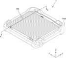
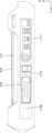
- FIG. 2is a perspective view of an ultrasonic diagnostic device assembly including a buffer device according to an example.
- Figure 3is a perspective view of a buffer device and an ultrasonic diagnostic device according to an example.
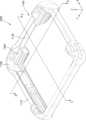
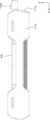
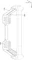
- Figure 4is a perspective view of a buffer device according to an example.
- Figure 5is a plan view of a buffer device according to an example.
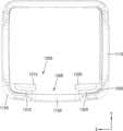
- FIG. 6is a plan view of an ultrasonic diagnostic device assembly having an ultrasonic imaging device arranged in a buffer device according to an example.
- Figure 7is an enlarged view of the P area shown in Figure 6.
- FIG. 8is a bottom view of an ultrasonic diagnostic device assembly having an ultrasonic imaging device arranged in a buffer device according to an example.
- FIG. 9is a side view of an ultrasonic diagnostic device assembly having an ultrasonic imaging device disposed in a buffer device according to an example.
- FIG. 10is a side view of an ultrasonic diagnostic device assembly having an ultrasonic imaging device disposed in a buffer device according to an example.
- FIG. 11is a cross-sectional view of the ultrasonic diagnostic device assembly taken along line A-A shown in FIG. 2.
- FIG. 12ais an enlarged cross-sectional view of a portion of the cross-sectional view of the ultrasonic diagnostic device assembly illustrated in FIG. 11.
- Fig. 12bis an enlarged cross-sectional view of a portion of the cross-sectional view of the ultrasonic diagnostic device assembly illustrated in Fig. 11.
- FIG. 13is a plan view of an ultrasonic diagnostic device assembly having an ultrasonic imaging device arranged in a buffer device according to an example.
- FIG. 14is a bottom view of an ultrasonic diagnostic device assembly having an ultrasonic imaging device arranged in a buffer device according to an example.
- FIG. 15is a cross-sectional view of an ultrasonic diagnostic device assembly having an ultrasonic imaging device arranged in a buffer device according to an example.
- Fig. 16is an enlarged cross-sectional view of a portion of the cross-sectional view of the ultrasonic diagnostic device assembly illustrated in Fig. 15.
- Fig. 17is an enlarged cross-sectional view of a portion of the cross-sectional view of the ultrasonic diagnostic device assembly illustrated in Fig. 15.
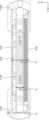
- Fig. 18ais a cross-sectional view of the buffer device taken along the line B-B shown in Fig. 4.
- Figure 18bis a cross-sectional view of the buffer device taken along the line C-C shown in Figure 4.
- Fig. 19is a perspective projection view of a buffer device according to an example.
- FIG. 20is a side view of an ultrasonic diagnostic device assembly having an ultrasonic imaging device disposed in a buffer device according to an example.
- FIG. 21is a side view of an ultrasonic diagnostic device assembly having an ultrasonic imaging device disposed in a buffer device according to an example.
- FIG. 22is a partial cross-sectional view of an ultrasonic diagnostic device assembly having an ultrasonic imaging device disposed in a buffer device according to an example.
- FIG. 23is a side view of an ultrasonic diagnostic device assembly with a probe coupled thereto according to an example.
- FIG. 24is a side view of an ultrasonic diagnostic device assembly with the probe separated according to an example.
- Fig. 25is a perspective view of a buffer device according to an example.
- Fig. 26is a partial cross-sectional view of an ultrasonic diagnostic device assembly according to an example.
- 'module' or 'unit'used in the specification may be implemented by one or a combination of two or more of software, hardware, or firmware, and according to the embodiments, a plurality of 'modules' or 'units' may be implemented as a single element, or a single 'module' or 'unit' may include a plurality of elements.
- each of the phrases “A or B”, “at least one of A and B”, “at least one of A or B”, “A, B, or C”, “at least one of A, B, and C”, and “at least one of A, B, or C”can include any one of the items listed together in the corresponding phrase, or all possible combinations thereof.
- the imagemay include a medical image acquired by a medical imaging device such as a magnetic resonance imaging (MRI) device, a computed tomography (CT) device, an ultrasound imaging device, or an X-ray imaging device.
- a medical imaging devicesuch as a magnetic resonance imaging (MRI) device, a computed tomography (CT) device, an ultrasound imaging device, or an X-ray imaging device.
- an 'object'is a subject of photography, and may include a person, an animal, or a part thereof.
- the objectmay include a part of a body (such as an organ or system) or a phantom.
- the term 'ultrasonic image'means an image of an object generated or processed based on an ultrasonic signal transmitted to the object and reflected from the object.
- FIG. 1is a block diagram illustrating the configuration of an ultrasound imaging system according to one embodiment of the present disclosure.
- an ultrasonic diagnostic device (100)may include a probe (20) and an ultrasonic imaging device (40).
- the probe (20)may include a display (112), a transmission module (113), a battery (114), a transducer (115), a charging module (116), a receiving module (117), an input interface (109), a processor (118), and a communication module (119).
- a display (112may include a display (112), a transmission module (113), a battery (114), a transducer (115), a charging module (116), a receiving module (117), an input interface (109), a processor (118), and a communication module (119).
- the probe (20)is illustrated as including both the transmission module (113) and the receiving module (117), but depending on the implementation form, the probe (20) may include only a part of the configurations of the transmission module (113) and the receiving module (117), and a part of the configurations of the transmission module (113) and the receiving module (117) may be included in the ultrasonic imaging device (40).
- the probe (20)may further include an image processor (130).
- the transducer (115)may include a plurality of transducers.
- the plurality of transducersmay be arranged in a predetermined arrangement and implemented as a transducer array.
- the transducer arraymay correspond to a one-dimensional (1D) array or a two-dimensional (2D) array.
- the plurality of transducersmay transmit ultrasonic signals to the target (10) according to a transmission signal applied from the transmission module (113).
- the plurality of transducersmay receive ultrasonic signals reflected from the target (10) and form or generate electrical reception signals.
- the charging module (116)can charge the battery (114).
- the charging module (116)can receive power from the outside. According to one embodiment of the present disclosure, the charging module (116) can receive power wirelessly. Also, according to one embodiment of the present disclosure, the charging module (116) can receive power wiredly. The charging module (116) can transfer the received power to the battery (114).
- the processor (118)controls the transmission module (113) to generate or form a transmission signal to be applied to each of the plurality of transducers, taking into account the positions and focus points of the plurality of transducers.
- the processor (118)controls the receiving module (117) to generate ultrasound data by converting an analog-to-digital reception signal received from the transducer (115) and adding the digitally converted reception signals by considering the positions and focal points of a plurality of transducers.
- an ultrasound imagecan be generated using the generated ultrasound data.
- the processor (118)can calculate a time delay value for digital beamforming for each sub-array of a plurality of sub-arrays included in the two-dimensional transducer array. In addition, the processor (118) can calculate a time delay value for analog beamforming for each transducer included in one of the plurality of sub-arrays. The processor (118) can control the analog beamformer and the digital beamformer to form a transmission signal to be applied to each of the plurality of transducers according to the time delay value for analog beamforming and the time delay value for digital beamforming.
- the processor (118)can control the analog beamformer to add up signals received from the plurality of transducers according to the time delay value for analog beamforming for each sub-array.
- the processor (118)can control the ultrasonic transmission/reception module (110) to convert the signal added for each sub-array into analog-to-digital.
- the processor (118)can control the digital beamformer to generate ultrasound data by adding digitally converted signals according to a time delay value for digital beamforming.
- the processor (118)controls the overall operation of the probe (20) and can control the operation of components of the probe (20).
- the processor (118)can perform or control various operations or functions of the probe (20) by executing programs or instructions stored in the memory (111).
- the processor (118)can receive a control signal from the input interface (109) of the probe (20) or an external device (e.g., an ultrasonic imaging device (40)) and control the operation of the probe (20).
- the processor (118)can receive a control signal from the input interface (109) or an external device and control the operation of the probe (20).
- the input interface (109)can receive a user's input for controlling the probe (20).
- user inputmay include, but is not limited to, inputs manipulating buttons, keypads, mouses, trackballs, jog switches, knobs, etc., inputs touching a touchpad or touchscreen, voice inputs, motion inputs, biometric inputs (e.g., iris recognition, fingerprint recognition, etc.), etc.
- inputs manipulating buttons, keypads, mouses, trackballs, jog switches, knobs, etc.inputs touching a touchpad or touchscreen
- voice inputse.g., voice inputs, motion inputs, biometric inputs (e.g., iris recognition, fingerprint recognition, etc.), etc.
- biometric inputse.g., iris recognition, fingerprint recognition, etc.
- the display (112)can display an ultrasonic image generated by the probe (20), an ultrasonic image generated by processing ultrasonic data generated by the probe (20), an ultrasonic image received from an ultrasonic imaging device (40), or various information processed by the ultrasonic diagnostic device (100).
- the display (112)can further display status information of the probe (20).
- the status information of the probe (20)can include at least one of device information of the probe (20), battery status information of the probe (20), frequency band information of the probe (20), output information of the probe (20), abnormality information of the probe (20), setting information of the probe (20), or temperature information of the probe (20).
- the probe (20)may include one or more displays (112) depending on the implementation form.
- the display (112)may include a touch panel or a touch screen.
- the display (112)may include a flexible display.
- the communication module (119)can wirelessly transmit generated ultrasonic data or ultrasonic images to an ultrasonic imaging device (40) via a wireless network.
- the communication module (119)can receive control signals and data from the ultrasonic imaging device (40).
- the ultrasonic imaging device (40)can receive ultrasonic data or ultrasonic images from the probe (20).
- the probe (20)when the probe (20) includes an image processor (130) capable of generating an ultrasound image using ultrasound data, the probe (20) can transmit the ultrasound data or the ultrasound image generated by the image processor (130) to the ultrasound imaging device (40).
- the probe (20)when the probe (20) does not include an image processor (130) capable of generating an ultrasound image using ultrasound data, the probe (20) may transmit the ultrasound data to an ultrasound imaging device (40).
- the ultrasound datamay include ultrasound raw data, and the ultrasound image may mean ultrasound image data.
- the ultrasonic imaging device (40)may include a processor (120), an image processor (130), a display (140), a memory (150), a communication module (160), and an input interface (170).
- the image processor (130)generates or processes an ultrasonic image using ultrasonic data received from the probe (20).
- the display (140)can display an ultrasonic image received from the probe (20), an ultrasonic image generated by processing ultrasonic data received from the probe (20), or various information processed in the ultrasonic diagnostic device (100).
- the ultrasonic imaging device (40)can include one or more displays (140) depending on the implementation type.
- the display (140)can include a touch panel or a touch screen.
- the display (140)can include a flexible display.
- the processor (120)controls the overall operation of the ultrasonic imaging device (40) and can control the operation of components of the ultrasonic imaging device (40).
- the processor (120)can execute a program or application stored in the memory (150) to perform or control various operations or functions of the ultrasonic imaging device (40).
- the processor (120)can receive a control signal from an input interface (170) or an external device and control the operation of the ultrasonic imaging device (40).
- the ultrasonic imaging device (40)includes a communication module (160) and can be connected to and communicate with an external device (e.g., a probe (20), a server, a medical device, a portable device (smartphone, tablet PC, wearable device, etc.)) through the communication module (160).
- an external devicee.g., a probe (20), a server, a medical device, a portable device (smartphone, tablet PC, wearable device, etc.
- the communication module (160)may include one or more components that enable communication with an external device.
- the communication module (160)may include, for example, at least one of a short-range communication module, a wired communication module, or a wireless communication module.
- the communication module (160) of the ultrasonic imaging device (40) and the communication module (119) of the probe (20)may communicate using a network or a short-range wireless communication method.
- the communication module (160) of the ultrasonic imaging device (40) and the communication module (119) of the probe (20)may communicate using any one of wireless data communication methods including Wireless LAN, Wi-Fi, Bluetooth, zigbee, WFD (Wi-Fi Direct), infrared Data Association (IrDA), Bluetooth LowEnergy (BLE), Near Field Communication (NFC), Wireless Broadband Internet (Wibro), World Interoperability for Microwave Access (WiMAX), Shared Wireless Access Protocol (SWAP), Wireless Gigabit Alliance (WiGig), RF communication, or 60GHz millimeter wave (mm Wave) short-range communication.
- wireless data communication methodsincluding Wireless LAN, Wi-Fi, Bluetooth, zigbee, WFD (Wi-Fi Direct), infrared Data Association (IrDA), Bluetooth LowEnergy (BLE), Near
- the communication module (160) of the ultrasound imaging device (40) and the communication module (119) of the probe (20)may include at least one of a wireless LAN communication module, a Wi-Fi communication module, a Bluetooth communication module, a zigbee communication module, a WFD (Wi-Fi Direct) communication module, an infrared communication (IrDA) module, a BLE (Bluetooth LowEnergy) communication module, an NFC (Near Field Communication) communication module, a Wibro (Wireless Broadband Internet) communication module, a WiMAX (World Interoperability for Microwave Access) communication module, a SWAP (Shared Wireless Access Protocol) communication module, a WiGig (Wireless Gigabit Alliance) communication module, an RF communication module, or a 60GHz millimeter wave (mm Wave) short-range communication module.
- a wireless LAN communication modulea Wi-Fi communication module
- a Bluetooth communication modulea zigbee communication module
- the probe (20)transmits device information (e.g., ID information) of the probe (20) to the ultrasonic imaging device (40) using a first communication method (e.g., BLE) and can be wirelessly paired with the ultrasonic imaging device (40).
- the probe (20)can transmit ultrasonic data and/or ultrasonic images to the paired ultrasonic imaging device (40).
- the device information of the probe (20)may include various information related to the serial number, model name, or battery status of the probe (20).
- the ultrasonic imaging device (40)may receive device information (e.g., ID information) of the probe (20) from the probe (20) using a first communication method (e.g., BLE), and may be wirelessly paired with the probe (20).
- the ultrasonic imaging device (40)may transmit an activation signal to the paired probe (20), and receive ultrasonic data and/or ultrasonic images from the probe (20).
- the activation signalmay include a signal for controlling the operation of the probe (20).
- the probe (20)may transmit device information (e.g., ID information) of the probe (20) to the ultrasonic imaging device (40) using a first communication method (e.g., BLE) and may be wirelessly paired with the ultrasonic imaging device (40).
- the probe (20)may transmit ultrasonic data and/or ultrasonic images to the ultrasonic imaging device (40) paired by the first communication method using a second communication method (e.g., 60 GHz millimeter wave, Wi-Fi).
- a first communication methode.g., BLE
- a second communication methode.g. 60 GHz millimeter wave, Wi-Fi
- the ultrasonic imaging device (40)may receive device information (e.g., ID information) of the probe (20) from the probe (20) using a first communication method (e.g., BLE) and may be wirelessly paired with the probe (20). In addition, the ultrasonic imaging device (40) may transmit an activation signal to the paired probe (20) and receive ultrasonic data and/or ultrasonic images from the probe (20) using a second communication method (e.g., 60 GHz millimeter wave, Wi-Fi).
- a first communication methode.g., BLE
- a second communication methode.g. 60 GHz millimeter wave, Wi-Fi
- a first communication method used to pair the probe (20) and the ultrasonic imaging device (40) with each othermay have a lower frequency band than a frequency band of a second communication method used to transmit ultrasonic data and/or ultrasonic images from the probe (20) to the ultrasonic imaging device (40).
- the display (140) of the ultrasonic imaging device (40)can display UIs (User Interfaces) indicating device information of the probe (20).
- the display (140)can display identification information of the wireless ultrasonic probe (20), a pairing method indicating a pairing method with the probe (20), a data communication status between the probe (20) and the ultrasonic imaging device (40), a method of performing data communication with the ultrasonic imaging device (40), or a UI indicating a battery status of the probe (20).
- the display (112) of the probe (20)may display a UI indicating device information of the probe (20).
- the display (112)may display identification information of the wireless ultrasonic probe (20), a pairing method indicating a pairing method with the probe (20), a data communication status between the probe (20) and the ultrasonic imaging device (40), a method of performing data communication with the ultrasonic imaging device (40), or a UI indicating a battery status of the probe (20).
- the communication module (160)can receive a control signal or data from an external device.
- the processor (120)can control the operation of the ultrasonic imaging device (40) according to the control signal received through the communication module (160).
- the processor (120)can transmit a control signal to an external device through a communication module (160) and control the external device according to the transmitted control signal.
- the external devicecan operate according to a control signal received from the ultrasonic imaging device (40) or process data received from the ultrasonic imaging device (40).
- An external devicemay receive or download a program or application related to an ultrasonic imaging device (40) from an ultrasonic imaging device (40), a probe (20), or a server, and install and execute the program or application on the external device.
- An ultrasonic imaging device (40), a probe (20), or a server that provides a program or applicationmay include a recording medium that stores instructions, commands, installation files, executable files, or related data of the program or application.
- the external devicemay also be sold with the program or application installed.
- the memory (150)can store various data or programs for driving and controlling the ultrasonic imaging device (40), input/output ultrasonic data, ultrasonic images, etc.
- FIG. 2is a perspective view of an ultrasonic diagnostic device assembly including a buffer device according to an example.
- FIG. 3is an exploded perspective view of the buffer device and the ultrasonic diagnostic device according to an example.
- an ultrasonic diagnostic device assembly (1)may include an ultrasonic diagnostic device (100) including a probe (20) and an ultrasonic imaging device (40), and a buffer device (1000) surrounding the ultrasonic imaging device (40).
- the ultrasound imaging device (40)may also be implemented in a portable form.
- portable ultrasound imaging devices (40)may include, but are not limited to, a smart phone, a laptop computer, a PDA, or a tablet PC including a probe and an application.
- a portable ultrasound imaging devicemay include a main body (41) and a handle portion (42) coupled to the main body (41).
- the handle portion (42)may include a grip portion (420) arranged to be spaced apart from the main body (41) by a predetermined distance, and a grip portion connecting portion (421) arranged at both ends of the grip portion (420) and connecting the grip portion (420) and the main body (41).
- a hollow area (422) in which a user's finger is placedmay be formed in the space arranged between the main body (41) and the grip portion (420). Since the handle portion (42) is arranged to be coupled to the main body (41) and the user can easily grip the main body (41), user convenience may be improved.
- the ultrasonic imaging device (40) and the probe (20)may be interconnected using connectors.
- the ultrasonic imaging device (40)may be provided with one or more connectors (470: see FIG. 20), and the probe (20) may be provided with a connector (210) coupled to one or more connectors (470) provided in the ultrasonic imaging device (40).
- the ultrasonic imaging device (40) and the probe (20)may establish communication or be paired using short-range wireless communication.
- the ultrasonic imaging device (40) and the probe (20)may perform communication using Bluetooth, BLE, Wi-Fi, or Wi-Fi Direct.
- the ultrasonic imaging device (40)can control the probe (20) and output information related to the probe (20) by executing a program or application related to the probe (20).
- the ultrasonic imaging device (40)can perform operations related to the probe (20) while communicating with a predetermined server.
- the probe (20)can be registered with the ultrasonic imaging device (40) or registered with a predetermined server.
- the ultrasonic imaging device (40)can communicate with the registered probe (20) and perform operations related to the probe (20).
- the ultrasonic imaging device (40)may include various types of input/output interfaces such as speakers, LEDs, and vibration devices.
- the ultrasonic imaging device (40)may output various information in the form of graphics, sounds, or vibrations through the input/output interface.
- the ultrasonic imaging device (40)may output various notifications or data through the input/output interface.
- the ultrasound imaging device (40)may process an ultrasound image or obtain additional information from an ultrasound image using an artificial intelligence (AI) model.
- AIartificial intelligence
- the ultrasound imaging device (40)may generate an ultrasound image or perform processing such as correction, image quality improvement, encoding, or decoding on an ultrasound image using an AI model.
- the ultrasound imaging device (40)may perform processing such as baseline definition, anatomical information acquisition, lesion information acquisition, surface extraction, boundary definition, length measurement, area measurement, volume measurement, or annotation generation from an ultrasound image using an AI model.
- the AI modelmay be provided on the ultrasound imaging device (40) or on the server.
- the AI modelmay be implemented using various artificial neural network models or deep neural network models.
- the AI modelmay be learned and generated using various machine learning algorithms or deep learning algorithms.
- the AI modelmay be implemented using, for example, models such as CNN (Convolutional Neural Network), RNN (Recurrent Neural Network), GAN (Generative Adversarial Network), and LSTM (Long Short-Term Memory).
- FIG. 4is a perspective view of a buffer device according to an example.
- FIG. 5is a plan view of a buffer device according to an example.
- FIG. 6is a plan view of an ultrasonic diagnostic device assembly in which an ultrasonic imaging device is arranged in a buffer device according to an example.
- FIG. 7is an enlarged view of a region P illustrated in FIG. 6.
- FIG. 8is a bottom view of an ultrasonic diagnostic device assembly in which an ultrasonic imaging device is arranged in a buffer device according to an example.
- the buffer device (1000)is arranged to surround the ultrasonic imaging device (40) to prevent the ultrasonic imaging device (40) from being damaged by external impact.
- the ultrasonic imaging device (40)is provided as a portable device, the user can move around while carrying the ultrasonic imaging device (40). At this time, the user may drop the ultrasonic imaging device (40) or collide it with an external structure, thereby damaging the ultrasonic imaging device (40).
- the buffer device (1000)can prevent the ultrasonic imaging device (40) from being damaged by external impact by absorbing impact that may be applied to the ultrasonic imaging device (40) in advance.
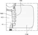
- a buffer device (1000)may include a first buffer part (1100) surrounding an outer circumference of a main body (41) and an outer circumference of a handle part (42), a second buffer part (1200) positioned so as to be spaced apart from the first buffer part (1100) by a predetermined distance and positioned between the main body (41) and the handle part (42), and a connecting part (1300) connecting the first buffer part (1100) and the second buffer part (1200).
- the main body (41)may include a main body case (410) forming the outer shape of the main body (41).
- the main body case (410)may be provided in a rectangular parallelepiped shape as illustrated in FIG. 3.
- the present disclosureis not limited thereto, and the main body case (410) may include different shapes depending on the intended use and the environment of use.
- the width direction of the main body case (410)is described as a first direction (X direction)
- the length direction of the main body case (410)is described as a second direction (Y direction)
- the thickness direction of the main body case (410)is described as a third direction (Z direction).
- the handle portion (42), as illustrated in FIG. 3,may include a grip portion (420) that is positioned to be spaced apart from the main body (41) by a predetermined interval along one direction, for example, the second direction (Y direction), and a grip portion connecting portion (421) that connects the grip portion (420) and the main body (41).
- the outer periphery of the handle portion (42)may be formed to extend from the main body case (410) along one plane (XY plane).
- the present disclosureis not limited thereto, and the shape of the handle portion (42) may include any shape that allows a predetermined hollow region (422) to be formed between the grip portion (420) and the main body (41) depending on the user's gripping method and the purpose of use.
- the outer periphery of the handle portion (42)is formed to extend from the main body case (410) along one plane (XY plane)
- the outer periphery of the main body case (410), the outer periphery of the grip portion (420), and the outer periphery of the grip portion connection portion (421)can have a shape substantially similar to a rectangular parallelepiped.
- the first buffer portion (1100)may be arranged to surround the outer circumference of the main body (41) and the outer circumference of the handle portion (42).
- the first buffer portion (1100)may include a side buffer portion (1110) for protecting the side of the main body case (410), a vertical buffer portion (1120) for protecting the upper and lower plates of the main body case (410) from vertical impact, and a handle buffer portion (1130) for protecting the side of the handle portion (42).
- the side buffer (1110)can protect at least one side of the outer periphery of the main body (41).
- the side buffer (1110)according to one example can have a shape corresponding to the side shape of the main body (41).
- the side buffer (1110)is arranged on the outer periphery of the side of the main body (41) and can protect the side of the main body (41) from an external impact applied along a direction of one plane (XY plane).
- the side buffer portion (1110)may include a first side buffer portion (1111) arranged to extend along the outer periphery of a first side (411) of the main body case (410), a second side buffer portion (1112) arranged to extend along the outer periphery of a second side (412) of the main body case (410), and a third side buffer portion (1113) arranged to extend along the outer periphery of a third side (413) of the main body case (410).
- the first side buffer (1111) and the third side buffer (1113)can be directly supported on the first side (411) of the main body case (410) and the third side (413) of the main body case (410) to protect the first side (411) and the third side (413) of the main body case (410) from external impact applied along a direction of one plane (XY plane).
- the second side buffer (1112)can be supported on the second side (412) of the main body case (410) to protect the second side of the main body case (410) from an external impact applied along a direction of one plane (XY plane).
- a stopper support (1150)can be arranged on the lower part of the second side (412) of the main body case (410) as illustrated in FIG. 8.
- the stopper support (1150)is provided in multiple pieces and can be arranged to be spaced apart from each other by a predetermined interval.
- the stopper support (1150)can be arranged to extend along the second direction (Y direction) and have one end supported on the second side (412) of the main body case (410) and the other end supported on the second side buffer (1112). Accordingly, the second side buffer (1112) and the stopper support (1150) are supported on the second side (412) of the main body case (410) and can protect the second side of the main body case (410) from an external impact applied along a plane (XY plane).
- the vertical buffer (1120)can protect the upper and lower plates of the main body case (410) from vertical impact.
- the vertical buffer (1120) according to an examplecan be arranged in one or more areas.
- the vertical buffer (1120)can be provided in multiple units and arranged between the first side buffer (1111) to the third side buffer (1113) and the handle buffer (1130) to be described later.
- the multiple vertical buffers (1120)can be arranged to be spaced apart from each other in four corner areas formed by the outer periphery of the main body case (410) and the outer periphery of the handle portion (42).
- the vertical buffer (1120) according to an examplecan have a thickness that exceeds the thickness of the main body (41) along the thickness direction of the ultrasonic imaging device (40), for example, the third direction (Z direction).
- the vertical buffer member (1120)when the vertical buffer member (1120) has a thickness exceeding the thickness of the main body (41) along the third direction (Z direction), the vertical buffer member (1120) can protect the upper or lower portion of the main body case (410) from an external impact applied along the vertical direction (Z direction). Matters related to the thickness of the vertical buffer member (1120) and the thickness of the main body (41) will be described in more detail later with reference to FIGS. 9 and 10.
- the handle buffer (1130)can protect at least one side surface of the outer periphery of the handle portion (42).
- the handle buffer (1130)can have a shape corresponding to the side surface shape of the handle portion (42).
- the handle buffer (1130)is arranged on the outer periphery of the side surface of the handle portion (42) to protect the side surface of the handle portion (42) from an external impact applied along a direction of one plane (XY plane).
- the handle buffer portion (1130)may include a shape extending along the outer periphery of the side surface of the grip portion (420).
- the handle buffer portion (1130)may protect the side surface of the grip portion (420) from an external impact applied along one plane (XY plane).
- the second buffer part (1200)is arranged between the main body (41) and the handle part (42) to prevent damage that may occur between the main body (41) and the handle part (42).
- the second buffer part (1200)may be arranged to be spaced apart from the first buffer part (1100) by a predetermined distance.
- the handle part (42)may be placed in the space formed between the first buffer part (1100) and the second buffer part (1200). Accordingly, the space (H) formed between the first buffer part (1100) and the second buffer part (1200) may be substantially equal to the width of the handle part (42).
- the present disclosureis not limited thereto, and when at least one of the first buffer portion (1100) or the second buffer portion (1200) includes an elastic material that can be deformed by external pressure, the gap (H) formed between the first buffer portion (1100) and the second buffer portion (1200) may be formed smaller than the width of the handle portion (42). In this case, the handle portion (42) may be fitted and seated between the first buffer portion (1100) and the second buffer portion (1200).
- the second buffer unit (1200)may be provided in multiple units. At this time, the multiple second buffer units (1200) may be arranged to be spaced apart from each other with a predetermined interval along one direction.
- the multiple second buffer units (1200)may include a 2-1 buffer unit (1210) and a 2-2 buffer unit (1220).
- the 2-1 buffer unit (1210) and the 2-2 buffer unit (1220)may be arranged to be spaced apart from each other along the first direction (X direction).
- the space spaced between the 2-1 buffer unit (1210) and the 2-2 buffer unit (1220)may be arranged to overlap with a hollow region (422) provided in the handle unit (42).
- the user's fingeris placed in the space between the 2-1 buffer part (1210) and the 2-2 buffer part (1220) and the hollow area (422) provided in the handle part (42), so that the user can more easily grasp the ultrasonic diagnostic device assembly (1) including the buffer device (1000).
- the connecting portion (1300)may be arranged between the first buffer portion (1100) and the second buffer portion (1200) to interconnect the first buffer portion (1100) and the second buffer portion (1200).
- the connecting portion (1300)may be arranged between the lower portions of the first buffer portion (1100) and the second buffer portion (1200).
- the connecting portion (1300)may be extended to a length equal to the spacing (H) formed between the first buffer portion (1100) and the second buffer portion (1200).
- a predetermined mounting portion (1350) having a groove shape, on which the handle portion (42) may be mounted,may be formed along the first buffer portion (1100), the connecting portion (1300), and the second buffer portion (1200).
- the connecting portion (1300)may also be provided in multiple units.
- the connecting portion (1300)may be provided in multiple units and include the first connecting portion (1310) and the second connecting portion (1320).
- the space spaced between the first connecting portion (1310) and the second connecting portion (1320)may be arranged to overlap with the hollow region (422) provided in the handle portion (42).
- At least one of the first buffer part (1100), the second buffer part (1200), and the connection part (1300)may be formed integrally.
- the first buffer part (1100), the second buffer part (1200), and the connection part (1300)may be formed integrally, thereby improving manufacturing convenience.
- the present disclosureis not limited thereto, and it goes without saying that the first buffer part (1100), the second buffer part (1200), and the connection part (1300) may be provided separately and then connected respectively.
- the elastic materialmay include at least one of silicone rubber, ethylene vinyl acetate (EVA), ethylene propylene diene monomer rubber (EPDM rubber), fluoro elastomers, acrylonitrile butadiene rubber (NBR rubber), styrene butadiene rubber (SBR rubber), natural rubber (NR rubber), chloroprene rubber (CR rubber), expandable polyethylene (EPE), expanded polypropylene (EPP), expanded polystyrene (EPS), and plastic.
- EVAethylene vinyl acetate
- EPDM rubberethylene propylene diene monomer rubber
- FBR rubberethylene propylene diene monomer rubber
- SBR rubberstyrene butadiene rubber
- NR rubbernatural rubber
- chloroprene rubberCR rubber
- EPEexpandable polyethylene
- EPPexpanded polypropylene
- EPSexpanded polystyrene
- At least one of the first buffer portion (1100) and the second buffer portion (1200)may include an elastic material. Accordingly, at least one of the first buffer part (1100) and the second buffer part (1200) can absorb shock applied from the outside and shock applied between the main body (41) and the handle part (42).
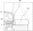
- FIG. 9is a side view of an ultrasonic diagnostic device assembly having an ultrasonic imaging device disposed on a buffer device according to an example.
- FIG. 10is a side view of an ultrasonic diagnostic device assembly having an ultrasonic imaging device disposed on a buffer device according to an example.
- a main body (41)may have a main body thickness (h 1 ) along a thickness direction of an ultrasonic imaging device, for example, a third direction (Z direction).
- a side buffer part (1110) for protecting a side surface of the main body (41), for example, a first side surface (411) of a main body case (410) to a third side surface (413) of a main body case (410), for example, the first side buffer part (1111) to the third side buffer part (1113)may have a side buffer part thickness (h 2 ) smaller than the main body thickness (h 1 ) along the third direction (Z direction).
- one or more regions of the first buffer portion (1100), for example, the vertical buffer portion (1120),may have a vertical buffer portion thickness (h 3 ) that exceeds the body thickness (h 1 ) along the thickness direction of the ultrasonic imaging device, for example, the third direction (Z direction).
- the vertical buffer portions (1120)may be provided in multiple pieces and arranged to be spaced apart from each other in four corner regions formed by the outer periphery of the body case (410) and the outer periphery of the handle portion (42).
- the vertical buffer portions (1120)may be provided in four pieces and may include the first vertical buffer portion (1121) to the fourth vertical buffer portions (1124).
- the first vertical buffer portion (1121) to the fourth vertical buffer portions (1124)may have a vertical buffer portion thickness (h 3 ) that exceeds the body thickness (h 1 ) along the third direction (Z direction). Accordingly, the first vertical buffer portion (1121) to the fourth vertical buffer portion (1124) can protect the upper surface (415) or the lower surface (416) of the main body case (410) from external impact applied along the vertical direction (Z direction).
- a handle portion (42)may have a handle portion thickness (h 4 ) along a thickness direction of an ultrasonic imaging device, for example, a third direction (Z direction).
- the handle portion thickness (h 4 )may be formed smaller than the main body thickness (h 1 ). Accordingly, a user may more easily grip the handle portion (42).
- a portion of a first buffer portion (1100) positioned to face the handle portion (42), for example, a handle buffer portion (1130),may have a handle buffer portion thickness (h 5 ) less than or equal to the handle portion thickness (h 4 ) along a thickness direction of an ultrasonic imaging device, for example, a third direction (Z direction ).
- the handle buffer thickness (h 5 ) of the handle buffer portion (1130)may be formed to be substantially the same as the handle portion thickness (h 4 ) of the handle portion (42). Accordingly, the handle buffer portion (1130) can protect the side of the handle portion (42) from external impact applied to the side of the handle portion (42) along a plane (XY plane) direction, and can also improve user convenience by minimizing the thickness of the grip portion so that the user can easily grip the handle portion (42).
- FIG. 11is a cross-sectional view of an ultrasonic diagnostic device assembly taken along the line A-A illustrated in FIG. 2.
- FIG. 12ais an enlarged cross-sectional view of a portion of the cross-sectional view of the ultrasonic diagnostic device assembly illustrated in FIG. 11.
- FIG. 12bis an enlarged cross-sectional view of a portion of the cross-sectional view of the ultrasonic diagnostic device assembly illustrated in FIG. 11.
- FIG. 13is a plan view of an ultrasonic diagnostic device assembly in which an ultrasonic imaging device is arranged in a buffer device according to an example.
- the ultrasonic imaging device (40)in order to protect the ultrasonic imaging device (40) from external impact, the ultrasonic imaging device (40) must be coupled to a buffer device (1000). In the case of a portable ultrasonic imaging device (40), since the ultrasonic imaging device (40) can be moved after being coupled to the buffer device (1000), the ultrasonic imaging device (40) must be coupled so as to be fixed to the buffer device (1000).
- the first fixing member (1910) and the second fixing member (1920)can fix the ultrasonic imaging device (40) to the buffer device (1000).
- four sides of the main body (41)can be supported by the first buffer member (1100) and the second buffer member (1200).
- the first side (411) to the third side (413) of the main body case (410)can be supported by the first buffer member (1100), and the fourth side (414) can be supported by the second buffer member (1200).
- the first fixing member (1910) and the second fixing member (1920) for fixing the ultrasonic imaging device (40) to the buffer device (1000)may be placed in at least one of the first buffer member (1100) or the second buffer member (1200).
- the first fixing member (1910)can be arranged on the second buffer member (1200) to support one side of the main body (41), thereby fixing the position of the main body (41) with respect to the second buffer member (1200).
- the first fixing member (1910) included in the second buffer member (1200)can fix the position of the fourth side (414) of the main body case (410) with respect to the second buffer member (1200).
- a groove (430)may be arranged on one side of the main body (41), for example, a fourth side (414) of the main body case (410).
- the first fixing part (1910)may include a stepped shape corresponding to the groove (430).
- the first fixing part (1910) of the stepped shape and the groove (430)may be mutually coupled to fix the position of the main body (41) with respect to the second buffer part (1200).
- the first fixing part (1910) included in the second buffer part (1200)may include an elastic material, the first fixing part (1910) may be mutually coupled with the groove (430) in a fitted form.
- the second fixing member (1920)can be arranged on the first buffer member (1100) to support another side of the main body (41), thereby fixing the position of the main body (41) with respect to the first buffer member (1100).
- the second fixing member (1920) included in the first buffer member (1100)can fix the position of the second side (412) of the main body case (410) with respect to the first buffer member (1100).
- a plurality of protrusions (440)may be arranged on another side of the main body (41), for example, a second side (412) of the main body case (410).
- the second fixing portion (1920)may include a plurality of recessed portions having shapes corresponding to the plurality of protrusions (440).
- the second fixing portion (1920) having a plurality of recessed portion shapes and the plurality of protrusions (440)may be mutually coupled to fix the position of the main body (41) with respect to the first buffer portion (1100).
- the second fixing portion (1920) included in the first buffer portion (1100)may include an elastic material, the second fixing portion (1920) may be mutually coupled with the plurality of protrusions (440) in a fitted form.
- a band fixing member (1500)can fix an ultrasonic imaging device (40) to a buffer device (1000).
- an upper surface or a lower surface of a main body (41)can be supported by a band fixing member (1500).
- an upper surface (415) or a lower surface (416) of a main body case (410)can be supported by a band fixing member (1500) arranged to cross the upper surface (415) or the lower surface (416) of the main body case (410).
- the band fixing member (1500) for fixing an ultrasonic imaging device (40) to a buffer device (1000)can be arranged on at least one of the upper surface (415) or the lower surface (416) of the main body case (410).
- the band fixing part (1500)may be provided in multiple pieces to support the upper surface (415) of the main body case (410).
- the band fixing part (1500)may include a first band fixing part (1510) and a second band fixing part (1520).
- the present disclosureis not limited thereto, and the band fixing part (1500) may be provided in a single piece.
- the first band fixing part (1510)may be arranged to cross the upper surface (415) of the main body case (410) along the first direction (X direction). At this time, both ends of the first band fixing part (1510) may be arranged to be detachably attached to the first buffer part (1100). For example, when the main body (41) is arranged in the buffer device (1000), both ends or one end of the first band fixing part (1510) may be separated from the first buffer part (1100). When the main body (41) is coupled to the buffer device (1000), both ends of the first band fixing part (1510) may be coupled to be fixed to the first buffer part (1100).
- the second band fixing part (1520)may be arranged to cross the upper surface (415) of the main body case (410) along the second direction (Y direction). At this time, one end of the second band fixing part (1520) may be arranged to be detachably attached to the first buffer part (1100). For example, when the main body (41) is arranged in the buffer device (1000), one end of the second band fixing part (1520) may be separated from the first buffer part (1100). When the main body (41) is coupled to the buffer device (1000), both ends of the second band fixing part (1520) may be coupled to be fixed to the first buffer part (1100).
- both ends or one end of the first band fixing member (1510) or the second band fixing member (1520)are described as being detachable from the first buffer member (1100), but the present disclosure is not limited thereto.
- both ends or one end of the band fixing member (1500)may be arranged to be detachable from the second buffer member (1200).
- FIG. 14is a bottom view of an ultrasonic diagnostic device assembly having an ultrasonic imaging device disposed on a buffer device according to an example.
- FIG. 15is a cross-sectional view of an ultrasonic diagnostic device assembly having an ultrasonic imaging device disposed on a buffer device according to an example.
- FIG. 16is an enlarged cross-sectional view of a portion of the cross-sectional view of the ultrasonic diagnostic device assembly illustrated in FIG. 15.
- FIG. 17is an enlarged cross-sectional view of a portion of the cross-sectional view of the ultrasonic diagnostic device assembly illustrated in FIG. 15.
- an ultrasonic imaging device (40)may include an intake part (450) through which outside air is introduced into the interior, and an exhaust part (460) through which the air introduced into the interior is discharged to the exterior.
- the intake part (450)may be disposed on one side of the main body (41), and the exhaust part (460) may be disposed on the other side of the main body (41).
- the intake part (450)may be disposed on the fourth side (414) of the main body case (410), and the exhaust part (460) may be disposed on the second side (412) of the main body case (410) opposite the fourth side (414) of the main body case (410).
- the present disclosureis not limited thereto, and the intake part (450) and the exhaust part (460) may be disposed on other than the mutually opposing sides of the main body (41).
- the intake path part (1610)may be arranged to be spaced apart from the intake part (450) by a predetermined distance.
- the intake path part (1610)may be arranged in the second buffer part (1200) facing the intake part (450) and may be arranged to be spaced apart from the intake part (450) by a predetermined distance along the second direction (Y direction).
- the space formed between the intake part (450) and the intake path part (1610)may form a path through which external air may be introduced.
- the intake path part (1610)may include a plurality of intake paths (1611) extending along one direction as a path guide through which external air may be introduced. At this time, each of the plurality of intake paths (1611) can be arranged to correspond to each of the plurality of intake holes (451) provided in the intake part (450).
- the exhaust path part (1620)may be arranged to be spaced apart from the exhaust part (460) by a predetermined distance.
- the exhaust path part (1620)may be arranged on the first buffer part (1100) facing the exhaust part (460) and may be arranged to be spaced apart from the exhaust part (460) by a predetermined distance along the second direction (Y direction).
- the space formed between the exhaust part (460) and the exhaust path part (1620)may form a path through which external air may be introduced.
- the exhaust path part (1620)may include a plurality of first exhaust holes (1621) as a path guide through which external air may be introduced. At this time, each of the plurality of first exhaust holes (1621) may be arranged to correspond to each of the plurality of second exhaust holes (461) provided in the exhaust part (460).
- Fig. 18ais a cross-sectional view of the buffer device taken along the line B-B shown in Fig. 4.
- Fig. 18bis a cross-sectional view of the buffer device taken along the line C-C shown in Fig. 4.
- a first buffer portion (1100)can protect an outer circumference of a side surface of a main body (41) and an outer circumference of a side surface of a handle portion (42).
- the side buffer portion (1110)can protect at least one side surface of the outer circumference of the main body (41).
- the side buffer portion (1110)is arranged on the outer circumference of the side surface of the main body (41) to protect the side surface of the main body (41) from an external impact applied along a direction of one plane (XY plane).
- the handle buffer portion (1130)can protect at least one side surface of the outer circumference of the handle portion (42).
- the handle buffer portion (1130)is arranged on the outer circumference of the side surface of the handle portion (42) to protect the side surface of the handle portion (42) from an external impact applied along a direction of one plane (XY plane).
- the first buffer part (1100)may include an elastic material. Accordingly, the first buffer part (1100) may absorb an impact applied from the outside and an impact applied to the main body (41) and the handle part (42). However, the amount of impact applied to the main body (41) and the handle part (42) may increase depending on the shape and weight of the main body (41) and the handle part (42). In order to protect the main body (41) and the handle part (42) from the increased amount of impact, a reinforcing member (1400) may be additionally placed on the first buffer part (1100).
- a reinforcing member (1400)may be positioned to be inserted into the center of the first buffer portion (1100). At this time, the reinforcing member (1400) may include a different material from the first buffer portion (1100). As an example, when the first buffer portion (1100) includes an elastic material, the reinforcing member (1400) may include a material having a different elastic coefficient from the elastic material. For example, the first buffer portion (1100) may include a rigid material such as a metal material or a plastic material.
- a reinforcing member (1400)may include a first reinforcing member (1410) and a third reinforcing member (1430) arranged at the center of the first side buffer portion (1111) and the third side buffer portion (1113), as illustrated in FIG. 18A.
- the reinforcing member (1400)may include the first reinforcing member (1410) and the third reinforcing member (1430) arranged to be surrounded by the first side buffer portion (1111) and the third side buffer portion (1113), respectively.
- first reinforcing member (1410) and the third reinforcing member (1430)may be arranged to extend in one direction, for example, in the second direction (Y direction), like the first side buffer portion (1111) and the third side buffer portion (1113).
- the reinforcing member (1400)may include a second reinforcing member (1420) and a fourth reinforcing member (1440) arranged at the center of the second side buffer portion (1112) and the handle buffer portion (1130), as illustrated in FIG. 18b.
- the reinforcing member (1400)may include the second reinforcing member (1420) and the fourth reinforcing member (1440) arranged to be surrounded by the second side buffer portion (1112) and the handle buffer portion (1130), respectively.
- the second reinforcing member (1420) and the fourth reinforcing member (1440)may be arranged to extend in one direction, for example, along the first direction (X direction), like the second side buffer portion (1112) and the handle buffer portion (1130).
- first reinforcing member (1410) and the second reinforcing member (1420) included in the reinforcing member (1400)may be provided in an integral shape in which they are interconnected, the second reinforcing member (1420) and the third reinforcing member (1430) are interconnected, the third reinforcing member (1430) and the fourth reinforcing member (1440) are interconnected, and the fourth reinforcing member (1440) and the first reinforcing member (1410) are interconnected.
- the present disclosureis not limited thereto, and the first reinforcing member (1410) to the second reinforcing member (1420) may be formed individually and arranged to be interconnected.
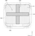
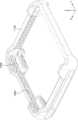
- Fig. 19is a perspective projection view of a buffer device according to an example.
- the first buffer part (1100) and the second buffer part (1200)can protect the main body (41) and the handle part (42) from external impact.
- the amount of impact applied to the main body (41) and the handle part (42)can increase.
- a plurality of impact-absorbing parts (1600)can be additionally arranged in the first buffer part (1100) and the second buffer part (1200).
- a plurality of shock absorbers (1600)may be arranged inside at least one of the first buffer unit (1100) and the second buffer unit (1200).
- the plurality of shock absorbers (1600)may have at least one of a polygonal or circular cross-section. Since the plurality of shock absorbers (1600) have at least one of a polygonal or circular cross-section, an impact applied from the outside may be prevented from being applied to the main body (41) or the handle unit (42) by the structural rigidity of the shape having the polygonal or circular cross-section.
- the plurality of shock absorbers (1600)may include the same or different material as the first buffer unit (1100) and the second buffer unit (1200).
- the plurality of shock absorbers (1600)may include a material having an elastic coefficient that is the same or different from that of the elastic material of the first buffer unit (1100) and the second buffer unit (1200).
- the plurality of shock absorbers (1600)may be formed integrally with the first buffer unit (1100) and the second buffer unit (1200).
- the present disclosureis not limited thereto, and a plurality of shock absorbing parts (1600) may be formed separately and combined inside the first buffer part (1100) and the second buffer part (1200).
- FIG. 20is a side view of an ultrasonic diagnostic device assembly having an ultrasonic imaging device disposed on a buffer device according to an example.
- FIG. 21is a side view of an ultrasonic diagnostic device assembly having an ultrasonic imaging device disposed on a buffer device according to an example.
- FIG. 22is a partial cross-sectional view of an ultrasonic diagnostic device assembly having an ultrasonic imaging device disposed on a buffer device according to an example.
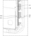
- an ultrasonic imaging device (40)may include one or more connectors (470) to which a probe (20) may be connected.
- one or more connectors (470)may be arranged on one side of a main body (41).
- one or more connectors (470)may be arranged on one side of a main body case (410).
- the present disclosureis not limited thereto, and one or more connectors (470) may be arranged in any area of the main body case (410).
- a connector hole (1710)may be arranged at a position corresponding to one or more of the connectors (470) described above.
- the connector hole (1710)may be provided in an opening shape through which one or more of the connectors (470) may be exposed to the outside.
- the connector hole (1710)may be arranged on a first side buffer portion (1111) corresponding to the first side (411). Since one or more of the connectors (470) may be exposed to the outside, a foreign substance arranged on the outside may be inserted into one or more of the connectors (470).
- a connector hole opening/closing part (1720)can open/close a connector hole (1710) to prevent foreign substances placed externally from being inserted into one or more connectors (470).
- the connector hole opening/closing part (1720)can be a dustproof member and a waterproof member that prevent foreign substances placed externally from being inserted into one or more connectors (470).
- the connector hole opening/closing part (1720)may include a shape corresponding to the connector hole (1710).
- the connector hole opening/closing part (1720)may be coupled to the first buffer part (1100) so as to be able to open/close the connector hole (1710).
- the connector hole opening/closing part (1720)may be arranged to be rotatable about one axis on the first buffer part (1100). Accordingly, when the probe (20) is coupled to the connector (470), the connector hole opening/closing part (1720) may open the connector hole (1710) as illustrated in FIG. 21. In addition, when the probe (20) is not coupled to the connector (470), the connector hole opening/closing part (1720) may be rotated about one axis to shield the connector hole (1710).
- FIG. 23is a side view of an ultrasonic diagnostic device assembly with a probe coupled thereto according to an example.
- FIG. 24is a side view of an ultrasonic diagnostic device assembly with a probe separated therefrom according to an example.
- an ultrasonic imaging device (40)may include one or more connectors (470) to which a probe (20) may be connected.
- the probe (20)may include a recessed portion (220) arranged in a region other than the connector (210).
- the recessed portion (220) provided in the probe (20)may be arranged in a state spaced apart from the ultrasonic imaging device (40).
- an impact applied from the outsidemay be transmitted to the connector (210) provided in the probe (20).
- a shock-absorbing step (1730)may be provided in a shape corresponding to a groove (220) provided in a probe (20) to support the groove (220).
- the shock-absorbing step (1730)may be arranged at one end of a connector hole (1710).
- the shock-absorbing step (1730)may be provided integrally with the first buffer (1100) and may include an elastic material.
- the shock-absorbing step (1730)may be provided separately and arranged to be coupled to one end of the connector hole (1710).
- the shock-absorbing step (1730)can prevent shock from being applied from the outside to the connector (210) provided in the probe (20).
- Fig. 25is a perspective view of a buffer device according to an example.
- Fig. 26is a partial cross-sectional view of an ultrasonic diagnostic device assembly according to an example.
- the main body (41)may include a groove portion (480) having a predetermined groove shape.
- the groove portion (480) provided in the main body (41)may be a joint or a joining portion between different configurations.
- the present disclosureis not limited thereto, and the groove portion (480) may include any opening shape through which a foreign substance placed externally may be in fluid communication with a component placed internally of the main body case (410) provided in the ultrasonic imaging device (40).
- a waterproofing part (1800)may include a shape corresponding to a groove (480) provided in a main body (41).
- the waterproofing part (1800)may include a protrusion shape corresponding to the groove (480).
- a waterproofing part (1800)may be arranged in at least one of a first buffering part (1100) or a second buffering part (1200).
- the waterproofing part (1800)may be arranged on an inner surface of at least one of the first buffering part (1100) or the second buffering part (1200).
- the waterproofing part (1800)may be arranged to extend along a periphery of at least one of the first buffering part (1100) or the second buffering part (1200).
- the waterproofing part (1800)may be formed integrally with at least one of the first buffering part (1100) or the second buffering part (1200).
- the waterproofing part (1800)may include the same material as at least one of the first buffering part (1100) or the second buffering part (1200), for example, an elastic material.
- the present disclosureis not limited thereto, and the waterproofing part (1800) may be provided separately and coupled to at least one of the first buffering part (1100) or the second buffering part (1200).
- the waterproofing part (1800)may include a different material from at least one of the first buffering part (1100) or the second buffering part (1200).
- the waterproof part (1800)may be positioned to be inserted into the groove part (480) to block foreign substances from entering from the outside.
- the waterproof part (1800)includes an elastic material
- the waterproof part (1800) provided in the shape of a protrusionmay be positioned to be inserted into the groove part (480) in a fitting manner to block foreign substances from entering from the outside.
Landscapes
- Life Sciences & Earth Sciences (AREA)
- Health & Medical Sciences (AREA)
- Biomedical Technology (AREA)
- Biophysics (AREA)
- Nuclear Medicine, Radiotherapy & Molecular Imaging (AREA)
- Pathology (AREA)
- Radiology & Medical Imaging (AREA)
- Engineering & Computer Science (AREA)
- Physics & Mathematics (AREA)
- Heart & Thoracic Surgery (AREA)
- Medical Informatics (AREA)
- Molecular Biology (AREA)
- Surgery (AREA)
- Animal Behavior & Ethology (AREA)
- General Health & Medical Sciences (AREA)
- Public Health (AREA)
- Veterinary Medicine (AREA)
- Ultra Sonic Daignosis Equipment (AREA)
Abstract
Description
Translated fromKorean본 개시는 완충 장치 및 이를 포함하는 초음파 진단 장치 조립체에 관한 것이다.The present disclosure relates to a buffer device and an ultrasonic diagnostic device assembly including the same.
근래 의료분야에서는 각종 질병의 조기 진단 또는 수술을 목적으로 인체의 생체 조직에 대한 정보를 영상화하여 획득하기 위한 각종 의료 영상 장치가 널리 이용되고 있다. 이러한 의료 영상 장치의 대표적인 예로는 초음파 진단 장치, CT(Computed Tomography) 장치, MRI(Magnetic Resonance Imaging) 장치를 포함할 수 있다.In recent years, various medical imaging devices have been widely used in the medical field to obtain information about the human body's biological tissues by visualizing them for the purpose of early diagnosis of various diseases or surgery. Representative examples of such medical imaging devices include ultrasound diagnostic devices, CT (Computed Tomography) devices, and MRI (Magnetic Resonance Imaging) devices.
초음파 진단 장치는 프로브(probe)의 트랜스듀서(transducer)로부터 생성되는 초음파 신호를 대상체로 조사하고, 대상체로부터 반사된 신호의 정보를 수신하여 대상체 내부의 부위(예를 들면, 연조직 또는 혈류)에 대한 적어도 하나의 영상을 비침습으로 획득하는 장치이다. 초음파 진단 장치는 대상체 내부의 관찰, 이물질 검출, 및 상해 측정 등 의학적 목적으로 사용될 수 있다. 이러한 초음파 진단 장치는 X선을 이용하는 영상 장치에 비하여 안정성이 높고, 실시간으로 영상의 디스플레이가 가능하며, 방사능 피폭이 없어 안전하다는 장점이 있어서 다른 화상 영상 장치와 함께 널리 이용된다.An ultrasound diagnostic device is a device that noninvasively obtains at least one image of a part (e.g., soft tissue or blood flow) inside the target by irradiating an ultrasound signal generated from a transducer of a probe to the target and receiving information on a signal reflected from the target. An ultrasound diagnostic device can be used for medical purposes such as observing the inside of a target, detecting foreign substances, and measuring injuries. Such ultrasound diagnostic devices have the advantages of high stability compared to imaging devices using X-rays, real-time image display, and safety due to the absence of radiation exposure, and are therefore widely used together with other imaging devices.
초음파 진단 장치는 사용 목적에 따라 이동 가능한 포터블 형태로 구현될 수 있다. 초음파 진단 장치를 이동시키는 과정에서 외부 충격에 의해 초음파 진단 장치가 파손될 위험이 증가될 수 있다.The ultrasonic diagnostic device may be implemented in a portable form that can be moved depending on the purpose of use. During the process of moving the ultrasonic diagnostic device, the risk of the ultrasonic diagnostic device being damaged by external impact may increase.
외부에서 인가되는 충격으로부터 초음파 진단 장치를 보호하는 완충 장치 및 이를 포함하는 초음파 진단 장치 조립체를 제공한다.A buffer device for protecting an ultrasonic diagnostic device from external impact and an ultrasonic diagnostic device assembly including the buffer device are provided.
초음파 진단 장치에 완충 장치가 배치된 상태에서, 사용자 편의성이 향상된 완충 장치 및 이를 포함하는 초음파 진단 장치 조립체를 제공한다.In a state where a buffer device is arranged in an ultrasonic diagnostic device, a buffer device with improved user convenience and an ultrasonic diagnostic device assembly including the buffer device are provided.
일 예시에 따른 본체 및 상기 본체에 결합되는 핸들부를 구비하는 초음파 영상 장치를 둘러싸는 완충 장치는, 상기 본체의 외주부와 상기 핸들부의 외주부를 둘러싸는 제1 완충부 및 상기 제1 완충부와 소정의 간격을 사이에 두고 이격되도록 배치되며, 상기 본체와 상기 핸들부 사이에 배치되는 제2 완충부를 포함할 수 있다.A buffer device surrounding an ultrasonic imaging device having a main body and a handle portion coupled to the main body according to an example may include a first buffer portion surrounding an outer circumference of the main body and an outer circumference of the handle portion, and a second buffer portion disposed so as to be spaced apart from the first buffer portion by a predetermined distance and disposed between the main body and the handle portion.
상기 제1 완충부와 상기 제2 완충부를 연결하는 연결부를 더 포함할 수 있다.It may further include a connecting portion connecting the first buffer portion and the second buffer portion.
상기 제1 완충부, 상기 제2 완충부 및 상기 연결부 중 하나 이상은 일체로 형성될 수 있다.At least one of the first buffer portion, the second buffer portion, and the connecting portion may be formed integrally.
상기 제2 완충부는 일 방향을 따라 상호 이격되도록 배치되는 제2-1 완충부재 및 제2-2 완충부재를 포함할 수 있다.The above second buffer member may include a second-first buffer member and a second-second buffer member that are arranged to be spaced apart from each other along one direction.
상기 핸들부는 상기 초음파 영상 장치의 두께 방향을 따라 핸들부 두께를 구비하며, 상기 핸들부와 마주보도록 배치되는 상기 제1 완충부의 일부 영역은 상기 초음파 영상 장치의 두께 방향을 따라 상기 핸들부 두께 이하의 두께를 구비할 수 있다.The above handle portion has a handle portion thickness along the thickness direction of the ultrasonic imaging device, and a portion of the first buffer portion positioned to face the handle portion may have a thickness less than or equal to the handle portion thickness along the thickness direction of the ultrasonic imaging device.
상기 본체는 상기 초음파 영상 장치의 두께 방향을 따라 본체 두께를 구비하며, 상기 제1 완충부 중 하나 이상의 영역은 상기 초음파 영상 장치의 두께 방향을 따라 상기 본체 두께를 초과하는 수직 완충부 두께를 구비할 수 있다.The above body has a body thickness along the thickness direction of the ultrasonic imaging device, and at least one region of the first buffer portion may have a vertical buffer portion thickness exceeding the body thickness along the thickness direction of the ultrasonic imaging device.
상기 제2 완충부는 상기 본체의 일면을 지지하여 상기 제2 완충부에 대한 상기 본체의 위치를 고정시키는 제1 고정부를 포함하고, 상기 제1 완충부는 상기 본체의 다른 일면을 지지하여 상기 제1 완충부에 대한 상기 본체의 위치를 고정시키는 제2 고정부를 포함할 수 있다.The second buffer portion may include a first fixing portion that supports one side of the main body and fixes the position of the main body with respect to the second buffer portion, and the first buffer portion may include a second fixing portion that supports the other side of the main body and fixes the position of the main body with respect to the first buffer portion.
상기 본체의 일면에 홈부가 배치되며, 상기 제1 고정부는 상기 홈부에 대응되는 형상의 단차부를 포함하고, 상기 본체의 다른 일면에 복수 개의 돌기부가 배치되며, 상기 제2 고정부는 상기 복수 개의 돌기부에 대응되는 복수 개의 홈부를 포함할 수 있다.A groove may be arranged on one side of the main body, the first fixing part may include a stepped part having a shape corresponding to the groove, a plurality of protrusions may be arranged on the other side of the main body, and the second fixing part may include a plurality of recessed parts corresponding to the plurality of protrusions.
상기 본체의 일면을 가로지르도록 배치되며, 양 단부 또는 일 단부가 상기 제1 완충부 또는 상기 제2 완충부에 탈착 가능하도록 배치되는 밴드 고정부;를 더 포함할 수 있다.The band fixing member may further include a band fixing member arranged to cross one side of the main body and having both ends or one end detachably attached to the first buffering member or the second buffering member.
상기 본체의 일면에 배치되는 흡기부와 소정의 간격을 사이에 두고 마주보도록 배치되는 흡기 유로부 및 상기 본체의 다른 일면에 배치되는 배기부와 소정의 간격을 사이에 두고 마주보도록 배치되는 배기 유로부를 더 포함할 수 있다.The device may further include an intake passage part arranged to face an intake part disposed on one side of the main body with a predetermined gap therebetween, and an exhaust passage part arranged to face an exhaust part disposed on the other side of the main body with a predetermined gap therebetween.
상기 흡기 유로부는 일 방향을 따라 연장된 복수 개의 흡기 유로를 구비하고, 상기 배기 유로부는 복수 개의 배기홀을 구비할 수 있다.The above intake passage part may have a plurality of intake passages extending in one direction, and the above exhaust passage part may have a plurality of exhaust holes.
상기 제1 완충부 및 상기 제2 완충부 중 하나 이상은 탄성 재질을 포함할 수 있다.At least one of the first buffer portion and the second buffer portion may include an elastic material.
상기 탄성 재질은 실리콘 고무, 에틸렌 초산 비닐 (EVA: Ethylene Vinyl Acetate). EPDM 고무(ethylene propylene diene Monomer rubber), 불소 고무(fluoro elastomers), NBR 고무 (acrylonitrile butadiene rubber), SBR 고무(Styrene Butadiene Rubber), NR 고무(Natural Rubber), CR 고무(chloroprene rubber), 확장형 폴리에틸렌(EPE: Expandable Polyethylene), 확장형 폴리프로필렌(EPP: Expanded polypropylene), 확장형 폴리스티렌(EPS: Expanded Polystyrene), 플라스틱(Plastic) 중 하나 이상을 포함할 수 있다.The above elastic material may include one or more of silicone rubber, ethylene vinyl acetate (EVA), ethylene propylene diene monomer rubber (EPDM rubber), fluoro elastomers, acrylonitrile butadiene rubber (NBR rubber), styrene butadiene rubber (SBR rubber), natural rubber (NR rubber), chloroprene rubber (CR rubber), expanded polyethylene (EPE), expanded polypropylene (EPP), expanded polystyrene (EPS), and plastic.
상기 제1 완충부의 중심부에 삽입되도록 배치되는 보강 부재를 더 포함할 수 있다.It may further include a reinforcing member positioned to be inserted into the center of the first buffer portion.
상기 보강 부재는 상기 제1 완충부와 상이한 물질을 포함할 수 있다.The above reinforcing member may include a different material from the first buffer portion.
상기 제1 완충부 및 상기 제2 완충부 중 하나 이상의 내부에 배치되며, 다각형 또는 원형 단면 중 하나 이상을 구비하는 복수 개의 충격 완화부를 더 포함할 수 있다.The device may further include a plurality of shock absorbing members arranged inside at least one of the first buffer member and the second buffer member and having at least one of a polygonal or circular cross-section.
상기 본체의 일면에 하나 이상의 커넥터가 배치되며, 상기 하나 이상의 커넥터와 대응되는 위치에 배치되는 커넥터 홀 및 상기 커넥터 홀을 개폐하는 커넥터 홀 개폐부를 더 포함할 수 있다.One or more connectors are arranged on one side of the above body, and a connector hole arranged at a position corresponding to the one or more connectors and a connector hole opening/closing part for opening and closing the connector hole may be further included.
상기 본체의 커넥터에 연결되는 프로브에 소정의 홈부가 배치되며, 상기 홈부에 대응되는 형상으로 마련되어 상기 홈부를 지지하는 충격 완화 단차부;를 더 포함할 수 있다.A probe connected to the connector of the above main body may further include a groove portion arranged therein, and a shock-absorbing step portion formed in a shape corresponding to the groove portion and supporting the groove portion.
상기 본체에 소정의 홈부가 배치되며, 상기 홈부에 대응되는 형상으로 마련되며, 상기 홈부에 삽입되어 외부로부터 유입되는 이물질을 차단하는 방수부;를 더 포함할 수 있다.The above body may further include a waterproof part having a predetermined groove portion arranged in a shape corresponding to the groove portion and inserted into the groove portion to block foreign substances entering from the outside.
일 예시에 따른 초음파 진단 장치 조립체는 상기 완충 장치, 본체, 상기 본체에 결합되는 핸들부를 구비하는 초음파 영상 장치 및 상기 초음파 영상 장치와 연결되는 프로브를 포함할 수 있다.An ultrasonic diagnostic device assembly according to one example may include an ultrasonic imaging device having the buffer device, a main body, a handle portion coupled to the main body, and a probe connected to the ultrasonic imaging device.
일 예시에 따른 완충 장치 및 이를 포함하는 초음파 진단 장치 조립체는 외부에서 인가되는 충격으로부터 초음파 진단 장치를 보호할 수 있다.A buffer device and an ultrasonic diagnostic device assembly including the buffer device according to an example can protect the ultrasonic diagnostic device from external impact.
또한, 일 예시에 따른 완충 장치 및 이를 포함하는 초음파 진단 장치 조립체는 초음파 진단 장치에 완충 장치가 배치된 상태에서, 초음파 진단 장치의 사용자 편의성을 향상시킬 수 있다.In addition, the buffer device and the ultrasonic diagnostic device assembly including the buffer device according to one example can improve the user convenience of the ultrasonic diagnostic device when the buffer device is arranged in the ultrasonic diagnostic device.
본 개시는, 다음의 자세한 설명과 그에 수반되는 도면들의 결합으로 쉽게 이해될 수 있으며, 참조 번호(reference numerals)들은 구조적 구성요소(structural elements)를 의미한다.The present disclosure can be readily understood by the combination of the following detailed description and the accompanying drawings, in which reference numerals refer to structural elements.
도 1은 본 개시의 일 실시예에 따른 초음파 영상 시스템의 구성을 도시한 블록도이다.FIG. 1 is a block diagram illustrating the configuration of an ultrasound imaging system according to one embodiment of the present disclosure.
도 2는 일 예시에 따른 완충 장치를 포함하는 초음파 진단 장치 조립체의 사시도이다.FIG. 2 is a perspective view of an ultrasonic diagnostic device assembly including a buffer device according to an example.
도 3은 일 예시에 따른 완충 장치와 초음파 진단 장치의 분리 사시도이다.Figure 3 is a perspective view of a buffer device and an ultrasonic diagnostic device according to an example.
도 4는 일 예시에 따른 완충 장치의 사시도이다.Figure 4 is a perspective view of a buffer device according to an example.
도 5는 일 예시에 따른 완충 장치의 평면도이다.Figure 5 is a plan view of a buffer device according to an example.
도 6은 일 예시에 따른 완충 장치에 초음파 영상 장치가 배치된 초음파 진단 장치 조립체의 평면도이다.FIG. 6 is a plan view of an ultrasonic diagnostic device assembly having an ultrasonic imaging device arranged in a buffer device according to an example.
도 7은 도 6에 도시된 P영역을 확대한 확대도이다.Figure 7 is an enlarged view of the P area shown in Figure 6.
도 8은 일 예시에 따른 완충 장치에 초음파 영상 장치가 배치된 초음파 진단 장치 조립체의 저면도이다.FIG. 8 is a bottom view of an ultrasonic diagnostic device assembly having an ultrasonic imaging device arranged in a buffer device according to an example.
도 9는 일 예시에 따른 완충 장치에 초음파 영상 장치가 배치된 초음파 진단 장치 조립체의 측면도이다.FIG. 9 is a side view of an ultrasonic diagnostic device assembly having an ultrasonic imaging device disposed in a buffer device according to an example.
도 10은 일 예시에 따른 완충 장치에 초음파 영상 장치가 배치된 초음파 진단 장치 조립체의 측면도이다.FIG. 10 is a side view of an ultrasonic diagnostic device assembly having an ultrasonic imaging device disposed in a buffer device according to an example.
도 11은 도 2에 도시된 A-A선을 따라 절단한 초음파 진단 장치 조립체의 단면도이다.FIG. 11 is a cross-sectional view of the ultrasonic diagnostic device assembly taken along line A-A shown in FIG. 2.
도 12a는 도 11에 도시된 초음파 진단 장치 조립체의 단면도의 일부를 확대한 확대 단면도이다.FIG. 12a is an enlarged cross-sectional view of a portion of the cross-sectional view of the ultrasonic diagnostic device assembly illustrated in FIG. 11.
도 12b는 도 11에 도시된 초음파 진단 장치 조립체의 단면도의 일부를 확대한 확대 단면도이다.Fig. 12b is an enlarged cross-sectional view of a portion of the cross-sectional view of the ultrasonic diagnostic device assembly illustrated in Fig. 11.
도 13은 일 예시에 따른 완충 장치에 초음파 영상 장치가 배치된 초음파 진단 장치 조립체의 평면도이다.FIG. 13 is a plan view of an ultrasonic diagnostic device assembly having an ultrasonic imaging device arranged in a buffer device according to an example.
도 14은 일 예시에 따른 완충 장치에 초음파 영상 장치가 배치된 초음파 진단 장치 조립체의 저면도이다.FIG. 14 is a bottom view of an ultrasonic diagnostic device assembly having an ultrasonic imaging device arranged in a buffer device according to an example.
도 15은 일 예시에 따른 완충 장치에 초음파 영상 장치가 배치된 초음파 진단 장치 조립체의 단면도이다.FIG. 15 is a cross-sectional view of an ultrasonic diagnostic device assembly having an ultrasonic imaging device arranged in a buffer device according to an example.
도 16는 도 15에 도시된 초음파 진단 장치 조립체의 단면도의 일부를 확대한 확대 단면도이다.Fig. 16 is an enlarged cross-sectional view of a portion of the cross-sectional view of the ultrasonic diagnostic device assembly illustrated in Fig. 15.
도 17는 도 15에 도시된 초음파 진단 장치 조립체의 단면도의 일부를 확대한 확대 단면도이다.Fig. 17 is an enlarged cross-sectional view of a portion of the cross-sectional view of the ultrasonic diagnostic device assembly illustrated in Fig. 15.
도 18a는 도 4에 도시된 B-B선을 따라 절단한 완충 장치의 단면도이다.Fig. 18a is a cross-sectional view of the buffer device taken along the line B-B shown in Fig. 4.
도 18b는 도 4에 도시된 C-C선을 따라 절단한 완충 장치의 단면도이다.Figure 18b is a cross-sectional view of the buffer device taken along the line C-C shown in Figure 4.
도 19는 일 예시에 따른 완충 장치에 투영 사시도이다.Fig. 19 is a perspective projection view of a buffer device according to an example.
도 20은 일 예시에 따른 완충 장치에 초음파 영상 장치가 배치된 초음파 진단 장치 조립체의 측면도이다.FIG. 20 is a side view of an ultrasonic diagnostic device assembly having an ultrasonic imaging device disposed in a buffer device according to an example.
도 21은 일 예시에 따른 완충 장치에 초음파 영상 장치가 배치된 초음파 진단 장치 조립체의 측면도이다.FIG. 21 is a side view of an ultrasonic diagnostic device assembly having an ultrasonic imaging device disposed in a buffer device according to an example.
도 22는 일 예시에 따른 완충 장치에 초음파 영상 장치가 배치된 초음파 진단 장치 조립체의 부분 단면도이다.FIG. 22 is a partial cross-sectional view of an ultrasonic diagnostic device assembly having an ultrasonic imaging device disposed in a buffer device according to an example.
도 23은 일 예시에 따른 프로브가 결합된 초음파 진단 장치 조립체의 측면도이다.FIG. 23 is a side view of an ultrasonic diagnostic device assembly with a probe coupled thereto according to an example.
도 24는 일 예시에 따른 프로브가 분리된 초음파 진단 장치 조립체의 측면도이다.FIG. 24 is a side view of an ultrasonic diagnostic device assembly with the probe separated according to an example.
도 25는 일 예시에 따른 완충 장치의 사시도이다.Fig. 25 is a perspective view of a buffer device according to an example.
도 26은 일 예시에 따른 초음파 진단 장치 조립체의 부분 단면도이다.Fig. 26 is a partial cross-sectional view of an ultrasonic diagnostic device assembly according to an example.
본 개시는 본 개시의 청구항의 권리범위를 명확히 하고, 본 개시의 실시예들이 속하는 기술분야에서 통상의 지식을 가진 자가 본 개시의 실시예들을 실시할 수 있도록, 본 개시의 실시예들의 원리를 설명하고, 실시예들을 개시한다. 본 개시의 실시예들은 다양한 형태로 구현될 수 있다.This disclosure clarifies the scope of the claims of the present disclosure and explains the principles of the embodiments of the present disclosure and discloses embodiments so that a person having ordinary skill in the art to which the embodiments of the present disclosure belong can practice the embodiments of the present disclosure. The embodiments of the present disclosure can be implemented in various forms.
명세서 전체에 걸쳐 동일 참조 부호는 동일 구성요소를 지칭한다. 본 명세서가 실시예들의 모든 요소들을 설명하는 것은 아니며, 본 발명이 속하는 기술분야에서 일반적인 내용 또는 실시예들 간에 중복되는 내용은 생략한다. 명세서에서 사용되는 '모듈' 또는'부'(unit)라는 용어는 소프트웨어, 하드웨어 또는 펌웨어 중 하나 또는 둘 이상의 조합으로 구현될 수 있으며, 실시예들에 따라 복수의 '모듈' 또는'부'가 하나의 요소(element)로 구현되거나, 하나의 ''모듈' 또는 부'가 복수의 요소들을 포함하는 것도 가능하다.Throughout the specification, the same reference numerals denote the same components. The specification does not describe all elements of the embodiments, and any content that is general in the technical field to which the present invention belongs or that is redundant between the embodiments is omitted. The term 'module' or 'unit' used in the specification may be implemented by one or a combination of two or more of software, hardware, or firmware, and according to the embodiments, a plurality of 'modules' or 'units' may be implemented as a single element, or a single 'module' or 'unit' may include a plurality of elements.
아이템에 대응하는 명사의 단수 형은 관련된 문맥상 명백하게 다르게 지시하지 않는 한, 상기 아이템 한 개 또는 복수 개를 포함할 수 있다.The singular form of a noun corresponding to an item may include one or more of said items, unless the context clearly indicates otherwise.
본 개시에서, "A 또는 B", "A 및 B 중 적어도 하나", "A 또는 B 중 적어도 하나", "A, B, 또는 C", "A, B, 및 C 중 적어도 하나", 및 "A, B, 또는 C 중 적어도 하나"와 같은 문구들 각각은 그 문구들 중 해당하는 문구에 함께 나열된 항목들 중 어느 하나, 또는 그들의 모든 가능한 조합을 포함할 수 있다.In this disclosure, each of the phrases "A or B", "at least one of A and B", "at least one of A or B", "A, B, or C", "at least one of A, B, and C", and "at least one of A, B, or C" can include any one of the items listed together in the corresponding phrase, or all possible combinations thereof.
"및/또는"이라는 용어는 복수의 관련된 기재된 구성요소들의 조합 또는 복수의 관련된 기재된 구성요소들 중의 어느 구성요소를 포함한다.The term "and/or" includes any combination of multiple related described elements or any one of multiple related described elements.
"제1", "제2", 또는 "첫째" 또는 "둘째"와 같은 용어들은 단순히 해당 구성요소를 다른 해당 구성요소와 구분하기 위해 사용될 수 있으며, 해당 구성요소들을 다른 측면(예: 중요성 또는 순서)에서 한정하지 않는다.Terms such as "first", "second", or "first" or "second" may be used merely to distinguish one component from another, and do not limit the components in any other respect (e.g., importance or order).
또한, 본 개시에서 사용한 '전면', '후면', '상면', '하면', '측면', '좌측', '우측', '상부', '하부' 등의 용어는 도면을 기준으로 정의한 것이며, 이 용어에 의해 각 구성요소의 형상 및 위치가 제한되는 것은 아니다.In addition, the terms 'front', 'rear', 'top', 'bottom', 'side', 'left', 'right', 'upper', 'lower', etc. used in the present disclosure are defined based on the drawings, and the shape and position of each component are not limited by these terms.
"포함하다" 또는 "가지다"등의 용어는 본 개시에 기재된 특징, 숫자, 단계, 동작, 구성요소, 부품 또는 이들을 조합한 것이 존재함을 지정하려는 것이지, 하나 또는 그 이상의 다른 특징들이나 숫자, 단계, 동작, 구성요소, 부품 또는 이들을 조합한 것들의 존재 또는 부가 가능성을 미리 배제하지 않는다.The terms "include" or "have" and the like are intended to specify the presence of a feature, number, step, operation, component, part or combination thereof described in the present disclosure, but do not exclude in advance the possibility of the presence or addition of one or more other features, numbers, steps, operations, components, parts or combinations thereof.
어떤 구성요소가 다른 구성요소와 "연결", "결합", "지지" 또는 "접촉"되어 있다고 할 때, 이는 구성요소들이 직접적으로 연결, 결합, 지지 또는 접촉되는 경우뿐 아니라, 제3 구성요소를 통하여 간접적으로 연결, 결합, 지지 또는 접촉되는 경우를 포함한다.When a component is said to be “connected,” “coupled,” “supported,” or “contacted” with another component, this includes not only cases where the components are directly connected, coupled, supported, or in contact, but also cases where the components are indirectly connected, coupled, supported, or in contact through a third component.
어떤 구성요소가 다른 구성요소 "상에" 위치하고 있다고 할 때, 이는 어떤 구성요소가 다른 구성요소에 접해 있는 경우뿐 아니라 두 구성요소 사이에 또 다른 구성요소가 존재하는 경우도 포함한다.When we say that a component is "on" another component, this includes not only cases where the component is in contact with the other component, but also cases where there is another component between the two components.
이하에서 첨부된 도면을 참조하여 다양한 실시예에 따른 초음파 장치를 구체적으로 설명한다. 첨부된 도면을 참조하여 설명함에 있어, 동일하거나 대응하는 구성 요소는 유사한 도면 번호를 부여하고 이에 대한 중복되는 설명은 생략할 수 있다.Hereinafter, an ultrasonic device according to various embodiments will be specifically described with reference to the attached drawings. In describing with reference to the attached drawings, identical or corresponding components are given similar drawing numbers and redundant descriptions thereof may be omitted.
본 개시에서 영상은 자기 공명 영상(MRI) 장치, 컴퓨터 단층 촬영(CT) 장치, 초음파 영상 장치, 또는 엑스레이 영상 장치 등의 의료 영상 장치에 의해 획득된 의료 영상을 포함할 수 있다.In the present disclosure, the image may include a medical image acquired by a medical imaging device such as a magnetic resonance imaging (MRI) device, a computed tomography (CT) device, an ultrasound imaging device, or an X-ray imaging device.
본 개시에서 '대상체(object)'는 촬영의 대상이 되는 것으로서, 사람, 동물, 또는 그 일부를 포함할 수 있다. 예를 들어, 대상체는 신체의 일부(장기 또는 기관 등; organ) 또는 팬텀(phantom) 등을 포함할 수 있다.In the present disclosure, an 'object' is a subject of photography, and may include a person, an animal, or a part thereof. For example, the object may include a part of a body (such as an organ or system) or a phantom.
본 개시에서 '초음파 영상'이란 대상체로 송신되고, 대상체로부터 반사된 초음파 신호에 근거하여 생성 또는 처리된 대상체(object)에 대한 영상을 의미한다.In the present disclosure, the term 'ultrasonic image' means an image of an object generated or processed based on an ultrasonic signal transmitted to the object and reflected from the object.
이하에서는 도면을 참조하여 본 개시의 실시예들을 상세히 설명한다.Hereinafter, embodiments of the present disclosure will be described in detail with reference to the drawings.
도 1은 본 개시의 일 실시예에 따른 초음파 영상 시스템의 구성을 도시한 블록도이다.FIG. 1 is a block diagram illustrating the configuration of an ultrasound imaging system according to one embodiment of the present disclosure.
도 1을 참조하면, 일 예시에 따른 초음파 진단 장치(100)는 프로브(20) 및 초음파 영상 장치(40)를 포함할 수 있다. 일 예시에 따른 프로브(20)는 디스플레이(112), 송신 모듈(113), 배터리(114), 트랜스듀서(115), 충전 모듈(116), 수신 모듈(117), 입력 인터페이스(109), 프로세서(118), 및 통신 모듈(119)을 포함할 수 있다. 도 1에서는 프로브(20)가 송신 모듈(113) 및 수신 모듈(117)을 모두 포함하는 것으로 도시하였으나, 구현 형태에 따라, 프로브(20)는 송신 모듈(113) 및 수신 모듈(117)의 구성 중 일부만을 포함할 수도 있으며, 송신 모듈(113) 및 수신 모듈(117)의 구성 중 일부는 초음파 영상 장치(40)에 포함될 수도 있다. 또한, 본 개시의 일 실시예에 따르면, 프로브(20)는 영상 프로세서(130)를 더 포함할 수도 있다.Referring to FIG. 1, an ultrasonic diagnostic device (100) according to an example may include a probe (20) and an ultrasonic imaging device (40). The probe (20) according to an example may include a display (112), a transmission module (113), a battery (114), a transducer (115), a charging module (116), a receiving module (117), an input interface (109), a processor (118), and a communication module (119). In FIG. 1, the probe (20) is illustrated as including both the transmission module (113) and the receiving module (117), but depending on the implementation form, the probe (20) may include only a part of the configurations of the transmission module (113) and the receiving module (117), and a part of the configurations of the transmission module (113) and the receiving module (117) may be included in the ultrasonic imaging device (40). In addition, according to an embodiment of the present disclosure, the probe (20) may further include an image processor (130).
트랜스듀서(115)는, 복수의 트랜스듀서들을 포함할 수 있다. 복수의 트랜스듀서들은 소정의 배열로 나열되어 트랜스듀서 어레이로 구현될 수 있다. 트랜스듀서 어레이는 1차원(1D) 어레이 또는 2차원(2D) 어레이에 대응할 수 있다. 복수의 트랜스듀서들은 송신 모듈(113)로부터 인가된 송신 신호에 따라 대상체(10)로 초음파 신호를 송출할 수 있다. 또한, 복수의 트랜스듀서들은 대상체(10)로부터 반사된 초음파 신호를 수신하여, 전기적인 수신 신호를 형성 또는 생성할 수 있다.The transducer (115) may include a plurality of transducers. The plurality of transducers may be arranged in a predetermined arrangement and implemented as a transducer array. The transducer array may correspond to a one-dimensional (1D) array or a two-dimensional (2D) array. The plurality of transducers may transmit ultrasonic signals to the target (10) according to a transmission signal applied from the transmission module (113). In addition, the plurality of transducers may receive ultrasonic signals reflected from the target (10) and form or generate electrical reception signals.
충전 모듈(116)은 배터리(114)를 충전시킬 수 있다. 충전 모듈(116)은 외부로부터 전력을 수신할 수 있다. 본 개시의 일 실시예에 따르면, 충전 모듈(116)은 무선으로 전력을 수신할 수 있다. 또한, 본 개시의 일 실시예에 따르면, 충전 모듈(116)은 유선으로 전력을 수신할 수도 있다. 충전 모듈(116)은 수신한 전력을 배터리(114)로 전달할 수 있다.The charging module (116) can charge the battery (114). The charging module (116) can receive power from the outside. According to one embodiment of the present disclosure, the charging module (116) can receive power wirelessly. Also, according to one embodiment of the present disclosure, the charging module (116) can receive power wiredly. The charging module (116) can transfer the received power to the battery (114).
프로세서(118)는 복수의 트랜스듀서들의 위치 및 집속점을 고려하여, 복수의 트랜스듀서들 각각에 인가될 송신 신호를 생성 또는 형성하도록 송신 모듈(113)를 제어한다.The processor (118) controls the transmission module (113) to generate or form a transmission signal to be applied to each of the plurality of transducers, taking into account the positions and focus points of the plurality of transducers.
프로세서(118)는 트랜스듀서(115)로부터 수신되는 수신 신호를 아날로그 디지털 변환하고, 복수의 트랜스듀서들의 위치 및 집속점을 고려하여, 디지털 변환된 수신 신호를 합산함으로써, 초음파 데이터를 생성하도록 수신 모듈(117)를 제어한다. 본 개시의 일 실시예에 따르면, 프로브(20)가 영상 프로세서(130)를 포함하는 경우, 생성된 초음파 데이터를 이용하여, 초음파 영상을 생성할 수 있다.The processor (118) controls the receiving module (117) to generate ultrasound data by converting an analog-to-digital reception signal received from the transducer (115) and adding the digitally converted reception signals by considering the positions and focal points of a plurality of transducers. According to one embodiment of the present disclosure, when the probe (20) includes an image processor (130), an ultrasound image can be generated using the generated ultrasound data.
프로브(20)가 2차원 프로브로 구현되는 경우, 프로세서(118)는 2차원 트랜스듀서 어레이에 포함되는 복수의 서브 어레이들 각각에 대하여, 서브 어레이 별로 디지털 빔포밍을 위한 시간 지연 값을 산출할 수 있다. 또한, 프로세서(118)는 복수의 서브 어레이들 중 어느 하나의 서브 어레이에 포함된 트랜스듀서들 각각에 대한 아날로그 빔포밍을 위한 시간 지연 값을 산출할 수 있다. 프로세서(118)는 아날로그 빔포밍을 위한 시간 지연 값 및 디지털 빔포밍을 위한 시간 지연 값들에 따라, 복수의 트랜스듀서들 각각에 인가될 송신 신호를 형성하도록 아날로그 빔포머 및 디지털 빔포머를 제어할 수 있다. 또한, 프로세서(118)는 복수의 트랜스듀서들로부터 수신한 신호들을 아날로그 빔포밍을 위한 시간 지연 값에 따라, 서브 어레이 별로 합산하도록 아날로그 빔포머를 제어할 수 있다. 또한, 프로세서(118)는 서브 어레이 별로 합산된 신호를 아날로그 디지털 변환하도록 초음파 송수신 모듈(110)을 제어할 수 있다. 또한, 프로세서(118)는 디지털 변환된 신호들을 디지털 빔포밍을 위한 시간 지연 값에 따라 합산하여, 초음파 데이터를 생성하도록 디지털 빔포머를 제어할 수 있다.When the probe (20) is implemented as a two-dimensional probe, the processor (118) can calculate a time delay value for digital beamforming for each sub-array of a plurality of sub-arrays included in the two-dimensional transducer array. In addition, the processor (118) can calculate a time delay value for analog beamforming for each transducer included in one of the plurality of sub-arrays. The processor (118) can control the analog beamformer and the digital beamformer to form a transmission signal to be applied to each of the plurality of transducers according to the time delay value for analog beamforming and the time delay value for digital beamforming. In addition, the processor (118) can control the analog beamformer to add up signals received from the plurality of transducers according to the time delay value for analog beamforming for each sub-array. In addition, the processor (118) can control the ultrasonic transmission/reception module (110) to convert the signal added for each sub-array into analog-to-digital. Additionally, the processor (118) can control the digital beamformer to generate ultrasound data by adding digitally converted signals according to a time delay value for digital beamforming.
프로세서(118)는 프로브(20)의 전반적인 동작을 제어하고, 프로브(20)의 구성 요소들의 동작을 제어할 수 있다. 프로세서(118)는 메모리(111)에 저장된 프로그램 또는 인스트럭션들을 실행함으로써, 프로브(20)의 다양한 동작 또는 기능을 수행하거나 제어할 수 있다. 또한, 프로세서(118)는 프로브(20)의 입력 인터페이스(109) 또는 외부 장치(예: 초음파 영상 장치(40))로부터 제어 신호를 수신하여, 프로브(20)의 동작을 제어할 수 있다. 또한, 프로세서(118)는 입력 인터페이스(109) 또는 외부 장치로부터 제어 신호를 수신하여, 프로브(20)의 동작을 제어할 수 있다. 입력 인터페이스(109)는, 프로브(20)를 제어하기 위한 사용자의 입력을 수신할 수 있다. 예를 들어, 사용자의 입력은 버튼, 키 패드, 마우스, 트랙볼, 조그 스위치, 놉(knop) 등을 조작하는 입력, 터치 패드나 터치 스크린을 터치하는 입력, 음성 입력, 모션 입력, 생체 정보 입력(예를 들어, 홍채 인식, 지문 인식 등) 등을 포함할 수 있으나 이에 한정되지 않는다.The processor (118) controls the overall operation of the probe (20) and can control the operation of components of the probe (20). The processor (118) can perform or control various operations or functions of the probe (20) by executing programs or instructions stored in the memory (111). In addition, the processor (118) can receive a control signal from the input interface (109) of the probe (20) or an external device (e.g., an ultrasonic imaging device (40)) and control the operation of the probe (20). In addition, the processor (118) can receive a control signal from the input interface (109) or an external device and control the operation of the probe (20). The input interface (109) can receive a user's input for controlling the probe (20). For example, user input may include, but is not limited to, inputs manipulating buttons, keypads, mouses, trackballs, jog switches, knobs, etc., inputs touching a touchpad or touchscreen, voice inputs, motion inputs, biometric inputs (e.g., iris recognition, fingerprint recognition, etc.), etc.
디스플레이(112)는 프로브(20)에 의해 생성된 초음파 영상, 프로브(20)에서 생성된 초음파 데이터를 처리하여 생성한 초음파 영상, 초음파 영상 장치(40)로부터 수신된 초음파 영상, 또는 초음파 진단 장치(100)에서 처리되는 다양한 정보 등을 표시할 수 있다. 또한, 디스플레이(112)는 프로브(20)의 상태 정보를 더 표시할 수 있다. 프로브(20)의 상태 정보는 프로브(20)의 장치 정보, 프로브(20)의 배터리 상태 정보, 프로브(20)의 주파수 대역 정보, 프로브(20)의 출력 정보, 프로브(20)의 이상 유무 정보, 프로브(20)의 설정 정보, 또는 프로브(20)의 온도 정보 중 적어도 하나를 포함할 수 있다.The display (112) can display an ultrasonic image generated by the probe (20), an ultrasonic image generated by processing ultrasonic data generated by the probe (20), an ultrasonic image received from an ultrasonic imaging device (40), or various information processed by the ultrasonic diagnostic device (100). In addition, the display (112) can further display status information of the probe (20). The status information of the probe (20) can include at least one of device information of the probe (20), battery status information of the probe (20), frequency band information of the probe (20), output information of the probe (20), abnormality information of the probe (20), setting information of the probe (20), or temperature information of the probe (20).
프로브(20)는 구현 형태에 따라 하나 또는 복수의 디스플레이(112)를 포함할 수 있다. 또한, 디스플레이(112)는 터치 패널 또는 터치 스크린을 포함할 수 있다. 또한, 디스플레이(112)는 플렉서블 디스플레이를 포함할 수 있다.The probe (20) may include one or more displays (112) depending on the implementation form. In addition, the display (112) may include a touch panel or a touch screen. In addition, the display (112) may include a flexible display.
통신 모듈(119)은 생성된 초음파 데이터 또는 초음파 영상을 무선 네트워크를 통하여, 초음파 영상 장치(40)로 무선 전송할 수 있다. 또한, 통신 모듈(119)은 초음파 영상 장치(40)로부터 제어 신호 및 데이터를 수신할 수 있다.The communication module (119) can wirelessly transmit generated ultrasonic data or ultrasonic images to an ultrasonic imaging device (40) via a wireless network. In addition, the communication module (119) can receive control signals and data from the ultrasonic imaging device (40).
초음파 영상 장치(40)는 프로브(20)로부터 초음파 데이터 또는 초음파 영상을 수신할 수 있다.The ultrasonic imaging device (40) can receive ultrasonic data or ultrasonic images from the probe (20).
본 개시의 일 실시예에서, 프로브(20)가 초음파 데이터를 이용하여 초음파 영상을 생성할 수 있는 영상 프로세서(130)를 포함하는 경우, 프로브(20)는 초음파 영상 장치(40)에게 초음파 데이터 또는 영상 프로세서(130)에 의해 생성된 초음파 영상을 전송할 수 있다.In one embodiment of the present disclosure, when the probe (20) includes an image processor (130) capable of generating an ultrasound image using ultrasound data, the probe (20) can transmit the ultrasound data or the ultrasound image generated by the image processor (130) to the ultrasound imaging device (40).
본 개시의 일 실시예에서, 프로브(20)가 초음파 데이터를 이용하여 초음파 영상을 생성할 수 있는 영상 프로세서(130)를 포함하지 않는 경우, 프로브(20)는 초음파 영상 장치(40)에게 초음파 데이터를 전송할 수 있다. 초음파 데이터는 초음파 로데이터(raw data)를 포함할 수 있고, 초음파 영상은 초음파 영상 데이터를 의미할 수 있다.In one embodiment of the present disclosure, when the probe (20) does not include an image processor (130) capable of generating an ultrasound image using ultrasound data, the probe (20) may transmit the ultrasound data to an ultrasound imaging device (40). The ultrasound data may include ultrasound raw data, and the ultrasound image may mean ultrasound image data.
초음파 영상 장치(40)는 프로세서(120), 영상 프로세서(130), 디스플레이(140), 메모리(150), 통신 모듈(160) 및 입력 인터페이스(170)를 포함할 수 있다.The ultrasonic imaging device (40) may include a processor (120), an image processor (130), a display (140), a memory (150), a communication module (160), and an input interface (170).
영상 프로세서(130)는 프로브(20)로부터 수신한 초음파 데이터를 이용하여, 초음파 영상을 생성 또는 처리한다.The image processor (130) generates or processes an ultrasonic image using ultrasonic data received from the probe (20).
디스플레이(140)는 프로브(20)로부터 수신한 초음파 영상, 프로브(20)로부터 수신된 초음파 데이터를 처리하여 생성한 초음파 영상, 또는 초음파 진단 장치(100)에서 처리되는 다양한 정보 등을 표시할 수 있다. 초음파 영상 장치(40)는 구현 형태에 따라 하나 또는 복수의 디스플레이(140)를 포함할 수 있다. 또한, 디스플레이(140)는 터치 패널 또는 터치 스크린을 포함할 수 있다. 또한, 디스플레이(140)는 플렉서블 디스플레이를 포함할 수 있다.The display (140) can display an ultrasonic image received from the probe (20), an ultrasonic image generated by processing ultrasonic data received from the probe (20), or various information processed in the ultrasonic diagnostic device (100). The ultrasonic imaging device (40) can include one or more displays (140) depending on the implementation type. In addition, the display (140) can include a touch panel or a touch screen. In addition, the display (140) can include a flexible display.
프로세서(120)는 초음파 영상 장치(40)의 전반적인 동작을 제어하고, 초음파 영상 장치(40)의 구성 요소들의 동작을 제어할 수 있다. 프로세서(120)는 메모리(150)에 저장된 프로그램 또는 어플리케이션을 실행하여, 초음파 영상 장치(40)의 다양한 동작 또는 기능을 수행하거나 제어할 수 있다. 또한, 프로세서(120)는 입력 인터페이스(170) 또는 외부 장치로부터 제어 신호를 수신하여, 초음파 영상 장치(40)의 동작을 제어할 수 있다.The processor (120) controls the overall operation of the ultrasonic imaging device (40) and can control the operation of components of the ultrasonic imaging device (40). The processor (120) can execute a program or application stored in the memory (150) to perform or control various operations or functions of the ultrasonic imaging device (40). In addition, the processor (120) can receive a control signal from an input interface (170) or an external device and control the operation of the ultrasonic imaging device (40).
초음파 영상 장치(40)는 통신 모듈(160)을 포함하며, 통신 모듈(160)을 통해 외부 장치(예를 들면, 프로브(20), 서버, 의료 장치, 휴대 장치(스마트폰, 태블릿 PC, 웨어러블 기기 등))와 연결되고 통신할 수 있다.The ultrasonic imaging device (40) includes a communication module (160) and can be connected to and communicate with an external device (e.g., a probe (20), a server, a medical device, a portable device (smartphone, tablet PC, wearable device, etc.)) through the communication module (160).
통신 모듈(160)은 외부 장치와 통신을 가능하게 하는 하나 이상의 구성 요소를 포함할 수 있다. 통신 모듈(160)은 예를 들어 근거리 통신 모듈, 유선 통신 모듈, 또는 무선 통신 모듈 중 적어도 하나를 포함할 수 있다.The communication module (160) may include one or more components that enable communication with an external device. The communication module (160) may include, for example, at least one of a short-range communication module, a wired communication module, or a wireless communication module.
초음파 영상 장치(40)의 통신 모듈(160)과 프로브(20)의 통신 모듈(119)은 네트워크를 이용하여 통신할 수도 있고, 근거리 무선 통신 방법을 이용하여 통신할 수도 있다. 예를 들어, 초음파 영상 장치(40)의 통신 모듈(160)과 프로브(20)의 통신 모듈(119)은 무선 랜(Wireless LAN), 와이파이(Wi-Fi), 블루투스(Bluetooth), 지그비(zigbee), WFD(Wi-Fi Direct), 적외선 통신(IrDA, infrared Data Association), BLE (Bluetooth LowEnergy), NFC(Near Field Communication), 와이브로(Wireless Broadband Internet, Wibro), 와이맥스(World Interoperability for Microwave Access, WiMAX), SWAP(Shared Wireless Access Protocol), 와이기그(Wireless Gigabit Allicance, WiGig), RF 통신, 또는 60GHz 밀리미터파(mm Wave) 근거리 통신 등을 포함하는 무선 데이터 통신 방법 중 어느 하나를 이용하여 통신할 수 있다.The communication module (160) of the ultrasonic imaging device (40) and the communication module (119) of the probe (20) may communicate using a network or a short-range wireless communication method. For example, the communication module (160) of the ultrasonic imaging device (40) and the communication module (119) of the probe (20) may communicate using any one of wireless data communication methods including Wireless LAN, Wi-Fi, Bluetooth, zigbee, WFD (Wi-Fi Direct), infrared Data Association (IrDA), Bluetooth LowEnergy (BLE), Near Field Communication (NFC), Wireless Broadband Internet (Wibro), World Interoperability for Microwave Access (WiMAX), Shared Wireless Access Protocol (SWAP), Wireless Gigabit Alliance (WiGig), RF communication, or 60GHz millimeter wave (mm Wave) short-range communication.
이를 위해, 초음파 영상 장치(40)의 통신 모듈(160)과 프로브(20)의 통신 모듈(119)은 무선 랜(Wireless LAN) 통신 모듈, 와이파이(Wi-Fi) 통신 모듈, 블루투스(Bluetooth) 통신 모듈, 지그비(zigbee) 통신 모듈, WFD(Wi-Fi Direct) 통신 모듈, 적외선 통신(IrDA, infrared Data Association) 모듈, BLE (Bluetooth LowEnergy) 통신 모듈, NFC(Near Field Communication) 통신 모듈, 와이브로(Wireless Broadband Internet, Wibro) 통신 모듈, 와이맥스(World Interoperability for Microwave Access, WiMAX) 통신 모듈, SWAP(Shared Wireless Access Protocol) 통신 모듈, 와이기그(Wireless Gigabit Allicance, WiGig) 통신 모듈, RF 통신 모듈, 또는 60GHz 밀리미터파(mm Wave) 근거리 통신 모듈 중 적어도 하나를 포함할 수 있다.To this end, the communication module (160) of the ultrasound imaging device (40) and the communication module (119) of the probe (20) may include at least one of a wireless LAN communication module, a Wi-Fi communication module, a Bluetooth communication module, a zigbee communication module, a WFD (Wi-Fi Direct) communication module, an infrared communication (IrDA) module, a BLE (Bluetooth LowEnergy) communication module, an NFC (Near Field Communication) communication module, a Wibro (Wireless Broadband Internet) communication module, a WiMAX (World Interoperability for Microwave Access) communication module, a SWAP (Shared Wireless Access Protocol) communication module, a WiGig (Wireless Gigabit Alliance) communication module, an RF communication module, or a 60GHz millimeter wave (mm Wave) short-range communication module.
본 개시의 일 실시예에서, 프로브(20)는 제1 통신 방법(예: BLE)을 이용하여 프로브(20)의 장치 정보(예: ID 정보)를 초음파 영상 장치(40)로 전송하고, 초음파 영상 장치(40)와 무선으로 페어링(paring)될 수 있다. 또한, 프로브(20)는 페어링된 초음파 영상 장치(40)에게 초음파 데이터 및/또는 초음파 영상을 전송할 수 있다.In one embodiment of the present disclosure, the probe (20) transmits device information (e.g., ID information) of the probe (20) to the ultrasonic imaging device (40) using a first communication method (e.g., BLE) and can be wirelessly paired with the ultrasonic imaging device (40). In addition, the probe (20) can transmit ultrasonic data and/or ultrasonic images to the paired ultrasonic imaging device (40).
프로브(20)의 장치 정보는 프로브(20)의 시리얼 넘버, 모델명, 또는 배터리 상태 등과 관련된 다양한 정보를 포함할 수 있다.The device information of the probe (20) may include various information related to the serial number, model name, or battery status of the probe (20).
초음파 영상 장치(40)는 제1 통신 방법(예: BLE)을 이용하여 프로브(20)로부터 프로브(20)의 장치 정보(예: ID 정보)를 수신하고, 프로브(20)와 무선으로 페어링(paring)될 수 있다. 또한, 초음파 영상 장치(40)는 페어링된 프로브(20)에게 활성화 신호를 전송하고, 프로브(20)로부터 초음파 데이터 및/또는 초음파 영상을 수신할 수 있다. 이 때, 활성화 신호는 프로브(20)의 동작을 제어하기 위한 신호를 포함할 수 있다.The ultrasonic imaging device (40) may receive device information (e.g., ID information) of the probe (20) from the probe (20) using a first communication method (e.g., BLE), and may be wirelessly paired with the probe (20). In addition, the ultrasonic imaging device (40) may transmit an activation signal to the paired probe (20), and receive ultrasonic data and/or ultrasonic images from the probe (20). At this time, the activation signal may include a signal for controlling the operation of the probe (20).
본 개시의 일 실시예에서, 프로브(20)는 제1 통신 방법(예: BLE)을 이용하여 프로브(20)의 장치 정보(예: ID 정보)를 초음파 영상 장치(40)로 전송하고, 초음파 영상 장치(40)와 무선으로 페어링(paring)될 수 있다. 또한, 프로브(20)는 제2 통신 방법(예: 60GHz 밀리미터파, 와이파이)을 이용하여 제1 통신 방법에 의해 페어링된 초음파 영상 장치(40)에게 초음파 데이터 및/또는 초음파 영상을 전송할 수 있다.In one embodiment of the present disclosure, the probe (20) may transmit device information (e.g., ID information) of the probe (20) to the ultrasonic imaging device (40) using a first communication method (e.g., BLE) and may be wirelessly paired with the ultrasonic imaging device (40). In addition, the probe (20) may transmit ultrasonic data and/or ultrasonic images to the ultrasonic imaging device (40) paired by the first communication method using a second communication method (e.g., 60 GHz millimeter wave, Wi-Fi).
초음파 영상 장치(40)는 제1 통신 방법(예: BLE)을 이용하여 프로브(20)로부터 프로브(20)의 장치 정보(예: ID 정보)를 수신하고, 프로브(20)와 무선으로 페어링(paring)될 수 있다. 또한, 초음파 영상 장치(40)는 페어링된 프로브(20)에게 활성화 신호를 전송하고, 제2 통신 방법(예: 60GHz 밀리미터파, 와이파이)을 이용하여 프로브(20)로부터 초음파 데이터 및/또는 초음파 영상을 수신할 수 있다.The ultrasonic imaging device (40) may receive device information (e.g., ID information) of the probe (20) from the probe (20) using a first communication method (e.g., BLE) and may be wirelessly paired with the probe (20). In addition, the ultrasonic imaging device (40) may transmit an activation signal to the paired probe (20) and receive ultrasonic data and/or ultrasonic images from the probe (20) using a second communication method (e.g., 60 GHz millimeter wave, Wi-Fi).
본 개시의 일 실시예에 따르면, 프로브(20)와 초음파 영상 장치(40)가 서로 페어링되는데 이용되는 제1 통신 방법은 프로브(20)가 초음파 영상 장치(40)에게 초음파 데이터 및/또는 초음파 영상을 전송하는데 이용되는 제2 통신 방법의 주파수 대역보다 낮은 주파수 대역을 가질 수 있다.According to one embodiment of the present disclosure, a first communication method used to pair the probe (20) and the ultrasonic imaging device (40) with each other may have a lower frequency band than a frequency band of a second communication method used to transmit ultrasonic data and/or ultrasonic images from the probe (20) to the ultrasonic imaging device (40).
초음파 영상 장치(40)의 디스플레이(140)는 프로브(20)의 장치 정보를 나타내는 UI(User Interface)들을 표시할 수 있다. 예를 들어, 디스플레이(140)는 무선 초음파 프로브(20)의 식별 정보, 프로브(20)와의 페어링 방법을 나타내는 페어링 방법, 프로브(20)와 초음파 영상 장치(40) 간의 데이터 통신 상태, 초음파 영상 장치(40)와의 데이터 통신을 수행하는 방법, 또는 프로브(20)의 배터리 상태를 나타내는 UI 등을 표시할 수 있다.The display (140) of the ultrasonic imaging device (40) can display UIs (User Interfaces) indicating device information of the probe (20). For example, the display (140) can display identification information of the wireless ultrasonic probe (20), a pairing method indicating a pairing method with the probe (20), a data communication status between the probe (20) and the ultrasonic imaging device (40), a method of performing data communication with the ultrasonic imaging device (40), or a UI indicating a battery status of the probe (20).
프로브(20)가 디스플레이(112)를 포함하는 경우, 프로브(20)의 디스플레이(112)는 프로브(20)의 장치 정보를 나타내는 UI를 표시할 수 있다. 예를 들어, 디스플레이(112)는 무선 초음파 프로브(20)의 식별 정보, 프로브(20)와의 페어링 방법을 나타내는 페어링 방법, 프로브(20)와 초음파 영상 장치(40) 간의 데이터 통신 상태, 초음파 영상 장치(40)와의 데이터 통신을 수행하는 방법, 또는 프로브(20)의 배터리 상태를 나타내는 UI등을 표시할 수 있다.When the probe (20) includes a display (112), the display (112) of the probe (20) may display a UI indicating device information of the probe (20). For example, the display (112) may display identification information of the wireless ultrasonic probe (20), a pairing method indicating a pairing method with the probe (20), a data communication status between the probe (20) and the ultrasonic imaging device (40), a method of performing data communication with the ultrasonic imaging device (40), or a UI indicating a battery status of the probe (20).
통신 모듈(160)은 외부 장치로부터 제어 신호 또는 데이터를 수신할 수 있다. 프로세서(120)는 통신 모듈(160)을 통해 수신된 제어 신호에 따라 초음파 영상 장치(40)의 동작을 제어할 수 있다.The communication module (160) can receive a control signal or data from an external device. The processor (120) can control the operation of the ultrasonic imaging device (40) according to the control signal received through the communication module (160).
또한, 프로세서(120)가 통신 모듈(160)을 통해 외부 장치로 제어 신호를 송신하여, 외부 장치를 송신된 제어 신호에 따라 제어하는 것도 가능하다. 외부 장치는 초음파 영상 장치(40)로부터 수신된 제어 신호에 따라 동작하거나, 초음파 영상 장치(40)로부터 수신된 데이터를 처리할 수 있다.In addition, it is also possible for the processor (120) to transmit a control signal to an external device through a communication module (160) and control the external device according to the transmitted control signal. The external device can operate according to a control signal received from the ultrasonic imaging device (40) or process data received from the ultrasonic imaging device (40).
외부 장치는 초음파 영상 장치(40)에 관련된 프로그램 또는 어플리케이션을 초음파 영상 장치(40), 프로브(20), 또는 서버로부터 수신 또는 다운로드하고, 프로그램 또는 어플리케이션을 외부 장치에 설치하여 실행할 수 있다. 프로그램 또는 어플리케이션을 제공하는 초음파 영상 장치(40), 프로브(20), 또는 서버는 해당 프로그램 또는 어플리케이션의 인스트럭션, 커맨드, 설치 파일, 실행 파일, 또는 관련 데이터 등을 저장하는 기록매체를 포함할 수 있다. 외부 장치는 프로그램 또는 어플리케이션이 설치된 상태로 판매되는 것도 가능하다.An external device may receive or download a program or application related to an ultrasonic imaging device (40) from an ultrasonic imaging device (40), a probe (20), or a server, and install and execute the program or application on the external device. An ultrasonic imaging device (40), a probe (20), or a server that provides a program or application may include a recording medium that stores instructions, commands, installation files, executable files, or related data of the program or application. The external device may also be sold with the program or application installed.
메모리(150)는 초음파 영상 장치(40)를 구동하고 제어하기 위한 다양한 데이터 또는 프로그램, 입/출력되는 초음파 데이터, 초음파 영상 등을 저장할 수 있다.The memory (150) can store various data or programs for driving and controlling the ultrasonic imaging device (40), input/output ultrasonic data, ultrasonic images, etc.
도 2는 일 예시에 따른 완충 장치를 포함하는 초음파 진단 장치 조립체의 사시도이다. 도 3은 일 예시에 따른 완충 장치와 초음파 진단 장치의 분리 사시도이다.FIG. 2 is a perspective view of an ultrasonic diagnostic device assembly including a buffer device according to an example. FIG. 3 is an exploded perspective view of the buffer device and the ultrasonic diagnostic device according to an example.
도 2 및 도 3을 참조하면, 일 예시에 따른 초음파 진단 장치 조립체(1)는 프로브(20)와 초음파 영상 장치(40)를 포함하는 초음파 진단 장치(100) 및 초음파 영상 장치(40)를 둘러싸는 완충 장치(1000)를 포함할 수 있다.Referring to FIGS. 2 and 3, an ultrasonic diagnostic device assembly (1) according to an example may include an ultrasonic diagnostic device (100) including a probe (20) and an ultrasonic imaging device (40), and a buffer device (1000) surrounding the ultrasonic imaging device (40).
일 예시에 따른 초음파 영상 장치(40)는 휴대형으로도 구현될 수 있다. 휴대형 초음파 영상 장치(40)의 예로는, 프로브 및 어플리케이션을 포함하는 스마트 폰(smart phone), 랩탑 컴퓨터, PDA, 또는 태블릿 PC 등이 있을 수 있으나, 이에 한정되지 않는다.The ultrasound imaging device (40) according to one example may also be implemented in a portable form. Examples of portable ultrasound imaging devices (40) may include, but are not limited to, a smart phone, a laptop computer, a PDA, or a tablet PC including a probe and an application.
일 예로서, 휴대형 초음파 영상 장치(40)는 본체(41) 및 본체(41)에 결합되는 핸들부(42)를 포함 할 수 있다. 핸들부(42)는 본체(41)와 소정의 간격을 사이에 두고 이격되도록 배치되는 그립부(420), 그립부(420)의 양 단부에 배치되며, 그립부(420)와 본체(41)를 연결하는 그립부 연결부(421)를 포함할 수 있다. 본체(41)와 그립부(420) 사이에 배치된 이격 공간에 사용자의 손가락이 배치되는 중공 영역(422)이 형성될 수 있다. 본체(41)에 핸들부(42)가 결합되도록 배치되고, 사용자는 본체(41)를 용이하게 파지할 수 있음에 따라, 사용자 편의성이 향상될 수 있다.As an example, a portable ultrasound imaging device (40) may include a main body (41) and a handle portion (42) coupled to the main body (41). The handle portion (42) may include a grip portion (420) arranged to be spaced apart from the main body (41) by a predetermined distance, and a grip portion connecting portion (421) arranged at both ends of the grip portion (420) and connecting the grip portion (420) and the main body (41). A hollow area (422) in which a user's finger is placed may be formed in the space arranged between the main body (41) and the grip portion (420). Since the handle portion (42) is arranged to be coupled to the main body (41) and the user can easily grip the main body (41), user convenience may be improved.
일 예로서, 초음파 영상 장치(40)와 프로브(20)는 커넥터를 이용하여 상호 연결될 수 있다. 일 예로서, 초음파 영상 장치(40)는 하나 이상의 커넥터(470: 도 20 참조)를 구비하고, 프로브(20)는 초음파 영상 장치(40)에 마련된 하나 이상의 커넥터(470)에 결합되는 커넥터(210)를 구비할 수 있다. 다만 본 개시가 이에 제한되는 것은 아니며, 초음파 영상 장치(40)와 프로브(20)는 근거리 무선 통신을 이용하여 통신을 수립하거나 페어링될 수 있다. 예를 들면, 초음파 영상 장치(40)와 프로브(20)는 블루투스, BLE, 와이파이, 또는 와이파이 다이렉트 등을 이용하여 통신을 수행할 수 있다.As an example, the ultrasonic imaging device (40) and the probe (20) may be interconnected using connectors. As an example, the ultrasonic imaging device (40) may be provided with one or more connectors (470: see FIG. 20), and the probe (20) may be provided with a connector (210) coupled to one or more connectors (470) provided in the ultrasonic imaging device (40). However, the present disclosure is not limited thereto, and the ultrasonic imaging device (40) and the probe (20) may establish communication or be paired using short-range wireless communication. For example, the ultrasonic imaging device (40) and the probe (20) may perform communication using Bluetooth, BLE, Wi-Fi, or Wi-Fi Direct.
초음파 영상 장치(40)는 프로브(20)와 관련된 프로그램 또는 어플리케이션을 실행하여, 프로브(20)를 제어하고, 프로브(20)에 관련된 정보를 출력할 수 있다. 초음파 영상 장치(40)는 소정의 서버와 통신하면서, 프로브(20)와 관련된 동작을 수행할 수 있다. 프로브(20)는 초음파 영상 장치(40)에 등록되거나, 소정의 서버에 등록될 수 있다. 초음파 영상 장치(40)는 등록된 프로브(20)와 통신하고, 프로브(20)에 관련된 동작을 수행할 수 있다.The ultrasonic imaging device (40) can control the probe (20) and output information related to the probe (20) by executing a program or application related to the probe (20). The ultrasonic imaging device (40) can perform operations related to the probe (20) while communicating with a predetermined server. The probe (20) can be registered with the ultrasonic imaging device (40) or registered with a predetermined server. The ultrasonic imaging device (40) can communicate with the registered probe (20) and perform operations related to the probe (20).
또한, 초음파 영상 장치(40)는 스피커, LED, 진동 장치 등의 다양한 형태의 입출력 인터페이스를 포함할 수 있다. 예를 들면, 초음파 영상 장치(40)는 입출력 인터페이스를 통해 다양한 정보를 그래픽, 소리, 또는 진동 등의 형태로 출력할 수 있다. 또한, 초음파 영상 장치(40)는 다양한 알림 또는 데이터를 입출력 인터페이스를 통해 출력할 수 있다.In addition, the ultrasonic imaging device (40) may include various types of input/output interfaces such as speakers, LEDs, and vibration devices. For example, the ultrasonic imaging device (40) may output various information in the form of graphics, sounds, or vibrations through the input/output interface. In addition, the ultrasonic imaging device (40) may output various notifications or data through the input/output interface.
본 개시의 일 실시에에 따르면, 초음파 영상 장치(40)는 인공지능(AI, Artificial Intelligence) 모델을 이용하여, 초음파 영상을 처리하거나, 초음파 영상으로부터 부가 정보를 획득할 수 있다. 본 개시의 일 실시예에 따르면, 초음파 영상 장치(40)는 AI 모델을 이용하여, 초음파 영상을 생성하거나, 초음파 영상에 대해 보정, 화질 개선, 인코딩, 또는 디코딩 등의 처리를 수행할 수 있다. 또한, 본 개시의 일 실시예에 따르면, 초음파 영상 장치(40)는 AI 모델을 이용하여, 초음파 영상으로부터, 기준선 정의, 해부학적 정보 획득, 병변 정보 획득, 표면 추출, 경계 정의, 길이 측정, 넓이 측정, 부피 측정, 또는 annotation 생성 등의 처리를 수행할 수 있다.According to one embodiment of the present disclosure, the ultrasound imaging device (40) may process an ultrasound image or obtain additional information from an ultrasound image using an artificial intelligence (AI) model. According to one embodiment of the present disclosure, the ultrasound imaging device (40) may generate an ultrasound image or perform processing such as correction, image quality improvement, encoding, or decoding on an ultrasound image using an AI model. In addition, according to one embodiment of the present disclosure, the ultrasound imaging device (40) may perform processing such as baseline definition, anatomical information acquisition, lesion information acquisition, surface extraction, boundary definition, length measurement, area measurement, volume measurement, or annotation generation from an ultrasound image using an AI model.
AI 모델은 초음파 영상 장치(40) 상에 구비되거나, 서버 상에 구비될 수 있다. AI 모델은 다양한 인공 신경망 모델(Artificial Neural Network) 또는 심층 신경망 모델(Deep Neural Network)을 이용하여 구현될 수 있다. 또한, AI 모델은 다양한 기계 학습(machine learning) 알고리즘 또는 딥 러닝(deep learning) 알고리즘을 이용하여 학습되고 생성될 수 있다. AI 모델은 예를 들면, CNN(Convolutional Neural Network), RNN(Recurrent Neural Network), 또는 GAN(Generative Adversarial Network), LSTM(Long Short-Term Memory) 등의 모델을 이용하여 구현될 수 있다.The AI model may be provided on the ultrasound imaging device (40) or on the server. The AI model may be implemented using various artificial neural network models or deep neural network models. In addition, the AI model may be learned and generated using various machine learning algorithms or deep learning algorithms. The AI model may be implemented using, for example, models such as CNN (Convolutional Neural Network), RNN (Recurrent Neural Network), GAN (Generative Adversarial Network), and LSTM (Long Short-Term Memory).
도 4는 일 예시에 따른 완충 장치의 사시도이다. 도 5는 일 예시에 따른 완충 장치의 평면도이다. 도 6은 일 예시에 따른 완충 장치에 초음파 영상 장치가 배치된 초음파 진단 장치 조립체의 평면도이다. 도 7은 도 6에 도시된 P영역을 확대한 확대도이다. 도 8은 일 예시에 따른 완충 장치에 초음파 영상 장치가 배치된 초음파 진단 장치 조립체의 저면도이다.FIG. 4 is a perspective view of a buffer device according to an example. FIG. 5 is a plan view of a buffer device according to an example. FIG. 6 is a plan view of an ultrasonic diagnostic device assembly in which an ultrasonic imaging device is arranged in a buffer device according to an example. FIG. 7 is an enlarged view of a region P illustrated in FIG. 6. FIG. 8 is a bottom view of an ultrasonic diagnostic device assembly in which an ultrasonic imaging device is arranged in a buffer device according to an example.
도 2 내지 도 3을 참조하면, 완충 장치(1000)는 초음파 영상 장치(40)를 둘러싸도록 배치되어 초음파 영상 장치(40)가 외부 충격으로부터 파손되는 것을 방지할 수 있다. 상술한 바와 같이 초음파 영상 장치(40)가 휴대형으로 마련되는 경우, 사용자는 초음파 영상 장치(40)를 휴대한 채 이동할 수 있다. 이때, 사용자는 초음파 영상 장치(40)를 떨어트리거나 외부 구조물에 충돌시켜 초음파 영상 장치(40)가 파손될 수 있다. 완충 장치(1000)는 초음파 영상 장치(40)에 인가될 수 있는 충격을 사전에 흡수함으로써, 외부 충격에 의해 초음파 영상 장치(40)가 파손되는 현상을 방지할 수 있다.Referring to FIGS. 2 and 3, the buffer device (1000) is arranged to surround the ultrasonic imaging device (40) to prevent the ultrasonic imaging device (40) from being damaged by external impact. As described above, if the ultrasonic imaging device (40) is provided as a portable device, the user can move around while carrying the ultrasonic imaging device (40). At this time, the user may drop the ultrasonic imaging device (40) or collide it with an external structure, thereby damaging the ultrasonic imaging device (40). The buffer device (1000) can prevent the ultrasonic imaging device (40) from being damaged by external impact by absorbing impact that may be applied to the ultrasonic imaging device (40) in advance.
도 4 내지 도 5를 참조하면, 일 예시에 따른, 완충 장치(1000)는 본체(41)의 외주부와 핸들부(42)의 외주부를 둘러싸는 제1 완충부(1100), 제1 완충부(1100)와 소정의 간격을 사이에 두고 이격되도록 배치되며, 본체(41)와 핸들부(42) 사이에 배치되는 제2 완충부(1200) 및 제1 완충부(1100)와 제2 완충부(1200)를 연결하는 연결부(1300)를 포함할 수 있다.Referring to FIGS. 4 and 5, according to an example, a buffer device (1000) may include a first buffer part (1100) surrounding an outer circumference of a main body (41) and an outer circumference of a handle part (42), a second buffer part (1200) positioned so as to be spaced apart from the first buffer part (1100) by a predetermined distance and positioned between the main body (41) and the handle part (42), and a connecting part (1300) connecting the first buffer part (1100) and the second buffer part (1200).
일 예시에 따르면, 본체(41)는 본체(41)의 외형을 형성하는 본체 케이스(410)를 포함할 수 있다. 예를 들어, 본체 케이스(410)는 도 3에 도시된 바와 같이 직육면체 형상으로 마련될 수 있다. 다만, 본 개시가 이에 제한되는 것은 아니며, 본체 케이스(410)는 사용 목적 및 사용 환경에 따라 상이한 형상을 포함할 수도 있다. 이하에서는 본체 케이스(410)가 직육면체 형상임을 기준으로 본체 케이스(410)의 폭 방향을 제1 방향(X 방향), 본체 케이스(410)의 길이 방향을 제2 방향(Y 방향) 및 본체 케이스(410)의 두께 방향을 제3 방향(Z 방향)으로 서술한다.According to one example, the main body (41) may include a main body case (410) forming the outer shape of the main body (41). For example, the main body case (410) may be provided in a rectangular parallelepiped shape as illustrated in FIG. 3. However, the present disclosure is not limited thereto, and the main body case (410) may include different shapes depending on the intended use and the environment of use. Hereinafter, based on the fact that the main body case (410) is a rectangular parallelepiped shape, the width direction of the main body case (410) is described as a first direction (X direction), the length direction of the main body case (410) is described as a second direction (Y direction), and the thickness direction of the main body case (410) is described as a third direction (Z direction).
핸들부(42)는 도 3에 도시된 바와 같이, 본체(41)와 일 방향, 예를 들어 제2 방향(Y 방향)을 따라 소정의 간격을 사이에 두고 이격되도록 배치되는 그립부(420) 및 그립부(420)와 본체(41)를 연결하는 그립부 연결부(421)를 포함할 수 있다. 이때, 핸들부(42)의 외주부는 본체 케이스(410)로부터 일 평면(XY 평면)을 따라 연장되도록 형성될 수 있다. 다만, 본 개시가 이에 제한되는 것은 아니며, 핸들부(42)의 형상은 사용자의 파지 방식 및 사용 목적에 따라 그립부(420)와 본체(41) 사이에 소정의 중공 영역(422)이 형성될 수 있는 임의의 형상을 포함할 수도 있다. 일 예시에 따라 핸들부(42)의 외주부가 본체 케이스(410)로부터 일 평면(XY 평면)을 따라 연장되도록 형성됨에 따라, 본체 케이스(410)의 외주부, 그립부(420)의 외주부 및 그립부 연결부(421)의 외주부는 실질적으로 직육면체와 유사한 형상을 구비할 수 있다.The handle portion (42), as illustrated in FIG. 3, may include a grip portion (420) that is positioned to be spaced apart from the main body (41) by a predetermined interval along one direction, for example, the second direction (Y direction), and a grip portion connecting portion (421) that connects the grip portion (420) and the main body (41). At this time, the outer periphery of the handle portion (42) may be formed to extend from the main body case (410) along one plane (XY plane). However, the present disclosure is not limited thereto, and the shape of the handle portion (42) may include any shape that allows a predetermined hollow region (422) to be formed between the grip portion (420) and the main body (41) depending on the user's gripping method and the purpose of use. As an example, since the outer periphery of the handle portion (42) is formed to extend from the main body case (410) along one plane (XY plane), the outer periphery of the main body case (410), the outer periphery of the grip portion (420), and the outer periphery of the grip portion connection portion (421) can have a shape substantially similar to a rectangular parallelepiped.
다시 도 4 내지 도 8을 참조하면, 제1 완충부(1100)는 본체(41)의 외주부와 핸들부(42)의 외주부를 둘러싸도록 배치될 수 있다. 예를 들어, 본체(41)의 외주부와 핸들부(42)의 외주부가 상술한 바와 같이 본체 케이스(410)의 외주부, 그립부(420)의 외주부 및 그립부 연결부(421)의 외주부로 이어지는 직육면체와 유사한 형상을 구비하는 경우, 제1 완충부(1100)는 본체 케이스(410)의 측면을 보호하기 위한 측면 완충부(1110), 수직 충격으로부터 본체 케이스(410)의 상판 및 하판을 보호하기 위한 수직 완충부(1120) 및 핸들부(42)의 측면을 보호하기 위한 핸들 완충부(1130)을 포함할 수 있다.Referring again to FIGS. 4 to 8, the first buffer portion (1100) may be arranged to surround the outer circumference of the main body (41) and the outer circumference of the handle portion (42). For example, if the outer circumference of the main body (41) and the outer circumference of the handle portion (42) have a shape similar to a rectangular parallelepiped that connects the outer circumference of the main body case (410), the outer circumference of the grip portion (420), and the outer circumference of the grip portion connection portion (421) as described above, the first buffer portion (1100) may include a side buffer portion (1110) for protecting the side of the main body case (410), a vertical buffer portion (1120) for protecting the upper and lower plates of the main body case (410) from vertical impact, and a handle buffer portion (1130) for protecting the side of the handle portion (42).
측면 완충부(1110)는 본체(41)의 외주부 중 적어도 하나 이상의 측면을 보호할 수 있다. 일 예시에 따른 측면 완충부(1110)는 본체(41)의 측면 형상에 대응되는 형상을 구비할 수 있다. 측면 완충부(1110)는 본체(41)의 측면의 외주부에 배치되어 일 평면(XY 평면) 방향을 따라 인가되는 외부 충격으로부터 본체(41)의 측면을 보호할 수 있다.The side buffer (1110) can protect at least one side of the outer periphery of the main body (41). The side buffer (1110) according to one example can have a shape corresponding to the side shape of the main body (41). The side buffer (1110) is arranged on the outer periphery of the side of the main body (41) and can protect the side of the main body (41) from an external impact applied along a direction of one plane (XY plane).
일 예로서, 본체 케이스(410)가 직육면체와 유사한 형상을 포함하는 경우, 측면 완충부(1110)는 본체 케이스(410)의 제1 측면(411)의 외주부를 따라 연장되도록 배치되는 제1 측면 완충부(1111), 본체 케이스(410)의 제2 측면(412)의 외주부를 따라 연장되도록 배치되는 제2 측면 완충부(1112) 및 본체 케이스(410)의 제3 측면(413)의 외주부를 따라 연장되도록 배치되는 제3 측면 완충부(1113)를 포함할 수 있다.As an example, when the main body case (410) includes a shape similar to a rectangular solid, the side buffer portion (1110) may include a first side buffer portion (1111) arranged to extend along the outer periphery of a first side (411) of the main body case (410), a second side buffer portion (1112) arranged to extend along the outer periphery of a second side (412) of the main body case (410), and a third side buffer portion (1113) arranged to extend along the outer periphery of a third side (413) of the main body case (410).
일 예로서, 제1 측면 완충부(1111) 및 제3 측면 완충부(1113)는 본체 케이스(410)의 제1 측면(411) 및 본체 케이스(410)의 제3 측면(413)에 직접 지지되어 일 평면(XY 평면) 방향을 따라 인가되는 외부 충격으로부터 본체 케이스(410)의 제1 측면(411) 및 제3 측면(413)을 보호할 수 있다.As an example, the first side buffer (1111) and the third side buffer (1113) can be directly supported on the first side (411) of the main body case (410) and the third side (413) of the main body case (410) to protect the first side (411) and the third side (413) of the main body case (410) from external impact applied along a direction of one plane (XY plane).
또한, 제2 측면 완충부(1112)는 본체 케이스(410)의 제2 측면(412)에 지지되어 일 평면(XY 평면) 방향을 따라 인가되는 외부 충격으로부터 본체 케이스(410)의 제2 측면을 보호할 수 있다. 이때, 본체 케이스(410)의 제2 측면(412)의 하부에는 도 8에 도시된 바와 같이 스토퍼 지지부(1150)가 배치될 수 있다. 스토퍼 지지부(1150)는 복수 개로 마련되며, 소정의 간격을 사이에 두고 이격되도록 배치될 수 있다. 예를 들어 스토퍼 지지부(1150)는 제2 방향(Y 방향)을 따라 연장되며, 일 단부가 본체 케이스(410)의 제2 측면(412)에 지지되고, 타 단부가 제2 측면 완충부(1112)에 지지되도록 배치될 수 있다. 이에 따라 제2 측면 완충부(1112) 및 스토퍼 지지부(1150)는 본체 케이스(410)의 제2 측면(412)에 지지되어 일 평면(XY 평면) 방향을 따라 인가되는 외부 충격으로부터 본체 케이스(410)의 제2 측면을 보호할 수 있다.In addition, the second side buffer (1112) can be supported on the second side (412) of the main body case (410) to protect the second side of the main body case (410) from an external impact applied along a direction of one plane (XY plane). At this time, a stopper support (1150) can be arranged on the lower part of the second side (412) of the main body case (410) as illustrated in FIG. 8. The stopper support (1150) is provided in multiple pieces and can be arranged to be spaced apart from each other by a predetermined interval. For example, the stopper support (1150) can be arranged to extend along the second direction (Y direction) and have one end supported on the second side (412) of the main body case (410) and the other end supported on the second side buffer (1112). Accordingly, the second side buffer (1112) and the stopper support (1150) are supported on the second side (412) of the main body case (410) and can protect the second side of the main body case (410) from an external impact applied along a plane (XY plane).
수직 완충부(1120)는 수직 충격으로부터 본체 케이스(410)의 상판 및 하판을 보호할 수 있다. 일 예시에 따른 수직 완충부(1120)는 하나 이상의 영역에 배치될 수 있다. 예를 들어 수직 완충부(1120)는 복수 개로 마련되어 제1 측면 완충부(1111) 내지 제3 측면 완충부(1113)와 후술하게 될 핸들 완충부(1130) 사이에 각각 배치될 수 있다. 환언하면, 복수 개의 수직 완충부(1120)는 본체 케이스(410)의 외주부 및 핸들부(42)의 외주부에 의해 형성되는 4개의 모서리 영역에 상호 이격되도록 배치될 수 있다. 또한 일 예시에 따른 수직 완충부(1120)는, 초음파 영상 장치(40)의 두께 방향, 예를 들어 제3 방향(Z 방향)을 따르는 본체(41)의 두께를 초과하는 두께를 구비할 수 있다.The vertical buffer (1120) can protect the upper and lower plates of the main body case (410) from vertical impact. The vertical buffer (1120) according to an example can be arranged in one or more areas. For example, the vertical buffer (1120) can be provided in multiple units and arranged between the first side buffer (1111) to the third side buffer (1113) and the handle buffer (1130) to be described later. In other words, the multiple vertical buffers (1120) can be arranged to be spaced apart from each other in four corner areas formed by the outer periphery of the main body case (410) and the outer periphery of the handle portion (42). In addition, the vertical buffer (1120) according to an example can have a thickness that exceeds the thickness of the main body (41) along the thickness direction of the ultrasonic imaging device (40), for example, the third direction (Z direction).
일 예로서, 수직 완충부(1120)가 제3 방향(Z 방향)을 따라 본체(41)의 두께를 초과하는 두께를 구비하는 경우, 수직 완충부(1120)는 수직 방향(Z 방향)을 따라 인가되는 외부 충격으로부터 본체 케이스(410)의 상부 또는 하부를 보호할 수 있다. 수직 완충부(1120)의 두께와 본체(41)의 두께와 관련된 사항은 도 9 및 도 10을 참조하여 보다 구체적으로 후술한다.As an example, when the vertical buffer member (1120) has a thickness exceeding the thickness of the main body (41) along the third direction (Z direction), the vertical buffer member (1120) can protect the upper or lower portion of the main body case (410) from an external impact applied along the vertical direction (Z direction). Matters related to the thickness of the vertical buffer member (1120) and the thickness of the main body (41) will be described in more detail later with reference to FIGS. 9 and 10.
핸들 완충부(1130)는 핸들부(42)의 외주부 중 적어도 하나 이상의 측면을 보호할 수 있다. 일 예시에 따른 핸들 완충부(1130)는 핸들부(42)의 측면 형상에 대응되는 형상을 구비할 수 있다. 이때, 핸들 완충부(1130)는 핸들부(42)의 측면의 외주부에 배치되어 일 평면(XY 평면) 방향을 따라 인가되는 외부 충격으로부터 핸들부(42)의 측면을 보호할 수 있다.The handle buffer (1130) can protect at least one side surface of the outer periphery of the handle portion (42). According to an example, the handle buffer (1130) can have a shape corresponding to the side surface shape of the handle portion (42). At this time, the handle buffer (1130) is arranged on the outer periphery of the side surface of the handle portion (42) to protect the side surface of the handle portion (42) from an external impact applied along a direction of one plane (XY plane).
일 예로서, 그립부(420)가 일 방향, 예를 들어 제1 방향(X 방향)을 따라 연장되도록 형성되는 경우, 핸들 완충부(1130)는 그립부(420)의 측면의 외주부를 따라 연장되는 형상을 포함할 수 있다. 핸들 완충부(1130)는 일 평면(XY 평면) 방향을 따라 인가되는 외부 충격으로부터 그립부(420)의 측면을 보호할 수 있다.As an example, when the grip portion (420) is formed to extend along one direction, for example, a first direction (X direction), the handle buffer portion (1130) may include a shape extending along the outer periphery of the side surface of the grip portion (420). The handle buffer portion (1130) may protect the side surface of the grip portion (420) from an external impact applied along one plane (XY plane).
제2 완충부(1200)는, 본체(41)와 핸들부(42) 사이에 배치되어 본체(41)와 핸들부(42) 사이에서 발생될 수 있는 파손을 방지할 수 있다. 일 예시에 따르면, 제2 완충부(1200)는 제1 완충부(1100)와 소정의 간격을 사이에 두고 이격되도록 배치될 수 있다. 이때, 제1 완충부(1100)와 제2 완충부(1200) 사이에 형성된 이격 공간에 핸들부(42)가 안착될 수 있다. 따라서, 제1 완충부(1100)와 제2 완충부(1200) 사이에 형성된 이격 간격(H)은 핸들부(42)의 폭과 실질적으로 동일할 수 있다. 다만, 본 개시가 이에 제한되는 것은 아니며, 제1 완충부(1100) 또는 제2 완충부(1200) 중 하나 이상이 외부 압력에 의해 변형가능한 탄성 재질을 포함하는 경우, 제1 완충부(1100)와 제2 완충부(1200) 사이에 형성된 이격 간격(H)은 핸들부(42)의 폭 보다 작게 형성될 수도 있다. 이때, 핸들부(42)는 제1 완충부(1100)와 제2 완충부(1200) 사이에 끼워 맞춤 형태로 안착될 수 있다.The second buffer part (1200) is arranged between the main body (41) and the handle part (42) to prevent damage that may occur between the main body (41) and the handle part (42). According to one example, the second buffer part (1200) may be arranged to be spaced apart from the first buffer part (1100) by a predetermined distance. At this time, the handle part (42) may be placed in the space formed between the first buffer part (1100) and the second buffer part (1200). Accordingly, the space (H) formed between the first buffer part (1100) and the second buffer part (1200) may be substantially equal to the width of the handle part (42). However, the present disclosure is not limited thereto, and when at least one of the first buffer portion (1100) or the second buffer portion (1200) includes an elastic material that can be deformed by external pressure, the gap (H) formed between the first buffer portion (1100) and the second buffer portion (1200) may be formed smaller than the width of the handle portion (42). In this case, the handle portion (42) may be fitted and seated between the first buffer portion (1100) and the second buffer portion (1200).
일 예시에 따른 제2 완충부(1200)는 복수 개로 마련될 수 있다. 이때, 복수 개의 제2 완충부(1200)는 일 방향을 따라 소정의 간격을 사이에 두고 이격되도록 배치될 수 있다. 일 예로서, 복수 개의 제2 완충부(1200)는 제2-1 완충부(1210) 및 제2-2 완충부(1220)을 포함할 수 있다. 제2-1 완충부(1210) 및 제2-2 완충부(1220)는 제1 방향(X 방향)을 따라 이격되도록 배치될 수 있다. 이때, 제2-1 완충부(1210)와 제2-2 완충부(1220) 사이에 이격된 공간은 핸들부(42)에 마련된 중공 영역(422)과 중첩되도록 배치될 수 있다. 이에 따라 사용자의 손가락이 제2-1 완충부(1210)와 제2-2 완충부(1220) 사이에 이격된 공간과 핸들부(42)에 마련된 중공 영역(422)에 배치됨으로써, 사용자가 완충 장치(1000)가 포함된 초음파 진단 장치 조립체(1)를 보다 용이하게 파지할 수 있다.The second buffer unit (1200) according to an example may be provided in multiple units. At this time, the multiple second buffer units (1200) may be arranged to be spaced apart from each other with a predetermined interval along one direction. As an example, the multiple second buffer units (1200) may include a 2-1 buffer unit (1210) and a 2-2 buffer unit (1220). The 2-1 buffer unit (1210) and the 2-2 buffer unit (1220) may be arranged to be spaced apart from each other along the first direction (X direction). At this time, the space spaced between the 2-1 buffer unit (1210) and the 2-2 buffer unit (1220) may be arranged to overlap with a hollow region (422) provided in the handle unit (42). Accordingly, the user's finger is placed in the space between the 2-1 buffer part (1210) and the 2-2 buffer part (1220) and the hollow area (422) provided in the handle part (42), so that the user can more easily grasp the ultrasonic diagnostic device assembly (1) including the buffer device (1000).
연결부(1300)는 제1 완충부(1100) 및 제2 완충부(1200) 사이에 배치되어 제1 완충부(1100) 및 제2 완충부(1200)를 상호 연결시킬 수 있다. 일 예로서, 연결부(1300)는 제1 완충부(1100)와 제2 완충부(1200)의 하단부 사이에 배치될 수 있다. 또한, 연결부(1300)는 제1 완충부(1100)와 제2 완충부(1200) 사이에 형성된 이격 간격(H)과 동일한 길이로 연장될 수 있다. 이에 따라 제1 완충부(1100), 연결부(1300) 및 제2 완충부(1200)를 따라 핸들부(42)가 안착될 수 있는 홈 형상의 소정의 안착부(1350)가 형성될 수 있다.The connecting portion (1300) may be arranged between the first buffer portion (1100) and the second buffer portion (1200) to interconnect the first buffer portion (1100) and the second buffer portion (1200). As an example, the connecting portion (1300) may be arranged between the lower portions of the first buffer portion (1100) and the second buffer portion (1200). In addition, the connecting portion (1300) may be extended to a length equal to the spacing (H) formed between the first buffer portion (1100) and the second buffer portion (1200). Accordingly, a predetermined mounting portion (1350) having a groove shape, on which the handle portion (42) may be mounted, may be formed along the first buffer portion (1100), the connecting portion (1300), and the second buffer portion (1200).
일 예시에 따른 제2 완충부(1200)가 복수 개로 마련되는 경우, 연결부(1300) 또한 복수 개로 마련될 수 있다. 일 예로서, 복수 개의 제2 완충부(1200)가 제2-1 완충부(1210) 및 제2-2 완충부(1220)을 포함하는 경우, 연결부(1300)는 복수 개로 마련되어 제1 연결부(1310) 및 제2 연결부(1320)를 포함할 수 있다. 이때, 제1 연결부(1310) 및 제2 연결부(1320) 사이에 이격된 공간은 핸들부(42)에 마련된 중공 영역(422)과 중첩되도록 배치될 수 있다.In the case where the second buffer portion (1200) according to an example is provided in multiple units, the connecting portion (1300) may also be provided in multiple units. For example, in the case where the multiple second buffer portions (1200) include the 2-1 buffer portion (1210) and the 2-2 buffer portion (1220), the connecting portion (1300) may be provided in multiple units and include the first connecting portion (1310) and the second connecting portion (1320). At this time, the space spaced between the first connecting portion (1310) and the second connecting portion (1320) may be arranged to overlap with the hollow region (422) provided in the handle portion (42).
일 예시에 따른 제1 완충부(1100), 제2 완충부(1200) 및 연결부(1300) 중 하나 이상은 일체로 형성될 수 있다. 예를 들어, 제1 완충부(1100), 제2 완충부(1200) 및 연결부(1300)는 일체로 형성됨으로써 제작 편의성을 향상시킬 수 있다. 다만, 본 개시가 이에 제한되는 것은 아니며, 제1 완충부(1100), 제2 완충부(1200) 및 연결부(1300) 각각은 별개로 마련되어 각각 연결될 수도 있음은 물론이다.According to an example, at least one of the first buffer part (1100), the second buffer part (1200), and the connection part (1300) may be formed integrally. For example, the first buffer part (1100), the second buffer part (1200), and the connection part (1300) may be formed integrally, thereby improving manufacturing convenience. However, the present disclosure is not limited thereto, and it goes without saying that the first buffer part (1100), the second buffer part (1200), and the connection part (1300) may be provided separately and then connected respectively.
또한, 일 예시에 따른 제1 완충부(1100), 제2 완충부(1200) 및 연결부(1300) 중 하나 이상은 탄성 재질을 포함할 수 있다. 예를 들어 탄성 재질은 실리콘 고무, 에틸렌 초산 비닐 (EVA: Ethylene Vinyl Acetate). EPDM 고무(ethylene propylene diene Monomer rubber), 불소 고무(fluoro elastomers), NBR 고무 (acrylonitrile butadiene rubber), SBR 고무(Styrene Butadiene Rubber), NR 고무(Natural Rubber), CR 고무(chloroprene rubber), 확장형 폴리에틸렌(EPE: Expandable Polyethylene), 확장형 폴리프로필렌(EPP: Expanded polypropylene), 확장형 폴리스티렌(EPS: Expanded Polystyrene), 플라스틱(Plastic) 중 하나 이상을 포함할 수 있다. 일 예로서, 제1 완충부(1100) 및 제2 완충부(1200) 중 하나 이상은 탄성 재질을 포함할 수 있다. 이에 따라 제1 완충부(1100) 및 제2 완충부(1200) 중 하나 이상은 외부로부터 인가되는 충격 및 본체(41) 및 핸들부(42) 사이에서 인가되는 충격을 흡수할 수 있다.In addition, at least one of the first buffer portion (1100), the second buffer portion (1200), and the connection portion (1300) according to an example may include an elastic material. For example, the elastic material may include at least one of silicone rubber, ethylene vinyl acetate (EVA), ethylene propylene diene monomer rubber (EPDM rubber), fluoro elastomers, acrylonitrile butadiene rubber (NBR rubber), styrene butadiene rubber (SBR rubber), natural rubber (NR rubber), chloroprene rubber (CR rubber), expandable polyethylene (EPE), expanded polypropylene (EPP), expanded polystyrene (EPS), and plastic. As an example, at least one of the first buffer portion (1100) and the second buffer portion (1200) may include an elastic material. Accordingly, at least one of the first buffer part (1100) and the second buffer part (1200) can absorb shock applied from the outside and shock applied between the main body (41) and the handle part (42).
도 9는 일 예시에 따른 완충 장치에 초음파 영상 장치가 배치된 초음파 진단 장치 조립체의 측면도이다. 도 10은 일 예시에 따른 완충 장치에 초음파 영상 장치가 배치된 초음파 진단 장치 조립체의 측면도이다.FIG. 9 is a side view of an ultrasonic diagnostic device assembly having an ultrasonic imaging device disposed on a buffer device according to an example. FIG. 10 is a side view of an ultrasonic diagnostic device assembly having an ultrasonic imaging device disposed on a buffer device according to an example.
도 9 및 도 10를 참조하면, 일 예시에 따른 본체(41)는 초음파 영상 장치의 두께 방향, 예를 들어 제3 방향(Z 방향)을 따라 본체 두께(h1)를 구비할 수 있다. 본체(41)의 측면, 예를 들어 본체 케이스(410)의 제1 측면(411) 내지 본체 케이스(410)의 제3 측면(413)을 보호하기 위한 측면 완충부(1110), 예를 들어 제1 측면 완충부(1111) 내지 제3 측면 완충부(1113)는 제3 방향(Z 방향)을 따라 본체 두께(h1) 보다 작은 측면 완충부 두께(h2)를 구비할 수 있다. 측면 완충부 두께(h2)가 본체 두께(h1) 보다 작은 경우, 본체(41)에 인가되는 제3 방향(Z 방향) 충격, 예를 들어 본체(41)를 떨어트리는 경우 본체(41)의 상부면(415) 또는 하부면(416)에 인가될 수 있는 충격을 방지할 수 없다.Referring to FIGS. 9 and 10, a main body (41) according to an example may have a main body thickness (h1 ) along a thickness direction of an ultrasonic imaging device, for example, a third direction (Z direction). A side buffer part (1110) for protecting a side surface of the main body (41), for example, a first side surface (411) of a main body case (410) to a third side surface (413) of a main body case (410), for example, the first side buffer part (1111) to the third side buffer part (1113) may have a side buffer part thickness (h2 ) smaller than the main body thickness (h1 ) along the third direction (Z direction). When the side buffer thickness (h2 ) is smaller than the main body thickness (h1 ), it is impossible to prevent a third direction (Z direction) impact applied to the main body (41), for example, an impact that may be applied to the upper surface (415) or the lower surface (416) of the main body (41) when the main body (41) is dropped.
일 예시에 따르면, 제1 완충부(1100) 중 하나 이상의 영역, 예를 들어 수직 완충부(1120)은 초음파 영상 장치의 두께 방향, 예를 들어 제3 방향(Z 방향)을 따라 본체 두께(h1)를 초과하는 수직 완충부 두께(h3)를 구비할 수 있다. 예를 들어 수직 완충부(1120)는 복수 개로 마련되어 본체 케이스(410)의 외주부 및 핸들부(42)의 외주부에 의해 형성되는 4개의 모서리 영역에 상호 이격되도록 배치될 수 있다. 예를 들어 수직 완충부(1120)는 4개로 마련되며, 제1 수직 완충부(1121) 내지 제4 수직 완충부(1124)를 포함할 수 있다. 이때, 제1 수직 완충부(1121) 내지 제4 수직 완충부(1124)는 제3 방향(Z 방향)을 따라 본체 두께(h1)를 초과하는 수직 완충부 두께(h3)를 구비할 수 있다. 이에 따라 제1 수직 완충부(1121) 내지 제4 수직 완충부(1124)는 수직 방향(Z 방향)을 따라 인가되는 외부 충격으로부터 본체 케이스(410)의 상부면(415) 또는 하부면(416)을 보호할 수 있다.According to one example, one or more regions of the first buffer portion (1100), for example, the vertical buffer portion (1120), may have a vertical buffer portion thickness (h3 ) that exceeds the body thickness (h1 ) along the thickness direction of the ultrasonic imaging device, for example, the third direction (Z direction). For example, the vertical buffer portions (1120) may be provided in multiple pieces and arranged to be spaced apart from each other in four corner regions formed by the outer periphery of the body case (410) and the outer periphery of the handle portion (42). For example, the vertical buffer portions (1120) may be provided in four pieces and may include the first vertical buffer portion (1121) to the fourth vertical buffer portions (1124). At this time, the first vertical buffer portion (1121) to the fourth vertical buffer portions (1124) may have a vertical buffer portion thickness (h3 ) that exceeds the body thickness (h1 ) along the third direction (Z direction). Accordingly, the first vertical buffer portion (1121) to the fourth vertical buffer portion (1124) can protect the upper surface (415) or the lower surface (416) of the main body case (410) from external impact applied along the vertical direction (Z direction).
일 예시에 따른 핸들부(42)는 초음파 영상 장치의 두께 방향, 예를 들어 제3 방향(Z 방향)을 따라 핸들부 두께(h4)를 구비할 수 있다. 일 예로서, 핸들부 두께(h4)는 본체 두께(h1) 보다 작게 형성될 수 있다. 이에 따라 사용자는 핸들부(42)를 보다 용이하게 파지할 수 있다. 핸들부(42)와 마주보도록 배치되는 제1 완충부(1100)의 일부 영역, 예를 들어 핸들 완충부(1130)는 초음파 영상 장치의 두께 방향, 예를 들어 제3 방향(Z 방향)을 따라 핸들부 두께(h4) 이하의 핸들 완충부 두께(h5)를 구비할 수 있다.According to an example, a handle portion (42) may have a handle portion thickness (h4 ) along a thickness direction of an ultrasonic imaging device, for example, a third direction (Z direction). As an example, the handle portion thickness (h4 ) may be formed smaller than the main body thickness (h1 ). Accordingly, a user may more easily grip the handle portion (42). A portion of a first buffer portion (1100) positioned to face the handle portion (42), for example, a handle buffer portion (1130), may have a handle buffer portion thickness (h 5 ) less than or equal to the handle portion thickness (h4 ) along a thickness direction of an ultrasonic imaging device, for example, a third direction (Zdirection ).
일 예로서, 핸들 완충부(1130)의 핸들 완충부 두께(h5)는 핸들부(42)의 핸들부 두께(h4)와 실질적으로 동일하게 형성될 수 있다. 이에 따라 핸들 완충부(1130)는 일 평면(XY 평면) 방향을 따라 핸들부(42)의 측면에 인가되는 외부 충격으로부터 핸들부(42)의 측면을 보호할 수 있을 뿐만 아니라, 사용자가 핸들부(42)를 용이하게 파지할 수 있도록 파지부의 두께를 최소화함으로써 사용자 편의성을 향상시킬 수 있다.As an example, the handle buffer thickness (h5 ) of the handle buffer portion (1130) may be formed to be substantially the same as the handle portion thickness (h4 ) of the handle portion (42). Accordingly, the handle buffer portion (1130) can protect the side of the handle portion (42) from external impact applied to the side of the handle portion (42) along a plane (XY plane) direction, and can also improve user convenience by minimizing the thickness of the grip portion so that the user can easily grip the handle portion (42).
도 11은 도 2에 도시된 A-A선을 따라 절단한 초음파 진단 장치 조립체의 단면도이다. 도 12a는 도 11에 도시된 초음파 진단 장치 조립체의 단면도의 일부를 확대한 확대 단면도이다. 도 12b는 도 11에 도시된 초음파 진단 장치 조립체의 단면도의 일부를 확대한 확대 단면도이다. 도 13은 일 예시에 따른 완충 장치에 초음파 영상 장치가 배치된 초음파 진단 장치 조립체의 평면도이다.FIG. 11 is a cross-sectional view of an ultrasonic diagnostic device assembly taken along the line A-A illustrated in FIG. 2. FIG. 12a is an enlarged cross-sectional view of a portion of the cross-sectional view of the ultrasonic diagnostic device assembly illustrated in FIG. 11. FIG. 12b is an enlarged cross-sectional view of a portion of the cross-sectional view of the ultrasonic diagnostic device assembly illustrated in FIG. 11. FIG. 13 is a plan view of an ultrasonic diagnostic device assembly in which an ultrasonic imaging device is arranged in a buffer device according to an example.
도 3에 도시된 바와 같이 초음파 영상 장치(40)를 외부 충격으로부터 보호하기 위해 초음파 영상 장치(40)를 완충 장치(1000)에 결합해야 한다. 휴대형 초음파 영상 장치(40)의 경우, 완충 장치(1000)에 초음파 영상 장치(40)를 결합한 후, 이동할 수 있으므로, 초음파 영상 장치(40)가 완충 장치(1000)에 고정되도록 결합되어야 한다.As shown in Fig. 3, in order to protect the ultrasonic imaging device (40) from external impact, the ultrasonic imaging device (40) must be coupled to a buffer device (1000). In the case of a portable ultrasonic imaging device (40), since the ultrasonic imaging device (40) can be moved after being coupled to the buffer device (1000), the ultrasonic imaging device (40) must be coupled so as to be fixed to the buffer device (1000).
도 11 내지 도 12b를 참조하면, 일 예시에 따른 제1 고정부(1910) 및 제2 고정부(1920)은 초음파 영상 장치(40)를 완충 장치(1000)에 고정시킬 수 있다. 일 예로서, 본체(41)의 4개의 측면은 제1 완충부(1100) 및 제2 완충부(1200)에 지지될 수 있다. 예를 들어, 본체 케이스(410)의 제1 측면(411) 내지 제3 측면(413)은 제1 완충부(1100)에 지지되며, 제4 측면(414)는 제2 완충부(1200)에 지지될 수 있다. 초음파 영상 장치(40)를 완충 장치(1000)에 고정시키기 위한 제1 고정부(1910) 및 제2 고정부(1920)는 제1 완충부(1100) 또는 제2 완충부(1200) 중 하나 이상에 배치될 수 있다.Referring to FIGS. 11 to 12B, the first fixing member (1910) and the second fixing member (1920) according to an example can fix the ultrasonic imaging device (40) to the buffer device (1000). As an example, four sides of the main body (41) can be supported by the first buffer member (1100) and the second buffer member (1200). For example, the first side (411) to the third side (413) of the main body case (410) can be supported by the first buffer member (1100), and the fourth side (414) can be supported by the second buffer member (1200). The first fixing member (1910) and the second fixing member (1920) for fixing the ultrasonic imaging device (40) to the buffer device (1000) may be placed in at least one of the first buffer member (1100) or the second buffer member (1200).
일 예시에 따르면, 제1 고정부(1910)는 제2 완충부(1200)에 배치되어 본체(41)의 일면을 지지함으로써, 제2 완충부(1200)에 대한 본체(41)의 위치를 고정시킬 수 있다. 예를 들어, 본체 케이스(410)의 제4 측면(414)이 제2 완충부(1200)에 지지되는 경우, 제2 완충부(1200)에 포함된 제1 고정부(1910)는, 제2 완충부(1200)에 대한 본체 케이스(410)의 제4 측면(414)의 위치를 고정시킬 수 있다.According to one example, the first fixing member (1910) can be arranged on the second buffer member (1200) to support one side of the main body (41), thereby fixing the position of the main body (41) with respect to the second buffer member (1200). For example, when the fourth side (414) of the main body case (410) is supported by the second buffer member (1200), the first fixing member (1910) included in the second buffer member (1200) can fix the position of the fourth side (414) of the main body case (410) with respect to the second buffer member (1200).
일 예로서, 본체(41)의 일면, 예를 들어 본체 케이스(410)의 제4 측면(414)에 홈부(430)가 배치될 수 있다. 제1 고정부(1910)는 홈부(430)에 대응되는 형상의 단차부 형상을 포함할 수 있다. 일 예시에 따르면, 단차부 형상의 제1 고정부(1910)와 홈부(430)는 상호 결합하여 제2 완충부(1200)에 대한 본체(41)의 위치를 고정시킬 수 있다. 이때, 제2 완충부(1200)에 포함된 제1 고정부(1910)는 탄성 물질을 포함할 수 있으므로, 제1 고정부(1910)는 홈부(430)와 끼워 맞춤 형태로 상호 결합될 수 있다.As an example, a groove (430) may be arranged on one side of the main body (41), for example, a fourth side (414) of the main body case (410). The first fixing part (1910) may include a stepped shape corresponding to the groove (430). According to an example, the first fixing part (1910) of the stepped shape and the groove (430) may be mutually coupled to fix the position of the main body (41) with respect to the second buffer part (1200). At this time, since the first fixing part (1910) included in the second buffer part (1200) may include an elastic material, the first fixing part (1910) may be mutually coupled with the groove (430) in a fitted form.
일 예시에 따르면, 제2 고정부(1920)는 제1 완충부(1100)에 배치되어 본체(41)의 다른 일면을 지지함으로써, 제1 완충부(1100)에 대한 본체(41)의 위치를 고정시킬 수 있다. 예를 들어, 본체 케이스(410)의 제2 측면(412)이 제1 완충부(1100)에 지지되는 경우, 제1 완충부(1100)에 포함된 제2 고정부(1920)는, 제1 완충부(1100)에 대한 본체 케이스(410)의 제2 측면(412)의 위치를 고정시킬 수 있다.According to one example, the second fixing member (1920) can be arranged on the first buffer member (1100) to support another side of the main body (41), thereby fixing the position of the main body (41) with respect to the first buffer member (1100). For example, when the second side (412) of the main body case (410) is supported by the first buffer member (1100), the second fixing member (1920) included in the first buffer member (1100) can fix the position of the second side (412) of the main body case (410) with respect to the first buffer member (1100).
일 예로서, 본체(41)의 다른 일면, 예를 들어 본체 케이스(410)의 제2 측면(412)에 복수 개의 돌기부(440)가 배치될 수 있다. 제2 고정부(1920)는 복수 개의 돌기부(440)에 대응되는 형상의 복수 개의 홈부 형상을 포함할 수 있다. 일 예시에 따르면, 복수 개의 홈부 형상의 제2 고정부(1920)와 복수 개의 돌기부(440)는 상호 결합하여 제1 완충부(1100)에 대한 본체(41)의 위치를 고정시킬 수 있다. 이때, 제1 완충부(1100)에 포함된 제2 고정부(1920)는 탄성 물질을 포함할 수 있으므로, 제2 고정부(1920)는 복수 개의 돌기부(440)와 끼워 맞춤 형태로 상호 결합될 수 있다.As an example, a plurality of protrusions (440) may be arranged on another side of the main body (41), for example, a second side (412) of the main body case (410). The second fixing portion (1920) may include a plurality of recessed portions having shapes corresponding to the plurality of protrusions (440). According to an example, the second fixing portion (1920) having a plurality of recessed portion shapes and the plurality of protrusions (440) may be mutually coupled to fix the position of the main body (41) with respect to the first buffer portion (1100). At this time, since the second fixing portion (1920) included in the first buffer portion (1100) may include an elastic material, the second fixing portion (1920) may be mutually coupled with the plurality of protrusions (440) in a fitted form.
도 13을 참조하면, 일 예시에 따른 밴드 고정부(1500)은 초음파 영상 장치(40)를 완충 장치(1000)에 고정시킬 수 있다. 일 예로서, 본체(41)의 상부면 또는 하부면은 밴드 고정부(1500)에 지지될 수 있다. 예를 들어, 본체 케이스(410)의 상부면(415) 또는 하부면(416)은, 본체 케이스(410)의 상부면(415) 또는 하부면(416)을 가로지르도록 배치되는 밴드 고정부(1500)에 의해 지지될 수 있다. 초음파 영상 장치(40)를 완충 장치(1000)에 고정시키기 위한 밴드 고정부(1500)는 본체 케이스(410)의 상부면(415) 또는 하부면(416) 중 하나 이상에 배치될 수 있다.Referring to FIG. 13, a band fixing member (1500) according to an example can fix an ultrasonic imaging device (40) to a buffer device (1000). As an example, an upper surface or a lower surface of a main body (41) can be supported by a band fixing member (1500). For example, an upper surface (415) or a lower surface (416) of a main body case (410) can be supported by a band fixing member (1500) arranged to cross the upper surface (415) or the lower surface (416) of the main body case (410). The band fixing member (1500) for fixing an ultrasonic imaging device (40) to a buffer device (1000) can be arranged on at least one of the upper surface (415) or the lower surface (416) of the main body case (410).
일 예시에 따르면, 밴드 고정부(1500)는 복수 개로 마련되어 본체 케이스(410)의 상부면(415)을 지지할 수 있다. 예를 들어, 밴드 고정부(1500)는 제1 밴드 고정부(1510) 및 제2 밴드 고정부(1520)를 포함할 수 있다. 다만, 본 개시가 이에 제한되는 것은 아니며, 밴드 고정부(1500)는 단수 개로 마련될 수도 있다.According to one example, the band fixing part (1500) may be provided in multiple pieces to support the upper surface (415) of the main body case (410). For example, the band fixing part (1500) may include a first band fixing part (1510) and a second band fixing part (1520). However, the present disclosure is not limited thereto, and the band fixing part (1500) may be provided in a single piece.
제1 밴드 고정부(1510)는 제1 방향(X 방향)을 따라 본체 케이스(410)의 상부면(415)을 가로지르도록 배치될 수 있다. 이때, 제1 밴드 고정부(1510)의 양 단부는 제1 완충부(1100)에 탈착 가능하도록 배치될 수 있다. 예를 들어, 본체(41)를 완충 장치(1000)에 배치시키는 경우, 제1 밴드 고정부(1510)의 양 단부 또는 일 단부를 제1 완충부(1100)로부터 분리시킬 수 있다. 본체(41)가 완충 장치(1000)에 결합된 경우, 제1 밴드 고정부(1510)의 양 단부는 제1 완충부(1100)에 고정되도록 결합 수 있다.The first band fixing part (1510) may be arranged to cross the upper surface (415) of the main body case (410) along the first direction (X direction). At this time, both ends of the first band fixing part (1510) may be arranged to be detachably attached to the first buffer part (1100). For example, when the main body (41) is arranged in the buffer device (1000), both ends or one end of the first band fixing part (1510) may be separated from the first buffer part (1100). When the main body (41) is coupled to the buffer device (1000), both ends of the first band fixing part (1510) may be coupled to be fixed to the first buffer part (1100).
제2 밴드 고정부(1520)는 제2 방향(Y 방향)을 따라 본체 케이스(410)의 상부면(415)을 가로지르도록 배치될 수 있다. 이때, 제2 밴드 고정부(1520)의 일 단부는 제1 완충부(1100)에 탈착 가능하도록 배치될 수 있다. 예를 들어, 본체(41)를 완충 장치(1000)에 배치시키는 경우, 제2 밴드 고정부(1520)의 일 단부를 제1 완충부(1100)로부터 분리시킬 수 있다. 본체(41)가 완충 장치(1000)에 결합된 경우, 제2 밴드 고정부(1520)의 양 단부는 제1 완충부(1100)에 고정되도록 결합 수 있다.The second band fixing part (1520) may be arranged to cross the upper surface (415) of the main body case (410) along the second direction (Y direction). At this time, one end of the second band fixing part (1520) may be arranged to be detachably attached to the first buffer part (1100). For example, when the main body (41) is arranged in the buffer device (1000), one end of the second band fixing part (1520) may be separated from the first buffer part (1100). When the main body (41) is coupled to the buffer device (1000), both ends of the second band fixing part (1520) may be coupled to be fixed to the first buffer part (1100).
상술한 예시에서는 제1 밴드 고정부(1510) 또는 제2 밴드 고정부(1520)의 양 단부 또는 일 단부가 제1 완충부(1100)에 탈착 가능하도록 서술하였으나, 본 개시가 이에 제한되는 것은 아니다. 제2 완충부(1200) 및 밴드 고정부(1500)의 상대적 위치에 따라 밴드 고정부(1500)의 양 단부 또는 일 단부가 제2 완충부(1200)에 탈착 가능하도록 배치될 수도 있다.In the above-described example, both ends or one end of the first band fixing member (1510) or the second band fixing member (1520) are described as being detachable from the first buffer member (1100), but the present disclosure is not limited thereto. Depending on the relative positions of the second buffer member (1200) and the band fixing member (1500), both ends or one end of the band fixing member (1500) may be arranged to be detachable from the second buffer member (1200).
도 14은 일 예시에 따른 완충 장치에 초음파 영상 장치가 배치된 초음파 진단 장치 조립체의 저면도이다. 도 15은 일 예시에 따른 완충 장치에 초음파 영상 장치가 배치된 초음파 진단 장치 조립체의 단면도이다. 도 16는 도 15에 도시된 초음파 진단 장치 조립체의 단면도의 일부를 확대한 확대 단면도이다. 도 17는 도 15에 도시된 초음파 진단 장치 조립체의 단면도의 일부를 확대한 확대 단면도이다.FIG. 14 is a bottom view of an ultrasonic diagnostic device assembly having an ultrasonic imaging device disposed on a buffer device according to an example. FIG. 15 is a cross-sectional view of an ultrasonic diagnostic device assembly having an ultrasonic imaging device disposed on a buffer device according to an example. FIG. 16 is an enlarged cross-sectional view of a portion of the cross-sectional view of the ultrasonic diagnostic device assembly illustrated in FIG. 15. FIG. 17 is an enlarged cross-sectional view of a portion of the cross-sectional view of the ultrasonic diagnostic device assembly illustrated in FIG. 15.
도 14 내지 도 17를 참조하면, 일 예시에 따른 초음파 영상 장치(40)는 외부 공기가 내부로 유입되는 흡기부(450)와 내부로 유입된 공기가 외부로 배출되는 배기부(460)를 포함할 수 있다. 일 예로서, 흡기부(450)는 본체(41)의 일 면에 배치되고, 배기부(460)는 본체(41)의 다른 일면에 배치될 수 있다. 예를 들어, 흡기부(450)는 본체 케이스(410)의 제4 측면(414)에 배치되고, 배기부(460)는 본체 케이스(410)의 제4 측면(414)에 대향하는 본체 케이스(410)의 제2 측면(412)에 배치될 수 있다. 다만, 본 개시가 이에 제한되는 것은 아니며, 흡기부(450)와 배기부(460)는 본체(41)의 상호 대향하는 양면이 아닌 다른 양면에 배치될 수도 있다.Referring to FIGS. 14 to 17, an ultrasonic imaging device (40) according to an example may include an intake part (450) through which outside air is introduced into the interior, and an exhaust part (460) through which the air introduced into the interior is discharged to the exterior. As an example, the intake part (450) may be disposed on one side of the main body (41), and the exhaust part (460) may be disposed on the other side of the main body (41). For example, the intake part (450) may be disposed on the fourth side (414) of the main body case (410), and the exhaust part (460) may be disposed on the second side (412) of the main body case (410) opposite the fourth side (414) of the main body case (410). However, the present disclosure is not limited thereto, and the intake part (450) and the exhaust part (460) may be disposed on other than the mutually opposing sides of the main body (41).
일 예시에 따른 흡기 유로부(1610)는 흡기부(450)와 소정의 간격을 사이에 두고 이격되도록 배치될 수 있다. 예를 들어, 흡기 유로부(1610)는 흡기부(450)와 마주보는 제2 완충부(1200)에 배치되어 흡기부(450)와 제2 방향(Y 방향)을 따라 소정의 간격을 사이에 두고 이격되도록 배치될 수 있다. 도 16에 도시된 바와 같이 흡기부(450)와 흡기 유로부(1610) 사이에 형성된 이격 공간은 외부 공기가 유입될 수 있는 유로를 형성할 수 있다. 일 예로서, 흡기 유로부(1610)는 외부 공기가 유입될 수 있는 유로 가이드로서, 일 방향을 따라 연장되는 복수 개의 흡기 유로(1611)를 포함할 수 있다. 이때 복수 개의 흡기 유로(1611) 각각은 흡기부(450)에 마련된 복수 개의 흡기홀(451) 각각과 상호 대응되도록 배치될 수 있다.According to an example, the intake path part (1610) may be arranged to be spaced apart from the intake part (450) by a predetermined distance. For example, the intake path part (1610) may be arranged in the second buffer part (1200) facing the intake part (450) and may be arranged to be spaced apart from the intake part (450) by a predetermined distance along the second direction (Y direction). As illustrated in FIG. 16, the space formed between the intake part (450) and the intake path part (1610) may form a path through which external air may be introduced. As an example, the intake path part (1610) may include a plurality of intake paths (1611) extending along one direction as a path guide through which external air may be introduced. At this time, each of the plurality of intake paths (1611) can be arranged to correspond to each of the plurality of intake holes (451) provided in the intake part (450).
일 예시에 따른 배기 유로부(1620)는 배기부(460)와 소정의 간격을 사이에 두고 이격되도록 배치될 수 있다. 예를 들어, 배기 유로부(1620)는 배기부(460)와 마주보는 제1 완충부(1100)에 배치되어 배기부(460)와 제2 방향(Y 방향)을 따라 소정의 간격을 사이에 두고 이격되도록 배치될 수 있다. 도 17에 도시된 바와 같이 배기부(460)와 배기 유로부(1620) 사이에 형성된 이격 공간은 외부 공기가 유입될 수 있는 유로를 형성할 수 있다. 일 예로서, 배기 유로부(1620)는 외부 공기가 유입될 수 있는 유로 가이드로서, 복수 개의 제1 배기홀(1621)을 포함할 수 있다. 이때 복수 개의 제1 배기홀(1621) 각각은 배기부(460)에 마련된 복수 개의 제2 배기홀(461) 각각과 상호 대응되도록 배치될 수 있다.According to an example, the exhaust path part (1620) may be arranged to be spaced apart from the exhaust part (460) by a predetermined distance. For example, the exhaust path part (1620) may be arranged on the first buffer part (1100) facing the exhaust part (460) and may be arranged to be spaced apart from the exhaust part (460) by a predetermined distance along the second direction (Y direction). As illustrated in FIG. 17, the space formed between the exhaust part (460) and the exhaust path part (1620) may form a path through which external air may be introduced. As an example, the exhaust path part (1620) may include a plurality of first exhaust holes (1621) as a path guide through which external air may be introduced. At this time, each of the plurality of first exhaust holes (1621) may be arranged to correspond to each of the plurality of second exhaust holes (461) provided in the exhaust part (460).
도 18a는 도 4에 도시된 B-B선을 따라 절단한 완충 장치의 단면도이다. 도 18b는 도 4에 도시된 C-C선을 따라 절단한 완충 장치의 단면도이다.Fig. 18a is a cross-sectional view of the buffer device taken along the line B-B shown in Fig. 4. Fig. 18b is a cross-sectional view of the buffer device taken along the line C-C shown in Fig. 4.
도 18a 내지 도 18b를 참조하면, 일 예시에 따른 제1 완충부(1100)는 본체(41)의 측면의 외주부 및 핸들부(42)의 측면의 외주부를 보호할 수 있다. 예를 들어 측면 완충부(1110)는 본체(41)의 외주부 중 적어도 하나 이상의 측면을 보호할 수 있다. 측면 완충부(1110)는 본체(41)의 측면의 외주부에 배치되어 일 평면(XY 평면) 방향을 따라 인가되는 외부 충격으로부터 본체(41)의 측면을 보호할 수 있다. 또한, 핸들 완충부(1130)는 핸들부(42)의 외주부 중 적어도 하나 이상의 측면을 보호할 수 있다. 핸들 완충부(1130)는 핸들부(42)의 측면의 외주부에 배치되어 일 평면(XY 평면) 방향을 따라 인가되는 외부 충격으로부터 핸들부(42)의 측면을 보호할 수 있다.Referring to FIGS. 18A and 18B , a first buffer portion (1100) according to an example can protect an outer circumference of a side surface of a main body (41) and an outer circumference of a side surface of a handle portion (42). For example, the side buffer portion (1110) can protect at least one side surface of the outer circumference of the main body (41). The side buffer portion (1110) is arranged on the outer circumference of the side surface of the main body (41) to protect the side surface of the main body (41) from an external impact applied along a direction of one plane (XY plane). In addition, the handle buffer portion (1130) can protect at least one side surface of the outer circumference of the handle portion (42). The handle buffer portion (1130) is arranged on the outer circumference of the side surface of the handle portion (42) to protect the side surface of the handle portion (42) from an external impact applied along a direction of one plane (XY plane).
상술한 바와 같이 일 예시에 따른 제1 완충부(1100)는 탄성 재질을 포함할 수 있다. 이에 따라 제1 완충부(1100)는 외부로부터 인가되는 충격 및 본체(41) 및 핸들부(42)에 인가되는 충격을 흡수할 수 있다. 다만, 본체(41) 및 핸들부(42)의 형상 및 무게에 따라 본체(41) 및 핸들부(42)에 인가되는 충격량이 증가할 수 있다. 증가된 충격량으로부터 본체(41) 및 핸들부(42)를 보호하기 위해 제1 완충부(1100)에 보강 부재(1400)가 추가 배치될 수 있다.As described above, the first buffer part (1100) according to an example may include an elastic material. Accordingly, the first buffer part (1100) may absorb an impact applied from the outside and an impact applied to the main body (41) and the handle part (42). However, the amount of impact applied to the main body (41) and the handle part (42) may increase depending on the shape and weight of the main body (41) and the handle part (42). In order to protect the main body (41) and the handle part (42) from the increased amount of impact, a reinforcing member (1400) may be additionally placed on the first buffer part (1100).
일 예시에 따른 보강 부재(1400)는 제1 완충부(1100)의 중심부에 삽입되도록 배치될 수 있다. 이때, 보강 부재(1400)는 제1 완충부(1100)와 상이한 물질을 포함할 수 있다. 일 예로서, 제1 완충부(1100)가 탄성 물질을 포함하는 경우, 보강 부재(1400)는 탄성 물질과 탄성 계수가 상이한 물질을 포함할 수 있다. 예를 들어 제1 완충부(1100)는 금속 재질, 플라스틱 재질 등과 같은 강성 물질을 포함할 수 있다.According to an example, a reinforcing member (1400) may be positioned to be inserted into the center of the first buffer portion (1100). At this time, the reinforcing member (1400) may include a different material from the first buffer portion (1100). As an example, when the first buffer portion (1100) includes an elastic material, the reinforcing member (1400) may include a material having a different elastic coefficient from the elastic material. For example, the first buffer portion (1100) may include a rigid material such as a metal material or a plastic material.
일 예시에 따른 보강 부재(1400)는, 도 18a에 도시된 바와 같이 제1 측면 완충부(1111) 및 제3 측면 완충부(1113)의 중심부에 배치되는 제1 보강 부재(1410) 및 제3 보강 부재(1430)를 포함할 수 있다. 환언하면, 보강 부재(1400)는 제1 측면 완충부(1111) 및 제3 측면 완충부(1113)에 의해 각각 둘러싸이도록 배치되는 제1 보강 부재(1410) 및 제3 보강 부재(1430)를 포함할 수 있다. 이때, 제1 보강 부재(1410) 및 제3 보강 부재(1430)는 제1 측면 완충부(1111) 및 제3 측면 완충부(1113)와 같이 일 방향, 예를 들어 제2 방향(Y 방향)을 따라 연장되도록 배치될 수 있다.According to an example, a reinforcing member (1400) may include a first reinforcing member (1410) and a third reinforcing member (1430) arranged at the center of the first side buffer portion (1111) and the third side buffer portion (1113), as illustrated in FIG. 18A. In other words, the reinforcing member (1400) may include the first reinforcing member (1410) and the third reinforcing member (1430) arranged to be surrounded by the first side buffer portion (1111) and the third side buffer portion (1113), respectively. At this time, the first reinforcing member (1410) and the third reinforcing member (1430) may be arranged to extend in one direction, for example, in the second direction (Y direction), like the first side buffer portion (1111) and the third side buffer portion (1113).
또한, 일 예시에 따른 보강 부재(1400)는, 도 18b에 도시된 바와 같이 제2 측면 완충부(1112) 및 핸들 완충부(1130)의 중심부에 배치되는 제2 보강 부재(1420) 및 제4 보강 부재(1440)를 포함할 수 있다. 환언하면, 보강 부재(1400)는 제2 측면 완충부(1112) 및 핸들 완충부(1130)에 의해 각각 둘러싸이도록 배치되는 제2 보강 부재(1420) 및 제4 보강 부재(1440)를 포함할 수 있다. 이때, 제2 보강 부재(1420) 및 제4 보강 부재(1440)는 제2 측면 완충부(1112) 및 핸들 완충부(1130)와 같이 일 방향, 예를 들어 제1 방향(X 방향)을 따라 연장되도록 배치될 수 있다.In addition, the reinforcing member (1400) according to one example may include a second reinforcing member (1420) and a fourth reinforcing member (1440) arranged at the center of the second side buffer portion (1112) and the handle buffer portion (1130), as illustrated in FIG. 18b. In other words, the reinforcing member (1400) may include the second reinforcing member (1420) and the fourth reinforcing member (1440) arranged to be surrounded by the second side buffer portion (1112) and the handle buffer portion (1130), respectively. At this time, the second reinforcing member (1420) and the fourth reinforcing member (1440) may be arranged to extend in one direction, for example, along the first direction (X direction), like the second side buffer portion (1112) and the handle buffer portion (1130).
상술한 예시에서는 도시하지 아니하였으나, 보강 부재(1400)에 포함된 제1 보강 부재(1410)와 제2 보강 부재(1420)는 상호 연결되고, 제2 보강 부재(1420)와 제3 보강 부재(1430)는 상호 연결되고, 제3 보강 부재(1430)와 제4 보강 부재(1440)는 상호 연결되고, 제4 보강 부재(1440)와 제1 보강 부재(1410)는 상호 연결되는 일체 형상으로 마련될 수 있다. 다만, 본 개시가 이에 제한되는 것은 아니며, 제1 보강 부재(1410) 내지 제2 보강 부재(1420)는 개별적으로 형성되어 상호 연결되도록 배치될 수도 있다.Although not shown in the above-described example, the first reinforcing member (1410) and the second reinforcing member (1420) included in the reinforcing member (1400) may be provided in an integral shape in which they are interconnected, the second reinforcing member (1420) and the third reinforcing member (1430) are interconnected, the third reinforcing member (1430) and the fourth reinforcing member (1440) are interconnected, and the fourth reinforcing member (1440) and the first reinforcing member (1410) are interconnected. However, the present disclosure is not limited thereto, and the first reinforcing member (1410) to the second reinforcing member (1420) may be formed individually and arranged to be interconnected.
도 19는 일 예시에 따른 완충 장치에 투영 사시도이다.Fig. 19 is a perspective projection view of a buffer device according to an example.
도 19를 참조하면, 일 예시에 따른 제1 완충부(1100) 및 제2 완충부(1200)는 본체(41) 및 핸들부(42)를 외부의 충격으로부터 보호할 수 있다. 본체(41) 및 핸들부(42)의 형상 및 무게에 따라 본체(41) 및 핸들부(42)에 인가되는 충격량이 증가할 수 있다. 증가된 충격량으로부터 본체(41) 및 핸들부(42)를 보호하기 위해 제1 완충부(1100) 및 제2 완충부(1200)에 복수 개의 충격 완화부(1600)가 추가 배치될 수 있다.Referring to FIG. 19, the first buffer part (1100) and the second buffer part (1200) according to an example can protect the main body (41) and the handle part (42) from external impact. Depending on the shape and weight of the main body (41) and the handle part (42), the amount of impact applied to the main body (41) and the handle part (42) can increase. In order to protect the main body (41) and the handle part (42) from the increased amount of impact, a plurality of impact-absorbing parts (1600) can be additionally arranged in the first buffer part (1100) and the second buffer part (1200).
일 예시에 따른 복수 개의 충격 완화부(1600)는 제1 완충부(1100) 및 제2 완충부(1200) 중 하나 이상의 내부에 배치될 수 있다. 일 예로서, 복수 개의 충격 완화부(1600)는 다각형 또는 원형 단면 중 하나 이상을 구비할 수 있다. 복수 개의 충격 완화부(1600)가 다각형 또는 원형 단면 중 하나 이상을 구비함에 따라 다각형 또는 원형 단면을 구비하는 형상의 구조적 강성에 의해 외부로부터 인가되는 충격이 본체(41) 또는 핸들부(42)로 인가되는 것을 방지할 수 있다.According to an example, a plurality of shock absorbers (1600) may be arranged inside at least one of the first buffer unit (1100) and the second buffer unit (1200). As an example, the plurality of shock absorbers (1600) may have at least one of a polygonal or circular cross-section. Since the plurality of shock absorbers (1600) have at least one of a polygonal or circular cross-section, an impact applied from the outside may be prevented from being applied to the main body (41) or the handle unit (42) by the structural rigidity of the shape having the polygonal or circular cross-section.
일 예로서, 복수 개의 충격 완화부(1600)는 제1 완충부(1100) 및 제2 완충부(1200)와 동일하거나 상이한 물질을 포함할 수 있다. 일 예로서, 제1 완충부(1100) 및 제2 완충부(1200)가 탄성 물질을 포함하는 경우, 복수 개의 충격 완화부(1600)는 제1 완충부(1100) 및 제2 완충부(1200)의 탄성 물질과 동일하거나 상이한 탄성 계수를 구비하는 물질을 포함할 수 있다. 일 예시에 따른 복수 개의 충격 완화부(1600)가 제1 완충부(1100) 및 제2 완충부(1200)와 동일한 물질을 포함하는 경우, 복수 개의 충격 완화부(1600)는 제1 완충부(1100) 및 제2 완충부(1200)와 일체로 형성될 수 있다. 다만, 본 개시가 이에 제한되는 것은 아니며, 복수 개의 충격 완화부(1600)는 별개로 형성되어 제1 완충부(1100) 및 제2 완충부(1200)의 내부에 결합될 수도 있다.As an example, the plurality of shock absorbers (1600) may include the same or different material as the first buffer unit (1100) and the second buffer unit (1200). As an example, when the first buffer unit (1100) and the second buffer unit (1200) include an elastic material, the plurality of shock absorbers (1600) may include a material having an elastic coefficient that is the same or different from that of the elastic material of the first buffer unit (1100) and the second buffer unit (1200). In an example, when the plurality of shock absorbers (1600) include the same material as the first buffer unit (1100) and the second buffer unit (1200), the plurality of shock absorbers (1600) may be formed integrally with the first buffer unit (1100) and the second buffer unit (1200). However, the present disclosure is not limited thereto, and a plurality of shock absorbing parts (1600) may be formed separately and combined inside the first buffer part (1100) and the second buffer part (1200).
도 20은 일 예시에 따른 완충 장치에 초음파 영상 장치가 배치된 초음파 진단 장치 조립체의 측면도이다. 도 21은 일 예시에 따른 완충 장치에 초음파 영상 장치가 배치된 초음파 진단 장치 조립체의 측면도이다. 도 22는 일 예시에 따른 완충 장치에 초음파 영상 장치가 배치된 초음파 진단 장치 조립체의 부분 단면도이다.FIG. 20 is a side view of an ultrasonic diagnostic device assembly having an ultrasonic imaging device disposed on a buffer device according to an example. FIG. 21 is a side view of an ultrasonic diagnostic device assembly having an ultrasonic imaging device disposed on a buffer device according to an example. FIG. 22 is a partial cross-sectional view of an ultrasonic diagnostic device assembly having an ultrasonic imaging device disposed on a buffer device according to an example.
도 20 내지 도 22를 참조하면, 일 예시에 따른 초음파 영상 장치(40)는 프로브(20)가 연결될 수 있는 하나 이상의 커넥터(470)를 포함할 수 있다. 일 예로서, 하나 이상의 커넥터(470)는 본체(41)의 일면에 배치될 수 있다. 예를 들어, 하나 이상의 커넥터(470)는 본체 케이스(410)의 일 측면에 배치될 수 있다. 다만, 본 개시가 이에 제한되는 것은 아니며, 하나 이상의 커넥터(470)는 본체 케이스(410)의 임의의 영역에 배치될 수도 있다.Referring to FIGS. 20 to 22, an ultrasonic imaging device (40) according to an example may include one or more connectors (470) to which a probe (20) may be connected. As an example, one or more connectors (470) may be arranged on one side of a main body (41). For example, one or more connectors (470) may be arranged on one side of a main body case (410). However, the present disclosure is not limited thereto, and one or more connectors (470) may be arranged in any area of the main body case (410).
일 예시에 따른 커넥터 홀(1710)은 상술한 하나 이상의 커넥터(470)에 대응되는 위치에 배치될 수 있다. 일 예로서, 커넥터 홀(1710)은 하나 이상의 커넥터(470)가 외부에 노출될 수 있는 개구 형상으로 마련될 수 있다. 예를 들어, 하나 이상의 커넥터(470)가 본체 케이스(410)의 제1 측면(411)에 배치되는 경우, 커넥터 홀(1710)은 제1 측면(411)에 대응되는 제1 측면 완충부(1111)에 배치될 수 있다. 하나 이상의 커넥터(470)가 외부로 노출될 수 있으므로, 외부에 배치된 이물질이 하나 이상의 커넥터(470)에 삽입될 수 있다.A connector hole (1710) according to an example may be arranged at a position corresponding to one or more of the connectors (470) described above. As an example, the connector hole (1710) may be provided in an opening shape through which one or more of the connectors (470) may be exposed to the outside. For example, when one or more of the connectors (470) are arranged on a first side (411) of the main body case (410), the connector hole (1710) may be arranged on a first side buffer portion (1111) corresponding to the first side (411). Since one or more of the connectors (470) may be exposed to the outside, a foreign substance arranged on the outside may be inserted into one or more of the connectors (470).
일 예시에 따른 커넥터 홀 개폐부(1720)는, 외부에 배치된 이물질이 하나 이상의 커넥터(470)에 삽입되는 것을 방지하도록 커넥터 홀(1710)을 개폐할 수 있다. 환언하면, 커넥터 홀 개폐부(1720)는 외부에 배치된 이물질이 하나 이상의 커넥터(470)에 삽입되는 것을 방지하는 방진 부재 및 방수 부재일 수 있다.According to an example, a connector hole opening/closing part (1720) can open/close a connector hole (1710) to prevent foreign substances placed externally from being inserted into one or more connectors (470). In other words, the connector hole opening/closing part (1720) can be a dustproof member and a waterproof member that prevent foreign substances placed externally from being inserted into one or more connectors (470).
일 예로서, 커넥터 홀 개폐부(1720)는 커넥터 홀(1710)과 대응되는 형상을 포함할 수 있다. 또한, 커넥터 홀 개폐부(1720)는 커넥터 홀(1710)을 개폐할 수 있도록 제1 완충부(1100)에 결합될 수 있다. 예를 들어 커넥터 홀 개폐부(1720)는 제1 완충부(1100)에 일 축을 중심으로 회전가능하도록 배치될 수 있다. 이에 따라 프로브(20)가 커넥터(470)에 결합되는 경우, 커넥터 홀 개폐부(1720)는 도 21에 도시된 바와 같이 커넥터 홀(1710)을 개방시킬 수 있다. 또한, 프로브(20)가 커넥터(470)에 결합되지 않는 경우, 커넥터 홀 개폐부(1720)는 일 축을 중심으로 회전하여 커넥터 홀(1710)을 차폐시킬 수 있다.As an example, the connector hole opening/closing part (1720) may include a shape corresponding to the connector hole (1710). In addition, the connector hole opening/closing part (1720) may be coupled to the first buffer part (1100) so as to be able to open/close the connector hole (1710). For example, the connector hole opening/closing part (1720) may be arranged to be rotatable about one axis on the first buffer part (1100). Accordingly, when the probe (20) is coupled to the connector (470), the connector hole opening/closing part (1720) may open the connector hole (1710) as illustrated in FIG. 21. In addition, when the probe (20) is not coupled to the connector (470), the connector hole opening/closing part (1720) may be rotated about one axis to shield the connector hole (1710).
도 23은 일 예시에 따른 프로브가 결합된 초음파 진단 장치 조립체의 측면도이다. 도 24는 일 예시에 따른 프로브가 분리된 초음파 진단 장치 조립체의 측면도이다.FIG. 23 is a side view of an ultrasonic diagnostic device assembly with a probe coupled thereto according to an example. FIG. 24 is a side view of an ultrasonic diagnostic device assembly with a probe separated therefrom according to an example.
도 23 및 도 24를 참조하면, 일 예시에 따른 초음파 영상 장치(40)는 프로브(20)가 연결될 수 있는 하나 이상의 커넥터(470)를 포함할 수 있다. 프로브(20)는 커넥터(210)를 제외한 나머지 영역에 배치되는 홈부(220)를 포함할 수 있다. 프로브(20)에 마련된 커넥터(210)가 초음파 영상 장치(40)에 마련된 하나 이상의 커넥터(470)에 연결되는 경우, 프로브(20)에 마련된 홈부(220)가 초음파 영상 장치(40)로부터 이격된 상태로 배치될 수 있다. 프로브(20)에 마련된 홈부(220)가 초음파 영상 장치(40)로부터 이격된 상태로 배치되는 경우, 외부로부터 인가되는 충격에 의해 프로브(20)에 마련된 커넥터(210)에 충격이 전달될 수 있다.Referring to FIGS. 23 and 24, an ultrasonic imaging device (40) according to an example may include one or more connectors (470) to which a probe (20) may be connected. The probe (20) may include a recessed portion (220) arranged in a region other than the connector (210). When the connector (210) provided in the probe (20) is connected to one or more connectors (470) provided in the ultrasonic imaging device (40), the recessed portion (220) provided in the probe (20) may be arranged in a state spaced apart from the ultrasonic imaging device (40). When the recessed portion (220) provided in the probe (20) is arranged in a state spaced apart from the ultrasonic imaging device (40), an impact applied from the outside may be transmitted to the connector (210) provided in the probe (20).
일 예시에 따른 충격 완화 단차부(1730)는 프로브(20)에 마련된 홈부(220)에 대응되는 형상으로 마련되어 홈부(220)를 지지할 수 있다. 일 예로서, 충격 완화 단차부(1730)는 커넥터 홀(1710)의 일 단부에 배치될 수 있다. 이때, 충격 완화 단차부(1730)는 제1 완충부(1100)와 일체로 마련될 수 있으며, 탄성 재질을 포함할 수 있다. 다만, 본 개시가 이에 제한되는 것은 아니며, 충격 완화 단차부(1730)는 별개로 마련되어 커넥터 홀(1710)의 일 단부에 결합되도록 배치될 수 있다. 상술한 바와 같이, 충격 완화 단차부(1730)가 프로브(20)에 마련된 홈부(220)를 지지함에 따라, 충격 완화 단차부(1730)는 외부로부터 프로브(20)에 마련된 커넥터(210)에 인가되는 충격을 방지할 수 있다.According to an example, a shock-absorbing step (1730) may be provided in a shape corresponding to a groove (220) provided in a probe (20) to support the groove (220). As an example, the shock-absorbing step (1730) may be arranged at one end of a connector hole (1710). At this time, the shock-absorbing step (1730) may be provided integrally with the first buffer (1100) and may include an elastic material. However, the present disclosure is not limited thereto, and the shock-absorbing step (1730) may be provided separately and arranged to be coupled to one end of the connector hole (1710). As described above, since the shock-absorbing step (1730) supports the groove (220) provided in the probe (20), the shock-absorbing step (1730) can prevent shock from being applied from the outside to the connector (210) provided in the probe (20).
도 25는 일 예시에 따른 완충 장치의 사시도이다. 도 26은 일 예시에 따른 초음파 진단 장치 조립체의 부분 단면도이다.Fig. 25 is a perspective view of a buffer device according to an example. Fig. 26 is a partial cross-sectional view of an ultrasonic diagnostic device assembly according to an example.
도 25 및 도 26을 참조하면, 일 예시에 따른 본체(41)는 소정의 홈 형상을 구비하는 홈부(480)를 포함할 수 있다. 일 예로서, 본체(41)에 마련된 홈부(480)는 상이한 구성 사이의 접합부 또는 결합부일 수 있다. 다만, 본 개시가 이에 제한되는 것은 아니며, 홈부(480)는, 외부에 배치된 이물질이 초음파 영상 장치(40)에 마련된 본체 케이스(410)의 내부에 배치된 부품과 유체 연통할 수 있는 임의의 개구 형상을 포함할 수 있다.Referring to FIGS. 25 and 26, the main body (41) according to an example may include a groove portion (480) having a predetermined groove shape. As an example, the groove portion (480) provided in the main body (41) may be a joint or a joining portion between different configurations. However, the present disclosure is not limited thereto, and the groove portion (480) may include any opening shape through which a foreign substance placed externally may be in fluid communication with a component placed internally of the main body case (410) provided in the ultrasonic imaging device (40).
일 예시에 따른 방수부(1800)는 본체(41)에 마련된 홈부(480)에 대응되는 형상을 포함할 수 있다. 예를 들어 방수부(1800)는 홈부(480)에 대응되는 돌출부 형상을 포함할 수 있다. 일 예시에 따른 방수부(1800)는 제1 완충부(1100) 또는 제2 완충부(1200) 중 하나 이상에 배치될 수 있다. 예를 들어 방수부(1800)는 제1 완충부(1100) 또는 제2 완충부(1200) 중 하나 이상의 내측면에 배치될 수 있다. 이때, 방수부(1800)는 제1 완충부(1100) 또는 제2 완충부(1200) 중 하나 이상의 둘레부를 따라 연장되도록 배치될 수 있다.According to an example, a waterproofing part (1800) may include a shape corresponding to a groove (480) provided in a main body (41). For example, the waterproofing part (1800) may include a protrusion shape corresponding to the groove (480). According to an example, a waterproofing part (1800) may be arranged in at least one of a first buffering part (1100) or a second buffering part (1200). For example, the waterproofing part (1800) may be arranged on an inner surface of at least one of the first buffering part (1100) or the second buffering part (1200). At this time, the waterproofing part (1800) may be arranged to extend along a periphery of at least one of the first buffering part (1100) or the second buffering part (1200).
또한, 방수부(1800)는 제1 완충부(1100) 또는 제2 완충부(1200) 중 하나 이상과 일체로 형성될 수 있다. 이때, 방수부(1800)는 제1 완충부(1100) 또는 제2 완충부(1200) 중 하나 이상과 동일한 물질 예를 들어 탄성 물질을 포함할 수 있다. 다만, 본 개시가 이에 제한되는 것은 아니며, 방수부(1800)는 별개로 마련되어 제1 완충부(1100) 또는 제2 완충부(1200) 중 하나 이상에 결합될 수 있다. 이때, 방수부(1800)는 제1 완충부(1100) 또는 제2 완충부(1200) 중 하나 이상과 상이한 물질을 포함할 수도 있다.In addition, the waterproofing part (1800) may be formed integrally with at least one of the first buffering part (1100) or the second buffering part (1200). At this time, the waterproofing part (1800) may include the same material as at least one of the first buffering part (1100) or the second buffering part (1200), for example, an elastic material. However, the present disclosure is not limited thereto, and the waterproofing part (1800) may be provided separately and coupled to at least one of the first buffering part (1100) or the second buffering part (1200). At this time, the waterproofing part (1800) may include a different material from at least one of the first buffering part (1100) or the second buffering part (1200).
일 예시에 따른, 방수부(1800)는 홈부(480)에 삽입되도록 배치되어 외부로부터 유입되는 이물질을 차단할 수 있다. 일 예로서, 방수부(1800)가 탄성 물질을 포함하는 경우, 돌출부 형상으로 마련된 방수부(1800)는 끼워 맞춤 방식으로 홈부(480)에 삽입되도록 배치되어 외부로부터 유입되는 이물질을 차단할 수 있다.According to one example, the waterproof part (1800) may be positioned to be inserted into the groove part (480) to block foreign substances from entering from the outside. As an example, if the waterproof part (1800) includes an elastic material, the waterproof part (1800) provided in the shape of a protrusion may be positioned to be inserted into the groove part (480) in a fitting manner to block foreign substances from entering from the outside.
전술한 실시예 외의 많은 실시예들이 본 발명의 특허청구범위 내에 존재한다. 본 발명은 다양한 변환을 가할 수 있고 여러 가지 실시예를 가질 수 있는 바, 특정 실시예들을 도면에 예시하고 상세한 설명에 상세하게 설명하고자 한다. 그러나, 이는 본 발명을 특정한 실시 형태에 대해 한정하려는 것이 아니며, 본 발명의 사상 및 기술 범위에 포함되는 모든 변환, 균등물 내지 대체물을 포함하는 것으로 이해되어야 한다.Many other embodiments other than the above-described embodiments exist within the scope of the claims of the present invention. The present invention can be modified in various ways and can have various embodiments, and specific embodiments are illustrated in the drawings and described in detail in the detailed description. However, this is not intended to limit the present invention to specific embodiments, but should be understood to include all modifications, equivalents, or substitutes included in the spirit and technical scope of the present invention.
Claims (15)
Translated fromKoreanApplications Claiming Priority (4)
| Application Number | Priority Date | Filing Date | Title |
|---|---|---|---|
| KR20230097063 | 2023-07-25 | ||
| KR10-2023-0097063 | 2023-07-25 | ||
| KR10-2023-0151948 | 2023-11-06 | ||
| KR1020230151948AKR20250015713A (en) | 2023-07-25 | 2023-11-06 | shock absorber and ultrasound diagnostic apparatus comprising the same |
Publications (1)
| Publication Number | Publication Date |
|---|---|
| WO2025023398A1true WO2025023398A1 (en) | 2025-01-30 |
Family
ID=94375525
Family Applications (1)
| Application Number | Title | Priority Date | Filing Date |
|---|---|---|---|
| PCT/KR2023/020642PendingWO2025023398A1 (en) | 2023-07-25 | 2023-12-14 | Buffer device and ultrasonic diagnostic device assembly comprising same |
Country Status (1)
| Country | Link |
|---|---|
| WO (1) | WO2025023398A1 (en) |
Citations (5)
| Publication number | Priority date | Publication date | Assignee | Title |
|---|---|---|---|---|
| US20060274493A1 (en)* | 2001-11-19 | 2006-12-07 | Richardson Curtis R | Protective enclosure for electronic device |
| JP2015198804A (en)* | 2014-04-09 | 2015-11-12 | コニカミノルタ株式会社 | Connection mechanism of portable ultrasonic image diagnostic device |
| JP2015205005A (en)* | 2014-04-21 | 2015-11-19 | 日立アロカメディカル株式会社 | Portable ultrasonic imaging apparatus |
| JP2016214723A (en)* | 2015-05-25 | 2016-12-22 | 株式会社日立製作所 | Ultrasonic diagnostic equipment |
| US20190200958A1 (en)* | 2017-12-28 | 2019-07-04 | Konica Minolta, Inc. | Cradle apparatus |
- 2023
- 2023-12-14WOPCT/KR2023/020642patent/WO2025023398A1/enactivePending
Patent Citations (5)
| Publication number | Priority date | Publication date | Assignee | Title |
|---|---|---|---|---|
| US20060274493A1 (en)* | 2001-11-19 | 2006-12-07 | Richardson Curtis R | Protective enclosure for electronic device |
| JP2015198804A (en)* | 2014-04-09 | 2015-11-12 | コニカミノルタ株式会社 | Connection mechanism of portable ultrasonic image diagnostic device |
| JP2015205005A (en)* | 2014-04-21 | 2015-11-19 | 日立アロカメディカル株式会社 | Portable ultrasonic imaging apparatus |
| JP2016214723A (en)* | 2015-05-25 | 2016-12-22 | 株式会社日立製作所 | Ultrasonic diagnostic equipment |
| US20190200958A1 (en)* | 2017-12-28 | 2019-07-04 | Konica Minolta, Inc. | Cradle apparatus |
Similar Documents
| Publication | Publication Date | Title |
|---|---|---|
| WO2018056572A1 (en) | Ultrasound probe, ultrasound imaging apparatus, ultrasound imaging system, and method for controlling thereof | |
| WO2018092993A1 (en) | Ultrasonic diagnostic device and operation method thereof | |
| WO2019039693A1 (en) | Ultrasound diagnosis apparatus and method of operating the same | |
| WO2015141913A1 (en) | Ultrasonic diagnostic apparatus and method of operating the same | |
| EP3217871A1 (en) | Magnetic resonance imaging apparatus and magnetic resonance image processing method | |
| WO2019039697A1 (en) | Ultrasound diagnosis apparatus and method of operating the same | |
| WO2019066541A1 (en) | Input device, electronic device, system comprising the same and control method thereof | |
| WO2015072808A1 (en) | Ultrasonic imaging apparatus and method of controlling the same | |
| WO2025023398A1 (en) | Buffer device and ultrasonic diagnostic device assembly comprising same | |
| WO2017095010A1 (en) | Ultrasonic imaging device and method for managing power of ultrasonic imaging device | |
| EP3179911A1 (en) | Method and apparatus for verifying a pulse sequence of magnetic resonance imaging apparatus | |
| WO2016093453A1 (en) | Ultrasound diagnostic apparatus and method of operating the same | |
| WO2017104998A1 (en) | Ultrasound apparatus, controlling method thereof and telemedicine system | |
| WO2020184830A1 (en) | Ultrasonic probe and method for manufacturing same | |
| WO2017082625A1 (en) | Probe device and control method therefor | |
| WO2021177562A1 (en) | Ultrasonic diagnostic apparatus and operation method therefor | |
| EP3672492A1 (en) | Ultrasound diagnosis apparatus and method of operating the same | |
| WO2015137616A1 (en) | Medical diagnostic apparatus and operating method thereof | |
| WO2020105822A1 (en) | Ultrasonic imaging apparatus and ultrasonic image generation method | |
| WO2023038407A1 (en) | Method and electronic device for estimating touch locations and touch pressures | |
| WO2017135698A1 (en) | Ultrasonic diagnosis device and method for manufacturing same | |
| WO2025164840A1 (en) | Ultrasonic imaging system and method for controlling same | |
| WO2020159008A1 (en) | Ultrasound imaging device and ultrasound image generation method | |
| EP3197365A1 (en) | Ultrasound diagnostic apparatus and method of generating ultrasound image | |
| KR20250015713A (en) | shock absorber and ultrasound diagnostic apparatus comprising the same |
Legal Events
| Date | Code | Title | Description |
|---|---|---|---|
| 121 | Ep: the epo has been informed by wipo that ep was designated in this application | Ref document number:23946822 Country of ref document:EP Kind code of ref document:A1 |