WO2025023340A1 - Hand rehabilitation device capable of customized rehabilitation according to hand shape - Google Patents
Hand rehabilitation device capable of customized rehabilitation according to hand shapeDownload PDFInfo
- Publication number
- WO2025023340A1 WO2025023340A1PCT/KR2023/010651KR2023010651WWO2025023340A1WO 2025023340 A1WO2025023340 A1WO 2025023340A1KR 2023010651 WKR2023010651 WKR 2023010651WWO 2025023340 A1WO2025023340 A1WO 2025023340A1
- Authority
- WO
- WIPO (PCT)
- Prior art keywords
- hand
- user
- shape
- moving member
- rehabilitation
- Prior art date
- Legal status (The legal status is an assumption and is not a legal conclusion. Google has not performed a legal analysis and makes no representation as to the accuracy of the status listed.)
- Pending
Links
Images


Classifications
- A—HUMAN NECESSITIES
- A61—MEDICAL OR VETERINARY SCIENCE; HYGIENE
- A61H—PHYSICAL THERAPY APPARATUS, e.g. DEVICES FOR LOCATING OR STIMULATING REFLEX POINTS IN THE BODY; ARTIFICIAL RESPIRATION; MASSAGE; BATHING DEVICES FOR SPECIAL THERAPEUTIC OR HYGIENIC PURPOSES OR SPECIFIC PARTS OF THE BODY
- A61H1/00—Apparatus for passive exercising; Vibrating apparatus; Chiropractic devices, e.g. body impacting devices, external devices for briefly extending or aligning unbroken bones
- A61H1/02—Stretching or bending or torsioning apparatus for exercising
- A61H1/0274—Stretching or bending or torsioning apparatus for exercising for the upper limbs
- A61H1/0285—Hand
- A61H1/0288—Fingers
- A—HUMAN NECESSITIES
- A61—MEDICAL OR VETERINARY SCIENCE; HYGIENE
- A61H—PHYSICAL THERAPY APPARATUS, e.g. DEVICES FOR LOCATING OR STIMULATING REFLEX POINTS IN THE BODY; ARTIFICIAL RESPIRATION; MASSAGE; BATHING DEVICES FOR SPECIAL THERAPEUTIC OR HYGIENIC PURPOSES OR SPECIFIC PARTS OF THE BODY
- A61H1/00—Apparatus for passive exercising; Vibrating apparatus; Chiropractic devices, e.g. body impacting devices, external devices for briefly extending or aligning unbroken bones
- A61H1/02—Stretching or bending or torsioning apparatus for exercising
- A61H2001/0207—Nutating movement of a body part around its articulation
- A—HUMAN NECESSITIES
- A61—MEDICAL OR VETERINARY SCIENCE; HYGIENE
- A61H—PHYSICAL THERAPY APPARATUS, e.g. DEVICES FOR LOCATING OR STIMULATING REFLEX POINTS IN THE BODY; ARTIFICIAL RESPIRATION; MASSAGE; BATHING DEVICES FOR SPECIAL THERAPEUTIC OR HYGIENIC PURPOSES OR SPECIFIC PARTS OF THE BODY
- A61H2201/00—Characteristics of apparatus not provided for in the preceding codes
- A61H2201/16—Physical interface with patient
- A61H2201/1602—Physical interface with patient kind of interface, e.g. head rest, knee support or lumbar support
- A61H2201/1635—Hand or arm, e.g. handle
- A61H2201/1638—Holding means therefor
- A—HUMAN NECESSITIES
- A61—MEDICAL OR VETERINARY SCIENCE; HYGIENE
- A61H—PHYSICAL THERAPY APPARATUS, e.g. DEVICES FOR LOCATING OR STIMULATING REFLEX POINTS IN THE BODY; ARTIFICIAL RESPIRATION; MASSAGE; BATHING DEVICES FOR SPECIAL THERAPEUTIC OR HYGIENIC PURPOSES OR SPECIFIC PARTS OF THE BODY
- A61H2201/00—Characteristics of apparatus not provided for in the preceding codes
- A61H2201/16—Physical interface with patient
- A61H2201/1602—Physical interface with patient kind of interface, e.g. head rest, knee support or lumbar support
- A61H2201/1645—Physical interface with patient kind of interface, e.g. head rest, knee support or lumbar support contoured to fit the user
- A61H2201/1647—Physical interface with patient kind of interface, e.g. head rest, knee support or lumbar support contoured to fit the user the anatomy of a particular individual
- A—HUMAN NECESSITIES
- A61—MEDICAL OR VETERINARY SCIENCE; HYGIENE
- A61H—PHYSICAL THERAPY APPARATUS, e.g. DEVICES FOR LOCATING OR STIMULATING REFLEX POINTS IN THE BODY; ARTIFICIAL RESPIRATION; MASSAGE; BATHING DEVICES FOR SPECIAL THERAPEUTIC OR HYGIENIC PURPOSES OR SPECIFIC PARTS OF THE BODY
- A61H2201/00—Characteristics of apparatus not provided for in the preceding codes
- A61H2201/16—Physical interface with patient
- A61H2201/1602—Physical interface with patient kind of interface, e.g. head rest, knee support or lumbar support
- A61H2201/165—Wearable interfaces
- A—HUMAN NECESSITIES
- A61—MEDICAL OR VETERINARY SCIENCE; HYGIENE
- A61H—PHYSICAL THERAPY APPARATUS, e.g. DEVICES FOR LOCATING OR STIMULATING REFLEX POINTS IN THE BODY; ARTIFICIAL RESPIRATION; MASSAGE; BATHING DEVICES FOR SPECIAL THERAPEUTIC OR HYGIENIC PURPOSES OR SPECIFIC PARTS OF THE BODY
- A61H2201/00—Characteristics of apparatus not provided for in the preceding codes
- A61H2201/50—Control means thereof
- A61H2201/5023—Interfaces to the user
- A—HUMAN NECESSITIES
- A61—MEDICAL OR VETERINARY SCIENCE; HYGIENE
- A61H—PHYSICAL THERAPY APPARATUS, e.g. DEVICES FOR LOCATING OR STIMULATING REFLEX POINTS IN THE BODY; ARTIFICIAL RESPIRATION; MASSAGE; BATHING DEVICES FOR SPECIAL THERAPEUTIC OR HYGIENIC PURPOSES OR SPECIFIC PARTS OF THE BODY
- A61H2205/00—Devices for specific parts of the body
- A61H2205/06—Arms
- A61H2205/065—Hands
- A61H2205/067—Fingers
- Y—GENERAL TAGGING OF NEW TECHNOLOGICAL DEVELOPMENTS; GENERAL TAGGING OF CROSS-SECTIONAL TECHNOLOGIES SPANNING OVER SEVERAL SECTIONS OF THE IPC; TECHNICAL SUBJECTS COVERED BY FORMER USPC CROSS-REFERENCE ART COLLECTIONS [XRACs] AND DIGESTS
- Y10—TECHNICAL SUBJECTS COVERED BY FORMER USPC
- Y10S—TECHNICAL SUBJECTS COVERED BY FORMER USPC CROSS-REFERENCE ART COLLECTIONS [XRACs] AND DIGESTS
- Y10S482/00—Exercise devices
Definitions
- the present inventionrelates to a hand rehabilitation device for performing rehabilitation exercises when there is limitation in movement of the hand or fingers.
- the present inventionrelates to a hand rehabilitation device capable of providing customized hand rehabilitation exercises according to the hand shape of a user performing rehabilitation exercises.
- the purpose of the present inventionis to provide a hand rehabilitation exercise device that can periodically stretch hands or fingers when stiffness occurs in the hands or fingers.
- an object of the present inventionis to provide a hand rehabilitation exercise device capable of providing customized rehabilitation exercise according to the user's hand size, thickness, shape, joint location, etc.
- the devicemay further include a control unit that calculates the size, thickness, and joint positions of the hand based on the image of the user's hand captured by the photographing unit, and adjusts the movement paths of the upper moving member and the lower moving member based on the calculated values.
- control unitcan extract user hand features using an artificial neural network by inputting an image of the user's hand captured by the shooting unit.
- the artificial neural networkmay correspond to a CNN (Convolutional Neural Network), RNN (Recurrent Neural Network), or GAN (Generative Adversarial Network) structure.
- CNNConvolutional Neural Network
- RNNRecurrent Neural Network
- GANGeneative Adversarial Network
- the photographing unitmay include a first photographing unit attached to the housing to photograph the upper surface of the user's hand; and a second photographing unit attached to the housing to photograph the side surface of the user's hand.
- control unitcan calculate the size, thickness, and joint positions of the user's hand using the first image acquired from the first photographing unit and the second image acquired from the second photographing unit.
- the housingincludes an upper moving guide guiding movement of the upper moving member; and a lower moving guide guiding movement of the lower moving member, and the lower moving guide may include a first lower moving guide and a second lower moving guide positioned below the first lower moving guide.
- control unitcan control the lower moving member to move along the first lower moving guide when the thickness of the user's hand exceeds a preset threshold, and can control the lower moving member to move along the second lower moving guide when the thickness of the user's hand is less than or equal to the preset threshold.
- control unitcan calculate the size, thickness, and joint positions of the hand using a combined image generated based on images acquired during a preset time unit.
- a hand rehabilitation exercise devicecapable of periodically stretching a hand or finger when stiffness occurs can be provided.
- the present inventioncan provide a hand rehabilitation exercise device that can provide customized rehabilitation exercise according to the user's hand size, thickness, shape, joint location, etc.
- FIG. 1is a perspective view showing the configuration of a hand rehabilitation device according to the first embodiment of the present invention.
- FIGS. 2 to 7are drawings for explaining the stretching process of the hand rehabilitation device according to the first embodiment of the present invention.
- Figure 8is a drawing showing the overall configuration of a hand rehabilitation device according to the second embodiment of the present invention.
- FIG. 9is another example of a movement guide of a hand rehabilitation device according to embodiments of the present invention.
- Figure 10is a drawing showing the overall configuration of a hand rehabilitation device according to a third embodiment of the present invention.
- Figures 11 to 13are examples of hand images acquired through the first photographing unit.
- Figures 14 to 16are examples of hand images acquired through the second photographing unit.
- first or secondare used to describe various components, these components are not limited by such terms. Such terms may only be used to distinguish one component from another. Thus, a first component referred to below may also be a second component within the technical scope of the present invention.
- each of the phrases “A or B”, “at least one of A and B”, “at least one of A or B”, “A, B or C”, “at least one of A, B and C”, and “at least one of A, B, or C”can include any one of the items listed together in that phrase, or all possible combinations thereof.
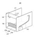
- FIG. 1is a perspective view showing the configuration of a hand rehabilitation device according to the first embodiment of the present invention.
- FIGS. 2 to 7are drawings for explaining the stretching process of the hand rehabilitation device according to the first embodiment of the present invention.
- the hand rehabilitation device (100) of the present inventionincludes a housing (110), an upper moving member (120), and a lower moving member (130).
- the housing (130)forms the overall appearance of the hand rehabilitation device (100) and provides a space (S) in which the user's hand can be positioned inside.
- the upper moving member (120) and the lower moving member (130)are positioned in the space (S) and are moved while applying an external force to the user's hand or fingers.
- the housing (110)is formed with a lower plate (110a), a left plate (110b), and a right plate (110c).
- a first movement guide (111) that guides the movement of the upper movement member (120) and a second movement guide (112) that guides the movement of the lower movement member (130)are formed on the left plate (110b) and the right plate (110c).
- the first moving guide (111) and the second moving guide (112)perform the function of guiding the movement of the upper moving member (120) and the lower moving member (130) for effective stretching of the stiffened user's fingers.
- the upper moving member (120) and the lower moving member (130)are formed in a cylindrical shape and move while rotating, so that the upper moving member (120) moves in the forward and backward directions, and the lower moving member (130) moves in the forward and backward directions and up and down directions, in order to provide effective stretching to the user's hands.
- the first moving guide (111)is formed in the forward and backward directions
- the second moving guide (112)includes a fourth part (112b) formed in the forward and backward directions, a fifth part (112c) formed in the upper and lower directions and connected to the fourth part (112b), and a sixth part (112d) formed in the forward and backward directions and connected to the fifth part (112c).
- the first moving guide (111)includes a first part (111a) formed in an up-down direction and a second part (111b) formed in a forward-backward direction and connected to the first part (111a), and the second moving guide (112) may further include a third part (112a) formed in an up-down direction and connected to the fourth part (112b).
- the upper movable member (120)is provided to be able to move up and down along the first part (111a), and the lower movable member (130) is provided to be able to move up and down along the third part (112a), so that a space can be formed in which the user's hand can easily enter the housing (110).
- the first moving guide (111) and the second moving guide (112)are formed so that there is a point where they intersect.
- the width (d1) of the first moving guide (111)be formed larger than the width (d2) of the second moving guide (112).
- the upper moving member (120)moves while making contact with the upper surface (A) of the hand, and the lower moving member (130) moves while making contact with the lower surface (B) of the hand.
- the upper surface (A) of the handis defined as the surface where the palm is
- the lower surface (B) of the handis defined as the surface where the back of the hand is.
- the upper movable member (120) and the lower movable member (130)may be formed with different diameters or widths depending on the purpose, but since the overall shape is the same, the overall shape will be described below based on the upper movable member (120).
- the shape of the cross section of the upper moving member (120)is not limited, but in this embodiment, it is formed in a cylindrical shape.
- the upper moving member (120)includes a rotation axis to enable rotation, and may include a driving unit (123) for rotating the rotation axis.
- the upper moving member (120)may include a contact portion (121) made of various materials that are harmless to the skin and have a coefficient of friction, etc., as it comes into contact with the user's hand during the stretching process.
- the contact portion (121) in the present embodimentmay be made detachable around the upper moving member (120) for cleaning or replacement.
- contact part (121)Since the contact part (121) is provided to be detachable, contact parts (121) of various sizes can be adopted taking into consideration the size and thickness of the user's hand, etc.
- the surface of the contact portion (121)may be provided with protrusions or the like for applying stimulation to the user's hand.
- guide projections (122) inserted into the first moving guide (111)may be formed at both ends of the upper moving member (120).
- the overall shape of the lower moving member (130)is the same as that of the upper moving member (120), and accordingly, the lower moving member (130) also includes a rotation axis, a contact portion (131), a guide protrusion (132), and a driving portion (133).
- a separate driving unitmay be provided to provide driving force to move the upper moving member (120) and the lower moving member (130) along the first moving guide (111) and the second moving guide (112).
- the upper moving member (120)is positioned at the upper part of the first part (111a) of the first moving guide (111), and the lower moving member (130) is positioned at the lower part of the third part (112a) of the second moving guide (112), and the user puts his/her hand into the internal space (S) of the housing (110).
- the upper moving member (120)moves to the lower part of the first part (111a), and the lower moving member (130) moves to the upper part of the third part (112c) and comes into contact with the user's hand (see Fig. 2).
- the upper moving member (120)moves backward along the second part (111b) of the first moving guide (111) while passing through the user's palm.
- the upper moving member (120)may be configured to rotate for more effective entry or stretching.
- the lower moving member (130)moves backward along the fourth part (112b) of the second moving guide (112) to maintain the state of supporting the lower part of the hand.
- the user's handis stretched from a folded state as in Fig. 2 to an unfolded state as in Fig. 4.
- the lower moving member (130)moves upward along the fifth part (112c) and induces the spread fingers to move inward.
- the lower moving member (130)may be configured to rotate around the rotation axis for more effective movement or stretching.
- the upper moving member (120)moves backward along the second part (111b) to avoid interference with the upward movement of the lower moving member (130).
- the lower moving member (130)moves forward along the sixth part (112d) of the second moving guide (112), thereby secondarily bending the user's finger.
- the upper moving member (120)moves to the upper part (111a) of the first moving guide (111). Then, the lower moving member (130) moves to the lower part (112a) of the second moving guide (112) to form the same position as in Fig. 1.
- Figure 8is a drawing showing the overall configuration of a hand rehabilitation device according to the second embodiment of the present invention.
- the first moving guide (211)is formed on the left plate (210a) of the housing (210), and the second moving guide (212) is formed on the right plate (210c) of the housing (210).
- the first moving guide (211) and the second moving guide (212)do not need to intersect each other.
- FIG. 9is another example of a movement guide of a hand rehabilitation device according to embodiments of the present invention.
- an upper moving guide (111) that guides the movement of the upper moving member (120), a first lower moving guide (112-1) that guides the movement of the lower moving member (130) and a second lower moving guide (112-2)are formed on the left plate (110b) or the right plate (110c).
- the first lower movement guide (112-1) and the second lower movement guide (112-2)are arranged vertically to guide the movement of the lower movement member (110) according to the shape of the user's hand.
- the first lower movement guide (112-1) and the second lower movement guide (112-2)can be arranged vertically in a parallel manner.
- the movement of the lower moving member (110)can be guided along the first lower moving guide (112-1). That is, by keeping the gap between the upper moving member (120) and the lower moving member (110) wide, hand rehabilitation exercise according to the hand size can be provided.
- the movement of the lower moving member (110)can be guided along the second lower moving guide (112-2). That is, the gap between the upper moving member (120) and the lower moving member (110) can be kept narrower than when moving along the first lower moving guide (112-1), thereby providing hand rehabilitation exercise according to the hand size.
- first lower movement guide (112-1) and the second lower movement guide (112-2)are illustrated in FIG. 9, additional lower movement guides may be provided to provide rehabilitation exercise suitable for the shape of the user's hand, and their shapes are not limited to those illustrated in FIG. 9.
- the upper moving guide (111) and the lower moving guide (112-1, 112-2)are formed so that there is a point where they intersect.
- the width (d1) of the upper moving guide (111)be formed larger than the width (d2) of the lower moving guide (112-1, 112-2). At this time, the widths (d2) of the first lower moving guide (112-1) and the second lower moving guide (112-2) may be formed to be the same.
- Figure 10is a drawing showing the overall configuration of a hand rehabilitation device according to a third embodiment of the present invention.
- the housing (310) of the present embodimentfurther includes an upper plate (310d) that shields the upper portion of the space (S).
- the first moving guide (313)is provided so as to be able to move forward and backward on the upper plate (310d).
- the upper moving member (330)further includes a connecting part (334) that is movably connected to the first moving guide (313) so that the upper moving member (330) is positioned at a certain distance from the bottom surface of the upper plate (310d).
- a second moving guide (312)is formed on at least one of the left plate (310a) and the right plate (310c).
- the first moving guide (313)is formed on the upper plate (310d), so that interference that occurs due to partial overlap of the moving paths of the upper moving member (320) and the lower moving member (130) can be avoided.
- the connecting portion (324)may be configured to be able to move in the up-and-down direction to secure a space for the user's hand to enter.
- the rehabilitation devicefurther includes a photographing unit (340-1, 340-2) for photographing the shape of the user's hand.
- the photographing unitmay include a first photographing unit (340-1) for photographing the upper surface of the user's hand and a second photographing unit (340-2) for photographing the side of the user's hand.
- the first photographing unit (340-1)may be formed by being attached to the upper plate (310d), and the second photographing unit (340-2) may be formed on the left plate (310a) or the right plate (310c).
- a devicemay further include a control unit that calculates the size, thickness, and joint positions of a hand based on an image of a user's hand captured by the photographing unit, and adjusts the movement paths of the upper movable member and the lower movable member based on the calculated values.
- control unitmay be formed by being attached to the hand rehabilitation exercise device, but may also be configured to be separately connected via a separate cable.
- the control unitcan extract user hand features using an artificial neural network by inputting an image of the user's hand captured by the camera unit.
- the artificial neural networkcan correspond to a CNN (Convolutional Neural Network), RNN (Recurrent Neural Network), or GAN (Generative Adversarial Network) structure.
- control unitcan calculate the size, thickness, and joint positions of the user's hand using the first image acquired from the first shooting unit (340-1) and the second image acquired from the second shooting unit (340-2).
- control unitcan guide the path of the lower moving member differently depending on the size of the user's hand. For example, the control unit can control the lower moving member to move along the first lower moving guide when the thickness of the user's hand exceeds a preset threshold, and can control the lower moving member to move along the second lower moving guide when the thickness of the user's hand is lower than the preset threshold.
- control unitcan calculate the size, thickness, and joint positions of the hand using a combined image generated based on images acquired during a preset time unit.
- Figures 11 to 13are examples of hand images acquired through the first photographing unit.
- the control unitcan extract hand features from the acquired image if it can identify the complete hand shape from the acquired image as shown in Fig. 11. That is, the control unit uses the acquired image as input and uses an artificial neural network to derive the size, thickness, joint positions, etc. of the hand.
- the control unitcan generate a combined image using another acquired image within a preset time. That is, if the acquired image captured at time t is as in Fig. 12, and the image acquired at time t+1 is as in Fig. 13, the two images can be combined to generate a combined image including the shape of the entire hand.
- control unitcan perform a step of determining whether a complete hand shape exists in the acquired image.
- Figures 14 to 16are examples of hand images acquired through the second photographing unit.
- the control unitcan extract hand features from the acquired image if it can identify the complete hand shape from the acquired image as shown in Fig. 14. That is, the control unit uses the acquired image as input and uses an artificial neural network to derive the size, thickness, joint positions, etc. of the hand.
- the control unitcan generate a combined image using another acquired image within a preset time. That is, if the acquired image captured at time t is as in Fig. 15, and the image acquired at time t+1 is as in Fig. 16, the two images can be combined to generate a combined image including the shape of the entire hand.
- control unitcan perform a step of determining whether a complete hand shape exists in the acquired image.
Landscapes
- Health & Medical Sciences (AREA)
- Epidemiology (AREA)
- Pain & Pain Management (AREA)
- Physical Education & Sports Medicine (AREA)
- Rehabilitation Therapy (AREA)
- Life Sciences & Earth Sciences (AREA)
- Animal Behavior & Ethology (AREA)
- General Health & Medical Sciences (AREA)
- Public Health (AREA)
- Veterinary Medicine (AREA)
- Rehabilitation Tools (AREA)
Abstract
Description
Translated fromKorean본 발명은 손 또는 손가락의 움직임에 제한이 있는 경우 재활 운동을 수행하기 위한 손 재활장치에 관한 것이다.The present invention relates to a hand rehabilitation device for performing rehabilitation exercises when there is limitation in movement of the hand or fingers.
구체적으로, 본 발명은 재활 운동을 수행하는 사용자의 손 모양에 따라 맞춤형 손 재활 운동을 제공할 수 있는 손 재활 장치에 관한 것이다.Specifically, the present invention relates to a hand rehabilitation device capable of providing customized hand rehabilitation exercises according to the hand shape of a user performing rehabilitation exercises.
손 또는 손가락을 움직이지 못하거나 움직임에 제한이 있는 경우, 발병의 원인을 제공하더라도 정상적인 움직임을 위하여는 재활운동이 필요한 것이 일반적이다.If you are unable to move your hand or fingers or have limited movement, rehabilitation exercises are usually necessary to restore normal movement, even if the cause of the condition is not present.
특히, 뇌졸증(Stroke)의 경우, 치료를 하더라도 반신마비, 언어장애 등이 발생하고, 이중 반신마비와 관련하여 손 또는 손가락을 움직이지 못하거나 움직임에 제한이 있는 현상이 일반적이다.In particular, in the case of stroke, even if treated, hemiplegia and speech disorders occur, and in relation to hemiplegia, it is common to be unable to move the hand or fingers or to have limited movement.
이의 재활을 위하여는 스트레칭, 감각자극, 근력강화 등을 위한 다양한 동작을 인위적으로 제공을 하여야 하고, 이를 위한 다양한 방법 및 장치에 대한 연구가 지속적으로 이루어지고 있다.In order to rehabilitate it, various movements such as stretching, sensory stimulation, and muscle strengthening must be artificially provided, and research on various methods and devices for this purpose is continuously being conducted.
특히, 손의 경우 손가락 등 다른 신체 부위에 비하여 다수의 관절이 있고, 이에 따라 편마비로 인한 강직 현상이 지속되는 경우 재활에 시간이 오래 걸 릴 수 있다는 문제점이 있다. 따라서 손 또는 손가락에 강직현상이 발생하는 경우 이를 주기적으로 스트레칭을 할 수 있는 장비에 대한 필요성이 존재한다.In particular, there is a problem that the hands have many joints compared to other body parts such as fingers, and therefore, if the stiffness caused by hemiplegia persists, rehabilitation may take a long time. Therefore, there is a need for equipment that can periodically stretch stiffness in the hands or fingers.
또한, 재활 운동 장치의 이동 부재 등이 특정 경로를 따라 이동하도록 고정된 경우 재활 운동을 수행하는 사용자의 손 형태에 따라서는 적절한 재활 운동을 제공할 수 없는 문제점이 존재한다. 따라서, 사용자의 손 크기, 두께, 형태, 관절의 위치 등에 따라 맞춤형 재활 운동을 제공할 수 있는 장치에 대한 필요성이 존재한다.In addition, if the moving member of the rehabilitation exercise device is fixed to move along a specific path, there is a problem that appropriate rehabilitation exercise cannot be provided depending on the shape of the hand of the user performing the rehabilitation exercise. Therefore, there is a need for a device that can provide customized rehabilitation exercise depending on the size, thickness, shape, and joint location of the user's hand.
본 발명의 목적은 손 또는 손가락에 강직현상이 발생하는 경우 이를 주기적으로 스트레칭을 할 수 있는 손 재활 운동장치를 제공하는 것이다.The purpose of the present invention is to provide a hand rehabilitation exercise device that can periodically stretch hands or fingers when stiffness occurs in the hands or fingers.
또한, 본 발명의 목적은 사용자의 손 크기, 두께, 형태, 관절의 위치 등에 따라 맞춤형 재활 운동을 제공할 수 있는 손 재활 운동장치를 제공하는 것이다.In addition, an object of the present invention is to provide a hand rehabilitation exercise device capable of providing customized rehabilitation exercise according to the user's hand size, thickness, shape, joint location, etc.
상기한 목적을 달성하기 위한 본 발명의 일 실시예에 따른 손 형태에 따른 맞춤 재활이 가능한 손 재활 장치는 사용자의 손 형태를 촬영하는 촬영부; 사용자의 손의 상면과 접촉을 하면서 이동하는 상부이동부재; 사용자의 손의 하면과 접촉을 하면서 이동하는 하부이동부재; 및 상기 상부이동부재 및 상기 하부이동부재가 이동 가능하도록 결합된 하우징을 포함한다.According to one embodiment of the present invention for achieving the above-described purpose, a hand rehabilitation device capable of customized rehabilitation according to a hand shape comprises: a photographing unit for photographing a user's hand shape; an upper moving member that moves while making contact with an upper surface of the user's hand; a lower moving member that moves while making contact with a lower surface of the user's hand; and a housing in which the upper moving member and the lower moving member are movably coupled.
이때, 상기 장치는 상기 촬영부에서 촬영된 사용자의 손 영상에 기반하여 손의 크기, 두께, 관절의 위치를 산출하고, 이에 기반하여 상기 상부이동부재 및 상기 하부이동부재의 이동경로를 조정하는 제어부를 더 포함할 수 있다.At this time, the device may further include a control unit that calculates the size, thickness, and joint positions of the hand based on the image of the user's hand captured by the photographing unit, and adjusts the movement paths of the upper moving member and the lower moving member based on the calculated values.
이때, 상기 제어부는 상기 촬영부에서 촬영된 사용자 손 영상을 입력으로, 인공 신경망을 이용하여 사용자 손 특징을 추출할 수 있다.At this time, the control unit can extract user hand features using an artificial neural network by inputting an image of the user's hand captured by the shooting unit.
이때, 상기 인공 신경망은 CNN(Convolutional Neural Network), RNN(Recurrent Neural Network) 또는 GAN(Generative Adversarial Network) 구조에 상응할 수 있다.At this time, the artificial neural network may correspond to a CNN (Convolutional Neural Network), RNN (Recurrent Neural Network), or GAN (Generative Adversarial Network) structure.
이때, 상기 촬영부는 상기 하우징에 부착되어 상기 사용자의 손 상면을 촬영하는 제1 촬영부; 및 상기 하우징에 부착되어 상기 하용자의 손 측면을 촬영하는 제2 촬영부를 포함할 수 있다.At this time, the photographing unit may include a first photographing unit attached to the housing to photograph the upper surface of the user's hand; and a second photographing unit attached to the housing to photograph the side surface of the user's hand.
이때, 상기 제어부는 상기 제1 촬영부에서 획득한 제1 이미지 및 상기 제2 촬영부에서 획득한 제2 이미지를 이용하여 상기 사용자 손의 크기, 두께, 관절의 위치를 산출할 수 있다.At this time, the control unit can calculate the size, thickness, and joint positions of the user's hand using the first image acquired from the first photographing unit and the second image acquired from the second photographing unit.
이때, 상기 하우징은 상기 상부이동부재의 이동을 안내하는 상부 이동가이드; 및 상기 하부이동부재의 이동을 안내하는 하부 이동가이드를 포함하고, 상기 하부 이동가이드는 제1 하부 이동가이드 및 상기 제1 하부 이동 가이드보다 아래에 위치하는 제2 하부 이동가이드를 포함할 수 있다.At this time, the housing includes an upper moving guide guiding movement of the upper moving member; and a lower moving guide guiding movement of the lower moving member, and the lower moving guide may include a first lower moving guide and a second lower moving guide positioned below the first lower moving guide.
이때, 상기 제어부는 상기 사용자의 손 두께가 기설정된 임계치를 초과하면 상기 하부이동부재가 상기 제1 하부 이동 가이드를 따라 이동하도록 제어하고, 상기 사용자의 손 두께가 기설정된 임계치 이하이면 상기 하부이동부재가 상기 제2 하부 이동 가이드를 따라 이동하도록 제어할 수 있다.At this time, the control unit can control the lower moving member to move along the first lower moving guide when the thickness of the user's hand exceeds a preset threshold, and can control the lower moving member to move along the second lower moving guide when the thickness of the user's hand is less than or equal to the preset threshold.
이때, 상기 제어부는 상기 촬영부에서 획득한 이미지 내에서 손 형태를 식별할 수 없으면, 기설정된 시간 단위 동안 획득된 이미지에 기반하여 생성된 결합 이미지를 이용하여 손의 크기, 두께, 관절의 위치를 산출할 수 있다.At this time, if the control unit cannot identify the shape of the hand in the image acquired from the photographing unit, the control unit can calculate the size, thickness, and joint positions of the hand using a combined image generated based on images acquired during a preset time unit.
본 발명에 따르면, 손 또는 손가락에 강직현상이 발생하는 경우 이를 주기적으로 스트레칭을 할 수 있는 손 재활 운동장치를 제공할 수 있다.According to the present invention, a hand rehabilitation exercise device capable of periodically stretching a hand or finger when stiffness occurs can be provided.
또한, 본 발명은 사용자의 손 크기, 두께, 형태, 관절의 위치 등에 따라 맞춤형 재활 운동을 제공할 수 있는 손 재활 운동장치를 제공할 수 있다.In addition, the present invention can provide a hand rehabilitation exercise device that can provide customized rehabilitation exercise according to the user's hand size, thickness, shape, joint location, etc.
도 1은 본 발명의 제1 실시예에 따른 손 재활장치의 구성을 나타낸 사시도이다.FIG. 1 is a perspective view showing the configuration of a hand rehabilitation device according to the first embodiment of the present invention.
도 2 내지 도 7은 본 발명의 제1 실시예에 따른 손 재활장치의 스트레칭 과정을 설명하기 위한 도면이다.FIGS. 2 to 7 are drawings for explaining the stretching process of the hand rehabilitation device according to the first embodiment of the present invention.
도 8은 본 발명의 제2 실시예의 손 재활장치의 전체적인 구성을 나타내는 도면이다.Figure 8 is a drawing showing the overall configuration of a hand rehabilitation device according to the second embodiment of the present invention.
도 9는 본 발명의 실시예들에 따른 손 재활장치의 이동가이드의 다른 예이다.FIG. 9 is another example of a movement guide of a hand rehabilitation device according to embodiments of the present invention.
도 10은 본 발명의 제3실시예의 손 재활장치의 전체적인 구성을 나타내는 도면이다.Figure 10 is a drawing showing the overall configuration of a hand rehabilitation device according to a third embodiment of the present invention.
도 11 내지 도 13은 제1 촬영부를 통해 획득된 손 영상의 일 예이다.Figures 11 to 13 are examples of hand images acquired through the first photographing unit.
도 14 내지 도 16은 제2 촬영부를 통해 획득된 손 영상의 일 예이다.Figures 14 to 16 are examples of hand images acquired through the second photographing unit.
본 발명의 이점 및 특징, 그리고 그것들을 달성하는 방법은 첨부되는 도면과 함께 상세하게 후술되어 있는 실시예들을 참조하면 명확해질 것이다. 그러나 본 발명은 이하에서 개시되는 실시예들에 한정되는 것이 아니라 서로 다른 다양한 형태로 구현될 것이며, 단지 본 실시예들은 본 발명의 개시가 완전하도록 하며, 본 발명이 속하는 기술분야에서 통상의 지식을 가진 자에게 발명의 범주를 완전하게 알려주기 위해 제공되는 것이며, 본 발명은 청구항의 범주에 의해 정의될 뿐이다. 명세서 전체에 걸쳐 동일 참조 부호는 동일 구성 요소를 지칭한다.The advantages and features of the present invention, and the methods for achieving them, will become clearer with reference to the embodiments described in detail below together with the accompanying drawings. However, the present invention is not limited to the embodiments disclosed below, but may be implemented in various different forms, and these embodiments are provided only to make the disclosure of the present invention complete and to fully inform those skilled in the art of the scope of the invention, and the present invention is defined only by the scope of the claims. Like reference numerals refer to like elements throughout the specification.
비록 "제1 " 또는 "제2 " 등이 다양한 구성요소를 서술하기 위해서 사용되나, 이러한 구성요소는 상기와 같은 용어에 의해 제한되지 않는다. 상기와 같은 용어는 단지 하나의 구성요소를 다른 구성요소와 구별하기 위하여 사용될 수 있다. 따라서, 이하에서 언급되는 제1 구성요소는 본 발명의 기술적 사상 내에서 제2 구성요소일 수도 있다.Although the terms "first" or "second" are used to describe various components, these components are not limited by such terms. Such terms may only be used to distinguish one component from another. Thus, a first component referred to below may also be a second component within the technical scope of the present invention.
본 명세서에서 사용된 용어는 실시예를 설명하기 위한 것이며 본 발명을 제한하고자 하는 것은 아니다. 본 명세서에서, 단수형은 문구에서 특별히 언급하지 않는 한 복수형도 포함한다. 명세서에서 사용되는 "포함한다(comprises)" 또는 "포함하는(comprising)"은 언급된 구성요소 또는 단계가 하나 이상의 다른 구성요소 또는 단계의 존재 또는 추가를 배제하지 않는다는 의미를 내포한다.The terminology used herein is for the purpose of describing embodiments only and is not intended to limit the invention. In this specification, the singular also includes the plural unless specifically stated otherwise. The terms "comprises" or "comprising" as used in the specification imply that the presence or addition of one or more other elements or steps is not excluded.
본 명세서에서, "A 또는 B", "A 및 B 중 적어도 하나", "A 또는 B 중 적어도 하나", "A, B 또는 C", "A, B 및 C 중 적어도 하나", 및 "A, B, 또는 C 중 적어도 하나"와 같은 문구들 각각은 그 문구들 중 해당하는 문구에 함께 나열된 항목들 중 어느 하나, 또는 그들의 모든 가능한 조합을 포함할 수 있다.In this specification, each of the phrases "A or B", "at least one of A and B", "at least one of A or B", "A, B or C", "at least one of A, B and C", and "at least one of A, B, or C" can include any one of the items listed together in that phrase, or all possible combinations thereof.
다른 정의가 없다면, 본 명세서에서 사용되는 모든 용어는 본 발명이 속하는 기술분야에서 통상의 지식을 가진 자에게 공통적으로 이해될 수 있는 의미로 해석될 수 있다. 또한, 일반적으로 사용되는 사전에 정의되어 있는 용어들은 명백하게 특별히 정의되어 있지 않는 한 이상적으로 또는 과도하게 해석되지 않는다.Unless otherwise defined, all terms used in this specification may be interpreted as having a meaning commonly understood by a person of ordinary skill in the art to which the present invention belongs. In addition, terms defined in commonly used dictionaries shall not be interpreted ideally or excessively unless explicitly specifically defined.
이하, 첨부된 도면을 참조하여 본 발명의 실시예들을 상세히 설명하기로 하며, 도면을 참조하여 설명할 때 동일하거나 대응하는 구성 요소는 동일한 도면 부호를 부여하고 이에 대한 중복되는 설명은 생략하기로 한다.Hereinafter, embodiments of the present invention will be described in detail with reference to the attached drawings. When describing with reference to the drawings, identical or corresponding components are given the same drawing reference numerals and redundant descriptions thereof will be omitted.
도 1은 본 발명의 제1 실시예에 따른 손 재활장치의 구성을 나타낸 사시도이다.FIG. 1 is a perspective view showing the configuration of a hand rehabilitation device according to the first embodiment of the present invention.
도 2 내지 도 7은 본 발명의 제1 실시예에 따른 손 재활장치의 스트레칭 과정을 설명하기 위한 도면이다.FIGS. 2 to 7 are drawings for explaining the stretching process of the hand rehabilitation device according to the first embodiment of the present invention.
도 1을 참조하면, 도1을 참조하면, 본 발명의 손 재활장치(100)는 하우징(110), 상부이동부재(120) 및 하부이동부재(130)을 포함한다.Referring to FIG. 1, the hand rehabilitation device (100) of the present invention includes a housing (110), an upper moving member (120), and a lower moving member (130).
하우징(130)은 손재활장치(100)의 전체적인 외관을 형성하고, 내부에 사용자의 손이 위치할 수 있는 공간(S)을 제공한다. 그리고 상부이동부재(120) 및 하부이동부재(130)은 상기 공간(S)에 배치되고, 이동을 하면서 사용자의 손 또는 손가락에 외력을 가하면서 움직일 수 있도록 한다.The housing (130) forms the overall appearance of the hand rehabilitation device (100) and provides a space (S) in which the user's hand can be positioned inside. In addition, the upper moving member (120) and the lower moving member (130) are positioned in the space (S) and are moved while applying an external force to the user's hand or fingers.
내부에 사용자의 손 및 상부이동부재(120) 및 하부이동부재(130)가 이동할 수 있는 공간(S)을 형성한다면 하우징(110)의 형태에는 제한이 없다. 구체적으로 본 실시예에서는 하우징(110)은 하부플레이트(110a), 좌측플레이트(110b) 및 우측플레이트(110c)가 형성된다.There is no limitation on the shape of the housing (110) as long as a space (S) is formed inside in which the user's hand and the upper moving member (120) and the lower moving member (130) can move. Specifically, in the present embodiment, the housing (110) is formed with a lower plate (110a), a left plate (110b), and a right plate (110c).
좌측플레이트(110b) 및 우측플레이트(110c)에는 상부이동부재(120)의 이동을 안내하는 제1 이동가이드(111) 및 하부이동부재(130)의 이동을 안내하는 제2 이동가이드(112)가 형성된다.A first movement guide (111) that guides the movement of the upper movement member (120) and a second movement guide (112) that guides the movement of the lower movement member (130) are formed on the left plate (110b) and the right plate (110c).
제1 이동가이드(111) 및 제2 이동가이드(112)는 강직된 사용자의 손가락에 대한 효과적인 스트레칭을 위한 상부이동부재(120) 및 하부이동부재(130)의 이동을 가이드하는 기능을 수행한다.The first moving guide (111) and the second moving guide (112) perform the function of guiding the movement of the upper moving member (120) and the lower moving member (130) for effective stretching of the stiffened user's fingers.
한편, 후술하는 것과 같이 원통형으로 형성되고, 자전하면서 이동을 하는 상부이동부재(120) 및 하부이동부재(130)를 통하여 하여 사용자에 손에 효과적인 스트레칭을 위하여 상부이동부재(120)는 전, 후 방향으로 이동을 하고, 하부이동부재(130)는 전후 방향 및 상하방향으로 이동을 하게 된다.Meanwhile, as described later, the upper moving member (120) and the lower moving member (130) are formed in a cylindrical shape and move while rotating, so that the upper moving member (120) moves in the forward and backward directions, and the lower moving member (130) moves in the forward and backward directions and up and down directions, in order to provide effective stretching to the user's hands.
따라서 제1 이동가이드(111)는 전, 후 방향으로 형성되고, 제2 이동가이드(112)는 전, 후 방향으로 형성되는 제4파트(112b), 제4파트(112b)와 연통되고 상, 하 방향으로 형성되는 제5파트(112c) 및 제5파트(112c)와 연통되고 전, 후 방향으로 형성되는 제6파트(112d)를 포함한다.Accordingly, the first moving guide (111) is formed in the forward and backward directions, and the second moving guide (112) includes a fourth part (112b) formed in the forward and backward directions, a fifth part (112c) formed in the upper and lower directions and connected to the fourth part (112b), and a sixth part (112d) formed in the forward and backward directions and connected to the fifth part (112c).
나아가 제1 이동가이드(111)는 상, 하 방향으로 형성되는 제1 파트 (111a) 및 제1 파트(111a)와 연통되고 전, 후 방향으로 형성되는 제2 파트(111b)를 포함하고, 제2 이동가이드(112)는 제4파트(112b)와 연통되고 상, 하 방향으로 형성되는 제3파트(112a)를 더 포함할 수 있다.Furthermore, the first moving guide (111) includes a first part (111a) formed in an up-down direction and a second part (111b) formed in a forward-backward direction and connected to the first part (111a), and the second moving guide (112) may further include a third part (112a) formed in an up-down direction and connected to the fourth part (112b).
일반적으로 사용자의 손이 강직이 되는 경우 손가락이 내측으로 접힌 상태가 되게 된다. 따라서 본 실시예에서는 상부이동부재(120)는 제1 파트(111a)를 따라 상, 하 이동 가능하게 구비되고, 하부이동부재(130)는 제3파트(112a)를 따라 상, 하 방향으로 이동 가능하게 구비되어 사용자의 손이 하우징(110)으로 진입하는 경우 용이하게 진입이 가능한 공간을 형성할 수 있다.In general, when the user's hand becomes stiff, the fingers are folded inward. Therefore, in this embodiment, the upper movable member (120) is provided to be able to move up and down along the first part (111a), and the lower movable member (130) is provided to be able to move up and down along the third part (112a), so that a space can be formed in which the user's hand can easily enter the housing (110).
상부이동부재(120) 및 하부이동부재(130)의 전체 이동 경로의 일부가 중복이 됨에 따라서 제1 이동가이드(111) 및 제2 이동가이드(112)는 교차를 하는 지점이 있도록 형성된다.Since a portion of the entire movement path of the upper moving member (120) and the lower moving member (130) overlaps, the first moving guide (111) and the second moving guide (112) are formed so that there is a point where they intersect.
그리고 제1 이동가이드(111)를 따라 이동하는 상부이동부재(120)가 이동가이드(123)를 이동을 하는 과정에서 제2 이동가이드(112)로 빠지는 것을 방지하기 위하여 제1 이동가이드(111)의 폭(d1)는 제2 이동가이드(112)의 폭(d2)보다 크게 형성되는 것이 바람직할 것이다.In order to prevent the upper moving member (120) moving along the first moving guide (111) from falling into the second moving guide (112) during the process of moving the moving guide (123), it is preferable that the width (d1) of the first moving guide (111) be formed larger than the width (d2) of the second moving guide (112).
상부이동부재(120)는 손의 상면(A)와 접촉을 하면서 이동하고, 하부이동부재(130)는 손의 하면(B)와 접촉을 하면서 이동을 한다.The upper moving member (120) moves while making contact with the upper surface (A) of the hand, and the lower moving member (130) moves while making contact with the lower surface (B) of the hand.
한편, 손의 상면(A)는 손바닥이 있는 면, 손의 하면(B)는 손등이 있는 면으로 정의를 하여 설명을 한다. 그리고 상부이동부재(120) 및 하부이동부재(130)는 목적에 따라 지름 또는 폭 등이 다르게 형성될 수는 있지만, 전체적인 형상이 동일하므로 이하 상부이동부재(120)를 기준으로 전체적인 형상을 설명한다.Meanwhile, the upper surface (A) of the hand is defined as the surface where the palm is, and the lower surface (B) of the hand is defined as the surface where the back of the hand is. In addition, the upper movable member (120) and the lower movable member (130) may be formed with different diameters or widths depending on the purpose, but since the overall shape is the same, the overall shape will be described below based on the upper movable member (120).
상부이동부재(120)의 단면의 형상은 제한이 없으나 본 실시예에서는 원통형으로 이루어진다. 상부이동부재(120)는 자전이 가능하도록 회전축을 포함하고, 회전축을 회전시키기 위한 구동부(123)를 포함할 수 있다.The shape of the cross section of the upper moving member (120) is not limited, but in this embodiment, it is formed in a cylindrical shape. The upper moving member (120) includes a rotation axis to enable rotation, and may include a driving unit (123) for rotating the rotation axis.
상부이동부재(120)는 스트레칭 과정에서 사용자의 손과 접촉을 하기 때문에 피부에 무해하며 마찰계수 등이 고려된 다양한 소재로 이루어진 접촉부(121)를 포함할 수 있다. 그리고 본 실시예에서의 접촉부(121)는 세척 또는 교체를 위하여 상부이동부재(120)의 둘레에 탈착이 가능하도록 이루어질 수 있다.The upper moving member (120) may include a contact portion (121) made of various materials that are harmless to the skin and have a coefficient of friction, etc., as it comes into contact with the user's hand during the stretching process. In addition, the contact portion (121) in the present embodiment may be made detachable around the upper moving member (120) for cleaning or replacement.
접촉부(121)가 탈착이 가능하도록 구비됨에 따라 사용자의 손의 크기 두께 등을 고려하여 다양한 크기의 접촉부(121)가 채택이 될 수 있을 것이다.Since the contact part (121) is provided to be detachable, contact parts (121) of various sizes can be adopted taking into consideration the size and thickness of the user's hand, etc.
나아가 도시되지는 않았지만, 접촉부(121)의 표면에는 사용자의 손에 자극을 인가하기 위한 돌기 등이 구비될 수 있을 것이다.Furthermore, although not shown, the surface of the contact portion (121) may be provided with protrusions or the like for applying stimulation to the user's hand.
그리고 상부이동부재(120)의 양 끝단에는 제1 이동가이드(111)에 삽입되는 가이드돌기(122)가 형성될 수 있을 것이다.And, guide projections (122) inserted into the first moving guide (111) may be formed at both ends of the upper moving member (120).
상기 설명한 것과 같이 하부이동부재(130)의 전체적인 형상은 상부이동부재(120)와 동일하고, 이에 따라 하부이동부재(130)도 회전축을 포함하고, 접촉부(131), 가이드돌기(132), 구동부(133)를 포함한다.As described above, the overall shape of the lower moving member (130) is the same as that of the upper moving member (120), and accordingly, the lower moving member (130) also includes a rotation axis, a contact portion (131), a guide protrusion (132), and a driving portion (133).
또한, 도시되지는 않았지만 상부이동부재(120) 및 하부이동부재(130)이 제1 이동가이드(111) 및 제2 이동가이드(112)를 따라 이동을 하도록 구동력을 제공하기 위한 별도의 구동부가 구비될 수 있을 것이다.In addition, although not shown, a separate driving unit may be provided to provide driving force to move the upper moving member (120) and the lower moving member (130) along the first moving guide (111) and the second moving guide (112).
그리고 일반적인 뇌졸증의 경우 편마비가 오는 경우가 일반적이므로 별도의 구동부 없이 사용자가 반대편 손을 이용하여 수동으로 구동되는 방식으로 구현이 될 수도 있을 것이다.And since it is common for a typical stroke to result in hemiplegia, it could be implemented in a way that the user manually operates it using the opposite hand without a separate driving unit.
도 1 내지 도 7을 참조하여, 본 실시예의 상부이동부재(120) 및 하부이동부재(130)이 이동을 하면서 사용자의 손을 스트레칭하는 과정을 설명한다.Referring to FIGS. 1 to 7, the process of stretching the user's hand while the upper movable member (120) and the lower movable member (130) of the present embodiment move will be described.
도 1에서와 같이 상부이동부재(120)는 제1 이동가이드(111)의 제1 파트(111a)의 상부에 위치하고, 하부이동부재(130)는 제2 이동가이드(112)의 제3파트(112a)의 하부에 위치한 상태에서 사용자는 손을 하우징(110)의 내부 공간(S)으로 넣게 된다.As shown in Fig. 1, the upper moving member (120) is positioned at the upper part of the first part (111a) of the first moving guide (111), and the lower moving member (130) is positioned at the lower part of the third part (112a) of the second moving guide (112), and the user puts his/her hand into the internal space (S) of the housing (110).
그리고 상부이동부재(120)는 제1 파트(111a)의 하부로 이동하고, 하부이동부재(130)는 제3파트(112c)의 상부로 이동을 하면서 사용자의 손과 접촉을 하게 된다(도 2 참조).And the upper moving member (120) moves to the lower part of the first part (111a), and the lower moving member (130) moves to the upper part of the third part (112c) and comes into contact with the user's hand (see Fig. 2).
그리고 도 3 및 도 4에서와 같이 상부이동부재(120)가 제1 이동가이드(111)의 제2 파트(111b)를 따라 후방으로 이동을 하면서 사용자의 손바닥을 경유하And as shown in FIGS. 3 and 4, the upper moving member (120) moves backward along the second part (111b) of the first moving guide (111) while passing through the user's palm.
여 손가락 내측면까지 진입을 하게 되고, 이 때 보다 효과적인 진입 또는 스트레칭을 위하여 상부이동부재(120)는 자전을 하도록 구성될 수 있을 것이다.It enters the inner side of the finger, and at this time, the upper moving member (120) may be configured to rotate for more effective entry or stretching.
한편, 이 때 하우이동부재(130)는 손의 하부를 지지한 상태를 유지하기 위하여 제2 이동가이드(112)의 제4파트(112b)를 따라 후방으로 이동을 하게 된다.Meanwhile, at this time, the lower moving member (130) moves backward along the fourth part (112b) of the second moving guide (112) to maintain the state of supporting the lower part of the hand.
그리고 이러한 상부이동부재(120) 및 하우이동부재(130)의 움직임에 따라 사용자의 손은 도2에서와 같이 접힌 상태에서 도4에서와 같이 펴진 상태로 스트레칭이 이루어지게 된다.And according to the movement of the upper moving member (120) and the lower moving member (130), the user's hand is stretched from a folded state as in Fig. 2 to an unfolded state as in Fig. 4.
도 5 내지 도 7의 과정을 통하여 도 4에서와 같이 펴진 손가락을 다시 내측으로 오므리는 동작이 이루어지게 되고, 이러한 과정을 통하여 사용자의 손가락은 구부러지는 동작 및 펴지는 동작이 반복하여 이루어져 편마비에 따른 강직성에 대한 스트레칭 재활이 가능하게 된다.Through the process of FIGS. 5 to 7, a motion is made to bend the extended fingers inward again as in FIG. 4, and through this process, the user's fingers are repeatedly bent and extended, enabling stretching rehabilitation for stiffness due to hemiplegia.
도 5를 참조하면, 하부이동부재(130)는 제5파트(112c)를 따라 상부로 이동을 하면서 펴진 손가락을 내측으로 움직이도록 유도를 한다. 그리고 이 과정에서 보다 효과적인 이동 또는 스트레칭을 위하여 하부이동부재(130)는 회전축을 중심으로 자전을 하도록 구성될 수 있을 것이다. 그리고 이 때 상부이동부재(120)는 하부이동부재(130)의 상부로의 이동에 간섭을 피하기 위하여 제2 파트(111b)를 따라 후방으로 이동을 하게 된다.Referring to Fig. 5, the lower moving member (130) moves upward along the fifth part (112c) and induces the spread fingers to move inward. In this process, the lower moving member (130) may be configured to rotate around the rotation axis for more effective movement or stretching. In this case, the upper moving member (120) moves backward along the second part (111b) to avoid interference with the upward movement of the lower moving member (130).
상부이동부재(120) 및 하부이동부재(130)의 상기 도 5에서와 같이 이동의 결과 사용자의 손가락은 도 6에서와 같이 1차적으로 굽히게 된다.As a result of the movement of the upper movable member (120) and the lower movable member (130) as shown in the above-described Fig. 5, the user's finger is initially bent as shown in Fig. 6.
그리고 도 7에서와 같이 하부이동부재(130)가 제2 이동가이드(112)의 제6파트(112d)를 따라 전방으로 이동을 하면서 사용자의 손가락을 2차적으로 굽히게 된다.And as shown in Fig. 7, the lower moving member (130) moves forward along the sixth part (112d) of the second moving guide (112), thereby secondarily bending the user's finger.
그리고 이러한 과정을 통하여 사용자가 손가락을 폈다 오므리는 스트레칭 과정이 이루어지게 된다.And through this process, the user's fingers are stretched and closed.
해당 과정이 수행된 다음, 상부이동부재(120)는 제1 이동가이드(111)의 제1 파트(111a)의 상부로 이동을 한다. 그리고 하부이동부재(130)는 제2 이동가이드(112)의 제3파트(112a)의 하부로 이동을 하여 도1에서와 같은 위치를 이루게 된다.After the process is performed, the upper moving member (120) moves to the upper part (111a) of the first moving guide (111). Then, the lower moving member (130) moves to the lower part (112a) of the second moving guide (112) to form the same position as in Fig. 1.
그리고 상기 설명한 과정이 다시 반복 수행되면서 사용자에 손에 대한 반복적인 스트레칭 과정이 이루어지게 된다.And as the above-described process is repeated, the user's hand undergoes a repetitive stretching process.
도 8은 본 발명의 제2 실시예의 손 재활장치의 전체적인 구성을 나타내는 도면이다.Figure 8 is a drawing showing the overall configuration of a hand rehabilitation device according to the second embodiment of the present invention.
한편, 본 발명의 제2 실시예의 손 재활장치의 전체적인 구성은 상기설명한 제1 실시예와 유사하므로, 이하 차이점을 중심으로 설명한다.Meanwhile, since the overall configuration of the hand rehabilitation device of the second embodiment of the present invention is similar to that of the first embodiment described above, the following description will focus on the differences.
도 8을 참조하면, 본 실시예에서는 제1 이동가이드(211)는 하우징(210)의 좌측플레이트(210a)에 형성되고, 제2 이동가이드(212)는 하우징(210)의 우측플레이트(210c)에 형성된다.Referring to FIG. 8, in the present embodiment, the first moving guide (211) is formed on the left plate (210a) of the housing (210), and the second moving guide (212) is formed on the right plate (210c) of the housing (210).
따라서 상기 제1 실시예와 달리 제1 이동가이드(211) 및 제2 이동가이드(212)는 서로 교차를 하도록 이루어질 필요가 없게 된다.Therefore, unlike the first embodiment, the first moving guide (211) and the second moving guide (212) do not need to intersect each other.
도 9는 본 발명의 실시예들에 따른 손 재활장치의 이동가이드의 다른 예이다.FIG. 9 is another example of a movement guide of a hand rehabilitation device according to embodiments of the present invention.
도 9를 참조하면, 좌측플레이트(110b) 또는 우측플레이트(110c)에는 상부이동부재(120)의 이동을 안내하는 상부 이동가이드(111), 하부이동부재(130)의 이동을 안내하는 제1 하부 이동가이드(112-1) 및 제2 하부 이동가이드(112-2)가 형성된다.Referring to FIG. 9, an upper moving guide (111) that guides the movement of the upper moving member (120), a first lower moving guide (112-1) that guides the movement of the lower moving member (130) and a second lower moving guide (112-2) are formed on the left plate (110b) or the right plate (110c).
제1 하부 이동가이드(112-1) 및 제2 하부 이동가이드(112-2)는 상하로 배치 되어 사용자의 손 모양에 따라 하부이동부재(110)의 이동을 가이드한다. 제1 하부 이동가이드(112-1) 및 제2 하부 이동가이드(112-2)는 평행한 형태로 상하로 배치될 수 있다.The first lower movement guide (112-1) and the second lower movement guide (112-2) are arranged vertically to guide the movement of the lower movement member (110) according to the shape of the user's hand. The first lower movement guide (112-1) and the second lower movement guide (112-2) can be arranged vertically in a parallel manner.
예를 들어, 사용자의 손 크기가 제1 임계값을 초과하거나 사용자의 손 두께가 제2 임계값을 초과하는 경우에는 제1 하부 이동가이드(112-1)를 따라 하부이동부재(110)의 이동을 가이드 할 수 있다. 즉, 상부이동부재(120)와 하부이동부재(110)의 간격을 넓게 유지하여 손 크기에 따른 손 재활 운동을 제공할 수 있다.For example, when the user's hand size exceeds a first threshold value or the user's hand thickness exceeds a second threshold value, the movement of the lower moving member (110) can be guided along the first lower moving guide (112-1). That is, by keeping the gap between the upper moving member (120) and the lower moving member (110) wide, hand rehabilitation exercise according to the hand size can be provided.
또한, 예를 들어, 사용자의 손 크기가 제1 임계값 이하이거나 사용자의 손 두께가 제2 임계값 이하인 경우에는 제2 하부 이동가이드(112-2)를 따라 하부이동부재(110)의 이동을 가이드 할 수 있다. 즉, 상부이동부재(120)와 하부이동부재(110)의 간격을 제1 하부 이동가이드(112-1)를 따라 이동하는 경우보다 좁게 유지하여 손 크기에 따른 손 재활 운동을 제공할 수 있다.In addition, for example, when the user's hand size is less than or equal to the first threshold value or the user's hand thickness is less than or equal to the second threshold value, the movement of the lower moving member (110) can be guided along the second lower moving guide (112-2). That is, the gap between the upper moving member (120) and the lower moving member (110) can be kept narrower than when moving along the first lower moving guide (112-1), thereby providing hand rehabilitation exercise according to the hand size.
도 9에는 제1 하부 이동가이드(112-1) 및 제2 하부 이동가이드(112-2)만이 도시되었으나, 하부 이동가이드는 사용자의 손 형태에 알맞은 재활 운동을 제공할 수 있도록 더 제공될 수 있으며, 그 형태가 도 9에 도시된 바에 따라 제한되는 것은 아니다.Although only the first lower movement guide (112-1) and the second lower movement guide (112-2) are illustrated in FIG. 9, additional lower movement guides may be provided to provide rehabilitation exercise suitable for the shape of the user's hand, and their shapes are not limited to those illustrated in FIG. 9.
상부이동부재(120) 및 하부이동부재(130)의 전체 이동 경로의 일부가 중복이 됨에 따라서 상부 이동가이드(111) 및 하부 이동가이드(112-1, 112-2)는 교차를 하는 지점이 있도록 형성된다.Since a portion of the entire movement path of the upper moving member (120) and the lower moving member (130) overlaps, the upper moving guide (111) and the lower moving guide (112-1, 112-2) are formed so that there is a point where they intersect.
그리고 상부 이동가이드(111)를 따라 이동하는 상부이동부재(120)가 이동을 하는 과정에서 하부 이동가이드(112-1, 112-2)로 빠지는 것을 방지하기 위하여 상부 이동가이드(111)의 폭(d1)는 하부 이동가이드(112-1, 112-2)의 폭(d2)보다 크게 형성되는 것이 바람직할 것이다. 이때, 제1 하부 이동가이드(112-1)와 제2 하부 이동가이드(112-2)의 폭(d2)은 동일하게 형성될 수 있다.In order to prevent the upper moving member (120) moving along the upper moving guide (111) from falling into the lower moving guide (112-1, 112-2) during the movement process, it is preferable that the width (d1) of the upper moving guide (111) be formed larger than the width (d2) of the lower moving guide (112-1, 112-2). At this time, the widths (d2) of the first lower moving guide (112-1) and the second lower moving guide (112-2) may be formed to be the same.
도 10은 본 발명의 제3실시예의 손 재활장치의 전체적인 구성을 나타내는 도면이다.Figure 10 is a drawing showing the overall configuration of a hand rehabilitation device according to a third embodiment of the present invention.
본 실시예의 손 재활장치의 전체적인 구성은 상기 설명한 실시예들과 유사하므로, 이하 차이점을 중심으로 설명한다.Since the overall configuration of the hand rehabilitation device of this embodiment is similar to the embodiments described above, the differences will be described below.
도 10를 참조하면, 본 실시예의 하우징(310)는 공간(S)의 상부를 차폐하는 상부플레이트(310d)를 더 포함한다. 그리고 제1 이동가이드(313)는 상부플레이트(310d)에 전, 후 방향으로 이동 가능하도록 구비된다.Referring to Fig. 10, the housing (310) of the present embodiment further includes an upper plate (310d) that shields the upper portion of the space (S). In addition, the first moving guide (313) is provided so as to be able to move forward and backward on the upper plate (310d).
그리고 상부이동부재(330)는 상부이동부재(330)가 상부플레이트(310d)의 저면에서 일정거리 이격되어 배치되도록 제1 이동가이드(313)에 이동 가능하게 결합되는 연결부(334)를 더 포함한다.In addition, the upper moving member (330) further includes a connecting part (334) that is movably connected to the first moving guide (313) so that the upper moving member (330) is positioned at a certain distance from the bottom surface of the upper plate (310d).
그리고 좌측플레이트(310a) 및 우측플레이트(310c) 중 적어도 하나에는 제2 이동가이드(312)가 형성된다.And a second moving guide (312) is formed on at least one of the left plate (310a) and the right plate (310c).
즉, 본 실시예에서는 제1 이동가이드(313)를 상부플레이트(310d)에 형성하여 상부이동부재(320) 및 하부이동부재(130) 이동경로가 일부 중복됨에 따라 발생하는 간섭을 회피할 수 있다.That is, in this embodiment, the first moving guide (313) is formed on the upper plate (310d), so that interference that occurs due to partial overlap of the moving paths of the upper moving member (320) and the lower moving member (130) can be avoided.
한편, 본 실시예에서의 제1 이동가이드(313)가 상부플레이트(310d)에 형성됨에 따라 사용자의 손이 진입하기 위한 공간의 확보를 위하여 연결부(324)는 상하 방향으로 이동이 가능하도록 구성될 수 있을 것이다.Meanwhile, as the first moving guide (313) in this embodiment is formed on the upper plate (310d), the connecting portion (324) may be configured to be able to move in the up-and-down direction to secure a space for the user's hand to enter.
또한, 본 발명의 실시예에 따른 재활 장치는 사용자의 손 형태를 촬영하기 위한 촬영부(340-1, 340-2)를 더 포함한다.In addition, the rehabilitation device according to an embodiment of the present invention further includes a photographing unit (340-1, 340-2) for photographing the shape of the user's hand.
이때 촬영부는 사용자의 손 상면을 촬영하기 위한 제1 촬영부(340-1) 및 사용자의 손 측면을 촬영하기 위한 제2 촬영부(340-2)를 포함할 수 있다. 제1 촬영부(340-1)는 상부플레이트(310d)에 부착되어 형성될 수 있으며, 제2 촬영부(340-2)는 좌측플레이트(310a) 또는 우측플레이트(310c)에 형성될 수 있다.At this time, the photographing unit may include a first photographing unit (340-1) for photographing the upper surface of the user's hand and a second photographing unit (340-2) for photographing the side of the user's hand. The first photographing unit (340-1) may be formed by being attached to the upper plate (310d), and the second photographing unit (340-2) may be formed on the left plate (310a) or the right plate (310c).
도 10에는 도시되지 않았지만, 본 발명의 일 실시예에 따른 장치는 상기 촬영부에서 촬영된 사용자의 손 영상에 기반하여 손의 크기, 두께, 관절의 위치를 산출하고, 이에 기반하여 상기 상부이동부재 및 상기 하부이동부재의 이동경로를 조정하는 제어부를 더 포함할 수 있다.Although not shown in FIG. 10, a device according to one embodiment of the present invention may further include a control unit that calculates the size, thickness, and joint positions of a hand based on an image of a user's hand captured by the photographing unit, and adjusts the movement paths of the upper movable member and the lower movable member based on the calculated values.
이때, 제어부는 손 재활 운동장치에 부착되어 형성될 수 있으나, 별도의 케이블을 통해 별도로 연결된 구성일 수도 있다.At this time, the control unit may be formed by being attached to the hand rehabilitation exercise device, but may also be configured to be separately connected via a separate cable.
이때, 제어부는 촬영부에서 촬영된 사용자 손 영상을 입력으로, 인공 신경망을 이용하여 사용자 손 특징을 추출할 수 있다. 이때, 인공 신경망은 CNN(Convolutional Neural Network), RNN(Recurrent Neural Network) 또는 GAN(Generative Adversarial Network) 구조에 상응할 수 있다.At this time, the control unit can extract user hand features using an artificial neural network by inputting an image of the user's hand captured by the camera unit. At this time, the artificial neural network can correspond to a CNN (Convolutional Neural Network), RNN (Recurrent Neural Network), or GAN (Generative Adversarial Network) structure.
이때, 제어부는 제1 촬영부(340-1)에서 획득한 제1 이미지 및 상기 제2 촬영부(340-2)에서 획득한 제2 이미지를 이용하여 상기 사용자 손의 크기, 두께, 관절의 위치를 산출할 수 있다.At this time, the control unit can calculate the size, thickness, and joint positions of the user's hand using the first image acquired from the first shooting unit (340-1) and the second image acquired from the second shooting unit (340-2).
이때, 제어부는 사용자의 손의 크기에 따라 하부이동부재의 경로를 다르게 가이드할 수 있다. 예를 들어, 제어부는 사용자의 손 두께가 기설정된 임계치를 초과하면 상기 하부이동부재가 상기 제1 하부 이동가이드를 따라 이동하도록 제어하고, 상기 사용자의 손 두께가 기설정된 임계치 이하이면 상기 하부이동부재가 상기 제2 하부 이동가이드를 따라 이동하도록 제어할 수 있다.At this time, the control unit can guide the path of the lower moving member differently depending on the size of the user's hand. For example, the control unit can control the lower moving member to move along the first lower moving guide when the thickness of the user's hand exceeds a preset threshold, and can control the lower moving member to move along the second lower moving guide when the thickness of the user's hand is lower than the preset threshold.
이때, 제어부는 촬영부에서 획득한 이미지 내에서 온전한 손 형태를 식별할 수 없으면, 기설정된 시간 단위 동안 획득된 이미지에 기반하여 생성된 결합 이미지를 이용하여 손의 크기, 두께, 관절의 위치를 산출할 수 있다.At this time, if the control unit cannot identify the complete hand shape within the image acquired from the photographing unit, the control unit can calculate the size, thickness, and joint positions of the hand using a combined image generated based on images acquired during a preset time unit.
도 11 내지 도 13은 제1 촬영부를 통해 획득된 손 영상의 일 예이다.Figures 11 to 13 are examples of hand images acquired through the first photographing unit.
제1 촬영부(340-1)의 형성 위치 및 각도에 따라서 도 11과 같이 사용자 손 형상 전체를 획득할 수 있는 경우와 도 12 및 도 13과 같이 사용자 손 형상 일부만을 획득할 수 있는 경우가 발생한다.Depending on the formation position and angle of the first shooting unit (340-1), there are cases where the entire user's hand shape can be acquired, as in Fig. 11, and cases where only a part of the user's hand shape can be acquired, as in Figs. 12 and 13.
제어부는 도 11과 같이 획득 이미지에서 온전한 손 형태를 식별할 수 있는 경우에는 획득 이미지에서 손 특징을 추출할 수 있다. 즉, 제어부는 획득 이미지를 입력으로 인공 신경망을 이용하여 손의 크기, 두께, 관절의 위치 등을 산출한다.The control unit can extract hand features from the acquired image if it can identify the complete hand shape from the acquired image as shown in Fig. 11. That is, the control unit uses the acquired image as input and uses an artificial neural network to derive the size, thickness, joint positions, etc. of the hand.
다만, 도 12 또는 도 13과 같이 획득 이미지에서 손의 형태를 식별할 수 없거나, 손 형태의 일부만을 식별 가능한 경우 제어부는 기설정된 시간 내의 다른 획득 이미지를 이용하여 결합이미지를 생성할 수 있다. 즉 t 시점에서 촬영된 획득 이미지가 도 12와 같고, t+1 시점에서 획득된 이미지가 도 13과 같은 경우 두 이미지를 결합하여 온전한 손의 형태를 포함하는 결합 이미지를 생성할 수 있다.However, if the shape of the hand cannot be identified in the acquired image as in Fig. 12 or Fig. 13, or if only a part of the shape of the hand can be identified, the control unit can generate a combined image using another acquired image within a preset time. That is, if the acquired image captured at time t is as in Fig. 12, and the image acquired at time t+1 is as in Fig. 13, the two images can be combined to generate a combined image including the shape of the entire hand.
위와 같은 과정을 수행하기 위하여 제어부는 획득 이미지에서 온전한 손 형태가 존재하는지 여부를 판단하는 단계를 수행할 수 있다.In order to perform the above process, the control unit can perform a step of determining whether a complete hand shape exists in the acquired image.
도 14 내지 도 16은 제2 촬영부를 통해 획득된 손 영상의 일 예이다.Figures 14 to 16 are examples of hand images acquired through the second photographing unit.
제1 촬영부(340-1)와 마찬가지로, 제2 촬영부(340-2)의 형성 위치 및 각도에 따라서 도 14과 같이 사용자 손 형상 전체를 획득할 수 있는 경우와 도 15 및 도 16과 같이 사용자 손 형상 일부만을 획득할 수 있는 경우가 발생한다.As with the first shooting unit (340-1), depending on the formation position and angle of the second shooting unit (340-2), there are cases where the entire user's hand shape can be acquired as in Fig. 14, and cases where only a part of the user's hand shape can be acquired as in Figs. 15 and 16.
제어부는 도 14과 같이 획득 이미지에서 온전한 손 형태를 식별할 수 있는 경우에는 획득 이미지에서 손 특징을 추출할 수 있다. 즉, 제어부는 획득 이미지를 입력으로 인공 신경망을 이용하여 손의 크기, 두께, 관절의 위치 등을 산출한다.The control unit can extract hand features from the acquired image if it can identify the complete hand shape from the acquired image as shown in Fig. 14. That is, the control unit uses the acquired image as input and uses an artificial neural network to derive the size, thickness, joint positions, etc. of the hand.
다만, 도 15 또는 도 16과 같이 획득 이미지에서 손의 형태를 식별할 수 없거나, 손 형태의 일부만을 식별 가능한 경우 제어부는 기설정된 시간 내의 다른 획득 이미지를 이용하여 결합이미지를 생성할 수 있다. 즉 t 시점에서 촬영된 획득 이미지가 도 15와 같고, t+1 시점에서 획득된 이미지가 도 16과 같은 경우 두 이미지를 결합하여 온전한 손의 형태를 포함하는 결합 이미지를 생성할 수 있다.However, if the shape of the hand cannot be identified in the acquired image as in Fig. 15 or Fig. 16, or if only a part of the shape of the hand can be identified, the control unit can generate a combined image using another acquired image within a preset time. That is, if the acquired image captured at time t is as in Fig. 15, and the image acquired at time t+1 is as in Fig. 16, the two images can be combined to generate a combined image including the shape of the entire hand.
위와 같은 과정을 수행하기 위하여 제어부는 획득 이미지에서 온전한 손 형태가 존재하는지 여부를 판단하는 단계를 수행할 수 있다.In order to perform the above process, the control unit can perform a step of determining whether a complete hand shape exists in the acquired image.
본 발명에서 설명하는 특정 실행들은 실시예들로서, 어떠한 방법으로도 본 발명의 범위를 한정하는 것은 아니다. 명세서의 간결함을 위하여, 종래 전자적인 구성들, 제어시스템들, 소프트웨어, 상기 시스템들의 다른 기능적인 측면들의 기재는 생략될 수 있다. 또한, 도면에 도시된 구성 요소들 간의 선들의 연결 또는 연결 부재들은 기능적인 연결 및/또는 물리적 또는 회로적 연결들을 예시적으로 나타낸 것으로서, 실제 장치에서는 대체 가능하거나 추가의 다양한 기능적인 연결, 물리적인 연결, 또는 회로 연결들로서 나타내어질 수 있다. 또한, “필수적인”, “중요하게” 등과 같이 구체적인 언급이 없다면 본 발명의 적용을 위하여 반드시 필요한 구성 요소가 아닐 수 있다.The specific implementations described in the present invention are examples and do not limit the scope of the present invention in any way. For the sake of brevity of the specification, descriptions of conventional electronic configurations, control systems, software, and other functional aspects of the systems may be omitted. In addition, the connections or lack of connections of lines between components illustrated in the drawings are merely representative of functional connections and/or physical or circuit connections, and may be replaced or represented as various additional functional connections, physical connections, or circuit connections in an actual device. In addition, if there is no specific mention such as “essential,” “important,” etc., it may not be a component absolutely necessary for the application of the present invention.
따라서, 본 발명의 사상은 상기 설명된 실시예에 국한되어 정해져서는 아니되며, 후술하는 특허청구범위뿐만 아니라 이 특허청구범위와 균등한 또는 이로부터 등가적으로 변경된 모든 범위는 본 발명의 사상의 범주에 속한다고 할 것이다.Therefore, the idea of the present invention should not be limited to the embodiments described above, and not only the scope of the patent claims described below but also all scopes equivalent to or equivalently modified from the scope of the patent claims are included in the scope of the idea of the present invention.
Claims (9)
Translated fromKoreanApplications Claiming Priority (2)
| Application Number | Priority Date | Filing Date | Title |
|---|---|---|---|
| KR1020230095247AKR20250014751A (en) | 2023-07-21 | 2023-07-21 | Apparatus for rehabilitating hand capable of customized rehabilitation based on shape of hand |
| KR10-2023-0095247 | 2023-07-21 |
Publications (1)
| Publication Number | Publication Date |
|---|---|
| WO2025023340A1true WO2025023340A1 (en) | 2025-01-30 |
Family
ID=94374881
Family Applications (1)
| Application Number | Title | Priority Date | Filing Date |
|---|---|---|---|
| PCT/KR2023/010651PendingWO2025023340A1 (en) | 2023-07-21 | 2023-07-24 | Hand rehabilitation device capable of customized rehabilitation according to hand shape |
Country Status (2)
| Country | Link |
|---|---|
| KR (1) | KR20250014751A (en) |
| WO (1) | WO2025023340A1 (en) |
Citations (5)
| Publication number | Priority date | Publication date | Assignee | Title |
|---|---|---|---|---|
| US20100042023A1 (en)* | 2008-08-11 | 2010-02-18 | Simon Fraser University | Continuous passive and active motion device and method for hand rehabilitation |
| JP2012050728A (en)* | 2010-09-02 | 2012-03-15 | Kagoshima Univ | Exercise device for recovering function of semi-paralyzed finger |
| KR20150099945A (en)* | 2014-02-24 | 2015-09-02 | (주)대성마리프 | Apparatus of training wrist |
| KR102421437B1 (en)* | 2020-11-11 | 2022-07-15 | 에이치로보틱스 주식회사 | Hand exercising apparatus |
| KR20230054522A (en)* | 2021-10-15 | 2023-04-25 | 건양대학교산학협력단 | Augmented reality rehabilitation training system applied with hand gesture recognition improvement technology |
Family Cites Families (1)
| Publication number | Priority date | Publication date | Assignee | Title |
|---|---|---|---|---|
| KR102353978B1 (en) | 2020-05-28 | 2022-01-24 | 주식회사 네오펙트 | Hand rehabilitation training apparatus |
- 2023
- 2023-07-21KRKR1020230095247Apatent/KR20250014751A/ennot_activeCeased
- 2023-07-24WOPCT/KR2023/010651patent/WO2025023340A1/enactivePending
Patent Citations (5)
| Publication number | Priority date | Publication date | Assignee | Title |
|---|---|---|---|---|
| US20100042023A1 (en)* | 2008-08-11 | 2010-02-18 | Simon Fraser University | Continuous passive and active motion device and method for hand rehabilitation |
| JP2012050728A (en)* | 2010-09-02 | 2012-03-15 | Kagoshima Univ | Exercise device for recovering function of semi-paralyzed finger |
| KR20150099945A (en)* | 2014-02-24 | 2015-09-02 | (주)대성마리프 | Apparatus of training wrist |
| KR102421437B1 (en)* | 2020-11-11 | 2022-07-15 | 에이치로보틱스 주식회사 | Hand exercising apparatus |
| KR20230054522A (en)* | 2021-10-15 | 2023-04-25 | 건양대학교산학협력단 | Augmented reality rehabilitation training system applied with hand gesture recognition improvement technology |
Also Published As
| Publication number | Publication date |
|---|---|
| KR20250014751A (en) | 2025-02-03 |
Similar Documents
| Publication | Publication Date | Title |
|---|---|---|
| WO2020009549A1 (en) | Hinge structure for terminal folded in two opposing directions | |
| WO2016199975A1 (en) | Flexible hinge device having interlocking structure | |
| WO2019225930A1 (en) | Hinge structure for terminal foldable in both directions | |
| WO2020111802A1 (en) | Foldable desk-type electronic magnifier | |
| WO2015194806A1 (en) | Robot finger structure | |
| WO2015170926A1 (en) | X-ray imaging apparatus | |
| WO2016053023A1 (en) | Rig for multi-camera photographing | |
| WO2022092589A1 (en) | Exercise coaching device based on artificial intelligence | |
| WO2025023340A1 (en) | Hand rehabilitation device capable of customized rehabilitation according to hand shape | |
| WO2018093056A1 (en) | Device for driving robot joint using wire, endoscope robot device comprising same, and medical robot device comprising same | |
| WO2020046025A2 (en) | Infolding-type hinge structure having flexible display panel installed thereon | |
| WO2023043065A1 (en) | Driving assembly and motion assistance device comprising same | |
| WO2017204586A1 (en) | Rehabilitation training apparatus | |
| WO2023003208A1 (en) | Apparatus for assisting muscular strength of upper arm | |
| WO2024150990A1 (en) | Display device | |
| WO2016195294A1 (en) | Electronic device having plurality of display units that can be folded and connected | |
| WO2020013495A1 (en) | X-ray photographing device | |
| WO2012138206A2 (en) | Exercise apparatus for leg stretching | |
| WO2021025441A1 (en) | Foldable hinge module installed in foldable display device | |
| WO2022131412A1 (en) | Finger movement assist apparatus | |
| WO2017204478A1 (en) | Hmd device for common use and game machine having same | |
| WO2023163507A1 (en) | Wearable upper body exercise device | |
| WO2021071195A1 (en) | Rehabilitation glove | |
| WO2018155849A1 (en) | Distance vision-realizing eyeglasses for image display device | |
| WO2022034952A1 (en) | Direction-switching device for rail-type walking assistance apparatus |
Legal Events
| Date | Code | Title | Description |
|---|---|---|---|
| 121 | Ep: the epo has been informed by wipo that ep was designated in this application | Ref document number:23946766 Country of ref document:EP Kind code of ref document:A1 |