WO2025009449A1 - Balloon for balloon catheter and balloon catheter - Google Patents
Balloon for balloon catheter and balloon catheterDownload PDFInfo
- Publication number
- WO2025009449A1 WO2025009449A1PCT/JP2024/023144JP2024023144WWO2025009449A1WO 2025009449 A1WO2025009449 A1WO 2025009449A1JP 2024023144 WJP2024023144 WJP 2024023144WWO 2025009449 A1WO2025009449 A1WO 2025009449A1
- Authority
- WO
- WIPO (PCT)
- Prior art keywords
- distal
- proximal
- balloon
- ridge
- segment
- Prior art date
- Legal status (The legal status is an assumption and is not a legal conclusion. Google has not performed a legal analysis and makes no representation as to the accuracy of the status listed.)
- Pending
Links
Images


Classifications
- A—HUMAN NECESSITIES
- A61—MEDICAL OR VETERINARY SCIENCE; HYGIENE
- A61M—DEVICES FOR INTRODUCING MEDIA INTO, OR ONTO, THE BODY; DEVICES FOR TRANSDUCING BODY MEDIA OR FOR TAKING MEDIA FROM THE BODY; DEVICES FOR PRODUCING OR ENDING SLEEP OR STUPOR
- A61M25/00—Catheters; Hollow probes
- A61M25/10—Balloon catheters
Definitions
- the present inventionrelates to a balloon for a balloon catheter and a balloon catheter equipped with said balloon.
- stenosis in blood vesselswhich are the channels through which blood circulates in the body
- blood vesselswhich are the channels through which blood circulates in the body
- stenosis in the coronary arteriesthat supply blood to the heart can lead to serious diseases such as angina pectoris and myocardial infarction.
- angioplastyPTA, PTCA, etc.
- PTAangioplasty
- PTCAPTCA
- Balloon catheters with ridges on the surface of the balloonare known (e.g., Patent Documents 1 to 3).
- the ridges of the ballooncan be inserted into the narrowed area when the balloon is inflated, effectively expanding the narrowed area.
- balloons with ridgestend to have high rigidity in the areas where the ridges are provided, and the flexibility in the longitudinal direction is easily reduced.
- balloon catheters with notches formed in the ridges on the balloon surfaceare known (e.g., Patent Documents 4 and 5). When such a balloon catheter is used, the flexibility in the longitudinal direction can be ensured even for balloons with ridges.
- a balloon with ridges on its surface and notches formed in the ridgescan provide a scoring function through the ridges, and the notches formed in the ridges ensure flexibility in the longitudinal direction of the balloon.
- blood vesselshave large bent sections, so it is desirable to be able to smoothly insert a balloon with ridges even in such bent sections. Therefore, it would be even more desirable if the flexibility of the balloon could be further improved.
- the present inventionwas made in consideration of the above circumstances, and its purpose is to provide a balloon for a balloon catheter, which has a balloon with ridges on its surface and can increase flexibility in the longitudinal direction, and a balloon catheter equipped with the balloon.
- a balloon for a balloon catheterhaving a longitudinal axis direction extending from a proximal side to a distal side and a radial direction perpendicular to the longitudinal axis direction,
- the balloonhas a straight tube portion, a proximal tapered portion located proximally of the straight tube portion, and a distal tapered portion located distally of the straight tube portion,
- the straight tube portionhas a cylindrical balloon body and a protrusion on an outer surface of the balloon body that protrudes radially outward and extends in the longitudinal axis direction,
- a notchis formed in the protrusion, and the protrusion is divided into a plurality of protrusion segments by the notch
- the balloon for a balloon catheterincludes a specific notch that satisfies the following requirement A.
- a distal surface of the convex strip segment adjacent to the proximal side of the particular notch(hereinafter referred to as a “proximal convex strip segment”) has a normal vector A on a line of intersection with an imaginary plane formed by the longitudinal axis direction and the radial direction, the normal vector A passing through the apex of the convex strip extends to one side of the imaginary plane toward the distal side;
- the proximal surface of the convex stripe segment adjacent to the distal side of the particular notch(hereinafter referred to as the "distal convex stripe segment”) has a normal vector B at the intersection with the imaginary plane that extends toward the proximal side on the other side of the imaginary plane.
- a balloon for a balloon catheterhaving a longitudinal axis direction extending from a proximal side to a distal side and a radial direction perpendicular to the longitudinal axis direction,
- the balloonhas a straight tube portion, a proximal tapered portion located proximally of the straight tube portion, and a distal tapered portion located distally of the straight tube portion,
- the straight tube portionhas a cylindrical balloon body and a protrusion on an outer surface of the balloon body that protrudes radially outward and extends in the longitudinal axis direction, A notch is formed in the protrusion, and the protrusion is divided into a plurality of protrusion segments by the notch,
- the balloon for a balloon catheterincludes a specific notch that satisfies the following requirement B.
- proximal convex strip segmentIn a planar view from the top side of the convex strip, the distal end edge of the convex strip segment adjacent to the proximal side of the specific notch (hereinafter referred to as the "proximal convex strip segment”) has a convex shape protruding toward the distal side, and the proximal end edge of the convex strip segment adjacent to the distal side of the specific notch (hereinafter referred to as the "distal convex strip segment”) has a convex shape protruding toward the proximal side.
- the convex ribhas a plurality of the specific notches arranged in the longitudinal axis direction, and when one side of the imaginary plane in the convex rib is defined as a first side and the other side of the imaginary plane is defined as a second side, the convex rib has the specific notches in which the normal vector A extends toward the first side toward the distal side and the normal vector B extends toward the second side toward the proximal side, and the specific notches in which the normal vector A extends toward the second side toward the distal side and the normal vector B extends toward the first side toward the proximal side, alternately provided in the longitudinal axis direction.
- the convex shape of the distal end edge of the proximal ridge segmentin a plan view seen from the apex side of the ridge, has a proximal first straight section located on one side of an imaginary line passing through the apex of the ridge and extending in the longitudinal axis direction, and a proximal second straight section located on the other side, the proximal first straight section and the proximal second straight section extending so as to move away from the imaginary line as they move proximally; and/or the convex shape of the proximal end edge of the distal ridge segment, in a plan view seen from the apex side of the ridge, has a distal first straight section located on one side of the imaginary line and a distal second straight section located on the other side, the distal first straight section and the distal second straight section extending so as to move away from the imaginary line as they move distally.
- the convex shape of the distal end edge of the proximal ridge segmentfurther has a proximal third straight section between the proximal first straight section and the proximal second straight section in a plan view seen from the apex side of the ridge, the proximal first straight section and the proximal second straight section being located proximal to the proximal third straight section, and/or the convex shape of the proximal end edge of the distal ridge segment further has a distal third straight section between the distal first straight section and the distal second straight section in a plan view seen from the apex side of the ridge, the distal first straight section and the distal second straight section being located distal to the distal third straight section.
- the balloon for a balloon catheter of the present inventionhas a ridge on the outer surface of the straight tube part of the balloon, so that when a balloon catheter equipped with the balloon is used to expand the balloon at a narrowed part of a blood vessel, the ridge bites into the narrowed part, allowing for effective expansion.
- a notchis formed in the ridge of the balloon, and the above-mentioned specific notch is formed as at least a part of the notch, which enhances the flexibility of the balloon.
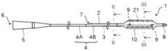
- FIG. 1illustrates an example of the configuration of a balloon catheter according to an embodiment of the present invention, and is a side view of the balloon catheter.
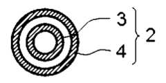
- 2shows a cross-sectional view of the balloon catheter shown in FIG. 1 along line II-II.
- 3shows a cross-sectional view of the balloon catheter shown in FIG. 1 taken along line III-III.
- 1is a perspective view of a balloon according to a first embodiment of the present invention;
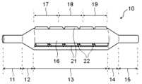
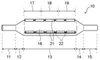
- FIG. FIG. 4illustrates an example of a perspective view of a balloon according to a second embodiment provided on a balloon catheter.
- FIG. 6shows a vertical cross-sectional view in the longitudinal direction of the straight tube portion of the balloon shown in FIGS. 4 and 5.
- FIG. 7shows a vertical cross-sectional view of the longitudinal axis direction of the ridge of the balloon shown in FIG. 6.
- 8A and 8Bshow an example of the configuration of a specific notch formed in a convex strip of a balloon according to the first embodiment and an adjacent convex strip segment, in which FIG. 8A shows an oblique view of the end of the convex strip segment, and FIG. 8B shows a plan view of the end of the convex strip segment as viewed from the top side of the convex strip.
- 9A and 9Bshow examples of the configuration of a specific notch formed in a convex strip of a balloon according to the first embodiment and the adjacent convex strip segment, in which FIG.
- FIG. 9Ashows an oblique view of the end of the convex strip segment
- FIG. 9Bshows a plan view of the end of the convex strip segment as viewed from the top side of the convex strip.
- 10A and 10Bshow an example of the configuration of a specific notch formed in a convex strip of a balloon according to the first embodiment and an adjacent convex strip segment, in which FIG. 10A shows an oblique view of the end of the convex strip segment, and FIG. 10B shows a plan view of the end of the convex strip segment as viewed from the top side of the convex strip.
- FIG. 11A and 11Bshow an example of the configuration of a specific notch formed in a convex strip of a balloon according to the first embodiment and an adjacent convex strip segment, in which FIG. 11A shows an oblique view of the end of the convex strip segment, and FIG. 11B shows a plan view of the end of the convex strip segment as viewed from the top side of the convex strip.
- 12A and 12Bshow an example of the configuration of a specific notch formed in a convex strip of a balloon according to the first embodiment and an adjacent convex strip segment, in which FIG. 12A shows an oblique view of the end of the convex strip segment, and FIG.
- FIG. 12Bshows a plan view of the end of the convex strip segment as viewed from the top side of the convex strip.
- 13Ashows an example of the configuration of a specific notch formed in a convex strip of a balloon in accordance with the first embodiment and an adjacent convex strip segment, in which FIG. 13A shows an oblique view of the end of the convex strip segment, and FIG. 13B shows a plan view of the end of the convex strip segment as viewed from the top side of the convex strip.
- 14A and 14Bshow an example of the configuration of a specific notch formed in a convex strip of a balloon according to the first embodiment and an adjacent convex strip segment, in which FIG.
- FIG. 14Ashows an oblique view of the end of the convex strip segment
- FIG. 14Bshows a plan view of the end of the convex strip segment as viewed from the top side of the convex strip.
- 15A and 15Bshow an example of the configuration of a specific notch formed in a convex strip of a balloon according to the first embodiment and an adjacent convex strip segment, in which FIG. 15A shows an oblique view of the end of the convex strip segment, and FIG. 15B shows a plan view of the end of the convex strip segment as viewed from the top side of the convex strip.
- FIG. 15Ashows an oblique view of the end of the convex strip segment
- FIG. 15Bshows a plan view of the end of the convex strip segment as viewed from the top side of the convex strip.
- FIG. 2is a plan view of the balloon according to the first embodiment, seen from the top side of the ridge, illustrating an example of the configuration of the ridge having multiple specific notches in the longitudinal axis direction.
- FIG. 11is a plan view of the balloon according to the first embodiment, seen from the top side of the ridge, illustrating another example of the ridge configuration in which multiple specific notches are provided in the longitudinal axis direction.
- 18A and 18Bshow an example of the configuration of a specific notch formed in a convex strip of a balloon according to the second embodiment and an adjacent convex strip segment, in which FIG. 18A shows an oblique view of the end of the convex strip segment, and FIG.
- FIG. 18Bshows a plan view of the end of the convex strip segment as viewed from the top side of the convex strip.
- 19A and 19Bshow examples of the configuration of a specific notch formed in a convex strip of a balloon according to the second embodiment and the adjacent convex strip segment, in which FIG. 19A shows an oblique view of the end of the convex strip segment, and FIG. 19B shows a plan view of the end of the convex strip segment as viewed from the top side of the convex strip.
- 20A and 20Bshow an example of the configuration of a specific notch formed in a convex strip of a balloon according to the second embodiment and an adjacent convex strip segment, in which FIG.
- FIG. 20Ashows an oblique view of the end of the convex strip segment
- FIG. 20Bshows a plan view of the end of the convex strip segment as viewed from the top side of the convex strip
- 21A and 21Bshow an example of the configuration of a specific notch formed in a convex strip of a balloon according to the second embodiment and an adjacent convex strip segment, in which FIG. 21A shows an oblique view of the end of the convex strip segment, and FIG. 21B shows a plan view of the end of the convex strip segment as viewed from the top side of the convex strip.
- FIG. 22A and 22Bshow an example of the configuration of a specific notch formed in a convex strip of a balloon according to the second embodiment and an adjacent convex strip segment, in which FIG. 22A shows an oblique view of the end of the convex strip segment, and FIG. 22B shows a plan view of the end of the convex strip segment as viewed from the top side of the convex strip.
- 23Ashows an example of the configuration of a specific notch formed in a convex strip of a balloon according to the second embodiment and an adjacent convex strip segment, where FIG. 23A shows an oblique view of the end of the convex strip segment, and FIG.
- FIG. 23Bshows a plan view of the end of the convex strip segment as viewed from the top side of the convex strip.
- 24A and 24Bshow an example of the configuration of a specific notch formed in a convex strip of a balloon according to the second embodiment and an adjacent convex strip segment, in which FIG. 24A shows an oblique view of the end of the convex strip segment, and FIG. 24B shows a plan view of the end of the convex strip segment as viewed from the top side of the convex strip.
- 25A and 25Bshow an example of the configuration of a specific notch formed in a convex strip of a balloon according to the second embodiment and an adjacent convex strip segment, in which FIG.
- FIG. 25Ashows an oblique view of the end of the convex strip segment
- FIG. 25Bshows a plan view of the end of the convex strip segment as viewed from the top side of the convex strip.
- 1shows an example of a cross-sectional view along the longitudinal axis direction of a ridge and a particular notch provided on a balloon.
- 13shows another example of a cross-sectional view along the longitudinal axis direction of a ridge and a particular notch provided on a balloon.
- 13shows another example of a cross-sectional view along the longitudinal axis direction of a ridge and a particular notch provided on a balloon.
- FIG. 13shows another example of a cross-sectional view along the longitudinal axis direction of a ridge and a particular notch provided on a balloon.
- FIG. 2illustrates another example of a perspective view of the balloon according to the first embodiment provided in the balloon catheter.
- FIG. 2illustrates another example of a perspective view of the balloon according to the first embodiment provided in the balloon catheter.
- FIG. 13illustrates another example of a perspective view of a balloon according to a second embodiment provided in a balloon catheter.
- FIG. 13illustrates another example of a perspective view of a balloon according to a second embodiment provided in a balloon catheter.
- 13shows another example of a vertical cross-sectional view of a balloon's ridges in the longitudinal axis direction.
- FIG. 1shows a side view of a balloon catheter
- Fig. 2shows a II-II cross-sectional view of the balloon catheter shown in Fig. 1
- Fig. 3shows a III-III cross-sectional view of the balloon catheter shown in Fig. 1
- Figs. 4 and 5show examples of perspective views of a balloon equipped in a balloon catheter.
- Fig. 1shows an example of the configuration of a rapid exchange type balloon catheter.
- FIG. 4shows a perspective view of a balloon according to a first embodiment, in which a specific notch that satisfies requirement A described later is formed in the convex stripes provided on the balloon surface.
- Fig. 5shows a perspective view of a balloon according to a second embodiment, in which a specific notch that satisfies requirement B described later is formed in the convex stripes provided on the balloon surface.
- the balloon catheter 1has a shaft 2 and a balloon 10 provided on the outside of the shaft 2.
- the balloon catheter 1has a proximal side and a distal side, and the balloon 10 is provided on the distal part of the shaft 2.
- the proximal side of the balloon catheter 1refers to the direction toward the user's (operator's) hand in the extension direction of the balloon catheter 1, and the distal side refers to the opposite direction of the proximal side, i.e., the direction toward the treatment target.
- the direction from the proximal side to the distal side of the balloon catheter 1is referred to as the longitudinal axis direction.
- the balloon catheter 1is configured so that fluid is supplied to the inside of the balloon 10 through the shaft 2, and the expansion and contraction of the balloon 10 can be controlled using an indeflator (a balloon pressurizer/depressurizer).
- the fluidmay be a pressurized fluid pressurized by a pump or the like.
- the fluid supplied to the inside of the balloon 10is referred to as the "balloon expansion fluid.”
- the shaft 2is composed of, for example, an inner shaft 3 and an outer shaft 4.
- the inner shaft 3is disposed in the inner cavity of the outer shaft 4.
- the inner shaft 3can function as a passage for a guide wire that guides the progress of the shaft 2, and when the balloon catheter 1 is used, the guide wire is inserted into the inner cavity of the inner shaft 3.
- the space between the inner shaft 3 and the outer shaft 4can function as a flow path for the balloon expansion fluid.
- a guidewire port 7is provided midway from the distal to the proximal side of the shaft 2, and the proximal end of the inner shaft 3 is connected to the guidewire port 7, and the distal end of the inner shaft 3 extends to the distal part of the shaft 2, forming a guidewire insertion passage that extends from the guidewire port 7 to the distal part of the shaft 2.
- the outer shaft 4may have a proximal outer shaft 4A and a distal outer shaft 4B, in which case it is preferable that the inner shaft 3 is disposed in the lumen of the distal outer shaft 4B.
- the proximal outer shaft 4A and the distal outer shaft 4Bmay be made of the same material, or may be made of different materials.
- the proximal outer shaft 4Ais made of resin or metal
- the distal outer shaft 4Bis made of resin.
- the outer shaft 4may not be divided into the proximal outer shaft 4A and the distal outer shaft 4B, but may be made of a single member, or the proximal outer shaft 4A and the distal outer shaft 4B may be further made of multiple tube members.
- a hub 5is preferably provided on the proximal side of the shaft 2.
- the hub 5preferably has a fluid injection section 6 that is connected to the flow path of the balloon expansion fluid in the shaft 2.
- the balloon 10, shaft 2 (inner shaft 3, outer shaft 4), and hub 5can be joined using conventional joining means such as adhesives or heat welding.
- the balloon cathetermay be an over-the-wire type balloon catheter in which the inner shaft extends from the distal to the proximal part of the shaft and a guidewire passage is formed from the distal to the proximal side of the shaft.
- the flow path of the balloon expansion fluid and the guidewire passage provided in the shaftextend to the hub, and that the hub is configured to have a fluid injection section communicating with the flow path of the balloon expansion fluid and a treatment section communicating with the guidewire passage.
- the hubhas a bifurcated structure, with the fluid injection section provided on one side of the bifurcated branch and the treatment section provided on the other side.
- the outer surface of the shaft 2is preferably coated.
- a rapid exchange type balloon catheter 1it is preferable that the outer surface of one or both of the proximal outer shaft 4A and the distal outer shaft 4B is coated, and it is more preferable that the outer surfaces of both the proximal outer shaft 4A and the distal outer shaft 4B are coated.
- an over-the-wire type balloon catheterit is preferable that the outer surface of the outer shaft is appropriately coated.
- the coatingcan be a hydrophilic coating or a hydrophobic coating depending on the purpose.
- the outer surface of the shaft 2can be coated by immersing the shaft 2 in a hydrophilic or hydrophobic coating agent, applying a hydrophilic or hydrophobic coating agent to the outer surface of the shaft 2, or covering the outer surface of the shaft 2 with a hydrophilic or hydrophobic coating agent.
- the coating agentmay contain drugs or additives.
- Hydrophilic coating agentsinclude hydrophilic polymers such as polyvinyl alcohol, polyethylene glycol, polyacrylamide, polyvinylpyrrolidone, and methyl vinyl ether maleic anhydride copolymers, as well as hydrophilic coating agents made from any combination of these.
- Hydrophobic coating agentsinclude polytetrafluoroethylene (PTFE), fluorinated ethylene propylene (FEP), perfluoroalkoxyalkane (PFA), silicone oil, hydrophobic urethane resin, carbon coat, diamond coat, diamond-like carbon (DLC) coat, ceramic coat, and substances with low surface free energy terminated with alkyl groups or perfluoroalkyl groups.
- PTFEpolytetrafluoroethylene
- FEPfluorinated ethylene propylene
- PFAperfluoroalkoxyalkane
- silicone oilsilicone oil
- hydrophobic urethane resincarbon coat
- diamond coatdiamond coat
- DLCdiamond-like carbon
- ceramic coatand substances with low surface free energy terminated with alkyl groups or perfluoroalkyl groups.
- a tip tip 8is provided at the distal end of the balloon catheter 1.
- the tip tip 8may be provided as a separate member from the inner shaft 3, distal to the distal end of the inner shaft 3, or the inner shaft 3 may extend distal to the distal end of the balloon 10, so that the distal end of the inner shaft 3 functions as the tip tip 8.
- the shaft 2may have an X-ray opaque marker 9 disposed at the portion where the balloon 10 is located in the longitudinal direction, so that the position of the balloon 10 can be confirmed under X-ray fluoroscopy.
- the X-ray opaque marker 9may be disposed, for example, on the inner shaft 3 disposed inside the balloon 10, and is preferably disposed at positions corresponding to both ends of the straight tube portion of the balloon 10, or may be disposed at a position corresponding to the center of the straight tube portion of the balloon 10.
- the balloon 10has a longitudinal axis direction and a radial direction, and is formed into a cylindrical shape with openings on the proximal and distal sides (see Figures 4 and 5).
- the radial direction of the balloon 10means a direction perpendicular to the longitudinal axis direction, extending radially from the center of the balloon 10.
- the balloon 10also has a circumferential direction, which is the direction along the outer periphery of the balloon 10 in an expanded state in a vertical cross section of the balloon 10 in the longitudinal axis direction.
- the balloon 10has a straight tube section 13, a proximal tapered section 12 located proximal to the straight tube section 13, and a distal tapered section 14 located distal to the straight tube section 13 in the longitudinal axis direction.
- the straight tube section 13is formed in a roughly cylindrical shape extending in the longitudinal axis direction, and is formed with the largest radial length (outer diameter) in the balloon 10.
- the proximal tapered section 12is located proximal to the straight tube section 13 and connects to the proximal end of the straight tube section 13.
- the proximal tapered section 12is formed so that the outer diameter decreases with increasing distance from the straight tube section 13.
- the distal tapered section 14is located distal to the straight tube section 13 and connects to the distal end of the straight tube section 13.
- the distal tapered section 14is formed so that the outer diameter decreases with increasing distance from the straight tube section 13.
- the balloon 10preferably further has a proximal sleeve portion 11 located proximal to the proximal taper portion 12 and a distal sleeve portion 15 located distal to the distal taper portion 14.
- the proximal sleeve portion 11is located proximal to the proximal taper portion 12 and is connected to the proximal end of the proximal sleeve portion 11.
- the proximal sleeve portion 11is formed in a substantially cylindrical shape.
- the distal sleeve portion 15is located distal to the distal taper portion 14 and is connected to the distal end of the distal sleeve portion 15.
- the distal sleeve portion 15is formed in a
- the straight tube section 13comes into sufficient contact with the narrowed area, making it easier to perform treatment such as expanding the narrowed area.
- the balloon 10has a proximal tapered section 12 and a distal tapered section 14, when the balloon 10 is deflated, the outer diameter of the proximal and distal ends of the balloon 10 can be reduced to reduce the step between the shaft 2 and the balloon 10, making it easier to insert the balloon 10 into a body cavity, a forceps channel of an endoscope, or a delivery catheter such as a guiding catheter.
- the inner shaft 3extends distally beyond the distal end of the outer shaft 4, and that the inner shaft 3 extends through the internal space of the balloon 10 from the proximal sleeve portion 11 to the distal sleeve portion 15. It is also preferable that the outer surface of the inner shaft 3 is joined to the internal surface of the distal sleeve portion 15 of the balloon 10, and the outer surface of the outer shaft 4 is joined to the internal surface of the proximal sleeve portion 11 of the balloon 10.
- the size of the balloon 10is not particularly limited.
- the size of the balloon 10can be set appropriately, for example, so that the length of the straight tube portion 13 in the longitudinal direction is in the range of 4 mm to 400 mm, and the outer diameter of the straight tube portion 13 is in the range of 1 mm to 30 mm.
- the balloon 10(particularly the balloon body 16) is preferably made of a resin, more preferably a thermoplastic resin. This makes it easier to manufacture the balloon 10 by molding.
- resins that make up the balloon 10include polyolefin resins such as polyethylene, polypropylene, and ethylene-propylene copolymers, polyester resins such as polyethylene terephthalate and polyester elastomers, polyurethane resins such as polyurethane and polyurethane elastomers, polyphenylene sulfide resins, polyamide resins such as polyamide and polyamide elastomers, fluorine-based resins, silicone resins, and natural rubbers such as latex rubber. These may be used alone or in combination of two or more.
- polyamide resinspolyester resins, and polyurethane resins are preferably used.
- elastomer resinsare preferably used in terms of thinning and flexibility of the balloon 10.
- nylon 12 and nylon 11are suitable materials for the balloon 10 among polyamide resins, and nylon 12 is preferably used because it can be molded relatively easily during blow molding.
- polyamide elastomerssuch as polyether ester amide elastomers and polyamide ether elastomers are preferably used in terms of thinning and flexibility of the balloon 10.
- polyether ester amide elastomersare preferably used in terms of high yield strength and good dimensional stability of the balloon 10.
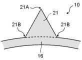
- the balloon 10has a ridge 21 on the outer surface of the straight tube section 13.
- the provision of the ridge 21 on the outer surface of the straight tube section 13gives the balloon 10 a scoring function, and when the balloon 10 is expanded at a narrowed portion of a blood vessel, it can bite into the calcified narrowed portion and create a crack in the narrowed portion. This allows the narrowed portion to be expanded while suppressing blood vessel dissection. It also makes it possible to increase the pressure resistance of the balloon 10 and suppress overexpansion when pressurized.
- the balloon 10can also be used to treat narrowed portions and lesions in body cavities other than blood vessels, but the following description focuses on the application of the balloon 10 to vascular treatment.
- Figure 6shows a vertical cross-section in the longitudinal direction of the straight tube section 13 of the balloon 10
- Figure 7shows an enlarged cross-section of the ridges 21 of the balloon 10.
- Figure 6shows an example of the configuration of the vertical cross-section in the longitudinal direction of the straight tube section 13 of the balloon 10 shown in Figures 4 and 5, with the ridges 21 provided at three locations in the circumferential direction of the straight tube section 13.
- the straight tube section 13 of the balloon 10has a cylindrical balloon body 16, and a convex streak 21 is provided on the outer surface of the balloon body 16.
- the convex streak 21is provided so as to protrude radially outward from the outer surface of the balloon body 16.
- the balloon 10has a convex streak region 25 and a convex streak non-existent region 26 formed on the outer surface of the straight tube section 13.
- the convex streak region 25also includes a portion in which a notch 22 is formed in the convex streak 21, as described below.
- the outer surface of the straight tube section 13is formed flat in the convex streak non-existent region 26, and for example, it is preferable that the outer surface of the straight tube section 13 is not formed in a recess in a part of the convex streak non-existent region 26. This makes it easier to uniformly expand the balloon 10 and to make it easier to achieve the scoring function of the convex streak 21 as desired.
- the outer surface of the straight pipe section 13 being formed flat in the non-ridge region 26means that the non-ridge region 26 is a flat surface that is curved in an arch shape, and no irregularities are formed on the curved flat surface. The irregularities do not include surface roughness that is unavoidably formed during manufacturing.
- the ridge 21has an apex 21A and a base 21B.
- the apex 21Arefers to the tip of the ridge 21, i.e., the part of the ridge 21 located most outward in the radial direction
- the base 21Brefers to the boundary with the balloon body 16, i.e., the part of the ridge 21 located most inward in the radial direction.
- the ridges 21can be made of, for example, resin. If the ridges 21 are made of resin, the balloon 10 having the ridges 21 can be manufactured by resin molding, making manufacturing easier. In this case, the ridges 21 and the balloon body 16 are preferably made of the same resin, and the ridges 21 and the balloon body 16 are preferably integrally molded.
- the balloon body 16may have an inner layer and an outer layer, and in this case, the ridges 21 are preferably made of the same resin as the outer layer of the balloon body 16. This makes it less likely that the ridges 21 will unintentionally fall off the balloon body 16.
- the ridges 21 and the balloon body 16may be made of different resins, as long as there is a certain degree of compatibility between the resin that makes up the ridges 21 and the resin that makes up the balloon body 16.
- the ridges 21may be made of metal, or a combination of metal and resin. In this case, it is preferable that the portion including the apex 21A of the ridges 21 is made of metal. This makes it easier for the ridges 21 to create cracks in or cut open the narrowed portion when the balloon 10 is inflated.
- the entire ridges 21may be made of metal, or the portion including the base 21B of the ridges 21 may be made of resin, and the portion including the apex 21A of the ridges 21 may be made of metal. Therefore, it is preferable that the ridges 21 are made of resin, metal, or a combination thereof.
- the balloon main body 16is defined as a portion having a cylindrical shape.
- the straight pipe section 13is the portion excluding the ridges 21 protruding radially outward, forming the balloon main body 16.
- the outer surface of the balloon main body 16can be considered to be formed in a cylindrical shape. Therefore, in a vertical cross section in the longitudinal axis direction of the straight pipe section 13, the outer shape of the balloon main body 16 is formed in a substantially circular shape, which allows the balloon main body 16 and the ridges 21 to be distinguished from each other.
- the ridge-present region 25is composed of the balloon main body 16 and the ridges 21, and the ridge-free region 26 is composed of the balloon main body 16.
- the ridges 21are provided on the outer surface of the straight tube section 13 so as to extend in a ridge-like pattern.
- the ridges 21extend approximately parallel to the longitudinal axis of the balloon 10.
- the ridges 21have an extension direction approximately parallel to the longitudinal axis of the balloon 10 and a width direction corresponding to the circumferential direction of the balloon 10.
- the ridges 21are provided at multiple different circumferential positions on the straight tube section 13 of the balloon 10. That is, the ridges 21 are provided at multiple locations on the balloon 10 in the circumferential direction. In this case, the ridges 21 are preferably arranged at approximately equal intervals on the straight tube section 13 of the balloon 10 in the circumferential direction. This makes it possible to create cracks at multiple locations on the narrowed section when the balloon 10 is expanded.
- the ridges 21are preferably provided at two or more locations on the circumferential direction of the balloon 10, more preferably three or more locations, and preferably 12 or less locations, more preferably 10 or less locations, and even more preferably 8 or less locations. In this case, the circumferential interval of the ridges 21 is preferably longer than the circumferential length of one ridge 21.
- the multiple ridges 21are preferably provided at approximately the same position in the longitudinal direction. That is, the proximal ends of the multiple ridges 21 are preferably located at approximately the same position in the longitudinal direction, and the distal ends of the multiple ridges 21 are preferably located at approximately the same position in the longitudinal direction.
- the cross-sectional shape of the convex ribs 21is not particularly limited.
- the shape of the convex ribs 21 in a vertical cross section in the longitudinal axis direction of the straight pipe section 13can be a polygon such as a triangle or a rectangle, a partial circular shape such as a semicircle or a sector, a wedge shape, a convex shape, a spindle shape, an irregular shape, etc.
- Polygonsinclude polygons with clear corner apexes and straight sides, as well as rounded polygons with rounded corners and polygons with at least some of the sides curved. It is preferable that the convex ribs 21 are formed so that their width gradually decreases toward the apex 21A.
- the height of the ridges 21is preferably 0.2 times or more the width (maximum width) of the ridges 21. If the ridges 21 are formed in this manner, when the balloon 10 is expanded at the narrowed portion, the ridges 21 are more likely to bite into the narrowed portion, and the scoring function of the ridges 21 can be improved.
- the ridges 21are preferably formed so that their width is maximum at the base 21B, so that the ridges 21 are stably installed on the outer surface of the balloon body 16.
- the height of the ridges 21is more preferably 0.4 times or more the width of the ridges 21, and even more preferably 0.7 times or more.
- the height of the ridges 21is preferably 2.0 times or less the width of the ridges 21, more preferably 1.8 times or less, and even more preferably 1.5 times or less. This makes it easier to ensure the flexibility of the balloon 10 in the area where the ridges 21 are present.
- the thickness of the portion where the ridges 21 are providedi.e., the thickness of the ridge-present region 25, is preferably formed to be thicker than the thickness of the portion where the ridges 21 are not provided, i.e., the thickness of the ridge-free region 26. This can improve the scoring function of the ridges 21.
- the thickness (maximum thickness) of the ridge-present region 25is preferably 1.5 times or more, more preferably 2.0 times or more, and even more preferably 2.5 times or more, the thickness (maximum thickness) of the ridge-free region 26.
- the ridges 21are preferably provided over a range of 60% or more in the longitudinal direction of the straight tube section 13, more preferably over a range of 70% or more, and even more preferably over a range of 80% or more. This makes it possible to create cracks over a wide range of the narrowed section when the balloon 10 is expanded.
- the ridges 21may be provided over a range of 90% or more in the longitudinal direction of the straight tube section 13, or may be provided over almost the entire longitudinal direction of the straight tube section 13, and may also be provided on the outer surface of the proximal taper section 12 and/or the distal taper section 14.
- the ridges 21may also be provided on the outer surface of the proximal sleeve section 11 and/or the distal sleeve section 15.
- the balloon 10may have an inner ridge that protrudes radially inward on the inner surface of the balloon 10 (not shown).
- the ridge 21 and the inner ridgemay be located at the same position in the longitudinal direction or circumferential direction of the balloon 10, and it is preferable that they are integrally molded, so that a portion of the balloon 10 may be formed thick.
- a balloon 10 provided with a convex rib 21tends to have higher rigidity in the area where the convex rib 21 is provided. Therefore, a balloon 10 provided with a convex rib 21 is more likely to have lower flexibility in the longitudinal direction than a balloon 10 without a convex rib 21. For example, in a shunt formed during hemodialysis, blood vessels are greatly bent at the arteriovenous anastomosis, and when a balloon is passed through such a location, it may be difficult to pass a balloon provided with a convex rib through the arteriovenous anastomosis.
- a balloon for the lower limbsthe balloon is inserted through the iliac artery during treatment, and blood vessels are greatly bent at the bifurcation where the left and right iliac arteries branch off from the abdominal aorta. Therefore, when a balloon for the lower limbs is provided with a convex rib, it may be difficult to pass the balloon from one of the left and right iliac arteries to the other. In particular, since a balloon for the lower limbs is long, there is a high possibility that the balloon will not be able to pass through a location where the blood vessels are greatly bent. Therefore, as shown in Figures 4 and 5, a notch 22 is formed in the convex rib 21 of the balloon 10. By forming the notches 22 in the ridges 21, the flexibility of the balloon 10 in the longitudinal direction can be improved.
- the notches 22are formed in each ridge 21. This allows the flexibility of the balloon 10 to be improved regardless of the direction in which the balloon 10 bends.
- the number of notches 22 formed in each ridge 21is not particularly limited as long as it is one or more, but from the viewpoint of increasing the flexibility of the balloon 10, the number of notches 22 formed in each ridge 21 is preferably two or more, and more preferably three or more. On the other hand, from the viewpoint of ensuring the scoring function of the balloon 10, the number of notches 22 formed in each ridge 21 is preferably 20 or less, more preferably 16 or less, even more preferably 12 or less, and even more preferably 8 or less.
- the notch 22may be formed so that a portion of the top 21A of the ridge 21 extending in the longitudinal direction is cut away.
- Figures 26 to 29show cross-sectional views along the longitudinal direction passing through the top 21A of the ridge 21 of a specific notch 22X described below, but as shown in Figures 26 and 28, the notch 22 may be formed so as to extend from the top 21A of the ridge 21 to the base 21B, or as shown in Figures 27 and 29, the notch 22 may be formed so as to extend partway from the top 21A of the ridge 21 to the base 21B.
- the depth of the notch 22corresponds to the height of the ridge 21.
- the depth of the notch 22is formed to be shorter than the height of the ridge 21.
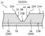
- 26 to 29show cross-sectional views of the ridge 21, including the notch 22, taken along an imaginary plane that passes through the apex 21A of the ridge 21 and is formed by the longitudinal axis direction and radial direction of the balloon 10.
- the notch 22has a bottom 22B and a top 22A, the bottom 22B being the radially innermost part of the notch 22, and the top 22A being the radially outermost part of the notch 22.
- the top 22A of the notch 22coincides with the top 21A of the ridge 21.
- the radial length from the top 22A to the bottom 22B of the notch 22is the depth of the notch 22.
- the convex strip 21is divided into a number of convex strip segments 24 by the notches 22.
- the convex strip segment 24is divided into a proximal convex strip segment 24 and a distal convex strip segment 24, with the bottom 22B of the notch 22 as the boundary.
- the convex strip segment 24 adjacent to the proximal side of the notch 22is referred to as the proximal convex strip segment 24P
- the convex strip segment 24 adjacent to the distal side of the notch 22is referred to as the distal convex strip segment 24D.
- a proximal convex strip segment 24Pis formed proximally from the proximal end of the bottom 22B of the notch 22
- a distal convex strip segment 24Dis formed distally from the distal end of the bottom 22B of the notch 22.
- the proximal end of the bottom 22B of the notch 22becomes the distal boundary of the proximal convex strip segment 24P
- the distal end of the bottom 22B of the notch 22becomes the proximal boundary of the distal convex strip segment 24D.
- the notch 22When the notch 22 is formed to extend from the top 21A to the base 21B of the convex strip 21, as shown in FIG. 26 and FIG. 28, the notch 22 forms an interrupted portion 23 of the convex strip 21, and the convex strip segments 24 are arranged on the proximal and distal sides of the interrupted portion 23.
- the ridge 21is formed by arranging the ridge segments 24 and the discontinuous portions 23 alternately in the longitudinal direction.
- the proximal ridge segment 24P and the distal ridge segment 24D adjacent to the notch 22may be spaced apart in the longitudinal direction as shown in Figures 26 and 27, or may be in contact with each other in the longitudinal direction as shown in Figures 28 and 29.
- the longitudinal length of the notch 22is preferably shorter than the longitudinal length of the ridge segment 24.
- the longitudinal length of the notch 22(if multiple notches 22 are provided, the longitudinal length of each notch 22) is preferably shorter than the longitudinal length of any of the ridge segments 24.
- the longitudinal length of the notch 22(if multiple notches 22 are provided, the longitudinal length of each notch 22) is preferably 0.5 times or less, more preferably 0.3 times or less, and even more preferably 0.2 times or less, the average longitudinal length of the ridge segments 24. This makes it easier to ensure the scoring function of the ridge 21.
- the length of the notch 22 in the longitudinal directionmeans the distance between the apexes of the proximal and distal ridge segments 24 on either side of the notch 22 in a cross section along the longitudinal direction passing through the apex 21A of the ridge 21, i.e., the distance between the distal end of the apex of the proximal ridge segment 24P and the proximal end of the apex of the distal ridge segment 24D.
- the total longitudinal length of the notches 22is preferably 20% or less of the longitudinal length of the ridge 21, more preferably 15% or less, and even more preferably 10% or less. This makes it easier to ensure the scoring function of the ridge 21.
- the longitudinal length of the ridge 21is determined as follows. Of the multiple ridge segments 24 constituting each ridge 21, the proximal end of the proximal-most ridge segment 24 becomes the proximal end of the ridge 21, the distal end of the distal-most ridge segment 24 becomes the distal end of the ridge 21, and the longitudinal length from the proximal end to the distal end of the ridge 21 becomes the longitudinal length of the ridge 21.
- the length in the longitudinal direction of the notch 22is preferably 0.2 times or more, more preferably 0.3 times or more, and even more preferably 0.5 times or more, the depth of the notch 22. This makes it easier to increase the flexibility of the straight tube section 13 of the balloon 10 in the longitudinal direction.
- the length in the longitudinal direction of the notch 22is preferably 5 times or less, more preferably 3 times or less, and even more preferably 2 times or less, the depth of the notch 22. This makes it easier to ensure the scoring function of the balloon 10.
- the length of the portion of the bottom 22B of the notch 22 extending parallel to the longitudinal axis directionis not formed to be too long compared to the longitudinal axis length of the notch 22 (the distance between the tops of the convex strip segments 24 on the proximal and distal sides of the notch 22).
- the length of the portion of the bottom 22B of the notch 22 extending parallel to the longitudinal axis directionis preferably 0.5 times or less, more preferably 0.3 times or less, and even more preferably 0.2 times or less, the longitudinal axis length of the notch 22. This makes it easier for the balloon 10 to bend smoothly at the notch 22 and makes it easier to ensure the scoring function of the convex strip 21.
- the bottom 22B of the notch 22does not need to include a portion extending parallel to the longitudinal axis direction. As shown in Figures 26 and 28, when the notch 22 is formed to extend from the top 21A of the ridge 21 to the base 21B, the longitudinal length of the discontinuous portion 23 of the ridge 21 (the longitudinal length of the discontinuous portion 23 on the outer surface of the balloon body 16) corresponds to the longitudinal length of the bottom 22B of the notch 22.
- the notch 22may be formed at any location in the longitudinal direction of the ridge 21 provided in the straight pipe section 13. For example, as shown in Figures 4 and 5, when the ridge 21 in the straight pipe section 13 is divided into three equal sections in the longitudinal direction into a proximal section 17, an intermediate section 18, and a distal section 19, the notch 22 may be provided in any of the proximal section 17, the intermediate section 18, and the distal section 19.
- the notch 22is provided at least in the distal section 19.
- the notch 22is provided in the distal section 19 of each ridge 21 provided in the straight tube section 13.
- the notch 22is provided in the proximal section 17 of the ridge 21. This increases the flexibility of the proximal portion of the balloon 10 (specifically, the portion of the balloon 10 that corresponds to the proximal section 17 of the ridge 21 in the longitudinal direction), and increases the ease of insertion of the curved portion of the balloon 10 when the balloon 10 is pulled back to pass through the curved portion after treatment with the balloon 10. In this case, it is preferable that the notch 22 is provided in the proximal section 17 of each ridge 21 provided in the straight tube portion 13.
- the proximal section 17, intermediate section 18, and distal section 19 of the convex rib 21are defined as follows: For each convex rib 21, the length in the longitudinal direction from the proximal end to the distal end of the convex rib 21 is defined as L, and the convex rib 21 is divided into three sections with a length of L/3, with the most proximal section defined as the proximal section 17, the most distal section defined as the distal section 19, and the section between the proximal section 17 and the distal section 19 defined as the intermediate section 18.
- the longitudinal position of the notch 22 in the convex rib 21, i.e., whether the notch 22 is located in the proximal section 17, intermediate section 18, or distal section 19 of the convex rib 21,is determined based on the position of the bottom 22B of the notch 22 in a cross section along the longitudinal direction passing through the top 21A of the convex rib 21 (specifically, a cross section along the longitudinal direction and radial direction passing through the top 21A of the convex rib 21).
- the midpoint of the longitudinal direction of the bottom 22B of the notch 22is determined to be the longitudinal position of the notch 22 on the convex strip 21.
- the bottom 22B of the notch 22is located exactly on the boundary between the proximal section 17 and the intermediate section 18 or the boundary between the intermediate section 18 and the distal section 19, it is determined to exist in both sections but to belong to neither section.
- the notch 22does not have to be provided in the middle section 18 of the ridge 21. If the ridge 21 is formed in this manner, it becomes easier to impart a high scoring function to the balloon 10 while increasing the flexibility of the balloon 10. On the other hand, in order to further increase the flexibility of the balloon 10, the notch 22 may also be provided in the middle section 18 of the ridge 21. For example, since the balloon 10 for the lower limbs has a long length in the longitudinal direction, by providing the notch 22 in the middle section 18, it is possible to ensure flexibility throughout the entire longitudinal direction of the balloon 10, even for a balloon 10 with a long length in the longitudinal direction.
- the notch 22may also be provided in the convex rib 21 of the proximal sleeve portion 11, the proximal tapered portion 12, the distal tapered portion 14, or the distal sleeve portion 15.
- the convex strip 21is provided with a specific notch 22X that satisfies the following requirement A or requirement B as part or all of the notch 22 described above.
- the balloon 10 according to the first embodiment shown in Fig. 4is provided with a specific notch 22X that satisfies the following requirement A in the convex strip 21, and the balloon 10 according to the second embodiment shown in Fig. 5 is provided with a specific notch 22X that satisfies the following requirement B in the convex strip 21.
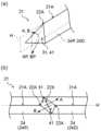
- the distal surface of the proximal ridge segment 24P adjacent to the distal side of a particular notch 22Xhas a normal vector A on the intersection line with an imaginary plane H formed by the longitudinal axis direction and the radial direction that passes through the apex 21A of the ridge 21, which extends to one side of the imaginary plane H toward the distal side, and the proximal surface of the distal ridge segment 24D adjacent to the distal side of a particular notch 22X has a normal vector B on the intersection line with the imaginary plane H that extends to the other side of the imaginary plane H toward the proximal side.
- Figures 8(a) to 15(a)show an oblique view of the distal end of the proximal convex strip segment 24P seen from the distal side or an oblique view of the proximal end of the distal convex strip segment 24D seen from the proximal side
- Figures 8(b) to 15(b)show plan views of the distal end of the proximal convex strip segment 24P and the proximal end of the distal convex strip segment 24D seen from the apex 21A side of the convex strip 21.
- the end of the ridge segment 24means the distal end of the proximal ridge segment 24P adjacent to a particular notch 22X and/or the proximal end of the distal ridge segment 24D.
- the convex rib 21 of the balloon 10has a distal end of the proximal convex rib segment 24P adjacent to a particular notch 22X and a proximal end of the distal convex rib segment 24D formed as follows:
- the distal surface 31 of the proximal convex rib segment 24Phas a normal vector A on the line of intersection with an imaginary plane H formed by the longitudinal axis direction and the radial direction passing through the apex 21A of the convex rib 21, which extends to one side of the imaginary plane H toward the distal side, and the proximal surface 41 of the distal convex rib segment 24D has a normal vector B on the line of intersection with the imaginary plane H, which extends to the other side of the imaginary plane H toward the proximal side.
- the extension direction of the normal vector A of the distal surface 31 of the proximal ridge segment 24P and the extension direction of the normal vector B of the proximal surface 41 of the distal ridge segment 24Dare determined when the proximal ridge segment 24P and the distal ridge segment 24D are positioned with a specific notch 22X between them, as shown in Figures 8(b) to 15(b).
- the distal surface 31 of the proximal convex streak segment 24Pmeans the portion of the proximal convex streak segment 24P facing the distal side.
- a normal vector A on the line of intersection with the imaginary plane H formed by the longitudinal axis direction and the radial direction passing through the apex 21A of the convex streak 21extends to one side (first side) of the imaginary plane H toward the distal side.
- the normal vector Aextends from the other side (second side) of the circumferential direction of the balloon 10 toward one side (first side) toward the distal side.
- the normal vector Amay extend parallel to the outer surface of the balloon body 16 (i.e., so that the radial position does not change), may extend radially outward toward the distal side, or may extend radially inward toward the distal side.
- the distal surface 31 of the proximal convex streak segment 24Pmay be formed so that such a normal vector A exists at least in a portion of the intersection with the imaginary plane H, but it is preferable that it be formed so that it has such a normal vector A at the apex 22A of the notch 22X on the intersection with the imaginary plane H, and it is even more preferable that it be formed so that it has such a normal vector A over the entire intersection with the imaginary plane H.
- the proximal surface 41 of the distal convex streak segment 24Dmeans the portion of the distal convex streak segment 24D facing the proximal side.
- the normal vector B on the intersection line with the imaginary plane H formed by the longitudinal axis direction and the radial direction passing through the apex 21A of the convex streak 21extends toward the other side of the imaginary plane H (the opposite side of the normal vector A and the imaginary plane H; the second side) toward the proximal side.
- the normal vector Bextends toward the proximal side from one side (first side) of the circumferential direction of the balloon 10 toward the other side (second side).
- the normal vector Bmay extend parallel to the outer surface of the balloon body 16 (i.e., so that the radial position does not change), may extend radially outward toward the proximal side, or may extend radially inward toward the proximal side.
- the proximal surface 41 of the distal convex stripe segment 24Dmay be formed so that such a normal vector B exists at least in a portion of the intersection with the imaginary plane H, but it is preferable that the proximal surface 41 be formed so that such a normal vector B exists at the apex 22A of the notch 22X on the intersection with the imaginary plane H, and it is even more preferable that the proximal surface 41 be formed so that such a normal vector B exists over the entire intersection with the imaginary plane H.
- the distal surface 31 of the proximal ridge segment 24P and the proximal surface 41 of the distal ridge segment 24Dmay be formed in a flat shape, a curved shape, or a combination of these.
- the shape of the distal surface 31 of the proximal ridge segment 24Pmay be the same as or different from the shape of the proximal surface 41 of the distal ridge segment 24D.
- the shapes of the distal surfaces 31 of multiple proximal ridge segments 24Pmay be the same as or different from each other, and the shapes of the proximal surfaces 41 of multiple distal ridge segments 24D may be the same as or different from each other.
- the distal surface 31 of the proximal ridge segment 24Pmay be composed of a single plane
- the proximal surface 41 of the distal ridge segment 24Dmay be composed of a single plane.
- the overall normal vector of the distal surface 31 of the proximal ridge segment 24Pcoincides with normal vector A
- the overall normal vector of the proximal surface 41 of the distal ridge segment 24Dcoincides with normal vector B.
- the distal surface 31 of the proximal convex streak segment 24Pmay be composed of two or more planes
- the proximal surface 41 of the distal convex streak segment 24Dmay be composed of two or more planes.
- at least one of the planes constituting the distal surface 31 of the proximal convex streak segment 24P and intersecting with the imaginary plane Hhas the normal vector A described above
- at least one of the planes constituting the proximal surface 41 of the distal convex streak segment 24D and intersecting with the imaginary plane Hhas the normal vector B described above.
- the planes that do not intersect with the imaginary plane Hmay be formed so that the normal vector extends parallel to the imaginary plane H, as shown in Figures 10 and 11, or may be formed so that the normal vector extends in the opposite circumferential direction to the normal vector A toward the distal side, as shown in Figure 12.
- the distal surface 31 of the proximal ridge segment 24Pmay have a plane having a normal vector that extends in a different direction from the normal vector A and in the same circumferential direction as the normal vector A toward the distal side.
- the planes that do not have the normal vector Amay be formed to include the apex 22A of the particular notch 22X, as shown in Figures 10 and 12, or may be formed not to include the apex 22A of the particular notch 22X, as shown in Figure 11.
- the planes that do not intersect with the imaginary plane Hmay be formed so that the normal vector extends parallel to the imaginary plane H, as shown in Figs. 10 and 11, or may be formed so that the normal vector extends in the opposite circumferential direction to the normal vector B toward the proximal side, as shown in Fig. 12.
- the proximal surface 41 of the distal ridge segment 24Dmay have a plane having a normal vector that extends in a different direction from the normal vector B and in the same circumferential direction as the normal vector B toward the proximal side.
- the planes that do not have the normal vector Bmay be formed to include the apex 22A of the particular notch 22X as shown in Figures 10 and 12, or may be formed not to include the apex 22A of the particular notch 22X as shown in Figure 11.
- the distal surface 31 of the proximal convex streak segment 24Pis composed of two or more planes, each of which intersects with the imaginary plane H and has the normal vector A described above
- the proximal surface 41 of the distal convex streak segment 24Dis composed of two or more planes, each of which intersects with the imaginary plane H and has the normal vector B described above.
- the distal surface 31 of the proximal convex streak segment 24Pmay be composed of two or more planes that intersect with the imaginary plane H, and the normal vector of each of the planes on the intersection line with the imaginary plane H may be formed to extend to one side of the imaginary plane H toward the distal side
- the proximal surface 41 of the distal convex streak segment 24Dmay be composed of two or more planes that intersect with the imaginary plane H, and the normal vector of each of the planes on the intersection line with the imaginary plane H may be formed to extend to the other side of the imaginary plane H toward the proximal side.
- the distal surface 31 of the proximal ridge segment 24Pmay be configured to include a curved surface
- the proximal surface 41 of the distal ridge segment 24Dmay be configured to include a curved surface.
- the distal surface 31 of the proximal ridge segment 24Pis preferably formed so that the area of the region formed so that the normal vector extends from the other side to one side in the circumferential direction toward the distal side is 50% or more of the total area of the distal surface 31, more preferably 60% or more, and even more preferably 70% or more.
- the proximal surface 41 of the distal ridge segment 24Dis preferably formed so that the area of the region formed so that the normal vector extends from one side to the other side in the circumferential direction toward the proximal side is 50% or more of the total area of the proximal surface 41, more preferably 60% or more, and even more preferably 70% or more.
- the angle between the normal vector A and the longitudinal axis direction toward the distal sidei.e., the angle between the projection vector AP of the normal vector A onto the outer surface of the balloon main body 16 and the longitudinal axis direction toward the distal side, is preferably 20° or more, more preferably 30° or more, and preferably 70° or less, and more preferably 60° or less.
- the angle between the normal vector B and the longitudinal axis direction toward the proximal sideis preferably 20° or more, more preferably 30° or more, and preferably 70° or less, and more preferably 60° or less.
- the distal surface 31 of the proximal convex streak segment 24P and the proximal surface 41 of the distal convex streak segment 24Dare formed in this manner, when the balloon 10 is bent with the specific notch 22X facing inward and the distal surface 31 of the proximal convex streak segment 24P and the proximal surface 41 of the distal convex streak segment 24D come into contact with each other, the distal end of the proximal convex streak segment 24P and the proximal end of the distal convex streak segment 24D are more likely to shift from each other in the width direction of the convex streak 21. This makes it easier to bend the balloon 10 significantly.
- the angle between the projection vector AP and the longitudinal axis direction toward the distal side and the angle between the projection vector BP and the longitudinal axis direction toward the proximal sideare in the range of more than 0° and less than 90°.
- the distal surface 31 of the proximal ridge segment 24P and the proximal surface 41 of the distal ridge segment 24Dare preferably closest in the longitudinal direction at least on the line of intersection with the imaginary plane H. That is, the longitudinal separation distance between the distal surface 31 of the proximal ridge segment 24P and the proximal surface 41 of the distal ridge segment 24D is preferably shortest at least on the line of intersection with the imaginary plane H.
- the distal end of the proximal ridge segment 24P and the proximal end of the distal ridge segment 24D shown in Figures 8 to 15are formed in this manner. This makes it easier to bend the balloon 10 significantly with the specific notch 22X facing inward.
- the distal surface 31 of the proximal ridge segment 24P and the proximal surface 41 of the distal ridge segment 24Dare preferably closest in the longitudinal direction at least on the line of intersection with the imaginary plane H in any vertical cross section in the radial direction.
- the distal surface 31 of the proximal ridge segment 24P and the proximal surface 41 of the distal ridge segment 24Dmay be closest in the longitudinal axis direction on the intersection line with the imaginary plane H as well as in other parts.
- the distance in the longitudinal direction between the distal surface 31 of the proximal ridge segment 24P and the proximal surface 41 of the distal ridge segment 24Dis preferably formed so that it remains the same or increases as it moves away from the imaginary plane H, and more preferably is formed so that it increases at least in part.
- the distal end of the proximal ridge segment 24P and the proximal end of the distal ridge segment 24D shown in Figures 8 to 15are formed in this manner.
- the balloon 10can be bent more greatly when a specific notch 22X is located on the side of the bent portion of the balloon 10 when the balloon 10 is bent.
- the distance in the longitudinal direction between the distal surface 31 of the proximal ridge segment 24P and the proximal surface 41 of the distal ridge segment 24Dis preferably formed in this manner in any vertical cross section in the radial direction.
- the distal surface 31 of the proximal convex strip segment 24Pmay extend radially outward at a proximal incline on the line of intersection with the imaginary plane H as shown in Figures 8 to 12, may extend radially as shown in Figure 14, or may extend radially outward at a distal incline as shown in Figure 15. Also, as shown in Figure 13, the distal surface 31 of the proximal convex strip segment 24P may have, on the line of intersection with the imaginary plane H, a portion extending radially and a portion extending radially outward at a proximal incline.
- the distal surface 31 of the proximal convex streak segment 24Pmay have, on the line of intersection with the imaginary plane H, a portion that extends radially outward at an incline toward the proximal side and a portion that extends radially outward at an incline toward the distal side, or may have a portion that extends radially outward at an incline toward the distal side and a portion that extends radially, or may have a portion that extends radially outward at an incline toward the proximal side, a portion that extends radially outward at an incline toward the distal side, and a portion that extends radially.
- the proximal surface 41 of the distal ridge segment 24Dmay extend radially outward at a distal incline on the line of intersection with the imaginary plane H as shown in Figures 8 to 12, may extend radially as shown in Figure 14, or may extend radially outward at a proximal incline as shown in Figure 15. Also, as shown in Figure 13, the proximal surface 41 of the distal ridge segment 24D may have, on the line of intersection with the imaginary plane H, a portion extending radially and a portion extending radially outward at a distal incline.
- the proximal surface 41 of the distal convex streak segment 24Dmay have, on the line of intersection with the imaginary plane H, a portion that extends radially outward at an incline toward the distal side and a portion that extends radially outward at an incline toward the proximal side, or may have a portion that extends radially outward at an incline toward the proximal side and a portion that extends radially, or may have a portion that extends radially outward at an incline toward the distal side, a portion that extends radially outward at an incline toward the proximal side, and a portion that extends radially.
- the distal surface 31 of the proximal ridge segment 24Ppreferably extends radially on the line of intersection with the imaginary plane H or extends with a proximal inclination toward the radial outward direction, and more preferably extends with a proximal inclination toward the radial outward direction at least in a portion of the line of intersection with the imaginary plane H.
- the proximal surface 41 of the distal ridge segment 24Dpreferably extends radially on the line of intersection with the imaginary plane H or extends with a distal inclination toward the radial outward direction, and more preferably extends with a distal inclination toward the radial outward direction at least in a portion of the line of intersection with the imaginary plane H. If the end of the ridge segment 24 is formed in this manner, it becomes easier to bend the balloon 10 significantly when the balloon 10 is bent with the specific notch 22X facing inward.
- the distal surface 31 of the proximal ridge segment 24Pextends at an incline proximally in the radially outward direction on the line of intersection with imaginary plane H
- the proximal surface 41 of the distal ridge segment 24Dextends at an incline distally in the radially outward direction on the line of intersection with imaginary plane H.
- Figures 26 to 29show examples of cross-sectional configurations of the distal end portion of the proximal ridge segment 24P and the proximal end portion of the distal ridge segment 24D shown in Figures 8 to 12 taken along the line of intersection with imaginary plane H, and the distal surface 31 of the proximal ridge segment 24P and the proximal surface 41 of the distal ridge segment 24D are formed in this manner.
- the specific notch 22Xis formed to extend from the apex 21A to the base 21B of the ridge 21, refer to the cross-sectional view of FIG. 26 or 28, and if it is formed to extend partway from the apex 21A to the base 21B of the ridge 21, refer to the cross-sectional view of FIG. 27 or 29. If the end of the ridge segment 24 is formed in this manner, it becomes easier to bend the balloon 10 significantly when the balloon 10 is bent with the specific notch 22X facing inward.
- the extension directions of the multiple specific notches 22X arranged in the longitudinal direction of the convex rib 21, i.e., the extension directions of the distal surface 31 of the proximal convex rib segment 24P and the proximal surface 41 of the distal convex rib segment 24D, when viewed from the apex 21A side of the convex rib 21,may or may not be aligned.
- Figures 16 and 17are plan views of the convex rib 21 viewed from the apex 21A side, and show examples of the configuration of a convex rib 21 in which multiple specific notches 22X are provided in the longitudinal direction. For example, as shown in FIG.
- the normal vector Amay extend toward the first side H1 toward the distal side
- the normal vector Bmay extend toward the second side H2 toward the proximal side.
- the convex rib 21may have a specific notch 22X in which the normal vector A extends toward the first side H1 toward the distal side and the normal vector B extends toward the second side H2 toward the proximal side, and a specific notch 22X in which the normal vector A extends toward the second side H2 toward the distal side and the normal vector B extends toward the first side H1 toward the proximal side, alternately provided in the longitudinal axis direction.
- the extension direction of the specific notch 22Xcan be set in various ways.
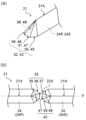
- Figures 18 to 25show various configuration examples of the end of the convex strip segment 24 adjacent to the specific notch 22X that satisfies requirement B.
- Figures 18(a) to 25(a)show a perspective view of the distal end of the proximal convex strip segment 24P seen from the distal side or a perspective view of the proximal end of the distal convex strip segment 24D seen from the proximal side
- Figures 18(b) to 25(b)show plan views of the distal end of the proximal convex strip segment 24P and the proximal end of the distal convex strip segment 24D seen from the apex 21A side of the convex strip 21.
- the distal end of the proximal streak segment 24P adjacent to the specific notch 22X and the proximal end of the distal streak segment 24Dare formed as follows: In a planar view from the apex 21A side of the streak 21, the distal end edge 32 of the proximal streak segment 24P adjacent to the proximal side of the specific notch 22X has a convex shape protruding toward the distal side, and the proximal end edge 42 of the distal streak segment 24D adjacent to the distal side of the specific notch 22X has a convex shape protruding toward the proximal side.
- the flexibility of the balloon 10can be improved.
- the balloon 10is bent with the specific notch 22X facing inward, when the distal end of the proximal convex stripe segment 24P adjacent to the specific notch 22X and the proximal end of the distal convex stripe segment 24D come into contact with each other, the tips of the convex shapes tend to slip apart. This makes it easier to bend the balloon 10 more significantly.
- the specific notch 22Xis located on the side of the bent part of the balloon 10 rather than on the inside of the bent balloon 10, the balloon 10 can be bent more significantly.
- the distal end edge 32 of the proximal ridge segment 24Pmeans the outer edge of the portion of the proximal ridge segment 24P facing the distal side in a planar view of the ridge 21 seen from the apex 21A side.
- the proximal end edge 42 of the distal ridge segment 24Dmeans the outer edge of the portion of the distal ridge segment 24D facing the proximal side in a planar view of the ridge 21 seen from the apex 21A side.
- the planar view of the ridge 21 seen from the apex 21A sidemeans the planar view of the ridge 21 seen from the radially outer side.
- the distal end edge 32 of the proximal side ridge segment 24Pmay be composed of a straight line, a curved line, or a combination of these, as long as it is formed into a convex shape protruding toward the distal side.
- the proximal end edge 42 of the distal side ridge segment 24Dmay be composed of a straight line, a curved line, or a combination of these, as long as it is formed into a convex shape protruding toward the proximal side.
- these edgesare composed of two or more straight lines.
- the convex shape of the distal end edge 32 of the proximal side ridge segment 24Pmay be the same as or different from the convex shape of the proximal end edge 42 of the distal side ridge segment 24D.
- the convex shapes of the distal end edges 32 of the multiple proximal ridge segments 24Pmay be the same or different from each other, and the convex shapes of the proximal end edges 42 of the multiple distal ridge segments 24D may be the same or different from each other.
- the convex shape of the distal end edge 32 of the proximal side convex stripe segment 24Pmay be configured to have a curved portion 33 curved toward the distal side
- the convex shape of the proximal end edge 42 of the distal side convex stripe segment 24Dmay be configured to have a curved portion 43 curved toward the proximal side. If the end of the convex stripe segment 24 is formed in this manner, even if the end of the convex stripe segment 24 hits the inner wall of the blood vessel when the balloon 10 is bent, the inner wall of the blood vessel is unlikely to be damaged. This makes it possible to make the balloon 10 safer.
- the convex shape of the distal end edge 32 of the proximal side convex stripe segment 24Phas a curved portion 33
- the curved portion 33 curved toward the distal sidemay be located distal to the line segment connecting both ends of the curved portion 33.
- the convex shape of the proximal end edge 42 of the distal convex strip segment 24Dhas a curved portion 43
- the curved portion 43 curved toward the proximal sidemay be located proximally of the line segment connecting both ends of the curved portion 43.
- the entire convex shapemay be composed of a curved portion, or only a part of the convex shape may be composed of a curved portion.
- the convex shapeis composed of a curved portion and a straight portion, and it is preferable that the distal end edge 32 of the proximal side convex strip segment 24P and/or the proximal end edge 42 of the distal side convex strip segment 24D are smoothly formed from the curved portion to the straight portion (i.e., in a plan view of the convex strip 21 seen from the top side, the inclination at the connection between the curved portion and the straight portion changes continuously).
- the convex shapeis composed of a curved portion and a straight portion, and it is preferable that the distal end edge 32 of the proximal side convex strip segment 24P and/or the proximal end edge 42 of the distal side convex strip segment 24D are smoothly formed from the curved portion to the straight portion (i.e., in a plan view of the convex strip 21 seen from the top side, the inclination at the connection between the curved portion and the straight portion changes continuously).
- the convex shape of the distal end edge 32 of the proximal side convex strip segment 24Pis composed only of the curved portion 33
- the convex shape of the proximal end edge 42 of the distal side convex strip segment 24Dis composed only of the curved portion 43.
- the convex shape of the distal end edge 32 of the proximal ridge segment 24Pis composed of a curved portion 33 and a straight portion 34
- the convex shape of the proximal end edge 42 of the distal ridge segment 24Dis composed of a curved portion 43 and a straight portion 44.
- the convex shape of the distal end edge 32 of the proximal ridge segment 24Pis composed of a curved portion 33, a proximal first straight portion 35, and a proximal second straight portion 36
- the convex shape of the proximal end edge 42 of the distal ridge segment 24Dis composed of a curved portion 43, a distal first straight portion 45, and a distal second straight portion 46.
- the convex shape of the distal end edge 32 of the proximal ridge segment 24Pmay be configured to have a proximal first straight portion 35 located on one side and a proximal second straight portion 36 located on the other side of an imaginary straight line F passing through the ridge 21A of the ridge 21 and extending in the longitudinal direction, as viewed from the apex 21A side of the ridge 21, and the proximal first straight portion 35 and the proximal second straight portion 36 may extend away from the imaginary straight line F as they move proximally.
- the convex shape of the proximal end edge 42 of the distal ridge segment 24Dmay be configured to have a distal first straight portion 45 located on one side and a distal second straight portion 46 located on the other side of the imaginary straight line F, as viewed from the apex 21A side of the ridge 21, and the distal first straight portion 45 and the distal second straight portion 46 may extend away from the imaginary straight line F as they move distally. If the end of the convex strip segment 24 is formed in this manner, the balloon 10 can be bent more greatly when a specific notch 22X is located on the side of the bent portion of the balloon 10 when the balloon 10 is bent.
- the proximal first straight portion 35may be directly connected to the proximal second straight portion 36, or the proximal first straight portion 35 and the proximal second straight portion 36 may be connected via another straight portion or curved portion, or the distal first straight portion 45 may be directly connected to the distal second straight portion 46, or the distal first straight portion 45 and the distal second straight portion 46 may be connected via another straight portion or curved portion.
- Figures 20 to 22show configuration examples of the distal end edge 32 of the proximal ridge segment 24P and the proximal end edge 42 of the distal ridge segment 24D formed in this manner, each of which will be described below.
- the convex shape of the distal end edge 32 of the proximal ridge segment 24Pis configured by connecting the distal end of the proximal first straight portion 35 to the distal end of the proximal second straight portion 36
- the convex shape of the proximal end edge 42 of the distal ridge segment 24Dis configured by connecting the proximal end of the distal first straight portion 45 to the proximal end of the distal second straight portion 46.
- the ends of the ridge segment 24are formed in this manner, when the balloon 10 is bent with the specific notch 22X facing inward, the distal end of the proximal ridge segment 24P and the proximal end of the distal ridge segment 24D are more likely to come into contact with each other when the balloon 10 is bent, making it easier to bend the balloon 10 significantly.
- the convex shape of the distal end edge 32 of the proximal side convex stripe segment 24Pis configured to have a curved portion 33 between the proximal side first straight portion 35 and the proximal side second straight portion 36
- the convex shape of the proximal end edge 42 of the distal side convex stripe segment 24Dis configured to have a curved portion 43 between the distal side first straight portion 45 and the distal side second straight portion 46.
- the curved portion 33 constituting the convex shape of the distal end edge 32 of the proximal side convex stripe segment 24Pis curved toward the distal side
- the curved portion 43 constituting the proximal end edge 42 of the distal side convex stripe segment 24Dis curved toward the proximal side. If the end of the convex stripe segment 24 is formed in this manner, even if the end of the convex stripe segment 24 hits the inner wall of the blood vessel when the balloon 10 is bent, the inner wall of the blood vessel is less likely to be damaged.
- the convex shape of the distal end edge 32 of the proximal ridge segment 24Phas a proximal third straight portion 37 between the proximal first straight portion 35 and the proximal second straight portion 36, and is configured so that the proximal first straight portion 35 and the proximal second straight portion 36 are located proximally relative to the proximal third straight portion 37, and the convex shape of the proximal end edge 42 of the distal ridge segment 24D has a distal third straight portion 47 between the distal first straight portion 45 and the distal second straight portion 46, and is configured so that the distal first straight portion 45 and the distal second straight portion 46 are located distal to the distal third straight portion 47.
- the inner wall of the blood vesselis less likely to be damaged even if the end of the ridge segment 24 hits the inner wall of the blood vessel when the balloon 10 is bent.
- proximal third straight portion 37extends so that the angle it forms with the longitudinal axis direction in a plan view seen from the apex 21A side of the convex rib 21 is greater than the angle it forms with the proximal first straight portion 35 and the longitudinal axis direction and the angle it forms with the proximal second straight portion 36 and the longitudinal axis direction in a plan view seen from the apex 21A side of the convex rib 21.
- the distal third straight portion 47extends so that the angle it forms with the longitudinal axis direction in a plan view seen from the apex 21A side of the convex rib 21 is greater than the angle it forms with the distal first straight portion 45 and the longitudinal axis direction and the angle it forms with the distal second straight portion 46 and the longitudinal axis direction in a plan view.
- the angles formed by the proximal first straight portion 35, the proximal second straight portion 36, the distal first straight portion 45, and the distal second straight portion 46 with the longitudinal axis directionare in the range of more than 0° and less than 90°
- the angles formed by the proximal third straight portion 37 and the distal third straight portion 47 with the longitudinal axis directionare in the range of more than 0° and less than 90°.
- the angle formed by the proximal third straight portion 37 and the distal third straight portion 47 with the longitudinal axis directionis 90°
- the proximal third straight portion 37 and the distal third straight portion 47extend perpendicular to the longitudinal axis direction.
- the angle formed by the proximal third straight portion 37 and the distal third straight portion 47 with the longitudinal axis directionis preferably 60° or more and 90° or less, more preferably 75° or more and 90° or less. This makes it difficult for the inner wall of the blood vessel to be damaged when the end of the convex strip segment 24 hits the inner wall of the blood vessel. It is more preferable that the proximal third straight portion 37 and/or the distal third straight portion 47 extend perpendicular to the longitudinal axis direction, and it is particularly preferable that both the proximal third straight portion 37 and the distal third straight portion 47 extend perpendicular to the longitudinal axis direction.
- the angle between the longitudinal axis direction of the proximal first straight portion 35, the proximal second straight portion 36, the distal first straight portion 45, and the distal second straight portion 46is preferably 20° or more, more preferably 30° or more, and is preferably 70° or less, and more preferably 60° or less.
- the most distal part of the distal end edge 32 of the proximal side ridge segment 24Pis preferably on an imaginary straight line F that passes through the apex 21A of the ridge 21 and extends in the longitudinal direction when viewed in a plan view from the apex 21A side of the ridge 21.
- the most proximal part of the proximal end edge 42 of the distal side ridge segment 24Dis preferably on an imaginary straight line F that passes through the apex 21A of the ridge 21 and extends in the longitudinal direction when viewed in a plan view from the apex 21A side of the ridge 21.
- the convex shape of the distal end edge 32 of the proximal ridge segment 24P and the convex shape of the proximal end edge 42 of the distal ridge segment 24Dmay be configured as shown in Figure 23. That is, in a plan view seen from the apex 21A side of the ridge 21, the distalmost portion of the distal end edge 32 of the proximal ridge segment 24P may be located on one side of an imaginary line F that passes through the apex 21A of the ridge 21 and extends in the longitudinal direction, and the proximalmost portion of the proximal end edge 42 of the distal ridge segment 24D may be located on the other side of an imaginary line F that passes through the apex 21A of the ridge 21 and extends in the longitudinal direction.
- the most distal portion of the distal end edge 32 of the proximal ridge segment 24P and the most proximal portion of the proximal end edge 42 of the distal ridge segment 24Dare offset from each other in the width direction of the ridge 21, which makes it easier to bend the balloon 10 significantly when bending the balloon 10 with the specific notch 22X facing inward.
- the specific notch 22Xis configured to also satisfy requirement A.
- the outer edge shape at any radial position of the distal end of the proximal ridge segment 24Pmay be similar or dissimilar to the distal end edge 32.
- the distal end edge 32 of the proximal ridge segment 24Pmay be composed of a curved portion
- the outer edge shape at any radial position of the distal end of the proximal ridge segment 24Pmay be composed of a straight portion.
- the outer edge shape at any radial position of the proximal end of the distal ridge segment 24Dmay be similar or dissimilar to the proximal end edge 42.
- the distal outer edge 38 of the proximal ridge segment 24Pmay extend radially outward at an incline toward the proximal side as shown in Figures 18 to 23, or may extend radially as shown in Figure 24.
- the distal outer edge 38 of the proximal ridge segment 24Pmay have a portion extending radially and a portion extending radially outward at an incline toward the proximal side.
- the distal outer edge 38 of the proximal ridge segment 24Pmay have a portion extending radially outward at an incline toward the distal side.
- the proximal outer edge 48 of the distal ridge segment 24Dmay extend radially outward at an incline toward the distal side as shown in Figures 18 to 23, or may extend radially as shown in Figure 24.
- the proximal outer edge 48 of the distal ridge segment 24Dmay have a portion that extends radially and a portion that extends radially outward at an incline toward the distal side.
- the proximal outer edge 48 of the distal ridge segment 24Dmay have a portion that extends radially outward at an incline toward the proximal side.
- the distal outer edge 38 of the proximal ridge segment 24Ppreferably extends at an incline toward the proximal side toward the radially outward direction
- the proximal outer edge 48 of the distal ridge segment 24Dpreferably extends at an incline toward the distal side toward the radially outward direction.
- Figures 26 to 29show examples of the configuration of cross sections along the longitudinal axis direction passing through the apex 21A of the ridge 21 of the distal end portion of the proximal ridge segment 24P and the proximal end portion of the distal ridge segment 24D shown in Figures 18 to 23, and the distal outer edge 38 of the proximal ridge segment 24P and the proximal outer edge 48 of the distal ridge segment 24D are formed in this manner.
- the specific notch 22Xis formed so as to extend from the top 21A of the ridge 21 to the base 21B, the cross-sectional view of FIG. 26 or FIG.
- the specific notch 22Xis formed so as to extend partway from the top 21A of the ridge 21 to the base 21B, the cross-sectional view of FIG. 27 or FIG. 29 is referred to.
- the end of the ridge segment 24is formed in this manner, it becomes easier to bend the balloon 10 greatly when bending the balloon 10 with the specific notch 22X on the inside.
- the distal end edge 32 of the proximal ridge segment 24P and the proximal end edge 42 of the distal ridge segment 24D as viewed from the top 21A side of the ridge 21are shaped by the bottom 22B of the specific notch 22X.
- only some of the notches 22 provided in the ridge 21may be formed as specific notches 22X, or all of the notches 22 may be formed as specific notches 22X. It is preferable that more of the notches 22 provided in the ridge 21 are formed as specific notches 22X. For example, it is preferable that 1/4 or more of the notches 22 provided in the ridge 21 are formed as specific notches 22X, more preferably 1/3 or more are formed as specific notches 22X, even more preferably 1/2 or more are formed as specific notches 22X, and even more preferably 2/3 or more are formed as specific notches 22X.
- each ridge 21It is preferable that a specific notch 22X is provided on each ridge 21. This makes it easier for the balloon 10 to bend in either radial direction.
- the specific notch 22Xis preferably provided at least in the distal section 19 of the ridge 21. Providing the specific notch 22X in the distal section 19 of the ridge 21 makes it easier to push and insert the balloon 10 into the bent portion of the blood vessel.
- the specific notch 22Xmay be provided in the distal section 19 of the ridge 21 in at least one ridge 21, but preferably the specific notch 22X is provided in the distal section 19 of each ridge 21.
- all of the notches 22 provided in the distal section 19 of the ridge 21may be formed as the specific notch 22X.
- the specific notch 22Xis provided in the proximal section 17 of the ridge 21.
- the specific notch 22Xmay be provided in the proximal section 17 of the ridge 21 in at least one ridge 21, but preferably the specific notch 22X is provided in the proximal section 17 of each ridge 21.
- all of the notches 22 provided in the proximal section 17 of the ridge 21may be formed as the specific notch 22X.
- the specific notch 22Xmay be provided in both the distal section 19 and the proximal section 17 of the ridge 21, and may also be provided in the middle section 18 of the ridge 21. By providing the specific notch 22X in the middle section 18 of the ridge 21, the flexibility of the balloon 10 can be further improved.
- a specific notch 22Xmay also be provided on the convex rib 21 of the proximal sleeve portion 11, the proximal tapered portion 12, the distal tapered portion 14, or the distal sleeve portion 15. This makes it easier to bend the balloon 10 significantly in portions other than the straight tube portion 13.
- the notches 22are provided at approximately equal intervals on the ridges 21, but the notches 22 may be provided at unequal intervals in the longitudinal axis direction on the ridges 21.
- Figures 30 to 33show other configuration examples of the ridges 21 provided on the balloon 10
- Figures 30 and 31show a configuration example of a modified version of the balloon 10 shown in Figure 4, that is, a balloon 10 provided with a ridge 21 having a specific notch 22X that satisfies requirement A
- Figures 32 and 33show a configuration example of a modified version of the balloon 10 shown in Figure 5, that is, a balloon 10 provided with a ridge 21 having a specific notch 22X that satisfies requirement B.
- the ridge 21may be provided with notches 22 such that the number of notches 22 provided in the distal section 19 is greater than the number of notches 22 provided in the intermediate section 18. This can increase the flexibility of the distal portion of the balloon 10, making it easier to push the balloon 10 through the bent portion. Also, by providing a smaller number of notches 22 in the intermediate section 18 of the ridge 21, or by not providing any notches 22, the scoring function in the intermediate section 18 of the ridge 21 can be improved.
- the convex rib 21may be provided with notches 22 such that the number of notches 22 in the distal section 19 and the number of notches 22 in the proximal section 17 are greater than the number of notches 22 in the intermediate section 18. This makes it easier to insert the balloon 10 into the bent section whether the balloon 10 is pushed through the bent section or pulled through the bent section. It also improves the scoring function of the intermediate section 18 of the convex rib 21.
- the depths of the multiple notches 22may be the same or different.
- the ridge 21may have the notches 22 as follows. That is, the ridge 21 may have the notches 22 formed such that the deepest depth of the notches 22 provided in the distal section 19 is deeper than the deepest depth of the notches 22 provided in the intermediate section 18. This can increase the flexibility of the distal portion of the balloon 10, making it easier to push the balloon 10 through the bent portion.
- the convex rib 21may have notches 22 formed such that the deepest depth of the notches 22 in the distal section 19 and the deepest depth of the notches 22 in the proximal section 17 are deeper than the deepest depth of the notches 22 in the intermediate section 18. This can increase the flexibility of the distal and proximal sections of the balloon 10, making it easier to insert the balloon 10 into the bent section whether the balloon 10 is pushed through the bent section or pulled through the bent section.
- the notches 22may be provided in the ridges 21 as follows. That is, the notches 22 may be formed in the ridges 21 so that the deepest depth of the notches 22 provided in the intermediate section 18 is deeper than the deepest depth of the notches 22 provided in the distal section 19. Alternatively, the notches 22 may be formed in the ridges 21 so that the deepest depth of the notches 22 provided in the intermediate section 18 is deeper than the deepest depth of the notches 22 provided in the distal section 19 and the deepest depth of the notches 22 provided in the proximal section 17. If the notches 22 are provided in the ridges 21 in this way, the number of notches 22 provided in the intermediate section 18 can be reduced while the flexibility in the intermediate section 18 can be increased. Therefore, it is easier to ensure flexibility throughout the entire longitudinal axis direction of the balloon 10 while ensuring the scoring function of the ridges 21.
- the length in the longitudinal direction of the straight tube section 13 of the balloon 10may be, for example, 4 mm or more, 10 mm or more, 20 mm or more, or 30 mm or more, but the longer the longitudinal length of the balloon 10 provided with the ridges 21, the more difficult it becomes to insert the balloon 10 through a curved section. Therefore, in order to more effectively utilize the effect of providing the notches 22 in the ridges 21, it is preferable that the longitudinal direction of the straight tube section 13 of the balloon 10 be 50 mm or more, more preferably 60 mm or more, and even more preferably 80 mm or more.
- the ridge 21may be formed so that its width narrows stepwise toward the apex 21A in a vertical cross section in the longitudinal axis direction of the straight tube portion 13, and the notch 22 may be formed only in the portion of the apex 21A side of the stepped ridge 21.
- the ridge 21may have a first step portion 27 adjacent to the outer surface of the balloon body portion 16 and a second step portion 28 on the apex 21A side, and the notch 22 may be formed in the second step portion 28 and not formed in the first step portion 27.
- the deep notch 22may be formed from the second step portion 28 to the first step portion 27, and the shallow notch 22 may be formed in the second step portion 28 and not formed in the first step portion 27.
- the first step portion 27 and the second step portion 28may be made of the same material or different materials.
- the first stage portion 27 and the second stage portion 28may both be made of resin, or the first stage portion 27 may be made of resin and the second stage portion 28 may be made of metal.
- the outer surface of the straight tube portion 13 of the balloon 10may hold a drug.
- the drugis not particularly limited as long as it is a pharmacologically active substance, and examples of the drug include drugs that are acceptable as medicines, such as gene therapy drugs, non-gene therapy drugs, small molecules, and cells.
- drugsthat are acceptable as medicines, such as gene therapy drugs, non-gene therapy drugs, small molecules, and cells.
- anti-restenosis drugssuch as antiproliferative agents and immunosuppressants can be preferably used as the drug.
- anti-restenosis drugssuch as antiproliferative agents and immunosuppressants can be preferably used as the drug.
- examples of such drugsinclude paclitaxel, sirolimus (rapamycin), everolimus, and zotarolimus.
- Balloon catheter 2Shaft 3: Inner shaft 4: Outer shaft, 4A: Proximal outer shaft, 4B: Distal outer shaft 5: Hub 6: Fluid injection section 7: Guidewire port 8: Distal tip 9: X-ray opaque marker 10: Balloon 11: Proximal sleeve section 12: Proximal tapered section 13: Straight tube section 14: Distal tapered section 15: Distal sleeve section 16: Balloon body section 17: Proximal section 18: Intermediate section 19: Distal section 21: Convex strip, 21A: Apex, 21B: Base 22: Notch, 22A: Apex, 22B: Bottom, 22X: Specific notch 23: Discontinued section 24: Convex strip segment, 24P: Proximal convex strip segment, 24D: Distal convex strip segment 25: Convex strip present region 26: Convex strip non-present region 27: First step portion 28: Second step portion 31: Distal surface (of the proximal convex streak
Landscapes
- Health & Medical Sciences (AREA)
- Life Sciences & Earth Sciences (AREA)
- Heart & Thoracic Surgery (AREA)
- Engineering & Computer Science (AREA)
- Biophysics (AREA)
- Pulmonology (AREA)
- Child & Adolescent Psychology (AREA)
- Anesthesiology (AREA)
- Biomedical Technology (AREA)
- Hematology (AREA)
- Animal Behavior & Ethology (AREA)
- General Health & Medical Sciences (AREA)
- Public Health (AREA)
- Veterinary Medicine (AREA)
- Media Introduction/Drainage Providing Device (AREA)
Abstract
Description
Translated fromJapanese本発明は、バルーンカテーテル用バルーンと当該バルーンを備えたバルーンカテーテルに関するものである。The present invention relates to a balloon for a balloon catheter and a balloon catheter equipped with said balloon.
体内で血液が循環するための流路である血管に狭窄が生じ、血液の循環が滞ることにより、様々な疾患が発生することが知られている。特に心臓に血液を供給する冠状動脈に狭窄が生じると、狭心症、心筋梗塞等の重篤な疾病をもたらすおそれがある。このような血管の狭窄部を治療する方法の一つとして、バルーンカテーテルを用いて狭窄部を拡張させる血管形成術(PTA、PTCA等)がある。It is known that stenosis in blood vessels, which are the channels through which blood circulates in the body, can lead to a variety of diseases due to stagnation of blood circulation. In particular, stenosis in the coronary arteries that supply blood to the heart can lead to serious diseases such as angina pectoris and myocardial infarction. One method of treating such vascular stenosis is angioplasty (PTA, PTCA, etc.), which uses a balloon catheter to expand the stenotic area.
バルーンカテーテルには、バルーンの表面に凸条が設けられたものが知られている(例えば、特許文献1~3)。このようなバルーンカテーテルを用いれば、バルーンを拡張させた際に、バルーンの凸条を狭窄部に食い込ませて、狭窄部を効果的に拡張させることができる。一方、凸条が設けられたバルーンは、凸条が設けられた部分で剛性が高くなる傾向を示し、長手軸方向の屈曲性が低下しやすくなる。これに対して、バルーン表面の凸条に切欠きが形成されたバルーンカテーテルが知られている(例えば、特許文献4、5)。このようなバルーンカテーテルを用いれば、凸条が設けられたバルーンであっても長手軸方向の屈曲性を確保することができる。Balloon catheters with ridges on the surface of the balloon are known (e.g.,
バルーン表面に凸条が設けられ、当該凸条に切欠きが形成されたバルーンは、凸条によってスコアリング機能を発揮することができるとともに、凸条に形成された切欠きによってバルーンの長手軸方向の屈曲性を確保することができる。一方、血管には大きく屈曲した屈曲部が存在することから、そのような屈曲部であっても、凸条が設けられたバルーンをスムーズに挿通できることが望まれる。そのため、バルーンの屈曲性をさらに高めることができればなお望ましい。A balloon with ridges on its surface and notches formed in the ridges can provide a scoring function through the ridges, and the notches formed in the ridges ensure flexibility in the longitudinal direction of the balloon. However, blood vessels have large bent sections, so it is desirable to be able to smoothly insert a balloon with ridges even in such bent sections. Therefore, it would be even more desirable if the flexibility of the balloon could be further improved.
本発明は前記事情に鑑みてなされたものであり、その目的は、表面に凸条が設けられたバルーンであって、長手軸方向への屈曲性を高めることができるバルーンカテーテル用バルーンと当該バルーンを備えたバルーンカテーテルを提供することにある。The present invention was made in consideration of the above circumstances, and its purpose is to provide a balloon for a balloon catheter, which has a balloon with ridges on its surface and can increase flexibility in the longitudinal direction, and a balloon catheter equipped with the balloon.
前記課題を解決することができた本発明のバルーンカテーテル用バルーンおよび当該バルーンを備えたバルーンカテーテルは、下記の通りである。
[1] 近位側から遠位側に延びる長手軸方向と、前記長手軸方向に垂直な径方向を有するバルーンカテーテル用バルーンであって、
前記バルーンは、直管部と、前記直管部よりも近位側に位置する近位側テーパー部と、前記直管部よりも遠位側に位置する遠位側テーパー部とを有し、
前記直管部は、筒形状のバルーン本体部と、前記バルーン本体部の外面に、径方向の外方に突出し前記長手軸方向に延びる凸条とを有し、
前記凸条には切欠きが形成されており、前記凸条は前記切欠きによって複数の凸条セグメントに区分され、
前記切欠きは、下記要件Aを満たす特定の切欠きを含むバルーンカテーテル用バルーン。
(要件A)
前記特定の切欠きの近位側に隣接する前記凸条セグメント(以下、「近位側凸条セグメント」と称する)の遠位面は、前記凸条の頂部を通り前記長手軸方向および前記径方向から形成される仮想平面との交線上における法線ベクトルAが、遠位側に向かって前記仮想平面の一方側に延びており、
前記特定の切欠きの遠位側に隣接する前記凸条セグメント(以下、「遠位側凸条セグメント」と称する)の近位面は、前記仮想平面との交線上における法線ベクトルBが、近位側に向かって前記仮想平面の他方側に延びている。
[2] 近位側から遠位側に延びる長手軸方向と、前記長手軸方向に垂直な径方向を有するバルーンカテーテル用バルーンであって、
前記バルーンは、直管部と、前記直管部よりも近位側に位置する近位側テーパー部と、前記直管部よりも遠位側に位置する遠位側テーパー部とを有し、
前記直管部は、筒形状のバルーン本体部と、前記バルーン本体部の外面に、径方向の外方に突出し前記長手軸方向に延びる凸条とを有し、
前記凸条には切欠きが形成されており、前記凸条は前記切欠きによって複数の凸条セグメントに区分され、
前記切欠きは、下記要件Bを満たす特定の切欠きを含むバルーンカテーテル用バルーン。
(要件B)
前記凸条の頂部側から見た平面視で、前記特定の切欠きの近位側に隣接する前記凸条セグメント(以下、「近位側凸条セグメント」と称する)の遠位端縁は遠位側に突出した凸形状を有し、前記特定の切欠きの遠位側に隣接する前記凸条セグメント(以下、「遠位側凸条セグメント」と称する)の近位端縁は近位側に突出した凸形状を有する。
[3] 前記凸条には、前記特定の切欠きが複数、前記長手軸方向に配置され、前記凸条において前記仮想平面の一方側を第1側、前記仮想平面の他方側を第2側としたとき、前記凸条に設けられた前記特定の切欠きの全てにおいて、前記法線ベクトルAが遠位側に向かって前記第1側に延びており、前記法線ベクトルBが近位側に向かって前記第2側に延びている[1]に記載のバルーン。
[4] 前記凸条には、前記特定の切欠きが複数、前記長手軸方向に配置され、前記凸条において前記仮想平面の一方側を第1側、前記仮想平面の他方側を第2側としたとき、前記凸条には、前記法線ベクトルAが遠位側に向かって前記第1側に延びており、前記法線ベクトルBが近位側に向かって前記第2側に延びている前記特定の切欠きと、前記法線ベクトルAが遠位側に向かって前記第2側に延びており、前記法線ベクトルBが近位側に向かって前記第1側に延びている前記特定の切欠きが、前記長手軸方向に交互に設けられている[1]に記載のバルーン。
[5] 前記近位側凸条セグメントの遠位面と前記遠位側凸条セグメントの近位面は、少なくとも前記仮想平面との交線上において前記長手軸方向に最も近接している[1]、[3]または[4]に記載のバルーン。
[6] 前記近位側凸条セグメントの遠位面と前記遠位側凸条セグメントの近位面の前記長手軸方向の離隔距離は、前記仮想平面から離れるに従い、変わらないか広がるように形成されている[5]に記載のバルーン。
[7] 前記近位側凸条セグメントの遠位面と前記遠位側凸条セグメントの近位面の前記長手軸方向の離隔距離は、前記仮想平面から離れるに従い、少なくとも一部において広がるように形成されている[6]に記載のバルーン。
[8] 前記近位側凸条セグメントの遠位面は、前記仮想平面との交線上において、径方向の外方に向かって近位側に傾斜しており、前記遠位側凸条セグメントの近位面は、前記仮想平面との交線上において、径方向の外方に向かって遠位側に傾斜している[1]、[3]~[7]のいずれかに記載のバルーン。
[9] 前記法線ベクトルAの前記バルーン本体部の外面への投影ベクトルAPと遠位側に向かう前記長手軸方向とのなす角は20°以上70°以下であり、前記法線ベクトルBの前記バルーン本体部の外面への投影ベクトルBPと近位側に向かう前記長手軸方向とのなす角は20°以上70°以下である[1]、[3]~[8]のいずれかに記載のバルーン。
[10] 前記近位側凸条セグメントの前記遠位端縁の最遠位部は、前記凸条の頂部側から見た平面視で、前記凸条の頂部を通り前記長手軸方向に延びる仮想直線上にある、および/または、前記遠位側凸条セグメントの前記近位端縁の最近位部は、前記凸条の頂部側から見た平面視で、前記凸条の頂部を通り前記長手軸方向に延びる仮想直線上にある[2]に記載のバルーン。
[11] 前記近位側凸条セグメントの前記遠位端縁の前記凸形状は、遠位側に向かって湾曲した湾曲部を有する、および/または、前記遠位側凸条セグメントの前記近位端縁の前記凸形状は、近位側に向かって湾曲した湾曲部を有する[2]または[10]に記載のバルーン。
[12] 前記近位側凸条セグメントの前記遠位端縁の前記凸形状は、前記凸条の頂部側から見た平面視で、前記凸条の頂部を通り前記長手軸方向に延びる仮想直線に対して一方側に位置する近位側第1直線部と他方側に位置する近位側第2直線部を有し、前記近位側第1直線部と前記近位側第2直線部は近位側にいくに従い前記仮想直線から離れるように延びている、および/または、前記遠位側凸条セグメントの前記近位端縁の前記凸形状は、前記凸条の頂部側から見た平面視で、前記仮想直線に対して一方側に位置する遠位側第1直線部と他方側に位置する遠位側第2直線部を有し、前記遠位側第1直線部と前記遠位側第2直線部は遠位側にいくに従い前記仮想直線から離れるように延びている[2]、[10]または[11]に記載のバルーン。
[13] 前記近位側凸条セグメントの前記遠位端縁の前記凸形状は、前記凸条の頂部側から見た平面視で、前記近位側第1直線部と前記近位側第2直線部の間に近位側第3直線部をさらに有し、前記近位側第1直線部と前記近位側第2直線部は前記近位側第3直線部よりも近位側に位置する、および/または、前記遠位側凸条セグメントの前記近位端縁の前記凸形状は、前記凸条の頂部側から見た平面視で、前記遠位側第1直線部と前記遠位側第2直線部の間に遠位側第3直線部をさらに有し、前記遠位側第1直線部と前記遠位側第2直線部は前記遠位側第3直線部よりも遠位側に位置する[12]に記載のバルーン。
[14] 前記近位側第3直線部および/または前記遠位側第3直線部は、前記長手軸方向に対して垂直に延びている[13]に記載のバルーン。
[15] 前記近位側第1直線部の遠位端は前記近位側第2直線部の遠位端に接続している、および/または、前記遠位側第1直線部の近位端は前記遠位側第2直線部の近位端に接続している[12]に記載のバルーン。
[16] 前記凸条の頂部を通る長手軸方向に沿った断面において、前記近位側凸条セグメントの遠位外縁は、径方向の外方に向かって近位側に傾斜して延びている、および/または、前記凸条の頂部を通る長手軸方向に沿った断面において、前記遠位側凸条セグメントの近位外縁は、径方向の外方に向かって遠位側に傾斜して延びている[2]、[10]~[15]のいずれかに記載のバルーン。
[17] 前記凸条は、樹脂製、金属製、またはその組み合わせである[1]~[16]のいずれかに記載のバルーン。
[18] [1]~[17]のいずれかに記載のバルーンを備えるバルーンカテーテル。The balloon for a balloon catheter and the balloon catheter including the balloon of the present invention, which are able to solve the above-mentioned problems, are as follows.
[1] A balloon for a balloon catheter having a longitudinal axis direction extending from a proximal side to a distal side and a radial direction perpendicular to the longitudinal axis direction,
The balloon has a straight tube portion, a proximal tapered portion located proximally of the straight tube portion, and a distal tapered portion located distally of the straight tube portion,
The straight tube portion has a cylindrical balloon body and a protrusion on an outer surface of the balloon body that protrudes radially outward and extends in the longitudinal axis direction,
A notch is formed in the protrusion, and the protrusion is divided into a plurality of protrusion segments by the notch,
The balloon for a balloon catheter includes a specific notch that satisfies the following requirement A.
(Requirement A)
a distal surface of the convex strip segment adjacent to the proximal side of the particular notch (hereinafter referred to as a “proximal convex strip segment”) has a normal vector A on a line of intersection with an imaginary plane formed by the longitudinal axis direction and the radial direction, the normal vector A passing through the apex of the convex strip extends to one side of the imaginary plane toward the distal side;
The proximal surface of the convex stripe segment adjacent to the distal side of the particular notch (hereinafter referred to as the "distal convex stripe segment") has a normal vector B at the intersection with the imaginary plane that extends toward the proximal side on the other side of the imaginary plane.
[2] A balloon for a balloon catheter having a longitudinal axis direction extending from a proximal side to a distal side and a radial direction perpendicular to the longitudinal axis direction,
The balloon has a straight tube portion, a proximal tapered portion located proximally of the straight tube portion, and a distal tapered portion located distally of the straight tube portion,
The straight tube portion has a cylindrical balloon body and a protrusion on an outer surface of the balloon body that protrudes radially outward and extends in the longitudinal axis direction,
A notch is formed in the protrusion, and the protrusion is divided into a plurality of protrusion segments by the notch,
The balloon for a balloon catheter includes a specific notch that satisfies the following requirement B.
(Requirement B)
In a planar view from the top side of the convex strip, the distal end edge of the convex strip segment adjacent to the proximal side of the specific notch (hereinafter referred to as the "proximal convex strip segment") has a convex shape protruding toward the distal side, and the proximal end edge of the convex strip segment adjacent to the distal side of the specific notch (hereinafter referred to as the "distal convex strip segment") has a convex shape protruding toward the proximal side.
[3] The balloon described in [1], wherein the convex strip has a plurality of the specific notches arranged in the longitudinal axis direction, and when one side of the imaginary plane in the convex strip is defined as a first side and the other side of the imaginary plane is defined as a second side, in all of the specific notches provided in the convex strip, the normal vector A extends toward the first side toward the distal side, and the normal vector B extends toward the second side toward the proximal side.
[4] The balloon described in [1], wherein the convex rib has a plurality of the specific notches arranged in the longitudinal axis direction, and when one side of the imaginary plane in the convex rib is defined as a first side and the other side of the imaginary plane is defined as a second side, the convex rib has the specific notches in which the normal vector A extends toward the first side toward the distal side and the normal vector B extends toward the second side toward the proximal side, and the specific notches in which the normal vector A extends toward the second side toward the distal side and the normal vector B extends toward the first side toward the proximal side, alternately provided in the longitudinal axis direction.
[5] The balloon described in [1], [3] or [4], wherein the distal surface of the proximal convex stripe segment and the proximal surface of the distal convex stripe segment are closest to each other in the longitudinal axis direction at least on the intersection line with the imaginary plane.
[6] The balloon described in [5], wherein the distance between the distal surface of the proximal ridge segment and the proximal surface of the distal ridge segment in the longitudinal direction remains constant or increases as the distance from the imaginary plane increases.
[7] The balloon described in [6], wherein the distance between the distal surface of the proximal ridge segment and the proximal surface of the distal ridge segment in the longitudinal direction is formed so as to widen at least in part as it moves away from the imaginary plane.
[8] The balloon according to any one of [1] to [7], wherein the distal surface of the proximal ridge segment is inclined radially outward toward the proximal side at the intersection line with the imaginary plane, and the proximal surface of the distal ridge segment is inclined radially outward toward the distal side at the intersection line with the imaginary plane.
[9] The balloon described in any one of [1], [3] to [8], wherein an angle between a projection vector AP of the normal vector A onto the outer surface of the balloon body and the longitudinal axis direction toward the distal side is 20° or more and 70° or less, and an angle between a projection vector BP of the normal vector B onto the outer surface of the balloon body and the longitudinal axis direction toward the proximal side is 20° or more and 70° or less.
[10] The balloon described in [2], wherein the distalmost portion of the distal end edge of the proximal side ridge segment is on an imaginary line that passes through the apex of the ridge and extends in the longitudinal axis direction when viewed in a plan view from the apex side of the ridge, and/or the proximalmost portion of the proximal end edge of the distal side ridge segment is on an imaginary line that passes through the apex of the ridge and extends in the longitudinal axis direction when viewed in a plan view from the apex side of the ridge.
[11] The balloon described in [2] or [10], wherein the convex shape of the distal end edge of the proximal ridge segment has a curved portion curved toward the distal side, and/or the convex shape of the proximal end edge of the distal ridge segment has a curved portion curved toward the proximal side.
[12] The balloon according to [2], [10] or [11], wherein the convex shape of the distal end edge of the proximal ridge segment, in a plan view seen from the apex side of the ridge, has a proximal first straight section located on one side of an imaginary line passing through the apex of the ridge and extending in the longitudinal axis direction, and a proximal second straight section located on the other side, the proximal first straight section and the proximal second straight section extending so as to move away from the imaginary line as they move proximally; and/or the convex shape of the proximal end edge of the distal ridge segment, in a plan view seen from the apex side of the ridge, has a distal first straight section located on one side of the imaginary line and a distal second straight section located on the other side, the distal first straight section and the distal second straight section extending so as to move away from the imaginary line as they move distally.
[13] The balloon according to [12], wherein the convex shape of the distal end edge of the proximal ridge segment further has a proximal third straight section between the proximal first straight section and the proximal second straight section in a plan view seen from the apex side of the ridge, the proximal first straight section and the proximal second straight section being located proximal to the proximal third straight section, and/or the convex shape of the proximal end edge of the distal ridge segment further has a distal third straight section between the distal first straight section and the distal second straight section in a plan view seen from the apex side of the ridge, the distal first straight section and the distal second straight section being located distal to the distal third straight section.
[14] The balloon described in [13], wherein the proximal third straight portion and/or the distal third straight portion extend perpendicular to the longitudinal axis direction.
[15] The balloon described in [12], wherein the distal end of the proximal first straight section is connected to the distal end of the proximal second straight section, and/or the proximal end of the distal first straight section is connected to the proximal end of the distal second straight section.
[16] The balloon described in any one of [2], [10] to [15], wherein in a cross section along the longitudinal axis direction passing through the apex of the ridge, the distal outer edge of the proximal ridge segment extends with an inclination toward the proximal side toward the radially outward direction, and/or, in a cross section along the longitudinal axis direction passing through the apex of the ridge, the proximal outer edge of the distal ridge segment extends with an inclination toward the distal side toward the radially outward direction.
[17] The balloon according to any one of [1] to [16], wherein the ridges are made of resin, metal, or a combination thereof.
[18] A balloon catheter comprising the balloon according to any one of [1] to [17].
本発明のバルーンカテーテル用バルーンは、バルーンの直管部の外面に凸条が設けられているため、当該バルーンを備えたバルーンカテーテルを用いて血管の狭窄部等においてバルーンを拡張させると、凸条が狭窄部等に食い込んで効果的に拡張させることができる。また、バルーンの凸条に切欠きが形成され、切欠きの少なくとも一部として上記の特定の切欠きが形成されているため、バルーンの屈曲性を高めることができる。The balloon for a balloon catheter of the present invention has a ridge on the outer surface of the straight tube part of the balloon, so that when a balloon catheter equipped with the balloon is used to expand the balloon at a narrowed part of a blood vessel, the ridge bites into the narrowed part, allowing for effective expansion. In addition, a notch is formed in the ridge of the balloon, and the above-mentioned specific notch is formed as at least a part of the notch, which enhances the flexibility of the balloon.
以下、下記実施の形態に基づき本発明を具体的に説明するが、本発明はもとより下記実施の形態によって制限を受けるものではなく、前・後記の趣旨に適合し得る範囲で適当に変更を加えて実施することも勿論可能であり、それらはいずれも本発明の技術的範囲に包含される。なお、各図面において、便宜上、ハッチングや部材符号等を省略する場合もあるが、かかる場合、明細書や他の図面を参照するものとする。また、図面における種々部材の寸法は、本発明の特徴の理解に資することを優先しているため、実際の寸法とは異なる場合がある。The present invention will be described in detail below based on the following embodiment, but the present invention is not limited to the following embodiment, and can of course be implemented with appropriate modifications within the scope of the intent described above and below, all of which are included in the technical scope of the present invention. In addition, hatching and component symbols may be omitted in each drawing for convenience, but in such cases, reference should be made to the specification or other drawings. Furthermore, the dimensions of various components in the drawings may differ from the actual dimensions, as priority is given to contributing to an understanding of the features of the present invention.
本発明の実施の形態に係るバルーンカテーテル用バルーンと、当該バルーンを備えたバルーンカテーテルの構成例について、図面を参照して説明する。図1~図5には、バルーンカテーテルの構成例を示した。図1は、バルーンカテーテルの側面図を表し、図2は、図1に示したバルーンカテーテルのII-II断面図を表し、図3は、図1に示したバルーンカテーテルのIII-III断面図を表し、図4および図5は、バルーンカテーテルに備えられるバルーンの斜視図の例を表す。図1にはラピッドエクスチェンジ型のバルーンカテーテルの構成例が示されている。図4には、第1実施形態に係るバルーンの斜視図が示されており、バルーン表面に設けられた凸条に後述する要件Aを満たす特定の切欠きが形成されている。図5には、第2実施形態に係るバルーンの斜視図が示されており、バルーン表面に設けられた凸条に後述する要件Bを満たす特定の切欠きが形成されている。A balloon for a balloon catheter according to an embodiment of the present invention and an example of the configuration of a balloon catheter equipped with the balloon will be described with reference to the drawings. Examples of the configuration of a balloon catheter are shown in Figs. 1 to 5. Fig. 1 shows a side view of a balloon catheter, Fig. 2 shows a II-II cross-sectional view of the balloon catheter shown in Fig. 1, Fig. 3 shows a III-III cross-sectional view of the balloon catheter shown in Fig. 1, and Figs. 4 and 5 show examples of perspective views of a balloon equipped in a balloon catheter. Fig. 1 shows an example of the configuration of a rapid exchange type balloon catheter. Fig. 4 shows a perspective view of a balloon according to a first embodiment, in which a specific notch that satisfies requirement A described later is formed in the convex stripes provided on the balloon surface. Fig. 5 shows a perspective view of a balloon according to a second embodiment, in which a specific notch that satisfies requirement B described later is formed in the convex stripes provided on the balloon surface.
バルーンカテーテル1は、シャフト2と、シャフト2の外側に設けられたバルーン10とを有する。バルーンカテーテル1は近位側と遠位側を有し、シャフト2の遠位部にバルーン10が設けられる。バルーンカテーテル1の近位側とは、バルーンカテーテル1の延在方向に対して使用者(術者)の手元側の方向を指し、遠位側とは近位側の反対方向、すなわち処置対象側の方向を指す。また、バルーンカテーテル1の近位側から遠位側への方向を長手軸方向と称する。The
バルーンカテーテル1は、シャフト2を通じてバルーン10の内部に流体が供給されるように構成され、インデフレーター(バルーン用加減圧器)を用いてバルーン10の拡張および収縮を制御することができる。流体は、ポンプ等により加圧された加圧流体であってもよい。以下、バルーン10の内部に供給される流体を「バルーン拡張流体」と称する。The
シャフト2は、例えば、インナーシャフト3とアウターシャフト4とから構成される。インナーシャフト3はアウターシャフト4の内腔に配置される。インナーシャフト3はシャフト2の進行をガイドするガイドワイヤの挿通路として機能させることができ、バルーンカテーテル1の使用の際、インナーシャフト3の内腔にガイドワイヤが挿通される。インナーシャフト3とアウターシャフト4の間の空間は、バルーン拡張流体の流路として機能させることができる。The
ラピッドエクスチェンジ型のバルーンカテーテル1では、シャフト2の遠位側から近位側に至る途中にガイドワイヤポート7が設けられ、インナーシャフト3の近位端がガイドワイヤポート7に接続し、インナーシャフト3の遠位端がシャフト2の遠位部まで延在することにより、ガイドワイヤポート7からシャフト2の遠位部まで延在するガイドワイヤ挿通路が形成される。In the rapid exchange
アウターシャフト4は近位側アウターシャフト4Aと遠位側アウターシャフト4Bを有していてもよく、この場合、遠位側アウターシャフト4Bの内腔にインナーシャフト3が配置されることが好ましい。近位側アウターシャフト4Aと遠位側アウターシャフト4Bは同じ材料から構成されていてもよく、互いに異なる材料から構成されていてもよい。例えば、近位側アウターシャフト4Aは樹脂または金属から構成され、遠位側アウターシャフト4Bは樹脂から構成されることが好ましい。なお、アウターシャフト4は近位側アウターシャフト4Aと遠位側アウターシャフト4Bに区分されず、1つの部材から構成されていてもよく、近位側アウターシャフト4Aと遠位側アウターシャフト4Bがさらに複数のチューブ部材から構成されていてもよい。The
シャフト2の近位側にはハブ5が設けられることが好ましい。ハブ5は、シャフト2のバルーン拡張流体の流路と連通した流体注入部6を有することが好ましい。バルーン10、シャフト2(インナーシャフト3、アウターシャフト4)、ハブ5の接合は、接着剤や熱溶着など従来公知の接合手段を用いて行うことができる。A
図面に示されていないが、バルーンカテーテルは、インナーシャフトがシャフトの遠位部から近位部まで延び、シャフトの遠位側から近位側にわたってガイドワイヤの挿通路が形成されたオーバーザワイヤ型のバルーンカテーテルであってもよい。この場合、シャフトに設けられたバルーン拡張流体の流路とガイドワイヤの挿通路がハブまで延在し、ハブは、バルーン拡張流体の流路と連通した流体注入部と、ガイドワイヤの挿通路と連通した処置部とを有するように構成されることが好ましい。ハブは二又に分岐した構造を有し、二又に分岐した一方に流体注入部が設けられ、他方に処置部が設けられることが好ましい。Although not shown in the drawings, the balloon catheter may be an over-the-wire type balloon catheter in which the inner shaft extends from the distal to the proximal part of the shaft and a guidewire passage is formed from the distal to the proximal side of the shaft. In this case, it is preferable that the flow path of the balloon expansion fluid and the guidewire passage provided in the shaft extend to the hub, and that the hub is configured to have a fluid injection section communicating with the flow path of the balloon expansion fluid and a treatment section communicating with the guidewire passage. It is preferable that the hub has a bifurcated structure, with the fluid injection section provided on one side of the bifurcated branch and the treatment section provided on the other side.
シャフト2の外面はコーティングが施されていることが好ましい。ラピッドエクスチェンジ型のバルーンカテーテル1では、近位側アウターシャフト4Aと遠位側アウターシャフト4Bの一方または両方の外面にコーティングが施されていることが好ましく、近位側アウターシャフト4Aと遠位側アウターシャフト4Bの両方の外面にコーティングが施されていることがより好ましい。オーバーザワイヤ型のバルーンカテーテルでは、アウターシャフトの外面に適宜コーティングが施されていることが好ましい。The outer surface of the
コーティングは、目的に応じて親水性コーティングまたは疎水性コーティングとすることができる。シャフト2を親水性コーティング剤または疎水性コーティング剤に浸漬したり、シャフト2の外面に親水性コーティング剤または疎水性コーティング剤を塗布したり、シャフト2の外面を親水性コーティング剤または疎水性コーティング剤で被覆したりすることにより、シャフト2の外面にコーティングを施すことができる。コーティング剤は、薬剤や添加剤を含んでいてもよい。The coating can be a hydrophilic coating or a hydrophobic coating depending on the purpose. The outer surface of the
親水性コーティング剤としては、ポリビニルアルコール、ポリエチレングリコール、ポリアクリルアミド、ポリビニルピロリドン、メチルビニルエーテル無水マレイン酸共重合体などの親水性ポリマーや、これらが任意の組み合わせで作られた親水性コーティング剤等が挙げられる。Hydrophilic coating agents include hydrophilic polymers such as polyvinyl alcohol, polyethylene glycol, polyacrylamide, polyvinylpyrrolidone, and methyl vinyl ether maleic anhydride copolymers, as well as hydrophilic coating agents made from any combination of these.
疎水性コーティング剤としては、ポリテトラフルオロエチレン(PTFE)、フッ化エチレンプロピレン(FEP)、パーフルオロアルコキシアルカン(PFA)、シリコーンオイル、疎水性ウレタン樹脂、カーボンコート、ダイヤモンドコート、ダイヤモンドライクカーボン(DLC)コート、セラミックコート、アルキル基やパーフルオロアルキル基で終端された表面自由エネルギーが小さい物質等が挙げられる。Hydrophobic coating agents include polytetrafluoroethylene (PTFE), fluorinated ethylene propylene (FEP), perfluoroalkoxyalkane (PFA), silicone oil, hydrophobic urethane resin, carbon coat, diamond coat, diamond-like carbon (DLC) coat, ceramic coat, and substances with low surface free energy terminated with alkyl groups or perfluoroalkyl groups.
バルーンカテーテル1の遠位端部には先端チップ8が設けられていることが好ましい。先端チップ8は、インナーシャフト3の遠位端よりも遠位側にインナーシャフト3とは別部材として設けられてもよく、インナーシャフト3がバルーン10の遠位端よりも遠位側まで延在することにより、インナーシャフト3の遠位端部が先端チップ8として機能してもよい。It is preferable that a
シャフト2には、バルーン10の位置をX線透視下で確認することを可能にするために、長手軸方向に対してバルーン10が位置する部分にX線不透過マーカー9が配置されていてもよい。X線不透過マーカー9は、例えば、バルーン10の内部に配置されたインナーシャフト3上に配置することができ、バルーン10の直管部の両端に相当する位置に配されることが好ましく、バルーン10の直管部の中央に相当する位置に配されてもよい。The
バルーン10は、長手軸方向と径方向を有し、近位側と遠位側に開口を有する筒状に形成されている(図4および図5を参照)。バルーン10の径方向とは、長手軸方向に垂直な方向であって、バルーン10の中心から放射方向に向かって延びる方向を意味する。バルーン10はまた、バルーン10の長手軸方向の垂直断面において、拡張状態のバルーン10の外周に沿った方向として、周方向を有する。The
バルーン10は、長手軸方向に対して、直管部13と、直管部13よりも近位側に位置する近位側テーパー部12と、直管部13よりも遠位側に位置する遠位側テーパー部14とを有する。直管部13は長手軸方向に延びる略円筒形に形成され、バルーン10において径方向の長さ(外径)が最も大きく形成される。近位側テーパー部12は直管部13の近位側に位置し、直管部13の近位端に接続する。近位側テーパー部12は、直管部13から離れるに従って外径が小さくなるように形成されている。遠位側テーパー部14は直管部13の遠位側に位置し、直管部13の遠位端に接続する。遠位側テーパー部14は、直管部13から離れるに従って外径が小さくなるように形成されている。バルーン10はさらに、近位側テーパー部12よりも近位側に位置する近位側スリーブ部11と、遠位側テーパー部14よりも遠位側に位置する遠位側スリーブ部15を有することが好ましい。近位側スリーブ部11は近位側テーパー部12の近位側に位置し、近位側スリーブ部11の近位端に接続する。近位側スリーブ部11は略円筒形に形成されている。遠位側スリーブ部15は遠位側テーパー部14の遠位側に位置し、遠位側スリーブ部15の遠位端に接続する。遠位側スリーブ部15は略円筒形に形成されている。The
上記のようにバルーン10が構成されることにより、バルーン10を狭窄部において拡張させた際に直管部13が狭窄部に十分に接触して、狭窄部の拡張等の治療を行いやすくなる。また、バルーン10が近位側テーパー部12と遠位側テーパー部14を有することにより、バルーン10を収縮させた際にバルーン10の近位端部と遠位端部の外径を小さくしてシャフト2とバルーン10との段差を小さくすることができ、バルーン10を体腔内や内視鏡の鉗子チャネル内、ガイディングカテーテルなどのデリバリー用のカテーテル内に挿通させやすくすることができる。By configuring the
シャフト2の遠位部において、インナーシャフト3はアウターシャフト4の遠位端より遠位側に延出し、インナーシャフト3がバルーン10の内部空間を近位側スリーブ部11から遠位側スリーブ部15にかけて延在することが好ましい。そして、インナーシャフト3の外面がバルーン10の遠位側スリーブ部15の内面に接合し、アウターシャフト4の外面がバルーン10の近位側スリーブ部11の内面に接合することが好ましい。このようにシャフト2の遠位部が構成されることにより、バルーン拡張流体を、インナーシャフト3とアウターシャフト4の間の空間を通ってバルーン10の内部空間に供給することができる。In the distal portion of the
バルーン10の大きさは特に限定されない。バルーン10の大きさは、例えば、直管部13の長手軸方向の長さが4mm~400mm、直管部13の外径が1mm~30mmの範囲で適宜設定することができる。The size of the
バルーン10(特にバルーン本体部16)は樹脂から構成されることが好ましく、より好ましくは熱可塑性樹脂から構成される。これにより、成形によりバルーン10を製造することが容易になる。バルーン10を構成する樹脂としては、例えば、ポリエチレン、ポリプロピレン、エチレン-プロピレン共重合体等のポリオレフィン樹脂、ポリエチレンテレフタレート、ポリエステルエラストマー等のポリエステル樹脂、ポリウレタン、ポリウレタンエラストマー等のポリウレタン樹脂、ポリフェニレンサルファイド樹脂、ポリアミド、ポリアミドエラストマー等のポリアミド樹脂、フッ素系樹脂、シリコーン樹脂、ラテックスゴム等の天然ゴム等が挙げられる。これらは1種のみを用いてもよく、2種以上を併用してもよい。なかでも、ポリアミド樹脂、ポリエステル樹脂、ポリウレタン樹脂が好適に用いられる。特に、バルーン10の薄膜化や柔軟性の点から、エラストマー樹脂を用いることが好ましい。例えばポリアミド樹脂の中でバルーン10に好適な材料として、ナイロン12、ナイロン11等が挙げられ、ブロー成形する際に比較的容易に成形可能である点から、ナイロン12が好適に用いられる。また、バルーン10の薄膜化や柔軟性の点から、ポリエーテルエステルアミドエラストマー、ポリアミドエーテルエラストマー等のポリアミドエラストマーが好ましく用いられる。なかでも、降伏強度が高く、バルーン10の寸法安定性が良好な点から、ポリエーテルエステルアミドエラストマーが好ましく用いられる。The balloon 10 (particularly the balloon body 16) is preferably made of a resin, more preferably a thermoplastic resin. This makes it easier to manufacture the
バルーン10は、直管部13の外面に凸条21を有する。直管部13の外面に凸条21が設けられることにより、バルーン10はスコアリング機能を有するものとなり、バルーン10を血管の狭窄部において拡張させた際に、石灰化した狭窄部に食い込んで、狭窄部に亀裂を入れたりすることが可能となる。そのため、血管の解離を抑えながら狭窄部を拡張させることができる。また、バルーン10の高耐圧化や加圧時の過拡張の抑制も可能となる。なお、バルーン10は、血管以外の体腔の狭窄部や病変部の治療に用いることもできるが、以下ではバルーン10を血管治療に適用する場合を中心に説明する。The
バルーン10の凸条21について、図6および図7を参照して詳しく説明する。図6には、バルーン10の直管部13の長手軸方向の垂直断面図が示され、図7には、バルーン10の凸条21の拡大断面図が示されている。図6には、図4および図5に示したバルーン10の直管部13の長手軸方向の垂直断面における構成例が示されており、凸条21が直管部13の周方向の3箇所に設けられている。The
バルーン10の直管部13は、筒形状のバルーン本体部16を有し、バルーン本体部16の外面に凸条21が設けられる。凸条21は、バルーン本体部16の外面から径方向の外方に突出するように設けられる。バルーン10は、凸条21が設けられることにより、直管部13の外面に凸条存在領域25と凸条非存在領域26が形成される。なお、凸条存在領域25には、後述するように、凸条21において切欠き22が形成された部分も含まれる。直管部13の外面は凸条非存在領域26において平坦に形成されることが好ましく、例えば、凸条非存在領域26の一部において直管部13の外面が窪んで形成されないことが好ましい。これにより、バルーン10を均等に拡張させることが容易になり、凸条21によるスコアリング機能を所望の通り発揮させやすくなる。なお、直管部13の外面が凸条非存在領域26において平坦に形成されるとは、凸条非存在領域26が平面をアーチ状にたわませた形状となり、アーチ状にたわんだ平面において凹凸が形成されないことを意味する。当該凹凸には、製造上不可避的に形成される表面粗さは含まれない。The
凸条21は、頂部21Aと基部21Bを有する。凸条21において、頂部21Aは凸条21の先端、すなわち凸条21の径方向の最も外方に位置する部分を意味し、基部21Bは、バルーン本体部16との境界、すなわち凸条21の径方向の最も内方に位置する部分を意味する。The
凸条21は、例えば樹脂から構成することができる。凸条21が樹脂から構成されていれば、凸条21を有するバルーン10を樹脂成形により製造することができ、製造が容易になる。この場合、凸条21とバルーン本体部16は同じ樹脂から構成されることが好ましく、凸条21とバルーン本体部16とが一体成形されていることが好ましい。バルーン本体部16は内層と外層を有していてもよく、この場合、凸条21はバルーン本体部16の外層と同じ樹脂から構成されていることが好ましい。これにより、凸条21が意図せずバルーン本体部16から脱落することが起こりにくくなる。あるいは、凸条21を構成する樹脂とバルーン本体部16を構成する樹脂とがある程度の相溶性があれば、凸条21とバルーン本体部16は互いに異なる樹脂から構成されていてもよい。The
凸条21は金属から構成されてもよく、あるいは金属と樹脂の組み合わせから構成されてもよい。この場合、凸条21の頂部21Aを含む部分が金属から構成されることが好ましい。これにより、バルーン10を拡張させた際に、凸条21によって狭窄部に亀裂を入れたり、狭窄部を切開することが容易になる。例えば、凸条21の全体が金属から構成されてもよく、凸条21の基部21Bを含む部分が樹脂から構成され、凸条21の頂部21Aを含む部分が金属から構成されてもよい。従って、凸条21は、樹脂製、金属製、またはその組み合わせであることが好ましい。The
直管部13において、バルーン本体部16は筒形状を有する部分として規定される。直管部13において径方向の外方に突出した凸条21を除いた部分がバルーン本体部16となる。バルーン本体部16は外面が円筒形に形成されていると見なすことができる。従って、直管部13の長手軸方向の垂直断面において、バルーン本体部16の外形は実質的に円形に形成され、これによりバルーン本体部16と凸条21とを区分することができる。凸条存在領域25はバルーン本体部16と凸条21とから構成され、凸条非存在領域26はバルーン本体部16から構成される。In the
凸条21は、直管部13の外面において、畝状に延びるように設けられる。凸条21はバルーン10の長手軸方向に略平行に延びている。従って、凸条21は、バルーン10の長手軸方向に略平行な延在方向と、バルーン10の周方向に対応する幅方向を有する。The
凸条21は、バルーン10の直管部13において、周方向の異なる位置に複数設けられる。すなわち凸条21は、バルーン10の周方向の複数箇所に設けられる。この場合、凸条21は、バルーン10の直管部13の周方向に略等間隔に配置されることが好ましい。これにより、バルーン10を拡張させた際に、狭窄部の複数の箇所に亀裂を入れることが可能となる。凸条21は、バルーン10の周方向に対して2箇所以上の位置に設けられることが好ましく、3箇所以上がより好ましく、また12箇所以下が好ましく、10箇所以下がより好ましく、8箇所以下がさらに好ましい。また、この場合の凸条21の周方向の間隔は、1つの凸条21の周方向の長さよりも長いことが好ましい。The
複数の凸条21は、長手軸方向に略同位置に設けられることが好ましい。すなわち、複数の凸条21の近位端は長手軸方向に互いに略同位置にあることが好ましく、複数の凸条21の遠位端は長手軸方向に互いに略同位置にあることが好ましい。The
凸条21の断面形状は特に限定されない。例えば、直管部13の長手軸方向の垂直断面における凸条21の形状としては、三角形、四角形等の多角形、半円形、扇形等の円形の部分形状、楔型、凸形、紡錘形、不定形等が挙げられる。多角形には、角部の頂点が明確であって辺が直線であるものの他に、角部が丸みを帯びている角丸多角形や、辺の少なくとも一部が曲線となっているものも含まれる。なお、凸条21は、頂部21Aに向かって幅が漸減するように形成されることが好ましい。The cross-sectional shape of the
直管部13の長手軸方向の垂直断面において、凸条21の高さは凸条21の幅(最大幅)の0.2倍以上であることが好ましい。このように凸条21が形成されていれば、狭窄部においてバルーン10を拡張させた際に、凸条21が狭窄部に食い込みやすくなり、凸条21によるスコアリング機能を高めることができる。凸条21は、基部21Bにおいて最大幅となるように形成されていることが好ましく、これにより凸条21がバルーン本体部16の外面に安定して設置される。凸条21の高さは凸条21の幅の0.4倍以上がより好ましく、0.7倍以上がさらに好ましい。一方、凸条21の高さは凸条21の幅の2.0倍以下が好ましく、1.8倍以下がより好ましく、1.5倍以下がさらに好ましい。これにより、凸条21が存在する部分でバルーン10の屈曲性を確保しやすくなる。In a vertical cross section in the longitudinal axis direction of the
直管部13において、凸条21が設けられた部分の肉厚、すなわち凸条存在領域25の肉厚は、凸条21が設けられない部分の肉厚、すなわち凸条非存在領域26の肉厚よりも厚く形成されていることが好ましい。これにより、凸条21によるスコアリング機能を高めることができる。凸条存在領域25の肉厚(最大肉厚)は、凸条非存在領域26の肉厚(最大肉厚)の1.5倍以上であることが好ましく、2.0倍以上がより好ましく、2.5倍以上がさらに好ましい。凸条存在領域25の肉厚の上限は特に限定されず、例えば、凸条非存在領域26の肉厚の30倍以下、20倍以下または10倍以下であってもよい。In the
バルーン10において、凸条21は、直管部13の長手軸方向の60%以上の範囲に設けられることが好ましく、70%以上の範囲がより好ましく、80%以上の範囲がさらに好ましい。これにより、バルーン10を拡張させた際に、狭窄部の広い範囲に亀裂を入れることが可能となる。凸条21は、直管部13の長手軸方向の90%以上の範囲に設けられてもよく、直管部13の長手軸方向のほぼ全体にわたって設けられてもよく、さらに近位側テーパー部12および/または遠位側テーパー部14の外面にも設けられてもよい。凸条21は、近位側スリーブ部11および/または遠位側スリーブ部15の外面にも設けられてもよい。In the
バルーン10は、バルーン10の内面において径方向の内方に向かって突出している内側凸条を有していてもよい(図示せず)。凸条21と内側凸条はバルーン10の長手軸方向や周方向に対して同じ位置に配置されていてもよく、これらは一体成形されていることが好ましく、これによりバルーン10の一部が肉厚に形成されていてもよい。The
凸条21が設けられたバルーン10は、凸条21が設けられた部分で剛性が高くなる傾向を示す。そのため、凸条21が設けられたバルーン10は、凸条21が設けられないバルーン10と比較して、長手軸方向の屈曲性が低下しやすくなる。例えば、血液透析の際に形成されるシャントでは、動静脈吻合部で血管が大きく屈曲するが、そのような箇所にバルーンを通過させる場合、凸条が設けられたバルーンを動静脈吻合部に通させることが難しくなるおそれがある。あるいは、下肢用のバルーンでは、治療の際に腸骨動脈にバルーンを挿通させたりするが、左右の腸骨動脈が腹部大動脈から分岐する分岐部では血管が大きく屈曲している。そのため、下肢用のバルーンに凸条が設けられる場合、バルーンを左右の腸骨動脈の一方から他方に通すことが難しくなるおそれがある。特に、下肢用のバルーンは長さが長いため、血管が大きく屈曲した箇所をバルーンが通過できなくなるおそれが高くなる。そこで、図4および図5に示すように、バルーン10には、凸条21に切欠き22が形成されている。凸条21に切欠き22が形成されることにより、バルーン10の長手軸方向の屈曲性を高めることができる。A
切欠き22は各凸条21に形成されることが好ましい。これにより、バルーン10が屈曲する方向に関わらず、バルーン10の屈曲性を高めることができる。It is preferable that the
各凸条21に形成される切欠き22の数は1以上であれば特に限定されないが、バルーン10の屈曲性を高める観点から、各凸条21に形成される切欠き22の数は2以上が好ましく、3以上がより好ましい。一方、バルーン10のスコアリング機能を確保する点から、各凸条21に形成される切欠き22の数は20以下が好ましく、16以下がより好ましく、12以下がさらに好ましく、8以下がさらにより好ましい。The number of
切欠き22は、長手軸方向に延在する凸条21の頂部21Aの一部が切除されるように形成されればよい。図26~図29には、後述する特定の切欠き22Xの凸条21の頂部21Aを通る長手軸方向に沿った断面図を示したが、図26および図28に示すように、切欠き22は、凸条21の頂部21Aから基部21Bまで延びるように形成されてもよく、図27および図29に示すように、凸条21の頂部21Aから基部21Bに至る途中まで延びるように形成されてもよい。前者の場合、切欠き22の深さは凸条21の高さに一致する。後者の場合、切欠き22の深さは凸条21の高さよりも短く形成される。図26~図29には、凸条21の頂部21Aを通り、バルーン10の長手軸方向および径方向から形成される仮想平面によって切り取られた、切欠き22を含む凸条21の断面図が示されている。The
切欠き22は底部22Bと頂部22Aを有し、底部22Bは切欠き22の径方向の最も内方に位置する部分を意味し、頂部22Aは切欠き22の径方向の最も外方に位置する部分を意味する。切欠き22の頂部22Aは凸条21の頂部21Aと一致する。切欠き22の頂部22Aから底部22Bまでの径方向の長さが、切欠き22の深さとなる。The
凸条21は、切欠き22によって複数の凸条セグメント24に区分される。具体的には、切欠き22の底部22Bを境界として、それより近位側の凸条セグメント24とそれより遠位側の凸条セグメント24に区分される。以下、切欠き22の近位側に隣接する凸条セグメント24を近位側凸条セグメント24Pと称し、切欠き22の遠位側に隣接する凸条セグメント24を遠位側凸条セグメント24Dと称する。The
図26および図27に示すように、切欠き22の底部22Bが長手軸方向に所定の長さで形成される場合は、切欠き22の底部22Bの近位端より近位側に近位側凸条セグメント24Pが形成され、切欠き22の底部22Bの遠位端より遠位側に遠位側凸条セグメント24Dが形成される。つまり、切欠き22の底部22Bの近位端が近位側凸条セグメント24Pの遠位側の境界となり、切欠き22の底部22Bの遠位端が遠位側凸条セグメント24Dの近位側の境界となる。図26および図28に示すように、切欠き22が凸条21の頂部21Aから基部21Bまで延びるように形成される場合は、切欠き22によって凸条21の途切れ部23が形成され、途切れ部23の近位側および遠位側に凸条セグメント24が配置される。この場合、凸条21は、凸条セグメント24と途切れ部23が長手軸方向に交互に配置されることにより形成される。切欠き22に隣接する近位側凸条セグメント24Pと遠位側凸条セグメント24Dは、図26および図27に示すように長手軸方向に離れて設けられていてもよく、図28および図29に示すように、長手軸方向に互いに接して設けられていてもよい。26 and 27, when the bottom 22B of the
切欠き22の長手軸方向の長さは、凸条セグメント24の長手軸方向の長さよりも短いことが好ましい。具体的には、各凸条21において、切欠き22の長手軸方向の長さ(切欠き22が複数設けられる場合は、各切欠き22の長手軸方向の長さ)は、いずれの凸条セグメント24の長手軸方向の長さよりも短いことが好ましい。また、各凸条21において、切欠き22の長手軸方向の長さ(切欠き22が複数設けられる場合は、各切欠き22の長手軸方向の長さ)は、凸条セグメント24の長手軸方向の長さの平均値の0.5倍以下が好ましく、0.3倍以下がより好ましく、0.2倍以下がさらに好ましい。これにより、凸条21によるスコアリング機能を確保することが容易になる。なお、切欠き22の長手軸方向の長さは、凸条21の頂部21Aを通る長手軸方向に沿った断面において、切欠き22を挟んで近位側と遠位側にある凸条セグメント24の頂部間距離、すなわち近位側凸条セグメント24Pの頂部の遠位端と遠位側凸条セグメント24Dの頂部の近位端との間の距離を意味する。The longitudinal length of the
各凸条21において、切欠き22の長手軸方向の長さの合計は、凸条21の長手軸方向の長さの20%以下であることが好ましく、15%以下がより好ましく、10%以下がさらに好ましい。これにより、凸条21によるスコアリング機能を確保することが容易になる。凸条21の長手軸方向の長さは次のように定められる。各凸条21を構成する複数の凸条セグメント24のうち、最も近位側にある凸条セグメント24の近位端が凸条21の近位端となり、最も遠位側にある凸条セグメント24の遠位端が凸条21の遠位端となり、凸条21の近位端から遠位端までの長手軸方向の長さが、凸条21の長手軸方向の長さとなる。In each
各切欠き22において、切欠き22の長手軸方向の長さは、切欠き22の深さの0.2倍以上が好ましく、0.3倍以上がより好ましく、0.5倍以上がさらに好ましい。これにより、バルーン10の直管部13の長手軸方向への屈曲性を高めることが容易になる。各切欠き22において、切欠き22の長手軸方向の長さは、切欠き22の深さの5倍以下が好ましく、3倍以下がより好ましく、2倍以下がさらに好ましい。これにより、バルーン10のスコアリング機能を確保することが容易になる。For each
切欠き22の底部22Bが長手軸方向に平行に延びる部分の長さは、切欠き22の長手軸方向の長さ(切欠き22を挟んで近位側と遠位側にある凸条セグメント24の頂部間距離)と比べて、あまり長く形成されないことが好ましい。各切欠き22において、切欠き22の底部22Bが長手軸方向に平行に延びる部分の長さは、切欠き22の長手軸方向の長さの0.5倍以下が好ましく、0.3倍以下がより好ましく、0.2倍以下がさらに好ましい。これにより、バルーン10が切欠き22でスムーズに屈曲しやすくなるとともに、凸条21によるスコアリング機能を確保することが容易になる。切欠き22の底部22Bは長手軸方向に平行に延びる部分が含まれなくてもよい。なお、図26および図28に示すように、切欠き22が凸条21の頂部21Aから基部21Bまで延びるように形成される場合は、凸条21の途切れ部23の長手軸方向の長さ(バルーン本体部16の外面における途切れ部23の長手軸方向の長さ)が切欠き22の底部22Bの長手軸方向の長さに相当する。It is preferable that the length of the portion of the bottom 22B of the
切欠き22は、直管部13に設けられた凸条21の長手軸方向のいずれの箇所に形成されてもよい。例えば図4および図5に示すように、直管部13において、凸条21を長手軸方向に3等分し近位区間17、中間区間18、遠位区間19に区分したとき、切欠き22は近位区間17、中間区間18、遠位区間19のいずれの区間に設けられてもよい。The
実施形態の一つとして、切欠き22は少なくとも遠位区間19に設けられることが好ましい。このように凸条21に切欠き22が形成されることにより、バルーン10の遠位部(具体的には、バルーン10において、長手軸方向に対して凸条21の遠位区間19に対応する部分)の屈曲性を高めることができる。この場合、直管部13に設けられた各凸条21の遠位区間19に切欠き22が設けられることが好ましい。In one embodiment, it is preferable that the
切欠き22は、凸条21の近位区間17に設けられることも好ましい。これにより、バルーン10の近位部(具体的には、バルーン10において、長手軸方向に対して凸条21の近位区間17に対応する部分)の屈曲性を高めることができ、バルーン10による治療後にバルーン10を引き戻して屈曲部を通過させる場合に、バルーン10の屈曲部の挿通性を高めることができる。この場合、直管部13に設けられた各凸条21の近位区間17に切欠き22が設けられることが好ましい。It is also preferable that the
凸条21の近位区間17、中間区間18、遠位区間19は次のように定められる。各凸条21において、凸条21の近位端から遠位端までの長手軸方向の長さをLとしたとき、凸条21をL/3の長さで3つに区分し、最も近位側の区間を近位区間17、最も遠位側の区間を遠位区間19、近位区間17と遠位区間19の間の区間を中間区間18と定める。凸条21における切欠き22の長手軸方向の位置、すなわち切欠き22が凸条21の近位区間17、中間区間18、遠位区間19のいずれに位置するかの判断は、凸条21の頂部21Aを通る長手軸方向に沿った断面(具体的には、凸条21の頂部21Aを通り長手軸方向と径方向に沿った断面)における切欠き22の底部22Bの位置に基づき決められる。切欠き22の底部22Bが長手軸方向に所定の長さで形成される場合は、切欠き22の底部22Bの長手軸方向の中点を、凸条21における切欠き22の長手軸方向の位置とする。切欠き22の底部22Bが近位区間17と中間区間18の境界または中間区間18と遠位区間19の境界にちょうど位置する場合は、両方の区間に存在するが、どちらの区間にも属しないと判断する。The
切欠き22は凸条21の中間区間18には設けられなくてもよい。このように凸条21が形成されていれば、バルーン10の屈曲性を高めつつ、バルーン10に高いスコアリング機能を付与することが容易になる。一方、バルーン10の屈曲性をより高めるために、凸条21の中間区間18にも切欠き22を設けてもよい。例えば、下肢用のバルーン10は長手軸方向の長さが長いため、中間区間18にも切欠き22を設けることにより、長手軸方向の長さが長いバルーン10においても、バルーン10の長手軸方向の全体にわたって屈曲性を確保することができる。The
バルーン10において、凸条21が、近位側スリーブ部11、近位側テーパー部12、遠位側テーパー部14、遠位側スリーブ部15の少なくとも1つにさらに設けられる場合は、切欠き22が、近位側スリーブ部11、近位側テーパー部12、遠位側テーパー部14または遠位側スリーブ部15の凸条21にも設けられてもよい。このように切欠き22を設けることにより、直管部13以外の部分においてもバルーン10の屈曲性を高めることができる。In the
凸条21には、上記に説明した切欠き22の一部または全部として、下記の要件Aまたは要件Bを満たす特定の切欠き22Xが設けられる。図4に示した第1実施形態に係るバルーン10は、凸条21に、下記の要件Aを満たす特定の切欠き22Xが設けられており、図5に示した第2実施形態に係るバルーン10は、凸条21に、下記の要件Bを満たす特定の切欠き22Xが設けられている。
(要件A)特定の切欠き22Xの遠位側に隣接する近位側凸条セグメント24Pの遠位面は、凸条21の頂部21Aを通り長手軸方向および径方向から形成される仮想平面Hとの交線上における法線ベクトルAが、遠位側に向かって仮想平面Hの一方側に延びており、特定の切欠き22Xの遠位側に隣接する遠位側凸条セグメント24Dの近位面は、仮想平面Hとの交線上における法線ベクトルBが、近位側に向かって仮想平面Hの他方側に延びている。
(要件B)凸条21の頂部21A側から見た平面視で、特定の切欠き22Xの近位側に隣接する近位側凸条セグメント24Pの遠位端縁は遠位側に突出した凸形状を有し、特定の切欠き22Xの遠位側に隣接する遠位側凸条セグメント24Dの近位端縁は近位側に突出した凸形状を有する。The
(Requirement A) The distal surface of the
(Requirement B) In a planar view from the apex 21A side of the
第1実施形態のバルーン10に設けられた凸条21の構成、具体的には要件Aを満たす特定の切欠き22Xに隣接した凸条セグメント24の端部の構成について、図8~図15を参照して説明する。図8~図15には、要件Aを満たす特定の切欠き22Xに隣接した凸条セグメント24の端部の様々な構成例が示されている。図8(a)~図15(a)には、近位側凸条セグメント24Pの遠位端部を遠位側から見た斜視図または遠位側凸条セグメント24Dの近位端部を近位側から見た斜視図が示されており、図8(b)~図15(b)には、近位側凸条セグメント24Pの遠位端部と遠位側凸条セグメント24Dの近位端部を凸条21の頂部21A側から見た平面図が示されている。なお、凸条セグメント24の端部とは、特定の切欠き22Xに隣接した近位側凸条セグメント24Pの遠位端部および/または遠位側凸条セグメント24Dの近位端部を意味する。The configuration of the
第1実施形態に係るバルーン10の凸条21は、特定の切欠き22Xに隣接する近位側凸条セグメント24Pの遠位端部と遠位側凸条セグメント24Dの近位端部が、次のように形成されている。近位側凸条セグメント24Pの遠位面31は、凸条21の頂部21Aを通り長手軸方向および径方向から形成される仮想平面Hとの交線上における法線ベクトルAが、遠位側に向かって仮想平面Hの一方側に延びており、遠位側凸条セグメント24Dの近位面41は、仮想平面Hとの交線上における法線ベクトルBが、近位側に向かって仮想平面Hの他方側に延びている。近位側凸条セグメント24Pの遠位面31の法線ベクトルAの延在方向と、遠位側凸条セグメント24Dの近位面41の法線ベクトルBの延在方向は、図8(b)~図15(b)に示されるように、近位側凸条セグメント24Pと遠位側凸条セグメント24Dが特定の切欠き22Xを間にして配置された状態で定められる。The
このように近位側凸条セグメント24Pの遠位端部と遠位側凸条セグメント24Dの近位端部が形成されることにより、凸条21の頂部21A側から見た平面視で、近位側凸条セグメント24Pの遠位面31の少なくとも一部(具体的には仮想平面Hと交差する部分を含む少なくとも一部)と遠位側凸条セグメント24Dの近位面41の少なくとも一部(具体的には仮想平面Hと交差する部分を含む少なくとも一部)が互いに対向して長手軸方向に対して斜めに延びるように形成される。そのため、特定の切欠き22Xを内側にしてバルーン10を屈曲させたとき、特定の切欠き22Xに隣接した近位側凸条セグメント24Pの遠位面31と遠位側凸条セグメント24Dの近位面41が当たった際に、近位側凸条セグメント24Pの遠位端部と遠位側凸条セグメント24Dの近位端部が凸条21の幅方向に互いにずれやすくなる。これにより、バルーン10を大きく屈曲させることが容易になる。By forming the distal end of the proximal
近位側凸条セグメント24Pの遠位面31とは、近位側凸条セグメント24Pが遠位側に面した部分を意味する。近位側凸条セグメント24Pの遠位面31では、凸条21の頂部21Aを通り長手軸方向および径方向から形成される仮想平面Hとの交線上における法線ベクトルAが、遠位側に向かって仮想平面Hの一方側(第1側)に延びている。法線ベクトルAは、遠位側に向かって、バルーン10の周方向の他方側(第2側)から一方側(第1側)に向かって延びている。法線ベクトルAは、バルーン本体部16の外面に平行に(すなわち径方向の位置が変わらないように)延びていてもよく、遠位側に向かって径方向の外方に延びていてもよく、遠位側に向かって径方向の内方に延びていてもよい。近位側凸条セグメント24Pの遠位面31は、仮想平面Hとの交線上の少なくとも一部でこのような法線ベクトルAが存在するように形成されていればよいが、仮想平面Hとの交線上の切欠き22Xの頂部22Aにおいてこのような法線ベクトルAを有するように形成されていることが好ましく、仮想平面Hとの交線上の全体においてこのような法線ベクトルAを有するように形成されていることがより好ましい。The
遠位側凸条セグメント24Dの近位面41とは、遠位側凸条セグメント24Dが近位側に面した部分を意味する。遠位側凸条セグメント24Dの近位面41では、凸条21の頂部21Aを通り長手軸方向および径方向から形成される仮想平面Hとの交線上における法線ベクトルBが、近位側に向かって仮想平面Hの他方側(法線ベクトルAと仮想平面Hを挟んで反対側;第2側)に延びている。法線ベクトルBは、近位側に向かって、バルーン10の周方向の一方側(第1側)から他方側(第2側)に向かって延びている。法線ベクトルBは、バルーン本体部16の外面に平行に(すなわち径方向の位置が変わらないように)延びていてもよく、近位側に向かって径方向の外方に延びていてもよく、近位側に向かって径方向の内方に延びていてもよい。遠位側凸条セグメント24Dの近位面41は、仮想平面Hとの交線上の少なくとも一部でこのような法線ベクトルBが存在するように形成されていればよいが、仮想平面Hとの交線上の切欠き22Xの頂部22Aにおいてこのような法線ベクトルBを有するように形成されていることが好ましく、仮想平面Hとの交線上の全体においてこのような法線ベクトルBを有するように形成されていることがより好ましい。The
近位側凸条セグメント24Pの遠位面31と遠位側凸条セグメント24Dの近位面41は、平面状に形成されていてもよく、曲面状に形成されていてもよく、これらの組み合わせから形成されていてもよい。近位側凸条セグメント24Pの遠位面31の形状は、遠位側凸条セグメント24Dの近位面41の形状と同じであっても異なっていてもよい。また、複数の近位側凸条セグメント24Pの遠位面31の形状は互いに同じであっても異なっていてもよく、複数の遠位側凸条セグメント24Dの近位面41の形状は互いに同じであっても異なっていてもよい。The
例えば図8、図9、図14および図15に示すように、近位側凸条セグメント24Pの遠位面31は1つの平面から構成されていてもよく、遠位側凸条セグメント24Dの近位面41は1つの平面から構成されていてもよい。この場合、近位側凸条セグメント24Pの遠位面31の全体の法線ベクトルが法線ベクトルAと一致し、遠位側凸条セグメント24Dの近位面41の全体の法線ベクトルが法線ベクトルBと一致する。For example, as shown in Figures 8, 9, 14 and 15, the
図10~図13に示すように、近位側凸条セグメント24Pの遠位面31は2つ以上の平面から構成されていてもよく、遠位側凸条セグメント24Dの近位面41は2つ以上の平面から構成されていてもよい。この場合、近位側凸条セグメント24Pの遠位面31を構成する平面のうち仮想平面Hと交差する少なくとも1つの平面が上記に説明した法線ベクトルAを有し、遠位側凸条セグメント24Dの近位面41を構成する平面のうち仮想平面Hと交差する少なくとも1つの平面が上記に説明した法線ベクトルBを有する。As shown in Figures 10 to 13, the
近位側凸条セグメント24Pの遠位面31を構成する平面のうち仮想平面Hと交差しない平面は、図10および図11に示すように、法線ベクトルが仮想平面Hと平行に延びるように形成されていてもよく、図12に示すように、法線ベクトルが遠位側に向かって法線ベクトルAと周方向に逆の方向に延びるように形成されていてもよい。また、図面には示されていないが、近位側凸条セグメント24Pの遠位面31は、法線ベクトルAとは異なる方向であって、遠位側に向かって法線ベクトルAと周方向に同じ方向に延びる法線ベクトルを有する平面を有していてもよい。Among the planes constituting the
近位側凸条セグメント24Pの遠位面31を構成する平面のうち法線ベクトルAを有しない平面は、図10および図12に示すように、特定の切欠き22Xの頂部22Aを含んで形成されてもよく、図11に示すように、特定の切欠き22Xの頂部22Aを含まないように形成されてもよい。Among the planes constituting the
遠位側凸条セグメント24Dの近位面41を構成する平面のうち仮想平面Hと交差しない平面は、図10および図11に示すように、法線ベクトルが仮想平面Hと平行に延びるように形成されていてもよく、図12に示すように、法線ベクトルが近位側に向かって法線ベクトルBと周方向に逆の方向に延びるように形成されていてもよい。また、図面には示されていないが、遠位側凸条セグメント24Dの近位面41は、法線ベクトルBとは異なる方向であって、近位側に向かって法線ベクトルBと周方向に同じ方向に延びる法線ベクトルを有する平面を有していてもよい。Among the planes constituting the
遠位側凸条セグメント24Dの近位面41を構成する平面のうち法線ベクトルBを有しない平面は、図10および図12に示すように、特定の切欠き22Xの頂部22Aを含んで形成されてもよく、図11に示すように、特定の切欠き22Xの頂部22Aを含まないように形成されてもよい。Among the planes constituting the
図13では、近位側凸条セグメント24Pの遠位面31が2つ以上の平面から構成され、各平面が仮想平面Hと交差し、上記に説明した法線ベクトルAを有しており、遠位側凸条セグメント24Dの近位面41が2つ以上の平面から構成され、各平面が仮想平面Hと交差し、上記に説明した法線ベクトルBを有している。このように、近位側凸条セグメント24Pの遠位面31は仮想平面Hと交差する2つ以上の平面から構成され、当該各平面の仮想平面Hとの交線上における法線ベクトルが遠位側に向かって仮想平面Hの一方側に延びるように形成されていてもよく、遠位側凸条セグメント24Dの近位面41は仮想平面Hと交差する2つ以上の平面から構成され、当該各平面の仮想平面Hとの交線上における法線ベクトルが近位側に向かって仮想平面Hの他方側に延びるように形成されていてもよい。13, the
図8~図15には示されていないが、近位側凸条セグメント24Pの遠位面31は曲面を含んで構成されてもよく、遠位側凸条セグメント24Dの近位面41は曲面を含んで構成されてもよい。近位側凸条セグメント24Pの遠位面31は、法線ベクトルが遠位側に向かって周方向の他方側から一方側に向かって延びるように形成された領域の面積が、遠位面31の全体の面積の50%以上となるように形成されることが好ましく、60%以上がより好ましく、70%以上がさらに好ましい。遠位側凸条セグメント24Dの近位面41は、法線ベクトルが近位側に向かって周方向の一方側から他方側に向かって延びるように形成された領域の面積が、近位面41の全体の面積の50%以上となるように形成されることが好ましく、60%以上がより好ましく、70%以上がさらに好ましい。Although not shown in Figures 8 to 15, the
凸条21の頂部21A側から見た平面視で、法線ベクトルAと遠位側に向かう長手軸方向とのなす角、すなわち法線ベクトルAのバルーン本体部16の外面への投影ベクトルAPと遠位側に向かう長手軸方向とのなす角は、20°以上が好ましく、30°以上がより好ましく、また70°以下が好ましく、60°以下がより好ましい。凸条21の頂部21A側から見た平面視で、法線ベクトルBと近位側に向かう長手軸方向とのなす角、すなわち法線ベクトルBのバルーン本体部16の外面への投影ベクトルBPと近位側に向かう長手軸方向とのなす角は、20°以上が好ましく、30°以上がより好ましく、また70°以下が好ましく、60°以下がより好ましい。このように近位側凸条セグメント24Pの遠位面31と遠位側凸条セグメント24Dの近位面41が形成されていれば、バルーン10が特定の切欠き22Xを内側にして屈曲し、近位側凸条セグメント24Pの遠位面31と遠位側凸条セグメント24Dの近位面41が当たった際に、近位側凸条セグメント24Pの遠位端部と遠位側凸条セグメント24Dの近位端部が凸条21の幅方向に互いにずれやすくなる。これにより、バルーン10を大きく屈曲させることが容易になる。なお、投影ベクトルAPと遠位側に向かう長手軸方向とのなす角と、投影ベクトルBPと近位側に向かう長手軸方向とのなす角は、0°超90°未満の範囲をとる。In a planar view from the apex 21A side of the
近位側凸条セグメント24Pの遠位面31と遠位側凸条セグメント24Dの近位面41は、少なくとも仮想平面Hとの交線上において長手軸方向に最も近接していることが好ましい。すなわち、近位側凸条セグメント24Pの遠位面31と遠位側凸条セグメント24Dの近位面41の長手軸方向の離隔距離は、少なくとも仮想平面Hとの交線上において最も短くなることが好ましい。図8~図15に示した近位側凸条セグメント24Pの遠位端部と遠位側凸条セグメント24Dの近位端部はこのように形成されている。これにより、バルーン10を、特定の切欠き22Xを内側にして大きく屈曲させることが容易になる。近位側凸条セグメント24Pの遠位面31と遠位側凸条セグメント24Dの近位面41は、径方向のいずれの垂直断面においても、少なくとも仮想平面Hとの交線上において長手軸方向に最も近接していることが好ましい。なお、近位側凸条セグメント24Pの遠位面31と遠位側凸条セグメント24Dの近位面41は、仮想平面Hとの交線上とともにそれ以外の部分においても長手軸方向に最も近接していてもよい。The
近位側凸条セグメント24Pの遠位面31と遠位側凸条セグメント24Dの近位面41の長手軸方向の離隔距離は、仮想平面Hから離れるに従い、変わらないか広がるように形成されていることが好ましく、少なくとも一部において広がるように形成されていることがより好ましい。図8~図15に示した近位側凸条セグメント24Pの遠位端部と遠位側凸条セグメント24Dの近位端部はこのように形成されている。このように近位側凸条セグメント24Pの遠位面31と遠位側凸条セグメント24Dの近位面41が形成されていれば、バルーン10を屈曲させた際に特定の切欠き22Xがバルーン10の屈曲部の側面に位置する場合に、バルーン10をより大きく屈曲させることができる。近位側凸条セグメント24Pの遠位面31と遠位側凸条セグメント24Dの近位面41の長手軸方向の離隔距離は、径方向のいずれの垂直断面においても、このように形成されていることが好ましい。The distance in the longitudinal direction between the
近位側凸条セグメント24Pの遠位面31は、仮想平面Hとの交線上において、図8~図12に示すように径方向の外方に向かって近位側に傾斜して延びていてもよく、図14に示すように径方向に延びていてもよく、図15に示すように径方向の外方に向かって遠位側に傾斜して延びていてもよい。また図13に示すように、近位側凸条セグメント24Pの遠位面31は、仮想平面Hとの交線上において、径方向に延びる部分と径方向の外方に向かって近位側に傾斜して延びる部分を有していてもよい。図面には示されていないが、近位側凸条セグメント24Pの遠位面31は、仮想平面Hとの交線上において、径方向の外方に向かって近位側に傾斜して延びる部分と径方向の外方に向かって遠位側に傾斜して延びる部分を有していてもよく、径方向の外方に向かって遠位側に傾斜して延びる部分と径方向に延びる部分を有していてもよく、径方向の外方に向かって近位側に傾斜して延びる部分と径方向の外方に向かって遠位側に傾斜して延びる部分と径方向に延びる部分を有していてもよい。The
遠位側凸条セグメント24Dの近位面41は、仮想平面Hとの交線上において、図8~図12に示すように径方向の外方に向かって遠位側に傾斜して延びていてもよく、図14に示すように径方向に延びていてもよく、図15に示すように径方向の外方に向かって近位側に傾斜して延びていてもよい。また図13に示すように、遠位側凸条セグメント24Dの近位面41は、仮想平面Hとの交線上において、径方向に延びる部分と径方向の外方に向かって遠位側に傾斜して延びる部分を有していてもよい。図面には示されていないが、遠位側凸条セグメント24Dの近位面41は、仮想平面Hとの交線上において、径方向の外方に向かって遠位側に傾斜して延びる部分と径方向の外方に向かって近位側に傾斜して延びる部分を有していてもよく、径方向の外方に向かって近位側に傾斜して延びる部分と径方向に延びる部分を有していてもよく、径方向の外方に向かって遠位側に傾斜して延びる部分と径方向の外方に向かって近位側に傾斜して延びる部分と径方向に延びる部分を有していてもよい。The
近位側凸条セグメント24Pの遠位面31は、仮想平面Hとの交線上において、径方向に延びているか、径方向の外方に向かって近位側に傾斜して延びていることが好ましく、仮想平面Hとの交線上の少なくとも一部において、径方向の外方に向かって近位側に傾斜して延びていることがより好ましい。遠位側凸条セグメント24Dの近位面41は、仮想平面Hとの交線上において、径方向に延びているか、径方向の外方に向かって遠位側に傾斜して延びていることが好ましく、仮想平面Hとの交線上の少なくとも一部において、径方向の外方に向かって遠位側に傾斜して延びていることがより好ましい。このように凸条セグメント24の端部が形成されていれば、特定の切欠き22Xを内側にしてバルーン10を屈曲させた際に、バルーン10を大きく屈曲させることが容易になる。The
近位側凸条セグメント24Pの遠位面31は、仮想平面Hとの交線上において、径方向の外方に向かって近位側に傾斜して延びていることが好ましく、遠位側凸条セグメント24Dの近位面41は、仮想平面Hとの交線上において、径方向の外方に向かって遠位側に傾斜して延びていることが好ましい。図26~図29には、図8~図12に示した近位側凸条セグメント24Pの遠位端部と遠位側凸条セグメント24Dの近位端部の、仮想平面Hとの交線に沿った断面図の構成例が示されており、近位側凸条セグメント24Pの遠位面31と遠位側凸条セグメント24Dの近位面41がこのように形成されている。特定の切欠き22Xが凸条21の頂部21Aから基部21Bまで延びるように形成される場合は、図26または図28の断面図が参照され、凸条21の頂部21Aから基部21Bに至る途中まで延びるように形成される場合は、図27または図29の断面図が参照される。このように凸条セグメント24の端部が形成されていれば、特定の切欠き22Xを内側にしてバルーン10を屈曲させた際に、バルーン10を大きく屈曲させることが容易になる。It is preferable that the
凸条21に特定の切欠き22Xが複数設けられる場合、凸条21の頂部21A側から見て、凸条21に長手軸方向に複数配置された特定の切欠き22Xの延在方向、すなわち近位側凸条セグメント24Pの遠位面31と遠位側凸条セグメント24Dの近位面41の延在方向は、揃っていてもよく、そうでなくてもよい。図16および図17には、凸条21を頂部21A側から見た平面図であって、特定の切欠き22Xが長手軸方向に複数設けられた凸条21の構成例が示されている。例えば、図16に示すように、凸条21において仮想平面Hの一方側を第1側H1、仮想平面Hの他方側を第2側H2としたとき、凸条21に設けられた特定の切欠き22Xの全てにおいて、法線ベクトルAが遠位側に向かって第1側H1に延びており、法線ベクトルBが近位側に向かって第2側H2に延びていてもよい。あるいは図17に示すように、凸条21には、法線ベクトルAが遠位側に向かって第1側H1に延びており、法線ベクトルBが近位側に向かって第2側H2に延びている特定の切欠き22Xと、法線ベクトルAが遠位側に向かって第2側H2に延びており、法線ベクトルBが近位側に向かって第1側H1に延びている特定の切欠き22Xが、長手軸方向に交互に設けられていてもよい。このように、特定の切欠き22Xの延在方向は様々設定することができる。When multiple
次に、第2実施形態のバルーン10に設けられた凸条21の構成、具体的には要件Bを満たす特定の切欠き22Xに隣接した凸条セグメント24の端部の構成について、図18~図25を参照して説明する。図18~図25には、要件Bを満たす特定の切欠き22Xに隣接した凸条セグメント24の端部の様々な構成例が示されている。図18(a)~図25(a)には、近位側凸条セグメント24Pの遠位端部を遠位側から見た斜視図または遠位側凸条セグメント24Dの近位端部を近位側から見た斜視図が示されており、図18(b)~図25(b)には、近位側凸条セグメント24Pの遠位端部と遠位側凸条セグメント24Dの近位端部を凸条21の頂部21A側から見た平面図が示されている。Next, the configuration of the
第2実施形態に係るバルーン10の凸条21は、特定の切欠き22Xに隣接する近位側凸条セグメント24Pの遠位端部と遠位側凸条セグメント24Dの近位端部が、次のように形成されている。凸条21の頂部21A側から見た平面視で、特定の切欠き22Xの近位側に隣接する近位側凸条セグメント24Pの遠位端縁32は遠位側に突出した凸形状を有し、特定の切欠き22Xの遠位側に隣接する遠位側凸条セグメント24Dの近位端縁42は近位側に突出した凸形状を有する。このように特定の切欠き22Xが形成されていても、バルーン10の屈曲性を高めることができる。具体的には、特定の切欠き22Xを内側にしてバルーン10を屈曲させた場合、特定の切欠き22Xに隣接した近位側凸条セグメント24Pの遠位端部と遠位側凸条セグメント24Dの近位端部とが当たった際に、凸形状の先端どうしが互いにずれやすくなる。そのため、バルーン10を大きく屈曲させることが容易になる。あるいは、バルーン10を屈曲させた際に特定の切欠き22Xが屈曲したバルーン10の内側ではなくバルーン10の屈曲部の側面に位置する場合は、バルーン10をより大きく屈曲させることができる。In the
近位側凸条セグメント24Pの遠位端縁32とは、凸条21を頂部21A側から見た平面視で、近位側凸条セグメント24Pが遠位側に面した部分の外縁を意味する。遠位側凸条セグメント24Dの近位端縁42とは、凸条21を頂部21A側から見た平面視で、遠位側凸条セグメント24Dが近位側に面した部分の外縁を意味する。凸条21を頂部21A側から見た平面視は、凸条21を径方向の外方側から見た平面視を意味する。The
近位側凸条セグメント24Pの遠位端縁32は、遠位側に突出した凸形状に形成される限り、直線から構成されてもよく、曲線から構成されてもよく、これらの組み合わせから構成されてもよい。遠位側凸条セグメント24Dの近位端縁42は、近位側に突出した凸形状に形成される限り、直線から構成されてもよく、曲線から構成されてもよく、これらの組み合わせから構成されてもよい。なお、近位側凸条セグメント24Pの遠位端縁32と遠位側凸条セグメント24Dの近位端縁42が直線から構成される場合は、これらの端縁は2以上の直線から構成される。近位側凸条セグメント24Pの遠位端縁32の凸形状は、遠位側凸条セグメント24Dの近位端縁42の凸形状と同じであっても異なっていてもよい。また、複数の近位側凸条セグメント24Pの遠位端縁32の凸形状は互いに同じであっても異なっていてもよく、複数の遠位側凸条セグメント24Dの近位端縁42の凸形状は互いに同じであっても異なっていてもよい。The
図18、図19および図21に示すように、近位側凸条セグメント24Pの遠位端縁32の凸形状は、遠位側に向かって湾曲した湾曲部33を有するように構成されてもよく、遠位側凸条セグメント24Dの近位端縁42の凸形状は、近位側に向かって湾曲した湾曲部43を有するように構成されてもよい。このように凸条セグメント24の端部が形成されていれば、バルーン10を屈曲させた際に凸条セグメント24の端部が血管の内壁に当たっても、血管の内壁が傷つくことが起こりにくい。これにより、安全性に優れたバルーン10とすることができる。近位側凸条セグメント24Pの遠位端縁32の凸形状が湾曲部33を有する場合、遠位側に向かって湾曲した湾曲部33は、湾曲部33の両端を結ぶ線分よりも遠位側に位置していればよい。遠位側凸条セグメント24Dの近位端縁42の凸形状が湾曲部43を有する場合、近位側に向かって湾曲した湾曲部43は、湾曲部43の両端を結ぶ線分よりも近位側に位置していればよい。18, 19 and 21, the convex shape of the
近位側凸条セグメント24Pの遠位端縁32および/または遠位側凸条セグメント24Dの近位端縁42の凸形状が湾曲部を有する場合、凸形状の全部が湾曲部から構成されていてもよく、一部のみが湾曲部から構成されていてもよい。後者の場合、凸形状は湾曲部と直線部から構成されることが好ましく、近位側凸条セグメント24Pの遠位端縁32および/または遠位側凸条セグメント24Dの近位端縁42が、湾曲部から直線部にかけて滑らかに形成されている(すなわち、凸条21を頂部側から見た平面視で、湾曲部と直線部の接続部における傾きが連続的に変化している)ことが好ましい。図18では、近位側凸条セグメント24Pの遠位端縁32の凸形状は湾曲部33のみから構成され、遠位側凸条セグメント24Dの近位端縁42の凸形状は湾曲部43のみから構成されている。図19では、近位側凸条セグメント24Pの遠位端縁32の凸形状は湾曲部33と直線部34とから構成され、遠位側凸条セグメント24Dの近位端縁42の凸形状は湾曲部43と直線部44とから構成されている。図21では、近位側凸条セグメント24Pの遠位端縁32の凸形状は湾曲部33と近位側第1直線部35と近位側第2直線部36とから構成され、遠位側凸条セグメント24Dの近位端縁42の凸形状は湾曲部43と遠位側第1直線部45と遠位側第2直線部46とから構成されている。When the convex shape of the
図20~図22に示すように、近位側凸条セグメント24Pの遠位端縁32の凸形状は、凸条21の頂部21A側から見て、凸条21の頂部21Aを通り長手軸方向に延びる仮想直線Fに対して一方側に位置する近位側第1直線部35と他方側に位置する近位側第2直線部36を有し、近位側第1直線部35と近位側第2直線部36が近位側にいくに従い仮想直線Fから離れるように延びるように構成されていてもよい。また、遠位側凸条セグメント24Dの近位端縁42の凸形状は、凸条21の頂部21A側から見て、仮想直線Fに対して一方側に位置する遠位側第1直線部45と他方側に位置する遠位側第2直線部46を有し、遠位側第1直線部45と遠位側第2直線部46が遠位側にいくに従い仮想直線Fから離れるように延びるように構成されていてもよい。このように凸条セグメント24の端部が形成されていれば、バルーン10を屈曲させた際に特定の切欠き22Xがバルーン10の屈曲部の側面に位置する場合に、バルーン10をより大きく屈曲させることができる。20 to 22, the convex shape of the
上記のように近位側凸条セグメント24Pの遠位端縁32および/または遠位側凸条セグメント24Dの近位端縁42が形成される場合、近位側第1直線部35は近位側第2直線部36と直接接続していてもよく、近位側第1直線部35と近位側第2直線部36が他の直線部または湾曲部を介して接続していてもよく、また遠位側第1直線部45は遠位側第2直線部46と直接接続していてもよく、遠位側第1直線部45と遠位側第2直線部46が他の直線部または湾曲部を介して接続していてもよい。図20~図22には、このように形成された近位側凸条セグメント24Pの遠位端縁32と遠位側凸条セグメント24Dの近位端縁42の構成例が示されており、それぞれについて以下に説明する。When the
図20では、近位側凸条セグメント24Pの遠位端縁32の凸形状は、近位側第1直線部35の遠位端が近位側第2直線部36の遠位端に接続して構成されており、遠位側凸条セグメント24Dの近位端縁42の凸形状は、遠位側第1直線部45の近位端が遠位側第2直線部46の近位端に接続して構成されている。このように凸条セグメント24の端部が形成されていれば、特定の切欠き22Xを内側にしてバルーン10を屈曲させた際に、近位側凸条セグメント24Pの遠位端部と遠位側凸条セグメント24Dの近位端部が互いにずれて当たりやすくなり、バルーン10を大きく屈曲させることが容易になる。In FIG. 20, the convex shape of the
図21では、近位側凸条セグメント24Pの遠位端縁32の凸形状は、近位側第1直線部35と近位側第2直線部36の間に湾曲部33を有するように構成されており、遠位側凸条セグメント24Dの近位端縁42の凸形状は、遠位側第1直線部45と遠位側第2直線部46の間に湾曲部43を有するように構成されている。近位側凸条セグメント24Pの遠位端縁32の凸形状を構成する湾曲部33は、遠位側に向かって湾曲しており、遠位側凸条セグメント24Dの近位端縁42を構成する湾曲部43は、近位側に向かって湾曲している。このように凸条セグメント24の端部が形成されていれば、バルーン10を屈曲させた際に凸条セグメント24の端部が血管の内壁に当たっても、血管の内壁が傷つきにくくなる。21, the convex shape of the
図22では、近位側凸条セグメント24Pの遠位端縁32の凸形状は、近位側第1直線部35と近位側第2直線部36の間に近位側第3直線部37を有し、近位側第1直線部35と近位側第2直線部36が近位側第3直線部37よりも近位側に位置するように構成されており、遠位側凸条セグメント24Dの近位端縁42の凸形状は、遠位側第1直線部45と遠位側第2直線部46の間に遠位側第3直線部47を有し、遠位側第1直線部45と遠位側第2直線部46が遠位側第3直線部47よりも遠位側に位置するように構成されている。このように凸条セグメント24の端部が形成されていても、バルーン10を屈曲させた際に凸条セグメント24の端部が血管の内壁に当たっても、血管の内壁が傷つきにくくなる。この場合、近位側第1直線部35の少なくとも一部と近位側第2直線部36の少なくとも一部が近位側第3直線部37よりも近位側に位置していればよく、遠位側第1直線部45の少なくとも一部と遠位側第2直線部46の少なくとも一部が遠位側第3直線部47よりも遠位側に位置していればよい。22, the convex shape of the
近位側第3直線部37は、凸条21の頂部21A側から見た平面視で、長手軸方向とのなす角が、近位側第1直線部35と長手軸方向とのなす角と、近位側第2直線部36と長手軸方向とのなす角よりも大きくなるように、延在していることが好ましい。遠位側第3直線部47は、凸条21の頂部21A側から見た平面視で、長手軸方向とのなす角が、遠位側第1直線部45と長手軸方向とのなす角と、遠位側第2直線部46と長手軸方向とのなす角よりも大きくなるように、延在していることが好ましい。なお、近位側第1直線部35、近位側第2直線部36、遠位側第1直線部45、遠位側第2直線部46と長手軸方向とのなす角は0°超90°未満の範囲をとり、近位側第3直線部37、遠位側第3直線部47と長手軸方向とのなす角は0°超90°以下の範囲をとる。近位側第3直線部37と遠位側第3直線部47の長手軸方向とのなす角が90°の場合は、近位側第3直線部37と遠位側第3直線部47は長手軸方向に対して垂直に延びることとなる。近位側第3直線部37と遠位側第3直線部47の長手軸方向とのなす角は、60°以上90°以下が好ましく、75°以上90°以下がより好ましい。これにより、凸条セグメント24の端部が血管の内壁に当たった際に、血管の内壁が傷つくことが起こりにくくなる。近位側第3直線部37および/または遠位側第3直線部47は長手軸方向に対して垂直に延びていることがさらに好ましく、近位側第3直線部37と遠位側第3直線部47の両方が長手軸方向に対して垂直に延びていることが特に好ましい。近位側第1直線部35と近位側第2直線部36と遠位側第1直線部45と遠位側第2直線部46の長手軸方向とのなす角は、20°以上が好ましく、30°以上がより好ましく、また70°以下が好ましく、60°以下がより好ましい。It is preferable that the proximal third
近位側凸条セグメント24Pの遠位端縁32の最遠位部は、凸条21の頂部21A側から見た平面視で、凸条21の頂部21Aを通り長手軸方向に延びる仮想直線F上にあることが好ましい。遠位側凸条セグメント24Dの近位端縁42の最近位部は、凸条21の頂部21A側から見た平面視で、凸条21の頂部21Aを通り長手軸方向に延びる仮想直線F上にあることが好ましい。図18~図22、図24および図25では、このように近位側凸条セグメント24Pの遠位端縁32と遠位側凸条セグメント24Dの近位端縁42が形成されている。このように凸条セグメント24の端部が形成されることにより、バルーン10を屈曲させた際に、特定の切欠き22Xがバルーン10の屈曲部の内側に位置しても側面に位置しても、バルーン10の屈曲方向によらずバルーン10を大きく屈曲させやすくなる。The most distal part of the
一方、近位側凸条セグメント24Pの遠位端縁32の凸形状と遠位側凸条セグメント24Dの近位端縁42の凸形状は、図23に示すように構成されていてもよい。すなわち、凸条21の頂部21A側から見た平面視で、近位側凸条セグメント24Pの遠位端縁32の最遠位部が、凸条21の頂部21Aを通り長手軸方向に延びる仮想直線Fに対して一方側に位置し、遠位側凸条セグメント24Dの近位端縁42の最近位部が、凸条21の頂部21Aを通り長手軸方向に延びる仮想直線Fに対して他方側に位置してもよい。この場合、近位側凸条セグメント24Pの遠位端縁32の最遠位部と遠位側凸条セグメント24Dの近位端縁42の最近位部が凸条21の幅方向に互いにずれて位置することとなり、これにより、特定の切欠き22Xを内側にしてバルーン10を屈曲させた際に特にバルーン10を大きく屈曲させることが容易になる。図23では、特定の切欠き22Xが要件Aをも満たすように構成されている。On the other hand, the convex shape of the
近位側凸条セグメント24Pの遠位端部の径方向の任意の位置における外縁形状(すなわち、凸条21をバルーン本体部16の外面に平行な任意の平面で切り取ったときの、近位側凸条セグメント24Pの遠位端部の外縁形状)は、遠位端縁32と相似形であっても非相似形であってもよい。例えば、近位側凸条セグメント24Pの遠位端縁32が湾曲部から構成され、近位側凸条セグメント24Pの遠位端部の径方向の任意の位置における外縁形状が直線部から構成されていてもよい。同様に、遠位側凸条セグメント24Dの近位端部の径方向の任意の位置における外縁形状は、近位端縁42と相似形であっても非相似形であってもよい。The outer edge shape at any radial position of the distal end of the
凸条21の頂部21Aを通る長手軸方向に沿った断面(具体的には、凸条21の頂部21Aを通り、長手軸方向および径方向から形成される仮想平面によって切り取られる凸条21の断面)において、近位側凸条セグメント24Pの遠位外縁38は、図18~図23に示すように径方向の外方に向かって近位側に傾斜して延びていてもよく、図24に示すように径方向に延びていてもよい。また図25に示すように、近位側凸条セグメント24Pの遠位外縁38は、径方向に延びる部分と径方向の外方に向かって近位側に傾斜して延びる部分を有していてもよい。図面には示されていないが、近位側凸条セグメント24Pの遠位外縁38は、径方向の外方に向かって遠位側に傾斜して延びる部分を有していてもよい。In a cross section along the longitudinal direction passing through the apex 21A of the ridge 21 (specifically, a cross section of the
凸条21の頂部21Aを通る長手軸方向に沿った断面において、遠位側凸条セグメント24Dの近位外縁48は、図18~図23に示すように径方向の外方に向かって遠位側に傾斜して延びていてもよく、図24に示すように径方向に延びていてもよい。また図25に示すように、遠位側凸条セグメント24Dの近位外縁48は、径方向に延びる部分と径方向の外方に向かって遠位側に傾斜して延びる部分を有していてもよい。図面には示されていないが、遠位側凸条セグメント24Dの近位外縁48は、径方向の外方に向かって近位側に傾斜して延びる部分を有していてもよい。In a cross section along the longitudinal axis passing through the apex 21A of the
凸条21の頂部21Aを通る長手軸方向に沿った断面において、近位側凸条セグメント24Pの遠位外縁38は、径方向の外方に向かって近位側に傾斜して延びていることが好ましく、遠位側凸条セグメント24Dの近位外縁48は、径方向の外方に向かって遠位側に傾斜して延びていることが好ましい。図26~図29には、図18~図23に示した近位側凸条セグメント24Pの遠位端部と遠位側凸条セグメント24Dの近位端部の、凸条21の頂部21Aを通る長手軸方向に沿った断面図の構成例が示されており、近位側凸条セグメント24Pの遠位外縁38と遠位側凸条セグメント24Dの近位外縁48がこのように形成されている。特定の切欠き22Xが凸条21の頂部21Aから基部21Bまで延びるように形成される場合は、図26または図28の断面図が参照され、凸条21の頂部21Aから基部21Bに至る途中まで延びるように形成される場合は、図27または図29の断面図が参照される。このように凸条セグメント24の端部が形成されていれば、特定の切欠き22Xを内側にしてバルーン10を屈曲させた際に、バルーン10を大きく屈曲させることが容易になる。この場合、凸条21の頂部21A側から見た近位側凸条セグメント24Pの遠位端縁32と遠位側凸条セグメント24Dの近位端縁42は、特定の切欠き22Xの底部22Bにより形状が定められる。In a cross section along the longitudinal axis direction passing through the apex 21A of the
第1実施形態と第2実施形態に係るバルーン10の直管部13では、凸条21に設けられた切欠き22のうち、一部の切欠き22のみが特定の切欠き22Xとして形成されてもよく、全部の切欠き22が特定の切欠き22Xとして形成されてもよい。なお、凸条21に設けられた切欠き22は、より多くが特定の切欠き22Xとして形成されることが好ましい。例えば、凸条21に設けられた切欠き22のうち1/4以上が特定の切欠き22Xとして形成されることが好ましく、1/3以上が特定の切欠き22Xとして形成されることがより好ましく、1/2以上が特定の切欠き22Xとして形成されることがさらに好ましく、2/3以上が特定の切欠き22Xとして形成されることがさらにより好ましい。In the
特定の切欠き22Xは、各凸条21に設けられることが好ましい。これにより、バルーン10が径方向のいずれの方向にも屈曲しやすくなる。It is preferable that a
特定の切欠き22Xは、少なくとも凸条21の遠位区間19に設けられることが好ましい。特定の切欠き22Xが凸条21の遠位区間19に設けられることにより、バルーン10を血管の屈曲部に押し込んで挿入することが容易になる。この場合、特定の切欠き22Xは、少なくとも1つの凸条21において、凸条21の遠位区間19に設けられればよいが、好ましくは各凸条21の遠位区間19に特定の切欠き22Xが設けられる。また、凸条21の遠位区間19に設けられる切欠き22の全部が特定の切欠き22Xとして形成されてもよい。The
特定の切欠き22Xは、凸条21の近位区間17に設けられることも好ましい。特定の切欠き22Xが凸条21の近位区間17に設けられることにより、バルーン10を引き戻して屈曲部を挿通させることが容易になる。この場合、特定の切欠き22Xは、少なくとも1つの凸条21において、凸条21の近位区間17に設けられればよいが、好ましくは各凸条21の近位区間17に特定の切欠き22Xが設けられる。また、凸条21の近位区間17に設けられる切欠き22の全部が特定の切欠き22Xとして形成されてもよい。It is also preferable that the
特定の切欠き22Xは、凸条21の遠位区間19と近位区間17の両方に設けられてもよく、さらに凸条21の中間区間18にも設けられてもよい。特定の切欠き22Xが凸条21の中間区間18にも設けられることにより、バルーン10の屈曲性をさらに高めることができる。The
第1実施形態と第2実施形態に係るバルーン10において、凸条21が、近位側スリーブ部11、近位側テーパー部12、遠位側テーパー部14、遠位側スリーブ部15の少なくとも1つにさらに設けられる場合は、特定の切欠き22Xが、近位側スリーブ部11、近位側テーパー部12、遠位側テーパー部14または遠位側スリーブ部15の凸条21にも設けられてもよい。これにより、バルーン10を直管部13以外の部分においても大きく屈曲させることが容易になる。In the
図4および図5に示したバルーン10の構成例では、凸条21に切欠き22が略等間隔に設けられていたが、凸条21において切欠き22は長手軸方向に不等間隔で設けられていてもよい。図30~図33には、バルーン10に設けられた凸条21の他の構成例が示されており、図30および図31には図4に示したバルーン10の変形例、すなわち要件Aを満たす特定の切欠き22Xを有する凸条21が設けられたバルーン10の構成例が示され、図32および図33には図5に示したバルーン10の変形例、すなわち要件Bを満たす特定の切欠き22Xを有する凸条21が設けられたバルーン10の構成例が示されている。In the configuration example of the
図30および図32に示すように、凸条21には、遠位区間19に設けられた切欠き22の数が、中間区間18に設けられた切欠き22の数よりも多くなるように、切欠き22が設けられてもよい。これにより、バルーン10の遠位部の屈曲性を高めることができ、バルーン10を押し込んで屈曲部に挿通することがさらに容易になる。また、凸条21の中間区間18に切欠き22がより少ない数設けられる、あるいは切欠き22が設けられないことにより、凸条21の中間区間18におけるスコアリング機能を高めることができる。As shown in Figures 30 and 32, the
図31および図33に示すように、凸条21には、遠位区間19に設けられた切欠き22の数と近位区間17に設けられた切欠き22の数が、中間区間18に設けられた切欠き22の数よりも多くなるように、切欠き22が設けられてもよい。これにより、バルーン10を押し込んで屈曲部に挿通させる場合も、バルーン10を引いて屈曲部に挿通させる場合も、バルーン10を屈曲部に挿通させることが容易になる。また、凸条21の中間区間18におけるスコアリング機能を高めることができる。As shown in Figures 31 and 33, the
凸条21に切欠き22が複数設けられる場合、複数の切欠き22の深さは互いに同じであっても異なっていてもよい。実施形態の一つとして、凸条21には次のように切欠き22が設けられてもよい。すなわち、凸条21には、遠位区間19に設けられた切欠き22の最も深い深さが、中間区間18に設けられた切欠き22の最も深い深さよりも深くなるように、切欠き22が形成されてもよい。これによりバルーン10の遠位部の屈曲性を高めることができ、バルーン10を押し込んで屈曲部に挿通させることが容易になる。When
凸条21には、遠位区間19に設けられた切欠き22の最も深い深さと近位区間17に設けられた切欠き22の最も深い深さが、中間区間18に設けられた切欠き22の最も深い深さよりも深くなるように、切欠き22が形成されてもよい。これにより、バルーン10の遠位部と近位部の屈曲性を高めることができ、バルーン10を押し込んで屈曲部に挿通させる場合も、バルーン10を引いて屈曲部に挿通させる場合も、バルーン10を屈曲部に挿通させることが容易になる。The
上記とは逆に、凸条21には次のように切欠き22が設けられてもよい。すなわち、凸条21には、中間区間18に設けられた切欠き22の最も深い深さが、遠位区間19に設けられた切欠き22の最も深い深さよりも深くなるように、切欠き22が形成されてもよい。あるいは、凸条21には、中間区間18に設けられた切欠き22の最も深い深さが、遠位区間19に設けられた切欠き22の最も深い深さと近位区間17に設けられた切欠き22の最も深い深さよりも深くなるように、切欠き22が形成されてもよい。このように凸条21に切欠き22が設けられていれば、中間区間18に設ける切欠き22の数を少なくしつつ、中間区間18における屈曲性を高めることができる。そのため、凸条21によるスコアリング機能を確保しつつ、バルーン10の長手軸方向の全体にわたって屈曲性を確保しやすくなる。On the contrary, the
バルーン10の直管部13の長手軸方向の長さは、例えば4mm以上、10mm以上、20mm以上または30mm以上であってもよいが、凸条21が設けられたバルーン10は、長手軸方向の長さが長いほど屈曲部を挿通させにくくなる。従って、凸条21に切欠き22を設けることの効果がより奏効される点から、バルーン10の直管部13の長手軸方向の長さは50mm以上であることが好ましく、60mm以上がより好ましく、80mm以上がさらに好ましい。The length in the longitudinal direction of the
図34に示すように、凸条21は、直管部13の長手軸方向の垂直断面において、頂部21Aに向かって段状に幅が狭まるように形成され、段状に形成された凸条21の頂部21A側の部分のみに切欠き22が形成されてもよい。例えば、凸条21は、バルーン本体部16の外面に隣接した第1段部分27と、それよりも頂部21A側の第2段部分28を有し、切欠き22が第2段部分28に形成され、第1段部分27に形成されなくてもよい。また、深さの深い切欠き22が第2段部分28から第1段部分27にかけて形成され、深さの浅い切欠き22が第2段部分28に形成され、第1段部分27に形成されなくてもよい。第1段部分27と第2段部分28は同じ材料から構成されていてもよく、互いに異なる材料から構成されていてもよい。例えば、第1段部分27と第2段部分28がともに樹脂から構成されたり、第1段部分27が樹脂から構成され、第2段部分28が金属から構成されてもよい。34, the
バルーン10の直管部13の外面には薬剤が保持されていてもよい。薬剤は、薬理活性物質であれば特に限定されず、例えば、遺伝子治療薬、非遺伝子治療薬、小分子、細胞等の医薬として許容される薬剤が挙げられる。特に、カテーテルを血管形成術における治療後の血管の再狭窄を抑制する目的で使用する場合は、薬剤として抗増殖剤や免疫抑制剤などの抗再狭窄剤を好ましく用いることができる。このような薬剤としては、例えば、パクリタキセル、シロリムス(ラパマイシン)、エベロリムス、ゾタロリムス等が挙げられる。The outer surface of the
本願は、2023年7月3日に出願された日本国特許出願第2023-109026号と第2023-109027号に基づく優先権の利益を主張するものである。2023年7月3日に出願された日本国特許出願第2023-109026号と第2023-109027号の明細書の全内容が、本願に参考のため援用される。This application claims the benefit of priority based on Japanese Patent Applications Nos. 2023-109026 and 2023-109027, filed on July 3, 2023. The entire contents of the specifications of Japanese Patent Applications Nos. 2023-109026 and 2023-109027, filed on July 3, 2023, are incorporated by reference into this application.
1:バルーンカテーテル
2:シャフト
3:インナーシャフト
4:アウターシャフト、4A:近位側アウターシャフト、4B:遠位側アウターシャフト
5:ハブ
6:流体注入部
7:ガイドワイヤポート
8:先端チップ
9:X線不透過マーカー
10:バルーン
11:近位側スリーブ部
12:近位側テーパー部
13:直管部
14:遠位側テーパー部
15:遠位側スリーブ部
16:バルーン本体部
17:近位区間
18:中間区間
19:遠位区間
21:凸条、21A:頂部、21B:基部
22:切欠き、22A:頂部、22B:底部、22X:特定の切欠き
23:途切れ部
24:凸条セグメント、24P:近位側凸条セグメント、24D:遠位側凸条セグメント
25:凸条存在領域
26:凸条非存在領域
27:第1段部分
28:第2段部分
31:(近位側凸条セグメントの)遠位面
32:(近位側凸条セグメントの)遠位端縁
33:(近位側凸条セグメントの遠位端縁の)湾曲部
34:(近位側凸条セグメントの遠位端縁の)直線部
35:近位側第1直線部
36:近位側第2直線部
37:近位側第3直線部
38:(近位側凸条セグメントの長手軸方向に沿った断面の)遠位外縁
41:(遠位側凸条セグメントの)近位面
42:(遠位側凸条セグメントの)近位端縁
43:(遠位側凸条セグメントの近位端縁の)湾曲部
44:(遠位側凸条セグメントの近位端縁の)直線部
45:遠位側第1直線部
46:遠位側第2直線部
47:遠位側第3直線部
48:(遠位側凸条セグメントの長手軸方向に沿った断面の)近位外縁
H:仮想平面
H1:第1側
H2:第2側
F:仮想直線1: Balloon catheter 2: Shaft 3: Inner shaft 4: Outer shaft, 4A: Proximal outer shaft, 4B: Distal outer shaft 5: Hub 6: Fluid injection section 7: Guidewire port 8: Distal tip 9: X-ray opaque marker 10: Balloon 11: Proximal sleeve section 12: Proximal tapered section 13: Straight tube section 14: Distal tapered section 15: Distal sleeve section 16: Balloon body section 17: Proximal section 18: Intermediate section 19: Distal section 21: Convex strip, 21A: Apex, 21B: Base 22: Notch, 22A: Apex, 22B: Bottom, 22X: Specific notch 23: Discontinued section 24: Convex strip segment, 24P: Proximal convex strip segment, 24D: Distal convex strip segment 25: Convex strip present region 26: Convex strip non-present region 27: First step portion 28: Second step portion 31: Distal surface (of the proximal convex streak segment) 32: Distal end edge (of the proximal convex streak segment) 33: Curved portion (of the distal end edge of the proximal convex streak segment) 34: Straight portion (of the distal end edge of the proximal convex streak segment) 35: Proximal first straight portion 36: Proximal second straight portion 37: Proximal third straight portion 38: Distal outer edge (of the cross section along the longitudinal axis direction of the proximal convex streak segment) 41: Proximal surface (of the distal convex streak segment) 42: Proximal end edge (of the distal convex streak segment) 43: Curved portion (of the proximal end edge of the distal convex streak segment) 44: Straight portion (of the proximal end edge of the distal convex streak segment) 45: Distal first straight portion 46: Distal second straight portion 47: Distal third straight portion 48: Proximal outer edge (of a cross section along the longitudinal axis direction of the distal convex strip segment) H: Imaginary plane H1: First side H2: Second side F: Imaginary straight line
Claims (18)
Translated fromJapanese前記バルーンは、直管部と、前記直管部よりも近位側に位置する近位側テーパー部と、前記直管部よりも遠位側に位置する遠位側テーパー部とを有し、
前記直管部は、筒形状のバルーン本体部と、前記バルーン本体部の外面に、径方向の外方に突出し前記長手軸方向に延びる凸条とを有し、
前記凸条には切欠きが形成されており、前記凸条は前記切欠きによって複数の凸条セグメントに区分され、
前記切欠きは、下記要件Aを満たす特定の切欠きを含むバルーンカテーテル用バルーン。
(要件A)
前記特定の切欠きの近位側に隣接する前記凸条セグメント(以下、「近位側凸条セグメント」と称する)の遠位面は、前記凸条の頂部を通り前記長手軸方向および前記径方向から形成される仮想平面との交線上における法線ベクトルAが、遠位側に向かって前記仮想平面の一方側に延びており、
前記特定の切欠きの遠位側に隣接する前記凸条セグメント(以下、「遠位側凸条セグメント」と称する)の近位面は、前記仮想平面との交線上における法線ベクトルBが、近位側に向かって前記仮想平面の他方側に延びている。A balloon for a balloon catheter having a longitudinal axis direction extending from a proximal side to a distal side and a radial direction perpendicular to the longitudinal axis direction,
The balloon has a straight tube portion, a proximal tapered portion located proximally of the straight tube portion, and a distal tapered portion located distally of the straight tube portion,
The straight tube portion has a cylindrical balloon body and a protrusion on an outer surface of the balloon body that protrudes radially outward and extends in the longitudinal axis direction,
A notch is formed in the protrusion, and the protrusion is divided into a plurality of protrusion segments by the notch,
The balloon for a balloon catheter includes a specific notch that satisfies the following requirement A.
(Requirement A)
a distal surface of the convex strip segment adjacent to the proximal side of the particular notch (hereinafter referred to as a “proximal convex strip segment”) has a normal vector A on a line of intersection with an imaginary plane formed by the longitudinal axis direction and the radial direction, the normal vector A passing through the apex of the convex strip extends to one side of the imaginary plane toward the distal side;
The proximal surface of the convex strip segment adjacent to the distal side of the particular notch (hereinafter referred to as the "distal convex strip segment") has a normal vector B at the intersection with the imaginary plane that extends toward the proximal side on the other side of the imaginary plane.
前記バルーンは、直管部と、前記直管部よりも近位側に位置する近位側テーパー部と、前記直管部よりも遠位側に位置する遠位側テーパー部とを有し、
前記直管部は、筒形状のバルーン本体部と、前記バルーン本体部の外面に、径方向の外方に突出し前記長手軸方向に延びる凸条とを有し、
前記凸条には切欠きが形成されており、前記凸条は前記切欠きによって複数の凸条セグメントに区分され、
前記切欠きは、下記要件Bを満たす特定の切欠きを含むバルーンカテーテル用バルーン。
(要件B)
前記凸条の頂部側から見た平面視で、前記特定の切欠きの近位側に隣接する前記凸条セグメント(以下、「近位側凸条セグメント」と称する)の遠位端縁は遠位側に突出した凸形状を有し、前記特定の切欠きの遠位側に隣接する前記凸条セグメント(以下、「遠位側凸条セグメント」と称する)の近位端縁は近位側に突出した凸形状を有する。A balloon for a balloon catheter having a longitudinal axis direction extending from a proximal side to a distal side and a radial direction perpendicular to the longitudinal axis direction,
The balloon has a straight tube portion, a proximal tapered portion located proximally of the straight tube portion, and a distal tapered portion located distally of the straight tube portion,
The straight tube portion has a cylindrical balloon body and a protrusion on an outer surface of the balloon body that protrudes radially outward and extends in the longitudinal axis direction,
A notch is formed in the protrusion, and the protrusion is divided into a plurality of protrusion segments by the notch,
The balloon for a balloon catheter includes a specific notch that satisfies the following requirement B.
(Requirement B)
In a planar view from the top side of the convex strip, the distal end edge of the convex strip segment adjacent to the proximal side of the specific notch (hereinafter referred to as the "proximal convex strip segment") has a convex shape protruding toward the distal side, and the proximal end edge of the convex strip segment adjacent to the distal side of the specific notch (hereinafter referred to as the "distal convex strip segment") has a convex shape protruding toward the proximal side.
前記凸条において前記仮想平面の一方側を第1側、前記仮想平面の他方側を第2側としたとき、前記凸条に設けられた前記特定の切欠きの全てにおいて、前記法線ベクトルAが遠位側に向かって前記第1側に延びており、前記法線ベクトルBが近位側に向かって前記第2側に延びている請求項1に記載のバルーン。The convex strip has a plurality of the specific notches arranged in the longitudinal axis direction,
2. The balloon of claim 1, wherein, when one side of the imaginary plane in the convex rib is a first side and the other side of the imaginary plane is a second side, in all of the specific notches provided in the convex rib, the normal vector A extends toward the first side toward the distal side, and the normal vector B extends toward the second side toward the proximal side.
前記凸条において前記仮想平面の一方側を第1側、前記仮想平面の他方側を第2側としたとき、前記凸条には、前記法線ベクトルAが遠位側に向かって前記第1側に延びており、前記法線ベクトルBが近位側に向かって前記第2側に延びている前記特定の切欠きと、前記法線ベクトルAが遠位側に向かって前記第2側に延びており、前記法線ベクトルBが近位側に向かって前記第1側に延びている前記特定の切欠きが、前記長手軸方向に交互に設けられている請求項1に記載のバルーン。The convex strip has a plurality of the specific notches arranged in the longitudinal axis direction,
2. The balloon of claim 1, wherein, when one side of the imaginary plane in the convex rib is a first side and the other side of the imaginary plane is a second side, the convex rib has the specific notch in which the normal vector A extends toward the first side toward the distal side and the normal vector B extends toward the second side toward the proximal side, and the specific notch in which the normal vector A extends toward the second side toward the distal side and the normal vector B extends toward the first side toward the proximal side, alternately provided in the longitudinal axis direction.
前記遠位側凸条セグメントの近位面は、前記仮想平面との交線上において、径方向の外方に向かって遠位側に傾斜している請求項1に記載のバルーン。a distal surface of the proximal convex stripe segment is inclined radially outwardly toward the proximal side on a line of intersection with the imaginary plane,
The balloon of claim 1 , wherein the proximal surface of the distal ridge segment is inclined radially outwardly toward the distal side at a line of intersection with the imaginary plane.
前記法線ベクトルBの前記バルーン本体部の外面への投影ベクトルBPと近位側に向かう前記長手軸方向とのなす角は20°以上70°以下である請求項1に記載のバルーン。an angle between a projection vector AP of the normal vector A onto the outer surface of the balloon body and the longitudinal axis direction toward the distal side is greater than or equal to 20° and less than or equal to 70°;
The balloon of claim 1, wherein an angle between a projection vector BP of the normal vector B onto the outer surface of the balloon body and the longitudinal axis direction toward the proximal side is greater than or equal to 20° and less than or equal to 70°.
前記遠位側凸条セグメントの前記近位端縁の最近位部は、前記凸条の頂部側から見た平面視で、前記凸条の頂部を通り前記長手軸方向に延びる仮想直線上にある請求項2に記載のバルーン。The most distal portion of the distal end edge of the proximal ridge segment is on a virtual straight line that passes through the apex of the ridge and extends in the longitudinal axis direction when viewed in a plan view from the apex side of the ridge, and/or
The balloon of claim 2, wherein the most proximal portion of the proximal end edge of the distal ridge segment is on an imaginary straight line that passes through the apex of the ridge and extends in the longitudinal axis direction when viewed in a plan view from the apex side of the ridge.
前記遠位側凸条セグメントの前記近位端縁の前記凸形状は、近位側に向かって湾曲した湾曲部を有する請求項2に記載のバルーン。the convex shape of the distal edge of the proximal ridge segment has a distally curved curvature; and/or
The balloon of claim 2 , wherein the convex shape of the proximal edge of the distal ridge segment has a curved portion that curves toward the proximal side.
前記遠位側凸条セグメントの前記近位端縁の前記凸形状は、前記凸条の頂部側から見た平面視で、前記仮想直線に対して一方側に位置する遠位側第1直線部と他方側に位置する遠位側第2直線部を有し、前記遠位側第1直線部と前記遠位側第2直線部は遠位側にいくに従い前記仮想直線から離れるように延びている請求項2に記載のバルーン。The convex shape of the distal end edge of the proximal side convex strip segment has, in a plan view seen from the apex side of the convex strip, a proximal side first straight line portion located on one side of an imaginary line passing through the apex of the convex strip and extending in the longitudinal axis direction, and a proximal side second straight line portion located on the other side, and the proximal side first straight line portion and the proximal side second straight line portion extend so as to move away from the imaginary line as they go proximally, and/or
3. The balloon of claim 2, wherein the convex shape of the proximal end edge of the distal ridge segment has, in a planar view from the apex side of the ridge, a distal first straight portion located on one side of the imaginary straight line and a distal second straight portion located on the other side, and the distal first straight portion and the distal second straight portion extend away from the imaginary straight line as they extend distally.
前記遠位側凸条セグメントの前記近位端縁の前記凸形状は、前記凸条の頂部側から見た平面視で、前記遠位側第1直線部と前記遠位側第2直線部の間に遠位側第3直線部をさらに有し、前記遠位側第1直線部と前記遠位側第2直線部は前記遠位側第3直線部よりも遠位側に位置する請求項12に記載のバルーン。The convex shape of the distal end edge of the proximal convex strip segment further has a proximal third straight portion between the proximal first straight portion and the proximal second straight portion in a plan view seen from the top side of the convex strip, and the proximal first straight portion and the proximal second straight portion are located proximally of the proximal third straight portion, and/or
13. The balloon of claim 12, wherein the convex shape of the proximal end edge of the distal ridge segment further has a distal third straight portion between the distal first straight portion and the distal second straight portion in a planar view from the apex side of the ridge, and the distal first straight portion and the distal second straight portion are located distal to the distal third straight portion.
前記遠位側第1直線部の近位端は前記遠位側第2直線部の近位端に接続している請求項12に記載のバルーン。a distal end of the proximal first straight section is connected to a distal end of the proximal second straight section; and/or
The balloon of claim 12 , wherein a proximal end of the distal first straight section is connected to a proximal end of the distal second straight section.
前記凸条の頂部を通る長手軸方向に沿った断面において、前記遠位側凸条セグメントの近位外縁は、径方向の外方に向かって遠位側に傾斜して延びている請求項2に記載のバルーン。In a cross section along the longitudinal axis passing through the apex of the ridge, the distal outer edge of the proximal ridge segment extends radially outwardly and proximally at an incline, and/or
The balloon of claim 2, wherein in a cross section along the longitudinal axis passing through the apex of the ridge, the proximal outer edge of the distal ridge segment extends radially outward at an inclination toward the distal side.
Applications Claiming Priority (4)
| Application Number | Priority Date | Filing Date | Title |
|---|---|---|---|
| JP2023-109027 | 2023-07-03 | ||
| JP2023109027AJP2025007551A (en) | 2023-07-03 | 2023-07-03 | Balloon for balloon catheter and balloon catheter |
| JP2023-109026 | 2023-07-03 | ||
| JP2023109026AJP2025007550A (en) | 2023-07-03 | 2023-07-03 | Balloon for balloon catheter and balloon catheter |
Publications (1)
| Publication Number | Publication Date |
|---|---|
| WO2025009449A1true WO2025009449A1 (en) | 2025-01-09 |
Family
ID=94172109
Family Applications (1)
| Application Number | Title | Priority Date | Filing Date |
|---|---|---|---|
| PCT/JP2024/023144PendingWO2025009449A1 (en) | 2023-07-03 | 2024-06-26 | Balloon for balloon catheter and balloon catheter |
Country Status (1)
| Country | Link |
|---|---|
| WO (1) | WO2025009449A1 (en) |
Citations (5)
| Publication number | Priority date | Publication date | Assignee | Title |
|---|---|---|---|---|
| JP2008519655A (en)* | 2004-11-12 | 2008-06-12 | ボストン サイエンティフィック リミテッド | Cutting balloon catheter with multi-segmented blade |
| JP2008526312A (en)* | 2004-12-30 | 2008-07-24 | クック インコーポレイテッド | Catheter assembly with plaque cutting balloon |
| US8454637B2 (en)* | 2011-01-20 | 2013-06-04 | Cook Medical Technologies Llc | Scoring balloon with offset scoring elements |
| JP2018528055A (en)* | 2015-09-17 | 2018-09-27 | ケイジェント ヴァスキュラー, エルエルシーCagent Vascular, Llc | Cuneiform cutting instrument for medical balloons |
| WO2023021936A1 (en)* | 2021-08-16 | 2023-02-23 | 株式会社グッドマン | Balloon for catheter and balloon catheter |
- 2024
- 2024-06-26WOPCT/JP2024/023144patent/WO2025009449A1/enactivePending
Patent Citations (5)
| Publication number | Priority date | Publication date | Assignee | Title |
|---|---|---|---|---|
| JP2008519655A (en)* | 2004-11-12 | 2008-06-12 | ボストン サイエンティフィック リミテッド | Cutting balloon catheter with multi-segmented blade |
| JP2008526312A (en)* | 2004-12-30 | 2008-07-24 | クック インコーポレイテッド | Catheter assembly with plaque cutting balloon |
| US8454637B2 (en)* | 2011-01-20 | 2013-06-04 | Cook Medical Technologies Llc | Scoring balloon with offset scoring elements |
| JP2018528055A (en)* | 2015-09-17 | 2018-09-27 | ケイジェント ヴァスキュラー, エルエルシーCagent Vascular, Llc | Cuneiform cutting instrument for medical balloons |
| WO2023021936A1 (en)* | 2021-08-16 | 2023-02-23 | 株式会社グッドマン | Balloon for catheter and balloon catheter |
Similar Documents
| Publication | Publication Date | Title |
|---|---|---|
| CN118787840A (en) | Balloon for balloon catheter and balloon catheter | |
| WO2025009449A1 (en) | Balloon for balloon catheter and balloon catheter | |
| JP2025007551A (en) | Balloon for balloon catheter and balloon catheter | |
| JP2025007550A (en) | Balloon for balloon catheter and balloon catheter | |
| JP2024072607A (en) | Balloon for balloon catheter, balloon catheter including same, and method for manufacturing balloon catheter | |
| WO2024214552A1 (en) | Balloon catheter-use balloon, and balloon catheter | |
| WO2024214553A1 (en) | Balloon for balloon catheter, and balloon catheter | |
| WO2023080063A1 (en) | Balloon for balloon catheter | |
| JP2024151846A (en) | Balloon for balloon catheter and balloon catheter | |
| JP2024151847A (en) | Balloon for balloon catheter and balloon catheter | |
| JP2024151848A (en) | Balloon for balloon catheter and balloon catheter | |
| JP2024171866A (en) | Balloon for balloon catheter and balloon catheter equipped with same | |
| WO2024247745A1 (en) | Balloon for balloon catheters and balloon catheter provided therewith | |
| WO2024106084A1 (en) | Balloon for balloon catheter and balloon catheter | |
| WO2024106083A1 (en) | Balloon for balloon catheter, and balloon catheter | |
| JP2024171867A (en) | Balloon for balloon catheter and balloon catheter equipped with same | |
| JP2025073657A (en) | Balloon for balloon catheter and balloon catheter equipped with same | |
| US20250269152A1 (en) | Balloon for balloon catheter, balloon catheter, and method for manufacturing balloon catheter | |
| JP2025073658A (en) | A balloon for a balloon catheter and a balloon catheter including the same. | |
| WO2025159018A1 (en) | Balloon for balloon catheter and balloon catheter | |
| JP2024140204A (en) | Balloon for balloon catheter, balloon catheter including same, and method for manufacturing balloon catheter | |
| WO2021186664A1 (en) | Catheter | |
| WO2024106079A1 (en) | Balloon for balloon catheter, balloon catheter, and method for manufacturing balloon catheter | |
| JP2024072699A (en) | Balloon for balloon catheter and balloon catheter | |
| JP2024140203A (en) | Balloon for balloon catheter, balloon catheter including same, and method for manufacturing balloon catheter |
Legal Events
| Date | Code | Title | Description |
|---|---|---|---|
| 121 | Ep: the epo has been informed by wipo that ep was designated in this application | Ref document number:24835962 Country of ref document:EP Kind code of ref document:A1 |