WO2024228534A1 - Substrate treatment device - Google Patents
Substrate treatment deviceDownload PDFInfo
- Publication number
- WO2024228534A1 WO2024228534A1PCT/KR2024/005833KR2024005833WWO2024228534A1WO 2024228534 A1WO2024228534 A1WO 2024228534A1KR 2024005833 WKR2024005833 WKR 2024005833WWO 2024228534 A1WO2024228534 A1WO 2024228534A1
- Authority
- WO
- WIPO (PCT)
- Prior art keywords
- line
- gas
- exhaust
- source gas
- exhaust line
- Prior art date
- Legal status (The legal status is an assumption and is not a legal conclusion. Google has not performed a legal analysis and makes no representation as to the accuracy of the status listed.)
- Pending
Links
Images


Classifications
- C—CHEMISTRY; METALLURGY
- C23—COATING METALLIC MATERIAL; COATING MATERIAL WITH METALLIC MATERIAL; CHEMICAL SURFACE TREATMENT; DIFFUSION TREATMENT OF METALLIC MATERIAL; COATING BY VACUUM EVAPORATION, BY SPUTTERING, BY ION IMPLANTATION OR BY CHEMICAL VAPOUR DEPOSITION, IN GENERAL; INHIBITING CORROSION OF METALLIC MATERIAL OR INCRUSTATION IN GENERAL
- C23C—COATING METALLIC MATERIAL; COATING MATERIAL WITH METALLIC MATERIAL; SURFACE TREATMENT OF METALLIC MATERIAL BY DIFFUSION INTO THE SURFACE, BY CHEMICAL CONVERSION OR SUBSTITUTION; COATING BY VACUUM EVAPORATION, BY SPUTTERING, BY ION IMPLANTATION OR BY CHEMICAL VAPOUR DEPOSITION, IN GENERAL
- C23C16/00—Chemical coating by decomposition of gaseous compounds, without leaving reaction products of surface material in the coating, i.e. chemical vapour deposition [CVD] processes
- C23C16/44—Chemical coating by decomposition of gaseous compounds, without leaving reaction products of surface material in the coating, i.e. chemical vapour deposition [CVD] processes characterised by the method of coating
- C23C16/4412—Details relating to the exhausts, e.g. pumps, filters, scrubbers, particle traps
- C—CHEMISTRY; METALLURGY
- C23—COATING METALLIC MATERIAL; COATING MATERIAL WITH METALLIC MATERIAL; CHEMICAL SURFACE TREATMENT; DIFFUSION TREATMENT OF METALLIC MATERIAL; COATING BY VACUUM EVAPORATION, BY SPUTTERING, BY ION IMPLANTATION OR BY CHEMICAL VAPOUR DEPOSITION, IN GENERAL; INHIBITING CORROSION OF METALLIC MATERIAL OR INCRUSTATION IN GENERAL
- C23C—COATING METALLIC MATERIAL; COATING MATERIAL WITH METALLIC MATERIAL; SURFACE TREATMENT OF METALLIC MATERIAL BY DIFFUSION INTO THE SURFACE, BY CHEMICAL CONVERSION OR SUBSTITUTION; COATING BY VACUUM EVAPORATION, BY SPUTTERING, BY ION IMPLANTATION OR BY CHEMICAL VAPOUR DEPOSITION, IN GENERAL
- C23C16/00—Chemical coating by decomposition of gaseous compounds, without leaving reaction products of surface material in the coating, i.e. chemical vapour deposition [CVD] processes
- C23C16/44—Chemical coating by decomposition of gaseous compounds, without leaving reaction products of surface material in the coating, i.e. chemical vapour deposition [CVD] processes characterised by the method of coating
- C23C16/455—Chemical coating by decomposition of gaseous compounds, without leaving reaction products of surface material in the coating, i.e. chemical vapour deposition [CVD] processes characterised by the method of coating characterised by the method used for introducing gases into reaction chamber or for modifying gas flows in reaction chamber
- C23C16/45523—Pulsed gas flow or change of composition over time
- C23C16/45525—Atomic layer deposition [ALD]
- C23C16/45527—Atomic layer deposition [ALD] characterized by the ALD cycle, e.g. different flows or temperatures during half-reactions, unusual pulsing sequence, use of precursor mixtures or auxiliary reactants or activations
- C23C16/45536—Use of plasma, radiation or electromagnetic fields
- C—CHEMISTRY; METALLURGY
- C23—COATING METALLIC MATERIAL; COATING MATERIAL WITH METALLIC MATERIAL; CHEMICAL SURFACE TREATMENT; DIFFUSION TREATMENT OF METALLIC MATERIAL; COATING BY VACUUM EVAPORATION, BY SPUTTERING, BY ION IMPLANTATION OR BY CHEMICAL VAPOUR DEPOSITION, IN GENERAL; INHIBITING CORROSION OF METALLIC MATERIAL OR INCRUSTATION IN GENERAL
- C23C—COATING METALLIC MATERIAL; COATING MATERIAL WITH METALLIC MATERIAL; SURFACE TREATMENT OF METALLIC MATERIAL BY DIFFUSION INTO THE SURFACE, BY CHEMICAL CONVERSION OR SUBSTITUTION; COATING BY VACUUM EVAPORATION, BY SPUTTERING, BY ION IMPLANTATION OR BY CHEMICAL VAPOUR DEPOSITION, IN GENERAL
- C23C16/00—Chemical coating by decomposition of gaseous compounds, without leaving reaction products of surface material in the coating, i.e. chemical vapour deposition [CVD] processes
- C23C16/44—Chemical coating by decomposition of gaseous compounds, without leaving reaction products of surface material in the coating, i.e. chemical vapour deposition [CVD] processes characterised by the method of coating
- C23C16/50—Chemical coating by decomposition of gaseous compounds, without leaving reaction products of surface material in the coating, i.e. chemical vapour deposition [CVD] processes characterised by the method of coating using electric discharges
- C23C16/505—Chemical coating by decomposition of gaseous compounds, without leaving reaction products of surface material in the coating, i.e. chemical vapour deposition [CVD] processes characterised by the method of coating using electric discharges using radio frequency discharges
Definitions
- the present inventionrelates to a substrate processing device, and more particularly, to a substrate processing device that prevents a source gas and a reaction gas that are discharged without being supplied to a process chamber from reacting inside an exhaust line to generate a deposit.
- Chemical vapor deposition (CVD) or atomic layer deposition (ALD)can be used to deposit a thin film on a substrate.
- a source gascan cause a chemical reaction on the surface of the substrate to form a thin film.
- atomic layer depositionsince one layer of the source gas attached to the surface of the substrate forms a thin film, it is possible to form a thin film with a thickness similar to the diameter of an atom.
- PECVDplasma enhanced chemical vapor deposition
- PEALDplasma enhanced atomic layer deposition
- the process gas for depositing a thin film on a substratemay include a source gas and a reaction gas.
- a thin filmmay be deposited on the substrate by injecting the reaction gas after the source gas is injected onto the substrate.
- the source gas and reaction gas that are not used for thin film depositionare discharged to the outside, and the discharged source gas and reaction gas may react with each other to form deposits inside the exhaust line. If the formation of the deposits continues and the deposits grow excessively, the exhaust line may be blocked or the pressure pump connected to the exhaust line may be damaged.
- the problem to be solved by the present inventionis to provide a substrate processing device that prevents source gas and reaction gas, which are discharged without being supplied to a process chamber, from reacting inside an exhaust line to generate deposits.
- a substrate processing deviceincludes a process chamber providing a process processing space for a substrate process, an exhaust line providing an exhaust path for process byproducts existing in the process chamber, a source gas line connected to the exhaust line and providing an exhaust path for source gas, and a reaction gas line connected to the exhaust line and providing an exhaust path for reaction gas, wherein outlets of the source gas line and the reaction gas line entering the exhaust line are formed at different heights.
- the above source gas line and the above reaction gas lineeach include an inlet line penetrating the exhaust line, and an exhaust line provided inside the exhaust line and discharging the source gas or the reaction gas.
- the above discharge lineis arranged parallel to the central axis of the exhaust line.
- the discharge line of the above reaction gas lineis formed longer than the discharge line of the above source gas line.
- At least a portion of the above exhaust lineis formed so as to face the inner wall of the exhaust line.
- At least a portion of said exhaust line facing the inner wall of said exhaust linecomprises a terminal of said exhaust line.
- the end of the above exhaust lineincludes an inclined surface facing the inner wall of the exhaust line.
- the lowest end of the inclined plane formed in the discharge line of the above source gas lineis located above the highest end of the inclined plane formed in the discharge line of the reaction gas line.
- the penetration line of the above source gas line and the penetration line of the above reaction gas linepenetrate the above exhaust line at the same height.
- the penetration line of the above source gas line and the penetration line of the above reaction gas linepenetrate the above exhaust line in opposite directions to each other.
- the above discharge lineis arranged adjacent to the inner wall of the exhaust line.
- the above source gas line and the above reaction gas lineprovide exhaust paths for the source gas and reaction gas not supplied to the process chamber, respectively.
- the above substrate processing apparatusfurther includes a chamber line connecting the process chamber and the exhaust line to provide an exhaust path for the process byproducts, wherein the source gas line and the reaction gas line are connected below the exhaust line relative to the chamber line.
- the above substrate processing devicefurther includes a gas supply unit for supplying a process gas to the process chamber, and the source gas line and the reaction gas line are branched from the gas supply unit and connected to the exhaust line.
- the source gas or reaction gas that is not supplied to the process chamberis supplied to the exhaust line through the source gas line or the reaction gas line.
- the substrate processing devicefurther includes a process gas injection unit that injects a process gas onto the substrate, and among the source gas or reaction gas supplied to the gas supply unit, the source gas or reaction gas that is not supplied to the process gas injection unit is supplied to the exhaust line through the source gas line or the reaction gas line.
- the substrate processing apparatusfurther includes a gas transfer line that provides a transfer path of a process gas transferred to the gas supply unit, and the supply of a source gas and a reaction gas to the gas supply unit through the gas transfer line is maintained regardless of each stage of a process cycle for the substrate, and in a source gas blocking step in which the source gas is blocked from being supplied to the process chamber, the source gas supplied to the gas supply unit is transferred to the exhaust line through the source gas line, and in a reaction gas blocking step in which the reaction gas is blocked from being supplied to the process chamber, the reaction gas supplied to the gas supply unit is transferred to the exhaust line through the reaction gas line.
- the substrate processing deviceAccording to the substrate processing device according to the embodiment of the present invention as described above, there is an advantage in that the heights of the exhaust ports of the source gas line and the reaction gas line entering the exhaust line are made different, thereby preventing the source gas and the reaction gas discharged without being supplied to the process chamber from reacting inside the exhaust line to generate deposits.
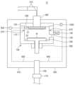
- Figure 1is a drawing showing a substrate processing device according to an embodiment of the present invention.
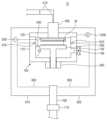
- Figure 2is a drawing showing that the substrate support has moved into the process processing space.
- Figure 3is a diagram explaining the process cycle.
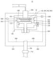
- Figure 4is a drawing showing process gas being supplied to a process chamber.
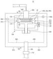
- Figure 5is a drawing showing the source gas being transferred outside the process chamber.
- Figure 6is a drawing showing the source gas and reaction gas being injected into the exhaust line.
- Figure 7is a drawing showing the source gas line and the reaction gas line connected to the exhaust line.
- Figure 8is a drawing for explaining the penetration direction of the exhaust line by the source gas line and the reaction gas line.
- Figure 9is a drawing showing that the source gas and the reaction gas are discharged by the source gas line and the reaction gas line.
- Figure 10is a drawing showing that a portion of the source gas line and the reaction gas line are formed so as to face the inner wall of the exhaust line.
- Figure 11is a drawing showing that an inclined surface is formed at the ends of the source gas line and the reaction gas line toward the inner wall of the exhaust line.
- FIG. 1is a drawing showing a substrate processing device according to an embodiment of the present invention
- FIG. 2is a drawing showing a substrate support part moved into a process processing space.
- a substrate processing device (10)is configured to include a process chamber (100), a substrate support unit (200), an elevator unit (300), a gas supply unit (400), a process gas injection unit (500), a power supply unit (600), an exhaust line (700), a chamber line (800), a source gas line (910), a reaction gas line (920), and a control unit (1000).
- the process chamber (100)provides a process processing space (SP1) for processing a substrate (W).
- the substrate processing device (10)according to an embodiment of the present invention can deposit a thin film on the substrate (W). Specifically, the substrate processing device (10) can deposit a thin film on the substrate (W) using a plasma enhanced chemical vapor deposition (PECVD) method or a plasma enhanced atomic layer deposition (PEALD) method.
- PECVDplasma enhanced chemical vapor deposition
- PEALDplasma enhanced atomic layer deposition
- the process chamber (100)may include a chamber body (110) and a chamber lid (120).
- the chamber body (110)provides a space for accommodating various components for the process of a substrate (W), and the chamber lid (120) may seal an upper opening of the chamber body (110).
- the chamber lid (120)may support a process gas injection unit (500).
- the process gas injection unit (500)may be fixed to the lower surface of the chamber lid (120).
- a process processing space (SP1)is formed, where a process for the substrate (W) can be performed.
- a substrate entrance (130) for entrance and exit of a substrate (W)may be formed on one side of the process chamber (100).
- a substrate entrance (130)may be formed on one side of the chamber body (110).
- the substrate (W)may be brought into or taken out of the process chamber (100) through the substrate entrance (130).
- the process chamber (100)may be equipped with a shutter (140).
- the shutter (140)may open or close the substrate entrance (130).
- the shutter (140)opens the substrate entrance (130)
- the substrate (W)may be brought in or taken out through the substrate entrance (130).
- the shutter (140)may close the substrate entrance (130) to block the inside of the process chamber (100) from the outside.
- the process chamber (100)may include a substrate placement space (SP2). Placement and movement of a substrate (W) may be performed in the substrate placement space (SP2).
- the substrate support (200)may have a mounting surface on which the substrate (W) can be mounted. A process may be performed on the substrate (W) mounted on the mounting surface of the substrate support (200).
- the substrate support (200)may heat the substrate (W).
- a heater(not shown) may be provided inside the substrate support (200). Heat emitted from the heater may be transferred to the substrate (W) through the body of the substrate support (200).
- the heatermay serve as an electrode for forming an electric field. As described below, when RF power is supplied to the process gas injection unit (500), an electric field may be formed between the process gas injection unit (500) and the heater.
- the substrate support member (200)can be raised to a process processing space (SP1) where a process for a substrate (W) is performed, or lowered to a substrate placement space (SP2) where placement and movement of the substrate (W) are performed.
- the elevating member (300)can generate a driving force to move the substrate support member (200) in an up-and-down direction.
- FIG. 1illustrates that the substrate support member (200) is settled on the bottom surface of the process chamber (100)
- FIG. 2illustrates that the substrate support member (200) has moved to an upper point inside the process chamber (100).
- the substrate support member (200)can be placed on the bottom surface of the process chamber (100) as shown in FIG. 1.
- a gas transfer line (410)may be connected to the gas supply unit (400).
- the gas transfer line (410)may provide a transfer path for process gas transferred to the gas supply unit (400).
- a plurality of gas transfer lines (410)may be provided. The plurality of gas transfer lines (410) may transfer different process gases.
- the gas supply unit (400)serves to supply process gas to the process gas injection unit (500).
- the gas supply unit (400)can be connected to the process gas injection unit (500).
- the process gas injection unit (500)performs the function of injecting the process gas to the substrate (W). Specifically, the process gas injection unit (500) can inject the process gas with a uniform distribution over the entire surface area of the substrate (W).
- the process gasmay include a source gas, a source purge gas, a reaction gas, and a reaction purge gas.
- the source gas, the source purge gas, the reaction gas, and the reaction purge gasmay be sequentially injected from the process gas injection unit (500), or at least some of them may be injected simultaneously.
- the source gas and the reaction gasmay collide with each other and react after being injected from the process gas injection unit (500).
- the source gas activated by the reaction gasmay come into contact with the substrate (W) to perform a process treatment on the substrate (W).
- the activated source gasmay be deposited as a thin film on the substrate (W).
- the process gas injection unit (500)can diffuse the process gas supplied to the process chamber (100) and inject the diffused process gas onto the substrate (W).
- the process gas injection unit (500)can be equipped with a plurality of injection holes for injecting the process gas.
- the plurality of injection holescan be distributed over a certain range of the process gas injection unit (500).
- the power supply unit (600)can supply RF power for generating plasma to the process chamber (100). Specifically, the power supply unit (600) can supply RF power to the process gas injection unit (500).
- the process gas injection unit (500)may have a separate electrode plate (not shown) that receives RF power, or may serve as an electrode that receives RF power on its own.
- the substrate support unit (200)may include a heater that serves as an electrode.
- RF poweris supplied to the process gas injection unit (500)
- an electric fieldmay be formed between the process gas injection unit (500) and the heater of the substrate support unit (200).
- the process gas introduced into the process chamber (100)is converted into particles in a plasma state by the electric field formed by the supply of RF power, and the plasma particles react with the surface of the substrate (W) so that a process treatment for the substrate (W) may be performed.
- the exhaust line (700)may provide an exhaust path for process byproducts present in the process chamber (100).
- the process byproductsmay include all substances that must be exhausted from the process chamber (100), such as remaining gases that are not used for forming a thin film among the process gases supplied to the process chamber (100).
- the process byproductsmay include a source gas, a reaction gas, a source purge gas, and a reaction purge gas.
- the exhaust line (700)may be equipped with a pressure pump (710).
- the pressure pump (710)may pressurize the internal space of the exhaust line (700) to transport process byproducts introduced into the exhaust line (700).
- the process chamber (100)may be equipped with a gas port (810).
- the gas port (810)may be arranged adjacent to the process treatment space (SP1) to provide an exhaust path for process byproducts introduced through the gas port (810).
- a chamber line (800)may be connected to the gas port (810).
- the chamber line (800)may connect the process chamber (100) and the exhaust line (700) to provide an exhaust path for process byproducts.
- the process byproducts introduced through the gas port (810)may be transferred to the exhaust line (700) through the chamber line (800).
- the source gas line (910)may be connected to the exhaust line (700) and provide an exhaust path for the source gas.
- the reaction gas line (920)may be connected to the exhaust line (700) and provide an exhaust path for the reaction gas.
- the source gas line (910) and the reaction gas line (920)may be branched from the gas supply unit (400) and connected to the exhaust line (700).
- the source gas line (910) and the reaction gas line (920)may provide exhaust paths for the source gas and the reaction gas that are not supplied to the process chamber (100), respectively.
- the gas supply unit (400)may supply the process gas to the process chamber (100). Meanwhile, the source gas or the reaction gas transferred to the gas supply unit (400) may not be temporarily supplied to the process chamber (100). In this case, the source gas or reaction gas not supplied to the process chamber (100) may be transported to the exhaust line (700) through the source gas line (910) or the reaction gas line (920) and discharged together with the process byproducts.
- the source gas line (910) and the reaction gas line (920)may be connected to the lower portion of the exhaust line (700) compared to the chamber line (800).
- the source gas and the reaction gas discharged from the source gas line (910) and the reaction gas line (920)are prevented from colliding with each other by the process byproduct discharged from the chamber line (800), and thus the formation of deposits may be limited.
- the control unit (1000)can perform overall control of the substrate processing device (10). For example, the control unit (1000) can operate the shutter (140) to open and close the substrate entrance (130), or control the lifting unit (300) to move the substrate support unit (200). In addition, the control unit (1000) can control the supply of process gas to the process chamber (100) by controlling the gas supply unit (400), or control the supply of RF power by the power supply unit (600). In addition, the control unit (1000) can control the pressure pump (710) to discharge process byproducts introduced into the exhaust line (700).
- FIG. 3is a drawing for explaining a process cycle
- FIG. 4is a drawing showing that a process gas is supplied to a process chamber
- FIG. 5is a drawing showing that a source gas is transferred to the outside of the process chamber
- FIG. 6is a drawing showing that a source gas and a reaction gas are injected into an exhaust line.
- multiple processescan be sequentially performed to deposit a thin film on a substrate (W).
- One process cyclemay include a source gas injection step (S1), a source purge gas injection step (S2), a reaction gas injection step (S3), and a reaction purge gas injection step (S4).
- S1source gas injection step
- S2source purge gas injection step
- S3reaction gas injection step
- S4reaction purge gas injection step
- a source gas injection stepS1
- S2source purge gas injection step
- S3reaction gas injection step
- RPGreaction purge gas
- RPGreaction purge gas
- RPGreaction purge gas
- a source gas (SG)may be injected into the process chamber (100).
- the source gas (SG)may be injected onto the surface of the substrate (W) through the process gas injection unit (500). Some of the source gas (SG) injected onto the substrate (W) may be adsorbed onto the surface of the substrate (W), and some may not be adsorbed.
- the non-adsorbed source gas (SG)may be deposited on the adsorbed source gas (SG) or may float inside the process chamber (100).
- a source purge gas (SPG)may be injected into the process chamber (100) in a source purge gas injection step (S2).
- the source purge gas (SPG)may be injected into the process chamber (100) through a process gas injection unit (500).
- the source purge gas injection step (S2)may include a step in which the source gas (SG) that is not adsorbed on the surface of the substrate (W) is discharged from the process chamber (100).
- the source gas (SG)when the source gas (SG) is purged from the process chamber (100), only the source gas (SG) adsorbed on the substrate (W) remains, and the source gas (SG) that is deposited on the adsorbed source gas (SG) or floats in the process chamber (100) may be discharged to the outside of the process chamber (100). Accordingly, one source gas layer may be formed on the surface of the substrate (W).
- a reaction gas (RG)can be injected into the process chamber (100) in a reaction gas injection step (S3).
- the reaction gas (RG)can be injected onto the surface of the substrate (W) through a process gas injection unit (500).
- the reaction gas (RG)can react with the source gas (SG) adsorbed on the substrate (W) to form a thin film.
- a reaction purge gas (RPG)may be injected into the process chamber (100) in a reaction purge gas injection step (S4).
- the reaction purge gas (RPG)As the reaction purge gas (RPG) is injected, the reaction gas (RG) may be purged from the process chamber (100).
- the reaction purge gas (RPG) for purging the reaction gas (RG)may be injected into the process chamber (100) through a process gas injection unit (500).
- the reaction purge gas (RPG)is injected into the process chamber (100), the source gas (SG) and the reaction gas (RG) that are not used to form a thin film on the surface of the substrate (W) may be discharged from the process chamber (100).
- a plurality of processes as described aboveare performed sequentially to form one process cycle, and a plurality of layers of thin films can be deposited on a substrate (W) through the plurality of process cycles.
- the source gas (SG) and the reaction gas (RG)can be transferred to the gas supply unit (400) through the gas transfer line (410). At this time, the supply of the source gas (SG) and the reaction gas (RG) through the gas transfer line (410) can be maintained regardless of each step of the process cycle.
- the source gas (SG)is also supplied to the gas supply unit (400) in the source purge gas injection step (S2), the reaction gas injection step (S3), and the reaction purge gas injection step (S4) (hereinafter referred to as the source gas blocking step).
- the source gas (SG)can be loaded into the gas supply unit (400) because the supply to the process chamber (100) is blocked.
- the reaction gas (RG)is also supplied to the gas supply unit (400) in the source gas injection step (S1), the source purge gas injection step (S2), and the reaction purge gas injection step (S4) (hereinafter referred to as the reaction gas blocking step), and this may affect the thin film quality of the substrate (W).
- the source gas line (910) and the reaction gas line (920)may provide exhaust paths for the source gas (SG) and the reaction gas (RG), respectively. That is, the source gas (SG) supplied to the gas supply unit (400) in the source gas blocking step may be transferred to the exhaust line (700) through the source gas line (910), and the reaction gas (RG) supplied to the gas supply unit (400) in the reaction gas blocking step may be transferred to the exhaust line (700) through the reaction gas line (920).
- FIG. 5illustrates that the source gas (SG) is transferred to the exhaust line (700) through the source gas line (910) in the source gas blocking step.
- the source gas (SG) and the reaction gas (RG)are not loaded into the gas supply unit (400) in the source gas blocking step and the reaction gas blocking step, the source gas (SG) and the reaction gas (RG) can be supplied to the process chamber (100) at a uniform pressure in each process cycle.
- the source gas (SG) and the reaction gas (RG)may be simultaneously transferred to the exhaust line (700) in the source purge gas injection step (S2) or the reaction purge gas injection step (S4).
- FIG. 6illustrates that the source gas (SG) and the reaction gas (RG) are simultaneously transferred to the exhaust line (700) through the source gas line (910) and the reaction gas line (920).
- the source gas (SG) and the reaction gas (RG)may react with each other to form a deposit inside the exhaust line (700). If the formation of the deposit continues and the deposit grows excessively, the exhaust line (700) may be closed or the pressure pump (710) connected to the exhaust line (700) may be damaged.
- the outlets of the source gas line (910) and the reaction gas line (920) entering the exhaust line (700)may be formed at different heights. Since the outlets of the source gas line (910) and the reaction gas line (920) are formed at different heights, collision between the source gas (SG) and the reaction gas (RG) discharged from the source gas line (910) and the reaction gas line (920) is prevented, and thus the formation of deposits may be limited.
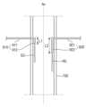
- FIG. 7is a drawing showing a source gas line and a reaction gas line connected to an exhaust line
- FIG. 8is a drawing for explaining the penetration direction of the exhaust line by the source gas line and the reaction gas line
- FIG. 9is a drawing showing that the source gas and the reaction gas are discharged by the source gas line and the reaction gas line.
- the source gas line (910) and the reaction gas line (920)can be connected to the exhaust line (700).
- the source gas line (910) and the reaction gas line (920)may include penetration lines (911, 921) and discharge lines (912, 922), respectively.
- the penetration lines (911, 921)pass through the exhaust line (700), and the discharge lines (912, 922) are provided inside the exhaust line (700) and may discharge the source gas (SG) or the reaction gas (RG).
- the penetration line (911) of the source gas line (910)is referred to as a source penetration line
- the penetration line (921) of the reaction gas line (920)is referred to as a reaction penetration line.
- the discharge line (912) of the source gas line (910)is referred to as a source discharge line
- the discharge line (922) of the reaction gas line (920)is referred to as a reaction discharge line.
- the penetration line (source penetration line) (911) of the source gas line (910) and the penetration line (reaction penetration line) (921) of the reaction gas line (920)can penetrate the exhaust line (700) at the same height.
- the source penetration line (911) and the reaction penetration line (921)can penetrate the exhaust line (700) in directions opposite to each other.
- the distance between the point where the source penetration line (911) penetrates the exhaust line (700) and the point where the reaction penetration line (921) penetrates the exhaust line (700)can be formed to the maximum.
- the discharge lines (912, 922)are different from the penetration direction of the penetration lines (911, 921) and can be extended to the penetration lines (911, 921) in a direction corresponding to the exhaust line (700). Specifically, the discharge lines (912, 922) can be arranged parallel to the central axis (Ax) of the exhaust line (700).
- the length of the source discharge line (912) and the length of the reaction discharge line (922)may be formed differently.
- the reaction discharge line (922)may be formed longer than the source discharge line (912).
- the length (L2) of the reaction discharge line (922)may be formed three times or more longer than the length (L1) of the source discharge line (912).
- the source exhaust line (912) and the reaction exhaust line (922)may be arranged adjacent to the inner wall of the exhaust line (700). That is, the source exhaust line (912) and the reaction exhaust line (922) may be arranged adjacent to the inner wall of the exhaust line (700) relative to the central axis (Ax) of the exhaust line (700). At this time, the source exhaust line (912) and the reaction exhaust line (922) may be spaced apart from the inner wall of the exhaust line (700) by a certain distance. Alternatively, the source exhaust line (912) and the reaction exhaust line (922) may be arranged in close contact with the inner wall of the exhaust line (700).
- the distance between the source gas (SG) and the reaction gas (RG) discharged from the source exhaust line (912) and the reaction exhaust line (922)is secured to the maximum extent, so that collision of the source gas (SG) and the reaction gas (RG) can be prevented.
- Figure 10is a drawing showing that a portion of the source gas line and the reaction gas line are formed so as to face the inner wall of the exhaust line.
- At least a portion (912a, 922a) of the exhaust lines (912, 922)may be formed to face the inner wall of the exhaust line (700).
- a portion (912a) of the source exhaust line (912)may be formed to face the inner wall of the exhaust line (700) adjacent thereto, and a portion (922a) of the reaction exhaust line (922) may be formed to face the inner wall of the exhaust line (700) adjacent thereto. Accordingly, collision between the source gas (SG) and the reaction gas (RG) may be prevented because the source gas (SG) and the reaction gas (RG) are discharged from the source exhaust line (912) and the reaction exhaust line (922) in directions away from each other.
- a portion (912a) of the source exhaust line (912) facing the inner wall of the exhaust line (700)may be the end of the source exhaust line (912), and a portion (922a) of the reaction exhaust line (922) facing the inner wall of the exhaust line (700) may be the end of the reaction exhaust line (922).
- Figure 11is a drawing showing that an inclined surface is formed at the ends of the source gas line and the reaction gas line toward the inner wall of the exhaust line.
- the end of the exhaust line (912, 922)may include an inclined surface (912b, 922b) facing the inner wall of the exhaust line (700).
- the end of the source exhaust line (912)may include an inclined surface (912b) facing the inner wall of the exhaust line (700) adjacent thereto, and the end of the reaction exhaust line (922) may include an inclined surface (922b) facing the inner wall of the exhaust line (700) adjacent thereto.
- the lowest end of the inclined surface (912b) of the source exhaust line (912)(hereinafter, referred to as the lowest source end) may be located above the highest end of the inclined surface (922b) of the reaction exhaust line (922) (hereinafter, referred to as the highest reaction end).
- the lowest source endmeans the lowest end of the inclined surface (912b)
- the highest reaction endmeans the highest end of the inclined surface (922b).
- the outlet of the source exhaust line (912)may be formed to face the inner wall of the exhaust line (700) adjacent thereto, and the outlet of the reaction exhaust line (922) may be formed to face the inner wall of the exhaust line (700) adjacent thereto. Accordingly, since the source gas (SG) and the reaction gas (RG) are discharged from the source exhaust line (912) and the reaction exhaust line (922) in a direction away from each other, collision between the source gas (SG) and the reaction gas (RG) may be prevented.
Landscapes
- Chemical & Material Sciences (AREA)
- Engineering & Computer Science (AREA)
- General Chemical & Material Sciences (AREA)
- Chemical Kinetics & Catalysis (AREA)
- Materials Engineering (AREA)
- Mechanical Engineering (AREA)
- Metallurgy (AREA)
- Organic Chemistry (AREA)
- Physics & Mathematics (AREA)
- Plasma & Fusion (AREA)
- Electromagnetism (AREA)
- Chemical Vapour Deposition (AREA)
Abstract
Description
Translated fromKorean본 발명은 기판 처리 장치에 관한 것으로서, 더욱 상세하게는 공정 챔버로 공급되지 않고 배출되는 소스 가스 및 반응 가스가 배기 라인의 내부에서 반응하여 증착물이 생성되는 것을 방지하는 기판 처리 장치에 관한 것이다.The present invention relates to a substrate processing device, and more particularly, to a substrate processing device that prevents a source gas and a reaction gas that are discharged without being supplied to a process chamber from reacting inside an exhaust line to generate a deposit.
기판에 박막을 증착시키기 위하여 화학 기상 증착법(CVD; Chemical Vapor Deposition) 또는 원자층 박막 증착법(ALD; Atomic Layer Deposition) 등이 이용될 수 있다. 화학 기상 증착법 또는 원자층 박막 증착법에 의한 경우 소스 가스가 기판의 표면에서 화학 반응을 일으켜 박막이 형성될 수 있다. 특히, 원자층 박막 증착법에 의한 경우 기판의 표면에 부착된 원료 기체의 한 층이 박막을 형성하기 때문에 원자의 직경과 유사한 두께의 박막을 형성하는 것이 가능하다.Chemical vapor deposition (CVD) or atomic layer deposition (ALD) can be used to deposit a thin film on a substrate. In the case of chemical vapor deposition or atomic layer deposition, a source gas can cause a chemical reaction on the surface of the substrate to form a thin film. In particular, in the case of atomic layer deposition, since one layer of the source gas attached to the surface of the substrate forms a thin film, it is possible to form a thin film with a thickness similar to the diameter of an atom.
공정 온도의 범위를 확장하기 위하여 플라즈마 화학 기상 증착법(PECVD; Plasma Enhanced Chemical Vapor Deposition) 또는 플라즈마 원자층 박막 증착법(PEALD; Plasma Enhanced Atomic Layer Deposition)이 이용될 수 있다. 플라즈마 화학 기상 증착법 및 플라즈마 원자층 박막 증착법은 화학 기상 증착법 및 원자층 박막 증착법에 비하여 낮은 온도에서 공정 처리가 가능하기 때문에 박막의 물성이 향상될 수 있다.To extend the range of process temperatures, plasma enhanced chemical vapor deposition (PECVD) or plasma enhanced atomic layer deposition (PEALD) can be used. Since plasma enhanced chemical vapor deposition and plasma enhanced atomic layer deposition can be processed at lower temperatures than chemical vapor deposition and atomic layer deposition, the properties of the thin film can be improved.
기판에 박막을 증착시키기 위한 공정 가스는 소스 가스 및 반응 가스를 포함할 수 있다. 기판으로 소스 가스가 분사된 이후에 반응 가스가 분사됨으로써 기판에 박막이 증착될 수 있다.The process gas for depositing a thin film on a substrate may include a source gas and a reaction gas. A thin film may be deposited on the substrate by injecting the reaction gas after the source gas is injected onto the substrate.
한편, 박막의 증착에 이용되지 못한 소스 가스 및 반응 가스는 외부로 배출되는데, 배출되는 소스 가스 및 반응 가스가 상호간에 반응하여 배기 라인의 내부에서 증착물을 형성할 수 있다. 증착물의 형성이 지속되어 증착물이 지나치게 성장하는 경우 배기 라인이 폐쇄되거나 배기 라인에 연결된 압력 펌프가 파손될 수 있다.Meanwhile, the source gas and reaction gas that are not used for thin film deposition are discharged to the outside, and the discharged source gas and reaction gas may react with each other to form deposits inside the exhaust line. If the formation of the deposits continues and the deposits grow excessively, the exhaust line may be blocked or the pressure pump connected to the exhaust line may be damaged.
따라서, 배기 라인의 내부에서 소스 가스 및 반응 가스의 반응을 방지하는 것을 가능하게 하는 발명의 등장이 요구된다.Therefore, there is a need for an invention that makes it possible to prevent the reaction of source gas and reactant gas inside an exhaust line.
본 발명이 해결하고자 하는 과제는 공정 챔버로 공급되지 않고 배출되는 소스 가스 및 반응 가스가 배기 라인의 내부에서 반응하여 증착물이 생성되는 것을 방지하는 기판 처리 장치를 제공하는 것이다.The problem to be solved by the present invention is to provide a substrate processing device that prevents source gas and reaction gas, which are discharged without being supplied to a process chamber, from reacting inside an exhaust line to generate deposits.
본 발명의 과제들은 이상에서 언급한 과제로 제한되지 않으며, 언급되지 않은 또 다른 과제들은 아래의 기재로부터 당업자에게 명확하게 이해될 수 있을 것이다.The tasks of the present invention are not limited to the tasks mentioned above, and other tasks not mentioned will be clearly understood by those skilled in the art from the description below.
본 발명의 실시예에 따른 기판 처리 장치는 기판의 공정을 위한 공정 처리 공간을 제공하는 공정 챔버와, 상기 공정 챔버에 존재하는 공정 부산물의 배기 경로를 제공하는 배기 라인과, 상기 배기 라인에 연결되고, 소스 가스의 배기 경로를 제공하는 소스 가스 라인, 및 상기 배기 라인에 연결되고, 반응 가스의 배기 경로를 제공하는 반응 가스 라인을 포함하되, 상기 배기 라인에 진입한 상기 소스 가스 라인 및 상기 반응 가스 라인의 배출구는 서로 다른 높이에 형성된다.A substrate processing device according to an embodiment of the present invention includes a process chamber providing a process processing space for a substrate process, an exhaust line providing an exhaust path for process byproducts existing in the process chamber, a source gas line connected to the exhaust line and providing an exhaust path for source gas, and a reaction gas line connected to the exhaust line and providing an exhaust path for reaction gas, wherein outlets of the source gas line and the reaction gas line entering the exhaust line are formed at different heights.
상기 소스 가스 라인 및 상기 반응 가스 라인은, 상기 배기 라인을 관통하는 관입 라인, 및 상기 배기 라인의 내부에 구비되고, 소스 가스 또는 반응 가스를 배출하는 배출 라인을 각각 포함한다.The above source gas line and the above reaction gas line each include an inlet line penetrating the exhaust line, and an exhaust line provided inside the exhaust line and discharging the source gas or the reaction gas.
상기 배출 라인은 상기 배기 라인의 중심축에 평행하게 배치된다.The above discharge line is arranged parallel to the central axis of the exhaust line.
상기 반응 가스 라인의 배출 라인은 상기 소스 가스 라인의 배출 라인에 비하여 길게 형성된다.The discharge line of the above reaction gas line is formed longer than the discharge line of the above source gas line.
상기 배출 라인의 적어도 일부는 상기 배기 라인의 내측벽을 향하도록 형성된다.At least a portion of the above exhaust line is formed so as to face the inner wall of the exhaust line.
상기 배기 라인의 내측벽을 향하는 상기 배출 라인의 적어도 일부는 상기 배출 라인의 말단을 포함한다.At least a portion of said exhaust line facing the inner wall of said exhaust line comprises a terminal of said exhaust line.
상기 배출 라인의 말단은 상기 배기 라인의 내측벽을 향하는 경사면을 포함한다.The end of the above exhaust line includes an inclined surface facing the inner wall of the exhaust line.
상기 소스 가스 라인의 배출 라인에 형성된 경사면의 최하 말단은 반응 가스 라인의 배출 라인에 형성된 경사면의 최상 말단에 비하여 상부에 위치한다.The lowest end of the inclined plane formed in the discharge line of the above source gas line is located above the highest end of the inclined plane formed in the discharge line of the reaction gas line.
상기 소스 가스 라인의 관입 라인과 상기 반응 가스 라인의 관입 라인은 동일한 높이에서 상기 배기 라인을 관통한다.The penetration line of the above source gas line and the penetration line of the above reaction gas line penetrate the above exhaust line at the same height.
상기 소스 가스 라인의 관입 라인과 상기 반응 가스 라인의 관입 라인은 상호간에 대향하는 방향으로 상기 배기 라인을 관통한다.The penetration line of the above source gas line and the penetration line of the above reaction gas line penetrate the above exhaust line in opposite directions to each other.
상기 배출 라인은 상기 배기 라인의 내측벽에 인접하여 배치된다.The above discharge line is arranged adjacent to the inner wall of the exhaust line.
상기 소스 가스 라인 및 상기 반응 가스 라인은 상기 공정 챔버로 공급되지 않은 소스 가스 및 반응 가스의 배기 경로를 각각 제공한다.The above source gas line and the above reaction gas line provide exhaust paths for the source gas and reaction gas not supplied to the process chamber, respectively.
상기 기판 처리 장치는 상기 공정 챔버와 상기 배기 라인을 연결하여 상기 공정 부산물의 배기 경로를 제공하는 챔버 라인을 더 포함하고, 상기 소스 가스 라인 및 상기 반응 가스 라인은 상기 챔버 라인에 비하여 상기 배기 라인의 하부에 연결된다.The above substrate processing apparatus further includes a chamber line connecting the process chamber and the exhaust line to provide an exhaust path for the process byproducts, wherein the source gas line and the reaction gas line are connected below the exhaust line relative to the chamber line.
상기 기판 처리 장치는 상기 공정 챔버로 공정 가스를 공급하는 가스 공급부를 더 포함하고, 상기 소스 가스 라인 및 상기 반응 가스 라인은 상기 가스 공급부에서 분기되어 상기 배기 라인에 연결된다.The above substrate processing device further includes a gas supply unit for supplying a process gas to the process chamber, and the source gas line and the reaction gas line are branched from the gas supply unit and connected to the exhaust line.
상기 가스 공급부로 이송된 소스 가스 또는 반응 가스 중 상기 공정 챔버로 공급되지 않은 소스 가스 또는 반응 가스는 상기 소스 가스 라인 또는 상기 반응 가스 라인을 통해 상기 배기 라인으로 이송된다.Among the source gas or reaction gas supplied to the above gas supply unit, the source gas or reaction gas that is not supplied to the process chamber is supplied to the exhaust line through the source gas line or the reaction gas line.
상기 기판 처리 장치는 상기 기판으로 공정 가스를 분사하는 공정 가스 분사부를 더 포함하고, 상기 가스 공급부로 이송된 소스 가스 또는 반응 가스 중 상기 공정 가스 분사부로 공급되지 않은 소스 가스 또는 반응 가스는 상기 소스 가스 라인 또는 상기 반응 가스 라인을 통해 상기 배기 라인으로 이송된다.The substrate processing device further includes a process gas injection unit that injects a process gas onto the substrate, and among the source gas or reaction gas supplied to the gas supply unit, the source gas or reaction gas that is not supplied to the process gas injection unit is supplied to the exhaust line through the source gas line or the reaction gas line.
상기 기판 처리 장치는 상기 가스 공급부로 이송되는 공정 가스의 이송 경로를 제공하는 가스 이송 라인을 더 포함하고, 상기 가스 이송 라인을 통한 상기 가스 공급부로의 소스 가스 및 반응 가스의 공급은 상기 기판에 대한 공정 사이클의 각 단계에 무관하게 유지되고, 소스 가스가 상기 공정 챔버로 공급되는 것이 차단되는 소스 가스 차단 단계에서 상기 가스 공급부로 공급된 소스 가스는 상기 소스 가스 라인을 통해 상기 배기 라인으로 이송되며, 반응 가스가 상기 공정 챔버로 공급되는 것이 차단되는 반응 가스 차단 단계에서 상기 가스 공급부로 공급된 반응 가스는 상기 반응 가스 라인을 통해 상기 배기 라인으로 이송된다.The substrate processing apparatus further includes a gas transfer line that provides a transfer path of a process gas transferred to the gas supply unit, and the supply of a source gas and a reaction gas to the gas supply unit through the gas transfer line is maintained regardless of each stage of a process cycle for the substrate, and in a source gas blocking step in which the source gas is blocked from being supplied to the process chamber, the source gas supplied to the gas supply unit is transferred to the exhaust line through the source gas line, and in a reaction gas blocking step in which the reaction gas is blocked from being supplied to the process chamber, the reaction gas supplied to the gas supply unit is transferred to the exhaust line through the reaction gas line.
기타 실시예들의 구체적인 사항들은 상세한 설명 및 도면들에 포함되어 있다.Specific details of other embodiments are included in the detailed description and drawings.
상기한 바와 같은 본 발명의 실시예에 따른 기판 처리 장치에 따르면 배기 라인으로 진입한 소스 가스 라인 및 반응 가스 라인의 배출구의 높이를 상이하게 함으로써 공정 챔버로 공급되지 않고 배출되는 소스 가스 및 반응 가스가 배기 라인의 내부에서 반응하여 증착물이 생성되는 것을 방지하는 장점이 있다.According to the substrate processing device according to the embodiment of the present invention as described above, there is an advantage in that the heights of the exhaust ports of the source gas line and the reaction gas line entering the exhaust line are made different, thereby preventing the source gas and the reaction gas discharged without being supplied to the process chamber from reacting inside the exhaust line to generate deposits.
도 1은 본 발명의 실시예에 따른 기판 처리 장치를 나타낸 도면이다.Figure 1 is a drawing showing a substrate processing device according to an embodiment of the present invention.
도 2는 기판 지지부가 공정 처리 공간으로 이동한 것을 나타낸 도면이다.Figure 2 is a drawing showing that the substrate support has moved into the process processing space.
도 3은 공정 사이클을 설명하기 위한 도면이다.Figure 3 is a diagram explaining the process cycle.
도 4는 공정 챔버로 공정 가스가 공급되는 것을 나타낸 도면이다.Figure 4 is a drawing showing process gas being supplied to a process chamber.
도 5는 공정 챔버의 외부로 소스 가스가 이송되는 것을 나타낸 도면이다.Figure 5 is a drawing showing the source gas being transferred outside the process chamber.
도 6은 배기 라인으로 소스 가스 및 반응 가스가 주입되는 것을 나타낸 도면이다.Figure 6 is a drawing showing the source gas and reaction gas being injected into the exhaust line.
도 7은 배기 라인에 소스 가스 라인 및 반응 가스 라인이 연결된 것을 나타낸 도면이다.Figure 7 is a drawing showing the source gas line and the reaction gas line connected to the exhaust line.
도 8은 소스 가스 라인 및 반응 가스 라인에 의한 배기 라인의 관통 방향을 설명하기 위한 도면이다.Figure 8 is a drawing for explaining the penetration direction of the exhaust line by the source gas line and the reaction gas line.
도 9는 소스 가스 라인 및 반응 가스 라인에 의해 소스 가스 및 반응 가스가 배출되는 것을 나타낸 도면이다.Figure 9 is a drawing showing that the source gas and the reaction gas are discharged by the source gas line and the reaction gas line.
도 10은 소스 가스 라인 및 반응 가스 라인의 일부가 배기 라인의 내측벽을 향하도록 형성된 것을 나타낸 도면이다.Figure 10 is a drawing showing that a portion of the source gas line and the reaction gas line are formed so as to face the inner wall of the exhaust line.
도 11은 소스 가스 라인 및 반응 가스 라인의 말단에 배기 라인의 내측벽을 향하는 경사면이 형성된 것을 나타낸 도면이다.Figure 11 is a drawing showing that an inclined surface is formed at the ends of the source gas line and the reaction gas line toward the inner wall of the exhaust line.
이하, 첨부된 도면을 참조하여 본 발명의 바람직한 실시예를 상세히 설명한다. 본 발명의 이점 및 특징, 그리고 그것들을 달성하는 방법은 첨부되는 도면과 함께 상세하게 후술되어 있는 실시 예들을 참조하면 명확해질 것이다. 그러나 본 발명은 이하에서 게시되는 실시 예들에 한정되는 것이 아니라 서로 다른 다양한 형태로 구현될 수 있으며, 단지 본 실시 예들은 본 발명의 게시가 완전하도록 하고, 본 발명이 속하는 기술분야에서 통상의 지식을 가진 자에게 발명의 범주를 완전하게 알려주기 위해 제공되는 것이며, 본 발명은 청구항의 범주에 의해 정의될 뿐이다. 명세서 전체에 걸쳐 동일 참조 부호는 동일 구성 요소를 지칭한다.Hereinafter, preferred embodiments of the present invention will be described in detail with reference to the accompanying drawings. The advantages and features of the present invention, and the methods for achieving them, will become apparent with reference to the embodiments described in detail below together with the accompanying drawings. However, the present invention is not limited to the embodiments disclosed below, but may be implemented in various different forms, and the present embodiments are provided only to make the disclosure of the present invention complete and to fully inform those skilled in the art of the scope of the invention, and the present invention is defined only by the scope of the claims. Like reference numerals refer to like elements throughout the specification.
다른 정의가 없다면, 본 명세서에서 사용되는 모든 용어(기술 및 과학적 용어를 포함)는 본 발명이 속하는 기술분야에서 통상의 지식을 가진 자에게 공통적으로 이해될 수 있는 의미로 사용될 수 있을 것이다. 또 일반적으로 사용되는 사전에 정의되어 있는 용어들은 명백하게 특별히 정의되어 있지 않는 한 이상적으로 또는 과도하게 해석되지 않는다.Unless otherwise defined, all terms (including technical and scientific terms) used in this specification may be used with a meaning that can be commonly understood by a person of ordinary skill in the art to which the present invention belongs. In addition, terms defined in commonly used dictionaries shall not be ideally or excessively interpreted unless explicitly specifically defined.
도 1은 본 발명의 실시예에 따른 기판 처리 장치를 나타낸 도면이고, 도 2는 기판 지지부가 공정 처리 공간으로 이동한 것을 나타낸 도면이다.FIG. 1 is a drawing showing a substrate processing device according to an embodiment of the present invention, and FIG. 2 is a drawing showing a substrate support part moved into a process processing space.
도 1 및 도 2를 참조하면, 본 발명의 실시예에 따른 기판 처리 장치(10)는 공정 챔버(100), 기판 지지부(200), 승강부(300), 가스 공급부(400), 공정 가스 분사부(500), 전력 공급부(600), 배기 라인(700), 챔버 라인(800), 소스 가스 라인(910), 반응 가스 라인(920) 및 제어부(1000)를 포함하여 구성된다.Referring to FIGS. 1 and 2, a substrate processing device (10) according to an embodiment of the present invention is configured to include a process chamber (100), a substrate support unit (200), an elevator unit (300), a gas supply unit (400), a process gas injection unit (500), a power supply unit (600), an exhaust line (700), a chamber line (800), a source gas line (910), a reaction gas line (920), and a control unit (1000).
공정 챔버(100)는 기판(W)의 공정을 위한 공정 처리 공간(SP1)을 제공한다. 본 발명의 실시예에 따른 기판 처리 장치(10)는 기판(W)에 박막을 증착할 수 있다. 구체적으로, 기판 처리 장치(10)는 플라즈마 화학 기상 증착법(PECVD; Plasma Enhanced Chemical Vapor Deposition) 또는 플라즈마 원자층 박막 증착법(PEALD; Plasma Enhanced Atomic Layer Deposition)을 이용하여 기판(W)에 박막을 증착할 수 있다.The process chamber (100) provides a process processing space (SP1) for processing a substrate (W). The substrate processing device (10) according to an embodiment of the present invention can deposit a thin film on the substrate (W). Specifically, the substrate processing device (10) can deposit a thin film on the substrate (W) using a plasma enhanced chemical vapor deposition (PECVD) method or a plasma enhanced atomic layer deposition (PEALD) method.
공정 챔버(100)는 챔버 본체(110) 및 챔버 리드(120)를 포함할 수 있다. 챔버 본체(110)는 기판(W)의 공정을 위한 각종 부품의 수용 공간을 제공하고, 챔버 리드(120)는 챔버 본체(110)의 상부 개구를 밀폐시킬 수 있다. 챔버 리드(120)는 공정 가스 분사부(500)를 지지할 수 있다. 공정 가스 분사부(500)는 챔버 리드(120)의 하측면에 고정될 수 있다.The process chamber (100) may include a chamber body (110) and a chamber lid (120). The chamber body (110) provides a space for accommodating various components for the process of a substrate (W), and the chamber lid (120) may seal an upper opening of the chamber body (110). The chamber lid (120) may support a process gas injection unit (500). The process gas injection unit (500) may be fixed to the lower surface of the chamber lid (120).
챔버 본체(110) 및 챔버 리드(120)가 결합됨으로써 공정 처리 공간(SP1)이 형성되어 기판(W)에 대한 공정이 수행될 수 있다.By combining the chamber body (110) and the chamber lid (120), a process processing space (SP1) is formed, where a process for the substrate (W) can be performed.
공정 챔버(100)의 일측에는 기판(W)의 출입을 위한 기판 출입구(130)가 형성될 수 있다. 예를 들어, 챔버 본체(110)의 일측에 기판 출입구(130)가 형성될 수 있다. 기판(W)은 기판 출입구(130)를 통해 공정 챔버(100)의 내부로 반입되거나 공정 챔버(100)의 외부로 반출될 수 있다.A substrate entrance (130) for entrance and exit of a substrate (W) may be formed on one side of the process chamber (100). For example, a substrate entrance (130) may be formed on one side of the chamber body (110). The substrate (W) may be brought into or taken out of the process chamber (100) through the substrate entrance (130).
공정 챔버(100)에는 셔터(140)가 구비될 수 있다. 셔터(140)는 기판 출입구(130)를 개방하거나 폐쇄할 수 있다. 셔터(140)가 기판 출입구(130)를 개방한 경우 기판 출입구(130)를 통해 기판(W)이 반입되거나 반출될 수 있다. 기판(W)에 대한 공정이 진행되는 경우에는 셔터(140)가 기판 출입구(130)를 폐쇄하여 공정 챔버(100)의 내부를 외부에 대하여 차단할 수 있다.The process chamber (100) may be equipped with a shutter (140). The shutter (140) may open or close the substrate entrance (130). When the shutter (140) opens the substrate entrance (130), the substrate (W) may be brought in or taken out through the substrate entrance (130). When a process for the substrate (W) is in progress, the shutter (140) may close the substrate entrance (130) to block the inside of the process chamber (100) from the outside.
공정 챔버(100)는 기판 배치 공간(SP2)을 포함할 수 있다. 기판 배치 공간(SP2)에서 기판(W)의 배치 및 이동이 수행될 수 있다.The process chamber (100) may include a substrate placement space (SP2). Placement and movement of a substrate (W) may be performed in the substrate placement space (SP2).
기판 지지부(200)는 기판(W)이 안착 가능한 안착면을 구비할 수 있다. 기판 지지부(200)의 안착면에 안착된 기판(W)에 대하여 공정이 수행될 수 있다. 기판 지지부(200)는 기판(W)을 가열할 수 있다. 이를 위하여. 기판 지지부(200)의 내부에는 히터(미도시)가 구비될 수 있다. 히터에서 발산된 열은 기판 지지부(200)의 몸체를 통해 기판(W)으로 전달될 수 있다. 히터는 전계의 형성을 위한 전극의 역할을 수행할 수 있다. 후술하는 바와 같이, 공정 가스 분사부(500)에 RF 전력이 공급되는 경우 공정 가스 분사부(500)와 히터의 사이에 전계가 형성될 수 있다.The substrate support (200) may have a mounting surface on which the substrate (W) can be mounted. A process may be performed on the substrate (W) mounted on the mounting surface of the substrate support (200). The substrate support (200) may heat the substrate (W). To this end, a heater (not shown) may be provided inside the substrate support (200). Heat emitted from the heater may be transferred to the substrate (W) through the body of the substrate support (200). The heater may serve as an electrode for forming an electric field. As described below, when RF power is supplied to the process gas injection unit (500), an electric field may be formed between the process gas injection unit (500) and the heater.
기판 지지부(200)는 기판(W)에 대한 공정이 수행되는 공정 처리 공간(SP1)으로 상승하거나 기판(W)의 배치 및 이동이 수행되는 기판 배치 공간(SP2)으로 하강할 수 있다. 승강부(300)는 구동력을 발생시켜 기판 지지부(200)를 상하 방향으로 이동시킬 수 있다. 도 1은 기판 지지부(200)가 공정 챔버(100)의 바닥면에 안착된 것을 도시하고 있고, 도 2는 기판 지지부(200)가 공정 챔버(100)의 내부에서 상부 지점으로 이동한 것을 도시하고 있다.The substrate support member (200) can be raised to a process processing space (SP1) where a process for a substrate (W) is performed, or lowered to a substrate placement space (SP2) where placement and movement of the substrate (W) are performed. The elevating member (300) can generate a driving force to move the substrate support member (200) in an up-and-down direction. FIG. 1 illustrates that the substrate support member (200) is settled on the bottom surface of the process chamber (100), and FIG. 2 illustrates that the substrate support member (200) has moved to an upper point inside the process chamber (100).
기판(W)이 공정 챔버(100)의 내부로 반입되거나 외부로 반출되는 경우 기판 지지부(200)는 도 1에 도시된 바와 같이 공정 챔버(100)의 바닥면에 안착될 수 있다.When the substrate (W) is brought into or taken out of the process chamber (100), the substrate support member (200) can be placed on the bottom surface of the process chamber (100) as shown in FIG. 1.
가스 공급부(400)에는 가스 이송 라인(410)이 연결될 수 있다. 가스 이송 라인(410)은 가스 공급부(400)로 이송되는 공정 가스의 이송 경로를 제공할 수 있다. 가스 이송 라인(410)은 복수 개가 구비될 수 있다. 복수의 가스 이송 라인(410)은 서로 다른 공정 가스를 이송할 수 있다.A gas transfer line (410) may be connected to the gas supply unit (400). The gas transfer line (410) may provide a transfer path for process gas transferred to the gas supply unit (400). A plurality of gas transfer lines (410) may be provided. The plurality of gas transfer lines (410) may transfer different process gases.
가스 공급부(400)는 공정 가스 분사부(500)로 공정 가스를 공급하는 역할을 수행한다. 가스 공급부(400)는 공정 가스 분사부(500)에 연결될 수 있다.The gas supply unit (400) serves to supply process gas to the process gas injection unit (500). The gas supply unit (400) can be connected to the process gas injection unit (500).
공정 가스 분사부(500)는 공정 가스를 기판(W)으로 분사하는 역할을 수행한다. 구체적으로, 공정 가스 분사부(500)는 기판(W)의 표면 전체 영역에 걸쳐 균일한 분포로 공정 가스가 분사되도록 할 수 있다. 본 발명에서 공정 가스는 소스 가스, 소스 퍼지 가스, 반응 가스 및 반응 퍼지 가스를 포함할 수 있다. 소스 가스, 소스 퍼지 가스, 반응 가스 및 반응 퍼지 가스는 공정 가스 분사부(500)에서 순차적으로 분사되거나 적어도 일부가 동시에 분사될 수 있다. 소스 가스 및 반응 가스는 공정 가스 분사부(500)에서 분사된 이후에 서로 충돌하여 반응할 수 있다. 그리고, 반응 가스에 의하여 활성화된 소스 가스가 기판(W)에 접촉하여 기판(W)에 대한 공정 처리가 수행될 수 있다. 예를 들어, 활성화된 소스 가스가 기판(W)에 박막으로 증착될 수 있다.The process gas injection unit (500) performs the function of injecting the process gas to the substrate (W). Specifically, the process gas injection unit (500) can inject the process gas with a uniform distribution over the entire surface area of the substrate (W). In the present invention, the process gas may include a source gas, a source purge gas, a reaction gas, and a reaction purge gas. The source gas, the source purge gas, the reaction gas, and the reaction purge gas may be sequentially injected from the process gas injection unit (500), or at least some of them may be injected simultaneously. The source gas and the reaction gas may collide with each other and react after being injected from the process gas injection unit (500). Then, the source gas activated by the reaction gas may come into contact with the substrate (W) to perform a process treatment on the substrate (W). For example, the activated source gas may be deposited as a thin film on the substrate (W).
공정 가스 분사부(500)는 공정 챔버(100)로 공급된 공정 가스를 확산시키고, 확산된 공정 가스를 기판(W)으로 분사할 수 있다. 공정 가스 분사부(500)는 공정 가스의 분사를 위한 복수의 분사홀을 구비할 수 있다. 복수의 분사홀은 공정 가스 분사부(500)의 일정 범위에 걸쳐 분포될 수 있다.The process gas injection unit (500) can diffuse the process gas supplied to the process chamber (100) and inject the diffused process gas onto the substrate (W). The process gas injection unit (500) can be equipped with a plurality of injection holes for injecting the process gas. The plurality of injection holes can be distributed over a certain range of the process gas injection unit (500).
전력 공급부(600)는 플라즈마의 발생을 위한 RF 전력을 공정 챔버(100)로 공급할 수 있다. 구체적으로, 전력 공급부(600)는 공정 가스 분사부(500)로 RF 전력을 공급할 수 있다. 공정 가스 분사부(500)는 RF 전력을 공급받는 별도의 전극 플레이트(미도시)를 구비하거나, 자체적으로 RF 전력을 공급받는 전극의 역할을 수행할 수 있다. 전술한 바와 같이, 기판 지지부(200)는 전극의 역할을 수행하는 히터를 포함할 수 있다. 공정 가스 분사부(500)로 RF 전력이 공급되는 경우 공정 가스 분사부(500)와 기판 지지부(200)의 히터의 사이에 전계가 형성될 수 있다. RF 전력의 공급으로 형성된 전계에 의해 공정 챔버(100)로 유입된 공정 가스가 플라즈마 상태의 입자로 변환되고, 플라즈마 입자가 기판(W)의 표면과 반응하여 기판(W)에 대한 공정 처리가 수행될 수 있다.The power supply unit (600) can supply RF power for generating plasma to the process chamber (100). Specifically, the power supply unit (600) can supply RF power to the process gas injection unit (500). The process gas injection unit (500) may have a separate electrode plate (not shown) that receives RF power, or may serve as an electrode that receives RF power on its own. As described above, the substrate support unit (200) may include a heater that serves as an electrode. When RF power is supplied to the process gas injection unit (500), an electric field may be formed between the process gas injection unit (500) and the heater of the substrate support unit (200). The process gas introduced into the process chamber (100) is converted into particles in a plasma state by the electric field formed by the supply of RF power, and the plasma particles react with the surface of the substrate (W) so that a process treatment for the substrate (W) may be performed.
배기 라인(700)은 공정 챔버(100)에 존재하는 공정 부산물의 배기 경로를 제공할 수 있다. 여기서, 공정 부산물은 공정 챔버(100)로 공급된 공정 가스 중 박막의 형성에 이용되지 않은 나머지 가스 등 공정 챔버(100)에서 배출되어야 하는 모든 물질을 포함할 수 있다. 예를 들어, 공정 부산물에는 소스 가스, 반응 가스, 소스 퍼지 가스 및 반응 퍼지 가스가 포함될 수 있다.The exhaust line (700) may provide an exhaust path for process byproducts present in the process chamber (100). Here, the process byproducts may include all substances that must be exhausted from the process chamber (100), such as remaining gases that are not used for forming a thin film among the process gases supplied to the process chamber (100). For example, the process byproducts may include a source gas, a reaction gas, a source purge gas, and a reaction purge gas.
배기 라인(700)에는 압력 펌프(710)가 구비될 수 있다. 압력 펌프(710)는 배기 라인(700)의 내부 공간을 가압하여 배기 라인(700)으로 유입된 공정 부산물이 이송되도록 할 수 있다.The exhaust line (700) may be equipped with a pressure pump (710). The pressure pump (710) may pressurize the internal space of the exhaust line (700) to transport process byproducts introduced into the exhaust line (700).
공정 챔버(100)에는 가스 포트(810)가 구비될 수 있다. 가스 포트(810)는 공정 처리 공간(SP1)에 인접하게 배치되어 가스 포트(810)를 통해 유입된 공정 부산물의 배출 경로를 제공할 수 있다. 가스 포트(810)에는 챔버 라인(800)이 연결될 수 있다. 챔버 라인(800)은 공정 챔버(100)와 배기 라인(700)을 연결하여 공정 부산물의 배기 경로를 제공할 수 있다. 가스 포트(810)로 유입된 공정 부산물은 챔버 라인(800)을 통해 배기 라인(700)으로 이송될 수 있다.The process chamber (100) may be equipped with a gas port (810). The gas port (810) may be arranged adjacent to the process treatment space (SP1) to provide an exhaust path for process byproducts introduced through the gas port (810). A chamber line (800) may be connected to the gas port (810). The chamber line (800) may connect the process chamber (100) and the exhaust line (700) to provide an exhaust path for process byproducts. The process byproducts introduced through the gas port (810) may be transferred to the exhaust line (700) through the chamber line (800).
소스 가스 라인(910)은 배기 라인(700)에 연결되고, 소스 가스의 배기 경로를 제공할 수 있다. 반응 가스 라인(920)은 배기 라인(700)에 연결되고, 반응 가스의 배기 경로를 제공할 수 있다. 소스 가스 라인(910) 및 반응 가스 라인(920)은 가스 공급부(400)에서 분기되어 배기 라인(700)에 연결될 수 있다. 소스 가스 라인(910) 및 반응 가스 라인(920)은 공정 챔버(100)로 공급되지 않은 소스 가스 및 반응 가스의 배기 경로를 각각 제공할 수 있다. 전술한 바와 같이, 가스 공급부(400)는 공정 챔버(100)로 공정 가스를 공급할 수 있다. 한편, 가스 공급부(400)로 이송된 소스 가스 또는 반응 가스는 일시적으로 공정 챔버(100)로 공급되지 못할 수 있다. 이러한 경우 공정 챔버(100)로 공급되지 않은 소스 가스 또는 반응 가스는 소스 가스 라인(910) 또는 반응 가스 라인(920)을 통해 배기 라인(700)으로 이송되어 공정 부산물과 함께 배출될 수 있다.The source gas line (910) may be connected to the exhaust line (700) and provide an exhaust path for the source gas. The reaction gas line (920) may be connected to the exhaust line (700) and provide an exhaust path for the reaction gas. The source gas line (910) and the reaction gas line (920) may be branched from the gas supply unit (400) and connected to the exhaust line (700). The source gas line (910) and the reaction gas line (920) may provide exhaust paths for the source gas and the reaction gas that are not supplied to the process chamber (100), respectively. As described above, the gas supply unit (400) may supply the process gas to the process chamber (100). Meanwhile, the source gas or the reaction gas transferred to the gas supply unit (400) may not be temporarily supplied to the process chamber (100). In this case, the source gas or reaction gas not supplied to the process chamber (100) may be transported to the exhaust line (700) through the source gas line (910) or the reaction gas line (920) and discharged together with the process byproducts.
소스 가스 라인(910) 및 반응 가스 라인(920)은 챔버 라인(800)에 비하여 배기 라인(700)의 하부에 연결될 수 있다. 소스 가스 라인(910) 및 반응 가스 라인(920)에서 배출된 소스 가스 및 반응 가스는 챔버 라인(800)에서 배출된 공정 부산물에 의해 상호간의 충돌이 방지되고, 이로 인해 증착물의 형성이 제한될 수 있다.The source gas line (910) and the reaction gas line (920) may be connected to the lower portion of the exhaust line (700) compared to the chamber line (800). The source gas and the reaction gas discharged from the source gas line (910) and the reaction gas line (920) are prevented from colliding with each other by the process byproduct discharged from the chamber line (800), and thus the formation of deposits may be limited.
제어부(1000)는 기판 처리 장치(10)에 대한 전반적인 제어를 수행할 수 있다. 예를 들어, 제어부(1000)는 셔터(140)를 동작시켜 기판 출입구(130)를 개폐하거나, 승강부(300)를 제어하여 기판 지지부(200)를 이동시킬 수 있다. 또한, 제어부(1000)는 가스 공급부(400)를 제어하여 공정 챔버(100)로 공정 가스가 공급되는 것을 제어하거나 전력 공급부(600)에 의해 RF 전력이 공급되는 것을 제어할 수도 있다. 또한, 제어부(1000)는 압력 펌프(710)를 제어하여 배기 라인(700)으로 유입된 공정 부산물이 배출되도록 할 수 있다.The control unit (1000) can perform overall control of the substrate processing device (10). For example, the control unit (1000) can operate the shutter (140) to open and close the substrate entrance (130), or control the lifting unit (300) to move the substrate support unit (200). In addition, the control unit (1000) can control the supply of process gas to the process chamber (100) by controlling the gas supply unit (400), or control the supply of RF power by the power supply unit (600). In addition, the control unit (1000) can control the pressure pump (710) to discharge process byproducts introduced into the exhaust line (700).
도 3은 공정 사이클을 설명하기 위한 도면이고, 도 4는 공정 챔버로 공정 가스가 공급되는 것을 나타낸 도면이고, 도 5는 공정 챔버의 외부로 소스 가스가 이송되는 것을 나타낸 도면이며, 도 6은 배기 라인으로 소스 가스 및 반응 가스가 주입되는 것을 나타낸 도면이다.FIG. 3 is a drawing for explaining a process cycle, FIG. 4 is a drawing showing that a process gas is supplied to a process chamber, FIG. 5 is a drawing showing that a source gas is transferred to the outside of the process chamber, and FIG. 6 is a drawing showing that a source gas and a reaction gas are injected into an exhaust line.
도 3을 참조하면, 기판(W)에 박막을 증착하기 위하여 복수의 공정이 순차적으로 수행될 수 있다.Referring to FIG. 3, multiple processes can be sequentially performed to deposit a thin film on a substrate (W).
하나의 공정 사이클은 소스 가스 주입 단계(S1), 소스 퍼지 가스 주입 단계(S2), 반응 가스 주입 단계(S3) 및 반응 퍼지 가스 주입 단계(S4)를 포함할 수 있다. 도 4에 도시된 바와 같이, 각 주입 단계에서 소스 가스(SG), 소스 퍼지 가스(SPG), 반응 가스(RG) 및 반응 퍼지 가스(RPG)가 공정 가스 분사부(500)를 통해 기판(W)으로 분사될 수 있다.One process cycle may include a source gas injection step (S1), a source purge gas injection step (S2), a reaction gas injection step (S3), and a reaction purge gas injection step (S4). As illustrated in FIG. 4, in each injection step, a source gas (SG), a source purge gas (SPG), a reaction gas (RG), and a reaction purge gas (RPG) may be injected onto a substrate (W) through a process gas injection unit (500).
다시 도 3을 설명하면, 소스 가스 주입 단계(S1)에서 공정 챔버(100)로 소스 가스(SG)가 주입될 수 있다. 소스 가스(SG)는 공정 가스 분사부(500)를 통해 기판(W)의 표면으로 분사될 수 있다. 기판(W)으로 분사된 소스 가스(SG) 중 일부는 기판(W)의 표면에 흡착되고, 다른 일부는 흡착되지 않을 수 있다. 흡착되지 않은 소스 가스(SG)는 흡착된 소스 가스(SG)에 적층되거나 공정 챔버(100)의 내부에서 부유할 수 있다.Referring again to FIG. 3, in the source gas injection step (S1), a source gas (SG) may be injected into the process chamber (100). The source gas (SG) may be injected onto the surface of the substrate (W) through the process gas injection unit (500). Some of the source gas (SG) injected onto the substrate (W) may be adsorbed onto the surface of the substrate (W), and some may not be adsorbed. The non-adsorbed source gas (SG) may be deposited on the adsorbed source gas (SG) or may float inside the process chamber (100).
소스 가스 주입 단계(S1)의 이후에 소스 퍼지 가스 주입 단계(S2)에서 공정 챔버(100)로 소스 퍼지 가스(SPG)가 주입될 수 있다. 소스 퍼지 가스(SPG)는 공정 가스 분사부(500)를 통해 공정 챔버(100)로 분사될 수 있다. 소스 퍼지 가스 주입 단계(S2)는 기판(W)의 표면에 흡착되지 않은 소스 가스(SG)가 공정 챔버(100)에서 배출되는 단계를 포함할 수 있다. 즉, 공정 챔버(100)에서 소스 가스(SG)가 퍼지되면, 기판(W)에 흡착된 소스 가스(SG)만이 잔류하고, 흡착된 소스 가스(SG)에 적층되거나 공정 챔버(100)에서 부유한 소스 가스(SG)는 공정 챔버(100)의 외부로 배출될 수 있다. 이에, 기판(W)의 표면에는 하나의 소스 가스층이 형성될 수 있다.After the source gas injection step (S1), a source purge gas (SPG) may be injected into the process chamber (100) in a source purge gas injection step (S2). The source purge gas (SPG) may be injected into the process chamber (100) through a process gas injection unit (500). The source purge gas injection step (S2) may include a step in which the source gas (SG) that is not adsorbed on the surface of the substrate (W) is discharged from the process chamber (100). That is, when the source gas (SG) is purged from the process chamber (100), only the source gas (SG) adsorbed on the substrate (W) remains, and the source gas (SG) that is deposited on the adsorbed source gas (SG) or floats in the process chamber (100) may be discharged to the outside of the process chamber (100). Accordingly, one source gas layer may be formed on the surface of the substrate (W).
소스 가스(SG)가 퍼지된 이후에 반응 가스 주입 단계(S3)에서 공정 챔버(100)로 반응 가스(RG)가 주입될 수 있다. 반응 가스(RG)는 공정 가스 분사부(500)를 통해 기판(W)의 표면으로 분사될 수 있다. 반응 가스(RG)는 기판(W)에 흡착된 소스 가스(SG)와 반응하여 박막을 형성할 수 있다.After the source gas (SG) is purged, a reaction gas (RG) can be injected into the process chamber (100) in a reaction gas injection step (S3). The reaction gas (RG) can be injected onto the surface of the substrate (W) through a process gas injection unit (500). The reaction gas (RG) can react with the source gas (SG) adsorbed on the substrate (W) to form a thin film.
소스 가스(SG)와 반응 가스(RG) 간의 반응에 의해 기판(W)에 박막이 형성된 이후에 반응 퍼지 가스 주입 단계(S4)에서 공정 챔버(100)로 반응 퍼지 가스(RPG)가 주입될 수 있다. 반응 퍼지 가스(RPG)가 주입됨에 따라 공정 챔버(100)에서 반응 가스(RG)가 퍼지될 수 있다. 반응 가스(RG)를 퍼지하기 위한 반응 퍼지 가스(RPG)는 공정 가스 분사부(500)를 통해 공정 챔버(100)로 분사될 수 있다. 반응 퍼지 가스(RPG)가 공정 챔버(100)로 주입됨에 따라 기판(W)의 표면에 박막을 형성하는데 이용되지 않은 소스 가스(SG) 및 반응 가스(RG)가 공정 챔버(100)에서 배출될 수 있다.After a thin film is formed on a substrate (W) by a reaction between a source gas (SG) and a reaction gas (RG), a reaction purge gas (RPG) may be injected into the process chamber (100) in a reaction purge gas injection step (S4). As the reaction purge gas (RPG) is injected, the reaction gas (RG) may be purged from the process chamber (100). The reaction purge gas (RPG) for purging the reaction gas (RG) may be injected into the process chamber (100) through a process gas injection unit (500). As the reaction purge gas (RPG) is injected into the process chamber (100), the source gas (SG) and the reaction gas (RG) that are not used to form a thin film on the surface of the substrate (W) may be discharged from the process chamber (100).
위와 같은 복수의 공정이 순차적으로 수행되어 하나의 공정 사이클을 형성하고, 복수의 공정 사이클을 통하여 복수 층의 박막이 기판(W)에 증착될 수 있다.A plurality of processes as described above are performed sequentially to form one process cycle, and a plurality of layers of thin films can be deposited on a substrate (W) through the plurality of process cycles.
소스 가스(SG) 및 반응 가스(RG)는 가스 이송 라인(410)을 통해 가스 공급부(400)로 이송될 수 있다. 이 때, 가스 이송 라인(410)을 통한 소스 가스(SG) 및 반응 가스(RG)의 공급은 공정 사이클의 각 단계에 무관하게 유지될 수 있다. 예를 들어, 소스 퍼지 가스 주입 단계(S2), 반응 가스 주입 단계(S3) 및 반응 퍼지 가스 주입 단계(S4)(이하, 소스 가스 차단 단계라 한다)에서도 소스 가스(SG)가 가스 공급부(400)로 공급되는 것이다. 소스 가스 차단 단계에서 소스 가스(SG)는 공정 챔버(100)로의 공급이 차단되기 때문에 가스 공급부(400)에 적재될 수 있다. 가스 공급부(400)에 소스 가스(SG)가 적재되는 경우 각 공정 사이클에서 공정 챔버(100)로 공급되는 소스 가스(SG)의 압력이 상이하게 형성되고, 이는 기판(W)의 박막 품질에 영향을 미칠 수 있다. 소스 가스(SG)와 마찬가지로 반응 가스(RG)도 소스 가스 주입 단계(S1), 소스 퍼지 가스 주입 단계(S2) 및 반응 퍼지 가스 주입 단계(S4)(이하, 반응 가스 차단 단계라 한다)에서 가스 공급부(400)로 공급되고, 이는 기판(W)의 박막 품질에 영향을 미칠 수 있다.The source gas (SG) and the reaction gas (RG) can be transferred to the gas supply unit (400) through the gas transfer line (410). At this time, the supply of the source gas (SG) and the reaction gas (RG) through the gas transfer line (410) can be maintained regardless of each step of the process cycle. For example, the source gas (SG) is also supplied to the gas supply unit (400) in the source purge gas injection step (S2), the reaction gas injection step (S3), and the reaction purge gas injection step (S4) (hereinafter referred to as the source gas blocking step). In the source gas blocking step, the source gas (SG) can be loaded into the gas supply unit (400) because the supply to the process chamber (100) is blocked. When the source gas (SG) is loaded into the gas supply unit (400), the pressure of the source gas (SG) supplied to the process chamber (100) in each process cycle is formed differently, which can affect the thin film quality of the substrate (W). Like the source gas (SG), the reaction gas (RG) is also supplied to the gas supply unit (400) in the source gas injection step (S1), the source purge gas injection step (S2), and the reaction purge gas injection step (S4) (hereinafter referred to as the reaction gas blocking step), and this may affect the thin film quality of the substrate (W).
소스 가스 차단 단계 및 반응 가스 차단 단계에서 소스 가스(SG) 및 반응 가스(RG)가 가스 공급부(400)에 적재되는 것을 방지하기 위하여 소스 가스 라인(910) 및 반응 가스 라인(920)이 소스 가스(SG) 및 반응 가스(RG)의 배기 경로를 각각 제공할 수 있다. 즉, 소스 가스 차단 단계에서 가스 공급부(400)로 공급된 소스 가스(SG)는 소스 가스 라인(910)을 통해 배기 라인(700)으로 이송되고, 반응 가스 차단 단계에서 가스 공급부(400)로 공급된 반응 가스(RG)는 반응 가스 라인(920)을 통해 배기 라인(700)으로 이송될 수 있다. 도 5는 소스 가스 차단 단계에서 소스 가스(SG)가 소스 가스 라인(910)을 통해 배기 라인(700)으로 이송되는 것을 도시하고 있다.In order to prevent the source gas (SG) and the reaction gas (RG) from being loaded into the gas supply unit (400) in the source gas blocking step and the reaction gas blocking step, the source gas line (910) and the reaction gas line (920) may provide exhaust paths for the source gas (SG) and the reaction gas (RG), respectively. That is, the source gas (SG) supplied to the gas supply unit (400) in the source gas blocking step may be transferred to the exhaust line (700) through the source gas line (910), and the reaction gas (RG) supplied to the gas supply unit (400) in the reaction gas blocking step may be transferred to the exhaust line (700) through the reaction gas line (920). FIG. 5 illustrates that the source gas (SG) is transferred to the exhaust line (700) through the source gas line (910) in the source gas blocking step.
소스 가스 차단 단계 및 반응 가스 차단 단계에서 소스 가스(SG) 및 반응 가스(RG)가 가스 공급부(400)에 적재되지 않음에 따라 소스 가스(SG) 및 반응 가스(RG)가 각 공정 사이클에서 균일한 압력으로 공정 챔버(100)에 공급될 수 있게 된다.Since the source gas (SG) and the reaction gas (RG) are not loaded into the gas supply unit (400) in the source gas blocking step and the reaction gas blocking step, the source gas (SG) and the reaction gas (RG) can be supplied to the process chamber (100) at a uniform pressure in each process cycle.
한편, 소스 퍼지 가스 주입 단계(S2) 또는 반응 퍼지 가스 주입 단계(S4)에서 소스 가스(SG) 및 반응 가스(RG)가 동시에 배기 라인(700)으로 이송될 수 있다. 도 6은 소스 가스(SG) 및 반응 가스(RG)가 소스 가스 라인(910) 및 반응 가스 라인(920)을 통해 배기 라인(700)으로 동시에 이송되는 것을 도시하고 있다. 배기 라인(700)으로 소스 가스(SG) 및 반응 가스(RG)가 동시에 유입된 경우 소스 가스(SG) 및 반응 가스(RG)가 상호간에 반응하여 배기 라인(700)의 내부에서 증착물을 형성할 수 있다. 증착물의 형성이 지속되어 증착물이 지나치게 성장하는 경우 배기 라인(700)이 폐쇄되거나 배기 라인(700)에 연결된 압력 펌프(710)가 파손될 수 있다. 배기 라인(700)으로 유입된 소스 가스(SG) 및 반응 가스(RG)에 의한 증착물의 형성을 방지하기 위하여 배기 라인(700)에 진입한 소스 가스 라인(910) 및 반응 가스 라인(920)의 배출구는 서로 다른 높이에 형성될 수 있다. 소스 가스 라인(910) 및 반응 가스 라인(920)의 배출구가 서로 다른 높이에 형성됨에 따라 소스 가스 라인(910) 및 반응 가스 라인(920)에서 배출된 소스 가스(SG) 및 반응 가스(RG) 간의 충돌이 방지되고, 이로 인해 증착물의 형성이 제한될 수 있다.Meanwhile, the source gas (SG) and the reaction gas (RG) may be simultaneously transferred to the exhaust line (700) in the source purge gas injection step (S2) or the reaction purge gas injection step (S4). FIG. 6 illustrates that the source gas (SG) and the reaction gas (RG) are simultaneously transferred to the exhaust line (700) through the source gas line (910) and the reaction gas line (920). When the source gas (SG) and the reaction gas (RG) are simultaneously introduced into the exhaust line (700), the source gas (SG) and the reaction gas (RG) may react with each other to form a deposit inside the exhaust line (700). If the formation of the deposit continues and the deposit grows excessively, the exhaust line (700) may be closed or the pressure pump (710) connected to the exhaust line (700) may be damaged. In order to prevent the formation of deposits by the source gas (SG) and the reaction gas (RG) introduced into the exhaust line (700), the outlets of the source gas line (910) and the reaction gas line (920) entering the exhaust line (700) may be formed at different heights. Since the outlets of the source gas line (910) and the reaction gas line (920) are formed at different heights, collision between the source gas (SG) and the reaction gas (RG) discharged from the source gas line (910) and the reaction gas line (920) is prevented, and thus the formation of deposits may be limited.
이하, 도 7 내지 도 11을 통하여 배기 라인(700)에 연결된 소스 가스 라인(910) 및 반응 가스 라인(920)의 형태에 대하여 자세히 설명하기로 한다.Hereinafter, the shapes of the source gas line (910) and the reaction gas line (920) connected to the exhaust line (700) will be described in detail with reference to FIGS. 7 to 11.
도 7은 배기 라인에 소스 가스 라인 및 반응 가스 라인이 연결된 것을 나타낸 도면이고, 도 8은 소스 가스 라인 및 반응 가스 라인에 의한 배기 라인의 관통 방향을 설명하기 위한 도면이며, 도 9는 소스 가스 라인 및 반응 가스 라인에 의해 소스 가스 및 반응 가스가 배출되는 것을 나타낸 도면이다.FIG. 7 is a drawing showing a source gas line and a reaction gas line connected to an exhaust line, FIG. 8 is a drawing for explaining the penetration direction of the exhaust line by the source gas line and the reaction gas line, and FIG. 9 is a drawing showing that the source gas and the reaction gas are discharged by the source gas line and the reaction gas line.
도 7 내지 도 9를 참조하면, 소스 가스 라인(910) 및 반응 가스 라인(920)은 배기 라인(700)에 연결될 수 있다.Referring to FIGS. 7 to 9, the source gas line (910) and the reaction gas line (920) can be connected to the exhaust line (700).
소스 가스 라인(910) 및 반응 가스 라인(920)은 관입 라인(911, 921) 및 배출 라인(912, 922)을 각각 포함할 수 있다. 관입 라인(911, 921)은 배기 라인(700)을 관통하고, 배출 라인(912, 922)은 배기 라인(700)의 내부에 구비되고, 소스 가스(SG) 또는 반응 가스(RG)를 배출할 수 있다. 이하, 소스 가스 라인(910)의 관입 라인(911)을 소스 관입 라인이라 하고, 반응 가스 라인(920)의 관입 라인(921)을 반응 관입 라인이라 한다. 또한, 소스 가스 라인(910)의 배출 라인(912)을 소스 배출 라인이라 하고, 반응 가스 라인(920)의 배출 라인(922)을 반응 배출 라인이라 한다.The source gas line (910) and the reaction gas line (920) may include penetration lines (911, 921) and discharge lines (912, 922), respectively. The penetration lines (911, 921) pass through the exhaust line (700), and the discharge lines (912, 922) are provided inside the exhaust line (700) and may discharge the source gas (SG) or the reaction gas (RG). Hereinafter, the penetration line (911) of the source gas line (910) is referred to as a source penetration line, and the penetration line (921) of the reaction gas line (920) is referred to as a reaction penetration line. In addition, the discharge line (912) of the source gas line (910) is referred to as a source discharge line, and the discharge line (922) of the reaction gas line (920) is referred to as a reaction discharge line.
소스 가스 라인(910)의 관입 라인(소스 관입 라인)(911)과 반응 가스 라인(920)의 관입 라인(반응 관입 라인)(921)은 동일한 높이에서 배기 라인(700)을 관통할 수 있다. 또한, 소스 관입 라인(911)과 반응 관입 라인(921)은 상호간에 대향하는 방향으로 배기 라인(700)을 관통할 수 있다. 이로 인해, 소스 관입 라인(911)이 배기 라인(700)을 관통한 지점과 반응 관입 라인(921)이 배기 라인(700)을 관통한 지점 간의 거리가 최대로 형성될 수 있다.The penetration line (source penetration line) (911) of the source gas line (910) and the penetration line (reaction penetration line) (921) of the reaction gas line (920) can penetrate the exhaust line (700) at the same height. In addition, the source penetration line (911) and the reaction penetration line (921) can penetrate the exhaust line (700) in directions opposite to each other. As a result, the distance between the point where the source penetration line (911) penetrates the exhaust line (700) and the point where the reaction penetration line (921) penetrates the exhaust line (700) can be formed to the maximum.
배출 라인(912, 922)은 관입 라인(911, 921)의 관입 방향에 대하여 상이하고, 배기 라인(700)에 대응되는 방향으로 관입 라인(911, 921)에 연장 형성될 수 있다. 구체적으로, 배출 라인(912, 922)은 배기 라인(700)의 중심축(Ax)에 평행하게 배치될 수 있다.The discharge lines (912, 922) are different from the penetration direction of the penetration lines (911, 921) and can be extended to the penetration lines (911, 921) in a direction corresponding to the exhaust line (700). Specifically, the discharge lines (912, 922) can be arranged parallel to the central axis (Ax) of the exhaust line (700).
소스 배출 라인(912)의 길이와 반응 배출 라인(922)의 길이는 상이하게 형성될 수 있다. 구체적으로, 반응 배출 라인(922)은 소스 배출 라인(912)에 비하여 길게 형성될 수 있다. 예를 들어, 반응 배출 라인(922)의 길이(L2)는 소스 배출 라인(912)의 길이(L1)에 비하여 3배 이상으로 형성될 수 있다. 이로 인해, 소스 배출 라인(912)의 배출구와 반응 배출 라인(922)의 배출구의 높이가 상이하게 형성되고, 소스 배출 라인(912)에서 배출된 소스 가스(SG)와 반응 배출 라인(922)에서 배출된 반응 가스(RG)의 충돌이 방지될 수 있다.The length of the source discharge line (912) and the length of the reaction discharge line (922) may be formed differently. Specifically, the reaction discharge line (922) may be formed longer than the source discharge line (912). For example, the length (L2) of the reaction discharge line (922) may be formed three times or more longer than the length (L1) of the source discharge line (912). As a result, the heights of the discharge port of the source discharge line (912) and the discharge port of the reaction discharge line (922) are formed differently, and collision between the source gas (SG) discharged from the source discharge line (912) and the reaction gas (RG) discharged from the reaction discharge line (922) can be prevented.
소스 배출 라인(912) 및 반응 배출 라인(922)은 배기 라인(700)의 내측벽에 인접하여 배치될 수 있다. 즉, 소스 배출 라인(912) 및 반응 배출 라인(922)은 배기 라인(700)의 중심축(Ax)에 비하여 배기 라인(700)의 내측벽에 인접하여 배치될 수 있다. 이 때, 소스 배출 라인(912) 및 반응 배출 라인(922)은 배기 라인(700)의 내측벽에서 일정 거리만큼 이격될 수 있다. 또는, 소스 배출 라인(912) 및 반응 배출 라인(922)은 배기 라인(700)의 내측벽에 밀착하여 배치될 수 있다. 소스 배출 라인(912) 및 반응 배출 라인(922)이 배기 라인(700)의 내측벽에 인접하여 배치됨에 따라 소스 배출 라인(912) 및 반응 배출 라인(922)에서 배출되는 소스 가스(SG) 및 반응 가스(RG) 간의 거리가 최대로 확보되어 소스 가스(SG) 및 반응 가스(RG)의 충돌이 방지될 수 있다.The source exhaust line (912) and the reaction exhaust line (922) may be arranged adjacent to the inner wall of the exhaust line (700). That is, the source exhaust line (912) and the reaction exhaust line (922) may be arranged adjacent to the inner wall of the exhaust line (700) relative to the central axis (Ax) of the exhaust line (700). At this time, the source exhaust line (912) and the reaction exhaust line (922) may be spaced apart from the inner wall of the exhaust line (700) by a certain distance. Alternatively, the source exhaust line (912) and the reaction exhaust line (922) may be arranged in close contact with the inner wall of the exhaust line (700). Since the source exhaust line (912) and the reaction exhaust line (922) are arranged adjacent to the inner wall of the exhaust line (700), the distance between the source gas (SG) and the reaction gas (RG) discharged from the source exhaust line (912) and the reaction exhaust line (922) is secured to the maximum extent, so that collision of the source gas (SG) and the reaction gas (RG) can be prevented.
도 10은 소스 가스 라인 및 반응 가스 라인의 일부가 배기 라인의 내측벽을 향하도록 형성된 것을 나타낸 도면이다.Figure 10 is a drawing showing that a portion of the source gas line and the reaction gas line are formed so as to face the inner wall of the exhaust line.
도 10을 참조하면, 배출 라인(912, 922)의 적어도 일부(912a, 922a)는 배기 라인(700)의 내측벽을 향하도록 형성될 수 있다.Referring to FIG. 10, at least a portion (912a, 922a) of the exhaust lines (912, 922) may be formed to face the inner wall of the exhaust line (700).
소스 배출 라인(912)의 일부(912a)는 이에 인접한 배기 라인(700)의 내측벽을 향하도록 형성되고, 반응 배출 라인(922)의 일부(922a)는 이에 인접한 배기 라인(700)의 내측벽을 향하도록 형성될 수 있다. 이로 인해, 소스 가스(SG) 및 반응 가스(RG)가 상호간에 멀어지는 방향으로 소스 배출 라인(912) 및 반응 배출 라인(922)에서 배출되기 때문에 소스 가스(SG) 및 반응 가스(RG) 간의 충돌이 방지될 수 있다. 배기 라인(700)의 내측벽을 향하는 소스 배출 라인(912)의 일부(912a)는 소스 배출 라인(912)의 말단이고, 배기 라인(700)의 내측벽을 향하는 반응 배출 라인(922)의 일부(922a)는 반응 배출 라인(922)의 말단일 수 있다.A portion (912a) of the source exhaust line (912) may be formed to face the inner wall of the exhaust line (700) adjacent thereto, and a portion (922a) of the reaction exhaust line (922) may be formed to face the inner wall of the exhaust line (700) adjacent thereto. Accordingly, collision between the source gas (SG) and the reaction gas (RG) may be prevented because the source gas (SG) and the reaction gas (RG) are discharged from the source exhaust line (912) and the reaction exhaust line (922) in directions away from each other. A portion (912a) of the source exhaust line (912) facing the inner wall of the exhaust line (700) may be the end of the source exhaust line (912), and a portion (922a) of the reaction exhaust line (922) facing the inner wall of the exhaust line (700) may be the end of the reaction exhaust line (922).
도 11은 소스 가스 라인 및 반응 가스 라인의 말단에 배기 라인의 내측벽을 향하는 경사면이 형성된 것을 나타낸 도면이다.Figure 11 is a drawing showing that an inclined surface is formed at the ends of the source gas line and the reaction gas line toward the inner wall of the exhaust line.
도 11을 참조하면, 배출 라인(912, 922)의 말단은 배기 라인(700)의 내측벽을 향하는 경사면(912b, 922b)을 포함할 수 있다.Referring to FIG. 11, the end of the exhaust line (912, 922) may include an inclined surface (912b, 922b) facing the inner wall of the exhaust line (700).
소스 배출 라인(912)의 말단은 이에 인접한 배기 라인(700)의 내측벽을 향하는 경사면(912b)을 포함하고, 반응 배출 라인(922)의 말단은 이에 인접한 배기 라인(700)의 내측벽을 향하는 경사면(922b)을 포함할 수 있다. 이 때, 소스 배출 라인(912)의 경사면(912b)의 최하 말단(이하, 소스 최하 말단이라 한다)은 반응 배출 라인(922)의 경사면(922b)의 최상 말단(이하, 반응 최상 말단이라 한다)에 비하여 상부에 위치할 수 있다. 여기서, 소스 최하 말단은 경사면(912b)의 최하단을 의미하고, 반응 최상 말단은 경사면(922b)의 최상단을 의미한다. 이로 인해, 소스 배출 라인(912)의 배출구는 이에 인접한 배기 라인(700)의 내측벽을 향하도록 형성되고, 반응 배출 라인(922)의 배출구는 이에 인접한 배기 라인(700)의 내측벽을 향하도록 형성될 수 있다. 이로 인해, 소스 가스(SG) 및 반응 가스(RG)가 상호간에 멀어지는 방향으로 소스 배출 라인(912) 및 반응 배출 라인(922)에서 배출되기 때문에 소스 가스(SG) 및 반응 가스(RG) 간의 충돌이 방지될 수 있다.The end of the source exhaust line (912) may include an inclined surface (912b) facing the inner wall of the exhaust line (700) adjacent thereto, and the end of the reaction exhaust line (922) may include an inclined surface (922b) facing the inner wall of the exhaust line (700) adjacent thereto. At this time, the lowest end of the inclined surface (912b) of the source exhaust line (912) (hereinafter, referred to as the lowest source end) may be located above the highest end of the inclined surface (922b) of the reaction exhaust line (922) (hereinafter, referred to as the highest reaction end). Here, the lowest source end means the lowest end of the inclined surface (912b), and the highest reaction end means the highest end of the inclined surface (922b). Accordingly, the outlet of the source exhaust line (912) may be formed to face the inner wall of the exhaust line (700) adjacent thereto, and the outlet of the reaction exhaust line (922) may be formed to face the inner wall of the exhaust line (700) adjacent thereto. Accordingly, since the source gas (SG) and the reaction gas (RG) are discharged from the source exhaust line (912) and the reaction exhaust line (922) in a direction away from each other, collision between the source gas (SG) and the reaction gas (RG) may be prevented.
이상과 첨부된 도면을 참조하여 본 발명의 실시예를 설명하였지만, 본 발명이 속하는 기술분야에서 통상의 지식을 가진 자는 본 발명이 그 기술적 사상이나 필수적인 특징을 변경하지 않고서 다른 구체적인 형태로 실시될 수 있다는 것을 이해할 수 있을 것이다. 그러므로 이상에서 기술한 실시예들은 모든 면에서 예시적인 것이며 한정적이 아닌 것으로 이해해야만 한다.Although the embodiments of the present invention have been described with reference to the above and the attached drawings, those skilled in the art to which the present invention pertains will understand that the present invention can be implemented in other specific forms without changing the technical idea or essential characteristics thereof. Therefore, it should be understood that the embodiments described above are exemplary in all respects and not restrictive.
Claims (17)
Translated fromKoreanApplications Claiming Priority (2)
| Application Number | Priority Date | Filing Date | Title |
|---|---|---|---|
| KR1020230057397AKR20240160724A (en) | 2023-05-03 | 2023-05-03 | Apparatus for processing substrate |
| KR10-2023-0057397 | 2023-05-03 |
Publications (1)
| Publication Number | Publication Date |
|---|---|
| WO2024228534A1true WO2024228534A1 (en) | 2024-11-07 |
Family
ID=93333133
Family Applications (1)
| Application Number | Title | Priority Date | Filing Date |
|---|---|---|---|
| PCT/KR2024/005833PendingWO2024228534A1 (en) | 2023-05-03 | 2024-04-30 | Substrate treatment device |
Country Status (2)
| Country | Link |
|---|---|
| KR (1) | KR20240160724A (en) |
| WO (1) | WO2024228534A1 (en) |
Citations (6)
| Publication number | Priority date | Publication date | Assignee | Title |
|---|---|---|---|---|
| US20060121211A1 (en)* | 2004-12-07 | 2006-06-08 | Byung-Chul Choi | Chemical vapor deposition apparatus and chemical vapor deposition method using the same |
| KR20170014800A (en)* | 2015-07-31 | 2017-02-08 | (주)나린테크 | Apparatus for Injecting Gas |
| CN109778143A (en)* | 2017-11-14 | 2019-05-21 | 北京北方华创微电子装备有限公司 | A kind of depositing system and its gas delivering methods |
| KR20190128562A (en)* | 2018-05-08 | 2019-11-18 | 에이에스엠 아이피 홀딩 비.브이. | Thin film forming method and substrate processing apparatus |
| KR20200060058A (en)* | 2018-11-22 | 2020-05-29 | 주식회사 원익아이피에스 | Substrate processing apparatus and substrate processing method using the same |
| KR102297741B1 (en)* | 2019-08-28 | 2021-09-06 | 주식회사 바이테크 | Large volume cvd apparatus |
Family Cites Families (1)
| Publication number | Priority date | Publication date | Assignee | Title |
|---|---|---|---|---|
| KR102656520B1 (en) | 2018-04-27 | 2024-04-12 | 주성엔지니어링(주) | Appratus and method for processing substrate |
- 2023
- 2023-05-03KRKR1020230057397Apatent/KR20240160724A/enactivePending
- 2024
- 2024-04-30WOPCT/KR2024/005833patent/WO2024228534A1/enactivePending
Patent Citations (6)
| Publication number | Priority date | Publication date | Assignee | Title |
|---|---|---|---|---|
| US20060121211A1 (en)* | 2004-12-07 | 2006-06-08 | Byung-Chul Choi | Chemical vapor deposition apparatus and chemical vapor deposition method using the same |
| KR20170014800A (en)* | 2015-07-31 | 2017-02-08 | (주)나린테크 | Apparatus for Injecting Gas |
| CN109778143A (en)* | 2017-11-14 | 2019-05-21 | 北京北方华创微电子装备有限公司 | A kind of depositing system and its gas delivering methods |
| KR20190128562A (en)* | 2018-05-08 | 2019-11-18 | 에이에스엠 아이피 홀딩 비.브이. | Thin film forming method and substrate processing apparatus |
| KR20200060058A (en)* | 2018-11-22 | 2020-05-29 | 주식회사 원익아이피에스 | Substrate processing apparatus and substrate processing method using the same |
| KR102297741B1 (en)* | 2019-08-28 | 2021-09-06 | 주식회사 바이테크 | Large volume cvd apparatus |
Also Published As
| Publication number | Publication date |
|---|---|
| KR20240160724A (en) | 2024-11-12 |
Similar Documents
| Publication | Publication Date | Title |
|---|---|---|
| WO2009102133A2 (en) | Batch-type atomic layer vapour-deposition device | |
| WO2013147481A1 (en) | Apparatus and cluster equipment for selective epitaxial growth | |
| WO2010067974A2 (en) | Apparatus for treating multiple substrates | |
| WO2019059531A1 (en) | Semiconductor manufacturing device | |
| WO2014003298A1 (en) | Process chamber and substrate processing method | |
| WO2015072691A1 (en) | Atomic layer deposition apparatus and method | |
| WO2012134070A2 (en) | Gas-injection apparatus, atomic layer deposition apparatus, and atomic layer deposition method using the apparatus | |
| WO2013100462A1 (en) | Substrate processing device | |
| WO2015156542A1 (en) | Gas spraying apparatus and substrate processing apparatus including same | |
| WO2013191415A1 (en) | Substrate processing apparatus | |
| WO2022260473A1 (en) | Method for forming barrier layer | |
| WO2018190696A1 (en) | Gas supply module for atomic layer deposition | |
| WO2013015481A1 (en) | Wafer carrier | |
| WO2013191414A1 (en) | Substrate processing apparatus | |
| WO2024228534A1 (en) | Substrate treatment device | |
| WO2017222348A1 (en) | Organic-inorganic thin film deposition apparatus and organic-inorganic thin film deposition method | |
| WO2014119971A1 (en) | Thin-film vapour deposition device | |
| WO2015072661A1 (en) | Reaction inducing unit, substrate treating apparatus, and thin-film deposition method | |
| WO2024248589A1 (en) | Substrate treatment apparatus | |
| WO2021251636A1 (en) | Substrate processing method | |
| WO2017222350A1 (en) | Gas module for atomic layer deposition apparatus, atomic layer deposition apparatus, and atomic layer deposition method using same | |
| WO2016060429A1 (en) | Reaction chamber for chemical vapor apparatus | |
| WO2025014266A1 (en) | Substrate processing apparatus | |
| WO2025014241A1 (en) | Substrate processing device and method | |
| WO2024043448A1 (en) | Substrate processing device and shower head manufacturing device |
Legal Events
| Date | Code | Title | Description |
|---|---|---|---|
| 121 | Ep: the epo has been informed by wipo that ep was designated in this application | Ref document number:24800217 Country of ref document:EP Kind code of ref document:A1 |