WO2024219519A1 - Waterproof push-pull closure having function of easily locking and unlocking fiber optic connector - Google Patents
Waterproof push-pull closure having function of easily locking and unlocking fiber optic connectorDownload PDFInfo
- Publication number
- WO2024219519A1 WO2024219519A1PCT/KR2023/005362KR2023005362WWO2024219519A1WO 2024219519 A1WO2024219519 A1WO 2024219519A1KR 2023005362 WKR2023005362 WKR 2023005362WWO 2024219519 A1WO2024219519 A1WO 2024219519A1
- Authority
- WO
- WIPO (PCT)
- Prior art keywords
- optical fiber
- fiber connector
- closure
- plunger
- insertion hole
- Prior art date
- Legal status (The legal status is an assumption and is not a legal conclusion. Google has not performed a legal analysis and makes no representation as to the accuracy of the status listed.)
- Pending
Links
Images


Classifications
- G—PHYSICS
- G02—OPTICS
- G02B—OPTICAL ELEMENTS, SYSTEMS OR APPARATUS
- G02B6/00—Light guides; Structural details of arrangements comprising light guides and other optical elements, e.g. couplings
- G02B6/24—Coupling light guides
- G02B6/36—Mechanical coupling means
- G02B6/38—Mechanical coupling means having fibre to fibre mating means
- G—PHYSICS
- G02—OPTICS
- G02B—OPTICAL ELEMENTS, SYSTEMS OR APPARATUS
- G02B6/00—Light guides; Structural details of arrangements comprising light guides and other optical elements, e.g. couplings
- G02B6/44—Mechanical structures for providing tensile strength and external protection for fibres, e.g. optical transmission cables
Definitions
- the present inventionrelates to a waterproof push-pull closure having a structure that can be attached or detached to an installation target, a sealed structure that has a waterproof effect, and a structure that allows easy fixation and unlocking (locking and unlocking) inside the closure simply by moving forward and backward when inserting an optical fiber connector.
- An optical cable closureis a sealing box that protects the fusion splice or branch point of an optical fiber.
- This structureadds a burden to the operator each time the optical fiber connector is installed or removed, and it also increases the overall cost of the equipment as well as complicates the internal structure.
- the present inventionhas been made to solve the above problems, and the purpose of the present invention is to provide a waterproof push-pull closure having an easy function of locking and unlocking an optical fiber connector, which can be hung or suspended in various forms on an installation object and attached and detached, the entire closure has a sealed structure to facilitate waterproofing, and an optical fiber connector mounted on the closure has an internal configuration in which the optical fiber connector can be fixed and unlocked inside the closure by simply moving it forward and backward by inserting it into the insertion hole of the closure, so that no separate fixing means is required and it is easy and convenient to use.
- the present inventionis a means for solving the above problems
- a closure (300)that can be detachably installed on an installation target where an optical cable (C) is installed and has a sealed structure so that it can have a waterproof effect from the outside;
- An optical fiber connector (100)that is selectively inserted into a plurality of insertion holes (307) formed in the closure (300) and branches into a plurality of lines so that a single optical cable (C) can be used for a plurality of purposes within the closure (300);
- An optical fiber connector locking device (200)that is installed in response to the bottom surface of the insertion hole (307) inside the closure (300) and is installed so as to be able to move up and down by the forward and backward movement of the optical fiber connector (100) to be mounted, thereby enabling the optical fiber connector (100) to be mounted and unmounted from the closure (300);
- An optical adapter (310)installed at the rear end of each insertion hole (307) within the closure (300) and connected to each optical fiber connector (100);
- the closure of the present inventioncan be detachably attached to the outside of an installation target, and has a sealed structure, thereby providing a waterproof effect.
- the present inventionhas a structure in which an optical fiber connector to be inserted into a closure can be easily and conveniently fixed and released inside the closure by simply inserting it into an insertion hole and moving it forward and backward without a separate device, thereby providing the effect of being easy and convenient to use.
- Figure 1is a drawing of a first embodiment showing a fixing structure of a closure according to the present invention.
- Figure 2is a drawing of a second embodiment showing the fixing structure of a closure according to the present invention.
- FIG. 3is a drawing of one embodiment showing the internal configuration of a closure according to the present invention.
- Figure 4is a cross-sectional view showing an embodiment of a closure according to the present invention.
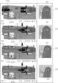
- FIGS. 5 and 6are drawings of one embodiment showing an operation in which an optical fiber connector is fixed or released by a rising and falling operation of a locking device according to a forward and backward operation of an optical fiber connector according to the present invention.
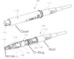
- FIGS. 7 and 8are drawings showing an embodiment of an optical fiber connector having waterproofing and a locking function according to the present invention.
- FIG. 9is a drawing showing an embodiment of the connection between an optical fiber connector and an optical adapter according to the present invention.
- Figure 10is a drawing of one embodiment showing the insertion and mounting appearance of an optical fiber connector according to the present invention.
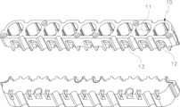
- FIG. 11is a drawing showing an embodiment of a housing according to the present invention.
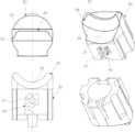
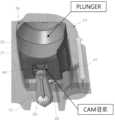
- FIG. 12is a drawing showing an embodiment of a plunger according to the present invention.
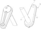
- Figure 13is a drawing showing an embodiment of a stick portion according to the present invention.
- FIG. 14 and FIG. 15are drawings of one embodiment showing the joint relationship of a housing, a plunger, and a stick portion according to the present invention.
- FIG. 16is a drawing of one embodiment showing the movement path of the plunger and the insertion projection within the heart cam according to the present invention.
- FIG. 17is a drawing of one embodiment showing the joining position of an optical fiber connector and a hook portion according to the heart cam stop position of the insertion protrusion according to the present invention.
- Insertion groove 131First diameter
- Insertion hole 310Optical adapter
- Adapter cover 321Home
- the present inventionhas the following features.
- a waterproof push-pull closure (300) having an easy locking and unlocking function of an optical fiber connector of the present inventionincludes a closure (300), an optical fiber connector (100), an optical fiber connector locking device (200), and an optical adapter (310).
- the above closure (300)can be detachably installed on an installation target where an optical cable (C) is installed, and a single optical fiber connector (100) is inserted into the closure (300) through an insertion hole (307), and then branches into a plurality of ports inside the closure (300) to be distributed to a plurality of places of use (home, etc.), and the closure (300) is configured to have a sealed structure so as to have a waterproof effect from the outside.
- this closure (300)When installing this closure (300) on an optical cable on a pole, it can be installed as a first fixing member (330) in the form of a ring so that the closure (300) can be hung on the main optical cable (C) and when installing it on a pole, it can be installed as a second fixing member (340) in the form of a band so that the closure (300) can be hung while wrapping the installation target according to the diameter of the outer circumference.
- a gasket (303)may be used between the main body (301a) and the cover (301b) constituting the closure (300) so that they can be fastened, or the parts may be installed inside the main body (301a) of the closure (300) at the factory and then manufactured by integrating them using an overmold method.
- the above optical fiber connector (100)is configured to be selectively inserted into a plurality of insertion holes (307) formed in the closure (300), so that a single optical cable (C) within the closure (300) can be branched into a plurality of lines so that it can be used for a plurality of purposes.
- This optical fiber connector (100)includes a connector body (110), a sealing member (120), a fitting groove (130), a step portion (140), and a dust cover portion (116).
- the above connector body (110)is installed outside of a device such as the closure (300) (branching device) described above, and is inserted into the insertion hole (307) of the connector body (110) in the closure (300) and connected to an optical adapter (310) (Adaptor) inside the closure (300).
- a plug (114)is formed at one end, a ferrule (113) (Ferrule) in which an optical fiber is arranged is formed at the center, and a boot (117) (Boot) that protects the outer periphery from the middle end to the rear end is configured.
- a dust cover (116)that is detachably mounted in the longitudinal direction on one outer periphery of the optical fiber connector (100), a ring (115) is formed at one end of the dust cover (116) to be used for fixing a wire for cable installation, and the sealing member (120), the fitting groove (130), and the step (140) can be protected from the outside, and the dust cover (116) is fastened to the protrusion (118) of the optical fiber connector body (110) in a bayonet shape.
- the above sealing member (120)is a ring made of elastic rubber material, etc., and is formed with a mounting groove (121) on the outer peripheral edge of the middle of the connector body (110), and is inserted into the mounting groove (121), so that when the inner part of the insertion hole (307) and the outer peripheral edge of the sealing member (120) come into contact, it can play a waterproofing role by preventing moisture or water from entering the insertion hole (307) into which the connector body (110) is inserted.
- the above-mentioned insertion groove (130)is formed on the outer periphery between the plug (114) and the sealing member (120) of the aforementioned connector body (110), and is a groove that is hooked onto and fixed by the optical fiber connector locking device (200) formed on the inner bottom surface of the insertion hole (307).
- step portion (140)is a catch portion of the optical fiber connector locking device (200) that makes the second diameter (132) of the connector body (110) at the rear end of the fitting groove (130) relatively larger than the first diameter (131) of the connector body (110) at the front end of the fitting groove (130), thereby forming a step therebetween.
- the above-mentioned insertion groove (130) for this purposeis composed of a first projection (134) that is sunken vertically from the first diameter (131), and an inclined surface (133) that forms a diagonal shape from the first projection (134) to the second diameter (132) and whose diameter gradually increases, thereby forming a triangular insertion groove (130).
- the plunger (30, Plunger) formed in the optical fiber connector locking device (200)will be described in detail when the optical fiber connector locking device (200) is described below, and its upper surface is formed in a shape corresponding to the insertion groove (130) so that it is inserted correspondingly into the insertion groove (130), thereby preventing the connector body (110) from being detached from the insertion hole (307).
- the plunger (30) formed on the upper surface of the optical fiber connector locking device (200)has a structure that rises when pressed once and descends when pressed again, repeating the rising and falling. If the plunger of the optical fiber connector locking device (200) has a structure that rises and falls, the internal configuration for this operation can be changed in various ways according to the user's embodiment, and is therefore not limited to a certain configuration.
- connection structure with the closure (300) through the optical fiber connector (100) with the configuration as aboveis explained.
- the optical fiber connector (100)is advanced while coming into contact with the upper surface of the plunger (30), so that the second diameter (132) portion is positioned correspondingly to the plunger (30) and the plunger (30) is pressed and raised, and then the optical fiber connector (100) is moved backward so that the plunger (30) is correspondingly inserted into the insertion groove (130), so that the optical fiber connector (100) is maintained in a fixed position within the insertion hole (307).
- the optical fiber connector (100)when the optical fiber connector (100) is inserted into the insertion hole (307), the optical fiber connector (100) is inserted further forward so that the second diameter (132) portion presses the plunger (30) again, thereby lowering the plunger (30) to the initial position, so that the first and second diameters (131, 132) portions of the optical fiber connector (100) do not get caught on the plunger (30), thereby moving the optical fiber connector (100) backward so that the optical fiber connector (100) can be separated from the insertion hole (307).
- the optical fiber connector locking device (200)is installed corresponding to the bottom surface of the insertion hole (307) inside the aforementioned closure (300) and is installed so as to be able to be raised and lowered up and down by the forward and backward movement of the optical fiber connector (100) to be mounted, thereby being a locking means that allows the optical fiber connector (100) to be mounted and removed from the closure (300).
- An optical fiber connector locking device (200) for this purposeincludes a housing (10), an elastic member (20), a plunger (30, Plunger), a Heart-Cam (40, Heart-Cam), and a stick portion (50, Stick).
- the above housing (10)has a rectangular tubular shape with a long length in one direction, and is divided into a plurality of spaces so that a plurality of vertical installation spaces (11) are formed in the longitudinal direction.
- the vertical installation spaces (11)form an opening hole (12) that is open at the front so as to communicate with the interior, and an opening hole (13) is formed by perforation at the front lower end.
- the above elastic member (20)is a spring that is installed upright in each of the aforementioned vertical installation spaces (11).
- the above plunger (30)is installed upright in each of the aforementioned vertical installation spaces (11), and has a hole (H) formed in the center so that an elastic member (20) can be inserted and mounted in the center of the inside.
- a part of the elastic member (20)is inserted inside, and is installed upright in each of the above vertical installation spaces (11), and has a structure that can be raised and lowered by the elastic member (20).
- the plunger (30)has a structure that repeats the raising and lowering by raising when pressed once and lowering when pressed again.
- the plunger (30)has a heart cam (40) formed in a heart shape on one side (front) corresponding to the opening hole (12).
- This heart cam (40)has a sunken shape with the left side in a 'C' shape and the right side in an inverted 'C' shape, so that the overall shape takes on a heart-shaped shape, and the insertion projection (53) of the stick portion (50) to be described later is inserted into the sunken portion (41) of this heart-shaped heart cam (40) and then rotates clockwise along the sunken portion (41).
- this plunger (30)further forms a seating groove (31) and a catch (34) on the upper surface.
- the above-mentioned fixing groove (31)is formed in a semicircular shape in the width direction of the housing (10) (in the forward and backward direction of the optical fiber connector (100) (in the insertion direction of the optical fiber connector (100))) on the upper surface of the plunger (30), so that the lower side of the outer periphery of the optical fiber connector (100) having a circular cross-section is brought into contact with the fixing groove (31) so that it can be inserted horizontally in the forward and backward direction orthogonal to the longitudinal direction of the housing (10).
- the above-mentioned catch (34)is formed in a semicircular shape by protruding in the left and right directions perpendicular to the forward and backward direction of the optical fiber connector (100) from the stop of the aforementioned anchoring groove (31), so that an insertion surface (32) that is inclined diagonally is formed on the front side, and an anchoring protrusion (33) that is perpendicular to the anchoring groove (31) is formed on the rear side.
- the above stick portion (50)is formed with a fitting projection (53) that is fitted into the front opening (13) of the housing (10) described above at one end and fitted into the heart cam (40) at the other end, so that each time the plunger (30) is pressed, the fitting projection (53) moves clockwise along the recessed portion (41) of the heart cam (40) and is alternately fixed to the upper point (A) and the lower point (B) of the heart cam (40), thereby performing a repetitive operation, thereby fixing the rising and falling positions of the plunger (30).
- the stick part (50) for this purposeincludes a horizontal stick (53), a vertical stick (52), and a fitting projection (53).
- the above horizontal stick (53)is fitted into the opening (13) and has a structure that allows it to rotate left and right on the bottom surface within the vertical installation space (11). However, since it can be removed to the outside when fitted horizontally, it is fitted so that it can be fitted diagonally within the vertical installation space (11).
- the above vertical stick (52)is extended upright from one end of the horizontal stick (53) toward the opening hole (12) so as to have an 'L'-shaped cross-section together with the horizontal stick (53).
- the above-described insertion projection (53)is a projection that corresponds to the heart cam (40) at the end of the above-described vertical stick (52) and is fitted so that it can move along the sunken portion (41) of the heart cam (40).
- the shape of the optical fiber connector (100) that is horizontally moved forward and backward while making corresponding contact with the upper surface of the plunger (30) described above in the present inventiongenerally has a circular cross-sectional structure, and forms an insertion groove (130) formed on the outer periphery so that the engaging portion (34) of the plunger (30) described above corresponds and is inserted, and based on the insertion groove (130), the outer periphery diameter (second diameter (132)) of the rear end of the insertion groove (130) is made larger than the outer periphery diameter (first diameter (131)) of the front end, which becomes the insertion head portion.
- the optical fiber connector (100)is horizontally mounted in a closure (300) that forms a separate insertion hole (307) into which the optical fiber connector (100) is inserted, and the optical fiber connector locking device (200) of the present invention is installed and used at a position corresponding to the outer periphery of the optical fiber connector (100) in the closure (300) into which the optical fiber connector (100) is inserted.
- the closure (300)can be a target of various devices without being limited to types and fields, and it is natural that other devices can be used as a substitute for the closure.
- the optical fiber connector (100)When the optical fiber connector (100) is advanced while the aforementioned insertion projection (53) is positioned at the upper point (A) and the plunger (30) is pressed, the optical fiber connector (100) comes into contact with the upper surface of the plunger (30), and the first diameter (131) portion of the optical fiber connector (100) passes horizontally over the upper surface of the plunger (30), and then the second diameter (132) portion comes to the position of the plunger (30), and the plunger (30) is pressed as this second diameter (132) portion corresponds to the plunger (30).
- the insertion projection (53)is rotated in an inverted C ( ⁇ ) shape and moves to the lower point (B) located at the center of the lower side of the heart cam (40), and as a result, the plunger (30) is raised by the return force of the compressed elastic member (20), so that the engaging portion (34) is positioned higher than the upper surface of the housing (10).
- the optical fiber connector (100)when the optical fiber connector (100) is to be removed, the optical fiber connector (100) is advanced so that the second diameter (132) portion is positioned at the engaging portion (34), and the second diameter (132) portion presses the plunger (30) again, and as a result, the insertion projection (53) moves clockwise in a C shape and moves to the upper point (A) located at the center of the upper side of the heart cam (40), and as a result, the elastic member (20) is compressed again and the plunger (30) is lowered.
- the engaging portion (34)is positioned at the same horizontal line as the upper surface of the housing (10) or at a lower height, so that the optical fiber connector (100) can be completely detached from the upper surface of the plunger (30) by moving the optical fiber connector (100) backward so that it can be separated. (Case 2, when the optical fiber connector (100) is unmounted)
- the above optical adapter (310)is installed at the rear end of each insertion hole (307) in the aforementioned closure (300) and is configured to be connected to each optical fiber connector (100).
- An optical adapter (310) for this purposeincludes an adapter (311), an adapter cover (320), a connecting pin (313), and an elastic body (314).
- the above adapter (311)is installed horizontally in the installation groove formed at the rear end of the insertion hole (307), and the extension portions (312) protruding on both sides are installed so that they are positioned upward and downward, so that the front end is connected to the optical fiber connector (100).
- the above adapter cover (320)is a cover that is assembled to the upper part of the installation groove and has a groove (321) formed so that the extension part (312) is positioned correspondingly.
- the above connecting pin (313)is configured such that one end is connected to the extension (312) within the home portion (321), and the other end is fixed to the adapter cover (320).
- the elastic body (314)is made of an elastic spring or the like, and is installed on the outer periphery of the connecting pin (313) within the home portion (321) to push the adapter (311) forward so that it is always positioned in a position connected to the optical fiber connector (100).
- the optical fiber connector (100)is inserted into the insertion hole (307) ((F) of FIG. 6), and the upper surface of the plunger (30) is contacted and advanced, but the elastic body (314) of the outer periphery of the optical adapter (310) connected to the optical fiber connector (100) is compressed and advanced so that the second diameter (132) part of the optical fiber connector (100) is positioned corresponding to the plunger (30) and the plunger (30) is pressed and raised ((G) of FIG.
- the optical adapter (310) and the optical fiber connector (100)are advanced backwards so that the plunger (30) is correspondingly inserted into the fitting groove (130) ((H) of FIG. 6), and the optical fiber connector (100) is In the first case, the position is maintained fixed within the insertion hole (307) ((A) of Fig. 5).
- the optical fiber connector (100)when the optical fiber connector (100) is inserted into the insertion hole (307) ((A) of FIG. 5), the optical fiber connector (100) is advanced again toward the optical adapter (310) within the insertion hole (307), but is advanced so that the elastic body (314) of the outer periphery of the optical adapter (310) connected to the optical fiber connector (100) is pressed and pushed backward ((B) of FIG. 5), so that the second diameter (132) part of the optical fiber connector (100) presses the plunger (30) again, thereby lowering the plunger (30) to the initial position ((C) of FIG.
Landscapes
- Physics & Mathematics (AREA)
- General Physics & Mathematics (AREA)
- Optics & Photonics (AREA)
- Mechanical Coupling Of Light Guides (AREA)
Abstract
Description
Translated fromKorean본 발명은 설치대상물에 탈부착이 가능한 구조를 가지면서, 밀폐형 구조로 방수효과를 가지며, 광섬유 커넥터의 삽입시 전, 후진 작동만으로도 클로져 내부에 고정 및 고정해제(록킹 및 언록킹)가 용이한 구조를 가지는 방수형 푸쉬풀 클로져에 관한 것이다.The present invention relates to a waterproof push-pull closure having a structure that can be attached or detached to an installation target, a sealed structure that has a waterproof effect, and a structure that allows easy fixation and unlocking (locking and unlocking) inside the closure simply by moving forward and backward when inserting an optical fiber connector.
광케이블 클로져는 광섬유의 융착접속부나 분기부 등을 보호하기 위한 밀폐함이다.An optical cable closure is a sealing box that protects the fusion splice or branch point of an optical fiber.
보통 전봇대 및 광케이블을 분기하기 위한 장소에 설치되는 것으로서, 광케이블 중 일부가 분기되어 내부에 장착되고, 다수의 사용처로 분기하는 역할을 하는 것이다.It is usually installed in places where utility poles and optical cables are branched out, and some of the optical cables are branched out and installed inside, and serve to branch out to multiple uses.
하지만, 이러한 기존의 클로져의 경우, 광섬유 커넥터가 클로져에 삽입장착되고, 외부로 탈거되지 않도록 하기 위해서는, 광섬유 커넥터가 끼워지는 삽입홀 주변에서 광섬유 커넥터를 클로져에 고정시키기 위한 별도의 고정수단으로 나사를 돌려 광섬유 커넥터가 장치에 고정될 수 있도록 구성한 것이 일반적이다However, in the case of these existing closures, in order to prevent the optical fiber connector from being inserted into the closure and removed externally, it is common to use a separate fixing means, such as a screw, to fix the optical fiber connector to the closure around the insertion hole into which the optical fiber connector is inserted, so that the optical fiber connector can be fixed to the device.
이러한 구조는 광섬유 커넥터를 장착 및 해제시마다 작업자에게 번거운 작업을 추가하는 것이 되는 것이고, 장비 전반의 가격 상승은 물론, 내부 구조의 복잡함을 유발하는 문제가 되었다.This structure adds a burden to the operator each time the optical fiber connector is installed or removed, and it also increases the overall cost of the equipment as well as complicates the internal structure.
이에, 이러한 별도의 고정수단이나 장치 없이도, 손쉽고 간단히 클로저 외부에서 광섬유 커넥터를 삽입장착 및 장착해제할 수 있는 장치의 개발이 절실히 요구되고 있는 실정이다.Accordingly, there is an urgent need for the development of a device that can easily and simply insert and remove an optical fiber connector from the outside of a closure without the need for a separate fixing means or device.
[선행기술문헌][Prior art literature]
[특허문헌][Patent Document]
미국공개특허공보 US2020/0218017A1(Jul,9,2020)United States Patent Publication No. US2020/0218017A1 (Jul,9,2020)
본 발명은 상기와 같은 문제점을 해결하기 위해 안출된 것으로서, 본 발명의 목적은 설치대상물에 다양한 형태로 걸거나 메달아 착탈이 가능토록 하며, 클로져 전체는 밀폐형 구조로 이루어져 방수가 용이토록 하고, 클로져에 장착되는 광섬유 커넥터는 클로져의 삽입홀에 삽입하여 전, 후진 작동만으로 클로져의 내부에서 고정 및 고정 해제가 가능한 내부구성을 가지도록 하여, 별도의 고정수단이 필요없으며 사용이 손쉽고 용이토록 한 광섬유 커넥터의 록킹 및 언록킹의 용이한 기능을 갖는 방수형 푸쉬풀 클로져를 제공하는데 있다.The present invention has been made to solve the above problems, and the purpose of the present invention is to provide a waterproof push-pull closure having an easy function of locking and unlocking an optical fiber connector, which can be hung or suspended in various forms on an installation object and attached and detached, the entire closure has a sealed structure to facilitate waterproofing, and an optical fiber connector mounted on the closure has an internal configuration in which the optical fiber connector can be fixed and unlocked inside the closure by simply moving it forward and backward by inserting it into the insertion hole of the closure, so that no separate fixing means is required and it is easy and convenient to use.
본 발명의 다른 목적 및 장점들은 하기에 설명될 것이며, 본 발명의 실시예에 의해 알게 될 것이다. 또한, 본 발명의 목적 및 장점들은 특허청구범위에 나타낸 수단 및 조합에 의해 실현될 수 있다.Other objects and advantages of the present invention will be described below and will be learned by the embodiments of the present invention. Furthermore, the objects and advantages of the present invention can be realized by the means and combinations indicated in the claims.
본 발명은 상기와 같은 문제점을 해결하기 위한 수단으로서,The present invention is a means for solving the above problems,
광케이블(C)이 설치된 설치대상물에 착탈가능하게 설치가 가능하며, 밀폐되는 구조로 구성되어, 외부로부터 방수효과를 가질 수 있도록 하는 클로져(300);A closure (300) that can be detachably installed on an installation target where an optical cable (C) is installed and has a sealed structure so that it can have a waterproof effect from the outside;
상기 클로져(300)에 형성된 다수 삽입홀(307)에 선택적으로 끼움결합되어, 클로져(300) 내에서 단일의 광케이블(C)이 다수의 사용처에 사용될 수 있도록 다수라인으로 분기되는 광섬유 커넥터(100);An optical fiber connector (100) that is selectively inserted into a plurality of insertion holes (307) formed in the closure (300) and branches into a plurality of lines so that a single optical cable (C) can be used for a plurality of purposes within the closure (300);
상기 클로져(300) 내부에서 삽입홀(307) 저면에 대응설치되어, 장착되는 광섬유 커넥터(100)의 전, 후진 작동에 의해 상, 하로 승하강 작동가능하게 설치됨으로써, 광섬유 커넥터(100)를 클로져(300)에 장착 및 장착해제 할 수 있도록 하는 광섬유 커넥터 잠금장치(200);An optical fiber connector locking device (200) that is installed in response to the bottom surface of the insertion hole (307) inside the closure (300) and is installed so as to be able to move up and down by the forward and backward movement of the optical fiber connector (100) to be mounted, thereby enabling the optical fiber connector (100) to be mounted and unmounted from the closure (300);
상기 클로져(300) 내에서 삽입홀(307)의 후단마다 설치되어, 상기 광섬유 커넥터(100)와 각각 연결되는 광어댑터(310);An optical adapter (310) installed at the rear end of each insertion hole (307) within the closure (300) and connected to each optical fiber connector (100);
를 포함하여 이루어지는 것을 특징으로 한다.It is characterized by including:
이상에서 살펴본 바와 같이, 본 발명의 클로져는 설치대상물의 외부에 착탈가능하게 결합이 가능하며, 밀폐형 구조이기에 방수가 가능한 효과가 있다.As described above, the closure of the present invention can be detachably attached to the outside of an installation target, and has a sealed structure, thereby providing a waterproof effect.
또한, 본 발명은 클로져에 삽입장착되는 광섬유 커넥터의 경우, 별도의 장치없이도 삽입홀 내에 삽입되어지는 전, 후진 작동만으로도, 클로져의 내부에서 손쉽고 용이하게 고정 및 고정해제가 가능한 구조를 가지도록 하여, 사용이 손쉽고 용이한 효과가 있다.In addition, the present invention has a structure in which an optical fiber connector to be inserted into a closure can be easily and conveniently fixed and released inside the closure by simply inserting it into an insertion hole and moving it forward and backward without a separate device, thereby providing the effect of being easy and convenient to use.
도 1은 본 발명에 따른 클로져의 고정구조를 나타낸 첫번째 실시예의 도면.Figure 1 is a drawing of a first embodiment showing a fixing structure of a closure according to the present invention.
도 2는 본 발명에 따른 클로져의 고정구조를 나타낸 두번째 실시예의 도면.Figure 2 is a drawing of a second embodiment showing the fixing structure of a closure according to the present invention.
도 3은 본 발명에 따른 클로져 내부의 구성을 나타낸 일실시예의 도면.FIG. 3 is a drawing of one embodiment showing the internal configuration of a closure according to the present invention.
도 4는 본 발명에 따른 클로져를 나타낸 일실시예의 단면도.Figure 4 is a cross-sectional view showing an embodiment of a closure according to the present invention.
도 5 및 도 6은 본 발명에 따른 광섬유 커넥터의 전, 후진 작동에 따른 잠금장치의 승, 하강 작동으로, 광섬유 커넥터가 고정 또는 고정 해제되는 작동을 나타낸 일실시예의 도면.FIGS. 5 and 6 are drawings of one embodiment showing an operation in which an optical fiber connector is fixed or released by a rising and falling operation of a locking device according to a forward and backward operation of an optical fiber connector according to the present invention.
도 7 및 도 8은 본 발명에 따른 방수 및 걸림기능을 갖는 광섬유 커넥터를 나타낸 일실시예의 도면.FIGS. 7 and 8 are drawings showing an embodiment of an optical fiber connector having waterproofing and a locking function according to the present invention.
도 9는 본 발명에 따른 광섬유 커넥터와 광어댑터의 연결을 나타낸 일실시예의 도면.FIG. 9 is a drawing showing an embodiment of the connection between an optical fiber connector and an optical adapter according to the present invention.
도 10은 본 발명에 따른 광섬유 커넥터의 삽입장착모습을 나타낸 일실시예의 도면.Figure 10 is a drawing of one embodiment showing the insertion and mounting appearance of an optical fiber connector according to the present invention.
도 11은 본 발명에 따른 하우징을 나타낸 일실시예의 도면.FIG. 11 is a drawing showing an embodiment of a housing according to the present invention.
도 12는 본 발명에 따른 플런져를 나타낸 일실시예의 도면.FIG. 12 is a drawing showing an embodiment of a plunger according to the present invention.
도 13은 본 발명에 따른 스틱부를 나타낸 일실시예의 도면.Figure 13 is a drawing showing an embodiment of a stick portion according to the present invention.
도 14 및 도 15는 본 발명에 따른 하우징, 플런져, 스틱부의 결합관계를 나타낸 일실시예의 도면.FIG. 14 and FIG. 15 are drawings of one embodiment showing the joint relationship of a housing, a plunger, and a stick portion according to the present invention.
도 16은 본 발명에 따른 플런져와 끼움돌기의 하트캠 내 이동경로를 나타낸 일실시예의 도면.FIG. 16 is a drawing of one embodiment showing the movement path of the plunger and the insertion projection within the heart cam according to the present invention.
도 17은 본 발명에 따른 끼움돌기의 하트캠 정지위치에 따른, 광섬유 커넥터와 걸침부의 결합위치를 나타낸 일실시예의 도면.FIG. 17 is a drawing of one embodiment showing the joining position of an optical fiber connector and a hook portion according to the heart cam stop position of the insertion protrusion according to the present invention.
<도면의 주요부분에 대한 부호의 표시><Indication of symbols for major parts of the drawing>
10: 하우징11: 수직설치공간10: Housing 11: Vertical installation space
12: 개구홀13: 개구공12: Open hole 13: Open hole
20: 탄성부재30: 플런져20: Elastic member 30: Plunger
31: 안착홈32: 삽입면31: Fixing groove 32: Insertion surface
33: 걸림턱 34: 걸침부33: hitch 34: hitch
40: 하트캠41: 함몰부위40: Heart Cam 41: Sunken Area
50: 스틱부51: 수평스틱50: Stick part 51: Horizontal stick
52: 수직스틱53: 끼움돌기52: Vertical stick 53: Insert stud
100: 광섬유 커넥터110: 커넥터 본체100: Fiber Optic Connector 110: Connector Body
113: 페룰부114: 플러그113: Ferrule 114: Plug
115: 고리116: 커버부115: Ring 116: Cover
117: 부트118: 돌기117: Boot 118: Bump
120: 실링부재121: 안착홈120: Sealing member 121: Fixing groove
130: 끼움홈131: 제 1직경130: Insertion groove 131: First diameter
132: 제 2직경133: 경사면132: 2nd diameter 133: Inclined surface
134: 제 1턱200: 광섬유 커넥터 잠금장치134: 1st jaw 200: Fiber optic connector lock
300: 클로져301a: 본체300:
301b: 덮개302: 고정체301b: Cover 302: Fixture
303: 가스켓304: 케이블 커버303: Gasket 304: Cable Cover
305: 안전바306: 먼지캡305: Safety bar 306: Dust cap
307: 삽입홀310: 광어댑터307: Insertion hole 310: Optical adapter
311: 어댑터312: 연장부311: Adapter 312: Extension
313: 연결핀314: 탄성체313: connecting pin 314: elastic body
320: 어댑터 커버321: 홈부320: Adapter cover 321: Home
A: 상단점B: 하단점A: Top point B: Bottom point
H: 홀H: hole
본 발명의 여러 실시예들을 상세히 설명하기 전에, 다음의 상세한 설명에 기재되거나 도면에 도시된 구성요소들의 구성 및 배열들의 상세로 그 응용이 제한되는 것이 아니라는 것을 알 수 있을 것이다. 본 발명은 다른 실시예들로 구현되고 실시될 수 있고 다양한 방법으로 수행될 수 있다. 또, 장치 또는 요소 방향(예를 들어 "전(front)", "후(back)", "위(up)", "아래(down)", "상(top)", "하(bottom)", "좌(left)", "우(right)", "횡(lateral)")등과 같은 용어들에 관하여 본원에 사용된 표현 및 술어는 단지 본 발명의 설명을 단순화하기 위해 사용되고, 관련된 장치 또는 요소가 단순히 특정 방향을 가져야 함을 나타내거나 의미하지 않는다는 것을 알 수 있을 것이다. 또한, "제 1(first)", "제 2(second)"와 같은 용어는 설명을 위해 본원 및 첨부 청구항들에 사용되고 상대적인 중요성 또는 취지를 나타내거나 의미하는 것으로 의도되지 않는다.Before explaining the various embodiments of the present invention in detail, it is to be understood that the applications thereof are not limited to the details of construction and arrangement of the components set forth in the following detailed description or illustrated in the drawings. The present invention is capable of other embodiments, of being practiced, and of being carried out in various ways. It is also to be understood that expressions and terminology used herein with respect to device or element orientation (e.g., “front,” “back,” “up,” “down,” “top,” “bottom,” “left,” “right,” “lateral,” and the like) are used merely to simplify the description of the present invention and do not necessarily indicate or imply that the relevant device or element must have a particular orientation. Furthermore, terms such as “first,” “second,” and the like are used herein and in the appended claims for descriptive purposes and are not intended to indicate or imply relative importance or intent.
본 발명은 상기의 목적을 달성하기 위해 아래의 특징을 갖는다.To achieve the above object, the present invention has the following features.
이하 첨부된 도면을 참조로 본 발명의 바람직한 실시예를 상세히 설명하도록 한다. 이에 앞서, 본 명세서 및 청구범위에 사용된 용어나 단어는 통상적이거나 사전적인 의미로 한정해서 해석되어서는 아니되며, 발명자는 그 자신의 발명을 가장 최선의 방법으로 설명하기 위해 용어의 개념을 적절하게 정의할 수 있다는 원칙에 입각하여 본 발명의 기술적 사상에 부합하는 의미와 개념으로 해석되어야만 한다.Hereinafter, a preferred embodiment of the present invention will be described in detail with reference to the attached drawings. Prior to this, the terms or words used in this specification and claims should not be interpreted as limited to their usual or dictionary meanings, and should be interpreted as meanings and concepts that conform to the technical idea of the present invention based on the principle that the inventor can appropriately define the concept of the term in order to explain his or her own invention in the best way.
따라서, 본 명세서에 기재된 실시예와 도면에 도시된 구성은 본 발명의 가장 바람직한 일 실시예에 불과할 뿐이고 본 발명의 기술적 사상을 모두 대변하는 것은 아니므로, 본 출원시점에 있어서 이들을 대체할 수 있는 다양한 균등물과 변형 예들이 있을 수 있음을 이해하여야 한다.Therefore, the embodiments described in this specification and the configurations illustrated in the drawings are only the most preferred embodiments of the present invention and do not represent all of the technical ideas of the present invention. Therefore, it should be understood that there may be various equivalents and modified examples that can replace them at the time of filing this application.
이하, 도 1 내지 도 17을 참조하여 본 발명의 바람직한 실시예에 따른 광섬유 커넥터의 록킹 및 언록킹의 용이한 기능을 갖는 방수형 푸쉬풀 클로져(300)를 상세히 설명하도록 한다.Hereinafter, with reference to FIGS. 1 to 17, a waterproof push-pull closure (300) having an easy locking and unlocking function of an optical fiber connector according to a preferred embodiment of the present invention will be described in detail.
이를 위한 본 발명의 광섬유 커넥터의 록킹 및 언록킹의 용이한 기능을 갖는 방수형 푸쉬풀 클로져(300)는 클로져(300), 광섬유 커넥터(100), 광섬유 커넥터 잠금장치(200), 광어댑터(310)를 포함한다.For this purpose, a waterproof push-pull closure (300) having an easy locking and unlocking function of an optical fiber connector of the present invention includes a closure (300), an optical fiber connector (100), an optical fiber connector locking device (200), and an optical adapter (310).
상기 클로져(300)는 광케이블(C)이 설치된 설치대상물에 착탈가능하게 설치가 가능한 것이며, 단일의 광섬유 커넥터(100)가 삽입홀(307)을 통해 클로져(300)에 삽입장착된 후, 클로져(300) 내부에서 다수개의 포트로 분기하여 다수의 사용처(가정 등)에 분배할 수 있도록 하는 것이며, 클로져(300) 전체가 밀폐되는 구조로 구성되어, 외부로부터 방수효과를 가질 수 있도록 하는 것이다.The above closure (300) can be detachably installed on an installation target where an optical cable (C) is installed, and a single optical fiber connector (100) is inserted into the closure (300) through an insertion hole (307), and then branches into a plurality of ports inside the closure (300) to be distributed to a plurality of places of use (home, etc.), and the closure (300) is configured to have a sealed structure so as to have a waterproof effect from the outside.
이러한 클로져(300)를 전주상의 광케이블에 설치시에는 메인 광케이블(C)에 클로져(300)를 걸어서 설치할 수 있도록 하는 고리형태의 제 1고정부(330)로 설치할 수 있으며, 전주에 설치시에는 외주연 직경에 맞춰 설치대상물을 감싸면서 클로져(300)를 메달수 있도록 하는 밴드 형태의 제 2고정부(340)로 설치할 수 있다.When installing this closure (300) on an optical cable on a pole, it can be installed as a first fixing member (330) in the form of a ring so that the closure (300) can be hung on the main optical cable (C) and when installing it on a pole, it can be installed as a second fixing member (340) in the form of a band so that the closure (300) can be hung while wrapping the installation target according to the diameter of the outer circumference.
또한, 이를 위한 클로져(300)의 경우, 상기 클로져(300)의 밀폐를 위하여, 클로져(300)를 구성하는 본체(301a)와 덮개(301b) 사이에 가스켓(303)을 사용하여 체결가능하게 이루어지도록 하거나, 상기 클로져(300)의 본체(301a)에 부품을 공장에서 내부에 설치한 후, 오버몰드(Overmold)방법으로 일체화하여 제작할 수 있다.In addition, in the case of the closure (300) for this, in order to seal the closure (300), a gasket (303) may be used between the main body (301a) and the cover (301b) constituting the closure (300) so that they can be fastened, or the parts may be installed inside the main body (301a) of the closure (300) at the factory and then manufactured by integrating them using an overmold method.
상기 광섬유 커넥터(100)는 클로져(300)에 형성된 다수 삽입홀(307)에 선택적으로 끼움결합되어, 클로져(300) 내에서 단일의 광케이블(C)이 다수의 사용처에 사용될 수 있도록 다수라인으로 분기되는 구성이다.The above optical fiber connector (100) is configured to be selectively inserted into a plurality of insertion holes (307) formed in the closure (300), so that a single optical cable (C) within the closure (300) can be branched into a plurality of lines so that it can be used for a plurality of purposes.
이러한 광섬유 커넥터(100)는 커넥터 본체(110), 실링부재(120), 끼움홈(130), 단차부(140), 먼지덮개부(116)를 포함한다.This optical fiber connector (100) includes a connector body (110), a sealing member (120), a fitting groove (130), a step portion (140), and a dust cover portion (116).
상기 커넥터 본체(110)는 전술된 클로져(300)(Closure, 분기 디바이스) 등의 장치 외부에서 설치되는 것으로, 이러한 클로져(300)에서 커넥터 본체(110)의 삽입홀(307)에 끼워져, 클로져(300) 내부의 광어댑터(310)(Adaptor)에 연결되는 것이다. 이를 위해 일단에는 플러그(114)가 형성되고, 일단 중심에는 광섬유가 배치된 페룰부(113)(Ferrule)가 형성되어 있으며, 중단부 이후 후단까지는 외주연을 보호하는 부트(117)(Boot)로 구성된다.The above connector body (110) is installed outside of a device such as the closure (300) (branching device) described above, and is inserted into the insertion hole (307) of the connector body (110) in the closure (300) and connected to an optical adapter (310) (Adaptor) inside the closure (300). To this end, a plug (114) is formed at one end, a ferrule (113) (Ferrule) in which an optical fiber is arranged is formed at the center, and a boot (117) (Boot) that protects the outer periphery from the middle end to the rear end is configured.
또한, 이러한 광섬유 커넥터(100)의 일단 외주연에는, 착탈가능한 형태로 길이방향으로 장착되는 먼지덮개부(116)를 더 구비함으로써, 먼지덮개부(116)의 일측 끝단에는 고리(115)를 형성하여 케이블 포설용 와이어 고정용으로 사용되며, 실링부재(120), 끼움홈(130), 단차부(140)가 외부로부터 보호될 수 있도록 할 수 있고, 이러한 먼지덮개부(116)는 광섬유 커넥터 본체(110)의 돌기(118)에 총검(Bayonet)형태로 체결되도록 한다.In addition, by further providing a dust cover (116) that is detachably mounted in the longitudinal direction on one outer periphery of the optical fiber connector (100), a ring (115) is formed at one end of the dust cover (116) to be used for fixing a wire for cable installation, and the sealing member (120), the fitting groove (130), and the step (140) can be protected from the outside, and the dust cover (116) is fastened to the protrusion (118) of the optical fiber connector body (110) in a bayonet shape.
상기 실링부재(120)는 탄성력을 가지는 고무재질 등의 링으로서, 커넥터 본체(110)의 중단 외주연에 안착홈(121)을 형성한 후 이러한 안착홈(121)에 끼워짐으로써, 상기 삽입홀(307) 내부와 실링부재(120)의 외주연이 접촉되면서, 커넥터 본체(110)가 삽입되는 삽입홀(307) 내로 물기나 수분이 유입되지 않도록 하는 방수역할을 할 수 있도록 하는 것이다.The above sealing member (120) is a ring made of elastic rubber material, etc., and is formed with a mounting groove (121) on the outer peripheral edge of the middle of the connector body (110), and is inserted into the mounting groove (121), so that when the inner part of the insertion hole (307) and the outer peripheral edge of the sealing member (120) come into contact, it can play a waterproofing role by preventing moisture or water from entering the insertion hole (307) into which the connector body (110) is inserted.
상기 끼움홈(130)은 전술된 커넥터 본체(110)에서 플러그(114)와 실링부재(120) 사이의 외주연에 형성되어, 삽입홀(307) 내부 저면에 형성된 광섬유 커넥터 잠금장치(200)에 걸려 대응장착되며 고정되도록 하는 홈이며,The above-mentioned insertion groove (130) is formed on the outer periphery between the plug (114) and the sealing member (120) of the aforementioned connector body (110), and is a groove that is hooked onto and fixed by the optical fiber connector locking device (200) formed on the inner bottom surface of the insertion hole (307).
상기 단차부(140)는 이러한 끼움홈(130) 전단측 커넥터 본체(110)의 제 1직경(131)보다, 끼움홈(130) 후단측 커넥터 본체(110)의 제 2직경(132)이 상대적으로 더 크도록 하여, 상호간 단차를 이루도록 하는, 상기 광섬유 커넥터 잠금장치(200)의 걸림부위이다.The above-mentioned step portion (140) is a catch portion of the optical fiber connector locking device (200) that makes the second diameter (132) of the connector body (110) at the rear end of the fitting groove (130) relatively larger than the first diameter (131) of the connector body (110) at the front end of the fitting groove (130), thereby forming a step therebetween.
이를 위한 상기 끼움홈(130)은 제 1직경(131)에서 수직으로 함몰되는 제 1턱(134)과, 상기 제 1턱(134)에서 제 2직경(132)까지 사선형태를 이루며, 직경이 점차 증가되는 경사면(133)으로 구성되어, 삼각형 형태의 끼움홈(130)을 이루는 것이다. 물론, 상기 광섬유 커넥터 잠금장치(200)에 형성된 플런져(30, Plunger)는 하기에서 광섬유 커넥터 잠금장치(200)를 설명시 상세하게 기재할 것이며, 상면이 끼움홈(130)에 대응되는 형상으로 형성되어, 상기 끼움홈(130)에 대응삽입됨으로써, 상기 삽입홀(307) 내에서 커넥터 본체(110)의 이탈이 방지되도록 하는 것이다.The above-mentioned insertion groove (130) for this purpose is composed of a first projection (134) that is sunken vertically from the first diameter (131), and an inclined surface (133) that forms a diagonal shape from the first projection (134) to the second diameter (132) and whose diameter gradually increases, thereby forming a triangular insertion groove (130). Of course, the plunger (30, Plunger) formed in the optical fiber connector locking device (200) will be described in detail when the optical fiber connector locking device (200) is described below, and its upper surface is formed in a shape corresponding to the insertion groove (130) so that it is inserted correspondingly into the insertion groove (130), thereby preventing the connector body (110) from being detached from the insertion hole (307).
우선적으로 상기 플런져(30) 내부에 위치된 광섬유 커넥터 잠금장치(200)의 경우, 광섬유 커넥터 잠금장치(200)의 상면에 형성된 플런져(30)는 한번누르면 상승하고, 다시 누르면 하강하는 승, 하강을 반복하는 구조를 가지는데, 이러한 광섬유 커넥터 잠금장치(200)의 플러져가 승, 하강되는 구조라면, 이러한 작동을 위한 내부의 구성은 사용자의 실시예에 따라 다양하게 변경이 가능할 것이기에, 일부구성으로 한정하지 않는다.First, in the case of the optical fiber connector locking device (200) located inside the plunger (30), the plunger (30) formed on the upper surface of the optical fiber connector locking device (200) has a structure that rises when pressed once and descends when pressed again, repeating the rising and falling. If the plunger of the optical fiber connector locking device (200) has a structure that rises and falls, the internal configuration for this operation can be changed in various ways according to the user's embodiment, and is therefore not limited to a certain configuration.
상기와 같은 구성을 통한 광섬유 커넥터(100)을 통한 클로져(300)와의 결합구조를 설명하면,The connection structure with the closure (300) through the optical fiber connector (100) with the configuration as above is explained.
최초에 플런져(30)가 눌려져 있는 상태에서, 광섬유 커넥터(100)를 플런져(30) 상면에 접촉되면서 전진시켜, 제 2직경(132)부분이 플런져(30)에 대응위치되면서 플런져(30)를 눌러 상승되도록 한 후, 광섬유 커넥터(100)를 후진시켜 끼움홈(130)에 플런져(30)가 대응삽입되면서, 광섬유 커넥터(100)가 삽입홀(307) 내에서 위치고정된 상태로 유지되도록 하는 제 1경우,In the first case, when the plunger (30) is initially pressed, the optical fiber connector (100) is advanced while coming into contact with the upper surface of the plunger (30), so that the second diameter (132) portion is positioned correspondingly to the plunger (30) and the plunger (30) is pressed and raised, and then the optical fiber connector (100) is moved backward so that the plunger (30) is correspondingly inserted into the insertion groove (130), so that the optical fiber connector (100) is maintained in a fixed position within the insertion hole (307).
상기 제 1경우를 통해 광섬유 커넥터(100)가 삽입홀(307)에 삽입되어 있는 상태에서, 광섬유 커넥터(100)를 더 전진삽입시켜 제 2직경(132)부분이 플런져(30)를 다시 누르도록 하여 플런져(30)를 최초위치로 하강시킴으로써, 광섬유 커넥터(100)의 제 1, 2직경(131, 132)부분이 플런져(30)에 걸리지 않도록 하여, 광섬유 커넥터(100)를 후진시켜 광섬유 커넥터(100)가 삽입홀(307)에서 분리될 수 있도록 하는 제 2경우로 작동되는 것이다.In the first case above, when the optical fiber connector (100) is inserted into the insertion hole (307), the optical fiber connector (100) is inserted further forward so that the second diameter (132) portion presses the plunger (30) again, thereby lowering the plunger (30) to the initial position, so that the first and second diameters (131, 132) portions of the optical fiber connector (100) do not get caught on the plunger (30), thereby moving the optical fiber connector (100) backward so that the optical fiber connector (100) can be separated from the insertion hole (307).
광섬유 커넥터 잠금장치(200)는 전술된 클로져(300) 내부에서 삽입홀(307) 저면에 대응설치되어, 장착되는 상기 광섬유 커넥터(100)의 전, 후진 작동에 의해 상, 하로 승하강 작동가능하게 설치됨으로써, 광섬유 커넥터(100)를 클로져(300)에 장착 및 장착해제 할 수 있도록 하는 잠금수단이다.The optical fiber connector locking device (200) is installed corresponding to the bottom surface of the insertion hole (307) inside the aforementioned closure (300) and is installed so as to be able to be raised and lowered up and down by the forward and backward movement of the optical fiber connector (100) to be mounted, thereby being a locking means that allows the optical fiber connector (100) to be mounted and removed from the closure (300).
이를 위한 광섬유 커넥터 잠금장치(200)는 하우징(10), 탄성부재(20), 플런져(30, Plunger), 하트캠(40, Heart-Cam), 스틱부(50, Stick)를 포함한다.An optical fiber connector locking device (200) for this purpose includes a housing (10), an elastic member (20), a plunger (30, Plunger), a Heart-Cam (40, Heart-Cam), and a stick portion (50, Stick).
상기 하우징(10)은 일방향으로 긴 길이를 가지는 사각관체 형상을 가지는 것으로, 길이방향을 향해 수직설치공간(11)이 다수형성되도록 다수개의 공간으로 구획되어 있고, 상기 수직설치공간(11)은 내부와 연통되도록 전방이 개구되는 개구홀(12)을 형성하고, 전방하단에는 개구공(13)이 천공형성되어 있도록 한다.The above housing (10) has a rectangular tubular shape with a long length in one direction, and is divided into a plurality of spaces so that a plurality of vertical installation spaces (11) are formed in the longitudinal direction. The vertical installation spaces (11) form an opening hole (12) that is open at the front so as to communicate with the interior, and an opening hole (13) is formed by perforation at the front lower end.
상기 탄성부재(20)는 전술된 수직설치공간(11) 각각마다 직립설치되는 스프링이다.The above elastic member (20) is a spring that is installed upright in each of the aforementioned vertical installation spaces (11).
상기 플런져(30)는 전술된 수직설치공간(11) 내에 각각 직립설치되는 것으로서, 중앙에는 탄성부재(20)가 내부중앙에 삽입장착되도록 홀(H)이 형성되어 있으며, 이렇게 탄성부재(20) 일부분이 내부에 삽입되는 상태로, 상기 수직설치공간(11)마다 직립설치되어, 탄성부재(20)에 의해 승, 하강이 가능한 구조를 가지는 것이다. 즉, 이러한 플런져(30)는 한번누르면 상승하고, 다시 누르면 하강하는 승, 하강을 반복하는 구조를 가지는 것이다.The above plunger (30) is installed upright in each of the aforementioned vertical installation spaces (11), and has a hole (H) formed in the center so that an elastic member (20) can be inserted and mounted in the center of the inside. In this way, a part of the elastic member (20) is inserted inside, and is installed upright in each of the above vertical installation spaces (11), and has a structure that can be raised and lowered by the elastic member (20). In other words, the plunger (30) has a structure that repeats the raising and lowering by raising when pressed once and lowering when pressed again.
또한, 이러한 플런져(30)는 상기 개구홀(12)에 대응위치되는 일면(전면)에 하트형태로 함몰형성되는 하트캠(40)을 형성하고 있다.In addition, the plunger (30) has a heart cam (40) formed in a heart shape on one side (front) corresponding to the opening hole (12).
이러한 하트캠(40)은 함몰형상이 왼쪽은 'C' 형태로 함몰되고, 오른쪽은 역'C'자 형태로 함몰되어, 전체 형태가 하트 형상과 같은 형태를 취하도록 하여, 후술될 스틱부(50)의 끼움돌기(53)가 이러한 하트형태의 하트캠(40)의 함몰부위(41)에 끼워진 후, 함몰부위(41)를 따라 시계방향으로 회전이 되는 형태를 가지도록 하는 것이다.This heart cam (40) has a sunken shape with the left side in a 'C' shape and the right side in an inverted 'C' shape, so that the overall shape takes on a heart-shaped shape, and the insertion projection (53) of the stick portion (50) to be described later is inserted into the sunken portion (41) of this heart-shaped heart cam (40) and then rotates clockwise along the sunken portion (41).
더불어, 이러한 플런져(30)는 상면에 안착홈(31)과 걸침부(34)를 더 형성한다.In addition, this plunger (30) further forms a seating groove (31) and a catch (34) on the upper surface.
상기 안착홈(31)은 플런져(30)의 상면에서 하우징(10)의 폭방향(광섬유 커넥터(100)의 전, 후진 방향(광섬유 커넥터(100)의 삽입방향))반원의 형태로 함몰형성되어, 원형단면을 가지는 광섬유 커넥터(100)의 외주연 하부측이 이러한 안착홈(31)에 대응접촉되면서, 하우징(10)의 길이방향과 직교되는 전, 후진 방향을 향해 수평으로 끼워질 수 있도록 하는 것이다.The above-mentioned fixing groove (31) is formed in a semicircular shape in the width direction of the housing (10) (in the forward and backward direction of the optical fiber connector (100) (in the insertion direction of the optical fiber connector (100))) on the upper surface of the plunger (30), so that the lower side of the outer periphery of the optical fiber connector (100) having a circular cross-section is brought into contact with the fixing groove (31) so that it can be inserted horizontally in the forward and backward direction orthogonal to the longitudinal direction of the housing (10).
상기 걸침부(34)는 전술된 안착홈(31)의 중단에서 광섬유 커넥터(100)의 전, 후진 방향과 직교되는 좌, 우 방향을 향해 반원의 형태로 돌출형성되는 것으로, 전면에는 사선으로 경사진 삽입면(32)을 형성하고, 후면은 안착홈(31)과 직각을 이루는 걸림턱(33)이 형성되어 있도록 한다.The above-mentioned catch (34) is formed in a semicircular shape by protruding in the left and right directions perpendicular to the forward and backward direction of the optical fiber connector (100) from the stop of the aforementioned anchoring groove (31), so that an insertion surface (32) that is inclined diagonally is formed on the front side, and an anchoring protrusion (33) that is perpendicular to the anchoring groove (31) is formed on the rear side.
상기 스틱부(50)는 일단이 전술된 하우징(10)의 전면측 개구공(13)에 끼워지고, 타단에는 하트캠(40)에 끼워지는 끼움돌기(53)를 형성하여, 상기 플런져(30)가 눌려질때마다, 상기 끼움돌기(53)가 하트캠(40)의 함몰부위(41)를 따라 시계방향으로 이동되면서 하트캠(40)의 상단점(A)과 하단점(B)에 교번으로 고정되는 반복작동을 함으로써, 플런져(30)의 승강위치 및 하강위치가 고정되도록 하는 용도로 사용된다.The above stick portion (50) is formed with a fitting projection (53) that is fitted into the front opening (13) of the housing (10) described above at one end and fitted into the heart cam (40) at the other end, so that each time the plunger (30) is pressed, the fitting projection (53) moves clockwise along the recessed portion (41) of the heart cam (40) and is alternately fixed to the upper point (A) and the lower point (B) of the heart cam (40), thereby performing a repetitive operation, thereby fixing the rising and falling positions of the plunger (30).
이를 위한 스틱부(50)는 수평스틱(53), 수직스틱(52), 끼움돌기(53)를 포함한다.The stick part (50) for this purpose includes a horizontal stick (53), a vertical stick (52), and a fitting projection (53).
상기 수평스틱(53)은 개구공(13)에 끼워져 수직설치공간(11) 내 저면에서 좌, 우로 회동이 가능한 구조를 가지되, 수평으로 끼워질 경우 외부로 탈거될 수 있기에, 수직설치공간(11) 내에서 사선형태로 끼워질 수 있도록 한다. 상기 수직스틱(52)은 수평스틱(53)의 일단에서 개구홀(12)측으로 직립연장되어, 수평스틱(53)과 함께 'ㄴ'자 형태의 단면을 가지도록 하는 것이며, 상기 끼움돌기(53)는 전술된 수직스틱(52) 끝단에서 하트캠(40)에 대응되며 끼워져, 하트캠(40)의 함몰부위(41)를 따라 이동될 수 있도록 하는 돌기이다.The above horizontal stick (53) is fitted into the opening (13) and has a structure that allows it to rotate left and right on the bottom surface within the vertical installation space (11). However, since it can be removed to the outside when fitted horizontally, it is fitted so that it can be fitted diagonally within the vertical installation space (11). The above vertical stick (52) is extended upright from one end of the horizontal stick (53) toward the opening hole (12) so as to have an 'L'-shaped cross-section together with the horizontal stick (53). The above-described insertion projection (53) is a projection that corresponds to the heart cam (40) at the end of the above-described vertical stick (52) and is fitted so that it can move along the sunken portion (41) of the heart cam (40).
우선적으로, 본 발명에서 전술된 플런져(30)의 상면에 대응접촉되어 수평으로 전, 후진되는 상기 광섬유 커넥터(100)의 형상은, 일반적으로 원형의 단면 구조를 가지며, 전술된 플런져(30)의 걸침부(34)가 대응되며 끼워지도록 외주연에 형성되는 끼움홈(130)을 형성하고 있고, 상기 끼움홈(130)을 기준으로, 삽입 머리부분이 되는 전단측의 외주연 직경(제 1직경(131))보다, 끼움홈(130)의 후단측의 외주연 직경(제 2직경(132))이 더 크도록 하는 것이다.First, the shape of the optical fiber connector (100) that is horizontally moved forward and backward while making corresponding contact with the upper surface of the plunger (30) described above in the present invention generally has a circular cross-sectional structure, and forms an insertion groove (130) formed on the outer periphery so that the engaging portion (34) of the plunger (30) described above corresponds and is inserted, and based on the insertion groove (130), the outer periphery diameter (second diameter (132)) of the rear end of the insertion groove (130) is made larger than the outer periphery diameter (first diameter (131)) of the front end, which becomes the insertion head portion.
또한, 이러한 광섬유 커넥터(100)는 광섬유 커넥터(100)가 삽입되어지는 별도의 삽입홀(307)을 형성하는 있는 클로져(300)에 수평으로 대응장착되는 것이고, 광섬유 커넥터(100)가 삽입되어지는 이러한 클로져(300)내 광섬유 커넥터(100)의 외주연과 대응되는 위치에, 본 발명의 광섬유 커넥터 잠금장치(200)가 설치되어 사용되는 것이다. 이렇듯 광섬유 커넥터(100)의 외주연이 이러한 본 발명의 광섬유 커넥터 잠금장치(200) 중 플런져(30)와 직교되는 형태로 삽입되는 구조를 가지는 것이라면, 상기 클로져(300)는 종류 및 분야에 국한없이 다양한 장치가 그 대상이 될 수 있고, 클로져 외에 다른 장치가 대체되어 사용될 수도 있음은 당연하다.In addition, the optical fiber connector (100) is horizontally mounted in a closure (300) that forms a separate insertion hole (307) into which the optical fiber connector (100) is inserted, and the optical fiber connector locking device (200) of the present invention is installed and used at a position corresponding to the outer periphery of the optical fiber connector (100) in the closure (300) into which the optical fiber connector (100) is inserted. If the outer periphery of the optical fiber connector (100) is inserted in a form orthogonal to the plunger (30) of the optical fiber connector locking device (200) of the present invention, the closure (300) can be a target of various devices without being limited to types and fields, and it is natural that other devices can be used as a substitute for the closure.
이에, 이러한 광섬유 커넥터 잠금장치(200)를 기준으로 광섬유 커넥터(100)와 전, 후진 작동을 통해 삽입홀(307) 내에서의 고정 및 고정 해제의 작동(상기의 제 1, 2경우)을 설명하면 하기와 같다.Accordingly, the operation of fixing and releasing the fixation within the insertion hole (307) through forward and backward operation with the optical fiber connector (100) based on this optical fiber connector locking device (200) (cases 1 and 2 above) is explained as follows.
상기 광섬유 커넥터(100)는 전술된 끼움돌기(53)가 상단점(A)에 위치되어 플런져(30)가 눌려져 있는 상태에서, 광섬유 커넥터(100)를 플런져(30) 상면에 접촉되면서 전진시키게 되면, 광섬유 커넥터(100)의 제 1직경(131)부분은 그대로 플런져(30)의 상면에서 수평으로 지나치게 된 후, 제 2직경(132)부분이 플런져(30)의 위치에 오게되면, 이러한 제 2직경(132)부분이 플런져(30)에 대응되어 플런져(30)가 눌리게 된다.When the optical fiber connector (100) is advanced while the aforementioned insertion projection (53) is positioned at the upper point (A) and the plunger (30) is pressed, the optical fiber connector (100) comes into contact with the upper surface of the plunger (30), and the first diameter (131) portion of the optical fiber connector (100) passes horizontally over the upper surface of the plunger (30), and then the second diameter (132) portion comes to the position of the plunger (30), and the plunger (30) is pressed as this second diameter (132) portion corresponds to the plunger (30).
이러한 눌림에 의해 끼움돌기(53)가 역C자(⊃) 형태로 회전되어, 하트캠(40)의 하단측 중심에 위치되는 하단점(B)으로 이동되고, 이에, 압축되어 있는 탄성부재(20)의 복귀력에 의해 플런져(30)가 상승되면서, 걸침부(34)가 하우징(10)의 상면보다 더 높은 위치에 위치하게 된다.Due to this pressing, the insertion projection (53) is rotated in an inverted C (⊃) shape and moves to the lower point (B) located at the center of the lower side of the heart cam (40), and as a result, the plunger (30) is raised by the return force of the compressed elastic member (20), so that the engaging portion (34) is positioned higher than the upper surface of the housing (10).
이후, 광섬유 커넥터(100) 외주연의 끼움홈(130)이 이러한 걸침부(34)에 대응되며 끼워지도록, 광섬유 커넥터(100)를 끼움홈(130)까지 후진시켜, 끼움홈(130)에 걸침부(34)가 대응삽입되도록 함으로써, 광섬유 커넥터(100)가 플런져(30)에 고정된 상태로 유지되도록 한다. (제 1경우, 광섬유 커넥터(100) 장착고정시)Afterwards, the optical fiber connector (100) is moved backwards to the insertion groove (130) so that the insertion groove (130) of the outer periphery of the optical fiber connector (100) corresponds to the hooking portion (34) and is inserted, so that the hooking portion (34) is inserted into the insertion groove (130), thereby maintaining the optical fiber connector (100) fixed to the plunger (30). (First case, when the optical fiber connector (100) is mounted and fixed)
상기 제 1경우 이후에, 광섬유 커넥터(100)를 탈거하고자 하는 경우, 광섬유 커넥터(100)를 전진시켜 걸침부(34) 부분에 제 2직경(132)부분이 위치되도록 하면, 제 2직경(132)부분이 다시 플런져(30)를 누르게 되고, 이에, 끼움돌기(53)가 C자 형태로 시계방향 이동되면서, 하트캠(40)의 상단측 중심에 위치되는 상단점(A)으로 이동되고, 이로써 탄성부재(20)는 다시 압축되면서 플런져(30)가 하강하게 된다. 이렇게 플런져(30)가 하강하게 되면, 걸침부(34)가 하우징(10)의 상면과 동일수평선상을 이루거나 더 낮은 높이에 위치하게 됨에 따라, 광섬유 커넥터(100)가 플런져(30) 상면에서 완전히 이탈되도록 광섬유 커넥터(100)를 후진시켜 분리시킬 수 있게 되는 것이다. (제 2경우, 광섬유 커넥터(100) 장착고정 해제시)After the first case above, when the optical fiber connector (100) is to be removed, the optical fiber connector (100) is advanced so that the second diameter (132) portion is positioned at the engaging portion (34), and the second diameter (132) portion presses the plunger (30) again, and as a result, the insertion projection (53) moves clockwise in a C shape and moves to the upper point (A) located at the center of the upper side of the heart cam (40), and as a result, the elastic member (20) is compressed again and the plunger (30) is lowered. When the plunger (30) is lowered in this way, the engaging portion (34) is positioned at the same horizontal line as the upper surface of the housing (10) or at a lower height, so that the optical fiber connector (100) can be completely detached from the upper surface of the plunger (30) by moving the optical fiber connector (100) backward so that it can be separated. (Case 2, when the optical fiber connector (100) is unmounted)
상기 광어댑터(310)는 전술된 클로져(300) 내에서 삽입홀(307)의 후단마다 설치되어, 상기 광섬유 커넥터(100)와 각각 연결되는 구성이다.The above optical adapter (310) is installed at the rear end of each insertion hole (307) in the aforementioned closure (300) and is configured to be connected to each optical fiber connector (100).
이를 위한 광어댑터(310)는 어댑터(311), 어댑터 커버(320), 연결핀(313), 탄성체(314)를 포함한다.An optical adapter (310) for this purpose includes an adapter (311), an adapter cover (320), a connecting pin (313), and an elastic body (314).
상기 어댑터(311)는 삽입홀(307)의 후단에 형성된 설치홈에 수평으로 배치되되, 양측면에 돌출형성되는 연장부(312)가 상, 하로 배치되도록 설치되어, 전단이 광섬유 커넥터(100)와 연결되는 부분이다.The above adapter (311) is installed horizontally in the installation groove formed at the rear end of the insertion hole (307), and the extension portions (312) protruding on both sides are installed so that they are positioned upward and downward, so that the front end is connected to the optical fiber connector (100).
상기 어댑터 커버(320)는 설치홈에 상부에 대응조립되며, 상기 연장부(312)가 대응위치되도록 홈부(321)가 형성되는 커버이다.The above adapter cover (320) is a cover that is assembled to the upper part of the installation groove and has a groove (321) formed so that the extension part (312) is positioned correspondingly.
상기 연결핀(313)은 홈부(321)내에서 일단은 연장부(312)와 연결되고, 타단은 어댑터 커버(320)에 고정되는 구성이며, 탄성체(314)는 탄성력 있는 스프링 등이 사용되는 것으로, 상기 홈부(321)내 연결핀(313)의 외주연에 설치되어, 상기 어댑터(311)가 항시 광섬유 커넥터(100)와 연결되는 위치에 배치되도록 전방으로 푸싱시키는 부분이다.The above connecting pin (313) is configured such that one end is connected to the extension (312) within the home portion (321), and the other end is fixed to the adapter cover (320). The elastic body (314) is made of an elastic spring or the like, and is installed on the outer periphery of the connecting pin (313) within the home portion (321) to push the adapter (311) forward so that it is always positioned in a position connected to the optical fiber connector (100).
이에, 상기 광어댑터(310) 및 전술된 광섬유 커넥터(100), 광섬유 커넥터 잠금장치(200) 3가지 구성 상호간의 작동관계를 설명하면 하기와 같다.Accordingly, the operational relationship between the three components of the optical adapter (310), the aforementioned optical fiber connector (100), and the optical fiber connector locking device (200) is explained as follows.
최초에 플런져(30)가 눌려져 있는 상태에서(도 6의 (E)), 광섬유 커넥터(100)를 삽입홀(307) 내로 삽입하여(도 6의 (F)), 플런져(30) 상면에 접촉시키며 전진시키되, 광섬유 커넥터(100)와 연결된 상기 광어댑터(310) 외주연의 탄성체(314)가 압착되면서 후방으로 밀리도록 전진시킴으로써, 광섬유 커넥터(100)의 제 2직경(132)부분이 플런져(30)에 대응위치되면서 플런져(30)를 눌러 상승되도록 한 후(도 6의 (G)), 상기 탄성체(314)가 원상복귀하면서 광어댑터(310)와 광섬유 커넥터(100)를 후진시켜 끼움홈(130)에 플런져(30)가 대응삽입되면서(도 6의 (H)), 광섬유 커넥터(100)가 삽입홀(307) 내에서 위치고정된 상태로 유지(도 5의 (A))되도록 하는 제 1경우,Initially, with the plunger (30) pressed ((E) of FIG. 6), the optical fiber connector (100) is inserted into the insertion hole (307) ((F) of FIG. 6), and the upper surface of the plunger (30) is contacted and advanced, but the elastic body (314) of the outer periphery of the optical adapter (310) connected to the optical fiber connector (100) is compressed and advanced so that the second diameter (132) part of the optical fiber connector (100) is positioned corresponding to the plunger (30) and the plunger (30) is pressed and raised ((G) of FIG. 6), and as the elastic body (314) returns to its original state, the optical adapter (310) and the optical fiber connector (100) are advanced backwards so that the plunger (30) is correspondingly inserted into the fitting groove (130) ((H) of FIG. 6), and the optical fiber connector (100) is In the first case, the position is maintained fixed within the insertion hole (307) ((A) of Fig. 5).
상기 제 1경우를 통해 광섬유 커넥터(100)가 삽입홀(307)에 삽입되어 있는 상태에서(도 5의 (A)), 광섬유 커넥터(100)를 삽입홀(307) 내에서 광어댑터(310)측으로 다시 전진시키되, 광섬유 커넥터(100)와 연결된 상기 광어댑터(310) 외주연의 탄성체(314)가 압착되면서 후방으로 밀리도록 전진시킴으로써(도 5의 (B)), 광섬유 커넥터(100)의 제 2직경(132)부분이 플런져(30)를 다시 누르도록 하여 플런져(30)를 최초위치로 하강시킴으로써(도 5의 (C)), 광섬유 커넥터(100)의 제 1, 2직경(131, 132)부분이 플런져(30)에 걸리지 않도록 하여, 광섬유 커넥터(100)를 후진시켜 광섬유 커넥터(100)가 삽입홀(307)에서 분리될 수 있도록 하는(도 5의 (D) 및 도 6의 (E)) 제 2경우로 작동되는 것으로(상기 도 5와 6에 도시된 (A) ~ (H) 작동이 연속반복), 상기 광섬유 커넥터(100)의 전, 후진 작동에 의한 플런져(30)의 승, 하강 연동작동 의해, 상기 광섬유 커넥터(100)와 플런져(30) 상호간의 착탈이 가능한 구조를 가지는 것이다.In the above first case, when the optical fiber connector (100) is inserted into the insertion hole (307) ((A) of FIG. 5), the optical fiber connector (100) is advanced again toward the optical adapter (310) within the insertion hole (307), but is advanced so that the elastic body (314) of the outer periphery of the optical adapter (310) connected to the optical fiber connector (100) is pressed and pushed backward ((B) of FIG. 5), so that the second diameter (132) part of the optical fiber connector (100) presses the plunger (30) again, thereby lowering the plunger (30) to the initial position ((C) of FIG. 5), so that the first and second diameters (131, 132) part of the optical fiber connector (100) does not get caught on the plunger (30), so that the optical fiber connector (100) is advanced backward, so that the optical fiber connector (100) is separated from the insertion hole (307). In the second case (operations (A) to (H) shown in FIGS. 5 and 6 are continuously repeated) in which the optical fiber connector (100) is moved forward and backward and the plunger (30) is moved upward and downward in conjunction with the optical fiber connector (100), the optical fiber connector (100) and the plunger (30) have a structure in which the optical fiber connector (100) and the plunger (30) can be attached and detached from each other.
이상과 같이, 본 발명은 비록 한정된 실시예와 도면에 의해 설명되었으나, 본 발명은 이것에 의해 한정되지 않으며 본 발명이 속하는 기술 분야에서 통상의 지식을 가진 자에 의해 본 발명의 기술 사상과 아래에 기재될 특허청구범위의 균등범위 내에서 다양한 수정 및 변경이 가능함은 물론이다.As described above, although the present invention has been described by means of limited embodiments and drawings, the present invention is not limited thereto, and various modifications and changes are possible by a person skilled in the art to which the present invention pertains within the technical spirit of the present invention and the scope of equivalents of the patent claims to be described below.
Claims (12)
Translated fromKoreanPriority Applications (1)
| Application Number | Priority Date | Filing Date | Title |
|---|---|---|---|
| PCT/KR2023/005362WO2024219519A1 (en) | 2023-04-20 | 2023-04-20 | Waterproof push-pull closure having function of easily locking and unlocking fiber optic connector |
Applications Claiming Priority (1)
| Application Number | Priority Date | Filing Date | Title |
|---|---|---|---|
| PCT/KR2023/005362WO2024219519A1 (en) | 2023-04-20 | 2023-04-20 | Waterproof push-pull closure having function of easily locking and unlocking fiber optic connector |
Publications (1)
| Publication Number | Publication Date |
|---|---|
| WO2024219519A1true WO2024219519A1 (en) | 2024-10-24 |
Family
ID=93152966
Family Applications (1)
| Application Number | Title | Priority Date | Filing Date |
|---|---|---|---|
| PCT/KR2023/005362PendingWO2024219519A1 (en) | 2023-04-20 | 2023-04-20 | Waterproof push-pull closure having function of easily locking and unlocking fiber optic connector |
Country Status (1)
| Country | Link |
|---|---|
| WO (1) | WO2024219519A1 (en) |
Citations (6)
| Publication number | Priority date | Publication date | Assignee | Title |
|---|---|---|---|---|
| KR20020014698A (en)* | 2000-08-10 | 2002-02-25 | 엠. 리차드 페이지 | Optical connector adapter |
| JP2006119238A (en)* | 2004-10-20 | 2006-05-11 | Dx Antenna Co Ltd | Optical fiber termination processing structure of light receiver |
| KR20100001665U (en)* | 2008-08-06 | 2010-02-17 | 동양텔레콤 주식회사 | Optical box |
| WO2017040517A1 (en)* | 2015-08-31 | 2017-03-09 | Commscope Technologies Llc | Splice-on fiber optic connector |
| US20210026084A1 (en)* | 2017-06-28 | 2021-01-28 | Corning Research & Development Corporation | Fiber optic connectors and multiport assemblies including retention features |
| KR20230083687A (en)* | 2021-12-03 | 2023-06-12 | 유씨엘트레이딩 주식회사 | Waterproof push-pull closure with easy function of optical fiber connector locking and unlocking. |
- 2023
- 2023-04-20WOPCT/KR2023/005362patent/WO2024219519A1/enactivePending
Patent Citations (6)
| Publication number | Priority date | Publication date | Assignee | Title |
|---|---|---|---|---|
| KR20020014698A (en)* | 2000-08-10 | 2002-02-25 | 엠. 리차드 페이지 | Optical connector adapter |
| JP2006119238A (en)* | 2004-10-20 | 2006-05-11 | Dx Antenna Co Ltd | Optical fiber termination processing structure of light receiver |
| KR20100001665U (en)* | 2008-08-06 | 2010-02-17 | 동양텔레콤 주식회사 | Optical box |
| WO2017040517A1 (en)* | 2015-08-31 | 2017-03-09 | Commscope Technologies Llc | Splice-on fiber optic connector |
| US20210026084A1 (en)* | 2017-06-28 | 2021-01-28 | Corning Research & Development Corporation | Fiber optic connectors and multiport assemblies including retention features |
| KR20230083687A (en)* | 2021-12-03 | 2023-06-12 | 유씨엘트레이딩 주식회사 | Waterproof push-pull closure with easy function of optical fiber connector locking and unlocking. |
Similar Documents
| Publication | Publication Date | Title |
|---|---|---|
| WO2012057519A2 (en) | Apparatus for opening/closing a drain | |
| WO2013094857A1 (en) | Safe electrical outlet | |
| BG63355B1 (en) | Connecting, dividing or assembly-type moulding | |
| KR20230083687A (en) | Waterproof push-pull closure with easy function of optical fiber connector locking and unlocking. | |
| WO2015008897A1 (en) | Hair clip | |
| WO2015159997A1 (en) | Separable pad-type adsorption cup | |
| WO2019177340A1 (en) | Lipstick case | |
| WO2016114456A1 (en) | Slide fastener | |
| WO2011096635A2 (en) | Construction panel and stiffening plate | |
| WO2018110738A1 (en) | Dental floss member and dental floss holder | |
| WO2015072681A1 (en) | Clip for fixing mat of vehicle carpet | |
| WO2014209011A1 (en) | Vacuum or waterproof case | |
| WO2021060715A2 (en) | Waterproof optical connector plug for outdoor field assembly, and method for manufacturing same | |
| WO2014073784A1 (en) | Connector and connection device for high voltage power supply having the connectors | |
| WO2024219519A1 (en) | Waterproof push-pull closure having function of easily locking and unlocking fiber optic connector | |
| WO2015002405A1 (en) | Wiper blade assembly | |
| WO2022085934A1 (en) | Safety cover in common use as electrical socket | |
| WO2020204629A2 (en) | Vehicle door coupling device | |
| WO2020080818A1 (en) | Functional duvet and manufacturing method thereof | |
| WO2024219518A1 (en) | Outdoor waterproof fiber optic connector | |
| WO2019054578A1 (en) | Device for preventing powerline from falling | |
| CN212366315U (en) | Trisection sealing cover | |
| WO2023191167A1 (en) | Connector | |
| WO2014168380A1 (en) | Filling guide and method for waterproofing floodlight cable using same | |
| WO2018131756A1 (en) | Outdoor optical connector |
Legal Events
| Date | Code | Title | Description |
|---|---|---|---|
| 121 | Ep: the epo has been informed by wipo that ep was designated in this application | Ref document number:23934168 Country of ref document:EP Kind code of ref document:A1 |