WO2024219205A1 - Communication control method, user device, and network device - Google Patents
Communication control method, user device, and network deviceDownload PDFInfo
- Publication number
- WO2024219205A1 WO2024219205A1PCT/JP2024/013443JP2024013443WWO2024219205A1WO 2024219205 A1WO2024219205 A1WO 2024219205A1JP 2024013443 WJP2024013443 WJP 2024013443WWO 2024219205 A1WO2024219205 A1WO 2024219205A1
- Authority
- WO
- WIPO (PCT)
- Prior art keywords
- quality information
- communication quality
- communication
- mcs
- designated
- Prior art date
- Legal status (The legal status is an assumption and is not a legal conclusion. Google has not performed a legal analysis and makes no representation as to the accuracy of the status listed.)
- Pending
Links
Images


Classifications
- H—ELECTRICITY
- H04—ELECTRIC COMMUNICATION TECHNIQUE
- H04W—WIRELESS COMMUNICATION NETWORKS
- H04W28/00—Network traffic management; Network resource management
- H04W28/16—Central resource management; Negotiation of resources or communication parameters, e.g. negotiating bandwidth or QoS [Quality of Service]
- H04W28/18—Negotiating wireless communication parameters
Definitions
- This disclosurerelates to a communication control method and a user device.
- schedulingis performed to efficiently utilize radio resources.
- the base stationcan allocate physical layer radio resources in the downlink and uplink to user equipment (UE: User Equipment).
- UEUser Equipment
- the base stationreceives channel status information (CSI) transmitted from the user equipment, and performs downlink scheduling based on the channel status information.
- the base stationallocates radio resources to the user equipment through this scheduling, and determines the modulation and coding scheme (MCS).
- MCSmodulation and coding scheme
- the base stationtransmits downlink control information (DCI) including the scheduling results to the user equipment.
- DCIdownlink control information
- the user equipmentreceives PDSCH data using the radio resources included in the downlink control information, and performs demodulation and decoding using the MCS included in the downlink control information.
- the base stationreceives a channel quality measurement reference signal (SRS: Sounding Reference Signal) transmitted from the user device, and performs uplink scheduling based on the channel quality measurement reference signal.
- the base stationallocates radio resources to the user device and determines the MCS through this scheduling.
- the base stationtransmits downlink control information (DCI) (also called UL grant) including the scheduling result to the user device.
- DCIdownlink control information
- the user deviceencodes and modulates data using the MCS included in the downlink control information, and transmits the data to the base station using the radio resources included in the downlink control information.
- 3GPP TS 38.212 V17.5.0(2023-03) 3GPP TS 38.214 V17.5.0 (2023-03) 3GPP TS 36.212 V17.1.0 (2022-03) 3GPP TS 36.213 V17.5.0 (2023-03)
- a communication control methodis a communication control method in a mobile communication system.
- the communication control methodincludes a step in which a user device transmits either desired communication quality information or specified communication quality information to a network device.
- the desired communication quality informationincludes desired communication quality information
- the specified communication quality informationincludes specified communication quality information.
- a user deviceis a user device capable of communicating with a network device.
- the user devicehas a transmission unit that transmits either desired communication quality information or designated communication quality information to the network device.
- the desired communication quality informationincludes desired communication quality information
- the designated communication quality informationincludes designated communication quality information.
- a network deviceis a network device capable of communicating with a user device.
- the network devicehas a receiving unit that receives either desired communication quality information or designated communication quality information from the user device, the desired communication quality information including desired communication quality information, and the designated communication quality information including designated communication quality information.
- FIG. 1is a diagram illustrating an example of the configuration of a mobile communication system according to the first embodiment.
- FIG. 2is a diagram illustrating an example of the configuration of a UE (user equipment) according to the first embodiment.
- Figure 3is a diagram showing an example configuration of a gNB (base station) according to the first embodiment.
- FIG. 4is a diagram illustrating an example of the configuration of the AMF according to the first embodiment.
- FIG. 5is a diagram illustrating an example of the configuration of an SMF according to the first embodiment.
- FIG. 6is a diagram illustrating an example of the configuration of a protocol stack of a user plane according to the first embodiment.
- FIG. 7is a diagram illustrating an example of the configuration of a protocol stack of a control plane according to the first embodiment.
- FIG. 1is a diagram illustrating an example of the configuration of a mobile communication system according to the first embodiment.
- FIG. 2is a diagram illustrating an example of the configuration of a UE (user equipment)
- FIG. 8is a diagram illustrating an example of an MCS table according to the first embodiment.
- FIG. 9is a diagram illustrating an example of an MCS table according to the first embodiment.
- FIG. 10is a diagram illustrating an example of an MCS table according to the first embodiment.
- FIG. 11is a diagram illustrating an example of an operation according to the first embodiment.
- FIG. 12is a diagram illustrating an example of an operation according to the first embodiment.
- FIG. 13Ais a diagram showing an example of a designated MCS value according to the second embodiment
- FIG. 13Bis a diagram showing an example of a designated number of RBs according to the second embodiment.
- FIG. 14is a diagram illustrating an example of an operation according to the second embodiment.
- FIG. 14is a diagram illustrating an example of an operation according to the second embodiment.
- FIG. 15is a diagram illustrating an example of the operation of a predetermined process according to the second embodiment.
- FIG. 16is a diagram illustrating an example of the operation of a predetermined process according to the second embodiment.
- FIG. 17is a diagram illustrating an example of the operation of a predetermined process according to the second embodiment.
- FIG. 18is a diagram illustrating an example of the operation of a predetermined process according to the second embodiment.
- FIG. 19is a diagram illustrating an example of an MCS table according to the second embodiment.
- FIG. 20is a diagram illustrating an example of an operation of the update process according to the second embodiment.
- Schedulingis performed based on the wireless quality between the base station and the user device. That is, the user device measures the wireless quality (channel state) based on a channel state measurement reference signal (CSI-RS) transmitted from the base station, and the base station measures the wireless quality based on a channel quality measurement reference signal (SRS) transmitted from the user device.
- CSI-RSchannel state measurement reference signal
- SRSchannel quality measurement reference signal
- the MCSis adaptively selected according to the wireless quality, enabling efficient communication.
- the user devicemay not be able to communicate with the base station at the desired communication quality. For example, if the user device desires to perform communication that requires a certain throughput, but the selected MCS is an MCS that supports communication with a throughput below the certain level, the user device may not be able to perform communication with the desired communication quality. As a result, the user device may not be able to properly communicate with the base station.
- the purpose of this disclosureis to enable user equipment to communicate appropriately with a base station.
- the MCSis determined based on the radio quality between the UE and the base station.
- the base stationmay transmit data to the UE in the downlink based on the determined MCS, but the UE may fail to decode the data and receive a negative acknowledgement signal (HARQ (Hybrid Automatic Repeat reQuest) NACK signal) from the UE.
- HARQHybrid Automatic Repeat reQuest
- the base stationretransmits the data using an MCS lower than the MCS used for the data that failed to be decoded.
- the communication error rate(BLER: Block Error Rate) is controlled by the network, and a maximum communication error rate (BLER: Block Error Rate) of 10% is maintained.
- BLERBlock Error Rate
- BLERBlock Error Rate
- the UEwhen communication between a UE and a base station is started, the UE does not receive a channel state measurement reference signal (CSI-RS) from the base station, and therefore cannot feed back channel state information (CSI) to the base station. Therefore, the base station may not be able to determine the MCS based on the wireless quality between the UE and the base station. Also, when communication starts, there is no data transmission or reception between the UE and the base station, so the network cannot calculate the communication error rate, and therefore cannot determine the MCS based on the communication error rate.
- CSI-RSchannel state measurement reference signal
- the networkwhen communication starts, there is no data transmission or reception between the UE and the base station, so the network cannot calculate the communication error rate, and therefore cannot determine the MCS based on the communication error rate.
- the base stationwhen communication starts, the base station will communicate with the UE using a predetermined fixed MCS value.
- the fixed MCSis not an appropriate MCS
- communication errorsmay occur in the UE or base station, causing repeated retransmissions, or the throughput expected by the user may not be achieved, making it impossible to establish communication.
- the UEmay not be able to communicate properly with the base station.
- the first embodimenttherefore aims to enable the user device to communicate appropriately with the base station.
- the first embodimentfocuses on the start of communication and aims to ensure that communication is performed appropriately at the start of communication.
- a user devicee.g., a UE transmits either desired communication quality information or specified communication quality information to a network device (e.g., an AMF).
- the desired communication quality informationincludes desired communication quality information
- the specified communication quality informationincludes specified communication quality information.
- the UEtransmits desired communication quality information to the network device, and the network device can determine the MCS taking the desired communication quality information into consideration. This allows the UE to communicate with the base station with the communication quality desired by the user, making it possible to communicate with the base station appropriately.
- the user devicetransmits desired communication quality information when starting communication with the network device. This enables the UE to communicate with the base station with the communication quality desired by the user at the start of communication.
- a “core network device”refers to a device (or functional block) connected to a network called a core network (CN).
- a “core network device”may also be a device (or functional block) connected to a 5G Core Network (5GC).
- a “core network device”may be an access and mobility management function (AMF), a session management function (SMF), a unified data management function (UDM), or a user plane function (UPF).
- a “core network device” and a “base station”may be collectively referred to as a "network device.”
- FIG. 1is a diagram showing the configuration of a mobile communication system 1.
- the mobile communication system 1complies with the 5th Generation System (5GS) of the 3GPP (registered trademark; the same applies below) standard.
- 5GSis used as an example, but the mobile communication system may also be at least partially applied to an LTE (Long Term Evolution) system.
- LTELong Term Evolution
- 6Gsixth generation
- the mobile communication system 1 shown in FIG. 1may be a 5G system.
- the mobile communication system 1has a user equipment (UE: User Equipment) 100, a gNB 200, an access and mobility management device (AMF: Access and Mobility Management Function) 300, and a session management device (SMF: Session Management Function) 400.
- UEUser Equipment
- AMFAccess and Mobility Management Function
- SMFSession Management Function
- AMF300 and SMF400are examples of core network devices. Although not shown in FIG. 1, other core network devices include UPF500 and UDM600.
- gNB (base station) 200is an example of a radio access network device connected to the core network (CN).
- CNcore network
- gNB200will be used as an example of a radio access network device, but the radio access network device may also be an eNB (evolved Node B), which is a base station for LTE (Long Term Evolution).
- the radio access network devicemay also be a base station for 6G or later.
- UE100is a mobile wireless communication device.
- UE100may be any device that is used by a user.
- UE100may be a mobile phone terminal (including a smartphone) and/or a tablet terminal, a notebook PC, a communication module (including a communication card or chipset), a sensor or a device provided in a sensor, a vehicle or a device provided in a vehicle (Vehicle UE), an aircraft or a device provided in an aircraft (Aerial UE, or UAV (Unmanned Aerial Vehicle)).
- UE100may be an IoT (Internet of Things) device, an IoT sensor, etc.
- IoTInternet of Things
- the gNBs 200are connected to each other via the Xn interface, which is an interface between base stations.
- the gNBs 200manage one or more cells.
- the gNBs 200perform wireless communication with the UEs 100 that have established a connection with their own cell.
- the gNBs 200have a radio resource management (RRM) function, a routing function for user data (hereinafter simply referred to as "data"), a measurement control function for mobility control and scheduling, and the like.
- RRMradio resource management
- Cellis used as a term indicating the smallest unit of a wireless communication area.
- Cellis also used as a term indicating a function or resource for performing wireless communication with the UEs 100.
- One cellbelongs to one carrier frequency (hereinafter simply referred to as "frequency").
- gNB200can also be connected to the EPC (Evolved Packet Core), which is the LTE core network.
- EPCEvolved Packet Core
- LTE base stationseNB: evolved Node B
- 5G networkLTE base stations and gNB200 can also be connected via a base station-to-base station interface.
- AMF300performs various mobility controls for UE100.
- AMF300can communicate with UE100 using NAS messages on the N1 interface.
- AMF300can also communicate with gNB200 using N2 messages on the N2 interface. By performing such communication, AMF300 performs mobility management for UE100 and location management for UE100.
- AMF300is connected to SMF400 via a network.
- the SMF400is a functional block that manages sessions, such as establishing, modifying, and releasing sessions.
- the SMF400is connected to the UPF500 via the N4 interface.
- the SMF400controls the UPF500 to select and control user plane functions.
- the SMF400also sets traffic control for the UPF500 and routes traffic in the UPF500 to an appropriate destination.
- the SMF400is connected to the AMF300 via the N11 interface.
- the SMF400is also connected to the UDM600 via the N10 interface.
- the UPF 500performs processing of user data in the core network, such as buffering packet data and routing and forwarding packet data under the control of the SMF 400.
- the UPF 500functions as an anchor point (end point) of the PDU session established with the UE 100, and can handle QoS (Quality of Service) of the user plane.
- QoSQuality of Service
- the UDM 600also generates authentication keys exchanged between the SIM card of the UE 100 and the communications carrier, supports the de-concealment of encrypted subscriber information identifiers (SUCI: Subscription Concealed Identifier), stores and manages subscriber information identifiers (SUPI: Subscription Permanent Identifier), and manages subscriber data.
- SUCISubscriber information identifier
- SUPISubscriber Permanent Identifier
- the UDM 600is connected to the AMF 300 together with the SMF 400.
- the UDM 600is connected to the AMF 300 via an N8 interface.
- FIG. 2is a diagram showing an example of the configuration of a UE 100 (user equipment) according to the first embodiment.
- the UE 100includes a receiver 110, a transmitter 120, and a controller 130.
- the receiver 110 and the transmitter 120constitute a wireless communication unit that performs wireless communication with the gNB 200.
- the receiving unit 110performs various types of reception under the control of the control unit 130.
- the receiving unit 110includes an antenna and a receiver.
- the receiverconverts the radio signal received by the antenna into a baseband signal (a received signal, e.g., a message such as an RRC message or a NAS message) and outputs it to the control unit 130.
- a baseband signala received signal, e.g., a message such as an RRC message or a NAS message
- the transmitting unit 120performs various transmissions under the control of the control unit 130.
- the transmitting unit 120includes an antenna and a transmitter.
- the transmitterconverts the baseband signal (transmission signal, e.g., a message such as an RRC message or a NAS message) output by the control unit 130 into a wireless signal and transmits it from the antenna.
- transmission signale.g., a message such as an RRC message or a NAS message
- the control unit 130performs various controls and processes in the UE 100. Such processes include processes of each layer described below.
- the control unit 130includes at least one processor and at least one memory.
- the memorystores programs executed by the processor and information used in the processes by the processor.
- the processormay include a baseband processor and a CPU (Central Processing Unit).
- the baseband processorperforms modulation/demodulation and encoding/decoding of baseband signals.
- the CPUexecutes programs stored in the memory to perform various processes. Note that the processes or operations in the UE 100 described below may be performed by the control unit 130. Also, the transmission of messages in the UE 100 described below may be performed by the transmission unit 120, and the reception of messages in the UE 100 may be performed by the reception unit 110.
- FIG. 3is a diagram showing the configuration of a gNB200 (base station) according to the first embodiment.
- the gNB200includes a transmitting unit 210, a receiving unit 220, a control unit 230, and a network communication unit 250.
- the transmitting unit 210 and the receiving unit 220constitute a wireless communication unit that performs wireless communication with the UE100.
- the network communication unit 250constitutes a network communication unit that performs communication with the AMF300.
- the transmitting unit 210performs various transmissions under the control of the control unit 230.
- the transmitting unit 210includes an antenna and a transmitter.
- the transmitterconverts the baseband signal (transmission signal) output by the control unit 230 into a radio signal and transmits it from the antenna.
- the receiving unit 220performs various types of reception under the control of the control unit 230.
- the receiving unit 220includes an antenna and a receiver.
- the receiverconverts the radio signal received by the antenna into a baseband signal (received signal) and outputs it to the control unit 230.
- the control unit 230performs various controls and processes in the gNB 200. Such processes include processes in each layer described below.
- the control unit 230includes at least one processor and at least one memory.
- the memorystores programs executed by the processor and information used in the processes by the processor.
- the processormay include a baseband processor and a CPU.
- the baseband processorperforms modulation/demodulation and encoding/decoding of baseband signals.
- the CPUexecutes programs stored in the memory to perform various processes. Note that the processes or operations in the gNB 200 described below may be performed by the control unit 230.
- the transmission of messages in the gNB 200 described belowmay be performed by the transmission unit 210 and the network communication unit 250, and the reception of messages in the gNB 200 may be performed by the reception unit 220 and the network communication unit 250.
- the network communication unit 250is connected to the UPF 500 and the AMF 300 via an NG interface, which is an interface between a base station and a core network. Specifically, the network communication unit 250 is connected to the AMF 300 via an N2 interface. The network communication unit 250 is also connected to the UPF 500 via an N3 interface. Various processes may be performed by the network communication unit 250 under the control of the control unit 230.
- gNB200may be composed of a CU (Central Unit) and a DU (Distributed Unit) (i.e., its functions may be divided), and the two units may be connected via an F1 interface, which is a fronthaul interface.
- CUCentral Unit
- DUDistributed Unit
- FIG. 4is a diagram showing an example of the configuration of the AMF 300 according to the first embodiment.
- the AMF 300has a receiving unit 310, a transmitting unit 320, and a control unit 330.
- the receiving unit 310performs various receptions under the control of the control unit 330.
- the receiving unit 310receives a message transmitted from the gNB 200 (e.g., a message via the N2 interface).
- the receiving unit 310may include an antenna and a receiver.
- the receiverreceives the message transmitted from the gNB 200 by converting the radio signal from the gNB 200 received by the antenna into a baseband signal.
- the receiving unit 310outputs the received message to the control unit 330.
- the receiving unit 310also receives a message transmitted from another core network device (e.g., the SMF 400) (e.g., a message via the N11 interface).
- the receiving unit 310outputs the received message to the control unit 330.
- the transmitting unit 320performs various transmissions under the control of the control unit 330.
- the transmitting unit 320transmits messages received from the control unit 330 (e.g., messages via the N2 interface) to the gNB 200.
- the transmitting unit 320may include an antenna and a transmitter.
- the transmitterconverts the messages received from the control unit 330 into radio signals, and transmits the radio signals from the antenna to the gNB 200.
- the transmitting unit 320also transmits messages received from the control unit 330 (e.g., messages via the N11 interface) to other core network devices (e.g., the SMF 400).
- the control unit 330performs various controls and processes in the AMF 300.
- the control unit 330includes at least one processor and at least one memory.
- the memorystores programs executed by the processor and information used in the processes by the processor.
- the processormay include a CPU.
- the CPUexecutes programs stored in the memory to perform various processes. Note that the processes or operations in the AMF 300 described below may be performed by the control unit 330. Also, the transmission of messages in the AMF 300 described below may be performed by the transmission unit 320, and the reception of messages in the AMF 300 may be performed by the reception unit 310.
- FIG. 5is a diagram showing an example of the configuration of SMF400. As shown in FIG. 5, SMF400 has a receiving unit 410, a transmitting unit 420, and a control unit 430.
- the receiving unit 410performs various receptions under the control of the control unit 430.
- the receiving unit 410receives messages sent from the UPF 500 (e.g., messages via the N4 interface) or messages sent from other core network devices (e.g., the AMF 300) (e.g., messages via the N11 interface).
- the receiving unit 410outputs the received messages to the control unit 430.
- the transmission unit 420performs various transmissions under the control of the control unit 430.
- the transmission unit 420transmits messages received from the control unit 430 (e.g., N4 messages) to the UPF 500, and transmits messages received from the control unit 430 (e.g., N11 messages) to the AMF 300.
- the control unit 430performs various controls and processes in the SMF 400.
- the control unit 430includes at least one processor and at least one memory.
- the memorystores programs executed by the processor and information used in the processes by the processor.
- the processormay include a CPU.
- the CPUexecutes programs stored in the memory to perform various processes. Note that the processes or operations in the SMF 400 described below may be performed by the control unit 430. Also, the transmission of messages in the SMF 400 described below may be performed by the transmission unit 420, and the reception of messages in the SMF 400 may be performed by the reception unit 410.
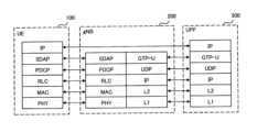
- the User Plane Protocol Stack 6is a diagram showing the configuration of a user plane protocol stack that handles data.
- the user plane protocolincludes a radio interface protocol between the UE 100 and the gNB 200 and a wired interface protocol between the gNB 200 and the UPF 500.
- the user plane radio interface protocolhas a physical (PHY) layer, a Medium Access Control (MAC) layer, a Radio Link Control (RLC) layer, a Packet Data Convergence Protocol (PDCP) layer, and a Service Data Adaptation Protocol (SDAP) layer.
- PHYphysical
- MACMedium Access Control
- RLCRadio Link Control
- PDCPPacket Data Convergence Protocol
- SDAPService Data Adaptation Protocol
- the PHY layerperforms encoding/decoding, modulation/demodulation, antenna mapping/demapping, and resource mapping/demapping. Data and control information are transmitted between the PHY layer of UE100 and the PHY layer of gNB200 via a physical channel.
- the PHY layer of UE100receives downlink control information (DCI) transmitted from gNB200 on a physical downlink control channel (PDCCH).
- DCIdownlink control information
- PDCCHphysical downlink control channel
- RNTIradio network temporary identifier
- the DCI transmitted from gNB200has CRC (Cyclic Redundancy Code) parity bits scrambled by the RNTI added.
- the MAC layerperforms data priority control, retransmission processing using hybrid ARQ (HARQ), random access procedures, etc.
- Data and control informationare transmitted between the MAC layer of UE100 and the MAC layer of gNB200 via a transport channel.
- the MAC layer of gNB200includes a scheduler. The scheduler determines the uplink and downlink transport format (transport block size, modulation and coding scheme (MCS)) and the resource blocks to be assigned to UE100.
- MCSmodulation and coding scheme
- the RLC layeruses the functions of the MAC layer and PHY layer to transmit data to the RLC layer on the receiving side. Data and control information are transmitted between the RLC layer of UE100 and the RLC layer of gNB200 via logical channels.
- the PDCP layerperforms header compression/decompression, encryption/decryption, etc.
- the SDAP layermaps between IP flows, which are the units for QoS control by the core network, and radio bearers, which are the units for QoS control by the AS (Access Stratum). Note that if the RAN is connected to the EPC, SDAP is not necessary.
- the user plane wired interface protocolincludes L1 (Layer 1), L2 (Layer 2), IP (Internet Protocol) layer, UDP (User Datagram Protocol) layer, and GTP-U (GPRS Tunneling Protocol for User Plane).
- L1Layer 1
- L2Layer 2
- IPInternet Protocol
- UDPUser Datagram Protocol
- GTP-UGPRS Tunneling Protocol for User Plane
- the L1 layercorresponds to the PHY layer in the user plane radio interface protocol.
- the L2 layerincludes the MAC layer in the user plane radio interface protocol.
- the L2 layeris also called the data link layer.
- the IP layercorresponds to the Internet layer. IP packets are sent and received between the IP layer of the gNB200 and the IP layer of the UPF500 using IP addresses.
- the UDP layercorresponds to the transport layer.
- UDP packetscan be sent between the UDP layer of gNB200 and the UDP of UPF500 without waiting for a response from the communication partner.
- the GTP-U layeris a layer that transmits and receives user plane PDUs (Protocol Data Units) using the General Packet Radio Service (GPRS) tunneling protocol. GTP-U packets are transmitted and received between the GTP-U layer of the gNB200 and the GTP-U layer of the UPF500. GPRS tunnels are identified by a Tunnel Endpoint Identifier (TEID).
- TEIDTunnel Endpoint Identifier
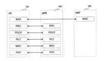
- FIG. 7is a diagram showing the configuration of a protocol stack of a radio interface of a control plane that handles signaling (control signals).
- the protocol stack of the radio interface of the control planehas an RRC (Radio Resource Control) layer and a NAS (Non-Access Stratum) instead of the SDAP layer shown in Figure 7.
- RRCRadio Resource Control
- NASNon-Access Stratum
- RRC signaling for various settingsis transmitted between the RRC layer of UE100 and the RRC layer of gNB200.
- the RRC layercontrols logical channels, transport channels, and physical channels in response to the establishment, re-establishment, and release of radio bearers.
- RRC connectionconnection between the RRC of UE100 and the RRC of gNB200
- UE100is in an RRC connected state.
- RRC connectionno connection between the RRC of UE100 and the RRC of gNB200
- UE100is in an RRC idle state.
- UE100is in an RRC inactive state.
- the NASwhich is located above the RRC layer, performs session management, mobility management, etc.
- NAS signalingis transmitted between the NAS of UE100 and the NAS of AMF300.
- UE100also has an application layer, etc.
- the layer below the NASis called the Access Stratum (AS).
- MCS tableNext, the MCS table according to the first embodiment will be described.
- the gNB 200When the gNB 200 determines the MCS by scheduling, the gNB 200 notifies the UE 100 of the determined MCS using the MCS index (I MCS ). Specifically, the gNB 200 transmits downlink control information (DCI) including the MCS index (I MCS ) to the UE 100.
- DCIdownlink control information
- UE100reads the MCS index from the DCI and obtains the modulation scheme and coding rate using a table.
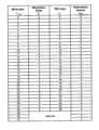
- FIG. 8is a diagram showing an example of a modulation scheme and a TBS (Transport Block Size) index table in the downlink in the LTE system.
- the UE 100can acquire the modulation scheme by acquiring the modulation order (Qm) corresponding to the MCS index (I MCS ).
- the UE 100can also acquire the coding rate corresponding to the MCS index (I MCS ) by using another table not shown. Note that there are multiple types of tables shown in FIG. 8, and the UE 100 selects one of the tables depending on the type of DCI format and the modulation scheme that the UE 100 can support.
- the UE 100determines a transport block size based on the TBS index (I TBS ) and the number of allocated resource blocks (the number of physical resource blocks (PRBs)).
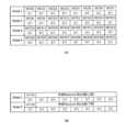
- Fig. 9is a diagram showing an example of a TBS table in an LTE system.
- the UE 100acquires a TBS index (I TBS ) corresponding to an MCS index (I MCS ) from the table shown in Fig. 8, and determines a transport block size (TBS) corresponding to the TBS index (I TBS ) and the number of allocated resource blocks (N PRB ) using the table shown in Fig. 9.
- TBSTBS index
- N PRBnumber of allocated resource blocks
- UE100receives data of the determined transport block size, demodulates the received data using the acquired modulation method, and decodes the demodulated data using the acquired coding rate.
- FIG. 10is a diagram showing an example of a modulation method and a TBS index table in the uplink in the LTE system.
- the procedure of obtaining an MCS index (I MCS ) from the downlink control information (DCI) (or UL grant) and obtaining a TBS index (I TBS ) corresponding to the MCS index (I MCS )is the same as in the downlink.
- the table used when determining the transport block size (TBS)is the same as the table shown in FIG. 9 used in the downlink.
- MCS tableThe tables shown in Figures 8 to 10 used when obtaining the MCS may be referred to as the "MCS table" below.
- the UE 100basically obtains the MCS index (I MCS ) from the DCI in the same manner, and obtains the modulation method and the coding rate by using the MCS table.
- the transport block sizeis calculated using a predetermined formula without using the MCS table.
- the UE 100transmits desired communication quality information to a network device when starting communication.
- UE100may experience frequent retransmissions due to reasons such as not achieving the expected throughput, resulting in a situation in which initial communication cannot be established.
- the network devicecan determine the MCS (specifically, the initial MCS value) based on the desired communication quality information, thereby avoiding a situation in which initial communication cannot be established. Therefore, communication can be performed with the communication quality desired by the user, and UE100 can appropriately communicate with gNB200.
- the desired communication quality informationmay include either an identifier (first identifier) indicating emphasis on delay or an identifier (second identifier) indicating emphasis on speed (or throughput).
- the identifier indicating emphasis on delayis, for example, an identifier indicating emphasis on delay due to communication errors rather than on throughput.
- the throughputmay be equal to or less than a first threshold, but when it is desired to avoid the time required for communication establishment due to retransmission due to a communication error, the UE 100 may include an identifier indicating emphasis on delay in the desired communication quality information.
- the identifier indicating emphasis on speedis, for example, an identifier indicating emphasis on throughput rather than on delay due to a communication error.
- the UE 100may include an identifier indicating emphasis on speed in the desired communication quality information.
- the identifier indicating an emphasis on delay and the identifier indicating an emphasis on speedmay both have different identifiers depending on the degree of emphasis. That is, the identifier indicating an emphasis on delay and the identifier indicating an emphasis on speed may both be divided into levels depending on the degree of emphasis.
- the identifier indicating an emphasis on delaymay be an identifier representing "1" as the emphasis on delay when it is desired to minimize delay as much as possible, and an identifier representing "3" as the emphasis on delay when it is desired that the delay be less than normal.
- the identifier indicating an emphasis on speedmay also be divided into levels depending on the degree of emphasis on speed.
- the desired communication quality informationmay include the desired MCS. That is, the desired MCS may be directly included in the desired communication quality information.
- UE100may determine the desired MCS based on the tolerable (or desired) error rate of communication errors and the desired throughput. At that time, UE100 may determine the desired MCS taking into account the quality evaluation index (e.g., SNR (Signal to Noise Ratio)) at the time the determination is made.
- the quality evaluation indexe.g., SNR (Signal to Noise Ratio)
- the error rate and throughput considered when UE 100 determines the MCSshould be commonly recognized in gNB 200. For example, even if UE 100 transmits a desired MCS to gNB 200, the error rate may be significantly different if the number of resource blocks allocated to UE 100 is different, even if the same MCS is used.
- the error rateshould be commonly recognized between the UE 100 and the gNB 200, for example, as follows.
- the MCS index (I MCS )(the same TBS index (I TBS ) obtained from the same MCS index) is the same
- the transport block sizewill be different.
- an error correction codesuch as a turbo code
- the longer the code lengththe higher the error correction effect will be, and the lower the error rate will be.
- the larger the number of resource blocks (N PRB )the larger the transport block size will be (FIG. 9), and the lower the error rate will be.
- the number of assigned resource blocks (N PRB )may be determined in the specifications (i.e., may be hard-coded).
- the gNB 200can also determine the resource blocks to be assigned to the UE 100, and can recognize the error rate tolerated by the UE 100.
- the UE 100 and the gNB 200should have a common understanding of the throughput, for example, as follows. That is, the throughput depends on the transport block size (FIG. 9) determined by the MCS index (I MCS ) and the number of allocated resource blocks (N PRB ), as well as the frequency of scheduling (or the frequency of resource allocation). For example, the throughput when resource allocation is performed every subframe is 1/8 compared to the case where resource allocation is performed every 8 subframes. Therefore, the scheduling frequency is shared between the UE 100 and the gNB 200. Alternatively, the scheduling frequency may be determined in the specifications (or may be hard-coded).
- the throughput considered when the UE 100 determines the desired MCScan be grasped in the gNB 200, and the gNB 200 can communicate with the UE 100 at that throughput.
- the scheduling frequencymay be expressed by the number of subframes in which scheduling is performed (how many subframes the scheduling is performed every).
- UE 100may determine a desired MCS based on the number of pre-shared resource blocks and the pre-shared scheduling frequency. That is, UE 100 may determine a desired MCS based on a predetermined number of resource blocks and a predetermined scheduling frequency.
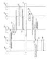
- Fig. 11is a diagram illustrating an example of an operation according to the first embodiment.
- a PDU session establishmentwill be described as an example at the start of communication.
- step S10UE 100 sends a PDU Session Establishment Request message including desired communication quality information to AMF 300.
- the PDU Session Establishment Request messageis an example of a NAS message, and is, for example, a message sent from UE 100 to AMF 300 to start (or establish) a PDU session.
- AMF 300receives the PDU Session Establishment Request message.
- step S11AMF300 selects SMF400.
- step S12AMF300 sends a PDU session request (Nsmf_PDUSession_CreateSMContext Request) message to the selected SMF400.
- the PDU session request messageis a message on the N11 interface, and is, for example, a message that AMF300 sends to SMF400 to associate a PDU session.
- step S13in response to receiving the PDU session request message, SMF400 obtains subscriber information (or contract information) from UDM600 using a subscriber information identifier (e.g., SUPI). At this time, SMF400 determines whether or not the subscriber (user) using UE100 is a subscriber for whom the operation according to the first embodiment is to be performed, based on the subscriber information. A subscriber who has made a contract to pay a specific fee may be a subscriber for whom the operation according to the first embodiment is to be performed, and in this case, SMF400 may determine whether or not the subscriber is a subscriber for whom the operation according to the first embodiment is to be performed, based on whether or not the subscriber has made the contract.
- subscriber information identifiere.g., SUPI
- step S14SMF400 transmits a PDU session response (Nsmf_PDUSession_CreateSMContext Response) message to AMF300.
- the PDU session response messageis a response message to the PDU session request message of step S12. If SMF400 accepts the PDU session establishment, it creates an SM context including information related to the association of the PDU session, and transmits the response message including the SM context ID. On the other hand, if SMF400 does not accept the PDU session establishment, it transmits the response message including the reason for rejection. In the following, the explanation will be given assuming that the PDU session establishment is accepted.
- SMF400transmits the response message to AMF300 including information indicating whether the subscriber (user) using UE100 is a subscriber to which the operation according to the first embodiment is to be performed.
- AMF300receives the response message.
- AMF300determines whether a subscriber (user) using UE100 is a subscriber who is a target of operation according to the first embodiment, based on information indicating whether the subscriber is a target of operation.
- step S15secondary authentication of the PDU session is performed between UE 100 and the network device.
- this secondary authenticationis performed as an option.
- step S16the SMF 400 executes a policy acquisition process, etc. Specifically, the SMF 400 acquires the policy to be applied to the PDU session from the PCF. The SMF 400 also selects the UPF 500 to which the PDU session is to be applied.
- the SMF 400sends an N1N2 message transfer (Namf_Communication_N1N2Message Transfer) message to the AMF 300.
- the transfer messageincludes, for example, N2SM information and an N1SM container.
- the N1SM informationincludes information for establishing a PDU session.
- the N1SM containerincludes a PDU session establishment permission provided by the AMF 300 to the UE 100.
- step S18in response to receiving the N1N2 message transfer message, the AMF300 transmits a PDU session request message to the gNB200.
- the request messageincludes N1SM information and an N1SM container.
- the AMF300may determine an initial MCS value for the UE100. In this case, since the AMF300 has acquired the desired communication quality information from the UE100 by the PDU session establishment request message (step S10), the AMF300 determines the initial MCS value according to the desired communication quality information.
- the AMF300may determine a fixed (or normal) MCS initial value as the initial MCS value.
- the AMF300transmits the determined initial MCS value by including it in the PDU session request message.
- gNB200transmits an RRC message (e.g., an RRC Connection Reconfiguration message) to UE100.
- the RRC messageincludes an N1SM container (including PDU session establishment permission, etc.).
- gNB200transmits the MCS initial value determined by AMF300 to UE100.
- gNB200may include the MCS initial value in the RRC message and transmit it to UE100.
- gNB200may include the MCS initial value in downlink control information (DCI) and transmit it to UE100.
- DCIdownlink control information
- step S20UE100 and gNB200 communicate uplink user data and downlink user data using the MCS based on the initial MCS value.
- Fig. 12summarizes an example of operation according to the first embodiment. Explanation of parts that overlap with the above explanation will be omitted as appropriate. Fig. 12 will be explained assuming that the AMF 300 performs processing as a network device.
- step S30AMF300 starts processing.
- step S31AMF300 receives a PDU session establishment request message from UE100.
- the PDU session establishment request messageincludes desired communication quality information.
- step S32the SMF 400 checks whether the UE 100 is a UE that is a target of operation according to the first embodiment. If the UE 100 is a UE that is a target of operation (Yes in step S32), the process proceeds to step S33. On the other hand, if the UE 100 is not a UE that is a target of operation (No in step S32), the process proceeds to step S37.
- the SMF400checks whether the UE is a target UE for operation as follows. That is, in response to receiving a PDU session establishment request message including desired communication quality information (step S31), the AMF300 transmits a PDU session request (Nsmf_PDUSession_CreateSMContext Request) message including instruction information to check whether the UE100 is a target UE for operation to the SMF400 (step S12 in FIG. 11). In response to receiving the instruction information, the SMF400 checks whether the UE100 is a target UE for operation. The SMF400 checks whether the subscriber using the UE100 is a target subscriber for operation according to the first embodiment based on the subscriber information acquired from the UDM600.
- PDU session requestNsmf_PDUSession_CreateSMContext Request
- the SMF 400includes the determination result in a PDU session response (Nsmf_PDUSession_CreateSMContext Response) message and transmits it to the AMF 300 (step S14).
- step S33AMF300 determines the initial MCS value based on the desired communication quality information.
- step S34AMF300 transmits the MCS initial value to gNB200.
- step S35gNB200 starts communication with UE100 with the initial MCS value.
- step S36AMF300 ends the series of processes.
- step S37AMF300 transmits a fixed (or normal) MCS initial value to gNB200.
- the AMF 300is described as determining the MCS initial value, but the MCS initial value may be determined by another network device.
- the SMF 400may determine the MCS initial value.
- the AMF 300transmits a PDU session request (Nsmf_PDUSession_CreateSMContext Request) message including desired communication quality information to the SMF 400 (step S12 in FIG. 11).
- the SMF 400checks with the UDM 600 whether the UE 100 is an operation target UE.
- the SMF 400determines the MCS initial value based on the desired communication quality information.
- the SMF 400determines a fixed (or normal) MCS initial value as the MCS initial value.
- the SMF 400includes the determined MCS initial value in a PDU session response (Nsmf_PDUSession_CreateSMContext Response) message (step S14) or an N1N2 message transfer (Namf_Communication_N1N2Message Transfer) message (step S17) and transmits the message to the AMF 300.
- the MCS initial valuemay be determined by the gNB 200, not by the core network device.
- the AMF 300transmits instruction information to the SMF 400 to instruct the SMF 400 to confirm whether the UE 100 is a target UE for operation (step S12), and receives the determination result from the SMF 400 (step S14).
- the AMF 300transmits the desired communication quality information received in step S10 and the determination result received from the SMF 400 in a PDU session request message (step S18) to the gNB 200.
- the gNB 200determines the MCS initial value based on the desired communication quality information, and if the UE 100 is not a target UE for operation, it determines a fixed (or normal) MCS initial value.
- a user devicee.g., UE100 transmits designated communication quality information to a network device
- a network devicee.g., gNB200
- the designated communication quality informationincludes at least one of a designated MCS value and a designated number of resource blocks.
- the designated MCS valueindicates the MCS designated by the user device (or user)
- the designated number of resource blocksindicates the number of resource blocks designated by the user device (or user).
- gNB200can grasp at least one of the designated MCS value designated by UE100 and the designated number of resource blocks designated by UE100. Therefore, in gNB200, if the current communication can maintain the designated MCS and the designated number of resource blocks, it is possible to maintain the communication.
- the communication content requiredmay vary greatly depending on the application executed by UE100. For each application, there may be requests such as "If a certain communication speed cannot be maintained, it is better not to connect to gNB200," “We want to minimize power consumption,” or “We want to minimize communication speed and prioritize communication distance and stability.” With gNB200, communication according to the requirements of each application is also possible using at least one of the specified MCS value and the specified number of resource blocks. Therefore, UE100 can communicate appropriately with gNB200.
- Figure 13(A)shows an example of a specified MCS value
- Figure 13(B)shows an example of a specified number of resource blocks.
- each designated MCS valuecorresponds to, for example, each MCS index (I MCS ).
- the designated MCS valueshould be set to "0x0000 0001"
- the designated MCS valueshould be set to "0x4000 0000”.
- the specified MCS valuecan specify a range of MCS by specifying multiple MCS. For example, when specifying "MCS20" to "MCS31", the specified MCS value can be "0x0000 0FFFF". For example, when it is desired to specify communication content that requires a throughput higher than the first threshold even if an error occurs, the UE 100 can transmit "0x0000 0FFFF" as the specified MCS value to the gNB 200, and the MCS value corresponding to the high throughput can be selected, thereby enabling communication that matches the communication content.
- the designated MCS valuemay specify different designated MCS values for the uplink and downlink.
- flag information indicating the uplink or downlinkmay exist separately from (or included in) the designated MCS value.
- the designated MCS valuemay be shared (or the same) for the uplink and downlink.
- the designated MCS value shown in Fig. 13(A)represents an example in which the MCS index (I MCS ) included in the DCI is 5 bits.
- the designated MCS valuecan range from "MCS0" to "MCS15"
- the designated MCS valuecan range from "MCS0" to "MCS63”.
- the designated MCS valuemay have a different range of values depending on the number of bits representing the MCS index (I MCS ).
- the specified number of resource blockscan be set to the upper limit of the number of resource blocks and/or the lower limit of the number of resource blocks. For example, if you want to set the upper limit of the specified number of resource blocks to "1", you can set the most significant bit of Octet1 to "1" and the desired number of resource blocks in Octet1 to "1" (for example, "10000001 00000000” (binary representation)). For example, in an IoT sensor that is simultaneously connected in large numbers and has an amount of information less than the second threshold, it is possible to prevent the allocation of more resource blocks than necessary by setting the specified number of resource blocks as described above.
- the number of designated resource blocksmay also be different for the uplink and downlink.
- flag information indicating the uplink or downlinkmay exist separately from (or included in) the designated number of resource blocks.
- the designated number of resource blocksmay be the same (or the same) for both the uplink and downlink.
- the specified communication quality informationmay include a specified MCS value without including a specified number of resource blocks.
- the specified communication quality informationmay include a specified number of resource blocks without including a specified MCS value.
- the specified communication quality informationmay include both a specified MCS value and a specified number of resource blocks. Even if only one of them is specified, it is possible to achieve communication that is in line with the communication content as described above, and by specifying both, it is possible to set up the communication in even more detail as described above.
- FIG. 14is a diagram showing an example of operation according to the second embodiment.
- UE 100transmits at least one of a specified MCS value and a specified number of resource blocks as the specified communication quality information.
- step S40UE 100 transmits a PDU Session Establishment Request message including the specified communication quality information to AMF 300.
- AMF 300receives the PDU Session Establishment Request message.
- step S41AMF300 selects SMF400.
- step S42the AMF 300 sends a PDU session request (Nsmf_PDUSession_CreateSMContext Request) message to the selected SMF 400.
- PDU session requestNsmf_PDUSession_CreateSMContext Request
- step S43in response to receiving the PDU session request message, SMF400 acquires subscriber information (or contract information) from UDM600 using a subscriber information identifier (e.g., SUPI) or the like.
- SMF400may determine whether or not the subscriber (user) using UE100 is a target subscriber for performing the operation according to the second embodiment based on the subscriber information.
- SMF400may determine whether or not the subscriber is a target subscriber based on whether or not the subscriber has made a contract to pay a specific fee.
- step S44SMF400 transmits a PDU session response (Nsmf_PDUSession_CreateSMContext Response) message to AMF300.
- SMF400transmits the response message to AMF300, including information indicating whether the subscriber (user) using UE100 is a subscriber for which the operation according to the second embodiment is to be performed.
- AMF300receives the response message.
- step S45secondary authentication of the PDU session is performed between UE 100 and the network device.
- this secondary authenticationis performed as an option.
- step S46the SMF400 executes policy acquisition processing, etc.
- step S47SMF400 sends an N1N2 message transfer (Namf_Communication_N1N2Message Transfer) message to AMF300.
- N1N2 message transferNamf_Communication_N1N2Message Transfer
- step S48in response to receiving the N1N2 message transfer message, AMF300 transmits a PDU session request message to gNB200. AMF300 transmits the information received in step S44 indicating whether the subscriber (user) using UE100 is a subscriber subject to the operation according to the second embodiment, and the specified communication quality information received in step S40, in the PDU session request message.
- step S49in response to receiving the PDU session request message, gNB200 decides to communicate with UE100 within the range indicated in the specified communication quality information, and transmits an RRC message including a PDU session establishment permission to UE100.
- step S50UE100 and gNB200 start communication within the range indicated in the specified communication quality information and maintain the communication.
- the gNB 200continues communication with the UE 100 within the range of the designated communication quality information.
- the gNB 200performs a predetermined process on the UE 100.
- the gNB 200performs a predetermined process on the UE 100.
- the gNB 200when the result of the scheduling determined from the wireless quality between the gNB 200 and the UE 100 is within the range of the designated communication quality information, the gNB 200 maintains communication with the UE 100. On the other hand, when the result of the scheduling is not within the range of the designated communication quality information, the gNB 200 performs a predetermined process.
- the gNB 200determines that it is not within the range of the designated communication quality information.
- the designated number of resource blocksis "10" and the scheduling result is a resource block number of "6" is allocated, the resource block numbers do not match, so the gNB 200 determines that it is not within the range of the designated communication quality information.
- the gNB 200determines that it is within the range of the designated communication quality information, and if the scheduling result is not included within the range, the gNB 200 determines that it is not within the range of the designated communication quality information.
- the gNB200When the scheduling result is not within the range of the specified communication quality information, the gNB200 performs a specified process, which enables, for example, the UE100 to avoid communications other than those indicated in the specified communication quality information and maintain the communications indicated in the specified communication quality information as much as possible.
- the predetermined processmay be a process of executing a handover for the UE 100.
- FIG. 15shows an example of the operation when a handover execution process is performed as the specified process.
- step S60when the gNB 200 starts processing (step S60), as described above, by comparing with the scheduling result, it determines whether or not it is within the range indicated by the designated communication quality information (step S61). Then, if it is within the range indicated by the designated communication quality information (Yes in step S61), the gNB 200 maintains the communication (step S62). On the other hand, if it is not within the range indicated by the designated communication quality information (No in step S61), the gNB 200 causes the UE 100 to execute a handover (step S63). For example, the gNB 200 transmits a handover request message to the UE 100. Then, the gNB 200 ends a series of processes (step S64). Since the UE 100 cannot maintain the communication indicated by the designated communication quality information in communication with the gNB 200, for example, the UE 100 is caused to perform a handover to another gNB, taking into consideration the possibility of communication indicated by the designated communication quality information.
- the predetermined processmay be a process of disconnecting communication with the UE 100 .
- FIG. 16shows an example of an operation when a communication disconnection process is performed as a predetermined process.
- the same processes as in FIG. 15are indicated with the same reference numerals.
- gNB200if gNB200 is not within the range indicated by the specified communication quality information (No in step S61), it performs a process to disconnect communication. For example, gNB200 transmits an RRC Release message to UE100. Considering that communication within the range indicated by the communication quality information will become possible after a predetermined time has elapsed, UE100 may perform a process to reconnect to gNB200.
- the specified processmay be a process of releasing resource blocks of other calls (or other PDU sessions) to UE 100.
- FIG. 17shows an example of an operation when a resource block release process is performed as a predetermined process.
- the same processes as in FIG. 15are denoted by the same reference numerals.
- gNB200performs a process to release the resource blocks of other calls (step S80).
- the call to be releasedmay be a call for which the specified number of resource blocks is not specified. If there are multiple calls for which the specified number of resource blocks is not specified, the call to be released may be the call with the largest number of allocated resource blocks. Alternatively, the call to be released may be a call for which the specified number of resource blocks is specified, but which is communicating using more than the specified number of resource blocks. If there are multiple calls communicating using more than the specified number of resource blocks, the call to be released may be the call with the largest number of resource blocks. Alternatively, if there are a call for which the specified number of resource blocks is not specified and a call for which the specified number of resource blocks is specified, but which is communicating using more than the specified number of resource blocks, the latter (or the former) may be given priority.
- gNB200may cause UE100 to perform a handover (step S63 in FIG. 15). gNB200 may also disconnect communication with UE100 (step S70 in FIG. 16).
- the specified processingmay be processing for continuing communication when a specified MCS value and a specified number of resource blocks are specified as the specified communication quality information, even if either one of them cannot be maintained, if the throughput estimated from both (hereinafter, sometimes referred to as the "estimated throughput") can be maintained.
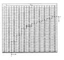
- FIG. 18shows an example of operation in which a process of continuing communication when the estimated throughput can be maintained is performed as a predetermined process.
- the same processes as in FIG. 15are denoted by the same reference numerals.
- the gNB200performs processing to continue communication if the estimated throughput can be maintained (step S85).
- the specified communication quality informationis a specified MCS of "11" or more and a specified number of resource blocks of "5" or more.
- the minimum value of the transmission block size (TBS)is estimated to be "1000" using the MCS table shown in FIG. 19. Even if the scheduling result falls outside the range of either the specified MCS value or the specified number of resource blocks, and communication based on the specified communication quality information cannot be maintained, gNB200 continues the communication if the transmission block size based on the scheduling result exceeds "1000" (the range indicated by the dotted line and arrow in FIG. 19).
- the gNB 200maintains the communication (step S85).
- the gNB 200determines that the communication cannot be continued. In this case, gNB200 may cause UE100 to perform handover (step S63 of FIG. 16) (step S63 of FIG. 15) or perform disconnection processing (step S70 of FIG. 16).
- gNB200performs a process to maintain communication if the transmission block size (or throughput) determined by scheduling is within the range of the transmission block size (or throughput) based on the specified communication quality information.
- the designated communication quality informationmay change in the UE 100. For example, when communication is started, communication with a throughput higher than a first threshold is required, but when a predetermined amount of data transmission is completed, communication with a throughput equal to or lower than the first threshold may be sufficient.
- the UE 100may transmit the updated designated communication quality information to the gNB 200.
- the updated designated communication quality informationmay be included in a periodic message (or information) that the UE 100 transmits to the gNB 200.
- FIG. 20is a diagram showing another example of operation according to the second embodiment.
- FIG. 20shows an example of operation using uplink control information (UPI) as an example of periodic information.
- UE100periodically transmits uplink control information (UPI) to gNB200 (steps S90 and S91).
- UE100transmits uplink control information including the updated designated communication quality information to gNB200 (step S93). Thereafter, transmission of uplink control information is performed periodically.
- UPIuplink control information
- the updated designated communication quality informationmay be included in a message (or information) that is not periodic.
- UE100may notify gNB200 of the updated designated communication quality information by transmitting an RRC message (e.g., a UE Capability Information message) including the updated designated communication quality information to gNB200.
- RRC messagee.g., a UE Capability Information message
- a programmay be provided that causes a computer to execute each operation and each process described in the first and second embodiments.
- the programmay be recorded in a computer-readable medium.
- the computer-readable medium on which the program is recordedmay be a non-transient recording medium.
- the non-transient recording mediumis not particularly limited, and may be, for example, a recording medium such as a CD-ROM or a DVD-ROM.
- circuits that execute each operation and each processmay be integrated, and a part of them may be configured as a semiconductor integrated circuit (chip set, SoC: System on a chip).
- a communication control method in a mobile communication systemcomprising: The method includes a step in which a user equipment (e.g., UE 100) transmits either desired communication quality information or specified communication quality information to a network device (e.g., AMF 300),
- the desired communication quality informationincludes desired communication quality information
- the specified communication quality informationincludes specified communication quality information.
- the determining stepincludes a step of the network device determining an MCS initial value as the MCS based on the desired communication quality information;
- the communication control methodaccording to any one of Supplementary Note 1 to Supplementary Note 3, further comprising a step of a base station included in the network device starting transmission and/or reception of user data to the user equipment using the MCS initial value.
- the desired communication quality informationincludes either a first identifier indicating a delay priority or a second identifier indicating a speed priority, the first identifier is an identifier indicating that a delay due to a communication error is given more importance than a throughput,
- the communication control methodaccording to any one of Supplementary Note 1 to Supplementary Note 4, wherein the second identifier is an identifier indicating that the throughput is prioritized over a delay due to the communication error.
- the designated communication quality informationincludes at least one of a designated MCS value and a designated number of resource blocks, The communication control method according to any one of Supplementary Note 1 to Supplementary Note 9, wherein the designated MCS value indicates an MCS designated by the user equipment, and the designated number of resource blocks indicates a number of resource blocks designated by the user equipment.
- a core network device included in the network devicereceives the designated communication quality information;
- the core network devicetransmits the designated communication quality information to a base station included in the network device; receiving the designated communication quality information by the base station;
- the base stationfurther includes a step of maintaining communication with the user equipment when a scheduling result determined from a radio quality between the base station and the user equipment is within a range of the designated communication quality information, and performing a predetermined process when the scheduling result is not within the range of the designated communication quality information,
- the communication control methodaccording to any one of Supplementary Note 1 to Supplementary Note 12, wherein the predetermined processing is any one of a processing for executing a handover for the user equipment, a processing for disconnecting communication for the user equipment, and a processing for releasing a resource block of another call to the user equipment.
- the network deviceis an Access and Mobility Management Function (AMF), The communication control method according to any one of Supplementary Note 1 to Supplementary Note 15, wherein the transmitting step includes a step in which the user equipment transmits a PDU Session Establishment Request message including either the desired communication quality information or the specified communication quality information to the AMF.
- AMFAccess and Mobility Management Function
- a user equipmente.g., UE 100 capable of communicating with a network device (e.g., gNB 200),
- a transmitting unite.g., a transmitting unit 120 that transmits either desired communication quality information or designated communication quality information to the network device,
- the desired communication quality informationincludes desired communication quality information
- the specified communication quality informationincludes specified communication quality information.
- Mobile communication system 100UE 110: Receiving unit 120: Transmitting unit 130: Control unit 200: gNB (RAN) 210: transmitting unit 220: receiving unit 230: control unit 250: network communication unit 300: AMF 310: Receiving unit 320: Transmitting unit 330: Control unit 400: SMF 410: Receiving unit 420: Transmitting unit 430: Control unit
Landscapes
- Engineering & Computer Science (AREA)
- Quality & Reliability (AREA)
- Computer Networks & Wireless Communication (AREA)
- Signal Processing (AREA)
- Mobile Radio Communication Systems (AREA)
Abstract
Description
Translated fromJapanese本開示は、通信制御方法及びユーザ装置に関する。This disclosure relates to a communication control method and a user device.
移動通信システムにおける基地局では、無線リソースを効率的に利用するために、スケジューリングが行われる。基地局は、スケジューリングにより、下りリンク及び上りリンクにおいて物理層の無線リソースをユーザ装置(UE:User Equipment)に割り当てることができる。In base stations in mobile communication systems, scheduling is performed to efficiently utilize radio resources. Through scheduling, the base station can allocate physical layer radio resources in the downlink and uplink to user equipment (UE: User Equipment).
下りリンクについては、例えば、以下のような処理が行われる。すなわち、基地局は、ユーザ装置から送信されたチャネル状態情報(CSI:Channel Status Information)を受信し、当該チャネル状態情報に基づいて、下りリンクのスケジューリングを行う。基地局は、当該スケジューリングにより、ユーザ装置に対して、無線リソースを割り当てるとともに、MCS(Modulation and Coding Scheme)を決定する。基地局は、スケジューリング結果を含む下り制御情報(DCI:Downlink Control Information)をユーザ装置へ送信する。ユーザ装置は、下り制御情報に含まれる無線リソースを用いてPDSCHのデータを受信し、下り制御情報に含まれるMCSを利用して、復調及び復号を行う。For example, the following processing is performed for the downlink. That is, the base station receives channel status information (CSI) transmitted from the user equipment, and performs downlink scheduling based on the channel status information. The base station allocates radio resources to the user equipment through this scheduling, and determines the modulation and coding scheme (MCS). The base station transmits downlink control information (DCI) including the scheduling results to the user equipment. The user equipment receives PDSCH data using the radio resources included in the downlink control information, and performs demodulation and decoding using the MCS included in the downlink control information.
一方、上りリンクについては、例えば、以下のような処理が行われる。すなわち、基地局は、ユーザ装置から送信されたチャネル品質測定用参照信号(SRS:Sounding Reference Signal)を受信し、当該チャネル品質測定用参照信号に基づいて、上りリンクのスケジューリングを行う。基地局は、当該スケジューリングにより、ユーザ装置に対する無線リソースを割り当てるとともにMCSを決定する。基地局は、スケジューリング結果を含む下り制御情報(DCI)(UL grantともいう。)をユーザ装置へ送信する。ユーザ装置は、下り制御情報に含まれるMCSを利用して、データを符号化及び変調を行い、下り制御情報に含まれる無線リソースを用いて当該データを基地局へ送信する。On the other hand, for the uplink, for example, the following processing is performed. That is, the base station receives a channel quality measurement reference signal (SRS: Sounding Reference Signal) transmitted from the user device, and performs uplink scheduling based on the channel quality measurement reference signal. The base station allocates radio resources to the user device and determines the MCS through this scheduling. The base station transmits downlink control information (DCI) (also called UL grant) including the scheduling result to the user device. The user device encodes and modulates data using the MCS included in the downlink control information, and transmits the data to the base station using the radio resources included in the downlink control information.
一態様に係る通信制御方法は、移動通信システムにおける通信制御方法である。前記通信制御方法は、ユーザ装置が、希望通信品質情報及び指定通信品質情報のいずれかをネットワーク装置へ送信するステップを有する。ここで、希望通信品質情報は希望する通信品質情報を含み、指定通信品質情報は指定された通信品質情報を含む。A communication control method according to one embodiment is a communication control method in a mobile communication system. The communication control method includes a step in which a user device transmits either desired communication quality information or specified communication quality information to a network device. Here, the desired communication quality information includes desired communication quality information, and the specified communication quality information includes specified communication quality information.
また、一態様に係るユーザ装置は、ネットワーク装置と通信可能なユーザ装置である。前記ユーザ装置は、希望通信品質情報及び指定通信品質情報のいずれかを前記ネットワーク装置へ送信する送信部を有する。ここで、希望通信品質情報は希望する通信品質情報を含み、指定通信品質情報は指定された通信品質情報を含む。Furthermore, a user device according to one embodiment is a user device capable of communicating with a network device. The user device has a transmission unit that transmits either desired communication quality information or designated communication quality information to the network device. Here, the desired communication quality information includes desired communication quality information, and the designated communication quality information includes designated communication quality information.
また、一態様に係るネットワーク装置は、ユーザ装置と通信可能なネットワーク装置である。前記ネットワーク装置は、前記ユーザ装置から、希望通信品質情報及び指定通信品質情報のいずれかを受信する受信部を有し、前記希望通信品質情報は希望する通信品質情報を含み、前記指定通信品質情報は指定された通信品質情報を含む。In addition, a network device according to one embodiment is a network device capable of communicating with a user device. The network device has a receiving unit that receives either desired communication quality information or designated communication quality information from the user device, the desired communication quality information including desired communication quality information, and the designated communication quality information including designated communication quality information.
スケジューリングは、基地局とユーザ装置との間の無線品質に基づいて行われる。すなわち、ユーザ装置は基地局から送信されたチャネル状態測定用参照信号(CSI-RS)に基づいて無線品質(チャネル状態)を測定し、基地局がユーザ装置から送信されたチャネル品質測定用参照信号(SRS)に基づいて無線品質を測定する。特に、MCSに関して、無線品質に応じて適応的に選択されることで、効率的な通信を行うことが可能となる。Scheduling is performed based on the wireless quality between the base station and the user device. That is, the user device measures the wireless quality (channel state) based on a channel state measurement reference signal (CSI-RS) transmitted from the base station, and the base station measures the wireless quality based on a channel quality measurement reference signal (SRS) transmitted from the user device. In particular, the MCS is adaptively selected according to the wireless quality, enabling efficient communication.
しかしながら、MCSが無線品質に応じて決定されることから、ユーザ装置では、希望する通信品質で基地局と通信を行うことができない場合がある。例えば、ユーザ装置では、一定のスループットが必要な通信を行うことを希望したけれども、選択されたMCSが一定以下のスループットの通信に対応するMCSである場合、希望する通信品質での通信を行うことができない。従って、ユーザ装置は、基地局との通信を適切に行うことができない場合がある。However, since the MCS is determined according to the wireless quality, the user device may not be able to communicate with the base station at the desired communication quality. For example, if the user device desires to perform communication that requires a certain throughput, but the selected MCS is an MCS that supports communication with a throughput below the certain level, the user device may not be able to perform communication with the desired communication quality. As a result, the user device may not be able to properly communicate with the base station.
そこで、本開示は、ユーザ装置が基地局との通信を適切に行うことを目的とする。The purpose of this disclosure is to enable user equipment to communicate appropriately with a base station.
[第1実施形態]
上述したように、MCSは、UEと基地局との間の無線品質に基づいて決定される。[First embodiment]
As described above, the MCS is determined based on the radio quality between the UE and the base station.
また、基地局では、決定したMCSに基づいて、下りリンクにおいてUEへデータを送信したものの、UEが当該データのデコードに失敗して、UEから否定応答信号(HARQ(Hybrid Automatic Repeat reQuest) NACK信号)を受信する場合がある。この場合、基地局は、デコードに失敗したデータに用いたMCSより低いMCSを利用してデータを再送信する。通信エラー率(BLER:Block Error Rate)はネットワークにより制御され、最大で10%の通信エラー率(BLER:Block Error Rate)が維持される。すなわち、MCSは、通信エラー率に基づいて決定される場合もある。In addition, the base station may transmit data to the UE in the downlink based on the determined MCS, but the UE may fail to decode the data and receive a negative acknowledgement signal (HARQ (Hybrid Automatic Repeat reQuest) NACK signal) from the UE. In this case, the base station retransmits the data using an MCS lower than the MCS used for the data that failed to be decoded. The communication error rate (BLER: Block Error Rate) is controlled by the network, and a maximum communication error rate (BLER: Block Error Rate) of 10% is maintained. In other words, the MCS may be determined based on the communication error rate.
しかし、UEとの基地局との通信が開始される際、UEは基地局からチャネル状態測定用参照信号(CSI-RS)を受信することがないため、チャネル状態情報(CSI)を基地局へフィードバックすることができない。従って、基地局では、UEと基地局との間の無線品質に基づいてMCSを決定することができない場合がある。また、通信開始の際は、UEと基地局との間でデータの送受信がないため、ネットワークでは、通信エラー率も算出できず、通信エラー率に基づいてMCSを決定することもできない。However, when communication between a UE and a base station is started, the UE does not receive a channel state measurement reference signal (CSI-RS) from the base station, and therefore cannot feed back channel state information (CSI) to the base station. Therefore, the base station may not be able to determine the MCS based on the wireless quality between the UE and the base station. Also, when communication starts, there is no data transmission or reception between the UE and the base station, so the network cannot calculate the communication error rate, and therefore cannot determine the MCS based on the communication error rate.
この場合、基地局では、通信開始の際に、予め決められた固定値のMCSを用いて、UEとの通信を行うことになる。In this case, when communication starts, the base station will communicate with the UE using a predetermined fixed MCS value.
しかしながら、固定値のMCSが適切なMCSでない場合、UE又は基地局では、通信エラーが発生して何度も再送を繰り返したり、ユーザが期待するスループットが出ずに通信を確立できなかったりする場合がある。そのため、UEが基地局との通信を適切に行うことができない場合がある。However, if the fixed MCS is not an appropriate MCS, communication errors may occur in the UE or base station, causing repeated retransmissions, or the throughput expected by the user may not be achieved, making it impossible to establish communication. As a result, the UE may not be able to communicate properly with the base station.
そこで、第1実施形態では、ユーザ装置が基地局との通信を適切に行うことを目的としている。特に、第1実施形態では、通信開始時に着目し、通信開始時における当該通信が適切に行われることを目的としている。The first embodiment therefore aims to enable the user device to communicate appropriately with the base station. In particular, the first embodiment focuses on the start of communication and aims to ensure that communication is performed appropriately at the start of communication.
そのため、第1実施形態では、ユーザ装置(例えばUE)が、希望通信品質情報及び指定通信品質情報のいずれかをネットワーク装置(例えばAMF)へ送信する。ここで、希望通信品質情報は希望する通信品質情報を含み、指定通信品質情報は指定された通信品質情報を含む。Therefore, in the first embodiment, a user device (e.g., a UE) transmits either desired communication quality information or specified communication quality information to a network device (e.g., an AMF). Here, the desired communication quality information includes desired communication quality information, and the specified communication quality information includes specified communication quality information.
このように、第1実施形態では、例えば、UEが希望通信品質情報をネットワーク装置へ送信するため、ネットワーク装置では、希望通信品質情報を考慮してMCSを決定することができる。これにより、UEは、ユーザが希望する通信品質で基地局と通信することが可能となるため、基地局との通信を適切に行うことが可能となる。In this way, in the first embodiment, for example, the UE transmits desired communication quality information to the network device, and the network device can determine the MCS taking the desired communication quality information into consideration. This allows the UE to communicate with the base station with the communication quality desired by the user, making it possible to communicate with the base station appropriately.
特に、第1実施形態では、ユーザ装置が、ネットワーク装置との通信を開始する際に希望通信品質情報を送信する。これにより、UEは、通信開始時において、ユーザが希望する通信品質で基地局との通信が可能となる。In particular, in the first embodiment, the user device transmits desired communication quality information when starting communication with the network device. This enables the UE to communicate with the base station with the communication quality desired by the user at the start of communication.
以下では、第1実施形態について具体的に説明する。The first embodiment will be described in detail below.
なお、「コアネットワーク装置」は、コアネットワーク(CN)と呼ばれるネットワークに接続された装置(又は機能ブロック)のことである。「コアネットワーク装置」は、5GC(5G Core Network)に接続された装置(又は機能ブロック)であってもよい。具体的には、「コアネットワーク装置」は、アクセスモビリティ管理装置(AMF:Access and Mobility Management Function)、セッション管理装置(SMF:Session Management Function)、統合データ管理装置(UDM:Unified Data Management)、又はユーザプレーン装置(UPF:User Plane Function)などであってもよい。「コアネットワーク装置」と「基地局」とをまとめて、「ネットワーク装置」と称する場合がある。Note that a "core network device" refers to a device (or functional block) connected to a network called a core network (CN). A "core network device" may also be a device (or functional block) connected to a 5G Core Network (5GC). Specifically, a "core network device" may be an access and mobility management function (AMF), a session management function (SMF), a unified data management function (UDM), or a user plane function (UPF). A "core network device" and a "base station" may be collectively referred to as a "network device."
(移動通信システムの構成)
最初に、第1実施形態に係る移動通信システムの構成例について説明する。(Configuration of a mobile communication system)
First, a configuration example of a mobile communication system according to the first embodiment will be described.
図1は、移動通信システム1の構成を表す図である。移動通信システム1は、3GPP(登録商標。以下同じ)規格の第5世代システム(5GS:5th Generation System)に準拠する。以下において、5GSを例に挙げて説明するが、移動通信システムにはLTE(Long Term Evolution)システムが少なくとも部分的に適用されてもよい。移動通信システムには第6世代(6G)システムが少なくとも部分的に適用されてもよい。図1に示す移動通信システム1は、5Gシステムであってもよい。FIG. 1 is a diagram showing the configuration of a
移動通信システム1は、ユーザ装置(UE:User Equipment)100と、gNB200と、アクセスモビリティ管理装置(AMF:Access and Mobility Management Function)300と、セッション管理装置(SMF:Session Management Function)400とを有する。The
AMF300とSMF400とは、コアネットワーク装置の一例である。図1には図示されていないが、コアネットワーク装置として、UPF500及びUDM600などがある。一方、gNB(基地局)200は、コアネットワーク(CN)と接続された無線アクセスネットワーク装置の一例である。以下では、無線アクセスネットワーク装置の一例としてgNB200を例にして説明するが、無線アクセスネットワーク装置は、LTE(Long Term Evolution)の基地局であるeNB(evolved Node B)であってもよい。当該無線アクセスネットワーク装置は、6G以降の基地局であってもよい。AMF300 and SMF400 are examples of core network devices. Although not shown in FIG. 1, other core network devices include UPF500 and UDM600. On the other hand, gNB (base station) 200 is an example of a radio access network device connected to the core network (CN). In the following, gNB200 will be used as an example of a radio access network device, but the radio access network device may also be an eNB (evolved Node B), which is a base station for LTE (Long Term Evolution). The radio access network device may also be a base station for 6G or later.
UE100は、移動可能な無線通信装置である。UE100は、ユーザにより利用される装置であればどのような装置であっても構わない。例えば、UE100は、携帯電話端末(スマートフォンを含む)及び/又はタブレット端末、ノートPC、通信モジュール(通信カード又はチップセットを含む)、センサ若しくはセンサに設けられる装置、車両若しくは車両に設けられる装置(Vehicle UE)、飛行体若しくは飛行体に設けられる装置(Aerial UE、又はUAV(Unmanned Aerial Vehicle))である。或いは、UE100は、IoT(Internet of Things)機器、又はIoTセンサなどであってもよい。UE100 is a mobile wireless communication device. UE100 may be any device that is used by a user. For example, UE100 may be a mobile phone terminal (including a smartphone) and/or a tablet terminal, a notebook PC, a communication module (including a communication card or chipset), a sensor or a device provided in a sensor, a vehicle or a device provided in a vehicle (Vehicle UE), an aircraft or a device provided in an aircraft (Aerial UE, or UAV (Unmanned Aerial Vehicle)). Alternatively, UE100 may be an IoT (Internet of Things) device, an IoT sensor, etc.
gNB200は、基地局間インタフェースであるXnインタフェースを介して相互に接続される。gNB200は、1又は複数のセルを管理する。gNB200は、自セルとの接続を確立したUE100との無線通信を行う。gNB200は、無線リソース管理(RRM)機能、ユーザデータ(以下、単に「データ」という)のルーティング機能、モビリティ制御・スケジューリングのための測定制御機能等を有する。「セル」は、無線通信エリアの最小単位を示す用語として用いられる。「セル」は、UE100との無線通信を行う機能又はリソースを示す用語としても用いられる。1つのセルは1つのキャリア周波数(以下、単に「周波数」と呼ぶ)に属する。The
なお、gNB200がLTEのコアネットワークであるEPC(Evolved Packet Core)に接続することもできる。LTEの基地局(eNB:evolved Node B)が5Gのネットワークに接続することもできる。LTEの基地局とgNB200とが基地局間インタフェースを介して接続することもできる。In addition, gNB200 can also be connected to the EPC (Evolved Packet Core), which is the LTE core network. LTE base stations (eNB: evolved Node B) can also be connected to the 5G network. LTE base stations and gNB200 can also be connected via a base station-to-base station interface.
AMF300は、UE100に対する各種モビリティ制御等を行う。AMF300は、N1インタフェース上のNASメッセージを用いてUE100と通信することが可能である。また、AMF300は、N2インタフェース上のN2メッセージを用いてgNB200と通信することが可能である。AMF300は、このような通信を行うことで、UE100に対するモビリティ管理、及びUE100に対する位置管理などを行う。なお、AMF300は、ネットワークを介して、SMF400と接続される。AMF300 performs various mobility controls for UE100. AMF300 can communicate with UE100 using NAS messages on the N1 interface. AMF300 can also communicate with gNB200 using N2 messages on the N2 interface. By performing such communication, AMF300 performs mobility management for UE100 and location management for UE100. AMF300 is connected to SMF400 via a network.
SMF400は、セッションの確立、セッションの修正、及びセッションの解放など、セッションに関する管理を行う機能ブロックである。SMF400は、N4インタフェースを介してUPF500と接続する。SMF400は、UPF500を制御して、ユーザプレーン機能の選択と制御とを行う。また、SMF400は、UPF500に対してトラフィック制御を設定し、UPF500におけるトラフィックを適切な送信先へルーティングする。なお、SMF400は、N11インタフェースを介して、AMF300と接続される。また、SMF400は、N10インタフェースを介して、UDM600とも接続される。The SMF400 is a functional block that manages sessions, such as establishing, modifying, and releasing sessions. The SMF400 is connected to the UPF500 via the N4 interface. The SMF400 controls the UPF500 to select and control user plane functions. The SMF400 also sets traffic control for the UPF500 and routes traffic in the UPF500 to an appropriate destination. The SMF400 is connected to the AMF300 via the N11 interface. The SMF400 is also connected to the UDM600 via the N10 interface.
図1には図示されていないが、UPF500は、SMF400による制御の下、パケットデータをバッファリングしたり、パケットデータをルーティングして転送したりするなど、コアネットワークにおいてユーザデータに対する処理を行う。UPF500は、UE100との間で確立されたPDUセッションのアンカーポイント(終点)として機能し、ユーザプレーンのQoS(Quality of Service)ハンドリングを行うことができる。Although not shown in FIG. 1, the
また、UDM600は、UE100のSIMカードと通信キャリアとの間で交換される認証キーの生成、暗号化された加入者情報識別子(SUCI:Subscription Concealed Identifier)の暗号化解除(de-concealment)のサポート、加入者情報識別子(SUPI:Subscription Permanent Identifier)の保存と管理、及び加入者データの管理などを行う。UDM600は、SMF400とともにAMF300と接続される。UDM600は、N8インタフェースを介してAMF300と接続される。The
次に、移動通信システム1に含まれる各装置の構成例について説明する。Next, we will explain an example of the configuration of each device included in the
(UEの構成例)
最初に、UE100の構成例について説明する。(Example of UE configuration)
First, a configuration example of the
図2は、第1実施形態に係るUE100(ユーザ装置)の構成例を表す図である。UE100は、受信部110、送信部120、及び制御部130を備える。受信部110及び送信部120は、gNB200との無線通信を行う無線通信部を構成する。FIG. 2 is a diagram showing an example of the configuration of a UE 100 (user equipment) according to the first embodiment. The
受信部110は、制御部130の制御下で各種の受信を行う。受信部110は、アンテナ及び受信機を含む。受信機は、アンテナが受信する無線信号をベースバンド信号(受信信号。例えば、RRCメッセージ又はNASメッセージなどのメッセージ。)に変換して制御部130に出力する。The receiving
送信部120は、制御部130の制御下で各種の送信を行う。送信部120は、アンテナ及び送信機を含む。送信機は、制御部130が出力するベースバンド信号(送信信号。例えば、RRCメッセージ又はNASメッセージなどのメッセージ。)を無線信号に変換してアンテナから送信する。The transmitting
制御部130は、UE100における各種の制御及び処理を行う。このような処理は、後述の各レイヤの処理を含む。制御部130は、少なくとも1つのプロセッサ及び少なくとも1つのメモリを含む。メモリは、プロセッサにより実行されるプログラム、及びプロセッサによる処理に用いられる情報を記憶する。プロセッサは、ベースバンドプロセッサと、CPU(Central Processing Unit)とを含んでもよい。ベースバンドプロセッサは、ベースバンド信号の変調・復調及び符号化・復号等を行う。CPUは、メモリに記憶されるプログラムを実行して各種の処理を行う。なお、後述するUE100における処理又は動作は、制御部130により行われてもよい。また、後述するUE100におけるメッセージの送信は送信部120により行われ、UE100におけるメッセージの受信は受信部110により行われてもよい。The
(gNBの構成例)
次に、gNB200の構成例について説明する。(Example of gNB configuration)
Next, an example configuration of gNB200 will be described.
図3は、第1実施形態に係るgNB200(基地局)の構成を表す図である。gNB200は、送信部210、受信部220、制御部230、及びネットワーク通信部250を備える。送信部210及び受信部220は、UE100との無線通信を行う無線通信部を構成する。ネットワーク通信部250は、AMF300との通信を行うネットワーク通信部を構成する。FIG. 3 is a diagram showing the configuration of a gNB200 (base station) according to the first embodiment. The gNB200 includes a transmitting
送信部210は、制御部230の制御下で各種の送信を行う。送信部210は、アンテナ及び送信機を含む。送信機は、制御部230が出力するベースバンド信号(送信信号)を無線信号に変換してアンテナから送信する。The transmitting
受信部220は、制御部230の制御下で各種の受信を行う。受信部220は、アンテナ及び受信機を含む。受信機は、アンテナが受信する無線信号をベースバンド信号(受信信号)に変換して制御部230に出力する。The receiving
制御部230は、gNB200における各種の制御及び処理を行う。このような処理は、後述の各レイヤの処理を含む。制御部230は、少なくとも1つのプロセッサ及び少なくとも1つのメモリを含む。メモリは、プロセッサにより実行されるプログラム、及びプロセッサによる処理に用いられる情報を記憶する。プロセッサは、ベースバンドプロセッサと、CPUとを含んでもよい。ベースバンドプロセッサは、ベースバンド信号の変調・復調及び符号化・復号等を行う。CPUは、メモリに記憶されるプログラムを実行して各種の処理を行う。なお、後述するgNB200における処理又は動作は、制御部230により行われてもよい。また、後述するgNB200におけるメッセージの送信は送信部210及びネットワーク通信部250により行われ、gNB200におけるメッセージの受信は受信部220及びネットワーク通信部250により行われてもよい。The
ネットワーク通信部250は、基地局-コアネットワーク間インタフェースであるNGインタフェースを介して、UPF500及びAMF300と接続される。具体的には、ネットワーク通信部250は、N2インタフェースによりAMF300と接続される。また、ネットワーク通信部250は、N3インタフェースによりUPF500と接続される。ネットワーク通信部250も制御部230の制御下で、各種処理が行われてもよい。The
なお、gNB200は、CU(Central Unit)とDU(Distributed Unit)とで構成され(すなわち、機能分割され)、両ユニット間がフロントホールインターフェイスであるF1インタフェースで接続されてもよい。In addition, gNB200 may be composed of a CU (Central Unit) and a DU (Distributed Unit) (i.e., its functions may be divided), and the two units may be connected via an F1 interface, which is a fronthaul interface.
(AMFの構成例)
次に、AMF300の構成例について説明する。(Example of AMF configuration)
Next, a configuration example of the
図4は、第1実施形態に係るAMF300の構成例を表す図である。図4に示すように、AMF300は、受信部310と、送信部320と、制御部330とを有する。FIG. 4 is a diagram showing an example of the configuration of the
受信部310は、制御部330の制御の下で各種の受信を行う。受信部310は、gNB200から送信されたメッセージ(例えばN2インタフェースによるメッセージ)を受信する。受信部310は、アンテナ及び受信機を含んでもよい。受信機は、アンテナで受信した、gNB200からの無線信号をベースバンド信号へ変換することで、gNB200から送信されたメッセージを受信する。受信部310は、受信した当該メッセージを制御部330へ出力する。また、受信部310は、他のコアネットワーク装置(例えばSMF400)から送信されたメッセージ(例えばN11インタフェースによるメッセージ)を受信する。受信部310は、受信した当該メッセージを制御部330へ出力する。The receiving
送信部320は、制御部330の制御の下で各種の送信を行う。送信部320は、制御部330から受け取ったメッセージ(例えばN2インタフェースによるメッセージ)をgNB200へ送信する。送信部320は、アンテナ及び送信機を含んでもよい。送信機は、制御部330から受けとったメッセージを無線信号へ変換し、アンテナから当該無線信号を送信することで当該メッセージをgNB200へ送信する。また、送信部320は、制御部330から受け取ったメッセージ(例えばN11インタフェースによるメッセージ)を、他のコアネットワーク装置(例えばSMF400)へ送信する。The transmitting
制御部330は、AMF300における各種の制御及び処理を行う。制御部330は、少なくとも1つのプロセッサ及び少なくとも1つのメモリを含む。メモリは、プロセッサにより実行されるプログラム、及びプロセッサによる処理に用いられる情報を記憶する。プロセッサは、CPUを含んでもよい。CPUは、メモリに記憶されるプログラムを実行して各種の処理を行う。なお、後述するAMF300における処理又は動作は、制御部330により行われてもよい。また、後述するAMF300におけるメッセージの送信は送信部320により行われ、AMF300におけるメッセージの受信は受信部310により行われてもよい。The
(SMFの構成例)
次に、SMF400の構成例について説明する。(Example of SMF configuration)
Next, a configuration example of the
図5は、SMF400の構成例を表す図である。図5に示すように、SMF400は、受信部410、送信部420、及び制御部430を有する。FIG. 5 is a diagram showing an example of the configuration of SMF400. As shown in FIG. 5, SMF400 has a receiving
受信部410は、制御部430の制御の下で各種の受信を行う。受信部410は、UPF500から送信されたメッセージ(例えばN4インタフェースによるメッセージ)又は他のコアネットワーク装置(例えばAMF300)から送信されたメッセージ(例えばN11インタフェースによるメッセージ)を受信する。受信部410は、受信したメッセージを制御部430へ出力する。The receiving
送信部420は、制御部430の制御の下で各種の送信を行う。送信部420は、制御部430から受け取ったメッセージ(例えばN4メッセージ)をUPF500へ送信したり、制御部430から受け取ったメッセージ(例えばN11メッセージ)をAMF300へ送信したりする。The
制御部430は、SMF400における各種の制御及び処理を行う。制御部430は、少なくとも1つのプロセッサ及び少なくとも1つのメモリを含む。メモリは、プロセッサにより実行されるプログラム、及びプロセッサによる処理に用いられる情報を記憶する。プロセッサは、CPUを含んでもよい。CPUは、メモリに記憶されるプログラムを実行して各種の処理を行う。なお、後述するSMF400における処理又は動作は、制御部430により行われてもよい。また、後述するSMF400におけるメッセージの送信は送信部420により行われ、SMF400におけるメッセージの受信は受信部410により行われてもよい。The
(ユーザプレーンのプロトコルスタック)
図6は、データを取り扱うユーザプレーンのプロトコルスタックの構成を表す図である。ユーザプレーンのプロトコルは、UE100とgNB200との間の無線インタフェースプロトコルと、gNB200とUPF500との間の有線インタフェースプロトコルとを含む。(User Plane Protocol Stack)
6 is a diagram showing the configuration of a user plane protocol stack that handles data. The user plane protocol includes a radio interface protocol between the
ユーザプレーンの無線インタフェースプロトコルは、物理(PHY)レイヤと、MAC(Medium Access Control)レイヤと、RLC(Radio Link Control)レイヤと、PDCP(Packet Data Convergence Protocol)レイヤと、SDAP(Service Data Adaptation Protocol)レイヤとを有する。The user plane radio interface protocol has a physical (PHY) layer, a Medium Access Control (MAC) layer, a Radio Link Control (RLC) layer, a Packet Data Convergence Protocol (PDCP) layer, and a Service Data Adaptation Protocol (SDAP) layer.
PHYレイヤは、符号化・復号、変調・復調、アンテナマッピング・デマッピング、及びリソースマッピング・デマッピングを行う。UE100のPHYレイヤとgNB200のPHYレイヤとの間では、物理チャネルを介してデータ及び制御情報が伝送される。なお、UE100のPHYレイヤは、gNB200から物理下りリンク制御チャネル(PDCCH)上で送信される下りリンク制御情報(DCI)を受信する。具体的には、UE100は、無線ネットワーク一時識別子(RNTI)を用いてPDCCHのブラインド復号を行い、復号に成功したDCIを自UE宛てのDCIとして取得する。gNB200から送信されるDCIには、RNTIによってスクランブルされたCRC(Cyclic Redundancy Code)パリティビットが付加されている。The PHY layer performs encoding/decoding, modulation/demodulation, antenna mapping/demapping, and resource mapping/demapping. Data and control information are transmitted between the PHY layer of UE100 and the PHY layer of gNB200 via a physical channel. The PHY layer of UE100 receives downlink control information (DCI) transmitted from gNB200 on a physical downlink control channel (PDCCH). Specifically, UE100 performs blind decoding of PDCCH using a radio network temporary identifier (RNTI) and acquires successfully decoded DCI as DCI addressed to the UE. The DCI transmitted from gNB200 has CRC (Cyclic Redundancy Code) parity bits scrambled by the RNTI added.
MACレイヤは、データの優先制御、ハイブリッドARQ(HARQ)による再送処理、及びランダムアクセスプロシージャ等を行う。UE100のMACレイヤとgNB200のMACレイヤとの間では、トランスポートチャネルを介してデータ及び制御情報が伝送される。gNB200のMACレイヤはスケジューラを含む。スケジューラは、上下リンクのトランスポートフォーマット(トランスポートブロックサイズ、変調・符号化方式(MCS))及びUE100への割当リソースブロックを決定する。The MAC layer performs data priority control, retransmission processing using hybrid ARQ (HARQ), random access procedures, etc. Data and control information are transmitted between the MAC layer of UE100 and the MAC layer of gNB200 via a transport channel. The MAC layer of gNB200 includes a scheduler. The scheduler determines the uplink and downlink transport format (transport block size, modulation and coding scheme (MCS)) and the resource blocks to be assigned to UE100.
RLCレイヤは、MACレイヤ及びPHYレイヤの機能を利用してデータを受信側のRLCレイヤに伝送する。UE100のRLCレイヤとgNB200のRLCレイヤとの間では、論理チャネルを介してデータ及び制御情報が伝送される。The RLC layer uses the functions of the MAC layer and PHY layer to transmit data to the RLC layer on the receiving side. Data and control information are transmitted between the RLC layer of UE100 and the RLC layer of gNB200 via logical channels.
PDCPレイヤは、ヘッダ圧縮・伸張、及び暗号化・復号化等を行う。The PDCP layer performs header compression/decompression, encryption/decryption, etc.
SDAPレイヤは、コアネットワークがQoS制御を行う単位であるIPフローとAS(Access Stratum)がQoS制御を行う単位である無線ベアラとのマッピングを行う。なお、RANがEPCに接続される場合は、SDAPが無くてもよい。The SDAP layer maps between IP flows, which are the units for QoS control by the core network, and radio bearers, which are the units for QoS control by the AS (Access Stratum). Note that if the RAN is connected to the EPC, SDAP is not necessary.
ユーザプレーンの有線インタフェースプロトコルは、L1(Layer 1)と、L2(Layer 2)と、IP(Internet Protocol)レイヤと、UDP(User Datagram Protocol)レイヤと、GTP-U(GPRS Tunneling Protocol for User Plane)とを有する。The user plane wired interface protocol includes L1 (Layer 1), L2 (Layer 2), IP (Internet Protocol) layer, UDP (User Datagram Protocol) layer, and GTP-U (GPRS Tunneling Protocol for User Plane).
L1レイヤは、ユーザプレーンの無線インタフェースプロトコルにおけるPHYレイヤに対応する。また、L2レイヤは、ユーザプレーンの無線インタフェースプロトコルにおけるMACレイヤを含む。L2レイヤはデータリンクレイヤとも呼ばれる。The L1 layer corresponds to the PHY layer in the user plane radio interface protocol. The L2 layer includes the MAC layer in the user plane radio interface protocol. The L2 layer is also called the data link layer.
IPレイヤは、インターネットレイヤに相当する。gNB200のIPレイヤとUPF500のIPレイヤとの間では、IPアドレスを用いてIPパケットが送受信される。The IP layer corresponds to the Internet layer. IP packets are sent and received between the IP layer of the gNB200 and the IP layer of the UPF500 using IP addresses.
UDPレイヤは、トランスポートレイヤに相当する。gNB200のUDPレイヤと、UPF500のUDPとの間では、通信相手の応答を待つことなくUDPパケットの送信が可能である。The UDP layer corresponds to the transport layer. UDP packets can be sent between the UDP layer of gNB200 and the UDP of UPF500 without waiting for a response from the communication partner.
GTP-Uレイヤは、GPRS(General Packet Radio Service)トンネリングプロトコルを用いて、ユーザプレーンPDU(Protocol Data Unit)を送受信するレイヤである。gNB200のGTP-Uレイヤと、UPF500のGTP-Uレイヤとの間では、GTP-Uパケットが送受信される。GPRSトンネルは、トンネルエンドポイント識別子(TEID:Tunnel Endpoint Identifier)により識別される。The GTP-U layer is a layer that transmits and receives user plane PDUs (Protocol Data Units) using the General Packet Radio Service (GPRS) tunneling protocol. GTP-U packets are transmitted and received between the GTP-U layer of the gNB200 and the GTP-U layer of the UPF500. GPRS tunnels are identified by a Tunnel Endpoint Identifier (TEID).
(制御プレーンのプロトコルスタック)
図7は、シグナリング(制御信号)を取り扱う制御プレーンの無線インタフェースのプロトコルスタックの構成を表す図である。(Control Plane Protocol Stack)
FIG. 7 is a diagram showing the configuration of a protocol stack of a radio interface of a control plane that handles signaling (control signals).
制御プレーンの無線インタフェースのプロトコルスタックは、図7に示したSDAPレイヤに代えて、RRC(Radio Resource Control)レイヤ及びNAS(Non-Access Stratum)を有する。The protocol stack of the radio interface of the control plane has an RRC (Radio Resource Control) layer and a NAS (Non-Access Stratum) instead of the SDAP layer shown in Figure 7.
UE100のRRCレイヤとgNB200のRRCレイヤとの間では、各種設定のためのRRCシグナリングが伝送される。RRCレイヤは、無線ベアラの確立、再確立及び解放に応じて、論理チャネル、トランスポートチャネル、及び物理チャネルを制御する。UE100のRRCとgNB200のRRCとの間にコネクション(RRCコネクション)がある場合、UE100はRRCコネクティッド状態にある。UE100のRRCとgNB200のRRCとの間にコネクション(RRCコネクション)がない場合、UE100はRRCアイドル状態にある。UE100のRRCとgNB200のRRCとの間のコネクションがサスペンドされている場合、UE100はRRCインアクティブ状態にある。RRC signaling for various settings is transmitted between the RRC layer of UE100 and the RRC layer of gNB200. The RRC layer controls logical channels, transport channels, and physical channels in response to the establishment, re-establishment, and release of radio bearers. When there is a connection (RRC connection) between the RRC of UE100 and the RRC of gNB200, UE100 is in an RRC connected state. When there is no connection (RRC connection) between the RRC of UE100 and the RRC of gNB200, UE100 is in an RRC idle state. When the connection between the RRC of UE100 and the RRC of gNB200 is suspended, UE100 is in an RRC inactive state.
RRCレイヤよりも上位に位置するNASは、セッション管理及びモビリティ管理等を行う。UE100のNASとAMF300のNASとの間では、NASシグナリングが伝送される。なお、UE100は、無線インタフェースのプロトコル以外にアプリケーションレイヤ等を有する。また、NASよりも下位のレイヤをAS(Access Stratum)と呼ぶ。The NAS, which is located above the RRC layer, performs session management, mobility management, etc. NAS signaling is transmitted between the NAS of UE100 and the NAS of AMF300. In addition to the radio interface protocol, UE100 also has an application layer, etc. The layer below the NAS is called the Access Stratum (AS).
(MCSテーブル)
次に、第1実施形態に係るMCSテーブルについて説明する。(MCS table)
Next, the MCS table according to the first embodiment will be described.
gNB200は、スケジューリングによって、MCSを決定すると、MCSインデックス(IMCS)を用いて、決定したMCSをUE100へ通知する。具体的には、gNB200は、MCSインデックス(IMCS)を含む下り制御情報(DCI)をUE100へ送信する。When the
第1に、UE100は、DCIからMCSインデックスを読み取り、テーブルを用いて、変調方式及び符号化率を取得する。First, UE100 reads the MCS index from the DCI and obtains the modulation scheme and coding rate using a table.
図8は、LTEシステムにおける下りリンクにおける変調方式及びTBS(Transport Block Size)インデックステーブルの例を表す図である。UE100は、MCSインデックス(IMCS)に対応する変調次数(Qm)を取得することで、変調方式を取得できる。また、UE100は、図示しない他のテーブルを利用して、MCSインデックス(IMCS)に対応する符号化率を取得できる。なお、図8に示すテーブルは、複数種類存在し、UE100は、DCIフォーマットの種別及びUE100でサポート可能な変調方式などに応じて、いずれかのテーブルを選択することになる。FIG. 8 is a diagram showing an example of a modulation scheme and a TBS (Transport Block Size) index table in the downlink in the LTE system. The
第2に、UE100は、TBSインデックス(ITBS)と割り当てられたリソースブロック数(物理リソースブロック(PRB)数)とに基づいて、トランスポートブロックサイズを決定する。Secondly, the
図9は、LTEシステムにおけるTBSテーブルの例を表す図である。UE100は、図8に示すテーブルからMCSインデックス(IMCS)に対応するTBSインデックス(ITBS)を取得し、図9に示すテーブルを用いて、TBSインデックス(ITBS)と、割当てリソースブロック数(NPRB)とに対応するトランスポートブロックサイズ(TBS)を決定する。Fig. 9 is a diagram showing an example of a TBS table in an LTE system. The
UE100は、決定したトランスポートブロックサイズのデータを受信し、取得した変調方式で受信したデータを復調し、取得した符号化率で復調後のデータを復号化する。UE100 receives data of the determined transport block size, demodulates the received data using the acquired modulation method, and decodes the demodulated data using the acquired coding rate.
上りリンクにおいても、UE100は、基本的には同様の手順で、データを符号化及び変調して、決定したトランスポートブロックサイズで送信する。ただし、上りリンクにおいては、変調方式及びTBSインデックステーブルが下りリンクのもの(図8)とは異なるテーブルが用いられる。図10は、LTEシステムにおける上りリンクにおける変調方式及びTBSインデックステーブルの例を表す図である。下り制御情報(DCI)(又はUL grant)からMCSインデックス(IMCS)を取得し、当該MCSインデックス(IMCS)に対応するTBSインデックス(ITBS)を取得する手順は下りリンクと同じである。なお、上りリンクでは、トランスポートブロックサイズ(TBS)を決定する際に用いるテーブルは、下りリンクと同じ図9に示すテーブルが用いられる。In the uplink, the
MCSを取得する際に用いられる図8乃至図10に示すテーブルを、以下では、「MCSテーブル」と称する場合がある。The tables shown in Figures 8 to 10 used when obtaining the MCS may be referred to as the "MCS table" below.
上述した例は、LTEシステムの例で説明した。5Gシステムについても、UE100は、基本的には同様の手順で、DCIからMCSインデックス(IMCS)を取得し、MCSテーブルを利用して、変調方式及び符号化率を取得する。ただし、トランスポートブロックサイズは、MCSテーブルを用いずに、所定の計算式を用いて計算される。The above example has been described using the example of the LTE system. For the 5G system, the
(希望通信品質情報の具体例)
次に、第1実施形態に係る希望通信品質情報の具体例について説明する。(Examples of desired communication quality information)
Next, a specific example of the desired communication quality information according to the first embodiment will be described.
上述したように、第1実施形態では、UE100が通信開始時に、希望通信品質情報をネットワーク装置へ送信する例について説明する。As described above, in the first embodiment, an example will be described in which the
例えば、通信開始時に適切なMCSが選択されていない場合、UE100では、期待するスループットが出ないなどの理由から再送が頻発して、初期の通信を確立できない事態が発生する場合がある。UE100が、通信開始時に希望通信品質情報を送信することで、ネットワーク装置では、希望通信品質情報に基づいてMCS(具体的にはMCS初期値)を決定することができ、初期の通信を確立できない事態を回避させることができる。従って、ユーザ側が希望する通信品質で通信を行うことが可能となり、UE100では、gNB200との通信を適切に行うことが可能となる。For example, if an appropriate MCS is not selected at the start of communication, UE100 may experience frequent retransmissions due to reasons such as not achieving the expected throughput, resulting in a situation in which initial communication cannot be established. By UE100 transmitting desired communication quality information at the start of communication, the network device can determine the MCS (specifically, the initial MCS value) based on the desired communication quality information, thereby avoiding a situation in which initial communication cannot be established. Therefore, communication can be performed with the communication quality desired by the user, and UE100 can appropriately communicate with gNB200.
第1に、希望通信品質情報は、遅延重視を示す識別子(第1識別子)及び速度重視(又はスループット重視)を示す識別子(第2識別子)のいずれかが含まれてもよい。遅延重視を示す識別子は、例えば、スループットよりも通信エラーによる遅延を重視することを示す識別子である。例えば、スループットが第1閾値以下でもよいが、通信エラーによる再送により通信確立に時間を要するのは回避したいことを希望する場合に、UE100が遅延重視を示す識別子を希望通信品質情報に含めてもよい。一方、速度重視を示す識別子は、例えば、通信エラーによる遅延よりもスループットを重視することを示す識別子である。例えば、通信エラーが多少発生してもよいが、通信エラーよりも、通信確立時から第1閾値よりも高いスループットを希望する場合に、UE100が速度重視を示す識別子を希望通信品質情報に含めてもよい。First, the desired communication quality information may include either an identifier (first identifier) indicating emphasis on delay or an identifier (second identifier) indicating emphasis on speed (or throughput). The identifier indicating emphasis on delay is, for example, an identifier indicating emphasis on delay due to communication errors rather than on throughput. For example, the throughput may be equal to or less than a first threshold, but when it is desired to avoid the time required for communication establishment due to retransmission due to a communication error, the
なお、遅延重視を示す識別子及び速度重視を示す識別子は、ともに重視の程度に応じて、異なる識別子を有してもよい。すなわち、遅延重視を示す識別子及び速度重視を示す識別子が、ともに、重視の程度に応じてレベル分けされてもよい。例えば、遅延重視を示す識別子について、最大限遅延を少なくすることを希望する場合は、遅延重視として「1」を表す識別子、遅延が通常の場合よりも少なくてもよいことを希望する場合は、遅延重視として「3」を表す識別子、などであってもよい。速度重視を示す識別子も、速度を重視する程度に応じてレベル分けされてもよい。In addition, the identifier indicating an emphasis on delay and the identifier indicating an emphasis on speed may both have different identifiers depending on the degree of emphasis. That is, the identifier indicating an emphasis on delay and the identifier indicating an emphasis on speed may both be divided into levels depending on the degree of emphasis. For example, the identifier indicating an emphasis on delay may be an identifier representing "1" as the emphasis on delay when it is desired to minimize delay as much as possible, and an identifier representing "3" as the emphasis on delay when it is desired that the delay be less than normal. The identifier indicating an emphasis on speed may also be divided into levels depending on the degree of emphasis on speed.
第2に、希望通信品質情報は、希望するMCSを含んでもよい。すなわち、希望するMCSを希望通信品質情報に直接含めてもよい。この場合、UE100は、許容(又は希望)する通信エラーのエラーレート及び希望するスループットに基づいて、希望するMCSを決定してもよい。その際、UE100は、当該決定が行われる時点での品質評価指標(例えば、SNR(Signal to Noise Ratio)など)を考慮して、希望するMCSを決定してもよい。Secondly, the desired communication quality information may include the desired MCS. That is, the desired MCS may be directly included in the desired communication quality information. In this case, UE100 may determine the desired MCS based on the tolerable (or desired) error rate of communication errors and the desired throughput. At that time, UE100 may determine the desired MCS taking into account the quality evaluation index (e.g., SNR (Signal to Noise Ratio)) at the time the determination is made.
(希望するMCSの決定方法)
UE100がMCSを決定する際に考慮したエラーレート及びスループットは、gNB200においても共通に認識しておくべきである。例えば、UE100が希望するMCSをgNB200へ送信しても、gNB200では、同じMCSであっても、UE100に割り当てるリソースブロック数が異なると、エラーレートが大きく異なる場合がある。(How to determine the desired MCS)
The error rate and throughput considered when
第1に、エラーレートについては、例えば、以下のようにして、UE100とgNB200とで共通認識を持つべきである。例えば、図8及び図9に示すMCSテーブルにおいて、同じMCSインデックス(IMCS)(から求まる同じTBSインデックス(ITBS))であっても、UE100に割り当てるリソースブロック数(NPRB)が異なるとトランスポートブロックサイズが異なる。一般に、ターボ符号などの誤り訂正符号においては符号長が長くなるほど誤り訂正効果が高くなり、エラーレートが低くなる。つまり、リソースブロック数(NPRB)が大きいほど、トランスポートブロックサイズが大きくなり(図9)、エラーレートも低くなる。従って、MCSに対してUE100が許容するエラーレートもgNB200において共通認識しておくことで、gNB200において適切にMCSを決定することが可能となる。そのため、第1実施形態では、割当てリソースブロック数(NPRB)を予め決めておき(例えば、NPRB=6など)、UE100とgNB200との間で共有させておく。或いは、当該割当てリソースブロック数(NPRB)が仕様上で決められてもよい(すなわち、ハードコーディングされてもよい)。割当てリソースブロック数(NPRB)がUE100とgNB200との間で共有されることで、gNB200は、UE100から希望するMCSを取得した場合、UE100に割り当てるリソースブロックも決定することができ、UE100が許容しているエラーレートを認識することが可能となる。First, the error rate should be commonly recognized between the
第2に、スループットについては、例えば、以下のようにして、UE100とgNB200とで共通認識を持つべきである。すなわち、スループットについては、MCSインデックス(IMCS)と割当てリソースブロック数(NPRB)とで決定されるトランスポートブロックサイズ(図9)の他、スケジューリングが行われる頻度(又はリソースの割り当てが行われる頻度)にも依存する。例えば、1サブフレーム毎にリソース割り当てが行われる場合のスループットは、8サブフレーム毎にリソース割り当てが行われる場合と比較して、1/8となる。従って、UE100とgNB200とにおいて、当該スケジューリング頻度を共有させておくようにする。或いは、当該スケジューリング頻度が仕様上で決められてもよい(又はハードコーディングされてもよい)。これにより、例えば、UE100が希望するMCSを決定する際に考慮したスループットをgNB200において把握することができ、gNB200は当該スループットでUE100との通信を行うことが可能となる。なお、スケジューリング頻度は、スケジューリングが行われるサブフレーム数(何サブフレーム毎にスケジューリングが行われるか)により表されてもよい。Secondly, the
このように、UE100では、予め共有されたリソースブロック数及び予め共有されたスケジューリング頻度に基づいて、希望するMCSを決定してもよい。すなわち、UE100は、予め決められたリソースブロック数及び予め決められたスケジューリング頻度に基づいて、希望するMCSを決定してもよい。In this way,
(第1実施形態に係る動作例)
図11は、第1実施形態に係る動作例を表す図である。図11では、通信開始時の例として、PDUセッション確立を例にして説明する。(Operation example according to the first embodiment)
Fig. 11 is a diagram illustrating an example of an operation according to the first embodiment. In Fig. 11, a PDU session establishment will be described as an example at the start of communication.
図11に示すように、ステップS10において、UE100は、希望通信品質情報を含むPDUセッション確立要求(PDU Session Establishment Request)メッセージをAMF300へ送信する。PDUセッション確立要求メッセージは、NASメッセージの一例であり、例えば、PDUセッションを開始(又は確立)するためにUE100からAMF300へ送信されるメッセージである。AMF300は、PDUセッション確立要求メッセージを受信する。As shown in FIG. 11, in step S10,
ステップS11において、AMF300は、SMF400を選択する。In step S11, AMF300 selects SMF400.
ステップS12において、AMF300は、選択したSMF400へ、PDUセッション要求(Nsmf_PDUSession_CreateSMContext Request)メッセージを送信する。PDUセッション要求メッセージは、N11インタフェース上のメッセージであり、例えば、AMF300がSMF400に対してPDUセッションの関連付けを行わせるためのメッセージである。In step S12, AMF300 sends a PDU session request (Nsmf_PDUSession_CreateSMContext Request) message to the selected SMF400. The PDU session request message is a message on the N11 interface, and is, for example, a message that AMF300 sends to SMF400 to associate a PDU session.
ステップS13において、SMF400は、PDUセッション要求メッセージを受信したことに応じて、加入者情報識別子(例えばSUPI)などを利用して、UDM600から加入者情報(又は契約情報)を取得する。このとき、SMF400は、加入者情報に基づいて、UE100を利用する加入者(ユーザ)が第1実施形態に係る動作を行う対象の加入者であるか否かを判断する。特定の料金を支払う契約を行った加入者が第1実施形態に係る動作対象の加入者であってもよく、この場合、SMF400は、当該契約を行った加入者か否かに基づいて第1実施形態に係る動作を行う対象の加入者か否かを判断してもよい。In step S13, in response to receiving the PDU session request message, SMF400 obtains subscriber information (or contract information) from UDM600 using a subscriber information identifier (e.g., SUPI). At this time, SMF400 determines whether or not the subscriber (user) using UE100 is a subscriber for whom the operation according to the first embodiment is to be performed, based on the subscriber information. A subscriber who has made a contract to pay a specific fee may be a subscriber for whom the operation according to the first embodiment is to be performed, and in this case, SMF400 may determine whether or not the subscriber is a subscriber for whom the operation according to the first embodiment is to be performed, based on whether or not the subscriber has made the contract.
ステップS14において、SMF400は、PDUセッション応答(Nsmf_PDUSession_CreateSMContext Response)メッセージをAMF300へ送信する。PDUセッション応答メッセージは、ステップS12のPDUセッション要求メッセージに対する応答メッセージである。SMF400は、当該PDUセッション確立を受け入れる場合は、PDUセッションの関連付けに関する情報を含むSMコンテキストを作成し、SMコンテキストIDを当該応答メッセージに含めて送信する。一方、SMF400は、当該PDUセッション確立を受け入れない場合は、拒否原因を当該応答メッセージに含めて送信する。以降では、当該PDUセッション確立を受け入れるものとして説明する。なお、SMF400は、当該応答メッセージに、UE100を利用する加入者(ユーザ)が第1実施形態に係る動作対象の加入者か否かを示す情報を含めて、AMF300へ送信する。AMF300は、当該応答メッセージを受信する。AMF300は、UE100を利用する加入者(ユーザ)が第1実施形態に係る動作対象の加入者か否かを示す情報に基づいて、当該加入者が動作対象の加入者か否かを判定する。In step S14, SMF400 transmits a PDU session response (Nsmf_PDUSession_CreateSMContext Response) message to AMF300. The PDU session response message is a response message to the PDU session request message of step S12. If SMF400 accepts the PDU session establishment, it creates an SM context including information related to the association of the PDU session, and transmits the response message including the SM context ID. On the other hand, if SMF400 does not accept the PDU session establishment, it transmits the response message including the reason for rejection. In the following, the explanation will be given assuming that the PDU session establishment is accepted. Note that SMF400 transmits the response message to AMF300 including information indicating whether the subscriber (user) using UE100 is a subscriber to which the operation according to the first embodiment is to be performed. AMF300 receives the response message. AMF300 determines whether a subscriber (user) using UE100 is a subscriber who is a target of operation according to the first embodiment, based on information indicating whether the subscriber is a target of operation.
ステップS15において、UE100とネットワーク装置との間でPDUセッションの二次認証が行われる。ただし、当該二次認証はオプションとして実行される。In step S15, secondary authentication of the PDU session is performed between
ステップS16において、SMF400は、ポリシー取得処理などを実行する。具体的には、SMF400は、PDUセッションに適用するポリシーをPCFから取得する。また、SMF400は、PDUセッションを適用するUPF500を選択する。 In step S16, the
ステップS17において、SMF400は、N1N2メッセージ転送(Namf_Communication_N1N2Message Transfer)メッセージをAMF300へ送信する。当該転送メッセージは、例えば、N2SM情報、及びN1SMコンテナなどが含まれる。N1SM情報には、PDUセッションを確立するための情報などが含まれる。一方、N1SMコンテナには、AMF300がUE100へ提供するPDUセッション確立許可などが含まれる。In step S17, the
ステップS18において、AMF300は、N1N2メッセージ転送メッセージを受信したことに応じて、PDUセッション要求(PDU Session Request)メッセージをgNB200へ送信する。当該要求メッセージには、N1SM情報及びN1SMコンテナなどが含まれる。ここで、AMF300は、UE100を利用する加入者が第1実施形態に係る動作対象の加入者であることを確認すると、UE100に対するMCS初期値を決定してもよい。この場合、AMF300は、PDUセッション確立要求メッセージ(ステップS10)により、希望通信品質情報をUE100から取得しているため、当該希望通信品質情報に従って、MCS初期値を決定する。なお、AMF300は、UE100が第1実施形態に係る動作対象の加入者でないことを確認した場合、MCS初期値として、固定(又は通常)のMCS初期値を決定してもよい。AMF300は、決定したMCS初期値を当該PDUセッション要求メッセージに含めて送信する。In step S18, in response to receiving the N1N2 message transfer message, the AMF300 transmits a PDU session request message to the gNB200. The request message includes N1SM information and an N1SM container. Here, when the AMF300 confirms that the subscriber using the UE100 is a subscriber for which the operation according to the first embodiment is to be performed, the AMF300 may determine an initial MCS value for the UE100. In this case, since the AMF300 has acquired the desired communication quality information from the UE100 by the PDU session establishment request message (step S10), the AMF300 determines the initial MCS value according to the desired communication quality information. Note that, when the AMF300 confirms that the UE100 is not a subscriber for which the operation according to the first embodiment is to be performed, the AMF300 may determine a fixed (or normal) MCS initial value as the initial MCS value. The AMF300 transmits the determined initial MCS value by including it in the PDU session request message.
ステップS19において、gNB200は、PDUセッション要求メッセージを受信したことに応じて、UE100へ、RRCメッセージ(例えば、RRC接続再設定(RRC Connection Reconfiguration)メッセージ)を送信する。当該RRCメッセージには、N1SMコンテナ(PDUセッション確立許可などを含む)などが含まれる。gNB200は、AMF300が決定したMCS初期値をUE100へ送信する。gNB200は、当該RRCメッセージにMCS初期値を含めてUE100へ送信してもよい。gNB200は、下り制御情報(DCI)にMCS初期値を含めてUE100へ送信してもよい。In step S19, in response to receiving the PDU session request message, gNB200 transmits an RRC message (e.g., an RRC Connection Reconfiguration message) to UE100. The RRC message includes an N1SM container (including PDU session establishment permission, etc.). gNB200 transmits the MCS initial value determined by AMF300 to UE100. gNB200 may include the MCS initial value in the RRC message and transmit it to UE100. gNB200 may include the MCS initial value in downlink control information (DCI) and transmit it to UE100.
ステップS20において、UE100とgNB200は、MCS初期値によるMCSを用いて、上りリンクのユーザデータの通信を行い、下りリンクのユーザデータの通信を行う。In step S20, UE100 and gNB200 communicate uplink user data and downlink user data using the MCS based on the initial MCS value.
(第1実施形態に係る動作のまとめ)
図12は、第1実施形態に係る動作例をまとめたものである。上述した説明と重複する部分は説明を適宜省略する。図12は、ネットワーク装置としてAMF300が処理を行うものとして説明する。(Summary of operations according to the first embodiment)
Fig. 12 summarizes an example of operation according to the first embodiment. Explanation of parts that overlap with the above explanation will be omitted as appropriate. Fig. 12 will be explained assuming that the
ステップS30において、AMF300は処理を開始する。In step S30, AMF300 starts processing.
ステップS31において、AMF300は、PDUセッション確立要求メッセージをUE100から受信する。PDUセッション確立要求メッセージには、希望通信品質情報が含まれる。In step S31, AMF300 receives a PDU session establishment request message from UE100. The PDU session establishment request message includes desired communication quality information.
ステップS32において、SMF400は、UE100が第1実施形態に係る動作対象のUEであるか否かを確認する。UE100が動作対象のUEである場合(ステップS32でYes)、処理はステップS33へ移行する。一方、UE100が動作対象のUEではない場合(ステップS32でNo)、処理はステップS37へ移行する。In step S32, the
例えば、SMF400は、以下のようにして動作対象のUEであるか否かを確認する。すなわち、AMF300は、希望通信品質情報を含むPDUセッション確立要求メッセージを受信(ステップS31)したことに応じて、UE100が動作対象のUEであるか否かを確認することを指示する指示情報を含むPDUセッション要求(Nsmf_PDUSession_CreateSMContext Request)メッセージをSMF400へ送信する(図11のステップS12)。SMF400は、当該指示情報を受信したことに応じて、UE100が動作対象のUEであるか否かを確認する。SMF400は、UDM600から取得した加入者情報に基づいて、UE100を利用する加入者が第1実施形態に係る動作対象の加入者であるか否かを確認する。加入者が対象の加入者であればUE100が動作対象であると判定し(ステップS32でYes)、加入者が対象の加入者でなければUE100が動作対象ではないと判定する(ステップS32でNo)。SMF400は、PDUセッション応答(Nsmf_PDUSession_CreateSMContext Response)メッセージに判定結果を含めてAMF300へ送信する(ステップS14)。For example, the SMF400 checks whether the UE is a target UE for operation as follows. That is, in response to receiving a PDU session establishment request message including desired communication quality information (step S31), the AMF300 transmits a PDU session request (Nsmf_PDUSession_CreateSMContext Request) message including instruction information to check whether the UE100 is a target UE for operation to the SMF400 (step S12 in FIG. 11). In response to receiving the instruction information, the SMF400 checks whether the UE100 is a target UE for operation. The SMF400 checks whether the subscriber using the UE100 is a target subscriber for operation according to the first embodiment based on the subscriber information acquired from the UDM600. If the subscriber is the target subscriber, it is determined that the
ステップS33において、AMF300は、希望通信品質情報に基づいて、MCS初期値を決定する。In step S33, AMF300 determines the initial MCS value based on the desired communication quality information.
ステップS34において、AMF300は、MCS初期値をgNB200へ送信する。In step S34, AMF300 transmits the MCS initial value to gNB200.
ステップS35において、gNB200は、MCS初期値でUE100との通信を開始する。In step S35, gNB200 starts communication with UE100 with the initial MCS value.
そして、ステップS36において、AMF300は一連の処理を終了する。Then, in step S36, AMF300 ends the series of processes.
一方、ステップS37において、AMF300は、固定(又は通常)のMCS初期値をgNB200へ送信する。On the other hand, in step S37, AMF300 transmits a fixed (or normal) MCS initial value to gNB200.
(第1実施形態に係る他の動作例1)
第1実施形態では、AMF300がMCS初期値を決定するものとして説明したが、MCS初期値を決定するのは他のネットワーク装置であってもよい。例えば、SMF400がMCS初期値を決定してもよい。この場合、AMF300は、希望通信品質情報を含むPDUセッション要求(Nsmf_PDUSession_CreateSMContext Request)メッセージをSMF400へ送信する(図11のステップS12)。SMF400は、希望通信品質情報を受信したことに応じて、UDM600に対して、UE100が動作対象のUEであるか否かを確認する。そして、SMF400は、UE100が動作対象のUEであることを確認すると、希望通信品質情報に基づいてMCS初期値を決定する、一方、SMF400は、UE100が動作対象のUEではないことを確認すると、MCS初期値として、固定(又は通常)のMCS初期値を決定する。SMF400は、決定したMCS初期値を、PDUセッション応答(Nsmf_PDUSession_CreateSMContext Response)メッセージ(ステップS14)、又は、N1N2メッセージ転送(Namf_Communication_N1N2Message Transfer)メッセージ(ステップS17)に含めてAMF300へ送信する。以降は、第1実施形態と同様に実施可能である。(Another Operation Example 1 According to the First Embodiment)
In the first embodiment, the
(第1実施形態に係る他の動作例2)
MCS初期値を決定するのは、コアネットワーク装置ではなく、gNB200が決定してもよい。この場合、AMF300は、第1実施形態と同様に、UE100が動作対象のUEであるか否かを確認することを指示する指示情報をSMF400へ送信し(ステップS12)、判定結果をSMF400から受信する(ステップS14)。AMF300は、ステップS10で受信した希望通信品質情報と、SMF400から受信した判定結果とを、PDUセッション要求メッセージ(ステップS18)に含めてgNB200へ送信する。gNB200は、判定結果に基づき、UE100が動作対象のUEであれば希望通信品質情報に基づいてMCS初期値を決定し、UE100が動作対象のUEでなければ固定(又は通常)のMCS初期値を決定する。(Another Operation Example 2 According to the First Embodiment)
The MCS initial value may be determined by the
[第2実施形態]
次に、第2実施形態について説明する。第2実施形態では、第1実施形態との相違点を中心に説明する。[Second embodiment]
Next, a second embodiment will be described, focusing on the differences from the first embodiment.
第2実施形態では、UE100が指定通信品質情報をネットワーク装置へ送信する例について説明する。具体的には、ユーザ装置(例えばUE100)が、指定通信品質情報をネットワーク装置(例えばgNB200)へ送信する。ここで、指定通信品質情報は、指定MCS値及び指定リソースブロック数の少なくともいずれかを含む。指定MCS値はユーザ装置(又はユーザ)により指定されたMCSを示し、指定リソースブロック数はユーザ装置(又はユーザ)により指定されたリソースブロック数を示す。In the second embodiment, an example in which UE100 transmits designated communication quality information to a network device will be described. Specifically, a user device (e.g., UE100) transmits designated communication quality information to a network device (e.g., gNB200). Here, the designated communication quality information includes at least one of a designated MCS value and a designated number of resource blocks. The designated MCS value indicates the MCS designated by the user device (or user), and the designated number of resource blocks indicates the number of resource blocks designated by the user device (or user).
このように、第2実施形態では、gNB200は、UE100により指定された指定MCS値及びUE100により指定された指定リソースブロック数の少なくともいずれかを把握することができる。そのため、gNB200では、現在の通信が、指定MCS及び指定リソースブロック数を維持することができれば、当該通信を維持させることが可能となる。In this way, in the second embodiment, gNB200 can grasp at least one of the designated MCS value designated by UE100 and the designated number of resource blocks designated by UE100. Therefore, in gNB200, if the current communication can maintain the designated MCS and the designated number of resource blocks, it is possible to maintain the communication.
例えば、UE100で実行されるアプリケーション毎に、要求される通信内容が大きく異なる場合がある。アプリケーション毎に、「一定の通信速度が維持できないのであればgNB200と接続しない方がよい。」、「消費電力を極端に抑えたい。」、又は「通信速度を抑え、通信距離及び安定性を重視する。」などが要求される場合がある。gNB200では、指定MCS値及び指定リソースブロック数の少なくともいずれかにより、アプリケーション毎の要求に応じた通信も可能となる。よって、UE100は、gNB200と適切に通信を行うことが可能となる。For example, the communication content required may vary greatly depending on the application executed by UE100. For each application, there may be requests such as "If a certain communication speed cannot be maintained, it is better not to connect to gNB200," "We want to minimize power consumption," or "We want to minimize communication speed and prioritize communication distance and stability." With gNB200, communication according to the requirements of each application is also possible using at least one of the specified MCS value and the specified number of resource blocks. Therefore, UE100 can communicate appropriately with gNB200.
(指定MCS値及び指定リソースブロック数の例)
次に、第2実施形態に係る指定MCS値及び指定リソースブロック数の例について説明する。(Example of specified MCS value and specified number of resource blocks)
Next, an example of the designated MCS value and the designated number of resource blocks according to the second embodiment will be described.
図13(A)は指定MCS値の例を表し、図13(B)は指定リソースブロック数の例を表す図である。Figure 13(A) shows an example of a specified MCS value, and Figure 13(B) shows an example of a specified number of resource blocks.
図13(A)に示すように、各指定MCS値は、例えば、各MCSインデックス(IMCS)に対応する。例えば、「MCS0」はMCSインデックス(IMCS)=0に対応し、「MCS31」はMCSインデックス(IMCS)=31に対応する。「MCS31」(=(MCSインデックス(IMCS)=31))を指定する場合は、指定MCS値として「0x0000 0001」とすればよく、「MCS0」(=(MCSインデックス(IMCS)=0))を指定する場合は、指定MCS値として「0x4000 0000」とすればよい。As shown in Fig. 13(A), each designated MCS value corresponds to, for example, each MCS index (IMCS ). For example, "MCS0" corresponds to MCS index (IMCS )=0, and "MCS31" corresponds to MCS index (IMCS )=31. When designating "MCS31" (=(MCS index (IMCS )=31)), the designated MCS value should be set to "0x0000 0001", and when designating "MCS0" (=(MCS index (IMCS )=0)), the designated MCS value should be set to "0x4000 0000".
指定MCS値は、複数のMCSを指定することで、MCSの範囲を指定することが可能である。例えば、「MCS20」から「MCS31」までを指定する場合は、指定MCS値は「0x0000 0FFFF」とすればよい。例えば、エラーが発生しても第1閾値よりも高いスループットが必要な通信内容を指定したい場合、UE100が「0x0000 0FFFF」を指定MCS値としてgNB200へ送信することで、当該高スループットに対応するMCS値が選択されるため、当該通信内容に合致した通信を実現することが可能となる。The specified MCS value can specify a range of MCS by specifying multiple MCS. For example, when specifying "MCS20" to "MCS31", the specified MCS value can be "0x0000 0FFFF". For example, when it is desired to specify communication content that requires a throughput higher than the first threshold even if an error occurs, the
また、指定MCS値は、上りリンクと下りリンクとで異なる指定MCS値を指定してもよい。この場合、指定MCS値とは別に(又は指定MCS値に含まれて)、上りリンク又は下りリンクを示すフラグ情報が存在してもよい。或いは、指定MCS値は、上りリンクと下りリンクとで共通して(又は同一のものが)使用されてもよい。Furthermore, the designated MCS value may specify different designated MCS values for the uplink and downlink. In this case, flag information indicating the uplink or downlink may exist separately from (or included in) the designated MCS value. Alternatively, the designated MCS value may be shared (or the same) for the uplink and downlink.
なお、図13(A)に示す指定MCS値は、DCIに含まれるMCSインデックス(IMCS)が5ビットの場合の例を表している。例えば、MCSインデックス(IMCS)が4ビットの場合、指定MCS値は「MCS0」から「MCS15」までの範囲をとることができ、MCSインデックス(IMCS)が6ビットの場合、指定MCS値は「MCS0」から「MCS63」までの範囲をとることができる。指定MCS値は、MCSインデックス(IMCS)を表すビット数に応じて取り得る値の範囲が異なってもよい。The designated MCS value shown in Fig. 13(A) represents an example in which the MCS index (IMCS ) included in the DCI is 5 bits. For example, when the MCS index (IMCS ) is 4 bits, the designated MCS value can range from "MCS0" to "MCS15", and when the MCS index (IMCS ) is 6 bits, the designated MCS value can range from "MCS0" to "MCS63". The designated MCS value may have a different range of values depending on the number of bits representing the MCS index (IMCS ).
図13(B)に示すように、指定リソースブロック数は、リソースブロック数の上限数、及び/又はリソースブロック数の下限数の指定が可能である。例えば、指定リソースブロック数の上限として、「1」を設定したい場合、Octet1の最上位ビットを「1」にし、Octet1における希望リソースブロック数を「1」に設定(例えば、「10000001 00000000」(2進表示))すればよい。例えば、多数同時接続し、情報量が第2閾値よりも少ないIoTセンサでは、指定リソースブロック数として、上記のような設定を行うことで、必要以上のリソースブロック数の割当てが行われないようにすることも可能である。逆に、第1閾値よりも高いスループットが必要な通信の場合、Octet2の最上位ビットを「1」にして指定リソースブロック数の下限数を設定し、Octet2の希望リソースブロック数を所定数以上に設定すれば、指定ブロック数の下限数以上のリソースブロック数を指定するができ、指定MCS値と組み合わせることで当該通信内容に即した通信が可能となる。As shown in FIG. 13B, the specified number of resource blocks can be set to the upper limit of the number of resource blocks and/or the lower limit of the number of resource blocks. For example, if you want to set the upper limit of the specified number of resource blocks to "1", you can set the most significant bit of Octet1 to "1" and the desired number of resource blocks in Octet1 to "1" (for example, "10000001 00000000" (binary representation)). For example, in an IoT sensor that is simultaneously connected in large numbers and has an amount of information less than the second threshold, it is possible to prevent the allocation of more resource blocks than necessary by setting the specified number of resource blocks as described above. Conversely, in the case of communication that requires a throughput higher than the first threshold, you can specify a number of resource blocks greater than the lower limit of the specified number by setting the most significant bit of Octet2 to "1" to set the lower limit of the specified number of resource blocks and setting the desired number of resource blocks in Octet2 to a predetermined number or more. This can be combined with the specified MCS value to enable communication that is in line with the content of the communication.
指定リソースブロック数も、上りリンクと下りリンクとで異なるリソースブロック数が指定されてもよい。この場合、指定リソースブロック数とは別に(又は指定ブロック数に含まれて)、上りリンク又は下りリンクを示すフラグ情報が存在してもよい。或いは、指定リソースブロック数は、上りリンクと下りリンクとで共通して(又は同一のものが)使用されてもよい。The number of designated resource blocks may also be different for the uplink and downlink. In this case, flag information indicating the uplink or downlink may exist separately from (or included in) the designated number of resource blocks. Alternatively, the designated number of resource blocks may be the same (or the same) for both the uplink and downlink.
なお、指定通信品質情報としては、指定リソースブロック数が含まれずに指定MCS値が含まれてもよい。或いは、指定通信品質情報として、指定MCS値が含まれずに指定リソースブロック数が含まれてもよい。或いは、指定通信品質情報には、指定MCS値と指定リソースブロック数とが双方含まれてもよい。一方の指定であっても、上述したように通信内容に即した通信の実現が可能であり、双方の指定により、上述したように更に細かく通信の設定が可能となる。The specified communication quality information may include a specified MCS value without including a specified number of resource blocks. Alternatively, the specified communication quality information may include a specified number of resource blocks without including a specified MCS value. Alternatively, the specified communication quality information may include both a specified MCS value and a specified number of resource blocks. Even if only one of them is specified, it is possible to achieve communication that is in line with the communication content as described above, and by specifying both, it is possible to set up the communication in even more detail as described above.
(第2実施形態に係る動作例)
次に、第2実施形態に係る動作例について説明する。(Operation example according to the second embodiment)
Next, an operation example according to the second embodiment will be described.
図14は、第2実施形態に係る動作例を表す図である。図14に示す例では、PDUセッション確立時において、UE100が指定通信品質情報として指定MCS値及び指定リソースブロック数の少なくともいずれかを送信する例である。FIG. 14 is a diagram showing an example of operation according to the second embodiment. In the example shown in FIG. 14, when a PDU session is established,
図14に示すように、ステップS40において、UE100は、指定通信品質情報を含むPDUセッション確立要求(PDU Session Establishment Request)メッセージをAMF300へ送信する。AMF300は、PDUセッション確立要求メッセージを受信する。As shown in FIG. 14, in step S40,
ステップS41において、AMF300は、SMF400を選択する。In step S41, AMF300 selects SMF400.
ステップS42において、AMF300は、選択したSMF400へ、PDUセッション要求(Nsmf_PDUSession_CreateSMContext Request)メッセージを送信する。In step S42, the
ステップS43において、SMF400は、PDUセッション要求メッセージを受信したことに応じて、加入者情報識別子(例えばSUPI)などを利用して、UDM600から加入者情報(又は契約情報)を取得する。SMF400は、第1実施形態と同様に、加入者情報に基づいて、UE100を利用する加入者(ユーザ)が第2実施形態に係る動作を行う対象の加入者であるか否かを判断してもよい。第1実施形態と同様に、SMF400は、特定の料金を支払う契約を行った加入者か否かに基づいて当該対象の加入者であるか否かを判断してもよい。In step S43, in response to receiving the PDU session request message, SMF400 acquires subscriber information (or contract information) from UDM600 using a subscriber information identifier (e.g., SUPI) or the like. As in the first embodiment, SMF400 may determine whether or not the subscriber (user) using UE100 is a target subscriber for performing the operation according to the second embodiment based on the subscriber information. As in the first embodiment, SMF400 may determine whether or not the subscriber is a target subscriber based on whether or not the subscriber has made a contract to pay a specific fee.
ステップS44において、SMF400は、PDUセッション応答(Nsmf_PDUSession_CreateSMContext Response)メッセージをAMF300へ送信する。SMF400は、当該応答メッセージに、UE100を利用する加入者(ユーザ)が第2実施形態に係る動作対象の加入者か否かを示す情報を含めて、AMF300へ送信する。AMF300は、当該応答メッセージを受信する。In step S44, SMF400 transmits a PDU session response (Nsmf_PDUSession_CreateSMContext Response) message to AMF300. SMF400 transmits the response message to AMF300, including information indicating whether the subscriber (user) using UE100 is a subscriber for which the operation according to the second embodiment is to be performed. AMF300 receives the response message.
ステップS45において、UE100とネットワーク装置との間でPDUセッションの二次認証が行われる。ただし、当該二次認証はオプションとして実行される。In step S45, secondary authentication of the PDU session is performed between
ステップS46において、SMF400は、ポリシー取得処理などを実行する。 In step S46, the SMF400 executes policy acquisition processing, etc.
ステップS47において、SMF400は、N1N2メッセージ転送(Namf_Communication_N1N2Message Transfer)メッセージをAMF300へ送信する。In step S47, SMF400 sends an N1N2 message transfer (Namf_Communication_N1N2Message Transfer) message to AMF300.
ステップS48において、AMF300は、N1N2メッセージ転送メッセージを受信したことに応じて、PDUセッション要求(PDU Session Request)メッセージをgNB200へ送信する。AMF300は、ステップS44で受信した、UE100を利用する加入者(ユーザ)が第2実施形態に係る動作対象の加入者か否かを示す情報と、ステップS40で受信した指定通信品質情報とを、PDUセッション要求メッセージに含めて送信する。In step S48, in response to receiving the N1N2 message transfer message, AMF300 transmits a PDU session request message to gNB200. AMF300 transmits the information received in step S44 indicating whether the subscriber (user) using UE100 is a subscriber subject to the operation according to the second embodiment, and the specified communication quality information received in step S40, in the PDU session request message.
ステップS49において、gNB200は、PDUセッション要求メッセージを受信したことに応じて、UE100との通信を指定通信品質情報に示された範囲で行うことを決定し、PDUセッション確立許可を含むRRCメッセージをUE100へ送信する。In step S49, in response to receiving the PDU session request message, gNB200 decides to communicate with UE100 within the range indicated in the specified communication quality information, and transmits an RRC message including a PDU session establishment permission to UE100.
ステップS50において、UE100とgNB200とは、指定通信品質情報に示された範囲内で通信を開始し、当該通信を維持する。In step S50, UE100 and gNB200 start communication within the range indicated in the specified communication quality information and maintain the communication.
(通信継続不可の場合の動作例)
ステップS50に示すように、gNB200は、指定通信品質情報の範囲内でUE100との通信を継続する。一方で、gNB200は、指定通信品質情報の範囲内を維持できないときは、UE100に対して所定の処理を行う。つまり、gNB200は、指定通信品質情報で示された範囲内での通信を維持できないとき、UE100に対して所定の処理を行う。(Example of operation when communication cannot continue)
As shown in step S50, the
具体的には、gNB200は、UE100との間の無線品質から決定したスケジューリングによるスケジューリング結果が、指定通信品質情報の範囲内のとき、UE100との通信を維持する。一方、gNB200は、スケジューリング結果が指定通信品質情報の範囲内でないとき、所定処理を行う。Specifically, when the result of the scheduling determined from the wireless quality between the
例えば、指定MCS値がMCSインデックス(IMCS)=10であり、スケジューリング結果として、MCSインデックス(IMCS)=2のMCSをスケジューリングした場合、MCSが一致しないため、gNB200は、指定通信品質情報の範囲内にないと判定する。また、例えば、指定リソースブロック数が「10」であり、スケジューリング結果として、リソースブロック数「6」を割り当てた場合、リソースブロック数が一致しないため、gNB200は、指定通信品質情報の範囲内にないと判定する。指定MCS値が範囲により示される場合も、指定リソースブロック数が範囲により示される場合も、当該範囲内にスケジューリング結果が含まれれば、gNB200は指定通信品質情報の範囲内にあると判定し、当該範囲内にスケジューリング結果が含まれなければ、gNB200は指定通信品質情報の範囲内にないと判定する。For example, when the designated MCS value is MCS index (IMCS ) = 10 and the scheduling result is MCS with MCS index (IMCS ) = 2, the MCS does not match, so the
gNB200は、スケジューリング結果が指定通信品質情報の範囲内でないとき、所定処理を行うことによって、例えば、UE100は、指定通信品質情報で示された通信以外の通信を回避して、指定通信品質情報に示された通信をできるだけ維持させることが可能となる。When the scheduling result is not within the range of the specified communication quality information, the gNB200 performs a specified process, which enables, for example, the UE100 to avoid communications other than those indicated in the specified communication quality information and maintain the communications indicated in the specified communication quality information as much as possible.
(所定処理の例1)
第1に、所定処理は、UE100に対するハンドオーバの実行処理であってもよい。(Example 1 of Predetermined Processing)
First, the predetermined process may be a process of executing a handover for the
図15は、所定処理としてハンドオーバの実行処理が行われる場合の動作例を表す図である。FIG. 15 shows an example of the operation when a handover execution process is performed as the specified process.
図15に示すように、gNB200は、処理を開始すると(ステップS60)、上述したように、スケジューリング結果と比較することで、指定通信品質情報で示された範囲内であるか否かを判定する(ステップS61)。そして、gNB200は、指定通信品質情報で示された範囲内であれば(ステップS61でYes)、通信を維持する(ステップS62)。一方、gNB200は、指定通信品質情報で示された範囲内になければ(ステップS61でNo)、UE100に対してハンドオーバを実行させる(ステップS63)。例えば、gNB200は、ハンドオーバ要求メッセージをUE100へ送信する。そして、gNB200は一連の処理を終了させる(ステップS64)。UE100は、gNB200との通信では指定通信品質情報で示された通信を維持できないため、例えば、指定通信品質情報で示された通信の可能性を考慮して、他のgNBへのハンドオーバを行わせるようにしている。As shown in FIG. 15, when the
(所定処理の例2)
第2に、所定処理は、UE100との通信の切断処理であってもよい。(Example 2 of Predetermined Processing)
Secondly, the predetermined process may be a process of disconnecting communication with the
図16は、所定処理として通信の切断処理が行われる場合の動作例を表す図である。図16は、図15と同一の処理には同一の符号が示されている。FIG. 16 shows an example of an operation when a communication disconnection process is performed as a predetermined process. In FIG. 16, the same processes as in FIG. 15 are indicated with the same reference numerals.
図16に示すように、gNB200は、指定通信品質情報で示された範囲内になければ(ステップS61でNo)、通信の切断処理を行う。例えば、gNB200は、RRC解放(RRC Release)メッセージをUE100へ送信する。所定時間経過後、通信品質情報で示された範囲の通信が可能になることを考慮して、UE100は、gNB200に対して再接続処理を行ってもよい。As shown in FIG. 16, if gNB200 is not within the range indicated by the specified communication quality information (No in step S61), it performs a process to disconnect communication. For example, gNB200 transmits an RRC Release message to UE100. Considering that communication within the range indicated by the communication quality information will become possible after a predetermined time has elapsed, UE100 may perform a process to reconnect to gNB200.
(所定処理の例3)
第3に、所定処理は、他の呼(又は他のPDUセッション)のリソースブロックをUE100に解放する処理であってもよい。(Example 3 of Predetermined Processing)
Thirdly, the specified process may be a process of releasing resource blocks of other calls (or other PDU sessions) to
図17は、所定処理としてリソースブロックの解放処理が行われる場合の動作例を表す図である。図17も、図15と同一の処理には同一の符号が示されている。FIG. 17 shows an example of an operation when a resource block release process is performed as a predetermined process. In FIG. 17, the same processes as in FIG. 15 are denoted by the same reference numerals.
図17に示すように、gNB200は、指定通信品質情報で示された範囲内になければ(ステップS61でNo)、他の呼のリソースブロックを解放する処理を行う(ステップS80)。As shown in FIG. 17, if the call is not within the range indicated by the specified communication quality information (No in step S61), gNB200 performs a process to release the resource blocks of other calls (step S80).
解放する対象の呼は、指定リソースブロック数が指定されていない呼であってもよい。指定されていない呼が複数存在する場合、解放する対象の呼は、割当てリソースブロック数が最も多い呼であってもよい。或いは、解放する対象の呼は、指定リソースブロック数が指定されているものの、指定リソースブロック数以上のリソースブロック数で通信中の呼であってもよい。指定リソースブロック数以上のリソースブロック数で通信している呼が複数存在する場合は、解放する対象の呼は、当該リソースブロック数が最も多い呼であってもよい。或いは、解放する対象の呼は、指定リソースブロック数が指定されていない呼と、指定リソースブロック数が指定されているものの、指定リソースブロック数以上のリソースブロック数で通信中の呼とが存在する場合、後者(又は前者)を優先してもよい。The call to be released may be a call for which the specified number of resource blocks is not specified. If there are multiple calls for which the specified number of resource blocks is not specified, the call to be released may be the call with the largest number of allocated resource blocks. Alternatively, the call to be released may be a call for which the specified number of resource blocks is specified, but which is communicating using more than the specified number of resource blocks. If there are multiple calls communicating using more than the specified number of resource blocks, the call to be released may be the call with the largest number of resource blocks. Alternatively, if there are a call for which the specified number of resource blocks is not specified and a call for which the specified number of resource blocks is specified, but which is communicating using more than the specified number of resource blocks, the latter (or the former) may be given priority.
ただし、他の呼のリソースブロックを解放しても、UE100に対するリソースブロック数が足りない場合(すなわち、解放されたリソースブロック数が指定リソースブロック数に届かない場合)、gNB200は、UE100に対してハンドオーバを行わせるようにしてもよい(図15のステップS63)。gNB200は、UE100との通信を切断(図16のステップS70)するようにしてもよい。However, if the number of resource blocks for UE100 is insufficient even after releasing the resource blocks of other calls (i.e., if the number of released resource blocks does not reach the specified number of resource blocks), gNB200 may cause UE100 to perform a handover (step S63 in FIG. 15). gNB200 may also disconnect communication with UE100 (step S70 in FIG. 16).
(所定処理の例4)
第4に所定処理は、指定通信品質情報として、指定MCS値及び指定リソースブロック数が指定された場合、いずれか一方が維持できない場合であっても、双方から推測されるスループット(以下では、「推測スループット」と称する場合がある。)が維持できる場合、通信を継続する処理であってもよい。(Example 4 of Predetermined Processing)
Fourth, the specified processing may be processing for continuing communication when a specified MCS value and a specified number of resource blocks are specified as the specified communication quality information, even if either one of them cannot be maintained, if the throughput estimated from both (hereinafter, sometimes referred to as the "estimated throughput") can be maintained.
図18は、所定処理として、推測スループットが維持できる場合に通信を継続する処理が行われる場合の動作例を表す図である。図18も、図15と同一の処理には同一の符号が示されている。FIG. 18 shows an example of operation in which a process of continuing communication when the estimated throughput can be maintained is performed as a predetermined process. In FIG. 18, the same processes as in FIG. 15 are denoted by the same reference numerals.
図18に示すように、gNB200は、指定通信品質情報で示された範囲内にない場合であっても(ステップS61でNo)、推測スループットが維持できる場合に通信を継続する処理を行う(ステップS85)。As shown in FIG. 18, even if the communication quality is not within the range indicated by the specified communication quality information (No in step S61), the gNB200 performs processing to continue communication if the estimated throughput can be maintained (step S85).
例えば、指定通信品質情報として、指定MCSが「11」以上、指定リソースブロック数が「5」以上が指定された場合を仮定する。この場合の伝送ブロックサイズ(TBS)の最小値は、図19に示すMCSテーブルを利用すると、「1000」と推測される。gNB200は、スケジューリング結果が指定MCS値及び指定リソースブロック数のいずれか一方の範囲外となって、指定通信品質情報による通信を維持できない場合であっても、スケジューリング結果による伝送ブロックサイズが「1000」を超える場合(図19の点線及び矢印で示される範囲)、当該通信を継続する。For example, assume that the specified communication quality information is a specified MCS of "11" or more and a specified number of resource blocks of "5" or more. In this case, the minimum value of the transmission block size (TBS) is estimated to be "1000" using the MCS table shown in FIG. 19. Even if the scheduling result falls outside the range of either the specified MCS value or the specified number of resource blocks, and communication based on the specified communication quality information cannot be maintained, gNB200 continues the communication if the transmission block size based on the scheduling result exceeds "1000" (the range indicated by the dotted line and arrow in FIG. 19).
例えば、スケジューリングの結果、割当てリソースブロック数(NPRB)=3となって、指定リソースブロック数である「5」以上ではない場合、指定通信品質情報で示された範囲内とはならない。しかし、スケジューリングの結果、TBSインデックス(ITBS)=17(MCSは「19」)であれば、伝送ブロックサイズが「1064」となり、伝送ブロックサイズの最小値「1000」を超える。すなわち、推測スループットを維持できる。この場合、gNB200は、通信を維持する(ステップS85)。一方、スケジューリングの結果、TBSインデックス(ITBS)=16(MCSは「18」)であれば、伝送ブロックサイズは「968」となって、伝送ブロックサイズの最小値「1000」以下となる。この場合、gNB200は、当該通信を継続できないと判定する。この場合、gNB200は、UE100に対してハンドオーバ(図16のステップS63)を行わせたり(図15のステップS63)、切断処理を行ったりしてもよい(図16のステップS70)。For example, if the number of assigned resource blocks (NPRB ) is 3 as a result of scheduling and is not equal to or greater than the designated number of resource blocks "5", it is not within the range indicated by the designated communication quality information. However, if the TBS index (ITBS ) is 17 (MCS is "19") as a result of scheduling, the transmission block size is "1064", which exceeds the minimum transmission block size value "1000". That is, the estimated throughput can be maintained. In this case, the
すなわち、gNB200では、所定処理として、スケジューリングにより決定した伝送ブロックサイズ(又はスループット)が、指定通信品質情報に基づく伝送ブロックサイズ(又はスループット)の範囲内にあれば、通信を維持する処理を行う。In other words, as a predetermined process, gNB200 performs a process to maintain communication if the transmission block size (or throughput) determined by scheduling is within the range of the transmission block size (or throughput) based on the specified communication quality information.
(第2実施形態に係る他の動作例)
UE100が、指定通信品質情報を送信後、UE100において指定通信品質情報が変化する場合がある。例えば、通信開始時は、第1閾値よりも高いスループットでの通信が必要であったが、所定量のデータ送信が終了すると、第1閾値以下のスループットでの通信でもよい場合などである。(Another Operation Example According to the Second Embodiment)
After the
そこで、UE100は、更新後の指定通信品質情報をgNB200へ送信してもよい。更新後の指定通信品質情報は、UE100がgNB200へ送信する定期的なメッセージ(又は情報)に含まれてもよい。Then, the
図20は、第2実施形態に係る他の動作例を表す図である。図20では、定期的な情報として、上り制御情報(UPI:Uplink Control Information)を例にした動作例を表している。図20に示すように、UE100は上り制御情報(UPI)を定期的にgNB200へ送信する(ステップS90及びステップS91)。UE100は、通信内容が変化した場合(ステップS92)、更新後の指定通信品質情報を含む上り制御情報をgNB200へ送信する(ステップS93)。以降は、上り制御情報の送信が定期的に行われる。FIG. 20 is a diagram showing another example of operation according to the second embodiment. FIG. 20 shows an example of operation using uplink control information (UPI) as an example of periodic information. As shown in FIG. 20, UE100 periodically transmits uplink control information (UPI) to gNB200 (steps S90 and S91). When the communication content changes (step S92), UE100 transmits uplink control information including the updated designated communication quality information to gNB200 (step S93). Thereafter, transmission of uplink control information is performed periodically.
更新後の指定通信品質情報は、定期的ではないメッセージ(又は情報)に含まれてもよい。例えば、UE100は、更新後の指定通信品質情報を含むRRCメッセージ(例えば、UE能力情報(UE Capability Information)メッセージ)をgNB200へ送信することで、更新後の指定通信品質情報をgNB200へ通知してもよい。The updated designated communication quality information may be included in a message (or information) that is not periodic. For example, UE100 may notify gNB200 of the updated designated communication quality information by transmitting an RRC message (e.g., a UE Capability Information message) including the updated designated communication quality information to gNB200.
[その他の実施形態]
第1実施形態及び第2実施形態で説明した各動作及び各処理をコンピュータに実行させるプログラムが提供されてもよい。プログラムは、コンピュータ読取り可能媒体に記録されていてもよい。コンピュータ読取り可能媒体を用いれば、コンピュータにプログラムをインストールすることが可能である。ここで、プログラムが記録されたコンピュータ読取り可能媒体は、非一過性の記録媒体であってもよい。非一過性の記録媒体は、特に限定されるものではないが、例えば、CD-ROM又はDVD-ROM等の記録媒体であってもよい。また、各動作及び各処理を実行する回路を集積化し、一部を半導体集積回路(チップセット、SoC:System on a chip)として構成してもよい。[Other embodiments]
A program may be provided that causes a computer to execute each operation and each process described in the first and second embodiments. The program may be recorded in a computer-readable medium. Using the computer-readable medium, it is possible to install the program in a computer. Here, the computer-readable medium on which the program is recorded may be a non-transient recording medium. The non-transient recording medium is not particularly limited, and may be, for example, a recording medium such as a CD-ROM or a DVD-ROM. In addition, circuits that execute each operation and each process may be integrated, and a part of them may be configured as a semiconductor integrated circuit (chip set, SoC: System on a chip).
以上、図面を参照して一実施形態について詳しく説明したが、具体的な構成は上述のものに限られることはなく、要旨を逸脱しない範囲内において様々な設計変更等をすることが可能である。また、矛盾しない範囲で、各実施形態、各動作、各処理、及び各ステップの全部又は一部を組み合わせることも可能である。Although one embodiment has been described in detail above with reference to the drawings, the specific configuration is not limited to that described above, and various design changes can be made without departing from the gist of the invention. Furthermore, it is also possible to combine all or part of each embodiment, operation, process, and step within a consistent range.
本願は、日本国特許出願第2023-068060号(2023年4月18日出願)の優先権を主張し、その内容の全てが本願明細書に組み込まれている。This application claims priority from Japanese Patent Application No. 2023-068060 (filed April 18, 2023), the entire contents of which are incorporated herein by reference.
(付記)
(付記1)
移動通信システム(例えば移動通信システム1)における通信制御方法であって、
ユーザ装置(例えばUE100)が、希望通信品質情報及び指定通信品質情報のいずれかをネットワーク装置(例えばAMF300)へ送信するステップ、を有し、
前記希望通信品質情報は希望する通信品質情報を含み、前記指定通信品質情報は指定された通信品質情報を含む
通信制御方法。(Additional Note)
(Appendix 1)
A communication control method in a mobile communication system (e.g., mobile communication system 1), comprising:
The method includes a step in which a user equipment (e.g., UE 100) transmits either desired communication quality information or specified communication quality information to a network device (e.g., AMF 300),
The desired communication quality information includes desired communication quality information, and the specified communication quality information includes specified communication quality information.
(付記2)
前記ネットワーク装置が、前記希望通信品質情報及び前記指定通信品質情報のいずれかに基づいて、前記ユーザ装置に対するMCS(Modulation and Coding Scheme)を決定するステップ、を更に有する
付記1記載の通信制御方法。(Appendix 2)
The communication control method according to
(付記3)
前記送信するステップは、前記ユーザ装置が、前記ネットワーク装置との通信を開始する際に前記希望通信品質情報を送信するステップを含む
付記1又は付記2に記載の通信制御方法。(Appendix 3)
The communication control method according to
(付記4)
前記決定するステップは、前記ネットワーク装置が、前記希望通信品質情報に基づいて、前記MCSとして、MCS初期値を決定するステップを含み、
前記ネットワーク装置に含まれる基地局が、前記MCS初期値を用いて前記ユーザ装置に対するユーザデータの送信及び/又は受信を開始するステップ、を更に含む
付記1乃至付記3のいずれかに記載の通信制御方法。(Appendix 4)
the determining step includes a step of the network device determining an MCS initial value as the MCS based on the desired communication quality information;
The communication control method according to any one of
(付記5)
前記希望通信品質情報は、遅延重視を示す第1識別子及び速度重視を示す第2識別子のいずれかを含み、
前記第1識別子は、スループットよりも通信エラーによる遅延を重視することを示す識別子であり、
前記第2識別子は、前記通信エラーによる遅延よりも前記スループットを重視することを示す識別子である
付記1乃至付記4のいずれかに記載の通信制御方法。(Appendix 5)
the desired communication quality information includes either a first identifier indicating a delay priority or a second identifier indicating a speed priority,
the first identifier is an identifier indicating that a delay due to a communication error is given more importance than a throughput,
The communication control method according to any one of
(付記6)
前記第1識別子及び前記第2識別子は、前記重視の程度に応じた異なる識別子を有する
付記1乃至付記5のいずれかに記載の通信制御方法。(Appendix 6)
The communication control method according to any one of
(付記7)
前記希望通信品質情報は、希望するMCSを含む
付記1乃至付記6のいずれかに記載の通信制御方法。(Appendix 7)
7. The communication control method according to
(付記8)
前記送信するステップは、前記ユーザ装置が、希望するスループット及び許容する通信エラーのエラーレートに基づいて、前記希望するMCSを決定するステップを含む
付記1乃至付記7のいずれかに記載の通信制御方法。(Appendix 8)
The communication control method according to any one of
(付記9)
前記決定するステップは、前記ユーザ装置が、予め決められたリソースブロック数及び予め決められたスケジューリング頻度に基づいて、前記希望するMCSを決定するステップを含む
付記1乃至付記8のいずれかに記載の通信制御方法。(Appendix 9)
The communication control method according to any one of
(付記10)
前記指定通信品質情報は、指定MCS値及び指定リソースブロック数の少なくともいずれかを含み、
前記指定MCS値は前記ユーザ装置により指定されたMCSを示し、前記指定リソースブロック数は前記ユーザ装置により指定されたリソースブロック数を示す
付記1乃至付記9いずれかに記載の通信制御方法。(Appendix 10)
The designated communication quality information includes at least one of a designated MCS value and a designated number of resource blocks,
The communication control method according to any one of
(付記11)
前記指定MCS値は、複数のMCSが指定可能である
付記1乃至付記10のいずれかに記載の通信制御方法。(Appendix 11)
The communication control method according to any one of
(付記12)
前記指定リソースブロック数は、前記リソースブロック数の上限数、及び/又は前記リソースブロック数の下限数が指定可能である
付記1乃至付記11のいずれかに記載の通信制御方法。(Appendix 12)
The communication control method according to any one of
(付記13)
前記ネットワーク装置に含まれるコアネットワーク装置が、前記指定通信品質情報を受信するステップと、
前記コアネットワーク装置が、前記指定通信品質情報を、前記ネットワーク装置に含まれる基地局へ送信するステップと、
前記基地局が、前記指定通信品質情報を受信するステップと、
前記基地局が、前記ユーザ装置との間の無線品質から決定したスケジューリングによるスケジューリング結果が、前記指定通信品質情報の範囲内のとき、前記ユーザ装置との通信を維持し、前記スケジューリング結果が前記指定通信品質情報の範囲内にないとき、所定処理を行うステップと、を更に有し、
前記所定処理は、前記ユーザ装置に対するハンドオーバの実行処理、前記ユーザ装置に対する通信の切断処理、及び他の呼のリソースブロックを前記ユーザ装置に解放する処理のいずれかである
付記1乃至付記12のいずれかに記載の通信制御方法。(Appendix 13)
A core network device included in the network device receives the designated communication quality information;
The core network device transmits the designated communication quality information to a base station included in the network device;
receiving the designated communication quality information by the base station;
The base station further includes a step of maintaining communication with the user equipment when a scheduling result determined from a radio quality between the base station and the user equipment is within a range of the designated communication quality information, and performing a predetermined process when the scheduling result is not within the range of the designated communication quality information,
The communication control method according to any one of
(付記14)
前記所定処理は、前記スケジューリングにより決定した伝送ブロックサイズが、前記指定通信品質情報に基づく伝送ブロックサイズの範囲内にあれば、前記通信を維持する処理を含む
付記1乃至付記13のいずれかに記載の通信制御方法。(Appendix 14)
The communication control method according to any one of
(付記15)
前記ユーザ装置が、更新後の指定通信品質情報を前記ネットワーク装置へ送信するステップ、を更に含む
付記1乃至付記14のいずれかに記載の通信制御方法。(Appendix 15)
The communication control method according to any one of
(付記16)
前記ネットワーク装置はAMF(Access and Mobility Management Function)であり、
前記送信するステップは、前記ユーザ装置が、前記希望通信品質情報及び前記指定通信品質情報のいずれかを含むPDUセッション確立要求(PDU Session Establishment Request)メッセージを前記AMFへ送信するステップを含む
付記1乃至付記15のいずれかに記載の通信制御方法。(Appendix 16)
The network device is an Access and Mobility Management Function (AMF),
The communication control method according to any one of
(付記17)
ネットワーク装置(例えばgNB200)と通信可能なユーザ装置(例えばUE100)であって、
希望通信品質情報及び指定通信品質情報のいずれかを前記ネットワーク装置へ送信する送信部(例えば送信部120)を有し、
前記希望通信品質情報は希望する通信品質情報を含み、前記指定通信品質情報は指定された通信品質情報を含む
ユーザ装置。(Appendix 17)
A user equipment (e.g., UE 100) capable of communicating with a network device (e.g., gNB 200),
A transmitting unit (e.g., a transmitting unit 120) that transmits either desired communication quality information or designated communication quality information to the network device,
The desired communication quality information includes desired communication quality information, and the specified communication quality information includes specified communication quality information.
1 :移動通信システム
100:UE
110:受信部
120:送信部
130:制御部
200:gNB(RAN)
210:送信部
220:受信部
230:制御部
250:ネットワーク通信部
300:AMF
310:受信部
320:送信部
330:制御部
400:SMF
410:受信部
420:送信部
430:制御部1: Mobile communication system 100: UE
110: Receiving unit 120: Transmitting unit 130: Control unit 200: gNB (RAN)
210: transmitting unit 220: receiving unit 230: control unit 250: network communication unit 300: AMF
310: Receiving unit 320: Transmitting unit 330: Control unit 400: SMF
410: Receiving unit 420: Transmitting unit 430: Control unit
Claims (18)
Translated fromJapaneseユーザ装置が、希望通信品質情報及び指定通信品質情報のいずれかをネットワーク装置へ送信すること、を有し、
前記希望通信品質情報は希望する通信品質情報を含み、前記指定通信品質情報は指定された通信品質情報を含む
通信制御方法。A communication control method in a mobile communication system, comprising:
The method includes a user device transmitting either desired communication quality information or specified communication quality information to a network device;
The desired communication quality information includes desired communication quality information, and the specified communication quality information includes specified communication quality information.
請求項1記載の通信制御方法。The communication control method according to claim 1 , further comprising: the network device determining a Modulation and Coding Scheme (MCS) for the user device based on either the desired communication quality information or the specified communication quality information.
請求項2記載の通信制御方法。The communication control method according to claim 2 , wherein the transmitting step includes transmitting the desired communication quality information from the user equipment when starting communication with the network equipment.
前記ネットワーク装置に含まれる基地局が、前記MCS初期値を用いて前記ユーザ装置に対するユーザデータの送信及び/又は受信を開始すること、を更に含む
請求項3記載の通信制御方法。The determining step includes determining, by the network device, an MCS initial value as the MCS based on the desired communication quality information;
The communication control method according to claim 3 , further comprising: a base station included in the network device starting transmission and/or reception of user data to the user device using the MCS initial value.
前記第1識別子は、スループットよりも通信エラーによる遅延を重視することを示す識別子であり、
前記第2識別子は、前記通信エラーによる遅延よりも前記スループットを重視することを示す識別子である
請求項3記載の通信制御方法。the desired communication quality information includes either a first identifier indicating a delay priority or a second identifier indicating a speed priority,
the first identifier is an identifier indicating that a delay due to a communication error is prioritized over a throughput,
The communication control method according to claim 3 , wherein the second identifier is an identifier indicating that the throughput is more important than a delay caused by the communication error.
請求項5記載の通信制御方法。The communication control method according to claim 5 , wherein the first identifier and the second identifier have different identifiers according to the degree of importance.
請求項3記載の通信制御方法。The communication control method according to claim 3 , wherein the desired communication quality information includes a desired MCS.
請求項7記載の通信制御方法。The communication control method according to claim 7 , wherein the transmitting step includes the user equipment determining the desired MCS based on a desired throughput and an error rate of a communication error that is tolerated.
請求項8記載の通信制御方法。The communication control method according to claim 8 , wherein the determining step includes the user equipment determining the desired MCS based on a predetermined number of resource blocks and a predetermined scheduling frequency.
前記指定MCS値は前記ユーザ装置により指定されたMCSを示し、前記指定リソースブロック数は前記ユーザ装置により指定されたリソースブロック数を示す
請求項1記載の通信制御方法。The designated communication quality information includes at least one of a designated MCS value and a designated number of resource blocks,
The communication control method according to claim 1 , wherein the designated MCS value indicates an MCS designated by the user device, and the designated number of resource blocks indicates a number of resource blocks designated by the user device.
請求項10記載の通信制御方法。The communication control method according to claim 10 , wherein a plurality of MCSs can be designated as the designated MCS value.
請求項10記載の通信制御方法。The communication control method according to claim 10 , wherein the specified number of resource blocks can be specified as an upper limit number of the number of resource blocks and/or a lower limit number of the number of resource blocks.
前記コアネットワーク装置が、前記指定通信品質情報を、前記ネットワーク装置に含まれる基地局へ送信することと、
前記基地局が、前記指定通信品質情報を受信することと、
前記基地局が、前記ユーザ装置との間の無線品質から決定したスケジューリングによるスケジューリング結果が、前記指定通信品質情報の範囲内のとき、前記ユーザ装置との通信を維持し、前記スケジューリング結果が前記指定通信品質情報の範囲内にないとき、所定処理を行うことと、を更に有し、
前記所定処理は、前記ユーザ装置に対するハンドオーバの実行処理、前記ユーザ装置に対する通信の切断処理、及び他の呼のリソースブロックを前記ユーザ装置に解放する処理のいずれかである
請求項1記載の通信制御方法。A core network device included in the network device receives the designated communication quality information;
The core network device transmits the designated communication quality information to a base station included in the network device;
the base station receiving the designated communication quality information;
The base station maintains communication with the user equipment when a scheduling result determined from a radio quality between the base station and the user equipment is within a range of the designated communication quality information, and performs a predetermined process when the scheduling result is not within the range of the designated communication quality information.
The communication control method according to claim 1 , wherein the predetermined process is any one of a process of executing a handover for the user equipment, a process of disconnecting communication with the user equipment, and a process of releasing a resource block of another call to the user equipment.
請求項13記載の通信制御方法。The communication control method according to claim 13 , wherein the predetermined process includes a process of maintaining the communication if the transmission block size determined by the scheduling is within a range of transmission block sizes based on the designated communication quality information.
請求項1記載の通信制御方法。The communication control method according to claim 1 , further comprising the user equipment transmitting the updated designated communication quality information to the network equipment.
前記送信することは、前記ユーザ装置が、前記希望通信品質情報及び前記指定通信品質情報のいずれかを含むPDUセッション確立要求(PDU Session Establishment Request)メッセージを前記AMFへ送信することを含む
請求項1記載の通信制御方法。The network device is an Access and Mobility Management Function (AMF),
The communication control method according to claim 1, wherein the transmitting step includes the user equipment transmitting a PDU session establishment request message including either the desired communication quality information or the specified communication quality information to the AMF.
希望通信品質情報及び指定通信品質情報のいずれかを前記ネットワーク装置へ送信する送信部を有し、
前記希望通信品質情報は希望する通信品質情報を含み、前記指定通信品質情報は指定された通信品質情報を含む
ユーザ装置。A user device capable of communicating with a network device,
a transmission unit for transmitting either desired communication quality information or designated communication quality information to the network device;
The desired communication quality information includes desired communication quality information, and the specified communication quality information includes specified communication quality information.
前記ユーザ装置から、希望通信品質情報及び指定通信品質情報のいずれかを受信する受信部を有し、
前記希望通信品質情報は希望する通信品質情報を含み、前記指定通信品質情報は指定された通信品質情報を含む
ネットワーク装置。A network device capable of communicating with a user device,
A receiving unit for receiving either desired communication quality information or designated communication quality information from the user device,
The desired communication quality information includes desired communication quality information, and the specified communication quality information includes specified communication quality information.
Applications Claiming Priority (2)
| Application Number | Priority Date | Filing Date | Title |
|---|---|---|---|
| JP2023068060 | 2023-04-18 | ||
| JP2023-068060 | 2023-04-18 |
Publications (1)
| Publication Number | Publication Date |
|---|---|
| WO2024219205A1true WO2024219205A1 (en) | 2024-10-24 |
Family
ID=93152724
Family Applications (1)
| Application Number | Title | Priority Date | Filing Date |
|---|---|---|---|
| PCT/JP2024/013443PendingWO2024219205A1 (en) | 2023-04-18 | 2024-04-01 | Communication control method, user device, and network device |
Country Status (1)
| Country | Link |
|---|---|
| WO (1) | WO2024219205A1 (en) |
Citations (6)
| Publication number | Priority date | Publication date | Assignee | Title |
|---|---|---|---|---|
| WO2010150898A1 (en)* | 2009-06-25 | 2010-12-29 | 京セラ株式会社 | Wireless communication system, radio base station and wireless communication method |
| JP2015041898A (en)* | 2013-08-22 | 2015-03-02 | パナソニック株式会社 | Wireless communication apparatus, wireless communication system, and wireless communication method |
| JP2019096935A (en)* | 2017-11-17 | 2019-06-20 | 株式会社Kddi総合研究所 | Radio communication system, control device, base station device, terminal device, radio communication quality measurement method, and computer program |
| WO2019171913A1 (en)* | 2018-03-06 | 2019-09-12 | パナソニックIpマネジメント株式会社 | Communication device and radio communication system |
| WO2022244496A1 (en)* | 2021-05-20 | 2022-11-24 | 株式会社Nttドコモ | Terminal, wireless communication system, and wireless communication method |
| JP2023029917A (en)* | 2018-05-22 | 2023-03-07 | 華為技術有限公司 | Method, apparatus and system for session management |
- 2024
- 2024-04-01WOPCT/JP2024/013443patent/WO2024219205A1/enactivePending
Patent Citations (6)
| Publication number | Priority date | Publication date | Assignee | Title |
|---|---|---|---|---|
| WO2010150898A1 (en)* | 2009-06-25 | 2010-12-29 | 京セラ株式会社 | Wireless communication system, radio base station and wireless communication method |
| JP2015041898A (en)* | 2013-08-22 | 2015-03-02 | パナソニック株式会社 | Wireless communication apparatus, wireless communication system, and wireless communication method |
| JP2019096935A (en)* | 2017-11-17 | 2019-06-20 | 株式会社Kddi総合研究所 | Radio communication system, control device, base station device, terminal device, radio communication quality measurement method, and computer program |
| WO2019171913A1 (en)* | 2018-03-06 | 2019-09-12 | パナソニックIpマネジメント株式会社 | Communication device and radio communication system |
| JP2023029917A (en)* | 2018-05-22 | 2023-03-07 | 華為技術有限公司 | Method, apparatus and system for session management |
| WO2022244496A1 (en)* | 2021-05-20 | 2022-11-24 | 株式会社Nttドコモ | Terminal, wireless communication system, and wireless communication method |
Similar Documents
| Publication | Publication Date | Title |
|---|---|---|
| KR102566795B1 (en) | Method, device and system for data transmission | |
| CN105934997B (en) | Base station, sending method, mobile station and retransmission control method | |
| EP3737183B1 (en) | Communication methods, apparatuses and computer-readable storage medium | |
| JPWO2018084199A1 (en) | Communication method | |
| CN109314987B (en) | Feedback information transmission method, device, equipment and system | |
| JP2011211758A (en) | Method of transmitting and receiving control information of data channel for high-speed uplink data transmission | |
| WO2015141728A1 (en) | Communication control method and user terminal | |
| US12047997B2 (en) | Transmission device, wireless communication method, wireless communication system, and reception device | |
| JP7571174B2 (en) | COMMUNICATION CONTROL METHOD, USER EQUIPMENT, PROCESSOR AND BASE STATION | |
| US12213182B2 (en) | Method and apparatus in user equipment and base station supporting enhanced random access procedure | |
| US20180255610A1 (en) | Radio terminal, processor, and network device | |
| WO2021192918A1 (en) | Communication control method | |
| KR101660983B1 (en) | Method of configuring radio resource by a mac layer of terminal in a wireless communication system | |
| JP2025501652A (en) | Method, device and communication system for transmitting and receiving information | |
| JP7119125B2 (en) | Communication control method | |
| JP6799610B2 (en) | Wireless terminals and base stations | |
| CN113544987B (en) | Communication method, device, equipment and readable storage medium | |
| WO2023149490A1 (en) | Communication method, user device, and base station | |
| WO2023140333A1 (en) | Communication control method | |
| US20230020973A1 (en) | Communication control method and relay user equipment | |
| TW202131729A (en) | Terminal and communication method | |
| JP7741356B2 (en) | Sidelink transmission method and apparatus | |
| CN116548012A (en) | A data transmission method and device | |
| US20240031280A1 (en) | Data transmission method and apparatus | |
| JP2020502874A (en) | Data transmission method, network device, and terminal device |
Legal Events
| Date | Code | Title | Description |
|---|---|---|---|
| 121 | Ep: the epo has been informed by wipo that ep was designated in this application | Ref document number:24792481 Country of ref document:EP Kind code of ref document:A1 |