WO2024195933A1 - Ultrasonic probe and ultrasonic diagnostic device comprising same - Google Patents
Ultrasonic probe and ultrasonic diagnostic device comprising sameDownload PDFInfo
- Publication number
- WO2024195933A1 WO2024195933A1PCT/KR2023/008021KR2023008021WWO2024195933A1WO 2024195933 A1WO2024195933 A1WO 2024195933A1KR 2023008021 WKR2023008021 WKR 2023008021WWO 2024195933 A1WO2024195933 A1WO 2024195933A1
- Authority
- WO
- WIPO (PCT)
- Prior art keywords
- ultrasonic
- housing
- module
- ultrasonic probe
- probe
- Prior art date
- Legal status (The legal status is an assumption and is not a legal conclusion. Google has not performed a legal analysis and makes no representation as to the accuracy of the status listed.)
- Pending
Links
Images


Classifications
- A—HUMAN NECESSITIES
- A61—MEDICAL OR VETERINARY SCIENCE; HYGIENE
- A61B—DIAGNOSIS; SURGERY; IDENTIFICATION
- A61B8/00—Diagnosis using ultrasonic, sonic or infrasonic waves
- A61B8/44—Constructional features of the ultrasonic, sonic or infrasonic diagnostic device
- A61B8/4444—Constructional features of the ultrasonic, sonic or infrasonic diagnostic device related to the probe
- A61B8/4472—Wireless probes
- A—HUMAN NECESSITIES
- A61—MEDICAL OR VETERINARY SCIENCE; HYGIENE
- A61B—DIAGNOSIS; SURGERY; IDENTIFICATION
- A61B8/00—Diagnosis using ultrasonic, sonic or infrasonic waves
- A—HUMAN NECESSITIES
- A61—MEDICAL OR VETERINARY SCIENCE; HYGIENE
- A61B—DIAGNOSIS; SURGERY; IDENTIFICATION
- A61B8/00—Diagnosis using ultrasonic, sonic or infrasonic waves
- A61B8/44—Constructional features of the ultrasonic, sonic or infrasonic diagnostic device
- A61B8/4427—Device being portable or laptop-like
- A—HUMAN NECESSITIES
- A61—MEDICAL OR VETERINARY SCIENCE; HYGIENE
- A61B—DIAGNOSIS; SURGERY; IDENTIFICATION
- A61B2560/00—Constructional details of operational features of apparatus; Accessories for medical measuring apparatus
- A61B2560/04—Constructional details of apparatus
- A61B2560/0406—Constructional details of apparatus specially shaped apparatus housings
Definitions
- the present inventionrelates to an ultrasonic probe and an ultrasonic diagnostic device including the same.
- Ultrasound imagingrefers to sending high-frequency sound waves from the surface of the human body to the inside of the body and visualizing the sound waves reflected inside.
- Ultrasound examinationprovides ultrasound images in real time. It has changed from the conventional analog method to digital, from 2D ultrasound diagnostic devices to 3D, and from 4D ultrasound diagnostic devices that include the flow of time. Recently, 4D ultrasound examinations that express even the movement of 3D images have also been used.
- An ultrasonic diagnostic deviceis a device that irradiates an ultrasonic signal generated from a transducer of a probe to a target object and receives information on an echo signal reflected from the target object to obtain an image of the internal part of the target object.
- Such ultrasonic diagnostic deviceshave the advantage of being more stable than diagnostic devices that use X-rays and of being able to display images in real time, and are therefore widely used together with other imaging diagnostic devices.
- ultrasonic diagnostic devicesare safe because they have higher accuracy than other diagnostic devices and there is no concern about radiation exposure to the human body, and are therefore widely used in various diagnostic processes.
- ultrasound imagesimaging, especially medical imaging
- various imaging methodscan be used to capture images of a patient or an area of interest, but most often, ultrasound images are captured by contacting the probe (transducer) with the patient's skin.
- the probetransducer
- the ultrasound probe usermay change the ultrasound probe to one with a different shape.
- the ultrasound probe usermay feel inconvenienced in the process of changing the ultrasound probe, and the examination time for the patient may increase. It may be considered to provide connectors with different geometric shapes so that the connector can be changed according to the patient's contact area, but changing the connector is as laborious as changing the ultrasound probe itself.
- a multi-head ultrasound probeis being developed in which a single ultrasound probe is provided with heads having various geometric shapes to reduce the inconvenience of ultrasound probe users.
- ultrasound probeswere used by connecting them to a cart-based ultrasound diagnostic device via a communication cable, but recently, in order to eliminate the inconvenience of the communication cable and improve the operability of the ultrasound probe, portable probes or wireless probes are being developed that remove the communication cable that transmits and receives ultrasound image data between the ultrasound probe and the ultrasound diagnostic device and connect the ultrasound probe and the ultrasound diagnostic device via wireless communication.
- Portable or wireless probescan be more frequently impacted than wired probes because they do not have a connecting cable, and can hit the floor without any restrictions when the user of the ultrasonic probe accidentally drops it.
- the impact applied to the ultrasonic probecan damage the transducer element of the ultrasonic probe. Damage to the transducer element can be confirmed as shown in Fig. 6.
- Fig. 6 (a)is a photograph taken with a normal camera of a damaged part of a transducer element
- Fig. 6 (b)is a photograph taken with a microscope of a damaged part of a transducer element
- Fig. 6 (c)shows an ultrasound image taken with a damaged transducer
- Fig. 6 (d)shows the electric capacitance at a damaged part of a transducer element.
- transducerIf the transducer is damaged, there is a cost to replace the transducer element, and if the transducer element is damaged, other components of the ultrasound probe often must be replaced as well, which can incur additional costs.
- the purpose of the present inventionis to provide an ultrasonic probe having excellent durability so that the ultrasonic probe is not damaged even when the ultrasonic probe is dropped to the floor.
- An ultrasonic probecomprises: a housing forming an outer appearance; an acoustic module provided on the inside of the housing, which transmits an ultrasonic signal and receives a reflected ultrasonic echo signal; and a power supply unit provided on the inside of the housing, which supplies power; wherein the acoustic module comprises: a linear module formed on one end of the housing and having a linear surface shape; and a convex module formed on the other end of the housing and having a curved surface shape; and the power supply unit can be arranged adjacent to the convex module.
- the power supply unitmay include a battery.
- the acoustic modulemay include a transducer unit that transmits an ultrasonic signal and receives a reflected ultrasonic echo signal; at least one matching layer arranged on a front side of the transducer unit; an absorbing layer arranged on a back side of the transducer unit; and a backing block arranged on a back side of the absorbing layer.
- the absorbing layer and backing block of the convex modulemay have a greater weight than the absorbing layer and backing block of the linear module.
- the sound-absorbing layer and backing block of the convex modulemay be composed of one or more of tungsten, tungsten carbide powder (WC Powder), aluminum powder (AL Powder), metal mesh, and metal frame.
- the housingincludes a first housing that accommodates the linear module; and a second housing that accommodates the convex module; and the second housing may be made of a material having greater strength or greater elasticity than the first housing.
- the material of the first housingmay be polyphenyl sulfone (PPSU), and the material of the second housing may be carbon fiber reinforced plastic (CFRP).
- PPSUpolyphenyl sulfone
- CFRPcarbon fiber reinforced plastic
- the second housingcan protrude outside the convex module.
- the second housingmay have a shape that surrounds the first housing.
- the first housingmay have a shock absorbing structure in a curved shape.
- the ultrasonic probemay be provided with a shock absorbing material around the shock-absorbing structure.
- the ultrasonic probemay be a wireless ultrasonic probe including a communication unit.
- the communication unitmay utilize at least one of wireless communication methods including Wireless LAN, Wi-Fi, Bluetooth, zigbee, WFD (Wi-Fi Direct), IrDA (infrared Data Association), BLE (Bluetooth Low Energy), NFC (Near Field Communication), Wibro (Wireless Broadband Internet), WiMAX (World Interoperability for Microwave Access, WiMAX), SWAP (Shared Wireless Access Protocol), WiGig (Wireless Gigabit Alliance, WiGig), and RF communication.
- wireless communication methodsincluding Wireless LAN, Wi-Fi, Bluetooth, zigbee, WFD (Wi-Fi Direct), IrDA (infrared Data Association), BLE (Bluetooth Low Energy), NFC (Near Field Communication), Wibro (Wireless Broadband Internet), WiMAX (World Interoperability for Microwave Access, WiMAX), SWAP (Shared Wireless Access Protocol), WiGig (Wireless Gigabit Alliance, WiGig), and RF communication.
- the ultrasonic probemay have its center of gravity biased toward the convex module.
- An ultrasonic diagnostic devicemay include the ultrasonic probe.
- the ultrasonic probe according to the present invention and the ultrasonic diagnostic device including the samecan prevent the housing or transducer of the ultrasonic probe from being damaged by external impact when dropped on the floor.
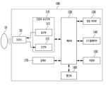
- FIG. 1is a block diagram illustrating the configuration of an ultrasonic diagnostic device (100) according to one embodiment of the present invention.
- FIG. 2is a block diagram illustrating the configuration of an ultrasonic diagnostic device (100) according to one embodiment of the present invention.
- FIG. 3is a block diagram illustrating the configuration of an ultrasonic diagnostic device (100) according to one embodiment of the present invention.
- Figures 4 (a) to (c)are perspective views of an ultrasonic diagnostic device (200) according to one embodiment of the present invention.
- Figures 5 (a) to (c)are perspective views of an ultrasonic diagnostic device (500) according to one embodiment of the present invention.
- Fig. 6 (a)is a photograph taken with a normal camera of a damaged part of a transducer element
- Fig. 6 (b)is a photograph taken with a microscope of a damaged part of a transducer element
- Fig. 6 (c)shows an ultrasound image taken with a damaged transducer
- Fig. 6 (d)shows the electric capacitance at a damaged part of a transducer element.
- Figure 7is a schematic diagram of a cross-section of an ultrasonic probe according to one embodiment of the present invention.
- FIG. 8is a drawing for explaining an acoustic module of an ultrasonic probe according to one embodiment of the present invention.
- FIG. 9is a drawing for explaining a housing of an ultrasonic probe according to one embodiment of the present invention.
- FIG. 10is a drawing showing that an ultrasonic probe according to one embodiment of the present invention rotates when dropped.
- Fig. 11(a)is a schematic diagram of a transducer element of a linear module
- Fig. 11(b)is a schematic diagram of a transducer element of a convex module.
- Fig. 12(a)shows the pitch of the linear module
- Fig. 12(b)shows the pitch of the convex module.
- FIG. 13(a), FIG. 13(b), and FIG. 13(c)are schematic diagrams of the structure of an ultrasonic probe according to one embodiment of the present invention.
- Figure 14shows the shock-absorbing structure of the first material.
- Figure 15shows a protrusion of the second material.
- firstmay be referred to as the second component
- second componentmay also be referred to as the first component
- expressions such as “first”, “second”, or “first-1”are exemplary terms for referring to different components, objects, images, pixels, or patches. Accordingly, expressions such as “first”, “second”, or “first-1” do not indicate an order or priority among components.
- ⁇ partmay refer to a unit that processes at least one function or operation.
- the termsmay refer to at least one hardware such as an FPGA (field-programmable gate array) / ASIC (application specific integrated circuit), at least one software stored in a memory, or at least one process processed by a processor.
- FPGAfield-programmable gate array
- ASICapplication specific integrated circuit
- the imagemay include a medical image acquired by a medical imaging device such as a magnetic resonance imaging (MRI) device, a computed tomography (CT) device, an ultrasonic imaging device, or an X-ray imaging device, and may also provide or control an ultrasonic image and a medical image of a modality other than ultrasonic.
- a medical imaging devicesuch as a magnetic resonance imaging (MRI) device, a computed tomography (CT) device, an ultrasonic imaging device, or an X-ray imaging device, and may also provide or control an ultrasonic image and a medical image of a modality other than ultrasonic.
- the 'object'refers to a subject of photography, and may include a person, an animal, or a part thereof.
- the objectmay include a part of the body (such as an organ or system) or a phantom.
- ultrasonic imagemeans an image of an object that is processed based on ultrasonic signals transmitted to the object and reflected from the object.
- FIG. 1is a block diagram illustrating the configuration of an ultrasonic diagnostic device (100) according to one embodiment of the present invention.
- An ultrasonic diagnostic device (100)may include a probe (20), an ultrasonic transceiver (110), a control unit (120), an image processing unit (130), a display unit (140), a storage unit (150), a communication unit (160), and an input unit (170).
- the ultrasonic diagnostic device (100)may be implemented in a cart type as well as a portable type.
- portable ultrasonic diagnostic devicesmay include, but are not limited to, a smart phone, a laptop computer, a PDA, a tablet PC, etc. that include a probe and an application.
- the probe (20)may include a plurality of transducers.
- the plurality of transducersmay transmit ultrasonic signals to the target (10) according to a transmission signal applied from the transmitter (113).
- the plurality of transducersmay receive ultrasonic signals reflected from the target (10) and form a reception signal.
- the probe (20)may be implemented as an integral part with the ultrasonic diagnostic device (100), or may be implemented as a separate part connected to the ultrasonic diagnostic device (100) via wired or wireless means.
- the ultrasonic diagnostic device (100)may be equipped with one or a plurality of probes (20) depending on the implementation form.
- the control unit (120)controls the transmission unit (113) to form a transmission signal to be applied to each of the plurality of transducers by considering the positions and focus points of the plurality of transducers included in the probe (20).
- the control unit (120)controls the receiving unit (115) to generate ultrasonic data by converting an analog-to-digital reception signal received from the probe (20) and adding the digitally converted reception signals while considering the positions and focus points of multiple transducers.
- the image processing unit (130)generates an ultrasonic image using ultrasonic data generated from the ultrasonic receiving unit (115).
- ultrasound imagescan represent the movement of an object as a Doppler image as well as a gray scale ultrasound image that scans the object according to A mode (amplitude mode), B mode (brightness mode), and M mode (motion mode).
- a modeamplitude mode
- B modebrightness mode
- M modemotion mode
- Mode Ais the most basic form of ultrasound image display method. It is a method of displaying the intensity of reflected sound as amplitude size on the time (distance) axis. When the reflected sound is strong, the amplitude is high, and when the reflected sound is weak, the amplitude is low. This is advantageous for distance measurement, but it is currently rarely used because the image changes even if the direction of the probe is slightly different.
- M modeis a mode that displays the distance of a moving reflector as a temporal change in a modified form of A mode. It designates the region of interest (ROI) in a 2D image as an M line and displays the change in that area over time. It is mainly used to observe heart valves and can also record fetal heart sounds, but it is recently being replaced by the Doppler method.
- ROIregion of interest
- B modeis a method of displaying reflected sound as the brightness of dots, and is currently used in most ultrasound diagnostic equipment.
- the brightness of each dotis proportional to the amplitude of the reflected signal. Recently, it provides brightness levels of 256 or more, and is also a mode that visualizes long-term movements in real time.
- the mode called 2D moderefers to B (brightness) mode, and it displays the cross-section of the target object in black and white shades on the screen in real time, and is the most commonly used mode.
- the Doppler modeis a mode that generally measures blood flow by detecting the flow of red blood cells in blood vessels, and uses the principle that the wavelength becomes shorter when the red blood cells approach the probe and longer when they move away.
- Doppler imagesmay include blood flow Doppler images (also called color Doppler images) that display blood flow, tissue Doppler images that display the movement of tissues, and spectral Doppler images that display the movement speed of an object as a waveform.
- the B mode componentis extracted from the ultrasound data and processed, and in the image generation process, an ultrasound image in which the intensity of the signal is expressed as brightness can be generated based on the B mode component extracted in the B mode processing process.
- the Doppler processing processthe Doppler component is extracted from the ultrasound data, and in the image generation process, a Doppler image in which the movement of the object (10) is expressed as color or waveform can be generated based on the extracted Doppler component.
- a two-dimensional ultrasound image or a three-dimensional image of the objectcan be generated, and an elastic image that visualizes the degree of deformation of the object (10) according to pressure can also be generated. Furthermore, various additional information can be expressed in the form of text or graphics on the ultrasound image. Meanwhile, the generated ultrasound image can be stored in memory.
- a measuring tool for measuring the objectcan be determined, and one of a plurality of measuring tools can be selected based on user input.
- a measurement tool selection menumay be provided for selecting one of a plurality of measurement tools, and the measurement tool selection menu may be displayed on a single screen together with the ultrasound image. Additionally, the measurement tool selection menu may be displayed on a separate screen from the touch screen on which the ultrasound image is displayed.
- one of the multiple measurement toolsmay be determined based on user input selecting one of the multiple measurement items to be measured.
- the measurement itemsmay include, but are not limited to, length, width, or angle.
- a predetermined measurement toolcan be determined corresponding to the selected measurement item.
- the display unit (140)can display the generated ultrasound image and various information processed in the ultrasound diagnosis device (100).
- the ultrasound diagnosis device (100)can include one or more display units (140) depending on the implementation type.
- the display unit (140)can be implemented as a touch screen by being combined with a touch panel.
- the control unit (120)can control the overall operation of the ultrasonic diagnostic device (100) and the signal flow between the internal components of the ultrasonic diagnostic device (100).
- the control unit (120)can include a memory that stores a program or data for performing a function of the ultrasonic diagnostic device (100), and a processor that processes the program or data.
- the control unit (120)can receive a control signal from the input unit (170) or an external device and control the operation of the ultrasonic diagnostic device (100).
- the ultrasonic diagnostic device (100)includes a communication unit (160) and can be connected to an external device (e.g., a server, a medical device, a portable device (smartphone, tablet PC, wearable device, etc.)) through the communication unit (160).
- an external devicee.g., a server, a medical device, a portable device (smartphone, tablet PC, wearable device, etc.)
- the communication unit (160)may include one or more components that enable communication with an external device, and may include, for example, at least one of a short-range communication module, a wired communication module, and a wireless communication module.
- the communication unit (160)may transmit and receive control signals and data from an external device and transmit the received control signals to the control unit (120) so that the control unit (120) controls the ultrasonic diagnostic device (100) according to the received control signals.
- control unit (120)can control the external device according to the control signal of the control unit by transmitting a control signal to the external device through the communication unit (160).
- the external devicecan process data of the external device according to a control signal from the control unit received through the communication unit.
- An external devicemay be installed with a program (artificial intelligence, etc.) capable of controlling the ultrasonic diagnostic device (100), and this program may include commands for performing part or all of the operations of the control unit (120).
- a programartificial intelligence, etc.
- the programmay be pre-installed on an external device, or the user of the external device may download and install the program from a server providing the application.
- the server providing the applicationmay include a storage medium on which the program is stored.
- the programmay include a storage medium of the server or a storage medium of the client device in a system comprising a server and a client device.
- the program productmay include a storage medium of the third device.
- the programmay include a S/W program itself that is transmitted from the server to the client device or the third device, or transmitted from the third device to the client device.
- one of the server, the client device, and the third devicemay execute the program to perform the method according to the disclosed embodiments.
- two or more of the server, the client device, and the third devicemay execute the program to perform the method according to the disclosed embodiments in a distributed manner.
- a servere.g., a cloud server or an artificial intelligence server, etc.
- a servermay execute a program stored on the server to control a client device in communication with the server to perform a method according to the disclosed embodiments.
- the storage unit (150)can store various data or programs for driving and controlling the ultrasonic diagnostic device (100), input/output ultrasonic data, acquired ultrasonic images, etc.
- the input unit (170)can receive a user's input for controlling the ultrasonic diagnostic device (100).
- the user's inputcan include, but is not limited to, input for operating a button, key pad, mouse, trackball, jog switch, knob, etc., input for touching a touch pad or touch screen, voice input, motion input, biometric information input (e.g., iris recognition, fingerprint recognition, etc.), etc.
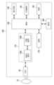
- FIG. 2is a block diagram illustrating the configuration of an ultrasonic diagnostic device (100) according to one embodiment of the present invention.
- the ultrasonic diagnostic device (100)may include a wireless probe (20) and an ultrasonic system (40).
- the wireless probe (20)may include a transmitter (113), a transducer (117), a receiver (115), a control unit (118), and a communication unit (119).
- the wireless probe (20)is illustrated as including both the transmitter (113) and the receiver (115), but depending on the implementation form, the wireless probe (20) may include only a part of the components of the transmitter (113) and the receiver (115), and a part of the components of the transmitter (113) and the receiver (115) may be included in the ultrasound system (40).
- the wireless probe (20)may further include an image processing unit (130).
- the transducer (117)may include a plurality of transducers.
- the plurality of transducersmay transmit ultrasonic signals to the target (10) according to a transmission signal applied from the transmitter (113).
- the plurality of transducersmay receive ultrasonic signals reflected from the target (10) and form a reception signal.
- the control unit (118)controls the transmission unit (113) to form a transmission signal to be applied to each of the plurality of transducers by considering the positions and focus points of the plurality of transducers.
- the control unit (118)controls the receiving unit (115) to convert the reception signal received from the transducer (117) into analog digital and generate ultrasonic data by adding the digitally converted reception signal considering the positions and focus points of the plurality of transducers.
- the wireless probe (20)includes an image processing unit (130)
- the generated ultrasonic datacan be used to generate an ultrasonic image.
- the communication unit (119)can wirelessly transmit the generated ultrasound data or ultrasound image to the ultrasound system (40) via a wireless network. Alternatively, the communication unit (119) can receive control signals and data from the ultrasound system (40).
- the ultrasonic diagnostic device (100)may be equipped with one or more wireless probes (20) depending on the implementation form.
- the ultrasound system (40)can receive ultrasound data or ultrasound images from a wireless probe (20).
- the ultrasound system (40)can include a control unit (120), an image processing unit (130), a display unit (140), a storage unit (150), a communication unit (160), and an input unit (170).
- the image processing unit (130)generates an ultrasonic image using ultrasonic data received from the wireless probe (20).
- the display unit (140)can display an ultrasound image received from a wireless probe (20), an ultrasound image generated from an ultrasound system (40), and various information processed by an ultrasound diagnostic device (100).
- the ultrasound diagnostic device (100)can include one or more display units (140) depending on the implementation type.
- the display unit (140)can be implemented as a touch screen by being combined with a touch panel.
- the control unit (120)can control the overall operation of the ultrasonic diagnostic device (100) and the signal flow between the internal components of the ultrasonic diagnostic device (100).
- the control unit (120)can include a memory that stores a program or data for performing a function of the ultrasonic diagnostic device (100), and a processor that processes the program or data.
- the control unit (120)can receive a control signal from the input unit (170) or an external device and control the operation of the ultrasonic diagnostic device (100).
- the ultrasound system (40)includes a communication unit (160) and can be connected to an external device (e.g., a server, a medical device, a portable device (smartphone, tablet PC, wearable device, etc.)) through the communication unit (160).
- an external devicee.g., a server, a medical device, a portable device (smartphone, tablet PC, wearable device, etc.)
- the communication unit (160)may include one or more components that enable communication with an external device, and may include, for example, at least one of a short-range communication module, a wired communication module, and a wireless communication module.
- the communication unit (160)may transmit and receive control signals and data from an external device and transmit the received control signals to the control unit (120) so that the control unit (120) controls the ultrasonic diagnostic device (100) according to the received control signals.
- control unit (120)can control the external device according to the control signal of the control unit by transmitting a control signal to the external device through the communication unit (160).
- the external devicecan process data of the external device according to a control signal from the control unit received through the communication unit.
- An external devicemay be installed with a program (artificial intelligence, etc.) capable of controlling the ultrasonic diagnostic device (100), and this program may include commands for performing part or all of the operations of the control unit (120).
- a programartificial intelligence, etc.
- the programmay be pre-installed on an external device, or the user of the external device may download and install the program from a server providing the application.
- the server providing the applicationmay include a storage medium on which the program is stored.
- the programmay include a storage medium of the server or a storage medium of the client device in a system comprising a server and a client device.
- the program productmay include a storage medium of the third device.
- the programmay include a S/W program itself that is transmitted from the server to the client device or the third device, or transmitted from the third device to the client device.
- one of the server, the client device, and the third devicemay execute a program to perform the method according to the disclosed embodiments.
- the client devicemay perform the method according to the disclosed embodiments via the server.
- two or more of a server, a client device, and a third devicemay execute the program to implement the method according to the disclosed embodiments in a distributed manner.
- a servere.g., a cloud server or an artificial intelligence server, etc.
- a servermay execute a program stored on the server to control a client device in communication with the server to perform a method according to the disclosed embodiments.
- the storage unit (150)can store various data or programs for driving and controlling the ultrasonic diagnostic device (100), input/output ultrasonic data, ultrasonic images, etc.
- the input unit (170)receives a user's input for controlling the ultrasonic diagnostic device (100).
- the user's inputmay include, but is not limited to, input for operating a button, key pad, mouse, trackball, jog switch, knob, etc., input for touching a touch pad or touch screen, voice input, motion input, biometric information input (e.g., iris recognition, fingerprint recognition, etc.), etc.
- FIG. 3is a block diagram illustrating the configuration of an ultrasonic diagnostic device (100) according to one embodiment of the present invention.
- the ultrasonic diagnostic device (100)may include a probe (20), an ultrasonic transceiver (110), a control unit (120), an image processing unit (130), a display unit (140), an input unit (170), a storage unit (150), and a communication unit (160).
- a probe (20)may include a plurality of transducers.
- the plurality of transducersmay be arranged two-dimensionally to form a two-dimensional transducer array.
- a two-dimensional transducer arraymay be in the form of a plurality of sub-arrays including a plurality of transducers arranged in a first direction in a second direction different from the first direction.
- the ultrasonic transceiver (110)may include an analog beamformer (116a) and a digital beamformer (116b).
- the ultrasonic transceiver (110) and the probe (20)are illustrated as separate components, but the probe (20) according to one embodiment may include part or all of the components of the ultrasonic transceiver (110) depending on the implementation form.
- the probe (20)may include part or all of the components of the ultrasonic transceiver (110) depending on the implementation form.
- the probe (20)may include one or both of an analog beamformer (116a) and a digital beamformer (116b).
- the control unit (120)can calculate a time delay value for digital beamforming for each sub-array among a plurality of sub-arrays included in the two-dimensional transducer array. In addition, the control unit (120) can calculate a time delay value for analog beamforming for each of the transducers included in one of the plurality of sub-arrays.
- the control unit (120)can control the analog beamformer (116a) and the digital beamformer (116b) to form a transmission signal to be applied to each of the plurality of transducers according to the time delay values for analog beamforming and the time delay values for digital beamforming.
- control unit (120)can control the analog beamformer (116a) to add up signals received from a plurality of transducers for each sub-array according to a time delay value for analog beamforming.
- control unit (120)can control the ultrasonic transceiver (110) to convert the signals added for each sub-array from analog to digital.
- control unit (120)can control the digital beamformer (116b) to add up digitally converted signals according to a time delay value for digital beamforming to generate ultrasonic data.
- the image processing unit (130)generates an ultrasonic image using the generated ultrasonic data.
- the display unit (140)can display the generated ultrasound image and various information processed in the ultrasound diagnosis device (100).
- the ultrasound diagnosis device (100)can include one or more display units (140) depending on the implementation type.
- the display unit (140)can be implemented as a touch screen by being combined with a touch panel.
- the control unit (120)can control the overall operation of the ultrasonic diagnostic device (100) and the signal flow between the internal components of the ultrasonic diagnostic device (100).
- the control unit (120)can include a memory that stores a program or data for performing a function of the ultrasonic diagnostic device (100), and a processor that processes the program or data.
- the control unit (120)can receive a control signal from the input unit (170) or an external device and control the operation of the ultrasonic diagnostic device (100).
- the ultrasonic diagnostic device (100)includes a communication unit (160) and can be connected to an external device (e.g., a server, a medical device, a portable device (smartphone, tablet PC, wearable device, etc.)) through the communication unit (160).
- an external devicee.g., a server, a medical device, a portable device (smartphone, tablet PC, wearable device, etc.)
- the communication unit (160)may include one or more components that enable communication with an external device, and may include, for example, at least one of a short-range communication module, a wired communication module, and a wireless communication module.
- the communication unit (160)may transmit and receive control signals and data from an external device and transmit the received control signals to the control unit (120) so that the control unit (120) controls the ultrasonic diagnostic device (100) according to the received control signals.
- control unit (120)can control the external device according to the control signal of the control unit by transmitting a control signal to the external device through the communication unit (160).
- the external devicecan process data of the external device according to a control signal from the control unit received through the communication unit.
- An external devicemay be installed with a program (artificial intelligence, etc.) capable of controlling the ultrasonic diagnostic device (100), and this program may include commands for performing part or all of the operations of the control unit (120).
- a programartificial intelligence, etc.
- the programmay be pre-installed on an external device, or the user of the external device may download and install the program from a server providing the application.
- the server providing the applicationmay include a storage medium on which the program is stored.
- the programmay include a storage medium of the server or a storage medium of the client device in a system comprising a server and a client device.
- the program productmay include a storage medium of the third device.
- the programmay include a S/W program itself that is transmitted from the server to the client device or the third device, or transmitted from the third device to the client device.
- one of the server, the client device, and the third devicemay execute the program to perform the method according to the disclosed embodiments.
- two or more of the server, the client device, and the third devicemay execute the program to perform the method according to the disclosed embodiments in a distributed manner.
- a servere.g., a cloud server or an artificial intelligence server, etc.
- a servermay execute a program stored on the server to control a client device in communication with the server to perform a method according to the disclosed embodiments.
- the storage unit (150)can store various data or programs for driving and controlling the ultrasonic diagnostic device (100), input/output ultrasonic data, ultrasonic images, etc.
- the input unit (170)can receive a user's input for controlling the ultrasonic diagnostic device (100).
- the user's inputcan include, but is not limited to, input for operating a button, key pad, mouse, trackball, jog switch, knob, etc., input for touching a touch pad or touch screen, voice input, motion input, biometric information input (e.g., iris recognition, fingerprint recognition, etc.), etc.
- Figures 4 (a) to (c)are perspective views of an ultrasonic diagnostic device (200) according to one embodiment of the present invention.
- the ultrasonic diagnostic device (200a, 200b)may include a main display unit (221) and a sub-display unit (222).
- One of the main display unit (221) and the sub-display unit (222)may be implemented as a touch screen.
- the main display unit (221) and the sub-display unit (222)may display an ultrasonic image or various information processed in the ultrasonic diagnostic device (200a, 200b).
- the main display unit (221) and the sub-display unit (222)may be implemented as a touch screen and provide a GUI, thereby receiving data for controlling the ultrasonic diagnostic device (200a, 200b) from a user.
- the main display unit (221)may display an ultrasonic image
- the sub-display unit (222)may display a control panel for controlling the display of the ultrasonic image in the form of a GUI.
- the sub display unit (222)can receive data for controlling the display of images through a control panel displayed in GUI format.
- the ultrasonic diagnostic device (200a, 200b)can control the display of ultrasonic images displayed on the main display unit (221) using the input control data.
- the ultrasonic diagnostic device (200b)may further include a control panel (265) in addition to the main display unit (221) and the sub display unit (222).
- the control panel (265)may include buttons, a trackball, a jog switch, a knob, etc., and may receive data for controlling the ultrasonic diagnostic device (200b) from a user.
- the control panel (265)may include a TGC (Time Gain Compensation) button (271), a Freeze button (272), etc.
- the TGC button (271)is a button for setting a TGC value according to the depth of an ultrasonic image.
- the ultrasonic diagnostic device (200b)detects the input of the Freeze button (272) while scanning an ultrasonic image, it may maintain a state in which a frame image at the corresponding point in time is displayed.
- buttons, trackballs, jog switches, knobs, etc. included in the control panel (265)may be provided as GUIs on the main display unit (221) or the sub display unit (222).
- the ultrasonic diagnostic device (200c)may also be implemented as a portable device.
- the portable ultrasonic diagnostic device (200c)may include, but are not limited to, a smart phone, a laptop computer, a PDA, a tablet PC, etc. that include a probe and an application.
- the ultrasonic diagnostic device (200c)includes a probe (20) and a main body (240), and the probe (20) can be connected to one side of the main body (240) by wire or wirelessly.
- the main body (240)can include a touch screen (245).
- the touch screen (245)can display an ultrasonic image, various information processed in the ultrasonic diagnostic device, a GUI, etc.
- Figures 5 (a) to (c)are perspective views of an ultrasonic diagnostic device (500) according to one embodiment of the present invention.
- an ultrasonic diagnostic device used indoors or an indoor ultrasonic diagnostic device (500)generally means a non-portable ultrasonic diagnostic device used for ultrasonic diagnosis, and such an indoor ultrasonic diagnostic device (500) is also called a cart-based device.
- the indoor ultrasonic diagnostic device (500)does not necessarily have to be used only indoors, but for convenience, it will be referred to as an indoor ultrasonic diagnostic device (500).
- the indoor ultrasonic diagnostic device (500)may have a portable docking unit (580) connected to a portable ultrasonic diagnostic device (400). All components of the indoor ultrasonic diagnostic device (500) used in the present invention except for the portable docking unit (580) are generally used, so a detailed description thereof is omitted.
- the indoor ultrasonic diagnostic device (500)has fewer constraints in terms of size, weight, power consumption, etc., and thus can be developed with a variety of diagnostic items and high performance.
- the portable ultrasonic diagnostic device (400)can be used with high performance.
- the location where the portable ultrasonic diagnostic device (400) is mounted on the indoor ultrasonic diagnostic device (500)can be any location where it is convenient for the user to use the portable ultrasonic diagnostic device (400) and the indoor ultrasonic diagnostic device (500) at the same time, and is not limited by (a) of FIG. 5.
- the portable ultrasonic diagnostic device (400)can be connected to the indoor ultrasonic diagnostic device (500) via a wire or through an integral part.
- the portable ultrasonic diagnostic device (400) of FIG. 5 (a)may correspond to the portable ultrasonic diagnostic device (201) of FIG. 5 (b).
- the portable ultrasonic diagnostic device (400)means a device that provides an ultrasonic image to a user by using ultrasonic image data received by connecting to an indoor ultrasonic diagnostic device (500) using a wireless or wired communication method (including USB (Universal Serial Bus)).
- the portable ultrasonic diagnostic device (400)may be a smart device that downloads and installs an app on a smartphone, etc.
- the portable ultrasonic diagnostic device (400)may be a device that provides an ultrasonic image to a user by using ultrasonic image data received through a wired or wireless communication connection with an indoor ultrasonic diagnostic device (500).
- the wireless communication methodmay include at least one of short-range data communication methods including a 60 GHz (mmWave) wireless local area network (WLAN), Wireless Local Area Network (Wi-Fi), Bluetooth, Zigbee, Wi-Fi Direct (WFD), Infrared Data Alliance (IrDA), Bluetooth Low Energy (BLE), Near Field Communication (NFC), Wireless Broadband Internet (Wibro), Worldwide Interoperability Shared Wireless Access Protocol (SWAP) for Microwave Access (WiMAX), Wireless Gigabit Alliance (WiGig), and radio frequency (RF) communication.
- short-range data communication methodsincluding a 60 GHz (mmWave) wireless local area network (WLAN), Wireless Local Area Network (Wi-Fi), Bluetooth, Zigbee, Wi-Fi Direct (WFD), Infrared Data Alliance (IrDA), Bluetooth Low Energy (BLE), Near Field Communication (NFC), Wireless Broadband Internet (Wibro), Worldwide Interoperability Shared Wireless Access Protocol (SWAP) for Microwave Access (WiMAX), Wireless Gigabit
- Fig. 5 (b)illustrates an ultrasonic diagnostic system in which a portable ultrasonic diagnostic device (201) is connected to a cart-based indoor ultrasonic diagnostic device (500).
- the cart-based indoor ultrasonic diagnostic device (500)can be connected to the portable ultrasonic diagnostic device (201) using the wireless communication method described above.
- the portable ultrasonic diagnostic device (201)can be equipped with at least one wireless communication module (not shown) for performing at least one of the wireless communication methods described above.
- the portable docking unit (580) of the cart-based indoor ultrasonic diagnostic device (500)can include at least one wireless communication module (not shown) for performing wireless communication with the portable ultrasonic diagnostic device (201).
- the wireless communication module in the cart-based indoor ultrasound diagnostic device (500)may be a module for performing communication according to at least one of the wireless communication methods described above.
- Fig. 5 (c)illustrates an ultrasonic diagnostic system in which a portable ultrasonic diagnostic device (202) is connected to a cart-based indoor ultrasonic diagnostic device (500).
- a portable ultrasonic diagnostic device (202)can be connected to a probe (301) through a probe port.
- the portable ultrasonic diagnostic device (202)can generate an ultrasonic image using an ultrasonic image corresponding to an ultrasonic signal received by the probe (301) and display the generated ultrasonic image on a display unit.
- the cart-based indoor ultrasonic diagnostic device (500)can be connected to the portable ultrasonic diagnostic device (202) using the wireless communication method described above.
- the connection between the cart-based indoor ultrasonic diagnostic device (500) and the portable ultrasonic diagnostic device (202) through wireless communicationcorresponds to the connection between the cart-based indoor ultrasonic diagnostic device (500) and the portable ultrasonic diagnostic device (201), and a detailed description thereof will be omitted.
- Figure 7is a schematic diagram of a cross-section of an ultrasonic probe according to one embodiment of the present invention.
- the ultrasonic probe (700)includes an acoustic module (701, 706), a signal processing module (702), a communication module (703), a power control module (704), and a power supply (705).
- the acoustic module (701, 706)receives a first power supply, transmits an ultrasonic signal to a target object, and receives an ultrasonic echo signal reflected from the target object to scan the target object.
- the acoustic module (701, 706)includes a transducer (not shown) and performs an ultrasonic scan of the target object using the transducer.
- the acoustic module (701, 706)can receive power required to perform an ultrasonic scan operation from a power supply unit (705), and the acoustic module (701, 706) can apply a high voltage, which is an analog voltage, to a transducer (not shown).
- An ultrasonic probe (700)is a multi-head probe equipped with two or more acoustic modules (701, 706), and specifically, may include a linear module (701, linear module) having a linear surface shape and a convex module (706, convex module) having a curved convex surface shape.
- the acoustic modules (701, 706)may be provided in other shapes known in the art in addition to linear or curved shapes.
- the linear module (701)is used to diagnose a relatively narrow area, and the size of the transducer element has a great influence on the diagnosis area, and is mainly used for diagnosing places such as blood vessels.
- the linear module (701)is mainly used to transmit high frequency, and has a structure in which the pitch, which is the distance between the centers of elements, is small and the area (thickness, length, width) of the active zone is narrow, so it is relatively smaller and lighter than the convex module.
- the convex module (706)can secure a wide diagnostic area because the transducer element has a curvature in the radial plane. Therefore, it is widely used for abdominal diagnosis, organ diagnosis, fetus diagnosis, etc.
- the convex module (706)is mainly used for transmitting low frequencies, and has a structure with a large pitch and a large effective area, so it is relatively heavier than the linear module.
- the signal processing module (702)receives power from the power supply unit (705), generates a pulse for generating an ultrasonic signal, and generates ultrasonic data using the ultrasonic echo signal. Specifically, the signal processing module (702) generates, adjusts, and controls (beamforming) a pulse for generating an ultrasonic signal generated from the acoustic module (701, 706).
- the signal processing module (702)can process the ultrasonic echo signal received from the acoustic module (701, 706) to generate ultrasonic data or an ultrasonic image using the ultrasonic data (processing).
- the signal processing module (702)can receive power from the power supply unit (705) and perform an ultrasonic scan operation.
- the signal processing module (702)may require a digital voltage having a predetermined frequency, a predetermined clock speed, or a predetermined sampling rate to generate and control a pulse.
- the communication module (703)receives power from the power supply (705) and transmits data to or receives data from an external medical device.
- the medical device(not shown) means any electronic device that can be linked to the ultrasound probe (700) via a wireless network.
- the medical devicemay correspond to an ultrasound diagnostic device and may be a cart-type ultrasound system, a fax viewer (PACS viewer), a smart phone, a laptop computer, a PDA, a tablet PC, etc.
- the medical device (not shown) that transmits and receives predetermined data with the communication module (703)may be not only a server or a medical device within a hospital, but also a portable terminal of a doctor or patient, and may be another type of medical imaging system such as a CT, MRI, or X-ray system.
- the communication module (703)transmits ultrasound data or ultrasound images generated by the signal processing module (702) to a medical device, and the medical device can generate and display ultrasound images using the transmitted ultrasound data.
- the power control module (704)can individually supply or cut off power to the acoustic module (701, 706), signal processing module (702), and communication module (703) based on the operating status of the ultrasonic probe (700).
- the power control module (704)can supply power to each of the sound module (701, 706), the signal processing module (702), and the communication module (703) based on a signal indicating the operating state of at least one of the sound module (701, 706), the signal processing module (702), and the communication module (703).
- the power supply unit (705)supplies power to at least one of the sound modules (701, 706), the signal processing module (702), and the communication module (703) under the control of the power control module (704).
- the power supply unit (705)may include a battery that charges power and supplies power to at least one of the sound module (701, 706), the signal processing module (702), and the communication module (703) using the charged power.
- the batterycharges power and may supply power to each internal component included in the ultrasonic probe (700) using the charged power.
- the power supply unit (705)may include a power circuit.
- the batterymay be configured as a rechargeable battery, so that when the charged power is discharged, it can be recharged using power supplied through the power line. Additionally, the battery may be charged by wireless power transmitted from an external source.
- the power supply unit (705)can supply power to at least one of the sound modules (701, 706), the signal processing module (702), and the communication module (703) using wireless power transmitted from the outside.
- the power supply unit (705)can receive a wireless power signal received from the outside, for example, an ultrasonic diagnostic device, and store and use the power generated by converting the received wireless power signal.
- wireless power transmission methodsinclude an electromagnetic induction method based on an electromagnetic induction phenomenon caused by a wireless power signal, an electromagnetic resonance method based on an electromagnetic resonance phenomenon caused by a wireless power signal of a specific frequency, an electromagnetic radiation method based on electromagnetic wave radiation, and a wireless power transmission method using ultrasonic waves.
- the power supply unit (705)can receive power using at least one of the wireless power transmission methods, and can convert the received power to be supplied to each component included in the ultrasonic probe (700). That is, the power supply unit (705) can convert the received wireless power so that it becomes less than or equal to the rated voltage and rated current of the ultrasonic probe (700).
- the power supply unit (705)can internally include a switched-mode power supply (SMPS) (not shown), a boost device (not shown), and/or a step-down device (not shown), and can convert the wireless power using these.
- SMPSswitched-mode power supply
- boost devicenot shown
- step-down devicenot shown
- the power supply unit (705)essentially includes a battery, and the battery occupies the largest volume inside the wireless probe and is the heaviest component of the wireless probe.
- the acoustic modules (701, 706), the signal processing module (702), and the communication module (703)can operate independently of each other, and even if the power of a specific module is cut off, the operation of other modules may not be affected. Power can be individually supplied or cut off to the acoustic modules (701, 706), the signal processing module (702), and the communication module (703), and accordingly, the ultrasonic probe (700) can minimize power consumption.
- FIG. 8is a drawing for explaining an acoustic module of an ultrasonic probe according to one embodiment of the present invention.
- the acoustic module (701, 706)may include a lens part (810, Lens), a transducer part (820, Transducer), and an absorbing part (830, Backing).
- the lens unit (810)may include a lens (811), a first matching layer (812), and a second matching layer (813).
- the lens unit (810)may change the direction in which an ultrasonic signal emitted from the transducer unit (820) is directed. Ultrasonic waves traveling in front of the transducer unit (820) may be focused on a specific point.
- the lens unit (810)may be provided in various shapes such as a linear shape, a convex shape, and a concave shape. The focusing point of the ultrasonic waves may vary depending on the curvature of the lens unit (810) or the shape of the lens unit (810).
- the matching layer (812, 813)is arranged between the lens (811) and the transducer unit (820).
- the matching layer (812, 813)matches the acoustic impedance of the transducer unit (820) and the acoustic impedance of the target object, so that the ultrasonic signal generated from the transducer unit (820) can be efficiently transmitted to the target object, or the ultrasonic echo signal returned from the target object can be efficiently transmitted to the transducer unit (820). Therefore, the matching layer (812, 813) is provided to have an intermediate value between the acoustic impedance of the transducer unit (820) and the acoustic impedance of the target object.
- the matching layers (812, 813)may include a plurality of layers.
- the matching layers (812, 813)include a plurality of layers, the plurality of layers may be arranged so that the acoustic impedance gradually changes from the transducer unit (820) toward the object, and accordingly, the acoustic impedance difference between the transducer unit (820) and the object may be gradually reduced.
- the first matching layer (812) and the second matching layer (813)may be arranged so that they have an intermediate value between the acoustic impedance of the transducer unit (820) and the acoustic impedance of the object, but the acoustic impedance of the first matching layer (812) and the acoustic impedance of the second matching layer (813) may be arranged so that the acoustic impedance of the first matching layer (812) and the acoustic impedance of the second matching layer (813) change gradually.
- the matching layers (812, 813)may be formed of a material such as glass or resin. As described above, the first matching layer (812) and the second matching layer (813) may be formed of different materials so that the acoustic impedance changes stepwise. Alternatively, there may be a difference in the composition ratio of the material forming the first matching layer (812) and the material forming the second matching layer (813), and there may be a difference in the thickness of the first matching layer (812) and the second matching layer (813).
- At least one of CS (Chemical Shield) and RF (Radio Frequency)may be formed between the lens portion (810) and the matching layer (812, 813).
- CSis preferably formed between the lens portion (810) and the matching layer (812, 813) because it can prevent liquid from penetrating into the ultrasonic probe (700) and shield EMI.
- the transducer unit (820)may be placed between the lens unit (810) and the backing unit (830). A plurality of transducer units (820) may be provided, and may receive an electrical signal. The transducer unit (820) may convert an ultrasonic signal and an electrical signal into each other. According to one embodiment, the transducer unit (820) may vibrate according to a transmitted electrical signal, and may emit an ultrasonic signal, which is acoustic energy, and may process acoustic energy reflected from an object to obtain an electrical signal.
- the backing part (830)is arranged on one side of the transducer part (820) to block ultrasonic waves emitted from the transducer part (820) from traveling backwards rather than in the direction in which the lens part (810) is arranged.
- the backing part (830)may be composed of a plurality of layers, but is not limited to a specific example, and various known structures and materials may be applied to the backing part (830) to enhance the ultrasonic blocking effect.
- the backing part (830)may have a structure in which a sound-absorbing layer (831) and a backing block (832) are laminated.
- the sound-absorbing layer (831) and the backing block (832)are each formed of a material capable of absorbing ultrasonic waves.
- the acoustic impedances of the sound-absorbing layer (831) and the backing block (832)may be combined in various ways, such as being equal to each other or being formed such that one is larger than the other, depending on the design, so that the desired acoustic impedance can be easily obtained.
- An absorbing layer (831)may be installed to prevent mechanical vibration of the transducer unit (820) from being transmitted to the backing block (832) or adjacent transducer elements.
- the backing block (832)may be installed to maintain a plurality of transducer elements in a straight line in the case of a linear module, or to maintain a plurality of transducer elements in an arc shape with a constant curvature in the case of a convex module.
- the sound-absorbing layer (831) and the backing block (832) provided in the convex module (706)may be manufactured from materials having a high weight specific gravity.
- materials having a high weight specific gravitytungsten, tungsten carbide powder (WC Powder), aluminum powder (AL Powder), etc. may be used, and a metal mesh and a metal frame may also be used.
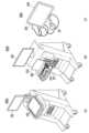
- FIG. 9is a drawing for explaining a housing of an ultrasonic probe according to one embodiment of the present invention.
- the ultrasonic probe (700) of the present inventionmay have an exterior formed by a first housing (707) and a second housing (708).
- the first housing (707) and the second housing (708)may support the exterior of the ultrasonic probe (20).
- the first housing (707) and the second housing (708)may provide a space in which a lens unit (810), a transducer unit (820), and/or a backing unit (830) may be accommodated.
- the first housing (707) and the second housing (708)may protect the acoustic module (701, 706) from external influences.
- the first housing (707)can be coupled with the second housing (708).
- the first housing (707) and the second housing (708)can form a contact surface having a predetermined shape.
- the first housing (707) and the second housing (708)can physically contact each other.
- the first housing (707) and the second housing (708)are coupled with each other, so that the inner region of the ultrasonic probe (700) can be separated from the outside.
- At least a portion of the first housing (707) and the second housing (708)may be connected to the acoustic module (701, 706). At least a portion of the first housing (707) and the second housing (708) may be connected to the lens unit (810).
- the first housing (707) and the second housing (708)may include an opening to expose the lens unit (810) to the outside. A portion of the first housing (707) and the second housing (708) forming the opening may be in physical contact with the lens unit (810).
- the first housing (707) and the second housing (708)may be referred to as a head housing.
- the first housing (707)can provide a space in which a linear module (701), a signal processing module (702), a communication module (703), and a power control module (704) of an ultrasonic probe (700) can be accommodated
- the second housing (708)can provide a space in which a power supply unit (705) and a convex module (706) can be accommodated.
- the first housing (707)can be in physical contact with a lens unit (810) of the linear module (701), and the second housing (708) can be in physical contact with a lens unit (810) of the convex module (706).
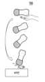
- FIG. 10is a drawing showing that an ultrasonic probe according to one embodiment of the present invention rotates when dropped.
- the linear module (701) and the convex module (706)may each mean the linear module (701) and the convex module (706) themselves, but may also mean a housing that accommodates the linear module (701) and a housing that accommodates the convex module (706).
- an ultrasonic probe (700)according to one embodiment of the present invention can rotate when dropped.
- the ultrasonic probe (700)is a multi-head probe equipped with a linear module (701) and a convex module (706) at both ends, and the ultrasonic probe (700) can be dropped while rotating so that the relatively heavy convex module (706) faces the floor.
- the power supply unit (705)which is the heaviest component among those provided inside the ultrasonic probe (700), is positioned close to the convex module (706), the center of gravity can be moved toward the convex module (706), so that the ultrasonic probe (700) rotates and falls so that the convex module (706), which is close to the center of gravity, faces the floor.
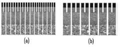
- Fig. 11(a)is a schematic diagram of a transducer element of a linear module
- Fig. 11(b)is a schematic diagram of a transducer element of a convex module.
- Fig. 12(a)shows the pitch of the linear module
- Fig. 12(b)shows the pitch of the convex module.
- the transducer element (709) of the linear module (701)is narrow and light in weight, whereas the transducer element (711) of the convex module (706) is relatively wide and heavy.
- the pitch of the linear module and the pitch of the convex modulerepresent the pitches of the transducer elements (709, 711), respectively.
- the pitch (the distance between the centers of the elements) of the linear moduleis small, while the pitch of the convex module is relatively large. Since the pitch of the convex module is relatively large, the transducer of the convex module has a relatively superior shock absorption capability compared to the linear module.
- the ultrasonic probe (700)can be dropped while rotating toward the convex module (706) that is relatively heavier than the linear module (701), and the convex module (706) that is relatively stronger than the linear module (701) and has excellent shock absorption capability is designed to collide with the floor while facing the floor. Accordingly, the possibility of damage to the ultrasonic probe (700) can be reduced.
- FIG. 13(a), FIG. 13(b), and FIG. 13(c)are schematic diagrams of the structure of an ultrasonic probe according to one embodiment of the present invention.
- the linear module (701)may be placed inside the first housing (707), and the convex module (706) may be placed inside the second housing (708).
- the linear module (701)may be placed inside the first housing (707) of the first material (710), and the convex module (706) may be placed inside the second housing (708) of the second material (712).
- the ultrasonic probe (700) of the present inventionis designed to hit the floor with the convex module (706) facing the floor when dropped, and the second material (712) of the second housing (708) in which the convex module (706) is provided may be a material with a high strength that is not damaged by external impact compared to the first material (710), or may be an elastic material that can absorb external impact.
- the material of the first housing (707)may be polyphenyl sulfone (PPSU), such as Radel PPSU (polyphenyl sulfone) from Solvay.
- the material of the second housing (708)may be carbon fiber reinforced plastic (CFRP).
- the first material (710) and the second material (712)may be used to mean the material of the first housing (707) and the material of the second housing (708), or may be used to mean the first housing (707) and the second housing (708) themselves.
- FIG. 13(b)illustrates that the second material (712) is designed to surround the first material (710), so that the amount of the second material (712) used can be relatively reduced.
- FIG. 13(c)illustrates that the second material (712) is designed to surround the first material (710), but the first material (710) has a shock-absorbing structure.
- Figure 14shows the shock-absorbing structure of the first material.
- the first material (710)may be arranged inside the second material (712), and the first material (710) may have a shock absorbing structure (713).
- the shock absorbing structure (713)may be applied without limitation as a shock absorbing structure (713) as long as it is a structure that can absorb upper and lower shocks or left and right shocks, and as illustrated in FIG. 14, it may have a shape in which a part is cut off in the cross section, a part is curved, a bent shape, a shape in which the entirety is curved, a part is in a circle shape, an S shape, or a part is thinned.
- a part of the shock absorbing structure (713) in FIG. 14 that is cut off or a part that is indicated as not including the first material (710)may be provided with a material that can absorb shock (shock absorbing material).
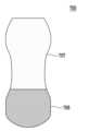
- Figure 15shows a protrusion of the second material.
- a protrusion (714)may be provided at the end of the second material (712), and the protrusion (714) may have a structure extending outward from the convex module (706). That is, the protrusion (714) may have a structure protruding outward from the convex module (706).
- the protrusion (714) protruding outwardly of the convex module (706)can prevent direct impact from being applied to the convex module (706) by hitting the floor.
- the protrusion (714)be formed into a curved surface so that there is no angled portion.
- a part of the linear module (701)may protrude outside the first material (710), and the part protruding from the linear module (701) may be specifically a lens part, and a part of the convex module (706) may protrude outside the second material (712), and the part protruding from the convex module (706) may also be a lens part. Accordingly, a part of the second material (712) may extend outside the convex module (706), specifically, the lens part of the convex module (706), to instead absorb an impact transmitted to the lens of the convex module (706).
- the first material (710)may also extend to the outside of the linear module (701) in a structure similar to that of the protrusion (714), thereby absorbing the impact transmitted to the linear module (701).
- the ultrasonic probe (700)is a multi-head probe, and when dropped, the convex module (706) rotates toward the floor, and the convex module (706) may hit the floor. Since the convex module (706) has a relatively superior shock absorption capability compared to the linear module (701), the probability of damage to the ultrasonic probe (700) can be reduced by allowing the convex module (706) to hit the floor when the ultrasonic probe (700) is dropped. Furthermore, by using a material with high strength or elasticity as the housing material of the convex module (706), the convex module (706) can be prevented from being damaged.
Landscapes
- Health & Medical Sciences (AREA)
- Life Sciences & Earth Sciences (AREA)
- Engineering & Computer Science (AREA)
- Biomedical Technology (AREA)
- Medical Informatics (AREA)
- Pathology (AREA)
- Radiology & Medical Imaging (AREA)
- Biophysics (AREA)
- Physics & Mathematics (AREA)
- Heart & Thoracic Surgery (AREA)
- Nuclear Medicine, Radiotherapy & Molecular Imaging (AREA)
- Molecular Biology (AREA)
- Surgery (AREA)
- Animal Behavior & Ethology (AREA)
- General Health & Medical Sciences (AREA)
- Public Health (AREA)
- Veterinary Medicine (AREA)
- Computer Networks & Wireless Communication (AREA)
- Ultra Sonic Daignosis Equipment (AREA)
Abstract
Description
Translated fromKorean본 발명은 초음파 프로브 및 이를 포함하는 초음파 진단 장치에 관한 것이다.The present invention relates to an ultrasonic probe and an ultrasonic diagnostic device including the same.
초음파 영상은 높은 주파수의 음파를 인체 표면에서 인체 내부로 보낸 후 내부에서 반사되는 음파를 영상화시키는 것을 의미하는 것으로, 초음파 검사는 초음파 영상을 실시간으로 제공한다. 종래의 아날로그 방식에서 디지털 방식으로, 2차원 초음파 진단 장치에서 3차원, 시간의 흐름이 포함된 4차원 초음파 진단 장치로 변화되고 있으며, 최근에는 3차원 영상의 움직임까지 표현되는 4차원 초음파 검사도 이용되고 있다.Ultrasound imaging refers to sending high-frequency sound waves from the surface of the human body to the inside of the body and visualizing the sound waves reflected inside. Ultrasound examination provides ultrasound images in real time. It has changed from the conventional analog method to digital, from 2D ultrasound diagnostic devices to 3D, and from 4D ultrasound diagnostic devices that include the flow of time. Recently, 4D ultrasound examinations that express even the movement of 3D images have also been used.
초음파 진단 장치는 프로브(probe)의 트랜스듀서(transducer)로부터 생성되는 초음파 신호를 대상체로 조사하고, 대상체로부터 반사된 에코 신호의 정보를 수신하여 대상체 내부의 부위에 대한 영상을 얻는 장치이며, 이러한 초음파 진단 장치는 X선을 이용하는 진단 장치에 비하여 안정성이 높고, 실시간으로 영상의 디스플레이가 가능하다는 장점이 있어서 다른 화상 진단 장치와 함께 널리 이용되고 있다. 특히, 타 진단 장치에 비하여 정확도가 높고 인체에 방사능 피폭 우려가 없어 안전한 초음파 진단 장치는 다양한 진단 과정에서 많이 이용되고 있다.An ultrasonic diagnostic device is a device that irradiates an ultrasonic signal generated from a transducer of a probe to a target object and receives information on an echo signal reflected from the target object to obtain an image of the internal part of the target object. Such ultrasonic diagnostic devices have the advantage of being more stable than diagnostic devices that use X-rays and of being able to display images in real time, and are therefore widely used together with other imaging diagnostic devices. In particular, ultrasonic diagnostic devices are safe because they have higher accuracy than other diagnostic devices and there is no concern about radiation exposure to the human body, and are therefore widely used in various diagnostic processes.
초음파 프로브로 초음파 영상을 촬영(촬상, 특히 의료용 촬상)하는 경우 환자 또는 관심 영역을 촬영하기 위해 다양한 촬영 방식이 사용될 수 있으나, 대체로 프로브(트랜스듀서)를 환자의 피부에 접촉시켜 초음파 영상을 촬영하는 경우가 많다, 피부에 접촉시키는 방식에서는, 촬영을 최적화하기 위해 촬영 부위에 맞는 기하학적 형상을 가지는 초음파 프로브를 선택할 필요가 있다.When taking ultrasound images (imaging, especially medical imaging) with an ultrasound probe, various imaging methods can be used to capture images of a patient or an area of interest, but most often, ultrasound images are captured by contacting the probe (transducer) with the patient's skin. In the skin-contact method, it is necessary to select an ultrasound probe with a geometric shape that suits the area to be captured in order to optimize the image.
특히, 환자의 검사 동안에 초음파 영상의 촬영 부위를 변경하기 위해서 초음파 프로브 사용자는 초음파 프로브를 형태가 다른 것으로 변경할 수 있는데, 이때 초음파 프로브 사용자는 초음파 프로브를 변경하는 과정에서 번거로움을 느낄 수 있고, 환자에 대한 검사 시간이 늘어날 수 있다. 기하학적 형상이 상이한 커넥터를 구비하여 환자의 접촉 부위에 따라 커넥터를 변경하는 것도 고려될 수 있으나, 커넥터를 변경하는 것도 초음파 프로브 자체를 변경하는 것과 마찬가지로 수고로움이 수반된다.In particular, in order to change the area to be captured in an ultrasound image during a patient examination, the ultrasound probe user may change the ultrasound probe to one with a different shape. In this case, the ultrasound probe user may feel inconvenienced in the process of changing the ultrasound probe, and the examination time for the patient may increase. It may be considered to provide connectors with different geometric shapes so that the connector can be changed according to the patient's contact area, but changing the connector is as laborious as changing the ultrasound probe itself.
이러한 초음파 사용자의 수고로움을 덜기 위해 초음파 프로브 사용자의 번거로움을 줄이기 위해 하나의 초음파 프로브에 여러 기하학적 형상을 가지는 헤드가 마련되는 멀티 헤드 초음파 프로브가 개발되고 있다.To reduce the burden on these ultrasound users, a multi-head ultrasound probe is being developed in which a single ultrasound probe is provided with heads having various geometric shapes to reduce the inconvenience of ultrasound probe users.
한편, 기존에는 초음파 프로브가 카트 기반의 초음파 진단 장치에 통신 케이블에 연결되어 사용되었으나, 최근에는 통신 케이블에 의한 번거로움을 해소하고 초음파 프로브의 조작성을 향상시키기 위해, 초음파 프로브와 초음파 진단 장치 간 초음파 영상 데이터를 송수신하는 통신 케이블을 제거하고 초음파 프로브와 초음파 진단 장치가 무선 통신에 연결되도록 하는 휴대용 프로브 또는 무선 프로브가 개발되고 있다.Meanwhile, in the past, ultrasound probes were used by connecting them to a cart-based ultrasound diagnostic device via a communication cable, but recently, in order to eliminate the inconvenience of the communication cable and improve the operability of the ultrasound probe, portable probes or wireless probes are being developed that remove the communication cable that transmits and receives ultrasound image data between the ultrasound probe and the ultrasound diagnostic device and connect the ultrasound probe and the ultrasound diagnostic device via wireless communication.
휴대용 프로브 또는 무선 프로브는, 연결되는 케이블이 없기 때문에 초음파 프로브 사용자가 부주의로 떨어트릴 때 아무런 제약이 없이 바닥과 부딪힐 수 있으므로, 유선 프로브 대비 초음파 프로브에 더욱 빈번하게 충격이 가해질 수 있다. 초음파 프로브에 가해지는 충격으로 인해, 초음파 프로브의 트랜스듀서 소자(transducer element)는 손상될 수 있다. 트랜스듀서 소자의 손상은 도 6에서와 같이 확인할 수 있다.Portable or wireless probes can be more frequently impacted than wired probes because they do not have a connecting cable, and can hit the floor without any restrictions when the user of the ultrasonic probe accidentally drops it. The impact applied to the ultrasonic probe can damage the transducer element of the ultrasonic probe. Damage to the transducer element can be confirmed as shown in Fig. 6.
도 6 (a)는 트랜스듀서 소자가 손상된 부분을 일반 카메라로 촬영한 사진이며, 도 6 (b)는 트랜스듀서 소자가 손상된 부분을 현미경으로 촬영한 사진이며, 도 6(c)는 손상된 트랜스듀서로 촬영한 초음파 영상을 나타낸 것이며, 도 6(d)는 트랜스듀서 소자가 손상된 부분에서 전기용량을 나타낸 것이다.Fig. 6 (a) is a photograph taken with a normal camera of a damaged part of a transducer element, Fig. 6 (b) is a photograph taken with a microscope of a damaged part of a transducer element, Fig. 6 (c) shows an ultrasound image taken with a damaged transducer, and Fig. 6 (d) shows the electric capacitance at a damaged part of a transducer element.
트랜스듀서가 손상되는 경우, 트랜스듀서 소자의 교체를 위해 비용이 발생하고, 트랜스듀서 소자가 손상되면 초음파 프로브의 다른 구성들도 함께 교체되어야 하는 경우가 많아 추가 비용도 발생할 수 있다.If the transducer is damaged, there is a cost to replace the transducer element, and if the transducer element is damaged, other components of the ultrasound probe often must be replaced as well, which can incur additional costs.
따라서 초음파 프로브에 가해지는 충격을 완충시키고, 초음파 프로브를 보호하기 위한 기술 개발이 필요한 실정이다.Therefore, there is a need to develop technology to cushion the impact on the ultrasonic probe and protect the ultrasonic probe.
본 발명은 초음파 프로브가 바닥으로 낙하하는 경우에도 초음파 프로브가 손상되지 않도록 내구성이 우수한 초음파 프로브를 제공하는 것을 그 목적으로 한다.The purpose of the present invention is to provide an ultrasonic probe having excellent durability so that the ultrasonic probe is not damaged even when the ultrasonic probe is dropped to the floor.
본 발명의 과제들은 이상에서 언급한 과제들로 제한되지 않으며, 언급되지 않은 또 다른 과제들은 아래의 기재로부터 통상의 지식을 가진 자에게 명확하게 이해될 수 있을 것이다.The tasks of the present invention are not limited to the tasks mentioned above, and other tasks not mentioned will be clearly understood by those of ordinary skill in the art from the description below.
본 발명에 따른 초음파 프로브는, 외관을 형성하는 하우징; 상기 하우징의 내측에 마련되며, 초음파 신호를 송신하고 반사되는 초음파 에코 신호를 수신하는 음향 모듈; 및 상기 하우징의 내측에 마련되며, 전원을 공급하는 전원부;를 포함하고, 상기 음향 모듈은, 상기 하우징 일단에 형성되는 선형의 표면 형상을 갖는 리니어 모듈; 및 상기 하우징 타단에 형성되는 곡면의 표면 형상을 갖는 컨벡스 모듈;을 포함하고, 상기 전원부는, 상기 컨벡스 모듈과 인접하게 배치될 수 있다.An ultrasonic probe according to the present invention comprises: a housing forming an outer appearance; an acoustic module provided on the inside of the housing, which transmits an ultrasonic signal and receives a reflected ultrasonic echo signal; and a power supply unit provided on the inside of the housing, which supplies power; wherein the acoustic module comprises: a linear module formed on one end of the housing and having a linear surface shape; and a convex module formed on the other end of the housing and having a curved surface shape; and the power supply unit can be arranged adjacent to the convex module.
구체적으로, 상기 전원부는, 배터리를 포함할 수 있다.Specifically, the power supply unit may include a battery.
구체적으로, 상기 음향 모듈은, 초음파 신호를 송신하고 반사되는 초음파 에코 신호를 수신하는 트랜스듀서부; 상기 트랜스듀서부의 전면에 배치되는 적어도 하나의 정합층; 상기 트랜스듀서부의 배면에 배치되는 흡음층; 및 상기 흡음층의 배면에 배치되는 백킹블럭을 포함할 수 있다.Specifically, the acoustic module may include a transducer unit that transmits an ultrasonic signal and receives a reflected ultrasonic echo signal; at least one matching layer arranged on a front side of the transducer unit; an absorbing layer arranged on a back side of the transducer unit; and a backing block arranged on a back side of the absorbing layer.
구체적으로, 상기 컨벡스 모듈의 흡음층 및 백킹블럭은, 상기 리니어 모듈의 흡음층 및 백킹블럭 대비 중량이 클 수 있다.Specifically, the absorbing layer and backing block of the convex module may have a greater weight than the absorbing layer and backing block of the linear module.
구체적으로, 상기 컨벡스 모듈의 흡음층 및 백킹블럭은, 텅스텐, 탄화 텅스텐 분말(Tungsten Carbide Powder, WC Powder), 알루미늄 분말(Aluminum powder, AL Powder), 금속 메쉬(metal mesh) 및 금속 프레임(metal frame) 중 어느 하나 이상으로 구성될 수 있다.Specifically, the sound-absorbing layer and backing block of the convex module may be composed of one or more of tungsten, tungsten carbide powder (WC Powder), aluminum powder (AL Powder), metal mesh, and metal frame.
구체적으로, 상기 하우징은, 상기 리니어 모듈을 수용하는 제1 하우징; 및 상기 컨벡스 모듈을 수용하는 제2 하우징;을 포함하고, 상기 제2 하우징은, 상기 제1 하우징 대비 강도가 큰 소재거나, 탄성이 큰 소재일 수 있다.Specifically, the housing includes a first housing that accommodates the linear module; and a second housing that accommodates the convex module; and the second housing may be made of a material having greater strength or greater elasticity than the first housing.
구체적으로, 상기 제1 하우징의 소재는 폴리페닐설폰(PolyPhenyl Sulfone, PPSU)이고, 상기 제2 하우징의 소재는 탄소섬유강화플라스틱(Carbon Fiber Reinforced Plastic, CFRP)일 수 있다.Specifically, the material of the first housing may be polyphenyl sulfone (PPSU), and the material of the second housing may be carbon fiber reinforced plastic (CFRP).
구체적으로, 상기 제2 하우징은, 상기 컨벡스 모듈의 외부로 돌출될 수 있다.Specifically, the second housing can protrude outside the convex module.
구체적으로, 상기 제2 하우징은, 상기 제1 하우징을 감싸는 형태를 가질 수 있다.Specifically, the second housing may have a shape that surrounds the first housing.
구체적으로, 상기 제1 하우징은, 굴곡이 진 형태의 충격 완화 구조를 가질 수 있다.Specifically, the first housing may have a shock absorbing structure in a curved shape.
구체적으로, 초음파 프로브는, 상기 충격 완화 구조 주변에 충격 흡수 물질이 구비될 수 있다.Specifically, the ultrasonic probe may be provided with a shock absorbing material around the shock-absorbing structure.
구체적으로, 상기 초음파 프로브는, 통신부를 포함하는 무선 초음파 프로브일 수 있다.Specifically, the ultrasonic probe may be a wireless ultrasonic probe including a communication unit.
구체적으로, 상기 통신부는, 무선 랜(Wireless LAN), 와이파이(Wi-Fi), 블루투스(Bluetooth), 지그비(zigbee), WFD(Wi-Fi Direct), 적외선 통신(IrDA, infrared Data Association), BLE (Bluetooth Low Energy), NFC(Near Field Communication), 와이브로(Wireless Broadband Internet, Wibro), 와이맥스(World Interoperability for Microwave Access, WiMAX), SWAP(Shared Wireless Access Protocol), 와이기그(Wireless Gigabit Allicance, WiGig) 및 RF 통신을 포함하는 무선 통신 방식 중 적어도 하나를 이용할 수 있다.Specifically, the communication unit may utilize at least one of wireless communication methods including Wireless LAN, Wi-Fi, Bluetooth, zigbee, WFD (Wi-Fi Direct), IrDA (infrared Data Association), BLE (Bluetooth Low Energy), NFC (Near Field Communication), Wibro (Wireless Broadband Internet), WiMAX (World Interoperability for Microwave Access, WiMAX), SWAP (Shared Wireless Access Protocol), WiGig (Wireless Gigabit Alliance, WiGig), and RF communication.
구체적으로, 초음파 프로브는, 무게 중심이 상기 컨벡스 모듈을 향하여 치우칠 수 있다.Specifically, the ultrasonic probe may have its center of gravity biased toward the convex module.
본 발명의 일 실시예에 따른 초음파 진단 장치는 상기 초음파 프로브를 포함할 수 있다.An ultrasonic diagnostic device according to one embodiment of the present invention may include the ultrasonic probe.
본 발명에 따른 초음파 프로브 및 이를 포함하는 초음파 진단 장치는, 바닥으로 낙하할 때 외부의 충격에 의해 초음파 프로브의 하우징 또는 트랜스듀서가 손상되는 것을 방지할 수 있다.The ultrasonic probe according to the present invention and the ultrasonic diagnostic device including the same can prevent the housing or transducer of the ultrasonic probe from being damaged by external impact when dropped on the floor.
본 발명의 효과가 상술한 효과들로 제한되는 것은 아니며, 언급되지 아니한 효과들은 본 명세서 및 첨부된 도면으로부터 본 발명이 속하는 기술분야에서 통상의 지식을 가진 자에게 명확하게 이해될 수 있을 것이다.The effects of the present invention are not limited to the effects described above, and effects not mentioned can be clearly understood by a person skilled in the art from this specification and the attached drawings.
도 1은 본 발명의 어느 하나의 실시예에 따른 초음파 진단 장치(100)의 구성을 도시한 블록도이다.FIG. 1 is a block diagram illustrating the configuration of an ultrasonic diagnostic device (100) according to one embodiment of the present invention.
도 2는 본 발명의 어느 하나의 실시예에 따른 초음파 진단 장치(100)의 구성을 도시한 블록도이다.FIG. 2 is a block diagram illustrating the configuration of an ultrasonic diagnostic device (100) according to one embodiment of the present invention.
도 3은 본 발명의 어느 하나의 실시예에 따른 초음파 진단 장치(100)의 구성을 도시한 블록도이다.FIG. 3 is a block diagram illustrating the configuration of an ultrasonic diagnostic device (100) according to one embodiment of the present invention.
도 4의 (a) 내지 (c)는 본 발명의 일 실시예에 따른 초음파 진단 장치(200)의 사시도이다.Figures 4 (a) to (c) are perspective views of an ultrasonic diagnostic device (200) according to one embodiment of the present invention.
도 5의 (a) 내지 (c)는 본 발명의 일 실시예에 따른 초음파 진단 장치(500)의 사시도이다.Figures 5 (a) to (c) are perspective views of an ultrasonic diagnostic device (500) according to one embodiment of the present invention.
도 6 (a)는 트랜스듀서 소자가 손상된 부분을 일반 카메라로 촬영한 사진이며, 도 6 (b)는 트랜스듀서 소자가 손상된 부분을 현미경으로 촬영한 사진이며, 도 6(c)는 손상된 트랜스듀서로 촬영한 초음파 영상을 나타낸 것이며, 도 6(d)는 트랜스듀서 소자가 손상된 부분에서 전기용량을 나타낸 것이다.Fig. 6 (a) is a photograph taken with a normal camera of a damaged part of a transducer element, Fig. 6 (b) is a photograph taken with a microscope of a damaged part of a transducer element, Fig. 6 (c) shows an ultrasound image taken with a damaged transducer, and Fig. 6 (d) shows the electric capacitance at a damaged part of a transducer element.
도 7은 본 발명의 일 실시예에 따른 초음파 프로브의 단면의 개략도이다.Figure 7 is a schematic diagram of a cross-section of an ultrasonic probe according to one embodiment of the present invention.
도 8은 본 발명의 일 실시예에 따른 초음파 프로브의 음향 모듈을 설명하기 위한 도면이다.FIG. 8 is a drawing for explaining an acoustic module of an ultrasonic probe according to one embodiment of the present invention.
도 9는 본 발명의 일 실시예에 따른 초음파 프로브의 하우징을 설명하기 위한 도면이다.FIG. 9 is a drawing for explaining a housing of an ultrasonic probe according to one embodiment of the present invention.
도 10은 본 발명의 일 실시예에 따른 초음파 프로브가 낙하할 때 회전하는 것을 나타내는 도면이다.FIG. 10 is a drawing showing that an ultrasonic probe according to one embodiment of the present invention rotates when dropped.
도 11(a)는 리니어 모듈의 트랜스듀서 소자의 개략도이고, 도 11(b)는 컨벡스 모듈의 트랜스듀서 소자의 개략도이다.Fig. 11(a) is a schematic diagram of a transducer element of a linear module, and Fig. 11(b) is a schematic diagram of a transducer element of a convex module.
도 12(a)는 리니어 모듈의 피치(pitch)를 나타내고, 도 12(b)는 컨벡스 모듈의 피치를 나타낸다.Fig. 12(a) shows the pitch of the linear module, and Fig. 12(b) shows the pitch of the convex module.
도 13(a), 도 13(b) 및 도 13(c)는 본 발명의 일 실시예에 따른 초음파 프로브의 구조의 개략도이다.FIG. 13(a), FIG. 13(b), and FIG. 13(c) are schematic diagrams of the structure of an ultrasonic probe according to one embodiment of the present invention.
도 14는 제1 소재의 충격 완화 구조를 나타낸 것이다.Figure 14 shows the shock-absorbing structure of the first material.
도 15는 제2 소재의 돌출부를 나타낸 것이다.Figure 15 shows a protrusion of the second material.
본 명세서는 본 발명의 권리 범위를 명확히 하고, 본 발명이 속하는 기술 분야에서 통상의 지식을 가진 자가 본 발명을 실시할 수 있도록, 본 발명의 원리를 설명하고, 실시예들을 개시한다. 개시된 실시 예들은 다양한 형태로 구현될 수 있다.This specification clarifies the scope of the present invention and explains the principles of the present invention and discloses embodiments so that a person having ordinary skill in the art to which the present invention pertains can practice the present invention. The disclosed embodiments can be implemented in various forms.
본 명세서 전체에서, 어떤 부분이 다른 부분과 "연결"되어 있다고 할 때, 이는 직접적으로 연결되어 있는 경우뿐 아니라, 간접적으로 연결되어 있는 경우를 포함하고, 간접적인 연결은 무선 통신망을 통해 연결되는 것을 포함한다.Throughout this specification, when a part is said to be "connected" to another part, this includes not only a direct connection but also an indirect connection, and an indirect connection includes a connection via a wireless communications network.
또한, 본 명세서에서 사용한 용어는 실시예를 설명하기 위해 사용된 것으로, 개시된 발명을 제한 및/또는 한정하려는 의도가 아니다. 단수의 표현은 문맥상 명백하게 다르게 뜻하지 않는 한, 복수의 표현을 포함한다. 본 명세서에서, "포함하다" 또는 "가지다" 등의 용어는 명세서상에 기재된 특징, 숫자, 단계, 동작, 구성요소, 부품 또는 이들을 조합한 것이 존재함을 지정하려는 것이지, 하나 또는 그 이상의 다른 특징들이나 숫자, 단계, 동작, 구성요소, 부품 또는 이들을 조합한 것들의 존재 또는 부가 가능성을 미리 배제하지 않는다.In addition, the terminology used herein is for the purpose of describing embodiments, and is not intended to limit and/or restrict the disclosed invention. The singular expression includes the plural expression unless the context clearly indicates otherwise. In this specification, the terms "comprises" or "has" and the like are intended to specify that a feature, number, step, operation, component, part, or combination thereof described in the specification is present, but do not exclude in advance the possibility of the presence or addition of one or more other features, numbers, steps, operations, components, parts, or combinations thereof.
또한, 본 명세서에서 사용한 "제1", "제2" 등과 같이 서수를 포함하는 용어는 다양한 구성요소들을 설명하는데 사용될 수 있지만, 상기 구성요소들은 상기 용어들에 의해 한정되지는 않으며, 상기 용어들은 하나의 구성요소를 다른 구성요소로부터 구별하는 목적으로만 사용된다. 예를 들어, 본 발명의 권리 범위를 벗어나지 않으면서 제1 구성요소는 제2 구성요소로 명명될 수 있고, 유사하게 제2 구성요소도 제1 구성요소로 명명될 수 있다.In addition, terms including ordinal numbers such as "first", "second", etc. used in this specification may be used to describe various components, but the components are not limited by the terms, and the terms are used only for the purpose of distinguishing one component from another. For example, without departing from the scope of the present invention, the first component may be referred to as the second component, and similarly, the second component may also be referred to as the first component.
또한, 본 명세서에서, "제1", "제2" 또는 "제1-1" 등의 표현은 서로 다른 구성 요소, 개체, 영상, 픽셀 또는 패치를 지칭하기 위한 예시적인 용어이다. 따라서, 상기 "제1", "제2" 또는 "제1-1" 등의 표현이 구성 요소 간의 순서를 나타내거나 우선 순위를 나타내는 것은 아니다.In addition, in this specification, expressions such as "first", "second", or "first-1" are exemplary terms for referring to different components, objects, images, pixels, or patches. Accordingly, expressions such as "first", "second", or "first-1" do not indicate an order or priority among components.
또한, "~부", "~기", "~블록", "~부재", "~모듈" 등의 용어는 적어도 하나의 기능이나 동작을 처리하는 단위를 의미할 수 있다. 예를 들어, 상기 용어들은 FPGA(field-programmable gate array) / ASIC(application specific integrated circuit) 등 적어도 하나의 하드웨어, 메모리에 저장된 적어도 하나의 소프트웨어 또는 프로세서에 의하여 처리되는 적어도 하나의 프로세스를 의미할 수 있다.Additionally, terms such as "~part", "~device", "~block", "~absence", and "~module" may refer to a unit that processes at least one function or operation. For example, the terms may refer to at least one hardware such as an FPGA (field-programmable gate array) / ASIC (application specific integrated circuit), at least one software stored in a memory, or at least one process processed by a processor.
각 단계들에 붙여지는 부호는 각 단계들을 식별하기 위해 사용되는 것으로 이들 부호는 각 단계들 상호 간의 순서를 나타내는 것이 아니며, 각 단계들은 문맥상 명백하게 특정 순서를 기재하지 않는 이상 명기된 순서와 다르게 실시될 수 있다.The symbols attached to each step are used to identify each step and do not indicate the order of the steps, and the steps may be performed in a different order than stated unless the context clearly indicates a specific order.
또한, 본 명세서에서 영상은 자기 공명 영상(MRI) 장치, 컴퓨터 단층 촬영(CT) 장치, 초음파 촬영 장치, 또는 엑스레이 촬영 장치 등의 의료 영상 장치에 의해 획득된 의료 영상을 포함할 수 있으며, 초음파 영상과 초음파 외 다른 모달리티(modality)의 의료 영상을 제공하거나 제어할 수도 있다.Additionally, in the present specification, the image may include a medical image acquired by a medical imaging device such as a magnetic resonance imaging (MRI) device, a computed tomography (CT) device, an ultrasonic imaging device, or an X-ray imaging device, and may also provide or control an ultrasonic image and a medical image of a modality other than ultrasonic.
또한, 본 명세서에서 '대상체(object)'는 촬영의 대상이 되는 것으로서, 사람, 동물, 또는 그 일부를 포함할 수 있다. 예를 들어, 대상체는 신체의 일부(장기 또는 기관 등; organ) 또는 팬텀(phantom) 등을 포함할 수 있다.In addition, in this specification, the 'object' refers to a subject of photography, and may include a person, an animal, or a part thereof. For example, the object may include a part of the body (such as an organ or system) or a phantom.
명세서 전체에서 "초음파 영상"이란 대상체로 송신되고, 대상체로부터 반사된 초음파 신호에 근거하여 처리된 대상체(object)에 대한 영상을 의미한다.Throughout the specification, the term "ultrasonic image" means an image of an object that is processed based on ultrasonic signals transmitted to the object and reflected from the object.
이하에서는 본 발명에 따른 실시예를 첨부된 도면을 참조하여 상세히 설명한다.Hereinafter, embodiments according to the present invention will be described in detail with reference to the attached drawings.
도 1은 본 발명의 어느 하나의 실시예에 따른 초음파 진단 장치(100)의 구성을 도시한 블록도이다.FIG. 1 is a block diagram illustrating the configuration of an ultrasonic diagnostic device (100) according to one embodiment of the present invention.
일 실시예에 따른 초음파 진단 장치(100)는 프로브(20), 초음파 송수신부(110), 제어부(120), 영상 처리부(130), 디스플레이부(140), 저장부(150), 통신부(160), 및 입력부(170)를 포함할 수 있다.An ultrasonic diagnostic device (100) according to one embodiment may include a probe (20), an ultrasonic transceiver (110), a control unit (120), an image processing unit (130), a display unit (140), a storage unit (150), a communication unit (160), and an input unit (170).
초음파 진단 장치(100)는 카트형뿐만 아니라 휴대형으로도 구현될 수 있다. 휴대형 초음파 진단 장치의 예로는 프로브 및 어플리케이션을 포함하는 스마트 폰(smart phone), 랩탑 컴퓨터, PDA, 태블릿 PC 등이 있을 수 있으나, 이에 한정되지 않는다.The ultrasonic diagnostic device (100) may be implemented in a cart type as well as a portable type. Examples of portable ultrasonic diagnostic devices may include, but are not limited to, a smart phone, a laptop computer, a PDA, a tablet PC, etc. that include a probe and an application.
프로브(20)는 복수의 트랜스듀서들을 포함할 수 있다. 복수의 트랜스듀서들은 송신부(113)로부터 인가된 송신 신호에 따라 대상체(10)로 초음파 신호를 송출할 수 있다. 복수의 트랜스듀서들은 대상체(10)로부터 반사된 초음파 신호를 수신하여, 수신 신호를 형성할 수 있다. 또한, 프로브(20)는 초음파 진단 장치(100)와 일체형으로 구현되거나, 또는 초음파 진단 장치(100)와 유무선으로 연결되는 분리형으로 구현될수 있다. 또한, 초음파 진단 장치(100)는 구현 형태에 따라 하나 또는 복수의 프로브(20)를 구비할 수 있다.The probe (20) may include a plurality of transducers. The plurality of transducers may transmit ultrasonic signals to the target (10) according to a transmission signal applied from the transmitter (113). The plurality of transducers may receive ultrasonic signals reflected from the target (10) and form a reception signal. In addition, the probe (20) may be implemented as an integral part with the ultrasonic diagnostic device (100), or may be implemented as a separate part connected to the ultrasonic diagnostic device (100) via wired or wireless means. In addition, the ultrasonic diagnostic device (100) may be equipped with one or a plurality of probes (20) depending on the implementation form.
제어부(120)는 프로브(20)에 포함되는 복수의 트랜스듀서들의 위치 및 집속점을 고려하여, 복수의 트랜스듀서들 각각에 인가될 송신 신호를 형성하도록 송신부(113)를 제어한다.The control unit (120) controls the transmission unit (113) to form a transmission signal to be applied to each of the plurality of transducers by considering the positions and focus points of the plurality of transducers included in the probe (20).
제어부(120)는 프로브(20)로부터 수신되는 수신 신호를 아날로그 디지털 변환하고, 복수의 트랜스듀서들의 위치 및 집속점을 고려하여, 디지털 변환된 수신 신호를 합산함으로써, 초음파 데이터를 생성하도록 수신부(115)를 제어 한다.The control unit (120) controls the receiving unit (115) to generate ultrasonic data by converting an analog-to-digital reception signal received from the probe (20) and adding the digitally converted reception signals while considering the positions and focus points of multiple transducers.
영상 처리부(130)는 초음파 수신부(115)에서 생성된 초음파 데이터를 이용하여, 초음파 영상을 생성한다.The image processing unit (130) generates an ultrasonic image using ultrasonic data generated from the ultrasonic receiving unit (115).
한편, 초음파 영상은 A 모드(amplitude mode), B 모드(brightness mode) 및 M 모드(motion mode)에 따라 대상체를 스캔한 그레이 스케일(gray scale)의 초음파 영상뿐만 아니라, 대상체의 움직임을 도플러 영상으로 나타낼 수 있다.Meanwhile, ultrasound images can represent the movement of an object as a Doppler image as well as a gray scale ultrasound image that scans the object according to A mode (amplitude mode), B mode (brightness mode), and M mode (motion mode).
A 모드는 초음파 영상 표시 방법 중 가장 기초적인 형태로 시간(거리) 축상에 반사음의 강도를 진폭 크기로 표시한 방법이며, 반사음이 강하면 진폭이 높고 반사음이 약하면 진폭이 낮아, 거리측정에는 유리하지만 탐촉자의 방향이 조금만 틀려도 화상이 변하기 때문에 현재는 거의 사용되지 않는 모드이다.Mode A is the most basic form of ultrasound image display method. It is a method of displaying the intensity of reflected sound as amplitude size on the time (distance) axis. When the reflected sound is strong, the amplitude is high, and when the reflected sound is weak, the amplitude is low. This is advantageous for distance measurement, but it is currently rarely used because the image changes even if the direction of the probe is slightly different.
M 모드는 A 모드의 변화된 형태로 움직이는 반사체의 거리를 시간적 변화로 표시하는 모드이다. 2D 영상 내 관심영역(ROI, region of interest)을 M 라인으로 지정하여 그 부위의 시간에 따른 변화를 표시하는 것으로, 주로 심장 판막을 관찰하는 데 이용되며, 태아의 심음도 기록할 수 있지만 최근에는 도플러 방법으로 많이 대체되고 있다.M mode is a mode that displays the distance of a moving reflector as a temporal change in a modified form of A mode. It designates the region of interest (ROI) in a 2D image as an M line and displays the change in that area over time. It is mainly used to observe heart valves and can also record fetal heart sounds, but it is recently being replaced by the Doppler method.
B 모드는 반사음을 점(dot)의 밝기로 표시하는 방법으로 현재 대부분 초음파 진단 장비에서 사용하는 방법이며, 각 점들의 밝기는 반사 신호의 진폭에 비례하며, 최근에는 256 이상의 밝기 레벨을 제공하고, 또한 장기 움직임을 실시간 그대로 영상화하여 나타내는 모드이다. 2D 모드라고 불리는 모드는, B(brightness) 모드를 의미하며, 대상체의 단면상을 실시간으로 화면에 흑백 음영으로 표시하며, 가장 많이 이용되는 모드이다B mode is a method of displaying reflected sound as the brightness of dots, and is currently used in most ultrasound diagnostic equipment. The brightness of each dot is proportional to the amplitude of the reflected signal. Recently, it provides brightness levels of 256 or more, and is also a mode that visualizes long-term movements in real time. The mode called 2D mode refers to B (brightness) mode, and it displays the cross-section of the target object in black and white shades on the screen in real time, and is the most commonly used mode.
그 외, 도플러 모드는 일반적으로 혈관 내 적혈구 흐름을 감지하여 혈류를 측정하는 모드로서, 적혈구가 탐촉자 쪽으로 다가오는 경우 파장이 짧아지고 멀어지는 경우 파장이 길어지는 원리를 이용하며, 혈류 흐름을 표시하는 방법에 따라, color Doppler, pulse wave Doppler(PW), continuous wqve Doppler(CW) 등이 있다. 도플러 영상은, 혈액의 흐름을 나타내는 혈류 도플러 영상 (또는, 컬러 도플러 영상으로도 불림), 조직의 움직임을 나타내는 티슈 도플러 영상, 및 대상체의 이동 속도를 파형으로 표시하는 스펙트럴 도플러 영상을 포함할 수 있다.In addition, the Doppler mode is a mode that generally measures blood flow by detecting the flow of red blood cells in blood vessels, and uses the principle that the wavelength becomes shorter when the red blood cells approach the probe and longer when they move away. Depending on the method of displaying the blood flow, there are color Doppler, pulse wave Doppler (PW), continuous wave Doppler (CW), etc. Doppler images may include blood flow Doppler images (also called color Doppler images) that display blood flow, tissue Doppler images that display the movement of tissues, and spectral Doppler images that display the movement speed of an object as a waveform.
그 외, 복합 모드로서 하나의 영상에 2개 또는 3개의 모드를 동시에 적용하여 2D를 기본으로 다른 모드를 함께 표시하는 모드, 3차원 입체 영상을 표시하는 3D 모드가 있다.In addition, there is a composite mode that applies two or three modes to one image at the same time, displays other modes together with 2D as the base, and a 3D mode that displays three-dimensional stereoscopic images.
B 모드 처리 과정에서는, 초음파 데이터로부터 B 모드 성분을 추출하여 처리하며, 영상 생성 과정에서는 B 모드 처리과정에서 추출된 B 모드 성분에 기초하여 신호의 강도가 휘도(brightness)로 표현되는 초음파 영상을 생성할 수 있다. 도플러 처리 과정에서는, 초음파 데이터로부터 도플러 성분을 추출하고, 영상 생성 과정에서는 추출된 도플러 성분에 기초하여 대상체(10)의 움직임을 컬러 또는 파형으로 표현하는 도플러 영상을 생성할 수 있다.In the B mode processing process, the B mode component is extracted from the ultrasound data and processed, and in the image generation process, an ultrasound image in which the intensity of the signal is expressed as brightness can be generated based on the B mode component extracted in the B mode processing process. In the Doppler processing process, the Doppler component is extracted from the ultrasound data, and in the image generation process, a Doppler image in which the movement of the object (10) is expressed as color or waveform can be generated based on the extracted Doppler component.
영상 생성 과정에서는, 대상체에 대한 2차원 초음파 영상 또는 3차원 영상을 생성할 수 있으며, 압력에 따른 대상체(10)의 변형 정도를 영상화한 탄성 영상 또한 생성할 수도 있다. 나아가, 초음파 영상 상에 여러 가지 부가 정보를 텍스트, 그래픽으로 표현할 수도 있다. 한편, 생성된 초음파 영상은 메모리에 저장될 수 있다.In the image generation process, a two-dimensional ultrasound image or a three-dimensional image of the object can be generated, and an elastic image that visualizes the degree of deformation of the object (10) according to pressure can also be generated. Furthermore, various additional information can be expressed in the form of text or graphics on the ultrasound image. Meanwhile, the generated ultrasound image can be stored in memory.
초음파 이미지 내의 대상체를 측정하는 과정에 있어서, 대상체 측정을 위한 측정 도구를 결정할 수 있으며, 사용자 입력에 기초하여 복수의 측정 도구 중 하나를 선택할 수 있다.In the process of measuring an object in an ultrasound image, a measuring tool for measuring the object can be determined, and one of a plurality of measuring tools can be selected based on user input.
예를 들어, 복수의 측정도구 중 하나를 선택하기 위한 측정 도구 선택 메뉴를 제공할 수 있으며, 측정 도구 선택 메뉴를 초음파 이미지와 함께 하나의 화면에 디스플레이할 수 있다. 또한, 측정 도구 선택 메뉴를 초음파 이미지가 디스플레이된 터치 스크린과 다른 별도의 화면에 디스플레이 할 수도 있다.For example, a measurement tool selection menu may be provided for selecting one of a plurality of measurement tools, and the measurement tool selection menu may be displayed on a single screen together with the ultrasound image. Additionally, the measurement tool selection menu may be displayed on a separate screen from the touch screen on which the ultrasound image is displayed.
또한, 측정하고자 하는 복수의 측정 항목 중 하나를 선택하는 사용자 입력에 기초하여, 복수의 측정 도구 중 하나를 결정할 수도 있다. 측정 항목은, 길이, 넓이 또는 각도를 포함할 수 있으나, 이에 제한되지 않는다.Additionally, one of the multiple measurement tools may be determined based on user input selecting one of the multiple measurement items to be measured. The measurement items may include, but are not limited to, length, width, or angle.
측정 항목 중 하나를 선택하는 사용자 입력을 수신함에 따라, 선택된 측정 항목에 대응하여 미리 결정된 측정 도구를 결정할 수 있다.Upon receiving user input for selecting one of the measurement items, a predetermined measurement tool can be determined corresponding to the selected measurement item.
디스플레이부(140)는 생성된 초음파 영상 및 초음파 진단 장치(100)에서 처리되는 다양한 정보를 표시할 수 있다. 초음파 진단 장치(100)는 구현 형태에 따라 하나 또는 복수의 디스플레이부(140)를 포함할 수 있다. 또한, 디스플레이부(140)는 터치패널과 결합하여 터치 스크린으로 구현될 수 있다.The display unit (140) can display the generated ultrasound image and various information processed in the ultrasound diagnosis device (100). The ultrasound diagnosis device (100) can include one or more display units (140) depending on the implementation type. In addition, the display unit (140) can be implemented as a touch screen by being combined with a touch panel.
제어부(120)는 초음파 진단 장치(100)의 전반적인 동작 및 초음파 진단 장치(100)의 내부 구성 요소들 사이의 신호 흐름을 제어할 수 있다. 제어부(120)는 초음파 진단 장치(100)의 기능을 수행하기 위한 프로그램 또는 데이터를 저장하는 메모리, 및 프로그램 또는 데이터를 처리하는 프로세서를 포함할 수 있다. 또한, 제어부(120)는 입력부(170) 또는 외부 장치로부터 제어신호를 수신하여, 초음파 진단 장치(100)의 동작을 제어할 수 있다.The control unit (120) can control the overall operation of the ultrasonic diagnostic device (100) and the signal flow between the internal components of the ultrasonic diagnostic device (100). The control unit (120) can include a memory that stores a program or data for performing a function of the ultrasonic diagnostic device (100), and a processor that processes the program or data. In addition, the control unit (120) can receive a control signal from the input unit (170) or an external device and control the operation of the ultrasonic diagnostic device (100).
초음파 진단 장치(100)는 통신부(160)를 포함하며, 통신부(160)를 통해 외부 장치(예를 들면, 서버, 의료 장치, 휴대 장치(스마트폰, 태블릿 PC, 웨어러블 기기 등))와 연결할 수 있다.The ultrasonic diagnostic device (100) includes a communication unit (160) and can be connected to an external device (e.g., a server, a medical device, a portable device (smartphone, tablet PC, wearable device, etc.)) through the communication unit (160).
통신부(160)는 외부 장치와 통신을 가능하게 하는 하나 이상의 구성 요소를 포함할 수 있으며, 예를 들어 근거리 통신 모듈, 유선 통신 모듈 및 무선 통신 모듈 중 적어도 하나를 포함할 수 있다.The communication unit (160) may include one or more components that enable communication with an external device, and may include, for example, at least one of a short-range communication module, a wired communication module, and a wireless communication module.
통신부(160)가 외부 장치로부터 제어 신호 및 데이터를 송수신하고, 수신된 제어 신호를 제어부(120)에 전달하여 제어부(120)로 하여금 수신된 제어 신호에 따라 초음파 진단 장치(100)를 제어하도록 하는 것도 가능하다.It is also possible for the communication unit (160) to transmit and receive control signals and data from an external device and transmit the received control signals to the control unit (120) so that the control unit (120) controls the ultrasonic diagnostic device (100) according to the received control signals.
또는, 제어부(120)가 통신부(160)를 통해 외부 장치에 제어 신호를 송신함으로써, 외부 장치를 제어부의 제어 신호에 따라 제어하는 것도 가능하다.Alternatively, the control unit (120) can control the external device according to the control signal of the control unit by transmitting a control signal to the external device through the communication unit (160).
예를 들어 외부 장치는 통신부를 통해 수신된 제어부의 제어 신호에 따라 외부 장치의 데이터를 처리할 수 있다.For example, the external device can process data of the external device according to a control signal from the control unit received through the communication unit.
외부 장치에는 초음파 진단 장치(100)를 제어할 수 있는 프로그램(인공 지능 등)이 설치될 수 있는 바, 이 프로그램은 제어부(120)의 동작의 일부 또는 전부를 수행하는 명령어를 포함할 수 있다.An external device may be installed with a program (artificial intelligence, etc.) capable of controlling the ultrasonic diagnostic device (100), and this program may include commands for performing part or all of the operations of the control unit (120).
프로그램은 외부 장치에 미리 설치될 수도 있고, 외부 장치의 사용자가 어플리케이션을 제공하는 서버로부터 프로그램을 다운로드하여 설치하는 것도 가능하다. 어플리케이션을 제공하는 서버에는 해당 프로그램이 저장된 기록매체가 포함될 수 있다.The program may be pre-installed on an external device, or the user of the external device may download and install the program from a server providing the application. The server providing the application may include a storage medium on which the program is stored.
또한, 프로그램은 서버 및 클라이언트 장치로 구성되는 시스템에서, 서버의 저장매체 또는 클라이언트 장치의 저장매체를 포함할 수 있다. 또는, 서버 또는 클라이언트 장치와 통신 연결되는 제3 장치(스마트폰, 태블릿 PC, 웨어러블 기기 등)가 존재하는 경우, 프로그램 제품은 제3 장치의 저장매체를 포함할 수 있다. 또는, 프로그램은 서버로부터 클라이언트 장치 또는 제3 장치로 전송되거나, 제3 장치로부터 클라이언트 장치로 전송되는 S/W 프로그램 자체를 포함할 수 있다.In addition, the program may include a storage medium of the server or a storage medium of the client device in a system comprising a server and a client device. Or, if there is a third device (such as a smartphone, tablet PC, wearable device, etc.) that is connected to the server or the client device for communication, the program product may include a storage medium of the third device. Or, the program may include a S/W program itself that is transmitted from the server to the client device or the third device, or transmitted from the third device to the client device.
이 경우, 서버, 클라이언트 장치 및 제3 장치 중 하나가 프로그램을 실행하여 개시된 실시예들에 따른 방법을 수행할 수 있다. 또는, 서버, 클라이언트 장치 및 제3 장치 중 둘 이상이 프로그램을 실행하여 개시된 실시예들에 따른 방법을 분산하여 실시할 수 있다.In this case, one of the server, the client device, and the third device may execute the program to perform the method according to the disclosed embodiments. Alternatively, two or more of the server, the client device, and the third device may execute the program to perform the method according to the disclosed embodiments in a distributed manner.
예를 들면, 서버(예로, 클라우드 서버 또는 인공 지능 서버 등)가 서버에 저장된 프로그램을 실행하여, 서버와 통신 연결된 클라이언트 장치가 개시된 실시예들에 따른 방법을 수행하도록 제어할 수 있다.For example, a server (e.g., a cloud server or an artificial intelligence server, etc.) may execute a program stored on the server to control a client device in communication with the server to perform a method according to the disclosed embodiments.
저장부(150)는 초음파 진단 장치(100)를 구동하고 제어하기 위한 다양한 데이터 또는 프로그램, 입/출력되는 초음파 데이터, 획득된 초음파 영상 등을 저장할 수 있다.The storage unit (150) can store various data or programs for driving and controlling the ultrasonic diagnostic device (100), input/output ultrasonic data, acquired ultrasonic images, etc.
입력부(170)는, 초음파 진단 장치(100)를 제어하기 위한 사용자의 입력을 수신할 수 있다. 예를 들어, 사용자의 입력은 버튼, 키 패드, 마우스, 트랙볼, 조그 스위치, 놉(knop) 등을 조작하는 입력, 터치 패드나 터치 스크린을 터치하는 입력, 음성 입력, 모션 입력, 생체 정보 입력(예를 들어, 홍채 인식, 지문 인식 등) 등을 포함할 수 있으나 이에 한정되지 않는다.The input unit (170) can receive a user's input for controlling the ultrasonic diagnostic device (100). For example, the user's input can include, but is not limited to, input for operating a button, key pad, mouse, trackball, jog switch, knob, etc., input for touching a touch pad or touch screen, voice input, motion input, biometric information input (e.g., iris recognition, fingerprint recognition, etc.), etc.
도 2는 본 발명의 어느 하나의 실시예에 따른 초음파 진단 장치(100)의 구성을 도시한 블록도이다.FIG. 2 is a block diagram illustrating the configuration of an ultrasonic diagnostic device (100) according to one embodiment of the present invention.
도 2를 참조하면, 초음파 진단 장치(100)는 무선 프로브(20) 및 초음파 시스템(40)을 포함할 수 있다.Referring to FIG. 2, the ultrasonic diagnostic device (100) may include a wireless probe (20) and an ultrasonic system (40).
무선 프로브(20)는 송신부(113), 트랜스듀서(117), 수신부(115), 제어부(118) 및 통신부(119)를 포함할 수 있다. 도 2에서는 무선 프로브(20)가 송신부(113) 및 수신부(115)를 모두 포함하는 것으로 도시하였으나, 구현 형태에 따라, 무선 프로브(20)는 송신부(113) 및 수신부(115)의 구성 중 일부만을 포함할 수도 있으며, 송신부(113) 및 수신부(115)의 구성 중 일부는 초음파 시스템(40)에 포함될 수도 있다. 또는, 무선 프로브(20)는 영상 처리부(130)를 더 포함할 수도 있다.The wireless probe (20) may include a transmitter (113), a transducer (117), a receiver (115), a control unit (118), and a communication unit (119). In FIG. 2, the wireless probe (20) is illustrated as including both the transmitter (113) and the receiver (115), but depending on the implementation form, the wireless probe (20) may include only a part of the components of the transmitter (113) and the receiver (115), and a part of the components of the transmitter (113) and the receiver (115) may be included in the ultrasound system (40). Alternatively, the wireless probe (20) may further include an image processing unit (130).
트랜스듀서(117)는, 복수의 트랜스듀서들을 포함할 수 있다. 복수의 트랜스듀서들은 송신부(113)로부터 인가된 송신 신호에 따라 대상체(10)로 초음파 신호를 송출할 수 있다. 복수의 트랜스듀서들은 대상체(10)로부터 반사된 초음파 신호를 수신하여, 수신 신호를 형성할 수 있다.The transducer (117) may include a plurality of transducers. The plurality of transducers may transmit ultrasonic signals to the target (10) according to a transmission signal applied from the transmitter (113). The plurality of transducers may receive ultrasonic signals reflected from the target (10) and form a reception signal.
제어부(118)는 복수의 트랜스듀서들의 위치 및 집속점을 고려하여, 복수의 트랜스듀서들 각각에 인가될 송신 신호를 형성하도록 송신부(113)를 제어한다.The control unit (118) controls the transmission unit (113) to form a transmission signal to be applied to each of the plurality of transducers by considering the positions and focus points of the plurality of transducers.
제어부(118)는 트랜스듀서(117)로부터 수신되는 수신 신호를 아날로그 디지털 변환하고, 복수의 트랜스듀서들의 위치 및 집속점을 고려하여, 디지털 변환된 수신 신호를 합산함으로써, 초음파 데이터를 생성하도록 수신부(115)를 제어한다. 또는, 무선 프로브(20)가 영상 처리부(130)를 포함하는 경우, 생성된 초음파 데이터를 이용하여, 초음파 영상을 생성할 수 있다.The control unit (118) controls the receiving unit (115) to convert the reception signal received from the transducer (117) into analog digital and generate ultrasonic data by adding the digitally converted reception signal considering the positions and focus points of the plurality of transducers. Alternatively, when the wireless probe (20) includes an image processing unit (130), the generated ultrasonic data can be used to generate an ultrasonic image.
통신부(119)는 생성된 초음파 데이터 또는 초음파 영상을 무선 네트워크를 통하여, 초음파 시스템(40)으로 무선 전송할 수 있다. 또는, 통신부(119)는 초음파 시스템(40)으로부터 제어 신호 및 데이터를 수신할 수 있다.The communication unit (119) can wirelessly transmit the generated ultrasound data or ultrasound image to the ultrasound system (40) via a wireless network. Alternatively, the communication unit (119) can receive control signals and data from the ultrasound system (40).
또한, 초음파 진단 장치(100)는 구현 형태에 따라 하나 이상의 무선 프로브(20)를 구비할 수 있다.Additionally, the ultrasonic diagnostic device (100) may be equipped with one or more wireless probes (20) depending on the implementation form.
초음파 시스템(40)은 무선 프로브(20)로부터 초음파 데이터 또는 초음파 영상을 수신할 수 있다. 초음파 시스템(40)은 제어부(120), 영상 처리부(130), 디스플레이부(140), 저장부(150), 통신부(160) 및 입력부(170)를 포함할 수 있다.The ultrasound system (40) can receive ultrasound data or ultrasound images from a wireless probe (20). The ultrasound system (40) can include a control unit (120), an image processing unit (130), a display unit (140), a storage unit (150), a communication unit (160), and an input unit (170).
영상 처리부(130)는 무선 프로브(20)로부터 수신한 초음파 데이터를 이용하여, 초음파 영상을 생성한다.The image processing unit (130) generates an ultrasonic image using ultrasonic data received from the wireless probe (20).
디스플레이부(140)는 무선 프로브(20)로부터 수신한 초음파 영상, 초음파 시스템(40)에서 생성된 초음파 영상 및 초음파 진단 장치(100)에서 처리되는 다양한 정보를 표시할 수 있다. 초음파 진단 장치(100)는 구현 형태에 따라 하나 또는 복수의 디스플레이부(140)를 포함할 수 있다. 또한, 디스플레이부(140)는 터치패널과 결합하여 터치 스크린으로 구현될 수 있다.The display unit (140) can display an ultrasound image received from a wireless probe (20), an ultrasound image generated from an ultrasound system (40), and various information processed by an ultrasound diagnostic device (100). The ultrasound diagnostic device (100) can include one or more display units (140) depending on the implementation type. In addition, the display unit (140) can be implemented as a touch screen by being combined with a touch panel.
제어부(120)는 초음파 진단 장치(100)의 전반적인 동작 및 초음파 진단 장치(100)의 내부 구성 요소들 사이의 신호 흐름을 제어할 수 있다. 제어부(120)는 초음파 진단 장치(100)의 기능을 수행하기 위한 프로그램 또는 데이터를 저장하는 메모리, 및 프로그램 또는 데이터를 처리하는 프로세서를 포함할 수 있다. 또한, 제어부(120)는 입력부(170) 또는 외부 장치로부터 제어신호를 수신하여, 초음파 진단 장치(100)의 동작을 제어할 수 있다.The control unit (120) can control the overall operation of the ultrasonic diagnostic device (100) and the signal flow between the internal components of the ultrasonic diagnostic device (100). The control unit (120) can include a memory that stores a program or data for performing a function of the ultrasonic diagnostic device (100), and a processor that processes the program or data. In addition, the control unit (120) can receive a control signal from the input unit (170) or an external device and control the operation of the ultrasonic diagnostic device (100).
초음파 시스템(40)은 통신부(160)를 포함하며, 통신부(160)를 통해 외부 장치(예를 들면, 서버, 의료 장치, 휴대 장치(스마트폰, 태블릿 PC, 웨어러블 기기 등))와 연결할 수 있다.The ultrasound system (40) includes a communication unit (160) and can be connected to an external device (e.g., a server, a medical device, a portable device (smartphone, tablet PC, wearable device, etc.)) through the communication unit (160).
통신부(160)는 외부 장치와 통신을 가능하게 하는 하나 이상의 구성 요소를 포함할 수 있으며, 예를 들어 근거리 통신 모듈, 유선 통신 모듈 및 무선 통신 모듈 중 적어도 하나를 포함할 수 있다.The communication unit (160) may include one or more components that enable communication with an external device, and may include, for example, at least one of a short-range communication module, a wired communication module, and a wireless communication module.
통신부(160)가 외부 장치로부터 제어 신호 및 데이터를 송수신하고, 수신된 제어 신호를 제어부(120)에 전달하여 제어부(120)로 하여금 수신된 제어 신호에 따라 초음파 진단 장치(100)를 제어하도록 하는 것도 가능하다.It is also possible for the communication unit (160) to transmit and receive control signals and data from an external device and transmit the received control signals to the control unit (120) so that the control unit (120) controls the ultrasonic diagnostic device (100) according to the received control signals.
또는, 제어부(120)가 통신부(160)를 통해 외부 장치에 제어 신호를 송신함으로써, 외부 장치를 제어부의 제어 신호에 따라 제어하는 것도 가능하다.Alternatively, the control unit (120) can control the external device according to the control signal of the control unit by transmitting a control signal to the external device through the communication unit (160).
예를 들어 외부 장치는 통신부를 통해 수신된 제어부의 제어 신호에 따라 외부 장치의 데이터를 처리할 수 있다.For example, the external device can process data of the external device according to a control signal from the control unit received through the communication unit.
외부 장치에는 초음파 진단 장치(100)를 제어할 수 있는 프로그램(인공 지능 등)이 설치될 수 있는 바, 이 프로그램은 제어부(120)의 동작의 일부 또는 전부를 수행하는 명령어를 포함할 수 있다.An external device may be installed with a program (artificial intelligence, etc.) capable of controlling the ultrasonic diagnostic device (100), and this program may include commands for performing part or all of the operations of the control unit (120).
프로그램은 외부 장치에 미리 설치될 수도 있고, 외부 장치의 사용자가 어플리케이션을 제공하는 서버로부터 프로그램을 다운로드하여 설치하는 것도 가능하다. 어플리케이션을 제공하는 서버에는 해당 프로그램이 저장된 기록매체가 포함될 수 있다.The program may be pre-installed on an external device, or the user of the external device may download and install the program from a server providing the application. The server providing the application may include a storage medium on which the program is stored.
또한, 프로그램은 서버 및 클라이언트 장치로 구성되는 시스템에서, 서버의 저장매체 또는 클라이언트 장치의 저장매체를 포함할 수 있다. 또는, 서버 또는 클라이언트 장치와 통신 연결되는 제3 장치(스마트폰, 태블릿 PC, 웨어러블 기기 등)가 존재하는 경우, 프로그램 제품은 제3 장치의 저장매체를 포함할 수 있다. 또는, 프로그램은 서버로부터 클라이언트 장치 또는 제3 장치로 전송되거나, 제3 장치로부터 클라이언트 장치로 전송되는 S/W 프로그램 자체를 포함할 수 있다.In addition, the program may include a storage medium of the server or a storage medium of the client device in a system comprising a server and a client device. Or, if there is a third device (such as a smartphone, tablet PC, wearable device, etc.) that is connected to the server or the client device for communication, the program product may include a storage medium of the third device. Or, the program may include a S/W program itself that is transmitted from the server to the client device or the third device, or transmitted from the third device to the client device.
이 경우, 서버, 클라이언트 장치 및 제3 장치 중 하나가 프로그램을 실행하여 개시된 실시예들에 따른 방법을 수행할 수 있다. 또는 클라이언트 장치가 서버를 거쳐서 개시된 실시예들에 따른 방법을 수행할 수도 있다.In this case, one of the server, the client device, and the third device may execute a program to perform the method according to the disclosed embodiments. Alternatively, the client device may perform the method according to the disclosed embodiments via the server.
또는, 서버, 클라이언트 장치 및 제3 장치 중 둘 이상이 프로그램을 실행하여 개시된 실시예들에 따른 방법을 분산하여 실시할 수 있다.Alternatively, two or more of a server, a client device, and a third device may execute the program to implement the method according to the disclosed embodiments in a distributed manner.
예를 들면, 서버(예로, 클라우드 서버 또는 인공 지능 서버 등)가 서버에 저장된 프로그램을 실행하여, 서버와 통신 연결된 클라이언트 장치가 개시된 실시예들에 따른 방법을 수행하도록 제어할 수 있다.For example, a server (e.g., a cloud server or an artificial intelligence server, etc.) may execute a program stored on the server to control a client device in communication with the server to perform a method according to the disclosed embodiments.
저장부(150)는 초음파 진단 장치(100)를 구동하고 제어하기 위한 다양한 데이터 또는 프로그램, 입/출력되는 초음파 데이터, 초음파 영상 등을 저장할 수 있다.The storage unit (150) can store various data or programs for driving and controlling the ultrasonic diagnostic device (100), input/output ultrasonic data, ultrasonic images, etc.
입력부(170)는, 초음파 진단 장치(100)를 제어하기 위한 사용자의 입력을 수신한다. 예를 들어, 사용자의 입력은 버튼, 키 패드, 마우스, 트랙볼, 조그 스위치, 놉(knop) 등을 조작하는 입력, 터치 패드나 터치 스크린을 터치하는 입력, 음성 입력, 모션 입력, 생체 정보 입력(예를 들어, 홍채 인식, 지문 인식 등) 등을 포함할 수 있으나 이에 한정되지 않는다.The input unit (170) receives a user's input for controlling the ultrasonic diagnostic device (100). For example, the user's input may include, but is not limited to, input for operating a button, key pad, mouse, trackball, jog switch, knob, etc., input for touching a touch pad or touch screen, voice input, motion input, biometric information input (e.g., iris recognition, fingerprint recognition, etc.), etc.
도 3은 본 발명의 어느 하나의 실시예에 따른 초음파 진단 장치(100)의 구성을 도시한 블록도이다.FIG. 3 is a block diagram illustrating the configuration of an ultrasonic diagnostic device (100) according to one embodiment of the present invention.
도 3을 참조하면, 초음파 진단 장치(100)는, 프로브(20), 초음파 송수신부(110), 제어부(120), 영상 처리부(130), 디스플레이부(140), 입력부(170), 저장부(150) 및 통신부(160)를 포함할 수 있다.Referring to FIG. 3, the ultrasonic diagnostic device (100) may include a probe (20), an ultrasonic transceiver (110), a control unit (120), an image processing unit (130), a display unit (140), an input unit (170), a storage unit (150), and a communication unit (160).
일 실시예에 따른 프로브(20)는 복수의 트랜스듀서들을 포함할 수 있다. 복수의 트랜스듀서들은 2차원으로 배열되어 2차원 트랜스듀서 어레이를 형성할 수 있다.A probe (20) according to one embodiment may include a plurality of transducers. The plurality of transducers may be arranged two-dimensionally to form a two-dimensional transducer array.
예를 들어, 2차원 트랜스듀서 어레이는 제1 방향으로 배열된 복수의 트랜스듀서들을 포함하는 서브 어레이를 제1 방향과 다른 제2 방향으로 복수 개 포함하는 형태일 수 있다.For example, a two-dimensional transducer array may be in the form of a plurality of sub-arrays including a plurality of transducers arranged in a first direction in a second direction different from the first direction.
또한, 초음파 송수신부(110)는 아날로그 빔포머(116a) 및 디지털 빔포머(116b)를 포함할 수 있다. 도 3에서는 초음파 송수신부(110)와 프로브(20)가 별개의 구성인 것으로 도시하였으나, 일 실시예에 따른 프로브(20)는 구현 형태에 따라, 초음파 송수신부(110)의 구성을 일부 또는 전부 포함할 수 있다. 예를 들어,In addition, the ultrasonic transceiver (110) may include an analog beamformer (116a) and a digital beamformer (116b). In FIG. 3, the ultrasonic transceiver (110) and the probe (20) are illustrated as separate components, but the probe (20) according to one embodiment may include part or all of the components of the ultrasonic transceiver (110) depending on the implementation form. For example,
프로브(20)는 아날로그 빔포머(116a) 및 디지털 빔포머(116b) 중 하나를 포함하거나 또는 둘 다 포함할 수 있다.The probe (20) may include one or both of an analog beamformer (116a) and a digital beamformer (116b).
제어부(120)는 2차원 트랜스듀서 어레이에 포함되는 복수의 서브 어레이들 각각에 대하여, 서브 어레이 별로 디지털 빔포밍을 위한 시간 지연 값을 산출할 수 있다. 또한, 제어부(120)는 복수의 서브 어레이들 중 어느 하나의 서브 어레이에 포함된 트랜스듀서들 각각에 대한 아날로그 빔포밍을 위한 시간 지연 값을 산출할 수 있다.The control unit (120) can calculate a time delay value for digital beamforming for each sub-array among a plurality of sub-arrays included in the two-dimensional transducer array. In addition, the control unit (120) can calculate a time delay value for analog beamforming for each of the transducers included in one of the plurality of sub-arrays.
제어부(120)는 아날로그 빔포밍을 위한 시간 지연 값 및 디지털 빔포밍을 위한 시간 지연 값들에 따라, 복수의 트랜스듀서들 각각에 인가될 송신 신호를 형성하도록 아날로그 빔포머(116a) 및 디지털 빔포머(116b)를 제어할 수 있다.The control unit (120) can control the analog beamformer (116a) and the digital beamformer (116b) to form a transmission signal to be applied to each of the plurality of transducers according to the time delay values for analog beamforming and the time delay values for digital beamforming.
또한, 제어부(120)는 복수의 트랜스듀서들로부터 수신한 신호들을 아날로그 빔포밍을 위한 시간 지연 값에 따라, 서브 어레이 별로 합산하도록 아날로그 빔포머(116a)를 제어할 수 있다. 또한, 제어부(120)는 서브 어레이 별로 합산된 신호를 아날로그 디지털 변환하도록 초음파 송수신부(110)를 제어할 수 있다. 또한, 제어부(120)는 디지털 변환된 신호들을 디지털 빔포밍을 위한 시간 지연값에 따라 합산하여, 초음파 데이터를 생성하도록 디지털 빔포머(116b)를 제어할 수 있다.In addition, the control unit (120) can control the analog beamformer (116a) to add up signals received from a plurality of transducers for each sub-array according to a time delay value for analog beamforming. In addition, the control unit (120) can control the ultrasonic transceiver (110) to convert the signals added for each sub-array from analog to digital. In addition, the control unit (120) can control the digital beamformer (116b) to add up digitally converted signals according to a time delay value for digital beamforming to generate ultrasonic data.
영상 처리부(130)는 생성된 초음파 데이터를 이용하여, 초음파 영상을 생성한다.The image processing unit (130) generates an ultrasonic image using the generated ultrasonic data.
디스플레이부(140)는 생성된 초음파 영상 및 초음파 진단 장치(100)에서 처리되는 다양한 정보를 표시할 수 있다. 초음파 진단 장치(100)는 구현 형태에 따라 하나 또는 복수의 디스플레이부(140)를 포함할 수 있다. 또한, 디스플레이부(140)는 터치패널과 결합하여 터치 스크린으로 구현될 수 있다.The display unit (140) can display the generated ultrasound image and various information processed in the ultrasound diagnosis device (100). The ultrasound diagnosis device (100) can include one or more display units (140) depending on the implementation type. In addition, the display unit (140) can be implemented as a touch screen by being combined with a touch panel.
제어부(120)는 초음파 진단 장치(100)의 전반적인 동작 및 초음파 진단 장치(100)의 내부 구성 요소들 사이의 신호 흐름을 제어할 수 있다. 제어부(120)는 초음파 진단 장치(100)의 기능을 수행하기 위한 프로그램 또는 데이터를 저장하는 메모리, 및 프로그램 또는 데이터를 처리하는 프로세서를 포함할 수 있다. 또한, 제어부(120)는 입력부(170) 또는 외부 장치로부터 제어신호를 수신하여, 초음파 진단 장치(100)의 동작을 제어할 수 있다.The control unit (120) can control the overall operation of the ultrasonic diagnostic device (100) and the signal flow between the internal components of the ultrasonic diagnostic device (100). The control unit (120) can include a memory that stores a program or data for performing a function of the ultrasonic diagnostic device (100), and a processor that processes the program or data. In addition, the control unit (120) can receive a control signal from the input unit (170) or an external device and control the operation of the ultrasonic diagnostic device (100).
초음파 진단 장치(100)는 통신부(160)를 포함하며, 통신부(160)를 통해 외부 장치(예를 들면, 서버, 의료 장치, 휴대 장치(스마트폰, 태블릿 PC, 웨어러블 기기 등))와 연결할 수 있다.The ultrasonic diagnostic device (100) includes a communication unit (160) and can be connected to an external device (e.g., a server, a medical device, a portable device (smartphone, tablet PC, wearable device, etc.)) through the communication unit (160).
통신부(160)는 외부 장치와 통신을 가능하게 하는 하나 이상의 구성 요소를 포함할 수 있으며, 예를 들어 근거리 통신 모듈, 유선 통신 모듈 및 무선 통신 모듈 중 적어도 하나를 포함할 수 있다.The communication unit (160) may include one or more components that enable communication with an external device, and may include, for example, at least one of a short-range communication module, a wired communication module, and a wireless communication module.
통신부(160)가 외부 장치로부터 제어 신호 및 데이터를 송수신하고, 수신된 제어 신호를 제어부(120)에 전달하여 제어부(120)로 하여금 수신된 제어 신호에 따라 초음파 진단 장치(100)를 제어하도록 하는 것도 가능하다.It is also possible for the communication unit (160) to transmit and receive control signals and data from an external device and transmit the received control signals to the control unit (120) so that the control unit (120) controls the ultrasonic diagnostic device (100) according to the received control signals.
또는, 제어부(120)가 통신부(160)를 통해 외부 장치에 제어 신호를 송신함으로써, 외부 장치를 제어부의 제어 신호에 따라 제어하는 것도 가능하다.Alternatively, the control unit (120) can control the external device according to the control signal of the control unit by transmitting a control signal to the external device through the communication unit (160).
예를 들어 외부 장치는 통신부를 통해 수신된 제어부의 제어 신호에 따라 외부 장치의 데이터를 처리할 수 있다.For example, the external device can process data of the external device according to a control signal from the control unit received through the communication unit.
외부 장치에는 초음파 진단 장치(100)를 제어할 수 있는 프로그램(인공 지능 등)이 설치될 수 있는 바, 이 프로그램은 제어부(120)의 동작의 일부 또는 전부를 수행하는 명령어를 포함할 수 있다.An external device may be installed with a program (artificial intelligence, etc.) capable of controlling the ultrasonic diagnostic device (100), and this program may include commands for performing part or all of the operations of the control unit (120).
프로그램은 외부 장치에 미리 설치될 수도 있고, 외부 장치의 사용자가 어플리케이션을 제공하는 서버로부터 프로그램을 다운로드하여 설치하는 것도 가능하다. 어플리케이션을 제공하는 서버에는 해당 프로그램이 저장된 기록매체가 포함될 수 있다.The program may be pre-installed on an external device, or the user of the external device may download and install the program from a server providing the application. The server providing the application may include a storage medium on which the program is stored.
또한, 프로그램은 서버 및 클라이언트 장치로 구성되는 시스템에서, 서버의 저장매체 또는 클라이언트 장치의 저장매체를 포함할 수 있다. 또는, 서버 또는 클라이언트 장치와 통신 연결되는 제3 장치(스마트폰, 태블릿 PC, 웨어러블 기기 등)가 존재하는 경우, 프로그램 제품은 제3 장치의 저장매체를 포함할 수 있다. 또는, 프로그램은 서버로부터 클라이언트 장치 또는 제3 장치로 전송되거나, 제3 장치로부터 클라이언트 장치로 전송되는 S/W 프로그램 자체를 포함할 수 있다.In addition, the program may include a storage medium of the server or a storage medium of the client device in a system comprising a server and a client device. Or, if there is a third device (such as a smartphone, tablet PC, wearable device, etc.) that is connected to the server or the client device for communication, the program product may include a storage medium of the third device. Or, the program may include a S/W program itself that is transmitted from the server to the client device or the third device, or transmitted from the third device to the client device.
이 경우, 서버, 클라이언트 장치 및 제3 장치 중 하나가 프로그램을 실행하여 개시된 실시예들에 따른 방법을 수행할 수 있다. 또는, 서버, 클라이언트 장치 및 제3 장치 중 둘 이상이 프로그램을 실행하여 개시된 실시예들에 따른 방법을 분산하여 실시할 수 있다.In this case, one of the server, the client device, and the third device may execute the program to perform the method according to the disclosed embodiments. Alternatively, two or more of the server, the client device, and the third device may execute the program to perform the method according to the disclosed embodiments in a distributed manner.
예를 들면, 서버(예로, 클라우드 서버 또는 인공 지능 서버 등)가 서버에 저장된 프로그램을 실행하여, 서버와 통신 연결된 클라이언트 장치가 개시된 실시예들에 따른 방법을 수행하도록 제어할 수 있다.For example, a server (e.g., a cloud server or an artificial intelligence server, etc.) may execute a program stored on the server to control a client device in communication with the server to perform a method according to the disclosed embodiments.
저장부(150)는 초음파 진단 장치(100)를 구동하고 제어하기 위한 다양한 데이터 또는 프로그램, 입/출력되는 초음파 데이터, 초음파 영상 등을 저장할 수 있다.The storage unit (150) can store various data or programs for driving and controlling the ultrasonic diagnostic device (100), input/output ultrasonic data, ultrasonic images, etc.
입력부(170)는, 초음파 진단 장치(100)를 제어하기 위한 사용자의 입력을 수신할 수 있다. 예를 들어, 사용자의 입력은 버튼, 키 패드, 마우스, 트랙볼, 조그 스위치, 놉(knop) 등을 조작하는 입력, 터치 패드나 터치 스크린을 터치하는 입력, 음성 입력, 모션 입력, 생체 정보 입력(예를 들어, 홍채 인식, 지문 인식 등) 등을 포함할 수 있으나 이에 한정되지 않는다.The input unit (170) can receive a user's input for controlling the ultrasonic diagnostic device (100). For example, the user's input can include, but is not limited to, input for operating a button, key pad, mouse, trackball, jog switch, knob, etc., input for touching a touch pad or touch screen, voice input, motion input, biometric information input (e.g., iris recognition, fingerprint recognition, etc.), etc.
도 4의 (a) 내지 (c)는 본 발명의 일 실시예에 따른 초음파 진단 장치(200)의 사시도이다.Figures 4 (a) to (c) are perspective views of an ultrasonic diagnostic device (200) according to one embodiment of the present invention.
도 4의 (a) 및 도 4의 (b)를 참조하면, 초음파 진단 장치(200a, 200b)는 메인 디스플레이부(221) 및 서브 디스플레이부(222)를 포함할 수 있다. 메인 디스플레이부(221) 및 서브 디스플레이부(222) 중 하나는 터치 스크린으로 구현될 수 있다. 메인 디스플레이부(221) 및 서브 디스플레이부(222)는 초음파 영상 또는 초음파 진단 장치(200a, 200b)에서 처리되는 다양한 정보를 표시할 수 있다. 또한, 메인 디스플레이부(221) 및 서브 디스플레이부(222)는 터치 스크린으로 구현되고, GUI 를 제공함으로써, 사용자로부터 초음파 진단 장치(200a, 200b)를 제어하기 위한 데이터를 입력 받을 수 있다. 예를 들어, 메인 디스플레이부(221)는 초음파 영상을 표시하고, 서브 디스플레이부(222)는 초음파 영상의 표시를 제어하기 위한 컨트롤 패널을 GUI 형태로 표시할 수 있다. 서브 디스플레이부(222)는 GUI 형태로 표시된 컨트롤 패널을 통하여, 영상의 표시를 제어하기 위한 데이터를 입력 받을 수 있다. 초음파 진단 장치(200a, 200b)는 입력 받은 제어 데이터를 이용하여, 메인 디스플레이부(221)에 표시된 초음파 영상의 표시를 제어할 수 있다.Referring to FIG. 4 (a) and FIG. 4 (b), the ultrasonic diagnostic device (200a, 200b) may include a main display unit (221) and a sub-display unit (222). One of the main display unit (221) and the sub-display unit (222) may be implemented as a touch screen. The main display unit (221) and the sub-display unit (222) may display an ultrasonic image or various information processed in the ultrasonic diagnostic device (200a, 200b). In addition, the main display unit (221) and the sub-display unit (222) may be implemented as a touch screen and provide a GUI, thereby receiving data for controlling the ultrasonic diagnostic device (200a, 200b) from a user. For example, the main display unit (221) may display an ultrasonic image, and the sub-display unit (222) may display a control panel for controlling the display of the ultrasonic image in the form of a GUI. The sub display unit (222) can receive data for controlling the display of images through a control panel displayed in GUI format. The ultrasonic diagnostic device (200a, 200b) can control the display of ultrasonic images displayed on the main display unit (221) using the input control data.
도 4의 (b)를 참조하면, 초음파 진단 장치(200b)는 메인 디스플레이부(221) 및 서브 디스플레이부(222) 이외에 컨트롤 패널(265)을 더 포함할 수 있다. 컨트롤 패널(265)은 버튼, 트랙볼, 조그 스위치, 놉(knop) 등을 포함할 수 있으며, 사용자로부터 초음파 진단 장치(200b)를 제어하기 위한 데이터를 입력 받을 수 있다. 예를 들어, 컨트롤 패널(265)은 TGC(Time Gain Compensation) 버튼(271), Freeze 버튼(272) 등을 포함할 수 있다. TGC 버튼(271)은, 초음파 영상의 깊이 별로 TGC 값을 설정하기 위한 버튼이다. 또한, 초음파 진단 장치(200b)는 초음파 영상을 스캔하는 도중에 Freeze 버튼(272) 입력이 감지되면, 해당 시점의 프레임 영상이 표시되는 상태를 유지시킬 수 있다.Referring to (b) of FIG. 4, the ultrasonic diagnostic device (200b) may further include a control panel (265) in addition to the main display unit (221) and the sub display unit (222). The control panel (265) may include buttons, a trackball, a jog switch, a knob, etc., and may receive data for controlling the ultrasonic diagnostic device (200b) from a user. For example, the control panel (265) may include a TGC (Time Gain Compensation) button (271), a Freeze button (272), etc. The TGC button (271) is a button for setting a TGC value according to the depth of an ultrasonic image. In addition, when the ultrasonic diagnostic device (200b) detects the input of the Freeze button (272) while scanning an ultrasonic image, it may maintain a state in which a frame image at the corresponding point in time is displayed.
한편, 컨트롤 패널(265)에 포함되는 버튼, 트랙볼, 조그 스위치, 놉(knop) 등은, 메인 디스플레이부(221) 또는 서브 디스플레이부(222)에 GUI로 제공될 수 있다.Meanwhile, buttons, trackballs, jog switches, knobs, etc. included in the control panel (265) may be provided as GUIs on the main display unit (221) or the sub display unit (222).
도 4의 (c)를 참조하면, 초음파 진단 장치(200c)는 휴대형으로도 구현될 수 있다. 휴대형 초음파 진단 장치(200c)의 예로는, 프로브 및 어플리케이션을 포함하는 스마트 폰(smart phone), 랩탑 컴퓨터, PDA, 태블릿 PC 등이 있을 수 있으나, 이에 한정되지 않는다.Referring to (c) of Fig. 4, the ultrasonic diagnostic device (200c) may also be implemented as a portable device. Examples of the portable ultrasonic diagnostic device (200c) may include, but are not limited to, a smart phone, a laptop computer, a PDA, a tablet PC, etc. that include a probe and an application.
초음파 진단 장치(200c)는 프로브(20)와 본체(240)를 포함하며, 프로브(20)는 본체(240)의 일측에 유선 또는 무선으로 연결될 수 있다. 본체(240)는 터치 스크린(245)을 포함할 수 있다. 터치 스크린(245)은 초음파 영상, 초음파 진단 장치에서 처리되는 다양한 정보, 및 GUI 등을 표시할 수 있다.The ultrasonic diagnostic device (200c) includes a probe (20) and a main body (240), and the probe (20) can be connected to one side of the main body (240) by wire or wirelessly. The main body (240) can include a touch screen (245). The touch screen (245) can display an ultrasonic image, various information processed in the ultrasonic diagnostic device, a GUI, etc.
도 5의 (a) 내지 (c)는 본 발명의 일 실시예에 따른 초음파 진단 장치(500)의 사시도이다.Figures 5 (a) to (c) are perspective views of an ultrasonic diagnostic device (500) according to one embodiment of the present invention.
도 5의 (a)를 참조하면, 실내에서 사용되는 초음파 진단 장치 또는 실내용 초음파 진단 장치(500)는 일반적으로 초음파 진단에 사용되는, 휴대형이 아닌 초음파 진단 장치를 의미하고 이러한 실내용 초음파 진단 장치(500)를 카트베이스 장비라고도 한다. 상기 실내용 초음파 진단 장치(500)가 반드시 실내에서만 사용되어야 하는 것은 아니나 편의상 실내용 초음파 진단 장치(500)라 칭하기로 한다.Referring to (a) of FIG. 5, an ultrasonic diagnostic device used indoors or an indoor ultrasonic diagnostic device (500) generally means a non-portable ultrasonic diagnostic device used for ultrasonic diagnosis, and such an indoor ultrasonic diagnostic device (500) is also called a cart-based device. The indoor ultrasonic diagnostic device (500) does not necessarily have to be used only indoors, but for convenience, it will be referred to as an indoor ultrasonic diagnostic device (500).
실내용 초음파 진단 장치(500)는 휴대용 초음파 진단 장치(400)와 연결되는 휴대용 도킹부(580)를 가질 수 있으며, 본 발명에서 사용되는 실내용 초음파 진단 장치(500)의 휴대용 도킹부(580)를 제외한 구성요소는 모두 일반적으로 사용되는 것이므로 이에 대한 자세한 설명은 생략한다.The indoor ultrasonic diagnostic device (500) may have a portable docking unit (580) connected to a portable ultrasonic diagnostic device (400). All components of the indoor ultrasonic diagnostic device (500) used in the present invention except for the portable docking unit (580) are generally used, so a detailed description thereof is omitted.
실내용 초음파 진단 장치(500)는 휴대용 초음파 진단 장치(400)와 달리 크기, 무게, 전력 소모 등의 측면에서 제약조건이 적어 진단항목이 다양하고 고성능으로 개발이 가능하다. 이러한 실내용 초음파 진단 장치(500)에 휴대용 초음파 진단 장치(400)를 장착하면 휴대용 초음파 진단 장치(400)를 고성능으로 사용할 수 있다. 다만, 휴대용 초음파 진단 장치(400)가 실내용 초음파 진단 장치(500)에 장착되는 위치는 사용자가 휴대용 초음파 진단 장치(400) 및 실내용 초음파 진단 장치(500)를 동시에 사용하기에 편한 위치이면 어느 곳이든 제한이 없고 도 5의 (a)에 의해 제한되는 것이 아니다. 나아가, 휴대용 초음파 진단 장치(400)는 실내용 초음파 진단 장치(500)와 유선 또는 일체를 통해 연결될 수 있다.Unlike the portable ultrasonic diagnostic device (400), the indoor ultrasonic diagnostic device (500) has fewer constraints in terms of size, weight, power consumption, etc., and thus can be developed with a variety of diagnostic items and high performance. When the portable ultrasonic diagnostic device (400) is mounted on the indoor ultrasonic diagnostic device (500), the portable ultrasonic diagnostic device (400) can be used with high performance. However, the location where the portable ultrasonic diagnostic device (400) is mounted on the indoor ultrasonic diagnostic device (500) can be any location where it is convenient for the user to use the portable ultrasonic diagnostic device (400) and the indoor ultrasonic diagnostic device (500) at the same time, and is not limited by (a) of FIG. 5. Furthermore, the portable ultrasonic diagnostic device (400) can be connected to the indoor ultrasonic diagnostic device (500) via a wire or through an integral part.
도 5의 (a) 및 (b) 를 참조하면, 도 5의 (a)의 휴대용 초음파 진단 장치(400)는 도 5의 (b)의 휴대용 초음파 진단 장치(201)에 대응될 수 있다.Referring to (a) and (b) of FIG. 5, the portable ultrasonic diagnostic device (400) of FIG. 5 (a) may correspond to the portable ultrasonic diagnostic device (201) of FIG. 5 (b).
복수의 트랜스듀서 소자를 포함하는 프로브(미도시)와 일체로 형성될 수 있다. 구체적으로 휴대용 초음파 진단 장치(400)는 실내용 초음파 진단 장치(500)와 무선 또는 유선 통신 방식(USB (Universal Serial Bus)포함)을 이용하여 연결되어 수신되는 초음파 영상 데이터를 이용하여 사용자에게 초음파 영상을 제공하는 장치를 의미한다. 일 예로, 휴대용 초음파 진단 장치(400)는 스마트폰 등에 앱(application)을 다운로드하여 설치하는 스마트 기기일 수 있다.It can be formed integrally with a probe (not shown) including a plurality of transducer elements. Specifically, the portable ultrasonic diagnostic device (400) means a device that provides an ultrasonic image to a user by using ultrasonic image data received by connecting to an indoor ultrasonic diagnostic device (500) using a wireless or wired communication method (including USB (Universal Serial Bus)). As an example, the portable ultrasonic diagnostic device (400) may be a smart device that downloads and installs an app on a smartphone, etc.
구체적으로 휴대용 초음파 진단 장치(400)는 실내용 초음파 진단 장치(500)와 유선 또는 무선 통신 방식으로 연결되어 수신된 초음파 영상 데이터를 이용하여 사용자에게 초음파 영상을 제공하는 장치일 수 있다.Specifically, the portable ultrasonic diagnostic device (400) may be a device that provides an ultrasonic image to a user by using ultrasonic image data received through a wired or wireless communication connection with an indoor ultrasonic diagnostic device (500).
일 예로, 무선 통신 방식은 60GHz(mmWave) 무선 근거리 통신망(WLAN)을 포함하는 근거리 데이터 통신 방법 중 적어도 하나를 포함할 수 있다. 근거리 무선망(Wi-Fi), 블루투스, 지그비, 와이파이 다이렉트(WFD), 적외선 데이터 협회(IrDA), 블루투스 저에너지(BLE), NFC(Near Field Communication), 무선 광대역 인터넷(Wibro), 마이크로파 액세스(WiMAX)에 대한 세계 상호 운용성 공유 무선 액세스 프로토콜(SWAP), 무선 기가비트 얼라이언스(WiGig), 무선 주파수(RF) 통신일 수 있다.For example, the wireless communication method may include at least one of short-range data communication methods including a 60 GHz (mmWave) wireless local area network (WLAN), Wireless Local Area Network (Wi-Fi), Bluetooth, Zigbee, Wi-Fi Direct (WFD), Infrared Data Alliance (IrDA), Bluetooth Low Energy (BLE), Near Field Communication (NFC), Wireless Broadband Internet (Wibro), Worldwide Interoperability Shared Wireless Access Protocol (SWAP) for Microwave Access (WiMAX), Wireless Gigabit Alliance (WiGig), and radio frequency (RF) communication.
도 5의 (b)는 휴대용 초음파 진단 장치(201)가 카트 기반 실내용 초음파 진단 장치(500)에 연결되는 초음파 진단 시스템을 예시한다.Fig. 5 (b) illustrates an ultrasonic diagnostic system in which a portable ultrasonic diagnostic device (201) is connected to a cart-based indoor ultrasonic diagnostic device (500).
카트 기반 실내용 초음파 진단 장치(500)는 상술한 무선 통신 방식을 이용하여 휴대용 초음파 진단 장치(201)와 연결될 수 있다. 구체적으로, 휴대용 초음파 진단 장치(201)는 상술한 무선 통신 방법 중 적어도 하나를 수행하기 위한 적어도 하나의 무선 통신 모듈(미도시)을 구비할 수 있다. 나아가, 카트 기반 실내용 초음파 진단 장치(500)의 휴대용 도킹부(580)는 휴대용 초음파 진단 장치(201)와 무선 통신을 수행하기 위한 적어도 하나의 무선 통신 모듈(미도시)을 포함할 수 있다.The cart-based indoor ultrasonic diagnostic device (500) can be connected to the portable ultrasonic diagnostic device (201) using the wireless communication method described above. Specifically, the portable ultrasonic diagnostic device (201) can be equipped with at least one wireless communication module (not shown) for performing at least one of the wireless communication methods described above. Furthermore, the portable docking unit (580) of the cart-based indoor ultrasonic diagnostic device (500) can include at least one wireless communication module (not shown) for performing wireless communication with the portable ultrasonic diagnostic device (201).
이 때, 카트 기반 실내용 초음파 진단 장치(500) 내의 무선 통신 모듈은 상술한 무선 통신 방식 중 적어도 하나에 따라 통신을 수행하기 위한 모듈일 수 있다.At this time, the wireless communication module in the cart-based indoor ultrasound diagnostic device (500) may be a module for performing communication according to at least one of the wireless communication methods described above.
도 5의 (c)는 휴대용 초음파 진단 장치(202)가 카트 기반 실내용 초음파 진단 장치(500)에 연결되는 초음파 진단 시스템을 예시한다.Fig. 5 (c) illustrates an ultrasonic diagnostic system in which a portable ultrasonic diagnostic device (202) is connected to a cart-based indoor ultrasonic diagnostic device (500).
휴대용 초음파 진단 장치(202)는 프로브 포트를 통해 프로브(301)에 결합될 수 있다. 휴대용 초음파 진단 장치(202)는 프로브(301)가 수신한 초음파 신호에 대응하는 초음파 영상을 이용하여 초음파 영상을 생성하여 디스플레이부에 표시할 수 있다.A portable ultrasonic diagnostic device (202) can be connected to a probe (301) through a probe port. The portable ultrasonic diagnostic device (202) can generate an ultrasonic image using an ultrasonic image corresponding to an ultrasonic signal received by the probe (301) and display the generated ultrasonic image on a display unit.
카트 기반 실내용 초음파 진단 장치(500)는 상술한 무선 통신 방식을 이용하여 휴대용 초음파 진단 장치(202)와 연결될 수 있다. 카트 기반 실내용 초음파 진단 장치(500)와 휴대용 초음파 진단 장치(202)간의 무선 통신을 통한 연결은 카트 기반 실내용 초음파 진단 장치(500)와 휴대용 초음파 진단 장치(201)간의 연결에 대응되는바, 이에 대한 자세한 설명은 생략하기로 한다.The cart-based indoor ultrasonic diagnostic device (500) can be connected to the portable ultrasonic diagnostic device (202) using the wireless communication method described above. The connection between the cart-based indoor ultrasonic diagnostic device (500) and the portable ultrasonic diagnostic device (202) through wireless communication corresponds to the connection between the cart-based indoor ultrasonic diagnostic device (500) and the portable ultrasonic diagnostic device (201), and a detailed description thereof will be omitted.
이하에서는 앞서 언급한 도 1 내지 도 3 등에 언급된 초음파 진단 장치 중 적어도 어느 하나에 적용될 수 있는 초음파 원격 진단 시스템의 일 실시예에 대해 설명한다.Hereinafter, an embodiment of an ultrasonic remote diagnostic system that can be applied to at least one of the ultrasonic diagnostic devices mentioned in FIGS. 1 to 3, etc., is described.
도 7은 본 발명의 일 실시예에 따른 초음파 프로브의 단면의 개략도이다.Figure 7 is a schematic diagram of a cross-section of an ultrasonic probe according to one embodiment of the present invention.
도 7을 참조하면, 초음파 프로브(700)는 음향 모듈(701, 706), 신호 처리 모듈(702), 통신 모듈(703), 전원제어모듈(704) 및 전원부(705)를 포함한다.Referring to FIG. 7, the ultrasonic probe (700) includes an acoustic module (701, 706), a signal processing module (702), a communication module (703), a power control module (704), and a power supply (705).
음향 모듈(701, 706, acoustic module)은 제1 전원을 공급받아, 대상체로 초음파 신호를 송출하고 대상체로부터 반사되는 초음파 에코 신호를 수신하여 대상체를 스캔(scan)한다. 구체적으로, 음향 모듈(701, 706)은 트랜스듀서(미도시)를 포함하며, 트랜스듀서를 이용하여 대상체를 초음파 스캔한다.The acoustic module (701, 706) receives a first power supply, transmits an ultrasonic signal to a target object, and receives an ultrasonic echo signal reflected from the target object to scan the target object. Specifically, the acoustic module (701, 706) includes a transducer (not shown) and performs an ultrasonic scan of the target object using the transducer.
음향 모듈(701, 706)은 초음파 스캔 동작을 수행하는데 필요한 전원을 전원부(705)로부터 공급받을 수 있으며, 음향 모듈(701, 706)은 아날로그 전압(analog voltage)인 고전압(high voltage)을 트랜스듀서(미도시)에 인가할 수 있다.The acoustic module (701, 706) can receive power required to perform an ultrasonic scan operation from a power supply unit (705), and the acoustic module (701, 706) can apply a high voltage, which is an analog voltage, to a transducer (not shown).
본 발명의 일 실시예에 따른 초음파 프로브(700)는 음향 모듈(701, 706)이 둘 이상이 구비되는 멀티 헤드 프로브로서, 구체적으로 선형의 표면 형상을 갖는 리니어 모듈(701, linear module)과 곡면으로 볼록한 표면 형상을 갖는 컨벡스 모듈(706, convex module)을 포함할 수 있다. 음향 모듈(701, 706)은 선형 또는 곡면 형상 이외에 당업계에 알려진 다른 형태로 마련될 수도 있다.An ultrasonic probe (700) according to one embodiment of the present invention is a multi-head probe equipped with two or more acoustic modules (701, 706), and specifically, may include a linear module (701, linear module) having a linear surface shape and a convex module (706, convex module) having a curved convex surface shape. The acoustic modules (701, 706) may be provided in other shapes known in the art in addition to linear or curved shapes.
리니어 모듈(701)은, 상대적으로 좁은 영역을 진단하기 위해 사용되며 트랜스듀서 소자의 크기가 진단 영역에 큰 영향을 끼치며, 주로 혈관 같은 곳의 진단에 사용 되고 있다. 리니어 모듈(701)은, 주로 고주파를 송신하기 위한 것으로, 소자(element) 중심 간의 간격인 피치(Pitch)가 작고 유효영역(Active zone)의 면적(두께, 길이, 넓이)이 좁은 구조를 가지고 있어, 컨벡스 모듈보다 상대적으로 작고 가볍다.The linear module (701) is used to diagnose a relatively narrow area, and the size of the transducer element has a great influence on the diagnosis area, and is mainly used for diagnosing places such as blood vessels. The linear module (701) is mainly used to transmit high frequency, and has a structure in which the pitch, which is the distance between the centers of elements, is small and the area (thickness, length, width) of the active zone is narrow, so it is relatively smaller and lighter than the convex module.
반대로, 컨벡스 모듈(706)은 트랜스듀서 소자가 방사면에 곡률을 가지고 있기 때문에 넓은 진단 영역을 확보 할 수 있다. 따라서 복부 진단용으로 장기나 태아 등의 진단에 널리 사용되고 있다. 컨벡스 모듈(706)은 주로 저주파를 송신하기 위한 것으로, 피치가 크고 유효영역의 면적이 넓은 구조를 가지고 있어 리니어 모듈보다 상대적으로 무겁다.On the other hand, the convex module (706) can secure a wide diagnostic area because the transducer element has a curvature in the radial plane. Therefore, it is widely used for abdominal diagnosis, organ diagnosis, fetus diagnosis, etc. The convex module (706) is mainly used for transmitting low frequencies, and has a structure with a large pitch and a large effective area, so it is relatively heavier than the linear module.
신호 처리 모듈(702)은 전원부(705)로부터 전원을 공급받아, 초음파 신호를 생성하기 위한 펄스를 생성하고, 초음파 에코 신호를 이용하여 초음파 데이터를 생성한다. 구체적으로, 신호 처리 모듈(702)은 음향 모듈(701, 706)에서 생성되는 초음파 신호를 생성하기 위한 펄스(pulse)를 생성, 조절 및 제어한다(빔포밍, Beamforming).The signal processing module (702) receives power from the power supply unit (705), generates a pulse for generating an ultrasonic signal, and generates ultrasonic data using the ultrasonic echo signal. Specifically, the signal processing module (702) generates, adjusts, and controls (beamforming) a pulse for generating an ultrasonic signal generated from the acoustic module (701, 706).
또한, 신호 처리 모듈(702)은 음향 모듈(701, 706)에서 수신된 초음파 에코 신호를 처리하여 초음파 데이터 또는 초음파 데이터를 이용한 초음파 영상을 생성할 수 있다(프로세싱, Processing). 신호 처리 모듈(702)은 전원을 전원부(705)로부터 공급받아 초음파 스캔 동작을 수행할 수 있다.In addition, the signal processing module (702) can process the ultrasonic echo signal received from the acoustic module (701, 706) to generate ultrasonic data or an ultrasonic image using the ultrasonic data (processing). The signal processing module (702) can receive power from the power supply unit (705) and perform an ultrasonic scan operation.
구체적으로, 신호 처리 모듈(702)은 펄스를 생성 및 조절하는데 있어서, 소정 주파수, 소정 클럭 속도(clock speed) 또는 소정 샘플링 레이트(sampling rate)를 가지는 디지털 전압(digital voltage)을 필요로 할 수 있다.Specifically, the signal processing module (702) may require a digital voltage having a predetermined frequency, a predetermined clock speed, or a predetermined sampling rate to generate and control a pulse.
통신 모듈(703)은 전원부(705)로부터 전원을 공급받아, 외부의 의료 장치로 데이터를 송신하거나 외부의 의료 장치로부터 데이터를 수신한다. 여기서, 의료 장치(미도시)는 초음파 프로브(700)와 무선 네트워크를 통하여 연결(link)될 수 있는 모든 전자기기를 뜻한다.The communication module (703) receives power from the power supply (705) and transmits data to or receives data from an external medical device. Here, the medical device (not shown) means any electronic device that can be linked to the ultrasound probe (700) via a wireless network.
구체적으로, 의료 장치(미도시)는 초음파 진단 장치와 대응될 수 있으며, 카트형 초음파 시스템, 팩스 뷰어(PACS viewer), 스마트 폰(smart phone), 랩탑 컴퓨터, PDA, 태블릿 PC 등이 될 수 있다. 또한, 통신 모듈(703)과 소정의 데이터를 송수신하는 의료 장치(미도시)는 병원 내의 서버나 의료 장치뿐만 아니라, 의사나 환자의 휴대용 단말이 될 수도 있으며, CT, MRI, X-ray 시스템과 같은 다른 종류의 의료 영상 시스템이 될 수도 있다.Specifically, the medical device (not shown) may correspond to an ultrasound diagnostic device and may be a cart-type ultrasound system, a fax viewer (PACS viewer), a smart phone, a laptop computer, a PDA, a tablet PC, etc. In addition, the medical device (not shown) that transmits and receives predetermined data with the communication module (703) may be not only a server or a medical device within a hospital, but also a portable terminal of a doctor or patient, and may be another type of medical imaging system such as a CT, MRI, or X-ray system.
예를 들어, 통신 모듈(703)은 신호 처리 모듈(702)에서 생성된 초음파 데이터 또는 초음파 영상을 의료 장치로 송신하고, 의료 장치는 송신된 초음파 데이터를 이용하여 초음파 영상을 생성 및 디스플레이 할 수 있다.For example, the communication module (703) transmits ultrasound data or ultrasound images generated by the signal processing module (702) to a medical device, and the medical device can generate and display ultrasound images using the transmitted ultrasound data.
전원제어모듈(704)은 초음파 프로브(700)의 동작 상태에 근거하여, 음향 모듈(701, 706), 신호 처리 모듈(702) 및 통신 모듈(703)으로 전원을 개별적으로 공급 또는 차단시킬 수 있다.The power control module (704) can individually supply or cut off power to the acoustic module (701, 706), signal processing module (702), and communication module (703) based on the operating status of the ultrasonic probe (700).
구체적으로, 전원제어모듈(704)은 음향 모듈(701, 706), 신호 처리 모듈(702) 및 통신 모듈(703) 중 적어도 하나의 동작 상태를 나타내는 신호에 기초하여 음향 모듈(701, 706), 신호 처리 모듈(702) 및 통신 모듈(703)에 각각 전원을 공급할 수 있다.Specifically, the power control module (704) can supply power to each of the sound module (701, 706), the signal processing module (702), and the communication module (703) based on a signal indicating the operating state of at least one of the sound module (701, 706), the signal processing module (702), and the communication module (703).
전원부(705)는 전원제어모듈(704)의 제어에 따라서, 음향 모듈(701, 706), 신호 처리 모듈(702) 및 통신 모듈(703) 중 적어도 하나에 전원을 공급한다.The power supply unit (705) supplies power to at least one of the sound modules (701, 706), the signal processing module (702), and the communication module (703) under the control of the power control module (704).
구체적으로, 전원부(705)는 전원을 충전하고 있으며, 충전된 전원을 이용하여 음향 모듈(701, 706), 신호 처리 모듈(702) 및 통신 모듈(703) 중 적어도 하나에 전원을 공급하는 배터리를 포함할 수 있다. 배터리는 전원을 충전(charge)하고 있으며, 충전된 전원을 이용하여 초음파 프로브(700)에 포함되는 각 내부 구성들로 전원을 공급할 수 있다. 또한 전원부(705)는 전원 회로를 포함할 수 있다.Specifically, the power supply unit (705) may include a battery that charges power and supplies power to at least one of the sound module (701, 706), the signal processing module (702), and the communication module (703) using the charged power. The battery charges power and may supply power to each internal component included in the ultrasonic probe (700) using the charged power. In addition, the power supply unit (705) may include a power circuit.
예를 들어, 배터리는 충전 배터리(rechargeable battery)로 구성되어, 충전된 전원이 방전되면, 전원선을 통하여 공급되는 전원을 이용하여 다시 충전될 수 있을 것이다. 또한, 배터리는 외부에서 송신되는 무선 전력에 의해서 충전될 수도 있을 것이다.For example, the battery may be configured as a rechargeable battery, so that when the charged power is discharged, it can be recharged using power supplied through the power line. Additionally, the battery may be charged by wireless power transmitted from an external source.
또한, 전원부(705)는 외부에서 송신되는 무선 전력을 이용하여 음향 모듈(701, 706), 신호 처리 모듈(702) 및 통신 모듈(703) 중 적어도 하나에 전원을 공급할 수 있다. 구체적으로, 전원부(705)는 외부, 예를 들어, 초음파 진단 장치에서 수신되는 무선 전력 신호를 수신하고, 수신된 무선 전력 신호를 변환하여 생성된 전원을 저장하여 이용할 수 있다.In addition, the power supply unit (705) can supply power to at least one of the sound modules (701, 706), the signal processing module (702), and the communication module (703) using wireless power transmitted from the outside. Specifically, the power supply unit (705) can receive a wireless power signal received from the outside, for example, an ultrasonic diagnostic device, and store and use the power generated by converting the received wireless power signal.
구체적으로, 무선 전력 송신 방식으로는 무선 전력 신호에 의하여 발생하는 전자기 유도 현상에 기초한 전자기 유도(Induction) 방식, 특정 주파수의 무선 전력 신호에 의하여 발생하는 전자기적 공진 현상에 기초한 전자기 공명(resonance) 방식, 전자파 방사에 기초한 전자기 방사(radiation) 방식, 초음파를 이용한 무선 전력 송신 방식 등이 있다.Specifically, wireless power transmission methods include an electromagnetic induction method based on an electromagnetic induction phenomenon caused by a wireless power signal, an electromagnetic resonance method based on an electromagnetic resonance phenomenon caused by a wireless power signal of a specific frequency, an electromagnetic radiation method based on electromagnetic wave radiation, and a wireless power transmission method using ultrasonic waves.
전원부(705)는 무선 전력 송신 방식들 중 적어도 하나의 방식을 이용하여 전력을 공급 받을 수 있으며, 수신된 전력을 초음파 프로브(700)에 포함되는 각 구성에 공급하기 적합하게 변환할 수 있다. 즉, 전원부(705)는, 초음파 프로브(700)의 정격 전압 (rated voltage) 및 정격 전류 (rated current) 이하가 되도록 수신된 무선 전력을 변환할 수 있다. 예를 들어, 전원부(705)는, SMPS(Switched-Mode Power Supply)(미도시), 승압 장치(미도시), 및/또는 강압 장치(미도시)를 내부적으로 포함하며, 이를 이용하여 무선 전력을 변환할 수 있다.The power supply unit (705) can receive power using at least one of the wireless power transmission methods, and can convert the received power to be supplied to each component included in the ultrasonic probe (700). That is, the power supply unit (705) can convert the received wireless power so that it becomes less than or equal to the rated voltage and rated current of the ultrasonic probe (700). For example, the power supply unit (705) can internally include a switched-mode power supply (SMPS) (not shown), a boost device (not shown), and/or a step-down device (not shown), and can convert the wireless power using these.
한편, 무선 프로브의 경우, 전원부(705)는 배터리를 필수적으로 포함하고 있는데, 배터리는 무선 프로브 내부에서 차지하는 부피가 가장 크고, 무선 프로브의 부품 중 가장 무게가 무겁다.Meanwhile, in the case of a wireless probe, the power supply unit (705) essentially includes a battery, and the battery occupies the largest volume inside the wireless probe and is the heaviest component of the wireless probe.
초음파 프로브(700)에 있어서 음향 모듈(701, 706), 신호 처리 모듈(702) 및 통신 모듈(703)은 상호 독립적으로 동작할 수 있으며, 특정 모듈의 전원을 차단하여도 다른 모듈의 동작에 영향을 미치지 않을 수 있다. 전원은 음향 모듈(701, 706), 신호 처리 모듈(702) 및 통신 모듈(703)로 개별적으로 공급 또는 차단될 수 있고, 그에 따라 초음파 프로브(700)는 소비 전력을 최소화할 수 있다.In the ultrasonic probe (700), the acoustic modules (701, 706), the signal processing module (702), and the communication module (703) can operate independently of each other, and even if the power of a specific module is cut off, the operation of other modules may not be affected. Power can be individually supplied or cut off to the acoustic modules (701, 706), the signal processing module (702), and the communication module (703), and accordingly, the ultrasonic probe (700) can minimize power consumption.
도 8은 본 발명의 일 실시예에 따른 초음파 프로브의 음향 모듈을 설명하기 위한 도면이다.FIG. 8 is a drawing for explaining an acoustic module of an ultrasonic probe according to one embodiment of the present invention.
도 8을 참조하여 보면, 음향 모듈(701, 706)은, 렌즈부(810, Lens), 트랜스듀서부(820, Transducer), 및 흡음부(830, Backing)를 포함할 수 있다.Referring to FIG. 8, the acoustic module (701, 706) may include a lens part (810, Lens), a transducer part (820, Transducer), and an absorbing part (830, Backing).
렌즈부(810)는 렌즈(811), 제1 정합층(812) 및 제2 정합층(813)을 포함할 수 있다. 렌즈부(810)는 트랜스듀서부(820)로부터 발산된 초음파 신호가 향하는 방향을 변경할 수 있다. 트랜스듀서부(820)의 전방으로 진행하는 초음파를 특정 지점에 집속시킬 수 있다. 렌즈부(810)는 선형, 볼록곡면, 오목곡면 등 다양한 형태로 마련될 수 있다. 렌즈부(810)의 곡률 또는 렌즈부(810)의 형태에 따라 초음파의 집속 지점이 달라질 수 있다.The lens unit (810) may include a lens (811), a first matching layer (812), and a second matching layer (813). The lens unit (810) may change the direction in which an ultrasonic signal emitted from the transducer unit (820) is directed. Ultrasonic waves traveling in front of the transducer unit (820) may be focused on a specific point. The lens unit (810) may be provided in various shapes such as a linear shape, a convex shape, and a concave shape. The focusing point of the ultrasonic waves may vary depending on the curvature of the lens unit (810) or the shape of the lens unit (810).
정합층(812, 813)은 렌즈(811)와 트랜스듀서부(820) 사이에 배치된다. 정합층(812, 813)은 트랜스듀서부(820)의 음향 임피던스와 대상체의 음향 임피던스를 정합(整合)시켜, 트랜스듀서부(820)에서 발생되는 초음파 신호가 대상체에 효율적으로 전달될 수 있도록 하거나, 또는 대상체로부터 되돌아오는 초음파 에코신호가 트랜스듀서부(820)에 효율적으로 전달될 수 있도록 한다. 따라서, 정합층(812, 813)은 트랜스듀서부(820)의 음향 임피던스와 대상체의 음향 임피던스의 중간값을 갖도록 마련된다.The matching layer (812, 813) is arranged between the lens (811) and the transducer unit (820). The matching layer (812, 813) matches the acoustic impedance of the transducer unit (820) and the acoustic impedance of the target object, so that the ultrasonic signal generated from the transducer unit (820) can be efficiently transmitted to the target object, or the ultrasonic echo signal returned from the target object can be efficiently transmitted to the transducer unit (820). Therefore, the matching layer (812, 813) is provided to have an intermediate value between the acoustic impedance of the transducer unit (820) and the acoustic impedance of the target object.
또한, 정합층(812, 813)은 복수의 층을 포함할 수 있다. 정합층(812, 813)이 복수의 층을 포함하는 경우, 복수의 층은 음향 임피던스가 트랜스듀서부(820)로부터 대상체를 향해 단계적으로 변화하도록 마련될 수 있으며, 이에 따라 트랜스듀서부(820)와 대상체 사이의 음향 임피던스 차이가 단계적으로 감소할 수 있다. 예를 들어, 제1 정합층(812) 및 제2 정합층(813)은 트랜스듀서부(820)의 음향 임피던스와 대상체의 음향 임피던스의 중간 값을 갖되, 제1 정합층(812)의 음향 임피던스와 제2 정합층(813)의 음향 임피던스가 단계적으로 변화하도록 마련될 수 있다.In addition, the matching layers (812, 813) may include a plurality of layers. When the matching layers (812, 813) include a plurality of layers, the plurality of layers may be arranged so that the acoustic impedance gradually changes from the transducer unit (820) toward the object, and accordingly, the acoustic impedance difference between the transducer unit (820) and the object may be gradually reduced. For example, the first matching layer (812) and the second matching layer (813) may be arranged so that they have an intermediate value between the acoustic impedance of the transducer unit (820) and the acoustic impedance of the object, but the acoustic impedance of the first matching layer (812) and the acoustic impedance of the second matching layer (813) may be arranged so that the acoustic impedance of the first matching layer (812) and the acoustic impedance of the second matching layer (813) change gradually.
정합층(812, 813)은 유리 또는 수지 등의 재질로 형성될 수 있다. 상술한 바와 같이 음향 임피던스가 단계적으로 변화하도록, 제1 정합층(812) 및 제2 정합층(813)은 서로 다른 재질로 형성될 수 있다. 또는, 제1 정합층(812)을 형성하는 재질과 제2 정합층(813)을 형성하는 재질의 구성비에 차이가 있을 수도 있고, 제1 정합층(812) 및 제2 정합층(813)의 두께에 차이가 있을 수도 있다.The matching layers (812, 813) may be formed of a material such as glass or resin. As described above, the first matching layer (812) and the second matching layer (813) may be formed of different materials so that the acoustic impedance changes stepwise. Alternatively, there may be a difference in the composition ratio of the material forming the first matching layer (812) and the material forming the second matching layer (813), and there may be a difference in the thickness of the first matching layer (812) and the second matching layer (813).
렌즈부(810)와 정합층(812, 813) 사이에 CS(Chemical Shield) 및 RF(Radio Frequency) 중 적어도 하나가 형성될 수 있다. 특히, CS는 초음파 프로브(700) 내부로 액체가 침입하는 것을 방지하고, EMI를 차폐할 수 있으므로, 렌즈부(810)와 정합층(812, 813) 사이에 형성되는 것이 바람직하다.At least one of CS (Chemical Shield) and RF (Radio Frequency) may be formed between the lens portion (810) and the matching layer (812, 813). In particular, CS is preferably formed between the lens portion (810) and the matching layer (812, 813) because it can prevent liquid from penetrating into the ultrasonic probe (700) and shield EMI.
트랜스듀서부(820)는 렌즈부(810)와 백킹부(830) 사이에 배치될 수 있다. 트랜스듀서부(820)는 복수개 구비될 수 있고, 전기적 신호를 제공받을 수 있다. 트랜스듀서부(820)는 초음파 신호와 전기적 신호를 상호 변환시킬 수 있다. 일 실시예에 따르면, 트랜스듀서부(820)는 전달되는 전기적 신호에 따라 진동하여, 음향 에너지인 초음파 신호를 발산할 수 있고, 대상체로부터 반사되는 음향 에너지를 처리하여 전기적 신호를 획득할 수 있다.The transducer unit (820) may be placed between the lens unit (810) and the backing unit (830). A plurality of transducer units (820) may be provided, and may receive an electrical signal. The transducer unit (820) may convert an ultrasonic signal and an electrical signal into each other. According to one embodiment, the transducer unit (820) may vibrate according to a transmitted electrical signal, and may emit an ultrasonic signal, which is acoustic energy, and may process acoustic energy reflected from an object to obtain an electrical signal.
백킹부(830)는 트랜스듀서부(820)에 일면에 배치되어, 트랜스듀서부(820)로부터 발산된 초음파가 렌즈부(810)가 배치된 방향이 아닌 후방으로 진행되는 것을 차단할 수 있다. 일 실시예에 따르면, 백킹부(830)는 복수의 층으로 구성될 수 있으나, 특정 예시에 한정되지 않고, 초음파의 차단 효과를 향상시키기 위해 공지된 다양한 구조와 소재가 백킹부(830)에 적용될 수 있다.The backing part (830) is arranged on one side of the transducer part (820) to block ultrasonic waves emitted from the transducer part (820) from traveling backwards rather than in the direction in which the lens part (810) is arranged. According to one embodiment, the backing part (830) may be composed of a plurality of layers, but is not limited to a specific example, and various known structures and materials may be applied to the backing part (830) to enhance the ultrasonic blocking effect.
도 8에서와 같이, 백킹부(830)는 흡음층(831)과 백킹블럭(832)이 적층된 구조일 수 있다. 흡음층(831) 및 백킹블럭(832)은 초음파를 흡수할 수 있는 재질로 각각 형성된다. 이러한 흡음층(831) 및 백킹블럭(832)의 각 음향 임피던스는 설계에 따라 서로 같거나 어느 하나가 다른 하나에 비해 크게 형성하는 등 다양하게 조합되도록 함으로써 얻고자 하는 음향 임피던스를 용이하게 얻을 수 있도록 한다.As shown in Fig. 8, the backing part (830) may have a structure in which a sound-absorbing layer (831) and a backing block (832) are laminated. The sound-absorbing layer (831) and the backing block (832) are each formed of a material capable of absorbing ultrasonic waves. The acoustic impedances of the sound-absorbing layer (831) and the backing block (832) may be combined in various ways, such as being equal to each other or being formed such that one is larger than the other, depending on the design, so that the desired acoustic impedance can be easily obtained.
흡음층(831)은 트랜스듀서부(820)의 기계적 진동을 백킹블럭(832)이나 인접하는 트랜스듀서 소자로 전파시키지 않기 위해 설치될 수 있다.An absorbing layer (831) may be installed to prevent mechanical vibration of the transducer unit (820) from being transmitted to the backing block (832) or adjacent transducer elements.
백킹블럭(832)은 리니어 모듈의 경우, 복수의 트랜스듀서 소자를 직선상으로 유지하기 위해, 초음파 프로브가 컨벡스 모듈의 경우, 복수의 트랜스듀서 소자를 일정한 곡률의 원호 형상으로 유지하기 위해 설치될 수 있다.The backing block (832) may be installed to maintain a plurality of transducer elements in a straight line in the case of a linear module, or to maintain a plurality of transducer elements in an arc shape with a constant curvature in the case of a convex module.
특히, 후술할 바와 같이, 본원발명의 초음파 프로브(700)가 바닥에 떨어지더라도 초음파 프로브(700)의 트랜스듀서 소자가 손상되는 것을 방지하기 위해, 컨벡스 모듈(706)에 구비되는 흡음층(831) 및 백킹블럭(832)은 무게비중이 큰 소재들로 제조될 수 있다. 예를 들어, 무게 비중이 큰 소재들로, 텅스텐, 탄화 텅스텐 분말(Tungsten Carbide Powder, WC Powder), 알루미늄 분말(Aluminum powder, AL Powder) 등이 사용될 수 있으며, 금속 메쉬(metal mesh), 금속 프레임(metal frame)도 사용될 수 있다.In particular, as will be described later, in order to prevent the transducer element of the ultrasonic probe (700) of the present invention from being damaged even when the ultrasonic probe (700) falls to the floor, the sound-absorbing layer (831) and the backing block (832) provided in the convex module (706) may be manufactured from materials having a high weight specific gravity. For example, as materials having a high weight specific gravity, tungsten, tungsten carbide powder (WC Powder), aluminum powder (AL Powder), etc. may be used, and a metal mesh and a metal frame may also be used.
도 9는 본 발명의 일 실시예에 따른 초음파 프로브의 하우징을 설명하기 위한 도면이다.FIG. 9 is a drawing for explaining a housing of an ultrasonic probe according to one embodiment of the present invention.
도 9를 참조하여 보면, 본원발명의 초음파 프로브(700)는, 제1 하우징(707)과 제2 하우징(708)으로 외관이 형성될 수 있다. 제1 하우징(707) 및 제2 하우징(708)은 초음파 프로브(20)의 외형을 지지할 수 있다. 제1 하우징(707) 및 제2 하우징(708)은 렌즈부(810), 트랜스듀서부(820), 및/또는 백킹부(830)가 수용될 수 있는 공간을 제공할 수 있다. 제1 하우징(707) 및 제2 하우징(708)은 외부 영향으로부터 음향 모듈(701, 706)을 보호할 수 있다.Referring to FIG. 9, the ultrasonic probe (700) of the present invention may have an exterior formed by a first housing (707) and a second housing (708). The first housing (707) and the second housing (708) may support the exterior of the ultrasonic probe (20). The first housing (707) and the second housing (708) may provide a space in which a lens unit (810), a transducer unit (820), and/or a backing unit (830) may be accommodated. The first housing (707) and the second housing (708) may protect the acoustic module (701, 706) from external influences.
제1 하우징(707)은 제2 하우징(708)과 결합될 수 있다. 제1 하우징(707)과 제2 하우징(708)은 소정의 형상을 가진 접촉면을 형성할 수 있다. 제1 하우징(707)과 제2 하우징(708)은 서로 물리적으로 접촉할 수 있다. 제1 하우징(707)과 제2 하우징(708)이 서로 결합되어, 초음파 프로브(700)의 내부 영역은 외부와 분리될 수 있다.The first housing (707) can be coupled with the second housing (708). The first housing (707) and the second housing (708) can form a contact surface having a predetermined shape. The first housing (707) and the second housing (708) can physically contact each other. The first housing (707) and the second housing (708) are coupled with each other, so that the inner region of the ultrasonic probe (700) can be separated from the outside.
제1 하우징(707) 및 제2 하우징(708)의 적어도 일부는 음향 모듈(701, 706)과 연결될 수 있다. 제1 하우징(707) 및 제2 하우징(708)의 적어도 일부는 렌즈부(810)와 연결될 수 있다. 일 실시예에 따르면, 제1 하우징(707) 및 제2 하우징(708)은 개구를 포함하여, 렌즈부(810)를 외부로 노출시킬 수 있다. 상기 개구를 형성하는 제1 하우징(707) 및 제2 하우징(708)의 일부는 렌즈부(810)와 물리적으로 접촉할 수 있다. 제1 하우징(707) 및 제2 하우징(708)은 헤드 하우징(head housing)으로 지칭될 수 있다.At least a portion of the first housing (707) and the second housing (708) may be connected to the acoustic module (701, 706). At least a portion of the first housing (707) and the second housing (708) may be connected to the lens unit (810). According to one embodiment, the first housing (707) and the second housing (708) may include an opening to expose the lens unit (810) to the outside. A portion of the first housing (707) and the second housing (708) forming the opening may be in physical contact with the lens unit (810). The first housing (707) and the second housing (708) may be referred to as a head housing.
도 7 및 도 9를 참조하여 보면, 제1 하우징(707)은 초음파 프로브(700)의 리니어 모듈(701), 신호 처리 모듈(702), 통신 모듈(703) 및 전원제어모듈(704)이 수용될 수 있는 공간을 제공할 수 있으며, 제2 하우징(708)은 전원부(705) 및 컨벡스 모듈(706)이 수용될 수 있는 공간을 제공할 수 있다. 제1 하우징(707)은 리니어 모듈(701)의 렌즈부(810)와 물리적으로 접촉할 수 있으며, 제2 하우징(708)은 컨벡스 모듈(706)의 렌즈부(810)와 물리적으로 접촉할 수 있다.Referring to FIGS. 7 and 9, the first housing (707) can provide a space in which a linear module (701), a signal processing module (702), a communication module (703), and a power control module (704) of an ultrasonic probe (700) can be accommodated, and the second housing (708) can provide a space in which a power supply unit (705) and a convex module (706) can be accommodated. The first housing (707) can be in physical contact with a lens unit (810) of the linear module (701), and the second housing (708) can be in physical contact with a lens unit (810) of the convex module (706).
도 10은 본 발명의 일 실시예에 따른 초음파 프로브가 낙하할 때 회전하는 것을 나타내는 도면이다.FIG. 10 is a drawing showing that an ultrasonic probe according to one embodiment of the present invention rotates when dropped.
이하에서 리니어 모듈(701) 및 컨벡스 모듈(706)은 리니어 모듈(701) 및 컨벡스 모듈(706) 그 자체를 각각 의미하는 것일 수 있으나, 리니어 모듈(701)을 수용한 하우징과 컨벡스 모듈(706)을 수용한 하우징을 포함하는 것을 각각 의미하는 것일 수 있다.Hereinafter, the linear module (701) and the convex module (706) may each mean the linear module (701) and the convex module (706) themselves, but may also mean a housing that accommodates the linear module (701) and a housing that accommodates the convex module (706).
도 10을 참조하여 보면, 본 발명의 일 실시예에 따른 초음파 프로브(700)는 낙하할 때 회전할 수 있다.Referring to FIG. 10, an ultrasonic probe (700) according to one embodiment of the present invention can rotate when dropped.
이는 물체가 높은 곳에서 낙하하면 질량이 큰 부분이 중력의 작용을 크게 받는 것을 이용한 것으로, 본 발명의 일 실시예에 따른 초음파 프로브(700)는 리니어 모듈(701)과 컨벡스 모듈(706)을 양단에 구비한 멀티 헤드 프로브로서, 초음파 프로브(700)는 상대적으로 무거운 컨벡스 모듈(706)이 바닥을 향하도록 회전하면서 낙하할 수 있다.This utilizes the fact that when an object is dropped from a high place, a part with a large mass is greatly affected by gravity. The ultrasonic probe (700) according to one embodiment of the present invention is a multi-head probe equipped with a linear module (701) and a convex module (706) at both ends, and the ultrasonic probe (700) can be dropped while rotating so that the relatively heavy convex module (706) faces the floor.
더욱이, 초음파 프로브(700) 내부에 구비된 부품 중 가장 무게가 큰 전원부(705)가 컨벡스 모듈(706)과 가깝게 배치되어 있어 무게 중심이 컨벡스 모듈(706) 쪽으로 옮겨질 수 있으므로, 초음파 프로브(700)는 무게 중심과 가까운 컨벡스 모듈(706)이 바닥을 향하도록 회전하면서 낙하하는 것이다.Furthermore, since the power supply unit (705), which is the heaviest component among those provided inside the ultrasonic probe (700), is positioned close to the convex module (706), the center of gravity can be moved toward the convex module (706), so that the ultrasonic probe (700) rotates and falls so that the convex module (706), which is close to the center of gravity, faces the floor.
도 11(a)는 리니어 모듈의 트랜스듀서 소자의 개략도이고, 도 11(b)는 컨벡스 모듈의 트랜스듀서 소자의 개략도이다.Fig. 11(a) is a schematic diagram of a transducer element of a linear module, and Fig. 11(b) is a schematic diagram of a transducer element of a convex module.
도 12(a)는 리니어 모듈의 피치(pitch)를 나타내고, 도 12(b)는 컨벡스 모듈의 피치를 나타낸다.Fig. 12(a) shows the pitch of the linear module, and Fig. 12(b) shows the pitch of the convex module.
도 11를 참조하여 보면, 리니어 모듈(701)의 트랜스듀서 소자(709)는, 폭이 좁고 무게가 가벼운 반면, 컨벡스 모듈(706)의 트랜스듀서 소자(711)는 상대적으로 폭이 넓고 무게도 무겁다.Referring to FIG. 11, the transducer element (709) of the linear module (701) is narrow and light in weight, whereas the transducer element (711) of the convex module (706) is relatively wide and heavy.
도 12를 참조하여 보면, 리니어 모듈의 피치(pitch)와 컨벡스 모듈의 피치는 각각 트랜스듀서 소자(709, 711)의 피치를 나타낸다. 리니어 모듈의 피치(소자 중심 간의 간격)는 작은 반면, 컨벡스 모듈의 피치는 상대적으로 크다. 컨벡스 모듈의 피치가 상대적으로 크기 때문에 컨벡스 모듈의 트랜스듀서가 리니어 모듈 대비 충격에 대한 흡수 능력이 상대적으로 우수하다.Referring to Fig. 12, the pitch of the linear module and the pitch of the convex module represent the pitches of the transducer elements (709, 711), respectively. The pitch (the distance between the centers of the elements) of the linear module is small, while the pitch of the convex module is relatively large. Since the pitch of the convex module is relatively large, the transducer of the convex module has a relatively superior shock absorption capability compared to the linear module.
본 발명의 일 실시예에 따른 초음파 프로브(700)는 낙하할 때 리니어 모듈(701) 대비 상대적으로 무거운 컨벡스 모듈(706) 방향으로 회전하며 낙하할 수 있고, 리니어 모듈(701) 대비 상대적으로 강도가 크고, 충격 흡수능력이 우수한 컨벡스 모듈(706)이 바닥을 향한 상태에서 바닥과 부딪히도록 설계된 것이다. 그에 따라 초음파 프로브(700)의 손상 가능성을 낮출 수 있다.According to one embodiment of the present invention, the ultrasonic probe (700) can be dropped while rotating toward the convex module (706) that is relatively heavier than the linear module (701), and the convex module (706) that is relatively stronger than the linear module (701) and has excellent shock absorption capability is designed to collide with the floor while facing the floor. Accordingly, the possibility of damage to the ultrasonic probe (700) can be reduced.
도 13(a), 도 13(b) 및 도 13(c)는 본 발명의 일 실시예에 따른 초음파 프로브의 구조의 개략도이다.FIG. 13(a), FIG. 13(b), and FIG. 13(c) are schematic diagrams of the structure of an ultrasonic probe according to one embodiment of the present invention.
도 9를 참조하여 보면, 리니어 모듈(701)은 제1 하우징(707) 내부에 배치되며, 컨벡스 모듈(706)은 제2 하우징(708) 내부에 배치될 수 있다.Referring to FIG. 9, the linear module (701) may be placed inside the first housing (707), and the convex module (706) may be placed inside the second housing (708).
도 13(a)를 참조하여 보면, 리니어 모듈(701)은 제1 소재(710)의 제1 하우징(707) 내부에 배치되며, 컨벡스 모듈(706)은 제2 소재(712)의 제2 하우징(708) 내부에 배치될 수 있다.Referring to FIG. 13(a), the linear module (701) may be placed inside the first housing (707) of the first material (710), and the convex module (706) may be placed inside the second housing (708) of the second material (712).
본 발명의 초음파 프로브(700)는 낙하할 때 컨벡스 모듈(706)이 바닥을 향한 상태에서 바닥에 부딪히도록 설계되어 있는바, 컨벡스 모듈(706)이 내부에 구비된 제2 하우징(708)의 제2 소재(712)는 제1 소재(710) 대비 외부 충격에도 손상되지 않는 강도가 큰 소재이거나, 외부 충격을 흡수할 수 있는 탄성이 있는 소재일 수 있다.The ultrasonic probe (700) of the present invention is designed to hit the floor with the convex module (706) facing the floor when dropped, and the second material (712) of the second housing (708) in which the convex module (706) is provided may be a material with a high strength that is not damaged by external impact compared to the first material (710), or may be an elastic material that can absorb external impact.
예를 들어, 제1 하우징(707)의 소재는 폴리페닐설폰(PolyPhenyl Sulfone, PPSU)일 수 있으며, Solvay의 Radel PPSU(폴리페닐설폰)일 수 있다. 제2 하우징(708)의 소재는 탄소섬유강화플라스틱(Carbon Fiber Reinforced Plastic, CFRP)일 수 있다.For example, the material of the first housing (707) may be polyphenyl sulfone (PPSU), such as Radel PPSU (polyphenyl sulfone) from Solvay. The material of the second housing (708) may be carbon fiber reinforced plastic (CFRP).
아래 표 1에서와 같이, CFRP 소재는 Radel PPSU 대비 강성(rigidity)이 20배 크고, 강도(strength)는 약 8.5배 크기 때문에, CFRP 소재를 제2 하우징(708)의 소재로 사용함으로써 초음파 프로브(700)의 손상을 방지할 수 있다.As shown in Table 1 below, since the CFRP material has 20 times greater rigidity and about 8.5 times greater strength than the Radel PPSU, damage to the ultrasonic probe (700) can be prevented by using the CFRP material as the material for the second housing (708).
이하에서 제1 소재(710) 및 제2 소재(712)는 제1 하우징(707)의 소재 및 제2 하우징(708)의 소재를 의미하는 것으로 사용될 수 있으며, 또는 제1 하우징(707) 및 제2 하우징(708) 그 자체를 의미하는 것으로 사용될 수 있다.도 13(b)는 제2 소재(712)가 제1 소재(710)를 감싸도록 설계한 것으로, 제2 소재(712)의 사용량을 상대적으로 줄일 수 있다. 도 13(c)는 제2 소재(712)가 제1 소재(710)를 감싸도록 설계하되, 제1 소재(710)가 충격 완화 구조를 가지는 것을 나타낸 것이다.Hereinafter, the first material (710) and the second material (712) may be used to mean the material of the first housing (707) and the material of the second housing (708), or may be used to mean the first housing (707) and the second housing (708) themselves. FIG. 13(b) illustrates that the second material (712) is designed to surround the first material (710), so that the amount of the second material (712) used can be relatively reduced. FIG. 13(c) illustrates that the second material (712) is designed to surround the first material (710), but the first material (710) has a shock-absorbing structure.
도 14는 제1 소재의 충격 완화 구조를 나타낸 것이다.Figure 14 shows the shock-absorbing structure of the first material.
도 14를 참조하여 보면, 제1 소재(710)는 제2 소재(712)의 내부에 배치될 수 있으며, 제1 소재(710)는 충격 완화 구조(713)를 가질 수 있다. 충격 완화 구조(713)는 상하 충격 또는 좌우 충격을 흡수할 수 있는 구조이면 충격 완화 구조(713)로 제한 없이 적용될 수 있으며, 도 14에 도시된 바와 같이, 단면에서 일부가 절단된 형태, 일부가 곡선인 형태, 구부러진 형태, 전체가 곡선인 형태, 일부가 원인 형태, S자 형태, 일부가 가늘어진 형태가 될 수 있다. 일 실시예로 도 14에서 충격 완화 구조(713)에서 절단된 부분이나 제1 소재(710)가 포함되지 않은 것으로 표시된 부분은 충격을 흡수할 수 있는 물질(충격 흡수 물질)으로 구비될 수 있다.Referring to FIG. 14, the first material (710) may be arranged inside the second material (712), and the first material (710) may have a shock absorbing structure (713). The shock absorbing structure (713) may be applied without limitation as a shock absorbing structure (713) as long as it is a structure that can absorb upper and lower shocks or left and right shocks, and as illustrated in FIG. 14, it may have a shape in which a part is cut off in the cross section, a part is curved, a bent shape, a shape in which the entirety is curved, a part is in a circle shape, an S shape, or a part is thinned. In one embodiment, a part of the shock absorbing structure (713) in FIG. 14 that is cut off or a part that is indicated as not including the first material (710) may be provided with a material that can absorb shock (shock absorbing material).
도 15는 제2 소재의 돌출부를 나타낸 것이다.Figure 15 shows a protrusion of the second material.
도 15를 참조하여 보면, 제2 소재(712)의 말단에는, 돌출부(714)가 구비될 수 있으며, 상기 돌출부(714)는 컨벡스 모듈(706)에서 외부로 연장된 구조를 가질 수 있다. 즉, 돌출부(714)는 컨벡스 모듈(706)의 바깥으로 돌출된 구조를 가질 수 있다.Referring to FIG. 15, a protrusion (714) may be provided at the end of the second material (712), and the protrusion (714) may have a structure extending outward from the convex module (706). That is, the protrusion (714) may have a structure protruding outward from the convex module (706).
초음파 프로브(700)가 낙하시 컨벡스 모듈(706)이 바닥을 향한 상태로 바닥에 부딪히면, 컨벡스 모듈(706)의 외부로 돌출된 돌출부(714)가 바닥에 부딪히며 컨벡스 모듈(706)로 직접 충격이 가해지는 것을 방지할 수 있다.When the ultrasonic probe (700) is dropped and hits the floor with the convex module (706) facing the floor, the protrusion (714) protruding outwardly of the convex module (706) can prevent direct impact from being applied to the convex module (706) by hitting the floor.
초음파 프로브(700)의 말단은 주로 각이 진 부분에서 크게 손상되기 때문에 돌출부(714)는 각이 진 부분이 없도록 곡면으로 형성되는 것이 바람직하다.Since the end of the ultrasonic probe (700) is mainly damaged at the angled portion, it is preferable that the protrusion (714) be formed into a curved surface so that there is no angled portion.
리니어 모듈(701)의 일부는 제1 소재(710)의 외부로 돌출될 수 있으며, 리니어 모듈(701)에서 돌출된 부분은 구체적으로 렌즈 부분일 수 있으며, 컨벡스 모듈(706)의 일부는 제2 소재(712)의 외부로 돌출될 수 있으며, 컨벡스 모듈(706)에서 돌출된 부분도 렌즈 부분일 수 있다. 그에 따라 제2 소재(712)의 일부가 컨벡스 모듈(706), 구체적으로 컨벡스 모듈(706)의 렌즈 부분의 외부로 연장되어 컨벡스 모듈(706)의 렌즈로 전달되는 충격을 대신 흡수할 수 있다.A part of the linear module (701) may protrude outside the first material (710), and the part protruding from the linear module (701) may be specifically a lens part, and a part of the convex module (706) may protrude outside the second material (712), and the part protruding from the convex module (706) may also be a lens part. Accordingly, a part of the second material (712) may extend outside the convex module (706), specifically, the lens part of the convex module (706), to instead absorb an impact transmitted to the lens of the convex module (706).
도면에 표현되지는 않았으나, 제1 소재(710)도 돌출부(714)의 구조와 유사하게 리니어 모듈(701)의 외부로 연장되어, 리니어 모듈(701)으로 전달되는 충격을 대신 흡수할 수 있다.Although not shown in the drawing, the first material (710) may also extend to the outside of the linear module (701) in a structure similar to that of the protrusion (714), thereby absorbing the impact transmitted to the linear module (701).
이와 같이 본 발명의 일 실시예에 따른 초음파 프로브(700)는 멀테 헤드 프로브로서, 낙하할 때 컨벡스 모듈(706)이 바닥을 향하도록 회전하고, 컨벡스 모듈(706) 부분이 바닥에 부딪힐 수 있다. 컨벡스 모듈(706)은 리니어 모듈(701) 대비 상대적으로 충격 흡수 능력이 우수하므로 초음파 프로브(700)가 낙하할 때 컨벡스 모듈(706)이 바닥에 부딪히도록 하여 초음파 프로브(700)의 손상 확률을 줄일 수 있다. 더욱이 컨벡스 모듈(706)의 하우징의 소재로 강도가 큰 것이나, 탄성이 큰 것을 사용하여, 컨벡스 모듈(706)이 손상되는 것도 방지할 수 있다.In this way, the ultrasonic probe (700) according to one embodiment of the present invention is a multi-head probe, and when dropped, the convex module (706) rotates toward the floor, and the convex module (706) may hit the floor. Since the convex module (706) has a relatively superior shock absorption capability compared to the linear module (701), the probability of damage to the ultrasonic probe (700) can be reduced by allowing the convex module (706) to hit the floor when the ultrasonic probe (700) is dropped. Furthermore, by using a material with high strength or elasticity as the housing material of the convex module (706), the convex module (706) can be prevented from being damaged.
이상에서와 같이 첨부된 도면을 참조하여 개시된 실시예들을 설명하였다. 본 발명이 속하는 기술분야에서 통상의 지식을 가진 자는 본 발명의 기술적 사상이나 필수적인 특징을 변경하지 않고도, 개시된 실시예들과 다른 형태로 본 발명이 실시될 수 있음을 이해할 것이다. 개시된 실시예들은 예시적인 것이며, 한정적으로 해석되어서는 안 된다.As described above, the disclosed embodiments have been described with reference to the attached drawings. Those skilled in the art to which the present invention pertains will understand that the present invention can be implemented in forms other than the disclosed embodiments without changing the technical idea or essential features of the present invention. The disclosed embodiments are exemplary and should not be construed as limiting.
본 발명의 단순한 변형 내지 변경은 모두 본 발명의 영역에 속하는 것으로 본 발명의 구체적인 보호 범위는 첨부된 특허청구범위에 의하여 명확해질 것이다.All simple modifications or changes of the present invention fall within the scope of the present invention, and the specific protection scope of the present invention will be made clear by the appended claims.
Claims (15)
Translated fromKoreanApplications Claiming Priority (2)
| Application Number | Priority Date | Filing Date | Title |
|---|---|---|---|
| KR10-2023-0037611 | 2023-03-22 | ||
| KR1020230037611AKR20240142940A (en) | 2023-03-22 | 2023-03-22 | Ultrasonic probe and ultrasound diagnosis apparatus including the same |
Publications (1)
| Publication Number | Publication Date |
|---|---|
| WO2024195933A1true WO2024195933A1 (en) | 2024-09-26 |
Family
ID=92842250
Family Applications (1)
| Application Number | Title | Priority Date | Filing Date |
|---|---|---|---|
| PCT/KR2023/008021PendingWO2024195933A1 (en) | 2023-03-22 | 2023-06-12 | Ultrasonic probe and ultrasonic diagnostic device comprising same |
Country Status (2)
| Country | Link |
|---|---|
| KR (1) | KR20240142940A (en) |
| WO (1) | WO2024195933A1 (en) |
Citations (5)
| Publication number | Priority date | Publication date | Assignee | Title |
|---|---|---|---|---|
| KR20100050845A (en)* | 2008-11-06 | 2010-05-14 | 주식회사 메디슨 | Portable ultrasonic diagnostic apparatus |
| US20100286527A1 (en)* | 2009-05-08 | 2010-11-11 | Penrith Corporation | Ultrasound system with multi-head wireless probe |
| KR20140120540A (en)* | 2013-04-03 | 2014-10-14 | 삼성메디슨 주식회사 | Portable ultrasound apparatus, portable ultrasound system and method for diagnosis using ultrasound |
| KR20190086915A (en)* | 2018-01-15 | 2019-07-24 | 삼성메디슨 주식회사 | Ultrasonic probe |
| KR102145768B1 (en)* | 2019-02-12 | 2020-08-19 | 문지환 | Flexible transducer manufacturing apparatus for measuring a biological signal and size and manufacturing method thereof |
- 2023
- 2023-03-22KRKR1020230037611Apatent/KR20240142940A/enactivePending
- 2023-06-12WOPCT/KR2023/008021patent/WO2024195933A1/enactivePending
Patent Citations (5)
| Publication number | Priority date | Publication date | Assignee | Title |
|---|---|---|---|---|
| KR20100050845A (en)* | 2008-11-06 | 2010-05-14 | 주식회사 메디슨 | Portable ultrasonic diagnostic apparatus |
| US20100286527A1 (en)* | 2009-05-08 | 2010-11-11 | Penrith Corporation | Ultrasound system with multi-head wireless probe |
| KR20140120540A (en)* | 2013-04-03 | 2014-10-14 | 삼성메디슨 주식회사 | Portable ultrasound apparatus, portable ultrasound system and method for diagnosis using ultrasound |
| KR20190086915A (en)* | 2018-01-15 | 2019-07-24 | 삼성메디슨 주식회사 | Ultrasonic probe |
| KR102145768B1 (en)* | 2019-02-12 | 2020-08-19 | 문지환 | Flexible transducer manufacturing apparatus for measuring a biological signal and size and manufacturing method thereof |
Also Published As
| Publication number | Publication date |
|---|---|
| KR20240142940A (en) | 2024-10-02 |
Similar Documents
| Publication | Publication Date | Title |
|---|---|---|
| WO2014209003A1 (en) | Method of moving the displays of an ultrasound diagnostic device and ultrasound diagnostic device | |
| WO2017065562A1 (en) | Probe apparatus, medical instrument comprising same, and control method of probe apparatus | |
| WO2016190517A1 (en) | Medical image display apparatus and method of providing user interface | |
| WO2016117807A1 (en) | Medical device diagnostic apparatus and control method thereof | |
| WO2015088277A1 (en) | Method and apparatus for displaying ultrasonic image | |
| WO2015160047A1 (en) | Medical imaging apparatus and method of operating the same | |
| WO2016190696A1 (en) | Method and apparatus for displaying medical image | |
| WO2021167274A1 (en) | Ultrasonic probe and manufacturing method therefor | |
| WO2017142281A1 (en) | Image processing apparatus, image processing method and recording medium thereof | |
| EP3329855B1 (en) | Ultrasonic probe and ultrasonic diagnostic apparatus including the same | |
| WO2015080522A1 (en) | Method and ultrasound apparatus for marking tumor on ultrasound elastography image | |
| KR20160028871A (en) | Probe for ultrasonic imaging apparatus and manufacturing method thereof | |
| WO2014209039A1 (en) | Apparatus and method for x-ray imaging of breast | |
| EP3073930A1 (en) | Method and ultrasound apparatus for marking tumor on ultrasound elastography image | |
| WO2016098929A1 (en) | Ultrasonic imaging device and method for controlling same | |
| WO2016024762A1 (en) | Method and apparatus for verifying a pulse sequence of magnetic resonance imaging apparatus | |
| EP3007625A1 (en) | Method and apparatus for providing medical information | |
| WO2016085211A1 (en) | X-ray apparatus and x-ray system | |
| WO2016047867A1 (en) | Ultrasound image processing method and ultrasound imaging apparatus thereof | |
| WO2017095010A1 (en) | Ultrasonic imaging device and method for managing power of ultrasonic imaging device | |
| WO2020184830A1 (en) | Ultrasonic probe and method for manufacturing same | |
| WO2024195933A1 (en) | Ultrasonic probe and ultrasonic diagnostic device comprising same | |
| KR102709896B1 (en) | The Ultrasonic Diagnostic Apparatus And Control Method Thereof | |
| WO2019135598A1 (en) | Control method for ulltrasonic diagnosis device and ultrasonic diagnosis device | |
| WO2015137616A1 (en) | Medical diagnostic apparatus and operating method thereof |
Legal Events
| Date | Code | Title | Description |
|---|---|---|---|
| 121 | Ep: the epo has been informed by wipo that ep was designated in this application | Ref document number:23928857 Country of ref document:EP Kind code of ref document:A1 |