WO2024172436A1 - Method of operating ue involved in beam pairing in sidelink mmwave in wireless communication system - Google Patents
Method of operating ue involved in beam pairing in sidelink mmwave in wireless communication systemDownload PDFInfo
- Publication number
- WO2024172436A1 WO2024172436A1PCT/KR2024/001982KR2024001982WWO2024172436A1WO 2024172436 A1WO2024172436 A1WO 2024172436A1KR 2024001982 WKR2024001982 WKR 2024001982WWO 2024172436 A1WO2024172436 A1WO 2024172436A1
- Authority
- WO
- WIPO (PCT)
- Prior art keywords
- message
- relay
- dca
- transmission
- information
- Prior art date
- Legal status (The legal status is an assumption and is not a legal conclusion. Google has not performed a legal analysis and makes no representation as to the accuracy of the status listed.)
- Pending
Links
Images


Classifications
- H—ELECTRICITY
- H04—ELECTRIC COMMUNICATION TECHNIQUE
- H04B—TRANSMISSION
- H04B7/00—Radio transmission systems, i.e. using radiation field
- H04B7/02—Diversity systems; Multi-antenna system, i.e. transmission or reception using multiple antennas
- H04B7/04—Diversity systems; Multi-antenna system, i.e. transmission or reception using multiple antennas using two or more spaced independent antennas
- H04B7/06—Diversity systems; Multi-antenna system, i.e. transmission or reception using multiple antennas using two or more spaced independent antennas at the transmitting station
- H—ELECTRICITY
- H04—ELECTRIC COMMUNICATION TECHNIQUE
- H04B—TRANSMISSION
- H04B7/00—Radio transmission systems, i.e. using radiation field
- H04B7/02—Diversity systems; Multi-antenna system, i.e. transmission or reception using multiple antennas
- H04B7/04—Diversity systems; Multi-antenna system, i.e. transmission or reception using multiple antennas using two or more spaced independent antennas
- H04B7/08—Diversity systems; Multi-antenna system, i.e. transmission or reception using multiple antennas using two or more spaced independent antennas at the receiving station
- H—ELECTRICITY
- H04—ELECTRIC COMMUNICATION TECHNIQUE
- H04W—WIRELESS COMMUNICATION NETWORKS
- H04W24/00—Supervisory, monitoring or testing arrangements
- H04W24/08—Testing, supervising or monitoring using real traffic
- H—ELECTRICITY
- H04—ELECTRIC COMMUNICATION TECHNIQUE
- H04W—WIRELESS COMMUNICATION NETWORKS
- H04W72/00—Local resource management
- H04W72/04—Wireless resource allocation
- H—ELECTRICITY
- H04—ELECTRIC COMMUNICATION TECHNIQUE
- H04W—WIRELESS COMMUNICATION NETWORKS
- H04W72/00—Local resource management
- H04W72/20—Control channels or signalling for resource management
- H04W72/25—Control channels or signalling for resource management between terminals via a wireless link, e.g. sidelink
- H—ELECTRICITY
- H04—ELECTRIC COMMUNICATION TECHNIQUE
- H04W—WIRELESS COMMUNICATION NETWORKS
- H04W76/00—Connection management
- H04W76/10—Connection setup
- H04W76/14—Direct-mode setup
- H—ELECTRICITY
- H04—ELECTRIC COMMUNICATION TECHNIQUE
- H04W—WIRELESS COMMUNICATION NETWORKS
- H04W8/00—Network data management
- H—ELECTRICITY
- H04—ELECTRIC COMMUNICATION TECHNIQUE
- H04W—WIRELESS COMMUNICATION NETWORKS
- H04W88/00—Devices specially adapted for wireless communication networks, e.g. terminals, base stations or access point devices
- H04W88/02—Terminal devices
- H04W88/04—Terminal devices adapted for relaying to or from another terminal or user
Definitions
- the following descriptionrelates to a wireless communication system, and more specifically, to operational methods and devices related to beam pairing, beam forming, etc. in sidelink mmWave.
- 5GRadio Access Technologies
- LTELong Term Evolution
- LTE-ALong Term Evolution
- WiFiWireless Fidelity
- 5G5th Generation
- the three major requirement areas of 5Gare (1) Enhanced Mobile Broadband (eMBB), (2) Massive Machine Type Communication (mMTC), and (3) Ultra-reliable and Low Latency Communications (URLLC).
- eMBBEnhanced Mobile Broadband
- mMTCMassive Machine Type Communication
- URLLCUltra-reliable and Low Latency Communications
- KPIKey Performance Indicator
- 5Gsupports these various use cases in a flexible and reliable manner.
- eMBBgoes far beyond basic mobile Internet access, covering rich interactive tasks, media and entertainment applications in the cloud or augmented reality.
- Datais one of the key drivers of 5G, and for the first time in the 5G era, we may not see dedicated voice services.
- voiceis expected to be handled as an application simply using the data connection provided by the communication system.
- the main reasons for the increased traffic volumeare the increase in content size and the increase in the number of applications requiring high data rates.
- Streaming servicesaudio and video
- interactive video and mobile Internet connectivitywill become more prevalent as more devices are connected to the Internet. Many of these applications require always-on connectivity to push real-time information and notifications to users. Cloud storage and applications are rapidly growing on mobile communication platforms, and this can be applied to both work and entertainment.
- cloud storageis a particular use case that is driving the growth of uplink data rates.
- 5Gis also used for remote work in the cloud, requiring much lower end-to-end latency to maintain a good user experience when tactile interfaces are used.
- EntertainmentFor example, cloud gaming and video streaming are other key factors driving the demand for mobile broadband capabilities. Entertainment is essential on smartphones and tablets anywhere, including in high-mobility environments such as trains, cars, and airplanes.
- Another use caseis augmented reality and information retrieval for entertainment.
- augmented realityrequires very low latency and instantaneous data volumes.
- URLLCencompasses new services that will transform industries through ultra-reliable/available low-latency links, such as remote control of critical infrastructure and self-driving vehicles. Reliability and latency levels are essential for smart grid control, industrial automation, robotics, and drone control and coordination.
- 5Gcan complement fiber-to-the-home (FTTH) and cable-based broadband (or DOCSIS) by delivering streams rated at hundreds of megabits per second to gigabits per second. These high speeds are required to deliver television at resolutions of 4K and beyond (6K, 8K and beyond), as well as virtual and augmented reality.
- Virtual Reality (VR) and Augmented Reality (AR) applicationsinclude near-immersive sporting events. Certain applications may require special network configurations. For example, VR gaming may require gaming companies to integrate their core servers with the network operator’s edge network servers to minimize latency.
- Automotiveis expected to be a major new driver for 5G, with many use cases for mobile communications in vehicles. For example, entertainment for passengers requires simultaneous high-capacity and high-mobility mobile broadband, as future users will continue to expect high-quality connectivity regardless of their location and speed.
- Another application in the automotive sectoris an augmented reality dashboard, which displays information superimposed on what the driver sees through the windshield, identifying objects in the dark and telling the driver about their distance and movement.
- wireless moduleswill enable communication between vehicles, information exchange between vehicles and supporting infrastructure, and information exchange between vehicles and other connected devices (e.g. devices accompanied by pedestrians).
- Safety systemscan guide drivers to alternative courses of action to drive more safely, thus reducing the risk of accidents.
- the next stepwill be remotely controlled or self-driven vehicles, which will require highly reliable and very fast communication between different self-driving vehicles and between vehicles and infrastructure.
- self-driving carswill perform all driving activities, leaving drivers to focus only on traffic anomalies that the car itself cannot identify.
- the technical requirements for self-driving carswill require ultra-low latency and ultra-high reliability to increase traffic safety to levels that humans cannot achieve.
- Smart cities and smart homeswill be embedded with dense wireless sensor networks.
- a distributed network of intelligent sensorswill identify conditions for cost- and energy-efficient maintenance of a city or home.
- a similar setupcan be done for each home.
- Temperature sensors, window and heating controllers, burglar alarms, and appliancesare all connected wirelessly. Many of these sensors are typically low data rates, low power, and low cost. However, for example, real-time HD video may be required for certain types of devices for surveillance.
- Smart gridsinterconnect these sensors using digital information and communication technologies to collect information and act on it. This information can include the actions of suppliers and consumers, allowing smart grids to improve efficiency, reliability, economy, sustainability of production, and distribution of fuels such as electricity in an automated manner. Smart grids can also be viewed as another sensor network with low latency.
- Telecommunication systemscan support telemedicine, which provides clinical care from a distance. This can help reduce distance barriers and improve access to health services that are not always available in remote rural areas. It can also be used to save lives in critical care and emergency situations.
- Mobile-based wireless sensor networkscan provide remote monitoring and sensors for parameters such as heart rate and blood pressure.
- Wireless and mobile communicationsare becoming increasingly important in industrial applications. Wiring is expensive to install and maintain. Therefore, the possibility of replacing cables with reconfigurable wireless links is an attractive opportunity for many industries. However, achieving this requires that wireless connections operate with similar delay, reliability and capacity as cables, and that their management is simplified. Low latency and very low error probability are the new requirements that need to be connected with 5G.
- Logistics and freight trackingare important use cases for mobile communications, enabling tracking of inventory and packages from anywhere using location-based information systems. Logistics and freight tracking use cases typically require low data rates but require wide range and reliable location information.
- a wireless communication systemis a multiple access system that supports communication with multiple users by sharing available system resources (e.g., bandwidth, transmission power, etc.).
- multiple access systemsinclude a CDMA (code division multiple access) system, an FDMA (frequency division multiple access) system, a TDMA (time division multiple access) system, an OFDMA (orthogonal frequency division multiple access) system, an SC-FDMA (single carrier frequency division multiple access) system, and an MC-FDMA (multi carrier frequency division multiple access) system.
- SLrefers to a communication method that establishes a direct link between user equipment (UE) to directly exchange voice or data between terminals without going through a base station (BS).
- UEuser equipment
- BSbase station
- SLis being considered as a solution to solve the burden on base stations due to rapidly increasing data traffic.
- V2Xvehicle-to-everything refers to a communication technology that exchanges information with other vehicles, pedestrians, and objects with built-in infrastructure through wired/wireless communication.
- V2Xcan be divided into four types: V2V (vehicle-to-vehicle), V2I (vehicle-to-infrastructure), V2N (vehicle-to-network), and V2P (vehicle-to-pedestrian).
- V2X communicationcan be provided through the PC5 interface and/or the Uu interface.
- Figure 1is a diagram for explaining and comparing V2X communication based on RAT prior to NR and V2X communication based on NR.
- V2X messagesmay include location information, dynamic information, attribute information, etc.
- a terminalmay transmit a CAM of a periodic message type and/or a DENM of an event triggered message type to another terminal.
- CAMmay include basic vehicle information such as vehicle dynamic status information such as direction and speed, vehicle static data such as dimensions, exterior lighting status, and route history.
- the terminalmay broadcast CAM, and the latency of the CAM may be less than 100ms.
- the terminalmay generate DENM and transmit it to other terminals.
- all vehicles within the transmission range of the terminalmay receive CAM and/or DENM.
- DENMmay have a higher priority than CAM.
- V2X scenarioshave been proposed in NR in relation to V2X communication.
- various V2X scenariosmay include vehicle platooning, advanced driving, extended sensors, and remote driving.
- vehiclescan dynamically form a group and move together. For example, in order to perform platoon operations based on vehicle platooning, vehicles belonging to the group can receive periodic data from the lead vehicle. For example, vehicles belonging to the group can use the periodic data to reduce or increase the gap between vehicles.
- the vehiclescan be semi-autonomous or fully automated.
- each vehiclecan adjust its trajectories or maneuvers based on data acquired from local sensors of nearby vehicles and/or nearby logical entities.
- each vehiclecan share driving intentions with nearby vehicles.
- raw data or processed data, or live video data acquired through local sensorscan be exchanged between vehicles, logical entities, pedestrian terminals, and/or V2X application servers.
- the vehiclecan perceive the environment better than it can perceive using its own sensors.
- a remote driver or V2X applicationcan operate or control the remote vehicle.
- cloud computing-based drivingcan be used to operate or control the remote vehicle.
- access to a cloud-based back-end service platformcan be considered for remote driving.
- the present disclosureaddresses as technical issues a method and device for operation related to beam pairing, beam forming, etc. in sidelink mmWave.
- One embodimentis a method for operating a first UE (User Equipment) related to beam pairing in a wireless communication system, the method comprising: a first UE transmitting a DCR (Direct Communication Request) message; the first UE receiving a DCA (Direct Communication Accept) message from a second UE; the first UE determining a transmission beam based on the DCA message; and the first UE establishing an RRC (Radio Resource Control) connection with the second UE using the transmission beam, wherein the DCR message includes a first beam index related to transmission of the DCR message of the first UE, and the DCA message includes the first beam index and a second beam index related to transmission of the DCA message of the second UE.
- DCRDirect Communication Request
- DCADirect Communication Accept
- RRCRadio Resource Control
- One embodimentis a first UE (User Equipment) involved in beam pairing in a wireless communication system, comprising: at least one processor; and at least one computer memory operably connected to the at least one processor and storing instructions that, when executed, cause the at least one processor to perform operations, the operations including: transmitting a Direct Communication Request (DCR) message; receiving a Direct Communication Accept (DCA) message from a second UE; determining a transmission beam based on the DCA message; and establishing an RRC (Radio Resource Control) connection with the second UE using the transmission beam, wherein the DCR message includes a first beam index related to transmission of the DCR message of the first UE, and the DCA message includes the first beam index and a second beam index related to transmission of the DCA message of the second UE.
- DCRDirect Communication Request
- DCADirect Communication Accept
- RRCRadio Resource Control
- One embodimentis a non-volatile computer-readable storage medium storing at least one computer program comprising instructions that, when executed by at least one processor, cause the at least one processor to perform operations for a first UE, the operations including: transmitting a Direct Communication Request (DCR) message; receiving a Direct Communication Accept (DCA) message from a second UE; determining a transmit beam based on the DCA message; and establishing an RRC (Radio Resource Control) connection with the second UE using the transmit beam, wherein the DCR message includes a first beam index associated with the DCR message transmission of the first UE, and the DCA message includes the first beam index and a second beam index associated with the DCA message transmission of the second UE.
- DCRDirect Communication Request
- DCADirect Communication Accept
- RRCRadio Resource Control
- the initial SL RRC message related to the establishment of the above RRC connectionmay include a first beam index related to the transmission of the DCR message of the first UE.
- the above DCA messagemay include a signal strength value measured via the above DCR message.
- the above first beam indexmay be different depending on the resource pool index or RS (Reference Signal) of the first UE.
- the above DCR message and the above DCA messageare based on omni-beam and may be transmitted via a relay UE.
- the above DCR message and the above DCA messagemay include a relay_enable_indication indicating forwarding by a relay.
- the transmission beam determined by the first UE based on the DCA message received via the omni-beammay be a beam in the direction where the relay is located.
- Information about the spatial filter used by the first UE and the second UE for the direct linkmay be recommended by the relay UE.
- the first UEmay be a source remote UE, and the second UE may be a target remote UE.
- the second UEmay establish an end-to-end link with the first UE via a relay UE, and receive information related to a reception beam of the relay UE from the relay UE.
- the second UEcan form a transmission beam of the second UE based on beam information formed by the relay UE to receive the transmission beam of the first UE.
- the second UEcan receive preferred beam and non-preferred beam information of the relay UE from the relay UE.
- the first UEmay be a source remote UE, and the second UE may be a target remote UE.
- itcan be defined how to perform beam forming/pairing initially when applying FR2 to sidelink. This enables initial coarse beam pairing of SL communication in the FR2 band.
- Figure 1is a diagram for explaining and comparing V2X communication based on RAT prior to NR and V2X communication based on NR.
- FIG. 2illustrates the structure of an LTE system according to one embodiment of the present disclosure.
- FIG. 3illustrates a radio protocol architecture for a user plane and a control plane according to an embodiment of the present disclosure.
- FIG. 4illustrates the structure of an NR system according to one embodiment of the present disclosure.
- FIG. 5illustrates a functional partition between NG-RAN and 5GC according to one embodiment of the present disclosure.
- Figure 6shows the structure of a radio frame of NR to which the embodiment(s) can be applied.
- FIG. 7illustrates a slot structure of an NR frame according to one embodiment of the present disclosure.
- FIG. 8illustrates a radio protocol architecture for SL communication according to one embodiment of the present disclosure.
- FIG. 9illustrates a radio protocol architecture for SL communication according to one embodiment of the present disclosure.
- FIG. 10illustrates a synchronization source or synchronization reference of V2X according to one embodiment of the present disclosure.
- FIG. 11illustrates a procedure for a terminal to perform V2X or SL communication depending on a transmission mode according to one embodiment of the present disclosure.
- FIG. 12illustrates a procedure for a terminal to perform path switching according to one embodiment of the present disclosure.
- Figure 13illustrates a direct to indirect path transition.
- Figure 14is a diagram related to packet duplication.
- FIGS 15 to 17are drawings for explaining embodiments.
- Figures 18 to 24are drawings illustrating various devices to which the embodiments can be applied.
- “/” and “,”should be interpreted as representing “and/or”.
- “A/B”can mean “A and/or B”.
- “A, B”can mean “A and/or B”.
- “A/B/C”can mean “at least one of A, B, and/or C”.
- “A, B, C”can mean “at least one of A, B, and/or C”.
- “or”should be interpreted as meaning “and/or.”
- “A or B”can include “only A,” “only B,” and/or “both A and B.”
- “or”should be interpreted as meaning “additionally or alternatively.”
- CDMAcode division multiple access
- FDMAfrequency division multiple access
- TDMAtime division multiple access
- OFDMAorthogonal frequency division multiple access
- SC-FDMAsingle carrier frequency division multiple access
- CDMAcan be implemented with wireless technologies such as UTRA (universal terrestrial radio access) or CDMA2000.
- TDMAcan be implemented with wireless technologies such as GSM (global system for mobile communications)/GPRS (general packet radio service)/EDGE (enhanced data rates for GSM evolution).
- GSMglobal system for mobile communications
- GPRSgeneral packet radio service
- EDGEenhanced data rates for GSM evolution
- OFDMAcan be implemented with wireless technologies such as IEEE (institute of electrical and electronics engineers) 802.11 (Wi-Fi), IEEE 802.16 (WiMAX), IEEE 802-20, E-UTRA (evolved UTRA).
- IEEE 802.16mis an evolution of IEEE 802.16e, providing backward compatibility with systems based on IEEE 802.16e.
- UTRAis part of UMTS (universal mobile telecommunications system).
- 3GPP (3rd generation partnership project) LTE (long term evolution)is a part of E-UMTS (evolved UMTS) that uses E-UTRA (evolved-UMTS terrestrial radio access), employing OFDMA in the downlink and SC-FDMA in the uplink.
- LTE-A(advanced) is an evolution of 3GPP LTE.
- 5G NRis a new clean-slate type mobile communication system that is the successor technology to LTE-A and has the characteristics of high performance, low latency, and high availability. 5G NR can utilize all available spectrum resources, from low frequency bands below 1 GHz to intermediate frequency bands between 1 GHz and 10 GHz, and high frequency (millimeter wave) bands above 24 GHz.
- FIG. 2illustrates the structure of an LTE system according to one embodiment of the present disclosure. This may be called an Evolved-UMTS Terrestrial Radio Access Network (E-UTRAN), or a Long Term Evolution (LTE)/LTE-A system.
- E-UTRANEvolved-UMTS Terrestrial Radio Access Network
- LTELong Term Evolution
- LTE-ALong Term Evolution
- the E-UTRANincludes a base station (20) that provides a control plane and a user plane to a terminal (10).
- the terminal (10)may be fixed or mobile, and may be called by other terms such as a mobile station (MS), a user terminal (UT), a subscriber station (SS), a mobile terminal (MT), a wireless device, etc.
- the base station (20)refers to a fixed station that communicates with the terminal (10), and may be called by other terms such as an evolved-NodeB (eNB), a base transceiver system (BTS), an access point, etc.
- eNBevolved-NodeB
- BTSbase transceiver system
- access pointetc.
- Base stations (20)can be connected to each other through the X2 interface.
- the base station (20)is connected to an EPC (Evolved Packet Core, 30) through the S1 interface, more specifically, to an MME (Mobility Management Entity) through the S1-MME and to an S-GW (Serving Gateway) through the S1-U.
- EPCEvolved Packet Core, 30
- MMEMobility Management Entity
- S-GWServing Gateway
- EPC (30)consists of MME, S-GW, and P-GW (Packet Data Network-Gateway).
- MMEhas terminal connection information or terminal capability information, and this information is mainly used for terminal mobility management.
- S-GWis a gateway with E-UTRAN as an end point
- P-GWis a gateway with PDN (Packet Data Network) as an end point.
- the layers of the Radio Interface Protocol between the terminal and the networkcan be divided into L1 (the first layer), L2 (the second layer), and L3 (the third layer) based on the three lower layers of the Open System Interconnection (OSI) standard model, which is widely known in communication systems.
- OSIOpen System Interconnection
- the physical layer belonging to the first layerprovides an information transfer service using a physical channel
- the RRC (Radio Resource Control) layer located in the third layercontrols radio resources between the terminal and the network.
- the RRC layerexchanges RRC messages between the terminal and the base station.
- FIG. 3(a)illustrates a radio protocol architecture for a user plane according to an embodiment of the present disclosure.
- FIG. 3(b)illustrates a wireless protocol structure for a control plane according to an embodiment of the present disclosure.
- the user planeis a protocol stack for transmitting user data
- the control planeis a protocol stack for transmitting control signals.
- the physical layerprovides information transmission services to the upper layer using a physical channel.
- the physical layeris connected to the upper layer, the Medium Access Control (MAC) layer, through a transport channel.
- Datamoves between the MAC layer and the physical layer through the transport channel.
- the transport channelis classified according to how and with what characteristics data is transmitted through the wireless interface.
- the physical channelcan be modulated using the OFDM (Orthogonal Frequency Division Multiplexing) method and utilizes time and frequency as radio resources.
- OFDMOrthogonal Frequency Division Multiplexing
- the MAC layerprovides services to the upper layer, the radio link control (RLC) layer, through logical channels.
- the MAC layerprovides a mapping function from multiple logical channels to multiple transport channels.
- the MAC layerprovides a logical channel multiplexing function by mapping from multiple logical channels to a single transport channel.
- the MAC sublayerprovides data transmission services on logical channels.
- the RLC layerperforms concatenation, segmentation, and reassembly of RLC SDUs (Serving Data Units).
- RLC SDUsServer Data Units
- the RLC layerprovides three operation modes: Transparent Mode (TM), Unacknowledged Mode (UM), and Acknowledged Mode (AM).
- TMTransparent Mode
- UMUnacknowledged Mode
- AMAcknowledged Mode
- AM RLCprovides error correction through automatic repeat request (ARQ).
- the RRC (Radio Resource Control) layeris defined only in the control plane.
- the RRC layeris responsible for controlling logical channels, transport channels, and physical channels in relation to the configuration, re-configuration, and release of radio bearers.
- RBrefers to a logical path provided by the first layer (physical layer or PHY layer) and the second layer (MAC layer, RLC layer, PDCP (Packet Data Convergence Protocol) layer) for data transmission between the terminal and the network.
- the functions of the PDCP layer in the user planeinclude forwarding of user data, header compression, and ciphering.
- the functions of the PDCP layer in the control planeinclude forwarding of control plane data and ciphering/integrity protection.
- Establishing an RBmeans the process of specifying the characteristics of the radio protocol layer and channel to provide a specific service, and setting each specific parameter and operation method.
- RBcan be divided into two types: SRB (Signaling Radio Bearer) and DRB (Data Radio Bearer).
- SRBis used as a channel to transmit RRC messages in the control plane
- DRBis used as a channel to transmit user data in the user plane.
- the terminalWhen an RRC connection is established between the RRC layer of the terminal and the RRC layer of the E-UTRAN, the terminal is in the RRC_CONNECTED state, otherwise it is in the RRC_IDLE state.
- RRC_CONNECTEDWhen an RRC connection is established between the RRC layer of the terminal and the RRC layer of the E-UTRAN, the terminal is in the RRC_CONNECTED state, otherwise it is in the RRC_IDLE state.
- an RRC_INACTIVE stateis additionally defined, and a terminal in the RRC_INACTIVE state can release the connection with the base station while maintaining the connection with the core network.
- Downlink transmission channels that transmit data from a network to a terminalinclude the BCH (Broadcast Channel) that transmits system information, and the downlink SCH (Shared Channel) that transmits user traffic or control messages. Traffic or control messages of downlink multicast or broadcast services may be transmitted through the downlink SCH, or may be transmitted through a separate downlink MCH (Multicast Channel). Meanwhile, uplink transmission channels that transmit data from a terminal to a network include the RACH (Random Access Channel) that transmits initial control messages, and the uplink SCH (Shared Channel) that transmits user traffic or control messages.
- RACHRandom Access Channel
- Logical channels that are located above the transport channel and are mapped to the transport channelinclude the Broadcast Control Channel (BCCH), Paging Control Channel (PCCH), Common Control Channel (CCCH), Multicast Control Channel (MCCH), and Multicast Traffic Channel (MTCH).
- BCCHBroadcast Control Channel
- PCCHPaging Control Channel
- CCCHCommon Control Channel
- MCCHMulticast Control Channel
- MTCHMulticast Traffic Channel
- a physical channelconsists of multiple OFDM symbols in the time domain and multiple sub-carriers in the frequency domain.
- One sub-frameconsists of multiple OFDM symbols in the time domain.
- a resource blockis a resource allocation unit and consists of multiple OFDM symbols and multiple sub-carriers.
- each subframecan use specific sub-carriers of specific OFDM symbols (e.g., the first OFDM symbol) of the corresponding subframe for the Physical Downlink Control Channel (PDCCH), i.e., the L1/L2 control channel.
- PDCCHPhysical Downlink Control Channel
- a Transmission Time Intervalis a unit time of subframe transmission.
- FIG. 4illustrates the structure of an NR system according to one embodiment of the present disclosure.
- the NG-RANmay include a gNB (next generation-Node B) and/or eNB that provide user plane and control plane protocol termination to the UE.
- FIG. 4exemplifies a case including only a gNB.
- the gNB and the eNBare connected to each other via an Xn interface.
- the gNB and the eNBare connected to a 5th generation core network (5G Core Network: 5GC) via an NG interface. More specifically, they are connected to an access and mobility management function (AMF) via an NG-C interface, and to a user plane function (UPF) via an NG-U interface.
- AMFaccess and mobility management function
- UPFuser plane function
- FIG. 5illustrates a functional partition between NG-RAN and 5GC according to one embodiment of the present disclosure.
- the gNBcan provide functions such as inter-cell radio resource management (Inter Cell RRM), radio bearer management (RB control), connection mobility control (Connection Mobility Control), radio admission control (Radio Admission Control), measurement configuration & provision, and dynamic resource allocation.
- the AMFcan provide functions such as NAS (Non Access Stratum) security and idle state mobility processing.
- the UPFcan provide functions such as mobility anchoring and PDU (Protocol Data Unit) processing.
- the SMFSession Management Function
- Figure 6shows the structure of a radio frame of NR to which the embodiment(s) can be applied.
- a radio framecan be used in uplink and downlink transmission in NR.
- a radio framehas a length of 10 ms and can be defined as two 5 ms half-frames (Half-Frames, HF).
- a half-framecan include five 1 ms subframes (Subframes, SF).
- a subframecan be divided into one or more slots, and the number of slots in a subframe can be determined according to the subcarrier spacing (SCS).
- SCSsubcarrier spacing
- Each slotcan include 12 or 14 OFDM (A) symbols according to the cyclic prefix (CP).
- each slotcan contain 14 symbols.
- each slotcan contain 12 symbols.
- the symbolscan contain OFDM symbols (or CP-OFDM symbols), SC-FDMA symbols (or DFT-s-OFDM symbols).
- Table 1 belowshows the number of symbols per slot ( ⁇ ) depending on the SCS setting ( ⁇ ) when normal CP is used. ), number of slots per frame ( ) and the number of slots per subframe ( ) is an example.
- Table 2illustrates the number of symbols per slot, the number of slots per frame, and the number of slots per subframe according to SCS when extended CP is used.
- OFDM(A) numerologye.g., SCS, CP length, etc.
- OFDM(A) numerologye.g., SCS, CP length, etc.
- the (absolute time) section of a time resourcee.g., subframe, slot, or TTI
- TUTime Unit
- multiple numerologies or SCScan be supported to support various 5G services. For example, when the SCS is 15 kHz, wide area in traditional cellular bands can be supported, and when the SCS is 30 kHz/60 kHz, dense-urban, lower latency and wider carrier bandwidth can be supported. When the SCS is 60 kHz or higher, a bandwidth greater than 24.25 GHz can be supported to overcome phase noise.
- the NR frequency bandcan be defined by two types of frequency ranges.
- the two types of frequency rangescan be FR1 and FR2.
- the numerical value of the frequency rangecan be changed, and for example, the two types of frequency ranges can be as shown in Table 3 below.
- FR1can mean “sub 6GHz range”
- FR2can mean “above 6GHz range” and can be called millimeter wave (mmW).
- mmWmillimeter wave
- FR1can include a band of 410 MHz to 7125 MHz as shown in Table 4 below. That is, FR1 can include a frequency band of 6 GHz (or 5850, 5900, 5925 MHz, etc.) or higher.
- the frequency band of 6 GHz (or 5850, 5900, 5925 MHz, etc.) or higher included in FR1can include an unlicensed band.
- the unlicensed bandcan be used for various purposes, for example, it can be used for communication for vehicles (e.g., autonomous driving).
- FIG. 7illustrates a slot structure of an NR frame according to one embodiment of the present disclosure.
- a slotincludes multiple symbols in the time domain.
- one slotmay include 14 symbols, but in the case of an extended CP, one slot may include 12 symbols.
- one slotmay include 7 symbols, but in the case of an extended CP, one slot may include 6 symbols.
- a carrierincludes a plurality of subcarriers in the frequency domain.
- An RBResource Block
- An RBResource Block
- a BWPBandwidth Part
- PPhysical Resource Block
- a carriercan include at most N (for example, 5) BWPs.
- Data communicationcan be performed through activated BWPs.
- Each elementcan be referred to as a Resource Element (RE) in the resource grid, and one complex symbol can be mapped.
- REResource Element
- the wireless interface between terminals or between terminals and a networkmay be composed of an L1 layer, an L2 layer, and an L3 layer.
- the L1 layermay mean a physical layer.
- the L2 layermay mean at least one of a MAC layer, an RLC layer, a PDCP layer, and an SDAP layer.
- the L3 layermay mean an RRC layer.
- V2X or SL (sidelink) communicationis explained.
- FIG. 8illustrates a radio protocol architecture for SL communication according to an embodiment of the present disclosure. Specifically, (a) of FIG. 8 illustrates a user plane protocol stack of LTE, and (b) of FIG. 8 illustrates a control plane protocol stack of LTE.
- FIG. 9illustrates a radio protocol architecture for SL communication according to an embodiment of the present disclosure. Specifically, (a) of FIG. 9 illustrates a user plane protocol stack of NR, and (b) of FIG. 9 illustrates a control plane protocol stack of NR.
- FIG. 10illustrates a synchronization source or synchronization reference of V2X according to one embodiment of the present disclosure.
- a terminalin V2X, can be directly synchronized to GNSS (global navigation satellite systems), or can be indirectly synchronized to GNSS through a terminal (within network coverage or out of network coverage) that is directly synchronized to GNSS.
- GNSSglobal navigation satellite systems
- the terminalcan calculate the DFN and subframe number using UTC (Coordinated Universal Time) and a (pre-)configured DFN offset.
- the terminalmay be directly synchronized to the base station, or may be synchronized to another terminal that is time/frequency synchronized to the base station.
- the base stationmay be an eNB or a gNB.
- the terminalmay receive synchronization information provided by the base station and be directly synchronized to the base station. Thereafter, the terminal may provide the synchronization information to other adjacent terminals.
- the terminalmay follow the cell associated with the frequency (if it is within cell coverage at the frequency), the primary cell, or the serving cell (if it is outside cell coverage at the frequency) for synchronization and downlink measurement.
- a base stationmay provide synchronization settings for a carrier used for V2X or SL communication.
- the terminalmay follow the synchronization settings received from the base station. If the terminal does not detect any cell on the carrier used for the V2X or SL communication and does not receive synchronization settings from the serving cell, the terminal may follow the preset synchronization settings.
- the terminalmay be synchronized to another terminal that has not obtained synchronization information directly or indirectly from the base station or GNSS.
- the synchronization source and preferencemay be preset for the terminal.
- the synchronization source and preferencemay be set via a control message provided by the base station.
- SL synchronization sourcecan be associated with a synchronization priority.
- the relationship between synchronization source and synchronization prioritycan be defined as in Table 5 or Table 6.
- Table 5 or Table 6is only an example, and the relationship between synchronization source and synchronization priority can be defined in various forms.
- P0may mean the highest priority
- P6may mean the lowest priority
- the base stationmay include at least one of a gNB or an eNB.
- GNSS-based synchronization or base station-based synchronizationcan be (pre-)configured.
- the terminalcan derive its transmission timing from the available synchronization reference with the highest priority.
- SL synchronization signalSidelink Synchronization Signal, SLSS
- SLSSSegment Synchronization Signal
- SLSSis an SL-specific sequence and may include a Primary Sidelink Synchronization Signal (PSSS) and a Secondary Sidelink Synchronization Signal (SSSS).
- PSSSPrimary Sidelink Synchronization Signal
- SSSSSecondary Sidelink Synchronization Signal
- the PSSSmay be referred to as a Sidelink Primary Synchronization Signal (S-PSS)
- S-SSSSidelink Secondary Synchronization Signal
- S-SSSSidelink Secondary Synchronization Signal
- length-127 M-sequencesmay be used for the S-PSS
- length-127 Gold sequencesmay be used for the S-SSS.
- a terminalmay detect an initial signal (signal detection) and acquire synchronization using the S-PSS.
- the terminalmay acquire detailed synchronization and detect a synchronization signal ID using the S-PSS and the S-SSS.
- PSBCHPhysical Sidelink Broadcast Channel
- PSBCHPhysical Sidelink Broadcast Channel
- the basic informationmay be information related to SLSS, duplex mode (DM), TDD UL/DL (Time Division Duplex Uplink/Downlink) configuration, resource pool related information, type of application related to SLSS, subframe offset, broadcast information, etc.
- the payload size of PSBCHmay be 56 bits including a 24-bit CRC.
- the S-PSS, S-SSS and PSBCHmay be included in a block format supporting periodic transmission (e.g., SL SS (Synchronization Signal)/PSBCH block, hereinafter referred to as S-SSB (Sidelink-Synchronization Signal Block)).
- the S-SSBmay have the same numerology (i.e., SCS and CP length) as the PSCCH (Physical Sidelink Control Channel)/PSSCH (Physical Sidelink Shared Channel) in a carrier, and the transmission bandwidth may be within a (pre-)configured SL BWP (Sidelink BWP).
- the bandwidth of the S-SSBmay be 11 RB (Resource Block).
- the PSBCHmay span 11 RBs.
- the frequency location of the S-SSBmay be (pre-)configured. Therefore, the terminal does not need to perform hypothesis detection in frequency to discover the S-SSB in the carrier.
- the transmitting terminalmay transmit one or more S-SSBs to a receiving terminal within one S-SSB transmission period according to the SCS.
- the number of S-SSBs that the transmitting terminal transmits to the receiving terminal within one S-SSB transmission periodmay be pre-configured or configured for the transmitting terminal.
- the S-SSB transmission periodmay be 160 ms.
- an S-SSB transmission period of 160 msmay be supported for all SCSs.
- the transmitting terminalcan transmit one or two S-SSBs to the receiving terminal within one S-SSB transmission period.
- the transmitting terminalcan transmit one or two S-SSBs to the receiving terminal within one S-SSB transmission period.
- the transmitting terminalcan transmit one, two, or four S-SSBs to the receiving terminal within one S-SSB transmission period.
- FIG. 11illustrates a procedure for a terminal to perform V2X or SL communication according to a transmission mode according to an embodiment of the present disclosure.
- the embodiment of FIG. 11can be combined with various embodiments of the present disclosure.
- the transmission modemay be referred to as a mode or a resource allocation mode.
- the transmission mode in LTEmay be referred to as an LTE transmission mode
- the transmission mode in NRmay be referred to as an NR resource allocation mode.
- (a) of Fig. 11represents a terminal operation related to LTE transmission mode 1 or LTE transmission mode 3.
- (a) of Fig. 11represents a terminal operation related to NR resource allocation mode 1.
- LTE transmission mode 1can be applied to general SL communication
- LTE transmission mode 3can be applied to V2X communication.
- (b) of Fig. 11represents terminal operation related to LTE transmission mode 2 or LTE transmission mode 4.
- (b) of Fig. 11represents terminal operation related to NR resource allocation mode 2.
- the base stationmay schedule SL resources to be used by the terminal for SL transmission.
- the base stationmay transmit information related to SL resources and/or information related to UL resources to the first terminal.
- the UL resourcesmay include PUCCH resources and/or PUSCH resources.
- the UL resourcesmay be resources for reporting SL HARQ feedback to the base station.
- the first terminalmay receive information related to a DG (dynamic grant) resource and/or information related to a CG (configured grant) resource from the base station.
- the CG resourcemay include a CG type 1 resource or a CG type 2 resource.
- the DG resourcemay be a resource that the base station configures/allocates to the first terminal via DCI (downlink control information).
- the CG resourcemay be a (periodic) resource that the base station configures/allocates to the first terminal via DCI and/or an RRC message.
- the base stationmay transmit an RRC message including information related to the CG resource to the first terminal.
- the base stationmay transmit an RRC message including information related to the CG resource to the first terminal, and the base station may transmit DCI related to activation or release of the CG resource to the first terminal.
- the first terminalmay transmit a PSCCH (e.g., Sidelink Control Information (SCI) or 1st-stage SCI) to the second terminal based on the resource scheduling.
- a PSCCHe.g., Sidelink Control Information (SCI) or 1st-stage SCI
- the first terminalmay transmit a PSSCH (e.g., 2nd-stage SCI, MAC PDU, data, etc.) related to the PSCCH to the second terminal.
- the first terminalmay receive a PSFCH related to the PSCCH/PSSCH from the second terminal.
- HARQ feedback informatione.g., NACK information or ACK information
- the first terminalmay transmit/report HARQ feedback information to the base station via PUCCH or PUSCH.
- the HARQ feedback information reported to the base stationmay be information that the first terminal generates based on the HARQ feedback information received from the second terminal.
- the HARQ feedback information reported to the base stationmay be information that the first terminal generates based on a rule set in advance.
- the DCImay be DCI for scheduling of SL.
- the format of the DCImay be DCI format 3_0 or DCI format 3_1. Table 7 shows an example of DCI for scheduling of SL.
- a terminalmay determine an SL transmission resource within an SL resource set by a base station/network or a preset SL resource.
- the set SL resource or the preset SL resourcemay be a resource pool.
- the terminalmay autonomously select or schedule resources for SL transmission.
- the terminalmay perform SL communication by selecting a resource by itself within the set resource pool.
- the terminalmay perform sensing and resource (re)selection procedures to select a resource by itself within a selection window.
- the sensingmay be performed on a subchannel basis.
- a first terminal that has selected a resource by itself within a resource poolmay transmit a PSCCH (e.g., SCI (Sidelink Control Information) or 1st-stage SCI) to a second terminal using the resource.
- a PSCCHe.g., SCI (Sidelink Control Information) or 1st-stage SCI
- the first terminalmay transmit a PSSCH (e.g., 2nd-stage SCI, MAC PDU, data, etc.) related to the PSCCH to the second terminal.
- the first terminalmay receive a PSFCH related to the PSCCH/PSSCH from the second terminal. Referring to (a) or (b) of FIG. 11, for example, the first terminal may transmit an SCI on the PSCCH to the second terminal.
- the first terminalmay transmit two consecutive SCIs (e.g., 2-stage SCIs) on the PSCCH and/or the PSSCH to the second terminal.
- the second terminalmay decode the two consecutive SCIs (e.g., 2-stage SCIs) to receive the PSSCH from the first terminal.
- an SCI transmitted on a PSCCHmay be referred to as a 1st SCI, a first SCI, a 1st-stage SCI, or a 1st-stage SCI format
- an SCI transmitted on a PSSCHmay be referred to as a 2nd SCI, a second SCI, a 2nd-stage SCI, or a 2nd-stage SCI format.
- a 1st-stage SCI formatmay include an SCI format 1-A
- a 2nd-stage SCI formatmay include an SCI format 2-A and/or an SCI format 2-B.
- Table 8shows an example of a 1st-stage SCI format.
- Table 9shows an example of the 2nd-stage SCI format.
- the first terminalcan receive PSFCH based on Table 10.
- the first terminal and the second terminalcan determine PSFCH resources based on Table 10, and the second terminal can transmit HARQ feedback to the first terminal using the PSFCH resources.
- the first terminalmay transmit SL HARQ feedback to the base station through PUCCH and/or PUSCH based on Table 11.
- Table 12is a disclosure related to selection and reselection of a sidelink relay UE in 3GPP TS 36.331.
- the disclosure of Table 12is used as prior art of the present disclosure, and for necessary details related thereto, refer to 3GPP TS 36.331.
- Figure 12shows the connection management and the procedure for path switching from direct to indirect as captured in the TR document (3GPP TR 38.836) related to Rel-17 NR SL.
- the remote UEneeds to establish its own PDU session/DRB with the network before transmitting user plane data.
- the PC5-RRC aspect PC5 unicast link establishment procedure of Rel-16 NR V2Xcan be reused to establish a secure unicast link between the remote UE and the relay UE for L2 UE-to-Network relaying before the remote UE establishes a Uu RRC connection with the network via the relay UE.
- the PC5 L2 configuration for transmission between the remote UE and the UE-to-Network Relay UEcan be based on the RLC/MAC configuration defined in the standard.
- the establishment of Uu SRB1/SRB2 and DRB of the remote UEfollows the legacy Uu configuration procedure for L2 UE-to-Network Relay.
- the high-level connection setup procedure illustrated in Figure 12applies to L2 UE-to-Network Relay.
- the Remote and Relay UEcan perform a discovery procedure and establish a PC5-RRC connection at step S1201 based on the existing Rel-16 procedure.
- the remote UEcan send the first RRC message (i.e., RRCSetupRequest) to establish connection with the gNB via the Relay UE using the default L2 configuration of PC5.
- the gNBresponds (S1203) to the remote UE with an RRCSetup message.
- the RRCSetup delivery to the remote UEuses the default configuration of PC5. If the Relay UE is not started in RRC_CONNECTED, it needs to perform its own connection setup upon receiving the message for the default L2 configuration of PC5. Details for the Relay UE to deliver the RRCSetupRequest/RRCSetup message to the remote UE at this step can be discussed in the WI step.
- step S1204the gNB and the Relay UE perform a relay channel setup procedure via Uu.
- the Relay/Remote UEsets up an RLC channel to relay SRB1 to the remote UE via PC5. This step prepares a relay channel for SRB1.
- a remote UE SRB1 message(e.g., RRCSetupComplete message) is transmitted to the gNB through the relay UE using the SRB1 relay channel over PC5. And the remote UE is RRC connected over Uu.
- step S1206the remote UE and the gNB establish security according to legacy procedures and the security message is delivered through the Relay UE.
- step S1210the gNB sets up an additional RLC channel between the gNB and the Relay UE for traffic relay.
- the Relay/Remote UEsets up an additional RLC channel between the Remote UE and the Relay UE for traffic relay.
- the gNBsends RRCReconfiguration to the Remote UE through the Relay UE to set up the Relay SRB2/DRB.
- the Remote UEsends RRCReconfigurationComplete to the gNB through the Relay UE in response.
- RRC reconfiguration and RRC disconnection procedurescan reuse legacy RRC procedures with message content/configuration design left in the WI phase.
- RRC connection re-establishment and RRC connection resumption procedurescan reuse existing RRC procedures as a baseline by considering the connection establishment procedure of the above L2 UE-to-Network Relay to handle relay-specific parts along with message content/configuration design. Message content/configuration can be defined later.
- Figure 13illustrates a direct to indirect path transition.
- the procedure of Figure 13can be used when a remote UE transitions to an indirect Relay UE for service continuity of L2 UE-to-Network Relay.
- the remote UEmeasures/discovers candidate relay UEs, and then reports one or more candidate relay UEs.
- the remote UEmay filter appropriate relay UEs that meet higher layer criteria when reporting.
- the reportmay include ID and SL RSRP information of the relay UE, where details related to PC5 measurement may be determined later.
- step S1302the gNB decides to switch to the target relay UE and the target (re)configuration is optionally transmitted to the relay UE.
- the RRC reconfiguration message to the remote UEmay include the ID of the target relay UE, the target Uu, and the PC5 configuration.
- step S1305if the connection is not yet established, the remote UE establishes a PC5 connection with the target relay UE.
- step S1306the remote UE feeds back RRCReconfigurationComplete to the gNB through the target path using the target configuration provided in RRCReconfiguration.
- step S1307the data path is switched.
- Table 13is the content disclosed in relation to Packet duplication of 3GPP TS 38.300 and is used as prior art of the present disclosure.
- Figure 16.1.3-1 in Table 13corresponds to Fig. 14.
- LCP RestrictionsWith LCP restrictions in MAC, RRC can restrict the mapping of a logical channel to a subset of the configured cells, numerologies, PUSCH transmission durations, configured grant configurations and control whether a logical channel can utilize the resources allocated by a Type 1 Configured Grant (see clause 10.3) or whether a logical channel can utilize dynamic grants indicating a certain physical priority level. With such restrictions, it then becomes possible to reserve, for instance, the numerology with the largest subcarrier spacing and/or shortest PUSCH transmission duration for URLLC services. Furthermore, RRC can associate logical channels with different SR configurations, for instance, to provide more frequent SR opportunities to URLLC services.
- PDCP control PDUsare not duplicated and always submitted to the primary RLC entity.
- RRCWhen configuring duplication for a DRB, RRC also sets the state of PDCP duplication (either activated or deactivated) at the time of (re-)configuration. After the configuration, the PDCP duplication state can then be dynamically controlled by means of a MAC control element and in DC, the UE applies the MAC CE commands regardless of their origin (MCG or SCG).
- MCGMobility Management Entity
- a MAC CEcan be used to dynamically control whether each of the configured secondary RLC entities for a DRB should be activated or deactivated, ie which of the RLC entities shall be used for duplicate transmission.
- Primary RLC entitycannot be deactivated.
- duplicationis deactivated for a DRB, all secondary RLC entities associated to this DRB are deactivated.
- a secondary RLC entityis deactivated, it is not re-established, the HARQ buffers are not flushed, and the transmitting PDCP entity should indicate to the secondary RLC entity to discard all duplicated PDCP PDUs.
- NG-RANWhen activating duplication for a DRB, NG-RAN should ensure that at least one serving cell is activated for each logical channel associated with an activated RLC entity of the DRB; and when the deactivation of SCells leaves no serving cells activated for a logical channel of the DRB, NG-RAN should ensure that duplication is also deactivated for the RLC entity associated with the logical channel.
- duplicationWhen duplication is activated, the original PDCP PDU and the corresponding duplicate(s) shall not be transmitted on the same carrier.
- the logical channels of a radio bearer configured with duplicationcan either belong to the same MAC entity (referred to as CA duplication) or to different ones (referred to as DC duplication).
- CA duplicationcan also be configured in either or both of the MAC entities together with DC duplication when duplication over more than two RLC entities is configured for the radio bearer.
- logical channel mapping restrictionsare used in a MAC entity to ensure that the different logical channels of a radio bearer in the MAC entity are not sent on the same carrier.
- CA duplicationis configured for an SRB, one of the logical channels associated to the SRB is mapped to SpCell.
- CA duplicationWhen CA duplication is deactivated for a DRB in a MAC entity (ie none or only one of RLC entities of the DRB in the MAC entity remains activated), the logical channel mapping restrictions of the logical channels of the DRB are lifted for as long as CA duplication remains deactivated for the DRB in the MAC entity.
- the PDCP entityWhen an RLC entity acknowledges the transmission of a PDCP PDU, the PDCP entity shall indicate to the other RLC entity(ies) to discard it.
- CA duplicationwhen an RLC entity restricted to only SCell(s) reaches the maximum number of retransmissions for a PDCP PDU, the UE informs the gNB but does not trigger RLF.
- FR2mmWave
- the following disclosure of the present inventionproposes a method for UE1 and UE2 to perform beam search, beam pairing, etc., such as coarse beam searching/pairing, through a relay UE.
- the first UE and the second UEcan be a UE and a UE performing sidelink communication, a remote UE and a relay UE, or a source remote UE and a target remote UE, respectively.
- the source remote UEcan be called a U2U remote UE
- the target remote UEcan be called a peer U2U remote UE
- the relay UEcan be called a U2U relay UE.
- a first UE (UE1) and a second UE (UE2)may perform coarse beam pairing during initial beam pairing (when transmitting a PC5-S (DCR/DCA) message) and may perform fine beam pairing during or after SL RRC connection.
- UE1 and UE2may perform coarse beam pairing during initial beam pairing (when transmitting a PC5-S (DCR/DCA) message) and may perform fine beam pairing during or after SL RRC connection.
- a first UEcan transmit a DCR (Direct Communication Request) message (S1501 of FIG. 15).
- the first UEcan receive a DCA (Direct Communication Accept) message from a second UE (S1502).
- the first UEcan determine a transmission beam based on the DCA message (S1503).
- the first UEcan establish an RRC (Radio Resource Control) connection with the second UE using the transmission beam (S1504).
- RRCRadio Resource Control
- the DCR messagemay include a first beam index related to the DCR message transmission of the first UE
- the DCA messagemay include the first beam index and a second beam index related to the DCA message transmission of the second UE.
- the initial beam pairing between the first UE and the second UEcan be performed through the beam index.
- the beam index(the first beam index) can be transmitted together (e.g., indicated on the second-SCI, PSCCH, etc.).
- the receiving UE(the second UE), which receives the beam index from the beam of the transmitting UE (the first UE), transmits a DCA message including the beam index (the first beam index) of the receiving transmitting UE (the first UE). This is to inform the DCR transmitting UE (the first UE) of which beam the receiving UE (the second UE) received.
- the receiving UEcan also transmit its own transmitting beam index (the second beam index) that it generated. This beam index can likewise be indicated on the second-SCI, PSCCH, etc.
- the reason why the receiving UE (second UE) includes this when transmitting DCAis that the receiving UE (second UE) can also transmit DCA through multiple beams for initial beam pairing, and it can help find the optimal beam between the transmitting and receiving UEs.
- the initial SL RRC message related to the above RRC connection establishmentmay include the first beam index related to the DCR message transmission of the first UE.
- the DCR transmitting UE(the first UE) that receives the DCA message may determine the transmission beam to be used between transmission/reception and may establish an RRC connection for SL using the same.
- the DCR transmitting UEmay also include the beam index in the initial SL RRC message. This is because when the transmitting UE selects one of several beams, it needs to inform the receiving UE of this. Through this, the receiving UE can determine its own reception beam to be used for SL based on the beam index used in the previous DCR/DCA.
- the above DCA messagemay include the signal strength value measured via the DCR message. That is, the second UE may transmit the signal strength value (e.g., RSRP/RSRQ/SINR value, etc.) measured via the DCR message when responding to the DCA message. From the perspective of the first UE, if the DCA message arrives via multiple paths, the signal strength value may be used to determine which direction of the beam (index) is the most appropriate.
- the signal strength valuee.g., RSRP/RSRQ/SINR value, etc.
- the above first beam indexmay be different depending on the resource pool index or RS (Reference Signal) of the first UE.
- the beam indexmay be a different value depending on the resource pool (set) index or RS (Reference Signal) of the transmitting UE (the first UE), and may be a value set by the transmitting UE (the first UE).
- the transmitting UEthe first UE
- itmay be set to a different value depending on the direction and type of the beam as a value for distinguishing the beam.
- the same beam indexmay be used for the direction and type of the same beam.
- the first UE and the second UEdo not know the information about the spatial filter of the other's TX/RX beam (e.g., which resource/resource pool (set)/RS (Reference Signal) is used to transmit/receive the beam) in the case of coarse beam pairing, they can transmit using omni-beam when transmitting the discovery/DCR/DCA message.
- the UE transmitting the DCR messagecan determine the resource location to receive the DCA message and broadcast it (e.g., indicating it on the second-SCI, PSCCH, etc.).
- the UE transmitting the DCA that receives it(the responding UE) can transmit the DCA message through the resource location indicated when transmitting the DCR message.
- the UE receiving the DCA messagecan guess which of its transmission beams the receiving UE responded to by knowing that the DCA message reaches the resource location designated by the UE. Through this, the transmitting/receiving UE can perform beam pairing when transmitting/receiving the initial DCA/DCR message.
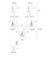
- the above DCR message and the DCA messagemay be based on omni-beam and transmitted through a relay UE. That is, in the above description, the first UE may be a source remote UE and the second UE may be a target remote UE.
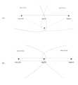
- the transmission beam that the first UE determines based on the DCA message received through the omni-beammay be a beam in the direction where the relay is. That is, as illustrated in FIG. 16, the first UE that receives the DCA message may perform beamforming in the direction where the relay UE is to establish a direct connection with the second UE.
- the second UE that transmitted the DCAmay also increase the reception rate by beamforming the reception beam in the direction where the DCA was transmitted. That is, by performing beamforming in the direction of the relay UE, a coarse beam having a directionality of at least 50% compared to an omni-beam may be formed.
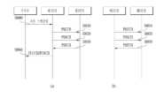
- FIG. 17An example of this is illustrated in Fig. 17. Referring to Fig. 17,
- the relay UEmay be utilized.
- the first UEmay transmit a DCR message via omni-beam (S1701), and the relay UE that receives it may forward it (S1702).
- the DCR message transmitted by the first UEmay include an index such as relay_enable_indication that indicates that the relay UE can forward it when it receives it.
- the second UEwhich has received the DCR message via the relay UE, may transmit a DCA message (S1703).
- the DCA messagemay also include an index such as relay_enable_indication.
- the relay UEwhich has received the DCA message, forwards it to the first UE (S1704).
- the DCR message and the DCA messagemay include relay_enable_indication indicating forwarding by the relay.
- the signal strength measured by the relay UE through DCA/DCR, etc.may be needed for the first UE to determine the most appropriate beam forming direction.
- the relay/target remote UEmay include the signal strength (e.g., RSRP/RSRQ/SINR, etc.) it measured in the DCA message and transmit it when transmitting the DCA.
- the signal strength values of the first-hop and second-hopmay be distinguished and notified to the source remote UE.
- information about the spatial filter used by the first UE and the second UE for the direct linkmay be recommended by the relay UE. That is, the relay UE may recommend information about the spatial filter that can be used for the direct link to the source remote UE and the target remote UE. This may be an operation performed after the source remote UE and the target remote UE each establish an SL connection with the relay UE. The source remote UE and the target remote UE, which have received the recommendation for the spatial filter from the relay UE, may use the corresponding value for beam search/pairing for the direct link.
- a beam to be used to find a relay UEwhen a direct path exists. That is, when a source remote UE and a target remote UE are looking for a candidate relay UE for switching to an indirect path while there is a direct connection, the beams to be used to find the candidate relay UE can be recommended to each other to be used to find the candidate relay UE.
- the first UE(User Equipment) includes at least one processor; and at least one computer memory operably connected to the at least one processor and storing instructions that, when executed, cause the at least one processor to perform operations, the operations including: transmitting a Direct Communication Request (DCR) message; receiving a Direct Communication Accept (DCA) message from a second UE; determining a transmission beam based on the DCA message; and establishing an RRC (Radio Resource Control) connection with the second UE using the transmission beam, wherein the DCR message includes a first beam index related to the DCR message transmission of the first UE, and the DCA message may include the first beam index and a second beam index related to the DCA message transmission of the second UE.
- DCRDirect Communication Request
- DCADirect Communication Accept
- RRCRadio Resource Control
- a nonvolatile computer-readable storage mediumstoring at least one computer program including instructions that, when executed by at least one processor, cause the at least one processor to perform operations for a first UE, the operations including: transmitting a Direct Communication Request (DCR) message; receiving a Direct Communication Accept (DCA) message from a second UE; determining a transmission beam based on the DCA message; and establishing an RRC (Radio Resource Control) connection with the second UE using the transmission beam, wherein the DCR message includes a first beam index associated with the DCR message transmission of the first UE, and the DCA message may include the first beam index and a second beam index associated with the DCA message transmission of the second UE.
- DCRDirect Communication Request
- DCADirect Communication Accept
- RRCRadio Resource Control
- the first UEmay be a source remote UE
- the second UEmay be a target remote UE
- the second UEmay establish an end-to-end link with the first UE through a relay UE and receive information related to a reception beam of the relay UE from the relay UE.
- the second UEmay form a transmission beam of the second UE based on beam information formed by the relay UE to receive the transmission beam of the first UE.
- the second UEmay also receive preferred beam and non-preferred beam information of the relay UE from the relay UE.
- This methodcan efficiently perform beam pairing between 1st-hop and 2nd-hop when U2U relay operates at FR2 frequency, and this will be discussed in detail below.
- the following descriptioncan be used/applied together with the above-described embodiment, but can also be used/applied independently of the above-described embodiment.
- the relay UEmay inform the target remote UE of beam related information of the first-hop. For example, the relay UE may inform the target remote UE of information (e.g., beam sequence and beam forming time) about the TX beam of the source remote UE (and/or the TX beam (and/or special filter) that the relay UE directs to the source remote UE and beam forming information for reception).
- informatione.g., beam sequence and beam forming time
- the target remote UE that receives thiscan use this information to (re)configure beam pairing between the relay UE and the target remote UE.
- the target remote UEmay form its own transmit beam according to the beam information formed by the relay UE to receive the message of the source remote UE.
- the receive beam (and/or spatial filter) of the relay UEis formed to be able to receive information of the source remote UE and the target remote UE
- the target remote UEmay form its own transmit beam according to the receive beam formed by the relay UE to receive the transmit beam of the source remote UE.
- a relay UEwith which beam pairing has been (re)established with a source remote UE, may inform (and/or recommend) to a target remote UE candidate transmit (and/or receive) beam information that the relay UE prefers (and/or disprefers) for communication with the target remote UE.
- the target remote UEupon receiving this, may (re)establish beam pairing between the target remote UE and the relay UE by reflecting the information received from the relay UE.
- relay selectionmay be triggered.
- the source/target remote UEsmay mutually recommend/negotiate (via direct link) a beam for selecting a relay UE.
- the beam information used to find the candidate relay UEe.g., information related to a receive beam used to receive a discovery message transmitted by the candidate relay UE, (and/or) information related to a transmit beam used by the candidate relay UE to transmit the discovery message
- the target remote UEmay be notified to the target remote UE along with the ID and RSRP (and/or SD-RSRP) of the candidate relay UE.
- path switching to the direct linkmay be triggered while the source remote UE and the target remote UE are communicating indirectly via the relay UE (when the source remote UE and the relay UE are beam paired and the target remote UE and the relay UE are beam paired). For example, if the signal strength of each hop (first-hop and second-hop) exceeds a set threshold, it may be determined that direct communication is possible and path switching from the indirect path to the direct path may be possible. In this case, the source remote UE and the target remote UE may recommend information for beam pairing of the direct link. For example, the source/target remote UE may inform each other of information about candidate beams to be used for the direct link via the indirect link and negotiate the beam to be used for the direct link.
- the relay UEcan report this to the target remote UE. Or, if BFD (Beam Failure Detection)/BFR (Beam Failure Recovery) occurs at the second-hop, the relay UE can report this to the source remote UE.
- BFDBeam Failure Detection
- BFRBeam Failure Recovery
- the source (and/or target) remote UEmay inform the target remote UE (and/or the source remote UE) of this using the indirect path.
- the source (and/or target) remote UEmay inform the target remote UE (and/or the source remote UE) of this using the direct path.
- the source remote UEmay inform the target remote UE of this through the indirect link, and may also inform the source remote UE of (candidate) (preferred) beam related information to be used for beam search/recovery (assist information).
- the target remote UE that receives thismay use the information to apply it to the beam search/recovery of the source remote UE.
- the source remote UEmay inform the target remote UE of this (e.g., if BFD/BFR occurs in the second-hop) through the direct link, and may also inform the relay UE of (candidate) (preferred) beam-related information to be used for beam search/recovery (assist information).
- the target remote UE that receives thismay use it for beam search/recovery with the relay UE of the indirect path.
- the transmission/reception beam (and/or spatial) related informationmay be a value indicating a beam sequence (seed information used to form CS-RS) (and/or) beam index information, resource (set) information associated with the beam, etc.
- a beam sequenceseed information used to form CS-RS
- beam indexresource (set) information associated with the beam
- the entire sequence that the UE can use, the order of the sequence, the time when the sequence is used, etc.may also be indicated.
- the entire number of indexes that the UE can use, the order of the index, the time when the corresponding index is used, etc.may also be indicated.
- the source remote UE, the target remote UE, and the relay UEmay be replaced by general UEs and gNBs. It is also obvious that the source remote UE and the target remote UE may be interpreted cross-wise. That is, the source remote UE may be interpreted as the target remote UE, and the target remote UE may be interpreted as the source remote UE, and may be replaced by the end remote UE.
- Fig. 18illustrates a communication system (1) applied to the present disclosure.
- a communication system (1) applied to the present disclosureincludes a wireless device, a base station, and a network.
- the wireless devicemeans a device that performs communication using a wireless access technology (e.g., 5G NR (New RAT), LTE (Long Term Evolution)) and may be referred to as a communication/wireless/5G device.
- the wireless devicemay include a robot (100a), a vehicle (100b-1, 100b-2), an XR (eXtended Reality) device (100c), a hand-held device (100d), a home appliance (100e), an IoT (Internet of Thing) device (100f), and an AI device/server (400).
- the vehiclemay include a vehicle equipped with a wireless communication function, an autonomous vehicle, a vehicle capable of performing vehicle-to-vehicle communication, etc.
- the vehiclemay include an Unmanned Aerial Vehicle (UAV) (e.g., a drone).
- UAVUnmanned Aerial Vehicle
- XR devicesinclude AR (Augmented Reality)/VR (Virtual Reality)/MR (Mixed Reality) devices and can be implemented in the form of HMD (Head-Mounted Device), HUD (Head-Up Display) installed in a vehicle, television, smartphone, computer, wearable device, home appliance, digital signage, vehicle, robot, etc.
- HMDHead-Mounted Device
- HUDHead-Up Display
- Portable devicescan include smartphone, smart pad, wearable device (e.g., smart watch, smart glass), computer (e.g., laptop, etc.).
- Home appliancescan include TV, refrigerator, washing machine, etc.
- IoT devicescan include sensors, smart meters, etc.
- base stations and networkscan also be implemented as wireless devices, and a specific wireless device (200a) can act as a base station/network node to other wireless devices.
- Wireless devices (100a to 100f)can be connected to a network (300) via a base station (200). Artificial Intelligence (AI) technology can be applied to the wireless devices (100a to 100f), and the wireless devices (100a to 100f) can be connected to an AI server (400) via the network (300).
- the network (300)can be configured using a 3G network, a 4G (e.g., LTE) network, a 5G (e.g., NR) network, etc.
- the wireless devices (100a to 100f)can communicate with each other via the base station (200)/network (300), but can also communicate directly (e.g., sidelink communication) without going through the base station/network.
- vehiclescan communicate directly (e.g. V2V (Vehicle to Vehicle)/V2X (Vehicle to everything) communication).
- IoT devicese.g., sensors
- IoT devicescan communicate directly with other IoT devices (e.g., sensors) or other wireless devices (100a to 100f).
- Wireless communication/connectioncan be established between wireless devices (100a to 100f)/base stations (200), and base stations (200)/base stations (200).
- the wireless communication/connectioncan be achieved through various wireless access technologies (e.g., 5G NR) such as uplink/downlink communication (150a), sidelink communication (150b) (or, D2D communication), and communication between base stations (150c) (e.g., relay, IAB (Integrated Access Backhaul)).
- 5G NRwireless access technologies
- a wireless device and a base station/wireless device, and a base station and a base stationcan transmit/receive wireless signals to/from each other.
- the wireless communication/connectioncan transmit/receive signals through various physical channels.
- various configuration information setting processes for transmitting/receiving wireless signalsvarious signal processing processes (e.g., channel encoding/decoding, modulation/demodulation, resource mapping/demapping, etc.), and resource allocation processes can be performed based on various proposals of the present disclosure.
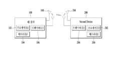
- FIG. 19illustrates a wireless device applicable to the present disclosure.
- the first wireless device (100) and the second wireless device (200)can transmit and receive wireless signals through various wireless access technologies (e.g., LTE, NR).
- ⁇ the first wireless device (100), the second wireless device (200) ⁇can correspond to ⁇ the wireless device (100x), the base station (200) ⁇ and/or ⁇ the wireless device (100x), the wireless device (100x) ⁇ of FIG. 18.
- a first wireless device (100)includes one or more processors (102) and one or more memories (104), and may additionally include one or more transceivers (106) and/or one or more antennas (108).
- the processor (102)controls the memories (104) and/or the transceivers (106), and may be configured to implement the descriptions, functions, procedures, suggestions, methods, and/or operational flowcharts disclosed in this document.
- the processor (102)may process information in the memory (104) to generate first information/signal, and then transmit a wireless signal including the first information/signal via the transceiver (106).
- the processor (102)may receive a wireless signal including second information/signal via the transceiver (106), and then store information obtained from signal processing of the second information/signal in the memory (104).
- the memory (104)may be connected to the processor (102) and may store various information related to the operation of the processor (102). For example, the memory (104) may perform some or all of the processes controlled by the processor (102), or may store software codes including instructions for performing the descriptions, functions, procedures, proposals, methods, and/or operational flowcharts disclosed in this document.
- the processor (102) and the memory (104)may be part of a communication modem/circuit/chip designed to implement wireless communication technology (e.g., LTE, NR).
- the transceiver (106)may be connected to the processor (102) and may transmit and/or receive wireless signals via one or more antennas (108).
- the transceiver (106)may include a transmitter and/or a receiver.
- the transceiver (106)may be used interchangeably with an RF (Radio Frequency) unit.
- a wireless devicemay also mean a communication modem/circuit/chip.
- the second wireless device (200)includes one or more processors (202), one or more memories (204), and may additionally include one or more transceivers (206) and/or one or more antennas (208).
- the processor (202)may be configured to control the memories (204) and/or the transceivers (206), and implement the descriptions, functions, procedures, suggestions, methods, and/or operational flowcharts disclosed in this document. For example, the processor (202) may process information in the memory (204) to generate third information/signals, and then transmit a wireless signal including the third information/signals via the transceivers (206). Additionally, the processor (202) may receive a wireless signal including fourth information/signals via the transceivers (206), and then store information obtained from signal processing of the fourth information/signals in the memory (204).
- the memory (204)may be connected to the processor (202) and may store various information related to the operation of the processor (202). For example, the memory (204) may perform some or all of the processes controlled by the processor (202), or may store software codes including instructions for performing the descriptions, functions, procedures, proposals, methods, and/or operational flowcharts disclosed in the present document.
- the processor (202) and the memory (204)may be part of a communication modem/circuit/chip designed to implement wireless communication technology (e.g., LTE, NR).
- the transceiver (206)may be connected to the processor (202) and may transmit and/or receive wireless signals via one or more antennas (208).
- the transceiver (206)may include a transmitter and/or a receiver.
- the transceiver (206)may be used interchangeably with an RF unit.
- a wireless devicemay also mean a communication modem/circuit/chip.
- one or more protocol layersmay be implemented by one or more processors (102, 202).
- processors (102, 202)may implement one or more layers (e.g., functional layers such as PHY, MAC, RLC, PDCP, RRC, SDAP).
- processors (102, 202)may generate one or more Protocol Data Units (PDUs) and/or one or more Service Data Units (SDUs) according to the descriptions, functions, procedures, proposals, methods, and/or operational flowcharts disclosed in this document.
- PDUsProtocol Data Units
- SDUsService Data Units
- One or more processors (102, 202)may generate messages, control information, data, or information according to the descriptions, functions, procedures, proposals, methods, and/or operational flowcharts disclosed in this document.
- One or more processors (102, 202)can generate signals (e.g., baseband signals) comprising PDUs, SDUs, messages, control information, data or information according to the functions, procedures, suggestions and/or methodologies disclosed herein, and provide the signals to one or more transceivers (106, 206).
- One or more processors (102, 202)can receive signals (e.g., baseband signals) from one or more transceivers (106, 206) and obtain PDUs, SDUs, messages, control information, data or information according to the descriptions, functions, procedures, suggestions, methods and/or operational flowcharts disclosed herein.
- signalse.g., baseband signals
- the one or more processors (102, 202)may be referred to as a controller, a microcontroller, a microprocessor, or a microcomputer.
- the one or more processors (102, 202)may be implemented by hardware, firmware, software, or a combination thereof.
- ASICsApplication Specific Integrated Circuits
- DSPsDigital Signal Processors
- DSPDsDigital Signal Processing Devices
- PLDsProgrammable Logic Devices
- FPGAsField Programmable Gate Arrays
- the descriptions, functions, procedures, suggestions, methods, and/or operational flowcharts disclosed in this documentmay be implemented using firmware or software, and the firmware or software may be implemented to include modules, procedures, functions, etc.
- the descriptions, functions, procedures, suggestions, methods and/or operational flowcharts disclosed in this documentmay be implemented using firmware or software configured to perform one or more of the following: included in one or more processors (102, 202), or stored in one or more memories (104, 204) and driven by one or more of the processors (102, 202).
- the descriptions, functions, procedures, suggestions, methods and/or operational flowcharts disclosed in this documentmay be implemented using firmware or software in the form of codes, instructions and/or sets of instructions.
- One or more memories (104, 204)may be coupled to one or more processors (102, 202) and may store various forms of data, signals, messages, information, programs, codes, instructions and/or commands.
- the one or more memories (104, 204)may be comprised of ROM, RAM, EPROM, flash memory, hard drives, registers, cache memory, computer readable storage media and/or combinations thereof.
- the one or more memories (104, 204)may be located internally and/or externally to the one or more processors (102, 202). Additionally, the one or more memories (104, 204) may be coupled to the one or more processors (102, 202) via various technologies, such as wired or wireless connections.
- One or more transceivers (106, 206)can transmit user data, control information, wireless signals/channels, etc., as described in the methods and/or flowcharts of this document, to one or more other devices.
- One or more transceivers (106, 206)can receive user data, control information, wireless signals/channels, etc., as described in the descriptions, functions, procedures, suggestions, methods and/or flowcharts of this document, from one or more other devices.
- one or more transceivers (106, 206)can be coupled to one or more processors (102, 202) and can transmit and receive wireless signals.
- one or more processors (102, 202)can control one or more transceivers (106, 206) to transmit user data, control information, or wireless signals to one or more other devices. Additionally, one or more processors (102, 202) may control one or more transceivers (106, 206) to receive user data, control information, or wireless signals from one or more other devices.
- one or more transceivers (106, 206)may be coupled to one or more antennas (108, 208), and one or more transceivers (106, 206) may be configured to transmit and receive user data, control information, wireless signals/channels, and the like, as referred to in the descriptions, functions, procedures, proposals, methods, and/or operational flowcharts disclosed herein, via one or more antennas (108, 208).
- one or more antennasmay be multiple physical antennas, or multiple logical antennas (e.g., antenna ports).
- One or more transceivers (106, 206)may convert received user data, control information, wireless signals/channels, etc.
- One or more transceivers (106, 206)may convert processed user data, control information, wireless signals/channels, etc. from baseband signals to RF band signals using one or more processors (102, 202).
- one or more transceivers (106, 206)may include an (analog) oscillator and/or filter.
- Fig. 20illustrates a vehicle or autonomous vehicle to which the present disclosure applies.
- the vehicle or autonomous vehiclemay be implemented as a mobile robot, a car, a train, a manned/unmanned aerial vehicle (AV), a ship, etc.
- AVmanned/unmanned aerial vehicle
- a vehicle or autonomous vehiclemay include an antenna unit (108), a communication unit (110), a control unit (120), a driving unit (140a), a power supply unit (140b), a sensor unit (140c), and an autonomous driving unit (140d).
- the antenna unit (108)may be configured as a part of the communication unit (110).
- the communication unit (110)can transmit and receive signals (e.g., data, control signals, etc.) with external devices such as other vehicles, base stations (e.g., base stations, road side units, etc.), servers, etc.
- the control unit (120)can control elements of the vehicle or autonomous vehicle (100) to perform various operations.
- the control unit (120)can include an ECU (Electronic Control Unit).
- the drive unit (140a)can drive the vehicle or autonomous vehicle (100) on the ground.
- the drive unit (140a)can include an engine, a motor, a power train, wheels, brakes, a steering device, etc.
- the power supply unit (140b)supplies power to the vehicle or autonomous vehicle (100) and can include a wired/wireless charging circuit, a battery, etc.
- the sensor unit (140c)can obtain vehicle status, surrounding environment information, user information, etc.
- the sensor unit (140c)may include an IMU (inertial measurement unit) sensor, a collision sensor, a wheel sensor, a speed sensor, an incline sensor, a weight detection sensor, a heading sensor, a position module, a vehicle forward/backward sensor, a battery sensor, a fuel sensor, a tire sensor, a steering sensor, a temperature sensor, a humidity sensor, an ultrasonic sensor, a light sensor, a pedal position sensor, etc.
- IMUintial measurement unit
- the autonomous driving unit (140d)may implement a technology for maintaining a driving lane, a technology for automatically controlling speed such as adaptive cruise control, a technology for automatically driving along a set path, a technology for automatically setting a path and driving when a destination is set, etc.
- the communication unit (110)can receive map data, traffic information data, etc. from an external server.
- the autonomous driving unit (140d)can generate an autonomous driving route and a driving plan based on the acquired data.
- the control unit (120)can control the driving unit (140a) so that the vehicle or autonomous vehicle (100) moves along the autonomous driving route according to the driving plan (e.g., speed/direction control).
- the communication unit (110)can irregularly/periodically acquire the latest traffic information data from an external server and can acquire surrounding traffic information data from surrounding vehicles.
- the sensor unit (140c)can acquire vehicle status and surrounding environment information during autonomous driving.
- the autonomous driving unit (140d)can update the autonomous driving route and driving plan based on the newly acquired data/information.
- the communication unit (110)can transmit information on the vehicle location, autonomous driving route, driving plan, etc. to an external server.
- External serverscan predict traffic information data in advance using AI technology, etc. based on information collected from vehicles or autonomous vehicles, and provide the predicted traffic information data to vehicles or autonomous vehicles.
- Fig. 21illustrates a vehicle to which the present disclosure applies.
- the vehiclemay also be implemented as a means of transportation, a train, an aircraft, a ship, etc.
- the vehicle (100)may include a communication unit (110), a control unit (120), a memory unit (130), an input/output unit (140a), and a position measurement unit (140b).
- the communication unit (110)can transmit and receive signals (e.g., data, control signals, etc.) with other vehicles or external devices such as base stations.
- the control unit (120)can control components of the vehicle (100) to perform various operations.
- the memory unit (130)can store data/parameters/programs/codes/commands that support various functions of the vehicle (100).
- the input/output unit (140a)can output AR/VR objects based on information in the memory unit (130).
- the input/output unit (140a)can include a HUD.
- the position measurement unit (140b)can obtain position information of the vehicle (100).
- the position informationcan include absolute position information of the vehicle (100), position information within a driving line, acceleration information, position information with respect to surrounding vehicles, etc.
- the position measurement unit (140b)can include GPS and various sensors.
- the communication unit (110) of the vehicle (100)can receive map information, traffic information, etc. from an external server and store them in the memory unit (130).
- the location measurement unit (140b)can obtain vehicle location information through GPS and various sensors and store them in the memory unit (130).
- the control unit (120)can generate a virtual object based on the map information, traffic information, vehicle location information, etc., and the input/output unit (140a) can display the generated virtual object on the vehicle window (1410, 1420).
- the control unit (120)can determine whether the vehicle (100) is being driven normally within the driving line based on the vehicle location information.
- control unit (120)can display a warning on the vehicle window through the input/output unit (140a). In addition, the control unit (120) can broadcast a warning message regarding driving abnormalities to surrounding vehicles through the communication unit (110). Depending on the situation, the control unit (120) can transmit vehicle location information and information regarding driving/vehicle abnormalities to relevant organizations through the communication unit (110).
- Fig. 22illustrates an XR device applicable to the present disclosure.
- the XR devicecan be implemented as an HMD, a HUD (Head-Up Display) equipped in a vehicle, a television, a smartphone, a computer, a wearable device, a home appliance, a digital signage, a vehicle, a robot, etc.
- HMDHead-Up Display
- the XR device (100a)may include a communication unit (110), a control unit (120), a memory unit (130), an input/output unit (140a), a sensor unit (140b), and a power supply unit (140c).
- the communication unit (110)can transmit and receive signals (e.g., media data, control signals, etc.) with external devices such as other wireless devices, portable devices, or media servers.
- the media datacan include videos, images, sounds, etc.
- the control unit (120)can control components of the XR device (100a) to perform various operations.
- the control unit (120)can be configured to control and/or perform procedures such as video/image acquisition, (video/image) encoding, metadata generation and processing, etc.
- the memory unit (130)can store data/parameters/programs/codes/commands required for driving the XR device (100a)/generation of XR objects.
- the input/output unit (140a)can obtain control information, data, etc.
- the input/output unit (140a)can include a camera, a microphone, a user input unit, a display unit, a speaker, and/or a haptic module.
- the sensor unit (140b)can obtain the XR device status, surrounding environment information, user information, etc.
- the sensor unit (140b)can include a proximity sensor, a light sensor, an acceleration sensor, a magnetic sensor, a gyro sensor, an inertial sensor, an RGB sensor, an IR sensor, a fingerprint recognition sensor, an ultrasonic sensor, a light sensor, a microphone, and/or a radar, etc.
- the power supply unit (140c)supplies power to the XR device (100a) and can include a wired/wireless charging circuit, a battery, etc.
- the memory unit (130) of the XR device (100a)may include information (e.g., data, etc.) required for creating an XR object (e.g., AR/VR/MR object).
- the input/output unit (140a)may obtain a command to operate the XR device (100a) from a user, and the control unit (120) may operate the XR device (100a) according to the user's operating command. For example, when a user attempts to watch a movie, news, etc. through the XR device (100a), the control unit (120) may transmit content request information to another device (e.g., a mobile device (100b)) or a media server through the communication unit (130).
- another devicee.g., a mobile device (100b)
- a media servere.g., a media server
- the communication unit (130)may download/stream content such as a movie or news from another device (e.g., a mobile device (100b)) or a media server to the memory unit (130).
- the control unit (120)controls and/or performs procedures such as video/image acquisition, (video/image) encoding, and metadata generation/processing for content, and can generate/output an XR object based on information about surrounding space or real objects acquired through the input/output unit (140a)/sensor unit (140b).
- the XR device (100a)is wirelessly connected to the mobile device (100b) through the communication unit (110), and the operation of the XR device (100a) can be controlled by the mobile device (100b).
- the mobile device (100b)can act as a controller for the XR device (100a).
- the XR device (100a)can obtain three-dimensional position information of the mobile device (100b), and then generate and output an XR object corresponding to the mobile device (100b).
- Fig. 23illustrates a robot applicable to the present disclosure. Robots can be classified into industrial, medical, household, military, etc., depending on the purpose or field of use.
- the robot (100)may include a communication unit (110), a control unit (120), a memory unit (130), an input/output unit (140a), a sensor unit (140b), and a driving unit (140c).
- the communication unit (110)can transmit and receive signals (e.g., driving information, control signals, etc.) with external devices such as other wireless devices, other robots, or control servers.
- the control unit (120)can control components of the robot (100) to perform various operations.
- the memory unit (130)can store data/parameters/programs/codes/commands that support various functions of the robot (100).
- the input/output unit (140a)can obtain information from the outside of the robot (100) and output information to the outside of the robot (100).
- the input/output unit (140a)can include a camera, a microphone, a user input unit, a display unit, a speaker, and/or a haptic module.
- the sensor unit (140b)can obtain internal information of the robot (100), surrounding environment information, user information, etc.
- the sensor unit (140b)may include a proximity sensor, an illuminance sensor, an acceleration sensor, a magnetic sensor, a gyro sensor, an inertial sensor, an IR sensor, a fingerprint recognition sensor, an ultrasonic sensor, a light sensor, a microphone, a radar, etc.
- the driving unit (140c)may perform various physical operations, such as moving a robot joint. In addition, the driving unit (140c) may allow the robot (100) to drive on the ground or fly in the air.
- the driving unit (140c)may include an actuator, a motor, wheels, brakes, a propeller, etc.
- Fig. 24illustrates an AI device applicable to the present disclosure.
- the AI devicemay be implemented as a fixed device or a movable device, such as a TV, a projector, a smartphone, a PC, a laptop, a digital broadcasting terminal, a tablet PC, a wearable device, a set-top box (STB), a radio, a washing machine, a refrigerator, a digital signage, a robot, a vehicle, etc.
- the AI device (100)may include a communication unit (110), a control unit (120), a memory unit (130), an input/output unit (140a/140b), a learning processor unit (140c), and a sensor unit (140d).
- the communication unit (110)can transmit and receive wired and wireless signals (e.g., sensor information, user input, learning models, control signals, etc.) with external devices such as other AI devices (e.g., 100x, 200, 400 of FIG. 18) or AI servers (e.g., 400 of FIG. 18) using wired and wireless communication technology.
- the communication unit (110)can transmit information in the memory unit (130) to the external device or transfer a signal received from the external device to the memory unit (130).
- the control unit (120)may determine at least one executable operation of the AI device (100) based on information determined or generated using a data analysis algorithm or a machine learning algorithm. Then, the control unit (120) may control components of the AI device (100) to perform the determined operation. For example, the control unit (120) may request, search, receive, or utilize data of the learning processor unit (140c) or the memory unit (130), and control components of the AI device (100) to perform a predicted operation or an operation determined to be desirable among at least one executable operation.
- control unit (120)may collect history information including operation contents of the AI device (100) or user feedback on the operation, and store the information in the memory unit (130) or the learning processor unit (140c), or transmit the information to an external device such as an AI server (FIG. 18, 400).
- the collected history informationmay be used to update a learning model.
- the memory unit (130)can store data that supports various functions of the AI device (100).
- the memory unit (130)can store data obtained from the input unit (140a), data obtained from the communication unit (110), output data of the learning processor unit (140c), and data obtained from the sensing unit (140).
- the memory unit (130)can store control information and/or software codes necessary for the operation/execution of the control unit (120).
- the input unit (140a)can obtain various types of data from the outside of the AI device (100).
- the input unit (140a)can obtain learning data for model learning, and input data to which the learning model is to be applied.
- the input unit (140a)may include a camera, a microphone, and/or a user input unit.
- the output unit (140b)may generate output related to vision, hearing, or touch.
- the output unit (140b)may include a display unit, a speaker, and/or a haptic module.
- the sensing unit (140)may obtain at least one of internal information of the AI device (100), surrounding environment information of the AI device (100), and user information using various sensors.
- the sensing unit (140)may include a proximity sensor, an illuminance sensor, an acceleration sensor, a magnetic sensor, a gyro sensor, an inertial sensor, an RGB sensor, an IR sensor, a fingerprint recognition sensor, an ultrasonic sensor, a light sensor, a microphone, and/or a radar.
- the learning processor unit (140c)can train a model composed of an artificial neural network using learning data.
- the learning processor unit (140c)can perform AI processing together with the learning processor unit of the AI server (Fig. 18, 400).
- the learning processor unit (140c)can process information received from an external device through the communication unit (110) and/or information stored in the memory unit (130).
- the output value of the learning processor unit (140c)can be transmitted to an external device through the communication unit (110) and/or stored in the memory unit (130).
Landscapes
- Engineering & Computer Science (AREA)
- Computer Networks & Wireless Communication (AREA)
- Signal Processing (AREA)
- Databases & Information Systems (AREA)
- Mobile Radio Communication Systems (AREA)
Abstract
Description
Translated fromKorean이하의 설명은 무선 통신 시스템에 대한 것으로, 보다 상세하게는 사이드링크 mmWave에서 beam pairing, beam forming 등 에 관련된 등에 관련된 동작 방법 및 장치이다.The following description relates to a wireless communication system, and more specifically, to operational methods and devices related to beam pairing, beam forming, etc. in sidelink mmWave.
무선 통신 시스템에서는 LTE, LTE-A, WiFi 등의 다양한 RAT(Radio Access Technology)이 사용되고 있으며, 5G 도 여기에 포함된다. 5G의 세 가지 주요 요구 사항 영역은 (1) 개선된 모바일 광대역 (Enhanced Mobile Broadband, eMBB) 영역, (2) 다량의 머신 타입 통신 (massive Machine Type Communication, mMTC) 영역 및 (3) 초-신뢰 및 저 지연 통신 (Ultra-reliable and Low Latency Communications, URLLC) 영역을 포함한다. 일부 사용 예(Use Case)는 최적화를 위해 다수의 영역들이 요구될 수 있고, 다른 사용 예는 단지 하나의 핵심 성능 지표 (Key Performance Indicator, KPI)에만 포커싱될 수 있다. 5G는 이러한 다양한 사용 예들을 유연하고 신뢰할 수 있는 방법으로 지원하는 것이다.In wireless communication systems, various RATs (Radio Access Technologies), such as LTE, LTE-A, and WiFi, are used, and 5G is also included. The three major requirement areas of 5G are (1) Enhanced Mobile Broadband (eMBB), (2) Massive Machine Type Communication (mMTC), and (3) Ultra-reliable and Low Latency Communications (URLLC). Some use cases may require multiple areas for optimization, while other use cases may focus on only one Key Performance Indicator (KPI). 5G supports these various use cases in a flexible and reliable manner.
eMBB는 기본적인 모바일 인터넷 액세스를 훨씬 능가하게 하며, 풍부한 양방향 작업, 클라우드 또는 증강 현실에서 미디어 및 엔터테인먼트 애플리케이션을 커버한다. 데이터는 5G의 핵심 동력 중 하나이며, 5G 시대에서 처음으로 전용 음성 서비스를 볼 수 없을 수 있다. 5G에서, 음성은 단순히 통신 시스템에 의해 제공되는 데이터 연결을 사용하여 응용 프로그램으로서 처리될 것이 기대된다. 증가된 트래픽 양(volume)을 위한 주요 원인들은 콘텐츠 크기의 증가 및 높은 데이터 전송률을 요구하는 애플리케이션 수의 증가이다. 스트리밍 서비스 (오디오 및 비디오), 대화형 비디오 및 모바일 인터넷 연결은 더 많은 장치가 인터넷에 연결될수록 더 널리 사용될 것이다. 이러한 많은 응용 프로그램들은 사용자에게 실시간 정보 및 알림을 푸쉬하기 위해 항상 켜져 있는 연결성이 필요하다. 클라우드 스토리지 및 애플리케이션은 모바일 통신 플랫폼에서 급속히 증가하고 있으며, 이것은 업무 및 엔터테인먼트 모두에 적용될 수 있다. 그리고, 클라우드 스토리지는 상향링크 데이터 전송률의 성장을 견인하는 특별한 사용 예이다. 5G는 또한 클라우드의 원격 업무에도 사용되며, 촉각 인터페이스가 사용될 때 우수한 사용자 경험을 유지하도록 훨씬 더 낮은 단-대-단(end-to-end) 지연을 요구한다. 엔터테인먼트 예를 들어, 클라우드 게임 및 비디오 스트리밍은 모바일 광대역 능력에 대한 요구를 증가시키는 또 다른 핵심 요소이다. 엔터테인먼트는 기차, 차 및 비행기와 같은 높은 이동성 환경을 포함하는 어떤 곳에서든지 스마트폰 및 태블릿에서 필수적이다. 또 다른 사용 예는 엔터테인먼트를 위한 증강 현실 및 정보 검색이다. 여기서, 증강 현실은 매우 낮은 지연과 순간적인 데이터 양을 필요로 한다.eMBB goes far beyond basic mobile Internet access, covering rich interactive tasks, media and entertainment applications in the cloud or augmented reality. Data is one of the key drivers of 5G, and for the first time in the 5G era, we may not see dedicated voice services. In 5G, voice is expected to be handled as an application simply using the data connection provided by the communication system. The main reasons for the increased traffic volume are the increase in content size and the increase in the number of applications requiring high data rates. Streaming services (audio and video), interactive video and mobile Internet connectivity will become more prevalent as more devices are connected to the Internet. Many of these applications require always-on connectivity to push real-time information and notifications to users. Cloud storage and applications are rapidly growing on mobile communication platforms, and this can be applied to both work and entertainment. And cloud storage is a particular use case that is driving the growth of uplink data rates. 5G is also used for remote work in the cloud, requiring much lower end-to-end latency to maintain a good user experience when tactile interfaces are used. Entertainment For example, cloud gaming and video streaming are other key factors driving the demand for mobile broadband capabilities. Entertainment is essential on smartphones and tablets anywhere, including in high-mobility environments such as trains, cars, and airplanes. Another use case is augmented reality and information retrieval for entertainment. Here, augmented reality requires very low latency and instantaneous data volumes.
또한, 가장 많이 예상되는 5G 사용 예 중 하나는 모든 분야에서 임베디드 센서를 원활하게 연결할 수 있는 기능 즉, mMTC에 관한 것이다. 2020년까지 잠재적인 IoT 장치들은 204 억 개에 이를 것으로 예측된다. 산업 IoT는 5G가 스마트 도시, 자산 추적(asset tracking), 스마트 유틸리티, 농업 및 보안 인프라를 가능하게 하는 주요 역할을 수행하는 영역 중 하나이다.Also, one of the most anticipated 5G use cases is mMTC, the ability to seamlessly connect embedded sensors across all sectors. It is predicted that there will be 20.4 billion potential IoT devices by 2020. Industrial IoT is one area where 5G will play a key role in enabling smart cities, asset tracking, smart utilities, agriculture, and security infrastructure.
URLLC는 주요 인프라의 원격 제어 및 자체-구동 차량(self-driving vehicle)과 같은 초 신뢰 / 이용 가능한 지연이 적은 링크를 통해 산업을 변화시킬 새로운 서비스를 포함한다. 신뢰성과 지연의 수준은 스마트 그리드 제어, 산업 자동화, 로봇 공학, 드론 제어 및 조정에 필수적이다.URLLC encompasses new services that will transform industries through ultra-reliable/available low-latency links, such as remote control of critical infrastructure and self-driving vehicles. Reliability and latency levels are essential for smart grid control, industrial automation, robotics, and drone control and coordination.
다음으로, 다수의 사용 예들에 대해 보다 구체적으로 살펴본다.Next, let's look at a number of use cases in more detail.
5G는 초당 수백 메가 비트에서 초당 기가 비트로 평가되는 스트림을 제공하는 수단으로 FTTH (fiber-to-the-home) 및 케이블 기반 광대역 (또는 DOCSIS)을 보완할 수 있다. 이러한 빠른 속도는 가상 현실과 증강 현실뿐 아니라 4K 이상(6K, 8K 및 그 이상)의 해상도로 TV를 전달하는데 요구된다. VR(Virtual Reality) 및 AR(Augmented Reality) 애플리케이션들은 거의 몰입형(immersive) 스포츠 경기를 포함한다. 특정 응용 프로그램은 특별한 네트워크 설정이 요구될 수 있다. 예를 들어, VR 게임의 경우, 게임 회사들이 지연을 최소화하기 위해 코어 서버를 네트워크 오퍼레이터의 에지 네트워크 서버와 통합해야 할 수 있다.5G can complement fiber-to-the-home (FTTH) and cable-based broadband (or DOCSIS) by delivering streams rated at hundreds of megabits per second to gigabits per second. These high speeds are required to deliver television at resolutions of 4K and beyond (6K, 8K and beyond), as well as virtual and augmented reality. Virtual Reality (VR) and Augmented Reality (AR) applications include near-immersive sporting events. Certain applications may require special network configurations. For example, VR gaming may require gaming companies to integrate their core servers with the network operator’s edge network servers to minimize latency.
자동차(Automotive)는 차량에 대한 이동 통신을 위한 많은 사용 예들과 함께 5G에 있어 중요한 새로운 동력이 될 것으로 예상된다. 예를 들어, 승객을 위한 엔터테인먼트는 동시의 높은 용량과 높은 이동성 모바일 광대역을 요구한다. 그 이유는 미래의 사용자는 그들의 위치 및 속도와 관계 없이 고품질의 연결을 계속해서 기대하기 때문이다. 자동차 분야의 다른 활용 예는 증강 현실 대시보드이다. 이는 운전자가 앞면 창을 통해 보고 있는 것 위에 어둠 속에서 물체를 식별하고, 물체의 거리와 움직임에 대해 운전자에게 말해주는 정보를 겹쳐서 디스플레이 한다. 미래에, 무선 모듈은 차량들 간의 통신, 차량과 지원하는 인프라구조 사이에서 정보 교환 및 자동차와 다른 연결된 디바이스들(예를 들어, 보행자에 의해 수반되는 디바이스들) 사이에서 정보 교환을 가능하게 한다. 안전 시스템은 운전자가 보다 안전한 운전을 할 수 있도록 행동의 대체 코스들을 안내하여 사고의 위험을 낮출 수 있게 한다. 다음 단계는 원격 조종되거나 자체 운전 차량(self-driven vehicle)이 될 것이다. 이는 서로 다른 자체 운전 차량들 사이 및 자동차와 인프라 사이에서 매우 신뢰성이 있고, 매우 빠른 통신을 요구한다. 미래에, 자체 운전 차량이 모든 운전 활동을 수행하고, 운전자는 차량 자체가 식별할 수 없는 교통 이상에만 집중하도록 할 것이다. 자체 운전 차량의 기술적 요구 사항은 트래픽 안전을 사람이 달성할 수 없을 정도의 수준까지 증가하도록 초 저 지연과 초고속 신뢰성을 요구한다.Automotive is expected to be a major new driver for 5G, with many use cases for mobile communications in vehicles. For example, entertainment for passengers requires simultaneous high-capacity and high-mobility mobile broadband, as future users will continue to expect high-quality connectivity regardless of their location and speed. Another application in the automotive sector is an augmented reality dashboard, which displays information superimposed on what the driver sees through the windshield, identifying objects in the dark and telling the driver about their distance and movement. In the future, wireless modules will enable communication between vehicles, information exchange between vehicles and supporting infrastructure, and information exchange between vehicles and other connected devices (e.g. devices accompanied by pedestrians). Safety systems can guide drivers to alternative courses of action to drive more safely, thus reducing the risk of accidents. The next step will be remotely controlled or self-driven vehicles, which will require highly reliable and very fast communication between different self-driving vehicles and between vehicles and infrastructure. In the future, self-driving cars will perform all driving activities, leaving drivers to focus only on traffic anomalies that the car itself cannot identify. The technical requirements for self-driving cars will require ultra-low latency and ultra-high reliability to increase traffic safety to levels that humans cannot achieve.
스마트 사회(smart society)로서 언급되는 스마트 도시와 스마트 홈은 고밀도 무선 센서 네트워크로 임베디드될 것이다. 지능형 센서의 분산 네트워크는 도시 또는 집의 비용 및 에너지-효율적인 유지에 대한 조건을 식별할 것이다. 유사한 설정이 각 가정을 위해 수행될 수 있다. 온도 센서, 창 및 난방 컨트롤러, 도난 경보기 및 가전 제품들은 모두 무선으로 연결된다. 이러한 센서들 중 많은 것들이 전형적으로 낮은 데이터 전송 속도, 저전력 및 저비용이다. 하지만, 예를 들어, 실시간 HD 비디오는 감시를 위해 특정 타입의 장치에서 요구될 수 있다.Smart cities and smart homes, referred to as smart societies, will be embedded with dense wireless sensor networks. A distributed network of intelligent sensors will identify conditions for cost- and energy-efficient maintenance of a city or home. A similar setup can be done for each home. Temperature sensors, window and heating controllers, burglar alarms, and appliances are all connected wirelessly. Many of these sensors are typically low data rates, low power, and low cost. However, for example, real-time HD video may be required for certain types of devices for surveillance.
열 또는 가스를 포함한 에너지의 소비 및 분배는 고도로 분산화되고 있어, 분산 센서 네트워크의 자동화된 제어가 요구된다. 스마트 그리드는 정보를 수집하고 이에 따라 행동하도록 디지털 정보 및 통신 기술을 사용하여 이런 센서들을 상호 연결한다. 이 정보는 공급 업체와 소비자의 행동을 포함할 수 있으므로, 스마트 그리드가 효율성, 신뢰성, 경제성, 생산의 지속 가능성 및 자동화된 방식으로 전기와 같은 연료들의 분배를 개선하도록 할 수 있다. 스마트 그리드는 지연이 적은 다른 센서 네트워크로 볼 수도 있다.The consumption and distribution of energy, including heat or gas, is becoming highly decentralized, requiring automated control of distributed sensor networks. Smart grids interconnect these sensors using digital information and communication technologies to collect information and act on it. This information can include the actions of suppliers and consumers, allowing smart grids to improve efficiency, reliability, economy, sustainability of production, and distribution of fuels such as electricity in an automated manner. Smart grids can also be viewed as another sensor network with low latency.
건강 부문은 이동 통신의 혜택을 누릴 수 있는 많은 응용 프로그램을 보유하고 있다. 통신 시스템은 멀리 떨어진 곳에서 임상 진료를 제공하는 원격 진료를 지원할 수 있다. 이는 거리에 대한 장벽을 줄이는데 도움을 주고, 거리가 먼 농촌에서 지속적으로 이용하지 못하는 의료 서비스들로의 접근을 개선시킬 수 있다. 이는 또한 중요한 진료 및 응급 상황에서 생명을 구하기 위해 사용된다. 이동 통신 기반의 무선 센서 네트워크는 심박수 및 혈압과 같은 파라미터들에 대한 원격 모니터링 및 센서들을 제공할 수 있다.The health sector has many applications that can benefit from mobile communications. Telecommunication systems can support telemedicine, which provides clinical care from a distance. This can help reduce distance barriers and improve access to health services that are not always available in remote rural areas. It can also be used to save lives in critical care and emergency situations. Mobile-based wireless sensor networks can provide remote monitoring and sensors for parameters such as heart rate and blood pressure.
무선 및 모바일 통신은 산업 응용 분야에서 점차 중요해지고 있다. 배선은 설치 및 유지 비용이 높다. 따라서, 케이블을 재구성할 수 있는 무선 링크들로의 교체 가능성은 많은 산업 분야에서 매력적인 기회이다. 그러나, 이를 달성하는 것은 무선 연결이 케이블과 비슷한 지연, 신뢰성 및 용량으로 동작하는 것과, 그 관리가 단순화될 것이 요구된다. 낮은 지연과 매우 낮은 오류 확률은 5G로 연결될 필요가 있는 새로운 요구 사항이다.Wireless and mobile communications are becoming increasingly important in industrial applications. Wiring is expensive to install and maintain. Therefore, the possibility of replacing cables with reconfigurable wireless links is an attractive opportunity for many industries. However, achieving this requires that wireless connections operate with similar delay, reliability and capacity as cables, and that their management is simplified. Low latency and very low error probability are the new requirements that need to be connected with 5G.
물류(logistics) 및 화물 추적(freight tracking)은 위치 기반 정보 시스템을 사용하여 어디에서든지 인벤토리(inventory) 및 패키지의 추적을 가능하게 하는 이동 통신에 대한 중요한 사용 예이다. 물류 및 화물 추적의 사용 예는 전형적으로 낮은 데이터 속도를 요구하지만 넓은 범위와 신뢰성 있는 위치 정보가 필요하다.Logistics and freight tracking are important use cases for mobile communications, enabling tracking of inventory and packages from anywhere using location-based information systems. Logistics and freight tracking use cases typically require low data rates but require wide range and reliable location information.
무선 통신 시스템은 가용한 시스템 자원(예를 들어, 대역폭, 전송 전력 등)을 공유하여 다중 사용자와의 통신을 지원하는 다중 접속(multiple access) 시스템이다. 다중 접속 시스템의 예로는 CDMA(code division multiple access) 시스템, FDMA(frequency division multiple access) 시스템, TDMA(time division multiple access) 시스템, OFDMA(orthogonal frequency division multiple access) 시스템, SC-FDMA(single carrier frequency division multiple access) 시스템, MC-FDMA(multi carrier frequency division multiple access) 시스템 등이 있다.A wireless communication system is a multiple access system that supports communication with multiple users by sharing available system resources (e.g., bandwidth, transmission power, etc.). Examples of multiple access systems include a CDMA (code division multiple access) system, an FDMA (frequency division multiple access) system, a TDMA (time division multiple access) system, an OFDMA (orthogonal frequency division multiple access) system, an SC-FDMA (single carrier frequency division multiple access) system, and an MC-FDMA (multi carrier frequency division multiple access) system.
사이드링크(sidelink, SL)란 단말(User Equipment, UE)들 간에 직접적인 링크를 설정하여, 기지국(Base Station, BS)을 거치지 않고, 단말 간에 음성 또는 데이터 등을 직접 주고 받는 통신 방식을 말한다. SL는 급속도로 증가하는 데이터 트래픽에 따른 기지국의 부담을 해결할 수 있는 하나의 방안으로서 고려되고 있다.Sidelink (SL) refers to a communication method that establishes a direct link between user equipment (UE) to directly exchange voice or data between terminals without going through a base station (BS). SL is being considered as a solution to solve the burden on base stations due to rapidly increasing data traffic.
V2X(vehicle-to-everything)는 유/무선 통신을 통해 다른 차량, 보행자, 인프라가 구축된 사물 등과 정보를 교환하는 통신 기술을 의미한다. V2X는 V2V(vehicle-to-vehicle), V2I(vehicle-to-infrastructure), V2N(vehicle-to- network) 및 V2P(vehicle-to-pedestrian)와 같은 4 가지 유형으로 구분될 수 있다. V2X 통신은 PC5 인터페이스 및/또는 Uu 인터페이스를 통해 제공될 수 있다.V2X (vehicle-to-everything) refers to a communication technology that exchanges information with other vehicles, pedestrians, and objects with built-in infrastructure through wired/wireless communication. V2X can be divided into four types: V2V (vehicle-to-vehicle), V2I (vehicle-to-infrastructure), V2N (vehicle-to-network), and V2P (vehicle-to-pedestrian). V2X communication can be provided through the PC5 interface and/or the Uu interface.
한편, 더욱 많은 통신 기기들이 더욱 큰 통신 용량을 요구하게 됨에 따라, 기존의 무선 액세스 기술(Radio Access Technology, RAT)에 비해 향상된 모바일 광대역 (mobile broadband) 통신에 대한 필요성이 대두되고 있다. 이에 따라, 신뢰도(reliability) 및 지연(latency)에 민감한 서비스 또는 단말을 고려한 통신 시스템이 논의되고 있는데, 개선된 이동 광대역 통신, 매시브 MTC(Machine Type Communication), URLLC(Ultra-Reliable and Low Latency Communication) 등을 고려한 차세대 무선 접속 기술을 새로운 RAT(new radio access technology) 또는 NR(new radio)이라 칭할 수 있다. NR에서도 V2X(vehicle-to-everything) 통신이 지원될 수 있다.Meanwhile, as more and more communication devices require greater communication capacity, there is a growing need for improved mobile broadband communication over existing Radio Access Technology (RAT). Accordingly, communication systems that consider services or terminals sensitive to reliability and latency are being discussed, and the next-generation radio access technology that considers improved mobile broadband communication, massive MTC (Machine Type Communication), URLLC (Ultra-Reliable and Low Latency Communication), etc. can be called new RAT (new radio access technology) or NR (new radio). V2X (vehicle-to-everything) communication can also be supported in NR.
도 1은 NR 이전의 RAT에 기반한 V2X 통신과 NR에 기반한 V2X 통신을 비교하여 설명하기 위한 도면이다.Figure 1 is a diagram for explaining and comparing V2X communication based on RAT prior to NR and V2X communication based on NR.
V2X 통신과 관련하여, NR 이전의 RAT에서는 BSM(Basic Safety Message), CAM(Cooperative Awareness Message), DENM(Decentralized Environmental Notification Message)과 같은 V2X 메시지를 기반으로, 안전 서비스(safety service)를 제공하는 방안이 주로 논의되었다. V2X 메시지는, 위치 정보, 동적 정보, 속성 정보 등을 포함할 수 있다. 예를 들어, 단말은 주기적인 메시지(periodic message) 타입의 CAM, 및/또는 이벤트 트리거 메시지(event triggered message) 타입의 DENM을 다른 단말에게 전송할 수 있다.In relation to V2X communication, in RATs prior to NR, methods for providing safety services based on V2X messages such as BSM (Basic Safety Message), CAM (Cooperative Awareness Message), and DENM (Decentralized Environmental Notification Message) have been mainly discussed. V2X messages may include location information, dynamic information, attribute information, etc. For example, a terminal may transmit a CAM of a periodic message type and/or a DENM of an event triggered message type to another terminal.
예를 들어, CAM은 방향 및 속도와 같은 차량의 동적 상태 정보, 치수와 같은 차량 정적 데이터, 외부 조명 상태, 경로 내역 등 기본 차량 정보를 포함할 수 있다. 예를 들어, 단말은 CAM을 방송할 수 있으며, CAM의 지연(latency)은 100ms보다 작을 수 있다. 예를 들어, 차량의 고장, 사고 등의 돌발적인 상황이 발행하는 경우, 단말은 DENM을 생성하여 다른 단말에게 전송할 수 있다. 예를 들어, 단말의 전송 범위 내에 있는 모든 차량은 CAM 및/또는 DENM을 수신할 수 있다. 이 경우, DENM은 CAM 보다 높은 우선 순위를 가질 수 있다.For example, CAM may include basic vehicle information such as vehicle dynamic status information such as direction and speed, vehicle static data such as dimensions, exterior lighting status, and route history. For example, the terminal may broadcast CAM, and the latency of the CAM may be less than 100ms. For example, when an emergency situation such as a vehicle breakdown or an accident occurs, the terminal may generate DENM and transmit it to other terminals. For example, all vehicles within the transmission range of the terminal may receive CAM and/or DENM. In this case, DENM may have a higher priority than CAM.
이후, V2X 통신과 관련하여, 다양한 V2X 시나리오들이 NR에서 제시되고 있다. 예를 들어, 다양한 V2X 시나리오들은, 차량 플래투닝(vehicle platooning), 향상된 드라이빙(advanced driving), 확장된 센서들(extended sensors), 리모트 드라이빙(remote driving) 등을 포함할 수 있다.Since then, various V2X scenarios have been proposed in NR in relation to V2X communication. For example, various V2X scenarios may include vehicle platooning, advanced driving, extended sensors, and remote driving.
예를 들어, 차량 플래투닝을 기반으로, 차량들은 동적으로 그룹을 형성하여 함께 이동할 수 있다. 예를 들어, 차량 플래투닝에 기반한 플라툰 동작들(platoon operations)을 수행하기 위해, 상기 그룹에 속하는 차량들은 선두 차량으로부터 주기적인 데이터를 수신할 수 있다. 예를 들어, 상기 그룹에 속하는 차량들은 주기적인 데이터를 이용하여, 차량들 사이의 간격을 줄이거나 넓힐 수 있다.For example, based on vehicle platooning, vehicles can dynamically form a group and move together. For example, in order to perform platoon operations based on vehicle platooning, vehicles belonging to the group can receive periodic data from the lead vehicle. For example, vehicles belonging to the group can use the periodic data to reduce or increase the gap between vehicles.
예를 들어, 향상된 드라이빙을 기반으로, 차량은 반자동화 또는 완전 자동화될 수 있다. 예를 들어, 각 차량은 근접 차량 및/또는 근접 로지컬 엔티티(logical entity)의 로컬 센서(local sensor)에서 획득된 데이터를 기반으로, 궤도(trajectories) 또는 기동(maneuvers)을 조정할 수 있다. 또한, 예를 들어, 각 차량은 근접한 차량들과 드라이빙 인텐션(driving intention)을 상호 공유할 수 있다.For example, based on improved driving, the vehicles can be semi-autonomous or fully automated. For example, each vehicle can adjust its trajectories or maneuvers based on data acquired from local sensors of nearby vehicles and/or nearby logical entities. Additionally, for example, each vehicle can share driving intentions with nearby vehicles.
예를 들어, 확장 센서들을 기반으로, 로컬 센서들을 통해 획득된 로 데이터(raw data) 또는 처리된 데이터(processed data), 또는 라이브 비디오 데이터(live video data)는 차량, 로지컬 엔티티, 보행자들의 단말 및/또는 V2X 응용 서버 간에 상호 교환될 수 있다. 따라서, 예를 들어, 차량은 자체 센서를 이용하여 감지할 수 있는 환경 보다 향상된 환경을 인식할 수 있다.For example, based on the extended sensors, raw data or processed data, or live video data acquired through local sensors can be exchanged between vehicles, logical entities, pedestrian terminals, and/or V2X application servers. Thus, for example, the vehicle can perceive the environment better than it can perceive using its own sensors.
예를 들어, 리모트 드라이빙을 기반으로, 운전을 하지 못하는 사람 또는 위험한 환경에 위치한 리모트 차량을 위해, 리모트 드라이버 또는 V2X 애플리케이션은 상기 리모트 차량을 동작 또는 제어할 수 있다. 예를 들어, 대중 교통과 같이 경로를 예측할 수 있는 경우, 클라우드 컴퓨팅 기반의 드라이빙이 상기 리모트 차량의 동작 또는 제어에 이용될 수 있다. 또한, 예를 들어, 클라우드 기반의 백엔드 서비스 플랫폼(cloud-based back-end service platform)에 대한 액세스가 리모트 드라이빙을 위해 고려될 수 있다.For example, based on remote driving, for a person who cannot drive or a remote vehicle located in a dangerous environment, a remote driver or V2X application can operate or control the remote vehicle. For example, in the case of predictable paths such as public transportation, cloud computing-based driving can be used to operate or control the remote vehicle. In addition, for example, access to a cloud-based back-end service platform can be considered for remote driving.
한편, 차량 플래투닝, 향상된 드라이빙, 확장된 센서들, 리모트 드라이빙 등 다양한 V2X 시나리오들에 대한 서비스 요구사항(service requirements)들을 구체화하는 방안이 NR에 기반한 V2X 통신에서 논의되고 있다.Meanwhile, a method to specify service requirements for various V2X scenarios, such as vehicle platooning, enhanced driving, expanded sensors, and remote driving, is being discussed in NR-based V2X communications.
본 개시는 사이드링크 mmWave에서 beam pairing, beam forming 등 에 관련된 등에 관련된 동작 방법 및 장치를 기술적 과제로 한다.The present disclosure addresses as technical issues a method and device for operation related to beam pairing, beam forming, etc. in sidelink mmWave.
일 실시예는, 무선통신시스템에서 beam pairing 에 관련된 제1 UE(User Equipment)의 동작 방법에 있어서, 제1 UE가 DCR (Direct Communication Request) 메시지를 전송; 상기 제1 UE가 제2 UE로부터 DCA (Direct Communication Accept) 메시지를 수신; 상기 제1 UE가 상기 DCA 메시지에 기초하여 송신 beam을 결정; 및 상기 제1 UE가 상기 송신 beam을 사용하여 상기 제2 UE와 RRC (Radio Resource Control) 연결을 수립을 포함하며, 상기 DCR 메시지는 상기 제1 UE의 DCR 메시지 전송에 관련된 제1 beam index를 포함하며, 상기 DCA 메시지는 상기 제1 beam index 및 상기 제2 UE의 DCA 메시지 전송에 관련된 제2 beam index를 포함하는, 방법이다.One embodiment is a method for operating a first UE (User Equipment) related to beam pairing in a wireless communication system, the method comprising: a first UE transmitting a DCR (Direct Communication Request) message; the first UE receiving a DCA (Direct Communication Accept) message from a second UE; the first UE determining a transmission beam based on the DCA message; and the first UE establishing an RRC (Radio Resource Control) connection with the second UE using the transmission beam, wherein the DCR message includes a first beam index related to transmission of the DCR message of the first UE, and the DCA message includes the first beam index and a second beam index related to transmission of the DCA message of the second UE.
일 실시예는, 무선통신시스템에서, beam pairing에 관련된 제1 UE(User Equipment)에 있어서, 적어도 하나의 프로세서; 및 상기 적어도 하나의 프로세서에 동작 가능하게 연결될 수 있고, 실행될 때 상기 적어도 하나의 프로세서로 하여금 동작들을 수행하게 하는 명령들을 저장하는 적어도 하나의 컴퓨터 메모리를 포함하며, 상기 동작들은, DCR (Direct Communication Request) 메시지를 전송; 제2 UE로부터 DCA (Direct Communication Accept) 메시지를 수신; 상기 DCA 메시지에 기초하여 송신 beam을 결정; 및 상기 송신 beam을 사용하여 상기 제2 UE와 RRC (Radio Resource Control) 연결을 수립을 포함하며, 상기 DCR 메시지는 상기 제1 UE의 DCR 메시지 전송에 관련된 제1 beam index를 포함하며, 상기 DCA 메시지는 상기 제1 beam index 및 상기 제2 UE의 DCA 메시지 전송에 관련된 제2 beam index를 포함하는, 제1 UE이다.One embodiment is a first UE (User Equipment) involved in beam pairing in a wireless communication system, comprising: at least one processor; and at least one computer memory operably connected to the at least one processor and storing instructions that, when executed, cause the at least one processor to perform operations, the operations including: transmitting a Direct Communication Request (DCR) message; receiving a Direct Communication Accept (DCA) message from a second UE; determining a transmission beam based on the DCA message; and establishing an RRC (Radio Resource Control) connection with the second UE using the transmission beam, wherein the DCR message includes a first beam index related to transmission of the DCR message of the first UE, and the DCA message includes the first beam index and a second beam index related to transmission of the DCA message of the second UE.
일 실시예는, 적어도 하나의 프로세서에 의해 실행될 때, 적어도 하나의 프로세서가 제1 UE를 위한 동작들을 수행하게 하는 명령을 포함하는 적어도 하나의 컴퓨터 프로그램을 저장하는 비휘발성 컴퓨터 판독 가능 저장 매체에 있어서, 상기 동작들은, DCR (Direct Communication Request) 메시지를 전송; 제2 UE로부터 DCA (Direct Communication Accept) 메시지를 수신; 상기 DCA 메시지에 기초하여 송신 beam을 결정; 및 상기 송신 beam을 사용하여 상기 제2 UE와 RRC (Radio Resource Control) 연결을 수립을 포함하며, 상기 DCR 메시지는 상기 제1 UE의 DCR 메시지 전송에 관련된 제1 beam index를 포함하며, 상기 DCA 메시지는 상기 제1 beam index 및 상기 제2 UE의 DCA 메시지 전송에 관련된 제2 beam index를 포함하는, 저장 매체이다.One embodiment is a non-volatile computer-readable storage medium storing at least one computer program comprising instructions that, when executed by at least one processor, cause the at least one processor to perform operations for a first UE, the operations including: transmitting a Direct Communication Request (DCR) message; receiving a Direct Communication Accept (DCA) message from a second UE; determining a transmit beam based on the DCA message; and establishing an RRC (Radio Resource Control) connection with the second UE using the transmit beam, wherein the DCR message includes a first beam index associated with the DCR message transmission of the first UE, and the DCA message includes the first beam index and a second beam index associated with the DCA message transmission of the second UE.
상기 RRC 연결 수립에 관련된 initial SL RRC 메시지는 상기 제1 UE의 DCR 메시지 전송에 관련된 제1 beam index를 포함할 수 있다.The initial SL RRC message related to the establishment of the above RRC connection may include a first beam index related to the transmission of the DCR message of the first UE.
상기 DCA 메시지는 상기 DCR 메시지를 통해 측정한 신호 세기 값을 포함할 수 있다.The above DCA message may include a signal strength value measured via the above DCR message.
상기 제1 beam index는 상기 제1 UE의 resource pool index 또는 RS(Reference Signal)에 따라 상이한 것일 수 있다.The above first beam index may be different depending on the resource pool index or RS (Reference Signal) of the first UE.
상기 DCR 메시지와 상기 DCA 메시지는 omni-beam에 기초하며, 릴레이 UE를 통해 전달되는 것일 수 있다.The above DCR message and the above DCA message are based on omni-beam and may be transmitted via a relay UE.
상기 DCR 메시지와 상기 DCA 메시지는 릴레이에 의한 포워딩을 지시하는 relay_enable_indication을 포함할 수 있다.The above DCR message and the above DCA message may include a relay_enable_indication indicating forwarding by a relay.
상기 제1 UE가 상기 omni-beam을 통해 수신된 상기 DCA 메시지에 기초하여 결정하는 상기 송신 beam은, 상기 릴레이가 있는 방향으로의 beam일 수 있다.The transmission beam determined by the first UE based on the DCA message received via the omni-beam may be a beam in the direction where the relay is located.
상기 제1 UE와 상기 제2 UE가 direct link에 사용하는 spatial filter에 대한 정보는 상기 릴레이 UE가 추천한 것일 수 있다.Information about the spatial filter used by the first UE and the second UE for the direct link may be recommended by the relay UE.
상기 제1 UE는 소스 리모트 UE이고, 상기 제2 UE는 타겟 리모트 UE일 수 있다.The first UE may be a source remote UE, and the second UE may be a target remote UE.
상기 제2 UE는 릴레이 UE를 통한 상기 제1 UE와의 end-to-end link를 수립하고, 상기 릴레이 UE로부터 릴레이 UE의 수신 beam에 관련된 정보를 수신하는 것일 수 있다.The second UE may establish an end-to-end link with the first UE via a relay UE, and receive information related to a reception beam of the relay UE from the relay UE.
상기 제2 UE는, 상기 릴레이 UE가 상기 제1 UE의 송신 beam을 수신하기 위해 형성한 beam 정보에 기초하여, 상기 제2 UE의 송신 beam을 형성할 수 있다.The second UE can form a transmission beam of the second UE based on beam information formed by the relay UE to receive the transmission beam of the first UE.
상기 제2 UE는 상기 릴레이 UE로부터 상기 릴레이 UE의 선호 빔 및 비선호 빔 정보를 수신할 수 있다.The second UE can receive preferred beam and non-preferred beam information of the relay UE from the relay UE.
상기 제1 UE는 소스 리모트 UE이고, 상기 제2 UE는 타겟 리모트 UE일 수 있다.The first UE may be a source remote UE, and the second UE may be a target remote UE.
일 실시예에 의하면, 사이드링크에 FR2 적용시 초기에 어떻게 beam forming/pairing을 해야할지 정의될 수 있다. 이를 통해서 FR2 대역대에서 SL 통신의 초기 coarse beam pairing이 가능할 수 있다.In one embodiment, it can be defined how to perform beam forming/pairing initially when applying FR2 to sidelink. This enables initial coarse beam pairing of SL communication in the FR2 band.
본 명세서에 첨부되는 도면은 실시예(들)에 대한 이해를 제공하기 위한 것으로서 다양한 실시형태들을 나타내고 명세서의 기재와 함께 원리를 설명하기 위한 것이다.The drawings attached to this specification are intended to provide an understanding of the embodiments and to illustrate various embodiments and, together with the description of the specification, to explain the principles.
도 1은 NR 이전의 RAT에 기반한 V2X 통신과 NR에 기반한 V2X 통신을 비교하여 설명하기 위한 도면이다.Figure 1 is a diagram for explaining and comparing V2X communication based on RAT prior to NR and V2X communication based on NR.
도 2는 본 개시의 일 실시 예에 따른, LTE 시스템의 구조를 나타낸다.FIG. 2 illustrates the structure of an LTE system according to one embodiment of the present disclosure.
도 3은 본 개시의 일 실시 예에 따른, 사용자 평면(user plane), 제어 평면(control plane)에 대한 무선 프로토콜 구조(radio protocol architecture)를 나타낸다.FIG. 3 illustrates a radio protocol architecture for a user plane and a control plane according to an embodiment of the present disclosure.
도 4는 본 개시의 일 실시 예에 따른, NR 시스템의 구조를 나타낸다.FIG. 4 illustrates the structure of an NR system according to one embodiment of the present disclosure.
도 5는 본 개시의 일 실시 예에 따른, NG-RAN과 5GC 간의 기능적 분할을 나타낸다.FIG. 5 illustrates a functional partition between NG-RAN and 5GC according to one embodiment of the present disclosure.
도 6은 실시예(들)이 적용될 수 있는 NR의 무선 프레임의 구조를 나타낸다.Figure 6 shows the structure of a radio frame of NR to which the embodiment(s) can be applied.
도 7은 본 개시의 일 실시 예에 따른, NR 프레임의 슬롯 구조를 나타낸다.FIG. 7 illustrates a slot structure of an NR frame according to one embodiment of the present disclosure.
도 8은 본 개시의 일 실시 예에 따른, SL 통신을 위한 무선 프로토콜 구조(radio protocol architecture)를 나타낸다.FIG. 8 illustrates a radio protocol architecture for SL communication according to one embodiment of the present disclosure.
도 9는 본 개시의 일 실시 예에 따른, SL 통신을 위한 무선 프로토콜 구조(radio protocol architecture)를 나타낸다.FIG. 9 illustrates a radio protocol architecture for SL communication according to one embodiment of the present disclosure.
도 10은 본 개시의 일 실시 예에 따른, V2X의 동기화 소스 또는 동기화 기준(synchronization reference)을 나타낸다.FIG. 10 illustrates a synchronization source or synchronization reference of V2X according to one embodiment of the present disclosure.
도 11은 본 개시의 일 실시 예에 따라, 단말이 전송 모드에 따라 V2X 또는 SL 통신을 수행하는 절차를 나타낸다.FIG. 11 illustrates a procedure for a terminal to perform V2X or SL communication depending on a transmission mode according to one embodiment of the present disclosure.
도 12는 본 개시의 일 실시 예에 따라, 단말이 path switching을 수행하는 절차를 나타낸다.FIG. 12 illustrates a procedure for a terminal to perform path switching according to one embodiment of the present disclosure.
도 13은 direct to indirect path 전환을 예시한다.Figure 13 illustrates a direct to indirect path transition.
도 14는 Packet duplication에 관련된 도면이다.Figure 14 is a diagram related to packet duplication.
도 15 내지 17은 실시예를 설명하기 위한 도면이다.Figures 15 to 17 are drawings for explaining embodiments.
도 18 내지 도 24는 실시예(들)이 적용될 수 있는 다양한 장치를 설명하는 도면이다.Figures 18 to 24 are drawings illustrating various devices to which the embodiments can be applied.
본 개시의 다양한 실시 예에서, “/” 및 “,”는 “및/또는”을 나타내는 것으로 해석되어야 한다. 예를 들어, “A/B”는 “A 및/또는 B”를 의미할 수 있다. 나아가, “A, B”는 “A 및/또는 B”를 의미할 수 있다. 나아가, “A/B/C”는 “A, B 및/또는 C 중 적어도 어느 하나”를 의미할 수 있다. 나아가, “A, B, C”는 “A, B 및/또는 C 중 적어도 어느 하나”를 의미할 수 있다.In various embodiments of the present disclosure, “/” and “,” should be interpreted as representing “and/or”. For example, “A/B” can mean “A and/or B”. Furthermore, “A, B” can mean “A and/or B”. Furthermore, “A/B/C” can mean “at least one of A, B, and/or C”. Furthermore, “A, B, C” can mean “at least one of A, B, and/or C”.
본 개시의 다양한 실시 예에서, “또는”은 “및/또는”을 나타내는 것으로 해석되어야 한다. 예를 들어, “A 또는 B”는 “오직 A”, “오직 B”, 및/또는 “A 및 B 모두”를 포함할 수 있다. 다시 말해, “또는”은 “부가적으로 또는 대안적으로”를 나타내는 것으로 해석되어야 한다.In various embodiments of the present disclosure, “or” should be interpreted as meaning “and/or.” For example, “A or B” can include “only A,” “only B,” and/or “both A and B.” In other words, “or” should be interpreted as meaning “additionally or alternatively.”
이하의 기술은 CDMA(code division multiple access), FDMA(frequency division multiple access), TDMA(time division multiple access), OFDMA(orthogonal frequency division multiple access), SC-FDMA(single carrier frequency division multiple access) 등과 같은 다양한 무선 통신 시스템에 사용될 수 있다. CDMA는 UTRA(universal terrestrial radio access)나 CDMA2000과 같은 무선 기술로 구현될 수 있다. TDMA는 GSM(global system for mobile communications)/GPRS(general packet radio service)/EDGE(enhanced data rates for GSM evolution)와 같은 무선 기술로 구현될 수 있다. OFDMA는 IEEE(institute of electrical and electronics engineers) 802.11(Wi-Fi), IEEE 802.16(WiMAX), IEEE 802-20, E-UTRA(evolved UTRA) 등과 같은 무선 기술로 구현될 수 있다. IEEE 802.16m은 IEEE 802.16e의 진화로, IEEE 802.16e에 기반한 시스템과의 하위 호환성(backward compatibility)를 제공한다. UTRA는 UMTS(universal mobile telecommunications system)의 일부이다. 3GPP(3rd generation partnership project) LTE(long term evolution)은 E-UTRA(evolved-UMTS terrestrial radio access)를 사용하는 E-UMTS(evolved UMTS)의 일부로써, 하향링크에서 OFDMA를 채용하고 상향링크에서 SC-FDMA를 채용한다. LTE-A(advanced)는 3GPP LTE의 진화이다.The following technology can be used in various wireless communication systems, such as CDMA (code division multiple access), FDMA (frequency division multiple access), TDMA (time division multiple access), OFDMA (orthogonal frequency division multiple access), and SC-FDMA (single carrier frequency division multiple access). CDMA can be implemented with wireless technologies such as UTRA (universal terrestrial radio access) or CDMA2000. TDMA can be implemented with wireless technologies such as GSM (global system for mobile communications)/GPRS (general packet radio service)/EDGE (enhanced data rates for GSM evolution). OFDMA can be implemented with wireless technologies such as IEEE (institute of electrical and electronics engineers) 802.11 (Wi-Fi), IEEE 802.16 (WiMAX), IEEE 802-20, E-UTRA (evolved UTRA). IEEE 802.16m is an evolution of IEEE 802.16e, providing backward compatibility with systems based on IEEE 802.16e. UTRA is part of UMTS (universal mobile telecommunications system). 3GPP (3rd generation partnership project) LTE (long term evolution) is a part of E-UMTS (evolved UMTS) that uses E-UTRA (evolved-UMTS terrestrial radio access), employing OFDMA in the downlink and SC-FDMA in the uplink. LTE-A (advanced) is an evolution of 3GPP LTE.
5G NR은 LTE-A의 후속 기술로서, 고성능, 저지연, 고가용성 등의 특성을 가지는 새로운 Clean-slate 형태의 이동 통신 시스템이다. 5G NR은 1GHz 미만의 저주파 대역에서부터 1GHz~10GHz의 중간 주파 대역, 24GHz 이상의 고주파(밀리미터파) 대역 등 사용 가능한 모든 스펙트럼 자원을 활용할 수 있다.5G NR is a new clean-slate type mobile communication system that is the successor technology to LTE-A and has the characteristics of high performance, low latency, and high availability. 5G NR can utilize all available spectrum resources, from low frequency bands below 1 GHz to intermediate frequency bands between 1 GHz and 10 GHz, and high frequency (millimeter wave) bands above 24 GHz.
설명을 명확하게 하기 위해, LTE-A 또는 5G NR을 위주로 기술하지만 본 개시의 일 실시 예에 따른 기술적 사상이 이에 제한되는 것은 아니다.For clarity of explanation, the description will focus on LTE-A or 5G NR, but the technical ideas according to one embodiment of the present disclosure are not limited thereto.
도 2는 본 개시의 일 실시 예에 따른, LTE 시스템의 구조를 나타낸다. 이는 E-UTRAN(Evolved-UMTS Terrestrial Radio Access Network), 또는 LTE(Long Term Evolution)/LTE-A 시스템이라고 불릴 수 있다.FIG. 2 illustrates the structure of an LTE system according to one embodiment of the present disclosure. This may be called an Evolved-UMTS Terrestrial Radio Access Network (E-UTRAN), or a Long Term Evolution (LTE)/LTE-A system.
도 2를 참조하면, E-UTRAN은 단말(10)에게 제어 평면(control plane)과 사용자 평면(user plane)을 제공하는 기지국(20)을 포함한다. 단말(10)은 고정되거나 이동성을 가질 수 있으며, MS(Mobile Station), UT(User Terminal), SS(Subscriber Station), MT(Mobile Terminal), 무선기기(Wireless Device) 등 다른 용어로 불릴 수 있다. 기지국(20)은 단말(10)과 통신하는 고정된 지점(fixed station)을 말하며, eNB(evolved-NodeB), BTS(Base Transceiver System), 액세스 포인트(Access Point) 등 다른 용어로 불릴 수 있다.Referring to FIG. 2, the E-UTRAN includes a base station (20) that provides a control plane and a user plane to a terminal (10). The terminal (10) may be fixed or mobile, and may be called by other terms such as a mobile station (MS), a user terminal (UT), a subscriber station (SS), a mobile terminal (MT), a wireless device, etc. The base station (20) refers to a fixed station that communicates with the terminal (10), and may be called by other terms such as an evolved-NodeB (eNB), a base transceiver system (BTS), an access point, etc.
기지국(20)들은 X2 인터페이스를 통하여 서로 연결될 수 있다. 기지국(20)은 S1 인터페이스를 통해 EPC(Evolved Packet Core, 30), 보다 상세하게는 S1-MME를 통해 MME(Mobility Management Entity)와 S1-U를 통해 S-GW(Serving Gateway)와 연결된다.Base stations (20) can be connected to each other through the X2 interface. The base station (20) is connected to an EPC (Evolved Packet Core, 30) through the S1 interface, more specifically, to an MME (Mobility Management Entity) through the S1-MME and to an S-GW (Serving Gateway) through the S1-U.
EPC(30)는 MME, S-GW 및 P-GW(Packet Data Network-Gateway)로 구성된다. MME는 단말의 접속 정보나 단말의 능력에 관한 정보를 가지고 있으며, 이러한 정보는 단말의 이동성 관리에 주로 사용된다. S-GW는 E-UTRAN을 종단점으로 갖는 게이트웨이이며, P-GW는 PDN(Packet Date Network)을 종단점으로 갖는 게이트웨이이다.EPC (30) consists of MME, S-GW, and P-GW (Packet Data Network-Gateway). MME has terminal connection information or terminal capability information, and this information is mainly used for terminal mobility management. S-GW is a gateway with E-UTRAN as an end point, and P-GW is a gateway with PDN (Packet Data Network) as an end point.
단말과 네트워크 사이의 무선인터페이스 프로토콜(Radio Interface Protocol)의 계층들은 통신시스템에서 널리 알려진 개방형 시스템간 상호접속(Open System Interconnection, OSI) 기준 모델의 하위 3개 계층을 바탕으로 L1 (제 1 계층), L2 (제 2 계층), L3(제 3 계층)로 구분될 수 있다. 이 중에서 제 1 계층에 속하는 물리 계층은 물리 채널(Physical Channel)을 이용한 정보전송서비스(Information Transfer Service)를 제공하며, 제 3 계층에 위치하는 RRC(Radio Resource Control) 계층은 단말과 네트워크 간에 무선 자원을 제어하는 역할을 수행한다. 이를 위해 RRC 계층은 단말과 기지국 간 RRC 메시지를 교환한다.The layers of the Radio Interface Protocol between the terminal and the network can be divided into L1 (the first layer), L2 (the second layer), and L3 (the third layer) based on the three lower layers of the Open System Interconnection (OSI) standard model, which is widely known in communication systems. Among these, the physical layer belonging to the first layer provides an information transfer service using a physical channel, and the RRC (Radio Resource Control) layer located in the third layer controls radio resources between the terminal and the network. To this end, the RRC layer exchanges RRC messages between the terminal and the base station.
도 3(a)는 본 개시의 일 실시 예에 따른, 사용자 평면(user plane)에 대한 무선 프로토콜 구조(radio protocol architecture)를 나타낸다.FIG. 3(a) illustrates a radio protocol architecture for a user plane according to an embodiment of the present disclosure.
도 3(b)은 본 개시의 일 실시 예에 따른, 제어 평면(control plane)에 대한 무선 프로토콜 구조를 나타낸다. 사용자 평면은 사용자 데이터 전송을 위한 프로토콜 스택(protocol stack)이고, 제어 평면은 제어신호 전송을 위한 프로토콜 스택이다.FIG. 3(b) illustrates a wireless protocol structure for a control plane according to an embodiment of the present disclosure. The user plane is a protocol stack for transmitting user data, and the control plane is a protocol stack for transmitting control signals.
도 3(a) 및 A3을 참조하면, 물리 계층(physical layer)은 물리 채널을 이용하여 상위 계층에게 정보 전송 서비스를 제공한다. 물리 계층은 상위 계층인 MAC(Medium Access Control) 계층과는 전송 채널(transport channel)을 통해 연결되어 있다. 전송 채널을 통해 MAC 계층과 물리 계층 사이로 데이터가 이동한다. 전송 채널은 무선 인터페이스를 통해 데이터가 어떻게 어떤 특징으로 전송되는가에 따라 분류된다.Referring to Figure 3(a) and A3, the physical layer provides information transmission services to the upper layer using a physical channel. The physical layer is connected to the upper layer, the Medium Access Control (MAC) layer, through a transport channel. Data moves between the MAC layer and the physical layer through the transport channel. The transport channel is classified according to how and with what characteristics data is transmitted through the wireless interface.
서로 다른 물리계층 사이, 즉 송신기와 수신기의 물리 계층 사이는 물리 채널을 통해 데이터가 이동한다. 상기 물리 채널은 OFDM(Orthogonal Frequency Division Multiplexing) 방식으로 변조될 수 있고, 시간과 주파수를 무선 자원으로 활용한다.Data is transferred between different physical layers, that is, between the physical layers of the transmitter and receiver, through a physical channel. The physical channel can be modulated using the OFDM (Orthogonal Frequency Division Multiplexing) method and utilizes time and frequency as radio resources.
MAC 계층은 논리 채널(logical channel)을 통해 상위 계층인 RLC(radio link control) 계층에게 서비스를 제공한다. MAC 계층은 복수의 논리 채널에서 복수의 전송 채널로의 맵핑 기능을 제공한다. 또한, MAC 계층은 복수의 논리 채널에서 단수의 전송 채널로의 맵핑에 의한 논리 채널 다중화 기능을 제공한다. MAC 부 계층은 논리 채널상의 데이터 전송 서비스를 제공한다.The MAC layer provides services to the upper layer, the radio link control (RLC) layer, through logical channels. The MAC layer provides a mapping function from multiple logical channels to multiple transport channels. In addition, the MAC layer provides a logical channel multiplexing function by mapping from multiple logical channels to a single transport channel. The MAC sublayer provides data transmission services on logical channels.
RLC 계층은 RLC SDU(Serving Data Unit)의 연결(concatenation), 분할(segmentation) 및 재결합(reassembly)을 수행한다. 무선 베어러(Radio Bearer, RB)가 요구하는 다양한 QoS(Quality of Service)를 보장하기 위해, RLC 계층은 투명모드(Transparent Mode, TM), 비확인 모드(Unacknowledged Mode, UM) 및 확인모드(Acknowledged Mode, AM)의 세 가지의 동작모드를 제공한다. AM RLC는 ARQ(automatic repeat request)를 통해 오류 정정을 제공한다.The RLC layer performs concatenation, segmentation, and reassembly of RLC SDUs (Serving Data Units). In order to guarantee various QoS (Quality of Service) required by Radio Bearers (RBs), the RLC layer provides three operation modes: Transparent Mode (TM), Unacknowledged Mode (UM), and Acknowledged Mode (AM). AM RLC provides error correction through automatic repeat request (ARQ).
RRC(Radio Resource Control) 계층은 제어 평면에서만 정의된다. RRC 계층은 무선 베어러들의 설정(configuration), 재설정(re-configuration) 및 해제(release)와 관련되어 논리 채널, 전송 채널 및 물리 채널들의 제어를 담당한다. RB는 단말과 네트워크간의 데이터 전달을 위해 제 1 계층(physical 계층 또는 PHY 계층) 및 제 2 계층(MAC 계층, RLC 계층, PDCP(Packet Data Convergence Protocol) 계층)에 의해 제공되는 논리적 경로를 의미한다.The RRC (Radio Resource Control) layer is defined only in the control plane. The RRC layer is responsible for controlling logical channels, transport channels, and physical channels in relation to the configuration, re-configuration, and release of radio bearers. RB refers to a logical path provided by the first layer (physical layer or PHY layer) and the second layer (MAC layer, RLC layer, PDCP (Packet Data Convergence Protocol) layer) for data transmission between the terminal and the network.
사용자 평면에서의 PDCP 계층의 기능은 사용자 데이터의 전달, 헤더 압축(header compression) 및 암호화(ciphering)를 포함한다. 제어 평면에서의 PDCP 계층의 기능은 제어 평면 데이터의 전달 및 암호화/무결성 보호(integrity protection)를 포함한다.The functions of the PDCP layer in the user plane include forwarding of user data, header compression, and ciphering. The functions of the PDCP layer in the control plane include forwarding of control plane data and ciphering/integrity protection.
RB가 설정된다는 것은 특정 서비스를 제공하기 위해 무선 프로토콜 계층 및 채널의 특성을 규정하고, 각각의 구체적인 파라미터 및 동작 방법을 설정하는 과정을 의미한다. RB는 다시 SRB(Signaling Radio Bearer)와 DRB(Data Radio Bearer) 두 가지로 나누어 질 수 있다. SRB는 제어 평면에서 RRC 메시지를 전송하는 통로로 사용되며, DRB는 사용자 평면에서 사용자 데이터를 전송하는 통로로 사용된다.Establishing an RB means the process of specifying the characteristics of the radio protocol layer and channel to provide a specific service, and setting each specific parameter and operation method. RB can be divided into two types: SRB (Signaling Radio Bearer) and DRB (Data Radio Bearer). SRB is used as a channel to transmit RRC messages in the control plane, and DRB is used as a channel to transmit user data in the user plane.
단말의 RRC 계층과 E-UTRAN의 RRC 계층 사이에 RRC 연결(RRC connection)이 확립되면, 단말은 RRC_CONNECTED 상태에 있게 되고, 그렇지 못할 경우 RRC_IDLE 상태에 있게 된다. NR의 경우, RRC_INACTIVE 상태가 추가로 정의되었으며, RRC_INACTIVE 상태의 단말은 코어 네트워크와의 연결을 유지하는 반면 기지국과의 연결을 해지(release)할 수 있다.When an RRC connection is established between the RRC layer of the terminal and the RRC layer of the E-UTRAN, the terminal is in the RRC_CONNECTED state, otherwise it is in the RRC_IDLE state. For NR, an RRC_INACTIVE state is additionally defined, and a terminal in the RRC_INACTIVE state can release the connection with the base station while maintaining the connection with the core network.
네트워크에서 단말로 데이터를 전송하는 하향링크 전송 채널로는 시스템 정보를 전송하는 BCH(Broadcast Channel)과 그 이외에 사용자 트래픽이나 제어 메시지를 전송하는 하향링크 SCH(Shared Channel)이 있다. 하향링크 멀티캐스트 또는 브로드캐스트 서비스의 트래픽 또는 제어메시지의 경우 하향링크 SCH를 통해 전송될 수도 있고, 또는 별도의 하향링크 MCH(Multicast Channel)을 통해 전송될 수도 있다. 한편, 단말에서 네트워크로 데이터를 전송하는 상향링크 전송 채널로는 초기 제어메시지를 전송하는 RACH(Random Access Channel)와 그 이외에 사용자 트래픽이나 제어메시지를 전송하는 상향링크 SCH(Shared Channel)가 있다.Downlink transmission channels that transmit data from a network to a terminal include the BCH (Broadcast Channel) that transmits system information, and the downlink SCH (Shared Channel) that transmits user traffic or control messages. Traffic or control messages of downlink multicast or broadcast services may be transmitted through the downlink SCH, or may be transmitted through a separate downlink MCH (Multicast Channel). Meanwhile, uplink transmission channels that transmit data from a terminal to a network include the RACH (Random Access Channel) that transmits initial control messages, and the uplink SCH (Shared Channel) that transmits user traffic or control messages.
전송 채널 상위에 있으며, 전송 채널에 맵핑되는 논리 채널(Logical Channel)로는 BCCH(Broadcast Control Channel), PCCH(Paging Control Channel), CCCH(Common Control Channel), MCCH(Multicast Control Channel), MTCH(Multicast Traffic Channel) 등이 있다.Logical channels that are located above the transport channel and are mapped to the transport channel include the Broadcast Control Channel (BCCH), Paging Control Channel (PCCH), Common Control Channel (CCCH), Multicast Control Channel (MCCH), and Multicast Traffic Channel (MTCH).
물리 채널(Physical Channel)은 시간 영역에서 여러 개의 OFDM 심벌과 주파수 영역에서 여러 개의 부반송파(sub-carrier)로 구성된다. 하나의 서브프레임(sub-frame)은 시간 영역에서 복수의 OFDM 심벌(symbol)들로 구성된다. 자원 블록은 자원 할당 단위로, 복수의 OFDM 심벌들과 복수의 부반송파(sub-carrier)들로 구성된다. 또한 각 서브프레임은 PDCCH(Physical Downlink Control Channel) 즉, L1/L2 제어 채널을 위해 해당 서브프레임의 특정 OFDM 심벌들(예, 첫 번째 OFDM 심볼)의 특정 부반송파들을 이용할 수 있다. TTI(Transmission Time Interval)는 서브프레임 전송의 단위시간이다.A physical channel consists of multiple OFDM symbols in the time domain and multiple sub-carriers in the frequency domain. One sub-frame consists of multiple OFDM symbols in the time domain. A resource block is a resource allocation unit and consists of multiple OFDM symbols and multiple sub-carriers. In addition, each subframe can use specific sub-carriers of specific OFDM symbols (e.g., the first OFDM symbol) of the corresponding subframe for the Physical Downlink Control Channel (PDCCH), i.e., the L1/L2 control channel. A Transmission Time Interval (TTI) is a unit time of subframe transmission.
도 4는 본 개시의 일 실시 예에 따른, NR 시스템의 구조를 나타낸다.FIG. 4 illustrates the structure of an NR system according to one embodiment of the present disclosure.
도 4를 참조하면, NG-RAN(Next Generation - Radio Access Network)은 단말에게 사용자 평면 및 제어 평면 프로토콜 종단(termination)을 제공하는 gNB(next generation-Node B) 및/또는 eNB를 포함할 수 있다. 도 4에서는 gNB만을 포함하는 경우를 예시한다. gNB 및 eNB는 상호 간에 Xn 인터페이스로 연결되어 있다. gNB 및 eNB는 5세대 코어 네트워크(5G Core Network: 5GC)와 NG 인터페이스를 통해 연결되어 있다. 보다 구체적으로, AMF(access and mobility management function)과는 NG-C 인터페이스를 통해 연결되고, UPF(user plane function)과는 NG-U 인터페이스를 통해 연결된다.Referring to FIG. 4, the NG-RAN (Next Generation - Radio Access Network) may include a gNB (next generation-Node B) and/or eNB that provide user plane and control plane protocol termination to the UE. FIG. 4 exemplifies a case including only a gNB. The gNB and the eNB are connected to each other via an Xn interface. The gNB and the eNB are connected to a 5th generation core network (5G Core Network: 5GC) via an NG interface. More specifically, they are connected to an access and mobility management function (AMF) via an NG-C interface, and to a user plane function (UPF) via an NG-U interface.
도 5는 본 개시의 일 실시 예에 따른, NG-RAN과 5GC 간의 기능적 분할을 나타낸다.FIG. 5 illustrates a functional partition between NG-RAN and 5GC according to one embodiment of the present disclosure.
도 5를 참조하면, gNB는 인터 셀 간의 무선 자원 관리(Inter Cell RRM), 무선 베어러 관리(RB control), 연결 이동성 제어(Connection Mobility Control), 무선 허용 제어(Radio Admission Control), 측정 설정 및 제공(Measurement configuration & Provision), 동적 자원 할당(dynamic resource allocation) 등의 기능을 제공할 수 있다. AMF는 NAS(Non Access Stratum) 보안, 아이들 상태 이동성 처리 등의 기능을 제공할 수 있다. UPF는 이동성 앵커링(Mobility Anchoring), PDU(Protocol Data Unit) 처리 등의 기능을 제공할 수 있다. SMF(Session Management Function)는 단말 IP(Internet Protocol) 주소 할당, PDU 세션 제어 등의 기능을 제공할 수 있다.Referring to FIG. 5, the gNB can provide functions such as inter-cell radio resource management (Inter Cell RRM), radio bearer management (RB control), connection mobility control (Connection Mobility Control), radio admission control (Radio Admission Control), measurement configuration & provision, and dynamic resource allocation. The AMF can provide functions such as NAS (Non Access Stratum) security and idle state mobility processing. The UPF can provide functions such as mobility anchoring and PDU (Protocol Data Unit) processing. The SMF (Session Management Function) can provide functions such as terminal IP (Internet Protocol) address allocation and PDU session control.
도 6은 실시예(들)이 적용될 수 있는 NR의 무선 프레임의 구조를 나타낸다.Figure 6 shows the structure of a radio frame of NR to which the embodiment(s) can be applied.
도 6을 참조하면, NR에서 상향링크 및 하향링크 전송에서 무선 프레임을 사용할 수 있다. 무선 프레임은 10ms의 길이를 가지며, 2개의 5ms 하프-프레임(Half-Frame, HF)으로 정의될 수 있다. 하프-프레임은 5개의 1ms 서브프레임(Subframe, SF)을 포함할 수 있다. 서브프레임은 하나 이상의 슬롯으로 분할될 수 있으며, 서브프레임 내 슬롯 개수는 부반송파 간격(Subcarrier Spacing, SCS)에 따라 결정될 수 있다. 각 슬롯은 CP(cyclic prefix)에 따라 12개 또는 14개의 OFDM(A) 심볼을 포함할 수 있다.Referring to FIG. 6, a radio frame can be used in uplink and downlink transmission in NR. A radio frame has a length of 10 ms and can be defined as two 5 ms half-frames (Half-Frames, HF). A half-frame can include five 1 ms subframes (Subframes, SF). A subframe can be divided into one or more slots, and the number of slots in a subframe can be determined according to the subcarrier spacing (SCS). Each slot can include 12 or 14 OFDM (A) symbols according to the cyclic prefix (CP).
노멀 CP(normal CP)가 사용되는 경우, 각 슬롯은 14개의 심볼을 포함할 수 있다. 확장 CP가 사용되는 경우, 각 슬롯은 12개의 심볼을 포함할 수 있다. 여기서, 심볼은 OFDM 심볼 (또는, CP-OFDM 심볼), SC-FDMA 심볼 (또는, DFT-s-OFDM 심볼)을 포함할 수 있다.When normal CP is used, each slot can contain 14 symbols. When extended CP is used, each slot can contain 12 symbols. Here, the symbols can contain OFDM symbols (or CP-OFDM symbols), SC-FDMA symbols (or DFT-s-OFDM symbols).
다음 표 1은 노멀 CP가 사용되는 경우, SCS 설정(μ)에 따라 슬롯 별 심볼의 개수(


표 2는 확장 CP가 사용되는 경우, SCS에 따라 슬롯 별 심볼의 개수, 프레임 별 슬롯의 개수와 서브프레임 별 슬롯의 개수를 예시한다.Table 2 illustrates the number of symbols per slot, the number of slots per frame, and the number of slots per subframe according to SCS when extended CP is used.

NR 시스템에서는 하나의 단말에게 병합되는 복수의 셀들간에 OFDM(A) 뉴머놀로지(numerology)(예, SCS, CP 길이 등)가 상이하게 설정될 수 있다. 이에 따라, 동일한 개수의 심볼로 구성된 시간 자원(예, 서브프레임, 슬롯 또는 TTI)(편의상, TU(Time Unit)로 통칭)의 (절대 시간) 구간이 병합된 셀들간에 상이하게 설정될 수 있다.In an NR system, OFDM(A) numerology (e.g., SCS, CP length, etc.) may be set differently between multiple cells that are merged into one terminal. Accordingly, the (absolute time) section of a time resource (e.g., subframe, slot, or TTI) (conveniently, collectively called TU (Time Unit)) consisting of the same number of symbols may be set differently between the merged cells.
NR에서, 다양한 5G 서비스들을 지원하기 위한 다수의 뉴머놀로지(numerology) 또는 SCS가 지원될 수 있다. 예를 들어, SCS가 15kHz인 경우, 전통적인 셀룰러 밴드들에서의 넓은 영역(wide area)이 지원될 수 있고, SCS가 30kHz/60kHz인 경우, 밀집한-도시(dense-urban), 더 낮은 지연(lower latency) 및 더 넓은 캐리어 대역폭(wider carrier bandwidth)이 지원될 수 있다. SCS가 60kHz 또는 그보다 높은 경우, 위상 잡음(phase noise)을 극복하기 위해 24.25GHz보다 큰 대역폭이 지원될 수 있다.In NR, multiple numerologies or SCS can be supported to support various 5G services. For example, when the SCS is 15 kHz, wide area in traditional cellular bands can be supported, and when the SCS is 30 kHz/60 kHz, dense-urban, lower latency and wider carrier bandwidth can be supported. When the SCS is 60 kHz or higher, a bandwidth greater than 24.25 GHz can be supported to overcome phase noise.
NR 주파수 밴드(frequency band)는 두 가지 타입의 주파수 범위(frequency range)로 정의될 수 있다. 상기 두 가지 타입의 주파수 범위는 FR1 및 FR2일 수 있다. 주파수 범위의 수치는 변경될 수 있으며, 예를 들어, 상기 두 가지 타입의 주파수 범위는 하기 표 3과 같을 수 있다. NR 시스템에서 사용되는 주파수 범위 중 FR1은 “sub 6GHz range”를 의미할 수 있고, FR2는 “above 6GHz range”를 의미할 수 있고 밀리미터 웨이브(millimeter wave, mmW)로 불릴 수 있다.The NR frequency band can be defined by two types of frequency ranges. The two types of frequency ranges can be FR1 and FR2. The numerical value of the frequency range can be changed, and for example, the two types of frequency ranges can be as shown in Table 3 below. Among the frequency ranges used in the NR system, FR1 can mean “sub 6GHz range”, and FR2 can mean “above 6GHz range” and can be called millimeter wave (mmW).

상술한 바와 같이, NR 시스템의 주파수 범위의 수치는 변경될 수 있다. 예를 들어, FR1은 하기 표 4와 같이 410MHz 내지 7125MHz의 대역을 포함할 수 있다. 즉, FR1은 6GHz (또는 5850, 5900, 5925 MHz 등) 이상의 주파수 대역을 포함할 수 있다. 예를 들어, FR1 내에서 포함되는 6GHz (또는 5850, 5900, 5925 MHz 등) 이상의 주파수 대역은 비면허 대역(unlicensed band)을 포함할 수 있다. 비면허 대역은 다양한 용도로 사용될 수 있고, 예를 들어 차량을 위한 통신(예를 들어, 자율주행)을 위해 사용될 수 있다.As described above, the numerical value of the frequency range of the NR system can be changed. For example, FR1 can include a band of 410 MHz to 7125 MHz as shown in Table 4 below. That is, FR1 can include a frequency band of 6 GHz (or 5850, 5900, 5925 MHz, etc.) or higher. For example, the frequency band of 6 GHz (or 5850, 5900, 5925 MHz, etc.) or higher included in FR1 can include an unlicensed band. The unlicensed band can be used for various purposes, for example, it can be used for communication for vehicles (e.g., autonomous driving).

도 7은 본 개시의 일 실시 예에 따른, NR 프레임의 슬롯 구조를 나타낸다.FIG. 7 illustrates a slot structure of an NR frame according to one embodiment of the present disclosure.
도 7을 참조하면, 슬롯은 시간 영역에서 복수의 심볼들을 포함한다. 예를 들어, 노멀 CP의 경우 하나의 슬롯이 14개의 심볼을 포함하나, 확장 CP의 경우 하나의 슬롯이 12개의 심볼을 포함할 수 있다. 또는 노멀 CP의 경우 하나의 슬롯이 7개의 심볼을 포함하나, 확장 CP의 경우 하나의 슬롯이 6개의 심볼을 포함할 수 있다.Referring to Fig. 7, a slot includes multiple symbols in the time domain. For example, in the case of a normal CP, one slot may include 14 symbols, but in the case of an extended CP, one slot may include 12 symbols. Or, in the case of a normal CP, one slot may include 7 symbols, but in the case of an extended CP, one slot may include 6 symbols.
반송파는 주파수 영역에서 복수의 부반송파들을 포함한다. RB(Resource Block)는 주파수 영역에서 복수(예를 들어, 12)의 연속한 부반송파로 정의될 수 있다. BWP(Bandwidth Part)는 주파수 영역에서 복수의 연속한 (P)RB((Physical) Resource Block)로 정의될 수 있으며, 하나의 뉴머놀로지(numerology)(예, SCS, CP 길이 등)에 대응될 수 있다. 반송파는 최대 N개(예를 들어, 5개)의 BWP를 포함할 수 있다. 데이터 통신은 활성화된 BWP를 통해서 수행될 수 있다. 각각의 요소는 자원 그리드에서 자원요소(Resource Element, RE)로 지칭될 수 있고, 하나의 복소 심볼이 맵핑될 수 있다.A carrier includes a plurality of subcarriers in the frequency domain. An RB (Resource Block) can be defined as a plurality (for example, 12) of consecutive subcarriers in the frequency domain. A BWP (Bandwidth Part) can be defined as a plurality of consecutive (P)RBs ((Physical) Resource Blocks) in the frequency domain and can correspond to one numerology (for example, SCS, CP length, etc.). A carrier can include at most N (for example, 5) BWPs. Data communication can be performed through activated BWPs. Each element can be referred to as a Resource Element (RE) in the resource grid, and one complex symbol can be mapped.
한편, 단말과 단말 간 무선 인터페이스 또는 단말과 네트워크 간 무선 인터페이스는 L1 계층, L2 계층 및 L3 계층으로 구성될 수 있다. 본 개시의 다양한 실시 예에서, L1 계층은 물리(physical) 계층을 의미할 수 있다. 또한, 예를 들어, L2 계층은 MAC 계층, RLC 계층, PDCP 계층 및 SDAP 계층 중 적어도 하나를 의미할 수 있다. 또한, 예를 들어, L3 계층은 RRC 계층을 의미할 수 있다.Meanwhile, the wireless interface between terminals or between terminals and a network may be composed of an L1 layer, an L2 layer, and an L3 layer. In various embodiments of the present disclosure, the L1 layer may mean a physical layer. In addition, for example, the L2 layer may mean at least one of a MAC layer, an RLC layer, a PDCP layer, and an SDAP layer. In addition, for example, the L3 layer may mean an RRC layer.
이하, V2X 또는 SL(sidelink) 통신에 대하여 설명한다.Below, V2X or SL (sidelink) communication is explained.
도 8은 본 개시의 일 실시 예에 따른, SL 통신을 위한 무선 프로토콜 구조(radio protocol architecture)를 나타낸다. 구체적으로, 도 8의 (a)는 LTE의 사용자 평면 프로토콜 스택을 나타내고, 도 8의 (b)는 LTE의 제어 평면 프로토콜 스택을 나타낸다.FIG. 8 illustrates a radio protocol architecture for SL communication according to an embodiment of the present disclosure. Specifically, (a) of FIG. 8 illustrates a user plane protocol stack of LTE, and (b) of FIG. 8 illustrates a control plane protocol stack of LTE.
도 9는 본 개시의 일 실시 예에 따른, SL 통신을 위한 무선 프로토콜 구조(radio protocol architecture)를 나타낸다. 구체적으로, 도 9의 (a)는 NR의 사용자 평면 프로토콜 스택을 나타내고, 도 9의 (b)는 NR의 제어 평면 프로토콜 스택을 나타낸다.FIG. 9 illustrates a radio protocol architecture for SL communication according to an embodiment of the present disclosure. Specifically, (a) of FIG. 9 illustrates a user plane protocol stack of NR, and (b) of FIG. 9 illustrates a control plane protocol stack of NR.
도 10은 본 개시의 일 실시 예에 따른, V2X의 동기화 소스(synchronization source) 또는 동기화 기준(synchronization reference)을 나타낸다.FIG. 10 illustrates a synchronization source or synchronization reference of V2X according to one embodiment of the present disclosure.
도 10을 참조하면, V2X에서, 단말은 GNSS(global navigation satellite systems)에 직접적으로 동기화 되거나, 또는 GNSS에 직접적으로 동기화된 (네트워크 커버리지 내의 또는 네트워크 커버리지 밖의) 단말을 통해 비간접적으로 GNSS에 동기화 될 수 있다. GNSS가 동기화 소스로 설정된 경우, 단말은 UTC(Coordinated Universal Time) 및 (미리) 설정된 DFN(Direct Frame Number) 오프셋을 사용하여 DFN 및 서브프레임 번호를 계산할 수 있다.Referring to Fig. 10, in V2X, a terminal can be directly synchronized to GNSS (global navigation satellite systems), or can be indirectly synchronized to GNSS through a terminal (within network coverage or out of network coverage) that is directly synchronized to GNSS. When GNSS is set as a synchronization source, the terminal can calculate the DFN and subframe number using UTC (Coordinated Universal Time) and a (pre-)configured DFN offset.
또는, 단말은 기지국에 직접 동기화되거나, 기지국에 시간/주파수 동기화된 다른 단말에게 동기화될 수 있다. 예를 들어, 상기 기지국은 eNB 또는 gNB일 수 있다. 예를 들어, 단말이 네트워크 커버리지 내에 있는 경우, 상기 단말은 기지국이 제공하는 동기화 정보를 수신하고, 상기 기지국에 직접 동기화될 수 있다. 그 후, 상기 단말은 동기화 정보를 인접한 다른 단말에게 제공할 수 있다. 기지국 타이밍이 동기화 기준으로 설정된 경우, 단말은 동기화 및 하향링크 측정을 위해 해당 주파수에 연관된 셀(상기 주파수에서 셀 커버리지 내에 있는 경우), 프라이머리 셀 또는 서빙 셀(상기 주파수에서 셀 커버리지 바깥에 있는 경우)을 따를 수 있다.Alternatively, the terminal may be directly synchronized to the base station, or may be synchronized to another terminal that is time/frequency synchronized to the base station. For example, the base station may be an eNB or a gNB. For example, when the terminal is within network coverage, the terminal may receive synchronization information provided by the base station and be directly synchronized to the base station. Thereafter, the terminal may provide the synchronization information to other adjacent terminals. When the base station timing is set as the synchronization criterion, the terminal may follow the cell associated with the frequency (if it is within cell coverage at the frequency), the primary cell, or the serving cell (if it is outside cell coverage at the frequency) for synchronization and downlink measurement.
기지국(예를 들어, 서빙 셀)은 V2X 또는 SL 통신에 사용되는 반송파에 대한 동기화 설정을 제공할 수 있다. 이 경우, 단말은 상기 기지국으로부터 수신한 동기화 설정을 따를 수 있다. 만약, 단말이 상기 V2X 또는 SL 통신에 사용되는 반송파에서 어떤 셀도 검출하지 못했고, 서빙 셀로부터 동기화 설정도 수신하지 못했다면, 상기 단말은 미리 설정된 동기화 설정을 따를 수 있다.A base station (e.g., a serving cell) may provide synchronization settings for a carrier used for V2X or SL communication. In this case, the terminal may follow the synchronization settings received from the base station. If the terminal does not detect any cell on the carrier used for the V2X or SL communication and does not receive synchronization settings from the serving cell, the terminal may follow the preset synchronization settings.
또는, 단말은 기지국이나 GNSS로부터 직접 또는 간접적으로 동기화 정보를 획득하지 못한 다른 단말에게 동기화될 수도 있다. 동기화 소스 및 선호도는 단말에게 미리 설정될 수 있다. 또는, 동기화 소스 및 선호도는 기지국에 의하여 제공되는 제어 메시지를 통해 설정될 수 있다.Alternatively, the terminal may be synchronized to another terminal that has not obtained synchronization information directly or indirectly from the base station or GNSS. The synchronization source and preference may be preset for the terminal. Alternatively, the synchronization source and preference may be set via a control message provided by the base station.
SL 동기화 소스는 동기화 우선 순위와 연관될 수 있다. 예를 들어, 동기화 소스와 동기화 우선 순위 사이의 관계는 표 5 또는 표 6과 같이 정의될 수 있다. 표 5 또는 표 6은 일 예에 불과하며, 동기화 소스와 동기화 우선 순위 사이의 관계는 다양한 형태로 정의될 수 있다.SL synchronization source can be associated with a synchronization priority. For example, the relationship between synchronization source and synchronization priority can be defined as in Table 5 or Table 6. Table 5 or Table 6 is only an example, and the relationship between synchronization source and synchronization priority can be defined in various forms.


표 5 또는 표 6에서, P0가 가장 높은 우선 순위를 의미할 수 있고, P6이 가장 낮은 우선순위를 의미할 수 있다. 표 5 또는 표 6에서, 기지국은 gNB 또는 eNB 중 적어도 어느 하나를 포함할 수 있다.In Table 5 or Table 6, P0 may mean the highest priority, and P6 may mean the lowest priority. In Table 5 or Table 6, the base station may include at least one of a gNB or an eNB.
GNSS 기반의 동기화 또는 기지국 기반의 동기화를 사용할지 여부는 (미리) 설정될 수 있다. 싱글-캐리어 동작에서, 단말은 가장 높은 우선 순위를 가지는 이용 가능한 동기화 기준으로부터 상기 단말의 전송 타이밍을 유도할 수 있다.Whether GNSS-based synchronization or base station-based synchronization is used can be (pre-)configured. In single-carrier operation, the terminal can derive its transmission timing from the available synchronization reference with the highest priority.
이하, SL 동기 신호(Sidelink Synchronization Signal, SLSS) 및 동기화 정보에 대해 설명한다.Below, the SL synchronization signal (Sidelink Synchronization Signal, SLSS) and synchronization information are described.
SLSS는 SL 특정적인 시퀀스(sequence)로, PSSS(Primary Sidelink Synchronization Signal)와 SSSS(Secondary Sidelink Synchronization Signal)를 포함할 수 있다. 상기 PSSS는 S-PSS(Sidelink Primary Synchronization Signal)라고 칭할 수 있고, 상기 SSSS는 S-SSS(Sidelink Secondary Synchronization Signal)라고 칭할 수 있다. 예를 들어, 길이-127 M-시퀀스(length-127 M-sequences)가 S-PSS에 대하여 사용될 수 있고, 길이-127 골드-시퀀스(length-127 Gold sequences)가 S-SSS에 대하여 사용될 수 있다. 예를 들어, 단말은 S-PSS를 이용하여 최초 신호를 검출(signal detection)할 수 있고, 동기를 획득할 수 있다. 예를 들어, 단말은 S-PSS 및 S-SSS를 이용하여 세부 동기를 획득할 수 있고, 동기 신호 ID를 검출할 수 있다.SLSS is an SL-specific sequence and may include a Primary Sidelink Synchronization Signal (PSSS) and a Secondary Sidelink Synchronization Signal (SSSS). The PSSS may be referred to as a Sidelink Primary Synchronization Signal (S-PSS), and the SSSS may be referred to as a Sidelink Secondary Synchronization Signal (S-SSS). For example, length-127 M-sequences may be used for the S-PSS, and length-127 Gold sequences may be used for the S-SSS. For example, a terminal may detect an initial signal (signal detection) and acquire synchronization using the S-PSS. For example, the terminal may acquire detailed synchronization and detect a synchronization signal ID using the S-PSS and the S-SSS.
PSBCH(Physical Sidelink Broadcast Channel)는 SL 신호 송수신 전에 단말이 가장 먼저 알아야 하는 기본이 되는 (시스템) 정보가 전송되는 (방송) 채널일 수 있다. 예를 들어, 상기 기본이 되는 정보는 SLSS에 관련된 정보, 듀플렉스 모드(Duplex Mode, DM), TDD UL/DL(Time Division Duplex Uplink/Downlink) 구성, 리소스 풀 관련 정보, SLSS에 관련된 애플리케이션의 종류, 서브프레임 오프셋, 방송 정보 등일 수 있다. 예를 들어, PSBCH 성능의 평가를 위해, NR V2X에서, PSBCH의 페이로드 크기는 24 비트의 CRC를 포함하여 56 비트일 수 있다.PSBCH (Physical Sidelink Broadcast Channel) may be a (broadcast) channel through which basic (system) information that a terminal must know first before transmitting and receiving an SL signal is transmitted. For example, the basic information may be information related to SLSS, duplex mode (DM), TDD UL/DL (Time Division Duplex Uplink/Downlink) configuration, resource pool related information, type of application related to SLSS, subframe offset, broadcast information, etc. For example, in order to evaluate PSBCH performance, in NR V2X, the payload size of PSBCH may be 56 bits including a 24-bit CRC.
S-PSS, S-SSS 및 PSBCH는 주기적 전송을 지원하는 블록 포맷(예를 들어, SL SS(Synchronization Signal)/PSBCH 블록, 이하 S-SSB(Sidelink-Synchronization Signal Block))에 포함될 수 있다. 상기 S-SSB는 캐리어 내의 PSCCH(Physical Sidelink Control Channel)/PSSCH(Physical Sidelink Shared Channel)와 동일한 뉴머놀로지(즉, SCS 및 CP 길이)를 가질 수 있고, 전송 대역폭은 (미리) 설정된 SL BWP(Sidelink BWP) 내에 있을 수 있다. 예를 들어, S-SSB의 대역폭은 11 RB(Resource Block)일 수 있다. 예를 들어, PSBCH는 11 RB에 걸쳐있을 수 있다. 그리고, S-SSB의 주파수 위치는 (미리) 설정될 수 있다. 따라서, 단말은 캐리어에서 S-SSB를 발견하기 위해 주파수에서 가설 검출(hypothesis detection)을 수행할 필요가 없다.The S-PSS, S-SSS and PSBCH may be included in a block format supporting periodic transmission (e.g., SL SS (Synchronization Signal)/PSBCH block, hereinafter referred to as S-SSB (Sidelink-Synchronization Signal Block)). The S-SSB may have the same numerology (i.e., SCS and CP length) as the PSCCH (Physical Sidelink Control Channel)/PSSCH (Physical Sidelink Shared Channel) in a carrier, and the transmission bandwidth may be within a (pre-)configured SL BWP (Sidelink BWP). For example, the bandwidth of the S-SSB may be 11 RB (Resource Block). For example, the PSBCH may span 11 RBs. And, the frequency location of the S-SSB may be (pre-)configured. Therefore, the terminal does not need to perform hypothesis detection in frequency to discover the S-SSB in the carrier.
한편, NR SL 시스템에서, 서로 다른 SCS 및/또는 CP 길이를 가지는 복수의 뉴머놀로지가 지원될 수 있다. 이 때, SCS가 증가함에 따라서, 전송 단말이 S-SSB를 전송하는 시간 자원의 길이가 짧아질 수 있다. 이에 따라, S-SSB의 커버리지(coverage)가 감소할 수 있다. 따라서, S-SSB의 커버리지를 보장하기 위하여, 전송 단말은 SCS에 따라 하나의 S-SSB 전송 주기 내에서 하나 이상의 S-SSB를 수신 단말에게 전송할 수 있다. 예를 들어, 전송 단말이 하나의 S-SSB 전송 주기 내에서 수신 단말에게 전송하는 S-SSB의 개수는 전송 단말에게 사전에 설정되거나(pre-configured), 설정(configured)될 수 있다. 예를 들어, S-SSB 전송 주기는 160ms 일 수 있다. 예를 들어, 모든 SCS에 대하여, 160ms의 S-SSB 전송 주기가 지원될 수 있다.Meanwhile, in the NR SL system, multiple numerologies having different SCS and/or CP lengths may be supported. In this case, as the SCS increases, the length of the time resource for a transmitting terminal to transmit an S-SSB may become shorter. Accordingly, the coverage of the S-SSB may decrease. Therefore, in order to ensure the coverage of the S-SSB, the transmitting terminal may transmit one or more S-SSBs to a receiving terminal within one S-SSB transmission period according to the SCS. For example, the number of S-SSBs that the transmitting terminal transmits to the receiving terminal within one S-SSB transmission period may be pre-configured or configured for the transmitting terminal. For example, the S-SSB transmission period may be 160 ms. For example, an S-SSB transmission period of 160 ms may be supported for all SCSs.
예를 들어, SCS가 FR1에서 15kHz인 경우, 전송 단말은 하나의 S-SSB 전송 주기 내에서 수신 단말에게 1개 또는 2개의 S-SSB를 전송할 수 있다. 예를 들어, SCS가 FR1에서 30kHz인 경우, 전송 단말은 하나의 S-SSB 전송 주기 내에서 수신 단말에게 1개 또는 2개의 S-SSB를 전송할 수 있다. 예를 들어, SCS가 FR1에서 60kHz인 경우, 전송 단말은 하나의 S-SSB 전송 주기 내에서 수신 단말에게 1개, 2개 또는 4개의 S-SSB를 전송할 수 있다.For example, when the SCS is 15 kHz at FR1, the transmitting terminal can transmit one or two S-SSBs to the receiving terminal within one S-SSB transmission period. For example, when the SCS is 30 kHz at FR1, the transmitting terminal can transmit one or two S-SSBs to the receiving terminal within one S-SSB transmission period. For example, when the SCS is 60 kHz at FR1, the transmitting terminal can transmit one, two, or four S-SSBs to the receiving terminal within one S-SSB transmission period.
도 11은 본 개시의 일 실시 예에 따라, 단말이 전송 모드에 따라 V2X 또는 SL 통신을 수행하는 절차를 나타낸다. 도 11의 실시 예는 본 개시의 다양한 실시 예와 결합될 수 있다. 본 개시의 다양한 실시 예에서, 전송 모드는 모드 또는 자원 할당 모드라고 칭할 수 있다. 이하, 설명의 편의를 위해, LTE에서 전송 모드는 LTE 전송 모드라고 칭할 수 있고, NR에서 전송 모드는 NR 자원 할당 모드라고 칭할 수 있다.FIG. 11 illustrates a procedure for a terminal to perform V2X or SL communication according to a transmission mode according to an embodiment of the present disclosure. The embodiment of FIG. 11 can be combined with various embodiments of the present disclosure. In various embodiments of the present disclosure, the transmission mode may be referred to as a mode or a resource allocation mode. Hereinafter, for convenience of explanation, the transmission mode in LTE may be referred to as an LTE transmission mode, and the transmission mode in NR may be referred to as an NR resource allocation mode.
예를 들어, 도 11의 (a)는 LTE 전송 모드 1 또는 LTE 전송 모드 3과 관련된 단말 동작을 나타낸다. 또는, 예를 들어, 도 11의 (a)는 NR 자원 할당 모드 1과 관련된 단말 동작을 나타낸다. 예를 들어, LTE 전송 모드 1은 일반적인 SL 통신에 적용될 수 있고, LTE 전송 모드 3은 V2X 통신에 적용될 수 있다.For example, (a) of Fig. 11 represents a terminal operation related to
예를 들어, 도 11의 (b)는 LTE 전송 모드 2 또는 LTE 전송 모드 4와 관련된 단말 동작을 나타낸다. 또는, 예를 들어, 도 11의 (b)는 NR 자원 할당 모드 2와 관련된 단말 동작을 나타낸다.For example, (b) of Fig. 11 represents terminal operation related to
도 11의 (a)를 참조하면, LTE 전송 모드 1, LTE 전송 모드 3 또는 NR 자원 할당 모드 1에서, 기지국은 SL 전송을 위해 단말에 의해 사용될 SL 자원을 스케줄링할 수 있다. 예를 들어, 단계 S8000에서, 기지국은 제 1 단말에게 SL 자원과 관련된 정보 및/또는 UL 자원과 관련된 정보를 전송할 수 있다. 예를 들어, 상기 UL 자원은 PUCCH 자원 및/또는 PUSCH 자원을 포함할 수 있다. 예를 들어, 상기 UL 자원은 SL HARQ 피드백을 기지국에게 보고하기 위한 자원일 수 있다.Referring to (a) of FIG. 11, in
예를 들어, 제 1 단말은 DG(dynamic grant) 자원과 관련된 정보 및/또는 CG(configured grant) 자원과 관련된 정보를 기지국으로부터 수신할 수 있다. 예를 들어, CG 자원은 CG 타입 1 자원 또는 CG 타입 2 자원을 포함할 수 있다. 본 명세서에서, DG 자원은, 기지국이 DCI(downlink control information)를 통해서 제 1 단말에게 설정/할당하는 자원일 수 있다. 본 명세서에서, CG 자원은, 기지국이 DCI 및/또는 RRC 메시지를 통해서 제 1 단말에게 설정/할당하는 (주기적인) 자원일 수 있다. 예를 들어, CG 타입 1 자원의 경우, 기지국은 CG 자원과 관련된 정보를 포함하는 RRC 메시지를 제 1 단말에게 전송할 수 있다. 예를 들어, CG 타입 2 자원의 경우, 기지국은 CG 자원과 관련된 정보를 포함하는 RRC 메시지를 제 1 단말에게 전송할 수 있고, 기지국은 CG 자원의 활성화(activation) 또는 해제(release)와 관련된 DCI를 제 1 단말에게 전송할 수 있다.For example, the first terminal may receive information related to a DG (dynamic grant) resource and/or information related to a CG (configured grant) resource from the base station. For example, the CG resource may include a
단계 S8010에서, 제 1 단말은 상기 자원 스케줄링을 기반으로 PSCCH(예, SCI(Sidelink Control Information) 또는 1st-stage SCI)를 제 2 단말에게 전송할 수 있다. 단계 S8020에서, 제 1 단말은 상기 PSCCH와 관련된 PSSCH(예, 2nd-stage SCI, MAC PDU, 데이터 등)를 제 2 단말에게 전송할 수 있다. 단계 S8030에서, 제 1 단말은 PSCCH/PSSCH와 관련된 PSFCH를 제 2 단말로부터 수신할 수 있다. 예를 들어, HARQ 피드백 정보(예, NACK 정보 또는 ACK 정보)가 상기 PSFCH를 통해서 상기 제 2 단말로부터 수신될 수 있다. 단계 S8040에서, 제 1 단말은 HARQ 피드백 정보를 PUCCH 또는 PUSCH를 통해서 기지국에게 전송/보고할 수 있다. 예를 들어, 상기 기지국에게 보고되는 HARQ 피드백 정보는, 상기 제 1 단말이 상기 제 2 단말로부터 수신한 HARQ 피드백 정보를 기반으로 생성(generate)하는 정보일 수 있다. 예를 들어, 상기 기지국에게 보고되는 HARQ 피드백 정보는, 상기 제 1 단말이 사전에 설정된 규칙을 기반으로 생성(generate)하는 정보일 수 있다. 예를 들어, 상기 DCI는 SL의 스케줄링을 위한 DCI일 수 있다. 예를 들어, 상기 DCI의 포맷은 DCI 포맷 3_0 또는 DCI 포맷 3_1일 수 있다. 표 7은 SL의 스케줄링을 위한 DCI의 일 예를 나타낸다.In step S8010, the first terminal may transmit a PSCCH (e.g., Sidelink Control Information (SCI) or 1st-stage SCI) to the second terminal based on the resource scheduling. In step S8020, the first terminal may transmit a PSSCH (e.g., 2nd-stage SCI, MAC PDU, data, etc.) related to the PSCCH to the second terminal. In step S8030, the first terminal may receive a PSFCH related to the PSCCH/PSSCH from the second terminal. For example, HARQ feedback information (e.g., NACK information or ACK information) may be received from the second terminal via the PSFCH. In step S8040, the first terminal may transmit/report HARQ feedback information to the base station via PUCCH or PUSCH. For example, the HARQ feedback information reported to the base station may be information that the first terminal generates based on the HARQ feedback information received from the second terminal. For example, the HARQ feedback information reported to the base station may be information that the first terminal generates based on a rule set in advance. For example, the DCI may be DCI for scheduling of SL. For example, the format of the DCI may be DCI format 3_0 or DCI format 3_1. Table 7 shows an example of DCI for scheduling of SL.

도 11의 (b)를 참조하면, LTE 전송 모드 2, LTE 전송 모드 4 또는 NR 자원 할당 모드 2에서, 단말은 기지국/네트워크에 의해 설정된 SL 자원 또는 미리 설정된 SL 자원 내에서 SL 전송 자원을 결정할 수 있다. 예를 들어, 상기 설정된 SL 자원 또는 미리 설정된 SL 자원은 자원 풀일 수 있다. 예를 들어, 단말은 자율적으로 SL 전송을 위한 자원을 선택 또는 스케줄링할 수 있다. 예를 들어, 단말은 설정된 자원 풀 내에서 자원을 스스로 선택하여, SL 통신을 수행할 수 있다. 예를 들어, 단말은 센싱(sensing) 및 자원 (재)선택 절차를 수행하여, 선택 윈도우 내에서 스스로 자원을 선택할 수 있다. 예를 들어, 상기 센싱은 서브채널 단위로 수행될 수 있다. 예를 들어, 단계 S8010에서, 자원 풀 내에서 자원을 스스로 선택한 제 1 단말은 상기 자원을 사용하여 PSCCH(예, SCI(Sidelink Control Information) 또는 1st-stage SCI)를 제 2 단말에게 전송할 수 있다. 단계 S8020에서, 제 1 단말은 상기 PSCCH와 관련된 PSSCH(예, 2nd-stage SCI, MAC PDU, 데이터 등)를 제 2 단말에게 전송할 수 있다. 단계 S8030에서, 제 1 단말은 PSCCH/PSSCH와 관련된 PSFCH를 제 2 단말로부터 수신할 수 있다. 도 11의 (a) 또는 (b)를 참조하면, 예를 들어, 제 1 단말은 PSCCH 상에서 SCI를 제 2 단말에게 전송할 수 있다. 또는, 예를 들어, 제 1 단말은 PSCCH 및/또는 PSSCH 상에서 두 개의 연속적인 SCI(예, 2-stage SCI)를 제 2 단말에게 전송할 수 있다. 이 경우, 제 2 단말은 PSSCH를 제 1 단말로부터 수신하기 위해 두 개의 연속적인 SCI(예, 2-stage SCI)를 디코딩할 수 있다. 본 명세서에서, PSCCH 상에서 전송되는 SCI는 1st SCI, 제 1 SCI, 1st-stage SCI 또는 1st-stage SCI 포맷이라고 칭할 수 있고, PSSCH 상에서 전송되는 SCI는 2nd SCI, 제 2 SCI, 2nd-stage SCI 또는 2nd-stage SCI 포맷이라고 칭할 수 있다. 예를 들어, 1st-stage SCI 포맷은 SCI 포맷 1-A를 포함할 수 있고, 2nd-stage SCI 포맷은 SCI 포맷 2-A 및/또는 SCI 포맷 2-B를 포함할 수 있다. 표 8은 1st-stage SCI 포맷의 일 예를 나타낸다.Referring to (b) of FIG. 11, in

표 9는 2nd-stage SCI 포맷의 일 예를 나타낸다.Table 9 shows an example of the 2nd-stage SCI format.

도 11의 (a) 또는 (b)를 참조하면, 단계 S8030에서, 제 1 단말은 표 10을 기반으로 PSFCH를 수신할 수 있다. 예를 들어, 제 1 단말 및 제 2 단말은 표 10을 기반으로 PSFCH 자원을 결정할 수 있고, 제 2 단말은 PSFCH 자원을 사용하여 HARQ 피드백을 제 1 단말에게 전송할 수 있다.Referring to (a) or (b) of FIG. 11, in step S8030, the first terminal can receive PSFCH based on Table 10. For example, the first terminal and the second terminal can determine PSFCH resources based on Table 10, and the second terminal can transmit HARQ feedback to the first terminal using the PSFCH resources.

도 11의 (a)를 참조하면, 단계 S8040에서, 제 1 단말은 표 11를 기반으로, PUCCH 및/또는 PUSCH를 통해서 SL HARQ 피드백을 기지국에게 전송할 수 있다.Referring to (a) of FIG. 11, in step S8040, the first terminal may transmit SL HARQ feedback to the base station through PUCCH and/or PUSCH based on Table 11.

한편, 다음 표 12는 3GPP TS 36.331에서 사이드링크 릴레이 UE의 선택 및 재선택에 관련된 개시내용이다. 표 12의 개시 내용은 본 개시의 종래 기술로써 사용되며, 관련하여 필요한 세부 사항은 3GPP TS 36.331를 참조한다.Meanwhile, the following Table 12 is a disclosure related to selection and reselection of a sidelink relay UE in 3GPP TS 36.331. The disclosure of Table 12 is used as prior art of the present disclosure, and for necessary details related thereto, refer to 3GPP TS 36.331.

도 12는 Rel-17 NR SL에 관련한 TR 문서(3GPP TR 38.836)에 capture되어 있는 connection management와 direct에서 indirect로 path switching 시 procedure를 나타낸다. 리모트 UE는 사용자 평면 데이터 전송 전에 네트워크와 자체 PDU 세션/DRB를 설정할 필요가 있다. Rel-16 NR V2X의 PC5-RRC 측면 PC5 유니캐스트 링크 설정 절차는, 리모트 UE가 릴레이 UE를 통해 네트워크와 Uu RRC connection을 수립하기 전에, 리모트 UE가 릴레이 UE사이에 L2 UE-to-Network relaying 를 위해 secure unicast link를 설정하는데 재사용될 수 있다.Figure 12 shows the connection management and the procedure for path switching from direct to indirect as captured in the TR document (3GPP TR 38.836) related to Rel-17 NR SL. The remote UE needs to establish its own PDU session/DRB with the network before transmitting user plane data. The PC5-RRC aspect PC5 unicast link establishment procedure of Rel-16 NR V2X can be reused to establish a secure unicast link between the remote UE and the relay UE for L2 UE-to-Network relaying before the remote UE establishes a Uu RRC connection with the network via the relay UE.
in-coverage 및 out-of-coverage 모두에 대해 리모트 UE가 gNB와의 연결 설정을 위한 첫 번째 RRC 메시지를 시작하면, 리모트 UE와 UE-to-Network Relay UE 간의 전송을 위한 PC5 L2 구성은 표준에 정의된 RLC/MAC 구성에 기초할 수 있다. 리모트 UE의 Uu SRB1/SRB2 및 DRB의 수립은 L2 UE-to-Network Relay에 대한 레거시 Uu 구성 절차를 따른다.For both in-coverage and out-of-coverage, when a remote UE initiates the first RRC message to establish connection with the gNB, the PC5 L2 configuration for transmission between the remote UE and the UE-to-Network Relay UE can be based on the RLC/MAC configuration defined in the standard. The establishment of Uu SRB1/SRB2 and DRB of the remote UE follows the legacy Uu configuration procedure for L2 UE-to-Network Relay.
도 12에 도시된 상위 수준 연결 설정 절차는 L2 UE-to-Network Relay에 적용된다.The high-level connection setup procedure illustrated in Figure 12 applies to L2 UE-to-Network Relay.
단계 S1200에서 Remote and Relay UE는 탐색 절차를 수행하고 기존 Rel-16 절차를 기준으로 단계 S1201에서 PC5-RRC 연결을 설정할 수 있다At step S1200, the Remote and Relay UE can perform a discovery procedure and establish a PC5-RRC connection at step S1201 based on the existing Rel-16 procedure.
단계 S1202에서 리모트 UE는 PC5의 기본 L2 구성을 사용하여 Relay UE를 통해 gNB와의 연결 설정을 위한 첫 번째 RRC 메시지(즉, RRCSetupRequest)를 전송할 수 있다. gNB는 RRCSetup 메시지로 리모트 UE에 응답(S1203)한다. 리모트 UE로의 RRCSetup 전달은 PC5의 기본 구성을 사용한다. Relay UE가 RRC_CONNECTED에서 시작되지 않았다면 PC5의 기본 L2 구성에 대한 메시지 수신 시 자체 연결 설정을 수행해야 한다. 이 단계에서 Relay UE가 리모트 UE에 대한 RRCSetupRequest/RRCSetup 메시지를 전달하기 위한 세부사항은 WI 단계에서 논의될 수 있다.In step S1202, the remote UE can send the first RRC message (i.e., RRCSetupRequest) to establish connection with the gNB via the Relay UE using the default L2 configuration of PC5. The gNB responds (S1203) to the remote UE with an RRCSetup message. The RRCSetup delivery to the remote UE uses the default configuration of PC5. If the Relay UE is not started in RRC_CONNECTED, it needs to perform its own connection setup upon receiving the message for the default L2 configuration of PC5. Details for the Relay UE to deliver the RRCSetupRequest/RRCSetup message to the remote UE at this step can be discussed in the WI step.
단계 S1204에서 gNB와 Relay UE는 Uu를 통해 릴레이 채널 설정 절차를 수행한다. gNB의 구성에 따라 Relay/Remote UE는 PC5를 통해 리모트 UE로 SRB1을 릴레이하기 위한 RLC 채널을 설정한다. 이 단계는 SRB1에 대한 릴레이 채널을 준비한다.In step S1204, the gNB and the Relay UE perform a relay channel setup procedure via Uu. Depending on the configuration of the gNB, the Relay/Remote UE sets up an RLC channel to relay SRB1 to the remote UE via PC5. This step prepares a relay channel for SRB1.
단계 S1205에서, 리모트 UE SRB1 메시지(예: RRCSetupComplete 메시지)는 PC5를 통해 SRB1 릴레이 채널을 사용하여 릴레이 UE를 통해 gNB로 전송된다. 그리고 리모트 UE는 Uu를 통해 RRC 연결된다.In step S1205, a remote UE SRB1 message (e.g., RRCSetupComplete message) is transmitted to the gNB through the relay UE using the SRB1 relay channel over PC5. And the remote UE is RRC connected over Uu.
단계 S1206에서, 리모트 UE와 gNB는 레거시 절차에 따라 보안을 설정하고 보안 메시지는 Relay UE를 통해 전달된다.In step S1206, the remote UE and the gNB establish security according to legacy procedures and the security message is delivered through the Relay UE.
단계 S1210에서, gNB는 트래픽 릴레이를 위해 gNB와 Relay UE 사이에 추가 RLC 채널을 설정한다. gNB의 구성에 따라 Relay/Remote UE는 트래픽 릴레이를 위해 리모트 UE와 Relay UE 사이에 추가 RLC 채널을 설정한다. gNB는 릴레이 SRB2/DRB를 설정하기 위해 릴레이 UE를 통해 리모트 UE에 RRCReconfiguration을 전송한다. 리모트 UE는 RRCReconfigurationComplete를 Relay UE를 통해 gNB에 응답으로 전송한다.In step S1210, the gNB sets up an additional RLC channel between the gNB and the Relay UE for traffic relay. Depending on the configuration of the gNB, the Relay/Remote UE sets up an additional RLC channel between the Remote UE and the Relay UE for traffic relay. The gNB sends RRCReconfiguration to the Remote UE through the Relay UE to set up the Relay SRB2/DRB. The Remote UE sends RRCReconfigurationComplete to the gNB through the Relay UE in response.
연결 설정 절차 외에 L2 UE-to-Network 릴레이의 경우:For L2 UE-to-Network relay, in addition to the connection setup procedure:
- RRC 재구성 및 RRC 연결 해제 절차는 WI 단계에 남겨진 메시지 내용/구성 설계와 함께 레거시 RRC 절차를 재사용할 수 있다.- RRC reconfiguration and RRC disconnection procedures can reuse legacy RRC procedures with message content/configuration design left in the WI phase.
- RRC 연결 재설정 및 RRC 연결 재개 절차는 메시지 내용/구성 설계와 함께 릴레이 특정 부분을 처리하기 위해 위의 L2 UE-to-Network Relay의 연결 설정 절차를 고려함으로써 기존 RRC 절차를 베이스라인으로 재사용할 수 있다. 메시지 컨텐트/구성은 추후 정의될 수 있다.- RRC connection re-establishment and RRC connection resumption procedures can reuse existing RRC procedures as a baseline by considering the connection establishment procedure of the above L2 UE-to-Network Relay to handle relay-specific parts along with message content/configuration design. Message content/configuration can be defined later.
도 13은 direct to indirect path 전환을 예시한다. L2 UE-to-Network Relay의 서비스 연속성을 위해 리모트 UE가 indirect Relay UE로 전환하는 경우 도 13의 절차가 사용될 수 있다.Figure 13 illustrates a direct to indirect path transition. The procedure of Figure 13 can be used when a remote UE transitions to an indirect Relay UE for service continuity of L2 UE-to-Network Relay.
도 13을 참조하면, 단계 S1301에서 리모트 UE는 후보 릴레이 UE를 측정/발견한 후 리모트 UE가 하나 또는 여러 개의 후보 릴레이 UE를 보고한다. 리모트 UE는 보고할 때 상위 계층 기준을 충족하는 적절한 릴레이 UE를 필터링할 수 있다. 보고에는 릴레이 UE의 ID 및 SL RSRP 정보가 포함될 수 있으며, 여기서 PC5 측정 관련 세부사항은 추후 결정될 수 있다.Referring to FIG. 13, in step S1301, the remote UE measures/discovers candidate relay UEs, and then reports one or more candidate relay UEs. The remote UE may filter appropriate relay UEs that meet higher layer criteria when reporting. The report may include ID and SL RSRP information of the relay UE, where details related to PC5 measurement may be determined later.
단계 S1302에서, gNB가 타겟 릴레이 UE로 전환하기로 결정하고 타겟 (재)구성((re)configuration)은 선택적으로 릴레이 UE로 전송된다.In step S1302, the gNB decides to switch to the target relay UE and the target (re)configuration is optionally transmitted to the relay UE.
단계 S1304에서, 리모트 UE에 대한 RRC 재구성 메시지는 타겟 릴레이 UE의 ID, 타겟 Uu 및 PC5 구성을 포함할 수 있다.In step S1304, the RRC reconfiguration message to the remote UE may include the ID of the target relay UE, the target Uu, and the PC5 configuration.
단계 S1305에서, 연결이 아직 설정되지 않은 경우 리모트 UE는 타겟 릴레이 UE와 PC5 연결을 설정한다.In step S1305, if the connection is not yet established, the remote UE establishes a PC5 connection with the target relay UE.
단계 S1306에서, 리모트 UE는 RRCReconfiguration에서 제공된 타겟 구성을 사용하여 대상 경로를 통해 gNB에 RRCReconfigurationComplete를 피드백한다.In step S1306, the remote UE feeds back RRCReconfigurationComplete to the gNB through the target path using the target configuration provided in RRCReconfiguration.
단계 S1307에서, 데이터 경로가 전환된다.In step S1307, the data path is switched.
표 13 은 3GPP TS 38.300의 Packet duplication에 관련하여 개시되어 있는 내용으로써, 본 개시 내용의 종래기술로써 사용된다. 표 13에서 Figure 16.1.3-1은 도 14에 해당한다.Table 13 is the content disclosed in relation to Packet duplication of 3GPP TS 38.300 and is used as prior art of the present disclosure. Figure 16.1.3-1 in Table 13 corresponds to Fig. 14.
With LCP restrictions in MAC, RRC can restrict the mapping of a logical channel to a subset of the configured cells, numerologies, PUSCH transmission durations, configured grant configurations and control whether a logical channel can utilise the resources allocated by a Type 1 Configured Grant (see clause 10.3) or whether a logical channel can utilise dynamic grants indicating a certain physical priority level. With such restrictions, it then becomes possible to reserve, for instance, the numerology with the largest subcarrier spacing and/or shortest PUSCH transmission duration for URLLC services. Furthermore, RRC can associate logical channels with different SR configurations, for instance, to provide more frequent SR opportunities to URLLC services.
16.1.3Packet Duplication
When duplication is configured for a radio bearer by RRC, at least one secondary RLC entity is added to the radio bearer to handle the duplicated PDCP PDUs as depicted on Figure 16.1.3-1, where the logical channel corresponding to the primary RLC entity is referred to as the primary logical channel, and the logical channel corresponding to the secondary RLC entity(ies), the secondary logical channel(s). All RLC entities have the same RLC mode. Duplication at PDCP therefore consists in submitting the same PDCP PDUs multiple times: once to each activated RLC entity for the radio bearer. With multiple independent transmission paths, packet duplication therefore increases reliability and reduces latency and is especially beneficial for URLLC services.
NOTE:PDCP control PDUs are not duplicated and always submitted to the primary RLC entity.
When configuring duplication for a DRB, RRC also sets the state of PDCP duplication (either activated or deactivated) at the time of (re-)configuration. After the configuration, the PDCP duplication state can then be dynamically controlled by means of a MAC control element and in DC, the UE applies the MAC CE commands regardless of their origin (MCG or SCG). When duplication is configured for an SRB the state is always active and cannot be dynamically controlled. When configuring duplication for a DRB with more than one secondary RLC entity, RRC also sets the state of each of them (i.e. either activated or deactivated). Subsequently, a MAC CE can be used to dynamically control whether each of the configured secondary RLC entities for a DRB should be activated or deactivated, i.e. which of the RLC entities shall be used for duplicate transmission. Primary RLC entity cannot be deactivated. When duplication is deactivated for a DRB, all secondary RLC entities associated to this DRB are deactivated. When a secondary RLC entity is deactivated, it is not re-established, the HARQ buffers are not flushed, and the transmitting PDCP entity should indicate to the secondary RLC entity to discard all duplicated PDCP PDUs.
When activating duplication for a DRB, NG-RAN should ensure that at least one serving cell is activated for each logical channel associated with an activated RLC entity of the DRB; and when the deactivation of SCells leaves no serving cells activated for a logical channel of the DRB, NG-RAN should ensure that duplication is also deactivated for the RLC entity associated with the logical channel.
When duplication is activated, the original PDCP PDU and the corresponding duplicate(s) shall not be transmitted on the same carrier. The logical channels of a radio bearer configured with duplication can either belong to the same MAC entity (referred to as CA duplication) or to different ones (referred to as DC duplication). CA duplication can also be configured in either or both of the MAC entities together with DC duplication when duplication over more than two RLC entities is configured for the radio bearer. In CA duplication, logical channel mapping restrictions are used in a MAC entity to ensure that the different logical channels of a radio bearer in the MAC entity are not sent on the same carrier. When CA duplication is configured for an SRB, one of the logical channels associated to the SRB is mapped to SpCell.
When CA duplication is deactivated for a DRB in a MAC entity (i.e. none or only one of RLC entities of the DRB in the MAC entity remains activated), the logical channel mapping restrictions of the logical channels of the DRB are lifted for as long as CA duplication remains deactivated for the DRB in the MAC entity.
When an RLC entity acknowledges the transmission of a PDCP PDU, the PDCP entity shall indicate to the other RLC entity(ies) to discard it. In addition, in case of CA duplication, when an RLC entity restricted to only SCell(s) reaches the maximum number of retransmissions for a PDCP PDU, the UE informs the gNB but does not trigger RLF.
16.1.2 LCP Restrictions
With LCP restrictions in MAC, RRC can restrict the mapping of a logical channel to a subset of the configured cells, numerologies, PUSCH transmission durations, configured grant configurations and control whether a logical channel can utilize the resources allocated by a
16.1.3 Packet Duplication
When duplication is configured for a radio bearer by RRC, at least one secondary RLC entity is added to the radio bearer to handle the duplicated PDCP PDUs as depicted on Figure 16.1.3-1, where the logical channel corresponding to the primary RLC entity is referred to as the primary logical channel, and the logical channel corresponding to the secondary RLC entity(ies), the secondary logical channel(s). All RLC entities have the same RLC mode. Duplication at PDCP therefore consists in submitting the same PDCP PDUs multiple times: once to each activated RLC entity for the radio bearer. With multiple independent transmission paths, packet duplication therefore increases reliability and reduces latency and is especially beneficial for URLLC services.
NOTE: PDCP control PDUs are not duplicated and always submitted to the primary RLC entity.
When configuring duplication for a DRB, RRC also sets the state of PDCP duplication (either activated or deactivated) at the time of (re-)configuration. After the configuration, the PDCP duplication state can then be dynamically controlled by means of a MAC control element and in DC, the UE applies the MAC CE commands regardless of their origin (MCG or SCG). When duplication is configured for an SRB the state is always active and cannot be dynamically controlled. When configuring duplication for a DRB with more than one secondary RLC entity, RRC also sets the state of each of them (ie either activated or deactivated). Subsequently, a MAC CE can be used to dynamically control whether each of the configured secondary RLC entities for a DRB should be activated or deactivated, ie which of the RLC entities shall be used for duplicate transmission. Primary RLC entity cannot be deactivated. When duplication is deactivated for a DRB, all secondary RLC entities associated to this DRB are deactivated. When a secondary RLC entity is deactivated, it is not re-established, the HARQ buffers are not flushed, and the transmitting PDCP entity should indicate to the secondary RLC entity to discard all duplicated PDCP PDUs.
When activating duplication for a DRB, NG-RAN should ensure that at least one serving cell is activated for each logical channel associated with an activated RLC entity of the DRB; and when the deactivation of SCells leaves no serving cells activated for a logical channel of the DRB, NG-RAN should ensure that duplication is also deactivated for the RLC entity associated with the logical channel.
When duplication is activated, the original PDCP PDU and the corresponding duplicate(s) shall not be transmitted on the same carrier. The logical channels of a radio bearer configured with duplication can either belong to the same MAC entity (referred to as CA duplication) or to different ones (referred to as DC duplication). CA duplication can also be configured in either or both of the MAC entities together with DC duplication when duplication over more than two RLC entities is configured for the radio bearer. In CA duplication, logical channel mapping restrictions are used in a MAC entity to ensure that the different logical channels of a radio bearer in the MAC entity are not sent on the same carrier. When CA duplication is configured for an SRB, one of the logical channels associated to the SRB is mapped to SpCell.
When CA duplication is deactivated for a DRB in a MAC entity (ie none or only one of RLC entities of the DRB in the MAC entity remains activated), the logical channel mapping restrictions of the logical channels of the DRB are lifted for as long as CA duplication remains deactivated for the DRB in the MAC entity.
When an RLC entity acknowledges the transmission of a PDCP PDU, the PDCP entity shall indicate to the other RLC entity(ies) to discard it. In addition, in case of CA duplication, when an RLC entity restricted to only SCell(s) reaches the maximum number of retransmissions for a PDCP PDU, the UE informs the gNB but does not trigger RLF.
SL 통신에 FR2(mmWave)를 적용하는 것이 현재 논의 중에 있다. 이러한 동작에 있어서 초기 beam searching 시 상대방의 beam을 searching/pairing을 어떻게 해야 할지가 문제될 수 있다. 이하 본 발명의 개시 내용에서는 릴레이 UE를 통해서 UE1과 UE2가 coarse beam searching/pairing 등 빔 서치, 빔 페어링 등을 수행하는 방법 등에 대해서 제안한다.The application of FR2 (mmWave) to SL communication is currently under discussion. In this operation, how to search/pair the beam of the counterpart during initial beam searching may be a problem. The following disclosure of the present invention proposes a method for UE1 and UE2 to perform beam search, beam pairing, etc., such as coarse beam searching/pairing, through a relay UE.
이하의 설명은 U2N 릴레이 동작, 혹은 multi-path relay 동작에서 릴레이 UE와 gNB, 리모트 UE와 릴레이 UE, 리모트 UE와 gNB는 FR2 주파수(mmWave)를 통해서 통신하는 경우뿐만 아니라, U2U 릴레이에서 소스 리모트 UE, 타겟 리모트 UE, 릴레이 UE, gNB가 FR2 주파수(mmWave)를 통해서 통신하는 경우에 적용될 수 있다. 이하의 설명에서 제1 UE와 제2 UE는 각각 사이드링크 통신을 수행하는 UE와 UE, 리모트 UE와 릴레이 UE, 또는 소스 리모트 UE와 타겟 리모트 UE일 수 있다. 소스 리모트 UE는 U2U remote UE, 타겟 리모트 UE는 peer U2U remote UE, 릴레이 UE는 U2U relay UE로 부를 수 있다.The following description can be applied not only to the case where the relay UE and the gNB, the remote UE and the relay UE, and the remote UE and the gNB communicate via the FR2 frequency (mmWave) in the U2N relay operation or the multi-path relay operation, but also to the case where the source remote UE, the target remote UE, the relay UE, and the gNB communicate via the FR2 frequency (mmWave) in the U2U relay. In the following description, the first UE and the second UE can be a UE and a UE performing sidelink communication, a remote UE and a relay UE, or a source remote UE and a target remote UE, respectively. The source remote UE can be called a U2U remote UE, the target remote UE can be called a peer U2U remote UE, and the relay UE can be called a U2U relay UE.
일 실시예에서는 제1 UE(UE1)과 제2 UE(UE2)는 초기 beam pairing 시(PC5-S(DCR/DCA) message 전송 시) coarse beam pairing을 수행하고, SL RRC connection 중 또는 이후에 fine beam pairing을 수행할 수 있다.In one embodiment, a first UE (UE1) and a second UE (UE2) may perform coarse beam pairing during initial beam pairing (when transmitting a PC5-S (DCR/DCA) message) and may perform fine beam pairing during or after SL RRC connection.
제1 UE(User Equipment)는 DCR (Direct Communication Request) 메시지를 전송(도 15의 S1501)할 수 있다. 제1 UE는 제2 UE로부터 DCA (Direct Communication Accept) 메시지를 수신(S1502)할 수 있다. 제1 UE는 상기 DCA 메시지에 기초하여 송신 beam을 결정(S1503)할 수 있다. 이후, 제1 UE는 상기 송신 beam을 사용하여 상기 제2 UE와 RRC (Radio Resource Control) 연결을 수립(S1504)할 수 있다.A first UE (User Equipment) can transmit a DCR (Direct Communication Request) message (S1501 of FIG. 15). The first UE can receive a DCA (Direct Communication Accept) message from a second UE (S1502). The first UE can determine a transmission beam based on the DCA message (S1503). Thereafter, the first UE can establish an RRC (Radio Resource Control) connection with the second UE using the transmission beam (S1504).
여기서, 상기 DCR 메시지는 상기 제1 UE의 DCR 메시지 전송에 관련된 제1 beam index를 포함하며, 상기 DCA 메시지는 상기 제1 beam index 및 상기 제2 UE의 DCA 메시지 전송에 관련된 제2 beam index를 포함할 수 있다.Here, the DCR message may include a first beam index related to the DCR message transmission of the first UE, and the DCA message may include the first beam index and a second beam index related to the DCA message transmission of the second UE.
즉, 제1 UE과 제2 UE의 초기 beam pairing이 beam index를 통해서 이루어 질 수 있는 것이다. 예를 들어 송신 UE(제1 UE)가 DCR 메시지를 전송할 때, beam index(제1 beam index)를 함께 전송할 수 있다(예, second-SCI, PSCCH 등에 표시). 송신 UE(제1 UE)의 beam으로부터 beam index를 수신한 수신 UE(제2 UE)는 DCA 메시지로 응답을 하면서 수신한 송신 UE(제1 UE)의 beam index(제1 beam index)를 포함하여 전송한다. 이는 DCR 송신 UE(제1 UE)로 하여금 수신 UE(제2 UE)가 어떤 beam으로 수신했는지 알리기 위함이다. 또한 수신 UE(제2 UE)는 자신이 생성한 자신의 송신 beam index(제2 beam index)도 포함하여 전송할 수도 있다. 이러한 beam index는 마찬가지로 second-SCI, PSCCH 등에 표시될 수 있다. 이를 수신 UE(제2 UE)가 DCA 전송 시 포함시키는 이유는 초기 beam pairing을 위해서 수신 UE(제2 UE) 또한 여러 beam을 통해서 DCA를 전송할 수 있고, 송/수신 UE 사이에 최적의 beam을 찾는데 도움이 될 수 있기 때문이다.That is, the initial beam pairing between the first UE and the second UE can be performed through the beam index. For example, when the transmitting UE (the first UE) transmits a DCR message, the beam index (the first beam index) can be transmitted together (e.g., indicated on the second-SCI, PSCCH, etc.). The receiving UE (the second UE), which receives the beam index from the beam of the transmitting UE (the first UE), transmits a DCA message including the beam index (the first beam index) of the receiving transmitting UE (the first UE). This is to inform the DCR transmitting UE (the first UE) of which beam the receiving UE (the second UE) received. In addition, the receiving UE (the second UE) can also transmit its own transmitting beam index (the second beam index) that it generated. This beam index can likewise be indicated on the second-SCI, PSCCH, etc. The reason why the receiving UE (second UE) includes this when transmitting DCA is that the receiving UE (second UE) can also transmit DCA through multiple beams for initial beam pairing, and it can help find the optimal beam between the transmitting and receiving UEs.
상기 RRC 연결 수립에 관련된 initial SL RRC 메시지는 상기 제1 UE의 DCR 메시지 전송에 관련된 제1 beam index를 포함할 수 있다. DCA 메시지를 수신한 DCR 송신 UE(제1 UE)는 송/수신 사이에 사용할 송신 beam을 결정하고 이를 이용하여 SL를 위한 RRC connection을 맺을 수 있는데, 이 경우에도 initial SL RRC 메시지에는 DCR 송신 UE는 beam index를 포함할 수도 있다. 송신 UE가 여러 beam 중 하나의 beam을 선택한 경우 이를 수신 UE에게 알려줄 필요가 있기 때문이다. 이를 통해서 수신 UE는 이전 DCR/DCA 시 사용한 beam index를 기반으로 SL에 사용할 자신의 수신 beam을 결정할 수 있다.The initial SL RRC message related to the above RRC connection establishment may include the first beam index related to the DCR message transmission of the first UE. The DCR transmitting UE (the first UE) that receives the DCA message may determine the transmission beam to be used between transmission/reception and may establish an RRC connection for SL using the same. In this case, the DCR transmitting UE may also include the beam index in the initial SL RRC message. This is because when the transmitting UE selects one of several beams, it needs to inform the receiving UE of this. Through this, the receiving UE can determine its own reception beam to be used for SL based on the beam index used in the previous DCR/DCA.
상기 DCA 메시지는 상기 DCR 메시지를 통해 측정한 신호 세기 값을 포함할 수 있다. 즉, 제2 UE는 DCA 메시지 응답 시 DCR 메시지를 통해 측정한 신호 세기 값(예를 들어, RSRP/RSRQ/SINR 값 등)을 포함하여 전송할 수도 있다. 제1 UE 입장에서 여러 경로를 통해서 DCA 메시지가 도달한 경우 이 중 어떤 방향의 beam(index)가 가장 적당한 것인지 판별하기 위해 이러한 신호 세기 값을 이용할 수 있다.The above DCA message may include the signal strength value measured via the DCR message. That is, the second UE may transmit the signal strength value (e.g., RSRP/RSRQ/SINR value, etc.) measured via the DCR message when responding to the DCA message. From the perspective of the first UE, if the DCA message arrives via multiple paths, the signal strength value may be used to determine which direction of the beam (index) is the most appropriate.
상기 제1 beam index는 상기 제1 UE의 resource pool index 또는 RS(Reference Signal)에 따라 상이한 것일 수 있다. 다시 말해, beam index는 송신 UE(제1 UE)의 resource pool (set) index, RS(Reference Signal)에 따라 다른 값일 수 있으며, 송신 UE(제1 UE)가 정한 값이 될 수 있다. 송신 UE(제1 UE)가 정했으나, beam을 구별하기 위한 값으로 beam의 방향, 종류에 따라 다른 값으로 설정될 수 있다. 동일한 beam의 방향, 종류에 대해서는 동일한 beam index를 가질 수 있다.The above first beam index may be different depending on the resource pool index or RS (Reference Signal) of the first UE. In other words, the beam index may be a different value depending on the resource pool (set) index or RS (Reference Signal) of the transmitting UE (the first UE), and may be a value set by the transmitting UE (the first UE). Although set by the transmitting UE (the first UE), it may be set to a different value depending on the direction and type of the beam as a value for distinguishing the beam. The same beam index may be used for the direction and type of the same beam.
다른 예로써, 제1 UE과 제2 UE는 coarse beam pairing 시 상대의 TX/RX beam의 spatial filter에 대한 정보(예를 들어, 어떤 resource/resource pool (set)/RS(Reference Signal)을 사용해서 beam을 송/수신 하는지)는 알지 못하므로, discovery/DCR/DCA 메시지 전송 시 omni-beam을 사용하여 전송할 수 있다. 또는 DCR 메시지 전송 시 DCA 메시지를 받을 자원 위치를 DCR 메시지를 전송하는 UE가 정하여 (예, second-SCI, PSCCH 등에 표시) broadcast 할 수도 있다. 이를 수신한 DCA를 전송할 UE(응답 UE)는 DCR 메시지 전송 시 indication 되어 있는 자원 위치를 통하여 DCA 메시지를 전송할 수 있다. DCA 메시지를 수신한 UE는 자신이 지정한 자원 위치에 DCA 메시지가 도달하는 것을 통하여 자신의 어떤 송신 beam에 대해서 수신 UE가 응답했는지를 짐작할 수 있다. 이를 통해서 송/수신 UE는 초기 DCA/DCR 메시지 송/수신 시 beam pairing을 수행할 수 있다.As another example, since the first UE and the second UE do not know the information about the spatial filter of the other's TX/RX beam (e.g., which resource/resource pool (set)/RS (Reference Signal) is used to transmit/receive the beam) in the case of coarse beam pairing, they can transmit using omni-beam when transmitting the discovery/DCR/DCA message. Or, when transmitting the DCR message, the UE transmitting the DCR message can determine the resource location to receive the DCA message and broadcast it (e.g., indicating it on the second-SCI, PSCCH, etc.). The UE transmitting the DCA that receives it (the responding UE) can transmit the DCA message through the resource location indicated when transmitting the DCR message. The UE receiving the DCA message can guess which of its transmission beams the receiving UE responded to by knowing that the DCA message reaches the resource location designated by the UE. Through this, the transmitting/receiving UE can perform beam pairing when transmitting/receiving the initial DCA/DCR message.
상기 DCR 메시지와 상기 DCA 메시지는 omni-beam에 기초하며, 릴레이 UE를 통해 전달되는 것일 수 있다. 즉, 상술한 설명에서, 상기 제1 UE는 소스 리모트 UE이고, 상기 제2 UE는 타겟 리모트 UE일 수 있다. 이러한 경우에 있어서, 상기 제1 UE가 상기 omni-beam을 통해 수신된 상기 DCA 메시지에 기초하여 결정하는 상기 송신 beam은, 상기 릴레이가 있는 방향으로의 beam일 수 있다. 즉, 도 16에 예시된 바와 같이, DCA 메시지를 수신한 제1 UE은 릴레이 UE가 있는 방향으로 beam forming을 하여 제2 UE와 direct connection을 맺을 수 있다. DCA를 전송한 제2 UE도 이를 전송한 방향으로 수신 beam을 beam forming 함으로써 수신율을 높일 수 있다. 즉, 릴레이 UE 방향으로 beam forming을 수행함으로써 적어도 omni-beam에 비해서는 50%의 방향성을 갖는 coarse beam을 형성할 수 있다.The above DCR message and the DCA message may be based on omni-beam and transmitted through a relay UE. That is, in the above description, the first UE may be a source remote UE and the second UE may be a target remote UE. In this case, the transmission beam that the first UE determines based on the DCA message received through the omni-beam may be a beam in the direction where the relay is. That is, as illustrated in FIG. 16, the first UE that receives the DCA message may perform beamforming in the direction where the relay UE is to establish a direct connection with the second UE. The second UE that transmitted the DCA may also increase the reception rate by beamforming the reception beam in the direction where the DCA was transmitted. That is, by performing beamforming in the direction of the relay UE, a coarse beam having a directionality of at least 50% compared to an omni-beam may be formed.
도 17에는 이러한 예가 도시되어 있다. 도 17을 참조하면,An example of this is illustrated in Fig. 17. Referring to Fig. 17,
제1 UE과 제2 UE가 초기 discovery/DCR/DCA 메시지 전송 시 omni-beam을 사용하여 메시지를 전송하는 경우 릴레이 UE를 이용할 수도 있다. 예를 들어, 제1 UE은 DCR 메시지를 omni-beam을 통해서 전송(S1701)하고 이를 수신한 릴레이 UE는 이를 포워딩(S1702)할 수 있다. 이 경우 제1 UE이 전송하는 DCR 메시지는 릴레이 UE가 수신했을 때 이를 포워딩할 수 있다는 relay_enable_indication 등의 index가 포함되어야 할 수 있다.When the first UE and the second UE transmit messages using omni-beam when transmitting initial discovery/DCR/DCA messages, the relay UE may be utilized. For example, the first UE may transmit a DCR message via omni-beam (S1701), and the relay UE that receives it may forward it (S1702). In this case, the DCR message transmitted by the first UE may include an index such as relay_enable_indication that indicates that the relay UE can forward it when it receives it.
릴레이 UE를 통하여 DCR 메시지를 수신한 제2 UE는 DCA 메시지를 전송(S1703)할 수 있다. 마찬가지로 DCA 메시지에도 relay_enable_indication 와 같은 index가 포함되어야 할 수 있다. 이러한 DCA 메시지를 수신한 릴레이 UE는 이를 제1 UE에 포워딩(S1704)한다. 상기 DCR 메시지와 상기 DCA 메시지는 릴레이에 의한 포워딩을 지시하는 relay_enable_indication을 포함할 수 있다.The second UE, which has received the DCR message via the relay UE, may transmit a DCA message (S1703). Likewise, the DCA message may also include an index such as relay_enable_indication. The relay UE, which has received the DCA message, forwards it to the first UE (S1704). The DCR message and the DCA message may include relay_enable_indication indicating forwarding by the relay.
이러한 방법으로 사용하는 경우 중간에 후보 릴레이 UE가 여러 개 존재할 수 도 있다. 제1 UE이 가장 적절한 beam forming 방향을 정하기 위해서 릴레이 UE가 DCA/DCR 등을 통해 측정한 신호 세기가 필요할 수도 있다. Relay/타겟 리모트 UE는 DCA 전달 시 자신이 측정한 신호 세기(예를 들어, RSRP/RSRQ/SINR 등)을 DCA 메시지에 포함하여 전송할 수도 있다. 릴레이 UE가 전송하는 경우에는 특히 first-hop과 second-hop의 신호 세기 값을 구별하여 소스 리모트 UE에게 알릴 수도 있다.When used in this way, there may be multiple candidate relay UEs in the middle. The signal strength measured by the relay UE through DCA/DCR, etc. may be needed for the first UE to determine the most appropriate beam forming direction. The relay/target remote UE may include the signal strength (e.g., RSRP/RSRQ/SINR, etc.) it measured in the DCA message and transmit it when transmitting the DCA. In the case where the relay UE transmits, the signal strength values of the first-hop and second-hop may be distinguished and notified to the source remote UE.
또한, 상기 제1 UE와 상기 제2 UE가 direct link에 사용하는 spatial filter에 대한 정보는 상기 릴레이 UE가 추천한 것일 수 있다. 즉, 릴레이 UE가 소스 리모트 UE와 타겟 리모트 UE에게 서로 direct link에 사용될 수 있는 spatial filter에 대한 정보를 recommendation 해 줄 수도 있다. 이는 소스 리모트 UE와 타겟 리모트 UE가 각각 릴레이 UE와 SL connection을 맺은 후에 이루어지는 동작이 될 수도 있다. 이러한 spatial filter에 대한 recommendation을 릴레이 UE로부터 받은 소스 리모트 UE와 타겟 리모트 UE는 해당 값을 이용하여 direct link를 위한 beam search/pairing에 이용할 수 있다.In addition, information about the spatial filter used by the first UE and the second UE for the direct link may be recommended by the relay UE. That is, the relay UE may recommend information about the spatial filter that can be used for the direct link to the source remote UE and the target remote UE. This may be an operation performed after the source remote UE and the target remote UE each establish an SL connection with the relay UE. The source remote UE and the target remote UE, which have received the recommendation for the spatial filter from the relay UE, may use the corresponding value for beam search/pairing for the direct link.
또는 direct path가 존재하는 상태에서 릴레이 UE를 찾는데 사용할 beam을 recommend 하는 방법도 가능하다. 즉, 소스 리모트 UE와 타겟 리모트 UE가 direct 연결이 있는 상태에서 indirect path로의 switching을 위해서 후보 릴레이 UE를 찾는 경우, 후보 릴레이 UE를 찾는데 사용할 beam을 서로 recommend 함으로써 후보 릴레이 UE를 찾는데 이용할 수도 있다.Alternatively, it is also possible to recommend a beam to be used to find a relay UE when a direct path exists. That is, when a source remote UE and a target remote UE are looking for a candidate relay UE for switching to an indirect path while there is a direct connection, the beams to be used to find the candidate relay UE can be recommended to each other to be used to find the candidate relay UE.
상술한 실시예에 의할 경우, 사이드링크에 FR2 적용시 초기에 어떻게 beam forming/pairing을 해야할지 정의될 수 있다. 이를 통해서 FR2 대역대에서 SL 통신의 초기 coarse beam pairing이 가능할 수 있다.According to the above-described embodiment, it can be defined how to perform beam forming/pairing initially when applying FR2 to the side link. Through this, initial coarse beam pairing of SL communication can be made possible in the FR2 band.
상술한 설명에서, 제1 UE(User Equipment)는 적어도 하나의 프로세서; 및 상기 적어도 하나의 프로세서에 동작 가능하게 연결될 수 있고, 실행될 때 상기 적어도 하나의 프로세서로 하여금 동작들을 수행하게 하는 명령들을 저장하는 적어도 하나의 컴퓨터 메모리를 포함하며, 상기 동작들은, DCR (Direct Communication Request) 메시지를 전송; 제2 UE로부터 DCA (Direct Communication Accept) 메시지를 수신; 상기 DCA 메시지에 기초하여 송신 beam을 결정; 및 상기 송신 beam을 사용하여 상기 제2 UE와 RRC (Radio Resource Control) 연결을 수립을 포함하며, 상기 DCR 메시지는 상기 제1 UE의 DCR 메시지 전송에 관련된 제1 beam index를 포함하며, 상기 DCA 메시지는 상기 제1 beam index 및 상기 제2 UE의 DCA 메시지 전송에 관련된 제2 beam index를 포함할 수 있다.In the above description, the first UE (User Equipment) includes at least one processor; and at least one computer memory operably connected to the at least one processor and storing instructions that, when executed, cause the at least one processor to perform operations, the operations including: transmitting a Direct Communication Request (DCR) message; receiving a Direct Communication Accept (DCA) message from a second UE; determining a transmission beam based on the DCA message; and establishing an RRC (Radio Resource Control) connection with the second UE using the transmission beam, wherein the DCR message includes a first beam index related to the DCR message transmission of the first UE, and the DCA message may include the first beam index and a second beam index related to the DCA message transmission of the second UE.
또한, 적어도 하나의 프로세서에 의해 실행될 때, 적어도 하나의 프로세서가 제1 UE를 위한 동작들을 수행하게 하는 명령을 포함하는 적어도 하나의 컴퓨터 프로그램을 저장하는 비휘발성 컴퓨터 판독 가능 저장 매체에 있어서, 상기 동작들은, DCR (Direct Communication Request) 메시지를 전송; 제2 UE로부터 DCA (Direct Communication Accept) 메시지를 수신; 상기 DCA 메시지에 기초하여 송신 beam을 결정; 및 상기 송신 beam을 사용하여 상기 제2 UE와 RRC (Radio Resource Control) 연결을 수립을 포함하며, 상기 DCR 메시지는 상기 제1 UE의 DCR 메시지 전송에 관련된 제1 beam index를 포함하며, 상기 DCA 메시지는 상기 제1 beam index 및 상기 제2 UE의 DCA 메시지 전송에 관련된 제2 beam index를 포함할 수 있다.Also, a nonvolatile computer-readable storage medium storing at least one computer program including instructions that, when executed by at least one processor, cause the at least one processor to perform operations for a first UE, the operations including: transmitting a Direct Communication Request (DCR) message; receiving a Direct Communication Accept (DCA) message from a second UE; determining a transmission beam based on the DCA message; and establishing an RRC (Radio Resource Control) connection with the second UE using the transmission beam, wherein the DCR message includes a first beam index associated with the DCR message transmission of the first UE, and the DCA message may include the first beam index and a second beam index associated with the DCA message transmission of the second UE.
한편, 상술한 설명에서 상기 제1 UE는 소스 리모트 UE, 상기 제2 UE는 타겟 리모트 UE이고, 상기 제2 UE는 릴레이 UE를 통한 상기 제1 UE와의 end-to-end link를 수립하고, 상기 릴레이 UE로부터 릴레이 UE의 수신 beam에 관련된 정보를 수신하는 것일 수 있다. 이러한 경우, 상기 제2 UE는, 상기 릴레이 UE가 상기 제1 UE의 송신 beam을 수신하기 위해 형성한 beam 정보에 기초하여, 상기 제2 UE의 송신 beam을 형성할 수 있다. 이와 관련하여, 상기 제2 UE는 상기 릴레이 UE로부터 상기 릴레이 UE의 선호 빔 및 비선호 빔 정보를 수신할 수도 있다.Meanwhile, in the above description, the first UE may be a source remote UE, the second UE may be a target remote UE, and the second UE may establish an end-to-end link with the first UE through a relay UE and receive information related to a reception beam of the relay UE from the relay UE. In this case, the second UE may form a transmission beam of the second UE based on beam information formed by the relay UE to receive the transmission beam of the first UE. In this regard, the second UE may also receive preferred beam and non-preferred beam information of the relay UE from the relay UE.
이러한 방법을 통해 FR2 주파수에서 U2U relay 동작 시 1st-hop과 2nd-hop 간의 beam pairing 을 효율적으로 수행할 수 있는데, 이하에서는 이에 대해 상세히 살펴본다. 이하의 설명은 상술한 실시예와 함께 사용/적용될 수도 있지만, 상술한 실시예와 독립적으로 사용/적용될 수도 있다This method can efficiently perform beam pairing between 1st-hop and 2nd-hop when U2U relay operates at FR2 frequency, and this will be discussed in detail below. The following description can be used/applied together with the above-described embodiment, but can also be used/applied independently of the above-described embodiment.
U2U relay 동작에서 소스 리모트 UE와 릴레이 UE 사이(first-hop)에 beam pairing이 (재)설정되면, 릴레이 UE는 타겟 리모트 UE에게 first-hop의 beam 관련 정보를 알려줄 수 있다. 예를 들어, 릴레이 UE는 소스 리모트 UE의 송신 beam (그리고/또는 릴레이 UE가 소스 리모트 UE로 향하는 TX beam(및/또는 special filter) 및 수신을 위한 beam 형성 정보 등)에 대한 정보(예를 들어, beam sequence 및 beam이 형성되는 시간 관련)를 타겟 리모트 UE에 알려 줄 수 있다.In U2U relay operation, when beam pairing is (re)established between a source remote UE and a relay UE (first-hop), the relay UE may inform the target remote UE of beam related information of the first-hop. For example, the relay UE may inform the target remote UE of information (e.g., beam sequence and beam forming time) about the TX beam of the source remote UE (and/or the TX beam (and/or special filter) that the relay UE directs to the source remote UE and beam forming information for reception).
이를 수신한 타겟 리모트 UE는 릴레이 UE와 타겟 리모트 UE사이의 beam pairing 시 이 정보를 이용하여 beam pairing을 (재)설정 할 수 있다. 예를 들어, 타겟 리모트 UE는 릴레이 UE가 소스 리모트 UE의 메시지를 수신하기 위해 형성한 beam 정보에 맞추어 자신의 송신 beam을 형성할 수도 있다. 릴레이 UE의 수신 beam(및/또는 spatial filter)은 소스 리모트 UE와 타겟 리모트 UE의 정보를 수신할 수 있도록 형성된다고 가정하고 타겟 리모트 UE는 릴레이 UE가 소스 리모트 UE의 송신 beam을 수신하기 위해 형성한 수신 beam에 맞추어 자신의 송신 beam을 형성할 수도 있다.The target remote UE that receives this can use this information to (re)configure beam pairing between the relay UE and the target remote UE. For example, the target remote UE may form its own transmit beam according to the beam information formed by the relay UE to receive the message of the source remote UE. Assuming that the receive beam (and/or spatial filter) of the relay UE is formed to be able to receive information of the source remote UE and the target remote UE, the target remote UE may form its own transmit beam according to the receive beam formed by the relay UE to receive the transmit beam of the source remote UE.
소스 리모트 UE와 beam pairing이 (재)설정 된 릴레이 UE는 타겟 리모트 UE에게 릴레이 UE가 타겟 리모트 UE와의 통신을 위해 선호(및/또는 비선호)하는 후보 송신(및/또는 수신) beam 정보를 알려줄(및/또는 recommend 할) 수도 있다. 이를 수신한 타겟 리모트 UE는 릴레이 UE로부터 받은 정보를 반영하여 타겟 리모트 UE와 릴레이 UE 사이의 beam pairing을 (재)설정 할 수도 있다.A relay UE, with which beam pairing has been (re)established with a source remote UE, may inform (and/or recommend) to a target remote UE candidate transmit (and/or receive) beam information that the relay UE prefers (and/or disprefers) for communication with the target remote UE. The target remote UE, upon receiving this, may (re)establish beam pairing between the target remote UE and the relay UE by reflecting the information received from the relay UE.
(path switching in U2U) 소스 리모트 UE와 타겟 리모트 UE가 direct SL로 (beam paring이 되어) 통신하고 있던 중, relay selection이 triggering 될 수도 있다. 이 경우 source/타겟 리모트 UE는 릴레이 UE를 선택하기 위한 beam에 대해서 (direct 링크를 통해) 상호 recommend/negotiation 할 수도 있다. 예를 들어, 소스 리모트 UE가 후보 릴레이 UE를 찾은 경우, 해당 후보 릴레이 UE를 찾을 때 사용한 beam 정보(예를 들어, 후보 릴레이 UE가 전송한 디스커버리 메시지를 수신할 때 사용한 수신 beam 관련 정보, (그리고/또는) 후보 릴레이 UE가 디스커버리 메시지를 전송할 때 사용한 송신 beam 관련 정보)를 타겟 리모트 UE에 후보 릴레이 UE의 ID 및 RSRP(및/또는 SD-RSRP)와 함께 알려줄 수도 있다.(path switching in U2U) While a source remote UE and a target remote UE are communicating (beam pairing) with direct SL, relay selection may be triggered. In this case, the source/target remote UEs may mutually recommend/negotiate (via direct link) a beam for selecting a relay UE. For example, when the source remote UE finds a candidate relay UE, the beam information used to find the candidate relay UE (e.g., information related to a receive beam used to receive a discovery message transmitted by the candidate relay UE, (and/or) information related to a transmit beam used by the candidate relay UE to transmit the discovery message) may be notified to the target remote UE along with the ID and RSRP (and/or SD-RSRP) of the candidate relay UE.
또는 소스 리모트 UE와 타겟 리모트 UE가 릴레이 UE를 통하여 indirect로 (소스 리모트 UE와 릴레이 UE가 beam pairing 되어 있고, 타겟 리모트 UE와 릴레이 UE가 beam pairing 되어 있는 경우) 통신하고 있던 중, direct link로 path switching이 triggering 될 수도 있다. 예를 들어, 각 hop(first-hop과 second-hop)의 신호 세기가 정해진 threshold를 초과하는 경우 direct 통신이 가능하다고 판단되어 indirect path에서 direct path로 path switching이 가능할 수도 있다. 이러한 경우, 소스 리모트 UE와 타겟 리모트 UE는 direct link의 beam paring을 위한 정보를 recommend 할 수도 있다. 예를 들어, source/타겟 리모트 UE는 indirect link를 통해서 direct link에 사용할 후보 beam에 대한 정보를 상호 알려주고 direct link에 사용할 beam을 negotiation 할 수도 있다.Alternatively, path switching to the direct link may be triggered while the source remote UE and the target remote UE are communicating indirectly via the relay UE (when the source remote UE and the relay UE are beam paired and the target remote UE and the relay UE are beam paired). For example, if the signal strength of each hop (first-hop and second-hop) exceeds a set threshold, it may be determined that direct communication is possible and path switching from the indirect path to the direct path may be possible. In this case, the source remote UE and the target remote UE may recommend information for beam pairing of the direct link. For example, the source/target remote UE may inform each other of information about candidate beams to be used for the direct link via the indirect link and negotiate the beam to be used for the direct link.
U2U relay 동작에서, first-hop에서 BFD(Beam Failure Detection)/BFR(Beam Failure Recovery)가 발생하면, 릴레이 UE는 이를 타겟 리모트 UE에게 알릴 수 있다. 또는 second-hop에서 BFD(Beam Failure Detection)/BFR(Beam Failure Recovery)가 발생한 경우에도 마찬가지로 릴레이 UE는 소스 리모트 UE에게 이를 report 할 수 있다.In U2U relay operation, if BFD (Beam Failure Detection)/BFR (Beam Failure Recovery) occurs at the first-hop, the relay UE can report this to the target remote UE. Or, if BFD (Beam Failure Detection)/BFR (Beam Failure Recovery) occurs at the second-hop, the relay UE can report this to the source remote UE.
소스 리모트 UE가 direct link와 indirect link를 모두 가지고 있는 multi-path U2U 동작을 수행하고 있는 경우, 소스 리모트 UE와 타겟 리모트 UE 사이의 direct link에서 BFD/BFR이 발생한 경우, source(및/또는 target) remote UE는 indirect path를 이용하여 이를 타겟 리모트 UE(및/또는 소스 리모트 UE)에 알릴 수 있다. 또는 소스 리모트 UE와 타겟 리모트 UE 사이의 indirect link에서 BFD/BFR이 발생한 경우, source(및/또는 target) remote UE는 direct path를 이용하여 타겟 리모트 UE(및/또는 소스 리모트 UE)에 알릴 수 있다.When a source remote UE is performing multi-path U2U operation having both direct link and indirect link, if BFD/BFR occurs on the direct link between the source remote UE and the target remote UE, the source (and/or target) remote UE may inform the target remote UE (and/or the source remote UE) of this using the indirect path. Alternatively, if BFD/BFR occurs on the indirect link between the source remote UE and the target remote UE, the source (and/or target) remote UE may inform the target remote UE (and/or the source remote UE) of this using the direct path.
Multi-path U2U relay 동작에서 direct path에 BFD/BFR이 발생한 경우, 소스 리모트 UE는 이를 indirect link를 통해 타겟 리모트 UE에 알리면서 소스 리모트 UE가 beam search/recovery에 사용할 (후보) (선호) beam 관련 정보를 함께 알릴 수도 있다 (assist 정보). 이를 수신한 타겟 리모트 UE는 해당 정보를 이용하여 소스 리모트 UE의 beam search/recovery에 적용할 수도 있다.In case of BFD/BFR occurrence on the direct path in multi-path U2U relay operation, the source remote UE may inform the target remote UE of this through the indirect link, and may also inform the source remote UE of (candidate) (preferred) beam related information to be used for beam search/recovery (assist information). The target remote UE that receives this may use the information to apply it to the beam search/recovery of the source remote UE.
Multi-path U2U relay 동작에서 indirect path에 BFD/BFR이 발생한 경우, 소스 리모트 UE는(예, second-hop에서 BFD/BFR이 발생한 경우) 이를 direct link를 통해 타겟 리모트 UE에 알리면서 릴레이 UE가 beam search/recovery에 사용할 (후보) (선호) beam 관련 정보를 함께 알릴 수도 있다 (assist 정보). 이를 수신한 타겟 리모트 UE는 indirect path의 릴레이 UE와의 beam search/recovery에 이를 이용할 수 도 있다.In case of BFD/BFR occurrence in the indirect path in multi-path U2U relay operation, the source remote UE may inform the target remote UE of this (e.g., if BFD/BFR occurs in the second-hop) through the direct link, and may also inform the relay UE of (candidate) (preferred) beam-related information to be used for beam search/recovery (assist information). The target remote UE that receives this may use it for beam search/recovery with the relay UE of the indirect path.
상술한 설명에서, 송신/수신 beam(및/또는 spatial) 관련 정보는 beam sequence(CS-RS를 형성하는데 사용한 seed 정보) (그리고/또는) beam index 정보, beam과 associated 된 자원 (set) 정보 등을 의미하는 값일 수 있다. Beam의 sequence를 알려주는 경우, UE가 사용할 수 있는 전체 sequence, sequence의 순서, sequence를 사용하는 time 등을 함께 알려줄 수도 있다. Beam index를 알려주는 경우, UE가 사용할 수 있는 전체 index의 개수, index의 순서, 해당 index를 사용하는 time 정보 등을 함께 알려줄 수도 있다.In the above description, the transmission/reception beam (and/or spatial) related information may be a value indicating a beam sequence (seed information used to form CS-RS) (and/or) beam index information, resource (set) information associated with the beam, etc. In case of indicating a beam sequence, the entire sequence that the UE can use, the order of the sequence, the time when the sequence is used, etc. may also be indicated. In case of indicating a beam index, the entire number of indexes that the UE can use, the order of the index, the time when the corresponding index is used, etc. may also be indicated.
상술한 설명에서, 소스 리모트 UE, 타겟 리모트 UE, 릴레이 UE는 일반 UE 및 gNB로 대체될 수도 있다. 또한 소스 리모트 UE와 타겟 리모트 UE는 교차되어 해석될 수 있음은 당연하다. 즉, 소스 리모트 UE는 타겟 리모트 UE로, 타겟 리모트 UE는 소스 리모트 UE로 해석될 수 있으며, end remote UE로 대체될 수도 있다.In the above description, the source remote UE, the target remote UE, and the relay UE may be replaced by general UEs and gNBs. It is also obvious that the source remote UE and the target remote UE may be interpreted cross-wise. That is, the source remote UE may be interpreted as the target remote UE, and the target remote UE may be interpreted as the source remote UE, and may be replaced by the end remote UE.
본 개시가 적용되는 통신 시스템 예Examples of communication systems to which the present disclosure applies
이로 제한되는 것은 아니지만, 본 문서에 개시된 본 개시의 다양한 설명, 기능, 절차, 제안, 방법 및/또는 동작 순서도들은 기기들간에 무선 통신/연결(예, 5G)을 필요로 하는 다양한 분야에 적용될 수 있다.Although not limited thereto, the various descriptions, functions, procedures, proposals, methods, and/or operational flowcharts of the present disclosure disclosed in this document may be applied to various fields requiring wireless communication/connectivity (e.g., 5G) between devices.
이하, 도면을 참조하여 보다 구체적으로 예시한다. 이하의 도면/설명에서 동일한 도면 부호는 다르게 기술하지 않는 한, 동일하거나 대응되는 하드웨어 블록, 소프트웨어 블록 또는 기능 블록을 예시할 수 있다.Hereinafter, more specific examples will be provided with reference to the drawings. In the drawings/descriptions below, the same drawing reference numerals may represent identical or corresponding hardware blocks, software blocks, or functional blocks, unless otherwise described.
도 18은 본 개시에 적용되는 통신 시스템(1)을 예시한다.Fig. 18 illustrates a communication system (1) applied to the present disclosure.
도 18을 참조하면, 본 개시에 적용되는 통신 시스템(1)은 무선 기기, 기지국 및 네트워크를 포함한다. 여기서, 무선 기기는 무선 접속 기술(예, 5G NR(New RAT), LTE(Long Term Evolution))을 이용하여 통신을 수행하는 기기를 의미하며, 통신/무선/5G 기기로 지칭될 수 있다. 이로 제한되는 것은 아니지만, 무선 기기는 로봇(100a), 차량(100b-1, 100b-2), XR(eXtended Reality) 기기(100c), 휴대 기기(Hand-held device)(100d), 가전(100e), IoT(Internet of Thing) 기기(100f), AI기기/서버(400)를 포함할 수 있다. 예를 들어, 차량은 무선 통신 기능이 구비된 차량, 자율 주행 차량, 차량간 통신을 수행할 수 있는 차량 등을 포함할 수 있다. 여기서, 차량은 UAV(Unmanned Aerial Vehicle)(예, 드론)를 포함할 수 있다. XR 기기는 AR(Augmented Reality)/VR(Virtual Reality)/MR(Mixed Reality) 기기를 포함하며, HMD(Head-Mounted Device), 차량에 구비된 HUD(Head-Up Display), 텔레비전, 스마트폰, 컴퓨터, 웨어러블 디바이스, 가전 기기, 디지털 사이니지(signage), 차량, 로봇 등의 형태로 구현될 수 있다. 휴대 기기는 스마트폰, 스마트패드, 웨어러블 기기(예, 스마트워치, 스마트글래스), 컴퓨터(예, 노트북 등) 등을 포함할 수 있다. 가전은 TV, 냉장고, 세탁기 등을 포함할 수 있다. IoT 기기는 센서, 스마트미터 등을 포함할 수 있다. 예를 들어, 기지국, 네트워크는 무선 기기로도 구현될 수 있으며, 특정 무선 기기(200a)는 다른 무선 기기에게 기지국/네트워크 노드로 동작할 수도 있다.Referring to FIG. 18, a communication system (1) applied to the present disclosure includes a wireless device, a base station, and a network. Here, the wireless device means a device that performs communication using a wireless access technology (e.g., 5G NR (New RAT), LTE (Long Term Evolution)) and may be referred to as a communication/wireless/5G device. Although not limited thereto, the wireless device may include a robot (100a), a vehicle (100b-1, 100b-2), an XR (eXtended Reality) device (100c), a hand-held device (100d), a home appliance (100e), an IoT (Internet of Thing) device (100f), and an AI device/server (400). For example, the vehicle may include a vehicle equipped with a wireless communication function, an autonomous vehicle, a vehicle capable of performing vehicle-to-vehicle communication, etc. Here, the vehicle may include an Unmanned Aerial Vehicle (UAV) (e.g., a drone). XR devices include AR (Augmented Reality)/VR (Virtual Reality)/MR (Mixed Reality) devices and can be implemented in the form of HMD (Head-Mounted Device), HUD (Head-Up Display) installed in a vehicle, television, smartphone, computer, wearable device, home appliance, digital signage, vehicle, robot, etc. Portable devices can include smartphone, smart pad, wearable device (e.g., smart watch, smart glass), computer (e.g., laptop, etc.). Home appliances can include TV, refrigerator, washing machine, etc. IoT devices can include sensors, smart meters, etc. For example, base stations and networks can also be implemented as wireless devices, and a specific wireless device (200a) can act as a base station/network node to other wireless devices.
무선 기기(100a~100f)는 기지국(200)을 통해 네트워크(300)와 연결될 수 있다. 무선 기기(100a~100f)에는 AI(Artificial Intelligence) 기술이 적용될 수 있으며, 무선 기기(100a~100f)는 네트워크(300)를 통해 AI 서버(400)와 연결될 수 있다. 네트워크(300)는 3G 네트워크, 4G(예, LTE) 네트워크 또는 5G(예, NR) 네트워크 등을 이용하여 구성될 수 있다. 무선 기기(100a~100f)는 기지국(200)/네트워크(300)를 통해 서로 통신할 수도 있지만, 기지국/네트워크를 통하지 않고 직접 통신(e.g. 사이드링크 통신(sidelink communication))할 수도 있다. 예를 들어, 차량들(100b-1, 100b-2)은 직접 통신(e.g. V2V(Vehicle to Vehicle)/V2X(Vehicle to everything) communication)을 할 수 있다. 또한, IoT 기기(예, 센서)는 다른 IoT 기기(예, 센서) 또는 다른 무선 기기(100a~100f)와 직접 통신을 할 수 있다.Wireless devices (100a to 100f) can be connected to a network (300) via a base station (200). Artificial Intelligence (AI) technology can be applied to the wireless devices (100a to 100f), and the wireless devices (100a to 100f) can be connected to an AI server (400) via the network (300). The network (300) can be configured using a 3G network, a 4G (e.g., LTE) network, a 5G (e.g., NR) network, etc. The wireless devices (100a to 100f) can communicate with each other via the base station (200)/network (300), but can also communicate directly (e.g., sidelink communication) without going through the base station/network. For example, vehicles (100b-1, 100b-2) can communicate directly (e.g. V2V (Vehicle to Vehicle)/V2X (Vehicle to everything) communication). Also, IoT devices (e.g., sensors) can communicate directly with other IoT devices (e.g., sensors) or other wireless devices (100a to 100f).
무선 기기(100a~100f)/기지국(200), 기지국(200)/기지국(200) 간에는 무선 통신/연결(150a, 150b, 150c)이 이뤄질 수 있다. 여기서, 무선 통신/연결은 상향/하향링크 통신(150a)과 사이드링크 통신(150b)(또는, D2D 통신), 기지국간 통신(150c)(e.g. relay, IAB(Integrated Access Backhaul)과 같은 다양한 무선 접속 기술(예, 5G NR)을 통해 이뤄질 수 있다. 무선 통신/연결(150a, 150b, 150c)을 통해 무선 기기와 기지국/무선 기기, 기지국과 기지국은 서로 무선 신호를 송신/수신할 수 있다. 예를 들어, 무선 통신/연결(150a, 150b, 150c)은 다양한 물리 채널을 통해 신호를 송신/수신할 수 있다. 이를 위해, 본 개시의 다양한 제안들에 기반하여, 무선 신호의 송신/수신을 위한 다양한 구성정보 설정 과정, 다양한 신호 처리 과정(예, 채널 인코딩/디코딩, 변조/복조, 자원 매핑/디매핑 등), 자원 할당 과정 등 중 적어도 일부가 수행될 수 있다.Wireless communication/connection (150a, 150b, 150c) can be established between wireless devices (100a to 100f)/base stations (200), and base stations (200)/base stations (200). Here, the wireless communication/connection can be achieved through various wireless access technologies (e.g., 5G NR) such as uplink/downlink communication (150a), sidelink communication (150b) (or, D2D communication), and communication between base stations (150c) (e.g., relay, IAB (Integrated Access Backhaul)). Through the wireless communication/connection (150a, 150b, 150c), a wireless device and a base station/wireless device, and a base station and a base station can transmit/receive wireless signals to/from each other. For example, the wireless communication/connection (150a, 150b, 150c) can transmit/receive signals through various physical channels. To this end, at least some of various configuration information setting processes for transmitting/receiving wireless signals, various signal processing processes (e.g., channel encoding/decoding, modulation/demodulation, resource mapping/demapping, etc.), and resource allocation processes can be performed based on various proposals of the present disclosure.
본 개시가 적용되는 무선 기기 예Examples of wireless devices to which this disclosure applies
도 19는 본 개시에 적용될 수 있는 무선 기기를 예시한다.FIG. 19 illustrates a wireless device applicable to the present disclosure.
도 19를 참조하면, 제1 무선 기기(100)와 제2 무선 기기(200)는 다양한 무선 접속 기술(예, LTE, NR)을 통해 무선 신호를 송수신할 수 있다. 여기서, {제1 무선 기기(100), 제2 무선 기기(200)}은 도 18의 {무선 기기(100x), 기지국(200)} 및/또는 {무선 기기(100x), 무선 기기(100x)}에 대응할 수 있다.Referring to FIG. 19, the first wireless device (100) and the second wireless device (200) can transmit and receive wireless signals through various wireless access technologies (e.g., LTE, NR). Here, {the first wireless device (100), the second wireless device (200)} can correspond to {the wireless device (100x), the base station (200)} and/or {the wireless device (100x), the wireless device (100x)} of FIG. 18.
제1 무선 기기(100)는 하나 이상의 프로세서(102) 및 하나 이상의 메모리(104)를 포함하며, 추가적으로 하나 이상의 송수신기(106) 및/또는 하나 이상의 안테나(108)을 더 포함할 수 있다. 프로세서(102)는 메모리(104) 및/또는 송수신기(106)를 제어하며, 본 문서에 개시된 설명, 기능, 절차, 제안, 방법 및/또는 동작 순서도들을 구현하도록 구성될 수 있다. 예를 들어, 프로세서(102)는 메모리(104) 내의 정보를 처리하여 제1 정보/신호를 생성한 뒤, 송수신기(106)을 통해 제1 정보/신호를 포함하는 무선 신호를 전송할 수 있다. 또한, 프로세서(102)는 송수신기(106)를 통해 제2 정보/신호를 포함하는 무선 신호를 수신한 뒤, 제2 정보/신호의 신호 처리로부터 얻은 정보를 메모리(104)에 저장할 수 있다. 메모리(104)는 프로세서(102)와 연결될 수 있고, 프로세서(102)의 동작과 관련한 다양한 정보를 저장할 수 있다. 예를 들어, 메모리(104)는 프로세서(102)에 의해 제어되는 프로세스들 중 일부 또는 전부를 수행하거나, 본 문서에 개시된 설명, 기능, 절차, 제안, 방법 및/또는 동작 순서도들을 수행하기 위한 명령들을 포함하는 소프트웨어 코드를 저장할 수 있다. 여기서, 프로세서(102)와 메모리(104)는 무선 통신 기술(예, LTE, NR)을 구현하도록 설계된 통신 모뎀/회로/칩의 일부일 수 있다. 송수신기(106)는 프로세서(102)와 연결될 수 있고, 하나 이상의 안테나(108)를 통해 무선 신호를 송신 및/또는 수신할 수 있다. 송수신기(106)는 송신기 및/또는 수신기를 포함할 수 있다. 송수신기(106)는 RF(Radio Frequency) 유닛과 혼용될 수 있다. 본 개시에서 무선 기기는 통신 모뎀/회로/칩을 의미할 수도 있다.A first wireless device (100) includes one or more processors (102) and one or more memories (104), and may additionally include one or more transceivers (106) and/or one or more antennas (108). The processor (102) controls the memories (104) and/or the transceivers (106), and may be configured to implement the descriptions, functions, procedures, suggestions, methods, and/or operational flowcharts disclosed in this document. For example, the processor (102) may process information in the memory (104) to generate first information/signal, and then transmit a wireless signal including the first information/signal via the transceiver (106). Additionally, the processor (102) may receive a wireless signal including second information/signal via the transceiver (106), and then store information obtained from signal processing of the second information/signal in the memory (104). The memory (104) may be connected to the processor (102) and may store various information related to the operation of the processor (102). For example, the memory (104) may perform some or all of the processes controlled by the processor (102), or may store software codes including instructions for performing the descriptions, functions, procedures, proposals, methods, and/or operational flowcharts disclosed in this document. Here, the processor (102) and the memory (104) may be part of a communication modem/circuit/chip designed to implement wireless communication technology (e.g., LTE, NR). The transceiver (106) may be connected to the processor (102) and may transmit and/or receive wireless signals via one or more antennas (108). The transceiver (106) may include a transmitter and/or a receiver. The transceiver (106) may be used interchangeably with an RF (Radio Frequency) unit. In the present disclosure, a wireless device may also mean a communication modem/circuit/chip.
제2 무선 기기(200)는 하나 이상의 프로세서(202), 하나 이상의 메모리(204)를 포함하며, 추가적으로 하나 이상의 송수신기(206) 및/또는 하나 이상의 안테나(208)를 더 포함할 수 있다. 프로세서(202)는 메모리(204) 및/또는 송수신기(206)를 제어하며, 본 문서에 개시된 설명, 기능, 절차, 제안, 방법 및/또는 동작 순서도들을 구현하도록 구성될 수 있다. 예를 들어, 프로세서(202)는 메모리(204) 내의 정보를 처리하여 제3 정보/신호를 생성한 뒤, 송수신기(206)를 통해 제3 정보/신호를 포함하는 무선 신호를 전송할 수 있다. 또한, 프로세서(202)는 송수신기(206)를 통해 제4 정보/신호를 포함하는 무선 신호를 수신한 뒤, 제4 정보/신호의 신호 처리로부터 얻은 정보를 메모리(204)에 저장할 수 있다. 메모리(204)는 프로세서(202)와 연결될 수 있고, 프로세서(202)의 동작과 관련한 다양한 정보를 저장할 수 있다. 예를 들어, 메모리(204)는 프로세서(202)에 의해 제어되는 프로세스들 중 일부 또는 전부를 수행하거나, 본 문서에 개시된 설명, 기능, 절차, 제안, 방법 및/또는 동작 순서도들을 수행하기 위한 명령들을 포함하는 소프트웨어 코드를 저장할 수 있다. 여기서, 프로세서(202)와 메모리(204)는 무선 통신 기술(예, LTE, NR)을 구현하도록 설계된 통신 모뎀/회로/칩의 일부일 수 있다. 송수신기(206)는 프로세서(202)와 연결될 수 있고, 하나 이상의 안테나(208)를 통해 무선 신호를 송신 및/또는 수신할 수 있다. 송수신기(206)는 송신기 및/또는 수신기를 포함할 수 있다 송수신기(206)는 RF 유닛과 혼용될 수 있다. 본 개시에서 무선 기기는 통신 모뎀/회로/칩을 의미할 수도 있다.The second wireless device (200) includes one or more processors (202), one or more memories (204), and may additionally include one or more transceivers (206) and/or one or more antennas (208). The processor (202) may be configured to control the memories (204) and/or the transceivers (206), and implement the descriptions, functions, procedures, suggestions, methods, and/or operational flowcharts disclosed in this document. For example, the processor (202) may process information in the memory (204) to generate third information/signals, and then transmit a wireless signal including the third information/signals via the transceivers (206). Additionally, the processor (202) may receive a wireless signal including fourth information/signals via the transceivers (206), and then store information obtained from signal processing of the fourth information/signals in the memory (204). The memory (204) may be connected to the processor (202) and may store various information related to the operation of the processor (202). For example, the memory (204) may perform some or all of the processes controlled by the processor (202), or may store software codes including instructions for performing the descriptions, functions, procedures, proposals, methods, and/or operational flowcharts disclosed in the present document. Here, the processor (202) and the memory (204) may be part of a communication modem/circuit/chip designed to implement wireless communication technology (e.g., LTE, NR). The transceiver (206) may be connected to the processor (202) and may transmit and/or receive wireless signals via one or more antennas (208). The transceiver (206) may include a transmitter and/or a receiver. The transceiver (206) may be used interchangeably with an RF unit. In the present disclosure, a wireless device may also mean a communication modem/circuit/chip.
이하, 무선 기기(100, 200)의 하드웨어 요소에 대해 보다 구체적으로 설명한다. 이로 제한되는 것은 아니지만, 하나 이상의 프로토콜 계층이 하나 이상의 프로세서(102, 202)에 의해 구현될 수 있다. 예를 들어, 하나 이상의 프로세서(102, 202)는 하나 이상의 계층(예, PHY, MAC, RLC, PDCP, RRC, SDAP와 같은 기능적 계층)을 구현할 수 있다. 하나 이상의 프로세서(102, 202)는 본 문서에 개시된 설명, 기능, 절차, 제안, 방법 및/또는 동작 순서도들에 따라 하나 이상의 PDU(Protocol Data Unit) 및/또는 하나 이상의 SDU(Service Data Unit)를 생성할 수 있다. 하나 이상의 프로세서(102, 202)는 본 문서에 개시된 설명, 기능, 절차, 제안, 방법 및/또는 동작 순서도들에 따라 메시지, 제어정보, 데이터 또는 정보를 생성할 수 있다. 하나 이상의 프로세서(102, 202)는 본 문서에 개시된 기능, 절차, 제안 및/또는 방법에 따라 PDU, SDU, 메시지, 제어정보, 데이터 또는 정보를 포함하는 신호(예, 베이스밴드 신호)를 생성하여, 하나 이상의 송수신기(106, 206)에게 제공할 수 있다. 하나 이상의 프로세서(102, 202)는 하나 이상의 송수신기(106, 206)로부터 신호(예, 베이스밴드 신호)를 수신할 수 있고, 본 문서에 개시된 설명, 기능, 절차, 제안, 방법 및/또는 동작 순서도들에 따라 PDU, SDU, 메시지, 제어정보, 데이터 또는 정보를 획득할 수 있다.Hereinafter, hardware elements of the wireless device (100, 200) will be described in more detail. Although not limited thereto, one or more protocol layers may be implemented by one or more processors (102, 202). For example, one or more processors (102, 202) may implement one or more layers (e.g., functional layers such as PHY, MAC, RLC, PDCP, RRC, SDAP). One or more processors (102, 202) may generate one or more Protocol Data Units (PDUs) and/or one or more Service Data Units (SDUs) according to the descriptions, functions, procedures, proposals, methods, and/or operational flowcharts disclosed in this document. One or more processors (102, 202) may generate messages, control information, data, or information according to the descriptions, functions, procedures, proposals, methods, and/or operational flowcharts disclosed in this document. One or more processors (102, 202) can generate signals (e.g., baseband signals) comprising PDUs, SDUs, messages, control information, data or information according to the functions, procedures, suggestions and/or methodologies disclosed herein, and provide the signals to one or more transceivers (106, 206). One or more processors (102, 202) can receive signals (e.g., baseband signals) from one or more transceivers (106, 206) and obtain PDUs, SDUs, messages, control information, data or information according to the descriptions, functions, procedures, suggestions, methods and/or operational flowcharts disclosed herein.
하나 이상의 프로세서(102, 202)는 컨트롤러, 마이크로 컨트롤러, 마이크로 프로세서 또는 마이크로 컴퓨터로 지칭될 수 있다. 하나 이상의 프로세서(102, 202)는 하드웨어, 펌웨어, 소프트웨어, 또는 이들의 조합에 의해 구현될 수 있다. 일 예로, 하나 이상의 ASIC(Application Specific Integrated Circuit), 하나 이상의 DSP(Digital Signal Processor), 하나 이상의 DSPD(Digital Signal Processing Device), 하나 이상의 PLD(Programmable Logic Device) 또는 하나 이상의 FPGA(Field Programmable Gate Arrays)가 하나 이상의 프로세서(102, 202)에 포함될 수 있다. 본 문서에 개시된 설명, 기능, 절차, 제안, 방법 및/또는 동작 순서도들은 펌웨어 또는 소프트웨어를 사용하여 구현될 수 있고, 펌웨어 또는 소프트웨어는 모듈, 절차, 기능 등을 포함하도록 구현될 수 있다. 본 문서에 개시된 설명, 기능, 절차, 제안, 방법 및/또는 동작 순서도들은 수행하도록 설정된 펌웨어 또는 소프트웨어는 하나 이상의 프로세서(102, 202)에 포함되거나, 하나 이상의 메모리(104, 204)에 저장되어 하나 이상의 프로세서(102, 202)에 의해 구동될 수 있다. 본 문서에 개시된 설명, 기능, 절차, 제안, 방법 및/또는 동작 순서도들은 코드, 명령어 및/또는 명령어의 집합 형태로 펌웨어 또는 소프트웨어를 사용하여 구현될 수 있다.The one or more processors (102, 202) may be referred to as a controller, a microcontroller, a microprocessor, or a microcomputer. The one or more processors (102, 202) may be implemented by hardware, firmware, software, or a combination thereof. For example, one or more Application Specific Integrated Circuits (ASICs), one or more Digital Signal Processors (DSPs), one or more Digital Signal Processing Devices (DSPDs), one or more Programmable Logic Devices (PLDs), or one or more Field Programmable Gate Arrays (FPGAs) may be included in the one or more processors (102, 202). The descriptions, functions, procedures, suggestions, methods, and/or operational flowcharts disclosed in this document may be implemented using firmware or software, and the firmware or software may be implemented to include modules, procedures, functions, etc. The descriptions, functions, procedures, suggestions, methods and/or operational flowcharts disclosed in this document may be implemented using firmware or software configured to perform one or more of the following: included in one or more processors (102, 202), or stored in one or more memories (104, 204) and driven by one or more of the processors (102, 202). The descriptions, functions, procedures, suggestions, methods and/or operational flowcharts disclosed in this document may be implemented using firmware or software in the form of codes, instructions and/or sets of instructions.
하나 이상의 메모리(104, 204)는 하나 이상의 프로세서(102, 202)와 연결될 수 있고, 다양한 형태의 데이터, 신호, 메시지, 정보, 프로그램, 코드, 지시 및/또는 명령을 저장할 수 있다. 하나 이상의 메모리(104, 204)는 ROM, RAM, EPROM, 플래시 메모리, 하드 드라이브, 레지스터, 캐쉬 메모리, 컴퓨터 판독 저장 매체 및/또는 이들의 조합으로 구성될 수 있다. 하나 이상의 메모리(104, 204)는 하나 이상의 프로세서(102, 202)의 내부 및/또는 외부에 위치할 수 있다. 또한, 하나 이상의 메모리(104, 204)는 유선 또는 무선 연결과 같은 다양한 기술을 통해 하나 이상의 프로세서(102, 202)와 연결될 수 있다.One or more memories (104, 204) may be coupled to one or more processors (102, 202) and may store various forms of data, signals, messages, information, programs, codes, instructions and/or commands. The one or more memories (104, 204) may be comprised of ROM, RAM, EPROM, flash memory, hard drives, registers, cache memory, computer readable storage media and/or combinations thereof. The one or more memories (104, 204) may be located internally and/or externally to the one or more processors (102, 202). Additionally, the one or more memories (104, 204) may be coupled to the one or more processors (102, 202) via various technologies, such as wired or wireless connections.
하나 이상의 송수신기(106, 206)는 하나 이상의 다른 장치에게 본 문서의 방법들 및/또는 동작 순서도 등에서 언급되는 사용자 데이터, 제어 정보, 무선 신호/채널 등을 전송할 수 있다. 하나 이상의 송수신기(106, 206)는 하나 이상의 다른 장치로부터 본 문서에 개시된 설명, 기능, 절차, 제안, 방법 및/또는 동작 순서도 등에서 언급되는 사용자 데이터, 제어 정보, 무선 신호/채널 등을 수신할 수 있다. 예를 들어, 하나 이상의 송수신기(106, 206)는 하나 이상의 프로세서(102, 202)와 연결될 수 있고, 무선 신호를 송수신할 수 있다. 예를 들어, 하나 이상의 프로세서(102, 202)는 하나 이상의 송수신기(106, 206)가 하나 이상의 다른 장치에게 사용자 데이터, 제어 정보 또는 무선 신호를 전송하도록 제어할 수 있다. 또한, 하나 이상의 프로세서(102, 202)는 하나 이상의 송수신기(106, 206)가 하나 이상의 다른 장치로부터 사용자 데이터, 제어 정보 또는 무선 신호를 수신하도록 제어할 수 있다. 또한, 하나 이상의 송수신기(106, 206)는 하나 이상의 안테나(108, 208)와 연결될 수 있고, 하나 이상의 송수신기(106, 206)는 하나 이상의 안테나(108, 208)를 통해 본 문서에 개시된 설명, 기능, 절차, 제안, 방법 및/또는 동작 순서도 등에서 언급되는 사용자 데이터, 제어 정보, 무선 신호/채널 등을 송수신하도록 설정될 수 있다. 본 문서에서, 하나 이상의 안테나는 복수의 물리 안테나이거나, 복수의 논리 안테나(예, 안테나 포트)일 수 있다. 하나 이상의 송수신기(106, 206)는 수신된 사용자 데이터, 제어 정보, 무선 신호/채널 등을 하나 이상의 프로세서(102, 202)를 이용하여 처리하기 위해, 수신된 무선 신호/채널 등을 RF 밴드 신호에서 베이스밴드 신호로 변환(Convert)할 수 있다. 하나 이상의 송수신기(106, 206)는 하나 이상의 프로세서(102, 202)를 이용하여 처리된 사용자 데이터, 제어 정보, 무선 신호/채널 등을 베이스밴드 신호에서 RF 밴드 신호로 변환할 수 있다. 이를 위하여, 하나 이상의 송수신기(106, 206)는 (아날로그) 오실레이터 및/또는 필터를 포함할 수 있다.One or more transceivers (106, 206) can transmit user data, control information, wireless signals/channels, etc., as described in the methods and/or flowcharts of this document, to one or more other devices. One or more transceivers (106, 206) can receive user data, control information, wireless signals/channels, etc., as described in the descriptions, functions, procedures, suggestions, methods and/or flowcharts of this document, from one or more other devices. For example, one or more transceivers (106, 206) can be coupled to one or more processors (102, 202) and can transmit and receive wireless signals. For example, one or more processors (102, 202) can control one or more transceivers (106, 206) to transmit user data, control information, or wireless signals to one or more other devices. Additionally, one or more processors (102, 202) may control one or more transceivers (106, 206) to receive user data, control information, or wireless signals from one or more other devices. Additionally, one or more transceivers (106, 206) may be coupled to one or more antennas (108, 208), and one or more transceivers (106, 206) may be configured to transmit and receive user data, control information, wireless signals/channels, and the like, as referred to in the descriptions, functions, procedures, proposals, methods, and/or operational flowcharts disclosed herein, via one or more antennas (108, 208). In this document, one or more antennas may be multiple physical antennas, or multiple logical antennas (e.g., antenna ports). One or more transceivers (106, 206) may convert received user data, control information, wireless signals/channels, etc. from RF band signals to baseband signals in order to process the received user data, control information, wireless signals/channels, etc. using one or more processors (102, 202). One or more transceivers (106, 206) may convert processed user data, control information, wireless signals/channels, etc. from baseband signals to RF band signals using one or more processors (102, 202). For this purpose, one or more transceivers (106, 206) may include an (analog) oscillator and/or filter.
본 개시가 적용되는 차량 또는 자율 주행 차량 예Examples of vehicles or autonomous vehicles to which this disclosure applies
도 20는 본 개시에 적용되는 차량 또는 자율 주행 차량을 예시한다. 차량 또는 자율 주행 차량은 이동형 로봇, 차량, 기차, 유/무인 비행체(Aerial Vehicle, AV), 선박 등으로 구현될 수 있다.Fig. 20 illustrates a vehicle or autonomous vehicle to which the present disclosure applies. The vehicle or autonomous vehicle may be implemented as a mobile robot, a car, a train, a manned/unmanned aerial vehicle (AV), a ship, etc.
도 20를 참조하면, 차량 또는 자율 주행 차량(100)은 안테나부(108), 통신부(110), 제어부(120), 구동부(140a), 전원공급부(140b), 센서부(140c) 및 자율 주행부(140d)를 포함할 수 있다. 안테나부(108)는 통신부(110)의 일부로 구성될 수 있다.Referring to FIG. 20, a vehicle or autonomous vehicle (100) may include an antenna unit (108), a communication unit (110), a control unit (120), a driving unit (140a), a power supply unit (140b), a sensor unit (140c), and an autonomous driving unit (140d). The antenna unit (108) may be configured as a part of the communication unit (110).
통신부(110)는 다른 차량, 기지국(e.g. 기지국, 노변 기지국(Road Side unit) 등), 서버 등의 외부 기기들과 신호(예, 데이터, 제어 신호 등)를 송수신할 수 있다. 제어부(120)는 차량 또는 자율 주행 차량(100)의 요소들을 제어하여 다양한 동작을 수행할 수 있다. 제어부(120)는 ECU(Electronic Control Unit)를 포함할 수 있다. 구동부(140a)는 차량 또는 자율 주행 차량(100)을 지상에서 주행하게 할 수 있다. 구동부(140a)는 엔진, 모터, 파워 트레인, 바퀴, 브레이크, 조향 장치 등을 포함할 수 있다. 전원공급부(140b)는 차량 또는 자율 주행 차량(100)에게 전원을 공급하며, 유/무선 충전 회로, 배터리 등을 포함할 수 있다. 센서부(140c)는 차량 상태, 주변 환경 정보, 사용자 정보 등을 얻을 수 있다. 센서부(140c)는 IMU(inertial measurement unit) 센서, 충돌 센서, 휠 센서(wheel sensor), 속도 센서, 경사 센서, 중량 감지 센서, 헤딩 센서(heading sensor), 포지션 모듈(position module), 차량 전진/후진 센서, 배터리 센서, 연료 센서, 타이어 센서, 스티어링 센서, 온도 센서, 습도 센서, 초음파 센서, 조도 센서, 페달 포지션 센서 등을 포함할 수 있다. 자율 주행부(140d)는 주행중인 차선을 유지하는 기술, 어댑티브 크루즈 컨트롤과 같이 속도를 자동으로 조절하는 기술, 정해진 경로를 따라 자동으로 주행하는 기술, 목적지가 설정되면 자동으로 경로를 설정하여 주행하는 기술 등을 구현할 수 있다.The communication unit (110) can transmit and receive signals (e.g., data, control signals, etc.) with external devices such as other vehicles, base stations (e.g., base stations, road side units, etc.), servers, etc. The control unit (120) can control elements of the vehicle or autonomous vehicle (100) to perform various operations. The control unit (120) can include an ECU (Electronic Control Unit). The drive unit (140a) can drive the vehicle or autonomous vehicle (100) on the ground. The drive unit (140a) can include an engine, a motor, a power train, wheels, brakes, a steering device, etc. The power supply unit (140b) supplies power to the vehicle or autonomous vehicle (100) and can include a wired/wireless charging circuit, a battery, etc. The sensor unit (140c) can obtain vehicle status, surrounding environment information, user information, etc. The sensor unit (140c) may include an IMU (inertial measurement unit) sensor, a collision sensor, a wheel sensor, a speed sensor, an incline sensor, a weight detection sensor, a heading sensor, a position module, a vehicle forward/backward sensor, a battery sensor, a fuel sensor, a tire sensor, a steering sensor, a temperature sensor, a humidity sensor, an ultrasonic sensor, a light sensor, a pedal position sensor, etc. The autonomous driving unit (140d) may implement a technology for maintaining a driving lane, a technology for automatically controlling speed such as adaptive cruise control, a technology for automatically driving along a set path, a technology for automatically setting a path and driving when a destination is set, etc.
일 예로, 통신부(110)는 외부 서버로부터 지도 데이터, 교통 정보 데이터 등을 수신할 수 있다. 자율 주행부(140d)는 획득된 데이터를 기반으로 자율 주행 경로와 드라이빙 플랜을 생성할 수 있다. 제어부(120)는 드라이빙 플랜에 따라 차량 또는 자율 주행 차량(100)이 자율 주행 경로를 따라 이동하도록 구동부(140a)를 제어할 수 있다(예, 속도/방향 조절). 자율 주행 도중에 통신부(110)는 외부 서버로부터 최신 교통 정보 데이터를 비/주기적으로 획득하며, 주변 차량으로부터 주변 교통 정보 데이터를 획득할 수 있다. 또한, 자율 주행 도중에 센서부(140c)는 차량 상태, 주변 환경 정보를 획득할 수 있다. 자율 주행부(140d)는 새로 획득된 데이터/정보에 기반하여 자율 주행 경로와 드라이빙 플랜을 갱신할 수 있다. 통신부(110)는 차량 위치, 자율 주행 경로, 드라이빙 플랜 등에 관한 정보를 외부 서버로 전달할 수 있다. 외부 서버는 차량 또는 자율 주행 차량들로부터 수집된 정보에 기반하여, AI 기술 등을 이용하여 교통 정보 데이터를 미리 예측할 수 있고, 예측된 교통 정보 데이터를 차량 또는 자율 주행 차량들에게 제공할 수 있다.For example, the communication unit (110) can receive map data, traffic information data, etc. from an external server. The autonomous driving unit (140d) can generate an autonomous driving route and a driving plan based on the acquired data. The control unit (120) can control the driving unit (140a) so that the vehicle or autonomous vehicle (100) moves along the autonomous driving route according to the driving plan (e.g., speed/direction control). During autonomous driving, the communication unit (110) can irregularly/periodically acquire the latest traffic information data from an external server and can acquire surrounding traffic information data from surrounding vehicles. In addition, the sensor unit (140c) can acquire vehicle status and surrounding environment information during autonomous driving. The autonomous driving unit (140d) can update the autonomous driving route and driving plan based on the newly acquired data/information. The communication unit (110) can transmit information on the vehicle location, autonomous driving route, driving plan, etc. to an external server. External servers can predict traffic information data in advance using AI technology, etc. based on information collected from vehicles or autonomous vehicles, and provide the predicted traffic information data to vehicles or autonomous vehicles.
본 개시가 적용되는 AR/VR 및 차량 예Examples of AR/VR and vehicles to which this disclosure applies
도 21은 본 개시에 적용되는 차량을 예시한다. 차량은 운송수단, 기차, 비행체, 선박 등으로도 구현될 수 있다.Fig. 21 illustrates a vehicle to which the present disclosure applies. The vehicle may also be implemented as a means of transportation, a train, an aircraft, a ship, etc.
도 21을 참조하면, 차량(100)은 통신부(110), 제어부(120), 메모리부(130), 입출력부(140a) 및 위치 측정부(140b)를 포함할 수 있다.Referring to FIG. 21, the vehicle (100) may include a communication unit (110), a control unit (120), a memory unit (130), an input/output unit (140a), and a position measurement unit (140b).
통신부(110)는 다른 차량, 또는 기지국 등의 외부 기기들과 신호(예, 데이터, 제어 신호 등)를 송수신할 수 있다. 제어부(120)는 차량(100)의 구성 요소들을 제어하여 다양한 동작을 수행할 수 있다. 메모리부(130)는 차량(100)의 다양한 기능을 지원하는 데이터/파라미터/프로그램/코드/명령을 저장할 수 있다. 입출력부(140a)는 메모리부(130) 내의 정보에 기반하여 AR/VR 오브젝트를 출력할 수 있다. 입출력부(140a)는 HUD를 포함할 수 있다. 위치 측정부(140b)는 차량(100)의 위치 정보를 획득할 수 있다. 위치 정보는 차량(100)의 절대 위치 정보, 주행선 내에서의 위치 정보, 가속도 정보, 주변 차량과의 위치 정보 등을 포함할 수 있다. 위치 측정부(140b)는 GPS 및 다양한 센서들을 포함할 수 있다.The communication unit (110) can transmit and receive signals (e.g., data, control signals, etc.) with other vehicles or external devices such as base stations. The control unit (120) can control components of the vehicle (100) to perform various operations. The memory unit (130) can store data/parameters/programs/codes/commands that support various functions of the vehicle (100). The input/output unit (140a) can output AR/VR objects based on information in the memory unit (130). The input/output unit (140a) can include a HUD. The position measurement unit (140b) can obtain position information of the vehicle (100). The position information can include absolute position information of the vehicle (100), position information within a driving line, acceleration information, position information with respect to surrounding vehicles, etc. The position measurement unit (140b) can include GPS and various sensors.
일 예로, 차량(100)의 통신부(110)는 외부 서버로부터 지도 정보, 교통 정보 등을 수신하여 메모리부(130)에 저장할 수 있다. 위치 측정부(140b)는 GPS 및 다양한 센서를 통하여 차량 위치 정보를 획득하여 메모리부(130)에 저장할 수 있다. 제어부(120)는 지도 정보, 교통 정보 및 차량 위치 정보 등에 기반하여 가상 오브젝트를 생성하고, 입출력부(140a)는 생성된 가상 오브젝트를 차량 내 유리창에 표시할 수 있다(1410, 1420). 또한, 제어부(120)는 차량 위치 정보에 기반하여 차량(100)이 주행선 내에서 정상적으로 운행되고 있는지 판단할 수 있다. 차량(100)이 주행선을 비정상적으로 벗어나는 경우, 제어부(120)는 입출력부(140a)를 통해 차량 내 유리창에 경고를 표시할 수 있다. 또한, 제어부(120)는 통신부(110)를 통해 주변 차량들에게 주행 이상에 관한 경고 메세지를 방송할 수 있다. 상황에 따라, 제어부(120)는 통신부(110)를 통해 관계 기관에게 차량의 위치 정보와, 주행/차량 이상에 관한 정보를 전송할 수 있다.For example, the communication unit (110) of the vehicle (100) can receive map information, traffic information, etc. from an external server and store them in the memory unit (130). The location measurement unit (140b) can obtain vehicle location information through GPS and various sensors and store them in the memory unit (130). The control unit (120) can generate a virtual object based on the map information, traffic information, vehicle location information, etc., and the input/output unit (140a) can display the generated virtual object on the vehicle window (1410, 1420). In addition, the control unit (120) can determine whether the vehicle (100) is being driven normally within the driving line based on the vehicle location information. If the vehicle (100) abnormally deviates from the driving line, the control unit (120) can display a warning on the vehicle window through the input/output unit (140a). In addition, the control unit (120) can broadcast a warning message regarding driving abnormalities to surrounding vehicles through the communication unit (110). Depending on the situation, the control unit (120) can transmit vehicle location information and information regarding driving/vehicle abnormalities to relevant organizations through the communication unit (110).
본 개시가 적용되는 XR 기기 예Examples of XR devices to which this disclosure applies
도 22은 본 개시에 적용되는 XR 기기를 예시한다. XR 기기는 HMD, 차량에 구비된 HUD(Head-Up Display), 텔레비전, 스마트폰, 컴퓨터, 웨어러블 디바이스, 가전 기기, 디지털 사이니지(signage), 차량, 로봇 등으로 구현될 수 있다.Fig. 22 illustrates an XR device applicable to the present disclosure. The XR device can be implemented as an HMD, a HUD (Head-Up Display) equipped in a vehicle, a television, a smartphone, a computer, a wearable device, a home appliance, a digital signage, a vehicle, a robot, etc.
도 22을 참조하면, XR 기기(100a)는 통신부(110), 제어부(120), 메모리부(130), 입출력부(140a), 센서부(140b) 및 전원공급부(140c)를 포함할 수 있다.Referring to FIG. 22, the XR device (100a) may include a communication unit (110), a control unit (120), a memory unit (130), an input/output unit (140a), a sensor unit (140b), and a power supply unit (140c).
통신부(110)는 다른 무선 기기, 휴대 기기, 또는 미디어 서버 등의 외부 기기들과 신호(예, 미디어 데이터, 제어 신호 등)를 송수신할 수 있다. 미디어 데이터는 영상, 이미지, 소리 등을 포함할 수 있다. 제어부(120)는 XR 기기(100a)의 구성 요소들을 제어하여 다양한 동작을 수행할 수 있다. 예를 들어, 제어부(120)는 비디오/이미지 획득, (비디오/이미지) 인코딩, 메타데이터 생성 및 처리 등의 절차를 제어 및/또는 수행하도록 구성될 수 있다. 메모리부(130)는 XR 기기(100a)의 구동/XR 오브젝트의 생성에 필요한 데이터/파라미터/프로그램/코드/명령을 저장할 수 있다. 입출력부(140a)는 외부로부터 제어 정보, 데이터 등을 획득하며, 생성된 XR 오브젝트를 출력할 수 있다. 입출력부(140a)는 카메라, 마이크로폰, 사용자 입력부, 디스플레이부, 스피커 및/또는 햅틱 모듈 등을 포함할 수 있다. 센서부(140b)는 XR 기기 상태, 주변 환경 정보, 사용자 정보 등을 얻을 수 있다. 센서부(140b)는 근접 센서, 조도 센서, 가속도 센서, 자기 센서, 자이로 센서, 관성 센서, RGB 센서, IR 센서, 지문 인식 센서, 초음파 센서, 광 센서, 마이크로폰 및/또는 레이더 등을 포함할 수 있다. 전원공급부(140c)는 XR 기기(100a)에게 전원을 공급하며, 유/무선 충전 회로, 배터리 등을 포함할 수 있다.The communication unit (110) can transmit and receive signals (e.g., media data, control signals, etc.) with external devices such as other wireless devices, portable devices, or media servers. The media data can include videos, images, sounds, etc. The control unit (120) can control components of the XR device (100a) to perform various operations. For example, the control unit (120) can be configured to control and/or perform procedures such as video/image acquisition, (video/image) encoding, metadata generation and processing, etc. The memory unit (130) can store data/parameters/programs/codes/commands required for driving the XR device (100a)/generation of XR objects. The input/output unit (140a) can obtain control information, data, etc. from the outside, and output the generated XR object. The input/output unit (140a) can include a camera, a microphone, a user input unit, a display unit, a speaker, and/or a haptic module. The sensor unit (140b) can obtain the XR device status, surrounding environment information, user information, etc. The sensor unit (140b) can include a proximity sensor, a light sensor, an acceleration sensor, a magnetic sensor, a gyro sensor, an inertial sensor, an RGB sensor, an IR sensor, a fingerprint recognition sensor, an ultrasonic sensor, a light sensor, a microphone, and/or a radar, etc. The power supply unit (140c) supplies power to the XR device (100a) and can include a wired/wireless charging circuit, a battery, etc.
일 예로, XR 기기(100a)의 메모리부(130)는 XR 오브젝트(예, AR/VR/MR 오브젝트)의 생성에 필요한 정보(예, 데이터 등)를 포함할 수 있다. 입출력부(140a)는 사용자로부터 XR 기기(100a)를 조작하는 명령을 회득할 수 있으며, 제어부(120)는 사용자의 구동 명령에 따라 XR 기기(100a)를 구동시킬 수 있다. 예를 들어, 사용자가 XR 기기(100a)를 통해 영화, 뉴스 등을 시청하려고 하는 경우, 제어부(120)는 통신부(130)를 통해 컨텐츠 요청 정보를 다른 기기(예, 휴대 기기(100b)) 또는 미디어 서버에 전송할 수 있다. 통신부(130)는 다른 기기(예, 휴대 기기(100b)) 또는 미디어 서버로부터 영화, 뉴스 등의 컨텐츠를 메모리부(130)로 다운로드/스트리밍 받을 수 있다. 제어부(120)는 컨텐츠에 대해 비디오/이미지 획득, (비디오/이미지) 인코딩, 메타데이터 생성/처리 등의 절차를 제어 및/또는 수행하며, 입출력부(140a)/센서부(140b)를 통해 획득한 주변 공간 또는 현실 오브젝트에 대한 정보에 기반하여 XR 오브젝트를 생성/출력할 수 있다.For example, the memory unit (130) of the XR device (100a) may include information (e.g., data, etc.) required for creating an XR object (e.g., AR/VR/MR object). The input/output unit (140a) may obtain a command to operate the XR device (100a) from a user, and the control unit (120) may operate the XR device (100a) according to the user's operating command. For example, when a user attempts to watch a movie, news, etc. through the XR device (100a), the control unit (120) may transmit content request information to another device (e.g., a mobile device (100b)) or a media server through the communication unit (130). The communication unit (130) may download/stream content such as a movie or news from another device (e.g., a mobile device (100b)) or a media server to the memory unit (130). The control unit (120) controls and/or performs procedures such as video/image acquisition, (video/image) encoding, and metadata generation/processing for content, and can generate/output an XR object based on information about surrounding space or real objects acquired through the input/output unit (140a)/sensor unit (140b).
또한, XR 기기(100a)는 통신부(110)를 통해 휴대 기기(100b)와 무선으로 연결되며, XR 기기(100a)의 동작은 휴대 기기(100b)에 의해 제어될 수 있다. 예를 들어, 휴대 기기(100b)는 XR 기기(100a)에 대한 콘트롤러로 동작할 수 있다. 이를 위해, XR 기기(100a)는 휴대 기기(100b)의 3차원 위치 정보를 획득한 뒤, 휴대 기기(100b)에 대응하는 XR 개체를 생성하여 출력할 수 있다.In addition, the XR device (100a) is wirelessly connected to the mobile device (100b) through the communication unit (110), and the operation of the XR device (100a) can be controlled by the mobile device (100b). For example, the mobile device (100b) can act as a controller for the XR device (100a). To this end, the XR device (100a) can obtain three-dimensional position information of the mobile device (100b), and then generate and output an XR object corresponding to the mobile device (100b).
본 개시가 적용되는 로봇 예Robot examples to which this disclosure applies
도 23은 본 개시에 적용되는 로봇을 예시한다. 로봇은 사용 목적이나 분야에 따라 산업용, 의료용, 가정용, 군사용 등으로 분류될 수 있다.Fig. 23 illustrates a robot applicable to the present disclosure. Robots can be classified into industrial, medical, household, military, etc., depending on the purpose or field of use.
도 23을 참조하면, 로봇(100)은 통신부(110), 제어부(120), 메모리부(130), 입출력부(140a), 센서부(140b) 및 구동부(140c)를 포함할 수 있다.Referring to FIG. 23, the robot (100) may include a communication unit (110), a control unit (120), a memory unit (130), an input/output unit (140a), a sensor unit (140b), and a driving unit (140c).
통신부(110)는 다른 무선 기기, 다른 로봇, 또는 제어 서버 등의 외부 기기들과 신호(예, 구동 정보, 제어 신호 등)를 송수신할 수 있다. 제어부(120)는 로봇(100)의 구성 요소들을 제어하여 다양한 동작을 수행할 수 있다. 메모리부(130)는 로봇(100)의 다양한 기능을 지원하는 데이터/파라미터/프로그램/코드/명령을 저장할 수 있다. 입출력부(140a)는 로봇(100)의 외부로부터 정보를 획득하며, 로봇(100)의 외부로 정보를 출력할 수 있다. 입출력부(140a)는 카메라, 마이크로폰, 사용자 입력부, 디스플레이부, 스피커 및/또는 햅틱 모듈 등을 포함할 수 있다. 센서부(140b)는 로봇(100)의 내부 정보, 주변 환경 정보, 사용자 정보 등을 얻을 수 있다. 센서부(140b)는 근접 센서, 조도 센서, 가속도 센서, 자기 센서, 자이로 센서, 관성 센서, IR 센서, 지문 인식 센서, 초음파 센서, 광 센서, 마이크로폰, 레이더 등을 포함할 수 있다. 구동부(140c)는 로봇 관절을 움직이는 등의 다양한 물리적 동작을 수행할 수 있다. 또한, 구동부(140c)는 로봇(100)을 지상에서 주행하거나 공중에서 비행하게 할 수 있다. 구동부(140c)는 액츄에이터, 모터, 바퀴, 브레이크, 프로펠러 등을 포함할 수 있다.The communication unit (110) can transmit and receive signals (e.g., driving information, control signals, etc.) with external devices such as other wireless devices, other robots, or control servers. The control unit (120) can control components of the robot (100) to perform various operations. The memory unit (130) can store data/parameters/programs/codes/commands that support various functions of the robot (100). The input/output unit (140a) can obtain information from the outside of the robot (100) and output information to the outside of the robot (100). The input/output unit (140a) can include a camera, a microphone, a user input unit, a display unit, a speaker, and/or a haptic module. The sensor unit (140b) can obtain internal information of the robot (100), surrounding environment information, user information, etc. The sensor unit (140b) may include a proximity sensor, an illuminance sensor, an acceleration sensor, a magnetic sensor, a gyro sensor, an inertial sensor, an IR sensor, a fingerprint recognition sensor, an ultrasonic sensor, a light sensor, a microphone, a radar, etc. The driving unit (140c) may perform various physical operations, such as moving a robot joint. In addition, the driving unit (140c) may allow the robot (100) to drive on the ground or fly in the air. The driving unit (140c) may include an actuator, a motor, wheels, brakes, a propeller, etc.
본 개시가 적용되는 AI 기기 예Examples of AI devices to which this disclosure applies
도 24는 본 개시에 적용되는 AI 기기를 예시한다. AI 기기는 TV, 프로젝터, 스마트폰, PC, 노트북, 디지털방송용 단말기, 태블릿 PC, 웨어러블 장치, 셋톱박스(STB), 라디오, 세탁기, 냉장고, 디지털 사이니지, 로봇, 차량 등과 같은, 고정형 기기 또는 이동 가능한 기기 등으로 구현될 수 있다.Fig. 24 illustrates an AI device applicable to the present disclosure. The AI device may be implemented as a fixed device or a movable device, such as a TV, a projector, a smartphone, a PC, a laptop, a digital broadcasting terminal, a tablet PC, a wearable device, a set-top box (STB), a radio, a washing machine, a refrigerator, a digital signage, a robot, a vehicle, etc.
도 24를 참조하면, AI 기기(100)는 통신부(110), 제어부(120), 메모리부(130), 입/출력부(140a/140b), 러닝 프로세서부(140c) 및 센서부(140d)를 포함할 수 있다.Referring to FIG. 24, the AI device (100) may include a communication unit (110), a control unit (120), a memory unit (130), an input/output unit (140a/140b), a learning processor unit (140c), and a sensor unit (140d).
통신부(110)는 유무선 통신 기술을 이용하여 다른 AI 기기(예, 도 18, 100x, 200, 400)나 AI 서버(예, 도 18의 400) 등의 외부 기기들과 유무선 신호(예, 센서 정보, 사용자 입력, 학습 모델, 제어 신호 등)를 송수신할 수 있다. 이를 위해, 통신부(110)는 메모리부(130) 내의 정보를 외부 기기로 전송하거나, 외부 기기로부터 수신된 신호를 메모리부(130)로 전달할 수 있다.The communication unit (110) can transmit and receive wired and wireless signals (e.g., sensor information, user input, learning models, control signals, etc.) with external devices such as other AI devices (e.g., 100x, 200, 400 of FIG. 18) or AI servers (e.g., 400 of FIG. 18) using wired and wireless communication technology. To this end, the communication unit (110) can transmit information in the memory unit (130) to the external device or transfer a signal received from the external device to the memory unit (130).
제어부(120)는 데이터 분석 알고리즘 또는 머신 러닝 알고리즘을 사용하여 결정되거나 생성된 정보에 기초하여, AI 기기(100)의 적어도 하나의 실행 가능한 동작을 결정할 수 있다. 그리고, 제어부(120)는 AI 기기(100)의 구성 요소들을 제어하여 결정된 동작을 수행할 수 있다. 예를 들어, 제어부(120)는 러닝 프로세서부(140c) 또는 메모리부(130)의 데이터를 요청, 검색, 수신 또는 활용할 수 있고, 적어도 하나의 실행 가능한 동작 중 예측되는 동작이나, 바람직한 것으로 판단되는 동작을 실행하도록 AI 기기(100)의 구성 요소들을 제어할 수 있다. 또한, 제어부(120)는 AI 장치(100)의 동작 내용이나 동작에 대한 사용자의 피드백 등을 포함하는 이력 정보를 수집하여 메모리부(130) 또는 러닝 프로세서부(140c)에 저장하거나, AI 서버(도 18, 400) 등의 외부 장치에 전송할 수 있다. 수집된 이력 정보는 학습 모델을 갱신하는데 이용될 수 있다.The control unit (120) may determine at least one executable operation of the AI device (100) based on information determined or generated using a data analysis algorithm or a machine learning algorithm. Then, the control unit (120) may control components of the AI device (100) to perform the determined operation. For example, the control unit (120) may request, search, receive, or utilize data of the learning processor unit (140c) or the memory unit (130), and control components of the AI device (100) to perform a predicted operation or an operation determined to be desirable among at least one executable operation. In addition, the control unit (120) may collect history information including operation contents of the AI device (100) or user feedback on the operation, and store the information in the memory unit (130) or the learning processor unit (140c), or transmit the information to an external device such as an AI server (FIG. 18, 400). The collected history information may be used to update a learning model.
메모리부(130)는 AI 기기(100)의 다양한 기능을 지원하는 데이터를 저장할 수 있다. 예를 들어, 메모리부(130)는 입력부(140a)로부터 얻은 데이터, 통신부(110)로부터 얻은 데이터, 러닝 프로세서부(140c)의 출력 데이터, 및 센싱부(140)로부터 얻은 데이터를 저장할 수 있다. 또한, 메모리부(130)는 제어부(120)의 동작/실행에 필요한 제어 정보 및/또는 소프트웨어 코드를 저장할 수 있다.The memory unit (130) can store data that supports various functions of the AI device (100). For example, the memory unit (130) can store data obtained from the input unit (140a), data obtained from the communication unit (110), output data of the learning processor unit (140c), and data obtained from the sensing unit (140). In addition, the memory unit (130) can store control information and/or software codes necessary for the operation/execution of the control unit (120).
입력부(140a)는 AI 기기(100)의 외부로부터 다양한 종류의 데이터를 획득할 수 있다. 예를 들어, 입력부(140a)는 모델 학습을 위한 학습 데이터, 및 학습 모델이 적용될 입력 데이터 등을 획득할 수 있다. 입력부(140a)는 카메라, 마이크로폰 및/또는 사용자 입력부 등을 포함할 수 있다. 출력부(140b)는 시각, 청각 또는 촉각 등과 관련된 출력을 발생시킬 수 있다. 출력부(140b)는 디스플레이부, 스피커 및/또는 햅틱 모듈 등을 포함할 수 있다. 센싱부(140)는 다양한 센서들을 이용하여 AI 기기(100)의 내부 정보, AI 기기(100)의 주변 환경 정보 및 사용자 정보 중 적어도 하나를 얻을 수 있다. 센싱부(140)는 근접 센서, 조도 센서, 가속도 센서, 자기 센서, 자이로 센서, 관성 센서, RGB 센서, IR 센서, 지문 인식 센서, 초음파 센서, 광 센서, 마이크로폰 및/또는 레이더 등을 포함할 수 있다.The input unit (140a) can obtain various types of data from the outside of the AI device (100). For example, the input unit (140a) can obtain learning data for model learning, and input data to which the learning model is to be applied. The input unit (140a) may include a camera, a microphone, and/or a user input unit. The output unit (140b) may generate output related to vision, hearing, or touch. The output unit (140b) may include a display unit, a speaker, and/or a haptic module. The sensing unit (140) may obtain at least one of internal information of the AI device (100), surrounding environment information of the AI device (100), and user information using various sensors. The sensing unit (140) may include a proximity sensor, an illuminance sensor, an acceleration sensor, a magnetic sensor, a gyro sensor, an inertial sensor, an RGB sensor, an IR sensor, a fingerprint recognition sensor, an ultrasonic sensor, a light sensor, a microphone, and/or a radar.
러닝 프로세서부(140c)는 학습 데이터를 이용하여 인공 신경망으로 구성된 모델을 학습시킬 수 있다. 러닝 프로세서부(140c)는 AI 서버(도 18, 400)의 러닝 프로세서부와 함께 AI 프로세싱을 수행할 수 있다. 러닝 프로세서부(140c)는 통신부(110)를 통해 외부 기기로부터 수신된 정보, 및/또는 메모리부(130)에 저장된 정보를 처리할 수 있다. 또한, 러닝 프로세서부(140c)의 출력 값은 통신부(110)를 통해 외부 기기로 전송되거나/되고, 메모리부(130)에 저장될 수 있다.The learning processor unit (140c) can train a model composed of an artificial neural network using learning data. The learning processor unit (140c) can perform AI processing together with the learning processor unit of the AI server (Fig. 18, 400). The learning processor unit (140c) can process information received from an external device through the communication unit (110) and/or information stored in the memory unit (130). In addition, the output value of the learning processor unit (140c) can be transmitted to an external device through the communication unit (110) and/or stored in the memory unit (130).
상술한 바와 같은 실시형태들은 다양한 이동통신 시스템에 적용될 수 있다.The embodiments described above can be applied to various mobile communication systems.
Claims (15)
Translated fromKoreanApplications Claiming Priority (4)
| Application Number | Priority Date | Filing Date | Title |
|---|---|---|---|
| US202363445288P | 2023-02-13 | 2023-02-13 | |
| US63/445,288 | 2023-02-13 | ||
| KR20230024518 | 2023-02-23 | ||
| KR10-2023-0024518 | 2023-02-23 |
Publications (1)
| Publication Number | Publication Date |
|---|---|
| WO2024172436A1true WO2024172436A1 (en) | 2024-08-22 |
Family
ID=92420077
Family Applications (1)
| Application Number | Title | Priority Date | Filing Date |
|---|---|---|---|
| PCT/KR2024/001982PendingWO2024172436A1 (en) | 2023-02-13 | 2024-02-13 | Method of operating ue involved in beam pairing in sidelink mmwave in wireless communication system |
Country Status (1)
| Country | Link |
|---|---|
| WO (1) | WO2024172436A1 (en) |
Citations (4)
| Publication number | Priority date | Publication date | Assignee | Title |
|---|---|---|---|---|
| WO2019182341A1 (en)* | 2018-03-20 | 2019-09-26 | 엘지전자 주식회사 | Method for determining transmission beam in wireless communication system supporting sidelink, and terminal therefor |
| KR20200046466A (en)* | 2018-10-24 | 2020-05-07 | 삼성전자주식회사 | Method and apparatus for searching a beam in a mobile communication system |
| KR20200054175A (en)* | 2017-09-13 | 2020-05-19 | 퀄컴 인코포레이티드 | Techniques for establishing a beam pair link |
| WO2021207219A1 (en)* | 2020-04-08 | 2021-10-14 | Idac Holdings, Inc. | Methods, apparatuses and systems directed to a change of wtru to wtru relay |
- 2024
- 2024-02-13WOPCT/KR2024/001982patent/WO2024172436A1/enactivePending
Patent Citations (4)
| Publication number | Priority date | Publication date | Assignee | Title |
|---|---|---|---|---|
| KR20200054175A (en)* | 2017-09-13 | 2020-05-19 | 퀄컴 인코포레이티드 | Techniques for establishing a beam pair link |
| WO2019182341A1 (en)* | 2018-03-20 | 2019-09-26 | 엘지전자 주식회사 | Method for determining transmission beam in wireless communication system supporting sidelink, and terminal therefor |
| KR20200046466A (en)* | 2018-10-24 | 2020-05-07 | 삼성전자주식회사 | Method and apparatus for searching a beam in a mobile communication system |
| WO2021207219A1 (en)* | 2020-04-08 | 2021-10-14 | Idac Holdings, Inc. | Methods, apparatuses and systems directed to a change of wtru to wtru relay |
Non-Patent Citations (1)
| Title |
|---|
| MONTERO LUCA, BALLESTEROS CHRISTIAN, DE MARCO CESAR, JOFRE LUIS: "Beam management for vehicle-to-vehicle (V2V) communications in millimeter wave 5G", VEHICULAR COMMUNICATIONS, ELSEVIER, NL, vol. 34, 1 April 2022 (2022-04-01), NL , pages 100424, XP055945504, ISSN: 2214-2096, DOI: 10.1016/j.vehcom.2021.100424* |
Similar Documents
| Publication | Publication Date | Title |
|---|---|---|
| WO2023014157A1 (en) | Method for operating remote ue related to path switching and measurement reporting in wireless communication system | |
| WO2021085908A1 (en) | Method for as configuration-related operation of sidelink ue in wireless communication system | |
| WO2022211582A1 (en) | Rrc connection-related operation method of ue in sidelink relay in wireless communication system | |
| WO2023244091A1 (en) | Method for operating ue related to qos split in ue-to-ue relay in wireless communication system | |
| WO2021085909A1 (en) | Method for operating ue related to pc5 unicast link release in wireless communication system | |
| WO2023043200A1 (en) | Operation method of relay ue related to sidelink connection establishment in wireless communication system | |
| WO2024063627A1 (en) | Method for operating relay ue related to configuration of ue-to-ue relay connection in wireless communication system | |
| WO2021040378A1 (en) | Ue operation method for transmitting or receiving sidelink signal after occurrence of rlf in wireless communication system, and apparatus therefor | |
| WO2024029921A1 (en) | Operation method of relay ue related to id configuration in ue-to-ue relay in wireless communication system | |
| WO2023244090A1 (en) | Method for operating ue related to link release of ue-to-ue relay in wireless communication system | |
| WO2023211202A1 (en) | Operation method of ue related to rlf in multi-path relay in wireless communication system | |
| WO2023219441A1 (en) | Ue operation method related to sidelink drx configuration for multi-path relay operation in wireless communication system | |
| WO2024058636A1 (en) | Operation method related to handover of remote ue and relay ue in wireless communication system | |
| WO2023211090A1 (en) | Method for operating relay ue that has received rrc reject in wireless communication system | |
| WO2023153889A1 (en) | Operation method of remote ue in path switching in wireless communication system | |
| WO2022240151A1 (en) | Sib-related operation method and device of sidelink remote ue and relay ue in wireless communication system | |
| WO2024172436A1 (en) | Method of operating ue involved in beam pairing in sidelink mmwave in wireless communication system | |
| WO2024167306A1 (en) | Operation method of relay ue related to beam failure in multi-path relay in wireless communication system | |
| WO2024167357A1 (en) | Method for operating multipath-related ue in ue-to-ue relay in wireless communication system | |
| WO2024167264A1 (en) | Operating method of relay ue, which is related to handover of relay ue in multi-path relay, in wireless communication system | |
| WO2024177435A1 (en) | Method for operating relay ue related to remaining pdb in ue-to-ue relay in wireless communication system | |
| WO2023249455A1 (en) | Operation method for ue related to idle relay ue in multi-path relay in wireless communication system | |
| WO2024128828A1 (en) | Remote ue operation method related to reporting rlf in direct path or indirect path in wireless communication system | |
| WO2023249453A1 (en) | Remote-ue operation method associated with indirect link establishment procedure in multi-path relay in wireless communication system | |
| WO2024063626A1 (en) | Operating method of source remote ue related to ue-to-ue relay in wireless communication system |
Legal Events
| Date | Code | Title | Description |
|---|---|---|---|
| 121 | Ep: the epo has been informed by wipo that ep was designated in this application | Ref document number:24733840 Country of ref document:EP Kind code of ref document:A1 |