WO2024172267A1 - Method for measuring preload of general anesthesia surgery patient on basis of acoustic variability index, and electronic device for performing same - Google Patents
Method for measuring preload of general anesthesia surgery patient on basis of acoustic variability index, and electronic device for performing sameDownload PDFInfo
- Publication number
- WO2024172267A1 WO2024172267A1PCT/KR2023/020660KR2023020660WWO2024172267A1WO 2024172267 A1WO2024172267 A1WO 2024172267A1KR 2023020660 WKR2023020660 WKR 2023020660WWO 2024172267 A1WO2024172267 A1WO 2024172267A1
- Authority
- WO
- WIPO (PCT)
- Prior art keywords
- heart
- heart sound
- sounds
- envelope
- sound signal
- Prior art date
- Legal status (The legal status is an assumption and is not a legal conclusion. Google has not performed a legal analysis and makes no representation as to the accuracy of the status listed.)
- Pending
Links
Images


Classifications
- A—HUMAN NECESSITIES
- A61—MEDICAL OR VETERINARY SCIENCE; HYGIENE
- A61B—DIAGNOSIS; SURGERY; IDENTIFICATION
- A61B5/00—Measuring for diagnostic purposes; Identification of persons
- A61B5/02—Detecting, measuring or recording for evaluating the cardiovascular system, e.g. pulse, heart rate, blood pressure or blood flow
- A61B5/02042—Determining blood loss or bleeding, e.g. during a surgical procedure
- A—HUMAN NECESSITIES
- A61—MEDICAL OR VETERINARY SCIENCE; HYGIENE
- A61B—DIAGNOSIS; SURGERY; IDENTIFICATION
- A61B5/00—Measuring for diagnostic purposes; Identification of persons
- A61B5/02—Detecting, measuring or recording for evaluating the cardiovascular system, e.g. pulse, heart rate, blood pressure or blood flow
- A61B5/02028—Determining haemodynamic parameters not otherwise provided for, e.g. cardiac contractility or left ventricular ejection fraction
- A—HUMAN NECESSITIES
- A61—MEDICAL OR VETERINARY SCIENCE; HYGIENE
- A61B—DIAGNOSIS; SURGERY; IDENTIFICATION
- A61B7/00—Instruments for auscultation
- A61B7/02—Stethoscopes
- A—HUMAN NECESSITIES
- A61—MEDICAL OR VETERINARY SCIENCE; HYGIENE
- A61B—DIAGNOSIS; SURGERY; IDENTIFICATION
- A61B7/00—Instruments for auscultation
- A61B7/02—Stethoscopes
- A61B7/023—Stethoscopes for introduction into the body, e.g. into the oesophagus
- G—PHYSICS
- G16—INFORMATION AND COMMUNICATION TECHNOLOGY [ICT] SPECIALLY ADAPTED FOR SPECIFIC APPLICATION FIELDS
- G16H—HEALTHCARE INFORMATICS, i.e. INFORMATION AND COMMUNICATION TECHNOLOGY [ICT] SPECIALLY ADAPTED FOR THE HANDLING OR PROCESSING OF MEDICAL OR HEALTHCARE DATA
- G16H50/00—ICT specially adapted for medical diagnosis, medical simulation or medical data mining; ICT specially adapted for detecting, monitoring or modelling epidemics or pandemics
- G16H50/20—ICT specially adapted for medical diagnosis, medical simulation or medical data mining; ICT specially adapted for detecting, monitoring or modelling epidemics or pandemics for computer-aided diagnosis, e.g. based on medical expert systems
Definitions
- the present disclosurerelates to a method for measuring the preload of a patient undergoing general anesthesia surgery, and more specifically, to a method for measuring the preload of a patient undergoing general anesthesia surgery based on an acoustic variability index and an electronic device for executing the same, and to a method, device, and computer program for measuring the preload by noninvasively determining the patient's fluid administration responsiveness based on the patient's cardiopulmonary sounds.
- Surgical patientsmay experience rapid changes in blood volume in a short period of time due to reasons such as bleeding. Accordingly, in most surgeries that require confirmation of blood volume changes, blood volume changes are estimated by indirectly measuring the 'preload amount', which is the pressure when the ventricle is filled with blood at the end of diastole.
- Cardiac output (CO) and stroke volume (SV)can be directly measured using a Swan-Ganz catheter that is directly connected to the jugular vein, right atrium, right ventricle, and pulmonary artery.
- COCardiac output
- SVstroke volume
- PVpulse pressure variation
- ABSPcontinuous arterial blood pressure
- SVVstroke volume variation
- PVipleth variability index
- the arterial pressure catheter for measuring PPV and SVVis an invasive examination method, so it still places a great burden on the patient's body, and although the blood volume variation index is noninvasive, its accuracy is relatively low, so the development of a preload measurement method using a new index is required.
- the problem that the present disclosure seeks to solveis to provide a method for calculating an Acoustic Variability Index (AVI) that noninvasively measures preload by analyzing a cardiopulmonary sound signal.
- AVIAcoustic Variability Index
- the problem that the present disclosure seeks to solveis to provide a method for measuring the full load of a general anesthesia surgical patient based on an acoustic variability index and an electronic device for executing the same.
- a method for analyzing heart sounds by an electronic device for measuring a preload of a patient undergoing general anesthesia surgeryincludes the steps of separating heart sounds and respiratory sounds from cardiopulmonary sound data of the patient acquired from an external source, specifying a respiratory interval from the separated respiratory sounds, obtaining a heart sound envelope for obtaining a peak signal by converting a heart sound signal, obtaining a heart sound index from the heart sound envelope, and analyzing the heart sound index to derive an Acoustic Variability Index (AVI).
- AVIAcoustic Variability Index
- a method for analyzing heart sounds by an electronic device for measuring a preload of a patient undergoing general anesthesia surgerymay include the steps of: separating heart sounds and respiratory sounds from cardiopulmonary sound data of the patient acquired from an external source; obtaining an envelope of a waveform generated as a result of performing a Hilbert transform on the heart sounds; detecting a first heart sound and a second heart sound; calculating at least one of a position, an intensity, and an area of each peak of the waveform; detecting a respiratory cycle from the respiratory sound; specifying a respiratory section from the respiratory cycle; calculating a heart sound index for each respiratory section; and calculating an Acoustic Variability Index (AVI) by analyzing the heart sound index.
- AVIAcoustic Variability Index
- An electronic device for measuring a preload of a patient undergoing general anesthesia surgerycomprises: a memory storing at least one instruction; a processor performing a preload measuring function by executing the instruction, wherein the processor is characterized in that it separates a heart sound of the patient through a high-pass filter and a band-pass filter using a cardiopulmonary sound separation module, specifies an inhalation and expiration section of the patient using an envelope of a waveform generated through a Hilbert transform using a respiratory interval specification module, detects first and second heart sound signals corresponding to local maximum values of the envelope using a heart sound index calculation module, and calculates an acoustic variability index from at least one of a time variation, an intensity variation, and an area variation of the first and second heart sound signals using an acoustic variability index calculation module.
- a computer-readable recording mediumrecording a computer program for executing a method for implementing the present disclosure may be further provided.
- a method for measuring the preload of a patient undergoing general anesthesia surgerycan noninvasively measure the preload of a patient by acquiring and analyzing cardiopulmonary sounds.
- a method for measuring preload of a patient undergoing general anesthesia surgeryaccording to an exemplary embodiment of the present disclosure and an electronic device for executing the same enable preload measurement by utilizing cardiopulmonary sounds obtainable from an esophageal stethoscope, since an esophageal stethoscope is inevitably used in the case of general anesthesia surgery, and is greatly effective in improving patient safety compared to existing invasive methods (Swan-Ganz catheter, arterial pressure catheter) and can improve accuracy compared to existing noninvasive methods (blood volume variation).
- a method for measuring the preload of a patient undergoing general anesthesia surgerycan identify multiple heart sounds (S1, S2) and automatically detect indicators using only cardiopulmonary sound signals without an ECG signal.
- FIG. 1is a block diagram illustrating a heart sound analysis system according to an exemplary embodiment of the present disclosure.
- FIG. 2is a flowchart illustrating a method for measuring the preload of a general anesthesia surgical patient based on an acoustic variability index according to an exemplary embodiment of the present disclosure.
- FIG. 3is a waveform diagram showing that a heart sound is separated from a pulmonary sound and transformed into an envelope shape for analysis by a full-load measuring device according to an exemplary embodiment of the present disclosure.
- FIG. 4is a diagram illustrating that a full-load measuring device according to an exemplary embodiment of the present disclosure separates heart sounds and lung sounds from cardiopulmonary sounds through a band-pass filter.
- FIG. 5is a diagram illustrating a method for determining a breathing cycle based on a peak by a full-load measuring device according to an exemplary embodiment of the present disclosure.
- FIG. 6is a diagram illustrating a method for obtaining a heart rate index by a full-load measuring device according to an exemplary embodiment of the present disclosure.
- FIG. 7A and FIG. 7Bare diagrams illustrating that a full-load measuring device according to an exemplary embodiment of the present disclosure compensates for the first sound separation phenomenon.
- FIG. 8is a graph showing a comparison of the intensity of the second heart sound among the heart sound indices obtained according to an embodiment of the present disclosure and the systemic vascular resistance.
- FIG. 9is a graph showing a comparison of the change in intensity of the first heart sound and SVV among the heart sound indices obtained according to an embodiment of the present disclosure.
- FIG. 10is a graph showing a comparison between an acoustic variability index derived according to an exemplary embodiment of the present disclosure and SVV, which is one of the existing utilized indices.
- FIG. 11is a block diagram showing an embodiment of a full load measuring device according to an exemplary embodiment of the present disclosure.
- first, second, etc.are used to distinguish one component from another, and the components are not limited by the aforementioned terms.
- each stepis used for convenience of explanation and do not describe the order of each step. Each step may be performed in a different order than specified unless the context clearly indicates a specific order.
- the 'full load measuring device'may mean a full load measuring method for a general anesthesia surgical patient based on an acoustic variability index and an electronic device executing the same.
- the full load measuring device in the present disclosureincludes various devices that can perform computational processing and provide results to a user.
- the full load measuring device according to the present disclosuremay include all of a computer, a server device, and a portable terminal, or may be in the form of any one of them.
- the computermay include, for example, a notebook, desktop, laptop, tablet PC, slate PC, etc. equipped with a WEB Browser.
- the server deviceis a server that processes information by communicating with external devices, and may include an application server, a computing server, a database server, a file server, a game server, a mail server, a proxy server, and a web server.
- a portable terminalis, for example, a wireless communication device that ensures portability and mobility, and may include all kinds of handheld-based wireless communication devices such as a PCS (Personal Communication System), GSM (Global System for Mobile communications), PDC (Personal Digital Cellular), PHS (Personal Handyphone System), PDA (Personal Digital Assistant), IMT (International Mobile Telecommunication)-2000, CDMA (Code Division Multiple Access)-2000, W-CDMA (W-Code Division Multiple Access), WiBro (Wireless Broadband Internet) terminal, a smart phone, and wearable devices such as a watch, ring, bracelet, anklet, necklace, glasses, contact lenses, or a head-mounted-device (HMD).
- PCSPersonal Communication System
- GSMGlobal System for Mobile communications
- PDCPersonal Digital Cellular
- PHSPersonal Handyphone System
- PDAPersonal Digital Assistant
- IMTInternational Mobile Telecommunication
- CDMACode Division Multiple Access
- W-CDMAWideband Code Division Multiple Access
- WiBroWireless Broadband Internet
- Preloadalso called reserve load
- cardiac outputincreases.
- the preloadcan be accurately identified in real time to take appropriate measures such as blood transfusion or fluid injection, the preload can be evaluated as data directly related to the patient's life.
- the preloadcan be indirectly estimated by obtaining basic monitoring data such as blood pressure or oxygen saturation using conventional monitoring devices.
- blood pressurecan be normal until a significant amount of blood loss occurs, the accuracy is insufficient and real-time monitoring is difficult.
- Fluid responsivenessis based on the idea that when a patient's blood volume is insufficient, there is a responsiveness in which blood pressure, etc. increase when fluid is administered. If blood pressure, etc. increase after fluid administration, it can be interpreted as being responsive (response(+)) and that the preload is low, and if there is no response (response(-)) that the preload is sufficient.
- Fluid responsivenessis a well-known way to evaluate whether a patient's blood volume is adequate, and it is a concept designed to predict before administration because fluid administration itself can be harmful to the patient. There is currently no known index that perfectly predicts fluid administration responsiveness, but many monitor equipment being released recently is being developed in the direction of developing indices that indicate fluid administration responsiveness and displaying them on the screen.
- Contractilityrefers to the strength of contraction and relaxation of the myocardium, and according to the Frank-Starling law, it can be defined as the relationship between left ventricular end-diastolic pressure (LVEDP) and cardiac output. In many cases where blood pressure drops despite sufficient preload, myocardial contractility is insufficient.
- LVEDPleft ventricular end-diastolic pressure
- echocardiographyrequires skill and is difficult to continuously monitor, making it difficult to use conveniently in actual clinical settings.
- the Vigilence® devicefrom Edward Lifescience® measures various hemodynamic indices through hemodilution after inserting a catheter into the pulmonary artery, and evaluates the patient's condition by observing whether cardiac output (CO) increases by 10-15% or more due to fluid administration. It uses the aforementioned indicator of fluid administration responsiveness, but as mentioned, time delay may occur due to the heat dilution time, and therefore accuracy is low in cases of rapid hemodynamic changes. In particular, since the long catheter passes through the heart and is inserted into the pulmonary artery, it is risky.
- Vigileo® deviceobtaineds data from the shape of the arterial pressure waveform measured from the radial artery, etc., and calculates stroke volume variation (SVV). It has the disadvantage of requiring the placement of an invasive arterial line, and there are reports of large errors in situations requiring the administration of large amounts of pressor agents, such as sepsis.
- the whole-body blood volumeis estimated based on the change in impedance of the thoracic cage measured by attaching electrical electrodes to four corners of the thoracic cage.
- This devicehas the fatal flaw of being too inaccurate and being subject to signal interference by the use of an electric cautery device during surgery.
- the present disclosureproposes configurations that enable automatic detection of the first heart sound (S1) and the second heart sound (S2) through only the cardiopulmonary sound signals without requiring the ECG signal, and define a new index called the acoustic variability index (AVI) that can utilize the heart sounds.
- AVIacoustic variability index
- ECGElectrocardiogram
- S1, S2first heart sound, second heart sound
- FIG. 1is a block diagram illustrating a heart sound analysis system (1) according to an exemplary embodiment of the present disclosure.
- the preload of a patient undergoing general anesthesia surgeryis an important indicator for determining the patient's cardiac output.
- a monitoring deviceVigillance, Edwards Lifesciences
- SVVstroke volume variation
- an esophageal stethoscopeis used for listening to body temperature and heart and lung sounds in general anesthesia surgery.
- heart sound signals contained in the heart and lung soundsare an important tool for providing information about the patient's heart condition, they are currently rarely used.
- the heart sound analysis system (1)may include a full load measuring device (10) and a heart sound detector (20).
- the cardiopulmonary sound analysis system (1)obtains cardiopulmonary sounds of a patient under general anesthesia, separates heart sounds and lung sounds from the obtained medical information (cardiopulmonary sounds), extracts features necessary for surgery and patient management, and processes them into data necessary for surgery or treatment.
- the full load measuring device (10)is an electronic device that implements a full load measuring method for a general anesthesia surgical patient based on an acoustic variability index, and it is assumed that the full load measuring method for a general anesthesia surgical patient based on an acoustic variability index is implemented through the full load measuring device (10).
- the full load measuring device (10)may be referred to as an electronic device according to an exemplary embodiment.
- the heart sound detector (20)may be a stethoscope or a microphone.
- the heart sound detector (20)may also be inserted into the patient's body using separate equipment.
- the heart sound detector (20)may be a catheter-type esophageal stethoscope (P) that has been previously inserted and placed in the patient's esophagus.
- the heart sound detector (20)may be mounted on the esophageal stethoscope in the form of a small microphone.
- the heart sound detector (20)may be attached to the outer end of the heart sound stethoscope or any other part of the middle point, and there is no limitation on the attachment range within the range in which cardiopulmonary sounds can be detected.
- a heart sound analysis system (1)can measure a preload amount by detecting a heart sound peak using a Hilbert transform and a Hilbert envelope based on an acoustic variability index (AVI).
- AVIacoustic variability index
- the full load measuring device (10)may include an input interface (I/F) (110), a heart sound separation module (120), a respiratory interval specific module (130), a heart sound index calculation module (140), an AVI calculation module (150), an output interface (160), and a database (170).
- I/Finput interface
- the full load measuring device (10) of Fig. 1is only one embodiment of the present disclosure, and therefore the present disclosure is not limited to Fig. 1.
- the input interface (110)is for inputting image information (or signal), audio information (or signal), data, or information input from a user, and may include at least one camera, at least one microphone, and at least one user input interface (110). Voice data or image data collected by the input interface (110) may be analyzed and processed into a user control command.
- the input interface (110)serves as a passageway for various types of external devices connected to the device.
- the interfacemay include at least one of a wired/wireless headset port, an external charger port, a wired/wireless data port, a memory card port, a port for connecting a device equipped with an identification module (SIM), an audio I/O (Input/Output) port, a video I/O (Input/Output) port, and an earphone port.
- SIMidentification module
- the devicemay perform appropriate control related to an external device connected to the interface.
- the user input interface (110)is for receiving information from a user. When information is input through the user input interface (110), the control unit can control the operation of the device to correspond to the input information.
- the user input interface (110)may include hardware-type physical keys (e.g., a button located on at least one of the front, rear, and side of the device, a dome switch, a jog wheel, a jog switch, etc.) and software-type touch keys.
- the touch keymay be formed of a virtual key, a soft key, or a visual key displayed on a display unit of a touch screen type through software processing, or may be formed of a touch key placed on a part other than the touch screen.
- the virtual key or visual keymay be displayed on the touch screen in various forms, and may be formed of, for example, graphics, text, icons, videos, or a combination thereof.
- the sensing unitsenses at least one of the internal information of the device, the surrounding environmental information surrounding the device, and the user information, and generates a sensing signal corresponding thereto.
- the control unitcan control the operation or operation of the device based on the sensing signal, or perform data processing, functions, or operations related to an application program installed in the device.
- the sensing unitmay include at least one of a proximity sensor, an illumination sensor, a touch sensor, an acceleration sensor, a magnetic sensor, a G-sensor, a gyroscope sensor, a motion sensor, an RGB sensor, an infrared sensor (IR sensor), a finger scan sensor, an ultrasonic sensor, an optical sensor (e.g., a camera), a microphone, an environmental sensor (e.g., at least one of a barometer, a hygrometer, a thermometer, a radiation detection sensor, a heat detection sensor, and a gas detection sensor), and a chemical sensor (e.g., a healthcare sensor, a biometric recognition sensor, etc.).
- the present devicemay utilize information sensed by at least two or more of these sensors in combination.
- the input interface (110)can receive a patient's heart and lung sounds from an external device.
- the input interface (110)can receive a patient's heart and lung sounds through a heart sound detector (20).
- the cardiopulmonary sound separation module (120)can separate heart sounds and lung sounds from cardiopulmonary sounds. The operation of the cardiopulmonary sound separation module (120) will be described in more detail with reference to FIGS. 3 and 4.
- the breathing interval specific module (130)determines the inhalation and exhalation points from lung sounds, and can specify the inflection point as the inhalation start point based on the first differentiation, thereby specifying the interval between inhalation and exhalation as the breathing interval. The operation of the breathing interval specific module (130) will be described in more detail with reference to Fig. 5.
- the heart sound index calculation module (140)can determine the first heart sound (S1) and the second heart sound (S2) from the heart sounds, and calculate heart sound indexes related to the peak intensity, area, time, etc. of each of the first heart sound (S1) and the second heart sound (S2). The operation of the heart sound index calculation module (140) will be described in more detail with reference to FIGS. 6, 7a, and 7b.
- the acoustic variable index (AVI) calculation module (150)can generate data for measuring the full load.
- the acoustic variable index calculation module (150)will be described in more detail with reference to FIG. 8.
- the processoris configured to control the overall organic operation of various functional units of the electronic device (100), such as processing one or more commands required for controlling the full load measuring device (10), performing operations according to the commands, and performing judgments according to program logic.
- the processorprocesses signals, data, information, etc. input or output through the input/output interface (110) or various processing modules (120 to 150), or drives an application program stored in a database (170), thereby providing or processing appropriate information or functions to the user.
- the processed datamay be stored in memory, used to build a database (170), or transmitted to the outside through the input/output interface (110) or various processing modules (120 to 150).
- Such a processormay be implemented as a general-purpose processor, a dedicated processor, an application processor, etc.
- the processormay be implemented as an arithmetic processor (e.g., a Central Processing Unit (CPU), a Graphic Processing Unit (GPU), an Application Processor (AP), etc.) that includes dedicated logic circuits (e.g., a Field Programmable Gate Array (FPGA), an Application Specific Integrated Circuits (ASICs), etc.), but is not limited thereto.
- the processoris not excluded from being implemented as a Digital Signal Processor (DSP), a Micro Controller Unit (MCU), or a Neural Processing Unit (NPU) specialized in processing artificial neural networks by converting analog signals into digital signals and performing high-speed processing.
- DSPDigital Signal Processor
- MCUMicro Controller Unit
- NPUNeural Processing Unit
- the processormay control any one or a combination of the components described above to implement various embodiments according to the present disclosure described in FIGS. 2 to 11 below on the device.
- the output interface (I/F) (160)is for generating output related to vision, hearing, or tactile sensations, and may include at least one of a display unit, an acoustic output interface, a haptic module, and an optical output interface.
- the display unitmay be formed as a layer structure with a touch sensor or formed as an integral part, thereby implementing a touch screen.
- This touch screenmay function as a user input unit that provides an input interface between the device and a user, and may provide an output interface between the device and a user.
- the display unitdisplays (outputs) information processed by this device.
- the display unitcan display execution screen information of an application program (e.g., an application) running on this device, or UI (User Interface) or GUI (Graphical User Interface) information according to such execution screen information.
- an application programe.g., an application
- UIUser Interface
- GUIGraphic User Interface
- the audio output interfacecan output audio data received through the communication unit or stored in the memory, or output audio signals related to functions performed by the device.
- the audio output interface (160)can include a receiver, a speaker, a buzzer, and the like.
- the haptic modulegenerates various tactile effects that the user can feel.
- a representative example of the tactile effect generated by the haptic modulecan be vibration.
- the intensity and pattern of the vibration generated by the haptic modulecan be controlled by the user's selection or the settings of the control unit.
- the haptic modulecan generate various tactile effects, such as effects caused by stimulation such as pin arrays moving vertically with respect to the contact skin surface, air injection or suction through nozzles or suction ports, brushing against the skin surface, contact with electrodes, electrostatic force, and effects caused by reproduction of hot and cold sensations using elements that can absorb or generate heat.
- the haptic modulecan not only convey a tactile effect through direct contact, but can also be implemented so that a user can feel a tactile effect through the muscle sense of a finger or arm. Two or more haptic modules may be provided depending on the configuration of the device.
- the light output interface (160)can output a signal to notify the occurrence of an event using the light of the light source of the device, or can output media such as an image to be displayed on an external screen, such as a projector.
- the light output interface (160)can adjust the wavelength and size of the light, as well as the projection position, so that an image is projected three-dimensionally onto an object to express the image in augmented reality.
- the output interface (160)serves as a passage for various types of external devices connected to the device.
- This interface sectionmay include at least one of a wired/wireless headset port, an external charger port, a wired/wireless data port, a memory card port, a port for connecting a device equipped with an identification module (SIM), an audio I/O (Input/Output) port, a video I/O (Input/Output) port, and an earphone port.
- SIMidentification module
- I/OInput/Output
- video I/OInput/Output
- a database (170)refers to a collection of data that is integrated and managed for the purpose of being shared and used by storing various types of information.
- the database (170)can temporarily or semi-permanently store data.
- the database (170)can store an operating program (OS: Operating System) for operating at least one device, data for hosting a website, or data regarding an application (e.g., a web application).
- OSOperating System
- the databasecan store modules in the form of computer codes as described above.
- the database (170)is managed through middleware separate from the application program.
- the database (170)includes a relational database (RDB), a key-value database, an object database, a document database, a memory database, etc.
- RDBrelational database
- the database (170)can store data supporting various functions of the device and programs for the operation of the control unit, can store input/output data (e.g., music files, still images, moving images, etc.), and can store a plurality of application programs (or applications) run on the device, data for the operation of the device, and commands. At least some of these application programs can be downloaded from an external server via wireless communication.
- input/output datae.g., music files, still images, moving images, etc.
- application programsor applications
- the database (170)may be implemented as a memory separate from the device or connected by wire or wirelessly.
- the memorymay include at least one type of storage medium among a flash memory type, a hard disk type, an SSD (Solid State Disk type), an SDD (Silicon Disk Drive type), a multimedia card micro type, a card type memory (for example, an SD or XD memory, etc.), a random access memory (RAM), a static random access memory (SRAM), a read-only memory (ROM), an electrically erasable programmable read-only memory (EEPROM), a programmable read-only memory (PROM), a magnetic memory, a magnetic disk, and an optical disk.
- a flash memory typefor example, an SD or XD memory, etc.
- RAMrandom access memory
- SRAMstatic random access memory
- ROMread-only memory
- EEPROMelectrically erasable programmable read-only memory
- PROMprogrammable read-only memory
- the full load measuring device (10)may be equipped with a DSP (Digital Signal Processor) including an amplifying means for amplifying the received heart sound (HS) and a filtering means for digitizing and simultaneously filtering the amplified heart sound.
- the filtering meansmay include an ADC (Analog-Digital Converter), a band pass filter, and a high pass filter.
- a bandpass filterperforms bandpass filtering on the digital signal of the converted heart sound. Since most of the noise that can be picked up by the esophageal stethoscope (P) is high frequency, a low frequency frequency band of 8 to 1000 Hz can be utilized.
- FIG. 2is a flowchart illustrating a method for measuring preload of a general anesthesia surgical patient based on an acoustic variability index according to an exemplary embodiment of the present disclosure.
- the method for measuring preload of a general anesthesia surgical patient based on an acoustic variability indexcan be understood as a technical methodology performed to measure preload by detecting heart sound peaks using a Hilbert transform and a Hilbert envelope for heart sounds based on an acoustic variability index (AVI).
- AVIacoustic variability index
- the full load measuring device (FIG. 1, 10)can receive cardiopulmonary sounds.
- the full load measuring device (10)can obtain cardiopulmonary sounds of a patient from a heart sound meter (FIG. 1, 20).
- the full load measuring device (10)can separate the cardiopulmonary sounds.
- the full load measuring device (10)can separate the cardiopulmonary sounds into the heart sound, which is the heartbeat sound, and the lung sound, which is the breathing sound in the lungs.
- heart soundsare generated by the dynamic movement of the valves and blood flow due to the contraction and relaxation of the atrium and ventricle.
- heart soundswere obtained using a stethoscope and used as useful information for diagnosis, but they have the disadvantage of being subjective and inaccurate for each practitioner.
- the present disclosureobtains and uses a phonocardiogram (PCG) through heart sounds (HS).
- the phonocardiogram (PCG)is a visual representation of heart sounds (HS), expressed as a graph including frequency and amplitude, and requires removal of heart murmurs, which are noises that are bound to be included in large amounts in heart sounds (HS).
- the phonocardiogram(PCG) reflects the function and hemodynamic status of the heart well.
- the systolic time interval (STI)is closely related to the patient's preload because of the principle that "the more blood volume in the ventricle, the longer it takes to empty it.”
- Analyzing the PCGcan identify the first heart sound (S1) and the second heart sound (S2), and the time difference between the first heart sound (S1) and the second heart sound (S2) (S1-S2 Time Interval; STI) is the systolic time interval (STI).
- step S115the full load measuring device (10) according to the exemplary embodiment of the present disclosure can perform a Hilbert transform on the heart sound and fit a Hilbert envelope to the transformed data. Since the Hilbert transform and the Hilbert envelope are well-known technical concepts, a detailed description thereof will be omitted.
- the full load measuring device (10)can detect the first first heart sound (S1) and the first second heart sound (S2) in the Hilbert envelope.
- the full load measuring device (10)can detect the heart sound based on the systolic time interval (STI).
- STIsystolic time interval
- the first heart sound (S1)can be heard in relation to the closure of the atrioventricular valve, because it contains the following four components.
- the first vibrationoccurs when the first contraction of the ventricular blood moving toward the atrium occurs, and the atrioventricular valve closes.
- the second componentis caused by the sudden tension of the closed atrioventricular valve.
- the third componentrepresents the vibration of the blood flow between the aortic root and the ventricular wall.
- the fourth componentis related to the vibration caused by the flow of blood into the great vessels.
- the first heart soundincludes sounds caused by the closure of the mitral valve between the left atrium and the left ventricle and the closure of the tricuspid valve between the right atrium and the right ventricle, and among these, the information related to the preload is the sound produced by the closure of the mitral valve.
- the second heart sound (S2)indicates the end of cardiac contraction and the beginning of cardiac relaxation, and can be heard at the time of closure of the aortic and pulmonary valves.
- the second heart sound (S2)is the result of the vibration of the cardiovascular system due to the deceleration and reversal of the flow in the pulmonary artery and the aorta.
- the second heart soundincludes sounds caused by the closure of the aortic valve and the pulmonary valve, and among these, the information related to the preload is the sound caused by the closure of the aortic valve.
- the systolic time interval (STI)which is the time difference between the first heart sound (S1) and the second heart sound (S2), is an indicator related to the preload. Since blood must be discharged through the left ventricular outlet of the same area, it can be inferred that the more blood remains in the heart during the corresponding cardiac cycle, the longer the time required, and thus the longer the opening and closing time interval of the two valves will be.
- the full load measuring device (10)can detect the first heart sound (S1) and the second heart sound (S2) in the entire heart sound section.
- the full load measuring device (10)can obtain an integrated graph including an envelope by detecting the first heart sound (S1) and the second heart sound (S2) for the entire heart sound that is a measurement target.
- the integrated graphcan be used to calculate the time interval of the heart sound based on the peak value, the intensity of the heart sound, the area formed by the heart sounds, etc. in the future.
- the full load measuring device (10)can calculate at least one of the peak position, intensity, and area for the heart sound waveform including the envelope.
- the peak position, intensity, and area for the heart sound waveformcan be used to calculate the heart sound index.
- the full load measuring device (10)can detect a respiratory cycle from separated lung sounds.
- the full load measuring device (10)can separate the exhalation time points and the inhalation time points from the lung sounds by reflecting the characteristics of exhalation and inhalation, and detect a respiratory section which is an exhalation-inhalation time interval.
- the full load measuring device (10)can specify the inhalation and exhalation signals by using the fact that the inhalation-expiration interval is shorter than the exhalation-inhalation interval,
- the full load measuring device (10)can specify a breathing interval.
- the full load measuring device (10)can calculate an average respiratory rate (PR) through the average of an inhalation-inhalation interval or an exhalation-exhalation interval, and can specify a breathing interval by finding an inflection point through first differentiation and specifying an inhalation start point.
- PRaverage respiratory rate
- the full load measuring device (10)can calculate a heart sound index for each respiratory interval.
- the full load measuring device (10)can use the amplitude of the second heart sound (S2) as the heart sound index.
- step S150the full load measuring device (10) according to the exemplary embodiment of the present disclosure can output an acoustic variability index (AVI).
- AVIacoustic variability index
- the full load measuring device (10)can calculate the acoustic variability index through the calculation process of the following mathematical expression 1.
- the first variable (F(s))is defined as in the following mathematical expression 2
- the second variable (G(s))is defined as in the following mathematical expression 3
- the third variable (H(s))is defined as in the following mathematical expression 4.
- AVIacoustic variability index
- the first variable (F(s))can indicate how much the blood flow changed from when the valve opened when blood flow flowed in to when the valve closed when blood flow flowed out.
- the first variablecan be interpreted as an indicator corresponding to the blood flow change.
- the second variable (G(s))is related to the valve sound between the ventricle and the atrium and can be generally interpreted as an index corresponding to the myocardial contractility.
- the third variable (H(s))is the valve sound between the heart and the arteries and can be generally interpreted as an indicator corresponding to vascular resistance.
- the full load measuring device (10)has been described as calculating mathematical expression 1, but is not limited thereto.
- the full load measuring device (10)can calculate an acoustic variability index (AVI) derived as a result of combinations of various variables such as mathematical expressions 2 and 3, mathematical expressions 2 and 4, mathematical expressions 3 and 4, and mathematical expressions 2, 3, and 4, and thereby perform analysis on cardiopulmonary sounds.
- AVIacoustic variability index
- At least one componentmay be added or deleted in accordance with the performance of the components illustrated in FIG. 2.
- the mutual positions of the componentsmay be changed in accordance with the performance or structure of the system.
- each component illustrated in FIG. 2represents software and/or hardware components such as a Field Programmable Gate Array (FPGA) and an Application Specific Integrated Circuit (ASIC).
- FPGAField Programmable Gate Array
- ASICApplication Specific Integrated Circuit
- FIG. 3is a drawing illustrating that a full-load measuring device according to an exemplary embodiment of the present disclosure separates heart sounds and lung sounds from cardiopulmonary sounds through a band-pass filter.
- the heart and lung soundscan be separated into heart sounds and lung sounds through a band pass filter (BPF).
- BPFband pass filter
- the full load measuring device (FIGS. 1 and 10)can separate heart sounds and lung sounds by using a BPF provided in the DSP.
- the 25-100 Hz bandis a heart sound signal region including both the first heart sound and the second heart sound signals.
- the 300-1800 Hz bandis a breath sound signal region including both the inspiration and expiration signals.
- the low frequency band below 25 Hzis a target region for removal as noise due to patient movement.
- the 100-300 Hz bandis a target region for removal as a signal processing interference region where heart sounds and breath sounds are mixed.
- the full load measuring device (10)can use a BPF that passes the 25 to 100 Hz band and the 300 to 1800 Hz band.
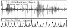
- Fig. 4is a waveform diagram showing that a heart sound is separated from a pulmonary sound and transformed into an envelope shape for analysis by a full-load measuring device according to an exemplary embodiment of the present disclosure.
- the pulmonary sound separation module (120) of Fig. 1can perform the operation of Fig. 4.
- the cardiopulmonary soundcan be obtained as a combination of heart sound and lung sound as indicated by the solid line and dotted line graph.
- the cardiopulmonary soundcan be separated into heart sound and lung sound by the methodology described in Fig. 4.
- the heart sound separated from the cardiopulmonary soundis a part of the cardiopulmonary sound as indicated by the solid line graph.
- the present disclosureperforms a Hilbert transform on a separated sound (a solid graph) to generate a Hilbert envelope. Referring to the lower graph of Fig. 4, a modification of the Hilbert envelope is illustrated.
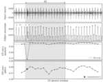
- FIG. 5is a diagram illustrating a method for determining a breathing cycle based on a peak by a full-load measuring device according to an exemplary embodiment of the present disclosure.
- the breathing period specific module (130) of FIG. 1can perform the operation of FIG. 5.
- the full load measuring device (10) according to the exemplary embodimentcan perform a Hilbert transform on the lung sound (upper graph of Fig. 5) and generate an envelope.
- the full load measuring device (10) according to the exemplary embodimentcan apply a moving average to the envelope to convert the signal into a form in which the peak value of respiration can be detected (lower graph of Fig. 5).
- the full load measuring device (10) according to the exemplary embodimentcan detect the peak of the respiratory signal by using a local maxima.
- the full load measuring device (10) according to the exemplary embodimentcan identify the inspiratory signal (red line) and the expiratory signal (green line) by using the fact that the inspiratory (t2)-expiratory (t3) interval is shorter than the expiratory (t3)-inspiratory (t4) interval.
- the full load measuring device (10)can calculate the respiratory rate (RR) as the average of the inspiration-inspiration interval or the expiration-expiration interval.
- the full load measuring device (10)can perform a first differentiation on a graph forming an envelope to find an inflection point and specify the detected inflection point as an inspiration start point. As a result, the full load measuring device (10) can specify a breathing section (P1).
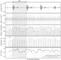
- FIG. 6is a diagram showing a method for obtaining a heart rate index and an error removal and separation correction method by a full load measuring device according to an exemplary embodiment of the present disclosure.
- the heart rate index calculation module (140) of FIG. 1can perform the operation of FIG. 6.
- the full load measuring device (10) according to the exemplary embodimentcan perform a Hilbert transform on the heart sound (the upper graph of Fig. 6) and generate an envelope.
- the full load measuring device (10) according to the exemplary embodimentcan apply a moving average to the envelope to convert the signal into a form in which the peak value of the heart sound can be detected (the upper graph of Fig. 6).
- the full load measuring device (10)can calculate the heart rate by applying the modified cross correlation method.
- the full load measuring device (10)can specify the peak of the first first heart sound intensity based on the first heart sound-second heart sound interval, shape, and frequency information.
- the peak specification criteriaare as follows.
- the full load measuring device (10)can detect both the first heart sound signal and the second heart sound signal peak throughout the entire heart rate interval (P2).
- the full load measuring device (10)can calculate heart sound indices such as first heart sound signal, second heart sound signal peak intensity, area, time, etc.
- the full load measuring device (10)can calculate first heart sound signal-second heart sound signal time interval, time interval variation, intensity ratio, intensity variation, etc. based on the heart sound indices.
- the full load measuring device (10)can determine an error value by utilizing the first heart sound signal-first heart sound signal interval, the second heart sound signal-second heart sound signal interval, the intensity of each of the first heart sound signal and the second heart sound signal, and the first heart sound signal-second heart sound signal interval information within the section (P2) (sub-graph of FIG. 6).
- the full load measuring device (10)can recalculate the time interval, time interval variation, intensity ratio, intensity variation, etc. of the first heart sound signal-second heart sound signal within one respiratory interval by correcting the removal section through linear interpolation after removing the error value (the lowermost graph of FIG. 6).
- the full load measuring device (10)can correct errors due to separation in the case of data in which the first heart sound separation phenomenon (S1 Split) is prominent.
- FIGS. 7a and 7bare drawings explaining that the full load measuring device according to an exemplary embodiment of the present disclosure corrects the first heart sound separation phenomenon.
- FIG. 7athe STI and pulse pressure obtained within a specific section (P3) are compared.
- Fig. 7bwhich is an enlarged and detailed illustration of the lower graph of Fig. 7a. Through Figs. 7a and 7b, it is explained that the first heart sound signal is separated and compensated.
- the first heart sound signalconsists of the sound that occurs when the bicuspid and tricuspid valves close, and since STI must utilize the bicuspid signal, it is difficult to measure the exact time interval when the tricuspid signal is judged as a peak.
- the present disclosurecan separate the bicuspid signal and the tricuspid signal by using curve fitting using a double Gaussian function.
- the full load measuring device (10)according to the exemplary embodiment can obtain only the bicuspid signal and calculate heart sound indices such as STI.
- FIG. 8is a graph showing a comparison of the intensity of the second heart sound and systemic vascular resistance (SVR) among heart sound indices obtained according to an embodiment of the present disclosure.
- the acquired second heart sound intensity and SVRare compared as shown in the graph.
- the black solid line in Fig. 8represents SVR, and the gray dotted line in Fig. 8 represents the second heart sound intensity as a heart sound index.
- Figure 9is a graph showing the difference in the amount of change in the intensity of the first heart sound in sections where SVV appears high (dotted line area of the top graph) and sections where SVV appears low (dashed line area of the top graph).
- the lower left and right graphs of Fig. 9represent the heart sounds and envelopes in areas with high and low SVV, respectively, and the cross-shaped marker at the bottom is the peak of the first heart sound intensity in that area.
- the amount of change in the area with high SVVis relatively large, which allows mathematical expression 3 to be understood in more detail.
- FIG. 10is a graph showing a comparison between an acoustic variability index derived according to an exemplary embodiment of the present disclosure and SVV, which is one of the existing utilized indices.
- Fig. 10represents SVV
- the vertical axis of Fig. 8represents an acoustic variability index according to an exemplary embodiment of the present disclosure.
- SVV and acoustic variability indexshow the results of regression analysis.
- Fig. 11is a block diagram showing an electronic device (30) which is an embodiment of a full load measuring device according to an exemplary embodiment of the present disclosure.
- the full load measuring device of Fig. 1can be implemented with the electronic device (30) of Fig. 11.
- the electronic device (30)may include an input/output unit (310), a communication unit (320), an identification unit (330), a database (340), and a processor (350).
- the electronic device (30)is an electronic device that implements a method for measuring the full load of a general anesthesia surgical patient based on an acoustic variability index, and it is assumed that the method for measuring the full load of a general anesthesia surgical patient based on an acoustic variability index is implemented through the electronic device (30).
- the input/output unit (310)may be various interfaces or connection ports that receive user input or output information to the user.
- the input/output unit (310)may be divided into an input module and an output module.
- the input modulereceives user input from a user.
- the input moduleis for inputting image information (or signal), audio information (or signal), data, or information input from a user, and may include at least one camera, at least one microphone, and at least one user input unit. Voice data or image data collected from the input unit may be analyzed and processed as a user control command.
- User inputcan take various forms, including key input, touch input, and voice input.
- input modulesthat can receive such user input include, in addition to traditional keypads, keyboards, and mice, touch sensors that detect the user's touch, microphones that receive voice signals, cameras that recognize gestures through image recognition, proximity sensors such as light sensors or infrared sensors that detect the approach of a user, motion sensors that recognize user movements through acceleration sensors or gyro sensors, and various other input means that detect or receive various forms of user input.
- the touch sensormay be implemented as a piezoelectric or electrostatic touch sensor that detects touch through a touch panel or touch film attached to the display panel, an optical touch sensor that detects touch in an optical manner, etc.
- the input modulemay be implemented in the form of an input interface (such as a USB port or PS/2 port) that connects an external input device that receives user input instead of a device that detects user input on its own.
- the output modulecan output various information and provide it to the user.
- the output moduleis a comprehensive concept that includes a display that outputs images, a speaker (and/or an amplifier connected thereto) that outputs sounds, a haptic device that generates vibrations, and various other forms of output means.
- the output modulecan also be implemented in the form of a port-type output interface that connects the individual output means described above.
- an output module in the form of a displaycan display text, still images, and moving images.
- the displayis a concept that broadly refers to an image display device including a liquid crystal display (LCD), a light emitting diode (LED) display, an organic light emitting diode (OLED) display, a flat panel display (FPD), a transparent display, a curved display, a flexible display, a 3D display, a holographic display, a projector, and various other devices that can perform an image output function.
- a displaymay be in the form of a touch display configured integrally with a touch sensor of the input module.
- the communication unit (320)can communicate with an external device. Therefore, the device can transmit and receive information with the external device through the communication unit.
- the communication unit (320)can include, for example, at least one of a wired communication module, a wireless communication module, a short-range communication module, and a location information module.
- the communication unitmay be composed of a wired communication module that connects to the Internet, etc. via a LAN (Local Area Network), a mobile communication module that connects to a mobile communication network via a mobile communication base station to transmit and receive data, a short-distance communication module that uses a WLAN (Wireless Local Area Network) series communication method such as Wi-Fi or a WPAN (Wireless Personal Area Network) series communication method such as Bluetooth or Zigbee, a satellite communication module that uses a GNSS (Global Navigation Satellite System) such as a GPS (Global Positioning System), or a combination thereof.
- WLANWireless Local Area Network
- WPANWireless Personal Area Network
- GNSSGlobal Navigation Satellite System
- GPSGlobal Positioning System
- the wireless communication technology used for communicationmay include NB-IoT (Narrowband Internet of Things) for low-power communication.
- NB-IoT technologymay be an example of LPWAN (Low Power Wide Area Network) technology and may be implemented with standards such as LTE Cat (category) NB1 and/or LTE Cat NB2, and is not limited to the names described above.
- a wireless communication technology implemented in a wireless device according to various embodimentsmay perform communication based on LTE-M technology.
- LTE-M technologymay be an example of LPWAN technology and may be called by various names such as eMTC (enhanced Machine Type Communication).
- LTE-M technologymay be implemented with at least one of various standards such as 1) LTE CAT 0, 2) LTE Cat M1, 3) LTE Cat M2, 4) LTE non-BL (non-Bandwidth Limited), 5) LTE-MTC, 6) LTE Machine Type Communication, and/or 7) LTE M, and is not limited to the names described above.
- the wireless communication technology implemented in the wireless device according to various embodimentsmay include at least one of ZigBee, Bluetooth, and Low Power Wide Area Network (LPWAN) considering low-power communication, and is not limited to the above-described names.
- ZigBee technologycan create PAN (personal area networks) related to small/low-power digital communication based on various standards such as IEEE 802.15.4, and may be called by various names.
- the wired communication modulemay include various wired communication modules such as a Local Area Network (LAN) module, a Wide Area Network (WAN) module, or a Value Added Network (VAN) module, as well as various cable communication modules such as a Universal Serial Bus (USB), a High Definition Multimedia Interface (HDMI), a Digital Visual Interface (DVI), RS-232 (recommended standard232), power line communication, or plain old telephone service (POTS).
- LANLocal Area Network
- WANWide Area Network
- VANValue Added Network
- USBUniversal Serial Bus
- HDMIHigh Definition Multimedia Interface
- DVIDigital Visual Interface
- RS-232recommended standard232
- POTSplain old telephone service
- the wireless communication modulemay include, in addition to a WiFi module and a Wireless Broadband module, a wireless communication module that supports various wireless communication methods such as GSM (global System for Mobile Communication), CDMA (Code Division Multiple Access), WCDMA (Wideband Code Division Multiple Access), UMTS (universal mobile telecommunications system), TDMA (Time Division Multiple Access), LTE (Long Term Evolution), 4G, 5G, and 6G.
- GSMGlobal System for Mobile Communication
- CDMACode Division Multiple Access
- WCDMAWideband Code Division Multiple Access
- UMTSuniversalal mobile telecommunications system
- TDMATime Division Multiple Access
- LTELong Term Evolution
- the wireless communication modulemay include a wireless communication interface including an antenna and a transmitter for transmitting a signal.
- the wireless communication modulemay further include a signal conversion module for modulating a digital control signal output from the control unit through the wireless communication interface into an analog wireless signal according to the control of the control unit.
- the wireless communication modulemay include a wireless communication interface including an antenna and a receiver for receiving a signal.
- the wireless communication modulemay further include a signal conversion module for demodulating an analog wireless signal received through the wireless communication interface into a digital control signal.
- the short-range communication moduleis for short-range communication and can support short-range communication using at least one of Bluetooth (BluetoothTM RFID (Radio Frequency Identification), Infrared Data Association; IrDA), UWB (Ultra Wideband), ZigBee, NFC (Near Field Communication), Wi-Fi (Wireless-Fidelity), Wi-Fi Direct, and Wireless USB (Wireless Universal Serial Bus) technologies.
- BluetoothBluetoothTM RFID (Radio Frequency Identification), Infrared Data Association; IrDA), UWB (Ultra Wideband), ZigBee, NFC (Near Field Communication), Wi-Fi (Wireless-Fidelity), Wi-Fi Direct, and Wireless USB (Wireless Universal Serial Bus) technologies.
- the location information moduleis a module for obtaining the location (or current location) of the electronic device according to the present disclosure, and representative examples thereof include a GPS (Global Positioning System) module or a Wi-Fi (Wireless Fidelity) module.
- a GPS moduleGlobal Positioning System
- Wi-FiWireless Fidelity
- the location of the electronic devicecan be obtained using a signal transmitted from a GPS satellite.
- a Wi-Fi modulethe location of the device can be obtained based on information of a wireless AP (Wireless Access Point) that transmits or receives a wireless signal with the Wi-Fi module.
- the location information modulemay perform any function of other modules of the communication unit to obtain data regarding the location of the device as a substitute or in addition.
- the location information moduleis a module used to obtain the location (or current location) of the device, and is not limited to a module that directly calculates or obtains the location of the device.
- the identification unit (330)may be a comprehensive concept that includes various forms of identification/sensing means that detect or receive various forms of external input, such as a camera that recognizes objects through image recognition, a detection sensor that detects approaching objects, a touch sensor according to user input, and others.
- the identification unitmay be understood as being identical to the input module in the input/output unit (310) and/or may be understood as being separate from the input module.
- the identification unit (330)may further include one or more of a magnetic sensor, an acceleration sensor, a temperature/humidity sensor, an infrared sensor, a gyroscope sensor, a position sensor (e.g., GPS), a barometric pressure sensor, a proximity sensor, an RGB sensor (illuminance sensor), a radar sensor, a light sensor, and a current sensor, but is not limited thereto. Since the function of each sensor can be intuitively inferred from its name by those skilled in the art, a detailed description thereof will be omitted.
- the database (340)can store various types of information.
- the databasecan store data temporarily or semi-permanently.
- the databasecan store an operating program (OS: Operating System) for operating the first device and/or the second device, data for hosting a website, a program for generating Braille, or data regarding an application (e.g., a web application).
- OSOperating System
- the databasecan store modules in the form of computer codes as described above.
- Examples of the database (340)may include a hard disk drive (HDD), a solid state drive (SSD), a flash memory, a read-only memory (ROM), a random access memory (RAM), etc. Such a database may be provided as a built-in type or a detachable type.
- HDDhard disk drive
- SSDsolid state drive
- flash memorya read-only memory
- RAMrandom access memory
- Such a databasemay be provided as a built-in type or a detachable type.
- the processor (350)controls the overall operation of the electronic device (30). To this end, the processor (350) may perform calculations and processing of various types of information and control the operation of components of the first device and/or the second device. For example, the processor (350) may execute a program or application for a method for measuring the full load of a general anesthesia surgical patient based on an acoustic variability index.
- the processor (350)may be implemented as a computer or a similar device according to hardware, software, or a combination thereof.
- the processor (350)may be provided in the form of an electronic circuit that processes electrical signals to perform a control function
- the processormay be provided in the form of a program that drives the hardware processor.
- the operations of the first device and/or the second devicemay be interpreted as being performed under the control of the processor (350).
- moduleswhen modules implemented as programs or applications for a method for measuring the full load of a general anesthesia surgical patient based on an acoustic variability index are executed, the modules may be interpreted as controlling the processor (350) to perform the following operations of the first device and/or the second device.
- the processor (350)may be implemented as a memory storing data for an algorithm for controlling the operation of components within the device or a program reproducing the algorithm, and at least one processor (not shown) performing the above-described operation using the data stored in the memory.
- the memory and the processormay be implemented as separate chips.
- the memory and the processormay be implemented as a single chip.
- processor (350)can control one or a combination of the components described above to implement various embodiments according to the present disclosure described in FIGS. 1 to 8 on the device.
- the electronic device (30)may include a memory storing at least one instruction; a processor performing a full load measurement function by executing the instruction, wherein the processor may be characterized by separating a heart sound of the patient through a high-pass filter and a band-pass filter using a heart-lung sound separation module, specifying an inhalation and expiration section of the patient using an envelope of a waveform generated through a Hilbert transform using a respiratory interval specification module, detecting a first heart sound and a second heart sound signal corresponding to a local maximum of the envelope using a heart sound index calculation module, and calculating an acoustic variability index from at least one of a time variation, an intensity variation, and an area variation of the first heart sound and the second heart sound signals using an acoustic variability index calculation module.
- each component illustrated in FIG. 11represents software and/or hardware components such as a Field Programmable Gate Array (FPGA) and an Application Specific Integrated Circuit (ASIC).
- FPGAField Programmable Gate Array
- ASICApplication Specific Integrated Circuit
- the present disclosuremay be implemented by various means.
- various embodimentsmay be implemented by hardware, firmware, software, or a combination thereof.
- the method according to the present inventioncan be implemented by one or more ASICs (application specific integrated circuits), DSPs (digital signal processors), DSPDs (digital signal processing devices), PLDs (programmable logic devices), FPGAs (field programmable gate arrays), processors, controllers, microcontrollers, microprocessors, and the like.
- ASICsapplication specific integrated circuits
- DSPsdigital signal processors
- DSPDsdigital signal processing devices
- PLDsprogrammable logic devices
- FPGAsfield programmable gate arrays
- processorscontrollers, microcontrollers, microprocessors, and the like.
- the method according to the present inventionmay be implemented in the form of a module, procedure or function that performs the functions or operations described below.
- software codemay be stored in a memory and may be driven by a processor.
- the memorymay be located inside or outside the processor, and may exchange data with the processor by various means already known.
- the steps of a method or algorithm described in connection with the embodiments of the present disclosuremay be implemented directly in hardware, implemented in a software module executed by hardware, or implemented by a combination of these.
- the software modulemay reside in a Random Access Memory (RAM), a Read Only Memory (ROM), an Erasable Programmable ROM (EPROM), an Electrically Erasable Programmable ROM (EEPROM), a Flash Memory, a hard disk, a removable disk, a CD-ROM, or any other form of computer-readable recording medium well known in the art to which the present disclosure pertains.
- RAMRandom Access Memory
- ROMRead Only Memory
- EPROMErasable Programmable ROM
- EEPROMElectrically Erasable Programmable ROM
- Flash Memorya hard disk, a removable disk, a CD-ROM, or any other form of computer-readable recording medium well known in the art to which the present disclosure pertains.
- the disclosed embodimentsmay be implemented in the form of a recording medium storing instructions executable by a computer.
- the instructionsmay be stored in the form of program codes, and when executed by a processor, may generate program modules to perform the operations of the disclosed embodiments.
- the recording mediummay be implemented as a computer-readable recording medium.
- Computer-readable storage mediainclude all types of storage media that store instructions that can be deciphered by a computer. Examples include ROM (Read Only Memory), RAM (Random Access Memory), magnetic tape, magnetic disk, flash memory, and optical data storage devices.
- ROMRead Only Memory
- RAMRandom Access Memory
- magnetic tapemagnetic tape
- magnetic diskmagnetic disk
- flash memoryoptical data storage devices
Landscapes
- Health & Medical Sciences (AREA)
- Life Sciences & Earth Sciences (AREA)
- Engineering & Computer Science (AREA)
- Biomedical Technology (AREA)
- Medical Informatics (AREA)
- Public Health (AREA)
- General Health & Medical Sciences (AREA)
- Surgery (AREA)
- Veterinary Medicine (AREA)
- Animal Behavior & Ethology (AREA)
- Physics & Mathematics (AREA)
- Pathology (AREA)
- Heart & Thoracic Surgery (AREA)
- Molecular Biology (AREA)
- Cardiology (AREA)
- Biophysics (AREA)
- Physiology (AREA)
- Acoustics & Sound (AREA)
- Data Mining & Analysis (AREA)
- Databases & Information Systems (AREA)
- Epidemiology (AREA)
- Primary Health Care (AREA)
- Nuclear Medicine, Radiotherapy & Molecular Imaging (AREA)
- Measuring Pulse, Heart Rate, Blood Pressure Or Blood Flow (AREA)
Abstract
Description
Translated fromKorean본 개시는 전신 마취 수술 환자의 전부하량을 측정하는 방법에 관한 것으로, 보다 상세하게는 음향가변성지표에 기반한 전신마취 수술환자 전부하량 측정 방법 및 이를 실행하는 전자 장치로서, 환자의 심폐음을 기초로 하여 비침습적으로 환자의 수액 투여 반응성을 판단하여 전부하량을 측정하는 방법, 장치 및 컴퓨터 프로그램에 관한 것이다.The present disclosure relates to a method for measuring the preload of a patient undergoing general anesthesia surgery, and more specifically, to a method for measuring the preload of a patient undergoing general anesthesia surgery based on an acoustic variability index and an electronic device for executing the same, and to a method, device, and computer program for measuring the preload by noninvasively determining the patient's fluid administration responsiveness based on the patient's cardiopulmonary sounds.
수술 환자는 출혈 등의 이유로 단시간에 급격한 혈액량의 변동이 발생할 수 있다. 이에 따라, 혈액량 변동 확인이 필요한 대부분의 수술에서는 이완기 말 심실에 피가 가득 찼을 때의 압력인 '전부하(preload)량'에 대한 간접측정 방식으로 혈액량 변동을 추정한다.Surgical patients may experience rapid changes in blood volume in a short period of time due to reasons such as bleeding. Accordingly, in most surgeries that require confirmation of blood volume changes, blood volume changes are estimated by indirectly measuring the 'preload amount', which is the pressure when the ventricle is filled with blood at the end of diastole.
경정맥-우심방-우심실-폐동맥으로 직접 연결되는 스완-간츠 카테터(Swan-Ganz catheter)를 활용하여 환자의 심박출량(Cardiac Output; CO)과 일회박출량(Stroke Volume; SV) 등을 직접 측정 가능하지만 부정맥, 폐경색, 폐동맥파열 및 감염 등 환자에게 치명적인 합병증 가능성이 크기 때문에 반드시 필요한 일부의 환자에게만 이용되어야 한다.Cardiac output (CO) and stroke volume (SV) can be directly measured using a Swan-Ganz catheter that is directly connected to the jugular vein, right atrium, right ventricle, and pulmonary artery. However, it should only be used for a small number of patients who absolutely need it because there is a high risk of fatal complications for the patient, such as arrhythmia, pulmonary infarction, pulmonary artery rupture, and infection.
종래 임상에서는 동맥압 카테터(Arterial Line catheter)로부터 측정된 연속 동맥압(Arterial Blood Pressure; ABP)으로부터 맥압변이(Pulse Pressure Variation; PPV)를 직접 측정하거나 동맥압 연산으로 일회박출량변이(Stroke Volume Variation; SVV)을 추산하여 전부하량을 모니터링 하는 방법과 혈량계 파형 데이터 연산으로 혈량변이지표(Pleth Variability index; PVi)를 산출하는 방법 등을 이용한다.In conventional clinical practice, methods such as directly measuring pulse pressure variation (PPV) from continuous arterial blood pressure (ABP) measured from an arterial line catheter or estimating stroke volume variation (SVV) by calculating arterial pressure to monitor preload, and calculating pleth variability index (PVi) by calculating plethysmography waveform data are used.
하지만, 상기 지표들 중 PPV와 SVV를 측정하기 위한 동맥압 카테터는 침습적인 검사 방법이므로 여전히 환자의 신체에 부담이 크며, 혈량변이지표는 비침습적이지만 정확도가 상대적으로 떨어지므로, 새로운 지표를 통한 전부하량 측정 방법의 개발이 요구되는 실정이다.However, among the above indices, the arterial pressure catheter for measuring PPV and SVV is an invasive examination method, so it still places a great burden on the patient's body, and although the blood volume variation index is noninvasive, its accuracy is relatively low, so the development of a preload measurement method using a new index is required.
본 개시가 해결하고자 하는 과제는 심폐음 신호를 분석하여 비침습적으로 전부하량을 측정하는 음향가변성지표(Acoustic Variability Index; AVI)를 산출하는 방법을 제공하는 것이다.The problem that the present disclosure seeks to solve is to provide a method for calculating an Acoustic Variability Index (AVI) that noninvasively measures preload by analyzing a cardiopulmonary sound signal.
또한, 본 개시가 해결하고자 하는 과제는 음향가변성지표에 기반한 전신마취 수술환자 전부하량 측정 방법 및 이를 실행하는 전자 장치를 제공하는 것이다.In addition, the problem that the present disclosure seeks to solve is to provide a method for measuring the full load of a general anesthesia surgical patient based on an acoustic variability index and an electronic device for executing the same.
본 개시가 해결하고자 하는 과제들은 이상에서 언급된 과제로 제한되지 않으며, 언급되지 않은 또 다른 과제들은 아래의 기재로부터 통상의 기술자에게 명확하게 이해될 수 있을 것이다.The problems to be solved by the present disclosure are not limited to the problems mentioned above, and other problems not mentioned will be clearly understood by those skilled in the art from the description below.
상술한 기술적 과제를 달성하기 위한 본 개시의 예시적 실시예에 따른 전신 마취 수술 환자의 전부하량을 측정하기 위한 전자 장치에 의한 심음 분석 방법은, 외부로부터 획득한 환자의 심폐음 데이터로부터 심음 및 호흡음을 분리하는 단계, 분리된 호흡음으로부터 호흡 구간을 특정하는 단계, 심음 신호를 변환함으로써 피크 신호 획득을 위한 심음 포락선을 획득하는 단계, 심음 포락선으로부터 심음지표를 획득하는 단계, 및 심음지표를 분석하여 음향가변성지표(Acoustic Variability Index; AVI)를 산출하는 단계를 포함한다.According to an exemplary embodiment of the present disclosure for achieving the above-described technical problem, a method for analyzing heart sounds by an electronic device for measuring a preload of a patient undergoing general anesthesia surgery includes the steps of separating heart sounds and respiratory sounds from cardiopulmonary sound data of the patient acquired from an external source, specifying a respiratory interval from the separated respiratory sounds, obtaining a heart sound envelope for obtaining a peak signal by converting a heart sound signal, obtaining a heart sound index from the heart sound envelope, and analyzing the heart sound index to derive an Acoustic Variability Index (AVI).
본 개시의 예시적 실시예에 따른 전신 마취 수술 환자의 전부하량을 측정하기 위한 전자 장치에 의한 심음 분석 방법은, 외부로부터 획득한 환자의 심폐음 데이터로부터 심음과 호흡음을 분리하는 단계; 상기 심음에 대해 힐버트(Hilbert) 변환을 수행한 결과로서 생성되는 파형의 포락선을 획득하는 단계; 제1 심음 및 제2 심음을 탐지하는 단계; 상기 파형의 피크(peak)별 위치, 세기, 및 면적 중 적어도 하나를 산출하는 단계; 상기 호흡음으로부터 호흡 주기를 탐지하는 단계; 상기 호흡 주기로부터 호흡 구간을 특정하는 단계; 상기 호흡 구간별 심음지표를 산출하는 단계; 및 상기 심음지표를 분석함으로써 음향가변성지표(Acoustic Variability Index; AVI)를 산출하는 단계를 포함할 수 있다.A method for analyzing heart sounds by an electronic device for measuring a preload of a patient undergoing general anesthesia surgery according to an exemplary embodiment of the present disclosure may include the steps of: separating heart sounds and respiratory sounds from cardiopulmonary sound data of the patient acquired from an external source; obtaining an envelope of a waveform generated as a result of performing a Hilbert transform on the heart sounds; detecting a first heart sound and a second heart sound; calculating at least one of a position, an intensity, and an area of each peak of the waveform; detecting a respiratory cycle from the respiratory sound; specifying a respiratory section from the respiratory cycle; calculating a heart sound index for each respiratory section; and calculating an Acoustic Variability Index (AVI) by analyzing the heart sound index.
본 개시의 예시적 실시예에 따른 전신 마취 수술 환자의 전부하량을 측정하기 위한 전자 장치는, 적어도 하나의 인스트럭션을 저장하는 메모리; 상기 인스트럭션을 실행함으로써 전부하량 측정 기능을 수행하는 프로세서를 포함하고, 상기 프로세서는, 심폐음 분리모듈을 이용해 하이패스필터 및 밴드패스필터를 통해 상기 환자의 심음을 분리하고, 호흡구간 특정모듈을 이용해 힐버트(Hilbert) 변환을 통해 생성된 파형의 포락선(Envelope)울 이용해 상기 환자의 흡기 및 호기 간 구간을 특정하며, 심음지표 산출모듈을 이용해 상기 포락선의 국부 최대값에 상응하는 제1 및 제2 심음 신호를 탐지하고, 음향가변성지표 연산모듈을 이용해 상기 제1 및 제2 심음 신호의 시간 변이, 세기 변이, 및 면적 변이 중 적어도 하나로부터 음향가변성지표를 산출하는 것을 특징으로 할 수 있다.An electronic device for measuring a preload of a patient undergoing general anesthesia surgery according to an exemplary embodiment of the present disclosure comprises: a memory storing at least one instruction; a processor performing a preload measuring function by executing the instruction, wherein the processor is characterized in that it separates a heart sound of the patient through a high-pass filter and a band-pass filter using a cardiopulmonary sound separation module, specifies an inhalation and expiration section of the patient using an envelope of a waveform generated through a Hilbert transform using a respiratory interval specification module, detects first and second heart sound signals corresponding to local maximum values of the envelope using a heart sound index calculation module, and calculates an acoustic variability index from at least one of a time variation, an intensity variation, and an area variation of the first and second heart sound signals using an acoustic variability index calculation module.
이 외에도, 본 개시를 구현하기 위한 방법을 실행하기 위한 컴퓨터 프로그램을 기록하는 컴퓨터 판독 가능한 기록 매체가 더 제공될 수 있다.In addition, a computer-readable recording medium recording a computer program for executing a method for implementing the present disclosure may be further provided.
본 개시의 예시적 실시예에 따른 전신 마취 수술 환자의 전부하량을 측정하기 위한 방법 및 이를 실행하는 전자 장치는, 심폐음을 획득, 분석하여 비침습적으로 환자의 전부하량을 측정할 수 있다.A method for measuring the preload of a patient undergoing general anesthesia surgery according to an exemplary embodiment of the present disclosure and an electronic device for executing the same can noninvasively measure the preload of a patient by acquiring and analyzing cardiopulmonary sounds.
본 개시의 예시적 실시예에 따른 전신 마취 수술 환자의 전부하량을 측정하기 위한 방법 및 이를 실행하는 전자 장치는, 전신 마취 수술의 경우, 필수적으로 식도청진기가 이용되기 때문에 식도청진기로부터 획득가능한 심폐음을 활용하여 전부하량 측정이 가능하고, 기존의 침습적 방법(스완-간츠 카테터, 동맥압 카테터) 대비 환자 안전 향상에 큰 효과가 있고, 기존의 비침습적 방법 (혈량 변이) 대비 정확도를 향상시킬 수 있다.A method for measuring preload of a patient undergoing general anesthesia surgery according to an exemplary embodiment of the present disclosure and an electronic device for executing the same enable preload measurement by utilizing cardiopulmonary sounds obtainable from an esophageal stethoscope, since an esophageal stethoscope is inevitably used in the case of general anesthesia surgery, and is greatly effective in improving patient safety compared to existing invasive methods (Swan-Ganz catheter, arterial pressure catheter) and can improve accuracy compared to existing noninvasive methods (blood volume variation).
본 개시의 예시적 실시예에 따른 전신 마취 수술 환자의 전부하량을 측정하기 위한 방법 및 이를 실행하는 전자 장치는, ECG 신호 없이 심폐음 신호만으로 복수의 심음(S1, S2)을 특정하고 지표를 자동 탐지할 수 있다.A method for measuring the preload of a patient undergoing general anesthesia surgery according to an exemplary embodiment of the present disclosure and an electronic device for executing the same can identify multiple heart sounds (S1, S2) and automatically detect indicators using only cardiopulmonary sound signals without an ECG signal.
본 개시의 효과들은 이상에서 언급된 효과로 제한되지 않으며, 언급되지 않은 또 다른 효과들은 아래의 기재로부터 통상의 기술자에게 명확하게 이해될 수 있을 것이다.The effects of the present disclosure are not limited to the effects mentioned above, and other effects not mentioned will be clearly understood by those skilled in the art from the description below.
도 1은 본 개시의 예시적 실시예에 따른 심폐음 분석 시스템을 도시하는 블록도이다.FIG. 1 is a block diagram illustrating a heart sound analysis system according to an exemplary embodiment of the present disclosure.
도 2는 본 개시의 예시적 실시예에 따른 음향가변성지표에 기반한 전신마취 수술환자 전부하량 측정 방법을 설명하는 흐름도이다.FIG. 2 is a flowchart illustrating a method for measuring the preload of a general anesthesia surgical patient based on an acoustic variability index according to an exemplary embodiment of the present disclosure.
도 3은 본 개시의 예시적 실시예에 따른 전부하량 측정장치에 의해 심폐음으로부터 심음이 분리되고, 분석을 위한 포락선 형태로 변형됨을 나타내는 파형도이다.FIG. 3 is a waveform diagram showing that a heart sound is separated from a pulmonary sound and transformed into an envelope shape for analysis by a full-load measuring device according to an exemplary embodiment of the present disclosure.
도 4는 본 개시의 예시적 실시예에 따른 전부하량 측정장치가 대역통과필터를 통해 심폐음에서 심음과 폐음을 분리함을 설명하는 도면이다.FIG. 4 is a diagram illustrating that a full-load measuring device according to an exemplary embodiment of the present disclosure separates heart sounds and lung sounds from cardiopulmonary sounds through a band-pass filter.
도 5는 본 개시의 예시적 실시예에 따른 전부하량 측정장치가 피크에 기반해 호흡 주기를 판정하는 방법을 설명하는 도면이다.FIG. 5 is a diagram illustrating a method for determining a breathing cycle based on a peak by a full-load measuring device according to an exemplary embodiment of the present disclosure.
도 6은 본 개시의 예시적 실시예에 따른 전부하량 측정장치가 심음지표를 획득하는 방법을 나타내는 도면이다.FIG. 6 is a diagram illustrating a method for obtaining a heart rate index by a full-load measuring device according to an exemplary embodiment of the present disclosure.
도 7a 및 도 7b는 본 개시의 예시적 실시예에 따른 전부하량 측정장치가 제1 심음 분리 현상을 보정함을 설명하는 도면이다.FIG. 7A and FIG. 7B are diagrams illustrating that a full-load measuring device according to an exemplary embodiment of the present disclosure compensates for the first sound separation phenomenon.
도 8은 본 개시의 실시예에 따라 획득한 심음 지표 중 제2 심음의 세기와 전신혈관저항의 비교를 나타낸 그래프이다.FIG. 8 is a graph showing a comparison of the intensity of the second heart sound among the heart sound indices obtained according to an embodiment of the present disclosure and the systemic vascular resistance.
도 9는 본 개시의 실시예에 따라 획득한 심음 지표 중 제1 심음의 세기 변화와 SVV의 비교를 나타낸 그래프이다.FIG. 9 is a graph showing a comparison of the change in intensity of the first heart sound and SVV among the heart sound indices obtained according to an embodiment of the present disclosure.
도 10은 본 개시의 예시적 실시예에 따라 도출된 음향가변성지표와 기존 활용 지표 중 하나인 SVV의 비교를 나타낸 그래프이다.FIG. 10 is a graph showing a comparison between an acoustic variability index derived according to an exemplary embodiment of the present disclosure and SVV, which is one of the existing utilized indices.
도 11은 본 개시의 예시적 실시예에 따른 전부하량 측정장치의 실시예를 나타내는 블록도이다.FIG. 11 is a block diagram showing an embodiment of a full load measuring device according to an exemplary embodiment of the present disclosure.
본 개시 전체에 걸쳐 동일 참조 부호는 동일 구성요소를 지칭한다. 본 개시가 실시예들의 모든 요소들을 설명하는 것은 아니며, 본 개시가 속하는 기술분야에서 일반적인 내용 또는 실시예들 간에 중복되는 내용은 생략한다. 명세서에서 사용되는 '부, 모듈, 부재, 블록'이라는 용어는 소프트웨어 또는 하드웨어로 구현될 수 있으며, 실시예들에 따라 복수의 '부, 모듈, 부재, 블록'이 하나의 구성요소로 구현되거나, 하나의 '부, 모듈, 부재, 블록'이 복수의 구성요소들을 포함하는 것도 가능하다.Throughout this disclosure, the same reference numerals refer to the same components. This disclosure does not describe all elements of the embodiments, and any content that is general in the technical field to which this disclosure belongs or that overlaps between the embodiments is omitted. The terms 'part, module, element, block' used in the specification can be implemented in software or hardware, and according to the embodiments, a plurality of 'parts, modules, elements, blocks' can be implemented as a single component, or a single 'part, module, element, block' can include a plurality of components.
명세서 전체에서, 어떤 부분이 다른 부분과 "연결"되어 있다고 할 때, 이는 직접적으로 연결되어 있는 경우뿐 아니라, 간접적으로 연결되어 있는 경우를 포함하고, 간접적인 연결은 무선 통신망을 통해 연결되는 것을 포함한다.Throughout the specification, when a part is said to be "connected" to another part, this includes not only a direct connection but also an indirect connection, and an indirect connection includes a connection via a wireless communications network.
또한 어떤 부분이 어떤 구성요소를 "포함"한다고 할 때, 이는 특별히 반대되는 기재가 없는 한 다른 구성요소를 제외하는 것이 아니라 다른 구성요소를 더 포함할 수 있는 것을 의미한다.Additionally, when a part is said to "include" a component, this does not mean that it excludes other components, but rather that it may include other components, unless otherwise specifically stated.
명세서 전체에서, 어떤 부재가 다른 부재 "상에" 위치하고 있다고 할 때, 이는 어떤 부재가 다른 부재에 접해 있는 경우뿐 아니라 두 부재 사이에 또 다른 부재가 존재하는 경우도 포함한다.Throughout the specification, when it is said that an element is "on" another element, this includes not only cases where the element is in contact with the other element, but also cases where there is another element between the two elements.
제1, 제2 등의 용어는 하나의 구성요소를 다른 구성요소로부터 구별하기 위해 사용되는 것으로, 구성요소가 전술된 용어들에 의해 제한되는 것은 아니다.The terms first, second, etc. are used to distinguish one component from another, and the components are not limited by the aforementioned terms.
단수의 표현은 문맥상 명백하게 예외가 있지 않는 한, 복수의 표현을 포함한다.Singular expressions include plural expressions unless the context clearly indicates otherwise.
각 단계들에 있어 식별부호는 설명의 편의를 위하여 사용되는 것으로 식별부호는 각 단계들의 순서를 설명하는 것이 아니며, 각 단계들은 문맥상 명백하게 특정 순서를 기재하지 않는 이상 명기된 순서와 다르게 실시될 수 있다.The identification codes in each step are used for convenience of explanation and do not describe the order of each step. Each step may be performed in a different order than specified unless the context clearly indicates a specific order.
이하 첨부된 도면들을 참고하여 본 개시의 작용 원리 및 실시예들에 대해 설명한다.The operating principle and embodiments of the present disclosure are described below with reference to the attached drawings.
본 명세서에서 '전부하량 측정장치'는 음향가변성지표에 기반한 전신마취 수술환자 전부하량 측정 방법 및 이를 실행하는 전자 장치를 의미할 수 있다. 본 개시에서의 전부하량 측정장치에는 연산처리를 수행하여 사용자에게 결과를 제공할 수 있는 다양한 장치들이 모두 포함된다. 예를 들어, 본 개시에 따른 전부하량 측정장치는, 컴퓨터, 서버 장치 및 휴대용 단말기를 모두 포함하거나, 또는 어느 하나의 형태가 될 수 있다.In this specification, the 'full load measuring device' may mean a full load measuring method for a general anesthesia surgical patient based on an acoustic variability index and an electronic device executing the same. The full load measuring device in the present disclosure includes various devices that can perform computational processing and provide results to a user. For example, the full load measuring device according to the present disclosure may include all of a computer, a server device, and a portable terminal, or may be in the form of any one of them.
여기에서, 컴퓨터는 예를 들어, 웹 브라우저(WEB Browser)가 탑재된 노트북, 데스크톱(desktop), 랩톱(laptop), 태블릿 PC, 슬레이트 PC 등을 포함할 수 있다.Here, the computer may include, for example, a notebook, desktop, laptop, tablet PC, slate PC, etc. equipped with a WEB Browser.
서버 장치는 외부 장치와 통신을 수행하여 정보를 처리하는 서버로써, 애플리케이션 서버, 컴퓨팅 서버, 데이터베이스 서버, 파일 서버, 게임 서버, 메일 서버, 프록시 서버 및 웹 서버 등을 포함할 수 있다.The server device is a server that processes information by communicating with external devices, and may include an application server, a computing server, a database server, a file server, a game server, a mail server, a proxy server, and a web server.
휴대용 단말기는 예를 들어, 휴대성과 이동성이 보장되는 무선 통신 장치로서, PCS(Personal Communication System), GSM(Global System for Mobile communications), PDC(Personal Digital Cellular), PHS(Personal Handyphone System), PDA(Personal Digital Assistant), IMT(International Mobile Telecommunication)-2000, CDMA(Code Division Multiple Access)-2000, W-CDMA(W-Code Division Multiple Access), WiBro(Wireless Broadband Internet) 단말, 스마트 폰(Smart Phone) 등과 같은 모든 종류의 핸드헬드(Handheld) 기반의 무선 통신 장치와 시계, 반지, 팔찌, 발찌, 목걸이, 안경, 콘택트 렌즈, 또는 머리 착용형 장치(head-mounted-device(HMD) 등과 같은 웨어러블 장치를 포함할 수 있다.A portable terminal is, for example, a wireless communication device that ensures portability and mobility, and may include all kinds of handheld-based wireless communication devices such as a PCS (Personal Communication System), GSM (Global System for Mobile communications), PDC (Personal Digital Cellular), PHS (Personal Handyphone System), PDA (Personal Digital Assistant), IMT (International Mobile Telecommunication)-2000, CDMA (Code Division Multiple Access)-2000, W-CDMA (W-Code Division Multiple Access), WiBro (Wireless Broadband Internet) terminal, a smart phone, and wearable devices such as a watch, ring, bracelet, anklet, necklace, glasses, contact lenses, or a head-mounted-device (HMD).
마취 환자 또는 중증 환자의 진료에는 많은 데이터들의 감시가 필요하다. 현재 사용되는 일반적인 모니터링 장치를 이용하면, 환자의 심전도, 혈압, 호기말 이산화탄소 분압, 말초산소포화도 및 체온을 일반적으로 감시할 수 있다. 일반적으로 감시되지 않지만 임상적으로 중요한 데이터로서 전신 체혈량(body fluid content, total blood amount)(이하, 동일/유사 의미인 "전부하량(preload)"으로 지칭함)과 심근수축력(cardiac contractile force)을 들 수 있다.The care of anesthetized patients or critically ill patients requires monitoring of many data. Using the currently available general monitoring devices, the patient's electrocardiogram, blood pressure, end-tidal carbon dioxide pressure, peripheral oxygen saturation, and body temperature can be generally monitored. Body fluid content (total blood amount) (hereinafter referred to as "preload" with the same/similar meaning) and cardiac contractile force are clinically important data that are not generally monitored.
전부하(preload)량은 예비하중으로도 지칭되며, 심장의 이완기 말에 심실에 채워지는 혈류량이다. 정상심장에서는 전부하가 증대하면 심박출량은 증대된다.Preload, also called reserve load, is the amount of blood that fills the ventricles at the end of the heart's diastole. In a normal heart, as preload increases, cardiac output increases.
외상 환자나 수술 환자 등에게서는 출혈 등으로 인한 이유로 단시간에 혈액량의 급격한 변동이 나타날 수 있는데, 이 때에 전부하량을 알아야 이러한 변동 유무를 알 수 있다. 즉, 전부하량을 실시간으로 정확하게 파악하여 수혈이나 수액 주입 등의 적절한 조치를 할 수 있기에, 전부하량은 환자의 생명과 직결되는 데이터로 평가될 수 있다. 종래의 모니터링 장치를 이용하여 혈압이나 산소포화도 등의 기본 감시 데이터를 획득한 후 전부하량을 간접적으로 추정할 수 있다. 그러나 예를 들어 상당량의 혈액 손실이 이루어지기 전까지 혈압은 정상일 수 있기에 정확도가 부족하며 실시간 감시가 어렵다.Trauma patients or surgical patients may experience rapid changes in blood volume in a short period of time due to reasons such as bleeding. In this case, the presence or absence of such changes can be detected by knowing the preload. In other words, since the preload can be accurately identified in real time to take appropriate measures such as blood transfusion or fluid injection, the preload can be evaluated as data directly related to the patient's life. The preload can be indirectly estimated by obtaining basic monitoring data such as blood pressure or oxygen saturation using conventional monitoring devices. However, since blood pressure can be normal until a significant amount of blood loss occurs, the accuracy is insufficient and real-time monitoring is difficult.
전부하량을 평가하는 다른 방법으로 "수액 투여 반응성(fluid responsiveness)"이 있다. 수액 투여 반응성은 수액을 환자에게 투여하였을 때에 환자의 혈량이 부족하다면 혈압 등이 상승하는 반응성이 있음에 착안한 것으로서, 수액을 투여한 후 혈압 등이 상승한다면 반응성이 있는 것으로(response(+)) 전부하량이 낮은 것이고, 반응이 없다면(response(-)) 전부하량이 충분한 것으로 해석될 수 있다. 수액 투여 반응성은 환자의 혈량이 적절한지 평가하는 잘 알려진 방법이며, 이는 수액 투여 자체가 환자에게 해로운 상황이 있으므로 투여 전에 예측하기 위해 고안된 개념이다. 수액 투여 반응성을 완벽하게 예측하는 지표는 현재까지 알려진 바 없으나, 최근에 출시되는 많은 모니터 장비 들은 수액 투여 반응성을 표시해주는 지표들을 자체적으로 개발하여 화면에 디스플레이 해주는 방향으로 개발되고 있다.Another way to evaluate preload is "fluid responsiveness." Fluid responsiveness is based on the idea that when a patient's blood volume is insufficient, there is a responsiveness in which blood pressure, etc. increase when fluid is administered. If blood pressure, etc. increase after fluid administration, it can be interpreted as being responsive (response(+)) and that the preload is low, and if there is no response (response(-)) that the preload is sufficient. Fluid responsiveness is a well-known way to evaluate whether a patient's blood volume is adequate, and it is a concept designed to predict before administration because fluid administration itself can be harmful to the patient. There is currently no known index that perfectly predicts fluid administration responsiveness, but many monitor equipment being released recently is being developed in the direction of developing indices that indicate fluid administration responsiveness and displaying them on the screen.
심근수축력(Contractility)은 심장근의 수축 및 이완의 근력을 의미하며, 'Frank-Starling 법칙'에 따르면 좌심실확장말기압(left ventricular end-diastolic pressure; LVEDP)에 따른 심박출량의 관계로 정의될 수 있다. 전부하량이 충분한데도 혈압이 떨어지는 경우는 많은 경우 심근수축력이 부족한 경우이다. 심근수축력을 평가하는 장비는 현재로서는 심초음파 이용 장비 이외에는 없다. 그러나 심초음파 이용 장비는 숙련도가 필요하며 지 속적 감시에 어려움이 있으므로 실제 임상 현장에서 편리하게 사용하기에는 무리가 따른다.Contractility refers to the strength of contraction and relaxation of the myocardium, and according to the Frank-Starling law, it can be defined as the relationship between left ventricular end-diastolic pressure (LVEDP) and cardiac output. In many cases where blood pressure drops despite sufficient preload, myocardial contractility is insufficient. Currently, there is no equipment to evaluate myocardial contractility other than echocardiography. However, echocardiography requires skill and is difficult to continuously monitor, making it difficult to use conveniently in actual clinical settings.
마취 환자 또는 중증 환자의 감시를 위한 데이터 모니터링 장치들 중 현재 시장에서 입수 가능한 대표적인 예를들면 아래와 같다.Some representative examples of data monitoring devices currently available on the market for monitoring anesthetized or critically ill patients are as follows:
Edward Lifescience®사의 Vigilence®장치는 카테터를 폐동맥에 거치시킨 후 혈액 희석법으로 각종 혈역학적 지표를 측정하며 특히 수액 투여에 의해 심박출량(CO)이 10~15% 이상 증가하는지 여부를 관찰하여 환자의 상태를 평가한다. 전술한 수액 투여 반응성의 지표를 이용하는 것인데, 언급한 바와 같이 체열 희석 시간 때문에 지연 오차(time delay)가 발생할 수 있고 따라서 급격한 혈역학적 변화 시에는 정확도가 낮으며 특히 카테터의 긴 도관이 심장 내로 관통하며 폐동맥에 거치하므로 위험성이 높다.The Vigilence® device from Edward Lifescience® measures various hemodynamic indices through hemodilution after inserting a catheter into the pulmonary artery, and evaluates the patient's condition by observing whether cardiac output (CO) increases by 10-15% or more due to fluid administration. It uses the aforementioned indicator of fluid administration responsiveness, but as mentioned, time delay may occur due to the heat dilution time, and therefore accuracy is low in cases of rapid hemodynamic changes. In particular, since the long catheter passes through the heart and is inserted into the pulmonary artery, it is risky.
Edward Lifescience®사의 다른 장비인 Vigileo®장치의 경우, 요골 동맥 등에서 측정한 동맥압 파형의 모양에서 데이터를 획득하여 일회 심박출 변이량(SVV; Stroke Volume Variation)을 연산한다. 침습적인 동맥관을 필수 적으로 거치한다는 단점이 있으며 패혈증 등 다량의 승압제의 투여가 요구되는 상황에서 오차가 크다는 보고들이 존재한다.Another device, the Vigileo® device from Edward Lifescience®, obtains data from the shape of the arterial pressure waveform measured from the radial artery, etc., and calculates stroke volume variation (SVV). It has the disadvantage of requiring the placement of an invasive arterial line, and there are reports of large errors in situations requiring the administration of large amounts of pressor agents, such as sepsis.
Chita Medical®사의 NICOM®장치의 경우, 흉곽의 모서리 4개소에 전기 전극을 부착하도록 하여 측정한 흉곽의 임피던스 변화를 토대로 전신 체혈량을 추정한다. 본 장치는 정확도가 너무 부족하고 수술 중 전기 소작기의 사 용에 의해 신호 간섭을 받는다는 치명적인 단점을 가진다.In the case of the NICOM® device from Chita Medical®, the whole-body blood volume is estimated based on the change in impedance of the thoracic cage measured by attaching electrical electrodes to four corners of the thoracic cage. This device has the fatal flaw of being too inaccurate and being subject to signal interference by the use of an electric cautery device during surgery.
그 외에도 심초음파 측정을 위한 장비가 Philips®, GE®, CardioQ®, zonare® 등에서 제조되고 있으나, 지속적 감시가 어려우며 숙련도가 반드시 필요하여, 마취 환자 또는 중증 환자에 필요한 데이터 제공에 제한점이 있다.In addition, equipment for echocardiographic measurements is manufactured by Philips®, GE®, CardioQ®, and Zonare®, but continuous monitoring is difficult and skill is essential, so there are limitations in providing data necessary for anesthetized patients or critically ill patients.
요컨대, 기존의 장비들은 정확도를 높이기 위하여 침습적인 방법을 사용한다는 점, 침습적인 사용이 아닌 몇몇 장비의 경우 정확도가 낮고 숙련도가 필요하며 지속적 감시가 어렵다는 점이 단점이다.In short, the disadvantages of existing equipment are that they use invasive methods to increase accuracy, and some equipment that is not invasive has low accuracy, requires skill, and is difficult to monitor continuously.
따라서, 수술 환자 또는 중증 외상 환자 등에 적용하여 전부하량 및/또는 심근수축력을 제공하는 장비의 개발이 요구되며, 특히 비침습적인 방법을 사용하면서 정확도를 높이고 지속 가능성이 우수하며 시술자의 숙련도와 무 관하게 데이터를 제공할 수 있는 장비의 개발이 필요한 실정이다.Therefore, there is a need for the development of equipment that can be applied to surgical patients or severely traumatized patients to provide full load and/or myocardial contractility, and in particular, equipment that can provide data regardless of the skill level of the operator while improving accuracy and sustainability using a non-invasive method is needed.
종래 기술에서 심음으로부터 추출 가능한 신호가 유의미하다는 연구들은 있으나 실제 수술에 활용 가능한 형태로 규정되지 않았고, 심음지표 산출 또한 구체화되지 않았다. 기존 심음 탐지 관련 논문에 따르면 실시간 자동 탐지의 경우 ECG 신호를 추가로 필요로 하며, 심폐음 단독 신호로는 심음의 실시간 자동 탐지가 불가능하다는 단점이 있다.There are studies that the signals that can be extracted from heart sounds in the past are significant, but they have not been defined in a form that can be used in actual surgery, and the calculation of heart sound indices has not been specified. According to existing papers on heart sound detection, in case of real-time automatic detection, an additional ECG signal is required, and there is a disadvantage in that real-time automatic detection of heart sounds is impossible with only a cardiopulmonary sound signal.
따라서, 본 개시는 ECG 신호를 필요로 하지 않고 심폐음 신호만을 통해 제1심음(S1), 제2심음(S2)을 특정하고 지표를 자동 탐지 가능케하며, 심음을 활용할 수 있는 음향가변성지표(AVI)라는 새로운 지표를 규정하는 구성들을 제안하기에 이르렀다.Accordingly, the present disclosure proposes configurations that enable automatic detection of the first heart sound (S1) and the second heart sound (S2) through only the cardiopulmonary sound signals without requiring the ECG signal, and define a new index called the acoustic variability index (AVI) that can utilize the heart sounds.
이하에서는 설명의 편의를 위해 의학용어들을 정의한다.Below, medical terms are defined for convenience of explanation.
ECG(Electrocardiogram): 심전도ECG(Electrocardiogram): Electrocardiogram
SVV(Stroke Volume Variation): 1회 심박출 변이량SVV(Stroke Volume Variation): Variation in one stroke
HS(Heart Sound): 심음HS(Heart Sound): Heart sound
PCG(Phonocardiogram): 심음도PCG (Phonocardiogram): Phonocardiogram
PP(Pulse Pressure): 맥압 (mmHg)PP(Pulse Pressure): Pulse pressure (mmHg)
STI(Systolic Time Interval, S1-S2 Interval): 수축기 시간 간격 (ms)STI(Systolic Time Interval, S1-S2 Interval): Systolic time interval (ms)
S1, S2: 제1심음, 제2심음S1, S2: first heart sound, second heart sound
도 1은 본 개시의 예시적 실시예에 따른 심폐음 분석 시스템(1)을 도시하는 블록도이다.FIG. 1 is a block diagram illustrating a heart sound analysis system (1) according to an exemplary embodiment of the present disclosure.
전신마취 수술 환자의 전부하량은 환자의 심박출량을 판단하는 중요한 지표이다. 심박출량을 직접적으로 측정할 수 있는 스완-간츠 카테터를 이용한 모니터링 장비(Vigillance, Edwards Lifesciences)가 있지만 심장에 카테터를 직접 삽입해야 하는 만큼 환자에게 가해지는 부담이 아주 커서 매우 제한적인 상황에서만 활용 중이다. 전부하량을 일회박출량변이(SVV)로 간접적인 측정을 하는 모니터링 장비(EV1000, Edwards Lifesciences)는 스완-간츠 카테터에 비해 침습도가 낮지만 이 역시 환자의 동맥에 직접 '동맥압 카테터'를 필요로 한다. 이러한 카테터의 사용은 합병증 발생 가능성이 있기 때문에 임상의사에 판단에 따라 카테터 사용 여부를 결정하게 된다. 단일 3차 의료시설의 비심장수술 환자 6만6천여명 중 약 30%의 수술에서만 '동맥압 카테터'가 사용되었다 (Jungyo Suh & SangWook Lee, Preoperative prediction of the need for arterial and central venous catheterization using machine learning techniques, Scientific reports, 2022).The preload of a patient undergoing general anesthesia surgery is an important indicator for determining the patient's cardiac output. There is a monitoring device (Vigillance, Edwards Lifesciences) that uses a Swan-Ganz catheter to directly measure cardiac output, but since the catheter must be directly inserted into the heart, the burden on the patient is very large, so it is used only in very limited situations. A monitoring device (EV1000, Edwards Lifesciences) that indirectly measures preload as stroke volume variation (SVV) is less invasive than the Swan-Ganz catheter, but this also requires an 'arterial pressure catheter' directly into the patient's artery. Since the use of such a catheter has the possibility of complications, the use of the catheter is determined by the clinician's judgment. Among 66,000 non-cardiac surgery patients at a single tertiary care facility, 'arterial pressure catheters' were used in only about 30% of surgeries (Jungyo Suh & SangWook Lee, Preoperative prediction of the need for arterial and central venous catheterization using machine learning techniques, Scientific reports, 2022).
비침습적인 전부하량 측정법은 혈량계(Plethysmograph)를 이용한 PVi(Pleth Variability Index, Masimo)가 있지만 일반적으로 SVV에 비해 수액투여반응성 정확도가 떨어진다 (HTA-2014-31 파형변이지수 측정법).There is a noninvasive preload measurement method using a plethysmograph, PVi (Pleth Variability Index, Masimo), but the accuracy of fluid administration responsiveness is generally lower than that of SVV (HTA-2014-31 Plethysmography Variability Index Measurement Method).
한편, 미국마취과협회(ASA)와 심평원의 권고에 따라 전신마취수술에서 체온과 심폐음 청취용으로 식도청진기가 사용된다. 심폐음에 담겨있는 심음 신호는 환자의 심장 상태에 대한 정보를 알려주는 중요한 도구임에도 현재 거의 사용되지 않고 있다.Meanwhile, according to the recommendations of the American Society of Anesthesiologists (ASA) and the Board of Review, an esophageal stethoscope is used for listening to body temperature and heart and lung sounds in general anesthesia surgery. Although the heart sound signals contained in the heart and lung sounds are an important tool for providing information about the patient's heart condition, they are currently rarely used.
도 1을 참조하면, 심폐음 분석 시스템(1)은 전부하량 측정장치(10), 및 심음감지기(20)를 포함할 수 있다.Referring to FIG. 1, the heart sound analysis system (1) may include a full load measuring device (10) and a heart sound detector (20).
심폐음 분석 시스템(1)은 전신마취 환자의 심폐음을 획득하고, 획득된 의료정보(심폐음)로부터 심음과 폐음을 분리하는 등 수술 및 환자 관리 필요한 특징점들을 추출하여, 수술 또는 시술에 필요한 데이터로 가공할 수 있다.The cardiopulmonary sound analysis system (1) obtains cardiopulmonary sounds of a patient under general anesthesia, separates heart sounds and lung sounds from the obtained medical information (cardiopulmonary sounds), extracts features necessary for surgery and patient management, and processes them into data necessary for surgery or treatment.
전부하량 측정장치(10)는 음향가변성지표에 기반한 전신마취 수술환자 전부하량 측정 방법을 구현하는 전자적 장치이며, 음향가변성지표에 기반한 전신마취 수술환자 전부하량 측정 방법은 전부하량 측정장치(10)를 통해 구현되는 것으로 가정된다. 전부하량 측정장치(10)는 예시적 실시예에 따라 전자 장치로 지칭될 수 있다.The full load measuring device (10) is an electronic device that implements a full load measuring method for a general anesthesia surgical patient based on an acoustic variability index, and it is assumed that the full load measuring method for a general anesthesia surgical patient based on an acoustic variability index is implemented through the full load measuring device (10). The full load measuring device (10) may be referred to as an electronic device according to an exemplary embodiment.
심음감지기(20)는 청진기 또는 마이크일 수 있다. 심음감지기(20)는 별도의 장비를 이용하여 환자의 체내에 삽입될 수도 있다. 예시적인 실시예에서, 심음감지기(20)는 으나, 미리 환자의 식도 내에 삽입되어 거치된 카테터 형식의 식도 청진기(P)일 수 있다. 예시적인 실시예에서, 심음감지기(20)는 소형 마이크의 형태로 식도 청진기에 장착될 수 있다. 예시적인 실시예에서, 심음감지기(20)는 심음 청진기의 외측 말단부나 또는 중간 지점의 여타 다른 부위에 부착될 수도 있으며 심폐음을 감지할 수 있는 범위 내에서는 부착 범위에 제한이 없다.다.The heart sound detector (20) may be a stethoscope or a microphone. The heart sound detector (20) may also be inserted into the patient's body using separate equipment. In an exemplary embodiment, the heart sound detector (20) may be a catheter-type esophageal stethoscope (P) that has been previously inserted and placed in the patient's esophagus. In an exemplary embodiment, the heart sound detector (20) may be mounted on the esophageal stethoscope in the form of a small microphone. In an exemplary embodiment, the heart sound detector (20) may be attached to the outer end of the heart sound stethoscope or any other part of the middle point, and there is no limitation on the attachment range within the range in which cardiopulmonary sounds can be detected.
본 개시의 예시적인 실시예에 따르면, 심폐음 분석 시스템(1)은 음향가변성지표(Acoustic Variability Index; AVI)에 기반해 심음에 대해 힐버트 변환 및 힐버트 포락선을 이용한 심음 피크치 검출을 통해 전부하(preload)량을 측정할 수 있다. 음향가변성지표(AVI)에 기반해 전부하량을 측정하는 방법은 이하의 도면을 참조하여 보다 구체적으로 설명될 것이다.According to an exemplary embodiment of the present disclosure, a heart sound analysis system (1) can measure a preload amount by detecting a heart sound peak using a Hilbert transform and a Hilbert envelope based on an acoustic variability index (AVI). A method of measuring a preload amount based on an acoustic variability index (AVI) will be described in more detail with reference to the drawings below.
전부하량 측정장치(10)는 입력 인터페이스(Interface; I/F)(110), 심폐음 분리모듈(120), 호흡구간 특정모듈(130), 심음지표 산출모듈(140), AVI 연산모듈(150), 출력 인터페이스(160), 및 데이터베이스(170)를 포함할 수 있다. 도 1의 전부하량 측정장치(10)는 본 개시의 일 실시예에 불과하므로 도 1을 통해 본 개시가 한정 해석되는 것은 아니다.The full load measuring device (10) may include an input interface (I/F) (110), a heart sound separation module (120), a respiratory interval specific module (130), a heart sound index calculation module (140), an AVI calculation module (150), an output interface (160), and a database (170). The full load measuring device (10) of Fig. 1 is only one embodiment of the present disclosure, and therefore the present disclosure is not limited to Fig. 1.
입력 인터페이스(110)는 영상 정보(또는 신호), 오디오 정보(또는 신호), 데이터, 또는 사용자로부터 입력되는 정보의 입력을 위한 것으로서, 적어도 하나의 카메라, 적어도 하나의 마이크로폰 및 사용자 입력 인터페이스(110) 중 적어도 하나를 포함할 수 있다. 입력 인터페이스(110)에서 수집한 음성 데이터나 이미지 데이터는 분석되어 사용자의 제어명령으로 처리될 수 있다.The input interface (110) is for inputting image information (or signal), audio information (or signal), data, or information input from a user, and may include at least one camera, at least one microphone, and at least one user input interface (110). Voice data or image data collected by the input interface (110) may be analyzed and processed into a user control command.
본 개시의 예시적인 실시예에서, 입력 인터페이스(110)는 인터페이스부는 본 장치에 연결되는 다양한 종류의 외부 기기와의 통로 역할을 수행한다. 이러한 인터페이스부는 유/무선 헤드셋 포트(port), 외부 충전기 포트(port), 유/무선 데이터 포트(port), 메모리 카드(memory card) 포트, 식별 모듈(SIM)이 구비된 장치를 연결하는 포트(port), 오디오 I/O(Input/Output) 포트(port), 비디오 I/O(Input/Output) 포트(port), 이어폰 포트(port) 중 적어도 하나를 포함할 수 있다. 본 장치에서는, 상기 인터페이스부에 연결된 외부 기기와 관련된 적절한 제어를 수행할 수 있다.In an exemplary embodiment of the present disclosure, the input interface (110) serves as a passageway for various types of external devices connected to the device. The interface may include at least one of a wired/wireless headset port, an external charger port, a wired/wireless data port, a memory card port, a port for connecting a device equipped with an identification module (SIM), an audio I/O (Input/Output) port, a video I/O (Input/Output) port, and an earphone port. The device may perform appropriate control related to an external device connected to the interface.
사용자 입력 인터페이스(110)는 사용자로부터 정보를 입력받기 위한 것으로서, 사용자 입력 인터페이스(110)를 통해 정보가 입력되면, 제어부는 입력된 정보에 대응되도록 본 장치의 동작을 제어할 수 있다. 이러한, 사용자 입력 인터페이스(110)는 하드웨어식 물리 키(예를 들어, 본 장치의 전면, 후면 및 측면 중 적어도 하나에 위치하는 버튼, 돔 스위치 (dome switch), 조그 휠, 조그 스위치 등) 및 소프트웨어식 터치 키를 포함할 수 있다. 일 예로서, 터치 키는, 소프트웨어적인 처리를 통해 터치스크린 타입의 디스플레이부 상에 표시되는 가상 키(virtual key), 소프트 키(soft key) 또는 비주얼 키(visual key)로 이루어지거나, 상기 터치스크린 이외의 부분에 배치되는 터치 키(touch key)로 이루어질 수 있다. 한편, 상기 가상키 또는 비주얼 키는, 다양한 형태를 가지면서 터치스크린 상에 표시되는 것이 가능하며, 예를 들어, 그래픽(graphic), 텍스트(text), 아이콘(icon), 비디오(video) 또는 이들의 조합으로 이루어질 수 있다.The user input interface (110) is for receiving information from a user. When information is input through the user input interface (110), the control unit can control the operation of the device to correspond to the input information. The user input interface (110) may include hardware-type physical keys (e.g., a button located on at least one of the front, rear, and side of the device, a dome switch, a jog wheel, a jog switch, etc.) and software-type touch keys. As an example, the touch key may be formed of a virtual key, a soft key, or a visual key displayed on a display unit of a touch screen type through software processing, or may be formed of a touch key placed on a part other than the touch screen. Meanwhile, the virtual key or visual key may be displayed on the touch screen in various forms, and may be formed of, for example, graphics, text, icons, videos, or a combination thereof.
센싱부는 본 장치의 내 정보, 본 장치를 둘러싼 주변 환경 정보 및 사용자 정보 중 적어도 하나를 센싱하고, 이에 대응하는 센싱 신호를 발생시킨다. 제어부는 이러한 센싱 신호에 기초하여, 본 장치의 구동 또는 동작을 제어하거나, 본 장치에 설치된 응용 프로그램과 관련된 데이터 처리, 기능 또는 동작을 수행 할 수 있다.The sensing unit senses at least one of the internal information of the device, the surrounding environmental information surrounding the device, and the user information, and generates a sensing signal corresponding thereto. The control unit can control the operation or operation of the device based on the sensing signal, or perform data processing, functions, or operations related to an application program installed in the device.
상기와 같은, 센싱부는 근접센서(proximity sensor), 조도 센서(illumination sensor), 터치 센서(touch sensor), 가속도 센서(acceleration sensor), 자기 센서(magnetic sensor), 중력 센서(G-sensor), 자이로스코프 센서(gyroscope sensor), 모션 센서(motion sensor), RGB 센서, 적외선 센서(IR 센서: infrared sensor), 지문인식 센서(finger scan sensor), 초음파 센서(ultrasonic sensor), 광 센서(optical sensor, 예를 들어, 카메라), 마이크로폰, 환경 센서(예를 들어, 기압계, 습도계, 온도계, 방사능 감지 센서, 열 감지 센서, 가스 감지 센서 중 적어도 하나를 포함함), 화학 센서(예를 들어, 헬스케어 센서, 생체 인식 센서 등) 중 적어도 하나를 포함할 수 있다. 한편, 본 장치는, 이러한 센서들 중 적어도 둘 이상의 센서에서 센싱되는 정보들을 조합하여 활용할 수 있다.As described above, the sensing unit may include at least one of a proximity sensor, an illumination sensor, a touch sensor, an acceleration sensor, a magnetic sensor, a G-sensor, a gyroscope sensor, a motion sensor, an RGB sensor, an infrared sensor (IR sensor), a finger scan sensor, an ultrasonic sensor, an optical sensor (e.g., a camera), a microphone, an environmental sensor (e.g., at least one of a barometer, a hygrometer, a thermometer, a radiation detection sensor, a heat detection sensor, and a gas detection sensor), and a chemical sensor (e.g., a healthcare sensor, a biometric recognition sensor, etc.). Meanwhile, the present device may utilize information sensed by at least two or more of these sensors in combination.
본 개시의 예시적인 실시예에 따르면, 입력 인터페이스(110)는 외부 장치로부터 환자의 심폐음을 수신할 수 있다. 예를 들어, 입력 인터페이스(110)는 심음감지기(20)를 통해 환자의 심폐음을 수신할 수 있다.According to an exemplary embodiment of the present disclosure, the input interface (110) can receive a patient's heart and lung sounds from an external device. For example, the input interface (110) can receive a patient's heart and lung sounds through a heart sound detector (20).
심폐음 분리모듈(120)은 심폐음에서 심음과 폐음을 분리할 수 있다. 심폐음 분리모듈(120)의 동작에 관하여는 도 3 및 도 4를 통해 보다 구체적으로 설명될 것이다.The cardiopulmonary sound separation module (120) can separate heart sounds and lung sounds from cardiopulmonary sounds. The operation of the cardiopulmonary sound separation module (120) will be described in more detail with reference to FIGS. 3 and 4.
호흡구간 특정모듈(130)은 폐음으로부터 흡기 시점과 호기 시점을 판정하고, 일차미분에 기반해 변곡점을 흡기시작점으로 특정함으로써 흡기와 호기 간 구간을 호흡구간으로 특정할 수 있다. 호흡구간 특정모듈(130)의 동작에 관하여는 도 5를 통해 보다 구체적으로 설명될 것이다.The breathing interval specific module (130) determines the inhalation and exhalation points from lung sounds, and can specify the inflection point as the inhalation start point based on the first differentiation, thereby specifying the interval between inhalation and exhalation as the breathing interval. The operation of the breathing interval specific module (130) will be described in more detail with reference to Fig. 5.
심음지표 산출모듈(140)은 심음에서 제1 심음(S1) 및 제2 심음(S2)을 판정하고, 제1 심음(S1) 및 제2 심음(S2) 각각의 피크세기, 면적, 시간 등과 관련된 심음지표를 산출할 수 있다. 심음지표 산출모듈(140)의 동작에 관하여는 도 6, 도 7a 및 도 7b를 통해 보다 구체적으로 설명될 것이다.The heart sound index calculation module (140) can determine the first heart sound (S1) and the second heart sound (S2) from the heart sounds, and calculate heart sound indexes related to the peak intensity, area, time, etc. of each of the first heart sound (S1) and the second heart sound (S2). The operation of the heart sound index calculation module (140) will be described in more detail with reference to FIGS. 6, 7a, and 7b.
음향가변성지표(AVI) 연산모듈(150)은 전부하량을 측정하기 위한 데이터를 생성할 수 있다. 음향가변성지표 연산모듈(150)에 관하여는 도 8을 참조하여 보다 상세히 설명될 것이다.The acoustic variable index (AVI) calculation module (150) can generate data for measuring the full load. The acoustic variable index calculation module (150) will be described in more detail with reference to FIG. 8.
프로세서는 전부하량 측정장치(10)의 제어에 필요한 하나 이상의 명령을 처리하고, 명령에 따른 연산하고, 프로그램 로직에 따른 판단을 수행하는 등 전자 장치(100)의 각종 기능부의 유기적인 동작을 전반적으로 제어하도록 구성된다. 프로세서는 입출력 인터페이스(110) 또는 각종 처리모듈(120 내지 150)을 통해 입력 또는 출력되는 신호, 데이터, 정보 등을 처리하거나 데이터베이스(170)에 저장된 응용 프로그램을 구동함으로써, 사용자에게 적절한 정보 또는 기능을 제공 또는 처리할 수 있다. 처리된 데이터는 메모리에 저장되거나 데이터베이스(170)를 구축하는데 이용되거나, 입출력 인터페이스(110) 또는 각종 처리모듈(120 내지 150)을 통해 외부에 전송될 수 있다. 이와 같은 프로세서는 범용 프로세서, 전용 프로세서 또는 애플리케이션 프로세서(application processor) 등으로 구현될 수 있다. 예시적인 실시예에서, 프로세서는 전용 논리 회로(예컨대, FPGA(Field Programmable Gate Array), ASICs(Application Specific Integrated Circuits) 등)를 포함하는 연산 프로세서(예를 들어, CPU(Central Processing Unit), GPU(Graphic Processing Unit), AP(Application Processor) 등)로 구현될 수 있으나 이에 제한되지 않는다. 예시적인 실시예에서, 프로세서는 아날로그 신호를 디지털로 변환해 고속 처리할 수 있는 DSP(Digital Signal Processor), MCU(Micro Controller Unit), 또는 인공신경망을 처리하는데 특화된 NPU(Neural Processing Unit) 등으로 구현됨을 배제하지 않는다.The processor is configured to control the overall organic operation of various functional units of the electronic device (100), such as processing one or more commands required for controlling the full load measuring device (10), performing operations according to the commands, and performing judgments according to program logic. The processor processes signals, data, information, etc. input or output through the input/output interface (110) or various processing modules (120 to 150), or drives an application program stored in a database (170), thereby providing or processing appropriate information or functions to the user. The processed data may be stored in memory, used to build a database (170), or transmitted to the outside through the input/output interface (110) or various processing modules (120 to 150). Such a processor may be implemented as a general-purpose processor, a dedicated processor, an application processor, etc. In an exemplary embodiment, the processor may be implemented as an arithmetic processor (e.g., a Central Processing Unit (CPU), a Graphic Processing Unit (GPU), an Application Processor (AP), etc.) that includes dedicated logic circuits (e.g., a Field Programmable Gate Array (FPGA), an Application Specific Integrated Circuits (ASICs), etc.), but is not limited thereto. In an exemplary embodiment, the processor is not excluded from being implemented as a Digital Signal Processor (DSP), a Micro Controller Unit (MCU), or a Neural Processing Unit (NPU) specialized in processing artificial neural networks by converting analog signals into digital signals and performing high-speed processing.
프로세서는 이하의 도 2 내지 도 11에서 설명되는 본 개시에 따른 다양한 실시 예들을 본 장치 상에서 구현하기 위하여, 위에서 살펴본 구성요소들을 중 어느 하나 또는 복수를 조합하여 제어할 수 있다.The processor may control any one or a combination of the components described above to implement various embodiments according to the present disclosure described in FIGS. 2 to 11 below on the device.
출력 인터페이스(I/F)(160)는 시각, 청각 또는 촉각 등과 관련된 출력을 발생시키기 위한 것으로, 디스플레이부, 음향 출력 인터페이스, 햅팁 모듈 및 광 출력 인터페이스 중 적어도 하나를 포함할 수 있다. 디스플레이부는 터치 센서와 상호 레이어 구조를 이루거나 일체형으로 형성됨으로써, 터치 스크린을 구현할 수 있다. 이러한 터치 스크린은, 본 장치와 사용자 사이의 입력 인터페이스를 제공하는 사용자 입력부로써 기능함과 동시에, 본 장치와 사용자 간에 출력 인터페이스를 제공할 수 있다.The output interface (I/F) (160) is for generating output related to vision, hearing, or tactile sensations, and may include at least one of a display unit, an acoustic output interface, a haptic module, and an optical output interface. The display unit may be formed as a layer structure with a touch sensor or formed as an integral part, thereby implementing a touch screen. This touch screen may function as a user input unit that provides an input interface between the device and a user, and may provide an output interface between the device and a user.
디스플레이부는 본 장치에서 처리되는 정보를 표시(출력)한다. 예를 들어, 디스플레이부는 본 장치에서 구동되는 응용 프로그램(일 예로, 어플리케이션)의 실행화면 정보, 또는 이러한 실행화면 정보에 따른 UI(User Interface), GUI(Graphic User Interface) 정보를 표시할 수 있다.The display unit displays (outputs) information processed by this device. For example, the display unit can display execution screen information of an application program (e.g., an application) running on this device, or UI (User Interface) or GUI (Graphical User Interface) information according to such execution screen information.
음향 출력 인터페이스는 통신부를 통해 수신되거나 또는 메모리에 저장된 오디오 데이터를 출력하거나, 본 장치에서 수행되는 기능과 관련된 음향 신호를 출력할 수 있다. 이러한 음향 출력 인터페이스(160)에는 리시버(receiver), 스피커(speaker), 버저(buzzer) 등이 포함될 수 있다.The audio output interface can output audio data received through the communication unit or stored in the memory, or output audio signals related to functions performed by the device. The audio output interface (160) can include a receiver, a speaker, a buzzer, and the like.
햅틱 모듈(haptic module)은 사용자가 느낄 수 있는 다양한 촉각 효과를 발생시킨다. 햅틱 모듈이 발생시키는 촉각 효과의 대표적인 예로는 진동이 될 수 있다. 햅틱 모듈에서 발생하는 진동의 세기와 패턴 등은 사용자의 선택 또는 제어부의 설정에 의해 제어될 수 있다. 또한, 햅틱 모듈은 진동 외에도, 접촉 피부면에 대해 수직 운동하는 핀 배열, 분사구나 흡입구를 통한 공기의 분사력이나 흡입력, 피부 표면에 대한 스침, 전극(electrode)의 접촉, 정전기력 등의 자극에 의한 효과와, 흡열이나 발열 가능한 소자를 이용한 냉온감 재현에 의한 효과 등 다양한 촉각 효과를 발생시킬 수 있다.The haptic module generates various tactile effects that the user can feel. A representative example of the tactile effect generated by the haptic module can be vibration. The intensity and pattern of the vibration generated by the haptic module can be controlled by the user's selection or the settings of the control unit. In addition to vibration, the haptic module can generate various tactile effects, such as effects caused by stimulation such as pin arrays moving vertically with respect to the contact skin surface, air injection or suction through nozzles or suction ports, brushing against the skin surface, contact with electrodes, electrostatic force, and effects caused by reproduction of hot and cold sensations using elements that can absorb or generate heat.
햅틱 모듈은 직접적인 접촉을 통해 촉각 효과를 전달할 수 있을 뿐만 아니라, 사용자가 손가락이나 팔 등의 근 감각을 통해 촉각 효과를 느낄 수 있도록 구현할 수도 있다. 햅틱 모듈은 본 장치의 구성 태양에 따라 2개 이상이 구비될 수 있다.The haptic module can not only convey a tactile effect through direct contact, but can also be implemented so that a user can feel a tactile effect through the muscle sense of a finger or arm. Two or more haptic modules may be provided depending on the configuration of the device.
광출력 인터페이스(160)는 본 장치의 광원의 빛을 이용하여 이벤트 발생을 알리기 위한 신호를 출력하거나 또는 프로젝터와 같이 영상과 같은 미디어를 외부 스크린 상에 표시되도록 출력할 수 있다. 예시적인 실시예에서, 광출력 인터페이스(160)는 이미지를 증강현실 상에 표현하기 위해 오브젝트에 상이 입체적으로 투영되도록 광의 파장과 크기, 투상위치를 조절할 수 있다.The light output interface (160) can output a signal to notify the occurrence of an event using the light of the light source of the device, or can output media such as an image to be displayed on an external screen, such as a projector. In an exemplary embodiment, the light output interface (160) can adjust the wavelength and size of the light, as well as the projection position, so that an image is projected three-dimensionally onto an object to express the image in augmented reality.
출력 인터페이스(160)는 본 장치에 연결되는 다양한 종류의 외부 기기와의 통로 역할을 수행한다. 이러한 인터페이스부는 유/무선 헤드셋 포트(port), 외부 충전기 포트(port), 유/무선 데이터 포트(port), 메모리 카드(memory card) 포트, 식별 모듈(SIM)이 구비된 장치를 연결하는 포트(port), 오디오 I/O(Input/Output) 포트(port), 비디오 I/O(Input/Output) 포트(port), 이어폰 포트(port) 중 적어도 하나를 포함할 수 있다.The output interface (160) serves as a passage for various types of external devices connected to the device. This interface section may include at least one of a wired/wireless headset port, an external charger port, a wired/wireless data port, a memory card port, a port for connecting a device equipped with an identification module (SIM), an audio I/O (Input/Output) port, a video I/O (Input/Output) port, and an earphone port.
데이터베이스(170)는 각종 정보를 저장함으로써 공유되어 사용될 목적으로 통합 관리되는 데이터의 집합을 의미한다. 데이터베이스(170)는 데이터를 임시적으로 또는 반영구적으로 저장할 수 있다. 예를 들어, 데이터베이스(170)에는 적어도 하나의 디바이스를 구동하기 위한 운영 프로그램(OS: Operating System), 웹 사이트를 호스팅하기 위한 데이터나 또는 애플리케이션(예를 들어, 웹 애플리케이션)에 관한 데이터 등이 저장될 수 있다. 또, 데이터베이스는 상술한 바와 같이 모듈들을 컴퓨터 코드 형태로 저장할 수 있다. 데이터베이스(170)는 응용 프로그램과 별개인 미들웨어(Middle ware)를 통해 관리된다.A database (170) refers to a collection of data that is integrated and managed for the purpose of being shared and used by storing various types of information. The database (170) can temporarily or semi-permanently store data. For example, the database (170) can store an operating program (OS: Operating System) for operating at least one device, data for hosting a website, or data regarding an application (e.g., a web application). In addition, the database can store modules in the form of computer codes as described above. The database (170) is managed through middleware separate from the application program.
데이터베이스(170)는 관계형 데이터베이스(RDB; relational database), 키-값형 데이터베이스, 객체형 데이터베이스, 문서형 데이터베이스, 메모리 데이터베이스 등을 포함한다.The database (170) includes a relational database (RDB), a key-value database, an object database, a document database, a memory database, etc.
데이터베이스(170)는 본 장치의 다양한 기능을 지원하는 데이터와, 제어부의 동작을 위한 프로그램을 저장할 수 있고, 입/출력되는 데이터들(예를 들어, 음악 파일, 정지영상, 동영상 등)을 저장할 있고, 본 장치에서 구동되는 다수의 응용 프로그램(application program 또는 애플리케이션(application)), 본 장치의 동작을 위한 데이터들, 명령어들을 저장할 수 있다. 이러한 응용 프로그램 중 적어도 일부는, 무선 통신을 통해 외부 서버로부터 다운로드 될 수 있다.The database (170) can store data supporting various functions of the device and programs for the operation of the control unit, can store input/output data (e.g., music files, still images, moving images, etc.), and can store a plurality of application programs (or applications) run on the device, data for the operation of the device, and commands. At least some of these application programs can be downloaded from an external server via wireless communication.
데이터베이스(170)는 본 장치와는 분리되거나, 유선 또는 무선으로 연결된 메모리로 구현될 수 있다. 이 때 메모리는 플래시 메모리 타입(flash memory type), 하드디스크 타입(hard disk type), SSD 타입(Solid State Disk type), SDD 타입(Silicon Disk Drive type), 멀티미디어 카드 마이크로 타입(multimedia card micro type), 카드 타입의 메모리(예를 들어 SD 또는 XD 메모리 등), 램(random access memory; RAM), SRAM(static random access memory), 롬(read-only memory; ROM), EEPROM(electrically erasable programmable read-only memory), PROM(programmable read-only memory), 자기 메모리, 자기 디스크 및 광디스크 중 적어도 하나의 타입의 저장매체를 포함할 수 있다.The database (170) may be implemented as a memory separate from the device or connected by wire or wirelessly. At this time, the memory may include at least one type of storage medium among a flash memory type, a hard disk type, an SSD (Solid State Disk type), an SDD (Silicon Disk Drive type), a multimedia card micro type, a card type memory (for example, an SD or XD memory, etc.), a random access memory (RAM), a static random access memory (SRAM), a read-only memory (ROM), an electrically erasable programmable read-only memory (EEPROM), a programmable read-only memory (PROM), a magnetic memory, a magnetic disk, and an optical disk.
도 1에 도시되지 않았으나, 전부하량 측정장치(10)는 수신된 심음(HS)을 증폭하는 증폭수단, 및 증폭된 심음을 디지털화함과 동시에 필터링하는 필터링수단을 포함하는 DSP(Digital Signal Processor)를 구비할 수 있다. 이 경우, 필터링 수단은 ADC(Aanalog-Digital Converter), 대역통과필터(Band Pass Filter) 고대역통과필터(High Pass Filter)를 포함할 수 있다.Although not shown in Fig. 1, the full load measuring device (10) may be equipped with a DSP (Digital Signal Processor) including an amplifying means for amplifying the received heart sound (HS) and a filtering means for digitizing and simultaneously filtering the amplified heart sound. In this case, the filtering means may include an ADC (Analog-Digital Converter), a band pass filter, and a high pass filter.
예시적인 실시예에서, 대역통과필터는 변환된 심음의 디지털 신호에 대한 대역 통과 필터링을 수행한다. 식도 청진기(P)에서 집음될 수 있는 노이즈가 대부분 고주파수이기 때문에, 8~1000 Hz의 저주파의 주파수 대역이 이용될 수 있다.In an exemplary embodiment, a bandpass filter performs bandpass filtering on the digital signal of the converted heart sound. Since most of the noise that can be picked up by the esophageal stethoscope (P) is high frequency, a low frequency frequency band of 8 to 1000 Hz can be utilized.
도 2는 본 개시의 예시적 실시예에 따른 음향가변성지표에 기반한 전신마취 수술환자 전부하량 측정 방법을 설명하는 흐름도이다. 본 개시에서 음향가변성지표에 기반한 전신마취 수술환자 전부하량 측정 방법이란 음향가변성지표(Acoustic Variability Index; AVI)에 기반해 심음에 대해 힐버트 변환 및 힐버트 포락선을 이용한 심음 피크치 검출을 통해 전부하(preload)량을 측정하기 위해 수행되는 기술적 방법론으로 이해될 수 있다.FIG. 2 is a flowchart illustrating a method for measuring preload of a general anesthesia surgical patient based on an acoustic variability index according to an exemplary embodiment of the present disclosure. In the present disclosure, the method for measuring preload of a general anesthesia surgical patient based on an acoustic variability index can be understood as a technical methodology performed to measure preload by detecting heart sound peaks using a Hilbert transform and a Hilbert envelope for heart sounds based on an acoustic variability index (AVI).
단계 S105에서, 본 개시의 예시적 실시예에 따른 전부하량 측정장치(도 1, 10)는 심폐음을 수신할 수 있다. 예시적 실시예에 따르면, 전부하량 측정장치(10)는 심음측정기(도 1, 20)로부터 환자의 심폐음을 획득할 수 있다.In step S105, the full load measuring device (FIG. 1, 10) according to an exemplary embodiment of the present disclosure can receive cardiopulmonary sounds. According to an exemplary embodiment, the full load measuring device (10) can obtain cardiopulmonary sounds of a patient from a heart sound meter (FIG. 1, 20).
단계 S110에서, 본 개시의 예시적 실시예에 따른 전부하량 측정장치(10)는 심폐음을 분리할 수 있다. 예시적 실시예에 따르면, 전부하량 측정장치(10)는 심폐음을 심장의 박동음인 심음과 폐에서의 호흡음인 폐음으로 각각 분리할 수 있다.In step S110, the full load measuring device (10) according to the exemplary embodiment of the present disclosure can separate the cardiopulmonary sounds. According to the exemplary embodiment, the full load measuring device (10) can separate the cardiopulmonary sounds into the heart sound, which is the heartbeat sound, and the lung sound, which is the breathing sound in the lungs.
여기에서, 심음(HS)은 심방, 심실의 수축과 이완에 따른 판막 운동 및 혈류의 역동적인 움직임으로 생성된다. 종래에는 청진기를 사용하여 심음을 획득하고 진료에 유용한 정보로서 사용하려 하였으나, 시술자마다 주관적이며 정확성이 낮다는 단점이 있다.Here, heart sounds (HS) are generated by the dynamic movement of the valves and blood flow due to the contraction and relaxation of the atrium and ventricle. In the past, heart sounds were obtained using a stethoscope and used as useful information for diagnosis, but they have the disadvantage of being subjective and inaccurate for each practitioner.
이러한 단점을 극복하고자, 본 개시는 심음(HS)을 통해 심음도(PCG)를 획득하여 이용한다. 심음도(PCG)는 심음(HS)을 시각적인 형태로 표시한 것으로서, 주파수와 진폭을 포함한 그래프로서 표현한 것인데, 심음(HS)에 많이 포함될 수밖에 없는 노이즈인 심잡음의 제거가 필요하다.To overcome these shortcomings, the present disclosure obtains and uses a phonocardiogram (PCG) through heart sounds (HS). The phonocardiogram (PCG) is a visual representation of heart sounds (HS), expressed as a graph including frequency and amplitude, and requires removal of heart murmurs, which are noises that are bound to be included in large amounts in heart sounds (HS).
심음도(PCG)는 심장의 기능과 혈역학적 상태를 잘 반영한다. 또한 수축기 시간 간격(STI)은 "심실 내의 혈량이 많을수록, 이를 비우는데 많은 시간이 소요된다"는 원리 때문에, 환자의 전부하량과 밀접한 관계가 있다.The phonocardiogram (PCG) reflects the function and hemodynamic status of the heart well. In addition, the systolic time interval (STI) is closely related to the patient's preload because of the principle that "the more blood volume in the ventricle, the longer it takes to empty it."
심음도(PCG)를 분석하면 제1심음(S1)과 제2심음(S2)을 확인할 수 있으며, 제1심음(S1)과 제2심음(S2)의 시간 차이(S1-S2 Time Interval; STI)가 수축기 시간 간격(STI)이다.Analyzing the PCG (Phonocardiography) can identify the first heart sound (S1) and the second heart sound (S2), and the time difference between the first heart sound (S1) and the second heart sound (S2) (S1-S2 Time Interval; STI) is the systolic time interval (STI).
단계 S115에서, 본 개시의 예시적 실시예에 따른 전부하량 측정장치(10)는 심음에 대해 힐버트(Hilbert) 변환하고, 변환된 데이터에 대해 힐버트 포락선(Hilbert Envelope)을 피팅할 수 있다. 힐버트 변환 및 힐버트 포락선은 공지의 기술적 개념이므로 구체적인 설명은 생략될 것이다.In step S115, the full load measuring device (10) according to the exemplary embodiment of the present disclosure can perform a Hilbert transform on the heart sound and fit a Hilbert envelope to the transformed data. Since the Hilbert transform and the Hilbert envelope are well-known technical concepts, a detailed description thereof will be omitted.
단계 S120에서, 본 개시의 예시적 실시예에 따른 전부하량 측정장치(10)는 힐버트 포락선에서 최초의 제1 심음(S1) 및 최초의 제2 심음(S2)을 탐지할 수 있다. 예시적 실시예에 따르면, 전부하량 측정장치(10)는 수축기 시간 간격(STI)에 기반해 심음을 탐지할 수 있다. 전부하량 측정을 위해 수축기 시간 간격(STI)을 이용하는 이유는 크게 두 가지를 들 수 있다.In step S120, the full load measuring device (10) according to the exemplary embodiment of the present disclosure can detect the first first heart sound (S1) and the first second heart sound (S2) in the Hilbert envelope. According to the exemplary embodiment, the full load measuring device (10) can detect the heart sound based on the systolic time interval (STI). There are two main reasons for using the systolic time interval (STI) for the full load measurement.
첫째, 제1 심음(S1)은 방실판막(atrioventricular valve)의 폐쇄와 관련되어 들을 수 있으며, 다음의 4개의 성분을 포함하기 때문이다. 심방을 향한 심실 이동 혈량의 1차 수축이 이루어지면 1차 진동이 발생하고 방실판막이 폐쇄된다. 2차 성분은 폐쇄된 방실판막의 갑작스러운 긴장에 의해 이루어진다. 3차 성분은 대동맥 근부와 심실 벽 사이의 혈류의 진동을 나타낸다. 4차 성분은 대혈관 내측으로의 혈류의 흐름에 의한 진동과 관련이 있다. 제1 심음은 좌심방과 좌심실 사이의 이첨판(Mitral valve) 폐쇄와 우심방과 우심실 사이의 삼첨판(Tricuspid valve) 폐쇄에 의해 발생하는 소리가 포함되어 있으며 이 중 전부하량과 관련된 정보는 이첨판이 닫히며 나는 소리이다.First, the first heart sound (S1) can be heard in relation to the closure of the atrioventricular valve, because it contains the following four components. The first vibration occurs when the first contraction of the ventricular blood moving toward the atrium occurs, and the atrioventricular valve closes. The second component is caused by the sudden tension of the closed atrioventricular valve. The third component represents the vibration of the blood flow between the aortic root and the ventricular wall. The fourth component is related to the vibration caused by the flow of blood into the great vessels. The first heart sound includes sounds caused by the closure of the mitral valve between the left atrium and the left ventricle and the closure of the tricuspid valve between the right atrium and the right ventricle, and among these, the information related to the preload is the sound produced by the closure of the mitral valve.
둘째, 제2심음(S2)은 심장 수축의 종료와 심장 이완의 시작을 나타내며, 대동맥과 폐 판막의 폐쇄 시간에 들을 수 있기 때문이다. 제2심음(S2)은 폐동맥과 대동맥 내측으로의 유동의 감속 및 역전에 의하여 심혈관 시스템의 진동의 결과이다. 제2 심음은 대동맥판막(Aortic valve)과 폐동맥판막(Pulmonary valve) 폐쇄에 의해 발생하는 소리가 포함되어 있으며 이 중 전부하량과 관련된 정보는 대동맥판막 폐쇄 시 발생하는 소리이다.Second, the second heart sound (S2) indicates the end of cardiac contraction and the beginning of cardiac relaxation, and can be heard at the time of closure of the aortic and pulmonary valves. The second heart sound (S2) is the result of the vibration of the cardiovascular system due to the deceleration and reversal of the flow in the pulmonary artery and the aorta. The second heart sound includes sounds caused by the closure of the aortic valve and the pulmonary valve, and among these, the information related to the preload is the sound caused by the closure of the aortic valve.
따라서, 제1심음(S1)과 제2심음(S2)의 시간 차이인 수축기 시간 간격(STI)은 전부하량과 관련된 지표가 된다. 혈액이 동일한 면적의 좌심실 유출로(Left ventricular outlet)로 배출되어야 하므로 해당 심주기 동안 심장 내에 머물러 있는 혈액량이 많아질수록 소요시간이 길어져서 두 판막의 개폐 시간간격 또한 길어질 것임을 유추할 수 있다.Therefore, the systolic time interval (STI), which is the time difference between the first heart sound (S1) and the second heart sound (S2), is an indicator related to the preload. Since blood must be discharged through the left ventricular outlet of the same area, it can be inferred that the more blood remains in the heart during the corresponding cardiac cycle, the longer the time required, and thus the longer the opening and closing time interval of the two valves will be.
단계 S125에서, 본 개시의 예시적 실시예에 따른 전부하량 측정장치(10)는 심음의 전 구간에서 제1 심음(S1) 및 제2 심음(S2)을 탐지할 수 있다. 예시적 실시예에 따르면, 전부하량 측정장치(10)는 측정 대상인 심음 전체에 대해 제1 심음(S1) 및 제2 심음(S2)을 탐지함으로써 포락선을 포함한 일체화된 그래프를 획득할 수 있다. 일체화된 그래프는 향후 피크값 기반 심음의 시간 간격, 심음 세기, 심음들이 형성하는 넓이 등의 산출에 이용될수 있다.In step S125, the full load measuring device (10) according to the exemplary embodiment of the present disclosure can detect the first heart sound (S1) and the second heart sound (S2) in the entire heart sound section. According to the exemplary embodiment, the full load measuring device (10) can obtain an integrated graph including an envelope by detecting the first heart sound (S1) and the second heart sound (S2) for the entire heart sound that is a measurement target. The integrated graph can be used to calculate the time interval of the heart sound based on the peak value, the intensity of the heart sound, the area formed by the heart sounds, etc. in the future.
단계 S130에서, 본 개시의 예시적 실시예에 따른 전부하량 측정장치(10)는 포락선을 포함한 심음 파형에 대해 피크(peak) 별 위치, 세기, 및 면적 중 적어도 하나를 산출할 수 있다. 심음 파형에 대한 피크(peak) 별 위치, 세기, 및 면적은 심음지표의 산출에 이용될 수 있다.In step S130, the full load measuring device (10) according to the exemplary embodiment of the present disclosure can calculate at least one of the peak position, intensity, and area for the heart sound waveform including the envelope. The peak position, intensity, and area for the heart sound waveform can be used to calculate the heart sound index.
단계 S135에서, 본 개시의 예시적 실시예에 따른 전부하량 측정장치(10)는 분리된 폐음으로부터 호흡 주기를 탐지할 수 있다. 예시적 실시예에 따르면, 전부하량 측정장치(10)는 폐음으로부터 호기의 특성 및 흡기의 특성을 반영해 호기 시점과 흡기 시점들을 각각 분리하고, 호기-흡기간 시구간인 호흡 구간을 탐지할 수 있다. 예시적 실시예에 따르면, 전부하량 측정장치(10)는 흡기-호기 간격이 호기-흡기 간격보다 짧음을 이용해 흡기와 호기 신호를 특정할 수 있고,In step S135, the full load measuring device (10) according to the exemplary embodiment of the present disclosure can detect a respiratory cycle from separated lung sounds. According to the exemplary embodiment, the full load measuring device (10) can separate the exhalation time points and the inhalation time points from the lung sounds by reflecting the characteristics of exhalation and inhalation, and detect a respiratory section which is an exhalation-inhalation time interval. According to the exemplary embodiment, the full load measuring device (10) can specify the inhalation and exhalation signals by using the fact that the inhalation-expiration interval is shorter than the exhalation-inhalation interval,
단계 S140에서, 본 개시의 예시적 실시예에 따른 전부하량 측정장치(10)는 호흡구간을 특정할 수 있다. 예시적 실시예에 따르면, 전부하량 측정장치(10)는 흡기-흡기 간격 또는 호기-호기 간격의 평균을 통해 평균호흡수(PR)를 산출할 수 있고, 일차미분을 통해 변곡점을 찾아 흡기시작점을 특정함으로써 호흡구간을 특정할 수 있다.In step S140, the full load measuring device (10) according to the exemplary embodiment of the present disclosure can specify a breathing interval. According to the exemplary embodiment, the full load measuring device (10) can calculate an average respiratory rate (PR) through the average of an inhalation-inhalation interval or an exhalation-exhalation interval, and can specify a breathing interval by finding an inflection point through first differentiation and specifying an inhalation start point.
단계 S145에서, 본 개시의 예시적 실시예에 따른 전부하량 측정장치(10)는 호흡 구간별 심음지표를 산출할 수 있다. 예시적 실시예에 따르면, 전부하량 측정장치(10)는 심음지표로서 제2 심음(S2)의 세기(amplitude)를 이용할 수 있다.In step S145, the full load measuring device (10) according to the exemplary embodiment of the present disclosure can calculate a heart sound index for each respiratory interval. According to the exemplary embodiment, the full load measuring device (10) can use the amplitude of the second heart sound (S2) as the heart sound index.
단계 S150에서, 본 개시의 예시적 실시예에 따른 전부하량 측정장치(10)는 음향가변성지표(AVI)를 출력할 수 있다. 예시적 실시예에 따르면, 전부하량 측정장치(10)는 하기의 수학식 1의 연산과정을 통해 음향가변성지표를 산출할 수 있다.In step S150, the full load measuring device (10) according to the exemplary embodiment of the present disclosure can output an acoustic variability index (AVI). According to the exemplary embodiment, the full load measuring device (10) can calculate the acoustic variability index through the calculation process of the following

여기에서, 제1 변수(F(s))는 다음의 수학식 2와 같이 정의되고, 제2 변수(G(s))는 다음의 수학식 3과 같이 정의되며, 제3 변수(H(s))는 다음의 수학식 4와 같이 정의된다. 다만 본 개시에서는 제1 내지 제3 변수만 설명되었으나, 더 많은 심박과 관련된 지표가 고려되어 더 연산될 수 있음은 통상의 기술자에게 자명하다.Here, the first variable (F(s)) is defined as in the following


즉, 음향가변성지표(AVI)란 일정 주기의 심장 박동 내에서 박출 혈류량에 관한 것이라고 일부 관점상 해석될 수 있다.That is, the acoustic variability index (AVI) can be interpreted from some perspectives as relating to the stroke volume within a certain period of heartbeat.
제1 변수(F(s))는 혈류 유입시 판막이 개방되고 혈류 유출시 판막이 폐쇄될 떄까지 얼마나 혈류량의 변동이 있었는지를 나타낼 수 있다. 즉 제1 변수는 혈류량 변동에 대응되는 지표로 해석될 수 있다.The first variable (F(s)) can indicate how much the blood flow changed from when the valve opened when blood flow flowed in to when the valve closed when blood flow flowed out. In other words, the first variable can be interpreted as an indicator corresponding to the blood flow change.
제2 변수(G(s))는 심실-심방 사이의 판막음과 관련된 것으로서 일반적으로 심근 수축력에 대응되는 지표로 해석될 수 있다.The second variable (G(s)) is related to the valve sound between the ventricle and the atrium and can be generally interpreted as an index corresponding to the myocardial contractility.
제3 변수(H(s))는 심장과 동맥 간의 판막음으로서 일반적으로 혈관 저항에 대응되는 지표로 해석될 수 있다.The third variable (H(s)) is the valve sound between the heart and the arteries and can be generally interpreted as an indicator corresponding to vascular resistance.
본 개시에서, 전부하량 측정장치(10)는 수학식 1을 연산하는 것으로 설명되었으나, 이에 국한되지는 않는다. 예를 들어, 전부하량 측정장치(10)는 수학식 2 및 3, 수학식 2 및 4, 수학식 3 및 4, 및 수학식 2, 3 및 4 등 다양한 변수들의 조합의 결과로서 도출되는 음향가변성지표(AVI)를 산출할수 있고, 이를 통해 심폐음에 대한 분석을 수행할 수 있다.In the present disclosure, the full load measuring device (10) has been described as calculating
도 2에 도시된 구성 요소들의 성능에 대응하여 적어도 하나의 구성요소가 추가되거나 삭제될 수 있다. 또한, 구성 요소들의 상호 위치는 시스템의 성능 또는 구조에 대응하여 변경될 수 있다는 것은 당해 기술 분야에서 통상의 지식을 가진 자에게 용이하게 이해될 것이다.At least one component may be added or deleted in accordance with the performance of the components illustrated in FIG. 2. In addition, it will be readily understood by those skilled in the art that the mutual positions of the components may be changed in accordance with the performance or structure of the system.
한편, 도 2에서 도시된 각각의 구성요소는 소프트웨어 및/또는 Field Programmable Gate Array(FPGA) 및 주문형 반도체(ASIC, Application Specific Integrated Circuit)와 같은 하드웨어 구성요소를 의미한다.Meanwhile, each component illustrated in FIG. 2 represents software and/or hardware components such as a Field Programmable Gate Array (FPGA) and an Application Specific Integrated Circuit (ASIC).
도 3은 본 개시의 예시적 실시예에 따른 전부하량 측정장치가 대역통과필터를 통해 심폐음에서 심음과 폐음을 분리함을 설명하는 도면이다.FIG. 3 is a drawing illustrating that a full-load measuring device according to an exemplary embodiment of the present disclosure separates heart sounds and lung sounds from cardiopulmonary sounds through a band-pass filter.
도 3을 참조하면, 심폐음은 대역통과필터(Band Pass Filter; BPF)를 통해 심음과 폐음으로 분리될 수 있다. 본 개시의 예시적 실시예에 따른 전부하량 측정장치(도 1, 10)는 DSP에 마련된 BPF를 이용해 심음 및 폐음을 분리할 수 있다.Referring to FIG. 3, the heart and lung sounds can be separated into heart sounds and lung sounds through a band pass filter (BPF). The full load measuring device (FIGS. 1 and 10) according to an exemplary embodiment of the present disclosure can separate heart sounds and lung sounds by using a BPF provided in the DSP.
예시적인 실시예에서, 25~100Hz 대역은 제1 심음 및 제2 심음 신호를 모두 포함한 심음 신호 영역이다. 예시적인 실시예에서, 300~1800Hz 대역은 흡기와 호기 신호를 모두 포함한 호흡음 신호 영역이다. 예시적인 실시예에서, 25Hz 이하의 저주파 대역은 환자 움직임에 의한 잡음으로써 제거대상 영역이다. 예시적인 실시예에서, 100~300Hz 대역은 심음과 호흡음이 섞인 신호처리 방해 영역으로서 제거대상 영역이다.In an exemplary embodiment, the 25-100 Hz band is a heart sound signal region including both the first heart sound and the second heart sound signals. In an exemplary embodiment, the 300-1800 Hz band is a breath sound signal region including both the inspiration and expiration signals. In an exemplary embodiment, the low frequency band below 25 Hz is a target region for removal as noise due to patient movement. In an exemplary embodiment, the 100-300 Hz band is a target region for removal as a signal processing interference region where heart sounds and breath sounds are mixed.
따라서, 본 개시의 예시적 실시예에 따른 전부하량 측정장치(10)는 25~100Hz 대역, 및 300~1800Hz 대역을 통과시키는 BPF를 이용할 수 있다.Therefore, the full load measuring device (10) according to the exemplary embodiment of the present disclosure can use a BPF that passes the 25 to 100 Hz band and the 300 to 1800 Hz band.
도 4는 본 개시의 예시적 실시예에 따른 전부하량 측정장치에 의해 심폐음으로부터 심음이 분리되고, 분석을 위한 포락선 형태로 변형됨을 나타내는 파형도이다. 도 1의 심폐음 분리 모듈(120)은 도 4의 동작을 수행할 수 있다.Fig. 4 is a waveform diagram showing that a heart sound is separated from a pulmonary sound and transformed into an envelope shape for analysis by a full-load measuring device according to an exemplary embodiment of the present disclosure. The pulmonary sound separation module (120) of Fig. 1 can perform the operation of Fig. 4.
도 4의 상부 그래프를 참조하면, 심폐음은 실선 및 점선 그래프로 표시된 것처럼 심음과 폐음의 조합으로 획득될 수 있다. 심폐음은 도 4에서 설명되는 방법론에 의해 심음과 폐음으로 분리될 수 있다. 도 4에 따르면, 심폐음에서 분리된 심음은 실선 그래프로 표시된 것처럼 심폐음의 일부이다.Referring to the upper graph of Fig. 4, the cardiopulmonary sound can be obtained as a combination of heart sound and lung sound as indicated by the solid line and dotted line graph. The cardiopulmonary sound can be separated into heart sound and lung sound by the methodology described in Fig. 4. According to Fig. 4, the heart sound separated from the cardiopulmonary sound is a part of the cardiopulmonary sound as indicated by the solid line graph.
본 개시는 분리된 심음(실선 그래프)에 대해 힐버트 변환을 수행하여 힐버트 포락선을 생성한다. 도 4의 하부 그래프를 참조하면 힐버트 포락선의 개형이 도시된다.The present disclosure performs a Hilbert transform on a separated sound (a solid graph) to generate a Hilbert envelope. Referring to the lower graph of Fig. 4, a modification of the Hilbert envelope is illustrated.
도 5는 본 개시의 예시적 실시예에 따른 전부하량 측정장치가 피크에 기반해 호흡 주기를 판정하는 방법을 설명하는 도면이다. 도 1의 호흡구간 특정모듈(130)은 도 5의 동작을 수행할 수 있다.FIG. 5 is a diagram illustrating a method for determining a breathing cycle based on a peak by a full-load measuring device according to an exemplary embodiment of the present disclosure. The breathing period specific module (130) of FIG. 1 can perform the operation of FIG. 5.
예시적 실시예에 따른 전부하량 측정장치(10)는 폐음(도 5의 상부 그래프)에 대해 힐버트 변환을 수행하고, 포락선을 생성할 수 있다. 예시적 실시예에 따른 전부하량 측정장치(10)는 포락선에 대해 이동평균을 적용해 호흡의 피크값을 탐지 가능한 형태로 신호를 변환(도 5의 하부 그래프)할 수 있다.The full load measuring device (10) according to the exemplary embodiment can perform a Hilbert transform on the lung sound (upper graph of Fig. 5) and generate an envelope. The full load measuring device (10) according to the exemplary embodiment can apply a moving average to the envelope to convert the signal into a form in which the peak value of respiration can be detected (lower graph of Fig. 5).
예시적 실시예에 따른 전부하량 측정장치(10)는 국부 최대값 (local maxima)을 이용해 호흡 신호의 피크를 탐지할 수 있다. 예시적 실시예에 따른 전부하량 측정장치(10)는 흡기(t2)-호기(t3) 간격이 호기(t3)-흡기(t4) 간격보다 짧음을 이용하여 흡기 신호(적색선)와 호기 신호(녹색선)를 특정할 수 있다.The full load measuring device (10) according to the exemplary embodiment can detect the peak of the respiratory signal by using a local maxima. The full load measuring device (10) according to the exemplary embodiment can identify the inspiratory signal (red line) and the expiratory signal (green line) by using the fact that the inspiratory (t2)-expiratory (t3) interval is shorter than the expiratory (t3)-inspiratory (t4) interval.
예시적 실시예에 따른 전부하량 측정장치(10)는 흡기-흡기 간격 혹은 호기-호기 간격의 평균으로 호흡수(RR)를 계산할 수 있다.The full load measuring device (10) according to an exemplary embodiment can calculate the respiratory rate (RR) as the average of the inspiration-inspiration interval or the expiration-expiration interval.
예시적 실시예에 따른 전부하량 측정장치(10)는 포락선을 구성하는 그래프에 일차미분을 수행해 변곡점을 찾을 수 있고, 탐지된 변곡점을 흡기 시작점으로 특정할 수 있다. 결과적으로, 전부하량 측정장치(10)는 호흡구간(P1)을 특정할 수 있다.The full load measuring device (10) according to the exemplary embodiment can perform a first differentiation on a graph forming an envelope to find an inflection point and specify the detected inflection point as an inspiration start point. As a result, the full load measuring device (10) can specify a breathing section (P1).
도 6은 본 개시의 예시적 실시예에 따른 전부하량 측정장치가 심음지표를 획득하는 방법과 오류제거 및 분리보정 방법을 나타내는 도면이다. 도 1의 심음지표 산출모듈(140)은 도 6의 동작을 수행할 수 있다.FIG. 6 is a diagram showing a method for obtaining a heart rate index and an error removal and separation correction method by a full load measuring device according to an exemplary embodiment of the present disclosure. The heart rate index calculation module (140) of FIG. 1 can perform the operation of FIG. 6.
예시적 실시예에 따른 전부하량 측정장치(10)는 심음(도 6의 최상부 그래프)에 대해 힐버트 변환을 수행하고, 포락선을 생성할 수 있다. 예시적 실시예에 따른 전부하량 측정장치(10)는 포락선에 대해 이동평균을 적용해 심음의 피크값을 탐지 가능한 형태로 신호를 변환(도 6의 차상부 그래프)할 수 있다.The full load measuring device (10) according to the exemplary embodiment can perform a Hilbert transform on the heart sound (the upper graph of Fig. 6) and generate an envelope. The full load measuring device (10) according to the exemplary embodiment can apply a moving average to the envelope to convert the signal into a form in which the peak value of the heart sound can be detected (the upper graph of Fig. 6).
예시적 실시예에 따른 전부하량 측정장치(10)는 변형된 상호상관(modified cross correlation) 방법을 적용해 심박을 계산할 수 있다. 예시적 실시예에 따르면, 전부하량 측정장치(10)는 제1 심음-제2 심음 간격, 형태 및 주파수 정보에 기반해 최초 제1 심음 세기의 피크를 특정할 수 있다. 예를 들어, 피크 특정 기준은 다음과 같다.The full load measuring device (10) according to the exemplary embodiment can calculate the heart rate by applying the modified cross correlation method. According to the exemplary embodiment, the full load measuring device (10) can specify the peak of the first first heart sound intensity based on the first heart sound-second heart sound interval, shape, and frequency information. For example, the peak specification criteria are as follows.
(1) 제1 심음 피크-제2 심음 시간 간격 < 제2 심음 피크-제1 심음 시간 간격(1) Interval between the first heart sound peak and the second heart sound < Interval between the second heart sound peak and the first heart sound
(2) 제1 심음 신호 두께 >제2 심음 신호 두께(2) First heart sound signal thickness > Second heart sound signal thickness
(3) 제1 심음 신호 주파수 < 제2 심음 신호 주파수(3) First heart sound signal frequency < Second heart sound signal frequency
예시적 실시예에 따른 전부하량 측정장치(10)는 심박 구간(P2) 전체에서 제1 심음 신호, 제2 심음 신호 피크를 모두 탐지할 수 있다.The full load measuring device (10) according to the exemplary embodiment can detect both the first heart sound signal and the second heart sound signal peak throughout the entire heart rate interval (P2).
예시적 실시예에 따른 전부하량 측정장치(10)는 제1 심음 신호, 제2 심음 신호 피크 세기, 면적, 시간 등에 관한 심음 지표를 산출할 수 있다. 전부하량 측정장치(10)는 심음 지표에 기반해 제1 심음 신호-제2 심음 신호 시간간격, 시간간격변이, 세기 비, 세기변이 등을 산출할 수 있다.The full load measuring device (10) according to an exemplary embodiment can calculate heart sound indices such as first heart sound signal, second heart sound signal peak intensity, area, time, etc. The full load measuring device (10) can calculate first heart sound signal-second heart sound signal time interval, time interval variation, intensity ratio, intensity variation, etc. based on the heart sound indices.
예시적 실시예에 따른 전부하량 측정장치(10)는 구간(P2) 내 제1 심음 신호-제1 심음 신호 간격, 제2 심음 신호-제2 심음 신호 간격, 제1 심음 신호, 제2 심음 신호 각각의 세기 및 제1 심음 신호-제2 심음 신호 간격 정보를 활용해, 오류 값을 판단할 수 있다 (도 6의 차하부 그래프).The full load measuring device (10) according to an exemplary embodiment can determine an error value by utilizing the first heart sound signal-first heart sound signal interval, the second heart sound signal-second heart sound signal interval, the intensity of each of the first heart sound signal and the second heart sound signal, and the first heart sound signal-second heart sound signal interval information within the section (P2) (sub-graph of FIG. 6).
예시적 실시예에 따른 전부하량 측정장치(10)는 오류 값 제거 후 선형 보간으로 제거구간을 보정하여 한 호흡구간 내의 제1 심음 신호-제2 심음 신호 시간간격, 시간간격변이, 세기 비, 세기변이 등을 재 산출할 수 있다 (도 6의 최하부 그래프).The full load measuring device (10) according to an exemplary embodiment can recalculate the time interval, time interval variation, intensity ratio, intensity variation, etc. of the first heart sound signal-second heart sound signal within one respiratory interval by correcting the removal section through linear interpolation after removing the error value (the lowermost graph of FIG. 6).
예시적 실시예에 따른 전부하량 측정장치(10)는 제1 심음 분리 현상(S1 Split)이 두드러지게 나타나는 데이터의 경우 분리에 의한 오차를 보정할 수 있다. 도 7a 및 도 7b는 본 개시의 예시적 실시예에 따른 전부하량 측정장치가 제1 심음 분리 현상을 보정함을 설명하는 도면이다.The full load measuring device (10) according to an exemplary embodiment can correct errors due to separation in the case of data in which the first heart sound separation phenomenon (S1 Split) is prominent. FIGS. 7a and 7b are drawings explaining that the full load measuring device according to an exemplary embodiment of the present disclosure corrects the first heart sound separation phenomenon.
도 7a를 참조하면, 특정 구간(P3) 내에서 획득한 STI와 맥압이 비교된다. 도 7a의 차하부 그래프를 확대하여 상세히 나타낸 도 7b를 함꼐 참조한다. 도 7a 및 7b를 통해 제1 심음 신호가 분리 보정됨이 설명된다.Referring to Fig. 7a, the STI and pulse pressure obtained within a specific section (P3) are compared. Refer also to Fig. 7b, which is an enlarged and detailed illustration of the lower graph of Fig. 7a. Through Figs. 7a and 7b, it is explained that the first heart sound signal is separated and compensated.
제1 심음 신호는 이첨판과 삼첨판이 닫힐 때 발생하는 소리로 구성되며 STI는 이첨판 신호를 활용해야 하기 때문에 삼첨판 신호가 피크로 판정될 경우 정확한 시간간격이 측정되기 어렵다.The first heart sound signal consists of the sound that occurs when the bicuspid and tricuspid valves close, and since STI must utilize the bicuspid signal, it is difficult to measure the exact time interval when the tricuspid signal is judged as a peak.
따라서, 본 개시는 이중가우시안(double gaussian) 함수를 이용한 곡선 맞춤(curve fitting)을 이용해, 이첨판 신호와 삼첨판 신호를 분리할 수 있다. 예시적 실시예에 따른 전부하량 측정장치(10)는 이첨판 신호만을 취득하여 STI 등 심음 지표를 산출할 수 있다.Therefore, the present disclosure can separate the bicuspid signal and the tricuspid signal by using curve fitting using a double Gaussian function. The full load measuring device (10) according to the exemplary embodiment can obtain only the bicuspid signal and calculate heart sound indices such as STI.
도 8은 본 개시의 실시예에 따라 획득한 심음 지표 중 제2 심음의 세기와 전신혈관저항(Systemic Vascular Resistance; SVR)의 비교를 나타낸 그래프이다.FIG. 8 is a graph showing a comparison of the intensity of the second heart sound and systemic vascular resistance (SVR) among heart sound indices obtained according to an embodiment of the present disclosure.
도 8를 참조하면, 획득한 제2 심음 세기와 SVR이 그래프와 같이 비교된다. 도 8의 흑색 실선은 SVR을 나타내며, 도 8의 회색 점선은 심음지표로서 제2 심음의 세기이다.Referring to Fig. 8, the acquired second heart sound intensity and SVR are compared as shown in the graph. The black solid line in Fig. 8 represents SVR, and the gray dotted line in Fig. 8 represents the second heart sound intensity as a heart sound index.
도 9는 SVV가 높게 나타나는 구간(최상단 그래프의 점선 영역)과 낮게 나타나는 구간(최상단 그래프의 파선 영역)에서의 제1 심음 세기의 변화량 차이를 나타내는 그래프이다.Figure 9 is a graph showing the difference in the amount of change in the intensity of the first heart sound in sections where SVV appears high (dotted line area of the top graph) and sections where SVV appears low (dashed line area of the top graph).
도 9의 하단 좌, 우측 그래프는 각각 SVV가 높은 영역과 낮은 영역의 심음과 포락선을 나타내며, 하단의 십자모양 마커는 해당 영역에서의 제 1심음 세기의 피크이다. SVV가 높은 영역에서의 변화량이 상대적으로 크게 나타나며 이를 통해 수학식 3이 보다 상세히 이해될 수 있다.The lower left and right graphs of Fig. 9 represent the heart sounds and envelopes in areas with high and low SVV, respectively, and the cross-shaped marker at the bottom is the peak of the first heart sound intensity in that area. The amount of change in the area with high SVV is relatively large, which allows mathematical expression 3 to be understood in more detail.
도 10은 본 개시의 예시적 실시예에 따라 도출된 음향가변성지표와 기존 활용 지표 중 하나인 SVV의 비교를 나타낸 그래프이다.FIG. 10 is a graph showing a comparison between an acoustic variability index derived according to an exemplary embodiment of the present disclosure and SVV, which is one of the existing utilized indices.
도 10의 가로축은 SVV를 나타내고, 도 8의 세로축은 본 개시의 예시적 실시예에 따른 음향가변성지표를 나타낸다.The horizontal axis of Fig. 10 represents SVV, and the vertical axis of Fig. 8 represents an acoustic variability index according to an exemplary embodiment of the present disclosure.
도 10에 따르면, SVV와 음향가변성지표가 회귀 분석된 결과값을 나타낸다. 회귀분석 설명력(R²)은 회귀선(Y=X)으로 설명된 부분(SSR)이 총 변동(SST) 중에서 어느 정도 차지하는지를 나타내는 값으로, R² = SSR/SST = 1 - SSE/SST를 구한 수치이다. 즉, 회귀 직선의 방정식이 얼마나 원래의 자료를 잘 설명하는지 나타내는 수치이다.According to Figure 10, SVV and acoustic variability index show the results of regression analysis. The regression analysis explanatory power (R²) is a value that indicates how much of the total variation (SST) is explained by the regression line (Y=X) (SSR), and is a value obtained by calculating R² = SSR/SST = 1 - SSE/SST. In other words, it is a value that indicates how well the equation of the regression line explains the original data.
본 개시에 따르면, SVV와 음향가변성지표가 회귀분석 설명력(R²)은 0.702로 상당부분 유사함이 통계적 유의성을 가지고 증명되었다.According to the present disclosure, it was proven with statistical significance that SVV and acoustic variability index are significantly similar in terms of regression analysis explanatory power (R²) of 0.702.
도 11은 본 개시의 예시적 실시예에 따른 전부하량 측정장치의 실시예인 전자 장치(30)를 나타내는 블록도이다. 도 1의 전부하량 측정 장치는 도 11의 전자 장치(30)로 구현될 수 있다.Fig. 11 is a block diagram showing an electronic device (30) which is an embodiment of a full load measuring device according to an exemplary embodiment of the present disclosure. The full load measuring device of Fig. 1 can be implemented with the electronic device (30) of Fig. 11.
도 11을 참고하면 전자 장치(30)는 입/출력부(310), 통신부(320), 식별부(330), 데이터베이스(340) 및 프로세서(350)를 포함할 수 있다. 이하에서는, 전자 장치(30)는 음향가변성지표에 기반한 전신마취 수술환자 전부하량 측정 방법을 구현하는 전자적 장치이며, 음향가변성지표에 기반한 전신마취 수술환자 전부하량 측정 방법은 전자 장치(30)를 통해 구현되는 것으로 가정된다.Referring to FIG. 11, the electronic device (30) may include an input/output unit (310), a communication unit (320), an identification unit (330), a database (340), and a processor (350). Hereinafter, the electronic device (30) is an electronic device that implements a method for measuring the full load of a general anesthesia surgical patient based on an acoustic variability index, and it is assumed that the method for measuring the full load of a general anesthesia surgical patient based on an acoustic variability index is implemented through the electronic device (30).
입/출력부(310)는 사용자 입력을 받거나 또는 사용자에게 정보를 출력하는 각종 인터페이스나 연결 포트 등일 수 있다. 입/출력부(310)는 입력 모듈과 출력 모듈로 구분될 수 있다.The input/output unit (310) may be various interfaces or connection ports that receive user input or output information to the user. The input/output unit (310) may be divided into an input module and an output module.
입력 모듈은 사용자로부터 사용자 입력을 수신한다. 입력 모듈은 영상 정보(또는 신호), 오디오 정보(또는 신호), 데이터, 또는 사용자로부터 입력되는 정보의 입력을 위한 것으로서, 적어도 하나의 카메라, 적어도 하나의 마이크로폰 및 사용자 입력부 중 적어도 하나를 포함할 수 있다. 입력부에서 수집한 음성 데이터나 이미지 데이터는 분석되어 사용자의 제어명령으로 처리될 수 있다.The input module receives user input from a user. The input module is for inputting image information (or signal), audio information (or signal), data, or information input from a user, and may include at least one camera, at least one microphone, and at least one user input unit. Voice data or image data collected from the input unit may be analyzed and processed as a user control command.
사용자 입력은 키 입력, 터치 입력, 음성 입력을 비롯한 다양한 형태로 이루어질 수 있다. 이러한 사용자 입력을 받을 수 있는 입력 모듈의 예로는 전통적인 형태의 키패드나 키보드, 마우스는 물론, 사용자의 터치를 감지하는 터치 센서, 음성 신호를 입력 받는 마이크, 영상 인식을 통해 제스처 등을 인식하는 카메라, 사용자 접근을 감지하는 조도 센서나 적외선 센서 등으로 구성되는 근접 센서, 가속도 센서나 자이로 센서 등을 통해 사용자 동작을 인식하는 모션 센서 및 그 외의 다양한 형태의 사용자 입력을 감지하거나 입력 받는 다양한 형태의 입력 수단을 모두 포함하는 포괄적인 개념이다.User input can take various forms, including key input, touch input, and voice input. Examples of input modules that can receive such user input include, in addition to traditional keypads, keyboards, and mice, touch sensors that detect the user's touch, microphones that receive voice signals, cameras that recognize gestures through image recognition, proximity sensors such as light sensors or infrared sensors that detect the approach of a user, motion sensors that recognize user movements through acceleration sensors or gyro sensors, and various other input means that detect or receive various forms of user input.
여기서, 터치 센서는 디스플레이 패널에 부착되는 터치 패널이나 터치 필름을 통해 터치를 감지하는 압전식 또는 정전식 터치 센서, 광학적인 방식에 의해 터치를 감지하는 광학식 터치 센서 등으로 구현될 수 있다. 이외에도 입력 모듈은 자체적으로 사용자 입력을 감지하는 장치 대신 사용자 입력을 입력 받는 외부의 입력 장치를 연결시키는 입력 인터페이스(USB 포트, PS/2 포트 등)의 형태로 구현될 수도 있다.Here, the touch sensor may be implemented as a piezoelectric or electrostatic touch sensor that detects touch through a touch panel or touch film attached to the display panel, an optical touch sensor that detects touch in an optical manner, etc. In addition, the input module may be implemented in the form of an input interface (such as a USB port or PS/2 port) that connects an external input device that receives user input instead of a device that detects user input on its own.
출력 모듈은 각종 정보를 출력해 사용자에게 이를 제공할 수 있다. 출력 모듈은 영상을 출력하는 디스플레이, 소리를 출력하는 스피커(및/또는 이와 연결된 증폭기(amplifier)), 진동을 발생시키는 햅틱 장치 및 그 외의 다양한 형태의 출력 수단을 모두 포함하는 포괄적인 개념이다. 이외에도 출력 모듈은 상술한 개별 출력 수단을 연결시키는 포트 타입의 출력 인터페이스의 형태로 구현될 수도 있다.The output module can output various information and provide it to the user. The output module is a comprehensive concept that includes a display that outputs images, a speaker (and/or an amplifier connected thereto) that outputs sounds, a haptic device that generates vibrations, and various other forms of output means. In addition, the output module can also be implemented in the form of a port-type output interface that connects the individual output means described above.
일 예로, 디스플레이 형태의 출력 모듈은 텍스트, 정지 영상, 동영상을 디스플레이 할 수 있다. 디스플레이는 액정 디스플레이(LCD: Liquid Crystal Display), 발광 다이오드(LED: light emitting diode) 디스플레이, 유기 발광 다이오드(OLED: Organic Light Emitting Diode) 디스플레이, 평판 디스플레이(FPD: Flat Panel Display), 투명 디스플레이(transparent display), 곡면 디스플레이(Curved Display), 플렉시블 디스플레이(flexible display), 3차원 디스플레이(1D display), 홀로그래픽 디스플레이(holographic display), 프로젝터 및 그 외의 영상 출력 기능을 수행할 수 있는 다양한 형태의 장치를 모두 포함하는 광의의 영상 표시 장치를 의미하는 개념이다. 이러한 디스플레이는 입력 모듈의 터치 센서와 일체로 구성된 터치 디스플레이의 형태일 수도 있다.For example, an output module in the form of a display can display text, still images, and moving images. The display is a concept that broadly refers to an image display device including a liquid crystal display (LCD), a light emitting diode (LED) display, an organic light emitting diode (OLED) display, a flat panel display (FPD), a transparent display, a curved display, a flexible display, a 3D display, a holographic display, a projector, and various other devices that can perform an image output function. Such a display may be in the form of a touch display configured integrally with a touch sensor of the input module.
통신부(320)는 외부 기기와 통신할 수 있다. 따라서, 장치(디바이스)는 통신부를 통해 외부 기기와 정보를 송수신할 수 있다. 통신부(320)는 예를 들어, 유선통신 모듈, 무선통신 모듈, 근거리 통신 모듈, 위치정보 모듈 중 적어도 하나를 포함할 수 있다.The communication unit (320) can communicate with an external device. Therefore, the device can transmit and receive information with the external device through the communication unit. The communication unit (320) can include, for example, at least one of a wired communication module, a wireless communication module, a short-range communication module, and a location information module.
여기서, 통신, 즉 데이터의 송수신은 유선 또는 무선으로 이루어질 수 있다. 이를 위해 통신부는 LAN(Local Area Network)를 통해 인터넷 등에 접속하는 유선 통신 모듈, 이동 통신 기지국을 거쳐 이동 통신 네트워크에 접속하여 데이터를 송수신하는 이동 통신 모듈, 와이파이(Wi-Fi) 같은 WLAN(Wireless Local Area Network) 계열의 통신 방식이나 블루투스(Bluetooth), 직비(Zigbee)와 같은 WPAN(Wireless Personal Area Network) 계열의 통신 방식을 이용하는 근거리 통신 모듈, GPS(Global Positioning System)과 같은 GNSS(Global Navigation Satellite System)을 이용하는 위성 통신 모듈 또는 이들의 조합으로 구성될 수 있다. 통신에 사용되는 무선 통신 기술은 저전력 통신을 위한 NB-IoT(Narrowband Internet of Things)를 포함할 수 있다. 이때, 예를 들어 NB-IoT 기술은 LPWAN(Low Power Wide Area Network) 기술의 일례일 수 있고, LTE Cat(category) NB1 및/또는 LTE Cat NB2 등의 규격으로 구현될 수 있으며, 상술한 명칭에 한정되는 것은 아니다. 추가적으로 또는 대체적으로, 다양한 실시예들에 따른 무선 기기에서 구현되는 무선 통신 기술은 LTE-M 기술을 기반으로 통신을 수행할 수 있다. 이때, 일 예로, LTE-M 기술은 LPWAN 기술의 일례일 수 있고, eMTC(enhanced Machine Type Communication) 등의 다양한 명칭으로 불릴 수 있다. 예를 들어, LTE-M 기술은 1) LTE CAT 0, 2) LTE Cat M1, 3) LTE Cat M2, 4) LTE non-BL(non-Bandwidth Limited), 5) LTE-MTC, 6) LTE Machine Type Communication, 및/또는 7) LTE M 등의 다양한 규격 중 적어도 어느 하나로 구현될 수 있으며 상술한 명칭에 한정되는 것은 아니다. 추가적으로 또는 대체적으로, 다양한 실시예들에 따른 무선 기기에서 구현되는 무선 통신 기술은 저전력 통신을 고려한 지그비(ZigBee), 블루투스(Bluetooth) 및 저전력 광역 통신망(Low Power Wide Area Network, LPWAN) 중 적어도 어느 하나를 포함할 수 있으며, 상술한 명칭에 한정되는 것은 아니다. 일 예로 ZigBee 기술은 IEEE 802.15.4 등의 다양한 규격을 기반으로 소형/저-파워 디지털 통신에 관련된 PAN(personal area networks)을 생성할 수 있으며, 다양한 명칭으로 불릴 수 있다.Here, communication, that is, data transmission and reception, can be performed wired or wirelessly. To this end, the communication unit may be composed of a wired communication module that connects to the Internet, etc. via a LAN (Local Area Network), a mobile communication module that connects to a mobile communication network via a mobile communication base station to transmit and receive data, a short-distance communication module that uses a WLAN (Wireless Local Area Network) series communication method such as Wi-Fi or a WPAN (Wireless Personal Area Network) series communication method such as Bluetooth or Zigbee, a satellite communication module that uses a GNSS (Global Navigation Satellite System) such as a GPS (Global Positioning System), or a combination thereof. The wireless communication technology used for communication may include NB-IoT (Narrowband Internet of Things) for low-power communication. At this time, for example, NB-IoT technology may be an example of LPWAN (Low Power Wide Area Network) technology and may be implemented with standards such as LTE Cat (category) NB1 and/or LTE Cat NB2, and is not limited to the names described above. Additionally or alternatively, a wireless communication technology implemented in a wireless device according to various embodiments may perform communication based on LTE-M technology. At this time, for example, LTE-M technology may be an example of LPWAN technology and may be called by various names such as eMTC (enhanced Machine Type Communication). For example, LTE-M technology may be implemented with at least one of various standards such as 1) LTE CAT 0, 2) LTE Cat M1, 3) LTE Cat M2, 4) LTE non-BL (non-Bandwidth Limited), 5) LTE-MTC, 6) LTE Machine Type Communication, and/or 7) LTE M, and is not limited to the names described above. Additionally or alternatively, the wireless communication technology implemented in the wireless device according to various embodiments may include at least one of ZigBee, Bluetooth, and Low Power Wide Area Network (LPWAN) considering low-power communication, and is not limited to the above-described names. For example, ZigBee technology can create PAN (personal area networks) related to small/low-power digital communication based on various standards such as IEEE 802.15.4, and may be called by various names.
유선 통신 모듈은, 지역 통신(Local Area Network; LAN) 모듈, 광역 통신(Wide Area Network; WAN) 모듈 또는 부가가치 통신(Value Added Network; VAN) 모듈 등 다양한 유선 통신 모듈뿐만 아니라, USB(Universal Serial Bus), HDMI(High Definition Multimedia Interface), DVI(Digital Visual Interface), RS-232(recommended standard232), 전력선 통신, 또는 POTS(plain old telephone service) 등 다양한 케이블 통신 모듈을 포함할 수 있다.The wired communication module may include various wired communication modules such as a Local Area Network (LAN) module, a Wide Area Network (WAN) module, or a Value Added Network (VAN) module, as well as various cable communication modules such as a Universal Serial Bus (USB), a High Definition Multimedia Interface (HDMI), a Digital Visual Interface (DVI), RS-232 (recommended standard232), power line communication, or plain old telephone service (POTS).
무선 통신 모듈은 와이파이(Wifi) 모듈, 와이브로(Wireless broadband) 모듈 외에도, GSM(global System for Mobile Communication), CDMA(Code Division Multiple Access), WCDMA(Wideband Code Division Multiple Access), UMTS(universal mobile telecommunications system), TDMA(Time Division Multiple Access), LTE(Long Term Evolution), 4G, 5G, 6G 등 다양한 무선 통신 방식을 지원하는 무선 통신 모듈을 포함할 수 있다.The wireless communication module may include, in addition to a WiFi module and a Wireless Broadband module, a wireless communication module that supports various wireless communication methods such as GSM (global System for Mobile Communication), CDMA (Code Division Multiple Access), WCDMA (Wideband Code Division Multiple Access), UMTS (universal mobile telecommunications system), TDMA (Time Division Multiple Access), LTE (Long Term Evolution), 4G, 5G, and 6G.
무선 통신 모듈은 신호를 송신하는 안테나 및 송신기(Transmitter)를 포함하는 무선 통신 인터페이스를 포함할 수 있다. 또한, 무선 통신 모듈은 제어부의 제어에 따라 무선 통신 인터페이스를 통해 제어부로부터 출력된 디지털 제어 신호를 아날로그 형태의 무선 신호로 변조하는 신호 변환 모듈을 더 포함할 수 있다.The wireless communication module may include a wireless communication interface including an antenna and a transmitter for transmitting a signal. In addition, the wireless communication module may further include a signal conversion module for modulating a digital control signal output from the control unit through the wireless communication interface into an analog wireless signal according to the control of the control unit.
무선 통신 모듈은 신호를 수신하는 안테나 및 수신기(Receiver)를 포함하는 무선 통신 인터페이스를 포함할 수 있다. 또한, 무선 통신 모듈은 무선 통신 인터페이스를 통하여 수신한 아날로그 형태의 무선 신호를 디지털 제어 신호로 복조하기 위한 신호 변환 모듈을 더 포함할 수 있다.The wireless communication module may include a wireless communication interface including an antenna and a receiver for receiving a signal. In addition, the wireless communication module may further include a signal conversion module for demodulating an analog wireless signal received through the wireless communication interface into a digital control signal.
근거리 통신 모듈은 근거리 통신(Short range communication)을 위한 것으로서, 블루투스(Bluetooth™RFID(Radio Frequency Identification), 적외선 통신(Infrared Data Association; IrDA), UWB(Ultra Wideband), ZigBee, NFC(Near Field Communication), Wi-Fi(Wireless-Fidelity), Wi-Fi Direct, Wireless USB(Wireless Universal Serial Bus) 기술 중 적어도 하나를 이용하여, 근거리 통신을 지원할 수 있다.The short-range communication module is for short-range communication and can support short-range communication using at least one of Bluetooth (Bluetooth™ RFID (Radio Frequency Identification), Infrared Data Association; IrDA), UWB (Ultra Wideband), ZigBee, NFC (Near Field Communication), Wi-Fi (Wireless-Fidelity), Wi-Fi Direct, and Wireless USB (Wireless Universal Serial Bus) technologies.
위치정보 모듈은 본 개시에 따른 전자 장치의 위치(또는 현재 위치)를 획득하기 위한 모듈로서, 그의 대표적인 예로는 GPS(Global Positioning System) 모듈 또는 Wi-Fi(Wireless Fidelity) 모듈이 있다. 예를 들어, GPS모듈을 활용하면, GPS 위성에서 보내는 신호를 이용하여 본 전자 장치의 위치를 획득할 수 있다. 다른 예로서, Wi-Fi모듈을 활용하면, Wi-Fi모듈과 무선신호를 송신 또는 수신하는 무선 AP(Wireless Access Point)의 정보에 기반하여, 본 장치의 위치를 획득할 수 있다. 필요에 따라서, 위치정보 모듈은 치환 또는 부가적으로 본 장치의 위치에 관한 데이터를 얻기 위해 통신부의 다른 모듈 중 어느 기능을 수행할 수 있다. 위치정보 모듈은 본 장치의 위치(또는 현재 위치)를 획득하기 위해 이용되는 모듈로, 본 장치의 위치를 직접적으로 계산하거나 획득하는 모듈로 한정되지는 않는다.The location information module is a module for obtaining the location (or current location) of the electronic device according to the present disclosure, and representative examples thereof include a GPS (Global Positioning System) module or a Wi-Fi (Wireless Fidelity) module. For example, if a GPS module is utilized, the location of the electronic device can be obtained using a signal transmitted from a GPS satellite. As another example, if a Wi-Fi module is utilized, the location of the device can be obtained based on information of a wireless AP (Wireless Access Point) that transmits or receives a wireless signal with the Wi-Fi module. If necessary, the location information module may perform any function of other modules of the communication unit to obtain data regarding the location of the device as a substitute or in addition. The location information module is a module used to obtain the location (or current location) of the device, and is not limited to a module that directly calculates or obtains the location of the device.
식별부(330)는 영상 인식을 통해 오브젝트 등을 인식하는 카메라, 오브젝트 접근을 감지하는 감지 센서, 사용자의 입력에 따른 터치 센서 및 그 외의 다양한 형태의 외부 입력을 감지하거나 입력 받는 다양한 형태의 식별/센싱 수단을 모두 포함하는 포괄적인 개념일 수 있다.The identification unit (330) may be a comprehensive concept that includes various forms of identification/sensing means that detect or receive various forms of external input, such as a camera that recognizes objects through image recognition, a detection sensor that detects approaching objects, a touch sensor according to user input, and others.
식별부는 입/출력부(310) 내의 입력 모듈과 동일한 것으로 이해될 수 있거나 및/또는 입력 모듈과는 별도의 것으로 이해될 수도 있다. 식별부(330)는 지자기 센서(Magnetic sensor), 가속도 센서(Acceleration sensor), 온/습도 센서, 적외선 센서, 자이로스코프 센서, 위치 센서(예컨대, GPS), 기압 센서, 근접 센서, RGB 센서(illuminance sensor), 라이다(radar) 센서, 조도 센서, 및 전류 센서 중 하나 이상을 더 포함할 수 있으나, 이에 한정되는 것은 아니다. 각 센서들의 기능은 그 명칭으로부터 당업자가 직관적으로 추론할 수 있으므로, 구체적인 설명은 생략하기로 한다.The identification unit may be understood as being identical to the input module in the input/output unit (310) and/or may be understood as being separate from the input module. The identification unit (330) may further include one or more of a magnetic sensor, an acceleration sensor, a temperature/humidity sensor, an infrared sensor, a gyroscope sensor, a position sensor (e.g., GPS), a barometric pressure sensor, a proximity sensor, an RGB sensor (illuminance sensor), a radar sensor, a light sensor, and a current sensor, but is not limited thereto. Since the function of each sensor can be intuitively inferred from its name by those skilled in the art, a detailed description thereof will be omitted.
데이터베이스(340)는 각종 정보를 저장할 수 있다. 데이터베이스는 데이터를 임시적으로 또는 반영구적으로 저장할 수 있다. 예를 들어, 데이터베이스에는 제1 디바이스 및/또는 제2 디바이스를 구동하기 위한 운용 프로그램(OS: Operating System), 웹 사이트를 호스팅하기 위한 데이터나 점자 생성을 위한 프로그램 내지는 어플리케이션(예를 들어, 웹 어플리케이션)에 관한 데이터 등이 저장될 수 있다. 또, 데이터베이스는 상술한 바와 같이 모듈들을 컴퓨터 코드 형태로 저장할 수 있다.The database (340) can store various types of information. The database can store data temporarily or semi-permanently. For example, the database can store an operating program (OS: Operating System) for operating the first device and/or the second device, data for hosting a website, a program for generating Braille, or data regarding an application (e.g., a web application). In addition, the database can store modules in the form of computer codes as described above.
데이터베이스(340)의 예로는 하드 디스크(HDD: Hard Disk Drive), SSD(Solid State Drive), 플래쉬 메모리(flash memory), 롬(ROM: Read-Only Memory), 램(RAM: Random Access Memory) 등이 있을 수 있다. 이러한 데이터베이스는 내장 타입 또는 탈부착 가능한 타입으로 제공될 수 있다.Examples of the database (340) may include a hard disk drive (HDD), a solid state drive (SSD), a flash memory, a read-only memory (ROM), a random access memory (RAM), etc. Such a database may be provided as a built-in type or a detachable type.
프로세서(350)는 전자 장치(30)의 전반적인 동작을 제어한다. 이를 위해 프로세서(350)는 각종 정보의 연산 및 처리를 수행하고 제1 디바이스 및/또는 제2 디바이스의 구성요소들의 동작을 제어할 수 있다. 예를 들어, 프로세서(350)는 음향가변성지표에 기반한 전신마취 수술환자 전부하량 측정 방법을 위한 프로그램 내지 어플리케이션을 실행시킬 수 있을 것이다.The processor (350) controls the overall operation of the electronic device (30). To this end, the processor (350) may perform calculations and processing of various types of information and control the operation of components of the first device and/or the second device. For example, the processor (350) may execute a program or application for a method for measuring the full load of a general anesthesia surgical patient based on an acoustic variability index.
프로세서(350)는 하드웨어 소프트웨어 또는 이들의 조합에 따라 컴퓨터나 이와 유사한 장치로 구현될 수 있다. 하드웨어적으로 프로세서(350)는 전기적인 신호를 처리하여 제어 기능을 수행하는 전자 회로 형태로 제공될 수 있으며, 소프트웨어적으로는 하드웨어적인 프로세서를 구동시키는 프로그램 형태로 제공될 수 있다. 한편, 이하의 설명에서 특별한 언급이 없는 경우에는 제1 디바이스 및/또는 제2 디바이스의 동작은 프로세서(350)의 제어에 의해 수행되는 것으로 해석될 수 있다. 즉, 음향가변성지표에 기반한 전신마취 수술환자 전부하량 측정 방법을 위한 프로그램 내지 어플리케이션으로 구현되는 모듈들이 실행되는 경우, 모듈들은 프로세서(350)가 제1 디바이스 및/또는 제2 디바이스를 이하의 동작들을 수행하도록 제어하는 것으로 해석될 수 있다.The processor (350) may be implemented as a computer or a similar device according to hardware, software, or a combination thereof. In terms of hardware, the processor (350) may be provided in the form of an electronic circuit that processes electrical signals to perform a control function, and in terms of software, the processor may be provided in the form of a program that drives the hardware processor. Meanwhile, unless otherwise specifically mentioned in the following description, the operations of the first device and/or the second device may be interpreted as being performed under the control of the processor (350). That is, when modules implemented as programs or applications for a method for measuring the full load of a general anesthesia surgical patient based on an acoustic variability index are executed, the modules may be interpreted as controlling the processor (350) to perform the following operations of the first device and/or the second device.
프로세서(350)는 본 장치 내의 구성요소들의 동작을 제어하기 위한 알고리즘 또는 알고리즘을 재현한 프로그램에 대한 데이터를 저장하는 메모리, 및 메모리에 저장된 데이터를 이용하여 전술한 동작을 수행하는 적어도 하나의 프로세서(미도시)로 구현될 수 있다. 이때, 메모리와 프로세서는 각각 별개의 칩으로 구현될 수 있다. 또는, 메모리와 프로세서는 단일 칩으로 구현될 수도 있다.The processor (350) may be implemented as a memory storing data for an algorithm for controlling the operation of components within the device or a program reproducing the algorithm, and at least one processor (not shown) performing the above-described operation using the data stored in the memory. In this case, the memory and the processor may be implemented as separate chips. Alternatively, the memory and the processor may be implemented as a single chip.
또한, 프로세서(350)는 상기 도 1 내지 도 8에서 설명된 본 개시에 따른 다양한 실시 예들을 본 장치 상에서 구현하기 위하여, 위에서 살펴본 구성요소들을 중 어느 하나 또는 복수를 조합하여 제어할 수 있다.In addition, the processor (350) can control one or a combination of the components described above to implement various embodiments according to the present disclosure described in FIGS. 1 to 8 on the device.
예시적인 실시예에서, 전자 장치(30)는 적어도 하나의 인스트럭션을 저장하는 메모리; 상기 인스트럭션을 실행함으로써 전부하량 측정 기능을 수행하는 프로세서를 포함하고, 상기 프로세서는, 심폐음 분리모듈을 이용해 고주파통과필터 및 대역통과필터를 통해 상기 환자의 심음을 분리하고, 호흡구간 특정 모듈을 이용해 힐버트 변환을 통해 생성된 파형의 포락선을 이용해 상기 환자의 흡기 및 호기 간 구간을 특정하며, 심음 지표 산출 모듈을 이용해 상기 포락선의 국부 최대값에 상응하는 제1 심음 및 제2 심음 신호를 탐지하고, 음향가변성지표 연산 모듈을 이용해 상기 제1 심음 및 제2 심음 신호의 시간 변이, 세기 변이, 및 면적 변이 중 적어도 하나로부터 음향가변성지표를 산출하는 것을 특징으로 할 수 있다.In an exemplary embodiment, the electronic device (30) may include a memory storing at least one instruction; a processor performing a full load measurement function by executing the instruction, wherein the processor may be characterized by separating a heart sound of the patient through a high-pass filter and a band-pass filter using a heart-lung sound separation module, specifying an inhalation and expiration section of the patient using an envelope of a waveform generated through a Hilbert transform using a respiratory interval specification module, detecting a first heart sound and a second heart sound signal corresponding to a local maximum of the envelope using a heart sound index calculation module, and calculating an acoustic variability index from at least one of a time variation, an intensity variation, and an area variation of the first heart sound and the second heart sound signals using an acoustic variability index calculation module.
한편, 도 11에서 도시된 각각의 구성요소는 소프트웨어 및/또는 Field Programmable Gate Array(FPGA) 및 주문형 반도체(ASIC, Application Specific Integrated Circuit)와 같은 하드웨어 구성요소를 의미한다.Meanwhile, each component illustrated in FIG. 11 represents software and/or hardware components such as a Field Programmable Gate Array (FPGA) and an Application Specific Integrated Circuit (ASIC).
요약하면, 본 개시는 다양한 수단을 통해 구현될 수 있다. 예를 들어, 다양한 실시예들은 하드웨어, 펌웨어(firmware), 소프트웨어 또는 그것들의 결합 등에 의해 구현될 수 있다.In summary, the present disclosure may be implemented by various means. For example, various embodiments may be implemented by hardware, firmware, software, or a combination thereof.
하드웨어에 의한 구현의 경우, 본 발명에 따른 방법은 하나 또는 그 이상의 ASICs(application specific integrated circuits), DSPs(digital signal processors), DSPDs(digital signal processing devices), PLDs(programmable logic devices), FPGAs(field programmable gate arrays), 프로세서, 컨트롤러, 마이크로 컨트롤러, 마이크로 프로세서 등에 의해 구현될 수 있다.In the case of hardware implementation, the method according to the present invention can be implemented by one or more ASICs (application specific integrated circuits), DSPs (digital signal processors), DSPDs (digital signal processing devices), PLDs (programmable logic devices), FPGAs (field programmable gate arrays), processors, controllers, microcontrollers, microprocessors, and the like.
펌웨어나 소프트웨어에 의한 구현의 경우, 본 발명에 따른 방법은 이하에서 설명된 기능 또는 동작들을 수행하는 모듈, 절차 또는 함수 등의 형태로 구현될 수 있다. 예를 들어, 소프트웨어 코드는 메모리에 저장되어 프로세서에 의해 구동될 수 있다. 상기 메모리는 상기 프로세서 내부 또는 외부에 위치할 수 있으며, 이미 공지된 다양한 수단에 의해 상기 프로세서와 데이터를 주고받을 수 있다.In the case of implementation by firmware or software, the method according to the present invention may be implemented in the form of a module, procedure or function that performs the functions or operations described below. For example, software code may be stored in a memory and may be driven by a processor. The memory may be located inside or outside the processor, and may exchange data with the processor by various means already known.
본 개시의 실시예와 관련하여 설명된 방법 또는 알고리즘의 단계들은 하드웨어로 직접 구현되거나, 하드웨어에 의해 실행되는 소프트웨어 모듈로 구현되거나, 또는 이들의 결합에 의해 구현될 수 있다. 소프트웨어 모듈은 RAM(Random Access Memory), ROM(Read Only Memory), EPROM(Erasable Programmable ROM), EEPROM(Electrically Erasable Programmable ROM), 플래시 메모리(Flash Memory), 하드 디스크, 착탈형 디스크, CD-ROM, 또는 본 개시가 속하는 기술 분야에서 잘 알려진 임의의 형태의 컴퓨터 판독가능 기록매체에 상주할 수도 있다.The steps of a method or algorithm described in connection with the embodiments of the present disclosure may be implemented directly in hardware, implemented in a software module executed by hardware, or implemented by a combination of these. The software module may reside in a Random Access Memory (RAM), a Read Only Memory (ROM), an Erasable Programmable ROM (EPROM), an Electrically Erasable Programmable ROM (EEPROM), a Flash Memory, a hard disk, a removable disk, a CD-ROM, or any other form of computer-readable recording medium well known in the art to which the present disclosure pertains.
한편, 개시된 실시예들은 컴퓨터에 의해 실행 가능한 명령어를 저장하는 기록매체의 형태로 구현될 수 있다. 명령어는 프로그램 코드의 형태로 저장될 수 있으며, 프로세서에 의해 실행되었을 때, 프로그램 모듈을 생성하여 개시된 실시예들의 동작을 수행할 수 있다. 기록매체는 컴퓨터로 읽을 수 있는 기록매체로 구현될 수 있다.Meanwhile, the disclosed embodiments may be implemented in the form of a recording medium storing instructions executable by a computer. The instructions may be stored in the form of program codes, and when executed by a processor, may generate program modules to perform the operations of the disclosed embodiments. The recording medium may be implemented as a computer-readable recording medium.
컴퓨터가 읽을 수 있는 기록매체로는 컴퓨터에 의하여 해독될 수 있는 명령어가 저장된 모든 종류의 기록 매체를 포함한다. 예를 들어, ROM(Read Only Memory), RAM(Random Access Memory), 자기 테이프, 자기 디스크, 플래쉬 메모리, 광 데이터 저장장치 등이 있을 수 있다.Computer-readable storage media include all types of storage media that store instructions that can be deciphered by a computer. Examples include ROM (Read Only Memory), RAM (Random Access Memory), magnetic tape, magnetic disk, flash memory, and optical data storage devices.
Claims (15)
Translated fromKoreanApplications Claiming Priority (2)
| Application Number | Priority Date | Filing Date | Title |
|---|---|---|---|
| KR1020230021404AKR102870339B1 (en) | 2023-02-17 | Method for measuring preload of patients undergoing general anesthesia surgery based on acoustic variability index, and electronic device for executing thereof | |
| KR10-2023-0021404 | 2023-02-17 |
Publications (1)
| Publication Number | Publication Date |
|---|---|
| WO2024172267A1true WO2024172267A1 (en) | 2024-08-22 |
Family
ID=92420184
Family Applications (1)
| Application Number | Title | Priority Date | Filing Date |
|---|---|---|---|
| PCT/KR2023/020660PendingWO2024172267A1 (en) | 2023-02-17 | 2023-12-14 | Method for measuring preload of general anesthesia surgery patient on basis of acoustic variability index, and electronic device for performing same |
Country Status (1)
| Country | Link |
|---|---|
| WO (1) | WO2024172267A1 (en) |
Citations (5)
| Publication number | Priority date | Publication date | Assignee | Title |
|---|---|---|---|---|
| KR20060088770A (en)* | 2005-02-02 | 2006-08-07 | 삼성전자주식회사 | Biological signal measuring apparatus and method |
| WO2006137067A2 (en)* | 2005-06-21 | 2006-12-28 | Earlysense Ltd. | Techniques for prediction and monitoring of clinical episodes |
| US20120132202A1 (en)* | 2002-10-09 | 2012-05-31 | Compumedics Limited | Method and Apparatus For Maintaining and Monitoring Sleep Quality During Drug Delivery |
| KR20200104341A (en)* | 2017-12-22 | 2020-09-03 | 레스메드 센서 테크놀로지스 리미티드 | Apparatus, systems, and methods for health and medical detection |
| KR20210023133A (en)* | 2019-08-22 | 2021-03-04 | 한양대학교 산학협력단 | Smart infusion pump |
- 2023
- 2023-12-14WOPCT/KR2023/020660patent/WO2024172267A1/enactivePending
Patent Citations (5)
| Publication number | Priority date | Publication date | Assignee | Title |
|---|---|---|---|---|
| US20120132202A1 (en)* | 2002-10-09 | 2012-05-31 | Compumedics Limited | Method and Apparatus For Maintaining and Monitoring Sleep Quality During Drug Delivery |
| KR20060088770A (en)* | 2005-02-02 | 2006-08-07 | 삼성전자주식회사 | Biological signal measuring apparatus and method |
| WO2006137067A2 (en)* | 2005-06-21 | 2006-12-28 | Earlysense Ltd. | Techniques for prediction and monitoring of clinical episodes |
| KR20200104341A (en)* | 2017-12-22 | 2020-09-03 | 레스메드 센서 테크놀로지스 리미티드 | Apparatus, systems, and methods for health and medical detection |
| KR20210023133A (en)* | 2019-08-22 | 2021-03-04 | 한양대학교 산학협력단 | Smart infusion pump |
Also Published As
| Publication number | Publication date |
|---|---|
| KR20240128748A (en) | 2024-08-27 |
Similar Documents
| Publication | Publication Date | Title |
|---|---|---|
| US11931132B2 (en) | System and method for obtaining bodily function measurements using a mobile device | |
| KR102680411B1 (en) | Apparatus and method for detecting calibration time point of blood pressure | |
| EP4327730B1 (en) | Noninvasive blood pressure measurement and monitoring | |
| US10052035B2 (en) | System and method for obtaining bodily function measurements using a mobile device | |
| RU2334462C2 (en) | Method for tracking time changes in indices of blood vessels elasticity and device for bioinformation take-out | |
| CN110446460B (en) | Information processing device and storage medium | |
| US20250127409A1 (en) | Apparatus for automated blood pressure monitoring using ultrasound and methods thereof | |
| KR20150138736A (en) | Apparatus and method for supplying health condition information of user using lung sound or heart sound | |
| US20230404416A1 (en) | A method and a device for calibrating a blood pressure estimation model for determining tonoarteriogram signals | |
| US20200085327A1 (en) | Expandable Multiple Physiological Parameter Monitoring Ring | |
| US20250040892A1 (en) | Cardiac health assessment systems and methods | |
| WO2024172267A1 (en) | Method for measuring preload of general anesthesia surgery patient on basis of acoustic variability index, and electronic device for performing same | |
| WO2024257970A1 (en) | Device for non-invasively calculating cardiac output and operating method therefor | |
| US20250000366A1 (en) | Apparatus for automated blood pressure monitoring and methods thereof | |
| KR102870339B1 (en) | Method for measuring preload of patients undergoing general anesthesia surgery based on acoustic variability index, and electronic device for executing thereof | |
| US20240081738A1 (en) | Nail Sensing Based, Wireless Multi-Modal Tonoarteriogram Monitoring Apparatus And System | |
| WO2021040292A1 (en) | Electronic device and method for providing personalized information based on biometric information | |
| WO2023080697A1 (en) | Method for dividing heart signal and device for dividing heart signal by using same | |
| TWI773259B (en) | System and method adopting contactless physiological signal measusing technique to accomplish remote tcm pulse diagnosis | |
| KR20180128159A (en) | High Sensitivity Multiple Bio-Signal Acquisition Device and Healthcare Method using the same | |
| JP2005329122A (en) | Pulse wave velocity measurement device | |
| Das et al. | Real time Blood Pressure Detection System using YOLOv3 method | |
| Narayan et al. | Factors that affect Camera based Self-Monitoring of Vitals in the Wild | |
| TW202222249A (en) | Method and device of contact-type blood pressure measurement | |
| CN115223732A (en) | System and method for remote TCM pulse diagnosis using non-contact physiological signal measurement technology |
Legal Events
| Date | Code | Title | Description |
|---|---|---|---|
| 121 | Ep: the epo has been informed by wipo that ep was designated in this application | Ref document number:23923066 Country of ref document:EP Kind code of ref document:A1 |