WO2024171476A1 - Location confirmation system, location confirmation device, location confirmation method, and program - Google Patents
Location confirmation system, location confirmation device, location confirmation method, and programDownload PDFInfo
- Publication number
- WO2024171476A1 WO2024171476A1PCT/JP2023/019899JP2023019899WWO2024171476A1WO 2024171476 A1WO2024171476 A1WO 2024171476A1JP 2023019899 WJP2023019899 WJP 2023019899WWO 2024171476 A1WO2024171476 A1WO 2024171476A1
- Authority
- WO
- WIPO (PCT)
- Prior art keywords
- real
- information
- time data
- time
- location
- Prior art date
- Legal status (The legal status is an assumption and is not a legal conclusion. Google has not performed a legal analysis and makes no representation as to the accuracy of the status listed.)
- Pending
Links
Images


Classifications
- G—PHYSICS
- G08—SIGNALLING
- G08B—SIGNALLING OR CALLING SYSTEMS; ORDER TELEGRAPHS; ALARM SYSTEMS
- G08B21/00—Alarms responsive to a single specified undesired or abnormal condition and not otherwise provided for
- G08B21/18—Status alarms
- G08B21/22—Status alarms responsive to presence or absence of persons
- G—PHYSICS
- G08—SIGNALLING
- G08B—SIGNALLING OR CALLING SYSTEMS; ORDER TELEGRAPHS; ALARM SYSTEMS
- G08B25/00—Alarm systems in which the location of the alarm condition is signalled to a central station, e.g. fire or police telegraphic systems
- G08B25/01—Alarm systems in which the location of the alarm condition is signalled to a central station, e.g. fire or police telegraphic systems characterised by the transmission medium
- G08B25/04—Alarm systems in which the location of the alarm condition is signalled to a central station, e.g. fire or police telegraphic systems characterised by the transmission medium using a single signalling line, e.g. in a closed loop
Definitions
- the present inventionrelates to a location confirmation system, a location confirmation device, a location confirmation method, and a program.
- a location confirmation methodhas been proposed that uses IoT devices that allow guardians to confirm the location of those being protected (children, elderly people, etc.) in remote locations, allowing guardians to keep track of the movements of those being protected at any time.
- IoT devices usedinclude GPS trackers (Non-Patent Document 1) and wireless communication devices such as beacons that communicate via Bluetooth (Non-Patent Document 2).
- location confirmation means using wireless communication devicesoften use a method that detects that a user has gone out when the user leaves a specified area within a building.
- the location confirmation meansmay mistakenly detect that the user has left the building, even if the user has not actually left the building.
- the present inventionwas made in consideration of these circumstances, and aims to provide technology that can more accurately detect when a user goes outside.
- a location confirmation systemincludes a sensor device that transmits a wireless signal, a real-time data relay unit that receives the wireless signal transmitted by the sensor device and transmits real-time data relay information, and a location confirmation device that receives the real-time data relay information, the real-time data relay information including sensor identification information of the sensor device and identification information of the real-time data relay unit, the location confirmation device stores real-time data information including reception date and time information indicating the date and time when the real-time data relay information was received and the real-time data relay information, calculates the elapsed time from the reception date and time information, and determines the location of the user based on the elapsed time.
- the location confirmation devicereceives real-time data relay information including sensor identification information of a sensor device and identification information of the real-time data relay unit from a real-time data relay unit, stores real-time data information including reception date and time information indicating the date and time when the real-time data relay information was received and the real-time data relay information, calculates the elapsed time from the reception date and time information, and determines the location of the user based on the elapsed time.
- the location confirmation methodincludes a wireless signal transmitting step in which a sensor device transmits a wireless signal to a real-time data relay unit, a wireless signal receiving step in which the real-time data relay unit within a range capable of receiving the wireless signal receives the wireless signal transmitted by the sensor device, a real-time data transmitting step in which the real-time data relay unit transmits real-time data relay information including sensor identification information of the sensor device and identification information of the real-time data relay unit to a location confirmation device, a data storing step in which the location confirmation device stores real-time data information including reception date and time information indicating the date and time when the real-time data relay information was received and the real-time data relay information, a timer step in which the location confirmation device calculates the elapsed time from the reception date and time information, and a determination step in which the location confirmation device determines the user's location based on the elapsed time.
- the programcauses a computer to execute a wireless signal transmitting step in which a sensor device transmits a wireless signal to a real-time data relay unit; a wireless signal receiving step in which the real-time data relay unit, located within a range capable of receiving the wireless signal, receives the wireless signal transmitted by the sensor device; a real-time data transmitting step in which the real-time data relay unit transmits real-time data relay information including sensor identification information of the sensor device and identification information of the real-time data relay unit to a location confirmation device; a data storing step in which the location confirmation device stores real-time data information including reception date and time information indicating the date and time when the real-time data relay information was received and the real-time data relay information; a timer step in which the location confirmation device calculates and records the elapsed time from the reception date and time information; and a determination step in which the location confirmation device determines the user's location based on the elapsed time.
- the present inventionmakes it possible to more accurately detect when a user goes outside.
- FIG. 1is a diagram showing a location confirmation device according to a first embodiment of the present invention, and a location confirmation system according to a fourth embodiment of the present invention.
- FIG. 2is a diagram illustrating an example of a method for transmitting location information according to the first embodiment of the present invention.
- 1is a diagram showing a configuration of a location confirmation device according to a first embodiment of the present invention
- FIG. 2is a diagram showing an example of display of real-time data according to the first embodiment of the present invention.
- FIG. 4is a diagram showing an example of a notification according to the first embodiment of the present invention.
- FIG. 2is a diagram showing a flow of a location confirmation method according to a first embodiment of the present invention.
- FIG. 13is a diagram showing a location confirmation device according to a second embodiment of the present invention.
- FIG. 13is a diagram showing a location confirmation device according to a third embodiment of the present invention.
- FIG. 13is a diagram showing a location confirmation system according to a fifth embodiment of the present invention.
- FIG. 1is a diagram showing the results of Example 1 of the present invention.
- FIG. 1is a diagram showing the results of Example 1 of the present invention.
- FIG. 13is a diagram showing the results of Example 2 of the present invention.
- 1A and 1Bare diagrams illustrating a case where a conventional location confirmation device makes an erroneous determination.
- FIG. 11is a diagram showing the configuration of a location confirmation system according to an additional embodiment 1 of the present invention.
- FIG. 11is a diagram showing the configuration of a location confirmation system according to an additional embodiment 2 of the present invention.
- FIG. 1shows the results of Additional Example 1 of the present invention.
- FIG. 13is a diagram showing the results of Additional Example 2 of the present invention.
- FIG. 1is a diagram showing the results of Additional Comparative Example 1 of the present invention.
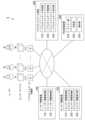
- the location confirmation device 1is a device for determining the status of each user U1, U2, ..., Um based on information periodically transmitted from sensor devices D1, D2, ..., Dm carried by each user U1, U2, ..., Um, and for monitoring these statuses over time.
- the sensor devices D1, D2, ..., Dminclude, for example, bioinformation measuring devices such as wearable sensors.
- Information transmitted from the sensor devices D1, D2, ... Dmcan be transmitted to the location confirmation device 1 via multiple real-time data relay units A1, A2, ... An.
- the real-time data relay units A1, A2, ... Anare wireless access points including devices capable of wireless communication.
- the real-time data relay units A1, A2, ... Ancan perform long-distance data communication between the sensor devices D1, D2, ... Dm and the location confirmation device 1.
- the real-time data relay units A1, A2, ... Anare installed, for example, inside a building.
- the information transmitted from the sensor devices D1, D2, ... Dm to the location confirmation device 1includes at least the location information described below, but is not limited to this.
- the information transmitted from the sensor devices D1, D2, ... Dm to the location confirmation device 1may include, for example, biological information of the users U1, U2 ... Um, such as body temperature, pulse, blood pressure, cardiac potential, and brain waves.
- the information transmitted from the sensor devices D1, D2, ... Dm to the location confirmation device 1may include, for example, information related to the movement of the users U1, U2 ... Um, such as acceleration and angular velocity.
- the information transmitted from the sensor devices D1, D2, ... Dm to the location confirmation device 1may include, for example, information related to the environment where the users U1, U2 ... Um are located, such as temperature, humidity, illuminance, and amount of ultraviolet light.
- the transmission of location information from the sensor devices D1, D2, ..., Dm to the location confirmation device 1is performed as follows. First, in a building in which the real-time data relay units A1, A2, ..., An are installed, the sensor devices D1, D2, ..., Dm periodically transmit wireless signals (FIG. 2(a)). Next, if there is a real-time data relay unit within a range in which the wireless signal can be received (in FIG.
- real-time data relay units A5 and A2are respectively provided for the sensor devices D1 and D2)
- the real-time data relay unittransmits a signal including the sensor identification information (described later) of the sensor devices D1, D2, ..., Dm that are the source of the received wireless signal, as well as the identification information of the real-time data relay unit itself to the location confirmation device 1 (FIG. 2(b)).
- the identification information of the real-time data relay unit itselfcorresponds to location information.
- the location confirmation device 1uses a correspondence table between the identification information of each real-time data relay unit and its location, which is stored in advance, to check the identification information of the real-time data relay unit, thereby determining the location of the real-time data relay unit. As a result, the operator of the location confirmation device 1 can grasp the location of the sensor devices D1, D2, ..., Dm at each time.
- the real-time data relay units A1, A2, ... Anare also installed in rooms within the building, but this is not limiting.
- the real-time data relay units A1, A2, ... Anmay be installed, for example, only in locations through which users U1, U2 ... Um pass when moving around (exits, corridors, elevator halls, etc.). This makes it possible to determine whether users U1, U2 ... Um are outside the building, while reducing the number of installed real-time data relay units A1, A2, ... An.
- Long-distance data communication between the real-time data relay units A1, A2, ..., Ancan be performed using various devices such as BLE devices and Wi-Fi routers.
- Various wireless communication methodscan be used, such as Bluetooth and Wi-Fi.
- the acquisition of location informationis not limited to the above method, and a method using a satellite positioning system such as GPS, GLONAS, Galileo, or QZSS may also be used in combination.
- FIG. 3shows the configuration of the location confirmation device 1.
- the location confirmation device 1includes a user information unit 10, a sensor information unit 20, a real-time data unit 30, a timer unit 40, a determination unit 50, and a notification unit 60.
- the user information section 10includes a user information registration section 11 and a user information storage section 12 .
- the user information registration unit 11registers basic information about users U1, U2, ..., Um.
- the basic informationmay be registered by a person operating the location confirmation device 1 by directly inputting the information.
- the basic informationmay also be registered by acquiring the basic information from an external database via a network such as the Internet.
- the basic informationincludes personal information such as the name, sex, date of birth, address, and facial photo of users U1, U2, ... Um.
- the basic informationmay also include information such as the results of health checkups and medical history of users U1, U2, ... Um.
- the basic informationmay include information on the measurement status indicating whether each of users U1, U2, ... Um is currently performing or stopping measurement using sensor devices D1, D2, ... Dm.
- the user information storage unit 12stores basic information about users U1, U2, ..., Um registered in the user information registration unit 11.
- the basic informationmay be stored, for example, in a CSV file format.
- the basic informationmay be stored, for example, using database software such as PostgreSQL and SQLite.
- the sensor information unit 20includes a sensor information registration unit 21 , a sensor information storage unit 22 , and a sensor information display unit 23 .
- the sensor information registration unit 21registers the sensor identification information of the sensor devices D1, D2, ..., Dm.
- the sensor identification informationmay be registered by a person operating the location confirmation device 1 by directly inputting the information.
- the sensor identification informationmay also be registered by acquiring the basic information from an external database via a network.
- the sensor identification informationis information that can identify the sensor, such as the sensor name, ID, MAC address, device registration number, etc.
- the sensor information storage unit 22stores the sensor identification information of the sensor devices D1, D2, ..., Dm registered by the sensor information registration unit 21.
- the sensor identification informationmay be stored, for example, in a CSV file format.
- the sensor identification informationmay be stored, for example, using database software such as PostgreSQL and SQLite.
- the real-time data (described later) from each sensor device D1, D2, ..., Dm stored in the real-time data storage unit 33may be transmitted to the sensor information storage unit 22, and the sensor information storage unit 22 may accumulate and store the real-time data in chronological order. After storing the real-time data in the sensor information storage unit 22, the real-time data transmitted by the real-time data storage unit 33 to the timer unit 40 and the determination unit 50 may be deleted from the real-time data storage unit 33.
- the sensor information display unit 23displays the sensor identification information of the sensors D1, D2, ..., Dm stored in the sensor information storage unit 22.
- the sensor identification informationmay be displayed, for example, using an application that uses a web browser or an application that uses a smartphone.
- the real time data unit 30includes a real time data receiving unit 31 , a real time data storage unit 32 , and a real time data display unit 33 .
- the real-time data receiving unit 31receives information transmitted from the real-time data relay units A1, A2, ..., An.
- the informationis expressed as data (real-time data) described in a file format such as JSON.
- the sensor devices D1, D2, ..., Dmtransmit information to any of the real-time data relay units A1, A2, ..., An (hereinafter, the real-time data relay units to which the sensor devices D1, D2, ..., Dm transmitted information are referred to as A(D1), A(D2), ..., A(Dm) for convenience), the real-time data relay units A(D1), A(D2), ..., A(Dm) are triggered by receiving information from the sensor devices D1, D2, ..., Dm and transmit information generated based on the information to the real-time data receiving unit 31.
- the information represented by the real-time dataincludes at least the identification information of the sensor devices D1, D2, ..., Dm that are the senders of the information.
- the information represented by the real-time datamay include information on a measurement stop command sent from the sensor devices D1, D2, ..., Dm that are the sender of the information.
- the measurement stop command informationis sent from the sensor devices D1, D2, ..., Dm to the real-time data relay units A(D1), A(D2), ..., A(Dm) when the users U1, U2, ..., Um operate the sensor devices D1, D2, ..., Dm (turning off the power, pressing the measurement stop button, etc.).
- the information represented by the real-time dataincludes at least the location information.
- the location informationis identification information of the real-time data relay units A (D1), A (D2), ..., A (Dm) that are within a range capable of receiving the wireless signal of the sensor device identified by the identification information (i.e., the real-time data relay units that transmitted information to the real-time data receiving unit 31).
- the information represented by the real-time datamay include the bioinformation and information related to the environment transmitted from the sensor devices D1, D2, ..., Dm.
- the real-time data receiving unit 31has a timekeeping function.
- the information represented by the real-time dataincludes at least information T1, T2, ... Tm of the date and time when the information transmitted from the real-time data relay units A (D1), A (D2), ... A (Dm) was received.
- the real-time data storage unit 32stores the real-time data sent from the real-time data receiving unit 31.
- the real-time datamay be stored, for example, in a CSV file format.
- the real-time datamay be stored, for example, using database software such as PostgreSQL and SQLite.
- a correspondence table between the identification information of the real-time data relay unit, which is location information, and its locationmay be stored in advance in the real-time data storage unit 32, and based on the identification information of the real-time data relay unit received, the real-time data storage unit 32 may refer to the correspondence table to determine the location, and further record the location as real-time data.
- the location informationidentification information of the real-time data relay unit
- the real-time data storage unit 32may filter the sensor devices D1, D2, ... Dm whose location is determined by the determination unit 50 based on the stored real-time data, and store real-time data only for the sensor devices D1, D2, ... Dm that satisfy a predetermined condition. For example, the past acceleration data of each user U1, U2, ...
- Um stored in the real-time data storage unit 32is used to calculate the average number of steps per day for each user and the average time each user spends in a posture (sitting, standing) per day (the fact that the number of steps and posture can be identified from acceleration data is shown, for example, in Takayuki Ogasawara and Masahiko Mukai, "Wearable Electrode Material hitoe (R) and its Application to Rehabilitation - From a Case Study of a Demonstration Experiment in a Rehabilitation Ward," in Chapter 2, Section 8 of "Biometric Information Sensing and Its Application to Human State Estimation” (Technical Information Association, 2020).).
- real-time datais stored only for the sensor devices Dk corresponding to users Uk whose average number of steps is equal to or greater than a predetermined value. This allows location checks to be limited to users who meet certain health conditions.
- the real-time data storage unit 32may not store real-time data only for the sensor device Dk that transmitted the measurement stop command information. This makes it possible to reduce the amount of data stored in the real-time data storage unit 32.
- the real-time data display unit 33displays the real-time data stored in the real-time data storage unit 32.
- the real-time datamay be displayed, for example, using an application that uses a web browser or an application that uses a smartphone.
- a list of combinations of identification information of the sensor device Dke.g., the sensor name
- information on the date and time Tke.g., the date and time
- the timer unit 40records the elapsed time during which the real-time data receiving unit 32 did not receive a signal from each of the real-time data relay units A (D1), A (D2), ..., A (Dm) for each of the sensor devices D1, D2, ..., Dm.
- the timer unit 40has a timekeeping function.
- the timer unit 40refers to information on each date and time T1, T2, ..., Tm, which was previously received by the real-time data receiving unit 31, of the real-time data transmitted from each of the real-time data relay units A (D1), A (D2), ..., A (Dm), from the real-time data storage unit 32.
- the timer unit 40periodically calculates the elapsed time ⁇ T1, ⁇ T2, ..., ⁇ Tm from each date and time based on the information on the reception date and time T1, T2, ..., Tm and the information on the current time measured by the timer unit 40 itself.
- the determination unit 50determines the location of each user U1, U2, ... Um for each sensor device D1, D2, ... Dm based on the information of the real-time data relay units A (D1), A (D2), ... A (Dm) stored in the real-time data storage unit 32 and the elapsed times ⁇ T1, ⁇ T2, ... ⁇ Tm calculated by the timer unit 40.
- FIG. 11we will explain cases where a conventional location confirmation device makes an erroneous determination.
- access pointscorresponding to the real-time data relay unit in this embodiment
- FIG. 11there are at least four possible cases shown in Figure 11 as combinations of the user's actual behavior and the location of the access point that last communicated with the location confirmation device.
- Case #1is when the user moves from a room to outside the building via the exit, and the final communication to the location confirmation device is made from the access point at the exit.
- the location confirmation devicecorrectly determines that the user is "outside the building” (conversely, the location confirmation device is expected to determine that the user is "outside the building” in such a case).
- Case #2is a case where the user returns from the room via the exit, and the final communication to the location confirmation device is made from the access point at the exit (a case where, for some reason, no communication is made at the access point in the room after the user returns from the exit).
- the location confirmation deviceerroneously determines that the user is "outside the building.”
- Case #3is when the user moves from a room to outside the building via the exit, and the last communication to the location confirmation device is made from the access point in the room (and for some reason no communication is made at the access point at the exit). In this case, after the last communication, the location confirmation device erroneously determines that the user is "inside the building.”
- Case #4is when the user leaves the room and returns to the room via the exit, and the final communication to the location confirmation device is made from the access point in the room before the user goes to the exit. In this case, after the final communication, the location confirmation device (eventually) correctly determines that the user is "inside the building.”
- cases #2 and #3are the ones where an incorrect judgment is made.
- case #2there is a possibility that the access point will subsequently communicate within the room, and the location information of the last access point with which communication took place will be updated to the room.
- case #3the user has actually left the building, so there is no possibility that the location information of the last access point with which communication took place will be updated (unless the user returns to the building).
- the judgment error in case #3(where the user is judged to be "inside the building" when in fact he is outside the building) is more serious than in case #2.
- the specified thresholdis set to a short value, it may increase the number of cases where an erroneous judgment is made.
- communicationmay be interrupted for a certain period of time even when there is no abnormality in the communication. Causes of this include, for example, temporary wireless communication interference and the user temporarily removing the sensor device.
- the specified thresholdis set to a short value compared to the typical time interval during which communication may be interrupted (hereinafter referred to as the "communication interruption time"), there is a risk that the number of cases where an erroneous judgment is made may increase.
- the communication interruption time at the access points of the exit and the roomis four minutes.
- the judgment unit 50(see FIG. 3) will erroneously judge the user's location to be "outside the building” even though the user is actually inside the building (room).
- the predetermined thresholdis set to six minutes
- communicationis continuously interrupted both at the exit and in the room to which the user subsequently moves, so communication may be interrupted for eight minutes, which is twice the communication interruption time.
- the judgment unit 50will again erroneously judge the user's location to be "outside the building” (or “possibly outside the building”).
- the predetermined thresholdis set to at least twice the communication interruption time.
- the above-mentioned predetermined threshold valuecan be set to a more suitable value by taking into consideration the unique circumstances of the building, such as the distances between the real-time data relay units (access points) A1, A2, ..., An within the building, and differences in the wireless communication environment at each location where the real-time data relay units A1, A2, ..., An are installed within the building.
- the notification unit 60notifies the operator of the location confirmation device 1 whether users U1, U2, ... Um are inside or outside the building (or may be outside the building) based on the judgment result of the judgment unit 50.
- the notification unit 60may instead notify them of a message indicating that sensor devices D1, D2, ..., Dm are measuring. If users U1, U2, ..., Um are likely outside the building, the notification unit 60 may instead notify them of the elapsed times ⁇ T1, ⁇ T2, ..., ⁇ Tm obtained from the timer unit 40.
- the notification by the notification unit 60may be displayed, for example, using an application that uses a web browser or an application that uses a smartphone.
- the display of the notification by the notification unit 60may be performed, for example, together with the display of real-time data by the real-time data display unit 33.
- FIG. 5shows an example of displaying notifications by the notification unit 60 together with the display of real-time data by the real-time data display unit 33.
- the display of notifications by the notification unit 60may be a display in which columns of notifications (messages) corresponding to the sensor devices D1, D2, ... Dm (D6 in FIGS. 4 and 5) displayed by their respective sensor names are added to the display of real-time data in tabular form shown in FIG. 4.
- the notification (message) displayed by the notification unit 60may be displayed in a different color depending on the content of the notification (message). For example, if the elapsed time ⁇ T1, ⁇ T2, ... ⁇ Tm is long, the time is displayed in a darker color according to the length (in FIG. 5, the rows for "Device 2" and "Device 5"). This makes it possible to prompt the operator of the location confirmation device 1 who has received the notification to issue a warning.
- the order in which the rows in the notification (message) displayed by the notification unit 60 are displayedmay be rearranged in descending order of the darkest color. This makes it easier to see the warned items.
- the notification (message) displayed by the notification unit 60may be supplemented with a notification (message).
- the additional notification (message)may, for example, be a message urging the corresponding user to check the status (the "Device 5" line in FIG. 5). This allows the operator of the location confirmation device 1 who receives the notification to be alerted not only by the color of the display but also by the text.
- the notification unit 60When the timer unit 40 and the determination unit 50 acquire new information for each of the sensor devices D1, D2, ..., Dm, the notification unit 60 resets the previous notification and issues a notification based on the new information. For example, in case #2 (a case where an incorrect determination is made) in FIG. 11, when a new transmission is made from the access point in the room to which the user has moved after leaving the exit, the notification unit 60 resets the previous notification and issues a new notification based on the information sent from the timer unit 40 and the determination unit 50 using the new transmission as a trigger. This allows the notification issued by the notification unit 60 to be updated to content based on the correct determination made by the determination unit 50.
- FIG. 6is a flow diagram of the location confirmation method according to this embodiment.
- the location confirmation method according to this embodimentincludes a sensor measurement step S1, a wireless signal transmission step S2, a wireless signal reception step S3, a real-time data transmission step S4, a real-time data storage step S5, a timer step S6, a determination step S7, and a notification step S8.
- the sensor devices D1, D2, ... Dmmeasure information about the users U1, U2, ... Um (step S1).
- the information measured by the sensor devices D1, D2, ... Dmmay include bio-information of the users U1, U2, ... Um, such as body temperature, pulse, blood pressure, cardiac potential, and brain waves.
- the information measured by the sensor devices D1, D2, ... Dmmay include information related to the movement of the users U1, U2, ... Um, such as acceleration and angular velocity.
- the information measured by the sensor devices D1, D2, ... Dmmay include information related to the environment where the users U1, U2, ... Um are located, such as temperature, humidity, illuminance, and amount of ultraviolet light.
- the sensor devices D1, D2, ..., Dmtransmit the measured information to the real-time data relay units A1, A2, ..., An (step S2).
- the sensor device Dkmay transmit measurement stop command information.
- the measurement stop command informationis transmitted from the sensor device Dk, for example, by the user Uk operating the sensor device Dk (turning off the power, pressing the measurement stop button, etc.).
- Transmission and reception between the sensor devices D1, D2, ... Dm and the real-time data relay units A1, A2, ... Anis performed as follows.
- the real-time data relay unit A (Dk)transmits a signal including the sensor identification information of the sensor device Dk, the real-time data relay unit A (Dk)'s own identification information (location information), and the information measured by the sensor device Dk to the location confirmation device 1 via the network (step S4).
- the real-time data relay unit A (Dk)may also transmit information of the measurement stop command received from the sensor device Dk.
- the real-time data receiving unit 32receives the information transmitted by the real-time data relay unit A (Dk).
- the real-time data receiving unit 32sends information (real-time data) including the information sent by the real-time data relay unit A (Dk) and information Tk of the date and time when the information was received to the real-time data storage unit 32.
- the real-time data storage unit 32stores the real-time data received from the real-time data receiving unit 32 (step S5).
- the real-time data storage unit 32may use the location information (identification information of the real-time data relay unit) to filter the real-time data to be stored in the real-time data storage unit 32, and store the real-time data only when the location indicated by the location information matches a specified location. This makes it possible to check the status of the protected person at a specified location, and also reduces the amount of data stored in the real-time data storage unit 32.
- the real-time data storage unit 32may filter the sensor devices D1, D2, ..., Dm whose locations are determined by the determination unit 50 based on the stored real-time data, and store real-time data only for the sensor devices D1, D2, ..., Dm that satisfy a predetermined condition. This makes it possible to narrow down the targets of location confirmation to only those users who are in a predetermined health condition.
- the real-time data storage unit 32may not store real-time data only for the sensor device Dk that transmitted the measurement stop command information. This makes it possible to reduce the amount of data stored in the real-time data storage unit 32.
- the timer unit 40records the elapsed time during which the real-time data receiving unit 32 did not receive a signal from each of the real-time data relay units A (D1), A (D2), ... A (Dm) for each sensor device D1, D2, ... Dm (step S6).
- the timer unit 40refers to the information of each date and time T1, T2, ... Tm, which was the last time the real-time data receiving unit 31 received information transmitted from each of the real-time data relay units A (D1), A (D2), ... A (Dm), from the real-time data storage unit 32.
- the timer unit 40periodically calculates the elapsed time ⁇ T1, ⁇ T2, ... ⁇ Tm from each date and time based on the information of the reception date and time T1, T2, ... Tm and the information of the current time measured by the timer unit 40 itself.
- the determination unit 50determines the location of each user U1, U2, ... Um for each sensor device D1, D2, ... Dm based on the information of the real-time data relay units A (D1), A (D2), ... A (Dm) stored in the real-time data storage unit 32 and the elapsed times ⁇ T1, ⁇ T2, ... ⁇ Tm calculated by the timer unit 40 (step S7).
- the notification unit 60notifies the operator of the location confirmation device 1 whether the users U1, U2, ..., Um are inside or outside the building (or may be outside the building) based on the determination result of the determination unit 50 (step S8). This allows the operator of the location confirmation device 1 to confirm the locations of the users U1, U2, ..., Um.
- the location confirmation device 1has a recording medium (e.g., a semiconductor memory) and a computer.
- the process of the location confirmation method carried out in this embodimentis recorded as a program on the recording medium.
- the location confirmation method carried out in this embodimentis carried out by the computer reading and executing the program recorded on the recording medium.
- the location confirmation devicedetects when a user has left the building based on the amount of time that has elapsed since data was no longer received from a specific location within the building. This makes it possible to more reliably detect when a user has left the building without installing equipment such as an entrance/exit control gate.
- FIG. 7shows the configuration of a location confirmation device 2 according to a second embodiment of the present invention.
- the location confirmation device 2includes a user information unit 10, a sensor information unit 20, a real-time data unit 30, a timer unit 40, a determination unit 50, a notification unit 60, and a user information linking unit 70.
- the user information linking unit 70links the information expressed by the real-time data stored in the real-time data storage unit 33 with the basic information of the user stored in the user information storage unit 12.
- the basic informationincludes at least information on the measurement status of the user.
- the information (real-time data) measured using the sensor device Dk up to that pointneeds to be linked to the basic information of the user Uk at that time and recorded in preparation for future data analysis.
- the user information linking unit 70links the information.
- the operator of the location confirmation device 2uses the user information registration unit 11 to register information indicating that measurement is to be ended for the user Uk (information on the measurement status).
- information indicating that measurement is to be ended for the user Ukis stored in the user information storage unit 12.
- the user information linking unit 70for example, periodically acquires basic information of user Uk stored in the user information storage unit 12.
- the user information linking unit 70links the information measured using the sensor device Dk (real-time data) stored in the real-time data storage unit 33 with the basic information of user Uk stored in the user information storage unit 12, and stores a record of the fact that the linking has been made in the user information linking unit 70.
- the record of the fact that the information has been linkedmay be made, for example, in a CSV file format, or may be made using database software such as PostgreSQL or SQLite.
- the user information linking unit 70sends to the notification unit 60 information indicating that the information (real-time data) measured using the sensor device Dk has been linked to the basic information of the user Uk stored in the user information storage unit 12. After receiving the information, the notification unit 60 resets the notification (message) related to the sensor device Dk (user Uk) and displays a notification (message) indicating that the measurement has ended.
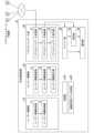
- FIG. 8shows the configuration of a location confirmation device 3 according to a third embodiment of the present invention.
- the location confirmation device 3includes a user information unit 10, a sensor information unit 20, a real-time data unit 30, a timer unit 40, a determination unit 50, a notification unit 60, and an automatic threshold determination unit 80.
- the first peak of the distribution of elapsed timeis considered to correspond to the communication interruption time when communication is interrupted due to, for example, temporary wireless communication interference or the user temporarily removing the sensor device, even when the user is not outside the building and communication is being performed. Therefore, by determining the specified threshold as described above, it is possible to set a specified threshold that is sufficiently long beyond the communication interruption time. This reduces the possibility that the determination unit 50 will make an erroneous determination.
- the conditions under which the automatic threshold determination unit 80 determines the predetermined thresholdare not limited to those described above.
- an appropriate timemay be determined based on information on elapsed time using AI.
- the fourth embodiment of the present inventionis a location confirmation system 4.
- the location confirmation system 4is composed of sensor devices D1, D2, ... Dm, real-time data relay units A1, A2, ... An, and a location confirmation device 1.
- Sensor devices D1, D2, ... Dmare measurement devices owned by users U1, U2, ... Um, respectively. Sensor devices D1, D2, ... Dm periodically measure data from users U1, U2, ... Um to monitor the status of users U1, U2, ... Um over time. Sensor devices D1, D2, ... Dm include, for example, biometric measurement devices such as wearable sensors. Sensor devices D1, D2, ... Dm have wireless communication capabilities. Sensor devices D1, D2, ... Dm wirelessly transmit information on the data measured from users U1, U2, ... Um to real-time data relay units A1, A2, ... An.
- Real-time data relay units A1, A2, ..., Anare connected to each other via a network so that they can communicate with each other.
- Real-time data relay units A1, A2, ..., Antransmit information wirelessly transmitted from the sensor devices D1, D2, ..., Dm via the network to the location confirmation device 1 which is also connected to each other via the network so that it can communicate with each other.
- the location confirmation device 1receives information transmitted from the real-time data relay units A1, A2, ..., An via the network. Based on the received information (real-time data), the location confirmation device 1 determines the location of the users U1, U2, ..., Um, and notifies the operator of the location confirmation device 1 (see Figure 3).
- the locations of users U1, U2, ..., Umcan be monitored over time using sensor devices D1, D2, ..., Dm. This allows an operator who is remote from users U1, U2, ..., Um to recognize the location of users U1, U2, ..., Um (in particular, whether they are outside the building or not) at all times.
- the fifth embodiment of the present inventionis a location confirmation system 5.
- the location confirmation system 5is composed of sensor devices D1, D2, ... Dm, real-time data relay units A1, A2, ... An, a user information device 100, a sensor information device 200, a real-time information device 300, and a location confirmation device 400.
- Location confirmation system 5differs from location confirmation system 4 in the fourth embodiment in the following ways.
- location confirmation device 1comprises a user information section 10, a sensor information section 20, a real-time data section 30, a timer section 40, a determination section 50, and a notification section 60.
- location confirmation system 5is configured such that user information device 100 corresponding to user information section 10, sensor information device 200 corresponding to sensor information section 20, and real-time data device 300 corresponding to real-time data section 30 are separate devices from location confirmation device 400.
- User information registration section 110 and user information storage section 120 in user information device 100are functionally the same as user information registration section 11 and user information storage section 12 of the same names in user information section 10, respectively.
- the sensor information registration unit 210, sensor information storage unit 220, and sensor information display unit 230provided in the sensor information device 200
- the real-time data receiving unit 310, real-time data storage unit 320, and real-time data display unit 330 provided in the real-time data device 300and the timer unit 410, determination unit 420, and notification unit 430 provided in the location confirmation device 400.
- the user information device 100, the sensor information device 200, the real-time data device 300, and the location confirmation device 400are connected to each other via a network so that they can communicate with each other.
- the transfer of information that was previously performed inside the location confirmation device 1can be performed between the user information device 100, the sensor information device 200, the real-time data device 300, and the location confirmation device 400.
- the location confirmation system 5can achieve the same effects as the location confirmation device 400.
- informationcan be managed in a distributed manner according to type.
- the user information device 100, the sensor information device 200, the real-time data device 300, and the location confirmation device 400may all be independent and separate devices, or any one of them may be a common device with any of the others.
- FIG. 12Ashows the configuration of a location confirmation system according to additional embodiment 1 of the present invention.
- the location confirmation device a1includes a user information unit 10, a sensor information unit 20, a real-time data unit 30, a timer unit 40, a determination unit 50, a notification unit 60, a learning unit a10, and a machine learning model creation unit a20.
- the learning unit a10performs machine learning using the user activity data acquired by the real-time data relay units A1, A2, . . . An and the user's location information obtained from the identification information of the real-time data relay units A1, A2, .
- the learning unit a10can use a learning device such as random forest or gradient boosting.
- the explanatory variablescan be user activity data included in the real-time data and acquired from a sensor device.
- the user activity datais, for example, data related to body movement, number of steps, and posture.
- Body movementis a quantification of the physical movement of the user's body per unit time (see Non-Patent Document 3).
- the objective variablecan be the user's daily location information obtained from the identification information of the real-time data relay units A1, A2, ..., An contained in the real-time data.
- Data showing a user's location information for a dayis, for example, the frequency of the user's activity.
- the frequency of a user's activityis indicated, for example, by a unique value that does not count duplicate access points more than once among the number of access points (real-time data relay units) that communicated during that day (i.e., the number of access points with which communication occurred more than once).
- Data showing a user's location information for a daycould be, for example, the time the user spent in a particular area, such as a residential space (see Figure 2).
- the machine learning model creation unit a20creates a machine learning model.
- the machine learning modelidentifies each area, such as a living space (see FIG. 2) that has a real-time data relay unit within a communication range of the user.
- the machine learning model a20estimates the user's daily location information, such as the frequency of the user's activities and the user's time spent in each area, based on the user's activity data acquired from the sensor device.
- the machine learning model creation unit a20creates a new learning model by adding data added over a fixed span of time, such as one week or one month. For example, if the accuracy estimated by the created model is at a high level, the machine learning model creation unit a20 stops adding data and stores it as the current learning model. For example, the machine learning model creation unit a20 uses cross-validation when examining the accuracy at the time of model creation.
- a machine learning modelcan be provided that estimates a user's daily location information based on activity data and location information acquired by the location confirmation device a1.
- the machine learning model created by the location confirmation device a1can be provided via a network to an external computer with more abundant computing resources, and estimation using the machine learning model can be performed by the external computer instead of by the location confirmation device a1 itself.
- estimationcan be performed faster.
- the learning modelcan be copied, it can be provided in the form of sale or the like to third parties who wish to use the learning model.
- a learning model that does not recognize defects, such as a neural networkis used, if an explanatory variable contains a defect, estimation is not performed in the form of an error, and measurement abnormalities can be identified.
- Additional embodiment 2 of the present inventionis a modified example of additional embodiment 1 of the present invention. Descriptions of components common to additional embodiment 1 of the present invention will be omitted.
- FIG. 12Bshows the configuration of a location confirmation device system according to additional embodiment 2 of the present invention.
- the location confirmation device a2includes a user information unit 10, a sensor information unit 20, a real-time data unit 30, a timer unit 40, a determination unit 50, a notification unit 60, a learning unit a10, a machine learning model creation unit a20, a machine learning model implementation unit a30, and an estimation unit a40.
- the machine learning model implementation unit a30implements the machine learning model created in advance by the machine learning model creation unit a20 in the location confirmation device a2.
- the machine learning model implementation unit a30implements the machine learning model in the location confirmation device a2 by storing the latest machine learning model created by the machine learning model creation unit a20.
- the machine learning model implementation unit a30stores an executable file of the machine learning model created using a programming language such as Python.
- the machine learning model implementation unit a30saves and stores the executable file of the machine learning model in a directory for storing machine learning models provided in the location confirmation device a2, for example.
- the machine learning model implementation unit a30may save a path set to easily launch the executable file of the machine learning model stored in the directory for storing machine learning models.
- the estimation unit a40identifies areas such as a living space having a real-time data relay unit within a communication range of the user.
- the estimation unit a40estimates the user's daily location information, such as the frequency of the user's activities and the user's time spent in each area, based on the user's activity data and location information acquired by the location confirmation device a2, using a machine learning model implemented in the location confirmation device a2.
- a machine learning modelthat estimates the user's daily location information based on the activity data and location information acquired by the location confirmation device a2 can be created in the location confirmation device a2 and used for the estimation.
- the user's daily location informationsuch as the frequency of the user's activities and the user's time spent in each area, can be estimated using only the explanatory variables described above.
- the location information collected by the access pointis highly specific personal information such as who was in which room and when, it is no longer necessary to handle such information, and therefore it is possible to provide the user's daily location information in a user-friendly manner.
- Examples 1 and 2 of the present inventionwill be described below with reference to Figures 10A to 10C. Examples 1 and 2 each examine the distribution of elapsed time during which a location confirmation device (corresponding to the location confirmation device 1 in the first embodiment of the present invention) did not receive signals from sensor devices owned by multiple users under the following conditions: ⁇ Building: Reinforced concrete building ⁇ Building exit: Swing door about 1m wide x 2m high, automatic door (sliding door) about 3m wide x 2m high ⁇ Building corridors: Approximately 2 to 3 meters wide ⁇ Number of real-time data relay units (access points) installed in the building: Approximately 40 units (including 5 units installed at exits or near wires leading to exits) Distance between real-time data relay units (access points) installed within a building: Approximately 5 to 10 m when there are no objects blocking radio waves between the real-time data relay units (access points) (however, in locations with reinforced concrete walls or many obstructions to space such as partitions, at least one real-time data relay unit
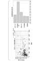
- FIG. 10Ashows the results of Example 1.
- FIG. 10Ashows a histogram of the elapsed time up to 20 minutes in 1-minute increments. The histogram has a first peak at the 4-minute position, which is the highest. This is thought to be because even when the user is inside the building and wireless communication is performed between the sensor device and the real-time data relay unit (access point), communication is frequently interrupted due to temporary data communication interference or removal of the sensor.
- the peaks located in longer time periods (9-10 minutes, 18-19 minutes)are low in height and have a gentle distribution around them, so they are not due to a specific factor like the first peak, but are formed because the user actually moved (temporarily) outside the communication range of the real-time data relay unit (access point) and communication was no longer performed.
- the threshold value used by the judgment unit 50(see FIG. 3) is set to 4 minutes, there is a high risk that the judgment unit 50 will erroneously judge the user to be “outside the building” when in fact the user is inside the building (see case #2 in FIG. 11), and will erroneously judge the user to be “inside the building” when in fact the user is outside the building (see case #3 in FIG. 11).
- the threshold value used by the determination unit 50(see FIG. 3) for the determination is set to a time longer than the period during which the above-mentioned communication interruptions frequently occur, for example, 10 minutes or more. This makes it possible to prevent the above-mentioned erroneous determination.
- the threshold value used by the judgment unit 50may be any i-th minimum value after the first peak of the histogram.
- the threshold value used by the determination unit 50may be set based on the average value of the histogram over a predetermined length of time, for example, 20 minutes. In FIG. 10A, the average value is 4.7, so the threshold value may be set initially below this at 6 minutes.
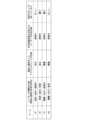
- FIG. 10Bdivides FIG. 10A into 5-minute intervals and shows the maximum, total, and average frequency (number of missing points) in each interval.
- the thresholdmay be automatically determined based on data for each interval, for example.
- Example 2The results of Example 2 are shown in Fig. 10C.
- Example 2is the result of filtering only data of elapsed time related to reception by a real-time data relay unit (access point) installed at the exit.
- the first peakis at the 4 minute position, as in Example 1.
- the threshold value used by the determination unit 50can be set to, for example, 8 minutes. This makes it possible to shorten the threshold value used for the determination in order to limit monitoring to going out through an exit, while preventing the above-mentioned erroneous determination. Furthermore, if it is anticipated that communication may be interrupted in a manner other than going out, it is possible to distinguish from such situations and accurately check the user's status.
- 10A to 13Cshow the results of a machine learning model estimating a user's daily location information based on the user's activity data acquired from a sensor device in additional embodiment 2.
- the user's activity dataconsists of data on the time the user walked, the time the user was standing or sitting, the time the user was lying down, and the user's body movements.
- the user's daily location informationis the frequency of the user's activities, as well as the time the user spent in the living space (see FIG. 2) and in a common area (e.g., the hallway in FIG. 2).
- the data on the time the user was walking, the time the user was standing/sitting, and the time the user was lying downwas obtained by determining whether the user was walking or not and what posture the user was in based on the acceleration data, and then measuring the duration of each of the walking, standing/sitting, and lying down states.
- the user's body movement datawas obtained by measuring the physical vibration of the user's chest over a 24-hour period using a detection device TX02 (NTT Technocross Corporation), which is equipped with inertial sensors such as an accelerometer and a gyroscope.
- the data used for the user's body movementincluded "average body movement” data, which is the average of the recorded values measured at a 1-minute rate over 24 hours, and "total body movement” data, which is the sum of the recorded values measured at a 1-minute rate over 24 hours.
- the frequency of a user's activityis indicated by a unique value (i.e., the number of access points with which communication occurred at least once) that does not count duplicate access points more than twice among the number of access points (real-time data relay units) that communicated during that day.
- Figure 13Ashows the results of Additional Example 1.
- Figure 13Ashows the results of the machine learning model estimating the frequency of a user's activity.
- the graph on the left side of FIG. 13Awill be described.
- the graph on the left sideshows the correlation between the true value and the predicted value of the unique value of the number of access points.
- the true value(horizontal axis) is the unique value of the number of access points actually obtained by observing the behavior of a certain user on a certain day in the additional embodiment 2.
- the predicted value(vertical axis) is the unique value of the number of access points estimated by the machine learning model based on the user's activity data obtained simultaneously with the true value.
- the points in the graphindicate the true value and the predicted value for each observation result.
- the straight line in the graphis a regression line obtained by using the least squares method for all observation results.
- the equation of the regression line(horizontal axis: x, vertical axis: y) and the correlation coefficient (R 2 ) are shown in the upper right of the graph.
- the graph on the right side of Figure 13Awill be explained.
- the graph on the right sideshows the contribution of each piece of data included in the user's activity data.
- the contributionis an index that indicates the degree to which the data contributes to the estimation made by the machine learning model.
- an index based on the calculation of the Shapley valueis used as the contribution.
- the correlation coefficient (R 2 ) between the true value and the predicted value of the unique value of the number of access pointsis relatively high (0.479).
- the data with a remarkably high contributionis the standing/sitting time.
- Example 2 10B and 10Care results of the machine learning model estimating the user's dwell time in each area.
- Fig. 10Bis the result of estimating the dwell time in the living space (room).
- the graph on the left side of Figure 13Bshows the correlation between the true and predicted values of time spent in the living space (room).
- the graph on the right side of Figure 13B, like Figure 13Ashows the contribution of each piece of data included in the user's activity data.
- the correlation coefficient (R 2 ) between the true value and the predicted value of the time spent in the living space (room)is relatively high (0.399).
- the data with the highest degree of contributionis the time spent in the lying position.
- FIG. 10Cshows the results of estimating the duration of stay in a common area.
- the graph on the left side of Figure 13Cshows the correlation between the true and predicted values of time spent in common areas.
- the graph on the right side of Figure 13C, like Figure 13Ashows the contribution of each piece of data included in the user activity data.
- the correlation coefficient (R 2 ) between the true value and the predicted value of the time spent in the common areais relatively low (0.091).
- the data with the highest contributionis the time spent standing and sitting.
- the time spent in a living space (room)can be accurately estimated based on the user's activity data acquired from the sensor device.
- the reason why the time spent in a lying position has a high contribution is thought to be because lying downis a characteristic behavior of a user staying in a living space (room).
- the frequency of user activitycan be accurately estimated based on the user activity data acquired from the sensor device, with regard to user movement.
- more accurate estimationis possible when the frequency of user activity is high. The reason why the standing/sitting time has a high contribution is thought to be because the user takes a standing position while moving.
- additional embodiment 2makes it possible to use machine learning to accurately estimate whether a user is staying in a living space (room) and whether the user is moving frequently.
- the real-time data storage unit 32may filter the sensor devices D1, D2, ... Dm whose location is determined by the determination unit 50 based on the stored real-time data, and store real-time data only for the sensor devices D1, D2, ... Dm that satisfy a predetermined condition.
- the real-time data storage unit 32may refer to basic information of users U1, U2, ... Um from the user information storage unit 12, filter users U1, U2, ... Um whose location is determined based on the basic information (e.g., extract users with underlying diseases), and store real-time data only for the users U1, U2, ... Um that satisfy a predetermined condition.
- the reception date and time informationis obtained using a timing function provided in the real-time data receiving unit 31, but the sensor devices D1, D2, ..., Dm themselves may have a timing function and transmit transmission date and time information to the real-time data relay units A1, A2, ..., An from the beginning.
- the program for executing the location confirmation methodis pre-recorded on a recording medium provided in the location confirmation device 1, but the location confirmation device 1 may download the program from another server via a network as necessary, or the program may be executed on the other server in response to a request from the location confirmation device 1, and the location confirmation device 1 may obtain the execution results from the other server.
Landscapes
- Business, Economics & Management (AREA)
- Emergency Management (AREA)
- Physics & Mathematics (AREA)
- General Physics & Mathematics (AREA)
- Mobile Radio Communication Systems (AREA)
Abstract
Description
Translated fromJapanese本発明は、所在確認システム、所在確認装置、所在確認方法及びプログラムに関する。The present invention relates to a location confirmation system, a location confirmation device, a location confirmation method, and a program.
保護者から遠隔地に所在する保護対象者(小児、高齢者等)の位置を確認できるIoTデバイスを用いて、保護対象者の行動をいつでも保護者が把握できるようにする所在確認手段が提案されている。A location confirmation method has been proposed that uses IoT devices that allow guardians to confirm the location of those being protected (children, elderly people, etc.) in remote locations, allowing guardians to keep track of the movements of those being protected at any time.
こうした所在確認手段では、IoTデバイスとして、GPSトラッカーや(非特許文献1)、Bluetoothで通信するビーコンのような無線通信デバイスが用いられている(非特許文献2)。In these location confirmation methods, IoT devices used include GPS trackers (Non-Patent Document 1) and wireless communication devices such as beacons that communicate via Bluetooth (Non-Patent Document 2).
非特許文献2のように、無線通信デバイスを用いた所在確認手段では、建物内の定められた範囲をユーザーが出ると、そのユーザーが外出したと検知する方法をとる場合が多い。As in Non-Patent
しかし、この場合、その建物の中で位置情報のデータが途切れたときや、通信がうまくいかないときには、実際にユーザーがその建物を出ていないにも拘らず、所在確認手段が、ユーザーが外出したと誤って検知を行ってしまうという課題があった。However, in this case, if location information data is interrupted or communication is not working properly within the building, the location confirmation means may mistakenly detect that the user has left the building, even if the user has not actually left the building.
ユーザーが外出しているか否かを確実に検知する手段としては、図書館等に設置される入退館管理ゲートが挙げられる。しかるに、保護対象者(小児、高齢者等)が居住する一般家庭において、かかる入退館管理ゲートを設置することは、設置スペースや費用の面で現実的ではない。One way to reliably detect whether a user is out or not is to use entrance/exit control gates installed in libraries, etc. However, installing such entrance/exit control gates in ordinary homes where people to be protected (children, elderly people, etc.) live is not realistic in terms of installation space and cost.
本発明はこのような事情に鑑みてなされたものであって、ユーザーの外出をより精度よく検知する技術を提供することを目的とする。The present invention was made in consideration of these circumstances, and aims to provide technology that can more accurately detect when a user goes outside.
本発明の第1の態様によれば、所在確認システムは、無線信号を送信するセンサーデバイスと、前記センサーデバイスが送信した前記無線信号を受信し、リアルタイムデータ中継情報を送信する、リアルタイムデータ中継部と、前記リアルタイムデータ中継情報を受信する所在確認装置と、を備え、前記リアルタイムデータ中継情報は、前記センサーデバイスのセンサー識別情報と前記リアルタイムデータ中継部の識別情報とを含み、前記所在確認装置は、前記リアルタイムデータ中継情報を受信した日時を示す受信日時情報と前記リアルタイムデータ中継情報とを含むリアルタイムデータ情報を格納し、前記受信日時情報からの経過時間を算出し、前記経過時間に基づき前記ユーザーの所在位置を判定する。According to a first aspect of the present invention, a location confirmation system includes a sensor device that transmits a wireless signal, a real-time data relay unit that receives the wireless signal transmitted by the sensor device and transmits real-time data relay information, and a location confirmation device that receives the real-time data relay information, the real-time data relay information including sensor identification information of the sensor device and identification information of the real-time data relay unit, the location confirmation device stores real-time data information including reception date and time information indicating the date and time when the real-time data relay information was received and the real-time data relay information, calculates the elapsed time from the reception date and time information, and determines the location of the user based on the elapsed time.
本発明の第2の態様によれば、所在確認装置は、リアルタイムデータ中継部から、センサーデバイスのセンサー識別情報と前記リアルタイムデータ中継部の識別情報とを含むリアルタイムデータ中継情報を受信し、前記リアルタイムデータ中継情報を受信した日時を示す受信日時情報と前記リアルタイムデータ中継情報とを含むリアルタイムデータ情報を格納し、前記受信日時情報からの経過時間を算出し、前記経過時間に基づき前記ユーザーの所在位置を判定する。According to a second aspect of the present invention, the location confirmation device receives real-time data relay information including sensor identification information of a sensor device and identification information of the real-time data relay unit from a real-time data relay unit, stores real-time data information including reception date and time information indicating the date and time when the real-time data relay information was received and the real-time data relay information, calculates the elapsed time from the reception date and time information, and determines the location of the user based on the elapsed time.
本発明の第3の態様によれば、所在確認方法は、センサーデバイスが無線信号をリアルタイムデータ中継部に送信する、無線信号送信ステップと、前記無線信号を受信可能な範囲内にある前記リアルタイムデータ中継部が、前記センサーデバイスが送信した前記無線信号を受信する、無線信号受信ステップと、前記リアルタイムデータ中継部が、前記センサーデバイスのセンサー識別情報と前記リアルタイムデータ中継部の識別情報とを含むリアルタイムデータ中継情報を所在確認装置に送信する、リアルタイムデータ送信ステップと、前記所在確認装置が、前記リアルタイムデータ中継情報を受信した日時を示す受信日時情報と前記リアルタイムデータ中継情報とを含むリアルタイムデータ情報を格納する、データ格納ステップと、前記所在確認装置が、前記受信日時情報からの経過時間を算出する、タイマーステップと、前記所在確認装置が、前記経過時間に基づきユーザーの所在位置を判定する、判定ステップと、を含む。According to a third aspect of the present invention, the location confirmation method includes a wireless signal transmitting step in which a sensor device transmits a wireless signal to a real-time data relay unit, a wireless signal receiving step in which the real-time data relay unit within a range capable of receiving the wireless signal receives the wireless signal transmitted by the sensor device, a real-time data transmitting step in which the real-time data relay unit transmits real-time data relay information including sensor identification information of the sensor device and identification information of the real-time data relay unit to a location confirmation device, a data storing step in which the location confirmation device stores real-time data information including reception date and time information indicating the date and time when the real-time data relay information was received and the real-time data relay information, a timer step in which the location confirmation device calculates the elapsed time from the reception date and time information, and a determination step in which the location confirmation device determines the user's location based on the elapsed time.
本発明の第4の態様によれば、プログラムは、センサーデバイスが無線信号をリアルタイムデータ中継部に送信する、無線信号送信ステップと、前記無線信号を受信可能な範囲内にある前記リアルタイムデータ中継部が、前記センサーデバイスが送信した前記無線信号を受信する、無線信号受信ステップと、前記リアルタイムデータ中継部が、前記センサーデバイスのセンサー識別情報と前記リアルタイムデータ中継部の識別情報とを含むリアルタイムデータ中継情報を所在確認装置に送信する、リアルタイムデータ送信ステップと、前記所在確認装置が、前記リアルタイムデータ中継情報を受信した日時を示す受信日時情報と前記リアルタイムデータ中継情報とを含むリアルタイムデータ情報を格納する、データ格納ステップと、前記所在確認装置が、前記受信日時情報からの経過時間を算出して記録する、タイマーステップと、前記所在確認装置が、前記経過時間に基づきユーザーの所在位置を判定する、判定ステップと、を、コンピューターに実行させる。According to a fourth aspect of the present invention, the program causes a computer to execute a wireless signal transmitting step in which a sensor device transmits a wireless signal to a real-time data relay unit; a wireless signal receiving step in which the real-time data relay unit, located within a range capable of receiving the wireless signal, receives the wireless signal transmitted by the sensor device; a real-time data transmitting step in which the real-time data relay unit transmits real-time data relay information including sensor identification information of the sensor device and identification information of the real-time data relay unit to a location confirmation device; a data storing step in which the location confirmation device stores real-time data information including reception date and time information indicating the date and time when the real-time data relay information was received and the real-time data relay information; a timer step in which the location confirmation device calculates and records the elapsed time from the reception date and time information; and a determination step in which the location confirmation device determines the user's location based on the elapsed time.
本発明によれば、ユーザーの外出をより精度よく検知することが可能となる。The present invention makes it possible to more accurately detect when a user goes outside.
以下、図面を用いて本発明の実施形態を説明するが、以下の実施形態は特許請求の範囲に係る発明を限定するものではない。また、実施形態の中で説明されている特徴の組合せの全てが発明の解決手段に必須であるとは限らない。Below, embodiments of the present invention will be explained using the drawings, but the following embodiments do not limit the invention according to the claims. Furthermore, not all of the combinations of features explained in the embodiments are necessarily essential to the solution of the invention.
<第1の実施形態>
以下、図1~6を用いて、本発明の第1の実施形態に係る所在確認装置を説明する。First Embodiment
A location confirmation device according to a first embodiment of the present invention will be described below with reference to FIGS.
[所在確認装置]
図1に示すように、所在確認装置1は、ユーザーU1、U2、・・・Umがそれぞれ所持するセンサーデバイスD1、D2、・・・Dmから定期的に送信される情報に基づき、各ユーザーU1、U2・・・Umの状態を判定し、これらの状態を経時的にモニターするための装置である。センサーデバイスD1、D2、・・・Dmは、例えば、ウェアラブルセンサー等の生体情報計測デバイスを含む。[Location confirmation device]
1, the
センサーデバイスD1、D2、・・・Dmから送信される情報は、複数のリアルタイムデータ中継部A1、A2、・・・Anを経由して所在確認装置1へ送信されることができる。リアルタイムデータ中継部A1、A2、・・・Anは、無線通信が可能な装置を含む、無線アクセスポイントである。リアルタイムデータ中継部A1、A2、・・・Anは、センサーデバイスD1、D2、・・・Dmと所在確認装置1との間の、長距離間データ通信を行うことができる。リアルタイムデータ中継部A1、A2、・・・Anは、例えば、建物の中に設置される。Information transmitted from the sensor devices D1, D2, ... Dm can be transmitted to the
センサーデバイスD1、D2、・・・Dmを起点として所在確認装置1へ送信される情報は、少なくとも、後述する位置情報を含むが、これに限られない。センサーデバイスD1、D2、・・・Dmが所在確認装置1に送信する情報は、例えば、体温、脈拍、血圧、心電位、脳波等のユーザーU1、U2・・・Umの生体情報を含んでもよい。センサーデバイスD1、D2、・・・Dmが所在確認装置1に送信する情報は、例えば、加速度、角速度等のユーザーU1、U2・・・Umの運動に係る情報を含んでもよい。センサーデバイスD1、D2、・・・Dmが所在確認装置1に送信する情報は、例えば、温度、湿度、照度、紫外線量等のユーザーU1、U2・・・Umが所在する場所の環境に係る情報を含んでもよい。The information transmitted from the sensor devices D1, D2, ... Dm to the
図2を参照して、位置情報の送信方法の例について説明する。センサーデバイスD1、D2、・・・Dmから所在確認装置1への位置情報の送信は、例えば、以下のようにして行われる。まず、リアルタイムデータ中継部A1、A2、・・・Anを設置した建物の中で、センサーデバイスD1、D2、・・・Dmが、定期的に無線信号を発信する(図2(a))。次に、当該無線信号を受信可能な範囲内にあるリアルタイムデータ中継部があった場合(図2(a)では、センサーデバイスD1、D2の各々に対し、リアルタイムデータ中継部A5、A2)、当該リアルタイムデータ中継部は、受信した無線信号の発信元であるセンサーデバイスD1、D2、・・・Dmのセンサー識別情報(後述)とともに、当該リアルタイムデータ中継部自身の識別情報を含む信号を、所在確認装置1に送信する(図2(b))。当該リアルタイムデータ中継部自身の識別情報が、位置情報に相当する。所在確認装置1は、予め備える各リアルタイムデータ中継部の識別情報とその位置との対応表を用いて、当該リアルタイムデータ中継部の識別情報を照合することにより、当該リアルタイムデータ中継部の位置を判定する。その結果、所在確認装置1の操作者は、個々の時刻におけるセンサーデバイスD1、D2、・・・Dmの位置を把握することができる。An example of a method for transmitting location information will be described with reference to FIG. 2. For example, the transmission of location information from the sensor devices D1, D2, ..., Dm to the
図2では、リアルタイムデータ中継部A1、A2、・・・Anは、建物内の居室にも設置しているが、この例に限らず、リアルタイムデータ中継部A1、A2、・・・Anは、例えば、ユーザーU1、U2・・・Umが移動する際に経由する場所(出口、廊下、エレベーターホール等)に限って設置してもよい。これにより、ユーザーU1、U2・・・Umの所在位置が建物外であるか否かの判定を可能としつつ、リアルタイムデータ中継部A1、A2、・・・Anの設置数を低減することができる。In FIG. 2, the real-time data relay units A1, A2, ... An are also installed in rooms within the building, but this is not limiting. The real-time data relay units A1, A2, ... An may be installed, for example, only in locations through which users U1, U2 ... Um pass when moving around (exits, corridors, elevator halls, etc.). This makes it possible to determine whether users U1, U2 ... Um are outside the building, while reducing the number of installed real-time data relay units A1, A2, ... An.
リアルタイムデータ中継部A1、A2、・・・Anの長距離間データ通信は、BLEデバイス、Wi-Fiルーター等、様々な装置を用いて行うことができる。無線通信の方式は、Bluetooth、Wi-Fi等、様々な方式が利用可能である。また、位置情報の取得は、上記方法に限られず、例えば、GPS、GLONAS、Galileo、QZSS等の衛星測位システムを用いた方法を併用してもよい。Long-distance data communication between the real-time data relay units A1, A2, ..., An can be performed using various devices such as BLE devices and Wi-Fi routers. Various wireless communication methods can be used, such as Bluetooth and Wi-Fi. In addition, the acquisition of location information is not limited to the above method, and a method using a satellite positioning system such as GPS, GLONAS, Galileo, or QZSS may also be used in combination.
図3に、所在確認装置1の構成を示す。所在確認装置1は、ユーザー情報部10と、センサー情報部20と、リアルタイムデータ部30と、タイマー部40と、判定部50と、通知部60とを備える。FIG. 3 shows the configuration of the
[ユーザー情報部]
ユーザー情報部10は、ユーザー情報登録部11と、ユーザー情報格納部12とを備える。[User Information Section]
The
ユーザー情報登録部11は、ユーザーU1、U2、・・・Umの基本情報の登録を行う。基本情報の登録は、所在確認装置1を操作する者が直接入力することによって行ってもよい。基本情報の登録は、外部のデータベースからインターネット等のネットワークを介して当該基本情報を取得することによって行ってもよい。The user
基本情報は、ユーザーU1、U2、・・・Umの氏名、性別、生年月日、住所、顔写真等の個人情報を含む。基本情報は、ユーザーU1、U2、・・・Umの健康診断の結果や病歴等の情報を含んでもよい。The basic information includes personal information such as the name, sex, date of birth, address, and facial photo of users U1, U2, ... Um. The basic information may also include information such as the results of health checkups and medical history of users U1, U2, ... Um.
基本情報は、ユーザーU1、U2、・・・Umの各々がその時点でセンサーデバイスD1、D2、・・・Dmによる計測を行っているか、又は中止しているかを表す、計測状況の情報を含んでもよい。The basic information may include information on the measurement status indicating whether each of users U1, U2, ... Um is currently performing or stopping measurement using sensor devices D1, D2, ... Dm.
ユーザー情報格納部12は、ユーザー情報登録部11で登録されたユーザーU1、U2、・・・Umの基本情報の格納を行う。基本情報の格納は、例えば、CSVファイル形式で行ってもよい。基本情報の格納は、例えば、PostgresSQL、SQLite等のデータベースソフトウェアを用いて行ってもよい。The user
[センサー情報部]
センサー情報部20は、センサー情報登録部21と、センサー情報格納部22と、センサー情報表示部23とを備える。[Sensor information section]
The
センサー情報登録部21は、センサーデバイスD1、D2、・・・Dmのセンサー識別情報の登録を行う。センサー識別情報の登録は、所在確認装置1を操作する者が直接入力することによって行ってもよい。センサー識別情報の登録は、外部のデータベースからネットワークを介して当該基本情報を取得することによって行ってもよい。センサー識別情報は、例えば、センサー名、ID、MACアドレス、機器登録番号等の、センサーを識別することができる情報である。The sensor
センサー情報格納部22は、センサー情報登録部21で登録されたセンサーデバイスD1、D2、・・・Dmのセンサー識別情報の格納を行う。センサー識別情報の格納は、例えば、CSVファイル形式で行ってもよい。センサー識別情報の格納は、例えば、PostgresSQL、SQLite等のデータベースソフトウェアを用いて行ってもよい。The sensor
センサー情報格納部22に、リアルタイムデータ格納部33が格納した各センサーデバイスD1、D2、・・・Dm由来のリアルタイムデータ(後述)を送信し、センサー情報格納部22がリアルタイムデータを時系列順に累積して格納する構成としてもよい。センサー情報格納部22にリアルタイムデータを格納した後に、リアルタイムデータ格納部33がタイマー部40及び判定部50に送信したリアルタイムデータを、リアルタイムデータ格納部33から削除する構成としてもよい。The real-time data (described later) from each sensor device D1, D2, ..., Dm stored in the real-time data storage unit 33 may be transmitted to the sensor
センサー情報表示部23は、センサー情報格納部22で格納されたセンサーD1、D2、・・・Dmのセンサー識別情報の表示を行う。センサー識別情報の表示は、例えば、WEBブラウザを使用したアプリケーションや、スマートフォンを使用したアプリケーションを用いて行ってもよい。The sensor
[リアルタイムデータ部]
リアルタイムデータ部30は、リアルタイムデータ受信部31と、リアルタイムデータ格納部32と、リアルタイムデータ表示部33とを備える。[Real-time data section]
The real
リアルタイムデータ受信部31は、リアルタイムデータ中継部A1、A2、・・・Anから送信される情報を受信する。当該情報は、例えば、JSON等のファイル形式で記述されるデータ(リアルタイムデータ)として表現される。センサーデバイスD1、D2、・・・Dmが、リアルタイムデータ中継部A1、A2、・・・Anのいずれかに情報を送信すると(以下、センサーデバイスD1、D2、・・・Dmの各々が情報を送信したリアルタイムデータ中継部を、便宜的にA(D1)、A(D2)、・・・A(Dm)と称する。)、当該リアルタイムデータ中継部A(D1)、A(D2)、・・・A(Dm)は、当該センサーデバイスD1、D2、・・・Dmから情報を受信したことをトリガーとして、当該情報に基づいて生成される情報を、リアルタイムデータ受信部31に送信する。The real-time
リアルタイムデータで表現される情報は、少なくとも、情報の送信元であるセンサーデバイスD1、D2、・・・Dmの識別情報を含む。The information represented by the real-time data includes at least the identification information of the sensor devices D1, D2, ..., Dm that are the senders of the information.
リアルタイムデータで表現される情報は、情報の送信元であるセンサーデバイスD1、D2、・・・Dmから送信された、計測中止コマンドの情報を含んでもよい。計測中止コマンドの情報は、例えば、ユーザーU1、U2、・・・UmがセンサーデバイスD1、D2、・・・Dmを操作すること(電源の停止、計測中止ボタンの押下等)により、センサーデバイスD1、D2、・・・Dmからリアルタイムデータ中継部A(D1)、A(D2)、・・・A(Dm)に送信される。The information represented by the real-time data may include information on a measurement stop command sent from the sensor devices D1, D2, ..., Dm that are the sender of the information. For example, the measurement stop command information is sent from the sensor devices D1, D2, ..., Dm to the real-time data relay units A(D1), A(D2), ..., A(Dm) when the users U1, U2, ..., Um operate the sensor devices D1, D2, ..., Dm (turning off the power, pressing the measurement stop button, etc.).
リアルタイムデータで表現される情報は、少なくとも、前記位置情報を含む。図2で例示した前記方法による場合は、位置情報は、前記識別情報で特定されるセンサーデバイスの無線信号を受信可能な範囲内にあるリアルタイムデータ中継部(すなわち、リアルタイムデータ受信部31に情報を送信したリアルタイムデータ中継部)A(D1)、A(D2)、・・・A(Dm)の識別情報である。リアルタイムデータで表現される情報は、センサーデバイスD1、D2、・・・Dmから送信された、前記生体情報や前記環境に係る情報を含んでもよい。The information represented by the real-time data includes at least the location information. In the case of the method illustrated in FIG. 2, the location information is identification information of the real-time data relay units A (D1), A (D2), ..., A (Dm) that are within a range capable of receiving the wireless signal of the sensor device identified by the identification information (i.e., the real-time data relay units that transmitted information to the real-time data receiving unit 31). The information represented by the real-time data may include the bioinformation and information related to the environment transmitted from the sensor devices D1, D2, ..., Dm.
リアルタイムデータ受信部31は、計時機能を備える。リアルタイムデータで表現される情報は、少なくとも、リアルタイムデータ中継部A(D1)、A(D2)、・・・A(Dm)から送信された情報を受信した日時の情報T1、T2、・・・Tmを含む。図2で例示した前記方法による場合は、リアルタイムデータで表現される情報は、少なくとも、センサーデバイスDkの識別情報、リアルタイムデータ中継部A(Dk)の識別情報、受信日時Tkの情報の、3種類の情報の組合せを含むこととなる(k=1、2、・・・m)。The real-time
リアルタイムデータ格納部32は、リアルタイムデータ受信部31から送られた前記リアルタイムデータを格納する。リアルタイムデータの格納は、例えば、CSVファイル形式で行ってもよい。リアルタイムデータの格納は、例えば、PostgresSQL、SQLite等のデータベースソフトウェアを用いて行ってもよい。The real-time data storage unit 32 stores the real-time data sent from the real-time
図2で例示した前記方法による場合は、位置情報であるリアルタイムデータ中継部の識別情報とその位置との対応表を、リアルタイムデータ格納部32に予め格納しておき、受信したリアルタイムデータ中継部の識別情報に基づき、リアルタイムデータ格納部32が当該対応表を参照して、その位置を判定し、更にその位置をリアルタイムデータとして記録してもよい。In the case of the method illustrated in FIG. 2, a correspondence table between the identification information of the real-time data relay unit, which is location information, and its location may be stored in advance in the real-time data storage unit 32, and based on the identification information of the real-time data relay unit received, the real-time data storage unit 32 may refer to the correspondence table to determine the location, and further record the location as real-time data.
リアルタイムデータ格納部32は、位置情報(リアルタイムデータ中継部の識別情報)を用いて、リアルタイムデータ格納部32に格納すべきリアルタイムデータをフィルタし、位置情報で示される位置が所定の位置に適合した場合に限って、リアルタイムデータを格納することとしてもよい。例えば、建物が病院であって、ユーザーU1、U2、・・・Umが入院患者である場合に、前記所定の位置をユーザーU1、U2、・・・Um各人の病室に設定し、センサーデバイスDkからのリアルタイムデータは、位置情報で示される位置がユーザーUkの病室であるときに限って、リアルタイムデータ格納部32に格納する(k=1、2、・・・m)。これにより、所定の位置における保護対象者の状態確認を行うことができるとともに、リアルタイムデータ格納部32に格納するデータ量を削減することができる。The real-time data storage unit 32 may use the location information (identification information of the real-time data relay unit) to filter the real-time data to be stored in the real-time data storage unit 32, and store the real-time data only when the location indicated by the location information matches a predetermined location. For example, if the building is a hospital and users U1, U2, ..., Um are hospitalized patients, the predetermined locations are set to the hospital rooms of users U1, U2, ..., Um, and real-time data from sensor device Dk is stored in the real-time data storage unit 32 only when the location indicated by the location information is the hospital room of user Uk (k = 1, 2, ..., m). This makes it possible to check the condition of the protected person at the predetermined location and reduce the amount of data stored in the real-time data storage unit 32.
リアルタイムデータ格納部32は、格納したリアルタイムデータに基づき、判定部50が所在位置の判定を行うセンサーデバイスD1、D2、・・・Dmをフィルタし、所定の条件を満たすセンサーデバイスD1、D2、・・・Dmに限って、リアルタイムデータを格納することとしてもよい。例えば、まず、リアルタイムデータ格納部32に格納された各ユーザーU1、U2、・・・Umの過去の加速度のデータを用いて、各ユーザーの一日あたりの平均歩数や、各ユーザーが一日のうちでとる姿勢(座位、立位)の平均時間を算出する(加速度のデータから歩数や姿勢を特定できることは、例えば、小笠原隆行,向野雅彦,「ウェアラブル電極素材hitoe (R)とリハビリテーションへの応用~回復期リハビリテーション病棟における実証実験の事例から~」,『生体情報センシングと人の状態推定への応用』(技術情報協会,2020年)第2章第8節に示されている。)。次に、平均歩数が所定の値以上のユーザーUkに対応するセンサーデバイスDkに限って、リアルタイムデータを格納する。これにより、所在確認の対象を、所定の健康状態にあるユーザーに絞ることができる。The real-time data storage unit 32 may filter the sensor devices D1, D2, ... Dm whose location is determined by the
リアルタイムデータで表現される情報が、前記計測中止コマンドの情報を含む場合には、リアルタイムデータ格納部32は、当該計測中止コマンドの情報を送信したセンサーデバイスDkに限って、リアルタイムデータを格納しないこととしてもよい。これにより、リアルタイムデータ格納部32に格納するデータ量を削減することができる。If the information represented by the real-time data includes the measurement stop command information, the real-time data storage unit 32 may not store real-time data only for the sensor device Dk that transmitted the measurement stop command information. This makes it possible to reduce the amount of data stored in the real-time data storage unit 32.
リアルタイムデータ表示部33は、リアルタイムデータ格納部32で格納されたリアルタイムデータの表示を行う。リアルタイムデータの表示は、例えば、WEBブラウザを使用したアプリケーションや、スマートフォンを使用したアプリケーションを用いて行ってもよい。The real-time data display unit 33 displays the real-time data stored in the real-time data storage unit 32. The real-time data may be displayed, for example, using an application that uses a web browser or an application that uses a smartphone.
図4に示すように、リアルタイムデータの表示では、例えば、センサーデバイスDkの識別情報(例えば、センサー名)、日時Tkの情報、及びリアルタイムデータ中継部A(Dk)の識別情報から照合される位置の情報の組合せのリストが、表形式で表示される(k=1、2、・・・m)。As shown in FIG. 4, when displaying real-time data, for example, a list of combinations of identification information of the sensor device Dk (e.g., the sensor name), information on the date and time Tk, and location information matched with the identification information of the real-time data relay unit A (Dk) is displayed in a table format (k=1, 2, ..., m).
[タイマー部]
図3に戻って、タイマー部40は、各センサーデバイスD1、D2、・・・Dmにつき、リアルタイムデータ中継部A(D1)、A(D2)、・・・A(Dm)の各々からリアルタイムデータ受信部32で信号が受信されなかった状態の経過時間を記録する。タイマー部40は、計時機能を備える。タイマー部40は、前記リアルタイムデータのうち、リアルタイムデータ中継部A(D1)、A(D2)、・・・A(Dm)の各々から送信される情報をリアルタイムデータ受信部31が前回受信した各日時T1、T2、・・・Tmの情報を、リアルタイムデータ格納部32から参照する。タイマー部40は、受信日時T1、T2、・・・Tmの情報とタイマー部40自ら計時する現在の時刻の情報とに基づき、当該各日時からの経過時間ΔT1、ΔT2、・・・ΔTmを、定期的に算出する。[Timer section]
Returning to FIG. 3, the
[判定部]
判定部50は、各センサーデバイスD1、D2、・・・Dmについて、リアルタイムデータ格納部32が格納するリアルタイムデータ中継部A(D1)、A(D2)、・・・A(Dm)の情報と、タイマー部40で算出された経過時間ΔT1、ΔT2、・・・ΔTmとに基づき、各ユーザーU1、U2、・・・Umの所在位置を判定する。[Determination section]
The
以下、従来の所在確認装置が誤った判定を行うケースについて説明した後に、本実施形態に係る所在確認装置1の判定部50が、ユーザーの正しい所在の判定をより確実に行う構成について説明する。Below, we will explain cases where a conventional location confirmation device makes an erroneous determination, and then explain the configuration of the
図11を用いて、従来の所在確認装置が誤った判定を行うケースについて説明する。例えば、所在確認手段に向けて無線通信を行うアクセスポイント(本実施形態のリアルタイムデータ中継部に相当する。)が、建物内の居室と出口とにあった場合は、ユーザーの実際の行動と、所在確認装置へ最後に通信をしたアクセスポイントの位置との組合せとして、少なくとも、図11に示す4つのケースがありうる。Using Figure 11, we will explain cases where a conventional location confirmation device makes an erroneous determination. For example, if access points (corresponding to the real-time data relay unit in this embodiment) that perform wireless communication with the location confirmation means are located in rooms and at exits within a building, there are at least four possible cases shown in Figure 11 as combinations of the user's actual behavior and the location of the access point that last communicated with the location confirmation device.
ケース#1は、ユーザーが居室から出口を経由して建物外に移動した場合において、所在確認装置への最後の通信が、出口のアクセスポイントから行われたケースである。このケースでは、最後の通信の後に、所在確認装置はユーザーの所在が「建物外」であると、正しく判定する(逆にいえば、所在確認装置は、このようなケースで、ユーザーの所在が「建物外」であると判定することが想定されている。)。
ケース#2は、ユーザーが居室から出口を経由して居室に戻った場合において、所在確認装置への最後の通信が、出口のアクセスポイントから行われたケース(ユーザーが出口から戻った後、居室のアクセスポイントでは、何らかの理由により通信が行われなかったケース)である。このケースでは、最後の通信の後に、所在確認装置はユーザーの所在が「建物外」であると、誤って判定する。
ケース#3は、ユーザーが居室から出口を経由して建物外に移動した場合において、所在確認装置への最後の通信が、居室のアクセスポイントから行われたケース(出口のアクセスポイントでは、何らかの理由により通信が行われなかったケース)である。このケースでは、最後の通信の後に、所在確認装置はユーザーの所在が「建物内」であると、誤って判定する。
ケース#4は、ユーザーが居室から出口を経由して居室に戻った場合において、所在確認装置への最後の通信が、ユーザーが出口に赴く前に、居室のアクセスポイントから行われたケースである。このケースでは、最後の通信の後に、所在確認装置はユーザーの所在が「建物内」であると、(結果的には)正しく判定する。
これらのケースのうち、誤った判定が行われるのは、ケース#2及び#3である。これらのうち、ケース#2は、その後居室内でアクセスポイントが通信を行い、最後に通信をしたアクセスポイントの位置の情報が居室へと更新される余地がある。他方、ケース#3は、実際にはユーザーが建物外に出て行ってしまっているため、(ユーザーが建物に戻らない限り)最後に通信をしたアクセスポイントの位置の情報が更新される余地はない。この点で、ケース#3の判定の誤り(ユーザーは、実際には建物外にいるのに、「建物内」にいると判定すること)は、ケース#2に比べて、より深刻である。Of these cases,
また、保護対象者(小児、高齢者等)が建物内にいると保護者が誤って認識している間、実際には保護対象者が建物外におり、所在が不明となっているという状態は、保護対象者の生命や身体に危険が及ぶ虞を高める。この点でも、ケース#3の判定の誤りは、ケース#2に比べて、より深刻である。Furthermore, if a guardian mistakenly believes that a protected person (child, elderly person, etc.) is inside the building, when in fact the protected person is outside the building and their whereabouts are unknown, this increases the risk of endangering the life and body of the protected person. In this respect, too, the error in judgment in
これに対し、本実施形態に係る所在確認装置1では、センサーデバイスDkにつき、リアルタイムデータ中継部A(Dk)が、建物内の出口以外(前記ケース#3では、居室)に設置されている場合において、経過時間ΔTkが所定の閾値を超えたときには、判定部50(図3参照)は、ユーザーUkの所在位置が「建物外」であると判定する(k=1、2、・・・m)。これにより、前記ケース#3においても、所在確認装置1は、ユーザーの所在位置が「建物外」であると正しく判定することができる。In contrast, in the
本実施形態に係る所在確認装置1では、センサーデバイスDkにつき、リアルタイムデータ中継部A(Dk)が、建物内の出口に設置されている場合において、経過時間ΔTkが所定の閾値を超えたときには、判定部50は、ユーザーUkの所在位置が「建物外」であると判定し、リアルタイムデータ中継部A(Dk)が、建物内の出口以外に設置されている場合において、経過時間ΔTkが所定の閾値を超えたときには、判定部50は、ユーザーUkの所在位置が「建物外の可能性がある」と判定してもよい(k=1、2、・・・m)。これにより、最後の通信が出口のアクセスポイントから行われたケース(ユーザーが建物外にいる蓋然性が比較的高いケース)と、最後の通信が出口以外のアクセスポイントから行われたケース(ユーザーが建物外にいる蓋然性が比較的低いケース)とを、区別して判定することができる。In the
前記所定の閾値は、短く設定すると、逆に誤った判定がされるケースを増やしてしまう場合がある。センサーデバイスD1、D2、・・・Dmとリアルタイムデータ中継部A1、A2、・・・Anとが利用する建物内の無線通信環境や、ユーザーU1、U2、・・・UmのセンサーデバイスD1、D2、・・・Dmの使い方によっては、通信に異常がない場合であっても、通信が一定の時間途切れることがあり得る。その要因としては、例えば、一時的な無線通信の混線や、ユーザーの一時的なセンサーデバイスの取り外しが挙げられる。この場合、通信が途切れ得る典型的な時間間隔(以下、「通信中断時間」と称する。)に比して、前記所定の閾値を短く設定してしまうと、逆に誤った判定がされるケースが増えてしまう虞がある。If the specified threshold is set to a short value, it may increase the number of cases where an erroneous judgment is made. Depending on the wireless communication environment in the building used by the sensor devices D1, D2, ... Dm and the real-time data relay units A1, A2, ... An, and on the usage of the sensor devices D1, D2, ... Dm by the users U1, U2, ... Um, communication may be interrupted for a certain period of time even when there is no abnormality in the communication. Causes of this include, for example, temporary wireless communication interference and the user temporarily removing the sensor device. In this case, if the specified threshold is set to a short value compared to the typical time interval during which communication may be interrupted (hereinafter referred to as the "communication interruption time"), there is a risk that the number of cases where an erroneous judgment is made may increase.
図11に戻って、例えば、ケース#4(正しく判定が行われるケース)において、出口及び居室のアクセスポイントで、前記通信中断時間が4分であったとする。この場合、前記所定の閾値を3分と設定してしまうと、ユーザーは実際には建物内(居室)にいるにも拘らず、判定部50(図3参照)は、ユーザーの所在位置が「建物外」であると、誤った判定を行うようになってしまう。また、前記所定の閾値を6分と設定した場合でも、ケース#4では、出口と、その後にユーザーが移動した居室との両方で、連続して通信が途切れているのであるから、前記通信中断時間の2倍の時間である8分間、通信が途切れ得る。このときも、判定部50は、ユーザーの所在位置が「建物外」である(又は、「建物外の可能性がある」)と、誤った判定を行ってしまう。Returning to FIG. 11, for example, in case #4 (a case where a correct judgment is made), the communication interruption time at the access points of the exit and the room is four minutes. In this case, if the predetermined threshold is set to three minutes, the judgment unit 50 (see FIG. 3) will erroneously judge the user's location to be "outside the building" even though the user is actually inside the building (room). Even if the predetermined threshold is set to six minutes, in
このように誤った判定が行われてしまうケースを増やさないようにするためには、前記所定の閾値は、前記通信中断時間の2倍以上とすることが好ましい。In order to prevent an increase in cases where such erroneous judgments are made, it is preferable to set the predetermined threshold to at least twice the communication interruption time.
なお、建物内のリアルタイムデータ中継部(アクセスポイント)A1、A2、・・・An相互の間の距離、建物内でリアルタイムデータ中継部A1、A2、・・・Anが設置された位置ごとの無線通信環境の違い等、建物固有の事情を考慮することにより、前記所定の閾値をより好適な値に設定することもできる。The above-mentioned predetermined threshold value can be set to a more suitable value by taking into consideration the unique circumstances of the building, such as the distances between the real-time data relay units (access points) A1, A2, ..., An within the building, and differences in the wireless communication environment at each location where the real-time data relay units A1, A2, ..., An are installed within the building.
[通知部]
図3に戻って、通知部60は、判定部50の判定結果に基づき、ユーザーU1、U2、・・・Umが、建物内にいるか、又は建物外にいるか(若しくは、建物外にいる可能性があるか)を、所在確認装置1の操作者に通知する。[Notification section]
Returning to Figure 3, the
通知部60は、ユーザーU1、U2、・・・Umが建物内にいる場合、その旨に代えて、センサーデバイスD1、D2、・・・Dmが計測中である旨のメッセージを通知してもよい。通知部60は、ユーザーU1、U2、・・・Umが建物外にいる可能性がある場合、その旨に代えて、タイマー部40から取得した経過時間ΔT1、ΔT2、・・・ΔTmを通知してもよい。If users U1, U2, ..., Um are inside the building, the
通知部60が行う通知は、例えば、WEBブラウザを使用したアプリケーションや、スマートフォンを使用したアプリケーションを用いて表示してもよい。通知部60が行う通知の表示は、例えば、リアルタイムデータ表示部33が行うリアルタイムデータの表示とともに行ってもよい。The notification by the
図5に、通知部60が行う通知の表示を、リアルタイムデータ表示部33が行うリアルタイムデータの表示とともに行う例を示す。図5に示すように、通知部60が行う通知の表示は、図4に示した表形式のリアルタイムデータの表示において、各センサー名で表示されるセンサーデバイスD1、D2、・・・Dm(図4及び図5では、D6)に対応する通知(メッセージ)の列を追加した表示としてもよい。FIG. 5 shows an example of displaying notifications by the
図5に示すように、通知部60が行う通知(メッセージ)の表示は、通知(メッセージ)の内容に応じて色を変えてもよい。例えば、経過時間ΔT1、ΔT2、・・・ΔTmが長時間にわたる場合には、その長さに応じてより濃い色で表示する(図5では、「Device 2」及び「Device 5」の行)。これにより、通知を受けた所在確認装置1の操作者に、警告を促すことができる。通知部60が行う通知(メッセージ)の表示される行の順番は、表示される色の濃い順に並べ直してもよい。これにより、警告された項目が、より視認しやすくなる。As shown in FIG. 5, the notification (message) displayed by the
図5に示すように、通知部60が行う通知(メッセージ)の表示は、経過時間ΔT1、ΔT2、・・・ΔTmが極めて長時間にわたる場合には、表示する通知(メッセージ)を追加してもよい。追加する通知(メッセージ)は、例えば、対応するユーザーの状態確認を促す内容とすることができる(図5では、「Device 5」の行)。これにより、通知を受けた所在確認装置1の操作者に、表示の色のみでなく文章によっても、警告を促すことができる。As shown in FIG. 5, when the elapsed time ΔT1, ΔT2, ... ΔTm is extremely long, the notification (message) displayed by the
通知部60は、センサーデバイスD1、D2、・・・Dmの各々につき、タイマー部40及び判定部50が新たに情報を取得した場合には、従前の通知をリセットして、前記新たな情報に基づく通知を行う。例えば、図11のケース#2(誤った判定が行われるケース)で、ユーザーが出口の後に移動した居室において、アクセスポイントから新たな送信が行われたときは、通知部60は、従前の通知をリセットして、当該新たな送信をトリガーとしてタイマー部40及び判定部50から送信された情報に基づき、新たな通知を行う。これにより、通知部60が行う通知を、判定部50における正しい判定に基づいた内容に更新することができる。When the
[所在確認方法]
以下、図1~3及び図6を用いて、本実施形態に係る所在確認方法を説明する。[Location verification method]
The location confirmation method according to this embodiment will be described below with reference to FIGS. 1 to 3 and 6. FIG.
図6は、本実施形態に係る所在確認方法のフロー図である。本実施形態に係る所在確認方法は、センサー計測ステップS1と、無線信号送信ステップS2と、無線信号受信ステップS3と、リアルタイムデータ送信ステップS4と、リアルタイムデータ格納ステップS5と、タイマーステップS6と、判定ステップS7と、通知ステップS8とを含む。FIG. 6 is a flow diagram of the location confirmation method according to this embodiment. The location confirmation method according to this embodiment includes a sensor measurement step S1, a wireless signal transmission step S2, a wireless signal reception step S3, a real-time data transmission step S4, a real-time data storage step S5, a timer step S6, a determination step S7, and a notification step S8.
まず、センサーデバイスD1、D2、・・・Dmは、ユーザーU1、U2、・・・Umに関する情報を計測する(ステップS1)。センサーデバイスD1、D2、・・・Dmが計測する情報は、例えば、体温、脈拍、血圧、心電位、脳波等のユーザーU1、U2・・・Umの生体情報を含んでもよい。センサーデバイスD1、D2、・・・Dmが計測する情報は、例えば、加速度、角速度等のユーザーU1、U2・・・Umの運動に係る情報を含んでもよい。センサーデバイスD1、D2、・・・Dmが計測する情報は、例えば、温度、湿度、照度、紫外線量等のユーザーU1、U2・・・Umが所在する場所の環境に係る情報を含んでもよい。First, the sensor devices D1, D2, ... Dm measure information about the users U1, U2, ... Um (step S1). The information measured by the sensor devices D1, D2, ... Dm may include bio-information of the users U1, U2, ... Um, such as body temperature, pulse, blood pressure, cardiac potential, and brain waves. The information measured by the sensor devices D1, D2, ... Dm may include information related to the movement of the users U1, U2, ... Um, such as acceleration and angular velocity. The information measured by the sensor devices D1, D2, ... Dm may include information related to the environment where the users U1, U2, ... Um are located, such as temperature, humidity, illuminance, and amount of ultraviolet light.
次に、センサーデバイスD1、D2、・・・Dmは、計測した情報を、リアルタイムデータ中継部A1、A2、・・・Anに送信する(ステップS2)。センサーデバイスDkは、計測中止コマンドの情報を送信してもよい。計測中止コマンドの情報は、例えば、ユーザーUkがセンサーデバイスDkを操作すること(電源の停止、計測中止ボタンの押下等)により、センサーデバイスDkから送信される。Next, the sensor devices D1, D2, ..., Dm transmit the measured information to the real-time data relay units A1, A2, ..., An (step S2). The sensor device Dk may transmit measurement stop command information. The measurement stop command information is transmitted from the sensor device Dk, for example, by the user Uk operating the sensor device Dk (turning off the power, pressing the measurement stop button, etc.).
センサーデバイスD1、D2、・・・Dmとリアルタイムデータ中継部A1、A2、・・・Anとの間の送受信は、以下のようにして行われる。リアルタイムデータ中継部A1、A2、・・・Anを設置した建物の中で、センサーデバイスDk(k=1、2、・・・m)が、定期的に無線信号を発信する。当該無線信号を受信可能な範囲内にあるリアルタイムデータ中継部(A(Dk)と称する。)があった場合、リアルタイムデータ中継部A(Dk)は、センサーデバイスDkが計測した情報を受信する(ステップS3)。当該無線信号を受信可能な範囲内にあるリアルタイムデータ中継部が複数あった場合には、それらの全てが当該無線信号を受信することとしてもよいし、それらのうちいずれかに限って当該無線信号を受信することとしてもよい。当該無線信号を受信可能な範囲内にあるリアルタイムデータ中継部がなかったときは、センサーデバイスDkが計測した情報の受信は行われない。Transmission and reception between the sensor devices D1, D2, ... Dm and the real-time data relay units A1, A2, ... An is performed as follows. In a building in which the real-time data relay units A1, A2, ... An are installed, the sensor device Dk (k = 1, 2, ... m) periodically transmits a wireless signal. If there is a real-time data relay unit (referred to as A (Dk)) within the range in which the wireless signal can be received, the real-time data relay unit A (Dk) receives the information measured by the sensor device Dk (step S3). If there are multiple real-time data relay units within the range in which the wireless signal can be received, all of them may receive the wireless signal, or only one of them may receive the wireless signal. If there is no real-time data relay unit within the range in which the wireless signal can be received, the information measured by the sensor device Dk is not received.
次に、リアルタイムデータ中継部A(Dk)は、センサーデバイスDkのセンサー識別情報、リアルタイムデータ中継部A(Dk)自身の識別情報(位置情報)、及びセンサーデバイスDkが計測した情報を含む信号を、ネットワークを介して、所在確認装置1に送信する(ステップS4)。リアルタイムデータ中継部A(Dk)は、センサーデバイスDkから受信した計測中止コマンドの情報を送信してもよい。リアルタイムデータ受信部32は、リアルタイムデータ中継部A(Dk)が送信した情報を受信する。Next, the real-time data relay unit A (Dk) transmits a signal including the sensor identification information of the sensor device Dk, the real-time data relay unit A (Dk)'s own identification information (location information), and the information measured by the sensor device Dk to the
次に、リアルタイムデータ受信部32は、リアルタイムデータ中継部A(Dk)が送信した情報、及び当該情報を受信した日時の情報Tkを含む情報(リアルタイムデータ)を、リアルタイムデータ格納部32に送る。リアルタイムデータ格納部32は、リアルタイムデータ受信部32から受け取った前記リアルタイムデータを格納する(ステップS5)。Next, the real-time data receiving unit 32 sends information (real-time data) including the information sent by the real-time data relay unit A (Dk) and information Tk of the date and time when the information was received to the real-time data storage unit 32. The real-time data storage unit 32 stores the real-time data received from the real-time data receiving unit 32 (step S5).
リアルタイムデータ格納部32は、位置情報(リアルタイムデータ中継部の識別情報)を用いて、リアルタイムデータ格納部32に格納すべきリアルタイムデータをフィルタし、位置情報で示される位置が所定の位置に適合した場合に限って、リアルタイムデータを格納することとしてもよい。これにより、所定の位置における保護対象者の状態確認を行うことができるとともに、リアルタイムデータ格納部32に格納するデータ量を削減することができる。The real-time data storage unit 32 may use the location information (identification information of the real-time data relay unit) to filter the real-time data to be stored in the real-time data storage unit 32, and store the real-time data only when the location indicated by the location information matches a specified location. This makes it possible to check the status of the protected person at a specified location, and also reduces the amount of data stored in the real-time data storage unit 32.
リアルタイムデータ格納部32は、格納したリアルタイムデータに基づき、判定部50が所在位置の判定を行うセンサーデバイスD1、D2、・・・Dmをフィルタし、所定の条件を満たすセンサーデバイスD1、D2、・・・Dmに限って、リアルタイムデータを格納することとしてもよい。これにより、所定の健康状態にあるユーザーのみに、所在確認の対象を絞ることができる。The real-time data storage unit 32 may filter the sensor devices D1, D2, ..., Dm whose locations are determined by the
リアルタイムデータで表現される情報が、前記計測中止コマンドの情報を含む場合には、リアルタイムデータ格納部32は、当該計測中止コマンドの情報を送信したセンサーデバイスDkに限って、リアルタイムデータを格納しないこととしてもよい。これにより、リアルタイムデータ格納部32に格納するデータ量を削減することができる。If the information represented by the real-time data includes the measurement stop command information, the real-time data storage unit 32 may not store real-time data only for the sensor device Dk that transmitted the measurement stop command information. This makes it possible to reduce the amount of data stored in the real-time data storage unit 32.
ステップS5と並行して、タイマー部40は、各センサーデバイスD1、D2、・・・Dmにつき、リアルタイムデータ中継部A(D1)、A(D2)、・・・A(Dm)の各々からリアルタイムデータ受信部32で信号が受信されなかった状態の経過時間を記録する(ステップS6)。タイマー部40は、前記リアルタイムデータのうち、リアルタイムデータ中継部A(D1)、A(D2)、・・・A(Dm)の各々から送信される情報をリアルタイムデータ受信部31が前回受信した各日時T1、T2、・・・Tmの情報を、リアルタイムデータ格納部32から参照する。タイマー部40は、受信日時T1、T2、・・・Tmの情報とタイマー部40自ら計時する現在の時刻の情報とに基づき、当該各日時からの経過時間ΔT1、ΔT2、・・・ΔTmを、定期的に算出する。In parallel with step S5, the
次に、判定部50は、各センサーデバイスD1、D2、・・・Dmについて、リアルタイムデータ格納部32が格納するリアルタイムデータ中継部A(D1)、A(D2)、・・・A(Dm)の情報と、タイマー部40で算出された経過時間ΔT1、ΔT2、・・・ΔTmとに基づき、各ユーザーU1、U2、・・・Umの所在位置を判定する(ステップS7)。Next, the
次に、通知部60は、判定部50の判定結果に基づき、ユーザーU1、U2、・・・Umが、建物内にいるか、又は建物外にいるか(若しくは、建物外にいる可能性があるか)を、所在確認装置1の操作者に通知する(ステップS8)。これにより、所在確認装置1の操作者は、ユーザーU1、U2、・・・Umの所在を確認することができる。Next, the
所在確認装置1は、記録媒体(例えば、半導体メモリ)及びコンピューターを有している。本実施形態で行われる所在確認方法の過程は、プログラムとして当該記録媒体に記録されている。本実施形態で行われる所在確認方法は、当該記録媒体に記録された当該プログラムを、当該コンピューターが読み出して、実行する。The
本実施形態によれば、所在確認装置は、建物内の特定の位置からのデータが受信されなくなってからの経過時間に応じて、ユーザーの外出を検知する。これにより、入退館管理ゲートのような設備を設置せずに、ユーザーの外出をより確実に検知することができる。According to this embodiment, the location confirmation device detects when a user has left the building based on the amount of time that has elapsed since data was no longer received from a specific location within the building. This makes it possible to more reliably detect when a user has left the building without installing equipment such as an entrance/exit control gate.
<第2の実施形態>
以下、図7を用いて、本発明の第2の実施形態について説明する。第1の実施形態と共通する構成要素は、説明を省略する。Second Embodiment
The second embodiment of the present invention will be described below with reference to Fig. 7. Descriptions of components common to the first embodiment will be omitted.
図7に、本発明の第2の実施形態に係る所在確認装置2の構成を示す。所在確認装置2は、ユーザー情報部10と、センサー情報部20と、リアルタイムデータ部30と、タイマー部40と、判定部50と、通知部60と、ユーザー情報紐づけ部70とを備える。FIG. 7 shows the configuration of a
[ユーザー情報紐づけ部]
ユーザー情報紐づけ部70は、リアルタイムデータ格納部33に格納された、リアルタイムデータで表現される情報と、ユーザー情報格納部12に格納されたユーザーの基本情報とを紐づける。基本情報は、少なくとも、ユーザーの前記計測状況の情報を含む。[User information linking section]
The user
例えば、あるユーザーUkについて計測を終了する場合に、それまでセンサーデバイスDkを用いて計測された情報(リアルタイムデータ)は、事後のデータ解析に備えて、その時点のユーザーUkの基本情報と紐づけて記録しておく必要がある。この場合に、ユーザー情報紐づけ部70は、情報の紐づけを行う。For example, when measurement is to be terminated for a certain user Uk, the information (real-time data) measured using the sensor device Dk up to that point needs to be linked to the basic information of the user Uk at that time and recorded in preparation for future data analysis. In this case, the user
あるユーザーUkについて計測を終了する場合、例えば、所在確認装置2の操作者は、ユーザー情報登録部11を用いて、ユーザーUkについて計測を終了する旨の情報(計測状況の情報)を登録する。これにより、ユーザー情報格納部12に、ユーザーUkについて計測を終了する旨の情報(計測状況の情報)が格納される。When ending measurement for a certain user Uk, for example, the operator of the
ユーザー情報紐づけ部70は、例えば、ユーザー情報格納部12に格納されたユーザーUkの基本情報を定期的に取得する。ユーザーUkの計測を終了する旨の情報(計測状況の情報)がユーザー情報格納部12に格納されたことが確認されたとき、ユーザー情報紐づけ部70は、リアルタイムデータ格納部33に格納された、センサーデバイスDkを用いて計測された情報(リアルタイムデータ)と、ユーザー情報格納部12に格納されたユーザーUkの基本情報とを紐づけ、当該紐づけを行った旨の記録をユーザー情報紐づけ部70に格納する。情報の紐づけを行った旨の記録は、例えば、CSVファイル形式で行ってもよく、PostgresSQL、SQLite等のデータベースソフトウェアを用いて行ってもよい。The user
ユーザー情報紐づけ部70は、センサーデバイスDkを用いて計測された情報(リアルタイムデータ)と、ユーザー情報格納部12に格納されたユーザーUkの基本情報との紐づけを行った旨の情報を、通知部60に送る。通知部60は、当該情報を受け取った後に、センサーデバイスDk(ユーザーUk)に係る通知(メッセージ)をリセットし、計測を終了した旨の通知(メッセージ)を表示する。The user
ユーザーUkについて計測を終了した後も、誤ってセンサーデバイスDkの電源が入ったままである等の予期せぬ理由により、実際には計測が続行し、センサーデバイスDkを用いて計測された情報(リアルタイムデータ)が送信され続け、ユーザーUkについて誤った通知が行われる虞がある。本実施形態によれば、このような場合にも、ユーザー情報紐づけ部70を備えることにより、ユーザーUkについて誤った通知が行われないようにすることができる。Even after the measurement of user Uk has been completed, due to unforeseen reasons such as the power of sensor device Dk being mistakenly left on, the measurement may actually continue, and the information (real-time data) measured using sensor device Dk may continue to be transmitted, which may result in an erroneous notification being sent to user Uk. According to this embodiment, even in such a case, by providing a user
<第3の実施形態>
以下、図8を用いて、本発明の第3の実施形態について説明する。第1の実施形態と共通する構成要素は、説明を省略する。Third Embodiment
Hereinafter, the third embodiment of the present invention will be described with reference to Fig. 8. Descriptions of components common to the first embodiment will be omitted.
図8に、本発明の第3の実施形態に係る所在確認装置3の構成を示す。所在確認装置3は、ユーザー情報部10と、センサー情報部20と、リアルタイムデータ部30と、タイマー部40と、判定部50と、通知部60と、自動閾値判定部80を備える。FIG. 8 shows the configuration of a
[自動閾値判定部]
自動閾値判定部80は、リアルタイムデータ中継部(アクセスポイント)Al(l=1、2、・・・n)ごとに、又は、センサーデバイスDk(k=1、2、・・・m)ごとに、判定部50が判定に用いる前記所定の閾値を、経過時間の情報に基づき、所与の条件に則り自動的に決定する。[Automatic threshold judgment section]
The automatic
自動閾値判定部80は、例えば、あるリアルタイムデータ中継部(アクセスポイント)Al(l=1、2、・・・n)における、経過時間(例えば、1分刻み)の分布の情報に基づき、分布の最初のピークを越えた時間を、所定の閾値として定める。経過時間の分布の最初のピークは、ユーザーが建物外に出ておらず、通信が行われる場合であっても、例えば、一時的な無線通信の混線や、ユーザーの一時的なセンサーデバイスの取り外しにより通信が途切れる、前記通信中断時間に相当すると考えられるため、前述の所定の閾値の定め方により、前記通信中断時間を超えて充分長い所定の閾値をとることができる。これにより、判定部50が誤った判定を行う可能性を低減することができる。The automatic
自動閾値判定部80が前記所定の閾値を決定するための条件は、前述のものに限られない。例えば、AIを用いて、経過時間の情報に基づき、好適な時間を決定してもよい。The conditions under which the automatic
本実施形態によれば、リアルタイムデータ中継部(アクセスポイント)Al(l=1、2、・・・n)ごとに、又は、センサーデバイスDk(k=1、2、・・・m)ごとに、前記所定の閾値を、所在確認装置3が自動的に決定する。これにより、前記所定の閾値を所在確認装置3の操作者が自ら経過時間の情報に基づき決定する必要がなくなる。According to this embodiment, the
<第4の実施形態>
以下、再び図1を用いて、本発明の第4の実施形態について説明する。第1の実施形態と共通する構成要素は、説明を省略する。Fourth Embodiment
Hereinafter, the fourth embodiment of the present invention will be described with reference to Fig. 1 again. Descriptions of components common to the first embodiment will be omitted.
図1に示すように、本発明の第4の実施形態は、所在確認システム4である。所在確認システム4は、センサーデバイスD1、D2、・・・Dm、リアルタイムデータ中継部A1、A2、・・・An、及び所在確認装置1からなる。As shown in FIG. 1, the fourth embodiment of the present invention is a
センサーデバイスD1、D2、・・・Dmは、各々ユーザーU1、U2・・・Umが所持する、計測用のデバイスである。センサーデバイスD1、D2、・・・Dmは、ユーザーU1、U2・・・Umの状態を経時的にモニターするためのデータを、ユーザーU1、U2・・・Umから定期的に計測する。センサーデバイスD1、D2、・・・Dmは、例えば、ウェアラブルセンサー等の生体情報計測デバイスを含む。センサーデバイスD1、D2、・・・Dmは、無線通信機能を備える。センサーデバイスD1、D2、・・・Dmは、ユーザーU1、U2・・・Umから計測したデータの情報を、リアルタイムデータ中継部A1、A2、・・・Anに無線で送信する。Sensor devices D1, D2, ... Dm are measurement devices owned by users U1, U2, ... Um, respectively. Sensor devices D1, D2, ... Dm periodically measure data from users U1, U2, ... Um to monitor the status of users U1, U2, ... Um over time. Sensor devices D1, D2, ... Dm include, for example, biometric measurement devices such as wearable sensors. Sensor devices D1, D2, ... Dm have wireless communication capabilities. Sensor devices D1, D2, ... Dm wirelessly transmit information on the data measured from users U1, U2, ... Um to real-time data relay units A1, A2, ... An.
所在するセンサーデバイスD1、D2、・・・Dmから、無線で送信された情報を受信する。リアルタイムデータ中継部A1、A2、・・・Anは、ネットワークで相互に通信可能に接続されている。リアルタイムデータ中継部A1、A2、・・・Anは、ネットワークで相互に通信可能に接続された所在確認装置1に、センサーデバイスD1、D2、・・・Dmから無線で送信された情報を、ネットワークを介して送信する。Receives information wirelessly transmitted from the sensor devices D1, D2, ..., Dm located. Real-time data relay units A1, A2, ..., An are connected to each other via a network so that they can communicate with each other. Real-time data relay units A1, A2, ..., An transmit information wirelessly transmitted from the sensor devices D1, D2, ..., Dm via the network to the
所在確認装置1は、リアルタイムデータ中継部A1、A2、・・・Anからネットワークを介して送信された情報を受信する。所在確認装置1は、受信した情報(リアルタイムデータ)に基づき、ユーザーU1、U2・・・Umの所在位置について判定を行い、所在確認装置1の操作者に通知する(図3参照)。The
本実施形態によれば、センサーデバイスD1、D2、・・・Dmを用いて、経時的にユーザーU1、U2・・・Umの所在をモニターできる。これにより、ユーザーU1、U2・・・Umから遠隔地にいる操作者であっても、逐一ユーザーU1、U2・・・Umの所在(特に、建物外にいるか否か)を認識することができる。According to this embodiment, the locations of users U1, U2, ..., Um can be monitored over time using sensor devices D1, D2, ..., Dm. This allows an operator who is remote from users U1, U2, ..., Um to recognize the location of users U1, U2, ..., Um (in particular, whether they are outside the building or not) at all times.
<第5の実施形態>
以下、図9を用いて、本発明の第5の実施形態について説明する。第1の実施形態と共通する構成要素は、説明を省略する。Fifth embodiment
Hereinafter, the fifth embodiment of the present invention will be described with reference to Fig. 9. Descriptions of components common to the first embodiment will be omitted.
図9に示すように、本発明の第5の実施形態は、所在確認システム5である。所在確認システム5は、センサーデバイスD1、D2、・・・Dm、リアルタイムデータ中継部A1、A2、・・・An、ユーザー情報装置100、センサー情報装置200、リアルタイム情報装置300、及び所在確認装置400からなる。As shown in FIG. 9, the fifth embodiment of the present invention is a
所在確認システム5が、第4の実施形態における所在確認システム4と異なる点は、以下のとおりである。所在確認システム4では、所在確認装置1が、ユーザー情報部10、センサー情報部20、リアルタイムデータ部30、タイマー部40、判定部50、通知部60を備えていた。これに対し、所在確認システム5では、ユーザー情報部10に相当するユーザー情報装置100、センサー情報部20に相当するセンサー情報装置200、リアルタイムデータ部30に相当するリアルタイムデータ装置300を、所在確認装置400とは別の装置とする構成としている。ユーザー情報装置100におけるユーザー情報登録部110、ユーザー情報格納部120は、その機能において、ユーザー情報部10において同名のユーザー情報登録部11、ユーザー情報格納部12と、それぞれ同じである。センサー情報装置200が備えるセンサー情報登録部210、センサー情報格納部220、及びセンサー情報表示部230、リアルタイムデータ装置300が備えるリアルタイムデータ受信部310、リアルタイムデータ格納部320、及びリアルタイムデータ表示部330、並びに、所在確認装置400が備えるタイマー部410、判定部420、及び通知部430についても同様である。
所在確認システム5において、ユーザー情報装置100、センサー情報装置200、リアルタイムデータ装置300、及び所在確認装置400は、ネットワークで相互に通信可能に接続されている。これにより、所在確認システム4では所在確認装置1の内部で行われていた情報の受渡しを、ユーザー情報装置100、センサー情報装置200、リアルタイムデータ装置300、及び所在確認装置400の間で行うことができる。その結果、所在確認システム5は、所在確認装置400と同じ作用効果を奏することができる。加えて、所在確認システム5では、情報の種類ごとに分散して管理を行うことができる。ユーザー情報装置100、センサー情報装置200、リアルタイムデータ装置300、及び所在確認装置400は、全て独立別個の装置としてもよく、いずれかが他のいずれかと共通の装置であってもよい。In the
<追加実施形態1>
以下、図12Aを用いて、本発明の追加実施形態1について説明する。第1の実施形態と共通する構成要素は、説明を省略する。<
An
図12Aに、本発明の追加実施形態1に係る所在確認システムの構成を示す。所在確認装置a1は、ユーザー情報部10と、センサー情報部20と、リアルタイムデータ部30と、タイマー部40と、判定部50と、通知部60と、学習部a10と、機械学習モデル作成部a20とを備える。FIG. 12A shows the configuration of a location confirmation system according to
[学習部]
学習部a10は、リアルタイムデータ中継部A1、A2、・・・Anによって取得したユーザーの活動データ、及びリアルタイムデータ中継部A1、A2、・・・An自身の識別情報から得られるユーザーの位置情報を用いて、機械学習を行う。[Learning Department]
The learning unit a10 performs machine learning using the user activity data acquired by the real-time data relay units A1, A2, . . . An and the user's location information obtained from the identification information of the real-time data relay units A1, A2, .
学習部a10には、例えば、ランダムフォレストや勾配ブースティングなどの学習器を用いることができる。The learning unit a10 can use a learning device such as random forest or gradient boosting.
学習部a10が機械学習に用いるデータのうち、説明変数は、リアルタイムデータに含まれる、センサーデバイスから取得したユーザーの活動データを用いることができる。ユーザーの活動データは、例えば、体動、歩数、姿勢に関するデータである。体動とは、ユーザーの単位時間あたりの身体の物理的な動きを定量化したものである(非特許文献3参照)。Of the data used by the learning unit a10 for machine learning, the explanatory variables can be user activity data included in the real-time data and acquired from a sensor device. The user activity data is, for example, data related to body movement, number of steps, and posture. Body movement is a quantification of the physical movement of the user's body per unit time (see Non-Patent Document 3).
学習部a10が機械学習に用いるデータのうち、目的変数は、リアルタイムデータに含まれる、リアルタイムデータ中継部A1、A2、・・・Anの識別情報から得られるユーザーの一日の位置情報を用いることができる。Among the data used by the learning unit a10 for machine learning, the objective variable can be the user's daily location information obtained from the identification information of the real-time data relay units A1, A2, ..., An contained in the real-time data.
ユーザーの一日の位置情報を示すデータは、例えば、ユーザーの活動の頻度である。ユーザーの活動の頻度は、例えば、その一日に通信を行ったアクセスポイント(リアルタイムデータ中継部)の数のうち、重複するアクセスポイントの数を2回以上カウントしないユニーク値(すなわち、通信が1回以上行われたアクセスポイントがいくつあるか)で示される。Data showing a user's location information for a day is, for example, the frequency of the user's activity. The frequency of a user's activity is indicated, for example, by a unique value that does not count duplicate access points more than once among the number of access points (real-time data relay units) that communicated during that day (i.e., the number of access points with which communication occurred more than once).
ユーザーの一日の位置情報を示すデータは、例えば、ユーザーが居住スペース(図2参照)等の特定のエリアに滞在していた時間である。Data showing a user's location information for a day could be, for example, the time the user spent in a particular area, such as a residential space (see Figure 2).
[機械学習モデル作成部]
機械学習モデル作成部a20は、機械学習モデルを作成する。機械学習モデルは、ユーザーが通信可能な範囲にあるリアルタイムデータ中継部を有する居住スペース(図2参照)等の各エリアを識別する。機械学習モデルa20は、センサーデバイスから取得したユーザーの活動データに基づき、ユーザーの活動の頻度、ユーザーの各エリアの滞在時間等の、ユーザーの一日の位置情報を推定する。[Machine Learning Model Creation Department]
The machine learning model creation unit a20 creates a machine learning model. The machine learning model identifies each area, such as a living space (see FIG. 2) that has a real-time data relay unit within a communication range of the user. The machine learning model a20 estimates the user's daily location information, such as the frequency of the user's activities and the user's time spent in each area, based on the user's activity data acquired from the sensor device.
機械学習モデル作成部a20は、例えば、一週間や一か月間などの一定のスパンで追加されたデータを加えて、新たな学習モデルを作成する。機械学習モデル作成部a20は、例えば、作成したモデルで推定した精度が高い水準を得たならば、データの追加をやめ、現行の学習モデルとして保管する。機械学習モデル作成部a20は、例えば、モデル作成時の精度を検討する際に交差検定を用いる。The machine learning model creation unit a20 creates a new learning model by adding data added over a fixed span of time, such as one week or one month. For example, if the accuracy estimated by the created model is at a high level, the machine learning model creation unit a20 stops adding data and stores it as the current learning model. For example, the machine learning model creation unit a20 uses cross-validation when examining the accuracy at the time of model creation.
本発明の追加実施形態1によれば、所在確認装置a1が取得した活動データや位置情報に基づき、ユーザーの一日の位置情報を推定する機械学習モデルを提供することができる。これにより、所在確認装置a1で作成された機械学習モデルを、より計算資源の潤沢な外部の計算機にネットワークを介して提供し、機械学習モデルによる推定を、所在確認装置a1自身において行う代わりに、外部の計算機で行うことができる。その結果、より高速に推定を行うことができる。さらに、学習モデルはコピー可能であるので、学習モデルを利用したい第三者に販売などの形で提供することができる。そのうえ、学習モデルは、たとえばニューラルネットワークのような欠損を認めないモデルを用いた場合は、説明変数に欠損が含まれるとエラーの形で推定が実行されないため、計測の異常を把握することができる。According to
<追加実施形態2>
以下、図12Bを用いて、本発明の追加実施形態2について説明する。本発明の追加実施形態2は、本発明の追加実施形態1の変形例である。本発明の追加実施形態1と共通する構成要素は、説明を省略する。<
12B,
図12Bに、本発明の追加実施形態2に係る所在確認装置システムの構成を示す。所在確認装置a2は、ユーザー情報部10と、センサー情報部20と、リアルタイムデータ部30と、タイマー部40と、判定部50と、通知部60と、学習部a10と、機械学習モデル作成部a20と、機械学習モデル実装部a30と、推定部a40とを備える。FIG. 12B shows the configuration of a location confirmation device system according to
[機械学習モデル実装部]
機械学習モデル実装部a30は、機械学習モデル作成部a20によってあらかじめ作成された機械学習モデルを、所在確認装置a2に実装する。[Machine Learning Model Implementation Department]
The machine learning model implementation unit a30 implements the machine learning model created in advance by the machine learning model creation unit a20 in the location confirmation device a2.
機械学習モデル実装部a30は、機械学習モデル作成部a20にて作成された最新の機械学習モデルを保管することにより、機械学習モデルを所在確認装置a2に実装する。機械学習モデル実装部a30は、例えば、Pythonなどのプログラミング言語を用いて作成された機械学習モデルの実行ファイルを保管する。機械学習モデル実装部a30は、例えば、所在確認装置a2に設けられた、機械学習モデル保存用のディレクトリに、機械学習モデルの実行ファイルを保存して保管する。機械学習モデル実装部a30は、機械学習モデル保存用のディレクトリに保存された機械学習モデルの実行ファイルを、簡便に起動するために設定したパスを保存してもよい。The machine learning model implementation unit a30 implements the machine learning model in the location confirmation device a2 by storing the latest machine learning model created by the machine learning model creation unit a20. The machine learning model implementation unit a30 stores an executable file of the machine learning model created using a programming language such as Python. The machine learning model implementation unit a30 saves and stores the executable file of the machine learning model in a directory for storing machine learning models provided in the location confirmation device a2, for example. The machine learning model implementation unit a30 may save a path set to easily launch the executable file of the machine learning model stored in the directory for storing machine learning models.
[推定部]
推定部a40は、ユーザーが通信可能な範囲にあるリアルタイムデータ中継部を有する居住スペース等のエリアを識別する。推定部a40は、所在確認装置a2に実装された機械学習モデルを用いて、所在確認装置a2が取得したユーザーの活動データや位置情報に基づき、ユーザーの活動の頻度、ユーザーの各エリアの滞在時間等の、ユーザーの一日の位置情報を推定する。[Estimation unit]
The estimation unit a40 identifies areas such as a living space having a real-time data relay unit within a communication range of the user. The estimation unit a40 estimates the user's daily location information, such as the frequency of the user's activities and the user's time spent in each area, based on the user's activity data and location information acquired by the location confirmation device a2, using a machine learning model implemented in the location confirmation device a2.
本発明の追加実施形態2によれば、所在確認装置a2が取得した活動データや位置情報に基づき、ユーザーの一日の位置情報を推定する機械学習モデルを、所在確認装置a2において作成し、推定に用いることができる。これにより、ひとたび機械学習モデルを作成してしまえば、上記の説明変数だけを用いて、ユーザーの活動の頻度、ユーザーの各エリアの滞在時間等の、ユーザーの一日の位置情報を推定できる。その結果、学習モデルの作成以後はアクセスポイントによる位置情報の収集が必須ではなくなるので、アクセスポイントの設置していないエリアや施設においても一日の位置情報を把握することができる。また、アクセスポイントで収集された位置情報は、いつだれがどの部屋にいたか、といった特定性の高い個人情報であるので、そういったものを取り扱わなくてよくなるため、ユーザーフレンドリーな形でユーザーの一日の位置情報を提供することができる。According to
以下、図10A~図10Cを用いて、本発明の実施例1及び2を説明する。実施例1及び2は、いずれも、以下の条件で、所在確認装置(本発明の第1の実施形態における所在確認装置1に相当)において、複数のユーザーが有するセンサーデバイスから信号が受信されなかった、経過時間の分布を調べたものである。
・建物:鉄筋のビル
・建物の出口:幅1m×高さ2m程度の開き戸、幅3m×高さ2m程度の自動ドア(引き戸)
・建物の廊下:幅2m~3m程度
・建物内に設置したリアルタイムデータ中継部(アクセスポイント)の数:約40台(うち、出口又は出口につながる導線付近に設置した数:5台)
・建物内に設置したリアルタイムデータ中継部(アクセスポイント)間の距離:リアルタイムデータ中継部(アクセスポイント)間に電波を遮蔽する物体が配置されていない状況で、約5m~10m(但し、鉄筋コンクリート壁がある場所や、パーテーションのような空間を遮るものが多い場所では、各部屋に少なくとも1台のリアルタイムデータ中継部(アクセスポイント)を設置)
・ユーザー数(センサーデバイス数):最大約20
・センサーデバイスの通信規格:Bluetooth Low Energy(BLE)Examples 1 and 2 of the present invention will be described below with reference to Figures 10A to 10C. Examples 1 and 2 each examine the distribution of elapsed time during which a location confirmation device (corresponding to the
・Building: Reinforced concrete building ・Building exit: Swing door about 1m wide x 2m high, automatic door (sliding door) about 3m wide x 2m high
・Building corridors: Approximately 2 to 3 meters wide ・Number of real-time data relay units (access points) installed in the building: Approximately 40 units (including 5 units installed at exits or near wires leading to exits)
Distance between real-time data relay units (access points) installed within a building: Approximately 5 to 10 m when there are no objects blocking radio waves between the real-time data relay units (access points) (however, in locations with reinforced concrete walls or many obstructions to space such as partitions, at least one real-time data relay unit (access point) must be installed in each room).
・Number of users (number of sensor devices):
・Sensor device communication standard: Bluetooth Low Energy (BLE)
<実施例1>
図10Aに、実施例1の結果を示す。図10Aは、前記経過時間を、刻み幅1分で、20分までヒストグラムにしたものである。ヒストグラムは、4分の位置に最初のピークを有し、このピークが最も高い。これは、ユーザーが建物内におり、センサーデバイスとリアルタイムデータ中継部(アクセスポイント)の間で無線通信が行われる場合であっても、一時的なデータ通信の混線やセンサーの取り外しなどによって、頻繁に通信が途切れるためであると考えられる。他方、より長い時間帯に位置するピーク(9~10分、18~19分)は、その高さが低く、かつその周辺になだらかな分布を有していることから、最初のピークのような特異的な要因によるものではなく、実際にユーザーがリアルタイムデータ中継部(アクセスポイント)の通信可能な範囲外に(一時的に)移動して通信が行われなくなったために形成されたものと考えられる。Example 1
FIG. 10A shows the results of Example 1. FIG. 10A shows a histogram of the elapsed time up to 20 minutes in 1-minute increments. The histogram has a first peak at the 4-minute position, which is the highest. This is thought to be because even when the user is inside the building and wireless communication is performed between the sensor device and the real-time data relay unit (access point), communication is frequently interrupted due to temporary data communication interference or removal of the sensor. On the other hand, the peaks located in longer time periods (9-10 minutes, 18-19 minutes) are low in height and have a gentle distribution around them, so they are not due to a specific factor like the first peak, but are formed because the user actually moved (temporarily) outside the communication range of the real-time data relay unit (access point) and communication was no longer performed.
この場合、仮に判定部50(図3参照)が判定に用いる閾値を4分と設定すると、ユーザーが実際には建物内にいるにも拘らず「建物外」にいると誤って判定する(図11のケース#2参照)、及び、ユーザーが実際には建物外にいるにも拘らず「建物内」にいると誤って判定する(図11のケース#3参照)虞が、高くなってしまう。In this case, if the threshold value used by the judgment unit 50 (see FIG. 3) is set to 4 minutes, there is a high risk that the
この場合、判定部50(図3参照)が判定に用いる閾値は、前述の通信の途切れが頻繁に生じる期間より長い時間、例えば10分以上に設定する。これにより、前述の誤った判定を防ぐことができる。In this case, the threshold value used by the determination unit 50 (see FIG. 3) for the determination is set to a time longer than the period during which the above-mentioned communication interruptions frequently occur, for example, 10 minutes or more. This makes it possible to prevent the above-mentioned erroneous determination.
判定部50(図3参照)が判定に用いる閾値は、ヒストグラムの最初のピークを迎えた後の任意のi番目の極小値を用いてもよい。図10Aでは、i=1の極小値であれば7分、i=2の極小値であれば12分、i=3の極小値であれば14分、15分、16分のいずれかの値を用いればよい。The threshold value used by the judgment unit 50 (see FIG. 3) for judgment may be any i-th minimum value after the first peak of the histogram. In FIG. 10A, the minimum value for i=1 is 7 minutes, the minimum value for i=2 is 12 minutes, and the minimum value for i=3 is 14 minutes, 15 minutes, or 16 minutes.
判定部50(図3参照)が判定に用いる閾値は、所定の長さの時間、例えば20分間の、ヒストグラムの平均値を基準として設定してもよい。図10Aでは、平均値は4.7であるため、これを初めに下回る6分に閾値を設定してもよい。The threshold value used by the determination unit 50 (see FIG. 3) for the determination may be set based on the average value of the histogram over a predetermined length of time, for example, 20 minutes. In FIG. 10A, the average value is 4.7, so the threshold value may be set initially below this at 6 minutes.
図10Bは、図10Aを、5分ごとの区間に分け、各区間における頻度(欠損回数)の最大値、合計、平均値を示したものである。本発明の第3の実施形態における自動閾値判定部80を用いる場合には、例えば、このような区間ごとのデータに基づいて、閾値を自動的に決定してもよい。FIG. 10B divides FIG. 10A into 5-minute intervals and shows the maximum, total, and average frequency (number of missing points) in each interval. When using the automatic
例えば、区間ごとの欠損回数の合計を参照し、最も少ない区間内(図10Bでは、6~10分)で、閾値を決定することが考えられる。これにより、誤った判定の虞を低減することができる。For example, it is possible to refer to the total number of defects for each section and determine the threshold within the section with the fewest defects (6 to 10 minutes in Figure 10B). This can reduce the risk of erroneous judgment.
<実施例2>
図10Cに、実施例2の結果を示す。実施例2は、経過時間のデータのうち、出口に設置したリアルタイムデータ中継部(アクセスポイント)の受信に係るもののみをフィルタリングした結果である。最初のピークは、実施例1と同様、4分の位置にある。他方、実施例1と異なり、6分から10分の間のように、分布が存在しない区間が生じている。Example 2
The results of Example 2 are shown in Fig. 10C. Example 2 is the result of filtering only data of elapsed time related to reception by a real-time data relay unit (access point) installed at the exit. The first peak is at the 4 minute position, as in Example 1. However, unlike Example 1, there are intervals where no distribution exists, such as between 6 and 10 minutes.
この場合、判定部50(図3参照)が判定に用いる閾値は、例えば8分に設定することが可能である。これにより、出口からの外出に限ったモニタリングのために、判定に用いる閾値をより短くしつつ、前述の誤った判定を防ぐことができる。また、外出以外に通信が中断される事態が想定される場合には、かかる事態と区別して、ユーザーの状態を精度よく確認することができる。In this case, the threshold value used by the determination unit 50 (see FIG. 3) for the determination can be set to, for example, 8 minutes. This makes it possible to shorten the threshold value used for the determination in order to limit monitoring to going out through an exit, while preventing the above-mentioned erroneous determination. Furthermore, if it is anticipated that communication may be interrupted in a manner other than going out, it is possible to distinguish from such situations and accurately check the user's status.
<追加実施例>
以下、図13A~13Cを用いて、本発明の追加実施例1、2を、追加比較例1とともに説明する。Additional Examples
Additional Examples 1 and 2 of the present invention will be described below together with Additional Comparative Example 1 with reference to FIGS. 13A to 13C.
図10A~13Cは、追加実施形態2において、センサーデバイスから取得したユーザーの活動データに基づき、機械学習モデルがユーザーの一日の位置情報を推定した結果である。ユーザーの活動データは、ユーザーが歩行していた時間、ユーザーが立位座位をとっていた時間、ユーザーが臥位をとっていた時間、ユーザーの体動の、各々のデータからなる。ユーザーの一日の位置情報は、ユーザーの活動の頻度、並びに、ユーザーが居住スペース(図2参照)、及び、共用エリア(例えば、図2の廊下)に滞在していた各時間である。10A to 13C show the results of a machine learning model estimating a user's daily location information based on the user's activity data acquired from a sensor device in
ユーザーが歩行していた時間、ユーザーが立位座位をとっていた時間、及びユーザーが臥位をとっていた時間のデータは、既に述べたように、加速度のデータに基づき、ユーザーが歩行中であるか否かや、ユーザーがどのような姿勢をとっているかを特定した上で、歩行状態、立位座位の状態、臥位の状態の各々が継続する時間を計測して取得した。As already mentioned, the data on the time the user was walking, the time the user was standing/sitting, and the time the user was lying down was obtained by determining whether the user was walking or not and what posture the user was in based on the acceleration data, and then measuring the duration of each of the walking, standing/sitting, and lying down states.
ユーザーの体動のデータは、加速度計や角速度計といった慣性センサを備える検出デバイスTX02(NTTテクノクロス社)を用いて、24時間のユーザーの胸部の物理的な振動を計測して取得した。ユーザーの体動のデータとして、1分レートで24時間にわたって計測した記録値の平均値である「平均体動」のデータと、1分レートで24時間にわたって計測した記録値の合計値である「総体動」のデータとを用いた。The user's body movement data was obtained by measuring the physical vibration of the user's chest over a 24-hour period using a detection device TX02 (NTT Technocross Corporation), which is equipped with inertial sensors such as an accelerometer and a gyroscope. The data used for the user's body movement included "average body movement" data, which is the average of the recorded values measured at a 1-minute rate over 24 hours, and "total body movement" data, which is the sum of the recorded values measured at a 1-minute rate over 24 hours.
ユーザーの活動の頻度は、その一日に通信を行ったアクセスポイント(リアルタイムデータ中継部)の数のうち、重複するアクセスポイントの数を2回以上カウントしないユニーク値(すなわち、通信が1回以上行われたアクセスポイントがいくつあるか)で示される。The frequency of a user's activity is indicated by a unique value (i.e., the number of access points with which communication occurred at least once) that does not count duplicate access points more than twice among the number of access points (real-time data relay units) that communicated during that day.
<追加実施例1>
図13Aに、追加実施例1の結果を示す。図13Aは、機械学習モデルがユーザーの活動の頻度を推定した結果である。Additional Example 1
Figure 13A shows the results of Additional Example 1. Figure 13A shows the results of the machine learning model estimating the frequency of a user's activity.
図13Aの左側のグラフを説明する。左側のグラフは、アクセスポイントの数のユニーク値の、真値と予測された値との相関を示す。真値(横軸)は、ある一日のあるユーザーの行動を追加実施形態2で観測し、実際に取得されたアクセスポイントの数のユニーク値である。予測された値(縦軸)は、真値と同時に取得されたユーザーの活動データに基づき、機械学習モデルが推定したアクセスポイントの数のユニーク値である。グラフ中の点は、個々の観測結果での、真値と予測された値とを示す。グラフ中の直線は、全ての観測結果につき、最小二乗法を用いて得られた回帰直線である。グラフの右上には、回帰直線の式(横軸:x、縦軸:y)、及び相関係数(R2)が示されている。The graph on the left side of FIG. 13A will be described. The graph on the left side shows the correlation between the true value and the predicted value of the unique value of the number of access points. The true value (horizontal axis) is the unique value of the number of access points actually obtained by observing the behavior of a certain user on a certain day in the
図13Aの右側のグラフを説明する。右側のグラフは、ユーザーの活動データに含まれる各データの寄与度を示す。寄与度とは、機械学習モデルが行う推定に、そのデータがどの程度寄与しているかを示す指標である。ここでは、シャープレイ値の計算に基づく指標(Shapley additive explanations、SHAP)を寄与度として用いている。The graph on the right side of Figure 13A will be explained. The graph on the right side shows the contribution of each piece of data included in the user's activity data. The contribution is an index that indicates the degree to which the data contributes to the estimation made by the machine learning model. Here, an index based on the calculation of the Shapley value (Shapley additive explanations, SHAP) is used as the contribution.
アクセスポイントの数のユニーク値の、真値と予測された値との相関係数(R2)は、比較的高い値(0.479)をとる。寄与度が際立って高いデータは、立位座位の時間である。The correlation coefficient (R2 ) between the true value and the predicted value of the unique value of the number of access points is relatively high (0.479).The data with a remarkably high contribution is the standing/sitting time.
<追加実施例2>
図10B、10Cは、機械学習モデルがユーザーの各エリアでの滞在時間を推定した結果である。図10Bは、居住スペース(居室)での滞在時間を推定した結果である。Additional Example 2
10B and 10C are results of the machine learning model estimating the user's dwell time in each area. Fig. 10B is the result of estimating the dwell time in the living space (room).
図13Bの左側のグラフは、図13Aと同様に、居住スペース(居室)での滞在時間の、真値と予測された値との相関を示す。図13Bの右側のグラフは、図13Aと同様に、ユーザーの活動データに含まれる各データの寄与度を示す。The graph on the left side of Figure 13B, like Figure 13A, shows the correlation between the true and predicted values of time spent in the living space (room). The graph on the right side of Figure 13B, like Figure 13A, shows the contribution of each piece of data included in the user's activity data.
居住スペース(居室)での滞在時間の、真値と予測された値との相関係数(R2)は、比較的高い値(0.399)をとる。寄与度が最も高いデータは、臥位の時間である。The correlation coefficient (R2 ) between the true value and the predicted value of the time spent in the living space (room) is relatively high (0.399). The data with the highest degree of contribution is the time spent in the lying position.
<追加比較例1>
図10Cは、共用エリアでの滞在時間を推定した結果である。Additional Comparative Example 1
FIG. 10C shows the results of estimating the duration of stay in a common area.
図13Cの左側のグラフは、図13Aと同様に、共用エリアでの滞在時間の、真値と予測された値との相関を示す。図13Cの右側のグラフは、図13Aと同様に、ユーザーの活動データに含まれる各データの寄与度を示す。The graph on the left side of Figure 13C, like Figure 13A, shows the correlation between the true and predicted values of time spent in common areas. The graph on the right side of Figure 13C, like Figure 13A, shows the contribution of each piece of data included in the user activity data.
共用エリアでの滞在時間の、真値と予測された値との相関係数(R2)は、比較的低い値(0.091)をとる。寄与度が最も高いデータは、立位座位の時間である。The correlation coefficient (R2 ) between the true value and the predicted value of the time spent in the common area is relatively low (0.091). The data with the highest contribution is the time spent standing and sitting.
追加実施例2が示すように、追加実施形態2において、センサーデバイスから取得したユーザーの活動データに基づき、居住スペース(居室)での滞在時間を、精度よく推定することができる。臥位の時間の寄与度が高いのは、臥位が、居住スペース(居室)に滞在するユーザーに特徴的な行動であるためであると考えられる。As shown in Additional Example 2, in
他方、追加比較例1が示すように、追加実施形態2において、センサーデバイスから取得したユーザーの活動データに基づき、共有エリアでの滞在時間を推定することは、居住スペース(居室)での滞在時間に比べると難しい。その理由は、共有エリアでの滞在中は、居住スペース(居室)での滞在中と異なり、ユーザーが移動することが比較的多いため、臥位の時間の寄与度が低下するからであると考えられる。On the other hand, as shown in Additional Comparative Example 1, in
その代わり、ユーザーの移動に関しては、追加実施例1が示すように、追加実施形態2において、センサーデバイスから取得したユーザーの活動データに基づき、ユーザーの活動の頻度を、精度よく推定することができる。特に、図13Bの左側のグラフからわかるように、ユーザーの活動の頻度が高い場合には、より精度よく推定することが可能である。立位座位の時間の寄与度が高いのは、移動中のユーザーが立位をとるためであると考えられる。Instead, as shown in Additional Example 1, in
追加実施例1、2から明らかなように、追加実施形態2によれば、ユーザーが居住スペース(居室)に滞在していることや、ユーザーが頻繁に移動していることを、機械学習を用いて、いずれも精度よく推定することができる。As is clear from additional examples 1 and 2,
以上、添付図面を参照しながら本発明に係る好適な実施の形態例について説明したが、本発明は係る例に限定されないことは言うまでもない。上述した例において示した各構成部材の諸形状や組み合わせ等は一例であって、本発明の主旨から逸脱しない範囲において設計要求等に基づき種々変更可能である。The above describes preferred embodiments of the present invention with reference to the attached drawings, but it goes without saying that the present invention is not limited to these examples. The shapes and combinations of the components shown in the above examples are merely examples, and various modifications can be made based on design requirements, etc., without departing from the spirit of the present invention.
例えば、本発明の第1の実施の形態では、リアルタイムデータ格納部32は、格納したリアルタイムデータに基づき、判定部50が所在位置の判定を行うセンサーデバイスD1、D2、・・・Dmをフィルタし、所定の条件を満たすセンサーデバイスD1、D2、・・・Dmに限って、リアルタイムデータを格納することとしてもよいとしたが、ユーザー情報格納部12からユーザーU1、U2、・・・Umの基本情報を参照し、当該基本情報に基づいて所在位置の判定を行うユーザーU1、U2、・・・Umをフィルタし(例えば、基礎疾患を有するユーザーを抽出する。)、所定の条件を満たすユーザーU1、U2、・・・Umに限って、リアルタイムデータを格納することとしてもよい。For example, in the first embodiment of the present invention, the real-time data storage unit 32 may filter the sensor devices D1, D2, ... Dm whose location is determined by the
例えば、本発明の第1の実施の形態では、リアルタイムデータ受信部31が備える計時機能により受信日時の情報を取得するとしたが、センサーデバイスD1、D2、・・・Dm自身が計時機能を備え、最初から送信日時の情報をリアルタイムデータ中継部A1、A2、・・・Anに向けて送信することとしてもよい。For example, in the first embodiment of the present invention, the reception date and time information is obtained using a timing function provided in the real-time
例えば、本発明の第1の実施の形態では、所在確認方法を実行するためのプログラムが、所在確認装置1の備える記録媒体に予め記録されているとしたが、当該プログラムを所在確認装置1が必要に応じ、ネットワークを介して別のサーバーからダウンロードすることとしてもよいし、所在確認装置1の要求に応じて当該別のサーバーで当該プログラムを実行し、その実行結果を所在確認装置1が当該別のサーバーから取得することとしてもよい。For example, in the first embodiment of the present invention, the program for executing the location confirmation method is pre-recorded on a recording medium provided in the
1,2,3,400…所在確認装置
4,5…所在確認システム
10…ユーザー情報部
100…ユーザー情報装置
11,110…ユーザー情報登録部
12,120…ユーザー情報格納部
20…センサー情報部
200…センサー情報装置
21,210…センサー情報登録部
22,220…センサー情報格納部
23,230…センサー情報表示部
30…リアルタイムデータ部
300…リアルタイムデータ装置
31,310…リアルタイムデータ受信部
32,320…リアルタイムデータ格納部
33,330…リアルタイムデータ表示部
40,410…タイマー部
50,410…判定部
60,430…通知部
70…ユーザー情報紐づけ部
80…自動閾値判定部
U1,U2,・・・Um…ユーザー
D1,D2,・・・Dm…センサーデバイス
A1,A2,・・・An…リアルタイムデータ中継部1, 2, 3, 400...
Claims (10)
Translated fromJapanese前記センサーデバイスが送信した前記無線信号を受信し、リアルタイムデータ中継情報を送信する、リアルタイムデータ中継部と、
前記リアルタイムデータ中継情報を受信する所在確認装置と、
を備え、
前記リアルタイムデータ中継情報は、前記センサーデバイスのセンサー識別情報と前記リアルタイムデータ中継部の識別情報とを含み、
前記所在確認装置は、前記リアルタイムデータ中継情報を受信した日時を示す受信日時情報と前記リアルタイムデータ中継情報とを含むリアルタイムデータ情報を格納し、前記受信日時情報からの経過時間を算出し、前記経過時間に基づきユーザーの所在位置を判定する、
所在確認システム。A sensor device that transmits a wireless signal;
a real-time data relay unit that receives the wireless signal transmitted by the sensor device and transmits real-time data relay information;
a location confirmation device for receiving the real-time data relay information;
Equipped with
the real-time data relay information includes sensor identification information of the sensor device and identification information of the real-time data relay unit;
the location confirmation device stores real-time data information including reception date and time information indicating a date and time when the real-time data relay information was received and the real-time data relay information, calculates an elapsed time from the reception date and time information, and determines a user's location based on the elapsed time.
Location confirmation system.
請求項1に記載の所在確認システム。the location identification device displays a notification about the user's location as determined by the location identification device.
The location confirmation system according to claim 1 .
前記所在確認装置は、前記センサーデバイスの前記リアルタイムデータ情報と、前記センサーデバイスが計測した前記ユーザーの前記ユーザー基本情報との紐づけを行い、前記紐づけを行った前記ユーザーに関して前記センサーデバイスが行う計測を終了する通知を表示する、
請求項1又は2に記載の所在確認システム。The location confirmation device stores user basic information indicating the status of the user;
the location confirmation device associates the real-time data information of the sensor device with the user basic information of the user measured by the sensor device, and displays a notification that the measurement performed by the sensor device is terminated for the associated user.
3. The location confirmation system according to claim 1 or 2.
請求項1に記載の所在確認システム。The location confirmation device compares the elapsed time with a predetermined threshold to determine the user's location.
The location confirmation system according to claim 1 .
請求項4に記載の所在確認システム。The location confirmation device automatically determines the predetermined threshold value based on the elapsed time data.
The location confirmation system according to claim 4.
前記リアルタイムデータ中継情報を受信した日時を示す受信日時情報と前記リアルタイムデータ中継情報とを含むリアルタイムデータ情報を格納し、
前記受信日時情報からの経過時間を算出し、
前記経過時間に基づきユーザーの所在位置を判定する、
所在確認装置。receiving real-time data relay information including sensor identification information of the sensor device and identification information of the real-time data relay unit from a real-time data relay unit;
storing real-time data information including reception date and time information indicating a date and time when the real-time data relay information was received and the real-time data relay information;
Calculating the elapsed time from the reception date and time information;
determining a location of the user based on the elapsed time;
Location confirmation device.
前記無線信号を受信可能な範囲内にある前記リアルタイムデータ中継部が、前記センサーデバイスが送信した前記無線信号を受信する、無線信号受信ステップと、
前記リアルタイムデータ中継部が、前記センサーデバイスのセンサー識別情報と前記リアルタイムデータ中継部の識別情報とを含むリアルタイムデータ中継情報を所在確認装置に送信する、リアルタイムデータ送信ステップと、
前記所在確認装置が、前記リアルタイムデータ中継情報を受信した日時を示す受信日時情報と前記リアルタイムデータ中継情報とを含むリアルタイムデータ情報を格納する、データ格納ステップと、
前記所在確認装置が、前記受信日時情報からの経過時間を算出する、タイマーステップと、
前記所在確認装置が、前記経過時間に基づきユーザーの所在位置を判定する、判定ステップと、
を含む所在確認方法。A wireless signal transmitting step in which the sensor device transmits a wireless signal to a real-time data relay unit;
a wireless signal receiving step in which the real-time data relay unit within a range capable of receiving the wireless signal receives the wireless signal transmitted by the sensor device;
a real-time data transmission step in which the real-time data relay unit transmits real-time data relay information including sensor identification information of the sensor device and identification information of the real-time data relay unit to a location confirmation device;
a data storage step in which the location confirmation device stores real-time data information including reception date and time information indicating a date and time when the real-time data relay information was received and the real-time data relay information;
a timer step in which the location confirmation device calculates an elapsed time from the reception date and time information;
a determining step in which the location confirmation device determines a location of the user based on the elapsed time;
Location verification methods, including:
前記無線信号を受信可能な範囲内にある前記リアルタイムデータ中継部が、前記センサーデバイスが送信した前記無線信号を受信する、無線信号受信ステップと、
前記リアルタイムデータ中継部が、前記センサーデバイスのセンサー識別情報と前記リアルタイムデータ中継部の識別情報とを含むリアルタイムデータ中継情報を所在確認装置に送信する、リアルタイムデータ送信ステップと、
前記所在確認装置が、前記リアルタイムデータ中継情報を受信した日時を示す受信日時情報と前記リアルタイムデータ中継情報とを含むリアルタイムデータ情報を格納する、データ格納ステップと、
前記所在確認装置が、前記受信日時情報からの経過時間を算出して記録する、タイマーステップと、
前記所在確認装置が、前記経過時間に基づきユーザーの所在位置を判定する、判定ステップと、
を、コンピューターに実行させるためのプログラム。A wireless signal transmitting step in which the sensor device transmits a wireless signal to a real-time data relay unit;
a wireless signal receiving step in which the real-time data relay unit within a range capable of receiving the wireless signal receives the wireless signal transmitted by the sensor device;
a real-time data transmission step in which the real-time data relay unit transmits real-time data relay information including sensor identification information of the sensor device and identification information of the real-time data relay unit to a location confirmation device;
a data storage step in which the location confirmation device stores real-time data information including reception date and time information indicating a date and time when the real-time data relay information was received and the real-time data relay information;
a timer step in which the location confirmation device calculates and records an elapsed time from the reception date and time information;
a determining step in which the location confirmation device determines a location of the user based on the elapsed time;
A program for causing a computer to execute the above.
前記学習部が行った機械学習の結果を用いて、ユーザーの一日の位置情報を推定する機械学習モデルを作成する機械学習モデル作成部と、
を前記所在確認装置が備える、請求項1に記載の所在確認システム。A learning unit that performs machine learning using the user's activity data included in the real-time data information and the location;
A machine learning model creation unit that creates a machine learning model that estimates a user's daily location information using the results of the machine learning performed by the learning unit;
The location confirmation system according to claim 1 , wherein the location confirmation device comprises:
前記機械学習モデル実装部に実装された前記機械学習モデルを用いて、前記ユーザーの活動データに基づき前記ユーザーの一日の位置情報を推定する推定部と、
を前記所在確認装置が備える、請求項9に記載の所在確認システム。a machine learning model implementation unit that implements the machine learning model created by the machine learning model creation unit in the location confirmation device;
an estimation unit that estimates daily location information of the user based on activity data of the user by using the machine learning model implemented in the machine learning model implementation unit;
The location confirmation system according to claim 9 , wherein the location confirmation device comprises:
Applications Claiming Priority (2)
| Application Number | Priority Date | Filing Date | Title |
|---|---|---|---|
| JPPCT/JP2023/004757 | 2023-02-13 | ||
| PCT/JP2023/004757WO2024171245A1 (en) | 2023-02-13 | 2023-02-13 | Location confirmation system, location confirmation device, location confirmation method, and program |
Publications (1)
| Publication Number | Publication Date |
|---|---|
| WO2024171476A1true WO2024171476A1 (en) | 2024-08-22 |
Family
ID=92420900
Family Applications (2)
| Application Number | Title | Priority Date | Filing Date |
|---|---|---|---|
| PCT/JP2023/004757PendingWO2024171245A1 (en) | 2023-02-13 | 2023-02-13 | Location confirmation system, location confirmation device, location confirmation method, and program |
| PCT/JP2023/019899PendingWO2024171476A1 (en) | 2023-02-13 | 2023-05-29 | Location confirmation system, location confirmation device, location confirmation method, and program |
Family Applications Before (1)
| Application Number | Title | Priority Date | Filing Date |
|---|---|---|---|
| PCT/JP2023/004757PendingWO2024171245A1 (en) | 2023-02-13 | 2023-02-13 | Location confirmation system, location confirmation device, location confirmation method, and program |
Country Status (1)
| Country | Link |
|---|---|
| WO (2) | WO2024171245A1 (en) |
Citations (5)
| Publication number | Priority date | Publication date | Assignee | Title |
|---|---|---|---|---|
| JP2009028444A (en)* | 2007-07-30 | 2009-02-12 | Aiphone Co Ltd | Nurse call system |
| JP2016153974A (en)* | 2015-02-20 | 2016-08-25 | 大日本印刷株式会社 | Monitoring system |
| JP2018161357A (en)* | 2017-03-27 | 2018-10-18 | 東洋エレクトロニクス株式会社 | Beacon transmission device and network system provided with the same |
| JP2018173835A (en)* | 2017-03-31 | 2018-11-08 | 西日本電信電話株式会社 | Monitoring device, monitoring method, and program |
| WO2020195383A1 (en)* | 2019-03-26 | 2020-10-01 | Necプラットフォームズ株式会社 | Portable terminal device, incoming call screen display method, incoming call history display method, and program |
- 2023
- 2023-02-13WOPCT/JP2023/004757patent/WO2024171245A1/enactivePending
- 2023-05-29WOPCT/JP2023/019899patent/WO2024171476A1/enactivePending
Patent Citations (5)
| Publication number | Priority date | Publication date | Assignee | Title |
|---|---|---|---|---|
| JP2009028444A (en)* | 2007-07-30 | 2009-02-12 | Aiphone Co Ltd | Nurse call system |
| JP2016153974A (en)* | 2015-02-20 | 2016-08-25 | 大日本印刷株式会社 | Monitoring system |
| JP2018161357A (en)* | 2017-03-27 | 2018-10-18 | 東洋エレクトロニクス株式会社 | Beacon transmission device and network system provided with the same |
| JP2018173835A (en)* | 2017-03-31 | 2018-11-08 | 西日本電信電話株式会社 | Monitoring device, monitoring method, and program |
| WO2020195383A1 (en)* | 2019-03-26 | 2020-10-01 | Necプラットフォームズ株式会社 | Portable terminal device, incoming call screen display method, incoming call history display method, and program |
Also Published As
| Publication number | Publication date |
|---|---|
| WO2024171245A1 (en) | 2024-08-22 |
Similar Documents
| Publication | Publication Date | Title |
|---|---|---|
| US11626004B2 (en) | Methods and systems for improving infection control in a facility | |
| US10602964B2 (en) | Location, activity, and health compliance monitoring using multidimensional context analysis | |
| CN113397520B (en) | Information detection method and device for indoor object, storage medium and processor | |
| US20220293278A1 (en) | Connected contact tracing | |
| JP2019074806A (en) | Life rhythm measurement system and life rhythm measurement method | |
| Garcia-Requejo et al. | Activity monitoring and location sensory system for people with mild cognitive impairments | |
| KR102188981B1 (en) | Smart lonely deate protecting system and method thereof | |
| WO2019130674A1 (en) | Abnormal behavior detection device, method, and system for nursing facility | |
| KR20130039625A (en) | Method and apparatus for circadian life pattern modeling and anomaly detection for living alone | |
| JP2021528135A (en) | Determining the reliability of vital signs of monitored persons | |
| Vuong et al. | mHealth sensors, techniques, and applications for managing wandering behavior of people with dementia: A review | |
| JP2017117423A (en) | Watching system and watching method | |
| Hung et al. | A hybrid key item locating method to assist elderly daily life using internet of things | |
| JP7647041B2 (en) | COMPUTER-IMPLEMENTED METHOD, ACTIVITY DETECTION DEVICE, AND SYSTEM FOR PROVIDING INFORMATION TO DETERMINE THE CONDITION OF A CARE RECIPIENT - Patent application | |
| KR102187389B1 (en) | Device, system and method for managing the person in quarantine | |
| WO2020003953A1 (en) | Program executed by computer, information processing device, and method executed by computer | |
| EP3357420A1 (en) | Monitoring activity of a person | |
| WO2024171476A1 (en) | Location confirmation system, location confirmation device, location confirmation method, and program | |
| JP4901674B2 (en) | Stay status monitoring system, stay status monitoring server, and stay status monitoring method | |
| CN111568427A (en) | System and method for monitoring activity state of old people | |
| AU2015299180B2 (en) | A system for identifying a change in walking speed of a person. | |
| EP3372162A1 (en) | A method, apparatus and system for monitoring a subject in an environment of interest | |
| Kutzick | Behavioral monitoring to enhance safety and wellness in old age | |
| EP3477653A1 (en) | Monitoring activity of a person | |
| Kang et al. | Smart Plug Hub: A Sensor Fusion-Based Approach to Non-Invasive Activities of Daily Living Estimation |
Legal Events
| Date | Code | Title | Description |
|---|---|---|---|
| 121 | Ep: the epo has been informed by wipo that ep was designated in this application | Ref document number:23922810 Country of ref document:EP Kind code of ref document:A1 | |
| ENP | Entry into the national phase | Ref document number:2025500629 Country of ref document:JP Kind code of ref document:A | |
| WWE | Wipo information: entry into national phase | Ref document number:2025500629 Country of ref document:JP |