WO2024155019A1 - Communication line and connector - Google Patents
Communication line and connectorDownload PDFInfo
- Publication number
- WO2024155019A1 WO2024155019A1PCT/KR2024/000524KR2024000524WWO2024155019A1WO 2024155019 A1WO2024155019 A1WO 2024155019A1KR 2024000524 WKR2024000524 WKR 2024000524WWO 2024155019 A1WO2024155019 A1WO 2024155019A1
- Authority
- WO
- WIPO (PCT)
- Prior art keywords
- connector
- coupling
- line
- present
- support member
- Prior art date
- Legal status (The legal status is an assumption and is not a legal conclusion. Google has not performed a legal analysis and makes no representation as to the accuracy of the status listed.)
- Pending
Links
Images


Classifications
- H—ELECTRICITY
- H01—ELECTRIC ELEMENTS
- H01Q—ANTENNAS, i.e. RADIO AERIALS
- H01Q1/00—Details of, or arrangements associated with, antennas
- H01Q1/44—Details of, or arrangements associated with, antennas using equipment having another main function to serve additionally as an antenna, e.g. means for giving an antenna an aesthetic aspect
- H01Q1/46—Electric supply lines or communication lines
- H—ELECTRICITY
- H01—ELECTRIC ELEMENTS
- H01Q—ANTENNAS, i.e. RADIO AERIALS
- H01Q13/00—Waveguide horns or mouths; Slot antennas; Leaky-waveguide antennas; Equivalent structures causing radiation along the transmission path of a guided wave
- H01Q13/02—Waveguide horns
- H—ELECTRICITY
- H01—ELECTRIC ELEMENTS
- H01R—ELECTRICALLY-CONDUCTIVE CONNECTIONS; STRUCTURAL ASSOCIATIONS OF A PLURALITY OF MUTUALLY-INSULATED ELECTRICAL CONNECTING ELEMENTS; COUPLING DEVICES; CURRENT COLLECTORS
- H01R12/00—Structural associations of a plurality of mutually-insulated electrical connecting elements, specially adapted for printed circuits, e.g. printed circuit boards [PCB], flat or ribbon cables, or like generally planar structures, e.g. terminal strips, terminal blocks; Coupling devices specially adapted for printed circuits, flat or ribbon cables, or like generally planar structures; Terminals specially adapted for contact with, or insertion into, printed circuits, flat or ribbon cables, or like generally planar structures
- H01R12/50—Fixed connections
- H01R12/51—Fixed connections for rigid printed circuits or like structures
- H01R12/55—Fixed connections for rigid printed circuits or like structures characterised by the terminals
- H01R12/57—Fixed connections for rigid printed circuits or like structures characterised by the terminals surface mounting terminals
- H—ELECTRICITY
- H01—ELECTRIC ELEMENTS
- H01R—ELECTRICALLY-CONDUCTIVE CONNECTIONS; STRUCTURAL ASSOCIATIONS OF A PLURALITY OF MUTUALLY-INSULATED ELECTRICAL CONNECTING ELEMENTS; COUPLING DEVICES; CURRENT COLLECTORS
- H01R13/00—Details of coupling devices of the kinds covered by groups H01R12/70 or H01R24/00 - H01R33/00
- H01R13/62—Means for facilitating engagement or disengagement of coupling parts or for holding them in engagement
- H01R13/629—Additional means for facilitating engagement or disengagement of coupling parts, e.g. aligning or guiding means, levers, gas pressure electrical locking indicators, manufacturing tolerances
Definitions
- the present inventionrelates to communication lines and connectors, and specifically relates to communication lines and connectors connected thereto.
- Impedance matchingis the step of adjusting the impedance of the input and output terminals to be equal in order to prevent the reflection phenomenon where the signal is reflected at the connection where the input terminal and the output terminal are connected. Since this impedance matching requires very delicate adjustment, the conventional technology has the problem that the time and cost required for impedance matching are excessive.
- a horn antennarefers to a tubular antenna with an empty interior whose cross-sectional area increases as it moves away from a probe that radiates or receives radio signals.
- the inner side of the horn antennais made of a conductor and can reflect transmitted and received wireless signals.
- Horn antennashave the advantage of being able to obtain high directivity compared to the manufacturing cost and being easy to operate due to their simple structure, so they are often used as directional antennas.
- the above-described background technologyis technical information that the inventor possessed for deriving the present invention or acquired in the process of deriving the present invention, and cannot necessarily be said to be known technology disclosed to the general public before filing the application for the present invention. .
- One problem that the present invention seeks to solveis to provide a communication line and connector that can be easily combined to form an antenna structure.
- Another problem that the present invention aims to solveis to provide a communication line and connector that does not require precise impedance matching, reduces manufacturing costs, and reduces high-frequency signal loss.
- Another problem that the present inventionaims to solve is to provide a communication line and connector that can transmit and receive communication signals using a dielectric, thereby miniaturizing the antenna structure and reducing signal path loss.
- Another problem that the present invention aims to solveis to provide a connector that can be mounted on the surface of a board separately from a communication line, thereby improving connection reliability and usability with the board.
- Another problem to be solved by the present inventionis to provide a communication line and connector that is easy to assemble or disassemble and is sturdy.
- Another problem that the present invention aims to solveis to provide communication lines and connectors that can be pressed in or pulled out using only a small amount of force, so there is a low risk of wear or damage even when combined repeatedly.
- a communication lineincludes a line part that transmits a communication signal through a dielectric, a coupling part that combines with a part of the connector to form an antenna structure that guides the communication signal. , and a coupling support member disposed at one end of the track section and supporting the coupling portion.
- the coupling portionmay further include a first inclined portion that is inclined downward as the distance from one end of the track portion increases.
- the width of the first inclined portionmay become narrower as the distance from one end of the track portion increases.
- a first side wallmay be formed downward along both ends of the first inclined portion, and the antenna structure may be formed as a part of the first inclined portion, the first side wall, and the connector.
- the coupling portionmay further include a connecting portion connecting one end of the track portion to the first inclined portion, and the body of the track portion is formed so that both sides of one end are stepped inward, so that both sides of the body of the connecting portion are formed.
- a spacecan be accommodated, and the wings extending from both sides of the body of the connection section are bent inward when both sides of the body of the connection section are coupled to both sides of one end of the body of the track section, so that the connection section is bent inward. It can be combined with banding on the track.
- the coupling portionmay further include a cover portion connected to the opposite side of the track portion from the first inclined portion and disposed to cover one end of the coupling support member.
- the coupling support memberis plate-shaped and can provide a space in which the coupling part is seated.
- the surface of the coupling support member on which the coupling portion is seatedmay include at least two surfaces with different inclinations, and may be formed to be in close contact with the surface of the coupling portion on which the coupling support member is seated.
- the connector according to an embodiment of the present inventionis combined with a communication line.
- the connectormay include a body cover formed to cover at least a portion of the body, and when the body of the connector and the body cover are coupled, at least a portion of the body cover may be in close contact with the body of the connector. there is.
- a second side wallmay be formed upward along both ends of the second inclined portion, and a portion of the connector forming the antenna structure covers the second inclined portion and the second side wall of the body cover. Parts may be included.
- the body of the connectormay further include a probe mounting portion connected to one side of the second inclined portion and providing a space for mounting a probe for transmitting and receiving a communication signal, and the probe mounting portion has a circumference. Accordingly, a third side wall may be formed upward, and the end of the coupling portion and a portion of the portion of the body cover covering the third side wall may form a shielding space when the coupling portion and the connector are coupled.
- a communication line and a connectorcan be easily combined with each other to form an antenna structure.
- communication lines and connectorsdo not require precise impedance matching, thereby reducing manufacturing costs and reducing high-frequency signal loss.
- the communication linetransmits and receives communication signals using a dielectric, so that the antenna structure can be miniaturized and the signal path loss can be reduced.
- the connectorcan be mounted separately from the communication line on the surface of the board, thereby improving connection reliability and usability with the board.
- communication lines and connectorscan be easily assembled or disassembled and can be robust.
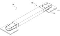
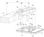
- FIG. 1is a perspective view of a communication device coupled to a substrate according to one embodiment of the present invention.
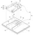
- Figure 2is an exploded perspective view of a communication line, connector, and board according to an embodiment of the present invention.
- Figure 3is a diagram for explaining the combination of the body and body cover of a connector disposed on a board according to an embodiment of the present invention.
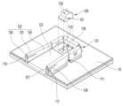
- Figure 4is a diagram for explaining the combination of the body, body cover, and probe support member of a connector disposed on a board according to an embodiment of the present invention.
- Figure 5is a perspective view of a connector disposed on a board according to an embodiment of the present invention.
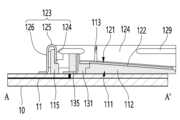
- FIG. 6is a cross-sectional view taken along the dashed-dotted line A-A' in FIG. 5.
- Figure 7is a cross-sectional view taken along the dashed line B-B' of Figure 5.
- Figure 8is a diagram for explaining a line part and a coupling support member according to an embodiment of the present invention.
- Figure 9is a perspective view of the bottom of the coupling portion according to an embodiment of the present invention.
- Figure 10is a diagram for explaining the combination of a connector, a line part, a coupling support member, and a coupling part arranged on a board according to an embodiment of the present invention.
- Figure 11is a diagram for explaining the combination of a connector, a line portion, a coupling support member, and a coupling portion disposed on a board according to another embodiment of the present invention.
- Figure 12is a diagram for explaining a connection part according to another embodiment of the present invention.
- Figure 13is a diagram for explaining a connector disposed on a board and a communication line coupled to the connector according to an embodiment of the present invention.
- FIG. 14is a cross-sectional view taken along the dashed line C-C' of FIG. 13.
- FIG. 15is a cross-sectional view taken along the dashed line D-D' of FIG. 13.
- Figure 16is a diagram for explaining an antenna structure according to an embodiment of the present invention.
- Figure 17is a diagram for explaining a probe protruding out of a connector according to another embodiment of the present invention.
- first, second, etc.are used to describe various elements, these elements are not limited by these terms. These terms are merely used to distinguish one component from another. Accordingly, the first component mentioned below may also be the second component within the technical spirit of the present invention.
- a dielectricis an electrical insulator with rare free charges.
- the dielectricmay include at least one of vacuum, gas including air, glass, rubber, or plastic.
- the plastic dielectricmay include liquid crystal polymer (LCP), polycarbonate (PC), and polytetrafluoroethylene (PTFE).
- transmission efficiency for communication signalsmay be a standard for evaluating communication signals, including uniformity and directivity of communication signals, signal loss during transmission, and accuracy of transmitted signals. In other words, if the uniformity and directivity of the communication signal are high, if the signal lost during transmission is small, or if the transmitted signal is accurate without noise, the transmission efficiency for the communication signal can be said to be high.
- FIG. 1is a perspective view of a communication device coupled to a substrate according to one embodiment of the present invention.
- the communication device 100includes a communication line 140 and a connector 110.
- the communication device 100can transmit a communication signal generated from one side to the other side, or transmit a communication signal generated from the other side to one side.
- the communication device 100according to an embodiment of the invention can transmit a communication signal generated from one side to the other side through the connector 110 and the communication line 140.
- the communication device 100can transmit a communication signal generated from the other side to one side through the connector 110 and the communication line 140.
- the connector 110may be connected to a communication line 140.
- a communication signalcan be transmitted to the communication line 140, or a signal transmitted from the communication line 140 can be transmitted to the substrate 10 or another configuration.
- coupling portions 170may be disposed at both ends of the line portion 150.
- the coupling portion 170may be connected to the connector 110.
- the connector 110may be seated on the board 10. In some cases, the connector 110 may be located outside the board 10.
- the communication line 140 according to an embodiment of the present inventionmay be directly or indirectly connected to the board 10 through the connector 110. Meanwhile, according to an embodiment of the present invention, the communication line 140 and the connector 110 may be coupled to each other through their respective configurations.
- Figure 2is an exploded perspective view of a communication line, connector, and board according to an embodiment of the present invention.
- the probe 135may radiate a communication signal.
- one side of the probe 135may emit or receive a communication signal.
- At least a portion of the probe 135may be disposed in the receiving hole 118 formed in the body 111 of the connector.
- the probe support member 130may be seated in the receiving hole 118.
- a space in which at least a portion of the probe 135 is disposedmay be formed in the probe support member 130 .
- a portion of the space where the probe 135 is placed in the probe support member 130may be penetrated in the vertical direction.
- an insertion protrusion 131may be formed on at least one side of the probe support member 130 to prevent separation due to movement due to external force.
- the insertion protrusion 131 formed on at least one side of the probe support member 130is caught by at least one locking protrusion 119 formed on the inner surface of the receiving hole 118 to hold the probe support member 130 in the receiving hole ( 118) can be fixed on the inside.
- a body cover 121may be coupled to the body 111 of the connector.
- the body cover 121may be coupled to the body 111 of the connector to cover the upper side of the body 111 of the connector.
- a hole 128may be formed in the body cover 121 to expose at least a portion of the probe 135.
- the hole 128 of the body cover 121may be similar to the shape of the upper hole of the receiving hole 118.
- the hole 128is a hole on the upper side of the receiving hole 118 in order for the probe support member 130 to be seated in the receiving hole 118 when the body 111 and body cover 121 of the connector are combined. It may be a shape that includes
- one side of the probe 135may be connected to transmit and receive a signal with the power feeder 11 disposed on the substrate 10, and the other side of the probe 135 may be connected to the power feeder 11.
- the received signalcan be radiated or the signal received from the outside can be transmitted to the power feeder 11.
- the power supply unit 11may transmit signals received from other components of the substrate 10 to the probe 135, and transmit signals received from the probe 135 to the substrate 10. It can be transmitted to other components in (10).
- the power feeder 11can transmit and receive signals to and from the substrate 10 from lines provided inside the substrate 10.
- the power feeder 11is disposed on the substrate 10 and can transmit and receive signals to and from other components included in the substrate 10 through a power feed line disposed inside the substrate 10.
- a line connecting the power supply unit 11 and other components included in the substrate 10may be exposed and disposed on the substrate 10.
- the shape of the power feeder 11is shown to be circular, but according to another embodiment of the present invention, the shape of the power feeder 11 may not be circular.
- the shape of the power feeder 11may be polygonal.
- the substrate 10 shown in FIG. 2may be a printed circuit board (PCB).
- the substrate 10may be a flexible printed circuit board (FPCB).
- the connector 110may be mounted on the surface of the substrate 10. Additionally, at this time, the technology for mounting the connector 110 may be surface mount technology (SMT).
- SMTsurface mount technology
- the connector 110includes a connector body 111 and a body cover 121. Additionally, in one embodiment of the present invention, the connector 110 is combined with the communication line 140 to form an antenna structure that guides communication signals.
- the antenna structure according to an embodiment of the present inventionmay be a structure that guides communication signals.
- the antenna structureefficiently guides the signal emitted from the probe 135 to one end of the line unit 150, or efficiently guides the signal emitted from one end of the line unit 150 to the probe 135. It could be a structure.
- the antenna structuremay be configured to include a structure advantageous for guiding communication signals.
- the antenna structuremay include a waveguide structure. The antenna structure will be described later with reference to FIGS. 14 to 16.
- Figure 3is a diagram for explaining the combination of the body and body cover of a connector disposed on a board according to an embodiment of the present invention.
- Figure 4is a diagram for explaining the combination of the body, body cover, and probe support member of a connector disposed on a board according to an embodiment of the present invention.
- Figure 5is a perspective view of a connector disposed on a board according to an embodiment of the present invention.
- FIG. 6is a cross-sectional view taken along the dashed-dotted line A-A' in FIG. 5.
- Figure 7is a cross-sectional view taken along the dashed line B-B' of Figure 5.
- the body 111 of the connectormay be mounted on the board 10 .
- a power feeder 11which is a conductor, may be disposed on the substrate 10.
- the power feeder 11 disposed on the substrate 10may be connected to the probe 135 to transmit and receive communication signals.
- the body 111 of the connectormay be made of a material that allows communication signals to pass through without loss in order to not reduce the transmission efficiency of communication signals.
- the body 111 of the connectormay be made of a solid material to firmly support the body cover 121.
- the body 111 of the connectormay be made of a hard dielectric with low signal loss.
- the body 111 of the connectormay be injection molded from a single material in order to reduce manufacturing costs and reduce signal loss.
- the body 111 of the connectormay be injection molded from a plastic material.
- the body 111 of the connectormay include a second inclined portion 112 and a probe mounting portion 114. Additionally, one side of the second inclined portion 112 and the probe mounting portion 114 may contact each other. According to an embodiment of the present invention, the second inclined portion 112 may be formed to extend from the upper surface of the probe mounting portion 114. Specifically, the second inclined portion 112 may be formed from the upper surface of the probe mounting portion 114 on which the third side wall 115 is not formed. Additionally, in the second inclined portion 112, one end of the line portion 150 may be disposed on a side opposite to the side where the probe mounting portion 114 is formed.
- the width of the second inclined portion 112may become wider as it approaches one end of the line portion 150. Additionally, according to one embodiment, when the connector 110 and the coupling portion 170 are coupled, the width of the second inclined portion 112 may become narrower as it moves away from one end of the line portion 150.
- the second inclined portion 112is formed to be inclined as it approaches one end of the line portion 150 according to an embodiment of the present invention, so that the directivity of the communication signal in the antenna structure can be increased, and thus the communication signal transmission efficiency can be increased.
- the width of the second inclined portion 112becomes wider as it approaches one end of the line portion 150, so that the directivity of the communication signal in the antenna structure can be increased, thereby improving the transmission efficiency of the communication signal.
- the body 111 of the connectoris connected to one side of the second inclined portion 112 and has a probe mounting portion 114 that provides a space for mounting the probe 135 for transmitting and receiving communication signals. It can be included. Additionally, the upper surface of the probe mounting unit 114 may have an inclination angle different from the upper surface of the second inclined unit 112. For example, the upper surface of the probe mounting unit 114 may be parallel to the substrate 10.
- the usermay use the probe mounting portion 114 according to the present invention. It may be easy to place the probe support member 130 according to one embodiment, and the probe support member 130 may not interfere with communication signals transmitted and received within the antenna structure.
- the body 111 of the connectorhas a receiving hole 118 penetrated through the upper and lower surfaces so that a probe support member 130 for fixing the probe 135 according to an embodiment of the present invention can be disposed. ) can be formed.
- the connector 110may be arranged so that the power supply unit 11 of the substrate 10 is located at the bottom of the receiving hole 118.
- a locking protrusion 119 on which the insertion protrusion 131 formed on at least one side of the probe support member 130 according to an embodiment of the present invention can be caughtmay be formed in the receiving hole 118.
- second side walls 113may be formed upward along both ends of the second inclined portion 112 on the second inclined portion 112 .
- the second side wall 113may include two side walls formed upwardly along both ends of the second inclined portion 112, respectively.
- each second side wall 113is shown to have a single extending direction, but each second side wall 113 according to another embodiment of the present invention includes a plurality of side walls extending in different directions. can do. Additionally, the height or shape of each second side wall 113 according to another embodiment of the present invention may be different from each other.
- a third side wall 115may be formed upward along the circumference of the probe mounting portion 114.
- the third side wall 115may be a side wall formed so that the second inclined portion 112 side is open. Additionally, the third side wall 115 may be formed by connecting a plurality of side walls extending in different directions. For example, the third side wall 115 may surround the probe mounting portion 114 and be formed in a “ ⁇ ” shape. Additionally, both ends of the third side wall 115 may be connected to each of the second side walls 113. When both ends of the third side wall 115 are connected to each of the second side walls 113, the shielding performance of the antenna structure can be further improved.
- the end of the coupling portion 170 and a portion of the portion covering the third side wall 115 of the body cover 121are shielded when the coupling portion 170 and the connector 110 are coupled.
- Spacecan be formed.
- a portion of the body cover 121 that covers the third side wall 115may be a portion of a bent portion 123 that will be described later.
- the shielding spacemay be a space that prevents the interior from being affected by external electromagnetic fields.
- At least one stopping protrusion 117may be formed to protrude on the outside of the second side wall 113 or the third side wall 115.
- the locking protrusion 117may be fastened to the locking hole 127 formed in the body cover 121.
- the upper edge of the stopping protrusion 117may be formed at an oblique angle. In this way, when the upper edge of the locking protrusion 117 is formed at an oblique angle, the user simply presses the body cover 121 downward from the upper side of the body 111 of the connector, and a portion of the body cover 121 is elastically deformed. , the body cover 121 can be easily coupled to the body 111 of the connector.
- the connector 110may further include a body cover 121 that covers at least a portion of the body 111 of the connector.
- the body cover 121may be formed by bending a plate-shaped conductor several times.
- the body cover 121may be preformed to cover at least a portion of the body 111 of the connector, and may be bent while being combined to cover at least a portion of the body 111 of the connector. If the body cover 121 is a plate-shaped conductor formed by bending several times, the manufacturing cost for creating a shape that covers the body 111 of the connector is reduced, and it can be easy to form a structure for shielding communication signals. .
- the body cover 121may be formed by combining a plurality of components with each other.
- the body cover 121may be formed by combining a plurality of conductors.
- the components constituting the body cover 121may have a simpler shape than the body cover 121, so the manufacturing process can be simplified.
- the plurality of components forming the body cover 121may be assembled, glued, ultrasonic fused, or welded to form the body cover 121.
- the body cover 121may be formed in advance to cover the body 111 of the connector.
- the body cover 121may be injection molded. In this case, since the process of bending the body cover 121 is not necessary, the process can be simplified, and the consistency of the antenna structure formed by the body cover 121 can be improved.
- the body cover 121when the body 111 of the connector and the body cover 121 are coupled, at least a portion of the body cover 121 may be in close contact with the body 111 of the connector.
- the upper side of the second inclined portion 112 shown in FIG. 3, the upper side of the probe mounting portion 114, and the second side wall 113are the body cover 121 as shown in FIG. 4. It can be tightly covered.
- the inclined surface 122when the body cover 121 is in close contact with the body 111 of the connector, the inclined surface 122, which is the same as the upper side of the second inclined portion 112 of the body 111 of the connector, is connected to the antenna.
- a structurecan be formed. Accordingly, a portion of the antenna structure can be determined by the shape of the second inclined portion 112 without plating the upper side of the second inclined portion 112 with a conductor.
- the body cover 121 that covers the body 111 of the connector in close contacthas an inclined surface 122 of the body cover disposed on the upper side of the second inclined portion 112 or a second side wall ( A bent portion 123 disposed outside the 113) may be formed.
- the inclined surface 122 of the body covermay be formed to slope downward as it approaches one end of the line unit 150 according to an embodiment of the present invention. Additionally, when the connector 110 and the communication line 140 are coupled, one end of the inclined surface 122 of the body cover may be bent downward so that a portion of the communication line 140 can be easily inserted.
- the bent portion 123may include an inward surface 124, an insertion surface 125, and an outward surface 126, and may be formed at both ends of the inclined surface 122 of the body cover. .
- the bent portion 123may be formed by bending the edge of the body cover 121 several times. A space into which the second side wall 113 can be inserted may be formed inside the bent portion 123.
- the inward surface 124may be formed by bending vertically upward from both ends of the inclined surface 122 of the body cover and then extending.
- the insertion surface 125may be formed by gently bending from the inward surface 124 in a direction opposite to the direction in which the inward surface 124 extends. That is, the insertion surface 125 may be formed by gently bending downward from the inward surface 124.
- the outward surface 126may be formed to extend downward from one end of the insertion surface 125. Additionally, the inward-facing surface 124 and the outward-facing surface 126 may be parallel to each other.
- the bent portion 123may cover the second side wall 113 and the third side wall 115 .
- the third side wall 115may be formed in a “ ⁇ ” shape with one side open as described above, so a portion of the bent portion 123 may be formed in a “ ⁇ ” shape with one side open.
- the bent portion 123may be formed to be connected in a “ ⁇ ” shape.
- the bent portion 123 of the body cover 121covers the second side wall 113 and the third side wall 115 of the connector body 111, and the lower portion of the antenna structure that guides the communication signal. This can be formed. That is, the bent portion 123 can prevent the outflow of communication signals and reflect communication signals in the antenna structure formed when the connector 110 and the communication line 140 are combined.
- the bent portion 123is coupled while covering the second side wall 113 and the third side wall 115 formed in various directions, so the body cover 121 coupled to the body 111 of the connector can be used in various ways. It can be firmly coupled even against external forces applied from any direction.
- At least one locking hole 127may be formed in the body cover 121.
- at least one catching hole 127 penetrating the outward surface 126may be formed on the outward surface 126 of the body cover 121.
- the body cover 121may be made of an elastic material.
- the outward surface 126may be elastically deformed, so the body cover 121 and the body of the connector ( 111) can be easily combined.
- the body cover 121may be formed of a conductor. If the body cover 121 is a conductor, an antenna structure that reflects communication signals and shields external electromagnetic waves can be easily formed.
- the body cover 121covers a portion of the body 111 of the connector and can be easily coupled to the body 111 of the connector by fastening the locking protrusion 117 and the locking hole 127. You can.
- the body cover 121is an elastic conductor, it is easy to form an antenna structure that reflects communication signals, and at the same time, the body cover 121 is attached to the body 111 of the connector by using the elastic deformation of the body cover 121. It may be easy to conclude.
- the hole 128 formed to penetrate the upper and lower surfaces of the body cover 121may have the same shape as the entrance of the receiving hole 118 formed in the body 111 of the connector. In this case, as the body 111 and body cover 121 of the connector are combined, the hole 128 and the receiving hole 118 are arranged up and down, creating a passage and space in which the probe support member 130 can be accommodated. can be formed.
- the connector 110may be positioned on the substrate 10 so that one side of the probe 135 is in contact with the power feeder 11 disposed on the substrate 10 . Additionally, the probe 135 may be a conductor. Accordingly, the probe 135 is connected to the power feeder 11 and can transmit and receive signals to and from the substrate 10.
- one side of the probe 135receives signals generated from various devices included in the substrate 10 through the power feeder 11, and the other side of the probe 135
- the signal received from the substrate 10may be radiated as a communication signal toward one end of the line unit 150.
- the communication signal radiated or received by the probe 135may be a wireless signal.
- the other side of the probe 135receives the communication signal emitted from one end of the line unit 150, and one side of the probe 135 receives the communication signal from one end of the line unit 150.
- a signalcan be transmitted to various devices included in the substrate 10 through the power supply unit 11.
- the probe 135may first be placed on the upper side of the power feeder 11 of the substrate 10 to be connected to the power feeder 11, and then be coupled to the probe support member 130. there is.
- the probe 141may be placed on the board 10 before the connector 110 is seated.
- the probe 135may first be coupled to the probe support member 130 and then the probe support member 130 may be inserted into the connector 110.
- the probe support member 130may be a dielectric that allows communication signals to pass without loss.
- the probe support member 130may be formed by injection molding from a plastic material. Accordingly, the communication signal radiated by the probe 135 may pass through the probe support member 130 and reach one end of the line unit 150.
- the communication line 140includes a line portion 150, a coupling support member 160, and a coupling portion 170.
- the line unit 150transmits a communication signal through a dielectric
- the coupling support member 160is disposed at one end of the line unit 150.
- the track unit 150 and the coupling support member 160will be described with reference to FIG. 8.
- Figure 8is a diagram for explaining a line part and a coupling support member according to an embodiment of the present invention.
- the body of the line unit 150transmits the communication signal radiated from the probe 135 and reaches one side of the line unit 150 to the other side, or to the other side of the line unit 150.
- the communication signal that arrivescan be transmitted and emitted from one side.
- both sides of the line unit 150may not be plated with a conductor.
- the line unit 150may be made of a dielectric containing at least one of vacuum, gas containing air, plastic, or rubber. Additionally, in order to maintain the shape of the line section 150 and protect the interior, a cover may be formed along the perimeter of the line section 150. At this time, the cover formed along the perimeter of the line unit 150 may be a conductor. If the cover is a conductor, it is possible to prevent signals transmitted from the inside of the line section 150 from being emitted to the outside of the line section 150 or from external electromagnetic waves affecting communication signals transmitted from the line section 150. there is.
- the cover formed along the circumference of the line portion 150may be formed of a conductor plated around the line portion 150, or may have a separate configuration.
- the dielectric forming the line portion 150is a vacuum, gas, or soft material
- the communication line 140can be flexibly bent and arranged regardless of the position or direction of the connector 110 seated on the board. .
- the line unit 150may be a tubular dielectric line. Additionally, at least one through hole may be formed in the line unit 150. The through hole may be formed from one side of the line unit 150 to the other side along the direction in which the signal is transmitted inside the line unit 150. In this case, the dielectric loss of the signal caused by the dielectric forming the line portion 150 can be reduced.
- the number and shape of through holes formed in the line unit 150are not limited.
- only one through hole with a circular cross-section perpendicular to the longitudinal direction of the line portion 150may be formed in the line portion 150.
- the line section 150may include one through hole whose cross-sectional shape perpendicular to the longitudinal direction of the line section 150 is circular and a plurality of through holes whose cross-sectional shape perpendicular to the longitudinal direction of the line section 150 is fan-shaped. They can be formed together, and each through hole can be separated by a dielectric. In this way, through-holes of various numbers and shapes are formed in the line portion 150, so that flexibility or a bearing capacity to resist external force can be adjusted.
- the cross-sectional shape perpendicular to the longitudinal direction of the line unit 150may be square. In this case, the durability of the line unit 150 against external pressure may be improved.
- the cross-sectional shape perpendicular to the longitudinal direction of the line unit 150 according to various embodiments of the present inventionmay be circular.
- the dielectric making up the line portion 150is a soft material, vacuum, or gas
- the flexibility of the line portion 150which has a circular cross-sectional shape perpendicular to the longitudinal direction of the line portion 150, can be improved.
- the line unit 150may be a shielding cable formed with a protective member or a shielding member therein.
- a braid shield, a spiral shield, or an SPC tapemay be placed on the inner or outer peripheral surface of the line unit 150. In this case, the bearing force or shielding force of the line unit 150 may be strengthened.
- the body of the line unit 150may be formed so that one end of both sides is stepped inside.
- a step portion 153may be formed at one end of the body of the line portion 150, and each of the step portions 153 formed on both sides of one end of the line portion 150 may be formed to be symmetrical to each other.
- a space in which both sides of the body of the connection portion 177 can be accommodatedcan be provided.
- the coupling support member 160may be plate-shaped.
- the coupling support member 160may have a thin and wide plate shape with a protrusion 165 formed on the lower side.
- an interpolation space 175may be formed between the protrusion 165 and the first side wall 173.
- the interpolation space 175may be a space into which a portion of the bent portion 123 is inserted when the coupling portion 170 and the connector 110 are coupled. Insertion of a portion of the bent portion 123 into the interpolation space 175 will be described later with reference to FIG. 11 .
- the surface on which the inclined surface 161 of the coupling support member is formedmay be formed to be in close contact with the surface of the coupling portion 170 on which the coupling support member 160 is seated.
- the inclined surface 161 of the coupling support member 160may be formed by bending to come into close contact with the first inclined part 172 of the coupling portion 170.
- the coupling support member 160may provide a space in which the coupling portion 170 is seated. That is, a portion of the coupling portion 170 may be seated on the upper surface of the coupling support member 160.
- the coupling portion 170will be described with reference to FIG. 9.
- Figure 9is a perspective view of the bottom of the coupling portion according to an embodiment of the present invention.
- the coupling portion 170may include a conductor that is bent several times. Additionally, the coupling portion 170 may be formed by cutting or bending a plurality of conductors and then bonding them to each other. Additionally, according to one embodiment of the present invention, the coupling portion 170 may be formed of the same material as that of the body cover 121. In this case, the antenna structure formed by combining the connector 110 and the coupling portion 170 can be made of a single material, so transmission efficiency for communication signals can be improved.
- the coupling portion 170may form at least a portion of the antenna structure. Additionally, the coupling unit 170 may include at least one inclined part to increase transmission efficiency for communication signals. According to an embodiment of the present invention, when the coupling portion 170 and the line portion 150 are coupled, the inclined portion included in the coupling portion 170 is inclined in a direction opposite to the direction toward the central axis of the line portion 150. You can.
- the coupling portion 170may include a first inclined portion 172 inclined in a direction opposite to the direction toward the central axis of the line portion 150, and the first inclined portion 172 may provide a communication signal. The inclination angle and deployed position can be adjusted to improve transmission efficiency.
- the first inclined portion 172is formed to slope downward as it moves away from one end of the line portion 150.
- the direction in which the first inclined portion 172 is inclined downwardmay be the direction in which the coupling portion 170 is coupled to the body cover 121 according to an embodiment of the present invention, and the body 111 of the connector is This may be the direction in which it is seated on the substrate 10.
- the first inclined portion 172when the first inclined portion 172 is coupled to the line portion 150 according to an embodiment of the present invention, it may be formed to slope upward as it approaches one end of the line portion 150.
- the width of the first inclined portion 172increases as the distance from one end of the line portion 150 increases. It can become narrow.
- the width of the first inclined portion 172may become wider as it approaches one end of the line portion 150. .
- the transmission efficiency for communication signalscan be increased by adjusting the inclination angle or the arranged position of the first inclined portion 172 included in the coupling portion 170. Specifically, considering the point and angle at which the communication signal is reflected, the inclination angle or the arranged position of the first inclined part 172 can be adjusted to improve the directivity of the communication signal or reduce noise.
- the first inclined portion 172 of the coupling portion 170 and the second inclined portion 112 of the body 111 of the connectormay be formed symmetrically with respect to each other. . That is, the angle at which the first slope 172 slopes upward as it gets closer to one end of the track 150 and the angle at which the second slope 112 slopes downward as it gets closer to one end of the line 150 are may be the same. In this case, the upper and lower surfaces of the antenna structure are formed symmetrically with respect to each other, so the transmission efficiency of communication signals can be further improved.
- first side walls 173may be formed downward along both ends of the first inclined portion 172. As described above, the first side wall 173, together with the first inclined portion 172, may form part of a space that guides communication signals to be transmitted and received. That is, a portion of the first slope 172 and the first side wall 173 may form part of the antenna structure.
- the antenna structuremay be formed as part of the first inclined portion 172, the first side wall 173, and the connector 110 according to an embodiment of the present invention. Additionally, as described above, a portion of the connector 110 forming the antenna structure may include a portion covering the second inclined portion 112 and the second side wall 113 of the body cover 121. Accordingly, the antenna structure may be formed as part of the first inclined portion 172, the first side wall 173, the second inclined portion 112, and the second side wall 113. According to one embodiment of the present invention, the coupling portion 170 may be combined with a portion of the connector 110 to form an antenna structure that guides communication signals.
- the coupling portion 170is connected to the first inclined portion 172 on the opposite side of the track portion 150 and includes a cover portion 176 disposed to cover one end of the coupling support member 160. can do.
- one surface of the cover portion 176may be parallel to the substrate 10 when the coupling portion 170 is coupled to the connector 110 disposed on the substrate 10.
- the cover portion 176corresponds to the portion where the body cover 121 covers the probe mounting portion 114 and the bent portion 123 that covers the third side wall 115. It may be a shape.
- the side wall surrounding the cover part 176may be formed so that the bent part 123 covering the third side wall 115 can be pressed into the inside, and one surface of the cover part 176 is covered with the body cover 121. ) may be formed parallel to the portion covering the probe mounting portion 114.
- the cover portion 176may form a shielding space together with the portion where the body cover 121 covers the probe mounting portion 114 and the bent portion 123 that covers the third side wall 115.
- the cover portion 176, the portion where the body cover 121 covers the probe mounting portion 114, and the bent portion 123 covering the third side wall 115are located at one end of the line portion 150 to form the probe 135. ) can be reflected, and the communication signal radiated backward from the probe 135 can be reflected forward toward one end of the line unit 150.
- the coupling portion 170may further include a connecting portion 177 connecting one end of the line portion 150 to the first inclined portion 172 .
- a connecting portion 177connecting one end of the line portion 150 to the first inclined portion 172 .
- wing portions 178may be formed by extending from both sides of the body of the connecting portion 177, respectively.
- the wing portion 178can be bent from the body of the connecting portion 177 and tighten the circumference of the track portion 150 to bind the connecting portion 177 and the track portion 150.
- the process of coupling the coupling portion 170 and the line portion 150 due to the wing portion 178will be described with reference to FIG. 10.
- Figure 10is a diagram for explaining the combination of a connector, a line part, a coupling support member, and a coupling part arranged on a board according to an embodiment of the present invention.
- the wings 178 extending from both sides of the body of the connecting portion 177are formed when both sides of the body of the connecting portion 177 are coupled to both sides of one end of the body of the track portion 150, Each is bent inward so that the connection portion 177 can be bent and coupled to the line portion 150.
- the coupling portion 170may be formed entirely of an elastic conductor. In this case, the user can insert one end of the line section 150 into the body of the connection section 177 and then bend the wing section 178 to easily bind the connection section 170 and the line section 150. .
- step portions 153may be formed on both sides of one end of the body of the line portion 150.
- the step portion 153may be formed to be stepped inside the line portion 150.
- the wing portion 178may be disposed in the space formed by the step portion 153. According to the above, the user does not need to measure the part where the wing part 178 should be bent, but simply inserts the wing part 178 into the step part 153 and places the wing part 178 in the optimal place for bending.
- the wing portion 178can be placed.
- the coupling portion 170is shown to be coupled from the upper side of the line portion 150 downward to couple with the line portion 150.
- the coupling direction of the line portion 150 and the coupling portion 170is as follows. It is not limited.
- the line portion 150may be slidably inserted into the connection portion 177 formed in the coupling portion 170. The sliding coupling of the line section 150 to the connection section 177 will be described later with reference to FIG. 11.
- the coupling support member 160may be disposed at one end of the line unit 150 to support the coupling portion 170.
- the line portion 150 and the coupling support member 160are shown to be formed integrally, but as described above, the line portion 150 and the coupling support member 160 are formed separately and then coupled to each other. It may be a state.
- the coupling support member 160may be first disposed inside the coupling portion 170, and then the line portion 150 may be coupled to the coupling portion 170. The coupling in which the coupling support member 160 is first placed inside the coupling portion 170 and then the track portion 150 is coupled to the coupling portion 170 will be described with reference to FIG. 11 .
- Figure 11is a diagram for explaining the combination of a connector, a line portion, a coupling support member, and a coupling portion disposed on a board according to another embodiment of the present invention.
- the coupling support member 1160is first placed inside the coupling portion 170, and then the line portion 1150 can be slide coupled to the connecting portion 177.
- a step portion 153may be formed on both sides of one end of the line portion 1150, and the body of the connection portion 177 may be seated in the space formed by the step portion 153.
- the line part 1150may come into contact with the coupling support member 1160.
- an interpolation space 175 for coupling the coupling portion 170 and the connector 110will be formed.
- the interpolation space 175is formed in the space between the first side wall 173 and the protrusion 165.
- a portion of the bent portion 123 formed while covering the second side wall 113may be inserted into the interpolation space 175 .
- the insertion surface 125forms the interpolation space 175 so that the inward surface 124 and the protrusion 165 form one boundary surface, and the outward surface 126 and the first side wall 173 form the other boundary surface. can be inserted into
- the interpolation space 175is formed on all sides except the side of the line portion 150 that is open from the coupling portion 170 and the connector 110. ) A part of the bent portion 123 may be inserted. Accordingly, the coupling portion 170 can be coupled to the connector 110 so as to be able to withstand external forces in various directions.
- a first convex portion 179may be formed on the inner surface 174 of the first side wall of the coupling portion 170.
- the first convex portion 179may include beading, embossing, or an elastic member.
- the elastic member included in the first convex portion 129may be a spring or a shape bent to have elasticity.
- the first convex portion 179may increase the pressure received when a portion of the bent portion 123 is inserted into the interpolation space 175.
- the userpresses the coupling portion 170 with the coupling support member 1160 disposed inside from the upper side of the connector 110 toward the connector 110 to press the coupling portion 170 into the connector 110. Therefore, the coupling of the coupling portion 170 and the connector 110 is very easy. In addition, since the connector 110 can be pressed into or pulled out of the coupling portion 170 using only a small amount of force, there is a small risk of the connector 110 and the coupling portion 170 being worn or damaged even if they are repeatedly coupled.
- the bent portion 123 of the connector 110is connected to the communication line ( The pressure pressurized into the interpolation space 175 of 140) can be increased.
- the communication line 140 and the connector 110can be more firmly coupled.
- connection part 177 and the wing part 178varies depending on the shape of the cross section perpendicular to the longitudinal direction of the line part 150 according to various embodiments of the present invention. It can be. Other shapes of the connection portion 177 and wing portion 178 will be described with reference to FIG. 12.
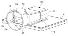
- Figure 12is a diagram for explaining a connection part according to another embodiment of the present invention.
- the shape formed by the connection portion 1277 and the wing portion 1278may be circular. Additionally, the wing portion 1278 may be bent several times to tighten one end of the track portion 150. In this case, the cross-sectional shape perpendicular to the longitudinal direction of one end of the line unit 150 may be circular.
- the shape formed by the connection part 1277 and the wing part 1278is shown as a circle, but as described above, the shape of the cross section perpendicular to the longitudinal direction of the body of the line part 150 is not limited to a specific shape. , the shape formed by the connection portion 1277 and the wing portion 1278 is also not limited to a specific shape.
- Figure 13is a diagram for explaining a connector disposed on a board and a communication line coupled to the connector according to an embodiment of the present invention.
- FIG. 14is a cross-sectional view taken along the dashed line C-C' of FIG. 13.
- FIG. 15is a cross-sectional view taken along the dashed line D-D' of FIG. 13.
- Figure 16is a diagram for explaining an antenna structure according to an embodiment of the present invention.
- one side of the probe 135is connected to the power feeder 11 disposed on the substrate 10, and the probe 135 may be fixed to the probe support member 130. Meanwhile, the locking protrusion 117 and the locking hole 127 may be fastened so that the body cover 121 tightly covers the upper side of the body 111 of the connector. At this time, the inclined surface 122 of the body cover may be disposed on the upper side of the second inclined portion 112 of the body 111 of the connector to have an inclination angle that is the same as that of the second inclined portion 112.
- the coupling portion 170may tightly cover the upper surface of the coupling support member 160 so that the coupling support member 160 fills the inside of the coupling portion 170.
- an interpolation space 175may be formed between the first side wall 173 of the coupling portion 170 and the protrusion 165 of the coupling support member 160.
- a portion of the bent portion 123 formed to cover the second side wall 113 and the third side wall 115may be inserted into the interpolation space 175 .
- the insertion surface 125is press-fitted into the inner insertion space 175, the inward surface 124 can form a boundary surface with the outer surface of the protrusion 165, and the outward surface 126 is inside the first side wall.
- a boundary surfacemay be formed with the side surface 174 or the inner surface of the cover portion 176.
- the antenna structure 191may include a lower inclined surface 193, an upper inclined surface 194, an inward surface 124, a portion of the insertion surface 125, and an inner surface 174 of the first side wall. Both sides of the antenna structure 191 may be empty to allow communication signals to be transmitted. That is, the antenna structure 191 may be formed with a first opening surface 197 on the probe 135 side and a second opening surface 198 on the line unit 150 side.
- the surfaces forming the antenna structure 191will be described in detail with reference to FIG. 16.
- the inclined surface 122 of the body cover formed parallel to the upper side of the second inclined portion 112may form the lower inclined surface 193 of the antenna structure 191.
- the inward surfaces 124 of the bent portions 123 of the body cover 121may be disposed upward from both ends of the lower slope 193, respectively.
- a portion of the insertion surface 125may be disposed by bending outward from the top of the inward surface 124.
- At least a portion of the inner surface of the first inclined portion 172may form the upper inclined surface 194 of the antenna structure 191.
- the inner surfaces 174 of the first side wallsmay be disposed downward from both ends of the upper slope 194, respectively. And, the inner surface 174 of the first side wall may meet a portion of the insertion surface 125.
- the inner space of the antenna structure 191expands from the first opening surface 197 to the second opening surface 198, from the probe 135 side to one end of the line unit 150. It can become wider. Accordingly, the antenna structure 191 may form a horn antenna structure.
- the surfaces forming the antenna structure 191may be plated with a conductor. Also, one end of the line unit 150 may not be plated with a conductor. In this case, communication signals propagating in the inner space of the antenna structure 191 may be reflected from the surfaces forming the antenna structure 191 and guided to have uniformity.
- the communication signal radiated from the probe 135passes through the first opening surface 197 and propagates directly to one end of the line unit 150, or is reflected from the surfaces forming the antenna structure 191 and passes through the line unit (197). 150) can be reached.
- the communication signal emitted from one end of the line unit 150passes through the second opening surface 198 and propagates directly to the probe 135, or is reflected from the surfaces forming the antenna structure 191 and is transmitted to the probe 135. can be received.
- the communication signalreaches one end of the line unit 150 in parallel from the probe 135, thereby improving uniformity. It can be improved.
- the cross section perpendicular to the longitudinal direction of the antenna structure 191 formed by combining the communication line 140 and the connector 110is illustrated as having a constant shape, but the shape of the antenna structure 191 is limited to this. It doesn't work.
- the shape of the cross section perpendicular to the longitudinal direction of the antenna structure 191may be circular, square, or polygonal except for a square.
- the shape of the opening surfaces 197 and 198 formed on both sides of the antenna structure 191may be circular, square, or polygonal except for a square shape.
- the shapes of the first opening surface 197 and the second opening surface 198may be different from each other.
- the coupling portion 170 side of the antenna structure 191may be filled with the coupling support member 160.
- the coupling support member 160may be made of a dielectric through which communication signals can pass without loss, communication signals can be guided in the antenna structure 191 without loss or noise.
- the surfaces exposed to the outsidemay be plated with a conductor. If the surfaces exposed to the outside are plated with a conductor, the communication signal propagating from the communication line 140 and the connector 110 may not be emitted to the outside, and may not be transmitted from the outside to the communication line 140 and the connector 110. By shielding electromagnetic waves, the transmission efficiency and accuracy of communication signals can be improved.
- the connector 110may be placed on the board 10 regardless of the position of the power feeder 11. To this end, the state in which the probe 135 protrudes out of the connector 110 will be described with reference to FIG. 17 .
- Figure 17is a diagram for explaining a probe protruding out of a connector according to another embodiment of the present invention.
- a through hole 1616may be formed on one side of the second side wall 1613 of the body 1611 of the connector and the outward surface 1626 of the body cover 1621.
- the probe 1635may extend to penetrate the through hole 1616 and protrude out of the connector 1610. At this time, the length at which the probe 1635 protrudes out of the connector 1610 is not limited.
- the probe 1635 protruding outside of the connector 1610may be connected to the power feeder 12 to transmit and receive signals to and from the substrate 10.
- the probe 1635can be connected to transmit and receive signals with the power feeder 12. Accordingly, the connector 1610 can be used while being seated on various types of boards 10, thereby improving usability.
Landscapes
- Coupling Device And Connection With Printed Circuit (AREA)
- Near-Field Transmission Systems (AREA)
Abstract
Description
Translated fromKorean본 발명은 통신 선로 및 커넥터에 관한 것으로서, 구체적으로 통신 선로 및 그와 연결되는 커넥터에 관한 것이다.The present invention relates to communication lines and connectors, and specifically relates to communication lines and connectors connected thereto.
고주파 신호를 전달하기 위한 종래의 기술에는 동축케이블을 통해 통신 신호를 전달하는 기술이 있다. 이 경우, 케이블의 시그널 핀 및 이와 접촉하는 커넥터의 시그널 핀 사이의 임피던스 매칭(impedance matching)이 이루어지도록 연결되어야 하고, 리셉터클(receptacle)의 시그널 핀 역시 동일한 성능으로 연결되어야 했다. 임피던스 매칭은 입력단 및 출력단이 연결된 연결부분에서 신호가 반사되는 리플렉션(reflection) 현상을 방지하기 위하여 입력단 및 출력단의 임피던스를 동일하게 조정하는 단계이다. 이러한 임피던스 매칭은 매우 섬세한 조정이 필요하므로, 종래의 기술은 임피던스 매칭에 소요되는 시간 및 비용이 과도하다는 문제가 있다.Conventional technology for transmitting high-frequency signals includes technology for transmitting communication signals through coaxial cables. In this case, the cable's signal pin and the signal pin of the connector in contact with it must be connected to achieve impedance matching, and the receptacle's signal pin must also be connected with the same performance. Impedance matching is the step of adjusting the impedance of the input and output terminals to be equal in order to prevent the reflection phenomenon where the signal is reflected at the connection where the input terminal and the output terminal are connected. Since this impedance matching requires very delicate adjustment, the conventional technology has the problem that the time and cost required for impedance matching are excessive.
또한, 고주파 신호를 전달하기 위한 종래의 기술에는 지향성 안테나를 통해 무선 신호를 방사 및 수신하는 기술도 있다. 이 때, 지향성 안테나 중 혼(horn) 안테나는, 무선 신호를 방사하거나 수신하는 프로브(probe)로부터 멀어질수록 단면적이 넓어지는, 내부가 비어있는 관형 안테나를 의미한다. 혼 안테나의 내측면은 도체로 이루어져 송수신되는 무선 신호를 반사할 수 있다. 혼 안테나는 제작 비용에 비해 높은 지향성을 얻을 수 있고 간단한 구조로 인해 조작이 용이하다는 장점이 있으므로, 지향성 안테나로써 자주 활용된다.Additionally, conventional technologies for transmitting high-frequency signals include technologies for radiating and receiving wireless signals through directional antennas. At this time, among directional antennas, a horn antenna refers to a tubular antenna with an empty interior whose cross-sectional area increases as it moves away from a probe that radiates or receives radio signals. The inner side of the horn antenna is made of a conductor and can reflect transmitted and received wireless signals. Horn antennas have the advantage of being able to obtain high directivity compared to the manufacturing cost and being easy to operate due to their simple structure, so they are often used as directional antennas.
하지만, 종래의 지향성 안테나를 통해 무선 신호를 방사하는 기술의 경우, 무선 신호의 주파수가 낮은 경우는 안테나의 크기가 증가된다는 문제가 있고, 무선 신호의 주파수가 높을 경우는 무선 신호가 자유 공간상에서 전송되면서 경로 손실(path loss)이 증가된다는 문제가 있다.However, in the case of technology that radiates wireless signals through a conventional directional antenna, there is a problem that the size of the antenna increases when the frequency of the wireless signal is low, and when the frequency of the wireless signal is high, the wireless signal is transmitted in free space. There is a problem that path loss increases as this happens.
또한, 종래에는 무선 신호 송수신용 통신 장치가 일체형으로 제조되어 기판에 실장되었으므로, 종래의 기술은 통신 장치를 제조하는 비용이 과대하고, 분해 및 조립이 난해하고, 운반이 어려운 문제가 있다.In addition, in the past, communication devices for transmitting and receiving wireless signals were manufactured as a single piece and mounted on a board, so the conventional technology has problems such as excessive manufacturing costs, difficult disassembly and assembly, and difficult transportation.
한편, 전술한 배경기술은 발명자가 본 발명의 도출을 위해 보유하고 있었거나, 본 발명의 도출 과정에서 습득한 기술 정보로서, 반드시 본 발명의 출원 전에 일반 공중에게 공개된 공지기술이라 할 수는 없다.Meanwhile, the above-described background technology is technical information that the inventor possessed for deriving the present invention or acquired in the process of deriving the present invention, and cannot necessarily be said to be known technology disclosed to the general public before filing the application for the present invention. .
(선행기술문헌) 한국등록특허 제10-0778821 호 (20071116)(Prior art literature) Korean Patent No. 10-0778821 (20071116)
본 발명이 해결하고자 하는 일 과제는, 용이하게 결합되어, 안테나 구조를 형성할 수 있는 통신 선로 및 커넥터를 제공하는 것이다.One problem that the present invention seeks to solve is to provide a communication line and connector that can be easily combined to form an antenna structure.
본 발명이 해결하고자 하는 다른 과제는, 정밀한 임피던스 매칭이 필요없어 제조 비용이 절감되고, 고주파 신호의 손실이 적은 통신 선로 및 커넥터를 제공하는 것이다.Another problem that the present invention aims to solve is to provide a communication line and connector that does not require precise impedance matching, reduces manufacturing costs, and reduces high-frequency signal loss.
본 발명이 해결하고자 하는 또 다른 과제는, 통신 신호를 유전체를 이용하여 송수신하여, 안테나 구조가 소형화되고 신호의 경로 손실이 감소될 수 있는 통신 선로 및 커넥터를 제공하는 것이다.Another problem that the present invention aims to solve is to provide a communication line and connector that can transmit and receive communication signals using a dielectric, thereby miniaturizing the antenna structure and reducing signal path loss.
본 발명이 해결하고자 하는 또 다른 과제는, 기판 표면에 통신 선로와 분리되어 실장될 수 있어, 기판과의 연결 신뢰성 및 활용성이 향상될 수 있는 커넥터를 제공하는 것이다.Another problem that the present invention aims to solve is to provide a connector that can be mounted on the surface of a board separately from a communication line, thereby improving connection reliability and usability with the board.
본 발명이 해결하고자 하는 또 다른 과제는, 조립 또는 분해하기 용이하고, 견고한 통신 선로 및 커넥터를 제공하는 것이다.Another problem to be solved by the present invention is to provide a communication line and connector that is easy to assemble or disassemble and is sturdy.
본 발명이 해결하고자 하는 또 다른 과제는, 조금의 힘만을 이용해서 압입되거나 인출될 수 있으므로, 반복해서 결합하여도 마모되거나 파손될 위험이 적은 통신 선로 및 커넥터를 제공하는 것이다.Another problem that the present invention aims to solve is to provide communication lines and connectors that can be pressed in or pulled out using only a small amount of force, so there is a low risk of wear or damage even when combined repeatedly.
본 발명의 과제들은 이상에서 언급한 과제들로 제한되지 않으며, 언급되지 않은 또 다른 과제들은 아래의 기재로부터 당업자에게 명확하게 이해될 수 있을 것이다.The problems of the present invention are not limited to the problems mentioned above, and other problems not mentioned will be clearly understood by those skilled in the art from the description below.
전술한 바와 같은 과제를 해결하기 위하여 본 발명의 일 실시예에 따른 통신 선로는, 유전체를 통해 통신 신호를 전송하는 선로부, 커넥터의 일부와 결합하여 통신 신호를 가이드하는 안테나 구조를 형성하는 결합부, 및 선로부의 일단에 배치되어, 결합부를 지지하는 결합지지부재를 포함한다.In order to solve the problems described above, a communication line according to an embodiment of the present invention includes a line part that transmits a communication signal through a dielectric, a coupling part that combines with a part of the connector to form an antenna structure that guides the communication signal. , and a coupling support member disposed at one end of the track section and supporting the coupling portion.
본 발명의 다른 특징에 따르면, 결합부는, 안테나 구조의 적어도 일부를 형성할 수 있고, 통신 신호에 대한 전송 효율을 높이기 위한 적어도 하나의 경사부를 포함할 수 있다.According to another feature of the present invention, the coupling portion may form at least a portion of the antenna structure and may include at least one inclined portion to increase transmission efficiency for communication signals.
본 발명의 다른 특징에 따르면, 결합부는, 선로부의 일단에서 멀어질수록 하향 경사지게 형성되는 제1 경사부를 더 포함할 수 있다.According to another feature of the present invention, the coupling portion may further include a first inclined portion that is inclined downward as the distance from one end of the track portion increases.
본 발명의 다른 특징에 따르면, 제1 경사부의 너비는 선로부의 일단에서 멀어질수록 좁아질 수 있다.According to another feature of the present invention, the width of the first inclined portion may become narrower as the distance from one end of the track portion increases.
본 발명의 다른 특징에 따르면, 제1 경사부에는 양측단을 따라 하방으로 제1 측벽이 형성될 수 있고, 안테나 구조는 제1 경사부, 제1 측벽 및 커넥터의 일부로 형성될 수 있다.According to another feature of the present invention, a first side wall may be formed downward along both ends of the first inclined portion, and the antenna structure may be formed as a part of the first inclined portion, the first side wall, and the connector.
본 발명의 다른 특징에 따르면, 결합부는, 선로부의 일단을 제1 경사부와 연결하는 연결부를 더 포함할 수 있고, 선로부의 바디는, 일단의 양측이 내부로 단차지게 형성되어 연결부의 바디의 양측이 수용될 수 있는 공간을 제공할 수 있고, 연결부의 바디의 양측으로부터 각각 연장되어 형성되는 날개부는, 연결부의 바디의 양측이 선로부의 바디의 일단의 양측에 결합시, 각각 내측으로 절곡되어 연결부가 선로부에 밴딩 결합될 수 있도록 할 수 있다.According to another feature of the present invention, the coupling portion may further include a connecting portion connecting one end of the track portion to the first inclined portion, and the body of the track portion is formed so that both sides of one end are stepped inward, so that both sides of the body of the connecting portion are formed. A space can be accommodated, and the wings extending from both sides of the body of the connection section are bent inward when both sides of the body of the connection section are coupled to both sides of one end of the body of the track section, so that the connection section is bent inward. It can be combined with banding on the track.
본 발명의 다른 특징에 따르면, 결합부는, 제1 경사부에서 선로부의 반대측에 연결되며 결합지지부재의 일단을 덮으며 배치되는 덮개부를 더 포함할 수 있다.According to another feature of the present invention, the coupling portion may further include a cover portion connected to the opposite side of the track portion from the first inclined portion and disposed to cover one end of the coupling support member.
본 발명의 다른 특징에 따르면, 결합지지부재는 판상이며, 결합부가 안착되는 공간을 제공할 수 있다.According to another feature of the present invention, the coupling support member is plate-shaped and can provide a space in which the coupling part is seated.
본 발명의 다른 특징에 따르면, 결합지지부재에서 결합부가 안착되는 면은, 서로 경사가 다른 적어도 두개의 면을 포함할 수 있고, 결합부에서 결합지지부재에 안착하는 면과 밀착되도록 형성될 수 있다.According to another feature of the present invention, the surface of the coupling support member on which the coupling portion is seated may include at least two surfaces with different inclinations, and may be formed to be in close contact with the surface of the coupling portion on which the coupling support member is seated. .
전술한 바와 같은 과제를 해결하기 위하여 본 발명의 일 실시예에 따른 커넥터는, 통신 선로와 결합한다.In order to solve the problems described above, the connector according to an embodiment of the present invention is combined with a communication line.
본 발명의 다른 특징에 따르면, 커넥터의 바디의 적어도 일부를 덮으며 형성되는 바디커버를 포함할 수 있고, 커넥터의 바디 및 바디커버가 결합시, 바디커버 중 적어도 일부는 커넥터의 바디와 밀착할 수 있다.According to another feature of the present invention, the connector may include a body cover formed to cover at least a portion of the body, and when the body of the connector and the body cover are coupled, at least a portion of the body cover may be in close contact with the body of the connector. there is.
본 발명의 다른 특징에 따르면, 제2 경사부에는 양측단을 따라 상방으로 제2 측벽이 형성될 수 있고, 안테나 구조를 이루는 커넥터의 일부는, 바디커버 중 제2 경사부 및 제2 측벽을 덮는 부분을 포함할 수 있다.According to another feature of the present invention, a second side wall may be formed upward along both ends of the second inclined portion, and a portion of the connector forming the antenna structure covers the second inclined portion and the second side wall of the body cover. Parts may be included.
본 발명의 다른 특징에 따르면, 커넥터의 바디는, 제2 경사부의 일측에 연결되며, 통신 신호를 송수신하는 프로브가 실장되는 공간을 제공하는 프로브 실장부를 더 포함할 수 있고, 프로브 실장부에는 둘레를 따라 상방으로 제3 측벽이 형성될 수 있고, 결합부의 단부 및 바디커버 중 제3 측벽을 덮는 부분의 일부는, 결합부 및 커넥터가 결합시 차폐 공간을 형성할 수 있다.According to another feature of the present invention, the body of the connector may further include a probe mounting portion connected to one side of the second inclined portion and providing a space for mounting a probe for transmitting and receiving a communication signal, and the probe mounting portion has a circumference. Accordingly, a third side wall may be formed upward, and the end of the coupling portion and a portion of the portion of the body cover covering the third side wall may form a shielding space when the coupling portion and the connector are coupled.
본 발명의 과제 해결 수단 중 어느 하나에 의하면, 통신 선로 및 커넥터는 서로 용이하게 결합되어 안테나 구조를 형성할 수 있다.According to one of the means for solving the problem of the present invention, a communication line and a connector can be easily combined with each other to form an antenna structure.
본 발명의 과제 해결 수단 중 어느 하나에 의하면, 통신 선로 및 커넥터는 정밀한 임피던스 매칭이 필요없어 제조 비용이 절감되고, 고주파 신호의 손실이 적다.According to one of the means for solving the problem of the present invention, communication lines and connectors do not require precise impedance matching, thereby reducing manufacturing costs and reducing high-frequency signal loss.
본 발명의 과제 해결 수단 중 어느 하나에 의하면, 통신 선로는 통신 신호를 유전체를 이용하여 송수신하여, 안테나 구조가 소형화되고 신호의 경로 손실이 감소될 수 있다.According to one of the means for solving the problem of the present invention, the communication line transmits and receives communication signals using a dielectric, so that the antenna structure can be miniaturized and the signal path loss can be reduced.
본 발명의 과제 해결 수단 중 어느 하나에 의하면, 커넥터는 기판 표면에 통신 선로와 분리되어 실장될 수 있어, 기판과의 연결 신뢰성 및 활용성이 향상될 수 있다.According to one of the means for solving the problem of the present invention, the connector can be mounted separately from the communication line on the surface of the board, thereby improving connection reliability and usability with the board.
본 발명의 과제 해결 수단 중 어느 하나에 의하면, 통신 선로 및 커넥터는 조립 또는 분해하기 용이하고, 견고할 수 있다.According to one of the means for solving the problem of the present invention, communication lines and connectors can be easily assembled or disassembled and can be robust.
본 발명의 과제 해결 수단 중 어느 하나에 의하면, 통신 선로 및 커넥터는 조금의 힘만을 이용해서 압입되거나 인출될 수 있으므로, 반복해서 결합하여도 마모되거나 파손될 위험이 적다.According to one of the means for solving the problem of the present invention, communication lines and connectors can be pressed in or pulled out using only a small amount of force, so there is little risk of wear or damage even if they are repeatedly combined.
본 발명에서 얻을 수 있는 효과는 이상에서 언급한 효과들로 제한되지 않으며, 언급하지 않은 또 다른 효과들은 아래의 기재로부터 본 발명이 속하는 기술분야에서 통상의 지식을 가진 자에게 명확하게 이해될 수 있을 것이다.The effects that can be obtained from the present invention are not limited to the effects mentioned above, and other effects not mentioned can be clearly understood by those skilled in the art from the description below. will be.
도 1는 본 발명의 일 실시예에 따라 기판에 결합된 통신 장치에 대한 사시도다.1 is a perspective view of a communication device coupled to a substrate according to one embodiment of the present invention.
도 2는 본 발명의 일 실시예에 따른 통신 선로, 커넥터 및 기판의 분해 사시도다.Figure 2 is an exploded perspective view of a communication line, connector, and board according to an embodiment of the present invention.
도 3은 본 발명의 일 실시예에 따라 기판에 배치된 커넥터의 바디 및 바디커버의 결합을 설명하기 위한 도면이다.Figure 3 is a diagram for explaining the combination of the body and body cover of a connector disposed on a board according to an embodiment of the present invention.
도 4는 본 발명의 일 실시예에 따라 기판에 배치된 커넥터의 바디, 바디커버 및 프로브 지지부재의 결합을 설명하기 위한 도면이다.Figure 4 is a diagram for explaining the combination of the body, body cover, and probe support member of a connector disposed on a board according to an embodiment of the present invention.
도 5는 본 발명의 일 실시예에 따라 기판에 배치된 커넥터에 대한 사시도다.Figure 5 is a perspective view of a connector disposed on a board according to an embodiment of the present invention.
도 6는 도 5의 일점 쇄선 A-A'을 자른 단면도다.FIG. 6 is a cross-sectional view taken along the dashed-dotted line A-A' in FIG. 5.
도 7은 도 5의 일점 쇄선 B-B'을 자른 단면도다.Figure 7 is a cross-sectional view taken along the dashed line B-B' of Figure 5.
도 8은 본 발명의 일 실시예에 따른 선로부 및 결합지지부재를 설명하기 위한 도면이다.Figure 8 is a diagram for explaining a line part and a coupling support member according to an embodiment of the present invention.
도 9는 본 발명의 일 실시예에 따른 결합부의 저면에 대한 사시도다.Figure 9 is a perspective view of the bottom of the coupling portion according to an embodiment of the present invention.
도 10은 본 발명의 일 실시예에 따라 기판에 배치된 커넥터, 선로부, 결합지지부재 및 결합부의 결합을 설명하기 위한 도면이다.Figure 10 is a diagram for explaining the combination of a connector, a line part, a coupling support member, and a coupling part arranged on a board according to an embodiment of the present invention.
도 11은 본 발명의 다른 실시예에 따라 기판에 배치된 커넥터, 선로부, 결합지지부재 및 결합부의 결합을 설명하기 위한 도면이다.Figure 11 is a diagram for explaining the combination of a connector, a line portion, a coupling support member, and a coupling portion disposed on a board according to another embodiment of the present invention.
도 12는 본 발명의 다른 실시예에 따른 연결부를 설명하기 위한 도면이다.Figure 12 is a diagram for explaining a connection part according to another embodiment of the present invention.
도 13은 본 발명의 일 실시예에 따라 기판에 배치된 커넥터 및 커넥터에 결합된 통신 선로를 설명하기 위한 도면이다.Figure 13 is a diagram for explaining a connector disposed on a board and a communication line coupled to the connector according to an embodiment of the present invention.
도 14는 도 13의 일점 쇄선 C-C'를 자른 단면도다.FIG. 14 is a cross-sectional view taken along the dashed line C-C' of FIG. 13.
도 15은 도 13의 일점 쇄선 D-D'를 자른 단면도다.FIG. 15 is a cross-sectional view taken along the dashed line D-D' of FIG. 13.
도 16은 본 발명의 일 실시예에 따른 안테나 구조를 설명하기 위한 도면이다.Figure 16 is a diagram for explaining an antenna structure according to an embodiment of the present invention.
도 17은 본 발명의 다른 실시예에 따라 커넥터의 외부로 돌출된 프로브를 설명하기 위한 도면이다.Figure 17 is a diagram for explaining a probe protruding out of a connector according to another embodiment of the present invention.
본 발명의 이점 및 특징, 그리고 그것들을 달성하는 방법은 첨부되는 도면과 함께 상세하게 후술되어 있는 실시예들을 참조하면 명확해질 것이다. 그러나 본 발명은 이하에서 개시되는 실시예들에 한정되는 것이 아니라 서로 다른 다양한 형태로 구현될 것이다. 본 실시예들은 단지 본 발명의 개시가 완전하도록 하여서 본 발명이 속하는 기술분야에서 통상의 지식을 가진 자에게 발명의 범주를 완전하게 알려주기 위해 제공되는 것이다. 즉, 본 발명은 청구항의 범주에 의해 정의될 뿐이다.The advantages and features of the present invention and methods for achieving them will become clear by referring to the embodiments described in detail below along with the accompanying drawings. However, the present invention is not limited to the embodiments disclosed below and will be implemented in various different forms. These embodiments are provided solely to ensure that the disclosure of the present invention is complete and to fully inform those skilled in the art of the present invention of the scope of the invention. In other words, the present invention is defined only by the scope of the claims.
본 발명의 실시예를 설명하기 위한 도면에 개시된 형상, 크기, 비율, 각도, 개수 등은 예시적인 것이므로 본 발명이 도시된 사항에 한정되는 것은 아니다. 또한, 본 발명을 설명함에 있어서, 관련된 공지 기술에 대한 구체적인 설명이 본 발명의 요지를 불필요하게 흐릴 수 있다고 판단되는 경우 그 상세한 설명은 생략한다. 본 명세서 상에서 언급된 '포함한다', '갖는다', '이루어진다' 등이 사용되는 경우 '~만'이 사용되지 않는 이상 다른 부분이 추가될 수 있다. 구성요소를 단수로 표현한 경우에 특별히 명시적인 기재 사항이 없는 한 복수를 포함하는 경우를 포함한다.The shapes, sizes, proportions, angles, numbers, etc. disclosed in the drawings for explaining embodiments of the present invention are illustrative, and the present invention is not limited to the matters shown. Additionally, in describing the present invention, if it is determined that a detailed description of related known technologies may unnecessarily obscure the gist of the present invention, the detailed description will be omitted. When 'includes', 'has', 'consists of', etc. mentioned in the specification are used, other parts may be added unless 'only' is used. In cases where a component is expressed in the singular, the plural is included unless specifically stated otherwise.
구성요소를 해석함에 있어서, 별도의 명시적 기재가 없더라도 오차 범위를 포함하는 것으로 해석한다. 예를 들어, 별도의 명시적 기재가 없는 한, '동일'의 의미는 완벽하게 동일하다는 의미가 아니라, 통상의 기술자가 발명을 실시함에 있어 충분히 겪을 수 있는 오차 범위가 적용된 '실질적 동일'을 의미한다.When interpreting components, it is interpreted to include the margin of error even if there is no separate explicit description. For example, unless explicitly stated otherwise, the meaning of 'same' does not mean completely identical, but rather means 'substantially identical' to which a sufficient margin of error that a person skilled in the art can experience in carrying out the invention is applied. do.
비록 제1, 제2 등이 다양한 구성요소들을 서술하기 위해서 사용되나, 이들 구성요소들은 이들 용어에 의해 제한되지 않는다. 이들 용어들은 단지 하나의 구성요소를 다른 구성요소와 구별하기 위하여 사용하는 것이다. 따라서, 이하에서 언급되는 제1 구성요소는 본 발명의 기술적 사상 내에서 제2 구성요소일 수도 있다.Although first, second, etc. are used to describe various elements, these elements are not limited by these terms. These terms are merely used to distinguish one component from another. Accordingly, the first component mentioned below may also be the second component within the technical spirit of the present invention.
별도로 명시하지 않는 한 명세서 전체에 걸쳐 동일 참조 부호는 동일 구성 요소를 지칭한다.Unless otherwise specified, like reference numerals refer to like elements throughout the specification.
본 발명의 여러 실시예들의 각각 특징들이 부분적으로 또는 전체적으로 서로 결합 또는 조합 가능하며, 당업자가 충분히 이해할 수 있듯이 기술적으로 다양한 연동 및 구동이 가능하며, 각 실시예들이 서로에 대하여 독립적으로 실시 가능할 수도 있고 연관 관계로 함께 실시 가능할 수도 있다.Each feature of the various embodiments of the present invention can be partially or fully combined or combined with each other, and as can be fully understood by those skilled in the art, various technical interconnections and operations are possible, and each embodiment may be implemented independently of each other. It may be possible to conduct them together due to a related relationship.
본 발명의 여러 실시예들을 설명하면서, 어떤 실시예의 일부 구성이 앞서 설명된 다른 실시예의 일부 구성과 실질적으로 동일하거나 대응된다면, 본 발명의 명확 간결한 설명을 위하여 그 구성에 대한 설명은 생략될 수 있다.While describing various embodiments of the present invention, if some configurations of an embodiment are substantially the same as or correspond to some configurations of other embodiments described above, description of those configurations may be omitted for a clear and concise description of the present invention. .
이하, 본 명세서에서 사용된 용어에 대하여 설명한다.Hereinafter, the terms used in this specification will be explained.
유전체는 자유 전하가 희박한 전기 부도체를 의미한다. 유전체는 진공, 공기를 포함한 기체, 유리, 고무 또는 플라스틱 중 적어도 하나를 포함할 수 있다. 이 중, 플라스틱 유전체는 LCP(Liquid Crystal Polymer), PC(Polycarbonate), PTFE(Polytetrafluoroethylene)를 포함할 수 있다.A dielectric is an electrical insulator with rare free charges. The dielectric may include at least one of vacuum, gas including air, glass, rubber, or plastic. Among these, the plastic dielectric may include liquid crystal polymer (LCP), polycarbonate (PC), and polytetrafluoroethylene (PTFE).
또한, 통신 신호에 대한 전송 효율이란, 통신 신호의 균일성 및 지향성, 전송 중 신호 손실 및 전송된 신호의 정확성을 모두 포함한 통신 신호의 평가 기준일 수 있다. 즉, 통신 신호의 균일성 및 지향성이 높거나, 전송 중 손실되는 신호가 적거나, 전송된 신호가 노이즈 없이 정확하다면, 통신 신호에 대한 전송 효율이 높다고 할 수 있다.Additionally, transmission efficiency for communication signals may be a standard for evaluating communication signals, including uniformity and directivity of communication signals, signal loss during transmission, and accuracy of transmitted signals. In other words, if the uniformity and directivity of the communication signal are high, if the signal lost during transmission is small, or if the transmitted signal is accurate without noise, the transmission efficiency for the communication signal can be said to be high.
이하, 첨부된 도면을 참조하여, 본 발명을 상세히 설명하기로 한다.Hereinafter, the present invention will be described in detail with reference to the attached drawings.
도 1는 본 발명의 일 실시예에 따라 기판에 결합된 통신 장치에 대한 사시도다.1 is a perspective view of a communication device coupled to a substrate according to one embodiment of the present invention.
먼저 도 1을 참조하면, 통신 장치(100)는 통신 선로(140) 및 커넥터(110)를 포함한다. 본 발명의 일 실시예에 따른 통신 장치(100)는 일측에서 발생된 통신 신호를 타측으로 전송하거나, 타측에서 발생된 통신신호를 일측으로 전송할 수 있다. 구체적으로, 발명의 일 실시예에 따른 통신 장치(100)는 일측에서 발생된 통신 신호를 커넥터(110)와 통신 선로(140)를 통해 타측으로 전송할 수 있다. 또한 통신 장치(100)는 타측에서 발생된 통신 신호를 커넥터(110)와 통신 선로(140)를 통해 일측으로 전송할 수 있다.First, referring to FIG. 1, the
도 1을 참조하면, 커넥터(110)는 통신 선로(140)와 연결될 수 있다. 본 발명의 실시예에 따르면, 통신 신호를 통신 선로(140)에 전송하거나, 통신 선로(140)로부터 전송된 신호를 기판(10) 또는 다른 구성으로 전송할 수 있다. 이 때, 본 발명의 일 실시예에 따르면 선로부(150)의 양단에는 결합부(170)가 배치될 수 있다. 본 발명의 일 실시예에 따르면, 결합부(170)는 커넥터(110)와 연결될 수 있다.Referring to FIG. 1, the
본 발명의 일 실시예에 따른 커넥터(110)는 기판(10) 상에 안착될 수 있다. 경우에 따라서 커넥터(110)는 기판(10) 외부에 위치할 수도 있다. 본 발명의 일 실시예에 따른 통신 선로(140)는 커넥터(110)를 통해 기판(10)에 직접 또는 간접적으로 연결될 수 있다. 한편, 본 발명의 일 실시예에 따르면 통신 선로(140)와 커넥터(110)는 각각에 형성된 구성을 통해 체결될 수도 있다.The
이하에서는 도 2를 참조하면서, 본 발명의 다양한 실시예에 따른 구성들에 대하여 설명하도록 하겠다. 각 구성들에 대한 더욱 자세한 설명이 필요한 경우는 본 명세서에 첨부된 다른 도면들을 추가로 참조하도록 한다.Hereinafter, configurations according to various embodiments of the present invention will be described with reference to FIG. 2. If a more detailed explanation of each configuration is required, please additionally refer to the other drawings attached to this specification.
도 2는 본 발명의 일 실시예에 따른 통신 선로, 커넥터 및 기판의 분해 사시도다.Figure 2 is an exploded perspective view of a communication line, connector, and board according to an embodiment of the present invention.
본 발명의 실시예에 따른 프로브(135)는 통신 신호를 방사할 수 있다. 예를 들어, 프로브(135)의 일측은 통신 신호를 방사하거나 수신할 수 있다.The
프로브(135)의 적어도 일부는 커넥터의 바디(111)에 형성된 수용홀(118)에 배치될 수 있다. 이 때 수용홀(118)에 배치된 프로브(135)의 적어도 일부를 고정하기 위해서, 프로브 지지부재(130)가 수용홀(118)에 안착될 수 있다. 프로브 지지부재(130)에는 프로브(135)의 적어도 일부가 배치되는 공간이 형성될 수 있다. 도 6에 도시된 바와 같이, 프로브 지지부재(130)에 프로브(135)가 배치되는 공간의 일부는, 상하 방향으로 관통되어 있을 수 있다. 또한, 프로브 지지부재(130)의 적어도 하나의 측면에는, 외력에 의한 움직임 등에 의한 이탈을 방지할 수 있도록 삽입돌기(131)가 형성될 수 있다. 프로브 지지부재(130)의 적어도 하나의 측면에 형성된 삽입돌기(131)는, 수용홀(118)의 내측면에 형성된 적어도 하나의 걸림턱(119)에 걸려서 프로브 지지부재(130)를 수용홀(118)의 내측에 고정할 수 있다.At least a portion of the
본 발명의 일 실시예에 따르면, 커넥터의 바디(111)에는 바디커버(121)가 결합될 수 있다. 바디커버(121)는 커넥터의 바디(111)의 상측을 덮도록 커넥터의 바디(111)와 결합될 수 있다. 바디커버(121)에는 프로브(135)의 적어도 일부가 노출될 수 있도록 홀(128)이 형성될 수 있다. 도 3에 도시된 바와 같이 바디커버(121)의 홀(128)은 수용홀(118)의 상측 구멍의 형상과 유사할 수 있다. 홀(128)은, 커넥터의 바디(111) 및 바디커버(121)가 결합된 상태에서, 프로브 지지부재(130)가 수용홀(118)에 안착되기 위하여, 수용홀(118)의 상측 구멍을 포함하는 형상일 수 있다.According to one embodiment of the present invention, a
본 발명의 일 실시예에 따르면, 프로브(135)의 일측은 기판(10)에 배치된 급전부(11)와 신호를 송수신하도록 연결될 수 있고, 프로브(135)의 타측은 급전부(11)로부터 수신한 신호를 방사하거나 외부로부터 수신한 신호를 급전부(11)로 송신할 수 있다.According to one embodiment of the present invention, one side of the
이 때, 본 발명의 일 실시예에 따른 급전부(11)는 기판(10)의 다른 구성들로부터 수신한 신호를 프로브(135)로 송신할 수 있고, 프로브(135)로부터 수신한 신호를 기판(10)의 다른 구성들에게 송신할 수 있다. 급전부(11)는 기판(10)의 내부에 배설된 선로로부터 기판(10)과 신호를 송수신할 수 있다. 예를 들어, 급전부(11)는 기판(10) 상에 배치되고, 기판(10)의 내부에 배설된 급전 선로를 통하여 기판(10)에 포함된 다른 구성들과 신호를 송수신할 수 있다. 한편, 본 발명의 다른 실시예에 따르면, 급전부(11) 및 기판(10)에 포함된 다른 구성들을 연결하는 선로는 기판(10) 상에 노출되어 배치될 수도 있다.At this time, the
한편, 도 2에서는 급전부(11)가 기판(10) 상에 배치된 것으로 도시되어 있으나, 본 발명의 다른 실시예에 따르면 급전부(11)는 기판(10)의 외부에 배치될 수도 있다. 예를 들어, 기판(10)에 포함된 다른 구성들과 연결된 급전 선로가 기판(10) 외부로 연장되어 급전부(11)와 연결될 수 있다.Meanwhile, in FIG. 2, the
또한, 도 2에서는 급전부(11)의 형상이 원형인 것이 도시되어 있으나, 본 발명의 다른 실시예에 따르면, 급전부(11)의 형상은 원형이 아닐 수 있다. 예를 들어, 급전부(11)의 형상은 다각형일 수 있다.Additionally, in FIG. 2, the shape of the
도 2에서 도시된 기판(10)은 인쇄 회로 기판(Printed Circuit Board; PCB)일 수 있다. 예를 들어, 기판(10)은 유연 인쇄 회로 기판(Flexible Printed Circuit Board; FPCB)일 수 있다. 본 발명의 일 실시예에 따르면, 기판(10)의 표면에 커넥터(110)가 실장될 수 있다. 또한, 이 때, 커넥터(110)를 실장하는 기술은 표면 실장 기술(Surface Mount Technology; SMT)일 수 있다.The
도 2를 참조하면, 커넥터(110)는 커넥터의 바디(111) 및 바디커버(121)를 포함한다. 또한, 본 발명의 일 실시예에 커넥터(110)는 통신 선로(140)와 결합하여 통신 신호를 가이드하는 안테나 구조를 형성한다.Referring to FIG. 2, the
본 발명의 실시예에 따른 안테나 구조는, 통신 신호를 가이드하는 구조일 수 있다. 예를 들어, 안테나 구조는 프로브(135)에서 방사된 신호를 선로부(150)의 일단으로 효율적으로 가이드하거나, 선로부(150)의 일단으로부터 방출된 신호를 프로브(135)로 효율적으로 가이드하는 구조일 수 있다. 이를 위해 안테나 구조는 통신 신호를 가이드하기에 유리한 구조를 포함하여 구성될 수도 있다. 예를 들어 안테나 구조는 도파관 구조를 포함할 수도 있다. 안테나 구조에 대해서는 도 14 내지 도 16을 참조하여 후술하겠다.The antenna structure according to an embodiment of the present invention may be a structure that guides communication signals. For example, the antenna structure efficiently guides the signal emitted from the
이하에서는 도 3 내지 도 7을 참조하면서, 커넥터(110), 프로브 지지부재(130) 및 프로브(135)에 대하여 자세히 설명하도록 하겠다.Hereinafter, the
도 3은 본 발명의 일 실시예에 따라 기판에 배치된 커넥터의 바디 및 바디커버의 결합을 설명하기 위한 도면이다. 도 4는 본 발명의 일 실시예에 따라 기판에 배치된 커넥터의 바디, 바디커버 및 프로브 지지부재의 결합을 설명하기 위한 도면이다. 도 5는 본 발명의 일 실시예에 따라 기판에 배치된 커넥터에 대한 사시도다. 도 6는 도 5의 일점 쇄선 A-A'을 자른 단면도다. 도 7은 도 5의 일점 쇄선 B-B'을 자른 단면도다.Figure 3 is a diagram for explaining the combination of the body and body cover of a connector disposed on a board according to an embodiment of the present invention. Figure 4 is a diagram for explaining the combination of the body, body cover, and probe support member of a connector disposed on a board according to an embodiment of the present invention. Figure 5 is a perspective view of a connector disposed on a board according to an embodiment of the present invention. FIG. 6 is a cross-sectional view taken along the dashed-dotted line A-A' in FIG. 5. Figure 7 is a cross-sectional view taken along the dashed line B-B' of Figure 5.
도 3 및 도 6을 참조하면, 커넥터의 바디(111)는 기판(10)에 실장될 수 있다. 또한, 기판(10)에는 도체인 급전부(11)가 배치될 수 있다. 이 때, 기판(10)에 배치된 급전부(11)는 프로브(135)와 통신 신호를 송수신하도록 연결될 수 있다. 한편, 커넥터의 바디(111)는 통신 신호의 전송 효율을 저하시키지 않기 위해, 통신 신호가 손실 없이 통과할 수 있는 소재로 이루어질 수 있다. 또한, 커넥터의 바디(111)는 바디커버(121)를 견고하게 지탱할 수 있도록 고체 소재로 이루어질 수 있다. 예를 들어, 커넥터의 바디(111)는 신호의 손실이 적은 단단한 유전체로 이루어질 수 있다. 또한, 커넥터의 바디(111)는 제조 비용을 절감시키고 신호의 손실을 감소시키기 위하여, 단일한 소재로 사출되어 성형될 수 있다. 예를 들어, 커넥터의 바디(111)는 플라스틱 소재로 사출되어 성형될 수 있다.Referring to FIGS. 3 and 6 , the
도 3을 참조하면, 커넥터의 바디(111)는 제2 경사부(112), 프로브 실장부(114)를 포함할 수 있다. 또한, 제2 경사부(112) 및 프로브 실장부(114)는 서로 일측이 맞닿을 수 있다. 본 발명의 실시예에 따르면 제2 경사부(112)는 프로브 실장부(114)의 상면에서부터 연장되어 형성될 수 있다. 구체적으로 제2 경사부(112)는, 프로브 실장부(114)의 상면 중 제3 측벽(115)이 형성되지 않은 측에서부터 형성될 수 있다. 또한, 제2 경사부(112)에서, 프로브 실장부(114)가 형성된 측의 반대 측에는 선로부(150)의 일단이 배치될 수 있다.Referring to FIG. 3, the
도 3 및 도 6을 참조하면, 커넥터의 바디(111)는, 본 발명의 일 실시예에 따른 결합부(170)와 결합시, 본 발명의 일 실시예에 따른 선로부(150)의 일단과 가까워질수록 하향 경사지게 형성되는 제2 경사부(112)를 포함할 수 있다. 이 때, 제2 경사부(112)가 경사진 방향은, 선로부(150)의 일단과 멀어질수록 상향 경사진 방향일 수 있다. 한편 본 발명의 실시예에 따르면, 제2 경사부(112)가 경사진 방향은, 커넥터가 기판상에 안착될 경우에는 기판의 안착 방향일 수도 있다. 또는, 제2 경사부(112)가 경사진 방향은, 커넥터의 바디(111)가 기판(10)에 실장된 방향일 수도 있다.3 and 6, when the
본 발명의 일 실시예에 따라 커넥터(110) 및 결합부(170)가 결합시, 제2 경사부(112)의 너비는 선로부(150)의 일단과 가까워질수록 넓어질 수 있다. 또한, 일 실시예에 따라 커넥터(110) 및 결합부(170)가 결합시, 제2 경사부(112)의 너비는 선로부(150)의 일단에서 멀어질수록 좁아질 수 있다.According to an embodiment of the present invention, when the
상술한 바와 같이, 제2 경사부(112)가 본 발명의 일 실시예에 따른 선로부(150)의 일단과 가까워질수록 경사지게 형성되어, 안테나 구조에서 통신 신호의 지향성을 높일 수 있으므로, 통신 신호의 전송 효율을 높일 수 있다. 또한 제2 경사부(112)의 너비는 선로부(150)의 일단과 가까워질수록 넓어져, 안테나 구조에서 통신 신호의 지향성을 높일 수 있으므로, 통신 신호의 전송 효율을 높일 수 있다.As described above, the second
도 3을 참조하면, 커넥터의 바디(111)는, 제2 경사부(112)의 일측에 연결되며, 통신 신호를 송수신하는 프로브(135)가 실장되는 공간을 제공하는 프로브 실장부(114)를 포함할 수 있다. 또한, 프로브 실장부(114)의 상측 면은 제2 경사부(112)의 상측 면과 다른 경사각을 가질 수 있다. 예를 들어, 프로브 실장부(114)의 상측 면은 기판(10)과 평행할 수 있다.Referring to FIG. 3, the
상술한 바와 같이, 프로브 실장부(114)가, 안테나 구조의 전송 효율을 높이기 위해 형성된 제2 경사부(112)와 다른 경사각을 갖도록 형성될 경우, 사용자가 프로브 실장부(114)에 본 발명의 일 실시예에 따른 프로브 지지부재(130)를 배치하기 용이할 수 있고, 프로브 지지부재(130)가 안테나 구조의 내부에서 송수신되는 통신 신호를 방해하지 않을 수 있다.As described above, when the
도 3 및 도 7을 참조하면, 커넥터의 바디(111)에는 본 발명의 일 실시예에 따른 프로브(135)를 고정하는 프로브 지지부재(130)가 배치될 수 있도록 상하면이 관통된 수용홀(118)이 형성될 수 있다. 이 때, 커넥터(110)는 수용홀(118)의 하단에 기판(10)의 급전부(11)가 위치하도록 배치될 수 있다. 수용홀(118)에는 본 발명의 일 실시예에 따른 프로브 지지부재(130)의 적어도 하나의 측면에 형성된 삽입돌기(131)가 걸릴 수 있는 걸림턱(119)이 형성될 수 있다.Referring to Figures 3 and 7, the
도 3을 참조하면, 제2 경사부(112)에는 제2 경사부(112)의 양측단을 따라 상방으로 제2 측벽(113)이 형성될 수 있다. 제2 측벽(113)은 제2 경사부(112)의 양측단을 따라 각각 상방으로 형성된 두개의 측벽을 포함할 수 있다. 도 3에서는 각각의 제2 측벽(113)은 단일한 연장 방향을 갖도록 도시되어 있지만, 본 발명의 다른 실시예에 따른 각각의 제2 측벽(113)은 서로 다른 방향으로 연장된 복수의 측벽을 포함할 수 있다. 또한, 본 발명의 또 다른 실시예에 따른 각각의 제2 측벽(113)의 높이 또는 형상은 서로 다를 수 있다.Referring to FIG. 3 ,
도 3을 참조하면, 프로브 실장부(114)에는 둘레를 따라 상방으로 제3 측벽(115)이 형성될 수 있다. 제3 측벽(115)은 제2 경사부(112) 측이 개방되도록 형성된 측벽일 수 있다. 또한, 제3 측벽(115)은 서로 다른 방향으로 연장된 복수의 측벽이 이어져서 형성될 수 있다. 예를 들어, 제3 측벽(115)은 프로브 실장부(114)를 둘러싸며 “ㄷ”자로 형성될 수 있다. 또한, 제3 측벽(115)의 양단은 제2 측벽(113) 각각과 연결될 수 있다. 제3 측벽(115)의 양단이 제2 측벽(113) 각각과 연결된 경우, 안테나 구조의 차폐 성능이 더욱 향상될 수 있다.Referring to FIG. 3, a
본 발명의 일 실시예에 따르면, 결합부(170)의 단부 및 바디커버(121) 중 제3 측벽(115)을 덮는 부분의 일부는, 결합부(170) 및 커넥터(110)가 결합시 차폐 공간을 형성할 수 있다. 또한, 바디커버(121) 중 제3 측벽(115)을 덮는 부분의 일부는, 후술할 절곡부(123)의 일부일 수 있다. 이 때, 차폐 공간은 내부가 외부 전자기장으로부터 영향을 받지 않도록 하는 공간일 수 있다.According to one embodiment of the present invention, the end of the
도 3 및 도 7을 참조하면, 제2 측벽(113) 또는 제3 측벽(115)의 외측에는 적어도 하나의 걸림돌기(117)가 돌출되어 형성될 수 있다. 걸림돌기(117)는 바디커버(121)에 형성된 걸림공(127)에 걸려서 체결될 수 있다. 또한, 걸림돌기(117)의 상측 모서리는 빗각으로 형성될 수 있다. 이와 같이 걸림돌기(117)의 상측 모서리가 빗각으로 형성된 경우, 사용자는 바디커버(121)를 커넥터의 바디(111)의 상측에서 하방으로 누르기만 해도, 바디커버(121)의 일부가 탄성변형하면서, 바디커버(121)가 커넥터의 바디(111)에 수월하게 결합될 수 있다.Referring to FIGS. 3 and 7 , at least one stopping
도 3 및 도 4를 참조하면, 커넥터(110)는 커넥터의 바디(111)의 적어도 일부를 덮으며 형성되는 바디커버(121)를 더 포함할 수 있다. 본 발명의 일 실시예에 따르면, 바디커버(121)는 판상의 도체가 여러 번 절곡되어 형성될 수 있다. 바디커버(121)는 커넥터의 바디(111)의 적어도 일부를 덮도록 미리 형성될 수 있고, 커넥터의 바디(111)의 적어도 일부를 덮도록 결합하면서 절곡될 수 있다. 바디커버(121)가 여러 번 절곡되어 형성된 판상의 도체일 경우, 커넥터의 바디(111)를 덮는 형상을 만들기 위한 제조 비용이 감소되고, 통신 신호를 차폐하기 위한 구조를 형성하기에 수월할 수 있다.Referring to FIGS. 3 and 4 , the
한편, 본 발명의 다른 실시예에 따르면, 바디커버(121)는 복수의 구성들이 서로 결합되어 형성될 수 있다. 예를 들어, 바디커버(121)는 복수의 도체들이 서로 결합되어 형성될 수 있다. 이러한 경우, 바디커버(121)를 구성하는 구성들은 바디커버(121)보다 단순한 형상일 수 있으므로, 제조 공정이 단순해질 수 있다. 또한, 바디커버(121)를 이루는 복수의 구성들은, 서로 조립되거나, 접착되거나, 초음파 융착되거나, 용접되어 바디커버(121)를 형성할 수 있다.Meanwhile, according to another embodiment of the present invention, the
한편, 본 발명의 또 다른 실시예에 따르면, 바디커버(121)는 미리 커넥터의 바디(111)를 덮는 형상이 갖춰진 채로 형성될 수 있다. 예를 들어, 바디커버(121)는 사출되어 성형될 수 있다. 이러한 경우, 바디커버(121)를 절곡하는 공정이 필요하지 않으므로 공정이 단순해질 수 있고, 바디커버(121)로 형성된 안테나 구조의 일관성이 향상될 수 있다.Meanwhile, according to another embodiment of the present invention, the
본 발명의 일 실시예에 따르면, 커넥터의 바디(111) 및 바디커버(121)가 결합시, 바디커버(121) 중 적어도 일부는 커넥터의 바디(111)와 밀착할 수 있다. 예를 들어, 도 3에 도시된 제2 경사부(112)의 상측면, 프로브 실장부(114)의 상측면 및 제2 측벽(113)은, 도4에 도시된 바와 같이 바디커버(121)가 밀착하여 덮을 수 있다.According to one embodiment of the present invention, when the
본 발명의 일 실시예에 따라 바디커버(121)가 커넥터의 바디(111)에 밀착될 경우, 커넥터의 바디(111)의 제2 경사부(112)의 상측면과 동일한 경사면(122)이 안테나 구조를 형성할 수 있다. 따라서, 제2 경사부(112)의 상측면을 도체로 도금하지 않고도, 제2 경사부(112)의 형상에 의해 안테나 구조의 일부가 결정될 수 있다. 본 발명의 일 실시예에 따르면, 커넥터의 바디(111)를 밀착하여 덮은 바디커버(121)에는, 제2 경사부(112)의 상측에 배치된 바디커버의 경사면(122) 또는 제2 측벽(113)의 외측에 배치된 절곡부(123)가 형성될 수 있다.According to an embodiment of the present invention, when the
도 4를 참조하면, 바디커버의 경사면(122)은 본 발명의 일 실시예에 따른 선로부(150)의 일단과 가까워질수록 하향 경사지게 형성될 수 있다. 또한, 커넥터(110) 및 통신 선로(140)가 결합시, 통신 선로(140)의 일부가 수월하게 삽입될 수 있도록, 바디커버의 경사면(122)의 일단은 하향으로 굴곡져서 형성될 수 있다.Referring to Figure 4, the
도 4를 참조하면, 절곡부(123)는 내향면(124), 삽입면(125) 및 외향면(126)을 포함할 수 있고, 바디커버의 경사면(122)의 양측단에서 형성될 수 있다. 절곡부(123)는 바디커버(121)의 가장자리가 여러 번 절곡되어 형성될 수 있다. 절곡부(123)의 내측에는 제2 측벽(113)이 삽입될 수 있는 공간이 형성될 수 있다.Referring to FIG. 4, the
도 4를 참조하면, 내향면(124)은 바디커버의 경사면(122)의 양측단에서부터 수직 상방으로 절곡된 후 연장되어 형성될 수 있다. 삽입면(125)은 내향면(124)에서부터 내향면(124)이 연장된 방향의 반대방향으로 완만하게 절곡되어 형성될 수 있다. 즉, 삽입면(125)은 내향면(124)에서부터 하방으로 부드럽게 구부러져 형성될 수 있다. 외향면(126)은 삽입면(125)의 일단에서부터 하방으로 연장되어 형성될 수 있다. 또한, 내향면(124) 및 외향면(126)은 서로 평행할 수 있다.Referring to FIG. 4, the
도 3 및 도 4를 참조하면, 절곡부(123)는 제2 측벽(113) 및 제3 측벽(115)을 덮을 수 있다. 이 때, 제3 측벽(115)은 상술한대로 일측이 개방된 “ㄷ”자 형상으로 형성될 수 있으므로, 절곡부(123)의 일부는 일측이 개방된 “ㄷ”자 형상으로 형성될 수 있다. 또한, 제2 측벽(113) 및 제3 측벽(115)은 서로 이어져 형성될 수 있으므로, 절곡부(123)는 “ㄷ”자 형상으로 이어져 형성될 수 있다.Referring to FIGS. 3 and 4 , the
상술한 바에 따라, 바디커버(121)의 절곡부(123)가 커넥터 바디(111)의 제2 측벽(113) 및 제3 측벽(115)을 덮으면서, 통신 신호를 가이드하는 안테나 구조의 하측 부분이 형성될 수 있다. 즉, 절곡부(123)는 커넥터(110) 및 통신 선로(140)가 결합시 형성되는 안테나 구조에서, 통신 신호의 유출을 막고, 통신 신호를 반사시킬 수 있다.As described above, the
또한, 상술한 바에 절곡부(123)는 다양한 방향으로 형성된 제2 측벽(113) 및 제3 측벽(115)을 덮으면서 결합되므로, 커넥터의 바디(111)에 결합된 바디커버(121)는 다양한 방향에서 가해지는 외력에도 견고하게 결합되어 있을 수 있다.In addition, as described above, the
도 3 및 도 4를 참조하면, 바디커버(121)에는 적어도 하나의 걸림공(127)이 형성될 수 있다. 예를 들어, 바디커버(121)의 외향면(126)에는, 외향면(126)을 관통하는 적어도 하나의 걸림공(127)이 형성될 수 있다.Referring to Figures 3 and 4, at least one
또한, 본 발명의 일 실시예에 따른 바디커버(121)는 탄성 소재로 이루어질 수 있다. 바디커버(121)가 탄성 소재로 이루어질 경우, 바디커버(121)가 커넥터의 바디(111)에 결합시, 외향면(126)이 탄성변형될 수 있으므로, 바디커버(121) 및 커넥터의 바디(111)의 결합이 용이할 수 있다. 또한, 바디커버(121)는 도체로 형성될 수 있다. 바디커버(121)가 도체일 경우, 통신 신호를 반사시키고, 외부의 전자기파를 차폐하는 안테나 구조가 용이하게 형성될 수 있다.Additionally, the
상술한 바에 따르면, 바디커버(121)는, 커넥터의 바디(111)의 일부를 덮으면서, 걸림돌기(117) 및 걸림공(127)의 체결에 의해 커넥터의 바디(111)에 수월하게 결합될 수 있다. 또한, 바디커버(121)가 탄성있는 도체이므로, 통신 신호를 반사하는 안테나 구조를 형성하기 용이한 동시에, 바디커버(121)의 탄성변형을 이용하여 커넥터의 바디(111)에 바디커버(121)를 체결하기 용이할 수 있다.According to the above, the
도 3 및 도 4를 참조하면, 바디커버(121)의 상하면을 관통하도록 형성된 홀(128)은, 커넥터의 바디(111)에 형성된 수용홀(118)의 입구의 형상과 동일할 수 있다. 이러한 경우, 커넥터의 바디(111) 및 바디커버(121)가 결합되면서, 홀(128) 및 수용홀(118)이 상하로 배치되면서, 프로브 지지부재(130)가 수용될 수 있는 통로 및 공간이 형성될 수 있다.Referring to FIGS. 3 and 4 , the
도 4 및 도 5를 참조하면, 프로브 지지부재(130)의 적어도 하나의 측면에는 삽입돌기(131)가 돌출되어 형성될 수 있다. 또한, 수용홀(118)의 내측에는 적어도 하나의 걸림턱(119)이 형성될 수 있다. 이에, 프로브 지지부재(130)는, 커넥터의 바디(111) 및 바디커버(121)가 결합시, 홀(128)을 통과하여 수용홀(118)에 안착될 수 있다. 그리고, 삽입돌기(131)가 걸림턱(119)에 걸리도록 체결되어, 프로브 지지부재(130)가 고정될 수 있다.Referring to Figures 4 and 5, an
도 6 및 도 7을 참조하면, 통신 신호를 송수신하는 프로브(135)는 프로브 지지부재(130)에 의해 수용홀(118) 내측에 고정될 수 있다. 프로브(135)는 프로브 지지부재(130)의 상하면을 관통하면서 프로브 지지부재(130)에 고정될 수 있다. 프로브(135)는 소정의 구간에서 직각으로 부드럽게 굴절된, 너비가 좁고 길이가 긴 띠 형상일 수 있다. 이 때, 굴절되는 부분이 다른 부분에 비하여 두께가 얇을 수 있다. 이러한 구성에 따르면, 프로브(135)는 작은 힘으로도 용이하게 굴절될 수 있다.Referring to Figures 6 and 7, the
도 6 및 도 7을 참조하면, 커넥터(110)는 프로브(135)의 일측이 기판(10)에 배설된 급전부(11)와 접촉하도록 기판(10) 상에 위치할 수 있다. 또한, 프로브(135)는 도체일 수 있다. 이에, 프로브(135)는 급전부(11)와 연결되어 기판(10)과 신호를 송수신할 수 있다.Referring to FIGS. 6 and 7 , the
구체적으로, 본 발명의 일 실시예에 따라, 프로브(135)의 일측은 급전부(11)를 통하여 기판(10)에 포함된 다양한 장치에서 발생된 신호를 수신하고, 프로브(135)의 타측은 기판(10)으로부터 수신한 신호를 선로부(150)의 일단을 향해 통신 신호로 방사할 수 있다. 이 때, 프로브(135)가 방사하거나 수신하는 통신 신호는 무선 신호일 수 있다. 또한, 본 발명의 일 실시예에 따라, 프로브(135)의 타측은 선로부(150)의 일단에서 방출된 통신 신호를 수신하고, 프로브(135)의 일측은 선로부(150)의 일단으로부터 수신한 신호를 급전부(11)를 통하여 기판(10)에 포함된 다양한 장치로 송신할 수 있다.Specifically, according to an embodiment of the present invention, one side of the
본 발명의 일 실시예에 따라, 프로브(135)는 먼저 기판(10)의 급전부(11)의 상측에 급전부(11)와 연결되도록 배치된 뒤, 프로브 지지부재(130)와 결합될 수 있다. 이러한 경우, 기판(10)에는 커넥터(110)가 안착되기 전, 프로브(141)가 배치될 수 있다. 또는, 본 발명의 다른 실시예에 따라, 프로브(135)는 먼저 프로브 지지부재(130)와 결합된 뒤, 프로브 지지부재(130)가 커넥터(110)에 삽입될 수 있다.According to an embodiment of the present invention, the
한편, 본 발명의 일 실시예에 따른 프로브 지지부재(130)는 통신 신호를 손실없이 통과시키는 유전체일 수 있다. 예를 들어, 프로브 지지부재(130)는 플라스틱 소재로 사출되어 형성될 수도 있다. 이에, 프로브(135)가 방사한 통신 신호는 프로브 지지부재(130)를 통과하여 선로부(150)의 일단에 도달할 수 있다.Meanwhile, the
도 3 내지 도 7을 참조하면, 바디커버(121)의 내향면(124) 또는 외향면(126)에는 제2 볼록부(129)가 형성될 수 있다. 제2 볼록부(129)는 내향면(124) 또는 외향면(126)의 두께가 증가시키기 위하여 비딩(beading), 엠보싱(embossing) 또는 탄성부재를 포함할 수 있다. 이 때, 제2 볼록부(129)에 포함된 탄성부재는 용수철이나 탄성을 갖도록 굴곡된 형상일 수 있다. 제2 볼록부(129)는 결합부(170) 및 바디커버(121)의 결합이 더욱 견고하게 이루어지도록 할 수 있다. 결합부(170) 및 바디커버(121)의 결합은 도 10 및 도 11을 참조하여 자세하게 후술하겠다.Referring to FIGS. 3 to 7 , a second
다시 도 2를 참조하면, 통신 선로(140)는 선로부(150), 결합지지부재(160) 및 결합부(170)를 포함한다. 본 발명의 일 실시예에 따르면, 선로부(150)는 유전체를 통해 통신 신호를 전송하고, 결합지지부재(160)는 선로부(150)의 일단에 배치된다. 선로부(150) 및 결합지지부재(160)에 대해서는 도 8을 참조하여 설명하도록 하겠다.Referring again to FIG. 2, the
도 8은 본 발명의 일 실시예에 따른 선로부 및 결합지지부재를 설명하기 위한 도면이다.Figure 8 is a diagram for explaining a line part and a coupling support member according to an embodiment of the present invention.
도 8을 참조하면, 결합지지부재(160)는 선로부(150)의 일단에 배치되어, 결합부(170)를 지지할 수 있다. 또한, 선로부(150) 및 결합지지부재(160)는 각각의 일단이 접촉하도록 배치될 수 있다. 또한, 본 발명의 일 실시예에 따른 선로부(150) 및 결합지지부재(160)는 통신 신호가 손실 없이 통과할 수 있도록 내부에 도체가 없는 유전체로 형성될 수 있다. 예를 들어, 선로부(150) 및 결합지지부재(160)는 플라스틱 소재로 사출되어 형성될 수도 있다. 또한, 선로부(150) 및 결합지지부재(160)를 이루는 소재는 동일할 수 있다. 이러한 경우, 선로부(150) 및 결합지지부재(160)는 각각 별개로 형성되어 서로 접촉하거나, 내부에 도체가 없는 유전체를 소재로 하여 일체로 형성될 수 있다. 선로부(150) 및 결합지지부재(160)를 이루는 소재가 동일할 경우, 선로부(150) 및 결합지지부재(160)를 같은 소재로 제조할 수 있으므로 제조 비용이 감소할 수 있고, 통신 신호에 발생할 수 있는 왜곡 또는 노이즈가 감소할 수 있다.Referring to FIG. 8, the
본 발명의 일 실시예에 따르면, 선로부(150)의 바디는 프로브(135)로부터 방사되어 선로부(150)의 일측에 도달한 통신 신호를 타측으로 전송하거나, 선로부(150)의 타측에 도달한 통신 신호를 전송하여 일측에서 방출되도록 할 수 있다. 이 때, 통신 신호를 방출하거나 수신하기 위하여, 선로부(150)의 양측은 도체로 도금되지 않을 수 있다.According to one embodiment of the present invention, the body of the
본 발명의 일 실시예에 따른 선로부(150)는, 진공, 공기를 포함한 기체, 플라스틱 또는 고무 중 적어도 하나를 포함하는 유전체로 이루어질 수 있다. 또한, 선로부(150)의 형상을 유지하고 내부를 보호하기 위해, 선로부(150)의 둘레를 따라 커버가 형성될 수 있다. 이 때, 선로부(150)의 둘레를 따라 형성된 커버는 도체일 수 있다. 커버가 도체일 경우, 선로부(150)의 내부에서 전송되는 신호가 선로부(150)의 외부로 방출되거나, 외부의 전자기파가 선로부(150)에서 전송되는 통신 신호에 영향을 주지 않도록 할 수 있다. 이 때, 본 발명의 다양한 실시예에 따르면, 선로부(150)의 둘레를 따라 형성된 커버는 선로부(150)의 둘레에 도금된 도체로 형성될 수도, 별개의 다른 구성일 수도 있다. 또한, 선로부(150)를 이루는 유전체가 진공, 기체 또는 연질의 소재인 경우, 통신 선로(140)는 기판 상에 안착된 커넥터(110)의 위치 또는 방향에 관계없이 유연하게 휘어져 배치될 수 있다.The
본 발명의 다양한 실시예에 따르면, 선로부(150)는 관 형상의 유전체 선로일 수 있다. 또한, 선로부(150)에는 적어도 하나의 관통홀이 형성될 수 있다. 관통홀은 선로부(150)의 내부에서 신호가 전송되는 방향을 따라 선로부(150)의 일측에서 타측까지 형성될 수 있다. 이러한 경우, 선로부(150)를 이루는 유전체로 인해 발생되는, 신호의 유전체 손실(dielectric loss)이 감소될 수 있다.According to various embodiments of the present invention, the
이 때, 선로부(150)에 형성된 관통홀의 개수 및 형상은 한정되지 않는다. 예를 들어, 선로부(150)에는 선로부(150)의 길이 방향에 수직한 단면의 형상이 원형인 관통홀이 하나만 형성될 수 있다. 또는, 선로부(150)에는 선로부(150)의 길이 방향에 수직한 단면의 형상이 원형인 관통홀 하나 및 선로부(150)의 길이 방향에 수직한 단면의 형상이 부채꼴인 관통홀 복수개가 함께 형성될 수 있고, 각각의 관통홀 사이는 유전체로 구분될 수 있다. 이와 같이 선로부(150)에 다양한 개수 및 형상의 관통홀이 형성되어, 유연성 또는 외력에 저항하는 지탱력을 조정할 수 있다.At this time, the number and shape of through holes formed in the
본 발명의 다양한 실시예에 따른 선로부(150)의 길이 방향에 수직한 단면 형상은 사각형일 수 있다. 이러한 경우, 선로부(150)가 외압에 대하여 견디는 내구성이 향상될 수 있다. 또는, 본 발명의 다양한 실시예에 따른 선로부(150)의 길이 방향에 수직한 단면 형상은 원형일 수 있다. 선로부(150)를 이루는 유전체가 연질의 소재이거나 진공 또는 기체일 경우, 선로부(150)의 길이 방향에 수직한 단면 형상이 원형인 선로부(150)는 유연성이 향상될 수 있다.The cross-sectional shape perpendicular to the longitudinal direction of the
본 발명의 다양한 실시예에 따른 선로부(150)는 내부에 보호부재 또는 차폐부재가 구성된 쉴딩(shielding) 케이블일 수 있다. 예를 들어, 선로부(150)의 내부 또는 외주면에는 브레이드 실드(braid shield), 스파이럴 실드(spiral shield) 또는 SPC 테이프가 배치될 수 있다. 이러한 경우, 선로부(150)의 지탱력 또는 차폐력이 강화될 수 있다.The
도 8을 참조하면, 선로부(150)의 바디는, 일단의 양측이 내부로 단차지게 형성될 수 있다. 예를 들어, 선로부(150)의 바디의 일단에는 단차부(153)가 형성될 수 있고, 선로부(150)의 일단의 양측에 형성된 단차부(153) 각각은 서로 대칭되도록 형성될 수 있다. 본 발명의 일 실시예에 따르면 연결부(177)의 바디의 양측이 수용될 수 있는 공간을 제공할 수 있다.Referring to FIG. 8, the body of the
도 8을 참조하면, 결합지지부재(160)는 판상일 수 있다. 예를 들어, 결합지지부재(160)는 하측에 돌출부(165)가 형성된 얇고 넓은 판 형상일 수 있다. 본 발명의 일 실시예에 따라 결합부(170)의 내측에 결합지지부재(160)가 결합시, 돌출부(165) 및 제1 측벽(173) 사이에는 내삽공간(175)이 형성될 수 있다. 내삽공간(175)은 결합부(170) 및 커넥터(110)가 결합시, 절곡부(123)의 일부가 삽입되는 공간일 수 있다. 내삽공간(175)에 절곡부(123)의 일부가 삽입되는 것은 도 11을 참조하여 후술하겠다.Referring to FIG. 8, the
도 8 및 도 9를 참조하면, 결합지지부재의 경사면(161)이 형성된 면은, 결합부(170)에서 결합지지부재(160)에 안착하는 면과 밀착되도록 형성될 수 있다. 예를 들어, 결합지지부재(160)의 경사면(161)은 결합부(170)의 제1 경사부(172)와 밀착되도록 절곡되어 형성될 수 있다.Referring to FIGS. 8 and 9 , the surface on which the
본 발명의 일 실시예에 따른 결합지지부재(160)는 결합부(170)가 안착되는 공간을 제공할 수 있다. 즉, 결합지지부재(160)의 상면에는 결합부(170)의 일부가 안착될 수 있다. 결합부(170)에 대해서는 도 9를 참조하여 설명하도록 하겠다.The
도 9는 본 발명의 일 실시예에 따른 결합부의 저면에 대한 사시도다.Figure 9 is a perspective view of the bottom of the coupling portion according to an embodiment of the present invention.
본 발명의 일 실시예에 따르면, 결합부(170)는 여러 번 절곡된 도체를 포함할 수 있다. 또한, 결합부(170)는 복수의 도체가 각각 절단 또는 절곡된 후 서로 접착되어 형성될 수 있다. 또한, 본 발명의 일 실시예에 따르면, 결합부(170)는 바디커버(121)의 소재와 동일한 소재로 형성될 수 있다. 이러한 경우, 커넥터(110) 및 결합부(170)의 결합으로 형성되는 안테나 구조는, 단일한 소재로 이루어질 수 있으므로, 통신 신호에 대한 전송 효율이 향상될 수 있다.According to one embodiment of the present invention, the
본 발명의 일 실시예에 따르면, 결합부(170)는 안테나 구조의 적어도 일부를 형성할 수 있다. 또한, 결합부(170)는 통신 신호에 대한 전송 효율을 높이기 위한 적어도 하나의 경사부를 포함할 수 있다. 본 발명의 일 실시예에 따라 결합부(170) 및 선로부(150)가 결합시, 결합부(170)가 포함하는 경사부는 선로부(150)의 중심축을 향하는 방향의 반대방향을 향하여 경사질 수 있다. 예를 들어, 결합부(170)는 선로부(150)의 중심축을 향하는 방향의 반대방향을 향하여 경사진 제1 경사부(172)를 포함할 수 있고, 제1 경사부(172)는 통신 신호에 대한 전송 효율을 향상시키기 위해 경사각 및 배치된 위치가 조정될 수 있다.According to one embodiment of the present invention, the
도 9를 참조하면, 결합부(170)는 본 발명의 일 실시예에 따라 선로부(150)와 결합시, 선로부(150)의 일단에서 멀어질수록 하향 경사지게 형성되는 제1 경사부(172)를 포함할 수 있다. 이 때, 제1 경사부(172)가 하향 경사지는 방향은 본 발명의 일 실시예에 따라 결합부(170)가 바디커버(121)와 결합하는 방향일 수 있고, 커넥터의 바디(111)가 기판(10)에 안착하는 방향일 수 있다. 또한, 제1 경사부(172)는, 본 발명의 일 실시예에 따라 선로부(150)와 결합시, 선로부(150)의 일단과 가까워질수록 상향 경사지게 형성될 수 있다.Referring to FIG. 9, when the
도 9를 참조하면, 본 발명의 일 실시예에 따라 선로부(150) 및 결합부(170)가 결합시, 제1 경사부(172)의 너비는 선로부(150)의 일단에서 멀어질수록 좁아질 수 있다. 또한, 본 발명의 일 실시예에 따라 선로부(150) 및 결합부(170)가 결합시, 제1 경사부(172)의 너비는 선로부(150)의 일단과 가까워질수록 넓어질 수 있다.Referring to FIG. 9, when the
상술한 바에 따르면, 결합부(170)에 포함된 제1 경사부(172)의 경사각 또는 배치된 위치를 조정하여, 통신 신호에 대한 전송 효율을 높일 수 있다. 구체적으로, 통신 신호가 반사되는 지점 및 각도를 고려하여, 제1 경사부(172)의 경사각 또는 배치된 위치를 조정하여, 통신 신호의 지향성을 향상시키거나 노이즈를 감소시킬 수 있다.According to the above description, the transmission efficiency for communication signals can be increased by adjusting the inclination angle or the arranged position of the first
또한, 본 발명의 일 실시예에 따르면, 결합부(170)의 제1 경사부(172) 및 커넥터의 바디(111)의 제2 경사부(112)는 서로에 대해 대칭적으로 형성될 수 있다. 즉, 제1 경사부(172)가 선로부(150)의 일단과 가까워질수록 상향 경사지는 각도 및 제2 경사부(112)가 선로부(150)의 일단과 가까워질수록 하향 경사지는 각도는 동일할 수 있다. 이 경우, 안테나 구조의 상면 및 하면이 서로에 대해 대칭적으로 형성되어, 통신 신호의 전송 효율이 더욱 향상될 수 있다.In addition, according to one embodiment of the present invention, the first
도 9를 참조하면, 제1 경사부(172)에는 양측단을 따라 하방으로 제1 측벽(173)이 형성될 수 있다. 상술한 바에 따르면, 제1 측벽(173)은 제1 경사부(172)와 함께 통신 신호가 송수신되도록 가이드하는 공간의 일부를 형성할 수 있다. 즉, 제1 경사부(172) 및 제1 측벽(173)의 일부는 안테나 구조의 일부를 형성할 수 있다.Referring to FIG. 9,
본 발명의 일 실시예에 따르면, 안테나 구조는 제1 경사부(172), 제1 측벽(173) 및 본 발명의 일 실시예에 따른 커넥터(110)의 일부로 형성될 수 있다. 또한, 상술한 바와 같이 안테나 구조를 이루는 커넥터(110)의 일부는, 바디커버(121) 중 제2 경사부(112) 및 제2 측벽(113)을 덮는 부분을 포함할 수 있다. 이에, 안테나 구조는 제1 경사부(172), 제1 측벽(173), 제2 경사부(112) 및 제2 측벽(113)의 일부로 형성될 수 있다. 본 발명의 일 실시예에 따르면, 결합부(170)는 커넥터(110)의 일부와 결합하여 통신 신호를 가이드하는 안테나 구조를 형성할 수 있다.According to an embodiment of the present invention, the antenna structure may be formed as part of the first
도 9를 참조하면, 결합부(170)는 제1 경사부(172)에서 선로부(150)의 반대측에서 연결되며 결합지지부재(160)의 일단을 덮으며 배치되는 덮개부(176)를 포함할 수 있다. 본 발명의 일 실시예에 따르면, 덮개부(176)의 일면은, 결합부(170)가 기판(10)에 배치된 커넥터(110)와 결합시, 기판(10)과 평행할 수 있다. 또한, 본 발명의 일 실시예에 따르면, 덮개부(176)는, 바디커버(121)가 프로브 실장부(114)를 덮는 부분 및 제3 측벽(115)을 덮는 절곡부(123)와 대응되는 형상일 수 있다. 정확하게는, 덮개부(176)를 둘러싼 측벽은, 내부에 제3 측벽(115)을 덮는 절곡부(123)가 압입될 수 있도록 형성될 수 있고, 덮개부(176)의 일면은 바디커버(121)가 프로브 실장부(114)를 덮는 부분과 평행하게 형성될 수 있다.Referring to FIG. 9, the
상술한 바에 따르면, 덮개부(176)는 바디커버(121)가 프로브 실장부(114)를 덮는 부분 및 제3 측벽(115)을 덮는 절곡부(123)와 함께 차폐공간을 형성할 수 있다. 또한, 덮개부(176), 바디커버(121)가 프로브 실장부(114)를 덮는 부분 및 제3 측벽(115)을 덮는 절곡부(123)는, 선로부(150)의 일단에서 프로브(135)를 지나쳐 진행한 통신 신호를 반사시킬 수 있고, 프로브(135)에서 후방으로 방사된 통신 신호를 선로부(150)의 일단을 향하는 전방으로 반사시킬 수 있다.As described above, the
도 9를 참조하면, 결합부(170)는 선로부(150)의 일단을 제1 경사부(172)와 연결하는 연결부(177)를 더 포함할 수 있다. 이 때, 사용자가 통신 선로(140)를 커넥터(110)에서 분리하기 위하여 선로부(150)를 들어올릴 경우, 제1 경사부(172) 및 연결부(177)의 연결 부분이 파손될 위험이 있다. 본 발명의 다른 실시예에 따르면, 이러한 문제를 방지하기 위하여 제1 경사부(172) 및 연결부(177)의 연결 부분의 내구성을 강화하는 비딩(beading) 또는 엠보싱(embossing)이 형성될 수 있다.Referring to FIG. 9 , the
도 9를 참조하면, 연결부(177)의 바디의 양측으로부터 각각 연장되어 날개부(178)가 형성될 수 있다. 날개부(178)는 연결부(177)의 바디에서 절곡되어 선로부(150)의 둘레를 조여서 연결부(177) 및 선로부(150)를 결속시킬 수 있다. 날개부(178)로 인하여 결합부(170) 및 선로부(150)가 결합되는 과정은 도 10을 참조하여 설명한다.Referring to FIG. 9,
도 10은 본 발명의 일 실시예에 따라 기판에 배치된 커넥터, 선로부, 결합지지부재 및 결합부의 결합을 설명하기 위한 도면이다.Figure 10 is a diagram for explaining the combination of a connector, a line part, a coupling support member, and a coupling part arranged on a board according to an embodiment of the present invention.
도 10을 참조하면, 연결부(177)의 바디의 양측으로부터 각각 연장되어 형성되는 날개부(178)는, 연결부(177)의 바디 양측이 선로부(150)의 바디의 일단의 양측에 결합시, 각각 내측으로 절곡되어 연결부(177)가 선로부(150)에 벤딩 결합될 수 있도록 한다. 이 때, 결합부(170)는 전체가 탄성있는 도체로 형성될 수 있다. 이러한 경우, 사용자는 연결부(177)의 바디에 선로부(150)의 일단을 삽입한 뒤, 날개부(178)를 절곡시켜 용이하게 결합부(170) 및 선로부(150)를 결속할 수 있다.Referring to FIG. 10, the
도 10을 참조하면, 선로부(150)의 바디의 일단의 양측에는 단차부(153)가 형성될 수 있다. 단차부(153)는 선로부(150)의 내부로 단차지게 형성될 수 있다. 이에, 단차부(153)로 인해 형성된 공간에는 날개부(178)가 배치될 수 있다. 상술한 바에 따르면, 사용자는 날개부(178)가 절곡되어야 하는 부분을 계측할 필요 없이, 날개부(178)를 단차부(153)에 끼우기만 하면 날개부(178)가 절곡될 최적의 장소에 날개부(178)를 배치할 수 있다.Referring to FIG. 10,
도 10에서는 결합부(170)가 선로부(150)와 결합하기 위해 선로부(150)의 상측에서 하방으로 결합되는 것이 도시되었지만, 선로부(150) 및 결합부(170)의 결합방향은 이에 한정되지 않는다. 예를 들어, 선로부(150)는 결합부(170)에 형성된 연결부(177)에 슬라이딩하여 삽입될 수 있다. 선로부(150)가 연결부(177)에 슬라이딩하는 결합은 도11을 참조하여 후술하겠다.In FIG. 10, the
또한, 결합지지부재(160)는 결합부(170)를 지지하도록 선로부(150)의 일단에 배치될 수 있다. 이 때, 도 10에서는 선로부(150) 및 결합지지부재(160)는 일체로 형성된 것이 도시되었지만, 상술한 바와 같이 선로부(150) 및 결합지지부재(160)는 별개로 형성된 뒤 서로 결합된 상태일 수 있다. 또는, 결합지지부재(160)가 결합부(170)의 내측에 먼저 배치되고, 그 후 선로부(150)가 결합부(170)에 결합될 수 있다. 결합지지부재(160)가 결합부(170)의 내측에 먼저 배치된 후 선로부(150)가 결합부(170)에 결합되는 결합은 도 11를 참조하여 설명하겠다.Additionally, the
도 11은 본 발명의 다른 실시예에 따라 기판에 배치된 커넥터, 선로부, 결합지지부재 및 결합부의 결합을 설명하기 위한 도면이다.Figure 11 is a diagram for explaining the combination of a connector, a line portion, a coupling support member, and a coupling portion disposed on a board according to another embodiment of the present invention.
도 11을 참조하면, 결합지지부재(1160)가 결합부(170)의 내측에 먼저 배치되고, 그 후 선로부(1150)가 연결부(177)에 슬라이드 결합할 수 있다. 이 때, 선로부(1150)의 일단의 양측에는 단차부(153)가 형성될 수 있고, 단차부(153)가 형성한 공간에 연결부(177)의 바디가 안착될 수 있다. 이 때, 연결부(177)의 바디가 단차부(153)에 안착된 경우, 선로부(1150)는 결합지지부재(1160)와 맞닿을 수 있다.Referring to FIG. 11, the
한편, 본 발명의 실시예에 따르면, 결합부(170)의 내측에 결합지지부재(160)가 배치되는 경우, 결합부(170) 및 커넥터(110)를 결합시키는 내삽공간(175)이 형성될 수 있다. 도 11을 참조하면, 내삽공간(175)은 제1 측벽(173) 및 돌출부(165) 사이의 공간에 형성된다. 제2 측벽(113)을 덮으면서 형성된 절곡부(123)의 일부는 내삽공간(175)에 삽입될 수 있다. 정확하게는, 내향면(124) 및 돌출부(165)가 일측 경계면을 형성하고, 외향면(126) 및 제1 측벽(173)이 타측 경계면을 형성하도록, 삽입면(125)이 내삽공간(175)에 삽입될 수 있다.Meanwhile, according to an embodiment of the present invention, when the
본 발명의 실시예에 따라 결합부(170) 및 커넥터(110)가 결합시, 결합부(170) 및 커넥터(110)에서 개방된 선로부(150) 측을 제외한 모든 측에서, 내삽공간(175)에 절곡부(123)의 일부가 삽입될 수 있다. 이에, 결합부(170)는 커넥터(110)에 여러 방향의 외력에도 지탱 가능하게 결합될 수 있다.According to an embodiment of the present invention, when the
도 11을 참조하면, 결합부(170)의 제1 측벽의 내측면(174)에는 제1 볼록부(179)가 형성될 수 있다. 제1 볼록부(179)는 비딩(beading), 엠보싱(embossing) 또는 탄성부재를 포함할 수 있다. 이 때, 제1 볼록부(129)에 포함된 탄성부재는 용수철이나 탄성을 갖도록 굴곡된 형상일 수 있다. 제1 볼록부(179)는 절곡부(123)의 일부가 내삽공간(175)에 삽입될 때 받는 압력을 높일 수 있다.Referring to FIG. 11 , a first
상술한 바에 따르면, 사용자는 커넥터(110)의 상측에서, 결합지지부재(1160)가 내측에 배치된 결합부(170)를 커넥터(110)측으로 눌러서 결합부(170)를 커넥터(110)에 압입할 수 있으므로, 결합부(170) 및 커넥터(110)의 결합이 매우 수월하다. 또한, 커넥터(110)는 결합부(170)에 조금의 힘만을 이용해서 압입되거나 인출될 수 있으므로, 커넥터(110) 및 결합부(170)는 반복해서 결합하여도 마모되거나 파손될 위험이 적다.According to the above-mentioned, the user presses the
또한 상술할 바에 따르면, 제1 볼록부(179) 및 제2 볼록부(129)는 통신 선로(140) 및 커넥터(110)가 결합시, 커넥터(110)의 절곡부(123)가 통신 선로(140)의 내삽공간(175)에 압입되는 압력을 증가시킬 수 있다. 통신 선로(140) 및 커넥터(110)는 더욱 견고하게 결합할 수 있다.Also, as described above, when the first
한편, 본 발명의 다른 실시예에 따르면 연결부(177) 및 날개부(178)의 형상은 본 발명의 다양한 실시예에 따른 선로부(150)의 길이 방향에 수직한 단면의 형상에 따라 다양하게 변경될 수 있다. 연결부(177) 및 날개부(178)의 다른 형상에 대해서는 도 12을 참조하여 설명하겠다.Meanwhile, according to another embodiment of the present invention, the shape of the
도 12는 본 발명의 다른 실시예에 따른 연결부를 설명하기 위한 도면이다.Figure 12 is a diagram for explaining a connection part according to another embodiment of the present invention.
도 12를 참조하면, 연결부(1277) 및 날개부(1278)가 이루는 형상은 원형일 수 있다. 또한, 날개부(1278)는 선로부(150)의 일단을 조이기 위하여 여러 번 절곡될 수 있다. 이러한 경우, 선로부(150)의 일단의 길이 방향에 수직한 단면의 형상은 원형일 수 있다. 도 12에서는 연결부(1277) 및 날개부(1278)가 이루는 형상이 원형으로 도시되어 있지만, 상술한 바와 같이 선로부(150)의 바디의 길이 방향에 수직한 단면의 형상은 특정한 형상으로 한정되지 않으므로, 연결부(1277) 및 날개부(1278)가 이루는 형상 역시 특정한 형상으로 한정되지 않는다.Referring to FIG. 12, the shape formed by the
이하로는 도 13 내지 도 16을 참조하여 통신 선로(140) 및 커넥터(110)의 결합과 안테나 구조를 설명하겠다.Hereinafter, the combination of the
도 13은 본 발명의 일 실시예에 따라 기판에 배치된 커넥터 및 커넥터에 결합된 통신 선로를 설명하기 위한 도면이다. 도 14는 도 13의 일점 쇄선 C-C'를 자른 단면도다. 도 15는 도 13의 일점 쇄선 D-D'를 자른 단면도다. 도 16은 본 발명의 일 실시예에 따른 안테나 구조를 설명하기 위한 도면이다.Figure 13 is a diagram for explaining a connector disposed on a board and a communication line coupled to the connector according to an embodiment of the present invention. FIG. 14 is a cross-sectional view taken along the dashed line C-C' of FIG. 13. FIG. 15 is a cross-sectional view taken along the dashed line D-D' of FIG. 13. Figure 16 is a diagram for explaining an antenna structure according to an embodiment of the present invention.
도 13 내지 도 15을 참조하면, 기판(10)에 배설된 급전부(11)와 프로브(135)의 일측이 연결되고, 프로브(135)는 프로브 지지부재(130)에 고정될 수 있다. 한편, 걸림돌기(117) 및 걸림공(127)이 체결되어, 커넥터의 바디(111)의 상측에 바디커버(121)가 밀착되게 덮도록 결합될 수 있다. 이 때, 바디커버의 경사면(122)은 커넥터의 바디(111)의 제2 경사부(112)의 상측에 제2 경사부(112)의 경사각과 동일한 경사각을 갖도록 배치될 수 있다.Referring to FIGS. 13 to 15 , one side of the
도 13 내지 도 15을 참조하면, 결합부(170)는, 결합지지부재(160)가 결합부(170)의 내측을 체우도록 결합지지부재(160)의 상면을 밀착되게 덮을 수 있다. 이 때, 결합부(170)의 제1 측벽(173) 및 결합지지부재(160)의 돌출부(165) 사이에는 내삽공간(175)이 형성될 수 있다. 내삽공간(175)에는, 제2 측벽(113) 및 제3 측벽(115)을 덮으며 형성된 절곡부(123)의 일부가 삽입될 수 있다. 이 때, 삽입면(125)이 내삽공간(175)에 압입되며, 내향면(124)은 돌출부(165)의 외측면과 경계면을 형성할 수 있고, 외향면(126)은 제1 측벽의 내측면(174) 또는 덮개부(176)의 내측면과 경계면을 형성할 수 있다.13 to 15, the
한편, 도 14 내지 도 16을 참조하면, 제1 경사부(172), 제1 측벽(173), 제2 경사부(112) 및 제2 측벽(113)의 일부는 안테나 구조(191)를 형성할 수 있다. 안테나 구조(191)는 하측경사면(193), 상측경사면(194), 내향면(124), 삽입면(125)의 일부 및 제1 측벽의 내측면(174)을 포함할 수 있다. 안테나 구조(191)의 양측은 통신 신호가 전달될 수 있도록 비어있을 수 있다. 즉, 안테나 구조(191)에는 프로브(135)측의 제1 개구면(197) 및 선로부(150)측의 제2 개구면(198)이 형성될 수 있다.Meanwhile, referring to FIGS. 14 to 16, the first
도 16을 참조하여 안테나 구조(191)를 이루는 면들에 대하여 자세하게 설명하겠다. 먼저, 본 발명의 일 실시예에 따르면, 제2 경사부(112)의 상측에 평행하게 형성된 바디커버의 경사면(122)의 적어도 일부는 안테나 구조(191)의 하측경사면(193)을 형성할 수 있다. 또한, 하측경사면(193)의 양측단에서부터 상방으로 바디커버(121)의 절곡부(123)의 내향면(124)이 각각 배치될 수 있다. 또한, 내향면(124)의 상단에서부터 외측으로 굴곡되어 삽입면(125)의 일부가 각각 배치될 수 있다.The surfaces forming the
또한, 발명의 일 실시예에 따르면, 제1 경사부(172)의 내측면의 적어도 일부는 안테나 구조(191)의 상측경사면(194)은 형성할 수 있다. 상측경사면(194)의 양측단에서부터 하방으로 제1 측벽의 내측면(174)이 각각 배치될 수 있다. 그리고, 제1 측벽의 내측면(174)은 삽입면(125)의 일부와 만날 수 있다.Additionally, according to one embodiment of the invention, at least a portion of the inner surface of the first
도 14 내지 도 16을 참조하면, 안테나 구조(191)의 내측 공간은 제1 개구면(197)에서부터 제2 개구면(198)으로 프로브(135) 측에서 선로부(150)의 일단으로 향할수록 넓어질 수 있다. 이에, 안테나 구조(191)는 혼 안테나 구조를 형성할 수 있다.Referring to FIGS. 14 to 16, the inner space of the
또한, 본 발명의 일 실시예에 따르면, 안테나 구조(191)를 이루는 면들은 도체로 도금될 수 있다. 그리고, 선로부(150)의 일단은 도체로 도금되지 않을 수 있다. 이 경우, 안테나 구조(191)의 내측 공간에서 전파되는 통신 신호는 안테나 구조(191)를 이루는 면들에서 반사되어 균일성을 갖도록 가이드될 수 있다.Additionally, according to one embodiment of the present invention, the surfaces forming the
예를 들어, 프로브(135)에서 방사된 통신 신호는 제1 개구면(197)을 통과하여 선로부(150)의 일단으로 곧바로 전파되거나, 안테나 구조(191)를 이루는 면들에서 반사되어 선로부(150)의 일단에 도달할 수 있다. 또한, 선로부(150)의 일단에서 방출된 통신 신호는 제2 개구면(198)을 통과하여 프로브(135)로 곧바로 전파되거나, 안테나 구조(191)를 이루는 면들에서 반사되어 프로브(135)에서 수신될 수 있다.For example, the communication signal radiated from the
한편, 본 발명의 다른 실시예에 따르면, 안테나 구조(191)를 이루는 면들의 경사각을 조정하여, 통신 신호가 프로브(135)에서 선로부(150)의 일단으로 평행하게 도달되어, 균일성이 더욱 향상되도록 할 수 있다.Meanwhile, according to another embodiment of the present invention, by adjusting the inclination angle of the surfaces forming the
한편, 도 16에서 통신 선로(140) 및 커넥터(110)의 결합으로 형성되는 안테나 구조(191)의 길이 방향에 수직한 단면이 일정한 형상으로 설명되어 있으나, 안테나 구조(191)의 형상은 이에 한정되지 않는다. 예를 들어, 안테나 구조(191)의 길이 방향에 수직한 단면의 형상은 원형, 사각형 또는 사각형을 제외한 다각형 형상일 수 있다. 또한, 안테나 구조(191)의 양측에 형성된 개구면(197, 198)의 형상도 원형, 사각형 또는 사각형을 제외한 다각형 형상일 수 있다. 또한, 제1 개구면(197) 및 제2 개구면(198)의 형상이 서로 다를 수도 있다.Meanwhile, in FIG. 16, the cross section perpendicular to the longitudinal direction of the
도 14 및 도15를 참조하면, 안테나 구조(191)에서 결합부(170) 측은 결합지지부재(160)로 채워질 수 있다. 이 때, 결합지지부재(160)는 통신 신호가 손실없이 통과할 수 있는 유전체로 이루어질 수 있으므로, 안테나 구조(191)에서 통신 신호는 손실이나 노이즈 없이 가이드될 수 있다.Referring to FIGS. 14 and 15 , the
본 발명의 일시예에 따르면, 통신 선로(140) 및 커넥터(110)가 결합시, 외부로 노출된 면들은 도체로 도금될 수 있다. 외부로 노출된 면들이 도체로 도금된 경우, 통신 선로(140) 및 커넥터(110)에서 전파되는 통신 신호가 외부로 방출되지 않을 수 있고, 외부로부터 통신 선로(140) 및 커넥터(110)에 전파된 전자기파를 차폐할 수 있어, 통신 신호의 전송 효율 및 정확도를 높일 수 있다.According to one embodiment of the present invention, when the
한편, 본 발명의 다른 실시예에 따르면, 커넥터(110)는 급전부(11)의 위치에 관계없이 기판(10)에 배치될 수 있다. 이를 위해, 프로브(135)가 커넥터(110)의 외부로 돌출된 상태에 대하여 도 17을 참조하여 설명하겠다.Meanwhile, according to another embodiment of the present invention, the
도 17은 본 발명의 다른 실시예에 따라 커넥터의 외부로 돌출된 프로브를 설명하기 위한 도면이다.Figure 17 is a diagram for explaining a probe protruding out of a connector according to another embodiment of the present invention.
도 17을 참조하면, 커넥터의 바디(1611)의 제2 측벽(1613) 및 바디커버(1621)의 외향면(1626)의 일측에 관통홀(1616)이 형성될 수 있다. 프로브(1635)는 관통홀(1616)을 관통하도록 연장되어, 커넥터(1610)의 외부로 돌출될 수 있다. 이 때, 프로브(1635)가 커넥터(1610)의 외부로 돌출되는 길이는 제한되지 않는다. 커넥터(1610)의 외부로 돌출된 프로브(1635)는 기판(10)과 신호를 송수신하도록 급전부(12)와 연결될 수 있다.Referring to FIG. 17, a through
이러한 구성에 따르면, 커넥터(1610)가 안착된 위치 및 급전부(12)의 위치 사이의 거리에 관계없이, 프로브(1635)는 급전부(12)와 신호를 송수신하도록 연결될 수 있다. 이에, 커넥터(1610)는 다양한 형태의 기판(10) 상에 안착되어 사용될 수 있으므로, 사용성이 향상된다.According to this configuration, regardless of the distance between the position where the
이상 첨부된 도면을 참조하여 본 발명의 실시예들을 더욱 상세하게 설명하였으나, 본 발명은 반드시 이러한 실시예로 국한되는 것은 아니고, 본 발명의 기술사상을 벗어나지 않는 범위 내에서 다양하게 변형실시될 수 있다. 따라서, 본 발명에 개시된 실시예들은 본 발명의 기술 사상을 한정하기 위한 것이 아니라 설명하기 위한 것이고, 이러한 실시예에 의하여 본 발명의 기술 사상의 범위가 한정되는 것은 아니다. 그러므로, 이상에서 기술한 실시예들은 모든 면에서 예시적인 것이며 한정적이 아닌 것으로 이해해야만 한다. 본 발명의 보호 범위는 아래의 청구범위에 의하여 해석되어야 하며, 그와 동등한 범위 내에 있는 모든 기술 사상은 본 발명의 권리범위에 포함되는 것으로 해석되어야 할 것이다.Although embodiments of the present invention have been described in more detail with reference to the accompanying drawings, the present invention is not necessarily limited to these embodiments, and various modifications may be made without departing from the technical spirit of the present invention. . Accordingly, the embodiments disclosed in the present invention are not intended to limit the technical idea of the present invention, but are for illustrative purposes, and the scope of the technical idea of the present invention is not limited by these embodiments. Therefore, the embodiments described above should be understood in all respects as illustrative and not restrictive. The scope of protection of the present invention should be interpreted in accordance with the claims below, and all technical ideas within the equivalent scope should be construed as being included in the scope of rights of the present invention.
Claims (14)
Translated fromKoreanApplications Claiming Priority (2)
| Application Number | Priority Date | Filing Date | Title |
|---|---|---|---|
| KR1020230007412AKR102633260B1 (en) | 2023-01-18 | 2023-01-18 | Communication line and connector |
| KR10-2023-0007412 | 2023-01-18 |
Publications (1)
| Publication Number | Publication Date |
|---|---|
| WO2024155019A1true WO2024155019A1 (en) | 2024-07-25 |
Family
ID=89903815
Family Applications (1)
| Application Number | Title | Priority Date | Filing Date |
|---|---|---|---|
| PCT/KR2024/000524PendingWO2024155019A1 (en) | 2023-01-18 | 2024-01-11 | Communication line and connector |
Country Status (2)
| Country | Link |
|---|---|
| KR (1) | KR102633260B1 (en) |
| WO (1) | WO2024155019A1 (en) |
Citations (5)
| Publication number | Priority date | Publication date | Assignee | Title |
|---|---|---|---|---|
| JP2003087036A (en)* | 2001-09-06 | 2003-03-20 | Ntt Docomo Kyushu Inc | Communication line surge protecting system |
| KR101098815B1 (en)* | 2010-12-07 | 2011-12-26 | 제일전기통신(주) | Connector for communication line |
| EP3089272A1 (en)* | 2015-04-29 | 2016-11-02 | AGC Glass Europe | Glazing panel having an electrically conductive connector |
| KR20180099975A (en)* | 2017-02-27 | 2018-09-06 | 몰렉스 엘엘씨 | Connector assembly for high speed signal transmission using dielectric wave guide |
| KR20220112037A (en)* | 2021-02-03 | 2022-08-10 | 삼성전자주식회사 | Flexible assembly including antenna pattern and electronic device with the same |
Family Cites Families (1)
| Publication number | Priority date | Publication date | Assignee | Title |
|---|---|---|---|---|
| KR100778821B1 (en) | 2007-10-25 | 2007-11-23 | 문엔지니어링 (주) | Generation communication terminal box for hybrid digital communication |
- 2023
- 2023-01-18KRKR1020230007412Apatent/KR102633260B1/enactiveActive
- 2024
- 2024-01-11WOPCT/KR2024/000524patent/WO2024155019A1/enactivePending
Patent Citations (5)
| Publication number | Priority date | Publication date | Assignee | Title |
|---|---|---|---|---|
| JP2003087036A (en)* | 2001-09-06 | 2003-03-20 | Ntt Docomo Kyushu Inc | Communication line surge protecting system |
| KR101098815B1 (en)* | 2010-12-07 | 2011-12-26 | 제일전기통신(주) | Connector for communication line |
| EP3089272A1 (en)* | 2015-04-29 | 2016-11-02 | AGC Glass Europe | Glazing panel having an electrically conductive connector |
| KR20180099975A (en)* | 2017-02-27 | 2018-09-06 | 몰렉스 엘엘씨 | Connector assembly for high speed signal transmission using dielectric wave guide |
| KR20220112037A (en)* | 2021-02-03 | 2022-08-10 | 삼성전자주식회사 | Flexible assembly including antenna pattern and electronic device with the same |
Also Published As
| Publication number | Publication date |
|---|---|
| KR102633260B1 (en) | 2024-02-05 |
Similar Documents
| Publication | Publication Date | Title |
|---|---|---|
| WO2019074310A1 (en) | Coaxial connector | |
| WO2018143614A1 (en) | Cavity filter | |
| WO2020111304A1 (en) | Receptacle connector | |
| WO2021187789A1 (en) | Board connector | |
| WO2018182109A1 (en) | Multiband base station antenna | |
| WO2021010776A1 (en) | Flexible cable | |
| WO2022035109A1 (en) | Antenna device | |
| WO2019245212A1 (en) | Antenna module comprising cavity | |
| WO2024155019A1 (en) | Communication line and connector | |
| WO2020159098A1 (en) | Wireless communication device | |
| WO2022035070A1 (en) | Board connector | |
| WO2019240489A1 (en) | Cavity filter and connecting structure included therein | |
| WO2024158157A1 (en) | Communication line and connector | |
| WO2024151094A1 (en) | Communication line and connector | |
| WO2019017594A1 (en) | Wireless communication chip having embedded antenna, embedded antenna for wireless communication chip, and method for manufacturing wireless communication chip having embedded antenna | |
| WO2021162357A1 (en) | Board connector | |
| WO2024096287A1 (en) | High-speed, high-frequency signal transmission connector | |
| WO2019240490A1 (en) | Cavity filter and connecting structure included therein | |
| WO2024075995A1 (en) | High-speed high-frequency signal transmission connector | |
| WO2022270664A1 (en) | Linearly polarized dual horn antenna | |
| WO2020080796A1 (en) | Cavity filter | |
| WO2019221548A1 (en) | Antenna device and method of manufacturing same | |
| WO2019151762A1 (en) | Cavity filter | |
| WO2024128363A1 (en) | Wireless earbud | |
| WO2022025581A1 (en) | Antenna device |
Legal Events
| Date | Code | Title | Description |
|---|---|---|---|
| 121 | Ep: the epo has been informed by wipo that ep was designated in this application | Ref document number:24744800 Country of ref document:EP Kind code of ref document:A1 | |
| NENP | Non-entry into the national phase | Ref country code:DE |