WO2024142502A1 - Conveyance vehicle system - Google Patents
Conveyance vehicle systemDownload PDFInfo
- Publication number
- WO2024142502A1 WO2024142502A1PCT/JP2023/033231JP2023033231WWO2024142502A1WO 2024142502 A1WO2024142502 A1WO 2024142502A1JP 2023033231 WJP2023033231 WJP 2023033231WWO 2024142502 A1WO2024142502 A1WO 2024142502A1
- Authority
- WO
- WIPO (PCT)
- Prior art keywords
- transport vehicle
- unit
- item
- rack
- running
- Prior art date
- Legal status (The legal status is an assumption and is not a legal conclusion. Google has not performed a legal analysis and makes no representation as to the accuracy of the status listed.)
- Pending
Links
Images


Classifications
- H—ELECTRICITY
- H01—ELECTRIC ELEMENTS
- H01L—SEMICONDUCTOR DEVICES NOT COVERED BY CLASS H10
- H01L21/00—Processes or apparatus adapted for the manufacture or treatment of semiconductor or solid state devices or of parts thereof
- H01L21/67—Apparatus specially adapted for handling semiconductor or electric solid state devices during manufacture or treatment thereof; Apparatus specially adapted for handling wafers during manufacture or treatment of semiconductor or electric solid state devices or components ; Apparatus not specifically provided for elsewhere
- H01L21/677—Apparatus specially adapted for handling semiconductor or electric solid state devices during manufacture or treatment thereof; Apparatus specially adapted for handling wafers during manufacture or treatment of semiconductor or electric solid state devices or components ; Apparatus not specifically provided for elsewhere for conveying, e.g. between different workstations
- H01L21/67703—Apparatus specially adapted for handling semiconductor or electric solid state devices during manufacture or treatment thereof; Apparatus specially adapted for handling wafers during manufacture or treatment of semiconductor or electric solid state devices or components ; Apparatus not specifically provided for elsewhere for conveying, e.g. between different workstations between different workstations
- H01L21/67736—Loading to or unloading from a conveyor
- B—PERFORMING OPERATIONS; TRANSPORTING
- B65—CONVEYING; PACKING; STORING; HANDLING THIN OR FILAMENTARY MATERIAL
- B65G—TRANSPORT OR STORAGE DEVICES, e.g. CONVEYORS FOR LOADING OR TIPPING, SHOP CONVEYOR SYSTEMS OR PNEUMATIC TUBE CONVEYORS
- B65G1/00—Storing articles, individually or in orderly arrangement, in warehouses or magazines
- B65G1/02—Storage devices
- B65G1/04—Storage devices mechanical
- B65G1/0457—Storage devices mechanical with suspended load carriers
- B—PERFORMING OPERATIONS; TRANSPORTING
- B65—CONVEYING; PACKING; STORING; HANDLING THIN OR FILAMENTARY MATERIAL
- B65G—TRANSPORT OR STORAGE DEVICES, e.g. CONVEYORS FOR LOADING OR TIPPING, SHOP CONVEYOR SYSTEMS OR PNEUMATIC TUBE CONVEYORS
- B65G1/00—Storing articles, individually or in orderly arrangement, in warehouses or magazines
- B65G1/02—Storage devices
- B65G1/04—Storage devices mechanical
- B65G1/0464—Storage devices mechanical with access from above
- B—PERFORMING OPERATIONS; TRANSPORTING
- B65—CONVEYING; PACKING; STORING; HANDLING THIN OR FILAMENTARY MATERIAL
- B65G—TRANSPORT OR STORAGE DEVICES, e.g. CONVEYORS FOR LOADING OR TIPPING, SHOP CONVEYOR SYSTEMS OR PNEUMATIC TUBE CONVEYORS
- B65G49/00—Conveying systems characterised by their application for specified purposes not otherwise provided for
- B65G49/05—Conveying systems characterised by their application for specified purposes not otherwise provided for for fragile or damageable materials or articles
- B65G49/06—Conveying systems characterised by their application for specified purposes not otherwise provided for for fragile or damageable materials or articles for fragile sheets, e.g. glass
- B65G49/061—Lifting, gripping, or carrying means, for one or more sheets forming independent means of transport, e.g. suction cups, transport frames
- B—PERFORMING OPERATIONS; TRANSPORTING
- B65—CONVEYING; PACKING; STORING; HANDLING THIN OR FILAMENTARY MATERIAL
- B65G—TRANSPORT OR STORAGE DEVICES, e.g. CONVEYORS FOR LOADING OR TIPPING, SHOP CONVEYOR SYSTEMS OR PNEUMATIC TUBE CONVEYORS
- B65G49/00—Conveying systems characterised by their application for specified purposes not otherwise provided for
- B65G49/05—Conveying systems characterised by their application for specified purposes not otherwise provided for for fragile or damageable materials or articles
- B65G49/06—Conveying systems characterised by their application for specified purposes not otherwise provided for for fragile or damageable materials or articles for fragile sheets, e.g. glass
- B65G49/067—Sheet handling, means, e.g. manipulators, devices for turning or tilting sheet glass
- B—PERFORMING OPERATIONS; TRANSPORTING
- B65—CONVEYING; PACKING; STORING; HANDLING THIN OR FILAMENTARY MATERIAL
- B65G—TRANSPORT OR STORAGE DEVICES, e.g. CONVEYORS FOR LOADING OR TIPPING, SHOP CONVEYOR SYSTEMS OR PNEUMATIC TUBE CONVEYORS
- B65G49/00—Conveying systems characterised by their application for specified purposes not otherwise provided for
- B65G49/05—Conveying systems characterised by their application for specified purposes not otherwise provided for for fragile or damageable materials or articles
- B65G49/06—Conveying systems characterised by their application for specified purposes not otherwise provided for for fragile or damageable materials or articles for fragile sheets, e.g. glass
- B65G49/068—Stacking or destacking devices; Means for preventing damage to stacked sheets, e.g. spaces
- H—ELECTRICITY
- H01—ELECTRIC ELEMENTS
- H01L—SEMICONDUCTOR DEVICES NOT COVERED BY CLASS H10
- H01L21/00—Processes or apparatus adapted for the manufacture or treatment of semiconductor or solid state devices or of parts thereof
- H01L21/67—Apparatus specially adapted for handling semiconductor or electric solid state devices during manufacture or treatment thereof; Apparatus specially adapted for handling wafers during manufacture or treatment of semiconductor or electric solid state devices or components ; Apparatus not specifically provided for elsewhere
- H01L21/677—Apparatus specially adapted for handling semiconductor or electric solid state devices during manufacture or treatment thereof; Apparatus specially adapted for handling wafers during manufacture or treatment of semiconductor or electric solid state devices or components ; Apparatus not specifically provided for elsewhere for conveying, e.g. between different workstations
- H01L21/67703—Apparatus specially adapted for handling semiconductor or electric solid state devices during manufacture or treatment thereof; Apparatus specially adapted for handling wafers during manufacture or treatment of semiconductor or electric solid state devices or components ; Apparatus not specifically provided for elsewhere for conveying, e.g. between different workstations between different workstations
- H01L21/67727—Apparatus specially adapted for handling semiconductor or electric solid state devices during manufacture or treatment thereof; Apparatus specially adapted for handling wafers during manufacture or treatment of semiconductor or electric solid state devices or components ; Apparatus not specifically provided for elsewhere for conveying, e.g. between different workstations between different workstations using a general scheme of a conveying path within a factory
- H—ELECTRICITY
- H01—ELECTRIC ELEMENTS
- H01L—SEMICONDUCTOR DEVICES NOT COVERED BY CLASS H10
- H01L21/00—Processes or apparatus adapted for the manufacture or treatment of semiconductor or solid state devices or of parts thereof
- H01L21/67—Apparatus specially adapted for handling semiconductor or electric solid state devices during manufacture or treatment thereof; Apparatus specially adapted for handling wafers during manufacture or treatment of semiconductor or electric solid state devices or components ; Apparatus not specifically provided for elsewhere
- H01L21/677—Apparatus specially adapted for handling semiconductor or electric solid state devices during manufacture or treatment thereof; Apparatus specially adapted for handling wafers during manufacture or treatment of semiconductor or electric solid state devices or components ; Apparatus not specifically provided for elsewhere for conveying, e.g. between different workstations
- H01L21/67703—Apparatus specially adapted for handling semiconductor or electric solid state devices during manufacture or treatment thereof; Apparatus specially adapted for handling wafers during manufacture or treatment of semiconductor or electric solid state devices or components ; Apparatus not specifically provided for elsewhere for conveying, e.g. between different workstations between different workstations
- H01L21/6773—Conveying cassettes, containers or carriers
- H—ELECTRICITY
- H01—ELECTRIC ELEMENTS
- H01L—SEMICONDUCTOR DEVICES NOT COVERED BY CLASS H10
- H01L21/00—Processes or apparatus adapted for the manufacture or treatment of semiconductor or solid state devices or of parts thereof
- H01L21/67—Apparatus specially adapted for handling semiconductor or electric solid state devices during manufacture or treatment thereof; Apparatus specially adapted for handling wafers during manufacture or treatment of semiconductor or electric solid state devices or components ; Apparatus not specifically provided for elsewhere
- H01L21/677—Apparatus specially adapted for handling semiconductor or electric solid state devices during manufacture or treatment thereof; Apparatus specially adapted for handling wafers during manufacture or treatment of semiconductor or electric solid state devices or components ; Apparatus not specifically provided for elsewhere for conveying, e.g. between different workstations
- H01L21/67703—Apparatus specially adapted for handling semiconductor or electric solid state devices during manufacture or treatment thereof; Apparatus specially adapted for handling wafers during manufacture or treatment of semiconductor or electric solid state devices or components ; Apparatus not specifically provided for elsewhere for conveying, e.g. between different workstations between different workstations
- H01L21/67733—Overhead conveying
- H—ELECTRICITY
- H01—ELECTRIC ELEMENTS
- H01L—SEMICONDUCTOR DEVICES NOT COVERED BY CLASS H10
- H01L21/00—Processes or apparatus adapted for the manufacture or treatment of semiconductor or solid state devices or of parts thereof
- H01L21/67—Apparatus specially adapted for handling semiconductor or electric solid state devices during manufacture or treatment thereof; Apparatus specially adapted for handling wafers during manufacture or treatment of semiconductor or electric solid state devices or components ; Apparatus not specifically provided for elsewhere
- H01L21/677—Apparatus specially adapted for handling semiconductor or electric solid state devices during manufacture or treatment thereof; Apparatus specially adapted for handling wafers during manufacture or treatment of semiconductor or electric solid state devices or components ; Apparatus not specifically provided for elsewhere for conveying, e.g. between different workstations
- H01L21/67763—Apparatus specially adapted for handling semiconductor or electric solid state devices during manufacture or treatment thereof; Apparatus specially adapted for handling wafers during manufacture or treatment of semiconductor or electric solid state devices or components ; Apparatus not specifically provided for elsewhere for conveying, e.g. between different workstations the wafers being stored in a carrier, involving loading and unloading
- H01L21/67769—Storage means
- B—PERFORMING OPERATIONS; TRANSPORTING
- B65—CONVEYING; PACKING; STORING; HANDLING THIN OR FILAMENTARY MATERIAL
- B65G—TRANSPORT OR STORAGE DEVICES, e.g. CONVEYORS FOR LOADING OR TIPPING, SHOP CONVEYOR SYSTEMS OR PNEUMATIC TUBE CONVEYORS
- B65G2201/00—Indexing codes relating to handling devices, e.g. conveyors, characterised by the type of product or load being conveyed or handled
- B65G2201/02—Articles
- B65G2201/0297—Wafer cassette
Definitions
- the X, Y, and Z directionswill be described assuming that the direction indicated by the arrow in the drawing is the + direction, and the direction opposite to the direction indicated by the arrow is the - direction.
- the rotation direction around the vertical axis or the Z axisis referred to as the ⁇ Z direction.
- the intersection R3is a connecting track that connects the first rail R1 and the second rail R2, connects the first rails R1 to each other, and connects the second rails R2 to each other.
- the intersection R3is a track that is used when the transport vehicle 3 travels along the first rail R1, when the transport vehicle 3 travels along the second rail R2, and when the transport vehicle 3 travels from the first rail R1 to the second rail R2 or from the second rail R2 to the first rail R1.
- the first body part 10is disposed below (on the -Z direction side) the lattice track R.
- the first body part 10is formed, for example, in a rectangular shape in a plan view.
- the first body part 10is formed to have dimensions that fit into one grid cell 2 of the lattice track R in a plan view. This ensures space that allows the first body part 10 to pass other transport vehicles 3 traveling on the adjacent first rail R1 or second rail R2.
- the first body part 10includes an upper unit 17 and a transfer part 18.
- the upper unit 17is suspended from the first running part 20 via the first connecting part 30.
- the upper unit 17is, for example, rectangular in a plan view, and has four corner parts on the upper surface 17a and the lower surface 17b.
- the holding portion 13holds (grabs) the flange portion Ma of the item M to suspend and hold the item M.
- the holding portion 13is, for example, a chuck having a claw portion 13a that can move horizontally, and holds the item M by inserting the claw portion 13a below the flange portion Ma of the item M and raising the holding portion 13.
- the holding portion 13is connected to a hanging member 13b such as a wire or belt.
- the first rotating part 16is provided between the slide part 11 and the lifting drive part 14.
- the first rotating part 16has a rotating member 16a and a rotation drive part 16b.
- the rotating member 16ais provided so as to be rotatable around an axis in the Z direction.
- the rotating member 16asupports the lifting drive part 14.
- the rotation drive part 16bis, for example, an electric motor, and rotates the rotating member 16a around the axis of the rotation axis AX3.
- the first rotating part 16rotates the rotating member 16a by the driving force from the rotation drive part 16b, and can rotate the lifting drive part 14 and the holding part 13 around the axis of the rotation axis AX3.
- the slide section 11has multiple movable plates arranged, for example, stacked in the Z direction.
- a lifting drive unit 14is attached to the lowest movable plate.
- the movable platesmove in a horizontal plane in a direction perpendicular to the traveling direction of the transport vehicle 3, and the lifting drive unit 14 and the holding unit 13 attached to the lowest movable plate move out (slide) to the side in a direction perpendicular to the traveling direction of the transport vehicle 3.
- the second rotating part 12is provided between the slide part 11 and the upper unit 17.
- the second rotating part 12has a rotating member 12a and a rotation drive part 12b.
- the rotating member 12ais provided so as to be rotatable around an axis in the Z direction.
- the rotating member 12asupports the slide part 11.
- the rotation drive part 12bis, for example, an electric motor, and rotates the rotating member 12a around the axis of the rotation axis AX1.
- the second rotating part 12rotates the rotating member 12a by the driving force from the rotation drive part 12b, and can rotate the slide part 11 (the lift drive part 14 and the holding part 13) around the axis of the rotation axis AX1.
- the transport vehicle 3can transfer the item M to the load port P, the loading port 65A, and the unloading port 65B by using the transfer part 18.
- the transport vehicle 3may be provided with a cover W.
- the cover Wsurrounds the transfer section 18 and the item M held on the transfer section 18.
- the cover Whas an open lower end and a cutout at the portion where the movable plate of the slide section 11 protrudes.
- the cover Whas an upper end attached to the rotating member 12a of the second rotating section 12, and rotates around the rotation axis AX1 as the rotating member 12a rotates.
- the first running part 20has running wheels 21 and auxiliary wheels 22.
- the running wheels 21are respectively arranged at the four corners of the upper surface 17a of the upper unit 17 (first main body part 10).
- Each of the running wheels 21is attached to an axle provided on the first connecting part 30.
- Each of the running wheels 21is rotated by the driving force of the running drive part 33.
- Each of the running wheels 21rolls on the lattice-shaped track R.
- Each of the running wheels 21rolls on the running surfaces R1a, R2a, R3a of the first rail R1, the second rail R2, and the intersection part R3, and drives the transport vehicle 3. Note that it is not limited to the case where all of the four running wheels 21 are rotated by the driving force of the running drive part 33, and a configuration in which only some of the four running wheels 21 are rotated may be adopted.
- the running wheels 21are provided so as to be rotatable in the ⁇ Z direction around the rotation axis AX2.
- the running wheels 21are rotated in the ⁇ Z direction by a direction-changing mechanism 34, which will be described later, and as a result, the running direction of the transport vehicle 3 can be changed.
- the auxiliary wheels 22are arranged one in front of and one behind the running direction of the running wheels 21.
- each of the auxiliary wheels 22can rotate around an axle that is parallel or nearly parallel along the XY plane.
- the lower ends of the auxiliary wheels 22are set so as to be higher than the lower ends of the running wheels 21. Therefore, when the running wheels 21 are running on the running surfaces R1a, R2a, R3a, the auxiliary wheels 22 do not come into contact with the running surfaces R1a, R2a, R3a.
- the first connecting portion 30connects the upper unit 17 of the first main body portion 10 to the first running portion 20.
- the first connecting portion 30is provided at each of the four corners of the upper surface 17a of the upper unit 17 (first main body portion 10).
- the first connecting portion 30causes the first main body portion 10 to be suspended from the first running portion 20 and positioned below the lattice-shaped track R.
- the first connecting portion 30has a support member 31 and a connection member 32.
- the support member 31rotatably supports the rotation shaft of the running wheel 21 and the rotation shaft of the auxiliary wheel 22.
- the support member 31maintains the relative position of the running wheel 21 and the auxiliary wheel 22.
- the support member 31is formed, for example, in a plate shape, and is formed to a thickness that allows it to pass through the gap between the first rail R1 and the intersection portion R3 and between the second rail R2 and the intersection portion R3.
- the first connecting portion 30is provided with a traveling drive unit 33 and a direction changing mechanism 34.
- the traveling drive unit 33is attached to the connection member 32.
- the traveling drive unit 33is a drive source that drives the traveling wheels 21, and an electric motor or the like is used.
- Each of the four traveling wheels 21is a drive wheel that is driven by the traveling drive unit 33.
- the four traveling wheels 21are controlled by the bogie controller 50 so that they have the same number of rotations per unit time.
- the direction change mechanism 34rotates the connection member 32 of the first coupling part 30 about the rotation axis AX2, thereby rotating the running wheels 21 in the ⁇ Z direction around the rotation axis AX2.
- By rotating the running wheels 21 in the ⁇ Z directionit is possible to switch the travel direction of the transport vehicle 3 from a first state in which the travel direction is the X direction to a second state in which the travel direction is the Y direction, or from the second state in which the travel direction is the Y direction to the first state in which the travel direction is the X direction.
- each of the running wheels 21 and auxiliary wheels 22 arranged at the four corners of the upper surface 17arotates in the ⁇ Z direction around the rotation axis AX2 within a range of 90 degrees.
- the transport vehicle 3is equipped with a position detection unit 38 that detects position information.
- the position detection unit 38detects the current position of the transport vehicle 3 by detecting a position marker (not shown) that indicates the position information.
- the position detection unit 38detects the position marker in a non-contact manner.
- the position markeris installed on the first rail R1 and the second rail R2 of the lattice track R.
- the trolley controller 50controls the first running unit 20, the lifting drive unit 14, and the slide unit 11 to deliver the item M held by the holding unit 13 to the entry port 65A and receive the item M placed on the exit port 65B while the trolley controller 50 is stopped at a stop position (specific stop position) between the entry port 65A and the exit port 65B.
- the trolley controller 50rotates the first rotating unit 16 so that the front surface Mb with the lid faces the second rack 61B
- the trolley controller 50rotates the first rotating unit 16 so that the front surface Mb with the lid faces the first rack 61A. Note that the trolley controller 50 does not rotate the first rotating unit 16 if the front surface Mb was oriented as described above before placing the item M on each rack.
- the storage device 6has a stocker 60 and a stacker crane 70 as described above.
- the stocker 60stores the items M transported by the transport vehicle 3.
- the stocker 60stores the items M arranged in the horizontal and vertical directions.
- the stocker 60 in this embodimentis composed of a first rack 61A and a second rack 61B arranged on either side of the running area A1 of the stacker crane 70 that travels along the Y direction.
- Each of the first rack 61A and the second rack 61Bhas a five-row, six-tiered loading section that can arrange five items M in the horizontal direction and six items M in the vertical direction.
- the loading sectionis composed of an input port 65A, an output port 65B and a storage section 65C.
- the stacker crane 70moves the items M placed on the first rack 61A and the second rack 61B inside the stacker 60. That is, the stacker crane 70 exchanges the items M between the loading sections of the first rack 61A, between the loading sections of the second rack 61B, and between the loading sections of the first rack 61A and the second rack 61B.
- the loading shelf 64is a member on which the item M is placed, and is a member that constitutes the loading portion for the item M.
- the loading shelf 64is arranged so that both ends in the Y direction and the rear end in the X direction of the underside of the item M can be supported from below.
- the item M placed on the loading shelf 64has both ends in the Y direction and the rear end of the underside of the item M supported by the support members.
- the loading shelf 64is provided with a pin (positioning member) 66 for positioning the item M.
- the pin 66is a convex portion formed so that it can engage with a concave portion or the like formed on the back surface of the item M.
- the positioning member for positioning one item Mis composed of three pins 66, 66, 66.
- the front surface Mb of the item Mfaces forward. Therefore, the items M stored on the first rack 61A and the second rack 61B, which are arranged opposite each other across the travel area A1 of the stacker crane 70, are placed on the loading shelf 64 with their front surfaces Mb facing each other.
- At least one entrance port 65A and one exit port 65Bare provided on the top of the rack 61.
- Multiple storage sections 65Care arranged vertically (Z direction) and horizontally (Y direction) below the loading port 65A and the unloading port 65B.
- the stacker crane 70includes a travel unit 71, a mast 72, a lifting unit 73, a transfer unit 74, and a crane controller 78.
- the crane controller 78is capable of communicating with the system controller 5.
- the running unit 71is equipped with a running motor and a lifting motor (not shown).
- the running unit 71has running wheels 71A, and runs along running rails R4 laid on the ground.
- the running unit 71runs when the running wheels 71A, driven by the running motor, roll on the running rails R4.
- the mast 72is a rectangular tubular member extending vertically, and is erected on the running unit 71.
- the lifting unit 73is provided so that it can rise and fall along the extension direction of the mast 72. The lifting unit 73 rises and falls by the driving force of the lifting motor.
- the transfer unit 74advances the item M, both ends of which are supported in the Y direction by the loading shelf 64, downward near the center in the Y direction and moves it upward through the notch 64a of the loading shelf 64, thereby supporting the item M from below and receiving the item M from the loading shelf 64.
- the transfer unit 74advances the item M, both ends of which are supported in the Y direction by the loading shelf 64 from below, upward to the loading shelf 64 and moves it downward through the notch 64a of the loading shelf 64, thereby supporting both Y direction ends of the underside of the item M on the loading shelf 64 and delivering the item M to the loading shelf 64.
- the system controller 5performs overall control of the multiple transport vehicles 3 and the storage device 6.
- the system controller 5is a computer consisting of a CPU, ROM, RAM, etc.
- the system controller 5can be configured as software in which a program stored in the ROM is loaded onto the RAM and executed by the CPU.
- the system controller 5may also be configured as hardware consisting of electronic circuits, etc.
- the transport vehicle 3releases the claw portion 13a from holding the item M and drives the lifting drive unit 14 to raise the holding unit 13 above the in-stock port 65A.
- the transport vehicle 3drives the slide unit 11 to move the holding unit 13 in the +X direction to above the out-stock port 65B of the second rack 61B.
- the transport vehicle 3drives the lifting drive unit 14 to lower the holding unit 13.
- the transport vehicle 3drives the lift drive portion 14 to raise the holding portion 13 above the outgoing port 65B. This allows the transport vehicle 3 to receive the item M from the outgoing port 65B.
- the transport vehicle 3drives the slide portion 11 to move the holding portion 13 in the -X direction to a predetermined position where the transport vehicle 3 will transport the item M while holding it.
- the transport vehicle 3moves to the destination in accordance with a command from the system controller 5.
- the track Ris made up of a grid of multiple first rails R1 extending in the X direction and second rails R2 extending in the Y direction perpendicular to the X direction, and the transport vehicle 3 moves in the X direction as the first running section 20 runs on a pair of first rails R1, R1 adjacent to each other in the Y direction, and moves in the Y direction as the first running section 20 runs on a pair of second rails R2, R2 adjacent to each other in the X direction.
- This configurationallows for more efficient storage and retrieval of goods M.
- the stocker 60is composed of two racks (first rack 61A and second rack 61B) has been described, but this is not limiting.
- the stocker 60may be composed of one rack 61, or may be composed of three or more racks 61.
- “Arranged so as to intersect with the track R below the track R”means that when the transport vehicle 3 travels on the lattice track R as in the above embodiment, the extension direction of the rack 61 does not coincide (are not parallel) with any of the extension directions of the first rail R1 and the second rail R2, and when the transport vehicle 3 travels along the track R that extends in one direction as in the above modified example, the extension direction of the rack 61 does not coincide (are not parallel) with the extension direction of the track R.
- the intersection position of the rack 61 and the track R in a plan viewcan be set as a specific stop position, and the loading port 65A and the unloading port 65B can be set to sandwich the specific stop position in a plan view.
- the rack 61has been described as being aligned in the extension direction of the track R (X direction or Y direction), but it may be arranged at an angle (at an angle) to the extension direction of the track R. Even in this case, the transport vehicle 3 can place an item M on the placement portion formed on the rack 61 by driving the second rotating portion 12.
Landscapes
- Engineering & Computer Science (AREA)
- Physics & Mathematics (AREA)
- Condensed Matter Physics & Semiconductors (AREA)
- General Physics & Mathematics (AREA)
- Manufacturing & Machinery (AREA)
- Computer Hardware Design (AREA)
- Microelectronics & Electronic Packaging (AREA)
- Power Engineering (AREA)
- Mechanical Engineering (AREA)
- Warehouses Or Storage Devices (AREA)
Abstract
Description
Translated fromJapanese本発明の一側面は、搬送車システムに関する。One aspect of the present invention relates to a transport vehicle system.
特許文献1には、物品を保持する保持部が昇降可能に設けられた天井搬送車(搬送車)と、物品を保管するストッカと、を備える搬送車システムが開示されている。特許文献1の搬送車システムでは、ストッカの最上段に複数の受渡部が設けられており、搬送車は、この受渡部の直上を通過するように構成されている。搬送車とストッカとの間における物品の受け渡しは、受渡部の直上に停止する搬送車が保持部を昇降させることによって行われる。
しかしながら、上記従来の搬送車システムでは、搬送車がストッカに物品を引き渡した後にストッカから物品を受け取る場合には、一の受渡部に物品を引き渡した後に他の受渡部に移動して物品を受け取る必要がある。このような移動は、時間を要し、システム全体の搬送効率を低下させる要因となっている。However, in the conventional transport vehicle system described above, when a transport vehicle delivers an item to a stocker and then receives an item from the stocker, it must deliver the item to one transfer section and then move to another transfer section to receive the item. This type of movement takes time and is a factor that reduces the transport efficiency of the entire system.
そこで、本発明の一側面の目的は、搬送車とストッカとの間で効率的な物品の入出庫が可能となる、搬送車システムを提供することにある。The objective of one aspect of the present invention is to provide a transport vehicle system that enables efficient loading and unloading of items between the transport vehicle and the stocker.
本発明の一側面に係る搬送車システムは、建屋の天井に設けられた軌道を走行して物品を搬送する搬送車と、物品を保管する保管装置と、を備える、搬送車システムであって、搬送車は、軌道を走行する走行部と、物品を保持する保持部と、走行部に対して保持部を昇降させる昇降駆動部と、走行部に対して保持部及び昇降駆動部を水平方向に移動させるスライド部と、搬送車を制御する搬送車制御部と、を有し、保管装置は、鉛直方向及び水平方向に配列される複数の載置部が配置されたラックを有するストッカと、複数の載置部に対して物品を受け渡す移載装置と、を有し、ラックの最上段に配置された複数の載置部の中には、少なくとも一つの入庫用の第一載置部と、少なくとも一つの出庫用の第二載置部と、が設定されており、搬送車制御部は、特定の停止位置に停止させた状態で、保持部が保持する物品を第一載置部に引き渡し、かつ第二載置部に載置された物品を受け取るように、走行部、昇降駆動部及びスライド部を制御する。 A transport vehicle system according to one aspect of the present invention is a transport vehicle system including a transport vehicle that travels on a track installed on the ceiling of a building to transport an item, and a storage device that stores the item, the transport vehicle has a travel section that travels on the track, a holding section that holds the item, a lift drive section that raises and lowers the holding section relative to the travel section, a slide section that moves the holding section and the lift drive section horizontally relative to the travel section, and a transport vehicle control section that controls the transport vehicle, the storage device has a stocker having a rack on which multiple placement sections arranged vertically and horizontally are arranged, and a transfer device that transfers items to the multiple placement sections, and among the multiple placement sections arranged on the top level of the rack, at least one first placement section for receiving items and at least one second placement section for retrieving items are set, and the transport vehicle control section controls the travel section, the lift drive section, and the slide section so that, when stopped at a specific stopping position, the item held by the holding section is transferred to the first placement section and the item placed on the second placement section is received.
この構成の搬送車システムでは、搬送車は、物品を入庫させるための受渡部(第一載置部)に物品を入庫させた後、物品を出庫させるための受渡部(第二載置部)に移動することによって、搬送車とストッカとの間で入出庫を行うのではなく、特定の停止位置に搬送車を停止させたまま、保持部が保持する物品を第一載置部に引き渡し、かつ第二載置部に載置された物品を受け取るように、走行部、昇降駆動部及びスライド部を制御している。これにより、搬送車の移動を伴うことなくストッカへ物品が入庫され、更にストッカから物品が出庫される。この結果、搬送車とストッカとの間で効率的な物品の入出庫が可能となる。In a transport vehicle system of this configuration, the transport vehicle does not enter and exit between the transport vehicle and the stocker by storing items in a delivery section (first loading section) for storing the items and then moving to a delivery section (second loading section) for retrieving the items, but rather, the travel section, lift drive section, and slide section are controlled so that the transport vehicle is stopped at a specific stopping position, the holding section delivers the items it is holding to the first loading section, and receives the items loaded on the second loading section. This allows items to be stored in the stocker and then removed from the stocker without moving the transport vehicle. As a result, efficient storing and retrieving of items becomes possible between the transport vehicle and the stocker.
本発明の一側面に係る搬送車システムでは、第一載置部及び第二載置部は、鉛直方向上方から見た平面視において搬送車の走行領域を挟むように配置された状態となるように設定されており、特定の停止位置は、平面視において第一載置部と第二載置部との間に設定されてもよい。この構成では、一方向に沿って物品を移動させる簡易なスライド部の制御によってストッカへ物品を入出庫させることができる。In a transport vehicle system according to one aspect of the present invention, the first and second placement sections are set to be arranged on either side of the travel area of the transport vehicle in a plan view seen vertically from above, and a specific stop position may be set between the first and second placement sections in a plan view. In this configuration, items can be loaded and unloaded from the stocker by controlling a simple slide section that moves the items in one direction.
本発明の一側面に係る搬送車システムでは、ストッカは、鉛直方向上方から見た平面視において搬送車の走行領域を挟んで対向するように配置される第一ラック及び第二ラックを有し、第一載置部は、第一ラックに設定され、第二載置部は、第二ラックに設定され、特定の停止位置は、平面視において第一載置部と第二載置部との間に設定されてもよい。この構成では、一方向に沿って物品を移動させる簡易なスライド部の制御によってストッカへ物品を入出庫させることができる。In a transport vehicle system according to one aspect of the present invention, the stocker has a first rack and a second rack arranged to face each other across the travel area of the transport vehicle in a plan view seen from above in the vertical direction, the first placement section is set on the first rack, the second placement section is set on the second rack, and a specific stop position may be set between the first placement section and the second placement section in the plan view. In this configuration, items can be loaded and unloaded from the stocker by controlling a simple slide section that moves the items in one direction.
本発明の一側面に係る搬送車システムでは、搬送車は、保持部を水平面内で回動させる回動部を更に有し、物品は、一方向における一方の端部である第一端部と、一方向における他方の端部であり第一端部とは形状が異なる第二端部と、を有し、ラックの載置部には、対向配置されたラックに載置される物品の第一端部同士が互いに向き合うように物品を位置決めする、位置決め部材が設けられており、搬送車制御部は、第一載置部に物品を載置する際には、第一端部が第二ラックを向くように回動部を回動させてもよい。この構成では、載置部に載置されるときの物品Mの向きを調整する機構を保管装置側に設けなくてもよい。In a transport vehicle system according to one aspect of the present invention, the transport vehicle further has a rotating part that rotates the holding part in a horizontal plane, the item has a first end that is one end in one direction and a second end that is the other end in the one direction and has a different shape from the first end, the placement part of the rack is provided with a positioning member that positions the item so that the first ends of the items placed on the opposing racks face each other, and when placing the item on the first placement part, the transport vehicle control part may rotate the rotating part so that the first end faces the second rack. In this configuration, it is not necessary to provide a mechanism on the storage device side that adjusts the orientation of the item M when it is placed on the placement part.
本発明の一側面に係る搬送車システムでは、軌道は、第一方向に延在すると共に第一方向と直交する第二方向に配列される複数の第一レールと、第二方向に延在すると共に第一方向に配列される第二レールと、が格子状に配置されており、搬送車は、第二方向に隣り合う一対の第一レールを走行部が走行することにより第一方向に移動し、第一方向に隣り合う一対の第二レールを走行部が走行することにより第二方向に移動してもよい。この構成では、搬送車が複数の方向から走行して載置部にアクセスでき、また、レールに沿って搬送車が一方向に走行する搬送車システムに比べて保管装置の配置の自由度を高めることができるので、より効率的な物品の入出庫が可能となる。In a transport vehicle system according to one aspect of the present invention, a track includes a plurality of first rails extending in a first direction and arranged in a second direction perpendicular to the first direction, and a plurality of second rails extending in the second direction and arranged in the first direction, which are arranged in a grid pattern, and the transport vehicle moves in the first direction by the running part running on a pair of first rails adjacent to each other in the second direction, and moves in the second direction by the running part running on a pair of second rails adjacent to each other in the first direction. In this configuration, the transport vehicle can travel from multiple directions to access the placement section, and the freedom of arrangement of the storage device can be increased compared to a transport vehicle system in which the transport vehicle travels in one direction along the rails, allowing for more efficient storage and retrieval of goods.
本発明の一側面に係る搬送車システムは、物品の搬送先を指示する搬送指令を搬送車に出力するシステムコントローラを更に備え、システムコントローラは、物品が載置された状態の第二載置部に対して走行領域を挟んで配置される第一載置部を搬送先とする搬送指令を前記搬送車に出力してもよい。この構成では、第一載置部に物品を入庫させた後、確実に、第二載置部から物品を出庫させることができる。The transport vehicle system according to one aspect of the present invention further includes a system controller that outputs a transport command to the transport vehicle indicating the destination of the item, and the system controller may output a transport command to the transport vehicle specifying the destination of the item as the first placement section that is disposed across the travel area from the second placement section on which the item is placed. In this configuration, after the item is stored in the first placement section, the item can be reliably removed from the second placement section.
本発明の一側面によれば、搬送車とストッカとの間で効率的な物品の入出庫が可能となる。One aspect of the present invention enables efficient loading and unloading of goods between transport vehicles and stockers.
以下、図面を参照して一実施形態に係る搬送車システム1について説明する。図面の説明において、同一要素には同一符号を付し、重複する説明を省略する。図面の寸法比率は、説明のものと必ずしも一致していない。説明の便宜のため、図1~図3においてXYZ座標を設定する。XYZ座標系では、水平面に平行な平面をXY平面とする。XY平面に沿った一方向をX方向(第一方向)と表記し、X方向に直交する方向をY方向(第二方向)と表記する。XY平面に垂直な方向はZ方向と表記する。X方向、Y方向及びZ方向のそれぞれは、図中の矢印の指す方向が+方向であり、矢印の指す方向と反対の方向が-方向であるとして説明する。また、垂直軸周り又はZ軸周りの回動方向をθZ方向と表記する。Below, a guided
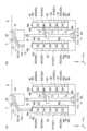
図1及び図2に示される搬送車システム1は、例えば半導体製造工場のクリーンルームにおいて、物品Mを搬送車3により搬送するためのグリッドシステムである。搬送車システム1は、軌道Rと、複数の搬送車3と、保管装置6と、システムコントローラ5と、を備える。複数の搬送車3は、クリーンルーム等の建屋の天井又は天井付近に敷設されている軌道Rを走行する。保管装置6は、軌道Rの下方に配置されており、物品Mを保管するストッカ60と、ストッカ60内で物品Mを移動させるスタッカクレーン(移載装置)70と、を有する。図5(A)に示されるように、ストッカ60は、Y方向に沿って走行するスタッカクレーン70の走行領域A1を挟むように配置された第一ラック61A及び第二ラック61Bによって構成されている。The
図1及び図2に示されるように、軌道Rは、天井に直接支持されてもよいし、天井に吊り下げられる部材等に支持されてもよい。軌道Rは、例えば、保管装置6、各種処理装置等に物品Mを搬送できるように設けられている。処理装置は、例えば、露光装置、コータディベロッパ、製膜装置、エッチング装置等である。物品Mは、例えば、半導体ウエハが収容された容器である。処理装置は、容器内の半導体ウエハに各種処理を施す。処理装置には、搬送車3との間で物品MをやりとりするロードポートP(図4参照)が設けられている。保管装置6は、搬送車3が搬送する物品Mを保管する。保管装置6には、搬送車3との間で物品Mをやりとりする入庫ポート(第一載置部)65A及び出庫ポート(第二載置部)65Bが設けられている。入庫ポート65A及び出庫ポート65Bについては、後段にて詳述する。As shown in Figs. 1 and 2, the track R may be supported directly on the ceiling or may be supported by a member suspended from the ceiling. The track R is provided so that the item M can be transported to, for example, a
軌道Rは、平面視で格子状に配置されている。軌道Rは、水平方向に沿って延び且つ天井等から吊り下げられたレールである。軌道Rは、複数の第一レールR1と、複数の第二レールR2と、複数の交差部R3と、を有する。以下、軌道Rを格子状軌道Rと称する。The track R is arranged in a lattice pattern in a plan view. The track R is a rail that extends horizontally and is suspended from a ceiling or the like. The track R has multiple first rails R1, multiple second rails R2, and multiple intersections R3. Hereinafter, the track R will be referred to as a lattice-shaped track R.
複数の第一レールR1は、それぞれX方向に沿って延在する。複数の第二レールR2は、それぞれY方向に沿って延在する。格子状軌道Rは、複数の第一レールR1と複数の第二レールR2とにより、平面視において格子状に形成されている。格子状軌道Rは、複数の第一レールR1と複数の第二レールR2とにより複数のマス目を形成する。交差部R3は、第一レールR1と第二レールR2とが交差する部分に配置される。交差部R3は、第一レールR1に対してX方向に隣り合うと共に第二レールR2に対してY方向に隣り合っている。交差部R3は、第一レールR1と第二レールR2との接続、第一レールR1同士の接続、第二レールR2同士の接続をする接続軌道である。交差部R3は、搬送車3が第一レールR1に沿って走行する際と、搬送車3が第二レールR2に沿って走行する際と、搬送車3が第一レールR1から第二レールR2又は第二レールR2から第一レールR1に走行する際と、の何れの際にも用いられる軌道である。The multiple first rails R1 each extend along the X direction. The multiple second rails R2 each extend along the Y direction. The lattice track R is formed in a lattice shape in a planar view by the multiple first rails R1 and the multiple second rails R2. The lattice track R forms multiple squares by the multiple first rails R1 and the multiple second rails R2. The intersection R3 is located at the portion where the first rail R1 and the second rail R2 intersect. The intersection R3 is adjacent to the first rail R1 in the X direction and adjacent to the second rail R2 in the Y direction. The intersection R3 is a connecting track that connects the first rail R1 and the second rail R2, connects the first rails R1 to each other, and connects the second rails R2 to each other. The intersection R3 is a track that is used when the
格子状軌道Rは、複数の第一レールR1と複数の第二レールR2とが直交する方向に設けられることで、平面視で複数のグリッドセル(セル)2が隣り合う状態となっている。一つのグリッドセル2は、一つのマス目に相当し、平面視において、Y方向に隣り合った二つの第一レールR1と、X方向に隣り合った二つの第二レールR2と、に囲まれた矩形領域である。なお、図1及び図2では格子状軌道Rの一部について示しており、格子状軌道Rは、図示している構成からX方向及びY方向に同様の構成が連続して形成されている。The lattice track R has multiple first rails R1 and multiple second rails R2 arranged in perpendicular directions, resulting in multiple grid cells (cells) 2 adjacent to each other in a planar view. One
第一レールR1、第二レールR2、及び交差部R3は、吊下部材Hによって不図示の天井に吊り下げ支持されている。吊下部材Hは、第一レールR1を吊り下げるための第一部分H1と、第二レールR2を吊り下げるための第二部分H2と、交差部R3を吊り下げるための第三部分H3と、を有する。第一部分H1及び第二部分H2は、それぞれ第三部分H3を挟んだ二か所に設けられている。The first rail R1, the second rail R2, and the intersection R3 are suspended from a ceiling (not shown) by a hanging member H. The hanging member H has a first portion H1 for suspending the first rail R1, a second portion H2 for suspending the second rail R2, and a third portion H3 for suspending the intersection R3. The first portion H1 and the second portion H2 are each provided at two locations on either side of the third portion H3.
第一レールR1、第二レールR2、及び交差部R3は、それぞれ、搬送車3の後述する走行車輪21が走行する走行面R1a,R2a,R3aを有する。第一レールR1と交差部R3との間、及び、第二レールR2と交差部R3との間には、それぞれ間隙が形成される。第一レールR1と交差部R3との間、及び、第二レールR2と交差部R3との間の間隙は、搬送車3が第一レールR1を走行して第二レールR2を横切る際、あるいは第二レールR2を走行して第一レールR1を横切る際に、搬送車3の一部である後述の第一連結部30(図3参照)が通過する部分である。従って、第一レールR1と交差部R3との間、及び、第二レールR2と交差部R3との間の間隙は、第一連結部30が通過可能な幅に設けられている。第一レールR1、第二レールR2、及び交差部R3は、同一の水平面に沿って設けられる。本実施形態において、第一レールR1、第二レールR2、及び交差部R3は、走行面R1a,R2a,R3aが同一の水平面上に配置される。The first rail R1, the second rail R2, and the intersection R3 each have a running surface R1a, R2a, and R3a on which the running
搬送車3は、搬送車システム1の軌道Rに沿って移動する。軌道Rは、搬送車3の走行路である。搬送車3は、搬送車システム1の軌道Rに沿って移動し、半導体ウエハを収容するFOUP、あるいはレチクルを収容するレチクルPod等の物品Mを搬送する。図1及び図5(A)に示されるように、本実施形態では、物品Mの一例として、一方向における一方の端部であって蓋が設けられる前面(第一端部)Mbと、一方向における他方の端部であって前面Mbとは形状が異なる背面(第二端部)Mcと、を有するFOUP(Front-Opening Unified Pod)が搬送される例を挙げて説明する。また、物品Mの底面には、後段にて詳述するピン(位置決め部材)66(図5(B)参照)に係合する複数の凹部が設けられている。物品Mの向きは、このようなピン66の配置に基づいて決定される。The
搬送車3の構成について説明する。図1~図4に示されるように、搬送車3は、格子状軌道Rに沿って走行可能に設けられている。搬送車3は、第一本体部10と、第一走行部20と、第一連結部30と、台車コントローラ(搬送車制御部)50と、を有する。台車コントローラ50は、システムコントローラ5と通信可能に設けられている。The configuration of the
第一本体部10は、格子状軌道Rの下方(-Z方向側)に配置される。第一本体部10は、平面視で例えば矩形状に形成される。第一本体部10は、平面視で格子状軌道Rにおける一つのグリッドセル2に収まる寸法に形成される。このため、隣り合う第一レールR1又は第二レールR2を走行する他の搬送車3とすれ違うことを可能とするスペースが確保される。第一本体部10は、上部ユニット17と、移載部18とを備える。上部ユニット17は、第一連結部30を介して第一走行部20から吊り下げられる。上部ユニット17は、例えば平面視で矩形状であり、上面17a及び下面17bに四つのコーナー部を有する。The
第一本体部10は、上面17aの四つのコーナー部のそれぞれに走行車輪21、第一連結部30、方向転換機構34を有する。この構成において、第一本体部10の上面17aの四つのコーナー部に配置された走行車輪21により、第一本体部10を安定して吊り下げ支持することができ、且つ、第一本体部10を安定して走行させることができる。The first
移載部18は、第一走行部20に対して水平方向に沿って移動し、処理装置におけるロードポートP及び保管装置6における入庫ポート65A及び出庫ポート65Bとの間で物品Mを移載する。移載部18は、上部ユニット17の下方に設けられている。移載部18は、Z方向の回動軸AX1周りに回動可能である。移載部18は、格子状軌道Rの下側で物品Mを保持する保持部13と、保持部13を鉛直方向に昇降させる昇降駆動部14と、昇降駆動部14を水平方向に沿って回動させる第一回動部(回動部)16と、昇降駆動部14を水平方向にスライド移動させるスライド部11と、スライド部11を保持する第二回動部12と、を有する。The
保持部13は、物品Mのフランジ部Maを保持(把持)することにより、物品Mを吊り下げて保持する。保持部13は、例えば、水平方向に移動可能な爪部13aを有するチャックであり、爪部13aを物品Mのフランジ部Maの下方に進入させ、保持部13を上昇させることで、物品Mを保持する。保持部13は、ワイヤあるいはベルト等の吊り下げ部材13bに接続されている。The holding
昇降駆動部14は、例えばホイストであり、吊り下げ部材13bを繰り出すことにより保持部13を下降させ、吊り下げ部材13bを巻き取ることにより保持部13を上昇させる。昇降駆動部14は、台車コントローラ50に制御され、所定の速度で保持部13を下降あるいは上昇させる。また、昇降駆動部14は、台車コントローラ50に制御され、保持部13を目標の高さに保持する。The lifting
第一回動部16は、スライド部11と昇降駆動部14との間に設けられる。第一回動部16は、回動部材16a及び回動駆動部16bを有する。回動部材16aは、Z方向の軸周り方向に回動可能に設けられる。回動部材16aは、昇降駆動部14を支持する。回動駆動部16bは、例えば電動モータ等が用いられ、回動部材16aを回動軸AX3の軸周り方向に回動させる。第一回動部16は、回動駆動部16bからの駆動力によって回動部材16aを回動させ、昇降駆動部14及び保持部13を回動軸AX3の軸周り方向に回動させることができる。The first
スライド部11は、例えばZ方向に重ねて配置された複数の可動板を有する。最下層の可動板には、昇降駆動部14が取り付けられている。スライド部11では、水平面内において搬送車3の走行方向と直角な方向に可動板が移動し、最下層の可動板に取り付けられた昇降駆動部14及び保持部13が搬送車3の走行方向と直角な方向に横出し(スライド移動)する。The
第二回動部12は、スライド部11と上部ユニット17との間に設けられる。第二回動部12は、回動部材12a及び回動駆動部12bを有する。回動部材12aは、Z方向の軸周り方向に回動可能に設けられる。回動部材12aは、スライド部11を支持する。回動駆動部12bは、例えば電動モータ等が用いられ、回動部材12aを回動軸AX1の軸周り方向に回動させる。第二回動部12は、回動駆動部12bからの駆動力によって回動部材12aを回動させ、スライド部11(昇降駆動部14及び保持部13)を回動軸AX1の軸周り方向に回動させることができる。搬送車3は、移載部18を用いることにより、ロードポートP、入庫ポート65A及び出庫ポート65Bに対して物品Mの受け渡しをすることができる。The second
なお、スライド部11が昇降駆動部14及び保持部13をスライド移動させていない状態において、回動軸AX1と回動軸AX3とは一致する。When the
搬送車3には、カバーWが設けられてもよい。カバーWは、移載部18及び移載部18に保持している物品Mを囲む。カバーWは、下端を開放した形状であって、且つ、スライド部11の可動板が突出する部分を切り欠いた形状を有している。カバーWは、上端が第二回動部12の回動部材12aに取り付けられており、回動部材12aの回動に伴って回動軸AX1の軸周りに回動する。The
第一走行部20は、走行車輪21及び補助車輪22を有する。走行車輪21は、上部ユニット17(第一本体部10)の上面17aの四つのコーナー部にそれぞれ配置される。走行車輪21のそれぞれは、第一連結部30に設けられた車軸に取り付けられている。走行車輪21のそれぞれは、走行駆動部33の駆動力により回転駆動する。走行車輪21のそれぞれは、格子状軌道R上を転動する。走行車輪21のそれぞれは、第一レールR1、第二レールR2、及び交差部R3の走行面R1a,R2a,R3aを転動し、搬送車3を走行させる。なお、四つの走行車輪21の全てが走行駆動部33の駆動力により回転駆動することに限定されず、四つの走行車輪21のうち一部について回転駆動させる構成であってもよい。The first running
走行車輪21は、回動軸AX2を中心としてθZ方向に回動可能に設けられている。走行車輪21は、後述する方向転換機構34によってθZ方向に回動し、その結果、搬送車3の走行方向を変更することができる。補助車輪22は、走行車輪21の走行方向の前後にそれぞれ一つずつ配置される。補助車輪22のそれぞれは、走行車輪21と同様に、XY平面に沿って平行又はほぼ平行な車軸の軸周りに回転可能である。補助車輪22の下端は、走行車輪21の下端より高くなるように設定されている。従って、走行車輪21が走行面R1a,R2a,R3aを走行しているときは、補助車輪22は、走行面R1a,R2a,R3aに接触しない。The running
また、第一レールR1と交差部R3との間、及び、第二レールR2と交差部R3との間の間隙を走行車輪21が通過する際には、補助車輪22が走行面R1a,R2a,R3aに接触して、走行車輪21の落ち込みを抑制している。なお、一つの走行車輪21に二つの補助車輪22,22を設けることに限定されず、例えば、一つの走行車輪21に一つの補助車輪22が設けられてもよいし、補助車輪22が設けられなくてもよい。In addition, when the running
第一連結部30は、第一本体部10の上部ユニット17と第一走行部20とを連結する。第一連結部30は、上部ユニット17(第一本体部10)の上面17aの四つのコーナー部にそれぞれ設けられている。この第一連結部30によって第一本体部10は、第一走行部20から吊り下げられた状態となり、格子状軌道Rよりも下方に配置される。第一連結部30は、支持部材31及び接続部材32を有する。支持部材31は、走行車輪21の回転軸及び補助車輪22の回転軸を回転可能に支持する。支持部材31は、走行車輪21と補助車輪22との相対位置を保持する。支持部材31は、例えば板状に形成され、第一レールR1と交差部R3との間、及び、第二レールR2と交差部R3との間の間隙を通過可能な厚さに形成される。The first connecting
接続部材32は、支持部材31から下方に延びて上部ユニット17の上面17aに連結され、上部ユニット17を保持する。接続部材32は、後述する走行駆動部33の駆動力を走行車輪21に伝達する伝達機構を内部に備える。この伝達機構は、チェーン又はベルトが用いられる構成であってもよいし、歯車列が用いられる構成であってもよい。接続部材32は、回動軸AX2を中心としてθZ方向に回動可能に設けられる。この接続部材32が回動軸AX2を中心として回動することで、支持部材31を介して走行車輪21を回動軸AX2周りのθZ方向に回動させることができる。The connecting
第一連結部30には、走行駆動部33及び方向転換機構34が設けられている。走行駆動部33は、接続部材32に装着される。走行駆動部33は、走行車輪21を駆動する駆動源であり、例えば電動モータ等が用いられる。四つの走行車輪21は、それぞれ走行駆動部33によって駆動される駆動輪である。四つの走行車輪21は、同一の単位時間あたりの回転数となるように台車コントローラ50によって制御される。The first connecting
方向転換機構34は、第一連結部30の接続部材32を、回動軸AX2を中心として回動させることにより、走行車輪21を回動軸AX2周りのθZ方向に回動させる。走行車輪21をθZ方向に回動させることにより、搬送車3の走行方向をX方向とする第一状態から走行方向をY方向とする第二状態に、又は走行方向をY方向とする第二状態から走行方向をX方向とする第一状態に切り替えることが可能である。方向転換機構34の回動により、上面17aの四つのコーナー部に配置された走行車輪21及び補助車輪22のそれぞれが回動軸AX2を中心としてθZ方向に90度の範囲で回動する。The
方向転換機構34の駆動は、台車コントローラ50によって制御される。走行車輪21及び補助車輪22を回動させることにより、走行車輪21が第一レールR1及び第二レールR2の一方に接触した状態から他方に接触した状態に移行する。このため、搬送車3の走行方向をX方向とする第一状態と、走行方向をY方向とする第二状態とで切り替えることができる。The driving of the
搬送車3は、Y方向に隣り合う一対の第一レールR1,R1を第一走行部20が走行することによりX方向に移動し、X方向に隣り合う一対の第二レールR2,R2を第一走行部20が走行することによりY方向に移動する。The
搬送車3は、位置情報を検出する位置検出部38を備える。位置検出部38は、位置情報を示す位置マーカ(図示せず)を検出することにより、搬送車3の現在位置を検出する。位置検出部38は、非接触により位置マーカを検出する。位置マーカは、格子状軌道Rの第一レールR1及び第二レールR2に設置される。The
台車コントローラ50は、搬送車3を統括的に制御する。台車コントローラ50は、CPU(Central Processing Unit)、ROM(Read Only Memory)及びRAM(Random Access Memory)等からなるコンピュータである。台車コントローラ50は、例えばROMに格納されているプログラムがRAM上にロードされてCPUで実行されるソフトウェアとして構成することができる。台車コントローラ50は、電子回路等によるハードウェアとして構成されてもよい。台車コントローラ50は、本実施形態では第一本体部10に設けられる例を示すが、第一本体部10の外部に設けられてもよい。The
台車コントローラ50は、搬送指令に基づいて、搬送車3の走行を制御する。台車コントローラ50は、走行駆動部33、方向転換機構34等を制御することにより、搬送車3の走行を制御する。台車コントローラ50は、例えば、走行速度、停止に関する動作、方向転換に関する動作を制御する。台車コントローラ50は、搬送指令に基づいて、搬送車3の移載動作を制御する。台車コントローラ50は、移載部18等を制御することにより、搬送車3の移載動作を制御する。台車コントローラ50は、所定のロードポートP及び出庫ポート65Bに配置されている物品Mを保持部13によって保持する(引き取る)荷つかみの動作、保持部13に保持する物品Mを所定のロードポートP及び入庫ポート65Aに下ろす(引き渡す)荷下ろしの動作を制御する。The
台車コントローラ50は、入庫ポート65Aと出庫ポート65Bとの間の停止位置(特定の停止位置)に停止させた状態で、保持部13が保持する物品Mを入庫ポート65Aに引き渡し、かつ出庫ポート65Bに載置された物品Mを受け取るように、第一走行部20、昇降駆動部14及びスライド部11を制御する。台車コントローラ50は、第一ラック61Aに物品Mを載置する際には、蓋がある前面Mbが第二ラック61Bを向くように第一回動部16を回動させ、第二ラック61Bに物品Mを載置する際には、蓋がある前面Mbが第一ラック61Aを向くように第一回動部16を回動させる。なお、台車コントローラ50は、各ラックに物品Mを載置する前に、上述したような前面Mbの向きとなっていた場合には、第一回動部16を回動させない。The
図1、図5(A)及び図5(B)に示されるように、保管装置6は、上述したようにストッカ60と、スタッカクレーン70と、を有する。ストッカ60には、搬送車3によって搬送されてきた物品Mが保管される。ストッカ60は、物品Mを水平方向及び鉛直方向に配列させた状態で保管する。本実施形態のストッカ60は、Y方向に沿って走行するスタッカクレーン70の走行領域A1を挟むように配置された第一ラック61A及び第二ラック61Bによって構成されている。第一ラック61A及び第二ラック61Bのそれぞれは、水平方向に5個の物品M、鉛直方向に6個の物品Mを配列させることができる5列6段の載置部を有する。載置部は、入庫ポート65A、出庫ポート65B及び保管部65Cから構成される。1, 5(A) and 5(B), the
スタッカクレーン70は、第一ラック61A及び第二ラック61Bに載置されている物品Mを、ストッカ60の内部で移動させる。すなわち、スタッカクレーン70は、第一ラック61Aの載置部同士での物品Mのやりとり、第二ラック61Bの載置部同士での物品Mのやりとり、第一ラック61Aの載置部と第二ラック61Bの載置部との間での物品Mのやりとりを行う。The
第一ラック61A及び第二ラック61Bのそれぞれは、フレーム62と、パネル63と、載置棚64と、を有する。フレーム62は、一方向に延在する部材であり、X方向、Y方向及びZ方向に沿って配置されており、パネル63と、載置棚64と、を支持する。パネル63は、第一ラック61A及び第二ラック61Bのそれぞれの一部を覆う板状の部材である。第一ラック61Aにおいて、スタッカクレーン70の走行領域A1に対向する側を前側としたとき、パネル63は、第一ラック61Aにおける後側と、第一ラック61Aのスタッカクレーン70の走行方向(Y方向)における両側と、に配置されている。すなわち、パネル63は、第一ラック61Aの後面(背面)及び側面を形成している。第二ラック61Bについても、第一ラック61Aと同様の位置にパネル63が配置される。Each of the
載置棚64は、物品Mが載置される部材であり、物品Mの載置部を構成する部材である。載置棚64は、物品Mの下面におけるY方向両端及びX方向後端を下方から支持可能に設けられている。すなわち、載置棚64に載置される物品Mは、支持部材によって物品Mの下面のY方向における両端及び後端が支持される。載置棚64には、物品Mを位置決めするためのピン(位置決め部材)66が設けられている。ピン66は、物品Mの背面に形成された凹部等に係合可能に形成された凸部である。The
本実施形態では、一つの物品Mを位置決めするための位置決め部材が、3つのピン66,66,66によって構成されている。3つのピン66,66,66に係合するように物品Mを載置棚64に載置すると、物品Mの前面Mbが前側を向く。このため、スタッカクレーン70の走行領域A1を挟んで対向するように配置される第一ラック61A及び第二ラック61Bに保管された物品Mは、前面Mbが互いに対向するような状態で載置棚64に載置されている。In this embodiment, the positioning member for positioning one item M is composed of three
載置棚64には、入庫用の載置部としての入庫ポート65Aと、出庫用の載置部としての出庫ポート65Bと、保管専用の載置部としての保管部65Cと、が設定される。入庫ポート65A及び出庫ポート65Bは、ラック61の最上段に設定される。本実施形態では、二個一組のラック61,61において、一方のラック61である第一ラック61Aの最上段に5個の入庫ポート65Aが設定され、他方のラック61である第二ラック61Bの最上段に5個の出庫ポート65Bが設定される。入庫ポート65Aと出庫ポート65Bとは、スタッカクレーン70の走行領域A1及び搬送車3の走行領域A2を挟んで、互いに対向するように設定される。なお、入庫ポート65A及び出庫ポート65Bは、ラック61の最上段に少なくとも一つ設定されておればよい。保管部65Cは、入庫ポート65A及び出庫ポート65Bの下方において、鉛直方向(Z方向)及び水平方向(Y方向)に複数配列される。The
スタッカクレーン70は、走行部71と、マスト72と、昇降部73と、移載部74と、クレーンコントローラ78と、を備える。クレーンコントローラ78は、システムコントローラ5と通信可能に設けられている。The
走行部71は、図示しない走行モータ及び昇降モータが配置されている。走行部71は、走行輪71Aを有し、地面に敷設された走行レールR4に沿って走行する。走行部71は、走行モータによって駆動する走行輪71Aが走行レールR4を転動することによって走行する。マスト72は、鉛直方向に延在する角筒部材であって、走行部71に立設されている。昇降部73は、マスト72の延在方向に沿って昇降可能に設けられている。昇降部73は、昇降モータによる駆動力によって昇降する。The running
移載部74は、昇降部73に設けられており、昇降部73と一体的に昇降可能に設けられている。移載部74は、載置棚64から物品Mを取り出すと共に、載置棚64に物品Mを載置する。より詳細には、移載部74は、入庫ポート65Aと保管部65Cとの間、互いに異なる保管部65C同士の間、及び保管部65Cと出庫ポート65Bとの間で物品Mをやりとりする。移載部74は、物品Mを下方から支持可能に形成されている。The
移載部74は、載置棚64によってY方向両端が支持された状態の物品MのY方向中央部近傍の下方に進出させると共に、載置棚64の切欠部64aを通って上方に移動させることによって物品Mを下方から支持し、載置棚64から物品Mを受け取る。移載部74は、物品MのY方向中央部近傍を下方から支持した状態の物品Mを載置棚64の上方に進出させると共に、載置棚64の切欠部64aを通って下方に移動させることによって物品Mの下面におけるY方向両端を載置棚64に支持させ、載置棚64に物品Mを引き渡す。The
クレーンコントローラ78は、システムコントローラ5からの命令によって、物品Mをストッカ60内で移動させる。例えば、システムコントローラ5からの命令によって、入庫ポート65Aに入庫された物品Mを所定の保管部65Cに移動させたり、所定の保管部65Cに保管されている物品Mを出庫ポート65Bに移動させたりする。The
システムコントローラ5は、複数の搬送車3、保管装置6と、を統括的に制御する。システムコントローラ5は、CPU、ROM及びRAM等からなるコンピュータである。システムコントローラ5は、例えばROMに格納されているプログラムがRAM上にロードされてCPUで実行されるソフトウェアとして構成することができる。システムコントローラ5は、電子回路等によるハードウェアとして構成されてもよい。The
システムコントローラ5は、物品Mの搬送先を指示する搬送指令を搬送車3に出力する。本実施形態のシステムコントローラ5は、搬送車3がストッカ60へ物品Mを入出庫させる場合、物品Mが載置された状態の出庫ポート65Bに対して搬送車3の走行領域A2を挟んで配置される入庫ポート65Aを搬送先とする搬送指令を搬送車3に出力する。搬送車3は、上記の搬送指令に基づいて軌道Rを走行し、入庫ポート65Aと出庫ポート65Bとの間の停止位置にまで移動する。停止位置に停止した搬送車3は、入庫ポート65Aに物品Mを引き渡し、出庫ポート65Bから物品Mを受け取る。なお、システムコントローラ5は、台車コントローラ50及びクレーンコントローラ78から定期的に送信されてくる搬送完了情報に基づいて、物品Mの在荷状況(各載置部における物品Mの有無)を監視している。The
次に、本実施形態の搬送車3がストッカ60へ物品Mを入出庫させる際の動作について、主に図7(A)~図10(B)を用いて説明する。Next, the operation of the
搬送車3がストッカ60へ物品Mを入出庫させる場合、システムコントローラ5は、物品Mが載置された状態の出庫ポート65Bに対して搬送車3の走行領域A2を挟んで配置される入庫ポート65Aを搬送先とする搬送指令を搬送車3に出力する。この搬送指令を受け取った搬送車3は、図7(A)に示されるように、物品Mを保持した状態で、入庫ポート65Aと出庫ポート65Bとの間の停止位置(特定の停止位置)に停止する。次に、搬送車3は、図7(B)に示されるように、スライド部11を駆動させ、第一ラック61Aの入庫ポート65Aの上方にまで保持部13を-X方向側に移動させる。次に、搬送車3は、図8(A)に示されるように、昇降駆動部14を駆動させ、保持部13を下降させることによって入庫ポート65Aに物品Mを載置する(引き渡す)。When the
次に、搬送車3は、図8(B)に示されるように、爪部13aによる物品Mの保持を開放し、昇降駆動部14を駆動させ、保持部13を入庫ポート65Aの上方に上昇させる。次に、搬送車3は、図9(A)に示されるように、スライド部11を駆動させ、第二ラック61Bの出庫ポート65Bの上方にまで+X方向側に保持部13を移動させる。次に、搬送車3は、図9(B)に示されるように、昇降駆動部14を駆動させ、保持部13を下降させる。Next, as shown in FIG. 8(B), the
次に、搬送車3は、図10(A)に示されるように、爪部13aによって物品Mを保持した状態で、昇降駆動部14を駆動させ、保持部13を出庫ポート65Bの上方に上昇させる。これにより、搬送車3は、出庫ポート65Bから物品Mを受け取る。次に、搬送車3は、図10(B)に示されるように、スライド部11を駆動させ、搬送車3が物品Mを保持した状態で搬送するときの所定位置にまで-X方向側に保持部13を移動させる。次に、搬送車3は、システムコントローラ5の命令にしたがって搬送先に移動する。Next, as shown in FIG. 10(A), while holding the item M with the
上記実施形態の搬送車システム1における作用効果について説明する。上記実施形態の搬送車システム1では、搬送車3は、物品Mを入庫させるための入庫ポート65Aに物品Mを入庫させた後、物品Mを出庫させるための出庫ポート65Bに移動することによって、搬送車3とストッカ60との間で入出庫を行うのではなく、特定の停止位置に停止させたまま、保持部13が保持する物品Mを入庫ポート65Aに引き渡し、かつ出庫ポート65Bに載置された物品Mを受け取るように、第一走行部20、昇降駆動部14及びスライド部11を制御している。これにより、搬送車3の移動を伴うことなくストッカ60へ物品Mが入庫され、更にストッカ60から物品Mが出庫される。この結果、搬送車3とストッカ60との間で効率的な物品の入出庫が可能となる。The effects of the
上記実施形態の搬送車システム1では、入庫ポート65A及び出庫ポート65Bは、鉛直方向上方から見た平面視において搬送車3の走行領域A2及びスタッカクレーン70の走行領域A1を挟んで配置されるように設定されている。更に、搬送車3がストッカ60に物品Mを入庫するときの搬送車3の停止位置(特定の停止位置)は、入庫ポート65Aと出庫ポート65Bとの間で設定されている。これにより、一方向に沿って物品Mを移動させる簡易なスライド部11の制御によってストッカ60へ物品Mを入出庫させることができる。In the
上記実施形態の搬送車システム1では、ストッカ60は、鉛直方向上方から見た平面視において搬送車3の走行領域A2及びスタッカクレーン70の走行領域A1を挟んで対向するように配置される第一ラック61A及び第二ラック61Bを有し、入庫ポート65Aは、第一ラック61Aに設定され、出庫ポート65Bは、第二ラック61Bに設定されている。更に、搬送車3がストッカ60に物品Mを入庫するときの搬送車3の停止位置(特定の停止位置)は、入庫ポート65Aと出庫ポート65Bとの間に設定されている。これにより、一方向に沿って物品Mを移動させる簡易なスライド部11の制御によってストッカ60へ物品Mを入出庫させることができる。In the
上記実施形態の搬送車システム1では、搬送車3が、保持部13を水平面内で回動させる第一回動部16を有している。これにより、対向配置された第一ラック61A及び第二ラック61Bにおいて、載置される物品Mの前面Mb同士が互いに向き合うように物品Mを位置決めするピン66が設けられている場合であっても、第一回動部16が保持部13を回動させることによって物品Mを所定の状態で引き渡したり、受け取ったりすることができる。この結果、載置部に載置されるときの物品Mの向きを調整する機構を保管装置側に設けなくてもよい。In the
上記実施形態の搬送車システム1では、軌道Rは、X方向に延在する複数の第一レールR1と、X方向と直交するY方向に延在する第二レールR2と、が格子状に配置されており、搬送車3は、Y方向に隣り合う一対の第一レールR1,R1を第一走行部20が走行することによりX方向に移動し、X方向に隣り合う一対の第二レールR2,R2を第一走行部20が走行することによりY方向に移動する。この構成では、より効率的な物品Mの入出庫が可能となる。In the
上記実施形態の搬送車システム1では、システムコントローラ5は、物品Mが載置された状態の出庫ポート65Bに対して搬送車3の走行領域A2を挟んで配置される入庫ポート65Aを搬送先とする搬送指令を搬送車に出力するので、入庫ポート65Aに物品Mを入庫させた後、確実に、出庫ポート65Bから物品Mを出庫させることができる。In the
以上、一実施形態について説明したが、本発明の一側面は、上記実施形態に限られない。発明の趣旨を逸脱しない範囲で種々の変更が可能である。Although one embodiment has been described above, one aspect of the present invention is not limited to the above embodiment. Various modifications are possible without departing from the spirit of the invention.
上記実施形態の搬送車システム1では、格子状に配置された軌道Rを搬送車3が走行する例を挙げて説明したが、これに限定されない。例えば、軌道Rは、一方向に延在しており、搬送車3は、当該軌道Rの延在方向に走行する構成の搬送車(OHT:Overhead Hoist Transfer)であってもよい。この場合であっても、搬送車3の走行領域A2を挟んで第一ラック61A及び第二ラック61Bを設置したり、搬送車3の走行領域A2に直交するように第一ラック61A及び第二ラック61Bを設置したりして、軌道Rの特定の停止位置を挟んだ状態となるように入庫ポート65A及び出庫ポート65Bを設定すればよい。この場合であっても、上記実施形態と同様の効果を享受できる。In the above embodiment of the
上記実施形態及び変形例の搬送車システム1では、ストッカ60が二つのラック(第一ラック61A及び第二ラック61B)によって構成されている例を挙げて説明したが、これに限定されない。例えば、ストッカ60は、一つのラック61によって構成されてもよいし、3つ以上のラック61によって構成されてもよい。In the above embodiment and modified example of the
例えば、ストッカ60が一つのラック61によって構成される場合、ラック61は、上方から見た平面視において、軌道Rの真下に軌道Rに沿って配置するか、軌道Rの下方において軌道Rと交差するように配置すればよい。「軌道Rの真下に軌道Rに沿って配置する」とは、上記実施形態のように格子状軌道Rを搬送車3が走行する場合には、ラック61の延在方向と、第一レールR1又は第二レールR2の延在方向とが一致するように(平行となるように)配置されること意味し、上記変形例のように一方向に延在する軌道Rに沿って搬送車3が走行する場合には、ラック61の延在方向と軌道Rの延在方向とが一致するように(平行となるように)配置されることを意味する。この場合、例えば、ラック61の上方の一箇所を特定の停止位置として設定すると共に、平面視において上記特定の停止位置を挟むように入庫ポート65Aと出庫ポート65Bとを設定すればよい。For example, when the
また、「軌道Rの下方において軌道Rと交差するように配置」とは、上記実施形態のように格子状軌道Rを搬送車3が走行する場合には、ラック61の延在方向と、第一レールR1及び第二レールR2延在方向の何れもが一致しない(平行とならないように)配置されること意味し、上記変形例のように一方向に延在する軌道Rに沿って搬送車3が走行する場合には、ラック61の延在方向と軌道Rの延在方向とが一致しないように(平行とならないように)配置されることを意味する。この場合、例えば、平面視においてラック61と軌道Rとの交差位置を特定の停止位置として設定すると共に、平面視において上記特定の停止位置を挟むように入庫ポート65Aと出庫ポート65Bとを設定すればよい。"Arranged so as to intersect with the track R below the track R" means that when the
上記実施形態及び変形例の搬送車システム1では、搬送車3がストッカ60へ物品Mを入出庫させる場合、スライド部11を駆動して第一本体部10から保持部13を水平方向に移動させた状態で入庫及び出庫を行う例を挙げて説明したがこれに限定されない。例えば、搬送車3がストッカ60へ物品Mを入庫させる場合には、スライド部11を駆動することなく保持部13を真下に下降させることによって行い、搬送車3がストッカ60から物品Mを出庫させる場合にのみ、第一本体部10から保持部13を水平方向に移動させた状態で行ってもよい。すなわち、搬送車3がストッカ60へ物品Mを入出庫させる場合、物品Mの入庫及び出庫の一方は、スライド部11を駆動して第一本体部10から保持部13を水平方向に移動させた状態で行うのではなく、真下に下降させることによって行ってもよい。In the above embodiment and modified example of the
上記実施形態及び変形例の搬送車システム1では、システムコントローラ5は、物品Mが載置された状態の出庫ポート65Bに対して搬送車3の走行領域A2を挟んで配置される入庫ポート65Aを搬送先とする搬送指令を搬送車3に出力する例を挙げて説明したが、これに限定されない。例えば、システムコントローラ5は、入庫ポート65Aを搬送先とする搬送指令を搬送車3に出力した後、スタッカクレーン70に対して、上記搬送先の入庫ポート65Aに対して搬送車3の走行領域A2を挟んで配置される出庫ポート65Bに他の載置部から物品Mを移動するように制御してもよい。In the above embodiment and modified example of the
上記実施形態及び変形例の搬送車システム1では、ラック61は、軌道Rの延在方向(X方向又はY方向)に揃えて配置される例を挙げて説明したが、軌道Rの延在方向に対して斜めに(角度を有した状態で)配置されてもよい。この場合であっても、搬送車3は、第二回動部12を駆動することによって、ラック61に構成される載置部に物品Mを載置することができる。In the above embodiment and modified example of the
1…搬送車システム、3…搬送車、5…システムコントローラ、6…保管装置、11…スライド部、13…保持部、14…昇降駆動部、16…第一回動部(回動部)、18…移載部、20…第一走行部(走行部)、50…台車コントローラ(搬送車制御部)、60…ストッカ、61…ラック、61A…第一ラック、61B…第二ラック、64…載置棚、65A…入庫ポート(第一載置部)、65B…出庫ポート(第二載置部)、65C…保管部、66…ピン(位置決め部材)、70…スタッカクレーン(移載装置)、M…物品、Ma…フランジ部、Mb…前面(第一端部)、Mc…背面(第二端部)、R…格子状軌道(軌道)R1…第一レール、R2…第二レール。1...Transport vehicle system, 3...Transport vehicle, 5...System controller, 6...Storage device, 11...Slide section, 13...Holding section, 14...Lifting drive section, 16...First rotation section (rotation section), 18...Transfer section, 20...First running section (running section), 50...Cart controller (Transport vehicle control section), 60...Storage, 61...Rack, 61A...First rack, 61B...Second rack, 64...Loading shelf, 65A...Storage port (first loading section), 65B...Outlet port (second loading section), 65C...Storage section, 66...Pin (positioning member), 70...Stacker crane (Transfer device), M...Item, Ma...Flange section, Mb...Front (first end), Mc...Back (second end), R...Grid track (track), R1...First rail, R2...Second rail.
Claims (6)
Translated fromJapanese前記搬送車は、
前記軌道を走行する走行部と、
前記物品を保持する保持部と、
前記走行部に対して前記保持部を昇降させる昇降駆動部と、
前記走行部に対して前記保持部及び前記昇降駆動部を水平方向に移動させるスライド部と、
前記搬送車を制御する搬送車制御部と、を有し、
前記保管装置は、
鉛直方向及び水平方向に配列される複数の載置部が配置されたラックを有するストッカと、
前記複数の載置部に対して前記物品を受け渡す移載装置と、を有し、
前記ラックの最上段に配置された前記複数の載置部の中には、少なくとも一つの入庫用の第一載置部と、少なくとも一つの出庫用の第二載置部と、が設定されており、
前記搬送車制御部は、特定の停止位置に停止させた状態で、前記保持部が保持する前記物品を前記第一載置部に引き渡し、かつ前記第二載置部に載置された前記物品を受け取るように、前記走行部、前記昇降駆動部及び前記スライド部を制御する、搬送車システム。A transport vehicle system including a transport vehicle that travels on a track installed on a ceiling of a building to transport an item, and a storage device that stores the item,
The transport vehicle is
A running unit that runs on the track;
A holding portion for holding the article;
a lifting drive unit that lifts and lowers the holding unit relative to the traveling unit;
a slide unit that moves the holding unit and the lift drive unit in a horizontal direction relative to the traveling unit;
A transport vehicle control unit that controls the transport vehicle,
The storage device includes:
a stocker having a rack on which a plurality of placement units are arranged in a vertical and horizontal direction;
A transfer device for transferring the article to the plurality of placement units,
Among the plurality of placement sections arranged on the top stage of the rack, at least one first placement section for receiving goods and at least one second placement section for retrieving goods are set,
The transport vehicle control unit controls the running unit, the lifting drive unit, and the slide unit so that, when stopped at a specific stopping position, the item held by the holding unit is transferred to the first loading unit, and the item placed on the second loading unit is received.
前記特定の停止位置は、前記平面視において前記第一載置部と前記第二載置部との間に設定されている、請求項1記載の搬送車システム。the first placement section and the second placement section are configured to be disposed on either side of a travel area of the transport vehicle in a plan view seen from above in a vertical direction,
The transport vehicle system according to claim 1 , wherein the specific stop position is set between the first platform and the second platform in the plan view.
前記第一載置部は、前記第一ラックに設定され、前記第二載置部は、前記第二ラックに設定され、
前記特定の停止位置は、前記平面視において前記第一載置部と前記第二載置部との間に設定されている、請求項1記載の搬送車システム。the stocker includes a first rack and a second rack that are arranged to face each other across a travel area of the transport vehicle in a plan view seen from above in a vertical direction,
The first placement section is set on the first rack, and the second placement section is set on the second rack,
The transport vehicle system according to claim 1 , wherein the specific stop position is set between the first platform and the second platform in the plan view.
前記物品は、一方向における一方の端部である第一端部と、前記一方向における他方の端部であり前記第一端部とは形状が異なる第二端部と、を有し、
前記ラックの前記載置部には、対向配置された前記ラックに載置される前記物品の前記第一端部同士が互いに向き合うように前記物品を位置決めする、位置決め部材が設けられており、
前記搬送車制御部は、前記第一載置部に前記物品を載置する際には、前記第一端部が前記第二ラックを向くように前記回動部を回動させる、請求項3記載の搬送車システム。The transport vehicle further includes a rotation unit that rotates the holding unit within a horizontal plane,
The article has a first end portion which is one end portion in one direction, and a second end portion which is the other end portion in the one direction and has a different shape from the first end portion,
a positioning member is provided in the placement portion of the rack to position the objects so that the first ends of the objects placed on the opposing racks face each other;
The transport vehicle system according to claim 3 , wherein the transport vehicle control unit rotates the rotating unit so that the first end faces the second rack when placing the item on the first placement unit.
前記搬送車は、前記第二方向に隣り合う一対の前記第一レールを前記走行部が走行することにより前記第一方向に移動し、前記第一方向に隣り合う一対の前記第二レールを前記走行部が走行することにより前記第二方向に移動する、請求項1~4の何れか一項記載の搬送車システム。The track includes a plurality of first rails extending in a first direction and arranged in a second direction perpendicular to the first direction, and a plurality of second rails extending in the second direction and arranged in the first direction, the plurality of first rails being arranged in a lattice pattern,
The transport vehicle moves in the first direction by the running part running on a pair of the first rails adjacent to each other in the second direction, and moves in the second direction by the running part running on a pair of the second rails adjacent to each other in the first direction.
前記システムコントローラは、前記物品が載置された状態の前記第二載置部に対して前記走行領域を挟んで配置される前記第一載置部を搬送先とする前記搬送指令を前記搬送車に出力する、請求項2又は3記載の搬送車システム。A system controller is further provided that outputs a transport command to the transport vehicle to indicate a destination of the article,
The transport vehicle system of claim 2 or 3, wherein the system controller outputs the transport command to the transport vehicle, specifying the first placement section, which is positioned across the running area from the second placement section on which the item is placed, as the destination.
Priority Applications (4)
| Application Number | Priority Date | Filing Date | Title |
|---|---|---|---|
| CN202380088864.0ACN120418169A (en) | 2022-12-27 | 2023-09-12 | Carrier system |
| JP2024567214AJPWO2024142502A1 (en) | 2022-12-27 | 2023-09-12 | |
| EP23911286.5AEP4624366A1 (en) | 2022-12-27 | 2023-09-12 | Conveyance vehicle system |
| KR1020257004682AKR20250038695A (en) | 2022-12-27 | 2023-09-12 | Return vehicle system |
Applications Claiming Priority (2)
| Application Number | Priority Date | Filing Date | Title |
|---|---|---|---|
| JP2022-209502 | 2022-12-27 | ||
| JP2022209502 | 2022-12-27 |
Publications (1)
| Publication Number | Publication Date |
|---|---|
| WO2024142502A1true WO2024142502A1 (en) | 2024-07-04 |
Family
ID=91717068
Family Applications (1)
| Application Number | Title | Priority Date | Filing Date |
|---|---|---|---|
| PCT/JP2023/033231PendingWO2024142502A1 (en) | 2022-12-27 | 2023-09-12 | Conveyance vehicle system |
Country Status (6)
| Country | Link |
|---|---|
| EP (1) | EP4624366A1 (en) |
| JP (1) | JPWO2024142502A1 (en) |
| KR (1) | KR20250038695A (en) |
| CN (1) | CN120418169A (en) |
| TW (1) | TW202440430A (en) |
| WO (1) | WO2024142502A1 (en) |
Citations (3)
| Publication number | Priority date | Publication date | Assignee | Title |
|---|---|---|---|---|
| JPH07323905A (en)* | 1994-06-03 | 1995-12-12 | Daifuku Co Ltd | Carrying device |
| JP3669057B2 (en) | 1996-06-03 | 2005-07-06 | アシスト シンコー株式会社 | Transport system to stocker |
| WO2018003287A1 (en)* | 2016-06-27 | 2018-01-04 | 村田機械株式会社 | Conveyance system |
- 2023
- 2023-09-12EPEP23911286.5Apatent/EP4624366A1/enactivePending
- 2023-09-12JPJP2024567214Apatent/JPWO2024142502A1/jaactivePending
- 2023-09-12KRKR1020257004682Apatent/KR20250038695A/enactivePending
- 2023-09-12WOPCT/JP2023/033231patent/WO2024142502A1/enactivePending
- 2023-09-12CNCN202380088864.0Apatent/CN120418169A/enactivePending
- 2023-10-12TWTW112138839Apatent/TW202440430A/enunknown
Patent Citations (3)
| Publication number | Priority date | Publication date | Assignee | Title |
|---|---|---|---|---|
| JPH07323905A (en)* | 1994-06-03 | 1995-12-12 | Daifuku Co Ltd | Carrying device |
| JP3669057B2 (en) | 1996-06-03 | 2005-07-06 | アシスト シンコー株式会社 | Transport system to stocker |
| WO2018003287A1 (en)* | 2016-06-27 | 2018-01-04 | 村田機械株式会社 | Conveyance system |
Non-Patent Citations (1)
| Title |
|---|
| See also references ofEP4624366A1 |
Also Published As
| Publication number | Publication date |
|---|---|
| TW202440430A (en) | 2024-10-16 |
| JPWO2024142502A1 (en) | 2024-07-04 |
| EP4624366A1 (en) | 2025-10-01 |
| KR20250038695A (en) | 2025-03-19 |
| CN120418169A (en) | 2025-08-01 |
Similar Documents
| Publication | Publication Date | Title |
|---|---|---|
| JP4967318B2 (en) | Stocker | |
| JP7211439B2 (en) | Conveyor system | |
| US20210057255A1 (en) | Automatic handling buffer for bare stocker | |
| KR101414530B1 (en) | Transporting vehicle system | |
| JP2009514235A (en) | Horizontal alignment stocker | |
| JP7347695B2 (en) | ceiling storage system | |
| JP7323059B2 (en) | carrier system | |
| KR101398929B1 (en) | Transporting vehicle system | |
| JP7740572B2 (en) | Rail-guided vehicle system | |
| WO2024142502A1 (en) | Conveyance vehicle system | |
| TWM605542U (en) | Wafer cassette stack device and wafer cassette conveying system | |
| JP2000124284A (en) | Transfer device | |
| JP7708328B2 (en) | Rail-guided vehicle system | |
| JP4030672B2 (en) | Cassette storage device | |
| WO2024070299A1 (en) | Overhead conveyance vehicle | |
| WO2024070303A1 (en) | Overhead conveyance vehicle | |
| WO2024070310A1 (en) | Overhead vehicle system | |
| TW202402640A (en) | Handling system | |
| KR20220026374A (en) | Transfer apparatus | |
| KR20070113850A (en) | Rack master, storage device equipped with the same and method of operation |
Legal Events
| Date | Code | Title | Description |
|---|---|---|---|
| 121 | Ep: the epo has been informed by wipo that ep was designated in this application | Ref document number:23911286 Country of ref document:EP Kind code of ref document:A1 | |
| ENP | Entry into the national phase | Ref document number:20257004682 Country of ref document:KR Kind code of ref document:A | |
| WWE | Wipo information: entry into national phase | Ref document number:1020257004682 Country of ref document:KR | |
| WWP | Wipo information: published in national office | Ref document number:1020257004682 Country of ref document:KR | |
| WWE | Wipo information: entry into national phase | Ref document number:2024567214 Country of ref document:JP Ref document number:202380088864.0 Country of ref document:CN | |
| WWE | Wipo information: entry into national phase | Ref document number:2023911286 Country of ref document:EP | |
| ENP | Entry into the national phase | Ref document number:2023911286 Country of ref document:EP Effective date:20250626 | |
| NENP | Non-entry into the national phase | Ref country code:DE | |
| WWP | Wipo information: published in national office | Ref document number:202380088864.0 Country of ref document:CN | |
| WWE | Wipo information: entry into national phase | Ref document number:11202504361R Country of ref document:SG | |
| WWP | Wipo information: published in national office | Ref document number:11202504361R Country of ref document:SG |