WO2024134751A1 - Guidewire - Google Patents
GuidewireDownload PDFInfo
- Publication number
- WO2024134751A1 WO2024134751A1PCT/JP2022/046822JP2022046822WWO2024134751A1WO 2024134751 A1WO2024134751 A1WO 2024134751A1JP 2022046822 WJP2022046822 WJP 2022046822WWO 2024134751 A1WO2024134751 A1WO 2024134751A1
- Authority
- WO
- WIPO (PCT)
- Prior art keywords
- section
- guidewire
- rear end
- coil
- core shaft
- Prior art date
- Legal status (The legal status is an assumption and is not a legal conclusion. Google has not performed a legal analysis and makes no representation as to the accuracy of the status listed.)
- Ceased
Links
Images


Classifications
- A—HUMAN NECESSITIES
- A61—MEDICAL OR VETERINARY SCIENCE; HYGIENE
- A61M—DEVICES FOR INTRODUCING MEDIA INTO, OR ONTO, THE BODY; DEVICES FOR TRANSDUCING BODY MEDIA OR FOR TAKING MEDIA FROM THE BODY; DEVICES FOR PRODUCING OR ENDING SLEEP OR STUPOR
- A61M25/00—Catheters; Hollow probes
- A61M25/01—Introducing, guiding, advancing, emplacing or holding catheters
- A61M25/09—Guide wires
- A61M2025/09058—Basic structures of guide wires
- A61M2025/09083—Basic structures of guide wires having a coil around a core
Definitions
- the present inventionrelates to a guidewire.
- Patent Document 1describes a guidewire in which the tip side of a core shaft made of a superelastic alloy is heat-treated.
- General guidewiresare sometimes "shaped" by bending the tip of the guidewire into a specific shape to fit the shape of blood vessels, etc.
- Guidewires that use a core shaft made of a superelastic materialhad room for improvement in "shaping performance,” which indicates the ease of shaping.
- shapeing performanceindicates the ease of shaping.
- hook shapingin which 1 to 2 millimeters of the tip of the guidewire are shaped into a hook at an angle of approximately 45 degrees.
- improvements in shaping performancewere required, there was also room for improvement in the durability of the guidewire against breakage, such as bending the guidewire while in use.
- the present inventionaims to provide a guidewire that has excellent shaping performance and durability, and can be easily shaped into a hook.
- the present inventionhas been made to solve at least some of the problems described above, and can be realized in the following form.
- One embodiment of the present inventionis a guidewire comprising a core shaft made of a superelastic material and a coil formed of strands wound in a spiral shape around the outer periphery of the tip of the core shaft, the core shaft having a first section on the inside of the coil, the first section being made of a thermally modified portion formed by thermally modifying the superelastic material, and a second section located on the rear end side of the first section, the second section either having a thermally modified portion of a shorter length than the first section or not having a thermally modified portion, and the coil having a sparsely wound section at the tip with gaps formed between adjacent strands.
- the provision of the first section consisting of a heat-modified portionsuppresses the superelastic properties of the core shaft, improving shaping performance. Furthermore, the provision of a sparsely wound portion at the tip of the coil improves the shaping performance at the tip of the guidewire. This makes it easy to give it a hook shape. Furthermore, the second section is provided with either a heat-modified portion that is shorter in length than the heat-modified portion at the tip, or a portion that is not heat-modified, thereby maintaining the superelasticity of the core shaft and the durability of the guidewire.
- the size of the gap between the wires of the sparsely wound portion in the longitudinal direction of the coilmay be equal to or greater than the outer diameter of the wires.
- the length of the fixing portioncan be shortened.
- the rear end of the first sectionmay be located rearward of the rear end of the openly coiled portion.
- a "body shape”When shaping a guidewire, a "body shape” may be applied, which is a gently curved shape.
- the first sectionwhich is made of a heat-denatured portion, extends over a wider area, making it easier to apply the body shape.
- the rear end of the first section and the rear end of the sparsely coiled sectionare located at different positions in the longitudinal direction, making it possible to make the change in bending rigidity of the guidewire more gradual.
- the rear end of the openly wound portionmay be located rearward of the rear end of the first section.
- the openly coiled portion at the tip sideextends over a wider range, making it easier to shape the body.
- the rear end of the openly coiled portion and the rear end of the first sectionare located at different positions in the longitudinal direction, making it possible to make the change in bending stiffness of the guidewire more gradual.
- the coilfurther has an openly wound portion at the rear end in which gaps are formed between adjacent strands of wire, and the size of the gaps between the strands of wire in the openly wound portion at the rear end in the longitudinal direction of the coil may be equal to or greater than the outer diameter of the strands of wire.
- the length of the fixing portioncan be shortened.
- the present inventioncan be realized in various forms, such as a guidewire, a method for manufacturing a guidewire, a method for manufacturing a catheter, an endoscope, a dilator, etc.
- FIG. 1is an explanatory diagram illustrating an example of an overall configuration of a guidewire according to a first embodiment
- 1is an explanatory diagram illustrating a longitudinal cross section of a distal end portion of a guidewire.
- FIG. FIG. 2is an explanatory diagram illustrating the AA cross section of the guidewire.
- 1is an explanatory diagram illustrating a longitudinal cross section of the distal end of a guidewire.
- FIG. 4is an explanatory diagram illustrating a vertical cross section of a rear end portion of the coil.
- FIG. 13is an explanatory diagram illustrating a longitudinal cross section of a distal end portion of a guidewire according to a third embodiment.
- FIG. 13is an explanatory diagram illustrating a longitudinal cross section of a distal end portion of a guidewire according to a fourth embodiment.
- FIG. 1is an explanatory diagram illustrating a hook-shaped tip of a guide wire.
- FIG. 13is an explanatory diagram illustrating a guide wire according to a first modified example.
- 13is an explanatory diagram illustrating a guide wire according to a fourth modified example.
- FIG. 13is an explanatory diagram illustrating a guide wire according to modification 8.
- the sizes of the components of the guidewire 1A of the first embodiment shown in Figures 1 to 6are illustrative and may be expressed on a scale different from the actual size.
- the end of each component of the guidewire 1A located on the tip sidewill be referred to as the "tip”, and the part including the “tip” and extending from the tip to the middle toward the rear end will be referred to as the "tip portion”.
- the end of each component located on the rear end sidewill be referred to as the "rear end”
- the part including the "rear end” and extending from the rear end to the middle toward the tip sidewill be referred to as the "rear portion”.
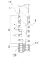
- FIG. 1is an explanatory diagram illustrating an overall view of a guidewire 1A of a first embodiment.
- the guidewire 1Ais a medical device used for treating blood vessels, etc.
- the guidewire 1Ahas a core shaft 10, a coil 20A, a tip fixing portion 30, and a rear end fixing portion 31.
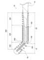
- FIG. 2is an explanatory diagram illustrating a longitudinal cross section of the tip of the guidewire 1A of the first embodiment.
- the core shaft 10is a long member extending from the tip to the rear end of the guidewire 1A.
- the core shaft 10is formed so that the outer diameter decreases toward the tip, and the tip has a straight section 11 with a substantially constant outer diameter in the longitudinal direction, and a tapered section 12 provided on the rear end side of the straight section 11. Details of the core shaft 10 will be described later.
- the core shaft 10is made of a superelastic material.
- the coil 20Ais a member formed of wire 21A wound in a spiral shape to cover the outer periphery of the tip of the core shaft 10.
- the coil 20Ahas, in order from the tip, a loosely wound section 22A, a densely wound section 23A, and a loosely wound section 24A.
- the densely wound section 23Ais a section with a small pitch where the wires 21A are wound so that they come into contact with each other.
- the loosely wound section 22A and the loosely wound section 24Ahave a larger pitch than the densely wound section 23A, and a gap G (FIGS. 4 and 5) is formed between adjacent wires 21A, as described below.
- the coil 20Ahas the densely wound section 23A and the loosely wound section 24A on the rear end side of the loosely wound section 22A, but the entire length of the coil 20A may be composed of the loosely wound section 22A. Alternatively, the entire rear end side of the coil 20A from the loosely wound section 22A may be the densely wound section 23A.
- the configuration of the loosely wound section 22A of the coil 20Ais not limited to the above example, and various modifications are possible. Details of openly wound portion 22A and openly wound portion 24A will be described later.
- the material of the coil 20Ais not particularly limited, but examples that can be used include stainless steel (SUS302, SUS304, SUS316, etc.), superelastic alloys such as Ni-Ti alloys, piano wire, nickel-chromium alloys, cobalt alloys, tungsten, platinum, etc.
- stainless steelSUS302, SUS304, SUS316, etc.
- superelastic alloyssuch as Ni-Ti alloys, piano wire, nickel-chromium alloys, cobalt alloys, tungsten, platinum, etc.
- the tip fixing part 30is a member that fixes the tip of the core shaft 10 and the tip of the coil 20A.
- the rear end fixing part 31is a member that fixes the middle part of the core shaft 10 and the rear end of the coil 20A.
- the tip fixing part 30 and the rear end fixing part 31are formed by applying molten brazing material or solder material to the core shaft 10 and the coil 20A and then cooling and solidifying them.
- the material of the tip fixing portion 30 and the rear end fixing portion 31is not particularly limited, but for example, solder material (aluminum alloy solder, silver solder, gold solder, etc.), metal solder (Ag-Sn alloy, Au-Sn alloy, etc.), adhesive (epoxy adhesive, etc.), etc. can be used.
- the core shaft 10has a first section S1 and a second section S2 inside the coil 20A.
- the first sectionextends from the tip of the core shaft 10 toward the rear end side, and is made of a heat-modified section 13A.
- the part of the core shaft 10 that is not heat-modified other than the heat-modified section 13Ais called the "non-heat-modified section 15A".
- the heat-modified section 13Ais a part in which the characteristics of the superelastic material forming the core shaft 10 are changed by heating the core shaft 10.
- the heat-modified section 13Ais a part in which the superelastic characteristics of the core shaft 10 are suppressed more than those of the non-heat-modified section 15A.
- the rear end 14A (rear end of the heat-modified section 13A) of the first section S1indicates the boundary between the heat-modified section 13A and the non-heat-modified section 15A.
- the rear end 14A of the first section S1is located on the rear end side of the rear end 25A of the loosely wound section 22A described later.
- the rear end 14A of the first section S1 and the rear end 25A of the open coil portion 22A on the tip sideare provided at different positions in the longitudinal direction of the core shaft 10.
- the length in the longitudinal direction from the tip to the rear end 14A of the first section S1is shown as Ls1.
- the length Ls1 of the first sectionis not particularly limited, but may be, for example, 2 to 7 millimeters.
- the second section S2is located inside the coil 20A and is located closer to the rear end than the first section S1.
- the second section S2does not have a thermally denatured portion 13A and is formed only by a non-thermally denatured portion 15A.
- the second section S2does not have a thermally denatured portion 13A, but the second section S2 may have a thermally denatured portion 13A formed therein as in the second embodiment described below.
- the length in the major axis direction of the thermally denatured portion 13A formed in the second section S2is shorter than the length of the thermally denatured portion 13A in the first section S1.
- the method for producing the thermally modified portion 13Ais not particularly limited, but for example, the thermally modified portion 13A can be formed by irradiating the surface of the core shaft 10 with a laser to heat the core shaft 10 to approximately 600 degrees to approximately 1000 degrees.
- FIG. 3is an explanatory diagram illustrating an example of an A-A cross section of the guide wire 1A of the first embodiment.
- the straight portion 11 of the core shaft 10is formed by a plane 16, a plane 17 facing the plane 16, and a curved surface 18 and a curved surface 19 connecting the planes 16 and 17.
- the cross section of the straight portion 11has a flat shape that extends long in a predetermined direction.
- the length of the cross section of the straight portion 11 in the direction Dx parallel to the plane 16is greater than the length of the direction Dy perpendicular to the plane 16.
- the straight portion 11is more likely to bend depending on the direction of the stress to which the straight portion 11 is subjected.
- the straight portion 11is more likely to bend when stress is applied to the straight portion 11 in the direction Dy perpendicular to the plane 16 than when stress is applied to the straight portion 11 in the direction Dx parallel to the plane 16.
- the length of the straight portion 11 in the longitudinal direction of the guide wire 1Ais not particularly limited, but can be, for example, 10 to 20 millimeters.
- the cross section of the tapered portion 12 and the portion of the core shaft 10 rearward of the tapered portion 12are circular.
- the method for producing the straight section 11is not particularly limited, but for example, it can be produced by pressing the tip of the core shaft 10, which is formed into a cylindrical shape, using a die with a flat surface.
- ⁇ Details of the open coil portion 22A on the tip side> 4is an explanatory diagram illustrating a longitudinal section of the tip of the guidewire 1A of the first embodiment.
- the openly coiled portion 22Awill be described in detail.
- the coil 20Ahas an openly coiled portion 22A in which a gap G is provided between adjacent wires 21A among the wires 21A wound in a spiral shape.
- the openly coiled portion 22Ais formed from the tip to the rear end side of the coil 20A, and its tip is embedded in the tip fixing portion 30.
- the rear end 25A of the openly coiled portion 22Aindicates the boundary between the openly coiled portion 22A and the densely coiled portion 23A.
- the length of the openly coiled portion 22A in the major axis directionis not limited, but can be, for example, about 0.5 to 2 millimeters.
- the size Lg of the gap G between the wires 21Ais equal to or larger than the outer diameter D of the wire 21A.
- the outer diameter D of the wire 21Arefers to the size of the wire 21A in the long axis direction of the coil 20A.
- the outer diameter D of the wire 21Ais defined as "the size in the long axis direction of the part of the wire 21A that is the largest in the long axis direction of the coil 20A.” In other words, the outer diameter D is the maximum outer diameter of the wire 21A.
- the configuration in which the size Lg of the gap G and the outer diameter D of the wire 21A are approximately the samecan be rephrased as a configuration in which the pitch of the openly wound portion 22A is approximately 200% when the pitch of the densely wound portion 23A, in which the wires 21A are wound so as to be in contact with each other, is 100%. Therefore, "the size Lg of the gap G is equal to or larger than the outer diameter D of the wire 21A" can be rephrased as "the pitch of the openly wound portion 22A is 200% or more when the pitch of the densely wound portion 23A is 100%.
- FIG. 5is an explanatory diagram illustrating a longitudinal section of the rear end of the coil 20A of the guide wire 1A of the first embodiment. The details of the openly coiled portion 24A will be described.
- the openly coiled portion 24Ais formed at the rear end of the coil 20A.
- the openly coiled portion 24Ais formed from the rear end of the coil 20A toward the tip end, and the rear end is embedded in the rear end fixing portion 31.
- a gap Gis formed between adjacent wires 21A, similar to the openly coiled portion 22A formed at the tip end described above.
- the length of the openly coiled portion 24A in the major axis directionis not limited, but can be, for example, about 0.5 to 2 millimeters.
- the pitch size of the densely coiled portion 23Ais 100%
- the pitch size of the openly coiled portion 24A described in FIG. 5is 200% or more.
- the size Lg of the gap G between the open coiled portion 22A and the open coiled portion 24Ais set to be equal to or larger than the outer diameter D of the wire 21A, but the size Lg of the gap G between the open coiled portion 22A and the open coiled portion 24A may be smaller than the outer diameter D of the wire 21A.
- the pitch of the densely coiled portion 23Ais set to 100%
- the size of the pitch of the open coiled portion 22A and the open coiled portion 24Acan be set to approximately 150% to 500%.
- the size of the pitch of the open coiled portion 22A and the open coiled portion 24Ais set to approximately 150% or more, adjacent wires 21A are sufficiently separated, and the thermal conductivity between the wires 21A is reduced.
- the amount of molten brazing material or solder material that flows along the wire 21A in the longitudinal directioncan be reduced.
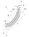
- FIG. 6is an explanatory diagram illustrating the shaped tip of guidewire 1A.
- the hook-shaped shape of about 1 to 2 mm of the tip of guidewire 1A at an angle of about 45 degreesis called “hook shape”
- the gently curved shape of about 20 mm of the tip of guidewire 1Ais called “body shape”.
- the hook-shaped partis shown as hook-shaped part Sa
- the body-shaped partis shown as body-shaped part Sb.
- Hook-shaped part Sais a part where heat-modified part 13A and loosely wound part 22A overlap.
- Heat-modified part 13Ais also provided in body-shaped part Sb.
- the cross section of straight part 11has a flat shape, it has a direction that is easy to bend.
- guidewire 1Ahas a part that is easiest to shape at the tip, and a part that is easy to shape is also provided on the rear end side of the tip. In other words, the ease of shaping of the guidewire 1A changes stepwise from the tip to the rear end.
- the guidewire 1Ahas a first section S1 consisting of a thermally modified portion 13A.
- the thermally modified portion 13Ahas reduced superelastic properties compared to the non-thermally modified portion 15A, so the force that tries to return to the original shape when deformed is reduced. This makes it easy to shape the guidewire 1A in the intended direction.
- the guidewire 1Ahas a sparsely wound portion 22A, and the size Lg of the gap G between adjacent strands 21A is equal to or larger than the outer diameter D of the strands 21A.
- the pitch of a coil in a typical guidewireis about 100% to about 120%
- the pitch of the sparsely wound portion 22Ais wider than 200%. Since adjacent strands 21A in the sparsely wound portion 22A are sufficiently spaced apart, the thermal conductivity between the strands 21A is reduced. As a result, when a brazing material or solder material is used in the tip fixing portion 30, the amount of molten brazing material or solder material that flows along the strands 21A in the longitudinal direction can be reduced.
- the length of the tip fixing portion 30 in the longitudinal directioncan be shortened, and the flexibility of the tip of the guidewire 1A can be improved.
- the tip of the guidewire 1Acan be made flexible, making it easier for the user of the guidewire 1A to shape it in the direction intended.
- the length of the loosely coiled portion 22A in the longitudinal directionis about 1 to 2 millimeters, it becomes easy to form a hook shape of about 1 to 2 millimeters.
- the rear end 14A of the first section S1is located rearward of the rear end 25A of the loosely wound portion 22A. This allows the portion of the core shaft 10 that is easy to shape to be more widely arranged, making it easier to perform body shaping. For example, by setting the longitudinal length Ls1 (FIG. 2) of the first section S1 to about 20 millimeters, it becomes easy to perform body shaping of about 20 millimeters. By performing body shaping, even when the guide wire 1A is inserted into a branching portion of a blood vessel with a large blood vessel diameter (for example, a blood vessel with a diameter of about 2 to 10 millimeters), the user of the guide wire 1A can easily advance the guide wire 1A in the intended direction.
- a large blood vessel diameterfor example, a blood vessel with a diameter of about 2 to 10 millimeters
- the heat-denatured portion 13Ais provided at the tip portion of the body shaping portion Sb, which is more likely to deform when shaping, making body shaping easier.
- the length of the second section S2becomes relatively longer, improving the durability of the core shaft 10 against bending and breaking, making it easier to achieve both shaping performance and durability.
- the rear end 14A of the first section S1is positioned rearward of the rear end 25A of the sparsely wound portion 22A, the rear end 14A of the first section S1 and the rear end 25A of the sparsely wound portion 22A on the tip side are located at different positions in the longitudinal direction of the core shaft 10.
- the change in bending rigidity of the core shaft 10 at the boundary between the thermally modified portion 13A and the non-thermally modified portion 15A and the change in bending rigidity of the coil 20A at the boundary between the sparsely wound portion 22A and the densely wound portion 23A (rear end 15A of the sparsely wound portion 22A)occur at different positions. This makes it possible to suppress a sudden change in bending rigidity in the longitudinal direction of the guidewire 1A.
- the second section S2does not have a heat-modified portion 13A, and is formed only from a non-heat-modified portion 15A. This allows the superelastic properties of the core shaft 10 to be maintained in the second section S2, and prevents the guidewire 1A from unintentionally breaking or bending. As a result, the shaping performance of the guidewire 1A can be improved, and the durability of the guidewire 1A can be increased.
- the coil 20Ahas a sparsely wound portion 24A at the rear end, and the size Lg of the gap G between adjacent wires 21A is equal to or larger than the outer diameter D of the wires 21A. While the coil pitch of a typical guidewire is 100% to 120%, the pitch of the sparsely wound portion 24A is expanded to 200% or more. As a result, similar to the sparsely wound portion 22A described above, the adjacent wires 21A are sufficiently spaced apart in the sparsely wound portion 24A, so that the thermal conductivity between the wires 21A is reduced.
- the longitudinal length of the rear end fixing portion 31can be shortened, and the flexibility of the guidewire 1A can be improved. This makes it possible to suppress an increase in bending stiffness occurring near the rear end fixing part 31 of the guidewire 1A, and reduces the possibility of breakage, such as bending or bending, of the guidewire 1A occurring near the rear end fixing part 31.
- the cross section of the straight portion 11 of the core shaft 10has a flattened shape that extends long in a predetermined direction. As a result, the straight portion 11 bends in a different direction depending on the direction of the stress it receives.
- the straight portion 11bends in the direction in which it bends easily, so that the guidewire 1A can be bent uniformly in a certain direction. In this embodiment, it is easy to bend and shape the tip of the guidewire 1A uniformly in the Dy direction shown in FIG. 3.
- the bendabilityis constant regardless of the direction, so it is difficult to bend the guidewire 1A uniformly in a certain direction, and there is a high possibility that the guidewire 1A will be shaped so as to be twisted.
- Second Embodiment 7is an explanatory diagram illustrating a longitudinal cross section of a distal end portion of a guidewire 1B of the second embodiment.
- the guidewire 1Bis different from the guidewire 1A of the first embodiment in that a thermally denatured portion 13B is provided in the second section S2. Description of the configuration of the guidewire 1B that is common to the guidewire 1A will be omitted.
- a thermally denatured portion 13Bis provided in a portion of the second section S2, and a non-thermally denatured portion 15B is provided in the portion other than the thermally denatured portion 13B.
- the length Ls2 in the long axis direction of the thermally denatured portion 13B provided in the second section S2is shorter than the length Ls1 in the long axis direction of the first section S1.
- the longitudinal length Ls2 of the thermally modified portion 13B provided in the second section S2is shorter than the longitudinal length Ls1 of the first section S1, thereby improving the durability of the core shaft 10 against breaking or bending.
- Third Embodiment 8is an explanatory diagram illustrating a longitudinal cross section of a distal end portion of a guidewire 1B of the third embodiment.
- the guidewire 1Cis different from the guidewire 1A of the first embodiment in that a rear end 25C of the openly coiled portion 22C is located further rearward than a rear end 14C of the first section S1.
- a description of the configuration of the guidewire 1C that is common to the guidewire 1Awill be omitted.
- the guidewire 1Cis easy to shape the body because the openly coiled portion 22C extends further toward the rear end and is provided over a wide range. Also in this embodiment, the rear end 14C of the first section S1 and the rear end 25C of the openly coiled portion 22C on the tip side are provided at different positions in the longitudinal direction of the core shaft 10. This makes it possible to suppress a sudden change in bending rigidity that occurs when the position where the bending rigidity of the core shaft 10 changes overlaps with the position where the bending rigidity of the coil 20C changes.
- Fourth Embodiment 9is an explanatory diagram illustrating a longitudinal cross section of a distal end portion of a guidewire 1D of the fourth embodiment.
- the guidewire 1Dis different from the guidewire 1A of the fourth embodiment in that a rear end 14D of the first section S1 and a rear end 25D of the openly coiled portion 22D are located at substantially the same position in the longitudinal direction of the coil 20C. Description of the configuration of the guidewire 1D that is common to the guidewire 1A will be omitted.
- the heat-modified portion 13D and the loosely wound portion 22Amake it easy to form a hook shape. Even in a configuration in which the heat-modified portion 13D does not extend further rearward than the rear end 25D of the loosely wound portion 22D as in this embodiment, the core shaft 10 has a straight portion 11 with a flattened cross-sectional shape, making it easy to give it a body shape. Furthermore, by setting the heat-modified portion 13D to be short, it is possible to ensure a wider range over which the durability of the core shaft 10 is maintained.
- FIG. 10is an explanatory diagram illustrating the tip of the guidewire 1D of the fourth embodiment that has been hook-shaped.
- the portion that has been given the hook shapeis shown as the hook-shaped portion Sa.
- the portion where the thermally denatured portion 13D and the loosely wound portion 22D are overlappingis easy to shape, so that the hook shape can be easily formed.
- FIG. 11is an explanatory diagram illustrating a guidewire 1E of the first modification.
- the guidewire 1Eis different from the guidewires of the respective embodiments in the position of the rear end 14E of the first section S1.
- the rear end 14A of the first section S1is located rearward of the rear end 25E of the openly coiled section 22A, and is formed over the entire length of the straight section 11.
- the rear end 14E of the first section S1may be located rearward of the rear end 25E of the openly coiled section 22E, and may be provided in the middle of the straight section 11.
- the hook shapecan be easily formed by the thermally modified section 13E and the openly coiled section 22E.
- the straight section 11can uniformly form the body shape in a predetermined direction. Furthermore, by setting the thermally modified section 13E to be short, the durability of the core shaft 10 can be maintained over a wider range.
- the first section S1is formed from the tip of the core shaft 10 toward the rear end, but it does not have to be formed from the tip of the core shaft 10.
- the first section S1only needs to be formed inside the coil (20A, 20B, 20C, 20D), and for example, the tip of the first section S1 may be provided on the rear end side of the tip of the core shaft 10.
- the first section S1 and the second section S2may have a portion in which the characteristics of the core shaft 10 are changed other than the thermally modified portions (13A, 13B, 13C, 13D).
- a portion in which the surface state of the core shaft 10 is changed by electrolytic polishing, shot peening, or the likemay be provided.
- ⁇ Modification 4> 12is an explanatory diagram illustrating a guidewire 1F of Modification 4.
- the guidewire 1Fhas a plurality of thermally denatured portions 13F in the second section S2. As in the guidewire 1F, two thermally denatured portions 13F may be provided in the second section S2.
- the cross section of the wires (21A, 21B, 21C, 21D)is circular, but it may be rectangular, such as square or oblong.
- the coils (20A, 20B, 20C, 20D)are formed of one wire (21A, 21B, 21C, 21D), but the coils may be formed by winding a plurality of wires (21A, 21B, 21C, 21D) in a spiral shape.
- the outer diameter D of the wire (21A, 21B, 21C, 21D)refers to the outer diameter D of the wire that has the largest outer diameter D among the plurality of wires (21A, 21B, 21C, 21D).
- the coils (20A, 20B, 20C, 20D)may be formed by bundling a plurality of wires (21A, 21B, 21C, 21D) to form a strand, and then winding the strand in a spiral shape.
- the gap between adjacent strandsis defined as gap G
- the outer diameter of the strandis defined as the outer diameter D of the wire (21A, 21B, 21C, 21D).
- FIG. 13is an explanatory diagram illustrating a guidewire 1G of the eighth modified example.
- the guidewire 1Ghas a plurality of coils (20G, 40).
- the outer periphery of the core shaft 10is covered with only one coil (20A, 20B, 20C, 20D), but another coil 40 may be provided on the outer periphery of the coil (20A, 20B, 20C, 20D).
- the outer periphery of the coil 20G that covers the outer periphery of the core shaft 10is further covered with a coil 40.
- the coil 40is formed by spirally winding a wire 41 that is different from the wire 21G that constitutes the coil 20G.
- the straight portion 11has a flat shape and is formed by the plane 16, the plane 17 opposite to the plane 16, the curved surface 18 connecting the plane 16 and the plane 17, and the curved surface 19.
- the straight portion 11does not have to be formed by the plane 16, the plane 17, the curved surface 18, and the curved surface 19.
- the straight portion 11may be formed by four planes, and in this case, the straight portion 11 can be made into a flat shape by adjusting the width of any plane.
- the straight portion 11does not have to be flat, and may be, for example, rectangular such as a square or a rectangle, or circular in cross section.
- the tapered portion 12 and the rear end side portion of the core shaft 10may be flattened.
Landscapes
- Health & Medical Sciences (AREA)
- Life Sciences & Earth Sciences (AREA)
- Biophysics (AREA)
- Pulmonology (AREA)
- Engineering & Computer Science (AREA)
- Anesthesiology (AREA)
- Biomedical Technology (AREA)
- Heart & Thoracic Surgery (AREA)
- Hematology (AREA)
- Animal Behavior & Ethology (AREA)
- General Health & Medical Sciences (AREA)
- Public Health (AREA)
- Veterinary Medicine (AREA)
- Media Introduction/Drainage Providing Device (AREA)
Abstract
Description
Translated fromJapanese本発明は、ガイドワイヤに関する。The present invention relates to a guidewire.
従来から、超弾性合金からなるコアシャフトを用いた医療用のガイドワイヤが知られている。特許文献1には、超弾性合金からなるコアシャフトの先端側に熱処理を施したガイドワイヤが記載されている。Medical guidewires using a core shaft made of a superelastic alloy have been known for some time.
一般的なガイドワイヤは、血管などの形状に適合させるためにガイドワイヤの先端部を所定の形状に曲げる「シェイピング」が施されることがある。超弾性材料のコアシャフトを用いたガイドワイヤには、シェイピングの容易さを表す「シェイピング性能」について改善の余地があった。特に、ガイドワイヤ先端の1から2ミリメートルを約45度の角度に鉤状の形状付けをする「鉤シェイプ」の容易さが求められていた。さらに、シェイピング性能の改善が求められる一方で、ガイドワイヤの使用中にガイドワイヤが折れ曲がるような破損に対する耐久性についても向上の余地があった。General guidewires are sometimes "shaped" by bending the tip of the guidewire into a specific shape to fit the shape of blood vessels, etc. Guidewires that use a core shaft made of a superelastic material had room for improvement in "shaping performance," which indicates the ease of shaping. In particular, there was a need for ease of "hook shaping," in which 1 to 2 millimeters of the tip of the guidewire are shaped into a hook at an angle of approximately 45 degrees. Furthermore, while improvements in shaping performance were required, there was also room for improvement in the durability of the guidewire against breakage, such as bending the guidewire while in use.
本発明は、シェイピング性能および耐久性に優れたガイドワイヤであって、鉤シェイプを容易に行うことができるガイドワイヤの提供を目的とする。The present invention aims to provide a guidewire that has excellent shaping performance and durability, and can be easily shaped into a hook.
本発明は、上述の課題の少なくとも一部を解決するためになされたものであり、以下の形態として実現することが可能である。The present invention has been made to solve at least some of the problems described above, and can be realized in the following form.
(1)本発明の一形態は、ガイドワイヤであって、超弾性材料からなるコアシャフトと、コアシャフトの先端部の外周に螺旋状に巻かれた素線により形成されたコイルと、を備え、コアシャフトは、コイルの内側に位置する部分に、超弾性材料が熱変成された熱変性部からなる第1区間と、第1区間の後端側に位置する第2の区間とを有し、第2の区間では、第1区間よりも短い長さの熱変性部が形成され、または、熱変性部が形成されておらず、コイルは、先端部に、互いに隣接する素線同士の間に隙間が形成された疎巻き部を有している。(1) One embodiment of the present invention is a guidewire comprising a core shaft made of a superelastic material and a coil formed of strands wound in a spiral shape around the outer periphery of the tip of the core shaft, the core shaft having a first section on the inside of the coil, the first section being made of a thermally modified portion formed by thermally modifying the superelastic material, and a second section located on the rear end side of the first section, the second section either having a thermally modified portion of a shorter length than the first section or not having a thermally modified portion, and the coil having a sparsely wound section at the tip with gaps formed between adjacent strands.
この構成によれば、熱変性部からなる第1区間が設けられていることによりコアシャフトの超弾性の特性が抑制され、シェイピング性能が向上する。さらに、コイルの先端部に疎巻き部が設けられていることにより、ガイドワイヤの先端部のシェイピング性能が向上する。これらにより、鉤シェイプを容易に付けることができる。また、第2区間では、先端側の熱変性部よりも長さが短い熱変性部か、熱変性されていない部分が設けられていることにより、コアシャフトの超弾性が維持され、ガイドワイヤの耐久性を維持することができる。With this configuration, the provision of the first section consisting of a heat-modified portion suppresses the superelastic properties of the core shaft, improving shaping performance. Furthermore, the provision of a sparsely wound portion at the tip of the coil improves the shaping performance at the tip of the guidewire. This makes it easy to give it a hook shape. Furthermore, the second section is provided with either a heat-modified portion that is shorter in length than the heat-modified portion at the tip, or a portion that is not heat-modified, thereby maintaining the superelasticity of the core shaft and the durability of the guidewire.
(2)上記形態のガイドワイヤにおいて、コイルの長軸方向における、疎巻き部の素線同士の間の隙間の大きさは、素線の外径以上であってもよい。(2) In the above-described guidewire configuration, the size of the gap between the wires of the sparsely wound portion in the longitudinal direction of the coil may be equal to or greater than the outer diameter of the wires.
この構成によれば、例えばロウ材やはんだ材などにより形成された固定部を先端側の疎巻き部に設けてコアシャフトとコイルを固定する場合に、固定部分の長さを短くすることができる。With this configuration, for example, when a fixing portion made of brazing material or solder material is provided on the open winding portion at the tip side to fix the core shaft and the coil, the length of the fixing portion can be shortened.
(3)上記形態のガイドワイヤにおいて、第1区間の後端は、疎巻き部の後端よりも後端側に位置してもよい。(3) In the above-described guidewire configuration, the rear end of the first section may be located rearward of the rear end of the openly coiled portion.
ガイドワイヤに形状付けを行う場合には、緩やかな曲線状に形状付けされる「ボディシェイプ」が付けられることがある。この構成によれば、熱変性部からなる第1区間がより広い範囲に延びていることにより、ボディシェイプを付けることが容易となる。また、第1区間の後端と疎巻き部の後端が長軸方向において異なる位置に設けられていることにより、ガイドワイヤの曲げ剛性の変化を緩やかにすることができる。When shaping a guidewire, a "body shape" may be applied, which is a gently curved shape. With this configuration, the first section, which is made of a heat-denatured portion, extends over a wider area, making it easier to apply the body shape. In addition, the rear end of the first section and the rear end of the sparsely coiled section are located at different positions in the longitudinal direction, making it possible to make the change in bending rigidity of the guidewire more gradual.
(4)上記形態のガイドワイヤにおいて、疎巻き部の後端は、第1区間の後端よりも後端側に位置してもよい。(4) In the above-described guidewire configuration, the rear end of the openly wound portion may be located rearward of the rear end of the first section.
この構成によれば、先端側の疎巻き部がより広い範囲に延びていることにより、ボディシェイプを付けることが容易となる。また、疎巻き部の後端と第1区間の後端が長軸方向において異なる位置に設けられていることにより、ガイドワイヤの曲げ剛性の変化を緩やかにすることができる。With this configuration, the openly coiled portion at the tip side extends over a wider range, making it easier to shape the body. In addition, the rear end of the openly coiled portion and the rear end of the first section are located at different positions in the longitudinal direction, making it possible to make the change in bending stiffness of the guidewire more gradual.
(5)上記形態のガイドワイヤにおいて、コイルは、さらに、後端部に、互いに隣接する素線同士の間に隙間が形成された疎巻き部を有し、コイルの長軸方向における、後端部に形成された疎巻き部の素線同士の間の隙間の大きさは、素線の外径以上であってもよい。(5) In the guidewire of the above embodiment, the coil further has an openly wound portion at the rear end in which gaps are formed between adjacent strands of wire, and the size of the gaps between the strands of wire in the openly wound portion at the rear end in the longitudinal direction of the coil may be equal to or greater than the outer diameter of the strands of wire.
この構成によれば、例えばロウ材やはんだ材などにより形成された固定部を後端側の疎巻き部に設けてコアシャフトとコイルを固定する場合に、固定部分の長さを短くすることができる。With this configuration, for example, when a fixing portion made of brazing material or solder material is provided on the open winding portion at the rear end to fix the core shaft and the coil, the length of the fixing portion can be shortened.
なお、本発明は、種々の態様で実現することが可能であり、例えば、ガイドワイヤ、ガイドワイヤの製造方法、カテーテルの製造方法、内視鏡、ダイレータ、などの形態で実現することができる。The present invention can be realized in various forms, such as a guidewire, a method for manufacturing a guidewire, a method for manufacturing a catheter, an endoscope, a dilator, etc.
<第1実施形態>
図1から図6で示されている第1実施形態のガイドワイヤ1Aの各構成部材の大きさは例示であり、実際とは異なる尺度で表されている場合がある。以下では、ガイドワイヤ1Aの各構成部材の、先端側に位置する端部を「先端」と記載し、「先端」を含み先端から後端側に向かって中途まで延びる部位を「先端部」と記載する。同様に、各構成部材の、後端側に位置する端部を「後端」と記載し、「後端」を含み後端から先端側に向かって中途まで延びる部位を「後端部」と記載する。First Embodiment
The sizes of the components of the
図1は、第1実施形態のガイドワイヤ1Aの全体図を例示した説明図である。ガイドワイヤ1Aは、血管の治療などに用いられる医療機器である。ガイドワイヤ1Aは、コアシャフト10、コイル20A、先端固定部30、後端固定部31を有している。FIG. 1 is an explanatory diagram illustrating an overall view of a
図2は、第1実施形態のガイドワイヤ1Aの先端部の縦断面を例示した説明図である。コアシャフト10は、ガイドワイヤ1Aの先端から後端まで延びる長尺の部材である。コアシャフト10は、先端側に向かって外径が小さくなるように形成されており、先端部には長軸方向において外径が略一定のストレート部11と、ストレート部11の後端側に設けられたテーパ部12を有している。コアシャフト10の詳細については後述する。FIG. 2 is an explanatory diagram illustrating a longitudinal cross section of the tip of the
コアシャフト10は超弾性材料により形成される。超弾性材料は特に限定されないが、例えば、Ni-Ti合金、Ni-Ti-X(X=Fe,Cu,V,Co,Cr,Mn,Nb等)合金、Cu-Zn-X(X=Al,Fe等)合金等の超弾性合金を用いることができる。The
コイル20Aは、コアシャフト10の先端部の外周を覆うように螺旋状に巻かれた素線21Aにより形成された部材である。コイル20Aは、先端側から順に疎巻き部22A、密巻き部23A、疎巻き部24Aを有している。密巻き部23Aは、素線21A同士が接触するように巻かれた、ピッチが小さい部分である。一方で、疎巻き部22Aおよび疎巻き部24Aは、密巻き部23Aよりもピッチが大きく、隣接する素線21Aの間に後述する隙間G(図4および図5)が形成されている部分である。本実施形態においてコイル20Aは疎巻き部22Aよりも後端側に密巻き部23Aと疎巻き部24Aを有しているが、コイル20Aの全長が疎巻き部22Aにより構成されていてもよい。または、コイル20Aのうち、疎巻き部22Aより後端側が全て密巻き部23Aであってもよい。コイル20Aの疎巻き部22Aの構成については前述の例に限らず種々の変更が可能である。疎巻き部22Aおよび疎巻き部24Aの詳細については後述する。The
コイル20Aの材料は特に限定されないが、例えば、ステンレス鋼(SUS302、SUS304、SUS316等)、Ni-Ti合金等の超弾性合金、ピアノ線、ニッケル-クロム系合金、コバルト合金、タングステン、白金等を用いることができる。The material of the
先端固定部30は、コアシャフト10の先端とコイル20Aの先端を固定する部材である。また、後端固定部31は、コアシャフト10の中間部分と、コイル20Aの後端を固定する部材である。例えば先端固定部30および後端固定部31は、溶融状態のロウ材やはんだ材などをコアシャフト10とコイル20Aに付着させた後に冷却して固めることにより形成される。The
先端固定部30および後端固定部31の材料は特に限定されないが、例えば、ロウ材(アルミニウム合金ロウ、銀ロウ、金ロウ等)、金属ハンダ(Ag-Sn合金、Au-Sn合金等)、接着剤(エポキシ系接着剤等)等を用いることができる。The material of the
<コアシャフト10の詳細>
コアシャフト10の詳細について説明する。コアシャフト10は、コイル20Aの内側に、第1区間S1と第2区間S2とを有している。第1の区間は、コアシャフト10の先端から後端側に向かって延びており、熱変性部13Aからなる。ここで、コアシャフト10のうち、熱変性部13A以外の熱変性されていない部分を「非熱変性部15A」と呼ぶ。熱変性部13Aは、コアシャフト10を加熱することにより、コアシャフト10を形成する超弾性材料の特性が変化した部分である。本実施形態において熱変性部13Aは、コアシャフト10の超弾性の特性が、非熱変性部15Aよりも抑制されている部分である。また、第1区間S1の後端(熱変性部13Aの後端)14Aは、熱変性部13Aと、非熱変性部15Aの境界を示している。第1区間S1の後端14Aは、後述する疎巻き部22Aの後端25Aよりも後端側に配置されている。これにより、第1区間S1の後端14Aと先端側の疎巻き部22Aの後端25Aはコアシャフト10の長軸方向において異なる位置に設けられている。図2には、第1区間S1の先端から後端14Aまでの長軸方向の長さをLs1として示している。第1区間の長さLs1は特に限定されないが、例えば2ミリメートルから7ミリメートルとすることができる。<Details of
The details of the
第2区間S2は、コイル20Aの内側であって、第1区間S1よりも後端側に位置している。第2区間S2には熱変性部13Aが形成されておらず、非熱変性部15Aのみにより形成されている。本実施形態において第2区間S2に熱変性部13Aは形成されていないが、後述する第2実施形態のように第2区間S2に熱変性部13Aを形成してもよい。この場合、第2区間S2に形成されている熱変性部13Aの長軸方向における長さは、第1区間S1の熱変性部13Aの長さよりも短い。The second section S2 is located inside the
熱変性部13Aの作製方法は特に限定されないが、例えば熱変性部13Aは、コアシャフト10の表面にレーザーを照射してコアシャフト10を約600度から約1000度に加熱することにより形成することができる。The method for producing the thermally modified
図3は、第1実施形態のガイドワイヤ1AのA-A断面を例示した説明図である。コアシャフト10のストレート部11は、平面16、平面16に対向する平面17、平面16と平面17を繋ぐ曲面18および曲面19により形成されている。ストレート部11の横断面は、所定の方向に長く延びる、扁平した形状である。本実施形態においては、ストレート部11の横断面の、平面16に平行な方向Dxの長さが、平面16に直交する方向Dyの長さよりも大きい。これにより、ストレート部11はストレート部11が受ける応力の方向によって曲がりやすさが異なる。例えばストレート部11に対して平面16に直交する方向Dyの応力が加わった場合の方が、平面16に平行な方向Dxの応力が加わった場合よりもストレート部11が曲がりやすい。ここで、ガイドワイヤ1Aの長軸方向におけるストレート部11の長さは特に限定されないが、例えば10から20ミリメートルとすることができる。また、図示しないが、テーパ部12やテーパ部12より後端側のコアシャフト10の横断面は円形である。FIG. 3 is an explanatory diagram illustrating an example of an A-A cross section of the
ストレート部11の作製方法は特に限定されないが、例えば、円柱状に成形されたコアシャフト10の先端部を、平面部を備えた金型によりプレス加工することで作製することができる。The method for producing the
<先端側の疎巻き部22Aの詳細>
図4は、第1実施形態のガイドワイヤ1Aの最先端の縦断面を例示した説明図である。疎巻き部22Aの詳細について説明する。コイル20Aは、螺旋状に巻かれた素線21Aのうち、隣接する素線21A同士の間に隙間Gが設けられた疎巻き部22Aを有する。疎巻き部22Aは、コイル20Aの先端から後端側に向かって形成され、その先端は先端固定部30に埋設されている。疎巻き部22Aの後端25Aは、疎巻き部22Aと密巻き部23Aの境界を示している。疎巻き部22Aの長軸方向の長さは限定されないが、例えば0.5ミリメートルから2ミリメートル程度にすることができる。<Details of the
4 is an explanatory diagram illustrating a longitudinal section of the tip of the
疎巻き部22Aを構成する素線21Aの外径をDとし、素線21A同士の隙間Gの長軸方向の大きさをLgとしたとき、素線21A同士の隙間Gの大きさLgは素線21Aの外径D以上である。ここで素線21Aの外径Dとは、コイル20Aの長軸方向における素線21Aの大きさである。また、本実施形態の素線21Aのように、素線21Aが円形であり、コイル20Aの長軸方向における素線21Aの大きさが横断面において一定でない場合には、「素線21Aのうち、コイル20Aの長軸方向における大きさが最も大きい部分の長軸方向における大きさ」を素線21Aの外径Dとする。つまり、素線21Aの最大外径を外径Dとする。ここで、隙間Gの大きさLgと素線21Aの外径Dが略同一である構成とは、素線21A同士が接触するように巻かれた密巻き部23Aのピッチの大きさを100%としたとき、疎巻き部22Aのピッチの大きさが約200%であるような構成と言い換えることができる。そのため、「隙間Gの大きさLgは素線21Aの外径D以上である」とは、言い換えると、密巻き部23Aのピッチの大きさを100%としたとき、疎巻き部22Aのピッチの大きさは200%以上であるといえる。図4に記載の疎巻き部22Aのように、隣接する素線21Aの間に隙間Gが形成されている場合には、先端固定部30のロウ材やはんだ材は疎巻き部22Aの隙間Gに流れ込んだ状態で固定される。If the outer diameter of the
<後端側の疎巻き部24Aの詳細>
図5は、第1実施形態のガイドワイヤ1Aのコイル20Aの後端部の縦断面を例示した説明図である。疎巻き部24Aの詳細について説明する。コイル20Aの後端部には、疎巻き部24Aが形成されている。疎巻き部24Aは、コイル20Aの後端から先端側に向かって形成され、その後端は後端固定部31に埋設されている。後端側に形成された疎巻き部24Aは、上述の先端側に形成された疎巻き部22Aと同様に、隣接する素線21A同士の間に隙間Gが形成されている。疎巻き部24Aの長軸方向の長さは限定されないが、例えば0.5ミリメートルから2ミリメートル程度にすることができる。密巻き部23Aのピッチの大きさを100%としたとき、図5に記載の疎巻き部24Aのピッチの大きさは200%以上である。<Details of the open winding
FIG. 5 is an explanatory diagram illustrating a longitudinal section of the rear end of the
本実施形態において、疎巻き部22Aおよび疎巻き部24Aの隙間Gの大きさLgは素線21Aの外径D以上としたが、疎巻き部22Aおよび疎巻き部24Aの隙間Gの大きさLgは素線21Aの外径Dより小さくてもよい。前述のように密巻き部23Aのピッチを100%としたとき、疎巻き部22Aおよび疎巻き部24Aのピッチの大きさは150%から500%程度にすることができる。疎巻き部22Aおよび疎巻き部24Aのピッチの大きさを約150%以上とすることで、隣接する素線21Aが十分に離間し、素線21A間での熱伝導率が低下する。これにより、先端固定部30にロウ材やはんだ材を用いた場合に、溶融したロウ材やはんだ材が素線21Aを伝って長軸方向に流れる量を小さくすることができる。In this embodiment, the size Lg of the gap G between the open coiled
図6は、シェイピングされたガイドワイヤ1Aの先端部を例示した説明図である。前述のように、本書においてはガイドワイヤ1Aの先端約1から2ミリメートルを約45度の角度に鉤状の形状付けをすることを「鉤シェイプ」と称し、ガイドワイヤ1Aの先端約20ミリメートルに緩やかな湾曲形状を付けることを「ボディシェイプ」と称する。図6においては、鉤シェイプが付けられた部分を鉤シェイプ部Saとし、ボディシェイプが付けられた部分をボディシェイプ部Sbとして示している。鉤シェイプ部Saは、熱変性部13Aと疎巻き部22Aが重なって設けられた部分である。また、ボディシェイプ部Sbにも熱変性部13Aが設けられている。さらに、ストレート部11の横断面は扁平した形状であるため、曲がりやすい方向を有している。このように、ガイドワイヤ1Aは最先端に最もシェイピングが容易な部分が設けられており、最先端より後端側にもシェイピングが容易な部分が設けられている。つまり、ガイドワイヤ1Aは先端側から後端側に向かって段階的にシェイピングの容易さが変化する。FIG. 6 is an explanatory diagram illustrating the shaped tip of
以上説明した本実施形態のガイドワイヤ1Aによれば、ガイドワイヤ1Aは熱変性部13Aからなる第1区間S1を有している。熱変性部13Aは非熱変性部15Aと比較して超弾性の特性が抑制されているため、変形したときに元の形状に戻ろうとする力が低減されている。これにより、ガイドワイヤ1Aを意図した方向にシェイピングすることが容易となる。According to the
ガイドワイヤ1Aは疎巻き部22Aを有しており、隣接する素線21Aの間の隙間Gの大きさLgは、素線21Aの外径D以上である。つまり、一般的なガイドワイヤのコイルのピッチが約100%から約120%であるのに対し、疎巻き部22Aのピッチは200%以上に広げられている。疎巻き部22Aの隣接する素線21A同士が十分に離間していることから、素線21A間での熱伝導率が低下する。これにより、先端固定部30にロウ材やはんだ材を用いた場合に、溶融したロウ材やはんだ材が素線21Aを伝って長軸方向に流れる量を小さくすることができる。従って、先端固定部30の長軸方向の長さを短くすることができ、ガイドワイヤ1Aの先端の柔軟性を向上させることができる。コイル20Aを疎巻きにしてコイル20A自身を柔軟にすることと、先端固定部30の長さを短くすることにより、ガイドワイヤ1Aの先端部を柔軟にでき、ガイドワイヤ1Aの使用者が意図した方向にシェイピングすることが容易となる。特に、疎巻き部22Aの長軸方向の長さを1から2ミリメートル程度にすると、1から2ミリメートル程度の鉤シェイプを行うことが容易となる。鉤シェイプを行うことで、ガイドワイヤ1Aが血管径の小さい血管(例えば直径1から2ミリメートル程度の血管)の分岐部に挿入された場合においても、ガイドワイヤ1Aの使用者はガイドワイヤ1Aを意図した方向に容易に進めることができる。The
第1区間S1の後端14Aは疎巻き部22Aの後端25Aよりも後端側に配置されている。これにより、コアシャフト10のうち、シェイピングすることが容易な部分がより広く配置されることで、ボディシェイプを行うことが容易となる。例えば、第1区間S1の長軸方向の長さLs1(図2)を20ミリメートル程度にすることで、20ミリメートル程度のボディシェイプを行うことが容易となる。ボディシェイプを行うことで、ガイドワイヤ1Aが血管径の大きな血管(例えば直径2ミリメートルから10ミリメートル程度の血管)の分岐部に挿入された場合においても、ガイドワイヤ1Aの使用者はガイドワイヤ1Aを意図した方向に容易に進めることができる。また、第1区間S1の長さを2から7ミリメートルにした場合においても、ボディシェイプ部Sbのうち、よりシェイピングするときの変形量が大きい先端部に熱変性部13Aが設けられていることで、ボディシェイプが容易となる。第1区間S1の長さLs1を短くすると、第2区間S2の長さが相対的に長くなり、コアシャフト10の曲げや折れに対する耐久性が向上するため、シェイピング性能と耐久性の維持を両立させることがより容易になる。The
第1区間S1の後端14Aが疎巻き部22Aの後端25Aよりも後端側に配置されていることで、第1区間S1の後端14Aと先端側の疎巻き部22Aの後端25Aはコアシャフト10の長軸方向において異なる位置に設けられている。これにより、熱変性部13Aと非熱変性部15Aの境界でのコアシャフト10の曲げ剛性の変化と、疎巻き部22Aと密巻き部23Aの境界(疎巻き部22Aの後端15A)でのコイル20Aの曲げ剛性の変化は、異なる位置で発生する。このため、ガイドワイヤ1Aの長軸方向における曲げ剛性の急激な変化を抑制することができる。Because the
第2区間S2には熱変性部13Aが設けられておらず、第2区間S2は非熱変性部15Aのみから形成されている。これにより、第2区間S2においてはコアシャフト10の超弾性の特性が維持され、ガイドワイヤ1Aが意図せず折れたり、曲がったりすることを抑制することができる。以上により、ガイドワイヤ1Aのシェイピング性能を改善し、なおかつガイドワイヤ1Aの耐久性を向上することができる。The second section S2 does not have a heat-modified
コイル20Aは後端側に疎巻き部24Aを有しており、隣接する素線21Aの間の隙間Gの大きさLgは、素線21Aの外径D以上である。一般的なガイドワイヤのコイルのピッチが100%から120%であるのに対し、疎巻き部24Aのピッチは200%以上に広げられている。これにより、上述した疎巻き部22Aと同様に、疎巻き部24Aにおいても隣接する素線21A同士が十分に離間していることから、素線21A間での熱伝導率が低下する。これにより、後端固定部31にロウ材やはんだ材を用いた場合に、溶融したロウ材やはんだ材が素線21Aの隙間Gを伝って長軸方向に流れる量を小さくすることができる。従って後端固定部31の長軸方向の長さを短くすることができ、ガイドワイヤ1Aの柔軟性を向上することができる。これによって、ガイドワイヤ1Aの後端固定部31付近に発生する曲げ剛性の増加を抑制することができ、後端固定部31付近でガイドワイヤ1Aの折れや曲がりなどの破損が発生する可能性を低減することができる。The
コアシャフト10のストレート部11の横断面は、所定の方向に長く延びる、扁平した形状である。これにより、ストレート部11はストレート部11が受ける応力の方向によって曲がりやすい方向が異なる。コアシャフト10をシェイピングする場合にストレート部11が曲がりやすい方向に曲がろうとすることで、ガイドワイヤ1Aを一定の方向に一様に曲げることができる。本実施形態においては、図3に記載のDy方向にガイドワイヤ1Aの先端部を一様に曲げてシェイピングすることが容易となる。例えば、ストレート部11の横断面が扁平した形状ではなく横断面の形状が円形であった場合は、方向によらず曲がりやすさが一定であるためガイドワイヤ1Aを一定の方向に一様に曲げることが困難であり、ガイドワイヤ1Aが捻れるようにシェイピングされる可能性が高くなる。The cross section of the
<第2実施形態>
図7は、第2実施形態のガイドワイヤ1Bの先端部の縦断面を例示した説明図である。ガイドワイヤ1Bは、第1実施形態のガイドワイヤ1Aと比較して、第2区間S2に熱変性部13Bが設けられているという点で異なる。ガイドワイヤ1Bのうち、ガイドワイヤ1Aと共通する構成については説明を省略する。Second Embodiment
7 is an explanatory diagram illustrating a longitudinal cross section of a distal end portion of a
第2区間S2の一部には、熱変性部13Bが設けられており、熱変性部13B以外の部分には非熱変性部15Bが設けられている。第2区間S2に設けられた熱変性部13Bの長軸方向の長さLs2は、第1区間S1の長軸方向の長さLs1よりも短い。A thermally denatured
ガイドワイヤ1Bのように、第2区間S2に熱変性部13Bが設けられている構成でも、第2区間S2に設けられた熱変性部13Bの長軸方向の長さLs2が第1区間S1の長軸方向の長さLs1よりも短いことで、コアシャフト10の折れや曲げに対する耐久性を向上させることができる。Even in a configuration in which the thermally modified
<第3実施形態>
図8は、第3実施形態のガイドワイヤ1Bの先端部の縦断面を例示した説明図である。ガイドワイヤ1Cは、第1実施形態のガイドワイヤ1Aと比較して、疎巻き部22Cの後端25Cが第1区間S1の後端14Cよりも後端側に位置するという点で異なる。ガイドワイヤ1Cのうち、ガイドワイヤ1Aと共通する構成については説明を省略する。Third Embodiment
8 is an explanatory diagram illustrating a longitudinal cross section of a distal end portion of a
ガイドワイヤ1Cは、疎巻き部22Cがより後端側に延び、広い範囲に設けられていることにより、ボディシェイプを行うことが容易である。また、本実施形態においても第1区間S1の後端14Cと先端側の疎巻き部22Cの後端25Cはコアシャフト10の長軸方向において異なる位置に設けられている。これにより、コアシャフト10の曲げ剛性の変化位置とコイル20Cの曲げ剛性の変化位置が重なって起きる、曲げ剛性の急激な変化を抑制することができる。The
<第4実施形態>
図9は、第4実施形態のガイドワイヤ1Dの先端部の縦断面を例示した説明図である。ガイドワイヤ1Dは、第4実施形態のガイドワイヤ1Aと比較して、第1区間S1の後端14Dと疎巻き部22Dの後端25Dがコイル20Cの長軸方向において略同一の位置にあるという点で異なる。ガイドワイヤ1Dのうち、ガイドワイヤ1Aと共通する構成については説明を省略する。Fourth Embodiment
9 is an explanatory diagram illustrating a longitudinal cross section of a distal end portion of a guidewire 1D of the fourth embodiment. The
ガイドワイヤ1Dにおいても、熱変性部13Dと疎巻き部22Aによって鉤シェイプを容易に行うことができる。また、本実施形態のように熱変性部13Dが、疎巻き部22Dの後端25Dよりも後端側に延びていない形態においても、コアシャフト10は扁平した横断面形状を有するストレート部11を有することによってボディシェイプを付けることが容易である。さらに、熱変性部13Dを短く設定することで、コアシャフト10の耐久性が維持される範囲をより広く確保することができる。In the
図10は、鉤シェイプされた第4実施形態のガイドワイヤ1Dの先端部を例示した説明図である。図10においては、鉤シェイプが付けられた部分を鉤シェイプ部Saとして示している。上述したガイドワイヤ1Dのうち、熱変性部13Dと疎巻き部22Dが重ねて設けられている部分はシェイピングを行うことが容易であるため、特に鉤シェイプを容易に行うことができる。FIG. 10 is an explanatory diagram illustrating the tip of the guidewire 1D of the fourth embodiment that has been hook-shaped. In FIG. 10, the portion that has been given the hook shape is shown as the hook-shaped portion Sa. In the above-mentioned
<変形例>
本発明は上記の実施形態に限られるものではなく、その要旨を逸脱しない範囲において種々の態様において実施することが可能であり、例えば次のような変形も可能である。<Modification>
The present invention is not limited to the above-described embodiment, and can be embodied in various forms without departing from the spirit and scope of the invention. For example, the following modifications are also possible.
<変形例1>
図11は、変形例1のガイドワイヤ1Eを例示した説明図である。ガイドワイヤ1Eは、各実施形態のガイドワイヤと比較して、第1区間S1の後端14Eの位置が異なる。第1実施形態のガイドワイヤ1Aにおいては、第1区間S1の後端14Aは疎巻き部22Aの後端25Eより後端側であって、ストレート部11の全長にわたって形成されていた。しかし、ガイドワイヤ1Eのように、第1区間S1の後端14Eは疎巻き部22Eの後端25Eより後端側であって、ストレート部11の中途の部分に設けられてもよい。ガイドワイヤ1Eにおいても熱変性部13Eと疎巻き部22Eにより鉤シェイプを容易に行うことができる。また、ストレート部11によりボディシェイプを所定の方向に一様に付けることができる。さらに、熱変性部13Eを短く設定することにより、より広い範囲でコアシャフト10の耐久性を維持することができる。<
FIG. 11 is an explanatory diagram illustrating a
<変形例2>
第1実施形態から第4実施形態のガイドワイヤ(1A、1B、1C、1D)において、第1区間S1はコアシャフト10の最先端から後端側に向かって形成されていたが、コアシャフト10の最先端から形成されていなくてもよい。第1区間S1は、コイル(20A、20B、20C、20D)の内側に形成されていればよく、例えば、コアシャフト10の先端よりも後端側に第1区間S1の先端が設けられてもよい。<Modification 2>
In the guidewires (1A, 1B, 1C, 1D) of the first to fourth embodiments, the first section S1 is formed from the tip of the
<変形例3>
第1区間S1および第2区間S2に熱変性部(13A、13B、13C、13D)以外のコアシャフト10の特性を変化させた部分を設けてもよい。例えば、電解研磨やショットピーニング加工などによりコアシャフト10の表面状態を変化させた部分を設けてもよい。<Modification 3>
The first section S1 and the second section S2 may have a portion in which the characteristics of the
<変形例4>
図12は、変形例4のガイドワイヤ1Fを例示した説明図である。ガイドワイヤ1Fは、第2区間に複数の熱変性部13Fを有している。ガイドワイヤ1Fのように、第2区間S2に2つの熱変性部13Fが設けられてもよい。<Modification 4>
12 is an explanatory diagram illustrating a
<変形例5>
第1実施形態から第4実施形態のガイドワイヤ(1A、1B、1C、1D)において、コアシャフト10のうち、第2区間S2よりも後端側に位置する部分には、熱変性部(13A、13B、13C、13D)が設けられていなかったが、熱変性部(13A、13B、13C、13D)を設けてもよい。<Modification 5>
In the guide wires (1A, 1B, 1C, 1D) of the first to fourth embodiments, no thermally modified portion (13A, 13B, 13C, 13D) was provided in the portion of the
<変形例6>
第1実施形態から第4実施形態のガイドワイヤ(1A、1B、1C、1D)において、素線(21A、21B、21C、21D)の横断面は円形であったが、正方形や長方形などの矩形であってもよい。<Modification 6>
In the guidewires (1A, 1B, 1C, 1D) of the first to fourth embodiments, the cross section of the wires (21A, 21B, 21C, 21D) is circular, but it may be rectangular, such as square or oblong.
<変形例7>
第1実施形態から第4実施形態のガイドワイヤ(1A、1B、1C、1D)において、コイル(20A、20B、20C、20D)は一つの素線(21A、21B、21C、21D)により形成されていたが、複数の素線(21A、21B、21C、21D)を螺旋状に巻くことにより形成されてもよい。この場合は、素線(21A、21B、21C、21D)の外径Dとは、複数の素線(21A、21B、21C、21D)のうち、最も外径Dが大きいものの外径Dのことをいう。また、複数の素線(21A、21B、21C、21D)を束ねてストランドを形成し、さらにそのストランドを螺旋状に巻くことによりコイル(20A、20B、20C、20D)を形成してもよい。この場合は、隣接するストランド同士の隙間を隙間Gとし、ストランドの外径を素線(21A、21B、21C、21D)の外径Dとする。<Modification 7>
In the guidewires (1A, 1B, 1C, 1D) of the first to fourth embodiments, the coils (20A, 20B, 20C, 20D) are formed of one wire (21A, 21B, 21C, 21D), but the coils may be formed by winding a plurality of wires (21A, 21B, 21C, 21D) in a spiral shape. In this case, the outer diameter D of the wire (21A, 21B, 21C, 21D) refers to the outer diameter D of the wire that has the largest outer diameter D among the plurality of wires (21A, 21B, 21C, 21D). The coils (20A, 20B, 20C, 20D) may be formed by bundling a plurality of wires (21A, 21B, 21C, 21D) to form a strand, and then winding the strand in a spiral shape. In this case, the gap between adjacent strands is defined as gap G, and the outer diameter of the strand is defined as the outer diameter D of the wire (21A, 21B, 21C, 21D).
<変形例8>
図13は、変形例8のガイドワイヤ1Gを例示した説明図である。ガイドワイヤ1Gは、複数のコイル(20G、40)を有している。第1実施形態から第4実施形態のガイドワイヤ(1A、1B、1C、1D)では、コアシャフト10の外周は1つのコイル(20A、20B、20C、20D)のみにより覆われていたが、コイル(20A、20B、20C、20D)の外周に別のコイル40を設けてもよい。図13に示すガイドワイヤ1Gは、コアシャフト10の外周を覆うコイル20Gの外周をさらにコイル40が覆っている。コイル40はコイル20Gを構成する素線21Gとは別の素線41が螺旋状に巻かれることにより形成されている。<Modification 8>
FIG. 13 is an explanatory diagram illustrating a
<変形例9>
第1実施形態のガイドワイヤ1Aにおいて、ストレート部11は扁平した形状であって、平面16、平面16に対向する平面17、平面16と平面17を繋ぐ曲面18および曲面19により形成されていたが、平面16、平面17、曲面18、および曲面19により形成されなくてもよい。例えば、ストレート部11は4つの平面により形成されてもよく、この場合は任意の平面の幅を調整することでストレート部11を扁平した形状とすることができる。また、ストレート部11は扁平した形状でなくてもよく、例えば、横断面において正方形や長方形などの矩形や、円形であってもよい。また、テーパ部12やコアシャフト10の後端側の部分が扁平した形状であってもよい。<
In the
1A…ガイドワイヤ
10…コアシャフト
11…ストレート部
12…テーパ部
13A…熱変性部
14A…熱変性部の後端
15A…非熱変性部
16…平面
17…平面
18…曲面
19…曲面
20A…コイル
21A…素線
22A…疎巻き部
23A…密巻き部
24A…疎巻き部
25A…疎巻き部の後端
30…先端固定部
31…後端固定部
Ls1…第1区間の長さ
Ls2…第2区間の熱変性部の長さ
D…素線の外径
G…素線の隙間
Lg…隙間の長さ
Sa…鉤シェイプ部
Sb…ボディシェイプ部Description of the
Claims (5)
Translated fromJapanese超弾性材料からなるコアシャフトと、
前記コアシャフトの先端部の外周に螺旋状に巻かれた素線により形成されたコイルと、
を備え、
前記コアシャフトは、前記コイルの内側に位置する部分に、前記超弾性材料が熱変成された熱変性部からなる第1区間と、前記第1区間の後端側に位置する第2の区間とを有し、
前記第2の区間では、前記第1区間よりも短い長さの前記熱変性部が形成され、または、前記熱変性部が形成されておらず、
前記コイルは、先端部に、互いに隣接する前記素線同士の間に隙間が形成された疎巻き部を有している、ガイドワイヤ。A guidewire comprising:
A core shaft made of a superelastic material;
a coil formed of wire wound in a spiral shape around the outer periphery of the tip end of the core shaft;
Equipped with
the core shaft has a first section, which is located inside the coil and is made of a heat-modified portion formed by heat-modifying the superelastic material, and a second section located on the rear end side of the first section,
In the second section, the thermally denatured portion is formed to a length shorter than that of the first section, or the thermally denatured portion is not formed,
The coil has an openly wound portion at a tip portion thereof in which gaps are formed between adjacent wires.
前記コイルの長軸方向における、前記疎巻き部の前記素線同士の間の隙間の大きさは、前記素線の外径以上である、ガイドワイヤ。2. The guidewire of claim 1,
A guidewire, wherein the size of the gaps between the wires in the open winding portion in the longitudinal direction of the coil is equal to or greater than the outer diameter of the wires.
前記第1区間の後端は、前記疎巻き部の後端よりも後端側に位置する、ガイドワイヤ。The guidewire according to claim 1 or 2,
A guidewire, wherein a rear end of the first section is located rearward of a rear end of the openly coiled portion.
前記疎巻き部の後端は、前記第1区間の後端よりも後端側に位置する、ガイドワイヤ。The guidewire according to claim 1 or 2,
A guidewire, wherein a rear end of the openly coiled portion is located rearward of a rear end of the first section.
前記コイルは、さらに、後端部に、互いに隣接する前記素線同士の間に隙間が形成された疎巻き部を有し、
前記コイルの長軸方向における、前記後端部に形成された疎巻き部の前記素線同士の間の隙間の大きさは、前記素線の外径以上である、ガイドワイヤ。The guidewire according to any one of claims 1 to 4,
The coil further has an open winding portion at a rear end portion in which gaps are formed between adjacent wires,
a size of a gap between the wires in the open coil portion formed at the rear end portion in the longitudinal direction of the coil is equal to or larger than an outer diameter of the wires.
Priority Applications (4)
| Application Number | Priority Date | Filing Date | Title |
|---|---|---|---|
| PCT/JP2022/046822WO2024134751A1 (en) | 2022-12-20 | 2022-12-20 | Guidewire |
| JP2024565430AJPWO2024134751A1 (en) | 2022-12-20 | 2022-12-20 | |
| CN202280102579.5ACN120344287A (en) | 2022-12-20 | 2022-12-20 | Guidewire |
| US19/233,254US20250303120A1 (en) | 2022-12-20 | 2025-06-10 | Guidewire |
Applications Claiming Priority (1)
| Application Number | Priority Date | Filing Date | Title |
|---|---|---|---|
| PCT/JP2022/046822WO2024134751A1 (en) | 2022-12-20 | 2022-12-20 | Guidewire |
Related Child Applications (1)
| Application Number | Title | Priority Date | Filing Date |
|---|---|---|---|
| US19/233,254ContinuationUS20250303120A1 (en) | 2022-12-20 | 2025-06-10 | Guidewire |
Publications (1)
| Publication Number | Publication Date |
|---|---|
| WO2024134751A1true WO2024134751A1 (en) | 2024-06-27 |
Family
ID=91588069
Family Applications (1)
| Application Number | Title | Priority Date | Filing Date |
|---|---|---|---|
| PCT/JP2022/046822CeasedWO2024134751A1 (en) | 2022-12-20 | 2022-12-20 | Guidewire |
Country Status (4)
| Country | Link |
|---|---|
| US (1) | US20250303120A1 (en) |
| JP (1) | JPWO2024134751A1 (en) |
| CN (1) | CN120344287A (en) |
| WO (1) | WO2024134751A1 (en) |
Citations (7)
| Publication number | Priority date | Publication date | Assignee | Title |
|---|---|---|---|---|
| US5551443A (en)* | 1993-06-24 | 1996-09-03 | Conceptus, Inc. | Guidewire-type device axially moveable by torque or axial force and methods for use thereof |
| JP2005312987A (en) | 1998-05-14 | 2005-11-10 | Boston Scientific Ltd | High performance coil wire |
| JP2006501926A (en)* | 2002-10-04 | 2006-01-19 | アドバンスド、カーディオバスキュラー、システムズ、インコーポレーテッド | Radiopaque Nitinol alloy for medical devices |
| JP2010000222A (en) | 2008-06-20 | 2010-01-07 | Piolax Medical Device:Kk | Guide wire, and its manufacturing method |
| JP2017153615A (en) | 2016-02-29 | 2017-09-07 | 株式会社パイオラックスメディカルデバイス | Guide wire and manufacturing method for the same |
| WO2019211903A1 (en)* | 2018-05-01 | 2019-11-07 | 朝日インテック株式会社 | Guide wire |
| WO2022092002A1 (en)* | 2020-10-30 | 2022-05-05 | テルモ株式会社 | Guide wire and method of manufacturing guide wire |
- 2022
- 2022-12-20CNCN202280102579.5Apatent/CN120344287A/enactivePending
- 2022-12-20WOPCT/JP2022/046822patent/WO2024134751A1/ennot_activeCeased
- 2022-12-20JPJP2024565430Apatent/JPWO2024134751A1/jaactivePending
- 2025
- 2025-06-10USUS19/233,254patent/US20250303120A1/enactivePending
Patent Citations (7)
| Publication number | Priority date | Publication date | Assignee | Title |
|---|---|---|---|---|
| US5551443A (en)* | 1993-06-24 | 1996-09-03 | Conceptus, Inc. | Guidewire-type device axially moveable by torque or axial force and methods for use thereof |
| JP2005312987A (en) | 1998-05-14 | 2005-11-10 | Boston Scientific Ltd | High performance coil wire |
| JP2006501926A (en)* | 2002-10-04 | 2006-01-19 | アドバンスド、カーディオバスキュラー、システムズ、インコーポレーテッド | Radiopaque Nitinol alloy for medical devices |
| JP2010000222A (en) | 2008-06-20 | 2010-01-07 | Piolax Medical Device:Kk | Guide wire, and its manufacturing method |
| JP2017153615A (en) | 2016-02-29 | 2017-09-07 | 株式会社パイオラックスメディカルデバイス | Guide wire and manufacturing method for the same |
| WO2019211903A1 (en)* | 2018-05-01 | 2019-11-07 | 朝日インテック株式会社 | Guide wire |
| WO2022092002A1 (en)* | 2020-10-30 | 2022-05-05 | テルモ株式会社 | Guide wire and method of manufacturing guide wire |
Also Published As
| Publication number | Publication date |
|---|---|
| US20250303120A1 (en) | 2025-10-02 |
| CN120344287A (en) | 2025-07-18 |
| JPWO2024134751A1 (en) | 2024-06-27 |
Similar Documents
| Publication | Publication Date | Title |
|---|---|---|
| US8137292B2 (en) | Elongated medical device for intracorporal use | |
| JP5067845B2 (en) | Medical guidewire | |
| EP2338556B1 (en) | Guidewire | |
| WO2016047499A1 (en) | Guide wire | |
| EP2338555B1 (en) | Guidewire | |
| EP2586483A1 (en) | Guidewire | |
| JP5142230B2 (en) | Guide wire | |
| EP1469901B1 (en) | Guide wire | |
| JP2006519072A (en) | Long-body medical device | |
| JP2008237253A (en) | Guide wire | |
| EP3097940B1 (en) | Medical guide wire | |
| US20120253321A1 (en) | Guidewire | |
| WO2019211903A1 (en) | Guide wire | |
| EP3061486B1 (en) | Medical guide wire | |
| JP7269934B2 (en) | guide wire | |
| WO2024134751A1 (en) | Guidewire | |
| WO2023073985A1 (en) | Guide wire | |
| WO2022092002A1 (en) | Guide wire and method of manufacturing guide wire | |
| JP7546454B2 (en) | Guidewires | |
| CN112312954A (en) | Guide wire | |
| JP7389123B2 (en) | guide wire | |
| JP6813243B2 (en) | Guide wire | |
| JP7514797B2 (en) | Guidewires | |
| JP6306994B2 (en) | Guide wire and guide wire manufacturing method | |
| JP7021350B2 (en) | Guide wire |
Legal Events
| Date | Code | Title | Description |
|---|---|---|---|
| 121 | Ep: the epo has been informed by wipo that ep was designated in this application | Ref document number:22969140 Country of ref document:EP Kind code of ref document:A1 | |
| WWE | Wipo information: entry into national phase | Ref document number:2024565430 Country of ref document:JP | |
| WWE | Wipo information: entry into national phase | Ref document number:CN2022801025795 Country of ref document:CN Ref document number:202280102579.5 Country of ref document:CN | |
| WWP | Wipo information: published in national office | Ref document number:202280102579.5 Country of ref document:CN | |
| WWE | Wipo information: entry into national phase | Ref document number:2022969140 Country of ref document:EP | |
| NENP | Non-entry into the national phase | Ref country code:DE |