WO2024128357A1 - Method for generating lidar data, and lidar device using same - Google Patents
Method for generating lidar data, and lidar device using sameDownload PDFInfo
- Publication number
- WO2024128357A1 WO2024128357A1PCT/KR2022/020518KR2022020518WWO2024128357A1WO 2024128357 A1WO2024128357 A1WO 2024128357A1KR 2022020518 WKR2022020518 WKR 2022020518WWO 2024128357 A1WO2024128357 A1WO 2024128357A1
- Authority
- WO
- WIPO (PCT)
- Prior art keywords
- laser
- detecting
- data
- sub
- lidar
- Prior art date
- Legal status (The legal status is an assumption and is not a legal conclusion. Google has not performed a legal analysis and makes no representation as to the accuracy of the status listed.)
- Ceased
Links
Images


Classifications
- G—PHYSICS
- G01—MEASURING; TESTING
- G01S—RADIO DIRECTION-FINDING; RADIO NAVIGATION; DETERMINING DISTANCE OR VELOCITY BY USE OF RADIO WAVES; LOCATING OR PRESENCE-DETECTING BY USE OF THE REFLECTION OR RERADIATION OF RADIO WAVES; ANALOGOUS ARRANGEMENTS USING OTHER WAVES
- G01S17/00—Systems using the reflection or reradiation of electromagnetic waves other than radio waves, e.g. lidar systems
- G01S17/88—Lidar systems specially adapted for specific applications
- G01S17/89—Lidar systems specially adapted for specific applications for mapping or imaging
- G01S17/894—3D imaging with simultaneous measurement of time-of-flight at a 2D array of receiver pixels, e.g. time-of-flight cameras or flash lidar
- G—PHYSICS
- G01—MEASURING; TESTING
- G01S—RADIO DIRECTION-FINDING; RADIO NAVIGATION; DETERMINING DISTANCE OR VELOCITY BY USE OF RADIO WAVES; LOCATING OR PRESENCE-DETECTING BY USE OF THE REFLECTION OR RERADIATION OF RADIO WAVES; ANALOGOUS ARRANGEMENTS USING OTHER WAVES
- G01S7/00—Details of systems according to groups G01S13/00, G01S15/00, G01S17/00
- G01S7/48—Details of systems according to groups G01S13/00, G01S15/00, G01S17/00 of systems according to group G01S17/00
- G01S7/483—Details of pulse systems
- G01S7/486—Receivers
- G01S7/4861—Circuits for detection, sampling, integration or read-out
- G01S7/4863—Detector arrays, e.g. charge-transfer gates
Definitions
- the present inventionrelates to a method of generating LiDAR data and a LiDAR device using the same, and more specifically, to a method of generating enhanced LiDAR data with high resolution and a LiDAR device using the same.
- LiDARLight Detection and Ranging
- Lidaris a device that uses a laser to obtain information on the surrounding distance. Thanks to its excellent precision and resolution and the ability to view objects in three dimensions, it is being applied to various fields such as drones and aircraft as well as automobiles.
- a solid-state-LiDAR deviceis a device that can acquire distance information about a three-dimensional surrounding space without a mechanically moving structure.
- a laser output arraycan be used to implement.
- the resolution of a solid-state LIDAR devicemay be determined by the arrangement of a laser detecting array for detecting lasers, and may have a relatively low resolution compared to a camera.
- One object of the present inventionis to provide a method for generating enhanced LIDAR data with relatively high resolution.
- a method of generating enhanced LiDAR data using a LiDAR deviceincluding a laser detecting array - wherein the laser detecting array includes a plurality of laser detecting units; , each of the plurality of laser detecting units includes a plurality of sub-detecting units -, a plurality of laser detecting units based on detection signals obtained from the plurality of sub-detecting units included in the plurality of laser detecting units.
- Enhancementcomprising obtaining second LIDAR data including sub-point data corresponding to each unit, and generating enhanced LIDAR data using the first LIDAR data and the second LIDAR data.
- a method of generating lidar datamay be provided.
- a method for generating enhanced LIDAR data with relatively high resolutioncan be provided.
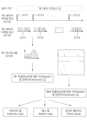
- Figure 1is a diagram for explaining a LiDAR device according to an embodiment.
- FIG. 2is a diagram showing various embodiments of a LiDAR device.
- Figure 3is a diagram for explaining the operation of a LiDAR device and LiDAR data according to an embodiment.
- Figure 4is a diagram for explaining lidar data according to one embodiment.
- Figure 5is a diagram for explaining lidar data according to an embodiment.
- Figure 6is a diagram for explaining information included in attribute data according to an embodiment.
- Figure 7is a diagram for explaining a LiDAR device according to an embodiment.
- FIG. 8is a diagram for explaining a laser output array and a laser detecting array included in a lidar device according to an embodiment.
- FIGS. 9 and 10are diagrams for explaining a LiDAR device according to an embodiment.
- 11 and 12are diagrams for explaining a laser emitting module and a laser detecting module according to an embodiment.
- FIG. 13 and 14are diagrams for explaining an emitting lens module and a detecting lens module according to an embodiment.
- Figure 15is a diagram showing a laser output unit according to one embodiment.
- Figure 16is a diagram for explaining a laser output array according to an embodiment.
- 17 and 18are diagrams for explaining a laser output array according to an embodiment.
- Figure 19is a diagram for explaining lidar data according to an embodiment.
- Figure 20is a diagram for explaining a method of acquiring detection values and LIDAR data according to an embodiment.
- Figure 21is a diagram for explaining a method of acquiring detection values and LIDAR data according to an embodiment.
- Figure 22is a diagram for explaining an operation section of a LiDAR device according to an embodiment.
- Figure 23is an exemplary diagram of lidar data according to an embodiment.
- Figure 24is a diagram for explaining the operation of a LiDAR device for generating an enhanced light capture map according to an embodiment.
- Figure 25is a diagram for explaining the operation of a laser output array according to an embodiment.
- Figure 26is an exemplary diagram of lidar data according to an embodiment.
- Figure 27is a diagram for explaining the laser output array and laser detecting array included in the lidar device according to one embodiment.
- Figure 28is a diagram for explaining a laser detecting unit and detecting value according to an embodiment.
- Figure 29is a diagram for explaining a laser detecting unit and detecting value according to an embodiment.
- Figure 30is a diagram for explaining a method of generating enhanced LIDAR data according to an embodiment.
- Figures 31 to 34are diagrams for explaining a method of generating enhanced lidar data according to an embodiment.
- Figure 35is a diagram illustrating lidar data and enhanced lidar data according to an embodiment.
- an element or layeris referred to as being “on” or “on” another element or layer, not just directly on top of the other element or layer, but also referring to another element or layer in between. Alternatively, it may include all cases involving other components.
- Numbersused in the description of this specification may be understood as identification symbols to distinguish one component from another component.
- a method of generating enhanced LiDAR data using a LiDAR deviceincluding a laser detecting array - wherein the laser detecting array includes a plurality of laser detecting units; , each of the plurality of laser detecting units includes a plurality of sub-detecting units -, a plurality of laser detecting units based on detection signals obtained from the plurality of sub-detecting units included in the plurality of laser detecting units.
- Enhancementcomprising obtaining second LIDAR data including sub-point data corresponding to each unit, and generating enhanced LIDAR data using the first LIDAR data and the second LIDAR data.
- a method of generating lidar datamay be provided.
- each point data corresponding to each of the plurality of laser detecting unitsmay include pixel coordinates and distance values corresponding to each of the plurality of laser detecting units.
- each sub point data corresponding to each of the plurality of sub detecting unitsmay include sub pixel coordinates and light capture values corresponding to each of the plurality of sub detecting units.
- the first LIDAR dataincludes at least one of a depth map, an intensity map, and a point cloud
- the second LIDAR dataincludes a light capture map ( Light capture map) data may be included.
- the distance value included in each of the plurality of point datais obtained based on a detecting signal obtained from a plurality of sub-detecting units included in the corresponding laser detecting unit, and the plurality of sub-point data
- the light capture value included in eachmay be obtained based on the detecting signal obtained from the corresponding sub-detecting unit.
- the first distance value included in the first LIDAR datais obtained based on a detecting signal obtained from a plurality of sub-detecting units included in the first laser detecting unit
- the second LIDARis The first light capture value included in the data is obtained based on the detecting signal obtained from the first sub-detecting unit included in the first laser detecting unit, and the second light included in the second LIDAR data
- the capture valueis obtained based on the detecting signal obtained from the second sub-detecting unit included in the first laser detecting unit
- the third light capture value included in the second LIDAR datais obtained from the second laser detecting unit. It may be obtained based on a detecting signal obtained from a third sub-detecting unit included in the detecting unit.
- the number of point data included in the first LIDAR datamay be less than the number of sub-point data included in the second LIDAR data.
- the number of pixel coordinates included in the first LIDAR datamay be less than the number of subpixel coordinates included in the second LIDAR data.
- the resolution of the second LIDAR datamay be higher than the resolution of the first LIDAR data.
- the enhanced LIDAR datamay include a plurality of enhanced point data.
- At this time, at least a portion of the plurality of enhanced point datamay be generated based on point data included in the first LIDAR data and sub-point data included in the second LIDAR data.
- the first enhanced point data included in the plurality of enhanced point datais at least first point data included in the first LIDAR data, first sub-point data included in the second LIDAR data, and second It may be generated based on second sub-point data included in LIDAR data.
- the first point datais point data corresponding to the first laser detecting unit
- the first sub point datais sub point data corresponding to the first sub detecting unit included in the first laser detecting unit
- the second sub point datamay be sub point data corresponding to the second sub detecting unit included in the second laser detecting unit.
- the first laser detecting unit and the second laser detecting unitmay be placed adjacent to each other.
- At this time, at least one sub-detecting unitmay be disposed between the first sub-detecting unit and the second sub-detecting unit.
- the number of enhanced point data included in the enhanced LIDAR datamay be the same as the number of sub-point data included in the second LIDAR data.
- the number of enhanced point data included in the enhanced LIDAR datamay be an integer multiple of the number of point data included in the first LIDAR data.
- the enhanced LIDAR datamay include at least one of a depth map, an intensity map, and a point cloud.
- LiDAR devicedescribed in this specification can be understood as a concept that includes various devices that measure distance using a laser, for example, LiDAR (LiDAR - Light Detection And Ranging), TOF sensor (Time of Flight sensor) -of-Flight sensor), etc., but is not limited to this.
- LiDARLiDAR - Light Detection And Ranging
- TOF sensorTime of Flight sensor
- a LIDAR deviceis a device that uses a laser to detect the distance to and location of an object.
- a LiDAR devicecan output a laser, and when the output laser is reflected from an object, the reflected laser can be received to measure the distance between the object and the LiDAR device and the position of the object.
- the distance and location of the objectcan be expressed through a coordinate system.
- the distance and location of an objectmay be expressed in a spherical coordinate system (r, ⁇ , *?* ⁇ ). However, it is not limited to this and may be expressed in a rectangular coordinate system (X, Y, Z) or a cylindrical coordinate system (r, ⁇ , z).
- the objectmay mean at least one object, but is not limited thereto, and may mean a part of an object for reflecting at least a portion of the laser output from the LiDAR device.
- the LiDAR devicemay use a laser output from the LiDAR device and reflected from the target to measure the distance to the target.
- the LIDAR devicemay use the time of flight (TOF) of the laser from when the laser is output until it is detected to measure the distance to the object.
- TOFtime of flight
- the LIDAR deviceuses the difference between a time value based on the output time of the output laser and a time value based on the detected time of the laser detected by reflection from the object to determine the distance of the object. can be measured.
- the time value based on the output time of the lasermay be obtained based on the control unit included in the LIDAR device according to one embodiment.
- the time value based on the laser output timemay be obtained based on the generation time of the trigger signal generated by the control unit included in the lidar device according to an embodiment, but is not limited to this.
- a time value based on the output time of the lasermay be obtained based on the laser output unit included in the LIDAR device according to one embodiment.
- a time value based on the output time of the lasermay be obtained by detecting the operation of a laser output unit included in a LiDAR device according to an embodiment, but is not limited to this.
- detection of the operation of the laser output unitmay mean detection of the flow of current or change in electric field of the laser output unit, but is not limited to this.
- a time value based on the output time of the lasermay be obtained based on a detector unit included in the LIDAR device according to an embodiment.
- the time value based on the laser output timemay be obtained based on the time value at which the detector unit included in the lidar device according to one embodiment detects the laser that is not reflected from the object, but is not limited to this. .
- a reference optical pathmay be provided for receiving the laser output from the laser output unit to the detector unit, but the present invention is not limited to this.
- a time value based on the detected time of the laser reflected and detected from the objectmay be obtained based on the detector unit included in the LIDAR device according to one embodiment.
- the time value based on the detected time of the laser reflected from the objectmay be obtained based on the time value of the detector included in the lidar device according to an embodiment of the detected laser reflected from the object.
- the time value based on the detected time of the laser reflected from the objectmay be obtained based on the time value of the detector included in the lidar device according to an embodiment of the detected laser reflected from the object.
- the LIDAR devicemay use triangulation method, interferometry method, phase shift measurement, etc. in addition to flight time to measure the distance of the object. It is not limited.
- the LiDAR devicemay be installed in a vehicle.
- the LIDAR devicemay be installed on the roof, hood, headlamp, or bumper of the vehicle.
- a plurality of LiDAR devicesmay be installed in a vehicle.
- one LiDAR devicemay be for observing the front and the other may be for observing the rear, but the present invention is not limited to this.
- one LiDAR devicemay be for observing the left side and the other may be for observing the right side, but the present invention is not limited to this.
- a LiDAR devicemay be installed in a vehicle.
- a LiDAR devicewhen a LiDAR device is installed inside a vehicle, it may be used to recognize the driver's gestures while driving, but is not limited to this.
- the LIDAR devicewhen the LIDAR device is installed inside or outside the vehicle, it may be for recognizing the driver's face, but is not limited to this.
- the LiDAR devicemay be installed on an unmanned aircraft.
- LIDAR devicescan be used for unmanned aerial vehicle systems (UAV Systems), drones, RPVs (Remote Piloted Vehicles), UAVs (Unmanned Aerial Vehicle Systems), UAS (Unmanned Aircraft Systems), and RPAVs (Remote Piloted Air/Aerials). Vehicle) or RPAS (Remote Piloted Aircraft System).
- UAV Systemsunmanned aerial vehicle systems
- RPVsRemote Piloted Vehicles
- UAVsUnmanned Aerial Vehicle Systems
- UASUnmanned Aircraft Systems
- RPAVsRemote Piloted Air/Aerials
- Vehicleor RPAS (Remote Piloted Aircraft System).
- a plurality of LiDAR devicesmay be installed on an unmanned aircraft.
- one LiDAR devicemay be for observing the front and the other may be for observing the rear, but the present invention is not limited to this.
- one LiDAR devicemay be for observing the left side and the other may be for observing the right side, but the present invention is not limited to this.
- the LiDAR devicemay be installed on a robot.
- the LIDAR devicemay be installed on personal robots, professional robots, public service robots, other industrial robots, or manufacturing robots.
- a plurality of LiDAR devicesmay be installed on the robot.
- one LiDAR devicemay be for observing the front and the other may be for observing the rear, but the present invention is not limited to this.
- one LiDAR devicemay be for observing the left side and the other may be for observing the right side, but the present invention is not limited to this.
- the LiDAR devicemay be installed on the robot.
- a LIDAR devicewhen installed in a robot, it may be for recognizing human faces, but is not limited to this.
- the LiDAR devicemay be installed for industrial security.
- LiDAR devicescould be installed in smart factories for industrial security.
- a plurality of LiDAR devicesmay be installed in a smart factory for industrial security.
- one LiDAR devicemay be for observing the front and the other may be for observing the rear, but the present invention is not limited to this.
- one LiDAR devicemay be for observing the left side and the other may be for observing the right side, but the present invention is not limited to this.
- a LiDAR devicemay be installed for industrial security.
- a LIDAR devicewhen installed for industrial security, it may be for recognizing a person's face, but is not limited to this.
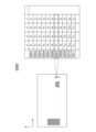
- Figure 1is a diagram for explaining a LiDAR device according to an embodiment.
- a LiDAR device 1000may include a laser output unit 100.
- the laser output unit 100may generate or output a laser.
- the laser output unit 100may include one or more laser output elements.
- the laser output unit 100may include a single laser output element or may include a plurality of laser output elements.
- the laser output unit 100may be configured as an array in which a plurality of laser output elements are arranged in an array, but the present invention is not limited thereto.
- the laser output unit 100may be implemented as a VCSEL array in which a plurality of VCSELs (Vertical Cavity Surface Emitting Lasers) are arranged in an array, but the present invention is not limited to this.
- VCSELsVertical Cavity Surface Emitting Lasers
- the laser output unit 100includes a laser diode (LD), solid-state laser, high power laser, light entitling diode (LED), Vertical Cavity Surface Emitting Laser (VCSEL), and external cavity. It may include a laser output device such as a diode laser (ECDL), but is not limited thereto.
- LDlaser diode
- LEDlight entitling diode
- VCSELVertical Cavity Surface Emitting Laser
- ECDLdiode laser
- the wavelength of the laser output from the laser output unit 100may be located in a specific wavelength range.
- the wavelength of the laser output from the laser output unit 100may be located in the 905nm band, may be located in the 940nm band, and may be located in the 1550nm band, but is not limited thereto. .
- the wavelength bandmay mean a band within a certain range based on the center wavelength.
- the 905nm bandmay mean a band within a 10nm difference based on 905nm
- the 940nm bandmay mean a band within a 10nm difference based on 940nm
- the 1550nm bandmay mean a band within a 10nm difference based on 1550nm. It may mean a band within the range of difference, but is not limited to this.
- the wavelength of the laser output from the laser output unit 100may be located in various wavelength ranges.
- the wavelength of the first laser output from the first laser output element included in the laser output unit 100is located in the 905 nm band, but The wavelength of the second laser output from the included second laser output element may be located in the 1550 nm band, but is not limited thereto.
- the wavelength of the laser output from the laser output unit 100may be located within a specific wavelength range but may be different wavelengths.
- the wavelength of the first laser output from the first laser output element included in the laser output unit 100is located in the 940 nm band and may be a 939 nm wavelength
- the laser outputaccording to one embodiment
- the wavelength of the second laser output from the second laser output device included in the unit 100is located in the 940 nm band and may be a 943 nm wavelength, but is not limited thereto.
- the LIDAR device 1000may include an optical unit 200.
- the optical unitmay be variously expressed as a steering unit, a scanning unit, etc. to explain the present invention, but is not limited thereto.
- the optical unit 200may function to change the flight path of the laser.
- the optic unit 200may function to change the flight path of the laser output from the laser output unit 100, and the laser output from the laser output unit 100 may be reflected from the object. In this case, it may function to change the flight path of the laser reflected from the object, but is not limited to this.
- optical unit 200may function to change the flight path of the laser by reflecting the laser.
- the optic unit 200may function to change the flight path by reflecting the laser output from the laser output unit 100, and the laser output from the laser output unit 100 may function to change the flight path.
- the laser output from the laser output unit 100may function to change the flight path.
- itmay function to change the flight path by reflecting the laser reflected from the object, but is not limited to this.
- the optical unit 200may include at least one optical means among various optical means for reflecting a laser.
- the optical unit 200includes a mirror, a resonance scanner, a MEMS mirror, a voice coil motor (VCM), a polygonal mirror, and a rotating mirror. It may include at least one optical means such as a rotating mirror or a galvano mirror, but is not limited thereto.
- the optical unit 200can change the flight path of the laser by refracting the laser.
- the optic unit 200may function to change the flight path by refracting the laser output from the laser output unit 100, and the laser output from the laser output unit 100 may be used to change the flight path of the laser output unit 100.
- the optic unit 200may function to change the flight path by refracting the laser reflected from the object, but is not limited to this.
- the optical unit 200may include at least one optical means among various optical means for refracting a laser.
- the optical unit 200may include at least one of optical means such as a lens, a prism, a micro lens, a microfluidie lens, or a metasurface. It may include, but is not limited to, one optical means.
- optical meanssuch as a lens, a prism, a micro lens, a microfluidie lens, or a metasurface. It may include, but is not limited to, one optical means.
- optical unit 200can change the flight path of the laser by changing the phase of the laser.
- the optic unit 200may function to change the flight path by changing the phase of the laser output from the laser output unit 100, and the laser output from the laser output unit 100 When reflected from an object, it may function to change the flight path by changing the phase of the laser reflected from the object, but is not limited to this.
- the optical unit 200may include at least one optical means among various optical means for changing the phase of the laser.
- the optical unit 200may include at least one optical means such as an optical phased array (OPA), a meta lens, or a metasurface. It is not limited to this.
- OPAoptical phased array
- meta lensa meta lens
- metasurfacea metasurface
- optical unit 200may include two or more optical units.
- the optical unit 200is a transmitting optical unit for irradiating the laser output from the laser output unit 100 according to an embodiment to the scan area of the LIDAR device. and a receiving optical unit for transmitting the laser reflected from the object to the detector unit 300, but is not limited thereto.
- the optic unit 200includes a first optical unit for changing the flight path of the laser output from the laser output unit 100 according to an embodiment to the direction of the first group, and It may include a second optical unit for changing the flight path of the laser output from the laser output unit 100 according to an embodiment to the direction of the second group, but is not limited to this.
- the optical unit 200expands the scan area of the LIDAR device by using the laser output from the laser output unit 100 according to an embodiment, and reflects from the object.
- the optical unit 200expands the scan area of the LIDAR device by using the laser output from the laser output unit 100 according to an embodiment, and reflects from the object.
- a combination of various configurationsmay be provided.
- the LIDAR device 100may include a detector unit 300.
- the detector unitmay be expressed in various ways as a light receiving unit, a receiving unit, a sensor unit, etc., but is not limited thereto.
- the detector unit 300may function to detect a laser.
- the detector unit 300may detect a laser reflected from an object located within the scan area of the LIDAR device 100 according to an embodiment.
- the detector unit 300may be arranged to receive a laser beam, and may function to generate an electrical signal based on the received laser beam.
- the detector unit 300may be arranged to receive a laser reflected from an object located within the scan area of the LiDAR device 100 according to an embodiment, and generate an electrical signal based on this. can be created.
- the detector unit 300may be arranged to receive the laser reflected from an object located within the scan area of the LiDAR device 100 according to an embodiment through at least one optical means, , the at least one optical means may be included in the above-described optical unit and may include an optical filter, etc., but is not limited thereto.
- the detector unit 300may generate laser detection information based on the generated electrical signal.
- the detector unit 300may generate laser detection information by comparing a predetermined threshold value with the rising edge, falling edge, or median value of the rising edge and falling edge of the generated electrical signal. , but is not limited to this.
- the detector unit 300may generate histogram data corresponding to laser detection information based on the generated electrical signal, but the present invention is not limited thereto.
- the detector unit 300may determine the laser detection point based on the generated laser detection information.
- the detector unit 300may determine the detection point of the laser based on the detection information of the laser generated based on the rising edge of the generated electrical signal and the falling edge of the generated electrical signal.
- the detection point of the lasercan be determined based on the detection information of the laser generated based on the detection information of the laser generated based on the rising edge of the generated electrical signal and the detection information of the laser generated based on the falling edge of the generated electrical signal. Based on this, the detection point of the laser can be determined, but is not limited to this.
- the detector unit 300may determine the detection point of the laser based on histogram data generated based on the generated electrical signal, but is not limited to this.
- the detector unit 300may determine the detection point of the laser based on the peak of the generated histogram data, determination of rising edge and falling edge based on a predetermined value, etc. However, it is not limited to this.
- the histogram datamay be generated based on an electrical signal generated from the detector unit 300 according to an embodiment during at least one scan cycle.
- the detector unit 300may include at least one detector element among various detector elements.
- the detector unit 300includes a PN photodiode, a phototransistor, a PIN photodiode, an avalanche photodiode (APD), a single-photon avalanche diode (SPAD), a silicon photomultiplier (SiPM), a comparator, and a CMOS. It may include at least one detector element such as a (complementary metal-oxide-semiconductor) or a charge coupled device (CCD), but is not limited thereto.
- a detector elementsuch as a (complementary metal-oxide-semiconductor) or a charge coupled device (CCD), but is not limited thereto.
- the detector unit 300may include one or more detector elements.
- the detector unit 300may include a single detector element or may include a plurality of detector elements.
- the detector unit 300may be configured as an array of a plurality of detector elements arranged in an array, but is not limited to this.
- the detector unit 300may be implemented as a SPAD array in which a plurality of SPADs (Single Photon Avalanche Diodes) are arranged in an array, but is not limited to this.
- SPADsSingle Photon Avalanche Diodes
- the LIDAR device 1000may include a control unit 400.
- control unitmay be expressed in various ways as a controller, etc. to explain the present invention, but is not limited thereto.
- the control unit 400may control the operation of the laser output unit 100, the optic unit 200, or the detector unit 300.
- control unit 400may control the operation of the laser output unit 100.
- control unit 400may control the output timing of the laser output from the laser output unit 100. Additionally, the control unit 400 can control the power of the laser output from the laser output unit 100. Additionally, the control unit 400 can control the pulse width of the laser output from the laser output unit 100. Additionally, the control unit 400 can control the cycle of the laser output from the laser output unit 100. Additionally, when the laser output unit 100 includes a plurality of laser output elements, the control unit 400 may control the laser output unit 100 to operate some of the plurality of laser output elements.
- control unit 400may control the operation of the optical unit 200.
- control unit 400may control the operating speed of the optical unit 200.
- the rotation speed of the rotating mirrorcan be controlled
- the optical unit 200 includes a MEMS mirrorthe repetition cycle of the MEMS mirror can be controlled.
- control unit 400may control the degree of operation of the optical unit 200.
- the optical unit 200includes a MEMS mirror
- the operating angle of the MEMS mirrorcan be controlled, but is not limited to this.
- control unit 400may control the operation of the detector unit 300.
- control unit 400may control the sensitivity of the detector unit 300.
- control unit 400may control the sensitivity of the detector unit 300 by adjusting a predetermined threshold value, but the sensitivity is not limited to this.
- control unit 400may control the operation of the detector unit 300.
- control unit 400can control the On/Off of the detector unit 300, and when the control unit 300 includes a plurality of sensor elements, the detector unit 400 can operate some of the sensor elements.
- the operation of (300)can be controlled.
- control unit 400may generate laser detection information based on the electrical signal generated from the detector unit 300.
- control unit 400compares a predetermined threshold value with the rising edge, falling edge, or the median value of the rising edge and falling edge of the electrical signal generated from the detector unit 300 to provide laser detection information. can be created, but is not limited to this.
- control unit 400may generate histogram data corresponding to laser detection information based on the electrical signal generated by the detector unit 300, but the present invention is not limited thereto.
- control unit 400may determine the detection point of the laser based on the laser detection information generated based on the rising edge of the electrical signal generated by the detector unit 300, and the generated The detection point of the laser can be determined based on the detection information of the laser generated based on the falling edge of the electrical signal, and the detection information of the laser generated based on the rising edge of the generated electrical signal and the detection information generated based on the falling edge can be determined.
- the detection point of the lasermay be determined based on the laser detection information, but is not limited to this.
- control unit 400may determine the detection point of the laser based on histogram data generated based on the electrical signal generated from the detector unit 300. It is not limited.
- control unit 400may control the laser operation based on the peak of the histogram data generated by the detector unit 300, the determination of the rising edge and falling edge based on a predetermined value, etc.
- the detection pointcan be determined, but is not limited to this.
- the histogram datamay be generated based on an electrical signal generated from the detector unit 300 according to an embodiment during at least one scan cycle.
- control unit 400may obtain distance information to the object based on the determined detection point of the laser.
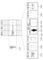
- FIG. 2is a diagram showing various embodiments of a LiDAR device.
- FIG. 2shows various This is a simply schematic diagram to explain one of the embodiments of the LiDAR device, and the various embodiments of the LiDAR device are not limited to (a) of FIG. 2.
- the LIDAR devicemay include a laser output unit 120, an optical unit 220, and a detector unit 320, and the optical unit 220 ) may include at least one lens 221 capable of collimating and steering the laser output from the laser output unit 120 and a multi-faceted mirror 222 rotating about at least one axis, but is limited to this. It doesn't work.
- the LIDAR devicemay include a laser output unit 130, an optical unit 230, and a detector unit 330, and the optical unit 230 ) is at least one lens 231 that can collimate and steer the laser output from the laser output unit 130 and at least one lens 232 that transmits the laser reflected from the object to the detector unit 330 ) may include, but is not limited to this.
- the LIDAR devicemay include a laser output unit 140, an optical unit 240, and a detector unit 340, and the optical unit 240 ) is at least one lens 241 that can collimate and steer the laser output from the laser output unit 130 and at least one lens 242 that transmits the laser reflected from the object to the detector unit 340 ) may include, but is not limited to this.
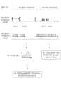
- Figure 3is a diagram for explaining the operation of a LiDAR device and LiDAR data according to an embodiment.
- the LiDAR device 1000includes a laser output unit for outputting a laser and a detector unit for detecting a laser, and the description of the laser output unit and the detector unit is described above. As such, overlapping descriptions will be omitted.
- the data processing unitmay acquire LiDAR data 1200 based on the laser detected by the LiDAR device 1000.
- the data processing unitmay be included in the LiDAR device 1000, and may be included in the control unit of the LiDAR device 1000 described above, but is not limited thereto, and may be included in the LiDAR device 1000 and at least one It may be connected through a communication method and positioned to acquire a signal generated from the detector unit included in the LiDAR device 1000.
- the LiDAR device 1000can form a field of view 1100 by irradiating a laser, and the laser reflected within the field of view 1100 is LiDAR data 1200 can be obtained by detection.
- the LiDAR data 1200may refer to various types of data obtained from the LiDAR device 1000, for example, point data obtained from the LiDAR device 1000. , point cloud, frame data, etc., but is not limited thereto.
- the point datamay be data including distance information, location information, etc.
- the point cloudmay refer to cluster data of the point data, but is not limited thereto.
- the frame datamay refer to a group of the point data, but is not limited thereto.
- the horizontal viewing angle 1110 and the vertical viewing angle 1120may be defined by the irradiated laser.
- the horizontal viewing angle 1110 of the LiDAR device 1000may be defined by the first laser 1111 irradiated at a first angle and the second laser 1112 irradiated at a second angle, , More specifically, it may be defined as the difference between the first angle at which the first laser 1111 is irradiated and the second angle at which the second laser 1112 is irradiated, but is not limited to this.
- the vertical viewing angle 1120 of the LiDAR device 1000may be defined by the third laser 1121 irradiated at a third angle and the fourth laser 1122 irradiated at a fourth angle. It may be, and more specifically, may be defined as the difference between the third angle at which the third laser 1121 is irradiated and the second angle at which the fourth laser 1122 is irradiated, but is not limited to this.
- the definition of the horizontal viewing angle 1110 and the vertical viewing angle 1120 of the LiDAR device 1000is not limited to the above-described example, and represents the area where the laser is irradiated from the LiDAR device 1000. It can be defined by various methods.
- the horizontal viewing angle 1110 and the vertical viewing angle 1120may be defined by the detected laser. More specifically, the horizontal viewing angle 1110 and the vertical viewing angle 1120 may be defined by point data generated by a detected laser.
- the horizontal viewing angle 1110 of the LIDAR device 1000may be defined by first point data 1210 and second point data 1220, and more specifically, the first point data 1220. It may be defined by the laser irradiation angle corresponding to 1210 and the laser irradiation angle corresponding to the second point data 1220, but is not limited thereto.
- the vertical viewing angle 1120 of the LiDAR device 1000may be defined by third point data 1230 and fourth point data 1240, and more specifically, the third point data 1230 and fourth point data 1240 may be used. It may be defined by the laser irradiation angle corresponding to the point data 1230 and the laser irradiation angle corresponding to the fourth point data 1240, but is not limited thereto.
- the definition of the horizontal viewing angle 1110 and the vertical viewing angle 1120 of the LiDAR device 1000is not limited to the above-described examples, and the area in which the LiDAR device 1000 can detect the laser It can be defined by various ways to express it.
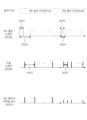
- the laser forming the viewing angle 1100 of the LiDAR device 1000may be irradiated to have angular resolution.
- the angular resolutionmay include horizontal angular resolution for resolution in the horizontal direction and vertical angular resolution for resolution in the vertical direction.
- the horizontal angular resolution and the vertical angular resolutionmay be defined by the irradiated laser.
- the horizontal angular resolution of the LiDAR device 1000may be defined by the fifth laser 1131 irradiated at a fifth angle and the sixth laser 1132 irradiated at a sixth angle. Specifically, it may be defined as the difference between the fifth angle at which the fifth laser 1131 is irradiated and the sixth angle at which the sixth laser 1132 is irradiated, but is not limited to this.
- the vertical angular resolution of the LiDAR device 1000may be defined by the seventh laser 1141 irradiated at a seventh angle and the eighth laser 1142 irradiated at an eighth angle, , More specifically, it may be defined as the difference between the seventh angle at which the seventh laser 1141 is irradiated and the eighth angle at which the eighth laser 1142 is irradiated, but is not limited to this.
- the definition of the horizontal angular resolution and vertical angular resolution of the LIDAR device 1000is not limited to the above-described example, and may be defined by various methods for expressing the angular resolution capable of distinguishing detection target objects. You can.
- LiDAR data 1200 acquired from the LiDAR device 1000may include point data having angular resolution.
- the angular resolutionmay include horizontal angular resolution for resolution in the horizontal direction and vertical angular resolution for resolution in the vertical direction.
- the horizontal angular resolution and the vertical angular resolutionmay be defined by the detected laser. More specifically, the horizontal angular resolution and the vertical angular resolution may be defined by point data generated by a detected laser.
- the horizontal angle resolution of the LIDAR device 1000may be defined by fifth point data 1250 and sixth point data 1260, and more specifically, the fifth point data 1250 ) may be defined by the laser irradiation angle corresponding to the laser irradiation angle and the laser irradiation angle corresponding to the sixth point data 1260, but is not limited thereto.
- the vertical angle resolution of the LIDAR device 1000may be defined by the seventh point data 1270 and the eighth point data 1280, and more specifically, the seventh point data ( It may be defined by the laser irradiation angle corresponding to 1270) and the laser irradiation angle corresponding to the eighth point data 1280, but is not limited thereto.
- the definition of the horizontal angular resolution and vertical angular resolution of the LIDAR device 1000is not limited to the above-described examples, and may be defined by various methods for expressing the angular resolution capable of distinguishing detection target objects. You can.
- the laser irradiated from the LiDAR device 1000may each have a size and divergence angle.
- each laser irradiated from the LiDAR device 1000may have a major axis length and a minor axis length, and may have a divergence angle, but is not limited thereto.
- each point data included in the LIDAR data 1200may include distance information.
- an optical origin 1300may be defined for the LiDAR device 1000.
- the optical origin 1300may mean the origin of a coordinate system for expressing the above-described LIDAR data.
- optical origin 1300may mean an origin defined when assuming that the laser irradiated from the LiDAR device 1000 is output from one point.
- optical origin 1300may mean the origin of distance measurement for measuring the distance using a laser in the LiDAR device 1000.
- optical origin 1300may mean an origin for describing point data obtained from the LIDAR device 1000.
- optical origin 1300may mean, but is not limited to, a physically derived optical origin, and may mean an optical origin artificially given to the LiDAR device 1000, but is not limited thereto. No.
- Figure 4is a diagram for explaining lidar data according to one embodiment.
- LiDAR datamay be expressed in various formats such as point cloud, depth map, and intensity map.
- the point cloudmay be a format in which information about each measurement point is converted into location information, and the point cloud according to one embodiment includes information on the angle at which the laser was irradiated or acquired, and It may include, but is not limited to, location coordinate values (x, y, z) and intensity value (I) obtained based on distance information.
- the depth mapmay be in a format that includes two-dimensional pixel position information and distance information for each measurement point, and the depth map according to one embodiment is irradiated with a laser or It may include, but is not limited to, pixel values (x, y) and distance values (D) obtained based on the acquired angle information.
- the intensity mapmay be in a format that includes two-dimensional pixel position information and intensity information for each measurement point, and the intensity map according to one embodiment is when the laser is irradiated or It may include, but is not limited to, pixel values (x, y) and intensity values (I) obtained based on the acquired angle information.
- LiDAR datamay be acquired in various formats, but for convenience of explanation, the description below will be based on LiDAR data acquired in the form of a point cloud.
- LIDAR datamay include point cloud data 2000.
- the point cloud data 2000may include a plurality of point data.
- each of the plurality of point datamay include position coordinate values (x, y, z) and intensity value (i), but is not limited thereto.
- the position coordinate value included in each of the plurality of point datamay be obtained based on the distance value.
- the position coordinate value included in each of the plurality of point datamay be obtained based on the angle (or coordinate) value at which the laser is output and the distance value obtained based on the output laser, but is not limited to this. .
- the position coordinate value included in each of the plurality of point datamay be obtained based on the coordinate value of the detector that acquired the laser and the distance value obtained based on the acquired laser, but is not limited to this. .
- the intensity value included in each of the plurality of point datamay be obtained based on an electrical signal obtained from a detector unit.
- the intensity value included in each of the plurality of point datamay be obtained based on characteristics such as size and width of the electrical signal obtained from the detector, but is not limited to this, and the intensity value included in each of the plurality of point data may be obtained based on the electrical signal obtained from the detector. It can be obtained by various algorithms.
- the intensity value included in each of the plurality of point datamay be obtained based on histogram data generated based on an electrical signal obtained from a detector unit, but is not limited to this.
- Figure 5is a diagram for explaining lidar data according to an embodiment.
- LIDAR datamay include point cloud data 2100.
- Point cloud data 2100may include at least one sub-point data set 2110.
- the at least one sub point data set 2110may mean a set of point data grouped by a specific rule or algorithm.
- the at least one sub point data set 2110may refer to a set of point data grouped by human input, but is not limited thereto.
- the at least one sub point data set 2110may refer to a set of point data grouped by a segment algorithm for the same object, but is not limited thereto.
- the at least one sub point data set 2110may refer to a set of point data grouped by a clustering algorithm, but is not limited thereto.
- the at least one sub point data set 2110may refer to a set of point data grouped by a learned machine learning model, but is not limited thereto.
- the at least one sub-point data set 2110may refer to a set of point data grouped by a learned deep learning model, but is not limited thereto.
- the LIDAR data processing unitmay acquire attribute data for at least one sub point data set 2110 described above.
- the LIDAR data processing unitmay acquire at least one attribute data for the at least one sub point data set 2110 according to a human input, but is not limited to this.
- the LIDAR data processing unitmay acquire at least one attribute data for the at least one sub point data set 2110 using a specific algorithm, but is not limited thereto.
- the LIDAR data processing unitmay acquire at least one attribute data for the at least one sub point data set 2110 using a learned machine learning model, but is limited to this. It doesn't work.
- the LIDAR data processing unitmay acquire at least one attribute data for the at least one sub point data set 2110 using a learned deep learning model, but is limited to this. It doesn't work.
- the above-described machine learning model or deep learning modelmay include at least one artificial neural network (ANN) layer.
- ANNartificial neural network
- the above-described machine learning model or deep learning modelmay be a feedforward neural network, a radial basis function network, a kohonen self-organizing network, or a deep neural network.
- At least one of various artificial neural network layerssuch as DNN, Convolutional neural network (CNN), Recurrent neural network (RNN), Long Short Term Memory Network (LSTM), or Gated Recurrent Units (GRUs) It may include, but is not limited to, an artificial neural network layer.
- the at least one artificial neural network layer included in the above-described machine learning model or deep learning modelmay be designed to use the same or different activation function.
- the activation functionis a sigmoid function, a hyperbolic tangent function (Tanh Fucntion), a Relu Function (Rectified Linear unit Fucntion), a leaky Relu Function, It may include, but is not limited to, the ELU Function (Exponential Linear unit function), Softmax function, etc., and various activation functions (custom activation functions) to output the result or transfer it to another artificial neural network layer. functions) may be included.
- machine learning model or deep learning modelmay be learned using at least one loss function.
- the at least one loss functionmay include, but is not limited to, MSE (Mean Squared Error), RMSE (Root Mean Squared Error), Binary Crossentropy, Categorical Crossentropy, Sparse Categorical Crossentropy, etc., and the predicted result value Various functions (including custom loss functions) can be included to calculate the difference between the and actual result values.
- MSEMel Squared Error
- RMSERoot Mean Squared Error
- Binary CrossentropyCategorical Crossentropy
- Sparse Categorical CrossentropySparse Categorical Crossentropy
- Various functionscan be included to calculate the difference between the and actual result values.
- machine learning model or deep learning modelcan be learned using at least one optimizer.
- the optimizercan be used to update the relationship parameters between input values and result values.
- the at least one optimizermay include Gradient descent, Batch Gradient Descent, Stochastic Gradient Descent, Mini-batch Gradient Descent, Momentum, AdaGrad, RMSProp, AdaDelta, Adam, NAG, NAdam, RAdam, AdamW, etc. It is not limited to this.
- Figure 6is a diagram for explaining information included in attribute data according to an embodiment.
- the LIDAR data processing unitmay acquire at least one attribute data 2200 for the sub point data set 2110 according to an embodiment.
- the at least one attribute data 2200includes class information 2210, center position information 2220, size information 2230, shape information 2240, It may include movement information 2250, identification information 2260, etc., but is not limited thereto.
- the same algorithm or modelmay be used to obtain each attribute data included in the at least one attribute data 2200, or different algorithms or models may be used.
- the at least one attribute data 2200may be obtained based on point cloud data included in one frame data.
- attribute datasuch as object class information 2210, center position information 2220, size information 2230, and shape information 2240 included in the at least one attribute data 2200 are included in one frame. It may be obtained based on point cloud data included in the data, but is not limited to this.
- the at least one attribute data 2200may be obtained based on point cloud data included in a plurality of frame data.
- attribute data such as movement information 2250 and identification information 2260 included in the at least one attribute data 2200may be obtained based on point cloud data included in a plurality of frame data. It is not limited to this.
- LiDAR data acquired in point cloud formatthrough FIGS. 4 to 6, but as described above, in addition to the point cloud format, LiDAR data obtained in formats such as depth map and intensity map are also described. The contents described can be applied.
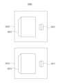
- Figure 7is a diagram for explaining a LiDAR device according to an embodiment.
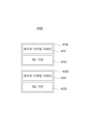
- the LiDAR device 3000may include a transmitting module 3010 and a receiving module 3020.
- the transmission module 3010may include a laser output array 3011 and a first lens assembly 3012, but is not limited thereto.
- the first lens assembly 3012may be expressed as a transmission lens assembly, transmission optics, transmission optics unit, transmission optics module, emitting optics, emitting optics unit, emitting optics module, etc. according to convenience. However, it is not limited to this.
- the laser output array 3011may output at least one laser.
- the laser output array 3011may output a plurality of lasers, but is not limited thereto.
- the laser output array 3011may output at least one laser at a first wavelength.
- the laser output array 3011may output at least one laser at a wavelength of 940 nm, and may output a plurality of lasers at a wavelength of 940 nm, but is not limited thereto.
- the first wavelengthmay be a wavelength range including an error range.
- the first wavelengthis a 940nm wavelength with an error range of 5nm, which may mean a wavelength range from 935nm to 945nm, but is not limited thereto.
- the laser output array 3011may output at least one laser at the same time.
- the laser output array 3011may output a first laser at a first time point, or output at least one laser at the same time, such as outputting the first and second lasers at a second time point. can do.
- the first lens assembly 3012may include at least two lens layers.
- the first lens assembly 3012may include at least four lens layers, but is not limited thereto.
- the first lens assembly 3012may collimate the laser output from the laser output array 3011.
- the first lens assembly 3012may change the divergence of the first laser by collimating the first laser output from the laser output array 3011, but the present invention is not limited to this.
- the first lens assembly 3012can steer the laser output from the laser output array 3011.
- the first lens assembly 3012may steer the first laser output from the laser output array 3011 in a first direction, and may steer the second laser output from the laser output array 3011. Steering in the second direction may be possible, but is not limited to this.
- the first lens assembly 3012may steer the plurality of lasers output from the laser output array 3011 to irradiate the plurality of lasers at different angles within the range of (x) degrees to (y) degrees. You can.
- the first lens assembly 3012may steer the first laser in a first direction to irradiate the first laser output from the laser output array 3011 at (x) degrees, and the laser output In order to irradiate the second laser output from the array 3011 at (y) degree, the second laser may be steered in the second direction, but the present invention is not limited to this.
- the receiving module 3020may include a laser detecting array 3021 and a second lens assembly 3022, but is not limited thereto.
- the second lens assembly 3022may be expressed as a receiving lens assembly, receiving optic, receiving optic unit, receiving optic module, receiving optic, receiving optic unit, receiving optic module, etc. according to convenience. However, it is not limited to this.
- the laser detecting array 3021can detect at least one laser.
- the laser detecting array 3021can detect a plurality of lasers.
- the laser detecting array 3021may include a plurality of detectors.
- the laser detecting array 3021may include a first detector and a second detector, but is not limited thereto.
- each of the plurality of detectors included in the laser detecting array 3021may receive different lasers.
- the first detector included in the laser detecting array 3021may receive a first laser received from a first direction
- the second detectormay receive a second laser received from a second direction.
- the laser detecting array 3021can detect at least a portion of the laser irradiated from the transmission module 3010.
- the laser detecting array 3021may detect at least a portion of the first laser irradiated from the transmission module 3010 and at least a portion of the second laser, but is not limited thereto. .
- the second lens assembly 3022may transmit the laser irradiated from the transmission module 3010 to the laser detecting array 3021.
- the second lens assembly 3022detects the first laser. It can be transmitted to the array 3021, and when the second laser irradiated in the second direction is reflected from the object located in the second direction, the second laser can be transmitted to the laser detecting array 3021, but is limited to this. It doesn't work.
- the second lens assembly 3022may distribute the laser beam emitted from the transmission module 3010 to at least two different detectors. For example, when the first laser radiated from the transmission module 3010 in the first direction is reflected from an object located in the first direction, the second lens assembly 3022 detects the first laser. It can be distributed to the first detector included in the array 3021, and when the second laser irradiated in the second direction is reflected from the object located in the second direction, the
- the second lasermay be distributed to the second detector included in the laser detecting array 3021, but is not limited to this.
- the laser output array 3011 and the laser detecting array 3021may be matched.
- the first laser output from the first laser output element included in the laser output array 3011may be detected by the first detector included in the laser detecting array 3021
- the laser output array 3011may detect the first laser output from the first laser output element included in the laser output array 3011.
- the second laser output from the second laser output device included in 3011may be detected by the second detector included in the laser detecting array 3021, but is not limited to this.
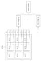
- FIG. 8is a diagram for explaining a laser output array and a laser detecting array included in a lidar device according to an embodiment.
- the LiDAR device 3100may include a laser output array 3110 and a laser detecting array 3120.
- the laser output array 3110may include a plurality of laser output units.
- the laser output array 3110may include a first laser output unit 3111 and a second laser output unit 3112.
- the laser output array 3110may be an array in which a plurality of laser output units are arranged in a two-dimensional matrix.
- the laser output array 3110may be an array in which a plurality of laser output units are arranged in a two-dimensional matrix having M rows and N columns, but is not limited to this.
- each of the plurality of laser output unitsmay include at least one laser output element.
- the first laser output unit 3111 included in the plurality of laser output unitsmay be comprised of one laser output element
- the second laser output unit 3112may be comprised of one laser output element. It may be configured, but is not limited to this.
- the first laser output unit 3111 included in the plurality of laser output unitsmay be composed of two or more laser output elements, and the second laser output unit 3112 may be configured to output two or more laser output elements. It may be composed of elements, but is not limited thereto.
- the laser output from each of the plurality of laser output unitsmay be irradiated in different directions.
- the first laser output from the first laser output unit 3111 included in the plurality of laser output unitsis irradiated in the first direction
- the second laser output from the second laser output unit 3112The laser may be irradiated in the second direction, but is not limited to this.
- lasers output from each of the plurality of laser output unitsmay not overlap each other at the target location.
- the first laser output from the first laser output unit 3111 included in the plurality of laser output unitsis 100 m away from the second laser output from the second laser output unit 3112. They may not overlap each other, but are not limited to this.
- the laser detecting array 3120may include a plurality of detecting units.
- the laser detecting array 3120may include a first detecting unit 3121 and a second detecting unit 3122.
- the laser detecting array 3120may be an array in which a plurality of detecting units are arranged in a two-dimensional matrix.
- the laser detecting array 3120may be an array in which a plurality of detecting units are arranged in a two-dimensional matrix having M rows and N columns, but is not limited to this.
- each of the plurality of detecting unitsmay include at least one laser detecting element.
- the first detecting unit 3121 included in the plurality of detecting unitsmay be composed of one laser detecting element
- the second detecting unit 3122may be composed of one laser detecting element. It may be composed of elements, but is not limited thereto.
- the first detecting unit 3121 included in the plurality of detecting unitsmay be composed of two or more laser detecting elements
- the second detecting unit 3122may be composed of two or more laser detecting elements. It may consist of a detecting element, but is not limited to this.
- each of the plurality of detecting unitscan detect lasers irradiated in different directions.
- the first detecting unit 3121 included in the plurality of laser output unitscan detect the first laser irradiated in the first direction
- the second detecting unit 3122can detect the second laser.
- the second laser irradiated in this directionmay be detected, but is not limited to this.
- each of the plurality of detecting unitscan detect laser output from a correspondingly arranged laser output unit.
- the first detecting unit 3121 included in the plurality of detecting unitsmay be configured to output a laser beam output from the first laser output unit 3111 arranged to correspond to the first detecting unit 3121. 1 laser can be detected, and the second detecting unit 3122 can detect the second laser output from the second laser output unit 3112 arranged to correspond to the second detecting unit 3122.
- the second detecting unit 3122can detect the second laser output from the second laser output unit 3112 arranged to correspond to the second detecting unit 3122.
- each of the plurality of detecting unitsmay detect laser output from at least two laser output units depending on the location of the object.
- the second detecting unit 3122 included in the plurality of detecting unitsuses the second laser output from the second laser output unit 3112. can be detected, and when the object is located in the second distance range, the first laser output from the first laser output unit 3111 can be detected, but is not limited to this.
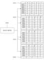
- At least one detecting valuemay be generated based on signals obtained from each of the plurality of detecting units.
- the detecting valuemay include a depth value (distance value), an intensity value, etc., but is not limited thereto.
- the coordinates of the detecting valuemay be determined based on the arrangement of each of the plurality of detecting units.
- the first detecting unit 3121 included in the plurality of detecting unitsmay be placed at a position of (1,1) in the laser detecting array, and the first detecting unit 3121 )
- the coordinates of the first detecting value generated based on the signal obtained from )may be determined as (1,1), but are not limited to this.
- the second detecting unit 3122 included in the plurality of detecting unitsmay be disposed at the position (2,1) in the laser detecting array, and the second detecting unit
- the coordinates of the second detecting value generated based on the signal obtained from 3122may be determined as (2,1), but are not limited to this.
- point datamay be generated based on the detecting value and the coordinates of the detecting value.
- a first detecting valuegenerated based on a signal obtained from the first detecting unit 3121 included in the plurality of detecting units and a first coordinate value that is the coordinate value of the first detecting value.
- First point datamay be generated based on , and the first point data may include 3D position coordinate values and intensity values, but is not limited thereto.
- Second point datamay be generated based on the coordinate values, and the second point data may include, but are not limited to, 3D position coordinate values and intensity values.
- the laser output array 3110 and the laser detecting array 3120may be arranged in an array having the same dimensions.
- the laser output array 3110 and the laser detecting array 3120may each have a plurality of laser output units and a plurality of detecting units arranged in an array having M rows and N columns. It is not limited to this.
- the laser output array 3110 and the laser detecting array 3120may be arranged in an array with different dimensions.
- the laser output array 3110has a plurality of laser output units arranged in an array having M rows and N columns
- the laser detecting array 3120has a plurality of detecting units M+3. It can be arranged as an array with N rows and N columns, but is not limited to this.
- the number of laser output units included in the laser output array 3110may be the same as the number of detecting units included in the laser detecting array 3120.
- the laser output array 3110may include M*N laser output units
- the laser detecting array 3120may include M*N detecting units, but is not limited thereto. No.
- the number of laser output units included in the laser output array 3110may be different from the number of detecting units included in the laser detecting array 3120.
- the laser output array 3110may include M*N laser output units, and the laser detecting array 3120 may include (M+3)*N detecting units. , but is not limited to this.
- the laser output array 3110may include (M*N)/2 laser output units
- the laser detecting array 3120may include M*N detecting units. However, it is not limited to this.
- the laser output array 3110may include (M*N)/2 laser output units
- the laser detecting array 3120may include (M+3)*N detecting units. It may include units, but is not limited thereto.
- the number of laser output elements included in each of the plurality of laser output units included in the laser output array 3110is determined by each of the plurality of laser detecting units included in the laser detecting array 3120. It may differ from the number of laser detecting elements included.
- the number of laser detecting elements included in the first laser detecting unit 3121may be 9. , but is not limited to this.
- the number of laser output elements included in the second laser output unit 3112is 1, the number of laser detecting elements included in the second laser detecting unit 3122 is 9. However, it is not limited to this.
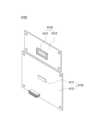
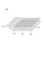
- FIGS. 9 and 10are diagrams for explaining a LiDAR device according to an embodiment.
- the LiDAR device 4000may include a transmitting module 4010 and a receiving module 4020.
- the transmission module 4010may include a laser emitting module 4011, an emitting optics module 4012, and an emitting optics holder 4013.
- the laser emitting module 4011may include a laser output array, and since the above-described contents can be applied to the laser output array, redundant description will be omitted.
- the emitting optics module 4012may include a lens assembly, and since the contents of the first lens assembly and the like described above may be applied to the lens assembly, overlapping descriptions will be omitted.
- the emitting optics holder 4013may be located between the laser emitting module 4011 and the emitting optics module 4012.
- the emitting optic holder 4013holds the laser emitting module 4011 and the emitting optic module 4012 in order to fix the relative positional relationship between the laser emitting module 4011 and the emitting optic module 4012. It may be located between the optic modules 4012, but is not limited to this.
- the emitting optic holder 4013may be formed to fix the movement of the emitting optic module 4012.
- the emitting optic holder 4013may be formed to include a hole into which at least a portion of the emitting optic module 4012 is inserted to limit the movement of the emitting optic module 4012. It is not limited.
- the receiving module 4020may include a laser detecting module 4021, a detecting optics module 4022, and a detecting optics holder 4023. .
- the laser detecting module 4021may include a laser detecting array, and since the above-described contents can be applied to the laser detecting array, redundant description will be omitted.
- the detecting optics module 4022may include a lens assembly, and since the contents of the second lens assembly and the like described above may be applied to the lens assembly, overlapping descriptions will be omitted.
- the detecting optic holder 4023may be located between the laser detecting module 4021 and the detecting optic module 4022.
- the detecting optic holder 4023holds the laser detecting module 4021 and the detecting optic module 4022 in order to fix the relative positional relationship between the laser detecting module 4021 and the detecting optic module 4022. It may be located between the tacting optics module 4022, but is not limited to this.
- the detecting optic holder 4023may be formed to fix the movement of the detecting optic module 4022.
- the detecting optic holder 4023may be formed to include a hole into which at least a portion of the detecting optic module 4022 is inserted to limit the movement of the detecting optic module 4022. It is not limited.
- the emitting optic holder 4013 and the detecting optic holder 4023may be formed as one piece.
- the emitting optic holder 4013 and the detecting optic holder 4023are formed as one body, so that each of the two holes of one optic holder is connected to the emitting optic module 4012 and the detecting optic module. At least a portion of 4013 may be formed to be inserted, but is not limited thereto.
- the emitting optic holder 4013 and the detecting optic holder 4023may not be physically distinguished, and may conceptually mean the first part and the second part of one optic holder, but are limited to this. It doesn't work.
- FIG. 10is a diagram for explaining an embodiment of the LiDAR device of FIG. 9, and the content described in FIG. 9 and the present invention is not limited by the shape shown in FIG. 10.
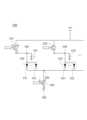
- 11 and 12are diagrams for explaining a laser emitting module and a laser detecting module according to an embodiment.
- the LIDAR device 4100may include a laser emitting module 4110 and a laser detecting module 4120.
- the laser emitting module 4110may include a laser emitting array 4111 and a first substrate 4112.
- the laser emitting array 4111may be provided in the form of a chip in which a plurality of laser emitting units are arranged in an array, but is not limited thereto.
- the laser emitting array 4111may be provided in the form of a laser emitting chip, but is not limited thereto.
- the laser emitting array 4111may be located on the first substrate 4112, but is not limited thereto.
- the first substrate 4112may include a laser emitting driver for controlling the operation of the laser emitting array 4111, but is not limited thereto.
- the laser detecting module 4120may include a laser detecting array 4121 and a second substrate 4122.
- the laser detecting array 4121may be provided in the form of a chip in which a plurality of laser detecting units are arranged in an array, but is not limited thereto.
- the laser detecting array 4121may be provided in the form of a laser detecting chip, but is not limited thereto.
- the laser detecting array 4121may be located on the second substrate 4122, but is not limited to this.
- the second substrate 4122may include a laser detecting driver for controlling the operation of the laser detecting array 4121, but is not limited thereto.
- first substrate 4112 and the second substrate 4122may be provided separately from each other as shown in FIG. 11, but are not limited to this and may be provided as one substrate.
- FIG. 12is a diagram for explaining an embodiment of the LiDAR device of FIG. 11, and the content described in FIG. 11 and the present invention is not limited by the shape shown in FIG. 12.
- FIG. 13 and 14are diagrams for explaining an emitting lens module and a detecting lens module according to an embodiment.
- the LIDAR device 4200may include an emitting lens module 4210 and a detecting lens module 4220.
- the emitting lens module 4210may include an emitting lens assembly 4211 and an emitting lens mounting tube 4212.
- the emitting lens assembly 4211may be disposed within the emitting lens mounting tube 4212.
- the emitting lens mounting tube 4212may refer to a barrel surrounding the emitting lens assembly 4211, but is not limited thereto.
- the detecting lens module 4220may include a detecting lens assembly 4221 and a detecting lens mounting tube 4222.
- the detecting lens assembly 4221may be disposed within the detecting lens mounting tube 4222.
- the detecting lens mounting tube 4222may refer to a barrel surrounding the detecting lens assembly 4221, but is not limited thereto.
- the emitting optics module 4210may be arranged to be aligned with the laser emitting module described above.
- the fact that the emitting optic module 4210 is arranged to be aligned with the above-described laser emitting modulemeans that it is physically arranged to have a preset relative positional relationship and can irradiate the laser at an optically target angle. It may include, but is not limited to, the meaning of being aligned so as to be able to do so.
- the detecting optic module 4220may be arranged to be aligned with the laser detecting module described above.
- the fact that the detecting optic module 4220 is arranged to be aligned with the above-described laser detecting modulemeans that it is physically arranged to have a preset relative positional relationship and that the laser is received at an optically target angle. It may include, but is not limited to, the meaning of being aligned so as to be detectable.
- FIG. 14is a diagram for explaining an embodiment of the LiDAR device of FIG. 13, and the content described in FIG. 13 and the present invention is not limited by the shape shown in FIG. 14.
- Figure 15is a diagram showing a laser output unit according to one embodiment.
- the laser output unit 100may include a VCSEL emitter 110.
- the VCSEL emitter 110includes an upper metal contact 10, an upper DBR layer (20, upper Distributed Bragg reflector), an active layer (40, quantum well), and a lower DBR layer (30, lower Distributed Bragg reflector). , may include a substrate 50 and a lower metal contact 60.
- the VCSEL emitter 110may emit a laser beam vertically from the top surface.
- the VCSEL emitter 110may emit a laser beam in a direction perpendicular to the surface of the upper metal contact 10.
- the VCSEL emitter 110may emit a laser beam perpendicular to the active layer 40.
- the VCSEL emitter 110may include an upper DBR layer 20 and a lower DBR layer 30.
- the upper DBR layer 20 and lower DBR layer 30may be composed of a plurality of reflective layers.
- the plurality of reflective layersmay be alternately arranged with reflective layers with high reflectivity and reflective layers with low reflectivity.
- the thickness of the plurality of reflective layersmay be one fourth of the laser wavelength emitted from the VCSEL emitter 110, but is not limited thereto.
- the upper DBR layer 20 and lower DBR layer 30may be doped into p-type and n-type.
- the upper DBR layer 20may be doped as p-type
- the lower DBR layer 30may be doped as n-type.
- the upper DBR layer 20may be doped as n-type
- the lower DBR layer 30may be doped as p-type.
- a substrate 50may be disposed between the lower DBR layer 30 and the lower metal contact 60. If the lower DBR layer 30 is doped to p-type, Substrate 50 can also become a p-type substrate, and if the lower DBR layer 30 is doped to n-type, Substrate 50 can also become an n-type substrate. there is.
- the VCSEL emitter 110may include an active layer 40.
- the active layer 40may be disposed between the upper DBR layer 20 and the lower DBR layer 30.
- the active layer 40may include a plurality of quantum wells that generate laser beams.
- the active layer 40can emit a laser beam.
- the VCSEL emitter 110may include a metal contact for electrical connection with a power source, etc.
- the VCSEL emitter 110may include an upper metal contact 10 and a lower metal contact 60.
- the VCSEL emitter 110may be electrically connected to the upper DBR layer 20 and the lower DBR layer 30 through a metal contact.
- the upper DBR layer 20is doped with p-type and the lower DBR layer 30 is doped with n-type
- p-type poweris supplied to the upper metal contact 10 to connect the upper DBR layer 20 and the other. It is electrically connected, and n-type power is supplied to the lower metal contact 60 so that it can be electrically connected to the lower DBR layer 30.
- n-type poweris supplied to the upper metal contact 10 to It is electrically connected to the layer 20
- p-type poweris supplied to the lower metal contact 60 so that it can be electrically connected to the lower DBR layer 30.
- the VCSEL emitter 110may include an oxidation area.
- the oxidation areacan be placed on top of the active layer.
- the oxidation areamay be insulating.
- electrical flowmay be restricted in the oxidation area.
- electrical connectionsmay be limited in the oxidation area.
- the oxidation areamay serve as an aperture. Specifically, since the oxidation area has insulating properties, the beam generated from the active layer 40 can be emitted only from a portion other than the oxidation area.
- the laser output unitmay include a plurality of VCSEL emitters 110.
- the laser output unitcan turn on a plurality of VCSEL emitters 110 at once or turn them on individually.
- the laser output unitmay emit laser beams of various wavelengths.
- the laser output unitcan emit a laser beam with a wavelength of 905 nm.
- the laser output unitmay emit a laser beam with a wavelength of 940 nm.
- the laser output unitmay emit a laser beam with a wavelength of 1550 nm.
- the wavelength of the laser output from the laser output unitmay change depending on the surrounding environment.
- the wavelength of the laser output from the laser output unitmay increase as the temperature of the surrounding environment increases.
- the wavelength of the laser output from the laser output unitmay decrease as the temperature of the surrounding environment decreases.
- the surrounding environmentmay include, but is not limited to, temperature, humidity, pressure, dust concentration, amount of surrounding light, altitude, gravity, acceleration, etc.
- the laser output unitmay emit a laser beam in a direction perpendicular to the support surface.
- the laser output unitmay emit a laser beam in a direction perpendicular to the emission surface.
- Figure 16is a diagram for explaining a laser output array according to an embodiment.
- the laser output array 5000may include a plurality of laser output units, at least one sub-array, at least one upper conductor, at least one lower conductor, and at least one power supply. You can.
- the at least one sub-arraymay refer to a group of operatively connected laser output units among the plurality of laser output units, may refer to a group of physically connected laser output units, and may refer to the same power supply unit.
- may refer to a group of laser output units connected tomay refer to a group of laser output units defined by the at least one upper conductor, and may refer to a group of laser output units defined by a capacitor electrically connected to the at least one power supply. It may refer to a group of output units, but is not limited to this.
- At least one sub-arraymay include a plurality of sub-arrays.
- At least one sub-arraymay include a plurality of sub-arrays including a first sub-array 5010, but is not limited thereto.
- At least one sub-arraymay include a plurality of laser output units.
- the first sub-array 5010may include a plurality of laser output units, but is not limited thereto.
- the first sub-array 5010may include a first laser output unit 5011 and a second laser output unit 5012, but is not limited thereto.
- a plurality of laser output units included in at least one sub-arraymay be connected to at least one upper conductor.
- a plurality of laser output units included in the first sub-array 5010may be connected to the first upper conductor 5013 through an upper metal contact, but the present invention is not limited to this.
- the first laser output unit 5011 and the second laser output unit 5012 included in the first sub-array 5010may provide the first laser output unit 5012 through each upper metal contact. It may be connected to the upper conductor 5013, but is not limited to this.
- a plurality of laser output units included in at least one sub-arraymay be connected to at least one lower conductor.
- a plurality of laser output units included in at least one sub-arraymay be connected to the first lower conductor 5014 through a lower metal contact, but is not limited to this.
- first laser output unit 5011 and the second laser output unit 5012 included in at least one sub-arrayare each connected to the first lower conductor 5014 through a lower metal contact. ), but is not limited to this.
- a plurality of laser output units included in at least one sub-arraymay receive energy from at least one power supply.
- the first laser output unit 5011 and the second laser output unit 5012 included in the first sub-array 5010 included in at least one sub-arrayare the first upper laser output unit 5012. It may be connected to the first power supply unit 5015 through a conductor 5013 and receive energy from the first power supply unit 5015, but is not limited to this.
- the first laser output unit 5011 and the second laser output unit 5012 included in the first sub-array 5010 included in at least one sub-arrayare the 1 It may be connected to the first power supply unit 5015 through the lower conductor 5014 and receive energy from the first power supply unit 5015, but is not limited to this.
- a plurality of laser output units included in at least one sub-arraymay receive voltage from at least one power supply.
- the first laser output unit 5011 and the second laser output unit 5012 included in the first sub-array 5010 included in at least one sub-arrayare the first upper laser output unit 5012. It may be connected to the first power supply unit 5015 through a conductor 5013 and receive voltage from the first power supply unit 5015, but is not limited to this.
- the first laser output unit 5011 and the second laser output unit 5012 included in the first sub-array 5010 included in at least one sub-arrayare the 1 It may be connected to the first power supply unit 5015 through the lower conductor 5014 and receive voltage from the first power supply unit 5015, but is not limited to this.
- the length of an electrical path between at least one power supply and at least one laser output unit included in at least one sub-array according to an embodimentmay be different from each other.
- the electrical path between the first laser output unit 5011 included in the first sub-array 5010 and the first power supply unit 5015is the second laser output. It may be smaller than the electrical path between the unit 5012 and the first power supply unit 5015, but is not limited to this.
- the electrical pathmay mean a path through which current or electrons move from the power supply unit to each laser output unit, and may include a concept that can be understood as an electrical path by those skilled in the art.
- 17 and 18are diagrams for explaining a laser output array according to an embodiment.
- FIGS. 17 and 18Before describing FIGS. 17 and 18 , since the respective components described in FIGS. 17 and 18 correspond to each other and the above-described contents can be applied, overlapping descriptions will be omitted.
- the laser output array 5100includes a plurality of laser output units, at least one sub-array, at least one upper conductor, at least one lower conductor, and at least one power supply. , may include at least one switch and at least one capacitor.
- the at least one sub-arraymay refer to a group of operatively connected laser output units among the plurality of laser output units, may refer to a group of physically connected laser output units, and may refer to the same power supply unit.
- may refer to a group of laser output units connected tomay refer to a group of laser output units defined by the at least one upper conductor, and may refer to a group of laser output units defined by a capacitor electrically connected to the at least one power supply. It may refer to a group of output units, but is not limited to this.
- the laser output array 5100may include a plurality of laser output units.
- the laser output array 5100includes a first laser output unit 5111, a second laser output unit 5112, a third laser output unit 5121, and a fourth laser output unit 5122. ), a fifth laser output unit 5131, and a sixth laser output unit 5132, but is not limited thereto.
- the laser output array 5100may include a plurality of sub-arrays including at least one laser output unit.
- the laser output array 5100includes a first sub-array 5110 including the first laser output unit 5111 and the second laser output unit 5112, and the third laser.
- a plurality of laser output units included in the laser output array 5100may be located between nodes having different voltages when each of the plurality of laser output units outputs laser. .
- the first laser output unit 5111 included in the laser output array 5100has different voltages when the first laser output unit 5111 outputs the first laser. It may be located between the first node 5191 and the second node 5192, but is not limited to this.
- energymay be supplied to the first laser output unit 5111 by the voltage difference between the first node 5191 and the second node 5192 to output the first laser, but it is limited to this. It doesn't work.
- the third laser output unit 5121 included in the laser output array 5100may have different voltages when the third laser output unit 5121 outputs the third laser. It may be located between the third node 5193 and the second node 5192, but is not limited to this.
- energymay be supplied to the third laser output unit 5121 by the voltage difference between the third node 5193 and the second node 5192 to output the third laser, but it is limited to this. It doesn't work.
- the fifth laser output unit 5131 included in the laser output array 5100may have different voltages when the fifth laser output unit 5131 outputs the fifth laser. It may be located between the fourth node 5194 and the second node 5192, but is not limited to this.
- energymay be supplied to the fifth laser output unit 5121 by the voltage difference between the fourth node 5194 and the second node 5192 to output the fifth laser, but is limited to this. It doesn't work.
- a plurality of laser output units included in at least one sub-array included in the laser output array 5100may be located between the same nodes.
- the first laser output unit 5111 and the second laser output unit 5112 included in the first sub-array 5110are the first node 5191 and the second node 5192. It may be located in between, but is not limited to this.
- the third laser output unit 5121 and the fourth laser output unit 5122 included in the second sub-array 5120may be connected to the third node 5193 and the second node ( 5192), but is not limited thereto.
- the fifth laser output unit 5131 and the sixth laser output unit 5132 included in the third sub-array 5130may be connected to the fourth node 5194 and the second node ( 5192), but is not limited thereto.
- the laser output array 5100may include at least one capacitor for supplying energy to at least one laser output unit.
- the energy supplied to the at least one laser output unitmay be expressed as voltage, current, charge, etc. for convenience, and may be expressed in various terms related to the energy for laser output from the at least one laser output unit. can be expressed.
- the laser output array 5100may include a first capacitor 5141, where the first capacitor 5141 supplies energy to the first laser output unit 5111. It may function, but is not limited to this.
- the laser output array 5100may include a second capacitor 5142, and the second capacitor 5142 supplies energy to the third laser output unit 5121. It may function to supply, but is not limited to this.
- the laser output array 5100may include a third capacitor 5143, and the third capacitor 5143 supplies energy to the fifth laser output unit 5131. It may function to supply, but is not limited to this.
- At least one capacitor included in the laser output array 5100may function to supply energy to at least one sub-array included in the laser output array 5100.
- the first capacitor 5141may function to supply energy to the first sub-array 5110 including the first laser output unit 5111 and the second laser output unit 5112. However, it is not limited to this.
- the second capacitor 5142functions to supply energy to the second sub-array 5120 including the third laser output unit 5121 and the fourth laser output unit 5122. It can be done, but it is not limited to this.
- the third capacitor 5143functions to supply energy to the third sub-array 5130 including the fifth laser output unit 5131 and the fifth laser output unit 5132. It can be done, but it is not limited to this.
- At least one capacitor included in the laser output array 5100may be coupled to at least one node.
- the first capacitor 5141may be connected to the first node 5191, but is not limited to this.
- the second capacitor 5142may be connected to the third node 5193, but is not limited to this.
- the third capacitor 5143may be connected to the fourth node 5194, but is not limited to this.
- At least one capacitor included in the laser output array 5100may be electrically connected to an upper conductor connected to the upper metal contact of each of the plurality of laser output units included in at least one sub-array. there is.
- the first capacitor 5141is connected to the upper metal contact of the first laser output unit 5111 and the upper metal contact of the second laser output unit 5112. It may be electrically connected to the upper conductor 5171, but is not limited to this.
- the third capacitor 5143is connected to the upper metal contact of the fifth laser output unit 5131 and the upper metal contact of the sixth laser output unit 5132. It may be electrically connected to the third upper conductor 5173, but is not limited to this.
- the laser output array 5100may include at least one power supply unit (HV) for charging the at least one capacitor.
- HVpower supply unit
- the laser output array 5100includes a power supply unit (HV) for charging the first capacitor 5141, the second capacitor 5142, and the third capacitor 5143. It can be done, but it is not limited to this.
- HVpower supply unit
- the power supply unit (HV)may be provided as one, but is not limited to this, and may be provided in plural pieces to each charge one capacitor, and may be provided in plural pieces to each charge multiple capacitors. .
- At least one power supply unit (HV) included in the laser output array 5100may function to charge the at least one capacitor through a node connected to the at least one capacitor.
- the power supply unit (HV)may function to charge the first capacitor 5141 through the first node 5191, but is not limited to this.
- the power supply unit (HV)may function to charge the second capacitor 5142 through the third node 5193, but is not limited to this.
- the power supply unit (HV)may function to charge the third capacitor 5143 through the fourth node 5194, but is not limited to this.
- the laser output array 5100includes at least one charging switch for controlling charging of the at least one capacitor and a charging switch driving driver for controlling driving of the at least one charging switch. can do.
- the at least one charging switchmay be implemented as a field effect transistor (FET), but is not limited to this.
- FETfield effect transistor
- the laser output array 5100controls the first charging switch 5151 to control charging of the first capacitor 5141 and the driving of the first charging switch 5151. It may include, but is not limited to, a first charging switch driving driver.
- the laser output array 5100includes a first charging switch 5151 for controlling charging of the first capacitor 5141 and a gate of the first charging switch 5151 ( It may include, but is not limited to, a first charging switch driving driver connected to the gate (Gate) to control the applied voltage.
- the laser output array 5100operates the second charging switch 5152 and the second charging switch 5152 to control charging of the second capacitor 5142. It may include, but is not limited to, a second charging switch driving driver for control.
- the laser output array 5100includes a second charging switch 5152 for controlling charging of the second capacitor 5142 and a gate of the second charging switch 5152 ( Gate) may include a second charging switch driving driver to control the applied voltage, but is not limited to this.
- the laser output array 5100operates the third charging switch 5153 and the third charging switch 5153 to control charging of the third capacitor 5143. It may include, but is not limited to, a third charging switch driving driver for control.
- the laser output array 5100includes a third charging switch 5153 for controlling charging of the third capacitor 5143 and a gate of the third charging switch 5153 ( It may include, but is not limited to, a third charging switch driving driver connected to the gate (Gate) to control the applied voltage.
- At least one charging switchmay be located between the at least one power supply included in the laser output array 5100 and the at least one capacitor.
- the first charging switch 5151may be located between the power supply unit (HV) and the first capacitor 5141, but is not limited to this.
- the second charging switch 5152may be located between the power supply unit (HV) and the second capacitor 5142, but is not limited to this.
- the third charging switch 5153may be located between the power supply unit (HV) and the third capacitor 5143, but is not limited to this.
- At least one charging switch included in the laser output array 5100may be coupled to at least one node.
- the first charging switch 5151may be connected to the first node 5191, but is not limited to this.
- the second charging switch 5152may be connected to the third node 5193, but is not limited to this.
- the third charging switch 5153may be connected to the fourth node 5194, but is not limited to this.
- the laser output array 5100includes at least one common driving switch for controlling the driving of at least one laser output unit and a common driving switch for controlling the driving of the at least one common driving switch. May include a driver (common driving switch driver).
- the at least one common driving switchmay be implemented as a field effect transistor (FET), but is not limited to this.
- FETfield effect transistor
- the laser output array 5100includes a common driving switch 5160 for controlling the driving of the first laser output unit 5111 and controlling the driving of the common driving switch 5160. It may include, but is not limited to, a common driving switch driving driver.
- the laser output array 5100includes at least one common driving switch for controlling the driving of a plurality of laser output units included in at least one sub-array and driving of the at least one common driving switch. It may include a common driving switch driver for control.
- the laser output array 5100controls the operation of the first laser output unit 5111 and the second laser output unit 5112 included in the first sub-array 5110. It may include, but is not limited to, a common driving switch 5160 and a common driving switch driving driver for controlling the driving of the common driving switch 5160.
- At least one common driving switchmay be located between at least one laser output unit included in the laser output array 5100 and the ground.
- the common driving switch 5160may be located between the first laser output unit 5111 and the first ground 5195, but is not limited to this.
- the common driving switch 5160may be located between the third laser output unit 5121 and the first ground 5195, but is not limited to this.
- the common driving switch 5160may be located between the fifth laser output unit 5131 and the first ground 5195, but is not limited to this.
- At least one common driving switchmay be located between the ground and a lower conductor connected to the lower metal of the plurality of laser output units included in the laser output array 5100.
- the common driving switch 5160is a lower part connected to each lower metal of the first to sixth laser output units 5111 to 5132 included in the laser output array 5100. It may be located between the conductor 5180 and the first ground 5195, but is not limited to this.
- At least one common driving switch included in the laser output array 5100may be coupled to at least one node.
- the common driving switch 5160may be connected to the second node 5192, but is not limited to this.
- the first charging switch 5151may be turned on.
- the first charging switch 5151is turned on by the operation of the first charging switch driving driver connected to the gate of the first charging switch 5151. It may be possible, but it is not limited to this.
- the first capacitor 5141may be charged by the power supply unit (HV).
- the present inventionis not limited to this.
- the common driving switch 5160may be turned on.
- the common driving switch 5160may be turned on by the operation of a common driving switch driving driver connected to the gate of the common driving switch 5160. , but is not limited to this.
- the first laser output included in the first sub-array 5110 by the first capacitor 5141 Energymay be supplied to the unit 5111 and the second laser output unit 5112, and thus the first laser and the second laser may be output, respectively.
- the common driving switch 5160as the common driving switch 5160 is turned on, the charges charged in the first capacitor 5141 are discharged, and the first capacitor 5141 and A current may flow between the first ground 5195, and at least a portion of the current may pass through the first laser output unit 5111 to generate light in the active area of the first laser output unit 5111. At least another portion of the current may pass through the second laser output unit 5112 to generate light in the active area of the second laser output unit 5112, and the first and second laser outputs Light generated from each of the units 5111 and 5112 may be emitted to each surface, which may be expressed as a third laser and a fourth laser, respectively, but is not limited thereto.
- the second charging switch 5152may be turned ON.
- the second charging switch 5152is turned ON by the operation of the second charging switch driving driver connected to the gate of the second charging switch 5152. It may be possible, but it is not limited to this.
- the second capacitor 5142may be charged by the power supply unit (HV).
- the second charging switch 5152As the second charging switch 5152 is turned on, the second charging switch 5152 and the third node 5193 are charged from the power supply unit (HV). ), a current may flow into the second capacitor 5142, and thus the second capacitor 5142 may be charged, but the present invention is not limited to this.
- the common driving switch 5160may be turned on.
- the common driving switch 5160may be turned on by the operation of a common driving switch driving driver connected to the gate of the common driving switch 5160. , but is not limited to this.
- the third laser output included in the second sub-array 5120 by the second capacitor 5142 Energymay be supplied to the unit 5121 and the fourth laser output unit 5122, and thus a third laser and a fourth laser may be output, respectively.
- the common driving switch 5160as the common driving switch 5160 is turned on, the charges charged in the second capacitor 5142 are discharged, and the second capacitor 5142 and A current may flow between the first ground 5195, and at least a portion of the current may pass through the third laser output unit 5121 to generate light in the active area of the third laser output unit 5121. At least another portion of the current may pass through the fourth laser output unit 5122 to generate light in the active area of the fourth laser output unit 5122, and the third and fourth laser outputs Light generated from each of the units 5121 and 5122 may be emitted to each surface, which may be expressed as a third laser and a fourth laser, respectively, but is not limited thereto.
- the third charging switch 5153may be turned on.
- the third charging switch 5153is turned ON by the operation of the third charging switch driving driver connected to the gate of the third charging switch 5153. It may be possible, but it is not limited to this.
- the third capacitor 5143may be charged by the power supply unit (HV).
- the third charging switch 5153As the third charging switch 5153 is turned on, the third charging switch 5153 and the fourth node 5194 are charged from the power supply unit (HV). ), a current may flow to the third capacitor 5143, and thus the third capacitor 5143 may be charged, but the present invention is not limited to this.
- the common driving switch 5160may be turned on.
- the common driving switch 5160may be turned on by the operation of a common driving switch driving driver connected to the gate of the common driving switch 5160. , but is not limited to this.
- the fifth laser output included in the third sub-array 5130 by the third capacitor 5143 Energymay be supplied to the unit 5131 and the sixth laser output unit 5132, and accordingly, the fifth laser and the sixth laser may be output, respectively.
- the common driving switch 5160is turned on, the charges charged in the third capacitor 5143 are discharged, and the third capacitor 5143 and A current may flow between the first ground 5195, and at least a portion of the current may pass through the fifth laser output unit 5131 to generate light in the active area of the fifth laser output unit 5131. At least another portion of the current may pass through the sixth laser output unit 5132 to generate light in the active area of the sixth laser output unit 5132, and the fifth and sixth laser outputs Light generated from each of the units 5131 and 5132 may be emitted to each surface, which may be expressed as a fifth laser and a sixth laser, respectively, but is not limited thereto.
- the laser output channel(subarray from which the laser is output) is charged. It can be selected by the capacitor being used.
- the first sub-array 5110may be selected as the laser output channel, and the common driving switch 5160 may be selected as the laser output channel.
- the switch 5160is driven, if the second capacitor 5142 is charged, the second sub-array 5120 may be selected as the laser output channel, and the common driving switch 5160 may be driven.
- the third capacitor 5143is charged, the third sub-array 5130 may be selected as the laser output channel.
- one capacitormay be charged, and a plurality of capacitors may be charged. may be charged, but is not limited to this.
- Figure 19is a diagram for explaining lidar data according to an embodiment.
- LiDAR data 6000includes point cloud data 6010, depth map data 6020, intensity map data 6030, and light capture map. (Light capture map) may include at least one data among the data 6040.
- Depth map data 6020may be data for expressing a distance value according to the location of a two-dimensional pixel.
- depth map data 6020may include at least one point data.
- the at least one point datamay include pixel coordinates (x', y') and a distance value (d) corresponding to the pixel coordinates (x', y').
- pixel coordinates (x', y') included in the depth map data 6020may correspond to a laser detecting unit.
- the first pixel coordinates included in the depth map data 6020may correspond to the first laser detecting unit, and the second pixel coordinates may be included in the second laser detecting unit. It is not limited.
- pixel coordinates (x', y') included in the depth map data 6020may correspond to a position on the laser detecting array of the laser detecting unit.
- the first pixel coordinates included in the depth map data 6020correspond to the first laser detecting unit, and the first laser detecting unit is located at (1,1) on the laser detecting array.
- the first pixel coordinatemay be (1,1)
- the second pixel coordinatecorresponds to the second laser detecting unit
- the second laser detecting unitis ( When located at 1,2), the second pixel coordinates may be (1,2), but are not limited thereto.
- the distance value d included in the depth map data 6020may be obtained based on a signal generated from a laser detecting unit.
- the first distance value corresponding to the first pixel coordinatesmay be obtained based on a signal generated from the first laser detecting unit
- the second distance value corresponding to the second pixel coordinatesmay be obtained based on the signal generated from the first laser detecting unit. It may be obtained based on a signal generated from the tacting unit, but is not limited to this.
- the first distance value corresponding to the first pixel coordinatemay be obtained based on first histogram data generated based on the signal generated from the first laser detecting unit, and the first distance value corresponding to the first pixel coordinate may be obtained based on the first histogram data generated based on the signal generated from the first laser detecting unit.
- the corresponding second distance valuemay be obtained based on second histogram data generated based on the signal generated from the second laser detecting unit, but is not limited to this.
- intensity map data 6030may be data for expressing intensity values according to the positions of two-dimensional pixels.
- intensity map data 6030may include at least one point data.
- the at least one point datamay include pixel coordinates (x'', y'') and an intensity value (i) corresponding to the pixel coordinates (x'', y'').
- pixel coordinates (x'', y'') included in the intensity map data 6030may correspond to a laser detecting unit.
- the first pixel coordinates included in the intensity map data 6030may correspond to the first laser detecting unit, and the second pixel coordinates may be included in the second laser detecting unit. It is not limited.
- pixel coordinates (x'', y'') included in the intensity map data 6030may correspond to a position on the laser detecting array of the laser detecting unit.
- the first pixel coordinates included in the intensity map data 6030correspond to the first laser detecting unit, and the first laser detecting unit detects (1,1) on the laser detecting array.
- the first pixel coordinatemay be (1,1)
- the second pixel coordinatecorresponds to the second laser detecting unit
- the second laser detecting unitis ( When located at 1,2), the second pixel coordinates may be (1,2), but are not limited thereto.
- the intensity value (i) included in the intensity map data 6030may be obtained based on a signal generated from a laser detecting unit.
- the first intensity value corresponding to the first pixel coordinatesmay be obtained based on a signal generated from the first laser detecting unit
- the second intensity value corresponding to the second pixel coordinatesmay be obtained based on the signal generated from the first laser detecting unit. It may be obtained based on a signal generated from the tacting unit, but is not limited to this.
- the first intensity value corresponding to the first pixel coordinatemay be obtained based on first histogram data generated based on the signal generated from the first laser detecting unit, and the first intensity value corresponding to the first pixel coordinate may be obtained based on the first histogram data generated based on the signal generated from the first laser detecting unit.
- the corresponding second intensity valuemay be obtained based on second histogram data generated based on the signal generated from the second laser detecting unit, but is not limited to this.
- light capture map data 6040may be data for expressing light capture values according to two-dimensional pixel positions.
- the light capture valueis a value for the intensity of light acquired during a unit time, and may be related to the number of photons obtained from the detecting unit during a unit time.
- the light capture valuemay be expressed as an ambient value, etc., depending on the embodiment, and the light capture map data 6040 may be expressed as ambient map data, etc.
- the light capture valuereflects the number of photons due to external light, but is not limited to this.
- light capture map data 6040may include at least one point data.
- the at least one point datamay include pixel coordinates (x''',y''') and a light capture value (v) corresponding to the pixel coordinates (x''',y''').
- pixel coordinates (x''', y''') included in the light capture map data 6040may correspond to a laser detecting unit.
- the first pixel coordinates included in the light capture map data 6040may correspond to the first laser detecting unit, and the second pixel coordinates may be included in the second laser detecting unit. It is not limited to this.
- pixel coordinates (x''', y''') included in the light capture map data 6040may correspond to a position on the laser detecting array of the laser detecting unit.
- the first pixel coordinates included in the light capture map data 6040correspond to the first laser detecting unit, and the first laser detecting unit is (1, When located at 1), the first pixel coordinate may be (1,1), the second pixel coordinate corresponds to the second laser detecting unit, and the second laser detecting unit is on the laser detecting array. When located at (1,2), the second pixel coordinates may be (1,2), but are not limited thereto.
- the light capture value (v) included in the light capture map data 6040may be obtained based on a signal generated from a laser detecting unit.
- the first light capture value corresponding to the first pixel coordinatesmay be obtained based on a signal generated from the first laser detecting unit
- the second light capture value corresponding to the second pixel coordinatesmay be obtained based on the signal generated from the first laser detecting unit. It may be obtained based on a signal generated from a laser detecting unit, but is not limited to this.
- the first light capture value corresponding to the first pixel coordinatemay be obtained by adding counting values generated based on the signal generated from the first laser detecting unit for a unit time
- the second pixel coordinateThe second light capture value corresponding to may be obtained by adding counting values generated based on the signal generated from the second laser detecting unit during unit time, but is not limited to this.
- point cloud data 6010may be data for expressing the location of a 3D point or various values according to the location of a 3D point.
- point cloud data 6010may include at least one point data.
- the at least one point dataincludes various values such as position coordinates (x, y, z) and intensity value (i) or light capture value (v) corresponding to the position coordinates (x, y, z). can do.
- the position coordinates (x, y, z) included in the point cloud data 6010may be obtained based on the direction and distance value in which the laser is output.
- the first position coordinatesmay be obtained based on the first direction and the first distance value, and the first position coordinates may be obtained based on the first direction and the first distance value,
- the second position coordinatesmay be obtained based on the second direction and the second distance value, but the second position coordinate is not limited to this.
- the position coordinates (x, y, z) included in the point cloud data 6010may be obtained based on the pixel coordinates corresponding to the laser detecting unit and the corresponding distance value.
- the first position coordinatescan be obtained based on the first pixel coordinate and the first distance value
- the pixel coordinate included in the second laser detecting unitis the second pixel coordinate, and is obtained based on the signal generated from the second laser detecting unit.
- the second position coordinatesmay be obtained based on the second pixel coordinates and the second distance value, but the method is not limited to this.
- the intensity value (i) or the light capture value (v) included in the point cloud data 6010may be a value corresponding to the pixel coordinates that are the basis for obtaining position coordinates.
- the first intensity value corresponding to the first position coordinatemay be a first intensity value corresponding to the first pixel coordinate
- the second intensity value corresponding to the second position coordinatemay be the first intensity value corresponding to the second pixel coordinate. It may be an intensity value of 2, but is not limited to this.
- pixel coordinates included in each of the depth map data 6020, the intensity map data 6030, and the light capture map data 6040may be the same, but are not limited to this, and are different from each other. may be different.
- Figure 20is a diagram for explaining a method of acquiring detection values and LIDAR data according to an embodiment.
- the operation section of the LiDAR devicemay include a first operation section 6110.
- the operation section of the LiDAR deviceis a time period in which the LiDAR device performs a series of operations to obtain the value of at least a portion of the point data included in the LiDAR data according to an embodiment. It can mean.
- the first laser emitting unit 6120may output a plurality of lasers.
- the first laser emitting unit 6120uses the first laser 6121, the second laser 6122, and the N laser ( 6123) can be output, but is not limited to this.
- the first laser detecting unit 6130may detect the acquired light and generate at least one signal.
- the first laser detecting unit 6130causes the laser output from the first laser emitting unit 6120 to be reflected from the object.
- a detecting signalmay be generated by detecting the laser output from the first laser emitting unit 6120 and reflected from the object, but the detection signal is not limited to this.
- the first laser detecting unit 6130may generate at least one signal by detecting light obtained during a plurality of detecting windows. there is.
- the first laser detecting unit 6130operates the first laser emitting unit 6120 during the first detecting window 6131.
- a first detecting signalcan be generated by detecting at least a portion of the first laser 6121 output from the second laser emitting unit 6120 during the second detecting window 6132.
- a second detecting signalmay be generated by detecting at least a portion of the laser beam 6122, and at least a portion of the Nth laser 6123 output from the first laser emitting unit 6120 during the Nth detecting window 6133.
- the Nth detecting signalcan be generated by detecting, but is not limited to this.
- the detecting windowmay be understood as a section for detecting light obtained by a laser detecting unit according to an embodiment, but is not limited thereto.
- the first operation section 6110 of the LIDAR deviceis expressed as an operation section for obtaining a distance value, an operation section for obtaining an intensity value, an operation section for obtaining distance and intensity values, etc. It may be possible, but it is not limited to this.
- the LIDAR devicemay generate at least one counting value based on the signal generated from the first laser detecting unit 6130.
- the LIDAR devicemay provide at least one detection signal generated from the first laser detecting unit 6130 during the first detecting window 6131 and the time at which the detecting signal was generated. At least one counting value assigned to a time bin may be generated, but is not limited to this.
- the LIDAR devicemay detect the detection signal generated from the first laser detecting unit 6130 during the second detecting window 6132 and the time at which the detection signal was generated. At least one counting value assigned to at least one time bin may be generated, but the method is not limited to this.
- the LIDAR devicemay detect the detection signal generated from the first laser detecting unit 6130 during the N-th detecting window 6133 and the time at which the detection signal was generated. At least one counting value assigned to at least one time bin may be generated, but the method is not limited to this.
- the LIDAR devicemay generate first histogram data 6140 based on the detecting signal generated from the first laser detecting unit 6130 in the first operation section 6110. there is.
- the LIDAR devicecreates a first histogram based on the detecting signal generated from the first laser detecting unit 6130 in a plurality of detecting windows included in the first operation section 6110. Data 6140 can be generated.
- the LIDAR devicemay include at least one counting value generated based on the detecting signal generated from the first laser detecting unit 6130 in the first detecting window 6131, 2 At least one counting value generated based on the detecting signal generated from the first laser detecting unit 6130 in the detecting window 6132 and the first laser detecting value in the N-th detecting window 6132
- the first histogram data 6140may be generated based on at least one counting value generated based on the detecting signal generated from the unit 6130, but is not limited to this.
- the first histogram data 6140may be generated by an algorithm that accumulates counting values assigned to time bins, which are unit times for dividing each of a plurality of detecting windows, but is not limited to this. , can be generated by various algorithms that can typically generate a histogram based on signals obtained from a laser detecting unit.
- the LIDAR devicemay generate at least one detecting value based on the first histogram data 6140, and the operation of generating the detecting value may be implemented through at least one processor. However, it is not limited to this.
- the LIDAR devicemay generate a distance value for the first pixel based on the first histogram data 6140, but is not limited to this.
- the LIDAR devicemay generate an intensity value for the first pixel based on the first histogram data 6140, but is not limited to this.
- the operation of generating the detecting value according to one embodimentmay be implemented by various algorithms.
- a rising edgeis obtained based on a threshold value, and a rising edge is obtained based on the rising edge.
- An algorithm for generating a distance valuemay be used, but is not limited to this, and various algorithms for generating a distance value using histogram data may be used.
- an algorithm that uses pulse width, peak power, etc.may be used to generate an intensity value for the first pixel based on the first histogram data 6140. It is not limited, and various algorithms can be used to generate intensity values using histogram data.
- the LiDAR devicemay include a plurality of laser emitting units and a plurality of laser detecting units, and the above-described first laser emitting unit 6120 and second laser detecting unit 6130 ) Detecting values for a plurality of pixels can be generated based on operations that can be understood as operations.
- the LiDAR devicemay include an M laser emitting unit and an M laser detecting unit, based on the operations of the M laser emitting unit and the M laser detecting unit.
- the distance value and intensity value for the Mth pixelcan be generated, but the method is not limited to this.
- the LiDAR devicemay acquire at least one LiDAR data using detecting values for a plurality of pixels.
- the LIDAR devicemay obtain a depth map using distance values for a plurality of pixels, but is not limited to this.
- the LIDAR devicemay obtain an intensity map using intensity values for a plurality of pixels, but the present invention is not limited thereto.
- the LIDAR devicemay acquire a point cloud using distance values and intensity values for a plurality of pixels, but is not limited to this.
- Figure 21is a diagram for explaining a method of acquiring detection values and LIDAR data according to an embodiment.
- the operation section of the LiDAR devicemay include a second operation section 6210.
- the operation section of the LiDAR deviceis a time period in which the LiDAR device performs a series of operations to obtain the value of at least a portion of the point data included in the LiDAR data according to an embodiment. It can mean.
- the first laser emitting unit 6220may not output laser, but is not limited to this.
- the first laser detecting unit 6230may detect the acquired light and generate at least one signal.
- the first laser detecting unit 6230may detect external light of the LiDAR device and generate a detecting signal. It is not limited to this.
- the first laser detecting unit 6230may generate at least one signal by detecting light obtained during the detecting window.
- the first laser detecting unit 6230detects external light obtained at a first time point during the detecting window 6231 and A first detecting signal may be generated, and a second detecting signal may be generated by detecting external light obtained at a second time point, but the present invention is not limited thereto.
- the detecting windowmay be understood as a section for detecting light obtained by a laser detecting unit according to an embodiment, but is not limited thereto.
- the second operation section 6210 of the LIDAR devicemay be expressed as an operation section for acquiring a light capture value, an operation section for obtaining an ambient value, etc., but is not limited thereto.
- the LIDAR devicemay generate at least one counting value based on the signal generated from the first laser detecting unit 6230.
- the LIDAR devicemay generate a first counting value based on the first detecting signal generated by detecting external light acquired at a first time point during the detecting window 6231, , A second counting value may be generated based on a second detecting signal generated by detecting external light obtained at a second time point, but is not limited to this.
- the LIDAR devicemay generate at least one detecting value based on the detecting signal generated from the first laser detecting unit 6230 in the second operation section 6210, , the operation of generating the detecting value may be implemented through at least one processor, but is not limited to this.
- the LIDAR devicemay provide light for the first pixel based on the detecting signal generated from the first laser detecting unit 6230 in the second operation section 6210. Capture values can be created, but are not limited to this.
- the LIDAR devicedetermines the ambient value for the first pixel based on the detecting signal generated from the first laser detecting unit 6230 in the second operation section 6210. can be created, but is not limited to this.
- the LIDAR devicemay include at least one counting value generated based on the detecting signal generated from the first laser detecting unit 6230 in the second operation section 6210.
- the light capture value for the first pixelmay be generated based on, but is not limited to this.
- the LIDAR devicemay include at least one counting value generated based on the detecting signal generated from the first laser detecting unit 6230 in the second operation section 6210.
- the ambient value for the first pixelmay be generated based on, but is not limited to this.
- the operation of generating the detecting value according to one embodimentmay be implemented by various algorithms.
- an algorithm that adds at least one counting value generated based on the signal generated from the first laser detecting unit 6230is used. It may be used, but is not limited to this.
- an algorithm that counts the number of signals generated from the first laser detecting unit 6230may be used, It is not limited to this.
- the LiDAR devicemay include a plurality of laser emitting units and a plurality of laser detecting units, and the above-described first laser emitting unit 6220 and second laser detecting unit 6230 ) Detecting values for a plurality of pixels can be generated based on operations that can be understood as operations.
- the LiDAR devicemay include an M laser emitting unit and an M laser detecting unit, based on the operations of the M laser emitting unit and the M laser detecting unit.
- the light capture value for the Mth pixelcan be generated, but the light capture value is not limited to this.
- the LiDAR devicemay acquire at least one LiDAR data using detecting values for a plurality of pixels.
- the LIDAR devicemay obtain a light capture map using light capture values for a plurality of pixels, but the present invention is not limited to this.
- Figure 22is a diagram for explaining an operation section of a LiDAR device according to an embodiment.
- the operation section of the LiDAR devicemay include a first operation section 6310 and a second operation section 6320.
- the operation section of the LiDAR deviceis a time period in which the LiDAR device performs a series of operations to obtain the value of at least a portion of the point data included in the LiDAR data according to an embodiment. It can mean.
- the overlapping descriptionis Decided to omit it.
- the first operation section 6310 and the second operation section 6320 of the LiDAR devicemay be separated in time.
- the operation of the LiDAR devicemay be performed in the second operation section 6320. It is not limited to this.
- the first operation section 6310 and the second operation section 6320 of the LiDAR devicemay overlap at least partially in time.
- the second operation section 6320may be included in the first operation section 6310 of the LiDAR device according to one embodiment, but the present invention is not limited thereto.
- the first operation section 6310 and the second operation section 6320 of the LiDAR devicemay be temporally the same.
- the operation of the LiDAR device performed in the first operation section 6310 of the LiDAR device and the operation of the LiDAR device performed in the second operation section 6320 according to one embodimentare in the same time period. It may be performed, but is not limited to this.
- the operation of the first laser emitting unit 6330 in the first operation section 6310 of the LiDAR deviceis the operation of the first laser emitting unit 6330 in the second operation section 6320.
- the actionsmay be different from each other.
- the first laser emitting unit 6330may output a laser according to the first cycle, and in the second operation section 6320, the first laser emitting unit 6330 may output the laser according to the first cycle.
- the unit 6330may not output a laser, but is not limited thereto.
- the operation of the first laser detecting unit 6340 in the first operation section 6310 of the LiDAR deviceis the operation of the first laser detecting unit 6340 in the second operation section 6320.
- the actionsmay be different from each other.
- the operation of the first laser detecting unit 6340may include a method of processing the detecting signal obtained from the first laser detecting unit 6340.
- thismay include a method of processing the detecting signal obtained from the first laser detecting unit 6340. It simply explains how to process , tied to the operation of the detecting unit.
- counting values generated based on a plurality of detecting signals obtained from each of a plurality of detecting windowsare assigned to a plurality of time bins, and the second operation section In (6320), one detecting value may be generated based on a plurality of detecting signals obtained from the detecting window, but the method is not limited to this.
- histogram datais generated by accumulating counting values assigned to the same time bin that are considered to have the same time from the point of laser output, and the second operation section In (6320), one detecting value can be generated based on a plurality of detecting signals acquired in the detecting window regardless of the laser output time, but the method is not limited to this.
- Figure 23is an exemplary diagram of lidar data according to an embodiment.
- FIG. 23shows point cloud data obtained based on detection values for the first to M pixels obtained according to the operation of the first operation section described in FIGS. 20 and 22.
- Figure 23(b)is obtained based on the detection values for the first to Mth pixels obtained according to the operation of the second operation section described through Figures 21 and 22.
- This diagramillustrates light capture map data as an example.
- point cloud data according to an embodimentincludes more specific information about the 3D spatial location of the surrounding environment than light capture map data according to an embodiment, and using this, 3D spatial location information about the surrounding environment is provided. Dimensional spatial positional relationships can be sensed more clearly.
- light capture map data according to an embodimentmay have better visibility of the surrounding environment than point cloud data according to an embodiment.
- light capture map data according to an embodimentmay be more similar to information obtained through the human eye than point cloud data according to an embodiment.
- different LiDAR data obtained from different operating sections of the LiDAR devicemay be data that more reflects different characteristics of the surrounding environment, so when using different LiDAR data appropriately, You will be able to perceive the surrounding situation more clearly than using a single lidar data.
- the quality obtainedmay vary depending on the intensity of external light.
- light capture map data according to an embodiment acquired during the day when the intensity of external light is strongcontains more information about the surrounding environment than light capture map data according to an embodiment acquired at night when the intensity of external light is weak. It can be included.
- Figure 24is a diagram for explaining the operation of a LiDAR device for generating an enhanced light capture map according to an embodiment.
- the operation section of the LiDAR devicemay include a first operation section 6410 and a second operation section 6420.
- the operation section of the LiDAR deviceis a time period in which the LiDAR device performs a series of operations to obtain the value of at least a portion of the point data included in the LiDAR data according to an embodiment. It can mean.
- the overlapping descriptionis Decided to omit it.
- the operation of the first laser emitting unit in the second operation section described with reference to FIGS. 21 and 22may be changed in order to generate an enhanced light capture map, and will be described below for convenience of explanation. For this purpose, this will be explained by comparing it with the operation of the first laser emitting unit in the first operation section.
- the operation of the first laser emitting unit 6430 in the first operation section 6410 of the enhanced LiDAR deviceis the operation of the first laser emitting unit 6430 in the second operation section 6420.
- the actionsmay be different from each other.
- the first laser emitting unit 6330may output a laser according to the first cycle 6431, and in the second operation section 6320, the first laser emitting unit 6330 may output the laser according to the first cycle 6431.
- the laser emitting unit 6330may output laser according to the second cycle 6432, but is not limited thereto.
- the second period 6432may be shorter than the first period 6431.
- the first operation section 6410 of the LIDAR devicewhich is an operation section for determining the distance based on the time when the laser output at a specific time is detected by the first laser detecting unit within the detecting window.
- the second operation section 6420is an operation section for determining the number and size of lights detected from the first laser detecting unit within the detecting window, there is a difference between the lasers output in the second operation section 6420. This may be because the interval is unrelated to the detecting window.
- the first laser emitting unit 6430may output a laser with first power 6433, and in the second operation section 6420 The first laser emitting unit 6430 may output laser with the second power 6434, but is not limited to this.
- the second power 6434may be smaller than the first power 6433.
- the first operation section 6410 of the LIDAR devicewhich is an operation section for determining the distance based on the time when the laser output at a specific time is detected by the first laser detecting unit within the detecting window.
- the second operation section 6420is an operation section for determining the number and size of lights detected from the first laser detecting unit within the detecting window, the power of the laser output in the second operation section 6420 This may be because it does not need to be as large as the power of the laser output in the first operation section 6410.
- the number of lasers output per unit time in the second operation section 6420is greater than the number of lasers output per unit time in the first operation section 6410, the number of lasers output in the second operation section 6420 This may be because the power of the laser needs to be adjusted to meet eye-safety standards.
- the first laser emitting unit 6330may output a laser having a first pulse width
- the first laser emitting unit 6330may output a laser having a first pulse width
- the second operation section 6320may output a laser having a first pulse width.
- the laser emitting unit 6330may output a laser having a second pulse width, but is not limited to this.
- the second pulse widthmay be smaller than the first pulse width, but is not limited to this.
- the distribution of the power of a plurality of lasers output from the first laser emitting unit 6330 in the first operation section 6310 of the LiDAR deviceis
- the power distribution of the plurality of lasers output from the scanning unit 6330may be different, but is not limited to this.
- the distribution of the power of the plurality of lasers output from the first laser emitting unit 6330 in the second operation section 6320is the distribution of power from the first laser emitting unit 6330 in the first operation section 6310. It may be larger than the distribution of power of a plurality of output lasers, but is not limited to this.
- Figure 25is a diagram for explaining the operation of a laser output array according to an embodiment.
- FIG. 25will be explained using the configuration and operation of the laser output array described through FIGS. 17 and 18, and for convenience of understanding, the configuration of FIGS. 17 and 18 may be referred to. there is.
- Figure 25shows that the first laser emitting unit 6550 is supplied with energy by a first capacitor to output a laser, and the first charge switch 6530 is used to control charging of the first capacitor. It can be explained based on an embodiment in which the driving switch 6540 is used to control the laser output of the first laser emitting unit 6550.
- the above-described details about the laser output unit, etc.can be applied to the first laser emitting unit 6550, and the above-described details about the charging switch can be applied to the first charging switch 6530, and the driving switch ( 6540), the contents of the driving switch described above can be applied, so overlapping descriptions will be omitted.
- the operation section of the LiDAR devicemay include a first operation section 6510 and a second operation section 6520.
- the operation section of the LiDAR deviceis a time period in which the LiDAR device performs a series of operations to obtain the value of at least a portion of the point data included in the LiDAR data according to an embodiment. It can mean.
- the overlapping descriptionis Decided to omit it.
- the first chargerin the first operation period 6510 and the second operation period 6520, is used to control the charging of the first capacitor for supplying energy to the first laser emitting unit 6550.
- Switch 6530may be driven.
- the time at which the first charging switch 6530 is driven in the first operation section 6510 of the LiDAR device and the time at which the first charging switch 6530 is driven in the second operation section 6520 Timescan be controlled to be different from each other.
- the time at which the first charging switch 6530 is driven in the first operation section 6510 of the LiDAR devicemay be controlled by the first time 6531, and the time and the second operation section 6520 may be controlled.
- the time at which the first charging switch 6530 is drivenmay be controlled by the second time 6532, and the first time 6531 and the second time 6532 may be different from each other.
- the second time 6532which is the time at which the first charging switch 6530 is driven in the second operation section 6520 of the LiDAR device, is the first charging switch (6530) in the first operation section 6510. 6530) may be controlled to be shorter than the first driving time 6531, but is not limited to this.
- the first time 6531which is the time at which the first charging switch 6530 is driven in the first operation section 6510 of the LiDAR device, is controlled to 800 ns
- the second operation section 6510 of the LiDAR devicemay be controlled to 16ns, but is not limited to this.
- the second time 6532which is the time at which the first charging switch 6530 is driven in the second operation section 6520 of the LiDAR device, may be controlled as a multiple of 16ns, such as 16ns, 32ns, 256ns, etc., but is limited to this. It doesn't work.
- the cycle in which the first charging switch 6530 is driven in the first operation section 6510 of the LiDAR deviceis the period in which the first charging switch 6530 is driven in the second operation section 6520.
- the cyclemay be different from each other.
- the cycle in which the first charging switch 6530 is driven in the first operation section 6510 of the LiDAR devicemay be the first cycle 6533, and the first charging switch 6530 is driven in the second operation section 6520.
- the cycle in which 6530 is drivenmay be the second cycle 6534, and the first cycle 6533 may be different from the second cycle 6534.
- the second cycle 6534which is the cycle in which the first charging switch 6530 is driven in the second operation section 6520 of the LiDAR device, is the first charging switch (6530) in the first operation section 6510. 6530) may be shorter than the first cycle 6533, which is the driving cycle, but is not limited to this.
- the driving switch 6540may be driven to output laser from the first laser emitting unit 6550 in the first operation section 6510 and the second operation section 6520.
- the time at which the driving switch 6540 is driven in the first operation section 6510 of the LiDAR device and the time at which the driving switch 6540 is driven in the second operation section 6520are different from each other. It can be controlled to do so.
- the time at which the driving switch 6540 is driven in the first operation section 6510 of the LiDAR devicemay be controlled by the first time, and the time and the driving switch 6540 in the second operation section 6520
- the driving timemay be controlled by a second time, and the first time and the second time may be different from each other.
- the second timewhich is the time at which the driving switch 6540 is driven in the second operation section 6520 of the LiDAR device, is the time at which the driving switch 6540 is driven in the first operation section 6510. It may be controlled to be shorter than the first time, but is not limited to this.
- the period in which the driving switch 6540 is driven in the first operation section 6510 of the LiDAR deviceis different from the period in which the driving switch 6540 is driven in the second operation section 6520. can do.
- the cycle in which the driving switch 6540 is driven in the first operation section 6510 of the LiDAR devicemay be the first cycle 6541, and the driving switch 6540 is driven in the second operation section 6520.
- the driven cyclemay be the second cycle 6542, and the first cycle 6533 may be different from the second cycle 6534.
- the second cycle 6542which is the cycle in which the driving switch 6540 is driven in the second operation section 6520 of the LiDAR device, is the driving switch 6540 in the first operation section 6510. It may be shorter than the first cycle 6541, which is the driving cycle, but is not limited to this.
- a lasermay be output from the first laser emitting unit 6550 in the first operation section 6510 and the second operation section 6520 of the LiDAR device, as described above. Since these can be applied, overlapping descriptions will be omitted.
- the number of times the first charging switch 6530 is driven in the second operation section 6520 of the LiDAR device, the number of times the driving switch 6540 is driven, and the first laser emitting The number of times the unit 6550 outputs the lasermay be a preset number.
- the number of times the first charging switch 6530 is driven in the second operation section 6520 of the LiDAR device, the number of times the driving switch 6540 is driven, and the first laser The number of times the emitting unit 6550 outputs the lasermay be 52 times, but is not limited to this.
- the number of times the first charging switch 6530 is driven in the second operation section 6520 of the LiDAR device, the number of times the driving switch 6540 is driven, and the first laser emitting The number of times the unit 6550 outputs the lasermay change depending on time.
- the number of times that the emitting unit 6550 outputs the lasermay be 1 time in the morning, 10 times in the afternoon, and 52 times in the evening, but is not limited to this.
- the number of times the first charging switch 6530 is driven in the second operation section 6520 of the LiDAR device, the number of times the driving switch 6540 is driven, and the first laser emitting The number of times the unit 6550 outputs the lasermay change depending on the amount of external light.
- the number of times the first charging switch 6530 is driven in the second operation section 6520 of the LiDAR device, the number of times the driving switch 6540 is driven, and the first laser The number of times the emitting unit 6550 outputs the laseris 52 times when the external light amount is level 1, 10 times when the external light amount is level 2, and 1 time when the external light amount is level 3. It is not limited.
- Figure 26is an exemplary diagram of lidar data according to an embodiment.
- FIG. 26is light capture map data obtained based on detection values for the first to M pixels obtained according to the operation of the second operation section described in FIGS. 21 and 22. is a diagram illustrating, and (b) in FIG. 26 is a diagram illustrating enhanced light capture map data obtained according to the operation of the second operation section described in FIGS. 24 and 25.
- FIG. 26is a diagram illustrating light capture map data and enhanced light capture map data obtained when the intensity of external light is weak.
- the enhanced light capture map datamay be data in which sufficient information is obtained even if the intensity of external light is weak.
- Figure 27is a diagram for explaining the laser output array and laser detecting array included in the lidar device according to one embodiment.
- a LiDAR device 6600may include a laser output array 6610 and a laser detecting array 6620.
- the laser output array 6610may include a plurality of laser output units.
- the laser output array 6610may include a first laser output unit 6611 and a second laser output unit 6612, but is not limited thereto.
- the laser output array 6610may be an array in which a plurality of laser output units are arranged in a two-dimensional matrix.
- the laser output array 6610may be an array in which a plurality of laser output units are arranged in a two-dimensional matrix with 56 rows and 192 columns, but is not limited to this.
- the laser output array 6610may be an array in which a plurality of laser output elements are arranged in a two-dimensional matrix.
- the laser output array 6610may be an array in which a plurality of laser output elements are arranged in a two-dimensional matrix with 56 rows and 192 columns, but is not limited to this.
- each of the plurality of laser output units included in the laser output array 6610may include at least one laser output element.
- the laser detecting array 6620may include a plurality of laser detecting units.
- the laser detecting array 6610may include a first laser detecting unit 6621 and a second laser detecting unit 6622, but is not limited thereto.
- the laser detecting array 6620may be an array in which a plurality of laser detecting units are arranged in a two-dimensional matrix form.
- the laser detecting array 6620may be an array in which a plurality of laser detecting units are arranged in a two-dimensional matrix with 56 rows and 192 columns, but is not limited to this.
- the laser detecting array 6620may be an array in which a plurality of laser detecting elements are arranged in a two-dimensional matrix form.
- the laser detecting array 6620may be an array in which a plurality of laser detecting elements are arranged in a two-dimensional matrix with 168 rows and 576 columns, but is not limited to this.
- each of the plurality of laser detecting units included in the laser detecting array 6620may include a plurality of laser detecting elements.
- each of the first laser detecting unit 6621 and the second laser detecting unit 6622may include nine laser detecting elements. It is not limited, and the first laser detecting unit 6621 and the second laser detecting unit 6622 each have 2, 3, 4, 5, 6, 7, 8, 9, etc. It may include a number of laser detecting elements.
- a plurality of laser detecting elementsmay be expressed as a sub-detecting unit, etc., depending on the embodiment.
- the number of laser output elements included in each laser output unit and the number of laser output elements included in each laser detecting unit according to one embodimentmay be different from each other.
- the ratio of the number of laser output elements included in each laser output unit and the number of laser detecting elements included in each laser detecting unitis 1:9.
- the laser detecting unitmay refer to a group of laser detecting elements for generating one distance value included in LIDAR data.
- the first laser detecting unit 6621may refer to a group of laser detecting elements for generating the first distance value included in the depth map data
- the second laser detecting unit The unit 6622may refer to a group of laser detecting elements for generating a second distance value included in the depth map data, but is not limited to this.
- the first laser detecting unit 6621is a laser detecting element for generating a first distance value used to generate the first position coordinates included in the point cloud data. It may refer to a group, and the second laser detecting unit 6622 may refer to a group of laser detecting elements for generating a second distance value used to generate a second position coordinate included in the point cloud data. However, it is not limited to this.
- a laser detecting unitmay refer to a group of laser detecting elements for generating a detecting value for pixel coordinates.
- the first laser detecting unit 6621is a laser detecting element for generating a first detecting value (a first distance value or a first intensity value) for the first pixel coordinates. It may mean a group, and the second laser detecting unit 6622 is a group of laser detecting elements for generating a second detecting value (second distance value or second intensity value) for the second pixel coordinates. It may mean, but is not limited to this.
- Figure 28is a diagram for explaining a laser detecting unit and detecting value according to an embodiment.
- the laser detecting unit 6700 shown in FIG. 28may be included in a laser detecting array included in a LiDAR device.
- the laser detecting unit 6700may include a plurality of sub-detecting units.
- the laser detecting unit 6700includes a first sub-detecting unit 6711, a second sub-detecting unit 6712, a third sub-detecting unit 6713, and a fourth sub-detecting unit.
- Detecting unit 6714, 5th sub-detecting unit 6715, 6th sub-detecting unit 6716, 7th sub-detecting unit 6717, 8th sub-detecting unit 6718, and 9th sub-detecting unitIt may include a detecting unit 6719, but is not limited thereto.
- the sub-detecting unitmay be understood as a laser detecting element included in the laser detecting unit, and may be understood as a unit configuration that is included in the laser detecting unit and outputs a detecting signal.
- the sub-detecting unitmay be understood as a laser detecting element included in the laser detecting unit, and may be understood as a unit configuration that is included in the laser detecting unit and outputs a detecting signal.
- itis not limited to this.
- Each of the plurality of sub-detecting unitsmay detect light and output a detecting signal.
- the first sub-detecting unit 6711may detect light and output a first detecting signal
- the second sub-detecting unit 6712may detect light and output a second detecting signal.
- a detecting signalcan be output
- the third sub-detecting unit 6713can detect light and output a third detecting signal
- the fourth sub-detecting unit 6714can detect light and output a fourth detecting signal.
- a detecting signalcan be output
- the fifth sub-detecting unit 6715can detect light and output a fifth detecting signal
- the sixth sub-detecting unit 6716can detect light and output a sixth detecting signal.
- a detecting signalcan be output, the seventh sub-detecting unit 6717 can detect light and output a seventh detecting signal, and the eighth sub-detecting unit 6718 can detect light and output an eighth detecting signal.
- a detecting signalcan be output, and the ninth sub-detecting unit 6719 can detect light and output a ninth detecting signal.
- a detecting valuemay be generated based on a detecting signal output from each of a plurality of sub-detecting units included in the laser detecting unit.
- the first detecting valueis based on the detecting signal output from each of the first to ninth sub-detecting units 6711 to 6719 included in the laser detecting unit 6700. It may be generated, but is not limited to this.
- the first detecting valuemay be a distance value or an intensity value.
- a detecting value for one pixel coordinatemay be generated based on the detecting signal output from the laser detecting unit.
- a first detecting valuemay be generated, but is not limited to this.
- the above-described contentsmay be applied to each of a plurality of laser detecting units included in the laser detecting array included in the LiDAR device.
- a plurality of detecting valuesmay be generated based on a detecting signal output from each of a plurality of laser detecting units included in a laser detecting array included in the LiDAR device.
- the laser detecting array included in the lidar deviceincludes 10,752 laser detecting units
- 10,752 pixelsare displayed based on the detecting signal output from each of the 10,752 laser detecting units.
- a distance valuemay be generated for each coordinate, but is not limited to this.
- the laser detecting array included in the lidar deviceincludes 10,752 laser detecting units, 10,752 based on the detecting signal output from each of the 10,752 laser detecting units.
- An intensity valuemay be generated for each pixel coordinate, but is not limited to this.
- a distance value or an intensity valuemay be generated for each of the 10,752 pixel coordinates, but the method is not limited to this.
- LIDAR datamay be generated based on a plurality of detecting values.
- depth map datamay be generated based on a plurality of detection values generated based on detecting signals output from a plurality of laser detecting units, but the present invention is not limited to this.
- intensity map datamay be generated based on a plurality of detection values generated based on detection signals output from a plurality of laser detecting units, but the intensity map data is not limited to this. .
- point cloud datamay be generated based on a plurality of detection values generated based on detecting signals output from a plurality of laser detecting units, but the point cloud data is not limited to this. .
- LIDAR data generated according to one embodimentmay include point data corresponding to the number of a plurality of laser detecting units.
- the depth map data generated according to one embodimentmay include 10,752 point data.
- each point datamay include pixel coordinates and a corresponding distance value, but is not limited to this.
- the intensity map data generated according to one embodimentincludes 10,752 point data.
- each point datamay include pixel coordinates and a corresponding intensity value, but is not limited thereto.
- the point cloud data generated according to one embodimentincludes 10,752 point data.
- each point datamay include pixel coordinates, but is not limited thereto.
- LiDAR data generated according to one embodimentmay have a resolution corresponding to the arrangement of a plurality of laser detecting units.
- the resolution of the depth map data generated according to an embodimentis 192*56 pixels. It may be possible, but it is not limited to this.
- the resolution of the intensity map data generated according to an embodimentis 192*56. It may be a pixel, but is not limited to this.
- the resolution of the point cloud data generated according to an embodimentis 192*56. It may be a pixel, but is not limited to this.
- the LIDAR devicegenerates a detection value for one pixel coordinate based on a plurality of detecting signals output from each of a plurality of sub-detecting units included in the laser detecting unit. Since the distance value or intensity value included in the detection value is configured to be the detection result for the laser output, the number of detecting cycles to obtain the detection value using multiple detection results for one laser is determined. This may be to reduce the frame rate and increase the overall frame generation speed.
- Figure 29is a diagram for explaining a laser detecting unit and detecting value according to an embodiment.
- the laser detecting unit 6800 shown in FIG. 29may be included in a laser detecting array included in a LiDAR device.
- the laser detecting unit 6800may include a plurality of sub-detecting units.
- the laser detecting unit 6800includes a first sub-detecting unit 6811, a second sub-detecting unit 6812, a third sub-detecting unit 6813, and a fourth sub-detecting unit.
- Detecting unit 6814, 5th sub-detecting unit 6815, 6th sub-detecting unit 6816, 7th sub-detecting unit 6817, 8th sub-detecting unit 6818 and 9th sub-detecting unitIt may include a detecting unit 6819, but is not limited thereto.
- the sub-detecting unitmay be understood as a laser detecting element included in the laser detecting unit, and may be understood as a unit configuration that is included in the laser detecting unit and outputs a detecting signal.
- the sub-detecting unitmay be understood as a laser detecting element included in the laser detecting unit, and may be understood as a unit configuration that is included in the laser detecting unit and outputs a detecting signal.
- itis not limited to this.
- Each of the plurality of sub-detecting unitsmay detect light and output a detecting signal.
- the first sub-detecting unit 6811may detect light and output a first detecting signal
- the second sub-detecting unit 6812may detect light and output a second detecting signal.
- a detecting signalcan be output
- the third sub-detecting unit 6813can detect light and output a third detecting signal
- the fourth sub-detecting unit 6814can detect light and output a fourth detecting signal.
- a detecting signalcan be output
- the fifth sub-detecting unit 6815can detect light and output a fifth detecting signal
- the sixth sub-detecting unit 6816can detect light and output a sixth detecting signal.
- a detecting signalcan be output, the seventh sub-detecting unit 6817 can detect light and output a seventh detecting signal, and the eighth sub-detecting unit 6818 can detect light and output an eighth detecting signal.
- a detecting signalcan be output, and the ninth sub-detecting unit 6819 can detect light and output a ninth detecting signal.
- a plurality of detecting valuesmay be generated based on each of the detecting signals output from each of the plurality of sub-detecting units included in the laser detecting unit.
- the first detecting valuemay be generated based on the first detecting signal output from the first detecting unit 6811 included in the laser detecting unit 6800, A second detecting value may be generated based on the second detecting signal output from the second detecting unit 6812, and a second detecting value may be generated based on the third detecting signal output from the third detecting unit 6813. 3 detecting values may be generated, and a fourth detecting value may be generated based on the fourth detecting signal output from the fourth detecting unit 6814, and output from the fifth detecting unit 6815.
- a fifth detecting valuemay be generated based on the fifth detecting signal, and a sixth detecting value may be generated based on the sixth detecting signal output from the sixth detecting unit 6816, A seventh detecting value may be generated based on the seventh detecting signal output from the seventh detecting unit 6817, and a seventh detecting value may be generated based on the eighth detecting signal output from the eighth detecting unit 6818. 8 detecting values may be generated, and a 9th detecting value may be generated based on the 9th detecting signal output from the 9th detecting unit 6819, but the present invention is not limited thereto.
- the first to ninth detecting valuesmay be light capture values.
- a plurality of detection values for a plurality of sub-pixel coordinatesmay be generated based on a detecting signal output from each of a plurality of sub-detecting units included in the laser detecting unit.
- first detection for the first subpixel coordinatesis performed based on the first detecting signal output from the first detecting unit 6811 included in the laser detecting unit 6800.
- a valuemay be generated, and a second detecting value for the second subpixel coordinates may be generated based on the second detecting signal output from the second detecting unit 6812, and the third detecting unit (
- a third detecting value for the third subpixel coordinatesmay be generated based on the third detecting signal output from 6813), and based on the fourth detecting signal output from the fourth detecting unit 6814.
- a fourth detecting value for the fourth subpixel coordinatemay be generated, and the fifth detecting value for the fifth subpixel coordinate may be generated based on the fifth detecting signal output from the fifth detecting unit 6815.
- a sixth detecting value for the sixth subpixel coordinatemay be generated based on the sixth detecting signal output from the sixth detecting unit 6816, and the seventh detecting unit 6817
- a seventh detecting value for the seventh subpixel coordinatemay be generated based on the seventh detecting signal output from the eighth detecting unit 6818.
- An eighth detecting value for the subpixel coordinatesmay be generated, and a ninth detecting value for the ninth subpixel coordinates may be generated based on the ninth detecting signal output from the ninth detecting unit 6819. It may be possible, but it is not limited to this.
- a plurality of detecting valuesmay be generated based on a detecting signal output from each of a plurality of sub-detecting units included in each of the plurality of laser detecting units.
- the laser detecting array included in the LiDAR deviceincludes 10,752 laser detecting units, and each laser detecting unit includes 9 sub-detecting units, 96,768 Light capture values for each of 96,768 subpixel coordinates may be generated based on the detecting signal output from each sub-detecting unit, but the light capture value is not limited to this.
- a plurality of laser detecting unitsare arranged in a matrix form with 56 rows and 192 columns, and a plurality of sub-detecting units included in each laser detecting unit are 3.
- light capture values for each of the 96,768 sub-pixel coordinatescan be generated based on the detecting signal output from each of the 96,768 sub-detecting units, but are limited to this. It doesn't work.
- LIDAR datamay be generated based on a plurality of detecting values.
- light capture map datamay be generated based on a plurality of detection values generated based on detection signals output from a plurality of sub-detecting units, but the present invention is not limited to this.
- LiDAR data generated according to one embodimentmay include sub-point data corresponding to the number of a plurality of sub-detecting units.
- Light capture map data generated according to the examplemay include 96,768 sub-point data.
- each sub-point datamay include sub-pixel coordinates and a corresponding light capture value, but is not limited to this.
- LIDAR data generated according to one embodimentmay have a resolution corresponding to the arrangement of a plurality of laser detecting units and an arrangement of a plurality of sub-detecting units.
- a plurality of laser detecting unitsare arranged in a matrix form with 56 rows and 192 columns, and a plurality of sub-detecting units included in each laser detecting unit are arranged in 3 rows.
- the resolution of the light capture map data generated according to one embodimentmay be 576*168 pixels, but is not limited thereto.
- the LIDAR devicegenerates a plurality of lights for a plurality of sub-pixel coordinates based on each of a plurality of detecting signals output from each of a plurality of sub-detecting units included in the laser detecting unit. Since the light capture value is configured to generate the capture value is related to the number of photons acquired within the detecting window, it is not difficult to obtain each light capture value without combining the detection results of a plurality of sub-detecting units. This may be because it may be to increase the resolution of light capture map data.
- LIDAR data obtained from a LIDAR devicemay have different resolutions.
- the resolution of light capture map data obtained from a lidar devicemay be higher than the resolution of depth map data or intensity map data.
- the detection value for one pixel coordinateis obtained based on the detecting signal obtained from a plurality of sub-detecting units, but the number of pixels is greater than the number of laser detecting units.
- 'enhanced lidar datadepth map data, intensity map data, point cloud data
- Figure 30is a diagram for explaining a method of generating enhanced LIDAR data according to an embodiment.
- FIG. 30Before describing FIG. 30, an exemplary configuration of a LIDAR device for implementing the method of FIG. 30 will be described.
- the LiDAR devicecontrols the operations of a transmitting module including a laser output array and transmission optics, a receiving module including a laser detecting array and receiving optics, a laser output array, and a laser detecting array, and It may include a controller for processing the detecting signal generated from the detecting array.
- the laser output array included in the LiDAR devicemay include a plurality of laser output units, and each of the plurality of laser output units may include at least one laser output element.
- the laser detecting array included in the LiDAR devicemay include a plurality of laser detecting units, and each of the plurality of laser detecting units may include a plurality of sub-detecting units.
- a method 6900 for generating enhanced LIDAR datais based on a plurality of detection signals obtained from a plurality of sub-detecting units included in a plurality of laser detecting units.
- each point data corresponding to each of the plurality of laser detecting unitsmay include pixel coordinates corresponding to each of the plurality of laser detecting units. there is.
- the first point data corresponding to the first laser detecting unitis the first pixel coordinate corresponding to the first laser detecting unit.
- the second point data corresponding to the second laser detecting unitmay include second pixel coordinates corresponding to the second laser detecting unit, but is not limited thereto.
- pixel coordinates included in each of the point datamay correspond to the location of the laser detecting unit.
- the first pixel coordinates included in the first point datamay correspond to the position on the laser detecting array of the first laser detecting unit
- the second pixel coordinates included in the second point datamay correspond to the position of the second laser detecting unit. It may correspond to a position on the laser detecting array of the detecting unit, but is not limited to this.
- each point data corresponding to each of the plurality of laser detecting unitshas a detection value corresponding to each of the plurality of laser detecting units. It can be included.
- the first point data corresponding to the first laser detecting unitis the first distance value corresponding to the first laser detecting unit. It may include, and the second point data corresponding to the second laser detecting unit may include a second distance value corresponding to the second laser detecting unit, but is not limited to this.
- the first point data corresponding to the first laser detecting unitis the first point data corresponding to the first laser detecting unit. It may include an intensity value, and the second point data corresponding to the second laser detecting unit may include a second intensity value corresponding to the second laser detecting unit, but the data is not limited thereto.
- each point data corresponding to each of the plurality of laser detecting unitsmay include three-dimensional position coordinates.
- the first point data corresponding to the first laser detecting unitis the first distance value corresponding to the first laser detecting unit. And it may include first position coordinates obtained based on the first pixel coordinates, and the second point data corresponding to the second laser detecting unit may include a second distance value and a second corresponding to the second laser detecting unit. It may include, but is not limited to, second position coordinates obtained based on pixel coordinates.
- the detection value included in each of the point datais obtained from a plurality of sub-detecting units included in the corresponding laser detecting unit. It can be obtained based on the acquired detecting signal.
- the first detecting value included in the first point datais a plurality of sub-detecting values included in the first laser detecting unit. It may be obtained based on the detecting signal obtained from the units, and the second detecting value included in the second point data is the detection value obtained from a plurality of sub-detecting units included in the second laser detecting unit. It may be obtained based on a signal, but is not limited to this.
- the first LIDAR datamay include at least one of depth map data, intensity map data, and point cloud data. there is.
- each sub point data corresponding to each of the plurality of sub-detecting unitsincludes sub-pixel coordinates corresponding to each of the plurality of sub-detecting units. can do.
- the first sub point data corresponding to the first sub-detecting unit included in the first laser detecting unitis It may include first sub-pixel coordinates corresponding to the detecting unit, and second sub-point data corresponding to the second sub-detecting unit included in the first laser detecting unit corresponds to the second sub-detecting unit. may include second sub-pixel coordinates, and the third sub-point data corresponding to the third sub-detecting unit included in the second laser detecting unit are the third sub-pixel coordinates corresponding to the third sub-detecting unit. It may include, but is not limited to this.
- each of the sub point data corresponding to each of the plurality of sub-detecting unitsis a detection value corresponding to each of the plurality of sub-detecting units. may include.
- the first sub point data corresponding to the first sub-detecting unit included in the first laser detecting unitis It may include a first light capture value corresponding to the detecting unit, and second sub point data corresponding to the second sub detecting unit included in the first laser detecting unit corresponds to the second sub detecting unit. may include a second light capture value, and the third sub point data corresponding to the third sub-detecting unit included in the second laser detecting unit is the third light capture value corresponding to the third sub-detecting unit. It may include, but is not limited to this.
- the detection value included in each of the sub point datais acquired based on the detecting signal obtained from the corresponding sub detecting unit. It can be.
- the first light capture value included in the first sub point datais the first sub point data included in the first laser detecting unit. It may be obtained based on a detecting signal obtained from the detecting unit, and the second light capture value included in the second sub point data is the light capture value obtained from the second sub detecting unit included in the first laser detecting unit. It may be obtained based on the detecting signal, and the third light capture value included in the third sub point data may be obtained based on the detecting signal obtained from the third sub detecting unit included in the second laser detecting unit.
- the second LIDAR datamay include light capture map data.
- the number of point data included in the first LIDAR datamay be different from the number of sub-point data included in the second LIDAR data.
- the number of point data included in the first LIDAR datamay be less than the number of sub-point data included in the second LIDAR data, but is not limited to this.
- the number of point data included in the first LIDAR datamay be 10,920, and the number of sub-point data included in the second LIDAR data may be 98,768. , but is not limited to this.
- the number of sub-point data included in the second LIDAR datamay be a multiple of the number of point data included in the first LIDAR data.
- the number of sub-point data included in the second LIDAR datamay be three times the number of point data included in the first LIDAR data, but is not limited to this.
- the resolution of the first LIDAR data and the resolution of the second LIDAR datamay be different from each other.
- the resolution of the first LIDAR datamay be 192*56, and the resolution of the second LIDAR data may be 576*56, but are not limited thereto.
- the enhanced LiDAR datamay include a plurality of enhanced point data.
- At least some of the plurality of enhanced point data included in the enhanced LiDAR dataare points included in the first LiDAR data. It may be generated based on data and sub-point data included in the second LIDAR data.
- the first enhanced point datais included in the first LIDAR data, and the first point data included in the second LIDAR data. It may be generated based on the first sub point data and the second sub point data included in the second LIDAR data.
- the first point datais point data corresponding to the first laser detecting unit
- the first sub point datais sub point data corresponding to the first sub detecting unit included in the first laser detecting unit
- the second sub point datamay be sub point data corresponding to the second sub detecting unit included in the second laser detecting unit.
- the step of generating enhanced LiDAR data(S6930) according to an embodiment, at least a portion of the plurality of enhanced point data included in the enhanced LiDAR data is included in the first LiDAR data. It may be generated based on the texting value and the light capture value included in the second LIDAR data.
- the first enhanced distance value included in the first enhanced point datais the first distance included in the first LIDAR data. It may be generated based on the value, the first light capture value included in the second LIDAR data, and the second light capture value included in the second LIDAR data.
- the first distance valueis a distance value corresponding to the first laser detecting unit
- the first light capture valueis a light capture value corresponding to the first sub-detecting unit included in the first laser detecting unit.
- the second light capture valuemay be a light capture value corresponding to the second sub-detecting unit included in the second laser detecting unit.
- the first enhanced intensity value included in the first enhanced point datais the first enhanced intensity value included in the first LIDAR data. It may be generated based on the 1 intensity value, the first light capture value included in the second LIDAR data, and the second light capture value included in the second LIDAR data.
- the first intensity valueis an intensity value corresponding to the first laser detecting unit
- the first light capture valueis a light capture value corresponding to the first sub-detecting unit included in the first laser detecting unit.
- the second light capture valuemay be a light capture value corresponding to the second sub-detecting unit included in the second laser detecting unit.
- each of a plurality of enhanced point data included in the enhanced LiDAR datamay include pixel coordinates.
- the pixel coordinates included in each of the enhanced point datamay correspond to the subpixel coordinates included in the second LIDAR data.
- the first pixel coordinates included in the first enhanced point dataare the first sub-point data included in the second LiDAR data. It may correspond to the first sub-pixel coordinates included in, and the second pixel coordinates included in the second enhanced point data are the second sub-pixel coordinates included in the second sub-point data included in the second LIDAR data. It may correspond, but is not limited to this.
- pixel coordinates included in each of the enhanced point datamay correspond to a sub-detecting unit.
- the first pixel coordinates included in the first enhanced point dataare the first sub-division included in the first laser detecting unit. It may correspond to a detecting unit, and the second pixel coordinates included in the second enhanced point data may correspond to a second sub-detecting unit included in the first laser detecting unit, and the third enhanced point data The third pixel coordinates included may correspond to the third sub-detecting unit included in the second laser detecting unit, but are not limited thereto.
- the enhanced LIDAR datais at least one of enhanced depth map data, enhanced intensity map data, and enhanced point cloud data. may include.
- the number of enhanced point data included in the enhanced LIDAR datamay be different from the number of point data included in the first LIDAR data.
- the number of enhanced point data included in the enhanced LIDAR datamay be greater than the number of point data included in the first LIDAR data, but is not limited thereto.
- the number of enhanced point data included in the enhanced LIDAR datamay be 32,256, and the number of point data included in the first LIDAR data may be 10,920. It is not limited to this.
- the number of enhanced point data included in the enhanced LIDAR datamay be a multiple of the number of point data included in the first LIDAR data.
- the number of enhanced point data included in the enhanced LIDAR datamay be three times the number of point data included in the first LIDAR data, but is not limited to this.
- the number of enhanced point data included in the enhanced LIDAR datamay be the same as the number of sub-point data included in the second LIDAR data.
- the resolution of the enhanced LiDAR data and the resolution of the first LiDAR datamay be different from each other.
- the resolution of the enhanced LiDAR datamay be 576*56, and the resolution of the first LiDAR data may be 192*56, but are not limited thereto.
- the resolution of the enhanced LiDAR data and the resolution of the second LiDAR datamay be the same.
- the resolution of the enhanced LiDAR datamay be 576*56, and the resolution of the second LiDAR data may be 576*56, but are not limited thereto.
- step (S6930) of generating enhanced LIDAR data according to an embodimentwill be described in more detail using a more specific embodiment.
- Figures 31 to 34are diagrams for explaining a method of generating enhanced lidar data according to an embodiment.
- FIG. 31is one of various embodiments of the method for generating enhanced LIDAR data described in FIG. 30.
- FIG. 31can be explained with reference to FIGS. 32 to 34.
- a method 6940 of generating enhanced LiDAR datagenerates third LiDAR data having a larger number of pixels than the first LiDAR data based on the first LiDAR data.
- Step (S6950)generating fourth LiDAR data by applying at least one filter to the third LiDAR data (S6960), and strengthening the fourth LiDAR data by adjusting it based on the second LiDAR data It may include at least one step of generating LiDAR data (S6970).
- the step of generating third LIDAR data (S6950) according to one embodimentcan be understood with reference to FIG. 32.
- the third LIDAR data 6992includes a larger number of pixels than the first LIDAR data 6991. It may be lidar data.
- the number of pixels included in the third LIDAR data 6992may be 32,256, and the first LIDAR data ( 6991), the number of pixels included may be 10,752, but is not limited to this.
- the third LIDAR data 6992is LIDAR data containing a larger number of point data than the first LIDAR data 6991. You can.
- the number of point data included in the third LIDAR data 6992may be 32,256, and the first LIDAR data may be 32,256.
- the number of pointer data included in (6991)may be 10,752, but is not limited to this.
- the resolution of the third LIDAR data 6992may be higher than the resolution of the first LIDAR data 6991.
- the resolution of the third LIDAR data 6992is 576*56 pixels
- the resolution of the first LIDAR data 6991is 576*56 pixels.
- the number of pixels, the number of point data, or the resolution of the third LIDAR data 6992are sub-scales of the above-described second LIDAR data. It may be the same as the number of pixels, number of sub-point data, or resolution.
- the third LIDAR data 6992may be generated by inserting pixel coordinates that do not have a detecting value between pixel coordinates included in the first LIDAR data 6991. , but is not limited to this.
- the third LIDAR data 6992inserts pixel coordinates without a detecting value around the pixel coordinates included in the first LIDAR data 6991. It may be generated, but is not limited to this.
- the third LIDAR data 6992contains at least one diagonal signal in a plurality of pixel coordinates included in the third LIDAR data 6992. It can be created by assigning a texting value.
- the first detection value included in the first LIDAR data 6991may be assigned to the first point data included in the third LIDAR data 6992, and the second The first LIDAR data (6991) and the second detection value may be assigned to the point data, but the point data is not limited to this.
- step of generating third LIDAR data (S6950)may be performed based on various methods of expanding the resolution of the acquired image in addition to the examples described above.
- the first LIDAR data 6991 and the third LIDAR data 6992are depth map data, intensity map data, and point It may be expressed as at least one data among cloud data.
- the step of generating fourth LIDAR data (S6960) according to one embodimentcan be understood with reference to FIG. 33.
- the fourth LIDAR data 6994is a pixel value ( It can be obtained based on the detecting value).
- the fourth LIDAR data 6994is a pixel value (detecting value) included in the third LIDAR data 6993. It can be obtained by applying at least one filter, but is not limited to this.
- the fourth LIDAR data 6994is a pixel value (detecting value) can be obtained by interpolating, but is not limited to this.
- the pixel value (detection value) of the pixel coordinates included in the fourth LIDAR data 6994is the third LIDAR data 6993.
- the pixel value (detecting value) of the pixel coordinates included in and the pixel value (detecting value) of the surrounding pixel coordinatesmay be generated based on the pixel value (detecting value) of the pixel coordinates included in and the pixel value (detecting value) of the surrounding pixel coordinates.
- the pixel value (detecting value) of the first pixel coordinates included in the fourth LiDAR data 6944is the pixel value (detecting value) of the first pixel coordinates included in the third LiDAR data 6993. ) and the pixel value (detecting value) of the surrounding pixel coordinates.
- At least one filtermay be understood as at least one kernel, etc., and the pixel value may be calculated by considering the relationship between pixel values of surrounding pixels. It can be understood as a variety of tools that can correct.
- At least one filtermay mean an average filter considering the distance between neighboring pixels, but is not limited to this.
- At least one filtermay mean a Gaussian filter considering the distance between neighboring pixels, but is not limited thereto.
Landscapes
- Engineering & Computer Science (AREA)
- Physics & Mathematics (AREA)
- Computer Networks & Wireless Communication (AREA)
- General Physics & Mathematics (AREA)
- Radar, Positioning & Navigation (AREA)
- Remote Sensing (AREA)
- Electromagnetism (AREA)
- Optical Radar Systems And Details Thereof (AREA)
Abstract
Description
Translated fromKorean본 발명은 라이다 데이터 생성 방법 및 이를 이용하는 라이다 장치에 관한 것으로, 보다 상세하게는 높은 해상도를 가지는 강화된 라이다 데이터 생성 방법 및 이를 이용하는 라이다 장치에 관한 것이다.The present invention relates to a method of generating LiDAR data and a LiDAR device using the same, and more specifically, to a method of generating enhanced LiDAR data with high resolution and a LiDAR device using the same.
근래에, 자율주행자동차 및 무인자동차에 대한 관심과 함께 라이다(LiDAR: Light Detection and Ranging)가 각광받고 있다. 라이다는 레이저를 이용하여 주변의 거리 정보를 획득하는 장치로서, 정밀도 및 해상도가 뛰어나며 사물을 입체로 파악할 수 있다는 장점 덕분에, 자동차뿐만 아니라 드론, 항공기 등 다양한 분야에 적용되고 있는 추세이다.Recently, LiDAR (Light Detection and Ranging) has been in the spotlight along with interest in self-driving cars and driverless cars. Lidar is a device that uses a laser to obtain information on the surrounding distance. Thanks to its excellent precision and resolution and the ability to view objects in three dimensions, it is being applied to various fields such as drones and aircraft as well as automobiles.
한편, 솔리드 스테이트 라이다 장치(Solid-state-LiDAR Device)는 기계식으로 움직이는 구성 없이 3차원 주변 공간에 대한 거리 정보를 획득할 수 있는 장치로서, 솔리드 스테이트 라이다 장치(Solid-state-LiDAR Device)를 구현하기 위해 레이저 출력 어레이가 이용될 수 있다.Meanwhile, a solid-state-LiDAR device is a device that can acquire distance information about a three-dimensional surrounding space without a mechanically moving structure. A laser output array can be used to implement.
다만, 솔리드 스테이트 라이다 장치는 레이저를 감지하기 위한 레이저 디텍팅 어레이의 배열에 의해 해상도가 결정될 수 있어, 카메라에 비해 상대적으로 낮은 해상도를 가질 수 있다.However, the resolution of a solid-state LIDAR device may be determined by the arrangement of a laser detecting array for detecting lasers, and may have a relatively low resolution compared to a camera.
따라서, 높은 해상도를 가지는 라이다 데이터를 획득하는 방법이 필요할 수 있다.Therefore, a method of acquiring lidar data with high resolution may be needed.
본 발명의 일 과제는 상대적으로 높은 해상도를 가지는 강화된 라이다 데이터 생성 방법을 제공하는 것이다.One object of the present invention is to provide a method for generating enhanced LIDAR data with relatively high resolution.
본 발명의 해결하고자 하는 과제들이 상술한 과제들로 제한되는 것은 아니며, 언급되지 아니한 과제들은 본 명세서 및 첨부된 도면으로부터 본 발명이 속하는 기술분야에서 통상의 지식을 가진 자에게 명확하게 이해될 수 있을 것이다.The problems to be solved by the present invention are not limited to the above-mentioned problems, and problems not mentioned can be clearly understood by those skilled in the art from this specification and the attached drawings. will be.
본 발명의 일 실시예에 따르면, 레이저 디텍팅 어레이를 포함하는 라이다 장치를 이용하여 강화된 라이다 데이터를 생성하는 방법으로서 -이 때, 레이저 디텍팅 어레이는 복수개의 레이저 디텍팅 유닛을 포함하며, 복수개의 레이저 디텍팅 유닛 각각은 복수개의 서브 디텍팅 유닛을 포함함-, 복수개의 레이저 디텍팅 유닛에 포함되는 복수개의 서브 디텍팅 유닛들로부터 획득된 디텍팅 신호에 기초하여 복수개의 레이저 디텍팅 유닛 각각에 대응되는 포인트 데이터들을 포함하는 제1 라이다 데이터를 획득하는 단계, 복수개의 레이저 디텍팅 유닛에 포함되는 복수개의 서브 디텍팅 유닛들로부터 획득된 디텍팅 신호에 기초하여 복수개의 서브 디텍팅 유닛 각각에 대응되는 서브 포인트 데이터들을 포함하는 제2 라이다 데이터를 획득하는 단계, 상기 제1 라이다 데이터 및 상기 제2 라이다 데이터를 이용하여 강화된 라이다 데이터를 생성하는 단계를 포함하는 강화된 라이다 데이터 생성 방법이 제공될 수 있다.According to an embodiment of the present invention, a method of generating enhanced LiDAR data using a LiDAR device including a laser detecting array - wherein the laser detecting array includes a plurality of laser detecting units; , each of the plurality of laser detecting units includes a plurality of sub-detecting units -, a plurality of laser detecting units based on detection signals obtained from the plurality of sub-detecting units included in the plurality of laser detecting units. Obtaining first LIDAR data including point data corresponding to each unit, performing a plurality of sub-detecting operations based on detection signals obtained from a plurality of sub-detecting units included in a plurality of laser detecting units. Enhancement comprising obtaining second LIDAR data including sub-point data corresponding to each unit, and generating enhanced LIDAR data using the first LIDAR data and the second LIDAR data. A method of generating lidar data may be provided.
본 발명의 과제의 해결 수단이 상술한 해결 수단들로 제한되는 것은 아니며, 언급되지 아니한 해결 수단들은 본 명세서 및 첨부된 도면으로부터 본 발명이 속하는 기술분야에서 통상의 지식을 가진 자에게 명확하게 이해될 수 있을 것이다.The solution to the problem of the present invention is not limited to the above-mentioned solution, and the solution not mentioned can be clearly understood by those skilled in the art from this specification and the attached drawings. You will be able to.
본 발명의 일 실시예에 따르면, 상대적으로 높은 해상도를 가지는 강화된 라이다 데이터 생성 방법이 제공될 수 있다.According to an embodiment of the present invention, a method for generating enhanced LIDAR data with relatively high resolution can be provided.
본 발명의 효과들이 상술한 효과들로 제한되는 것은 아니며, 언급되지 아니한 효과들은 본 명세서 및 첨부된 도면으로부터 본 발명이 속하는 기술분야에서 통상의 지식을 가진 자에게 명확하게 이해될 수 있을 것이다.The effects of the present invention are not limited to the effects described above, and effects not mentioned can be clearly understood by those skilled in the art from this specification and the attached drawings.
도 1은 일 실시예에 따른 라이다 장치를 설명하기 위한 도면이다.Figure 1 is a diagram for explaining a LiDAR device according to an embodiment.
도 2는 라이다 장치의 다양한 실시예들을 나타낸 도면이다.Figure 2 is a diagram showing various embodiments of a LiDAR device.
도 3은 일 실시예에 따른 라이다 장치의 동작 및 라이다 데이터를 설명하기 위한 도면이다.Figure 3 is a diagram for explaining the operation of a LiDAR device and LiDAR data according to an embodiment.
도 4는 일 실시예에 따른 라이다 데이터를 설명하기 위한 도면이다.Figure 4 is a diagram for explaining lidar data according to one embodiment.
도 5는 일 실시예에 따른 라이다 데이터를 설명하기 위한 도면이다.Figure 5 is a diagram for explaining lidar data according to an embodiment.
도 6은 일 실시예에 따른 속성 데이터에 포함되는 정보들에 대해 설명하기 위한 도면이다.Figure 6 is a diagram for explaining information included in attribute data according to an embodiment.
도 7은 일 실시예에 따른 라이다 장치를 설명하기 위한 도면이다.Figure 7 is a diagram for explaining a LiDAR device according to an embodiment.
도 8은 일 실시예에 따른 라이다 장치에 포함되는 레이저 출력 어레이 및 레이저 디텍팅 어레이에 대해 설명하기 위한 도면이다.FIG. 8 is a diagram for explaining a laser output array and a laser detecting array included in a lidar device according to an embodiment.
도 9 및 도 10은 일 실시예에 따른 라이다 장치를 설명하기 위한 도면이다.9 and 10 are diagrams for explaining a LiDAR device according to an embodiment.
도 11 및 도 12는 일 실시예에 따른 레이저 이미팅 모듈 및 레이저 디텍팅 모듈에 대하여 설명하기 위한 도면이다.11 and 12 are diagrams for explaining a laser emitting module and a laser detecting module according to an embodiment.
도 13 및 도 14는 일 실시예에 따른 이미팅 렌즈 모듈 및 디텍팅 렌즈 모듈에 대하여 설명하기 위한 도면이다.13 and 14 are diagrams for explaining an emitting lens module and a detecting lens module according to an embodiment.
도 15는 일 실시예에 따른 레이저 출력부를 나타낸 도면이다.Figure 15 is a diagram showing a laser output unit according to one embodiment.
도 16은 일 실시예에 따른 레이저 출력 어레이에 대해 설명하기 위한 도면이다.Figure 16 is a diagram for explaining a laser output array according to an embodiment.
도 17 및 도 18은 일 실시예에 따른 레이저 출력 어레이에 대해 설명하기 위한 도면이다.17 and 18 are diagrams for explaining a laser output array according to an embodiment.
도 19는 일 실시예에 따른 라이다 데이터에 대하여 설명하기 위한 도면이다.Figure 19 is a diagram for explaining lidar data according to an embodiment.
도 20은 일 실시예에 따른 디텍팅 값 및 라이다 데이터 획득 방법에 대하여 설명하기 위한 도면이다.Figure 20 is a diagram for explaining a method of acquiring detection values and LIDAR data according to an embodiment.
도 21은 일 실시예에 따른 디텍팅 값 및 라이다 데이터 획득 방법에 대하여 설명하기 위한 도면이다.Figure 21 is a diagram for explaining a method of acquiring detection values and LIDAR data according to an embodiment.
도 22는 일 실시예에 따른 라이다 장치의 동작 구간을 설명하기 위한 도면이다.Figure 22 is a diagram for explaining an operation section of a LiDAR device according to an embodiment.
도 23은 일 실시예에 따른 라이다 데이터에 대한 예시적인 도면이다.Figure 23 is an exemplary diagram of lidar data according to an embodiment.
도 24는 일 실시예에 따른 강화된 라이트 캡쳐 맵을 생성하기 위한 라이다 장치의 동작을 설명하기 위한 도면이다.Figure 24 is a diagram for explaining the operation of a LiDAR device for generating an enhanced light capture map according to an embodiment.
도 25는 일 실시예에 따른 레이저 출력 어레이의 동작에 대하여 설명하기 위한 도면이다.Figure 25 is a diagram for explaining the operation of a laser output array according to an embodiment.
도 26은 일 실시예에 따른 라이다 데이터에 대한 예시적인 도면이다.Figure 26 is an exemplary diagram of lidar data according to an embodiment.
도 27은 일 실시예에 따른 라이다 장치에 포함되는 레이저 출력 어레이 및 레이저 디텍팅 어레이에 대해 설명하기 위한 도면이다.Figure 27 is a diagram for explaining the laser output array and laser detecting array included in the lidar device according to one embodiment.
도 28은 일 실시예에 따른 레이저 디텍팅 유닛 및 디텍팅 값에 대하여 설명하기 위한 도면이다.Figure 28 is a diagram for explaining a laser detecting unit and detecting value according to an embodiment.
도 29는 일 실시예에 따른 레이저 디텍팅 유닛 및 디텍팅 값에 대하여 설명하기 위한 도면이다.Figure 29 is a diagram for explaining a laser detecting unit and detecting value according to an embodiment.
도 30은 일 실시예에 따른 강화된 라이다 데이터를 생성하는 방법에 대하여 설명하기 위한 도면이다.Figure 30 is a diagram for explaining a method of generating enhanced LIDAR data according to an embodiment.
도 31 내지 도 34는 일 실시예에 따른 강화된 라이다 데이터를 생성하는 방법에 대하여 설명하기 위한 도면이다.Figures 31 to 34 are diagrams for explaining a method of generating enhanced lidar data according to an embodiment.
도 35는 일 실시예에 따른 라이다 데이터 및 강화된 라이다 데이터를 예시적으로 도시한 도면이다.Figure 35 is a diagram illustrating lidar data and enhanced lidar data according to an embodiment.
본 명세서에 기재된 실시예는 본 발명이 속하는 기술 분야에서 통상의 지식을 가진 자에게 본 발명의 사상을 명확히 설명하기 위한 것이므로, 본 발명이 본 명세서에 기재된 실시예에 한정되는 것은 아니며, 본 발명의 범위는 본 발명의 사상을 벗어나지 아니하는 수정예 또는 변형예를 포함하는 것으로 해석되어야 한다.The embodiments described in this specification are intended to clearly explain the idea of the present invention to those skilled in the art to which the present invention pertains, and the present invention is not limited to the embodiments described in this specification, and the present invention is not limited to the embodiments described in this specification. The scope should be construed to include modifications or variations that do not depart from the spirit of the present invention.
본 명세서에서 사용되는 용어는 본 발명에서의 기능을 고려하여 가능한 현재 널리 사용되고 있는 일반적인 용어를 선택하였으나 이는 본 발명이 속하는 기술 분야에서 통상의 지식을 가진 자의 의도, 판례 또는 새로운 기술의 출현 등에 따라 달라질 수 있다. 다만, 이와 달리 특정한 용어를 임의의 의미로 정의하여 사용하는 경우에는 그 용어의 의미에 관하여 별도로 기재할 것이다. 따라서 본 명세서에서 사용되는 용어는 단순한 용어의 명칭이 아닌 그 용어가 가진 실질적인 의미와 본 명세서의 전반에 걸친 내용을 토대로 해석되어야 한다.The terms used in this specification are general terms that are currently widely used as much as possible in consideration of their function in the present invention, but this may vary depending on the intention of those skilled in the art, precedents, or the emergence of new technology in the technical field to which the present invention pertains. You can. However, if a specific term is defined and used in an arbitrary sense, the meaning of the term will be described separately. Therefore, the terms used in this specification should be interpreted based on the actual meaning of the term and the overall content of this specification, not just the name of the term.
본 명세서에 첨부된 도면은 본 발명을 용이하게 설명하기 위한 것으로 도면에 도시된 형상은 본 발명의 이해를 돕기 위하여 필요에 따라 과장되어 표시된 것일 수 있으므로 본 발명이 도면에 의해 한정되는 것은 아니다.The drawings attached to this specification are intended to easily explain the present invention, and the shapes shown in the drawings may be exaggerated as necessary to aid understanding of the present invention, so the present invention is not limited by the drawings.
본 명세서에서 기술하는 구성요소(element) 또는 층이 다른 구성 요소 또는 층의 “위(on)” 또는 “상(on)”으로 지칭되는 것은 다른 구성요소 또는 층의 바로 위 뿐만 아니라 중간에 다른 층 또는 다른 구성 요소를 개재한 경우를 모두 포함할 수 있다.As used herein, an element or layer is referred to as being “on” or “on” another element or layer, not just directly on top of the other element or layer, but also referring to another element or layer in between. Alternatively, it may include all cases involving other components.
본 명세서에 전반에 걸쳐 동일한 참조번호들은 원칙적으로 동일한 구성 요소들을 나타낼 수 있다.Like reference numerals throughout this specification may in principle refer to the same elements.
본 명세서의 설명 과정에서 이용되는 숫자(예를 들어, 제1, 제2 등)는 하나의 구성요소를 다른 구성요소와 구분하기 위한 식별 기호로서 이해될 수 있다.Numbers (eg, first, second, etc.) used in the description of this specification may be understood as identification symbols to distinguish one component from another component.
본 명세서의 설명 과정에서 이용되는 구성 요소에 대한 접미사 “모듈” 및 “부”는 명세서 작성의 용이함에 따라 이용되거나 혼용 되는 것으로, 그 자체로 서로 구별되는 의미 또는 역할은 갖는 것이 아닐 수 있다.The suffixes “module” and “part” for components used in the description of this specification are used or mixed depending on the ease of writing the specification, and may not have distinct meanings or roles in and of themselves.
본 명세서에서 본 발명에 관련된 공지의 구성 도는 기능에 대한 구체적인 설명이 본 발명의 요지를 흐릴 수 있다고 판단되는 경우에 이에 관한 자세한 설명은 필요에 따라 생략하기로 한다.In this specification, if it is determined that a detailed description of a known configuration or function related to the present invention may obscure the gist of the present invention, the detailed description thereof will be omitted as necessary.
본 발명의 일 실시예에 따르면, 레이저 디텍팅 어레이를 포함하는 라이다 장치를 이용하여 강화된 라이다 데이터를 생성하는 방법으로서 -이 때, 레이저 디텍팅 어레이는 복수개의 레이저 디텍팅 유닛을 포함하며, 복수개의 레이저 디텍팅 유닛 각각은 복수개의 서브 디텍팅 유닛을 포함함-, 복수개의 레이저 디텍팅 유닛에 포함되는 복수개의 서브 디텍팅 유닛들로부터 획득된 디텍팅 신호에 기초하여 복수개의 레이저 디텍팅 유닛 각각에 대응되는 포인트 데이터들을 포함하는 제1 라이다 데이터를 획득하는 단계, 복수개의 레이저 디텍팅 유닛에 포함되는 복수개의 서브 디텍팅 유닛들로부터 획득된 디텍팅 신호에 기초하여 복수개의 서브 디텍팅 유닛 각각에 대응되는 서브 포인트 데이터들을 포함하는 제2 라이다 데이터를 획득하는 단계, 상기 제1 라이다 데이터 및 상기 제2 라이다 데이터를 이용하여 강화된 라이다 데이터를 생성하는 단계를 포함하는 강화된 라이다 데이터 생성 방법이 제공될 수 있다.According to an embodiment of the present invention, a method of generating enhanced LiDAR data using a LiDAR device including a laser detecting array - wherein the laser detecting array includes a plurality of laser detecting units; , each of the plurality of laser detecting units includes a plurality of sub-detecting units -, a plurality of laser detecting units based on detection signals obtained from the plurality of sub-detecting units included in the plurality of laser detecting units. Obtaining first LIDAR data including point data corresponding to each unit, performing a plurality of sub-detecting operations based on detection signals obtained from a plurality of sub-detecting units included in a plurality of laser detecting units. Enhancement comprising obtaining second LIDAR data including sub-point data corresponding to each unit, and generating enhanced LIDAR data using the first LIDAR data and the second LIDAR data. A method of generating lidar data may be provided.
이 때, 상기 복수개의 레이저 디텍팅 유닛 각각에 대응되는 포인트 데이터 각각은 복수개의 레이저 디텍팅 유닛 각각에 대응되는 픽셀 좌표 및 거리 값을 포함할 수 있다.At this time, each point data corresponding to each of the plurality of laser detecting units may include pixel coordinates and distance values corresponding to each of the plurality of laser detecting units.
이 때, 상기 복수개의 서브 디텍팅 유닛 각각에 대응되는 서브 포인트 데이터 각각은 복수개의 서브 디텍팅 유닛 각각에 대응되는 서브 픽셀 좌표 및 라이트 캡쳐 값(Light capture Value)을 포함할 수 있다.At this time, each sub point data corresponding to each of the plurality of sub detecting units may include sub pixel coordinates and light capture values corresponding to each of the plurality of sub detecting units.
이 때, 상기 제1 라이다 데이터는 뎁스 맵(Depth map), 인텐시티 맵(Intensity map) 및 포인트 클라우드(Point cloud) 중 적어도 하나의 데이터를 포함하며, 상기 제2 라이다 데이터는 라이트 캡쳐 맵(Light capture map) 데이터를 포함할 수 있다.At this time, the first LIDAR data includes at least one of a depth map, an intensity map, and a point cloud, and the second LIDAR data includes a light capture map ( Light capture map) data may be included.
이 때, 상기 복수개의 포인트 데이터들 각각에 포함되는 거리 값은 대응되는 레이저 디텍팅 유닛에 포함되는 복수개의 서브 디텍팅 유닛들로부터 획득된 디텍팅 신호에 기초하여 획득되며, 상기 복수개의 서브 포인트 데이터들 각각에 포함되는 라이트 캡쳐 값은 대응되는 서브 디텍팅 유닛으로부터 획득된 디텍팅 신호에 기초하여 획득될 수 있다.At this time, the distance value included in each of the plurality of point data is obtained based on a detecting signal obtained from a plurality of sub-detecting units included in the corresponding laser detecting unit, and the plurality of sub-point data The light capture value included in each may be obtained based on the detecting signal obtained from the corresponding sub-detecting unit.
이 때, 상기 제1 라이다 데이터에 포함되는 제1 거리 값은 제1 레이저 디텍팅 유닛에 포함되는 복수개의 서브 디텍팅 유닛들로부터 획득된 디텍팅 신호에 기초하여 획득되며, 상기 제2 라이다 데이터에 포함되는 제1 라이트 캡쳐 값은 상기 제1 레이저 디텍팅 유닛에 포함되는 제1 서브 디텍팅 유닛으로부터 획득된 디텍팅 신호에 기초하여 획득되고, 상기 제2 라이다 데이터에 포함되는 제2 라이트 캡쳐 값은 상기 제1 레이저 디텍팅 유닛에 포함되는 제2 서브 디텍팅 유닛으로부터 획득된 디텍팅 신호에 기초하여 획득되며, 상기 제2 라이다 데이터에 포함되는 제3 라이트 캡쳐 값은 제2 레이저 디텍팅 유닛에 포함되는 제3 서브 디텍팅 유닛으로부터 획득된 디텍팅 신호에 기초하여 획득될 수 있다.At this time, the first distance value included in the first LIDAR data is obtained based on a detecting signal obtained from a plurality of sub-detecting units included in the first laser detecting unit, and the second LIDAR is The first light capture value included in the data is obtained based on the detecting signal obtained from the first sub-detecting unit included in the first laser detecting unit, and the second light included in the second LIDAR data The capture value is obtained based on the detecting signal obtained from the second sub-detecting unit included in the first laser detecting unit, and the third light capture value included in the second LIDAR data is obtained from the second laser detecting unit. It may be obtained based on a detecting signal obtained from a third sub-detecting unit included in the detecting unit.
이 때, 상기 제1 라이다 데이터에 포함되는 포인트 데이터의 개수는 상기 제2 라이다 데이터에 포함되는 서브 포인트 데이터의 개수 보다 적을 수 있다.At this time, the number of point data included in the first LIDAR data may be less than the number of sub-point data included in the second LIDAR data.
이 때, 상기 제1 라이다 데이터에 포함되는 픽셀 좌표의 개수는 상기 제2 라이다 데이터에 포함되는 서브 픽셀 좌표의 개수 보다 적을 수 있다.At this time, the number of pixel coordinates included in the first LIDAR data may be less than the number of subpixel coordinates included in the second LIDAR data.
이 때, 상기 제2 라이다 데이터의 해상도는 상기 제1 라이다 데이터의 해상도 보다 높을 수 있다.At this time, the resolution of the second LIDAR data may be higher than the resolution of the first LIDAR data.
이 때, 상기 강화된 라이다 데이터는 복수개의 강화된 포인트 데이터를 포함 할 수 있다.At this time, the enhanced LIDAR data may include a plurality of enhanced point data.
이 때, 상기 복수개의 강화된 포인트 데이터의 적어도 일부는 상기 제1 라이다 데이터에 포함되는 포인트 데이터 및 상기 제2 라이다 데이터에 포함되는 서브 포인트 데이터를 기초로 생성될 수 있다.At this time, at least a portion of the plurality of enhanced point data may be generated based on point data included in the first LIDAR data and sub-point data included in the second LIDAR data.
이 때, 상기 복수개의 강화된 포인트 데이터에 포함되는 제1 강화된 포인트 데이터는 적어도 제1 라이다 데이터에 포함되는 제1 포인트 데이터, 제2 라이다 데이터에 포함되는 제1 서브 포인트 데이터 및 제2 라이다 데이터에 포함되는 제2 서브 포인트 데이터에 기초하여 생성될 수 있다.At this time, the first enhanced point data included in the plurality of enhanced point data is at least first point data included in the first LIDAR data, first sub-point data included in the second LIDAR data, and second It may be generated based on second sub-point data included in LIDAR data.
이 때, 상기 제1 포인트 데이터는 제1 레이저 디텍팅 유닛에 대응되는 포인트 데이터이며, 상기 제1 서브 포인트 데이터는 제1 레이저 디텍팅 유닛에 포함되는 제1 서브 디텍팅 유닛에 대응되는 서브 포인트 데이터이며, 상기 제2 서브 포인트 데이터는 제2 레이저 디텍팅 유닛에 포함되는 제2 서브 디텍팅 유닛에 대응되는 서브 포인트 데이터일 수 있다.At this time, the first point data is point data corresponding to the first laser detecting unit, and the first sub point data is sub point data corresponding to the first sub detecting unit included in the first laser detecting unit. , and the second sub point data may be sub point data corresponding to the second sub detecting unit included in the second laser detecting unit.
이 때, 상기 제1 레이저 디텍팅 유닛 및 상기 제2 레이저 디텍팅 유닛은 서로 인접하게 배치될 수 있다.At this time, the first laser detecting unit and the second laser detecting unit may be placed adjacent to each other.
이 때, 상기 제1 서브 디텍팅 유닛 및 상기 제2 서브 디텍팅 유닛 사이에 적어도 하나의 서브 디텍팅 유닛이 배치될 수 있다.At this time, at least one sub-detecting unit may be disposed between the first sub-detecting unit and the second sub-detecting unit.
이 때, 상기 강화된 라이다 데이터에 포함되는 강화된 포인트 데이터의 개수는 상기 제2 라이다 데이터에 포함되는 서브 포인트 데이터의 개수와 동일할 수 있다.At this time, the number of enhanced point data included in the enhanced LIDAR data may be the same as the number of sub-point data included in the second LIDAR data.
이 때, 상기 강화된 라이다 데이터에 포함되는 강화된 포인트 데이터의 개수는 상기 제1 라이다 데이터에 포함되는 포인트 데이터의 개수의 정수배일 수 있다.At this time, the number of enhanced point data included in the enhanced LIDAR data may be an integer multiple of the number of point data included in the first LIDAR data.
이 때, 상기 강화된 라이다 데이터는 뎁스 맵(Depth map), 인텐시티 맵(Intensity map) 및 포인트 클라우드(Point cloud) 중 적어도 하나의 데이터를 포함할 수 있다.At this time, the enhanced LIDAR data may include at least one of a depth map, an intensity map, and a point cloud.
이하에서는 본 발명에 따른 라이다 장치를 설명한다.Below, the LiDAR device according to the present invention will be described.
다만, 본 명세서에서 기술하는 라이다 장치는 레이저를 이용하여 거리를 측정하는 다양한 장치를 포함하는 개념으로 이해될 수 있으며, 예를 들어, 라이다(LiDAR - Light Detection And Ranging), TOF 센서(Time-of-Flight sensor) 등을 포함하는 개념으로 이해될 수 있으나, 이에 한정되지 않는다.However, the LiDAR device described in this specification can be understood as a concept that includes various devices that measure distance using a laser, for example, LiDAR (LiDAR - Light Detection And Ranging), TOF sensor (Time of Flight sensor) -of-Flight sensor), etc., but is not limited to this.
라이다 장치는 레이저를 이용하여 대상체와의 거리 및 대상체의 위치를 탐지하기 위한 장치이다. 예를 들어, 라이다 장치는 레이저를 출력할 수 있고, 출력된 레이저가 대상체에서 반사된 경우 반사된 레이저를 수신하여 대상체와 라이다 장치의 거리 및 대상체의 위치를 측정할 수 있다. 이때, 대상체의 거리 및 위치는 좌표계를 통해 표현될 수 있다. 예를 들어, 대상체의 거리 및 위치는 구좌표계(r, θ, *?*φ)로 표현될 수 있다. 다만, 이에 한정되는 것은 아니며, 직교좌표계(X, Y, Z) 또는 원통 좌표계(r, θ, z) 등으로 표현될 수 있다.A LIDAR device is a device that uses a laser to detect the distance to and location of an object. For example, a LiDAR device can output a laser, and when the output laser is reflected from an object, the reflected laser can be received to measure the distance between the object and the LiDAR device and the position of the object. At this time, the distance and location of the object can be expressed through a coordinate system. For example, the distance and location of an object may be expressed in a spherical coordinate system (r, θ, *?*ϕ). However, it is not limited to this and may be expressed in a rectangular coordinate system (X, Y, Z) or a cylindrical coordinate system (r, θ, z).
또한, 이 때, 대상체는 적어도 하나의 물체를 의미할 수 있으나, 이에 한정되지 않으며, 상기 라이다 장치로부터 출력된 레이저의 적어도 일부를 반사하기 위한 물체의 일 부분을 의미할 수도 있다.Additionally, at this time, the object may mean at least one object, but is not limited thereto, and may mean a part of an object for reflecting at least a portion of the laser output from the LiDAR device.
또한, 일 실시예에 따른 라이다 장치는 대상체의 거리를 측정하기 위해 라이다 장치에서 출력되어 대상체에서 반사된 레이저를 이용할 수 있다.Additionally, the LiDAR device according to one embodiment may use a laser output from the LiDAR device and reflected from the target to measure the distance to the target.
예를 들어, 일 실시예에 따른 라이다 장치는 대상체의 거리를 측정하기 위해 레이저가 출력된 후 감지되기 까지 레이저의 비행 시간 (TOF : Time Of Flight)을 이용할 수 있다.For example, the LIDAR device according to one embodiment may use the time of flight (TOF) of the laser from when the laser is output until it is detected to measure the distance to the object.
보다 구체적인 예를 들어, 일 실시예에 따른 라이다 장치는 출력된 레이저의 출력 시간에 기초한 시간 값과 대상체에서 반사되어 감지된 레이저의 감지된 시간에 기초한 시간 값의 차이를 이용하여, 대상체의 거리를 측정할 수 있다.For a more specific example, the LIDAR device according to one embodiment uses the difference between a time value based on the output time of the output laser and a time value based on the detected time of the laser detected by reflection from the object to determine the distance of the object. can be measured.
이 때, 상기 레이저의 출력 시간에 기초한 시간 값은 일 실시예에 따른 라이다 장치에 포함되는 제어부에 기초하여 획득될 수 있다.At this time, the time value based on the output time of the laser may be obtained based on the control unit included in the LIDAR device according to one embodiment.
예를 들어, 상기 레이저 출력 시간에 기초한 시간 값은 일 실시예에 따른 라이다 장치에 포함되는 제어부에서 생성된 트리거 신호의 발생 시점에 기초하여 획득될 수 있으나, 이에 한정되지 않는다.For example, the time value based on the laser output time may be obtained based on the generation time of the trigger signal generated by the control unit included in the lidar device according to an embodiment, but is not limited to this.
또한, 상기 레이저의 출력 시간에 기초한 시간 값은 일 실시예에 따른 라이다 장치에 포함되는 레이저 출력부에 기초하여 획득될 수 있다.Additionally, a time value based on the output time of the laser may be obtained based on the laser output unit included in the LIDAR device according to one embodiment.
예를 들어, 상기 레이저의 출력 시간에 기초한 시간 값은 일 실시예에 따른 라이다 장치에 포함되는 레이저 출력부의 동작을 감지하여 획득될 수 있으나, 이에 한정되지 않는다.For example, a time value based on the output time of the laser may be obtained by detecting the operation of a laser output unit included in a LiDAR device according to an embodiment, but is not limited to this.
이 때, 상기 레이저 출력부의 동작에 대한 감지는 상기 레이저 출력부의 전류의 흐름, 전기장의 변화 등에 대한 감지를 의미할 수 있으나, 이에 한정되지 않는다.At this time, detection of the operation of the laser output unit may mean detection of the flow of current or change in electric field of the laser output unit, but is not limited to this.
또한, 상기 레이저의 출력 시간에 기초한 시간 값은 일 실시예에 따른 라이다 장치에 포함되는 디텍터부에 기초하여 획득될 수 있다.Additionally, a time value based on the output time of the laser may be obtained based on a detector unit included in the LIDAR device according to an embodiment.
예를 들어, 상기 레이저 출력 시간에 기초한 시간 값은 일 실시예에 따른 라이다 장치에 포함되는 디텍터부에서 대상체로부터 반사되지 않은 레이저를 감지한 시간 값에 기초하여 획득될 수 있으나, 이에 한정되지 않는다.For example, the time value based on the laser output time may be obtained based on the time value at which the detector unit included in the lidar device according to one embodiment detects the laser that is not reflected from the object, but is not limited to this. .
이 때, 상기 레이저 출력부로부터 출력된 레이저가 상기 디텍터부로 수광되기 위한 레퍼런스 광경로가 구비될 수 있으나, 이에 한정되지 않는다.At this time, a reference optical path may be provided for receiving the laser output from the laser output unit to the detector unit, but the present invention is not limited to this.
또한, 상기 대상체로부터 반사되어 감지된 레이저의 감지된 시간에 기초한 시간 값은 일 실시예에 따른 라이다 장치에 포함되는 디텍터부에 기초하여 획득될 수 있다.Additionally, a time value based on the detected time of the laser reflected and detected from the object may be obtained based on the detector unit included in the LIDAR device according to one embodiment.
예를 들어, 상기 대상체로부터 반사되어 감지된 레이저의 감지된 시간에 기초한 시간 값은 일 실시예에 따른 라이다 장치에 포함되는 디텍터부에서 대상체로부터 반사된 레이저를 감지한 시간 값에 기초하여 획득될 수 있으나, 이에 한정되지 않는다.For example, the time value based on the detected time of the laser reflected from the object may be obtained based on the time value of the detector included in the lidar device according to an embodiment of the detected laser reflected from the object. However, it is not limited to this.
또한, 일 실시예에 따른 라이다 장치는 대상체의 거리를 측정하기 위해 비행 시간 외에도 삼각 측량법(Triangulation method), 간섭계 방법(Interferometry method), 위상 변화 측정법(Phase shift measurement) 등을 이용할 수 있으나, 이에 한정되지 않는다.In addition, the LIDAR device according to one embodiment may use triangulation method, interferometry method, phase shift measurement, etc. in addition to flight time to measure the distance of the object. It is not limited.
일 실시예에 따른 라이다 장치는 차량에 설치될 수 있다. 예를 들어, 라이다 장치는 차량의 루프, 후드, 헤드램프 또는 범퍼 등에 설치될 수 있다.The LiDAR device according to one embodiment may be installed in a vehicle. For example, the LIDAR device may be installed on the roof, hood, headlamp, or bumper of the vehicle.
또한, 일 실시예에 따른 복수 개의 라이다 장치가 차량에 설치될 수 있다. 예를 들어, 라이다 장치 2개가 차량의 루프에 설치되는 경우, 하나의 라이다 장치는 전방을 관측하기 위한 것이고, 나머지 하나는 후방을 관측하기 위한 것일 수 있으나, 이에 한정되지 않는다. 또한, 예를 들어, 라이다 장치 2개가 차량의 루프에 설치되는 경우, 하나의 라이다 장치는 좌측을 관측하기 위한 것이고, 나머지 하나는 우측을 관측하기 위한 것일 수 있으나, 이에 한정되지 않는다.Additionally, a plurality of LiDAR devices according to an embodiment may be installed in a vehicle. For example, when two LiDAR devices are installed on the roof of a vehicle, one LiDAR device may be for observing the front and the other may be for observing the rear, but the present invention is not limited to this. Additionally, for example, when two LiDAR devices are installed on the roof of a vehicle, one LiDAR device may be for observing the left side and the other may be for observing the right side, but the present invention is not limited to this.
또한, 일 실시예에 따른 라이다 장치가 차량에 설치될 수 있다. 예를 들어, 라이다 장치가 차량 내부에 설치되는 경우, 주행 중 운전자의 제스쳐를 인식하기 위한 것일 수 있으나, 이에 한정되지 않는다. 또한 예를 들어, 라이다 장치가 차량 내부 또는 차량 외부에 설치되는 경우, 운전자의 얼굴을 인식하기 위한 것일 수 있으나, 이에 한정되지 않는다.Additionally, a LiDAR device according to an embodiment may be installed in a vehicle. For example, when a LiDAR device is installed inside a vehicle, it may be used to recognize the driver's gestures while driving, but is not limited to this. Also, for example, when the LIDAR device is installed inside or outside the vehicle, it may be for recognizing the driver's face, but is not limited to this.
일 실시예에 따른 라이다 장치는 무인 비행체에 설치될 수 있다. 예를 들어, 라이다 장치는 무인항공기 시스템(UAV System), 드론(Drone), RPV(Remote Piloted Vehicle), UAVs(Unmanned Aerial Vehicle System), UAS(Unmanned Aircraft System), RPAV(Remote Piloted Air/Aerial Vehicle) 또는 RPAS(Remote Piloted Aircraft System) 등에 설치될 수 있다.The LiDAR device according to one embodiment may be installed on an unmanned aircraft. For example, LIDAR devices can be used for unmanned aerial vehicle systems (UAV Systems), drones, RPVs (Remote Piloted Vehicles), UAVs (Unmanned Aerial Vehicle Systems), UAS (Unmanned Aircraft Systems), and RPAVs (Remote Piloted Air/Aerials). Vehicle) or RPAS (Remote Piloted Aircraft System).
또한, 일 실시예에 따른 복수 개의 라이다 장치가 무인 비행체에 설치될 수 있다. 예를 들어, 라이다 장치 2개가 무인 비행체에 설치되는 경우, 하나의 라이다 장치는 전방을 관측하기 위한 것이고, 나머지 하나는 후방을 관측하기 위한 것일 수 있으나, 이에 한정되지 않는다. 또한, 예를 들어, 라이다 장치 2개가 무인 비행체에 설치되는 경우, 하나의 라이다 장치는 좌측을 관측하기 위한 것이고, 나머지 하나는 우측을 관측하기 위한 것일 수 있으나, 이에 한정되지 않는다.Additionally, a plurality of LiDAR devices according to one embodiment may be installed on an unmanned aircraft. For example, when two LiDAR devices are installed on an unmanned aircraft, one LiDAR device may be for observing the front and the other may be for observing the rear, but the present invention is not limited to this. Additionally, for example, when two LiDAR devices are installed on an unmanned aerial vehicle, one LiDAR device may be for observing the left side and the other may be for observing the right side, but the present invention is not limited to this.
일 실시예에 따른 라이다 장치는 로봇에 설치될 수 있다. 예를 들어, 라이다 장치는 개인용 로봇, 전문 로봇, 공공 서비스 로봇, 기타 산업용 로봇 또는 제조업용 로봇 등에 설치될 수 있다.The LiDAR device according to one embodiment may be installed on a robot. For example, the LIDAR device may be installed on personal robots, professional robots, public service robots, other industrial robots, or manufacturing robots.
또한, 일 실시예에 따른 복수 개의 라이다 장치가 로봇에 설치될 수 있다. 예를 들어, 라이다 장치 2개가 로봇에 설치되는 경우, 하나의 라이다 장치는 전방을 관측하기 위한 것이고, 나머지 하나는 후방을 관측하기 위한 것일 수 있으나, 이에 한정되지 않는다. 또한, 예를 들어, 라이다 장치 2개가 로봇에 설치되는 경우, 하나의 라이다 장치는 좌측을 관측하기 위한 것이고, 나머지 하나는 우측을 관측하기 위한 것일 수 있으나, 이에 한정되지 않는다.Additionally, a plurality of LiDAR devices according to one embodiment may be installed on the robot. For example, when two LiDAR devices are installed on a robot, one LiDAR device may be for observing the front and the other may be for observing the rear, but the present invention is not limited to this. Additionally, for example, when two LiDAR devices are installed on a robot, one LiDAR device may be for observing the left side and the other may be for observing the right side, but the present invention is not limited to this.
또한, 일 실시예에 따른 라이다 장치가 로봇에 설치될 수 있다. 예를 들어, 라이다 장치가 로봇에 설치되는 경우, 사람의 얼굴을 인식하기 위한 것일 수 있으나, 이에 한정되지 않는다.Additionally, the LiDAR device according to one embodiment may be installed on the robot. For example, when a LIDAR device is installed in a robot, it may be for recognizing human faces, but is not limited to this.
또한, 일 실시예에 따른 라이다 장치는 산업 보안을 위해 설치될 수 있다. 예를 들어, 라이다 장치는 산업 보안을 위해 스마트 공장에 설치될 수 있다.Additionally, the LiDAR device according to one embodiment may be installed for industrial security. For example, LiDAR devices could be installed in smart factories for industrial security.
또한, 일 실시예에 따른 복수 개의 라이다 장치가 산업 보안을 위해 스마트 공장에 설치될 수 있다. 예를 들어, 라이다 장치 2개가 스마트 공장에 설치되는 경우, 하나의 라이다 장치는 전방을 관측하기 위한 것이고, 나머지 하나는 후방을 관측하기 위한 것일 수 있으나, 이에 한정되지 않는다. 또한, 예를 들어, 라이다 장치 2개가 스마트 공장에 설치되는 경우, 하나의 라이다 장치는 좌측을 관측하기 위한 것이고, 나머지 하나는 우측을 관측하기 위한 것일 수 있으나, 이에 한정되지 않는다.Additionally, a plurality of LiDAR devices according to one embodiment may be installed in a smart factory for industrial security. For example, when two LiDAR devices are installed in a smart factory, one LiDAR device may be for observing the front and the other may be for observing the rear, but the present invention is not limited to this. Additionally, for example, when two LiDAR devices are installed in a smart factory, one LiDAR device may be for observing the left side and the other may be for observing the right side, but the present invention is not limited to this.
또한, 일 실시예에 따른 라이다 장치가 산업 보안을 위해 설치될 수 있다. 예를 들어, 라이다 장치가 산업 보안을 위해 설치되는 경우, 사람의 얼굴을 인식하기 위한 것일 수 있으나, 이에 한정되지 않는다.Additionally, a LiDAR device according to an embodiment may be installed for industrial security. For example, when a LIDAR device is installed for industrial security, it may be for recognizing a person's face, but is not limited to this.
도 1은 일 실시예에 따른 라이다 장치를 설명하기 위한 도면이다.Figure 1 is a diagram for explaining a LiDAR device according to an embodiment.
도 1을 참조하면, 일 실시예에 따른 라이다 장치(1000)는 레이저 출력부(100)를 포함할 수 있다.Referring to FIG. 1, a
이 때, 일 실시예에 따른 레이저 출력부(100)는 레이저를 생성하거나 출력할 수 있다.At this time, the
또한, 일 실시예에 따른 레이저 출력부(100)는 하나 이상의 레이저 출력 소자를 포함할 수 있다.Additionally, the
예를 들어, 일 실시예에 따른 레이저 출력부(100)는 단일 레이저 출력 소자를 포함할 수 있으며, 복수개의 레이저 출력 소자를 포함할 수도 있다.For example, the
또한, 일 실시예에 따른 레이저 출력부(100)는 복수개의 레이저 출력 소자들이 어레이 형태로 배열된 어레이로 구성될 수 있으나, 이에 한정되지 않는다.Additionally, the
예를 들어, 일 실시예에 따른 레이저 출력부(100)는 복수개의 VCSEL(Vertical Cavity Surface Emitting Laser)들이 어레이 형태로 배열된 VCSEL array로 구현될 수 있으나, 이에 한정되지 않는다.For example, the
또한, 일 실시예에 따른 레이저 출력부(100)는 레이저 다이오드(Laser Diode:LD), Solid-state laser, High power laser, Light entitling diode(LED), Vertical Cavity Surface Emitting Laser(VCSEL), External cavity diode laser(ECDL) 등의 레이저 출력 소자를 포함할 수 있으나, 이에 한정되지 않는다.In addition, the
또한, 일 실시예에 따른 레이저 출력부(100)로부터 출력되는 레이저의 파장은 특정 파장 범위에 위치할 수 있다.Additionally, the wavelength of the laser output from the
예를 들어, 일 실시예에 따른 레이저 출력부(100)로부터 출력되는 레이저의 파장은 905nm 대역에 위치할 수 있으며, 940nm 대역에 위치할 수 있고, 1550nm 대역에 위치할 수 있으나, 이에 한정되지 않는다.For example, the wavelength of the laser output from the
이 때, 파장의 대역은 중심 파장을 기준으로 일정 범위 내의 대역을 의미할 수 있다.At this time, the wavelength band may mean a band within a certain range based on the center wavelength.
예를 들어, 905nm 대역은 905nm 를 기준으로 10nm 차이의 범위 내의 대역을 의미할 수 있으며, 940nm 대역은 940nm 를 기준으로 10nm 차이의 범위 내의 대역을 의미할 수 있고, 1550nm 대역은 1550nm 를 기준으로 10nm 차이의 범위 내의 대역을 의미할 수 있으나, 이에 한정되지 않는다.For example, the 905nm band may mean a band within a 10nm difference based on 905nm, the 940nm band may mean a band within a 10nm difference based on 940nm, and the 1550nm band may mean a band within a 10nm difference based on 1550nm. It may mean a band within the range of difference, but is not limited to this.
또한, 일 실시예에 따른 레이저 출력부(100)로부터 출력되는 레이저의 파장은 다양한 파장 범위에 위치할 수 있다.Additionally, the wavelength of the laser output from the
예를 들어, 일 실시예에 따른 레이저 출력부(100)에 포함되는 제1 레이저 출력 소자로부터 출력된 제1 레이저의 파장은 905nm 대역에 위치하되, 일 실시예에 따른 레이저 출력부(100)에 포함되는 제2 레이저 출력 소자로부터 출력된 제2 레이저의 파장은 1550nm 대역에 위치할 수 있으나, 이에 한정되지 않는다.For example, the wavelength of the first laser output from the first laser output element included in the
또한, 일 실시예에 따른 레이저 출력부(100)로부터 출력되는 레이저의 파장은 특정 파장 범위 내에 위치하되 서로 다른 파장일 수 있다.Additionally, the wavelength of the laser output from the
예를 들어, 일 실시예에 따른 레이저 출력부(100)에 포함되는 제1 레이저 출력 소자로부터 출력된 제1 레이저의 파장은 940nm 대역에 위치하되 939nm 파장일 수 있으며, 일 실시예에 따른 레이저 출력부(100)에 포함되는 제2 레이저 출력 소자로부터 출력된 제2 레이저의 파장은 940nm 대역에 위치하되 943nm 파장일 수 있으나, 이에 한정되지 않는다.For example, the wavelength of the first laser output from the first laser output element included in the
다시 도 1을 참조하면, 일 실시예에 따른 라이다 장치(1000)는 옵틱부(200)를 포함할 수 있다.Referring again to FIG. 1, the
이 때, 상기 옵틱부는 본 발명을 설명하기 위하여, 스티어링부, 스캔부 등으로 다양하게 표현될 수 있으나, 이에 한정되지 않는다.At this time, the optical unit may be variously expressed as a steering unit, a scanning unit, etc. to explain the present invention, but is not limited thereto.
일 실시예에 따른 옵틱부(200)는 레이저의 비행 경로를 변경하도록 기능할 수 있다.The
예를 들어, 일 실시예에 따른 옵틱부(200)는 레이저 출력부(100)로부터 출력된 레이저의 비행 경로를 변경하도록 기능할 수 있으며, 레이저 출력부(100)로부터 출력된 레이저가 대상체로부터 반사된 경우, 대상체로부터 반사된 레이저의 비행 경로를 변경하도록 기능할 수 있으나, 이에 한정되지 않는다.For example, the
또한, 일 실시예에 따른 옵틱부(200)는 레이저를 반사함으로써 레이저의 비행 경로를 변경하도록 기능할 수 있다.Additionally, the
예를 들어, 일 실시예에 따른 옵틱부(200)는 레이저 출력부(100)로부터 출력된 레이저를 반사하여 비행 경로를 변경하도록 기능할 수 있으며, 레이저 출력부(100)로부터 출력된 레이저가 대상체로부터 반사된 경우, 대상체로부터 반사된 레이저를 반사하여 비행 경로를 변경하도록 기능할 수 있으나, 이에 한정되지 않는다.For example, the
이 때, 일 실시예에 따른 옵틱부(200)는 레이저를 반사시키기 위한 다양한 광학 수단 중 적어도 하나의 광학 수단을 포함할 수 있다.At this time, the
예를 들어, 일 실시예에 따른 옵틱부(200)는 미러(mirror), 공진 스캐너(Resonance scanner), 멤스 미러(MEMS mirror), VCM(Voice Coil Motor), 다면 미러(Polygonal mirror), 회전 미러(Rotating mirror) 또는 갈바노 미러(Galvano mirror) 등의 광학 수단 중 적어도 하나의 광학 수단을 포함할 수 있으나, 이에 한정되지 않는다.For example, the
또한, 일 실시예에 따른 옵틱부(200)는 레이저를 굴절시킴으로써 레이저의 비행 경로를 변경할 수 있다.Additionally, the
예를 들어, 일 실시예에 따른 옵틱부(200)는 레이저 출력부(100)로부터 출력된 레이저를 굴절시켜 비행 경로를 변경하도록 기능할 수 있으며, 레이저 출력부(100)로부터 출력된 레이저가 대상체로부터 반사된 경우, 대상체로부터 반사된 레이저를 굴절시켜 비행 경로를 변경하도록 기능할 수 있으나, 이에 한정되지 않는다.For example, the
이 때, 일 실시예에 따른 옵틱부(200)는 레이저를 굴절시키기 위한 다양한 광학 수단 중 적어도 하나의 광학 수단을 포함할 수 있다.At this time, the
예를 들어, 일 실시예에 따른 옵틱부(200)는 렌즈(lens), 프리즘(prism), 마이크로렌즈(Micro lens), 액체 렌즈(Microfluidie lens) 또는 메타 표면 (Metasurface) 등의 광학 수단 중 적어도 하나의 광학 수단을 포함할 수 있으나, 이에 한정되지 않는다.For example, the
또한, 일 실시예에 따른 옵틱부(200)는 레이저의 위상을 변경시킴으로써 레이저의 비행 경로를 변경할 수 있다.Additionally, the
예를 들어, 일 실시예에 따른 옵틱부(200)는 레이저 출력부(100)로부터 출력된 레이저를 위상을 변경시켜 비행 경로를 변경하도록 기능할 수 있으며, 레이저 출력부(100)로부터 출력된 레이저가 대상체로부터 반사된 경우, 대상체로부터 반사된 레이저의 위상을 변경시켜 비행 경로를 변경하도록 기능할 수 있으나, 이에 한정되지 않는다.For example, the
이 때, 일 실시예에 따른 옵틱부(200)는 레이저의 위상을 변경시키기 위한 다양한 광학 수단 중 적어도 하나의 광학 수단을 포함할 수 있다.At this time, the
예를 들어, 일 실시예에 따른 옵틱부(200)는 OPA(Optical Phased Array), 메타 렌즈(Meta lens) 또는 메타 표면(Metasurface) 등의 광학 수단 중 적어도 하나의 광학 수단을 포함할 수 있으나, 이에 한정되지 않는다.For example, the
또한, 일 실시예에 따른 옵틱부(200)는 둘 이상의 옵틱부를 포함할 수 있다.Additionally, the
예를 들어, 일 실시예에 따른 옵틱부(200)는 일 실시예에 따른 레이저 출력부(100)로부터 출력된 레이저를 라이다 장치의 스캔 영역으로 조사하기 위한 트랜스미팅 옵틱부(Transmitting Optic unit) 및 대상체로부터 반사된 레이저를 디텍터부(300)로 전달하기 위한 리시빙 옵틱부(Receiving Optic Unit)를 포함할 수 있으나, 이에 한정되지 않는다.For example, the
또한, 예를 들어, 일 실시예에 따른 옵틱부(200)는 일 실시예에 따른 레이저 출력부(100)로부터 출력된 레이저의 비행 경로를 제1 그룹의 방향으로 변경하기 위한 제1 옵틱부 및 일 실시예에 따른 레이저 출력부(100)로부터 출력된 레이저의 비행 경로를 제2 그룹의 방향으로 변경하기 위한 제2 옵틱부를 포함할 수 있으나, 이에 한정되지 않는다.In addition, for example, the
또한, 상술한 예시들 외에도, 일 실시예에 따른 옵틱부(200)는 일 실시예에 따른 레이저 출력부(100)로부터 출력된 레이저를 이용하여 라이다 장치의 스캔영역을 확장하고, 대상체로부터 반사된 레이저를 일 실시예에 따른 디텍터부(300)로 전달하기 위하여 다양한 구성들의 조합으로 제공될 수 있다.In addition, in addition to the above-described examples, the
다시 도 1을 참조하면, 일 실시예에 따른 라이다 장치(100)는 디텍터부(300)를 포함할 수 있다.Referring again to FIG. 1, the
이 때, 상기 디텍터부는 본 발명을 설명하기 위하여, 수광부, 수신부, 센서부 등으로 다양하게 표현될 수 있으나, 이에 한정되지 않는다.At this time, in order to explain the present invention, the detector unit may be expressed in various ways as a light receiving unit, a receiving unit, a sensor unit, etc., but is not limited thereto.
일 실시예에 따른 디텍터부(300)는 레이저를 감지하도록 기능할 수 있다.The
예를 들어, 일 실시예에 따른 디텍터부(300)는 일 실시예에 따른 라이다 장치(100)의 스캔 영역 내에 위치하는 대상체로부터 반사된 레이저를 감지할 수 있다.For example, the
또한, 일 실시예에 따른 디텍터부(300)는 레이저를 전달받도록 배치될 수 있으며, 전달받은 레이저를 기초로 전기적 신호를 생성하도록 기능할 수 있다.Additionally, the
예를 들어, 일 실시예에 따른 디텍터부(300)는 일 실시예에 따른 라이다 장치(100)의 스캔 영역 내에 위치하는 대상체로부터 반사된 레이저를 전달받도록 배치될 수 있으며, 이를 기초로 전기적 신호를 생성할 수 있다.For example, the
이 때, 일 실시예에 따른 디텍터부(300)는 일 실시예에 따른 라이다 장치(100)의 스캔 영역 내에 위치하는 대상체로부터 반사된 레이저를 적어도 하나의 광학 수단을 통하여 전달받도록 배치될 수 있으며, 상기 적어도 하나의 광학 수단은 상술한 옵틱부 중에 포함될 수 있으며, 광학 필터 등을 포함할 수 있으나, 이에 한정되지 않는다.At this time, the
또한, 일 실시예에 따른 디텍터부(300)는 생성된 전기적 신호를 기초로 레이저의 감지 정보를 생성할 수 있다.Additionally, the
예를 들어, 일 실시예에 따른 디텍터부(300)는 미리 정해진 문턱 값과 생성된 전기적 신호의 rising edge, falling edge 또는 rising edge와 falling edge의 중앙값을 비교하여 레이저의 감지 정보를 생성할 수 있으나, 이에 한정되지 않는다.For example, the
또한, 예를 들어, 일 실시예에 따른 디텍터부(300)는 생성된 전기적 신호를 기초로 레이저의 감지 정보에 대응되는 히스토그램 데이터를 생성할 수 있으나, 이에 한정되지 않는다.Additionally, for example, the
또한, 일 실시예에 따른 디텍터부(300)는 생성된 레이저의 감지 정보를 기초로 레이저 감지 시점을 결정할 수 있다.Additionally, the
예를 들어, 일 실시예에 따른 디텍터부(300)는 생성된 전기적 신호의 rising edge를 기초로 생성된 레이저의 감지 정보를 기초로 레이저의 감지 시점을 결정할 수 있으며, 생성된 전기적 신호의 falling edge를 기초로 생성된 레이저의 감지 정보를 기초로 레이저의 감지 시점을 결정할 수 있고, 생성된 전기적 신호의 rising edge를 기초로 생성된 레이저의 감지 정보 및 falling edge를 기초로 생성된 레이저의 감지 정보를 기초로 레이저의 감지 시점을 결정할 수 있으나, 이에 한정되지 않는다.For example, the
또한, 예를 들어, 일 실시예에 따른 디텍터부(300)는 생성된 전기적 신호를 기초로 생성된 히스토그램 데이터(Histogram data)를 기초로 레이저의 감지 시점을 결정할 수 있으나, 이에 한정되지 않는다.Additionally, for example, the
보다 구체적인 예를 들어, 일 실시예에 따른 디텍터부(300)는 생성된 히스토그램 데이터의 피크, 미리 정해진 값을 기초로 한 rising edge 및 falling edge에 대한 판단 등을 기초로 레이저의 감지 시점을 결정할 수 있으나, 이에 한정되지 않는다.For a more specific example, the
이 때, 상기 히스토그램 데이터는 적어도 한 번 이상의 스캔 사이클 동안 일 실시예에 따른 디텍터부(300)로부터 생성된 전기적 신호를 기초로 생성될 수 있다.At this time, the histogram data may be generated based on an electrical signal generated from the
또한, 일 실시예에 따른 디텍터부(300)는 다양한 디텍터 소자 중 적어도 하나의 디텍터 소자를 포함할 수 있다.Additionally, the
예를 들어, 일 실시예에 따른 디텍터부(300)는 PN 포토 다이오드, 포토트랜지스터, PIN 포토다이오드, APD(Avalanche Photodiode), SPAD(Single-photon avalanche diode), SiPM(Silicon PhotoMultipliers), Comparator, CMOS(Complementary metal-oxide-semiconductor) 또는 CCD(charge coupled device) 등의 디텍터 소자 중 적어도 하나의 디텍터 소자를 포함할 수 있으나, 이에 한정되지 않는다.For example, the
또한, 일 실시예에 따른 디텍터부(300)는 하나 이상의 디텍터 소자를 포함할 수 있다.Additionally, the
예를 들어, 일 실시예에 따른 디텍터부(300)는 단일 디텍터 소자를 포함할 수 있으며, 복수개의 디텍터 소자를 포함할 수도 있다.For example, the
또한, 일 실시예에 따른 디텍터부(300)는 복수개의 디텍터 소자들이 어레이 형태로 배열된 어레이로 구성될 수 있으나, 이에 한정되지 않는다.Additionally, the
예를 들어, 일 실시예에 따른 디텍터부(300)는 복수개의 SPAD(Single Photon Avalanche Diode)들이 어레이 형태로 배열된 SPAD array로 구현될 수 있으나, 이에 한정되지 않는다.For example, the
다시 도 1을 참조하면, 일 실시예에 따른 라이다 장치(1000)는 제어부(400)를 포함할 수 있다.Referring again to FIG. 1, the
이 때, 상기 제어부는 본 발명을 설명하기 위하여, 컨트롤러 등으로 다양하게 표현될 수 있으나, 이에 한정되지 않는다.At this time, the control unit may be expressed in various ways as a controller, etc. to explain the present invention, but is not limited thereto.
일 실시예에 따른 제어부(400)는 레이저 출력부(100), 옵틱부(200) 또는 디텍터부(300)의 동작을 제어할 수 있다.The
또한, 일 실시예에 따른 제어부(400)는 레이저 출력부(100)의 동작을 제어할 수 있다.Additionally, the
예를 들어, 제어부(400)는 레이저 출력부(100)에서 출력되는 레이저의 출력 시점을 제어할 수 있다. 또한, 제어부(400)는 레이저 출력부(100)에서 출력되는 레이저의 파워를 제어할 수 있다. 또한, 제어부(400)는 레이저 출력부(100)에서 출력되는 레이저의 펄스 폭(Pulse Width)를 제어할 수 있다. 또한, 제어부(400)는 레이저 출력부(100)에서 출력되는 레이저의 주기를 제어할 수 있다. 또한, 레이저 출력부(100)가 복수 개의 레이저 출력 소자를 포함하는 경우, 제어부(400)는 복수 개의 레이저 출력 소자 중 일부가 동작되도록 레이저 출력부(100)를 제어할 수 있다.For example, the
또한, 일 실시예에 따른 제어부(400)는 옵틱부(200)의 동작을 제어할 수 있다.Additionally, the
예를 들어, 제어부(400)는 옵틱부(200) 동작 속도를 제어할 수 있다. 구체적으로 옵틱부(200)가 회전 미러를 포함하는 경우 회전 미러의 회전 속도를 제어할 수 있으며, 옵틱부(200)가 멤스 미러(MEMS mirror)를 포함하는 경우 사이 멤스 미러의 반복 주기를 제어할 수 있으나, 이에 한정되지 않는다.For example, the
또한, 예를 들어, 제어부(400)는 옵틱부(200)의 동작 정도를 제어할 수 있다. 구체적으로, 옵틱부(200)가 멤스 미러를 포함하는 경우 멤스 미러의 동작 각도를 제어할 수 있으나, 이에 한정되지 않는다.Additionally, for example, the
또한, 일 실시예에 따른 제어부(400)는 디텍터부(300)의 동작을 제어할 수 있다.Additionally, the
예를 들어, 제어부(400)는 디텍터부(300)의 민감도를 제어할 수 있다. 구체적으로, 제어부(400)는 미리 정해진 문턱 값을 조절하여 디텍터부(300)의 민감도를 제어할 수 있으나, 이에 한정되지 않는다.For example, the
또한, 예를 들어, 제어부(400)는 디텍터부(300)의 동작을 제어할 수 있다. 구체적으로, 제어부(400)는 디텍터부(300)의 On/Off를 제어할 수 있으며, 제어부(300)가 복수 개의 센서 소자를 포함하는 경우 복수 개의 센서 소자 중 일부의 센서 소자가 동작되도록 디텍터부(300)의 동작을 제어할 수 있다.Also, for example, the
또한, 일 실시예에 따른 제어부(400)는 디텍터부(300)로부터 생성된 전기적 신호를 기초로 레이저의 감지 정보를 생성할 수 있다.Additionally, the
예를 들어, 일 실시예에 따른 제어부(400)는 미리 정해진 문턱 값과 디텍터부(300)로부터 생성된 전기적 신호의 rising edge, falling edge 또는 rising edge와 falling edge의 중앙값을 비교하여 레이저의 감지 정보를 생성할 수 있으나, 이에 한정되지 않는다.For example, the
또한, 예를 들어, 일 실시예에 따른 제어부(400)는 디텍터부(300)로부터 생성된 전기적 신호를 기초로 레이저의 감지 정보에 대응되는 히스토그램 데이터를 생성할 수 있으나, 이에 한정되지 않는다.Additionally, for example, the
또한, 일 실시예에 따른 제어부(400)는 디텍터부(300)로부터 생성된 레이저의 감지 정보를 기초로 레이저 감지 시점을 결정할 수 있다.Additionally, the
예를 들어, 일 실시예에 따른 제어부(400)는 디텍터부(300)로부터 생성된 전기적 신호의 rising edge를 기초로 생성된 레이저의 감지 정보를 기초로 레이저의 감지 시점을 결정할 수 있으며, 생성된 전기적 신호의 falling edge를 기초로 생성된 레이저의 감지 정보를 기초로 레이저의 감지 시점을 결정할 수 있고, 생성된 전기적 신호의 rising edge를 기초로 생성된 레이저의 감지 정보 및 falling edge를 기초로 생성된 레이저의 감지 정보를 기초로 레이저의 감지 시점을 결정할 수 있으나, 이에 한정되지 않는다.For example, the
또한, 예를 들어, 일 실시예에 따른 제어부(400)는 디텍터부(300)로부터 생성된 전기적 신호를 기초로 생성된 히스토그램 데이터(Histogram data)를 기초로 레이저의 감지 시점을 결정할 수 있으나, 이에 한정되지 않는다.In addition, for example, the
보다 구체적인 예를 들어, 일 실시예에 따른 제어부(400)는 디텍터부(300)로부터 생성된 히스토그램 데이터의 피크, 미리 정해진 값을 기초로 한 rising edge 및 falling edge에 대한 판단 등을 기초로 레이저의 감지 시점을 결정할 수 있으나, 이에 한정되지 않는다.For a more specific example, the
이 때, 상기 히스토그램 데이터는 적어도 한 번 이상의 스캔 사이클 동안 일 실시예에 따른 디텍터부(300)로부터 생성된 전기적 신호를 기초로 생성될 수 있다.At this time, the histogram data may be generated based on an electrical signal generated from the
또한, 일 실시예에 따른 제어부(400)는 결정된 레이저의 감지 시점을 기초로 대상체와의 거리 정보를 획득할 수 있다.Additionally, the
예를 들어, 일 실시예에 따른 제어부(400)는 결정된 레이저의 출력 시점과 결정된 레이저의 감지 시점을 기초로 대상체와의 거리 정보를 획득할 수 있으나, 이에 한정되지 않는다.For example, the
도 2는 라이다 장치의 다양한 실시예들을 나타낸 도면이다.Figure 2 is a diagram showing various embodiments of a LiDAR device.
도 2의 (a)를 참조하면, 일 실시예에 따른 라이다 장치는 레이저 출력부(110), 옵틱부(210) 및 디텍터부(310)를 포함할 수 있으며, 상기 옵틱부(210)는 기 설정된 범위에서 노딩하는 노딩미러(211) 및 적어도 하나의 축을 기준으로 회전하는 다면미러(212)를 포함할 수 있으나, 이에 한정되지 않는다.Referring to (a) of FIG. 2, the LIDAR device according to one embodiment may include a
이 때, 상기 레이저 출력부(110), 상기 옵틱부(210) 및 상기 디텍터부(310)에 대하여 상술한 내용들이 적용될 수 있으므로 중복되는 서술은 생략하기로 하며, 도 2의 (a)는 다양한 라이다 장치의 실시예들 중 하나의 실시예를 설명하기 위해 간편하게 도식화 한 도면으로, 라이다 장치의 다양한 실시예들은 도 2의 (a)에 국한되지 않는다.At this time, since the above-described contents can be applied to the
또한, 도 2의 (b)를 참조하면, 일 실시예에 따른 라이다 장치는 레이저 출력부(120), 옵틱부(220) 및 디텍터부(320)를 포함할 수 있으며, 상기 옵틱부(220)는 상기 레이저 출력부(120)로부터 출력된 레이저를 콜리메이션 하고 스티어링 할 수 있는 적어도 하나의 렌즈(221) 및 적어도 하나의 축을 기준으로 회전하는 다면미러(222)를 포함할 수 있으나, 이에 한정되지 않는다.In addition, referring to (b) of FIG. 2, the LIDAR device according to one embodiment may include a
이 때, 상기 레이저 출력부(120), 상기 옵틱부(220) 및 상기 디텍터부(320)에 대하여 상술한 내용들이 적용될 수 있으므로 중복되는 서술은 생략하기로 하며, 도 2의 (b)는 다양한 라이다 장치의 실시예들 중 하나의 실시예를 설명하기 위해 간편하게 도식화 한 도면으로, 라이다 장치의 다양한 실시예들은 도 2의 (b)에 국한되지 않는다.At this time, since the above-described contents can be applied to the
또한, 도 2의 (c)를 참조하면, 일 실시예에 따른 라이다 장치는 레이저 출력부(130), 옵틱부(230) 및 디텍터부(330)를 포함할 수 있으며, 상기 옵틱부(230)는 상기 레이저 출력부(130)로부터 출력된 레이저를 콜리메이션 하고 스티어링 할 수 있는 적어도 하나의 렌즈(231) 및 대상체로부터 반사된 레이저를 상기 디텍터부(330)로 전달하는 적어도 하나의 렌즈(232)를 포함할 수 있으나, 이에 한정되지 않는다.In addition, referring to (c) of FIG. 2, the LIDAR device according to one embodiment may include a
이 때, 상기 레이저 출력부(130), 상기 옵틱부(230) 및 상기 디텍터부(330)에 대하여 상술한 내용들이 적용될 수 있으므로 중복되는 서술은 생략하기로 하며, 도 2의 (c)는 다양한 라이다 장치의 실시예들 중 하나의 실시예를 설명하기 위해 간편하게 도식화 한 도면으로, 라이다 장치의 다양한 실시예들은 도 2의 (c)에 국한되지 않는다.At this time, since the above-described contents can be applied to the
또한, 도 2의 (d)를 참조하면, 일 실시예에 따른 라이다 장치는 레이저 출력부(140), 옵틱부(240) 및 디텍터부(340)를 포함할 수 있으며, 상기 옵틱부(240)는 상기 레이저 출력부(130)로부터 출력된 레이저를 콜리메이션 하고 스티어링 할 수 있는 적어도 하나의 렌즈(241) 및 대상체로부터 반사된 레이저를 상기 디텍터부(340)로 전달하는 적어도 하나의 렌즈(242)를 포함할 수 있으나, 이에 한정되지 않는다.In addition, referring to (d) of FIG. 2, the LIDAR device according to one embodiment may include a
이 때, 상기 레이저 출력부(140), 상기 옵틱부(240) 및 상기 디텍터부(340)에 대하여 상술한 내용들이 적용될 수 있으므로 중복되는 서술은 생략하기로 하며, 도 2의 (d)는 다양한 라이다 장치의 실시예들 중 하나의 실시예를 설명하기 위해 간편하게 도식화 한 도면으로, 라이다 장치의 다양한 실시예들은 도 2의 (d)에 국한되지 않는다.At this time, since the above-described contents can be applied to the
도 3은 일 실시예에 따른 라이다 장치의 동작 및 라이다 데이터를 설명하기 위한 도면이다.Figure 3 is a diagram for explaining the operation of a LiDAR device and LiDAR data according to an embodiment.
도 3을 참조하면, 일 실시예에 따른 라이다 장치(1000)는 레이저를 출력하기 위한 레이저 출력부 및 레이저를 감지하기 위한 디텍터부를 포함하며, 상기 레이저 출력부 및 상기 디텍터부에 대한 설명은 상술한 바 중복되는 서술은 생략하기로 한다.Referring to FIG. 3, the
또한, 도 3을 참조하면, 일 실시예에 따른 데이터 처리부는 상기 라이다 장치(1000)에서 감지된 레이저를 기초로 라이다 데이터(1200)를 획득할 수 있다.Additionally, referring to FIG. 3, the data processing unit according to one embodiment may acquire
이 때, 상기 데이터 처리부는 상기 라이다 장치(1000)에 포함될 수 있으며, 상술한 상기 라이다 장치(1000)의 제어부에 포함될 수 있으나, 이에 한정되지 않으며, 상기 라이다 장치(1000)와 적어도 하나의 통신 방법을 통해 연결되어 상기 라이다 장치(1000)에 포함되는 상기 디텍터부로부터 발생되는 신호를 획득하도록 위치할 수도 있다.At this time, the data processing unit may be included in the
또한, 도 3을 참조하면, 일 실시예에 따른 라이다 장치(1000)는 레이저를 조사하여 시야각(Field of View)(1100)을 형성할 수 있으며, 상기 시야각(1100)내에서 반사된 레이저를 감지하여 라이다 데이터(1200)를 획득할 수 있다.Additionally, referring to FIG. 3, the
이 때, 상기 라이다 장치(1000)의 상기 시야각(1100)은 레이저가 조사되는 영역을 의미하거나, 레이저를 감지할 수 있는 영역을 의미할 수 있으나, 이에 한정되지 않는다.At this time, the
또한, 상기 라이다 데이터(1200)는 상기 라이다 장치(1000)로부터 획득되는 다양한 종류의 데이터를 의미할 수 있으며, 예를 들어, 상기 라이다 장치(1000)로부터 획득되는 포인트 데이터(Point data), 포인트 클라우드(Point cloud), 프레임 데이터(Frame data) 등을 의미할 수 있으나, 이에 한정되지 않는다.In addition, the
이 때, 상기 포인트 데이터는 거리 정보, 위치 정보 등을 포함하는 데이터일 수 있으며, 상기 포인트 클라우드는 상기 포인트 데이터의 군집 데이터를 의미할 수 있으나, 이에 한정되지 않는다.At this time, the point data may be data including distance information, location information, etc., and the point cloud may refer to cluster data of the point data, but is not limited thereto.
또한, 상기 프레임 데이터는 상기 포인트 데이터의 그룹을 의미할 수 있으나, 이에 한정되지 않는다.Additionally, the frame data may refer to a group of the point data, but is not limited thereto.
또한, 상기 라이다 장치(1000)의 상기 시야각(1100)은 수평 방향의 스캔 범위에 대한 수평 시야각(1110) 및 수직 방향의 스캔 범위에 대한 수직 시야각(1120)을 포함할 수 있다.Additionally, the
또한, 상기 수평 시야각(1110) 및 상기 수직 시야각(1120)은 조사된 레이저에 의해 정의될 수 있다.Additionally, the
예를 들어, 상기 라이다 장치(1000)의 상기 수평 시야각(1110)은 제1 각도로 조사된 제1 레이저(1111) 및 제2 각도로 조사된 제2 레이저(1112)에 의해 정의될 수 있으며, 보다 구체적으로 상기 제1 레이저(1111)가 조사된 상기 제1 각도와 상기 제2 레이저(1112)가 조사된 제2 각도의 차이로 정의될 수 있으나, 이에 한정되지 않는다.For example, the
또한, 예를 들어, 상기 라이다 장치(1000)의 상기 수직 시야각(1120)은 제3 각도로 조사된 제3 레이저(1121) 및 제4 각도로 조사된 제4 레이저(1122)에 의해 정의될 수 있으며, 보다 구체적으로 상기 제3 레이저(1121)가 조사된 상기 제3 각도와 상기 제4 레이저(1122)가 조사된 제2 각도의 차이로 정의될 수 있으나, 이에 한정되지 않는다.In addition, for example, the
다만, 상기 라이다 장치(1000)의 상기 수평 시야각(1110) 및 상기 수직 시야각(1120)에 대한 정의는 상술한 예시에 한정되지 않으며, 상기 라이다 장치(1000)로부터 레이저가 조사되는 영역을 표현하기 위한 다양한 방법들에 의해 정의될 수 있다.However, the definition of the
또한, 상기 수평 시야각(1110) 및 상기 수직 시야각(1120)은 감지된 레이저에 의해 정의될 수 있다. 보다 구체적으로 상기 수평 시야각(1110) 및 상기 수직 시야각(1120)은 감지된 레이저에 의해 생성되는 포인트 데이터에 의해 정의될 수 있다.Additionally, the
예를 들어, 상기 라이다 장치(1000)의 상기 수평 시야각(1110)은 제1 포인트 데이터(1210) 및 제2 포인트 데이터(1220)에 의해 정의될 수 있으며, 보다 구체적으로, 상기 제1 포인트 데이터(1210)에 대응되는 레이저의 조사 각도와 상기 제2 포인트 데이터(1220)에 대응되는 레이저의 조사 각도에 의해 정의될 수 있으나, 이에 한정되지 않는다.For example, the
또한, 예를 들어, 상기 라이다 장치(1000)의 상기 수직 시야각(1120)은 제3 포인트 데이터(1230) 및 제4 포인트 데이터(1240)에 의해 정의될 수 있으며, 보다 구체적으로, 상기 제3 포인트 데이터(1230)에 대응되는 레이저의 조사 각도와 상기 제4 포인트 데이터(1240)에 대응되는 레이저의 조사 각도에 의해 정의될 수 있으나, 이에 한정되지 않는다.Additionally, for example, the
다만, 상기 라이다 장치(1000)의 상기 수평 시야각(1110) 및 상기 수직 시야각(1120)에 대한 정의는 상술한 예시에 한정되지 않으며, 상기 라이다 장치(1000)가 레이저를 감지할 수 있는 영역을 표현하기 위한 다양한 방법들에 의해 정의될 수 있다.However, the definition of the
또한, 도 3을 참조하면, 일 실시예에 따른 라이다 장치(1000)의 상기 시야각(1100)을 형성하는 레이저는 각도 분해능(Angular resolution)을 가지도록 조사될 수 있다.Additionally, referring to FIG. 3, the laser forming the
이 때, 상기 각도 분해능은 수평 방향의 분해능에 대한 수평 각도 분해능 및 수직 방향의 분해능에 대한 수직 각도 분해능을 포함할 수 있다.At this time, the angular resolution may include horizontal angular resolution for resolution in the horizontal direction and vertical angular resolution for resolution in the vertical direction.
또한, 상기 수평 각도 분해능 및 상기 수직 각도 분해능은 조사된 레이저에 의해 정의될 수 있다.Additionally, the horizontal angular resolution and the vertical angular resolution may be defined by the irradiated laser.
예를 들어, 상기 라이다 장치(1000)의 상기 수평 각도 분해능은 제5 각도로 조사된 제5 레이저(1131) 및 제6 각도로 조사된 제6 레이저(1132)에 의해 정의될 수 있으며, 보다 구체적으로 상기 제5 레이저(1131)가 조사된 상기 제5 각도와 상기 제6 레이저(1132)가 조사된 상기 제6 각도의 차이로 정의될 수 있으나, 이에 한정되지 않는다.For example, the horizontal angular resolution of the
또한, 예를 들어, 상기 라이다 장치(1000)의 상기 수직 각도 분해능은 제7 각도로 조사된 제7 레이저(1141) 및 제8 각도로 조사된 제8 레이저(1142)에 의해 정의될 수 있으며, 보다 구체적으로 상기 제7 레이저(1141)가 조사된 상기 제7 각도와 상기 제8 레이저(1142)가 조사된 상기 제8 각도의 차이로 정의될 수 있으나, 이에 한정되지 않는다.In addition, for example, the vertical angular resolution of the
다만, 상기 라이다 장치(1000)의 상기 수평 각도 분해능 및 수직 각도 분해능에 대한 정의는 상술한 예시에 한정되지 않으며, 감지 대상 객체를 구분할 수 있는 각도 분해능을 표현하기 위한 다양한 방법들에 의해 정의될 수 있다.However, the definition of the horizontal angular resolution and vertical angular resolution of the
또한, 도 3을 참조하면, 일 실시예에 따른 라이다 장치(1000)로부터 획득되는 라이다 데이터(1200)는 각도 분해능(Angular resolution)을 가지는 포인트 데이터들을 포함할 수 있다.Additionally, referring to FIG. 3,
이 때, 상기 각도 분해능은 수평 방향의 분해능에 대한 수평 각도 분해능 및 수직 방향의 분해능에 대한 수직 각도 분해능을 포함할 수 있다.At this time, the angular resolution may include horizontal angular resolution for resolution in the horizontal direction and vertical angular resolution for resolution in the vertical direction.
또한, 상기 수평 각도 분해능 및 상기 수직 각도 분해능은 감지된 레이저에 의해 정의될 수 있다. 보다 구체적으로 상기 수평 각도 분해능 및 상기 수직 각도 분해능은 감지된 레이저에 의해 생성되는 포인트 데이터에 의해 정의될 수 있다.Additionally, the horizontal angular resolution and the vertical angular resolution may be defined by the detected laser. More specifically, the horizontal angular resolution and the vertical angular resolution may be defined by point data generated by a detected laser.
예를 들어, 상기 라이다 장치(1000)의 상기 수평 각도 분해능은 제5 포인트 데이터(1250) 및 제6 포인트 데이터(1260)에 의해 정의될 수 있으며, 보다 구체적으로, 상기 제5 포인트 데이터(1250)에 대응되는 레이저의 조사 각도와 상기 제6 포인트 데이터(1260)에 대응되는 레이저의 조사 각도에 의해 정의될 수 있으나, 이에 한정되지 않는다.For example, the horizontal angle resolution of the
또한 예를 들어, 상기 라이다 장치(1000)의 상기 수직 각도 분해능은 제7 포인트 데이터(1270) 및 제8 포인트 데이터(1280)에 의해 정의될 수 있으며, 보다 구체적으로, 상기 제7 포인트 데이터(1270)에 대응되는 레이저의 조사 각도와 상기 제8 포인트 데이터(1280)에 대응되는 레이저의 조사 각도에 의해 정의될 수 있으나, 이에 한정되지 않는다.Also, for example, the vertical angle resolution of the
다만, 상기 라이다 장치(1000)의 상기 수평 각도 분해능 및 수직 각도 분해능에 대한 정의는 상술한 예시에 한정되지 않으며, 감지 대상 객체를 구분할 수 있는 각도 분해능을 표현하기 위한 다양한 방법들에 의해 정의될 수 있다.However, the definition of the horizontal angular resolution and vertical angular resolution of the
또한, 상기 라이다 장치(1000)에서 조사되는 레이저는 각각 크기와 발산 각을 가질 수 있다.Additionally, the laser irradiated from the
예를 들어, 상기 라이다 장치(1000)에서 조사되는 레이저 각각은 장축길이와 단축 길이를 가질 수 있으며, 발산각(Divergence angle)을 가질 수 있으나, 이에 한정되지 않는다.For example, each laser irradiated from the
또한, 상기 라이다 데이터(1200)에 포함되는 각각의 포인트 데이터는 거리 정보를 포함할 수 있다.Additionally, each point data included in the
또한, 상기 라이다 장치(1000)에 대하여 광학적 원점(1300)이 정의될 수 있다.Additionally, an
이 때, 상기 광학적 원점(1300)은 상술한 라이다 데이터를 표현하기 위한 좌표계의 원점을 의미할 수 있다.At this time, the
또한, 상기 광학적 원점(1300)은 상기 라이다 장치(1000)에서 조사되는 레이저가 한점에서 출력되는 것을 가정했을 때 정의되는 원점을 의미할 수 있다.Additionally, the
또한, 상기 광학적 원점(1300)은 상기 라이다 장치(1000)에서 레이저를 이용하여 거리를 측정하기 위한 거리 측정의 원점을 의미할 수 있다.Additionally, the
또한, 상기 광학적 원점(1300)은 상기 라이다 장치(1000)에서 획득되는 포인트 데이터를 기술하기 위한 원점을 의미할 수 있다.Additionally, the
또한, 상기 광학적 원점(1300)은 물리적으로 도출되는 광학적 원점을 의미할 수 있으나, 이에 한정되지 않으며, 상기 라이다 장치(1000)에 대하여 인위적으로 부여되는 광학적 원점을 의미할 수 있으나, 이에 한정되지 않는다.In addition, the
도 4는 일 실시예에 따른 라이다 데이터를 설명하기 위한 도면이다.Figure 4 is a diagram for explaining lidar data according to one embodiment.
일 실시예에 따른 라이다 데이터는 포인트 클라우드(Point Cloud), 뎁스 맵(Depth map), 인텐시티 맵(Intensity map) 등의 다양한 형식으로 표현될 수 있다.LiDAR data according to one embodiment may be expressed in various formats such as point cloud, depth map, and intensity map.
이 때, 포인트 클라우드(Point Cloud)는 각각의 측정점들에 대한 정보를 위치 정보로 변환하여 나타낸 형식일 수 있으며, 일 실시예에 따른 포인트 클라우드(Point Cloud)는 레이저가 조사되거나 획득된 각도 정보 및 거리 정보에 기초하여 획득된 위치 좌표 값(x,y,z) 및 인텐시티 값(I) 을 포함할 수 있으나, 이에 한정되지 않는다.At this time, the point cloud may be a format in which information about each measurement point is converted into location information, and the point cloud according to one embodiment includes information on the angle at which the laser was irradiated or acquired, and It may include, but is not limited to, location coordinate values (x, y, z) and intensity value (I) obtained based on distance information.
또한, 이 때, 뎁스 맵(Depth map)은 각각의 측정점들에 대한 2차원 픽셀 위치 정보와 거리 정보를 포함하는 형식일 수 있으며, 일 실시예에 따른 뎁스 맵(Depth map)은 레이저가 조사되거나 획득된 각도 정보를 기초로 획득된 픽셀 값(x,y) 및 거리 값(D)을 포함할 수 있으나, 이에 한정되지 않는다.In addition, at this time, the depth map may be in a format that includes two-dimensional pixel position information and distance information for each measurement point, and the depth map according to one embodiment is irradiated with a laser or It may include, but is not limited to, pixel values (x, y) and distance values (D) obtained based on the acquired angle information.
또한, 이 때, 인텐시티맵(Intensity map)은 각각의 측정점들에 대한 2차원 픽셀 위치 정보와 인텐시티 정보를 포함하는 형식일 수 있으며, 일 실시예에 따른 인텐시티 맵(Intensity map)은 레이저가 조사되거나 획득된 각도 정보를 기초로 획득된 픽셀 값(x,y) 및 인텐시티 값(I)을 포함할 수 있으나, 이에 한정되지 않는다.In addition, at this time, the intensity map may be in a format that includes two-dimensional pixel position information and intensity information for each measurement point, and the intensity map according to one embodiment is when the laser is irradiated or It may include, but is not limited to, pixel values (x, y) and intensity values (I) obtained based on the acquired angle information.
또한, 상술한 예시들 외에도 라이다 데이터는 다양한 형식으로 획득될 수 있으나, 설명의 편의를 위해서 이하에서는 포인트 클라우드의 형식으로 획득되는 라이다 데이터를 기준으로 설명하기로 한다.In addition, in addition to the examples described above, LiDAR data may be acquired in various formats, but for convenience of explanation, the description below will be based on LiDAR data acquired in the form of a point cloud.
도 4를 참조하면, 일 실시예에 따른 라이다 데이터는 포인트 클라우드 데이터(2000)를 포함할 수 있다.Referring to FIG. 4, LIDAR data according to one embodiment may include
또한, 일 실시예에 따른 상기 포인트 클라우드 데이터(2000)는 복수개의 포인트 데이터를 포함할 수 있다.Additionally, the
또한, 일 실시예에 따른 복수개의 포인트 데이터 각각은 위치 좌표 값(x,y,z) 및 인텐시티 값(i)을 포함할 수 있으나, 이에 한정되지 않는다.Additionally, each of the plurality of point data according to one embodiment may include position coordinate values (x, y, z) and intensity value (i), but is not limited thereto.
이 때, 상기 복수개의 포인트 데이터 각각에 포함되는 위치 좌표 값은 거리 값에 기초하여 획득될 수 있다.At this time, the position coordinate value included in each of the plurality of point data may be obtained based on the distance value.
예를 들어, 상기 복수개의 포인트 데이터 각각에 포함되는 위치 좌표 값은 레이저가 출력된 각도(또는 좌표)값 및 출력된 레이저를 기초로 획득된 거리 값에 기초하여 획득될 수 있으나, 이에 한정되지 않는다.For example, the position coordinate value included in each of the plurality of point data may be obtained based on the angle (or coordinate) value at which the laser is output and the distance value obtained based on the output laser, but is not limited to this. .
또한, 예를 들어, 상기 복수개의 포인트 데이터 각각에 포함되는 위치 좌표 값은 레이저를 획득된 디텍터의 좌표 값 및 획득된 레이저를 기초로 획득된 거리 값에 기초하여 획득될 수 있으나, 이에 한정되지 않는다.In addition, for example, the position coordinate value included in each of the plurality of point data may be obtained based on the coordinate value of the detector that acquired the laser and the distance value obtained based on the acquired laser, but is not limited to this. .
또한, 상기 복수개의 포인트 데이터 각각에 포함되는 인텐시티 값은 디텍터부로부터 획득된 전기적 신호에 기초하여 획득될 수 있다.Additionally, the intensity value included in each of the plurality of point data may be obtained based on an electrical signal obtained from a detector unit.
예를 들어, 상기 복수개의 포인트 데이터 각각에 포함되는 인텐시티 값은 디텍터부로부터 획득된 전기적 신호의 크기, 폭 등의 특징을 기초로 획득될 수 있으나, 이에 한정되지 않으며, 디텍터부로부터 획득된 전기적 신호에 대한 다양한 알고리즘 들에 의해 획득될 수 있다.For example, the intensity value included in each of the plurality of point data may be obtained based on characteristics such as size and width of the electrical signal obtained from the detector, but is not limited to this, and the intensity value included in each of the plurality of point data may be obtained based on the electrical signal obtained from the detector. It can be obtained by various algorithms.
또한, 예를 들어, 상기 복수개의 포인트 데이터 각각에 포함되는 인텐시티 값은 디텍터부로부터 획득된 전기적 신호를 기초로 생성된 히스토그램 데이터를 기초로 획득될 수 있으나, 이에 한정되지 않는다.Additionally, for example, the intensity value included in each of the plurality of point data may be obtained based on histogram data generated based on an electrical signal obtained from a detector unit, but is not limited to this.
도 5는 일 실시예에 따른 라이다 데이터를 설명하기 위한 도면이다.Figure 5 is a diagram for explaining lidar data according to an embodiment.
도 5를 참조하면, 일 실시예에 따른 라이다 데이터는 포인트 클라우드 데이터(2100)를 포함할 수 있다.Referring to FIG. 5, LIDAR data according to one embodiment may include
이 때, 상기 포인트 클라우드 데이터(2100)에 대하여는 상술한 내용들이 적용될 수 있으므로 중복되는 서술은 생략하기로 한다.At this time, since the above-described contents can be applied to the
일 실시예에 따른 포인트 클라우드 데이터(2100)는 적어도 하나의 서브 포인트 데이터 셋(2110)을 포함할 수 있다.
이 때, 상기 적어도 하나의 서브 포인트 데이터 셋(2110)은 특정 규칙이나 알고리즘 등에 의해 그룹핑 된 포인트 데이터들의 집합을 의미할 수 있다.At this time, the at least one sub
예를 들어, 상기 적어도 하나의 서브 포인트 데이터 셋(2110)은 사람의 입력에 의해 그룹핑 된 포인트 데이터들의 집합을 의미할 수 있으나, 이에 한정되지 않는다.For example, the at least one sub
또한, 예를 들어, 상기 적어도 하나의 서브 포인트 데이터 셋(2110)은 동일한 객체에 대한 세그먼트 알고리즘에 의해 그룹핑 된 포인트 데이터들의 집합을 의미할 수 있으나, 이에 한정되지 않는다.Additionally, for example, the at least one sub
또한, 예를 들어, 상기 적어도 하나의 서브 포인트 데이터 셋(2110)은 클러스터링 알고리즘에 의해 그룹핑 된 포인트 데이터들의 집합을 의미할 수 있으나, 이에 한정되지 않는다.Additionally, for example, the at least one sub
또한, 예를 들어, 상기 적어도 하나의 서브 포인트 데이터 셋(2110)은 학습된 머신러닝 모델에 의해 그룹핑 된 포인트 데이터들의 집합을 의미할 수 있으나, 이에 한정되지 않는다.Additionally, for example, the at least one sub
또한, 예를 들어, 상기 적어도 하나의 서브 포인트 데이터 셋(2110)은 학습된 딥러닝 모델에 의해 그룹핑 된 포인트 데이터들의 집합을 의미할 수 있으나, 이에 한정되지 않는다.Additionally, for example, the at least one
또한, 일 실시예에 따른 라이다 데이터 처리부는 상술한 적어도 하나의 서브 포인트 데이터 셋(2110)에 대한 속성 데이터를 획득할 수 있다.Additionally, the LIDAR data processing unit according to one embodiment may acquire attribute data for at least one sub
예를 들어, 일 실시예에 따른 라이다 데이터 처리부는 사람의 입력에 따라 상기 적어도 하나의 서브 포인트 데이터 셋(2110)에 대한 적어도 하나의 속성 데이터를 획득할 수 있으나, 이에 한정되지 않는다.For example, the LIDAR data processing unit according to one embodiment may acquire at least one attribute data for the at least one sub
또한, 예를 들어, 일 실시예에 따른 라이다 데이터 처리부는 특정 알고리즘을 이용하여 상기 적어도 하나의 서브 포인트 데이터 셋(2110)에 대한 적어도 하나의 속성 데이터를 획득할 수 있으나, 이에 한정되지 않는다.Additionally, for example, the LIDAR data processing unit according to one embodiment may acquire at least one attribute data for the at least one sub
또한, 예를 들어, 일 실시예에 따른 라이다 데이터 처리부는 학습된 머신러닝 모델을 이용하여 상기 적어도 하나의 서브 포인트 데이터 셋(2110)에 대한 적어도 하나의 속성 데이터를 획득할 수 있으나, 이에 한정되지 않는다.In addition, for example, the LIDAR data processing unit according to one embodiment may acquire at least one attribute data for the at least one sub
또한, 예를 들어, 일 실시예에 따른 라이다 데이터 처리부는 학습된 딥러닝 모델을 이용하여 상기 적어도 하나의 서브 포인트 데이터 셋(2110)에 대한 적어도 하나의 속성 데이터를 획득할 수 있으나, 이에 한정되지 않는다.In addition, for example, the LIDAR data processing unit according to one embodiment may acquire at least one attribute data for the at least one sub
또한, 상술한 머신러닝 모델 또는 딥러닝 모델은 적어도 하나의 인공 신경망 층(Artificial neural network, ANN)을 포함할 수 있다.Additionally, the above-described machine learning model or deep learning model may include at least one artificial neural network (ANN) layer.
예를 들어, 상술한 머신러닝 모델 또는 딥러닝 모델은 전방 전달 신경망(Feedforward neural network) ), 방사 신경망(radial basis function network) 또는 코헨 자기조직 신경망(kohonen self-organizing network), 심층 신경망(Deep neural network, DNN), 합성곱신경망(Convolutional neural network, CNN), 순환 인공 신경망(Recurrent neural network, RNN), LSTM(Long Short Term Memory Network) 또는 GRUs(Gated Recurrent Units) 등 다양한 인공 신경망 층 중 적어도 하나의 인공 신경망 층을 포함할 수 있으나, 이에 한정되지 않는다.For example, the above-described machine learning model or deep learning model may be a feedforward neural network, a radial basis function network, a kohonen self-organizing network, or a deep neural network. At least one of various artificial neural network layers, such as DNN, Convolutional neural network (CNN), Recurrent neural network (RNN), Long Short Term Memory Network (LSTM), or Gated Recurrent Units (GRUs) It may include, but is not limited to, an artificial neural network layer.
또한, 상술한 머신러닝 모델 또는 딥러닝 모델에 포함되는 상기 적어도 하나의 인공 신경망 층은 동일하거나 상이한 활성 함수(Activation function)를 이용하도록 설게될 수 있다.Additionally, the at least one artificial neural network layer included in the above-described machine learning model or deep learning model may be designed to use the same or different activation function.
이 때, 상기 활성 함수(Activation function)는 시그모이드 함수(Sigmoid Function), 하이퍼볼릭탄젠트 함수(Tanh Fucntion), 렐루 함수(Relu Function, Rectified Linear unit Fucntion), 리키 렐루 함수(leaky Relu Function), 엘루 함수(ELU Function, Exponential Linear unit function), 소프트맥스 함수(Softmax function) 등을 포함할 수 있으나, 이에 한정되지 않으며, 결과값을 출력하거나 다른 인공 신경망 층으로 전달하기 위한 다양한 활성 함수(커스텀 활성 함수들 포함)들이 포함될 수 있다.At this time, the activation function is a sigmoid function, a hyperbolic tangent function (Tanh Fucntion), a Relu Function (Rectified Linear unit Fucntion), a leaky Relu Function, It may include, but is not limited to, the ELU Function (Exponential Linear unit function), Softmax function, etc., and various activation functions (custom activation functions) to output the result or transfer it to another artificial neural network layer. functions) may be included.
또한, 상술한 머신러닝 모델 또는 딥러닝 모델은 적어도 하나의 손실 함수를 이용하여 학습될 수 있다.Additionally, the above-described machine learning model or deep learning model may be learned using at least one loss function.
이 때, 상기 적어도 하나의 손실 함수는 MSE(Mean Squared Error), RMSE(Root Mean Squared Error), Binary Crossentropy, Categorical Crossentropy, Sparse Categorical Crossentropy 등을 포함할 수 있으나, 이에 한정되지 않으며, 예측된 결과값과 실제 결과 값의 차이를 계산하기 위한 다양한 함수(커스텀 손실 함수들 포함)들이 포함될 수 있다.At this time, the at least one loss function may include, but is not limited to, MSE (Mean Squared Error), RMSE (Root Mean Squared Error), Binary Crossentropy, Categorical Crossentropy, Sparse Categorical Crossentropy, etc., and the predicted result value Various functions (including custom loss functions) can be included to calculate the difference between the and actual result values.
또한, 상술한 머신러닝 모델 또는 딥러닝 모델은 적어도 하나의 옵티마이저(Optimizer)를 이용하여 학습될 수 있다.Additionally, the above-described machine learning model or deep learning model can be learned using at least one optimizer.
이 때, 상기 옵티마이저는 입력값과 결과값 사이의 관계 파라미터를 갱신시키기 위하여 이용될 수 있다.At this time, the optimizer can be used to update the relationship parameters between input values and result values.
이 때, 상기 적어도 하나의 옵티마이저는 Gradient descent, Batch Gradient Descent, Stochastic Gradient Descent, Mini-batch Gradient Descent, Momentum, AdaGrad, RMSProp, AdaDelta, Adam, NAG, NAdam, RAdam, AdamW 등을 포함할 수 있으나, 이에 한정되지 않는다.At this time, the at least one optimizer may include Gradient descent, Batch Gradient Descent, Stochastic Gradient Descent, Mini-batch Gradient Descent, Momentum, AdaGrad, RMSProp, AdaDelta, Adam, NAG, NAdam, RAdam, AdamW, etc. It is not limited to this.
이하에서는 획득된 속성 데이터들에 대해 보다 구체적으로 기술하기로 한다.Below, the obtained attribute data will be described in more detail.
도 6은 일 실시예에 따른 속성 데이터에 포함되는 정보들에 대해 설명하기 위한 도면이다.Figure 6 is a diagram for explaining information included in attribute data according to an embodiment.
도 6을 참조하면, 일 실시예에 따른 라이다 데이터 처리부는 일 실시예에 따른 서브 포인트 데이터 셋(2110)에 대한 적어도 하나의 속성 데이터(2200)를 획득할 수 있다.Referring to FIG. 6, the LIDAR data processing unit according to an embodiment may acquire at least one
이 때, 상기 적어도 하나의 속성 데이터(2200)는 상기 서브 포인트 데이터 셋(2110)이 나타내는 객체의 클래스 정보(2210), 중심 위치 정보(2220), 사이즈 정보(2230), 형상 정보(2240), 이동 정보(2250), 식별 정보(2260) 등을 포함할 수 있으나, 이에 한정되지 않는다.At this time, the at least one
또한, 상기 적어도 하나의 속성 데이터(2200)에 포함되는 각각의 속성 데이터들을 획득하기 위해 동일한 알고리즘이나 모델이 이용될 수 있으며, 서로 상이한 알고리즘이나 모델이 이용될 수도 있다.Additionally, the same algorithm or model may be used to obtain each attribute data included in the at least one
또한, 상기 적어도 하나의 속성 데이터(2200)는 하나의 프레임 데이터에 포함되는 포인트 클라우드 데이터를 기초로 획득될 수 있다.Additionally, the at least one
예를 들어, 상기 적어도 하나의 속성 데이터(2200)에 포함되는 객체의 클래스 정보(2210), 중심 위치 정보(2220), 사이즈 정보(2230), 형상 정보(2240) 등의 속성 데이터는 하나의 프레임 데이터에 포함되는 포인트 클라우드 데이터를 기초로 획득될 수 있으나, 이에 한정되지 않는다.For example, attribute data such as
또한, 상기 적어도 하나의 속성 데이터(2200)는 복수개의 프레임 데이터에 포함되는 포인트 클라우드 데이터를 기초로 획득될 수 있다.Additionally, the at least one
예를 들어, 상기 적어도 하나의 속성 데이터(2200)에 포함되는 이동 정보(2250), 식별 정보(2260) 등의 속성 데이터는 복수개의 프레임 데이터에 포함되는 포인트 클라우드 데이터를 기초로 획득될 수 있으나, 이에 한정되지 않는다.For example, attribute data such as
또한, 도 4 내지 도 6을 통하여 포인트 클라우드 형식으로 획득되는 라이다 데이터를 기초로 설명하였으나, 앞서 기술한 바와 같이 포인트 클라우드 형식 외에도 뎁스 맵, 인텐시티 맵 등의 형식으로 획득되는 라이다 데이터의 경우도 서술한 내용들이 적용될 수 있다.In addition, the description was made based on LiDAR data acquired in point cloud format through FIGS. 4 to 6, but as described above, in addition to the point cloud format, LiDAR data obtained in formats such as depth map and intensity map are also described. The contents described can be applied.
도 7은 일 실시예에 따른 라이다 장치를 설명하기 위한 도면이다.Figure 7 is a diagram for explaining a LiDAR device according to an embodiment.
도 7을 참조하면, 일 실시예에 따른 라이다 장치(3000)는 송신 모듈(3010) 및 수신 모듈(3020)을 포함할 수 있다.Referring to FIG. 7, the
또한, 상기 송신 모듈(3010)은 레이저 출력 어레이(3011) 및 제1 렌즈 어셈블리(3012)를 포함할 수 있으나, 이에 한정되지 않는다.Additionally, the
이 때, 상기 레이저 출력 어레이(3011)는 상술한 레이저 출력부등의 내용들이 적용될 수 있으므로 중복되는 서술은 생략하기로 한다.At this time, since the above-described laser output unit, etc. can be applied to the
또한, 이 때, 상기 제1 렌즈 어셈블리(3012)는 편의에 따라 송신 렌즈 어셈블리, 송신 옵틱, 송신 옵틱부, 송신 옵틱 모듈, 이미팅 옵틱, 이미팅 옵틱부, 이미팅 옵틱 모듈 등으로 표현될 수 있으나, 이에 한정되지 않는다.Additionally, at this time, the
또한, 상기 레이저 출력 어레이(3011)는 적어도 하나 이상의 레이저를 출력할 수 있다. 예를 들어, 상기 레이저 출력 어레이(3011)는 복수개의 레이저를 출력할 수 있으나, 이에 한정되지 않는다.Additionally, the
또한, 상기 레이저 출력 어레이(3011)는 적어도 하나 이상의 레이저를 제1 파장으로 출력할 수 있다. 예를 들어, 상기 레이저 출력 어레이(3011)는 적어도 하나 이상의 레이저를 940nm 파장으로 출력할 수 있으며, 복수개의 레이저를 940nm 파장으로 출력할 수 있으나, 이에 한정되지 않는다.Additionally, the
이 때, 상기 제1 파장은 오차 범위를 포함하는 파장 범위일 수 있다. 예를 들어, 상기 제1 파장은 5nm 오차 범위의 940nm 파장으로 935nm 부터 945nm 파장 범위를 의미할 수 있으나, 이에 한정되지 않는다.At this time, the first wavelength may be a wavelength range including an error range. For example, the first wavelength is a 940nm wavelength with an error range of 5nm, which may mean a wavelength range from 935nm to 945nm, but is not limited thereto.
또한, 상기 레이저 출력 어레이(3011)는 동일 시점에 적어도 하나 이상의 레이저를 출력할 수 있다. 예를 들어, 상기 레이저 출력 어레이(3011)는 제1 시점에 제1 레이저를 출력할 수 있거나, 제2 시점에 제1 및 제2 레이저를 출력할 수 있는 등 동일 시점에 적어도 하나 이상의 레이저를 출력할 수 있다.Additionally, the
또한, 상기 제1 렌즈 어셈블리(3012)는 적어도 둘 이상의 렌즈층을 포함할 수 있다. 예를 들어, 상기 제1 렌즈 어셈블리(3012)는 적어도 4개의 렌즈층을 포함할 수 있으나, 이에 한정되지 않는다.Additionally, the
또한, 상기 제1 렌즈 어셈블리(3012)는 상기 레이저 출력 어레이(3011)로부터 출력된 레이저를 콜리메이팅(Collimating) 할 수 있다. 예를 들어, 상기 제1 렌즈 어셈블리(3012)는 상기 레이저 출력 어레이(3011)로부터 출력된 제1 레이저를 콜리메이팅하여 상기 제1 레이저의 다이버전스(Divergence)를 변경할 수 있으나, 이에 한정되지 않는다.Additionally, the
또한, 상기 제1 렌즈 어셈블리(3012)는 상기 레이저 출력 어레이(3011)로부터 출력된 레이저를 스티어링 할 수 있다. 예를 들어, 상기 제1 렌즈 어셈블리(3012)는 상기 레이저 출력 어레이(3011)로부터 출력된 제1 레이저를 제1 방향으로 스티어링 할 수 있으며, 상기 레이저 출력 어레이(3011)로부터 출력된 제2 레이저를 제2 방향으로 스티어링 할 수 있으나, 이에 한정되지 않는다.Additionally, the
또한, 상기 제1 렌즈 어셈블리(3012)는 상기 레이저 출력 어레이(3011)로부터 출력된 복수개의 레이저를 (x)도 내지 (y)도 범위 내의 서로 다른 각도로 조사하기 위해 상기 복수개의 레이저를 스티어링 할 수 있다. 예를 들어, 상기 제1 렌즈 어셈블리(3012)는 상기 레이저 출력 어레이(3011)로부터 출력된 제1 레이저를 (x)도로 조사하기 위해 제1 레이저를 제1 방향으로 스티어링 할 수 있으며, 상기 레이저 출력 어레이(3011)로부터 출력된 제2 레이저를 (y)도로 조사하기 위해 제2 레이저를 제2 방향으로 스티어링 할 수 있으나, 이에 한정되지 않는다.In addition, the
또한, 상기 수신 모듈(3020)은 레이저 디텍팅 어레이(3021) 및 제2 렌즈 어셈블리(3022)를 포함할 수 있으나, 이에 한정되지 않는다.Additionally, the
이 때, 상기 레이저 디텍팅 어레이(3021)는 상술한 디텍터부 등의 내용들이 적용될 수 있으므로 중복되는 서술은 생략하기로 한다.At this time, since the above-described detector unit, etc. can be applied to the
또한, 이 때, 상기 제2 렌즈 어셈블리(3022)는 편의에 따라 수신 렌즈 어셈블리, 수신 옵틱, 수신 옵틱부, 수신 옵틱 모듈, 리시빙 옵틱, 리시빙 옵틱부, 리시빙 옵틱 모듈 등으로 표현될 수 있으나, 이에 한정되지 않는다.Additionally, at this time, the
또한, 상기 레이저 디텍팅 어레이(3021)는 적어도 하나 이상의 레이저를 감지할 수 있다. 예를 들어, 상기 레이저 디텍팅 어레이(3021)는 복수개의 레이저를 감지할 수 있다.Additionally, the
또한, 상기 레이저 디텍팅 어레이(3021)는 복수개의 디텍터를 포함할 수 있다. 예를 들어, 상기 레이저 디텍팅 어레이(3021)는 제1 디텍터 및 제2 디텍터를 포함할 수 있으나, 이에 한정되지 않는다.Additionally, the
또한, 상기 레이저 디텍팅 어레이(3021)에 포함되는 복수개의 디텍터 각각은 서로 다른 레이저를 수신할 수 있다. 예를 들어, 상기 레이저 디텍팅 어레이(3021)에 포함되는 제1 디텍터는 제1 방향에서 수신되는 제1 레이저를 수신할 수 있으며, 제2 디텍터는 제2 방향에서 수신되는 제2 레이저를 수신할 수 있으나, 이에 한정되지 않는다.Additionally, each of the plurality of detectors included in the
또한, 상기 레이저 디텍팅 어레이(3021)는 상기 송신 모듈(3010)로부터 조사된 레이저의 적어도 일부를 감지할 수 있다. 예를 들어, 상기 레이저 디텍팅 어레이(3021)는 상기 송신 모듈(3010)로부터 조사된 제1 레이저의 적어도 일부를 감지할 수 있으며, 제2 레이저의 적어도 일부를 감지할 수 있으나, 이에 한정되지 않는다.Additionally, the
또한, 상기 제2 렌즈 어셈블리(3022)는 상기 송신 모듈(3010)로부터 조사된 레이저를 상기 레이저 디텍팅 어레이(3021)로 전달할 수 있다. 예를 들어, 상기 제2 렌즈 어셈블리(3022)는 상기 송신 모듈(3010)로부터 제1 방향으로 조사된 제1 레이저가 상기 제1 방향에 위치한 대상체로부터 반사된 경우 상기 제1 레이저를 상기 레이저 디텍팅 어레이(3021)로 전달할 수 있으며, 제2 방향으로 조사된 제2 레이저가 상기 제2 방향에 위치한 대상체로부터 반사된 경우 상기 제2 레이저를 상기 레이저 디텍팅 어레이(3021)로 전달할 수 있으나, 이에 한정되지 않는다.Additionally, the
또한, 상기 제2 렌즈 어셈블리(3022)는 상기 송신 모듈(3010)로부터 조사된 레이저를 적어도 둘 이상의 서로 다른 디텍터로 분배할 수 있다. 예를 들어, 상기 제2 렌즈 어셈블리(3022)는 상기 송신 모듈(3010)로부터 제1 방향으로 조사된 제1 레이저가 상기 제1 방향에 위치한 대상체로부터 반사된 경우 상기 제1 레이저를 상기 레이저 디텍팅 어레이(3021)에 포함된 제1 디텍터로 분배할 수 있으며, 제2 방향으로 조사된 제2 레이저가 상기 제2 방향에 위치한 대상체로부터 반사된 경우 상기Additionally, the
제2 레이저를 상기 레이저 디텍팅 어레이(3021)에 포함된 제2 디텍터로 분배할 수 있으나, 이에 한정되지 않는다. The second laser may be distributed to the second detector included in the
또한, 상기 레이저 출력 어레이(3011)와 상기 레이저 디텍팅 어레이(3021) 적어도 일부 매칭될 수 있다. 예를 들어, 상기 레이저 출력 어레이(3011)에 포함되는 제1 레이저 출력 소자로부터 출력된 제1 레이저는 상기 레이저 디텍팅 어레이(3021)에 포함되는 제1 디텍터에서 감지될 수 있으며, 상기 레이저 출력 어레이(3011)에 포함되는 제2 레이저 출력 소자로부터 출력된 제2 레이저는 상기 레이저 디텍팅 어레이(3021)에 포함되는 제2 디텍터에서 감지될 수 있으나, 이에 한정되지 않는다.Additionally, at least part of the
도 8은 일 실시예에 따른 라이다 장치에 포함되는 레이저 출력 어레이 및 레이저 디텍팅 어레이에 대해 설명하기 위한 도면이다.FIG. 8 is a diagram for explaining a laser output array and a laser detecting array included in a lidar device according to an embodiment.
도 8을 참조하면, 일 실시예에 따른 라이다 장치(3100)는 레이저 출력 어레이(3110) 및 레이저 디텍팅 어레이(3120)를 포함할 수 있다.Referring to FIG. 8, the
이 때, 상기 레이저 출력 어레이(3110) 및 상기 레이저 디텍팅 어레이(3120)에 대하여는 상술한 내용들이 적용될 수 있으므로, 중복되는 서술은 생략하기로 한다.At this time, since the above-described contents can be applied to the
상기 레이저 출력 어레이(3110)는 복수개의 레이저 출력 유닛을 포함할 수 있다.The
예를 들어, 상기 레이저 출력 어레이(3110)는 제1 레이저 출력 유닛(3111) 및 제2 레이저 출력 유닛(3112)을 포함할 수 있다.For example, the
또한, 상기 레이저 출력 어레이(3110)는 복수개의 레이저 출력 유닛이 2차원 매트릭스 형태로 배열된 어레이 일 수 있다.Additionally, the
예를 들어, 상기 레이저 출력 어레이(3110)는 복수개의 레이저 출력 유닛이 M개의 행과 N개의 열을 가지는 2차원 매트릭스 형태로 배열된 어레이일 수 있으나, 이에 한정되지 않는다.For example, the
또한, 상기 복수개의 레이저 출력 유닛 각각은 적어도 하나의 레이저 출력 소자를 포함할 수 있다.Additionally, each of the plurality of laser output units may include at least one laser output element.
예를 들어, 상기 복수개의 레이저 출력 유닛에 포함되는 상기 제1 레이저 출력 유닛(3111)은 하나의 레이저 출력 소자로 구성될 수 있으며, 상기 제2 레이저 출력 유닛(3112)은 하나의 레이저 출력 소자로 구성될 수 있으나, 이에 한정되지 않는다.For example, the first
또한, 예를 들어, 상기 복수개의 레이저 출력 유닛에 포함되는 상기 제1 레이저 출력 유닛(3111)은 둘 이상의 레이저 출력 소자로 구성될 수 있으며, 상기 제2 레이저 출력 유닛(3112)은 둘 이상의 레이저 출력 소자로 구성될 수 있으나, 이에 한정되지 않는다.In addition, for example, the first
또한, 상기 복수개의 레이저 출력 유닛 각각으로부터 출력된 레이저는 서로 다른 방향으로 조사될 수 있다.Additionally, the laser output from each of the plurality of laser output units may be irradiated in different directions.
예를 들어, 상기 복수개의 레이저 출력 유닛에 포함되는 상기 제1 레이저 출력 유닛(3111)으로부터 출력된 제1 레이저는 제1 방향으로 조사되며, 상기 제2 레이저 출력 유닛(3112)으로부터 출력된 제2 레이저는 제2 방향으로 조사될 수 있으나, 이에 한정되지 않는다.For example, the first laser output from the first
또한, 상기 복수개의 레이저 출력 유닛 각각으로부터 출력된 레이저는 타겟 위치에서 서로 오버랩되지 않을 수 있다.Additionally, lasers output from each of the plurality of laser output units may not overlap each other at the target location.
예를 들어, 상기 복수개의 레이저 출력 유닛에 포함되는 상기 제1 레이저 출력 유닛(3111)으로부터 출력된 상기 제1 레이저는 상기 제2 레이저 출력 유닛(3112)으로부터 출력된 상기 제2 레이저와 100m 거리에서 서로 오버랩 되지 않을 수 있으나, 이에 한정되지 않는다.For example, the first laser output from the first
상기 레이저 디텍팅 어레이(3120)는 복수개의 디텍팅 유닛을 포함할 수 있다.The
예를 들어, 상기 레이저 디텍팅 어레이(3120)는 제1 디텍팅 유닛(3121) 및 제2 디텍팅 유닛(3122)을 포함할 수 있다.For example, the
또한, 상기 레이저 디텍팅 어레이(3120)는 복수개의 디텍팅 유닛이 2차원 매트릭스 형태로 배열된 어레이 일 수 있다.Additionally, the
예를 들어, 상기 레이저 디텍팅 어레이(3120)는 복수개의 디텍팅 유닛이 M개의 행과 N개의 열을 가지는 2차원 매트릭스 형태로 배열된 어레일 수 있으나, 이에 한정되지 않는다.For example, the
또한, 상기 복수개의 디텍팅 유닛 각각은 적어도 하나의 레이저 디텍팅 소자를 포함할 수 있다.Additionally, each of the plurality of detecting units may include at least one laser detecting element.
예를 들어, 상기 복수개의 디텍팅 유닛에 포함되는 상기 제1 디텍팅 유닛(3121)은 하나의 레이저 디텍팅 소자로 구성될 수 있으며, 상기 제2 디텍팅 유닛(3122)은 하나의 레이저 디텍팅 소자로 구성될 수 있으나, 이에 한정되지 않는다.For example, the first detecting
또한, 예를 들어, 상기 복수개의 디텍팅 유닛에 포함되는 상기 제1 디텍팅 유닛(3121)은 둘 이상의 레이저 디텍팅 소자로 구성될 수 있으며, 상기 제2 디텍팅 유닛(3122)은 둘 이상의 레이저 디텍팅 소자로 구성될 수 있으나, 이에 한정되지 않는다.In addition, for example, the first detecting
또한, 상기 복수개의 디텍팅 유닛 각각은 서로 다른 방향으로 조사된 레이저를 감지할 수 있다.Additionally, each of the plurality of detecting units can detect lasers irradiated in different directions.
예를 들어, 상기 복수개의 레이저 출력 유닛에 포함되는 상기 제1 디텍팅 유닛(3121)은 제1 방향으로 조사된 제1 레이저를 감지할 수 있으며, 상기 제2 디텍팅 유닛(3122)은 제2 방향으로 조사된 제2 레이저를 감지할 수 있으나, 이에 한정되지 않는다.For example, the first detecting
또한, 상기 복수개의 디텍팅 유닛 각각은 대응되도록 배치되는 레이저 출력 유닛으로부터 출력된 레이저를 감지할 수 있다.Additionally, each of the plurality of detecting units can detect laser output from a correspondingly arranged laser output unit.
예를 들어, 상기 복수개의 디텍팅 유닛에 포함되는 상기 제1 디텍팅 유닛(3121)은 상기 제1 디텍팅 유닛(3121)과 대응되도록 배치되는 상기 제1 레이저 출력 유닛(3111)으로부터 출력된 제1 레이저를 감지할 수 있으며, 상기 제2 디텍팅 유닛(3122)은 상기 제2 디텍팅 유닛(3122)과 대응되도록 배치되는 상기 제2 레이저 출력 유닛(3112)으로부터 출력된 제2 레이저를 감지할 수 있으나, 이에 한정되지 않는다.For example, the first detecting
또한, 상기 복수개의 디텍팅 유닛 각각은 대상체의 위치에 따라 적어도 둘 이상의 레이저 출력 유닛으로부터 출력된 레이저를 감지할 수 있다.Additionally, each of the plurality of detecting units may detect laser output from at least two laser output units depending on the location of the object.
예를 들어, 상기 복수개의 디텍팅 유닛에 포함되는 상기 제2 디텍팅 유닛(3122)은 대상체가 제1 거리 범위에 위치하는 경우, 상기 제2 레이저 출력 유닛(3112)으로부터 출력된 상기 제2 레이저를 감지할 수 있으며, 대상체가 제2 거리 범위에 위치하는 경우, 상기 제1 레이저 출력 유닛(3111)으로부터 출력된 상기 제1 레이저를 감지할 수 있으나, 이에 한정되지 않는다.For example, when the object is located in a first distance range, the second detecting
또한, 상기 복수개의 디텍팅 유닛 각각으로부터 획득된 신호에 기초하여 적어도 하나의 디텍팅 값이 생성될 수 있다.Additionally, at least one detecting value may be generated based on signals obtained from each of the plurality of detecting units.
이 때, 상기 디텍팅 값은 뎁스 값(거리 값), 인텐시티 값 등을 포함할 수 있으나, 이에 한정되지 않는다.At this time, the detecting value may include a depth value (distance value), an intensity value, etc., but is not limited thereto.
또한, 상기 복수개의 디텍팅 유닛 각각의 배치에 기초하여 상기 디텍팅 값의 좌표가 결정될 수 있다.Additionally, the coordinates of the detecting value may be determined based on the arrangement of each of the plurality of detecting units.
예를 들어, 상기 복수개의 디텍팅 유닛에 포함되는 상기 제1 디텍팅 유닛(3121)은 상기 레이저 디텍팅 어레이 내의 (1,1)의 위치에 배치될 수 있으며, 상기 제1 디텍팅 유닛(3121)으로부터 획득된 신호에 기초하여 생성되는 제1 디텍팅 값의 좌표는 (1,1)로 결정될 수 있으나, 이에 한정되지 않는다.For example, the first detecting
또한, 예를 들어, 상기 복수개의 디텍팅 유닛에 포함되는 상기 제2 디텍팅 유닛(3122)은 상기 레이저 디텍팅 어레이 내의 (2,1)의 위치에 배치될 수 있으며, 상기 제2 디텍팅 유닛(3122)으로부터 획득된 신호에 기초하여 생성되는 제2 디텍팅 값의 좌표는 (2,1)로 결정될 수 있으나, 이에 한정되지 않는다.Additionally, for example, the second detecting
또한, 상술한 예시들은 복수개의 디텍팅 유닛 각각의 배치 위치에 직접적으로 대응되는 좌표값이 산출된 예시를 서술한 것일 뿐 본 발명의 내용은 이에 한정되지 않으며, 상기 복수개의 디텍팅 유닛 각각의 배치에 기초하여 상기 디텍팅 값의 좌표가 결정될 수 있는 다양한 규칙들을 포함할 수 있다.In addition, the above-described examples merely describe examples in which coordinate values directly corresponding to the arrangement positions of each of the plurality of detection units are calculated, and the content of the present invention is not limited thereto, and the arrangement of each of the plurality of detection units It may include various rules by which the coordinates of the detecting value can be determined based on .
또한, 상기 디텍팅 값 및 상기 디텍팅 값의 좌표에 기초하여 포인트 데이터가 생성될 수 있다.Additionally, point data may be generated based on the detecting value and the coordinates of the detecting value.
예를 들어, 상기 복수개의 디텍팅 유닛에 포함되는 상기 제1 디텍팅 유닛(3121)으로부터 획득된 신호에 기초하여 생성된 제1 디텍팅 값 및 상기 제1 디텍팅 값의 좌표 값인 제1 좌표 값을 기초로 제1 포인트 데이터가 생성될 수 있으며, 상기 제1 포인트 데이터는 3차원 위치 좌표값 및 인텐시티 값을 포함할 수 있으나, 이에 한정되지 않는다.For example, a first detecting value generated based on a signal obtained from the first detecting
또한, 예를 들어, 상기 복수개의 디텍팅 유닛에 포함되는 상기 제2 디텍팅 유닛(3122)으로부터 획득된 신호에 기초하여 생성된 제2 디텍팅 값 및 상기 제2 디텍팅 값의 좌표 값인 제2 좌표 값을 기초로 제2 포인트 데이터가 생성될 수 있으며, 상기 제2 포인트 데이터는 3차원 위치 좌표값 및 인텐시티 값을 포함할 수 있으나, 이에 한정되지 않는다.In addition, for example, a second detecting value generated based on a signal obtained from the second detecting
또한, 상기 레이저 출력 어레이(3110) 및 상기 레이저 디텍팅 어레이(3120)는 서로 동일한 디멘젼(Dimension)을 가지는 어레이로 배열될 수 있다.Additionally, the
예를 들어, 상기 레이저 출력 어레이(3110) 및 상기 레이저 디텍팅 어레이(3120)는 각각 복수개의 레이저 출력 유닛 및 복수개의 디텍팅 유닛이 M개의 행과 N개의 열을 가지는 어레이로 배열될 수 있으나, 이에 한정되지 않는다.For example, the
또한, 상기 레이저 출력 어레이(3110) 및 상기 레이저 디텍팅 어레이(3120)는 서로 상이한 디멘젼(Dimension)을 가지는 어레이로 배열될 수 있다.Additionally, the
예를 들어, 상기 레이저 출력 어레이(3110)는 복수개의 레이저 출력 유닛이 M 개의 행과 N개의 열을 가지는 어레이로 배열되되, 상기 레이저 디텍팅 어레이(3120)는 복수개의 디텍팅 유닛이 M+3개의 행과 N개의 열을 가지는 어레이로 배열 될 수 있으나, 이에 한정되지 않는다.For example, the
또한, 상기 레이저 출력 어레이(3110)에 포함되는 복수개의 레이저 출력 유닛의 개수는 상기 레이저 디텍팅 어레이(3120)에 포함되는 복수개의 디텍팅 유닛의 개수와 동일 할 수 있다.Additionally, the number of laser output units included in the
예를 들어, 상기 레이저 출력 어레이(3110)는 M*N개의 레이저 출력 유닛을 포함할 수 있으며, 상기 레이저 디텍팅 어레이(3120)는 M*N개의 디텍팅 유닛을 포함할 수 있으나, 이에 한정되지 않는다.For example, the
또한, 상기 레이저 출력 어레이(3110)에 포함되는 복수개의 레이저 출력 유닛의 개수는 상기 레이저 디텍팅 어레이(3120)에 포함되는 복수개의 디텍팅 유닛의 개수와 상이할 수 있다.Additionally, the number of laser output units included in the
예를 들어, 상기 레이저 출력 어레이(3110)는 M*N개의 레이저 출력 유닛을 포함할 수 있으며, 상기 레이저 디텍팅 어레이(3120)는 (M+3)*N개의 디텍팅 유닛을 포함할 수 있으나, 이에 한정되지 않는다.For example, the
또한, 예를 들어, 상기 레이저 출력 어레이(3110)는 (M*N)/2 개의 레이저 출력 유닛을 포함할 수 있으며, 상기 레이저 디텍팅 어레이(3120)는 M*N개의 디텍팅 유닛을 포함할 수 있으나, 이에 한정되지 않는다.Also, for example, the
또한, 예를 들어, 상기 레이저 출력 어레이(3110)는 (M*N)/2 개의 레이저 출력 유닛을 포함할 수 있으며, 상기 레이저 디텍팅 어레이(3120)는 (M+3)*N개의 디텍팅 유닛을 포함할 수 있으나, 이에 한정되지 않는다.Additionally, for example, the
또한, 상기 레이저 출력 어레이(3110)에 포함되는 상기 복수개의 레이저 출력 유닛들 각각에 포함되는 레이저 출력 소자의 개수는 상기 레이저 디텍팅 어레이(3120)에 포함되는 상기 복수개의 레이저 디텍팅 유닛들 각각에 포함되는 레이저 디텍팅 소자의 개수와 상이할 수 있다.In addition, the number of laser output elements included in each of the plurality of laser output units included in the
예를 들어, 상기 제1 레이저 출력 유닛(3111)에 포함되는 레이저 출력 소자의 개수가 1개일 때, 상기 제1 레이저 디텍팅 유닛(3121)에 포함되는 레이저 디텍팅 소자의 개수는 9개일 수 있으나, 이에 한정되지 않는다.For example, when the number of laser output elements included in the first
또한, 예를 들어, 상기 제2 레이저 출력 유닛(3112)에 포함되는 레이저 출력 소자의 개수가 1개일 때, 상기 제2 레이저 디텍팅 유닛(3122)에 포함되는 레이저 디텍팅 소자의 개수는 9개일 수 있으나, 이에 한정되지 않는다.In addition, for example, when the number of laser output elements included in the second
도 9 및 도 10은 일 실시예에 따른 라이다 장치를 설명하기 위한 도면이다.9 and 10 are diagrams for explaining a LiDAR device according to an embodiment.
도 9 및 도 10을 참조하면, 일 실시예에 따른 라이다 장치(4000)는 송신 모듈(4010) 및 수신 모듈(4020)를 포함할 수 있다.Referring to FIGS. 9 and 10 , the
또한, 도 9 및 도 10을 참조하면, 상기 송신 모듈(4010)은 레이저 이미팅 모듈(4011), 이미팅 옵틱 모듈(4012), 이미팅 옵틱 홀더(4013)를 포함할 수 있다.Additionally, referring to FIGS. 9 and 10 , the
이 때, 상기 레이저 이미팅 모듈(4011)은 레이저 출력 어레이를 포함할 수 있으며, 상기 레이저 출력 어레이에 대하여는 상술한 내용들이 적용될 수 있으므로 중복되는 서술은 생략하기로 한다.At this time, the
또한, 상기 이미팅 옵틱 모듈(4012)은 렌즈 어셈블리를 포함할 수 있으며, 상기 렌즈 어셈블리에 대하여는 상술한 제1 렌즈 어셈블리 등의 내용들이 적용될 수 있으므로 중복되는 서술은 생략하기로 한다.Additionally, the emitting
또한, 상기 이미팅 옵틱 홀더(4013)는 상기 레이저 이미팅 모듈(4011)과 상기 이미팅 옵틱 모듈(4012) 사이에 위치할 수 있다.Additionally, the emitting
예를 들어, 상기 이미팅 옵틱 홀더(4013)는 상기 레이저 이미팅 모듈(4011)과 상기 이미팅 옵틱 모듈(4012) 사이의 상대적 위치 관계를 고정시키기 위하여 상기 레이저 이미팅 모듈(4011)과 상기 이미팅 옵틱 모듈(4012) 사이에 위치할 수 있으나, 이에 한정되지 않는다.For example, the emitting
또한, 상기 이미팅 옵틱 홀더(4013)는 상기 이미팅 옵틱 모듈(4012)의 움직임을 고정하도록 형성될 수 있다.Additionally, the emitting
예를 들어, 상기 이미팅 옵틱 홀더(4013)는 상기 이미팅 옵틱 모듈(4012)의 움직임이 제한되도록 상기 이미팅 옵틱 모듈(4012)의 적어도 일부가 삽입되는 홀을 포함하도록 형성될 수 있으나, 이에 한정되지 않는다.For example, the emitting
또한, 도 9 및 도 10을 참조하면, 일 실시예에 따른 수신 모듈(4020)은 레이저 디텍팅 모듈(4021), 디텍팅 옵틱 모듈(4022) 및 디텍팅 옵틱 홀더(4023)를 포함할 수 있다.Additionally, referring to FIGS. 9 and 10, the
이 때, 상기 레이저 디텍팅 모듈(4021)은 레이저 디텍팅 어레이를 포함할 수 있으며, 상기 레이저 디텍팅 어레이에 대하여는 상술한 내용들이 적용될 수 있으므로 중복되는 서술은 생략하기로 한다.At this time, the
또한, 상기 디텍팅 옵틱 모듈(4022)은 렌즈 어셈블리를 포함할 수 있으며, 상기 렌즈 어셈블리에 대하여는 상술한 제2 렌즈 어셈블리 등의 내용들이 적용될 수 있으므로 중복되는 서술은 생략하기로 한다.Additionally, the detecting
또한, 상기 디텍팅 옵틱 홀더(4023)는 상기 레이저 디텍팅 모듈(4021)과 상기 디텍팅 옵틱 모듈(4022) 사이에 위치할 수 있다.Additionally, the detecting
예를 들어, 상기 디텍팅 옵틱 홀더(4023)는 상기 레이저 디텍팅 모듈(4021)과 상기 디텍팅 옵틱 모듈(4022) 사이의 상대적 위치 관계를 고정시키기 위하여 상기 레이저 디텍팅 모듈(4021)과 상기 디텍팅 옵틱 모듈(4022) 사이에 위치할 수 있으나, 이에 한정되지 않는다.For example, the detecting
또한, 상기 디텍팅 옵틱 홀더(4023)는 상기 디텍팅 옵틱 모듈(4022)의 움직임을 고정하도록 형성될 수 있다.Additionally, the detecting
예를 들어, 상기 디텍팅 옵틱 홀더(4023)는 상기 디텍팅 옵틱 모듈(4022)의 움직임이 제한되도록 상기 디텍팅 옵틱 모듈(4022)의 적어도 일부가 삽입되는 홀을 포함하도록 형성될 수 있으나, 이에 한정되지 않는다.For example, the detecting
또한, 상기 이미팅 옵틱 홀더(4013)와 상기 디텍팅 옵틱 홀더(4023)는 일체로서 형성될 수 있다.Additionally, the emitting
예를 들어, 상기 이미팅 옵틱 홀더(4013)와 상기 디텍팅 옵틱 홀더(4023)는 일체로서 형성되어 하나의 옵틱 홀더의 2개의 홀 각각이 상기 이미팅 옵틱 모듈(4012)과 상기 디텍팅 옵틱 모듈(4013)의 적어도 일부가 삽입되도록 형성될 수 있으나, 이에 한정되지 않는다.For example, the emitting
또한, 상기 이미팅 옵틱 홀더(4013)와 상기 디텍팅 옵틱 홀더(4023)는 물리적으로 구분되지 않을 수 있으며, 개념적으로 하나의 옵틱 홀더의 제1 부분 및 제2 부분을 의미할 수 있으나, 이에 한정되지 않는다.In addition, the emitting
또한, 도 10은 도 9의 라이다 장치의 일 실시예를 설명하기 위한 도면이며, 도 10에 도시된 형상에 의해 도 9 및 본 발명에서 설명하는 내용들이 제한되지 않는다.In addition, FIG. 10 is a diagram for explaining an embodiment of the LiDAR device of FIG. 9, and the content described in FIG. 9 and the present invention is not limited by the shape shown in FIG. 10.
도 11 및 도 12는 일 실시예에 따른 레이저 이미팅 모듈 및 레이저 디텍팅 모듈에 대하여 설명하기 위한 도면이다.11 and 12 are diagrams for explaining a laser emitting module and a laser detecting module according to an embodiment.
도 11 및 도 12를 참조하면, 일 실시예에 따른 라이다 장치(4100)는 레이저 이미팅 모듈(4110) 및 레이저 디텍팅 모듈(4120)을 포함할 수 있다.Referring to FIGS. 11 and 12 , the
또한, 도 11 및 도 12를 참조하면, 일 실시예에 따른 레이저 이미팅 모듈(4110)은 레이저 이미팅 어레이(4111) 및 제1 기판(4112)을 포함할 수 있다.Additionally, referring to FIGS. 11 and 12 , the
이 때, 상기 레이저 이미팅 어레이(4111)에 대하여는 상술한 내용들이 적용될 수 있으므로 중복되는 서술은 생략하기로 한다.At this time, since the above-described contents can be applied to the
일 실시예에 따른 레이저 이미팅 어레이(4111)는 복수개의 레이저 이미팅 유닛이 어레이 형태로 배열된 칩 형태로 제공될 수 있으나, 이에 한정되지 않는다.The
예를 들어, 상기 레이저 이미팅 어레이(4111)는 레이저 이미팅 칩 형태로 제공될 수 있으나, 이에 한정되지 않는다.For example, the
또한, 상기 레이저 이미팅 어레이(4111)는 상기 제1 기판(4112) 상에 위치할 수 있으나, 이에 한정되지 않는다.Additionally, the
또한, 상기 제1 기판(4112)은 상기 레이저 이미팅 어레이(4111)의 동작을 제어하기 위한 레이저 이미팅 드라이버를 포함할 수 있으나, 이에 한정되지 않는다.Additionally, the
또한, 도 11 및 도 12를 참조하면, 일 실시예에 따른 레이저 디텍팅 모듈(4120)은 레이저 디텍팅 어레이(4121) 및 제2 기판(4122)을 포함할 수 있다.Additionally, referring to FIGS. 11 and 12 , the
이 때, 상기 레이저 디텍팅 어레이(4121)에 대하여는 상술한 내용들이 적용될 수 있으므로 중복되는 서술은 생략하기로 한다.At this time, since the above-described contents can be applied to the
일 실시예에 따른 레이저 디텍팅 어레이(4121)는 복수개의 레이저 디텍팅 유닛이 어레이 형태로 배열된 칩 형태로 제공될 수 있으나, 이에 한정되지 않는다.The
예를 들어, 상기 레이저 디텍팅 어레이(4121)는 레이저 디텍팅 칩 형태로 제공될 수 있으나, 이에 한정되지 않는다.For example, the
또한, 상기 레이저 디텍팅 어레이(4121)는 상기 제2 기판(4122) 상에 위치할 수 있으나, 이에 한정되지 않는다.Additionally, the
또한, 상기 제2 기판(4122)은 상기 레이저 디텍팅 어레이(4121)의 동작을 제어하기 위한 레이저 디텍팅 드라이버를 포함할 수 있으나, 이에 한정되지 않는다.Additionally, the
또한, 상기 제1 기판(4112) 및 상기 제2 기판(4122)은 도 11에 도시된 바와 같이 서로 분리되어 제공될 수 있으나, 이에 한정되지 않으며, 하나의 기판으로 제공될 수도 있다.Additionally, the
또한, 도 12는 도 11의 라이다 장치의 일 실시예를 설명하기 위한 도면이며, 도 12에 도시된 형상에 의해 도 11 및 본 발명에서 설명하는 내용들이 제한되지 않는다.In addition, FIG. 12 is a diagram for explaining an embodiment of the LiDAR device of FIG. 11, and the content described in FIG. 11 and the present invention is not limited by the shape shown in FIG. 12.
도 13 및 도 14는 일 실시예에 따른 이미팅 렌즈 모듈 및 디텍팅 렌즈 모듈에 대하여 설명하기 위한 도면이다.13 and 14 are diagrams for explaining an emitting lens module and a detecting lens module according to an embodiment.
도 13 및 도 14를 참조하면, 일 실시예에 따른 라이다 장치(4200)는 이미팅 렌즈 모듈(4210) 및 디텍팅 렌즈 모듈(4220)을 포함할 수 있다.Referring to FIGS. 13 and 14 , the
또한, 도 13 및 도 14를 참조하면, 일 실시예에 따른 이미팅 렌즈 모듈(4210)은 이미팅 렌즈 어셈블리(4211) 및 이미팅 렌즈 장착 튜브(4212)를 포함할 수 있다.Additionally, referring to FIGS. 13 and 14 , the emitting
이 때, 상기 이미팅 렌즈 어셈블리(4211)에 대하여는 상술한 내용들이 적용될 수 있으므로 중복되는 서술은 생략하기로 한다.At this time, since the above-described contents can be applied to the emitting
일 실시예에 따른 이미팅 렌즈 어셈블리(4211)는 상기 이미팅 렌즈 장착 튜브(4212) 내에 배치될 수 있다.The emitting
또한, 상기 이미팅 렌즈 장착 튜브(4212)는 상기 이미팅 렌즈 어셈블리(4211)를 둘러싸는 경통을 의미할 수 있으나, 이에 한정되지 않는다.Additionally, the emitting
또한, 도 13 및 도 14를 참조하면, 일 실시예에 따른 디텍팅 렌즈 모듈(4220)은 디텍팅 렌즈 어셈블리(4221) 및 디텍팅 렌즈 장착 튜브(4222)를 포함할 수 있다.Additionally, referring to FIGS. 13 and 14 , the detecting
이 때, 상기 디텍팅 렌즈 어셈블리(4221)에 대하여는 상술한 내용들이 적용될 수 있으므로 중복되는 서술은 생략하기로 한다.At this time, since the above-described contents can be applied to the detecting
일 실시예에 따른 디텍팅 렌즈 어셈블리(4221)는 상기 디텍팅 렌즈 장착 튜브(4222) 내에 배치될 수 있다.The detecting
또한, 상기 디텍팅 렌즈 장착 튜브(4222)는 상기 디텍팅 렌즈 어셈블리(4221)를 둘러싸는 경통을 의미할 수 있으나, 이에 한정되지 않는다.Additionally, the detecting
또한, 도 14를 참조하면, 상기 이미팅 옵틱 모듈(4210)은 상술한 레이저 이미팅 모듈과 얼라인 되도록 배치될 수 있다.Additionally, referring to FIG. 14, the emitting
이 때, 상기 이미팅 옵틱 모듈(4210)이 상술한 레이저 이미팅 모듈과 얼라인 되도록 배치된다는 의미는 물리적으로 기 설정된 상대적 위치 관계를 가지도록 배치된다는 의미 및 광학적으로 타겟하는 각도로 레이저를 조사할 수 있도록 얼라인 된다는 의미를 포함할 수 있으나, 이에 한정되지 않는다.At this time, the fact that the emitting
또한, 도 14를 참조하면, 상기 디텍팅 옵틱 모듈(4220)은 상술한 레이저 디텍팅 모듈과 얼라인 되도록 배치될 수 있다.Additionally, referring to FIG. 14, the detecting
이 때, 상기 디텍팅 옵틱 모듈(4220)이 상술한 레이저 디텍팅 모듈과 얼라인 되도록 배치된다는 의미는 물리적으로 기 설정된 상대적 위치 관계를 가지도록 배치된다는 의미 및 광학적으로 타겟하는 각도로 수광되는 레이저를 감지할 수 있도록 얼라인 된다는 의미를 포함할 수 있으나, 이에 한정되지 않는다.At this time, the fact that the detecting
또한, 도 14는 도 13의 라이다 장치의 일 실시예를 설명하기 위한 도면이며, 도 14에 도시된 형상에 의해 도 13 및 본 발명에서 설명하는 내용들이 제한되지 않는다.In addition, FIG. 14 is a diagram for explaining an embodiment of the LiDAR device of FIG. 13, and the content described in FIG. 13 and the present invention is not limited by the shape shown in FIG. 14.
도 15는 일 실시예에 따른 레이저 출력부를 나타낸 도면이다.Figure 15 is a diagram showing a laser output unit according to one embodiment.
도 15를 참조하면, 일 실시예에 따른 레이저 출력부(100)는 VCSEL emitter(110)를 포함할 수 있다.Referring to FIG. 15, the
일 실시예에 따른 VCSEL emitter(110)는 상부 메탈 컨택(10), 상부 DBR 레이어(20, upper Distributed Bragg reflector), active 레이어(40, quantum well), 하부 DBR 레이어(30, lower Distributed Bragg reflector), 기판(50, substrate) 및 하부 메탈 컨택(60)을 포함할 수 있다.The
또한, 일 실시예에 따른 VCSEL emitter(110)는 상단 표면에서 수직으로 레이저 빔을 방출할 수 있다. 예를 들어, VCSEL emitter(110)는 상부 메탈 컨택(10)의 표면과 수직인 방향으로 레이저 빔을 방출할 수 있다. 또한, 예를 들어, VCSEL emitter(110)는 active 레이어(40)에 수직으로 레이저 빔을 방출할 수 있다.Additionally, the
일 실시예에 따른 VCSEL emitter(110)는 상부 DBR 레이어(20) 및 하부 DBR 레이어(30)를 포함할 수 있다.The
일 실시예에 따른 상부 DBR 레이어(20) 및 하부 DBR 레이어(30)는 복수 개의 반사층으로 이루어질 수 있다. 예를 들어, 복수 개의 반사층은 반사율이 높은 반사층과 반사율이 낮은 반사층이 교대로 배치될 수 있다. 이때, 복수 개의 반사층의 두께는 VCSEL emitter(110)에서 방출되는 레이저 파장의 4분의 1일 수 있으나, 이에 한정되지 않는다.The
또한, 일 실시예에 따른 상부 DBR 레이어(20) 및 하부 DBR 레이어(30)는 p형 및 n형으로 도핑될 수 있다. 예를 들어, 상부 DBR 레이어(20)는 p형으로 도핑되고, 하부 DBR 레이어(30)는 n형으로 도핑될 수 있다. 또는, 예를 들어, 상부 DBR 레이어(20)는 n형으로 도핑되고, 하부 DBR 레이어(30)는 p형으로 도핑될 수 있다.Additionally, the
또한, 일 실시예에 따르면 하부 DBR 레이어(30)와 하부 메탈 컨택(60) 사이에는 substrate(50)가 배치될 수 있다. 하부 DBR 레이어(30)가 p형으로 도핑되는 경우 Substrate(50)도 p형 substrate가 될 수 있고, 하부 DBR 레이어(30)가 n형으로 도핑되는 경우 Substrate(50)도 n형 substrate가 될 수 있다.Additionally, according to one embodiment, a
일 실시예에 따른 VCSEL emitter(110)는 active 레이어(40)를 포함할 수 있다.The
일 실시예에 따른 active 레이어(40)는 상부 DBR 레이어(20) 및 하부 DBR 레이어(30) 사이에 배치될 수 있다.The
일 실시예에 따른 active 레이어(40)는 레이저 빔을 생성하는 복수 개의 퀀텀 웰(Quantum well)을 포함할 수 있다. Active 레이어(40)는 레이저 빔을 방출시킬 수 있다.The
일 실시예에 따른 VCSEL emitter(110)는 전원 등과의 전기적 연결을 위해 메탈 컨택을 포함할 수 있다. 예를 들어 VCSEL emitter(110)는 상부 메탈 컨택(10) 및 하부 메탈 컨택(60)을 포함할 수 있다.The
또한 일 실시예에 따른 VCSEL emitter(110)는 메탈 컨택을 통해 상부 DBR 레이어(20) 및 하부 DBR 레이어(30)와 전기적으로 연결될 수 있다.Additionally, the
예를 들어, 상부 DBR 레이어(20)가 p형으로 도핑되고 하부 DBR 레이어(30)가 n형으로 도핑되는 경우, 상부 메탈 컨택(10)에는 p형 전원이 공급되어 상부 DBR 레이어(20)와 전기적으로 연결되고, 하부 메탈 컨택(60)에는 n형 전원이 공급되어 하부 DBR 레이어(30)와 전기적으로 연결될 수 있다.For example, when the
또한 예를 들어, 예를 들어, 상부 DBR 레이어(20)가 n형으로 도핑되고 하부 DBR 레이어(30)가 p형으로 도핑되는 경우, 상부 메탈 컨택(10)에는 n형 전원이 공급되어 상부 DBR 레이어(20)와 전기적으로 연결되고, 하부 메탈 컨택(60)에는 p형 전원이 공급되어 하부 DBR 레이어(30)와 전기적으로 연결될 수 있다.Also, for example, when the
일 실시예에 따른 VCSEL emitter(110)는 oxidation area를 포함할 수 있다. Oxidation area는 active layer의 상부에 배치될 수 있다.The
일 실시예에 따른 oxidation area는 절연성을 띌 수 있다. 예를 들어, oxidation area에는 전기적 흐름이 제한될 수 있다. 예를 들어, oxidation area에는 전기적 연결이 제한될 수 있다.The oxidation area according to one embodiment may be insulating. For example, electrical flow may be restricted in the oxidation area. For example, electrical connections may be limited in the oxidation area.
또한 일 실시예에 따른 oxidation area는 aperture의 역할을 할 수 있다. 구체적으로, oxidation area는 절연성을 가지므로, oxidation area가 아닌 부분에서만 active layer(40)로부터 생성된 빔이 방출될 수 있다.Additionally, the oxidation area according to one embodiment may serve as an aperture. Specifically, since the oxidation area has insulating properties, the beam generated from the
일 실시예에 따른 레이저 출력부는 복수 개의 VCSEL emitter(110)를 포함할 수 있다.The laser output unit according to one embodiment may include a plurality of
또한, 일 실시예에 따른 레이저 출력부는 복수 개의 VCSEL emitter(110)들을 한번에 on시킬 수 있거나, 개별적으로 on시킬 수 있다.Additionally, the laser output unit according to one embodiment can turn on a plurality of
일 실시예에 따른 레이저 출력부는 다양한 파장의 레이저 빔을 출사할 수 있다. 예를 들어, 레이저 출력부는 파장이 905nm인 레이저 빔을 출사할 수 있다. 또한, 예를 들어, 레이저 출력부는 파장이 940nm인 레이저 빔을 출사할 수 있다. 또한 예를 들어, 레이저 출력부는 1550nm의 파장을 갖는 레이저 빔을 출사할 수 있다.The laser output unit according to one embodiment may emit laser beams of various wavelengths. For example, the laser output unit can emit a laser beam with a wavelength of 905 nm. Additionally, for example, the laser output unit may emit a laser beam with a wavelength of 940 nm. Also, for example, the laser output unit may emit a laser beam with a wavelength of 1550 nm.
또한 일 실시예에 따라 레이저 출력부로부터 출력되는 레이저의 파장은 주변 환경에 의해 변화될 수 있다. 예를 들어, 레이저 출력부로부터 출력되는 레이저의 파장은 주변 환경의 온도가 증가할수록, 증가할 수 있다. 또는 예를 들어, 레이저 출력부로부터 출력되는 레이저의 파장은 주변 환경의 온도가 감소할수록, 감소할 수 있다. 상기 주변 환경이란, 온도, 습도, 압력, 먼지의 농도, 주변 광량, 고도, 중력, 가속도 등을 포함할 수 있으나, 이에 한정되지 않는다.Additionally, according to one embodiment, the wavelength of the laser output from the laser output unit may change depending on the surrounding environment. For example, the wavelength of the laser output from the laser output unit may increase as the temperature of the surrounding environment increases. Or, for example, the wavelength of the laser output from the laser output unit may decrease as the temperature of the surrounding environment decreases. The surrounding environment may include, but is not limited to, temperature, humidity, pressure, dust concentration, amount of surrounding light, altitude, gravity, acceleration, etc.
레이저 출력부는 지지면과 수직한 방향으로 레이저 빔을 출사할 수 있다. 또는, 레이저 출력부는 상기 출사면과 수직한 방향으로 레이저 빔을 출사할 수 있다.The laser output unit may emit a laser beam in a direction perpendicular to the support surface. Alternatively, the laser output unit may emit a laser beam in a direction perpendicular to the emission surface.
도 16은 일 실시예에 따른 레이저 출력 어레이에 대해 설명하기 위한 도면이다.Figure 16 is a diagram for explaining a laser output array according to an embodiment.
도 16을 참조하면, 일 실시예에 따른 레이저 출력 어레이(5000)는 복수개의 레이저 출력 유닛, 적어도 하나의 서브 어레이, 적어도 하나의 상부 전도체, 적어도 하나의 하부 전도체, 적어도 하나의 전원 공급부를 포함할 수 있다.Referring to FIG. 16, the
이 때, 상기 적어도 하나의 서브 어레이는 상기 복수개의 레이저 출력 유닛 중 동작적으로 연결된 레이저 출력 유닛의 그룹을 의미할 수 있으며, 물리적으로 연결된 레이저 출력 유닛의 그룹을 의미할 수 있고, 동일할 전원 공급부와 연결된 레이저 출력 유닛의 그룹을 의미할 수 있으며, 상기 적어도 하나의 상부 전도체에 의해 정의되는 레이저 출력 유닛의 그룹을 의미할 수 있으며, 상기 적어도 하나의 전원 공급부와 전기적으로 연결된 커패시터에 의해 정의되는 레이저 출력 유닛의 그룹을 의미할 수 있으나, 이에 한정되지 않는다.At this time, the at least one sub-array may refer to a group of operatively connected laser output units among the plurality of laser output units, may refer to a group of physically connected laser output units, and may refer to the same power supply unit. may refer to a group of laser output units connected to, may refer to a group of laser output units defined by the at least one upper conductor, and may refer to a group of laser output units defined by a capacitor electrically connected to the at least one power supply. It may refer to a group of output units, but is not limited to this.
일 실시예에 따른 적어도 하나의 서브 어레이는 복수개의 서브 어레이를 포함할 수 있다.At least one sub-array according to an embodiment may include a plurality of sub-arrays.
예를 들어, 일 실시예에 따른 적어도 하나의 서브 어레이는 제1 서브 어레이(5010)를 포함하는 복수개의 서브 어레이를 포함할 수 있으나, 이에 한정되지 않는다.For example, at least one sub-array according to an embodiment may include a plurality of sub-arrays including a first sub-array 5010, but is not limited thereto.
또한, 일 실시예에 따른 적어도 하나의 서브 어레이는 복수개의 레이저 출력 유닛을 포함할 수 있다.Additionally, at least one sub-array according to an embodiment may include a plurality of laser output units.
예를 들어, 상기 제1 서브 어레이(5010)는 복수개의 레이저 출력 유닛을 포함할 수 있으나, 이에 한정되지 않는다.For example, the first sub-array 5010 may include a plurality of laser output units, but is not limited thereto.
보다 구체적인 예를 들어, 상기 제1 서브 어레이(5010)는 제1 레이저 출력 유닛(5011) 및 제2 레이저 출력 유닛(5012)를 포함할 수 있으나, 이에 한정되지 않는다.For a more specific example, the first sub-array 5010 may include a first
또한, 일 실시예에 따른 적어도 하나의 서브 어레이에 포함되는 복수개의 레이저 출력 유닛들은 적어도 하나의 상부 전도체와 연결될 수 있다.Additionally, a plurality of laser output units included in at least one sub-array according to an embodiment may be connected to at least one upper conductor.
예를 들어, 일 실시예에 따른 상기 제1 서브 어레이(5010)에 포함되는 복수개의 레이저 출력 유닛들은 상부 메탈 컨택을 통해 제1 상부 전도체(5013)와 연결될 수 있으나, 이에 한정되지 않는다.For example, a plurality of laser output units included in the first sub-array 5010 according to an embodiment may be connected to the first
또한, 예를 들어, 일 실시예에 따른 상기 제1 서브 어레이(5010)에 포함되는 제1 레이저 출력 유닛(5011) 및 제2 레이저 출력 유닛(5012)은 각각의 상부 메탈 컨택을 통해 상기 제1 상부 전도체(5013)와 연결될 수 있으나, 이에 한정되지 않는다.In addition, for example, the first
또한, 일 실시예에 따른 적어도 하나의 서브 어레이에 포함되는 복수개의 레이저 출력 유닛들은 적어도 하나의 하부 전도체와 연결될 수 있다.Additionally, a plurality of laser output units included in at least one sub-array according to an embodiment may be connected to at least one lower conductor.
예를 들어, 일 실시예에 따른 적어도 하나의 서브 어레이에 포함되는 복수개의 레이저 출력 유닛들은 하부 메탈 컨택을 통해 제1 하부 전도체(5014)와 연결될 수 있으나, 이에 한정되지 않는다 For example, a plurality of laser output units included in at least one sub-array according to an embodiment may be connected to the first
또한, 예를 들어, 일 실시예에 따른 적어도 하나의 서브 어레이에 포함되는 제1 레이저 출력 유닛(5011) 및 제2 레이저 출력 유닛(5012)은 각각 하부 메탈 컨택을 통해 상기 제1 하부 전도체(5014)와 연결될 수 있으나, 이에 한정되지 않는다.In addition, for example, the first
또한, 일 실시예에 따른 적어도 하나의 서브 어레이에 포함되는 복수개의 레이저 출력 유닛들은 적어도 하나의 전원 공급부로부터 에너지를 공급받을 수 있다.Additionally, a plurality of laser output units included in at least one sub-array according to an embodiment may receive energy from at least one power supply.
예를 들어, 일 실시예에 따른 적어도 하나의 서브 어레이에 포함되는 상기 제1 서브 어레이(5010)에 포함되는 제1 레이저 출력 유닛(5011) 및 제2 레이저 출력 유닛(5012)는 상기 제1 상부 전도체(5013)를 통해 제1 전원 공급부(5015)와 연결되어 상기 제1 전원 공급부(5015)로부터 에너지를 공급받을 수 있으나, 이에 한정되지 않는다.For example, the first
또한, 예를 들어, 일 실시예에 따른 적어도 하나의 서브 어레이에 포함되는 상기 제1 서브 어레이(5010)에 포함되는 제1 레이저 출력 유닛(5011) 및 제2 레이저 출력 유닛(5012)는 상기 제1 하부 전도체(5014)를 통해 제1 전원 공급부(5015)와 연결되어 상기 제1 전원 공급부(5015)로부터 에너지를 공급받을 수 있으나, 이에 한정되지 않는다.In addition, for example, the first
또한, 일 실시예에 따른 적어도 하나의 서브 어레이에 포함되는 복수개의 레이저 출력 유닛들은 적어도 하나의 전원 공급부로부터 전압을 인가 받을 수 있다.Additionally, a plurality of laser output units included in at least one sub-array according to an embodiment may receive voltage from at least one power supply.
예를 들어, 일 실시예에 따른 적어도 하나의 서브 어레이에 포함되는 상기 제1 서브 어레이(5010)에 포함되는 제1 레이저 출력 유닛(5011) 및 제2 레이저 출력 유닛(5012)는 상기 제1 상부 전도체(5013)를 통해 제1 전원 공급부(5015)와 연결되어 상기 제1 전원 공급부(5015)로부터 전압을 인가 받을 수 있으나, 이에 한정되지 않는다.For example, the first
또한, 예를 들어, 일 실시예에 따른 적어도 하나의 서브 어레이에 포함되는 상기 제1 서브 어레이(5010)에 포함되는 제1 레이저 출력 유닛(5011) 및 제2 레이저 출력 유닛(5012)는 상기 제1 하부 전도체(5014)를 통해 제1 전원 공급부(5015)와 연결되어 상기 제1 전원 공급부(5015)로부터 전압을 인가받을 수 있으나, 이에 한정되지 않는다.In addition, for example, the first
또한, 일 실시예에 따른 적어도 하나의 서브 어레이에 포함되는 적어도 하나의 레이저 출력 유닛들과 적어도 하나의 전원 공급부 사이의 전기적 경로의 길이는 서로 상이할 수 있다.Additionally, the length of an electrical path between at least one power supply and at least one laser output unit included in at least one sub-array according to an embodiment may be different from each other.
예를 들어, 도 16에 도시된 바와 같이 상기 제1 서브 어레이(5010)에 포함된 상기 제1 레이저 출력 유닛(5011)과 상기 제1 전원 공급부(5015) 사이의 전기적 경로는 상기 제2 레이저 출력 유닛(5012)과 상기 제1 전원 공급부(5015) 사이의 전기적 경로 보다 작을 수 있으나, 이에 한정되지 않는다.For example, as shown in FIG. 16, the electrical path between the first
이 때, 상기 전기적 경로는 전원 공급부로부터 각각의 레이저 출력 유닛 까지 전류 또는 전자가 이동되는 경로를 의미할 수 있으며, 통상의 기술자에게 전기적 경로로 이해될 수 있는 개념을 포함할 수 있다.At this time, the electrical path may mean a path through which current or electrons move from the power supply unit to each laser output unit, and may include a concept that can be understood as an electrical path by those skilled in the art.
또한, 제1 서브 어레이(5010) 등을 기준으로 서술한 내용들은 다른 서브 어레이 등에도 적용 될 수 있으므로, 중복되는 서술은 생략하기로 한다.In addition, since the contents described based on the first sub-array 5010, etc. can be applied to other sub-arrays, etc., overlapping descriptions will be omitted.
도 17 및 도 18은 일 실시예에 따른 레이저 출력 어레이에 대해 설명하기 위한 도면이다.17 and 18 are diagrams for explaining a laser output array according to an embodiment.
도 17 및 도 18을 설명하기에 앞서, 도 17 및 도 18에서 설명하는 각각의 구성들은 대응되어 상술한 내용들이 적용될 수 있으므로, 중복되는 서술은 생략하기로 한다.Before describing FIGS. 17 and 18 , since the respective components described in FIGS. 17 and 18 correspond to each other and the above-described contents can be applied, overlapping descriptions will be omitted.
도 17 및 도 18을 참조하면, 일 실시예에 따른 레이저 출력 어레이(5100)는 복수개의 레이저 출력 유닛, 적어도 하나의 서브 어레이, 적어도 하나의 상부 전도체, 적어도 하나의 하부 전도체, 적어도 하나의 전원 공급부, 적어도 하나의 스위치, 적어도 하나의 커패시터를 포함할 수 있다.17 and 18, the
이 때, 상기 적어도 하나의 서브 어레이는 상기 복수개의 레이저 출력 유닛 중 동작적으로 연결된 레이저 출력 유닛의 그룹을 의미할 수 있으며, 물리적으로 연결된 레이저 출력 유닛의 그룹을 의미할 수 있고, 동일할 전원 공급부와 연결된 레이저 출력 유닛의 그룹을 의미할 수 있으며, 상기 적어도 하나의 상부 전도체에 의해 정의되는 레이저 출력 유닛의 그룹을 의미할 수 있으며, 상기 적어도 하나의 전원 공급부와 전기적으로 연결된 커패시터에 의해 정의되는 레이저 출력 유닛의 그룹을 의미할 수 있으나, 이에 한정되지 않는다.At this time, the at least one sub-array may refer to a group of operatively connected laser output units among the plurality of laser output units, may refer to a group of physically connected laser output units, and may refer to the same power supply unit. may refer to a group of laser output units connected to, may refer to a group of laser output units defined by the at least one upper conductor, and may refer to a group of laser output units defined by a capacitor electrically connected to the at least one power supply. It may refer to a group of output units, but is not limited to this.
일 실시예에 따른 레이저 출력 어레이(5100)는 복수개의 레이저 출력 유닛을 포함할 수 있다.The
예를 들어, 일 실시예에 따른 레이저 출력 어레이(5100)는 제1 레이저 출력 유닛(5111), 제2 레이저 출력 유닛(5112), 제3 레이저 출력 유닛(5121), 제4 레이저 출력 유닛(5122), 제5 레이저 출력 유닛(5131) 및 제6 레이저 출력 유닛(5132)을 포함할 수 있으나, 이에 한정되지 않는다.For example, the
또한, 일 실시예에 따른 레이저 출력 어레이(5100)는 적어도 하나의 레이저 출력 유닛을 포함하는 복수개의 서브 어레이를 포함할 수 있다.Additionally, the
예를 들어, 일 실시예에 따른 레이저 출력 어레이(5100)는 상기 제1 레이저 출력 유닛(5111) 및 상기 제2 레이저 출력 유닛(5112)를 포함하는 제1 서브 어레이(5110), 상기 제3 레이저 출력 유닛(5121) 및 상기 제4 레이저 출력 유닛(5122)을 포함하는 제2 서브 어레이(5120) 및 상기 제5 레이저 출력 유닛(5131) 및 상기 제6 레이저 출력 유닛(5132)을 포함하는 제3 서브 어레이(5130)를 포함할 수 있으나, 이에 한정되지 않는다.For example, the
또한, 일 실시예에 따른 레이저 출력 어레이(5100)에 포함되는 복수개의 레이저 출력 유닛은 상기 복수개의 레이저 출력 유닛 각각이 레이저를 출력할 때 서로 다른 전압을 가지는 노드(node) 사이에 위치할 수 있다.Additionally, a plurality of laser output units included in the
예를 들어, 일 실시예에 따른 레이저 출력 어레이(5100)에 포함되는 상기 제1 레이저 출력 유닛(5111)은 상기 제1 레이저 출력 유닛(5111)이 제1 레이저를 출력할 때 서로 다른 전압을 가지는 제1 노드(5191) 및 제2 노드(5192) 사이에 위치할 수 있으나, 이에 한정되지 않는다.For example, the first
이 때, 상기 제1 노드(5191)와 상기 제2 노드(5192) 사이의 전압 차이에 의해 상기 제1 레이저 출력 유닛(5111)에 에너지가 공급되어 상기 제1 레이저가 출력될 수 있으나, 이에 한정되지 않는다.At this time, energy may be supplied to the first
또한, 예를 들어, 일 실시예에 따른 레이저 출력 어레이(5100)에 포함되는 상기 제3 레이저 출력 유닛(5121)은 상기 제3 레이저 출력 유닛(5121)이 제3 레이저를 출력할 때 서로 다른 전압을 가지는 제3 노드(5193) 및 제2 노드(5192) 사이에 위치할 수 있으나, 이에 한정되지 않는다.In addition, for example, the third
이 때, 상기 제3 노드(5193)와 상기 제2 노드(5192) 사이의 전압 차이에 의해 상기 제3 레이저 출력 유닛(5121)에 에너지가 공급되어 상기 제3 레이저가 출력될 수 있으나, 이에 한정되지 않는다.At this time, energy may be supplied to the third
또한, 예를 들어, 일 실시예에 따른 레이저 출력 어레이(5100)에 포함되는 상기 제5 레이저 출력 유닛(5131)은 상기 제5 레이저 출력 유닛(5131)이 제5 레이저를 출력할 때 서로 다른 전압을 가지는 제4 노드(5194) 및 제2 노드(5192) 사이에 위치할 수 있으나, 이에 한정되지 않는다.In addition, for example, the fifth
이 때, 상기 제4 노드(5194)와 상기 제2 노드(5192) 사이의 전압 차이에 의해 상기 제5 레이저 출력 유닛(5121)에 에너지가 공급되어 상기 제5 레이저가 출력될 수 있으나, 이에 한정되지 않는다.At this time, energy may be supplied to the fifth
또한, 일 실시예에 따른 레이저 출력 어레이(5100)에 포함되는 적어도 하나의 서브 어레이에 포함되는 복수개의 레이저 출력 유닛은 동일한 노드 사이에 위치할 수 있다.Additionally, a plurality of laser output units included in at least one sub-array included in the
예를 들어, 상기 제1 서브 어레이(5110)에 포함되는 상기 제1 레이저 출력 유닛(5111) 및 상기 제2 레이저 출력 유닛(5112)는 상기 제1 노드(5191) 및 상기 제2 노드(5192) 사이에 위치할 수 있으나, 이에 한정되지 않는다.For example, the first
또한, 예를 들어, 상기 제2 서브 어레이(5120)에 포함되는 상기 제3 레이저 출력 유닛(5121) 및 상기 제4 레이저 출력 유닛(5122)는 상기 제3 노드(5193) 및 상기 제2 노드(5192) 사이에 위치할 수 있으나, 이에 한정되지 않는다.In addition, for example, the third
또한, 예를 들어, 상기 제3 서브 어레이(5130)에 포함되는 상기 제5 레이저 출력 유닛(5131) 및 상기 제6 레이저 출력 유닛(5132)는 상기 제4 노드(5194) 및 상기 제2 노드(5192) 사이에 위치할 수 있으나, 이에 한정되지 않는다.In addition, for example, the fifth
또한, 일 실시예에 따른 레이저 출력 어레이(5100)는 적어도 하나의 레이저 출력 유닛에 에너지를 공급하기 위한 적어도 하나의 커패시터(capacitor)를 포함할 수 있다.Additionally, the
이 때, 상기 적어도 하나의 레이저 출력 유닛에 공급되는 에너지는 편의에 따라 전압, 전류, 전하 등으로 표현될 수 있으며, 상기 적어도 하나의 레이저 출력 유닛으로부터 레이저가 출력되기 위한 에너지와 관련된 다양한 용어들로 표현될 수 있다.At this time, the energy supplied to the at least one laser output unit may be expressed as voltage, current, charge, etc. for convenience, and may be expressed in various terms related to the energy for laser output from the at least one laser output unit. can be expressed.
예를 들어, 일 실시예에 따른 레이저 출력 어레이(5100)는 제1 커패시터(5141)를 포함할 수 있으며, 상기 제1 커패시터(5141)는 상기 제1 레이저 출력 유닛(5111)에 에너지를 공급하도록 기능할 수 있으나, 이에 한정되지 않는다.For example, the
또한, 예를 들어, 일 실시예에 따른 레이저 출력 어레이(5100)는 제2 커패시터(5142)를 포함할 수 있으며, 상기 제2 커패시터(5142)는 상기 제3 레이저 출력 유닛(5121)에 에너지를 공급하도록 기능할 수 있으나, 이에 한정되지 않는다.Additionally, for example, the
또한, 예를 들어, 일 실시예에 따른 레이저 출력 어레이(5100)는 제3 커패시터(5143)를 포함할 수 있으며, 상기 제3 커패시터(5143)는 상기 제5 레이저 출력 유닛(5131)에 에너지를 공급하도록 기능할 수 있으나, 이에 한정되지 않는다.Additionally, for example, the
또한, 일 실시예에 따른 레이저 출력 어레이(5100)에 포함되는 적어도 하나의 커패시터는 상기 레이저 출력 어레이(5100)에 포함되는 적어도 하나의 서브 어레이에 에너지를 공급하도록 기능할 수 있다.Additionally, at least one capacitor included in the
예를 들어, 상기 제1 커패시터(5141)는 상기 제1 레이저 출력 유닛(5111) 및 상기 제2 레이저 출력 유닛(5112)을 포함하는 상기 제1 서브 어레이(5110)에 에너지를 공급하도록 기능할 수 있으나, 이에 한정되지 않는다.For example, the
또한, 예를 들어, 상기 제2 커패시터(5142)는 상기 제3 레이저 출력 유닛(5121) 및 상기 제4 레이저 출력 유닛(5122)을 포함하는 상기 제2 서브 어레이(5120)에 에너지를 공급하도록 기능할 수 있으나, 이에 한정되지 않는다.Also, for example, the
또한, 예를 들어, 상기 제3 커패시터(5143)는 상기 제5 레이저 출력 유닛(5131) 및 상기 제5 레이저 출력 유닛(5132)을 포함하는 상기 제3 서브 어레이(5130)에 에너지를 공급하도록 기능할 수 있으나, 이에 한정되지 않는다.Also, for example, the
또한, 일 실시예에 따른 레이저 출력 어레이(5100)에 포함되는 적어도 하나의 커패시터는 적어도 하나의 노드와 연결(couple) 될 수 있다.Additionally, at least one capacitor included in the
예를 들어, 상기 제1 커패시터(5141)는 상기 제1 노드(5191)와 연결될 수 있으나, 이에 한정되지 않는다.For example, the
또한, 예를 들어, 상기 제2 커패시터(5142)는 상기 제3 노드(5193)와 연결될 수 있으나, 이에 한정되지 않는다.Also, for example, the
또한, 예를 들어, 상기 제3 커패시터(5143)는 상기 제4 노드(5194)와 연결될 수 있으나, 이에 한정되지 않는다.Also, for example, the
또한, 일 실시예에 따른 레이저 출력 어레이(5100)에 포함되는 적어도 하나의 커패시터는 적어도 하나의 서브 어레이에 포함되는 복수개의 레이저 출력 유닛들 각각의 상부 메탈 컨택과 연결되는 상부 전도체와 전기적으로 연결될 수 있다.Additionally, at least one capacitor included in the
예를 들어, 도 18을 참조하면, 상기 제1 커패시터(5141)는 상기 제1 레이저 출력 유닛(5111)의 상부 메탈 컨택 및 상기 제2 레이저 출력 유닛(5112)의 상부 메탈 컨택과 연결되는 제1 상부 전도체(5171)와 전기적으로 연결될 수 있으나, 이에 한정되지 않는다.For example, referring to FIG. 18, the
또한, 예를 들어, 도 18을 참조하면, 상기 제3 커패시터(5143)는 상기 제5 레이저 출력 유닛(5131)의 상부 메탈 컨택 및 상기 제6 레이저 출력 유닛(5132)의 상부 메탈 컨택과 연결되는 제3 상부 전도체(5173)와 전기적으로 연결될 수 있으나, 이에 한정되지 않는다.Also, for example, referring to FIG. 18, the
또한, 일 실시예에 따른 레이저 출력 어레이(5100)는 상기 적어도 하나의 커패시터를 충전하기 위한 적어도 하나의 전원 공급부(HV)를 포함할 수 있다.Additionally, the
예를 들어, 일 실시예에 따른 레이저 출력 어레이(5100)는 상기 제1 커패시터(5141), 상기 제2 커패시터(5142) 및 상기 제3 커패시터(5143)를 충전하기 위한 전원 공급부(HV)를 포함할 수 있으나, 이에 한정되지 않는다.For example, the
이 때, 상기 전원 공급부(HV)는 하나로 제공될 수 있으나, 이에 한정되지 않으며, 각각 하나의 커패시터를 충전하기 위하여 복수개로 제공될 수도 있으며, 각각 복수개의 커패시터를 충전하기 위하여 복수개로 제공될 수도 있다.At this time, the power supply unit (HV) may be provided as one, but is not limited to this, and may be provided in plural pieces to each charge one capacitor, and may be provided in plural pieces to each charge multiple capacitors. .
다만, 도 17 및 도 18에서는 설명의 편의를 위해서 하나의 전원 공급부를 포함하는 레이저 출력 어레이(5100)를 기준으로 설명하기로 하나, 이는 설명의 편의를 위한 것일 뿐 본 발명의 기술적 사상은 이에 한정되지 않음을 명확히 한다.However, in FIGS. 17 and 18, for convenience of explanation, the description will be based on the
또한, 일 실시예에 따른 레이저 출력 어레이(5100)에 포함되는 적어도 하나의 전원 공급부(HV)는 상기 적어도 하나의 커패시터와 연결된 노드를 통하여 상기 적어도 하나의 커패시터를 충전하도록 기능할 수 있다.Additionally, at least one power supply unit (HV) included in the
예를 들어, 일 실시예에 따른 상기 전원 공급부(HV)는 상기 제1 노드(5191)를 통해 상기 제1 커패시터(5141)를 충전하도록 기능할 수 있으나, 이에 한정되지 않는다.For example, the power supply unit (HV) according to one embodiment may function to charge the
또한, 예를 들어, 일 실시예에 따른 상기 전원 공급부(HV)는 상기 제3 노드(5193)를 통해 상기 제2 커패시터(5142)를 충전하도록 기능할 수 있으나, 이에 한정되지 않는다.Additionally, for example, the power supply unit (HV) according to one embodiment may function to charge the
또한, 예를 들어, 일 실시예에 따른 상기 전원 공급부(HV)는 상기 제4 노드(5194)를 통해 상기 제3 커패시터(5143)를 충전하도록 기능할 수 있으나, 이에 한정되지 않는다.Additionally, for example, the power supply unit (HV) according to one embodiment may function to charge the
또한, 일 실시예에 따른 레이저 출력 어레이(5100)는 상기 적어도 하나의 커패시터에 대한 충전을 제어하기 위한 적어도 하나의 충전 스위치 및 상기 적어도 하나의 충전 스위치의 구동을 제어하기 위한 충전 스위치 구동 드라이버를 포함할 수 있다.In addition, the
이 때, 상기 적어도 하나의 충전 스위치는 전계 효과 트랜지스터 (Field Effect Transistor, FET)로 구현될 수 있으나, 이에 한정되지 않는다.At this time, the at least one charging switch may be implemented as a field effect transistor (FET), but is not limited to this.
예를 들어, 일 실시예에 따른 레이저 출력 어레이(5100)는 상기 제1 커패시터(5141)의 충전을 제어하기 위한 제1 충전 스위치(5151) 및 상기 제1 충전 스위치(5151)의 구동을 제어하기 위한 제1 충전 스위치 구동 드라이버를 포함할 수 있으나, 이에 한정되지 않는다.For example, the
보다 구체적인 예를 들어, 일 실시예에 따른 레이저 출력 어레이(5100)는 상기 제1 커패시터(5141)의 충전을 제어하기 위한 제1 충전 스위치(5151) 및 상기 제1 충전 스위치(5151)의 게이트(Gate)에 연결되어 인가되는 전압을 제어하기 위한 제1 충전 스위치 구동 드라이버를 포함할 수 있으나, 이에 한정되지 않는다.For a more specific example, the
또한, 예를 들어, 일 실시예에 따른 레이저 출력 어레이(5100)는 상기 제2 커패시터(5142)의 충전을 제어하기 위한 제2 충전 스위치(5152) 및 상기 제2 충전 스위치(5152)의 구동을 제어하기 위한 제2 충전 스위치 구동 드라이버를 포함할 수 있으나, 이에 한정되지 않는다.In addition, for example, the
보다 구체적인 예를 들어, 일 실시예에 따른 레이저 출력 어레이(5100)는 상기 제2 커패시터(5142)의 충전을 제어하기 위한 제2 충전 스위치(5152) 및 상기 제2 충전 스위치(5152)의 게이트(Gate)에 연결되어 인가되는 전압을 제어하기 위한 제2 충전 스위치 구동 드라이버를 포함할 수 있으나, 이에 한정되지 않는다.For a more specific example, the
또한, 예를 들어, 일 실시예에 따른 레이저 출력 어레이(5100)는 상기 제3 커패시터(5143)의 충전을 제어하기 위한 제3 충전 스위치(5153) 및 상기 제3 충전 스위치(5153)의 구동을 제어하기 위한 제3 충전 스위치 구동 드라이버를 포함할 수 있으나, 이에 한정되지 않는다.In addition, for example, the
보다 구체적인 예를 들어, 일 실시예에 따른 레이저 출력 어레이(5100)는 상기 제3 커패시터(5143)의 충전을 제어하기 위한 제3 충전 스위치(5153) 및 상기 제3 충전 스위치(5153)의 게이트(Gate)에 연결되어 인가되는 전압을 제어하기 위한 제3 충전 스위치 구동 드라이버를 포함할 수 있으나, 이에 한정되지 않는다.For a more specific example, the
또한, 일 실시예에 따른 적어도 하나의 충전 스위치는 상기 레이저 출력 어레이(5100)에 포함되는 상기 적어도 하나의 전원 공급부와 상기 적어도 하나의 커패시터 사이에 위치할 수 있다.Additionally, at least one charging switch according to one embodiment may be located between the at least one power supply included in the
예를 들어, 일 실시예에 따른 상기 제1 충전 스위치(5151)는 상기 전원 공급부(HV)와 상기 제1 커패시터(5141) 사이에 위치할 수 있으나, 이에 한정되지 않는다.For example, the
또한, 예를 들어, 일 실시예에 따른 상기 제2 충전 스위치(5152)는 상기 전원 공급부(HV)와 상기 제2 커패시터(5142) 사이에 위치할 수 있으나, 이에 한정되지 않는다.Additionally, for example, the
또한, 예를 들어, 일 실시예에 따른 상기 제3 충전 스위치(5153)는 상기 전원 공급부(HV)와 상기 제3 커패시터(5143) 사이에 위치할 수 있으나, 이에 한정되지 않는다.Additionally, for example, the
또한, 일 실시예에 따른 레이저 출력 어레이(5100)에 포함되는 적어도 하나의 충전 스위치는 적어도 하나의 노드와 연결(couple) 될 수 있다.Additionally, at least one charging switch included in the
예를 들어, 상기 제1 충전 스위치(5151)는 상기 제1 노드(5191)와 연결될 수 있으나, 이에 한정되지 않는다.For example, the
또한, 예를 들어, 상기 제2 충전 스위치(5152)는 상기 제3 노드(5193)와 연결될 수 있으나, 이에 한정되지 않는다.Also, for example, the
또한, 예를 들어, 상기 제3 충전 스위치(5153)는 상기 제4 노드(5194)와 연결될 수 있으나, 이에 한정되지 않는다.Also, for example, the
또한, 일 실시예에 따른 레이저 출력 어레이(5100)는 적어도 하나의 레이저 출력 유닛의 구동을 제어하기 위한 적어도 하나의 공통 구동 스위치 및 상기 적어도 하나의 공통 구동 스위치의 구동을 제어하기 위한 공통 구동 스위치 구동 드라이버(Common driving switch driver)를 포함할 수 있다.In addition, the
이 때, 상기 적어도 하나의 공통 구동 스위치는 전계 효과 트랜지스터 (Field Effect Transistor, FET)로 구현될 수 있으나, 이에 한정되지 않는다.At this time, the at least one common driving switch may be implemented as a field effect transistor (FET), but is not limited to this.
예를 들어, 일 실시예에 따른 레이저 출력 어레이(5100)는 상기 제1 레이저 출력 유닛(5111)의 구동을 제어하기 위한 공통 구동 스위치(5160) 및 상기 공통 구동 스위치(5160)의 구동을 제어하기 위한 공통 구동 스위치 구동 드라이버를 포함할 수 있으나, 이에 한정되지 않는다.For example, the
또한, 일 실시예에 따른 레이저 출력 어레이(5100)는 적어도 하나의 서브 어레이에 포함되는 복수개의 레이저 출력 유닛의 구동을 제어하기 위한 적어도 하나의 공통 구동 스위치 및 상기 적어도 하나의 공통 구동 스위치의 구동을 제어하기 위한 공통 구동 스위치 구동 드라이버(Common driving switch driver)를 포함할 수 있다.In addition, the
예를 들어, 일 실시예에 따른 레이저 출력 어레이(5100)는 상기 제1 서브 어레이(5110)에 포함되는 상기 제1 레이저 출력 유닛(5111) 및 상기 제2 레이저 출력 유닛(5112)의 구동을 제어하기 위한 공통 구동 스위치(5160) 및 상기 공통 구동 스위치(5160)의 구동을 제어하기 위한 공통 구동 스위치 구동 드라이버를 포함할 수 있으나, 이에 한정되지 않는다.For example, the
또한, 일 실시예에 따른 적어도 하나의 공통 구동 스위치는 상기 레이저 출력 어레이(5100)에 포함되는 적어도 하나의 레이저 출력 유닛과 그라운드 사이에 위치할 수 있다.Additionally, at least one common driving switch according to one embodiment may be located between at least one laser output unit included in the
예를 들어, 일 실시예에 따른 상기 공통 구동 스위치(5160)는 상기 제1 레이저 출력 유닛(5111)과 제1 그라운드(5195) 사이에 위치할 수 있으나, 이에 한정되지 않는다.For example, the
또한, 예를 들어, 일 실시예에 따른 상기 공통 구동 스위치(5160)는 상기 제3 레이저 출력 유닛(5121)과 제1 그라운드(5195) 사이에 위치할 수 있으나, 이에 한정되지 않는다.Additionally, for example, the
또한, 예를 들어, 일 실시예에 따른 상기 공통 구동 스위치(5160)는 상기 제5 레이저 출력 유닛(5131)과 제1 그라운드(5195) 사이에 위치할 수 있으나, 이에 한정되지 않는다.Additionally, for example, the
또한, 일 실시예에 따른 적어도 하나의 공통 구동 스위치는 상기 레이저 출력 어레이(5100)에 포함되는 복수개의 레이저 출력 유닛의 하부 메탈과 연결되는 하부 전도체와 그라운드 사이에 위치할 수 있다.Additionally, at least one common driving switch according to one embodiment may be located between the ground and a lower conductor connected to the lower metal of the plurality of laser output units included in the
예를 들어, 일 실시예에 따른 상기 공통 구동 스위치(5160)는 상기 레이저 출력 어레이(5100)에 포함되는 상기 제1 내지 제6 레이저 출력 유닛(5111 내지 5132)의 각각의 하부 메탈과 연결되는 하부 전도체(5180)와 상기 제1 그라운드(5195) 사이에 위치할 수 있으나, 이에 한정되지 않는다.For example, the
또한, 일 실시예에 따른 레이저 출력 어레이(5100)에 포함되는 적어도 하나의 공통 구동 스위치는 적어도 하나의 노드와 연결(couple) 될 수 있다.Additionally, at least one common driving switch included in the
예를 들어, 상기 공통 구동 스위치(5160)는 상기 제2 노드(5192)와 연결될 수 있으나, 이에 한정되지 않는다.For example, the
이하에서는 위와 같은 구성을 가지는 레이저 출력 어레이의 동작을 보다 구체적으로 설명하기로 한다.Hereinafter, the operation of the laser output array having the above configuration will be described in more detail.
[제1 서브 어레이(5110)에 포함되는 제1 레이저 출력 유닛(5111) 및 제2 레이저 출력 유닛(5112)의 레이저 출력 동작][Laser output operation of the first
일 실시예에 따른 제1 충전 시퀀스에서, 상기 제1 충전 스위치(5151)가 ON 될 수 있다.In the first charging sequence according to one embodiment, the
예를 들어, 일 실시예에 따른 제1 충전 시퀀스에서, 상기 제1 충전 스위치(5151)의 게이트(Gate)에 연결된 제1 충전 스위치 구동 드라이버의 동작에 의해 상기 제1 충전 스위치(5151)가 ON 될 수 있으나, 이에 한정되지 않는다.For example, in the first charging sequence according to one embodiment, the
또한, 일 실시예에 따른 제1 충전 시퀀스에서, 상기 제1 충전 스위치(5151)가 ON 됨에 따라, 상기 전원 공급부(HV)에 의해 상기 제1 커패시터(5141)가 충전될 수 있다.Additionally, in the first charging sequence according to one embodiment, as the
예를 들어, 일 실시예에 따른 제1 충전 시퀀스에서, 상기 제1 충전 스위치(5151)가 ON 됨에 따라, 상기 전원 공급부(HV)로부터 상기 제1 충전 스위치(5151) 및 상기 제1 노드(5191)를 통해 상기 제1 커패시터(5141)로 전류가 흐를 수 있으며, 이에 따라 상기 제1 커패시터(5141)가 충전될 수 있으나, 이에 한정되지 않는다.For example, in the first charging sequence according to one embodiment, as the
또한, 일 실시예에 따른 제1 구동 시퀀스에서, 상기 공통 구동 스위치(5160)가 ON될 수 있다.Additionally, in the first driving sequence according to one embodiment, the
예를 들어, 일 실시예에 따른 제1 구동 시퀀스에서, 상기 공통 구동 스위치(5160)의 게이트(Gate)에 연결된 공통 구동 스위치 구동 드라이버의 동작에 의해 상기 공통 구동 스위치(5160)가 ON 될 수 있으나, 이에 한정되지 않는다.For example, in a first driving sequence according to an embodiment, the
또한, 일 실시예에 따른 제1 구동 시퀀스에서, 상기 공통 구동 스위치(5160)가 ON 됨에 따라, 상기 제1 커패시터(5141)에 의해 상기 제1 서브 어레이(5110)에 포함되는 상기 제1 레이저 출력 유닛(5111) 및 상기 제2 레이저 출력 유닛(5112)에 에너지가 공급될 수 있으며, 이에 따라 각각 제1 레이저 및 제2 레이저가 출력될 수 있다.Additionally, in the first driving sequence according to one embodiment, as the
예를 들어, 일 실시예에 따른 제1 구동 시퀀스에서, 상기 공통 구동 스위치(5160)가 ON 됨에 따라, 상기 제1 커패시터(5141)에 충전된 전하들이 방전되며, 상기 제1 커패시터(5141)와 상기 제1 그라운드(5195)사이에 전류가 흐를 수 있으며, 상기 전류의 적어도 일부는 상기 제1 레이저 출력 유닛(5111)을 통과하여 상기 제1 레이저 출력 유닛(5111)의 액티브 영역에서 빛을 생성할 수 있으며, 상기 전류의 다른 적어도 일부는 상기 제2 레이저 출력 유닛(5112)을 통과하여 상기 제2 레이저 출력 유닛(5112)의 액티브 영역에서 빛을 생성할 수 있으며, 상기 제1 및 제2 레이저 출력 유닛(5111,5112) 각각으로부터 생성된 빛이 각각의 표면으로 방출될 수 있고, 이는 각각 제3 레이저 및 제4 레이저로 표현될 수 있으나, 이에 한정되지 않는다.For example, in the first driving sequence according to one embodiment, as the
[제2 서브 어레이(5120)에 포함되는 제3 레이저 출력 유닛(5121) 및 제4 레이저 출력 유닛(5122)의 레이저 출력 동작][Laser output operation of the third
일 실시예에 따른 제2 충전 시퀀스에서, 상기 제2 충전 스위치(5152)가 ON 될 수 있다.In the second charging sequence according to one embodiment, the
예를 들어, 일 실시예에 따른 제2 충전 시퀀스에서, 상기 제2 충전 스위치(5152)의 게이트(Gate)에 연결된 제2 충전 스위치 구동 드라이버의 동작에 의해 상기 제2 충전 스위치(5152)가 ON 될 수 있으나, 이에 한정되지 않는다.For example, in the second charging sequence according to one embodiment, the
또한, 일 실시예에 따른 제2 충전 시퀀스에서, 상기 제2 충전 스위치(5152)가 ON 됨에 따라, 상기 전원 공급부(HV)에 의해 상기 제2 커패시터(5142)가 충전될 수 있다.Additionally, in the second charging sequence according to one embodiment, as the
예를 들어, 일 실시예에 따른 제2 충전 시퀀스에서, 상기 제2 충전 스위치(5152)가 ON 됨에 따라, 상기 전원 공급부(HV)로부터 상기 제2 충전 스위치(5152) 및 상기 제3 노드(5193)를 통해 상기 제2 커패시터(5142)로 전류가 흐를 수 있으며, 이에 따라 상기 제2 커패시터(5142)가 충전될 수 있으나, 이에 한정되지 않는다.For example, in the second charging sequence according to one embodiment, as the
또한, 일 실시예에 따른 제2 구동 시퀀스에서, 상기 공통 구동 스위치(5160)가 ON될 수 있다.Additionally, in the second driving sequence according to one embodiment, the
예를 들어, 일 실시예에 따른 제2 구동 시퀀스에서, 상기 공통 구동 스위치(5160)의 게이트(Gate)에 연결된 공통 구동 스위치 구동 드라이버의 동작에 의해 상기 공통 구동 스위치(5160)가 ON 될 수 있으나, 이에 한정되지 않는다.For example, in a second driving sequence according to an embodiment, the
또한, 일 실시예에 따른 제2 구동 시퀀스에서, 상기 공통 구동 스위치(5160)가 ON 됨에 따라, 상기 제2 커패시터(5142)에 의해 상기 제2 서브 어레이(5120)에 포함되는 상기 제3 레이저 출력 유닛(5121) 및 상기 제4 레이저 출력 유닛(5122)에 에너지가 공급될 수 있으며, 이에 따라 각각 제3 레이저 및 제4 레이저가 출력될 수 있다.Additionally, in the second driving sequence according to one embodiment, as the
예를 들어, 일 실시예에 따른 제2 구동 시퀀스에서, 상기 공통 구동 스위치(5160)가 ON 됨에 따라, 상기 제2 커패시터(5142)에 충전된 전하들이 방전되며, 상기 제2 커패시터(5142)와 상기 제1 그라운드(5195)사이에 전류가 흐를 수 있으며, 상기 전류의 적어도 일부는 상기 제3 레이저 출력 유닛(5121)을 통과하여 상기 제3 레이저 출력 유닛(5121)의 액티브 영역에서 빛을 생성할 수 있으며, 상기 전류의 다른 적어도 일부는 상기 제4 레이저 출력 유닛(5122)을 통과하여 상기 제4 레이저 출력 유닛(5122)의 액티브 영역에서 빛을 생성할 수 있으며, 상기 제3 및 제4 레이저 출력 유닛(5121,5122) 각각으로부터 생성된 빛이 각각의 표면으로 방출될 수 있고, 이는 각각 제3 레이저 및 제4 레이저로 표현될 수 있으나, 이에 한정되지 않는다.For example, in the second driving sequence according to one embodiment, as the
[제3 서브 어레이(5130)에 포함되는 제5 레이저 출력 유닛(5131) 및 제6 레이저 출력 유닛(5132)의 레이저 출력 동작][Laser output operation of the fifth
일 실시예에 따른 제3 충전 시퀀스에서, 상기 제3 충전 스위치(5153)가 ON 될 수 있다.In the third charging sequence according to one embodiment, the
예를 들어, 일 실시예에 따른 제3 충전 시퀀스에서, 상기 제3 충전 스위치(5153)의 게이트(Gate)에 연결된 제3 충전 스위치 구동 드라이버의 동작에 의해 상기 제3 충전 스위치(5153)가 ON 될 수 있으나, 이에 한정되지 않는다.For example, in the third charging sequence according to one embodiment, the
또한, 일 실시예에 따른 제3 충전 시퀀스에서, 상기 제3 충전 스위치(5153)가 ON 됨에 따라, 상기 전원 공급부(HV)에 의해 상기 제3 커패시터(5143)가 충전될 수 있다.Additionally, in the third charging sequence according to one embodiment, as the
예를 들어, 일 실시예에 따른 제3 충전 시퀀스에서, 상기 제3 충전 스위치(5153)가 ON 됨에 따라, 상기 전원 공급부(HV)로부터 상기 제3 충전 스위치(5153) 및 상기 제4 노드(5194)를 통해 상기 제3 커패시터(5143)로 전류가 흐를 수 있으며, 이에 따라 상기 제3 커패시터(5143)가 충전될 수 있으나, 이에 한정되지 않는다.For example, in the third charging sequence according to one embodiment, as the
또한, 일 실시예에 따른 제3 구동 시퀀스에서, 상기 공통 구동 스위치(5160)가 ON될 수 있다.Additionally, in the third driving sequence according to one embodiment, the
예를 들어, 일 실시예에 따른 제3 구동 시퀀스에서, 상기 공통 구동 스위치(5160)의 게이트(Gate)에 연결된 공통 구동 스위치 구동 드라이버의 동작에 의해 상기 공통 구동 스위치(5160)가 ON 될 수 있으나, 이에 한정되지 않는다.For example, in the third driving sequence according to one embodiment, the
또한, 일 실시예에 따른 제3 구동 시퀀스에서, 상기 공통 구동 스위치(5160)가 ON 됨에 따라, 상기 제3 커패시터(5143)에 의해 상기 제3 서브 어레이(5130)에 포함되는 상기 제5 레이저 출력 유닛(5131) 및 상기 제6 레이저 출력 유닛(5132)에 에너지가 공급될 수 있으며, 이에 따라 각각 제5 레이저 및 제6 레이저가 출력될 수 있다.Additionally, in the third driving sequence according to one embodiment, as the
예를 들어, 일 실시예에 따른 제3 구동 시퀀스에서, 상기 공통 구동 스위치(5160)가 ON 됨에 따라, 상기 제3 커패시터(5143)에 충전된 전하들이 방전되며, 상기 제3 커패시터(5143)와 상기 제1 그라운드(5195)사이에 전류가 흐를 수 있으며, 상기 전류의 적어도 일부는 상기 제5 레이저 출력 유닛(5131)을 통과하여 상기 제5 레이저 출력 유닛(5131)의 액티브 영역에서 빛을 생성할 수 있으며, 상기 전류의 다른 적어도 일부는 상기 제6 레이저 출력 유닛(5132)을 통과하여 상기 제6 레이저 출력 유닛(5132)의 액티브 영역에서 빛을 생성할 수 있으며, 상기 제5 및 제6 레이저 출력 유닛(5131,5132) 각각으로부터 생성된 빛이 각각의 표면으로 방출될 수 있고, 이는 각각 제5 레이저 및 제6 레이저로 표현될 수 있으나, 이에 한정되지 않는다.For example, in the third driving sequence according to one embodiment, as the
[레이저 출력 채널(서브어레이)의 선택][Selection of laser output channel (subarray)]
앞서 기술한 바와 같이, 일 실시예에 따른 레이저 출력 어레이(5100)와 같이 공통 구동 스위치를 이용하여 최종적인 레이저 출력을 제어하는 레이저 출력 어레이의 경우 레이저 출력 채널(레이저가 출력되는 서브어레이)은 충전되는 커패시터에 의해 선택될 수 있다.As described above, in the case of a laser output array that controls the final laser output using a common driving switch, such as the
예를 들어, 상기 공통 구동 스위치(5160)가 구동될 때, 상기 제1 커패시터(5141)가 충전되어 있는 경우, 상기 제1 서브 어레이(5110)가 레이저 출력 채널로 선택될 수 있으며, 상기 공통 구동 스위치(5160)가 구동될 때, 상기 제2 커패시터(5142)가 충전되어 있는 경우, 상기 제2 서브 어레이(5120)가 레이저 출력 채널로 선택될 수 있고, 상기 공통 구동 스위치(5160)가 구동될 때, 상기 제3 커패시터(5143)가 충전되어 있는 경우, 상기 제3 서브 어레이(5130)가 레이저 출력 채널로 선택될 수 있으며, 의도에 따라, 1개의 커패시터가 충전되어 있을 수 있으며, 복수개의 커패시터가 충전되어 있을 수 있으나, 이에 한정되지 않는다.For example, when the
이는, 결국 각각의 서브 어레이와 연결된 커패시터의 충전 여부에 따라 채널이 선택될 수 있음을 의미할 수 있으며, 동작 단위(서브어레이) 별로 독립적으로 제어 가능함을 의미할 수 있다.This may mean that the channel can be selected depending on whether the capacitor connected to each sub-array is charged, and can be controlled independently for each operation unit (sub-array).
도 19는 일 실시예에 따른 라이다 데이터에 대하여 설명하기 위한 도면이다.Figure 19 is a diagram for explaining lidar data according to an embodiment.
도 19를 참조하면, 일 실시예에 따른 라이다 데이터(6000)는 포인트 클라우드 데이터(6010), 뎁스 맵(Depth map) 데이터(6020), 인텐시티 맵(Intensity map) 데이터(6030) 및 라이트 캡쳐 맵(Light capture map) 데이터(6040) 중 적어도 하나의 데이터를 포함할 수 있다.Referring to FIG. 19,
일 실시예에 따른 뎁스 맵(Depth map) 데이터(6020)는 2차원 픽셀의 위치에 따른 거리 값을 표현하기 위한 데이터일 수 있다.
또한, 일 실시예에 따른 뎁스 맵 데이터(6020)는 적어도 하나의 포인트 데이터를 포함할 수 있다.Additionally,
이 때, 상기 적어도 하나의 포인트 데이터는 픽셀 좌표(x',y') 및 픽셀 좌표(x',y')에 대응되는 거리 값(d)을 포함할 수 있다.At this time, the at least one point data may include pixel coordinates (x', y') and a distance value (d) corresponding to the pixel coordinates (x', y').
또한, 일 실시예에 따른 뎁스 맵 데이터(6020)에 포함되는 픽셀 좌표(x',y')는 레이저 디텍팅 유닛에 대응될 수 있다.Additionally, pixel coordinates (x', y') included in the
예를 들어, 일 실시예에 따른 뎁스 맵 데이터(6020)에 포함되는 제1 픽셀 좌표는 제1 레이저 디텍팅 유닛에 대응되며, 제2 픽셀 좌표는 제2 레이저 디텍팅 유닛에 포함될 수 있으나, 이에 한정되지 않는다.For example, the first pixel coordinates included in the
또한, 일 실시예에 따른 뎁스 맵 데이터(6020)에 포함되는 픽셀 좌표(x',y')는 레이저 디텍팅 유닛의 레이저 디텍팅 어레이 상의 위치에 대응될 수 있다.Additionally, pixel coordinates (x', y') included in the
예를 들어, 일 실시예에 따른 뎁스 맵 데이터(6020)에 포함되는 제1 픽셀 좌표가 제1 레이저 디텍팅 유닛에 대응되며, 상기 제1 레이저 디텍팅 유닛이 레이저 디텍팅 어레이 상의 (1,1)에 위치하는 경우, 상기 제1 픽셀 좌표는 (1,1)일 수 있으며, 제2 픽셀 좌표가 제2 레이저 디텍팅 유닛에 대응되며, 상기 제2 레이저 디텍팅 유닛이 레이저 디텍팅 어레이 상의 (1,2)에 위치하는 경우, 상기 제2 픽셀 좌표는 (1,2)일 수 있으나, 이에 한정되지 않는다.For example, the first pixel coordinates included in the
또한, 일 실시예에 따른 뎁스 맵 데이터(6020)에 포함되는 거리 값(d)은 레이저 디텍팅 유닛으로부터 생성된 신호에 기초하여 획득될 수 있다.Additionally, the distance value d included in the
예를 들어, 제1 픽셀 좌표에 대응되는 제1 거리 값은 제1 레이저 디텍팅 유닛으로부터 생성된 신호에 기초하여 획득될 수 있으며, 제2 픽셀 좌표에 대응되는 제2 거리 값은 제2 레이저 디텍팅 유닛으로부터 생성된 신호에 기초하여 획득될 수 있으나, 이에 한정되지 않는다.For example, the first distance value corresponding to the first pixel coordinates may be obtained based on a signal generated from the first laser detecting unit, and the second distance value corresponding to the second pixel coordinates may be obtained based on the signal generated from the first laser detecting unit. It may be obtained based on a signal generated from the tacting unit, but is not limited to this.
또한, 예를 들어, 제1 픽셀 좌표에 대응되는 제1 거리 값은 제1 레이저 디텍팅 유닛으로부터 생성된 신호에 기초하여 생성된 제1 히스토그램 데이터를 기초로 획득될 수 있으며, 제2 픽셀 좌표에 대응되는 제2 거리 값은 제2 레이저 디텍팅 유닛으로부터 생성된 신호에 기초하여 생성된 제2 히스토그램 데이터를 기초로 획득될 수 있으나, 이에 한정되지 않는다.Additionally, for example, the first distance value corresponding to the first pixel coordinate may be obtained based on first histogram data generated based on the signal generated from the first laser detecting unit, and the first distance value corresponding to the first pixel coordinate may be obtained based on the first histogram data generated based on the signal generated from the first laser detecting unit. The corresponding second distance value may be obtained based on second histogram data generated based on the signal generated from the second laser detecting unit, but is not limited to this.
또한, 일 실시예에 따른 인텐시티 맵(Intensity map) 데이터(6030)는 2차원 픽셀의 위치에 따른 인텐시티 값을 표현하기 위한 데이터일 수 있다.Additionally,
또한, 일 실시예에 따른 인텐시티 맵 데이터(6030)는 적어도 하나의 포인트 데이터를 포함할 수 있다.Additionally,
이 때, 상기 적어도 하나의 포인트 데이터는 픽셀 좌표(x'',y'') 및 픽셀 좌표(x'',y'')에 대응되는 인텐시티 값(i)을 포함할 수 있다.At this time, the at least one point data may include pixel coordinates (x'', y'') and an intensity value (i) corresponding to the pixel coordinates (x'', y'').
또한, 일 실시예에 따른 인텐시티 맵 데이터(6030)에 포함되는 픽셀 좌표(x'',y'')는 레이저 디텍팅 유닛에 대응될 수 있다.Additionally, pixel coordinates (x'', y'') included in the
예를 들어, 일 실시예에 따른 인텐시티 맵 데이터(6030)에 포함되는 제1 픽셀 좌표는 제1 레이저 디텍팅 유닛에 대응되며, 제2 픽셀 좌표는 제2 레이저 디텍팅 유닛에 포함될 수 있으나, 이에 한정되지 않는다.For example, the first pixel coordinates included in the
또한, 일 실시예에 따른 인텐시티 맵 데이터(6030)에 포함되는 픽셀 좌표(x'',y'')는 레이저 디텍팅 유닛의 레이저 디텍팅 어레이 상의 위치에 대응될 수 있다.Additionally, pixel coordinates (x'', y'') included in the
예를 들어, 일 실시예에 따른 인텐시티 맵 데이터(6030)에 포함되는 제1 픽셀 좌표가 제1 레이저 디텍팅 유닛에 대응되며, 상기 제1 레이저 디텍팅 유닛이 레이저 디텍팅 어레이 상의 (1,1)에 위치하는 경우, 상기 제1 픽셀 좌표는 (1,1)일 수 있으며, 제2 픽셀 좌표가 제2 레이저 디텍팅 유닛에 대응되며, 상기 제2 레이저 디텍팅 유닛이 레이저 디텍팅 어레이 상의 (1,2)에 위치하는 경우, 상기 제2 픽셀 좌표는 (1,2)일 수 있으나, 이에 한정되지 않는다.For example, the first pixel coordinates included in the
또한, 일 실시예에 따른 인텐시티 맵 데이터(6030)에 포함되는 인텐시티 값(i)은 레이저 디텍팅 유닛으로부터 생성된 신호에 기초하여 획득될 수 있다.Additionally, the intensity value (i) included in the
예를 들어, 제1 픽셀 좌표에 대응되는 제1 인텐시티 값은 제1 레이저 디텍팅 유닛으로부터 생성된 신호에 기초하여 획득될 수 있으며, 제2 픽셀 좌표에 대응되는 제2 인텐시티 값은 제2 레이저 디텍팅 유닛으로부터 생성된 신호에 기초하여 획득될 수 있으나, 이에 한정되지 않는다.For example, the first intensity value corresponding to the first pixel coordinates may be obtained based on a signal generated from the first laser detecting unit, and the second intensity value corresponding to the second pixel coordinates may be obtained based on the signal generated from the first laser detecting unit. It may be obtained based on a signal generated from the tacting unit, but is not limited to this.
또한, 예를 들어, 제1 픽셀 좌표에 대응되는 제1 인텐시티 값은 제1 레이저 디텍팅 유닛으로부터 생성된 신호에 기초하여 생성된 제1 히스토그램 데이터를 기초로 획득될 수 있으며, 제2 픽셀 좌표에 대응되는 제2 인텐시티 값은 제2 레이저 디텍팅 유닛으로부터 생성된 신호에 기초하여 생성된 제2 히스토그램 데이터를 기초로 획득될 수 있으나, 이에 한정되지 않는다.Additionally, for example, the first intensity value corresponding to the first pixel coordinate may be obtained based on first histogram data generated based on the signal generated from the first laser detecting unit, and the first intensity value corresponding to the first pixel coordinate may be obtained based on the first histogram data generated based on the signal generated from the first laser detecting unit. The corresponding second intensity value may be obtained based on second histogram data generated based on the signal generated from the second laser detecting unit, but is not limited to this.
또한, 일 실시예에 따른 라이트 캡쳐 맵(Light capture map) 데이터(6040)는 2차원 픽셀 위치에 따른 라이트 캡쳐 값을 표현하기 위한 데이터일 수 있다.Additionally, light
이 때, 상기 라이트 캡쳐 값은 단위 시간 동안 획득된 빛의 세기에 대한 값으로, 단위 시간 동안 디텍팅 유닛으로부터 획득된 광자의 개수에 관한 것일 수 있다.At this time, the light capture value is a value for the intensity of light acquired during a unit time, and may be related to the number of photons obtained from the detecting unit during a unit time.
또한, 이 때, 상기 라이트 캡쳐 값은 실시예에 따라 엠비언트 값 등으로 표현될 수 있으며, 상기 라이트 캡쳐 맵 데이터(6040)는 엠비언트(Ambient map) 데이터 등으로 표현될 수 있다.Additionally, at this time, the light capture value may be expressed as an ambient value, etc., depending on the embodiment, and the light
이는, 상기 라이트 캡쳐 값이 외부광으로 인한 광자의 개수가 반영된 값임을 의미할 수 있으나, 이에 한정되지 않는다.This may mean that the light capture value reflects the number of photons due to external light, but is not limited to this.
또한, 일 실시예에 따른 라이트 캡쳐 맵 데이터(6040)는 적어도 하나의 포인트 데이터를 포함할 수 있다.Additionally, light
이 때, 상기 적어도 하나의 포인트 데이터는 픽셀 좌표(x''',y''') 및 픽셀 좌표(x''',y''')에 대응되는 라이트 캡쳐 값(v)을 포함할 수 있다.At this time, the at least one point data may include pixel coordinates (x''',y''') and a light capture value (v) corresponding to the pixel coordinates (x''',y'''). there is.
또한, 일 실시예에 따른 라이트 캡쳐 맵 데이터(6040)에 포함되는 픽셀 좌표(x''',y''')는 레이저 디텍팅 유닛에 대응될 수 있다.Additionally, pixel coordinates (x''', y''') included in the light
예를 들어, 일 실시예에 따른 라이트 캡쳐 맵 데이터(6040)에 포함되는 제1 픽셀 좌표는 제1 레이저 디텍팅 유닛에 대응되며, 제2 픽셀 좌표는 제2 레이저 디텍팅 유닛에 포함될 수 있으나, 이에 한정되지 않는다.For example, the first pixel coordinates included in the light
또한, 일 실시예에 따른 라이트 캡쳐 맵 데이터(6040)에 포함되는 픽셀 좌표(x''',y''')는 레이저 디텍팅 유닛의 레이저 디텍팅 어레이 상의 위치에 대응될 수 있다.Additionally, pixel coordinates (x''', y''') included in the light
예를 들어, 일 실시예에 따른 라이트 캡쳐 맵 데이터(6040)에 포함되는 제1 픽셀 좌표가 제1 레이저 디텍팅 유닛에 대응되며, 상기 제1 레이저 디텍팅 유닛이 레이저 디텍팅 어레이 상의 (1,1)에 위치하는 경우, 상기 제1 픽셀 좌표는 (1,1)일 수 있으며, 제2 픽셀 좌표가 제2 레이저 디텍팅 유닛에 대응되며, 상기 제2 레이저 디텍팅 유닛이 레이저 디텍팅 어레이 상의 (1,2)에 위치하는 경우, 상기 제2 픽셀 좌표는 (1,2)일 수 있으나, 이에 한정되지 않는다.For example, the first pixel coordinates included in the light
또한, 일 실시예에 따른 라이트 캡쳐 맵 데이터(6040)에 포함되는 라이트 캡쳐 값(v)은 레이저 디텍팅 유닛으로부터 생성된 신호에 기초하여 획득될 수 있다.Additionally, the light capture value (v) included in the light
예를 들어, 제1 픽셀 좌표에 대응되는 제1 라이트 캡쳐 값은 제1 레이저 디텍팅 유닛으로부터 생성된 신호에 기초하여 획득될 수 있으며, 제2 픽셀 좌표에 대응되는 제2 라이트 캡쳐 값은 제2 레이저 디텍팅 유닛으로부터 생성된 신호에 기초하여 획득될 수 있으나, 이에 한정되지 않는다.For example, the first light capture value corresponding to the first pixel coordinates may be obtained based on a signal generated from the first laser detecting unit, and the second light capture value corresponding to the second pixel coordinates may be obtained based on the signal generated from the first laser detecting unit. It may be obtained based on a signal generated from a laser detecting unit, but is not limited to this.
또한, 예를 들어, 제1 픽셀 좌표에 대응되는 제1 라이트 캡쳐 값은 단위 시간 동안 제1 레이저 디텍팅 유닛으로부터 생성된 신호에 기초하여 생성된 카운팅 값들을 합하여 획득될 수 있으며, 제2 픽셀 좌표에 대응되는 제2 라이트 캡쳐 값은 단위 시간 동안 제2 레이저 디텍팅 유닛으로부터 생성된 신호에 기초하여 생성된 카운팅 값들을 합하여 획득될 수 있으나, 이에 한정되지 않는다.Additionally, for example, the first light capture value corresponding to the first pixel coordinate may be obtained by adding counting values generated based on the signal generated from the first laser detecting unit for a unit time, and the second pixel coordinate The second light capture value corresponding to may be obtained by adding counting values generated based on the signal generated from the second laser detecting unit during unit time, but is not limited to this.
또한, 일 실시예에 따른 포인트 클라우드(Point cloud) 데이터(6010)는 3차원 포인트의 위치 또는 3차원 포인트의 위치에 따른 다양한 값을 표현하기 위한 데이터 일 수 있다.Additionally,
또한, 일 실시예에 따른 포인트 클라우드 데이터(6010)는 적어도 하나의 포인트 데이터를 포함할 수 있다.Additionally,
이 때, 상기 적어도 하나의 포인트 데이터는 위치 좌표(x,y,z) 및 위치 좌표(x,y,z)에 대응되는 인텐시티 값(i) 또는 라이트 캡쳐 값(v) 등의 다양한 값을 포함할 수 있다.At this time, the at least one point data includes various values such as position coordinates (x, y, z) and intensity value (i) or light capture value (v) corresponding to the position coordinates (x, y, z). can do.
또한, 일 실시예에 따른 포인트 클라우드 데이터(6010)에 포함되는 위치 좌표(x,y,z)는 레이저가 출력된 방향 및 거리 값에 기초하여 획득될 수 있다.Additionally, the position coordinates (x, y, z) included in the
예를 들어, 제1 방향으로 출력된 레이저에 의해 획득된 거리 값이 제1 거리 값인 경우 제1 위치 좌표는 제1 방향 및 제1 거리 값에 기초하여 획득될 수 있으며, 제2 방향으로 출력된 레이저에 의해 획득된 거리 값이 제2 거리 값인 경우 제2 위치 좌표는 제2 방향 및 제2 거리 값에 기초하여 획득될 수 있으나, 이에 한정되지 않는다.For example, if the distance value obtained by the laser output in the first direction is the first distance value, the first position coordinates may be obtained based on the first direction and the first distance value, and the first position coordinates may be obtained based on the first direction and the first distance value, When the distance value obtained by the laser is the second distance value, the second position coordinates may be obtained based on the second direction and the second distance value, but the second position coordinate is not limited to this.
또한, 일 실시예에 따른 포인트 클라우드 데이터(6010)에 포함되는 위치 좌표(x,y,z)는 레이저 디텍팅 유닛에 대응되는 픽셀 좌표 및 이에 대응되는 거리 값에 기초하여 획득될 수 있다.Additionally, the position coordinates (x, y, z) included in the
예를 들어, 제1 레이저 디텍팅 유닛에 대응되는 픽셀 좌표가 제1 픽셀 좌표이며, 제1 레이저 디텍팅 유닛으로부터 생성된 신호에 기초하여 획득된 거리 값이 제1 거리 값인 경우, 제1 위치 좌표는 제1 픽셀 좌표 및 제1 거리 값에 기초하여 획득될 수 있으며, 제2 레이저 디텍팅 유닛에 포함되는 픽셀 좌표가 제2 픽셀 좌표이며, 제2 레이저 디텍팅 유닛으로부터 생성된 신호에 기초하여 획득된 거리 값이 제2 거리 값인 경우, 제2 위치 좌표는 제2 픽셀 좌표 및 제2 거리 값에 기초하여 획득될 수 있으나, 이에 한정되지 않는다.For example, when the pixel coordinates corresponding to the first laser detecting unit are the first pixel coordinates and the distance value obtained based on the signal generated from the first laser detecting unit is the first distance value, the first position coordinates Can be obtained based on the first pixel coordinate and the first distance value, the pixel coordinate included in the second laser detecting unit is the second pixel coordinate, and is obtained based on the signal generated from the second laser detecting unit. When the obtained distance value is a second distance value, the second position coordinates may be obtained based on the second pixel coordinates and the second distance value, but the method is not limited to this.
또한, 일 실시예에 따른 포인트 클라우드 데이터(6010)에 포함되는 인텐시티 값(i) 또는 라이트 캡쳐 값(v) 은 위치 좌표를 획득하기 위하여 기초가 되는 픽셀 좌표에 대응되는 값일 수 있다.Additionally, the intensity value (i) or the light capture value (v) included in the
예를 들어, 제1 위치 좌표에 대응되는 제1 인텐시티 값은 제1 픽셀 좌표에 대응되는 제1 인텐시티 값일 수 있으며, 제2 위치 좌표에 대응되는 제2 인텐시티 값은 제2 픽셀 좌표에 대응되는 제2 인텐시티 값일 수 있으나, 이에 한정되지 않는다.For example, the first intensity value corresponding to the first position coordinate may be a first intensity value corresponding to the first pixel coordinate, and the second intensity value corresponding to the second position coordinate may be the first intensity value corresponding to the second pixel coordinate. It may be an intensity value of 2, but is not limited to this.
또한, 일 실시예에 따르면, 상기 뎁스 맵 데이터(6020), 상기 인텐시티 맵 데이터(6030) 및 상기 라이트 캡쳐 맵 데이터(6040) 각각에 포함되는 픽셀 좌표는 동일할 수 있으나, 이에 한정되지 않으며, 서로 상이할 수 있다.Additionally, according to one embodiment, pixel coordinates included in each of the
도 20은 일 실시예에 따른 디텍팅 값 및 라이다 데이터 획득 방법에 대하여 설명하기 위한 도면이다.Figure 20 is a diagram for explaining a method of acquiring detection values and LIDAR data according to an embodiment.
도 20을 참조하면, 일 실시예에 따른 라이다 장치의 동작 구간은 제1 동작 구간(6110)을 포함할 수 있다.Referring to FIG. 20, the operation section of the LiDAR device according to one embodiment may include a first operation section 6110.
이 때, 일 실시예에 따른 라이다 장치의 동작 구간은 일 실시예에 따른 라이다 데이터에 포함되는 포인트 데이터의 적어도 일부에 대한 값을 획득하기 위해 라이다 장치가 일련의 동작을 수행하는 시간 구간을 의미할 수 있다.At this time, the operation section of the LiDAR device according to an embodiment is a time period in which the LiDAR device performs a series of operations to obtain the value of at least a portion of the point data included in the LiDAR data according to an embodiment. It can mean.
일 실시예에 따른 라이다 장치의 제1 동작 구간(6110)에서, 제1 레이저 이미팅 유닛(6120)은 복수개의 레이저를 출력할 수 있다.In the first operation section 6110 of the LiDAR device according to one embodiment, the first laser emitting unit 6120 may output a plurality of lasers.
예를 들어, 일 실시예에 따른 라이다 장치의 제1 동작 구간(6110)에서, 제1 레이저 이미팅 유닛(6120)은 제1 레이저(6121), 제2 레이저(6122) 및 제N 레이저(6123)를 출력할 수 있으나, 이에 한정되지 않는다.For example, in the first operation section 6110 of the LiDAR device according to one embodiment, the first laser emitting unit 6120 uses the
또한, 일 실시예에 따른 라이다 장치의 제1 동작 구간(6110)에서, 제1 레이저 디텍팅 유닛(6130)은 획득된 빛을 감지하여 적어도 하나의 신호를 생성할 수 있다.Additionally, in the first operation section 6110 of the LiDAR device according to one embodiment, the first
예를 들어, 일 실시예에 따른 라이다 장치의 제1 동작 구간(6110)에서, 제1 레이저 디텍팅 유닛(6130)은 제1 레이저 이미팅 유닛(6120)으로부터 출력된 레이저가 대상체로부터 반사되어 제1 레이저 디텍팅 유닛(6130)으로 전달되는 경우, 상기 제1 레이저 이미팅 유닛(6120)으로부터 출력되어 대상체로부터 반사된 레이저를 감지하여 디텍팅 신호를 생성할 수 있으나, 이에 한정되지 않는다.For example, in the first operation section 6110 of the LiDAR device according to one embodiment, the first
또한, 일 실시예에 따른 라이다 장치의 제1 동작 구간(6110)에서, 제1 레이저 디텍팅 유닛(6130)은 복수개의 디텍팅 윈도우 동안 획득된 빛을 감지하여 적어도 하나의 신호를 생성할 수 있다.Additionally, in the first operation section 6110 of the LiDAR device according to an embodiment, the first
예를 들어, 일 실시예에 따른 라이다 장치의 제1 동작 구간(6110)에서, 제1 레이저 디텍팅 유닛(6130)은 제1 디텍팅 윈도우(6131) 동안 제1 레이저 이미팅 유닛(6120)으로부터 출력된 제1 레이저(6121)의 적어도 일부를 감지하여 제1 디텍팅 신호를 생성할 수 있으며, 제2 디텍팅 윈도우(6132) 동안 제1 레이저 이미팅 유닛(6120)으로부터 출력된 제2 레이저(6122)의 적어도 일부를 감지하여 제2 디텍팅 신호를 생성할 수 있고, 제N 디텍팅 윈도우(6133) 동안 제1 레이저 이미팅 유닛(6120)으로부터 출력된 제N 레이저(6123)의 적어도 일부를 감지하여 제N 디텍팅 신호를 생성할 수 있으나, 이에 한정되지 않는다.For example, in the first operation section 6110 of the LiDAR device according to an embodiment, the first
이 때, 상기 디텍팅 윈도우는 일 실시예에 따른 레이저 디텍팅 유닛이 획득되는 빛을 감지하기 위한 구간으로 이해될 수 있으나, 이에 한정되지 않는다.At this time, the detecting window may be understood as a section for detecting light obtained by a laser detecting unit according to an embodiment, but is not limited thereto.
또한, 일 실시예에 따른 라이다 장치의 제1 동작 구간(6110)은 거리 값을 획득하기 위한 동작 구간, 인텐시티 값을 획득하기 위한 동작 구간, 거리 및 인텐시티 값을 획득하기 위한 동작 구간 등으로 표현될 수 있으나, 이에 한정되지 않는다.In addition, the first operation section 6110 of the LIDAR device according to one embodiment is expressed as an operation section for obtaining a distance value, an operation section for obtaining an intensity value, an operation section for obtaining distance and intensity values, etc. It may be possible, but it is not limited to this.
또한, 일 실시예에 따른 라이다 장치는 상기 제1 레이저 디텍팅 유닛(6130)으로부터 생성된 신호에 기초하여 적어도 하나의 카운팅 값을 생성할 수 있다.Additionally, the LIDAR device according to one embodiment may generate at least one counting value based on the signal generated from the first
예를 들어, 일 실시예에 따른 라이다 장치는 제1 디텍팅 윈도우(6131)동안 제1 레이저 디텍팅 유닛(6130)으로부터 생성된 디텍팅 신호 및 디텍팅 신호가 생성된 시간에 기초하여 적어도 하나의 타임빈에 할당되는 적어도 하나의 카운팅 값을 생성할 수 있으나, 이에 한정되지 않는다.For example, the LIDAR device according to one embodiment may provide at least one detection signal generated from the first
또한, 예를 들어, 일 실시예에 따른 라이다 장치는 제2 디텍팅 윈도우(6132)동안 제1 레이저 디텍팅 유닛(6130)으로부터 생성된 디텍팅 신호 및 디텍팅 신호가 생성된 시간에 기초하여 적어도 하나의 타임빈에 할당되는 적어도 하나의 카운팅 값을 생성할 수 있으나, 이에 한정되지 않는다.In addition, for example, the LIDAR device according to one embodiment may detect the detection signal generated from the first
또한, 예를 들어, 일 실시예에 따른 라이다 장치는 제N 디텍팅 윈도우(6133)동안 제1 레이저 디텍팅 유닛(6130)으로부터 생성된 디텍팅 신호 및 디텍팅 신호가 생성된 시간에 기초하여 적어도 하나의 타임빈에 할당되는 적어도 하나의 카운팅 값을 생성할 수 있으나, 이에 한정되지 않는다.In addition, for example, the LIDAR device according to one embodiment may detect the detection signal generated from the first
또한, 일 실시예에 따른 라이다 장치는 상기 제1 동작 구간(6110)에서 상기 제1 레이저 디텍팅 유닛(6130)으로부터 생성된 디텍팅 신호에 기초하여 제1 히스토그램 데이터(6140)를 생성할 수 있다.In addition, the LIDAR device according to one embodiment may generate
또한, 일 실시예에 따른 라이다 장치는 상기 제1 동작 구간(6110)에 포함되는 복수개의 디텍팅 윈도우에서 상기 제1 레이저 디텍팅 유닛(6130)으로부터 생성된 디텍팅 신호에 기초하여 제1 히스토그램 데이터(6140)를 생성할 수 있다.In addition, the LIDAR device according to one embodiment creates a first histogram based on the detecting signal generated from the first
예를 들어, 일 실시예에 따른 라이다 장치는 제1 디텍팅 윈도우(6131)에서 상기 제1 레이저 디텍팅 유닛(6130)으로부터 생성된 디텍팅 신호에 기초하여 생성된 적어도 하나의 카운팅 값, 제2 디텍팅 윈도우(6132)에서 상기 제1 레이저 디텍팅 유닛(6130)으로부터 생성된 디텍팅 신호에 기초하여 생성된 적어도 하나의 카운팅 값 및 제N 디텍팅 윈도우(6132)에서 상기 제1 레이저 디텍팅 유닛(6130)으로부터 생성된 디텍팅 신호에 기초하여 생성된 적어도 하나의 카운팅 값에 기초하여 제1 히스토그램 데이터(6140)를 생성할 수 있으나, 이에 한정되지 않는다.For example, the LIDAR device according to one embodiment may include at least one counting value generated based on the detecting signal generated from the first
이 때, 상기 제1 히스토그램 데이터(6140)를 생성하는 것은 복수개의 디텍팅 윈도우 각각을 분할하기 위한 단위 시간인 타임 빈에 할당되는 카운팅 값들을 누적하는 알고리즘에 의해 생성될 수 있으나, 이에 한정되지 않으며, 통상적으로 레이저 디텍팅 유닛으로부터 획득된 신호에 기초하여 히스토그램을 생성할 수 있는 다양한 알고리즘에 의해 생성될 수 있다.At this time, the
또한, 일 실시예에 따른 라이다 장치는 제1 히스토그램 데이터(6140)를 기초로 적어도 하나의 디텍팅 값을 생성할 수 있으며, 상기 디텍팅 값을 생성하는 동작은 적어도 하나의 프로세서를 통해 구현될 수 있으나, 이에 한정되지 않는다.Additionally, the LIDAR device according to one embodiment may generate at least one detecting value based on the
예를 들어, 일 실시예에 따른 라이다 장치는 제1 히스토그램 데이터(6140)를 기초로 제1 픽셀(Pixel)에 대한 거리 값을 생성할 수 있으나, 이에 한정되지 않는다.For example, the LIDAR device according to one embodiment may generate a distance value for the first pixel based on the
또한, 예를 들어, 일 실시예에 따른 라이다 장치는 제1 히스토그램 데이터(6140)를 기초로 제1 픽셀에 대한 인텐시티 값을 생성할 수 있으나, 이에 한정되지 않는다.Additionally, for example, the LIDAR device according to one embodiment may generate an intensity value for the first pixel based on the
또한, 일 실시예에 따른 상기 디텍팅 값을 생성하는 동작은 다양한 알고리즘에 의해 구현될 수 있다.Additionally, the operation of generating the detecting value according to one embodiment may be implemented by various algorithms.
예를 들어, 일 실시예에 따라 제1 히스토그램 데이터(6140)를 기초로 제1 픽셀(Pixel)에 대한 거리 값을 생성하기 위해, 문턱 값을 기초로 Rising edge 를 획득하고, Rising edge 를 기초로 거리 값이 생성되는 알고리즘이 이용될 수 있으나, 이에 한정되지 않으며, 히스토그램 데이터를 이용하여 거리 값을 생성하기 위한 다양한 알고리즘들이 이용될 수 있다.For example, according to one embodiment, in order to generate a distance value for the first pixel (Pixel) based on the
또한, 예를 들어, 일 실시예에 따라 제1 히스토그램 데이터(6140)를 기초로 제1 픽셀에 대한 인텐시티 값을 생성하기 위해, Pulse width, Peak power 등이 이용되는 알고리즘이 이용될 수 있으나, 이에 한정되지 않으며, 히스토그램 데이터를 이용하여 인텐시티 값을 생성하기 위한 다양한 알고리즘들이 이용될 수 있다.Additionally, for example, according to one embodiment, an algorithm that uses pulse width, peak power, etc. may be used to generate an intensity value for the first pixel based on the
또한, 일 실시예에 따른 라이다 장치는 복수개의 레이저 이미팅 유닛 및 복수개의 레이저 디텍팅 유닛을 포함할 수 있으며, 상술한 제1 레이저 이미팅 유닛(6120) 및 제2 레이저 디텍팅 유닛(6130)의 동작으로 이해될 수 있는 동작들에 기초하여 복수개의 픽셀에 대한 디텍팅 값들을 생성할 수 있다.In addition, the LiDAR device according to one embodiment may include a plurality of laser emitting units and a plurality of laser detecting units, and the above-described first laser emitting unit 6120 and second laser detecting unit 6130 ) Detecting values for a plurality of pixels can be generated based on operations that can be understood as operations.
예를 들어, 일 실시예에 따른 라이다 장치는 제M 레이저 이미팅 유닛 및 제M 레이저 디텍팅 유닛을 포함할 수 있으며, 제M 레이저 이미팅 유닛 및 제M 레이저 디텍팅 유닛의 동작들에 기초하여 제M 픽셀에 대한 거리 값 및 인텐시티 값을 생성할 수 있으나, 이에 한정되지 않는다.For example, the LiDAR device according to one embodiment may include an M laser emitting unit and an M laser detecting unit, based on the operations of the M laser emitting unit and the M laser detecting unit. Thus, the distance value and intensity value for the Mth pixel can be generated, but the method is not limited to this.
또한, 일 실시예에 따른 라이다 장치는 복수개의 픽셀에 대한 디텍팅 값들을 이용하여 적어도 하나의 라이다 데이터를 획득할 수 있다.Additionally, the LiDAR device according to one embodiment may acquire at least one LiDAR data using detecting values for a plurality of pixels.
예를 들어, 일 실시예에 따른 라이다 장치는 복수개의 픽셀에 대한 거리 값을 이용하여 뎁스 맵을 획득할 수 있으나, 이에 한정되지 않는다.For example, the LIDAR device according to one embodiment may obtain a depth map using distance values for a plurality of pixels, but is not limited to this.
또한, 예를 들어, 일 실시예에 따른 라이다 장치는 복수개의 픽셀에 대한 인텐시티 값을 이용하여 인텐시티 맵을 획득할 수 있으나, 이에 한정되지 않는다.Additionally, for example, the LIDAR device according to one embodiment may obtain an intensity map using intensity values for a plurality of pixels, but the present invention is not limited thereto.
또한, 예를 들어, 일 실시예에 따른 라이다 장치는 복수개의 픽셀에 대한 거리 값 및 인텐시티 값을 이용하여 포인트 클라우드를 획득할 수 있으나, 이에 한정되지 않는다.Additionally, for example, the LIDAR device according to one embodiment may acquire a point cloud using distance values and intensity values for a plurality of pixels, but is not limited to this.
도 21은 일 실시예에 따른 디텍팅 값 및 라이다 데이터 획득 방법에 대하여 설명하기 위한 도면이다.Figure 21 is a diagram for explaining a method of acquiring detection values and LIDAR data according to an embodiment.
도 21을 참조하면, 일 실시예에 따른 라이다 장치의 동작 구간은 제2 동작 구간(6210)을 포함할 수 있다.Referring to FIG. 21, the operation section of the LiDAR device according to one embodiment may include a second operation section 6210.
이 때, 일 실시예에 따른 라이다 장치의 동작 구간은 일 실시예에 따른 라이다 데이터에 포함되는 포인트 데이터의 적어도 일부에 대한 값을 획득하기 위해 라이다 장치가 일련의 동작을 수행하는 시간 구간을 의미할 수 있다.At this time, the operation section of the LiDAR device according to an embodiment is a time period in which the LiDAR device performs a series of operations to obtain the value of at least a portion of the point data included in the LiDAR data according to an embodiment. It can mean.
일 실시예에 따른 라이다 장치의 제2 동작 구간(6210)에서, 제1 레이저 이미팅 유닛(6220)은 레이저를 출력하지 않을 수 있으나, 이에 한정되지 않는다.In the second operation section 6210 of the LiDAR device according to one embodiment, the first laser emitting unit 6220 may not output laser, but is not limited to this.
또한, 일 실시예에 따른 라이다 장치의 제2 동작 구간(6210)에서, 제1 레이저 디텍팅 유닛(6230)은 획득된 빛을 감지하여 적어도 하나의 신호를 생성할 수 있다.Additionally, in the second operation section 6210 of the LiDAR device according to one embodiment, the first
예를 들어, 일 실시예에 따른 라이다 장치의 제2 동작 구간(6210)에서, 제1 레이저 디텍팅 유닛(6230)은 라이다 장치의 외부광을 감지하여 디텍팅 신호를 생성할 수 있으나, 이에 한정되지 않는다.For example, in the second operation section 6210 of the LiDAR device according to one embodiment, the first
또한, 일 실시예에 따른 라이다 장치의 제2 동작 구간(6210)에서, 제1 레이저 디텍팅 유닛(6230)은 디텍팅 윈도우 동안 획득된 빛을 감지하여 적어도 하나의 신호를 생성할 수 있다.Additionally, in the second operation section 6210 of the LiDAR device according to an embodiment, the first
예를 들어, 일 실시예에 따른 라이다 장치의 제2 동작 구간(6210)에서, 제1 레이저 디텍팅 유닛(6230)은 디텍팅 윈도우(6231) 동안 제1 시점에 획득된 외부광을 감지하여 제1 디텍팅 신호를 생성할 수 있으며, 제2 시점에 획득된 외부광을 감지하여 제2 디텍팅 신호를 생성할 수 있으나, 이에 한정되지 않는다.For example, in the second operation section 6210 of the LiDAR device according to one embodiment, the first
이 때, 상기 디텍팅 윈도우는 일 실시예에 따른 레이저 디텍팅 유닛이 획득되는 빛을 감지하기 위한 구간으로 이해될 수 있으나, 이에 한정되지 않는다.At this time, the detecting window may be understood as a section for detecting light obtained by a laser detecting unit according to an embodiment, but is not limited thereto.
또한, 일 실시예에 따른 라이다 장치의 제2 동작 구간(6210)은 라이트 캡쳐 값을 획득하기 위한 동작 구간, 엠비언트 값을 획득하기 위한 동작 구간 등으로 표현될 수 있으나, 이에 한정되지 않는다.In addition, the second operation section 6210 of the LIDAR device according to one embodiment may be expressed as an operation section for acquiring a light capture value, an operation section for obtaining an ambient value, etc., but is not limited thereto.
또한, 일 실시예에 따른 라이다 장치는 상기 제1 레이저 디텍팅 유닛(6230)으로부터 생성된 신호에 기초하여 적어도 하나의 카운팅 값을 생성할 수 있다.Additionally, the LIDAR device according to one embodiment may generate at least one counting value based on the signal generated from the first
예를 들어, 일 실시예에 따른 라이다 장치는 디텍팅 윈도우(6231) 동안 제1 시점에 획득된 외부광을 감지하여 생성된 제1 디텍팅 신호를 기초로 제1 카운팅 값을 생성할 수 있으며, 제2 시점에 획득된 외부광을 감지하여 생성된 제2 디텍팅 신호를 기초로 제2 카운팅 값을 생성할 수 있으나, 이에 한정되지 않는다.For example, the LIDAR device according to one embodiment may generate a first counting value based on the first detecting signal generated by detecting external light acquired at a first time point during the detecting
또한, 일 실시예에 따른 라이다 장치는 상기 제2 동작 구간(6210)에서 상기 제1 레이저 디텍팅 유닛(6230)으로부터 생성된 디텍팅 신호에 기초하여 적어도 하나의 디텍팅 값을 생성할 수 있으며, 상기 디텍팅 값을 생성하는 동작은 적어도 하나의 프로세서를 통해 구현될 수 있으나, 이에 한정되지 않는다.In addition, the LIDAR device according to one embodiment may generate at least one detecting value based on the detecting signal generated from the first
예를 들어, 일 실시예에 따른 라이다 장치는 상기 제2 동작 구간(6210)에서 상기 제1 레이저 디텍팅 유닛(6230)으로부터 생성된 디텍팅 신호를 기초로 제1 픽셀(Pixel)에 대한 라이트 캡쳐 값을 생성할 수 있으나, 이에 한정되지 않는다.For example, the LIDAR device according to one embodiment may provide light for the first pixel based on the detecting signal generated from the first
또한, 예를 들어, 일 실시예에 따른 라이다 장치는 상기 제2 동작 구간(6210)에서 상기 제1 레이저 디텍팅 유닛(6230)으로부터 생성된 디텍팅 신호를 기초로 제1 픽셀에 대한 엠비언트 값을 생성할 수 있으나, 이에 한정되지 않는다.In addition, for example, the LIDAR device according to one embodiment determines the ambient value for the first pixel based on the detecting signal generated from the first
또한, 예를 들어, 일 실시예에 따른 라이다 장치는 상기 제2 동작 구간(6210)에서 상기 제1 레이저 디텍팅 유닛(6230)으로부터 생성된 디텍팅 신호를 기초로 생성된 적어도 하나의 카운팅 값을 기초로 제1 픽셀에 대한 라이트 캡쳐 값을 생성할 수 있으나, 이에 한정되지 않는다.Additionally, for example, the LIDAR device according to one embodiment may include at least one counting value generated based on the detecting signal generated from the first
또한, 예를 들어, 일 실시예에 따른 라이다 장치는 상기 제2 동작 구간(6210)에서 상기 제1 레이저 디텍팅 유닛(6230)으로부터 생성된 디텍팅 신호를 기초로 생성된 적어도 하나의 카운팅 값을 기초로 제1 픽셀에 대한 엠비언트 값을 생성할 수 있으나, 이에 한정되지 않는다.Additionally, for example, the LIDAR device according to one embodiment may include at least one counting value generated based on the detecting signal generated from the first
또한, 일 실시예에 따른 상기 디텍팅 값을 생성하는 동작은 다양한 알고리즘에 의해 구현될 수 있다.Additionally, the operation of generating the detecting value according to one embodiment may be implemented by various algorithms.
예를 들어, 일 실시예에 따라 제1 픽셀에 대한 라이트 캡쳐 값을 생성하기 위하여, 상기 제1 레이저 디텍팅 유닛(6230)으로부터 생성된 신호에 기초하여 생성된 적어도 하나의 카운팅 값을 더하는 알고리즘이 이용될 수 있으나, 이에 한정되지 않는다.For example, in order to generate a light capture value for the first pixel according to one embodiment, an algorithm that adds at least one counting value generated based on the signal generated from the first
또한, 예를 들어, 일 실시예에 따라 제1 픽셀에 대한 라이트 캡쳐 값을 생성하기 위하여, 상기 제1 레이저 디텍팅 유닛(6230)으로부터 생성된 신호의 개수를 카운팅하는 알고리즘이 이용될 수 있으나, 이에 한정되지 않는다.Additionally, for example, in order to generate a light capture value for the first pixel according to one embodiment, an algorithm that counts the number of signals generated from the first
또한, 일 실시예에 따른 라이다 장치는 복수개의 레이저 이미팅 유닛 및 복수개의 레이저 디텍팅 유닛을 포함할 수 있으며, 상술한 제1 레이저 이미팅 유닛(6220) 및 제2 레이저 디텍팅 유닛(6230)의 동작으로 이해될 수 있는 동작들에 기초하여 복수개의 픽셀에 대한 디텍팅 값들을 생성할 수 있다.In addition, the LiDAR device according to one embodiment may include a plurality of laser emitting units and a plurality of laser detecting units, and the above-described first laser emitting unit 6220 and second laser detecting unit 6230 ) Detecting values for a plurality of pixels can be generated based on operations that can be understood as operations.
예를 들어, 일 실시예에 따른 라이다 장치는 제M 레이저 이미팅 유닛 및 제M 레이저 디텍팅 유닛을 포함할 수 있으며, 제M 레이저 이미팅 유닛 및 제M 레이저 디텍팅 유닛의 동작들에 기초하여 제M 픽셀에 대한 라이트 캡쳐 값을 생성할 수 있으나, 이에 한정되지 않는다.For example, the LiDAR device according to one embodiment may include an M laser emitting unit and an M laser detecting unit, based on the operations of the M laser emitting unit and the M laser detecting unit. Thus, the light capture value for the Mth pixel can be generated, but the light capture value is not limited to this.
또한, 일 실시예에 따른 라이다 장치는 복수개의 픽셀에 대한 디텍팅 값들을 이용하여 적어도 하나의 라이다 데이터를 획득할 수 있다.Additionally, the LiDAR device according to one embodiment may acquire at least one LiDAR data using detecting values for a plurality of pixels.
예를 들어, 일 실시예에 따른 라이다 장치는 복수개의 픽셀에 대한 라이트 캡쳐 값을 이용하여 라이트 캡쳐 맵을 획득할 수 있으나, 이에 한정되지 않는다.For example, the LIDAR device according to one embodiment may obtain a light capture map using light capture values for a plurality of pixels, but the present invention is not limited to this.
도 22는 일 실시예에 따른 라이다 장치의 동작 구간을 설명하기 위한 도면이다.Figure 22 is a diagram for explaining an operation section of a LiDAR device according to an embodiment.
도 22를 참조하면, 일 실시예에 따른 라이다 장치의 동작 구간은 제1 동작 구간(6310) 및 제2 동작 구간(6320)을 포함할 수 있다.Referring to FIG. 22, the operation section of the LiDAR device according to one embodiment may include a first operation section 6310 and a second operation section 6320.
이 때, 일 실시예에 따른 라이다 장치의 동작 구간은 일 실시예에 따른 라이다 데이터에 포함되는 포인트 데이터의 적어도 일부에 대한 값을 획득하기 위해 라이다 장치가 일련의 동작을 수행하는 시간 구간을 의미할 수 있다.At this time, the operation section of the LiDAR device according to an embodiment is a time period in which the LiDAR device performs a series of operations to obtain the value of at least a portion of the point data included in the LiDAR data according to an embodiment. It can mean.
또한, 이 때, 일 실시예에 따른 제1 동작 구간(6310) 및 제2 동작 구간(6320)에 대하여는 상술한 제1 동작 구간 및 제2 동작 구간에 대한 내용들이 적용될 수 있으므로, 중복되는 서술은 생략하기로 한다.In addition, at this time, since the contents of the first operation section and the second operation section described above may be applied to the first operation section 6310 and the second operation section 6320 according to one embodiment, the overlapping description is Decided to omit it.
일 실시예에 따르면, 라이다 장치의 제1 동작 구간(6310) 및 제2 동작 구간(6320)은 시간적으로 분리될 수 있다.According to one embodiment, the first operation section 6310 and the second operation section 6320 of the LiDAR device may be separated in time.
예를 들어, 일 실시예에 따른 라이다 장치의 제1 동작 구간(6310)에서 라이다 장치의 동작이 수행된 후 제2 동작 구간(6320)에서의 라이다 장치의 동작이 수행될 수 있으나, 이에 한정되지 않는다.For example, after the operation of the LiDAR device is performed in the first operation section 6310 of the LiDAR device according to one embodiment, the operation of the LiDAR device may be performed in the second operation section 6320. It is not limited to this.
또한, 일 실시예에 따르면, 라이다 장치의 제1 동작 구간(6310) 및 제2 동작 구간(6320)은 시간적으로 적어도 일부 오버랩될 수 있다.Additionally, according to one embodiment, the first operation section 6310 and the second operation section 6320 of the LiDAR device may overlap at least partially in time.
예를 들어, 일 실시예에 따른 라이다 장치의 제1 동작 구간(6310)에 제2 동작 구간(6320)이 포함될 수 있으나, 이에 한정되지 않는다.For example, the second operation section 6320 may be included in the first operation section 6310 of the LiDAR device according to one embodiment, but the present invention is not limited thereto.
또한, 일 실시예에 따르면, 라이다 장치의 제1 동작 구간(6310) 및 제2 동작 구간(6320)은 시간적으로 동일할 수 있다.Additionally, according to one embodiment, the first operation section 6310 and the second operation section 6320 of the LiDAR device may be temporally the same.
예를 들어, 일 실시예에 따른 라이다 장치의 제1 동작 구간(6310)에서 수행되는 라이다 장치의 동작 및 제2 동작 구간(6320)에서 수행되는 라이다 장치의 동작은 서로 동일한 시간 구간에 수행될 수 있으나, 이에 한정되지 않는다.For example, the operation of the LiDAR device performed in the first operation section 6310 of the LiDAR device and the operation of the LiDAR device performed in the second operation section 6320 according to one embodiment are in the same time period. It may be performed, but is not limited to this.
또한, 일 실시예에 따르면, 라이다 장치의 제1 동작 구간(6310)에서 제1 레이저 이미팅 유닛(6330)의 동작은 제2 동작 구간(6320)에서 제1 레이저 이미팅 유닛(6330)의 동작과 서로 상이할 수 있다.In addition, according to one embodiment, the operation of the first
예를 들어, 라이다 장치의 제1 동작 구간(6310)에서 제1 레이저 이미팅 유닛(6330)은 제1 주기에 따라 레이저를 출력할 수 있으며 제2 동작 구간(6320)에서 제1 레이저 이미팅 유닛(6330)은 레이저를 출력하지 않을 수 있으나, 이에 한정되지 않는다.For example, in the first operation section 6310 of the LiDAR device, the first
또한, 일 실시예에 따르면, 라이다 장치의 제1 동작 구간(6310)에서 제1 레이저 디텍팅 유닛(6340)의 동작은 제2 동작 구간(6320)에서 제1 레이저 디텍팅 유닛(6340)의 동작과 서로 상이할 수 있다.In addition, according to one embodiment, the operation of the first
이 때, 상기 제1 레이저 디텍팅 유닛(6340)의 동작은 제1 레이저 디텍팅 유닛(6340)으로부터 획득된 디텍팅 신호를 처리하는 방법을 포함할 수 있으며, 이는 설명의 편의를 위해서 디텍팅 신호를 처리하는 방법을 디텍팅 유닛의 동작에 묶어서 설명한 것일 뿐이다.At this time, the operation of the first
예를 들어, 라이다 장치의 제1 동작 구간(6310)에서는 복수개의 디텍팅 윈도우 각각에서 획득된 복수개의 디텍팅 신호를 기초로 생성된 카운팅 값을 복수개의 타임빈에 할당하며, 제2 동작 구간(6320)에서는 디텍팅 윈도우에서 획득된 복수개의 디텍팅 신호를 기초로 하나의 디텍팅 값을 생성할 수 있으나, 이에 한정되지 않는다.For example, in the first operation section 6310 of the LIDAR device, counting values generated based on a plurality of detecting signals obtained from each of a plurality of detecting windows are assigned to a plurality of time bins, and the second operation section In (6320), one detecting value may be generated based on a plurality of detecting signals obtained from the detecting window, but the method is not limited to this.
또한, 예를 들어, 라이다 장치의 제1 동작 구간(6310)에서는 레이저 출력 시점으로부터 동일한 시간을 가지는 것으로 간주되는 동일한 타임빈에 할당된 카운팅 값들을 누적하여 히스토그램 데이터를 생성하며, 제2 동작 구간(6320)에서는 레이저 출력 시점과 무관하게 디텍팅 윈도우에서 획득된 복수개의 디텍팅 신호를 기초로 하나의 디텍팅 값을 생성할 수 있으나, 이에 한정되지 않는다.In addition, for example, in the first operation section 6310 of the LIDAR device, histogram data is generated by accumulating counting values assigned to the same time bin that are considered to have the same time from the point of laser output, and the second operation section In (6320), one detecting value can be generated based on a plurality of detecting signals acquired in the detecting window regardless of the laser output time, but the method is not limited to this.
도 23은 일 실시예에 따른 라이다 데이터에 대한 예시적인 도면이다.Figure 23 is an exemplary diagram of lidar data according to an embodiment.
보다 구체적으로, 도 23의 (a)는 도 20 및 도 22를 통해 기술한 제1 동작 구간의 동작에 따라 획득된 제1 내지 제M 픽셀에 대한 디텍팅 값을 기초로 획득된 포인트 클라우드 데이터를 예시적으로 도시한 도면이며, 도 23의 (b)는 도 21 및 도 22를 통해 기술한 제2 동작 구간의 동작에 따라 획득된 제1 내지 제M 픽셀에 대한 디텍팅 값을 기초로 획득된 라이트 캡쳐 맵 데이터를 예시적으로 도시한 도면이다.More specifically, (a) in FIG. 23 shows point cloud data obtained based on detection values for the first to M pixels obtained according to the operation of the first operation section described in FIGS. 20 and 22. This is an exemplary drawing, and Figure 23(b) is obtained based on the detection values for the first to Mth pixels obtained according to the operation of the second operation section described through Figures 21 and 22. This diagram illustrates light capture map data as an example.
도 23을 참조하면, 일 실시예에 따른 포인트 클라우드 데이터는 일 실시예에 따른 라이트 캡쳐 맵 데이터 보다 주변 환경에 대한 3차원 공간적 위치에 대한 구체적인 정보를 포함하고 있으며, 이를 이용하면 주변 환경에 대한 3차원 공간적 위치 관계들에 대해 보다 명확하게 감지 할 수 있다.Referring to FIG. 23, point cloud data according to an embodiment includes more specific information about the 3D spatial location of the surrounding environment than light capture map data according to an embodiment, and using this, 3D spatial location information about the surrounding environment is provided. Dimensional spatial positional relationships can be sensed more clearly.
또한, 다시 도 23을 참조하면, 일 실시예에 따른 라이트 캡쳐 맵 데이터는 일 실시예에 따른 포인트 클라우드 데이터 보다 주변 환경에 대한 시인성이 좋을 수 있다.Additionally, referring again to FIG. 23, light capture map data according to an embodiment may have better visibility of the surrounding environment than point cloud data according to an embodiment.
즉, 일 실시예에 따른 라이트 캡쳐 맵 데이터는 일 실시예에 따른 포인트 클라우드 데이터 보다 사람의 눈을 통해 획득되는 정보와 유사할 수 있다.That is, light capture map data according to an embodiment may be more similar to information obtained through the human eye than point cloud data according to an embodiment.
따라서, 라이다 장치의 서로 다른 동작 구간으로부터 획득된 서로 다른 라이다 데이터는 주변 환경에 대한 서로 다른 특성을 보다 더 반영하고 있는 데이터 일 수 있으므로, 이와 같이 서로 다른 라이다 데이터를 적절하게 이용하는 경우에 하나의 라이다 데이터를 이용하는 것 보다 명확하게 주변 상황을 인지 할 수 있을 것이다.Therefore, different LiDAR data obtained from different operating sections of the LiDAR device may be data that more reflects different characteristics of the surrounding environment, so when using different LiDAR data appropriately, You will be able to perceive the surrounding situation more clearly than using a single lidar data.
다만, 일 실시예에 따른 라이트 캡쳐 맵 데이터의 경우, 외부광의 세기에 따라 획득되는 품질이 상이해 질 수 있다.However, in the case of light capture map data according to one embodiment, the quality obtained may vary depending on the intensity of external light.
예를 들어, 외부광의 세기가 강한 낮에 획득된 일 실시예에 따른 라이트 캡쳐 맵 데이터의 경우 외부광의 세기가 약한 밤에 획득된 일 실시예에 따른 라이트 캡쳐 맵 데이터 보다 주변 환경에 대한 많은 정보들을 포함할 수 있다.For example, light capture map data according to an embodiment acquired during the day when the intensity of external light is strong contains more information about the surrounding environment than light capture map data according to an embodiment acquired at night when the intensity of external light is weak. It can be included.
따라서, 주변 환경 변화에 대한 라이다 데이터의 품질 또는 주변 상황에 대한 인지 성능의 변화를 감소시키고, 안정성을 향상시키기 위하여 외부광의 세기에 따라 획득되는 품질의 변화가 적은 '강화된 라이트 캡쳐 맵 데이터'를 획득할 필요가 있다.Therefore, in order to reduce changes in the quality of LiDAR data or cognitive performance of surrounding situations due to changes in the surrounding environment and improve stability, 'enhanced light capture map data' with less change in quality obtained depending on the intensity of external light is used. It is necessary to obtain.
도 24는 일 실시예에 따른 강화된 라이트 캡쳐 맵을 생성하기 위한 라이다 장치의 동작을 설명하기 위한 도면이다.Figure 24 is a diagram for explaining the operation of a LiDAR device for generating an enhanced light capture map according to an embodiment.
도 24를 참조하면, 일 실시예에 따른 라이다 장치의 동작 구간은 제1 동작 구간(6410) 및 제2 동작 구간(6420)을 포함할 수 있다.Referring to FIG. 24, the operation section of the LiDAR device according to one embodiment may include a first operation section 6410 and a second operation section 6420.
이 때, 일 실시예에 따른 라이다 장치의 동작 구간은 일 실시예에 따른 라이다 데이터에 포함되는 포인트 데이터의 적어도 일부에 대한 값을 획득하기 위해 라이다 장치가 일련의 동작을 수행하는 시간 구간을 의미할 수 있다.At this time, the operation section of the LiDAR device according to an embodiment is a time period in which the LiDAR device performs a series of operations to obtain the value of at least a portion of the point data included in the LiDAR data according to an embodiment. It can mean.
또한, 이 때, 일 실시예에 따른 제1 동작 구간(6410) 및 제2 동작 구간(6420)에 대하여는 상술한 제1 동작 구간 및 제2 동작 구간에 대한 내용들이 적용될 수 있으므로, 중복되는 서술은 생략하기로 한다.In addition, at this time, since the contents of the first operation section and the second operation section described above may be applied to the first operation section 6410 and the second operation section 6420 according to one embodiment, the overlapping description is Decided to omit it.
또한, 일 실시예에 따르면, 강화된 라이트 캡쳐 맵을 생성하기 위하여 도 21 및 도 22를 통해 기술한 제2 동작 구간에서의 제1 레이저 이미팅 유닛의 동작이 달라질 수 있으며, 이하에서는 설명의 편의를 위해서, 이를 제1 동작 구간에서의 제1 레이저 이미팅 유닛의 동작과 비교하여 설명하기로 한다.In addition, according to one embodiment, the operation of the first laser emitting unit in the second operation section described with reference to FIGS. 21 and 22 may be changed in order to generate an enhanced light capture map, and will be described below for convenience of explanation. For this purpose, this will be explained by comparing it with the operation of the first laser emitting unit in the first operation section.
일 실시예에 따르면, 강화된 라이다 장치의 제1 동작 구간(6410)에서 제1 레이저 이미팅 유닛(6430)의 동작은 제2 동작 구간(6420)에서 제1 레이저 이미팅 유닛(6430)의 동작과 서로 상이할 수 있다.According to one embodiment, the operation of the first
예를 들어, 라이다 장치의 제1 동작 구간(6310)에서 제1 레이저 이미팅 유닛(6330)은 제1 주기(6431)에 따라 레이저를 출력할 수 있으며 제2 동작 구간(6320)에서 제1 레이저 이미팅 유닛(6330)은 제2 주기(6432)에 따라 레이저를 출력할 수 있으나, 이에 한정되지 않는다.For example, in the first operation section 6310 of the LiDAR device, the first
이 때, 상기 제2 주기(6432)는 상기 제1 주기(6431) 보다 짧을 수 있다.At this time, the
이는, 라이다 장치의 제1 동작 구간(6410)은 특정 시점에 출력된 레이저가 디텍팅 윈도우 내에서 제1 레이저 디텍팅 유닛으로부터 감지되는 시점을 판단하여 이를 기초로 거리를 판단하기 위한 동작 구간이나, 제2 동작 구간(6420)은 디텍팅 윈도우 내에서 제1 레이저 디텍팅 유닛으로부터 감지되는 빛 들의 개수, 크기 등을 판단하기 위한 동작 구간이기 때문에 제2 동작 구간(6420)에서 출력되는 레이저들 사이의 간격은 디텍팅 윈도우와 무관하기 때문일 수 있다.This is the first operation section 6410 of the LIDAR device, which is an operation section for determining the distance based on the time when the laser output at a specific time is detected by the first laser detecting unit within the detecting window. , Since the second operation section 6420 is an operation section for determining the number and size of lights detected from the first laser detecting unit within the detecting window, there is a difference between the lasers output in the second operation section 6420. This may be because the interval is unrelated to the detecting window.
또한, 예를 들어, 라이다 장치의 제1 동작 구간(6410)에서 제1 레이저 이미팅 유닛(6430)은 제1 파워(6433)로 레이저를 출력할 수 있으며, 제2 동작 구간(6420)에서 제1 레이저 이미팅 유닛(6430)은 제2 파워(6434)로 레이저를 출력할 수 있으나, 이에 한정되지 않는다.Additionally, for example, in the first operation section 6410 of the LiDAR device, the first
이 때, 상기 제2 파워(6434)는 상기 제1 파워(6433) 보다 작을 수 있다.At this time, the
이는, 라이다 장치의 제1 동작 구간(6410)은 특정 시점에 출력된 레이저가 디텍팅 윈도우 내에서 제1 레이저 디텍팅 유닛으로부터 감지되는 시점을 판단하여 이를 기초로 거리를 판단하기 위한 동작 구간이나, 제2 동작 구간(6420)은 디텍팅 윈도우 내에서 제1 레이저 디텍팅 유닛으로부터 감지되는 빛 들의 개수, 크기 등을 판단하기 위한 동작 구간이기 때문에 제2 동작 구간(6420)에서 출력되는 레이저의 파워가 제1 동작 구간(6410)에서 출력되는 레이저의 파워만큼 클 필요가 없기 때문일 수 있다.This is the first operation section 6410 of the LIDAR device, which is an operation section for determining the distance based on the time when the laser output at a specific time is detected by the first laser detecting unit within the detecting window. , Since the second operation section 6420 is an operation section for determining the number and size of lights detected from the first laser detecting unit within the detecting window, the power of the laser output in the second operation section 6420 This may be because it does not need to be as large as the power of the laser output in the first operation section 6410.
또한, 이는, 제2 동작 구간(6420)에서 단위 시간당 출력되는 레이저의 개수가 제1 동작 구간(6410)에서 단위 시간 당 출력 되는 레이저의 개수 보다 많은 경우, 제2 동작 구간(6420)에서 출력되는 레이저의 파워가 Eye-safety 기준을 만족하도록 조정되어야 할 필요성이 있기 때문일 수 있다.In addition, if the number of lasers output per unit time in the second operation section 6420 is greater than the number of lasers output per unit time in the first operation section 6410, the number of lasers output in the second operation section 6420 This may be because the power of the laser needs to be adjusted to meet eye-safety standards.
또한, 예를 들어, 라이다 장치의 제1 동작 구간(6310)에서 제1 레이저 이미팅 유닛(6330)은 제1 펄스폭을 가지는 레이저를 출력할 수 있으며, 제2 동작 구간(6320)에서 제1 레이저 이미팅 유닛(6330)은 제2 펄스폭을 가지는 레이저를 출력할 수 있으나, 이에 한정되지 않는다.Additionally, for example, in the first operation section 6310 of the LiDAR device, the first
이 때, 상기 제2 펄스폭은 상기 제1 펄스폭 보다 작을 수 있으나, 이에 한정되지 않는다.At this time, the second pulse width may be smaller than the first pulse width, but is not limited to this.
또한, 예를 들어, 라이다 장치의 제1 동작 구간(6310)에서 제1 레이저 이미팅 유닛(6330)으로부터 출력되는 복수개의 레이저의 파워의 분포는 제2 동작 구간(6320)에서 제1 레이저 이미팅 유닛(6330)으로부터 출력되는 복수개의 레이저의 파워의 분포는 상이할 수 있으나, 이에 한정되지 않는다.In addition, for example, the distribution of the power of a plurality of lasers output from the first
이 때, 상기 제2 동작 구간(6320)에서 제1 레이저 이미팅 유닛(6330)으로부터 출력되는 복수개의 레이저의 파워의 분포는 제1 동작 구간(6310)에서 제1 레이저 이미팅 유닛(6330)으로부터 출력되는 복수개의 레이저의 파워의 분포 보다 클 수 있으나, 이에 한정되지 않는다.At this time, the distribution of the power of the plurality of lasers output from the first
이하에서는 상술한 레이저 이미팅 유닛의 동작을 구현하기 위한 레이저 출력 어레이의 동작을 보다 구체적으로 설명하기로 한다.Hereinafter, the operation of the laser output array to implement the operation of the above-described laser emitting unit will be described in more detail.
도 25는 일 실시예에 따른 레이저 출력 어레이의 동작에 대하여 설명하기 위한 도면이다.Figure 25 is a diagram for explaining the operation of a laser output array according to an embodiment.
우선, 도 25는 설명의 편의를 위해서 도 17 및 도 18을 통해 기술한 레이저 출력 어레이의 구성 및 동작을 이용하여 설명하기로 하며, 이해의 편의를 위해서 도 17 및 도 18의 구성이 참조될 수 있다.First, for convenience of explanation, FIG. 25 will be explained using the configuration and operation of the laser output array described through FIGS. 17 and 18, and for convenience of understanding, the configuration of FIGS. 17 and 18 may be referred to. there is.
특히, 도 25는 제1 레이저 이미팅 유닛(6550)이 제1 커패시터에 의해 에너지가 공급되어 레이저를 출력하며, 제1 커패시터에 대한 충전을 제어하기 위하여 제1 충전 스위치(6530)가 이용되고, 제1 레이저 이미팅 유닛(6550)의 레이저 출력을 제어하기 위하여 구동 스위치(6540)가 이용되는 실시예를 기초로 설명될 수 있다.In particular, Figure 25 shows that the first laser emitting unit 6550 is supplied with energy by a first capacitor to output a laser, and the
따라서, 제1 레이저 이미팅 유닛(6550)에 대하여는 상술한 레이저 출력 유닛등에 대한 내용들이 적용될 수 있으며, 제1 충전 스위치(6530)에 대하여는 상술한 충전 스위치에 대한 내용들이 적용될 수 있고, 구동 스위치(6540)에 대하여는 상술한 구동 스위치에 대한 내용들이 적용될 수 있으므로, 중복되는 서술은 생략하기로 한다.Therefore, the above-described details about the laser output unit, etc. can be applied to the first laser emitting unit 6550, and the above-described details about the charging switch can be applied to the
도 25를 참조하면, 일 실시예에 따른 라이다 장치의 동작 구간은 제1 동작 구간(6510) 및 제2 동작 구간(6520)을 포함할 수 있다.Referring to FIG. 25, the operation section of the LiDAR device according to one embodiment may include a first operation section 6510 and a second operation section 6520.
이 때, 일 실시예에 따른 라이다 장치의 동작 구간은 일 실시예에 따른 라이다 데이터에 포함되는 포인트 데이터의 적어도 일부에 대한 값을 획득하기 위해 라이다 장치가 일련의 동작을 수행하는 시간 구간을 의미할 수 있다.At this time, the operation section of the LiDAR device according to an embodiment is a time period in which the LiDAR device performs a series of operations to obtain the value of at least a portion of the point data included in the LiDAR data according to an embodiment. It can mean.
또한, 이 때, 일 실시예에 따른 제1 동작 구간(6510) 및 제2 동작 구간(6520)에 대하여는 상술한 제1 동작 구간 및 제2 동작 구간에 대한 내용들이 적용될 수 있으므로, 중복되는 서술은 생략하기로 한다.In addition, at this time, since the contents of the first operation section and the second operation section described above may be applied to the first operation section 6510 and the second operation section 6520 according to one embodiment, the overlapping description is Decided to omit it.
일 실시예에 따르면, 제1 동작 구간(6510) 및 제2 동작 구간(6520)에서, 제1 레이저 이미팅 유닛(6550)에 에너지를 공급하기 위한 제1 커패시터의 충전을 제어하기 위해 제1 충전 스위치(6530)가 구동될 수 있다.According to one embodiment, in the first operation period 6510 and the second operation period 6520, the first charger is used to control the charging of the first capacitor for supplying energy to the first laser emitting unit 6550.
또한, 일 실시예에 따르면, 라이다 장치의 제1 동작 구간(6510)에서 제1 충전 스위치(6530)가 구동되는 시간과 제2 동작 구간(6520)에서 제1 충전 스위치(6530)가 구동되는 시간은 서로 상이하도록 제어될 수 있다.In addition, according to one embodiment, the time at which the
예를 들어, 라이다 장치의 제1 동작 구간(6510)에서 제1 충전 스위치(6530)가 구동되는 시간은 제1 시간(6531)으로 제어될 수 있으며, 시간과 제2 동작 구간(6520)에서 제1 충전 스위치(6530)가 구동되는 시간은 제2 시간(6532)으로 제어될 수 있고, 제1 시간(6531) 및 제2 시간(6532)은 서로 상이할 수 있다.For example, the time at which the
또한, 예를 들어, 라이다 장치의 제2 동작 구간(6520)에서 제1 충전 스위치(6530)가 구동되는 시간인 제2 시간(6532)은 제1 동작 구간(6510)에서 제1 충전 스위치(6530)가 구동되는 시간인 제1 시간(6531)보다 짧도록 제어될 수 있으나, 이에 한정되지 않는다.In addition, for example, the
또한, 예를 들어, 라이다 장치의 제1 동작 구간(6510)에서 제1 충전 스위치(6530)가 구동되는 시간인 제1 시간(6531)은 800ns 로 제어되되, 라이다 장치의 제2 동작 구간(6520)에서 제1 충전 스위치(6530)가 구동되는 시간인 제2 시간(6532)은 16ns 로 제어될 수 있으나, 이에 한정되지 않는다.In addition, for example, the
이 때, 라이다 장치의 제2 동작 구간(6520)에서 제1 충전 스위치(6530)가 구동되는 시간인 제2 시간(6532)은 16ns, 32ns, 256ns 등 16ns 의 배수로 제어될 수 있으나, 이에 한정되지 않는다.At this time, the
또한, 일 실시예에 따르면, 라이다 장치의 제1 동작 구간(6510)에서 제1 충전 스위치(6530)가 구동되는 주기는 제2 동작 구간(6520)에서 제1 충전 스위치(6530)가 구동되는 주기와 서로 상이할 수 있다.In addition, according to one embodiment, the cycle in which the
예를 들어, 라이다 장치의 제1 동작 구간(6510)에서 제1 충전 스위치(6530)가 구동되는 주기는 제1 주기(6533)일 수 있으며, 제2 동작 구간(6520)에서 제1 충전 스위치(6530)가 구동되는 주기는 제2 주기(6534)일 수 있으며, 상기 제1 주기(6533)는 상기 제2 주기(6534)와 서로 상이할 수 있다.For example, the cycle in which the
또한, 예를 들어, 라이다 장치의 제2 동작 구간(6520)에서 제1 충전 스위치(6530)가 구동되는 주기인 제2 주기(6534)는 제1 동작 구간(6510)에서 제1 충전 스위치(6530)가 구동되는 주기인 제1 주기(6533)보다 짧을 수 있으나, 이에 한정되지 않는다.In addition, for example, the
또한, 일 실시예에 따르면, 제1 동작 구간(6510) 및 제2 동작 구간(6520)에서, 제1 레이저 이미팅 유닛(6550)으로부터 레이저가 출력되도록 구동 스위치(6540)가 구동될 수 있다.Additionally, according to one embodiment, the driving
또한, 일 실시예에 따르면, 라이다 장치의 제1 동작 구간(6510)에서 구동 스위치(6540)가 구동되는 시간과 제2 동작 구간(6520)에서 구동 스위치(6540)가 구동되는 시간은 서로 상이하도록 제어될 수 있다.In addition, according to one embodiment, the time at which the
예를 들어, 라이다 장치의 제1 동작 구간(6510)에서 구동 스위치(6540)가 구동되는 시간은 제1 시간으로 제어될 수 있으며, 시간과 제2 동작 구간(6520)에서 구동 스위치(6540)가 구동되는 시간은 제2 시간으로 제어될 수 있고, 제1 시간 및 제2 시간은 서로 상이할 수 있다.For example, the time at which the
또한, 예를 들어, 라이다 장치의 제2 동작 구간(6520)에서 구동 스위치(6540)가 구동되는 시간인 제2 시간은 제1 동작 구간(6510)에서 구동 스위치(6540)가 구동되는 시간인 제1 시간보다 짧도록 제어될 수 있으나, 이에 한정되지 않는다.In addition, for example, the second time, which is the time at which the
또한, 일 실시예에 따르면, 라이다 장치의 제1 동작 구간(6510)에서 구동 스위치(6540)가 구동되는 주기는 제2 동작 구간(6520)에서 구동 스위치(6540)가 구동되는 주기와 서로 상이할 수 있다.In addition, according to one embodiment, the period in which the
예를 들어, 라이다 장치의 제1 동작 구간(6510)에서 구동 스위치(6540)가 구동되는 주기는 제1 주기(6541)일 수 있으며, 제2 동작 구간(6520)에서 구동 스위치(6540)가 구동되는 주기는 제2 주기(6542)일 수 있으며, 상기 제1 주기(6533)는 상기 제2 주기(6534)와 서로 상이할 수 있다.For example, the cycle in which the
또한, 예를 들어, 라이다 장치의 제2 동작 구간(6520)에서 제 구동 스위치(6540)가 구동되는 주기인 제2 주기(6542)는 제1 동작 구간(6510)에서 구동 스위치(6540)가 구동되는 주기인 제1 주기(6541)보다 짧을 수 있으나, 이에 한정되지 않는다.In addition, for example, the
또한, 일 실시예에 따르면, 라이다 장치의 제1 동작 구간(6510) 및 제2 동작 구간(6520)에서 제1 레이저 이미팅 유닛(6550)으로부터 레이저가 출력될 수 있으며, 이에 대하여는 상술한 내용들이 적용될 수 있으므로, 중복되는 서술은 생략하기로 한다.In addition, according to one embodiment, a laser may be output from the first laser emitting unit 6550 in the first operation section 6510 and the second operation section 6520 of the LiDAR device, as described above. Since these can be applied, overlapping descriptions will be omitted.
또한, 일 실시예에 따르면, 라이다 장치의 제2 동작 구간(6520)에서 상기 제1 충전 스위치(6530)가 구동하는 횟수, 상기 구동 스위치(6540)가 구동하는 횟수, 상기 제1 레이저 이미팅 유닛(6550)이 레이저를 출력하는 횟수는 미리 설정된 횟수일 수 있다.In addition, according to one embodiment, the number of times the
예를 들어, 일 실시예에 따르면, 라이다 장치의 제2 동작 구간(6520)에서 상기 제1 충전 스위치(6530)가 구동하는 횟수, 상기 구동 스위치(6540)가 구동하는 횟수, 상기 제1 레이저 이미팅 유닛(6550)이 레이저를 출력하는 횟수는 52번일 수 있으나, 이에 한정되지 않는다.For example, according to one embodiment, the number of times the
또한, 일 실시예에 따르면, 라이다 장치의 제2 동작 구간(6520)에서 상기 제1 충전 스위치(6530)가 구동하는 횟수, 상기 구동 스위치(6540)가 구동하는 횟수, 상기 제1 레이저 이미팅 유닛(6550)이 레이저를 출력하는 횟수는 시간에 따라 변경될 수 있다.In addition, according to one embodiment, the number of times the
예를 들어, 일 실시예에 따르면, 라이다 장치의 제2 동작 구간(6520)에서 상기 제1 충전 스위치(6530)가 구동하는 횟수, 상기 구동 스위치(6540)가 구동하는 횟수, 상기 제1 레이저 이미팅 유닛(6550)이 레이저를 출력하는 횟수는 오전 시간에는 1번이되, 오후에는 10번이며, 저녁에는 52번일 수 있으나, 이에 한정되지 않는다.For example, according to one embodiment, the number of times the
또한, 일 실시예에 따르면, 라이다 장치의 제2 동작 구간(6520)에서 상기 제1 충전 스위치(6530)가 구동하는 횟수, 상기 구동 스위치(6540)가 구동하는 횟수, 상기 제1 레이저 이미팅 유닛(6550)이 레이저를 출력하는 횟수는 외부광의 광량에 따라 변경될 수 있다.In addition, according to one embodiment, the number of times the
예를 들어, 일 실시예에 따르면, 라이다 장치의 제2 동작 구간(6520)에서 상기 제1 충전 스위치(6530)가 구동하는 횟수, 상기 구동 스위치(6540)가 구동하는 횟수, 상기 제1 레이저 이미팅 유닛(6550)이 레이저를 출력하는 횟수는 외부 광량이 1단계인 경우 52번이되, 외부 광량이 2단계인 경우, 10번이며, 외부 광량이 3단계인 경우 1번일 수 있으나, 이에 한정되지 않는다.For example, according to one embodiment, the number of times the
도 26은 일 실시예에 따른 라이다 데이터에 대한 예시적인 도면이다.Figure 26 is an exemplary diagram of lidar data according to an embodiment.
보다 구체적으로, 도 26의 (a)는 도 21 및 도 22를 통해 기술한 제2 동작 구간의 동작에 따라 획득된 제1 내지 제M 픽셀에 대한 디텍팅 값을 기초로 획득된 라이트 캡쳐 맵 데이터를 예시적으로 도시한 도면이며, 도 26의 (b)는 도 24 및 도 25를 통해 기술한 제2 동작 구간의 동작에 따라 획득된 강화된 라이트 캡쳐 맵 데이터를 예시적으로 도시한 도면이다.More specifically, (a) in FIG. 26 is light capture map data obtained based on detection values for the first to M pixels obtained according to the operation of the second operation section described in FIGS. 21 and 22. is a diagram illustrating, and (b) in FIG. 26 is a diagram illustrating enhanced light capture map data obtained according to the operation of the second operation section described in FIGS. 24 and 25.
특히 도 26은 외부광의 세기가 약할 때 획득된 라이트 캡쳐 맵 데이터 및 강화된 라이트 캡쳐 맵 데이터를 예시적으로 도시한 도면이다.In particular, FIG. 26 is a diagram illustrating light capture map data and enhanced light capture map data obtained when the intensity of external light is weak.
도 26을 참조하면, 강화된 라이트 캡쳐 맵 데이터는 외부 광의 세기가 약하더라도 충분한 정보가 획득된 데이터일 수 있음을 알 수 있다.Referring to FIG. 26, it can be seen that the enhanced light capture map data may be data in which sufficient information is obtained even if the intensity of external light is weak.
도 27은 일 실시예에 따른 라이다 장치에 포함되는 레이저 출력 어레이 및 레이저 디텍팅 어레이에 대해 설명하기 위한 도면이다.Figure 27 is a diagram for explaining the laser output array and laser detecting array included in the lidar device according to one embodiment.
도 27을 참조하면, 일 실시예에 따른 라이다 장치(6600)는 레이저 출력 어레이(6610) 및 레이저 디텍팅 어레이(6620)를 포함할 수 있다.Referring to FIG. 27, a
이 때, 상기 레이저 출력 어레이(6610) 및 레이저 디텍팅 어레이(6620)에 대하여는 상술한 내용들이 적용될 수 있으므로, 중복되는 서술은 생략하기로 한다.At this time, since the above-described contents can be applied to the
일 실시예에 따른 레이저 출력 어레이(6610)는 복수개의 레이저 출력 유닛을 포함할 수 있다.The
예를 들어, 일 실시예에 따른 레이저 출력 어레이(6610)는 제1 레이저 출력 유닛(6611) 및 제2 레이저 출력 유닛(6612)을 포함할 수 있으나, 이에 한정되지 않는다.For example, the
또한, 일 실시예에 따른 레이저 출력 어레이(6610)는 복수개의 레이저 출력 유닛이 2차원 매트릭스 형태로 배열된 어레이일 수 있다.Additionally, the
예를 들어, 일 실시예에 따른 레이저 출력 어레이(6610)는 복수개의 레이저 출력 유닛이 56개의 행과 192개의 열을 가지는 2차원 매트릭스 형태로 배열된 어레이일 수 있으나, 이에 한정되지 않는다.For example, the
또한, 일 실시예에 따른 레이저 출력 어레이(6610)는 복수개의 레이저 출력 소자가 2차원 매트릭스 형태로 배열된 어레이일 수 있다.Additionally, the
예를 들어, 일 실시예에 따른 레이저 출력 어레이(6610)는 복수개의 레이저 출력 소자가 56개의 행과 192개의 열을 가지는 2차원 매트릭스 형태로 배열된 어레이일 수 있으나, 이에 한정되지 않는다.For example, the
또한, 일 실시예에 따른 레이저 출력 어레이(6610)에 포함되는 복수개의 레이저 출력 유닛 각각은 적어도 하나의 레이저 출력 소자를 포함할 수 있다.Additionally, each of the plurality of laser output units included in the
또한, 일 실시예에 따른 레이저 디텍팅 어레이(6620)는 복수개의 레이저 디텍팅 유닛을 포함할 수 있다.Additionally, the
예를 들어, 일 실시예에 따른 레이저 디텍팅 어레이(6610)는 제1 레이저 디텍팅 유닛(6621) 및 제2 레이저 디텍팅 유닛(6622)을 포함할 수 있으나, 이에 한정되지 않는다.For example, the
또한, 일 실시예에 따른 레이저 디텍팅 어레이(6620)는 복수개의 레이저 디텍팅 유닛이 2차원 매트릭스 형태로 배열된 어레이일 수 있다.Additionally, the
예를 들어, 일 실시예에 따른 레이저 디텍팅 어레이(6620)는 복수개의 레이저 디텍팅 유닛이 56개의 행과 192개의 열을 가지는 2차원 매트릭스 형태로 배열된 어레이일 수 있으나, 이에 한정되지 않는다.For example, the
또한, 일 실시예에 따른 레이저 디텍팅 어레이(6620)는 복수개의 레이저 디텍팅 소자가 2차원 매트릭스 형태로 배열된 어레이일 수 있다.Additionally, the
예를 들어, 일 실시예에 따른 레이저 디텍팅 어레이(6620)는 복수개의 레이저 디텍팅 소자가 168개의 행과 576개의 열을 가지는 2차원 매트릭스 형태로 배열된 어레이일 수 있으나, 이에 한정되지 않는다.For example, the
또한, 일 실시예에 따른 레이저 디텍팅 어레이(6620)에 포함되는 복수개의 레이저 디텍팅 유닛 각각은 복수개의 레이저 디텍팅 소자를 포함할 수 있다.Additionally, each of the plurality of laser detecting units included in the
예를 들어, 도 27에 도시된 바와 같이 일 실시예에 따른 제1 레이저 디텍팅 유닛(6621) 및 제2 레이저 디텍팅 유닛(6622) 각각은 9개의 레이저 디텍팅 소자를 포함할 수 있으나, 이에 한정되지 않으며, 제1 레이저 디텍팅 유닛(6621) 및 제2 레이저 디텍팅 유닛(6622) 각각은 2개, 3개, 4개, 5개, 6개, 7개, 8개, 9개 등의 개수의 레이저 디텍팅 소자를 포함할 수 있다.For example, as shown in FIG. 27, each of the first
또한 일 실시예에 따른 복수개의 레이저 디텍팅 소자는 실시예에 따라 서브 디텍팅 유닛 등으로 표현될 수 있다.Additionally, a plurality of laser detecting elements according to one embodiment may be expressed as a sub-detecting unit, etc., depending on the embodiment.
또한, 일 실시예에 따른 레이저 출력 유닛 각각에 포함되는 레이저 출력 소자의 개수와 레이저 디텍팅 유닛 각각에 포함되는 레이저 출력 소자의 개수는 서로 상이할 수 있다.Additionally, the number of laser output elements included in each laser output unit and the number of laser output elements included in each laser detecting unit according to one embodiment may be different from each other.
예를 들어, 도 27에 도시된 바와 같이 일 실시예에 따른 레이저 출력 유닛 각각에 포함되는 레이저 출력 소자의 개수와 레이저 디텍팅 유닛 각각에 포함되는 레이저 디텍팅 소자의 개수의 비는 1:9일 수 있으나, 이에 한정되지 않으며, 1:2,1:3,1:4,1:5,1:6,1:7,1:8,1:9 등 다양한 비율로 제공될 수 있다.For example, as shown in FIG. 27, the ratio of the number of laser output elements included in each laser output unit and the number of laser detecting elements included in each laser detecting unit according to one embodiment is 1:9. However, it is not limited to this and can be provided in various ratios such as 1:2, 1:3, 1:4, 1:5, 1:6, 1:7, 1:8, 1:9, etc.
또한, 일 실시예에 따른 레이저 디텍팅 유닛은 라이다 데이터에 포함되는 하나의 거리 값을 생성하기 위한 레이저 디텍팅 소자의 그룹을 의미할 수 있다.Additionally, the laser detecting unit according to one embodiment may refer to a group of laser detecting elements for generating one distance value included in LIDAR data.
예를 들어, 일 실시예에 따른 제1 레이저 디텍팅 유닛(6621)은 뎁스 맵 데이터에 포함되는 제1 거리 값을 생성하기 위한 레이저 디텍팅 소자의 그룹을 의미할 수 있으며, 제2 레이저 디텍팅 유닛(6622)은 뎁스 맵 데이터에 포함되는 제2 거리 값을 생성하기 위한 레이저 디텍팅 소자의 그룹을 의미할 수 있으나, 이에 한정되지 않는다.For example, the first
또한, 예를 들어, 일 실시예에 따른 제1 레이저 디텍팅 유닛(6621)은 포인트 클라우드 데이터에 포함되는 제1 위치 좌표를 생성하기 위해 이용되는 제1 거리 값을 생성하기 위한 레이저 디텍팅 소자의 그룹을 의미할 수 있으며, 제2 레이저 디텍팅 유닛(6622)은 포인트 클라우드 데이터에 포함되는 제2 위치 좌표를 생성하기 위해 이용되는 제2 거리 값을 생성하기 위한 레이저 디텍팅 소자의 그룹을 의미할 수 있으나, 이에 한정되지 않는다.In addition, for example, the first
또한, 일 실시예에 따른 레이저 디텍팅 유닛은 픽셀 좌표에 대한 디텍팅 값을 생성하기 위한 레이저 디텍팅 소자의 그룹을 의미할 수 있다.Additionally, a laser detecting unit according to an embodiment may refer to a group of laser detecting elements for generating a detecting value for pixel coordinates.
예를 들어, 일 실시예에 따른 제1 레이저 디텍팅 유닛(6621)은 제1 픽셀 좌표에 대한 제1 디텍팅 값(제1 거리 값 또는 제1 인텐시티 값)을 생성하기 위한 레이저 디텍팅 소자의 그룹을 의미할 수 있으며, 제2 레이저 디텍팅 유닛(6622)은 제2 픽셀 좌표에 대한 제2 디텍팅 값(제2 거리 값 또는 제2 인텐시티 값)을 생성하기 위한 레이저 디텍팅 소자의 그룹을 의미할 수 있으나, 이에 한정되지 않는다.For example, the first
도 28은 일 실시예에 따른 레이저 디텍팅 유닛 및 디텍팅 값에 대하여 설명하기 위한 도면이다.Figure 28 is a diagram for explaining a laser detecting unit and detecting value according to an embodiment.
도 28을 설명하기에 앞서, 도 28에 도시된 레이저 디텍팅 유닛(6700)은 라이다 장치에 포함되는 레이저 디텍팅 어레이에 포함될 수 있다.Before describing FIG. 28, the
도 28을 참조하면, 일 실시예에 따른 레이저 디텍팅 유닛(6700)은 복수개의 서브 디텍팅 유닛을 포함할 수 있다.Referring to FIG. 28, the
예를 들어, 일 실시예에 따른 레이저 디텍팅 유닛(6700)은 제1 서브 디텍팅 유닛(6711), 제2 서브 디텍팅 유닛(6712), 제3 서브 디텍팅 유닛(6713), 제4 서브 디텍팅 유닛(6714), 제5 서브 디텍팅 유닛(6715), 제6 서브 디텍팅 유닛(6716), 제7 서브 디텍팅 유닛(6717), 제8 서브 디텍팅 유닛(6718) 및 제9 서브 디텍팅 유닛(6719)을 포함할 수 있으나, 이에 한정되지 않는다.For example, the
이 때, 일 실시예에 따른 서브 디텍팅 유닛은 레이저 디텍팅 유닛에 포함되는 레이저 디텍팅 소자로 이해될 수 있으며, 레이저 디텍팅 유닛에 포함되며, 디텍팅 신호를 출력하는 단위 구성으로 이해될 수 있으나, 이에 한정되지 않는다.At this time, the sub-detecting unit according to one embodiment may be understood as a laser detecting element included in the laser detecting unit, and may be understood as a unit configuration that is included in the laser detecting unit and outputs a detecting signal. However, it is not limited to this.
일 실시예에 따른 복수개의 서브 디텍팅 유닛 각각은 빛을 감지하여 디텍팅 신호를 출력할 수 있다.Each of the plurality of sub-detecting units according to an embodiment may detect light and output a detecting signal.
예를 들어, 일 실시예에 따른 제1 서브 디텍팅 유닛(6711)은 빛을 감지하여 제1 디텍팅 신호를 출력할 수 있으며, 제2 서브 디텍팅 유닛(6712)은 빛을 감지하여 제2 디텍팅 신호를 출력할 수 있고, 제3 서브 디텍팅 유닛(6713)은 빛을 감지하여 제3 디텍팅 신호를 출력할 수 있으며, 제4 서브 디텍팅 유닛(6714)은 빛을 감지하여 제4 디텍팅 신호를 출력할 수 있고, 제5 서브 디텍팅 유닛(6715)은 빛을 감지하여 제5 디텍팅 신호를 출력할 수 있으며, 제6 서브 디텍팅 유닛(6716)은 빛을 감지하여 제6 디텍팅 신호를 출력할 수 있고, 제7 서브 디텍팅 유닛(6717)은 빛을 감지하여 제7 디텍팅 신호를 출력할 수 있으며, 제8 서브 디텍팅 유닛(6718)은 빛을 감지하여 제8 디텍팅 신호를 출력할 수 있고, 제9 서브 디텍팅 유닛(6719)은 빛을 감지하여 제9 디텍팅 신호를 출력할 수 있다.For example, the first
또한, 일 실시예에 따르면, 레이저 디텍팅 유닛에 포함되는 복수개의 서브 디텍팅 유닛 각각으로부터 출력된 디텍팅 신호에 기초하여 디텍팅 값이 생성될 수 있다.Additionally, according to one embodiment, a detecting value may be generated based on a detecting signal output from each of a plurality of sub-detecting units included in the laser detecting unit.
예를 들어, 일 실시예에 따르면, 레이저 디텍팅 유닛(6700)에 포함되는 제1 내지 제9 서브 디텍팅 유닛(6711 내지 6719) 각각으로부터 출력된 디텍팅 신호에 기초하여 제1 디텍팅 값이 생성될 수 있으나, 이에 한정되지 않는다.For example, according to one embodiment, the first detecting value is based on the detecting signal output from each of the first to ninth
이 때, 상기 제1 디텍팅 값은 거리 값 또는 인텐시티 값일 수 있다.At this time, the first detecting value may be a distance value or an intensity value.
또한, 이 때, 디텍팅 신호에 기초하여 거리 값 또는 인텐시티 값을 생성하는 것에 대하여는 상술한 내용들이 적용될 수 있으므로, 중복되는 서술은 생략하기로 한다.Also, at this time, since the above-described details can be applied to generating a distance value or intensity value based on the detecting signal, overlapping descriptions will be omitted.
또한, 일 실시예에 따르면, 레이저 디텍팅 유닛으로부터 출력된 디텍팅 신호에 기초하여 하나의 픽셀 좌표에 대한 디텍팅 값이 생성될 수 있다.Additionally, according to one embodiment, a detecting value for one pixel coordinate may be generated based on the detecting signal output from the laser detecting unit.
예를 들어, 일 실시예에 따르면, 레이저 디텍팅 유닛(6700)에 포함되는 제1 내지 제9 서브 디텍팅 유닛(6711 내지 6719) 각각으로부터 출력된 디텍팅 신호에 기초하여 제1 픽셀 좌표에 대한 제1 디텍팅 값이 생성될 수 있으나, 이에 한정되지 않는다.For example, according to one embodiment, based on the detecting signal output from each of the first to ninth
또한, 일 실시예에 따르면, 라이다 장치에 포함되는 레이저 디텍팅 어레이에 포함되는 복수개의 레이저 디텍팅 유닛 각각에 대하여 상술한 내용들이 적용될 수 있다.Additionally, according to one embodiment, the above-described contents may be applied to each of a plurality of laser detecting units included in the laser detecting array included in the LiDAR device.
또한, 일 실시예에 따르면, 라이다 장치에 포함되는 레이저 디텍팅 어레이에 포함되는 복수개의 레이저 디텍팅 유닛 각각으로부터 출력된 디텍팅 신호에 기초하여 복수개의 디텍팅 값이 생성될 수 있다.Additionally, according to one embodiment, a plurality of detecting values may be generated based on a detecting signal output from each of a plurality of laser detecting units included in a laser detecting array included in the LiDAR device.
예를 들어, 일 실시예에 따른 라이다 장치에 포함되는 레이저 디텍팅 어레이가 10,752개의 레이저 디텍팅 유닛을 포함하는 경우, 10,752개의 레이저 디텍팅 유닛 각각으로부터 출력된 디텍팅 신호에 기초하여 10,752개의 픽셀 좌표 각각에 대한 거리 값이 생성될 수 있으나, 이에 한정되지 않는다.For example, when the laser detecting array included in the lidar device according to one embodiment includes 10,752 laser detecting units, 10,752 pixels are displayed based on the detecting signal output from each of the 10,752 laser detecting units. A distance value may be generated for each coordinate, but is not limited to this.
또한, 예를 들어, 일 실시예에 따른 라이다 장치에 포함되는 레이저 디텍팅 어레이가 10,752개의 레이저 디텍팅 유닛을 포함하는 경우, 10,752개의 레이저 디텍팅 유닛 각각으로부터 출력된 디텍팅 신호에 기초하여 10,752개의 픽셀 좌표 각각에 대한 인텐시티 값이 생성될 수 있으나, 이에 한정되지 않는다.In addition, for example, when the laser detecting array included in the lidar device according to one embodiment includes 10,752 laser detecting units, 10,752 based on the detecting signal output from each of the 10,752 laser detecting units. An intensity value may be generated for each pixel coordinate, but is not limited to this.
또한, 예를 들어, 일 실시예에 따른 복수개의 레이저 디텍팅 유닛이 56개의 행과 192개의 열을 가지는 매트릭스 형태로 배열된 경우, 10,752개의 레이저 디텍팅 유닛 각각으로부터 출력된 디텍팅 신호에 기초하여 10,752개의 픽셀 좌표 각각에 대한 거리 값 또는 인텐시티 값이 생성될 수 있으나, 이에 한정되지 않는다.In addition, for example, when a plurality of laser detecting units according to one embodiment are arranged in a matrix form with 56 rows and 192 columns, based on the detecting signal output from each of the 10,752 laser detecting units A distance value or an intensity value may be generated for each of the 10,752 pixel coordinates, but the method is not limited to this.
또한, 일 실시예에 따르면, 복수개의 디텍팅 값을 기초로 라이다 데이터가 생성될 수 있다.Additionally, according to one embodiment, LIDAR data may be generated based on a plurality of detecting values.
예를 들어, 일 실시예에 따르면, 복수개의 레이저 디텍팅 유닛으로부터 출력된 디텍팅 신호에 기초하여 생성된 복수개의 디텍팅 값을 기초로 뎁스 맵 데이터가 생성될 수 있으나, 이에 한정되지 않는다.For example, according to one embodiment, depth map data may be generated based on a plurality of detection values generated based on detecting signals output from a plurality of laser detecting units, but the present invention is not limited to this.
또한, 예를 들어, 일 실시예에 따르면, 복수개의 레이저 디텍팅 유닛으로부터 출력된 디텍팅 신호에 기초하여 생성된 복수개의 디텍팅 값을 기초로 인텐시티 맵 데이터가 생성될 수 있으나, 이에 한정되지 않는다.Additionally, for example, according to one embodiment, intensity map data may be generated based on a plurality of detection values generated based on detection signals output from a plurality of laser detecting units, but the intensity map data is not limited to this. .
또한, 예를 들어, 일 실시예에 따르면, 복수개의 레이저 디텍팅 유닛으로부터 출력된 디텍팅 신호에 기초하여 생성된 복수개의 디텍팅 값을 기초로 포인트 클라우드 데이터가 생성될 수 있으나, 이에 한정되지 않는다.Additionally, for example, according to one embodiment, point cloud data may be generated based on a plurality of detection values generated based on detecting signals output from a plurality of laser detecting units, but the point cloud data is not limited to this. .
또한, 일 실시예에 따라 생성된 라이다 데이터는 복수개의 레이저 디텍팅 유닛의 개수에 대응되는 포인트 데이터를 포함할 수 있다.Additionally, LIDAR data generated according to one embodiment may include point data corresponding to the number of a plurality of laser detecting units.
예를 들어, 일 실시예에 따른 라이다 장치에 포함되는 레이저 디텍팅 어레이가 10,752개의 레이저 디텍팅 유닛을 포함하는 경우, 일 실시예에 따라 생성된 뎁스 맵 데이터는 10,752개의 포인트 데이터를 포함할 수 있으며, 이 때, 각각의 포인트 데이터는 픽셀 좌표 및 대응되는 거리 값을 포함할 수 있으나, 이에 한정되지 않는다.For example, if the laser detecting array included in the LiDAR device according to one embodiment includes 10,752 laser detecting units, the depth map data generated according to one embodiment may include 10,752 point data. In this case, each point data may include pixel coordinates and a corresponding distance value, but is not limited to this.
또한, 예를 들어, 일 실시예에 따른 라이다 장치에 포함되는 레이저 디텍팅 어레이가 10,752개의 레이저 디텍팅 유닛을 포함하는 경우, 일 실시예에 따라 생성된 인텐시티 맵 데이터는 10,752개의 포인트 데이터를 포함할 수 있으며, 이 때, 각각의 포인트 데이터는 픽셀 좌표 및 대응되는 인텐시티 값을 포함할 수 있으나, 이에 한정되지 않는다.Additionally, for example, if the laser detecting array included in the LiDAR device according to one embodiment includes 10,752 laser detecting units, the intensity map data generated according to one embodiment includes 10,752 point data. In this case, each point data may include pixel coordinates and a corresponding intensity value, but is not limited thereto.
또한, 예를 들어, 일 실시예에 따른 라이다 장치에 포함되는 레이저 디텍팅 어레이가 10,752개의 레이저 디텍팅 유닛을 포함하는 경우, 일 실시예에 따라 생성된 포인트 클라우드 데이터는 10,752개의 포인트 데이터를 포함할 수 있으며, 이 때, 각각의 포인트 데이터는 픽셀 좌표를 포함할 수 있으나, 이에 한정되지 않는다.Additionally, for example, if the laser detecting array included in the LIDAR device according to one embodiment includes 10,752 laser detecting units, the point cloud data generated according to one embodiment includes 10,752 point data. In this case, each point data may include pixel coordinates, but is not limited thereto.
또한, 일 실시예에 따라 생성된 라이다 데이터는 복수개의 레이저 디텍팅 유닛의 배열에 대응되는 해상도를 가질 수 있다.Additionally, LiDAR data generated according to one embodiment may have a resolution corresponding to the arrangement of a plurality of laser detecting units.
예를 들어, 일 실시예에 따른 복수개의 레이저 디텍팅 유닛이 56개의 행과 192개의 열을 가지는 매트릭스 형태로 배열된 경우, 일 실시예에 따라 생성된 뎁스 맵 데이터의 해상도는 192*56 픽셀이 될 수 있으나, 이에 한정되지 않는다.For example, when a plurality of laser detecting units according to an embodiment are arranged in a matrix form with 56 rows and 192 columns, the resolution of the depth map data generated according to an embodiment is 192*56 pixels. It may be possible, but it is not limited to this.
또한, 예를 들어, 일 실시예에 따른 복수개의 레이저 디텍팅 유닛이 56개의 행과 192개의 열을 가지는 매트릭스 형태로 배열된 경우, 일 실시예에 따라 생성된 인텐시티 맵 데이터의 해상도는 192*56 픽셀이 될 수 있으나, 이에 한정되지 않는다.In addition, for example, when a plurality of laser detecting units according to an embodiment are arranged in a matrix form with 56 rows and 192 columns, the resolution of the intensity map data generated according to an embodiment is 192*56. It may be a pixel, but is not limited to this.
또한, 예를 들어, 일 실시예에 따른 복수개의 레이저 디텍팅 유닛이 56개의 행과 192개의 열을 가지는 매트릭스 형태로 배열된 경우, 일 실시예에 따라 생성된 포인트 클라우드 데이터의 해상도는 192*56 픽셀이 될 수 있으나, 이에 한정되지 않는다.Additionally, for example, when a plurality of laser detecting units according to an embodiment are arranged in a matrix form with 56 rows and 192 columns, the resolution of the point cloud data generated according to an embodiment is 192*56. It may be a pixel, but is not limited to this.
일 실시예에 따른 라이다 장치가 도 28에서 설명한 것처럼 레이저 디텍팅 유닛에 포함되는 복수개의 서브 디텍팅 유닛 각각으로부터 출력된 복수개의 디텍팅 신호에 기초하여 하나의 픽셀 좌표에 대한 디텍팅 값을 생성하도록 구성되는 것은 디텍팅 값에 포함되는 거리 값 또는 인텐시티 값이 출력된 레이저에 대한 감지 결과 이기 때문에 하나의 레이저에 대한 복수개의 감지 결과를 이용하여 디텍팅 값을 획득하기 위한 디텍팅 사이클의 개수를 줄이고, 전체적인 프레임 생성 속도를 증가시키기 위함일 수 있다.As described in FIG. 28, the LIDAR device according to one embodiment generates a detection value for one pixel coordinate based on a plurality of detecting signals output from each of a plurality of sub-detecting units included in the laser detecting unit. Since the distance value or intensity value included in the detection value is configured to be the detection result for the laser output, the number of detecting cycles to obtain the detection value using multiple detection results for one laser is determined. This may be to reduce the frame rate and increase the overall frame generation speed.
도 29는 일 실시예에 따른 레이저 디텍팅 유닛 및 디텍팅 값에 대하여 설명하기 위한 도면이다.Figure 29 is a diagram for explaining a laser detecting unit and detecting value according to an embodiment.
도 29를 설명하기에 앞서, 도 29에 도시된 레이저 디텍팅 유닛(6800)은 라이다 장치에 포함되는 레이저 디텍팅 어레이에 포함될 수 있다.Before describing FIG. 29, the
도 29를 참조하면, 일 실시예에 따른 레이저 디텍팅 유닛(6800)은 복수개의 서브 디텍팅 유닛을 포함할 수 있다.Referring to FIG. 29, the
예를 들어, 일 실시예에 따른 레이저 디텍팅 유닛(6800)은 제1 서브 디텍팅 유닛(6811), 제2 서브 디텍팅 유닛(6812), 제3 서브 디텍팅 유닛(6813), 제4 서브 디텍팅 유닛(6814), 제5 서브 디텍팅 유닛(6815), 제6 서브 디텍팅 유닛(6816), 제7 서브 디텍팅 유닛(6817), 제8 서브 디텍팅 유닛(6818) 및 제9 서브 디텍팅 유닛(6819)을 포함할 수 있으나, 이에 한정되지 않는다.For example, the
이 때, 일 실시예에 따른 서브 디텍팅 유닛은 레이저 디텍팅 유닛에 포함되는 레이저 디텍팅 소자로 이해될 수 있으며, 레이저 디텍팅 유닛에 포함되며, 디텍팅 신호를 출력하는 단위 구성으로 이해될 수 있으나, 이에 한정되지 않는다.At this time, the sub-detecting unit according to one embodiment may be understood as a laser detecting element included in the laser detecting unit, and may be understood as a unit configuration that is included in the laser detecting unit and outputs a detecting signal. However, it is not limited to this.
일 실시예에 따른 복수개의 서브 디텍팅 유닛 각각은 빛을 감지하여 디텍팅 신호를 출력할 수 있다.Each of the plurality of sub-detecting units according to an embodiment may detect light and output a detecting signal.
예를 들어, 일 실시예에 따른 제1 서브 디텍팅 유닛(6811)은 빛을 감지하여 제1 디텍팅 신호를 출력할 수 있으며, 제2 서브 디텍팅 유닛(6812)은 빛을 감지하여 제2 디텍팅 신호를 출력할 수 있고, 제3 서브 디텍팅 유닛(6813)은 빛을 감지하여 제3 디텍팅 신호를 출력할 수 있으며, 제4 서브 디텍팅 유닛(6814)은 빛을 감지하여 제4 디텍팅 신호를 출력할 수 있고, 제5 서브 디텍팅 유닛(6815)은 빛을 감지하여 제5 디텍팅 신호를 출력할 수 있으며, 제6 서브 디텍팅 유닛(6816)은 빛을 감지하여 제6 디텍팅 신호를 출력할 수 있고, 제7 서브 디텍팅 유닛(6817)은 빛을 감지하여 제7 디텍팅 신호를 출력할 수 있으며, 제8 서브 디텍팅 유닛(6818)은 빛을 감지하여 제8 디텍팅 신호를 출력할 수 있고, 제9 서브 디텍팅 유닛(6819)은 빛을 감지하여 제9 디텍팅 신호를 출력할 수 있다.For example, the first
또한, 일 실시예에 따르면, 레이저 디텍팅 유닛에 포함되는 복수개의 서브 디텍팅 유닛 각각으로부터 출력된 디텍팅 신호 각각에 기초하여 복수개의 디텍팅 값이 생성될 수 있다.Additionally, according to one embodiment, a plurality of detecting values may be generated based on each of the detecting signals output from each of the plurality of sub-detecting units included in the laser detecting unit.
예를 들어, 일 실시예에 따르면, 레이저 디텍팅 유닛(6800)에 포함되는 제1 디텍팅 유닛(6811)으로부터 출력된 제1 디텍팅 신호에 기초하여 제1 디텍팅 값이 생성될 수 있으며, 제2 디텍팅 유닛(6812)으로부터 출력된 제2 디텍팅 신호에 기초하여 제2 디텍팅 값이 생성될 수 있고, 제3 디텍팅 유닛(6813)으로부터 출력된 제3 디텍팅 신호에 기초하여 제3 디텍팅 값이 생성될 수 있으며, 제4 디텍팅 유닛(6814)으로부터 출력된 제4 디텍팅 신호에 기초하여 제4 디텍팅 값이 생성될 수 있고, 제5 디텍팅 유닛(6815)으로부터 출력된 제5 디텍팅 신호에 기초하여 제5 디텍팅 값이 생성될 수 있으며, 제6 디텍팅 유닛(6816)으로부터 출력된 제6 디텍팅 신호에 기초하여 제6 디텍팅 값이 생성될 수 있고, 제7 디텍팅 유닛(6817)으로부터 출력된 제7 디텍팅 신호에 기초하여 제7 디텍팅 값이 생성될 수 있으며, 제8 디텍팅 유닛(6818)으로부터 출력된 제8 디텍팅 신호에 기초하여 제8 디텍팅 값이 생성될 수 있고, 제9 디텍팅 유닛(6819)으로부터 출력된 제9 디텍팅 신호에 기초하여 제9 디텍팅 값이 생성될 수 있으나 이에 한정되지 않는다.For example, according to one embodiment, the first detecting value may be generated based on the first detecting signal output from the first detecting
이 때, 상기 제1 내지 제9 디텍팅 값은 라이트 캡쳐 값일 수 있다.At this time, the first to ninth detecting values may be light capture values.
또한, 이 때, 디텍팅 신호에 기초하여 라이트 캡쳐 값을 생성하는 것에 대하여는 상술한 내용들이 적용될 수 있으므로, 중복되는 서술은 생략하기로 한다.Also, at this time, since the above-described contents can be applied to generating a light capture value based on the detecting signal, redundant description will be omitted.
또한, 일 실시예에 따르면 레이저 디텍팅 유닛에 포함되는 복수개의 서브 디텍팅 유닛 각각으로부터 출력된 디텍팅 신호에 기초하여 복수개의 서브 픽셀 좌표에 대한 복수개의 디텍팅 값이 생성될 수 있다.Additionally, according to one embodiment, a plurality of detection values for a plurality of sub-pixel coordinates may be generated based on a detecting signal output from each of a plurality of sub-detecting units included in the laser detecting unit.
예를 들어, 일 실시예에 따르면, 레이저 디텍팅 유닛(6800)에 포함되는 제1 디텍팅 유닛(6811)으로부터 출력된 제1 디텍팅 신호에 기초하여 제1 서브 픽셀 좌표에 대한 제1 디텍팅 값이 생성될 수 있으며, 제2 디텍팅 유닛(6812)으로부터 출력된 제2 디텍팅 신호에 기초하여 제2 서브 픽셀 좌표에 대한 제2 디텍팅 값이 생성될 수 있고, 제3 디텍팅 유닛(6813)으로부터 출력된 제3 디텍팅 신호에 기초하여 제3 서브 픽셀 좌표에 대한 제3 디텍팅 값이 생성될 수 있으며, 제4 디텍팅 유닛(6814)으로부터 출력된 제4 디텍팅 신호에 기초하여 제4 서브 픽셀 좌표에 대한 제4 디텍팅 값이 생성될 수 있고, 제5 디텍팅 유닛(6815)으로부터 출력된 제5 디텍팅 신호에 기초하여 제5 서브 픽셀 좌표에 대한 제5 디텍팅 값이 생성될 수 있으며, 제6 디텍팅 유닛(6816)으로부터 출력된 제6 디텍팅 신호에 기초하여 제6 서브 픽셀 좌표에 대한 제6 디텍팅 값이 생성될 수 있고, 제7 디텍팅 유닛(6817)으로부터 출력된 제7 디텍팅 신호에 기초하여 제7 서브 픽셀 좌표에 대한 제7 디텍팅 값이 생성될 수 있으며, 제8 디텍팅 유닛(6818)으로부터 출력된 제8 디텍팅 신호에 기초하여 제8 서브 픽셀 좌표에 대한 제8 디텍팅 값이 생성될 수 있고, 제9 디텍팅 유닛(6819)으로부터 출력된 제9 디텍팅 신호에 기초하여 제9 서브 픽셀 좌표에 대한 제9 디텍팅 값이 생성될 수 있으나 이에 한정되지 않는다.For example, according to one embodiment, first detection for the first subpixel coordinates is performed based on the first detecting signal output from the first detecting
또한, 일 실시예에 따르면, 복수개의 레이저 디텍팅 유닛 각각에 포함되는 복수개의 서브 디텍팅 유닛 각각으로부터 출력된 디텍팅 신호에 기초하여 복수개의 디텍팅 값이 생성될 수 있다.Additionally, according to one embodiment, a plurality of detecting values may be generated based on a detecting signal output from each of a plurality of sub-detecting units included in each of the plurality of laser detecting units.
예를 들어, 일 실시예에 따른 라이다 장치에 포함되는 레이저 디텍팅 어레이가 10,752개의 레이저 디텍팅 유닛을 포함하며, 각각의 레이저 디텍팅 유닛이 9개의 서브 디텍팅 유닛을 포함하는 경우, 96,768개의 서브 디텍팅 유닛 각각으로부터 출력된 디텍팅 신호에 기초하여 96,768개의 서브 픽셀 좌표 각각에 대한 라이트 캡쳐 값이 생성될 수 있으나, 이에 한정되지 않는다.For example, if the laser detecting array included in the LiDAR device according to one embodiment includes 10,752 laser detecting units, and each laser detecting unit includes 9 sub-detecting units, 96,768 Light capture values for each of 96,768 subpixel coordinates may be generated based on the detecting signal output from each sub-detecting unit, but the light capture value is not limited to this.
또한, 예를 들어, 일 실시예에 따른 복수개의 레이저 디텍팅 유닛이 56개의 행과 192개의 열을 가지는 매트릭스 형태로 배열되고, 각각의 레이저 디텍팅 유닛에 포함되는 복수개의 서브 디텍팅 유닛이 3개의 행과 3개의 열을 가지는 매트릭스 형태로 배열되는 경우, 96,768개의 서브 디텍팅 유닛 각각으로부터 출력된 디텍팅 신호에 기초하여 96,768개의 서브 픽셀 좌표 각각에 대한 라이트 캡쳐 값이 생성될 수 있으나, 이에 한정되지 않는다.In addition, for example, a plurality of laser detecting units according to one embodiment are arranged in a matrix form with 56 rows and 192 columns, and a plurality of sub-detecting units included in each laser detecting unit are 3. When arranged in a matrix form with rows and 3 columns, light capture values for each of the 96,768 sub-pixel coordinates can be generated based on the detecting signal output from each of the 96,768 sub-detecting units, but are limited to this. It doesn't work.
또한, 일 실시예에 따르면, 복수개의 디텍팅 값을 기초로 라이다 데이터가 생성될 수 있다.Additionally, according to one embodiment, LIDAR data may be generated based on a plurality of detecting values.
예를 들어, 일 실시예에 따르면, 복수개의 서브 디텍팅 유닛으로부터 출력된 디텍팅 신호에 기초하여 생성된 복수개의 디텍팅 값을 기초로 라이트 캡쳐 맵 데이터가 생성될 수 있으나, 이에 한정되지 않는다.For example, according to one embodiment, light capture map data may be generated based on a plurality of detection values generated based on detection signals output from a plurality of sub-detecting units, but the present invention is not limited to this.
또한, 일 실시예에 따라 생성된 라이다 데이터는 복수개의 서브 디텍팅 유닛의 개수에 대응되는 서브 포인트 데이터를 포함할 수 있다.Additionally, LiDAR data generated according to one embodiment may include sub-point data corresponding to the number of a plurality of sub-detecting units.
예를 들어, 일 실시예에 따른 라이다 장치에 포함되는 레이저 디텍팅 어레이가 10,752개의 레이저 디텍팅 유닛을 포함하며, 각각의 레이저 디텍팅 유닛이 9개의 서브 디텍팅 유닛을 포함하는 경우, 일 실시예에 따라 생성된 라이트 캡쳐 맵 데이터는 96,768개의 서브 포인트 데이터를 포함할 수 있으며, 이 때, 각각의 서브 포인트 데이터는 서브 픽셀 좌표 및 대응되는 라이트 캡쳐 값을 포함할 수 있으나, 이에 한정되지 않는다.For example, when a laser detecting array included in a LiDAR device according to an embodiment includes 10,752 laser detecting units, and each laser detecting unit includes 9 sub-detecting units, one implementation Light capture map data generated according to the example may include 96,768 sub-point data. In this case, each sub-point data may include sub-pixel coordinates and a corresponding light capture value, but is not limited to this.
또한, 일 실시예에 따라 생성된 라이다 데이터는 복수개의 레이저 디텍팅 유닛의 배열 및 복수개의 서브 디텍팅 유닛의 배열에 대응되는 해상도를 가질 수 있다.Additionally, LIDAR data generated according to one embodiment may have a resolution corresponding to the arrangement of a plurality of laser detecting units and an arrangement of a plurality of sub-detecting units.
예를 들어, 일 실시예에 따른 복수개의 레이저 디텍팅 유닛이 56개의 행과 192개의 열을 가지는 매트릭스 형태로 배열되고, 각각의 레이저 디텍팅 유닛에 포함되는 복수개의 서브 디텍팅 유닛이 3개의 행과 3개의 열을 가지는 매트릭스 형태로 배열되는 경우, 일 실시예에 따라 생성된 라이트 캡쳐 맵 데이터의 해상도는 576*168 픽셀이 될 수 있으나, 이에 한정되지 않는다.For example, according to one embodiment, a plurality of laser detecting units are arranged in a matrix form with 56 rows and 192 columns, and a plurality of sub-detecting units included in each laser detecting unit are arranged in 3 rows. When arranged in a matrix form with three columns, the resolution of the light capture map data generated according to one embodiment may be 576*168 pixels, but is not limited thereto.
일 실시예에 따른 라이다 장치가 도 29에서 설명한 것처럼 레이저 디텍팅 유닛에 포함되는 복수개의 서브 디텍팅 유닛 각각으로부터 출력된 복수개의 디텍팅 신호 각각에 기초하여 복수개의 서브 픽셀 좌표에 대한 복수개의 라이트 캡쳐 값을 생성하도록 구성되는 것은 라이트 캡쳐 값이 디텍팅 윈도우 내에 획득된 광자의 개수와 관련된 것이기 때문에, 복수개의 서브 디텍팅 유닛들의 감지 결과를 합치지 않아도 각각의 라이트 캡쳐 값을 획득하는 것이 어렵지 않기 때문일 수 있으며, 라이트 캡쳐 맵 데이터의 해상도를 증가시키기 위함일 수 있다.As described in FIG. 29, the LIDAR device according to one embodiment generates a plurality of lights for a plurality of sub-pixel coordinates based on each of a plurality of detecting signals output from each of a plurality of sub-detecting units included in the laser detecting unit. Since the light capture value is configured to generate the capture value is related to the number of photons acquired within the detecting window, it is not difficult to obtain each light capture value without combining the detection results of a plurality of sub-detecting units. This may be because it may be to increase the resolution of light capture map data.
도 28 및 도 29를 통해 설명한 바와 같이, 일 실시예에 따른 라이다 장치로부터 획득되는 라이다 데이터는 해상도가 상이할 수 있다.As explained with FIGS. 28 and 29, LIDAR data obtained from a LIDAR device according to an embodiment may have different resolutions.
예를 들어, 일 실시예에 따른 라이다 장치로부터 획득되는 라이트 캡쳐 맵 데이터의 해상도는 뎁스 맵 데이터 또는 인텐시티 맵 데이터의 해상도보다 높을 수 있다.For example, the resolution of light capture map data obtained from a lidar device according to an embodiment may be higher than the resolution of depth map data or intensity map data.
이하에서는, 도 28을 통해 설명한 바와 같이 복수개의 서브 디텍팅 유닛들로부터 획득된 디텍팅 신호에 기초하여 하나의 픽셀 좌표에 대한 디텍팅 값을 획득하되, 레이저 디텍팅 유닛의 개수보다 많은 픽셀 개수를 가지는 '강화된 라이다 데이터(뎁스 맵 데이터, 인텐시티 맵 데이터, 포인트 클라우드 데이터)'를 생성하는 기술에 대하여 보다 구체적으로 기술하기로 한다.Hereinafter, as described with reference to FIG. 28, the detection value for one pixel coordinate is obtained based on the detecting signal obtained from a plurality of sub-detecting units, but the number of pixels is greater than the number of laser detecting units. We will describe in more detail the technology for generating 'enhanced lidar data (depth map data, intensity map data, point cloud data)'.
도 30은 일 실시예에 따른 강화된 라이다 데이터를 생성하는 방법에 대하여 설명하기 위한 도면이다.Figure 30 is a diagram for explaining a method of generating enhanced LIDAR data according to an embodiment.
도 30을 설명하기에 앞서, 도 30의 방법을 구현하기 위한 라이다 장치의 예시적인 구성을 설명하기로 한다.Before describing FIG. 30, an exemplary configuration of a LIDAR device for implementing the method of FIG. 30 will be described.
다만, 이는 이해의 편의를 위한 예시적인 구성일 뿐 도 30의 방법을 구현하기 위한 라이다 장치의 구성이 예시적인 구성에 한정되는 것은 아니다.However, this is only an exemplary configuration for convenience of understanding, and the configuration of the LIDAR device for implementing the method of FIG. 30 is not limited to the exemplary configuration.
일 실시예에 따른 라이다 장치는 레이저 출력 어레이 및 송신 옵틱을 포함하는 송신 모듈, 레이저 디텍팅 어레이 및 수신 옵틱을 포함하는 수신 모듈, 레이저 출력 어레이 및 레이저 디텍팅 어레이의 동작을 제어하며, 레이저 디텍팅 어레이로부터 생성된 디텍팅 신호를 처리하기 위한 컨트롤러를 포함할 수 있다.The LiDAR device according to an embodiment controls the operations of a transmitting module including a laser output array and transmission optics, a receiving module including a laser detecting array and receiving optics, a laser output array, and a laser detecting array, and It may include a controller for processing the detecting signal generated from the detecting array.
또한, 일 실시예에 따른 라이다 장치에 포함되는 레이저 출력 어레이는 복수개의 레이저 출력 유닛을 포함할 수 있으며, 복수개의 레이저 출력 유닛 각각은 적어도 하나의 레이저 출력 소자를 포함할 수 있다.Additionally, the laser output array included in the LiDAR device according to one embodiment may include a plurality of laser output units, and each of the plurality of laser output units may include at least one laser output element.
또한, 일 실시예에 따른 라이다 장치에 포함되는 레이저 디텍팅 어레이는 복수개의 레이저 디텍팅 유닛을 포함할 수 있으며, 복수개의 레이저 디텍팅 유닛 각각은 복수개의 서브 디텍팅 유닛을 포함할 수 있다.Additionally, the laser detecting array included in the LiDAR device according to one embodiment may include a plurality of laser detecting units, and each of the plurality of laser detecting units may include a plurality of sub-detecting units.
도 30을 참조하면, 일 실시예에 따른 강화된 라이다 데이터를 생성하는 방법(6900)은 복수개의 레이저 디텍팅 유닛에 포함되는 복수개의 서브 디텍팅 유닛들로부터 획득된 디텍팅 신호에 기초하여 복수개의 레이저 디텍팅 유닛 각각에 대응되는 포인트 데이터들을 포함하는 제1 라이다 데이터를 획득하는 단계(S6910), 복수개의 레이저 디텍팅 유닛에 포함되는 복수개의 서브 디텍팅 유닛들로부터 획득된 디텍팅 신호에 기초하여 복수개의 서브 디텍팅 유닛 각각에 대응되는 서브 포인트 데이터들을 포함하는 제2 라이다 데이터를 획득하는 단계(S6920) 및 상기 제1 라이다 데이터 및 상기 제2 라이다 데이터를 이용하여 강화된 라이다 데이터를 생성하는 단계(S6930)를 포함할 수 있다.Referring to FIG. 30, a
일 실시예에 따른 제1 라이다 데이터를 획득하는 단계(S6910)에 대하여는 상술한 내용들이 적용될 수 있으므로 중복되는 서술은 생략하기로 한다.Since the above-described information can be applied to the step (S6910) of acquiring first LIDAR data according to an embodiment, overlapping descriptions will be omitted.
일 실시예에 따른 제1 라이다 데이터를 획득하는 단계(S6910)에서, 상기 복수개의 레이저 디텍팅 유닛 각각에 대응되는 포인트 데이터 각각은 복수개의 레이저 디텍팅 유닛 각각에 대응되는 픽셀 좌표를 포함할 수 있다.In the step of acquiring first LIDAR data (S6910) according to an embodiment, each point data corresponding to each of the plurality of laser detecting units may include pixel coordinates corresponding to each of the plurality of laser detecting units. there is.
예를 들어, 일 실시예에 따른 제1 라이다 데이터를 획득하는 단계(S6910)에서, 제1 레이저 디텍팅 유닛에 대응되는 제1 포인트 데이터는 제1 레이저 디텍팅 유닛에 대응되는 제1 픽셀 좌표를 포함할 수 있으며, 제2 레이저 디텍팅 유닛에 대응되는 제2 포인트 데이터는 제2 레이저 디텍팅 유닛에 대응되는 제2 픽셀 좌표를 포함할 수 있으나, 이에 한정되지 않는다.For example, in the step of acquiring the first LIDAR data (S6910) according to an embodiment, the first point data corresponding to the first laser detecting unit is the first pixel coordinate corresponding to the first laser detecting unit. may include, and the second point data corresponding to the second laser detecting unit may include second pixel coordinates corresponding to the second laser detecting unit, but is not limited thereto.
이 때, 상기 포인트 데이터들 각각에 포함되는 픽셀 좌표는 레이저 디텍팅 유닛의 위치에 대응될 수 있다.At this time, pixel coordinates included in each of the point data may correspond to the location of the laser detecting unit.
예를 들어, 제1 포인트 데이터에 포함되는 제1 픽셀 좌표는 제1 레이저 디텍팅 유닛의 레이저 디텍팅 어레이 상의 위치에 대응될 수 있으며, 제2 포인트 데이터에 포함되는 제2 픽셀 좌표는 제2 레이저 디텍팅 유닛의 레이저 디텍팅 어레이 상의 위치에 대응될 수 있으나, 이에 한정되지 않는다.For example, the first pixel coordinates included in the first point data may correspond to the position on the laser detecting array of the first laser detecting unit, and the second pixel coordinates included in the second point data may correspond to the position of the second laser detecting unit. It may correspond to a position on the laser detecting array of the detecting unit, but is not limited to this.
또한, 일 실시예에 따른 제1 라이다 데이터를 획득하는 단계(S6910)에서, 상기 복수개의 레이저 디텍팅 유닛 각각에 대응되는 포인트 데이터 각각은 복수개의 레이저 디텍팅 유닛 각각에 대응되는 디텍팅 값을 포함할 수 있다.Additionally, in the step of acquiring the first LIDAR data (S6910) according to an embodiment, each point data corresponding to each of the plurality of laser detecting units has a detection value corresponding to each of the plurality of laser detecting units. It can be included.
예를 들어, 일 실시예에 따른 제1 라이다 데이터를 획득하는 단계(S6910)에서, 제1 레이저 디텍팅 유닛에 대응되는 제1 포인트 데이터는 제1 레이저 디텍팅 유닛에 대응되는 제1 거리 값을 포함할 수 있으며, 제2 레이저 디텍팅 유닛에 대응되는 제2 포인트 데이터는 제2 레이저 디텍팅 유닛에 대응되는 제2 거리 값을 포함할 수 있으나, 이에 한정되지 않는다.For example, in the step of acquiring first LIDAR data (S6910) according to an embodiment, the first point data corresponding to the first laser detecting unit is the first distance value corresponding to the first laser detecting unit. It may include, and the second point data corresponding to the second laser detecting unit may include a second distance value corresponding to the second laser detecting unit, but is not limited to this.
또한, 예를 들어, 일 실시예에 따른 제1 라이다 데이터를 획득하는 단계(S6910)에서, 제1 레이저 디텍팅 유닛에 대응되는 제1 포인트 데이터는 제1 레이저 디텍팅 유닛에 대응되는 제1 인텐시티 값을 포함할 수 있으며, 제2 레이저 디텍팅 유닛에 대응되는 제2 포인트 데이터는 제2 레이저 디텍팅 유닛에 대응되는 제2 인텐시티 값을 포함할 수 있으나, 이에 한정되지 않는다.Additionally, for example, in the step of acquiring the first LIDAR data (S6910) according to an embodiment, the first point data corresponding to the first laser detecting unit is the first point data corresponding to the first laser detecting unit. It may include an intensity value, and the second point data corresponding to the second laser detecting unit may include a second intensity value corresponding to the second laser detecting unit, but the data is not limited thereto.
또한, 일 실시예에 따른 제1 라이다 데이터를 획득하는 단계(S6910)에서, 상기 복수개의 레이저 디텍팅 유닛 각각에 대응되는 포인트 데이터 각각은 3차원 위치 좌표를 포함할 수 있다.Additionally, in the step of acquiring first LIDAR data (S6910) according to an embodiment, each point data corresponding to each of the plurality of laser detecting units may include three-dimensional position coordinates.
예를 들어, 일 실시예에 따른 제1 라이다 데이터를 획득하는 단계(S6910)에서, 제1 레이저 디텍팅 유닛에 대응되는 제1 포인트 데이터는 제1 레이저 디텍팅 유닛에 대응되는 제1 거리 값 및 제1 픽셀 좌표를 기초로 획득된 제1 위치 좌표를 포함할 수 있으며, 제2 레이저 디텍팅 유닛에 대응되는 제2 포인트 데이터는 제2 레이저 디텍팅 유닛에 대응되는 제2 거리 값 및 제2 픽셀 좌표를 기초로 획득된 제2 위치 좌표를 포함할 수 있으나, 이에 한정되지 않는다.For example, in the step of acquiring first LIDAR data (S6910) according to an embodiment, the first point data corresponding to the first laser detecting unit is the first distance value corresponding to the first laser detecting unit. And it may include first position coordinates obtained based on the first pixel coordinates, and the second point data corresponding to the second laser detecting unit may include a second distance value and a second corresponding to the second laser detecting unit. It may include, but is not limited to, second position coordinates obtained based on pixel coordinates.
또한, 일 실시예에 따른 제1 라이다 데이터를 획득하는 단계(S6910)에서, 상기 포인트 데이터들 각각에 포함되는 디텍팅 값은 대응되는 레이저 디텍팅 유닛에 포함되는 복수개의 서브 디텍팅 유닛들로부터 획득된 디텍팅 신호에 기초하여 획득될 수 있다.Additionally, in the step of acquiring first LIDAR data (S6910) according to an embodiment, the detection value included in each of the point data is obtained from a plurality of sub-detecting units included in the corresponding laser detecting unit. It can be obtained based on the acquired detecting signal.
예를 들어, 일 실시예에 따른 제1 라이다 데이터를 획득하는 단계(S6910)에서, 제1 포인트 데이터에 포함되는 제1 디텍팅 값은 제1 레이저 디텍팅 유닛에 포함되는 복수개의 서브 디텍팅 유닛들로부터 획득된 디텍팅 신호에 기초하여 획득될 수 있으며, 제2 포인트 데이터에 포함되는 제2 디텍팅 값은 제2 레이저 디텍팅 유닛에 포함되는 복수개의 서브 디텍팅 유닛들로부터 획득된 디텍팅 신호에 기초하여 획득될 수 있으나, 이에 한정되지 않는다.For example, in the step of acquiring the first LIDAR data (S6910) according to an embodiment, the first detecting value included in the first point data is a plurality of sub-detecting values included in the first laser detecting unit. It may be obtained based on the detecting signal obtained from the units, and the second detecting value included in the second point data is the detection value obtained from a plurality of sub-detecting units included in the second laser detecting unit. It may be obtained based on a signal, but is not limited to this.
또한, 일 실시예에 따른 제1 라이다 데이터를 획득하는 단계(S6910)에서, 상기 제1 라이다 데이터는 뎁스 맵 데이터, 인텐시티 맵 데이터 및 포인트 클라우드 데이터 중 적어도 하나의 라이다 데이터를 포함할 수 있다.Additionally, in the step (S6910) of acquiring first LIDAR data according to an embodiment, the first LIDAR data may include at least one of depth map data, intensity map data, and point cloud data. there is.
일 실시예에 따른 제2 라이다 데이터를 획득하는 단계(S6920)에 대하여는 상술한 내용들이 적용될 수 있으므로 중복되는 서술은 생략하기로 한다.Since the above-described information can be applied to the step (S6920) of acquiring second LIDAR data according to an embodiment, overlapping descriptions will be omitted.
일 실시예에 따른 제2 라이다 데이터를 획득하는 단계(S6920)에서, 상기 복수개의 서브 디텍팅 유닛 각각에 대응되는 서브 포인트 데이터 각각은 복수개의 서브 디텍팅 유닛 각각에 대응되는 서브 픽셀 좌표를 포함할 수 있다.In the step of acquiring second LIDAR data (S6920) according to an embodiment, each sub point data corresponding to each of the plurality of sub-detecting units includes sub-pixel coordinates corresponding to each of the plurality of sub-detecting units. can do.
예를 들어, 일 실시예에 따른 제2 라이다 데이터를 획득하는 단계(S6920)에서, 제1 레이저 디텍팅 유닛에 포함되는 제1 서브 디텍팅 유닛에 대응되는 제1 서브 포인트 데이터는 제1 서브 디텍팅 유닛에 대응되는 제1 서브 픽셀 좌표를 포함할 수 있으며, 상기 제1 레이저 디텍팅 유닛에 포함되는 제2 서브 디텍팅 유닛에 대응되는 제2 서브 포인트 데이터는 제2 서브 디텍팅 유닛에 대응되는 제2 서브 픽셀 좌표를 포함할 수 있고, 제2 레이저 디텍팅 유닛에 포함되는 제3 서브 디텍팅 유닛에 대응되는 제3 서브 포인트 데이터는 제3 서브 디텍팅 유닛에 대응되는 제3 서브 픽셀 좌표를 포함할 수 있으나, 이에 한정되지 않는다.For example, in the step of acquiring second LIDAR data (S6920) according to an embodiment, the first sub point data corresponding to the first sub-detecting unit included in the first laser detecting unit is It may include first sub-pixel coordinates corresponding to the detecting unit, and second sub-point data corresponding to the second sub-detecting unit included in the first laser detecting unit corresponds to the second sub-detecting unit. may include second sub-pixel coordinates, and the third sub-point data corresponding to the third sub-detecting unit included in the second laser detecting unit are the third sub-pixel coordinates corresponding to the third sub-detecting unit. It may include, but is not limited to this.
또한, 일 실시예에 따른 제2 라이다 데이터를 획득하는 단계(S6920)에서, 상기 복수개의 서브 디텍팅 유닛 각각에 대응되는 서브 포인트 데이터 각각은 복수개의 서브 디텍팅 유닛 각각에 대응되는 디텍팅 값을 포함할 수 있다.Additionally, in the step of acquiring second LIDAR data (S6920) according to an embodiment, each of the sub point data corresponding to each of the plurality of sub-detecting units is a detection value corresponding to each of the plurality of sub-detecting units. may include.
예를 들어, 일 실시예에 따른 제2 라이다 데이터를 획득하는 단계(S6920)에서, 제1 레이저 디텍팅 유닛에 포함되는 제1 서브 디텍팅 유닛에 대응되는 제1 서브 포인트 데이터는 제1 서브 디텍팅 유닛에 대응되는 제1 라이트 캡쳐 값을 포함할 수 있으며, 상기 제1 레이저 디텍팅 유닛에 포함되는 제2 서브 디텍팅 유닛에 대응되는 제2 서브 포인트 데이터는 제2 서브 디텍팅 유닛에 대응되는 제2 라이트 캡쳐 값을 포함할 수 있고, 제2 레이저 디텍팅 유닛에 포함되는 제3 서브 디텍팅 유닛에 대응되는 제3 서브 포인트 데이터는 제3 서브 디텍팅 유닛에 대응되는 제3 라이트 캡쳐 값을 포함할 수 있으나, 이에 한정되지 않는다.For example, in the step of acquiring second LIDAR data (S6920) according to an embodiment, the first sub point data corresponding to the first sub-detecting unit included in the first laser detecting unit is It may include a first light capture value corresponding to the detecting unit, and second sub point data corresponding to the second sub detecting unit included in the first laser detecting unit corresponds to the second sub detecting unit. may include a second light capture value, and the third sub point data corresponding to the third sub-detecting unit included in the second laser detecting unit is the third light capture value corresponding to the third sub-detecting unit. It may include, but is not limited to this.
또한, 일 실시예에 따른 제2 라이다 데이터를 획득하는 단계(S6920)에서, 상기 서브 포인트 데이터들 각각에 포함되는 디텍팅 값은 대응되는 서브 디텍팅 유닛으로부터 획득된 디텍팅 신호에 기초하여 획득될 수 있다.Additionally, in the step of acquiring second LIDAR data (S6920) according to an embodiment, the detection value included in each of the sub point data is acquired based on the detecting signal obtained from the corresponding sub detecting unit. It can be.
예를 들어, 일 실시예에 따른 제2 라이다 데이터를 획득하는 단계(S6920)에서, 제1 서브 포인트 데이터에 포함되는 제1 라이트 캡쳐 값은 제1 레이저 디텍팅 유닛에 포함되는 제1 서브 디텍팅 유닛으로부터 획득된 디텍팅 신호에 기초하여 획득될 수 있으며, 제2 서브 포인트 데이터에 포함되는 제2 라이트 캡쳐 값은 상기 제1 레이저 디텍팅 유닛에 포함되는 제2 서브 디텍팅 유닛으로부터 획득된 디텍팅 신호에 기초하여 획득될 수 있고, 제3 서브 포인트 데이터에 포함되는 제3 라이트 캡쳐 값은 제2 레이저 디텍팅 유닛에 포함되는 제3 서브 디텍팅 유닛으로부터 획득된 디텍팅 신호에 기초하여 획득될 수 있으나, 이에 한정되지 않는다.For example, in the step of acquiring second LIDAR data (S6920) according to an embodiment, the first light capture value included in the first sub point data is the first sub point data included in the first laser detecting unit. It may be obtained based on a detecting signal obtained from the detecting unit, and the second light capture value included in the second sub point data is the light capture value obtained from the second sub detecting unit included in the first laser detecting unit. It may be obtained based on the detecting signal, and the third light capture value included in the third sub point data may be obtained based on the detecting signal obtained from the third sub detecting unit included in the second laser detecting unit. However, it is not limited to this.
또한, 일 실시예에 따른 제2 라이다 데이터를 획득하는 단계(S6920)에서, 상기 제2 라이다 데이터는 라이트 캡쳐 맵 데이터를 포함할 수 있다.Additionally, in the step of acquiring second LIDAR data (S6920) according to an embodiment, the second LIDAR data may include light capture map data.
또한, 일 실시예에 따르면, 상기 제1 라이다 데이터에 포함되는 포인트 데이터의 개수는 상기 제2 라이다 데이터에 포함되는 서브 포인트 데이터의 개수와 상이할 수 있다.Additionally, according to one embodiment, the number of point data included in the first LIDAR data may be different from the number of sub-point data included in the second LIDAR data.
예를 들어, 일 실시예에 따르면, 상기 제1 라이다 데이터에 포함되는 포인트 데이터의 개수는 상기 제2 라이다 데이터에 포함되는 서브 포인트 데이터의 개수 보다 적을 수 있으나, 이에 한정되지 않는다.For example, according to one embodiment, the number of point data included in the first LIDAR data may be less than the number of sub-point data included in the second LIDAR data, but is not limited to this.
또한, 예를 들어, 일 실시예에 따르면, 상기 제1 라이다 데이터에 포함되는 포인트 데이터의 개수는 10,920개 이며, 상기 제2 라이다 데이터에 포함되는 서브 포인트 데이터의 개수는 98,768개 일 수 있으나, 이에 한정되지 않는다.In addition, for example, according to one embodiment, the number of point data included in the first LIDAR data may be 10,920, and the number of sub-point data included in the second LIDAR data may be 98,768. , but is not limited to this.
또한, 일 실시예에 따르면, 상기 제2 라이다 데이터에 포함되는 서브 포인트 데이터의 개수는 상기 제1 라이다 데이터에 포함되는 포인트 데이터의 개수의 배수일 수 있다.Additionally, according to one embodiment, the number of sub-point data included in the second LIDAR data may be a multiple of the number of point data included in the first LIDAR data.
예를 들어, 일 실시예에 따르면, 상기 제2 라이다 데이터에 포함되는 서브 포인트 데이터의 개수는 상기 제1 라이다 데이터에 포함되는 포인트 데이터의 개수의 3배일 수 있으나, 이에 한정되지 않는다.For example, according to one embodiment, the number of sub-point data included in the second LIDAR data may be three times the number of point data included in the first LIDAR data, but is not limited to this.
또한, 일 실시예에 따르면, 상기 제1 라이다 데이터의 해상도와 상기 제2 라이다 데이터의 해상도는 서로 상이할 수 있다.Additionally, according to one embodiment, the resolution of the first LIDAR data and the resolution of the second LIDAR data may be different from each other.
예를 들어, 일 실시예에 따르면, 상기 제1 라이다 데이터의 해상도는 192*56이며, 상기 제2 라이다 데이터의 해상도는 576*56일 수 있으나, 이에 한정되지 않는다.For example, according to one embodiment, the resolution of the first LIDAR data may be 192*56, and the resolution of the second LIDAR data may be 576*56, but are not limited thereto.
또한, 일 실시예에 따른 강화된 라이다 데이터를 생성하는 단계(S6930)에서, 상기 강화된 라이다 데이터는 복수개의 강화된 포인트 데이터를 포함할 수 있다.Additionally, in the step of generating enhanced LiDAR data (S6930) according to one embodiment, the enhanced LiDAR data may include a plurality of enhanced point data.
또한, 일 실시예에 따른 강화된 라이다 데이터를 생성하는 단계(S6930)에서, 상기 강화된 라이다 데이터에 포함된 복수개의 강화된 포인트 데이터의 적어도 일부는 상기 제1 라이다 데이터에 포함되는 포인트 데이터 및 상기 제2 라이다 데이터에 포함되는 서브 포인트 데이터에 기초하여 생성될 수 있다.Additionally, in the step of generating enhanced LiDAR data (S6930) according to an embodiment, at least some of the plurality of enhanced point data included in the enhanced LiDAR data are points included in the first LiDAR data. It may be generated based on data and sub-point data included in the second LIDAR data.
예를 들어, 일 실시예에 따른 강화된 라이다 데이터를 생성하는 단계(S6930)에서, 제1 강화된 포인트 데이터는 제1 라이다 데이터에 포함되는 제1 포인트 데이터, 제2 라이다 데이터에 포함되는 제1 서브 포인트 데이터 및 제2 라이다 데이터에 포함되는 제2 서브 포인트 데이터에 기초하여 생성될 수 있다.For example, in the step of generating enhanced LIDAR data (S6930) according to an embodiment, the first enhanced point data is included in the first LIDAR data, and the first point data included in the second LIDAR data. It may be generated based on the first sub point data and the second sub point data included in the second LIDAR data.
이 때, 상기 제1 포인트 데이터는 제1 레이저 디텍팅 유닛에 대응되는 포인트 데이터이며, 상기 제1 서브 포인트 데이터는 제1 레이저 디텍팅 유닛에 포함되는 제1 서브 디텍팅 유닛에 대응되는 서브 포인트 데이터이며, 상기 제2 서브 포인트 데이터는 제2 레이저 디텍팅 유닛에 포함되는 제2 서브 디텍팅 유닛에 대응되는 서브 포인트 데이터 일 수 있다.At this time, the first point data is point data corresponding to the first laser detecting unit, and the first sub point data is sub point data corresponding to the first sub detecting unit included in the first laser detecting unit. , and the second sub point data may be sub point data corresponding to the second sub detecting unit included in the second laser detecting unit.
또한, 일 실시예에 따른 강화된 라이다 데이터를 생성하는 단계(S6930)에서, 상기 강화된 라이다 데이터에 포함된 복수개의 강화된 포인트 데이터의 적어도 일부는 상기 제1 라이다 데이터에 포함되는 디텍팅 값 및 상기 제2 라이다 데이터에 포함되는 라이트 캡쳐 값에 기초하여 생성될 수 있다.Additionally, in the step of generating enhanced LiDAR data (S6930) according to an embodiment, at least a portion of the plurality of enhanced point data included in the enhanced LiDAR data is included in the first LiDAR data. It may be generated based on the texting value and the light capture value included in the second LIDAR data.
예를 들어, 일 실시예에 따른 강화된 라이다 데이터를 생성하는 단계(S6930)에서, 제1 강화된 포인트 데이터에 포함되는 제1 강화된 거리 값은 제1 라이다 데이터에 포함되는 제1 거리 값, 제2 라이다 데이터에 포함되는 제1 라이트 캡쳐 값 및 제2 라이다 데이터에 포함되는 제2 라이트 캡쳐 값에 기초하여 생성될 수 있다.For example, in the step of generating enhanced LIDAR data (S6930) according to an embodiment, the first enhanced distance value included in the first enhanced point data is the first distance included in the first LIDAR data. It may be generated based on the value, the first light capture value included in the second LIDAR data, and the second light capture value included in the second LIDAR data.
이 때, 상기 제1 거리 값은 제1 레이저 디텍팅 유닛에 대응되는 거리 값이며, 상기 제1 라이트 캡쳐 값은 제1 레이저 디텍팅 유닛에 포함되는 제1 서브 디텍팅 유닛에 대응되는 라이트 캡쳐 값이며, 상기 제2 라이트 캡쳐 값은 제2 레이저 디텍팅 유닛에 포함되는 제2 서브 디텍팅 유닛에 대응되는 라이트 캡쳐 값일 수 있다.At this time, the first distance value is a distance value corresponding to the first laser detecting unit, and the first light capture value is a light capture value corresponding to the first sub-detecting unit included in the first laser detecting unit. , and the second light capture value may be a light capture value corresponding to the second sub-detecting unit included in the second laser detecting unit.
또한, 예를 들어, 일 실시예에 따른 강화된 라이다 데이터를 생성하는 단계(S6930)에서, 제1 강화된 포인트 데이터에 포함되는 제1 강화된 인텐시티 값은 제1 라이다 데이터에 포함되는 제1 인텐시티 값, 제2 라이다 데이터에 포함되는 제1 라이트 캡쳐 값 및 제2 라이다 데이터에 포함되는 제2 라이트 캡쳐 값에 기초하여 생성될 수 있다.Additionally, for example, in the step of generating enhanced LIDAR data (S6930) according to an embodiment, the first enhanced intensity value included in the first enhanced point data is the first enhanced intensity value included in the first LIDAR data. It may be generated based on the 1 intensity value, the first light capture value included in the second LIDAR data, and the second light capture value included in the second LIDAR data.
이 때, 상기 제1 인텐시티 값은 제1 레이저 디텍팅 유닛에 대응되는 인텐시티 값이며, 상기 제1 라이트 캡쳐 값은 제1 레이저 디텍팅 유닛에 포함되는 제1 서브 디텍팅 유닛에 대응되는 라이트 캡쳐 값이며, 상기 제2 라이트 캡쳐 값은 제2 레이저 디텍팅 유닛에 포함되는 제2 서브 디텍팅 유닛에 대응되는 라이트 캡쳐 값일 수 있다.At this time, the first intensity value is an intensity value corresponding to the first laser detecting unit, and the first light capture value is a light capture value corresponding to the first sub-detecting unit included in the first laser detecting unit. , and the second light capture value may be a light capture value corresponding to the second sub-detecting unit included in the second laser detecting unit.
또한, 일 실시예에 따른 강화된 라이다 데이터를 생성하는 단계(S6930)에서, 상기 강화된 라이다 데이터에 포함된 복수개의 강화된 포인트 데이터 각각은 픽셀 좌표를 포함할 수 있다.Additionally, in the step of generating enhanced LiDAR data (S6930) according to an embodiment, each of a plurality of enhanced point data included in the enhanced LiDAR data may include pixel coordinates.
이 때, 상기 강화된 포인트 데이터 각각에 포함되는 픽셀 좌표는 제2 라이다 데이터에 포함되는 서브 픽셀 좌표에 대응될 수 있다.At this time, the pixel coordinates included in each of the enhanced point data may correspond to the subpixel coordinates included in the second LIDAR data.
예를 들어, 일 실시예에 따른 강화된 라이다 데이터를 생성하는 단계(S6930)에서, 제1 강화된 포인트 데이터에 포함되는 제1 픽셀 좌표는 제2 라이다 데이터에 포함되는 제1 서브 포인트 데이터에 포함되는 제1 서브 픽셀 좌표에 대응될 수 있으며, 제2 강화된 포인트 데이터에 포함되는 제2 픽셀 좌표는 제2 라이다 데이터에 포함되는 제2 서브 포인트 데이터에 포함되는 제2 서브 픽셀 좌표에 대응될 수 있으나, 이에 한정되지 않는다.For example, in the step of generating enhanced LiDAR data (S6930) according to an embodiment, the first pixel coordinates included in the first enhanced point data are the first sub-point data included in the second LiDAR data. It may correspond to the first sub-pixel coordinates included in, and the second pixel coordinates included in the second enhanced point data are the second sub-pixel coordinates included in the second sub-point data included in the second LIDAR data. It may correspond, but is not limited to this.
또한, 이 때, 상기 강화된 포인트 데이터 각각에 포함되는 픽셀 좌표는 서브 디텍팅 유닛에 대응될 수 있다.Additionally, at this time, pixel coordinates included in each of the enhanced point data may correspond to a sub-detecting unit.
예를 들어, 일 실시예에 따른 강화된 라이다 데이터를 생성하는 단계(S6930)에서, 제1 강화된 포인트 데이터에 포함되는 제1 픽셀 좌표는 제1 레이저 디텍팅 유닛에 포함되는 제1 서브 디텍팅 유닛에 대응될 수 있으며, 제2 강화된 포인트 데이터에 포함되는 제2 픽셀 좌표는 상기 제1 레이저 디텍팅 유닛에 포함되는 제2 서브 디텍팅 유닛에 대응될 수 있고, 제3 강화된 포인트 데이터에 포함되는 제3 픽셀 좌표는 제2 레이저 디텍팅 유닛에 포함되는 제3 서브 디텍팅 유닛에 대응될 수 있으나, 이에 한정되지 않는다.For example, in the step of generating enhanced LIDAR data (S6930) according to an embodiment, the first pixel coordinates included in the first enhanced point data are the first sub-division included in the first laser detecting unit. It may correspond to a detecting unit, and the second pixel coordinates included in the second enhanced point data may correspond to a second sub-detecting unit included in the first laser detecting unit, and the third enhanced point data The third pixel coordinates included may correspond to the third sub-detecting unit included in the second laser detecting unit, but are not limited thereto.
또한, 일 실시예에 따른 강화된 라이다 데이터를 생성하는 단계(S6930)에서, 상기 강화된 라이다 데이터는 강화된 뎁스 맵 데이터, 강화된 인텐시티 맵 데이터, 강화된 포인트 클라우드 데이터 중 적어도 하나의 데이터를 포함할 수 있다.Additionally, in the step of generating enhanced LIDAR data (S6930) according to an embodiment, the enhanced LIDAR data is at least one of enhanced depth map data, enhanced intensity map data, and enhanced point cloud data. may include.
또한, 일 실시예에 따르면, 상기 강화된 라이다 데이터에 포함되는 강화된 포인트 데이터의 개수는 상기 제1 라이다 데이터에 포함되는 포인트 데이터의 개수와 상이할 수 있다.Additionally, according to one embodiment, the number of enhanced point data included in the enhanced LIDAR data may be different from the number of point data included in the first LIDAR data.
예를 들어, 일 실시예에 따르면, 상기 강화된 라이다 데이터에 포함되는 강화된 포인트 데이터의 개수는 상기 제1 라이다 데이터에 포함되는 포인트 데이터의 개수 보다 많을 수 있으나, 이에 한정되지 않는다.For example, according to one embodiment, the number of enhanced point data included in the enhanced LIDAR data may be greater than the number of point data included in the first LIDAR data, but is not limited thereto.
또한, 예를 들어, 일 실시예에 따르면, 강화된 라이다 데이터에 포함되는 강화된 포인트 데이터의 개수는 32,256개 이며, 상기 제1 라이다 데이터에 포함되는 포인트 데이터의 개수는 10,920개일 수 있으나, 이에 한정되지 않는다.In addition, for example, according to one embodiment, the number of enhanced point data included in the enhanced LIDAR data may be 32,256, and the number of point data included in the first LIDAR data may be 10,920. It is not limited to this.
또한, 일 실시예에 따르면, 상기 강화된 라이다 데이터에 포함되는 강화된 포인트 데이터의 개수는 상기 제1 라이다 데이터에 포함되는 포인트 데이터의 개수의 배수일 수 있다.Additionally, according to one embodiment, the number of enhanced point data included in the enhanced LIDAR data may be a multiple of the number of point data included in the first LIDAR data.
예를 들어, 일 실시예에 따르면, 상기 강화된 라이다 데이터에 포함되는 강화된 포인트 데이터의 개수는 상기 제1 라이다 데이터에 포함되는 포인트 데이터의 개수의 3배일 수 있으나, 이에 한정되지 않는다.For example, according to one embodiment, the number of enhanced point data included in the enhanced LIDAR data may be three times the number of point data included in the first LIDAR data, but is not limited to this.
또한, 일 실시예에 따르면, 상기 강화된 라이다 데이터에 포함된 강화된 포인트 데이터의 개수는 상기 제2 라이다 데이터에 포함되는 서브 포인트 데이터의 개수와 동일 할 수 있다.Additionally, according to one embodiment, the number of enhanced point data included in the enhanced LIDAR data may be the same as the number of sub-point data included in the second LIDAR data.
예를 들어, 일 실시예에 따르면, 강화된 라이다 데이터에 포함되는 강화된 포인트 데이터의 개수는 32,256개이며, 상기 제2 라이다 데이터에 포함되는 서브 포인트 데이터의 개수는 32,256개일 수 있으나, 이에 한정되지 않는다.For example, according to one embodiment, the number of enhanced point data included in the enhanced LIDAR data may be 32,256, and the number of sub-point data included in the second LIDAR data may be 32,256. It is not limited.
또한, 일 실시예에 따르면, 상기 강화된 라이다 데이터의 해상도와 상기 제1 라이다 데이터의 해상도는 서로 상이할 수 있다.Additionally, according to one embodiment, the resolution of the enhanced LiDAR data and the resolution of the first LiDAR data may be different from each other.
예를 들어, 일 실시예에 따르면, 상기 강화된 라이다 데이터의 해상도는 576*56일 수 있으며, 상기 제1 라이다 데이터의 해상도는 192*56일 수 있으나, 이에 한정되지 않는다.For example, according to one embodiment, the resolution of the enhanced LiDAR data may be 576*56, and the resolution of the first LiDAR data may be 192*56, but are not limited thereto.
또한, 일 실시예에 따르면, 상기 강화된 라이다 데이터의 해상도와 상기 제2 라이다 데이터의 해상도는 서로 동일할 수 있다.Additionally, according to one embodiment, the resolution of the enhanced LiDAR data and the resolution of the second LiDAR data may be the same.
예를 들어, 일 실시예에 따르면, 상기 강화된 라이다 데이터의 해상도는 576*56일 수 있으며, 상기 제2 라이다 데이터의 해상도는 576*56일 수 있으나, 이에 한정되지 않는다.For example, according to one embodiment, the resolution of the enhanced LiDAR data may be 576*56, and the resolution of the second LiDAR data may be 576*56, but are not limited thereto.
이하에서는 일 실시예에 따른 강화된 라이다 데이터를 생성하는 단계(S6930)에 대하여 보다 구체적인 실시예를 이용하여 보다 구체적으로 설명하기로 한다.Hereinafter, the step (S6930) of generating enhanced LIDAR data according to an embodiment will be described in more detail using a more specific embodiment.
도 31 내지 도 34는 일 실시예에 따른 강화된 라이다 데이터를 생성하는 방법에 대하여 설명하기 위한 도면이다.Figures 31 to 34 are diagrams for explaining a method of generating enhanced lidar data according to an embodiment.
도 31을 설명하기에 앞서, 도 31은 도 30에서 설명한 강화된 라이다 데이터를 생성하는 방법의 다양한 실시예들 중 하나의 실시예임을 밝혀둔다.Before describing FIG. 31, it should be noted that FIG. 31 is one of various embodiments of the method for generating enhanced LIDAR data described in FIG. 30.
또한, 도 31은 도 32 내지 도 34를 참조하여 설명될 수 있다.Additionally, FIG. 31 can be explained with reference to FIGS. 32 to 34.
도 31을 참조하면, 일 실시예에 따른 강화된 라이다 데이터를 생성하는 방법(6940)은 제1 라이다 데이터를 기초로 제1 라이다 데이터보다 많은 픽셀 수를 가지는 제3 라이다 데이터를 생성하는 단계(S6950), 제3 라이다 데이터에 대해 적어도 하나의 필터를 적용하여 제4 라이다 데이터를 생성하는 단계(S6960) 및 제2 라이다 데이터를 기초로 제4 라이다 데이터를 조정하여 강화된 라이다 데이터를 생성하는 단계(S6970) 중 적어도 하나의 단계를 포함할 수 있다.Referring to FIG. 31, a
일 실시예에 따른 제3 라이다 데이터를 생성하는 단계(S6950)는 도 32를 같이 참조하여 이해될 수 있다.The step of generating third LIDAR data (S6950) according to one embodiment can be understood with reference to FIG. 32.
또한, 도 32를 참조하면, 일 실시예에 따른 제3 라이다 데이터를 생성하는 단계(S6950)에서, 제3 라이다 데이터(6992)는 제1 라이다 데이터(6991) 보다 많은 픽셀 수를 포함하는 라이다 데이터 일 수 있다.Additionally, referring to FIG. 32, in the step of generating third LIDAR data (S6950) according to one embodiment, the
예를 들어, 일 실시예에 따른 제3 라이다 데이터를 생성하는 단계(S6950)에서, 제3 라이다 데이터(6992)에 포함되는 픽셀의 수는 32,256개 일 수 있으며, 제1 라이다 데이터(6991)에 포함되는 픽셀의 수는 10,752개 일 수 있으나, 이에 한정되지 않는다.For example, in the step of generating third LIDAR data (S6950) according to one embodiment, the number of pixels included in the
또한, 일 실시예에 따른 제3 라이다 데이터를 생성하는 단계(S6950)에서, 제3 라이다 데이터(6992)는 제1 라이다 데이터(6991) 보다 많은 포인트 데이터 수를 포함하는 라이다 데이터 일 수 있다.Additionally, in the step of generating third LIDAR data (S6950) according to an embodiment, the
예를 들어, 일 실시예에 따른 제3 라이다 데이터를 생성하는 단계(S6950)에서, 제3 라이다 데이터(6992)에 포함되는 포인트 데이터의 수는 32,256개 일 수 있으며, 제1 라이다 데이터(6991)에 포함되는 포인터 데이터의 수는 10,752개 일 수 있으나, 이에 한정되지 않는다.For example, in the step of generating third LIDAR data (S6950) according to an embodiment, the number of point data included in the
또한, 일 실시예에 따른 제3 라이다 데이터를 생성하는 단계(S6950)에서, 제3 라이다 데이터(6992)의 해상도는 제1 라이다 데이터(6991)의 해상도보다 높을 수 있다.Additionally, in the step of generating third LIDAR data (S6950) according to an embodiment, the resolution of the
예를 들어, 일 실시예에 따른 제3 라이다 데이터를 생성하는 단계(S6950)에서, 제3 라이다 데이터(6992)의 해상도는 576*56 픽셀이며, 제1 라이다 데이터(6991)의 해상도는 192*56 픽셀일 수 있으나, 이에 한정되지 않는다.For example, in the step of generating third LIDAR data (S6950) according to an embodiment, the resolution of the
또한, 일 실시예에 따른 제3 라이다 데이터를 생성하는 단계(S6950)에서, 제3 라이다 데이터(6992)의 픽셀의 수, 포인트 데이터의 수 또는 해상도는 상술한 제2 라이다 데이터의 서브 픽셀의 수, 서브 포인트 데이터의 수 또는 해상도와 동일 할 수 있다.In addition, in the step of generating third LIDAR data (S6950) according to an embodiment, the number of pixels, the number of point data, or the resolution of the
또한, 일 실시예에 따른 제3 라이다 데이터를 생성하는 단계(S6950)에서, 제3 라이다 데이터(6992)는 디텍팅 값을 가지지 않는 픽셀 좌표를 삽입하여 생성될 수 있다.Additionally, in the step of generating third LIDAR data (S6950) according to one embodiment, the
예를 들어, 일 실시예에 따르면, 제3 라이다 데이터(6992)는 제1 라이다 데이터(6991)에 포함되는 픽셀 좌표들 사이에 디텍팅 값을 가지지 않는 픽셀 좌표를 삽입하여 생성될 수 있으나, 이에 한정되지 않는다.For example, according to one embodiment, the
또한, 예를 들어, 일 실시예에 따르면, 제3 라이다 데이터(6992)는 제1 라이다 데이터(6991)에 포함되는 픽셀 좌표들을 중심으로 주변에 디텍팅 값을 가지지 않는 픽셀 좌표를 삽입하여 생성될 수 있으나, 이에 한정되지 않는다.In addition, for example, according to one embodiment, the
또한, 일 실시예에 따른 제3 라이다 데이터를 생성하는 단계(S6950)에서, 제3 라이다 데이터(6992)는 제3 라이다 데이터(6992)에 포함되는 복수개의 픽셀 좌표에 적어도 하나의 디텍팅 값이 할당되어 생성될 수 있다.Additionally, in the step of generating third LIDAR data (S6950) according to an embodiment, the
예를 들어, 일 실시예에 따르면, 제3 라이다 데이터(6992)에 포함되는 제1 포인트 데이터에 제1 라이다 데이터(6991)에 포함되는 제1 디텍팅 값이 할당될 수 있으며, 제2 포인트 데이터에 제1 라이다 데이터(6991) 제2 디텍팅 값이 할당될 수 있으나, 이에 한정되지 않는다.For example, according to one embodiment, the first detection value included in the
또한, 일 실시예에 따른 제3 라이다 데이터를 생성하는 단계(S6950)는 상술한 예시들 외에 획득된 이미지의 해상도를 확장하는 다양한 방법 등에 기초하여 수행될 수 있다.Additionally, the step of generating third LIDAR data (S6950) according to an embodiment may be performed based on various methods of expanding the resolution of the acquired image in addition to the examples described above.
또한, 일 실시예에 따른 제3 라이다 데이터를 생성하는 단계(S6950)에서, 상기 제1 라이다 데이터(6991) 및 상기 제3 라이다 데이터(6992)는 뎁스 맵 데이터, 인텐시티 맵 데이터, 포인트 클라우드 데이터 중 적어도 하나의 데이터로 표현될 수 있다.Additionally, in the step of generating third LIDAR data (S6950) according to an embodiment, the
일 실시예에 따른 제4 라이다 데이터를 생성하는 단계(S6960)는 도 33을 같이 참조하여 이해될 수 있다.The step of generating fourth LIDAR data (S6960) according to one embodiment can be understood with reference to FIG. 33.
또한, 도 33을 참조하면, 일 실시예에 따른 제4 라이다 데이터를 생성하는 단계(S6960)에서, 제4 라이다 데이터(6994)는 제3 라이다 데이터(6993)에 포함되는 픽셀 값(디텍팅 값)을 기초로 획득될 수 있다.Additionally, referring to FIG. 33, in the step of generating fourth LIDAR data (S6960) according to one embodiment, the
예를 들어, 일 실시예에 따른 제4 라이다 데이터를 생성하는 단계(S6960)에서, 제4 라이다 데이터(6994)는 제3 라이다 데이터(6993)에 포함되는 픽셀 값(디텍팅 값)에 적어도 하나의 필터를 적용하여 획득될 수 있으나, 이에 한정되지 않는다.For example, in the step of generating fourth LIDAR data (S6960) according to an embodiment, the
또한, 예를 들어, 일 실시예에 따른 제4 라이다 데이터를 생성하는 단계(S6960)에서, 제4 라이다 데이터(6994)는 제3 라이다 데이터(6993)에 포함되는 픽셀 값(디텍팅 값)을 인터폴레이션 하여 획득될 수 있으나, 이에 한정되지 않는다.Additionally, for example, in the step of generating fourth LIDAR data (S6960) according to one embodiment, the
또한, 일 실시예에 따른 제4 라이다 데이터를 생성하는 단계(S6960)에서, 제4 라이다 데이터(6994)에 포함되는 픽셀 좌표의 픽셀 값(디텍팅 값)은 제3 라이다 데이터(6993)에 포함되는 픽셀 좌표의 픽셀 값(디텍팅 값) 및 주변 픽셀 좌표의 픽셀 값(디텍팅 값)을 기초로 생성될 수 있다.In addition, in the step of generating fourth LIDAR data (S6960) according to an embodiment, the pixel value (detection value) of the pixel coordinates included in the
예를 들어, 제4 라이다 데이터(6944)에 포함되는 제1 픽셀 좌표의 픽셀 값(디텍팅 값)은 제3 라이다 데이터(6993)에 포함되는 제1 픽셀 좌표의 픽셀 값(디텍팅 값) 및 주변 픽셀 좌표의 픽셀 값(디텍팅 값)을 기초로 생성될 수 있다.For example, the pixel value (detecting value) of the first pixel coordinates included in the fourth LiDAR data 6944 is the pixel value (detecting value) of the first pixel coordinates included in the third LiDAR data 6993. ) and the pixel value (detecting value) of the surrounding pixel coordinates.
또한, 일 실시예에 따른 제4 라이다 데이터를 생성하는 단계(S6960)에서, 적어도 하나의 필터는 적어도 하나의 커널 등으로 이해될 수 있으며, 주변 픽셀의 픽셀 값 사이의 관계를 고려하여 픽셀 값을 보정할 수 있는 다양한 툴 들로 이해될 수 있다.Additionally, in the step of generating fourth LIDAR data (S6960) according to an embodiment, at least one filter may be understood as at least one kernel, etc., and the pixel value may be calculated by considering the relationship between pixel values of surrounding pixels. It can be understood as a variety of tools that can correct.
예를 들어, 일 실시예에 따른 제4 라이다 데이터를 생성하는 단계(S6960)에서, 적어도 하나의 필터는 주변 픽셀 사이의 거리를 고려한 평균 필터를 의미할 수 있으나, 이에 한정되지 않는다.For example, in the step of generating fourth LIDAR data (S6960) according to an embodiment, at least one filter may mean an average filter considering the distance between neighboring pixels, but is not limited to this.
또한, 예를 들어, 일 실시예에 따른 제4 라이다 데이터를 생성하는 단계(S6960)에서, 적어도 하나의 필터는 주변 픽셀 사이의 거리를 고려한 가우시안 필터를 의미할 수 있으나, 이에 한정되지 않는다.Additionally, for example, in the step of generating fourth LIDAR data (S6960) according to an embodiment, at least one filter may mean a Gaussian filter considering the distance between neighboring pixels, but is not limited thereto.
또한, 일 실시예에 따른 제4 라이다 데이터를 생성하는 단계(S6960)에서, 상기 제3 라이다 데이터(6993) 및 상기 제4 라이다 데이터(6994)는 뎁스 맵 데이터, 인텐시티 맵 데이터, 포인트 클라우드 데이터 중 적어도 하나의 데이터로 표현될 수 있다.Additionally, in the step of generating fourth LIDAR data (S6960) according to an embodiment, the
일 실시예에 따른 강화된 라이다 데이터를 생성하는 단계(S6970)는 도 34를 같이 참조하여 이해될 수 있다.The step (S6970) of generating enhanced LIDAR data according to an embodiment can be understood with reference to FIG. 34.
또한, 일 실시예에 따른 강화된 라이다 데이터를 생성하는 단계(S6970)에서, 상기 제2 라이다 데이터는 상술한 라이트 캡쳐 맵 데이터로 이해될 수 있으며, 이에 대하여는 상술한 내용들이 적용될 수 있으므로 중복되는 서술은 생략하기로 한다.Additionally, in the step of generating enhanced LiDAR data (S6970) according to an embodiment, the second LiDAR data may be understood as the light capture map data described above, and the above-described contents may be applied to this, so there is no overlap. We will omit the description.
또한, 도 34를 참조하면, 일 실시예에 따른 강화된 라이다 데이터를 생성하는 단계(S6970)에서, 강화된 라이다 데이터(6996)는 제4 라이다 데이터(6995)에 포함되는 픽셀 값(디텍팅 값)을 기초로 획득될 수 있다.Additionally, referring to FIG. 34, in the step of generating enhanced LIDAR data (S6970) according to one embodiment, the
예를 들어, 일 실시예에 따른 강화된 라이다 데이터를 생성하는 단계(S6970)에서, 강화된 라이다 데이터(6996)는 제4 라이다 데이터(6995)에 포함되는 픽셀 값(디텍팅 값)에 상기 제2 라이다 데이터를 기초로 설계된 가중치를 가지는 필터를 적용하여 획득될 수 있으나, 이에 한정되지 않는다.For example, in the step of generating enhanced LiDAR data (S6970) according to an embodiment, the
또한, 일 실시예에 따른 강화된 라이다 데이터를 생성하는 단계(S6970)에서, 강화된 라이다 데이터(6996)에 포함되는 강화된 디텍팅 값은 제4 라이다 데이터(6995)에 포함되는 픽셀 값(디텍팅 값) 및 제2 라이다 데이터에 포함되는 라이트 캡쳐 값을 기초로 생성될 수 있다.Additionally, in the step of generating enhanced LIDAR data (S6970) according to an embodiment, the enhanced detection value included in the
예를 들어, 일 실시예에 따른 강화된 라이다 데이터를 생성하는 단계(S6970)에서, 강화된 라이다 데이터(6996)의 (1,1)에 위치하는 제1 픽셀 좌표에 대한 강화된 디텍팅 값은 제4 라이다 데이터(6995)의 (1,1)에 위치하는 픽셀 좌표에 대한 픽셀 값(디텍팅 값), 제2 라이다 데이터의 (1,1)에 위치하는 픽셀 좌표에 대한 라이트 캡쳐 값 및 제2 라이다 데이터의 (1,1) 주변에 위치하는 픽셀 좌표에 대한 라이트 캡쳐 값들을 기초로 생성될 수 있으나, 이에 한정되지 않는다.For example, in the step of generating enhanced LiDAR data (S6970) according to an embodiment, enhanced detection of the first pixel coordinate located at (1,1) of the enhanced
또한, 일 실시예에 따른 강화된 라이다 데이터를 생성하는 단계(S6970)는 제2 라이다 데이터에 포함되는 라이트 캡쳐 값들의 분포를 고려하여 제4 라이다 데이터의 픽셀 값(디텍팅 값)들을 조정하는 단계로 이해될 수 있으며, 상술한 예시들 외에도 이를 수행하기 위한 다양한 방법들이 적용될 수 있다.In addition, the step of generating enhanced LiDAR data (S6970) according to an embodiment is to calculate the pixel values (detection values) of the fourth LiDAR data in consideration of the distribution of light capture values included in the second LiDAR data. It can be understood as an adjustment step, and various methods for performing this can be applied in addition to the examples described above.
또한, 도 34를 참조하면, 제2 라이다 데이터를 고려함으로써 상기 강화된 라이다 데이터(6996) 는 상기 제4 라이다 데이터(6995)보다 노이즈가 감소하고 물체의 형상을 더 잘 반영하는 데이터가 될 수 있음을 알 수 있다.In addition, referring to FIG. 34, by considering the second LIDAR data, the
또한, 일 실시예에 따른 강화된 라이다 데이터를 생성하는 단계(S6970)에서, 상기 강화된 라이다 데이터(6996) 및 상기 제4 라이다 데이터(6995)는 뎁스 맵 데이터, 인텐시티 맵 데이터, 포인트 클라우드 데이터 중 적어도 하나의 데이터로 표현될 수 있다.In addition, in the step of generating enhanced LIDAR data (S6970) according to an embodiment, the
도 35는 일 실시예에 따른 라이다 데이터 및 강화된 라이다 데이터를 예시적으로 도시한 도면이다.Figure 35 is a diagram illustrating lidar data and enhanced lidar data according to an embodiment.
보다 구체적으로, 도 35의 (a)는 일 실시예에 따른 포인트 클라우드 데이터를 도시한 도면이며, 도 35의 (b)는 일 실시예에 따른 강화된 포인트 클라우드 데이터를 도시한 도면이다.More specifically, FIG. 35(a) is a diagram illustrating point cloud data according to an embodiment, and FIG. 35(b) is a diagram illustrating enhanced point cloud data according to an embodiment.
도 35를 참조하면, 본 발명에서 개시하는 강화된 라이다 데이터를 생성하는 방법에 의해 생성된 강화된 포인트 클라우드는 일 실시예에 따른 라이다 데이터보다 높은 해상도를 가질 수 있다.Referring to FIG. 35, the enhanced point cloud generated by the method for generating enhanced LIDAR data disclosed in the present invention may have a higher resolution than the LIDAR data according to one embodiment.
따라서, 도 35의 (a)에 도시된 포인트 클라우드에 포함되는 포인트 데이터들 사이에 존재하는 빈 공간들이 도 35의 (b)에 도시된 강화된 포인트 클라우드에서 메워질 수 있으며, 이에 따라 보다 선명하고 물체의 형상을 보다 잘 반영하는 라이다 데이터가 생성될 수 있음을 확인할 수 있다.Therefore, the empty spaces that exist between the point data included in the point cloud shown in (a) of FIG. 35 can be filled in the enhanced point cloud shown in (b) of FIG. 35, resulting in a clearer and clearer point cloud. It can be confirmed that lidar data that better reflects the shape of the object can be generated.
본 명세서에서 기술한 강화된 라이다 데이터는 최초로 생성된 라이다 데이터에 비해 높은 해상도를 가질 수 있다. 따라서, 본 명세서에서 기술한 강화된 라이다 데이터 생성 방법은 라이다 데이터의 해상도를 업샘플링(Upsampling) 한다는 점에서 라이다 데이터에 대한 업샘플링 방법, 라이다 데이터에 대한 업스케일링 방법, 라이다 데이터에 대한 슈퍼 레졸루션(Super resolution) 수행 방법 등으로 표현될 수 있다.The enhanced LiDAR data described herein may have higher resolution than the initially generated LiDAR data. Therefore, the enhanced LiDAR data generation method described in this specification is an upsampling method for LiDAR data, an upscaling method for LiDAR data, and LiDAR data in that the resolution of LiDAR data is upsampled. It can be expressed as a method of performing super resolution, etc.
실시예에 따른 방법은 다양한 컴퓨터 수단을 통하여 수행될 수 있는 프로그램 명령 형태로 구현되어 컴퓨터 판독 가능 매체에 기록될 수 있다. 상기 컴퓨터 판독 가능 매체는 프로그램 명령, 데이터 파일, 데이터 구조 등을 단독으로 또는 조합하여 포함할 수 있다. 상기 매체에 기록되는 프로그램 명령은 실시예를 위하여 특별히 설계되고 구성된 것들이거나 컴퓨터 소프트웨어 당업자에게 공지되어 사용 가능한 것일 수도 있다. 컴퓨터 판독 가능 기록 매체의 예에는 하드 디스크, 플로피 디스크 및 자기 테이프와 같은 자기 매체(magnetic media), CD-ROM, DVD와 같은 광기록 매체(optical media), 플롭티컬 디스크(floptical disk)와 같은 자기-광 매체(magneto-optical media), 및 롬(ROM), 램(RAM), 플래시 메모리 등과 같은 프로그램 명령을 저장하고 수행하도록 특별히 구성된 하드웨어 장치가 포함된다. 프로그램 명령의 예에는 컴파일러에 의해 만들어지는 것과 같은 기계어 코드뿐만 아니라 인터프리터 등을 사용해서 컴퓨터에 의해서 실행될 수 있는 고급 언어 코드를 포함한다. 상기된 하드웨어 장치는 실시예의 동작을 수행하기 위해 하나 이상의 소프트웨어 모듈로서 작동하도록 구성될 수 있으며, 그 역도 마찬가지이다.The method according to the embodiment may be implemented in the form of program instructions that can be executed through various computer means and recorded on a computer-readable medium. The computer-readable medium may include program instructions, data files, data structures, etc., singly or in combination. Program instructions recorded on the medium may be specially designed and configured for the embodiment or may be known and available to those skilled in the art of computer software. Examples of computer-readable recording media include magnetic media such as hard disks, floppy disks, and magnetic tapes, optical media such as CD-ROMs and DVDs, and magnetic media such as floptical disks. -Includes optical media (magneto-optical media) and hardware devices specifically configured to store and execute program instructions, such as ROM, RAM, flash memory, etc. Examples of program instructions include machine language code, such as that produced by a compiler, as well as high-level language code that can be executed by a computer using an interpreter, etc. The hardware devices described above may be configured to operate as one or more software modules to perform the operations of the embodiments, and vice versa.
이상과 같이 실시예들이 비록 한정된 실시예와 도면에 의해 설명되었으나, 해당 기술분야에서 통상의 지식을 가진 자라면 상기의 기재로부터 다양한 수정 및 변형이 가능하다. 예를 들어, 설명된 기술들이 설명된 방법과 다른 순서로 수행되거나, 및/또는 설명된 시스템, 구조, 장치, 회로 등의 구성요소들이 설명된 방법과 다른 형태로 결합 또는 조합되거나, 다른 구성요소 또는 균등물에 의하여 대치되거나 치환되더라도 적절한 결과가 달성될 수 있다.As described above, although the embodiments have been described with limited examples and drawings, various modifications and variations can be made by those skilled in the art from the above description. For example, the described techniques are performed in a different order than the described method, and/or components of the described system, structure, device, circuit, etc. are combined or combined in a different form than the described method, or other components are used. Alternatively, appropriate results may be achieved even if substituted or substituted by an equivalent.
그러므로, 다른 구현들, 다른 실시예들 및 특허청구범위와 균등한 것들도 후술하는 특허청구범위의 범위에 속한다.Therefore, other implementations, other embodiments, and equivalents of the claims also fall within the scope of the claims described below.
전술한 바와 같이, 발명의 실시를 위한 최선의 형태에서, 관련된 사항을 기술하였다.As described above, the relevant details have been described in the best mode for carrying out the invention.
Claims (18)
Translated fromKoreanPriority Applications (1)
| Application Number | Priority Date | Filing Date | Title |
|---|---|---|---|
| PCT/KR2022/020518WO2024128357A1 (en) | 2022-12-15 | 2022-12-15 | Method for generating lidar data, and lidar device using same |
Applications Claiming Priority (1)
| Application Number | Priority Date | Filing Date | Title |
|---|---|---|---|
| PCT/KR2022/020518WO2024128357A1 (en) | 2022-12-15 | 2022-12-15 | Method for generating lidar data, and lidar device using same |
Publications (1)
| Publication Number | Publication Date |
|---|---|
| WO2024128357A1true WO2024128357A1 (en) | 2024-06-20 |
Family
ID=91485989
Family Applications (1)
| Application Number | Title | Priority Date | Filing Date |
|---|---|---|---|
| PCT/KR2022/020518CeasedWO2024128357A1 (en) | 2022-12-15 | 2022-12-15 | Method for generating lidar data, and lidar device using same |
Country Status (1)
| Country | Link |
|---|---|
| WO (1) | WO2024128357A1 (en) |
Citations (4)
| Publication number | Priority date | Publication date | Assignee | Title |
|---|---|---|---|---|
| WO2018126248A1 (en)* | 2017-01-02 | 2018-07-05 | Okeeffe James | Micromirror array for feedback-based image resolution enhancement |
| KR20200028446A (en)* | 2017-08-31 | 2020-03-16 | 에스지 디제이아이 테크놀러지 코., 엘티디 | Solid state light detection and ranging (LIDAR) systems, and systems and methods to improve solid state light detection and ranging (LIDAR) resolution |
| US20200116836A1 (en)* | 2018-08-09 | 2020-04-16 | Ouster, Inc. | Subpixel apertures for channels in a scanning sensor array |
| US20200319318A1 (en)* | 2019-04-03 | 2020-10-08 | Analog Devices, Inc. | System and method for improved resolution in a lidar system |
- 2022
- 2022-12-15WOPCT/KR2022/020518patent/WO2024128357A1/ennot_activeCeased
Patent Citations (4)
| Publication number | Priority date | Publication date | Assignee | Title |
|---|---|---|---|---|
| WO2018126248A1 (en)* | 2017-01-02 | 2018-07-05 | Okeeffe James | Micromirror array for feedback-based image resolution enhancement |
| KR20200028446A (en)* | 2017-08-31 | 2020-03-16 | 에스지 디제이아이 테크놀러지 코., 엘티디 | Solid state light detection and ranging (LIDAR) systems, and systems and methods to improve solid state light detection and ranging (LIDAR) resolution |
| US20200116836A1 (en)* | 2018-08-09 | 2020-04-16 | Ouster, Inc. | Subpixel apertures for channels in a scanning sensor array |
| US20200319318A1 (en)* | 2019-04-03 | 2020-10-08 | Analog Devices, Inc. | System and method for improved resolution in a lidar system |
Non-Patent Citations (1)
| Title |
|---|
| ZHUO SHENGLONG; ZHAO LEI; XIA TAO; WANG LEI; SHI SHI; WU YIFAN; LIU CHANG; WANG CHILL; WANG YUWEI; LI YUAN; YU HENGWEI; XU JIQING;: "Solid-State dToF LiDAR System Using an Eight-Channel Addressable, 20W/Ch Transmitter, and a 128x128 SPAD Receiver with SNR-Based Pixel Binning and Resolution Upscaling", 2022 IEEE CUSTOM INTEGRATED CIRCUITS CONFERENCE (CICC), IEEE, 24 April 2022 (2022-04-24), pages 1 - 2, XP034124002, DOI: 10.1109/CICC53496.2022.9772823* |
Similar Documents
| Publication | Publication Date | Title |
|---|---|---|
| WO2019135494A1 (en) | Lidar device | |
| WO2021235778A1 (en) | Lidar device | |
| WO2021096266A2 (en) | Vcsel array and lidar device using same | |
| WO2019135495A1 (en) | Distance calculation method, and lidar device for implementing same | |
| WO2021040250A1 (en) | Vcsel array and lidar device using same | |
| WO2021010757A1 (en) | Mobile robot and control method thereof | |
| WO2021045529A1 (en) | Lidar device | |
| WO2022164289A1 (en) | Method for generating intensity information having extended expression range by reflecting geometric characteristic of object, and lidar apparatus performing same method | |
| WO2021107524A1 (en) | Camera actuator and camera module including same | |
| WO2024128546A1 (en) | Lidar device used to generate high-resolution lidar data | |
| EP3927503A1 (en) | Plurality of autonomous mobile robots and controlling method for the same | |
| WO2021177692A1 (en) | Distance measuring camera apparatus | |
| WO2024096421A1 (en) | Lidar device comprising laser detection array and laser output array | |
| WO2020101232A1 (en) | Camera module | |
| WO2018212608A1 (en) | Movable marking system, method for controlling movable marking device, and computer-readable recording medium | |
| WO2021149859A1 (en) | Lawn mower robot and control method for same | |
| WO2022102856A1 (en) | Lidar device | |
| WO2017086622A1 (en) | Image forming device and light-emitting element included in same | |
| WO2024128357A1 (en) | Method for generating lidar data, and lidar device using same | |
| WO2024204891A1 (en) | Method for generating lidar data free of flaring artifacts, flaring artifact removal method, and lidar device | |
| WO2024204893A1 (en) | Method for generating color image by using lidar device, and lidar device using same | |
| WO2023249407A1 (en) | Laser output array, reception optics, and lidar device using same | |
| WO2024143849A1 (en) | Lidar device with improved short range measurement performance | |
| WO2025170263A1 (en) | Lidar device comprising laser emitting assembly and laser detecting assembly | |
| WO2018164538A1 (en) | Scanner |
Legal Events
| Date | Code | Title | Description |
|---|---|---|---|
| 121 | Ep: the epo has been informed by wipo that ep was designated in this application | Ref document number:22968617 Country of ref document:EP Kind code of ref document:A1 | |
| NENP | Non-entry into the national phase | Ref country code:DE |