Atty. Dkt. No.: P.JAG01-15PCT/046434-0815 SYNTHESIS OF FEW ATOMIC LAYER GOLD CRYSTALS CROSS-REFERENCE TO RELATED APPLICATIONS [0001] The present application claims the benefit of priority to U.S. Provisional Patent App. No. 63/429,344, filed December 1, 2022, the entire contents of which is incorporated herein by reference. TECHNICAL FIELD [0002] The present disclosure relates generally to two-dimensional (2D) materials, specifically to 2D gold materials (goldene), methods of fabricating the same, and devices that include the same. BACKGROUND [0003] Two-dimensional (“2D”) materials, which are single crystalline layer (single layer) or up to a few layers (few layer) of atoms or molecules, are of significant interest to researchers because of their applications across varied disciplines. Well known 2D materials, such as graphene, have extensive research and discovered applications. Advances in 2D materials have led to significant research activities in the so-called field of van der Waals (“vdW”) crystals and spintronics with an emphasis on the discovery of a room temperature vdW ferromagnetic spin source. Recent advances in vdW heterostructures comprising a vertical stack of different 2D materials have expanded the scope of custom designing a variety of devices with novel properties by manipulating the material and stacking sequence. [0004] Overall, there have been significant advances in the field of metal nanostructures, especially gold, due to potential high impact applications in areas such as photonics, electronics, optical-sensing/imaging, and drug-delivery. Because of its very strong relativistic effects and spin orbit coupling (“SOC”), 2D gold (“goldene”) has received significant attention from both theoretical and experimental material scientists. Researchers have so far developed a range of gold nanostructures using various biological, photochemical, and wet chemical methods. Recently, Ye, et al., reported a facile strategy to synthesize two atomic layer thick free-standing gold structures with enhanced catalytic properties. Zhu, et al., reported their success in producing one-atom-thick, 2D gold membrane with a hexagonal lattice embedded in a thicker gold film by in-situ transmission 1 4880-2846-5044.1 Atty. Dkt. No.: P.JAG01-15PCT/046434-0815 electron microscopy straining of gold film. Forti, et al., reported a semiconductor response for a stable 2D gold film sandwiched between silicon carbide and a monolayer of graphene. [0005] In addition, there are also several significant theoretical literatures on 2D gold and gold clusters, which prefer to be planar are already available. For example, Yang, et al., have proposed four potentially viable 2D gold lattice structures (hexagon close-packed (“hcp”), honeycomb, square, and tetra-coordinate) with deep electronic property implications. They showed that hcp gold (“CPG”) is the most stable in terms of cohesive energy and that it is metallic. [0006] Building upon this, Liu, et al., showed that honeycomb gold (“HG”) is energetically only slightly less stable than CPG and therefore equally probable. They calculated the electron density distribution (“EDD”) for HG, CPG, and face-centered cubic (“fcc”) gold. While both CPG and fcc gold showed a uniform spatial charge distribution, consistent with their metallic characteristic, EDD for HG showed directionality and covalent characteristics similar to that of graphene. Unlike graphene, their calculations also showed that HG is a semiconductor with a tunable bandgap based on whether it has an “arm chair” or “zig zag” structure, which are both probable. They attributed this rare semiconductor band structure of HG, a 2D transition metal, to its very strong SOC. Highlighting the critical importance of synthesizing the so called “gapped” 2D transition metal crystals (e.g., honeycomb gold) through their theoretical research, they noted that such solids have never been discovered. They recognized that the non-directionality of metallic bonding severely restricted the application of the established synthetic routes for other 2D materials (e.g., graphene) to 2D transition metal crystals. [0007] However, there remains a need for obtaining gold in a single atomic layer or a few atomic layers in the form of goldene, for example, particularly produced by a process to provide improved electrical and other desired properties. SUMMARY [0008] One aspect relates to a method of forming a thin film. The method includes providing a substrate and depositing a first gold film over the substrate. The first gold film includes a plurality of gold atoms and a first thickness that corresponds to at least two layers of the gold atoms. The method includes performing a thermal treatment to the first gold film, thereby transforming the 2 4880-2846-5044.1 Atty. Dkt. No.: P.JAG01-15PCT/046434-0815 first gold film into a plurality of second gold films each having a second thickness that is less than the first thickness. [0009] One aspect relates to a method of forming a nanostructure. The method includes forming a plurality of first films that each include elemental gold and each have a first thickness that corresponds to one layer of gold atoms. Forming the first film includes providing a first substrate, depositing a second film over the substrate, where the second film has a second thickness that corresponds to at least two layers of the gold atoms, and performing a thermal treatment to the second film, thereby transforming the second film into the first films. The method includes preparing a dispersion of the first films. The method includes depositing the dispersion on a second substrate to form a third film. The method includes applying a range of voltage to the gold atoms at each one of a plurality of locations on the third film, thereby causing the gold atoms to self- assemble into a nanostructure. [0010] One aspect relates to a thin film including a plurality of metallic atoms. The thin film is defined by a thickness that corresponds to one layer of the metallic atoms. The thin film exhibits non-conducting and semiconductor behaviors. [0011] One aspect relates to thin film including a plurality of gold atoms. The thin film is defined by a thickness that corresponds to one layer of the gold atoms. The thin film exhibits non- conducting and semiconductor behaviors. [0012] One aspect relates to thin film including a plurality of gold atoms. The thin film is defined by a thickness that corresponds to a plurality of discrete layers of the gold atoms held by van der Waals forces along the thickness. The thin film exhibits non-conducting and semiconductor behaviors. [0013] One aspect relates to a thin film including a plurality of aluminum atoms. The thin film is defined by a thickness that corresponds to one layer of the aluminum atoms. [0014] One aspect relates to a semiconductor device. The semiconductor device includes a substrate and an insulating layer over the substrate. The semiconductor device includes a semiconductor channel layer over the insulating layer. The semiconductor channel layer includes gold atoms. The semiconductor device includes a pair of conductive electrodes over the 3 4880-2846-5044.1 Atty. Dkt. No.: P.JAG01-15PCT/046434-0815 semiconductor channel layer. A portion of the semiconductor channel layer is exposed between the pair of conductive electrodes. [0015] One aspect relates to a method of forming a semiconductor device. The method includes providing a substrate having a front side and a back side opposite the front side. The method includes forming an insulating layer over the front side. The method includes depositing a dispersion including gold atoms over the insulating layer, resulting in a semiconductor channel layer. The method includes forming a pair of conductive electrodes over the semiconductor channel layer. A portion of the semiconductor channel layer is exposed between the pair of conductive electrodes. BRIEF DESCRIPTION OF THE FIGURES [0016] Before turning to the Figures, which illustrate certain exemplary embodiments in detail, it should be understood that the present disclosure is not limited to the details or methodology set forth in the description or illustrated in the Figures. It should also be understood that the terminology used herein is for the purpose of description only and should not be regarded as limiting. [0017] Figure 1A-1B illustrate an example method of forming a goldene film. Figure 1A is a flowchart of the example method of forming the goldene film. The example method of Figure 1A is depicted schematically in Figure 1B, showing an example implementation of the example method of Figure 1A. [0018] Figures 2A-2C show the effect of post-heat treatment temperature on a gold thin film, and Figures 2D-2E show the effect of post-heat treatment on an aluminum thin film. Figure 2A shows the atomic force microscopy (“AFM”) image of gold film subjected to post-heat treatment at 350°C for 60 seconds. AFM scan of gold film post-heat treated at 425°C for 60 seconds is shown in Figure 2B. These findings show a solid-state de-wetting of the gold film and formation of crystallites. Figure 2C shows that subjecting the gold film to 475°C for 60 seconds resulted in the formation of thin 2D gold films. Figure 2D shows an AFM image of a thin 2D aluminum film after subjecting the aluminum thin film to a heat treatment similar to that depicted in Figure 2C for forming the thin 2D gold films. Figure 2E shows solid-state de-wetting of the thin aluminum film. 4 4880-2846-5044.1 Atty. Dkt. No.: P.JAG01-15PCT/046434-0815 [0019] Figures 3A-3H show characterization of heat-treated gold film on sapphire. Figure 3A is a scanning electron microscope (“SEM”) image of a region of the heat-treated gold film on sapphire showing a superlattice type structure. Energy-dispersive X-ray spectroscopy (“EDS”) spectra of a region in Figure 3A confirmed that the film includes gold (Figure 3B). Figure 3C, is the low angle X -ray powder diffraction (“XRD”) spectrum of the film with peaks at 58 Å, 46 Å and 13.3 Å, respectively, indicating an apparent long range superlattice ordering. Figure 3D is an AFM image showing the ubiquitous presence of hexagonal gold crystallites. Figure 3E is a high magnification AFM image of these hexagonal shaped gold crystals. The height profile of two gold crystals (indicated by white solid line in Figure 3E) is shown to be approximately 2 Å in Figure 3F. Figure 3G-3H show height profile of a 2D aluminum film prepared by the thermal treatment process (capable of inducing a thermal de-wetting process, for example) provided herein, indicating that the 2D aluminum film has an atomic layer thickness. [0020] Figure 4 shows a SEM image of a heat-treated gold film. Figure 4 demonstrates the tendency of the heat-treated gold to form honeycomb type structures. [0021] Figures 5A-5D show AFM characterization of a heat-treated gold film. In Figure 5A, the ubiquitous presence of 2D gold crystals on sapphire after the heat treatment process were observed. Figure 5B and 5C are higher magnification images of a region in Figure 5A. Figure 5D is a high magnification AFM scan of another region on the sapphire sample. AFM height measurements from these scans show that they are one-atom-thick (e.g., having a thickness of one atomic layer) gold crystallites with a thickness of approximately 2 Å. [0022] Figure 6 shows a selected area XRD of a heat-treated gold film. Selected area XRD patterns for gold on (0001) sapphire substrate after heat-treating the sample at 475°C for 60 seconds are shown. Diffraction peaks marked S” are due to the sapphire substrate. The diffraction peaks marked G” are due to gold corresponding to the (200) and (220) diffraction peaks. Data collected at room temperature using a Bragg-Brentano diffractometer, Cu X-ray tube, reflection mode geometry. [0023] Figures 7A-7I show TEM characterization. Figure 7A is a low magnification TEM image of a goldene film. Figure 7B shows selective area electron diffraction (“SAED”) pattern collected from a marked region (in Figure 7A). SAED pattern detects the presence of (111), (200), 5 4880-2846-5044.1 Atty. Dkt. No.: P.JAG01-15PCT/046434-0815 and (220) reflections of fcc gold. Figure 7C is a higher magnification image of the goldene film demonstrating the lattice fringes across the image field. Inset of Figure 7C shows the fast Fourier transform (“FFT”) from the marked region viewed along [011] zone axis. Presence of (200), (111), and (111) planes are consistent with fcc gold. Figure 7D is a high-resolution TEM image taken from the marked region from Figure 7C. Two parallel white solid lines reveal 0.24 nm lattice spacing (d-spacing). Figure 7E is an inverse fast Fourier transform (“IFFT”) image extracted from the marked region in Figure 7C. IFFT image confirms the predominance of honeycomb structures marked with white ink. The lattice further shows an inter-planar angle of 55.7° consistent with fcc gold. The (0001) hcp, (001) and (110) fcc lattice planes are marked on the IFFT image as well. Figure 7F a high-resolution transmission electron microscopy (“TEM”) image collected from another region in the goldene film showing a highly ordered crystalline lattice across the image field. Inset of the Figure 7F shows FFT extracted from the marked region. Figure 7G is a high magnification image collected from the marked region in Figure 7F. It shows several marked honeycomb lattice structures. Figure 7H is an IFFT image from the marked region in Figure 7F. Inset of Figure 7H shows the schematic illustration of possible fcc to hcp transformation due to uniaxial tension along a close packed direction in a basal plane of fcc followed by compression along c-axis transformation to a (0001) plane of hcp. Several hcp to fcc (200) transition lattices (white hexagon boxes) and herringbone to (200) fcc transition (white rectangular boxes) also observed. Similar observation was also marked in Figure 7E. Figure 7I is an IFFT image of the region extracted from the marked region (Figure 7F) depicting several herringbone structures. [0024] Figures 8A-8L show AFM analysis. Figure 8A, shows the image of an ordered, one- dimensional (superlattice) array of one-atom-thick gold (goldene crystal) with an approximate thickness of 2 Å (Figure 8B). The approximate d-spacing of the superlattice is 40 nm. In Figure 8C is a hexagonal network of one-atom-thick (approximately 1 Å) 2D gold with a super lattice spacing of approximately 36 nm (Figure 8D). Figure 8E illustrates a fine two-dimensional ordered array of gold with an approximate thickness of 1 Å (Figure 8F). The approximate d- spacing of the superlattice is 4.6 nm. In Figures 8G and 8H a one-atom-thick (approximately 1 Å) two dimensional cubic superlattice array of gold is shown with a d-spacing of 120 nm The bottom curve in Figure 8H corresponds to the height profile across the white line labelled “1” in Figure 8G. The top curve ( height profile) in Figure 8H corresponds to the white line labelled “2” in 6 4880-2846-5044.1 Atty. Dkt. No.: P.JAG01-15PCT/046434-0815 Figure 8G showing the growth of a second layer of cubic goldene crystal with a height of 2 Å. Figures 8I and 8J illustrate several distinct, one-atom thick gold crystals with a thickness of approximately 1.75 Å to approximately 2 Å. Figure 8K is a high magnification image of a 2 μm sized goldene crystal with a thickness of approximately 2 Å (Figure 8L). [0025] Figures 9A-9F show AFM images of free standing, 1D and 2D ordered superlattice arrays of one-atom-thick gold. Figure 9A shows a 1 μm scan of ordered one-dimensional array with an average height of 1.03 Å. An approximate d-spacing of 37 nm was estimated (i.e., approximately 30X of the 13.3 Å superlattice spacing shown in Figure 3B). Figure 9B shows a 3 µm scan of one-atom-thick 2D array of gold on sapphire. An average height of 0.89 Å and an approximate d-spacing of 58 nm (Figure 9E) (i.e., approximately 10X of the 58 Å first order superlattice spacing shown in Figure 3B) was observed. Figure 9C shows the 2D cubic array of gold with an average height of approximately 2 Å (Figure 9F). [0026] Figures 10A-10L are AFM images of several, large-sized one-atom-thick 2D gold films. Figures 10A, 10C, 10E, 10G, 10I, and 10K show AFM images of one-atom-thick gold films that are several micrometers large -sized with a thickness of approximately 2 Å, as shown in Figures 10B, 10D, 10F, 10H, 10J, and 10L. [0027] Figures 11A-11H show an error map of AFM measurements shown in Figures 8A, 8C, 8E, and 8K. In Figure 11A is the error data for the scan shown in Figure 8A, indicating an average error of approximately 0.1 Å. Figure 11B shows the error data for the scan shown in Figure 8C, showing an error of approximately 0.05 Å. In Figure 11C, the error data for the scan shown in Figure 8E, showing an average error of approximately 0.05 Å is shown. Figure 11D shows the error data for the scan in Figure 8K, showing an average error of approximately 0.15 Å. [0028] Figures 12A-12L show electric field-induced self-assembly of goldene obtained through an e-printing process. Figures 12A and 12B are AFM images of a 1 µm and 500 nm square electric field induced self-assembled goldene supracrystals. Height profiles extracted from Figures 12A and 12B are also shown in Figures 12E and 12F, respectively. Figure 12C is an AFM image of a vertical stack of three goldene supracrystal layers. The third layer comprises four 400 nm square goldene supracrystals. These vertical stacks are clearly observed in the height profiles shown in Figure 12G. Figure 12D is an AFM image of a two-atom-thick (e.g., having a thickness 7 4880-2846-5044.1 Atty. Dkt. No.: P.JAG01-15PCT/046434-0815 of two atomic layers), 1 μm square gold supracrystal. Figure 12H is the height profile along the white line in Figure 12D. Figure 12I is an IV profile of a goldene film, showing a typical Schottky characteristic with a knee voltage of approximately 3.2 V. Figure 12J shows another goldene IV profile with a clear demonstration of the Coulomb staircase phenomenon. The periodicity of the Coulomb oscillations is shown in Figure 12K by plotting the slope of the IV curve (shown in Figure 12J) as a function the applied voltage. The inset of Figure 12K shows the zoomed image of a region in the Figure. Figure 12L shows the AFM image of the word “GOLDENE” printed using an electric field induced self-assembly of goldene. [0029] Figures 13A-13B show an effect of the electric field printing on a goldene film. Figure 13A is the AFM image of the goldene film prior to the application of the field to print the word “GOLDENE” shown in Figure 12L. Figure 13B is the height profile of the goldene film prior to the application of the electric filed printing at a location corresponding to the white line marker in Figure 12L. [0030] Figures 14A-14L show supracrystalline structure. Figures 14A and 14E and 14B and 14F are e-printed (1 μm × 1 μm; printed using the e-printing technique) simple cubic and face centered cubic goldene supracrystals. When the d-spacing was reduced to < 100 nm, the simple cubic array transformed into a herringbone structure as shown in Figures 14C and 14G and 14D and 14H with a bend angle of 125° at every 28 nm. Figures 14I and 14J are e-printed goldene rods and self-assembled oriented ellipsoidal arrays, the latter indicating goldene magnetism. Figures 14K and 14L are sub-nm-thick e-printed letters and patterns on a goldene film synthesized on silicon. [0031] Figures 15A-15C show electric field printing (“e-printing”) of patterns and directed self-assembly of oriented arrays on a goldene film. Figure 15A is the height profile along the white line marker on the goldene rod in Figure 14I. Figure 15B is the height profile along the white line marker across the oriented goldene ellipsoids in Figure 14J. Figure 15C is the height profile along the white line across the patterned goldene array in Figure 14L. [0032] Figures 16A-16B show IV characteristics of as-deposited gold films. Figure 16A is an AFM image of the as-deposited gold thin film sample, and Figure 16B shows the representative IV characteristic collected from the same region. 8 4880-2846-5044.1 Atty. Dkt. No.: P.JAG01-15PCT/046434-0815 [0033] Figures 17A-17B are each an AFM image of a cleaned sapphire substrate. Figure 17A is a 5-μm scan and Figure 17B is 100-nm scan collected from the freshly cleaned sapphire substrate. The average roughness values for 5-µm (Figure 17A) and 100-nm scans (Figure 17B) are Ra=102 pm and Rrms=130 pm, respectively. The sapphire substrate used in the studies was always plasma-cleaned prior to gold film deposition. [0034] Figures 18A-18F show magnetic and optical properties of a goldene film. Figure 18A shows an AFM image of periodic goldene array that is one-atom-thick measured along the white line marker, as shown in Figure 18B. Figure 18C shows an magnetic force microscopy (“MFM”) amplitude image of the goldene array shown in Figure 18A. A periodic pattern of the amplitude (mV) is observed and Figure 18D shows a quantitative plot of the amplitude array along the white marker line in Figure 18C. It is consistent with the frequency of the topographic array in Figures 18A and 18B. Figure 18E shows an optical absorption spectrum the goldene film. Several well- resolved intense bands and some fine bands were observed. Figure 18F is the Tauc’s plot and the optical bandgap of the goldene film is calculated to be approximately 3.59 eV. [0035] Figures 19A-19B show nanoscale magnetism of a one-atom-thick goldene array. Figure 19A is the MFM phase image corresponding to the AFM topographic image shown in Figure 18A. Figure 19B is the variation in the phase (magnetic domain) structure along the white line mark in Figure 19A. The observed periodicity is consistent with the topographic and amplitude data shown in Figures 18B and 18D. [0036] Figures 20A-20D show nanoscale magnetism of goldene crystals. Figure 20A is the AFM topographic image of a stack of goldene crystals with an approximate thickness of 2 Å, as shown in Figure 20B. Figure 20C is the MFM phase image, and Figure 20D is the MFM amplitude image; of the goldene crystals, where the MFM phase and MFM amplitude images were both obtained at a sample-tip distance of approximately 50 nm. [0037] Figures 21A-21D show AFM and MFM data of a standard test (calibration) sample. Figure 21A shows the topographic (AFM) image of a standard test (calibration) sample provided by the instrument manufacturer for the AFM. Figure 21B is the phase (MFM) image of the test sample. Figure 21C and 21D shows higher magnification AFM and MFM images, respectively, of the test sample. 9 4880-2846-5044.1 Atty. Dkt. No.: P.JAG01-15PCT/046434-0815 [0038] Figure 22 illustrates an X-ray reflectivity (“XRR”) pattern for an as-deposited gold film on (0001) a sapphire substrate where the measured film thickness is demonstrated to be 66 nm, with an inset illustration of the selected range of XRR pattern. Data collected at room temperature using a Bragg-Brentano diffractometer, Cu X-ray tube, reflection mode geometry. [0039] Figures 23A-23B illustrate an example e-printing process. Figure 23A is a flowchart of an example e-printing process, which is depicted schematically in Figure 23B that shows an example implementation of the example e-printing process of Figure 23A. [0040] Figures 24A-24B are high resolution X-ray photoelectron spectroscopy (“XPS”) spectra collected for gold films: Au (4f) (Figure 24A) and Au (4f) with Lorentzian peak fitting model (Figure 24B), where Au (4f) high-resolution spectrum showed two well-defined peaks located at the binding energies of 84.02 eV and 88.04 eV corresponding to Au 4f7/2 and Au 4f5/2, respectively. [0041] Figures 25A-25C illustrate catalysis application of goldene. Figure 25A shows a synthetic scheme for the reduction of phenyl acetylene into styrene using porous gold material (e.g., goldene) as a catalyst. Figure 25B is a plot illustrating percentage of conversion of the reduced product (i.e., styrene) using the porous gold material as the catalyst. Figure 25C is an SEM image of the porous morphology of goldene. [0042] Figures 26A-26C illustrate fabrication of a metal-semiconductor-metal (MSM) goldene device by a micro-electromechanical system (MEMS) technique. Figure 26A shows a 1 cm × 1 cm diced sample (or dice) of goldene. Each dice includes four devices. Figure 26B shows that each device, occupying an area enclosed by a box with dashed lines of Figure 26A, includes two square-shaped contact pads each having a size of 1 mm × 1 mm on both sides for contact probes. Figure 26C illustrates a central region of the goldene MSM device, which is enclosed by a box with dashed lines of Figure 26B, having an arm thickness of approximately 500 µm. A gap between the two contact pads (or electrodes) was varied between approximately 2 µm to approximately 4 µm for different deivces having an arm length of approximately 200 µm to approximately 500 µm. 10 4880-2846-5044.1 Atty. Dkt. No.: P.JAG01-15PCT/046434-0815 [0043] Figure 27 is a flowchart depicting an example method of fabricating a goldene MSM device. [0044] Figures 28A-28H each illustrate a schematic cross-sectional view of an example goldene-coated MSM device at an intermediate step of the example method shown in Figure 27. In the fabrication process, a 4’’ Si wafer with 3 µm of thermally grown oxide was used as a substrate (Figure 28A). A Si
3N
4 layer with 200 nm in thickness was deposited by a plasma- enhanced chemical vapor deposition (“PECVD”) process (Figure 28B). The Si
3N
4-covered Si wafer was baked at 150° C on a hot plate and subsequently coated with a positive photoresist (e.g., AZ5214E; Figure 28C). A reverse tone recipe was then used to create a negative profile of the patterned structures. These patterns structures were exposed to UV light and developed (Figure 28D). Furthermore, the patterned wafer was coated with a 5-nm thick chromium (Cr) and 100 nm of aluminum (Al) formed by an e-beam deposition process (Figure 28E). Ultrasonification in acetone led to lift off of the photoresist from the substrate except the portions the patterned structures (Figure 28F). These structures were further patterned and coated with a negative resist layer (SU82002; Figure 28G) to eliminate any short circuit. The SU8 coating have covered all the wafer except the electrode gap and contact pad. The goldene layer was deposited over the substrate using drop-casting technique between the gap of two electrode (Figure 28H). [0045] Figures 29A-29D show optical images of an uncoated MSM device. Figures 32A, 32B, 32C, and 32D are optical images of a single MEMS device with 10x, 20x, 50x, and 100x optic zoom, respectively, prior to performing a goldene drop-casting process. [0046] Figures 30A-30D show SEM images of uncoated (e.g., not metal/goldene-coated) MSM devices fabricated using MEMS fabrication techniques. Figure 30A is an SEM image of a 1 cm × 1 cm diced MSM device. Metal-coated (e.g., aluminum-coated), exposed regions, such as contact pads and open electrode area, were formed to be high contrast whereas SU8 coated regions were of lower contrast. Figure 30B is an SEM image of a single MSM device. Figure 30C shows the open electrode area of an uncoated MEMS device. Figure 30D is a high-resolution SEM image of an electrode gap in an uncoated MSM device. 11 4880-2846-5044.1 Atty. Dkt. No.: P.JAG01-15PCT/046434-0815 [0047] Figures 31A-31B illustrate IV measurements of an un-coated MSM device. Figure 31A is a typical IV curve collected for the uncoated MSM device, revealing an insulating response. Figure 31B is a zoomed view of the IV curve of Figure 31A. [0048] Figures 32A-32C are optical images showing a goldene-coated MSM device. Figure 32A is an optical image of a goldene-coated MSM device with 5x optical zoom. Figure 32B is a zoomed optical image of the goldene-coated MSM device with 100x optical zoom. Figure 32C is an optical image with a high resolution of 100x optical zoom taken from another location of the same goldene-coated MSM device. [0049] Figures 33A-33C are SEM images of goldene-coated MSM devices. Figure 33A is an SEM image of 1 cm × 1 cm diced, goldene-coated MSM devices fabricated using MEMS techniques. Each diced sample includes four goldene-coated MSM devices. Aluminum-coated contact pad showed a high contrast while drop-casted and dried goldene droplets were also observed in the electrode gap of each device. Figure 33B is an SEM image of a single goldene- coated MSM device. Drop-casted and dried goldene droplet resulted in noticeable boundaries. Figure 33C is a high-resolution SEM image of the electrode gap within the goldene-coated MSM device, where the goldene was drop-casted and dried in ambience conditions. [0050] Figures 34A-34B illustrate IV measurements of a goldene-coated MSM device. Figure 34A is a photograph of diced 1 cm × 1 cm goldene-coated MSM device. Figure 34B shows a typical IV response collected for the goldene-coated MSM device, revealing semiconducting response. [0051] Figure 35 is a flowchart depicting an example method of fabricating a goldene field- effect transistor (FET). [0052] Figures 36A-36G each illustrate a schematic cross-sectional view of an example goldene-coated FET at an intermediate step of the example method shown in Figure 35. In the fabrication process, a 4’’ Si wafer with 285 nm of thermally grown oxide (e.g., SiO
2) was used as a substrate (Figure 36A). A Si
3N
4 layer with 200 nm in thickness was deposited by a plasma- enhanced chemical vapor deposition (“PECVD”) process (Figure 36B). A goldene layer was deposited onto the thermally grown oxide layer using a drop-casting technique (Figure 36C). The 12 4880-2846-5044.1 Atty. Dkt. No.: P.JAG01-15PCT/046434-0815 goldene layer was then masked or patterned using a TEM grid (Figure 36D) and aluminium was deposited over the masked goldene layer to form contact electrode by an e-beam deposition process (Figure 36E). The TEM grid was subsequently removed in a lift-off process from the aluminium- deposited layer (Figure 36F). [0053] Figures 37A-37B are schematic illustration of a back gate FET goldene device. Figures 37A is a schematic illustration of a cross-section view, which is along plane A-A’ of Figure 37B, which is a 3D perspective view of the back gate FET. [0054] Figures 38A-38D are SEM images of a back-gate field-effect transistor (back gate FET) device from goldene. Figure 38A is an SEM image of a back gate FET goldene device scanned in an 750 µm
2 area. Figure 38B is an SEM image of the back gate FET goldene device over 500 µm
2 scan area. The contact probe marks on the devices were also observed in some devices. Figure 38C is an SEM image of a single back gate FET goldene device. Figure 38D is a photograph of the back gate FET goldene device being probed during IV measurements. [0055] Figures 39A-39D illustrate electrical characterization of a goldene MSM device. Figure 39A shows a typical IV response collected from the MSM device, indicating a semiconducting response. Figure 39B shows output characteristics of the back gate goldene FET at different gate voltages, such as -12V, -10V, -8V, -6V, -4V, -2V, 0V, 2V, 4V, 6V, 8V, 10V and 12V, respectively. Figure 39C shows transfer characteristics of the back gate goldene FET at different source/drain voltages. Such as 4V, 2V, 0V, -2V, -4V and -5V, respectively. Figure 39D shows calculation of field effect mobility of the back gate FET was performed, where electrons are the majority carriers under ambient conditions. [0056] Figures 40A-40D show IV results of different gold-containing MSM devices. Figure 40A is a schematic of testing a goldene-containing (e.g., containing one or more one-atom-thick goldene films in contact with an electrode) MSM device (e.g., the example diced sample 300 or the example semiconductor device 400) with an IV response showing semiconductor behavior (Figure 40B). Figure 40C is a schematic of testing a gold-containing (e.g., containing a gold film in contact with an electrode) MSM device with an IV response showing metallic/conductor behavior (Figure 40D). In both MSM devices, the electrode includes aluminum (Al) and the goldene film(s) or gold film are disposed over an insulating SiO
2 layer and a silicon (Si) substrate. 13 4880-2846-5044.1 Atty. Dkt. No.: P.JAG01-15PCT/046434-0815 [0057] Figures 41A-41D illustrate results of computational structural investigation of goldene. Figure 41A shows an initial coplanar structure containing hc and fcc lattice. Figure 41B shows a resulting hcp structure after relaxation. Figure 41C shows a resulting coplanar structure when using 5% compression. Figure 41D shows a resulting coplanar structure when using 10% compression. Yellow spheres represent gold atoms. [0058] Figures 42A-42B show goldene coplanar sheet density of states (DOS). Figure 42A shows that the DOS calculated with conventional density functional theory (DFT) corresponds to metallic characteristics. Figure 42B shows that the DOS calculated with Hubbard correction correspond to semiconductor characteristics. [0059] Figure 43 illustrates partial DOS showing the s and d states of gold. The vertical dashed line is fermi energy level. [0060] Figure 44 shows an Electron Localization Function (ELF) mapped over the optimized structure of the compressed goldene. Regions of heightened ELF values, depicted in red, indicate zones of strong electron-electron correlation. These regions are especially evident around gold atoms in hc part of the sheet, highlighting the dominant role of electron-electron interactions in governing the goldene’s unique electronic properties. [0061] Reference is made to the accompanying drawings throughout the following detailed description. In the drawings, similar symbols typically identify similar components, unless context dictates otherwise. The illustrative implementations described in the detailed description, drawings, and claims are not meant to be limiting. Other implementations may be utilized, and other changes may be made, without departing from the spirit or scope of the subject matter presented here. It will be readily understood that the aspects of the present disclosure, as generally described herein, and illustrated in the Figures, can be arranged, substituted, combined, and designed in a wide variety of different configurations, all of which are explicitly contemplated and made part of this disclosure. DETAILED DESCRIPTION [0062] As noted, despite the understanding of the theoretical existence of and synthesis processes for so called “gapped” 2D transition metal crystals, such have yet to be discovered. 14 4880-2846-5044.1 Atty. Dkt. No.: P.JAG01-15PCT/046434-0815 Described herein are gapped 2D gold crystals (or goldene, goldene films/layers, goldene crystalline films/layers, etc.), and methods for forming same. The gapped 2D materials may be a single-gold-atom-thick crystalline layer (a single layer) or a stack of multiple crystalline layers held together by vdW force(s) along the direction of the stack’s thickness, collectively referred to as goldene. [0063] In one approach to formation of goldene utilizes the phenomenon of “melting point depression” in high surface to volume ratio materials. Crystal surfaces should start to melt at temperatures that are significantly lower than their standard bulk melting temperatures. Killean, et al., reported a linear decrease in the melting point of metals with a decrease in their Debye temperatures. Frenken, et al., were the first to report a partial disordering (melting) of the Pb(110) surface starting at 75% below its bulk melting point. These findings were also corroborated by Breuer, et al.. Ma, et al. reported a range of surface Debye temperatures for polycrystalline gold films from 83°K to 121°K, as compared to their bulk value of 165°K. Santos, et al., observed solid state de-wetting of gold films resulting in the formation of crystallites and islands growth below 360°C. At temperatures greater than 360°C, they observed that the gold film started to melt and diffuse on the surface to the crystallites. According to the Lindemann criterion, a solid should start to melt when the amplitude of its atomic vibrations and nearest-neighbors distance (R
IN) become comparable. It is also established that the vibrational amplitude of surface atoms of a crystalline material could be up to 100% higher than their bulk value, resulting in up to a 50% decrease in their surface Debye temperatures compared to their bulk temperatures. [0064] In one embodiment, the method further utilizes the phenomenon of electric field induced self-assembly. The goldene supracrystals self-assembly into structures (e.g., herringbone structures). Further, the formation and self-assembly process has been harnessed, in one embodiment, as a technique to print using an electric field (“e-print”) goldene arrays, patterns, and texts. [0065] In order to confirm the presence of goldene, high resolution transmission electron microscopy (“HRTEM”), selective area electron diffraction (“SAED”), atomic force microscopy (“AFM”), and energy dispersive spectroscopy (“EDS”) were used. The testing confirmed the synthesis of free standing, one-atom-thick goldene crystals (or one-atom-thick gold film) and self- 15 4880-2846-5044.1 Atty. Dkt. No.: P.JAG01-15PCT/046434-0815 assembled 1D and 2D goldene superlattice arrays. Further, HRTEM lattice imaging of goldene revealed herringbone and honeycomb lattice structures. These features are only observed at the goldene surface due to its re-construction. The presence of such features as surface-only features by a non-surface characterization technique such as HRTEM unequivocally confirmed the absence of 3-dimensionality in the goldene. Self-assembly transformation of e-printed goldene SC supracrystal to herringbone structures for lattice spacings <100 nm confirmed that they are essentially one-atom-thick surfaces. Goldene has an optical bandgap of 3.59 eV and exhibited multiple intense and highly resolved absorption peaks and finer bands across a wide energy range that is consistent with the optical properties reported for gold clusters. It is a semiconductor with a knee voltage of approximately 3.2 V. Periodic room temperature Coulomb blockade oscillations were observed as Coulomb staircase in the current/voltage characteristics. Goldene’s nanoscale magnetism was confirmed by MFM. [0066] A flowchart of a method 100 is provided in Figure 1A depicting an example process of forming a goldene film, while Figure 1B illustrates an example implementation of the process described by the method 100, according to some embodiments. A suitable gold film is provided. In one embodiment, the gold film is deposited on a substrate by thermal evaporation. Such gold film may be referred to as an “as-deposited” gold film 132 and generally have a thickness that is greater than a few atomic layers. The thermal evaporation may utilize a single cycle of heating, partial melting, then recrystallization of the as-deposited gold film 132, as described in the experimental results below. A 60 second cycle is used for one embodiment. [0067] Specifically, at operation 110, a substrate, such as a sapphire substrate, is provided (or received). At operation 120, the substrate is prepared, such as plasma-cleaned. At operation 130, a gold film is deposited over the substrate by a suitable process, such as by thermal evaporation. In some embodiments, the process of thermal evaporation includes heating a source of a target material, such as a gold wire, to form a vaporized target material that is subsequently deposited on the substrate to form a film, such as the as-deposited gold film 132. The as-deposited gold film 132 has a thickness that corresponds to two or more gold atoms, where each gold atom has a thickness of approximately 2 Å. In some embodiments, the thickness of the as-deposited gold film 132 is in a range of approximately 10 nm to approximately 100 nm. The as-deposited gold film 132 includes elemental gold and substantially free of other elements. 16 4880-2846-5044.1 Atty. Dkt. No.: P.JAG01-15PCT/046434-0815 [0068] At operation 140, a thermal treatment process is performed to heat the as-deposited gold film 132 to within a suitable range of pre-determined temperature and duration, resulting in a plurality of goldene films 142 (e.g., first goldene films) each defined by a thickness corresponding to one atomic layer. In the present embodiments, the pre-determined temperatures are below a bulk melting point of gold, resulting in partial melting and/or disordering of a portion, such as a surface, of the as-deposited gold film 132. In some embodiments, such partial melting further triggers a physical phenomenon where the as-deposited gold film 132 starts to recede from the substrate-film interface. The resulting decrease in surface energy and the associated higher melt/solid equilibrium temperature then leads to re-crystallization of gold on the substrate. In some embodiments, the resulting cycle of recurrent melting and re-crystallization should create an instability at the film/substrate interface which would be resolved if the re-crystallization process produced a stable 2D structure of gold, namely goldene, because by definition, it does not have any “bulk.” [0069] Each goldene film 142, according to some embodiments, has a thickness that is less than that of the as-deposited gold film 132. In some embodiments, the thickness of one goldene film 142 corresponds to one atomic layer. The goldene film 142 includes a plurality of elemental gold atoms. In some embodiments, the goldene films 142 each have a thickness (in Å) that is approximately 2 Å, corresponding to one discrete atomic layer. [0070] In some embodiments, the suitable range of temperature and duration is determined by a series of experiments. For example, the suitable range of temperature may be approximately 475°C to approximately 550°C, inclusive, and the suitable range of duration may be approximately 5 seconds to approximately 60, seconds inclusive. For comparison purposes, the bulk melting point of gold is approximately 1064°C. Though the present embodiments are not limited to these ranges, prolonged thermal treatment, such as at a duration greater than 60 seconds or, too much heat, such as at a temperature above approximately 550°C, may lead to complete melting of the surface of the as-deposited gold film 132, which does not result in the 2D goldene films 142 described herein. In contrast, at below 5 sections of thermal treatment, no goldene film formation has been observed, and at below approximately 475°C, solid state de-wetting has been observed at any given time, and no goldene film has been formed.

17 4880-2846-5044.1 Atty. Dkt. No.: P.JAG01-15PCT/046434-0815 [0071] Subsequently and optionally, at operation 150, the formed goldene films 142 may be removed from the substrate as a dispersion, for example, by ultrasonication in isopropyl alcohol (“IPA”). In this regard, the dispersion is considered an aqueous dispersion. At operation 160, the dispersion may be further diluted by IPA and centrifuged. At operation 170, the dispersion of the goldene films 142 may be applied to a second substrate, such as another plasma-cleaned sapphire substrate or a silicon substrate (e.g., in preparation for forming a semiconductor device). As one non-limiting example, the dispersion can be drop-cast on a substrate, resulting in one or more self- assembled freestanding, one-atom-thick goldene films 172 (e.g., second goldene films). In some embodiments, the goldene films 172 form a stacked crystalline structure along a thickness of the goldene films, where the stacked goldene films are held together by vdW forces. As a non-limiting example, the dispersion forms a stack of 2, 3, or 4 goldene films 172, corresponding to 2, 3, or 4 atomic layers, respectively, held by vdW force(s) along a thickness of the stacked structure. In other embodiments, the dispersion forms a plurality of goldene films 172 each having a thickness that corresponds to one atomic layer. In contrast, the as-deposited gold film 132 formed at the operation 130 includes a 3D network of gold atoms held together by metallic bonds and has a thickness that is greater than approximately 4 Å. In some embodiments, the dispersion of the goldene films 142 is applied in an additional process, such as the e-printing process, described in detail below. [0072] The Experimental Results and Figures 2A-2C, 3A-3F, and 4-11H illustrate various analytical and characterization results confirming the structure and properties of the goldene films provided herein (e.g., the goldene films 142 or 172). For example, the goldene film, having undergone the thermal treatment at operation 140, exhibits an optical bandgap of approximately 3.59 eV, demonstrating non-conducting or insulating behavior as a Mott insulator along a thickness of the goldene film, or semiconductor behavior with a knee voltage of approximately 3.2 V. In some embodiments, the goldene film demonstrates behaviors consistent with that of an n-type semiconductor when used as a channel layer material. [0073] In some embodiments, the method 100 depicted in Figures 1A-1B may be adapted to form 2D films of a metal different from gold, such as 2D aluminum films. As evidenced by Figures 2D-2E and 3G-3H, topographic AFM images demonstrate an average thickness of the deposited and thermally treated aluminum film to be approximately 5Å (Figure 3G, corresponding to Figure 18 4880-2846-5044.1 Atty. Dkt. No.: P.JAG01-15PCT/046434-0815 2D) and approximately 4.3Å (Figure 3H, corresponding to Figure 2E), where an aluminum unit cell has a height of approximately 4.05 Å, indicating a film thickness of one atomic layer of aluminum. Figure 2D shows a one-atom thick porous aluminum membrane and Figure 2E shows a uniform size distribution of one atom thick aluminum crystals. In further embodiments, the process of forming goldene film and 2D aluminum film can be applied to a broad class of quantum materials. [0074] In some embodiments, the dispersion of goldene (obtained and processed at operations 150 and 160 of the method 100, for example) is applied by a process of self-assembly, such as a process of applying a localized electric field to goldene films, referred to as “e-printing.” A flowchart of a method 200 is provided in Figure 23A depicting an example process of e-printing a pattern on a goldene film, while Figure 23B illustrates an example implementation of the process described by the method 200, according to some embodiments. [0075] At operation 205 (not depicted in Figure 23B), the dispersion of goldene as prepared by the method 100, for example, is drop-cast on a substrate, resulting in an as-cast goldene film. The dispersion of goldene is alternatively referred to as an aqueous dispersion ink. In some embodiments, the substrate is a silicon substrate. In some embodiments, the operation 205 is similar to the operation 170. For example, the as-cast goldene film includes one or more one-atom- thick goldene films stacked along a vertical direction along a thickness of the goldene films, where the stacked goldene films are held together by vdW forces. At operation 210, topography of the as-cast goldene film is measured using a suitable technique, such as AFM (in non-contact AFM mode, for example). [0076] At operation 220, a range of voltage (or voltage sweep) over a duration of time is applied to select locations of the as-cast goldene film. In some embodiments, the range of voltage induces an electric filed across a thickness of the goldene film in the select locations, leading to the nucleation and subsequent self-assembly of the gold particles in the as-cast goldene film into discrete nanostructures. In this regard, the nanostructures may be defined by a thickness that is a multiple of one atomic layer of gold atoms (i.e., forming discrete layers of gold atoms. In some embodiments, the select locations are organized in a pre-determined pattern, such as in the case of printing goldene in a lattice (periodic pattern) of a supracrystal or other crystal structures, or 19 4880-2846-5044.1 Atty. Dkt. No.: P.JAG01-15PCT/046434-0815 printing text. Example patterns according to which the gold atoms of the as-cast goldene film self- assemble under the influence of the applied voltage include supracrystal, simple cubic (“SC”), face centered cubic (“fcc”), herringbone arrays, oriented ellipsoidal structures, and rods. [0077] In some embodiments, the voltage is applied by a conductive AFM probe (or cantilever) implemented in conductive AFM mode, for example. The range of voltage is generally applied between a positive voltage and a negative voltage of the same magnitude. In some examples, the range of voltage is between approximately +10 V to approximately - 10 V, inclusive, such as between approximately +5 V and approximately -5 V, between approximately +5.75V to approximately – 5.75 V, between approximately +10V to approximately -10 V, etc. [0078] At operation 230, a printing mask may be optionally applied over the as-cast goldene film during the application of the voltage (at operation 220) to facilitate the e-printing process. The printing mask may be implemented as a virtual mask configured to register locations or pixels that correspond to the pattern or text to be printed onto the goldene film. At operation 240, topography of the goldene nanostructures formed by the e-printing process at operation 220 may be measured using AFM in the non-contact mode, for example. In this regard, changes in the topographical features across the e-printed nanostructures and the surrounding regions of the as-cast goldene film may be monitored. The Experimental Results and Figures 12A-22 illustrate various analytical and characterization results confirming the structure and properties of the goldene film. [0079] The e-printing technique should be generally applicable to all materials which exhibit Coulomb blockade and are non-conducting, such as Mott insulators (i.e., exhibiting non- conducting or insulating behavior), in particular when their size is in the nano regime, for example, quantum dots and 2D crystals. It should be appreciated that the key principle is that by using the e-printing technique, the process is able to locally re-arrange the electronic charge distribution (“EDD”) within the quantum dots and 2D crystals and aggregate them as pixels. In this regard, the e-printed nanostructures exhibit non-conducting or semiconductor behavior, while portions of the as-cast goldene film not subjected to e-printing generally exhibit conductive behavior. Furthermore, as shown in Figure 14J, the e-printed goldene nanostructures having an ordered array of ellipsoidal goldene crystals indicate that the nanostructures exhibit ferromagnetism at room temperature. 20 4880-2846-5044.1 Atty. Dkt. No.: P.JAG01-15PCT/046434-0815 [0080] In general, it is believed that the electron charges are confined to the axial plane of goldene platelets resulting in charge polarization of their axial plane. Upon application of the electric field (e.g., by applying a voltage sweep), these charged goldene platelets agglomerate and nucleate at the point of electric field application resulting in discrete pixels of goldene platelets (or layers, films, etc.). The goldene platelets may be held together by vdW forces along their thickness. Accordingly, in some embodiments, if the electric field is used to modulate the charges and nucleate them, light (e.g., laser) of suitable wavelength(s) may be used to induce the process of e- printing where there is significant optical absorption. [0081] The ability to e-print (i.e., additive printing) sub-nanometer thick goldene, such as in the form of pixels, is expected to have profound implications for the fields of single electron tunneling (“SET”) device architecture and high-density information storage. The potential to leverage the well-developed hard disk writing technologies to e-print goldene pixels should help facilitate ease of fabrication and commercialization of such systems. Further, it is believed that the described e-printing process can be extended to include optical (e.g., laser) techniques to modulate the Coulomb islands in the goldene axial plane. [0082] In some embodiments, referring to the Experimental Results and Figures 25A-25C, the goldene films (or nanostructures) prepared by the method 100 and the method 200, for example, also exhibits chemically catalytic activity for at least the reduction of alkyne triple bond into alkene double bond (e.g., styrene). The catalytic goldene film may have a porous structure as shown in Figure 25C. [0083] In many embodiments, the goldene films (or nanostructures) provided herein, due to its semiconductor behavior, are applied as components in semiconductor devices, such as in metal- semiconductor-metal (MSM) devices and field-effect transistors (FETs). [0084] Referring to Figures 26A-26C, an example diced sample 300 including four substantially identical MSM devices 310, 320, 330, and 340 is depicted. Using the device 310 as an example, each MSM device includes two contact probes (or contact electrodes) 302A and 302B disposed over a substrate, such as a silicon substrate. The contact probes 302A and 302B are adjacent one another along a horizontal axis and separated along the horizontal axis by a gap 306. The MSM device further includes a pair of contact pads 304A and 304B disposed on distal ends 21 4880-2846-5044.1 Atty. Dkt. No.: P.JAG01-15PCT/046434-0815 of the contact probes 302A and 302B, respectively. The contact pads 304A and 304B are each configured as a substantially square shape in the depicted example, with a horizonal dimension L1 (e.g., a width) and a vertical dimension L2 (e.g., a height) being substantially the same. The contact probes 302A and 302B each has a vertical dimension L4 that is less than the vertical dimension L2. The gap 306 has a horizontal dimension L5 along the horizontal axis and a vertical dimension L6 along the vertical axis. In some embodiments, L1 and L2 are each approximately 1 mm; L4 is approximately 500 µm; L3, which is a difference between L2 and L4, is approximately 500 µm; L5 is approximately 2 µm to approximately 4 µm; and L6 is approximately 200 µm to approximately 500 µm, depending on specific designs of the MSM device. [0085] Without coating the gap 306 with any semiconductor material, such as a goldene film provided herein, the MSM device (e.g., 310-340) as shown in Figures 29A-30D exhibit IV response consistent with that of an insulator (Figures 31A-31B). In contrast, after drop-casting and drying the goldene film in the gap 306, as shown in Figures 32A-33D, the MSM device demonstrate IV response consistent with that of a semiconductor (Figures 34A-34B), indicating that the MSM device is a functional semiconductor device. [0086] A flowchart of a method 500 is provided in Figure 27 depicting an example process of forming an example semiconductor device 400 (e.g., an MSM device) containing a goldene film, while Figures 28A-28H illustrate cross-sectional views of the device 400 at intermediate stages of the method 500, according to some embodiments. [0087] At operation 502, referring to Figure 28A, a substrate 402, such as a silicon substrate, is provided (or received). The substrate 402 includes an oxide layer 404 disposed thereover, where the oxide layer 404 may be deposited or otherwise formed by an oxidation process, such as a thermal oxidation or chemical oxidation process. At operation 504, referring to Figure 28B, a insulating layer 406 (or dielectric layer) is deposited over the oxide layer 404 by a suitable process, such as a plasma-enhanced chemical vapor deposition process (“PECVD”). The insulating layer 406 may include any suitable material, such as silicon nitride Si
3N
4. [0088] At operation 506, referring to Figures 28C-28D, a first patterned structure 408’ is formed over the insulating layer 406. For example, forming the first patterned structure 408’ may include first depositing a photoresist layer 408 over the insulating layer 406 and subsequently 22 4880-2846-5044.1 Atty. Dkt. No.: P.JAG01-15PCT/046434-0815 patterning the photoresist layer 408 using a suitable photolithography process (via exposure to a light source and development using a suitable solvent, for example) to form the first patterned structure 408’. The first patterned structure 408’ is configured to mask portions of the underlying insulating layer 406 from the subsequent operations. [0089] At operation 508, referring to Figure 28E, a metal layer 412 containing chromium (with a thickness of approximately 5 nm) and aluminum (with a thickness of approximately 100 nm) is deposited over the device 400, such as over the portions of the insulating layer 406 exposed by the first patterned structure 408’. The metal layer 412 may be deposited using a suitable process, such as an e-beam deposition process. [0090] Subsequently, at operation 510 and referring to Figure 28F, portions of the metal layer 412 are removed along with the first patterned structure 408’ during a lift-off process, leaving behind remaining portions 412’ of the metal layer 412 over the insulating layer 406. [0091] At operation 512, referring to Figure 28G, a second patterned structure 414’ is formed over the remaining portions 412’of the metal layer 412, filling gaps among the remaining portions 412’of the metal layer 412 except for gap 418, which corresponds to the gap 306 of Figures 26B- 26C. The second patterned structure 414’ may include a photoresist material that differs from the photoresist material of the first patterned structure 408’. [0092] At operation 514, referring to Figure 28H, a goldene film 420 (or nanostructure), such as that prepared by the method 100 or the method 200, is deposited by drop-casting, as provided by the method 100, or by e-printing, as provided by the method 200, respectively, to fill the gap 418, thereby completing the fabrication of the device 400. In this regard, the deposited goldene film 420 may include one or more discrete, one-atom-thick goldene films stacked along a vertical direction along a thickness of the goldene films, where the stacked goldene films are held together by vdW forces. [0093] In addition, a flowchart of a method 700 is provided in Figure 35 depicting an example process of forming an example semiconductor device 600 (e.g., an FET) containing a goldene film, while Figures 36A-36F illustrate cross-sectional views of the device 600 at intermediate stages of the method 700, according to some embodiments. 23 4880-2846-5044.1 Atty. Dkt. No.: P.JAG01-15PCT/046434-0815 [0094] At operation 702, referring to Figures 36A-36B, a substrate 602, such as a silicon substrate, is provided (or received). The substrate 602 includes an insulating layer 604 (e.g., an oxide layer) disposed thereover, where the insulating layer 604 may be deposited or otherwise formed by an oxidation process. At operation 704, referring to Figure 36C, a goldene film 608 (or nanostructure), such as that prepared by the method 100 or the method 200, is deposited by drop- casting or e-printing, respectively, over a portion of the insulating layer 604. In this regard, the deposited goldene film 608 may include one or more discrete, one-atom-thick goldene films stacked along a vertical direction along a thickness of the goldene films, where the stacked goldene films are held together by vdW forces. [0095] At operation 706, referring to Figure 36D, a grid pattern 612 (e.g., a TEM grid pattern) is provided over the goldene film 608. The grid pattern 612 is configured as a patterned structure for masking portions of the underlying goldene film 608 from the subsequent operations. At operation 708, referring to Figure 36E, a metal layer 616 is deposited over the grid pattern 612, where some portions of the metal layer 616 are formed over the grid pattern 612 and other portions of the metal layer 616 are formed over the goldene film 608. In some embodiments, the metal layer 616 includes aluminum deposited by an e-beam deposition process, for example. [0096] At operation 710, referring to Figure 36F, the grid pattern 412 is removed by a lift-off process, leaving behind a patterned metal layer 616’ over the goldene film 608. In some embodiments, a portion 608’ of the goldene film 608 exposed by the patterned metal layer 616’ is configured as a channel layer of the device 600 (e.g., an FET), while portions of the patterned metal layer 616’ adjacent to the channel layer are configured as source/drain (S/D) electrodes (or conductive electrodes) of the device 600. [0097] In some embodiments, referring to Figure 35, the method 700 further includes an operation 710 during which a gate electrode (not depicted as a part of the device 600) is formed to complete the device 600 as an FET. In some embodiments, the gate electrode is formed on a same side (e.g., a front side) as the channel layer and the source/drain electrodes. In some embodiments, the gate electrode is formed on an opposite side (e.g., a back side) of the channel layer and the source/drain electrodes, resulting in a back-gate FET. 24 4880-2846-5044.1 Atty. Dkt. No.: P.JAG01-15PCT/046434-0815 [0098] An example back-gate FET 800 is illustrated in Figures 37A-37B. The back-gate FET 800 includes a substrate 802, which may include a silicon substrate, such as a heavily doped n- type silicon substrate. The back-gate FET 800 includes an insulating layer (e.g., an oxide layer) 804 and a goldene channel layer 806 over a front side 802A of the substrate 802. The goldene channel layer 806 behaves as an n-type channel layer at room temperature. The back-gate FET 800 includes a pair of conductive electrodes 810 and 812 over the goldene channel layer 806, where the conductive electrode 810 and 812 are configured as S/D electrodes of the back-gate FET 800, and a portion of the goldene channel layer 806 is laterally interposed between the conductive electrodes 810 and 812. The back-gate FET 800 further includes a gate electrode 814 formed on a back side 802B of the substrate 802. Example back-gate FETs are illustrated in Figures 38A-38D. Electrical properties (e.g., IV response) of the depicted MSM devices and the back-gate FETs are analyzed with results shown in Figures 39A-39D, confirming the n-type semiconductor channel behavior of the goldene film at room temperature for various semiconductor device applications. [0099] Using the goldene film as a channel layer material in semiconductor devices have demonstrated many improvements over existing technologies. For example, charge carriers in a 2D material, such as goldene, are confined to their atomically thin axial plane, resulting in effective gate control and superior control of short-channel effects. Enhanced n- and p-type carrier injection at contacts enables ambipolar operation and reconfigurable electronic devices in some instances. Furthermore, zero dangling-bond property at a surface of goldene (or other van der Waals materials) allows for very low (or no) levels of trap states and significantly decreases scattering at interfaces, leading to improved carrier mobility. In comparison, a thickness limit for efficient channel carrier transport for conventional silicon semiconductors is approximately 3 nm, which is an order of magnitude larger than a thickness of a semiconductive goldene film. Still further, creation of a new paradigm in vdW heterostructures that combines layers of different 2D materials, including goldene, may be used to tune electronic properties at a fundamental and device level. [0100] Experimental IV results shown in Figures 40A-40B further corroborate the semiconductor behavior of the goldene film for a two-probe device. This is in contrast to a two- probe device including an as-deposited gold film 132, which has a 3D, rather than 2D, structure and behaves as a conductor, as shown in Figures 40C-40D. Furthermore, DFT may be employed 25 4880-2846-5044.1 Atty. Dkt. No.: P.JAG01-15PCT/046434-0815 to investigate and confirm the electrical properties of the goldene film, as demonstrated by Figures 41A-44 and discussed in Experimental Results. [0101] In addition to the those described above, goldene (e.g., films, nanostructures, etc.) have demonstrated many attractive properties for various applications. For example, due to its strong spin-orbit coupling, the semiconductor and Mott insulator (e.g., along a thickness of goldene) properties of goldene strongly enable applications in the field of spintronics. Since goldene can be prepared as an aqueous dispersion ink, it enables ink jet printing of flexible electronic circuits and devices. Goldene may prove to be a suitable replacement for the environmentally unstable pentacene semiconductor widely used in flexible electronics. In addition, the unique attributes of goldene extend its potential applications to photodetectors. Its wide bandgap opens doors to high- frequency electronics and solar blind UV detectors, the latter being especially pertinent in space communication and astronomy. Furthermore, the localized charge properties of goldene can be harnessed for advanced energy storage solutions such as supercapacitors and the next-generation of batteries. Still further, it has been demonstrated that goldene exhibits memory and collective force response behavior that is usually observed only in living (i.e., biotic) species. Experimental Results. [0102] Guided by the above methods and hypothesis, experiments were carried out to successfully synthesize one-atom-thick crystalline goldene structures exhibiting several unique properties. As series of experiments were conducted to determine the optimum temperature for goldene formation in which a thin film of gold on a single crystal sapphire (0001) substrate was exposed to temperatures of 350°C, 425°C and 475°C, respectively, for 60 seconds. Typical solid- state de-wetting of the gold films at 350°C and 425°C when the film separated into several small crystallites. In contrast, 2D nanostructures of gold were formed at 475°C and no solid-state de- wetting was observed (Figures 2A-2C). Heat treatment durations greater than 60 seconds resulted in the complete melting of the films that is qualitatively consistent with the literature observations. A. Film Deposition. [0103] Thermal evaporation process was used to deposit gold thin films (or three-dimensional (3D) gold films, multi-layered gold films, etc.) onto sapphire substrates as shown in Figure 1B. High purity gold wire with purity of 99.99% and wire diameter of 2.0 mm was procured from 26 4880-2846-5044.1 Atty. Dkt. No.: P.JAG01-15PCT/046434-0815 Sigma Aldrich. The sapphire film substrates were purchased from University Wafers Inc. USA. The sapphire substrates were single crystalline, c-axis (0001) orientation, double side polished with diameter and thickness of 50.8 mm and 430 µm, respectively. Denton Vacuum LLC 502 B system was used to deposit the gold thin films onto freshly cleaned (after plasma treatment) sapphire substrates. A base pressure of approximately 3 × 10
-7 torr was achieved prior the deposition of the gold films. Prior to the evaporation process, a lower current of approximately 50 A was applied for a duration of 3 minutes for preconditioning the tungsten boat. The film deposition rate was calibrated at 1 Å/sec at 72 Å by an in-built quartz crystal monitor (“QCM”) and maintained constant throughout the process. Gold films with different thicknesses (e.g., 10 nm, 25 nm, 30 nm, 50 nm (66 nm by X-ray reflectivity), 100 nm, 200 nm) on sapphire substrate were deposited. After the deposition of the gold films, the samples were diced into 5 mm × 5 mm square shaped samples and heat-treated in a preheated oven (Carbolite 1200, UK). Post-deposition heat-treatment temperature ranged from 350°C to 475°C in air. The duration of heat treatment were 2 seconds, 5 seconds, 30 seconds, and 60 seconds, respectively. i. Thermal de-wetting and partial melting phenomenon [0104] More specifically, the goldene film was formed utilizing a the phenomenon of “melting point depression” in high surface to volume ratio materials. With regard to that phenomenon, Lindemann criterion dictates that a solid should start to melt when the amplitude of its atomic vibrations and nearest-neighbors distance (R
IN) become comparable. [0105] In other words, a solid will melt if the ratio: 2
1 γ
=(u )2 R
IN w
here 4
2 2
h T u = MkBΘ2 s reaches an optimum value γ
m. In the above equation, the term (u
2) is the mean square of the displacement of an atom from its equilibrium position. h, is the Planck’s constant, M, is the atomic mass of the metal, k
B, is the Boltzmann’s constant and Q
s, is the surface Debye temperature. Killean et al. reported a linear decrease in the melting point of metals with a decrease in their Debye 27 4880-2846-5044.1 Atty. Dkt. No.: P.JAG01-15PCT/046434-0815 temperatures. It is well established that the vibrational amplitude of surface atoms of a crystalline material could be up to 100% higher than their bulk value, resulting in up to a 50% decrease in their surface Debye temperatures compared to their bulk temperatures. In other words, crystal surfaces would start to melt at temperatures that are significantly lower than their standard bulk melting temperatures. Frenken et al. were the first to report a partial disordering (melting) of the Pb (110) surface starting at 75% below its bulk melting point. These findings were corroborated by Breuer et al.. Ma et al. reported a range of surface Debye temperatures for polycrystalline gold films from 83°K to 121°K as compared to their bulk value of 165°K. Santos et al. observed solid state de-wetting of gold films resulting in the formation of crystallites and islands growth below 360°C. At temperatures greater than 360°C, they observed the gold film to melt and diffuse on the surface to the crystallites. [0106] Based on the above observations, it is hypothesized that exposure of a gold thin film sample deposited on a substrate (e.g. sapphire) to within a temperature range and duration range would lead to (partial) melting /disordering of its surface, resulting in the following phenomenon: the gold film in contact with the substrate would start to melt first and recede from the substrate- film interface; the resulting decrease in surface energy and the associated higher melt/solid equilibrium temperature, would lead to re-crystallization of gold on the substrate. This process of recurrent melting and re-crystallization is likely to result in instability at the film/substrate interface. This instability would be resolved if the re-crystallization process resulted in a 2D structure of gold (which, by definition, does not have any “bulk”). [0107] As a first step, the optimum temperature for goldene formation was determined through a series of screening experiments in which a thin film of gold on a single crystal sapphire (0001) substrate was exposed to temperatures of 350°C, 425°C and 475°C, respectively, for 60 seconds. Typical solid-state de-wetting of the films was observed at 350°C and 425°C when the film separated into several small crystallites. In contrast, 2D nanostructures of gold were formed at 475°C and no solid-state de-wetting was observed. The observations for 60 seconds heat-treatment were qualitatively similar to the observations for heat-treatment times of 5, 10 and 30 seconds. Heat treatment durations greater than 60 seconds resulted in the complete melting of the films that is qualitatively consistent with the literature observations. 28 4880-2846-5044.1 Atty. Dkt. No.: P.JAG01-15PCT/046434-0815 [0108] The heating cycle used for the experiments described below is shown in Figures 2A- 2C. Figure 2A shows the AFM image of gold film subjected to post-heat treatment at 350°C for 60 seconds. AFM scan of gold film post-heat treated at 425°C for 60 seconds is shown in Figure 2B. These findings show a solid-state de-wetting of the gold film and formation of crystallites. In Figure 2C, the show that subjecting the gold film to 475°C for 60 seconds resulted in the formation of thin 2D gold films. Figure 22 confirms the thickness of the deposited layer as 66 nm by XRR measurements. B. Film Characterizations. i. Goldene Dispersion Process. [0109] A facile technique was used to transfer and create IPA dispersions of the heat-treated gold films, as shown in Figure 1B. The heat-treated gold film deposited on sapphire was placed in a glass vial in 10 mL volume of IPA and closed tightly. It was then placed in a standard lab ultrasonication (de-ionized) water bath for 10 minutes. Ultrasonication of the film in IPA resulted in a dispersion of the gold film into the IPA solution. The dispersion was further diluted ten times with IPA, centrifuged and the supernatant was used to drop-cast films on the TEM grids as well as freshly cleaned sapphire substrates. Prior to analytical characterizations, these drop-casted dispersions were dried for several hours under ambient conditions. i.i. AFM Characterizations. [0110] Park Atomic Force Microscope (Park NX10, Park Systems, Korea) was extensively used to measure the surface topography, MFM and conductive-atomic force microscopy (“C-AFM”) of post heat-treated gold films. Super Sharp Standard NCH cantilevers were mounted on Park AFM System and AFM topography data were collected in a “true” non-contact mode. Topography, phase, amplitude and error scans were obtained simultaneously. Silicon cantilevers with resonant frequencies of 204kHz to497 kHz and a force constant of 10-130 Nm
-1 were used. The technical specifications of these probes were, with respect to their thickness, length, width and tip height, 4 ± 1 µm, 125 ± 10 µm, 30 ± 7.5 µm, and 10 µm to 15 µm, respectively. These probes have typical tip radius 2 nm. Cantilever amplitude of 20 nm was used in these measurements. AFM scans were collected at 512 × 512 pixel/lines with a scan speed of 0.30 at fixed angle of 0°. AFM scan artifacts were minimized by acquiring the typical scan at an angle of 90 under identical scan parameters. 29 4880-2846-5044.1 Atty. Dkt. No.: P.JAG01-15PCT/046434-0815 All the AFM scans were post-processed by Gwyddion
TM free software (version 2.55), a SPM data visualization and analysis tool. [0111] In addition to conventional AFM imaging, the surface magnetic properties of gold films deposited on sapphire substrate were examined by magnetic atomic force microscopy (“MFM”) attachment to the Park NX10 atomic force microscope. In this mode, the sample surface was scanned twice: the tip scans the sample surface for topography information first which was followed by a second scan during which the tip scans the sample surface for magnetic signals at an increased tip-to-sample distance. In thin films, MFM is used to acquire an image map of the magnetic domain structures of the sample surface. In these experiments, a sharp tip was used, coated with a soft magnetic thin film to enable measurement of magnetic domains in soft magnetic samples. Magnetic tips were used with a low coercivity of approximately 0.75 Oe and remanence of 225 emu/cm
3 so that they could be magnetized and reoriented easily. The force constant and resonant frequency for these probes were 2.8 Nm
-1 and 75 kHz, respectively. The technical specifications of MFM probes were (i.e., thickness, length, and width) 3 µm, 225 µm and 30 µm, respectively. [0112] Additionally, Park NX10 AFM equipment was used for Current vs. Voltage (IV) spectroscopy on gold nanostructures. The low noise design feature of the system in conductive AFM (“C-AFM”) option enabled us to precisely measure the extremely small changes in a sample’s electronic characteristics. Conductive Platinum Silicide Coated Silicon probes (“Pt-Si- NCH”) cantilever was used for C-AFM experiments. These probes were coated with electrically conducting silicide coating both side (i.e., tip side as well as detector side). The technical specifications of these probes were, with respect to their thickness, length, width and tip height, 4 ± 1 µm, 125 ± 10 µm, 30 ± 7.5 µm, and 10 µm to15 µm, respectively. The resonant frequencies of 204 kHz to 497 kHz and force constant of 10-130 Nm
-1 were used. These probes could also be used for conductive AFM and Tunneling AFM applications. IV spectroscopy was carried out in more than five different locations on the same sample and were also repeatable in the different samples over a closed cycle voltage range from + 10 V to -10 V and vice versa. iii. Chemical and Structural Characterization (EDS/TEM/SAED). 30 4880-2846-5044.1 Atty. Dkt. No.: P.JAG01-15PCT/046434-0815 [0113] Surface morphology of the heat-treated gold films deposited on sapphire was analyzed by a field emission scanning electron microscope (FE-SEM, Quanta FEG 450). EDS was performed with SEM in an attachment at 10 kV accelerating voltage and ∼10 mm working distance in high vacuum operation. X-ray diffraction measurements were carried out using a Panalytical Empyrean X-ray diffractometer equipped with a Cu anode X-ray tube operated at 45 kV and 40 mA in Bragg–Brentano geometry. TEM samples were characterized using a Talos F200X FEG Transmission Electron Microscope with a lattice-fringe resolution of 0.14 nm at an accelerating voltage of 200 kV equipped with CETA 16M camera. High- resolution images of periodic structures were analyzed using TIA software. C. Characterization of Heat-Treated Gold Films on Sapphire. [0114] Figures 3A-3F show results from the heat-treated film on sapphire prior to any further processing. SEM imaging (Figure 3A) revealed the ubiquitous presence of small hexagonal crystallites, consistent with the AFM observations in Figure 3D. Figure 3B is the EDS spectra of a region in Figure 3A confirming that it is a gold film. XRD spectrum of the film

.
[0115] High resolution-XPS spectrum is collected for Au (4f) as shown in Figures 24A-24B. Figure 24A represents the HR-XPS spectra collected for Au (4f) in the binding energy range of 80 eV to 90 eV. Two well-defined peaks of curves C3 and C2 located at 84.02 eV and 88.04 eV, respectively, are observed. The detailed signature of spin states IS estimated by de-convolution of binding energy peaks using Lorentzian peak fitting model of the same HR-XPS spectrum (Figure 24B). A fitted cure C1 accounts for both of the curves C2 and C3 with their individual peaks fitted in Lorentzian fitting model. 31 4880-2846-5044.1 Atty. Dkt. No.: P.JAG01-15PCT/046434-0815 [0116] De-convolution of binding energy peaks showed 84.02 eV and 88.04 eV corresponding to Au 4f
7/2 and Au 4f
5/2, respectively. Observation of the well-defined Au 4f doublet apparently implies a single chemical environment. Au 4f
7/2 peak position is shifted to a higher energy level than that for metallic gold (i.e., 83.8 eV) by 0.22 eV. This directional shift to higher energies for goldene is qualitatively consistent with the 0.6 eV shift reported in the literature for Au adatoms clusters and the standard peak position of metallic gold, namely, 83.8 eV for thicker gold films. E. TEM Analysis. [0117] Figures 7A-7I report the results of high-resolution transmission electron microscope (“HRTEM”) characterization of goldene films in bright field mode. In bright field mode of imaging, the incident beam direction is normal to the specimen surface and the atomic positions realized by high resolution TEM imaging in the same regions. The detailed procedure of TEM sample preparation is described in the supplementary data file. Figure 7A is low magnification image of goldene film and Figure 7B is the selective area electron diffraction (SAED) pattern data of the film. It can be inferred from the respective d-spacing of 2.40 Å, 2.05 Å, and 1.467 Å (JCPDS card No. 04-0784) that these (hkl) values correspond to the observed (111), (200), and (220) reflections of fcc gold. Figure 7C is a higher magnification image of the marked region of Figure 7A, showing a crystalline lattice. In the inset of Figure 7C is shown the FFT viewed along [011] zone axis from the marked region in Figure 7C. These lattice directions of (200), (111), and (111) are consistent with fcc gold. [0118] Figure 7D is a magnified lattice image of the region within the white box in Figure 7C, revealing a highly ordered structure with a spacing of 0.24 nm as indicated by the two parallel white dashed lines. In some locations, a slightly larger lattice spacing is measured of 0.26 nm which could be attributed to possible strain in the goldene films during the film transfer process. It was observed that (200) fcc and (0001) honeycomb (white box) lattice structures are seen across the entire image field. The fcc lattice plane directions (200), (111), and (111) are marked on the crystalline lattice with yellow lines with 55.7° angles between them. The increase in the inter- planer angle approximately 1° from the standard angle of 54.7° might also be attributed to the lattice strain. Figure 7E is an IFFT image of a region in Figure 7D, confirming the predominance of honeycomb (white box) lattices. The ubiquitous presence was observed of lattice transformation 32 4880-2846-5044.1 Atty. Dkt. No.: P.JAG01-15PCT/046434-0815 between honeycomb goldene (“HG”) and close packed goldene across the image field. The extraction of (0001) hcp and (200) fcc lattice planes on IFFT image demonstrates the possibility of hcp to fcc transformation due to uniaxial compression of hcp along c-axis transformation to a (200) plane of fcc. [0119] Additional high-resolution TEM image, collected from another region in the goldene film (Figure 7F), again confirmed the presence of a highly ordered crystalline lattice across the image field. Inset of the Figure 7F reveals FFT extracted from the marked region (Figure 7F) with lattice spacing of 0.248 nm, 0.24 nm, and 0.23 nm (i.e., consistent with fcc Au single crystal structure). Figure 7G is a high magnification image from inside the white square in Figure 7F, showing several honeycomb lattices highlighted by white hexagonal boxes. A lattice spacing of 0.24 nm is again measured, as indicated by the two parallel white dashed lines. At some locations a change is seen in the d spacing by ± 0.02 nm. [0120] A possible reason for the smaller goldene lattice spacing than the reported 0.26 nm value for gold clusters by Westenfelder et al. is unclear, but might again indicate a more compressed goldene axial plane. Figure 7H is an IFFT image of a region in Figure 7F observing several regions showing herringbone and honeycomb structures. Herringbone to fcc (200) or (100) to herringbone to fcc (200) transition lattices that are highlighted by the yellow boxes. Honeycomb/herringbone to (200) transition lattices are highlighted by the white box. A schematic illustration was constructed (inset of the Figure 7H) of possible hcp to fcc transformation due to uniaxial tension along a close packed direction in a basal plane of hcp. It demonstrates a compression along the c-axis in hcp (0001) transformation to a (100) plane of fcc. Figure 7I is an IFFT image extracted from a region within the white box in Figure 7F. One can clearly see the presence of herringbone structures (white boxes) in the entire image field. [0121] The observation of the herringbone goldene lattice is consistent with the well- established phenomenon of gold surface layer reconstruction to form herringbone structures. The strained boundaries on the crystal surface between the predominant fcc and the compressed hcp result in the formation of ridges with the herringbone structure. The pioneering STM work by Barth et al. also confirmed the presence of (herringbone) superlattices arranged in a zigzag fashion with a bending angle of 120° at every 250 Å. Moreover, Li, et al., reported that zigzag structures 33 4880-2846-5044.1 Atty. Dkt. No.: P.JAG01-15PCT/046434-0815 (i.e., herringbone) are the most energetically stable for planar gold clusters in comparison to linear and square forms and for Au
3 clusters calculated a bend angle of 137°. [0122] The observation of the prevalence of honeycomb goldene lattice is consistent with the predictions of Liu, et al.. Based on their energy and dynamic analysis calculations, they concluded that a one-atom-thick two-dimensional gold with a honeycomb structure (“HG”) is stable from a thermodynamic and lattice dynamic viewpoint. They also noted that 2D close packed gold (“CPG”) is energetically only slightly more stable, implying that both structures should be equally probable. This is consistent with the results discussed in Figures 7A-7I showing the ubiquitous presence of HG to CPG transitions. Because of relativistic effects, it is known that gold exhibits strong spin orbit coupling (“SOC”) and increased Coulombic attraction between valence electrons and nuclei. Liu et al. claimed that this would result in band splitting and showed that HG exhibits a covalent bonding characteristic and is a semiconductor with a band gap of 0.1 eV to 0.3 eV. [0123] Thus, the results confirm the synthesis of stable honeycomb structured goldene and demonstrate that it is a semi-conductor. HRTEM lattice imaging of goldene revealed both herringbone and honeycomb lattices, which are to be observed only at the gold surface due to its

[0124] AFM characterization was carried out of goldene films confirming that they are one- atom-thick (approximately 2 Å) crystals. Freestanding goldene films on sapphire were prepared from dispersions of the heat-treated samples. AFM analysis of these films (Figures 8A-8L) revealed the ubiquitous presence of self-assembled 1D, 2D (hexagonal) superlattice arrays and single crystals of goldene. A one-atom-thick (approximately 1 Å to 2 Å), 1-d goldene array with a d-spacing of approximately 40 nm (approximately 30X of the 13.3 Å peak reported in Figure 3B) is shown in Figures 8A-8B. A hexagonal, 2D array with a thickness of approximately 1 Å and a d-spacing of approximately 36 nm (approximately 27X of the 13.3 Å peak observed Figure 3B) is shown in Figures 8C-8D. Figure 8E is a high magnification image of a 1 Å thick supracrystalline array with a d-spacing of 4.6 nm (Figure 8F) that is consistent with the 2
nd order peak of 46 Å reported in Figure 3B. Shown is a 3 µm scan image of a 1 Å thick cubic, superlattice 34 4880-2846-5044.1 Atty. Dkt. No.: P.JAG01-15PCT/046434-0815 array with a periodicity of approximately 120 nm along the white line labelled 1 in Figure 8G and black line in Figure 8H (approximately 26X of the 46 Å peak in Figure 3B). The nucleation and growth is observed of a second layer of cubic crystals on top of the first layer with a thickness of 2 Å (white line labelled 2 in Figure 8G and top curve in Figure 8H). Several well-formed and distinct goldene crystals that are approximately 2 Å thick are shown in Figures 8I-8J. Figure 8K shows a higher magnification image of a 2 Å thick crystal (Figure 8L). Additional data on goldene superlattices and 2D crystals that are several micrometers long are shown in Figures 9A-9F and Figures 10A-10L. In Figures 11A-11H also show the error map observed during the AFM thickness measurement of the data shown in Figures 8A, 8C, 8E, and 8K, namely, ± 10 pm, ± 5 pm, ± 10 pm, and ± 10 pm. They are very small compared to the measured thicknesses. G. Electric-Field-Induced Self-Assembly– e-Printing. [0125] Further, the goldene material is able to be applied by self-assembly, such as via utilizing the effect of applying a localized electric field to goldene films. For example, electric fields may be applied using conductive-AFM (“C-AFM”) feature in an AFM system, as shown in an example implementation in Figure 23. In the experiments, a “Ultimate Low-noise Conductive” AFM (“ULCA”) mode was used to suppress the electrical noise in the order of a few femto-amperes. Goldene samples were prepared by “drop-casting” the dispersion onto a clean silicon wafer. C- AFM cantilever tip was used to subject specific locations on the film to a voltage sweep over a given duration of time. Voltage ranges between + 10 to -10V and sweep times of 0.5 seconds to 15 seconds were used. This process resulted in the nucleation and self-assembly of discrete goldene structures at these locations. Optimization of the process resulted in the synthesis of a variety of self-assembled goldene structures (Figures 12A-12L and 14A-14L), namely, supracrystals, simple cubic (“SC”), face centered cubic (“fcc”), herringbone arrays, oriented ellipsoidal structures, and rods. Further, the results show that one is able to print/record stable sub-nanometer thick patterns and texts. [0126] Some examples of electric field induced self-assembly of goldene supracrystals are shown in Figures 12A-12D with their height profiles listed in Figures 12E-12H, respectively. [0127] Figure 12A shows a 0.95 µm × 0.95 µm sized square pattern written in an array of a 20 × 20 grid ( a total of 400 points) points. The voltage was swept from +5V to -5V for a duration 35 4880-2846-5044.1 Atty. Dkt. No.: P.JAG01-15PCT/046434-0815 of 0.2 seconds. Figure 12E shows a height profile extracted from (Figure 12A) the pattern with 2 Å thickness pattern. [0128] Figure 12B shows a 0.45 µm × 0.45 µm sized square pattern written in an array written in 10 × 10 grid points. Total selected IV points were 100 in this image. The voltage was swept from +5V to -5V for a duration of 0.25 seconds. Figure 12F shows a periodic height profile extracted from Figure 12B with 2Å thickness pattern. [0129] Figure 12C shows a 2 × 2 matrix of 0.45 µm × 0.45 µm squared grid array written in 10 × 10 grid points with a total of 100 grid points in each grid. The voltage was swept from +5V to -5V for a duration of 0.25 seconds. The above grid pattern writing process were repeated for three times resulted in three layer of e-printing goldene patterns. Figure 12F shows a measured step heights of approximately 1.7 Å, 1.5 Å and 1.5 Å confirmed that these are three layer thick one-atom-thick goldene supracrystals. [0130] Figure 12D shows an image of 0.95 µm × 0.95 µm sized square pattern array with 20 x 20 grid points of gold supracrystals. Total grid points of 400 were used in this pattern. The voltage was swept from +5V to -5V for a duration of 0.5 seconds. The same 20 x 20 pattern were written two times and resulted in a measured height of 4 Å along the white line, as shown in Figure 12H. Pattern writing in two times resulted in 2 atoms thick goldene crystal. [0131] Figure 12I shows an IV response collected from a goldene film with a voltage sweep of +10V to -10V for a duration of 60 seconds. A closer look at the IV data obtained during the voltage sweep revealed two remarkable findings. First, a semiconductor response is observed from goldene exhibiting a typical Schottky IV characteristic with a “knee voltage” of approximately 3.2 V. Second, a stepwise IV characteristic (i.e., Coulomb staircase) is observed between 0 to -10 V indicating a Coulomb blockade phenomenon. Extensive experimentation confirmed the presence of periodic, room temperature Coulomb blockade oscillations manifest as Coulomb staircase in the current/voltage spectra. (Figure 12J). The periodicity of the IV oscillations in Figure 12J was further confirmed by plotting the rate of change of current as function of the applied voltage, that is, dI/dV vs. V (Figure 12K), implying equally spaced charging peaks, in an ideal Coulomb blockade context within goldene crystals. The zoomed view of the same plot is also included in the inset of the Figure 12K. It is important to note that while the amplitude of the oscillations 36 4880-2846-5044.1 Atty. Dkt. No.: P.JAG01-15PCT/046434-0815 clearly increased with increasing magnitude of the applied voltage, the frequency of the oscillations seemed to remain constant. [0132] The Coulomb blockade phenomenon in goldene is better explained by the concept of electron localization in 2D crystals. The existing extensive DFT studies that already exist for gold clusters can be relied on for comparison due to their relevance to goldene. First, it is now very well established that energetically stable, 2D planar gold structures are predicted for cluster sizes of up to 12 atoms due to relativistic effects, thereby providing strong support for the existence of stable goldene. Secondly, one should not expect electron de-localization in goldene atoms because of the absence of a three dimensional “bulk” phase, resulting in electrons being pinned at each atom. This is again well supported by the established literature in the field of electronic structure of gold clusters. Moreover, static polarizability is a strong indicator of valence electron de-localization and the electronic structure and DFT calculations reported by Li, et al., clearly showed that it increased linearly with gold cluster size, confirming a strong electron affinity to the nucleus and a dense electronic structure. It is logical to infer that these observations would apply to goldene. While electrons in gold clusters with even number of atoms are paired up, odd numbered clusters have one unpaired electron and are therefore ferromagnetic. Based on these observations, one could logically conclude that goldene crystals will be ferromagnetic. [0133] It was therefore concluded that the phenomenon of localized electrons and the associated strong electron-electron (Coulombic) interactions in the axial lattice plane (or direction of its thickness) of a goldene film would lead to the observed Coulomb blockade effect and opening of the bandgap for a Mott insulator along a thickness of the goldene film. This would result in a highly compressed lattice along the axial plane and would explain the measurement of a smaller interatomic spacing of 0.24 nm compared to the reported 0.26 nm for 2D planar gold clusters. The continuous charging of the Coulomb blockaded goldene crystals during the IV sweep should therefore result in equally spaced charging peaks (i.e., Coulombic oscillations) around the threshold voltage for electron flow, consistent with the present observations. The presence of localized charge accumulation (i.e., Coulomb islands) in goldene crystals, as supported by the spatial EDD distribution calculations previously published, would further explain the electric field effect, namely, nucleation of stable goldene clusters and patterns by manipulation of these charges with the C-AFM probe. In addition, the Mott insulator behavior along its direction of thickness 37 4880-2846-5044.1 Atty. Dkt. No.: P.JAG01-15PCT/046434-0815 implies that there is zero leakage current between layers of goldene films (e.g., when arranged in a device), providing enhanced device performance. [0134] The results also demonstrate the ability to e-print the word “GOLDENE” (Figure 12L) on the silicon substrate prepared from the drop casting of goldene. The AFM image of the region prior to electric field application and the height profiles of the “GOLDENE” letters are shown in Figures 13A-13B. H. Supracrystalline Structures. [0135] In Figures 14A-14L illustrate the ability to extend the electric field effect to e-print several supracrystalline goldene structures. [0136] Figure 14A shows e-printed SC goldene structures over 0.83 μm × 0.83 μm sized square pattern with 6 × 6 matrix written with a total of 36 points. The voltage was swept from +5V to -5V for a duration of 7 seconds. Figure 14E shows a height profile extracted from Figure 14A the pattern with a thickness of 2 Å. [0137] Figure 14B shows e-printed fcc goldene structures that are patterned over 0.82 µm × 0.82 µm squared grid with a 6 × 6 array. Total points in this scanned array were 36. The voltage range was swept from +5V to -5V for a duration of 7 seconds. The second grid were also written with an array of 5 × 5 over a area of 0.83 µm × 0.83 µm with total 25 point. The voltage range and duration were maintained identical to the previous array. Figure 14F shows the extracted height profile (Figure 14B) with 2 Å thickness. [0138] For a superlattice spacings that are less than 100 nm, the e-printing process was performed to make SC supracrystals over a spacing of 0.36 µm × 0.36 µm with 5 × 5 pattern is shown in Figure 14C. The voltage was swept from +5.75 V to -5.75 V for a duration of 12 seconds. The height profile extracted from Figure 14C demonstrated a thickness of 2 Å shown in the Figure 14G. [0139] Figure 14D shows e-printed fcc goldene structures that are patterned over 0.9 µm × 0.9 µm squared grid with 10 × 10 array. Total points in this scanned array were 100. The voltage range was swept from +5.25 V to -5.25 V for a duration of 2 seconds. The height profile extracted 38 4880-2846-5044.1 Atty. Dkt. No.: P.JAG01-15PCT/046434-0815 across the fcc array from Figure 14D resulted in a thickness of 2 Å shown in Figure 14H. These extracted height profiles produced 2 Å thick herringbone structures instead (Figures 14C/14G and 14D/14H), indicating further local charge re-distribution in the Coulomb islands in the nucleation sites due to minimum energy requirements. Moreover, the measured thickness of 2 Å and bending angles of approximately 125° across the length of approximately 28 nm (Figure 14C) is consistent with the reported literature values for gold surface atoms and clusters. It is important to reiterate that the herringbone structure is a surface atomic reconstruction phenomenon in gold and observation of 1 μm 2 Å thick goldene supracrystals with stable herringbone structure implies that these crystals are one-atom thick surfaces. [0140] Figure 14I shows an ordered parallel array of subnanometer sized goldene rods. Goldene structures that are patterned over a line grid with a dimension of 0.15 µm × 0.64 µm repeated over for 5 columns. Total points in each scan line were 12. The voltage range was swept from +5V to -5V for a duration of 2 seconds. Figure 15A shows the height profile extracted from Figure 14I with an average thickness of 2 Å. [0141] Figure 14J shows an e-printed oriented ordered array of ellipsoidal goldene crystals indicating ferromagnetism in the goldene. An array of 4 x 4 with 16 array points over an squared area of 0.38 µm × 0.38 µm was selected. The voltage was swept from +5.25V to -5.25V for a duration of 2 seconds. Figure 15B shows the height profile extracted from the aligned array points shown in Figure 14J with 2 Å goldene thickness. It is important to notice that this e-printing phenomenon was not observed in “as deposited” gold films (Figures 16A-16B). Figures 17A- 17B are the AFM image of a clean sapphire wafer. [0142] The MFM and the well established “dual pass” (lift mode) technique were used to characterize the nanoscale magnetism of the free standing goldene films. Topographical data (AFM) by the true non-contact mode was obtained first and and deconvoluted magnetic gradient force field data (MFM) of the same region was obtained at a much larger tip/sample distance during the second scan ( with a raised height of 50 nm ). This process ensured the removal of any residual topographical contribution due to van der Waals forces from the MFM signal. Typically, the amplitude and phase information were recorded due to the long-range magnetic force (gradient) interaction between the gold sample and the cantilever tip. 39 4880-2846-5044.1 Atty. Dkt. No.: P.JAG01-15PCT/046434-0815 [0143] Figure 18A shows the AFM topographic image of an ordered goldene array with a thickness of 0.8 Å (Figure 18B). MFM amplitude image the topographic scan (in Figure 18A) is shown in the Figure 18C. A tip/sample distance of 50 nm was used for the MFM scan. The magnitude of the amplitude signal is proportional to the intensity of magnetic force exerted by the gold sample on the cantilever tip in the gradient field and a peak amplitude of 5 mV was observed. The periodicty of the amplitude signal (Figure 18D) was consistent with that of the topographic signal. This was further confirmed by the the corresponding MFM (phase) image shown in Figures 19A-19B. Figures 20A-20D shows additional AFM topographic image and the corresponding MFM phase and amplitude images of goldene crystals, confirming their magnetism. Figures 21A- 21D show the topographic and MFM data of the standard test sample provided by the instrument manufacturer for calibration purposes. [0144] The optical absorption spectrum for goldene is shown in Figure 18E. Optical properties of gold nanoparticles are extremely well studied and exhibit an absorption band around 540 nm due to surface plasmon resonance. An interesting aspect of this phenomenon is the presence of a very strong UV band for small nanometer-sized gold clusters and for clusters of few gold atoms, when the absorption phenomenon transitions from plasmon resonance to molecular absorption that is characteristic of their true electronic structure. Prior research has shown that gold clusters tend to remain planar up to 12 atoms. Strong absorption bands were observed around 310 nm (4.0 eV), 335 nm (3.7 eV), 528 nm (2.35 eV), 553 nm (2.24 eV), 592 nm (2.09 eV), 626 nm (1.98 eV) and 648 nm (1.91 eV) and several finer bands. These bands compared very well with the absorption bands of various gold clusters reported by Lecoultre, et al.. Results of their extensive study of optical absorption of small gold clusters (Aun: n=1-5 and 7-9) frozen in Neon at 7°K, revealed a large number of transitions across a wide UV-Vis energy range (Table 1). Similar to the results for goldene, they also observed a number of intense and highly resolved bands and fine structures. A Tauc plot was to calculate the optical band gap of goldene to be 3.59 eV (Figure 18F) which is consistent with the optical bandgap value of approximately 3.5 eV for gold clusters containing up to eight atoms, as reported by Koppen, et al. [0145] Table 1. 40 4880-2846-5044.1 Atty. Dkt. No.: P.JAG01-15PCT/046434-0815 Goldene, Au
2 Au
3 Au
5 Au
7 Au
8 Au
9 (eV) nm(eV) (eV) (eV) (eV) (eV) (eV) [0146]
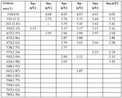
ms: Au (4f) (Figure 24A) and Au (4f) with Lorentzian peak fitting model (Figure 24B). The high-resolution spectrum of Au (4f) showed two well-defined peaks located at the binding energies of 84.02 eV and 88.04 eV, corresponding to Au 4f7/2 and Au 4f5/2, respectively. I. Catalytic Activity of Goldene. [0147] Goldene’s (e.g., in the form of a porous goldene film) ability to facilitate the reduction of alkyne triple bond to alkene double bond as a catalyst was evaluated using a phenyl acetylene as model compound. Initially, a reduction reaction as shown in Figure 25A without any catalyst and the experimental proton NMR suggested no reduction at all. After addition of a porous goldene sample (Figure 25C; approximately 1 mol % loading) to the reaction mixture of phenyl acetylene and PhMeSiH in DMF/water mixture for 1 hour, with stirring in room temperature, the reaction yielded 98 % conversion of the reduced styrene (Figure 25B). The conversion of the product was calculated from qNMR. 41 4880-2846-5044.1 Atty. Dkt. No.: P.JAG01-15PCT/046434-0815 J. Semiconductor Device Fabrication and Characterization. [0148] Example MSM devices, such as those shown in Figures 32A-33D, were fabricated by depositing 100 nm thick aluminum electrodes. The IV responses of these devices were tested using an Agilent B 1505 A curve tracer and typical IV response recorded for one of the devices under test are shown in the Figure 39A. It is evident from the IV curve that an ohmic contact is formed between goldene and aluminum electrode. The IV response of MSM goldene device showed a typical semiconducting response. Furthermore, the detailed electrical characteristics of a typical multilayer goldene device are measured at room temperature (Figure 39B). The source-drain current (I
D) was measured while sweeping the source-drain voltage (V
D) at different fixed gate voltages (V
g). The gate voltage was varied from different gate voltage such as 12V, -10V, -8V, - 6V, -4V, -2V, 0V, 2V, 4V, 6V, 8V, 10V and 12V, respectively. [0149] Figure 39C showed the transfer characteristics of an example back-gate FET goldene device, such as those depicted in Figures 38A-38D, which exhibits n-type channel behavior at room temperature. Figure 39D shows calculated electron field-effect mobility of the example back-gate FETs each with a channel thickness of approximately 33 µm are found to be 2.515 x 10-
6 cm
2V
−1s
−1. The lower values of the electronic field mobilities in the current back-gate FET device are due to the larger channel length in the device. K. First Principle Computational Investigation of Goldene. [0150] Density Functional Theory (DFT) is employed to validate both the structural and electronic attributes of goldene, corroborating the present experimental observations. The unique stability of goldene’s honeycomb (HC) configuration arises from adjacent face centered cubic (fcc) and Hexagonal Close-Packed (HCP) lattice arrangements as observed in the experiments (Figure 41A). For computational modeling, an initial co-planar sheet integrating HC and fcc configurations was used. Following energy minimization procedures, this initial arrangement naturally evolved into a fully HCP structure, which is the most energetically favorable configuration (Figure 41B). [0151] Notably, the experimental data indicates a shorter bond length compared to previously published literature, signifying a compressed lattice structure. To emulate this, two separate compressions of the initial lattice—5% and 10%—were executed. In both scenarios, the HC 42 4880-2846-5044.1 Atty. Dkt. No.: P.JAG01-15PCT/046434-0815 configuration retained its stability, as depicted in Figures 41C-41D. Remarkably, a 10% compression yielded a bond length of 2.4 Å, closely aligning with the present experimental observations. [0152] Upon verifying the structural integrity of both the 5% and 10% compressed relaxed configurations, subsequent analyses were conducted to explore the electrical characteristics of this intriguing material. Conventional DFT approximations indicated that both structures exhibit metallic properties (Figure 42A). However, a different picture emerged when advanced techniques such as the Hubbard correction model or HSE06 functional were applied: these approaches revealed the material’s semiconducting nature (Figure 42B). More specifically, calculations utilizing a Hubbard “U” value of 3 demonstrated the emergence of a band gap within the gold d- states at the fermi level (Figure 43). This finding supports the notion that goldene behaves as a Mott insulator, as illustrated in Figures 42A-42B and Figure 43. Furthermore, as shown in Figure 44, ELF mapped over the optimized structure of the compressed goldene indicates regions of strong electron-electron correlation responsible for the unique electrical properties of goldene. Definitions. [0153] No claim element herein is to be construed under the provisions of 35 U.S.C. § 112(f), unless the element is expressly recited using the phrase “means for.” [0154] As utilized herein, the terms “approximately,” “about,” “substantially,” and similar terms are intended to have a broad meaning in harmony with the common and accepted usage by those of ordinary skill in the art to which the subject matter of this disclosure pertains. It should be understood by those of skill in the art who review this disclosure that these terms are intended to allow a description of certain features described and claimed without restricting the scope of these features to the precise numerical ranges provided. Accordingly, these terms should be interpreted as indicating that insubstantial or inconsequential modifications or alterations of the subject matter described and claimed are considered to be within the scope of the disclosure as recited in the appended claims. [0155] It should be noted that the term “exemplary” and variations thereof, as used herein to describe various embodiments, are intended to indicate that such embodiments are possible 43 4880-2846-5044.1 Atty. Dkt. No.: P.JAG01-15PCT/046434-0815 examples, representations, or illustrations of possible embodiments (and such terms are not intended to connote that such embodiments are necessarily extraordinary or superlative examples). [0156] The term “coupled” and variations thereof, as used herein, means the joining of two members directly or indirectly to one another. Such joining may be stationary (e.g., permanent or fixed) or moveable (e.g., removable or releasable). Such joining may be achieved with the two members coupled directly to each other, with the two members coupled to each other using a separate intervening member and any additional intermediate members coupled with one another, or with the two members coupled to each other using an intervening member that is integrally formed as a single unitary body with one of the two members. If “coupled” or variations thereof are modified by an additional term (e.g., directly coupled), the generic definition of “coupled” provided above is modified by the plain language meaning of the additional term (e.g., “directly coupled” means the joining of two members without any separate intervening member), resulting in a narrower definition than the generic definition of “coupled” provided above. Such coupling may be mechanical, electrical, or fluidic. [0157] Any references herein to the positions of elements (e.g., “top,” “bottom,” “above,” “below”) are merely used to describe the orientation of various elements in the Figures. It should be noted that the orientation of various elements may differ according to other exemplary embodiments, and that such variations are intended to be encompassed by the present disclosure. [0158] Various embodiments are described in the general context of method steps, which may be implemented in one embodiment by a program product including computer-executable instructions, such as program code, executed by computers in networked environments. Generally, program modules include routines, programs, objects, components, data structures, etc. that perform particular tasks or implement particular abstract data types. Computer-executable instructions, associated data structures, and program modules represent examples of program code for executing steps of the methods disclosed herein. The particular sequence of such executable instructions or associated data structures represents examples of corresponding acts for implementing the functions described in such steps. [0159] Software and web implementations of the present invention could be accomplished with standard programming techniques with rule-based logic and other logic to accomplish the 44 4880-2846-5044.1 Atty. Dkt. No.: P.JAG01-15PCT/046434-0815 various database searching steps, correlation steps, comparison steps and decision steps. It should also be noted that the words “component” and “module,” as used herein and in the claims, are intended to encompass implementations using one or more lines of software code, and/or hardware implementations, and/or equipment for receiving manual inputs. [0160] As used herein, the singular forms “a,” “an,” and “the” include plural referents unless the context clearly dictates otherwise. Thus, for example, the term “a member” is intended to mean a single member or a combination of members, “a material” is intended to mean one or more materials, or a combination thereof. [0161] As used herein, the terms “about” and “approximately” generally mean plus or minus 10% of the stated value. For example, about 0.5 would include 0.45 and 0.55, about 10 would include 9 to 11, about 1000 would include 900 to 1100. [0162] It should be noted that the term “exemplary” as used herein to describe various embodiments is intended to indicate that such embodiments are possible examples, representations, and/or illustrations of possible embodiments (and such term is not intended to connote that such embodiments are necessarily extraordinary or superlative examples). [0163] The terms “coupled,” “connected,” and the like as used herein mean the joining of two members directly or indirectly to one another. Such joining may be stationary (e.g., permanent) or moveable (e.g., removable or releasable). Such joining may be achieved with the two members or the two members and any additional intermediate members being integrally formed as a single unitary body with one another or with the two members or the two members and any additional intermediate members being attached to one another. [0164] It is important to note that the construction and arrangement of the various exemplary embodiments are illustrative only. Although only a few embodiments have been described in detail in this disclosure, those skilled in the art who review this disclosure will readily appreciate that many modifications are possible (e.g., variations in sizes, dimensions, structures, shapes and proportions of the various elements, values of parameters, mounting arrangements, use of materials, colors, orientations, etc.) without materially departing from the novel teachings and advantages of the subject matter described herein. Other substitutions, modifications, changes and 45 4880-2846-5044.1 Atty. Dkt. No.: P.JAG01-15PCT/046434-0815 omissions may also be made in the design, operating conditions and arrangement of the various exemplary embodiments without departing from the scope of the present invention. [0165] While this specification contains many specific implementation details, these should not be construed as limitations on the scope of any inventions or of what may be claimed, but rather as descriptions of features specific to particular implementations of particular inventions. Certain features described in this specification in the context of separate implementations can also be implemented in combination in a single implementation. Conversely, various features described in the context of a single implementation can also be implemented in multiple implementations separately or in any suitable subcombination. Moreover, although features may be described above as acting in certain combinations and even initially claimed as such, one or more features from a claimed combination can in some cases be excised from the combination, and the claimed combination may be directed to a subcombination or variation of a subcombination. [0166] Although the figures and description may illustrate a specific order of method steps, the order of such steps may differ from what is depicted and described, unless specified differently above. Also, two or more steps may be performed concurrently or with partial concurrence, unless specified differently above. 46 4880-2846-5044.1
 [0115] High resolution-XPS spectrum is collected for Au (4f) as shown in Figures 24A-24B. Figure 24A represents the HR-XPS spectra collected for Au (4f) in the binding energy range of 80 eV to 90 eV. Two well-defined peaks of curves C3 and C2 located at 84.02 eV and 88.04 eV, respectively, are observed. The detailed signature of spin states IS estimated by de-convolution of binding energy peaks using Lorentzian peak fitting model of the same HR-XPS spectrum (Figure 24B). A fitted cure C1 accounts for both of the curves C2 and C3 with their individual peaks fitted in Lorentzian fitting model. 31 4880-2846-5044.1 Atty. Dkt. No.: P.JAG01-15PCT/046434-0815 [0116] De-convolution of binding energy peaks showed 84.02 eV and 88.04 eV corresponding to Au 4f7/2 and Au 4f5/2, respectively. Observation of the well-defined Au 4f doublet apparently implies a single chemical environment. Au 4f7/2 peak position is shifted to a higher energy level than that for metallic gold (i.e., 83.8 eV) by 0.22 eV. This directional shift to higher energies for goldene is qualitatively consistent with the 0.6 eV shift reported in the literature for Au adatoms clusters and the standard peak position of metallic gold, namely, 83.8 eV for thicker gold films. E. TEM Analysis. [0117] Figures 7A-7I report the results of high-resolution transmission electron microscope (“HRTEM”) characterization of goldene films in bright field mode. In bright field mode of imaging, the incident beam direction is normal to the specimen surface and the atomic positions realized by high resolution TEM imaging in the same regions. The detailed procedure of TEM sample preparation is described in the supplementary data file. Figure 7A is low magnification image of goldene film and Figure 7B is the selective area electron diffraction (SAED) pattern data of the film. It can be inferred from the respective d-spacing of 2.40 Å, 2.05 Å, and 1.467 Å (JCPDS card No. 04-0784) that these (hkl) values correspond to the observed (111), (200), and (220) reflections of fcc gold. Figure 7C is a higher magnification image of the marked region of Figure 7A, showing a crystalline lattice. In the inset of Figure 7C is shown the FFT viewed along [011] zone axis from the marked region in Figure 7C. These lattice directions of (200), (111), and (111) are consistent with fcc gold. [0118] Figure 7D is a magnified lattice image of the region within the white box in Figure 7C, revealing a highly ordered structure with a spacing of 0.24 nm as indicated by the two parallel white dashed lines. In some locations, a slightly larger lattice spacing is measured of 0.26 nm which could be attributed to possible strain in the goldene films during the film transfer process. It was observed that (200) fcc and (0001) honeycomb (white box) lattice structures are seen across the entire image field. The fcc lattice plane directions (200), (111), and (111) are marked on the crystalline lattice with yellow lines with 55.7° angles between them. The increase in the inter- planer angle approximately 1° from the standard angle of 54.7° might also be attributed to the lattice strain. Figure 7E is an IFFT image of a region in Figure 7D, confirming the predominance of honeycomb (white box) lattices. The ubiquitous presence was observed of lattice transformation 32 4880-2846-5044.1 Atty. Dkt. No.: P.JAG01-15PCT/046434-0815 between honeycomb goldene (“HG”) and close packed goldene across the image field. The extraction of (0001) hcp and (200) fcc lattice planes on IFFT image demonstrates the possibility of hcp to fcc transformation due to uniaxial compression of hcp along c-axis transformation to a (200) plane of fcc. [0119] Additional high-resolution TEM image, collected from another region in the goldene film (Figure 7F), again confirmed the presence of a highly ordered crystalline lattice across the image field. Inset of the Figure 7F reveals FFT extracted from the marked region (Figure 7F) with lattice spacing of 0.248 nm, 0.24 nm, and 0.23 nm (i.e., consistent with fcc Au single crystal structure). Figure 7G is a high magnification image from inside the white square in Figure 7F, showing several honeycomb lattices highlighted by white hexagonal boxes. A lattice spacing of 0.24 nm is again measured, as indicated by the two parallel white dashed lines. At some locations a change is seen in the d spacing by ± 0.02 nm. [0120] A possible reason for the smaller goldene lattice spacing than the reported 0.26 nm value for gold clusters by Westenfelder et al. is unclear, but might again indicate a more compressed goldene axial plane. Figure 7H is an IFFT image of a region in Figure 7F observing several regions showing herringbone and honeycomb structures. Herringbone to fcc (200) or (100) to herringbone to fcc (200) transition lattices that are highlighted by the yellow boxes. Honeycomb/herringbone to (200) transition lattices are highlighted by the white box. A schematic illustration was constructed (inset of the Figure 7H) of possible hcp to fcc transformation due to uniaxial tension along a close packed direction in a basal plane of hcp. It demonstrates a compression along the c-axis in hcp (0001) transformation to a (100) plane of fcc. Figure 7I is an IFFT image extracted from a region within the white box in Figure 7F. One can clearly see the presence of herringbone structures (white boxes) in the entire image field. [0121] The observation of the herringbone goldene lattice is consistent with the well- established phenomenon of gold surface layer reconstruction to form herringbone structures. The strained boundaries on the crystal surface between the predominant fcc and the compressed hcp result in the formation of ridges with the herringbone structure. The pioneering STM work by Barth et al. also confirmed the presence of (herringbone) superlattices arranged in a zigzag fashion with a bending angle of 120° at every 250 Å. Moreover, Li, et al., reported that zigzag structures 33 4880-2846-5044.1 Atty. Dkt. No.: P.JAG01-15PCT/046434-0815 (i.e., herringbone) are the most energetically stable for planar gold clusters in comparison to linear and square forms and for Au3 clusters calculated a bend angle of 137°. [0122] The observation of the prevalence of honeycomb goldene lattice is consistent with the predictions of Liu, et al.. Based on their energy and dynamic analysis calculations, they concluded that a one-atom-thick two-dimensional gold with a honeycomb structure (“HG”) is stable from a thermodynamic and lattice dynamic viewpoint. They also noted that 2D close packed gold (“CPG”) is energetically only slightly more stable, implying that both structures should be equally probable. This is consistent with the results discussed in Figures 7A-7I showing the ubiquitous presence of HG to CPG transitions. Because of relativistic effects, it is known that gold exhibits strong spin orbit coupling (“SOC”) and increased Coulombic attraction between valence electrons and nuclei. Liu et al. claimed that this would result in band splitting and showed that HG exhibits a covalent bonding characteristic and is a semiconductor with a band gap of 0.1 eV to 0.3 eV. [0123] Thus, the results confirm the synthesis of stable honeycomb structured goldene and demonstrate that it is a semi-conductor. HRTEM lattice imaging of goldene revealed both herringbone and honeycomb lattices, which are to be observed only at the gold surface due to its


