WO2024111961A2 - Multilayer-coated vascular stent and manufacturing method therefor - Google Patents
Multilayer-coated vascular stent and manufacturing method thereforDownload PDFInfo
- Publication number
- WO2024111961A2 WO2024111961A2PCT/KR2023/017949KR2023017949WWO2024111961A2WO 2024111961 A2WO2024111961 A2WO 2024111961A2KR 2023017949 WKR2023017949 WKR 2023017949WWO 2024111961 A2WO2024111961 A2WO 2024111961A2
- Authority
- WO
- WIPO (PCT)
- Prior art keywords
- sintered
- layer
- peripheral surface
- outer peripheral
- ptfe
- Prior art date
- Legal status (The legal status is an assumption and is not a legal conclusion. Google has not performed a legal analysis and makes no representation as to the accuracy of the status listed.)
- Ceased
Links
Images


Classifications
- A—HUMAN NECESSITIES
- A61—MEDICAL OR VETERINARY SCIENCE; HYGIENE
- A61F—FILTERS IMPLANTABLE INTO BLOOD VESSELS; PROSTHESES; DEVICES PROVIDING PATENCY TO, OR PREVENTING COLLAPSING OF, TUBULAR STRUCTURES OF THE BODY, e.g. STENTS; ORTHOPAEDIC, NURSING OR CONTRACEPTIVE DEVICES; FOMENTATION; TREATMENT OR PROTECTION OF EYES OR EARS; BANDAGES, DRESSINGS OR ABSORBENT PADS; FIRST-AID KITS
- A61F2/00—Filters implantable into blood vessels; Prostheses, i.e. artificial substitutes or replacements for parts of the body; Appliances for connecting them with the body; Devices providing patency to, or preventing collapsing of, tubular structures of the body, e.g. stents
- A61F2/82—Devices providing patency to, or preventing collapsing of, tubular structures of the body, e.g. stents
- B—PERFORMING OPERATIONS; TRANSPORTING
- B29—WORKING OF PLASTICS; WORKING OF SUBSTANCES IN A PLASTIC STATE IN GENERAL
- B29C—SHAPING OR JOINING OF PLASTICS; SHAPING OF MATERIAL IN A PLASTIC STATE, NOT OTHERWISE PROVIDED FOR; AFTER-TREATMENT OF THE SHAPED PRODUCTS, e.g. REPAIRING
- B29C53/00—Shaping by bending, folding, twisting, straightening or flattening; Apparatus therefor
- B29C53/56—Winding and joining, e.g. winding spirally
- B29C53/58—Winding and joining, e.g. winding spirally helically
- B—PERFORMING OPERATIONS; TRANSPORTING
- B29—WORKING OF PLASTICS; WORKING OF SUBSTANCES IN A PLASTIC STATE IN GENERAL
- B29C—SHAPING OR JOINING OF PLASTICS; SHAPING OF MATERIAL IN A PLASTIC STATE, NOT OTHERWISE PROVIDED FOR; AFTER-TREATMENT OF THE SHAPED PRODUCTS, e.g. REPAIRING
- B29C61/00—Shaping by liberation of internal stresses; Making preforms having internal stresses; Apparatus therefor
- B29C61/02—Thermal shrinking
- B—PERFORMING OPERATIONS; TRANSPORTING
- B29—WORKING OF PLASTICS; WORKING OF SUBSTANCES IN A PLASTIC STATE IN GENERAL
- B29C—SHAPING OR JOINING OF PLASTICS; SHAPING OF MATERIAL IN A PLASTIC STATE, NOT OTHERWISE PROVIDED FOR; AFTER-TREATMENT OF THE SHAPED PRODUCTS, e.g. REPAIRING
- B29C63/00—Lining or sheathing, i.e. applying preformed layers or sheathings of plastics; Apparatus therefor
- B29C63/18—Lining or sheathing, i.e. applying preformed layers or sheathings of plastics; Apparatus therefor using tubular layers or sheathings
- B—PERFORMING OPERATIONS; TRANSPORTING
- B29—WORKING OF PLASTICS; WORKING OF SUBSTANCES IN A PLASTIC STATE IN GENERAL
- B29C—SHAPING OR JOINING OF PLASTICS; SHAPING OF MATERIAL IN A PLASTIC STATE, NOT OTHERWISE PROVIDED FOR; AFTER-TREATMENT OF THE SHAPED PRODUCTS, e.g. REPAIRING
- B29C63/00—Lining or sheathing, i.e. applying preformed layers or sheathings of plastics; Apparatus therefor
- B29C63/22—Lining or sheathing, i.e. applying preformed layers or sheathings of plastics; Apparatus therefor using layers or sheathings having a shape adapted to the shape of the article
- B—PERFORMING OPERATIONS; TRANSPORTING
- B29—WORKING OF PLASTICS; WORKING OF SUBSTANCES IN A PLASTIC STATE IN GENERAL
- B29C—SHAPING OR JOINING OF PLASTICS; SHAPING OF MATERIAL IN A PLASTIC STATE, NOT OTHERWISE PROVIDED FOR; AFTER-TREATMENT OF THE SHAPED PRODUCTS, e.g. REPAIRING
- B29C63/00—Lining or sheathing, i.e. applying preformed layers or sheathings of plastics; Apparatus therefor
- B29C63/26—Lining or sheathing of internal surfaces
- B29C63/30—Lining or sheathing of internal surfaces using sheet or web-like material
- B29C63/32—Lining or sheathing of internal surfaces using sheet or web-like material by winding helically
- B—PERFORMING OPERATIONS; TRANSPORTING
- B29—WORKING OF PLASTICS; WORKING OF SUBSTANCES IN A PLASTIC STATE IN GENERAL
- B29C—SHAPING OR JOINING OF PLASTICS; SHAPING OF MATERIAL IN A PLASTIC STATE, NOT OTHERWISE PROVIDED FOR; AFTER-TREATMENT OF THE SHAPED PRODUCTS, e.g. REPAIRING
- B29C63/00—Lining or sheathing, i.e. applying preformed layers or sheathings of plastics; Apparatus therefor
- B29C63/26—Lining or sheathing of internal surfaces
- B29C63/34—Lining or sheathing of internal surfaces using tubular layers or sheathings
- B—PERFORMING OPERATIONS; TRANSPORTING
- B29—WORKING OF PLASTICS; WORKING OF SUBSTANCES IN A PLASTIC STATE IN GENERAL
- B29C—SHAPING OR JOINING OF PLASTICS; SHAPING OF MATERIAL IN A PLASTIC STATE, NOT OTHERWISE PROVIDED FOR; AFTER-TREATMENT OF THE SHAPED PRODUCTS, e.g. REPAIRING
- B29C65/00—Joining or sealing of preformed parts, e.g. welding of plastics materials; Apparatus therefor
- B29C65/02—Joining or sealing of preformed parts, e.g. welding of plastics materials; Apparatus therefor by heating, with or without pressure
Definitions
- the present inventionrelates to a multilayer covered vascular stent and a method of manufacturing the same, and more specifically, to a multilayer covered vascular stent that can be flexibly and stably applied to blood vessels in joint areas with many bends, and a method of manufacturing the same.
- Stentsare commonly used as tubular structures left inside the lumen of a blood vessel to relieve obstruction.
- the stentis inserted within the lumen in its unexpanded form and then expanded in place either on its own or using an auxiliary device.
- stentsWhen used in procedures to relieve stenosis of coronary arteries, stents are placed percutaneously through the femoral artery.
- Stentsare constructed using metals with spring-like or hyperelastic properties that exhibit an essentially constant radial support structure.
- Self-expanding stentsare also used in blood vessels that are close to the skin, such as the carotid artery, or vessels that can carry a lot of blood, such as the popliteal artery.
- Self-expanding stentsresist pressure or displacement and maintain their shape thanks to their inherent elastic resilience.
- restenosismay occur as a result of elastic restoration of the stenotic lesion.
- All stentscontain cells, generally of two groups: open-cell or closed-cell (alveolar) designs or structures that facilitate varying degrees of plaque or tissue extrusion. It becomes.
- Closed-cellmeans that each opening or cell is isolated from each other by a fully-connected metal perimeter.
- Open-cell designshave openings, or cells, that can communicate with other surrounding cells because they are not completely surrounded by a metal perimeter.
- the aforementioned openingsmean that there are gaps or “open” passages leading to other cells.
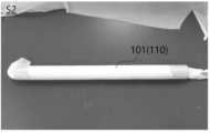
- the existing cover stentis used by covering the outer peripheral surface of the stent 3 made of wire with a polymer material (2), as shown in Figure 10. Due to the characteristics of the polymer material (2), it lacks flexibility, so it is difficult to use in blood vessels in the joint area with many bends. When applied or bent, there was a problem in which the internal metal stent (3) pierced and tore the cover, that is, the sheath of the polymer material (2).
- the present inventionwas invented to improve the above problems, and is intended to provide a multilayer covered vascular stent that can be flexibly and stably applied to blood vessels in highly curved joint areas and a method of manufacturing the same.
- the present inventionis a non-sintered expanded polytetrafluoroelastomer that is fused to the inner and outer peripheral surfaces of a cylindrical wire made of a metal material and interlocks with the wire to shrink and expand integrally with the wire.
- Roethylene (hereinafter e-PTFE) layerand a sintered e-PTFE layer formed on the inner and outer peripheral surfaces of the non-sintered e-PTFE layer.
- the present inventionis a non-sintered material that can be contracted and expanded integrally with the wire, from the inner peripheral surface of a cylindrical wire made of a metal material toward the center of the wire, and from the outer peripheral surface of the wire in the centrifugal direction of the wire.
- a multilayer covered vascular stentcharacterized in that an expanded polytetrafluoroethylene (hereinafter referred to as e-PTFE) layer and a sintered e-PTFE layer are sequentially placed to form a multilayer layer.
- e-PTFEexpanded polytetrafluoroethylene
- the non-sintered e-PTFE layerincludes a first non-sintered fusion layer having an outer peripheral surface fused to the inner peripheral surface of the wire, and a second non-sintered fusion layer that is fused to the outer peripheral surface of the wire and is fused and integrated with the first non-sintered fused layer. It includes a sintered fused layer, wherein the sintered e-PTFE layer is formed on an inner peripheral surface of the first non-sintered fused layer and an outer peripheral surface of the second non-sintered fused layer.
- the sintered e-PTFE layerincludes a first sintered layer having an outer peripheral surface in contact with the inner peripheral surface of the non-sintered e-PTFE layer, and a second sintered layer having an inner peripheral surface in contact with the outer peripheral surface of the non-sintered e-PTFE layer. It is characterized by including.
- the present inventionis a non-sintered expanded polytetrafluoroethylene (hereinafter referred to as e-PTFE) layer that is interlocked with the wire on the inner and outer peripheral surfaces of a cylindrical wire made of a metal material and can contract and expand integrally with the wire.
- e-PTFEnon-sintered expanded polytetrafluoroethylene
- the present inventionincludes the first step of preparing a cylindrical jig and forming a first sintered layer made of sintered expanded polytetrafluoroethylene (hereinafter referred to as e-PTFE) material on the outer peripheral surface of the jig; A second step of forming a first non-sintered fusion layer made of a non-sintered e-PTFE material on the layer made of the sintered e-PTFE material; A third step of inserting the inner peripheral surface of a cylindrical wire made of a metal material into contact with the outer peripheral surface of the first non-sintered fusion layer; A fourth step of forming a second non-sintered fusion layer made of the non-sintered e-PTFE material on the outer peripheral surface of the wire; A fifth step of manufacturing an intermediate product by forming a second sintered layer made of the sintered e-PTFE material on the outer peripheral surface of the second non-sintered fused layer; And a sixth step of putting the jig formed
- the fifth stepfurther includes the process of pressing and winding a Teflon tape around the outer peripheral surface of the intermediate product.
- the first sintered layeris formed by winding a tape made of the sintered e-PTFE material multiple times around the outer peripheral surface of the jig, or a tube made of the sintered e-PTFE material is formed by wrapping the tape made of the sintered e-PTFE material in the jig. It is characterized by being formed by covering the outer circumferential surface of the.
- the first non-sintered fusion layeris formed by winding a tape made of the non-sintered e-PTFE material multiple times on the outer peripheral surface of the first sintered layer, or the non-sintered e-PTFE material is formed by winding the first sintered layer multiple times. It is characterized in that it is formed by covering the outer peripheral surface of the first sintered layer with a tube made of material.
- the second non-sintered fusion layeris formed by winding a tape made of the non-sintered e-PTFE material multiple times around the outer peripheral surface of the wire, or a tape made of the non-sintered e-PTFE material is formed. It is characterized in that it is formed by covering the outer peripheral surface of the wire with a tube.
- the second sintered layeris formed by winding a tape made of the sintered e-PTFE material multiple times on the outer peripheral surface of the second non-sintered fusion layer, or by wrapping the tape made of the sintered e-PTFE material multiple times.
- the tubeis formed by covering the outer peripheral surface of the second non-sintered fusion layer.
- the heat treatmentis characterized by maintaining a pressure of 80 bar or more for 10 minutes at a temperature of 330 to 340 ° C. in a heat treatment chamber into which distilled water is added.
- the metal materialis characterized as a shape memory alloy containing Nitinol.
- FIG. 1is a cross-sectional conceptual diagram showing the cross-sectional structure of a multilayer-covered vascular stent according to an embodiment of the present invention.
- Figures 2 to 8show step-by-step the manufacturing method of a multilayer covered vascular stent according to an embodiment of the present invention, with Figure 2 showing the first step, Figure 3 showing the second step, and Figure 4 showing the third step.
- Figure 5is a perspective conceptual diagram showing the fourth step
- Figures 6 and 7show the fifth step
- Figure 8shows the sixth step.
- Figure 9is a perspective conceptual diagram showing the finished product structure of a multilayer covered vascular stent manufactured through the manufacturing method of a multilayer covered vascular stent according to an embodiment of the present invention.
- Figure 1is a cross-sectional conceptual diagram showing the cross-sectional structure of a multilayer-covered vascular stent according to an embodiment of the present invention.
- FIG. 2 to 8show step-by-step the manufacturing method of a multilayer covered vascular stent according to an embodiment of the present invention, with FIG. 2 showing the first step (S1) and FIG. 3 showing the second step (S2). , Figure 4 shows the third step (S3), Figure 5 shows the fourth step (S4), Figures 6 and 7 show the fifth step (S5), and Figure 8 shows the sixth step (S6).
- Thisis a concept diagram of a squint.
- Figure 9is a perspective conceptual diagram showing the structure of the finished product 320 of a multilayer-covered vascular stent manufactured through the manufacturing method of a multilayer-covered vascular stent according to an embodiment of the present invention.
- the present inventionis a non-sintered expanded poly that is fused to the inner and outer peripheral surfaces of a cylindrical wire 300 made of a metal material and interlocks with the wire 300 to shrink and expand integrally with the wire 300. It may include a tetrafluoroethylene (e-PTFE) layer 100.
- e-PTFEtetrafluoroethylene
- the present inventionmay include a sintered e-PTFE layer 200 formed on the inner and outer peripheral surfaces of the non-sintered e-PTFE layer 100.
- the present inventionis integrated with the wire 300 from the inner peripheral surface of the cylindrical wire 300 made of a metal material toward the center of the wire 300 and from the outer peripheral surface of the wire 300 in the centrifugal direction of the wire 300. It can be seen that the non-sintered e-PTFE layer 100, which is capable of shrinking and expanding, and the sintered e-PTFE layer 200 are sequentially arranged to form a multi-layer structure.
- the non-sintered e-PTFE layer 100is fused to the first non-sintered fusion layer 110, which has an outer peripheral surface fused to the inner peripheral surface of the wire 300, and to the outer peripheral surface of the wire 300 to form a first non-sintered fused layer 110. It may include a second non-sintered fusion layer 120 that is fused and integrated with the layer 110.
- the sintered e-PTFE layer 200which will be described later, is formed on the inner peripheral surface of the first non-sintered fused layer 110 and the outer peripheral surface of the second non-sintered fused layer 120.
- the sintered e-PTFE layer 200includes a first sintered layer 210 having an outer peripheral surface in contact with the inner peripheral surface of the non-sintered e-PTFE layer 100, and an outer peripheral surface of the non-sintered e-PTFE layer 100. It may include a second sintered layer 220 having an inner peripheral surface in contact with the second sintered layer 220 .
- the first and second non-sintered fused layers 110 and 120 disposed on the inner and outer peripheral surfaces of the wire 300are made of non-sintered e-PTFE material as described above, and the non-sintered e-PTFE materials are fused to each other. Since this works well, the wire 300 is fixed between the first and second non-sintered fusion layers 110 and 120, so that the first and second non-sintered fusion layers 110 and 120 are linked to the contraction and expansion of the wire 300. This allows it to expand and contract.
- the metal wire 300may be a shape memory alloy containing Nitinol.
- Nitinolalso called nickel titanium, is a metal alloy of nickel and titanium, and the two components exist in almost equal atomic ratios.
- Nitinolexhibits shape memory effect and pseudoelasticity at different temperatures.
- Shape memoryis the ability of Nitinol to experience deformation at specific temperatures.
- Nitinolmaintains its deformation when external pressure is removed and returns to its original, undeformed state when heated above its deformation temperature.
- Pseudoelasticityis the property of experiencing a large deformation and immediately returning to an undeformed shape when the external load is removed.
- the present inventionprovides a non-sintered e-PTFE layer 100 on the inner and outer peripheral surfaces of a cylindrical wire 300 made of a metal material, which is capable of contracting and expanding integrally with the wire 300 in conjunction with the wire 300, and a non-sintered e-PTFE layer 100.
- a non-sintered e-PTFE layer 100on the inner and outer peripheral surfaces of a cylindrical wire 300 made of a metal material, which is capable of contracting and expanding integrally with the wire 300 in conjunction with the wire 300, and a non-sintered e-PTFE layer 100.
- a cylindrical jig 400is prepared as shown in FIG. 2, and a first sintered layer 210 made of sintered e-PTFE material is formed on the outer peripheral surface of the jig 400 (S1: first step). .
- the jig 400is made of a metal material such as stainless steel, but it is not limited to this, and of course, any material that has excellent durability, heat resistance, corrosion resistance, and chemical resistance can be used.
- a first non-sintered fused layer 110 made of a non-sintered e-PTFE materialis formed on the layer made of a sintered e-PTFE material (S2: second step).
- a second non-sintered fusion layer 120 made of a non-sintered e-PTFE materialis formed on the outer peripheral surface of the wire 300 (S4: fourth step).
- the intermediate product 310is manufactured by forming a second sintered layer 220 made of sintered e-PTFE material on the outer peripheral surface of the second non-sintered fusion layer 120 (S5: fifth step). .
- the first sintered layer 210is formed by winding a tape (not shown below) made of a sintered e-PTFE material multiple times around the outer peripheral surface of the jig 400, or Figure 2
- the tube 201 made of sintered e-PTFE materialcan be formed by covering the outer peripheral surface of the jig 400.
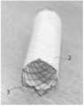
- the first non-sintered fusion layer 110is formed by wrapping a tape (not shown below) made of a non-sintered e-PTFE material on the outer peripheral surface of the first sintered layer 210 a plurality of times. It can be formed by covering the outer peripheral surface of the first sintered layer 210 with a tube 101 made of a non-sintered e-PTFE material, as shown in FIG. 3 .
- the second non-sintered fusion layer 120is formed by winding a tape made of a non-sintered e-PTFE material multiple times around the outer peripheral surface of the wire 300, or as shown in FIG. 5.
- the tube 101 made of non-sintered e-PTFE materialcan be formed by covering the outer peripheral surface of the wire 300.
- the formation of the second sintered layer 220 in the fifth step (S5)is formed by winding a tape made of sintered e-PTFE material multiple times around the outer peripheral surface of the second non-sintered fusion layer 120, or Figure 6 As shown, the tube 201 made of sintered e-PTFE material can be formed by covering the outer peripheral surface of the second non-sintered fusion layer 120.
- the fifth step (S5)it is of course possible to additionally perform the operation of pressing and winding the Teflon tape 600 made of general PTFE material on the outer peripheral surface of the intermediate product 310, as shown in FIG. 7.
- the process of winding the Teflon tape 600 around the outer peripheral surface of the intermediate product 310prevents airflow from occurring due to separation or lifting between each layer, and ensures uniformity at the desired temperature by ensuring that each layer adheres closely to each other. It is compressed so that it can be fused properly.
- the heat treatmentis performed at a pressure of 80 bar or more for 10 minutes at a temperature of 330 to 340 °C, more preferably around 337 °C, in the heat treatment chamber 510 into which distilled water 520 is added, as shown in FIG. This can be done by maintaining.
- the basic technical idea of the present inventionis to provide a multilayer covered vascular stent and a manufacturing method thereof that can be flexibly and stably applied to blood vessels in joint areas with many bends.
Landscapes
- Engineering & Computer Science (AREA)
- Manufacturing & Machinery (AREA)
- Health & Medical Sciences (AREA)
- Mechanical Engineering (AREA)
- Biomedical Technology (AREA)
- Oral & Maxillofacial Surgery (AREA)
- Life Sciences & Earth Sciences (AREA)
- Cardiology (AREA)
- Physics & Mathematics (AREA)
- Transplantation (AREA)
- Heart & Thoracic Surgery (AREA)
- Vascular Medicine (AREA)
- Thermal Sciences (AREA)
- Animal Behavior & Ethology (AREA)
- General Health & Medical Sciences (AREA)
- Public Health (AREA)
- Veterinary Medicine (AREA)
- Prostheses (AREA)
- Materials For Medical Uses (AREA)
Abstract
Description
Translated fromKorean본 발명은 다층 피복 혈관 스텐트 및 이것의 제조 방법에 관한 것으로, 더욱 상세하게는 굴곡이 많은 관절 부위의 혈관에 유연하고 안정적으로 적용할 수 있도록 한 다층 피복 혈관 스텐트 및 이것의 제조 방법에 관한 것이다.The present invention relates to a multilayer covered vascular stent and a method of manufacturing the same, and more specifically, to a multilayer covered vascular stent that can be flexibly and stably applied to blood vessels in joint areas with many bends, and a method of manufacturing the same.
스텐트는 폐색(obstruction)을 경감하기 위해 혈관의 루멘 내부에 남겨지는 관형 구조체로서 사용되는 것이 일반적이다.Stents are commonly used as tubular structures left inside the lumen of a blood vessel to relieve obstruction.
통상적으로, 스텐트는 확장되지 않은 형태로 루멘 내부에 삽입된 후에, 자체적으로 또는 보조 기기를 사용하여 제위치에서 확장된다.Typically, the stent is inserted within the lumen in its unexpanded form and then expanded in place either on its own or using an auxiliary device.
관상 동맥의 협착을 경감시키기 위한 시술에 사용되면, 스텐트는 대퇴부 동맥을 통해 경피적으로(percutaneously) 위치된다.When used in procedures to relieve stenosis of coronary arteries, stents are placed percutaneously through the femoral artery.
스텐트는 본질적으로 일정한 방사상 지지구조를 나타내는 스프링형 또는 초탄성 특성을 갖는 금속을 사용하여 구성된다.Stents are constructed using metals with spring-like or hyperelastic properties that exhibit an essentially constant radial support structure.
또한, 자체-확장식 스텐트는 피부 가까이에 있는 경동맥과 같은 혈관이나 많은 혈액이 이동할 수 있는 슬와 동맥과 같은 혈관에 사용되기도 한다.Self-expanding stents are also used in blood vessels that are close to the skin, such as the carotid artery, or vessels that can carry a lot of blood, such as the popliteal artery.
자체-확장식 스텐트는 고유의 탄성 복원력 덕분에 압력 또는 변위에 견디며, 자체의 형상을 유지한다.Self-expanding stents resist pressure or displacement and maintain their shape thanks to their inherent elastic resilience.
스텐트가 없을 경우에는, 협착 장애의 탄성 복원력의 결과로서 재협착이 발생할 수 있다.In the absence of a stent, restenosis may occur as a result of elastic restoration of the stenotic lesion.
이러한 문제점은, 스텐트 자체 내의 플라크 또는 조직의 탈출이 "셀(cells)"이라 불리는 지지되지 않은 영역에서 발생하게 되기 때문에, 스텐트에 의해서는 제거되지 않는다.This problem is not eliminated by stents because herniation of plaque or tissue within the stent itself occurs in unsupported areas called "cells".
모든 스텐트는 셀을 구비하며, 일반적으로 두개의 그룹, 즉 플라크 또는 조직의 탈출 정도를 용이하게 가변시키는 개방-셀(open-cell; 개포) 또는 폐쇄-셀(closed-cell; 폐포) 디자인 또는 구조로 된다.All stents contain cells, generally of two groups: open-cell or closed-cell (alveolar) designs or structures that facilitate varying degrees of plaque or tissue extrusion. It becomes.
폐쇄-셀은 각각의 개구 또는 셀이 전체-연결형 금속 주변부에 의해 서로 격리된다는 것을 의미한다.Closed-cell means that each opening or cell is isolated from each other by a fully-connected metal perimeter.
개방-셀 디자인은 금속 주변부에 의해 완전하게 둘러싸이지 않기 때문에 주위의 다른 셀들과 연통할 수 있는 개구들 또는 셀들을 갖는다.Open-cell designs have openings, or cells, that can communicate with other surrounding cells because they are not completely surrounded by a metal perimeter.
즉, 전술한 개구들은 다른 셀들에 이어지는 갭들 또는 "개방" 통로들이 존재한다는 의미이다.That is, the aforementioned openings mean that there are gaps or “open” passages leading to other cells.
다수의 스텐트 디자인이 보고되고 있지만, 이들 디자인은 탈출 및 다수의 다른 제한에 영향을 받는다.Although a number of stent designs have been reported, these designs are subject to prolapse and a number of other limitations.
또한, 혈관을 통해 스텐트를 조작하기 위해서는 스텐트의 가요성이 중요하며, 가요성이 떨어지는 스텐트는 결점을 갖는다.Additionally, in order to manipulate a stent through a blood vessel, the flexibility of the stent is important, and stents with poor flexibility have drawbacks.
특히, 기존의 커버 스텐트는 도 10과 같이 와이어로 이루어진 스텐트(3)의 외주면에 고분자 소재(2)를 덮어서 사용하게 되는데, 고분자 소재(2)의 특성상 유연성이 부족해 굴곡이 많은 관절 부위의 혈관에 적용시 휘거나 구부러질 때 내부의 금속재 스텐트(3)가 커버, 즉 고분자 소재(2)의 피복을 찔러 찢어지는 문제가 있었던 것이다.In particular, the existing cover stent is used by covering the outer peripheral surface of the
[선행기술문헌][Prior art literature]
[특허문헌][Patent Document]
공개특허 제10-2009-0108143호Public Patent No. 10-2009-0108143
본 발명은 상기와 같은 문제점을 개선하기 위하여 발명된 것으로, 굴곡이 많은 관절 부위의 혈관에 유연하고 안정적으로 적용할 수 있도록 하는 다층 피복 혈관 스텐트 및 이것의 제조 방법을 제공하기 위한 것이다.The present invention was invented to improve the above problems, and is intended to provide a multilayer covered vascular stent that can be flexibly and stably applied to blood vessels in highly curved joint areas and a method of manufacturing the same.
상기와 같은 목적을 달성하기 위하여, 본 발명은 금속재로 이루어진 원통 형상의 와이어 내주면과 외주면에 융착되어 상기 와이어와 연동하여 상기 와이어와 일체로 수축 및 팽창 가능한 비소결(Non-sintered) 확장형 폴리테트라플루오로에틸렌(이하 e-PTFE) 레이어; 및 상기 비소결 e-PTFE 레이어의 내주면과 외주면에 형성되는 소결(Sintered) e-PTFE 레이어를 포함하는 것을 특징으로 하는 다층 피복 혈관 스텐트를 제공할 수 있을 것이다.In order to achieve the above object, the present invention is a non-sintered expanded polytetrafluoroelastomer that is fused to the inner and outer peripheral surfaces of a cylindrical wire made of a metal material and interlocks with the wire to shrink and expand integrally with the wire. Roethylene (hereinafter e-PTFE) layer; and a sintered e-PTFE layer formed on the inner and outer peripheral surfaces of the non-sintered e-PTFE layer.
또한, 본 발명은 금속재로 이루어진 원통 형상의 와이어 내주면으로부터 상기 와이어의 중심을 향하여, 그리고 상기 와이어의 외주면으로부터 상기 와이어의 원심 방향으로 각각, 상기 와이어와 일체로 수축 및 팽창 가능한 비소결(Non-sintered) 확장형 폴리테트라플루오로에틸렌(이하 e-PTFE) 레이어와, 소결(Sintered) e-PTFE 레이어가 순차적으로 배치되어 다층 레이어를 형성하는 것을 특징으로 하는 다층 피복 혈관 스텐트를 제공할 수도 있을 것이다.In addition, the present invention is a non-sintered material that can be contracted and expanded integrally with the wire, from the inner peripheral surface of a cylindrical wire made of a metal material toward the center of the wire, and from the outer peripheral surface of the wire in the centrifugal direction of the wire. ) It may be possible to provide a multilayer covered vascular stent characterized in that an expanded polytetrafluoroethylene (hereinafter referred to as e-PTFE) layer and a sintered e-PTFE layer are sequentially placed to form a multilayer layer.
여기서, 상기 비소결 e-PTFE 레이어는, 상기 와이어의 내주면에 융착되는 외주면을 가지는 제1 비소결 융착 레이어와, 상기 와이어의 외주면에 융착되어 상기 제1 비소결 융착 레이어와 융착 일체화되는 제2 비소결 융착 레이어를 포함하며, 상기 소결 e-PTFE 레이어는 상기 제1 비소결 융착 레이어의 내주면과 상기 제2 비소결 융착 레이어의 외주면에 형성되는 것을 특징으로 한다.Here, the non-sintered e-PTFE layer includes a first non-sintered fusion layer having an outer peripheral surface fused to the inner peripheral surface of the wire, and a second non-sintered fusion layer that is fused to the outer peripheral surface of the wire and is fused and integrated with the first non-sintered fused layer. It includes a sintered fused layer, wherein the sintered e-PTFE layer is formed on an inner peripheral surface of the first non-sintered fused layer and an outer peripheral surface of the second non-sintered fused layer.
이때, 상기 소결 e-PTFE 레이어는, 상기 비소결 e-PTFE 레이어의 내주면과 접촉하는 외주면을 가지는 제1 소결 레이어와, 상기 비소결 e-PTFE 레이어의 외주면과 접촉하는 내주면을 가지는 제2 소결 레이어를 포함하는 것을 특징으로 한다.At this time, the sintered e-PTFE layer includes a first sintered layer having an outer peripheral surface in contact with the inner peripheral surface of the non-sintered e-PTFE layer, and a second sintered layer having an inner peripheral surface in contact with the outer peripheral surface of the non-sintered e-PTFE layer. It is characterized by including.
한편, 본 발명은 금속재로 이루어진 원통 형상의 와이어 내주면과 외주면에 상기 와이어와 연동하여 상기 와이어와 일체로 수축 및 팽창 가능한 비소결(Non-sintered) 확장형 폴리테트라플루오로에틸렌(이하 e-PTFE) 레이어와, 상기 비소결 e-PTFE 레이어의 내주면과 외주면에 형성되는 소결(Sintered) e-PTFE 레이어를 형성하고 열처리하는 것을 특징으로 하는 다층 피복 혈관 스텐트의 제조 방법을 제공할 수 있을 것이다.Meanwhile, the present invention is a non-sintered expanded polytetrafluoroethylene (hereinafter referred to as e-PTFE) layer that is interlocked with the wire on the inner and outer peripheral surfaces of a cylindrical wire made of a metal material and can contract and expand integrally with the wire. It will be possible to provide a method of manufacturing a multilayer covered vascular stent, characterized in that a sintered e-PTFE layer is formed on the inner and outer peripheral surfaces of the non-sintered e-PTFE layer and heat treatment is performed.
또한, 본 발명은 원기둥 형상의 지그를 준비하고, 상기 지그의 외주면에 소결(Sintered) 확장형 폴리테트라플루오로에틸렌(이하 e-PTFE) 소재로 이루어진 제1 소결 레이어를 형성하는 제1 단계; 상기 소결 e-PTFE 소재로 이루어진 레이어 위에 비소결(Non-sintered) e-PTFE 소재로 이루어진 제1 비소결 융착 레이어를 형성하는 제2 단계; 상기 제1 비소결 융착 레이어의 외주면에 금속재로 이루어진 원통 형상의 와이어 내주면이 접촉되게 끼우는 제3 단계; 상기 와이어의 외주면에 상기 비소결 e-PTFE 소재로 이루어진 제2 비소결 융착 레이어를 형성하는 제4 단계; 상기 제2 비소결 융착 레이어의 외주면에 상기 소결 e-PTFE 소재로 이루어진 제2 소결 레이어를 형성함으로써 중간제품을 제작하는 제5 단계; 및 상기 중간제품이 외주면에 형성된 상기 지그를 열처리 장비에 투입하여 일정시간 동안 일정 온도와 일정 압력으로 열처리하는 제6 단계를 포함하는 것을 특징으로 하는 다층 피복 혈관 스텐트의 제조 방법을 제공할 수도 있을 것이다.In addition, the present invention includes the first step of preparing a cylindrical jig and forming a first sintered layer made of sintered expanded polytetrafluoroethylene (hereinafter referred to as e-PTFE) material on the outer peripheral surface of the jig; A second step of forming a first non-sintered fusion layer made of a non-sintered e-PTFE material on the layer made of the sintered e-PTFE material; A third step of inserting the inner peripheral surface of a cylindrical wire made of a metal material into contact with the outer peripheral surface of the first non-sintered fusion layer; A fourth step of forming a second non-sintered fusion layer made of the non-sintered e-PTFE material on the outer peripheral surface of the wire; A fifth step of manufacturing an intermediate product by forming a second sintered layer made of the sintered e-PTFE material on the outer peripheral surface of the second non-sintered fused layer; And a sixth step of putting the jig formed on the outer peripheral surface of the intermediate product into a heat treatment equipment and heat treating it at a constant temperature and pressure for a certain period of time may be provided. .
여기서, 상기 제5 단계는, 상기 중간제품의 외주면에 테프론 테이프를 압박하여 권취하는 과정을 더 포함하는 것을 특징으로 한다.Here, the fifth step further includes the process of pressing and winding a Teflon tape around the outer peripheral surface of the intermediate product.
이때, 상기 제1 단계에서 상기 제1 소결 레이어의 형성은, 상기 소결 e-PTFE 소재로 이루어진 테이프를 상기 지그의 외주면에 복수회 권취하여 형성하거나, 상기 소결 e-PTFE 소재로 이루어진 튜브를 상기 지그의 외주면에 씌워서 형성하는 것을 특징으로 한다.At this time, in the first step, the first sintered layer is formed by winding a tape made of the sintered e-PTFE material multiple times around the outer peripheral surface of the jig, or a tube made of the sintered e-PTFE material is formed by wrapping the tape made of the sintered e-PTFE material in the jig. It is characterized by being formed by covering the outer circumferential surface of the.
그리고, 상기 제2 단계에서 상기 제1 비소결 융착 레이어의 형성은, 상기 비소결 e-PTFE 소재로 이루어진 테이프를 상기 제1 소결 레이어의 외주면에 복수회 권취하여 형성하거나, 상기 비소결 e-PTFE 소재로 이루어진 튜브를 상기 제1 소결 레이어의 외주면에 씌워서 형성하는 것을 특징으로 한다.In the second step, the first non-sintered fusion layer is formed by winding a tape made of the non-sintered e-PTFE material multiple times on the outer peripheral surface of the first sintered layer, or the non-sintered e-PTFE material is formed by winding the first sintered layer multiple times. It is characterized in that it is formed by covering the outer peripheral surface of the first sintered layer with a tube made of material.
그리고, 상기 제4 단계에서 상기 제2 비소결 융착 레이어의 형성은, 상기 비소결 e-PTFE 소재로 이루어진 테이프를 상기 와이어의 외주면에 복수회 권취하여 형성하거나, 상기 비소결 e-PTFE 소재로 이루어진 튜브를 상기 와이어의 외주면에 씌워서 형성하는 것을 특징으로 한다.In the fourth step, the second non-sintered fusion layer is formed by winding a tape made of the non-sintered e-PTFE material multiple times around the outer peripheral surface of the wire, or a tape made of the non-sintered e-PTFE material is formed. It is characterized in that it is formed by covering the outer peripheral surface of the wire with a tube.
그리고, 상기 제5 단계에서 상기 제2 소결 레이어의 형성은, 상기 소결 e-PTFE 소재로 이루어진 테이프를 상기 제2 비소결 융착 레이어의 외주면에 복수회 권취하여 형성하거나, 상기 소결 e-PTFE 소재로 이루어진 튜브를 상기 제2 비소결 융착 레이어의 외주면에 씌워서 형성하는 것을 특징으로 한다.And, in the fifth step, the second sintered layer is formed by winding a tape made of the sintered e-PTFE material multiple times on the outer peripheral surface of the second non-sintered fusion layer, or by wrapping the tape made of the sintered e-PTFE material multiple times. The tube is formed by covering the outer peripheral surface of the second non-sintered fusion layer.
또한, 상기 열처리는, 증류수가 투입된 열처리 챔버 내에서 330~340℃의 온도로 80bar 이상의 압력을 10분간 유지함으로써 이루어지는 것을 특징으로 한다.In addition, the heat treatment is characterized by maintaining a pressure of 80 bar or more for 10 minutes at a temperature of 330 to 340 ° C. in a heat treatment chamber into which distilled water is added.
아울러, 상기 금속재는, 니티놀(Nitinol)을 포함하는 형상 기억 합금인 것을 특징으로 한다.In addition, the metal material is characterized as a shape memory alloy containing Nitinol.
상기와 같은 구성의 본 발명에 따르면, 굴곡이 많은 관절 부위의 혈관에 유연하고 안정적으로 적용할 수 있게 될 것이다.According to the present invention configured as described above, it will be possible to flexibly and stably apply to blood vessels in joint areas with many bends.
따라서, 기존의 스텐트에 비하여 와이어가 수축 및 팽창하거나 구부러지는 등의 동작을 수행하더라도 고분자 소재, 즉 e-PTFE 레이어를 찔러 찢거나 하는 치명적인 문제의 발생을 미연에 방지할 수 있으므로, 매우 신뢰도 높은 제품을 수요처에 제공할 수 있는 특장점을 가지게 될 것이다.Therefore, compared to existing stents, even if the wire contracts, expands, or bends, it can prevent fatal problems such as tearing the polymer material, i.e. e-PTFE layer, in advance, making it a highly reliable product. It will have special advantages that can be provided to customers.
도 1은 본 발명의 일 실시예에 따른 다층 피복 혈관 스텐트의 단면 구조를 도시한 단면 개념도1 is a cross-sectional conceptual diagram showing the cross-sectional structure of a multilayer-covered vascular stent according to an embodiment of the present invention.
도 2 내지 도 8은 본 발명의 일 실시예에 따른 다층 피복 혈관 스텐트의 제조 방법을 단계별로 도시한 것으로, 도 2는 제1 단계를, 도 3은 제2 단계를, 도 4는 제3 단계를, 도 5는 제4 단계를, 도 6 및 도 7은 제5 단계를, 도 8은 제6 단계를 각각 도시한 사시 개념도Figures 2 to 8 show step-by-step the manufacturing method of a multilayer covered vascular stent according to an embodiment of the present invention, with Figure 2 showing the first step, Figure 3 showing the second step, and Figure 4 showing the third step. , Figure 5 is a perspective conceptual diagram showing the fourth step, Figures 6 and 7 show the fifth step, and Figure 8 shows the sixth step.
도 9는 본 발명의 일 실시예에 따른 다층 피복 혈관 스텐트의 제조 방법을 통하여 제조된 다층 피복 혈관 스텐트의 완제품 구조를 도시한 사시 개념도Figure 9 is a perspective conceptual diagram showing the finished product structure of a multilayer covered vascular stent manufactured through the manufacturing method of a multilayer covered vascular stent according to an embodiment of the present invention.
본 발명의 이점 및 특징, 그리고 그것들을 달성하는 방법은 첨부되는 도면과 함께 상세하게 후술되는 실시예를 참조하면 명확해질 것이다.The advantages and features of the present invention and methods for achieving them will become clear by referring to the embodiments described in detail below along with the accompanying drawings.
그러나, 본 발명은 이하에서 개시되는 실시예로 한정되는 것이 아니라 서로 다른 다양한 형태로 구현될 것이다.However, the present invention is not limited to the embodiments disclosed below, but will be implemented in various different forms.
본 명세서에서 본 실시예는 본 발명의 개시가 완전하도록 하며, 본 발명이 속하는 기술 분야에서 통상의 지식을 가진 자에게 발명의 범주를 완전하게 알려주기 위해 제공되는 것이다.The examples herein are provided to make the disclosure of the present invention complete and to fully inform those skilled in the art of the scope of the invention.
그리고 본 발명은 청구항의 범주에 의해 정의될 뿐이다.And the present invention is only defined by the scope of the claims.
따라서, 몇몇 실시예에서, 잘 알려진 구성 요소, 잘 알려진 동작 및 잘 알려진 기술들은 본 발명이 모호하게 해석되는 것을 피하기 위하여 구체적으로 설명되지 않는다.Accordingly, in some embodiments, well-known components, well-known operations and well-known techniques are not specifically described in order to avoid ambiguous interpretation of the present invention.
또한, 명세서 전체에 걸쳐 동일 참조 부호는 동일 구성 요소를 지칭하고, 본 명세서에서 사용된(언급된) 용어들은 실시예를 설명하기 위한 것이며 본 발명을 제한하고자 하는 것은 아니다.In addition, the same reference numerals refer to the same components throughout the specification, and the terms used (mentioned) in the specification are for explaining embodiments and are not intended to limit the present invention.
본 명세서에서, 단수형은 문구에서 특별히 언급하지 않는 한 복수형도 포함하며, '포함(또는, 구비)한다'로 언급된 구성 요소 및 동작은 하나 이상의 다른 구성요소 및 동작의 존재 또는 추가를 배제하지 않는다.In this specification, the singular also includes the plural unless specifically stated in the phrase, and elements and operations referred to as 'including (or, including)' do not exclude the presence or addition of one or more other elements and operations. .
다른 정의가 없다면, 본 명세서에서 사용되는 모든 용어(기술 및 과학적 용어를 포함)는 본 발명이 속하는 기술 분야에서 통상의 지식을 가진 자에게 공통적으로 이해될 수 있는 의미로 사용될 수 있을 것이다.Unless otherwise defined, all terms (including technical and scientific terms) used in this specification may be used with meanings that can be commonly understood by those skilled in the art to which the present invention pertains.
또 일반적으로 사용되는 사전에 정의되어 있는 용어들은 정의되어 있지 않은 한 이상적으로 또는 과도하게 해석되지 않는다.Additionally, terms defined in commonly used dictionaries are not interpreted ideally or excessively unless they are defined.
이하, 첨부된 도면을 참고로 본 발명의 바람직한 실시예에 대하여 설명한다.Hereinafter, preferred embodiments of the present invention will be described with reference to the attached drawings.
우선, 도 1은 본 발명의 일 실시예에 따른 다층 피복 혈관 스텐트의 단면 구조를 도시한 단면 개념도이다.First, Figure 1 is a cross-sectional conceptual diagram showing the cross-sectional structure of a multilayer-covered vascular stent according to an embodiment of the present invention.
그리고, 도 2 내지 도 8은 본 발명의 일 실시예에 따른 다층 피복 혈관 스텐트의 제조 방법을 단계별로 도시한 것으로, 도 2는 제1 단계(S1)를, 도 3은 제2 단계(S2)를, 도 4는 제3 단계(S3)를, 도 5는 제4 단계(S4)를, 도 6 및 도 7은 제5 단계(S5)를, 도 8은 제6 단계(S6)를 각각 도시한 사시 개념도이다.2 to 8 show step-by-step the manufacturing method of a multilayer covered vascular stent according to an embodiment of the present invention, with FIG. 2 showing the first step (S1) and FIG. 3 showing the second step (S2). , Figure 4 shows the third step (S3), Figure 5 shows the fourth step (S4), Figures 6 and 7 show the fifth step (S5), and Figure 8 shows the sixth step (S6). This is a concept diagram of a squint.
또한, 도 9는 본 발명의 일 실시예에 따른 다층 피복 혈관 스텐트의 제조 방법을 통하여 제조된 다층 피복 혈관 스텐트의 완제품(320) 구조를 도시한 사시 개념도이다.In addition, Figure 9 is a perspective conceptual diagram showing the structure of the
도 1과 같이 본 발명은 금속재로 이루어진 원통 형상의 와이어(300) 내주면과 외주면에 융착되어 와이어(300)와 연동하여 와이어(300)와 일체로 수축 및 팽창 가능한 비소결(Non-sintered) 확장형 폴리테트라플루오로에틸렌(이하 e-PTFE) 레이어(100)를 포함할 수 있다.As shown in Figure 1, the present invention is a non-sintered expanded poly that is fused to the inner and outer peripheral surfaces of a
본 발명은 비소결 e-PTFE 레이어(100)의 내주면과 외주면에 형성되는 소결(Sintered) e-PTFE 레이어(200)를 포함할 수 있다.The present invention may include a sintered
본 발명은 상기와 같은 실시예의 적용이 가능하며 다음과 같은 다양한 실시예의 적용 또한 가능함은 물론이다.The present invention can be applied to the above-mentioned embodiments, and of course, it is also possible to apply the following various embodiments.
우선, 본 발명은 금속재로 이루어진 원통 형상의 와이어(300) 내주면으로부터 와이어(300)의 중심을 향하여, 그리고 와이어(300)의 외주면으로부터 와이어(300)의 원심 방향으로 각각, 와이어(300)와 일체로 수축 및 팽창 가능한 비소결 e-PTFE 레이어(100)와, 소결 e-PTFE 레이어(200)가 순차적으로 배치되어 다층 레이어를 형성하는 구조임을 파악할 수 있다.First, the present invention is integrated with the
여기서, 비소결 e-PTFE 레이어(100)는, 와이어(300)의 내주면에 융착되는 외주면을 가지는 제1 비소결 융착 레이어(110)와, 와이어(300)의 외주면에 융착되어 제1 비소결 융착 레이어(110)와 융착 일체화되는 제2 비소결 융착 레이어(120)를 포함할 수 있다.Here, the non-sintered
이때, 후술할 소결 e-PTFE 레이어(200)는 제1 비소결 융착 레이어(110)의 내주면과 제2 비소결 융착 레이어(120)의 외주면에 형성되는 것을 파악할 수 있다.At this time, it can be seen that the sintered
또한, 소결 e-PTFE 레이어(200)는, 비소결 e-PTFE 레이어(100)의 내주면과 접촉하는 외주면을 가지는 제1 소결 레이어(210)와, 비소결 e-PTFE 레이어(100)의 외주면과 접촉하는 내주면을 가지는 제2 소결 레이어(220)를 포함할 수 있다.In addition, the sintered
즉, 와이어(300)의 내주면과 외주면에 배치된 제1, 2 비소결 융착 레이어(110, 120)는 전술한 바와 같이 비소결 e-PTFE 소재로 이루어지는데, 비소결 e-PTFE 소재끼리는 서로 융착이 잘 되므로, 제1, 2 비소결 융착 레이어(110, 120) 사이에서 와이어(300)가 고정되어 제1, 2 비소결 융착 레이어(110, 120)가 와이어(300)의 수축 및 팽창에 연동하여 수축 팽창할 수 있게 되는 것이다.That is, the first and second non-sintered fused
그러나, 와이어(300)의 내주면과 외주면에 소결 e-PTFE를 배치할 경우 와이어(300)와 부착 결합이 되지 않으므로, 와이어(300)의 내주면과 외주면에는 비소결 e-PTFE 소재로 배치시킨 후, 제1, 2 비소결 융착 레이어(110, 120) 각각의 내주면과 외주면에 소결 e-PTFE 소재를 배치하면, 비소결 e-PTFE 소재와 소결 e-PTFE 소재가 열처리시 상호 융착이 원활하게 이루어지게 되는 것이다.However, when sintered e-PTFE is placed on the inner and outer peripheral surfaces of the
금속재의 와이어(300)는 니티놀(Nitinol)을 포함하는 형상 기억 합금일 수도 있다.The
니티놀(Nitinol)은 니켈 타이타늄(Nickel titanium)이라고도 불리는 소재이며, 니켈과 타이타늄의 금속 합금으로, 두 성분이 거의 동등한 원자적 비율로 존재한다.Nitinol, also called nickel titanium, is a metal alloy of nickel and titanium, and the two components exist in almost equal atomic ratios.
니켈의 성분의 정도에 따라 니티놀 55, 니티놀 60 등과 같이 각기 다른 합금 이름이 붙여진다.Depending on the level of nickel, different alloy names are given, such as
니티놀은 각기 다른 온도에서 형상 기억 효과와 의탄성을 보인다.Nitinol exhibits shape memory effect and pseudoelasticity at different temperatures.
형상 기억은 특정 온도에서 변형을 경험하는 니티놀의 능력이다.Shape memory is the ability of Nitinol to experience deformation at specific temperatures.
니티놀은 외부 압력이 제거될 때 변형을 유지하다가 변형 온도 위로 가열 시 변형되지 않은 원래 상태로 복원된다.Nitinol maintains its deformation when external pressure is removed and returns to its original, undeformed state when heated above its deformation temperature.
의탄성은 큰 변형을 경험하다가 외부 적재를 제거 시 변형되지 않는 모양으로 바로 되돌아가는 성질이다.Pseudoelasticity is the property of experiencing a large deformation and immediately returning to an undeformed shape when the external load is removed.
이하, 본 발명의 바람직한 실시예에 따른 다층 피복 혈관 스텐트의 제조 방법에 관하여 도 2 내지 도 8를 참조하여 살펴보기로 한다.Hereinafter, a method for manufacturing a multilayer-covered vascular stent according to a preferred embodiment of the present invention will be examined with reference to FIGS. 2 to 8.
우선, 본 발명은 금속재로 이루어진 원통 형상의 와이어(300) 내주면과 외주면에 와이어(300)와 연동하여 와이어(300)와 일체로 수축 및 팽창 가능한 비소결 e-PTFE 레이어(100)와, 비소결 e-PTFE 레이어(100)의 내주면과 외주면에 형성되어 비소결 e-PTFE 레이어(100)를 보호하는 소결 e-PTFE 레이어(200)를 형성하고 열처리함으로써, 도 9와 같은 완제품(320) 제조가 가능하게 되는 것이다.First, the present invention provides a non-sintered
구체적으로 살펴보면, 도 2와 같이 원기둥 형상의 지그(400)를 준비하고, 지그(400)의 외주면에 소결 e-PTFE 소재로 이루어진 제1 소결 레이어(210)를 형성한다(S1: 제1 단계).Specifically, a
본 발명에서는 지그(400)를 스테인리스 스틸과 같은 금속재로 사용하였으나, 반드시 이에 국한되지 않으며 내구성과 내열성과 내부식성 및 내화학성이 우수한 소재라면 어떠한 것도 적용할 수 있음은 물론이다.In the present invention, the
그리고, 도 3과 같이 소결 e-PTFE 소재로 이루어진 레이어 위에 비소결 e-PTFE 소재로 이루어진 제1 비소결 융착 레이어(110)를 형성한다(S2: 제2 단계).Then, as shown in FIG. 3, a first non-sintered fused
그리고, 도 4와 같이 제1 비소결 융착 레이어(110)의 외주면에 금속재로 이루어진 원통 형상의 와이어(300) 내주면이 접촉되게 끼운다(S3: 제3 단계).Then, as shown in FIG. 4, the inner peripheral surface of the
그리고, 도 5와 같이 와이어(300)의 외주면에 비소결 e-PTFE 소재로 이루어진 제2 비소결 융착 레이어(120)를 형성한다(S4: 제4 단계).Then, as shown in FIG. 5, a second
또한, 도 6과 같이 제2 비소결 융착 레이어(120)의 외주면에 소결 e-PTFE 소재로 이루어진 제2 소결 레이어(220)를 형성함으로써 중간제품(310)을 제작한다(S5: 제5 단계).In addition, as shown in FIG. 6, the
아울러, 도 8과 같이 중간제품(310)이 외주면에 형성된 지그(400)를 열처리 장비(500)에 투입하여 일정시간 동안 일정 온도와 일정 압력으로 열처리(S6: 제6 단계)하면, 도 9와 같은 완제품(320)의 생산이 가능하게 된다.In addition, as shown in Figure 8, when the
우선, 제1 단계(S1)에서 제1 소결 레이어(210)의 형성은, 소결 e-PTFE 소재로 이루어진 테이프(이하 미도시)를 지그(400)의 외주면에 복수회 권취하여 형성하거나, 도 2(b)와 같이 소결 e-PTFE 소재로 이루어진 튜브(201)를 지그(400)의 외주면에 씌워서 형성할 수 있다.First, in the first step (S1), the
그리고, 제2 단계(S2)에서 제1 비소결 융착 레이어(110)의 형성은, 비소결 e-PTFE 소재로 이루어진 테이프(이하 미도시)를 제1 소결 레이어(210)의 외주면에 복수회 권취하여 형성하거나, 도 3과 같이 비소결 e-PTFE 소재로 이루어진 튜브(101)를 제1 소결 레이어(210)의 외주면에 씌워서 형성할 수 있다.And, in the second step (S2), the first
그리고, 제4 단계(S4)에서 제2 비소결 융착 레이어(120)의 형성은, 비소결 e-PTFE 소재로 이루어진 테이프를 와이어(300)의 외주면에 복수회 권취하여 형성하거나, 도 5와 같이 비소결 e-PTFE 소재로 이루어진 튜브(101)를 와이어(300)의 외주면에 씌워서 형성할 수 있다.And, in the fourth step (S4), the second
또한, 제5 단계(S5)에서 제2 소결 레이어(220)의 형성은, 소결 e-PTFE 소재로 이루어진 테이프를 제2 비소결 융착 레이어(120)의 외주면에 복수회 권취하여 형성하거나, 도 6과 같이 소결 e-PTFE 소재로 이루어진 튜브(201)를 제2 비소결 융착 레이어(120)의 외주면에 씌워서 형성할 수 있다.In addition, the formation of the
한편, 제5 단계(S5)는, 도 7과 같이 중간제품(310)의 외주면에 일반 PTFE 소재로 이루어진 테프론 테이프(600)를 압박하여 권취하는 작업을 추가적으로 실시할 수도 있음은 물론이다.Meanwhile, in the fifth step (S5), it is of course possible to additionally perform the operation of pressing and winding the
해당 작업은 생략하고 제6 단계(S6)에 따른 작업을 진행하여도 무방하다.You may omit this work and proceed with the work according to step 6 (S6).
중간제품(310)의 외주면에 테프론 테이프(600)를 압박 권취하는 작업을 실시하는 것은, 각각의 레이어 사이가 벌어지거나 들떠서 공기충이 발생하는 것을 방지하고, 각각의 레이어가 상호 밀착되어 원하는 온도에서 균일하게 융착될 수 있도록 압축하는 것이다.The process of winding the
한편, 제6 단계(S6)에서 열처리는, 도 8과 같이 증류수(520)가 투입된 열처리 챔버(510) 내에서 330~340℃, 더욱 바람직하게는 337℃ 내외의 온도로 80bar 이상의 압력을 10분간 유지함으로써 수행될 수 있다.Meanwhile, in the sixth step (S6), the heat treatment is performed at a pressure of 80 bar or more for 10 minutes at a temperature of 330 to 340 ℃, more preferably around 337 ℃, in the
이상과 같이 본 발명은 굴곡이 많은 관절 부위의 혈관에 유연하고 안정적으로 적용할 수 있도록 하는 다층 피복 혈관 스텐트 및 이것의 제조 방법을 제공하는 것을 기본적인 기술적 사상으로 하고 있음을 알 수 있다.As described above, it can be seen that the basic technical idea of the present invention is to provide a multilayer covered vascular stent and a manufacturing method thereof that can be flexibly and stably applied to blood vessels in joint areas with many bends.
그리고, 본 발명의 기본적인 기술적 사상의 범주 내에서 당해 업계 통상의 지식을 가진 자에게 있어서는 다른 많은 변형 및 응용 또한 가능함은 물론이다.And, of course, many other modifications and applications are possible for those skilled in the art within the scope of the basic technical idea of the present invention.
Claims (14)
Translated fromKoreanApplications Claiming Priority (4)
| Application Number | Priority Date | Filing Date | Title |
|---|---|---|---|
| KR20220158302 | 2022-11-23 | ||
| KR10-2022-0158302 | 2022-11-23 | ||
| KR10-2023-0010640 | 2023-01-27 | ||
| KR1020230010640AKR20240078575A (en) | 2022-11-23 | 2023-01-27 | Multi-layered covered vascular stent and the manufacturing method of this |
Publications (2)
| Publication Number | Publication Date |
|---|---|
| WO2024111961A2true WO2024111961A2 (en) | 2024-05-30 |
| WO2024111961A3 WO2024111961A3 (en) | 2024-11-07 |
Family
ID=91195933
Family Applications (1)
| Application Number | Title | Priority Date | Filing Date |
|---|---|---|---|
| PCT/KR2023/017949CeasedWO2024111961A2 (en) | 2022-11-23 | 2023-11-09 | Multilayer-coated vascular stent and manufacturing method therefor |
Country Status (1)
| Country | Link |
|---|---|
| WO (1) | WO2024111961A2 (en) |
Family Cites Families (5)
| Publication number | Priority date | Publication date | Assignee | Title |
|---|---|---|---|---|
| WO2000071057A1 (en)* | 1999-05-20 | 2000-11-30 | Scimed Life Systems, Inc. | Stent-graft with increased flexibility |
| US11623438B2 (en)* | 2012-01-16 | 2023-04-11 | Merit Medical Systems, Inc. | Rotational spun material covered medical appliances and methods of manufacture |
| KR20150052719A (en)* | 2013-11-06 | 2015-05-14 | 주식회사 비씨엠 | A making methods for stent graft and the stent graft thereof |
| ES2989899T3 (en)* | 2015-02-26 | 2024-11-28 | Merit Medical Systems Inc | Medical devices in layers |
| KR102535715B1 (en)* | 2020-11-17 | 2023-05-23 | 주식회사 비씨엠 | Method of forming a PTFE film on a stent, and a stent manufactured by the method and a jig used for the method |
- 2023
- 2023-11-09WOPCT/KR2023/017949patent/WO2024111961A2/ennot_activeCeased
Also Published As
| Publication number | Publication date |
|---|---|
| WO2024111961A3 (en) | 2024-11-07 |
Similar Documents
| Publication | Publication Date | Title |
|---|---|---|
| US6770086B1 (en) | Stent covering formed of porous polytetraflouroethylene | |
| US7914639B2 (en) | Partial encapsulation of stents | |
| WO2018095090A1 (en) | Anti-shrinkage stent graft and production method thereof | |
| CN106667630B (en) | Can even inflation bracket | |
| EP1620047B1 (en) | Metallic implantable grafts and method of making same | |
| CA2167708C (en) | A thin-wall polytetrafluoroethylene tube | |
| US20250090300A1 (en) | Pancreatic stent with drainage feature | |
| CA2388947C (en) | Micro structure stent configurations | |
| EP1420717B2 (en) | Self-supporting metallic implantable grafts | |
| US6936066B2 (en) | Complaint implantable medical devices and methods of making same | |
| EP0821648B1 (en) | Methods of manufacture of radially-enlargeable ptfe tape-reinforced vascular grafts | |
| Isayama et al. | Measurement of radial and axial forces of biliary self-expandable metallic stents | |
| US6558414B2 (en) | Partial encapsulation of stents using strips and bands | |
| US7722664B2 (en) | Endoluminal stent having a matched stiffness region and/or a stiffness gradient | |
| WO2016125951A1 (en) | Linking stent and production method for same | |
| WO2016167399A1 (en) | Method for manufacturing stent | |
| DE69630668D1 (en) | SELF-EXPANDABLE ENDOVASCULAR STENT ARRANGEMENT, METHOD FOR THE PRODUCTION AND STENT GUIDE SET INCLUDED IN SUCH A STENT ARRANGEMENT AND INSERTION CATHETER FOR INSERTING THIS STENT IN A BODY VESSEL OF A PATIENT | |
| WO2024111961A2 (en) | Multilayer-coated vascular stent and manufacturing method therefor | |
| WO2016200103A1 (en) | Re-expandable stent, and treatment apparatus using same | |
| JP2003511151A (en) | Covered stent and method for producing the same | |
| CN106923931A (en) | Overlay film frame | |
| CN205459227U (en) | Stent graft | |
| WO2018032358A1 (en) | Endoprosthesis having graft portion and stent graft portion | |
| WO2018110736A1 (en) | Method for fabricating medical stent having resistance-reinforced end parts, and stent fabricated thereby | |
| KR20240078575A (en) | Multi-layered covered vascular stent and the manufacturing method of this |
Legal Events
| Date | Code | Title | Description |
|---|---|---|---|
| 121 | Ep: the epo has been informed by wipo that ep was designated in this application | Ref document number:23894890 Country of ref document:EP Kind code of ref document:A2 | |
| NENP | Non-entry into the national phase | Ref country code:DE |