WO2024089969A1 - Earphone device - Google Patents
Earphone deviceDownload PDFInfo
- Publication number
- WO2024089969A1 WO2024089969A1PCT/JP2023/028707JP2023028707WWO2024089969A1WO 2024089969 A1WO2024089969 A1WO 2024089969A1JP 2023028707 WJP2023028707 WJP 2023028707WWO 2024089969 A1WO2024089969 A1WO 2024089969A1
- Authority
- WO
- WIPO (PCT)
- Prior art keywords
- emitting unit
- sound emitting
- mode
- sound
- unit
- Prior art date
- Legal status (The legal status is an assumption and is not a legal conclusion. Google has not performed a legal analysis and makes no representation as to the accuracy of the status listed.)
- Ceased
Links
Images


Classifications
- H—ELECTRICITY
- H04—ELECTRIC COMMUNICATION TECHNIQUE
- H04R—LOUDSPEAKERS, MICROPHONES, GRAMOPHONE PICK-UPS OR LIKE ACOUSTIC ELECTROMECHANICAL TRANSDUCERS; DEAF-AID SETS; PUBLIC ADDRESS SYSTEMS
- H04R1/00—Details of transducers, loudspeakers or microphones
- H04R1/10—Earpieces; Attachments therefor ; Earphones; Monophonic headphones
- H04R1/1025—Accumulators or arrangements for charging
- G—PHYSICS
- G10—MUSICAL INSTRUMENTS; ACOUSTICS
- G10K—SOUND-PRODUCING DEVICES; METHODS OR DEVICES FOR PROTECTING AGAINST, OR FOR DAMPING, NOISE OR OTHER ACOUSTIC WAVES IN GENERAL; ACOUSTICS NOT OTHERWISE PROVIDED FOR
- G10K11/00—Methods or devices for transmitting, conducting or directing sound in general; Methods or devices for protecting against, or for damping, noise or other acoustic waves in general
- G10K11/16—Methods or devices for protecting against, or for damping, noise or other acoustic waves in general
- G10K11/175—Methods or devices for protecting against, or for damping, noise or other acoustic waves in general using interference effects; Masking sound
- G10K11/178—Methods or devices for protecting against, or for damping, noise or other acoustic waves in general using interference effects; Masking sound by electro-acoustically regenerating the original acoustic waves in anti-phase
- G10K11/1783—Methods or devices for protecting against, or for damping, noise or other acoustic waves in general using interference effects; Masking sound by electro-acoustically regenerating the original acoustic waves in anti-phase handling or detecting of non-standard events or conditions, e.g. changing operating modes under specific operating conditions
- G—PHYSICS
- G10—MUSICAL INSTRUMENTS; ACOUSTICS
- G10K—SOUND-PRODUCING DEVICES; METHODS OR DEVICES FOR PROTECTING AGAINST, OR FOR DAMPING, NOISE OR OTHER ACOUSTIC WAVES IN GENERAL; ACOUSTICS NOT OTHERWISE PROVIDED FOR
- G10K11/00—Methods or devices for transmitting, conducting or directing sound in general; Methods or devices for protecting against, or for damping, noise or other acoustic waves in general
- G10K11/16—Methods or devices for protecting against, or for damping, noise or other acoustic waves in general
- G10K11/175—Methods or devices for protecting against, or for damping, noise or other acoustic waves in general using interference effects; Masking sound
- G10K11/178—Methods or devices for protecting against, or for damping, noise or other acoustic waves in general using interference effects; Masking sound by electro-acoustically regenerating the original acoustic waves in anti-phase
- G10K11/1787—General system configurations
- G10K11/17873—General system configurations using a reference signal without an error signal, e.g. pure feedforward
- G—PHYSICS
- G10—MUSICAL INSTRUMENTS; ACOUSTICS
- G10K—SOUND-PRODUCING DEVICES; METHODS OR DEVICES FOR PROTECTING AGAINST, OR FOR DAMPING, NOISE OR OTHER ACOUSTIC WAVES IN GENERAL; ACOUSTICS NOT OTHERWISE PROVIDED FOR
- G10K11/00—Methods or devices for transmitting, conducting or directing sound in general; Methods or devices for protecting against, or for damping, noise or other acoustic waves in general
- G10K11/16—Methods or devices for protecting against, or for damping, noise or other acoustic waves in general
- G10K11/175—Methods or devices for protecting against, or for damping, noise or other acoustic waves in general using interference effects; Masking sound
- G10K11/178—Methods or devices for protecting against, or for damping, noise or other acoustic waves in general using interference effects; Masking sound by electro-acoustically regenerating the original acoustic waves in anti-phase
- G10K11/1787—General system configurations
- G10K11/17885—General system configurations additionally using a desired external signal, e.g. pass-through audio such as music or speech
- H—ELECTRICITY
- H04—ELECTRIC COMMUNICATION TECHNIQUE
- H04R—LOUDSPEAKERS, MICROPHONES, GRAMOPHONE PICK-UPS OR LIKE ACOUSTIC ELECTROMECHANICAL TRANSDUCERS; DEAF-AID SETS; PUBLIC ADDRESS SYSTEMS
- H04R1/00—Details of transducers, loudspeakers or microphones
- H04R1/10—Earpieces; Attachments therefor ; Earphones; Monophonic headphones
- H04R1/1016—Earpieces of the intra-aural type
- H—ELECTRICITY
- H04—ELECTRIC COMMUNICATION TECHNIQUE
- H04R—LOUDSPEAKERS, MICROPHONES, GRAMOPHONE PICK-UPS OR LIKE ACOUSTIC ELECTROMECHANICAL TRANSDUCERS; DEAF-AID SETS; PUBLIC ADDRESS SYSTEMS
- H04R1/00—Details of transducers, loudspeakers or microphones
- H04R1/10—Earpieces; Attachments therefor ; Earphones; Monophonic headphones
- H04R1/1041—Mechanical or electronic switches, or control elements
- G—PHYSICS
- G10—MUSICAL INSTRUMENTS; ACOUSTICS
- G10K—SOUND-PRODUCING DEVICES; METHODS OR DEVICES FOR PROTECTING AGAINST, OR FOR DAMPING, NOISE OR OTHER ACOUSTIC WAVES IN GENERAL; ACOUSTICS NOT OTHERWISE PROVIDED FOR
- G10K2210/00—Details of active noise control [ANC] covered by G10K11/178 but not provided for in any of its subgroups
- G10K2210/10—Applications
- G10K2210/108—Communication systems, e.g. where useful sound is kept and noise is cancelled
- G10K2210/1081—Earphones, e.g. for telephones, ear protectors or headsets
- G—PHYSICS
- G10—MUSICAL INSTRUMENTS; ACOUSTICS
- G10K—SOUND-PRODUCING DEVICES; METHODS OR DEVICES FOR PROTECTING AGAINST, OR FOR DAMPING, NOISE OR OTHER ACOUSTIC WAVES IN GENERAL; ACOUSTICS NOT OTHERWISE PROVIDED FOR
- G10K2210/00—Details of active noise control [ANC] covered by G10K11/178 but not provided for in any of its subgroups
- G10K2210/30—Means
- G10K2210/321—Physical
- G10K2210/3219—Geometry of the configuration
- H—ELECTRICITY
- H04—ELECTRIC COMMUNICATION TECHNIQUE
- H04R—LOUDSPEAKERS, MICROPHONES, GRAMOPHONE PICK-UPS OR LIKE ACOUSTIC ELECTROMECHANICAL TRANSDUCERS; DEAF-AID SETS; PUBLIC ADDRESS SYSTEMS
- H04R1/00—Details of transducers, loudspeakers or microphones
- H04R1/10—Earpieces; Attachments therefor ; Earphones; Monophonic headphones
- H04R1/1083—Reduction of ambient noise
- H—ELECTRICITY
- H04—ELECTRIC COMMUNICATION TECHNIQUE
- H04R—LOUDSPEAKERS, MICROPHONES, GRAMOPHONE PICK-UPS OR LIKE ACOUSTIC ELECTROMECHANICAL TRANSDUCERS; DEAF-AID SETS; PUBLIC ADDRESS SYSTEMS
- H04R2460/00—Details of hearing devices, i.e. of ear- or headphones covered by H04R1/10 or H04R5/033 but not provided for in any of their subgroups, or of hearing aids covered by H04R25/00 but not provided for in any of its subgroups
- H04R2460/01—Hearing devices using active noise cancellation
- H—ELECTRICITY
- H04—ELECTRIC COMMUNICATION TECHNIQUE
- H04R—LOUDSPEAKERS, MICROPHONES, GRAMOPHONE PICK-UPS OR LIKE ACOUSTIC ELECTROMECHANICAL TRANSDUCERS; DEAF-AID SETS; PUBLIC ADDRESS SYSTEMS
- H04R2460/00—Details of hearing devices, i.e. of ear- or headphones covered by H04R1/10 or H04R5/033 but not provided for in any of their subgroups, or of hearing aids covered by H04R25/00 but not provided for in any of its subgroups
- H04R2460/03—Aspects of the reduction of energy consumption in hearing devices
- H—ELECTRICITY
- H04—ELECTRIC COMMUNICATION TECHNIQUE
- H04R—LOUDSPEAKERS, MICROPHONES, GRAMOPHONE PICK-UPS OR LIKE ACOUSTIC ELECTROMECHANICAL TRANSDUCERS; DEAF-AID SETS; PUBLIC ADDRESS SYSTEMS
- H04R5/00—Stereophonic arrangements
- H04R5/033—Headphones for stereophonic communication
Definitions
- the present inventionrelates to an earphone device.
- An earphone deviceis worn in the user's ear and outputs sound waves in response to audio signals from a sound source, such as a mobile terminal such as a smartphone or a portable music player.
- a sound sourcesuch as a mobile terminal such as a smartphone or a portable music player.
- a mobile terminalsuch as a smartphone or a portable music player.
- a wireless communication linesuch as Bluetooth (registered trademark).
- completely wireless earphonesfor example, completely wireless earphones equipped with a noise cancellation function are known (see, for example, Patent Document 2).
- the noise cancellation function of a completely wireless earphoneis enabled, for example, when the completely wireless earphone is turned on.
- the earhears a sound in which external sounds have been muted by the noise cancellation function.
- the other ear to which the other sound-emitting unit of the completely wireless earphone is not attachedcan hear external sounds. For this reason, the user feels discomfort and stress from the difference in sound between both ears.
- completely wireless earphonesthere are completely wireless earphones whose noise cancellation function can be enabled by operating an operation switch, for example. Since completely wireless earphones are only large enough to fit in the auricle, the operation switch arranged on the completely wireless earphones is small and the operation method is inevitably simple. Since users operate the operation switch of the completely wireless earphones near their ears without looking at them, there are many cases of erroneous operation.
- completely wireless earphonesthere are completely wireless earphones that detect whether they are being worn or not using a wearing sensor (IR sensor, capacitive sensor, etc.) and enable the noise cancellation function.
- IR sensorIR sensor, capacitive sensor, etc.
- the present inventionaims to operate a desired function when the earphone device is worn in the ear.
- the earphone devicecomprises a sound emitting unit that is attached to the ear of a user, the sound emitting unit having an antenna that receives an audio signal, a driver unit that is driven based on the audio signal received by the antenna, and a battery that stores power to be supplied to the antenna, the battery is charged when the sound emitting unit is housed in a charger, the sound emitting unit is in a stopped state when the sound emitting unit is housed in a charger, and in an operating state when the sound emitting unit is not housed in a charger, the operating modes of the sound emitting unit in the operating state include a first operating mode and a second operating mode, and when the state of the sound emitting unit is switched from the stopped state to the operating state, the operating mode of the sound emitting unit for a predetermined time after the switching is the first operating mode.
- the earphone deviceoperates the desired function when it is placed in the ear.
- FIG. 1is a perspective view showing an embodiment of an earphone device according to the present invention.
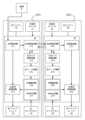
- FIG. 2is a functional block diagram of the earphone device of FIG. 1 .
- FIG. 2is a perspective view of a charger in which the earphone device of FIG. 1 is housed.
- FIG. 4is a functional block diagram of the earphone device in a state where it is housed in the charger of FIG. 3 .
- FIG. 4is a functional block diagram of the earphone device in a state where it is removed from the charger of FIG. 3 .
- 2is a sequence diagram showing the operation of the earphone device of FIG. 1 . 1.
- FIG. 4is a sequence diagram showing another operation of the earphone device of FIG.
- FIG. 4is another functional block diagram of the earphone device shown in FIG. 3 when removed from the charger.
- 9is a flowchart showing the operation of the earphone device of FIG. 8 .
- FIG. 1is a perspective view showing a first embodiment of the device 1. As shown in FIG. FIG. 2 is a functional block diagram of the device 1.
- This device 1is worn on the user's ear and outputs sound waves in response to an audio signal from a sound source S, such as a mobile terminal such as a smartphone or a portable music player.
- a sound source Ssuch as a mobile terminal such as a smartphone or a portable music player.
- This device 1receives the audio signal from the sound source S, for example, via a wireless communication line such as Bluetooth (registered trademark).
- “User”refers to a natural person who uses the device 1 by wearing it on the ear.
- This device 1comprises a left sound output unit 10 and a right sound output unit 20.
- This device 1is a so-called completely wireless earphone in which the left and right sound output units 10, 20 are not physically connected by a cable or the like.
- the left sound emission unit 10is worn on the left ear of the user and outputs sound waves corresponding to an audio signal from a sound source S.
- the left sound emission unit 10includes a left housing 11, a left sound guide tube 12, a left earpiece 13, a left operation switch 14, a left power receiving terminal 15, a left driver unit 16, a left circuit board 17, a left battery 18, and a left microphone 19.
- the left sound emission unit 10is an example of a sound emission unit in the present invention, and an example of a first sound emission unit.
- the left housing 11houses the left driver unit 16, the left circuit board 17, the left battery 18, and the left microphone 19.
- the left housing 11is made of, for example, a synthetic resin such as plastic.
- the left sound guide tube 12guides sound waves from the left driver unit 16 to the ear canal of the user's left ear when the device 1 is in use.
- the left sound guide tube 12is molded integrally with the left housing 11.
- the left earpiece 13When the left sound output unit 10 is attached to the left ear, the left earpiece 13 fits closely to the user's ear canal.
- the left earpiece 13is attached to the outer circumferential surface of the left sound guide tube 12.
- the left earpiece 13is made of an elastic material such as silicone rubber.
- the left operation switch 14is a switch used to control the operation of the device 1.
- the left operation switch 14is, for example, a push switch.
- the left operation switch 14is located on a portion of the outer surface of the left housing 11 that is exposed from the left ear when the left sound emission unit 10 is worn on the left ear. Specific operations for the left operation switch 14 will be described later.
- the left operation switch 14is an example of an operation unit in the present invention.
- the left operation switchmay be a touch sensor.
- a small touch sensoris disposed on the portion exposed from the left ear (for example, the outer surface of the left housing or the outermost surface of the left housing opposite the ear (the circular area indicated by the symbol "T" in FIG. 1)).
- the touch sensoris operated by the user by clicking, pressing and holding, sliding, etc.
- the touch sensoris, for example, a known touch sensor such as a resistive film type or a capacitive type.
- the left power receiving terminal 15receives power from a charger 30 (see FIG. 3) described below, which is supplied to the left battery 18.
- the left power receiving terminal 15is arranged exposed to the outside of the left housing 11. As shown in FIG. 5, within the left housing 11, the left power receiving terminal 15 is electrically connected to the left battery 18 and a left timer processing circuit 174 described below. The specific function of the left power receiving terminal 15 will be described later.
- the left driver unit 16is driven based on an audio signal from the sound source S received from the left receiving circuit 171 described below. That is, the left driver unit 16 outputs sound waves based on the audio signal from the sound source S.
- the left driver unit 16is, for example, a dynamic type electro-acoustic transducer.
- the left driver unit 16is an example of a driver unit in the present invention.
- the left circuit board 17is a board on which electronic circuits, etc., described below, are mounted.
- the left circuit board 17is, for example, a PCB (Printed Circuit Board).
- the left circuit board 17is electrically connected to the left operation switch 14, the left driver unit 16, the left battery 18, and the left microphone 19.
- the left circuit board 17is implemented with a left receiving circuit 171, a left signal processing circuit 172, a left transmitting/receiving circuit 173, a left timer processing circuit 174, a left mode circuit 175, a left amplifier circuit 176, and a left ANC (Active Noise Control) circuit 177.
- a left receiving circuit 171a left signal processing circuit 172, a left transmitting/receiving circuit 173, a left timer processing circuit 174, a left mode circuit 175, a left amplifier circuit 176, and a left ANC (Active Noise Control) circuit 177.
- the left receiving circuit 171receives an audio signal from a sound source S via a wireless communication line.
- the audio signal received by the left receiving circuit 171is a digital signal.
- the left receiving circuit 171transmits the received audio signal to the left signal processing circuit 172 and the left transmitting/receiving circuit 173.
- the left receiving circuit 171is an example of an antenna in the present invention.
- the left signal processing circuit 172processes the audio signal received from the left receiving circuit 171 and transmits the processed signal to the left driver unit 16.
- the left signal processing circuit 172is, for example, a D/A conversion circuit. That is, the signal after processing by the left signal processing circuit 172 is, for example, a D/A converted analog signal.
- the left transmission/reception circuit 173transmits and receives signals (audio signals, instruction signals, etc.) to and from the right transmission/reception circuit 273 of the right sound emission unit 20, which will be described later.
- the specific operation of the left transmission/reception circuit 173will be described later.
- the left transmission/reception circuit 173is an example of a first communication unit in the present invention.
- the left timer processing circuit 174is equipped with a timer and performs processing necessary for the operation of the left sound emission unit 10 based on the timer time.
- the left timer processing circuit 174generates an instruction signal based on the timer time and transmits the instruction signal to the left transmission/reception circuit 173 and the left mode circuit 175. The specific operation of the left timer processing circuit 174 will be described later.
- the "timer time”is the time measured by a timer provided in the left timer processing circuit 174.
- the timer timeis also measured by a timer provided in the right timer processing circuit 274, which will be described later.
- the "instruction signal”is a signal that is generated and transmitted by the left timer processing circuit 174, and is a signal that instructs the left mode circuit 175 and the right mode circuit 275 (described later) on the timing of switching the operating modes of the left and right sound emitting units 10 and 20.
- the "operation mode”is a mode that indicates a state in which one of the multiple functions provided by the left and right sound emission units 10 and 20 is operating.
- the operation modesinclude a first operation mode and a second operation mode. The specific contents of the operation modes will be described later.
- the left mode circuit 175switches the operation mode of the left sound emission unit 10 based on an instruction signal from the left timer processing circuit 174.
- the operation modes of the left sound emission unit 10include a hear-through mode and a noise cancellation (ANC) mode.
- the left mode circuit 175switches the connection between either the left amplifier circuit 176 or the left ANC circuit 177 and the left timer processing circuit 174.
- the operation mode of the left sound emission unit 10 when the state of the left sound emission unit 10 is switched from a stopped state to an operating stateis the first operation mode
- the operation mode of the left sound emission unit 10 after being switched from the first operation modeis the second operation mode.
- the "hear-through mode”is an operating mode in which the hear-through function operates so that sounds external to the left sound output unit 10 are taken in by the left sound output unit 10, allowing the user to hear surrounding sounds.
- the "noise cancellation mode”is an operating mode in which the noise cancellation function operates by outputting a cancellation sound from the left sound output unit 10 that is in the opposite phase to the external sound (sound around the user) of the left sound output unit 10, thereby muting (canceling) the external sound.
- the “stopped state”is a state in which the left sound output unit 10 is not operating.
- the stopped stateis, for example, a state in which the supply of power from the left battery 18 to the electronic circuit of the left circuit board 17 is stopped, and the electronic circuit mounted on the left circuit board 17 is not operating.
- the "operating state”is a state in which the left sound output unit 10 is operating.
- the operating stateis, for example, a state in which power is supplied from the left battery 18 to the electronic circuit of the left circuit board 17, and the electronic circuit mounted on the left circuit board 17 is operating.
- the left amplifier circuit 176amplifies the sound outside the left sound output unit 10 picked up by the left microphone 19 and transmits it as an amplified signal to the left signal processing circuit 172.
- the left mode circuit 175operates the left amplifier circuit 176.
- the left amplifier circuit 176is, for example, a known amplifier circuit.
- the left ANC circuit 177generates a cancellation signal of an opposite phase corresponding to the sound outside the left sound emission unit 10 picked up by the left microphone 19, and transmits the cancellation signal to the left signal processing circuit 172.
- the left mode circuit 175operates the left ANC circuit 177.
- the left ANC circuit 177is, for example, a known ANC circuit.
- the operating mode of the left sound emitting unitmay include a "normal mode” in which neither the hear-through function nor the noise cancellation function is operated.
- the operating mode of the left sound emitting unit 10may include a "normal mode” and either a "hear-through mode” or a "noise cancellation mode.”
- the left mode circuitdoes not operate either the left amplifier circuit or the left ANC circuit.
- the left battery 18stores the power required for the operation of the left sound emission unit 10 (e.g., the power supplied to the left circuit board 17).
- the left battery 18is an example of a battery in the present invention.
- the left microphone 19picks up sounds outside the left sound output unit 10.
- the left microphone 19is, for example, a well-known condenser microphone.
- the right sound emission unit 20is worn on the right ear of the user and outputs sound waves corresponding to an audio signal from a sound source S.
- the configuration of the right sound emission unit 20is the same as the configuration of the left sound emission unit 10. That is, the right sound emission unit 20 includes a right housing 21, a right sound guide tube 22, a right earpiece 23, a right operation switch 24, a right power receiving terminal (not shown), a right driver unit 26, a right circuit board 27, a right battery 28, and a right microphone 29.
- the right sound emission unit 20is an example of a second sound emission unit in the present invention.
- the right housing 21corresponds to the left housing 11
- the right sound guide tube 22corresponds to the left sound guide tube 12
- the right earpiece 23corresponds to the left earpiece 13
- the right operation switch 24corresponds to the left operation switch 14
- the right power receiving terminalcorresponds to the left power receiving terminal 15
- the right driver unit 26corresponds to the left driver unit 16
- the right circuit board 27corresponds to the left circuit board 17
- the right battery 28corresponds to the left battery 18,
- the right microphone 29corresponds to the left microphone 19.
- Each corresponding parthas the same function.
- the right operation switch 24is an example of an operation unit in the present invention.
- the right driver unit 26is an example of a driver unit in the present invention.
- the right battery 28is an example of a battery in the present invention.
- the right circuit board 27is electrically connected to the right operation switch 24, the right driver unit 26, the right battery 28, and the right microphone 29.
- the right circuit board 27is implemented with a right receiving circuit 271, a right signal processing circuit 272, a right transmitting/receiving circuit 273, a right timer processing circuit 274, a right mode circuit 275, a right amplifier circuit 276, and a right ANC circuit 277.
- the right receiving circuit 271corresponds to the left receiving circuit 171
- the right signal processing circuit 272corresponds to the left signal processing circuit 172
- the right transmitting/receiving circuit 273corresponds to the left transmitting/receiving circuit 173
- the right timer processing circuit 274corresponds to the left timer processing circuit 174
- the right mode circuit 275corresponds to the left mode circuit 175
- the right amplifier circuit 276corresponds to the left amplifier circuit 176
- the right ANC circuit 277corresponds to the left ANC circuit 177.
- Each corresponding circuithas the same function. Therefore, the description of the operations of the right circuit board 27 that are common to the left circuit board 17 will be omitted.
- the right receiving circuit 271is an example of an antenna in the present invention.
- the right transmission/reception circuit 273is an example of the second communication unit in the present invention.
- FIG. 3is a perspective view of the charger 30 in which the device 1 is housed.
- the figureshows a state in which the left and right sound emitting units 10, 20 are respectively housed in the charger 30 and a lid portion 312, which will be described later, is open.
- FIG. 4is a functional block diagram of the device 1 and the charger 30. As shown in FIG. The figure shows a state in which the device 1 is housed in a charger 30. In the figure, dotted lines indicate the flow of power, and solid lines indicate the flow of signals.
- the charger 30is a charger dedicated to the device 1. When the left and right sound emitting units 10, 20 are housed in the charger 30, the left and right sound emitting units 10, 20 are electrically connected to the charger 30. When the left and right sound emitting units 10, 20 are housed in the charger 30, the left battery 18 of the left sound emitting unit 10 and the right battery 28 of the right sound emitting unit 20 are charged.
- the charger 30includes a case 31, a control circuit 32, a battery 33, a power supply terminal 34, and an external power supply terminal 35.
- the case 31includes a main body 311, a lid 312, and a storage section (not shown).
- the case 31is made of, for example, a synthetic resin such as plastic.
- the main body 311houses the storage section, the control circuit 32, the battery 33, and the power supply terminal 34.
- the main body 311is a hollow cylinder with a bottom and a rounded rectangular shape in a plan view.
- the lid portion 312prevents the left and right sound emission units 10, 20 housed in the housing portion from jumping out of the housing portion.
- the lid portion 312is attached to the main body portion 311 so as to be able to open and close. When the lid portion 312 closes the main body portion 311, the lid portion 312 is locked to the main body portion 311.
- the control circuit 32controls the operation of the charger 30.
- the control circuit 32is electrically connected to the battery 33, the power supply terminal 34, and the external power supply terminal 35. The specific operation of the control circuit 32 will be described later.
- the battery 33stores power from the external power source 40. Power from the external power source 40 is supplied to the battery 33 via the control circuit 32.
- the power stored in the battery 33is supplied to each of the left and right sound emitting units 10, 20 via the control circuit 32. The power stored in the battery 33 is supplied to each of the housed left and right sound emitting units 10, 20 even when the charger 30 is not connected to the external power source 40.
- the power supply terminal 34is exposed inside the housing.
- the power supply terminal 34is electrically connected to the control circuit 32 and is connected to the battery 33 via the control circuit 32.
- the left power receiving terminal 15When the left sound output unit 10 is housed in the charger 30, the left power receiving terminal 15 is electrically connected to the power supply terminal 34. At this time, power is supplied to the left battery 18 of the left sound output unit 10. On the other hand, when the left sound output unit 10 is removed from the charger 30, the electrical connection between the left power receiving terminal 15 and the power supply terminal 34 is cut off. At this time, the supply of power to the left battery 18 of the left sound output unit 10 is stopped. In the right sound output unit 20, the relationship between the power supply terminal 34 and the right power receiving terminal (not shown) is the same as the relationship between the power supply terminal 34 and the left power receiving terminal 15.
- the external power supply terminal 35is, for example, a USB terminal for a USB (Universal Serial Bus) cable that supplies power from the external power supply 40 to the battery 33.
- the external power supply terminal 35is disposed on the outer surface of the main body 311.
- the control circuit 32monitors and controls the flow of power.
- the control circuit 32monitors the charge state of the battery 33, and supplies power to the battery 33 if the battery 33 is not fully charged, and stops the supply of power to the battery 33 if the battery 33 is fully charged. In this way, the control circuit 32 appropriately monitors the charge state of the battery 33 and controls the charge state of the battery 33.
- the control circuit 32detects that the left power receiving terminal 15 and the power supply terminal 34 are electrically connected. Having detected the connection, the control circuit 32 supplies power to the left battery 18 via the power supply terminal 34 and the left power receiving terminal 15. As a result, the left battery 18 stores the supplied power. In other words, when the left sound emission unit 10 is housed in the charger 30, the left battery 18 is charged. When the left sound emission unit 10 is housed in the charger 30, the left sound emission unit 10 is in a stopped state.
- FIG. 5is a functional block diagram of the device 1 and the charger 30. As shown in FIG. The figure shows the device 1 removed from the charger 30.
- the control circuit 32 of the charger 30detects that the electrical connection between the left power receiving terminal 15 and the power supply terminal 34 has been cut off. Having detected that the connection has been cut off, the control circuit 32 stops the supply of power from the battery 33 to the power supply terminal 34.
- the left timer processing circuit 174 of the left sound emitting unit 10detects that the electrical connection between the left power receiving terminal 15 and the power supply terminal 34 has been cut off. Upon detecting that the connection has been cut off, the left timer processing circuit 174 generates an instruction signal to switch to the first operating mode, and transmits the instruction signal to the left mode circuit 175 and the left transmission/reception circuit 173.
- the connection between the left power receiving terminal 15 and the power supply terminal 34is cut off, and therefore the supply of power to the left battery 18 is stopped. At this time, the supply of power from the left battery 18 begins to the electronic circuit of the left circuit board 17.
- the state of the left sound emission unit 10switches from a stopped state to an operating state. In other words, when the left sound emission unit 10 is not contained in the charger 30, the state of the left sound emission unit 10 is in an operating state.
- the relationship between the left sound output unit 10 and the charger 30 described aboveis the same as the relationship between the right sound output unit 20 and the charger 30.
- FIG. 6is a sequence diagram showing the operation of the present device 1. As shown in FIG. This figure is a sequence diagram showing an example in which the operation modes of the left and right sound emitting units 10, 20 are switched from the hear-through mode to the noise cancellation mode.
- the userwill first remove the left sound emission unit 10 from the charger 30 and place it on the ear, and then remove the right sound emission unit 20 from the charger 30 and place it on the ear.
- the left sound output unit 10When the left sound output unit 10 is removed from the charger 30 by the user, power from the left battery 18 is supplied to the electronic circuit mounted on the left circuit board 17, and the left sound output unit 10 starts up (S10). In other words, when the left sound output unit 10 is removed from the charger 30, the state of the left sound output unit 10 switches from a stopped state to an operating state.
- the left sound emitting unit 10When the left sound emitting unit 10 is removed from the charger 30, the left sound emitting unit 10 starts operating in the hear-through mode, which is the first operating mode (S11). In other words, when the state of the left sound emitting unit 10 switches from a stopped state to an operating state, the operating mode of the left sound emitting unit 10 becomes the hear-through mode, which is the first operating mode.
- S11the first operating mode
- the left sound output unit 10transmits a connection signal from the left transmission/reception circuit 173 (S12).
- connection signalis a signal transmitted between the left transceiver circuit 173 and the right transceiver circuit 273 to establish a communication connection between the left and right sound emission units 10, 20.
- the left receiving circuit 171receives an audio signal from the sound source S
- the audio signalis transmitted to the left signal processing circuit 172 and the left transmitting/receiving circuit 173.
- the left ANC circuit 177generates a cancellation signal and transmits it to the left signal processing circuit 172.
- the audio signal transmitted from the left receiving circuit 171 and the cancellation signal transmitted from the left ANC circuit 177are superimposed and transmitted to the left driver unit 16.
- the left driver unit 16outputs sound waves that activate the noise cancellation function based on the superimposed signal.
- the left sound emission unit 10, removed from the charger 30,is worn on the user's left ear while operating in the hear-through mode, which is the first operating mode. Because the left sound emission unit 10 worn on the left ear is operating in hear-through mode, the user can hear external sounds coming from the left ear on which the left sound emission unit 10 is worn, and external sounds coming from the right ear on which nothing is worn, in the same way. Therefore, the user can hear external sounds from both ears without feeling any discomfort.
- the right sound emitting unit 20is then removed from the charger 30 by the user.
- the right sound emitting unit 20is removed from the charger 30, power from the right battery 28 is supplied to the electronic circuit mounted on the right circuit board 27, and the right sound emitting unit 20 is started up (S20).
- the state of the right sound emitting unit 20switches from a stopped state to an operating state.
- the right sound emitting unit 20when the right sound emitting unit 20 is removed from the charger 30, the right sound emitting unit 20 starts operating in the hear-through mode, which is the first operating mode (S21).
- the hear-through modewhich is the first operating mode (S21).
- the state of the right sound emitting unit 20switches from a stopped state to an operating state, the operating mode of the right sound emitting unit 20 becomes the hear-through mode, which is the first operating mode.
- the audio signalis transmitted to the right signal processing circuit 272 via the left transmitting/receiving circuit 173 and the right transmitting/receiving circuit 273.
- the right ANC circuit 277also generates a cancellation signal and transmits it to the right signal processing circuit 272.
- the audio signal transmitted from the right transmitting/receiving circuit 273 and the cancellation signal transmitted from the right ANC circuit 277are superimposed and transmitted to the right driver unit 26.
- the right driver unit 26outputs sound waves that activate the noise cancellation function based on the superimposed signal.
- connection signal transmitted from the left transmission/reception circuit 173is received by the right transmission/reception circuit 273.
- the received connection signalis transmitted from the right transmission/reception circuit 273 to the left transmission/reception circuit 173 (S22).
- connectionis established (S13, S23).
- the connectionis established when the left transmitting/receiving circuit 173 receives a message from the right transmitting/receiving circuit 273 that the right sound emitting unit 20 is in an operating state.
- the left timer processing circuit 174starts counting a preset time (S14).
- the right sound emitting unit 20starts counting a preset time (S24).
- the "set time”is a time set as a time assumed to elapse from when one sound emitting unit (in this embodiment, the left sound emitting unit 10) is removed from the charger 30 and the other sound emitting unit (in this embodiment, the right sound emitting unit 20) is removed from the charger 30 until the other sound emitting unit (right sound emitting unit 20) is completely attached.
- the time when the connection is establishedis considered to be the timing for removing the other sound emitting unit (right sound emitting unit 20).
- the device 1assumes that the left and right sound emitting units 10 and 20 are attached to the ears, and performs the operation (switching of the operating mode) described below.
- the set timeis preset. In this embodiment, the set time is, for example, 2 seconds.
- the set timemay be set based on the comparison result of the timer times measured by the left and right timer processing circuits, as described later in the second embodiment.
- the device 1does not have a wearing sensor that is provided in conventional completely wireless earphones. Therefore, in the device 1, the time when the connection is established is set as the timing for removing the other sound emission unit (right sound emission unit 20), and the time when a set time has elapsed from the same timing is set as the timing for wearing the left and right sound emission units 10, 20. With this setting, the left and right sound emission units 10, 20 operate in hear-through mode before being worn on both ears of the user, and automatically operate in noise cancellation mode when the left and right sound emission units 10, 20 are worn on both ears of the user.
- the operation mode of the left and right sound emission units 10, 20automatically switches from the first operation mode (hear-through mode) to the second operation mode (noise cancellation mode) when the left and right sound emission units 10, 20 are worn on both ears of the user. Therefore, when one sound output unit (left sound output unit 10) is attached to one ear, the user can hear external sounds without feeling uncomfortable or stressed, and when the left and right sound output units 10, 20 are attached to both ears, the user can hear musical sounds from which external sounds have been erased. In this way, with this device 1, the user can switch from hear-through mode to noise cancellation mode without feeling uncomfortable or stressed.
- the left timer processing circuit 174sends an instruction signal to the left mode circuit 175 (S16).
- the right timer processing circuit 274sends an instruction signal to the right mode circuit 275 (S26).
- the right mode circuit 275which has received the instruction signal, switches the electronic circuit connected to the right signal processing circuit 272 from the right amplifier circuit 276 to the right ANC circuit 277. That is, the operation modes of the left and right sound emitting units 10, 20 simultaneously switch from the hear-through mode to the noise cancellation mode (S17, S27).
- the operation mode of the left and right sound emitting units 10, 20switches from the first operation mode (hear-through mode) to the second operation mode (noise cancellation mode).
- the “standby time”is the time that the left sound emitting unit 10 (right sound emitting unit 20) in the operating state waits in the first operating mode without switching the operating mode.
- the standby timeis the time from when the left sound emitting unit 10 (right sound emitting unit 20) starts operating in the first operating mode to when the operating mode of the left sound emitting unit 10 (right sound emitting unit 20) switches to the second operating mode.
- the standby timeis assumed and set as the time from when one sound emitting unit (left sound emitting unit 10) is removed from the charger 30 to when the other sound emitting unit (right sound emitting unit 20) is worn on the ear.
- the standby timeis the total time from when the state of the left sound emitting unit 10 switches from a stopped state to an operating state (time) to when a connection is established (in other words, when the state of the right sound emitting unit 20 switches from a stopped state to an operating state) in the left sound emitting unit 10, and the time from when the count of the set time starts to when the count ends.
- the waiting timeis an example of a predetermined time in the present invention.
- the right sound emission unit 20While the set time is being counted, the right sound emission unit 20 is attached to the right ear while operating in the hear-through mode, which is the first operating mode.
- the operating mode of the left and right sound emission units 10, 20is the hear-through mode until the set time has elapsed. Therefore, even if the left and right sound emission units 10, 20 are attached to both ears, the user can hear external sounds from both ears.
- the operating mode of the left and right sound emission units 10, 20switches from the hear-through mode to the noise cancellation mode. Therefore, the user can feel that the mode has switched from the hear-through mode to the noise cancellation mode.
- the left ANC circuit 177transmits a cancellation signal to the left signal processing circuit 172.
- the audio signal transmitted from the left receiving circuit 171 and the cancellation signal transmitted from the left ANC circuit 177are superimposed and transmitted to the left driver unit 16.
- the left driver unit 16Based on the superimposed signal, the left driver unit 16 outputs sound waves that have activated the noise cancellation function.
- the right sound emission unit 20the same operation as in the left sound emission unit 10 is performed, and sound waves that have activated the noise cancellation function are output.
- the device 1includes a left sound output unit 10 (right sound output unit 20) that is attached to the user's ear.
- the left sound output unit 10 (right sound output unit 20)includes a left receiving circuit 171 (right receiving circuit 271), a left driver unit 16 (right driver unit 26), and a left battery 18 (right battery 28).
- the left sound output unit 10 (right sound output unit 20)is in a stopped state when the left sound output unit 10 (right sound output unit 20) is housed in the charger 30, and is in an operating state when the left sound output unit 10 (right sound output unit 20) is not housed in the charger 30.
- the operating mode of the left sound output unit 10 (right sound output unit 20) in such an operating stateincludes a first operating mode and a second operating mode.
- the state of the left sound emitting unit 10 (right sound emitting unit 20)is switched from a stopped state to an operating state, the operating mode of the left sound emitting unit 10 (right sound emitting unit 20) for the first waiting time (predetermined time) after switching is the first operating mode.
- the left sound emitting unit 10operates in the first operating mode until the waiting time has elapsed after switching.
- the left sound emitting unit 10(right sound emitting unit 20) on the ear
- the left sound emitting unit 10(right sound emitting unit 20) is already operating in the first operating mode, so that the desired function (in this embodiment, the hear-through function) is operated without causing the user to feel stress.
- the operation mode of the left sound emission unit 10is the second operation mode after the first waiting time (predetermined time) has elapsed since the switching.
- the operation mode of the left sound emission unit 10automatically switches to the second operation mode after the waiting time has elapsed since the switching. Therefore, when the user wears the left sound emission unit 10 (right sound emission unit 20) on his/her ear, the operation mode is switched in the left sound emission unit 10 (right sound emission unit 20) without causing stress to the user, and the desired function is operated.
- the device 1includes a left sound emission unit 10 and a right sound emission unit 20.
- the operating mode of the left sound emission unit 10is the first operating mode until the right sound emission unit 20 is switched to an operating state.
- the operating mode of the left sound emission unit 10is already operated in the first operating mode. Therefore, when the user wears the left sound emission unit 10 on his/her ear, it is already operating in the first operating mode, so the desired function is operated without causing stress to the user.
- the operation mode of the left sound emission unit 10 operating in the first operation modeswitches to the second operation mode after the right sound emission unit 20 switches to an operating state and a standby time (predetermined time) has elapsed.
- the operation mode of the left sound emission unit 10automatically switches to the second operation mode after the right sound emission unit 20 switches to an operating state and a standby time has elapsed. Therefore, there is no erroneous operation when switching the operation mode, the operation mode is switched without causing stress to the user, and the desired function is operated.
- the left sound emission unit 10(right sound emission unit 20) has a noise cancellation function, and in the first operation mode, the noise cancellation function is disabled, and in the second operation mode, the noise cancellation function is enabled. According to this configuration, the left sound emission unit 10 (right sound emission unit 20) automatically switches between enabled and disabled noise cancellation function, so there is no erroneous operation by the user in the left sound emission unit 10 (right sound emission unit 20), and the user does not feel stressed.
- a set time(standby time) is set so that the noise cancellation function is switched to enabled in the left sound emission unit 10 (right sound emission unit 20), so that the user can feel that the noise cancellation function has been switched to.
- the left sound output unit 10(right sound output unit 20) has a hear-through function, which is enabled in the first operating mode and disabled in the second operating mode.
- the left sound output unit 10(right sound output unit 20) is worn on one ear of the user while operating with the hear-through function. Therefore, the user can hear external sounds in the same way on the ear on which the left sound output unit 10 is worn and on the ear on which nothing is worn. In other words, the user can hear external sounds from both ears without feeling any discomfort.
- the left sound emission unit 10includes a left transmission/reception circuit 173, and the right sound emission unit 20 includes a right transmission/reception circuit 273.
- the standby time(predetermined time) is determined based on the time when the left transmission/reception circuit 173 receives information from the right transmission/reception circuit 273 that the right sound emission unit 20 is in an operating state.
- the operation mode of the right sound emission unit 20when the operation mode of the right sound emission unit 20 is switched from a stopped state to an operating state, it switches from the first operation mode to the second operation mode when the operation mode of the left sound emission unit 10 switches from the first operation mode to the second operation mode.
- the operation modes of the left and right sound emission units 10, 20 worn on the left and right earscan be switched simultaneously.
- the first operation modemay be a noise cancellation mode and the second operation mode may be a hear-through mode.
- the operating modemay be switched when the connection between the left and right transmission/reception circuits is closed.
- a user who is using the left and right sound emitting unitsmay remove one of the sound emitting units from one of the ears and place it in a charger.
- the operating mode of the other sound emitting unitis controlled so that it switches from the noise cancellation mode to the hear-through mode, triggered by the connection between the left and right transmission/reception circuits being closed.
- the second embodimentdiffers from the first embodiment in that the set time is set based on a comparison of the time from when the state of the left and right sound emission units 10, 20 switches from a stopped state to an operating state to when the connection is established.
- the set timeis set based on a comparison of the time from when the state of the left and right sound emission units 10, 20 switches from a stopped state to an operating state to when the connection is established.
- FIG. 7is a sequence diagram showing another operation of the device 1.
- This figureis a sequence diagram showing an example in which the operation modes of the left and right sound emitting units 10, 20 are switched from the hear-through mode to the noise cancellation mode.
- the left sound output unit 10starts measuring the timer time using the left timer processing circuit 174 (S31).
- the left sound output unit 10also starts operating in the hear-through mode, which is the first operating mode (S32).
- the left sound output unit 10transmits a connection signal from the left transmission/reception circuit 173 (S33).
- the left sound emission unit 10 removed from the charger 30is attached to the user's left ear while operating in the hear-through mode, which is the first operating mode. Because the left sound emission unit 10 attached to the left ear is operating in hear-through mode, the user can hear external sounds coming from the left ear on which the left sound emission unit 10 is attached, and external sounds coming from the right ear on which nothing is attached, in the same way. Therefore, the user can hear external sounds from both ears without feeling any discomfort.
- the right sound output unit 20is removed from the charger 30 by the user.
- the right sound output unit 20is removed from the charger 30
- poweris supplied from the right battery 28 to the electronic circuit mounted on the right circuit board 27, and the right sound output unit 20 starts up (S50).
- the right sound emission unit 20starts measuring the timer time using the right timer processing circuit 274 (S51).
- the right sound output unit 20also starts operating in the hear-through mode, which is the first operating mode (S52).
- connection signal transmitted from the left transmission/reception circuit 173is received by the right transmission/reception circuit 273.
- the received connection signalis transmitted from the right transmission/reception circuit 273 to the left transmission/reception circuit 173 (S53).
- the left timer processing circuit 174ends the measurement of the timer time by the left timer processing circuit 174 (S35).
- the right sound emission unit 20ends the measurement of the timer time by the right timer processing circuit 274 (S55).
- the left timer processing circuit 174compares the measurement result of the timer time of the left timer processing circuit 174 (time A) with the measurement result of the timer time of the right timer processing circuit 274 (time B) and sets the set time (S36, S56).
- the left timer processing circuit 174performs the following process. First, the left timer processing circuit 174 compares time A with time B. Next, the left timer processing circuit 174 selects the longer timer time (time A, time B) as a result of comparing time A with time B. The selected timer time becomes the first candidate time, which is a candidate for the set time. Here, the left timer processing circuit 174 compares the first candidate time with a predetermined sample time (5 seconds in this embodiment).
- the left timer processing circuit 174sets the first candidate time as the set time. On the other hand, if the first candidate time is equal to or greater than the sample time, the left timer processing circuit 174 sets the second candidate time (2 seconds in this embodiment) that is set in advance as the set time.
- the set timeis set based on the comparison result of the timer times measured by the left and right timer processing circuits 174, 274, as described above.
- the timer time of the left timer processing circuit 174is the elapsed time (time A) from the time when the state of the left sound emission unit 10 switches from a stopped state to an operating state to the time when the state of the right sound emission unit 20 switches from a stopped state to an operating state (in this embodiment, the establishment of the connection is considered to be the timing when the left sound emission unit 10 is attached to the left ear).
- the timer time of the right timer processing circuit 274is the elapsed time (time B) from the time when the state of the right sound emission unit 20 switches from a stopped state to an operating state to the time when the connection is established, which is a very short time. Therefore, by comparing time A and time B, the present device 1 can always set the set time based on the timer time (first candidate time) of the sound emission unit (left sound emission unit 10) that was first removed from the charger 30.
- the elapsed time(the time from when the left sound emitting unit 10 is taken out of the charger 30 to when it is worn on the left ear) is a unique time that differs for each user, but in this embodiment, the set time is set based on that elapsed time. Therefore, in this device 1, the desired function can be operated at the optimal timing for each user. Also, when the first candidate time is greater than the sample time, this device 1 assumes that only the sound emitting unit (left sound emitting unit 10) first taken out of the charger 30 was used by the user, and does not adopt the first candidate time as the set time for the sound emitting unit (right sound emitting unit 20) taken out later from the charger 30, but adopts the second candidate time.
- this device 1can operate the desired function at the appropriate timing for each of the left and right sound emitting units 10, 20.
- the left timer processing circuit 174 and the right timer processing circuit 274share the set time via the left transmission/reception circuit 173 and the right transmission/reception circuit 273.
- the left timer processing circuit 174 and the right timer processing circuit 274simultaneously start counting the set time based on the set set time (S37, S57).
- the left timer processing circuit 174sends an instruction signal to the left mode circuit 175 (S39).
- the right timer processing circuit 274sends an instruction signal to the right mode circuit 275 (S59).
- the operation modes of the left and right sound emission units 10, 20are simultaneously switched from the hear-through mode to the noise cancellation mode (S40, S50).
- the operation modes of the left and right sound emission units 10, 20are switched from the first operation mode (hear-through mode) to the second operation mode (noise cancellation mode).
- the standby time(predetermined time) is determined based on the elapsed time from when the state of the left sound emission unit 10 is switched from the stopped state to the operating state to when the state of the right sound emission unit 20 is switched from the stopped state to the operating state.
- the timing of switching the operation modes of the left and right sound emission units 10 and 20is determined based on the actual usage of the user, such as the elapsed time taken for the user to wear the left sound emission unit 10 and the elapsed time thereafter until the right sound emission unit 20 is removed from the charger 30. Therefore, the operation modes of the left and right sound emission units 10 and 20 are switched at an appropriate timing according to the user. Since the operation modes are switched at an appropriate timing, the desired function is operated without causing the user to feel stress.
- the timing for ending the timer time measurementis not limited to the point at which a connection is established.
- the timing for ending the timer time measurementmay be the point at which the left sound emitting unit is able to transmit and receive a connection signal to and from the right sound emitting unit.
- the set timedoes not have to be set based on the result of comparing time A and time B. That is, for example, the set time may be determined based on the elapsed time from the point when the state of the left sound emitting unit switches from a stopped state to an operating state to the point when the state of the right sound emitting unit switches from a stopped state to an operating state.
- the set timemay be set flexibly depending on the time the user takes to wear the sound emitting unit, etc.
- the third embodimentdiffers from the first embodiment in that the first operation mode is an operation-disabled mode and the second operation mode is an operation-enabled mode. Also, the time from when one of the sound-emitting units 10, 20 switches from a stopped state to an operating state to when the operation mode is switched differs from the first embodiment.
- elements common to the first embodimentare given the same reference numerals, and some or all of the description thereof will be omitted.
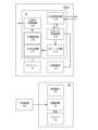
- FIG. 8is a functional block diagram of the device 1 and the charger 30. As shown in FIG. The figure shows a state in which the device 1 is removed from the charger 30. For convenience of explanation, the left signal processing circuit 172, the left amplifier circuit 176, and the left ANC circuit 177 (see FIG. 5) are omitted in the figure.
- the left circuit board 17is equipped with a left signal processing circuit 172 (see FIG. 5), a left transmission/reception circuit 173, a left timer processing circuit 174, a left mode circuit 175, a left amplifier circuit 176 (see FIG. 5), a left ANC circuit 177 (see FIG. 5), a left operation switching circuit 178, and a left function control circuit 179.
- the left mode circuit 175switches the operation mode of the left sound emission unit 10 based on an instruction signal from the left timer processing circuit 174.
- the operation modes of the left sound emission unit 10include an operation disabled mode and an operation enabled mode.
- the first operation modeis the operation disabled mode
- the second operation modeis the operation enabled mode.
- the "operation disabled mode”is an operating mode in which, even if the left operation switch 14 is operated by the user, the operation signal from the left operation switch 14 is not input to the left function control circuit 179.
- the operation signal indicating the operation content of the left operation switch 14is stopped by the left operation switching circuit 178 and is not sent to the left function control circuit 179. Therefore, in the left sound emission unit 10 operating in the operation disabled mode, the function corresponding to the operation content of the left operation switch 14 does not operate. In other words, in the left sound emission unit 10 operating in the operation disabled mode, the operation function of the left operation switch 14 is disabled.
- the "operation signal”is a signal that indicates the operation of the left operation switch 14, and is generated by the left operation switch 14 according to the operation of the left operation switch 14 by the user.
- the generated operation signalis sent to the left function control circuit 179 via the left operation switching circuit 178.
- the "operation enabled mode”is an operation mode in which, when the left operation switch 14 is operated by the user, an operation signal from the left operation switch 14 is input to the left function control circuit 179. In the operation enabled mode, an operation signal is sent from the left operation switching circuit 178 to the left function control circuit 179. Therefore, in the left sound output unit 10 operating in the operation enabled mode, a function according to the operation content of the left operation switch 14 operates. In other words, in the left sound output unit 10 operating in the operation enabled mode, the operation function of the left operation switch 14 is enabled.
- the left operation switching circuit 178is a switch circuit that switches the presence or absence of an electrical connection between the left operation switch 14 and the left function control circuit 179.
- the left operation switching circuit 178electrically connects and disconnects the left operation switch 14 and the left function control circuit 179 based on an instruction signal from the left mode circuit 175. Specifically, when the operation mode of the sound emission unit 10 is the first operation mode (operation disabled mode), the left operation switching circuit 178 disconnects the electrical connection between the left operation switch 14 and the left function control circuit 179. On the other hand, when the operation mode of the sound emission unit 10 is the second operation mode (operation enabled mode), the left operation switching circuit 178 electrically connects the left operation switch 14 and the left function control circuit 179.
- the left function control circuit 179controls the operation of each function of the left sound emission unit 10 based on the operation signal.
- the functions controlled by the left function control circuit 179include, for example, adjusting the volume, selecting the sound quality, enabling/disabling the hear-through function and the noise cancellation function, and switching between musical sounds and telephone calls. The specific control of the left function control circuit 179 will be described later.
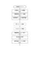
- FIG. 9is a flowchart showing still another operation of the device 1. This figure shows an example in which the operation mode of the left sound output unit 10 is switched from the operation disabled mode to the operation enabled mode.
- the left sound output unit 10When the left sound output unit 10 is removed from the charger 30 by the user, power is supplied from the left battery 18 to the electronic circuit mounted on the left circuit board 17, and the left sound output unit 10 starts up (S70). At this time, the state of the left sound output unit 10 switches from a stopped state to an operating state.
- the left sound emitting unit 10starts counting the preset waiting time (5 seconds in this embodiment) (S71).
- the left timer processing circuit 174starts counting the waiting time.
- the "standby time”is the time that the left sound emission unit 10, once in an operating state, waits in the first operating mode without switching the operating mode.
- the left sound emitting unit 10when the left sound emitting unit 10 is removed from the charger 30, the left sound emitting unit 10 starts operating in the operation disabled mode, which is the first operating mode (S72). In other words, when the state of the left sound emitting unit 10 switches from a stopped state to an operating state, the operating mode of the left sound emitting unit 10 becomes the operation disabled mode, which is the first operating mode.
- the left sound emitting unit 10transmits a connection signal from the left transmitting/receiving circuit 173. If the right sound emitting unit 20 is removed from the charger 30 while the standby time is being counted, a connection between the left sound emitting unit 10 and the right sound emitting unit 20 is established.
- the left timer processing circuit 174sends an instruction signal to the left mode circuit 175 (S74).
- the operation signal by the operation of the left operation switch 14is transmitted to the left function control circuit 179.
- the left function control circuit 179controls the functions of the left sound emission unit 10 based on the operation signal. That is, for example, when the operation signal indicates an operation content for enabling the noise cancellation function, the left function control circuit 179 operates the left ANC circuit 177 via the left mode circuit 175 or directly to transmit a cancellation signal to the left signal processing circuit 172. Also, for example, when the operation signal indicates an operation content for enabling the hear-through function, the left function control circuit 179 operates the left amplifier circuit 176 via the left mode circuit 175 or directly to transmit an amplified signal to the left signal processing circuit 172.
- the left sound emitting unit 10 removed from the charger 30is attached to the left ear of the user while operating in the first operating mode.
- the left sound emitting unit 10is only large enough to fit in the auricle, so the left operation switch 14 of the left sound emitting unit 10 is small and the operation method is inevitably simple.
- the useroperates the left operation switch 14 of the left sound emitting unit 10 near the ear without visually checking the left sound emitting unit 10, which may result in erroneous operation.
- the operating mode of the left sound emitting unit 10is the operation disabled mode and the operation of the left operation switch 14 is disabled, so the left sound emitting unit 10 is attached to the left ear without being erroneously operated.
- the operation switchis a touch sensor
- the usercan operate the earphones simply by touching the touch sensor when wearing the earphones in their ears. Touching the touch sensor can cause erroneous operation. For this reason, the earphone device according to this embodiment is particularly effective when the operation switch is a touch sensor.
- the operation of the right sound output unit 20is the same as that of the left sound output unit 10. Therefore, in the right sound output unit 20, the operation of the right operation switch 24 is also disabled from the time it is removed from the charger 30 until the standby time has elapsed.
- the operation modes of the left and right sound emitting unitsmay be switched simultaneously.
- the operation modes of the left and right sound emitting unitsmay be switched after the waiting time described in the first and second embodiments has elapsed.
- the left sound emission unit 10(right sound emission unit 20) is provided with a left operation switch 14 (right operation switch 24) that controls the operation of the left sound emission unit 10 (right sound emission unit 20).
- the operation function of the left operation switch 14(right operation switch 24) is disabled in the first operation mode and is enabled in the second operation mode. According to this configuration, when the left sound emission unit 10 (right sound emission unit 20) is worn on the user's ear, the operation function of the left operation switch 14 (right operation switch 24) is disabled, so the user can wear the left sound emission unit 10 (right sound emission unit 20) on the ear without operating it erroneously.
- the operation mode of the left sound emission unit 10automatically switches to the second operation mode when it is worn, so the desired function is operated without causing the user to feel stress.
- the waiting timeis not limited to the time in this embodiment. That is, for example, the time in the present invention can be set according to the time it takes for the user to put on the sound emitting unit.
- the first embodiment (second embodiment) and the third embodimenthave been described as separate embodiments, but they may be combined with each other. Also, for example, after the switching of the operation mode of the first embodiment (second embodiment) is completed, the switching of the operation mode of the third embodiment may be performed. Conversely, after the switching of the operation mode of the third embodiment is completed, the switching of the operation mode of the first embodiment (second embodiment) may be performed.
- the power flow and signal flow in each embodimentare merely examples, and the present invention is not limited to the power flow and signal flow in each embodiment.
- This device10 Left sound output unit (sound output unit, first sound output unit) 14 Left operation switch (operation part) 16 Left driver unit (driver unit) 171 Left receiving circuit (antenna) 173 Left transmitting/receiving circuit (first communication unit) 18 Left battery (battery) 20 Right sound output unit (sound output unit, second sound output unit) 24 Right operation switch (operation part) 26 Right driver unit (driver unit) 271 Right receiving circuit (antenna) 273 Right transmitting/receiving circuit (second communication unit) 28 Right battery (battery) 30 Charger
Landscapes
- Physics & Mathematics (AREA)
- Engineering & Computer Science (AREA)
- Acoustics & Sound (AREA)
- Multimedia (AREA)
- Signal Processing (AREA)
- Health & Medical Sciences (AREA)
- Audiology, Speech & Language Pathology (AREA)
- General Health & Medical Sciences (AREA)
- Headphones And Earphones (AREA)
Abstract
Description
Translated fromJapanese本発明は、イヤホン装置に関する。The present invention relates to an earphone device.
イヤホン装置は、使用者の耳に装着されて、スマートホンなどの携帯端末や、携帯型音楽再生機などの音源からの音声信号に応じた音波を出力する。イヤホン装置では、小型で多機能な製品が増えている。近年、ワイヤレスイヤホンでは、左右の放音ユニット間がケーブルなどで物理的に連結されていない完全ワイヤレスイヤホンが普及している(例えば、特許文献1参照)。完全ワイヤレスイヤホンは、例えば、ブルートゥース(登録商標)などの無線通信回線を介して、音源からの音声信号を受信する。An earphone device is worn in the user's ear and outputs sound waves in response to audio signals from a sound source, such as a mobile terminal such as a smartphone or a portable music player. There is an increasing number of small, multi-functional earphone devices. In recent years, completely wireless earphones in which the left and right sound emitting units are not physically connected by a cable or the like have become popular (see, for example, Patent Document 1). Completely wireless earphones receive audio signals from a sound source via a wireless communication line such as Bluetooth (registered trademark).
完全ワイヤレスイヤホンの中には、例えば、ノイズキャンセル機能を備える完全ワイヤレスイヤホンが知られている(例えば、特許文献2参照)。完全ワイヤレスイヤホンのノイズキャンセル機能は、例えば、完全ワイヤレスイヤホンを起動させたタイミングで有効になる。ノイズキャンセル機能が有効になった状態で、完全ワイヤレスイヤホンの片方の放音ユニットが片方の耳に装着されると、その耳ではノイズキャンセル機能により外部の音が消音された音が聞こえる。一方、完全ワイヤレスイヤホンの他方の放音ユニットが装着されていない別の耳では外部の音が聞こえる。そのため、使用者は、両耳の差音に違和感やストレスを感じる。Among completely wireless earphones, for example, completely wireless earphones equipped with a noise cancellation function are known (see, for example, Patent Document 2). The noise cancellation function of a completely wireless earphone is enabled, for example, when the completely wireless earphone is turned on. When one sound-emitting unit of the completely wireless earphone is attached to one ear with the noise cancellation function enabled, the ear hears a sound in which external sounds have been muted by the noise cancellation function. Meanwhile, the other ear to which the other sound-emitting unit of the completely wireless earphone is not attached can hear external sounds. For this reason, the user feels discomfort and stress from the difference in sound between both ears.
また、完全ワイヤレスイヤホンの中には、例えば、操作スイッチの操作によりノイズキャンセル機能が有効になる完全ワイヤレスイヤホンが存在する。完全ワイヤレスイヤホンは、耳介に収まる程度の大きさしか有さないので、完全ワイヤレスイヤホンに配置された操作スイッチは小さく、操作方法もシンプルにならざるを得ない。使用者は、目視することなく耳元の完全ワイヤレスイヤホンの操作スイッチを操作するので、誤操作も多い。一方で、完全ワイヤレスイヤホンの中には、装着センサ(IRセンサ,静電容量方式のセンサなど)により装着の有無を検知して、ノイズキャンセル機能を有効に切り替える完全ワイヤレスイヤホンも存在する。しかし、装着センサを備えた完全ワイヤレスイヤホンでは、個人差により装着センサが反応しない、衣服のポケットに入れられたときに装着センサが反応する、などの誤動作が生じ得る。Furthermore, among completely wireless earphones, there are completely wireless earphones whose noise cancellation function can be enabled by operating an operation switch, for example. Since completely wireless earphones are only large enough to fit in the auricle, the operation switch arranged on the completely wireless earphones is small and the operation method is inevitably simple. Since users operate the operation switch of the completely wireless earphones near their ears without looking at them, there are many cases of erroneous operation. On the other hand, among completely wireless earphones, there are completely wireless earphones that detect whether they are being worn or not using a wearing sensor (IR sensor, capacitive sensor, etc.) and enable the noise cancellation function. However, with completely wireless earphones equipped with a wearing sensor, malfunctions can occur, such as the wearing sensor not reacting due to individual differences, or the wearing sensor reacting when the earphones are placed in a clothing pocket.
本発明は、イヤホン装置が耳に装着されるときに、所望の機能を動作させることを目的とする。The present invention aims to operate a desired function when the earphone device is worn in the ear.
本発明に係るイヤホン装置は、使用者の耳に装着される放音ユニット、を有してなり、放音ユニットは、音声信号を受信するアンテナと、アンテナに受信された音声信号に基づいて駆動するドライバユニットと、アンテナに供給される電力を蓄えるバッテリと、を備え、バッテリは、放音ユニットが充電器に収容されているときに充電され、放音ユニットは、放音ユニットが充電器に収容されているときに停止状態で、放音ユニットが充電器に収容されていないときに動作状態で、動作状態における放音ユニットの動作モードは、第1動作モードと、第2動作モードと、を含み、放音ユニットの状態が停止状態から動作状態に切り替わったとき、切替後から所定時間の放音ユニットの動作モードは、第1動作モードである、ことを特徴とする。The earphone device according to the present invention comprises a sound emitting unit that is attached to the ear of a user, the sound emitting unit having an antenna that receives an audio signal, a driver unit that is driven based on the audio signal received by the antenna, and a battery that stores power to be supplied to the antenna, the battery is charged when the sound emitting unit is housed in a charger, the sound emitting unit is in a stopped state when the sound emitting unit is housed in a charger, and in an operating state when the sound emitting unit is not housed in a charger, the operating modes of the sound emitting unit in the operating state include a first operating mode and a second operating mode, and when the state of the sound emitting unit is switched from the stopped state to the operating state, the operating mode of the sound emitting unit for a predetermined time after the switching is the first operating mode.
本発明によれば、イヤホン装置が耳に装着されるときに、所望の機能を動作させる。According to the present invention, the earphone device operates the desired function when it is placed in the ear.
●第1実施形態●
以下、図面を参照しながら、本発明に係るイヤホン装置(以下「本装置」という。)の実施の形態(以下「第1実施形態」という。)について説明する。First embodiment
DETAILED DESCRIPTION OF THE PREFERRED EMBODIMENTS An embodiment (hereinafter referred to as a "first embodiment") of an earphone device (hereinafter referred to as "the device") according to the present invention will be described below with reference to the drawings.
●イヤホン装置の構成
図1は、本装置1の第1実施形態を示す斜視図である。
図2は、本装置1の機能ブロック図である。Configuration of the Earphone Device FIG. 1 is a perspective view showing a first embodiment of the
FIG. 2 is a functional block diagram of the
本装置1は、使用者の耳に装着されて、スマートホンなどの携帯端末や、携帯型音楽再生機などの音源Sからの音声信号に応じた音波を出力する。本装置1は、例えば、ブルートゥース(登録商標)などの無線通信回線を介して、音源Sからの音声信号を受信する。This
「使用者」とは、本装置1を耳に装着して使用する自然人である。"User" refers to a natural person who uses the
本装置1は、左放音ユニット10と右放音ユニット20とを有してなる。本装置1は、左右の放音ユニット10,20の間がケーブルなどにより物理的に連結されていない、いわゆる完全ワイヤレスイヤホンである。This
左放音ユニット10は、使用者の左耳に装着されて、音源Sからの音声信号に応じた音波を出力する。左放音ユニット10は、左筐体11と、左音導管12と、左イヤピース13と、左操作スイッチ14と、左受電端子15と、左ドライバユニット16と、左回路基板17と、左バッテリ18と、左マイクロホン19と、を備える。左放音ユニット10は、本発明における放音ユニットの一例であり、第1放音ユニットの一例である。The left
左筐体11は、左ドライバユニット16と、左回路基板17と、左バッテリ18と、左マイクロホン19と、を収容する。左筐体11は、例えば、プラスチックなどの合成樹脂製である。The
左音導管12は、本装置1の使用時に左ドライバユニット16からの音波を使用者の左耳の外耳道に導く。左音導管12は、左筐体11と一体に成形される。The left
左イヤピース13は、左放音ユニット10が左耳に装着された状態において、使用者の外耳道と密着する。左イヤピース13は、左音導管12の外周面に取り付けられる。左イヤピース13は、例えば、シリコンゴムなどの弾性材製である。When the left
左操作スイッチ14は、本装置1の動作を制御するために用いられるスイッチである。左操作スイッチ14は、例えば、押圧スイッチである。左操作スイッチ14は、左放音ユニット10が左耳に装着された状態において、左筐体11の外側面のうち、左耳から露出した部分に配置される。左操作スイッチ14に対する具体的な操作については、後述される。左操作スイッチ14は、本発明における操作部の一例である。The
なお、本発明における、左操作スイッチは、タッチセンサでもよい。左操作スイッチがタッチセンサの場合には、左耳から露出した部分(例えば、左筐体の外側面や、左筐体の耳側反対の最外面(図1において符号「T」で示される円形域)など)に、小型のタッチセンサが配置される。タッチセンサに対する操作は、使用者のクリック、長押し、スライドなどである。タッチセンサは、例えば、抵抗膜方式や静電容量方式などの公知のタッチセンサである。In addition, in the present invention, the left operation switch may be a touch sensor. When the left operation switch is a touch sensor, a small touch sensor is disposed on the portion exposed from the left ear (for example, the outer surface of the left housing or the outermost surface of the left housing opposite the ear (the circular area indicated by the symbol "T" in FIG. 1)). The touch sensor is operated by the user by clicking, pressing and holding, sliding, etc. The touch sensor is, for example, a known touch sensor such as a resistive film type or a capacitive type.
左受電端子15は、左バッテリ18に供給される電力を、後述される充電器30(図3参照)から受電する。左受電端子15は、左筐体11の外部に露出して配置される。図5に示されるとおり、左筐体11内において、左受電端子15は、左バッテリ18と、後述される左タイマ処理回路174と、に電気的に接続される。左受電端子15の具体的な機能は、後述される。The left
左ドライバユニット16は、後述される左受信回路171から受信された音源Sからの音声信号に基づいて駆動する。すなわち、左ドライバユニット16は、音源Sからの音声信号に基づいて、音波を出力する。左ドライバユニット16は、例えば、ダイナミック型の電気音響変換器である。左ドライバユニット16は、本発明におけるドライバユニットの一例である。The
左回路基板17は、後述される電子回路などが実装される基板である。左回路基板17は、例えば、PCB(Printed Circuit Board)である。左回路基板17は、左操作スイッチ14と、左ドライバユニット16と、左バッテリ18と、左マイクロホン19と、それぞれ電気的に接続される。The
左回路基板17には、左受信回路171と、左信号処理回路172と、左送受信回路173と、左タイマ処理回路174と、左モード回路175と、左増幅回路176と、左ANC(Active Noise Control)回路177と、が実装される。The
左受信回路171は、音源Sからの音声信号を、無線通信回線を介して受信する。左受信回路171に受信される音声信号はデジタル信号である。左受信回路171は、受信された音声信号を左信号処理回路172と左送受信回路173とに送信する。左受信回路171は、本発明におけるアンテナの一例である。The left receiving circuit 171 receives an audio signal from a sound source S via a wireless communication line. The audio signal received by the left receiving circuit 171 is a digital signal. The left receiving circuit 171 transmits the received audio signal to the left
左信号処理回路172は、左受信回路171から受信した音声信号を処理し、処理した信号を左ドライバユニット16に送信する。左信号処理回路172は、例えば、D/A変換回路である。すなわち、左信号処理回路172に処理された後の信号は、例えば、D/A変換されたアナログ信号である。The left
左送受信回路173は、後述される右放音ユニット20の右送受信回路273との間で信号(音声信号、後述される指示信号など)を送受信する。左送受信回路173の具体的な動作は、後述される。左送受信回路173は、本発明における第1通信部の一例である。The left transmission/
左タイマ処理回路174は、タイマを備え、タイマ時間に基づいて左放音ユニット10の動作に必要な処理を行う。左タイマ処理回路174は、タイマ時間に基づいて指示信号を生成し、指示信号を左送受信回路173と左モード回路175とに送信する。左タイマ処理回路174の具体的な動作は、後述される。The left
「タイマ時間」は、左タイマ処理回路174が備えるタイマで計測される時間である。タイマ時間は、後述される右タイマ処理回路274が備えるタイマでも計測される。The "timer time" is the time measured by a timer provided in the left
「指示信号」は、左タイマ処理回路174により生成・送信される信号であり、左モード回路175と後述される右モード回路275とに、左右の放音ユニット10,20の動作モードの切替のタイミングを指示する信号である。The "instruction signal" is a signal that is generated and transmitted by the left
「動作モード」は、左右の放音ユニット10,20が備えている複数の機能のうち、1の機能が動作されている状態を示すモードである。動作モードは、第1動作モードと第2動作モードとを含む。動作モードの具体的な内容は、後述される。The "operation mode" is a mode that indicates a state in which one of the multiple functions provided by the left and right
左モード回路175は、左タイマ処理回路174からの指示信号に基づいて、左放音ユニット10の動作モードを切り替える。左放音ユニット10の動作モードは、ヒアスルーモードと、ノイズキャンセル(ANC)モードと、を含む。左モード回路175は、左増幅回路176または左ANC回路177のいずれかと、左タイマ処理回路174との接続を切り替える。本実施の形態では、左放音ユニット10の状態が停止状態から動作状態に切り替わったときの左放音ユニット10の動作モードは第1動作モードであり、第1動作モードから切り替えられた後の左放音ユニット10の動作モードは第2動作モードである。The left mode circuit 175 switches the operation mode of the left
「ヒアスルーモード」は、左放音ユニット10の外部の音が左放音ユニット10に取り入れられることにより、使用者が周囲の音を聞き取ることができるヒアスルー機能が動作する動作モードである。The "hear-through mode" is an operating mode in which the hear-through function operates so that sounds external to the left
「ノイズキャンセルモード」は、左放音ユニット10の外部の音(使用者の周囲の音)と逆位相のキャンセル音を左放音ユニット10から出力して、外部の音を消音(キャンセル)するノイズキャンセル機能が動作する動作モードである。The "noise cancellation mode" is an operating mode in which the noise cancellation function operates by outputting a cancellation sound from the left
「停止状態」は、左放音ユニット10が動作していない状態である。停止状態は、例えば、左回路基板17の電子回路に左バッテリ18からの電力の供給が停止され、左回路基板17に実装されている電子回路が動作していない状態である。The "stopped state" is a state in which the left
「動作状態」は、左放音ユニット10が動作している状態である。動作状態は、例えば、左回路基板17の電子回路に左バッテリ18からの電力が供給され、左回路基板17に実装されている電子回路が動作している状態である。The "operating state" is a state in which the left
左増幅回路176は、左マイクロホン19が収音した左放音ユニット10の外部の音を増幅させて、増幅信号として左信号処理回路172に送信する。左放音ユニット10をヒアスルーモードで動作させるとき、左モード回路175は左増幅回路176を動作させる。左増幅回路176は、例えば、公知の増幅回路である。The
左ANC回路177は、左マイクロホン19が収音した左放音ユニット10の外部の音に対応する逆位相のキャンセル信号を生成して、キャンセル信号を左信号処理回路172に送信する。左放音ユニット10がノイズキャンセルモードで動作するとき、左モード回路175は左ANC回路177を動作させる。左ANC回路177は、例えば、公知のANC回路である。The left ANC circuit 177 generates a cancellation signal of an opposite phase corresponding to the sound outside the left
なお、左放音ユニットの動作モードは、ヒアスルー機能とノイズキャンセル機能とのいずれも動作させない「通常モード」を含んでもよい。すなわち、左放音ユニット10の動作モードは、「通常モード」と、「ヒアスルーモード」または「ノイズキャンセルモード」のいずれか1つと、を含んでもよい。左放音ユニットの動作モードが通常モードのとき、左モード回路は、左増幅回路と左ANC回路とのいずれの回路も動作させない。The operating mode of the left sound emitting unit may include a "normal mode" in which neither the hear-through function nor the noise cancellation function is operated. In other words, the operating mode of the left
左バッテリ18は、左放音ユニット10の動作に必要な電力(例えば、左回路基板17に供給される電力など)を蓄える。左バッテリ18は、本発明におけるバッテリの一例である。The left battery 18 stores the power required for the operation of the left sound emission unit 10 (e.g., the power supplied to the left circuit board 17). The left battery 18 is an example of a battery in the present invention.
左マイクロホン19は、左放音ユニット10の外部の音を収音する。左マイクロホン19は、例えば、公知のコンデンサマイクロホンである。The
右放音ユニット20は、使用者の右耳に装着されて、音源Sからの音声信号に応じた音波を出力する。右放音ユニット20の構成は、左放音ユニット10の構成と共通する。すなわち、右放音ユニット20は、右筐体21と、右音導管22と、右イヤピース23と、右操作スイッチ24と、右受電端子(不図示)と、右ドライバユニット26と、右回路基板27と、右バッテリ28と、右マイクロホン29と、を備える。右放音ユニット20は、本発明における第2放音ユニットの一例である。The right
右筐体21は左筐体11に、右音導管22は左音導管12に、右イヤピース23は左イヤピース13に、右操作スイッチ24は左操作スイッチ14に、右受電端子は左受電端子15に、右ドライバユニット26は左ドライバユニット16に、右回路基板27は左回路基板17に、右バッテリ28は左バッテリ18に、右マイクロホン29は左マイクロホン19に、それぞれ対応する。対応するそれぞれは、同じ機能を備える。右操作スイッチ24は、本発明における操作部の一例である。右ドライバユニット26は本発明におけるドライバユニットの一例である。右バッテリ28は、本発明におけるバッテリの一例である。The
右回路基板27は、右操作スイッチ24と、右ドライバユニット26と、右バッテリ28と、右マイクロホン29と、それぞれ電気的に接続される。The
右回路基板27には、右受信回路271と、右信号処理回路272と、右送受信回路273と、右タイマ処理回路274と、右モード回路275と、右増幅回路276と、右ANC回路277と、が実装される。右受信回路271は左受信回路171に、右信号処理回路272は左信号処理回路172に、右送受信回路273は左送受信回路173に、右タイマ処理回路274は左タイマ処理回路174に、右モード回路275は左モード回路175に、右増幅回路276は左増幅回路176に、右ANC回路277は左ANC回路177に、それぞれ対応する。対応するそれぞれは、同じ機能を備える。そのため、右回路基板27において、左回路基板17と共通する動作の説明については、省略される。右受信回路271は、本発明におけるアンテナの一例である。右送受信回路273は、本発明における第2通信部の一例である。The
●充電器の構成
次に、本装置1の充電器30の構成について説明する。以下の説明において、図1~図2は、適宜参照される。Configuration of the Charger Next, a description will be given of the configuration of the
図3は、本装置1が収容された状態の充電器30の斜視図である。
同図は、充電器30に左右の放音ユニット10,20それぞれが収容されて、後述される蓋部312が開いた状態を示す。
図4は、本装置1と充電器30それぞれの機能ブロック図である。
同図は、本装置1が充電器30に収容された状態を示す。同図において、点線は電力の流れを示し、実線は信号の流れを示す。FIG. 3 is a perspective view of the
The figure shows a state in which the left and right
FIG. 4 is a functional block diagram of the
The figure shows a state in which the
充電器30は、本装置1専用の充電器である。左右の放音ユニット10,20が充電器30に収容されたとき、左右の放音ユニット10,20それぞれは、充電器30と電気的に接続される。左右の放音ユニット10,20が充電器30に収容されたとき、左放音ユニット10の左バッテリ18と、右放音ユニット20の右バッテリ28それぞれが充電される。充電器30は、ケース部31と、制御回路32と、バッテリ33と、給電端子34と、外部電源端子35と、を備える。The
ケース部31は、本体部311と蓋部312と収容部(不図示)とを備える。ケース部31は、例えば、プラスチックなどの合成樹脂製である。The
本体部311は、収容部と、制御回路32と、バッテリ33と、給電端子34と、を収容する。本体部311は、有底の平面視において角丸矩形の有底の中空筒状である。The
蓋部312は、収容部に収容された左右の放音ユニット10,20それぞれが、収容部の外部に飛び出すことを防止する。蓋部312は、本体部311に開閉可能に取付けられている。蓋部312が本体部311を閉じたとき、蓋部312は、本体部311にロックされる。The
制御回路32は、充電器30の動作を制御する。制御回路32は、バッテリ33と、給電端子34と、外部電源端子35と、それぞれ電気的に接続される。制御回路32の具体的な動作は、後述される。The
バッテリ33は、外部電源40からの電力を蓄える。外部電源40からの電力は、制御回路32を介してバッテリ33に供給される。左右の放音ユニット10,20が充電器30に収容されたとき、バッテリ33に蓄えられた電力は、制御回路32を介して、左右の放音ユニット10,20それぞれに供給される。バッテリ33に蓄えられた電力は、充電器30が外部電源40に接続されていないときでも、収容された左右の放音ユニット10,20それぞれに供給される。The
給電端子34は、収容部の内部に露出して配置される。給電端子34は、制御回路32と電気的に接続され、制御回路32を介してバッテリ33に接続される。The
左放音ユニット10が充電器30に収容されたとき、左受電端子15は、給電端子34と電気的に接続される。このとき、左放音ユニット10の左バッテリ18への電力の供給が行われる。一方、左放音ユニット10が充電器30から取り出されたとき、左受電端子15と給電端子34との電気的な接続は切断される。このとき、左放音ユニット10の左バッテリ18への電力の供給は停止される。右放音ユニット20において、給電端子34と右受電端子(不図示)との関係は、給電端子34と左受電端子15との関係と共通する。When the left
外部電源端子35は、例えば、外部電源40からの電力をバッテリ33に供給するUSB(Universal Serial Bus)ケーブル用のUSB端子である。外部電源端子35は、本体部311の外側面に配置される。The external
●イヤホン装置と充電器との関係
次に、本装置1と充電器30との関係ついて説明する。以下の説明において、左放音ユニット10を例にして、本装置1と充電器30との関係について説明される。Relationship Between Earphone Device and Charger Next, a description will be given of the relationship between the
先ず、左放音ユニット10が充電器30に収容された状態における、左放音ユニット10と充電器30との動作について説明する(図4参照)。充電器30が外部電源40に接続されているとき、制御回路32は電力の流れを監視・制御する。制御回路32は、バッテリ33の蓄電状態を監視して、バッテリ33が完全に充電されていなければバッテリ33に電力を供給し、バッテリ33が完全に充電されていればバッテリ33への電力の供給を停止する。このように、制御回路32は、適切にバッテリ33の蓄電状態を監視し、バッテリ33の蓄電状態を制御する。First, the operation of the left
左放音ユニット10が充電器30に収容されているとき、制御回路32は、左受電端子15と給電端子34とが電気的に接続されていることを検知する。接続を検知した制御回路32は、給電端子34と左受電端子15とを介して、左バッテリ18に電力を供給する。その結果、左バッテリ18は、供給された電力を蓄える。つまり、左放音ユニット10が充電器30に収容されているとき、左バッテリ18が充電される。左放音ユニット10が充電器30に収容されているとき、左放音ユニット10の状態は停止状態である。When the left
次に、左放音ユニット10が、充電器30から取り出された状態の動作について説明する。Next, we will explain the operation when the left
図5は、本装置1と充電器30それぞれの機能ブロック図である。
同図は、本装置1が充電器30から取り出された状態を示す。FIG. 5 is a functional block diagram of the
The figure shows the
左放音ユニット10が充電器30から取り出された時、左受電端子15と給電端子34との間の電気的な接続は、切断される。この時、充電器30の制御回路32は、左受電端子15と給電端子34との電気的な接続が切断されたことを検知する。同接続が切断されたことを検知した制御回路32は、バッテリ33から給電端子34への電力の供給を停止する。When the left
左放音ユニット10が充電器30から取り出された時、左放音ユニット10の左タイマ処理回路174は、左受電端子15と給電端子34との電気的な接続が切断されたことを検知する。同接続が切断されたことを検知した左タイマ処理回路174は、第1動作モードへの切替を指示する指示信号を生成し、指示信号を左モード回路175と左送受信回路173とに送信する。When the left
左放音ユニット10が充電器30から取り出された時、左受電端子15と給電端子34との接続が切断されているので、左バッテリ18への電力の供給が停止される。この時、左回路基板17の電子回路には、左バッテリ18からの電力の供給が開始される。換言すれば、左放音ユニット10が充電器30から取り出された時、左放音ユニット10の状態は、停止状態から動作状態に切り替わる。すなわち、左放音ユニット10が充電器30に収容されていないとき、左放音ユニット10の状態は動作状態である。When the left
以上説明された左放音ユニット10と充電器30との関係は、右放音ユニット20と充電器30との関係と共通する。The relationship between the left
●イヤホン装置の動作(1)
次に、本装置1の動作について、説明する。Operation of the earphone device (1)
Next, the operation of the
図6は、本装置1の動作を示すシーケンス図である。
同図は、左右の放音ユニット10,20の動作モードがヒアスルーモードから、ノイズキャンセルモードに切り替わる一例を示す、シーケンス図である。FIG. 6 is a sequence diagram showing the operation of the
This figure is a sequence diagram showing an example in which the operation modes of the left and right
以下の本装置1の動作の説明において、使用者は、左右の放音ユニット10,20のうち、左放音ユニット10を充電器30から取り出して耳に装着した後に、右放音ユニット20を充電器30から取り出して耳に装着するものとする。In the following explanation of the operation of the
左放音ユニット10が、使用者により充電器30から取り出された時、左バッテリ18からの電力が左回路基板17に実装されている電子回路に供給されて、左放音ユニット10が起動する(S10)。換言すれば、充電器30から左放音ユニット10が取り出された時、左放音ユニット10の状態は、停止状態から動作状態に切り替わる。When the left
また、左放音ユニット10は、充電器30から左放音ユニット10が取り出された時、第1動作モードであるヒアスルーモードでの動作を開始する(S11)。つまり、左放音ユニット10の状態が、停止状態から動作状態に切り替わったとき、左放音ユニット10の動作モードは、第1動作モードであるヒアスルーモードとなる。When the left
次いで、左放音ユニット10は、左送受信回路173から接続信号を送信する(S12)。Then, the left
「接続信号」は、左右の放音ユニット10,20間の通信接続を確立するために、左送受信回路173と右送受信回路273との間で送受信される信号である。The "connection signal" is a signal transmitted between the
左放音ユニット10の状態が停止状態から動作状態に切り替わったとき、音源Sからの音声信号を左受信回路171が受信した場合には、音声信号は、左信号処理回路172と左送受信回路173とに送信される。また、左ANC回路177は、キャンセル信号を生成して左信号処理回路172に送信する。左信号処理回路172において、左受信回路171から送信された音声信号と、左ANC回路177から送信されたキャンセル信号と、が重畳され、左ドライバユニット16に送信される。左ドライバユニット16は、重畳された信号に基づいて、ノイズキャンセル機能を動作させた音波を出力する。When the state of the left
充電器30から取り出された左放音ユニット10は、第1動作モードであるヒアスルーモードで動作した状態で、使用者の左耳に装着される。左耳に装着された左放音ユニット10はヒアスルーモードで動作しているので、使用者は、左放音ユニット10が装着されている左耳から聞こえる外部の音と、何も装着されていない右耳から聞こえる外部の音と、を同じように聞くことができる。したがって、使用者は、両耳から外部の音を違和感を感じることなく聞くことができる。The left
次いで、右放音ユニット20が、使用者により充電器30から取り出される。充電器30から右放音ユニット20が取り出された時、右バッテリ28からの電力が右回路基板27に実装されている電子回路に供給されて、右放音ユニット20が起動する(S20)。換言すれば、充電器30から右放音ユニット20が取り出された時、右放音ユニット20の状態は停止状態から動作状態に切り替わる。The right
また、右放音ユニット20は、充電器30から右放音ユニット20が取り出された時、第1動作モードであるヒアスルーモードでの動作を開始する(S21)。つまり、右放音ユニット20の状態が停止状態から動作状態に切り替わったとき、右放音ユニット20の動作モードは、第1動作モードであるヒアスルーモードとなる。In addition, when the right
右放音ユニット20の状態が停止状態から動作状態に切り替わったとき、音源Sから音声信号を左受信回路171が受信した場合には、音声信号は、左送受信回路173と右送受信回路273とを介して、右信号処理回路272に送信される。また、右ANC回路277は、キャンセル信号を生成して右信号処理回路272に送信する。右信号処理回路272において、右送受信回路273から送信された音声信号と、右ANC回路277から送信されたキャンセル信号と、が重畳され、右ドライバユニット26に送信される。右ドライバユニット26は、重畳された信号に基づいて、ノイズキャンセル機能を動作させた音波を出力する。When the state of the right
次いで、右放音ユニット20では、左送受信回路173から送信された接続信号が右送受信回路273に受信される。受信された接続信号は、右送受信回路273から左送受信回路173に送信される(S22)。Next, in the right
次いで、左右の放音ユニット10,20では、左送受信回路173と右送受信回路273との間で接続信号が送受信されると、コネクションが確立される(S13,S23)。換言すると、右放音ユニット20が動作状態であることを、左送受信回路173が右送受信回路273から受信した時点で、コネクションが確立される。Next, in the left and right
左タイマ処理回路174は、コネクションが確立された時、あらかじめ設定された設定時間のカウントを開始する(S14)。同様に、右放音ユニット20は、コネクションが確立された時、あらかじめ設定された設定時間のカウントを開始する(S24)。When a connection is established, the left
「設定時間」は、一方の放音ユニット(本実施の形態では、左放音ユニット10)が充電器30から取り出された状態で、他方の放音ユニット(本実施の形態では、右放音ユニット20)が充電器30から取り出された時から、他方の放音ユニット(右放音ユニット20)の装着が完了する時までの経過時間として想定される時間として設定されている時間である。本実施の形態では、コネクションが確立した時が他方の放音ユニット(右放音ユニット20)の取り出しのタイミングであるとみなされている。設定時間のカウントが終了した時、本装置1では、左右の放音ユニット10,20が耳に装着されているものとして想定され、後述される動作(動作モードの切替)が実行される。本実施の形態において、設定時間はあらかじめ設定されている。本実施の形態では、設定時間は、例えば、2秒である。The "set time" is a time set as a time assumed to elapse from when one sound emitting unit (in this embodiment, the left sound emitting unit 10) is removed from the
なお、本発明において、設定時間は、第2実施形態で後述されるとおり、左右のタイマ処理回路で計測されたタイマ時間の比較結果に基づいて設定されてもよい。In addition, in the present invention, the set time may be set based on the comparison result of the timer times measured by the left and right timer processing circuits, as described later in the second embodiment.
ここで、本装置1は、従来の完全ワイヤレスイヤホンが備える装着センサを備えていない。そのため、本装置1では、コネクションが確立した時点が、他方の放音ユニット(右放音ユニット20)の取り出しのタイミングであると設定され、同タイミングから設定時間が経過した時が左右の放音ユニット10,20の装着のタイミングであると設定される。この設定により、左右の放音ユニット10,20は、使用者の両耳に装着される前にヒアスルーモードで動作して、左右の放音ユニット10,20が使用者の両耳に装着されるタイミングで、自動的にノイズキャンセルモードで動作する。すなわち、左右の放音ユニット10,20の動作モードは、左右の放音ユニット10,20が使用者の両耳に装着されるタイミングで、第1動作モード(ヒアスルーモード)から第2動作モード(ノイズキャンセルモード)に自動的に切り替わる。したがって、使用者は、一方の放音ユニット(左放音ユニット10)が片耳に装着されている状態では違和感やストレスを感じることなく外部の音を聞くことができ、左右の放音ユニット10,20が使用者の両耳に装着されるタイミングで外部の音が消去された楽音を聞くことができる。このように、本装置1では、使用者が違和感やストレスを感じることなく、ヒアスルーモードからノイズキャンセルモードへの切替ができる。Here, the
設定時間のカウントが終了した時(S15,S25)、左タイマ処理回路174は、指示信号を左モード回路175に送信する(S16)。同様に、右タイマ処理回路274は、指示信号を右モード回路275に送信する(S26)。When the count of the set time has finished (S15, S25), the left
指示信号を受信した左モード回路175は、左信号処理回路172と接続される電子回路を、左増幅回路176から左ANC回路177に切り替える。同様に、指示信号を受信した右モード回路275は、右信号処理回路272と接続される電子回路を、右増幅回路276から右ANC回路277に切り替える。すなわち、左右の放音ユニット10,20の動作モードは、同時にヒアスルーモードからノイズキャンセルモードに切り替わる(S17,S27)。換言すれば、左放音ユニット10の状態が停止状態から動作状態に切り替わった後(切替後)から待機時間が経過した後、左右の放音ユニット10,20の動作モードは、第1動作モード(ヒアスルーモード)から第2動作モード(ノイズキャンセルモード)に切り替わる。The left mode circuit 175, which has received the instruction signal, switches the electronic circuit connected to the left
「待機時間」は、動作状態となった左放音ユニット10(右放音ユニット20)が、動作モードを切り替えることなく第1動作モードの状態で待機する時間である。換言すれば、待機時間は、左放音ユニット10(右放音ユニット20)が第1動作モードで動作を開始した時から、左放音ユニット10(右放音ユニット20)の動作モードが第2動作モードに切り替わった時までの時間である。本実施の形態において、待機時間は、一方の放音ユニット(左放音ユニット10)が充電器30から取り出された時から他方の放音ユニット(右放音ユニット20)が耳に装着される時までの時間として想定され、設定されている。本実施の形態では、待機時間は、左放音ユニット10において、左放音ユニット10の状態が停止状態から動作状態に切り替わった時(時点)からコネクションが確立した時(換言すれば、右放音ユニット20の状態が停止状態から動作状態に切り替わった時点)までの時間と、設定時間のカウントが開始された時からカウントが終了した時までの時間と、の合計時間である。待機時間は、本発明における所定時間の一例である。The "standby time" is the time that the left sound emitting unit 10 (right sound emitting unit 20) in the operating state waits in the first operating mode without switching the operating mode. In other words, the standby time is the time from when the left sound emitting unit 10 (right sound emitting unit 20) starts operating in the first operating mode to when the operating mode of the left sound emitting unit 10 (right sound emitting unit 20) switches to the second operating mode. In this embodiment, the standby time is assumed and set as the time from when one sound emitting unit (left sound emitting unit 10) is removed from the
設定時間がカウントされている間に、右放音ユニット20は、第1動作モードであるヒアスルーモードで動作している状態で、右耳に装着される。ここで、設定時間が経過するまでの間、左右の放音ユニット10,20の動作モードは、ヒアスルーモードである。そのため、使用者は、両耳に左右の放音ユニット10,20が装着されていても、両耳から外部の音を聞くことができる。また、左右の放音ユニット10,20が両耳に装着された後で、左右の放音ユニット10,20の動作モードは、ヒアスルーモードからノイズキャンセルモードに切り替わる。そのため、使用者は、ヒアスルーモードからノイズキャンセルモードに切り替わったことを実感できる。While the set time is being counted, the right
左放音ユニット10では、左ANC回路177は、キャンセル信号を左信号処理回路172に送信する。左信号処理回路172において、左受信回路171から送信された音声信号と、左ANC回路177から送信されたキャンセル信号と、が重畳され、左ドライバユニット16に送信される。左ドライバユニット16からは、重畳された信号に基づいて、ノイズキャンセル機能を動作させた音波が出力される。右放音ユニット20においても、左放音ユニット10と同様な動作が行われて、ノイズキャンセル機能を動作させた音波が出力される。In the left
●まとめ(1)●
以上説明した実施の形態によれば、本装置1は、使用者の耳に装着される左放音ユニット10(右放音ユニット20)を有してなる。左放音ユニット10(右放音ユニット20)は、左受信回路171(右受信回路271)と、左ドライバユニット16(右ドライバユニット26)と、左バッテリ18(右バッテリ28)と、を備える。左放音ユニット10(右放音ユニット20)は、左放音ユニット10(右放音ユニット20)が充電器30に収容されているときに停止状態で、左放音ユニット10(右放音ユニット20)が充電器30に収容されていないときに動作状態である。このような動作状態における左放音ユニット10(右放音ユニット20)の動作モードは、第1動作モードと、第2動作モードと、を含む。左放音ユニット10(右放音ユニット20)の状態が停止状態から動作状態に切り替わったとき、切替後から第1待機時間(所定時間)の左放音ユニット10(右放音ユニット20)の動作モードは、第1動作モードである。この構成によれば、左放音ユニット10(右放音ユニット20)の状態が停止状態から動作状態に切り替わったとき、切替後から待機時間が経過するまでの左放音ユニット10(右放音ユニット20)は、第1動作モードで動作している。そのため、使用者が耳に左放音ユニット10(右放音ユニット20)を装着するとき、すでに左放音ユニット10(右放音ユニット20)は第1動作モードで動作しているので、使用者にストレスを感じさせずに所望の機能(本実施の形態では、ヒアスルー機能)が動作される。●Summary (1)●
According to the embodiment described above, the
また、以上説明した実施の形態によれば、本装置1は、左放音ユニット10(右放音ユニット20)の状態が停止状態から動作状態に切り替わったとき、切替後から第1待機時間(所定時間)が経過した後、左放音ユニット10(右放音ユニット20)の動作モードは、第2動作モードである。この構成によれば、切替後から待機時間が経過した後、左放音ユニット10(右放音ユニット20)の動作モードは自動的に第2動作モードに切り替わる。そのため、使用者が耳に左放音ユニット10(右放音ユニット20)を装着するとき、左放音ユニット10(右放音ユニット20)では、使用者にストレスを感じさせずに動作モードが切り替えられ、所望の機能が動作される。Furthermore, according to the embodiment described above, in the
さらに、以上説明した実施の形態によれば、本装置1は、左放音ユニット10と、右放音ユニット20と、を備える。左放音ユニット10と右放音ユニット20とが停止状態において、左放音ユニット10が動作状態に切り替わったとき、左放音ユニット10の動作モードは、右放音ユニット20が動作状態に切り替わるまでの間、第1動作モードである。この構成によれば、左放音ユニット10が動作状態に切り替わったとき、左放音ユニット10の動作モードは、すでに第1動作モードで動作されている。そのため、使用者が耳に左放音ユニット10を装着するとき、すでに第1動作モードで動作されているので、使用者にストレスを感じさせずに所望の機能が動作される。Furthermore, according to the embodiment described above, the
さらにまた、以上説明した実施の形態によれば、第1動作モードで動作している左放音ユニット10の動作モードは、右放音ユニット20が動作状態に切り替わって待機時間(所定時間)が経過した後に、第2動作モードに切り替わる。この構成によれば、左放音ユニット10の動作モードは、右放音ユニット20が動作状態に切り替わって待機時間が経過した後に、自動的に第2動作モードに切り替わる。そのため、動作モードの切替における誤操作がなくなり、使用者にストレスを感じさせずに動作モードが切り替えられ、所望の機能が動作される。Furthermore, according to the embodiment described above, the operation mode of the left
さらにまた、以上説明した実施の形態によれば、左放音ユニット10(右放音ユニット20)は、ノイズキャンセル機能を備え、第1動作モードにおいて、ノイズキャンセル機能は無効で、第2動作モードにおいて、ノイズキャンセル機能は有効である。この構成によれば、左放音ユニット10(右放音ユニット20)はノイズキャンセル機能の有効と無効とを自動的に切り替えるので、左放音ユニット10(右放音ユニット20)では、使用者の誤操作がなく、使用者はストレスを感じない。左放音ユニット10(右放音ユニット20)を使用者の耳に装着した後に、左放音ユニット10(右放音ユニット20)においてノイズキャンセル機能が有効に切り替わるように設定時間(待機時間)が設定されることで、使用者は、ノイズキャンセル機能に切り替わったことを実感できる。Furthermore, according to the embodiment described above, the left sound emission unit 10 (right sound emission unit 20) has a noise cancellation function, and in the first operation mode, the noise cancellation function is disabled, and in the second operation mode, the noise cancellation function is enabled. According to this configuration, the left sound emission unit 10 (right sound emission unit 20) automatically switches between enabled and disabled noise cancellation function, so there is no erroneous operation by the user in the left sound emission unit 10 (right sound emission unit 20), and the user does not feel stressed. After the left sound emission unit 10 (right sound emission unit 20) is worn on the user's ear, a set time (standby time) is set so that the noise cancellation function is switched to enabled in the left sound emission unit 10 (right sound emission unit 20), so that the user can feel that the noise cancellation function has been switched to.
さらにまた、以上説明した実施の形態によれば、左放音ユニット10(右放音ユニット20)は、ヒアスルー機能を備え、第1動作モードにおいて、ヒアスルー機能は有効で、第2動作モードにおいて、ヒアスルー機能は無効である。この構成によれば、左放音ユニット10(右放音ユニット20)は、ヒアスルー機能で動作している状態で使用者の片側の耳に装着される。そのため、使用者は、左放音ユニット10が装着された耳と何も装着されていない耳とにおいて、外部の音を同じように聞くことができる。つまり、使用者は、外部の音を両耳から違和感を感じることなく聞くことができる。Furthermore, according to the embodiment described above, the left sound output unit 10 (right sound output unit 20) has a hear-through function, which is enabled in the first operating mode and disabled in the second operating mode. According to this configuration, the left sound output unit 10 (right sound output unit 20) is worn on one ear of the user while operating with the hear-through function. Therefore, the user can hear external sounds in the same way on the ear on which the left
さらにまた、以上説明した実施の形態によれば、左放音ユニット10は左送受信回路173を、右放音ユニット20は右送受信回路273を、備える。待機時間(所定時間)は、右放音ユニット20が動作状態であることを、左送受信回路173が右送受信回路273から受信した時点に基づいて決定される。この構成によれば、左右の放音ユニット10,20が装着センサを備えなくても、使用者が左右の放音ユニット10,20を装着するタイミングを予測するので、左右の放音ユニット10,20の動作モードは、適切なタイミングで切り替えられる。また、一方の放音ユニットのみが使用されているとき、第1動作モードが維持される。すなわち、一方の放音ユニットが片耳のみに装着されている間、片耳での使用に適切な動作モードが維持される。Furthermore, according to the embodiment described above, the left
さらにまた、以上説明した実施の形態によれば、本装置1では、停止状態から動作状態に切り替わった右放音ユニット20の動作モードは、左放音ユニット10の動作モードが第1動作モードから第2動作モードに切り替わったとき、第1動作モードから第2動作モードに切り替わる。この構成によれば、左右の耳に装着された左右の放音ユニット10,20の動作モードは、同時に切り替えることができる。Furthermore, according to the embodiment described above, in the
なお、本発明において、第1動作モードがノイズキャンセルモードで、かつ、第2動作モードがヒアスルーモードでもよい。In the present invention, the first operation mode may be a noise cancellation mode and the second operation mode may be a hear-through mode.
また、本発明において、動作モードは、左送受信回路と右送受信回路とのコネクションが閉じられた場合に、切り替えられてもよい。例えば、左右の放音ユニットを使用中の使用者が、片側の耳から一方の放音ユニットを取り外して、充電器に収容する場合がある。このような場合には、他方の放音ユニットの動作モードは、左送受信回路と右送受信回路とのコネクションが閉じられたことをトリガーとして、ノイズキャンセルモードからヒアスルーモードに切り替わるように制御される。Furthermore, in the present invention, the operating mode may be switched when the connection between the left and right transmission/reception circuits is closed. For example, a user who is using the left and right sound emitting units may remove one of the sound emitting units from one of the ears and place it in a charger. In such a case, the operating mode of the other sound emitting unit is controlled so that it switches from the noise cancellation mode to the hear-through mode, triggered by the connection between the left and right transmission/reception circuits being closed.
●第2実施形態●
次に、本装置1の別の実施の形態(以下「第2実施形態」という。)について、先に説明した第1実施形態とは異なる部分を中心に説明する。第2実施形態では、本装置1の動作のうち、左右の放音ユニット10,20の状態が停止状態から動作状態に切り替わった時からコネクションが確立した時までの時間を比較した結果により設定時間が設定される点が、第1実施形態と異なる。以下の説明において、第1実施形態と共通する要素については、同一の符号が付され、その説明の一部または全ては省略される。Second embodiment
Next, another embodiment of the present device 1 (hereinafter referred to as the "second embodiment") will be described, focusing on the differences from the first embodiment described above. The second embodiment differs from the first embodiment in that the set time is set based on a comparison of the time from when the state of the left and right
●イヤホン装置の動作(2)
図7は、本装置1の別の動作を示すシーケンス図である。
同図は、左右の放音ユニット10,20の動作モードがヒアスルーモードから、ノイズキャンセルモードに切り替わる一例を示す、シーケンス図である。Operation of the earphone device (2)
FIG. 7 is a sequence diagram showing another operation of the
This figure is a sequence diagram showing an example in which the operation modes of the left and right
左放音ユニット10が、使用者により充電器30から取り出された時、左バッテリ18からの電力が左回路基板17に実装されている電子回路に供給されて、左放音ユニット10が起動する(S30)。When the left
次いで、左放音ユニット10は、左タイマ処理回路174によるタイマ時間の計測を開始する(S31)。Next, the left
また、左放音ユニット10は、第1動作モードであるヒアスルーモードでの動作を開始する(S32)。The left
次いで、左放音ユニット10は、左送受信回路173から接続信号を送信する(S33)。Then, the left
充電器30から取り出された左放音ユニット10は、第1動作モードであるヒアスルーモードで動作している状態で、使用者の左耳に装着される。左耳に装着された左放音ユニット10はヒアスルーモードで動作しているので、使用者は、左放音ユニット10が装着されている左耳から聞こえる外部の音と、何も装着されていない右耳から聞こえる外部の音と、を同じように聞くことができる。したがって、使用者は、両耳から外部の音を違和感を感じることなく聞くことができる。The left
次いで、右放音ユニット20が、使用者により充電器30から取り出される。充電器30から右放音ユニット20が取り出された時、右バッテリ28からの電力が右回路基板27に実装されている電子回路に供給されて、右放音ユニット20が起動する(S50)。Then, the right
次いで、右放音ユニット20は、右タイマ処理回路274によるタイマ時間の計測を開始する(S51)。Next, the right
また、右放音ユニット20は、第1動作モードあるヒアスルーモードで動作を開始する(S52)。The right
次いで、左送受信回路173から送信された接続信号が右送受信回路273に受信される。受信された接続信号は、右送受信回路273から左送受信回路173に送信される(S53)。Then, the connection signal transmitted from the left transmission/
次いで、左右の放音ユニット10,20では、左送受信回路173と右送受信回路273との間で接続信号が送受信されると、コネクションが確立される(S34,S54)。Next, in the left and right
左タイマ処理回路174は、コネクションが確立された時、左タイマ処理回路174によるタイマ時間の計測を終了させる(S35)。同様に、右放音ユニット20は、コネクションが確立された時、右タイマ処理回路274によるタイマ時間の計測を終了させる(S55)。When the connection is established, the left
左タイマ処理回路174は、左タイマ処理回路174のタイマ時間の計測結果(タイムA)と、右タイマ処理回路274のタイマ時間の計測結果(タイムB)とを比較して、設定時間を設定する(S36,S56)。左タイマ処理回路174では、次の処理が行なわれる。先ず、左タイマ処理回路174は、タイムAとタイムBとを比較する。次いで、左タイマ処理回路174は、タイムAとタイムBとを比較した結果、時間が長い方のタイマ時間(タイムA,タイムB)を選択する。選択されたタイマ時間は、設定時間の候補である第1候補時間になる。ここで、左タイマ処理回路174は、第1候補時間と、あらかじめ決められたサンプル時間(本実施の形態では5秒)とを比較する。左タイマ処理回路174は、第1候補時間がサンプル時間よりも小さい場合には、第1候補時間を設定時間として設定する。一方、左タイマ処理回路174は、第1候補時間がサンプル時間以上の場合には、あらかじめ設定されている第2候補時間(本実施の形態では2秒)を設定時間として設定する。The left
ここで、設定時間は、前述のとおり、左右のタイマ処理回路174,274で計測されたタイマ時間の比較結果に基づいて設定される。左タイマ処理回路174のタイマ時間は、左放音ユニット10の状態が停止状態から動作状態に切り替わった時点から、右放音ユニット20の状態が停止状態から動作状態に切り替わった時点(本実施の形態では、コネクションの確立を左放音ユニット10が左耳に装着されたタイミングとみなしている)まで、の経過時間(タイムA)である。一方、右タイマ処理回路274のタイマ時間は、右放音ユニット20の状態が停止状態から動作状態に切り替わった時点から、コネクションの確立された時点まで、の経過時間(タイムB)であり、非常に短い時間である。そのため、本装置1は、タイムAとタイムBとを比較することで、常に、最初に充電器30から取り出された放音ユニット(左放音ユニット10)のタイマ時間(第1候補時間)に基づいて、設定時間を設定できる。Here, the set time is set based on the comparison result of the timer times measured by the left and right
経過時間(左放音ユニット10が充電器30から取り出された時から左耳に装着される時までの時間)は使用者ごとに異なる固有の時間であるが、本実施の形態では、その経過時間に基づいて設定時間が設定される。そのため、本装置1では、使用者ごとに最適なタイミングで所望の機能を動作させることができる。また、第1候補時間がサンプル時間よりも大きいとき、本装置1は、最初に充電器30から取り出された放音ユニット(左放音ユニット10)のみが使用者に使用されていたとみなして、後に充電器30から取り出された放音ユニット(右放音ユニット20)の設定時間に第1候補時間を採用せず、第2候補時間を採用する。そのため、一方の放音ユニット(左放音ユニット10)のみが使用されているとき、および、その後に他方の放音ユニット(右放音ユニット20)が使用されるとき、のいずれにおいても、本装置1は、左右の放音ユニット10,20ごとに適切なタイミングで所望の機能を動作させることができる。The elapsed time (the time from when the left
次いで、左タイマ処理回路174により設定時間が設定された後、左タイマ処理回路174と右タイマ処理回路274とは、左送受信回路173と右送受信回路273とを介して、設定時間を共有する。左タイマ処理回路174と右タイマ処理回路274とは、設定された設定時間に基づいて、設定時間のカウントを同時に開始する(S37,S57)。Next, after the set time is set by the left
設定時間のカウントが終了した時(S38,S58)、左タイマ処理回路174は、指示信号を左モード回路175に送信する(S39)。同様に、右タイマ処理回路274は、指示信号を右モード回路275に送信する(S59)。When the count of the set time has finished (S38, S58), the left
次いで、左右の放音ユニット10,20の動作モードは、同時にヒアスルーモードからノイズキャンセルモードに切り替わる(S40,S50)。換言すれば、左放音ユニット10の状態が停止状態から動作状態に切り替わった後(切替後)から待機時間が経過した後、左右の放音ユニット10,20の動作モードは、第1動作モード(ヒアスルーモード)から第2動作モード(ノイズキャンセルモード)に切り替わる。Then, the operation modes of the left and right
●まとめ(2)●
以上説明した実施の形態によれば、本装置1では、待機時間(所定時間)は、左放音ユニット10の状態が停止状態から動作状態に切り替わった時点から、右放音ユニット20の状態が停止状態から動作状態に切り替わった時点まで、の経過時間に基づいて決定される。この構成によれば、使用者が左放音ユニット10の装着にかける経過時間や、その後の、右放音ユニット20が充電器30より取り出されるまでの経過時間などの、使用者の使用実態に基づいて、左右の放音ユニット10,20における動作モードの切替のタイミングが決まる。そのため、使用者に応じた適切なタイミングで、左右の放音ユニット10,20の動作モードの切替が行われる。適切なタイミングで動作モードの切替が行われるので、使用者にストレスを感じさせずに所望の機能が動作される。●Summary (2)●
According to the embodiment described above, in the
なお、本発明において、タイマ時間の計測を終了させるタイミングはコネクションが確立した時点に限られない。すなわち、例えば、タイマ時間の計測を終了させるタイミングは、左放音ユニットが、右放音ユニットと接続信号を送受信可能になった時点でもよい。In the present invention, the timing for ending the timer time measurement is not limited to the point at which a connection is established. In other words, for example, the timing for ending the timer time measurement may be the point at which the left sound emitting unit is able to transmit and receive a connection signal to and from the right sound emitting unit.
また、本発明において、設定時間は、タイムAとタイムBとを比較した結果に基づいて設定されなくてもよい。すなわち、例えば、設定時間は、左放音ユニットの状態が停止状態から動作状態に切り替わった時点から、右放音ユニットの状態が停止状態から動作状態に切り替わった時点までの経過時間に基づいて決定されてもよい。設定時間は、使用者が放音ユニットの装着にかける時間などに応じて、柔軟に設定されてもよい。Furthermore, in the present invention, the set time does not have to be set based on the result of comparing time A and time B. That is, for example, the set time may be determined based on the elapsed time from the point when the state of the left sound emitting unit switches from a stopped state to an operating state to the point when the state of the right sound emitting unit switches from a stopped state to an operating state. The set time may be set flexibly depending on the time the user takes to wear the sound emitting unit, etc.
●第3実施形態●
次に、本装置1のさらに別の実施の形態(以下「第3実施形態」という。)について、先に説明した第1実施形態とは異なる部分を中心に説明する。第3実施形態では、第1動作モードが操作無効モードであり、第2動作モードが操作有効モードである点が、第1実施形態と異なる。また、本装置1の動作のうち、一方の放音ユニット10,20の状態が停止状態から動作状態に切り替わった時から動作モードの切替の時までの時間が、第1実施形態と異なる。以下の説明において、第1実施形態と共通する要素については、同一の符号が付され、その説明の一部または全ては省略される。Third embodiment
Next, a further embodiment of the present device 1 (hereinafter referred to as the "third embodiment") will be described, focusing on the differences from the first embodiment described above. The third embodiment differs from the first embodiment in that the first operation mode is an operation-disabled mode and the second operation mode is an operation-enabled mode. Also, the time from when one of the sound-emitting
●イヤホン装置と充電器の構成
図8は、本装置1と充電器30それぞれの機能ブロック図である。
同図は、本装置1が充電器30から取り出された状態を示す。同図では、説明の便宜上、左信号処理回路172と左増幅回路176と左ANC回路177それぞれ(図5参照)の図示は、省略される。Configuration of the Earphone Device and Charger FIG. 8 is a functional block diagram of the
The figure shows a state in which the
左回路基板17には、左信号処理回路172(図5参照)と、左送受信回路173と、左タイマ処理回路174と、左モード回路175と、左増幅回路176(図5参照)と、左ANC回路177(図5参照)と、左操作切替回路178と、左機能制御回路179と、が実装される。The
左モード回路175は、左タイマ処理回路174からの指示信号に基づいて、左放音ユニット10の動作モードを切り替える。左放音ユニット10の動作モードは、操作無効モードと、操作有効モードと、を含む。本実施の形態では、第1動作モードが操作無効モードであり、第2動作モードが操作有効モードである。The left mode circuit 175 switches the operation mode of the left
「操作無効モード」は、左操作スイッチ14が使用者に操作されても、左操作スイッチ14からの操作信号が左機能制御回路179に入力されない動作モードである。操作無効モードでは、左操作スイッチ14の操作内容を示す操作信号が、左操作切替回路178で止められて、左機能制御回路179に送信されない。したがって、操作無効モードで動作している左放音ユニット10では、左操作スイッチ14の操作内容に応じた機能は、動作しない。すなわち、操作無効モードで動作している左放音ユニット10では、左操作スイッチ14の操作機能は無効である。The "operation disabled mode" is an operating mode in which, even if the
「操作信号」は、左操作スイッチ14の操作内容を示す信号であり、使用者による左操作スイッチ14の操作内容に応じて、左操作スイッチ14より生成される。生成された操作信号は、左操作切替回路178を介して、左機能制御回路179に送信される。The "operation signal" is a signal that indicates the operation of the
「操作有効モード」は、左操作スイッチ14が使用者に操作されると、左操作スイッチ14からの操作信号が左機能制御回路179に入力される動作モードである。操作有効モードでは、操作信号が左操作切替回路178から左機能制御回路179に送信される。したがって、操作有効モードで動作している左放音ユニット10では、左操作スイッチ14の操作内容に応じた機能は、動作する。すなわち、操作有効モードで動作している左放音ユニット10では、左操作スイッチ14の操作機能は有効である。The "operation enabled mode" is an operation mode in which, when the
左操作切替回路178は、左操作スイッチ14と左機能制御回路179との間の電気的な接続の有無を切り替えるスイッチ回路である。左操作切替回路178は、左モード回路175からの指示信号に基づいて、左操作スイッチ14と左機能制御回路179との間を電気的に接続し、同接続を切断する。具体的には、放音ユニット10の動作モードが第1動作モード(操作無効モード)のとき、左操作切替回路178は、左操作スイッチ14と左機能制御回路179との間の電気的な接続を切断する。一方、放音ユニット10の動作モードが第2動作モード(操作有効モード)のとき、左操作切替回路178は、左操作スイッチ14と左機能制御回路179との間を電気的に接続する。The left operation switching circuit 178 is a switch circuit that switches the presence or absence of an electrical connection between the
左機能制御回路179は、操作信号に基づいて、左放音ユニット10が備える各機能の動作を制御する。左機能制御回路179が制御する機能は、例えば、音量の調整と、音質の選択と、ヒアスルー機能およびノイズキャンセル機能の有効/無効と、楽音または通話音声の切替と、などを含む。左機能制御回路179の具体的な制御は、後述される。The left function control circuit 179 controls the operation of each function of the left
●イヤホン装置の動作(3)
図9は、本装置1のさらに別の動作を示すフローチャートである。
同図は、左放音ユニット10の動作モードが操作無効モードから操作有効モードに切り替わる一例を示す。Operation of the earphone device (3)
FIG. 9 is a flowchart showing still another operation of the
This figure shows an example in which the operation mode of the left
以下の本装置1の動作の説明において、使用者は、左放音ユニット10を充電器30から最初に取り出されるものとする。In the following explanation of the operation of the
左放音ユニット10が、使用者により充電器30から取り出された時、左バッテリ18からの電力が左回路基板17に実装されている電子回路に供給されて、左放音ユニット10が起動する(S70)。この時、左放音ユニット10の状態は停止状態から動作状態に切り替わる。When the left
次いで、左放音ユニット10では、充電器30から左放音ユニット10が取り出された時、あらかじめ設定された待機時間(本実施の形態では5秒)のカウントが開始される(S71)。この時、左タイマ処理回路174は、待機時間のカウントを開始する。Next, when the left
本実施の形態において、「待機時間」は、動作状態となった左放音ユニット10が、動作モードを切り替えることなく第1動作モードの状態で待機する時間である。In this embodiment, the "standby time" is the time that the left
また、左放音ユニット10は、充電器30から左放音ユニット10が取り出された時、第1動作モードである操作無効モードで動作を開始する(S72)。つまり、左放音ユニット10の状態が、停止状態から動作状態に切り替わったとき、左放音ユニット10の動作モードは、第1動作モードである操作無効モードとなる。In addition, when the left
次いで、左放音ユニット10は、左送受信回路173から接続信号を送信する。待機時間のカウントの間に、右放音ユニット20が充電器30から取り出された場合には、左放音ユニット10と右放音ユニット20とのコネクションの確立などが行われる。Then, the left
待機時間のカウントが終了した時(S73)、左タイマ処理回路174は、指示信号を左モード回路175に送信する(S74)。When the waiting time count ends (S73), the left
指示信号を受信した左モード回路175は、左操作切替回路178の動作モードを、操作無効モード(第1動作モード)から操作有効モード(第2動作モード)に切り替える(S75)。このとき、左操作スイッチ14の操作は有効になる。操作有効モードで動作する左放音ユニット10では、左操作スイッチ14の操作による操作信号は、左機能制御回路179に送信される。左機能制御回路179は、操作信号に基づいて、左放音ユニット10が備える機能を制御する。すなわち、例えば、操作信号がノイズキャンセル機能を有効にさせる操作内容を示すとき、左機能制御回路179は、左モード回路175を介して、または、直接的に左ANC回路177を動作させて、キャンセル信号を左信号処理回路172に送信させる。また、例えば、操作信号がヒアスルー機能を有効にさせる操作内容を示すとき、左機能制御回路179は、左モード回路175を介して、または、直接的に左増幅回路176を動作させて、増幅信号を左信号処理回路172に送信させる。The left mode circuit 175, which has received the instruction signal, switches the operation mode of the left operation switching circuit 178 from the operation disabled mode (first operation mode) to the operation enabled mode (second operation mode) (S75). At this time, the operation of the
充電器30から取り出された左放音ユニット10は、第1動作モードで動作している状態で、使用者の左耳に装着される。前述のとおり、左放音ユニット10は耳介に収まる程度の大きさしか有さないので、左放音ユニット10の左操作スイッチ14は小さく、操作方法もシンプルにならざるを得ない。使用者は、左放音ユニット10を目視することなく耳元の左放音ユニット10の左操作スイッチ14を操作するので、誤操作も生じ得る。本実施の形態では、左放音ユニット10が左耳に装着されたとき、左放音ユニット10の動作モードは操作無効モードであり、左操作スイッチ14の操作は無効にされるので、左放音ユニット10は誤操作されることなく左耳に装着される。The left
なお、本実施の形態において、操作スイッチがタッチセンサの場合には、使用者は、耳への装着時にタッチセンサに触れてしまうだけで操作がされる。タッチセンサへの接触は、誤操作の原因になる。そのため、特に、操作スイッチがタッチセンサの場合に、本実施の形態に係るイヤホン装置は有効である。In this embodiment, if the operation switch is a touch sensor, the user can operate the earphones simply by touching the touch sensor when wearing the earphones in their ears. Touching the touch sensor can cause erroneous operation. For this reason, the earphone device according to this embodiment is particularly effective when the operation switch is a touch sensor.
右放音ユニット20の動作は、左放音ユニット10の動作と共通する。そのため、右放音ユニット20においても、充電器30から取り出されてから待機時間が経過するまでの間、右操作スイッチ24の操作は無効にされる。The operation of the right
なお、左右の放音ユニットにおける動作モードの切替は、同時に行なわれてもよい。この場合、例えば、第1実施形態や第2実施形態で説明された待機時間の経過により、左右の放音ユニットの動作モードが切り替えられてもよい。The operation modes of the left and right sound emitting units may be switched simultaneously. In this case, for example, the operation modes of the left and right sound emitting units may be switched after the waiting time described in the first and second embodiments has elapsed.
●まとめ(3)●
以上説明した実施の形態によれば、左放音ユニット10(右放音ユニット20)は、左放音ユニット10(右放音ユニット20)の動作を制御する左操作スイッチ14(右操作スイッチ24)を備えている。左操作スイッチ14(右操作スイッチ24)の操作機能は、第1動作モードにおいて、無効であり、第2動作モードにおいて、有効である。この構成によれば、使用者の耳に左放音ユニット10(右放音ユニット20)を装着するときに、左操作スイッチ14(右操作スイッチ24)の操作機能は無効なので、使用者は、誤操作することなく、左放音ユニット10(右放音ユニット20)を耳に装着できる。使用者が耳に左放音ユニット10(右放音ユニット20)を装着するとき、誤操作がないので、使用者はストレスを感じさせない。また、左放音ユニット10(右放音ユニット20)の動作モードは装着されたタイミングで自動的に第2動作モードに切り替わるので、使用者にストレスを感じさせずに所望の機能が動作される。●Summary (3)●
According to the embodiment described above, the left sound emission unit 10 (right sound emission unit 20) is provided with a left operation switch 14 (right operation switch 24) that controls the operation of the left sound emission unit 10 (right sound emission unit 20). The operation function of the left operation switch 14 (right operation switch 24) is disabled in the first operation mode and is enabled in the second operation mode. According to this configuration, when the left sound emission unit 10 (right sound emission unit 20) is worn on the user's ear, the operation function of the left operation switch 14 (right operation switch 24) is disabled, so the user can wear the left sound emission unit 10 (right sound emission unit 20) on the ear without operating it erroneously. When the user wears the left sound emission unit 10 (right sound emission unit 20) on the ear, there is no operating error, so the user does not feel stressed. In addition, the operation mode of the left sound emission unit 10 (right sound emission unit 20) automatically switches to the second operation mode when it is worn, so the desired function is operated without causing the user to feel stress.
なお、本発明において、待機時間(所定時間)は、本実施の形態の時間に限定されない。すなわち、例えば、本発明における時間は、使用者における放音ユニットを装着するまでの時間に応じて、設定され得る。In addition, in the present invention, the waiting time (predetermined time) is not limited to the time in this embodiment. That is, for example, the time in the present invention can be set according to the time it takes for the user to put on the sound emitting unit.
また、本発明において、第1実施形態(第2実施形態)と第3実施形態とは別々の実施形態として説明したが、それぞれ組み合わされてもよい。また、例えば、第1実施形態(第2実施形態)の動作モードの切替が終了した後、第3実施形態の動作モードの切替が行われてもよい。反対に、第3実施形態の動作モードの切替が終了した後に、第1実施形態(第2実施形態)の動作モードの切替が行われてもよい。In addition, in the present invention, the first embodiment (second embodiment) and the third embodiment have been described as separate embodiments, but they may be combined with each other. Also, for example, after the switching of the operation mode of the first embodiment (second embodiment) is completed, the switching of the operation mode of the third embodiment may be performed. Conversely, after the switching of the operation mode of the third embodiment is completed, the switching of the operation mode of the first embodiment (second embodiment) may be performed.
さらに、本発明において、各実施形態における電力の流れや信号の流れは、一例であって、各実施形態における電力の流れや信号の流れに限定されない。Furthermore, in the present invention, the power flow and signal flow in each embodiment are merely examples, and the present invention is not limited to the power flow and signal flow in each embodiment.
1 本装置(イヤホン装置)
10 左放音ユニット(放音ユニット、第1放音ユニット)
14 左操作スイッチ(操作部)
16 左ドライバユニット(ドライバユニット)
171 左受信回路(アンテナ)
173 左送受信回路(第1通信部)
18 左バッテリ(バッテリ)
20 右放音ユニット(放音ユニット、第2放音ユニット)
24 右操作スイッチ(操作部)
26 右ドライバユニット(ドライバユニット)
271 右受信回路(アンテナ)
273 右送受信回路(第2通信部)
28 右バッテリ(バッテリ)
30 充電器1. This device (earphone device)
10 Left sound output unit (sound output unit, first sound output unit)
14 Left operation switch (operation part)
16 Left driver unit (driver unit)
171 Left receiving circuit (antenna)
173 Left transmitting/receiving circuit (first communication unit)
18 Left battery (battery)
20 Right sound output unit (sound output unit, second sound output unit)
24 Right operation switch (operation part)
26 Right driver unit (driver unit)
271 Right receiving circuit (antenna)
273 Right transmitting/receiving circuit (second communication unit)
28 Right battery (battery)
30 Charger
Claims (10)
Translated fromJapaneseを有してなり、
前記放音ユニットは、
音声信号を受信するアンテナと、
前記アンテナに受信された前記音声信号に基づいて駆動するドライバユニットと、
前記アンテナに供給される電力を蓄えるバッテリと、
を備え、
前記バッテリは、前記放音ユニットが充電器に収容されているときに充電され、
前記放音ユニットは、
前記放音ユニットが前記充電器に収容されているときに停止状態で、
前記放音ユニットが前記充電器に収容されていないときに動作状態で、
前記動作状態における前記放音ユニットの動作モードは、
第1動作モードと、
第2動作モードと、
を含み、
前記放音ユニットの状態が前記停止状態から前記動作状態に切り替わったとき、切替後から所定時間の前記放音ユニットの前記動作モードは、前記第1動作モードである、
ことを特徴とするイヤホン装置。A sound emitting unit that is worn on the user's ear;
and
The sound emitting unit is
an antenna for receiving an audio signal;
a driver unit that is driven based on the audio signal received by the antenna;
a battery for storing power to be supplied to the antenna;
Equipped with
The battery is charged when the sound emitting unit is housed in a charger,
The sound emitting unit is
When the sound emitting unit is in a stopped state while being housed in the charger,
In an operating state when the sound emitting unit is not housed in the charger,
The operation mode of the sound emitting unit in the operating state is:
a first mode of operation;
a second mode of operation; and
Including,
When the state of the sound emitting unit is switched from the stopped state to the operating state, the operating mode of the sound emitting unit for a predetermined time after the switching is the first operating mode.
An earphone device comprising:
請求項1記載のイヤホン装置。When the state of the sound emitting unit is switched from the stopped state to the operating state, after the predetermined time has elapsed since the switching, the operating mode of the sound emitting unit is the second operating mode.
The earphone device according to claim 1.
前記放音ユニットの動作を制御する操作部、
を備え、
前記操作部の操作機能は、
前記第1動作モードにおいて、無効であり、
前記第2動作モードにおいて、有効である、
請求項1記載のイヤホン装置。The sound emitting unit is
An operation unit for controlling the operation of the sound emitting unit;
Equipped with
The operation function of the operation unit is
In the first mode of operation, it is disabled;
is effective in the second mode of operation;
The earphone device according to claim 1.
前記使用者の一方の耳に装着される第1放音ユニットと、
前記使用者の他方の耳に装着される第2放音ユニットと、
を備え、
前記第1放音ユニットと前記第2放音ユニットとが前記停止状態において、前記第1放音ユニットが前記動作状態に切り替わったとき、前記第1放音ユニットの前記動作モードは、前記第2放音ユニットが前記動作状態に切り替わるまでの間、前記第1動作モードである、
請求項1記載のイヤホン装置。The sound emitting unit is
A first sound emitting unit that is attached to one ear of the user;
A second sound emitting unit that is attached to the other ear of the user;
Equipped with
When the first sound emitting unit and the second sound emitting unit are in the stopped state and the first sound emitting unit is switched to the operating state, the operating mode of the first sound emitting unit is the first operating mode until the second sound emitting unit is switched to the operating state.
The earphone device according to claim 1.
請求項4記載のイヤホン装置。The operation mode of the first sound emitting unit operating in the first operation mode is switched to the second operation mode after the second sound emitting unit is switched to the operating state and the predetermined time has elapsed.
5. The earphone device according to claim 4.
前記第1動作モードにおいて、前記ノイズキャンセル機能は無効で、
前記第2動作モードにおいて、前記ノイズキャンセル機能は有効である、
請求項5記載のイヤホン装置。The sound emitting unit has a noise canceling function,
In the first operating mode, the noise cancellation function is disabled,
In the second operation mode, the noise cancellation function is enabled.
The earphone device according to claim 5.
前記第1動作モードにおいて、前記ヒアスルー機能は有効で、
前記第2動作モードにおいて、前記ヒアスルー機能は無効である、
請求項6記載のイヤホン装置。The sound emitting unit has a hear-through function,
In the first operation mode, the hear-through function is enabled,
In the second operation mode, the hear-through function is disabled.
The earphone device according to claim 6.
前記第1放音ユニットが前記停止状態から前記動作状態に切り替わった時点から、
前記第2放音ユニットが前記停止状態から前記動作状態に切り替わった時点まで、
の経過時間に基づいて決定される、
請求項5記載のイヤホン装置。The predetermined time is
From the time when the first sound emitting unit is switched from the stopped state to the operating state,
Until the second sound emitting unit switches from the stopped state to the operating state,
determined based on the elapsed time of
The earphone device according to claim 5.
前記第2放音ユニットと通信する第1通信部、
を備え、
前記第2放音ユニットは、
前記第1放音ユニットと通信する第2通信部、
を備え、
前記所定時間は、前記第2放音ユニットが前記動作状態であることを、前記第1通信部が前記第2通信部から受信した時点に基づいて決定される、
請求項5記載のイヤホン装置。The first sound emitting unit is
a first communication unit that communicates with the second sound emitting unit;
Equipped with
The second sound emitting unit is
A second communication unit that communicates with the first sound emitting unit;
Equipped with
The predetermined time is determined based on a time point when the first communication unit receives, from the second communication unit, information that the second sound emitting unit is in the operating state.
The earphone device according to claim 5.
請求項5記載のイヤホン装置。The operation mode of the second sound emitting unit, which has been switched from the stopped state to the operating state, is switched from the first operation mode to the second operation mode when the first sound emitting unit is switched from the first operation mode to the second operation mode.
The earphone device according to claim 5.
Priority Applications (4)
| Application Number | Priority Date | Filing Date | Title |
|---|---|---|---|
| JP2024552837AJPWO2024089969A1 (en) | 2022-10-27 | 2023-08-07 | |
| CN202380074205.1ACN120036011A (en) | 2022-10-27 | 2023-08-07 | Earphone device |
| EP23882185.4AEP4589981A1 (en) | 2022-10-27 | 2023-08-07 | Earphone device |
| AU2023367856AAU2023367856A1 (en) | 2022-10-27 | 2023-08-07 | Earphone device |
Applications Claiming Priority (2)
| Application Number | Priority Date | Filing Date | Title |
|---|---|---|---|
| JP2022-172665 | 2022-10-27 | ||
| JP2022172665 | 2022-10-27 |
Publications (1)
| Publication Number | Publication Date |
|---|---|
| WO2024089969A1true WO2024089969A1 (en) | 2024-05-02 |
Family
ID=90830478
Family Applications (1)
| Application Number | Title | Priority Date | Filing Date |
|---|---|---|---|
| PCT/JP2023/028707CeasedWO2024089969A1 (en) | 2022-10-27 | 2023-08-07 | Earphone device |
Country Status (5)
| Country | Link |
|---|---|
| EP (1) | EP4589981A1 (en) |
| JP (1) | JPWO2024089969A1 (en) |
| CN (1) | CN120036011A (en) |
| AU (1) | AU2023367856A1 (en) |
| WO (1) | WO2024089969A1 (en) |
Citations (4)
| Publication number | Priority date | Publication date | Assignee | Title |
|---|---|---|---|---|
| JP2012023637A (en)* | 2010-07-15 | 2012-02-02 | Audio Technica Corp | Noise cancel headphone |
| JP2019186870A (en)* | 2018-04-17 | 2019-10-24 | 株式会社オーディオテクニカ | Wireless earphone, charger therefor and wireless earphone system |
| JP2020039243A (en)* | 2018-09-04 | 2020-03-12 | 広州由我科技股▲ふん▼有限公司Guangzhou U&I Technology Company Limited | Bluetooth(r) earphone, and charging case and charging system thereof |
| JP2023102074A (en)* | 2022-01-11 | 2023-07-24 | パナソニックIpマネジメント株式会社 | Wireless headphones and how to control wireless headphones |
- 2023
- 2023-08-07AUAU2023367856Apatent/AU2023367856A1/enactivePending
- 2023-08-07CNCN202380074205.1Apatent/CN120036011A/enactivePending
- 2023-08-07JPJP2024552837Apatent/JPWO2024089969A1/jaactivePending
- 2023-08-07WOPCT/JP2023/028707patent/WO2024089969A1/ennot_activeCeased
- 2023-08-07EPEP23882185.4Apatent/EP4589981A1/enactivePending
Patent Citations (4)
| Publication number | Priority date | Publication date | Assignee | Title |
|---|---|---|---|---|
| JP2012023637A (en)* | 2010-07-15 | 2012-02-02 | Audio Technica Corp | Noise cancel headphone |
| JP2019186870A (en)* | 2018-04-17 | 2019-10-24 | 株式会社オーディオテクニカ | Wireless earphone, charger therefor and wireless earphone system |
| JP2020039243A (en)* | 2018-09-04 | 2020-03-12 | 広州由我科技股▲ふん▼有限公司Guangzhou U&I Technology Company Limited | Bluetooth(r) earphone, and charging case and charging system thereof |
| JP2023102074A (en)* | 2022-01-11 | 2023-07-24 | パナソニックIpマネジメント株式会社 | Wireless headphones and how to control wireless headphones |
Also Published As
| Publication number | Publication date |
|---|---|
| CN120036011A (en) | 2025-05-23 |
| EP4589981A1 (en) | 2025-07-23 |
| AU2023367856A1 (en) | 2025-05-01 |
| JPWO2024089969A1 (en) | 2024-05-02 |
Similar Documents
| Publication | Publication Date | Title |
|---|---|---|
| US10469932B2 (en) | Dual mode headphones and methods for constructing the same | |
| KR101128170B1 (en) | Portable terminal having acoustic transducer and the control method | |
| US8620007B2 (en) | Headset capable of being used as external speaker and method of adjusting an output thereof | |
| KR101960680B1 (en) | Earphone charging case | |
| US8831242B2 (en) | Donned/doffed Mute Control | |
| US9578408B2 (en) | Headphone device | |
| JP3163344U (en) | Microphone technology | |
| US20100020998A1 (en) | Headset wearing mode based operation | |
| US20130114823A1 (en) | Headset With Proximity Determination | |
| JP7396796B2 (en) | earphone device | |
| US9838774B2 (en) | Headset apparatus | |
| JP2004266321A (en) | Ear-mounted communication device | |
| JP2009159447A (en) | Bone conduction speaker cap and wireless communication system using the same | |
| CN112533097A (en) | Earphone in-box detection method, earphone box and storage medium | |
| CN112653956A (en) | Earphone box, earphone device, mobile terminal and charging method of wireless earphone | |
| CN117714923A (en) | Headphones and methods of executing commands through the headphones | |
| WO2024089969A1 (en) | Earphone device | |
| US12200426B2 (en) | Setting system of wireless headphone and setting method of wireless headphone | |
| JPWO2018167901A1 (en) | Headphones | |
| WO2002007841A1 (en) | Sound conveying doll through bone conduction | |
| KR20070042644A (en) | Wireless voice input / output device for mobile terminal and its system | |
| JP6403497B2 (en) | Communications system | |
| US20240381018A1 (en) | Protective, multifunction earbud system | |
| TW202145801A (en) | Controlling method for intelligent active noise cancellation | |
| JP2021111934A (en) | Audio apparatus |
Legal Events
| Date | Code | Title | Description |
|---|---|---|---|
| 121 | Ep: the epo has been informed by wipo that ep was designated in this application | Ref document number:23882185 Country of ref document:EP Kind code of ref document:A1 | |
| WWE | Wipo information: entry into national phase | Ref document number:2024552837 Country of ref document:JP | |
| WWE | Wipo information: entry into national phase | Ref document number:AU2023367856 Country of ref document:AU | |
| WWE | Wipo information: entry into national phase | Ref document number:2023882185 Country of ref document:EP | |
| WWE | Wipo information: entry into national phase | Ref document number:202380074205.1 Country of ref document:CN | |
| ENP | Entry into the national phase | Ref document number:2023882185 Country of ref document:EP Effective date:20250417 | |
| ENP | Entry into the national phase | Ref document number:2023367856 Country of ref document:AU Date of ref document:20230807 Kind code of ref document:A | |
| WWP | Wipo information: published in national office | Ref document number:202380074205.1 Country of ref document:CN | |
| NENP | Non-entry into the national phase | Ref country code:DE | |
| WWP | Wipo information: published in national office | Ref document number:2023882185 Country of ref document:EP |