WO2024048936A1 - Solar panel self-cleaning device and method - Google Patents
Solar panel self-cleaning device and methodDownload PDFInfo
- Publication number
- WO2024048936A1 WO2024048936A1PCT/KR2023/008728KR2023008728WWO2024048936A1WO 2024048936 A1WO2024048936 A1WO 2024048936A1KR 2023008728 WKR2023008728 WKR 2023008728WWO 2024048936 A1WO2024048936 A1WO 2024048936A1
- Authority
- WO
- WIPO (PCT)
- Prior art keywords
- solar panel
- rotor
- cleaning
- energy
- self
- Prior art date
- Legal status (The legal status is an assumption and is not a legal conclusion. Google has not performed a legal analysis and makes no representation as to the accuracy of the status listed.)
- Ceased
Links
Images


Classifications
- B—PERFORMING OPERATIONS; TRANSPORTING
- B08—CLEANING
- B08B—CLEANING IN GENERAL; PREVENTION OF FOULING IN GENERAL
- B08B1/00—Cleaning by methods involving the use of tools
- B08B1/30—Cleaning by methods involving the use of tools by movement of cleaning members over a surface
- B08B1/32—Cleaning by methods involving the use of tools by movement of cleaning members over a surface using rotary cleaning members
- B—PERFORMING OPERATIONS; TRANSPORTING
- B08—CLEANING
- B08B—CLEANING IN GENERAL; PREVENTION OF FOULING IN GENERAL
- B08B7/00—Cleaning by methods not provided for in a single other subclass or a single group in this subclass
- B—PERFORMING OPERATIONS; TRANSPORTING
- B08—CLEANING
- B08B—CLEANING IN GENERAL; PREVENTION OF FOULING IN GENERAL
- B08B7/00—Cleaning by methods not provided for in a single other subclass or a single group in this subclass
- B08B7/0035—Cleaning by methods not provided for in a single other subclass or a single group in this subclass by radiant energy, e.g. UV, laser, light beam or the like
- H—ELECTRICITY
- H01—ELECTRIC ELEMENTS
- H01B—CABLES; CONDUCTORS; INSULATORS; SELECTION OF MATERIALS FOR THEIR CONDUCTIVE, INSULATING OR DIELECTRIC PROPERTIES
- H01B5/00—Non-insulated conductors or conductive bodies characterised by their form
- H01B5/14—Non-insulated conductors or conductive bodies characterised by their form comprising conductive layers or films on insulating-supports
- H—ELECTRICITY
- H02—GENERATION; CONVERSION OR DISTRIBUTION OF ELECTRIC POWER
- H02S—GENERATION OF ELECTRIC POWER BY CONVERSION OF INFRARED RADIATION, VISIBLE LIGHT OR ULTRAVIOLET LIGHT, e.g. USING PHOTOVOLTAIC [PV] MODULES
- H02S40/00—Components or accessories in combination with PV modules, not provided for in groups H02S10/00 - H02S30/00
- H02S40/10—Cleaning arrangements
- Y—GENERAL TAGGING OF NEW TECHNOLOGICAL DEVELOPMENTS; GENERAL TAGGING OF CROSS-SECTIONAL TECHNOLOGIES SPANNING OVER SEVERAL SECTIONS OF THE IPC; TECHNICAL SUBJECTS COVERED BY FORMER USPC CROSS-REFERENCE ART COLLECTIONS [XRACs] AND DIGESTS
- Y02—TECHNOLOGIES OR APPLICATIONS FOR MITIGATION OR ADAPTATION AGAINST CLIMATE CHANGE
- Y02E—REDUCTION OF GREENHOUSE GAS [GHG] EMISSIONS, RELATED TO ENERGY GENERATION, TRANSMISSION OR DISTRIBUTION
- Y02E10/00—Energy generation through renewable energy sources
- Y02E10/50—Photovoltaic [PV] energy
Definitions
- the present inventionrelates to a solar panel self-cleaning device and method. More specifically, the electrode of the cleaning unit generates a magnetic field using electric energy supplied from an energy generation unit capable of self-generating and supplying energy, thereby causing the solar panel to be cleaned. It is about self-cleaning technology for solar panels that removes foreign substances on the surface.
- One of the main challenges with existing solar panelscan be a reduction in output power due to impurities such as dust and other particles that can coat the solar panels.
- solar panelshave the disadvantage that when dust accumulates on the solar panel, the area exposed to sunlight is reduced and the output is greatly reduced.
- Additional methods being consideredinclude applying a hydrophobic or hydrophilic coating to the glass surface of solar panels and using robots to automate manual cleaning.
- EDSElectrodynamic Screen Effect
- EDShas attracted attention to solve the problem of dust accumulation on solar panels of vehicles operating on the Moon and Mars.
- EDS technologyhas the advantage of removing impurities from the surface using electrodynamic force without manpower or water.
- the current EDS technologyis that the moisture layer condensed on the surface of the solar panel not only shields the electric field, but also acts as a trap for dust particles due to the resistance of the moisture layer such as dielectrophoresis forces, adhesion, etc., effectively removing the dust particles.
- the resistance of the moisture layersuch as dielectrophoresis forces, adhesion, etc.
- the present inventionprovides a self-cleaning device and method for solar panels that remove foreign substances on the surface of the solar panel as the electrodes of the cleaning part generate a magnetic field using electric energy supplied from an energy generation unit capable of self-generating and supplying energy.
- the purposeis to provide
- the present inventionutilizes an energy generation unit capable of self-generating and supplying energy as a power source, and does not require additional electrical equipment for the electrodes of the cleaning unit to generate a magnetic field, thereby reducing the cost and cost of implementing a solar panel self-cleaning device and method.
- the purposeis to shorten time.
- the purpose of the present inventionis to remove impurities attached to the surface of a solar panel by using an energy generation unit capable of self-generating and supplying energy as a power source to generate a magnetic field in the cleaning unit, thereby improving the power generation efficiency of the solar panel. do.
- a solar panel self-cleaning deviceincludes a rotor and a plurality of stators, and as the rotor rotates due to wind, the mechanical energy generated by friction between the rotor and the plurality of stators is used as electricity. It may include an energy generation unit that generates energy and a cleaning unit that is located on the solar panel, generates an electric field using the generated electric energy, and cleans impurities on the surface of the solar panel using the electric field.
- the rotormay include a plurality of blades divided into a first charging region and a second charging region, and the plurality of stators may include a plurality of blades each divided into a metal region and a blank region.
- the energy generation unitgenerates mechanical energy according to a contact voltage difference between the first charged area and the metal area by mutual friction when the first charged area is located on the metal area while the rotor rotates, and the generated Mechanical energy can be generated into electrical energy.
- the first charged regionis made of any one of vinyl, polydimethylsiloxane, Teflon, polytetrafluoroethylene, polyethylene, sulfur compound, and glass
- the second charged regionis made of fur, polypropylene, silk, nylon, and rubber.
- , and paper, and the metal regionmay be formed of any one of aluminum, copper, silver, and gold.
- the energy generation unitmay control output of voltage, current, and charge related to the electrical energy according to the number of blades constituting the rotor and the plurality of stators and the number of rotations of the rotor.
- the cleaning unitmay include one or more electrode sets positioned on the solar panel, and a protective film covering the one or more electrode sets.
- the cleaning unittransfers the electrical energy to the one or more electrode sets, and forms a magnetic field in the one or more electrode sets, so that the formed magnetic field repels impurities on the protective film to clean the solar panel. there is.
- Each electrode constituting the one or more electrode setsis formed of any one of transparent copper, polystyrene sulfonate, carbon nanotubes, silver nanowires, indium tin oxide, and florine-doped tin oxide, and the protective film is polyethylene It may be made of any one of mead, Teflon, polyurethane, fluororesin film, silicon dioxide, nylon, and polyethylene terephthalate.
- the protective filmforms a surface of the solar panel, and the thickness of the protective film and the spacing between electrodes in the one or more electrode sets may be inversely proportional to the efficiency of cleaning the impurities.
- the solar panel self-cleaning methodis an energy generation unit including a rotor and a plurality of stators, and as the rotor rotates by wind, the rotor generates friction between the plurality of stators.
- Generating mechanical energy into electrical energy and, in a cleaning unit located on a solar panel, generating an electric field using the generated electric energy, and cleaning impurities on the surface of the solar panel using the electric field.may include.
- the rotormay include a plurality of blades divided into a first charging region and a second charging region, and the plurality of stators may include a plurality of blades each divided into a metal region and a blank region.
- the step of generating mechanical energy generated by friction between the rotor and the plurality of stators as electrical energy as the rotor rotates due to windincludes the step of generating electrical energy when the rotor rotates.
- the first electrified areais positioned on the metal area while rotating, mechanical energy is generated according to the difference in contact voltage between the first electrified area and the metal area by mutual friction, and the generated mechanical energy is generated as electrical energy. It may include steps.
- the step of generating an electric field using the generated electrical energy and cleaning impurities on the surface of the solar panel using the electric fieldincludes: one or more electrode sets positioned on the solar panel, and covering the one or more electrode sets.
- the electrical energyis transferred to the one or more electrode sets, and a magnetic field is formed in the one or more electrode sets so that the formed magnetic field repels impurities on the protective film to It may include cleaning the solar panel.
- the present inventionprovides a self-cleaning device and method for solar panels that remove foreign substances on the surface of the solar panel as the electrodes of the cleaning part generate a magnetic field using electric energy supplied from an energy generation unit capable of self-generating and supplying energy. can be provided.
- the present inventionutilizes an energy generation unit capable of self-generating and supplying energy as a power source, and does not require additional electrical equipment for the electrodes of the cleaning unit to generate a magnetic field, thereby reducing the cost and cost of implementing a solar panel self-cleaning device and method. You can save time.
- the present inventionuses an energy generation unit capable of self-generating and supplying energy as a power source to generate a magnetic field in the cleaning unit to remove impurities attached to the surface of the solar panel, thereby improving the power generation efficiency of the solar panel.
- FIG. 1 and 2are diagrams illustrating a solar panel self-cleaning device according to an embodiment of the present invention.
- 3A and 3Bare diagrams illustrating an energy generation unit according to an embodiment of the present invention.
- Figure 4is a diagram explaining the rotor and stator of the energy generation unit according to an embodiment of the present invention.
- Figures 5A to 5Care diagrams illustrating electrical characteristics according to the number of blades constituting the rotor and stator according to an embodiment of the present invention.
- Figure 6is a diagram illustrating the impurity removal performance of the solar panel self-cleaning device based on weight measurement according to an embodiment of the present invention.
- FIGS. 7A to 7Eare diagrams illustrating the impurity removal performance of the solar panel self-cleaning device based on OM (Optical Microscope) measurement according to an embodiment of the present invention.
- FIGS. 8A to 8Care diagrams illustrating changes in solar output according to dust removal of a solar panel self-cleaning device according to an embodiment of the present invention.
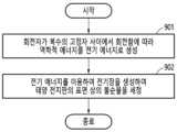
- Figure 9is a diagram explaining a solar panel self-cleaning method according to an embodiment of the present invention.
- FIGS. 10A to 10Dare diagrams illustrating experimental data related to the operating characteristics of a solar panel self-cleaning device according to an embodiment of the present invention.
- first or secondmay be used to describe various components, but the components should not be limited by the terms.
- the above termsare used only for the purpose of distinguishing one component from another component, for example, a first component may be named a second component, without departing from the scope of rights according to the concept of the present invention, Similarly, the second component may also be referred to as the first component.
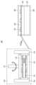
- FIG. 1 and 2are diagrams illustrating a solar panel self-cleaning device according to an embodiment of the present invention.
- FIG. 1illustrates the components of a solar panel self-cleaning device according to one embodiment of the present invention.
- the solar panel self-cleaning device 100includes an energy generation unit 110 and a cleaning unit 120.
- the energy generation unit 110includes a rotor and a plurality of stators, and as the rotor rotates due to wind, the mechanical energy generated by friction between the rotor and the plurality of stators may be generated as electrical energy.
- the cleaning unit 120is located on the solar panel, generates an electric field using the electrical energy generated by the energy generating unit 110, and uses the electric field to remove impurities on the surface of the solar panel. It can be cleaned.
- the cleaning unit 120consists of one or more electrode sets positioned on a solar panel and a protective film covering the one or more electrode sets.
- the one or more electrode setsgenerate an electric field using electrical energy, and the one or more electrode sets generate an electric field through the electric field. Remove impurities on the surface of solar panels.
- the present inventionprovides a self-cleaning device for solar panels that removes foreign substances on the surface of the solar panel as the electrodes of the cleaning part generate a magnetic field using electric energy supplied from an energy generation unit capable of self-generating and supplying energy. can be provided.
- the solar panel self-cleaning device 100may be referred to as a solar panel self-cleaning system
- the energy generation unit 110may be referred to as an energy generation element
- the cleaning unit 120may be referred to as a cleaning device.
- the energy generation unit 110when wind blows, rotates the reference bar to which the rotor is connected, and as the reference bar rotates, the rotor rotates. As the rotor rotates, friction occurs with a plurality of stators to generate electrical energy. can be created.
- the solar panel self-cleaning device 100can replace the existing pulse generator that draws electrical energy from the outside to the energy generation unit 110.
- the solar panel self-cleaning device 100connects the energy generation unit 110, which can supply electricity on its own even without an external power supply that requires electricity supply, and the cleaning unit 120 to remove impurities such as dust on the surface of the solar panel. It can be self-removed.
- FIG. 2illustrates in more detail the components of a solar panel self-cleaning device according to an embodiment of the present invention.
- the solar panel self-cleaning device 200includes an energy generation unit 210 and a cleaning unit 220.
- the energy generation unit 210includes a reference bar 211 that rotates the rotor 212, a stator 213 that rubs against the rotor 212, and a stator that secures the rotor 212 and the stator 213. It consists of a fixing frame (214).
- the rotor 212is located between the stators 213, and the stators 213 have a double structure and are composed of a plurality of stators.
- the energy generation unit 210has a double stacked structure including a plurality of stators 213, so the generation rate of electrical energy can be increased.
- the rotor 212includes a plurality of blades divided into a first charged region and a second charged region
- the stator 213includes a plurality of blades divided into a metal region and a blank region.
- the first charged area and the second charged areaare each made of different materials, so they are expressed in different colors, and the metal area appears to be protruding.
- the energy generation unit 210generates mechanical energy according to the contact voltage difference between the first charged area and the metal area by mutual friction when the first charged area is located on the metal area while the rotor 212 rotates. And the generated mechanical energy can be generated as electrical energy.
- the energy generation unit 210generates mechanical energy by friction between the rotor 212 and the stator 213 into electrical energy, and supplies the electrical energy to the cleaning unit 220. .
- the cleaning unit 220is made of an electrode 221 and a protective film 222, and is located on the solar panel 230.
- the solar panel 230consists of a solar cell 231 and glass 232 covering the solar cell.
- the cleaning unit 220includes one or more electrode sets consisting of two electrodes 221 located on the solar panel 230 and a protective film 222 covering the one or more electrode sets.
- the cleaning unit 220transfers electrical energy to one or more electrode sets and forms a magnetic field in the one or more electrode sets, so that the formed magnetic field repels impurities on the protective film 222 to clean the solar panel 230. do.
- each electrode 221 constituting one or more electrode setsis formed of any one of copper, polystyrene sulfonate, carbon nanotubes, silver nanowires, transparent indium tin oxide, and florine-doped tin oxide. . That is, the electrode 221 may be formed as a transparent electrode.
- each electrode 221 forming one or more electrode setshas a width of 0.5 mm to 3 mm, and may be positioned to be spaced apart from other electrodes by a width of 0.5 mm to 3 mm.
- the widths between electrodes 221 in one or more electrode setsmay be determined to be 0.5 mm, 1 mm, 2 mm, and 3 mm.
- the protective film 222may be formed of any one of polyimide, Teflon, polyurethane, fluororesin film, silicon dioxide, nylon, and polyethylene terephthalate.
- the protective film 222when the protective film 222 is made of nylon, it may be efficient to make the protective film 222 because the dust removal rate (DRE) is measured to be about 50% or more.
- DREdust removal rate
- the protective film 222covers the entire glass 232, which is the surface of the solar panel 230, and forms the surface of the solar panel 230.
- the thickness of the protective film 222is inversely proportional to the efficiency of cleaning impurities.
- the spacing between the electrodes 221 and the thickness of the protective film 222 in one or more electrode setsare inversely proportional to the efficiency of cleaning impurities.
- the thickness of the protective film 222is preferably 0.05 mm, which indicates that the thickness of the electrode 221 is also preferably 0.05 mm or less.
- the cleaning unit 220is capable of surface cleaning even when the glass 232 is any one of a window, a vehicle surface, a vehicle windshield, or an optical device.
- the electrode 221may be a transparent electrode having a transmittance of 90% or more for sunlight having a wavelength of 300 nm to 700 nm.
- the cleaning part 220 located on the surface of the solar panel 230has the advantage of not acting as an obstacle to sunlight entering the solar panel 230 because the electrode 221 and the protective film 222 have high transparency. This exists.
- 3A and 3Bare diagrams illustrating an energy generation unit according to an embodiment of the present invention.
- FIG. 3aillustrates the components of the energy generation unit according to an embodiment of the present invention in more detail.
- the energy generation unit 300includes a rotor 310 and a stator 320. Although only one stator 320 is expressed to explain the rotor 310, one more stator 320 is located on the rotor 310, forming a double stack structure.
- the rotor 310includes a plurality of blades divided into a first charging area 311 and a second charging area 312.
- the rotor 310is divided into a first charging area 311 and a second charging area 312 and includes a plurality of blades, including one blade for each area.
- the stator 320includes a plurality of wings divided into a metal area 321 and a blank area 322.
- stator 320includes a plurality of wings as the metal area 321 is divided into a plurality of parts.
- the energy generation unit 300when the rotor 310 rotates and the first charging area 311 is located on the metal area 321, the energy generation unit 300 is mutually rubbed and the first charging area 311 is formed. Mechanical energy is generated according to the contact voltage difference between the and the metal region 321, and the generated mechanical energy can be generated as electrical energy.
- the first charging region 311may be formed of any one of vinyl, polydimethylsiloxane, Teflon, polytetrafluoroethylene, polyethylene, sulfur compound, and glass.
- the second charging area 312may be formed of any one of fur, polypropylene, silk, nylon, rubber, and paper.
- the first charged area 311may be made of a negatively charged material
- the second charged area 312may be made of a positively charged material
- the metal region 321may be formed of any one of aluminum, copper, silver, and gold.
- the energy generation unit 300may increase electricity production as the rotor 310 is located between the stators 320.
- Figure 3billustrates the components of the energy generation unit according to an embodiment of the present invention as an image.
- the energy generation unit 330includes a rotor 331 and a stator 332.
- Figure 3bconfirms the structure in which the rotor 331 is located between the stators 332.
- Figure 4is a diagram explaining the rotor and stator of the energy generation unit according to an embodiment of the present invention.
- Figure 4illustrates an image according to the change in the number of blades of the rotor and stator of the energy generation unit according to an embodiment of the present invention.
- the rotor 400, the rotor 401, the rotor 402, the rotor 403, the stator 410, the stator 411, the stator 412, and the stator 413Illustrate.
- Figures 5A to 5Care diagrams illustrating electrical characteristics according to the number of blades constituting the rotor and stator according to an embodiment of the present invention.
- Figures 5A to 5Cillustrate experimental results on electrical characteristics according to the number of blades constituting the rotor and stator according to an embodiment of the present invention.
- FIGS. 5A to 5Cmay be the result of an experiment using the rotor and stator illustrated in FIG. 4.
- Figure 5aillustrates voltage output according to the number of blades constituting the rotor and stator according to an embodiment of the present invention.
- the graph 500illustrates the change in voltage according to the number of wings, and it can be seen that the voltage output corresponding to the 24 (2) double structure is the largest.
- Figure 5billustrates current output according to the number of blades constituting the rotor and stator according to an embodiment of the present invention.
- the graph 510illustrates the change in current according to the number of each blade, and it can be seen that the current output corresponding to 24 (2) double-layer structures is the largest.
- Figure 5cillustrates charge output according to the number of blades constituting the rotor and stator according to an embodiment of the present invention.
- the graph 520illustrates the change in charge according to the number of each wing, and it can be seen that the output of charge corresponding to 24 (2) double structures is the largest.
- Graphs 500 to 520show that the number of blades constituting the rotor and stator is related to the control of the output of voltage, current, and charge related to the magnitude of electrical energy generated in the energy generation unit.
- the energy generatormay control the output of voltage, current, and charge related to electrical energy depending on the number of blades constituting the rotor and a plurality of stators.
- the number of blades of the rotor and stator constituting the energy generation unitis 24, and the stator is composed of a plurality to increase the generation rate of electric energy.
- Figure 6is a diagram illustrating the impurity removal performance of the solar panel self-cleaning device based on weight measurement according to an embodiment of the present invention.
- Figure 6is a comparison experiment of dust weight before and after operation of the energy generation unit in the solar panel self-cleaning device of the present invention, in which 100 times the weight of dust removed by the cleaning unit is divided by the weight of dust before removal to confirm that actual dust is removed. The numerical weight dust removal rate is illustrated.
- the indicator line 601illustrates a case where the spacing between electrodes in the electrode set forming the cleaning part is 0.5 mm
- the indicator line 602illustrates the electrode set forming the cleaning part.
- the indicator line 603illustrates the case where the spacing between the electrodes in the electrode set forming the cleaning unit is 2 mm
- the indicator line 604illustrates the case where the spacing between the electrodes forms the cleaning unit.
- a case in which the spacing between electrodes in an electrode set is 3 mmis exemplified.
- the graph 600represents the rotation speed of the rotor on the horizontal axis and the dust removal rate (DRE) on the vertical axis.
- the indicator lines 601 to 604show the same trend of increasing dust removal rate as the rotation speed increases.
- the change in dust removal rate according to rotation speed in relation to the indicator lines 601 to 604can be summarized as Tables 1 to 4 below.
- the dust removal rate based on dust weightis determined based on Equation 1 below.
- Equation 1DRE Weight is the dust removal rate based on the dust weight
- Tables 1 to 4show the dust removal rate based on the dust measurement weight with the amount of dust and the amount of remaining dust in each situation after dust generation and dust removal.
- Table 1relates to the indicator line 601, which may be the case where the spacing between electrodes in the electrode set forming the cleaning portion is 0.5 mm.
- Table 2relates to the indicator line 602, which may be the case where the spacing between electrodes in the electrode set forming the cleaning portion is 1 mm.
- Table 3relates to the indicator line 603, which may be the case where the spacing between electrodes in the electrode set forming the cleaning portion is 2 mm.
- Table 4relates to the indicator line 604, which may be the case where the spacing between electrodes in the electrode set forming the cleaning portion is 3 mm.
- the spacing between electrodes in the electrode set forming the cleaning partmay be 0.5 mm to 1 mm.
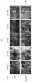
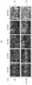
- FIGS. 7A to 7Eare diagrams illustrating the impurity removal performance of the solar panel self-cleaning device based on OM (Optical Microscope) measurement according to an embodiment of the present invention.
- FIG. 7Aillustrates the results of an OM DRE (Optical Microscope Dust Removal rate) experiment
- FIGS. 7B to 7Eillustrate images of the OM DRE experiment results.
- Figure 7shows a dust weight comparison experiment before and after the energy generation unit is operated in the solar panel self-cleaning device of the present invention, in which 100 times the dust area removed by the cleaning unit is divided by the dust area before removal to confirm that actual dust is removed.
- the numerical optical microscope dust removal rate (OM DRE)is illustrated.
- the indicator line 701illustrates the case where the spacing between electrodes in the electrode set forming the cleaning part is 0.5 mm
- the indicator line 702illustrates the electrode set forming the cleaning part.
- the indicator line 703illustrates the case where the spacing between the electrodes in the electrode set forming the cleaning unit is 2 mm
- the indicator line 704illustrates the case where the spacing between the electrodes forms the cleaning unit.
- a case in which the spacing between electrodes in an electrode set is 3 mmis exemplified.
- the graph 700represents the rotation speed of the rotor on the horizontal axis and the dust removal rate (DRE) on the vertical axis.
- the indicator lines 701 to 704show the same trend of increasing dust removal rate as the rotation speed increases.
- the energy generation unitmay control the output of voltage, current, and charge related to electrical energy depending on the number of rotations of the rotor.
- the dust removal rate based on the optical imageis determined based on Equation 2 below.
- Equation 2DRE OM represents the dust removal rate based on the optical image, and the change in dust removal rate according to rotation speed in relation to the indicator lines 701 to 704 can be summarized as Tables 5 to 8 below.
- Table 5relates to the indicator line 701, which may be the case where the spacing between electrodes in the electrode set forming the cleaning portion is 0.5 mm.
- Table 6relates to the indicator line 702, which may be the case where the spacing between electrodes in the electrode set forming the cleaning portion is 1 mm.
- Table 7relates to the indicator line 703, which may be the case where the spacing between electrodes in the electrode set forming the cleaning portion is 2 mm.
- Table 8relates to the indicator line 704, which may be the case where the spacing between electrodes in the electrode set forming the cleaning portion is 3 mm.
- the spacing between electrodes in the electrode set forming the cleaning partmay be 0.5 mm to 1 mm.
- FIG. 7Billustrates an optical image corresponding to indicator line 701 in FIG. 7A.
- the image 710 corresponding to the case where the gap between the electrodes in the electrode set forming the cleaning part is 0.5 mmcan be divided into before removal of dust (711) and after removal of dust (712). You can.
- Before dust removal (711)corresponds to before in Table 5
- after dust removal (712)corresponds to after dust removal in Table 5.
- FIG. 7Cillustrates an optical image corresponding to indicator line 702 in FIG. 7A.
- the image 720 corresponding to the case where the gap between electrodes in the electrode set forming the cleaning part is 1 mmcan be divided into before dust removal (721) and after dust removal (722). there is.
- Before dust removal (721)corresponds to before in Table 6
- after dust removal (722)corresponds to after dust removal in Table 6.
- FIG. 7Dillustrates an optical image corresponding to indicator line 703 in FIG. 7A.
- the image 730 corresponding to the case where the gap between electrodes in the electrode set forming the cleaning part is 2 mmcan be divided into before dust removal (731) and after dust removal (732). there is.
- Before dust removal (731)corresponds to before in Table 7
- after dust removal (732)corresponds to after dust removal in Table 7.
- FIG. 7Eillustrates an optical image corresponding to indicator line 704 in FIG. 7A.
- the image 740 corresponding to the case where the gap between electrodes in the electrode set forming the cleaning part is 3 mmcan be divided into before dust removal (741) and after dust removal (742). there is.
- Before dust removal (741)corresponds to before in Table 8
- after dust removal (742)corresponds to after dust removal in Table 8.
- the present inventionutilizes an energy generation unit capable of self-generating and supplying energy as a power source, and does not require additional electrical equipment for the electrodes of the cleaning unit to generate a magnetic field, thereby implementing a solar panel self-cleaning device and method. You can save cost and time.
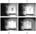
- FIGS. 8A to 8Care diagrams illustrating changes in solar output according to dust removal of a solar panel self-cleaning device according to an embodiment of the present invention.
- Figure 8ashows a case where a cleaning unit is attached to the surface of a solar panel according to an embodiment of the present invention, and a glass substrate with transparent electrodes patterned at regular intervals is attached to the surface of the cleaning unit, and a glass substrate with transparent electrodes patterned at regular intervals is attached on the attached glass.
- image 800illustrates the first step of preparing the bench
- image 801illustrates the second step of placing the sample on the bench
- image 802illustrates the second step of placing the sample on the bench.
- image 803illustrates the fourth step of removing dirt through the self-cleaning capability of the cleaning unit.
- Figure 8billustrates the current density and efficiency relative to experimental results according to the experiment performed in Figure 8a.
- the graph 810 in FIG. 8Bshows the efficiency as a measurement result for the first step 811, the second step 812, the third step 813, and the fourth step 814.
- the solar panel self-cleaning devicecan effectively remove dust on the solar panel and restore the efficiency of the solar panel.
- Figure 8cillustrates current density versus voltage in relation to experimental results according to the experiment performed in Figure 8a.
- the graph 820 in FIG. 8Cshows measurement results for the first step 821, the second step 822, the third step 823, and the fourth step 824.
- the current density and voltage of the fourth stage where dust is removedare measured to be close to the second stage before the dust is located.
- the fourth stageconfirms that solar panel self-cleaning devices can help provide superior effects with regard to the electrical energy production of solar panels.
- the solar panel self-cleaning devicecan effectively remove dust on the solar panel and restore the current density and voltage productivity of the solar panel.
- the present inventionuses an energy generation unit capable of self-generating and supplying energy as a power source to generate a magnetic field in the cleaning unit to remove impurities attached to the surface of the solar panel, thereby improving the power generation efficiency of the solar panel. there is.
- Figure 9is a diagram explaining a solar panel self-cleaning method according to an embodiment of the present invention.
- Figure 9shows the surface of the solar panel as the solar panel self-cleaning method according to an embodiment of the present invention uses electric energy supplied from the energy generation unit capable of self-generating and supplying energy, and the electrode of the cleaning unit generates a magnetic field. Illustrates the self-cleaning procedure of a solar panel to remove contaminants from the solar panel.
- the solar panel self-cleaning methodmay generate mechanical energy into electrical energy as the rotor rotates between a plurality of stators.
- the solar panel self-cleaning methodincludes a rotor and a plurality of stators, and as the rotor rotates between the plurality of stators due to wind, the rotor generates mechanical energy generated by friction between the plurality of stators, and the mechanical energy Electrical energy can be generated by converting it into electrical energy.
- step 902the solar panel self-cleaning method according to an embodiment of the present invention uses electrical energy to generate an electric field to clean impurities on the surface of the solar panel.
- the solar panel cleaning methodis located on the solar panel, generates an electric field using generated electrical energy, and uses the electric field to remove impurities on the surface of the solar panel, thereby cleaning the impurities.
- the solar panel cleaning methodtransfers electrical energy to one or more electrode sets in the cleaning unit, and forms a magnetic field in one or more electrode sets, so that the formed magnetic field repels impurities such as dust on the protective film to clean the solar panel. can be cleaned.
- the present inventionprovides a self-cleaning method of a solar panel that removes foreign substances on the surface of the solar panel as the electrode of the cleaning part generates a magnetic field using electric energy supplied from an energy generation unit capable of self-generating and supplying energy. can be provided.
- FIGS. 10A to 10Dare diagrams illustrating experimental data related to the operating characteristics of a solar panel self-cleaning device according to an embodiment of the present invention.
- Figure 10aillustrates the dust removal rate according to the number of fans and the presence or absence of a stack of a solar panel self-cleaning device according to an embodiment of the present invention.
- a graph 1000indicates rotation speed on the horizontal axis and dust removal rate (DRE) on the vertical axis.
- the graph 1000illustrates that the dust removal rate is improved when the number of fans increases and a stack exists regardless of the rotation speed.
- Figure 10billustrates the dust removal rate according to the type of dielectric material forming the protective film of the solar panel self-cleaning device according to an embodiment of the present invention.
- the graph 1010illustrates the types of dielectric materials as PFA (Perfuo alkyl), PI (Polyimide), PET (poly(ethyleneterephthalate)), and Nylon on the horizontal axis, and the left and right vertical axes. shows the dust removal rate.
- PFAPerfuo alkyl
- PIPolyimide
- PETpoly(ethyleneterephthalate)
- Nylonon the horizontal axis, and the left and right vertical axes. shows the dust removal rate.
- the left vertical axisis based on weight, and the right vertical axis is based on OM (optical microscope).
- the indicator line 1011indicates the OM-based dust removal rate
- the indicator line 1012indicates the weight-based dust removal rate
- the protective film forming materialas nylon.
- Figure 10cillustrates a comparison between a glass substrate on which a transparent electrode without a protective film is placed according to the prior art and a cleaning unit of a solar panel self-cleaning device according to an embodiment of the present invention.
- the indicator line 1021may indicate the prior art, and the indicator line 1022 may indicate the present invention.
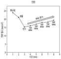
- Figure 10dillustrates the change in current density according to the rotation speed of the energy generation unit of the solar panel self-cleaning device according to an embodiment of the present invention.
- a graph 1030shows a change in time on the horizontal axis and a change in current density on the vertical axis.
- the graph 1030shows that as time passes, the rotation speed in the energy generation unit increases, the dust removal rate increases as the rotation speed increases, and the current density of the solar cell increases according to the increased dust removal rate.
- an increase in the rotation speed of the energy generation unitleads to an increase in the dust removal rate
- an increase in the dust removal rateleads to an increase in the current density of the solar cell, which leads to an increase in the power generation efficiency of the solar cell.
- devices and components described in embodimentsmay include, for example, a processor, a controller, an arithmetic logic unit (ALU), a digital signal processor, a microcomputer, a field programmable array (FPA), It may be implemented using one or more general-purpose or special-purpose computers, such as a programmable logic unit (PLU), microprocessor, or any other device capable of executing and responding to instructions.
- a processing devicemay execute an operating system (OS) and one or more software applications that run on the operating system. Additionally, a processing device may access, store, manipulate, process, and generate data in response to the execution of software.
- OSoperating system
- a processing devicemay access, store, manipulate, process, and generate data in response to the execution of software.
- a single processing devicemay be described as being used; however, those skilled in the art will understand that a processing device includes multiple processing elements and/or multiple types of processing elements. It can be seen that it may include.
- a processing devicemay include a plurality of processors or one processor and one controller. Additionally, other processing configurations, such as parallel processors, are possible.
- the method according to the embodimentmay be implemented in the form of program instructions that can be executed through various computer means and recorded on a computer-readable medium.
- the computer-readable mediummay include program instructions, data files, data structures, etc., singly or in combination.
- Program instructions recorded on the mediummay be specially designed and configured for the embodiment or may be known and available to those skilled in the art of computer software.
- Examples of computer-readable recording mediainclude magnetic media such as hard disks, floppy disks, and magnetic tapes, optical media such as CD-ROMs and DVDs, and magnetic media such as floptical disks.
- program instructionsinclude machine language code, such as that produced by a compiler, as well as high-level language code that can be executed by a computer using an interpreter, etc.
- the hardware devices described abovemay be configured to operate as one or more software modules to perform the operations of the embodiments, and vice versa.
- Softwaremay include a computer program, code, instructions, or a combination of one or more of these, which may configure a processing unit to operate as desired, or may be processed independently or collectively. You can command the device.
- Software and/or datamay be used on any type of machine, component, physical device, virtual equipment, computer storage medium or device to be interpreted by or to provide instructions or data to a processing device. , or may be permanently or temporarily embodied in a transmitted signal wave.
- Softwaremay be distributed over networked computer systems and stored or executed in a distributed manner.
- Software and datamay be stored on one or more computer-readable recording media.
Landscapes
- Physics & Mathematics (AREA)
- Optics & Photonics (AREA)
- Photovoltaic Devices (AREA)
- Cleaning In General (AREA)
Abstract
Description
Translated fromKorean본 발명은 태양 전지판 자가 세정 장치 및 방법에 관한 것으로, 보다 구체적으로, 자가 에너지 발전 및 공급이 가능한 에너지 발전부로부터 공급되는 전기 에너지를 이용하여 세정부의 전극이 자기장을 발생시킴에 따라 태양 전지판의 표면 상의 이물질을 제거하는 태양 전지판의 자가 세정 기술에 관한 것이다.The present invention relates to a solar panel self-cleaning device and method. More specifically, the electrode of the cleaning unit generates a magnetic field using electric energy supplied from an energy generation unit capable of self-generating and supplying energy, thereby causing the solar panel to be cleaned. It is about self-cleaning technology for solar panels that removes foreign substances on the surface.
재생 에너지 분야에서는 태양 전지판을 사용하는 태양광 발전이 광범위한 관심을 얻고 있어서, 태양광 발전을 위한 태양 전지판의 설치 지역의 증가 및 그 수요가 증가하고 있다.In the field of renewable energy, solar power generation using solar panels is gaining widespread attention, leading to an increase in the installation area and demand for solar panels for solar power generation.
기존 태양 전지판의 주요 과제 중 하나는 태양 전지판을 덮을 수 있는 먼지 및 기타 입자와 같은 불순물에 의한 출력 전력의 감소일 수 있다.One of the main challenges with existing solar panels can be a reduction in output power due to impurities such as dust and other particles that can coat the solar panels.
태양 전지판은 태양 전지판 위에 먼지와 같은 불순물이 누적되면 출력이 크게 줄어드는 단점이 존재한다.Solar panels have the disadvantage that output is greatly reduced when impurities such as dust accumulate on the solar panel.
즉, 태양 전지판은 태양 전지판 위에 먼지가 쌓이면 태양광에 노출되는 면적이 감소하여 출력이 크게 줄어드는 단점이 존재한다.In other words, solar panels have the disadvantage that when dust accumulates on the solar panel, the area exposed to sunlight is reduced and the output is greatly reduced.
이러한 문제를 해소하기 위한 일반적인 접근법은 태양 전지판을 기계적으로 청소하는 것이며, 이는 물과 육체 노동과 같은 물리적인 요소가 추가로 요구된다.A common approach to solving this problem is to mechanically clean solar panels, which requires additional physical components such as water and manual labor.
또한, 그러한 육체 노동 또는 물의 공급을 대신하기 위한 로봇과 같은 기계적 장치가 많이 개발되고 있는데 이러한 기계적 장치는 동작 오류가 발생되어서 태양 전지판의 세정에 문제가 발생되기도 한다.In addition, many mechanical devices, such as robots, are being developed to replace physical labor or water supply, but these mechanical devices sometimes cause operation errors and cause problems in cleaning solar panels.
또한, 추가적으로 고려되고 있는 방식에는 태양 전지판의 유리 표면에 소수성 또는 친수성 코팅을 도포하고 로봇을 사용하여 수동 세척을 자동화하는 방식이 존재한다.Additional methods being considered include applying a hydrophobic or hydrophilic coating to the glass surface of solar panels and using robots to automate manual cleaning.
그러나, 반복적인 기계적 세척은 태양 전지판의 유리 표면을 손상시키며 대량의 물을 필요로 하는 문제점도 존재한다.However, repeated mechanical cleaning damages the glass surface of solar panels and requires a large amount of water.
다른 접근 방법으로는 EDS(Electrodynamic Screen Effect)를 이용한 세정 방식이 존재하는데, 전극을 통한 EDS는 전기장을 생성하여 태양 전지판의 먼지 입자가 정전기력을 경험하고 태양 전지판에서 반발 되도록 하는 기술이다.Another approach is a cleaning method using EDS (Electrodynamic Screen Effect). EDS through electrodes is a technology that generates an electric field so that dust particles on the solar panel experience electrostatic force and are repelled from the solar panel.
EDS의 사용은 달과 화성에서 작동하는 차량의 태양 전지판에 먼지 축적 문제를 해결하기 위해 관심을 끌었다.The use of EDS has attracted attention to solve the problem of dust accumulation on solar panels of vehicles operating on the Moon and Mars.
달의 경우, 저 중력, 제로 자기장 및 단단한 진공 환경으로 인해 EDS가 먼지 입자를 격퇴(repel)할 수 있다.In the case of the Moon, the low gravity, zero magnetic field, and tight vacuum environment allow EDS to repel dust particles.
즉, EDS 기술은 인력과 물 없이 전기 역학적 힘으로 표면에 불순물을 제거하는 기술로서 장점이 존재한다.In other words, EDS technology has the advantage of removing impurities from the surface using electrodynamic force without manpower or water.
그러나, 현재의 EDS 기술은 현재 사용중인 전극 재료의 낮은 투명도와 지국의 습도 레벨로 인해, 지상 적용에 실용적이지 못하다는 단점이 존재한다.However, current EDS technology has the disadvantage of being impractical for terrestrial applications due to the low transparency of the electrode materials currently in use and the humidity levels in the field.
다시 말해, 현재의 EDS 기술은 태양 전지판의 표면에 응축된 수분 층은 전기장을 차폐할 뿐만 아니라 유전 영 동력(dielectrophoresis forces), 접착력 등과 같은 수분층의 저항력으로 인해 먼지 입자의 트랩 역할을 함에 따라 효과적으로 먼지를 제거하지 못하는 단점이 존재한다.In other words, the current EDS technology is that the moisture layer condensed on the surface of the solar panel not only shields the electric field, but also acts as a trap for dust particles due to the resistance of the moisture layer such as dielectrophoresis forces, adhesion, etc., effectively removing the dust particles. There is a disadvantage of not being able to remove .
본 발명은 자가 에너지 발전 및 공급이 가능한 에너지 발전부로부터 공급되는 전기 에너지를 이용하여 세정부의 전극이 자기장을 발생시킴에 따라 태양 전지판의 표면 상의 이물질을 제거하는 태양 전지판의 자가 세정 장치 및 방법을 제공하는 것을 목적으로 한다.The present invention provides a self-cleaning device and method for solar panels that remove foreign substances on the surface of the solar panel as the electrodes of the cleaning part generate a magnetic field using electric energy supplied from an energy generation unit capable of self-generating and supplying energy. The purpose is to provide
본 발명은 자가 에너지 발전 및 공급이 가능한 에너지 발전부를 전력원으로 활용하여 세정부의 전극이 자기장을 발생하기 위한 추가적인 전기 설비를 요구하지 않음에 따라 태양 전지판 자가 세정 장치 및 방법의 구현을 위한 비용 및 시간을 단축하는 것을 목적으로 한다.The present invention utilizes an energy generation unit capable of self-generating and supplying energy as a power source, and does not require additional electrical equipment for the electrodes of the cleaning unit to generate a magnetic field, thereby reducing the cost and cost of implementing a solar panel self-cleaning device and method. The purpose is to shorten time.
본 발명은 자가 에너지 발전 및 공급이 가능한 에너지 발전부를 전력원으로 활용하여 세정부의 자기장을 생성함에 따라 태양 전지판의 표면에 부착된 불순물 제거하고, 이에 따른 태양 전지판의 발전 효율을 향상시키는 것을 목적으로 한다.The purpose of the present invention is to remove impurities attached to the surface of a solar panel by using an energy generation unit capable of self-generating and supplying energy as a power source to generate a magnetic field in the cleaning unit, thereby improving the power generation efficiency of the solar panel. do.
본 발명의 일실시예에 따른 태양 전지판 자가 세정 장치는 회전자와 복수의 고정자를 포함하고, 바람에 의해 상기 회전자가 회전함에 따라 상기 회전자가 상기 복수의 고정자 사이에서 마찰되어 발생되는 역학적 에너지를 전기 에너지로 생성하는 에너지 발전부 및 태양 전지판 상에 위치하고, 상기 생성된 전기 에너지를 이용하여 전기장을 생성하며, 상기 전기장을 이용하여 상기 태양 전지판의 표면 상의 불순물을 세정하는 세정부를 포함할 수 있다.A solar panel self-cleaning device according to an embodiment of the present invention includes a rotor and a plurality of stators, and as the rotor rotates due to wind, the mechanical energy generated by friction between the rotor and the plurality of stators is used as electricity. It may include an energy generation unit that generates energy and a cleaning unit that is located on the solar panel, generates an electric field using the generated electric energy, and cleans impurities on the surface of the solar panel using the electric field.
상기 회전자는 제1 대전 영역과 제2 대전 영역으로 구분되는 복수의 날개를 포함하고, 상기 복수의 고정자는 각각은 금속 영역과 공백 영역으로 구분되는 복수의 날개를 포함할 수 있다.The rotor may include a plurality of blades divided into a first charging region and a second charging region, and the plurality of stators may include a plurality of blades each divided into a metal region and a blank region.
상기 에너지 발전부는 상기 회전자가 회전하면서 상기 제1 대전 영역이 상기 금속 영역 상에 위치하면 상호 마찰되어 상기 제1 대전 영역과 상기 금속 영역 사이의 접촉 전압 차이에 따른 역학적 에너지가 발생되고, 상기 발생된 역학적 에너지를 전기 에너지로 생성할 수 있다.The energy generation unit generates mechanical energy according to a contact voltage difference between the first charged area and the metal area by mutual friction when the first charged area is located on the metal area while the rotor rotates, and the generated Mechanical energy can be generated into electrical energy.
상기 제1 대전 영역은 비닐, 폴리디메틸실록산, 테플론, 폴리테트라 플루오로에틸렌, 폴리에틸렌, 황화합물, 유리 중 어느 하나의 물질로 형성되고, 상기 제2 대전 영역은 털, 폴리프로필렌, 실크, 나일론, 고무, 및 종이 중 어느 하나의 물질로 형성되며, 상기 금속 영역은 알루미늄, 구리, 은 및 금 중 어느 하나의 금속 물질로 형성될 수 있다.The first charged region is made of any one of vinyl, polydimethylsiloxane, Teflon, polytetrafluoroethylene, polyethylene, sulfur compound, and glass, and the second charged region is made of fur, polypropylene, silk, nylon, and rubber. , and paper, and the metal region may be formed of any one of aluminum, copper, silver, and gold.
상기 에너지 발전부는 상기 회전자 및 상기 복수의 고정자를 구성하는 날개들의 수 및 상기 회전자의 회전 수에 따라 상기 전기 에너지와 관련된 전압, 전류 및 전하의 출력이 제어될 수 있다.The energy generation unit may control output of voltage, current, and charge related to the electrical energy according to the number of blades constituting the rotor and the plurality of stators and the number of rotations of the rotor.
상기 세정부는 상기 태양 전지판 상에 하나 이상의 전극 세트가 위치하고, 상기 하나 이상의 전극 세트를 덮는 보호 필름을 포함할 수 있다.The cleaning unit may include one or more electrode sets positioned on the solar panel, and a protective film covering the one or more electrode sets.
상기 세정부는 상기 전기 에너지를 상기 하나 이상의 전극 세트에 전달하고, 상기 하나 이상의 전극 세트에서 자기장을 형성하여 상기 형성된 자기장이 상기 보호 필름 상에 불순물을 격퇴(repel)시켜 상기 태양 전지판을 세정할 수 있다.The cleaning unit transfers the electrical energy to the one or more electrode sets, and forms a magnetic field in the one or more electrode sets, so that the formed magnetic field repels impurities on the protective film to clean the solar panel. there is.
상기 하나 이상의 전극 세트를 이루는 각각의 전극은 투명한 구리, 폴리 폴리스티렌 설포 네이트, 탄소 나노 튜브, 은 나노 와이어, 인듐 주석 산화물 및 플로린 도핑된 주석 산화물 중 어느 하나의 물질로 형성되고, 상기 보호 필름은 폴리이미드, 테플론, 폴리우레탄, 불소수지 필름, 이산화규소, 나일론, 및 폴리에틸렌 테레프탈레이트 중 어느 하나의 물질로 형성될 수 있다.Each electrode constituting the one or more electrode sets is formed of any one of transparent copper, polystyrene sulfonate, carbon nanotubes, silver nanowires, indium tin oxide, and florine-doped tin oxide, and the protective film is polyethylene It may be made of any one of mead, Teflon, polyurethane, fluororesin film, silicon dioxide, nylon, and polyethylene terephthalate.
상기 보호 필름은 상기 태양 전지판의 표면을 이루고, 상기 보호 필름의 두께 및 상기 하나 이상의 전극 세트에서 전극 사이 간격은 상기 불순물을 세정하는 효율과 반비례할 수 있다.The protective film forms a surface of the solar panel, and the thickness of the protective film and the spacing between electrodes in the one or more electrode sets may be inversely proportional to the efficiency of cleaning the impurities.
본 발명의 일실시예에 따르면 태양 전지판 자가 세정 방법은 회전자와 복수의 고정자를 포함하는 에너지 발전부에서, 바람에 의해 상기 회전자가 회전함에 따라 상기 회전자가 상기 복수의 고정자 사이에서 마찰되어 발생되는 역학적 에너지를 전기 에너지로 생성하는 단계 및 태양 전지판 상에 위치하는 세정부에 있어서, 상기 생성된 전기 에너지를 이용하여 전기장을 생성하며, 상기 전기장을 이용하여 상기 태양 전지판의 표면 상의 불순물을 세정하는 단계를 포함할 수 있다.According to one embodiment of the present invention, the solar panel self-cleaning method is an energy generation unit including a rotor and a plurality of stators, and as the rotor rotates by wind, the rotor generates friction between the plurality of stators. Generating mechanical energy into electrical energy and, in a cleaning unit located on a solar panel, generating an electric field using the generated electric energy, and cleaning impurities on the surface of the solar panel using the electric field. may include.
상기 회전자는 제1 대전 영역과 제2 대전 영역으로 구분되는 복수의 날개를 포함하고, 상기 복수의 고정자는 각각은 금속 영역과 공백 영역으로 구분되는 복수의 날개를 포함할 수 있다.The rotor may include a plurality of blades divided into a first charging region and a second charging region, and the plurality of stators may include a plurality of blades each divided into a metal region and a blank region.
상기 회전자와 복수의 고정자를 포함하는 에너지 발전부에서, 바람에 의해 상기 회전자가 회전함에 따라 상기 회전자가 상기 복수의 고정자 사이에서 마찰되어 발생되는 역학적 에너지를 전기 에너지로 생성하는 단계는 상기 회전자가 회전하면서 상기 제1 대전 영역이 상기 금속 영역 상에 위치하면 상호 마찰되어 상기 제1 대전 영역과 상기 금속 영역 사이의 접촉 전압 차이에 따른 역학적 에너지가 발생되고, 상기 발생된 역학적 에너지를 전기 에너지로 생성하는 단계를 포함할 수 있다.In the energy power generation unit including the rotor and a plurality of stators, the step of generating mechanical energy generated by friction between the rotor and the plurality of stators as electrical energy as the rotor rotates due to wind includes the step of generating electrical energy when the rotor rotates. When the first electrified area is positioned on the metal area while rotating, mechanical energy is generated according to the difference in contact voltage between the first electrified area and the metal area by mutual friction, and the generated mechanical energy is generated as electrical energy. It may include steps.
상기 생성된 전기 에너지를 이용하여 전기장을 생성하며, 상기 전기장을 이용하여 상기 태양 전지판의 표면 상의 불순물을 세정하는 단계는, 상기 태양 전지판 상에 하나 이상의 전극 세트가 위치하고, 상기 하나 이상의 전극 세트를 덮는 보호 필름을 포함하는 상기 세정부에서, 상기 전기 에너지를 상기 하나 이상의 전극 세트에 전달하고, 상기 하나 이상의 전극 세트에서 자기장을 형성하여 상기 형성된 자기장이 상기 보호 필름 상에 불순물을 격퇴(repel)시켜 상기 태양 전지판을 세정하는 단계를 포함할 수 있다.The step of generating an electric field using the generated electrical energy and cleaning impurities on the surface of the solar panel using the electric field includes: one or more electrode sets positioned on the solar panel, and covering the one or more electrode sets. In the cleaning unit including a protective film, the electrical energy is transferred to the one or more electrode sets, and a magnetic field is formed in the one or more electrode sets so that the formed magnetic field repels impurities on the protective film to It may include cleaning the solar panel.
본 발명은 자가 에너지 발전 및 공급이 가능한 에너지 발전부로부터 공급되는 전기 에너지를 이용하여 세정부의 전극이 자기장을 발생시킴에 따라 태양 전지판의 표면 상의 이물질을 제거하는 태양 전지판의 자가 세정 장치 및 방법을 제공할 수 있다.The present invention provides a self-cleaning device and method for solar panels that remove foreign substances on the surface of the solar panel as the electrodes of the cleaning part generate a magnetic field using electric energy supplied from an energy generation unit capable of self-generating and supplying energy. can be provided.
본 발명은 자가 에너지 발전 및 공급이 가능한 에너지 발전부를 전력원으로 활용하여 세정부의 전극이 자기장을 발생하기 위한 추가적인 전기 설비를 요구하지 않음에 따라 태양 전지판 자가 세정 장치 및 방법의 구현을 위한 비용 및 시간을 절약할 수 있다.The present invention utilizes an energy generation unit capable of self-generating and supplying energy as a power source, and does not require additional electrical equipment for the electrodes of the cleaning unit to generate a magnetic field, thereby reducing the cost and cost of implementing a solar panel self-cleaning device and method. You can save time.
본 발명은 자가 에너지 발전 및 공급이 가능한 에너지 발전부를 전력원으로 활용하여 세정부의 자기장을 생성함에 따라 태양 전지판의 표면에 부착된 불순물 제거하고, 이에 따른 태양 전지판의 발전 효율을 향상시킬 수 있다.The present invention uses an energy generation unit capable of self-generating and supplying energy as a power source to generate a magnetic field in the cleaning unit to remove impurities attached to the surface of the solar panel, thereby improving the power generation efficiency of the solar panel.
도 1 및 도 2는 본 발명의 일실시예에 따른 태양 전지판 자가 세정 장치를 설명하는 도면이다.1 and 2 are diagrams illustrating a solar panel self-cleaning device according to an embodiment of the present invention.
도 3a 및 도 3b는 본 발명의 일실시예에 따른 에너지 발전부를 설명하는 도면이다.3A and 3B are diagrams illustrating an energy generation unit according to an embodiment of the present invention.
도 4는 본 발명의 일실시예에 따른 에너지 발전부의 회전자와 고정자를 설명하는 도면이다.Figure 4 is a diagram explaining the rotor and stator of the energy generation unit according to an embodiment of the present invention.
도 5a 내지 도 5c는 본 발명의 일실시예에 따른 회전자와 고정자를 구성하는 날개의 수에 따른 전기적 특성을 설명하는 도면이다.Figures 5A to 5C are diagrams illustrating electrical characteristics according to the number of blades constituting the rotor and stator according to an embodiment of the present invention.
도 6은 본 발명의 일실시예에 따른 무게 측정에 기반한 태양 전지판 자가 세정 장치의 불순물 제거 성능을 설명하는 도면이다.Figure 6 is a diagram illustrating the impurity removal performance of the solar panel self-cleaning device based on weight measurement according to an embodiment of the present invention.
도 7a 내지 도 7e는 본 발명의 일실시예에 따른 OM(Optical Microscope) 측정에 기반한 태양 전지판 자가 세정 장치의 불순물 제거 성능을 설명하는 도면이다.7A to 7E are diagrams illustrating the impurity removal performance of the solar panel self-cleaning device based on OM (Optical Microscope) measurement according to an embodiment of the present invention.
도 8a 내지 도 8c는 본 발명의 일실시예에 따른 태양 전지판 자가 세정 장치의 먼지 제거에 따른 태양광 출력 변화를 설명하는 도면이다.FIGS. 8A to 8C are diagrams illustrating changes in solar output according to dust removal of a solar panel self-cleaning device according to an embodiment of the present invention.
도 9는 본 발명의 일실시예에 따른 태양 전지판 자가 세정 방법을 설명하는 도면이다.Figure 9 is a diagram explaining a solar panel self-cleaning method according to an embodiment of the present invention.
도 10a 내지 도 10d는 본 발명의 일실시예에 따른 태양 전지판 자가 세정 장치의 동작 특성과 관련된 실험 데이터를 설명하는 도면이다.10A to 10D are diagrams illustrating experimental data related to the operating characteristics of a solar panel self-cleaning device according to an embodiment of the present invention.
본 명세서에 개시되어 있는 본 발명의 개념에 따른 실시예들에 대해서 특정한 구조적 또는 기능적 설명들은 단지 본 발명의 개념에 따른 실시예들을 설명하기 위한 목적으로 예시된 것으로서, 본 발명의 개념에 따른 실시예들은 다양한 형태로 실시될 수 있으며 본 명세서에 설명된 실시예들에 한정되지 않는다.Specific structural or functional descriptions of the embodiments according to the concept of the present invention disclosed in this specification are merely illustrative for the purpose of explaining the embodiments according to the concept of the present invention. They may be implemented in various forms and are not limited to the embodiments described herein.
본 발명의 개념에 따른 실시예들은 다양한 변경들을 가할 수 있고 여러 가지 형태들을 가질 수 있으므로 실시예들을 도면에 예시하고 본 명세서에 상세하게 설명하고자 한다. 그러나, 이는 본 발명의 개념에 따른 실시예들을 특정한 개시형태들에 대해 한정하려는 것이 아니며, 본 발명의 사상 및 기술 범위에 포함되는 변경, 균등물, 또는 대체물을 포함한다.Since the embodiments according to the concept of the present invention can make various changes and have various forms, the embodiments will be illustrated in the drawings and described in detail in this specification. However, this is not intended to limit the embodiments according to the concept of the present invention to specific disclosed forms, and includes changes, equivalents, or substitutes included in the spirit and technical scope of the present invention.
제1 또는 제2 등의 용어를 다양한 구성요소들을 설명하는데 사용될 수 있지만, 상기 구성요소들은 상기 용어들에 의해 한정되어서는 안 된다. 상기 용어들은 하나의 구성요소를 다른 구성요소로부터 구별하는 목적으로만, 예를 들어 본 발명의 개념에 따른 권리 범위로부터 이탈되지 않은 채, 제1 구성요소는 제2 구성요소로 명명될 수 있고, 유사하게 제2 구성요소는 제1 구성요소로도 명명될 수 있다.Terms such as first or second may be used to describe various components, but the components should not be limited by the terms. The above terms are used only for the purpose of distinguishing one component from another component, for example, a first component may be named a second component, without departing from the scope of rights according to the concept of the present invention, Similarly, the second component may also be referred to as the first component.
어떤 구성요소가 다른 구성요소에 "연결되어" 있다거나 "접속되어" 있다고 언급된 때에는, 그 다른 구성요소에 직접적으로 연결되어 있거나 또는 접속되어 있을 수도 있지만, 중간에 다른 구성요소가 존재할 수도 있다고 이해되어야 할 것이다. 반면에, 어떤 구성요소가 다른 구성요소에 "직접 연결되어" 있다거나 "직접 접속되어" 있다고 언급된 때에는, 중간에 다른 구성요소가 존재하지 않는 것으로 이해되어야 할 것이다. 구성요소들 간의 관계를 설명하는 표현들, 예를 들어 "~사이에"와 "바로~사이에" 또는 "~에 직접 이웃하는" 등도 마찬가지로 해석되어야 한다.When a component is said to be "connected" or "connected" to another component, it is understood that it may be directly connected to or connected to the other component, but that other components may exist in between. It should be. On the other hand, when it is mentioned that a component is “directly connected” or “directly connected” to another component, it should be understood that there are no other components in between. Expressions that describe the relationship between components, such as “between”, “immediately between” or “directly adjacent to”, should be interpreted similarly.
본 명세서에서 사용한 용어는 단지 특정한 실시예들을 설명하기 위해 사용된 것으로, 본 발명을 한정하려는 의도가 아니다. 단수의 표현은 문맥상 명백하게 다르게 뜻하지 않는 한, 복수의 표현을 포함한다. 본 명세서에서, "포함하다" 또는 "가지다" 등의 용어는 설시된 특징, 숫자, 스테이지, 동작, 구성요소, 부분품 또는 이들을 조합한 것이 존재함으로 지정하려는 것이지, 하나 또는 그 이상의 다른 특징들이나 숫자, 스테이지, 동작, 구성요소, 부분품 또는 이들을 조합한 것들의 존재 또는 부가 가능성을 미리 배제하지 않는 것으로 이해되어야 한다.The terminology used herein is only used to describe specific embodiments and is not intended to limit the invention. Singular expressions include plural expressions unless the context clearly dictates otherwise. In this specification, terms such as “include” or “have” are intended to designate the presence of a described feature, number, stage, operation, component, part, or combination thereof, as well as one or more other features or numbers, It should be understood that this does not exclude in advance the possibility of the presence or addition of stages, operations, components, parts, or combinations thereof.
다르게 정의되지 않는 한, 기술적이거나 과학적인 용어를 포함해서 여기서 사용되는 모든 용어들은 본 발명이 속하는 기술 분야에서 통상의 지식을 가진 자에 의해 일반적으로 이해되는 것과 동일한 의미를 가진다. 일반적으로 사용되는 사전에 정의되어 있는 것과 같은 용어들은 관련 기술의 문맥상 가지는 의미와 일치하는 의미를 갖는 것으로 해석되어야 하며, 본 명세서에서 명백하게 정의하지 않는 한, 이상적이거나 과도하게 형식적인 의미로 해석되지 않는다.Unless otherwise defined, all terms used herein, including technical or scientific terms, have the same meaning as commonly understood by a person of ordinary skill in the technical field to which the present invention pertains. Terms as defined in commonly used dictionaries should be interpreted as having meanings consistent with the meanings they have in the context of the related technology, and unless clearly defined in this specification, should not be interpreted in an idealized or overly formal sense. No.
이하, 실시예들을 첨부된 도면을 참조하여 상세하게 설명한다. 그러나, 특허출원의 범위가 이러한 실시예들에 의해 제한되거나 한정되는 것은 아니다. 각 도면에 제시된 동일한 참조 부호는 동일한 부재를 나타낸다.Hereinafter, embodiments will be described in detail with reference to the attached drawings. However, the scope of the patent application is not limited or limited by these examples. The same reference numerals in each drawing indicate the same members.
도 1 및 도 2는 본 발명의 일실시예에 따른 태양 전지판 자가 세정 장치를 설명하는 도면이다.1 and 2 are diagrams illustrating a solar panel self-cleaning device according to an embodiment of the present invention.
도 1은 본 발명의 일실시예에 따른 태양 전지판 자가 세정 장치의 구성 요소를 예시한다.1 illustrates the components of a solar panel self-cleaning device according to one embodiment of the present invention.
도 1을 참고하면, 본 발명의 일실시예에 따른 태양 전지판 자가 세정 장치(100)는 에너지 발전부(110) 및 세정부(120)를 포함한다.Referring to FIG. 1, the solar panel self-cleaning
일례로, 에너지 발전부(110)는 회전자와 복수의 고정자를 포함하고, 바람에 의해 회전자가 회전함에 따라 회전자가 복수의 고정자 사이에서 마찰되어 발생되는 역학적 에너지를 전기 에너지로 생성할 수 있다.For example, the
본 발명의 일실시예에 따르면 세정부(120)는 태양 전지판 상에 위치하고, 에너지 발전부(110)에서 생성된 전기 에너지를 이용하여 전기장을 생성하며, 전기장을 이용하여 태양 전지판의 표면 상의 불순물을 세정할 수 있다.According to one embodiment of the present invention, the
예를 들어, 세정부(120)는 태양 전지판 상에 하나 이상의 전극 세트가 위치하고, 하나 이상의 전극 세트를 덮는 보호 필름으로 구성되어 하나 이상의 전극 세트가 전기 에너지를 이용하여 전기장을 생성하며, 전기장을 통해 태양 전지판의 표면 상의 불순물을 제거한다.For example, the
따라서, 본 발명은 자가 에너지 발전 및 공급이 가능한 에너지 발전부로부터 공급되는 전기 에너지를 이용하여 세정부의 전극이 자기장을 발생시킴에 따라 태양 전지판의 표면 상의 이물질을 제거하는 태양 전지판의 자가 세정 장치를 제공할 수 있다.Therefore, the present invention provides a self-cleaning device for solar panels that removes foreign substances on the surface of the solar panel as the electrodes of the cleaning part generate a magnetic field using electric energy supplied from an energy generation unit capable of self-generating and supplying energy. can be provided.
예를 들어, 태양 전지판 자가 세정 장치(100)는 태양 전지판 자가 세정 시스템으로 지칭하고, 에너지 발전부(110)는 에너지 발전 소자로 지칭하며, 세정부(120)는 세정 장치로 지칭할 수 있다.For example, the solar panel self-cleaning
본 발명의 일실시예에 따르면 에너지 발전부(110)는 바람이 불면 회전자가 연결된 기준봉이 회전되고, 기준봉이 회전됨에 따라 회전자가 회전하며, 회전자가 회전되면서 복수의 고정자와 마찰이 이루어져 전기 에너지를 생성할 수 있다.According to one embodiment of the present invention, when wind blows, the
이에 따라, 태양 전지판 자가 세정 장치(100)는 에너지 발전부(110)로 외부로부터 전기 에너지를 끌어오는 기존 펄스 발생기를 대체할 수 있다.Accordingly, the solar panel self-cleaning
즉, 태양 전지판 자가 세정 장치(100)는 전기 공급이 필요한 외부 전원장치가 없어도 스스로 전기 공급이 가능한 에너지 발전부(110)와 세정부(120)를 연결하여 태양 전지판의 표면 상의 먼지와 같은 불순물을 자가 제거할 수 있다.In other words, the solar panel self-cleaning
도 2는 본 발명의 일실시예에 따른 태양 전지판 자가 세정 장치의 구성 요소를 보다 구체적으로 예시한다.Figure 2 illustrates in more detail the components of a solar panel self-cleaning device according to an embodiment of the present invention.
도 2를 참고하면, 본 발명의 일실시예에 따른 태양 전지판 자가 세정 장치(200)는 에너지 발전부(210) 및 세정부(220)를 포함한다.Referring to FIG. 2, the solar panel self-cleaning
일례로, 에너지 발전부(210)는 회전자(212)를 회전 시키는 기준봉(211), 회전자(212)와 마찰되는 고정자(213) 및 회전자(212)와 고정자(213)를 고정하는 고정틀(214)로 구성된다.For example, the
회전자(212)는 고정자(213)의 사이에 위치하는데 고정자(213)는 이중 구조로 이루어져서 복수로 구성된다.The
즉, 에너지 발전부(210)는 복수의 고정자(213)를 포함하는 이중 스택 구조(2 stacked structure)를 이루고 있어서, 전기 에너지의 생성율이 증가될 수 있다.That is, the
회전자(212)는 제1 대전 영역과 제2 대전 영역으로 구분되는 복수의 날개를 포함하고, 고정자(213)는 금속 영역과 공백 영역으로 구분되는 복수의 날개를 포함한다.The
제1 대전 영역과 제2 대전 영역은 각각이 서로 다른 물질로 이루어져 있어서 다른 색으로 표현되었고, 금속 영역은 돌출되어 보인다.The first charged area and the second charged area are each made of different materials, so they are expressed in different colors, and the metal area appears to be protruding.
일례로, 에너지 발전부(210)는 회전자(212)가 회전하면서 제1 대전 영역이 금속 영역 상에 위치하면 상호 마찰되어 제1 대전 영역과 금속 영역 사이의 접촉 전압 차이에 따른 역학적 에너지가 발생되고, 발생된 역학적 에너지를 전기 에너지로 생성할 수 있다.For example, the
본 발명의 일실시예에 따르면 에너지 발전부(210)는 회전자(212)와 고정자(213)의 마찰에 의한 역학적 에너지를 전기적 에너지로 생성하고, 전기적 에너지를 세정부(220)로 공급할 수 있다.According to one embodiment of the present invention, the
일례로, 세정부(220)는 전극(221) 보호 필름(222)으로 이루어지고, 태양 전지판(230) 상에 위치한다.For example, the
태양 전지판(230)은 태양 전지(231)와 태양 전지를 덮는 유리(232)로 이루어져 있다.The
즉, 세정부(220)는 태양 전지판(230) 상에 2 개의 전극(221)으로 이루어진, 하나 이상의 전극 세트가 위치하고, 하나 이상의 전극 세트를 덮는 보호 필름(222)을 포함한다.That is, the
세정부(220)는 전기 에너지를 하나 이상의 전극 세트에 전달하고, 하나 이상의 전극 세트에서 자기장을 형성하여 형성된 자기장이 보호 필름(222) 상에 불순물을 격퇴(repel)시켜 태양 전지판(230)을 세정한다.The
예를 들어, 하나 이상의 전극 세트를 이루는 각각의 전극(221)은 구리, 폴리 폴리스티렌 설포 네이트, 탄소 나노 튜브, 은 나노 와이어, 투명한 인듐 주석 산화물 및 플로린 도핑된 주석 산화물 중 어느 하나의 물질로 형성된다. 즉, 전극(221)은 투명 전극으로 형성될 수 있다.For example, each
본 발명의 일실시예에 따르면 하나 이상의 전극 세트를 이루는 각각의 전극(221)은 0.5mm 내지 3mm의 폭을 갖고, 다른 전극과 서로 0.5mm 내지 3mm의 폭으로 이격되어 위치할 수 있다.According to one embodiment of the present invention, each
예를 들어, 하나 이상의 전극 세트에서 전극(221)간의 폭은 0.5mm, 1mm, 2mm 및 3mm으로 결정될 수 있다.For example, the widths between
또한, 보호 필름(222)은 폴리이미드, 테플론, 폴리우레탄, 불소수지 필름, 이산화규소, 나일론, 및 폴리에틸렌 테레프탈레이트 중 어느 하나의 물질로 형성될 수 있다.Additionally, the
예를 들어, 보호 필름(222)은 나일론으로 형성되는 경우에 먼지 제거율(dust removal rate, DRE)가 약 50 % 이상으로 측정됨에 따라 나일론으로 형성되는 것이 효율적일 수 있다.For example, when the
본 발명의 일실시예에 따르면 보호 필름(222)은 태양 전지판(230)의 표면인 유리(232)를 모두 덮고 있어 태양 전지판(230)의 표면을 이루고 있다.According to one embodiment of the present invention, the
보호 필름(222)의 두께는 불순물을 세정하는 효율과 반비례한다.The thickness of the
다시 말해, 하나 이상의 전극 세트에서 전극(221)들 사이 간격 및 보호 필름(222)의 두께는 불순물을 세정하는 효율과 반비례한다.In other words, the spacing between the
즉, 세정부(220)를 형성하는 전극 세트에서 전극(221)들 사이의 간격이 증가하면 불순물을 세정하는 효과는 감소될 수 있는데, 이는 도 6 및 도 7a를 이용하여 보충 설명한다.That is, if the distance between the
예를 들어, 유리(232)의 두께가 2mm인 경우에는 보호 필름(222)의 두께는 0.05mm인 것이 바람직하고, 이는 전극(221)의 형성 두께도 0.05mm 이하인 것이 바람직한 것 을 나타낸다.For example, when the thickness of the
예를 들어, 세정부(220)는 유리(232)가 창, 차량 표면, 차량 앞유리 또는 광학 장치 중 어느 하나일 경우에서도 표면 세정이 가능하다.For example, the
또한, 전극(221)은 300nm 내지 700nm의 파장(wavelength)을 갖는 태양광에 대하여 90% 이상의 투과율(transmittance)를 갖는 투명 전극일 수 있다.Additionally, the
즉, 태양 전지판(230)의 표면에 위치하는 세정부(220)는 전극(221)과 보호 필름(222)의 투명도가 높아서 태양광이 태양 전지판(230)으로 입사하는데 방해 요소로서 작용되지 않는 장점이 존재한다.That is, the
도 3a 및 도 3b는 본 발명의 일실시예에 따른 에너지 발전부를 설명하는 도면이다.3A and 3B are diagrams illustrating an energy generation unit according to an embodiment of the present invention.
도 3a는 본 발명의 일실시예에 따른 에너지 발전부의 구성 요소를 보다 구체적으로 예시한다.Figure 3a illustrates the components of the energy generation unit according to an embodiment of the present invention in more detail.
도 3a를 참고하면, 본 발명의 일실시예에 따른 에너지 발전부(300)는 회전자(310)와 고정자(320)를 포함한다. 고정자(320)는 회전자(310)를 설명하기 위해 하나만을 표현 하였으나 회전자(310) 상에 고정자(320)가 하나 더 위치하여 이중 스택 구조로 이루어진다.Referring to FIG. 3A, the
본 발명의 일실시예에 따르면 회전자(310)는 제1 대전 영역(311)과 제2 대전 영역(312)으로 구분되는 복수의 날개를 포함한다.According to one embodiment of the present invention, the
일례로, 회전자(310)는 제1 대전 영역(311)과 제2 대전 영역(312)이 구분되어서, 각 영역 마다 하나의 날개로 포함하여 복수의 날개를 포함한다.For example, the
고정자(320)는 금속 영역(321)과 공백 영역(322)으로 구분되는 복수의 날개를 포함한다.The
즉, 고정자(320)는 금속 영역(321)이 복수로 구분 되어 포함됨에 따라 복수의 날개를 포함한다.That is, the
본 발명의 일실시예에 따르면 에너지 발전부(300)는 회전자(310)가 회전하면서 제1 대전 영역(311)이 금속 영역(321) 상에 위치하면 상호 마찰되어 제1 대전 영역(311)과 금속 영역(321) 사이의 접촉 전압 차이에 따른 역학적 에너지가 발생되고, 발생된 역학적 에너지를 전기 에너지로 생성할 수 있다.According to one embodiment of the present invention, when the
일례로, 제1 대전 영역(311)은 비닐, 폴리디메틸실록산, 테플론, 폴리테트라 플루오로에틸렌, 폴리에틸렌, 황화합물, 유리 중 어느 하나의 물질로 형성될 수 있다.For example, the
예를 들어, 제2 대전 영역(312)은 털, 폴리프로필렌, 실크, 나일론, 고무, 및 종이 중 어느 하나의 물질로 형성될 수 있다.For example, the
예를 들어, 제1 대전 영역(311)은 음의 대전 물질로 이루어지고, 제2 대전 영역(312)은 양의 대전 물질로 이루어질 수 있다.For example, the first charged
예를 들어, 금속 영역(321)은 알루미늄, 구리, 은 및 금 중 어느 하나의 금속 물질로 형성될 수 있다.For example, the
예를 들어, 에너지 발전부(300)는 고정자(320)들 사이에 회전자(310)가 위치함에 따라 전기 생산량이 증가될 수 있다.For example, the
도 3b는 본 발명의 일실시예에 따른 에너지 발전부의 구성 요소를 이미지로 예시한다.Figure 3b illustrates the components of the energy generation unit according to an embodiment of the present invention as an image.
도 3b를 참고하면, 본 발명의 일실시예에 따른 에너지 발전부(330)는 회전자(331)와 고정자(332)를 포함한다.Referring to FIG. 3B, the
도 3b는 고정자(332)들 사이에 회전자(331)가 위치하는 구조를 확인 시켜 준다.Figure 3b confirms the structure in which the
도 4는 본 발명의 일실시예에 따른 에너지 발전부의 회전자와 고정자를 설명하는 도면이다.Figure 4 is a diagram explaining the rotor and stator of the energy generation unit according to an embodiment of the present invention.
도 4는 본 발명의 일실시예에 따른 에너지 발전부의 회전자와 고정자의 날개 수 변화에 따른 이미지를 예시한다.Figure 4 illustrates an image according to the change in the number of blades of the rotor and stator of the energy generation unit according to an embodiment of the present invention.
도 4를 참고하면, 회전자(400), 회전자(401), 회전자(402), 회전자(403), 고정자(410), 고정자(411), 고정자(412) 및 고정자(413)를 예시한다.Referring to Figure 4, the
회전자(400)와 고정자(410)의 날개 수가 대응하여 8개인 경우를 예시한다.A case in which the number of blades of the
회전자(401)와 고정자(411)의 날개 수가 대응하여 16개인 경우를 예시한다.A case in which the number of blades of the
회전자(402)와 고정자(412)의 날개 수가 대응하여 24개인 경우를 예시한다.A case in which the number of blades of the
회전자(403)와 고정자(413)의 날개 수가 대응하여 32개인 경우를 예시한다.A case in which the number of blades of the
회전자(400) 내지 회전자(403)와 고정자(410) 내지 고정자(413)의 날개 수에 따른 전기적 특성 변화는 도 5a 내지 도 5c를 이용하여 보충 설명한다.Changes in electrical characteristics according to the number of blades of the
도 5a 내지 도 5c는 본 발명의 일실시예에 따른 회전자와 고정자를 구성하는 날개의 수에 따른 전기적 특성을 설명하는 도면이다.Figures 5A to 5C are diagrams illustrating electrical characteristics according to the number of blades constituting the rotor and stator according to an embodiment of the present invention.
도 5a 내지 도 5c는 본 발명의 일실시예에 따른 회전자와 고정자를 구성하는 날개의 수에 따른 전기적 특성에 대한 실험 결과를 예시한다.Figures 5A to 5C illustrate experimental results on electrical characteristics according to the number of blades constituting the rotor and stator according to an embodiment of the present invention.
도 5a 내지 도 5c에서의 전기적 특성은 도 4에서 예시된 회전자와 고정자를 이용한 실험 결과일 수 있다.The electrical characteristics in FIGS. 5A to 5C may be the result of an experiment using the rotor and stator illustrated in FIG. 4.
도 5a는 본 발명의 일실시예에 따른 회전자와 고정자를 구성하는 날개의 수에 따른 전압 출력을 예시한다.Figure 5a illustrates voltage output according to the number of blades constituting the rotor and stator according to an embodiment of the present invention.
도 5a의 그래프(500)를 참고하면, 날개의 수가 8개, 16개, 24개 및 32개 인 경우에 더하여 고정자가 2중 구조인 24개(2)를 예시한다.Referring to the
그래프(500)는 각 날개의 수에 따른 전압의 변화를 예시하고, 2중 구조인 24개(2)에 해당하는 전압의 출력이 가장 큰 것을 확인할 수 있다.The
도 5b는 본 발명의 일실시예에 따른 회전자와 고정자를 구성하는 날개의 수에 따른 전류 출력을 예시한다.Figure 5b illustrates current output according to the number of blades constituting the rotor and stator according to an embodiment of the present invention.
도 5b의 그래프(510)를 참고하면, 날개의 수가 8개, 16개, 24개 및 32개 인 경우에 더하여 고정자가 2중 구조인 24개(2)를 예시한다.Referring to the
그래프(510)는 각 날개의 수에 따른 전류의 변화를 예시하고, 2중 구조인 24개(2)에 해당하는 전류의 출력이 가장 큰 것을 확인할 수 있다.The
도 5c는 본 발명의 일실시예에 따른 회전자와 고정자를 구성하는 날개의 수에 따른 전하 출력을 예시한다.Figure 5c illustrates charge output according to the number of blades constituting the rotor and stator according to an embodiment of the present invention.
도 5c의 그래프(520)를 참고하면, 날개의 수가 8개, 16개, 24개 및 32개 인 경우에 더하여 고정자가 2중 구조인 24개(2)를 예시한다.Referring to the
그래프(520)는 각 날개의 수에 따른 전하의 변화를 예시하고, 2중 구조인 24개(2)에 해당하는 전하의 출력이 가장 큰 것을 확인할 수 있다.The
그래프(500) 내지 그래프(520)는 회전자와 고정자를 구성하는 날개들의 수가 에너지 발전부에서 생성되는 전기 에너지의 크기와 관련된 전압, 전류 및 전하의 출력의 제어에 관련됨을 나타낸다.
예를 들어, 에너지 발전부는 회전자 및 복수의 고정자를 구성하는 날개들의 수에 따라 전기 에너지와 관련된 전압, 전류 및 전하의 출력이 제어할 수 있다.For example, the energy generator may control the output of voltage, current, and charge related to electrical energy depending on the number of blades constituting the rotor and a plurality of stators.
바람직하게는 에너지 발전부를 구성하는 회전자 및 고정자의 날개의 수는 24개이고, 고정자는 복수로 구성되는 것이 전기 에너지의 생성율을 높일 수 있다.Preferably, the number of blades of the rotor and stator constituting the energy generation unit is 24, and the stator is composed of a plurality to increase the generation rate of electric energy.
도 6은 본 발명의 일실시예에 따른 무게 측정에 기반한 태양 전지판 자가 세정 장치의 불순물 제거 성능을 설명하는 도면이다.Figure 6 is a diagram illustrating the impurity removal performance of the solar panel self-cleaning device based on weight measurement according to an embodiment of the present invention.
도 6은 본 발명의 태양 전지판 자가 세정 장치에서 에너지 발전부 작동 전과 후의 먼지 무게 비교 실험을 통해 실제 먼지가 제거됨을 확인하기 위하여 세정부에 의해 제거된 먼지 무게의 100배를 제거 전 먼지 무게로 나눈 수치인 무게 기반 먼지 제거율(Weight dust removal rate)을 예시한다.Figure 6 is a comparison experiment of dust weight before and after operation of the energy generation unit in the solar panel self-cleaning device of the present invention, in which 100 times the weight of dust removed by the cleaning unit is divided by the weight of dust before removal to confirm that actual dust is removed. The numerical weight dust removal rate is illustrated.
도 6의 그래프(600)를 참고하면, 지시선(601)은 세정부를 형성하는 전극 세트에서 전극들 사이의 간격이 0.5mm인 경우를 예시하고, 지시선(602)은 세정부를 형성하는 전극 세트에서 전극들 사이의 간격이 1mm인 경우를 예시하며, 지시선(603)은 세정부를 형성하는 전극 세트에서 전극들 사이의 간격이 2mm인 경우를 예시하고, 지시선(604)은 세정부를 형성하는 전극 세트에서 전극들 사이의 간격이 3mm인 경우를 예시한다.Referring to the
그래프(600)는 가로축에서 회전자의 회전 속도(rotation speed)를 나타내고, 세로축에서 먼지 제거율(dust removal rate, DRE)를 나타낸다.The
지시선(601) 내지 지시선(604)은 회전 속도가 증가하면 먼지 제거율이 증가하는 추세를 동일하게 나타낸다.The indicator lines 601 to 604 show the same trend of increasing dust removal rate as the rotation speed increases.
회전자의 회전 속도가 증가되면 전기 에너지 생성이 증가되고, 전기 에너지 생성 증가에 따른 자기장의 크기도 증가될 수 있어서 먼지 제거율이 증가되는 것일 수 있다.When the rotation speed of the rotor increases, the generation of electrical energy increases, and the size of the magnetic field may increase due to the increase in generation of electrical energy, thereby increasing the dust removal rate.
지시선(601) 내지 지시선(604)과 관련하여 회전 속도에 따른 먼지 제거율의 변화는 하기 표 1 내지 표 4와 같이 정리할 수 있다.The change in dust removal rate according to rotation speed in relation to the indicator lines 601 to 604 can be summarized as Tables 1 to 4 below.
먼지 무게에 기반한 먼지 제거율은 하기 수학식 1에 기반하여 결정된다.The dust removal rate based on dust weight is determined based on
[수학식 1][Equation 1]

수학식 1에서, DREWeight는 먼지 무게에 기반한 먼지 제거율이고, 표 1 내지 표 4에서는 먼지 생성 및 먼지 제거 후 각각의 상황에서 먼지 양과 남은 먼지 양으로 먼지 측정 무게를 기반하여 먼지 제거율을 나타낸다.In
표 1은 지시선(601)과 관련되며, 세정부를 형성하는 전극 세트에서 전극들 사이의 간격이 0.5mm인 경우일 수 있다.Table 1 relates to the indicator line 601, which may be the case where the spacing between electrodes in the electrode set forming the cleaning portion is 0.5 mm.
표 2는 지시선(602)과 관련되며, 세정부를 형성하는 전극 세트에서 전극들 사이의 간격이 1mm인 경우일 수 있다.Table 2 relates to the indicator line 602, which may be the case where the spacing between electrodes in the electrode set forming the cleaning portion is 1 mm.
표 3은 지시선(603)과 관련되며, 세정부를 형성하는 전극 세트에서 전극들 사이의 간격이 2mm인 경우일 수 있다.Table 3 relates to the indicator line 603, which may be the case where the spacing between electrodes in the electrode set forming the cleaning portion is 2 mm.
표 4는 지시선(604)과 관련되며, 세정부를 형성하는 전극 세트에서 전극들 사이의 간격이 3mm인 경우일 수 있다.Table 4 relates to the indicator line 604, which may be the case where the spacing between electrodes in the electrode set forming the cleaning portion is 3 mm.
지시선(601) 내지 지시선(604)에 기반한 먼지 제거율을 고려하면 세정부를 형성하는 전극 세트에서 전극들 사이의 간격은 0.5mm 내지 1mm인 것이 바람직할 수 있다.Considering the dust removal rate based on the indicator line 601 to 604, it may be desirable for the spacing between electrodes in the electrode set forming the cleaning part to be 0.5 mm to 1 mm.
도 7a 내지 도 7e는 본 발명의 일실시예에 따른 OM(Optical Microscope) 측정에 기반한 태양 전지판 자가 세정 장치의 불순물 제거 성능을 설명하는 도면이다.7A to 7E are diagrams illustrating the impurity removal performance of the solar panel self-cleaning device based on OM (Optical Microscope) measurement according to an embodiment of the present invention.
도 7a는 OM DRE(Optical Microscope Dust Removal rate) 실험 결과를 예시하고, 도 7b 내지 도 7e는 OM DRE 실험 결과 이미지를 예시한다.FIG. 7A illustrates the results of an OM DRE (Optical Microscope Dust Removal rate) experiment, and FIGS. 7B to 7E illustrate images of the OM DRE experiment results.
도 7은 본 발명의 태양 전지판 자가 세정 장치에서 에너지 발전부 작동 전과 후의 먼지 무게 비교 실험을 통해 실제 먼지가 제거됨을 확인하기 위하여 세정부에 의해 제거된 먼지 면적의 100배를 제거 전 먼지 면적으로 나눈 수치인 광학 이미지 기반 먼지 제거율(optical microscope dust removal rate, OM DRE)을 예시한다.Figure 7 shows a dust weight comparison experiment before and after the energy generation unit is operated in the solar panel self-cleaning device of the present invention, in which 100 times the dust area removed by the cleaning unit is divided by the dust area before removal to confirm that actual dust is removed. The numerical optical microscope dust removal rate (OM DRE) is illustrated.
도 7a의 그래프(700)를 참고하면, 지시선(701)은 세정부를 형성하는 전극 세트에서 전극들 사이의 간격이 0.5mm인 경우를 예시하고, 지시선(702)은 세정부를 형성하는 전극 세트에서 전극들 사이의 간격이 1mm인 경우를 예시하며, 지시선(703)은 세정부를 형성하는 전극 세트에서 전극들 사이의 간격이 2mm인 경우를 예시하고, 지시선(704)은 세정부를 형성하는 전극 세트에서 전극들 사이의 간격이 3mm인 경우를 예시한다.Referring to the
그래프(700)는 가로축에서 회전자의 회전 속도(rotation speed)를 나타내고, 세로축에서 먼지 제거율(dust removal rate, DRE)를 나타낸다.The
지시선(701) 내지 지시선(704)은 회전 속도가 증가하면 먼지 제거율이 증가하는 추세를 동일하게 나타낸다.The indicator lines 701 to 704 show the same trend of increasing dust removal rate as the rotation speed increases.
회전자의 회전 속도가 증가되면 전기 에너지 생성이 증가되고, 전기 에너지 생성 증가에 따른 자기장의 크기도 증가될 수 있어서 먼지 제거율이 증가되는 것일 수 있다.When the rotation speed of the rotor increases, the generation of electrical energy increases, and the size of the magnetic field may increase due to the increase in generation of electrical energy, thereby increasing the dust removal rate.
예를 들어, 에너지 발전부는 회전자의 회전 수에 따라 전기 에너지와 관련된 전압, 전류 및 전하의 출력이 제어될 수 있다.For example, the energy generation unit may control the output of voltage, current, and charge related to electrical energy depending on the number of rotations of the rotor.
광학 이미지에 기반한 먼지 제거율은 하기 수학식 2에 기반하여 결정된다.The dust removal rate based on the optical image is determined based on
[수학식2][Equation 2]

수학식 2에서, DREOM은 광학 이미지에 기반한 먼지 제거율을 나타내고, 지시선(701) 내지 지시선(704)과 관련하여 회전 속도에 따른 먼지 제거율의 변화는 하기 표 5 내지 표 8과 같이 정리할 수 있다.In
표 5 내지 표 8에서는 이전(before)은 먼지 제거 이전의 표면 먼지 비율을 나타내고, 먼지 제거후는 먼지 제거 후 표면 잔존 먼지 비율을 나타낸다.In Tables 5 to 8, before indicates the surface dust ratio before dust removal, and after dust removal indicates the surface dust ratio remaining after dust removal.
표 5는 지시선(701)과 관련되며, 세정부를 형성하는 전극 세트에서 전극들 사이의 간격이 0.5mm인 경우일 수 있다.Table 5 relates to the
표 6은 지시선(702)과 관련되며, 세정부를 형성하는 전극 세트에서 전극들 사이의 간격이 1mm인 경우일 수 있다.Table 6 relates to the indicator line 702, which may be the case where the spacing between electrodes in the electrode set forming the cleaning portion is 1 mm.
표 7은 지시선(703)과 관련되며, 세정부를 형성하는 전극 세트에서 전극들 사이의 간격이 2mm인 경우일 수 있다.Table 7 relates to the indicator line 703, which may be the case where the spacing between electrodes in the electrode set forming the cleaning portion is 2 mm.
표 8은 지시선(704)과 관련되며, 세정부를 형성하는 전극 세트에서 전극들 사이의 간격이 3mm인 경우일 수 있다.Table 8 relates to the
지시선(701) 내지 지시선(704)에 기반한 먼지 제거율을 고려하면 세정부를 형성하는 전극 세트에서 전극들 사이의 간격은 0.5mm 내지 1mm인 것이 바람직할 수 있다.Considering the dust removal rate based on the
도 7b는 도 7a의 지시선(701)에 대응하는 광학 이미지를 예시한다.FIG. 7B illustrates an optical image corresponding to
도 7b를 참고하면, 세정부를 형성하는 전극 세트에서 전극들 사이의 간격이 0.5mm인 경우에 해당하는 이미지(710)는 먼지의 제거 전(711)과 먼지의 제거 후(712)로 구분될 수 있다.Referring to Figure 7b, the
먼지의 제거 전(711)은 표 5의 이전에 해당하고, 먼지의 제거 후(712)는 표 5의 먼지 제거 후에 해당된다.Before dust removal (711) corresponds to before in Table 5, and after dust removal (712) corresponds to after dust removal in Table 5.
도 7c는 도 7a의 지시선(702)에 대응하는 광학 이미지를 예시한다.FIG. 7C illustrates an optical image corresponding to indicator line 702 in FIG. 7A.
도 7c를 참고하면, 세정부를 형성하는 전극 세트에서 전극들 사이의 간격이 1mm인 경우에 해당하는 이미지(720)는 먼지의 제거 전(721)과 먼지의 제거 후(722)로 구분될 수 있다.Referring to FIG. 7C, the
먼지의 제거 전(721)은 표 6의 이전에 해당하고, 먼지의 제거 후(722)는 표 6의 먼지 제거 후에 해당된다.Before dust removal (721) corresponds to before in Table 6, and after dust removal (722) corresponds to after dust removal in Table 6.
도 7d는 도 7a의 지시선(703)에 대응하는 광학 이미지를 예시한다.FIG. 7D illustrates an optical image corresponding to indicator line 703 in FIG. 7A.
도 7d를 참고하면, 세정부를 형성하는 전극 세트에서 전극들 사이의 간격이 2mm인 경우에 해당하는 이미지(730)는 먼지의 제거 전(731)과 먼지의 제거 후(732)로 구분될 수 있다.Referring to FIG. 7D, the
먼지의 제거 전(731)은 표 7의 이전에 해당하고, 먼지의 제거 후(732)는 표 7의 먼지 제거 후에 해당된다.Before dust removal (731) corresponds to before in Table 7, and after dust removal (732) corresponds to after dust removal in Table 7.
도 7e는 도 7a의 지시선(704)에 대응하는 광학 이미지를 예시한다.FIG. 7E illustrates an optical image corresponding to
도 7e를 참고하면, 세정부를 형성하는 전극 세트에서 전극들 사이의 간격이 3mm인 경우에 해당하는 이미지(740)는 먼지의 제거 전(741)과 먼지의 제거 후(742)로 구분될 수 있다.Referring to Figure 7e, the
먼지의 제거 전(741)은 표 8의 이전에 해당하고, 먼지의 제거 후(742)는 표 8의 먼지 제거 후에 해당된다.Before dust removal (741) corresponds to before in Table 8, and after dust removal (742) corresponds to after dust removal in Table 8.
따라서, 본 발명은 자가 에너지 발전 및 공급이 가능한 에너지 발전부를 전력원으로 활용하여 세정부의 전극이 자기장을 발생하기 위한 추가적인 전기 설비를 요구하지 않음에 따라 태양 전지판 자가 세정 장치 및 방법의 구현을 위한 비용 및 시간을 절약할 수 있다.Therefore, the present invention utilizes an energy generation unit capable of self-generating and supplying energy as a power source, and does not require additional electrical equipment for the electrodes of the cleaning unit to generate a magnetic field, thereby implementing a solar panel self-cleaning device and method. You can save cost and time.
도 8a 내지 도 8c는 본 발명의 일실시예에 따른 태양 전지판 자가 세정 장치의 먼지 제거에 따른 태양광 출력 변화를 설명하는 도면이다.FIGS. 8A to 8C are diagrams illustrating changes in solar output according to dust removal of a solar panel self-cleaning device according to an embodiment of the present invention.
도 8a는 본 발명의 일실시예에 따른 태양 전지판의 표면에 세정부를 부착한 경우를 가정하여, 세정부의 표면에 투명 전극이 일정 간격으로 패턴된 유리 기판을 부착하고, 부착된 유리 상에 먼지를 위치 시킨 후 EDS를 이용하여 제거함에 따라 본 발명의 태양 전지판 자가 세정 장치의 세정 능력을 확인하는 실험 과정을 예시한다.Figure 8a shows a case where a cleaning unit is attached to the surface of a solar panel according to an embodiment of the present invention, and a glass substrate with transparent electrodes patterned at regular intervals is attached to the surface of the cleaning unit, and a glass substrate with transparent electrodes patterned at regular intervals is attached on the attached glass. This illustrates an experimental process to confirm the cleaning ability of the solar panel self-cleaning device of the present invention by placing dust and then removing it using EDS.
도 8a를 참고하면, 이미지(800)는 실험대를 준비한 제1 단계를 예시하고, 이미지(801)는 실험대 위에 샘플을 위치시킨 제2 단계를 예시하며, 이미지(802)는 샘플 위에 먼지를 위치시킨 제3 단계를 예시하며, 이미지(803)는 세정부의 자가 세정 능력을 통해 먼지를 제거하는 제4 단계를 예시한다.Referring to FIG. 8A,
도 8b는 도 8a에서 실행된 실험에 따른 실험 결과와 관련하여 전류 밀도 및 효율성을 예시한다.Figure 8b illustrates the current density and efficiency relative to experimental results according to the experiment performed in Figure 8a.
도 8b의 그래프(810)는 제1 단계(811), 제2 단계(812), 제3 단계(813) 및 제4 단계(814)에 대한 측정 결과로 효율성을 나타낸다.The
그래프(810)에 따르면 먼지가 제거된 제4 단계의 전류 밀도 및 효율성이 먼지가 위치하기 이전인 제2 단계에 근접하도록 회복되는 것을 확인시켜준다.According to the
즉, 본 발명의 일실시예에 따른 태양 전지판 자가 세정 장치는 태양 전지판 상의 먼지를 효과적으로 제거하여 태양 전지판의 효율성을 회복하는 효과를 제공할 수 있다.That is, the solar panel self-cleaning device according to an embodiment of the present invention can effectively remove dust on the solar panel and restore the efficiency of the solar panel.
도 8c는 도 8a에서 실행된 실험에 따른 실험 결과와 관련하여 전류 밀도 대 전압을 예시한다.Figure 8c illustrates current density versus voltage in relation to experimental results according to the experiment performed in Figure 8a.
도 8c의 그래프(820)는 제1 단계(821), 제2 단계(822), 제3 단계(823) 및 제4 단계(824)에 대한 측정 결과를 나타낸다.The
그래프(820)에 따르면 먼지가 제거된 제4 단계의 전류 밀도 및 전압이 먼지가 위치하기 이전인 제2 단계에 근접하도록 측정되는 것을 예시한다.According to the
먼지가 위치하는 제3 단계에 대비하여 제4 단계는 태양 전지판 자가 세정 장치가 태양 전지판의 전기 에너지 생산과 관련하여 월등한 효과를 제공하도록 지원할 수 있음을 확인 시켜준다.Compared to the third stage where the dust is located, the fourth stage confirms that solar panel self-cleaning devices can help provide superior effects with regard to the electrical energy production of solar panels.
즉, 본 발명의 일실시예에 따른 태양 전지판 자가 세정 장치는 태양 전지판 상의 먼지를 효과적으로 제거하여 태양 전지판의 전류 밀도 및 전압 생산성을 회복하는 효과를 제공할 수 있다.That is, the solar panel self-cleaning device according to an embodiment of the present invention can effectively remove dust on the solar panel and restore the current density and voltage productivity of the solar panel.
따라서, 본 발명은 자가 에너지 발전 및 공급이 가능한 에너지 발전부를 전력원으로 활용하여 세정부의 자기장을 생성함에 따라 태양 전지판의 표면에 부착된 불순물 제거하고, 이에 따른 태양 전지판의 발전 효율을 향상시킬 수 있다.Therefore, the present invention uses an energy generation unit capable of self-generating and supplying energy as a power source to generate a magnetic field in the cleaning unit to remove impurities attached to the surface of the solar panel, thereby improving the power generation efficiency of the solar panel. there is.
도 9는 본 발명의 일실시예에 따른 태양 전지판 자가 세정 방법을 설명하는 도면이다.Figure 9 is a diagram explaining a solar panel self-cleaning method according to an embodiment of the present invention.
도 9는 본 발명의 일실시예에 따른 태양 전지판 자가 세정 방법이 자가 에너지 발전 및 공급이 가능한 에너지 발전부로부터 공급되는 전기 에너지를 이용하여 세정부의 전극이 자기장을 발생시킴에 따라 태양 전지판의 표면 상의 이물질을 제거하는 태양 전지판의 자가 세정 하는 절차를 예시한다.Figure 9 shows the surface of the solar panel as the solar panel self-cleaning method according to an embodiment of the present invention uses electric energy supplied from the energy generation unit capable of self-generating and supplying energy, and the electrode of the cleaning unit generates a magnetic field. Illustrates the self-cleaning procedure of a solar panel to remove contaminants from the solar panel.
도 9를 참고하면, 단계(901)에서 본 발명의 일실시예에 따른 태양 전지판 자가 세정 방법이 회전자가 복수의 고정자 사이에서 회전함에 따라 역학적 에너지를 전기 에너지로 생성할 수 있다.Referring to FIG. 9, in
즉, 태양 전지판 자가 세정 방법은 회전자와 복수의 고정자를 포함하고, 바람에 의해 회전자가 복수의 고정자 사이에서 회전함에 따라 회전자가 복수의 고정자 사이에서 마찰되어 발생되는 역학적 에너지를 발생시키고, 역학적 에너지를 전기 에너지로 변환하여 전기 에너지를 생성할 수 있다.That is, the solar panel self-cleaning method includes a rotor and a plurality of stators, and as the rotor rotates between the plurality of stators due to wind, the rotor generates mechanical energy generated by friction between the plurality of stators, and the mechanical energy Electrical energy can be generated by converting it into electrical energy.
단계(902)에서 본 발명의 일실시예에 따른 태양 전지판 자가 세정 방법이 전기 에너지를 이용하여 전기장을 생성하여 태양 전지판의 표면 상의 불순물을 세정한다.In
즉, 태양 전지판 세정 방법이 태양 전지판 상에 위치하고, 생성된 전기 에너지를 이용하여 전기장을 생성하며, 전기장을 이용하여 태양 전지판의 표면 상의 불순물을 제거하여, 불순물을 세정할 수 있다.That is, the solar panel cleaning method is located on the solar panel, generates an electric field using generated electrical energy, and uses the electric field to remove impurities on the surface of the solar panel, thereby cleaning the impurities.
다시 말해, 태양 전지판 세정 방법은 전기 에너지를 세정부의 하나 이상의 전극 세트에 전달하고, 하나 이상의 전극 세트에서 자기장을 형성하여 형성된 자기장이 보호 필름 상에 먼지와 같은 불순물을 격퇴(repel)시켜 태양 전지판을 세정할 수 있다.In other words, the solar panel cleaning method transfers electrical energy to one or more electrode sets in the cleaning unit, and forms a magnetic field in one or more electrode sets, so that the formed magnetic field repels impurities such as dust on the protective film to clean the solar panel. can be cleaned.
따라서, 본 발명은 자가 에너지 발전 및 공급이 가능한 에너지 발전부로부터 공급되는 전기 에너지를 이용하여 세정부의 전극이 자기장을 발생시킴에 따라 태양 전지판의 표면 상의 이물질을 제거하는 태양 전지판의 자가 세정 방법을 제공할 수 있다.Therefore, the present invention provides a self-cleaning method of a solar panel that removes foreign substances on the surface of the solar panel as the electrode of the cleaning part generates a magnetic field using electric energy supplied from an energy generation unit capable of self-generating and supplying energy. can be provided.
도 10a 내지 도 10d는 본 발명의 일실시예에 따른 태양 전지판 자가 세정 장치의 동작 특성과 관련된 실험 데이터를 설명하는 도면이다.10A to 10D are diagrams illustrating experimental data related to the operating characteristics of a solar panel self-cleaning device according to an embodiment of the present invention.
도 10a는 본 발명의 일실시예에 따른 태양 전지판 자가 세정 장치의 팬(fan)의 개수 및 스택(stack) 유무에 따른 먼지 제거율을 예시한다.Figure 10a illustrates the dust removal rate according to the number of fans and the presence or absence of a stack of a solar panel self-cleaning device according to an embodiment of the present invention.
도 10a를 참고하면, 그래프(1000)는 가로축에서 회전 속도(rotation speed)를 나타내고, 세로축에서 먼지 제거율(dust removal rate, DRE)을 나타낸다.Referring to FIG. 10A, a
그래프(1000)는 회전 속도에 관계 없이 팬의 개수가 증가하고, 스택이 존재하는 경우에 먼지 제거율이 향상되는 것을 예시한다.The
여기서, 8 fan의 데이터와 24 fan의 데이터를 비교하면 팬의 개수 증가에 따른 먼지 제거율의 향상을 확인할 수 있고, 24 fan의 데이터와 24 fan(2)의 데이터를 비교하면 스택의 유무에 따른 먼지 제거율의 향상을 확인할 수 있다.Here, if you compare the data of 8 fans and the data of 24 fans, you can see the improvement in dust removal rate as the number of fans increases, and if you compare the data of 24 fans and the data of 24 fans (2), you can see the dust removal rate depending on the presence or absence of a stack. An improvement in removal rate can be confirmed.
도 10b는 본 발명의 일실시예에 따른 태양 전지판 자가 세정 장치의 보호 필름을 형성하는 유전체 물질의 종류에 따른 먼지 제거율을 예시한다.Figure 10b illustrates the dust removal rate according to the type of dielectric material forming the protective film of the solar panel self-cleaning device according to an embodiment of the present invention.
도 10b를 참고하면, 그래프(1010)는 가로축에서 유전체 물질의 종류를 PFA(Perfuo alkyl), PI(Polyimide), PET(poly(ethyleneterephthalate)) 및 나일론(Nylon) 으로 예시하고, 좌 세로축과 우 세로축에서 먼지 제거율을 나타낸다.Referring to FIG. 10b, the
좌 세로축은 무게(weight) 기반이고, 우 세로축은 OM(optical microscope) 기반이다.The left vertical axis is based on weight, and the right vertical axis is based on OM (optical microscope).
그래프(1010)를 참고하면, 지시선(1011)은 OM 기반 먼지 제거율을 나타내고, 지시선(1012)은 무게 기반 먼지 제거율을 나타낸다.Referring to the
지시선(1011)과 지지선(1012)을 참고하면, 나일론으로 보호 필름 형성 물질을 결정하는 것이 바람직할 수 있다.Referring to the
도 10c는 종래 기술에 따라 보호 필름이 없는 투명 전극이 배치된 유리 기판과 본 발명의 일실시예에 따른 태양 전지판 자가 세정 장치의 세정부를 비교 설명한다.Figure 10c illustrates a comparison between a glass substrate on which a transparent electrode without a protective film is placed according to the prior art and a cleaning unit of a solar panel self-cleaning device according to an embodiment of the present invention.
도 10c의 그래프(1020)를 참고하면, 지시선(1021)은 종래 기술을 나타내고, 지시선(1022)은 본 발명을 나타낼 수 있다.Referring to the
지시선(1021)과 지시선(1022)을 비교하면 투과도에 차이가 없음에 따라 본 발명의 일실시예에 따른 태양 전지판 자가 세정 장치의 세정부가 태양 전지판에 적용 가능함을 확인할 수 있다.Comparing the
도 10d는 본 발명의 일실시예에 따른 태양 전지판 자가 세정 장치의 에너지 발전부의 회전 속도에 따른 전류 밀도 변화를 예시한다.Figure 10d illustrates the change in current density according to the rotation speed of the energy generation unit of the solar panel self-cleaning device according to an embodiment of the present invention.
도 10d를 참고하면, 그래프(1030)는 가로축에서 시간의 변화를 나타내고, 세로축에서 전류 밀도의 변화를 나타낸다.Referring to FIG. 10D, a
그래프(1030)는 시간이 경과할 수 록 에너지 발전부에서 회전 속도가 증가하고, 회전 속도의 증가에 따라 먼지 제거율이 증가하고, 증가된 먼지 제거율에 따라 태양 전지의 전류 밀도가 증가하는 것을 나타낸다.The
즉, 에너지 발전부의 회전 속도의 증가는 먼지 제거율 증가로 이어지고, 먼지 제거율의 증가는 태양 전지의 전류 밀도 증가로 이어지는데 이는 태양 전지의 발전 효율 증가로 연결됨을 나타낸다.In other words, an increase in the rotation speed of the energy generation unit leads to an increase in the dust removal rate, and an increase in the dust removal rate leads to an increase in the current density of the solar cell, which leads to an increase in the power generation efficiency of the solar cell.
이상에서 설명된 장치는 하드웨어 구성요소, 소프트웨어 구성요소, 및/또는 하드웨어 구성요소 및 소프트웨어 구성요소의 조합으로 구현될 수 있다. 예를 들어, 실시예들에서 설명된 장치 및 구성요소는, 예를 들어, 프로세서, 콘트롤러, ALU(arithmetic logic unit), 디지털 신호 프로세서(digital signal processor), 마이크로컴퓨터, FPA(field programmable array), PLU(programmable logic unit), 마이크로프로세서, 또는 명령(instruction)을 실행하고 응답할 수 있는 다른 어떠한 장치와 같이, 하나 이상의 범용 컴퓨터 또는 특수 목적 컴퓨터를 이용하여 구현될 수 있다. 처리 장치는 운영 체제(OS) 및 상기 운영 체제 상에서 수행되는 하나 이상의 소프트웨어 애플리케이션을 수행할 수 있다. 또한, 처리 장치는 소프트웨어의 실행에 응답하여, 데이터를 접근, 저장, 조작, 처리 및 생성할 수도 있다. 이해의 편의를 위하여, 처리 장치는 하나가 사용되는 것으로 설명된 경우도 있지만, 해당 기술분야에서 통상의 지식을 가진 자는, 처리 장치가 복수 개의 처리 요소(processing element) 및/또는 복수 유형의 처리 요소를 포함할 수 있음을 알 수 있다. 예를 들어, 처리 장치는 복수 개의 프로세서 또는 하나의 프로세서 및 하나의 콘트롤러를 포함할 수 있다. 또한, 병렬 프로세서(parallel processor)와 같은, 다른 처리 구성(processing configuration)도 가능하다.The device described above may be implemented with hardware components, software components, and/or a combination of hardware components and software components. For example, devices and components described in embodiments may include, for example, a processor, a controller, an arithmetic logic unit (ALU), a digital signal processor, a microcomputer, a field programmable array (FPA), It may be implemented using one or more general-purpose or special-purpose computers, such as a programmable logic unit (PLU), microprocessor, or any other device capable of executing and responding to instructions. A processing device may execute an operating system (OS) and one or more software applications that run on the operating system. Additionally, a processing device may access, store, manipulate, process, and generate data in response to the execution of software. For ease of understanding, a single processing device may be described as being used; however, those skilled in the art will understand that a processing device includes multiple processing elements and/or multiple types of processing elements. It can be seen that it may include. For example, a processing device may include a plurality of processors or one processor and one controller. Additionally, other processing configurations, such as parallel processors, are possible.
실시예에 따른 방법은 다양한 컴퓨터 수단을 통하여 수행될 수 있는 프로그램 명령 형태로 구현되어 컴퓨터 판독 가능 매체에 기록될 수 있다. 상기 컴퓨터 판독 가능 매체는 프로그램 명령, 데이터 파일, 데이터 구조 등을 단독으로 또는 조합하여 포함할 수 있다. 상기 매체에 기록되는 프로그램 명령은 실시예를 위하여 특별히 설계되고 구성된 것들이거나 컴퓨터 소프트웨어 당업자에게 공지되어 사용 가능한 것일 수도 있다. 컴퓨터 판독 가능 기록 매체의 예에는 하드 디스크, 플로피 디스크 및 자기 테이프와 같은 자기 매체(magnetic media), CD-ROM, DVD와 같은 광기록 매체(optical media), 플롭티컬 디스크(floptical disk)와 같은 자기-광 매체(magneto-optical media), 및 롬(ROM), 램(RAM), 플래시 메모리 등과 같은 프로그램 명령을 저장하고 수행하도록 특별히 구성된 하드웨어 장치가 포함된다. 프로그램 명령의 예에는 컴파일러에 의해 만들어지는 것과 같은 기계어 코드뿐만 아니라 인터프리터 등을 사용해서 컴퓨터에 의해서 실행될 수 있는 고급 언어 코드를 포함한다. 상기된 하드웨어 장치는 실시예의 동작을 수행하기 위해 하나 이상의 소프트웨어 모듈로서 작동하도록 구성될 수 있으며, 그 역도 마찬가지이다.The method according to the embodiment may be implemented in the form of program instructions that can be executed through various computer means and recorded on a computer-readable medium. The computer-readable medium may include program instructions, data files, data structures, etc., singly or in combination. Program instructions recorded on the medium may be specially designed and configured for the embodiment or may be known and available to those skilled in the art of computer software. Examples of computer-readable recording media include magnetic media such as hard disks, floppy disks, and magnetic tapes, optical media such as CD-ROMs and DVDs, and magnetic media such as floptical disks. -Includes optical media (magneto-optical media) and hardware devices specifically configured to store and execute program instructions, such as ROM, RAM, flash memory, etc. Examples of program instructions include machine language code, such as that produced by a compiler, as well as high-level language code that can be executed by a computer using an interpreter, etc. The hardware devices described above may be configured to operate as one or more software modules to perform the operations of the embodiments, and vice versa.
소프트웨어는 컴퓨터 프로그램(computer program), 코드(code), 명령(instruction), 또는 이들 중 하나 이상의 조합을 포함할 수 있으며, 원하는 대로 동작하도록 처리 장치를 구성하거나 독립적으로 또는 결합적으로(collectively) 처리 장치를 명령할 수 있다. 소프트웨어 및/또는 데이터는, 처리 장치에 의하여 해석되거나 처리 장치에 명령 또는 데이터를 제공하기 위하여, 어떤 유형의 기계, 구성요소(component), 물리적 장치, 가상 장치(virtual equipment), 컴퓨터 저장 매체 또는 장치, 또는 전송되는 신호 파(signal wave)에 영구적으로, 또는 일시적으로 구체화(embody)될 수 있다. 소프트웨어는 네트워크로 연결된 컴퓨터 시스템 상에 분산되어서, 분산된 방법으로 저장되거나 실행될 수도 있다. 소프트웨어 및 데이터는 하나 이상의 컴퓨터 판독 가능 기록 매체에 저장될 수 있다.Software may include a computer program, code, instructions, or a combination of one or more of these, which may configure a processing unit to operate as desired, or may be processed independently or collectively. You can command the device. Software and/or data may be used on any type of machine, component, physical device, virtual equipment, computer storage medium or device to be interpreted by or to provide instructions or data to a processing device. , or may be permanently or temporarily embodied in a transmitted signal wave. Software may be distributed over networked computer systems and stored or executed in a distributed manner. Software and data may be stored on one or more computer-readable recording media.
이상과 같이 실시예들이 비록 한정된 도면에 의해 설명되었으나, 해당 기술분야에서 통상의 지식을 가진 자라면 상기의 기재로부터 다양한 수정 및 변형이 가능하다. 예를 들어, 설명된 기술들이 설명된 방법과 다른 순서로 수행되거나, 및/또는 설명된 시스템, 구조, 장치, 회로 등의 구성요소들이 설명된 방법과 다른 형태로 결합 또는 조합되거나, 다른 구성요소 또는 균등물에 의하여 대치되거나 치환되더라도 적절한 결과가 달성될 수 있다.Although the embodiments have been described with limited drawings as described above, various modifications and variations can be made by those skilled in the art from the above description. For example, the described techniques are performed in a different order than the described method, and/or components of the described system, structure, device, circuit, etc. are combined or combined in a different form than the described method, or other components are used. Alternatively, appropriate results may be achieved even if substituted or substituted by an equivalent.
그러므로, 다른 구현들, 다른 실시예들 및 특허청구범위와 균등한 것들도 후술하는 특허청구범위의 범위에 속한다.Therefore, other implementations, other embodiments, and equivalents of the claims also fall within the scope of the claims described below.
Claims (13)
Translated fromKoreanApplications Claiming Priority (2)
| Application Number | Priority Date | Filing Date | Title |
|---|---|---|---|
| KR10-2022-0111134 | 2022-09-02 | ||
| KR1020220111134AKR102836950B1 (en) | 2022-09-02 | 2022-09-02 | Apparatus and method of cleaning surface of solar cell panel with self-cleaning function |
Publications (1)
| Publication Number | Publication Date |
|---|---|
| WO2024048936A1true WO2024048936A1 (en) | 2024-03-07 |
Family
ID=90098208
Family Applications (1)
| Application Number | Title | Priority Date | Filing Date |
|---|---|---|---|
| PCT/KR2023/008728CeasedWO2024048936A1 (en) | 2022-09-02 | 2023-06-23 | Solar panel self-cleaning device and method |
Country Status (2)
| Country | Link |
|---|---|
| KR (1) | KR102836950B1 (en) |
| WO (1) | WO2024048936A1 (en) |
Citations (5)
| Publication number | Priority date | Publication date | Assignee | Title |
|---|---|---|---|---|
| US20130263393A1 (en)* | 2010-12-07 | 2013-10-10 | Trustees Of Boston University | Self-cleaning solar panels and concentrators with transparent electrodynamic screens |
| US20140246951A1 (en)* | 2013-03-01 | 2014-09-04 | Georgia Tech Research Corporation | Segmentally structured disk triboelectric nanogenerator |
| US20180375443A1 (en)* | 2015-12-03 | 2018-12-27 | Koninklijke Philips N.V. | Energy generation system and method |
| KR20200059245A (en)* | 2017-09-11 | 2020-05-28 | 더 리서치 파운데이션 포 더 스테이트 유니버시티 오브 뉴욕 | Solar panel self-cleaning system and method using electrodynamic shielding |
| KR20220118588A (en)* | 2021-02-18 | 2022-08-26 | 중앙대학교 산학협력단 | Stackable disk-shaped triboelectric nanogenerator to generate energy from omnidirectional wind and operation method thereof |
Family Cites Families (3)
| Publication number | Priority date | Publication date | Assignee | Title |
|---|---|---|---|---|
| KR100836269B1 (en) | 2007-11-15 | 2008-06-10 | 광주광역시 남구 | Street lamp |
| KR101030144B1 (en) | 2010-08-06 | 2011-04-22 | (주) 성광 엘이디 | Urban control street light with cleaning device for solar panel and its management system |
| KR101776573B1 (en) | 2017-04-20 | 2017-09-18 | 이재욱 | Solar power and wind power generation set having increased generation efficiency |
- 2022
- 2022-09-02KRKR1020220111134Apatent/KR102836950B1/enactiveActive
- 2023
- 2023-06-23WOPCT/KR2023/008728patent/WO2024048936A1/ennot_activeCeased
Patent Citations (5)
| Publication number | Priority date | Publication date | Assignee | Title |
|---|---|---|---|---|
| US20130263393A1 (en)* | 2010-12-07 | 2013-10-10 | Trustees Of Boston University | Self-cleaning solar panels and concentrators with transparent electrodynamic screens |
| US20140246951A1 (en)* | 2013-03-01 | 2014-09-04 | Georgia Tech Research Corporation | Segmentally structured disk triboelectric nanogenerator |
| US20180375443A1 (en)* | 2015-12-03 | 2018-12-27 | Koninklijke Philips N.V. | Energy generation system and method |
| KR20200059245A (en)* | 2017-09-11 | 2020-05-28 | 더 리서치 파운데이션 포 더 스테이트 유니버시티 오브 뉴욕 | Solar panel self-cleaning system and method using electrodynamic shielding |
| KR20220118588A (en)* | 2021-02-18 | 2022-08-26 | 중앙대학교 산학협력단 | Stackable disk-shaped triboelectric nanogenerator to generate energy from omnidirectional wind and operation method thereof |
Also Published As
| Publication number | Publication date |
|---|---|
| KR102836950B1 (en) | 2025-07-22 |
| KR20240032304A (en) | 2024-03-12 |
Similar Documents
| Publication | Publication Date | Title |
|---|---|---|
| WO2018164396A1 (en) | Electronic dust collecting apparatus and method of manufacturing dust collector | |
| WO2011162542A2 (en) | Conductive film with high transmittance having a number of anti reflection coatings, touch panel using the same and manufacturing method thereof | |
| WO2018012826A1 (en) | Display apparatus | |
| WO2020091307A1 (en) | Variable low resistance line nonvolatile memory device and method for operating same | |
| WO2014137192A2 (en) | Transparent substrate including fine metal line and method for manufacturing same | |
| WO2020222445A1 (en) | Substrate for display | |
| EP2820641A1 (en) | Display device | |
| WO2011046388A2 (en) | Solar photovoltaic device and a production method for the same | |
| WO2021029568A1 (en) | Substrate for display | |
| WO2010114313A2 (en) | Solar cell and manufacturing method thereof | |
| WO2019235700A1 (en) | Photovoltaic cell and method for manufacturing photovoltaic cell | |
| WO2022265243A1 (en) | Display device and electronic device comprising same | |
| WO2022173101A1 (en) | Display device | |
| WO2021010556A1 (en) | Louver assembly to which solar module is mountable | |
| WO2024048936A1 (en) | Solar panel self-cleaning device and method | |
| WO2017078387A1 (en) | Power generation apparatus | |
| WO2019107829A1 (en) | Motor | |
| WO2019059720A2 (en) | Method for producing liquid crystal orientation film | |
| WO2024080479A1 (en) | Display device | |
| WO2021080059A1 (en) | Scanner and electronic device having same | |
| WO2021261731A1 (en) | Magnetic bearing having coaxial eddy-current displacement sensor | |
| WO2022045581A1 (en) | Eyewear having electrochromic lens | |
| WO2024196025A1 (en) | Ionizer and air conditioner equipped with same | |
| WO2020242243A1 (en) | Lens and lens assembly comprising same | |
| WO2021235725A1 (en) | Elastic member |
Legal Events
| Date | Code | Title | Description |
|---|---|---|---|
| 121 | Ep: the epo has been informed by wipo that ep was designated in this application | Ref document number:23860621 Country of ref document:EP Kind code of ref document:A1 | |
| NENP | Non-entry into the national phase | Ref country code:DE | |
| 122 | Ep: pct application non-entry in european phase | Ref document number:23860621 Country of ref document:EP Kind code of ref document:A1 |