WO2024048061A1 - Ground power supply device and wiring - Google Patents
Ground power supply device and wiringDownload PDFInfo
- Publication number
- WO2024048061A1 WO2024048061A1PCT/JP2023/024614JP2023024614WWO2024048061A1WO 2024048061 A1WO2024048061 A1WO 2024048061A1JP 2023024614 WJP2023024614 WJP 2023024614WWO 2024048061 A1WO2024048061 A1WO 2024048061A1
- Authority
- WO
- WIPO (PCT)
- Prior art keywords
- wiring
- power supply
- power
- power transmission
- resonant
- Prior art date
- Legal status (The legal status is an assumption and is not a legal conclusion. Google has not performed a legal analysis and makes no representation as to the accuracy of the status listed.)
- Ceased
Links
Images


Classifications
- B—PERFORMING OPERATIONS; TRANSPORTING
- B60—VEHICLES IN GENERAL
- B60L—PROPULSION OF ELECTRICALLY-PROPELLED VEHICLES; SUPPLYING ELECTRIC POWER FOR AUXILIARY EQUIPMENT OF ELECTRICALLY-PROPELLED VEHICLES; ELECTRODYNAMIC BRAKE SYSTEMS FOR VEHICLES IN GENERAL; MAGNETIC SUSPENSION OR LEVITATION FOR VEHICLES; MONITORING OPERATING VARIABLES OF ELECTRICALLY-PROPELLED VEHICLES; ELECTRIC SAFETY DEVICES FOR ELECTRICALLY-PROPELLED VEHICLES
- B60L53/00—Methods of charging batteries, specially adapted for electric vehicles; Charging stations or on-board charging equipment therefor; Exchange of energy storage elements in electric vehicles
- B60L53/10—Methods of charging batteries, specially adapted for electric vehicles; Charging stations or on-board charging equipment therefor; Exchange of energy storage elements in electric vehicles characterised by the energy transfer between the charging station and the vehicle
- B60L53/12—Inductive energy transfer
- B60L53/122—Circuits or methods for driving the primary coil, e.g. supplying electric power to the coil
- B—PERFORMING OPERATIONS; TRANSPORTING
- B60—VEHICLES IN GENERAL
- B60L—PROPULSION OF ELECTRICALLY-PROPELLED VEHICLES; SUPPLYING ELECTRIC POWER FOR AUXILIARY EQUIPMENT OF ELECTRICALLY-PROPELLED VEHICLES; ELECTRODYNAMIC BRAKE SYSTEMS FOR VEHICLES IN GENERAL; MAGNETIC SUSPENSION OR LEVITATION FOR VEHICLES; MONITORING OPERATING VARIABLES OF ELECTRICALLY-PROPELLED VEHICLES; ELECTRIC SAFETY DEVICES FOR ELECTRICALLY-PROPELLED VEHICLES
- B60L53/00—Methods of charging batteries, specially adapted for electric vehicles; Charging stations or on-board charging equipment therefor; Exchange of energy storage elements in electric vehicles
- B60L53/30—Constructional details of charging stations
- B60L53/35—Means for automatic or assisted adjustment of the relative position of charging devices and vehicles
- B60L53/36—Means for automatic or assisted adjustment of the relative position of charging devices and vehicles by positioning the vehicle
- B—PERFORMING OPERATIONS; TRANSPORTING
- B60—VEHICLES IN GENERAL
- B60L—PROPULSION OF ELECTRICALLY-PROPELLED VEHICLES; SUPPLYING ELECTRIC POWER FOR AUXILIARY EQUIPMENT OF ELECTRICALLY-PROPELLED VEHICLES; ELECTRODYNAMIC BRAKE SYSTEMS FOR VEHICLES IN GENERAL; MAGNETIC SUSPENSION OR LEVITATION FOR VEHICLES; MONITORING OPERATING VARIABLES OF ELECTRICALLY-PROPELLED VEHICLES; ELECTRIC SAFETY DEVICES FOR ELECTRICALLY-PROPELLED VEHICLES
- B60L53/00—Methods of charging batteries, specially adapted for electric vehicles; Charging stations or on-board charging equipment therefor; Exchange of energy storage elements in electric vehicles
- B60L53/30—Constructional details of charging stations
- B60L53/35—Means for automatic or assisted adjustment of the relative position of charging devices and vehicles
- B60L53/38—Means for automatic or assisted adjustment of the relative position of charging devices and vehicles specially adapted for charging by inductive energy transfer
- B60L53/39—Means for automatic or assisted adjustment of the relative position of charging devices and vehicles specially adapted for charging by inductive energy transfer with position-responsive activation of primary coils
- H—ELECTRICITY
- H02—GENERATION; CONVERSION OR DISTRIBUTION OF ELECTRIC POWER
- H02J—CIRCUIT ARRANGEMENTS OR SYSTEMS FOR SUPPLYING OR DISTRIBUTING ELECTRIC POWER; SYSTEMS FOR STORING ELECTRIC ENERGY
- H02J50/00—Circuit arrangements or systems for wireless supply or distribution of electric power
- H02J50/10—Circuit arrangements or systems for wireless supply or distribution of electric power using inductive coupling
- H02J50/12—Circuit arrangements or systems for wireless supply or distribution of electric power using inductive coupling of the resonant type
- H—ELECTRICITY
- H02—GENERATION; CONVERSION OR DISTRIBUTION OF ELECTRIC POWER
- H02J—CIRCUIT ARRANGEMENTS OR SYSTEMS FOR SUPPLYING OR DISTRIBUTING ELECTRIC POWER; SYSTEMS FOR STORING ELECTRIC ENERGY
- H02J50/00—Circuit arrangements or systems for wireless supply or distribution of electric power
- H02J50/40—Circuit arrangements or systems for wireless supply or distribution of electric power using two or more transmitting or receiving devices
- H02J50/402—Circuit arrangements or systems for wireless supply or distribution of electric power using two or more transmitting or receiving devices the two or more transmitting or the two or more receiving devices being integrated in the same unit, e.g. power mats with several coils or antennas with several sub-antennas
- H—ELECTRICITY
- H02—GENERATION; CONVERSION OR DISTRIBUTION OF ELECTRIC POWER
- H02J—CIRCUIT ARRANGEMENTS OR SYSTEMS FOR SUPPLYING OR DISTRIBUTING ELECTRIC POWER; SYSTEMS FOR STORING ELECTRIC ENERGY
- H02J50/00—Circuit arrangements or systems for wireless supply or distribution of electric power
- H02J50/70—Circuit arrangements or systems for wireless supply or distribution of electric power involving the reduction of electric, magnetic or electromagnetic leakage fields
- H—ELECTRICITY
- H02—GENERATION; CONVERSION OR DISTRIBUTION OF ELECTRIC POWER
- H02J—CIRCUIT ARRANGEMENTS OR SYSTEMS FOR SUPPLYING OR DISTRIBUTING ELECTRIC POWER; SYSTEMS FOR STORING ELECTRIC ENERGY
- H02J50/00—Circuit arrangements or systems for wireless supply or distribution of electric power
- H02J50/90—Circuit arrangements or systems for wireless supply or distribution of electric power involving detection or optimisation of position, e.g. alignment
- B—PERFORMING OPERATIONS; TRANSPORTING
- B60—VEHICLES IN GENERAL
- B60L—PROPULSION OF ELECTRICALLY-PROPELLED VEHICLES; SUPPLYING ELECTRIC POWER FOR AUXILIARY EQUIPMENT OF ELECTRICALLY-PROPELLED VEHICLES; ELECTRODYNAMIC BRAKE SYSTEMS FOR VEHICLES IN GENERAL; MAGNETIC SUSPENSION OR LEVITATION FOR VEHICLES; MONITORING OPERATING VARIABLES OF ELECTRICALLY-PROPELLED VEHICLES; ELECTRIC SAFETY DEVICES FOR ELECTRICALLY-PROPELLED VEHICLES
- B60L2270/00—Problem solutions or means not otherwise provided for
- B60L2270/10—Emission reduction
- B60L2270/14—Emission reduction of noise
- B60L2270/147—Emission reduction of noise electro magnetic [EMI]
- B—PERFORMING OPERATIONS; TRANSPORTING
- B60—VEHICLES IN GENERAL
- B60M—POWER SUPPLY LINES, AND DEVICES ALONG RAILS, FOR ELECTRICALLY- PROPELLED VEHICLES
- B60M7/00—Power lines or rails specially adapted for electrically-propelled vehicles of special types, e.g. suspension tramway, ropeway, underground railway
- H—ELECTRICITY
- H02—GENERATION; CONVERSION OR DISTRIBUTION OF ELECTRIC POWER
- H02J—CIRCUIT ARRANGEMENTS OR SYSTEMS FOR SUPPLYING OR DISTRIBUTING ELECTRIC POWER; SYSTEMS FOR STORING ELECTRIC ENERGY
- H02J2310/00—The network for supplying or distributing electric power characterised by its spatial reach or by the load
- H02J2310/40—The network being an on-board power network, i.e. within a vehicle
- H02J2310/48—The network being an on-board power network, i.e. within a vehicle for electric vehicles [EV] or hybrid vehicles [HEV]
- Y—GENERAL TAGGING OF NEW TECHNOLOGICAL DEVELOPMENTS; GENERAL TAGGING OF CROSS-SECTIONAL TECHNOLOGIES SPANNING OVER SEVERAL SECTIONS OF THE IPC; TECHNICAL SUBJECTS COVERED BY FORMER USPC CROSS-REFERENCE ART COLLECTIONS [XRACs] AND DIGESTS
- Y02—TECHNOLOGIES OR APPLICATIONS FOR MITIGATION OR ADAPTATION AGAINST CLIMATE CHANGE
- Y02T—CLIMATE CHANGE MITIGATION TECHNOLOGIES RELATED TO TRANSPORTATION
- Y02T10/00—Road transport of goods or passengers
- Y02T10/60—Other road transportation technologies with climate change mitigation effect
- Y02T10/70—Energy storage systems for electromobility, e.g. batteries
- Y—GENERAL TAGGING OF NEW TECHNOLOGICAL DEVELOPMENTS; GENERAL TAGGING OF CROSS-SECTIONAL TECHNOLOGIES SPANNING OVER SEVERAL SECTIONS OF THE IPC; TECHNICAL SUBJECTS COVERED BY FORMER USPC CROSS-REFERENCE ART COLLECTIONS [XRACs] AND DIGESTS
- Y02—TECHNOLOGIES OR APPLICATIONS FOR MITIGATION OR ADAPTATION AGAINST CLIMATE CHANGE
- Y02T—CLIMATE CHANGE MITIGATION TECHNOLOGIES RELATED TO TRANSPORTATION
- Y02T10/00—Road transport of goods or passengers
- Y02T10/60—Other road transportation technologies with climate change mitigation effect
- Y02T10/7072—Electromobility specific charging systems or methods for batteries, ultracapacitors, supercapacitors or double-layer capacitors
- Y—GENERAL TAGGING OF NEW TECHNOLOGICAL DEVELOPMENTS; GENERAL TAGGING OF CROSS-SECTIONAL TECHNOLOGIES SPANNING OVER SEVERAL SECTIONS OF THE IPC; TECHNICAL SUBJECTS COVERED BY FORMER USPC CROSS-REFERENCE ART COLLECTIONS [XRACs] AND DIGESTS
- Y02—TECHNOLOGIES OR APPLICATIONS FOR MITIGATION OR ADAPTATION AGAINST CLIMATE CHANGE
- Y02T—CLIMATE CHANGE MITIGATION TECHNOLOGIES RELATED TO TRANSPORTATION
- Y02T90/00—Enabling technologies or technologies with a potential or indirect contribution to GHG emissions mitigation
- Y02T90/10—Technologies relating to charging of electric vehicles
- Y02T90/14—Plug-in electric vehicles
Definitions
- the present disclosurerelates to a ground power supply device and wiring.
- a ground power supply devicethat has a plurality of coils for contactless power transmission and one power source that supplies power to the coils, and these coils and the power source are each connected with a conductor (Japanese Patent Application Laid-Open No. 2019-526219).
- the conductors that connect the power source and the coilshave different lengths because the distance between the power source and the coils differs for each coil. Since the parasitic inductance of the conductor differs depending on the length of the conductor, the resonant frequency differs for each resonant circuit including conductors and coils of different lengths.
- an object of the present disclosureis to suppress differences in resonance frequencies among multiple coils connected to one power source.
- the gist of this disclosureis as follows.
- a ground power supply devicethat transmits power to a vehicle in a non-contact manner, comprising a plurality of resonant circuits and one power supply source that supplies alternating current power of the same frequency to all the resonant circuits,
- Each resonant circuithas a coil embedded in the road for contactless power transmission, and wiring connecting each coil and the power supply source,
- the wiring of each resonant circuithas a length that is at least partially different from the wiring of the other resonant circuits, and due to the different lengths, the parasitic inductance of the wiring is at least different from that of the wiring of the other resonant circuits.
- the above-mentioned resonant circuitfurther includes a capacitor having a different capacitance so that the resonant frequency of all the resonant circuits becomes equal even if the inductance parasitic to the wiring is different.
- the capacitor described in (1) abovehas a capacitance such that the resonant frequency of all resonant circuits is the same as the frequency of the AC power even if the inductance parasitic to the wiring is different.
- Ground feeding equipment(3) The ground power supply device according to (1) or (2) above, wherein wiring of a plurality of resonant circuits including a plurality of coils arranged adjacent to each other has the same length.
- the wiringhas a first portion having the same length in all the resonant circuits, and a second portion having partially different lengths among the resonant circuits,
- the wiringis at least partially configured by connecting in series a plurality of wiring modules each having a cable having the same length and a capacitor connected to the cable, The capacitor of each wiring module has a capacitance that cancels the influence on the resonant frequency caused in the coil due to the inductance parasitic in the cable of the wiring module at the frequency of the AC power,
- the resonant circuit having wires of different lengthsis any one of (1) to (7) above, in which the lengths of the wires are different due to a difference in the number of the wiring modules that constitute the wires of the resonant circuit.
- the ground power supply device described in . (9)The ground power supply device according to (8), wherein the length of the cable of the wiring module is equal to an integral multiple of the distance between adjacent coils
- FIG. 1is a diagram schematically showing a ground power supply device and a vehicle according to the first embodiment.
- FIG. 2is a diagram schematically showing the configuration of a ground power supply device and a vehicle according to the first embodiment.
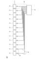
- FIG. 3is a diagram schematically showing the configuration of the ground power supply device according to the first embodiment.
- FIG. 4is a diagram similar to FIG. 3, schematically showing the configuration of a ground power supply device according to a modification of the first embodiment.
- FIG. 5is a diagram similar to FIGS. 3 and 4, schematically showing the configuration of a ground power supply device according to the second embodiment.
- FIG. 6is a diagram similar to FIGS. 3 to 5, schematically showing the configuration of a ground power supply device according to the third embodiment.
- FIG. 7is a diagram schematically showing the configuration of each wiring module.
- FIG. 8is a diagram schematically showing the configuration of a ground power supply device according to the fourth embodiment.
- FIG. 1is a diagram schematically showing a ground power supply device 1 and a vehicle 5 according to the first embodiment.
- the ground power supply device 1transmits power to the vehicle 5 by contactless power transmission using magnetic field resonance coupling.
- contactless power transmissionis performed from the ground power supply device 1 to the vehicle 5 while the vehicle 5 is traveling.
- runningmeans a state in which the vehicle 5 is located on the road for running. Therefore, the term “running” includes not only a state where the vehicle 5 is actually running at any speed greater than zero, but also a state where the vehicle 5 is stopped on the road, for example, waiting at a traffic light.
- the ground power supply device 1includes a plurality of power transmission units 21 embedded in the road (underground) on which the vehicle 5 travels. As shown in FIG. 1, in this embodiment, the power transmission units 21 are arranged at predetermined intervals along each lane 100 at the center of each lane 100 on which the vehicle 5 travels.
- FIG. 2is a diagram schematically showing the configuration of the ground power supply device 1 and the vehicle 5.
- the ground power supply device 1includes a power supply 2 , a power supply unit 10 , a plurality of power transmission side resonance circuits 20 including a power transmission unit 21 , and a controller 30 .
- the power transmission side resonant circuit 20 including the power transmission unit 21is embedded in the road (underground).
- the power supply unit 10 and the controller 30may be embedded within the road, or may be placed at a location other than the road (including on the ground).
- one power supply unit 10is connected to a plurality of power transmission side resonant circuits 20.
- the power supply 2supplies power to the power transmission unit 21 via the power supply unit 10.
- the power supply 2is, for example, a commercial AC power supply that supplies single-layer AC power.
- the power source 2may be another AC power source that supplies three-phase AC power, or may be a DC power source such as a fuel cell.
- the power supply unit 10converts AC power supplied from the power supply 2 into high-frequency AC power to be supplied to the power transmission side resonant circuit 20.
- the power supply unit 10includes a power transmission side rectifier circuit 11 and an inverter 12. In the power supply unit 10 , AC power supplied from the power supply 2 is rectified in the power transmission side rectifier circuit 11 and converted into DC current, and this DC current is converted into AC power in the inverter 12 .
- the power supply 2 and the power supply unit 10function as a power supply source that supplies alternating current power to the power transmission side resonant circuit 20.
- the power transmission side rectifier circuit 11is electrically connected to the power supply 2 and the inverter 12.
- the power transmission side rectifier circuit 11rectifies the AC power supplied from the power source 2 , converts it into DC power, and supplies the DC power to the inverter 12 .
- the power transmission side rectifier circuit 11is, for example, an AC/DC converter.
- one power transmission side rectifier circuit 11is provided in one power supply unit 10. Note that if the power source 2 is a DC power source, the power transmission side rectifier circuit 11 may be omitted.
- the inverter 12is electrically connected to the power transmission side rectifier circuit 11 and the power transmission side resonant circuit 20.
- the inverter 12converts the DC power supplied from the power transmission side rectifier circuit 11 into AC power (high frequency AC power) with a higher frequency than the AC power of the power source 2, and supplies the high frequency AC power to the power transmission side resonant circuit 20.
- the power supply unit 10includes the number of inverters 12 corresponding to the power transmission side resonant circuits 20. Each inverter 12 is connected to a corresponding one different power transmission side resonant circuit 20 . Further, each inverter 12 supplies alternating current power of the same frequency to the power transmission side resonant circuit 20. Therefore, the power supply unit 10 supplies AC power of the same frequency to all the power transmission side resonant circuits 20.
- the power transmission side resonant circuit 20includes a power transmission unit 21 and wiring 22.
- the power transmission side resonant circuit 20is connected to the power supply unit 10 and generates an alternating magnetic field when high frequency AC power is supplied from the power supply unit 10.
- the power transmission unit 21includes a power transmission coil 23 and a power transmission capacitor 24.
- the power transmission side coil 23 and the power transmission side capacitor 24constitute a resonator.
- Various parameters of the power transmitting coil 23 and the power transmitting capacitor 24are such that the resonance frequency of the power transmitting unit 21 is determined by a predetermined value.
- the setting valueis determined as follows.
- the predetermined setting valueis, for example, 10 kHz to 100 GHz, preferably 85 kHz, which is defined by the SAE TIR J2954 standard as a frequency band for contactless power transmission.
- all the power transmission units 21are configured such that various parameters of the power transmission side coil 23 and the power transmission side capacitor 24 are the same. In other words, all power transmission units 21 have the same configuration.
- the power transmission unit 21is embedded within the road, and therefore the power transmission coil 23 and the power transmission capacitor 24 are also embedded within the road.
- the power transmission unit 21is arranged at the center of the lane through which the vehicle 5 passes, such that the center of the power transmission coil 23 is located at the center of the lane.
- the power transmission side coil 23 of the power transmission unit 21generates an alternating current magnetic field for power transmission.
- the wiring 22is used to connect the inverter 12 of the power supply unit 10 and the power transmission unit 21 (that is, the power transmission side coil 23).
- the ground power supply device 1includes a plurality of power transmission units 21 and a plurality of inverters 12 corresponding to different power transmission units 21, respectively. Each wiring 22 connects one inverter 12 and one power transmission unit 21 corresponding thereto.
- the controller 30is, for example, a general-purpose computer, and performs various controls on the ground power supply device 1.
- the controller 30is electrically connected to the inverter 12 of the power supply unit 10 and controls the inverter 12 to control power transmission by the power transmission unit 21 .
- the controller 30identifies the power transmission unit 21 on which the vehicle 5 having the power receiving device 50 is traveling, based on the output from an arbitrary sensor (not shown), and The inverter 12 is controlled to supply power to the power transmission unit 21.
- the controller 30includes a processor that executes various processes, and a memory that stores programs for the processor to execute various processes and various data used when the processor executes the various processes.
- the vehicle 5includes a motor 41, a battery 42, a power control unit (PCU) 43, a power receiving device 50, and an electronic control unit (ECU) 45.
- the vehicle 5is an electric vehicle (BEV) in which a motor 41 drives the vehicle 5, or a hybrid vehicle (HEV) in which an internal combustion engine drives the vehicle 5 in addition to the motor 41.
- BEVelectric vehicle
- HEVhybrid vehicle
- the motor 41is, for example, an AC synchronous motor, and functions as an electric motor and a generator.
- the motor 41functions as an electric motor, it is driven using electric power stored in the battery 42 as a power source.
- the output of the motor 41is transmitted to the wheels via a reduction gear and an axle.
- the motor 41is driven by the rotation of the wheels, and the motor 41 functions as a generator to generate regenerative power.
- the battery 42is a rechargeable secondary battery, and is composed of, for example, a lithium ion battery, a nickel metal hydride battery, or the like.
- the battery 42stores electric power necessary for running the vehicle 5 (for example, electric power for driving the motor 41).
- the battery 42is charged.
- the battery 42is charged.
- the state of charge (SOC) of the battery 42is restored.
- the battery 42may be chargeable by an external power source other than the ground power supply device 1 via a charging port provided in the vehicle 5.
- the PCU 43is electrically connected to the battery 42 and motor 41.
- PCU 43includes an inverter, a boost converter, and a DC/DC converter.
- the inverterconverts the DC power supplied from the battery 42 into AC power, and supplies the AC power to the motor 41.
- the inverterconverts AC power (regenerated power) generated by the motor 41 into DC power, and supplies the DC power to the battery 42 .
- the boost converterboosts the voltage of the battery 42 as necessary when the electric power stored in the battery 42 is supplied to the motor 41.
- the DC/DC convertersteps down the voltage of the battery 42 when the electric power stored in the battery 42 is supplied to an electronic device such as a headlight.
- the power receiving device 50receives power from the power transmission unit 21 and supplies the received power to the battery 42.
- the power receiving device 50includes a power receiving side resonant circuit 51, a power receiving side rectifying circuit 54, and a charging circuit 55.
- the power receiving side resonant circuit 51is arranged at the bottom of the vehicle 5 so that the distance from the road surface is small.
- the power reception side resonant circuit 51has the same configuration as the power transmission unit 21 and includes a power reception side coil 52 and a power reception side capacitor 53.
- the power receiving side coil 52is configured such that a current flows through the power receiving side coil 52 when a magnetic field is generated around it.
- the power receiving side coil 52 and the power receiving side capacitor 53constitute a resonator.
- Various parameters of the power receiving side coil 52 and the power receiving side capacitor 53are based on the resonance frequency of the power receiving side resonant circuit 51. is determined to match the resonant frequency of the power transmission unit 21. Note that if the amount of deviation between the resonant frequency of the power receiving side resonant circuit 51 and the resonant frequency of the power transmitting unit 21 is small, for example, if the resonant frequency of the power receiving side resonant circuit 51 is within ⁇ 20% of the resonant frequency of the power transmitting unit 21. For example, the resonant frequency of the power receiving side resonant circuit 51 does not necessarily have to match the resonant frequency of the power transmitting unit 21.
- the power receiving side resonant circuit 51faces the power transmitting unit 21 as shown in FIG.
- the poweris transmitted to the power receiving side resonant circuit 51 which resonates at the power receiving side.
- an induced currentflows through the power receiving side resonant circuit 51 due to electromagnetic induction, and an induced electromotive force is generated in the power receiving side resonant circuit 51 due to the induced current. That is, the power transmitting unit 21 transmits power to the power receiving side resonant circuit 51, and the power receiving side resonant circuit 51 receives power from the power transmitting unit 21.
- the power receiving side rectifier circuit 54is electrically connected to the power receiving side resonant circuit 51 and the charging circuit 55.
- the power receiving side rectifier circuit 54rectifies the AC power supplied from the power receiving side resonant circuit 51, converts it into DC power, and supplies the DC power to the charging circuit 55.
- the power receiving side rectifier circuit 54is, for example, an AC/DC converter.
- the charging circuit 55is electrically connected to the power receiving side rectifier circuit 54 and the battery 42.
- the charging circuit 55converts the DC power supplied from the power receiving rectifier circuit 54 to a voltage level of the battery 42 and supplies the voltage level to the battery 42 .
- Charging circuit 55is, for example, a DC/DC converter.
- the ECU 45performs various controls on the vehicle 5.
- the ECU 45is electrically connected to the charging circuit 55 of the power receiving device 50 and controls the charging circuit 55 to control charging of the battery 42 with the power transmitted from the power transmission unit 21 .
- the ECU 45is electrically connected to the PCU 43 and controls the PCU 43 to control the transfer of electric power between the battery 42 and the motor 41 .
- FIG. 3is a diagram schematically showing the configuration of the ground power supply device 1. As shown in FIG. In particular, FIG. 3 shows how a plurality of power transmission side resonant circuits 20 are connected to one power supply unit 10. In addition, in FIG. 3, only one of the plurality of power transmission side resonant circuits 20 is indicated by reference number 20.
- a plurality of power transmission units 21 connected to one power supply unit 10are arranged in a line along a lane on a road.
- Each power transmission unit 21 and the power supply unit 10are connected by wiring 22 of a separate power transmission side resonant circuit 20 .
- the wiring 22 connecting each power transmission unit 21 and the power supply unit 10each has two conductive wires through which current flows in opposite directions.
- each power transmission unit 21 and the power supply unit 10are connected by one wiring 22 that is arranged without slack between them. Therefore, the plurality of wires 22 that respectively connect each power transmission unit 21 and the power supply unit 10 have different lengths. That is, in this embodiment, the wiring 22 of each power transmission side resonant circuit 20 has a different length from the wiring 22 of other power transmission side resonance circuits 20.
- the wirings 22 of the power transmission side resonant circuit 20have different lengths, different parasitic inductances occur for each wiring 22. In particular, the longer the wiring 22 is, the greater the parasitic inductance of the wiring 22 becomes. If a different parasitic inductance exists in each wiring 22 in this way, the resonance frequency will differ for each power transmission side resonant circuit 20 having each wiring 22. If the resonant frequency differs for each power transmission side resonant circuit 20 in this way, the resonant frequency of some of the power transmission side resonant circuits 20 will be a frequency different from the frequency of the AC power supplied by the power supply unit 10.
- the resonance frequency of some of the power transmission side resonance circuits 20will be a different frequency from the resonance frequency of the power reception side resonance circuit 51 of the vehicle 5.
- the resonant frequency of the power transmitting side resonant circuit 20becomes a frequency different from the frequency of AC power or the resonant frequency of the power receiving side resonant circuit 51, the transmission efficiency in contactless power transmission decreases.
- a resonance compensation capacitor 25is provided in the power transmission side resonance circuit 20 according to this embodiment.
- the resonance compensation capacitor 25is connected in series with the wiring 22 in the middle of the wiring 22.
- each wiring 22has a resonance compensation capacitor 25.
- the resonance compensation capacitor 25is connected to one of the two conductive wires of each wiring 22.
- the resonance compensation capacitor 25has a different capacitance depending on the length of the wiring 22 of the power transmission side resonance circuit 20 in which the resonance compensation capacitor 25 is provided. Specifically, the capacitance of the resonance compensation capacitor 25 becomes smaller as the length of the wiring 22 becomes longer. More specifically, the resonance compensation capacitor 25 is configured such that even if the parasitic inductances of the wiring 22 of the power transmission side resonant circuit 20 are different from each other, the resonant frequency of the power transmission side resonant circuit 20 is the same as the AC supplied by the power supply unit 10. It has a capacitance equal to the frequency of the power.
- the resonant frequency of the power transmission side resonant circuit 20is supplied by the power supply unit 10. It can be made equal to the frequency of the AC power used. Therefore, according to the present embodiment, even in such a case, the resonant frequencies of all the power transmitting side resonant circuits 20 can be made almost the same, and the resonant frequencies of all the power transmitting side resonant circuits 20 can be made to be the same as those of the vehicle 5.
- the resonant frequencycan be made equal to the resonant frequency of the power receiving side resonant circuit 51. Therefore, according to this embodiment, the transmission efficiency between the power transmission unit 21 and the power receiving side resonant circuit 51 can be made high.
- the resonance compensation capacitor 25is connected in series with the wiring 22 in the middle of the wiring 22.
- the resonance compensation capacitor 25may be provided between the wiring 22 and the power transmission unit 21 and between the wiring 22 and the inverter 12 of the power supply unit 10.
- the resonance compensation capacitor 25may be provided within the power transmission unit 21 (for example, between the power transmission side coil 23 and the power transmission side capacitor 24 of the power transmission unit 21). Good too.
- one resonance compensation capacitor 25is provided in one power transmission side resonance circuit 20.
- a plurality of resonance compensation capacitors 25may be provided in one power transmission side resonance circuit 20.
- the resonance compensation capacitor 25is connected to one of the two conductive wires of each wiring 22.
- the resonance compensation capacitor 25may be connected to each of the two conductive wires of each wiring 22. Even in this case, the capacitance of these resonance compensation capacitors 25 is set to a value such that the resonance frequency of the power transmission side resonance circuit 20 is equal to the frequency of the AC power supplied by the power supply unit 10.
- FIG. 4is a diagram similar to FIG. 3, schematically showing the configuration of the ground power supply device 1 according to a modification of the first embodiment.
- the wiring of the resonance circuit 20, the power transmission side resonance circuit 20 including the four power transmission units 21 in the center, and the power transmission side resonance circuit 20 including the four power transmission units 21 on the left sidehave the same length.
- the resonance compensation capacitors 25 in the power transmission side resonance circuit 20 having the wiring lines 22 of the same lengthhave the same capacitance.
- the number of variations in the length of the wiring and the number of variations in the resonance compensation capacitor 25can be reduced, manufacturing costs can be reduced, and the ground power supply device 1 can be easily installed.
- the wiring 22 of the power transmission side resonant circuit 20has a length that is at least partially different from the wiring 22 of the other power transmission side resonance circuits 20, and the lengths are different. Therefore, the parasitic inductance of the wiring 22 is formed to be at least partially different from that of the wiring 22 of other power transmission side resonant circuits 20.
- ground power supply device 1 according to a second embodimentwill be described.
- the configuration of the ground power supply device 1 according to the second embodimentis basically the same as the configuration of the ground power supply device 1 according to the first embodiment. Below, the explanation will focus on parts that are different from the configuration of the ground power supply device 1 according to the first embodiment.
- FIG. 5is a diagram similar to FIGS. 3 and 4, schematically showing the configuration of the ground power supply device 1 according to the second embodiment. Also in this embodiment, one power transmission unit 21 and one wiring 22 constitute one power transmission side resonant circuit 20. Further, in FIG. 5 as well, a plurality of power transmission side resonant circuits 20 are connected to one power supply unit 10.
- each wiring 22has two parts: a first wiring part 22a and a second wiring part 22b.
- the first wiring portion 22a of each wiring 22is connected to the corresponding power transmission unit 21 and first connector 26.
- a plurality of first wiring portions 22a connected to a plurality of power transmission units 21 arranged adjacent to each otherare connected to one first connector 26 (in the example shown in FIG. 5, four first wiring portions 22a). Therefore, one first connector 26 is connected to a plurality of power transmission units 21 arranged adjacently.
- all the first wiring portions 22ahave the same length. Therefore, regarding the first wiring portion 22a, there is no difference in the magnitude of parasitic inductance between the power transmission side resonant circuits 20.
- the second wiring portion 22b of each wiring 22is connected to the corresponding second connector 27 and power supply unit 10.
- a plurality of second wiring portions 22b of one group having the same lengthare connected to one second connector 27 (in the example shown in FIG. 5, four second wiring portions 22b).
- the second connector 27is connected to the same number of second wiring portions 22b as the number of first wiring portions 22a connected to the first connector 26.
- the second connector 27is connected to the first connector 26, thereby connecting the second wiring portion 22b to the corresponding first wiring portion 22a.
- the plurality of second wiring portions 22b having the same lengthare connected to the first wiring portion 22a via the same first connector 26 and the same second connector 27.
- a plurality of power transmitting side resonant circuits 20 including power transmitting units 21 (power transmitting coils 23)(specifically, a power transmitting side resonant circuit 20 including four power transmitting units 21 on the right side and four power transmitting units 21 in the center).
- the wiring of the power transmission side resonant circuit 20 and the power transmission side resonance circuit 20 including the four power transmission units 21 on the left sidehave the same length.
- a resonance compensation capacitor 25is provided in the second wiring portion 22b.
- the resonance compensation capacitor 25is connected in series with the second wiring portion 22b in the middle of the second wiring portion 22b.
- the resonance compensation capacitor 25is connected to one of the two conductive wires of each second wiring portion 22b.
- the resonance compensation capacitor 25 provided in each second wiring portion 22bhas a capacitance that corresponds to the length of the second wiring portion 22b. Therefore, in this embodiment, the resonance compensation capacitors 25 provided in the plurality of second wiring portions 22b of each group having the same length and connected to the same second connector 27 have the same capacitance.
- the wirings 22 of the power transmission side resonant circuit 20 including the second wiring portions 22b having the same lengthall have the same length and therefore have the same parasitic inductance. Therefore, since the resonance compensation capacitors 25 provided in the second wiring portion 22b have the same capacitance, the resonance frequencies of these power transmission side resonance circuits 20 can be made to be the same frequency.
- the first wiring portions 22ahave the same length. Therefore, one first connector 26 and the plurality of first wiring portions 22a connected thereto have the same configuration. Therefore, parts can be shared in manufacturing the first connector 26 and the first wiring portion 22a. Further, the second wiring portions 22b connected to one second connector 27 have the same configuration. Therefore, the number of variations in the length of the second wiring portion 22b and the number of variations in the resonance compensation capacitor 25 can be reduced with respect to the number of power transmission units 21, and therefore manufacturing costs can be reduced and the ground power supply device 1 can be easily installed.
- the first wiring portion 22a connected to the plurality of power transmission units 21is connected to the second wiring portion 22a at the same point by the first connector 26 and the second connector 27. Since it is connected to the wiring portion 22b, the wiring can be easily routed.
- the resonance compensation capacitor 25is not provided in the first wiring portion 22a. Therefore, in this embodiment, the capacitance of the resonance compensation capacitor 25 provided in the second wiring portion 22b is set in consideration of the length of the wiring 22 including the first wiring portion 22a and the second wiring portion 22b. Ru. Furthermore, in this embodiment, since the length of the first wiring portion 22a is the same in all the power transmission side resonant circuits 20, the length of the first wiring portion 22a is the same in all the power transmission side resonant circuits 20, so the length of the second wiring portion 22b is The capacitance of the provided resonance compensation capacitor 25 and the capacitance of the power transmission side capacitor 24 of the power transmission unit 21 can be set. Since the first wiring portion 22a does not include the resonance compensation capacitor 25 in this manner, the first wiring portion 22a can have a simple configuration.
- one group of second wiring portions 22b having the same lengthmay include a plurality of second wiring portions 22b other than four.
- a resonance compensation capacitormay also be provided in the first wiring portion 22a.
- the capacitances of the resonance compensation capacitors provided in all the first wiring portions 22aare also equal.
- the first wiring portion 22ahas a capacitance corresponding to the length of the first wiring portion 22a so as to cancel the influence on the resonance frequency of the power transmission unit 21 due to parasitic inductance parasitic to the first wiring portion 22a.
- ground power supply device 1 according to a third embodimentwill be described.
- the configuration of the ground power supply device 1 according to the third embodimentis basically the same as the configuration of the ground power supply device 1 according to the second embodiment. Therefore, below, the explanation will focus on the parts that are different from the configuration of the ground power supply device according to the second embodiment.
- FIG. 6is a diagram similar to FIGS. 3 to 5, schematically showing the configuration of the ground power supply device 1 according to the third embodiment.
- each wiring 22has a first wiring portion 22a and a second wiring portion 22c.
- the first wiring portion 22a of each wiring 22is connected to the corresponding power transmission unit 21 and changeover switch 28.
- a plurality of first wiring portions 22a connected to a plurality of power transmission units 21 arranged adjacent to each otherare connected to one changeover switch 28.
- all the first wiring portions 22ahave the same length.
- one second wiring portion 22cis connected to one changeover switch 28. Therefore, one second wiring portion 22c is connected to a plurality of first wiring portions 22a via the changeover switch 28. The plurality of second wiring portions 22c are respectively connected to different changeover switches 28 and one common power supply unit 10. In this embodiment, one second wiring portion 22c is shared by a plurality of power transmission side resonant circuits 20. In any case, also in this embodiment, one power transmission unit 21 and one wiring 22 constitute one power transmission side resonant circuit 20.
- the resonance compensation capacitor 25is provided in the second wiring portion 22c. Also in this embodiment, the resonance compensation capacitor 25 provided in each second wiring portion 22c has a capacitance corresponding to the length of the second wiring portion 22c.
- Each changeover switch 28is connected to a plurality of power transmission units 21 via a plurality of first wiring portions 22a, and is connected to a power supply unit 10 via a single second wiring portion 22c.
- the changeover switch 28selectively connects one of the first wiring parts 22a connected to the changeover switch 28 to the second wiring part 22c. Therefore, the changeover switch 28 selectively connects one power transmission unit 21 among the plurality of power transmission units 21 to the power supply unit 10 . In other words, the changeover switch 28 switches the power transmission unit 21 connected to the power supply unit 10.
- the changeover switch 28is connected to and controlled by the controller 30.
- the controller 30identifies the power transmission unit 21 on which the vehicle 5 having the power receiving device 50 is traveling based on the output from an arbitrary sensor (not shown), and connects the identified power transmission unit 21 and the power source.
- the selector switch 28is switched so that the unit 10 is connected.
- one second wiring portion 22cis connected to a plurality of power transmission units 21. That is, one second wiring portion 22c is shared by a plurality of power transmission side resonant circuits 20. This makes it easier to lay the second wiring portion 22c.
- the number of inverters 12 required in the power supply unit 10can be reduced, and therefore the manufacturing cost of the power supply unit 10 can be reduced.
- ground power supply device 1 according to a fourth embodimentwill be described with reference to FIGS. 7 and 8.
- the configuration of the ground power supply device 1 according to the fourth embodimentis basically the same as the configuration of the ground power supply device 1 according to the first embodiment. Therefore, below, the explanation will focus on the parts that are different from the configuration of the ground power supply device 1 according to the first embodiment.
- each power transmission unit 21 and the power supply unit 10are connected by one wiring 22 having mutually different lengths.
- each power transmission unit 21 and the power supply unit 10are connected by a plurality of wiring modules 29 connected in series.
- FIG. 7is a diagram schematically showing the configuration of each wiring module 29. As shown in FIG. 7, each wiring module 29 includes a cable 35, a resonance compensation capacitor 25 connected in series to the cable 35, and a connector 36.
- each wiring module 29has two cables 35 through which current flows in opposite directions. Further, in this embodiment, each wiring module 29 has one resonance compensation capacitor 25, and the resonance compensation capacitor 25 is connected to one of the two cables 35. Further, both ends of the two cables 35 are connected to connectors 36, respectively.
- the connector 36 of each wiring module 29can be connected to the connector 36 of another wiring module 29.
- each wiring module 29may include a plurality of resonance compensation capacitors 25. In this case, one or more resonance compensation capacitors 25 are connected to each cable 35, respectively.
- all wiring modules 29are configured such that their cables 35 have the same length and their resonance compensation capacitors 25 have the same capacitance.
- the length of the cables 35 of all the wiring modules 29is equal to the interval between the adjacent power transmission units 21 (particularly the interval between the adjacent power transmission coils 23).
- the resonance compensation capacitor 25is configured to provide electrostatic capacitance that cancels out the influence on the resonance frequency of the power transmission unit 21 (that is, the resonance frequency generated in the power transmission side coil 23) due to the parasitic inductance that is parasitic in the cable 35 that constitutes each wiring module 29. Has capacity.
- FIG. 8is a diagram schematically showing the configuration of the ground power supply device 1 according to the fourth embodiment.
- each wiring 22connects one power transmission unit 21 and power supply unit 10.
- the wires 22have different lengths.
- each wiring 22is configured by connecting a plurality of wiring modules 29 in series. As described above, since the cables 35 of all the wiring modules 29 have the same length, the lengths of the wiring 22 differ depending on the number of wiring modules 29 that make up the wiring 22. . Therefore, the wiring 22 used for the power transmission unit 21 that is farther away from the power supply unit 10 is configured with a larger number of wiring modules 29 .
- all the wiring 22is configured by a plurality of wiring modules 29 having the same configuration. Therefore, it is not necessary to use separate configurations of wiring with resonance compensation capacitors having different capacitances for each wiring 22 having a different length. Therefore, it becomes easier to manufacture the wiring 22, and it also becomes easier to route the wiring 22 when installing the power transmission side resonant circuit 20.
- all the wires 22 connected to the power supply unit 10have different lengths. However, similar to the example shown in FIG. 4, some of the wirings 22 may have the same length. In this case, the wirings 22 having the same length are constructed by connecting the same number of wiring modules 29 in series.
- all of the wiring 22 extending from the power supply unit 10 to each power transmission unit 21is formed by the wiring module 29.
- only a portion of each wiring 22may be formed by the wiring module 29.
- the second wiring portions 22b and 22care formed by connecting the wiring modules 29 in series, and the first wiring portion 22a is formed without using the wiring module 29. It may be formed into Note that when only the second wiring portions 22b and 22c are configured by wiring modules 29 in this way, the length of the cables 35 of all wiring modules 29 is determined by the distance between adjacent power transmission units 21 (especially , the distance between adjacent power transmitting coils 23), which is an integral multiple of twice or more.
- the length of the cables 35 of all the wiring modules 29is equal to the distance between the power transmission units 21 arranged next to each other. It is said to be 4 times more.
- the ground power supply device 1supplies power to the running vehicle 5 in a non-contact manner.
- the ground power supply device 1may supply power to vehicles 5 that are not running, such as parked vehicles 5, in a non-contact manner.
- the ground power supply device 1is provided, for example, in a parking lot having a plurality of parking sections, and the power transmission unit 21 is provided in each of the plurality of parking sections.
- Ground power supply device 5Vehicle 10 Power supply unit 20 Power transmission side resonance circuit 21 Power transmission unit 22 Wiring 25 Resonance compensation capacitor 30 Controller
Landscapes
- Engineering & Computer Science (AREA)
- Power Engineering (AREA)
- Computer Networks & Wireless Communication (AREA)
- Transportation (AREA)
- Mechanical Engineering (AREA)
- Physics & Mathematics (AREA)
- Electromagnetism (AREA)
- Electric Propulsion And Braking For Vehicles (AREA)
- Charge And Discharge Circuits For Batteries Or The Like (AREA)
- Current-Collector Devices For Electrically Propelled Vehicles (AREA)
Abstract
Description
Translated fromJapanese本開示は、地上給電装置及び配線に関する。The present disclosure relates to a ground power supply device and wiring.
非接触で送電するための複数のコイルと、コイルに電力を供給する一つの電源とを有し、これらコイルと電源とがそれぞれ導体で接続された、地上給電装置が知られている(特開2019-526219号公報)。A ground power supply device is known that has a plurality of coils for contactless power transmission and one power source that supplies power to the coils, and these coils and the power source are each connected with a conductor (Japanese Patent Application Laid-Open No. 2019-526219).
電源とコイルとを接続する導体は、電源とコイルとの間の距離がコイル毎に異なることから、互いにその長さが異なる。導体の長さによって導体に寄生するインダクタンスが異なるため、長さの異なる導体とコイルとを含む共振回路毎に共振周波数が異なってしまう。The conductors that connect the power source and the coils have different lengths because the distance between the power source and the coils differs for each coil. Since the parasitic inductance of the conductor differs depending on the length of the conductor, the resonant frequency differs for each resonant circuit including conductors and coils of different lengths.
上記課題に鑑みて、本開示の目的は、一つの電源に接続された複数のコイルにおいて共振周波数が異なってしまうことを抑制することにある。In view of the above-mentioned problems, an object of the present disclosure is to suppress differences in resonance frequencies among multiple coils connected to one power source.
本開示の要旨は以下のとおりである。The gist of this disclosure is as follows.
(1)車両に非接触で電力を伝送する地上給電装置であって、
複数の共振回路と、全ての前記共振回路に同一の周波数の交流電力を供給する一つの電力供給源とを備え、
各共振回路は、道路内に埋め込まれた非接触で電力を伝送するためのコイルと、各コイルと前記電力供給源とを接続する配線とを有し、
各共振回路の配線は、他の共振回路の配線とは少なくとも部分的に異なる長さを有すると共に、該長さが異なることによって該配線に寄生するインダクタンスが前記他の共振回路の配線とは少なくとも部分的に異なるように形成され、
前記共振回路は、前記配線に寄生するインダクタンスが異なっていても、全ての共振回路の共振周波数が等しくなるになるように、異なる静電容量を有するコンデンサを更に有する、地上給電装置。
(2)前記コンデンサは、前記配線に寄生するインダクタンスが異なっていても、全ての共振回路の共振周波数が前記交流電力の周波数と同一になるような静電容量を有する、上記(1)に記載の地上給電装置。
(3)隣接して並んで配置された複数のコイルを含む複数の共振回路の配線は、同一の長さを有する、上記(1)又は(2)に記載の地上給電装置。
(4)前記配線は、全ての前記共振回路において同一の長さを有する第1部分と、前記共振回路間で部分的に異なる長さを有する第2部分とを有し、
前記第2部分に前記コンデンサが設けられる、上記(1)~(3)のいずれか1つに記載の地上給電装置。
(5)同一の長さを有する複数の前記第2部分に設けられたコンデンサは同一の静電容量を有する、上記(4)に記載の地上給電装置。
(6)前記第1部分は、コンデンサを有さない、上記(4)又は(5)に記載の地上給電装置。
(7)前記第1部分は前記コイルに接続され、前記第2部分は前記電力供給源に接続され、同一の長さを有する複数の前記第2部分は同一のコネクタによって前記第1部分に接続される、上記(4)~(6)のいずれか1つに記載の地上給電装置。
(8)前記配線は、少なくとも部分的に、同一の長さを有するケーブルと該ケーブルに接続されたコンデンサとをそれぞれ有する複数の配線モジュールを直列に接続することによって構成され、
各配線モジュールのコンデンサは、前記交流電力の周波数において該配線モジュールのケーブルに寄生したインダクタンスによる前記コイルに生じる共振周波数への影響を打ち消すような静電容量を有し、
長さが異なる配線を有する前記共振回路は、該共振回路の配線を構成する前記配線モジュールの数が異なることによって該配線の長さが異なる、上記(1)~(7)のいずれか1つに記載の地上給電装置。
(9)前記配線モジュールのケーブルの長さは、隣り合うコイル同士の間隔の整数倍に等しい、上記(8)に記載の地上給電装置。(1) A ground power supply device that transmits power to a vehicle in a non-contact manner,
comprising a plurality of resonant circuits and one power supply source that supplies alternating current power of the same frequency to all the resonant circuits,
Each resonant circuit has a coil embedded in the road for contactless power transmission, and wiring connecting each coil and the power supply source,
The wiring of each resonant circuit has a length that is at least partially different from the wiring of the other resonant circuits, and due to the different lengths, the parasitic inductance of the wiring is at least different from that of the wiring of the other resonant circuits. formed differently in parts,
The above-mentioned resonant circuit further includes a capacitor having a different capacitance so that the resonant frequency of all the resonant circuits becomes equal even if the inductance parasitic to the wiring is different.
(2) The capacitor described in (1) above has a capacitance such that the resonant frequency of all resonant circuits is the same as the frequency of the AC power even if the inductance parasitic to the wiring is different. Ground feeding equipment.
(3) The ground power supply device according to (1) or (2) above, wherein wiring of a plurality of resonant circuits including a plurality of coils arranged adjacent to each other has the same length.
(4) The wiring has a first portion having the same length in all the resonant circuits, and a second portion having partially different lengths among the resonant circuits,
The ground power supply device according to any one of (1) to (3) above, wherein the second portion is provided with the capacitor.
(5) The ground power supply device according to (4) above, wherein the capacitors provided in the plurality of second portions having the same length have the same capacitance.
(6) The ground power supply device according to (4) or (5) above, wherein the first portion does not have a capacitor.
(7) the first part is connected to the coil, the second part is connected to the power supply, and a plurality of the second parts having the same length are connected to the first part by the same connector; The ground power supply device according to any one of (4) to (6) above.
(8) The wiring is at least partially configured by connecting in series a plurality of wiring modules each having a cable having the same length and a capacitor connected to the cable,
The capacitor of each wiring module has a capacitance that cancels the influence on the resonant frequency caused in the coil due to the inductance parasitic in the cable of the wiring module at the frequency of the AC power,
The resonant circuit having wires of different lengths is any one of (1) to (7) above, in which the lengths of the wires are different due to a difference in the number of the wiring modules that constitute the wires of the resonant circuit. The ground power supply device described in .
(9) The ground power supply device according to (8), wherein the length of the cable of the wiring module is equal to an integral multiple of the distance between adjacent coils.
以下、図面を参照して実施形態について詳細に説明する。なお、以下の説明では、同様な構成要素には同一の参照番号を付す。Hereinafter, embodiments will be described in detail with reference to the drawings. In addition, in the following description, the same reference number is attached to the same component.
第一実施形態
<地上給電装置の概要>
図1を参照して、第一実施形態に係る地上給電装置1と、地上給電装置1から電力を受電可能な車両5の概要について説明する。図1は、第一実施形態に係る地上給電装置1及び車両5を概略的に示す図である。地上給電装置1は、磁界共振結合(磁界共鳴)による非接触電力伝送により車両5へ送電する。特に、本実施形態では、車両5が走行しているときに、地上給電装置1から車両5への非接触電力伝送が行われる。First embodiment <Summary of ground power supply device>
With reference to FIG. 1, an overview of a ground power supply device 1 according to the first embodiment and a
なお、走行中という用語は、車両5が走行のために道路上に位置する状態を意味する。したがって、走行中という用語は、車両5が実際にゼロよりも大きい任意の速度で走っている状態のみならず、例えば信号待ちなどによって道路上で停止している状態も含む。Note that the term "running" means a state in which the
地上給電装置1は、車両5が走行する道路内(地中)に埋め込まれた複数の送電ユニット21を有する。図1に示されるように、本実施形態では、送電ユニット21は、車両5が走行する各車線100の中央に、各車線100に沿って所定間隔毎に配置される。The ground power supply device 1 includes a plurality of
<地上給電装置の構成>
次に、図2を参照して、地上給電装置1の構成について概略的に説明する。図2は、地上給電装置1及び車両5の構成を概略的に示す図である。図2に示されるように、地上給電装置1は、電源2と、電源ユニット10と、送電ユニット21を含む複数の送電側共振回路20と、コントローラ30と、を有する。送電ユニット21を含む送電側共振回路20は道路内(地中)に埋め込まれる。一方、電源ユニット10及びコントローラ30は、道路内に埋め込まれてもよいし、道路とは別の場所(地上を含む)に配置されてもよい。本実施形態では、一つの電源ユニット10が複数の送電側共振回路20に接続される。<Configuration of ground power supply device>
Next, with reference to FIG. 2, the configuration of the ground power supply device 1 will be schematically described. FIG. 2 is a diagram schematically showing the configuration of the ground power supply device 1 and the
電源2は、電源ユニット10を介して、送電ユニット21に電力を供給する。電源2は、例えば、単層交流電力を供給する商用交流電源である。なお、電源2は、三相交流電力を供給する他の交流電源であってもよいし、燃料電池のような直流電源であってもよい。The
電源ユニット10は、電源2から供給された交流電力を、送電側共振回路20に供給するための高周波交流電力に変換する。電源ユニット10は、送電側整流回路11及びインバータ12を有する。電源ユニット10では、電源2から供給される交流電力が送電側整流回路11において整流されて直流電流に変換され、この直流電流がインバータ12において交流電力に変換される。電源2と電源ユニット10は、送電側共振回路20に交流電力を供給する電力供給源として機能する。The
送電側整流回路11は、電源2及びインバータ12に電気的に接続される。送電側整流回路11は、電源2から供給される交流電力を整流して直流電力に変換し、直流電力をインバータ12に供給する。送電側整流回路11は例えばAC/DCコンバータである。本実施形態では、一つの電源ユニット10に一つの送電側整流回路11が設けられる。なお、電源2が直流電源である場合には、送電側整流回路11は省略されてもよい。The power transmission
インバータ12は送電側整流回路11及び送電側共振回路20に電気的に接続される。インバータ12は、送電側整流回路11から供給された直流電力を、電源2の交流電力よりも高い周波数の交流電力(高周波交流電力)に変換し、高周波交流電力を送電側共振回路20に供給する。本実施形態では、電源ユニット10は、送電側共振回路20に対応する数のインバータ12を有する。各インバータ12は、それぞれ対応する一つの互いに異なる送電側共振回路20に接続される。また、各インバータ12は、互いに同一の周波数の交流電力を送電側共振回路20に供給する。したがって、電源ユニット10は、全ての送電側共振回路20に同一の周波数の交流電力を供給する。The
送電側共振回路20は、送電ユニット21と、配線22と、を有する。送電側共振回路20は、電源ユニット10に接続されると共に、電源ユニット10から高周波交流電力が供給されると交番磁界を発生させる。The power transmission side
送電ユニット21は、送電側コイル23と送電側コンデンサ24とを有する。送電側コイル23は、電流が流れると、非接触で電力を伝送すべく磁界を発生させる。送電側コイル23と送電側コンデンサ24とは共振器を構成する。送電側コイル23及び送電側コンデンサ24の各種パラメータ(送電側コイル23の外形及び内径、送電側コイル23の巻数、送電側コンデンサ24の静電容量、等)は、送電ユニット21の共振周波数が所定の設定値になるように定められる。所定の設定値は、例えば10kHz~100GHzであり、好ましくは、非接触電力伝送用の周波数帯域としてSAE TIR J2954規格によって定められた85kHzである。また、本実施形態では、全ての送電ユニット21は、送電側コイル23及び送電側コンデンサ24の各種パラメータが互いに同一になるように構成される。換言すると、全ての送電ユニット21は、同一の構成を有する。The
送電ユニット21は、上述したように、道路内に埋め込まれ、よって送電側コイル23及び送電側コンデンサ24も道路内に埋め込まれる。送電ユニット21は、送電側コイル23の中心が車線の中央に位置するように、車両5が通過する車線の中央に配置される。インバータ12から配線22を介して送電ユニット21に高周波電力が供給されると、送電ユニット21の送電側コイル23は、送電するための交流磁界を発生させる。As described above, the
配線22は、電源ユニット10のインバータ12と送電ユニット21(すなわち、送電側コイル23)とを接続するのに用いられる。本実施形態では、地上給電装置1は、複数の送電ユニット21を有すると共に、それぞれ異なる送電ユニット21に対応する複数のインバータ12を有する。各配線22は、一つのインバータ12と、これに対応する一つの送電ユニット21とを接続する。The
コントローラ30は、例えば汎用コンピュータであり、地上給電装置1の各種制御を行う。例えば、コントローラ30は、電源ユニット10のインバータ12に電気的に接続され、送電ユニット21による送電を制御すべくインバータ12を制御する。具体的には、例えば、コントローラ30は、任意のセンサ(図示せず)からの出力に基づいて受電装置50を有する車両5が上を走行している送電ユニット21を特定すると共に、特定された送電ユニット21に電力を供給するようにインバータ12を制御する。コントローラ30は、各種処理を実行するプロセッサと、プロセッサが各種処理を実行されるためのプログラム及びプロセッサが各種処理を実行するときに使用される各種データ等を記憶するメモリと、を有する。The
<車両の構成>
次に、図2を参照して、車両5の構成について概略的に説明する。図2に示されるように、車両5は、モータ41、バッテリ42、パワーコントロールユニット(PCU)43、受電装置50、及び電子制御ユニット(ECU)45を有する。車両5は、モータ41が車両5を駆動する電動車両(BEV)、又はモータ41に加えて内燃機関が車両5を駆動するハイブリッド車両(HEV)である。<Vehicle configuration>
Next, the configuration of the
モータ41は、例えば交流同期モータであり、電動機及び発電機として機能する。モータ41は、電動機として機能するとき、バッテリ42に蓄えられた電力を動力源として駆動される。モータ41の出力は減速機及び車軸を介して車輪に伝達される。一方、車両5の減速時には車輪の回転によってモータ41が駆動され、モータ41は発電機として機能して回生電力を発電する。The
バッテリ42は、充電可能な二次電池であり、例えば、リチウムイオン電池、ニッケル水素電池等から構成される。バッテリ42は車両5の走行に必要な電力(例えばモータ41の駆動電力)を蓄える。送電ユニット21から受電装置50が受電した電力が供給されると、バッテリ42が充電される。また、モータ41によって発電された回生電力がバッテリ42に供給されると、バッテリ42が充電される。バッテリ42が充電されると、バッテリ42の充電率(SOC:State Of Charge)が回復する。なお、バッテリ42は、車両5に設けられた充電ポートを介して地上給電装置1以外の外部電源によっても充電可能であってもよい。The
PCU43はバッテリ42及びモータ41に電気的に接続される。PCU43は、インバータ、昇圧コンバータ及びDC/DCコンバータを有する。インバータは、バッテリ42から供給された直流電力を交流電力に変換し、交流電力をモータ41に供給する。一方、インバータは、モータ41によって発電された交流電力(回生電力)を直流電力に変換し、直流電力をバッテリ42に供給する。昇圧コンバータは、バッテリ42に蓄えられた電力がモータ41に供給されるときに、必要に応じてバッテリ42の電圧を昇圧する。DC/DCコンバータは、バッテリ42に蓄えられた電力がヘッドライト等の電子機器に供給されるときに、バッテリ42の電圧を降圧する。The
受電装置50は、送電ユニット21から受電し、受電した電力をバッテリ42に供給する。受電装置50は、受電側共振回路51、受電側整流回路54及び充電回路55を有する。The
受電側共振回路51は、路面との距離が小さくなるように車両5の底部に配置される。受電側共振回路51は、送電ユニット21と同様の構成を有し、受電側コイル52及び受電側コンデンサ53を有する。受電側コイル52は、周りに磁界が生じると、受電側コイル52に電流が流れるように構成される。受電側コイル52と受電側コンデンサ53とは、共振器を構成する。受電側コイル52及び受電側コンデンサ53の各種パラメータ(受電側コイル52の外径及び内径、受電側コイル52の巻数、受電側コンデンサ53の静電容量等)は、受電側共振回路51の共振周波数が送電ユニット21の共振周波数と一致するように定められる。なお、受電側共振回路51の共振周波数と送電ユニット21の共振周波数とのずれ量が小さければ、例えば受電側共振回路51の共振周波数が送電ユニット21の共振周波数の±20%の範囲内であれば、受電側共振回路51の共振周波数は送電ユニット21の共振周波数と必ずしも一致している必要はない。The power receiving side
図2に示されるように受電側共振回路51が送電ユニット21と対向しているときに、送電ユニット21によって交流磁界が生成されると、交流磁界の振動が、送電ユニット21と同一の共振周波数で共鳴する受電側共振回路51に伝達される。この結果、電磁誘導によって受電側共振回路51に誘導電流が流れ、誘導電流によって受電側共振回路51において誘導起電力が発生する。すなわち、送電ユニット21は受電側共振回路51へ送電し、受電側共振回路51は送電ユニット21から受電する。When the power receiving side
受電側整流回路54は受電側共振回路51及び充電回路55に電気的に接続される。受電側整流回路54は、受電側共振回路51から供給される交流電力を整流して直流電力に変換し、直流電力を充電回路55に供給する。受電側整流回路54は例えばAC/DCコンバータである。The power receiving
充電回路55は受電側整流回路54及びバッテリ42に電気的に接続される。充電回路55は、受電側整流回路54から供給された直流電力をバッテリ42の電圧レベルに変換してバッテリ42に供給する。送電ユニット21から送電された電力が受電装置50によってバッテリ42に供給されると、バッテリ42が充電される。充電回路55は例えばDC/DCコンバータである。The charging
ECU45は車両5の各種制御を行う。例えば、ECU45は、受電装置50の充電回路55に電気的に接続され、送電ユニット21から送電された電力によるバッテリ42の充電を制御すべく充電回路55を制御する。また、ECU45は、PCU43に電気的に接続され、バッテリ42とモータ41との間の電力の授受を制御すべくPCU43を制御する。The
<送電側共振回路>
次に、図3を参照して、送電側共振回路20の構成について説明する。図3は、地上給電装置1の構成を概略的に示す図である。特に、図3は、一つの電源ユニット10に複数の送電側共振回路20が接続されている様子を示している。なお、図3では、複数の送電側共振回路20のうち一つのみが参照番号20で示されている。<Power transmission side resonant circuit>
Next, the configuration of the power transmission side
図3に示されるように、一つの電源ユニット10に接続されている複数の送電ユニット21は、道路内に、車線に沿って一列に配置されている。各送電ユニット21と、電源ユニット10とは、それぞれ別々の送電側共振回路20の配線22によって接続されている。各送電ユニット21と電源ユニット10とを接続する配線22は、それぞれ、電流が逆方向に流れる2本の導線を有する。As shown in FIG. 3, a plurality of
また、図3に示されるように、一列に配置された複数の送電ユニット21のそれぞれと一つの電源ユニット10との間隔は互いに異なる。そして、本実施形態では、各送電ユニット21と電源ユニット10とは、これらの間に弛みなく配置された一つの配線22によって接続される。したがって、各送電ユニット21と電源ユニット10とをそれぞれ接続する複数の配線22は互いに異なる長さを有する。すなわち、本実施形態では、各送電側共振回路20の配線22は、他の送電側共振回路20の配線22とは異なる長さを有する。Furthermore, as shown in FIG. 3, the intervals between each of the plurality of
ここで、送電側共振回路20の配線22は互いに異なる長さを有することから、各配線22毎に異なる寄生インダクタンスが寄生する。特に、配線22の長さが長いほど、その配線22に寄生する寄生インダクタンスが大きくなる。このように各配線22毎に異なる寄生インダクタンスが寄生すると、各配線22を有する送電側共振回路20毎に共振周波数が異なってしまう。このように送電側共振回路20毎に共振周波数が異なると、一部の送電側共振回路20の共振周波数は、電源ユニット10によって供給される交流電力の周波数とは異なる周波数になってしまう。また、このように送電側共振回路20毎に共振周波数が異なると、一部の送電側共振回路20の共振周波数は、車両5の受電側共振回路51の共振周波数と異なる周波数になってしまう。送電側共振回路20の共振周波数が、交流電力の周波数や受電側共振回路51の共振周波数と異なった周波数になると、非接触電力伝送における伝送効率が低下する。Here, since the
そこで、本実施形態に係る送電側共振回路20には、共振補償コンデンサ25が設けられる。本実施形態では、共振補償コンデンサ25は、配線22の途中に配線22と直列に接続される。換言すると、本実施形態では、各配線22は、それぞれ共振補償コンデンサ25を有する。また、本実施形態では、共振補償コンデンサ25は、各配線22の2本の導線のうち1本の導線に接続される。Therefore, a
共振補償コンデンサ25は、共振補償コンデンサ25が設けられた送電側共振回路20の配線22の長さに応じて異なる静電容量を有する。具体的には、共振補償コンデンサ25の静電容量は、配線22の長さが長くなるにつれて、小さくなる。より詳細には、共振補償コンデンサ25は、送電側共振回路20の配線22に寄生する寄生インダクタンスが互いに異なっていても、その送電側共振回路20の共振周波数が、電源ユニット10によって供給される交流電力の周波数と等しくなるような静電容量を有する。The
本実施形態によれば、送電側共振回路20毎に配線22の長さが異なって配線22に寄生する寄生インダクタンスが異なっている場合でも、送電側共振回路20の共振周波数を電源ユニット10によって供給される交流電力の周波数と等しくすることができる。したがって、本実施形態によれば、このような場合でも、全ての送電側共振回路20の共振周波数をほぼ同一にすることができ、また、全ての送電側共振回路20の共振周波数を車両5の受電側共振回路51の共振周波数と等しくすることができる。よって、本実施形態によれば、送電ユニット21と受電側共振回路51との間の伝送効率を高いものとすることができる。According to this embodiment, even if the length of the
<変形例>
上記実施形態では、共振補償コンデンサ25は、配線22の途中に配線22と直列に接続されている。しかしながら、共振補償コンデンサ25は、配線22と送電ユニット21との間、配線22と電源ユニット10のインバータ12との間に設けられてもよい。或いは、共振補償コンデンサ25は、送電側共振回路20内で直列に接続されれば、送電ユニット21内(例えば、送電ユニット21の送電側コイル23と送電側コンデンサ24との間)に設けられてもよい。<Modified example>
In the embodiment described above, the
また、上記実施形態では、一つの送電側共振回路20に一つの共振補償コンデンサ25が設けられる。しかしながら、一つの送電側共振回路20に複数の共振補償コンデンサ25が設けられてもよい。例えば、上記実施携帯では、各配線22の2本の導線のうち1本の導線に共振補償コンデンサ25が接続されている。しかしながら、各配線22の2本の導線のそれぞれに共振補償コンデンサ25が接続されてもよい。この場合でも、これら共振補償コンデンサ25の静電容量は、送電側共振回路20の共振周波数が、電源ユニット10によって供給される交流電力の周波数と等しくなるような値とされる。Furthermore, in the above embodiment, one
さらに、上記実施形態では、電源ユニット10に接続される全ての配線22は互いに異なる長さを有している。しかしながら、一部の配線22同士は同じ長さを有していてもよい。図4は、第一実施形態の一つの変形例に係る地上給電装置1の構成を概略的に示す、図3と同様な図である。図4に示した例では、隣接して並んだ複数の送電ユニット21(送電側コイル23)を含む複数の送電側共振回路20(具体的には、右側の4つの送電ユニット21を含む送電側共振回路20と、中央の4つの送電ユニット21を含む送電側共振回路20と、左側の4つの送電ユニット21を含む送電側共振回路20)の配線は、同一の長さを有する。このように同じ長さの配線22を有する送電側共振回路20における共振補償コンデンサ25は同じ静電容量を有する。この結果、配線の長さのバリエーションの数及び共振補償コンデンサ25のバリエーションの数を減らすことができ、製造コストを低減することができると共に地上給電装置1を敷設し易くすることができる。Further, in the above embodiment, all the
以上より、本実施形態及びその変形例では、送電側共振回路20の配線22は、他の送電側共振回路20の配線22とは少なくとも部分的に異なる長さを有すると共に、長さが異なることによって配線22に寄生するインダクタンスが他の送電側共振回路20の配線22とは少なくとも部分的に異なるように形成される。From the above, in the present embodiment and its modification, the
第二実施形態
次に、図5を参照して、第二実施形態に係る地上給電装置1について説明する。第二実施形態に係る地上給電装置1の構成は、基本的に第一実施形態に係る地上給電装置1の構成と同様である。以下では、第一実施形態に係る地上給電装置1の構成とは異なる部分を中心に説明する。Second Embodiment Next, with reference to FIG. 5, a ground power supply device 1 according to a second embodiment will be described. The configuration of the ground power supply device 1 according to the second embodiment is basically the same as the configuration of the ground power supply device 1 according to the first embodiment. Below, the explanation will focus on parts that are different from the configuration of the ground power supply device 1 according to the first embodiment.
図5は、第二実施形態に係る地上給電装置1の構成を概略的に示す、図3及び図4と同様な図である。本実施形態においても、一つの送電ユニット21及び一つの配線22が一つの送電側共振回路20を構成する。また、図5においても、一つの電源ユニット10に複数の送電側共振回路20が接続されている。FIG. 5 is a diagram similar to FIGS. 3 and 4, schematically showing the configuration of the ground power supply device 1 according to the second embodiment. Also in this embodiment, one
図5に示されるように、各配線22は、第1配線部分22aと第2配線部分22bとの2つの部分を有する。各配線22の第1配線部分22aは、対応する送電ユニット21と第1コネクタ26とに接続される。一つの第1コネクタ26には、隣接して並んだ複数の送電ユニット21に接続された複数の第1配線部分22aが接続される(図5に示した例では、4本の第1配線部分22a)。したがって、一つの第1コネクタ26は、隣接して並んだ複数の送電ユニット21に接続されることになる。また、本実施形態では、全ての第1配線部分22aは同一の長さを有する。したがって、第1配線部分22aに関しては送電側共振回路20間で寄生インダクタンスの大きさの違いはない。As shown in FIG. 5, each
各配線22の第2配線部分22bは、対応する第2コネクタ27と電源ユニット10とに接続される。一つの第2コネクタ27には、長さの等しい一つのグループの複数の第2配線部分22bが接続される(図5に示した例では、4本の第2配線部分22b)。特に、第2コネクタ27には、第1コネクタ26に接続される第1配線部分22aの数と同数の第2配線部分22bが接続される。第2コネクタ27は第1コネクタ26に接続され、これによって第2配線部分22bが対応する第1配線部分22aに接続される。本実施形態では、同一の長さを有する複数の第2配線部分22bは、同一の第1コネクタ26及び同一の第2コネクタ27を介して第1配線部分22aに接続されることになる。また、第1コネクタ26は、隣接して並んだ複数の送電ユニット21に接続された複数の第1配線部分22aが接続されることから、図5に示した例では、隣接して並んだ複数の送電ユニット21(送電側コイル23)を含む複数の送電側共振回路20(具体的には、右側の4つの送電ユニット21を含む送電側共振回路20と、中央の4つの送電ユニット21を含む送電側共振回路20と、左側の4つの送電ユニット21を含む送電側共振回路20)の配線は、同一の長さを有する。The
また、本実施形態では、第2配線部分22bに、共振補償コンデンサ25が設けられる。特に、共振補償コンデンサ25は、第2配線部分22bの途中に第2配線部分22bと直列に接続される。また、本実施形態においても、共振補償コンデンサ25は、各第2配線部分22bの2本の導線のうちの1本の導線に接続される。加えて、本実施形態でも、各第2配線部分22bに設けられた共振補償コンデンサ25は、その第2配線部分22bの長さに応じた静電容量を有する。したがって、本実施形態では、同一の第2コネクタ27に接続された長さの等しい各グループの複数の第2配線部分22bに設けられた共振補償コンデンサ25は同一の静電容量を有する。ここで、長さの等しい第2配線部分22bを含む送電側共振回路20の配線22はいずれも同一の長さを有し、よって同一の寄生インダクタンスを有する。このため、第2配線部分22bに設けられた共振補償コンデンサ25がこのように同一の静電容量を有することにより、これら送電側共振回路20の共振周波数を等しい周波数とすることができる。Furthermore, in this embodiment, a
本実施形態によれば、第1配線部分22aは同一の長さを有する。よって、一つの第1コネクタ26とこれに接続された複数の第1配線部分22aとは同一の構成を有する。したがって、第1コネクタ26及び第1配線部分22aの製造に当たっては部品を共用することができる。また、一つの第2コネクタ27に接続される第2配線部分22bは同一の構成を有する。したがって、送電ユニット21の数に対して第2配線部分22bの長さのバリエーションの数及び共振補償コンデンサ25のバリエーションの数を減らすことができ、よって製造コストを低減することができると共に地上給電装置1を敷設し易くすることができる。また、送電ユニット21は互いに異なる位置に配置されているにもかかわらず、複数の送電ユニット21に接続された第1配線部分22aが第1コネクタ26及び第2コネクタ27によって同一地点にて第2配線部分22bに接続されるため、配線の取り回しがし易くなる。According to this embodiment, the
一方、本実施形態では、第1配線部分22aには、共振補償コンデンサ25は設けられない。したがって、本実施形態では、第1配線部分22a及び第2配線部分22bを含む配線22の長さを考慮して、第2配線部分22bに設けられた共振補償コンデンサ25の静電容量が設定される。また、本実施形態では、第1配線部分22aの長さは、全ての送電側共振回路20において同一であるため、第1配線部分22aに生じる寄生インダクタンスを考慮して、第2配線部分22bに設けられた共振補償コンデンサ25の静電容量や送電ユニット21の送電側コンデンサ24の静電容量を設定することができる。このように第1配線部分22aが共振補償コンデンサ25を有さないことにより、第1配線部分22aを簡単な構成にすることができる。On the other hand, in this embodiment, the
なお、上記実施形態では、一つのコネクタ26、27には4本の配線部分22a、22bが接続される。しかしながら、一つのコネクタ26、27には複数の配線部分22a、22bが接続されれば、4本以外の配線部分22a、22bが接続さてもよい。したがって、長さの等しい第2配線部分22bの一つのグループには4本以外の複数本の第2配線部分22bが含まれていてもよい。Note that in the above embodiment, four
また、第1配線部分22aにも共振補償コンデンサが設けられてもよい。この場合、全ての第1配線部分22aの長さが等しいことから、全ての第1配線部分22aに設けられる共振補償コンデンサの静電容量も等しい。また、第1配線部分22aは、第1配線部分22aに寄生した寄生インダクタンスによる送電ユニット21の共振周波数への影響を打ち消すように、第1配線部分22aの長さに対応した静電容量を有する。Furthermore, a resonance compensation capacitor may also be provided in the
第三実施形態
次に、図6を参照して、第三実施形態に係る地上給電装置1について説明する。第三実施形態に係る地上給電装置1の構成は、基本的に第二実施形態に係る地上給電装置1の構成と同様である。したがって、以下では、第二実施形態に係る地上給電装置の構成とは異なる部分を中心に説明する。Third Embodiment Next, with reference to FIG. 6, a ground power supply device 1 according to a third embodiment will be described. The configuration of the ground power supply device 1 according to the third embodiment is basically the same as the configuration of the ground power supply device 1 according to the second embodiment. Therefore, below, the explanation will focus on the parts that are different from the configuration of the ground power supply device according to the second embodiment.
図6は、第三実施形態に係る地上給電装置1の構成を概略的に示す、図3~図5と同様な図である。図6に示されるように、本実施形態においても、各配線22は、第1配線部分22aと第2配線部分22cとを有する。各配線22の第1配線部分22aは、対応する送電ユニット21と切替スイッチ28とに接続される。一つの切替スイッチ28には、隣接して並んだ複数の送電ユニット21に接続された複数の第1配線部分22aが接続される。また、本実施形態でも、全ての第1配線部分22aは同一の長さを有する。FIG. 6 is a diagram similar to FIGS. 3 to 5, schematically showing the configuration of the ground power supply device 1 according to the third embodiment. As shown in FIG. 6, also in this embodiment, each
一方、本実施形態では、一つの切替スイッチ28に対して一つの第2配線部分22cが接続される。したがって、一つの第2配線部分22cは、切替スイッチ28を介して複数の第1配線部分22aに接続される。複数の第2配線部分22cは、それぞれ異なる切替スイッチ28と、共通の一つの電源ユニット10とに接続される。本実施形態では、一つの第2配線部分22cは、複数の送電側共振回路20に共用されることになる。いずれにせよ、本実施形態においても、一つの送電ユニット21及び一つの配線22が一つの送電側共振回路20を構成する。On the other hand, in this embodiment, one
また、本実施形態でも、第2配線部分22cに、共振補償コンデンサ25が設けられる。本実施形態でも、各第2配線部分22cに設けられた共振補償コンデンサ25は、その第2配線部分22cの長さに応じた静電容量を有する。Also in this embodiment, the
各切替スイッチ28は、複数の第1配線部分22aを介して複数の送電ユニット21に接続されると共に、一つの第2配線部分22cを介して電源ユニット10に接続される。切替スイッチ28は、切替スイッチ28に接続された複数の第1配線部分22aのうち一つの第1配線部分22aを選択的に第2配線部分22cに接続する。したがって、切替スイッチ28は、複数の送電ユニット21のうち一つの送電ユニット21を選択的に電源ユニット10に接続する。換言すると、切替スイッチ28は、電源ユニット10に接続される送電ユニット21を切り替える。Each
切替スイッチ28は、コントローラ30に接続されて、コントローラ30によって制御される。コントローラ30は、例えば、任意のセンサ(図示せず)からの出力に基づいて受電装置50を有する車両5が上を走行している送電ユニット21を特定すると共に、特定された送電ユニット21と電源ユニット10とが接続されるように切替スイッチ28を切り替える。The
本実施形態によれば、複数の送電ユニット21に対して一つの第2配線部分22cが接続される。すなわち、複数の送電側共振回路20において、一つの第2配線部分22cが共用される。これにより、第2配線部分22cを敷設し易くなる。加えて、電源ユニット10において必要なインバータ12の数を少なくすることができ、よって電源ユニット10の製造コストを下げることができる。According to this embodiment, one
第四実施形態
次に、図7及び図8を参照して、第四実施形態に係る地上給電装置1について説明する。第四実施形態に係る地上給電装置1の構成は、基本的に第一実施形態に係る地上給電装置1の構成と同様である。したがって、以下では、第一実施形態に係る地上給電装置1の構成とは異なる部分を中心に説明する。Fourth Embodiment Next, a ground power supply device 1 according to a fourth embodiment will be described with reference to FIGS. 7 and 8. The configuration of the ground power supply device 1 according to the fourth embodiment is basically the same as the configuration of the ground power supply device 1 according to the first embodiment. Therefore, below, the explanation will focus on the parts that are different from the configuration of the ground power supply device 1 according to the first embodiment.
第一実施形態に係る地上給電装置1では、各送電ユニット21と電源ユニット10とは、互いに長さの異なる一つの配線22によって接続されていた。これに対して、本実施形態に係る地上給電装置1では、各送電ユニット21と電源ユニット10とは、直列に接続された複数の配線モジュール29によって接続される。In the ground power supply device 1 according to the first embodiment, each
図7は、各配線モジュール29の構成を概略的に示す図である。図7に示されるように、各配線モジュール29は、ケーブル35と、ケーブル35に直列に接続された共振補償コンデンサ25と、コネクタ36と、を有する。FIG. 7 is a diagram schematically showing the configuration of each
図7に示されるように、各配線モジュール29は、電流が互いに逆方向に流れる2本のケーブル35を有する。また、本実施形態では、各配線モジュール29は1つの共振補償コンデンサ25を有し、共振補償コンデンサ25は、2本のケーブル35のうちの1本のケーブル35に接続される。また、2本のケーブル35の両端はそれぞれコネクタ36に接続される。各配線モジュール29のコネクタ36は、別の配線モジュール29のコネクタ36と接続することができる。なお、各配線モジュール29は、複数の共振補償コンデンサ25を有してもよい。この場合、各ケーブル35にそれぞれ1つ以上の共振補償コンデンサ25が接続される。As shown in FIG. 7, each
本実施形態では、全ての配線モジュール29は、そのケーブル35が同一の長さを有するように、及びその共振補償コンデンサ25が同一の静電容量を有するように構成される。特に、本実施形態では、全ての配線モジュール29のケーブル35の長さは、隣り合って配置された送電ユニット21の間隔(特に、隣り合って配置された送電側コイル23の間隔)と等しい。また、共振補償コンデンサ25は、各配線モジュール29を構成するケーブル35に寄生した寄生インダクタンスによる送電ユニット21の共振周波数(すなわち、送電側コイル23に生じる共振周波数)への影響を打ち消すような静電容量を有する。In this embodiment, all
図8は、第四実施形態に係る地上給電装置1の構成を概略的に示す図である。図8に示されるように、各配線22は、一つの送電ユニット21と電源ユニット10とを接続する。配線22は、互いに異なる長さを有する。また、本実施形態では、各配線22は、複数の配線モジュール29を直列に接続することによって構成される。上述したように、全ての配線モジュール29のケーブル35は同一の長さを有することから、配線22は、配線22を構成する配線モジュール29の数が異なることによって、その長さが異なることになる。したがって、電源ユニット10からの距離が遠い送電ユニット21に用いられる配線22ほど、多くの配線モジュール29によって構成される。FIG. 8 is a diagram schematically showing the configuration of the ground power supply device 1 according to the fourth embodiment. As shown in FIG. 8, each
本実施形態によれば、同一の構成を有する複数の配線モジュール29によって全ての配線22が構成される。したがって、異なる長さを有する配線22毎に、異なる静電容量を有する共振補償コンデンサを備えた個別の構成の配線を用いる必要がない。このため、配線22を製造し易くなると共に、送電側共振回路20の敷設の際にも配線22の取り回しがし易くなる。According to this embodiment, all the
なお、上記実施形態では、電源ユニット10に接続される全ての配線22は互いに異なる長さを有している。しかしながら、図4に示された例と同様に、一部の配線22同士は同一の長さを有しても良い。この場合、同一の長さを有する配線22同士は、同一の数の配線モジュール29を直列に接続することによって構成される。Note that in the above embodiment, all the
また、上記実施形態では、電源ユニット10から各送電ユニット21まで延びる配線22全てを配線モジュール29によって形成している。しかしながら、各配線22の一部のみを配線モジュール29によって形成してもよい。例えば、上述した第二実施形態及び第三実施形態おいて、第2配線部分22b、22cのみを配線モジュール29を直列に接続することによって形成し、第1配線部分22aは配線モジュール29を用いずに形成してもよい。なお、このように第2配線部分22b、22cのみを配線モジュール29によって構成する場合には、全ての配線モジュール29のケーブル35の長さは、隣り合って配置された送電ユニット21の間隔(特に、隣り合って配置された送電側コイル23の間隔)の2倍以上の整数倍の長さとされる。特に、図5及び図6に示した例では、4つの送電ユニット21がまとめられているため、全ての配線モジュール29のケーブル35の長さは、隣り合って配置された送電ユニット21の間隔の4倍とされる。Furthermore, in the above embodiment, all of the
また、上記全ての実施形態では、地上給電装置1は、走行中の車両5に非接触で電力を供給する。しかしながら、地上給電装置1は、駐車している車両5等、走行中でない車両5に非接触で電力を供給してもよい。具体的には、地上給電装置1は、例えば、複数の駐車区画を有する駐車場に設けられ、複数の駐車区画のそれぞれに送電ユニット21が設けられる。Furthermore, in all the embodiments described above, the ground power supply device 1 supplies power to the running
以上、本開示に係る好適な実施形態を説明したが、本開示はこれら実施形態に限定されるものではなく、特許請求の範囲の記載内で様々な修正及び変更を施すことができる。Although preferred embodiments according to the present disclosure have been described above, the present disclosure is not limited to these embodiments, and various modifications and changes can be made within the scope of the claims.
1 地上給電装置
5 車両
10 電源ユニット
20 送電側共振回路
21 送電ユニット
22 配線
25 共振補償コンデンサ
30 コントローラ1 Ground
Claims (10)
Translated fromJapanese複数の共振回路と、全ての前記共振回路に同一の周波数の交流電力を供給する一つの電力供給源とを備え、
各共振回路は、道路内に埋め込まれた非接触で電力を伝送するためのコイルと、各コイルと前記電力供給源とを接続する配線とを有し、
各共振回路の配線は、他の共振回路の配線とは少なくとも部分的に異なる長さを有すると共に、該長さが異なることによって該配線に寄生するインダクタンスが前記他の共振回路の配線とは少なくとも部分的に異なるように形成され、
前記共振回路は、前記配線に寄生するインダクタンスが異なっていても、全ての共振回路の共振周波数が等しくなるになるように、異なる静電容量を有するコンデンサを更に有する、地上給電装置。A ground power supply device that transmits power to a vehicle in a non-contact manner,
comprising a plurality of resonant circuits and one power supply source that supplies alternating current power of the same frequency to all the resonant circuits,
Each resonant circuit has a coil embedded in the road for contactless power transmission, and wiring connecting each coil and the power supply source,
The wiring of each resonant circuit has a length that is at least partially different from the wiring of the other resonant circuits, and due to the different lengths, the parasitic inductance of the wiring is at least different from that of the wiring of the other resonant circuits. formed differently in parts,
The above-mentioned resonant circuit further includes a capacitor having a different capacitance so that the resonant frequency of all the resonant circuits becomes equal even if the inductance parasitic to the wiring is different.
前記第2部分に前記コンデンサが設けられる、請求項1又は2に記載の地上給電装置。The wiring has a first portion having the same length in all the resonant circuits, and a second portion having partially different lengths among the resonant circuits,
The ground power supply device according to claim 1 or 2, wherein the second portion is provided with the capacitor.
各配線モジュールのコンデンサは、前記交流電力の周波数において該配線モジュールのケーブルに寄生したインダクタンスによる前記コイルに生じる共振周波数への影響を打ち消すような静電容量を有し、
長さが異なる配線を有する前記共振回路は、該共振回路の配線を構成する前記配線モジュールの数が異なることによって該配線の長さが異なる、請求項1又は2に記載の地上給電装置。The wiring is configured, at least in part, by connecting in series a plurality of wiring modules each having a cable having the same length and a capacitor connected to the cable,
The capacitor of each wiring module has a capacitance that cancels the influence on the resonant frequency caused in the coil due to the inductance parasitic in the cable of the wiring module at the frequency of the AC power,
3. The ground power feeding device according to claim 1, wherein the resonant circuits having wirings having different lengths have different lengths due to a difference in the number of the wiring modules forming the wirings of the resonant circuit.
各共振回路の配線は、道路内に埋め込まれた非接触で電力を伝送するための前記共振回路の各コイルと前記電力供給源とを接続し、
各共振回路の配線は、他の共振回路の配線とは少なくとも部分的に異なる長さを有すると共に、該長さが異なることによって該配線に寄生するインダクタンスが前記他の共振回路の配線とは少なくとも部分的に異なるように形成され、
各配線は、前記配線に寄生するインダクタンスが異なっていても、全ての共振回路の共振周波数が等しくなるになるように、異なる静電容量を有するコンデンサを有する、配線。Wiring used in the resonant circuit of a ground power supply device that non-contactly transmits power to a vehicle, comprising multiple resonant circuits and one power supply source that supplies alternating current power of the same frequency to all of the resonant circuits. There it is,
Wiring of each resonant circuit connects each coil of the resonant circuit embedded in the road for contactless power transmission with the power supply source,
The wiring of each resonant circuit has a length that is at least partially different from the wiring of the other resonant circuits, and due to the different lengths, the parasitic inductance of the wiring is at least different from that of the wiring of the other resonant circuits. formed differently in parts,
Each wiring has a capacitor having a different capacitance so that the resonant frequencies of all the resonant circuits are equal even if the parasitic inductance of the wiring is different.
Priority Applications (2)
| Application Number | Priority Date | Filing Date | Title |
|---|---|---|---|
| EP23859831.2AEP4582296A1 (en) | 2022-09-01 | 2023-07-03 | Ground power supply device and wiring |
| CN202380063248.XACN119816428A (en) | 2022-09-01 | 2023-07-03 | Ground power supply and wiring |
Applications Claiming Priority (2)
| Application Number | Priority Date | Filing Date | Title |
|---|---|---|---|
| JP2022-139372 | 2022-09-01 | ||
| JP2022139372AJP2024034850A (en) | 2022-09-01 | 2022-09-01 | Ground power supply equipment and wiring |
Publications (1)
| Publication Number | Publication Date |
|---|---|
| WO2024048061A1true WO2024048061A1 (en) | 2024-03-07 |
Family
ID=90099509
Family Applications (1)
| Application Number | Title | Priority Date | Filing Date |
|---|---|---|---|
| PCT/JP2023/024614CeasedWO2024048061A1 (en) | 2022-09-01 | 2023-07-03 | Ground power supply device and wiring |
Country Status (4)
| Country | Link |
|---|---|
| EP (1) | EP4582296A1 (en) |
| JP (1) | JP2024034850A (en) |
| CN (1) | CN119816428A (en) |
| WO (1) | WO2024048061A1 (en) |
Citations (4)
| Publication number | Priority date | Publication date | Assignee | Title |
|---|---|---|---|---|
| JP2011121456A (en)* | 2009-12-10 | 2011-06-23 | Toyota Motor Corp | Feeder system, vehicle, and vehicle power feeding system |
| JP2017005772A (en)* | 2015-06-04 | 2017-01-05 | 株式会社デンソー | Non-contact power supply device |
| JP2019526219A (en) | 2013-12-31 | 2019-09-12 | エレクトリック ロード リミテッド | System and method for powering an electric vehicle on a road via wireless power transmission |
| WO2021117507A1 (en)* | 2019-12-12 | 2021-06-17 | 株式会社デンソー | Non-contact power supply system |
- 2022
- 2022-09-01JPJP2022139372Apatent/JP2024034850A/enactivePending
- 2023
- 2023-07-03CNCN202380063248.XApatent/CN119816428A/enactivePending
- 2023-07-03WOPCT/JP2023/024614patent/WO2024048061A1/ennot_activeCeased
- 2023-07-03EPEP23859831.2Apatent/EP4582296A1/enactivePending
Patent Citations (4)
| Publication number | Priority date | Publication date | Assignee | Title |
|---|---|---|---|---|
| JP2011121456A (en)* | 2009-12-10 | 2011-06-23 | Toyota Motor Corp | Feeder system, vehicle, and vehicle power feeding system |
| JP2019526219A (en) | 2013-12-31 | 2019-09-12 | エレクトリック ロード リミテッド | System and method for powering an electric vehicle on a road via wireless power transmission |
| JP2017005772A (en)* | 2015-06-04 | 2017-01-05 | 株式会社デンソー | Non-contact power supply device |
| WO2021117507A1 (en)* | 2019-12-12 | 2021-06-17 | 株式会社デンソー | Non-contact power supply system |
Also Published As
| Publication number | Publication date |
|---|---|
| EP4582296A1 (en) | 2025-07-09 |
| CN119816428A (en) | 2025-04-11 |
| JP2024034850A (en) | 2024-03-13 |
Similar Documents
| Publication | Publication Date | Title |
|---|---|---|
| CN103561994B (en) | Vehicle and power transmission/receptisystem system | |
| CN103561995B (en) | Vehicle, electrical equipment and electric power send by electricity system | |
| US9573485B2 (en) | Electric machine and power supply system having battery pack | |
| CN102177042B (en) | Non-contact power transmission device and vehicle with non-contact power transmission device | |
| WO2011118404A1 (en) | Power-feed device | |
| US9533592B2 (en) | Vehicle | |
| EP2295279B1 (en) | Vehicle, and vehicle controlling method | |
| CN103814502A (en) | Non-contact power transmission device, non-contact power reception device and non-contact power transmission and reception system | |
| EP2523823A2 (en) | Power transmission system and power supply device for vehicles | |
| CN114788130A (en) | Non-contact power supply system | |
| EP3072139B1 (en) | Power reception device and power transmission device | |
| WO2024048061A1 (en) | Ground power supply device and wiring | |
| JP7726847B2 (en) | Vehicle, power supply device, and power supply method | |
| JP2024081965A (en) | Power receiving device and non-contact power supply system | |
| WO2024100983A1 (en) | Power transmission device | |
| JP2015027224A (en) | Non-contact power receiving device | |
| JP2013135478A (en) | Power supply apparatus and communication method | |
| JPWO2013042229A1 (en) | Non-contact power transmission device, non-contact power reception device and non-contact power transmission / reception system |
Legal Events
| Date | Code | Title | Description |
|---|---|---|---|
| 121 | Ep: the epo has been informed by wipo that ep was designated in this application | Ref document number:23859831 Country of ref document:EP Kind code of ref document:A1 | |
| WWE | Wipo information: entry into national phase | Ref document number:202380063248.X Country of ref document:CN | |
| WWE | Wipo information: entry into national phase | Ref document number:2023859831 Country of ref document:EP | |
| NENP | Non-entry into the national phase | Ref country code:DE | |
| ENP | Entry into the national phase | Ref document number:2023859831 Country of ref document:EP Effective date:20250401 | |
| WWP | Wipo information: published in national office | Ref document number:202380063248.X Country of ref document:CN | |
| WWP | Wipo information: published in national office | Ref document number:2023859831 Country of ref document:EP |