WO2024036673A1 - Smart power strip and plant monitoring control method - Google Patents
Smart power strip and plant monitoring control methodDownload PDFInfo
- Publication number
- WO2024036673A1 WO2024036673A1PCT/CN2022/117475CN2022117475WWO2024036673A1WO 2024036673 A1WO2024036673 A1WO 2024036673A1CN 2022117475 WCN2022117475 WCN 2022117475WWO 2024036673 A1WO2024036673 A1WO 2024036673A1
- Authority
- WO
- WIPO (PCT)
- Prior art keywords
- control circuit
- information
- circuit
- communication control
- sensor
- Prior art date
- Legal status (The legal status is an assumption and is not a legal conclusion. Google has not performed a legal analysis and makes no representation as to the accuracy of the status listed.)
- Ceased
Links
Images


Classifications
- H—ELECTRICITY
- H04—ELECTRIC COMMUNICATION TECHNIQUE
- H04Q—SELECTING
- H04Q9/00—Arrangements in telecontrol or telemetry systems for selectively calling a substation from a main station, in which substation desired apparatus is selected for applying a control signal thereto or for obtaining measured values therefrom
- H—ELECTRICITY
- H01—ELECTRIC ELEMENTS
- H01R—ELECTRICALLY-CONDUCTIVE CONNECTIONS; STRUCTURAL ASSOCIATIONS OF A PLURALITY OF MUTUALLY-INSULATED ELECTRICAL CONNECTING ELEMENTS; COUPLING DEVICES; CURRENT COLLECTORS
- H01R13/00—Details of coupling devices of the kinds covered by groups H01R12/70 or H01R24/00 - H01R33/00
- H01R13/66—Structural association with built-in electrical component
- H01R13/665—Structural association with built-in electrical component with built-in electronic circuit
- H01R13/6683—Structural association with built-in electrical component with built-in electronic circuit with built-in sensor
- G—PHYSICS
- G01—MEASURING; TESTING
- G01R—MEASURING ELECTRIC VARIABLES; MEASURING MAGNETIC VARIABLES
- G01R19/00—Arrangements for measuring currents or voltages or for indicating presence or sign thereof
- G01R19/175—Indicating the instants of passage of current or voltage through a given value, e.g. passage through zero
- G—PHYSICS
- G01—MEASURING; TESTING
- G01D—MEASURING NOT SPECIALLY ADAPTED FOR A SPECIFIC VARIABLE; ARRANGEMENTS FOR MEASURING TWO OR MORE VARIABLES NOT COVERED IN A SINGLE OTHER SUBCLASS; TARIFF METERING APPARATUS; MEASURING OR TESTING NOT OTHERWISE PROVIDED FOR
- G01D21/00—Measuring or testing not otherwise provided for
- G01D21/02—Measuring two or more variables by means not covered by a single other subclass
- G—PHYSICS
- G01—MEASURING; TESTING
- G01R—MEASURING ELECTRIC VARIABLES; MEASURING MAGNETIC VARIABLES
- G01R21/00—Arrangements for measuring electric power or power factor
- G01R21/06—Arrangements for measuring electric power or power factor by measuring current and voltage
- H—ELECTRICITY
- H01—ELECTRIC ELEMENTS
- H01R—ELECTRICALLY-CONDUCTIVE CONNECTIONS; STRUCTURAL ASSOCIATIONS OF A PLURALITY OF MUTUALLY-INSULATED ELECTRICAL CONNECTING ELEMENTS; COUPLING DEVICES; CURRENT COLLECTORS
- H01R13/00—Details of coupling devices of the kinds covered by groups H01R12/70 or H01R24/00 - H01R33/00
- H01R13/66—Structural association with built-in electrical component
- H01R13/665—Structural association with built-in electrical component with built-in electronic circuit
- H01R13/6691—Structural association with built-in electrical component with built-in electronic circuit with built-in signalling means
- H—ELECTRICITY
- H04—ELECTRIC COMMUNICATION TECHNIQUE
- H04Q—SELECTING
- H04Q2209/00—Arrangements in telecontrol or telemetry systems
- H04Q2209/30—Arrangements in telecontrol or telemetry systems using a wired architecture
- H—ELECTRICITY
- H04—ELECTRIC COMMUNICATION TECHNIQUE
- H04Q—SELECTING
- H04Q2209/00—Arrangements in telecontrol or telemetry systems
- H04Q2209/40—Arrangements in telecontrol or telemetry systems using a wireless architecture
- H04Q2209/43—Arrangements in telecontrol or telemetry systems using a wireless architecture using wireless personal area networks [WPAN], e.g. 802.15, 802.15.1, 802.15.4, Bluetooth or ZigBee
- H—ELECTRICITY
- H04—ELECTRIC COMMUNICATION TECHNIQUE
- H04Q—SELECTING
- H04Q2209/00—Arrangements in telecontrol or telemetry systems
- H04Q2209/60—Arrangements in telecontrol or telemetry systems for transmitting utility meters data, i.e. transmission of data from the reader of the utility meter
- H—ELECTRICITY
- H04—ELECTRIC COMMUNICATION TECHNIQUE
- H04Q—SELECTING
- H04Q2209/00—Arrangements in telecontrol or telemetry systems
- H04Q2209/80—Arrangements in the sub-station, i.e. sensing device
- H04Q2209/88—Providing power supply at the sub-station
Definitions
- the inventionbelongs to the technical field of plant monitoring and control, and in particular relates to an intelligent cutting arrangement and plant monitoring and control method.
- the device for light monitoringhas an application number of CN201810774698.0
- the invention patentdiscloses an electronic decoration and its vase, electronic plants, a light management system and a light supplement method, wherein the light management system includes a processing unit; a monitoring unit, wherein the monitoring unit is used to obtain a Plant type information and a plant lighting information, wherein the monitoring unit is communicatively connected to the processing unit; and a supplementary light unit.
- the technical solution disclosed in the above patent documentcan be controllably connected to the processing unit and can implement a light supplement strategy to supplement light for the plant, its single function can only monitor the light during the growth of the plant. and control. If you need to monitor and control other growth parameters of plants, you need to set up other monitoring equipment. For example, when monitoring soil, you need to combine it with the invention patent with application number CN201610841709.3.
- the disclosed intelligent control watering device for plant bionic remediation of contaminated soilhas great disadvantages when using a variety of monitoring equipment in combination. Firstly, it leads to a great increase in production costs. Secondly, because each monitoring equipment has its own characteristics.
- the separate control partrequires users to use different monitoring equipment respectively, which in turn causes great inconvenience during use and can easily cause problems that affect the efficiency of plant monitoring. If human control is required, each monitoring device needs to be controlled separately. The equipment is controlled, which leads to the problem of inconvenient control. In addition, when powering different monitoring equipment, it is necessary to use a separate socket for power supply. However, the sockets on the market currently have a single function, and most of them only have the power supply function and cannot be connected with each other. The monitoring equipment is used in conjunction with intelligence, which leads to the problem that the single function of the inserts during plant monitoring affects the use, thereby affecting the efficiency of plant monitoring.
- the purpose of the present inventionis to provide an intelligent cutting arrangement and plant monitoring and control method, aiming to solve the cost increase and cost increase caused by using multiple monitoring equipment to monitor separately in the process of plant monitoring in the prior art, and each monitoring equipment works independently.
- Technical problemssuch as inconvenient control and the single plug-in function on the market cannot cooperate with various monitoring equipment and cannot meet the needs of use, thus affecting the efficiency of plant monitoring.
- an embodiment of the present inventionprovides an intelligent power strip, which includes an output socket.
- the output socketis used to connect to an external power supply.
- the output socketis also used to connect to an environmental monitoring device and monitor the environment.
- the devicesupplies power, and the environmental monitoring device is used to monitor current environmental information; it also includes:
- Sensor interface circuitthe sensor interface circuit is used to connect environmental monitoring devices
- a communication control circuitthe communication control circuit is connected to the sensor interface circuit, and the communication control circuit is used to obtain the current environmental information monitored by the environmental monitoring device through the sensor interface circuit;
- the communication control circuitis also used for information interaction with the intelligent communication terminal to send the acquired current environment information to the intelligent communication terminal;
- the communication control circuitis also configured to generate environmental control information according to the environmental adjustment information after receiving the environmental adjustment information sent by the intelligent communication terminal, and send the environmental control information to each environment through the sensor interface circuit. Monitoring device, the environmental control information is used to regulate each environmental monitoring device.
- the sensor interface circuitincludes a sensor identification end, a sensor information receiving end and a sensor control end; the sensor identification end, the sensor information receiving end and the sensor control end are all connected to the communication control circuit, The sensor identification end, the sensor information receiving end and the sensor control end are also used to connect to an environmental monitoring device; after the environmental monitoring device is connected to the sensor identification end and the sensor control end, the communication The control circuit identifies the sensor type of the connected environmental monitoring device according to the sensor identification terminal; the communication control circuit obtains the current environmental information monitored by the connected environmental monitoring device according to the sensor information receiving terminal; the communication control circuit is also used to The environmental control information is sent to the environmental monitoring device via the sensor control terminal.
- an electric metering circuitis also included.
- the electric metering circuitis used to connect to an external power supply.
- the electric metering circuitis also connected to the communication control circuit.
- the communication control circuitis also used to send a power usage inquiry signal to The electricity metering circuit, after receiving the electricity usage query signal, generates actual electricity usage information based on the actual electricity input from the external power supply, and sends the actual electricity usage information to the communication control circuit;
- the communication control circuitAfter receiving the actual power usage information, the communication control circuit sends the actual power usage information to the smart communication terminal, so that the smart communication terminal displays the actual power usage information.
- the zero-crossing detection circuitis connected to the communication control circuit and is used to detect the zero-point voltage of the external power supply;
- the power supply switch control circuitis connected to the communication control circuit.
- the circuit and the output socketare both connected, and the communication control circuit is also used to generate a power supply start signal after obtaining the zero point voltage detected by the zero-crossing detection circuit, and send the power supply start signal to the power supply switch.
- a control circuitso that the power supply switch control circuit controls the output socket to open the output socket at zero voltage according to the power supply start signal.
- a key start-stop circuitis also included.
- the key start-stop circuitis connected to the communication control circuit.
- the communication control circuitobtains the socket that triggers the key start-stop circuit.
- a socket control signalis generated, and the socket control signal is sent to the power supply switch control circuit.
- the power supply switch control circuitcontrols the output socket to turn on the output socket at zero voltage according to the socket control signal. Output socket.
- the smart power strip of the present inventionalso integrates a sensor interface circuit for connecting environmental monitoring devices, so that each environmental monitoring device can be connected to the sensor interface circuit in a unified manner. It is no longer necessary to use each monitoring device separately for separate monitoring. Instead, the monitoring devices that work separately are connected in series through the intelligent power strip, and the current monitoring equipment monitored during the plant production process is realized through the set communication control circuit. Unified and centralized processing of environmental information can be realized by using only one device of the intelligent power strip as the main control device, avoiding the high production cost problem caused by each monitoring device in the existing technology having a control device, and can be realized through smart devices such as mobile phones.
- the communication terminalinteracts with the smart power strip, allowing the user to send environment adjustment information through the smart communication terminal, and uses the smart power strip as an information receiving and transfer point to conduct monitoring on all monitoring equipment connected to the smart power strip. Control, achieving unified control of the plant growth process.
- the smart power stripit is also possible to use the smart power strip as the main control device for the first time. Since power supply is a necessary part of the plant monitoring process, by combining power supply and control, There is no need to set up a separate power supply, which greatly improves the convenience in the process of plant growth monitoring to meet user needs and improve the efficiency of plant monitoring.
- an embodiment of the present inventionalso provides a plant monitoring and control method.
- the plant monitoring and control methodis based on the above-mentioned intelligent inserting.
- the plant monitoring and control methodincludes the following steps:
- Step S100The communication control circuit identifies the sensor type of the connected environmental monitoring device according to the sensor identification terminal in the sensor interface circuit;
- Step S200The communication control circuit obtains the current environmental information monitored by the connected environmental monitoring device according to the sensor information receiving end in the sensor interface circuit;
- Step S300The communication control circuit sends the current environment information to the intelligent communication terminal, so that the intelligent communication terminal displays the current environment information.
- the plant monitoring and control methodfurther includes the following steps:
- Step S410After the intelligent communication terminal sends the environment adjustment information to the communication control circuit, the communication control circuit generates environment control information according to the environment adjustment information;
- Step S420The communication control circuit sends the environmental control information to each environmental monitoring device via the sensor interface circuit, and the environmental control information is used to regulate each environmental monitoring device.
- the plant monitoring and control methodfurther includes the following steps:
- Step S510After acquiring the zero-point voltage detected by the zero-crossing detection circuit in the smart strip, the communication control circuit generates a power supply start signal according to the zero-point voltage;
- Step S520The communication control circuit sends the power supply start signal to the power supply switch control circuit in the smart strip;
- Step S530The power supply switch control circuit controls the output socket to open the output socket at zero voltage according to the power supply start signal.
- the plant monitoring and control methodfurther includes the following steps:
- Step S610The communication control circuit sends a power usage query signal to the electricity metering circuit in the smart power strip;
- Step S620After receiving the power usage query signal, the electricity metering circuit generates actual power usage information based on the actual power input from the external power source, and sends the actual power usage information to the communication control circuit;
- Step S630After receiving the actual power usage information, the communication control circuit sends the actual power usage information to the smart communication terminal, so that the smart communication terminal displays the actual power usage information.
- an embodiment of the present inventionalso provides a plant monitoring and control method.
- the plant monitoring and control methodis based on the above-mentioned intelligent insertion and intelligent control terminal.
- the plant monitoring and control methodincludes the following steps:
- Step S710The communication control circuit identifies the sensor type of the connected environmental monitoring device according to the sensor identification terminal in the sensor interface circuit;
- Step S720The communication control circuit obtains the current environmental information monitored by the connected environmental monitoring device according to the sensor information receiving end in the sensor interface circuit;
- Step S730The communication control circuit sends the current environment information to the intelligent communication terminal;
- Step S740The intelligent communication terminal displays the current environment information
- the plant monitoring and control method of the present inventionfirst uses the communication control circuit to identify the sensor type of the connected environmental monitoring device according to the sensor identification terminal in the sensor interface circuit; then, the communication control circuit uses the sensor interface circuit to identify the sensor type of the connected environmental monitoring device.
- the sensor information receiving end in the deviceobtains the current environmental information monitored by the connected environmental monitoring device; then, the communication control circuit sends the current environmental information to the intelligent communication terminal, so that the intelligent communication terminal displays the current environmental information , and furthermore, it is also possible to realize that there is no need to use each monitoring device separately for separate monitoring, but to connect the monitoring devices that work separately through the intelligent power strip, and to realize the control of the plant production process through the set communication control circuit.
- the current environmental information monitored in the plantis processed in a unified and centralized manner, realizing the first use of smart power strips as the main control device. Since power supply is a necessary part of the plant monitoring process, by combining power supply and control, there is no need to set up a separate power supply, which greatly Improve the convenience in the process of plant growth monitoring to meet the needs of users and improve the efficiency of plant monitoring.
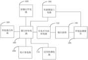
- Figure 1is a schematic diagram of the overall structure of an intelligent power strip provided by an embodiment of the present invention.
- Figure 2is a schematic flow chart of a plant monitoring and control method provided by an embodiment of the present invention.
- Figure 3is a schematic flow chart of regulating various environmental monitoring devices provided by an embodiment of the present invention.
- Figure 4is a schematic flow chart of opening an output socket according to an embodiment of the present invention.
- Figure 5is a schematic flow chart for displaying actual power usage information provided by an embodiment of the present invention.
- Figure 6is a schematic flowchart of a smart communication terminal displaying current environment information provided by an embodiment of the present invention.
- first and secondare used for descriptive purposes only and cannot be understood as indicating or implying relative importance or implicitly indicating the quantity of indicated technical features. Therefore, features defined as “first” and “second” may explicitly or implicitly include one or more of these features.
- “plurality”means two or more than two, unless otherwise explicitly and specifically limited.
- the terms “installation”, “connection”, “connection”, “fixing” and other termsshould be understood in a broad sense.
- itcan be a fixed connection or a removable connection.
- the specific meanings of the above terms in the embodiments of the present inventioncan be understood according to specific circumstances.
- a smart power stripincluding an output socket 100.
- the output socket 100is used to connect to an external power supply.
- the output socket 100is also used to communicate with environmental monitoring.
- the device 200is connected to and supplies power to each of the environmental monitoring devices 200, and the environmental monitoring devices 200 are used to monitor current environmental information.
- the environmental monitoring device 200includes but is not limited to various types of sensors, such as temperature and humidity sensors, dimmers, heating pads, carbon dioxide detection sensors, cameras, etc., and then based on the environmental monitoring device 200, temperature, humidity, Acquisition of information such as carbon dioxide concentration and images can also enable dimming and control of heating pads.
- sensorssuch as temperature and humidity sensors, dimmers, heating pads, carbon dioxide detection sensors, cameras, etc.
- the smart stripalso includes a sensor interface circuit 300 and a communication control circuit 400.
- the sensor interface circuit 300is used to connect the environmental monitoring device 200; the communication control circuit 400 is connected to the sensor interface circuit 300.
- the circuit 400is used to obtain the current environmental information monitored by the environmental monitoring device 200 through the sensor interface circuit 300 .
- the communication control circuit 400is also used for information interaction with the intelligent communication terminal 500 to send the acquired current environment information to the intelligent communication terminal 500 .
- the smart communication terminal 500includes but is not limited to electronic devices such as mobile phones, tablets, and other computers, as long as it can realize information control with the communication control circuit 400 .
- the communication method between the communication control circuit 400 and the smart communication terminal 500includes but is not limited to Bluetooth and WiFi.
- the communication control circuit 400is also configured to, after receiving the environment adjustment information sent by the smart communication terminal 500, generate environment control information according to the environment adjustment information, and send the environment control information through the sensor interface circuit 300. to each environmental monitoring device 200, and the environmental control information is used to regulate each environmental monitoring device 200.
- the environment adjustment informationis specific sensor parameters set by the user on the smart communication terminal 500, such as "increase lighting", and then the communication control circuit 400 generates environment control information according to the environment adjustment information.
- the environment control informationis instruction information corresponding to the environment adjustment information.
- the environment control informationis used to regulate each environment monitoring device 200 and make each of the environment monitoring devices 200 take actions that match the environment adjustment information. .
- the smart power strip of the present inventionalso integrates a sensor interface circuit 300 for connecting the environmental monitoring devices 200, so that each environmental monitoring device 200 can be connected to the sensor interface in a unified manner.
- Circuit 300so that there is no need to use each monitoring device separately for separate monitoring. Instead, the monitoring devices that work individually are connected in series through the intelligent power strip, and the communication control circuit 400 is provided to realize the control of the plant production process.
- the current environmental information monitored in the systemis uniformly and centrally processed, and only one device of the intelligent power strip can be used as the main control device to avoid the high production cost problem caused by each monitoring device in the existing technology having a control device, and Information can be interacted with the smart power strip through a smart communication terminal 500 such as a mobile phone, so that the user can send environment adjustment information through the smart communication terminal 500, and use the smart power strip as an information receiving and transfer point to control all devices related to the smart power strip.
- the monitoring equipment connected to the power stripis regulated and controlled, achieving unified control of the plant growth process.
- the smart power stripit is also possible to use the smart power strip as the main control device for the first time. Since power supply is a necessary part of the plant monitoring process, By combining power supply and control, there is no need to set up a separate power supply, which greatly improves the convenience in the process of plant growth monitoring to meet user needs and improve the efficiency of plant monitoring.
- the sensor interface circuit 300includes a sensor identification terminal, a sensor information receiving terminal and a sensor control terminal.
- the sensor identification end, the sensor information receiving end and the sensor control endare all connected to the communication control circuit 400, and the sensor identification end, the sensor information receiving end and the sensor control end are also used for Connected to the environmental monitoring device 200; after the environmental monitoring device 200 is connected to the sensor identification terminal and the sensor control terminal, the communication control circuit 400 identifies the sensor type of the connected environmental monitoring device 200 according to the sensor identification terminal; The communication control circuit 400 obtains the current environmental information monitored by the connected environmental monitoring device 200 according to the sensor information receiving end; the communication control circuit 400 is also used to send the environmental control information to the environment via the sensor control end. Monitoring device 200.
- the frequency of the environmental monitoring device 200is pre-identified and stored as a specific frequency corresponding to the environmental monitoring device 200, so that each Each of the environmental monitoring devices 200 corresponds to a specific frequency.
- the communication control circuit 400identifies the sensor type of the connected environmental monitoring device 200 according to the sensor identification terminal based on a specific frequency, so that the communication control circuit 400 learns the specific type of the connected environmental monitoring device 200.
- the communication control circuit 400sends the sensor type to the intelligent communication terminal 500
- the corresponding environmental monitoring device 200will be displayed on the intelligent communication terminal 500, thereby realizing visual display of each sensor type.
- the environmental monitoring device 200is used to facilitate users to control each of the environmental monitoring devices 200 individually or uniformly.
- labelscan also be set for each of the environmental monitoring devices 200 in advance, so that each of the environmental monitoring devices 200 corresponds to a specific label.
- the communication control circuit 400identifies the sensor type of the connected environmental monitoring device 200 according to the sensor identification terminal based on a specific tag.
- the smart power stripalso includes an electrical metering circuit 600.
- the electrical metering circuit 600is used to connect to an external power supply.
- the electrical metering circuit 600is also connected to the electrical metering circuit 600.
- the communication control circuit 400is connected to the communication control circuit 400.
- the communication control circuit 400is also used to send a power usage query signal to the power metering circuit 600. After receiving the power usage query signal, the power metering circuit 600 obtains an external power source. The input actual power energy generates actual power usage information, and sends the actual power usage information to the communication control circuit 400;
- the communication control circuit 400After receiving the actual power usage information, the communication control circuit 400 sends the actual power usage information to the smart communication terminal 500 so that the smart communication terminal 500 displays the actual power usage information. In this way, through the setting of the electricity metering circuit 600, the user can be informed of the power consumption information of various environmental monitoring devices 200 in a timely manner, thereby achieving timely regulation.
- the smart stripalso includes a zero-crossing detection circuit 710 and a power supply switch control circuit 720.
- the zero-crossing detection circuit 710is connected to the communication control circuit 400. , and is used to detect the zero-point voltage of the external power supply;
- the power supply switch control circuit 720is connected to both the communication control circuit 400 and the output socket 100, and the communication control circuit 400 is also used to obtain the zero-crossing detection circuit
- a power supply start signalis generated, and the power supply start signal is sent to the power supply switch control circuit 720, so that the power supply switch control circuit 720 controls the output socket according to the power supply start signal.
- 100turns on the output socket 100 at zero voltage.
- the power supply switch control circuit 720includes a plurality of relays (not shown), and each of the relays is connected to a plug point in the output socket 100 .
- a relayis controlled to close, the plug point corresponding to the relay is powered on, and the plug point can be used to power external devices.
- the external power supplyis alternating current, taking the mains power as an example, there is a voltage of 0 during the conversion process of the positive waveform and the negative waveform, which is the zero-point voltage described in this application.
- the relaywhen the output socket 100 is turned on at zero point voltage, specifically the relay is closed at zero point voltage to minimize damage to the relay.
- controlling the closing of the relay when it is energizedis likely to cause sparks and damage to the relay.
- the present inventionbased on the setting of the zero-crossing detection circuit 710, greatly improves the safety in the process of controlling the relay, and also greatly improves the service life of the relay, thereby indirectly improving the performance of the smart power strip. service life.
- the smart power stripalso includes a key start and stop circuit 800.
- the key start and stop circuit 800is connected to the communication control circuit 400 to trigger the key start and stop circuit.
- the communication control circuit 400When the circuit 800 is stopped, the communication control circuit 400 generates a socket control signal after acquiring the socket start and stop signal that triggers the key start and stop circuit 800, and sends the socket control signal to the power supply switch control circuit 720,
- the power supply switch control circuit 720controls the output socket 100 to turn on the output socket 100 at zero voltage according to the socket control signal.
- the key start-stop circuit 800includes a plurality of keys (not shown). By triggering each of the keys, the power supply of the plug point in the output socket 100 is set, thereby improving the efficiency during use. convenience.
- the present inventionalso provides a plant monitoring and control method.
- the plant monitoring and control methodis based on the above-mentioned intelligent inserting.
- the plant monitoring and control methodincludes the following steps: :
- Step S100The communication control circuit 400 identifies the sensor type of the connected environmental monitoring device 200 according to the sensor identification terminal in the sensor interface circuit 300;
- Step S200The communication control circuit 400 obtains the current environmental information monitored by the connected environmental monitoring device 200 according to the sensor information receiving end in the sensor interface circuit 300;
- Step S300The communication control circuit 400 sends the current environment information to the intelligent communication terminal 500, so that the intelligent communication terminal 500 displays the current environment information.
- the plant monitoring and control methodfurther includes the following steps:
- Step S410After the intelligent communication terminal 500 sends the environment adjustment information to the communication control circuit 400, the communication control circuit 400 generates environment control information according to the environment adjustment information;
- Step S420The communication control circuit 400 sends the environmental control information to each environmental monitoring device 200 through the sensor interface circuit 300, and the environmental control information is used to regulate each environmental monitoring device 200.
- the plant monitoring and control method of the present inventionfirst uses the communication control circuit 400 to identify the sensor type of the connected environmental monitoring device 200 according to the sensor identification terminal in the sensor interface circuit 300; then, the communication control circuit 400 identifies the sensor type of the connected environmental monitoring device 200 according to the The sensor information receiving end in the sensor interface circuit 300 obtains the current environmental information monitored by the connected environmental monitoring device 200; then, the communication control circuit 400 sends the current environmental information to the intelligent communication terminal 500, so that the intelligent The communication terminal 500 displays the current environment information, and thus can realize that there is no need to use each monitoring device separately for separate monitoring, but the monitoring devices that work separately are connected in series through the intelligent power strip, and the monitoring devices are connected through the set
- the communication control circuit 400realizes unified and centralized processing of the current environmental information monitored during the plant production process, and realizes the first use of intelligent power strips as the main control device. Since power supply is a necessary part of the plant monitoring process, the power supply and The combination of control eliminates the need to set up a separate power supply, which greatly improves the convenience
- the plant monitoring and control methodfurther includes the following steps:
- Step S510After acquiring the zero-point voltage detected by the zero-crossing detection circuit 710 in the smart strip, the communication control circuit 400 generates a power supply start signal according to the zero-point voltage;
- Step S520The communication control circuit 400 sends the power supply start signal to the power supply switch control circuit 720 in the smart strip;
- Step S530The power supply switch control circuit 720 controls the output socket 100 to open the output socket 100 at zero voltage according to the power supply start signal.
- the power supply switch control circuit 720controls the output socket 100 to open the output socket 100 at zero voltage according to the power supply start signal, thus avoiding the need to control the relay when it is energized in the prior art. Closing can easily cause sparks and damage to the relay, which greatly improves the safety of the relay control process and greatly increases the service life of the relay, thereby indirectly increasing the service life of the smart power strip.
- the plant monitoring and control methodfurther includes the following steps:
- Step S610The communication control circuit 400 sends a power usage query signal to the electricity metering circuit 600 in the smart strip;
- Step S620After receiving the power usage query signal, the electricity metering circuit 600 generates actual power usage information based on the actual power input from the external power source, and sends the actual power usage information to the communication control circuit 400 ;
- Step S630After receiving the actual power usage information, the communication control circuit 400 sends the actual power usage information to the smart communication terminal 500, so that the smart communication terminal 500 displays the actual power usage information. .
- the present inventionfirst uses the electricity metering circuit 600 to generate actual electricity usage information based on the actual electricity input from the external power source after receiving the electricity usage inquiry signal, and sends the actual electricity usage information to the
- the communication control circuit 400then causes the communication control circuit 400 to send the actual power usage information to the smart communication terminal 500 after receiving the actual power usage information, so that the smart communication terminal 500 displays the actual power usage information.
- the actual power usage informationis described to realize on-demand statistics and display of power.
- the present inventionalso provides a plant monitoring and control method.
- the plant monitoring and control methodis based on the above-mentioned intelligent insertion and intelligent control terminal.
- the plant monitoring and control methodincludes the following steps:
- Step S710The communication control circuit 400 identifies the sensor type of the connected environmental monitoring device 200 according to the sensor identification terminal in the sensor interface circuit 300;
- Step S720The communication control circuit 400 obtains the current environmental information monitored by the connected environmental monitoring device 200 according to the sensor information receiving end in the sensor interface circuit 300;
- Step S730The communication control circuit 400 sends the current environment information to the intelligent communication terminal 500;
- Step S740The intelligent communication terminal 500 displays the current environment information.
Landscapes
- Engineering & Computer Science (AREA)
- Physics & Mathematics (AREA)
- General Physics & Mathematics (AREA)
- Microelectronics & Electronic Packaging (AREA)
- Power Engineering (AREA)
- Computer Networks & Wireless Communication (AREA)
- Testing And Monitoring For Control Systems (AREA)
- Selective Calling Equipment (AREA)
- Telephonic Communication Services (AREA)
Abstract
Description
Translated fromChinese本发明属于植物监测控制技术领域,尤其涉及一种智能排插及植物监测控制方法。The invention belongs to the technical field of plant monitoring and control, and in particular relates to an intelligent cutting arrangement and plant monitoring and control method.
目前,市面上对植物生长进行监测时一般采用使用多个监测设备,每个监测设备分别使用一个插座进行供电,其中的监测设备包括多种,如进行光照监测的设备有申请号为CN201810774698.0的发明专利中公开了一种电子装饰物及其花瓶、电子植物以及光照管理系统和光照补充方法,其中所述光照管理系统包括一处理单元;一监测单元,其中所述监测单元用于获取一植物种类信息和一植物光照信息,其中所述监测单元被可通信地连接于所述处理单元;以及一补光单元。Currently, when monitoring plant growth on the market, multiple monitoring devices are generally used. Each monitoring device uses a socket for power supply. There are many kinds of monitoring devices. For example, the device for light monitoring has an application number of CN201810774698.0 The invention patent discloses an electronic decoration and its vase, electronic plants, a light management system and a light supplement method, wherein the light management system includes a processing unit; a monitoring unit, wherein the monitoring unit is used to obtain a Plant type information and a plant lighting information, wherein the monitoring unit is communicatively connected to the processing unit; and a supplementary light unit.
上述专利文件中公开的技术方案虽然能够实现可控制地连接于所述处理单元,并能执行补光策略以为所述植物补充光照,但是其功能单一仅能够对植物生长过程中的的光照进行监测及控制,而若需要对植物进行其他参数的生长参数的监测及调控时,则需要再另行设置其他的监测设备,如对土壤进行监测时,需要结合如申请号为CN201610841709.3的发明专利中公开的用于植物仿生修复污染土壤的智能控制浇水装置,这样在将多种监测设备组合使用时存在极大弊端,首先导致了生产成本的极大提升,其次因各监测设备均分别具有其单独的控制部分,导致用户需要分别根据不同的监测设备进行使用,进而导致了使用过程中的极大不便利,极易产生影响植物监测效率的问题,并且若需要人为调控则需要分别对各监测设备进行调控,因而又导致了调控不便的问题,另外, 在对不同监测设备的供电时,需要使用单独的插座进行供电,而目前市面上的插座功能单一,大多仅具备供电功能而无法与各监测设备进行智能配合使用,故导致在植物监测时排插因功能单一导致影响使用,进而影响植物监测效率的问题。Although the technical solution disclosed in the above patent document can be controllably connected to the processing unit and can implement a light supplement strategy to supplement light for the plant, its single function can only monitor the light during the growth of the plant. and control. If you need to monitor and control other growth parameters of plants, you need to set up other monitoring equipment. For example, when monitoring soil, you need to combine it with the invention patent with application number CN201610841709.3. The disclosed intelligent control watering device for plant bionic remediation of contaminated soil has great disadvantages when using a variety of monitoring equipment in combination. Firstly, it leads to a great increase in production costs. Secondly, because each monitoring equipment has its own characteristics. The separate control part requires users to use different monitoring equipment respectively, which in turn causes great inconvenience during use and can easily cause problems that affect the efficiency of plant monitoring. If human control is required, each monitoring device needs to be controlled separately. The equipment is controlled, which leads to the problem of inconvenient control. In addition, when powering different monitoring equipment, it is necessary to use a separate socket for power supply. However, the sockets on the market currently have a single function, and most of them only have the power supply function and cannot be connected with each other. The monitoring equipment is used in conjunction with intelligence, which leads to the problem that the single function of the inserts during plant monitoring affects the use, thereby affecting the efficiency of plant monitoring.
因此,实有必要设计一种智能排插及植物监测控制方法。Therefore, it is necessary to design an intelligent cutting and plant monitoring and control method.
发明内容Contents of the invention
本发明的目的在于提供一种智能排插及植物监测控制方法,旨在解决现有技术中在植物监测过程中因使用多种监测设备分别监控,而各监测设备分别独立工作导致的成本提升、调控不便、以及市面上的排插功能单一导致不能与各监测设备配合导致满足不了使用需求,进而影响植物监测效率的技术问题。The purpose of the present invention is to provide an intelligent cutting arrangement and plant monitoring and control method, aiming to solve the cost increase and cost increase caused by using multiple monitoring equipment to monitor separately in the process of plant monitoring in the prior art, and each monitoring equipment works independently. Technical problems such as inconvenient control and the single plug-in function on the market cannot cooperate with various monitoring equipment and cannot meet the needs of use, thus affecting the efficiency of plant monitoring.
为实现上述目的,本发明实施例提供一种智能排插,包括输出插座,所述输出插座用于接入外部电源,所述输出插座还用于与环境监测器件连接并为各所述环境监测器件供电,所述环境监测器件用于监测当前环境信息;还包括:In order to achieve the above object, an embodiment of the present invention provides an intelligent power strip, which includes an output socket. The output socket is used to connect to an external power supply. The output socket is also used to connect to an environmental monitoring device and monitor the environment. The device supplies power, and the environmental monitoring device is used to monitor current environmental information; it also includes:
传感器接口电路,所述传感器接口电路用于连接环境监测器件;Sensor interface circuit, the sensor interface circuit is used to connect environmental monitoring devices;
通信控制电路,所述通信控制电路与所述传感器接口电路连接,所述通信控制电路用于经所述传感器接口电路获取所述环境监测器件监测的当前环境信息;A communication control circuit, the communication control circuit is connected to the sensor interface circuit, and the communication control circuit is used to obtain the current environmental information monitored by the environmental monitoring device through the sensor interface circuit;
所述通信控制电路还用于与智能通信终端作信息交互,以将获取的当前环境信息发送至所述智能通信终端;The communication control circuit is also used for information interaction with the intelligent communication terminal to send the acquired current environment information to the intelligent communication terminal;
所述通信控制电路还用于在接收所述智能通信终端发送的环境调整信息后,根据所述环境调整信息生成环境控制信息,并将所述环境控制信息经所述传感器接口电路发送至各环境监测器件,所述环境控制信息用于调控各环境监测器件。The communication control circuit is also configured to generate environmental control information according to the environmental adjustment information after receiving the environmental adjustment information sent by the intelligent communication terminal, and send the environmental control information to each environment through the sensor interface circuit. Monitoring device, the environmental control information is used to regulate each environmental monitoring device.
可选地,所述传感器接口电路包括传感器识别端、传感器信息接收端和传感器控制端;所述传感器识别端、所述传感器信息接收端和所述传感器控制端 均与所述通信控制电路连接,所述传感器识别端、所述传感器信息接收端和所述传感器控制端还均用于与环境监测器件连接;在环境监测器件连接至所述传感器识别端和所述传感器控制端后,所述通信控制电路根据所述传感器识别端识别连接的环境监测器件的传感器类别;所述通信控制电路根据所述传感器信息接收端获取连接的环境监测器件监测的当前环境信息;所述通信控制电路还用于将所述环境控制信息经所述传感器控制端发送至环境监测器件。Optionally, the sensor interface circuit includes a sensor identification end, a sensor information receiving end and a sensor control end; the sensor identification end, the sensor information receiving end and the sensor control end are all connected to the communication control circuit, The sensor identification end, the sensor information receiving end and the sensor control end are also used to connect to an environmental monitoring device; after the environmental monitoring device is connected to the sensor identification end and the sensor control end, the communication The control circuit identifies the sensor type of the connected environmental monitoring device according to the sensor identification terminal; the communication control circuit obtains the current environmental information monitored by the connected environmental monitoring device according to the sensor information receiving terminal; the communication control circuit is also used to The environmental control information is sent to the environmental monitoring device via the sensor control terminal.
可选地,还包括电计量电路,所述电计量电路用于与外部电源连接,所述电计量电路还与所述通信控制电路连接,所述通信控制电路还用于发送电量使用查询信号至所述电计量电路,所述电计量电路在接收所述电量使用查询信号后,根据获取的外部电源输入的实际电能生成实际电量使用信息,并将所述实际电量使用信息发送至所述通信控制电路;Optionally, an electric metering circuit is also included. The electric metering circuit is used to connect to an external power supply. The electric metering circuit is also connected to the communication control circuit. The communication control circuit is also used to send a power usage inquiry signal to The electricity metering circuit, after receiving the electricity usage query signal, generates actual electricity usage information based on the actual electricity input from the external power supply, and sends the actual electricity usage information to the communication control circuit;
所述通信控制电路在接收所述实际电量使用信息后,将所述实际电量使用信息发送至所述智能通信终端,以使所述智能通信终端显示所述实际电量使用信息。After receiving the actual power usage information, the communication control circuit sends the actual power usage information to the smart communication terminal, so that the smart communication terminal displays the actual power usage information.
可选地,还包括过零检测电路和供电开关控制电路,所述过零检测电路与所述通信控制电路连接,并用于检测外部电源的零点电压;所述供电开关控制电路与所述通信控制电路和所述输出插座均连接,所述通信控制电路还用于在获取所述过零检测电路检测到的零点电压后,生成供电开启信号,并将所述供电开启信号发送至所述供电开关控制电路,以使所述供电开关控制电路根据所述供电开启信号控制所述输出插座在零点电压时开启所述输出插座。Optionally, it also includes a zero-crossing detection circuit and a power supply switch control circuit. The zero-crossing detection circuit is connected to the communication control circuit and is used to detect the zero-point voltage of the external power supply; the power supply switch control circuit is connected to the communication control circuit. The circuit and the output socket are both connected, and the communication control circuit is also used to generate a power supply start signal after obtaining the zero point voltage detected by the zero-crossing detection circuit, and send the power supply start signal to the power supply switch. A control circuit, so that the power supply switch control circuit controls the output socket to open the output socket at zero voltage according to the power supply start signal.
可选地,还包括按键启停电路,所述按键启停电路与所述通信控制电路连接,触发所述按键启停电路时,所述通信控制电路在获取触发所述按键启停电路的插座启停信号后,生成插座控制信号,并将所述插座控制信号发送至所述供电开关控制电路,所述供电开关控制电路根据所述插座控制信号控制所述输出插座在零点电压时开启所述输出插座。Optionally, a key start-stop circuit is also included. The key start-stop circuit is connected to the communication control circuit. When the key start-stop circuit is triggered, the communication control circuit obtains the socket that triggers the key start-stop circuit. After the start/stop signal, a socket control signal is generated, and the socket control signal is sent to the power supply switch control circuit. The power supply switch control circuit controls the output socket to turn on the output socket at zero voltage according to the socket control signal. Output socket.
本发明实施例提供的智能排插中的上述一个或多个技术方案至少具有如下 技术效果之一:One or more of the above technical solutions in the smart power strip provided by embodiments of the present invention have at least one of the following technical effects:
较之现有技术中的普通排插,本发明所述的智能排插还集成了用于连接环境监测器件的传感器接口电路,这样使各环境监测器件能够统一连接至所述传感器接口电路,这样无需再分别使用各监测设备进行分别监测,而是通过所述智能排插将各分别单独工作的监测设备进行串联,并通过设置的所述通信控制电路实现将对植物生产过程中监测到的当前环境信息进行统一集中处理,仅需所述智能排插一个设备作为主控的器件即可实现,避免现有技术中各监测设备均具有控制器件导致的生产成本高问题,并可以通过手机等智能通信终端与所述智能排插进行信息交互,使用户可以通过智能通信终端来发送环境调整信息,并以所述智能排插为信息接收及中转点来对所有与智能排插连接的监测设备进行调控,实现了对植物生长过程中的统一调控,此外通过智能排插还实现了首次以智能排插为主控器件,因供电是植物监测过程中的必需部分,故通过将供电和控制结合,无需单独设置供电,极大提升对植物生长监测过程中的便利性,以满足用户的使用需求,提升了植物监测的效率。Compared with ordinary power strips in the prior art, the smart power strip of the present invention also integrates a sensor interface circuit for connecting environmental monitoring devices, so that each environmental monitoring device can be connected to the sensor interface circuit in a unified manner. It is no longer necessary to use each monitoring device separately for separate monitoring. Instead, the monitoring devices that work separately are connected in series through the intelligent power strip, and the current monitoring equipment monitored during the plant production process is realized through the set communication control circuit. Unified and centralized processing of environmental information can be realized by using only one device of the intelligent power strip as the main control device, avoiding the high production cost problem caused by each monitoring device in the existing technology having a control device, and can be realized through smart devices such as mobile phones. The communication terminal interacts with the smart power strip, allowing the user to send environment adjustment information through the smart communication terminal, and uses the smart power strip as an information receiving and transfer point to conduct monitoring on all monitoring equipment connected to the smart power strip. Control, achieving unified control of the plant growth process. In addition, through the smart power strip, it is also possible to use the smart power strip as the main control device for the first time. Since power supply is a necessary part of the plant monitoring process, by combining power supply and control, There is no need to set up a separate power supply, which greatly improves the convenience in the process of plant growth monitoring to meet user needs and improve the efficiency of plant monitoring.
为实现上述目的,本发明实施例还提供一种植物监测控制方法,所述植物监测控制方法基于上述的智能排插进行,所述植物监测控制方法包括以下步骤:In order to achieve the above object, an embodiment of the present invention also provides a plant monitoring and control method. The plant monitoring and control method is based on the above-mentioned intelligent inserting. The plant monitoring and control method includes the following steps:
步骤S100:所述通信控制电路根据所述传感器接口电路中的传感器识别端识别连接的环境监测器件的传感器类别;Step S100: The communication control circuit identifies the sensor type of the connected environmental monitoring device according to the sensor identification terminal in the sensor interface circuit;
步骤S200:所述通信控制电路根据所述传感器接口电路中的传感器信息接收端获取连接的环境监测器件监测的当前环境信息;Step S200: The communication control circuit obtains the current environmental information monitored by the connected environmental monitoring device according to the sensor information receiving end in the sensor interface circuit;
步骤S300:所述通信控制电路将所述当前环境信息发送至智能通信终端,以使所述智能通信终端展示所述当前环境信息。Step S300: The communication control circuit sends the current environment information to the intelligent communication terminal, so that the intelligent communication terminal displays the current environment information.
可选地,所述植物监测控制方法还包括以下步骤:Optionally, the plant monitoring and control method further includes the following steps:
步骤S410:所述智能通信终端发送环境调整信息至所述通信控制电路后,所述通信控制电路根据所述环境调整信息生成环境控制信息;Step S410: After the intelligent communication terminal sends the environment adjustment information to the communication control circuit, the communication control circuit generates environment control information according to the environment adjustment information;
步骤S420:所述通信控制电路将所述环境控制信息经所述传感器接口电路 发送至各环境监测器件,所述环境控制信息用于调控各环境监测器件。Step S420: The communication control circuit sends the environmental control information to each environmental monitoring device via the sensor interface circuit, and the environmental control information is used to regulate each environmental monitoring device.
可选地,所述植物监测控制方法还包括以下步骤:Optionally, the plant monitoring and control method further includes the following steps:
步骤S510:所述通信控制电路在获取过所述智能排插中的过零检测电路检测到的零点电压后,根据所述零点电压生成供电开启信号;Step S510: After acquiring the zero-point voltage detected by the zero-crossing detection circuit in the smart strip, the communication control circuit generates a power supply start signal according to the zero-point voltage;
步骤S520:所述通信控制电路将所述供电开启信号发送至所述智能排插中的供电开关控制电路;Step S520: The communication control circuit sends the power supply start signal to the power supply switch control circuit in the smart strip;
步骤S530:所述供电开关控制电路根据所述供电开启信号控制所述输出插座在零点电压时开启所述输出插座。Step S530: The power supply switch control circuit controls the output socket to open the output socket at zero voltage according to the power supply start signal.
可选地,所述植物监测控制方法还包括以下步骤:Optionally, the plant monitoring and control method further includes the following steps:
步骤S610:所述通信控制电路发送电量使用查询信号至所述智能排插中的电计量电路;Step S610: The communication control circuit sends a power usage query signal to the electricity metering circuit in the smart power strip;
步骤S620:所述电计量电路在接收所述电量使用查询信号后,根据获取的外部电源输入的实际电能生成实际电量使用信息,并将所述实际电量使用信息发送至所述通信控制电路;Step S620: After receiving the power usage query signal, the electricity metering circuit generates actual power usage information based on the actual power input from the external power source, and sends the actual power usage information to the communication control circuit;
步骤S630:所述通信控制电路在接收所述实际电量使用信息后,将所述实际电量使用信息发送至所述智能通信终端,以使所述智能通信终端显示所述实际电量使用信息。Step S630: After receiving the actual power usage information, the communication control circuit sends the actual power usage information to the smart communication terminal, so that the smart communication terminal displays the actual power usage information.
为实现上述目的,本发明实施例还提供一种植物监测控制方法,所述植物监测控制方法基于上述的智能排插和智能控制终端进行,所述植物监测控制方法包括以下步骤:In order to achieve the above object, an embodiment of the present invention also provides a plant monitoring and control method. The plant monitoring and control method is based on the above-mentioned intelligent insertion and intelligent control terminal. The plant monitoring and control method includes the following steps:
步骤S710:所述通信控制电路根据所述传感器接口电路中的传感器识别端识别连接的环境监测器件的传感器类别;Step S710: The communication control circuit identifies the sensor type of the connected environmental monitoring device according to the sensor identification terminal in the sensor interface circuit;
步骤S720:所述通信控制电路根据所述传感器接口电路中的传感器信息接收端获取连接的环境监测器件监测的当前环境信息;Step S720: The communication control circuit obtains the current environmental information monitored by the connected environmental monitoring device according to the sensor information receiving end in the sensor interface circuit;
步骤S730:所述通信控制电路将所述当前环境信息发送至智能通信终端;Step S730: The communication control circuit sends the current environment information to the intelligent communication terminal;
步骤S740:所述智能通信终端展示所述当前环境信息Step S740: The intelligent communication terminal displays the current environment information
本发明实施例提供的植物监测控制方法中的上述一个或多个技术方案至少具有如下技术效果之一:One or more of the above technical solutions in the plant monitoring and control method provided by the embodiments of the present invention have at least one of the following technical effects:
本发明所述植物监测控制方法,先通过所述通信控制电路根据所述传感器接口电路中的传感器识别端识别连接的环境监测器件的传感器类别;然后,所述通信控制电路根据所述传感器接口电路中的传感器信息接收端获取连接的环境监测器件监测的当前环境信息;接着,所述通信控制电路将所述当前环境信息发送至智能通信终端,以使所述智能通信终端展示所述当前环境信息,进而亦能够实现无需再分别使用各监测设备进行分别监测,而是通过所述智能排插将各分别单独工作的监测设备进行串联,并通过设置的所述通信控制电路实现将对植物生产过程中监测到的当前环境信息进行统一集中处理,实现了首次以智能排插为主控器件,因供电是植物监测过程中的必需部分,故通过将供电和控制结合,无需单独设置供电,极大提升对植物生长监测过程中的便利性,以满足用户的使用需求,提升了植物监测的效率。The plant monitoring and control method of the present invention first uses the communication control circuit to identify the sensor type of the connected environmental monitoring device according to the sensor identification terminal in the sensor interface circuit; then, the communication control circuit uses the sensor interface circuit to identify the sensor type of the connected environmental monitoring device. The sensor information receiving end in the device obtains the current environmental information monitored by the connected environmental monitoring device; then, the communication control circuit sends the current environmental information to the intelligent communication terminal, so that the intelligent communication terminal displays the current environmental information , and furthermore, it is also possible to realize that there is no need to use each monitoring device separately for separate monitoring, but to connect the monitoring devices that work separately through the intelligent power strip, and to realize the control of the plant production process through the set communication control circuit. The current environmental information monitored in the plant is processed in a unified and centralized manner, realizing the first use of smart power strips as the main control device. Since power supply is a necessary part of the plant monitoring process, by combining power supply and control, there is no need to set up a separate power supply, which greatly Improve the convenience in the process of plant growth monitoring to meet the needs of users and improve the efficiency of plant monitoring.
为了更清楚地说明本发明实施例中的技术方案,下面将对实施例或现有技术描述中所需要使用的附图作简单地介绍,显而易见地,下面描述中的附图仅仅是本发明的一些实施例,对于本领域普通技术人员来讲,在不付出创造性劳动性的前提下,还可以根据这些附图获得其他的附图。In order to more clearly illustrate the technical solutions in the embodiments of the present invention, the drawings needed to be used in the description of the embodiments or prior art will be briefly introduced below. Obviously, the drawings in the following description are only illustrative of the present invention. For some embodiments, for those of ordinary skill in the art, other drawings can be obtained based on these drawings without exerting creative efforts.
图1为本发明实施例提供的智能排插的整体结构示意图;Figure 1 is a schematic diagram of the overall structure of an intelligent power strip provided by an embodiment of the present invention;
图2为本发明实施例提供的植物监测控制方法的流程示意图;Figure 2 is a schematic flow chart of a plant monitoring and control method provided by an embodiment of the present invention;
图3为本发明实施例提供的调控各环境监测器件的流程示意图;Figure 3 is a schematic flow chart of regulating various environmental monitoring devices provided by an embodiment of the present invention;
图4为本发明实施例提供的开启输出插座的流程示意图;Figure 4 is a schematic flow chart of opening an output socket according to an embodiment of the present invention;
图5为本发明实施例提供的显示实际电量使用信息的流程示意图;Figure 5 is a schematic flow chart for displaying actual power usage information provided by an embodiment of the present invention;
图6为本发明实施例提供的智能通信终端展示当前环境信息的流程示意图。Figure 6 is a schematic flowchart of a smart communication terminal displaying current environment information provided by an embodiment of the present invention.
其中,图中各附图标记:Among them, each figure in the figure is marked with:
100、输出插座;200、环境监测器件;300、传感器接口电路;400、通信控制电路;500、智能通信终端;600、电计量电路;710、过零检测电路;720、供电开关控制电路;800、按键启停电路。100. Output socket; 200. Environmental monitoring device; 300. Sensor interface circuit; 400. Communication control circuit; 500. Intelligent communication terminal; 600. Electricity metering circuit; 710. Zero-crossing detection circuit; 720. Power supply switch control circuit; 800 , button start and stop circuit.
下面详细描述本发明的实施例,所述实施例的示例在附图中示出,其中自始至终相同或类似的标号表示相同或类似的元件或具有相同或类似功能的元件。下面通过参考附图描述的实施例是示例性的,旨在用于解释本发明的实施例,而不能理解为对本发明的限制。Embodiments of the present invention are described in detail below, examples of which are illustrated in the accompanying drawings, wherein the same or similar reference numerals throughout represent the same or similar elements or elements with the same or similar functions. The embodiments described below with reference to the drawings are exemplary and are intended to explain the embodiments of the present invention and are not to be construed as limitations of the present invention.
在本发明实施例的描述中,需要理解的是,术语“长度”、“宽度”、“上”、“下”、“前”、“后”、“左”、“右”、“竖直”、“水平”、“顶”、“底”“内”、“外”等指示的方位或位置关系为基于附图所示的方位或位置关系,仅是为了便于描述本发明实施例和简化描述,而不是指示或暗示所指的装置或元件必须具有特定的方位、以特定的方位构造和操作,因此不能理解为对本发明的限制。In the description of the embodiments of the present invention, it should be understood that the terms "length", "width", "upper", "lower", "front", "back", "left", "right", "vertical" ", "horizontal", "top", "bottom", "inner", "outer", etc. indicate the orientation or positional relationship based on the orientation or positional relationship shown in the drawings, and are only for convenience and simplicity in describing the embodiments of the present invention. The description does not indicate or imply that the device or element referred to must have a specific orientation, be constructed and operate in a specific orientation, and therefore is not to be construed as a limitation of the invention.
此外,术语“第一”、“第二”仅用于描述目的,而不能理解为指示或暗示相对重要性或者隐含指明所指示的技术特征的数量。由此,限定有“第一”、“第二”的特征可以明示或者隐含地包括一个或者更多个该特征。在本发明实施例的描述中,“多个”的含义是两个或两个以上,除非另有明确具体的限定。In addition, the terms “first” and “second” are used for descriptive purposes only and cannot be understood as indicating or implying relative importance or implicitly indicating the quantity of indicated technical features. Therefore, features defined as "first" and "second" may explicitly or implicitly include one or more of these features. In the description of the embodiments of the present invention, "plurality" means two or more than two, unless otherwise explicitly and specifically limited.
在本发明实施例中,除非另有明确的规定和限定,术语“安装”、“相连”、“连接”、“固定”等术语应做广义理解,例如,可以是固定连接,也可以是可拆卸连接,或成一体;可以是机械连接,也可以是电连接;可以是直接相连,也可以通过中间媒介间接相连,可以是两个元件内部的连通或两个元件的相互作用关系。对于本领域的普通技术人员而言,可以根据具体情况理解上述术语在本发明实施例中的具体含义。In the embodiments of the present invention, unless otherwise expressly stipulated and limited, the terms "installation", "connection", "connection", "fixing" and other terms should be understood in a broad sense. For example, it can be a fixed connection or a removable connection. Disassembly and connection, or integration; it can be a mechanical connection or an electrical connection; it can be a direct connection or an indirect connection through an intermediate medium; it can be an internal connection between two elements or an interaction between two elements. For those of ordinary skill in the art, the specific meanings of the above terms in the embodiments of the present invention can be understood according to specific circumstances.
在本发明的一个实施例中,如图1所示,提供一种智能排插,包括输出插 座100,所述输出插座100用于接入外部电源,所述输出插座100还用于与环境监测器件200连接并为各所述环境监测器件200供电,所述环境监测器件200用于监测当前环境信息。In one embodiment of the present invention, as shown in Figure 1, a smart power strip is provided, including an
其中,所述环境监测器件200包括但不限于为各类传感器,如温湿度传感器、调光器、加热垫、二氧化碳检测传感器以及摄像头等,进而基于所述环境监测器件200来实现温度、湿度、二氧化碳浓度以及图像等的信息获取,还能够实现调光以及加热垫的控制。Wherein, the
所述智能排插还包括传感器接口电路300和通信控制电路400,所述传感器接口电路300用于连接环境监测器件200;所述通信控制电路400与所述传感器接口电路300连接,所述通信控制电路400用于经所述传感器接口电路300获取所述环境监测器件200监测的当前环境信息。The smart strip also includes a
所述通信控制电路400还用于与智能通信终端500作信息交互,以将获取的当前环境信息发送至所述智能通信终端500。所述智能通信终端500包括但不限于手机、平板机其他电脑等电子设备,只要能够实现与所述通信控制电路400的信息调控即可。The
进一步地,所述通信控制电路400与所述智能通信终端500的通信方式包括但不限于蓝牙以及WiFi。Further, the communication method between the
所述通信控制电路400还用于在接收所述智能通信终端500发送的环境调整信息后,根据所述环境调整信息生成环境控制信息,并将所述环境控制信息经所述传感器接口电路300发送至各环境监测器件200,所述环境控制信息用于调控各环境监测器件200。其中,所述环境调整信息为用户对所述智能通信终端500上所设置的具体传感器参数,如“增加光照”,接着所述通信控制电路400根据所述环境调整信息生成环境控制信息,所述环境控制信息是与所述环境调整信息对应的指令信息,所述环境控制信息用于调控各环境监测器件200,并使各所述各环境监测器件200作出与所述环境调整信息相匹配的动作。The
较之现有技术中的普通排插,本发明所述的智能排插还集成了用于连接环 境监测器件200的传感器接口电路300,这样使各环境监测器件200能够统一连接至所述传感器接口电路300,这样无需再分别使用各监测设备进行分别监测,而是通过所述智能排插将各分别单独工作的监测设备进行串联,并通过设置的所述通信控制电路400实现将对植物生产过程中监测到的当前环境信息进行统一集中处理,仅需所述智能排插一个设备作为主控的器件即可实现,避免现有技术中各监测设备均具有控制器件导致的生产成本高问题,并可以通过手机等智能通信终端500与所述智能排插进行信息交互,使用户可以通过智能通信终端500来发送环境调整信息,并以所述智能排插为信息接收及中转点来对所有与智能排插连接的监测设备进行调控,实现了对植物生长过程中的统一调控,此外通过智能排插还实现了首次以智能排插为主控器件,因供电是植物监测过程中的必需部分,故通过将供电和控制结合,无需单独设置供电,极大提升对植物生长监测过程中的便利性,以满足用户的使用需求,提升了植物监测的效率。Compared with ordinary power strips in the prior art, the smart power strip of the present invention also integrates a
在本发明的另一个实施例中,所述传感器接口电路300包括传感器识别端、传感器信息接收端和传感器控制端。In another embodiment of the present invention, the
所述传感器识别端、所述传感器信息接收端和所述传感器控制端均与所述通信控制电路400连接,所述传感器识别端、所述传感器信息接收端和所述传感器控制端还均用于与环境监测器件200连接;在环境监测器件200连接至所述传感器识别端和所述传感器控制端后,所述通信控制电路400根据所述传感器识别端识别连接的环境监测器件200的传感器类别;所述通信控制电路400根据所述传感器信息接收端获取连接的环境监测器件200监测的当前环境信息;所述通信控制电路400还用于将所述环境控制信息经所述传感器控制端发送至环境监测器件200。The sensor identification end, the sensor information receiving end and the sensor control end are all connected to the
进一步地,基于所述传感器识别端对各类环境监测器件200进行识别之前,预先识别环境监测器件200所具有的频率,并存储为与该环境监测器件200对应的特定频率,这样使每个所述环境监测器件200均对应具有一个特定的频率。 当各环境监测器件200与所述传感器接口电路300连接时,所述通信控制电路400基于特定的频率根据所述传感器识别端识别连接的环境监测器件200的传感器类别,这样使所述通信控制电路400获知连接的环境监测器件200的具体类别,在所述通信控制电路400将传感器类别发送至智能通信终端500后,在智能通信终端500上将显示对应的环境监测器件200,进而实现可视化显示各所述环境监测器件200,以方便用户对各所述环境监测器件200进行单独或统一调控。Further, before identifying various types of
在本发明另一实施例中,亦可以预先对各所述环境监测器件200设定标签,这样使每个所述环境监测器件200均对应具有一个特定标签。当各环境监测器件200与所述传感器接口电路300连接时,所述通信控制电路400基于特定标签根据所述传感器识别端识别连接的环境监测器件200的传感器类别。In another embodiment of the present invention, labels can also be set for each of the
在本发明的另一个实施例中,如图1所示,所述智能排插还包括电计量电路600,所述电计量电路600用于与外部电源连接,所述电计量电路600还与所述通信控制电路400连接,所述通信控制电路400还用于发送电量使用查询信号至所述电计量电路600,所述电计量电路600在接收所述电量使用查询信号后,根据获取的外部电源输入的实际电能生成实际电量使用信息,并将所述实际电量使用信息发送至所述通信控制电路400;In another embodiment of the present invention, as shown in Figure 1, the smart power strip also includes an
所述通信控制电路400在接收所述实际电量使用信息后,将所述实际电量使用信息发送至所述智能通信终端500,以使所述智能通信终端500显示所述实际电量使用信息。这样通过所述电计量电路600的设置,实现了能够使用户及时获知各类环境监测器件200的耗电信息,进而实现及时调控。After receiving the actual power usage information, the
在本发明的另一个实施例中,如图1所示,所述智能排插还包括过零检测电路710和供电开关控制电路720,所述过零检测电路710与所述通信控制电路400连接,并用于检测外部电源的零点电压;所述供电开关控制电路720与所述通信控制电路400和所述输出插座100均连接,所述通信控制电路400还用于在获取所述过零检测电路710检测到的零点电压后,生成供电开启信号,并将所述供电开启信号发送至所述供电开关控制电路720,以使所述供电开关控制电 路720根据所述供电开启信号控制所述输出插座100在零点电压时开启所述输出插座100。In another embodiment of the present invention, as shown in Figure 1, the smart strip also includes a zero-crossing
本实施例中,所述供电开关控制电路720中包括多个继电器(图未示),每个所述继电器分别与所述输出插座100内的一个插接点连接。当控制一个继电器闭合时,与该继电器对应的插接点上电,进而可以使用该插接点为外部器件供电。In this embodiment, the power supply
进一步地,本实施例中,因外部电源为交流电,以市电为例,其在正向波形和负向波形的转换过程中存在着电压为0的电压,即为本申请中所述零点电压,当在零点电压时开启所述输出插座100,具体为在在零点电压时闭合继电器,以最大程度降低继电器的损伤,较之现有技术中在继电器通电时控制其闭合容易造成产生火花以及对继电器造成损伤的问题,本发明基于所述过零检测电路710的设置,极大提升了对继电器控制过程中的安全性,亦极大提升继电器的使用寿命,进而间接提高所述智能排插的使用寿命。Furthermore, in this embodiment, since the external power supply is alternating current, taking the mains power as an example, there is a voltage of 0 during the conversion process of the positive waveform and the negative waveform, which is the zero-point voltage described in this application. , when the
在本发明的另一个实施例中,如图1所示,所述智能排插还包括按键启停电路800,所述按键启停电路800与所述通信控制电路400连接,触发所述按键启停电路800时,所述通信控制电路400在获取触发所述按键启停电路800的插座启停信号后,生成插座控制信号,并将所述插座控制信号发送至所述供电开关控制电路720,所述供电开关控制电路720根据所述插座控制信号控制所述输出插座100在零点电压时开启所述输出插座100。In another embodiment of the present invention, as shown in Figure 1, the smart power strip also includes a key start and stop
本实施例中,所述按键启停电路800中包括多个按键(图未示),通过触发各所述按键来对输出插座100内的插接点的供电与否设置,进而提升了使用过程中的便利性。In this embodiment, the key start-
在本发明的另一个实施例中,如图2所示,本发明还提供一种植物监测控制方法,所述植物监测控制方法基于上述的智能排插进行,所述植物监测控制方法包括以下步骤:In another embodiment of the present invention, as shown in Figure 2, the present invention also provides a plant monitoring and control method. The plant monitoring and control method is based on the above-mentioned intelligent inserting. The plant monitoring and control method includes the following steps: :
步骤S100:所述通信控制电路400根据所述传感器接口电路300中的传感 器识别端识别连接的环境监测器件200的传感器类别;Step S100: The
步骤S200:所述通信控制电路400根据所述传感器接口电路300中的传感器信息接收端获取连接的环境监测器件200监测的当前环境信息;Step S200: The
步骤S300:所述通信控制电路400将所述当前环境信息发送至智能通信终端500,以使所述智能通信终端500展示所述当前环境信息。Step S300: The
在本发明的另一个实施例中,如图3所示,所述植物监测控制方法还包括以下步骤:In another embodiment of the present invention, as shown in Figure 3, the plant monitoring and control method further includes the following steps:
步骤S410:所述智能通信终端500发送环境调整信息至所述通信控制电路400后,所述通信控制电路400根据所述环境调整信息生成环境控制信息;Step S410: After the
步骤S420:所述通信控制电路400将所述环境控制信息经所述传感器接口电路300发送至各环境监测器件200,所述环境控制信息用于调控各环境监测器件200。Step S420: The
本发明所述植物监测控制方法,先通过所述通信控制电路400根据所述传感器接口电路300中的传感器识别端识别连接的环境监测器件200的传感器类别;然后,所述通信控制电路400根据所述传感器接口电路300中的传感器信息接收端获取连接的环境监测器件200监测的当前环境信息;接着,所述通信控制电路400将所述当前环境信息发送至智能通信终端500,以使所述智能通信终端500展示所述当前环境信息,进而亦能够实现无需再分别使用各监测设备进行分别监测,而是通过所述智能排插将各分别单独工作的监测设备进行串联,并通过设置的所述通信控制电路400实现将对植物生产过程中监测到的当前环境信息进行统一集中处理,实现了首次以智能排插为主控器件,因供电是植物监测过程中的必需部分,故通过将供电和控制结合,无需单独设置供电,极大提升对植物生长监测过程中的便利性,以满足用户的使用需求,提升了植物监测的效率。The plant monitoring and control method of the present invention first uses the
在本发明的另一个实施例中,如图4所示,所述植物监测控制方法还包括以下步骤:In another embodiment of the present invention, as shown in Figure 4, the plant monitoring and control method further includes the following steps:
步骤S510:所述通信控制电路400在获取过所述智能排插中的过零检测电路710检测到的零点电压后,根据所述零点电压生成供电开启信号;Step S510: After acquiring the zero-point voltage detected by the zero-crossing
步骤S520:所述通信控制电路400将所述供电开启信号发送至所述智能排插中的供电开关控制电路720;Step S520: The
步骤S530:所述供电开关控制电路720根据所述供电开启信号控制所述输出插座100在零点电压时开启所述输出插座100。Step S530: The power supply
进一步地,本发明中通过所述供电开关控制电路720根据所述供电开启信号控制所述输出插座100在零点电压时开启所述输出插座100,进而避免了现有技术中在继电器通电时控制其闭合容易造成产生火花以及对继电器造成损伤的问题,极大提升了对继电器控制过程中的安全性,亦极大提升继电器的使用寿命,进而间接提高所述智能排插的使用寿命。Furthermore, in the present invention, the power supply
在本发明的另一个实施例中,如图5所示,所述植物监测控制方法还包括以下步骤:In another embodiment of the present invention, as shown in Figure 5, the plant monitoring and control method further includes the following steps:
步骤S610:所述通信控制电路400发送电量使用查询信号至所述智能排插中的电计量电路600;Step S610: The
步骤S620:所述电计量电路600在接收所述电量使用查询信号后,根据获取的外部电源输入的实际电能生成实际电量使用信息,并将所述实际电量使用信息发送至所述通信控制电路400;Step S620: After receiving the power usage query signal, the
步骤S630:所述通信控制电路400在接收所述实际电量使用信息后,将所述实际电量使用信息发送至所述智能通信终端500,以使所述智能通信终端500显示所述实际电量使用信息。Step S630: After receiving the actual power usage information, the
进一步地,本发明先通过所述电计量电路600在接收所述电量使用查询信号后,根据获取的外部电源输入的实际电能生成实际电量使用信息,并将所述实际电量使用信息发送至所述通信控制电路400,然后,使所述通信控制电路400在接收所述实际电量使用信息后,将所述实际电量使用信息发送至所述智能通信终端500,以使所述智能通信终端500显示所述实际电量使用信息,实现了 对电量的按需统计以及显示。Further, the present invention first uses the
在本发明的另一个实施例中,如图6所示,本发明还提供一种植物监测控制方法,所述植物监测控制方法基于上述的智能排插和智能控制终端进行,所述植物监测控制方法包括以下步骤:In another embodiment of the present invention, as shown in Figure 6, the present invention also provides a plant monitoring and control method. The plant monitoring and control method is based on the above-mentioned intelligent insertion and intelligent control terminal. The plant monitoring and control method The method includes the following steps:
步骤S710:所述通信控制电路400根据所述传感器接口电路300中的传感器识别端识别连接的环境监测器件200的传感器类别;Step S710: The
步骤S720:所述通信控制电路400根据所述传感器接口电路300中的传感器信息接收端获取连接的环境监测器件200监测的当前环境信息;Step S720: The
步骤S730:所述通信控制电路400将所述当前环境信息发送至智能通信终端500;Step S730: The
步骤S740:所述智能通信终端500展示所述当前环境信息。Step S740: The
以上所述仅为本发明的较佳实施例而已,并不用以限制本发明,凡在本发明的精神和原则之内所作的任何修改、等同替换和改进等,均应包含在本发明的保护范围之内。The above are only preferred embodiments of the present invention and are not intended to limit the present invention. Any modifications, equivalent substitutions and improvements made within the spirit and principles of the present invention shall be included in the protection of the present invention. within the range.
Claims (10)
Translated fromChinesePriority Applications (1)
| Application Number | Priority Date | Filing Date | Title |
|---|---|---|---|
| US18/140,355US20240369604A1 (en) | 2022-08-15 | 2022-09-07 | Smart plant monitoring power connector and method for controlling plant monitoring |
Applications Claiming Priority (2)
| Application Number | Priority Date | Filing Date | Title |
|---|---|---|---|
| CN202210975627.3ACN115347426A (en) | 2022-08-15 | 2022-08-15 | Intelligent plugging and plant monitoring and control method |
| CN202210975627.3 | 2022-08-15 |
Publications (1)
| Publication Number | Publication Date |
|---|---|
| WO2024036673A1true WO2024036673A1 (en) | 2024-02-22 |
Family
ID=83951497
Family Applications (1)
| Application Number | Title | Priority Date | Filing Date |
|---|---|---|---|
| PCT/CN2022/117475CeasedWO2024036673A1 (en) | 2022-08-15 | 2022-09-07 | Smart power strip and plant monitoring control method |
Country Status (5)
| Country | Link |
|---|---|
| US (1) | US20240369604A1 (en) |
| EP (1) | EP4325883A1 (en) |
| CN (1) | CN115347426A (en) |
| CA (1) | CA3205516A1 (en) |
| WO (1) | WO2024036673A1 (en) |
Citations (5)
| Publication number | Priority date | Publication date | Assignee | Title |
|---|---|---|---|---|
| US9603316B1 (en)* | 2015-12-07 | 2017-03-28 | Jonathan Mansey | Method and system for monitoring and control of hydroponic growing environment |
| CN206573898U (en)* | 2017-03-07 | 2017-10-20 | 吴国娟 | Plant intelligent conserves terminal |
| CN108134456A (en)* | 2018-01-26 | 2018-06-08 | 江南大学 | A kind of intelligent sharing jack system and control method |
| CN111509955A (en)* | 2019-01-31 | 2020-08-07 | 上海晶丰明源半导体股份有限公司 | Switch control circuit, intelligent switch and switch control method |
| CN114353874A (en)* | 2021-12-31 | 2022-04-15 | 赛诺韦尔科技有限公司 | Greenhouse plant growth monitoring system |
Family Cites Families (16)
| Publication number | Priority date | Publication date | Assignee | Title |
|---|---|---|---|---|
| US8704678B2 (en)* | 2005-03-08 | 2014-04-22 | Jackson Kit Wang | Systems and methods for modifying utility usage |
| US10474213B1 (en)* | 2005-05-30 | 2019-11-12 | Invent.Ly, Llc | Predictive power management in a wireless sensor network using scheduling data |
| WO2011064882A1 (en)* | 2009-11-27 | 2011-06-03 | 株式会社東芝 | Power usage calculation system |
| CN102130575B (en)* | 2010-12-08 | 2013-02-06 | 河南省电力公司许昌供电公司 | AC load start-stop control circuit |
| US8674543B2 (en)* | 2010-12-22 | 2014-03-18 | Lg Electronics Inc. | Electronic device for controlling consumption power and method of operating the same |
| US20120215464A1 (en)* | 2011-02-18 | 2012-08-23 | Utilivista Limited | Energy consumption monitor |
| US8639391B1 (en)* | 2012-11-08 | 2014-01-28 | Green Edge Technologies, Inc. | Systems, devices, and methods for automation and energy management |
| KR101709331B1 (en)* | 2014-11-03 | 2017-02-23 | 주식회사 아이시냅스 | Smart multi-tab device and method for controlling the same |
| CN204389961U (en)* | 2015-02-27 | 2015-06-10 | 晏文临 | A kind of integrated monitoring socket and jack system |
| CN104865853B (en)* | 2015-03-25 | 2017-12-08 | 重庆金瓯科技发展有限责任公司 | A kind of wiring board intelligent control implementation method and its intelligent controlling device and system |
| CN204558819U (en)* | 2015-04-30 | 2015-08-12 | 重庆三加一科技有限公司 | A kind of multifunctional intellectual Energy control socket based on Zigbee module |
| EP3525339B1 (en)* | 2016-10-04 | 2022-07-13 | Shindengen Electric Manufacturing Co., Ltd. | Starter generator device and starting/generating method |
| CN108958095B (en)* | 2017-05-27 | 2021-02-05 | 深圳市海洋王照明工程有限公司 | Intelligent socket, integrated sensor terminal and control system |
| SG11202007477TA (en)* | 2018-02-05 | 2020-09-29 | Nat Univ Singapore | Smart electrical outlet/socket device, system, and associated method |
| CN109976275A (en)* | 2019-03-22 | 2019-07-05 | 深圳市联智物联网科技有限公司 | A kind of environmental data wireless monitor system and its working method for wisdom agricultural |
| CN209963410U (en)* | 2019-07-15 | 2020-01-17 | 深圳市图灵科创产业发展有限公司 | Intelligent socket |
- 2022
- 2022-08-15CNCN202210975627.3Apatent/CN115347426A/enactivePending
- 2022-09-07USUS18/140,355patent/US20240369604A1/enactivePending
- 2022-09-07WOPCT/CN2022/117475patent/WO2024036673A1/ennot_activeCeased
- 2023
- 2023-07-06CACA3205516Apatent/CA3205516A1/enactivePending
- 2023-07-19EPEP23186278.0Apatent/EP4325883A1/enactivePending
Patent Citations (5)
| Publication number | Priority date | Publication date | Assignee | Title |
|---|---|---|---|---|
| US9603316B1 (en)* | 2015-12-07 | 2017-03-28 | Jonathan Mansey | Method and system for monitoring and control of hydroponic growing environment |
| CN206573898U (en)* | 2017-03-07 | 2017-10-20 | 吴国娟 | Plant intelligent conserves terminal |
| CN108134456A (en)* | 2018-01-26 | 2018-06-08 | 江南大学 | A kind of intelligent sharing jack system and control method |
| CN111509955A (en)* | 2019-01-31 | 2020-08-07 | 上海晶丰明源半导体股份有限公司 | Switch control circuit, intelligent switch and switch control method |
| CN114353874A (en)* | 2021-12-31 | 2022-04-15 | 赛诺韦尔科技有限公司 | Greenhouse plant growth monitoring system |
Also Published As
| Publication number | Publication date |
|---|---|
| US20240369604A1 (en) | 2024-11-07 |
| CN115347426A (en) | 2022-11-15 |
| CA3205516A1 (en) | 2024-02-15 |
| EP4325883A1 (en) | 2024-02-21 |
Similar Documents
| Publication | Publication Date | Title |
|---|---|---|
| CN202494912U (en) | Intelligent household energy saving control system | |
| CN1116591C (en) | Electronic balance with wait state | |
| CN106384920A (en) | Fixed smart socket | |
| KR20150109059A (en) | Method for automatic mapping between smart plug and electronic device in a home gateway and apparatus thereof | |
| CN102915021A (en) | Intelligent power supply control system | |
| US20150303693A1 (en) | Power control system and method thereof | |
| CN203287771U (en) | Remote switch device based on power-line carrier communication | |
| TW201346515A (en) | Smart energy-saving control method and system | |
| CN102662386A (en) | Intelligent short message temperature switch with switchable control mode | |
| US20150212532A1 (en) | Control system capable of changing the state of an electrical appliance according to exceptional conditions | |
| US10243373B2 (en) | Power control system, power control device, server device, and method for controlling power control system | |
| WO2024036673A1 (en) | Smart power strip and plant monitoring control method | |
| CN206135100U (en) | A fixed smart socket | |
| CN113271560A (en) | Wireless sensor deployment device | |
| CN206388957U (en) | Multifunctional socket | |
| CN206057861U (en) | A kind of lighting control system | |
| CN112087053A (en) | Equipment power supply control system based on router | |
| CN110021860A (en) | Intelligent wall socket | |
| CN109940561A (en) | A kind of display methods of electric tool and its electricity | |
| CN214544883U (en) | Intelligent control device for simulating indoor illumination | |
| CN116582832A (en) | WIFI-based power supply data acquisition method, system and equipment | |
| CN109831859A (en) | Security protection lighting integrated road lamp system and control method | |
| CN213987214U (en) | Humiture intelligent acquisition and light control system based on single live wire | |
| CN109654670A (en) | Remote air conditioner monitoring method, apparatus and system | |
| CN212620875U (en) | Low-power-consumption outdoor electrical box monitoring system |
Legal Events
| Date | Code | Title | Description |
|---|---|---|---|
| 121 | Ep: the epo has been informed by wipo that ep was designated in this application | Ref document number:22955449 Country of ref document:EP Kind code of ref document:A1 | |
| NENP | Non-entry into the national phase | Ref country code:DE | |
| 122 | Ep: pct application non-entry in european phase | Ref document number:22955449 Country of ref document:EP Kind code of ref document:A1 |