WO2024035180A1 - Vacuum cleaner station and method for controlling vacuum cleaner station - Google Patents
Vacuum cleaner station and method for controlling vacuum cleaner stationDownload PDFInfo
- Publication number
- WO2024035180A1 WO2024035180A1PCT/KR2023/011880KR2023011880WWO2024035180A1WO 2024035180 A1WO2024035180 A1WO 2024035180A1KR 2023011880 WKR2023011880 WKR 2023011880WWO 2024035180 A1WO2024035180 A1WO 2024035180A1
- Authority
- WO
- WIPO (PCT)
- Prior art keywords
- mop
- vacuum cleaner
- management module
- dust
- nozzle
- Prior art date
- Legal status (The legal status is an assumption and is not a legal conclusion. Google has not performed a legal analysis and makes no representation as to the accuracy of the status listed.)
- Ceased
Links
Images


Classifications
- A—HUMAN NECESSITIES
- A47—FURNITURE; DOMESTIC ARTICLES OR APPLIANCES; COFFEE MILLS; SPICE MILLS; SUCTION CLEANERS IN GENERAL
- A47L—DOMESTIC WASHING OR CLEANING; SUCTION CLEANERS IN GENERAL
- A47L11/00—Machines for cleaning floors, carpets, furniture, walls, or wall coverings
- A47L11/40—Parts or details of machines not provided for in groups A47L11/02 - A47L11/38, or not restricted to one of these groups, e.g. handles, arrangements of switches, skirts, buffers, levers
- A—HUMAN NECESSITIES
- A47—FURNITURE; DOMESTIC ARTICLES OR APPLIANCES; COFFEE MILLS; SPICE MILLS; SUCTION CLEANERS IN GENERAL
- A47L—DOMESTIC WASHING OR CLEANING; SUCTION CLEANERS IN GENERAL
- A47L13/00—Implements for cleaning floors, carpets, furniture, walls, or wall coverings
- A47L13/10—Scrubbing; Scouring; Cleaning; Polishing
- A47L13/50—Auxiliary implements
- A47L13/58—Wringers for scouring pads, mops, or the like, combined with buckets
Definitions
- the present inventionrelates to a vacuum cleaner station and a control method of the vacuum cleaner station, and more specifically, to a vacuum cleaner station capable of washing mops and a control method of the vacuum cleaner station.
- a vacuum cleaneris a home appliance that sucks in small trash or dust by sucking air using electricity and fills the dust bin inside the product, and is commonly called a vacuum cleaner.
- vacuum cleanerscan be divided into manual vacuum cleaners, in which the user moves the vacuum cleaner while performing cleaning, and automatic vacuum cleaners, in which the vacuum cleaner performs cleaning while traveling on its own.
- manual cleanerscan be classified into canister-type cleaners, upright cleaners, hand-held cleaners, and stick-type cleaners.
- canister-type vacuum cleanerswere widely used as household cleaners, but recently, hand-held vacuum cleaners and stick vacuum cleaners, which provide improved convenience of use by providing a dust bin and vacuum cleaner body, are increasingly being used.
- a canisty-type vacuum cleanerhas its main body and suction port connected by a rubber hose or pipe, and in some cases, it can be used by inserting a brush into the suction port.
- the Hand Vacuum Cleaneris designed to maximize portability. Although it is light in weight, it is short in length, so the cleaning area you can sit on may be limited. Therefore, it is used to clean localized areas, such as on a desk or sofa, or inside a car.
- Stick vacuum cleanerscan be used while standing, so you can clean without bending down. Therefore, it is advantageous for cleaning a large area while moving. While a handheld vacuum cleaner cleans narrow spaces, a stick vacuum cleaner can clean larger spaces and high places that cannot be reached by hand. Recently, stick vacuum cleaners have been provided in module types, allowing users to actively change the vacuum cleaner type for various purposes.
- Dry cleaningis a method of cleaning by sweeping or sucking dust, and a conventional vacuum cleaner corresponds to this.
- Wet cleaningis a method of cleaning by wiping away dust with a mop.
- a dry-only vacuum cleanerwas used for dry cleaning
- a wet-only vacuum cleanerwas used for wet cleaning.
- a main body, a dry cleaning module and a wet cleaning moduleare provided.
- the dry cleaning moduleis mounted on the main body
- the wet cleaning moduleis mounted on the main body. method has been studied.
- the wet cleaning moduleincludes a water tank that stores water, a heater that heats water to generate steam, and a mop that receives water or steam and wipes the floor.
- water supplied from the water tankis converted into steam through a heater, and the mop is wetted with this steam.
- the mop containing high temperature steamrotates in contact with the surface being cleaned, contaminants on the surface being cleaned can be removed.
- the capacity of the dust bin for storing collected dust in conventional handheld vacuum cleaners and stick vacuum cleanersis small, so users have the inconvenience of having to empty the dust bin every time.
- a vacuum cleaner stationwas developed that is connected to the dust bin of a vacuum cleaner and sucks the dust inside the bin.
- Korean Patent Publication No. 10-2020-0074001discloses a cleaning device including a vacuum cleaner and a docking station.
- the prior patent documentincludes a vacuum cleaner including a dust bin in which foreign substances are collected, and a docking station connected to the dust bin to remove foreign substances collected in the dust bin.
- the dust binis provided to be docked to the docking station, and the docking station It is configured to include a suction device for sucking in foreign substances and internal air in the dust bin docked at the docking station.
- the prior patent documentis configured to include a collection unit that collects foreign substances inside the docking station.
- the present inventionwas created to improve the problems of the conventional vacuum cleaner station and control method of the vacuum cleaner station as described above, and its purpose is to provide a vacuum cleaner station and a control method of the vacuum cleaner station that can wash contaminated mops.
- the purpose of the present inventionis to provide a cleaner station that can wash and dry contaminated mops by supplying water to them, and a method of controlling the cleaner station.
- the mopwhen washing or drying a contaminated mop, the mop can be rotated to increase washing and drying efficiency, and a vacuum cleaner station equipped with a heating unit can supply heated water and hot air to the mop and a control method for the vacuum cleaner station.
- the purposeis to provide.
- the purposeis to provide a cleaner station that can replenish water in the water tank of the mop nozzle or steam wet nozzle and a method of controlling the cleaner station.
- the purposeis to provide a vacuum cleaner station and a control method for the vacuum cleaner station that can improve stability by distinguishing between dry nozzles and wet nozzles.
- the vacuum cleaner stationincludes a housing; a coupling portion disposed in the housing and coupled to at least a portion of the dust bin of the vacuum cleaner; a dust collector accommodated inside the housing, disposed below the coupling portion, and collecting dust inside the dust bin; a dust collection motor accommodated inside the housing, disposed below the dust collection unit, and generating a suction force to suck dust inside the dust bin; and a mop management module mounted on the housing and disposed below the wet nozzle of the cleaner, and washing the mop of the wet nozzle, wherein the mop management module controls the mop when the dust bin is coupled to the housing. It may be provided with at least one washing protrusion that comes into contact with.
- the mop management modulemay include a nozzle detection unit that detects whether the wet nozzle is coupled to the mop management module.
- the vacuum cleaneris equipped with a dry nozzle or a wet nozzle, and the nozzle detection unit can detect which nozzle connected to the vacuum cleaner is the dry nozzle or the wet nozzle.
- the wet nozzlehas a magnet, and when a magnetic field is detected by the nozzle detection unit, the mop management module can enter a washing standby mode.
- the mop management modulemay include a receiving groove accommodating at least a portion of the wet nozzle therein and having the washing protrusion on a bottom surface facing the mop.
- the bottom surface of the receiving groovemay be formed to slope downward toward one side in the first direction.
- the mop management modulemay include a first inclined floor surface and a second inclined floor surface in which the floor surface is inclined downward toward the center of a second direction intersecting the first direction.
- the washing protrusionincludes a pair of rear protrusions extending rearward from the center of the front-back direction of the receiving groove so that the distance between them becomes farther toward the rear; and a pair of front protrusions formed to be symmetrical to the pair of rear protrusions in the anteroposterior direction, wherein the pair of rear protrusions may be arranged to be spaced apart from the pair of front protrusions.
- the mop management modulemay include a washing unit that supplies water to the mop and discharges contaminated water after washing the mop.
- the mop management moduleincludes at least one water supply port formed in the receiving groove and connected to the washing unit, and supplying the water to the mop; at least one drain formed in the receiving groove and connected to the washing unit, and discharging the contaminated water; the drain is formed lower than the water supply port, and at least one drain is provided between the drain and the water supply port.
- a slopemay be formed.
- the laundry unitincludes a water supply box that stores the water and is connected to the water supply port through a water supply pipe.
- a sewage tankin which the contaminated water is stored and connected to the drain through a drain pipe; a water supply pump that flows the water to the water supply port; and a drainage pump that flows the contaminated water into the sewage tank.
- the water supply container and the wastewater containerare detachably coupled to the lower side of the housing, and the water supply container and the sewage container may be arranged to face each other with respect to the center line of the mop management module.
- the mop management modulemay further include a heating unit provided to provide heat to the water supply.
- the mop management modulemay further include a drying unit that supplies air to the mop to dry the mop.
- the mop management moduleincludes at least one air outlet formed in the receiving groove, connected to the drying unit, and supplying the air to the mop, wherein the drying unit includes: a blow fan; and a drying duct connecting the blow fan and the at least one air outlet to provide a flow path through which the air flows.
- the mop management modulemay further include a heating unit provided to provide heat to at least one of the water supply and the air.
- the heating unitincludes a heating member body formed so that a water supply pipe through which the water flows passes through; and a plurality of heat dissipation fins that protrude from the heating member body and are disposed inside the drying duct through which the air flows.
- the mop management modulemay include a water replenishment nozzle that supplies water or heated water to the water tank of the wet nozzle.
- the cleaner stationfurther includes a control unit that drives the dust collection motor, and the control unit rotates the mop while driving the mop management module when a washing start signal is input while the cleaner is coupled to the housing. It can be characterized.
- the vacuum cleaner stationincludes a housing; a coupling portion disposed in the housing, coupled to at least a portion of the dust bin of the vacuum cleaner, and including a charging portion for charging the vacuum cleaner; a dust collector accommodated inside the housing, disposed below the coupling portion, and collecting dust inside the dust bin; a dust collection motor accommodated inside the housing, disposed below the dust collection unit, and generating a suction force to suck dust inside the dust bin; and a mop management module mounted on the housing and disposed below the wet nozzle of the cleaner, and washing the mop of the wet nozzle, wherein the mop management module accommodates at least a portion of the wet nozzle therein. It may be provided with a receiving groove into which the mop comes into contact.
- the vacuum cleaner stationincludes a housing; a coupling portion disposed in the housing, coupled to at least a portion of the dust bin of the vacuum cleaner, and including a charging portion for charging the vacuum cleaner; a dust collector accommodated inside the housing, disposed below the coupling portion, and collecting dust inside the dust bin; a dust collection motor accommodated inside the housing, disposed below the dust collection unit, and generating a suction force to suck dust inside the dust bin; a control unit that controls driving of the dust collection motor; and a mop management module mounted on the housing and disposed below the wet nozzle of the cleaner, and washing the mop of the wet nozzle, wherein the control unit controls the operation of the mop management module when washing the mop.
- the operation of the wet nozzlecan be controlled so that the mop rotates.
- the method of controlling a cleaner stationincludes a standby mode step in which a cleaner is coupled and a mop of the cleaner is in contact with a mop management module; A washing mode step of inputting a washing start signal to the mop management module, driving the mop management module to supply water to the mop of the cleaner, and rotating the mop by driving the wet nozzle of the cleaner. .
- the standby mode stepit is possible to detect whether the nozzle connected to the cleaner is a dry nozzle or a wet nozzle.
- the washing mode stepmay be characterized by supplying heated water to the mop by driving a heating unit provided in the mop management module.
- the control method of the cleaner stationmay further include a dry mode step of supplying air to the mop when a drying start signal is input to the mop management module after the washing mode step is completed after operating for a predetermined time.
- heated airmay be supplied to the mop by driving a heating unit provided in the mop management module.
- the control method of the cleaner stationmay further include a water replenishment step of supplying water or heated water to the water tank of the cleaner after the dry mode step is completed by operating for a predetermined time.
- a contaminated mopcan be washed and dried, thereby reducing the user's inconvenience and relieving the user's discomfort, and washing and drying is possible regardless of the type of nozzle, making it convenient to use. .
- the mopwhen washing or drying a contaminated mop, the mop can be rotated to increase washing and drying efficiency, and a heating unit can be provided to supply heated water and hot air to the mop.
- watercan be added to the water tank of the mop nozzle or steam mop nozzle, which has the effect of reducing user inconvenience.
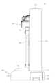
- FIG. 1is a perspective view of a vacuum cleaner system consisting of a vacuum cleaner station and a vacuum cleaner according to an embodiment of the present invention.
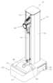
- Figure 2is a side view of Figure 1.
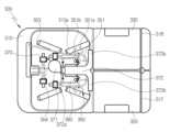
- FIGS 3 to 5are perspective views with the cover in Figure 1 removed.
- Figure 6is a perspective view for explaining a vacuum cleaner according to an embodiment of the present invention.
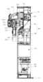
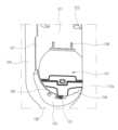
- Figure 7is a cross-sectional view for explaining the interior of a vacuum cleaner according to an embodiment of the present invention.
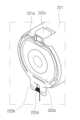
- Figure 8is a diagram for explaining the lower side of the dust bin of a vacuum cleaner according to an embodiment of the present invention.
- Figure 9is a schematic diagram of the configuration of a vacuum cleaner system according to an embodiment of the present invention.
- Figure 10is a diagram for explaining a coupling part in a vacuum cleaner station according to an embodiment of the present invention.
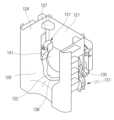
- Figure 11is an exploded perspective view to explain a fixing unit in a vacuum cleaner station according to an embodiment of the present invention.
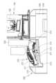
- FIG. 12is a diagram for explaining a cleaner and a cover opening unit in a cleaner station according to an embodiment of the present invention.
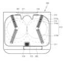
- Figures 13 and 14are diagrams for explaining the arrangement structure of a mop management module according to an embodiment of the present invention.
- Figure 15is a diagram for explaining the water supply flow path of the washing unit of the mop management module according to an embodiment of the present invention.
- Figure 16is a diagram for explaining the arrangement structure of a mop in a receiving groove according to an embodiment of the present invention.
- 17is a plan view of a portion of a mop management module according to an embodiment of the present invention.
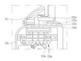
- Figure 18is a diagram showing the interior of a mop management module in which a washing unit and a heating unit are installed according to an embodiment of the present invention.
- Figure 19is a diagram showing the interior of a mop management module in which a washing unit, a heating unit, and a drying unit are installed according to an embodiment of the present invention.
- Figure 20is a diagram for explaining the air flow path of the washing unit of the mop management module according to an embodiment of the present invention.
- Figure 21is a diagram for explaining the structure of a heating unit of a mop management module according to an embodiment of the present invention.
- Figure 22is a diagram showing a state in which a water replenishment nozzle is installed in the mop management module according to an embodiment of the present invention.
- Figures 23 and 24are diagrams showing the combined state of water replenishment nozzles according to the type of nozzle in the mop management module according to an embodiment of the present invention.
- Figure 25is a diagram for explaining the position where a mop is placed according to the type of nozzle in the mop management module according to an embodiment of the present invention.
- Figure 26is a diagram for explaining a nozzle detection unit according to an embodiment of the present invention.
- Figure 27is a block diagram for explaining the control configuration in the vacuum cleaner station according to an embodiment of the present invention.
- Figure 28is a flowchart for explaining a control method of a vacuum cleaner station according to an embodiment of the present invention.
- Figure 1shows a perspective view of a cleaner system consisting of a cleaner station and a cleaner according to an embodiment of the present invention
- Figure 2shows a side view of Figure 1
- Figures 3 to 5show the cover removed from Figure 1.
- a perspective view of one stateis shown
- FIG. 6is a perspective view for explaining the cleaner according to an embodiment of the present invention
- FIG. 7is a cross-sectional view for explaining the interior of the cleaner according to an embodiment of the present invention.
- 8shows a drawing to explain the lower side of the dust bin of the vacuum cleaner according to an embodiment of the present invention
- FIG. 9shows a schematic diagram of the configuration of the vacuum cleaner system according to an embodiment of the present invention.
- FIG. 10shows a drawing for explaining a coupling part in a vacuum cleaner station according to an embodiment of the present invention
- Figure 11shows an exploded perspective view for explaining a fixing unit in a vacuum cleaner station according to an embodiment of the present invention.
- FIG. 12is a diagram illustrating a cleaner and a cover opening unit in a cleaner station according to an embodiment of the present invention.
- the vacuum cleaner system 10may include a vacuum cleaner station 100 and a vacuum cleaner 200.
- Vacuum cleaner system 10may include a cleaner station 100 .
- a cleaner 200may be coupled to the cleaner station 100.
- the main body of the cleaner 200may be coupled to the side of the cleaner station 100.
- the vacuum cleaner station 100can remove dust from the dust bin 220 of the vacuum cleaner 200.
- Figures 6 and 7show drawings for explaining the cleaner in the vacuum cleaner system according to an embodiment of the present invention
- Figure 8shows a drawing showing the lower side of the dust bin of the vacuum cleaner according to an embodiment of the present invention. It is done.
- the vacuum cleaner 200may refer to a vacuum cleaner that is manually operated by a user.
- the vacuum cleaner 200may refer to a handheld vacuum cleaner or a stick vacuum cleaner.
- the vacuum cleaner 200may be mounted on the vacuum cleaner station 100.
- the cleaner 200may be supported by the cleaner station 100.
- the cleaner 200may be coupled to the cleaner station 100.
- the direction of the vacuum cleaner 200can be defined based on when the dust bin 220 and the lower surface of the battery housing 230 are placed on the ground.
- the frontmay refer to the direction in which the suction unit 212 is disposed based on the suction motor 214
- the rearmay refer to the direction in which the handle 216 is disposed relative to the suction motor 214.
- the direction located on the right sidecan be called right
- the direction located on the left sidecan be called left.
- the upper and lower sidesmay be defined along a direction perpendicular to the ground based on when the dust bin 220 and the lower side of the battery housing 230 are placed on the ground.
- the vacuum cleaner 200may include a main body 210.
- the main body 210may include a main body housing 211, a suction unit 212, a dust separation unit 213, a suction motor 214, an air discharge cover 215, a handle 216, and an operating unit 218. there is.
- the main housing 211may have the appearance of the vacuum cleaner 200.
- the main housing 211may provide a space to accommodate the suction motor 214 and a filter (not shown) therein.
- the main housing 211may be configured in a shape similar to a cylinder.
- the suction part 212may protrude outward from the main housing 211.
- the suction part 212may be formed in a cylindrical shape with an open interior.
- the suction unit 212may be combined with the extension pipe 250.
- the suction part 212may provide a flow path through which air containing dust can flow (hereinafter referred to as a 'suction flow path').
- a virtual linecan be formed that penetrates the inside of the suction part 212, which has a cylindrical shape.
- the dust separation unit 213may be in communication with the suction unit 212.
- the dust separation unit 213can separate dust sucked into the dust through the suction unit 212.
- the space inside the dust separator 213may be in communication with the space inside the dust bin 220.
- the dust separation unit 213may include at least one cyclone unit capable of separating dust by cyclonic flow. Additionally, the space inside the dust separation unit 213 may communicate with the suction flow path. Accordingly, the air and dust sucked in through the suction unit 212 flows spirally along the inner peripheral surface of the dust separation unit 213. Therefore, cyclonic flow may occur in the internal space of the dust separation unit 213.
- the dust separation unit 213is in communication with the suction unit 212, and is configured to apply the principle of a dust collector using centrifugal force to separate dust sucked into the interior of the main body 210 through the suction unit 212.
- the dust separation unit 213may further include a secondary cyclone that again separates dust from the air discharged from the cyclone.
- the secondary cyclonemay be located inside the cyclone so that the size of the dust separation unit is minimized.
- the secondary cyclonemay include multiple cyclone bodies arranged in parallel. The air discharged from the cyclone can be divided and passed through multiple cyclone bodies.
- the axis of the cyclonic flow of the secondary cyclonemay also extend in the vertical direction, and the axis of the cyclonic flow of the cyclone and the axis of the cyclonic flow of the secondary cyclone may be coaxial in the vertical direction, This may be collectively referred to as the axis of the cyclonic flow of the dust separation unit 213.
- the suction motor 214may generate suction force to suck air.
- the suction motor 214may be accommodated within the main housing 211.
- the suction motor 214can generate suction force by rotation.
- the suction motor 214may be provided in a similar cylindrical shape.
- a virtual suction motor axiscan be formed by extending the rotation axis of the suction motor 214.
- the air discharge cover 215may be disposed on one side of the main housing 211 in the axial direction.
- the air discharge cover 215may accommodate a filter for filtering air.
- a HEPA filtermay be accommodated in the air discharge cover 215.
- An air outlet 215amay be formed in the air discharge cover 215 to discharge air sucked by the suction force of the suction motor 214.
- a flow guidemay be disposed on the air discharge cover 215.
- the flow guidemay guide the flow of air discharged through the air outlet 215a.
- Handle 216may be held by a user.
- the handle 216may be placed behind the suction motor 214.
- the handle 216may be shaped similarly to a cylinder.
- the handle 216may be formed in the shape of a curved cylinder.
- the handle 216may be disposed at a predetermined angle with the main housing 211, the suction motor 214, or the dust separation unit 213.
- the handle 216includes a grip portion formed in the form of a pillar so that the user can hold it, a first extension portion 217 connected to one end in the longitudinal direction (axial direction) of the grip portion and extending toward the suction motor 214, and a handle 216. It may include a second extension portion connected to the other end in the longitudinal direction (axial direction) of the branch and extending toward the dust bin 220 .
- a virtual gripper penetration linemay be formed that extends along the longitudinal direction of the gripper (axial direction of the column) and passes through the gripper.
- the gripper penetration linemay be a virtual line formed inside the cylindrical handle 216, or may be a virtual line formed parallel to at least a portion of the outer surface (outer peripheral surface) of the gripper.
- the upper surface of the handle 216may form a partial appearance of the upper surface of the vacuum cleaner 200. Through this, it is possible to prevent one component of the vacuum cleaner 200 from coming into contact with the user's arm when the user grips the handle 216.
- the first extension portion 217may extend from the grip portion toward the main body housing 211 or the suction motor 214. At least a portion of the first extension 217 may extend in the horizontal direction.
- the second extensionmay extend from the handle 216 toward the dust bin 220 . At least a portion of the second extension may extend in the horizontal direction.
- the manipulation unit 218may be disposed on the handle 216.
- the manipulation unit 218may be placed on an inclined surface formed in the upper area of the handle 216.
- the usercan input an operation or stop command for the vacuum cleaner 200 through the control panel 218.
- the vacuum cleaner 200may include a dust bin 220.
- the dust bin 220may be in communication with the dust separator 213.
- the dust bin 220can store dust separated from the dust separator 213.
- the dust bin 220may include a dust bin main body 221, a discharge cover 222, a dust bin compression lever 223, and a compressor (not shown).
- the dust bin main body 221may provide a space to store dust separated from the dust separator 213.
- the dust bin body 221may be formed similarly to a cylindrical shape.
- a virtual machineis formed that penetrates the interior (internal space) of the dust container body 221 and extends along the longitudinal direction of the dust container body 221 (meaning the axial direction in the cylindrical dust container body 221).
- a dust bin penetration linecan be formed.
- the lower side of the dust bin body 221may be partially open. Additionally, a lower surface extension portion 221a may be formed on the lower surface of the dust bin main body 221. The lower surface extension portion 221a may be formed to block a portion of the lower surface of the dust bin main body 221.
- the dust bin 220may include an exhaust cover 222.
- the discharge cover 222may be placed on the lower side of the dust bin 220.
- the discharge cover 222may be provided to open and close one end of the dust bin body 221 in the longitudinal direction. Specifically, the discharge cover 222 can selectively open and close the lower part of the dust bin 220 that opens downward.
- the discharge cover 222may include a cover body 222a and a hinge portion 222b.
- the cover body 222amay be formed to block a portion of the lower surface of the dust bin body 221.
- the cover body 222amay rotate downward based on the hinge portion 222b.
- the hinge portion 222bmay be disposed adjacent to the battery housing 230.
- the hinge portion 222bmay be provided with a torsion spring 222d. Accordingly, when the discharge cover 222 is separated from the dust bin main body 221, the cover main body 222a is moved from the dust bin main body 221 to a predetermined axis by the elastic force of the torsion spring 222d. It can be supported in a state rotated by more than an angle.
- the discharge cover 222may be coupled to the dust bin 220 through a hook connection. Meanwhile, the discharge cover 222 can be separated from the dust bin 220 through the coupling lever 222c.
- the coupling lever 222cmay be placed in front of the dust bin. Specifically, the coupling lever 222c may be disposed on the front outer surface of the dust bin 220. When an external force is applied, the coupling lever 222c may elastically deform the hook extending from the cover main body 222a to release the hook coupling between the cover main body 222a and the dust bin main body 221.
- the discharge cover 222When the discharge cover 222 is closed, the lower side of the dust bin 220 may be blocked (sealed) by the discharge cover 222 and the lower surface extension portion 221a.
- the dust bin 220may include a dust bin compression lever 223 (see FIG. 6).
- the dust bin compression lever 223may be disposed outside the dust bin 220 or the dust separator 213.
- the dust bin compression lever 223may be arranged to move up and down outside the dust bin 220 or the dust separator 213.
- the dust bin compression lever 223may be connected to a compressor (not shown).
- the compressor (not shown)When the dust bin compression lever 223 moves downward due to an external force, the compressor (not shown) may also move downward. Through this, user convenience can be provided.
- the compressor (not shown) and the dust bin compression lever 223can be returned to their original positions by an elastic member (not shown). Specifically, when the external force applied to the dust bin compression lever 223 is removed, the elastic member may move the dust bin compression lever 223 and the compressor (not shown) upward.
- a compressor(not shown) may be placed inside the dust bin body 221.
- the compressorcan move in the internal space of the dust bin main body 221. Specifically, the compressor can move up and down within the dust bin main body 221. Through this, the compressor can compress the dust in the dust bin body 221 downward.
- the compressormoves from the upper part of the dust bin 220 to the lower part to remove foreign matter such as remaining dust in the dust bin 220. can be removed.
- the suction power of the vacuum cleanercan be improved by preventing residual dust from remaining in the dust bin 220.
- bad odors generated by the residuecan be removed.
- the vacuum cleaner 200may include a battery housing 230.
- a battery 240may be accommodated in the battery housing 230.
- the battery housing 230may be placed below the handle 216.
- the battery housing 230may have a hexahedral shape with an open bottom. The rear of the battery housing 230 may be connected to the handle 216.
- the battery housing 230may include a receiving portion that opens downward.
- the battery 240can be attached and detached through the receiving portion of the battery housing 230.
- the vacuum cleaner 200may include a battery 240.
- the battery 240may be detachably coupled to the vacuum cleaner 200.
- the battery 240may be detachably coupled to the battery housing 230.
- the battery 240may be inserted into the battery housing 230 from below. With this configuration, the portability of the vacuum cleaner 200 can be improved.
- the battery 240may be provided integrally within the battery housing 230. At this time, the lower surface of the battery 240 is not exposed to the outside.
- the battery 240may supply power to the suction motor 214 of the vacuum cleaner 200.
- the battery 240may be placed below the handle 216.
- the battery 240may be placed behind the dust bin 220.
- the lower surface of the battery 240may be exposed to the outside. Since the battery 240 may be placed on the floor when the vacuum cleaner 200 is placed on the floor, the battery 240 can be immediately separated from the battery housing 230. Additionally, since the lower surface of the battery 240 is exposed to the outside and comes into direct contact with the external air of the battery 240, the cooling performance of the battery 240 can be improved.
- the structure for attaching and detaching the battery 240 and the battery housing 230can be reduced, so the overall size of the vacuum cleaner 200 can be reduced. Yes, and lightweighting is possible.
- the vacuum cleaner 200may include an extension pipe 250.
- the extension pipe 250may be in communication with the dry nozzle 260.
- the extension pipe 250may be in communication with the main body 210.
- the extension tube 250may communicate with the suction part 212 of the main body 210.
- the extension tube 250is formed in a long cylindrical shape and may be provided to allow length adjustment.
- the main body 210may be connected to the extension tube 250.
- the main body 210may be connected to the dry nozzle 260, the mop nozzle 280, and the steam mop nozzle 270 through the extension pipe 250.
- the main body 210may generate suction force through the suction motor 214 and provide suction force to the dry nozzle 260, the mop nozzle 280, and the steam mop nozzle 270 through the extension pipe 250.
- the vacuum cleaner 200may have a dry nozzle 260 coupled to the extension pipe 250 of the vacuum cleaner 200 for dry cleaning, and wet nozzles 270 and 280 may be coupled to the extension pipe 250 of the vacuum cleaner 200 for wet cleaning. ) can be combined.
- Wet nozzles 270 and 280may include a mop nozzle 280 and a steam mop nozzle 270. That is, the cleaner 200 may include a dry nozzle 260, a mop nozzle 280, and a steam mop nozzle 270, as shown in FIGS. 3 to 5 .
- Wet nozzles 270 and 280may be connected to the extension tube 250, as shown in FIGS. 3 and 4.
- the mop nozzle 280may operate by receiving power from the vacuum cleaner 200. Alternatively, the mop nozzle 280 may operate by receiving power from a separate battery provided in the mop nozzle 280. The mop nozzle 280 may be configured to wet clean the surface being cleaned using a rotating mop 281.
- the steam mop nozzle 270may operate by receiving power from the cleaner 200. Alternatively, the steam mop nozzle 270 may operate by receiving power from a separate battery provided in the steam mop nozzle 270.
- the steam mop nozzle 270may be configured to wet clean the surface being cleaned using a rotating mop 281. This steam mop nozzle 270 can provide heated moisture to the steam mop 271.
- the steam mop nozzle 270 and the mop nozzle 280may have the same structure in that they wet clean the surface being cleaned, and the steam mop nozzle 270 is additionally configured with a heater that generates steam in the mop nozzle 280.
- the volumecan be relatively large compared to the mop nozzle 280.
- the dry nozzle 260may be in communication with the extension pipe 250, as shown in FIG. 5 . Accordingly, external air and dust may flow into the main body 210 of the vacuum cleaner 200 through the dry nozzle 260 and the extension pipe 250 by the suction force generated in the main body 210 of the vacuum cleaner 200.
- the vacuum cleaner 200when the vacuum cleaner 200 is coupled to the vacuum cleaner station 100 when the dry nozzle 260 is connected, the vacuum cleaner 200 can be mounted on the vacuum cleaner station 100 without extending the extension pipe 250. Accordingly, as shown in FIG. 5, the extension pipe connection portion 261 to which the extension pipe 250 of the dry nozzle 260 is connected is arranged to be spaced upward from the mop management module 300. Additionally, the vacuum cleaner 200 to which the dry nozzle 260 is connected is coupled to and mounted on the vacuum cleaner station 100, and can be charged or empty the dust bin 220.
- the vacuum cleaner 200when the vacuum cleaner 200 is coupled to the vacuum cleaner station 100 when the wet nozzles 270 and 280 are connected, the vacuum cleaner 200 can be mounted on the vacuum cleaner station 100 with the extension tube 250 extended.
- the extension tube 250may be extended by one stage.
- the extension tube connectors 274 and 283 to which the extension tubes 250 of the wet nozzles 270 and 280 are connectedare arranged to be spaced upward from the mop management module 300.
- the vacuum cleaner 200 to which the wet nozzles 270 and 280 are connectedis coupled to and mounted on the vacuum cleaner station 100, and can be charged or empty the dust bin 220.
- Wet nozzles 270 and 280include at least one mop 271 and 281.
- the mop 281may be connected to the lower side of the mop nozzle 280 and is a component that cleans the surface being cleaned by rubbing it, including moisture.
- the mop 281may be arranged as a pair on the left and right sides of the mop nozzle 280.
- the mop 281may have a rotation axis disposed perpendicular to the surface to be cleaned, and rotates around the axis to scrub and clean the surface to be cleaned.
- two or more mops 281can be rotated in different directions to facilitate user operation.
- the mop 281 on the rightmay rotate clockwise (CW)
- the mop 281 on the leftmay rotate counterclockwise (CCW).
- the pair of mops 281can push the mop nozzle 280 forward due to friction, and the user can more easily move the vacuum cleaner 200 forward.
- the wet nozzles 270 and 280may be equipped with water tanks 272 and 282.
- the water tank 282may be detachably installed on the upper surface of the mop nozzle 280.
- the water tank 282is a component that supplies water to the mop 281.
- water stored in the water tank 282may be supplied after flowing into the heater and changing phase into steam.
- This water tank 282can be periodically separated from the mop nozzle 280 to replenish water. Additionally, in the present invention, water can be replenished without separating the water tank 282 from the mop nozzle 280, which will be described in detail later.
- dust in the dust bin 220 of the cleaner 200may be collected in the dust collection unit 170 of the cleaner station 100 by gravity and the suction force of the dust collection motor 191. Through this, dust in the dust bin 220 can be removed without any separate manipulation by the user, thereby providing user convenience. Additionally, the user can eliminate the inconvenience of having to empty the dust bin 220 every time. Additionally, when the dust bin 220 is emptied, dust can be prevented from scattering.
- the cleaner 200may be coupled to the side of the housing 110.
- the main body 210 of the vacuum cleaner 200may be mounted on the coupling portion 120.
- the dust bin 220 and the battery housing 230 of the vacuum cleaner 200may be arranged to face the coupling surface 121, and the outer peripheral surface of the dust bin body 221 may be coupled to the dust bin guide surface 122.
- the suction unit 212may be coupled to the suction guide surface 126 of the coupling unit 120.
- the central axis of the dust bin 220may be arranged in a direction parallel to the ground, and the extension pipe 250 may be arranged along a direction perpendicular to the ground.
- the vacuum cleaner station 100 of the present inventionwill be described as follows.
- a cleaner 200may be placed in the cleaner station 100.
- a vacuum cleaner 200may be coupled to the side of the vacuum cleaner station 100.
- the main body of the cleaner 200may be coupled to the side of the cleaner station 100.
- the vacuum cleaner station 100can remove dust from the dust bin 220 of the vacuum cleaner 200.
- the cleaner station 100may include a housing 110 .
- the housing 110may form the exterior of the vacuum cleaner station 100.
- the housing 110may be formed in a pillar shape including at least one outer wall surface 112.
- the housing 110may be formed in a shape similar to a square pillar.
- the housing 110may be formed with a space capable of accommodating a dust collection unit 170 that stores dust therein and a dust suction module 190 that generates a flow force to collect dust into the dust collection unit 170.
- the housing 110may include a lower side 111, an outer wall surface 112, and an upper surface 113.
- the lower side 111may support the lower side of the dust suction module 190 in the direction of gravity. That is, the lower side 111 may support the lower side of the dust collection motor 191 of the dust suction module 190.
- the lower side 111may be disposed toward the ground, which is the surface to be cleaned.
- the lower side 111may be arranged parallel to the ground or inclined at a predetermined angle with the ground. This configuration has the advantage of stably supporting the dust collection motor 191 and balancing the overall weight even when the vacuum cleaner 200 is combined.
- the lower side 111may be coupled to or fixed to the mop management module 300, which will be described later, and may be supported and in contact with the upper surface of the mop management module 300.
- the outer wall surface 112may refer to a surface formed along the direction of gravity and may refer to a surface connected to the lower side 111.
- the outer wall surface 112may mean a surface connected perpendicularly to the lower side 111.
- the outer wall surface 112may be disposed to be inclined at a predetermined angle with the lower side surface 111.
- the outer wall surface 112may include at least one surface.
- the outer wall surface 112may include a first outer wall surface 112a, a second outer wall surface 112b, a third outer wall surface 112c, and a fourth outer wall surface 112d.
- the first outer wall surface 112amay be disposed in the front of the cleaner station 100.
- the frontmay mean the surface on which the vacuum cleaner 200 is exposed when the vacuum cleaner 200 is coupled to the vacuum cleaner station 100. Accordingly, the first outer wall surface 112a may form the front exterior of the cleaner station 100.
- the directionis defined as follows.
- the directioncan be defined while the vacuum cleaner 200 is mounted on the vacuum cleaner station 100.
- the direction in which the vacuum cleaner 200 is exposed to the outside of the vacuum cleaner station 100may be called the front.
- the direction in which the suction motor 214 of the vacuum cleaner 200 is disposedmay be referred to as the front. Additionally, the direction opposite to the direction in which the suction motor 214 is disposed in the vacuum cleaner station 100 may be called the rear.
- the surface facing the front based on the internal space of the housing 110may be called the rear of the vacuum cleaner station 100. Accordingly, the rear may refer to the direction in which the second outer wall surface 112b is formed.
- the left sidewhen looking at the front based on the internal space of the housing 110, the left side can be called the left side, and the right side can be called the right side. Accordingly, the left side may refer to the direction in which the third outer wall surface 112c is formed, and the right side may refer to the direction in which the fourth outer wall surface 112d is formed.
- the first outer wall surface 112amay be formed in a flat shape, or may be formed entirely in a curved shape, or may include a curved surface in a portion.
- the first outer wall surface 112amay have an appearance corresponding to the shape of the vacuum cleaner 200.
- the coupling portion 120may be disposed on the first outer wall surface 112a.
- a structure for mounting various types of dry nozzles 260 used in the vacuum cleaner 200may be added to the first outer wall surface 112a.
- the second outer wall surface 112bmay be a surface facing the first outer wall surface 112a. That is, the second outer wall surface 112b may be disposed at the rear of the cleaner station 100. Here, the rear may be a surface facing the surface to which the cleaner 200 or the second cleaner is coupled. Accordingly, the second outer wall surface 112b may form the exterior of the rear of the vacuum cleaner station 100.
- the second outer wall surface 112bmay be formed in a planar shape.
- the vacuum cleaner station 100can be brought into close contact with an indoor wall and the vacuum cleaner station 100 can be stably supported.
- a structure for mounting various types of dry nozzles 260 used in the vacuum cleaner 200may be added to the second outer wall surface 112b.
- the third outer wall surface 112c and the fourth outer wall surface 112dmay refer to surfaces connecting the first outer wall surface 112a and the second outer wall surface 112b.
- the third outer wall surface 112cmay be disposed on the left side of the station 100, and the fourth outer wall surface 112d may be disposed on the right side of the vacuum cleaner station 100.
- the third outer wall surface 112cmay be disposed on the right side of the cleaner station 100, and the fourth outer wall surface 112d may be disposed on the left side of the cleaner station 100.
- the third outer wall surface 112c or the fourth outer wall surface 112dmay be formed in a flat shape, or may be formed entirely in a curved shape, or may be formed with a curved surface in a portion.
- a structure for mounting various types of dry nozzles 260 used in the vacuum cleaner 200may be added to the third outer wall surface 112c or the fourth outer wall surface 112d.
- the upper surface 113may form the upper exterior of the cleaner station 100. That is, the upper surface 113 may refer to a surface disposed at the uppermost part of the vacuum cleaner station 100 in the direction of gravity and exposed to the outside.
- the direction of the cleaner station 100may be defined based on the state in which the lower side 111 of the cleaner station 100 is installed on the ground.
- the upper and lower sidesmay refer to the upper and lower sides, respectively, along the direction of gravity (direction perpendicular to the ground) when the vacuum cleaner station 100 is installed on the ground.
- the upper surface 113can be arranged not only parallel to the ground, but also inclined at a predetermined angle with the ground.
- a display unit 410may be disposed on the upper surface 113.
- the display unit 410may display the status of the vacuum cleaner station 100 and the vacuum cleaner 200, and may also display information such as cleaning progress and a map of the cleaning area.
- the upper surface 113may be provided to be separable from the outer wall surface 112. At this time, when the upper surface 113 is separated, the battery 240 separated from the cleaner 200 can be accommodated in the internal space surrounded by the outer wall surface 112, and a terminal for charging the separated battery 240 is provided. (not shown) may be provided.
- the housing 110may form a space passage portion 180 therein through which air introduced from the dust bin 220 can flow.
- the coupling portion 120 of the vacuum cleaner station 100 of the present inventionwill be described with reference to FIGS. 9 to 11 as follows.
- the cleaner station 100may include a coupling portion 120 to which the cleaner 200 is coupled.
- the coupling portion 120is disposed on the first outer wall surface 112a, and the main body 210, dust bin 220, and battery housing 230 of the vacuum cleaner 200 can be coupled to each other.
- the coupling portion 120may include a coupling surface 121.
- the coupling surface 121may be disposed on the side of the housing 110.
- the coupling surface 121may refer to a surface formed in a concave groove shape on the first outer wall surface 112a toward the inside of the vacuum cleaner station 100.
- the coupling surface 121may mean a surface formed by forming a step with the first outer wall surface 112a.
- a vacuum cleaner 200can be accommodated in the coupling surface 121.
- the coupling surface 121may face the lower surface of the dust bin 220 and the battery housing 230 of the vacuum cleaner 200.
- the lower sidemay refer to the side facing the ground when the user uses the vacuum cleaner 200 or places it on the ground.
- the angle formed by the coupling surface 121 with the groundmay be a right angle.
- the coupling surface 121may be disposed inclined at a predetermined angle with the ground. Through this, when the cleaner 200 is coupled to the coupling surface 121, the cleaner station 100 can be stably supported.
- a dust passage hole 121amay be formed on the coupling surface 121 to allow air from outside the housing 110 to flow into the interior.
- the dust passage hole 121amay be formed in a hole shape corresponding to the shape of the dust container 220 to allow dust in the dust container 220 to flow into the dust collection unit 170.
- the dust passage hole 121amay be formed to correspond to the shape of the discharge cover 222 of the dust bin 220.
- the dust passage hole 121amay be formed to communicate with the flow path portion 180, which will be described later.
- the coupling portion 120may include a dust bin guide surface 122.
- the dust bin guide surface 122may be disposed on the first outer wall surface 112a.
- the dust bin guide surface 122may be connected to the first outer wall surface 112a. Additionally, the dust bin guide surface 122 may be connected to the coupling surface 121.
- the dust bin guide surface 122may be formed in a shape corresponding to the outer surface of the dust bin 220.
- the front outer surface of the dust bin 220may be coupled to the dust bin guide surface 122.
- a protrusion movement hole 122amay be formed in the dust bin guide surface 122, and a push protrusion 151, which will be described later, may be moved linearly along the protrusion movement hole 122a.
- a gear box 155that accommodates gears of the cover opening unit 150, which will be described later, may be provided on the lower side of the dust bin guide surface 122 in the direction of gravity.
- a guide space 122b through which the push protrusion 151 can movemay be formed between the dust bin guide surface 122 and the upper surface of the gear box 155. And the guide space 122b may be in communication with the first flow path 181 through the bypass hole 122c.
- the protrusion movement hole 122a, the guide space 122b, the bypass hole 122c, and the first flow path 181may form one bypass flow path.
- the coupling portion 120may include a guide protrusion 123.
- Guide protrusion 123may be disposed on the coupling surface 121.
- the guide protrusion 123may protrude from the coupling surface 121 toward the front of the cleaner station 100.
- Two guide protrusions 123may be arranged spaced apart from each other. The distance between the two guide protrusions 123 spaced apart from each other may correspond to the width of the battery housing 230 of the vacuum cleaner 200. Through this, the convenience of coupling the vacuum cleaner 200 to the coupling surface 121 can be provided.
- the coupling portion 120may include a side wall 124.
- the side wall 124may refer to a wall disposed on both sides of the coupling surface 121 and may be connected perpendicularly to the coupling surface 121.
- the side wall 124may be connected to the first outer wall surface 112a. Additionally, the side wall 124 may form a surface connected to the dust bin guide surface 122. Through this, the vacuum cleaner 200 can be stably accommodated.
- the coupling unit 120may include a coupling sensor 125.
- the coupling sensor 125can detect whether the cleaner 200 is coupled to the coupling unit 120.
- Combination sensor 125may also include a contact sensor.
- the combination sensor 125may include a micro switch.
- the coupling sensor 125may be placed on the guide protrusion 123. Therefore, when the battery housing 230 or battery 240 of the vacuum cleaner 200 is coupled between the pair of guide protrusions 123, it comes into contact with the coupling sensor 125, and the coupling sensor 125 is connected to the vacuum cleaner 200. ) can be detected to be combined.
- the combination sensor 125may also include a non-contact sensor.
- the combination sensor 125may include an infrared sensor (IR sensor).
- the coupling sensor 125may be placed on the side wall 124. Therefore, when the dust bin 220 or main body 210 of the vacuum cleaner 200 passes the side wall 124 and reaches the coupling surface 121, the coupling sensor 125 detects the presence of the dust bin 220 or main body 210. It can be detected.
- the coupling sensor 125may face the dust bin 220 or the battery housing 230 of the vacuum cleaner 200.
- the coupling sensor 125may be a means of determining whether power is applied to the battery 240 of the vacuum cleaner 200 and whether the vacuum cleaner 200 is coupled.
- the coupling portion 120may include a suction guide surface 126.
- the suction guide surface 126may be disposed on the first outer wall surface 112a.
- the suction guide surface 126may be connected to the dust bin guide surface 122.
- the suction unit 212may be coupled to the suction guide surface 126.
- the shape of the suction part guide surface 126may be formed to correspond to the shape of the suction part 212.
- the coupling portion 120may further include a fixing member entrance hole 127.
- the fixing member access hole 127may be formed in the form of a long hole along the side wall 124 to allow the fixing member 131 to enter and exit.
- the dust bin guide surface 122, the guide protrusion 123, and the suction guide surface 126can be stably placed on the coupling portion 120. Through this, it is possible to provide convenience in that the dust bin 220 and the battery housing 230 of the vacuum cleaner 200 are coupled to the coupling surface 121.
- the vacuum cleaner station 100 of the present inventionmay include a fixing unit 130.
- the fixing unit 130may be disposed on the side wall 124.
- the fixing unit 130can fix the vacuum cleaner 200 coupled to the dust bin guide surface 122.
- the fixing unit 130may fix the dust bin 220 of the vacuum cleaner 200 coupled to the dust bin guide surface 122.
- the fixing unit 130may include a fixing member 131 that fixes the dust bin 220 and the battery housing 230 of the vacuum cleaner 200, and a fixing motor (not shown) that drives the fixing member 131. there is. Additionally, the fixing unit 130 may further include a fixing unit link 135 that transmits the power of the fixing unit motor to the fixing member 131.
- the fixing member 131is disposed on the side wall 124 of the coupling portion 120 and may be provided to move back and forth on the side wall 124 to fix the dust bin 220. Specifically, the fixing member 131 may be accommodated inside the fixing member access hole 127.
- the fixing member 131may be disposed on both sides of the coupling portion 120, respectively. As an example, two fixing members 131 may be arranged symmetrically in pairs in the left and right directions on the coupling surface 121.
- the fixing part motormay provide power to move the fixing member 131.
- the fixing unit link 135can convert the rotational force of the fixing unit motor into reciprocating movement of the fixing member 131.
- the fixing member 131moves toward the dust bin 220 and can fix the dust bin 220. Additionally, the fixing member 131 that fixed the dust bin 220 may be moved away from the dust bin 220 when the application of external force is released.
- the fixing member 131may be moved by the power of the fixing part motor 133. That is, the fixing member 131 can be moved by receiving power through at least one fixing part motor 133 and a fixing part link 135 connected to the fixing part motor 133.
- the fixing member 131may be moved by the suction force of the dust collection motor 191. That is, the fixing member 131 can be moved by receiving suction force through a passage such as a hose.
- the fixing unit 130may further include a fixing sealer 136.
- the fixed sealer 136may be disposed on the dust bin guide surface 122 to airtight the dust bin 220 when the vacuum cleaner 200 is coupled thereto. With this configuration, when the dust bin 220 of the vacuum cleaner 200 is coupled, the fixed sealer 136 can be pressed by the self-weight of the vacuum cleaner 200, and the dust bin 220 and the dust bin guide surface 122 are sealed. It can be.
- the suction power of the vacuum cleanercan be improved by preventing residual dust from remaining in the dust bin 220.
- bad odors generated by the residuecan be removed.
- the door unit 140 of the present inventionwill be described with reference to FIGS. 8 and 9 as follows.
- the vacuum cleaner station 100 of the present inventionmay include a door unit 140.
- the door unit 140may be configured to open and close the dust passage hole 121a.
- the door unit 140may include a door 141, a door motor 142, and a door arm.
- the door 141is hinged to the coupling surface 121 and can open and close the dust passage hole 121a. Based on the state of the door 141 blocking the dust passage hole 121a, a hinge portion may be disposed on the upper side of the door 141, and a door arm may be coupled to the lower side of the door 141.
- This door 141may be formed in a shape that can airtight the dust passage hole 121a.
- the outer surface exposed to the outside of the cleaner station 100 at the door 141is formed to have a diameter corresponding to the diameter of the dust passing hole 121a
- the inner surface disposed inside the cleaner station 100is formed to have a diameter larger than the diameter of the dust passage hole 121a.
- the door 141may be in contact with the discharge cover 222. And, as the door 141 rotates, the discharge cover 222 may rotate in conjunction with the door 141.
- the door motor 142may provide power to rotate the door 141.
- the door motor 142may rotate the door arm in the forward or reverse direction.
- the forward directionmay mean the direction in which the door arm pulls the door 141. Accordingly, when the door arm rotates in the forward direction, the dust passing hole 121a may be opened.
- the reverse directionmay mean the direction in which the door arm pushes the door 141. Accordingly, when the door arm rotates in the reverse direction, the dust passing hole 121a may be at least partially closed.
- the forward directionmay be the opposite direction to the reverse direction.
- the door armconnects the door 141 and the door motor 142, and can open and close the door 141 using power generated from the door motor 142.
- the door unit 140may further include a door opening/closing detection unit 144.
- the door opening/closing detection unit 144may be provided inside the housing 110 and can detect whether the door 141 is in an open state.
- the door opening/closing detection unit 144may be disposed at both ends of the rotational movement area of the door arm. As another example, the door opening/closing detection unit 144 may be disposed at both ends of the movement area of the door 141, respectively.
- the door opening/closing detection unit 144may include a contact sensor.
- the door opening/closing detection unit 144may include a micro switch.
- the door opening/closing detection unit 144may also include a non-contact sensor.
- the door opening/closing detection unit 144may include an infrared sensor (IR sensor).
- the door unit 140can selectively open and close at least a portion of the engaging surface 121 to communicate with the outside of the first outer wall surface 112a and the flow path portion 180 and/or the dust collection portion 170. there is.
- the door unit 140may be opened when the discharge cover 222 of the vacuum cleaner 200 is opened. Additionally, when the door unit 140 is closed, the discharge cover 222 of the vacuum cleaner 200 may be closed in conjunction with it.
- the door motor 142rotates the door 141 to couple the discharge cover 222 to the dust bin main body 221. Specifically, the door motor 142 rotates the door 141 by rotating the door 141, and the rotating door 141 can push the discharge cover 222 toward the dust bin body 221.
- the cover opening unit 150will be described as follows.
- the vacuum cleaner station 100 of the present inventionmay include a cover opening unit 150.
- the cover opening unit 150is disposed in the coupling portion 120 and can open the discharge cover 222 of the cleaner 200.
- the cover opening unit 150may include a push protrusion 151, a cover opening motor 152, cover opening gears 153a and 153b, a support plate, and a gear box 155.
- the push protrusion 151may move to press the coupling lever 222c when the vacuum cleaner 200 is coupled.
- the push protrusion 151may be disposed on the dust bin guide surface 122. Specifically, a protrusion movement hole may be formed in the dust bin guide surface 122, and the push protrusion 151 may pass through the protrusion movement hole and be exposed to the outside.
- the push protrusion 151may be placed at a position where the coupling lever 222c can be pressed when the vacuum cleaner 200 is coupled. That is, the coupling lever 222c may be disposed on the protrusion movement hole. Additionally, the coupling lever 222c may be disposed on the moving area of the push protrusion 151.
- the push protrusion 151may make a linear reciprocating motion to press the coupling lever 222c. Specifically, the push protrusion 151 may be coupled to the gear box 155 to guide linear movement. The push protrusion 151 is coupled to the cover opening gears 153a and 153b and can be moved together by the movement of the cover opening gears 153a and 153b.
- the cover opening motor 152may provide power to move the push protrusion 151. Specifically, the cover opening motor 152 may rotate the motor shaft (not shown) in the forward or reverse direction.
- the forward directionmay mean the direction in which the push protrusion 151 presses the coupling lever 222c.
- the reverse directionmay refer to the direction in which the push protrusion 151 pressed against the coupling lever 222c is returned to its original position. The forward direction may be the opposite direction to the reverse direction.
- the cover opening gears 153a and 153bare coupled to the cover opening motor 152 and can move the push protrusion 151 using the power of the cover opening motor 152.
- the cover opening gears 153a and 153bmay be accommodated inside the gear box 155.
- the drive gear 153a of the cover opening gears 153a and 153bmay be coupled to the motor shaft of the cover opening motor 152 to receive power.
- the driven gear 153b of the cover opening gears 153a and 153bmay be coupled to the push protrusion 151 to move the push protrusion 151.
- the driven gear 153bmay be provided in the form of a rack gear, meshed with the driving gear 153a, and receive power from the driving gear 153a.
- the discharge cover 222may be provided with a torsion spring 222d. Due to the elastic force of the torsion spring 222d, the discharge cover 222 can be rotated more than a predetermined angle and supported in the rotated position. Accordingly, the discharge cover 222 can be opened, and the inside of the dust container 220 can be communicated with the dust passing hole 121a.
- the gear box 155is provided inside the housing 110 and disposed below the coupling portion 120 in the direction of gravity, and the cover opening gear 153 can be accommodated therein.
- the gear box 155may be provided with a cover open detection unit 155f.
- the cover open detection unit 155fmay include a contact sensor.
- the cover open detection unit 155fmay include a micro switch.
- the cover open detection unit 155fmay also include a non-contact sensor.
- the cover open detection unit 155fmay include an infrared sensor (IR sensor).
- At least one cover open detection unit 155fmay be disposed on the inner or outer surface of the gear box 155.
- one cover open detection unit 155fmay be disposed on the inner surface of the gear box 155. At this time, the cover open detection unit 155f can detect that the push protrusion 151 is in the initial position.
- two cover open detection units 155fmay be disposed on the outer surface of the gear box 155. At this time, the cover opening detection unit 155f can detect the initial position of the push protrusion 151 and the cover opening position.
- the usercan open the dust bin 220 without separately opening the discharge cover 222 of the vacuum cleaner 200 by using the cover opening unit 150, thereby improving convenience.
- the cleaner station 100may include a dust collection unit 170.
- the dust collection unit 170may be disposed inside the housing 110.
- the dust collection unit 170may be disposed below the coupling unit 120 in the direction of gravity.
- the dust collection unit 170may refer to a dust bag that collects dust sucked from the inside of the dust bin 220 of the vacuum cleaner 200 by the dust collection motor 191.
- the dust collection unit 170may be detachably coupled to the housing 110.
- the dust collection unit 170can be separated from the housing 110 and discarded, and a new dust collection unit 170 can be coupled to the housing 110. That is, the dust collection unit 170 may be defined as a consumable part.
- the dust bagmay be provided so that when suction force is generated by the dust collection motor 191, the volume increases and dust is accommodated inside.
- the dust bagmay be made of a material that allows air to pass through but does not allow foreign substances such as dust to pass through.
- the dust bagmay be made of a non-woven material and may have a hexahedral shape when expanded in volume.
- the dust bagmay include roll vinyl (not shown). With this configuration, when the dust bag is sealed or bonded, dust or odor collected inside the dust bag can be prevented from leaking out of the dust bag. At this time, the dust bag can be mounted on the housing 110 through a dust bag cartridge (not shown). If necessary, the dust bag can be replaced via a dust bag cartridge.
- the cleaner station 100may include a flow path portion 180.
- the flow path portion 180may connect the dust bin 220 and the dust collection unit 170 of the vacuum cleaner 200.
- the flow path portion 180may be disposed on the rear side of the coupling surface 121.
- the flow path 180may refer to the space between the dust bin 220 and the dust collection unit 170 of the vacuum cleaner 200.
- the flow path portion 180may be a space formed rearward from the dust passing hole 121a, or may be a flow path through which dust and air can flow by being bent downward from the dust passing hole 121a.
- the first flow path 181may be arranged substantially parallel to the axis of the suction motor 214 or a virtual penetration line passing through the dust bin 220. At this time, the axis of the suction motor 214 or the through line of the dust bin 220 may pass through the first flow path 181.
- the second flow path 182may be formed at a predetermined angle with the first flow path 181.
- the first flow path 181 and the second flow path 182may be formed at a right angle.
- the second flow path 182extends downward from the first flow path 181 and is in communication with the first flow path 181 to guide air passing through the first flow path 181 to the dust collection unit 170. .
- the second flow path 182may be arranged in a direction parallel to the axis of the dust collection motor 191. With this configuration, a decrease in the suction power of the dust collection motor 191 in the first flow path 181 and the second flow path 182 can be minimized.
- Dust in the dust bin 220 of the vacuum cleaner 200may move to the dust collection unit 170 through the flow path portion 180.
- the cleaner station 100may include a dust suction module 190.
- the dust suction module 190may include a dust collection motor 191, a first filter (not shown), and a second filter (not shown).
- the dust collection motor 191may be disposed below the dust collection unit 170.
- the dust collection motor 191may generate suction force in the flow path portion 180. Through this, the dust collection motor 191 can provide suction power to suck dust in the dust bin 220 of the vacuum cleaner 200.
- the dust collection motor 191can generate suction force by rotation.
- the dust collection motor 191may be formed in a shape similar to a cylinder.
- a virtual dust collection motor axis line extending from the rotation axis of the dust collection motor 191can be formed.
- the first filter(not shown) may be disposed between the dust collection unit 170 and the dust collection motor 191.
- the first filtermay be a pre-filter.
- a second filtermay be disposed between the dust collection motor 191 and the outer wall surface 112.
- the second filtermay be a HEPA filter.
- the cleaner station 100may further include a charging unit 128.
- the charging unitmay be disposed in the coupling unit 120.
- the charging unit 128may be electrically connected to the cleaner 200 coupled to the coupling unit 120.
- the charging unit 128may supply power to the battery of the vacuum cleaner 200 coupled to the coupling unit 120.
- the cleaner station 100may further include a side door (not shown).
- a side doormay be placed in the housing 110.
- the side doorcan selectively expose the dust collection unit 170 to the outside. Through this, the user can easily remove the dust collection unit 170 from the cleaner station 100.
- FIGS 13 and 14show drawings to explain the arrangement structure of the mop management module according to an embodiment of the present invention.
- the vacuum cleaner station 100 of the present inventionmay include a mop management module 300 that washes the mop 281 of the mop nozzle 280.
- the mop management module 300is provided to wash the contaminated mop 281, and when the vacuum cleaner 200 is coupled to the vacuum cleaner station 100, the mop management module 300 automatically detects that the vacuum cleaner 200 is coupled to the vacuum cleaner station 100. It can work as Alternatively, the mop management module 300 may enter a washing standby mode when the vacuum cleaner 200 is coupled to the vacuum cleaner station 100 and operate according to the signal when a washing start signal is input. This washing start signal may be generated when the user operates a separate operation button.
- the mop management module 300is disposed adjacent to the mop 281 of the mop nozzle 280 for washing the mop 281, and at least a portion of the mop management module 300 may be in contact with the mop 281.
- the mop management module 300may be disposed on the lower side of the cleaner 200 and may be provided with a receiving groove 311 in which at least a portion of the mop nozzle 280 is accommodated.
- the mop management module 300may be placed below the cleaner 200 and the cleaner station 100.
- the rear of the mop management module 300may be placed below the vacuum cleaner station 100 and the front of the mop management module 300 may be placed below the cleaner 200 .
- This mop management module 300includes a management module body 310.
- the management module body 310is provided to accommodate parts for washing the mop 281, and may be provided in a box shape, for example.
- the management module body 310may be mounted on the lower side of the housing 110 and placed below the mop nozzle 280 of the vacuum cleaner 200.
- the management module body 310may be formed to have a width in the left and right directions larger than the width in the left and right directions of the mop nozzle 280 and may be formed to protrude toward the front of the cleaner station 100. Additionally, the management module body 310 may be formed to protrude further forward from the cleaner station 100 than the cleaner 200 when coupled to the cleaner station 100. That is, when the vacuum cleaner 200 is coupled to the vacuum cleaner station 100, the front end of the management module body 310 may be located forward of the front end of the mop nozzle 280.
- the management module main body 310may have a housing 110 mounted on the rear of the upper side and a receiving groove 311 on the front of the upper side.
- the receiving groove 311may be formed by recessing a portion of the front of the upper side of the management module body 310, and the bottom surface 312, which is the inner surface, may be disposed to face the mop 281.
- the receiving groove 311provides a space in which the mop 281 can be washed, and is formed to open upward so that at least a portion of the mop nozzle 280 can easily enter the inside of the receiving groove 311.
- a cover 340may be detachably coupled to the management module body 310.
- the cover 340is arranged to cover at least a portion of the receiving groove 311 and minimizes the water or air supplied to the receiving groove 311 from being blown out to the outside.
- This cover 340is detachably coupled to the circumference of the receiving groove 311 on the upper side of the management module main body 310, or a part of the cover 340 is inserted into the receiving groove 311 and the management module main body 310. It can be detachably coupled to (310).
- the cover 340may be made of a transparent material and may be provided with an extension tube insertion portion 341 so that a portion connected to the extension tube 250 of the mop nozzle 280 can be inserted.
- Figure 15shows a diagram for explaining the water supply flow path of the washing unit of the mop management module according to an embodiment of the present invention
- Figure 16illustrates the arrangement structure of the mop within the receiving groove according to an embodiment of the present invention.
- a drawing for thisis shown
- Figure 17shows a plan view of a part of the mop management module according to an embodiment of the present invention
- Figure 18shows a mop management module installed with a washing unit and a heating unit according to an embodiment of the present invention.
- a drawing showing the interior of the moduleis shown.
- the receiving groove 311is formed by recessing a portion of the upper side of the management module body 310 to accommodate the mop nozzle 280, and the inner bottom surface 312 is disposed to face the mop 281.
- the bottom surface 312may be formed to cause friction with the mop 281 when the mop 281 rotates and separate dust from the mop 281.
- the bottom surface 312has at least one washing protrusion 313 that contacts and supports the mop 281, and the bottom surface 312 may be arranged to be spaced apart from the mop 281.
- the mop 281is placed on the washing protrusion 313.
- the washing protrusion 313is in contact with the mop 281, and when the mop 281 rotates in this state, the washing protrusion 313 rubs against the mop 281 and scratches the mop 281.
- At least one washing protrusion 313is formed to protrude from the bottom surface 312 so as to evenly rub against the rotating mop 281, that is, to easily separate dust from the mop 281.
- a plurality of washing protrusions 313may be formed to be long along a direction intersecting the rotational direction of the mop 281 and may be provided to be radially spaced apart from each other on the bottom surface 312.
- the washing protrusion 313has one end disposed adjacent to the center of the mop 281 and is formed to be long along the radial direction of the mop 281 so as to rub against as much of the area as possible of the rotating mop 281. You can. That is, the other end of the washing protrusion 313 may be disposed adjacent to the outer circumference of the mop 281.
- washing protrusions 313may be configured as a pair or multiple pairs so as to each contact the two mops 281. These washing protrusions 313 may be composed of a pair of rear protrusions 313b and a pair of front protrusions 313a.
- a pair of rear protrusions 313b and a pair of front protrusions 313amay be disposed rear and front, respectively, in the receiving groove 311, and may be formed long along the front-to-back direction. Additionally, the pair of rear protrusions 313b and the pair of front protrusions 313a may be inclined toward the rear or front.
- the pair of rear protrusions 313bmay be formed to extend rearward from the middle of the front-back direction of the receiving groove 311.
- the pair of rear protrusions 313bmay be formed so that the distance between them becomes farther toward the rear.
- the front end of this pair of rear protrusions 313bmay be disposed adjacent to the center of the mop 281 and the rear end may be disposed adjacent to the outer periphery of the mop 281.
- the pair of rear protrusions 313bmay be provided with a drain 315 that supplies water to the mop 281.
- the pair of front protrusions 313amay be formed to be symmetrical to the pair of rear protrusions 313b in the receiving groove 311 in the front-to-back direction. That is, the pair of front protrusions 313a and the pair of rear protrusions 313b may be formed to be line symmetrical with respect to imaginary lines in the left and right directions. At this time, this virtual line is an virtual line passing through the middle between a pair of front protrusions 313a and a pair of rear protrusions 313b.
- the pair of front protrusions 313amay be formed to extend forward from the center of the front-back direction of the receiving groove 311, and may be formed so that the distance between them becomes farther forward.
- the rear end of this pair of front protrusions 313amay be disposed adjacent to the center of the mop 281, and the rear end may be disposed adjacent to the outer periphery of the mop 281.
- This pair of rear protrusions 313bmay be spaced apart from the pair of front protrusions 313a with a gap a. That is, the front end of the rear protrusion 313b and the rear end of the front protrusion 313a are spaced apart by the gap a.
- This gap (a)can provide a space through which air supplied to the receiving groove 311 can flow.
- the pair of rear protrusions 313bmay be formed so that the height protruding from the bottom surface 312 increases as they move forward, and the pair of front protrusions 313a may be formed in a height protruding from the bottom surface 312 as they move backward. can be formed to increase.
- the protruding end surface of the washing protrusion 313may be formed not as a flat surface but as a curved surface.
- the washing protrusion 313may be provided with at least one friction protrusion 313c that protrudes from the protruding end surface.
- the friction protrusions 313cmay be formed long along the longitudinal direction of the washing protrusions 313, and when provided in plural, may be provided to be spaced apart in the width direction. Accordingly, when the mop 281 rotates while in contact with the washing protrusion 313, it rubs against the plurality of friction protrusions 313c and the washing dust can be easily separated.
- At least one water supply port 314may be formed in each of the pair of rear protrusions 313b.
- the water inlet 314may be formed on the protruding end surface of the rear protrusion 313b, and may be formed between the friction protrusions 313c as shown in the drawing. Accordingly, the water supply port 314 is sealed by the mop 281, thereby preventing water supply from being smoothly provided. That is, the water supply port 314 and the mop 281 are spaced apart by the protruding height of the friction protrusion 313c, and water can be smoothly supplied through the spaced space. Additionally, water discharged through the water supply port 314 may be continuously supplied to the mop 281 while flowing along the space formed between the friction protrusions 313c.
- the water discharged through the water inlet 314flows along the protruding end surface of the rear protrusion 313b, between the friction protrusions 313c, and the space formed by the mop 281 and continues to be in contact with the mop 281. comes into contact with. Accordingly, the mop 281 can quickly receive water supply and washing efficiency is increased.
- auxiliary water supply port 314amay be additionally formed on each of the pair of rear protrusions 313b.
- the auxiliary water supply port 314amay also be formed on the protruding end surface of the washing protrusion 313 between the friction protrusions 313c, and may be spaced apart along the longitudinal direction of the water supply port 314 and the washing protrusion 313. can be formed.
- the auxiliary water supply port 314amay be disposed closer to the drain port 315 than the water supply port 314. That is, the distance between the auxiliary water supply port 314a and the drain port 315 may be shorter than the distance between the water supply port 314 and the drain port 315.
- watermay be supplied to the mop 281 through at least one of the water supply port 314 and the auxiliary water supply port 314a.
- watercan be supplied to the mop 281 through the water supply port 314.
- watermay be supplied to the steam mop 271 through the auxiliary water supply port 314a.
- the drain 315can be directly supplied to the mop 281 as it is formed on the rear protrusion 313b, and is supplied toward the lower side of the mop 281 and is ejected to the outside when supplied to the mop management module 300. It can prevent splashing around.
- the pair of rear protrusions 313bmay have auxiliary friction protrusions 313d formed between the friction protrusions 313c.
- the auxiliary friction protrusion 313dis formed to allow the water supply port 314 and the auxiliary water supply port 314a to be spaced apart from the mop 281. Accordingly, the auxiliary friction protrusion 313d may be formed to protrude from the protruding end surfaces of the pair of rear protrusions 313b and may be formed at a position adjacent to the water supply port 314 and the auxiliary water supply port 314a.
- the bottom surface 312may be inclined or may include a curved surface to guide the water supplied inside the receiving groove 311 to the drain 315.
- the receiving groove 311is provided with at least one water supply port 314 connected to a washing unit 350 to be described later to supply water to the mop 281. Additionally, the receiving groove 311 has at least one drain 315 connected to the washing unit 350 to discharge contaminated water.
- the water supply port 314may be provided as two to supply water to each of the two mops 281, and the drain port 315 may be provided as one, but is not limited thereto.
- This drain hole 315is formed lower than the water supply hole 314.
- the drain hole 315is formed at the bottom of the bottom surface 312 of the receiving groove 311.
- at least one inclined surfaceis formed between the drain hole 315 and the water supply hole 314 to guide water or contaminated water to the drain hole 315.
- the bottom surface 312may be formed to slope downward toward one side in the first direction.
- the first directionmay be a front-to-back direction, and one side of the first direction may be forward. Accordingly, the bottom surface 312 is formed to become lower as it moves forward.
- This floor surface 312may be composed of a first inclined floor surface 312a and a second inclined floor surface 312b.
- the floor surface 312may be comprised of a first inclined floor surface 312a, a second inclined floor surface 312b, and a central floor surface 312c.
- a drain 315may be formed at the front of the central bottom surface 312c.
- the first inclined floor surface 312a and the second inclined floor surface 312bmay be formed to slope downward toward the center of the second direction intersecting the first direction.
- the second directionmay be a left-right direction
- the floor surface 312may be composed of a first inclined floor surface 312a and a second inclined floor surface 312b and may be formed to slope downward toward the center in the left-right direction.
- the first inclined floor surface 312a and the second inclined floor surface 312bare also formed to slope downward toward the front.
- central floor surface 312cis provided between the first inclined floor surface 312a and the second inclined floor surface 312b to connect the first inclined floor surface 312a and the second inclined floor surface 312b. is formed
- This central bottom surface 312cis formed to slope downward toward the front, and the drain 315 may be disposed at the frontmost part of the central floor surface 312c.
- the water or contaminated water discharged from the water supply port 314flows to the drain port 315 along the first inclined bottom surface 312a, the second inclined bottom surface 312b, and the central bottom surface 312c. .
- the mop management module 300may include a washing unit 350 that supplies water to the mop 281.
- the washing unit 350may be placed inside the management module main body 310, supply water to the mop 281, and discharge contaminated water from washing the mop 281.
- the laundry unit 350may include a water supply box 320 and a water supply pipe 351 for supplying water, and may include a sewage tank 330 and a drain pipe 354 for recovering contaminated water.
- control unit 400drives the washing unit 350 and rotates the mop 281.
- the operation of the nozzle 280can be controlled.
- the water supply box 320stores water.
- the water supply box 320may be detachably coupled to the management module main body 310.
- the management module main body 310may be provided with a water tank insertion groove 317 into which the water tank 320 is inserted and detachably coupled.
- the water supply pipe 351is disposed between the water supply box 320 and the water supply port 314, and one end may be connected to the water supply box 320 and the other end may be connected to the water supply port 314.
- the water supply pipe 351may be additionally connected to the auxiliary water supply port 314a. That is, the other end of the water supply pipe 351 may be branched and connected to the first branch pipe 351a and the second branch pipe 351b, and the ends of the first branch pipe 351a and the second branch pipe 351b may be Each may be connected to the water supply port 314 and the auxiliary water supply port 314a.
- a water supply valve 351cmay be disposed at the intersection point of the water supply pipe 351, the first branch pipe 351a, and the second branch pipe 351b.
- the water supply valve 351cconnects the water supply pipe 351 only to the first branch pipe 351a, connects the water supply pipe 351 only to the second branch pipe 351b, or connects the water supply pipe 351 to the first branch pipe (351b). It can be operated to connect to 351a) and the second branch pipe 351b.
- the sewage tank 330may store contaminated water.
- the waste bin 330may be detachably coupled to the management module main body 310.
- the management module main body 310may be provided with a wastewater container insertion groove 318 into which the wastewater container 330 is inserted and detachably coupled.
- the water supply box 320 and the wastewater container 330may be placed below the vacuum cleaner station 100. Additionally, the water tank 320 and the wastewater tank 330 may be arranged to face each other based on the center line of the management module main body 310.
- the center linemay be a line connecting the centers of the left and right directions of the management module main body 310, and refers to a line arranged along the front and back directions.
- the water supply box 320 and the wastewater box 330may be arranged to be pulled out through the right and left sides of the management module main body 310, respectively.
- the water tank insertion groove 317may be formed by being recessed on the right side of the management module body 310, and the waste tank insertion groove 318 may be formed by being recessed on the left side of the management module body 310.
- the drain pipe 354is disposed between the sewage tank 330 and the drain 315, and one end may be connected to the sewage tank 330 and the other end may be connected to the drain 315.
- the laundry unit 350may further include a water supply pump 352 and a drainage pump 355.
- the water supply pump 352is provided to flow water from the water supply box 320 to the water supply port 314, and may be placed in the water supply pipe 351 or the water supply box 320.
- the drainage pump 355is provided to flow contaminated water discharged through the water supply port 314 into the sewage tank 330, and may be disposed in the drain pipe 354.
- the water 15shows the flow path of the water supply, and the water is stored in the water supply box 320 and flows through the water supply pipe 351 by the water supply pump 352. Additionally, water may be supplied to the mop 281 through the water supply port 314 or the auxiliary water supply port 314a. In addition, contaminated water discharged from the mop 281 or water not supplied to the mop 281 flows into the drain 315 along the bottom surface 312. Contaminated water or water is discharged through the drain hole 315a formed in the drain 315, flows through the drain pipe 354 by the drain pump 355, and is recovered in the sewage tank 330.
- the drain 315may be formed by a portion of the central bottom surface 312c being depressed.
- the drain 315may be provided with a drain filter 315b. That is, a drain filter 315b may be installed in the drain 315 to filter out foreign substances from contaminated water.
- a drain hole 315a to which the drain pipe 354 is connectedmay be formed on the bottom of the drain hole 315. Additionally, the bottom surface of the drain hole 315 may be formed to slope downward toward the drain hole 315a.
- the mop management module 300may further include a heating unit 360 to provide heated water to the mop 281.
- Heating unit 360is provided to provide heat to the water supply.
- the heating unit 360may be disposed adjacent to a portion of the water supply pipe 351.
- a flow path through which water flowsis formed inside the heating unit 360, and a water supply pipe 351 is connected between the heating unit 360 and the water supply box 320 and between the heating unit 360 and the water inlet 314. It can be arranged to do so.
- the heating unit 360operates, its own temperature increases and it provides heat to the water passing through the heating unit 360.
- the laundry unit 350can provide heated water to the water supply port 314 or the auxiliary water supply port 314a.
- Figure 19shows a diagram showing the interior of a mop management module in which a washing unit, a heating unit, and a drying unit are installed according to an embodiment of the present invention
- Figure 20shows a view of the washing unit of the mop management module according to an embodiment of the present invention.
- a drawingis shown to explain the air flow path.
- the mop management module 300has an air outlet 316 formed in the receiving groove 311, is connected to the air outlet 316, and removes moisture from the mop 281 and dries it. It may further include a unit 370.
- At least one air outlet 316is formed in the receiving groove 311 to supply air toward the inside of the receiving groove 311.
- the air outlet 316may be formed on the inner rear surface of the receiving groove 311 and may be disposed between rear ends of a pair of rear protrusions 313b. Accordingly, the air is guided to the rear protrusion (313b) and passes through the gap (a).
- the drying unit 370may be placed inside the management module body 310 and is provided to remove moisture from the mop 281 by supplying air toward the inside of the receiving groove 311.
- the drying unit 370may include a blow fan 371 that generates wind, and a drying duct 372 that provides a flow path.
- control unit 400can control the operation of the mop nozzle 280 to rotate the mop 281 even when driving the drying unit 370.
- the blow fan 371generates wind and is provided to supply air to the inside of the receiving groove 311 through the drying duct 372.
- the drying duct 372may be disposed between the blow fan 371 and at least one air outlet 316 to provide a flow path through which air flows.
- the duct inlet 372amay be connected to the discharge port of the blow fan 371, and the duct outlet 372b may be connected to the air discharge port 316.
- the duct outlet 372bmay be branched from the drying duct 372 and may be provided in plural pieces, and each may be connected to a plurality of air discharge ports 316.
- the drying duct 372is provided with two duct outlets 372b branching to the left and right and can guide air to each air outlet 316.
- the mop nozzle 280may be driven so that the mop 281 rotates when the drying unit 370 is driven.
- the area in contact with the air of the mop 281increases, thereby improving drying efficiency.
- Figure 21is a diagram for explaining the structure of the heating unit of the mop management module according to an embodiment of the present invention.
- the mop management module 300includes a heating unit 360 to provide heat to at least one of water supply and air.
- the heating unit 360is disposed inside the management module main body 310 and adjacent to at least one of the water supply pipe 351 and the drying duct 372.
- This heating unit 360may include a heating member case 361 and a heating member body 362.
- the heating member case 361may be made of an insulating material and is formed to surround the heating member body 362.
- the temperature of the heating member body 362increases when the heating unit 360 is driven and provides heat to at least one of the water supply and the air.
- the heating member body 362may be disposed with the water supply pipe 351 penetrating it, or may have a flow path connected to the water supply pipe 351 formed therein. Accordingly, when the heating unit 360 is driven and the water passes through the heating member body 362, the heating member body 362 provides heat to the water.
- the heating member body 362may be formed to protrude from the heating member body 362 and may be provided with a plurality of heat dissipation fins 363 disposed inside the drying duct 372.
- the heat dissipation fins 363may be formed in a plate shape and arranged to be spaced apart in the left and right directions, and a plurality of slits 364 may be formed on each of them.
- the drying duct 372is connected to the heating member case 361 and may be provided with a heat dissipation fin insertion hole 372c into which a plurality of heat dissipation fins 363 are inserted.
- the heat dissipation fin 363may protrude from the heating member body 362, pass through the heat dissipation fin insertion hole 372c, and be disposed inside the drying duct 372. Accordingly, when the heating unit 360 is driven, heat is provided to the air flowing through the drying duct 372. Air absorbs heat while passing between the plurality of heat dissipation fins 363 and through the slit 364, and the drying unit 370 can provide hot air to the receiving groove 311 when the heating unit 360 is driven.
- Figure 22is a diagram showing a state in which a water replenishment nozzle is installed in the mop management module according to an embodiment of the present invention, and Figures 22 and 24 show the water replenishment nozzle according to the type of nozzle in the mop management module according to an embodiment of the present invention. A drawing showing the assembled state of the water replenishment nozzle is shown.
- the mop management module 300may further include a water replenishment nozzle 390.
- the mop management module 300may be equipped with a water replenishment nozzle 390 to save the user the inconvenience of replenishing water in the water tank 282 by attaching and detaching the water tank 282 from the mop nozzle 280.
- the water replenishment nozzle 390is provided to supply water or heated water to the water tank 282 of the mop nozzle 280.
- the water replenishment nozzle 390is connected to the water supply box 320 and the water supply pipe 351 to supply water stored in the water supply box 320 to the water tank 282.
- the water supply pipe 351may be branched from one side and include an auxiliary water supply pipe 353 connected to a connector formed in the water replenishment nozzle 390.
- the water from the water supply box 320flows through the auxiliary water supply pipe 353 and can flow into the water replenishment nozzle 390 by the water supply pump 352.
- the management module body 310may be provided with a storage groove 319 into which the water replenishment nozzle 390 is inserted when not in use.
- the storage groove 319may be disposed at the front end of the upper side of the management module main body 310.
- the storage groove 319may be formed by recessing a portion of the upper side of the management module body 310 in front of the receiving groove 311, and the water replenishment nozzle 390 may be rotatably installed. At this time, the rotation axis of the water replenishment nozzle 390 may coincide with the center of the connector to which the auxiliary water supply pipe 353 is connected.
- This water replenishment nozzle 390is rotatably installed in the storage groove 319, and an inlet (not shown) connected to the water tank 282 may be provided on the lower side of the other end.
- FIG. 23shows a state in which the steam mop nozzle 270 is seated in the receiving groove 311 and the water replenishment nozzle 390 is connected to the steam water tank 272.
- the water replenishment nozzle 390is inserted into the receiving groove 319 before the steam mop nozzle 270 is seated in the receiving groove 311. Then, when the steam mop nozzle 270 is seated in the receiving groove 311, the water replenishment nozzle 390 rotates so that the inlet is connected to the steam water tank 272, and water can be supplied to the steam water tank 272. .
- Figure 24shows a state in which the mop nozzle 280 is seated in the receiving groove 311 and the water replenishment nozzle 390 is connected to the water tank 282.
- the water replenishment nozzle 390is inserted into the receiving groove 319 before the mop nozzle 280 is seated in the receiving groove 311. Then, when the mop nozzle 280 is seated in the receiving groove 311, the water replenishment nozzle 390 rotates so that the inlet is connected to the water tank 282, and water can be supplied to the water tank 282.
- the length in the front-to-back directionis shorter than that of the steam mop nozzle 270.
- the water replenishment nozzle 390can be connected to the water tank 282 by rotating so that the other end protrudes further rearward. there is.
- the water replenishment nozzle 390although not shown in the drawing, may be provided so that its length can be adjusted so that the inlet can be easily connected to the water tank 282.
- the water replenishment nozzle 390can drive the heating unit 360 to provide heated water to the water tank 282 and the steam water tank 272, and reduce the power supplied to the heater of the cleaner 200. There is a saving effect. In addition, there is an effect of shortening the wet cleaning preparation time of the vacuum cleaner 200.
- Figure 25is a diagram for explaining the position where a mop is placed according to the type of nozzle in the mop management module according to an embodiment of the present invention.
- the steam mop 271is larger than the mop 281 and its center is located relatively forward. Accordingly, when the steam mop nozzle 270 is inserted into the receiving groove 311, water can be provided to the mop 281 through the auxiliary water supply port 314a. However, water can also be provided through the water supply port 314.
- the mop management module 300is provided with a nozzle detection unit 380 to determine whether the mop nozzle 280 or the steam mop nozzle 270 is inserted into the receiving groove 311.
- the nozzle detection unit 380can detect whether the wet nozzles 270 and 280 are coupled to the mop management module 300.
- the nozzle detection unit 380is provided to detect whether the nozzle inserted into the receiving groove 311 is a dry nozzle 260 or a wet nozzle 270 or 280.
- This nozzle detection unit 380may be a micro switch or an infrared sensor, or may be a Hall sensor that detects a magnetic field.
- the nozzle detection unit 380may be a Hall sensor, and the magnet 273 may be installed only in the wet nozzles 270 and 280.
- the nozzle detection unit 380detects the magnetic field, it recognizes that the wet nozzles 270 and 280 are inserted into the receiving groove 311. That is, when the magnetic field is detected by the nozzle detection unit 380, it can be determined that the nozzle connected to the cleaner 200 is a wet nozzle 270, 280, and the control unit 400 sets the mop management module 300 to a wash standby mode. You can enter .
- Figure 26shows a diagram for explaining a nozzle detection unit according to an embodiment of the present invention.
- the nozzle detection unit 380may be disposed around the receiving groove 311. Specifically, the nozzle detection unit 380 may be installed on the inner surface of the receiving groove 311 and on the inner surface opposite to the extension tube connection part 283 connected to the extension tube 250 of the mop nozzle 280.
- the steam mop nozzle 270may be provided with a magnet 273.
- the steam mop nozzle 270may have a magnet 273 installed at the rear of the portion connected to the extension pipe 250. Accordingly, when the cleaner 200 is coupled to the cleaner station 100 and the steam mop nozzle 270 is inserted into the receiving groove 311, the nozzle detection unit 380 can recognize the magnetic field of the magnet 273.
- the mop nozzle 280may also be provided with a magnet 273, and in this case, the nozzle detection unit 380 detects that the nozzle inserted into the receiving groove 311 is a dry nozzle 260 and a wet nozzle 270, 280. You can detect which nozzle it is.
- the control unit 400can use the nozzle detection unit 380 to control the mop management module 300 to be driven only when the nozzle detection unit 380 detects a magnetic field. That is, the mop management module 300 enters the washing standby mode when the magnetic field is detected by the nozzle detection unit 380, and can be driven according to the user's input. On the other hand, if the magnetic field is not detected by the nozzle detection unit 380, the mop management module 300 does not enter the washing standby mode and may not be driven even if the user inputs a signal.
- FIG. 13shows the arrangement structure of the wet nozzles 270 and 280 with respect to the mop management module 300 when the vacuum cleaner 200 to which the wet nozzles 270 and 280 are connected is mounted on the cleaner station 100.
- FIG. 14shows the arrangement structure of the dry nozzle 260 with respect to the mop management module 300 when the vacuum cleaner 200 to which the dry nozzle 260 is connected is mounted on the cleaner station 100.
- the wet nozzles 270 and 280can be adjusted so that the mops 271 and 281 are supported on the washing protrusion 313. That is, the extension tube 250 is extended by one stage, and the extension tube connection parts 274 and 283 are arranged to face the nozzle detection unit 380 in the front-back direction.
- the extension pipe connection part 261is located at a position spaced upward from the mop management module 300, and the dry nozzle 260 can be mounted in an upright position. Additionally, an empty space may be provided in front of the nozzle detection unit 380.
- the nozzle detection unit 380may be an infrared sensor.
- the nozzle detection unit 380can measure the distance to a component located in front or measure the amount of light. That is, if the distance from the nozzle 380 is less than a certain distance, the control unit 400 may determine that the nozzle inserted into the receiving groove 311 is a wet nozzle 270 or 280. Conversely, if the distance from the nozzle to the nozzle detection unit 380 exceeds a certain distance, the control unit 400 may determine that the nozzle inserted into the receiving groove 311 is a dry nozzle 260. At this time, the nozzle detection unit 380 may be a distance measurement sensor.
- the control unit 400may determine that the nozzle inserted into the receiving groove 311 is a wet nozzle 270 or 280. Conversely, when the amount of light measured by the nozzle detection unit 380 exceeds a certain amount of light, the control unit 400 may determine that the nozzle inserted into the receiving groove 311 is a dry nozzle 260.
- the mop management module 300enters the washing standby mode. Additionally, the mop management module 300 may be operable in the wash standby mode.
- Figure 27shows a block diagram for explaining the control configuration in the vacuum cleaner station according to an embodiment of the present invention.
- control configuration of the vacuum cleaner station 100 of the present inventionis described as follows.
- the cleaner station 100includes a coupling part 120, a fixing unit 130, a dust bin cover control unit 140, a cover opening unit 150, a dust collection part 170, and a flow path part 180. ) and a control unit 400 that controls the dust suction module 190.
- the control unit 400may be composed of a printed circuit board and elements mounted on the printed circuit board.
- the coupling sensor 125When the coupling sensor 125 detects the coupling of the vacuum cleaner 200, the coupling sensor 125 may transmit a signal indicating that the vacuum cleaner 200 is coupled to the coupling unit 120. At this time, the control unit 400 may receive a signal from the coupling sensor 125 and determine that the vacuum cleaner 200 is coupled to the coupling unit 120.
- control unit 400may determine that the vacuum cleaner 200 is coupled to the coupling unit 120.
- control unit 400when the control unit 400 receives a signal from the fixation detection unit 137 that the dust bin 220 is fixed, it may determine that the vacuum cleaner 200 is coupled to the coupling unit 120.
- control unit 400may operate the cover opening motor 152 to open the discharge cover 222 of the vacuum cleaner 200.
- the cover open detection unit 155fallows the guide protrusion 123 to move rearward so that the support plate 154 can reach a predetermined open position, and when the support plate 154 reaches the predetermined open position, the discharge cover 222 is opened. can transmit a signal.
- the control unit 400may receive a signal that the discharge cover 222 is open from the cover open detection unit 155f and determine that the discharge cover 222 is open.
- the control unit 400may stop the operation of the cover opening motor 152 when it is determined that the discharge cover 222 is open.
- the control unit 400may drive the dust collection motor 191 to suck in dust inside the dust bin 220.
- the control unit 400may operate the display unit 410 to display the dust bin emptying status and charging status for the vacuum cleaner 200.
- the vacuum cleaner station 100 of the present inventionmay include a display unit 410.
- the display unit 410may be placed in the housing 110, as well as in a separate display device, and may be provided in a terminal, including a mobile phone.
- the display unit 410may be configured to include at least one of a display panel capable of outputting text and/or graphics, and a speaker capable of outputting voice signals and sounds. The user can easily understand the status of the current administration, remaining time, etc. through the information displayed through the display unit.
- the vacuum cleaner station 100may include a memory 430.
- the memory 430may include various data for driving and operating the vacuum cleaner station 100.
- the cleaner station 100may include an input unit 440.
- the input unit 440generates key input data that the user inputs to control the operation of the vacuum cleaner station 100.
- the input unit 440may be composed of a key pad, a dome switch, a touch pad (static pressure/electrostatic), etc.
- the touch padforms a mutual layer structure with the display unit 410, it can be called a touch screen.
- the usercan check the dust bin emptying status by checking the display unit 410 and close the discharge cover 222 by pressing the button.
- the usercan operate the cover control unit 140 by applying an external force to the button, and the discharge cover 222 can be fastened to the dust bin 220 by the cover control unit 140.
- the usercan eliminate the inconvenience of having to directly close the discharge cover 222 of the dust bin 220, and prevent the discharge cover 222 from being exposed to the dust bin 220 in an unclosed state, preventing dust from scattering. can be prevented.
- control unit 400can detect the position or closure of the discharge cover 222 by mounting an additional sensor on the push protrusion 151 or the door 141, and display the display unit 410 to indicate the location of the discharge cover 222. Can indicate whether it is closed or not. Additionally, the control unit 400 may generate a warning sound, a warning light, and a warning message when the vacuum cleaner 200 is about to be separated from the vacuum cleaner station 100 with the discharge cover 222 not closed. At this time, the warning message may convey a request to close the discharge cover 222 by pressing a button.
- control unit 400can receive a signal detected by the nozzle detection unit 380, and determines whether the nozzle inserted into the receiving groove 311 is a dry nozzle 260 or a wet nozzle 270 or 280 according to the received signal. ) can be determined. In addition, when the control unit 400 determines that the mop nozzle 280 or the steam mop nozzle 270 is inserted into the receiving groove 311, it can transmit a wash standby mode signal in a ready state to the mop management module 300. .
- Figure 28shows a flowchart for explaining a control method of a vacuum cleaner station according to an embodiment of the present invention.
- control method of the vacuum cleaner stationis described as follows.
- the control method of the vacuum cleaner station of the present inventionmay include a washing standby mode step (S120), a washing mode step (S220), and a drying mode step (S320).
- a step (S110) of confirming whether the vacuum cleaner 200 is coupled to the vacuum cleaner station 100may be performed.
- step S110If it is confirmed that the vacuum cleaner 200 is coupled to the vacuum cleaner station 100 in step S110, the washing standby mode step (S120) is performed. Then, when it is confirmed that the vacuum cleaner 200 is not coupled to the vacuum cleaner station 100 in step S110, control of the mop management module 300 is terminated.
- the coupling sensor 125may transmit a signal indicating that the vacuum cleaner 200 is coupled to the coupling unit 120.
- step S110when it is confirmed that the vacuum cleaner 200 is coupled to the vacuum cleaner station 100, it is additionally determined whether the nozzle coupled to the cleaner 200 is a dry nozzle 260 or a wet nozzle 270 or 280. You can check it.
- the washing standby mode step (S120)is performed.
- the mop management module 300may be operated in a washing standby mode.
- step S120the vacuum cleaner 200 is coupled to the vacuum cleaner station 100, and the mop 281 of the vacuum cleaner 200 is in contact with the mop management module 300. Specifically, the mop 281 is in contact with the washing protrusion 313 provided in the mop management module 300.
- step S210a step (S210) of checking whether a washing start signal is input can be performed.
- the washing mode step (S220)is performed.
- the washing mode step (S220)operates the mop management module 300 to supply water to the mop 281 of the vacuum cleaner 200 and drives the mop nozzle 280 to rotate the mop 281 of the vacuum cleaner 200. do. Specifically, the washing unit 350 can be driven to supply water to the mop 281 and to recover contaminated water. At the same time, washing efficiency can be improved by rotating the mop 281.
- step S220in order to further improve washing efficiency, the heating unit 360 may be driven and heated water may be supplied to the mop 281. Additionally, step S220 may be performed for a set washing time, and when the set washing time has elapsed, water supply is stopped and operation of the washing unit 350 is stopped.
- step S310a step of checking whether a drying start signal is input can be performed.
- the drying mode step (S320)is performed.
- the mop management module 300is driven to supply air to the mop 281 to dry the mop 281.
- the mop nozzle 280is driven to rotate the mop 281 and drying efficiency can be increased.
- step S320in order to further improve drying efficiency, the heating unit 360 may be driven and heated air may be supplied to the mop 281. Additionally, step S320 may proceed for a set drying time, and when the set drying time elapses, the air supply is stopped, the washing unit 350 is stopped, and the rotation of the mop 281 is also stopped.
- control of the mop management module 300is terminated and the mop management module 300 may be arranged to output a drying completion notification sound.
- the charging mode step or the water replenishment stepmay be performed.
- the charging mode stagepower is supplied from the vacuum cleaner station to charge the vacuum cleaner, and when charging is complete, the charging mode stage can be ended.
- water or heated watermay be supplied to the water tank 282 of the cleaner 200.
- a part of the washing unit 350may be driven to supply water from the water supply box 320 to the water tank 282.
Landscapes
- Electric Vacuum Cleaner (AREA)
Abstract
Description
Translated fromKorean본 발명은 청소기 스테이션 및 청소기 스테이션의 제어 방법에 관한 것으로, 보다 상세하게는 걸레를 세탁할 수 있는 청소기 스테이션 및 청소기 스테이션의 제어 방법에 관한 것이다.The present invention relates to a vacuum cleaner station and a control method of the vacuum cleaner station, and more specifically, to a vacuum cleaner station capable of washing mops and a control method of the vacuum cleaner station.
일반적으로 청소기는 전기를 이용하여 공기를 흡입하는 방식으로 작은 쓰레기나 먼지를 빨아들여 제품 속에 있는 먼지통에 채우는 가전기기로, 진공 청소기로 불리는 것이 일반적이다.In general, a vacuum cleaner is a home appliance that sucks in small trash or dust by sucking air using electricity and fills the dust bin inside the product, and is commonly called a vacuum cleaner.
이러한 청소기는 사용자가 직접 청소기를 이동시키면서 청소를 수행하기 위한 수동 청소기와, 스스로 주행하면서 청소를 수행하는 자동 청소기로 구분될 수 있다. 수동 청소기는 청소기의 형태에 따라, 캐니스터형 청소기, 업라이트 청소기, 핸디형 청소기 및 스틱형 청소기 등으로 구분될 수 있다.These vacuum cleaners can be divided into manual vacuum cleaners, in which the user moves the vacuum cleaner while performing cleaning, and automatic vacuum cleaners, in which the vacuum cleaner performs cleaning while traveling on its own. Depending on the type of cleaner, manual cleaners can be classified into canister-type cleaners, upright cleaners, hand-held cleaners, and stick-type cleaners.
가정용 청소기에서는 과거 캐니스터형 청소기가 많이 사용되었지만, 최근에는 먼지통과 청소기 본체를 일체로 제공하여 사용 편의성이 좋아진 핸디형 청소기와 스틱 청소기가 많이 사용되는 추세이다.In the past, canister-type vacuum cleaners were widely used as household cleaners, but recently, hand-held vacuum cleaners and stick vacuum cleaners, which provide improved convenience of use by providing a dust bin and vacuum cleaner body, are increasingly being used.
캐니스티형 청소기는 본체와 흡입구가 고무호스나 파이프로 연결되어 있고 경우에 따라 흡입구에 솔을 끼어서 사용 가능하다.A canisty-type vacuum cleaner has its main body and suction port connected by a rubber hose or pipe, and in some cases, it can be used by inserting a brush into the suction port.
핸디형 청소기(Hand Vacuum Cleaner)는 휴대성을 극대화시킨 것으로, 무게가 가볍지만 길이가 짧기 때문에 앉아서 청소 영역에 제한이 있을 수 있다. 따라서, 책상 또는 소파 위나, 자동차 안과 같이 국부적인 장소를 청소하는데 사용된다.The Hand Vacuum Cleaner is designed to maximize portability. Although it is light in weight, it is short in length, so the cleaning area you can sit on may be limited. Therefore, it is used to clean localized areas, such as on a desk or sofa, or inside a car.
스틱 청소기는 서서 사용할 수 있어 허리를 숙이지 않고도 청소가 가능하다. 따라서 넓은 영역을 이동하면서 청소하는데 유리하다. 핸디형 청소기가 좁은 공간의 청소를 한다면, 스틱형은 그보다는 넓은 공간 청소를 할 수 있고 손에 닿지 않는 높은 곳의 청소를 할 수 있다. 최근에는 스틱 청소기를 모듈 타입으로 제공하여 다양한 대상에 능동적으로 청소기 타입을 변경하여 사용하기도 한다.Stick vacuum cleaners can be used while standing, so you can clean without bending down. Therefore, it is advantageous for cleaning a large area while moving. While a handheld vacuum cleaner cleans narrow spaces, a stick vacuum cleaner can clean larger spaces and high places that cannot be reached by hand. Recently, stick vacuum cleaners have been provided in module types, allowing users to actively change the vacuum cleaner type for various purposes.
피청소면인 바닥을 청소하는 방식은 크게 건식 청소와 습식 청소로 나뉜다. 건식 청소는 먼지를 쓸어내거나 빨아들여 청소하는 방식으로, 종래의 진공청소기가 이에 해당한다. 습식 청소는 걸레로 먼지를 닦아내 청소하는 방식이다. 이외에 습식 청소 중에는 고온의 스팀을 생성 및 분사하여 살균 및 청소를 하는 방식도 있다.Methods for cleaning the floor, which is the surface to be cleaned, are largely divided into dry cleaning and wet cleaning. Dry cleaning is a method of cleaning by sweeping or sucking dust, and a conventional vacuum cleaner corresponds to this. Wet cleaning is a method of cleaning by wiping away dust with a mop. In addition, during wet cleaning, there is also a method of sterilizing and cleaning by generating and spraying high temperature steam.
최근 건축에 다양한 자재들이 사용됨에 따라, 청소 방식도 다양화되었다. 종래에는 바닥이 주로 나무 재질로 구성되며, 이는 습식 청소가 불가능하여 건식 청소만 수행되었다. 하지만, 최근에는 바닥이 강판이나 대리석 등의 다양한 재질로 구성되며, 이는 습식 청소도 가능하다.As various materials are used in construction recently, cleaning methods have also diversified. Conventionally, floors were mainly made of wood, and wet cleaning was not possible, so only dry cleaning was performed. However, these days, floors are made of various materials such as steel plates and marble, and these can also be cleaned wet.
종래에는 건식 청소를 위하여 건식 전용 청소기를 사용하였고, 습식 청소를 위하여 습식 전용 청소기를 사용하였다. 하지만, 다양한 종류의 바닥을 청소하기 위하여 두가지 종류의 청소기를 구매하여야 하는 불편함이 있었다. 전술한 문제점을 해결하기 위하여, 하나의 본체, 건식 청소모듈 및 습식 청소모듈을 구비하여, 건식 청소를 하기 위해서는 본체에 건식 청소모듈을 장착하고, 습식 청소를 하기 위해서는 본체에 습식 청소모듈을 장착하는 방식이 연구되었다.Conventionally, a dry-only vacuum cleaner was used for dry cleaning, and a wet-only vacuum cleaner was used for wet cleaning. However, there was the inconvenience of having to purchase two types of vacuum cleaners to clean various types of floors. In order to solve the above-mentioned problem, a main body, a dry cleaning module and a wet cleaning module are provided. For dry cleaning, the dry cleaning module is mounted on the main body, and for wet cleaning, the wet cleaning module is mounted on the main body. method has been studied.
상기 습식 청소모듈은 물을 저장하는 물통, 물을 가열하여 스팀을 생성하는 히터, 물 또는 스팀을 전달받아 바닥을 닦아내는 걸레 등을 포함한다.The wet cleaning module includes a water tank that stores water, a heater that heats water to generate steam, and a mop that receives water or steam and wipes the floor.
습식 청소모듈은 물통에서 공급되는 물이 히터를 거쳐 스팀으로 상변환되며 이 스팀으로 걸레가 적셔진다. 이때, 고온의 스팀을 머금은 걸레가 피청소면에 맞닿아 회전하면서 피청소면의 오염물질이 제거될 수 있다.In the wet cleaning module, water supplied from the water tank is converted into steam through a heater, and the mop is wetted with this steam. At this time, as the mop containing high temperature steam rotates in contact with the surface being cleaned, contaminants on the surface being cleaned can be removed.
한편, 종래의 핸디형 청소기와 스틱 청소기는 집진된 먼지를 저장하는 먼지통의 용량이 작아 사용자가 매번 먼지통을 비워야 하는 번거로움이 있었다.Meanwhile, the capacity of the dust bin for storing collected dust in conventional handheld vacuum cleaners and stick vacuum cleaners is small, so users have the inconvenience of having to empty the dust bin every time.
또한, 먼지통을 비우게 되는 경우 먼지가 비산하여 사용자의 건강상 해로운 영향을 주는 문제가 있었다.Additionally, when the dust bin is emptied, there is a problem in that dust scatters and has a detrimental effect on the user's health.
이를 해결하기 위하여, 진공 청소기의 먼지통과 연결되어 먼지통 내부의 먼지를 흡입하는 청소기 스테이션이 개발되었다.To solve this problem, a vacuum cleaner station was developed that is connected to the dust bin of a vacuum cleaner and sucks the dust inside the bin.
한국 공개특허공보 제10-2020-0074001호에는 진공 청소기와 도킹 스테이션을 포함하는 청소 장치를 개시하고 있다.Korean Patent Publication No. 10-2020-0074001 discloses a cleaning device including a vacuum cleaner and a docking station.
상기 선행특허문헌은, 이물질이 집진되는 먼지통을 포함하는 진공 청소기와 상기 먼지통에 집진된 이물질을 제거하도록 상기 먼지통과 연결되는 도킹 스테이션을 포함하고 상기 먼지통이 상기 도킹 스테이션에 도킹되도록 마련되며 상기 도킹 스테이션에는 상기 도킹 스테이션에 도킹된 상기 먼지통 내의 이물질과 내부 공기를 흡입하는 흡입장치를 포함하도록 구성되어 있다.The prior patent document includes a vacuum cleaner including a dust bin in which foreign substances are collected, and a docking station connected to the dust bin to remove foreign substances collected in the dust bin. The dust bin is provided to be docked to the docking station, and the docking station It is configured to include a suction device for sucking in foreign substances and internal air in the dust bin docked at the docking station.
또한, 상기 선행특허문헌은, 도킹 스테이션 내부에서 이물질을 포집하는 포집부를 포함하도록 구성되어 있다.Additionally, the prior patent document is configured to include a collection unit that collects foreign substances inside the docking station.
그러나, 상기 선행특허문헌에 개시된 도킹 스테이션은 진공 청소기의 먼지통을 비워주는 반면, 습식 노즐의 오염된 걸레는 세탁할 수 없어서 오염된 걸레는 사용자가 직접 탈거하여 세탁을 한 뒤 건조시켜 보관해야 하는 불편함이 있었다.However, while the docking station disclosed in the prior patent document empties the dust bin of the vacuum cleaner, the contaminated mop of the wet nozzle cannot be washed, so the user has to manually remove the contaminated mop, wash it, dry it, and store it. There was something.
또한, 세탁한 걸레를 재사용할 경우 청소기를 작동시키기 전에 사용자가 직접 세탁한 걸레를 습식 노즐의 회전부에 맞추어 부착을 해야하는 불편함도 있었다.Additionally, when reusing a washed mop, there was the inconvenience of having to attach the washed mop to the rotating part of the wet nozzle before operating the vacuum cleaner.
또한, 습식 노즐에 구비된 물탱크에 물이 모두 소진된 경우에도, 사용자가 습식 노즐에서 물탱크를 분리한 후 물을 보충하여 다시 장착시켜야 하고, 사용자가 수시로 물탱크 내의 물 잔량을 확인해야 하는 불편함도 있었다.In addition, even if all the water in the water tank provided in the wet nozzle is exhausted, the user must remove the water tank from the wet nozzle, refill the water, and reinstall it, and the user must check the remaining amount of water in the water tank from time to time. There was also discomfort.
본 발명은 상기한 바와 같은 종래 청소기 스테이션 및 청소기 스테이션의 제어 방법이 가지는 문제점들을 개선하기 위해 창출된 것으로 오염된 걸레를 세탁할 수 있는 청소기 스테이션 및 청소기 스테이션의 제어 방법을 제공함에 그 목적이 있다.The present invention was created to improve the problems of the conventional vacuum cleaner station and control method of the vacuum cleaner station as described above, and its purpose is to provide a vacuum cleaner station and a control method of the vacuum cleaner station that can wash contaminated mops.
또한, 오염된 걸레에 급수를 공급하여 세탁하고 건조시킬 수 있는 청소기 스테이션 및 청소기 스테이션의 제어 방법을 제공함에 그 목적이 있다.Additionally, the purpose of the present invention is to provide a cleaner station that can wash and dry contaminated mops by supplying water to them, and a method of controlling the cleaner station.
또한, 오염된 걸레를 세탁하거나 건조시킬 때 걸레를 회전시켜 세탁 효율과 건조 효율을 높일 수 있고, 가열 유닛을 구비하여 걸레에 가열된 급수와 열풍을 공급할 수 있는 청소기 스테이션 및 청소기 스테이션의 제어 방법을 제공함에 그 목적이 있다.In addition, when washing or drying a contaminated mop, the mop can be rotated to increase washing and drying efficiency, and a vacuum cleaner station equipped with a heating unit can supply heated water and hot air to the mop and a control method for the vacuum cleaner station. The purpose is to provide.
또한, 걸레 노즐 또는 스팀 습식 노즐의 물탱크에 물을 보충할 수 있는 청소기 스테이션 및 청소기 스테이션의 제어 방법을 제공함에 그 목적이 있다.In addition, the purpose is to provide a cleaner station that can replenish water in the water tank of the mop nozzle or steam wet nozzle and a method of controlling the cleaner station.
또한, 건식 노즐과 습식 노즐을 판별하여 안정성을 향상시킬 수 있는 청소기 스테이션 및 청소기 스테이션의 제어 방법을 제공함에 그 목적이 있다.Additionally, the purpose is to provide a vacuum cleaner station and a control method for the vacuum cleaner station that can improve stability by distinguishing between dry nozzles and wet nozzles.
본 발명의 과제들은 이상에서 언급한 과제로 제한되지 않으며, 언급되지 않은 또 다른 목적들은 아래의 기재로부터 당업자에게 명확하게 이해될 수 있을 것이다.The objects of the present invention are not limited to the problems mentioned above, and other objects not mentioned will be clearly understood by those skilled in the art from the description below.
상기한 바와 같은 목적을 달성하기 위하여 본 발명에 의한 청소기 스테이션은, 하우징; 상기 하우징에 배치되고, 청소기의 먼지통의 적어도 일부가 결합되는 결합부; 상기 하우징의 내부에 수용되고, 상기 결합부의 하측에 배치되며, 상기 먼지통의 내부의 먼지를 포집하는 먼지 집진부; 상기 하우징의 내부에 수용되고, 상기 먼지 집진부의 하측에 배치되며, 상기 먼지통의 내부의 먼지를 흡입하는 흡입력을 발생시키는 집진 모터; 및 상기 하우징에 장착되어 상기 청소기의 습식 노즐의 하측에 배치되며, 상기 습식 노즐의 걸레를 세탁하는 걸레 관리 모듈;을 포함하고, 상기 걸레 관리 모듈은, 상기 먼지통이 상기 하우징에 결합될 때 상기 걸레가 접촉되는 적어도 하나의 세탁용 돌기를 구비할 수 있다.In order to achieve the above-described object, the vacuum cleaner station according to the present invention includes a housing; a coupling portion disposed in the housing and coupled to at least a portion of the dust bin of the vacuum cleaner; a dust collector accommodated inside the housing, disposed below the coupling portion, and collecting dust inside the dust bin; a dust collection motor accommodated inside the housing, disposed below the dust collection unit, and generating a suction force to suck dust inside the dust bin; and a mop management module mounted on the housing and disposed below the wet nozzle of the cleaner, and washing the mop of the wet nozzle, wherein the mop management module controls the mop when the dust bin is coupled to the housing. It may be provided with at least one washing protrusion that comes into contact with.
상기 걸레 관리 모듈은, 상기 걸레 관리 모듈에 상기 습식 노즐이 결합되는지 여부를 감지하는 노즐 감지부를 구비할 수 있다.The mop management module may include a nozzle detection unit that detects whether the wet nozzle is coupled to the mop management module.
상기 청소기는 건식 노즐 또는 상기 습식 노즐이 장착되고, 상기 노즐 감지부는, 상기 청소기에 연결된 노즐이 상기 건식 노즐과 상기 습식 노즐 중 어떤 노즐인지를 감지할 수 있다.The vacuum cleaner is equipped with a dry nozzle or a wet nozzle, and the nozzle detection unit can detect which nozzle connected to the vacuum cleaner is the dry nozzle or the wet nozzle.
상기 습식 노즐은 자석을 구비하고, 상기 노즐 감지부에서 자기장이 감지되면 상기 걸레 관리 모듈이 세탁 대기 모드가 될 수 있다.The wet nozzle has a magnet, and when a magnetic field is detected by the nozzle detection unit, the mop management module can enter a washing standby mode.
상기 걸레 관리 모듈은, 내부에 상기 습식 노즐의 적어도 일부가 수용되고, 상기 걸레와 마주보는 바닥면에 상기 세탁용 돌기를 구비하는 수용홈;을 구비할 수 있다.The mop management module may include a receiving groove accommodating at least a portion of the wet nozzle therein and having the washing protrusion on a bottom surface facing the mop.
상기 걸레 관리 모듈은, 상기 수용홈의 바닥면이 제1 방향의 일측으로 갈수록 하향 경사지게 형성될 수 있다.In the mop management module, the bottom surface of the receiving groove may be formed to slope downward toward one side in the first direction.
상기 걸레 관리 모듈은, 상기 바닥면이 상기 제1 방향과 교차하는 제2 방향의 중앙으로 갈수록 하향 경사지게 형성되는 제1 경사 바닥면과 제2 경사 바닥면을 포함할 수 있다.The mop management module may include a first inclined floor surface and a second inclined floor surface in which the floor surface is inclined downward toward the center of a second direction intersecting the first direction.
상기 세탁용 돌기는, 상기 수용홈의 전후 방향의 가운데에서 후방으로 연장되어 형성되되 후방으로 갈수록 그 사이가 멀어지도록 형성되는 한쌍의 후방 돌기; 및 상기 한쌍의 후방 돌기와 전후 방향으로 대칭되게 형성되는 한쌍의 전방 돌기;를 포함하고, 상기 한쌍의 후방 돌기는 상기 한쌍의 전방 돌기와 각각 간극을 두고 이격되게 배치될 수 있다.The washing protrusion includes a pair of rear protrusions extending rearward from the center of the front-back direction of the receiving groove so that the distance between them becomes farther toward the rear; and a pair of front protrusions formed to be symmetrical to the pair of rear protrusions in the anteroposterior direction, wherein the pair of rear protrusions may be arranged to be spaced apart from the pair of front protrusions.
상기 걸레 관리 모듈은, 상기 걸레로 급수를 공급하며 상기 걸레를 세탁한 후 오염수를 배출시키는 세탁 유닛;을 포함할 수 있다.The mop management module may include a washing unit that supplies water to the mop and discharges contaminated water after washing the mop.
상기 걸레 관리 모듈은, 상기 수용홈에 형성되어 상기 세탁 유닛과 연결되며, 상기 걸레로 상기 급수를 공급하는 적어도 하나의 급수구; 상기 수용홈에 형성되어 상기 세탁 유닛과 연결되며, 상기 오염수를 배출시키는 적어도 하나의 배수구;를 구비하고, 상기 배수구가 상기 급수구 보다 하측에 형성되며, 상기 배수구와 급수구 사이에는 적어도 하나의 경사면이 형성될 수 있다.The mop management module includes at least one water supply port formed in the receiving groove and connected to the washing unit, and supplying the water to the mop; at least one drain formed in the receiving groove and connected to the washing unit, and discharging the contaminated water; the drain is formed lower than the water supply port, and at least one drain is provided between the drain and the water supply port. A slope may be formed.
상기 세탁 유닛은, 상기 급수가 저장되며 상기 급수구에 급수관을 통해 연결되는 급수함; 상기 오염수가 저장되며 상기 배수구에 배수관을 통해 연결되는 오수함; 상기 급수를 상기 급수구로 유동시키는 급수용 펌프; 및 상기 오염수를 상기 오수함으로 유동시키는 배수용 펌프;를 포함할 수 있다.The laundry unit includes a water supply box that stores the water and is connected to the water supply port through a water supply pipe. a sewage tank in which the contaminated water is stored and connected to the drain through a drain pipe; a water supply pump that flows the water to the water supply port; and a drainage pump that flows the contaminated water into the sewage tank.
상기 걸레 관리 모듈은, 상기 하우징의 하측에 상기 급수함과 오수함이 착탈 가능하게 결합되고, 상기 급수함과 오수함은 상기 걸레 관리 모듈의 중심선을 기준으로 서로 대향되게 배치될 수 있다.In the mop management module, the water supply container and the wastewater container are detachably coupled to the lower side of the housing, and the water supply container and the sewage container may be arranged to face each other with respect to the center line of the mop management module.
상기 걸레 관리 모듈은, 상기 급수에 열을 제공하도록 마련되는 가열 유닛;을 더 포함할 수 있다.The mop management module may further include a heating unit provided to provide heat to the water supply.
상기 걸레 관리 모듈은, 상기 걸레에 공기를 공급하여 상기 걸레를 건조시키는 건조 유닛;을 더 포함할 수 있다.The mop management module may further include a drying unit that supplies air to the mop to dry the mop.
상기 걸레 관리 모듈은, 상기 수용홈에 형성되어 상기 건조 유닛과 연결되며 상기 걸레로 상기 공기를 공급하는 적어도 하나의 공기 토출구를 구비하고, 상기 건조 유닛은, 블로우 팬; 및상기 블로우 팬과 상기 적어도 하나의 공기 토출구 사이를 연결하여 상기 공기가 유동하는 유로를 제공하는 건조용 덕트;를 포함할 수 있다.The mop management module includes at least one air outlet formed in the receiving groove, connected to the drying unit, and supplying the air to the mop, wherein the drying unit includes: a blow fan; and a drying duct connecting the blow fan and the at least one air outlet to provide a flow path through which the air flows.
상기 걸레 관리 모듈은, 상기 급수와 공기 중 적어도 하나에 열을 제공하도록 마련되는 가열 유닛;을 더 포함할 수 있다.The mop management module may further include a heating unit provided to provide heat to at least one of the water supply and the air.
상기 가열 유닛은, 상기 급수가 유동하는 급수관이 관통하도록 형성된 가열부재 몸체; 및 상기 가열부재 몸체에서 돌출되어 형성되며 상기 공기가 유동하는 건조용 덕트의 내부에 배치되는 복수 개의 방열핀;을 포함할 수 있다.The heating unit includes a heating member body formed so that a water supply pipe through which the water flows passes through; and a plurality of heat dissipation fins that protrude from the heating member body and are disposed inside the drying duct through which the air flows.
상기 걸레 관리 모듈은, 상기 습식 노즐의 물탱크에 급수 또는 가열된 급수를 공급하는 물 보충 노즐;을 포함할 수 있다.The mop management module may include a water replenishment nozzle that supplies water or heated water to the water tank of the wet nozzle.
상기 청소기 스테이션은 상기 집진 모터를 구동시키는 제어부;를 더 포함하고, 상기 제어부는, 상기 청소기가 상기 하우징에 결합된 상태에서 세탁 시작 신호가 입력되면 상기 걸레 관리 모듈을 구동하면서 상기 걸레를 회전시키는 것을 특징으로 할 수 있다.The cleaner station further includes a control unit that drives the dust collection motor, and the control unit rotates the mop while driving the mop management module when a washing start signal is input while the cleaner is coupled to the housing. It can be characterized.
또한, 본 발명에 의한 청소기 스테이션은, 하우징; 상기 하우징에 배치되고, 청소기의 먼지통의 적어도 일부가 결합되며 청소기를 충전하기 위한 충전부를 구비하는 결합부; 상기 하우징의 내부에 수용되고, 상기 결합부의 하측에 배치되며, 상기 먼지통의 내부의 먼지를 포집하는 먼지 집진부; 상기 하우징의 내부에 수용되고, 상기 먼지 집진부의 하측에 배치되며, 상기 먼지통의 내부의 먼지를 흡입하는 흡입력을 발생시키는 집진 모터; 및 상기 하우징에 장착되어 상기 청소기의 습식 노즐의 하측에 배치되며, 상기 습식 노즐의 걸레를 세탁하는 걸레 관리 모듈;을 포함하고, 상기 걸레 관리 모듈은, 내부에 상기 습식 노즐의 적어도 일부가 수용되어 상기 걸레가 접촉되는 수용홈을 구비할 수 있다.In addition, the vacuum cleaner station according to the present invention includes a housing; a coupling portion disposed in the housing, coupled to at least a portion of the dust bin of the vacuum cleaner, and including a charging portion for charging the vacuum cleaner; a dust collector accommodated inside the housing, disposed below the coupling portion, and collecting dust inside the dust bin; a dust collection motor accommodated inside the housing, disposed below the dust collection unit, and generating a suction force to suck dust inside the dust bin; and a mop management module mounted on the housing and disposed below the wet nozzle of the cleaner, and washing the mop of the wet nozzle, wherein the mop management module accommodates at least a portion of the wet nozzle therein. It may be provided with a receiving groove into which the mop comes into contact.
그리고, 본 발명에 의한 청소기 스테이션은, 하우징; 상기 하우징에 배치되고, 청소기의 먼지통의 적어도 일부가 결합되며 청소기를 충전하기 위한 충전부를 구비하는 결합부; 상기 하우징의 내부에 수용되고, 상기 결합부의 하측에 배치되며, 상기 먼지통의 내부의 먼지를 포집하는 먼지 집진부; 상기 하우징의 내부에 수용되고, 상기 먼지 집진부의 하측에 배치되며, 상기 먼지통의 내부의 먼지를 흡입하는 흡입력을 발생시키는 집진 모터; 상기 집진 모터의 구동을 제어하는 제어부; 및 상기 하우징에 장착되어 상기 청소기의 습식 노즐의 하측에 배치되며, 상기 습식 노즐의 걸레를 세탁하는 걸레 관리 모듈;을 포함하고, 상기 제어부는 상기 걸레를 세탁할 때 상기 걸레 관리 모듈의 구동을 제어하면서 상기 걸레가 회전하도록 상기 습식 노즐의 구동을 제어할 수 있다.And, the vacuum cleaner station according to the present invention includes a housing; a coupling portion disposed in the housing, coupled to at least a portion of the dust bin of the vacuum cleaner, and including a charging portion for charging the vacuum cleaner; a dust collector accommodated inside the housing, disposed below the coupling portion, and collecting dust inside the dust bin; a dust collection motor accommodated inside the housing, disposed below the dust collection unit, and generating a suction force to suck dust inside the dust bin; a control unit that controls driving of the dust collection motor; and a mop management module mounted on the housing and disposed below the wet nozzle of the cleaner, and washing the mop of the wet nozzle, wherein the control unit controls the operation of the mop management module when washing the mop. The operation of the wet nozzle can be controlled so that the mop rotates.
또한, 본 발명에 의한 청소기 스테이션의 제어 방법은, 청소기가 결합되고, 상기 청소기의 걸레가 걸레 관리 모듈에 접촉되는 대기 모드 단계; 상기 걸레 관리 모듈에 세탁 시작 신호가 입력되고, 상기 걸레 관리 모듈을 구동하여 상기 청소기의 걸레에 급수를 공급하고 상기 청소기의 습식 노즐을 구동하여 상기 걸레를 회전시키는 세탁 모드 단계;를 포함할 수 있다.In addition, the method of controlling a cleaner station according to the present invention includes a standby mode step in which a cleaner is coupled and a mop of the cleaner is in contact with a mop management module; A washing mode step of inputting a washing start signal to the mop management module, driving the mop management module to supply water to the mop of the cleaner, and rotating the mop by driving the wet nozzle of the cleaner. .
상기 대기 모드 단계는, 상기 청소기에 연결된 노즐이 건식 노즐과 상기 습식 노즐 중 어떤 노즐인지를 감지할 수 있다.In the standby mode step, it is possible to detect whether the nozzle connected to the cleaner is a dry nozzle or a wet nozzle.
상기 세탁 모드 단계는, 상기 걸레 관리 모듈에 구비된 가열 유닛을 구동하여 상기 걸레에 가열된 급수를 공급하는 것을 특징으로 할 수 있다.The washing mode step may be characterized by supplying heated water to the mop by driving a heating unit provided in the mop management module.
상기 청소기 스테이션의 제어 방법은 상기 세탁 모드 단계가 소정 시간 동안 구동되어 종료된 후, 상기 걸레 관리 모듈에 건조 시작 신호가 입력되면 상기 걸레에 공기를 공급하는 건조 모드 단계;를 더 포함할 수 있다.The control method of the cleaner station may further include a dry mode step of supplying air to the mop when a drying start signal is input to the mop management module after the washing mode step is completed after operating for a predetermined time.
상기 건조 모드 단계는, 상기 걸레 관리 모듈에 구비된 가열 유닛을 구동하여 상기 걸레에 가열된 공기를 공급할 수 있다.In the dry mode step, heated air may be supplied to the mop by driving a heating unit provided in the mop management module.
상기 청소기 스테이션의 제어 방법은 상기 건조 모드 단계가 소정 시간 동안 구동되어 종료된 후, 상기 청소기의 물탱크에 급수 또는 가열된 급수를 공급하는 물 보충 단계;를 더 포함할 수 있다.The control method of the cleaner station may further include a water replenishment step of supplying water or heated water to the water tank of the cleaner after the dry mode step is completed by operating for a predetermined time.
본 발명의 기타 구체적인 사항들은 상세한 설명 및 도면들에 포함되어 있다.Other specific details of the invention are included in the detailed description and drawings.
상기한 바와 같은 본 발명의 청소기 스테이션 및 청소기 스테이션의 제어 방법에 따르면 다음과 같은 효과가 하나 혹은 그 이상 있다.According to the cleaner station and the control method of the cleaner station of the present invention as described above, one or more of the following effects are achieved.
본 발명에 따르면 오염된 걸레를 세탁하고 건조할 수 있어서 사용자의 번거로움을 줄일 수 있고, 사용자의 불쾌감을 해소할 수 있고, 노즐의 종류에 상관 없이 세탁과 건조가 가능하여 사용이 편리한 효과가 있다.According to the present invention, a contaminated mop can be washed and dried, thereby reducing the user's inconvenience and relieving the user's discomfort, and washing and drying is possible regardless of the type of nozzle, making it convenient to use. .
또한, 오염된 걸레를 세탁하거나 건조시킬 때 걸레를 회전시켜 세탁 효율과 건조 효율을 높일 수 있고, 가열 유닛을 구비하여 걸레에 가열된 급수와 열풍을 공급할 수 있는 효과가 있다.In addition, when washing or drying a contaminated mop, the mop can be rotated to increase washing and drying efficiency, and a heating unit can be provided to supply heated water and hot air to the mop.
또한, 걸레 노즐 또는 스팀 걸레 노즐의 물탱크에 물을 보충할 수 있어서 사용자의 번거로움을 줄일 수 있는 효과가 있다.In addition, water can be added to the water tank of the mop nozzle or steam mop nozzle, which has the effect of reducing user inconvenience.
또한, 건식 노즐과 습식 노즐을 판별하여 안정성을 향상시킬 수 있는 효과가 있다.In addition, there is an effect of improving stability by distinguishing between dry nozzles and wet nozzles.
본 발명의 효과들은 이상에서 언급한 효과들로 제한되지 않으며, 언급되지 않은 또 다른 효과들은 청구범위의 기재로부터 당업자에게 명확하게 이해될 수 있을 것이다.The effects of the present invention are not limited to the effects mentioned above, and other effects not mentioned will be clearly understood by those skilled in the art from the description of the claims.
도 1은 본 발명의 실시예에 따른 청소기 스테이션과 청소기로 구성된 청소기 시스템에 대한 사시도이다.1 is a perspective view of a vacuum cleaner system consisting of a vacuum cleaner station and a vacuum cleaner according to an embodiment of the present invention.
도 2는 도 1의 측면도이다.Figure 2 is a side view of Figure 1.
도 3 내지 도 5는 도 1에서 덮개를 분리한 상태의 사시도이다.Figures 3 to 5 are perspective views with the cover in Figure 1 removed.
도 6은 본 발명의 실시예에 따른 청소기를 설명하기 위한 사시도이다.Figure 6 is a perspective view for explaining a vacuum cleaner according to an embodiment of the present invention.
도 7은 본 발명의 실시예에 따른 청소기의 내부를 설명하기 위한 단면도이다.Figure 7 is a cross-sectional view for explaining the interior of a vacuum cleaner according to an embodiment of the present invention.
도 8은 본 발명의 실시예에 따른 청소기의 먼지통 하측 면을 설명하기 위한 도면이다.Figure 8 is a diagram for explaining the lower side of the dust bin of a vacuum cleaner according to an embodiment of the present invention.
도 9는 본 발명의 실시예에 따른 청소기 시스템의 구성에 대한 개략도이다.Figure 9 is a schematic diagram of the configuration of a vacuum cleaner system according to an embodiment of the present invention.
도 10은 본 발명의 실시예에 따른 청소기 스테이션에서 결합부를 설명하기 위한 도면이다.Figure 10 is a diagram for explaining a coupling part in a vacuum cleaner station according to an embodiment of the present invention.
도 11은 본 발명의 실시예에 따른 청소기 스테이션에서 고정 유닛을 설명하기 위한 분해 사시도이다.Figure 11 is an exploded perspective view to explain a fixing unit in a vacuum cleaner station according to an embodiment of the present invention.
도 12는 본 발명의 실시예에 따른 청소기 스테이션에서 청소기와 커버 개방 유닛에 대하여 설명하기 위한 도면이다.FIG. 12 is a diagram for explaining a cleaner and a cover opening unit in a cleaner station according to an embodiment of the present invention.
도 13 및 도 14는 본 발명의 실시예에 따른 걸레 관리 모듈의 배치구조를 설명하기 위한 도면이다.Figures 13 and 14 are diagrams for explaining the arrangement structure of a mop management module according to an embodiment of the present invention.
도 15는 본 발명의 실시예에 따른 걸레 관리 모듈의 세탁 유닛의 급수 유동 경로를 설명하기 위한 도면이다.Figure 15 is a diagram for explaining the water supply flow path of the washing unit of the mop management module according to an embodiment of the present invention.
도 16은 본 발명의 실시예에 따른 수용홈 내에서 걸레의 배치구조를 설명하기 위한 도면이다.Figure 16 is a diagram for explaining the arrangement structure of a mop in a receiving groove according to an embodiment of the present invention.
도 17은 본 발명의 실시예에 따른 걸레 관리 모듈의 일부에 대한 평면도이다.17 is a plan view of a portion of a mop management module according to an embodiment of the present invention.
도 18은 본 발명의 실시예에 따른 세탁 유닛과 가열 유닛이 설치된 걸레 관리 모듈의 내부를 보여주는 도면이다.Figure 18 is a diagram showing the interior of a mop management module in which a washing unit and a heating unit are installed according to an embodiment of the present invention.
도 19는 본 발명의 실시예에 따른 세탁 유닛, 가열 유닛 및 건조 유닛이 설치된 걸레 관리 모듈의 내부를 보여주는 도면이다.Figure 19 is a diagram showing the interior of a mop management module in which a washing unit, a heating unit, and a drying unit are installed according to an embodiment of the present invention.
도 20은 본 발명의 실시예에 따른 걸레 관리 모듈의 세탁 유닛의 공기 유동 경로를 설명하기 위한 도면이다.Figure 20 is a diagram for explaining the air flow path of the washing unit of the mop management module according to an embodiment of the present invention.
도 21은 본 발명의 실시예에 따른 걸레 관리 모듈의 가열 유닛의 구조를 설명하기 위한 도면이다.Figure 21 is a diagram for explaining the structure of a heating unit of a mop management module according to an embodiment of the present invention.
도 22는 본 발명의 실시예에 따른 걸레 관리 모듈에 물 보충 노즐이 설치된 상태를 보여주는 도면이다.Figure 22 is a diagram showing a state in which a water replenishment nozzle is installed in the mop management module according to an embodiment of the present invention.
도 23및 도 24는 본 발명의 실시예에 따른 걸레 관리 모듈에서 노즐의 종류에 따른 물 보충 노즐의 결합 상태를 보여주는 도면이다.Figures 23 and 24 are diagrams showing the combined state of water replenishment nozzles according to the type of nozzle in the mop management module according to an embodiment of the present invention.
도 25는 본 발명의 실시예에 따른 걸레 관리 모듈에서 노즐의 종류에 따른 걸레가 놓이는 위치를 설명하기 위한 도면이다.Figure 25 is a diagram for explaining the position where a mop is placed according to the type of nozzle in the mop management module according to an embodiment of the present invention.
도 26은 본 발명의 실시예에 따른 노즐 감지부를 설명하기 위한 도면이다.Figure 26 is a diagram for explaining a nozzle detection unit according to an embodiment of the present invention.
도 27은 본 발명의 실시예에 따른 청소기 스테이션에서 제어 구성을 설명하기 위한 블록도이다.Figure 27 is a block diagram for explaining the control configuration in the vacuum cleaner station according to an embodiment of the present invention.
도 28은 본 발명의 실시예에 따른 청소기 스테이션의 제어 방법을 설명하기 위한 순서도이다.Figure 28 is a flowchart for explaining a control method of a vacuum cleaner station according to an embodiment of the present invention.
이하 첨부된 도면을 참조하여 본 발명의 바람직한 실시예를 상세히 설명하기로 한다.Hereinafter, preferred embodiments of the present invention will be described in detail with reference to the attached drawings.
본 발명은 다양한 변경을 가할 수 있고 여러 가지 실시예를 가질 수 있는 바, 특정 실시예들을 도면에 예시하고 상세한 설명에 구체적으로 설명하고자 한다. 이는 본 발명을 특정한 실시 형태에 대해 한정하려는 의도는 아니며, 본 발명의 사상 및 기술 범위에 포함되는 모든 변경, 균등물 내지 대체물을 포함하는 것으로 해석되어야 한다.Since the present invention can make various changes and have various embodiments, specific embodiments will be illustrated in the drawings and described in detail in the detailed description. This is not intended to limit the present invention to specific embodiments, and should be interpreted as including all changes, equivalents, and substitutes included in the spirit and technical scope of the present invention.
이하, 본 발명의 실시예들에 의하여 청소기 스테이션을 설명하기 위한 도면들을 참고하여 본 발명에 대하여 설명하도록 한다.Hereinafter, the present invention will be described with reference to drawings for explaining a vacuum cleaner station according to embodiments of the present invention.
도 1에는 본 발명의 실시예에 따른 청소기 스테이션과 청소기로 구성된 청소기 시스템에 대한 사시도가 도시되어 있고, 도 2에는 도 1의 측면도가 도시되어 있고, 도 3 내지 도 5에는 도 1에서 덮개를 분리한 상태의 사시도가 도시되어 있고, 도 6에는 본 발명의 실시예에 따른 청소기를 설명하기 위한 사시도가 도시되어 있고, 도 7에는 본 발명의 실시예에 따른 청소기의 내부를 설명하기 위한 단면도가 도시되어 있고, 도 8에는 본 발명의 실시예에 따른 청소기의 먼지통 하측 면을 설명하기 위한 도면이 도시되어 있고, 도 9에는 본 발명의 실시예에 따른 청소기 시스템의 구성에 대한 개략도가 도시되어 있고, 도 10에는 본 발명의 실시예에 따른 청소기 스테이션에서 결합부를 설명하기 위한 도면이 도시되어 있고, 도 11에는 본 발명의 실시예에 따른 청소기 스테이션에서 고정 유닛을 설명하기 위한 분해 사시도가 도시되어 있으며, 도 12에는 본 발명의 실시예에 따른 청소기 스테이션에서 청소기와 커버 개방 유닛에 대하여 설명하기 위한 도면이 도시되어 있다.Figure 1 shows a perspective view of a cleaner system consisting of a cleaner station and a cleaner according to an embodiment of the present invention, Figure 2 shows a side view of Figure 1, and Figures 3 to 5 show the cover removed from Figure 1. A perspective view of one state is shown, FIG. 6 is a perspective view for explaining the cleaner according to an embodiment of the present invention, and FIG. 7 is a cross-sectional view for explaining the interior of the cleaner according to an embodiment of the present invention. 8 shows a drawing to explain the lower side of the dust bin of the vacuum cleaner according to an embodiment of the present invention, and FIG. 9 shows a schematic diagram of the configuration of the vacuum cleaner system according to an embodiment of the present invention. Figure 10 shows a drawing for explaining a coupling part in a vacuum cleaner station according to an embodiment of the present invention, and Figure 11 shows an exploded perspective view for explaining a fixing unit in a vacuum cleaner station according to an embodiment of the present invention. FIG. 12 is a diagram illustrating a cleaner and a cover opening unit in a cleaner station according to an embodiment of the present invention.
도 1 및 도 12를 참조하면, 본 명세서의 일 실시예에 따른 청소기 시스템 (10)은 청소기 스테이션(100)과, 청소기(200)를 포함할 수 있다.Referring to FIGS. 1 and 12 , the
청소기 시스템(10)은 청소기 스테이션(100)을 포함할 수 있다. 청소기 스테이션(100)에는 청소기(200)가 결합될 수 있다. 구체적으로, 청소기 스테이션(100)의 측면에는 청소기(200)의 본체가 결합될 수 있다. 청소기 스테이션(100)은 청소기(200)의 먼지통(220)의 먼지를 제거할 수 있다.
한편, 도 6 및 도 7에는 본 발명의 실시예에 따른 청소기 시스템에서 청소기를 설명하기 위한 도면이 개시되고, 도 8에는 본 발명의 실시예에 따른 청소기의 먼지통 하측 면을 설명하기 위한 도면이 개시되어 있다.Meanwhile, Figures 6 and 7 show drawings for explaining the cleaner in the vacuum cleaner system according to an embodiment of the present invention, and Figure 8 shows a drawing showing the lower side of the dust bin of the vacuum cleaner according to an embodiment of the present invention. It is done.
먼저, 도 1 내지 도 12를 참조하여 청소기(200)의 구조를 설명하면 다음과 같다.First, the structure of the
청소기(200)는 사용자가 수동으로 조작하는 청소기를 의미할 수 있다. 예를 들어, 청소기(200)는 핸디형 청소기나, 스틱 청소기를 의미할 수 있다.The
청소기(200)는 청소기 스테이션(100)에 거치될 수 있다. 청소기(200)는 청소기 스테이션(100)에 의해 지지될 수 있다. 청소기(200)는 청소기 스테이션(100)에 결합될 수 있다.The
한편, 본 발명의 일 실시예에서는 지면 위에 먼지통(220) 및 배터리 하우징(230)의 하측 면을 놓았을 때를 기준으로 청소기(200)의 방향을 정의할 수 있다.Meanwhile, in one embodiment of the present invention, the direction of the
이때, 전방이란 흡입 모터(214)를 기준으로 흡입부(212)가 배치되는 방향이고, 후방이란 흡입 모터(214)를 기준으로 핸들(216)이 배치되는 방향을 의미할 수 있다. 그리고, 흡입 모터(214)에서 흡입부(212)를 바라볼 때를 기준으로 오른쪽에 배치되는 방향을 우측이라 부를 수 있고, 왼쪽에 배치되는 방향을 좌측이라 부를 수 있다. 또한, 본 발명의 일 실시예에서는 지면 위에 먼지통(220) 및 배터리 하우징(230)의 하측 면을 놓았을 때를 기준으로 지면과 수직한 방향을 따라 상측 및 하측을 정의할 수 있다.At this time, the front may refer to the direction in which the
청소기(200)는 본체(210)를 포함할 수 있다. 본체(210)는 본체 하우징(211), 흡입부(212), 먼지 분리부(213), 흡입 모터(214), 공기 배출 커버(215), 핸들(216) 및 조작부(218)를 포함할 수 있다.The
본체 하우징(211)은 청소기(200)의 외관을 이룰 수 있다. 본체 하우징(211)은 흡입 모터(214)와 필터(미도시)를 내부에 수용할 수 있는 공간을 제공할 수 있다. 본체 하우징(211)은 원통에 유사한 형태로 구성될 수 있다.The
흡입부(212)는 본체 하우징(211)에서 외측으로 돌출될 수 있다. 일 예로, 흡입부(212)는 내부가 개구된 원통 형상으로 형성될 수 있다. 흡입부(212)는 연장관(250)과 결합될 수 있다. 흡입부(212)는 먼지를 포함하는 공기가 유동할 수 있는 유로(이하, '흡입 유로'라고 부를 수 있다.)를 제공할 수 있다.The
한편, 본 실시예에서는 원통 형상으로 구성된 흡입부(212)의 내부를 관통하는 가상의 선을 형성할 수 있다.Meanwhile, in this embodiment, a virtual line can be formed that penetrates the inside of the
먼지 분리부(213)는 흡입부(212)와 연통될 수 있다. 먼지 분리부(213)는 흡입부(212)를 통해 내부로 흡입된 먼지를 분리할 수 있다. 먼지 분리부(213) 내부의 공간은 먼지통(220) 내부의 공간과 연통될 수 있다.The
예를 들어, 먼지 분리부(213)는 싸이클론 유동에 의해 먼지를 분리할 수 있는 싸이클론부를 적어도 하나 이상 구비할 수 있다. 그리고, 먼지 분리부(213) 내부의 공간은 상기 흡입 유로와 연통될 수 있다. 따라서, 흡입부(212)를 통하여 흡입되는 공기와 먼지는 먼지 분리부(213)의 내주면을 따라 나선 유동하게 된다. 따라서, 먼지 분리부(213)의 내부 공간에서 싸이클론 유동이 발생할 수 있다.For example, the
먼지 분리부(213)는 흡입부(212)와 연통되며, 흡입부(212)를 통해 본체(210)의 내부로 흡입된 먼지를 분리하기 위해, 원심력을 이용하는 집진기의 원리를 적용한 구성이다.The
먼지 분리부(213)는 싸이클론에서 배출된 공기에서 먼지를 재차 분리하는 2차 싸이클론을 더 포함할 수 있다. 이때, 먼지 분리부의 크기가 최소화되도록 2차 싸이클론은 싸이클론의 내부에 위치될 수 있다. 2차 싸이클론은 병렬로 배치되는 다수의 싸이클론 바디를 포함할 수 있다. 싸이클론에서 배출된 공기는 다수의 싸이클론 바디로 나뉘어 통과될 수 있다.The
이때, 2차 싸이클론의 싸이클론 유동의 축 또한 상하 방향으로 연장될 수 있으며, 싸이클론의 싸이클론 유동의 축과 2차 싸이클론의 싸이클론 유동의 축은 상하 방향으로 동축을 형성할 수 있으며, 이는 먼지 분리부(213)의 싸이클론 유동의 축으로 통칭될 수 있다.At this time, the axis of the cyclonic flow of the secondary cyclone may also extend in the vertical direction, and the axis of the cyclonic flow of the cyclone and the axis of the cyclonic flow of the secondary cyclone may be coaxial in the vertical direction, This may be collectively referred to as the axis of the cyclonic flow of the
흡입 모터(214)는 공기를 흡입시키는 흡입력을 발생시킬 수 있다. 흡입 모터(214)는 본체 하우징(211) 내에 수용될 수 있다. 흡입 모터(214)는 회전에 의하여 흡입력을 발생시킬 수 있다. 일 예로, 흡입 모터(214)는 원통 형태와 유사하게 구비될 수 있다.The
한편, 본 실시예에서는 흡입 모터(214)의 회전축을 연장한 가상의 흡입 모터 축선을 형성할 수 있다.Meanwhile, in this embodiment, a virtual suction motor axis can be formed by extending the rotation axis of the
공기 배출 커버(215)는 본체 하우징(211)의 축 방향 일측에 배치될 수 있다. 공기 배출 커버(215)에는 공기를 필터링하기 위한 필터가 수용될 수 있다. 일 예로, 공기 배출 커버(215)에는 헤파(HEPA) 필터가 수용될 수 있다.The
공기 배출 커버(215)에는 흡입 모터(214)의 흡입력에 의하여 흡입된 공기를 배출시키는 공기 배출구(215a)가 형성될 수 있다.An
공기 배출 커버(215)에는 유동 가이드가 배치될 수 있다. 유동 가이드는 공기 배출구(215a)를 통하여 배출되는 공기의 유동을 가이드할 수 있다.A flow guide may be disposed on the
핸들(216)은 사용자에 의해 파지될 수 있다. 핸들(216)은 흡입 모터(214)의 후방에 배치될 수 있다. 일 예로, 핸들(216)은 원기둥 형태와 유사하게 형성될 수 있다. 또는, 핸들(216)은 구부러진 원기둥 형태로 형성될 수 있다. 핸들(216)은 본체 하우징(211) 또는 흡입 모터(214) 또는 먼지 분리부(213)와 소정 각도를 이루어 배치될 수 있다.Handle 216 may be held by a user. The
핸들(216)은 사용자가 잡을 수 있도록 기둥 형태로 형성된 파지부, 파지부의 길이 방향(축 방향) 일측 단부에 연결되고 흡입 모터(214)를 향하여 연장 형성되는 제1 연장부(217) 및 파지부의 길이 방향(축 방향) 타측 단부에 연결되고, 먼지통(220)을 향하여 연장 형성되는 제2 연장부를 포함할 수 있다.The
한편, 본 실시예에서는 파지부의 길이 방향(기둥의 축 방향)을 따라 연장 형성되고, 파지부를 관통하는 가상의 파지부 관통선을 형성할 수 있다.Meanwhile, in this embodiment, a virtual gripper penetration line may be formed that extends along the longitudinal direction of the gripper (axial direction of the column) and passes through the gripper.
일 예로, 파지부 관통선은 원기둥 형태의 핸들(216) 내부에 형성된 가상의 선일 수 있고, 파지부의 외측면(외주면) 중 적어도 일부와 평행하게 형성된 가상의 선일 수 있다.For example, the gripper penetration line may be a virtual line formed inside the
핸들(216)의 상면은 청소기(200)의 상면의 일부 외관을 형성할 수 있다. 이를 통해, 사용자가 핸들(216)을 파지하는 경우 청소기(200)의 일 구성이 사용자의 팔에 접촉되는 것을 방지할 수 있다.The upper surface of the
제1 연장부(217)는 파지부에서 본체 하우징(211) 또는 흡입 모터(214)를 향해 연장될 수 있다. 제1 연장부(217)의 적어도 일부는 수평 방향으로 연장될 수 있다.The
제2 연장부는 핸들(216)에서 먼지통(220)을 향해 연장될 수 있다. 제2 연장부의 적어도 일부는 수평 방향으로 연장될 수 있다.The second extension may extend from the
조작부(218)는 핸들(216)에 배치될 수 있다. 조작부(218)는 핸들(216)의 상부 영역에 형성되는 경사면에 배치될 수 있다. 사용자는 조작부(218)를 통하여 청소기(200)의 동작이나 정지 명령을 입력할 수 있다.The
청소기(200)는 먼지통(220)을 포함할 수 있다. 먼지통(220)은 먼지 분리부(213)와 연통될 수 있다. 먼지통(220)은 먼지 분리부(213)에서 분리된 먼지를 저장할 수 있다.The
먼지통(220)은 먼지통 본체(221), 배출 커버(222), 먼지통 압축 레버(223) 및 압축자(미도시)를 포함할 수 있다.The
먼지통 본체(221)는 먼지 분리부(213)에서 분리된 먼지를 저장할 수 있는 공간을 제공할 수 있다. 일 예로, 먼지통 본체(221)는 원통 형태와 유사하게 형성될 수 있다.The dust bin
한편, 본 실시예에서는 먼지통 본체(221)의 내부(내부 공간)를 관통하고, 먼지통 본체(221)의 길이 방향(원통 형태의 먼지통 본체(221)에서 축 방향을 의미함)을 따라 연장 형성된 가상의 먼지통 관통선을 형성할 수 있다.Meanwhile, in this embodiment, a virtual machine is formed that penetrates the interior (internal space) of the
먼지통 본체(221)의 하측 면은 일부가 개방될 수 있다. 또한, 먼지통 본체(221)의 하측 면에는 하면 연장부(221a)가 형성될 수 있다. 하면 연장부(221a)는 먼지통 본체(221)의 하측 면 일부를 막도록 형성될 수 있다.The lower side of the
먼지통(220)은 배출 커버(222)를 포함할 수 있다. 배출 커버(222)는 먼지통(220)의 하측 면에 배치될 수 있다.The
배출 커버(222)는 먼지통 본체(221)의 길이 방향 일측 단부를 개폐하도록 구비될 수 있다. 구체적으로 배출 커버(222)는 하방으로 개구되는 먼지통(220)의 하부를 선택적으로 개폐시킬 수 있다.The discharge cover 222 may be provided to open and close one end of the
배출 커버(222)는 커버 본체(222a) 및 힌지부(222b)를 포함할 수 있다. 커버 본체(222a)는 먼지통 본체(221)의 하측 면 일부를 막도록 형성될 수 있다. 커버 본체(222a)는 힌지부(222b)를 기준으로 하방으로 회전할 수 있다. 힌지부(222b)는 배터리 하우징(230)과 인접하게 배치될 수 있다. 힌지부(222b)에는 토션스프링(222d)이 구비될 수 있다. 따라서, 배출 커버(222)가 먼지통 본체(221)에서 분리될 경우, 토션스프링(222d)의 탄성력에 의하여, 커버 본체(222a)는 먼지통 본체(221)에서 힌지부(222b)를 축으로 하여 소정 각도 이상 회전한 상태로 지지될 수 있다.The discharge cover 222 may include a
배출 커버(222)는 후크 결합을 통해 먼지통(220)과 결합될 수 있다. 한편, 배출 커버(222)는 결합 레버(222c)를 통해 먼지통(220)에서 분리될 수 있다. 결합 레버(222c)는 먼지통의 전방에 배치될 수 있다. 구체적으로, 결합 레버(222c)는 먼지통(220)의 전방 측 외측면에 배치될 수 있다. 외력 인가 시, 결합 레버(222c)는 커버 본체(222a)와 먼지통 본체(221)의 후크 결합을 해제시키도록 커버 본체(222a)에서 연장 형성된 후크를 탄성 변형시킬 수 있다.The discharge cover 222 may be coupled to the
배출 커버(222)가 닫혀있는 경우, 먼지통(220)의 하측 면은 배출 커버(222) 및 하면 연장부(221a)에 의하여 막힐(실링될) 수 있다.When the discharge cover 222 is closed, the lower side of the
먼지통(220)은 먼지통 압축 레버(223)를 포함할 수 있다(도 6 참조). 먼지통 압축 레버(223)는 먼지통(220) 또는 먼지 분리부(213)의 외부에 배치될 수 있다. 먼지통 압축 레버(223)는 먼지통(220) 또는 먼지 분리부(213)의 외부에 상하로 이동하게 배치될 수 있다. 먼지통 압축 레버(223)는 압축자(미도시)와 연결될 수 있다. 외력에 의해 먼지통 압축 레버(223)가 아래로 이동하는 경우 압축자(미도시)도 같이 아래로 이동할 수 있다. 이를 통해, 사용자의 편의성을 제공할 수 있다. 압축자(미도시)와 먼지통 압축 레버(223)는 탄성 부재(미도시)에 의해 원위치로 복귀할 수 있다. 구체적으로, 먼지통 압축 레버(223)에 가해지는 외력이 제거되는 경우, 탄성 부재는 먼지통 압축 레버(223)와 압축자(미도시)를 위로 이동시킬 수 있다.The
압축자(미도시)는 먼지통 본체(221)의 내부에 배치될 수 있다. 압축자는 먼지통 본체(221)의 내부 공간을 이동할 수 있다. 구체적으로, 압축자는 먼지통 본체(221) 내에서 상하로 이동할 수 있다. 이를 통해, 압축자는 먼지통 본체(221) 내의 먼지를 하방으로 압축할 수 있다. 또한, 배출 커버(222)가 먼지통 본체(221)로부터 분리되어 먼지통(220)의 하부가 개방되는 경우, 압축자는 먼지통(220)의 상부에서 하부로 이동하여 먼지통(220) 내의 잔여 먼지 등의 이물질을 제거할 수 있다. 이를 통해, 먼지통(220) 내에 잔여 먼지가 잔존하지 않도록 하여 청소기의 흡입력을 향상시킬 수 있다. 더불어, 먼지통(220) 내에 잔여 먼지가 잔존하지 않도록 하여 잔여물로 인해 발생하는 악취를 제거할 수 있다.A compressor (not shown) may be placed inside the
청소기(200)는 배터리 하우징(230)을 포함할 수 있다. 배터리 하우징(230)에는 배터리(240)가 수용될 수 있다. 배터리 하우징(230)은 핸들(216)의 하측에 배치될 수 있다. 일 예로, 배터리 하우징(230)은 하부가 개방된 육면체 형상일 수 있다. 배터리 하우징(230)의 후면은 핸들(216)과 연결될 수 있다.The
배터리 하우징(230)은 하방으로 개방되는 수용부를 포함할 수 있다. 배터리 하우징(230)의 수용부를 통하여 배터리(240)가 착탈될 수 있다.The
청소기(200)는 배터리(240)를 포함할 수 있다.The
예를 들어, 배터리(240)는 청소기(200)에 분리 가능하게 결합될 수 있다. 배터리(240)는 배터리 하우징(230)에 분리 가능하게 결합될 수 있다. 일 예로, 배터리(240)는 배터리 하우징(230)의 하방에서 배터리 하우징(230)의 내부로 삽입될 수 있다. 이와 같은 구성으로 청소기(200)의 휴대성이 향상될 수 있다.For example, the
이와는 달리, 배터리(240)는 배터리 하우징(230) 내부에 일체로 구비될 수 있다. 이때, 배터리(240)의 하면은 외부에 노출되지 않는다.In contrast, the
배터리(240)는 청소기(200)의 흡입 모터(214)에 전원을 공급할 수 있다. 배터리(240)는 핸들(216)의 하부에 배치될 수 있다. 배터리(240)는 먼지통(220)의 후방에 배치될 수 있다.The
실시예에 따라 배터리(240)가 배터리 하우징(230)에 결합된 경우, 배터리(240)의 하면은 외부로 노출될 수 있다. 청소기(200)를 바닥에 내려 놓을 때 배터리(240)가 바닥에 놓일 수 있으므로, 배터리(240)를 배터리 하우징(230)에서 바로 분리할 수 있다. 또한, 배터리(240)의 하면이 외부로 노출되어 배터리(240)의 외부 공기와 직접 접촉하므로, 배터리(240)의 냉각 성능이 향상될 수 있다.Depending on the embodiment, when the
한편, 배터리(240)가 배터리 하우징(230)에 일체로 고정되는 경우에는, 배터리(240)와 배터리 하우징(230)의 착탈을 위한 구조를 줄일 수 있으므로, 청소기(200)의 전체적인 크기를 줄일 수 있고, 경량화가 가능하다.On the other hand, when the
청소기(200)는 연장관(250)을 포함할 수 있다. 연장관(250)은 건식 노즐(260)과 연통될 수 있다. 연장관(250)은 본체(210)와 연통될 수 있다. 연장관(250)은 본체(210)의 흡입부(212)와 연통될 수 있다. 연장관(250)은 긴 원통 형상으로 형성되며 길이 조절이 가능하도록 제공될 수 있다.The
본체(210)는 연장관(250)과 연결될 수 있다. 본체(210)는 연장관(250)을 통해 건식 노즐(260), 걸레 노즐(280) 및 스팀 걸레 노즐(270)과 연결될 수 있다. 본체(210)는 흡입 모터(214)를 통해 흡입력을 발생시키고, 연장관(250)을 통해 건식 노즐(260), 걸레 노즐(280) 및 스팀 걸레 노즐(270)에 흡입력을 제공할 수 있다.The main body 210 may be connected to the
한편, 피청소면인 지면을 청소하는 방식은 크게 건식 청소와 습식 청소로 나뉠 수 있다. 청소기(200)는 건식 청소를 위해 청소기(200)의 연장관(250)에 건식 노즐(260)이 결합될 수 있고, 습식 청소를 위해 청소기(200)의 연장관(250)에 습식 노즐(270, 280)이 결합될 수 있다. 습식 노즐(270, 280)은 걸레 노즐(280)과 스팀 걸레 노즐(270)을 포함할 수 있다. 즉, 청소기(200)는 도 3 내지 도 5에 도시된 바와 같이, 건식 노즐(260), 걸레 노즐(280) 및 스팀 걸레 노즐(270)을 포함할 수 있다.Meanwhile, methods of cleaning the surface being cleaned can be largely divided into dry cleaning and wet cleaning. The
습식 노즐(270, 280)은 도 3 및 도 4에 도시된 바와 같이, 연장관(250)에 연결될 수 있다.
도 3을 참조하면, 걸레 노즐(280)은 청소기(200)로부터 전원을 공급받아 작동할 수 있다. 또는 걸레 노즐(280)은 걸레 노즐(280)에 구비되는 별도의 배터리로부터 전원을 공급받아 작동할 수 있다. 걸레 노즐(280)은 회전하는 걸레(281)를 이용하여 피청소면을 습식 청소하도록 구성될 수 있다.Referring to FIG. 3, the
도 4를 참조하면, 스팀 걸레 노즐(270)은 청소기(200)로부터 전원을 공급받아 작동할 수 있다. 또는 스팀 걸레 노즐(270)은 스팀 걸레 노즐(270)에 구비되는 별도의 배터리로부터 전원을 공급받아 작동할 수 있다. 스팀 걸레 노즐(270)은 회전하는 걸레(281)를 이용하여 피청소면을 습식 청소하도록 구성될 수 있다. 이러한 스팀 걸레 노즐(270)은 스팀 걸레(271)에 가열된 수분을 제공할 수 있다.Referring to FIG. 4, the
스팀 걸레 노즐(270)과 걸레 노즐(280)은 피청소면을 습식 청소한다는 점에서 동일한 구조로 구성될 수 있으며, 스팀 걸레 노즐(270)은 걸레 노즐(280)에 스팀을 발생시키는 히터가 추가 구성되어 걸레 노즐(280)에 비해 부피가 상대적으로 크게 제공될 수 있다.The
건식 노즐(260)은 도 5에 도시된 바와 같이, 연장관(250)과 연통될 수 있다. 따라서, 외부의 공기와 먼지는 청소기(200)의 본체(210)에서 발생한 흡입력에 의해 건식 노즐(260)과 연장관(250)을 지나 청소기(200)의 본체(210)로 유입될 수 있다.The
이때, 청소기(200)는 건식 노즐(260)이 연결된 경우 청소기 스테이션(100)에 결합될 때 연장관(250)을 연장하지 않은 상태로 청소기 스테이션(100)에 거치될 수 있다. 이에 따라 도 5에 도시된 바와 같이 건식 노즐(260)의 연장관(250)이 연결되는 연장관 연결부(261)가 걸레 관리 모듈(300)에서 상측으로 이격되게 배치된다. 그리고, 건식 노즐(260)이 연결된 청소기(200)는 청소기 스테이션(100)에 결합되어 거치되며, 충전되거나 먼지통(220)을 비우는 작업을 수행할 수 있다.At this time, when the
또한, 청소기(200)는 습식 노즐(270, 280)이 연결된 경우 청소기 스테이션(100)에 결합될 때 연장관(250)을 연장한 상태로 청소기 스테이션(100)에 거치될 수 있다. 여기서, 연장관(250)은 1단 연장될 수 있다. 이에 따라 도 3 및 도 4에 도시된 바와 같이 습식 노즐(270, 280)의 연장관(250)이 연결되는 연장관 연결부(274, 283)가 걸레 관리 모듈(300)에서 상측으로 이격되게 배치된다. 그리고, 습식 노즐(270, 280)이 연결된 청소기(200)는 청소기 스테이션(100)에 결합되어 거치되며, 충전되거나 먼지통(220)을 비우는 작업 수행이 가능하다. 단, 걸레 관리 모듈(300)의 구동 중에는 청소기(200)나 습식 노즐(270, 280)을 충전하는 작업만 가능하며, 먼지통(220)을 비우는 작업은 후술할 세탁 유닛(350)을 구동하기 전이나 건조 유닛(370)이 정지된 상태에서 가능하다.Additionally, when the
습식 노즐(270, 280)은 적어도 하나의 걸레(271, 281)를 포함한다. 걸레(281)는 걸레 노즐(280)의 하측에 연결될 수 있으며, 수분을 포함하여 피청소면을 문질러 청소하는 구성요소이다. 일 예로, 걸레(281)는 걸레 노즐(280)의 좌측과 우측에 한 쌍으로 배치될 수 있다.
걸레(281)는 피청소면에 수직으로 배치되는 회전축을 구비할 수 있고, 회전축을 중심으로 회전하여 피청소면을 문질러 청소한다.The
이때, 2 이상의 걸레(281)는 다른 방향으로 회전하여 사용자의 조작을 용이하게 할 수 있다. 예를 들면, 우측의 걸레(281)는 시계방향(CW)으로 회전하고, 좌측의 걸레(281)는 반시계방향(CCW)으로 회전할 수 있다. 따라서, 한 쌍의 걸레(281)는 마찰력으로 인하여 걸레 노즐(280)을 전방으로 밀어낼 수 있고, 사용자는 보다 손쉽게 청소기(200)를 전진시킬 수 있다.At this time, two or
또한, 습식 노즐(270, 280)은 물탱크(272, 282)가 장착될 수 있다. 물탱크(282)는 걸레 노즐(280)의 상부면에 착탈 가능하게 설치될 수 있다. 물탱크(282)는 걸레(281)에 물을 공급하는 구성요소이다. 단, 스팀 걸레 노즐의 경우 물탱크(282)에 저장된 물은 히터에 유입되어 스팀으로 상변화된 후 공급될 수 있다. 이러한 물탱크(282)는 주기적으로 걸레 노즐(280)에서 분리하여 물을 보충할 수 있다. 또한, 본 발명에서는 물탱크(282)를 걸레 노즐(280)에서 분리하지 않고도 물을 보충할 수 있으며, 이에 대해서는 구체적으로 후술한다.Additionally, the
한편, 청소기(200)의 먼지통(220) 내의 먼지는 중력 및 집진 모터(191)의 흡입력에 의하여 청소기 스테이션(100)의 먼지 집진부(170)로 포집될 수 있다. 이를 통해, 사용자의 별도의 조작 없이도 먼지통(220) 안의 먼지를 제거할 수 있으므로 사용자 편의성을 제공할 수 있다. 또한, 사용자가 매번 먼지통(220)을 비워야 하는 번거로움을 제거할 수 있다. 또한, 먼지통(220)을 비우게 되는 경우 먼지가 비산하는 것을 방지할 수 있다.Meanwhile, dust in the
청소기(200)는 하우징(110)의 측면에 결합될 수 있다. 구체적으로, 청소기(200)의 본체(210)는 결합부(120)에 거치될 수 있다. 더욱 구체적으로, 청소기(200)의 먼지통(220) 및 배터리 하우징(230)은 결합면(121)과 마주보도록 배치될 수 있고, 먼지통 본체(221)의 외주면은 먼지통 가이드면(122)에 결합될 수 있으며, 흡입부(212)는 결합부(120)의 흡입부 가이드면(126)에 결합될 수 있다. 이 경우, 먼지통(220)의 중심축은 지면과 나란한 방향으로 배치되고, 연장관(250)은 지면과 수직한 방향을 따라 배치될 수 있다.The cleaner 200 may be coupled to the side of the
본 발명의 청소기 스테이션(100)을 설명하면 다음과 같다.The
청소기 스테이션(100)에는 청소기(200)가 배치될 수 있다. 청소기 스테이션(100)의 측면에는 청소기(200)가 결합될 수 있다. 구체적으로, 청소기 스테이션(100)의 측면에는 청소기(200)의 본체가 결합될 수 있다. 청소기 스테이션(100)은 청소기(200)의 먼지통(220)의 먼지를 제거할 수 있다.A cleaner 200 may be placed in the
청소기 스테이션(100)은 하우징(110)을 포함할 수 있다. 하우징(110)은 청소기 스테이션(100)의 외관을 형성할 수 있다. 구체적으로, 하우징(110)은 적어도 하나 이상의 외벽면(112)을 포함하는 기둥 형태로 형성될 수 있다. 일 예로, 하우징(110)은 사각 기둥과 유사한 형태로 형성될 수 있다.The
하우징(110)은 내부에 먼지를 저장하는 먼지 집진부(170) 및 먼지 집진부(170)로 먼지가 집진되는 유동력을 발생시키는 먼지 흡입 모듈(190)을 수용할 수 있는 공간이 형성될 수 있다.The
하우징(110)은 하측면(111), 외벽면(112) 및 상부면(113)을 포함할 수 있다.The
하측면(111)은 먼지 흡입 모듈(190)의 중력 방향 하측을 지지할 수 있다. 즉, 하측면(111)은 먼지 흡입 모듈(190)의 집진 모터(191)의 하측을 지지할 수 있다.The
이때, 하측면(111)은 피청소면인 지면을 향하여 배치될 수 있다. 하측면(111)은 지면과 평행하게 배치되는 것은 물론, 지면과 소정 각도로 경사지게 배치되는 것도 가능하다. 이와 같은 구성으로 집진 모터(191)를 안정적으로 지지할 수 있고, 청소기(200)가 결합된 경우에도 전체적인 무게의 균형을 잡을 수 있는 장점이 있다.At this time, the
한편, 실시예에 따라 하측면(111)은 후술할 걸레 관리 모듈(300)에 결합되거나 고정되어 걸레 관리 모듈(300)의 상부면에 접촉되며 지지될 수 있다.Meanwhile, depending on the embodiment, the
외벽면(112)은 중력 방향을 따라 형성된 면을 의미할 수 있고, 하측면(111)과 연결된 면을 의미할 수 있다. 예를 들어, 외벽면(112)은 하측면(111)과 수직하게 연결된 면을 의미할 수 있다. 이와 다른 실시예로, 외벽면(112)은 하측면(111)과 소정 각도로 경사지게 배치되는 것도 가능하다.The outer wall surface 112 may refer to a surface formed along the direction of gravity and may refer to a surface connected to the
외벽면(112)은 적어도 하나의 면을 포함하여 구성될 수 있다. 일 예로, 외벽면(112)은 제1 외벽면(112a), 제2 외벽면(112b), 제3 외벽면(112c) 및 제4 외벽면(112d)을 포함할 수 있다.The outer wall surface 112 may include at least one surface. As an example, the outer wall surface 112 may include a first
이때, 본 실시예에서 제1 외벽면(112a)은 청소기 스테이션(100)의 정면에 배치될 수 있다. 여기서 정면이라 함은, 청소기(200)가 청소기 스테이션(100)에 결합된 상태에서, 청소기(200)가 노출된 면을 의미할 수 있다. 따라서 제1 외벽면(112a)은 청소기 스테이션(100)의 정면의 외관을 형성할 수 있다.At this time, in this embodiment, the first
한편, 본 실시예의 이해를 위하여 방향에 대하여 정의하면 다음과 같다. 본 실시예에서는 청소기(200)가 청소기 스테이션(100)에 거치된 상태에서 방향을 정의할 수 있다.Meanwhile, for understanding of this embodiment, the direction is defined as follows. In this embodiment, the direction can be defined while the
청소기(200)가 청소기 스테이션(100)에 거치되었을 때, 청소기(200)가 청소기 스테이션(100)의 외부로 노출되는 방향을 전방이라고 부를 수 있다.When the
다른 관점에서, 청소기(200)가 청소기 스테이션(100)에 거치되었을 때, 청소기(200)의 흡입 모터(214)가 배치된 방향을 전방이라고 부를 수 있다. 그리고 청소기 스테이션(100)에서 흡입 모터(214)가 배치된 방향의 반대 방향을 후방이라고 부를 수 있다.From another perspective, when the
그리고, 하우징(110)의 내부 공간을 기준으로 정면과 마주보는 방향의 면을 청소기 스테이션(100)의 후면이라고 부를 수 있다. 따라서, 후면은 제2 외벽면(112b)이 형성된 방향을 의미할 수 있다.Also, the surface facing the front based on the internal space of the
그리고, 하우징(110)의 내부 공간을 기준으로 하여 상기 정면을 바라보았을 때 좌측의 면을 좌면이라 부를 수 있고, 우측의 면을 우면이라 부를 수 있다. 따라서, 좌면은 제3 외벽면(112c)이 형성된 방향을 의미할 수 있고, 우면은 제4 외벽면(112d)이 형성된 방향을 의미할 수 있다.And, when looking at the front based on the internal space of the
제1 외벽면(112a)은 평면 형태로 형성되는 것은 물론, 전체적으로 곡면 형태로 형성될 수도 있으며, 일부분에 곡면을 포함하여 형성될 수 있다.The first
제1 외벽면(112a)은 청소기(200)의 형상에 대응한 외관을 가질 수 있다. 상세하게는, 제1 외벽면(112a)에는 결합부(120)가 배치될 수 있다. 이러한 구성에 의하여, 청소기(200)는 청소기 스테이션(100)에 결합될 수 있고, 청소기 스테이션(100)에 의하여 지지될 수 있다. 결합부(120)의 구체적인 구성에 대해서는 후술하기로 한다.The first
한편, 제1 외벽면(112a)에는 청소기(200)에 사용되는 다양한 형태의 건식 노즐(260)을 거치하는 구조가 추가되는 것도 가능하다.Meanwhile, a structure for mounting various types of
본 실시예에서 제2 외벽면(112b)은 제1 외벽면(112a)과 마주보는 면일 수 있다. 즉, 제2 외벽면(112b)은 청소기 스테이션(100)의 후면에 배치될 수 있다. 여기서 후면이라 함은, 청소기(200) 또는 제2 청소기가 결합되는 면과 마주보는 면일 수 있다. 따라서 제2 외벽면(112b)은 청소기 스테이션(100)의 후면의 외관을 형성할 수 있다.In this embodiment, the second outer wall surface 112b may be a surface facing the first
일 예로, 제2 외벽면(112b)은 평면 형태로 형성될 수 있다. 이러한 구성에 의하여, 청소기 스테이션(100)을 실내의 벽에 밀착시킬 수 있고, 청소기 스테이션(100)을 안정적으로 지지할 수 있다.For example, the second outer wall surface 112b may be formed in a planar shape. With this configuration, the
다른 예로, 제2 외벽면(112b)에는 청소기(200)에 사용되는 다양한 형태의 건식 노즐(260)을 거치하는 구조가 추가되는 것도 가능하다.As another example, a structure for mounting various types of
본 실시예에서 제3 외벽면(112c) 및 제4 외벽면(112d)은 제1 외벽면(112a)과 제2 외벽면(112b)을 연결시키는 면을 의미할 수 있다. 이때, 제3 외벽면(112c)이 스테이션(100)의 좌면에 배치되고, 제4 외벽면(112d)이 청소기 스테이션(100)의 우면에 배치될 수 있다. 이와는 달리, 제3 외벽면(112c)이 청소기 스테이션(100)의 우면에 배치되고, 제4 외벽면(112d)이 청소기 스테이션(100)의 좌면에 배치되는 것도 가능하다.In this embodiment, the third
제3 외벽면(112c) 또는 제4 외벽면(112d)은 평면 형태로 형성되는 것은 물론, 전체적으로 곡면 형태로 형성될 수도 있으며, 일부분에 곡면을 포함하여 형성될 수 있다.The third
한편, 제3 외벽면(112c) 또는 제4 외벽면(112d)에는 청소기(200)에 사용되는 다양한 형태의 건식 노즐(260)을 거치하는 구조가 추가되는 것도 가능하다.Meanwhile, a structure for mounting various types of
상부면(113)은 청소기 스테이션(100)의 상측 외관을 형성할 수 있다. 즉, 상부면(113)은 청소기 스테이션(100)에서 중력 방향 가장 상측에 배치되어 외부로 노출된 면을 의미할 수 있다.The
참고로, 본 발명의 실시예에서 지면 위에 청소기 스테이션(100)의 하측면(111)이 설치된 상태를 기준으로 청소기 스테이션(100)의 방향을 정의할 수 있다.For reference, in an embodiment of the present invention, the direction of the
즉, 상측 및 하측이라 함은 청소기 스테이션(100)이 지면에 설치된 상태에서 중력 방향(지면과 수직한 방향)을 따라 상측 및 하측을 각각 의미할 수 있다.That is, the upper and lower sides may refer to the upper and lower sides, respectively, along the direction of gravity (direction perpendicular to the ground) when the
이때, 상부면(113)은 지면과 평행하게 배치되는 것은 물론, 지면과 소정 각도로 경사지게 배치되는 것도 가능하다.At this time, the
상부면(113)에는 표시부(410)가 배치될 수 있다. 일 예로, 표시부(410)에는 청소기 스테이션(100)의 상태, 청소기(200)의 상태를 표시할 수 있고, 그 외에 청소 진행 상황, 청소 구역에 대한 지도 등의 정보를 표시할 수 있다.A
한편, 실시예에 따라 상부면(113)은 외벽면(112)에서 분리 가능하게 구비될 수 있다. 이때, 상부면(113)이 분리되면, 외벽면(112)으로 둘러싸인 내부 공간에는 청소기(200)에서 분리된 배터리(240)가 수용될 수 있고, 분리된 배터리(240)를 충전할 수 있는 단자(미도시)가 구비될 수 있다.Meanwhile, depending on the embodiment, the
하우징(110)은 내부에 먼지통(220)에서부터 유입된 공기가 유동할 수 있는 공간 유로부(180)를 형성할 수 있다.The
도 9 내지 도 11을 참고하여 본 발명의 청소기 스테이션(100)의 결합부(120)를 설명하면 다음과 같다.The
청소기 스테이션(100)은 청소기(200)가 결합되기 위한 결합부(120)를 포함할 수 있다. 구체적으로, 결합부(120)는 제1 외벽면(112a)에 배치되고, 청소기(200)의 본체(210), 먼지통(220) 및 배터리 하우징(230)이 결합될 수 있다.The
결합부(120)는 결합면(121)을 포함할 수 있다. 결합면(121)은 하우징(110)의 측면에 배치될 수 있다. 일 예로, 결합면(121)은 제1 외벽면(112a)에서 청소기 스테이션(100)의 내측을 향하여 오목하게 홈 형태로 형성된 면을 의미할 수 있다. 즉, 결합면(121)은 제1 외벽면(112a)과 단을 이루어 형성된 면을 의미할 수 있다.The
결합면(121)에는 청소기(200)가 수용될 수 있다. 일 예로, 결합면(121)은 청소기(200)의 먼지통(220) 및 배터리 하우징(230)의 하측 면과 마주볼 수 있다. 여기서 하측 면은 사용자가 청소기(200)를 사용하거나 지면에 놓았을 때, 지면을 향하는 면을 의미할 수 있다.A
일 예로, 결합면(121)이 지면과 이루는 각도는 직각일 수 있다. 이를 통해, 청소기(200)가 결합면(121)에 결합될 경우 청소기 스테이션(100)의 공간을 최소화할 수 있다.For example, the angle formed by the
다른 예로, 결합면(121)은 지면과 소정 각도로 경사를 이루어 배치될 수 있다. 이를 통해, 청소기(200)가 결합면(121)에 결합될 경우 청소기 스테이션(100)이 안정적으로 지지될 수 있다.As another example, the
결합면(121)에는 하우징(110) 외부의 공기가 내부로 유입 가능하도록 먼지 통과 홀(121a)이 형성될 수 있다. 먼지 통과 홀(121a)은 먼지통(220)의 먼지가 먼지 집진부(170)로 유입되도록 먼지통(220)의 형태에 대응하여 홀 형태로 형성될 수 있다. 먼지 통과 홀(121a)은 먼지통(220)의 배출 커버(222)의 형태에 대응하여 형성될 수 있다. 먼지 통과 홀(121a)은 후술할 유로부(180)와 연통되도록 형성될 수 있다.A dust passage hole 121a may be formed on the
결합부(120)는 먼지통 가이드면(122)을 포함할 수 있다. 먼지통 가이드면(122)은 제1 외벽면(112a)에 배치될 수 있다. 먼지통 가이드면(122)은 제1 외벽면(112a)과 연결될 수 있다. 또한, 먼지통 가이드면(122)은 결합면(121)과 연결될 수 있다.The
먼지통 가이드면(122)은 먼지통(220)의 외측면과 대응되는 형상으로 형성될 수 있다. 먼지통 가이드면(122)에는 먼지통(220)의 전방 외측면이 결합될 수 있다.The dust
한편, 도 12를 참고하면, 먼지통 가이드면(122)에는 돌기 이동 홀(122a)이 형성될 수 있고, 돌기 이동 홀(122a)을 따라 후술할 푸쉬 돌기(151)가 직선 이동될 수 있다. 또한, 먼지통 가이드면(122)의 중력 방향 하측에는 후술할 커버 개방 유닛(150)의 기어 등이 수용되는 기어 박스(155)가 구비될 수 있다. 이때, 먼지통 가이드면(122)과 기어 박스(155)의 상측 면 사이에는 푸쉬 돌기(151)가 이동할 수 있는 가이드 공간(122b)이 형성될 수 있다. 그리고 상기 가이드 공간(122b)은 바이패스 홀(122c)을 통하여 제1 유로(181)와 연통될 수 있다. 즉, 돌기 이동 홀(122a), 가이드 공간(122b), 바이패스 홀(122c) 및 제1 유로(181)는 하나의 바이패스 유로를 형성할 수 있다. 이와 같은 구성으로, 먼지통(220)이 결합부(120)에 결합된 상태에서 집진 모터(191)가 작동되면, 바이패스 유로를 통하여 먼지통(220)과 먼지통 가이드면(122)에 잔존하는 먼지 등을 흡입할 수 있는 장점이 있다.Meanwhile, referring to FIG. 12, a
도 11을 참고하면, 결합부(120)는 가이드 돌기(123)를 포함할 수 있다. 가이드 돌기(123)는 결합면(121)에 배치될 수 있다. 가이드 돌기(123)는 결합면(121)에서 청소기 스테이션(100)의 전방을 향하여 돌출될 수 있다. 가이드 돌기(123)는 서로 이격되어 2개 배치될 수 있다. 서로 이격되는 2개의 가이드 돌기(123) 사이의 거리는 청소기(200)의 배터리 하우징(230)의 폭에 대응될 수 있다. 이를 통해, 청소기(200)가 결합면(121)에 결합되는 편의성을 제공할 수 있다.Referring to FIG. 11, the
결합부(120)는 측벽(124)을 포함할 수 있다. 측벽(124)은 결합면(121)의 양 측면에 배치되는 벽면을 의미할 수 있고, 결합면(121)과 수직하게 연결될 수 있다. 측벽(124)은 제1 외벽면(112a)과 연결될 수 있다. 또한, 측벽(124)은 먼지통 가이드면(122)과 연결되는 면을 이룰 수 있다. 이를 통해, 청소기(200)를 안정적으로 수용할 수 있다.The
결합부(120)는 결합 센서(125)를 포함할 수 있다. 결합 센서(125)는 청소기(200)가 결합부(120)에 결합되는지 여부를 감지할 수 있다.The
결합 센서(125)는 접촉 센서를 포함할 수도 있다. 일 예로, 결합 센서(125)는 마이크로 스위치(micro switch)를 포함할 수 있다. 이때, 결합 센서(125)는 가이드 돌기(123)에 배치될 수 있다. 따라서, 청소기(200)의 배터리 하우징(230) 또는 배터리(240)가 한 쌍의 가이드 돌기(123) 사이에 결합되면, 결합 센서(125)와 접촉하게 되고, 결합 센서(125)는 청소기(200)가 결합되었음을 감지할 수 있다.
한편, 결합 센서(125)는 비접촉 센서를 포함하는 것도 가능하다. 일 예로, 결합 센서(125)는 적외선 센서부(IR sensor)를 포함할 수 있다. 이때, 결합 센서(125)는 측벽(124)에 배치될 수 있다. 따라서, 청소기(200)의 먼지통(220) 또는 본체(210)가 측벽(124)을 지나 결합면(121)에 도달하면, 결합 센서(125)는 먼지통(220) 또는 본체(210)의 존재를 감지할 수 있다.Meanwhile, the
결합 센서(125)는 청소기(200)의 먼지통(220) 또는 배터리 하우징(230)과 대향할 수 있다.The
결합 센서(125)는 청소기(200)의 배터리(240)에 전원이 인가되는 것과 함께 청소기(200)가 결합되었는지 여부에 대하여 판단하는 수단이 될 수 있다.The
결합부(120)는 흡입부 가이드면(126)을 포함할 수 있다. 흡입부 가이드면(126)은 제1 외벽면(112a)에 배치될 수 있다. 흡입부 가이드면(126)은먼지통 가이드면(122)과 연결될 수 있다. 흡입부 가이드면(126)에는 흡입부(212)가 결합될 수 있다. 흡입부 가이드면(126)의 형상은 흡입부(212)의 형상과 대응되는 형상으로 형성될 수 있다.The
결합부(120)는 고정부재 출입홀(127)을 더 포함할 수 있다. 고정부재 출입홀(127)은 고정부재(131)가 출입 가능하도록 측벽(124)을 따라 장홀 형태로 형성될 수 있다.The
이러한 구성으로, 사용자가 청소기(200)를 청소기 스테이션(100)의 결합부(120)에 결합시키는 경우, 먼지통 가이드면(122), 가이드 돌기(123) 및 흡입부 가이드면(126)에 의해 청소기(200)의 본체(210)가 안정적으로 결합부(120)에 배치될 수 있다. 이를 통해, 청소기(200)의 먼지통(220) 및 배터리 하우징(230)이 결합면(121)에 결합되는 편의성을 제공할 수 있다.With this configuration, when the user couples the cleaner 200 to the
도 10 및 도 11을 참조하여, 본 발명에 따른 고정 유닛(130)을 설명하면 다음과 같다.With reference to FIGS. 10 and 11, the fixing
본 발명의 청소기 스테이션(100)은 고정 유닛(130)을 포함할 수 있다. 고정 유닛(130)은 측벽(124)에 배치될 수 있다. 고정 유닛(130)은 먼지통 가이드면(122)에 결합되는 청소기(200)를 고정시킬 수 있다. 구체적으로, 고정 유닛(130)은 먼지통 가이드면(122)에 결합되는 청소기(200)의 먼지통(220)을 고정시킬 수 있다.The
고정 유닛(130)은 청소기(200)의 먼지통(220) 및 배터리 하우징(230)을 고정시키는 고정부재(131)와, 고정부재(131)를 구동시키는 고정부 모터(미도시)를 포함할 수 있다. 또한 고정 유닛(130)은 고정부 모터의 동력을 고정부재(131)에 전달하는 고정부 링크(135)를 더 포함할 수 있다.The fixing
고정부재(131)는 결합부(120)의 측벽(124)에 배치되고, 먼지통(220)을 고정시키도록 측벽(124)에서 왕복 이동 가능하게 구비될 수 있다. 구체적으로, 고정부재(131)는 고정부재 출입홀(127)의 내부에 수용될 수 있다.The fixing
고정부재(131)는 결합부(120)의 양 측에 각각 배치될 수 있다. 일 예로, 고정부재(131)는 결합면(121)에 좌우 방향으로 2개가 대칭적으로 쌍을 이루어 배치될 수 있다.The fixing
고정부 모터는 고정부재(131)를 이동시키는 동력을 제공할 수 있다.The fixing part motor may provide power to move the fixing
고정부 링크(135)는 고정부 모터의 회전력을 고정부재(131)의 왕복 이동으로 변환시킬 수 있다.The fixing
고정부재(131)는 외력이 인가되면 먼지통(220)을 향하여 이동되어 먼지통(220)을 고정시킬 수 있다. 또한, 먼지통(220)을 고정하던 고정부재(131)는 외력 인가가 해제되면 먼지통(220)에서부터 멀어지도록 이동될 수 있다.When an external force is applied, the fixing
일 예로, 고정부재(131)는 고정부 모터(133)의 동력에 의하여 이동될 수 있다. 즉, 고정부재(131)는 적어도 하나 이상의 고정부 모터(133) 및 고정부 모터(133)와 연결된 고정부 링크(135)를 통하여 동력을 전달받아 이동될 수 있다.As an example, the fixing
다른 예로, 고정부재(131)는 집진 모터(191)의 흡입력에 의하여 이동될 수 있다. 즉, 고정부재(131)는 호스 등의 유로를 통하여 흡입력을 전달받아 이동될 수 있다.As another example, the fixing
한편, 고정 유닛(130)은 고정 실러(136)를 더 포함할 수 있다. 고정 실러(136)는 청소기(200)가 결합될 경우, 먼지통(220)을 기밀하도록 먼지통 가이드면(122)에 배치될 수 있다. 이와 같은 구성으로, 청소기(200)의 먼지통(220)이 결합되면, 청소기(200)의 자중에 의하여 고정 실러(136)를 가압할 수 있고, 먼지통(220)과 먼지통 가이드면(122)이 밀봉될 수 있다.Meanwhile, the fixing
이를 통해, 먼지통(220) 내에 잔여 먼지가 잔존하지 않도록 하여 청소기의 흡입력을 향상시킬 수 있다. 더불어, 먼지통(220) 내에 잔여 먼지가 잔존하지 않도록 하여 잔여물로 인해 발생하는 악취를 제거할 수 있다.Through this, the suction power of the vacuum cleaner can be improved by preventing residual dust from remaining in the
도 8 및 도 9를 참조하여 본 발명의 도어 유닛(140)을 설명하면 다음과 같다.The
본 발명의 청소기 스테이션(100)은 도어 유닛(140)을 포함할 수 있다. 도어 유닛(140)은 먼지 통과 홀(121a)을 개폐할 수 있도록 구성될 수 있다.The
도어 유닛(140)은 도어(141), 도어 모터(142) 및 도어 암을 포함할 수 있다.The
도어(141)는 결합면(121)에 힌지 결합되고, 먼지 통과 홀(121a)을 개폐할 수 있다. 도어(141)는 먼지 통과 홀(121a)을 막고 있는 상태를 기준으로, 도어(141)의 상측에는 힌지부가 배치되고, 도어(141)의 하측에는 도어 암이 결합될 수 있다. 이러한 도어(141)는 먼지 통과 홀(121a)을 기밀할 수 있는 형태로 형성될 수 있다. 일 예로, 도어(141)에서 청소기 스테이션(100)의 외부에 노출되는 외측면은 먼지 통과 홀(121a)의 직경에 대응하는 직경을 갖도록 형성되고, 청소기 스테이션(100)의 내부에 배치된 내측면은 먼지 통과 홀(121a)의 직경보다 큰 직경을 갖도록 형성된다.The
이와 같은 구성으로, 도어(141)가 먼지 통과 홀(121a)을 닫고 있는 상태에서, 도어 암이 도어(141)를 당기면, 힌지부를 축으로 도어(141)가 청소기 스테이션(100)의 내측을 향하여 회전 이동하고, 먼지 통과 홀(121a)이 개방될 수 있다. 한편, 먼지 통과 홀(121a)이 개방된 상태에서, 도어 암이 도어(141)를 밀면, 도어(141)가 청소기 스테이션(100)의 외측을 향하여 회전 이동하고, 먼지 통과 홀(121a)이 막힐 수 있다.In this configuration, when the door arm pulls the
한편, 청소기(200)가 청소기 스테이션(100)에 결합되고 배출 커버(222)가 먼지통 본체(210)에서 분리된 상태에서, 도어(141)는 배출 커버(222)와 접촉될 수 있다. 그리고, 도어(141)의 회전에 따라 배출 커버(222)는 도어(141)와 연동하여 회전될 수 있다.Meanwhile, when the cleaner 200 is coupled to the
도어 모터(142)는 도어(141)를 회전시키는 동력을 제공할 수 있다. 구체적으로, 도어 모터(142)는 도어 암을 정방향 또는 역방향으로 회전시킬 수 있다. 여기서 정방향이라 함은, 도어 암이 도어(141)를 당기는 방향을 의미할 수 있다. 따라서, 도어 암이 정방향으로 회전하면, 먼지 통과 홀(121a)이 개방될 수 있다. 또한 역방향이라 함은, 도어 암이 도어(141)를 미는 방향을 의미할 수 있다. 따라서, 도어 암이 역방향으로 회전하면, 먼지 통과 홀(121a)이 적어도 일부 폐쇄될 수 있다. 정방향은 역방향과 반대 방향일 수 있다.The
도어 암은 도어(141)와 도어 모터(142)를 연결시키고, 도어 모터(142)에서 발생한 동력을 이용하여 도어(141)를 개폐시킬 수 있다.The door arm connects the
도어 유닛(140)은 도어 개폐 감지부(144)를 더 포함할 수 있다. 도어 개폐 감지부(144)는 하우징(110) 내부에 구비될 수 있고, 도어(141)가 개방 상태인지 여부를 감지할 수 있다.The
일 예로, 도어 개폐 감지부(144)는 도어 암의 회전 이동 영역의 양측 단부에 각각 배치될 수 있다. 다른 예로, 도어 개폐 감지부(144)는 도어(141)의 이동 영역의 양측 단부에 각각 배치될 수 있다.As an example, the door opening/
도어 개폐 감지부(144)는 접촉 센서를 포함할 수도 있다. 일 예로, 도어 개폐 감지부(144)는 마이크로 스위치(micro switch)를 포함할 수 있다.The door opening/
한편, 도어 개폐 감지부(144)는 비접촉 센서를 포함하는 것도 가능하다. 일 예로, 도어 개폐 감지부(144)는 적외선 센서부(IR sensor)를 포함할 수 있다.Meanwhile, the door opening/
이러한 구성으로, 도어 유닛(140)은 결합면(121)의 적어도 일부를 선택적으로 개폐하여 제1 외벽면(112a)의 외측과 유로부(180) 및/또는 먼지 집진부(170)를 연통시킬 수 있다.With this configuration, the
도어 유닛(140)은 청소기(200)의 배출 커버(222)가 열리는 경우 같이 열릴 수 있다. 또한, 도어 유닛(140)이 닫히면, 청소기(200)의 배출 커버(222)가 이와 연동하여 같이 닫힐 수 있다.The
청소기(200)의 먼지통(220)의 먼지가 제거되는 경우, 도어 모터(142)는 도어(141)를 회전시킴으로써 배출 커버(222)를 먼지통 본체(221)에 결합시킬 수 있다. 구체적으로, 도어 모터(142)는 도어(141)를 회전시킴으로써 도어(141)를 회전시키고, 회전하는 도어(141)는 배출 커버(222)를 먼지통 본체(221)를 향하여 밀 수 있다.When dust is removed from the
커버 개방 유닛(150)을 설명하면 다음과 같다.The
본 발명의 청소기 스테이션(100)은 커버 개방 유닛(150)을 포함할 수 있다. 커버 개방 유닛(150)은 결합부(120)에 배치되고, 청소기(200)의 배출 커버(222)를 개방시킬 수 있다.The
커버 개방 유닛(150)은 도 12에 도시된 바와 같이, 푸쉬 돌기(151), 커버 개방 모터(152), 커버 개방 기어(153a, 153b), 지지판 및 기어 박스(155)를 포함할 수 있다.As shown in FIG. 12, the
푸쉬 돌기(151)는 청소기(200) 결합 시, 결합 레버(222c)를 가압하도록 이동할 수 있다.The
푸쉬 돌기(151)는 먼지통 가이드면(122)에 배치될 수 있다. 구체적으로, 먼지통 가이드면(122)에는 돌기 이동 홀이 형성될 수 있고, 푸쉬 돌기(151)가 돌기 이동 홀을 통과하여 외부에 노출될 수 있다.The
푸쉬 돌기(151)는 청소기(200)가 결합될 경우, 결합 레버(222c)를 누를 수 있는 위치에 배치될 수 있다. 즉, 결합 레버(222c)는 돌기 이동 홀 상에 배치될 수 있다. 또한, 결합 레버(222c)는 푸쉬 돌기(151)의 이동 영역 상에 배치될 수 있다.The
푸쉬 돌기(151)는 결합 레버(222c)를 가압하도록 직선 왕복운동할 수 있다. 구체적으로, 푸쉬 돌기(151)는 기어 박스(155)에 결합되어 직선 이동이 가이드될 수 있다. 푸쉬 돌기(151)는 커버 개방 기어(153a, 153b)와 결합되어, 커버 개방 기어(153a, 153b)의 이동에 의하여 함께 이동될 수 있다.The
커버 개방 모터(152)는 푸쉬 돌기(151)를 이동시키는 동력을 제공할 수 있다. 구체적으로, 커버 개방 모터(152)는 모터 샤프트(미도시)를 정방향 또는 역방향으로 회전시킬 수 있다. 여기서 정방향이라 함은, 푸쉬 돌기(151)가 결합 레버(222c)를 누르는 방향을 의미할 수 있다. 또한 역방향이라 함은, 결합 레버(222c)를 누른 푸쉬 돌기(151)를 원위치로 복귀시키는 방향을 의미할 수 있다. 정방향은 역방향과 반대 방향일 수 있다.The
커버 개방 기어(153a, 153b)는 커버 개방 모터(152)와 결합되고, 커버 개방 모터(152)의 동력을 이용하여 푸쉬 돌기(151)를 이동시킬 수 있다. 구체적으로, 커버 개방 기어(153a, 153b)는 기어 박스(155)의 내부에 수용될 수 있다. 커버 개방 기어(153a, 153b)의 구동기어(153a)는 커버 개방 모터(152)의 모터 샤프트와 결합되어 동력을 전달받을 수 있다. 커버 개방 기어(153a, 153b)의 피동기어(153b)는 푸쉬 돌기(151)와 결합되어 푸쉬 돌기(151)를 이동시킬 수 있다. 일 예로, 피동기어(153b)는 렉 기어 형태로 구비되어 구동기어(153a)와 치합되고, 구동기어(153a)로부터 동력을 전달받을 수 있다.The cover opening gears 153a and 153b are coupled to the
이때, 배출 커버(222)에는 토션스프링(222d)이 구비될 수 있다. 토션스프링(222d)의 탄성력에 의하여 배출 커버(222)는 소정 각도 이상 회전될 수 있고, 회전된 위치에서 지지될 수 있다. 따라서, 배출 커버(222)는 개방될 수 있고, 먼지 통과 홀(121a)과 먼지통(220) 내부를 연통시킬 수 있다.At this time, the discharge cover 222 may be provided with a
기어 박스(155)는 하우징(110)의 내부에 구비되고, 결합부(120)의 중력 방향 하측에 배치되며, 커버 개방 기어(153)가 내부에 수용될 수 있다.The
기어 박스(155)에는 커버 개방 감지부(155f)가 구비될 수 있다. 이때, 커버 개방 감지부(155f)는 접촉 센서를 포함할 수도 있다. 일 예로, 커버 개방 감지부(155f)는 마이크로 스위치(micro switch)를 포함할 수 있다. 한편, 커버 개방 감지부(155f)는 비접촉 센서를 포함하는 것도 가능하다. 일 예로, 커버 개방 감지부(155f)는 적외선 센서부(IR sensor)를 포함할 수 있다.The
커버 개방 감지부(155f)는 기어 박스(155)의 내측 면 또는 외측 면에 적어도 하나 배치될 수 있다. 일 예로, 커버 개방 감지부(155f)는 기어 박스(155)의 내측면에 한 개 배치될 수 있다. 이때, 커버 개방 감지부(155f)는 푸쉬 돌기(151)가 초기 위치에 있는 것을 감지할 수 있다.At least one cover
다른 예로, 커버 개방 감지부(155f)는 기어 박스(155)의 외측 면에 두 개 배치되는 것도 가능하다. 이때, 커버 개방 감지부(155f)는 푸쉬 돌기(151)의 초기 위치 및 커버 개방 위치를 감지할 수 있다.As another example, two cover
따라서, 본 발명에 의하면, 커버 개방 유닛(150)에 의하여 사용자가 별도로 청소기(200)의 배출 커버(222)를 열지 않고도 먼지통(220)을 개방시킬 수 있어 편의성을 향상시킬 수 있다.Therefore, according to the present invention, the user can open the
또한, 청소기(200)가 청소기 스테이션(100)에 결합된 상태에서 배출 커버(222)가 열리므로, 먼지가 비산하는 것을 방지할 수 있는 효과가 있다.In addition, since the discharge cover 222 is opened while the
한편, 도 9를 참조하여 먼지 집진부(170)를 설명하면 다음과 같다.Meanwhile, the
청소기 스테이션(100)은 먼지 집진부(170)를 포함할 수 있다. 먼지 집진부(170)는 하우징(110)의 내부에 배치될 수 있다. 먼지 집진부(170)는 결합부(120)의 중력 방향 하측에 배치될 수 있다.The
일 예로, 먼지 집진부(170)는 집진 모터(191)에 의해 청소기(200)의 먼지통(220) 내부로부터 흡입되는 먼지를 수집하는 먼지 봉투를 의미할 수 있다.As an example, the
먼지 집진부(170)는 하우징(110)에 착탈 가능하게 결합될 수 있다.The
따라서, 먼지 집진부(170)는 하우징(110)으로부터 분리되어 폐기될 수 있고, 새로운 먼지 집진부(170)가 하우징(110)에 결합될 수 있다. 즉, 먼지 집진부(170)는 소모성 부품으로 정의될 수 있다.Accordingly, the
먼지 봉투는 집진 모터(191)에 의해 흡입력이 발생되면 부피가 늘어나면서 먼지가 내부로 수용되도록 구비될 수 있다.The dust bag may be provided so that when suction force is generated by the
이를 위해, 먼지 봉투는 공기는 투과되지만 먼지와 같은 이물질은 투과되지 않는 재질로 마련될 수 있다. 일 예로, 먼지 봉투는 부직포 재질로 이루어질 수 있고, 부피가 늘어났을 때를 기준으로 육면체 형태를 가질 수 있다.To this end, the dust bag may be made of a material that allows air to pass through but does not allow foreign substances such as dust to pass through. As an example, the dust bag may be made of a non-woven material and may have a hexahedral shape when expanded in volume.
따라서, 사용자가 먼지가 포집된 봉투 등을 별도로 묶을 필요가 없으므로, 사용자 편의를 향상시킬 수 있다.Accordingly, since the user does not need to separately tie a bag containing dust, etc., user convenience can be improved.
이와는 달리, 먼지 봉투는 롤 비닐(미도시)을 포함할 수 있다. 이와 같은 구성으로, 먼지 봉투가 밀봉 또는 접합되면 먼지 봉투 내부에 포집된 먼지 또는 악취가 먼지 봉투 바깥으로 새어 나오는 것을 방지할 수 있다. 이때, 먼지 봉투는 먼지 봉투 카트리지(미도시)를 통하여 하우징(110)에 장착될 수 있다. 필요에 따라, 먼지 봉투는 먼지 봉투 카트리지를 통하여 교체될 수 있다.Alternatively, the dust bag may include roll vinyl (not shown). With this configuration, when the dust bag is sealed or bonded, dust or odor collected inside the dust bag can be prevented from leaking out of the dust bag. At this time, the dust bag can be mounted on the
한편, 도 9를 참조하여 유로부(180)를 설명하면 다음과 같다.Meanwhile, the
청소기 스테이션(100)은 유로부(180)를 포함할 수 있다.The
유로부(180)는 청소기(200)의 먼지통(220)과 먼지 집진부(170)를 연결할 수 있다. 유로부(180)는 결합면(121)의 후측에 배치될 수 있다. 유로부(180)는 청소기(200)의 먼지통(220)과 먼지 집진부(170) 사이의 공간을 의미할 수 있다. 유로부(180)는 먼지 통과 홀(121a)에서 후측으로 형성된 공간일 수 있고, 먼지 통과 홀(121a)에서 하방을 향하여 절곡 형성되어 먼지 및 공기가 유동할 수 있는 유로일 수 있다.The
구체적으로, 청소기(200)가 청소기 스테이션(100)에 결합되어 먼지 통과 홀(121a)이 개방되면, 먼지통(220)의 내부 공간과 연통되는 제1 유로(181), 제1 유로(181)와 먼지 집진부(170)의 내부 공간 사이를 연통시키는 제2 유로(182)를 포함할 수 있다.Specifically, when the cleaner 200 is coupled to the
일 예로, 제1 유로(181)는 흡입 모터(214)의 축선 또는 먼지통(220)을 관통하는 가상의 관통선과 실질적으로 평행하게 배치될 수 있다. 이때, 흡입 모터(214)의 축선 또는 먼지통(220)의 관통선은 제1 유로(181)를 관통할 수 있다.For example, the
이때, 제2 유로(182)는 제1 유로(181)와 소정 각도를 이루어 형성될 수 있다. 일 예로, 제1 유로(181)와 제2 유로(182)는 직각으로 형성될 수 있다. 이와 같은 구성으로, 청소기 스테이션(100)의 전체적인 부피를 최소화시킬 수 있다.At this time, the
제2 유로(182)는 제1 유로(181)에서 하측으로 연장 형성되고, 제1 유로(181)와 연통되어 제1 유로(181)를 통과한 공기를 먼지 집진부(170)로 안내할 수 있다.The
제2 유로(182)는 집진 모터(191)의 축선과 나란한 방향으로 배치될 수 있다. 이와 같은 구성으로, 집진 모터(191)의 흡입력이 제1 유로(181) 및 제2 유로(182)에서 감소되는 것을 최소화할 수 있다.The
유로부(180)를 통해 청소기(200)의 먼지통(220) 내의 먼지가 먼지 집진부(170)로 이동할 수 있다.Dust in the
한편, 도 9를 참조하여 먼지 흡입 모듈(190)을 설명하면 다음과 같다.Meanwhile, the
청소기 스테이션(100)은 먼지 흡입 모듈(190)을 포함할 수 있다. 먼지 흡입 모듈(190)은 집진 모터(191), 제1 필터(미도시) 및 제2 필터(미도시)를 포함할 수 있다.The
집진 모터(191)는 먼지 집진부(170)의 하부에 배치될 수 있다. 집진 모터(191)는 유로부(180)에 흡입력을 발생시킬 수 있다. 이를 통해, 집진 모터(191)는 청소기(200)의 먼지통(220) 내의 먼지를 흡입할 수 있는 흡입력을 제공할 수 있다.The
집진 모터(191)는 회전에 의하여 흡입력을 발생시킬 수 있다. 일 예로, 집진 모터(191)는 원기둥과 유사한 형태로 형성될 수 있다.The
한편, 본 실시예에서는 집진 모터(191)의 회전축을 연장한 가상의 집진 모터 축선을 형성할 수 있다.Meanwhile, in this embodiment, a virtual dust collection motor axis line extending from the rotation axis of the
제1 필터(미도시)는 먼지 집진부(170)와 집진 모터(191) 사이에 배치될 수 있다. 제1 필터는 프리 필터일 수 있다.The first filter (not shown) may be disposed between the
제2 필터(미도시)는 집진 모터(191)와 외벽면(112) 사이에 배치될 수 있다. 제2 필터(미도시)는 헤파(HEPA) 필터일 수 있다.A second filter (not shown) may be disposed between the
한편, 청소기 스테이션(100)은 충전부(128)를 더 포함할 수 있다. 충전부는 결합부(120)에 배치될 수 있다. 충전부(128)는 결합부(120)에 결합되는 청소기(200)와 전기적으로 연결될 수 있다. 충전부(128)는 결합부(120)에 결합되는 청소기(200)의 배터리에 전력을 공급할 수 있다.Meanwhile, the
또한, 청소기 스테이션(100)은 측면 도어(미도시)를 더 포함할 수 있다. 측면 도어는 하우징(110)에 배치될 수 있다. 측면 도어는 먼지 집진부(170)를 선택적으로 외부로 노출시킬 수 있다. 이를 통해, 사용자가 먼지 집진부(170)를 청소기 스테이션(100)으로부터 손쉽게 제거할 수 있게 한다.Additionally, the
도 13 및 도 14에는 본 발명의 실시예에 따른 걸레 관리 모듈의 배치구조를 설명하기 위한 도면이 도시되어 있다.Figures 13 and 14 show drawings to explain the arrangement structure of the mop management module according to an embodiment of the present invention.
도 13에 따르면, 본 발명의 청소기 스테이션(100)은 걸레 노즐(280)의 걸레(281)를 세탁하는 걸레 관리 모듈(300)을 포함할 수 있다.According to FIG. 13, the
걸레 관리 모듈(300)은 오염된 걸레(281)를 세탁하도록 마련되고, 청소기(200)가 청소기 스테이션(100)에 결합되면 청소기(200)가 청소기 스테이션(100)에 결합된 것을 감지한 후 자동으로 작동할 수 있다. 또는, 걸레 관리 모듈(300)은 청소기(200)가 청소기 스테이션(100)에 결합되면 세탁 대기 모드가 되고, 세탁 시작 신호가 입력되면 신호에 따라 작동할 수 있다. 이러한 세탁 시작 신호는 사용자가 별도의 조작 버튼을 조작할 때 생성될 수 있다.The
걸레 관리 모듈(300)은 걸레(281)의 세탁을 위해 걸레 노즐(280)의 걸레(281)와 인접하게 배치되고 적어도 일부가 걸레(281)와 접촉될 수 있다. 일 예로, 걸레 관리 모듈(300)은 청소기(200)의 하측에 배치될 수 있으며, 걸레 노즐(280)의 적어도 일부가 수용되는 수용홈(311)을 구비할 수 있다.The
또한, 걸레 관리 모듈(300)은 청소기(200)와 청소기 스테이션(100)의 하측에 배치될 수 있다. 걸레 관리 모듈(300)의 후방은 청소기 스테이션(100)의 하측에 배치되고 전방은 청소기(200)의 하측에 배치될 수 있다.Additionally, the
이러한 걸레 관리 모듈(300)은 관리 모듈 본체(310)를 포함한다. 관리 모듈 본체(310)는 걸레(281)의 세탁을 위한 부품들이 수용될 수 있도록 제공되고, 일 예로, 함체 형상으로 제공될 수 있다.This
관리 모듈 본체(310)는 하우징(110)의 하측에 장착되어 청소기(200)의 걸레 노즐(280)의 하측에 배치될 수 있다. 관리 모듈 본체(310)는 좌우 방향의 폭이 걸레 노즐(280)의 좌우 방향의 폭 보다 크도록 형성되고, 청소기 스테이션(100)의 전방으로 돌출되도록 형성될 수 있다. 또한, 관리 모듈 본체(310)는 청소기 스테이션(100)에 결합된 상태의 청소기(200) 보다 청소기 스테이션(100)에서 전방으로 더 돌출되도록 형성될 수 있다. 즉, 청소기 스테이션(100)에 청소기(200)가 결합된 상태에서, 관리 모듈 본체(310)의 전방 단부는 걸레 노즐(280)의 전방 단부 보다 전방에 위치할 수 있다.The
관리 모듈 본체(310)는 상측면 중 후방에 하우징(110)이 장착되고 상측면 중 전방에 수용홈(311)을 구비할 수 있다.The management module
수용홈(311)은 관리 모듈 본체(310)의 상측면 중 전방의 일부가 함몰되어 형성될 수 있고, 안쪽면인 바닥면(312)이 걸레(281)와 대향되게 배치될 수 있다. 수용홈(311)은 걸레(281)가 세탁될 수 있는 공간을 제공하며, 상측으로 개방되도록 형성되어 수용홈(311)의 내측으로 걸레 노즐(280)의 적어도 일부가 쉽게 들어올 수 있다.The receiving
그리고, 도 1 내지 도 2에 도시된 바와 같이, 관리 모듈 본체(310)에는 덮개(340)가 착탈 가능하게 결합될 수 있다. 덮개(340)는 수용홈(311)의 적어도 일부를 덮도록 배치되며, 수용홈(311)에 공급되는 급수나 공기가 외부로 분출되는 것을 최소화한다. 이러한 덮개(340)는 관리 모듈 본체(310)의 상측면의 수용홈(311)의 둘레에 착탈 가능하게 결합되거나, 덮개(340)의 일부가 수용홈(311)의 내측으로 삽입되며 관리 모듈 본체(310)에 착탈 가능하게 결합될 수 있다. 또한, 덮개(340)는 투명 재질로 형성될 수 있으며, 걸레 노즐(280)의 연장관(250)과 연결되는 부분이 삽입될 수 있도록 연장관 삽입부(341)를 구비할 수 있다.And, as shown in FIGS. 1 and 2, a
도 15에는 본 발명의 실시예에 따른 걸레 관리 모듈의 세탁 유닛의 급수 유동 경로를 설명하기 위한 도면이 도시되어 있고, 도 16에는 본 발명의 실시예에 따른 수용홈 내에서 걸레의 배치구조를 설명하기 위한 도면이 도시되어 있고, 도 17에는 본 발명의 실시예에 따른 걸레 관리 모듈의 일부에 대한 평면도가 도시되어 있으며, 도 18에는 본 발명의 실시예에 따른 세탁 유닛과 가열 유닛이 설치된 걸레 관리 모듈의 내부를 보여주는 도면이 도시되어 있다.Figure 15 shows a diagram for explaining the water supply flow path of the washing unit of the mop management module according to an embodiment of the present invention, and Figure 16 illustrates the arrangement structure of the mop within the receiving groove according to an embodiment of the present invention. A drawing for this is shown, and Figure 17 shows a plan view of a part of the mop management module according to an embodiment of the present invention, and Figure 18 shows a mop management module installed with a washing unit and a heating unit according to an embodiment of the present invention. A drawing showing the interior of the module is shown.
도 15 내지 도 18을 참고하여, 걸레 관리 모듈(300)의 수용홈(311), 세탁 유닛(350), 급수함(320) 및 오수함(330)에 대해 설명한다.With reference to FIGS. 15 to 18 , the receiving
수용홈(311)은 걸레 노즐(280)이 수용되도록 관리 모듈 본체(310)의 상측면 일부가 함몰되어 형성되며 안쪽면인 바닥면(312)이 걸레(281)와 대향되게 배치된다. 바닥면(312)은 걸레(281)가 회전할 때 걸레(281)와 마찰을 일으키며 걸레(281)에서 먼지가 분리되도록 형성될 수 있다. 일 예로, 바닥면(312)은 걸레(281)가 접촉되어 지지되는 적어도 하나의 세탁용 돌기(313)를 구비하며, 바닥면(312)은 걸레(281)와 이격되도록 배치될 수 있다.The receiving
세탁용 돌기(313)는 먼지통(220)이 하우징(110)에 결합될 때 걸레(281)가 놓이게 된다. 세탁용 돌기(313)는 걸레(281)가 접촉되며, 이 상태에서 걸레(281)가 회전하게 되면 세탁용 돌기(313)가 걸레(281)와 마찰하며 걸레(281)를 긁어주게 된다. 세탁용 돌기(313)는 회전하는 걸레(281)와 고르게 마찰될 수 있도록, 즉, 걸레(281)에서 먼지를 용이하게 분리시킬 수 있도록 바닥면(312)에서 돌출되어 형성되며 적어도 하나 구비된다.When the
일 예로, 세탁용 돌기(313)는 복수 개로 구비되며 걸레(281)의 회전방향과 교차하는 방향을 따라 길게 형성되어 바닥면(312)에 방사상으로 이격되게 구비될 수 있다. 세탁용 돌기(313)는 회전하는 걸레(281)의 가능한 한 많은 면적과 마찰할 수 있도록, 일측 단부가 걸레(281)의 중심과 인접하게 배치되고 걸레(281)의 반경방향을 따라 길게 형성될 수 있다. 즉, 세탁용 돌기(313)는 타측 단부가 걸레(281)의 외측 둘레와 인접하게 배치될 수 있다.As an example, a plurality of washing
또한, 세탁용 돌기(313)는 2개의 걸레(281)에 각각 접촉되도록 한쌍으로 구성되거나 복수 쌍으로 구성될 수 있다. 이러한 세탁용 돌기(313)는 한쌍의 후방 돌기(313b)와 한쌍의 전방 돌기(313a)로 구성될 수 있다.Additionally, the
한쌍의 후방 돌기(313b)와 한쌍의 전방 돌기(313a)는 각각 수용홈(311)에서 후방과 전방에 배치될 수 있으며, 전후 방향을 따라 길게 형성될 수 있다. 또한, 한쌍의 후방 돌기(313b)와 한쌍의 전방 돌기(313a)는 후방 또는 전방으로 갈수록 경사지게 형성될 수 있다.A pair of
한쌍의 후방 돌기(313b)는 수용홈(311)의 전후 방향의 가운데에서 후방으로 연장되어 형성될 수 있다. 특히, 한쌍의 후방 돌기(313b)는 후방으로 갈수록 그 사이가 멀어지도록 형성될 수 있다. 이러한 한쌍의 후방 돌기(313b)는 전방 단부가 걸레(281)의 중심과 인접하게 배치되고 후방 단부가 걸레(281)의 외측 둘레와 인접하게 배치될 수 있다. 또한, 한쌍의 후방 돌기(313b)는 걸레(281)에 급수를 공급하는 배수구(315)를 구비할 수 있다.The pair of
한쌍의 전방 돌기(313a)는 수용홈(311)에서 한쌍의 후방 돌기(313b)와 전후 방향으로 대칭되게 형성될 수 있다. 즉, 한쌍의 전방 돌기(313a)와 한쌍의 후방 돌기(313b)는 좌우 방향의 가상선을 기준으로 선대칭을 이루도록 형성될 수 있다. 이때, 이 가상선은 한쌍의 전방 돌기(313a)와 한쌍의 후방 돌기(313b) 사이의 가운데를 지나는 가상선이다. 한쌍의 전방 돌기(313a)는 수용홈(311)의 전후 방향의 가운데에서 전방으로 연장되어 형성될 수 있고, 전방으로 갈수록 그 사이가 멀어지도록 형성될 수 있다. 이러한 한쌍의 전방 돌기(313a)는 후방 단부가 걸레(281)의 중심과 인접하게 배치되고, 후방 단부가 걸레(281)의 외측 둘레와 인접하게 배치될 수 있다.The pair of
이러한 한쌍의 후방 돌기(313b)는 한쌍의 전방 돌기(313a)와 간극(a)을 두고 이격되게 배치될 수 있다. 즉, 후방 돌기(313b)의 전방 단부와 전방 돌기(313a)의 후방 단부는 간극(a) 만큼 이격되게 형성된다. 이 간극(a)은 수용홈(311)에 공급되는 공기가 유동할 수 있는 공간을 제공할 수 있다.This pair of
그리고, 한쌍의 후방 돌기(313b)는 전방으로 갈수록 바닥면(312)에서 돌출되는 높이가 높아지도록 형성될 수 있으며, 한쌍의 전방 돌기(313a)는 후방으로 갈수록 바닥면(312)에서 돌출되는 높이가 높아지도록 형성될 수 있다.In addition, the pair of
또한, 세탁용 돌기(313)는 돌출된 단부면이 평평한 평면이 아니라 굴곡진 면으로 형성될 수 있다. 또는, 세탁용 돌기(313)는 돌출된 단부면에서 돌출되어 형성되는 적어도 하나의 마찰 돌기(313c)를 구비할 수 있다. 마찰 돌기(313c)는 세탁용 돌기(313)의 길이방향을 따라 길게 형성될 수 있고, 복수 개로 구비되는 경우 폭방향으로 이격되어 구비될 수 있다. 이에 따라, 걸레(281)가 세탁용 돌기(313)와 접촉된 상태에서 회전하게 되면 복수의 마찰 돌기(313c)와 마찰하며 세탁먼지가 용이하게 분리될 수 있다.Additionally, the protruding end surface of the
한편, 한쌍의 후방 돌기(313b)는 각각에 적어도 하나의 급수구(314)가 형성될 수 있다. 급수구(314)는 후방 돌기(313b)의 돌출된 단부면에 형성될 수 있으며, 도면에 도시된 바와 같이 마찰 돌기(313c) 사이에 형성될 수 있다. 이에 따라 급수구(314)가 걸레(281)에 밀폐되어 급수가 원활하게 제공되지 못하는 것을 방지할 수 있다. 즉, 급수구(314)와 걸레(281) 사이가 마찰 돌기(313c)의 돌출 높이 만큼 이격되며 이격된 공간을 통해 급수가 원활하게 공급될 수 있다. 또한, 급수구(314)를 통해 토출되는 급수는 마찰 돌기(313c) 사이에 형성된 공간을 따라 유동하면서 걸레(281)에 지속적으로 공급될 수 있다. 즉, 급수구(314)를 통해 토출되는 급수는 후방 돌기(313b)의 돌출된 단부면, 마찰 돌기(313c) 사이 및 걸레(281)에 의해 형성되는 공간을 따라 유동하면서 걸레(281)와 지속적으로 접촉하게 된다. 이에 따라 걸레(281)는 급수를 신속하게 공급받을 수 있으며 세탁 효율이 높아지게 된다.Meanwhile, at least one
또한, 한쌍의 후방 돌기(313b)는 각각에 적어도 하나의 보조 급수구(314a)가 추가로 형성될 수 있다. 보조 급수구(314a)도 마찰 돌기(313c) 사이에 세탁용 돌기(313)의 돌출된 단부면에 형성될 수 있으며, 급수구(314)와 세탁용 돌기(313)의 길이방향을 따라 이격되게 형성될 수 있다. 보조 급수구(314a)는 급수구(314)에 비해 배수구(315)와 인접하게 배치될 수 있다. 즉, 보조 급수구(314a)와 배수구(315) 사이의 거리는 급수구(314)와 배수구(315) 사이의 거리 보다 짧게 배치될 수 있다. 그리고, 급수는 급수구(314)와 보조 급수구(314a) 중 적어도 하나를 통해 걸레(281)에 공급될 수 있다. 단, 수용홈(311)에 스팀 물걸레 노즐인 걸레 노즐(280)이 수용된 경우 급수가 급수구(314)를 통해 걸레(281)에 공급될 수 있다. 또한, 수용홈(311)에 스팀 걸레 노즐(270)이 수용된 경우 급수가 보조 급수구(314a)를 통해 스팀 걸레(271)에 공급될 수 있다.Additionally, at least one auxiliary
이때, 배수구(315)는 후방 돌기(313b)에 형성됨에 따라 걸레(281)에 직접적으로 공급될 수 있고, 걸레(281)의 하측을 향해 공급되어 공급시 외부로 분출되어 걸레 관리 모듈(300)의 주변으로 튀는 것을 방지할 수 있다.At this time, the
또한, 한쌍의 후방 돌기(313b)는 마찰 돌기(313c) 사이에 보조 마찰 돌기(313d)가 형성될 수 있다. 보조 마찰 돌기(313d)는 급수구(314)와 보조 급수구(314a)가 걸레(281)와 이격될 수 있도록 형성된다. 이에 따라 보조 마찰 돌기(313d)는 한쌍의 후방 돌기(313b)의 돌출된 단부면에서 돌출되어 형성되되 급수구(314)와 보조 급수구(314a)에 인접한 위치에 형성될 수 있다.Additionally, the pair of
한편, 바닥면(312)은 수용홈(311)의 내측으로 공급되는 급수를 배수구(315)로 가이드하기 위해 경사지게 형성되거나 곡면을 포함할 수 있다.Meanwhile, the
여기서, 수용홈(311)은 걸레(281)에 급수를 공급하기 위해 후술할 세탁 유닛(350)과 연결되는 적어도 하나의 급수구(314)를 구비한다. 그리고, 수용홈(311)은 오염수를 배출시키기 위해 세탁 유닛(350)과 연결되는 적어도 하나의 배수구(315)를 구비한다. 급수구(314)는 2개의 걸레(281)에 각각 급수를 공급하기 위해 2개로 구비될 수 있으며, 배수구(315)는 1개로 구비될 수 있으나 이에 한정하는 것은 아니다.Here, the receiving
이러한 배수구(315)는 급수구(314) 보다 하측에 형성된다. 특히, 배수구(315)는 수용홈(311)의 바닥면(312) 중에서 가장 하측에 형성된다. 그리고, 배수구(315)와 급수구(314) 사이에는 적어도 하나의 경사면이 형성되어 급수나 오염수를 배수구(315)로 가이드할 수 있다.This
구체적으로 살펴보면, 바닥면(312)은 제1 방향의 일측으로 갈수록 하향 경사지게 형성될 수 있다. 여기서, 제1 방향은 전후 방향일 수 있으며, 제1 방향의 일측은 전방일 수 있다. 이에 따라, 바닥면(312)은 전방으로 갈수록 낮아지도록 형성된다.Looking specifically, the
이러한 바닥면(312)은 제1 경사 바닥면(312a)과 제2 경사 바닥면(312b)으로 이루어질 수 있다. 또는, 바닥면(312)은 제1 경사 바닥면(312a), 제2 경사 바닥면(312b) 및 중앙 바닥면(312c)으로 이루어질 수 있다. 그리고, 중앙 바닥면(312c)의 가장 전방에 배수구(315)가 형성될 수 있다.This
제1 경사 바닥면(312a)과 제2 경사 바닥면(312b)은 제1 방향과 교차하는 제2 방향의 중앙으로 갈수록 하향 경사지게 형성될 수 있다. 여기서, 제2 방향은 좌우 방향일 수 있으며 바닥면(312)이 제1 경사 바닥면(312a)과 제2 경사 바닥면(312b)으로 이루어져 좌우 방향의 가운데로 갈수록 하향 경사지게 형성될 수 있다. 이때, 바닥면(312)은 전방으로 갈수록 하향 경사져있기 때문에 제1 경사 바닥면(312a)과 제2 경사 바닥면(312b)도 전방으로 갈수록 하향 경사지게 형성된다.The first
또한, 중앙 바닥면(312c)은 제1 경사 바닥면(312a)과 제2 경사 바닥면(312b) 사이에 구비되어 제1 경사 바닥면(312a)과 제2 경사 바닥면(312b)을 연결하도록 형성된다. 이러한 중앙 바닥면(312c)은 전방으로 갈수록 하향 경사지게 형성되고 중앙 바닥면(312c) 중에서 가장 전방에 배수구(315)가 배치될 수 있다. In addition, the
이에 따라, 급수구(314)에서 토출된 급수나 오염수는 제1 경사 바닥면(312a), 제2 경사 바닥면(312b) 및 중앙 바닥면(312c)을 따라 배수구(315)로 유동하게 된다.Accordingly, the water or contaminated water discharged from the
한편, 걸레 관리 모듈(300)은 걸레(281)에 급수를 공급하는 세탁 유닛(350)을 포함할 수 있다.Meanwhile, the
세탁 유닛(350)은 관리 모듈 본체(310)의 내부에 배치될 수 있고, 걸레(281)로 급수를 공급하며 걸레(281)를 세탁한 오염수를 배출시킬 수 있다. 세탁 유닛(350)은 급수를 공급하기 위한 급수함(320)과 급수관(351)을 포함할 수 있으며 오염수를 회수하기 위한 오수함(330)과 배수관(354)을 포함할 수 있다.The
그리고, 제어부(400)는 청소기(200)가 청소기 스테이션(100)의 하우징(110)에 결합된 상태에서 세탁 시작 신호가 입력되면 세탁 유닛(350)을 구동하면서 걸레(281)를 회전시키도록 걸레 노즐(280)의 구동을 제어할 수 있다.And, when a washing start signal is input while the
급수함(320)은 급수가 저장된다. 급수함(320)은 관리 모듈 본체(310)에 착탈 가능하게 결합될 수 있다. 관리 모듈 본체(310)는 급수함(320)이 삽입되어 착탈 가능하게 결합되는 급수통 삽입홈(317)을 구비할 수 있다.The
급수관(351)은 급수함(320)과 급수구(314) 사이에 배치되며 일측 단부가 급수함(320)과 연결되고 타측 단부가 급수구(314)와 연결될 수 있다. 급수관(351)은 추가로 보조 급수구(314a)와도 연결될 수 있다. 즉, 급수관(351)은 타측 단부가 분기되어 제1 분기관(351a)과 제2 분기관(351b)에 연결될 수 있으며, 제1 분기관(351a)과 제2 분기관(351b)의 단부는 각각 급수구(314)와 보조 급수구(314a)에 연결될 수 있다.The
급수관(351), 제1 분기관(351a) 및 제2 분기관(351b)의 교차 지점에는 급수 밸브(351c)가 배치될 수 있다. 급수 밸브(351c)는 급수관(351)을 제1 분기관(351a)에만 연결시키거나, 급수관(351)을 제2 분기관(351b)에만 연결시키거나, 급수관(351)을 제1 분기관(351a) 및 제2 분기관(351b)에 연결시키도록 작둥될 수 있다.A
오수함(330)은 오염수가 저장될 수 있다. 오수함(330)은 관리 모듈 본체(310)에 착탈 가능하게 결합될 수 있다. 관리 모듈 본체(310)는 오수함(330)이 삽입되어 착탈 가능하게 결합되는 오수통 삽입홈(318)을 구비할 수 있다.The
이때, 급수함(320)과 오수함(330)은 청소기 스테이션(100)의 하측에 배치될 수 있다. 또한, 급수함(320)과 오수함(330)은 관리 모듈 본체(310)의 중심선을 기준으로 서로 대향되게 배치될 수 있다. 여기서, 중심선은 관리 모듈 본체(310)의 좌우 방향의 중심들을 연결한 선일 수 있으며, 전후 방향을 따라 배치되는 선을 의미한다.At this time, the
그리고, 급수함(320)과 오수함(330)은 각각 관리 모듈 본체(310)의 우측면과 좌측면을 통해 인출되도록 배치될 수 있다. 급수통 삽입홈(317)은 관리 모듈 본체(310)의 우측면에서 함몰되어 형성될 수 있으며, 오수통 삽입홈(318)은 관리 모듈 본체(310)의 좌측면에서 함몰되어 형성될 수 있다.In addition, the
배수관(354)은 오수함(330)과 배수구(315) 사이에 배치되며 일측 단부가 오수함(330)과 연결되고 타측 단부가 배수구(315)와 연결될 수 있다.The
또한, 세탁 유닛(350)은 급수용 펌프(352)와 배수용 펌프(355)를 더 포함할 수 있다.Additionally, the
급수용 펌프(352)는 급수함(320)의 급수를 급수구(314)로 유동시키도록 마련되고, 급수관(351) 또는 급수함(320)에 배치될 수 있다.The
배수용 펌프(355)는 급수구(314)를 통해 배출되는 오염수를 오수함(330)으로 유동시키도록 마련되고, 배수관(354)에 배치될 수 있다.The
도 15에는 급수의 유동 경로가 표시되어 있으며, 급수는 급수함(320)에 저장되어 있다가 급수용 펌프(352)에 의해 급수관(351)을 유동한다. 그리고, 급수는 급수구(314) 또는 보조 급수구(314a)를 통해 걸레(281)에 공급될 수 있다. 그리고, 걸레(281)에서 토출된 오염수나 걸레(281)에 공급되지 못한 급수는 바닥면(312)을 따라 배수구(315)로 유동한다. 오염수나 급수는 배수구(315)에 형성된 배수홀(315a)을 통해 배출되며 배수용 펌프(355)에 의해 배수관(354)을 유동하고, 오수함(330)으로 회수된다.15 shows the flow path of the water supply, and the water is stored in the
이때, 배수구(315)는 중앙 바닥면(312c)의 일부가 함몰되어 형성될 수 있다. 배수구(315)는 배수 필터(315b)를 구비할 수 있다. 즉, 배수구(315)에는 오염수에서 이물을 걸러내기 위해 배수 필터(315b)가 설치될 수 있다. 그리고, 배수구(315)의 바닥면에는 배수관(354)이 연결되는 배수홀(315a)이 형성될 수 있다. 또한, 배수구(315)의 바닥면은 배수홀(315a) 측으로 갈수록 하향 경사지도록 형성될 수 있다.At this time, the
추가로, 걸레 관리 모듈(300)은 걸레(281)에 가열된 급수를 제공하기 위해 가열 유닛(360)을 더 포함할 수 있다.Additionally, the
가열 유닛(360)은 급수에 열을 제공하도록 마련된다. 가열 유닛(360)은 급수관(351)의 일부와 인접하게 배치될 수 있다. 또는, 가열 유닛(360)의 내부에 급수가 유동하는 유로가 형성되고 가열 유닛(360)과 급수함(320) 사이, 가열 유닛(360)과 급수구(314) 사이를 급수관(351)이 연결하도록 마련될 수 있다. 가열 유닛(360)은 작동시 자체 온도가 상승하게 되고, 가열 유닛(360)을 통과하는 급수에 열을 제공한다. 이와 같이 가열 유닛(360)이 구비됨에 따라 세탁 유닛(350)은 급수구(314) 또는 보조 급수구(314a)에 가열된 급수를 제공할 수 있다.
도 19에는 본 발명의 실시예에 따른 세탁 유닛, 가열 유닛 및 건조 유닛이 설치된 걸레 관리 모듈의 내부를 보여주는 도면이 도시되어 있고, 도 20에는 본 발명의 실시예에 따른 걸레 관리 모듈의 세탁 유닛의 공기 유동 경로를 설명하기 위한 도면이 도시되어 있다.Figure 19 shows a diagram showing the interior of a mop management module in which a washing unit, a heating unit, and a drying unit are installed according to an embodiment of the present invention, and Figure 20 shows a view of the washing unit of the mop management module according to an embodiment of the present invention. A drawing is shown to explain the air flow path.
도 19 및 도 20에 따르면, 걸레 관리 모듈(300)은 수용홈(311)에 공기 토출구(316)가 형성되고, 공기 토출구(316)와 연결되며 걸레(281)의 습기를 제거하여 건조시키는 건조 유닛(370)을 더 포함할 수 있다.According to FIGS. 19 and 20, the
공기 토출구(316)는 수용홈(311)에 적어도 하나 형성되어 수용홈(311)의 내측을 향해 공기를 공급할 수 있다. 공기 토출구(316)는 수용홈(311)의 내측 후방면에 형성될 수 있으며, 한쌍의 후방 돌기(313b)의 후방 단부 사이에 배치될 수 있다. 이에 따라 공기가 후방 돌기(313b)에 가이드 되며 간극(a)을 통과하며At least one
건조 유닛(370)은 관리 모듈 본체(310)의 내부에 배치될 수 있고, 수용홈(311)의 내부를 향해 공기를 공급하여 걸레(281)의 습기를 제거하도록 마련된다. 건조 유닛(370)은 바람을 발생시키는 블로우 팬(371)과, 유로를 제공하는 건조용 덕트(372)를 포함할 수 있다.The drying
그리고, 제어부(400)는 건조 유닛(370)을 구동할 때에도 걸레(281)를 회전시키도록 걸레 노즐(280)의 구동을 제어할 수 있다.Also, the
블로우 팬(371)은 바람을 발생시키며 건조용 덕트(372)를 통해 수용홈(311)의 내부에 공기를 공급하도록 구비된다.The
건조용 덕트(372)는 블로우 팬(371)과 적어도 하나의 공기 토출구(316) 사이에 배치되어 공기가 유동하는 유로를 제공할 수 있다. 이러한 건조용 덕트(372)는 덕트 입구(372a)가 블로우 팬(371)의 토출구와 연결되고, 덕트 출구(372b)가 공기 토출구(316)와 연결될 수 있다. 이때, 덕트 출구(372b)는 건조용 덕트(372)에서 분기되어 복수 개로 구비될 수 있으며, 복수의 공기 토출구(316)에 각각 연결될 수 있다.The drying
본 발명에서는 2개의 걸레(281)에 공기를 공급하기 위해 공기 토출구(316)가 2개로 구비된다. 이에 따라 건조용 덕트(372)는 좌우로 분기되는 2개의 덕트 출구(372b)를 구비하며 각각의 공기 토출구(316)로 공기를 가이드할 수 있다.In the present invention, two
이때, 걸레(281)의 빠른 건조를 위해, 건조 유닛(370)의 구동시 걸레(281)가 회전하도록 걸레 노즐(280)을 구동시킬 수 있다. 걸레(281)가 회전하는 상태에서 수용홈(311)에 공기가 공급되면 걸레(281)의 공기와 접촉하는 면적이 증가하여 건조 효율이 향상될 수 있다.At this time, in order to quickly dry the
도 20에는 공기 유동 경로가 표시되어 있으며, 공기 토출구(316)를 통해 수용홈(311)에 공급되는 공기는 걸레(281)의 회전 방향을 따라 순환하며 걸레(281)를 건조시킬 수 있다.20 shows the air flow path, and the air supplied to the receiving
도 21에는 본 발명의 실시예에 따른 걸레 관리 모듈의 가열 유닛의 구조를 설명하기 위한 도면이 도시되어 있다.Figure 21 is a diagram for explaining the structure of the heating unit of the mop management module according to an embodiment of the present invention.
도 21에 따르면, 걸레 관리 모듈(300)은 급수와 공기 중 적어도 하나에 열을 제공하기 위해 가열 유닛(360)을 포함한다.According to FIG. 21, the
가열 유닛(360)은 관리 모듈 본체(310)의 내부에 배치되되, 급수관(351)과 건조용 덕트(372) 중 적어도 하나와 인접하게 배치된다. 이러한 가열 유닛(360)은 가열부재 케이스(361)와 가열부재 몸체(362)를 포함할 수 있다.The
가열부재 케이스(361)는 단열 소재로 이루어질 수 있으며, 가열부재 몸체(362)를 감싸도록 형성된다.The
가열부재 몸체(362)는 가열 유닛(360)의 구동시 온도가 상승하며 급수와 공기 중 적어도 하나에 열을 제공한다. 가열부재 몸체(362)는 일 예로, 급수관(351)이 관통하여 배치되거나, 내부에 급수관(351)과 연결되는 유로가 형성될 수 있다. 이에 따라 가열 유닛(360)의 구동시 급수가 가열부재 몸체(362)를 통과하면 가열부재 몸체(362)는 급수에 열을 제공한다.The temperature of the
또한, 가열부재 몸체(362)는 가열부재 몸체(362)에서 돌출되어 형성되며 건조용 덕트(372)의 내부에 배치되는 복수 개의 방열핀(363)을 구비할 수 있다. 방열핀(363)은 판 형상으로 형성되어 좌우 방향으로 이격되어 배치될 수 있고, 각각에 복수 개의 슬릿(364)이 형성될 수 있다.In addition, the
건조용 덕트(372)는 가열부재 케이스(361)가 연결되며 복수 개의 방열핀(363)이 삽입되는 방열핀 삽입구(372c)를 구비할 수 있다.The drying
방열핀(363)은 가열부재 몸체(362)에서 돌출되어 방열핀 삽입구(372c)를 통과하여 건조용 덕트(372)의 내부에 배치될 수 있다. 이에 따라 가열 유닛(360)의 구동시 건조용 덕트(372)를 유동하는 공기에 열을 제공한다. 공기는 복수 개의 방열핀(363) 사이와 슬릿(364)을 통과하며 열을 흡수하며, 건조 유닛(370)은 가열 유닛(360)의 구동시 수용홈(311)에 열풍을 제공할 수 있다.The
도 22에는 본 발명의 실시예에 따른 걸레 관리 모듈에 물 보충 노즐이 설치된 상태를 보여주는 도면이 도시되어 있고, 도 22 및 도 24에는 본 발명의 실시예에 따른 걸레 관리 모듈에서 노즐의 종류에 따른 물 보충 노즐의 결합 상태를 보여주는 도면이 도시되어 있다.Figure 22 is a diagram showing a state in which a water replenishment nozzle is installed in the mop management module according to an embodiment of the present invention, and Figures 22 and 24 show the water replenishment nozzle according to the type of nozzle in the mop management module according to an embodiment of the present invention. A drawing showing the assembled state of the water replenishment nozzle is shown.
도 22 내지 도 24를 참조하면, 걸레 관리 모듈(300)은 물 보충 노즐(390)을 더 포함할 수 있다.22 to 24, the
걸레 관리 모듈(300)은 사용자가 걸레 노즐(280)에서 물탱크(282)를 착탈하여 물탱크(282)에 물을 보충하는 번거로움을 덜기 위해 물 보충 노즐(390)을 구비할 수 있다.The
물 보충 노즐(390)은 걸레 노즐(280)의 물탱크(282)에 급수 또는 가열된 급수를 공급하도록 마련된다. 물 보충 노즐(390)은 급수함(320)과 급수관(351)을 통해 연결되어 급수함(320)에 저장된 급수를 물탱크(282)에 공급할 수 있다.The
급수관(351)은 일측에서 분기되어 물 보충 노즐(390)에 형성된 연결구에 연결되는 보조 급수관(353)을 구비할 수 있다. 급수함(320)의 급수는 보조 급수관(353)을 유동하며 급수용 펌프(352)에 의해 물 보충 노즐(390)의 내부로 유동할 수 있다.The
관리 모듈 본체(310)는 물 보충 노즐(390)을 사용하지 않을 때 삽입되도록 형성된 수납홈(319)을 구비할 수 있다. 수납홈(319)은 관리 모듈 본체(310)의 상측면 중 전방 단부에 배치될 수 있다. 수납홈(319)은 관리 모듈 본체(310)의 상측면 중 수용홈(311) 보다 전방의 일부가 함몰되어 형성될 수 있으며, 물 보충 노즐(390)이 회전 가능하게 설치될 수 있다. 이 때, 물 보충 노즐(390)의 회전축은 보조 급수관(353)이 연결되는 연결구의 중심과 일치할 수 있다.The
이러한 물 보충 노즐(390)은 일측 단부가 수납홈(319)에 회전 가능하게 설치되고 타측 단부의 하측면에 물탱크(282)와 연결되는 주입구(미도시)가 구비될 수 있다.One end of this
도 23에는 수용홈(311)에 스팀 걸레 노즐(270)이 안착되고, 물 보충 노즐(390)이 스팀 물탱크(272)와 연결된 상태가 도시되어 있다. 물 보충 노즐(390)은 수용홈(311)에 스팀 걸레 노즐(270)이 안착되기 전에는 수납홈(319) 내에 삽입된다. 그리고, 수용홈(311)에 스팀 걸레 노즐(270)이 안착되면 물 보충 노즐(390)이 회전하여 주입구가 스팀 물탱크(272)와 연결되고, 스팀 물탱크(272)에 급수를 공급할 수 있다.FIG. 23 shows a state in which the
도 24에는 수용홈(311)에 걸레 노즐(280)이 안착된 상태에서 물 보충 노즐(390)이 물탱크(282)와 연결된 상태가 도시되어 있다. 물 보충 노즐(390)은 수용홈(311)에 걸레 노즐(280)이 안착되기 전에는 수납홈(319) 내에 삽입된다. 그리고, 수용홈(311)에 걸레 노즐(280)이 안착되면 물 보충 노즐(390)이 회전하여 주입구가 물탱크(282)와 연결되고, 물탱크(282)에 급수를 공급할 수 있다. 걸레 노즐(280)의 경우 스팀 걸레 노즐(270)에 비해 전후 방향의 길이가 짧으며, 이 경우 물 보충 노즐(390)은 타측 단부가 후방으로 더 돌출되도록 회전하여 물탱크(282)와 연결될 수 있다.Figure 24 shows a state in which the
이때, 물 보충 노즐(390)은 도면에는 도시하지 않았으나, 주입구가 물탱크(282)와 용이하게 연결되도록 길이 조절이 가능하도록 마련될 수 있다.At this time, the
또한, 물 보충 노즐(390)은 가열 유닛(360)을 구동시켜 물탱크(282)와 스팀 물탱크(272)에 가열된 급수를 제공할 수 있으며, 청소기(200)의 히터에 공급되는 전력을 절약할 수 있는 효과가 있다. 또한, 청소기(200)의 습식 청소 준비 시간을 단축시킬 수 있는 효과가 있다.In addition, the
도 25에는 본 발명의 실시예에 따른 걸레 관리 모듈에서 노즐의 종류에 따른 걸레가 놓이는 위치를 설명하기 위한 도면이 도시되어 있다.Figure 25 is a diagram for explaining the position where a mop is placed according to the type of nozzle in the mop management module according to an embodiment of the present invention.
도 25를 참조하면, 걸레 노즐(270, 280)의 종류에 따라 걸레(271, 281)의 위치에 차이가 있으며, 걸레(281)는 스팀 걸레(271) 보다 크기가 작고 중심이 상대적으로 후방에 위치된다. 이에 따라 수용홈(311)에 걸레 노즐(280)이 삽입되면 급수구(314)를 통해 걸레(281)에 급수를 제공할 수 있다. 단, 보조 급수구(314a)에도 급수를 제공할 수 있다.Referring to Figure 25, there is a difference in the position of the mop (271, 281) depending on the type of mop nozzle (270, 280), and the mop (281) is smaller in size than the steam mop (271) and its center is relatively rearward. is located. Accordingly, when the
또한, 스팀 걸레(271)는 걸레(281) 보다 크기가 크고 중심이 상대적으로 전방에 위치된다. 이에 따라 수용홈(311)에 스팀 걸레 노즐(270)이 삽입되면 보조 급수구(314a)를 통해 걸레(281)에 급수를 제공할 수 있다. 단, 급수구(314)에도 급수를 제공할 수 있다.Additionally, the
이에 따라, 걸레 관리 모듈(300)은 수용홈(311)에 걸레 노즐(280)이 삽입된 것인지 스팀 걸레 노즐(270)이 삽입된 것인지 판별하기 위해 노즐 감지부(380)가 구비된다.Accordingly, the
노즐 감지부(380)는 걸레 관리 모듈(300)에 습식 노즐(270, 280)이 결합되는지 여부를 감지할 수 있다.The
구체적으로, 노즐 감지부(380)는 수용홈(311)에 삽입된 노즐이 건식 노즐(260)과 습식 노즐(270, 280) 중 어떤노즐인지를 감지하도록 마련된다.Specifically, the
이러한 노즐 감지부(380)는 마이크로 스위치 또는 적외선 센서 등일 수 있으며, 자기장을 검출하는 홀센서일 수 있다.This
일 예로, 노즐 감지부(380)는 홀센서일 수 있으며, 습식 노즐(270, 280)에만 자석(273)이 설치될 수 있다. 이 경우, 노즐 감지부(380)는 자기장이 인지되면 수용홈(311)에 습식 노즐(270, 280)이 삽입된 것으로 인지한다. 즉, 노즐 감지부(380)에서 자기장이 감지되면 청소기(200)에 연결된 노즐이 습식 노즐(270, 280)인 것으로 판단할 수 있으며, 제어부(400)에서 걸레 관리 모듈(300)에 세탁 대기 모드를 입력할 수 있다.For example, the
도 26에는 본 발명의 실시예에 따른 노즐 감지부를 설명하기 위한 도면이 도시되어 있다.Figure 26 shows a diagram for explaining a nozzle detection unit according to an embodiment of the present invention.
도 26을 참조하면, 노즐 감지부(380)는 수용홈(311)의 둘레에 배치될 수 있다. 구체적으로, 노즐 감지부(380)는 수용홈(311)의 내측면에 설치되되 걸레 노즐(280)의 연장관(250)과 연결되는 연장관 연결부(283)와 대향되는 내측면에 설치될 수 있다.Referring to FIG. 26, the
그리고, 스팀 걸레 노즐(270)은 자석(273)을 구비할 수 있다. 구체적으로, 스팀 걸레 노즐(270)은 연장관(250)과 연결되는 부분의 후면에 자석(273)이 설치될 수 있다. 이에 따라, 청소기(200)가 청소기 스테이션(100)에 결합되어 수용홈(311)에 스팀 걸레 노즐(270)이 삽입되면 노즐 감지부(380)에서 자석(273)의 자기장을 인지할 수 있다.Additionally, the
또한, 걸레 노즐(280)에도 자석(273)이 구비될 수 있으며, 이 경우 노즐 감지부(380)는 수용홈(311)에 삽입된 노즐이 건식 노즐(260)과 습식 노즐(270, 280) 중 어떤 노즐인지를 감지할 수 있다. 이때, 제어부(400)는 노즐 감지부(380)를 이용하여, 노즐 감지부(380)에서 자기장을 인지해야만 걸레 관리 모듈(300)을 구동할 수 있도록 제어할 수 있다. 즉, 걸레 관리 모듈(300)은 노즐 감지부(380)에서 자기장이 감지되면 세탁 대기 모드가 되고, 사용자의 입력에 따라 구동될 수 있다. 반면에, 노즐 감지부(380)에서 자기장이 감지되지 않은 경우에는 걸레 관리 모듈(300)이 세탁 대기 모드로 되지 않으며, 사용자가 신호를 입력하여도 구동되지 않을 수 있다.In addition, the
또한, 도 13에는 습식 노즐(270, 280)이 연결된 청소기(200)가 청소기 스테이션(100)에 거치될 때 걸레 관리 모듈(300)에 대한 습식 노즐(270, 280)의 배치 구조가 도시되어 있다. 도 14에는 건식 노즐(260)이 연결된 청소기(200)가 청소기 스테이션(100)에 거치될 때 걸레 관리 모듈(300)에 대한 건식 노즐(260)의 배치 구조가 도시되어 있다.In addition, FIG. 13 shows the arrangement structure of the
도 13에 따르면, 청소기(200)가 청소기 스테이션(100)에 거치될 때 습식 노즐(270, 280)은 걸레(271, 281)가 세탁용 돌기(313)에 지지되도록 조절될 수 있다. 즉, 연장관(250)이 1단 연장되며 연장관 연결부(274, 283)가 노즐 감지부(380)와 전후 방향으로 대향되게 배치된다.According to FIG. 13, when the cleaner 200 is mounted on the
도 14에 따르면, 청소기(200)가 청소기 스테이션(100)에 거치될 때 건식 노즐(260)을 세탁용 돌기(313)에 지지되도록 조절할 필요가 없으며, 연장관(250)이 수축된 상태를 유지할 수 있다. 이에 따라, 연장관 연결부(261)는 걸레 관리 모듈(300)에서 상측으로 이격된 위치에 위치하게 되고, 건식 노즐(260)은 세워진 상태로 거치될 수 있다. 또한, 노즐 감지부(380)의 전방에는 빈 공간이 마련될 수 있다.According to FIG. 14, when the cleaner 200 is mounted on the
그리고, 노즐 감지부(380)는 다른 예로, 적외선 센서일 수 있다. 노즐 감지부(380)는 전방에 위치되는 부품과의 거리를 측정하거나, 광량을 측정할 수 있다. 즉, 노즐 감지부(380)는 노즐과의 거리가 일정 거리 이하인 경우 제어부(400) 에서는 수용홈(311)에 삽입된 노즐이 습식 노즐(270, 280)인 것으로 판단할 수 있다. 반대로, 노즐 감지부(380)는 노즐과의 거리가 일정 거리를 초과하는 경우 제어부(400) 에서는 수용홈(311)에 삽입된 노즐이 건식 노즐(260) 인 것으로 판단할 수 있다. 이때, 노즐 감지부(380)는 거리 측정 센서일 수도 있다. 또는, 노즐 감지부(380)에서 측정되는 광량이 일정 광량 이하인 경우 제어부(400) 에서는 수용홈(311)에 삽입된 노즐이 습식 노즐(270, 280)인 것으로 판단할 수 있다. 반대로, 노즐 감지부(380)에서 측정되는 광량이 일정 광량을 초과하는 경우 제어부(400) 에서는 수용홈(311)에 삽입된 노즐이 건식 노즐(260)인 것으로 판단할 수 있다.And, as another example, the
그리고, 제어부(400)에서 수용홈(311)에 삽입된 노즐이 습식 노즐(270, 280)인 것으로 판단되면 걸레 관리 모듈(300)은 세탁 대기 모드가 된다. 그리고, 걸레 관리 모듈(300)은 세탁 대기 모드에서 구동 가능할 수 있다.And, if the
도 27에는 본 발명의 실시예에 따른 청소기 스테이션에서 제어 구성을 설명하기 위한 블록도가 도시되어 있다.Figure 27 shows a block diagram for explaining the control configuration in the vacuum cleaner station according to an embodiment of the present invention.
도 27을 참조하여, 본 발명의 청소기 스테이션(100)의 제어 구성을 설명하면 다음과 같다.With reference to FIG. 27, the control configuration of the
본 발명의 실시예에 따른 청소기 스테이션(100)은 결합부(120), 고정 유닛(130), 먼지통 커버 제어 유닛(140), 커버 개방 유닛(150), 먼지 집진부(170), 유로부(180) 및 먼지 흡입 모듈(190)을 제어하는 제어부(400)를 더 포함할 수 있다.The
제어부(400)는 인쇄회로기판과 상기 인쇄회로기판에 실장된 소자들로 구성될 수 있다.The
결합 센서(125)가 청소기(200)의 결합을 감지하면, 결합 센서(125)는 청소기(200)가 결합부(120)에 결합되었다는 신호를 송신할 수 있다. 이때, 제어부(400)는 결합 센서(125)의 신호를 수신하여 청소기(200)가 결합부(120)에 결합되었다고 판단할 수 있다.When the
또한, 충전부(128)에서 청소기(200)의 배터리(240)에 전원을 공급하면, 제어부(400)는 청소기(200)가 결합부(120)에 결합되었다고 판단할 수 있다.Additionally, when the charging
그리고, 제어부(400)는 고정 감지부(137)로부터 먼지통(220)이 고정되었다는 신호를 수신하면, 청소기(200)가 결합부(120)에 결합되었다고 판단할 수 있다.And, when the
제어부(400)는, 청소기(200)가 결합부(120)에 고정되었다고 판단되면 커버 개방 모터(152)를 작동시켜, 청소기(200)의 배출 커버(222)를 개방시킬 수 있다.If it is determined that the
커버 개방 감지부(155f)는 가이드 돌기(123)가 후방으로 이동하여 지지판(154)이 소정 개방 위치에 도달할 수 있고, 지지판(154)이 소정 개방 위치에 도달하면 배출 커버(222)가 열렸다는 신호를 송신할 수 있다. 제어부(400)는 커버 개방 감지부(155f)로부터 배출 커버(222)가 열렸다는 신호를 수신하여 배출 커버(222)가 열렸다고 판단할 수 있다. 제어부(400)는 배출 커버(222)가 열렸다고 판단되면 커버 개방 모터(152)의 작동을 중단시킬 수 있다.The cover
제어부(400)는 집진 모터(191)를 구동시켜 먼지통(220) 내부의 먼지를 흡입시킬 수 있다.The
제어부(400)는 표시부(410)를 작동시켜 청소기(200)에 대한 먼지통 비움 상황 및 충전 상황에 대하여 표시할 수 있다.The
한편, 본 발명의 청소기 스테이션(100)은 표시부(410)를 포함할 수 있다.Meanwhile, the
표시부(410)는 하우징(110)에 배치되는 것은 물론, 별도의 표시 장치에 배치될 수 있고, 휴대 전화를 포함한 단말기에 구비될 수 있다.The
표시부(410)는 문자 및/또는 도형의 출력이 가능한 디스플레이 패널, 및 음성신호 및 음향의 출력이 가능한 스피커 중 적어도 어느 하나를 포함하도록 구성될 수 있다. 사용자는 표시부를 통해서 출력되는 정보를 통해 현재 진행 중인 행정의 상황, 잔여 시간 등을 용이하게 파악할 수 있다.The
한편, 본 발명의 실시예에 따른 청소기 스테이션(100)은 메모리(430)를 포함할 수 있다. 메모리(430)는, 청소기 스테이션(100)의 구동 및 동작을 위한 다양한 데이터들을 포함할 수 있다.Meanwhile, the
한편, 본 발명의 실시예에 따른 청소기 스테이션(100)은 입력부(440)를 포함할 수 있다. 입력부(440)는 사용자가 청소기 스테이션(100)의 동작 제어를 위하여 입력하는 키 입력 데이터를 발생시킨다. 이를 위해, 입력부(440)는, 키 패드(key pad), 돔 스위치(dome switch), 터치 패드(정압/정전) 등으로 구성될 수 있다. 특히, 터치 패드가 표시부(410)와 상호 레이어 구조를 이룰 경우, 이를 터치스크린(touch screen)이라 부를 수 있다.Meanwhile, the
그리고, 집진 모터(191)의 작동이 종료된 후, 사용자는 표시부(410)를 확인하여 먼지통 비움 상황을 확인할 수 있고, 버튼을 눌러 배출 커버(222)를 닫을 수 있다.And, after the operation of the
즉, 사용자는 버튼에 외력을 인가하여 커버 제어 유닛(140)을 작동시킬 수 있고 배출 커버(222)는 커버 제어 유닛(140)에 의해 먼지통(220)에 체결될 수 있다.That is, the user can operate the
이에 따라 사용자가 먼지통(220)의 배출 커버(222)를 직접 닫아야 하는 번거로움을 제거할 수 있고, 먼지통(220)에 배출 커버(222)가 닫히지 않은 상태로 노출되는 것을 방지하여 먼지가 비산하는 것을 방지할 수 있다.Accordingly, the user can eliminate the inconvenience of having to directly close the discharge cover 222 of the
또한, 제어부(400)는 푸쉬 돌기(151) 또는 도어(141)에 추가 센서를 장착하여 배출 커버(222)의 위치 또는 닫힘 여부를 감지할 수 있고, 표시부(410)에 배출 커버(222)의 닫힘 여부를 표시할 수 있다. 또한, 제어부(400)는 배출 커버(222)가 닫히지 않은 상태로 청소기(200)가 청소기 스테이션(100)에서 분리되려고 할 때 경고음, 경고등 및 경고메세지 등을 생성시킬 수 있다. 이때, 경고메세지는 버튼을 눌러 배출 커버(222)를 닫아달라는 내용을 전달할 수 있다.In addition, the
또한, 제어부(400)는 노즐 감지부(380)에서 감지되는 신호를 수신할 수 있고, 수신되는 신호에 따라 수용홈(311)에 삽입된 노즐이 건식 노즐(260)인지 습식 노즐(270, 280)인지 판별할 수 있다. 그리고, 제어부(400)는 수용홈(311)에 걸레 노즐(280)이나 스팀 걸레 노즐(270)이 삽입된 것으로 판별되면 걸레 관리 모듈(300)에 준비 상태인 세탁 대기 모드 신호를 송신할 수 있다.In addition, the
도 28에는 본 발명의 실시예에 따른 청소기 스테이션의 제어 방법을 설명하기 위한 순서도가 도시되어 있다.Figure 28 shows a flowchart for explaining a control method of a vacuum cleaner station according to an embodiment of the present invention.
도 28을 참고하여, 본 발명의 실시예에 따른 청소기 스테이션의 제어 방법을 설명하면 다음과 같다.With reference to FIG. 28, the control method of the vacuum cleaner station according to an embodiment of the present invention is described as follows.
본 발명의 청소기 스테이션의 제어 방법은 세탁 대기 모드 단계(S120), 세탁 모드 단계(S220) 및 건조 모드 단계(S320)를 포함할 수 있다.The control method of the vacuum cleaner station of the present invention may include a washing standby mode step (S120), a washing mode step (S220), and a drying mode step (S320).
단, 세탁 대기 모드 단계(S120)를 진행하기 전에 청소기(200)가 청소기 스테이션(100)에 결합된 것인지 확인하는 단계(S110)를 진행할 수 있다.However, before proceeding with the washing standby mode step (S120), a step (S110) of confirming whether the
S110 단계에서 청소기(200)가 청소기 스테이션(100)에 결합된 것으로 확인이 되면 세탁 대기 모드 단계(S120)를 진행한다. 그리고, S110 단계에서 청소기(200)가 청소기 스테이션(100)에 결합되지 않은 것으로 확인이 되면 걸레 관리 모듈(300)의 제어를 종료한다.If it is confirmed that the
일 예로, 결합 센서(125)가 청소기(200)의 결합을 감지하면, 결합 센서(125)는 청소기(200)가 결합부(120)에 결합되었다는 신호를 송신할 수 있다.For example, when the
S110 단계에서는, 청소기(200)가 청소기 스테이션(100)에 결합된 것으로 확인이 되면, 추가적으로 청소기(200)에 결합된 노즐이 건식 노즐(260)과 습식 노즐(270, 280) 중 어떤 노즐인지를 확인할 수 있다.In step S110, when it is confirmed that the
그리고, 청소기(200)에 결합된 노즐이 건식 노즐(260)인 경우에도 걸레 관리 모듈(300)의 제어를 종료한다.Also, even when the nozzle coupled to the
청소기(200)에 결합된 노즐이 습식 노즐(270, 280)인 경우 세탁 대기 모드 단계(S120)를 진행한다. 걸레 관리 모듈(300)은 세탁 대기 모드에서 구동 가능할 수 있다.If the nozzle coupled to the
S120 단계에서는, 청소기(200)가 청소기 스테이션(100)에 결합되고, 청소기(200)의 걸레(281)가 걸레 관리 모듈(300)에 접촉된다. 구체적으로, 걸레(281)는 걸레 관리 모듈(300)에 구비된 세탁용 돌기(313)에 접촉된다.In step S120, the
그 다음, 세탁 시작 신호의 입력 여부를 확인하는 단계(S210)를 진행할 수 있다. S210 단계에서 세탁 시작 신호가 입력되면 세탁 모드 단계(S220)를 진행한다.Next, a step (S210) of checking whether a washing start signal is input can be performed. When the washing start signal is input in step S210, the washing mode step (S220) is performed.
세탁 모드 단계(S220)는 걸레 관리 모듈(300)을 구동하여 청소기(200)의 걸레(281)에 급수를 공급하고 청소기(200)의 걸레(281)를 회전시키도록 걸레 노즐(280)을 구동한다. 구체적으로, 세탁 유닛(350)을 구동하여 걸레(281)에 급수를 공급하며 오염수를 회수할 수 있다. 이와 동시에, 걸레(281)를 회전시켜 세탁 효율을 향상시킬 수 있다.The washing mode step (S220) operates the
S220 단계에서는, 세탁 효율을 보다 향상시키기 위해 가열 유닛(360)을 구동시키며 걸레(281)에 가열된 급수를 공급할 수 있다. 또한, S220 단계는 설정된 세탁 시간 동안 진행될 수 있으며, 설정된 세탁 시간이 지나면 급수 공급이 중단되며 세탁 유닛(350)의 구동이 정지된다.In step S220, in order to further improve washing efficiency, the
그 다음, 건조 시작 신호의 입력 여부를 확인하는 단계(S310)를 진행할 수 있다. S310 단계에서 건조 시작 신호가 입력되면 건조 모드 단계(S320)를 진행한다.Next, a step (S310) of checking whether a drying start signal is input can be performed. When a drying start signal is input in step S310, the drying mode step (S320) is performed.
건조 모드 단계(S320)는 걸레 관리 모듈(300)을 구동하여 걸레(281)에 공기를 공급하여 걸레(281)를 건조시킨다. 이때, 걸레 노즐(280)을 구동하여 걸레(281)를 회전시키며 건조 효율을 높일 수 있다.In the dry mode step (S320), the
그리고, S320 단계에서는, 건조 효율을 보다 향상시키기 위해 가열 유닛(360)을 구동시키며 걸레(281)에 가열된 공기를 공급할 수 있다. 또한, S320 단계는 설정된 건조 시간 동안 진행될 수 있으며, 설정된 건조 시간이 지나면 공기 공급이 중단되며 세탁 유닛(350)의 구동이 정지되고, 걸레(281)의 회전도 정지된다.And, in step S320, in order to further improve drying efficiency, the
이렇게 걸레(281)의 건조가 완료되면 걸레 관리 모듈(300)의 제어를 종료하며 걸레 관리 모듈(300)에서 건조 완료 알림음을 출력하도록 마련될 수 있다.When drying of the
추가로, 건조 모드 단계가 종료된 후, 충전 모드 단계 또는 물 보충 단계를 진행할 수 있다.Additionally, after the drying mode step is completed, the charging mode step or the water replenishment step may be performed.
충전 모드 단계에서는 청소기 스테이션으로부터 전력을 공급받아 청소기를 충전하며, 충전이 완료되면 충전 모드 단계를 종료할 수 있다.In the charging mode stage, power is supplied from the vacuum cleaner station to charge the vacuum cleaner, and when charging is complete, the charging mode stage can be ended.
물 보충 단계에서는 건조 모드 단계가 건조 시간 동안 구동되어 종료된 후, 청소기(200)의 물탱크(282)에 급수 또는 가열된 급수를 공급할 수 있다. 이때, 세탁 유닛(350)의 일부가 구동되어 급수함(320)의 급수를 물탱크(282)에 공급할 수 있다.In the water replenishment step, after the dry mode step is run for the drying time and ends, water or heated water may be supplied to the
이상 본 발명을 구체적인 실시예를 통하여 상세히 설명하였으나, 이는 본 발명을 구체적으로 설명하기 위한 것으로, 본 발명은 이에 한정되지 않으며, 본 발명은 본 발명의 기술적 사상 내에서 당해 분야의 통상의 지식을 가진 자에 의해 그 변형이나 개량이 가능함은 명백하다.Although the present invention has been described in detail through specific examples, this is for detailed explanation of the present invention, and the present invention is not limited thereto, and the present invention is intended to be understood by those skilled in the art within the technical spirit of the present invention. It is clear that modification or improvement is possible.
본 발명의 단순한 변형 내지 변경은 모두 본 발명의 영역에 속하는 것으로 본 발명의 구체적인 보호 범위는 첨부된 특허청구범위에 의하여 명확해질 것이다. All simple modifications or changes of the present invention fall within the scope of the present invention, and the specific scope of protection of the present invention will be made clear by the appended claims.
Claims (24)
Translated fromKoreanApplications Claiming Priority (4)
| Application Number | Priority Date | Filing Date | Title |
|---|---|---|---|
| US202263396656P | 2022-08-10 | 2022-08-10 | |
| US63/396,656 | 2022-08-10 | ||
| KR10-2023-0104803 | 2023-08-10 | ||
| KR1020230104803AKR20240021731A (en) | 2022-08-10 | 2023-08-10 | Station for cleaner and controlling method thereof |
Publications (1)
| Publication Number | Publication Date |
|---|---|
| WO2024035180A1true WO2024035180A1 (en) | 2024-02-15 |
Family
ID=89852189
Family Applications (1)
| Application Number | Title | Priority Date | Filing Date |
|---|---|---|---|
| PCT/KR2023/011880CeasedWO2024035180A1 (en) | 2022-08-10 | 2023-08-10 | Vacuum cleaner station and method for controlling vacuum cleaner station |
Country Status (1)
| Country | Link |
|---|---|
| WO (1) | WO2024035180A1 (en) |
Citations (5)
| Publication number | Priority date | Publication date | Assignee | Title |
|---|---|---|---|---|
| KR102289499B1 (en)* | 2016-12-16 | 2021-08-12 | 윈징 인텔리전스 테크놀로지 (동관) 컴퍼니 리미티드 | Base station and cleaning robot system |
| CN214965119U (en)* | 2021-01-22 | 2021-12-03 | 尚科宁家(中国)科技有限公司 | Base station |
| CN114424906A (en)* | 2020-10-29 | 2022-05-03 | 深圳市普森斯科技有限公司 | Sweeping robot system and its control method |
| WO2022133174A2 (en)* | 2020-12-18 | 2022-06-23 | Bissell Inc. | Docking station for an autonomous floor cleaner |
| CN217137952U (en)* | 2021-11-17 | 2022-08-09 | 追觅创新科技(苏州)有限公司 | Cleaning seat, cleaning base station and self-cleaning system |
- 2023
- 2023-08-10WOPCT/KR2023/011880patent/WO2024035180A1/ennot_activeCeased
Patent Citations (5)
| Publication number | Priority date | Publication date | Assignee | Title |
|---|---|---|---|---|
| KR102289499B1 (en)* | 2016-12-16 | 2021-08-12 | 윈징 인텔리전스 테크놀로지 (동관) 컴퍼니 리미티드 | Base station and cleaning robot system |
| CN114424906A (en)* | 2020-10-29 | 2022-05-03 | 深圳市普森斯科技有限公司 | Sweeping robot system and its control method |
| WO2022133174A2 (en)* | 2020-12-18 | 2022-06-23 | Bissell Inc. | Docking station for an autonomous floor cleaner |
| CN214965119U (en)* | 2021-01-22 | 2021-12-03 | 尚科宁家(中国)科技有限公司 | Base station |
| CN217137952U (en)* | 2021-11-17 | 2022-08-09 | 追觅创新科技(苏州)有限公司 | Cleaning seat, cleaning base station and self-cleaning system |
Similar Documents
| Publication | Publication Date | Title |
|---|---|---|
| WO2022075718A1 (en) | Cleaner station | |
| WO2023153793A1 (en) | Cleaner station and method for controlling cleaner station | |
| WO2022154507A1 (en) | Cleaner station, cleaner system, and control method therefor | |
| WO2022182201A1 (en) | Cleaner | |
| WO2022182202A1 (en) | Cleaner | |
| WO2022265426A1 (en) | Cleaner station and cleaner system | |
| WO2023101494A1 (en) | Vacuum cleaner station, vacuum cleaner system, and control method therefor | |
| WO2022131710A1 (en) | Cleaner system | |
| WO2022010335A1 (en) | Cleaner station | |
| WO2021137476A1 (en) | Charging station for robot cleaner | |
| WO2024035180A1 (en) | Vacuum cleaner station and method for controlling vacuum cleaner station | |
| WO2023014136A1 (en) | Dust collecting device, cleaner, and cleaner station | |
| WO2025053700A1 (en) | Robot cleaner system | |
| WO2025053699A1 (en) | Robot cleaner system | |
| WO2025053696A1 (en) | Robot cleaner station | |
| WO2025023556A1 (en) | Cleaner system | |
| WO2025053698A1 (en) | Robot cleaner station | |
| WO2023132732A1 (en) | Cleaner system and control method thereof | |
| WO2024029667A1 (en) | Cleaner and cleaner system | |
| WO2023132733A1 (en) | Cleaner station | |
| WO2024210230A1 (en) | Cleaner station | |
| WO2023171941A1 (en) | Vacuum cleaner station | |
| WO2024172465A1 (en) | Cleaner station | |
| WO2024191089A1 (en) | Cleaner station | |
| WO2024117750A1 (en) | Vacuum cleaner station |
Legal Events
| Date | Code | Title | Description |
|---|---|---|---|
| 121 | Ep: the epo has been informed by wipo that ep was designated in this application | Ref document number:23853047 Country of ref document:EP Kind code of ref document:A1 | |
| NENP | Non-entry into the national phase | Ref country code:DE | |
| 122 | Ep: pct application non-entry in european phase | Ref document number:23853047 Country of ref document:EP Kind code of ref document:A1 |