WO2024016168A1 - Intelligent perfusion system - Google Patents
Intelligent perfusion systemDownload PDFInfo
- Publication number
- WO2024016168A1 WO2024016168A1PCT/CN2022/106526CN2022106526WWO2024016168A1WO 2024016168 A1WO2024016168 A1WO 2024016168A1CN 2022106526 WCN2022106526 WCN 2022106526WWO 2024016168 A1WO2024016168 A1WO 2024016168A1
- Authority
- WO
- WIPO (PCT)
- Prior art keywords
- lumen
- control chip
- main control
- sheath
- pressure
- Prior art date
- Legal status (The legal status is an assumption and is not a legal conclusion. Google has not performed a legal analysis and makes no representation as to the accuracy of the status listed.)
- Ceased
Links
Images


Classifications
- A—HUMAN NECESSITIES
- A61—MEDICAL OR VETERINARY SCIENCE; HYGIENE
- A61B—DIAGNOSIS; SURGERY; IDENTIFICATION
- A61B5/00—Measuring for diagnostic purposes; Identification of persons
- A61B5/01—Measuring temperature of body parts ; Diagnostic temperature sensing, e.g. for malignant or inflamed tissue
- A—HUMAN NECESSITIES
- A61—MEDICAL OR VETERINARY SCIENCE; HYGIENE
- A61B—DIAGNOSIS; SURGERY; IDENTIFICATION
- A61B5/00—Measuring for diagnostic purposes; Identification of persons
- A61B5/03—Measuring fluid pressure within the body other than blood pressure, e.g. cerebral pressure ; Measuring pressure in body tissues or organs
Definitions
- the inventionrelates to the technical field of medical devices, and in particular to an intelligent perfusion system.
- Kidney stonesare a common disease in urology, and their incidence is increasing. With the development of medical equipment, the mainstream of treatment has gradually changed from traditional surgery to minimally invasive surgery. The development of new flexible ureteroscopy and related equipment has also made the application of flexible ureteroscopy technology more and more widespread in the treatment of upper urinary tract stones. It has the advantages of less trauma, rapid patient recovery, and high stone clearance rate. Usually, during lithotripsy surgery for kidney stones, in order to maintain a clear surgical field of view and flush out the gravel, renal pelvis irrigation and perfusion are often performed. However, current standard operations may still cause an increase in intrarenal pelvic pressure, leading to perfusion containing bacteria and endotoxins.
- the fluidis absorbed through renal reflux, causing postoperative fever and sepsis. Therefore, continuously and effectively monitoring intrarenal pressure and controlling intrarenal pelvic pressure at a certain level can reduce the occurrence of renal reflux and improve the safety of minimally invasive kidney stone surgery.
- the pressure monitoring unit inside the human body and outside the bodyare connected through corresponding pressure measuring tubes.
- the pressure in the cavitychanges, it cannot be fed back to the pressure monitoring unit through the pressure measuring pipe in time.
- the material of the pressure measuring pipe and the pressure inside the pipeWhether there is gas or gravel that affects the flow also has an impact on the accuracy of the measurement. Therefore, the pressure measured in this way not only has a certain delay, but also cannot truly reflect the pressure state in the cavity.
- hypothermia phenomenaare very likely to occur: (1) When normal saline is infused during the operation, if the temperature of the saline is low, it is easy to cause hypothermia in the human body, which may be life-threatening in severe cases. ; (2) During the process of holmium laser lithotripsy, the local water temperature will continue to rise beyond the limit value, which can easily cause thermal damage to the tissue, resulting in a series of complications, such as ureteral stenosis.
- the data monitoring in the prior artis single, and generally only considers the damage caused by liquid pressure factors to the human body, without considering the temperature factor.
- the monitoringis imperfect and the effect is not good.
- the present inventionprovides an intelligent perfusion system to solve the problem in the prior art that only pressure factors are considered and pressure monitoring is delayed.
- the inventionprovides an intelligent perfusion system, which includes: a pressure sensor, a temperature sensor, a metal tube, a catheter, a perfusion device, and a guide sheath; wherein,
- the pressure sensor and the temperature sensorare installed in the metal tube;
- the pressure sensor and the temperature sensorare connected to the perfusion device;
- the proximal end of the metal tubeis connected to the distal end of the conduit, and the proximal end of the metal tube is an end of the metal tube close to the conduit;
- the metal tube and the catheterare configured to be inserted into the lumen of the introducing sheath in sequence;
- the perfusion deviceincludes: a main control chip, a data acquisition interface, a data output interface, and a perfusion pump; wherein,
- the data collection interfaceis connected to the main control chip
- the data acquisition interfaceis used to receive the first pressure signal collected by the pressure sensor, and is also used to receive the temperature signal collected by the temperature sensor, and transmit the first pressure signal and the temperature signal to the main unit. control chip;
- the data output interfaceis connected to the main control chip, and the main control chip is used to output the first pressure signal and the temperature signal through the data output interface;
- the perfusion pumpis connected to the main control chip.
- the perfusion devicefurther includes: an external pipeline pressure monitoring interface, the external pipeline pressure monitoring interface is connected to the main control chip, and the external pipeline pressure monitoring interface is used to receive pressure in the external pipeline. and transmit the second pressure signal to the main control chip.
- the perfusion devicefurther includes: a secondary confirmation module, the secondary confirmation module is connected between the data collection interface and the main control chip;
- the secondary confirmation moduleis used to confirm the number of uses of the pressure sensor and the temperature sensor, product model, and trace production batch.
- the perfusion devicefurther includes: a heating module, the heating module is connected to the main control chip, and the heating module is used to heat the saline in the saline bag.
- the perfusion pumpis connected to one of the saline bags.
- the perfusion devicefurther includes: a weighing module, the weighing module is connected to the main control chip, the weighing module is used to identify the amount of saline corresponding to the saline bag, and transfer the saline into the saline bag. The inventory is transferred to the main control chip.
- the main control chipis also used to collect the number of uses of the catheter, and output the number of uses of the catheter through the data output interface.
- the pressure sensor and the temperature sensorare sealed in the metal tube through soft glue.
- a gapis left between the soft plastic package and the pressure sensor to communicate with atmospheric pressure.
- the guiding sheathincludes: a guiding sheath tube and a handle joint;
- the guide sheathhas at least two lumens: a first lumen and a second lumen;
- the handle jointis connected to the proximal end of the guiding sheath.
- At least part of the lumen wall of the lumenis shared with the guiding sheath wall of the guiding sheath;
- the at least part of the cavity wallis provided with a cavity slot along the extending direction of the cavity, and the cavity slot runs through both ends of the cavity, so that components inserted into the cavity can pass through the cavity opening.
- the grooveis peeled away from the introducer sheath.
- At least one of the lumenis provided with a lumen slot along the extending direction of the lumen, and the lumen slot runs through both ends of the lumen;
- the guide sheath groovesare slotted in the same direction, and the guide sheath grooves run through both ends of the guide sheath, so that the components inserted into the lumen can pass through the lumen grooves and all the slots in sequence.
- the guide sheath grooveis peeled off from the guide sheath.
- the grooves of the guide sheathcorrespond to the grooves of the lumen, and the grooves of the guide sheath are in the radial extension direction of the corresponding lumen grooves.
- italso includes: an inner tube, the inner tube being inserted into the first cavity;
- the distal end of at least part of the lumen wallhas a first lumen tapered structure
- the distal end of the inner tubehas an inner tube tapered structure
- the distal end of the first lumenis located at the distal end of the guiding sheath;
- the edge of the tapered structure of the inner tubeis aligned with the edge of the tapered structure of the first lumen.
- the intelligent perfusion system provided by the present inventioncan avoid increased surgical risks due to pressure exceeding the range and reduce the probability of postoperative complications by simultaneously monitoring pressure and temperature; at the same time, it can also avoid human body damage caused by excessively low temperature. Risk of hypothermia, or thermal damage due to excessive temperatures.
- the intelligent perfusion system provided by the present inventioncan reach a predetermined position through the channel of the guide sheath, directly measure the real pressure and temperature at the position, and can feed back the real status of the pressure and temperature in the body.
- the first pressure signal collected by the pressure sensoris checked through the external pipeline pressure monitoring interface. If the second pressure signal received by the external pipeline pressure monitoring interface is different from the third pressure signal received by the pressure sensor, If the pressure signal difference is too large, it is determined that the pressure sensor is abnormal, which can be fed back to the main control chip, and then the main control chip can make an abnormal prompt or control the perfusion pump to stop perfusion, which can prevent blind perfusion due to abnormal pressure signals. serious harm to the patient.
- the number of times of use of the catheteris collected through the main control chip, which can effectively identify and control the number of times of use of the catheter, avoiding the difficulty of artificially recording the number of times during product use, and thus avoiding the risk of excessive use. safety hazards arising from it.
- the pressure sensor and the temperature sensorare packaged in a metal tube through soft glue packaging, which ensures the sealing and insulation of the chip and also ensures the sensitivity of pressure monitoring.
- the instrumentpasses through the guiding sheath. After the lumen enters the designated position, it can be quickly peeled off from the slot without retreating to the proximal end of the introducer sheath, and the withdrawal speed is faster.
- Figure 1is a schematic diagram of metal tubes and conduits of an intelligent perfusion system according to an embodiment of the present invention
- Figure 2is a schematic diagram of the metal tube and conduit of the intelligent perfusion device according to another embodiment of the present invention.
- Figure 3is a schematic diagram of the metal tube and conduit of the intelligent perfusion device according to another embodiment of the present invention.
- Figure 4is a schematic diagram of the perfusion device of the intelligent perfusion system according to an embodiment of the present invention.
- Figure 5is a schematic diagram of the perfusion device of the intelligent perfusion system according to an embodiment of the present invention.
- Figure 6is a schematic diagram of an introducer sheath according to an embodiment of the present invention.
- Figure 7is a cross-sectional view of an introducer sheath according to an embodiment of the present invention.
- Figure 8is a cross-sectional view of an introducing sheath according to an embodiment of the present invention.
- Figure 9is a cross-sectional view of an introducing sheath according to another embodiment of the present invention.
- Figure 10is a cross-sectional view of an introducing sheath according to another embodiment of the present invention.
- Figure 11is a side view of a multi-lumen introducing sheath according to a preferred embodiment of the present invention.
- Figure 12is a schematic diagram of the distal part of a multi-lumen introducing sheath according to an embodiment of the present invention.
- Figure 13is a front view of a multi-lumen introducing sheath according to a preferred embodiment of the present invention.
- Figure 14is an exploded view of a multi-lumen introducer sheath according to a preferred embodiment of the present invention.
- Figure 15is a complete assembly diagram of the multi-lumen introducing sheath according to a preferred embodiment of the present invention.
- Figure 16is a schematic diagram of a multi-lumen introducing sheath according to a preferred embodiment of the present invention.
- first and secondare only used for descriptive purposes and cannot be understood as indicating or implying relative importance or implicitly indicating the number of indicated technical features. Therefore, features defined as “first” and “second” may explicitly or implicitly include one or more of these features.
- pluralmeans a plurality, such as two, three, four, etc., unless otherwise clearly and specifically limited.
- connectionand other terms should be understood in a broad sense.
- itcan be a fixed connection, a detachable connection, or an integrated connection; it can be a mechanical connection. , it can also be electrically connected or can communicate with each other; it can be directly connected, or it can be indirectly connected through an intermediary, it can be the internal connection of two components or the interaction between two components.
- connectioncan be a fixed connection, a detachable connection, or an integrated connection; it can be a mechanical connection. , it can also be electrically connected or can communicate with each other; it can be directly connected, or it can be indirectly connected through an intermediary, it can be the internal connection of two components or the interaction between two components.
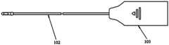
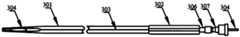
- an intelligent perfusion systemwhich includes: a pressure sensor, a temperature sensor, a metal tube 101, a catheter 102, a perfusion device, and an introduction sheath; wherein, the pressure sensor and the temperature sensor are installed in the metal tube 101.
- the pressure sensor and temperature sensorare connected to the perfusion device; the proximal end of the metal tube 101 is connected to the distal end of the conduit 102, and the proximal end of the metal tube 101 is the end of the metal tube 101 close to the conduit 102.
- the metal tube 101 and the catheter 102are configured to be sequentially inserted into the lumen of the introducer sheath.
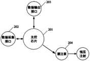
- the perfusion deviceincludes: main control chip 201, data acquisition interface 202, data output interface 203, and perfusion pump 204.
- the data acquisition interface 202is connected to the main control chip 201; the data acquisition interface 202 is used to receive the pressure signal collected by the pressure sensor and the temperature signal collected by the temperature sensor, and transmit the pressure signal and temperature signal to the main control chip. 201;
- the data output interface 203is connected to the main control chip 201, and the main control chip 201 is used to output pressure signals and temperature signals through the data output interface 203;
- the perfusion pump 204is connected to the main control chip 201, and the perfusion pump 4 is used to supply the urinary system.
- Physiological salineis perfused inside to provide the liquid environment required for surgery.
- the pressure monitoring methodis set outside the body, and the physiological saline in the pipeline is transmitted to the external sensor to achieve indirect water pressure monitoring. This is not only very troublesome in terms of calibration and use, but also difficult to achieve real-time high accuracy. Monitoring and data feedback are delayed, unable to provide timely data support to the operator, and unable to quickly respond to high-pressure surgical risks.
- the pressure sensor and the temperature sensorcan follow the catheter into the lesion site to monitor the pressure and temperature of the lesion site in real time. The data is more accurate, without delay, and can truly reflect the pressure and temperature in the cavity.
- a slot 1011can be provided in the wall of the metal pipe 101. Please refer to Figure 1.
- the pressure sensor and the temperature sensorare arranged in the slot 1011.
- the pressure sensor and the temperature sensorare encapsulated in a metal tube through soft glue.
- the metal tubecan protect the pressure sensor and the temperature sensor.
- the soft gluenot only plays a fixing role, but also ensures that the pressure sensor and the temperature sensor can normally accept the outside world. The role of pressure and temperature data.
- a gapis left between the soft plastic package and the pressure sensor to communicate with the atmospheric pressure, so that the pressure sensor can measure the gauge pressure more accurately.
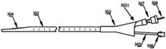
- the interface housing 103also includes an interface housing 103.
- the interface housing 103is connected to the proximal end of the catheter 102. Please refer to Figure 2.
- the interfaces of the pressure sensor and the temperature sensorare arranged in the interface housing 103, and the data monitor can establish a connection with the interfaces in the interface housing 103.
- the interface housing 103can protect the interface well.
- the catheter protective tube 104is disposed on the outer wall of the proximal end of the catheter 102. Please refer to FIG. 3 .
- the conduit 102is connected to the interface housing 103 or the handle, it is possible to prevent the conduit from being damaged due to local stress concentration.
- the perfusion pumpmay use a peristaltic pump to achieve constant pressure injection.
- the pressure sensor and temperature sensorcan be connected to the data acquisition interface after passing through the preprocessing module.
- the preprocessing modulemay include: a signal preprocessing module, a memory module, and an ADC module connected in sequence.
- the signal preprocessing moduleis connected to a pressure sensor and a temperature sensor, and the ADC module is connected to a data acquisition interface.
- the output of the data output interface 203can be for viewing, such as through a display screen; the output of the data output interface can also be for listening, such as through a sound broadcast. Alternatively, it can be included both ways.
- the perfusion devicealso includes: an external pipeline pressure monitoring interface 205.
- the external pipeline pressure monitoring interface 205is connected to the main control chip 201. Please refer to Figure 5.
- the external pipeline pressure monitoring interface 205is used to receive the second pressure signal in the external pipeline and transmit the second pressure signal to the main control chip.
- the external pipelineis filled with physiological saline and connected to the body, and the pressure value of the pipeline connected to the body is monitored in real time.
- the pressure collector of the second pressure signalis located outside the body, so the second pressure signal will have a certain lag relative to the first pressure signal. However, it is sufficient here to detect the status of the pressure sensor installed at the front end of the guide wire.
- the main control chipcan control to stop the perfusion or prompt an abnormality.
- the pressure sensoris abnormal during use of the product and cannot feed back correct data to the main control chip, and the host blindly performs perfusion, it will cause serious harm to the patient.
- the abnormality of the pressure sensorcan be detected through the external pipeline pressure monitoring interface 205 and fed back to the main control chip.
- the main control chipcan control to stop the perfusion or prompt abnormality to reduce harm to the patient.
- the perfusion devicefurther includes: a secondary confirmation module 206.
- the secondary confirmation module 206is connected between the data acquisition interface 202 and the main control chip 201. Please refer to Figure 5.
- the secondary confirmation module 206is also connected between the external pipeline pressure monitoring interface 205 and the main control chip 201 .
- the secondary confirmation moduleis used to confirm the number of uses of pressure sensors and temperature sensors, product models, traceability of production batches, etc.
- the perfusion devicefurther includes: a heating module 207.
- the heating module 207is connected to the main control chip 201. Please refer to Figure 5. When the temperature detected by the temperature sensor is too low, the heating module 207 is used to heat the salt water in the salt water bag, without the operator needing to perform heating processing through other equipment.
- the main control chipcan control the perfusion pump to communicate with one of the saline bags.
- the perfusion devicefurther includes: a weighing module 208.
- the weighing module 208is connected to the main control chip 201. Please refer to Figure 5.
- the weighing module 208is used to identify the saline inventory of the corresponding saline bag, and transmit the saline inventory to the main control chip.
- the main control chip 201can control the perfusion pump 204 to connect to other saline bags without manual switching, reducing increased workload.
- a sound warningcan also be used to prompt the operator to replace the spare saline bag, so that the surgical process is uninterrupted.
- the main control chipis also used to collect the number of times the catheter is used, and output the number of times the catheter is used through the data output interface 203 .
- the perfusion devicefurther includes: a data storage module 209.
- the data storage module 209is connected to the main control chip 201. Please refer to Figure 5.
- the main control chip 201is used to transmit pressure signals and temperature signals to the data storage module 209 for storage.
- the number of times the catheter is usedcan also be transmitted to the data storage module for storage.
- the data in the data storage modulecan be output wirelessly or through the output interface 210 connected to the main control chip. Please refer to Figure 5 .
- the data interface 210may be a USB interface.
- the perfusion devicefurther includes: a vacuum pump 211.
- the vacuum pump 211is connected to the main control chip 201. Please refer to Figure 5.
- the vacuum pump 211is used to suck wastewater under negative pressure to discharge crushed stones from the body and reduce the temperature and pressure of liquids in the body.
- the perfusion devicealso includes: a vacuum monitoring module 212.
- the vacuum monitoring moduleis connected to the main control chip and the vacuum pump respectively. Please refer to Figure 5.
- the vacuum monitoring module 212is used for monitoring the vacuum environment.
- the perfusion devicefurther includes a speaker 213.
- the speaker 213is connected to the main control chip 201. Please refer to Figure 5. When the pressure or temperature is abnormal, an alarm sound can be sounded through the speaker 213 to remind the staff, making it easier to find problems and avoid danger.
- the perfusion devicefurther includes: a foot pedal 214.
- the foot pedal 214is connected to the main control chip 201. Please refer to Figure 5.
- the foot pedal 214is used to manually control the perfusion, that is, when the foot pedal 214 is stepped on, the perfusion is continued, and when the foot pedal 214 is released, the perfusion stops.
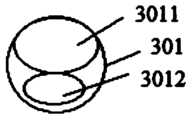
- the introducer sheathincludes: an introducer sheath tube 301 and a handle connector 302. Please refer to Figure 6 .
- the guiding sheath 301has at least two lumens: a first lumen 3011 and a second lumen 3012; the handle joint 302 is connected to the proximal end of the guiding sheath 301.
- At least part of the lumen of the lumencan be shared with the introducer sheath wall of the guide sheath.
- Figure 8to include two lumens: a first lumen 3011 and a second lumen 3012. example.
- the lumen and the introducing sheathmay not share the same wall.
- Figure 9.It is also possible for only part of the lumen to share the wall with the introducing sheath, please refer to Figure 10.
- the size and shape of the cavityare not necessarily those shown in Figures 8, 9, and 10, and can be designed differently according to actual needs.
- At least part of the lumen wall of the lumenis shared with the introducer sheath wall of the introducer sheath, as shown in FIG. 8 .
- At least part of the lumen wallis provided with lumen slots 303 along the extending direction of the lumen.
- the lumen slots 303run through both ends of the lumen, so that components inserted into the lumen can be peeled off from the guiding sheath via the lumen slots. out, please refer to Figure 11.
- the handle jointcan also be provided with a handle joint slot along the extending direction of the cavity.
- the handle joint slotruns through both ends of the handle joint, and the handle joint slot is connected with the cavity slot.
- the channel slottingmay be provided on only one cavity, or the cavity slotting may be provided on multiple cavity channels.
- At least one lumenis provided with a lumen slot along the extending direction of the lumen, and the lumen slot runs through both ends of the lumen;
- the guide sheathis provided with a guide sheath slot that is consistent with the slot direction, and the guide sheath is The sheath grooves run through both ends of the guide sheath, so that the components inserted into the lumen can be peeled off from the guide sheath through the lumen grooves and the guide sheath grooves.
- the handle jointcan also be provided with a handle joint slot along the lumen extension direction, the handle joint slot runs through both ends of the handle joint, and the handle joint slot is connected with the guide sheath slot.
- the grooves of the guide sheathcorrespond to the grooves of the lumen, and the grooves of the guide sheath are in the radial extension direction of the corresponding lumen grooves, so that the peeling off of the components is simpler and more convenient.
- the instrument inserted into the guiding sheathmust be withdrawn to the proximal end of the guiding sheath before it can be withdrawn, which is relatively slow.
- slotsare provided in the lumen and the side wall of the guide sheath, so that the components in the guide sheath can be removed from the guide sheath through the slot (that is, from the side wall of the guide sheath). It is peeled off in the sheath, and the peeling speed is faster, saving operation time.
- the catheter 102can be peeled away from the side wall of the introducer sheath.
- the multi-lumen guiding sheathcan be pushed to the proximal end of the catheter.
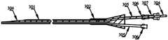
- the introducer sheathfurther includes: an inner tube 304, which is disposed in the first lumen; at least part of the lumen wall of the distal end of the first lumen and the guide sheath wall of the guide sheath When shared, at least part of the distal end of the lumen wall has a first lumen tapered structure; the distal end of the inner tube has an inner tube tapered structure; and the distal end of the first lumen wall is located at the distal end of the guiding sheath.
- the edge of the tapered structure of the inner tubeis aligned with the edge of the tapered structure of the first lumen.
- the inner tube 304can be withdrawn.
- a filled tapered structureis formed between the inner tube 304 and the first lumen.
- the tapered structure of the inner tubehas the same shape as the tapered structure (sharp edge) of the guiding sheath.
- the distal end of the first lumenwhen the first lumen and the guiding sheath do not share a wall, the distal end of the first lumen has a first lumen tapered structure; the distal end of the inner tube has an inner tube tapered structure; the guide The distal end of the sheath has a guide sheath tapered structure.
- the distal end of the first lumenis located at the distal end of the guiding sheath, and the distal end of the inner tube is located at the distal end of the guiding sheath, the tapered structure of the inner tube, the tapered structure of the first lumen, and the cone of the guiding sheath The edges of the structure are aligned.
- the inner diameter of the proximal end of the handle jointis larger than the outer diameter of the distal end of the handle joint. Please refer to Figure 6.
- the large inner diameter of the proximal endincreases the operating space when multiple instruments are inserted, and reduces or avoids Interaction between devices.
- the multi-lumen introducing sheathalso includes: an extension tube 305.
- the extension tube 305is connected to the proximal end of the lumen.
- the proximal end of the lumenis the end of the lumen close to the handle joint; the arrangement of the extension tube makes it easier to install the instrument. Through.
- extension tubesmay be provided in only some lumens, or extension tubes may be provided in each lumen. Please refer to Figure 6 .
- the proximal end of the extension tubecan extend beyond the proximal end of the handle connector, please refer to Figure 6, or it can not extend the proximal end of the handle connector, please refer to the extension tube of the upper lumen in Figure 13.
- the multi-lumen introducing sheathfurther includes: an insertion joint 306, which corresponds to the extension tube 305 one-to-one; the insertion joint 306 is connected to the proximal end of the extension tube 305, and the proximal end of the extension tube is away from the lumen of the extension tube.
- an insertion joint 306which corresponds to the extension tube 305 one-to-one; the insertion joint 306 is connected to the proximal end of the extension tube 305, and the proximal end of the extension tube is away from the lumen of the extension tube.
- the introducer sheathfurther includes: a locking joint 307 configured to be locked with the insertion joint 306 .
- the locking joint 307can be used to lock the inner tube or instrument and the guiding sheath after the inner tube or instrument is inserted into place, to prevent relative movement between the inner tube or instrument and the guiding sheath.
- the locking jointwhen the lumen is provided with a lumen slot, and the lumen slot is upward, the locking joint can also be used to drive the guide sheath to move downward, thereby allowing the inner tube or catheter 102 to pass through the lumen.
- the slotpeels away from the introducer sheath.
- a sliding rod 308please refer to Figure 14.
- the sliding rod 308cooperates with the locking joint 307, and the locking joint 307 is screwed and fixed with the female head of the handle joint 302.
- the preset position (bending position 309) of the guiding sheath starting from the proximal endhas a certain bending angle (for example, it can be 45°). After assembly is completed, the actual assembly position of the sliding rod 308 is inside the handle joint 303 and between the bending position and the proximal end of the introducer sheath. Please refer to Figure 15.
- the guiding sheathreaches the lesion position, loosen the locking valve of the locking joint 307 and withdraw the inner tube, then insert the instrument (such as a pressure measuring catheter), and after inserting it in place, unscrew the handle joint 302 and the locking joint 307
- the male and female headsare used to slide down the sliding rod 308 fixed on the locking joint 307 at a certain angle with the guiding sheath to drive the inserted instrument (such as a pressure measuring catheter) to slide in the direction of the slot of the guiding sheath. , and then quickly peel the catheter out of the introducer sheath through the slot of the introducer sheath.
- part of the edge of the proximal end of the handle joint 302is configured as an outwardly inclined rounded edge 3021, please refer to FIG. 16 .
- the instrument or inner tubeis inserted into the handle joint 302 at an angle. Setting the edge to be inclined outward can make the instrument (such as a pressure measuring catheter) insert with the handle joint first.
- the angle of the cavityremains consistent, making insertion smoother; in addition, the edges are set to rounded edges, which enhances its strength and prevents the risk of breakage caused by excessive force when tightening or loosening the locking joint.
- the number of lumens in the guiding sheath in the above embodimentsis two as an example. In different embodiments, three or more lumens may also be provided, which will not be described again here.
- an implementation modemeans the specific features described in conjunction with the embodiment or example, Structures, materials or features are included in at least one embodiment or example of the invention.
- schematic representations of the above termsdo not necessarily refer to the same embodiment or example.
- the specific features, structures, materials or characteristics describedmay be combined in any suitable manner in any one or more embodiments or examples.
Landscapes
- Health & Medical Sciences (AREA)
- Life Sciences & Earth Sciences (AREA)
- Medical Informatics (AREA)
- Biophysics (AREA)
- Pathology (AREA)
- Engineering & Computer Science (AREA)
- Biomedical Technology (AREA)
- Heart & Thoracic Surgery (AREA)
- Physics & Mathematics (AREA)
- Molecular Biology (AREA)
- Surgery (AREA)
- Animal Behavior & Ethology (AREA)
- General Health & Medical Sciences (AREA)
- Public Health (AREA)
- Veterinary Medicine (AREA)
- Hematology (AREA)
- Media Introduction/Drainage Providing Device (AREA)
Abstract
Description
Translated fromChinese本发明涉及医疗器械技术领域,尤其涉及一种智能灌注系统。The invention relates to the technical field of medical devices, and in particular to an intelligent perfusion system.
肾结石是泌尿外科常见疾病,其发病率有增加趋势。随着医学设备的发展,其治疗的主流逐渐由传统手术向微创手术转变。而新型输尿管软镜及相关设备的发展,也使得输尿管软镜技术在上尿路结石治疗方面的应用也越来越广泛,具有创伤小、患者恢复快、清石率高等优点。通常在进行肾结石碎石手术时,为保持手术视野的清晰及冲出碎石,常进行肾盂冲洗灌注,但目前的规范操作仍然可能造成肾盂内压升高,导致含有细菌及内毒素的灌注液经肾返流吸收,引起术后发热及脓毒症。因此持续有效地监控肾内压力,并将肾盂内压控制在一定水平,可降低肾返流的发生,提高肾结石微创手术的安全性。Kidney stones are a common disease in urology, and their incidence is increasing. With the development of medical equipment, the mainstream of treatment has gradually changed from traditional surgery to minimally invasive surgery. The development of new flexible ureteroscopy and related equipment has also made the application of flexible ureteroscopy technology more and more widespread in the treatment of upper urinary tract stones. It has the advantages of less trauma, rapid patient recovery, and high stone clearance rate. Usually, during lithotripsy surgery for kidney stones, in order to maintain a clear surgical field of view and flush out the gravel, renal pelvis irrigation and perfusion are often performed. However, current standard operations may still cause an increase in intrarenal pelvic pressure, leading to perfusion containing bacteria and endotoxins. The fluid is absorbed through renal reflux, causing postoperative fever and sepsis. Therefore, continuously and effectively monitoring intrarenal pressure and controlling intrarenal pelvic pressure at a certain level can reduce the occurrence of renal reflux and improve the safety of minimally invasive kidney stone surgery.
现有技术中通过相应的测压管连接人体内腔与体外的压力监测单元,腔体内的压力发生改变时,无法及时通过测压管道反馈给压力监测单元,而测压管道的材质以及管道内是否有影响流动的气体或碎石对测量的准确性也是有影响的。因此通过此种方式测量得出的压力不但具有一定的延迟性,更无法真实的反映腔体内的压力状态。In the existing technology, the pressure monitoring unit inside the human body and outside the body are connected through corresponding pressure measuring tubes. When the pressure in the cavity changes, it cannot be fed back to the pressure monitoring unit through the pressure measuring pipe in time. However, the material of the pressure measuring pipe and the pressure inside the pipe Whether there is gas or gravel that affects the flow also has an impact on the accuracy of the measurement. Therefore, the pressure measured in this way not only has a certain delay, but also cannot truly reflect the pressure state in the cavity.
另外,在肾结石碎石手术过程中,还极易出现以下两种失温现象:(1)在术中灌注生理盐水时,若因盐水温度低,容易造成人体失温,严重的将危及生命;(2)钬激光碎石过程中,局部水温会持续升高至超出限定值,容易引起组织热损伤,从而产生一系列并发症,如输尿管狭窄。In addition, during kidney stone lithotripsy surgery, the following two hypothermia phenomena are very likely to occur: (1) When normal saline is infused during the operation, if the temperature of the saline is low, it is easy to cause hypothermia in the human body, which may be life-threatening in severe cases. ; (2) During the process of holmium laser lithotripsy, the local water temperature will continue to rise beyond the limit value, which can easily cause thermal damage to the tissue, resulting in a series of complications, such as ureteral stenosis.
现有技术中的数据监测单一,一般只考虑了液体压力因素对人体的损伤,未考虑温度因素,监测不完善、效果不好。The data monitoring in the prior art is single, and generally only considers the damage caused by liquid pressure factors to the human body, without considering the temperature factor. The monitoring is imperfect and the effect is not good.
发明内容Contents of the invention
本发明提供一种智能灌注系统,以解决现有技术中只考虑压力因素,且 压力监测有延迟的问题。The present invention provides an intelligent perfusion system to solve the problem in the prior art that only pressure factors are considered and pressure monitoring is delayed.
本发明提供一种智能灌注系统,其包括:压力传感器、温度传感器、金属管、导管、灌注装置、导引鞘;其中,The invention provides an intelligent perfusion system, which includes: a pressure sensor, a temperature sensor, a metal tube, a catheter, a perfusion device, and a guide sheath; wherein,
所述压力传感器、所述温度传感器安装于所述金属管内;The pressure sensor and the temperature sensor are installed in the metal tube;
所述压力传感器、所述温度传感器连接所述灌注装置;The pressure sensor and the temperature sensor are connected to the perfusion device;
所述金属管的近端连接所述导管的远端,所述金属管的近端为所述金属管的靠近所述导管的一端;The proximal end of the metal tube is connected to the distal end of the conduit, and the proximal end of the metal tube is an end of the metal tube close to the conduit;
所述金属管、所述导管被配置为能够依次插入所述导引鞘的腔道内;The metal tube and the catheter are configured to be inserted into the lumen of the introducing sheath in sequence;
所述灌注装置包括:主控芯片、数据采集接口、数据输出接口、灌注泵;其中,The perfusion device includes: a main control chip, a data acquisition interface, a data output interface, and a perfusion pump; wherein,
所述数据采集接口与所述主控芯片相连;The data collection interface is connected to the main control chip;
所述数据采集接口用于接收所述压力传感器采集的第一压力信号,还用于接收所述温度传感器采集的温度信号,并将所述第一压力信号、所述温度信号传输到所述主控芯片;The data acquisition interface is used to receive the first pressure signal collected by the pressure sensor, and is also used to receive the temperature signal collected by the temperature sensor, and transmit the first pressure signal and the temperature signal to the main unit. control chip;
所述数据输出接口与所述主控芯片相连,所述主控芯片用于将所述第一压力信号、所述温度信号通过所述数据输出接口输出;The data output interface is connected to the main control chip, and the main control chip is used to output the first pressure signal and the temperature signal through the data output interface;
所述灌注泵与所述主控芯片相连。The perfusion pump is connected to the main control chip.
较佳地,所述灌注装置还包括:外管路压力监测接口,所述外管路压力监测接口与所述主控芯片相连,所述外管路压力监测接口用于接收外管路内的第二压力信号,并将所述第二压力信号传输到所述主控芯片。Preferably, the perfusion device further includes: an external pipeline pressure monitoring interface, the external pipeline pressure monitoring interface is connected to the main control chip, and the external pipeline pressure monitoring interface is used to receive pressure in the external pipeline. and transmit the second pressure signal to the main control chip.
较佳地,所述灌注装置还包括:二次确认模块,所述二次确认模块连接在所述数据采集接口与所述主控芯片之间;Preferably, the perfusion device further includes: a secondary confirmation module, the secondary confirmation module is connected between the data collection interface and the main control chip;
所述二次确认模块用于确认所述压力传感器、所述温度传感器的使用次数、产品型号、追溯生产批次。较佳地,所述灌注装置还包括:加热模块,所述加热模块与所述主控芯片相连,所述加热模块用于对所述盐水袋中的盐水进行加热。The secondary confirmation module is used to confirm the number of uses of the pressure sensor and the temperature sensor, product model, and trace production batch. Preferably, the perfusion device further includes: a heating module, the heating module is connected to the main control chip, and the heating module is used to heat the saline in the saline bag.
较佳地,所述盐水袋的数量为多个,所述灌注泵与其中一所述盐水袋相连通。Preferably, there are multiple saline bags, and the perfusion pump is connected to one of the saline bags.
较佳地,所述灌注装置还包括:称重模块,所述称重模块与所述主控芯片相连,所述称重模块用于识别对应所述盐水袋的盐水存量,且将所述盐水 存量传输到所述主控芯片。Preferably, the perfusion device further includes: a weighing module, the weighing module is connected to the main control chip, the weighing module is used to identify the amount of saline corresponding to the saline bag, and transfer the saline into the saline bag. The inventory is transferred to the main control chip.
较佳地,所述主控芯片还用于采集所述导管的使用次数,且将所述导管的使用次数通过所述数据输出接口输出。Preferably, the main control chip is also used to collect the number of uses of the catheter, and output the number of uses of the catheter through the data output interface.
较佳地,所述压力传感器、所述温度传感器通过软胶封装于所述金属管内。Preferably, the pressure sensor and the temperature sensor are sealed in the metal tube through soft glue.
较佳地,所述软胶封装与所述压力传感器之间留有间隙,以连通大气压。Preferably, a gap is left between the soft plastic package and the pressure sensor to communicate with atmospheric pressure.
较佳地,所述导引鞘包括:导引鞘管、手柄接头;Preferably, the guiding sheath includes: a guiding sheath tube and a handle joint;
所述导引鞘管内具有至少两腔道:第一腔道、第二腔道;The guide sheath has at least two lumens: a first lumen and a second lumen;
所述手柄接头连接在所述导引鞘管的近端。The handle joint is connected to the proximal end of the guiding sheath.
较佳地,所述腔道的至少部分腔道壁与所述导引鞘管的导引鞘管壁共用;Preferably, at least part of the lumen wall of the lumen is shared with the guiding sheath wall of the guiding sheath;
所述至少部分腔道壁设置有沿腔道延长方向的腔道开槽,所述腔道开槽贯穿所述腔道的两端,以使插入所述腔道内的部件经由所述腔道开槽从所述导引鞘管内剥离出来。The at least part of the cavity wall is provided with a cavity slot along the extending direction of the cavity, and the cavity slot runs through both ends of the cavity, so that components inserted into the cavity can pass through the cavity opening. The groove is peeled away from the introducer sheath.
较佳地,至少一所述腔道设置有沿腔道延长方向的腔道开槽,所述腔道开槽贯穿所述腔道的两端;所述导引鞘管上设置有与所述开槽方向一致的导引鞘管开槽,所述导引鞘管开槽贯穿所述导引鞘管的两端,以使插入所述腔道内的部件依次经由所述腔道开槽、所述导引鞘管开槽从所述导引鞘管内剥离出来。Preferably, at least one of the lumen is provided with a lumen slot along the extending direction of the lumen, and the lumen slot runs through both ends of the lumen; The guide sheath grooves are slotted in the same direction, and the guide sheath grooves run through both ends of the guide sheath, so that the components inserted into the lumen can pass through the lumen grooves and all the slots in sequence. The guide sheath groove is peeled off from the guide sheath.
较佳地,所述导引鞘管开槽与所述腔道开槽一一对应,所述导引鞘管开槽在对应的所述腔道开槽的径向延长方向上。Preferably, the grooves of the guide sheath correspond to the grooves of the lumen, and the grooves of the guide sheath are in the radial extension direction of the corresponding lumen grooves.
较佳地,还包括:内管,所述内管穿设于所述第一腔道内;Preferably, it also includes: an inner tube, the inner tube being inserted into the first cavity;
所述第一腔道的远端的至少部分腔道壁与所述导引鞘管的导引鞘管壁共用时,所述至少部分腔道壁的远端具有第一腔道锥形结构;When at least part of the lumen wall of the distal end of the first lumen is shared with the guide sheath wall of the guide sheath, the distal end of at least part of the lumen wall has a first lumen tapered structure;
所述内管的远端具有内管锥形结构;The distal end of the inner tube has an inner tube tapered structure;
所述第一腔道的远端位于所述导引鞘管的远端;The distal end of the first lumen is located at the distal end of the guiding sheath;
所述内管的远端位于所述导引鞘管的远端时,所述内管锥形结构的边缘与所述第一腔道锥形结构的边缘相对齐。When the distal end of the inner tube is located at the distal end of the guiding sheath, the edge of the tapered structure of the inner tube is aligned with the edge of the tapered structure of the first lumen.
本发明提供的智能灌注系统,通过对压力、温度进行同时监测,可以避免因压力超出范围而增加的手术风险,减少术后并发症发生的概率;同时还能避免因温度过低而造成的人体失温的风险,或者因温度过高而引起的热损 伤的风险。The intelligent perfusion system provided by the present invention can avoid increased surgical risks due to pressure exceeding the range and reduce the probability of postoperative complications by simultaneously monitoring pressure and temperature; at the same time, it can also avoid human body damage caused by excessively low temperature. Risk of hypothermia, or thermal damage due to excessive temperatures.
本发明提供的智能灌注系统,通过引导鞘的通道可以达到预定位置,直接测量该位置的真实压力、温度,可以反馈体内压力、温度的真实状态。The intelligent perfusion system provided by the present invention can reach a predetermined position through the channel of the guide sheath, directly measure the real pressure and temperature at the position, and can feed back the real status of the pressure and temperature in the body.
本发明的一可选方案中,通过外管路压力监测接口对压力传感器采集到的第一压力信号进行检查,如果外管路压力监测接口接收到的第二压力信号与压力传感器接收到的第一压力信号相差太大,则判定为压力传感器出现异常,可以反馈给主控芯片,进而主控芯片可以做出异常提示或控制灌注泵停止灌注,可以防止由于压力信号异常,还盲目灌注,对患者造成的严重伤害。In an optional solution of the present invention, the first pressure signal collected by the pressure sensor is checked through the external pipeline pressure monitoring interface. If the second pressure signal received by the external pipeline pressure monitoring interface is different from the third pressure signal received by the pressure sensor, If the pressure signal difference is too large, it is determined that the pressure sensor is abnormal, which can be fed back to the main control chip, and then the main control chip can make an abnormal prompt or control the perfusion pump to stop perfusion, which can prevent blind perfusion due to abnormal pressure signals. serious harm to the patient.
本发明的一可选方案中,通过主控芯片采集导管的使用次数,可以有效识别并控制导管的使用次数,避免了产品使用过程中难以做人为的次数记录,进而可以避免因使用次数过多而产生的安全隐患。In an optional solution of the present invention, the number of times of use of the catheter is collected through the main control chip, which can effectively identify and control the number of times of use of the catheter, avoiding the difficulty of artificially recording the number of times during product use, and thus avoiding the risk of excessive use. safety hazards arising from it.
本发明的一可选方案中,通过软胶封装将压力传感器、温度传感器封装于金属管内,保证了芯片密封、绝缘,同时也保证了压力监测的灵敏度。In an optional solution of the present invention, the pressure sensor and the temperature sensor are packaged in a metal tube through soft glue packaging, which ensures the sealing and insulation of the chip and also ensures the sensitivity of pressure monitoring.
本发明的一可选方案中,通过在腔道的腔道壁和/或导引鞘管的导引鞘管壁设置开槽,即在导引鞘的侧面设置开槽,器械经由导引鞘的腔道进入指定位置后,可以从开槽中迅速剥离出来,无需后撤至导引鞘的近端撤出,撤出速度更快。In an optional solution of the present invention, by arranging grooves on the lumen wall of the lumen and/or the wall of the guiding sheath, that is, arranging grooves on the side of the guiding sheath, the instrument passes through the guiding sheath. After the lumen enters the designated position, it can be quickly peeled off from the slot without retreating to the proximal end of the introducer sheath, and the withdrawal speed is faster.
为了更清楚地说明本发明实施例或现有技术中的技术方案,下面将对实施例或现有技术描述中所需要使用的附图作简单地介绍,显而易见地,下面描述中的附图仅仅是本发明的一些实施例,对于本领域普通技术人员来讲,在不付出创造性劳动性的前提下,还可以根据这些附图获得其他的附图。In order to explain the embodiments of the present invention or the technical solutions in the prior art more clearly, the drawings needed to be used in the description of the embodiments or the prior art will be briefly introduced below. Obviously, the drawings in the following description are only These are some embodiments of the present invention. For those of ordinary skill in the art, other drawings can be obtained based on these drawings without exerting any creative effort.
图1为本发明的一实施例的智能灌注系统的金属管、导管的示意图;Figure 1 is a schematic diagram of metal tubes and conduits of an intelligent perfusion system according to an embodiment of the present invention;
图2为本发明的另一实施例的智能灌注装置的金属管、导管的示意图;Figure 2 is a schematic diagram of the metal tube and conduit of the intelligent perfusion device according to another embodiment of the present invention;
图3为本发明的另一实施例的智能灌注装置的金属管、导管的示意图;Figure 3 is a schematic diagram of the metal tube and conduit of the intelligent perfusion device according to another embodiment of the present invention;
图4为本发明的一实施例的智能灌注系统的灌注装置的示意图;Figure 4 is a schematic diagram of the perfusion device of the intelligent perfusion system according to an embodiment of the present invention;
图5为本发明的一实施例的智能灌注系统的灌注装置的示意图;Figure 5 is a schematic diagram of the perfusion device of the intelligent perfusion system according to an embodiment of the present invention;
图6为本发明的一实施例的导引鞘的示意图;Figure 6 is a schematic diagram of an introducer sheath according to an embodiment of the present invention;
图7为本发明的一实施例的导引鞘的剖视图;Figure 7 is a cross-sectional view of an introducer sheath according to an embodiment of the present invention;
图8为本发明的一实施例的导引鞘管的截面图;Figure 8 is a cross-sectional view of an introducing sheath according to an embodiment of the present invention;
图9为本发明的另一实施例的导引鞘管的截面图;Figure 9 is a cross-sectional view of an introducing sheath according to another embodiment of the present invention;
图10为本发明的另一实施例的导引鞘管的截面图;Figure 10 is a cross-sectional view of an introducing sheath according to another embodiment of the present invention;
图11为本发明的一较佳实施例的多腔导引鞘的侧视图;Figure 11 is a side view of a multi-lumen introducing sheath according to a preferred embodiment of the present invention;
图12为本发明的一实施例的多腔导引鞘的远端部分示意图;Figure 12 is a schematic diagram of the distal part of a multi-lumen introducing sheath according to an embodiment of the present invention;
图13为本发明的一较佳实施例的多腔导引鞘的主视图;Figure 13 is a front view of a multi-lumen introducing sheath according to a preferred embodiment of the present invention;
图14为本发明的一较佳实施例的多腔导引鞘的爆炸图;Figure 14 is an exploded view of a multi-lumen introducer sheath according to a preferred embodiment of the present invention;
图15为本发明的一较佳实施例的多腔导引鞘的装配完成图;Figure 15 is a complete assembly diagram of the multi-lumen introducing sheath according to a preferred embodiment of the present invention;
图16为本发明的一较佳实施例的多腔导引鞘的示意图;Figure 16 is a schematic diagram of a multi-lumen introducing sheath according to a preferred embodiment of the present invention;
附图标记说明:Explanation of reference symbols:
101-金属管,101-metal tube,
1011-开槽;1011-grooving;
102-导管,102-catheter,
103-接口外壳,103-interface housing,
104-导管护管;104-Catheter protection tube;
201-主控芯片,201-main control chip,
202-数据采集接口,202-data collection interface,
203-数据输出接口,203-data output interface,
204-灌注泵,204-perfusion pump,
205-外管路压力监测接口,205-External pipeline pressure monitoring interface,
206-二次确认模块,206-Second confirmation module,
207-加热模块,207-Heating module,
208-称重模块,208-Weighing module,
209-数据存储模块,209-data storage module,
210-数据接口,210-data interface,
211-真空泵,211-vacuum pump,
212-真空监测模块,212-vacuum monitoring module,
213-扬声器,213-speaker,
214-脚踏;214-pedal;
301-导引鞘管,301-Introducing sheath,
3011-第一腔道,3011-First cavity,
3012-第二腔道;3012-Second cavity;
302-手柄接头,302-handle joint,
3021-圆角边缘,3021-rounded edges,
303-腔道开槽,303-Channel slotting,
304-内管,304-inner tube,
305-延长管,305-extension tube,
306-插入接头,306-Insert connector,
307-锁紧接头,307-locking joint,
308-滑杆,308-slider,
309-折弯位置。309-Bending position.
下面将结合本发明实施例中的附图,对本发明实施例中的技术方案进行清楚、完整地描述,显然,所描述的实施例仅仅是本发明一部分实施例,而不是全部的实施例。基于本发明中的实施例,本领域普通技术人员在没有做出创造性劳动前提下所获得的所有其他实施例,都属于本发明保护的范围。The technical solutions in the embodiments of the present invention will be clearly and completely described below with reference to the accompanying drawings in the embodiments of the present invention. Obviously, the described embodiments are only some of the embodiments of the present invention, rather than all the embodiments. Based on the embodiments of the present invention, all other embodiments obtained by those of ordinary skill in the art without creative efforts fall within the scope of protection of the present invention.
在本发明说明书的描述中,需要理解的是,术语“上部”、“下部”、“上端”、“下端”、“下表面”、“上表面”等指示的方位或位置关系为基于附图所示的方位或位置关系,仅是为了便于描述本发明和简化描述,而不是指示或暗示所指的装置或元件必须具有特定的方位、以特定的方位构造和操作,因此不能理解为对本发明的限制。In the description of the present invention, it should be understood that the orientation or positional relationship indicated by the terms "upper part", "lower part", "upper end", "lower end", "lower surface", "upper surface", etc. is based on the accompanying drawings. The orientation or positional relationship shown is only to facilitate the description of the present invention and simplify the description, and does not indicate or imply that the device or element referred to must have a specific orientation, be constructed and operated in a specific orientation, and therefore cannot be understood as limiting the scope of the present invention. limits.
在本发明说明书的描述中,术语“第一”、“第二”仅用于描述目的,而不能理解为指示或暗示相对重要性或隐含指明所指示的技术特征的数量。由此,限定有“第一”、“第二”的特征可以明示或者隐含地包括一个或者更多个该特征。In the description of the present invention, the terms "first" and "second" are only used for descriptive purposes and cannot be understood as indicating or implying relative importance or implicitly indicating the number of indicated technical features. Therefore, features defined as "first" and "second" may explicitly or implicitly include one or more of these features.
在本发明的描述中,“多个”的含义是多个,例如两个,三个,四个等,除非另有明确具体的限定。In the description of the present invention, "plurality" means a plurality, such as two, three, four, etc., unless otherwise clearly and specifically limited.
在本发明说明书的描述中,除非另有明确的规定和限定,术语“连接”等术语应做广义理解,例如,可以是固定连接,也可以是可拆卸连接,或 成一体;可以是机械连接,也可以是电连接或可以互相通讯;可以是直接相连,也可以通过中间媒介间接相连,可以是两个元件内部的连通或两个元件的相互作用关系。对于本领域的普通技术人员而言,可以根据具体情况理解上述术语在本发明中的具体含义。In the description of the present invention, unless otherwise clearly stated and limited, the terms "connection" and other terms should be understood in a broad sense. For example, it can be a fixed connection, a detachable connection, or an integrated connection; it can be a mechanical connection. , it can also be electrically connected or can communicate with each other; it can be directly connected, or it can be indirectly connected through an intermediary, it can be the internal connection of two components or the interaction between two components. For those of ordinary skill in the art, the specific meanings of the above terms in the present invention can be understood according to specific circumstances.
下面以具体地实施例对本发明的技术方案进行详细说明。下面这几个具体的实施例可以相互结合,对于相同或相似的概念或过程可能在某些实施例不再赘述。The technical solution of the present invention will be described in detail below with specific examples. The following specific embodiments can be combined with each other, and the same or similar concepts or processes may not be described again in some embodiments.
一实施例中,提供一种智能灌注系统,其包括:压力传感器、温度传感器、金属管101、导管102、灌注装置、导引鞘;其中,压力传感器、温度传感器安装于金属管101内。压力传感器、温度传感器连接灌注装置;金属管101的近端连接导管102的远端,金属管101的近端为金属管101的靠近导管102的一端,请参考图1。金属管101、导管102被配置为能够依次插入导引鞘的腔道内。In one embodiment, an intelligent perfusion system is provided, which includes: a pressure sensor, a temperature sensor, a
其中,灌注装置包括:主控芯片201、数据采集接口202、数据输出接口203、灌注泵204,请参考图4。其中,数据采集接口202与主控芯片201相连;数据采集接口202用于接收压力传感器采集的压力信号,还用于接收温度传感器采集的温度信号,并将压力信号、温度信号传输到主控芯片201;数据输出接口203与主控芯片201相连,主控芯片201用于将压力信号、温度信号通过数据输出接口203输出;灌注泵204与主控芯片201相连,灌注泵4用于为泌尿系统内灌注生理盐水,提供手术所需的液态环境。Among them, the perfusion device includes:
市面上现有灌注系统,压力监测方式设置在体外,通过管路中的生理盐水传递至外部传感器上,实现间接的水压监测方式,不仅在校准使用方式上非常麻烦,而且难以达到实时高精度监测,数据反馈显现延迟,无法及时给操作者提供数据支持,无法快速响应处理高压的手术风险。上述实施例中,压力传感器、温度传感器能够跟随导管进入病灶部位,对病灶部位的压力、温度进行实时监测,数据更准确,没有延迟,能够真实的反应腔体内的压力、温度。In the existing perfusion systems on the market, the pressure monitoring method is set outside the body, and the physiological saline in the pipeline is transmitted to the external sensor to achieve indirect water pressure monitoring. This is not only very troublesome in terms of calibration and use, but also difficult to achieve real-time high accuracy. Monitoring and data feedback are delayed, unable to provide timely data support to the operator, and unable to quickly respond to high-pressure surgical risks. In the above embodiment, the pressure sensor and the temperature sensor can follow the catheter into the lesion site to monitor the pressure and temperature of the lesion site in real time. The data is more accurate, without delay, and can truly reflect the pressure and temperature in the cavity.
一实施例中,可以在金属管101的管壁开设开槽1011,请参考图1,压力传感器、温度传感器设置在开槽1011中。In one embodiment, a
一实施例中,压力传感器、温度传感器通过软胶封装于金属管内,金属 管可以保护压力传感器、温度传感器,软胶在起到固定作用的同时,还能保证压力传感器、温度传感器能够正常接受外界的压力、温度数据的作用。In one embodiment, the pressure sensor and the temperature sensor are encapsulated in a metal tube through soft glue. The metal tube can protect the pressure sensor and the temperature sensor. The soft glue not only plays a fixing role, but also ensures that the pressure sensor and the temperature sensor can normally accept the outside world. The role of pressure and temperature data.
一实施例中,软胶封装与压力传感器之间留有间隙,以连通大气压,这样能够使得压力传感器能够更准确地测量表压。In one embodiment, a gap is left between the soft plastic package and the pressure sensor to communicate with the atmospheric pressure, so that the pressure sensor can measure the gauge pressure more accurately.
一实施例中,还包括:接口外壳103,接口外壳103连接导管102的近端,请参考图2。压力传感器、温度传感器的接口设置于接口外壳103内,数据监测仪可以跟接口外壳103内的接口建立连接。接口外壳103可以很好地保护接口。In one embodiment, it also includes an
一实施例中,还包括:导管护管104,导管护管104设置于导管102的近端的外壁,请参考图3。当导管102与接口外壳103或手柄连接时,可以避免导管因局部位置应力集中,从而折损导管。In one embodiment, it also includes: a catheter
一实施例中,灌注泵可以采用蠕动泵,来实现恒压注射。In one embodiment, the perfusion pump may use a peristaltic pump to achieve constant pressure injection.
一实施例中,压力传感器、温度传感器可以经过预处理模块后再连接数据采集接口。预处理模块可以包括:依次连接的信号前置处理模块、存储器模块、ADC模块,信号前置处理模块连接压力传感器、温度传感器,ADC模块连接数据采集接口。In one embodiment, the pressure sensor and temperature sensor can be connected to the data acquisition interface after passing through the preprocessing module. The preprocessing module may include: a signal preprocessing module, a memory module, and an ADC module connected in sequence. The signal preprocessing module is connected to a pressure sensor and a temperature sensor, and the ADC module is connected to a data acquisition interface.
一实施例中,数据输出接口203输出的可以为观看的,如:通过显示屏输出;数据输出接口输出的也可以为听的,如:通过声音播报输出。或者,也可以两种方式都包括。In one embodiment, the output of the
一实施例中,灌注装置还包括:外管路压力监测接口205,外管路压力监测接口205与主控芯片201相连,请参考图5。外管路压力监测接口205用于接收外管路内的第二压力信号,并将第二压力信号传输到主控芯片。外管路打满生理盐水连通到体内,实时监测连通体内的管路压力值,第二压力信号的压力采集器位于体外,因此第二压力信号相对于第一压力信号会有一定的滞后性,但是此处用于对设置在导丝前端的压力传感器的状态进行检测已经足够,第二压力信号与第一压力信号会存在一定的差值,但是该差值过大,如超过预设范围时,则能判定第一压力信号异常,此时主控芯片可以控制停止灌注或提示异常。In one embodiment, the perfusion device also includes: an external pipeline
若产品使用过程中,压力传感器异常,无法反馈给主控芯片正确数据时,主机若盲目进行灌注,则将对患者产生严重危害。上述实施例通过外管路压 力监测接口205可以监测到压力传感器的异常,并反馈给主控芯片,主控芯片可以控制停止灌注或提示异常,减少对患者的伤害。If the pressure sensor is abnormal during use of the product and cannot feed back correct data to the main control chip, and the host blindly performs perfusion, it will cause serious harm to the patient. In the above embodiment, the abnormality of the pressure sensor can be detected through the external pipeline
一实施例中,灌注装置还包括:二次确认模块206,二次确认模块206连接在数据采集接口202与主控芯片201之间,请参考图5。当包括外管路压力监测接口205时,二次确认模块206还连接在外管路压力监测接口205与主控芯片201之间。二次确认模块用于确认压力传感器、温度传感器的使用次数、产品型号、追溯生产批次等。In one embodiment, the perfusion device further includes: a
一实施例中,灌注装置还包括:加热模块207,加热模块207与主控芯片201相连,请参考图5。当温度传感器检测到的温度过低时,加热模块207用于对盐水袋中的盐水进行加热,无需操作者再通过其他设备做加热处理。In one embodiment, the perfusion device further includes: a
一实施例中,盐水袋的数量为多个,主控芯片可以控制灌注泵与其中一盐水袋相连通。In one embodiment, there are multiple saline bags, and the main control chip can control the perfusion pump to communicate with one of the saline bags.
一实施例中,灌注装置还包括:称重模块208,称重模块208与主控芯片201相连,请参考图5。称重模块208用于识别对应盐水袋的盐水存量,且将盐水存量传输到主控芯片,当盐水存量不足时,主控芯片201可以控制灌注泵204连通其他的盐水袋,无需人为切换,减少了工作量。优选地,还可以通过声音警示提示操作者更换备用盐水袋,手术过程不间断。In one embodiment, the perfusion device further includes: a weighing
一实施例中,主控芯片还用于采集导管的使用次数,且将导管的使用次数通过数据输出接口203输出。In one embodiment, the main control chip is also used to collect the number of times the catheter is used, and output the number of times the catheter is used through the
一实施例中,灌注装置还包括:数据存储模块209,数据存储模块209与主控芯片201相连,请参考图5。主控芯片201用于将压力信号、温度信号传输到数据存储模块209中进行存储。优选地,还可以将导管的使用次数传输到数据存储模块中进行存储。In one embodiment, the perfusion device further includes: a
一实施例中,数据存储模块中的数据可以通过无线输出,也可以通过与主控芯片相连的输出接口210输出,请参考图5。In one embodiment, the data in the data storage module can be output wirelessly or through the
一实施例中,数据接口210可以为USB接口。In one embodiment, the
一实施例中,灌注装置还包括:真空泵211,真空泵211与主控芯片201相连,请参考图5。真空泵211用于负压抽吸废水,实现体内碎结石的排出,降低体内液体温度及压力。In one embodiment, the perfusion device further includes: a
一实施例中,灌注装置还包括:真空监测模块212,真空监测模块分别 与主控芯片、真空泵相连,请参考图5。真空监测模块212用于真空环境的监测。In one embodiment, the perfusion device also includes: a
一实施例中,灌注装置还包括:扬声器213,扬声器213与主控芯片201相连,请参考图5。当压力、温度出现异常时,可以通过扬声器213发出警报声,提醒工作人员,更容易发现问题,避免危险。In one embodiment, the perfusion device further includes a
一实施例中,灌注装置还包括:脚踏214,脚踏214与主控芯片201相连,请参考图5。脚踏214用于人为控制灌注,即:踩下脚踏214时进行持续灌注,松开脚踏214时灌注停止。In one embodiment, the perfusion device further includes: a
一实施例中,导引鞘包括:导引鞘管301、手柄接头302,请参考图6。导引鞘管301内具有至少两腔道:第一腔道3011、第二腔道3012;手柄接头302连接在导引鞘管301的近端。In one embodiment, the introducer sheath includes: an
一实施例中,腔道的至少部分腔道可以与导引鞘管的导引鞘管壁共用,请参考图8,以包括两个腔道:第一腔道3011、第二腔道3012为例。腔道与导引鞘管也可以都不共用管壁,请参考图9。也可以只有部分腔道与导引鞘管共用管壁,请参考图10。腔道的大小、形状不一定为图8、图9、图10中的,可以根据实际需要进行不同的设计。In one embodiment, at least part of the lumen of the lumen can be shared with the introducer sheath wall of the guide sheath. Please refer to Figure 8 to include two lumens: a
一实施例中,腔道的至少部分腔道壁与导引鞘管的导引鞘管壁共用,如图8中所示。至少部分腔道壁设置有沿腔道延长方向的腔道开槽303,腔道开槽303贯穿腔道的两端,以使插入腔道内的部件可以经由腔道开槽从导引鞘管内剥离出来,请参考图11。In one embodiment, at least part of the lumen wall of the lumen is shared with the introducer sheath wall of the introducer sheath, as shown in FIG. 8 . At least part of the lumen wall is provided with
当需要将腔道内的部件镜腔道开槽剥离时,因为手柄接头设置在导引鞘的近端,需要将手柄接头从导引鞘管上拆除。当然,也可在手柄接头也设置沿腔道延长方向的手柄接头开槽,手柄接头开槽贯通手柄接头的两端,手柄接头开槽与腔道开槽相连通。When it is necessary to remove the components in the lumen through slotting and stripping the lumen, because the handle connector is set at the proximal end of the introducer sheath, the handle connector needs to be removed from the guide sheath tube. Of course, the handle joint can also be provided with a handle joint slot along the extending direction of the cavity. The handle joint slot runs through both ends of the handle joint, and the handle joint slot is connected with the cavity slot.
不同实施例中,可以只在一个腔道上设置腔道开槽,也可以在多个腔道都设置腔道开槽。In different embodiments, the channel slotting may be provided on only one cavity, or the cavity slotting may be provided on multiple cavity channels.
一实施例中,腔道的腔道壁与导引鞘管的导引鞘壁不共用时,如图9中所示。至少一腔道设置有沿腔道延长方向的腔道开槽,腔道开槽贯穿腔道的两端;导引鞘管上设置有与开槽方向一致的导引鞘管开槽,导引鞘管开槽贯穿导引鞘管的两端,以使插入腔道内的部件可以依次经由腔道开槽、导引 鞘管开槽从导引鞘管内剥离出来。In one embodiment, when the lumen wall of the lumen and the introducing sheath wall of the introducing sheath tube are not shared, as shown in FIG. 9 . At least one lumen is provided with a lumen slot along the extending direction of the lumen, and the lumen slot runs through both ends of the lumen; the guide sheath is provided with a guide sheath slot that is consistent with the slot direction, and the guide sheath is The sheath grooves run through both ends of the guide sheath, so that the components inserted into the lumen can be peeled off from the guide sheath through the lumen grooves and the guide sheath grooves.
当需要将腔道内的部件经腔道开槽剥离时,因为手柄接头设置在导引鞘的近端,需要将手柄接头从导引鞘管上拆除。当然,也可在手柄接头也设置沿腔道延长方向的手柄接头开槽,手柄接头开槽贯通手柄接头的两端,手柄接头开槽与导引鞘管开槽相连通。When the components in the lumen need to be peeled off through the lumen slot, because the handle connector is set at the proximal end of the introducer sheath, the handle connector needs to be removed from the introducer sheath tube. Of course, the handle joint can also be provided with a handle joint slot along the lumen extension direction, the handle joint slot runs through both ends of the handle joint, and the handle joint slot is connected with the guide sheath slot.
一实施例中,导引鞘管开槽与腔道开槽一一对应,导引鞘管开槽在对应的腔道开槽的径向延长方向上,这样部件的剥离更简单、方便。In one embodiment, the grooves of the guide sheath correspond to the grooves of the lumen, and the grooves of the guide sheath are in the radial extension direction of the corresponding lumen grooves, so that the peeling off of the components is simpler and more convenient.
现有技术中的插入导引鞘管内的器械必须回撤至导引鞘管的近端才能撤出,速度比较慢。上述实施例的导引鞘管,通过在腔道及导引鞘管的侧壁设置开槽,使得导引鞘管内的部件可以经由开槽(即从导引鞘管的侧壁)从导引鞘管中剥离出来,剥离速度更快,节省了手术时间。In the prior art, the instrument inserted into the guiding sheath must be withdrawn to the proximal end of the guiding sheath before it can be withdrawn, which is relatively slow. In the guide sheath of the above embodiment, slots are provided in the lumen and the side wall of the guide sheath, so that the components in the guide sheath can be removed from the guide sheath through the slot (that is, from the side wall of the guide sheath). It is peeled off in the sheath, and the peeling speed is faster, saving operation time.
导管102可以从导引鞘管的侧壁剥离。对于导引鞘管的侧壁未设置开槽的多腔导引鞘,导管102经由导引鞘管的腔道插入预定位置后,即可将多腔导引鞘推至导管的近端。The
一实施例中,导引鞘还包括:内管304,内管304穿设于第一腔道内;第一腔道的远端的至少部分腔道壁与导引鞘管的导引鞘管壁共用时,至少部分腔道壁的远端具有第一腔道锥形结构;内管的远端具有内管锥形结构;第一腔道的远端位于导引鞘管的远端。内管的远端位于导引鞘管的远端时,内管锥形结构的边缘与第一腔道锥形结构的边缘相对齐,请参考图12。在多腔导引鞘达到指定位置后,内管304可以撤出。内管304与第一腔道之间形成了填充式的锥形结构,内管的锥形结构与导引鞘的锥形结构(锐利边)的形状相同,在导引鞘进入组织过程中,导引鞘的远端与组织接触,且处于压迫状态,两者装配后会相对分摊一点组织及压迫力到内管的表面,相当于减小了导引鞘管的锐利边对组织的接触面积,从而降低了组织被刮伤的风险。In one embodiment, the introducer sheath further includes: an
一实施例中,第一腔道与导引鞘管不共用管壁时,第一腔道的远端具有第一腔道锥形结构;内管的远端具有内管锥形结构;导引鞘管的远端具有导引鞘管锥形结构。第一腔道的远端位于导引鞘管的远端,内管的远端位于导引鞘管的远端时,内管锥形结构、第一腔道锥形结构、导引鞘管锥形结构的边缘相对齐。In one embodiment, when the first lumen and the guiding sheath do not share a wall, the distal end of the first lumen has a first lumen tapered structure; the distal end of the inner tube has an inner tube tapered structure; the guide The distal end of the sheath has a guide sheath tapered structure. When the distal end of the first lumen is located at the distal end of the guiding sheath, and the distal end of the inner tube is located at the distal end of the guiding sheath, the tapered structure of the inner tube, the tapered structure of the first lumen, and the cone of the guiding sheath The edges of the structure are aligned.
一实施例中,手柄接头的近端的内径大于手柄接头的远端的外径,请参考图6,近端内径大,加大了多个器械通入时的操作空间,减小或避免了器械之间的互相影响。In one embodiment, the inner diameter of the proximal end of the handle joint is larger than the outer diameter of the distal end of the handle joint. Please refer to Figure 6. The large inner diameter of the proximal end increases the operating space when multiple instruments are inserted, and reduces or avoids Interaction between devices.
一实施例中,多腔导引鞘还包括:延长管305,延长管305连通腔道的近端,腔道的近端为腔道靠近手柄接头的一端;延长管的设置更方便了器械的通入。In one embodiment, the multi-lumen introducing sheath also includes: an
不同实施例中,可以只在部分腔道设置延长管,也可以在每个腔道都设置延长管,请参考图6。延长管的近端可以延伸出手柄接头的近端,请参考图6,也可以不延伸处手柄接头的近端,请参考图13中位于上侧的腔道的延长管。In different embodiments, extension tubes may be provided in only some lumens, or extension tubes may be provided in each lumen. Please refer to Figure 6 . The proximal end of the extension tube can extend beyond the proximal end of the handle connector, please refer to Figure 6, or it can not extend the proximal end of the handle connector, please refer to the extension tube of the upper lumen in Figure 13.
一实施例中,多腔导引鞘还包括:插入接头306,插入接头306与延长管305一一对应;插入接头306连接延长管305的近端,延长管的近端为延长管的远离腔道的一端,请参考图6、图7、图11。插入接口的设置更方便了器械的插入。In one embodiment, the multi-lumen introducing sheath further includes: an
一实施例中,导引鞘还包括:锁紧接头307,锁紧接头307被配置为能够与插入接头306相锁紧。锁紧接头307可以用于内管或器械插入到位后,将内管或器械与导引鞘之间进行锁紧,防止内管或器械与导引鞘管之间的相对移动。In one embodiment, the introducer sheath further includes: a locking joint 307 configured to be locked with the
一实施例中,当该腔道设置有腔道开槽,且腔道开槽向上时,锁紧接头还可以用于带动导引鞘管向下运动,进而使得内管或导管102经腔道开槽从导引鞘中剥离出来。In one embodiment, when the lumen is provided with a lumen slot, and the lumen slot is upward, the locking joint can also be used to drive the guide sheath to move downward, thereby allowing the inner tube or
一实施例中,还包括:滑杆308,请参考图14。滑杆308与锁紧接头307配合,锁紧接头307与手柄接头302的母头旋紧固定。导引鞘管的从近端开始的预设位置处(折弯位置309)有一定的折弯角度(如:可以为45°)。装配完成后,滑杆308实际装配位置在手柄接头303内部,且位于导引鞘管的折弯位置到近端之间,请参考图15。在手术使用时导引鞘管到达病变位置后拧松锁紧接头307的锁定阀并抽出内管,再插入器械(如:测压导管),插入到位后拧掉手柄接头302和锁紧接头307的公母头,利用固定在锁紧接头307上的滑杆308与导引鞘管呈一定角度向下滑动带动插入的器械(如:测压导管)朝着导引鞘的开槽的方向滑动,进而快速将 导管经导引鞘的开槽从导引鞘中剥离出来。In one embodiment, it also includes: a sliding
一实施例中,手柄接头302的近端的部分边缘设置为向外倾斜的圆角边缘3021,请参考图16。如图中所示,一般为了方便操作,器械或内管是倾斜着插入手柄接头302的,将边缘设置为向外倾斜的,可以使得器械(如:测压导管)插入时同手柄接头第一腔道的角度保持一致,插入更顺畅;另外,将边缘设置为圆角边缘,增强了其强度,防止了与锁紧接头旋紧或拧松时用力过大存在的拧断的风险。In one embodiment, part of the edge of the proximal end of the
上述实施例中的导引鞘管内的腔道数量都是以两个为例,不同实施例中,也可以设置三个或三个以上的腔道,此处不再赘述。The number of lumens in the guiding sheath in the above embodiments is two as an example. In different embodiments, three or more lumens may also be provided, which will not be described again here.
在本说明书的描述中,参考术语“一种实施方式”、“一种实施例”、“具体实施过程”、“一种举例”等的描述意指结合该实施例或示例描述的具体特征、结构、材料或者特点包含于本发明的至少一个实施例或示例中。在本说明书中,对上述术语的示意性表述不一定指的是相同的实施例或示例。而且,描述的具体特征、结构、材料或者特点可以在任何的一个或多个实施例或示例中以合适的方式结合。In the description of this specification, reference to the terms "an implementation mode", "an example", "specific implementation process", "an example", etc. means the specific features described in conjunction with the embodiment or example, Structures, materials or features are included in at least one embodiment or example of the invention. In this specification, schematic representations of the above terms do not necessarily refer to the same embodiment or example. Furthermore, the specific features, structures, materials or characteristics described may be combined in any suitable manner in any one or more embodiments or examples.
最后应说明的是:以上各实施例仅用以说明本发明的技术方案,而非对其限制;尽管参照前述各实施例对本发明进行了详细的说明,本领域的普通技术人员应当理解:其依然可以对前述各实施例所记载的技术方案进行修改,或者对其中部分或者全部技术特征进行等同替换;而这些修改或者替换,并不使相应技术方案的本质脱离本发明各实施例技术方案的范围。Finally, it should be noted that the above embodiments are only used to illustrate the technical solution of the present invention, but not to limit it. Although the present invention has been described in detail with reference to the foregoing embodiments, those of ordinary skill in the art should understand that: The technical solutions described in the foregoing embodiments can still be modified, or some or all of the technical features can be equivalently replaced; and these modifications or substitutions do not deviate from the essence of the corresponding technical solutions from the technical solutions of the embodiments of the present invention. scope.
Claims (14)
Translated fromChinesePriority Applications (1)
| Application Number | Priority Date | Filing Date | Title |
|---|---|---|---|
| PCT/CN2022/106526WO2024016168A1 (en) | 2022-07-19 | 2022-07-19 | Intelligent perfusion system |
Applications Claiming Priority (1)
| Application Number | Priority Date | Filing Date | Title |
|---|---|---|---|
| PCT/CN2022/106526WO2024016168A1 (en) | 2022-07-19 | 2022-07-19 | Intelligent perfusion system |
Publications (1)
| Publication Number | Publication Date |
|---|---|
| WO2024016168A1true WO2024016168A1 (en) | 2024-01-25 |
Family
ID=89616729
Family Applications (1)
| Application Number | Title | Priority Date | Filing Date |
|---|---|---|---|
| PCT/CN2022/106526CeasedWO2024016168A1 (en) | 2022-07-19 | 2022-07-19 | Intelligent perfusion system |
Country Status (1)
| Country | Link |
|---|---|
| WO (1) | WO2024016168A1 (en) |
Cited By (1)
| Publication number | Priority date | Publication date | Assignee | Title |
|---|---|---|---|---|
| CN119345562A (en)* | 2024-10-16 | 2025-01-24 | 浙江医高医疗科技有限公司 | A sheath insertion system |
Citations (9)
| Publication number | Priority date | Publication date | Assignee | Title |
|---|---|---|---|---|
| US5338662A (en)* | 1992-09-21 | 1994-08-16 | Bio-Preserve Medical Corporation | Organ perfusion device |
| WO2000029046A2 (en)* | 1998-11-12 | 2000-05-25 | Jostra Ab | Perfusion system |
| US20160096000A1 (en)* | 2014-10-01 | 2016-04-07 | Auxilium Device Research, LLC | Micropuncture vascular access set |
| CN106237417A (en)* | 2016-05-19 | 2016-12-21 | 黄健 | A kind of multi-functional perfusion attracts platform and using method |
| CN109998698A (en)* | 2019-04-05 | 2019-07-12 | 福建医科大学附属协和医院 | It can be to the digital control system of renal plevis pressure row real-time control in Flexible ureteroscope art based on sheath optical fiber pressure sensor monitoring |
| CN110623692A (en)* | 2019-09-24 | 2019-12-31 | 廉宇 | Temperature and pressure measuring guide sheath |
| CN210019270U (en)* | 2019-03-07 | 2020-02-07 | 武汉佑康科技有限公司 | Temperature and pressure monitoring control endoscope |
| CN211243329U (en)* | 2019-06-27 | 2020-08-14 | 上海英诺伟医疗器械有限公司 | Multifunctional monitoring device and system for lumen temperature, guide sheath and endoscope |
| US20200268966A1 (en)* | 2015-11-16 | 2020-08-27 | Onefusion Ag | Procedure to operate a perfusion device and perfusion device to implement the procedure |
- 2022
- 2022-07-19WOPCT/CN2022/106526patent/WO2024016168A1/ennot_activeCeased
Patent Citations (9)
| Publication number | Priority date | Publication date | Assignee | Title |
|---|---|---|---|---|
| US5338662A (en)* | 1992-09-21 | 1994-08-16 | Bio-Preserve Medical Corporation | Organ perfusion device |
| WO2000029046A2 (en)* | 1998-11-12 | 2000-05-25 | Jostra Ab | Perfusion system |
| US20160096000A1 (en)* | 2014-10-01 | 2016-04-07 | Auxilium Device Research, LLC | Micropuncture vascular access set |
| US20200268966A1 (en)* | 2015-11-16 | 2020-08-27 | Onefusion Ag | Procedure to operate a perfusion device and perfusion device to implement the procedure |
| CN106237417A (en)* | 2016-05-19 | 2016-12-21 | 黄健 | A kind of multi-functional perfusion attracts platform and using method |
| CN210019270U (en)* | 2019-03-07 | 2020-02-07 | 武汉佑康科技有限公司 | Temperature and pressure monitoring control endoscope |
| CN109998698A (en)* | 2019-04-05 | 2019-07-12 | 福建医科大学附属协和医院 | It can be to the digital control system of renal plevis pressure row real-time control in Flexible ureteroscope art based on sheath optical fiber pressure sensor monitoring |
| CN211243329U (en)* | 2019-06-27 | 2020-08-14 | 上海英诺伟医疗器械有限公司 | Multifunctional monitoring device and system for lumen temperature, guide sheath and endoscope |
| CN110623692A (en)* | 2019-09-24 | 2019-12-31 | 廉宇 | Temperature and pressure measuring guide sheath |
Cited By (1)
| Publication number | Priority date | Publication date | Assignee | Title |
|---|---|---|---|---|
| CN119345562A (en)* | 2024-10-16 | 2025-01-24 | 浙江医高医疗科技有限公司 | A sheath insertion system |
Similar Documents
| Publication | Publication Date | Title |
|---|---|---|
| US12226079B2 (en) | Endoscopic scope device with a sensor | |
| WO2022246956A1 (en) | Surgical system for endoscope flushing and suction and control method | |
| WO2021190669A1 (en) | Electronic flexible ureteroscope, apparatus, system, and method for use | |
| US20210000521A1 (en) | Devices, systems, and methods for cryogenic biopsy sampling | |
| CN109998698A (en) | It can be to the digital control system of renal plevis pressure row real-time control in Flexible ureteroscope art based on sheath optical fiber pressure sensor monitoring | |
| WO2021190670A1 (en) | Underwater planing system capable of avoiding bladder injury, and method for use | |
| CN104783775B (en) | A kind of ureter with real-time pressure detection and adsorption capacity imports sheath | |
| CN209984261U (en) | Numerical control system capable of controlling pressure of renal pelvis in ureteroscope operation in real time based on monitoring of sheath side optical fiber pressure sensor | |
| WO2024016168A1 (en) | Intelligent perfusion system | |
| CN115153747A (en) | data monitoring system | |
| CN115192811A (en) | Intelligent perfusion system | |
| TWI239253B (en) | A medical bi-directional in-out switchable irrigation-drainage system | |
| CN221259959U (en) | Flow detection device for microwave ablation instrument and microwave ablation system comprising flow detection device | |
| CN211243329U (en) | Multifunctional monitoring device and system for lumen temperature, guide sheath and endoscope | |
| WO2024016170A1 (en) | Data monitoring system | |
| CN211383170U (en) | Movable external hanging module for monitoring infusion state and controlling dripping speed | |
| CN112006670A (en) | Control system for composite venous catheter and real-time monitoring of central venous pressure | |
| CN101156804A (en) | Temperature control microwave melt needle | |
| WO2024131413A1 (en) | Medical resection device and endoscope system | |
| CN106139295A (en) | Irrigation of bladder connecting tube | |
| WO2024045715A1 (en) | Ureter sheath and device for inserting same in human ureter | |
| CN216060973U (en) | Cooling device, auxiliary device and medical system for uterine fibroids ablation surgery | |
| CN223248174U (en) | Binary channels ureteroscope that possesses temperature measurement pressure measurement function | |
| CN218774144U (en) | Intelligent perfusion device | |
| CN218247996U (en) | Abdominal cavity flushing pressurizer |
Legal Events
| Date | Code | Title | Description |
|---|---|---|---|
| 121 | Ep: the epo has been informed by wipo that ep was designated in this application | Ref document number:22951446 Country of ref document:EP Kind code of ref document:A1 | |
| NENP | Non-entry into the national phase | Ref country code:DE | |
| 122 | Ep: pct application non-entry in european phase | Ref document number:22951446 Country of ref document:EP Kind code of ref document:A1 |