WO2023286463A1 - Detection device, detection system, and detection method - Google Patents
Detection device, detection system, and detection methodDownload PDFInfo
- Publication number
- WO2023286463A1 WO2023286463A1PCT/JP2022/021429JP2022021429WWO2023286463A1WO 2023286463 A1WO2023286463 A1WO 2023286463A1JP 2022021429 WJP2022021429 WJP 2022021429WWO 2023286463 A1WO2023286463 A1WO 2023286463A1
- Authority
- WO
- WIPO (PCT)
- Prior art keywords
- event
- road
- camera
- vehicle
- sensor
- Prior art date
- Legal status (The legal status is an assumption and is not a legal conclusion. Google has not performed a legal analysis and makes no representation as to the accuracy of the status listed.)
- Ceased
Links
Images


Classifications
- G—PHYSICS
- G06—COMPUTING OR CALCULATING; COUNTING
- G06V—IMAGE OR VIDEO RECOGNITION OR UNDERSTANDING
- G06V20/00—Scenes; Scene-specific elements
- G06V20/40—Scenes; Scene-specific elements in video content
- G06V20/44—Event detection
- G—PHYSICS
- G06—COMPUTING OR CALCULATING; COUNTING
- G06V—IMAGE OR VIDEO RECOGNITION OR UNDERSTANDING
- G06V20/00—Scenes; Scene-specific elements
- G06V20/50—Context or environment of the image
- G06V20/52—Surveillance or monitoring of activities, e.g. for recognising suspicious objects
- G06V20/54—Surveillance or monitoring of activities, e.g. for recognising suspicious objects of traffic, e.g. cars on the road, trains or boats
- G—PHYSICS
- G08—SIGNALLING
- G08G—TRAFFIC CONTROL SYSTEMS
- G08G1/00—Traffic control systems for road vehicles
- G—PHYSICS
- G08—SIGNALLING
- G08G—TRAFFIC CONTROL SYSTEMS
- G08G1/00—Traffic control systems for road vehicles
- G08G1/01—Detecting movement of traffic to be counted or controlled
- G08G1/04—Detecting movement of traffic to be counted or controlled using optical or ultrasonic detectors
- G—PHYSICS
- G06—COMPUTING OR CALCULATING; COUNTING
- G06T—IMAGE DATA PROCESSING OR GENERATION, IN GENERAL
- G06T2207/00—Indexing scheme for image analysis or image enhancement
- G06T2207/30—Subject of image; Context of image processing
- G06T2207/30236—Traffic on road, railway or crossing
Definitions
- the present disclosurerelates to detection devices, detection systems, and detection methods.
- This applicationclaims priority based on Japanese Application No. 2021-116600 filed on July 14, 2021, and incorporates all the descriptions described in the Japanese Application.
- a systemin which a camera is installed on a road on which vehicles travel, and the road conditions are monitored based on the images captured by the camera.
- Patent Document 1describes a system that detects vehicles ignoring traffic signals at intersections and photographs the detected vehicles with a camera.
- This systemconsists of an intersection panorama camera that captures the entire intersection, a vehicle camera that captures specific vehicles that have entered the intersection, and a speed sensor that detects vehicles approaching the intersection at a speed higher than a set speed.
- the speed detectordetects a vehicle (candidate vehicle ignoring the signal) entering the intersection at a red light at a speed higher than the set speed
- the image of the vehicle camerais image-processed to detect the candidate vehicle ignoring the signal.
- the systemconverts the image of the vehicle camera into a plurality of still images and records them. As a result, the vehicle number (license plate) and the driver of the vehicle ignoring the signal at the intersection are recorded as a still image.
- the detection device of the present disclosureacquires sensor information from a sensor that detects the object by transmitting an electromagnetic wave to a road and receiving the electromagnetic wave reflected by the object, and based on the acquired sensor information, preset a detection unit that detects an event detected by the detection unit; and a selection unit that selects, from among a plurality of cameras installed on the road, a camera that captures an image related to the event, according to the content of the event detected by the detection unit. and an instruction unit that instructs the camera selected by the selection unit to shoot.
- the detection method of the present disclosureacquires sensor information from a sensor that detects the object by transmitting an electromagnetic wave to a road and receiving the electromagnetic wave reflected by the object, and based on the acquired sensor information, preset a step of detecting an event that has been detected; a step of selecting a camera from among a plurality of cameras installed on a road to capture an image of the event according to the content of the detected event; and issuing a photographing instruction to the object.
- FIG. 1is a schematic diagram showing an installation example of a detection system according to an embodiment.
- FIG. 2is a perspective view schematically showing a sensor unit according to the embodiment;
- FIG. 3is a block diagram showing the functional configuration of the detection system according to the embodiment;
- FIG. 4is a flow chart showing the control structure of a program executed by the detection device according to the embodiment.
- FIG. 5is a flow chart showing the control structure of a program executed by the detection device according to the embodiment.
- FIG. 6is a flow chart showing the control structure of a program executed by the camera according to the embodiment.
- FIG. 7is a sequence diagram illustrating an example of a detection method executed by the detection system according to the embodiment;
- FIG. 8is a block diagram illustrating processing by a learned discrimination model according to the modification.
- FIG. 9is a block diagram illustrating processing for generating learning data according to the modification.
- FIG. 10is a flowchart showing the order of operations performed by the detection device according to the modification.
- an object of the present disclosureis to provide a detection device, a detection system, and a detection method that can more accurately record image information related to detected events.
- Embodiments of the present disclosureinclude at least the following as gists thereof.
- the detection device of the present disclosureacquires sensor information from a sensor that detects the object by transmitting an electromagnetic wave to the road and receiving the electromagnetic wave reflected by the object, and based on the acquired sensor information a detection unit that detects a preset event; and a camera that captures an image of the event is selected from a plurality of cameras installed on the road in accordance with the content of the event detected by the detection unit.
- the detection deviceincludes a selection unit and an instruction unit that instructs the camera selected by the selection unit to shoot.
- a camera that captures an image related to the detected eventis selected from a plurality of cameras installed on the road according to the content of the detected event. Image information about the detected event can be recorded more accurately because a suitable camera can be selected for capturing the image about the detected event.
- the detection unitmay detect one or more events from among the plurality of events set in advance based on the sensor information. .
- the detection unitmay detect one or more events from among the plurality of events set in advance based on the sensor information. .
- the plurality of preset eventsmay include events that can occur in the target area from which the sensor acquires the sensor information. This makes it possible to record suitable image information for an event that can occur in the target area from which sensor information is to be acquired.
- the plurality of preset eventsare exceeding the legal speed or the designated speed, driving the vehicle over speed on the road, driving the vehicle in the wrong direction on the road, parking the vehicle on the road, traffic congestion on the road, and on the road the presence of falling objects in the There is a strong need to record such events. Therefore, with such a configuration, it is possible to preferably record image information related to an event that is highly necessary to be recorded.
- the selection unitselects the target area from which the sensor acquires the sensor information from among the plurality of cameras.
- a camera that captures an area downstream with respect to the running direction of the roadmay be selected.
- the selection unitselects the target area from which the sensor acquires the sensor information, from among the plurality of cameras, to the road.
- a camera that captures an area upstream with respect to the running direction of the vehiclemay be selected.
- the instruction unitsets a first shooting condition for shooting a predetermined number of frames and a second shooting condition for shooting a number of frames larger than the predetermined number of frames.
- a first shooting condition for shooting a predetermined number of framesmay be determined as the imaging conditions of the camera selected by the selection unit, or an instruction to perform imaging under the determined imaging conditions may be given.
- the instruction unitperforms the first photographing
- the conditionmay be determined as the photographing condition of the camera selected by the selection unit, or may be instructed to photograph under the determined first photographing condition.
- the instruction unit detects the 2may be determined as the imaging condition of the camera selected by the selection unit, or an instruction to perform imaging under the determined second imaging condition may be issued.
- shooting with a larger number of framesmakes it possible to include the vehicle in motion more reliably in the image. Also, in the case of an event in which an object that is stationary or traveling at a relatively low speed, such as a parked object, a traffic jam, or a fallen object, is shot, the data capacity can be saved by shooting with a smaller number of frames.
- the methodmay further include a detailed detection unit that detects detailed information of the event detected by the detection unit based on the image captured by the camera selected by the selection unit.
- the detection unitdetects, as the preset event, overspeeding road driving by a vehicle exceeding the legal speed or a designated speed, reverse driving of the vehicle on the road, or parking of the vehicle on the road.
- the detail detection unitmay detect information about the license plate of the target vehicle as the detailed information.
- a detection systemincludes the sensor, the plurality of cameras, and the detection device according to any one of (1) to (10).
- the detection method of the present disclosureacquires sensor information from a sensor that detects the object by transmitting an electromagnetic wave to the road and receiving the electromagnetic wave reflected by the object, and based on the acquired sensor information , a step of detecting a preset event, a step of selecting a camera for capturing an image of the event from among a plurality of cameras installed on the road according to the content of the detected event, and a step of selecting and a step of instructing the camera to shoot.
- the detection method of the present disclosuresince the camera is selected according to the content of the detected event, it is possible to more accurately record the image information regarding the detected event.
- the detection systemacquires sensor information from sensors installed on the road and detects the occurrence of these events by processing the acquired sensor information. Further, the detection system acquires (records) detailed information about the event by instructing the camera to shoot based on the detection result.
- the location that the camera should shoot and the things that the camera should shootdiffer depending on the content of the event that occurs (event type, event location, etc.). For example, when a sensor detects that there is a falling object on the road, it is necessary to photograph the falling object with a camera and detect what the falling object is based on the image. In this case, the location to be photographed by the camera is the location where the sensor detected the falling object, and it is preferable that the camera zooms in and photographs the location in order to know the details of the falling object.
- the cameracaptures the vehicle and detects the license plate information of the vehicle based on the image.
- the locations to be photographed by the cameraare the location where the sensor detected the vehicle and a location located upstream in the direction of travel on the road (i.e., the location where the vehicle traveling in the opposite direction passes after the sensor detects it). location). Therefore, in addition to the camera that captures the detected location, it is preferable to operate another camera located upstream in the traffic direction.
- the detection system according to the present embodimentselects a camera to be used for capturing images related to the event from a plurality of cameras installed on the road according to the content of the detected event.
- the detection system according to the present embodimentcan detect events based on the detection results of each event, even when various events occur on the road, and the place where the event occurs and the matter to be recorded differ for each event. Accurately record the situation using a camera.
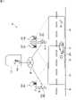
- FIG. 1is a schematic diagram showing an installation example of a detection system 10 according to this embodiment.
- the detection system 10includes a plurality of detection devices 20a, 20b and a plurality of sensor units 30a, 30b, 30c.
- the detection devices 20a and 20bpreferably have the same configuration. Detecting devices 20a and 20b are simply referred to as "detecting device 20" unless otherwise distinguished.
- the sensor units 30a, 30b, 30cpreferably have the same configuration.
- the sensor units 30a, 30b, and 30care simply referred to as "sensor unit 30" unless otherwise distinguished.
- two detection devices 20 and three sensor units 30are illustrated in FIG. 1, the number of detection devices 20 and sensor units 30 included in the detection system 10 is not particularly limited.
- the detection device 20is a device that detects an event based on sensor information from the sensor unit 30.
- the detection device 20functions as an integrated processing device that processes sensor information from the sensor unit 30, controls the sensor unit 30 and the like, and communicates information with other detection devices.
- the detection device 20is communicably connected to the sensor unit 30 by wire or wirelessly.
- the detection device 20acontrols, for example, the sensor units 30a and 30b
- the detection device 20bcontrols, for example, the sensor unit 30c.
- the detection device 20a and the detection device 20bare connected via a telecommunications network N1.
- the detection devices 20 and the sensor units 30may be in one-to-many correspondence like the detection device 20a, or may be in one-to-one correspondence like the detection device 20b. Alternatively, one detection device 20 may control all sensor units 30 included in the detection system 10 .
- the detection device 20 and the sensor unit 30are installed at a position facing the roadway or its vicinity (these are collectively referred to as "road R1").
- the road R1is, for example, a highway (highway national highway). Note that the road R1 is not particularly limited as long as it is a road on which vehicles travel, and may be a general national road, a prefectural road, or other roads.
- the road R1may include, in addition to the area where the vehicle can normally travel, an area where the vehicle can enter in an emergency, such as a road shoulder and an emergency parking strip, and a median strip.
- arrow AR1indicates the direction of vehicle traffic on road R1.
- the road R1is, for example, a one-way street, and vehicle traffic is permitted only in the traffic direction AR1.
- the downstream in the traffic direction AR1will be simply referred to as “downstream”
- the upstream in the traffic direction AR1will be simply referred to as “upstream”.
- the detection device 20ais provided below the column 6a, and the sensor units 30a and 30b are provided above the column 6a.
- the detection device 20bis provided below the column 6b, and the sensor unit 30c is provided above the column 6b.
- the sensor unit 30is a unit for detecting events on the road R1.
- the sensor unit 30adetects events in the first area A1, the sensor unit 30b detects events in the second area A2, and the sensor unit 30c detects events in the third area A3.
- the first to third areas A1 to A3are areas included in the road R1.
- the area set in each sensor unit 30may not overlap with other areas like the first area A1, or may overlap with other areas like the second area A2 and the third area A3. may In this embodiment, the target areas for event detection are arranged in the order of the first area A1, the second area A2, and the third area A3 from upstream.
- the detection device 20communicates with the management device 200 via the telecommunications network N1.
- the management device 200is a device that manages multiple detection devices 20 .
- This management device 200is provided, for example, in the traffic control center TC1.
- FIG. 2is a perspective view schematically showing the sensor unit 30a.
- the sensor unit 30ahas a housing 31a, a sensor 40a, and a camera 50a.
- the sensor 40a and the camera 50aare accommodated in one housing 31a.
- the sensor 40a and the camera 50amay be accommodated in separate housings.
- the sensor units 30b and 30calso have the same configuration as the sensor unit 30a.
- the sensor unit 30bhas a housing (not shown), and a sensor 40b and a camera 50b housed in the housing.
- the sensor unit 30calso has a housing (not shown), and a sensor 40c and a camera 50c housed in the housing.
- the housings of the sensor units 30a, 30b, and 30c, the sensors 40a to 40c, and the cameras 50a to 50bpreferably have the same configuration. camera 50”.
- the sensor 40is a millimeter wave radar for measuring the position, direction, speed, etc. of the object by radiating electromagnetic waves in the millimeter wave band (20 to 300 GHz) toward the object and receiving and processing the reflected waves.
- electromagnetic wavesincluding.
- FMCWFrequency Modulated Continuous Wave
- the sensor 40has a transmitter that transmits electromagnetic waves to the road R1, a receiver that receives electromagnetic waves (reflected waves) reflected on the road R1 (or objects on the road R1), and a processing circuit.
- the processing circuitdetects the distance, the direction of the object, and the speed of the object for which the intensity of the reflected wave is equal to or greater than a predetermined threshold. Specifically, the processing circuit calculates the distance from the sensor 40 to the object by measuring the time from when the electromagnetic waves are transmitted until when the reflected waves are received.
- the receiving unitincludes a plurality of receiving antennas, and the processing circuit detects the position of the object with respect to the sensor 40 based on the phase difference of the reflected waves caused by the time difference when the plurality of receiving antennas receive the reflected waves. Calculate direction.
- the processing circuitryalso calculates the velocity of the object relative to sensor 40 based on the Doppler shift of the received electromagnetic waves.
- the sensor 40transmits data on the position (distance and direction) and speed of the object thus obtained to the detection device 20 as sensor information D1.
- the sensor 40may be configured to include other object detection sensors such as a lidar (LiDAR).
- the sensor 40may be a camera (image sensor) that captures the road R1 with visible light or infrared light.
- the camera 50may have both the function of the sensor 40 for detecting the presence and type of an event and the function of the camera 50 for detecting detailed information about the event.
- the sensor 40may be a camera different from the camera 50 .
- the camera 50is an imaging device for recording detailed information on events detected by the sensor 40 .
- the camera 50usually captures a full view of the target area, and records detailed information of the event when an event is detected.
- This camera 50has a movable section 51 capable of changing the photographing direction, a zoom lens 52 capable of changing the focal length, and an imaging device 53 that converts optical information into electronic signals.
- the camera 50may acquire images (still images) one by one according to a command from the detection device 20, or may acquire a plurality of images as a moving image with a predetermined number of frames according to a command from the detection device 20.
- the camera 50may have a light-emitting section that emits visible light or infrared light (for example, strobe light emission).
- the area captured by the camera 50includes the area where the sensor 40 detects an event.
- the camera 50aphotographs an area including the first area A1.
- a camera 50 that captures an area including the area detected by the sensor 40 in this manneris referred to as a "camera 50 corresponding to the sensor 40".
- the camera 50 corresponding to the sensor 40ais “camera 50a”
- the camera 50 corresponding to the sensor 40bis "camera 50b”.
- FIG. 3is a block diagram showing the functional configuration of the detection system 10. As shown in FIG. FIG. 3 shows the functional configuration of the detection device 20a in detail, and the functional configuration of the detection device 20b is omitted because it is the same as that of the detection device 20a.
- the detection device 20 (20a)detects an event that has occurred on the road R1 based on the sensor information D1 transmitted from the sensor 40.
- the detection device 20is substantially a computer and has a control section 21 , a storage section 22 and a communication interface functioning as a communication section 23 .
- the control unit 21includes an arithmetic unit (processor).
- the computing unitincludes, for example, a CPU (Central Processing Unit).
- the computing unitmay be configured to further include a GPU (Graphics Processing Unit).
- the storage unit 22includes a main storage unit and an auxiliary storage unit.
- the main storage unitincludes, for example, RAM (Random Access Memory).
- the auxiliary storage unitincludes, for example, an HDD (Hard Disk Drive) or an SSD (Solid State Drive).
- the detecting device 20realizes the functions of the respective units 24 to 27 described later by the control unit 21 (calculating unit) executing a computer program stored in the storage unit 22 .
- the control unit 21has a detection unit 24, a selection unit 25, an instruction unit 26, and a detail detection unit 27 as functional units.
- Each of these functional units 24 to 27may be implemented by the same processing area in the control unit 21, or may be implemented by separate processing areas.
- one CPUmay implement both the functions of the detection unit 24 and the details detection unit 27, or the CPU that implements the functions of the detection unit 24 and the CPU that implements the functions of the details detection unit 27 may be It may be provided separately.
- the detection unit 24detects a predetermined event on the road R1 based on the sensor information D1 acquired from the sensor 40.
- the storage unit 22stores a selection table in which the content of the event is associated with the camera 50 used for shooting, the shooting conditions, and the like for each of a plurality of types of events.
- the selection unit 25refers to the selection table and selects the camera 50 to be used for capturing the image Im1 related to the event from among the plurality of cameras 50 according to the content of the event detected by the detection unit 24 .
- the instruction unit 26instructs the camera 50 selected by the selection unit 25 to shoot.
- the detail detection unit 27detects event detail information D3 based on the image Im1 captured by the camera 50 .
- the storage unit 22stores computer programs, sensor information D1, image Im1, detailed information D3, selection tables and other parameters.
- the communication unit 23transmits and receives various types of information to and from other detection devices 20 and the management device 200 via the telecommunications network N1.
- the detection unit 24Based on the sensor information from the sensor 40, the detection unit 24 is set to be able to detect multiple types of events.
- the multiple types of events to be detectedinclude overspeeding, reverse driving, parking (illegal parking), falling objects, and traffic jams of the vehicle V1.
- the detection unit 24has a function of performing predetermined preprocessing on the sensor information D1 from the sensor 40, and a function of executing event detection processing for detecting an event based on the data obtained by the preprocessing.
- Preprocessingincludes clustering processing, tracking processing, and the like.
- the clustering processis a process of recognizing an object (for example, a vehicle V1) by combining a plurality of reflected wave points included in the sensor information D1 into one combined body. By this processing, it becomes possible to recognize each target object (vehicle V1), and the size of the target object can also be estimated.
- Tracking processingpredicts the next detected position from the time-series data of the position (distance and direction) and speed of the object (vehicle V1) obtained by the clustering process, and compares the actual detected position with the predicted position. This is a process of identifying and tracking an object. Further, the detecting unit 24 gives a vehicle ID to each detected vehicle V1 in order to identify the detected vehicle V1. Note that such preprocessing may be performed on the sensor unit 30 side.
- the event detection processdetects the occurrence of an event, the vehicle ID of the vehicle V1 involved in the event, and the place of occurrence (occurrence position) of the event based on the speed, position (running lane, etc.), running state, etc. of each vehicle V1. This is the process of detecting.
- the detection unit 24detects overspeeding of the vehicle V1 by comparing the speed of the vehicle with a predetermined speed threshold.
- the detection unit 24also detects reverse running of the vehicle V1 by monitoring the running direction of the vehicle V1 for a certain period of time.
- the detection unit 24further detects parking of the vehicle V1 when the position of the vehicle V1 does not change for a certain period of time (that is, when the speed is 0). In this case, the detection unit 24 detects illegal parking of the vehicle V1 depending on whether or not the parking position is a parking prohibition position.
- the detection unit 24further detects the falling object M1 based on the speed, direction, size, etc. of the object. For example, when the object is smaller than a predetermined size (for example, the size of a small vehicle) and is stationary, the detection unit 24 recognizes the object as the falling object M1. Furthermore, for example, when the target object is smaller than a predetermined size and is recognized as originating from the vehicle V1 in motion and as if the target object is generated from behind the vehicle V1, the detection unit 24 detects the target object as the vehicle V1. It is recognized as the falling object M1 from V1.
- a predetermined sizefor example, the size of a small vehicle
- the detection unit 24detects the target object as the vehicle V1. It is recognized as the falling object M1 from V1.
- the detection unit 24further determines the number of vehicles V1 passing through each lane for a predetermined time (for example, 5 minutes to 10 minutes), the average speed of the vehicles V1, the occupation ratio of the vehicles V1 to the lane, and the like. is calculated, and congestion is detected based on the calculation result.
- a predetermined timefor example, 5 minutes to 10 minutes
- the detection unit 24When the detection unit 24 detects the occurrence of an event, it creates event information D2 regarding the detected event.
- the event information D2includes, for example, the type of the detected event, the place of occurrence of the event (location information), the time of occurrence, the vehicle ID of the vehicle V1 involved in the event, and the like.
- the management device 200has a control unit 201 , a storage unit 202 , and a communication unit 203 in the same hardware configuration as the detection device 20 .
- the control unit 201includes an arithmetic unit (processor) such as a CPU.
- the storage unit 202includes a main storage unit and an auxiliary storage unit.
- a communication unit 203functions as a communication interface.
- ⁇ Software configuration> 4 and 5are flow charts showing the control structure of the program executed by the detection device 20.
- FIG. 4 and 5are flow charts showing the control structure of the program executed by the detection device 20.
- the programincludes step S201 of receiving sensor information D1 from sensor 40, step S202 of executing processing for detecting an event based on the received sensor information D1, and and step S203 for branching the flow of control.
- step S202in addition to the process of detecting an event, the process of generating event information D2 regarding the detected event is also executed.
- the event to be detectedis, of the events that can occur in the areas A1 to A3, which are the target areas of the sensor 40, events that are likely to cause traffic delays or accidents, for example.
- the event to be detectedis also an event preset in the computer program stored in the storage unit 22 . Events to be detected include, for example, the following events.
- This programis further executed when the detected event is "parking" or "falling object", step S204 of referring to the selection table to select the camera 50 at the location where the event occurs, and setting the shooting conditions of the selected camera. and step S205 of determining.
- This programis further executed when the detected event is "excessive speed", step S206 of referring to the selection table to select the camera 50 where the event occurred, and step S207 of determining the shooting conditions of the selected camera. including.
- This programis further executed when the detected event is "reverse running", step S208 of referring to the selection table to select the camera 50 where the event occurred, and step S209 of determining the shooting conditions of the selected camera. including.
- This programis further executed when the detected event is "traffic jam", step S210 of referring to the selection table to select the camera 50 at the location where the event occurred, and step S211 of determining the photographing conditions of the selected camera. including.
- the programfurther includes a step S214 of transmitting a control signal to the selected camera 50, a step S215 of receiving an image Im transmitted from the camera 50 that transmitted the control signal, a step S215 of receiving the a step S216 of detecting detailed information D3 of the event from the image Im, and a step S217 of storing the detected detailed information D3 in the storage unit 22 and transmitting it to the management device 200 via the communication unit 23 and the telecommunications network N1; including.
- the detection device 20repeatedly executes the above processing.
- FIG. 6is a flow chart showing the control structure of the program executed by the camera 50.
- this programincludes step S301 for photographing in the normal mode, step S302 for receiving a control signal from the detection device 20, and photographing in a predetermined photographing mode based on the instruction of the received control signal. It includes a step S303 and a step S304 of transmitting the image Im taken in the predetermined shooting mode to the detecting device 20 that has sent the control signal.
- the normal mode in step S301refers to a mode in which the entire view of the target area is photographed using, for example, the number of frames equal to or less than the first number of frames F1.
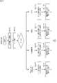
- FIG. 7is a sequence diagram showing an example of the detection method executed by the detection system 10. As shown in FIG. The operation of the detection system 10 will now be described with appropriate reference to FIGS. 1 to 7.
- FIG. 7is a sequence diagram showing an example of the detection method executed by the detection system 10. As shown in FIG. The operation of the detection system 10 will now be described with appropriate reference to FIGS. 1 to 7.
- FIG. 7is a sequence diagram showing an example of the detection method executed by the detection system 10. As shown in FIG. The operation of the detection system 10 will now be described with appropriate reference to FIGS. 1 to 7.
- FIG. 7is a sequence diagram showing an example of the detection method executed by the detection system 10. As shown in FIG. The operation of the detection system 10 will now be described with appropriate reference to FIGS. 1 to 7.
- FIG. 7is a sequence diagram showing an example of the detection method executed by the detection system 10. As shown in FIG. The operation of the detection system 10 will now be described with appropriate reference to FIGS. 1 to 7.
- FIG. 7is a sequence diagram showing
- the sensor 40aconstantly transmits electromagnetic waves to the road R1 and receives reflected waves.
- the sensor 40agenerates sensor information D1 (electrical signal) based on the received reflected wave, and transmits the generated sensor information D1 to the detection device 20a (step S1).
- the control unit 21 of the detection device 20aUpon receiving the sensor information D1, the control unit 21 of the detection device 20a stores the received sensor information D1 in the storage unit 22.
- the detection unit 24 of the detection device 20aperforms the above-described preprocessing and event detection processing based on the received sensor information D1, thereby determining the occurrence of a predetermined event and the vehicle ID of the vehicle V1 involved in the event. Then, the event occurrence location (occurrence position) and the like are detected, and event information D2 relating to the detected event is created (step S2).
- the created event information D2is stored in the storage unit 22 .
- the event information D2includes, for example, the type of event, the place where the event occurred, the time when the event occurred, the vehicle ID of the vehicle V1 related to the event, and the speed of the vehicle V1 related to the event.
- predetermined eventsmay include events other than the above.
- the selection unit 25extracts information about the type of event and the place where the event occurs from the event information D2.
- the selection unit 25selects the camera 50 to be used for capturing the image Im1 related to the event from among the plurality of cameras 50a to 50c according to the type of event included in the event information D2 (step S3: second step). .
- the instruction unit 26refers to the selection table and determines the shooting conditions of the selected camera 50 (step S4).
- the photographing conditionsinclude, for example, the photographing location (center of road R1 or shoulder), zoom magnification, photographing start time, photographing time from photographing start to photographing end, number of frames, and the like.
- the selection unit 25determines which type the detected event corresponds to (step S203). Then, if the type of event is "parking" or "falling object", the selection unit 25 selects the camera 50 that captures the location of the event (steps S204, S3). More specifically, when the vehicle V1 parked in the first area A1, which is the target area of the sensor 40a, is detected based on the sensor information D1 of the sensor 40a, the selection unit 25 shoots the first area A1. select the camera 50a to be used.
- the instruction unit 26determines the imaging conditions of the selected camera 50a (steps S205, S4). Specifically, the instruction unit 26 determines the shooting location and zoom magnification so that the license plate of the vehicle V1 is included. In addition, since the parked vehicle V1 is not expected to move immediately (for example, within a few seconds), the instruction unit 26 reduces the number of frames to a relatively small predetermined first number in order to save data capacity. The number of frames is determined as F1 (for example, 5 frames per second).
- the selection unit 25selects the camera 50a that captures the first area A1 (step S204). Then, the instruction unit 26 determines the shooting location so as to include the location of the falling object M1, and determines the zoom magnification according to the size of the falling object M1. Also, since it is considered that the fallen object M1 will not move immediately, like the parked vehicle V1, the instruction unit 26 determines the number of frames to be the first number of frames F1 (step S205).
- the details of the removal workinclude the object of the fallen object M1 (for example, whether the fallen object M1 is a heavy object) and the place change depending on The worker who performs the removal work judges the details of the fallen object M1 based on detailed information D3, which will be described later, and proceeds to the removal work of the fallen object M1.
- the instruction unit 26may determine both the shooting conditions for specifying the target of the falling object M1 and the shooting conditions for specifying the location of the falling object M1.
- the photographing conditions for specifying the objectare, for example, conditions for zooming in and photographing the falling object M1 in order to specify in detail what the falling object M1 is.
- the photographing condition for location identificationis, for example, a condition for photographing the full view of the first area A1 including the fallen object M1 in order to specify in detail where the fallen object M1 is located on the road R1.
- the instruction unit 26instructs the camera 50a to perform photographing for object identification for a predetermined photographing time and then photographing for location identification for a predetermined photographing time as photographing conditions.
- the selection unit 25shoots a location downstream of the location where the event occurred (the location of the falling object M1).
- the camera 50may be selected, and the instruction unit 26 may determine the shooting location and zoom magnification of the camera 50 so as to include the license plate of the vehicle V1.
- the selection unit 25selects the camera 50 that captures the location where the event occurs and the camera 50 that captures locations downstream of the location where the event occurs (step S206, step S3). .
- the selection unit 25selects the camera 50a for photographing the first area A1. , the cameras 50b and 50c for capturing the downstream of the first area A1 are selected. Note that the selection unit 25 may not select the camera 50 that captures the location where the event occurs, but may select only the camera 50 that captures a location downstream of the location where the event occurs.
- the instruction unit 26determines the imaging conditions of the selected cameras 50a, 50b, and 50c (steps S207 and S4). Specifically, the instruction unit 26 determines the shooting times of the cameras 50a, 50b, and 50c based on the event occurrence time included in the event information D2 and the speed of the vehicle V1. Further, the instruction unit 26 determines the photographing locations and zoom magnifications of the cameras 50a, 50b, and 50c so that the license plate of the vehicle V1 is included.
- the instruction unit 26sets the number of frames to a second number F2 larger than the first number F1 (for example, 30 sheets).
- the number of framesmay be determined based on the speed of vehicle V1. For example, the number of frames may be increased as the speed of the vehicle V1 increases.
- the selection unit 25selects the camera 50 that captures the location where the event occurs and the camera 50 that captures a location upstream of the location where the event occurs (step S208, step S3). .
- the selection unit 25selects the camera that captures the second area A2. 50b and a camera 50a that captures an image upstream of the second area A2. Note that the selection unit 25 may not select the camera 50 that captures the location where the event occurs, but may select only the camera 50 that captures a location upstream of the location where the event occurs.
- the instruction unit 26determines the imaging conditions of the selected cameras 50a and 50b (steps S209 and S4). Specifically, the instruction unit 26 determines the shooting times of the cameras 50a and 50b based on the event occurrence time included in the event information D2 and the speed of the vehicle V1. Further, the instruction unit 26 determines the photographing locations and zoom magnifications of the cameras 50a and 50b so that the license plate of the vehicle V1 is included. Further, in order to more reliably photograph the license plate of the running vehicle V1, the instruction unit 26 determines the number of frames to be the second number F2, which is larger than the first number F1.
- the selection unit 25selects the camera 50 that captures the location of the event (step S210, step S3). More specifically, when traffic congestion is detected in the first area A1 based on the sensor information D1 of the sensor 40a, the selection unit 25 selects the camera 50a that captures the first area A1.
- the selection unit 25uses a camera that captures locations upstream and downstream of the event occurrence location. 50 may be further selected.
- the instruction unit 26determines the imaging conditions of the selected camera 50a (steps S211, S4). Specifically, the instruction unit 26 determines the zoom magnification (for example, 1) of the camera 50a so that the full view of the first area A1 is included. In addition, the vehicle V1 included in the traffic jam is traveling at a relatively low speed, and the traffic jam situation is not likely to change immediately (for example, within a few seconds). Determine the number of frames F1.
- the zoom magnificationfor example, 1
- the instruction unit 26instructs the camera 50 selected by the selection unit 25 to shoot (steps S5 to S7).
- the instruction unit 26 of the detection device 20atransmits a control signal to the camera 50a (or the camera 50b) (step S214, step S5).
- the instruction unit 26 of the detection device 20atransmits a control signal to the detection device 20b that controls the camera 50c via the telecommunications network N1 (steps S214, S6). .
- the detection device 20btransmits a control signal to the camera 50c (step S7).
- the camera 50normally operates in normal mode (step S301, steps S8 and S9).
- the normal moderefers to a mode in which the entire view of the target area is photographed with the number of frames equal to or less than the first number of frames F1, for example. Note that the camera 50 may always operate in a standby mode (a power-saving standby mode in which photography is not performed).
- the camera 50When the camera 50 receives the control signal from the instruction unit 26 (step S302), the camera 50 operates in a predetermined shooting mode based on the control signal (steps S303, steps S10, S11).
- the predetermined photographing modeis a mode in which photographing is performed under various photographing conditions determined by the instruction section 26 in step S4.
- the camera 50When the camera 50 finishes shooting in the shooting mode, it transmits the image Im1 to the detection device 20 (step S304, steps S12-S14).
- the detection device 20stores the received image Im1 in the storage unit 22 .
- the cameras 50a and 50btransmit the image Im1 to the detection device 20a (step S12).
- the camera 50ctransmits the image Im1 to the detection device 20b (step S13), and the detection device 20b transmits the image Im1 to the detection device 20a via the electric communication network N1 (step S14).
- the control unit 21 of the detection device 20 areceives the image Im (steps S ⁇ b>215 , steps S ⁇ b>12 and S ⁇ b>14 ), and stores the received image Im in the storage unit 22 .
- the detailed detection unit 27 of the detection device 20adetects the detailed information D3 of the event based on the event information D2 and the image Im1 (steps S216 and S15). For example, if the event is "falling object", the detail detection unit 27 trims the location where the falling object M1 is shown from the image Im1 based on the event information D2, and detects the trimmed image as the detailed information D3. Note that the detail detection unit 27 may detect the image Im1 itself as the detailed information D3 without trimming the image Im1.
- the detail detection unit 27identifies the location where the license plate of the vehicle V1 is shown from the image Im1 based on the event information D2. . Then, the detail detection unit 27 reads characters on the license plate and detects the character information as detailed information D3. Note that the detail detection unit 27 may detect a trimmed image obtained by trimming the license plate portion as the detail information D3. That is, the detail detection unit 27 detects information about the license plate of the vehicle V1 (information including at least one of character information of the license plate and an image including the license plate) as the detailed information D3. Further, when the event type is "traffic jam", the detail detection unit 27 detects the image Im1 itself as the detailed information D3.
- the detailed detection unit 27stores the detected detailed information D3 in the storage unit 22, and transmits the detailed information D3 to the management device 200 via the communication unit 23 and the telecommunications network N1 (steps S217 and S16).
- the control unit 201 of the management device 200stores the detailed information D3 received by the communication unit 203 in the storage unit 202 .
- the detection device 20includes a selection unit 25 that selects a camera 50 to be used for capturing an image Im1 related to the event from a plurality of cameras 50 installed on the road R1 according to the detected event, and the selected camera 50 and an instruction unit 26 for instructing photographing. Therefore, a more suitable image Im1 can be recorded according to the detected event. Further, the detailed information D3 of the event can be detected more accurately based on the image Im1.
- the camera 50 located downstream from the location where the event was detectedis instructed to shoot, so that the vehicle V1 in motion is captured in the image Im1 more reliably. be able to.
- the type of the eventis "reverse driving”
- the camera 50 located upstream from the location where the event was detectedis instructed to shoot, so that the vehicle V1 in motion is captured in the image Im1 more reliably. be able to.
- the instruction unit 26determines shooting conditions for the camera 50 selected by the selection unit 25 according to the detected event, and instructs the camera 50 selected by the selection unit 25 to shoot under the shooting conditions. Therefore, a more suitable image Im1 can be acquired according to the event, and the detailed information D3 of the event can be detected more accurately based on the image Im1.
- the instruction unit 26determines the number of frames of the selected camera 50 to be the second number of frames F2, which is larger than the first number of frames F1. This makes it possible to more reliably include the vehicle V1 in motion in the image Im1. Also, if the event is "parking”, “overspeed” or “reverse driving”, the shooting location and zoom magnification of the selected camera 50 are determined so that the license plate of the vehicle V1 is captured. Detailed information D3 containing information can be detected more accurately.
- the detection unit 24may be configured to detect one or a plurality of events occurring on the road R1 from a plurality of preset events using a learning model learned by machine learning.
- FIG. 8is a block diagram illustrating processing by a learned discrimination model.
- the storage unit 22stores a learned discrimination model MD1.
- the identification model MD1is, for example, a model obtained by learning correspondences between multiple types of events and labels L1 by a predetermined learning algorithm LA1 using learning data LD1 (teacher data).
- a support vector machinefor example, can be used for the learning algorithm LA1.
- the learning algorithm LA1may use algorithms other than support vector machines (for example, neural networks such as deep learning).
- the feature amount FV1 of the objectis extracted by preprocessing the input sensor information D1.
- a feature quantity FV1 effective for event detectionis extracted from the sensor information D1 by signal processing.
- the extracted feature quantity FV1is input to the discrimination model MD1, and the label L1, which is the detection result of the event, is output.
- FIG. 9is a block diagram illustrating processing for generating learning data LD1.
- Learning data LD1is generated by detecting and labeling each event individually. Events such as reverse driving, excessive speed, traffic congestion, etc. can be automatically detected from the sensor information D1 as described above. When these events are detected, it is possible to generate learning data LD1 by extracting data in a predetermined time range including the event detection time and by associating the extracted data with the label L1 of each event.
- learning data LD1regarding parking (illegal parking) and falling objects.
- various illegal parking and various falling objectsare detected by the sensor 40 in the target area of the sensor 40, and the operator inputs the corresponding label L1 based on the sensor information D1 displayed on the display.
- learning data LD1is generated.
- the discriminant model MD1By creating the discriminant model MD1 using such learning data LD1, it is possible to accurately detect a plurality of types of events. In particular, it is possible to improve the detection accuracy of events such as parked vehicles and falling objects.
- ⁇ Modified example when control signals conflict>an event is detected based on the sensor information D1, and a control signal including one shooting condition is sent to the camera 50 in step S5, for example.
- a control signal including one shooting conditionis sent to the camera 50 in step S5, for example.
- multiple eventsmay occur simultaneously on the road R1.
- the vehicle V1may run in the opposite direction in the second area A2.
- the detection unit 24 of the detection device 20adetermines that a "falling object" has occurred as an event based on the sensor information D1 of the sensor 40a, and based on the sensor information D1 of the sensor 40b, as an event It is determined that "reverse running” has occurred.
- the selection unit 25selects the camera 50a for photographing the location of the occurrence of the "falling object” according to the detected event "falling object", and the instruction unit 26 selects the photographing conditions (for example, the full view of the first area A1). A condition for setting the zoom magnification to 1 and the number of frames to be the first frame number F1 for photographing is determined. Then, the instruction unit 26 transmits a control signal CS1 corresponding to "falling object" to the camera 50a.
- the selection unit 25selects the camera 50a that captures the upstream of the occurrence location of the “reverse run” according to the detected event “reverse run”, and the instruction unit 26 sets the shooting conditions (for example, the vehicle V1 is set to a zoom magnification larger than 1 and the number of frames is set to the second number of frames F2 in order to photograph the license plate. Then, the instruction unit 26 transmits a control signal CS2 corresponding to "reverse running" to the camera 50a.
- a plurality of control signals CS1 and CS2may be sent to the camera 50 at the same time. That is, in one camera 50, a plurality of control signals CS1 and CS2 may conflict.
- the cameras 50perform shooting in the order in which the control signals are input.
- the control signal CS1is first input to the camera 50a and the camera 50a captures the entire view of the first area A1 for a predetermined capturing time based on the control signal CS1
- the vehicle V1 running in the opposite direction during the capturingis There is a risk of passing through the first area A1.
- the vehicle V1 running in the opposite directionmay be missed.
- the control signalis assigned a priority parameter for each type of event.
- the type of eventis "excessive speed”
- the object to be photographedis the vehicle V1 that is running, and the vehicle V1 decelerates to easily exit the state of exceeding the predetermined speed.
- the time during which the vehicle V1 can be photographed during the occurrence of the eventis limited. For this reason, the highest priority is given to shooting related to "speeding".
- the type of eventis "reverse driving"
- the object to be photographedis the running vehicle V1
- the time at which the camera 50 can photograph the vehicle V1 during the occurrence of the eventis limited to some extent.
- the vehicle V1is more difficult to get out of the reverse running state. Therefore, even if the camera 50c fails to capture the vehicle V1 running in the reverse direction, there is a possibility that the other camera 50a can capture the image. is high. For this reason, the shooting priority for "reverse driving” is set lower than that for "excessive speed”.
- the object to be photographedis the parked vehicle V1. ” and “reverse running”.
- the parked vehicle V1may start and move from its place, it is preferable to shoot the event earlier than when the event is "falling object”. For this reason, the shooting priority for "parking” is set lower than “overspeed” and “reversing” and higher than "falling object”.
- the priority of the image related to "traffic jam”is set lower than that of other events.
- the priority of each type of event in this modificationis, in descending order, excessive speed, reverse driving, parking, falling objects, and congestion.
- the said priorityis an example and may be other than said order.
- the detection device 20is provided separately from the sensor unit 30 .
- part or all of detection device 20may be included in sensor unit 30 .
- a computermay be installed in the sensor unit 30 and the computer may detect an event based on the sensor information D1 of the sensor 40 .
- the computer equipped with the sensor unit 30functions as the detection unit 24 .
- the detection device 20may be realized by a computer installed in one place as in the above embodiment, or may be realized by a plurality of computers distributed among the sensor units 30.
- the sensor 40capable of monitoring an area of 200 m and the camera 50 capable of monitoring an area of 100 m
- one sensor 40has two The cameras 50 may correspond, the sensors 40 may be installed every 200 m, and the cameras 50 may be installed every 100 m.
- the detection system according to this modificationhas a function in which a plurality of sensor units 30 (sensors 40) and a plurality of detection devices 20 operate in cooperation. As a result, the vehicle V1 traveling across the target area of the sensor 40 is tracked.
- an eventsuch as excessive speed or reverse running is assumed as an event to be detected. That is, when the detection system 10 detects an event such as overspeeding or reverse driving, the detection system 10 identifies the target vehicle V1 of the event, and tracks the identified event target vehicle V1 beyond the target area where the event was detected. Further, the detection system 10 records the event target vehicle V1 while tracking the event target vehicle V1 by switching the selection of the camera 50 for photographing the event target vehicle V1 according to the tracking situation.
- the plurality of sensor units 30work together by operating based on the same time.
- Each of the plurality of sensor units 30synchronizes time by acquiring time information from, for example, an NTP (Network Timing Protocol) server.
- NTPNetwork Timing Protocol
- FIG. 10is a flow chart showing the order of operations performed by the detection devices 20a and 20b according to this modification.
- the processing of a part of the tracking section when the event target vehicle V1 is trackedwill be described.
- the sensor information D1 obtained from the sensors 40a and 40cwill be referred to as sensor information D1a and D1c, respectively
- the event information D2 detected based on the sensors 40a and 40cwill be referred to as event information D2a and D2c, respectively.
- the detection device 20adetects overspeeding of the vehicle V1. Specifically, the detection device 20a receives the sensor information D1a from the sensor 40a (step S401). Subsequently, the detection unit 24 of the detection device 20a detects the event "speeding" based on the received sensor information D1a, and generates event information D2a including the vehicle ID, position, speed, size, etc. of the vehicle V1. Generate (step S402). The detection device 20a selects the camera 50 that captures the location where the event occurs and the camera 50 that captures the location downstream of the location where the event occurs, according to the detected event (excessive speed). The detecting device 20a issues a photographing instruction to the camera 50 for photographing the place where the event occurs, and also transmits the event information D2a to the downstream detecting device 20b (step S403).
- the detection device 20breceives the sensor information D1c from the sensor 40c (step S501).
- the detecting device 20breceives the event information D2a from the detecting device 20a (step S502). Note that the detection device 20b may receive the sensor information D1c after receiving the event information D2a.
- the detecting device 20bextracts information about the vehicle V1 from the sensor information D1c based on the event information D2a (step S503). With this configuration, even if the sensor information D1c acquired from the sensor 40c does not include the event "speeding", information (for example, position, speed) of the vehicle V1 can be obtained from the sensor information D1c. can be obtained.
- the detection device 20bfurther assigns the same ID (or a corresponding ID) as the vehicle ID included in the event information D2a received from the detection device 20a as the vehicle ID of the event information D2c generated based on the sensor 40c. .
- the event information D2a detected based on the sensor 40a and the event information D2c detected based on the sensor 40ccan be linked. Since the same (or corresponding) ID is given to the vehicle V1 in the separate event information D2a and D2c, the vehicle V1 can be tracked more easily.
- the detection device 20bselects the camera 50 for photographing the vehicle V1 and determines the photographing conditions according to the detection of the vehicle V1.
- the detection device 20bissues a photographing instruction to the selected camera, and transmits the event information D2a received from the detection device 20a and the dignity and direction D2c detected by the detection device 20b to another detection device located downstream of the detection device 20b. Send.
- the detection system according to this modificationtracks and records the overspeeding vehicle V1.
- the present disclosureis not limited to such an example.
- the event target vehiclemay be tracked and recorded.
- event informationis sent to other detectors located upstream of the detector that detected the event.
- the sensor 40 of the above-described embodimenttransmits electromagnetic waves to the road R1, and acquires sensor information D1 including information regarding events occurring on the road R1 based on the reflected waves.
- the sensor 40may transmit electromagnetic waves to an area other than the road R1 and acquire the sensor information D1 including information about an event that occurs in an area other than the road R1.
- the sensor 40may acquire the sensor information D1 from an area located in the vicinity of the road R1 in addition to the road R1.
- the detection device 20may detect an event that will hinder the passage of the vehicle V1 on the road R1 in the future.
- the detection unit 24selects a camera 50 for capturing an image related to the event from among the plurality of cameras 50 installed on the road R1 according to the details of the event. do.
- the contents of the eventinclude, for example, the place where the event occurred and the type of the event.
- the detection unit 24selects a camera 50 suitable for photographing the event (for example, a camera 50 close to the event occurrence place) according to the content of the detected event (that is, the event occurrence place).
- the detection unit 24may detect only "excessive speed" as an event based on the sensor information D1. That is, only the route of steps S203 ⁇ S206 ⁇ S207 in FIG. 6 may be selected. In this case, the selection unit 25 selects the camera 50 that captures the location where the event occurs and the camera 50 that captures a location downstream of the location where the event occurs. image information regarding excess) can be recorded more accurately.
- the detection unit 24may detect only "reverse driving" as an event based on the sensor information D1. That is, only the route of steps S203 ⁇ S208 ⁇ S209 in FIG. 6 may be selected. In this case, the selection unit 25 selects the camera 50 that captures the location where the event occurs and the camera 50 that captures the location upstream from the location where the event occurs. It is possible to record image information related to running (running) more accurately.
Landscapes
- Engineering & Computer Science (AREA)
- Physics & Mathematics (AREA)
- General Physics & Mathematics (AREA)
- Multimedia (AREA)
- Theoretical Computer Science (AREA)
- Traffic Control Systems (AREA)
Abstract
Description
Translated fromJapanese 本開示は、検出装置、検出システム及び検出方法に関する。
本出願は、2021年7月14日出願の日本出願第2021-116600号に基づく優先権を主張し、前記日本出願に記載された全ての記載内容を援用するものである。The present disclosure relates to detection devices, detection systems, and detection methods.
This application claims priority based on Japanese Application No. 2021-116600 filed on July 14, 2021, and incorporates all the descriptions described in the Japanese Application.
従来、車両が通行する道路にカメラを設置し、当該カメラにより撮影される画像に基づいて、道路状況を監視するシステムが知られている。Conventionally, a system is known in which a camera is installed on a road on which vehicles travel, and the road conditions are monitored based on the images captured by the camera.
特許文献1には、交差点において信号を無視した車両を検出し、検出した車両をカメラで撮影するシステムが記載されている。このシステムは、交差点の全景を写しこむ交差点全景用カメラ、交差点内に侵入した特定の車両を撮影する車両撮影用カメラ、交差点に設定以上のスピードで進入してくる車両を検出する速度感知器を含む。赤信号時に、設定以上のスピードで交差点に進入してくる車両(信号無視候補車両)を速度感知器が検出すると、車両撮影用カメラの映像を画像処理して信号無視候補車両を検出する。信号無視候補車両が検出されると、システムは、車両撮影用カメラの映像を複数コマの静止画像に変換して記録する。これにより、交差点において信号を無視した車両の車両番号(ナンバープレート)及び運転者が静止画像として記録される。Patent Document 1 describes a system that detects vehicles ignoring traffic signals at intersections and photographs the detected vehicles with a camera. This system consists of an intersection panorama camera that captures the entire intersection, a vehicle camera that captures specific vehicles that have entered the intersection, and a speed sensor that detects vehicles approaching the intersection at a speed higher than a set speed. include. When the speed detector detects a vehicle (candidate vehicle ignoring the signal) entering the intersection at a red light at a speed higher than the set speed, the image of the vehicle camera is image-processed to detect the candidate vehicle ignoring the signal. When a signal ignoring candidate vehicle is detected, the system converts the image of the vehicle camera into a plurality of still images and records them. As a result, the vehicle number (license plate) and the driver of the vehicle ignoring the signal at the intersection are recorded as a still image.
本開示の検出装置は、電磁波を道路へ送信し対象物で反射した前記電磁波を受信することで前記対象物を検知するセンサからセンサ情報を取得し、取得した前記センサ情報に基づいて、予め設定されたイベントを検出する検出部と、前記検出部が検出したイベントの内容に応じて、道路上に設置された複数のカメラの中から、前記イベントに関する画像を撮影するカメラを選択する選択部と、前記選択部が選択した前記カメラに対して撮影の指示をする指示部と、を備える、検出装置である。The detection device of the present disclosure acquires sensor information from a sensor that detects the object by transmitting an electromagnetic wave to a road and receiving the electromagnetic wave reflected by the object, and based on the acquired sensor information, preset a detection unit that detects an event detected by the detection unit; and a selection unit that selects, from among a plurality of cameras installed on the road, a camera that captures an image related to the event, according to the content of the event detected by the detection unit. and an instruction unit that instructs the camera selected by the selection unit to shoot.
本開示の検出方法は、電磁波を道路へ送信し対象物で反射した前記電磁波を受信することで前記対象物を検知するセンサからセンサ情報を取得し、取得した前記センサ情報に基づいて、予め設定されたイベントを検出するステップと、検出したイベントの内容に応じて、道路上に設置された複数のカメラの中から、前記イベントに関する画像を撮影するカメラを選択するステップと、選択した前記カメラに対して撮影の指示をするステップと、を備える、検出方法である。The detection method of the present disclosure acquires sensor information from a sensor that detects the object by transmitting an electromagnetic wave to a road and receiving the electromagnetic wave reflected by the object, and based on the acquired sensor information, preset a step of detecting an event that has been detected; a step of selecting a camera from among a plurality of cameras installed on a road to capture an image of the event according to the content of the detected event; and issuing a photographing instruction to the object.
[発明が解決しようとする課題]
特許文献1のシステムでは、車両撮影用カメラの映像を画像処理した際に信号無視候補車両が検出されない場合、車両撮影用カメラの映像は静止画像に変換されない。すなわち、信号無視のようなイベントを検出した場合でも、車両撮影用カメラによって信号無視候補車両が適切に撮影されていない場合は、信号無視候補車両に関する情報(車両番号等)は記録されないという問題がある。[Problems to be solved by the invention]
In the system of Patent Literature 1, if no signal ignoring candidate vehicle is detected when image processing is performed on the image captured by the vehicle camera, the image captured by the vehicle camera is not converted into a still image. In other words, even if an event such as ignoring traffic lights is detected, if the ignoring signal candidate vehicles are not properly photographed by the vehicle camera, the information (vehicle numbers, etc.) regarding the ignoring signal candidate vehicles will not be recorded. be.
かかる課題に鑑み、本開示は、検出したイベントに関する画像情報をより正確に記録することができる検出装置、検出システム及び検出方法を提供することを目的とする。In view of such problems, an object of the present disclosure is to provide a detection device, a detection system, and a detection method that can more accurately record image information related to detected events.
[発明の効果]
本開示によれば、検出したイベントに関する画像情報をより正確に記録することができる。[The invention's effect]
According to the present disclosure, image information regarding detected events can be recorded more accurately.
[本開示の実施形態の説明]
本開示の実施形態には、その要旨として、少なくとも以下のものが含まれる。[Description of Embodiments of the Present Disclosure]
Embodiments of the present disclosure include at least the following as gists thereof.
(1)本開示の検出装置は、電磁波を道路に送信し対象物で反射した前記電磁波を受信することで前記対象物を検知するセンサからセンサ情報を取得し、取得した前記センサ情報に基づいて、予め設定されたイベントを検出する検出部と、前記検出部が検出したイベントの内容に応じて、道路上に設置された複数のカメラの中から、前記イベントに関する画像を撮影するカメラを選択する選択部と、前記選択部が選択した前記カメラに対して撮影の指示をする指示部と、を備える、検出装置である。(1) The detection device of the present disclosure acquires sensor information from a sensor that detects the object by transmitting an electromagnetic wave to the road and receiving the electromagnetic wave reflected by the object, and based on the acquired sensor information a detection unit that detects a preset event; and a camera that captures an image of the event is selected from a plurality of cameras installed on the road in accordance with the content of the event detected by the detection unit. The detection device includes a selection unit and an instruction unit that instructs the camera selected by the selection unit to shoot.
本開示の検出装置によれば、検出したイベントの内容に応じて、道路上に設置された複数のカメラの中から検出したイベントに関する画像を撮影するカメラを選択する。検出したイベントに関する画像を撮影するのに好適なカメラを選択できるため、検出したイベントに関する画像情報をより正確に記録することができる。According to the detection device of the present disclosure, a camera that captures an image related to the detected event is selected from a plurality of cameras installed on the road according to the content of the detected event. Image information about the detected event can be recorded more accurately because a suitable camera can be selected for capturing the image about the detected event.
(2)前記予め設定されたイベントは複数あってもよく、前記検出部は、予め設定された複数のイベントの中から、前記センサ情報に基づいて、1又は複数のイベントを検出してもよい。これにより、検出したイベントに応じて、当該イベントに関する画像を撮影するカメラを選択できるので、検出したイベントに関する画像情報を好適に記録することができる。(2) There may be a plurality of events set in advance, and the detection unit may detect one or more events from among the plurality of events set in advance based on the sensor information. . As a result, it is possible to select a camera for capturing an image related to the event according to the detected event, so that image information related to the detected event can be preferably recorded.
(3)前記予め設定された複数のイベントは、前記センサが前記センサ情報を取得する対象領域において生じ得るイベントを含んでもよい。これにより、センサ情報を取得する対象領域において生じ得るイベントについて、好適な画像情報を記録することができる。(3) The plurality of preset events may include events that can occur in the target area from which the sensor acquires the sensor information. This makes it possible to record suitable image information for an event that can occur in the target area from which sensor information is to be acquired.
(4)前記予め設定された複数のイベントは、法定速度又は指定速度を超える、車両による速度超過の道路走行、道路における車両の逆走、道路への車両の駐車、道路の渋滞、及び道路上における落下物の存在、のうちの少なくとも1つを含んでもよい。こうしたイベントは、記録する必要性が高い。そのため、このように構成すれば、記録する必要性が高いイベントに関する画像情報を好適に記録することができる。(4) The plurality of preset events are exceeding the legal speed or the designated speed, driving the vehicle over speed on the road, driving the vehicle in the wrong direction on the road, parking the vehicle on the road, traffic congestion on the road, and on the road the presence of falling objects in the There is a strong need to record such events. Therefore, with such a configuration, it is possible to preferably record image information related to an event that is highly necessary to be recorded.
(5)前記検出部が前記イベントとして車両による速度超過の道路走行を検出した場合、前記選択部は、前記複数のカメラの中から、前記センサが前記センサ情報を取得する対象領域よりも、前記道路の走行方向に対して下流の領域を撮影対象とするカメラを選択してもよい。(5) When the detection unit detects that the vehicle is traveling on an excessive speed road as the event, the selection unit selects the target area from which the sensor acquires the sensor information from among the plurality of cameras. A camera that captures an area downstream with respect to the running direction of the road may be selected.
このように構成することで、速度超過の道路走行をする車両をより確実に撮影することができる。By configuring in this way, it is possible to more reliably shoot vehicles traveling on the road at excessive speeds.
(6)前記検出部が前記イベントとして道路における車両の逆走を検出した場合、前記選択部は、前記複数のカメラの中から、前記センサが前記センサ情報を取得する対象領域よりも、前記道路の走行方向に対して上流の領域を撮影対象とするカメラを選択してもよい。(6) When the detection unit detects that the vehicle is traveling in the wrong direction on the road as the event, the selection unit selects the target area from which the sensor acquires the sensor information, from among the plurality of cameras, to the road. A camera that captures an area upstream with respect to the running direction of the vehicle may be selected.
このように構成することで、逆走する車両をより確実に撮影することができる。By configuring in this way, it is possible to shoot vehicles traveling in the opposite direction more reliably.
(7)前記指示部は、前記検出部が検出した前記イベントに応じて、所定のフレーム数で撮影する第1の撮影条件、及び、前記所定のフレーム数よりも多いフレーム数で撮影する第2の撮影条件のいずれかを、前記選択部が選択したカメラの撮影条件として決定してもよく、決定した前記撮影条件による撮影の指示をしてもよい。(7) According to the event detected by the detection unit, the instruction unit sets a first shooting condition for shooting a predetermined number of frames and a second shooting condition for shooting a number of frames larger than the predetermined number of frames. may be determined as the imaging conditions of the camera selected by the selection unit, or an instruction to perform imaging under the determined imaging conditions may be given.
このように構成することで、イベントに応じて、より好適なフレーム数により撮影することができるため、画像に基づいてイベントの詳細情報をより正確に検出することができる。With this configuration, it is possible to shoot with a more suitable number of frames depending on the event, so detailed information of the event can be detected more accurately based on the image.
(8)前記検出部が、前記予め設定されたイベントとして、道路への車両の駐車、道路の渋滞、又は道路上における落下物の存在を検出した場合、前記指示部は、前記第1の撮影条件を前記選択部が選択したカメラの撮影条件として決定してもよく、決定した前記第1の撮影条件による撮影の指示をしてもよい。また、前記検出部が、前記予め設定されたイベントとして、法定速度又は指定速度を超える、車両による速度超過の道路走行、又は道路における車両の逆走を検出した場合、前記指示部は、前記第2の撮影条件を前記選択部が選択したカメラの撮影条件として決定してもよく、決定した前記第2の撮影条件による撮影の指示をしてもよい。(8) When the detection unit detects parking of a vehicle on a road, traffic congestion on a road, or presence of a fallen object on a road as the preset event, the instruction unit performs the first photographing The condition may be determined as the photographing condition of the camera selected by the selection unit, or may be instructed to photograph under the determined first photographing condition. Further, when the detection unit detects, as the preset event, the vehicle traveling on a road exceeding the legal speed or the designated speed, or the vehicle traveling in the wrong direction on the road, the instruction unit detects the 2 may be determined as the imaging condition of the camera selected by the selection unit, or an instruction to perform imaging under the determined second imaging condition may be issued.
速度超過又は逆走のように走行中の車両を撮影対象とするイベントの場合、より多いフレーム数により撮影することで、走行中の車両をより確実に画像に含めることができる。また、駐車、渋滞又は落下物のように停止又は比較的低速で走行している物体を撮影対象とするイベントの場合、より少ないフレーム数により撮影することで、データ容量を節約することができる。In the case of an event that targets a vehicle in motion, such as speeding or driving in the wrong direction, shooting with a larger number of frames makes it possible to include the vehicle in motion more reliably in the image. Also, in the case of an event in which an object that is stationary or traveling at a relatively low speed, such as a parked object, a traffic jam, or a fallen object, is shot, the data capacity can be saved by shooting with a smaller number of frames.
(9)前記選択部により選択されたカメラが撮影した画像に基づいて、前記検出部により検出されたイベントの詳細情報を検出する詳細検出部をさらに含んでもよい。(9) The method may further include a detailed detection unit that detects detailed information of the event detected by the detection unit based on the image captured by the camera selected by the selection unit.
(10)前記検出部が、前記予め設定されたイベントとして、法定速度又は指定速度を超える、車両による速度超過の道路走行、道路における車両の逆走、又は、道路への車両の駐車を検出した場合、前記詳細検出部は、前記詳細情報として、対象車両のナンバープレートに関する情報を検出してもよい。(10) The detection unit detects, as the preset event, overspeeding road driving by a vehicle exceeding the legal speed or a designated speed, reverse driving of the vehicle on the road, or parking of the vehicle on the road. In this case, the detail detection unit may detect information about the license plate of the target vehicle as the detailed information.
(11)本開示の検出システムは、前記センサと、複数の前記カメラと、前記(1)から前記(10)のいずれかの検出装置と、を備える検出システムである。(11) A detection system according to the present disclosure includes the sensor, the plurality of cameras, and the detection device according to any one of (1) to (10).
(12)本開示の検出方法は、電磁波を道路へ送信し対象物で反射した前記電磁波を受信することで前記対象物を検知するセンサからセンサ情報を取得し、取得した前記センサ情報に基づいて、予め設定されたイベントを検出するステップと、検出したイベントの内容に応じて、道路上に設置された複数のカメラの中から、前記イベントに関する画像を撮影するカメラを選択するステップと、選択した前記カメラに対して撮影の指示をするステップと、を備える、検出方法である。(12) The detection method of the present disclosure acquires sensor information from a sensor that detects the object by transmitting an electromagnetic wave to the road and receiving the electromagnetic wave reflected by the object, and based on the acquired sensor information , a step of detecting a preset event, a step of selecting a camera for capturing an image of the event from among a plurality of cameras installed on the road according to the content of the detected event, and a step of selecting and a step of instructing the camera to shoot.
本開示の検出方法によれば、検出したイベントの内容に応じてカメラを選択するため、検出したイベントに関する画像情報をより正確に記録することができる。According to the detection method of the present disclosure, since the camera is selected according to the content of the detected event, it is possible to more accurately record the image information regarding the detected event.
[本開示の実施形態の詳細]
以下、図面を参照して、本開示の実施形態の詳細を説明する。[Details of the embodiment of the present disclosure]
Hereinafter, details of embodiments of the present disclosure will be described with reference to the drawings.
道路上では、違法駐車、車両からの落下物、車両の速度超過、逆走及び渋滞等の多種類のイベントが発生し得る。これらのイベントは、重大な事故に繋がりやすい。そのため、このようなイベントについては、例えばイベント発生時の状況等を確認するために、イベントに関する画像情報を記録することが望まれる。On roads, many types of events can occur, such as illegal parking, objects falling from vehicles, vehicle speeding, wrong-way driving, and traffic jams. These events are likely to lead to serious accidents. Therefore, for such events, it is desirable to record image information related to the event, for example, in order to confirm the situation at the time the event occurred.
本実施形態に係る検出システムは、道路上に設置されたセンサからセンサ情報を取得し、取得したセンサ情報を処理することによってこれらイベントの発生を検出する。検出システムはさらに、検出結果に基づいて、カメラに撮影の指示をすることで、イベントの詳細な情報を取得(記録)する。The detection system according to this embodiment acquires sensor information from sensors installed on the road and detects the occurrence of these events by processing the acquired sensor information. Further, the detection system acquires (records) detailed information about the event by instructing the camera to shoot based on the detection result.
カメラが撮影すべき場所や、カメラが撮影すべき事柄は、発生するイベントの内容(イベントの種類、イベントの発生場所等)によって異なる。例えば、センサにより道路に落下物があることが検出された場合、カメラにより当該落下物を撮影し、画像に基づいて当該落下物が何であるかを検出する必要がある。この場合、カメラが撮影すべき場所は、センサが落下物を検出した場所であり、落下物の詳細を知るためにカメラは当該場所をズームして撮影することが好適である。 The location that the camera should shoot and the things that the camera should shoot differ depending on the content of the event that occurs (event type, event location, etc.). For example, when a sensor detects that there is a falling object on the road, it is necessary to photograph the falling object with a camera and detect what the falling object is based on the image. In this case, the location to be photographed by the camera is the location where the sensor detected the falling object, and it is preferable that the camera zooms in and photographs the location in order to know the details of the falling object.
また、センサにより道路を逆走する車両が検出された場合には、カメラにより当該車両を撮影し、画像に基づいて当該車両のナンバープレートに関する情報を検出できれば好ましい。この場合、カメラが撮影すべき場所は、センサが当該車両を検出した場所と、当該場所よりも道路の通行方向上流に位置する場所(すなわち、逆走する車両がセンサの検出時点以降に通過する場所)である。このため、当該検出した場所を撮影するカメラに加え、通行方向の上流に位置する他のカメラを動作させることができれば好ましい。Also, if the sensor detects a vehicle driving in the wrong direction, it is preferable that the camera captures the vehicle and detects the license plate information of the vehicle based on the image. In this case, the locations to be photographed by the camera are the location where the sensor detected the vehicle and a location located upstream in the direction of travel on the road (i.e., the location where the vehicle traveling in the opposite direction passes after the sensor detects it). location). Therefore, in addition to the camera that captures the detected location, it is preferable to operate another camera located upstream in the traffic direction.
そこで、本実施形態に係る検出システムは、検出したイベントの内容に応じて、道路上に設置された複数のカメラの中から当該イベントに関する画像の撮影に使用するカメラを選択する。これにより、本実施形態に係る検出システムは、道路上において種々のイベントが発生し、そのイベント毎に発生する場所及び記録すべき事柄等が異なる場合でも、各々のイベントの検出結果に基づいてイベントの状況を、カメラを用いて正確に記録する。Therefore, the detection system according to the present embodiment selects a camera to be used for capturing images related to the event from a plurality of cameras installed on the road according to the content of the detected event. As a result, the detection system according to the present embodiment can detect events based on the detection results of each event, even when various events occur on the road, and the place where the event occurs and the matter to be recorded differ for each event. Accurately record the situation using a camera.
〈検出システムの全体構成〉
図1は、本実施形態に係る検出システム10の設置例を示す模式図である。検出システム10は、複数の検出装置20a,20bと、複数のセンサユニット30a,30b,30cと、を含む。検出装置20a,20bは、それぞれ同じ構成を有しているのが好ましい。検出装置20a,20bは、特に区別しない場合、単に「検出装置20」と称する。センサユニット30a,30b,30cは、それぞれ同じ構成を有しているのが好ましい。センサユニット30a,30b,30cは、特に区別しない場合、単に「センサユニット30」と称する。図1では、2個の検出装置20、3個のセンサユニット30を例示しているが、検出システム10に含まれる検出装置20及びセンサユニット30の個数は特に限定されない。<Overall configuration of detection system>
FIG. 1 is a schematic diagram showing an installation example of a
検出装置20は、センサユニット30からのセンサ情報に基づいてイベントを検出する装置である。検出装置20は、センサユニット30からのセンサ情報を処理したり、センサユニット30等を制御したり、他の検出装置との間で情報を伝達したりする統合処理装置として機能する。検出装置20は、有線又は無線によりセンサユニット30と通信可能に接続されている。本実施形態において、検出装置20aは例えばセンサユニット30a,30bを制御し、検出装置20bは例えばセンサユニット30cを制御する。検出装置20aと検出装置20bとは、電気通信回線網N1を介して接続されている。The
なお、検出装置20とセンサユニット30は、検出装置20aのように一対多で対応していてもよいし、検出装置20bのように一対一で対応していてもよい。また、1個の検出装置20が検出システム10に含まれる全てのセンサユニット30を制御してもよい。The
検出装置20及びセンサユニット30は、車道又はその近傍であって車道に面する位置(これらを「道路R1」と総称する)に設置されている。道路R1は、例えば高速道路(高速自動車国道)である。なお、道路R1は、車両が通行する道路であれば特に限定されず、一般国道、都道府県道、その他の道路であってもよい。道路R1は、車両が通常に走行可能な領域の他に、路肩及び非常駐車帯等、非常時に車両が進入可能な領域、並びに中央分離帯を含む構成であってもよい。The
図1において、矢印AR1は、道路R1における車両の通行方向を示している。道路R1は例えば一方通行であり、車両の通行は通行方向AR1のみ許容されている。以下の説明において、通行方向AR1の下流を単に「下流」と適宜称し、通行方向AR1の上流を単に「上流」と適宜称する。In FIG. 1, arrow AR1 indicates the direction of vehicle traffic on road R1. The road R1 is, for example, a one-way street, and vehicle traffic is permitted only in the traffic direction AR1. In the following description, the downstream in the traffic direction AR1 will be simply referred to as "downstream", and the upstream in the traffic direction AR1 will be simply referred to as "upstream".
道路R1には、所定間隔ごと(例えば、100m~300mごと)に支柱6a,6b,・・・が設けられている。検出装置20aは支柱6aの下部に設けられ、センサユニット30a,30bは支柱6aの上部に設けられている。検出装置20bは支柱6bの下部に設けられ、センサユニット30cは支柱6bの上部に設けられている。
センサユニット30は、道路R1におけるイベントを検出するためのユニットである。センサユニット30aは第1領域A1におけるイベントを検出し、センサユニット30bは第2領域A2におけるイベントを検出し、センサユニット30cは第3領域A3におけるイベントを検出する。第1~第3領域A1~A3は、道路R1に含まれる領域である。各センサユニット30に設定される領域は、第1領域A1のように他の領域と重複していなくてもよいし、第2領域A2及び第3領域A3のように他の領域と重複していてもよい。本実施形態において、イベント検出の対象領域は、上流から第1領域A1、第2領域A2及び第3領域A3の順に並んでいる。The
検出装置20は、電気通信回線網N1を介して管理装置200と通信する。管理装置200は、複数の検出装置20を管理する装置である。この管理装置200は、例えば交通管制センターTC1に設けられている。The
〈センサユニットの構成〉
図2は、センサユニット30aを概略的に示す斜視図である。センサユニット30aは、筐体31aと、センサ40aと、カメラ50aと、を有する。本実施形態では、センサ40aとカメラ50aとが1個の筐体31aに収容されている。ただし、センサ40aとカメラ50aとは別々の筐体に収容されていてもよい。<Configuration of sensor unit>
FIG. 2 is a perspective view schematically showing the
センサユニット30b,30cも、センサユニット30aと同様の構成を有している。具体的には、センサユニット30bは、筐体(図示省略)と、筐体に収容される、センサ40b及びカメラ50bとを有する。センサユニット30cも、筐体(図示省略)と、筐体に収容される、センサ40c及びカメラ50cとを有する。センサユニット30a,30b,30cの筐体、センサ40a~40c及びカメラ50a~50bは、それぞれ同じ構成であるのが好ましく、特に区別しない場合には単に「筐体31」、「センサ40」、「カメラ50」と称する。The
センサ40は、ミリ波帯(20~300GHz)の電磁波を対象物に向けて放射し、反射波を受信して処理することで対象物の位置、方向及び速度等を計測するためのミリ波レーダを含む。ミリ波レーダの変調方式には、例えばFMCW(Frequency Modulated Continuous Wave)が用いられる。センサ40は、道路R1へ電磁波を発信する発信部と、道路R1(又は道路R1上の物体)において反射した電磁波(反射波)を受信する受信部と、処理回路とを有する。The
処理回路は、反射波の強さが所定の閾値以上である対象物の距離、その対象物の方向及びその対象物の速度を検出する。具体的には、処理回路は、電磁波を発信してから反射波を受信するまでの時間を測定することによってセンサ40から対象物までの距離を算出する。受信部には、複数の受信アンテナが含まれており、処理回路は、当該複数の受信アンテナが反射波を受信する際の時間差から生じる反射波の位相差に基づいて、センサ40に対する対象物の方向を算出する。処理回路はさらに、受信した電磁波のドップラーシフトに基づいて、センサ40に対する対象物の速度を算出する。The processing circuit detects the distance, the direction of the object, and the speed of the object for which the intensity of the reflected wave is equal to or greater than a predetermined threshold. Specifically, the processing circuit calculates the distance from the
センサ40は、このようにして得た対象物の位置(距離及び方向)と速度のデータをセンサ情報D1として検出装置20に送信する。なお、センサ40はライダ(LiDAR)等の他の物体検出センサを含む構成であってもよい。The
センサ40は、道路R1を可視光又は赤外光により撮影するカメラ(撮像センサ)であってもよい。この場合、カメラ50に、イベントの有無及び種類を検出するためのセンサ40としての機能と、イベントの詳細な情報を検出するためのカメラ50としての機能の両方を持たせてもよい。また、センサ40はカメラ50と異なるカメラであってもよい。The
カメラ50はセンサ40により検出されたイベントの詳細な情報を記録するための撮像装置である。カメラ50は、例えば、通常時は対象となる領域の全景を撮影しており、イベントが検出された時に当該イベントの詳細な情報を記録する。このカメラ50は、撮影方向を変更可能な可動部51と、焦点距離を変更可能なズームレンズ52と、光学情報を電子信号に変換する撮像素子53とを有する。カメラ50は、検出装置20からの指令により画像(静止画)を1枚ずつ取得してもよいし、検出装置20の指令により所定のフレーム数にて複数の画像を動画として取得してもよい。さらにカメラ50は、可視光又は赤外光により発光(例えば、ストロボ発光)する発光部を有していてもよい。The
本実施形態において、カメラ50が撮影する領域は、センサ40がイベントを検出する領域を含む。例えば、センサ40aが第1領域A1のイベントを検出する場合、カメラ50aは第1領域A1を含む領域を撮影する。このように、センサ40が検出する領域を含む領域を撮影するカメラ50を、「センサ40と対応するカメラ50」と称する。本実施形態の場合、センサ40aと対応するカメラ50は「カメラ50a」であり、センサ40bと対応するカメラ50は「カメラ50b」である。In this embodiment, the area captured by the
〈検出装置の構成〉
図3は、検出システム10の機能構成を示すブロック図である。図3では、検出装置20aの機能構成を詳細に示しており、検出装置20bの機能構成については検出装置20aと同様であるため図示省略している。<Structure of detector>
FIG. 3 is a block diagram showing the functional configuration of the
検出装置20(20a)は、センサ40から送信されるセンサ情報D1に基づいて、道路R1で発生したイベントを検出する。検出装置20は、実質的にコンピュータであって、制御部21と、記憶部22と、通信部23として機能する通信インターフェースとを有する。制御部21は演算部(プロセッサ)を含む。演算部は、例えばCPU(Central Processing Unit)を含む。演算部は、GPU(Graphics Processing Unit)をさらに含む構成であってもよい。記憶部22は、主記憶部及び補助記憶部を含む。主記憶部は、例えばRAM(Random Access Memory)を含む。補助記憶部は、例えばHDD(Hard Disk Drive)又はSSD(Solid State Drive)を含む。検出装置20は、制御部21(演算部)が記憶部22に記憶されたコンピュータプログラムを実行することによって、後述する各部24~27の機能を実現する。The detection device 20 (20a) detects an event that has occurred on the road R1 based on the sensor information D1 transmitted from the
制御部21は、検出部24と、選択部25と、指示部26と、詳細検出部27と、を機能部として有する。これらの各機能部24~27は、制御部21における同一の処理領域によって実現されてもよいし、別々の処理領域によって実現されてもよい。例えば、1個のCPUが検出部24及び詳細検出部27の両方の機能を実現してもよいし、検出部24の機能を実現するCPUと、詳細検出部27の機能を実現するCPUとが別個に設けられてもよい。The
検出部24は、センサ40から取得したセンサ情報D1に基づいて、道路R1における所定のイベントを検出する。記憶部22には、複数種類のイベント毎に、イベントの内容と、撮影に使用するカメラ50及び撮影条件等とが対応付けられた選択テーブルが記憶されている。選択部25は、選択テーブルを参照して、検出部24が検出したイベントの内容に応じて、複数のカメラ50の中からイベントに関する画像Im1の撮影に使用するカメラ50を選択する。指示部26は、選択部25が選択したカメラ50に撮影の指示をする。詳細検出部27は、カメラ50が撮影する画像Im1に基づいて、イベントの詳細情報D3を検出する。The
記憶部22は、コンピュータプログラム、センサ情報D1、画像Im1、詳細情報D3、選択テーブル及びその他のパラメータを記憶する。通信部23は、電気通信回線網N1を介して他の検出装置20及び管理装置200に各種の情報を送受信する。The
〈検出部24によるイベントの検出〉
検出部24は、センサ40からのセンサ情報に基づいて、複数種類のイベントを検出可能に設定されている。検出対象とする複数種類のイベントは、車両V1の速度超過、逆走、駐車(違法駐車)、落下物及び渋滞を含む。<Detection of event by
Based on the sensor information from the
検出部24は、センサ40からのセンサ情報D1に対して所定の前処理を行う機能、及び当該前処理によって得られたデータに基づいてイベントを検出するイベント検出処理を実行する機能を持つ。前処理はクラスタリング処理及びトラッキング処理等を含む。The
クラスタリング処理は、センサ情報D1に含まれる複数の反射波の点をまとめて一つの結合体とすることで対象物(例えば、車両V1)を認識する処理である。この処理により、対象物(車両V1)を1台ごとに認識可能になるとともに、対象物の大きさも推定できる。The clustering process is a process of recognizing an object (for example, a vehicle V1) by combining a plurality of reflected wave points included in the sensor information D1 into one combined body. By this processing, it becomes possible to recognize each target object (vehicle V1), and the size of the target object can also be estimated.
トラッキング処理は、クラスタリング処理で得られた対象物(車両V1)の位置(距離及び方向)と速度の時系列データから、次の検知位置を予測し、実際の検知位置と予測位置とを比較することで対象物を同定して追尾する処理である。検出部24はさらに、このようにして検知した車両V1を識別するために、検知した車両V1ごとに車両IDを付与する。なお、このような前処理は、センサユニット30側で実行されてもよい。Tracking processing predicts the next detected position from the time-series data of the position (distance and direction) and speed of the object (vehicle V1) obtained by the clustering process, and compares the actual detected position with the predicted position. This is a process of identifying and tracking an object. Further, the detecting
イベント検出処理は、車両V1毎の速度、位置(走行車線等)、走行状態等に基づいてイベントの発生、発生したイベントに関与した車両V1の車両ID及びイベントの発生場所(発生位置)等を検出する処理である。The event detection process detects the occurrence of an event, the vehicle ID of the vehicle V1 involved in the event, and the place of occurrence (occurrence position) of the event based on the speed, position (running lane, etc.), running state, etc. of each vehicle V1. This is the process of detecting.
具体的には、検出部24は、車両の速度を所定の速度閾値と比較することで車両V1の速度超過を検出する。検出部24はまた、車両V1の走行方向を一定時間モニタすることで車両V1の逆走を検出する。検出部24はさらに、車両V1の位置が一定時間変化しない場合(すなわち、速度が0である場合)に車両V1の駐車を検出する。この場合、検出部24は駐車されている位置が駐車禁止位置か否かに応じて、車両V1の違法駐車を検出する。Specifically, the
検出部24はさらに、対象物の速度、方向及び大きさ等に基づいて落下物M1を検出する。例えば、対象物が所定の大きさ(例えば、小型の車両の大きさ)よりも小さく、かつ静止している場合、検出部24は当該対象物を落下物M1と認識する。さらに例えば、対象物が所定の大きさよりも小さく、かつ走行中の車両V1を起点に当該対象物が当該車両V1の後方から発生するように認識される場合、検出部24は当該対象物を車両V1からの落下物M1と認識する。The
検出部24はさらに、複数の車両のデータに基づいて、所定時間(例えば5分~10分)の車線ごとに通過する車両V1の台数、車両V1の平均速度及び車線に対する車両V1の占有率等を算出し、その算出結果に基づいて渋滞を検出する。Based on the data of a plurality of vehicles, the
検出部24は、イベントの発生を検出すると、検出したイベントに関するイベント情報D2を作成する。イベント情報D2は、例えば、検出したイベントの種類、イベントの発生場所(位置情報)、発生時刻及びイベントに関与した車両V1の車両ID等を含む。When the
〈管理装置の構成〉
管理装置200は、ハードウェア構成としては、検出装置20と同様に、制御部201と、記憶部202と、通信部203とを有する。制御部201はCPU等の演算部(プロセッサ)を含む。記憶部202は、主記憶部及び補助記憶部を含む。通信部203は通信インターフェースとして機能する。<Configuration of management device>
The
〈ソフトウェア構成〉
図4及び図5は、検出装置20で実行されるプログラムの制御構造を示すフローチャートである。<Software configuration>
4 and 5 are flow charts showing the control structure of the program executed by the
図4を参照して、このプログラムは、センサ40からセンサ情報D1を受信するステップS201と、受信したセンサ情報D1に基づいてイベントを検出する処理を実行するステップS202と、検出したイベントに応じて制御の流れを分岐させるステップS203とを含む。ステップS202では、イベントを検出する処理に加えて、検出したイベントに関するイベント情報D2を生成する処理も実行される。検出対象のイベントは、センサ40の対象領域である領域A1~A3において生じ得るイベントのうち、例えば交通の遅延又は事故の原因となりやすいイベントである。また、検出対象のイベントは、記憶部22に格納されるコンピュータプログラムに予め設定されたイベントでもある。検出対象のイベントには、例えば以下のイベントが含まれる。Referring to FIG. 4, the program includes step S201 of receiving sensor information D1 from
速度超過:車両V1による速度超過の道路走行を表すイベント
逆走 :道路R1における車両V1の逆走を表すイベント
駐車 :道路R1に車両V1が駐車していることを表すイベント
落下物 :道路R1上に落下物M1が存在していることを表すイベント
渋滞 :道路R1で渋滞が発生していることを表すイベントOverspeeding: Event indicating that the vehicle V1 travels too fast on the road Reverse driving: Event indicating that the vehicle V1 is traveling in the reverse direction on the road R1 Parking: Event indicating that the vehicle V1 is parked on the road R1 Falling object: On the road R1 Traffic congestion: Event indicating that traffic congestion is occurring on road R1
このプログラムはさらに、検出されたイベントが「駐車」又は「落下物」の場合に実行され、選択テーブルを参照してイベント発生場所のカメラ50を選択するステップS204と、選択したカメラの撮影条件を決定するステップS205とを含む。This program is further executed when the detected event is "parking" or "falling object", step S204 of referring to the selection table to select the
このプログラムはさらに、検出されたイベントが「速度超過」の場合に実行され、選択テーブルを参照してイベント発生場所のカメラ50を選択するステップS206と、選択したカメラの撮影条件を決定するステップS207とを含む。This program is further executed when the detected event is "excessive speed", step S206 of referring to the selection table to select the
このプログラムはさらに、検出されたイベントが「逆走」の場合に実行され、選択テーブルを参照してイベント発生場所のカメラ50を選択するステップS208と、選択したカメラの撮影条件を決定するステップS209とを含む。This program is further executed when the detected event is "reverse running", step S208 of referring to the selection table to select the
このプログラムはさらに、検出されたイベントが「渋滞」の場合に実行され、選択テーブルを参照してイベント発生場所のカメラ50を選択するステップS210と、選択したカメラの撮影条件を決定するステップS211とを含む。This program is further executed when the detected event is "traffic jam", step S210 of referring to the selection table to select the
図5を参照して、このプログラムはさらに、選択したカメラ50に対して制御信号を送信するステップS214と、制御信号を送信したカメラ50から送信される画像Imを受信するステップS215と、受信した画像Imからイベントの詳細情報D3を検出するステップS216と、検出した詳細情報D3を記憶部22に記憶するとともに、通信部23及び電気通信回線網N1を介して管理装置200に送信するステップS217とを含む。5, the program further includes a step S214 of transmitting a control signal to the selected
検出装置20は、上記の処理を繰返し実行する。The
図6は、カメラ50で実行されるプログラムの制御構造を示すフローチャートである。図6を参照して、このプログラムは、通常モードで撮影するステップS301と、検出装置20からの制御信号を受信するステップS302と、受信した制御信号の指示に基づいて所定の撮影モードで撮影するステップS303と、所定の撮影モードにて撮影した画像Imを、制御信号を送信した検出装置20に送信するステップS304とを含む。ステップS301の通常モードとは、例えば第1フレーム数F1以下のフレーム数により、対象となる領域の全景を撮影するモードをいう。FIG. 6 is a flow chart showing the control structure of the program executed by the
〈検出システムの動作〉
図7は、検出システム10が実行する検出方法の一例を示すシーケンス図である。
以下、図1から図7を適宜参照しながら、検出システム10の動作について説明する。<Operation of detection system>
FIG. 7 is a sequence diagram showing an example of the detection method executed by the
The operation of the
センサ40aは、常時、道路R1へ電磁波を発信し、反射波を受信している。センサ40aは、受信した反射波に基づいてセンサ情報D1(電気信号)を生成し、生成したセンサ情報D1を検出装置20aに送信する(ステップS1)。The
検出装置20aの制御部21は、センサ情報D1を受信すると、受信されたセンサ情報D1を記憶部22に格納する。検出装置20aの検出部24は、受信されたセンサ情報D1に基づいて、上記の前処理及びイベント検出処理を実行することで、所定のイベントの発生、発生したイベントに関与した車両V1の車両ID及びイベントの発生場所(発生位置)等を検出し、検出したイベントに関するイベント情報D2を作成する(ステップS2)。作成されたイベント情報D2は、記憶部22に格納される。イベント情報D2は、例えば、イベントの種類、イベントの発生場所、イベントの発生時刻、イベントに関する車両V1の車両ID、イベントに関する車両V1の速度を含む。Upon receiving the sensor information D1, the
なお、所定のイベントには、上記以外のイベントが含まれていてもよい。It should be noted that the predetermined events may include events other than the above.
次に、選択部25は、イベント情報D2からイベントの種類及びイベントの発生場所に関する情報を抽出する。選択部25は、イベント情報D2に含まれるイベントの種類に応じて、複数のカメラ50a~50cの中から当該イベントに関する画像Im1の撮影に使用するカメラ50を選択する(ステップS3:第2ステップ)。Next, the
続いて、指示部26は、選択テーブルを参照して、選択したカメラ50の撮影条件を決定する(ステップS4)。撮影条件は、例えば、撮影場所(道路R1の中央か、路肩か)、ズーム倍率、撮影開始時刻、撮影開始から撮影終了までの撮影時間、フレーム数等を含む。Subsequently, the
例えば、選択部25は、検出したイベントがいずれの種類に該当するかを判定する(ステップS203)。そして、イベントの種類が「駐車」又は「落下物」である場合、選択部25はイベントの発生場所を撮影するカメラ50を選択する(ステップS204、ステップS3)。より具体的には、センサ40aのセンサ情報D1に基づいて、センサ40aの対象領域である第1領域A1に駐車している車両V1が検出された場合、選択部25は第1領域A1を撮影するカメラ50aを選択する。For example, the
続いて、指示部26は、選択されたカメラ50aの撮影条件を決定する(ステップS205、ステップS4)。具体的には、指示部26は車両V1のナンバープレートが含まれるように撮影場所とズーム倍率を決定する。また、駐車している車両V1はすぐには(例えば、数秒のうちには)移動しないと考えられるため、データ容量を節約するために、指示部26はフレーム数を比較的小さい所定の第1フレーム数F1(例えば、1秒間に5枚)に決定する。Subsequently, the
また、センサ40aのセンサ情報D1に基づいて第1領域A1の落下物M1が検出された場合、選択部25は第1領域A1を撮影するカメラ50aを選択する(ステップS204)。そして、指示部26は落下物M1の場所が含まれるように撮影場所を決定し、落下物M1の大きさに応じてズーム倍率を決定する。また、落下物M1は、駐車している車両V1と同様に、すぐには移動しないと考えられるため、指示部26はフレーム数を第1フレーム数F1に決定する(ステップS205)。Also, when the falling object M1 in the first area A1 is detected based on the sensor information D1 of the
落下物M1が検出された場合、落下物M1を撤去する必要がある。撤去作業の内容は、落下物M1の対象(例えば、落下物M1が重量物か否か)及び場所(例えば、落下物M1が道路R1の中央に落下しているか、道路R1の路肩に落下しているか)よって変わる。撤去作業を行う作業員は、落下物M1の詳細を後述の詳細情報D3に基づいて判断し、落下物M1の撤去作業に赴く。When the falling object M1 is detected, it is necessary to remove the falling object M1. The details of the removal work include the object of the fallen object M1 (for example, whether the fallen object M1 is a heavy object) and the place change depending on The worker who performs the removal work judges the details of the fallen object M1 based on detailed information D3, which will be described later, and proceeds to the removal work of the fallen object M1.
このため、落下物M1が検出された場合、指示部26は、落下物M1の対象特定用の撮影条件と、落下物M1の場所特定用の撮影条件と、の両方を決定してもよい。対象特定用の撮影条件は、例えば、落下物M1が何なのかを詳細に特定するために落下物M1をズームして撮影する条件である。場所特定用の撮影条件は、例えば、落下物M1が道路R1のどこに位置しているのかを詳細に特定するために落下物M1を含む第1領域A1の全景を撮影する条件である。指示部26は、例えば、撮影条件として、所定の撮影時間だけ対象特定用の撮影を行い、その後所定の撮影時間だけ場所特定用の撮影を行うようにカメラ50aに指示する。Therefore, when the falling object M1 is detected, the
また、落下物M1を検出する際に、落下物M1を落とした車両V1を併せて検出できた場合、選択部25はイベントの発生場所(落下物M1の場所)よりも下流の場所を撮影するカメラ50を選択し、指示部26は車両V1のナンバープレートが含まれるようにカメラ50の撮影場所とズーム倍率を決定してもよい。Further, when detecting the falling object M1, if the vehicle V1 that dropped the falling object M1 can also be detected, the
イベントが「速度超過」である場合、選択部25はイベントの発生場所を撮影するカメラ50と、イベントの発生場所よりも下流の場所を撮影するカメラ50とを選択する(ステップS206、ステップS3)。If the event is "excessive speed", the
より具体的には、センサ40aのセンサ情報D1に基づいて第1領域A1を、所定速度を超過して走行する車両V1が検出された場合、選択部25は第1領域A1を撮影するカメラ50aと、第1領域A1の下流を撮影するカメラ50b,50cを選択する。なお、選択部25は、イベントの発生場所を撮影するカメラ50を選択せず、イベントの発生場所よりも下流の場所を撮影するカメラ50のみを選択してもよい。More specifically, when the vehicle V1 traveling in the first area A1 exceeding a predetermined speed is detected based on the sensor information D1 of the
続いて、指示部26は、選択されたカメラ50a,50b,50cの撮影条件を決定する(ステップS207、ステップS4)。具体的には、指示部26はイベント情報D2に含まれるイベントの発生時刻と、車両V1の速度に基づいて、カメラ50a,50b,50cの撮影時刻をそれぞれ決定する。また、指示部26は、車両V1のナンバープレートが含まれるように、カメラ50a,50b,50cの撮影場所とズーム倍率をそれぞれ決定する。Subsequently, the
また、所定速度を超過して走行する車両V1のナンバープレートをより確実に撮影するために、指示部26はフレーム数を第1フレーム数F1よりも多い第2フレーム数F2(例えば、1秒間に30枚)に決定する。フレーム数は、車両V1の速度に基づいて決定されてもよい。例えば、車両V1の速度が速いほど、フレーム数を多くしてもよい。In addition, in order to more reliably photograph the license plate of the vehicle V1 traveling at a speed exceeding the predetermined speed, the
イベントが「逆走」である場合、選択部25はイベントの発生場所を撮影するカメラ50と、イベントの発生場所よりも上流の場所を撮影するカメラ50とを選択する(ステップS208、ステップS3)。If the event is "reverse running", the
より具体的には、センサ40bのセンサ情報D1に基づいて第2領域A2を通行方向AR1とは反対側に走行する車両V1が検出された場合、選択部25は第2領域A2を撮影するカメラ50bと、第2領域A2よりも上流を撮影するカメラ50aを選択する。なお、選択部25は、イベントの発生場所を撮影するカメラ50を選択せず、イベントの発生場所よりも上流の場所を撮影するカメラ50のみを選択してもよい。More specifically, when the vehicle V1 traveling in the second area A2 in the opposite direction to the traffic direction AR1 is detected based on the sensor information D1 of the
続いて、指示部26は、選択されたカメラ50a,50bの撮影条件を決定する(ステップS209、ステップS4)。具体的には、指示部26はイベント情報D2に含まれるイベントの発生時刻と、車両V1の速度に基づいて、カメラ50a,50bの撮影時刻をそれぞれ決定する。また、指示部26は、車両V1のナンバープレートが含まれるように、カメラ50a,50bの撮影場所とズーム倍率をそれぞれ決定する。また、走行中の車両V1のナンバープレートをより確実に撮影するために、指示部26はフレーム数を第1フレーム数F1よりも多い第2フレーム数F2に決定する。Subsequently, the
イベントが「渋滞」である場合、選択部25はイベントの発生場所を撮影するカメラ50を選択する(ステップS210、ステップS3)。より具体的には、センサ40aのセンサ情報D1に基づいて第1領域A1における渋滞が検出された場合、選択部25は第1領域A1を撮影するカメラ50aを選択する。If the event is "traffic jam", the
なお、渋滞の開始位置(下流側の端)及び終了位置(上流側の端)を継続的に監視するために、選択部25は、イベントの発生場所よりも上流及び下流の場所を撮影するカメラ50をさらに選択してもよい。In order to continuously monitor the start position (downstream end) and end position (upstream end) of the traffic jam, the
続いて、指示部26は、選択されたカメラ50aの撮影条件を決定する(ステップS211、ステップS4)。具体的には、指示部26は第1領域A1の全景が含まれるように、カメラ50aのズーム倍率(例えば、1倍)を決定する。また、渋滞に含まれる車両V1は比較的低速で走行しており、渋滞の状況はすぐには(例えば、数秒のうちには)変化しないと考えられるため、指示部26はフレーム数を第1フレーム数F1に決定する。Subsequently, the
次に、指示部26は、選択部25が選択したカメラ50に撮影の指示をする(ステップS5~S7)。例えば、カメラ50a(又はカメラ50b)が選択されている場合、検出装置20aの指示部26は、カメラ50a(又はカメラ50b)に制御信号を送信する(ステップS214、ステップS5)。また、カメラ50cが選択されている場合、検出装置20aの指示部26は、電気通信回線網N1を介して、カメラ50cを制御する検出装置20bに制御信号を送信する(ステップS214、ステップS6)。そして、検出装置20bが、カメラ50cに制御信号を送信する(ステップS7)。Next, the
カメラ50は、常時には、通常モードにて動作している(ステップS301、ステップS8,S9)。通常モードとは、例えば第1フレーム数F1以下のフレーム数により、対象となる領域の全景を撮影するモードをいう。なお、カメラ50は、常時には、スタンバイモード(撮影を行わず、省電力にて待機しているモード)にて動作していてもよい。The
カメラ50が指示部26からの制御信号を受信すると(ステップS302)、カメラ50は制御信号に基づき、所定の撮影モードにて動作する(ステップS303、ステップS10,S11)。所定の撮影モードとは、指示部26がステップS4において決定した各種の撮影条件により撮影するモードをいう。When the
カメラ50は、撮影モードによる撮影を終了すると、検出装置20へ画像Im1を送信する(ステップS304、ステップS12~S14)。検出装置20は、受信した画像Im1を記憶部22に記憶する。具体的には、カメラ50a,50bは検出装置20aへ画像Im1を送信する(ステップS12)。また、カメラ50cは検出装置20bへ画像Im1を送信し(ステップS13)、検出装置20bは電気通信回線網N1を介して検出装置20aへ画像Im1を送信する(ステップS14)。検出装置20aの制御部21は、画像Imを受信し(ステップS215、ステップS12,S14)、受信された画像Imを記憶部22に格納する。When the
次に、検出装置20aの詳細検出部27は、イベント情報D2及び画像Im1に基づいて、イベントの詳細情報D3を検出する(ステップS216、ステップS15)。例えば、イベントが「落下物」である場合、詳細検出部27はイベント情報D2に基づいて画像Im1から落下物M1が写っている場所をトリミングし、当該トリミング画像を詳細情報D3として検出する。なお、詳細検出部27は、画像Im1をトリミングせず、画像Im1自体を詳細情報D3として検出してもよい。Next, the
また、イベントの種類が「駐車」、「速度超過」又は「逆走」である場合、詳細検出部27はイベント情報D2に基づいて画像Im1から車両V1のナンバープレートが写っている場所を特定する。そして、詳細検出部27は、ナンバープレートの文字を読み取り、その文字情報を詳細情報D3として検出する。なお、詳細検出部27は、ナンバープレートの部分をトリミングしたトリミング画像を詳細情報D3として検出してもよい。すなわち、詳細検出部27は、車両V1のナンバープレートに関する情報(ナンバープレートの文字情報、及びナンバープレートを含む画像の少なくともひとつを含む情報)を詳細情報D3として検出する。また、イベントの種類が「渋滞」である場合、詳細検出部27は画像Im1自体を詳細情報D3として検出する。If the type of event is "parking", "overspeed" or "reverse driving", the
詳細検出部27は、検出した詳細情報D3を記憶部22に記憶するとともに、通信部23及び電気通信回線網N1を介して管理装置200に詳細情報D3を送信する(ステップS217、ステップS16)。管理装置200の制御部201は、通信部203において受信した詳細情報D3を記憶部202に記憶する。The
〈本実施形態の作用効果〉
検出装置20は、検出したイベントに応じて、道路R1上に設置された複数のカメラ50の中から、イベントに関する画像Im1の撮影に使用するカメラ50を選択する選択部25と、選択したカメラ50に撮影の指示をする指示部26とを有する。このため、検出したイベントに応じて、より好適な画像Im1を記録することができる。また、画像Im1に基づいてイベントの詳細情報D3をより正確に検出することができる。<Action and effect of the present embodiment>
The
例えば、イベントの種類が「速度超過」である場合、イベントを検出した場所よりも下流の場所にあるカメラ50に撮影の指示がなされるため、走行中の車両V1をより確実に画像Im1に写すことができる。また、イベントの種類が「逆走」である場合、イベントを検出した場所よりも上流の場所にあるカメラ50に撮影の指示がなされるため、走行中の車両V1をより確実に画像Im1に写すことができる。For example, if the type of event is "excessive speed", the
特に、指示部26は、検出したイベントに応じて、選択部25が選択したカメラ50の撮影条件を決定するとともに、選択部25が選択したカメラ50に、当該撮影条件による撮影の指示をする。このため、イベントに応じて、より好適な画像Im1を取得することができ、画像Im1に基づいてイベントの詳細情報D3をより正確に検出することができる。In particular, the
例えば、イベントが「速度超過」又は「逆走」である場合、指示部26は、選択したカメラ50のフレーム数を第1フレーム数F1よりも多い第2フレーム数F2に決定する。これにより、走行中の車両V1をより確実に画像Im1に含めることができる。また、イベントが「駐車」、「速度超過」又は「逆走」である場合、車両V1のナンバープレートが写るように、選択したカメラ50の撮影場所とズーム倍率が決定されるため、ナンバープレートに関する情報を含む詳細情報D3をより正確に検出することができる。For example, if the event is "excessive speed" or "reverse running", the
〈変形例〉
以下、実施形態の変形例を説明する。変形例において、実施形態から変更のない部分については同じ符号を付して説明を省略する。<Modification>
Modifications of the embodiment will be described below. In the modified example, the same reference numerals are given to the same parts as those of the embodiment, and the description thereof will be omitted.
〈機械学習によるイベントの検出〉
検出部24は、機械学習によって学習された学習モデルを用いて、予め設定された複数のイベントの中から道路R1で発生した1又は複数のイベントを検出する構成としてもよい。<Event detection by machine learning>
The
図8は、学習済の識別モデルによる処理を説明するブロック図である。
記憶部22には、学習済の識別モデルMD1が記憶されている。識別モデルMD1は、例えば、学習データLD1(教師データ)を用いて、複数種類のイベントとラベルL1との対応を所定の学習アルゴリズムLA1で学習させたモデルである。学習アルゴリズムLA1には、例えば、サポートベクターマシンを用いることができる。学習アルゴリズムLA1は、サポートベクターマシン以外の他のアルゴリズム(例えば深層学習等のニューラルネットワーク等)を用いてもよい。FIG. 8 is a block diagram illustrating processing by a learned discrimination model.
The
この変形例では、入力されたセンサ情報D1を前処理することによって対象物の特徴量FV1を抽出する。この前処理では、信号処理によって、センサ情報D1からイベントの検出に有効な特徴量FV1が抽出される。抽出した特徴量FV1は識別モデルMD1に入力され、イベントの検出結果であるラベルL1が出力される。In this modified example, the feature amount FV1 of the object is extracted by preprocessing the input sensor information D1. In this preprocessing, a feature quantity FV1 effective for event detection is extracted from the sensor information D1 by signal processing. The extracted feature quantity FV1 is input to the discrimination model MD1, and the label L1, which is the detection result of the event, is output.
図9は、学習データLD1の生成処理を説明するブロック図である。
学習データLD1は、各イベントを個別に検出してラベル付けすることにより生成される。逆走、速度超過、渋滞等のイベントは、上記のように、センサ情報D1から自動で検出することができる。これらのイベントが検出されると、イベント検出時刻を含む所定の時間範囲のデータを抽出し、抽出したデータに各イベントのラベルL1を対応付けることで学習データLD1を生成することができる。FIG. 9 is a block diagram illustrating processing for generating learning data LD1.
Learning data LD1 is generated by detecting and labeling each event individually. Events such as reverse driving, excessive speed, traffic congestion, etc. can be automatically detected from the sensor information D1 as described above. When these events are detected, it is possible to generate learning data LD1 by extracting data in a predetermined time range including the event detection time and by associating the extracted data with the label L1 of each event.
一方、駐車(違法駐車)、及び落下物に関する学習データLD1は、人手で生成するのが好ましい。具体的には、例えば、センサ40の対象領域において、種々の違法駐車及び種々の落下物をセンサ40で検出し、ディスプレイに表示されるセンサ情報D1に基づいてオペレータが対応するラベルL1を入力することで学習データLD1を生成する。このような学習データLD1を用いて識別モデルMD1を作成することで、複数種類のイベントを精度よく検出することが可能となる。特に、駐車車両、及び落下物等のイベントの検出精度を高めることができる。On the other hand, it is preferable to manually generate the learning data LD1 regarding parking (illegal parking) and falling objects. Specifically, for example, various illegal parking and various falling objects are detected by the
〈制御信号が競合する場合の変形例〉
上記の実施形態では、センサ情報D1に基づいてイベントが検出され、例えばステップS5ではカメラ50に1個の撮影条件を含む制御信号が送信される。しかしながら、実際には、道路R1では複数のイベントが同時期に発生する場合がある。例えば、第1領域A1において落下物M1が存在している状態で、第2領域A2において逆走する車両V1が発生する場合がある。<Modified example when control signals conflict>
In the above embodiment, an event is detected based on the sensor information D1, and a control signal including one shooting condition is sent to the
この場合、検出装置20aの検出部24は、センサ40aのセンサ情報D1に基づいて、イベントとして「落下物」が発生していると判定するとともに、センサ40bのセンサ情報D1に基づいて、イベントとして「逆走」が発生していると判定する。選択部25は、検出したイベント「落下物」に応じて、「落下物」の発生場所を撮影するカメラ50aを選択し、指示部26は、その撮影条件(例えば、第1領域A1の全景を撮影するためにズーム倍率を1倍とし、フレーム数を第1フレーム数F1とする条件)を決定する。そして、指示部26は、カメラ50aに「落下物」に対応する制御信号CS1を送信する。In this case, the
また、選択部25は、検出したイベント「逆走」に応じて、「逆走」の発生場所よりも上流を撮影するカメラ50aを選択し、指示部26は、その撮影条件(例えば、車両V1のナンバープレートを撮影するために1倍よりも大きいズーム倍率とし、フレーム数を第2フレーム数F2とする条件)を決定する。そして、指示部26は、カメラ50aに「逆走」に対応する制御信号CS2を送信する。In addition, the
このように、検出システム10において道路R1で発生する複数のイベントが同時期に検出されると、カメラ50には複数の制御信号CS1,CS2が同時期に送信される場合がある。すなわち、1個のカメラ50において、複数の制御信号CS1,CS2が競合する場合がある。In this way, when multiple events occurring on the road R1 are detected in the
この場合、カメラ50において制御信号が入力された順に撮影を行うことが考えられる。しかしながら、例えば制御信号CS1が先にカメラ50aに入力され、カメラ50aが制御信号CS1に基づいて所定の撮影時間だけ第1領域A1の全景を撮影した場合、その撮影中に逆走する車両V1が第1領域A1を通過するおそれがある。この場合、逆走する車両V1を撮り逃がすおそれがある。In this case, it is conceivable that the
そこで、本変形例では、制御信号に、イベントの種類ごとに優先度のパラメータを付与する。例えば、イベントの種類が「速度超過」である場合、撮影の対象が走行中の車両V1であり、かつ車両V1が減速することで所定速度を超過している状態を脱しやすいため、カメラ50がイベントの発生中に車両V1を撮影可能な時刻が限られている。このため、「速度超過」に関する撮影の優先度を最も高くする。Therefore, in this modified example, the control signal is assigned a priority parameter for each type of event. For example, when the type of event is "excessive speed", the object to be photographed is the vehicle V1 that is running, and the vehicle V1 decelerates to easily exit the state of exceeding the predetermined speed. The time during which the vehicle V1 can be photographed during the occurrence of the event is limited. For this reason, the highest priority is given to shooting related to "speeding".
また、イベントの種類が「逆走」である場合、撮影の対象が走行中の車両V1であるため、カメラ50がイベントの発生中に車両V1を撮影可能な時刻がある程度限られている。しかしながら、「速度超過」の場合と比べて、車両V1は逆走している状態を脱しにくいため、例えばカメラ50cで逆走する車両V1を撮り逃しても、他のカメラ50aで撮影できる可能性が高い。このため、「逆走」に関する撮影の優先度を「速度超過」よりも低くする。In addition, when the type of event is "reverse driving", the object to be photographed is the running vehicle V1, so the time at which the
また、イベントの種類が「駐車」である場合、撮影の対象が駐車中の車両V1であるため、カメラ50がイベントの発生中に車両V1を撮影可能な時刻は、イベントの種類が「速度超過」及び「逆走」の場合と比べて長い。一方で、駐車中の車両V1は発進してその場所から移動する場合があるため、イベントが「落下物」である場合よりも早くに撮影した方が好適である。このため、「駐車」に関する撮影の優先度を「速度超過」及び「逆走」よりも低くし、「落下物」よりも高くする。Further, when the event type is "parking", the object to be photographed is the parked vehicle V1. ” and “reverse running”. On the other hand, since the parked vehicle V1 may start and move from its place, it is preferable to shoot the event earlier than when the event is "falling object". For this reason, the shooting priority for "parking" is set lower than "overspeed" and "reversing" and higher than "falling object".
また、イベントの種類が「渋滞」である場合、例えば画像に基づいてナンバープレートの文字情報を取得したり、落下物を特定したりする必要がないため、他のイベントと比べて画像の必要性が低い。このため、「渋滞」に関する画像の優先度を他のイベントよりも低くする。以上により、本変形例のイベントの種類ごとの優先度は、高い順に、速度超過、逆走、駐車、落下物、渋滞となる。なお、当該優先度は一例であり、上記の順以外となってもよい。Also, if the type of event is "traffic jam", for example, it is not necessary to obtain the character information of the license plate or identify the falling object based on the image, so the need for images compared to other events is low. Therefore, the priority of the image related to "traffic jam" is set lower than that of other events. As described above, the priority of each type of event in this modification is, in descending order, excessive speed, reverse driving, parking, falling objects, and congestion. In addition, the said priority is an example and may be other than said order.
そして、1個のカメラ50において、複数の制御信号が競合する場合、優先度の高いイベントに対応する制御信号から順に撮影を行う。例えば、カメラ50aに「落下物」に対応する制御信号CS1が入力され、その後カメラ50aが落下物M1の撮影中に「逆走」に対応する制御信号CS2が入力された場合、カメラ50aは、一旦制御信号CS1に基づく撮影を中断し、より優先度の高い制御信号CS2に基づいて、逆走している車両V1の撮影を行う。このように構成することで、複数の制御信号が競合する場合にも、より好適に画像を撮影することができる。Then, when a plurality of control signals compete with each other in one
〈検出装置の変形例〉
上記の実施形態に係る検出装置20は、センサユニット30と別体として設けられている。しかしながら、検出装置20の一部又は全部が、センサユニット30に含まれていてもよい。例えば、センサユニット30にコンピュータが搭載され、当該コンピュータがセンサ40のセンサ情報D1に基づいてイベントを検出してもよい。この場合、センサユニット30搭載されたコンピュータは、検出部24として機能する。<Modification of detection device>
The
すなわち、検出装置20は、上記の実施形態のように1箇所に設置されたコンピュータによって実現されてもよいし、センサユニット30に分散された複数のコンピュータによって実現されてもよい。That is, the
〈カメラとセンサの変形例〉
上記の実施形態では、センサユニット30にセンサ40とカメラ50が搭載されているため、センサ40とカメラ50は一対一で対応し、センサ40とカメラ50の設置間隔は等しい。しかしながら、センサ40とカメラ50は一対多で対応してもよいし、センサ40とカメラ50の設置間隔は異なっていてもよい。<Modified example of camera and sensor>
In the above-described embodiment, since the
例えば、200m分の領域を監視できるセンサ40と、100m分の領域を監視できるカメラ50を用いる場合、200m分の第1領域A1におけるイベントを検出するために、1個のセンサ40に2個のカメラ50を対応させ、センサ40は200mごとに設置し、カメラ50は100mごとに設置してもよい。For example, when using the
〈検出部の変形例〉
本変形例に係る検出システムは、複数のセンサユニット30(センサ40)及び複数の検出装置20が連携して動作する機能を持つ。これにより、センサ40の対象領域を跨いで走行する車両V1を追跡する。この変形例では、速度超過又は逆走等のイベントを検出対象のイベントとして想定する。すなわち、検出システム10は、速度超過又は逆走等のイベントを検出すると、当該イベントの対象車両V1を特定し、特定したイベント対象車両V1をイベントが検出された対象領域を超えて追跡する。さらに本検出システム10は、当該イベント対象車両V1を撮影するカメラ50の選択を追跡状況の応じて切り替えることで、イベント対象車両V1を追跡しながら記録する。<Modified example of detector>
The detection system according to this modification has a function in which a plurality of sensor units 30 (sensors 40) and a plurality of
複数のセンサユニット30は、同じ時刻に基づいて動作することにより連係動作する。複数のセンサユニット30の各々は、例えば、NTP(Network Timing Protocol)サーバから時刻情報を取得することで、時刻を同期させる。The plurality of
図10は、本変形例に係る検出装置20a,20bが実行する動作の順序を示すフローチャートである。この例では、イベント対象車両V1を追跡する場合における一部の追跡区間の処理について説明する。
以下、区別するために、センサ40a,40cから取得されるセンサ情報D1をそれぞれセンサ情報D1a,D1cとし、センサ40a,40cに基づいて検出されるイベント情報D2をそれぞれイベント情報D2a,D2cとする。FIG. 10 is a flow chart showing the order of operations performed by the
Hereinafter, for distinction, the sensor information D1 obtained from the
図1を参照して、例えば、第1領域A1において車両V1が所定速度を超過して走行したとする。検出装置20aは、車両V1の速度超過を検出する。具体的には、検出装置20aは、センサ40aからセンサ情報D1aを受信する(ステップS401)。続いて、検出装置20aの検出部24は、受信したセンサ情報D1aに基づいて、イベント「速度超過」を検出し、車両V1の車両ID、位置、速度、及び大きさ等を含むイベント情報D2aを生成する(ステップS402)。検出装置20aは、検出したイベント(速度超過)に応じて、イベントの発生場所を撮影するカメラ50と、イベントの発生場所よりも下流の場所を撮影するカメラ50とを選択する。検出装置20aは、イベントの発生場所を撮影するカメラ50に対して撮影指示を出すとともに、イベント情報D2aを、下流に位置する検出装置20bに送信する(ステップS403)。With reference to FIG. 1, for example, assume that the vehicle V1 travels at a speed exceeding a predetermined speed in the first area A1. The
検出装置20bは、センサ40cからセンサ情報D1cを受信している(ステップS501)。検出装置20bは検出装置20aからイベント情報D2aを受信する(ステップS502)。なお、検出装置20bにおいて、イベント情報D2aが受信された後にセンサ情報D1cが受信されてもよい。検出装置20bは、イベント情報D2aに基づいて、センサ情報D1cから車両V1の情報を抽出する(ステップS503)。このように構成することで、センサ40cから取得されるセンサ情報D1cにイベント「速度超過」が含まれていない場合であっても、当該センサ情報D1cから車両V1の情報(例えば、位置、速度)を取得することができる。The
検出装置20bはさらに、検出装置20aから受信したイベント情報D2aに含まれる車両のIDと同じID(又は、対応するID)を、センサ40cに基づいて生成されるイベント情報D2cの車両IDとして付与する。これにより、センサ40aに基づいて検出されるイベント情報D2aと、センサ40cに基づいて検出されるイベント情報D2cとを紐付けることができる。別々のイベント情報D2a,D2cにおいて、車両V1には同じ(又は対応する)IDが付与されているため、より容易に車両V1を追跡することができる。The
検出装置20bは、車両V1の検出に応じて、車両V1を撮影するカメラ50を選択するとともに撮影条件を決定する。検出装置20bは、選択したカメラに対して撮影指示を出すとともに、検出装置20aから受信したイベント情報D2a及び自身が検出した威厳と上方D2cを、検出装置20bの下流に位置する他の検出装置に送信する。このように、本変形例に係る検出システムは、速度超過した車両V1を追跡しながら記録する。The
なお、この変形例では、速度超過のイベントを検出した場合の例について示したが、本開示はこのような例に限定されない。例えば、逆走のイベントを検出した場合に、イベント対象車両を追跡しながら記録するようにしてもよい。この場合、イベント情報は、イベントを検出した検出装置の上流に位置する他の検出装置に送信される。Although this modified example shows an example in which an overspeed event is detected, the present disclosure is not limited to such an example. For example, when an event of reverse driving is detected, the event target vehicle may be tracked and recorded. In this case, event information is sent to other detectors located upstream of the detector that detected the event.
《その他》
上記の実施形態のセンサ40は、道路R1に電磁波を送信し、その反射波に基づいて、道路R1で発生するイベントに関する情報を含むセンサ情報D1を取得する。しかしながら、センサ40は、道路R1以外の領域に電磁波を送信して、道路R1以外の領域で発生するイベントに関する情報を含むセンサ情報D1を取得してもよい。例えば、道路R1の脇にある斜面にゴミなどの落下物M1が付着している場合、風などにより落下物M1が移動して、道路R1に侵入するおそれがある。このため、センサ40は道路R1に加え、道路R1の近傍に位置する領域からセンサ情報D1を取得してもよい。そして、道路R1の近傍に位置する領域において、将来的に道路R1における車両V1の通行に支障を及ぼすイベントを、検出装置20が検出してもよい。"others"
The
上記の実施形態では、センサ情報D1に基づいて、予め設定されている所定の複数種類のイベントのうちから少なくとも1個のイベントが検出される。しかしながら、予め設定されている所定のイベントは、複数種類であることは必須ではなく、1種類であってもよい。この場合でも、検出部24は予め設定されたイベントを検出すると、当該イベントの内容に応じて、道路R1上に設置された複数のカメラ50の中から、イベントに関する画像を撮影するカメラ50を選択する。イベントの内容としては、例えばイベントの発生場所、及びイベントの種類等が挙げられる。例えば、検出部24は、検出したイベントの内容(すなわち、イベントの発生場所)に応じて、当該イベントの撮影に適したカメラ50(例えばイベント発生場所に近いカメラ50)を選択する。In the above-described embodiment, at least one event is detected from among a plurality of preset types of events based on the sensor information D1. However, the preset predetermined event does not necessarily have to be of a plurality of types, and may be of a single type. Even in this case, when detecting a preset event, the
また例えば、検出部24は、センサ情報D1に基づいて、イベントとして「速度超過」のみを検出してもよい。すなわち、図6のステップS203→S206→S207のルートのみが選択されてもよい。この場合、選択部25はイベントの発生場所を撮影するカメラ50と、イベントの発生場所よりも下流の場所を撮影するカメラ50とを選択するため、車両V1の撮り逃しを防止し、イベント(速度超過)に関する画像情報をより正確に記録することができる。Also, for example, the
さらに例えば、検出部24は、センサ情報D1に基づいて、イベントとして「逆走」のみを検出してもよい。すなわち、図6のステップS203→S208→S209のルートのみが選択されてもよい。この場合、選択部25はイベントの発生場所を撮影するカメラ50と、イベントの発生場所よりも上流の場所を撮影するカメラ50とを選択するため、車両V1の撮り逃しを防止し、イベント(逆走)に関する画像情報をより正確に記録することができる。Furthermore, for example, the
《補記》
なお、上記の実施形態及び各種の変形例については、その少なくとも一部を、相互に任意に組み合わせてもよい。また、今回開示された実施形態はすべての点で例示であって制限的なものではないと考えられるべきである。本開示の範囲は請求の範囲によって示され、請求の範囲と均等の意味及び範囲内での全ての変更が含まれることが意図される。《Supplement》
In addition, at least a part of the above embodiments and various modifications may be combined arbitrarily with each other. Moreover, it should be considered that the embodiment disclosed this time is illustrative in all points and is not restrictive. The scope of the present disclosure is indicated by the claims, and is intended to include all changes within the meaning and range of equivalents to the claims.
10 検出システム
20,20a,20b 検出装置
21 制御部
22 記憶部
23 通信部
24 検出部
25 選択部
26 指示部
27 詳細検出部
200 管理装置
201 制御部
202 記憶部
203 通信部
30,30a,30b,30c センサユニット
31,31a 筐体
40,40a,40b,40c センサ
50,50a,50b,50c カメラ
51 可動部
52 ズームレンズ
53 撮影素子
6a,6b 支柱
TC1 交通管制センター
N1 電気通信回線網
R1 道路
A1 第1領域
A2 第2領域
A3 第3領域
V1 車両
M1 落下物
AR1 通行方向
D1,D1a,D1c センサ情報
D2,D2a,D2c イベント情報
D3 詳細情報
Im1 画像
F1 第1フレーム数
F2 第2フレーム数
CS1,CS2 制御信号
FV1 特徴量
L1 ラベル
LD1 学習データ
LA1 学習アルゴリズム
MD1 識別モデル
10
Claims (12)
Translated fromJapanese前記検出部が検出したイベントの内容に応じて、道路上に設置された複数のカメラの中から、前記イベントに関する画像を撮影するカメラを選択する選択部と、
前記選択部が選択した前記カメラに対して撮影の指示をする指示部と、
を備える、検出装置。Sensor information is acquired from a sensor that detects an object by transmitting an electromagnetic wave to a road and receiving the electromagnetic wave reflected by the object, and a preset event is detected based on the acquired sensor information. Department and
a selection unit that selects a camera for capturing an image related to the event from among a plurality of cameras installed on a road according to the content of the event detected by the detection unit;
an instruction unit that instructs the camera selected by the selection unit to shoot;
A detection device, comprising:
前記検出部は、予め設定された複数のイベントの中から、前記センサ情報に基づいて、1又は複数のイベントを検出する、請求項1に記載の検出装置。There are a plurality of preset events,
The detection device according to claim 1, wherein the detection unit detects one or more events from a plurality of preset events based on the sensor information.
法定速度又は指定速度を超える、車両による速度超過の道路走行、
道路における車両の逆走、
道路への車両の駐車、
道路の渋滞、及び
道路上における落下物の存在、のうちの少なくとも1つを含む、
請求項2又は請求項3に記載の検出装置。The plurality of preset events are
Excessive road driving by vehicle exceeding the legal speed or designated speed,
Reverse running of the vehicle on the road,
parking a vehicle on the road,
including at least one of road congestion and the presence of falling objects on the road;
4. A detection device according to claim 2 or 3.
請求項1から請求項4のいずれか1項に記載の検出装置。When the detection unit detects that the vehicle is traveling on a road at an excessive speed as the event, the selection unit selects, from among the plurality of cameras, a target area from which the sensor acquires the sensor information. select a camera that covers the area downstream with respect to the direction,
The detection device according to any one of claims 1 to 4.
請求項1から請求項5のいずれか1項に記載の検出装置。When the detection unit detects that the vehicle is traveling in the wrong direction on the road as the event, the selection unit selects, from among the plurality of cameras, the traveling direction of the road rather than the target area from which the sensor acquires the sensor information. select a camera that captures the area upstream of
6. A detection device according to any one of claims 1 to 5.
請求項1から請求項6のいずれか1項に記載の検出装置。The instruction unit selects a first shooting condition for shooting with a predetermined number of frames and a second shooting condition for shooting with a larger number of frames than the predetermined number of frames, according to the event detected by the detection unit. Either one is determined as the shooting condition of the camera selected by the selection unit, and an instruction is given to shoot according to the determined shooting condition.
A detection device according to any one of claims 1 to 6.
前記検出部が、前記予め設定されたイベントとして、法定速度又は指定速度を超える、車両による速度超過の道路走行、又は道路における車両の逆走を検出した場合、前記指示部は、前記第2の撮影条件を前記選択部が選択したカメラの撮影条件として決定し、決定した前記第2の撮影条件による撮影の指示をする、請求項7に記載の検出装置。When the detection unit detects, as the preset event, parking of a vehicle on the road, traffic congestion on the road, or presence of a fallen object on the road, the instruction unit changes the first imaging condition to the determined as the photographing condition of the camera selected by the selection unit, instructing photographing under the determined first photographing condition;
When the detection unit detects, as the preset event, overspeeding road driving by the vehicle exceeding the legal speed or designated speed, or reverse driving of the vehicle on the road, the instruction unit detects the second 8. The detection device according to claim 7, wherein the selection unit determines the photographing condition as the photographing condition of the camera selected, and instructs photographing according to the determined second photographing condition.
請求項1から請求項8のいずれか1項に記載の検出装置。Further comprising a detailed detection unit that detects detailed information of the event detected by the detection unit based on the image captured by the camera selected by the selection unit,
A detection device according to any one of claims 1 to 8.
前記詳細検出部は、前記詳細情報として、対象車両のナンバープレートに関する情報を検出する、請求項9に記載の検出装置。When the detection unit detects, as the preset event, overspeed road driving by the vehicle exceeding the legal speed or the designated speed, reverse driving of the vehicle on the road, or parking of the vehicle on the road,
10. The detection device according to claim 9, wherein said detail detection unit detects information regarding a license plate of a target vehicle as said detailed information.
複数の前記カメラと、
請求項1から請求項10のいずれか1項に記載の検出装置と、
を備える検出システム。the sensor;
a plurality of said cameras;
A detection device according to any one of claims 1 to 10;
A detection system comprising:
検出したイベントの内容に応じて、道路上に設置された複数のカメラの中から、前記イベントに関する画像を撮影するカメラを選択するステップと、
選択した前記カメラに対して撮影の指示をするステップと、
を備える、検出方法。
A step of acquiring sensor information from a sensor that detects the object by transmitting an electromagnetic wave to a road and receiving the electromagnetic wave reflected by the object, and detecting a preset event based on the acquired sensor information. When,
a step of selecting a camera for capturing an image related to the event from among a plurality of cameras installed on the road according to the content of the detected event;
a step of instructing the selected camera to shoot;
A detection method comprising:
Priority Applications (3)
| Application Number | Priority Date | Filing Date | Title |
|---|---|---|---|
| US18/578,010US20240331391A1 (en) | 2021-07-14 | 2022-05-25 | Detection device, detection system, and detection method |
| CN202280047654.2ACN117597712A (en) | 2021-07-14 | 2022-05-25 | Detection device, detection system and detection method |
| JP2023535165AJPWO2023286463A1 (en) | 2021-07-14 | 2022-05-25 |
Applications Claiming Priority (2)
| Application Number | Priority Date | Filing Date | Title |
|---|---|---|---|
| JP2021116600 | 2021-07-14 | ||
| JP2021-116600 | 2021-07-14 |
Publications (1)
| Publication Number | Publication Date |
|---|---|
| WO2023286463A1true WO2023286463A1 (en) | 2023-01-19 |
Family
ID=84919946
Family Applications (1)
| Application Number | Title | Priority Date | Filing Date |
|---|---|---|---|
| PCT/JP2022/021429CeasedWO2023286463A1 (en) | 2021-07-14 | 2022-05-25 | Detection device, detection system, and detection method |
Country Status (4)
| Country | Link |
|---|---|
| US (1) | US20240331391A1 (en) |
| JP (1) | JPWO2023286463A1 (en) |
| CN (1) | CN117597712A (en) |
| WO (1) | WO2023286463A1 (en) |
Families Citing this family (1)
| Publication number | Priority date | Publication date | Assignee | Title |
|---|---|---|---|---|
| CN114663804A (en)* | 2022-03-02 | 2022-06-24 | 小米汽车科技有限公司 | Driving area detection method, device, mobile equipment and storage medium |
Citations (3)
| Publication number | Priority date | Publication date | Assignee | Title |
|---|---|---|---|---|
| JPH06251285A (en)* | 1993-03-01 | 1994-09-09 | Koito Ind Ltd | Signal disregarding vehicle detecting device |
| JP2002541536A (en)* | 1999-02-05 | 2002-12-03 | ブレット・ホール | Anti-collision system |
| JP2003157487A (en)* | 2001-11-22 | 2003-05-30 | Mitsubishi Electric Corp | Traffic condition monitoring device |
- 2022
- 2022-05-25USUS18/578,010patent/US20240331391A1/enactivePending
- 2022-05-25WOPCT/JP2022/021429patent/WO2023286463A1/ennot_activeCeased
- 2022-05-25JPJP2023535165Apatent/JPWO2023286463A1/jaactivePending
- 2022-05-25CNCN202280047654.2Apatent/CN117597712A/enactivePending
Patent Citations (3)
| Publication number | Priority date | Publication date | Assignee | Title |
|---|---|---|---|---|
| JPH06251285A (en)* | 1993-03-01 | 1994-09-09 | Koito Ind Ltd | Signal disregarding vehicle detecting device |
| JP2002541536A (en)* | 1999-02-05 | 2002-12-03 | ブレット・ホール | Anti-collision system |
| JP2003157487A (en)* | 2001-11-22 | 2003-05-30 | Mitsubishi Electric Corp | Traffic condition monitoring device |
Also Published As
| Publication number | Publication date |
|---|---|
| JPWO2023286463A1 (en) | 2023-01-19 |
| CN117597712A (en) | 2024-02-23 |
| US20240331391A1 (en) | 2024-10-03 |
Similar Documents
| Publication | Publication Date | Title |
|---|---|---|
| JP3876288B2 (en) | State recognition system and state recognition display generation method | |
| EP3806062B1 (en) | Detection device and detection system | |
| US11914041B2 (en) | Detection device and detection system | |
| US20020054210A1 (en) | Method and apparatus for traffic light violation prediction and control | |
| US20210004607A1 (en) | Identification and classification of traffic conflicts | |
| KR102101956B1 (en) | Enforcement system for school-zone using pedestrian detection | |
| CN114093160A (en) | Dangerous driving detection device, system, method and storage medium | |
| CN113808418B (en) | Road condition information display system, method, vehicle, computer device and storage medium | |
| KR102656881B1 (en) | System and for combination management of traffic safety based on AIoT | |
| JP2019207655A (en) | Detection device and detection system | |
| WO2020101071A1 (en) | Traffic monitoring system using lidar capable of providing notification of road obstacle and tracking vehicle | |
| KR102466910B1 (en) | Apparatus, system and method for analyzing images for analyzing and providing vehicle information | |
| KR101210615B1 (en) | Regulation system of u-turn violation vehicle | |
| JP2019207654A (en) | Detection device and detection system | |
| WO2023286463A1 (en) | Detection device, detection system, and detection method | |
| CN111710175B (en) | Control method and device of traffic signal lamp | |
| KR20240016549A (en) | System and method for detecting jaywalking | |
| TWI712997B (en) | Method and device for detecting violations | |
| KR101091859B1 (en) | Traffic situation automatic detection system using video detection technique | |
| KR102340902B1 (en) | Apparatus and method for monitoring school zone | |
| KR102693570B1 (en) | Traffic signal system based on group network cameras and method fpr processing thereof | |
| KR102450169B1 (en) | Crosswalk Control System Employing AI | |
| KR20190055294A (en) | monitering system for outbreak situation by using vehicle driving information | |
| KR20230093612A (en) | Object movement monitoring device on the road | |
| KR20250117073A (en) | Image analysis system and operation method thereof |
Legal Events
| Date | Code | Title | Description |
|---|---|---|---|
| 121 | Ep: the epo has been informed by wipo that ep was designated in this application | Ref document number:22841810 Country of ref document:EP Kind code of ref document:A1 | |
| WWE | Wipo information: entry into national phase | Ref document number:2023535165 Country of ref document:JP | |
| WWE | Wipo information: entry into national phase | Ref document number:202280047654.2 Country of ref document:CN | |
| WWE | Wipo information: entry into national phase | Ref document number:18578010 Country of ref document:US | |
| NENP | Non-entry into the national phase | Ref country code:DE | |
| 122 | Ep: pct application non-entry in european phase | Ref document number:22841810 Country of ref document:EP Kind code of ref document:A1 |