WO2023277246A1 - Amplification module having gas moving passage and extract moving passage - Google Patents
Amplification module having gas moving passage and extract moving passageDownload PDFInfo
- Publication number
- WO2023277246A1 WO2023277246A1PCT/KR2021/012126KR2021012126WWO2023277246A1WO 2023277246 A1WO2023277246 A1WO 2023277246A1KR 2021012126 WKR2021012126 WKR 2021012126WWO 2023277246 A1WO2023277246 A1WO 2023277246A1
- Authority
- WO
- WIPO (PCT)
- Prior art keywords
- passage
- amplification module
- chamber
- extract
- accommodating
- Prior art date
- Legal status (The legal status is an assumption and is not a legal conclusion. Google has not performed a legal analysis and makes no representation as to the accuracy of the status listed.)
- Ceased
Links
Images


Classifications
- B—PERFORMING OPERATIONS; TRANSPORTING
- B01—PHYSICAL OR CHEMICAL PROCESSES OR APPARATUS IN GENERAL
- B01L—CHEMICAL OR PHYSICAL LABORATORY APPARATUS FOR GENERAL USE
- B01L3/00—Containers or dishes for laboratory use, e.g. laboratory glassware; Droppers
- B01L3/50—Containers for the purpose of retaining a material to be analysed, e.g. test tubes
- B01L3/502—Containers for the purpose of retaining a material to be analysed, e.g. test tubes with fluid transport, e.g. in multi-compartment structures
- B01L3/5027—Containers for the purpose of retaining a material to be analysed, e.g. test tubes with fluid transport, e.g. in multi-compartment structures by integrated microfluidic structures, i.e. dimensions of channels and chambers are such that surface tension forces are important, e.g. lab-on-a-chip
- B01L3/502723—Containers for the purpose of retaining a material to be analysed, e.g. test tubes with fluid transport, e.g. in multi-compartment structures by integrated microfluidic structures, i.e. dimensions of channels and chambers are such that surface tension forces are important, e.g. lab-on-a-chip characterised by venting arrangements
- B—PERFORMING OPERATIONS; TRANSPORTING
- B01—PHYSICAL OR CHEMICAL PROCESSES OR APPARATUS IN GENERAL
- B01L—CHEMICAL OR PHYSICAL LABORATORY APPARATUS FOR GENERAL USE
- B01L7/00—Heating or cooling apparatus; Heat insulating devices
- B01L7/52—Heating or cooling apparatus; Heat insulating devices with provision for submitting samples to a predetermined sequence of different temperatures, e.g. for treating nucleic acid samples
- C—CHEMISTRY; METALLURGY
- C12—BIOCHEMISTRY; BEER; SPIRITS; WINE; VINEGAR; MICROBIOLOGY; ENZYMOLOGY; MUTATION OR GENETIC ENGINEERING
- C12Q—MEASURING OR TESTING PROCESSES INVOLVING ENZYMES, NUCLEIC ACIDS OR MICROORGANISMS; COMPOSITIONS OR TEST PAPERS THEREFOR; PROCESSES OF PREPARING SUCH COMPOSITIONS; CONDITION-RESPONSIVE CONTROL IN MICROBIOLOGICAL OR ENZYMOLOGICAL PROCESSES
- C12Q1/00—Measuring or testing processes involving enzymes, nucleic acids or microorganisms; Compositions therefor; Processes of preparing such compositions
- C12Q1/68—Measuring or testing processes involving enzymes, nucleic acids or microorganisms; Compositions therefor; Processes of preparing such compositions involving nucleic acids
- C12Q1/6844—Nucleic acid amplification reactions
- C12Q1/686—Polymerase chain reaction [PCR]
- B—PERFORMING OPERATIONS; TRANSPORTING
- B01—PHYSICAL OR CHEMICAL PROCESSES OR APPARATUS IN GENERAL
- B01L—CHEMICAL OR PHYSICAL LABORATORY APPARATUS FOR GENERAL USE
- B01L2200/00—Solutions for specific problems relating to chemical or physical laboratory apparatus
- B01L2200/06—Fluid handling related problems
- B01L2200/0684—Venting, avoiding backpressure, avoid gas bubbles
- B—PERFORMING OPERATIONS; TRANSPORTING
- B01—PHYSICAL OR CHEMICAL PROCESSES OR APPARATUS IN GENERAL
- B01L—CHEMICAL OR PHYSICAL LABORATORY APPARATUS FOR GENERAL USE
- B01L2200/00—Solutions for specific problems relating to chemical or physical laboratory apparatus
- B01L2200/06—Fluid handling related problems
- B01L2200/0689—Sealing
- B—PERFORMING OPERATIONS; TRANSPORTING
- B01—PHYSICAL OR CHEMICAL PROCESSES OR APPARATUS IN GENERAL
- B01L—CHEMICAL OR PHYSICAL LABORATORY APPARATUS FOR GENERAL USE
- B01L2200/00—Solutions for specific problems relating to chemical or physical laboratory apparatus
- B01L2200/10—Integrating sample preparation and analysis in single entity, e.g. lab-on-a-chip concept
- B—PERFORMING OPERATIONS; TRANSPORTING
- B01—PHYSICAL OR CHEMICAL PROCESSES OR APPARATUS IN GENERAL
- B01L—CHEMICAL OR PHYSICAL LABORATORY APPARATUS FOR GENERAL USE
- B01L2300/00—Additional constructional details
- B01L2300/06—Auxiliary integrated devices, integrated components
- B—PERFORMING OPERATIONS; TRANSPORTING
- B01—PHYSICAL OR CHEMICAL PROCESSES OR APPARATUS IN GENERAL
- B01L—CHEMICAL OR PHYSICAL LABORATORY APPARATUS FOR GENERAL USE
- B01L2300/00—Additional constructional details
- B01L2300/08—Geometry, shape and general structure
- B—PERFORMING OPERATIONS; TRANSPORTING
- B01—PHYSICAL OR CHEMICAL PROCESSES OR APPARATUS IN GENERAL
- B01L—CHEMICAL OR PHYSICAL LABORATORY APPARATUS FOR GENERAL USE
- B01L2300/00—Additional constructional details
- B01L2300/08—Geometry, shape and general structure
- B01L2300/0809—Geometry, shape and general structure rectangular shaped
- B01L2300/0816—Cards, e.g. flat sample carriers usually with flow in two horizontal directions
- B—PERFORMING OPERATIONS; TRANSPORTING
- B01—PHYSICAL OR CHEMICAL PROCESSES OR APPARATUS IN GENERAL
- B01L—CHEMICAL OR PHYSICAL LABORATORY APPARATUS FOR GENERAL USE
- B01L2300/00—Additional constructional details
- B01L2300/08—Geometry, shape and general structure
- B01L2300/0861—Configuration of multiple channels and/or chambers in a single devices
Definitions
- the present inventionrelates to an amplification module having a gas flow path and an extract liquid flow path.
- Patent Registration No. 10-1989920 by the present applicanthas been developed and used.
- the bufferis directly dispensed and stored inside the buffer chamber, but there is a problem in that micro-leakage occurs through various layer structures in the lower portion of the buffer chamber and adversely affects extraction performance during long-term storage.
- the pad disposed between the upper body and the base plateis made of a rubber material, and as the pad is compressed between the upper body and the base plate, the diameter of the holes formed in the pad decreases, thereby extracting a capacity different from the product design intention. There was a problem moving to this amplification module.
- a sealing member sealing the buffer chamberis perforated by a protruding member due to vibration generated during production and distribution of the product, and reagents stored in the buffer chamber leak and become contaminated.
- Patent Document 1Korea Patent Document No. 10-1989920 (2019.06.11.)
- Patent Document 2Korea Patent Document No. 10-2065649 (2020.01.07.)
- Patent Document 3Korea Patent Document No. 10-2065650 (2020.01.07.)
- Patent Document 4Korea Patent Document No. 10-2076220 (2020.02.05.)
- the inner chamber accommodating reagents necessary for dielectric extractionis provided separately from the outer chamber, and as the upper and lower parts of the inner chamber are sealed, the reagents contained in a single chamber leak out to the outside in the conventional dielectric extraction device. Its purpose is to provide a dielectric extraction device that solves the problem.
- the sealing member sealing the upper and lower openings of the inner chamber by the protruding members formed on the cover and the outer chamberis prevented from being perforated. Its purpose is to provide a dielectric extraction device including a safety clip to prevent.
- an object of the present inventionis to provide a dielectric extraction device that solves the problem of cross-contamination between reagents due to the capillary phenomenon occurring through the space between the double chambers through a unique inner chamber design (lower inner chamber).
- an object of the present inventionis to provide a dielectric extraction device solved through a unique inner chamber design (upper inner chamber) to prevent reagents from leaking out in a structure for preventing capillarity.
- the sealing membercan be torn with little force, and the perforated portion expands, so that the reagent contained in the inner chamber flows out smoothly to the outside. Its purpose is to provide
- an object of the present inventionis to provide a dielectric extraction device in which an inclined portion is formed around a discharge hole through which reagents are discharged so that reagents are smoothly discharged through the discharge hole.
- an object of the present inventionis to provide a dielectric extraction device in which sealed flow channels are formed without a phenomenon in which reagents flow out of the middle in the course of moving reagents by achieving a strong coupling between the base plate - the flow cover - the pad - the outer chamber.
- the bead chamber in which the beads necessary for dielectric extraction and amplification are accommodatedalso has a double chamber structure of an outer chamber and a bead chamber, thereby maintaining the performance of beads vulnerable to moisture for a long time.
- the purposeis to provide a dielectric extraction device. .
- the amplification modulehas a plurality of accommodation units, and primers and probes for amplifying different genomes are stored in each accommodation unit, thereby providing a genome extraction device capable of diagnosing various types of diseases through genome extraction once. There is a purpose.
- the length, thickness, and patterns of the gas flow passage and the extract flow passageare provided differently, so that the extraction liquid or amplification product introduced into the accommodation unit is prevented from mixing.
- an object of the present inventionis to provide a dielectric extraction method using the aforementioned dielectric extraction device.
- One embodiment of the present invention for solving the above problemsis an amplification module coupled to an extraction device and accommodating an extract extracted from the extraction device, formed on a body, one side of the body, and of the extraction device. At least one inlet communicating with the discharge hole, an accommodating portion formed on the other side of the body and serving as a space for accommodating the extraction liquid, formed on one surface of the body, and gas movement connecting any one inlet of the one or more inlets to the receiving portion. It provides an amplification module including a passage and an extraction liquid passage formed on a surface opposite to one surface of the body and connecting the other one of the one or more inlets to the receiving part.
- the gas flow passagemay be connected to an upper portion of the accommodating part, and the extract liquid flow passage may be connected to a lower portion of the accommodating portion.
- the receiving portionmay have a rounded edge.
- the gas flow passage and the extract flow passageare bent one or more times from the inlet to the receiving portion, and edges of the bent portions may be rounded.
- the accommodating portionmay have a shape in which a width becomes narrower as the distance from the gas flow passage and the extract flow passage increases.
- the accommodating partis provided with a plurality
- the gas movement passageis formed to extend from any one of the injection ports so as to be connected to the plurality of accommodating parts in a one-to-one correspondence
- the extract liquid movement passageis formed in the plurality of accommodating parts. It may be formed extending from the other inlet so as to be connected in a one-to-one correspondence.
- the plurality of gas flow passagesmay be formed to have different lengths.
- the length of the gas flow passagemay be shorter as it is connected to the receiving part located at the top.
- the gas movement passagemay include a communication hole formed through the body while communicating with the accommodating part, a movement passage extending from the communication hole, a storage passage accommodating a predetermined capacity of gas, and one of the movement passages. It includes a passage pattern forming part that is combined at more than one point and closes the movement passage of the combined part, but the number of the storage passages and the number of points where the passage pattern forming part is combined may increase as the gas movement passage is connected to the accommodation part located at the upper part. there is.
- the plurality of extract moving passagesmay be formed to have different lengths from each other.
- the plurality of extract moving passages having different lengthsmay have a thinner thickness than the extract moving passages connected to the receiving part located at the top.
- the extract moving passagemay be extended as one from the inlet to one point, then branched from the one point toward each receiving part.
- the extract moving passagemay have a different thickness from the branched one point.
- a material for amplifying the dielectric contained in the extractmay be stored in the receiving unit.
- a plurality of accommodating unitsmay be provided, and different materials for amplifying a dielectric material may be stored in each of the plurality of accommodating units.
- the one surface and the opposite surface of the bodymay be sealed by a sealing member attached to the one surface and the opposite surface.
- an inner chamber accommodating reagents necessary for dielectric extractionis provided separately from an outer chamber, and the upper and lower portions of the inner chamber are sealed, so that reagents accommodated in a single chamber in a conventional dielectric extraction device are removed from the outside.
- the leakage problemis solved.
- the sealing member sealing the upper and lower openings of the inner chamberis perforated by protruding members formed on the cover and the outer chamber. prevented
- the sealing membercan be torn with little force, and the perforated portion expands, so that the reagent contained in the inner chamber flows out smoothly.
- an inclined portionis formed around the discharge hole through which the reagents are discharged, so that the reagents are smoothly discharged through the discharge hole.
- the bead chamber in which beads necessary for dielectric extraction and amplification are accommodatedalso has a double chamber structure of an outer chamber and a bead chamber, so that it is possible to maintain the performance of beads that are vulnerable to moisture for a long time.
- the performance of the beadis maintained by the dehumidifying unit located above the bead chamber.
- the amplification modulehas a plurality of receptacles, and primers and probes for amplifying different genomes are stored in each receptacle, various types of diseases can be diagnosed through genome extraction once.
- the length, thickness, and patterns of the gas flow path and the extract flow pathare provided differently depending on the location of the connected accommodation unit, so that the extraction liquid or amplification product introduced into the accommodation unit is prevented from being mixed.
- FIG. 1is a perspective view showing the overall appearance of a dielectric extraction device according to an embodiment of the present invention.
- FIG. 2is a perspective view of the dielectric extraction device of FIG. 1 viewed from another side.
- Figure 3is an exploded perspective view of Figure 1;
- FIG. 4is a view for explaining a coupling relationship between an outer chamber and an inner chamber.
- FIG. 5is a view for explaining a coupling relationship between an inner chamber and a safety clip.
- FIG. 6is a plan view of the outer chamber.
- FIG. 7is a cross-sectional view illustrating a coupling relationship between an inner chamber and an outer chamber.
- FIG. 8is an enlarged view for explaining a protruding member formed on a lower surface of an outer chamber.
- 9is a view for explaining the inner chamber in more detail.
- FIG. 10is a bottom perspective view for explaining the cover in more detail.
- FIG. 11is an exploded perspective view illustrating a flow cover and a pad disposed between a base plate and an outer chamber in more detail.
- FIG. 12is an exploded perspective view for specifically explaining configurations of a piston.
- FIG. 13is a bottom perspective view of the flow cover.
- 15is a cross-sectional view for specifically explaining a dielectric extraction device according to an embodiment of the present invention.
- 16is another cross-sectional view for specifically explaining a dielectric extraction device according to an embodiment of the present invention.
- 17 to 19are views for explaining an amplification module according to a first embodiment of the present invention.
- 20 to 22are views for explaining an amplification module according to a second embodiment of the present invention.
- 23 to 25are views for explaining an amplification module according to a third embodiment of the present invention.
- 26is a plan view of a bead chamber.
- 27 and 28are perspective views for explaining the configuration of the bead chamber in more detail.
- FIG. 29is a cross-sectional view of the bead chamber of FIG. 28;
- FIG. 30is a longitudinal cross-sectional view of the bead chamber of FIG. 28 for explaining a structure coupled with an outer chamber.
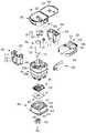
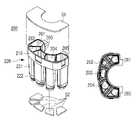
- the dielectric extraction device 1000includes an outer chamber 100, an inner chamber 200, a cover 300, a base plate 400, and a safety clip 500. , an amplification module 600, a piston 700, a driving unit 800 and a bead chamber 900.
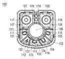
- the outer chamber 100is divided into a plurality of first spaces 101 , 102 , 103 , 104 , 105 , 106 , and 107 by outer chamber partition walls. That is, the plurality of first spaces 101, 102, 103, 104, 105, 106, and 107 may be spaces independent of each other.
- the plurality of first spaces 101 , 102 , 103 , 104 , 105 , 106 , and 107may be provided with open tops and closed bottoms.
- first discharge holes 121, 122 formed along the circumferential direction while spaced apart from the central portion of the outer chamber 100 by a first distance on the bottom surfaces of the plurality of first spaces 101, 102, 103, 104, 105, 123, 124, and 125are formed through, and a second discharge hole 126 formed along the circumferential direction while being spaced apart from the central portion of the outer chamber 100 by a second distance on the bottom surface of the remaining first spaces 106 and 107, 127) are formed through.
- discharge holes 128 and 129 communicating with the amplification module 600are formed through the bottom surface of the space between the first spaces 106 and 107 .
- the first distancemay be shorter than the second distance, but in another embodiment, the first distance may be longer than the second distance.
- reagents stored in the inner chamber 200which will be described later, are introduced, and in the remaining plurality of first spaces 106 and 107, reagents stored in the bead chamber 900 are put. Beads are put in.
- Piston inserts 108 into which pistons 700 are insertedare formed through the center of the plurality of first spaces 101 , 102 , 103 , 104 , 105 , 106 , and 107 .
- a piston 700is inserted into the piston insert 108, and a driving unit (not shown) of the diagnostic device is coupled to the piston 700 to move the piston 700 up and down, thereby moving the first space 101, 102, 103, 104, It is possible for reagents (fluids) of 105, 106, and 107 to enter and exit the fluid accommodating part 701 inside the piston 700. More specific details will be described later.
- the upper outer surface 100a of the outer chamber 100is connected to the upper portion of the lower outer surface 100b and is recessed toward the central portion.
- the safety clip 500is coupled to the upper outer surface 100a of the outer chamber 100, and the boundary between the upper outer surface 100a and the lower outer surface 100b serves as a step of the safety clip 500, so that the safety clip ( 500) is coupled to the upper outer surface 100a, the coupled position may be maintained.
- the safety clip 500has a length that covers at least a portion of the circumference of the upper outer surface 100a of the outer chamber 100 and includes an extended outer chamber coupling portion 510 and a handle 520 formed on one side of the outer chamber coupling portion 510.
- the cover 300presses the inner chamber 200 coupled to the outer chamber 100 to open the upper and lower openings of the inner chamber 200. becoming can be prevented.
- the usermay start the extraction process after removing the safety clip 500 from the outer chamber 100 by gripping the handle 520 .
- reagents in the inner chamber 200are not injected into the outer chamber 100, and the safety clip 500 is removed from the outer chamber 100. Only when it is possible for the reagent in the inner chamber 200 to be introduced into the outer chamber 100.
- the safety clip 500includes an outer chamber coupling part 510 , a handle 520 , an upper extension part 530 and a side extension part 540 .
- the outer chamber coupling part 510is coupled to the outer chamber 100 while at least partially surrounding the outer surface (specifically, the upper outer surface 100a) of the outer chamber 100 . More specifically, the outer chamber coupling part 510 is coupled to the outer chamber 100 so as to surround the four outer surfaces of the outer chamber 100, but the extended ends of the outer chamber coupling part 510 may be configured to be spaced apart from each other. there is. As shown in FIG. 1 , when the safety clip 500 is coupled to the outer chamber 100, the extended end of the outer chamber coupling part 510 is caught on one of the outer surfaces of the outer chamber 100, so that the user The safety clip 500 can be separated from the outer chamber 100 only when holding the safety clip 500 and applying an external force in one direction.
- the handle 520extends outward from the outer chamber coupling part 510 and is gripped by a user to separate the safety clip 500 from the outer chamber 100 .
- the upper extension part 530extends upward from one side of the outer chamber coupling part 510 , and the side extension part 540 extends from the upper extension part 530 toward the center of the outer chamber 100 .
- the cover support member 541protrudes from the upper surface of the side extension part 540, and the inner chamber coupling part 542 is formed at the extended end of the side extension part 540. ) is characterized by protruding formation.
- a first sealing member S1sealing the upper openings of the plurality of second spaces 201 , 202 , 203 , 204 , and 205 of the chamber 200 and a third sealing member sealing the upper openings of the bead chamber 900 . It plays a role in preventing (S3) from tearing (preventing perforation).
- the safety clip 500is coupled to the outer chamber 100 and the inner chamber 200 as shown in FIG. In this case, contact between the protruding members 311, 312, 313, 314, 315, 316, and 317 and the first sealing member S1 and the third sealing member S3 is blocked. Therefore, when the safety clip 500 is coupled to the outer chamber 100 and the inner chamber 200, perforation of the inner chamber 200 and the bead chamber 900 is prevented and accommodated in the inner chamber 200. A phenomenon in which reagents and beads accommodated in the bead chamber 900 flow out to the outer chamber 100 can be prevented.
- the inner chamber coupling part 542is a part that is coupled to the fixing part 230 of the inner chamber 200 when the safety clip 500 is coupled to the outer chamber 100 .
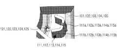
- the lower surface of the inner chamber 200is located at a position spaced a predetermined distance from the lower surface of the outer chamber 100, and thus the plurality of second spaces 201 , 202, 203, 204, 205 to prevent the second sealing member (S2) sealing the lower openings from being torn by the protruding members (111, 112, 113, 114, 115) formed on the bottom surface of the outer chamber (100) It becomes (see FIG. 15).
- the inner chamber coupling part 542is shown in the form of a coupling protrusion and the fixing part 230 is shown in the form of a coupling groove coupled to the coupling protrusion, but in other embodiments, the inner chamber coupling portion 542 is It may be provided in the form of a coupling groove, and the fixing part 230 may be provided in the form of a coupling protrusion coupled with the coupling groove.
- a seating portion 109 providing a space in which the fixing portion 230 of the inner chamber 200 is seatedis recessed in the outer chamber 100 (more specifically, the outer chamber partition wall).
- the inner chamber 200is fixed at a position spaced a predetermined distance from the lower surface of the outer chamber 100 through a coupling structure with the safety clip 100, but the fixing part 230 of the inner chamber 200 is the seating part 109 ), the fixing force can be further improved.
- an insertion space 130is recessed on an upper side of an inner wall of the outer chamber 100, and a coupling hook 240 of the inner chamber 200 may be coupled to the insertion space 130.
- a stopper 131protrudes toward the inside of the outer chamber 100 on the upper side of the insertion space 130 . Therefore, when the inner chamber 200 is not pressurized by the cover 300, the coupling hook 240 of the inner chamber 200 is located on the stopper 131, but the inner chamber 200 is not pressurized by the cover 300. When is pressed, the coupling hook 240 can pass through the stopper 131 and be inserted into the insertion space 130 .
- FIG. 7instead of the coupling hook 240 formed in the inner chamber 200, a locking protrusion 250 protruding outward from the outer wall of the inner chamber 200 is provided, and the locking protrusion 250 is attached to the outer chamber 100. ) The downward movement of the inner chamber 200 is partially restricted by the stopper 131 formed on the inner wall.
- the locking protrusion 250passes through the stopper 131 and is inserted into the insertion space 130, Accordingly, the second sealing member S2 sealing the plurality of second spaces of the inner chamber 200 is perforated by the protruding member formed in the outer chamber 100 .
- the inner chamber 200is partitioned into a plurality of second spaces 201 , 202 , 203 , 204 , and 205 by inner chamber partition walls. That is, the plurality of second spaces 201, 202, 203, 204, and 205 may be spaces independent of each other.
- Upper and lower portions of the plurality of second spaces 201, 202, 203, 204, and 205are open (that is, the plurality of second spaces have an upper opening and a lower opening), and the upper portion is the first sealing member S1 ), and the lower part is sealed by the second sealing member S2.
- the first sealing member S1 and the second sealing member S2may be, for example, a film, but are not limited thereto, and a film made of any material that does not allow fluid to pass through may be applied.
- Different reagentsare put into the plurality of second spaces 201, 202, 203, 204, and 205.
- the second sealing member S2seals the lower part of the plurality of second spaces, and then the reagents are introduced.
- the introduction of reagents into the inner chamber 200may be completed by the first sealing member S1 sealing the upper portions of the plurality of second spaces.
- the inner chamber 200includes an upper inner chamber 210 and a lower inner chamber 220 .
- the upper inner chamber 210is integrally formed, and when combined with the outer chamber 100, is configured to come into close contact with the inner wall of the outer chamber 100.
- the lower inner chamber 220is connected to the upper inner chamber 210 and includes a curved portion spaced apart from the inner wall of the outer chamber 100 when coupled with the outer chamber 100 (radially facing inward). .
- the present inventionuses a double chamber structure consisting of an inner chamber and an outer chamber, there may be a risk of cross-contamination between reagents in the inner chamber 200 during operation.
- Cross-contaminationcan be achieved by the occurrence of capillarity through a microspace between the inner chamber and the outer chamber.
- the inner chamber 200is sufficiently spaced from the inner wall of the outer chamber 100. The capillary phenomenon was prevented by adopting a curved structure as much as possible.
- the outer chamber 100 and the inner chamber 200are designed to be separated from each other to prevent the capillary phenomenon, so that the upper inner chamber 210 is installed in the outer chamber 100 to prevent reagents from leaking out through the spaced part. ) was configured to be in close contact with the inner wall of the
- Second protruding members 111, 112, 113, 114, and 115 protruding into the spaces 101, 102, 103, 104, and 105are formed.
- Each of the second protruding members 111, 112, 113, 114, and 115may be disposed in a one-to-one correspondence with the plurality of first spaces 101, 102, 103, 104, and 105, for example, reference numeral 111.
- the corresponding second protruding membertears the second sealing member S2 sealing the lower part of the second space corresponding to reference numeral 201, and the second protruding member corresponding to reference numeral 115 breaks the second space corresponding to reference numeral 205
- the second sealing member S2 sealing the lower partis torn.
- the second protruding members 111, 112, 113, 114, and 115are protrusions 111a, 112a, and 113a protruding from the bottom surfaces of the plurality of first spaces 101, 102, 103, 104, and 105 by a first height h1. , 114a, 115a) and the protrusions 111a, 112a, 113a, 114a, and 115a, and protruding from the bottom surface by a second height h2 lower than the first height h1, the wings 111b, 112b, and 113b , 114b, 115b).
- the wings 111b, 112b, 113b, 114b, and 115bmay have a structure extending in both left and right directions from the protrusions 111a, 112a, 113a, 114a, and 115a.
- the protruding portionserves to puncture the second sealing member S2, and the wing portion serves to expand the piercing portion of the second sealing member S2.
- the wing portionserves to expand the piercing portion of the second sealing member S2.
- point-contactis made between the second sealing member S2 sealing the lower portion of the inner chamber 200 and the protrusion, through the point-contact.
- the second sealing member S2When the second sealing member S2 is torn by the protruding members 111, 112, 113, 114, and 115, it is stored in the plurality of second spaces 201, 202, 203, 204, and 205 of the inner chamber 200.
- the reagentsare discharged into the plurality of first spaces 101 , 102 , 103 , 104 , and 105 of the outer chamber 100 .
- the spilled reagentsare discharged through the first discharge holes 121 , 122 , 123 , 124 , and 125 formed on the bottom surface of the first spaces 101 , 102 , 103 , 104 , and 105 .
- first discharge holes 121, 122, 123, 124, and 125there is a part inclined downward.
- the inclined portionmay have an angle of 3 degrees to 10 degrees, and reagents leaked into the first spaces 101, 102, 103, 104, and 105 through the first discharge holes 121, 122, 123, 124, 125) can be easily performed.
- the cover 300is coupled to the top of the outer chamber 100 and is configured to cover the top of the outer chamber 100 and the inner chamber 200 .
- a cover 300includes a cover body 301 and a cover 302 .
- the cover body 301has a first insertion hole 307 aligned with the piston insertion part 108 and a first sample input hole 309 through which a sample is introduced (in the attached drawing, the first sample input hole). 309 is aligned with the first space 105, so that the sample can be introduced into the first space 105 through the first sample input hole 309), and a first seal is placed on the lower surface of the cover body 301.
- the first protruding members 311, 312, 313, 314, and 315 tearing the member S1 and the third protruding members 316, 317 tearing the third sealing member S3protrude.
- the first protruding members 311, 312, 313, 314, and 315may be disposed in a one-to-one correspondence with the plurality of first spaces 101, 102, 103, 104, 105, 106, and 107, and the third protruding member ( 316 and 317 may be arranged in a one-to-one correspondence with the plurality of third spaces 910 and 920 .
- the first protruding member corresponding to reference numeral 311tears the first sealing member S1 sealing the upper part of the second space corresponding to reference numeral 201, and the first protruding member corresponding to reference numeral 315
- the first sealing member S1 sealing the upper part of the second space corresponding to 205is torn.
- a spacer member 320is formed on the bottom surface of the cover body 301 along the periphery of the first insertion hole 307 .
- the separation member 320is a part that separates the first protruding member and the first sealing member from each other while the safety clip 500 is coupled to the outer chamber 100 . That is, as the separation member 320 is supported by the cover support member 541 , the cover 300 is separated from the inner chamber 100 by a predetermined distance.
- the cover 302is hingedly rotatably connected to one side of the cover body 301 .
- a second insertion hole 308 aligned with the first insertion hole 307is formed through the central portion of the cover 302 .
- Second protruding members 111, 112, 113, 114, 115, 116, and 117are formed on the bottom surface of the outer chamber 100, and the first protruding members 311, 312, 313, 314 and 315 and the third protruding members 316 and 317 are formed, the first sealing member S1 and the second sealing member (S1) sealing the upper and lower openings of the inner chamber 200 by the protruding members ( S2) and the third sealing member S3 sealing the upper opening of the bead chamber 900 are torn.
- the reagents stored in the inner chamber 200flow out into the plurality of first spaces 101, 102, 103, 104, and 105 of the outer chamber 100, sealing the upper opening of the inner chamber 200.
- the second sealing member S2serves as an air vent so that reagents can be sufficiently discharged into the first space.
- the base plate 400is coupled to the lower part of the outer chamber 100, and the reagents are stored in the first spaces 101, 102, 103, 104, 105, 106, and 107 of the outer chamber 100 and the piston 700. It includes a plurality of passages guiding a path moving between the fluid accommodating units.
- the base plate 400may have liquid passages 401 to 408 through which liquid may move and an air passage 409 through which air may move, and the outer chamber 100 and the base A flow cover 410 and a pad 420 disposed on the upper surface of the base plate 400 may further be included between the plates 400 to prevent leakage of liquid when coupled to the outer chamber 100 .
- the base plate 400 - the flow cover 410 - the pad 420are combined, the upper surfaces of the liquid flow path and the air flow path of the base plate 400 are blocked by the flow cover 410 and the pad 420 to form a space. The perfect euro is completed.
- the liquid passages 401 to 408are connected to the flow cover 410, the pad 420, and the outer chamber 100 to provide a space in which the specimen and the reagent can be moved and mixed.
- the air passage 409connects the amplification module 600 and the vacuum control part of the piston 700 to control the vacuum that may occur when the dielectric extracted by the amplification module 600 moves, and to It serves to prevent contamination of the amplification product.
- one end of the air passage 409communicates with the fluid receiving portion 701 of the piston 700 and the other end communicates with the amplification module 600, so that the air discharged from the amplification module 600 passes through the air passage. It may pass through 409 and be discharged to the fluid accommodating part 701 .
- a plurality of passages 401 , 402 , 403 , 404 , 405 , 406 , 407 , 408 , and 409are formed above the base plate 400 .
- Each passagedoes not cross each other and is formed to extend from the center of the lower body 400 to the outer portion.
- the liquid flow pathhas components corresponding to reference numerals 401 to 408, and the air channel has a component corresponding to reference numeral 409.
- one end of some of the plurality of passagesmay be disposed on the same circumference, and the other ends may also be disposed on the same circumference.
- One end of the air passage 409 of the plurality of passagesis located on a circumference different from that of the other liquid passages 401 to 408, and the other end is also located on a circumference different from the other ends of the other liquid passages 401 to 408. So, it is possible to control the vacuum.
- a piston driving unit insertion hole 400ais formed through the center of the base plate 400 so that the piston driving unit 800 for rotating the piston 700 can be coupled thereto.
- a flow cover 410is placed in the seating space above the base plate 400 .
- the flow cover 410may be made of, for example, plastic, and may be integrally provided with the base plate 400 by being ultrasonically welded while seated on the top of the base plate 400 .
- the flow cover 410has a first through hole 410a aligned with the piston driving unit insertion hole 400a, and has a plurality of first flow cover holes on a first circumference spaced a first distance from the first through hole 410a. (411a, 412a, 413a, 414a, 415a, 416a, 417a, 418a) are formed through, and a plurality of second flow cover holes (411b, 412b) on a second circumference spaced apart from the first through hole (410a) by a second distance.
- a plurality of third flow cover holes 416b, 417b, and 418bare formed through and formed on a third circumference at a third distance from the first through hole 410a, and an air flow path is formed.
- Fourth flow cover holes 419a and 419b communicating with one end and the other end of 409are formed through.
- the first flow cover holeis aligned with the inner end of the flow path formed in the lower body 400
- the second flow cover hole and the third flow cover holeare aligned with the other outer end of the flow path
- the fourth flow cover holeis It communicates with one end and the other end of the air passage.
- the second distancemay be longer than the first distance and shorter than the third distance.
- first coupling protrusions 410b protruding upward and downwardmay be further formed on the outer circumference of the first through hole 410a.
- melting protrusions 410c coupled along the edges of the plurality of passages of the base plate 400may protrude from the lower surface of the flow cover 410 (see FIG. 12 ).
- the melting protrusion 410cis melted and integrated with the base plate 400. Through this, close coupling between the base plate 400 and the flow cover 410 is possible.
- a pad 420is placed on the flow cover 410 .
- the pad 420may be made of, for example, a silicon material, but any material having a predetermined elasticity may be applied without being particularly limited thereto.
- a plurality of second coupling protrusions 410dprotrude from the upper surface of the flow cover 410, and the second coupling protrusions 410d are coupled to the coupling grooves 420c of the pad 420 so that the flow cover 410 - A firm coupling is made between the pads 420 .
- the first coupling protrusion 410b of the flow cover 410is also inserted into the second through hole 420a of the pad 420, so that the two components can be firmly coupled.
- the pad 420has a second through hole 420a aligned with the first through hole 410a, and has a plurality of first pad holes 421a on a first circumference separated by a first distance from the second through hole 420a.
- 422a, 423a, 424a, 425a, 426a, 427a, 428aare formed through, and a plurality of second pad holes 421b, 422b, 423b, 424b and 425b) are formed through, and a plurality of third pad holes 426b, 427b, and 428b are formed through and formed on a third circumference at a third distance from the second through hole 420a, and Fourth pad holes 429a and 429b communicating with one end and the other end are formed through.
- first pad holeis aligned with the first flow cover hole
- second pad holeis aligned with the second flow cover hole
- third pad holeis aligned with the third flow cover hole
- fourth pad holeis aligned with Aligned with the fourth flow cover hole.
- a protruding portion protruding from the portion where the hole 429b is formed and narrowing toward the upper sideis further formed. Through the formation of the protruding portion, even when the pad 420 is closely disposed between the outer chamber 100 and the base plate 400, a problem in which the diameter of the pad holes is decreased unintentionally may be solved.
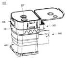
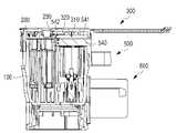
- the amplification module 600is coupled to the outer chamber 100 and is configured to accommodate the pre-processed specimen. Completion of the pretreatment of the specimen means that genomes such as DNA and RNA included in the specimen are lysed into the reagent.
- a genome amplification processPCR, etc.
- the amplification module 600is coupled to the outer chamber 100 in a vertical direction.
- the upper part 631 of the accommodating part 630 of the amplifying module 600is coupled to the outer chamber 100 such that the lower part 632 is farther from the ground.
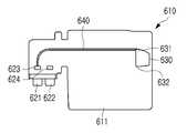
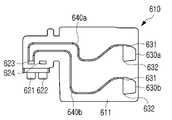
- the amplification module 600includes a body 610, inlets 621 and 622, a receiving part 630, a gas flow path 640, and an extraction liquid flow path 650.
- the body 610is a part constituting the outer shape of the amplification module 600, and injection ports 621 and 622 coupled to the discharge holes 128 and 129 of the outer chamber 100 are formed on one side of the body 610.
- the injection holes 621 and 622are coupled to the discharge holes 128 and 129, and serve as an inlet for the extract liquid discharged from the discharge holes 128 and 129 to be introduced into the receiving part 630.
- the amplification module 600may have two inlets 621 and 622, but is not particularly limited thereto, and embodiments having more than two inlets may also be included in the scope of the present invention. .
- the amplification module 600has two inlets 621 and 622 and will be described in detail.
- One of the two inlets 621 and 622communicates with the air passage 409 and the other inlet 622 communicates with the liquid passage 408 . That is, the extract containing the pretreated sample is introduced through the other inlet 622, and in this process, the air in the receiving part 630 is discharged to the air passage 409 through one inlet 621. It can be.
- the other side of the body 610is formed with a receiving portion 630, which is a space for accommodating the extract introduced through the inlet 621.
- the receiving part 630may be manufactured in a form penetrating both one surface and the opposite surface of the body 610, but in another example, it may be manufactured in a form penetrating only one surface and not penetrating the other surface. It is the same in both the above embodiments that the open portion is sealed by the sealing member. Therefore, the extraction liquid and air are introduced into or discharged from the receiving unit 630 only through the gas flow passage 640 and the extraction liquid flow passage 650 .
- One or more accommodating units 630may be provided in one amplification module 600 .
- FIG. 17shows an amplification module with one accommodating unit
- FIG. 20shows an amplification module with two accommodating units
- FIG. 23shows an amplification module with four accommodating units.
- the accommodating part 630may have a substantially trapezoidal shape, and more specifically, preferably has a trapezoidal shape with rounded edges.
- the trapezoid shapemeans a shape in which the width becomes narrower as the distance from the gas flow passage 640 and the extract flow passage 650 increases. Since the receiving part 630 has the above shape, even when the extract is injected through the extract moving passage 650, the problem of bubbles being generated is solved. If air bubbles remain in the accommodating part 630, a problem of detection failure that may occur in the fluorescence detection process after the amplification process occurs, and thus it is possible to solve the above problem through the shape of the accommodating part 630.
- the amplification module 600is provided with one or more accommodating units 630, and it is also possible that different types of primers and probes are provided in each accommodating unit 630. Therefore, it has the advantage that a plurality of detection processes can be simultaneously performed on the genome extracted from one specimen.
- primers and probes for corona virus amplificationare provided in one accommodating unit 630a
- primers and probes for influenza virus amplificationare provided in the other accommodating unit 630b, so that in one amplification module 600 It is possible to perform various detection processes simultaneously.
- the gas movement passage 640is formed on one surface 611 of the body 610, and is configured to connect the inlet 621 and the upper portion 631 of the accommodating portion 630.
- the extract moving passage 650is formed on the opposite surface 612 opposite to the one surface 611, and is configured to connect the inlet 622 and the lower portion 632 of the receiving portion 630.
- the gas movement passage 640serves as a passage through which the gas in the accommodating part 630 moves.
- the passage of the amplification module 600communicates with the dielectric extraction device 100 and has the characteristics of a closed passage at the same time. Since the receiving portion 630 is filled with air before the extraction liquid is injected, if the extraction liquid is injected, air of a capacity suitable for it must be discharged to the outside. In the present invention, the air inside the accommodating part 630 is discharged to the air passage 409 through the inlet 621 through the gas flow passage 640, so that the pressure in the accommodating part 630 is reduced and the air remains. The bubble problem caused by this was also solved. Similar to the accommodating portion 630, the gas movement passage 640 also has connecting portions of the passage provided in a curved shape without an angled portion to minimize the generation of air bubbles.
- the gas passage 640is connected to the end of the upper part 631 of the accommodating part 630.
- the gas flow passages 640 connected to the accommodating units 630have different lengths.
- the extractis injected from the lower accommodating unit, and the extract is injected at a more delayed time in the upper accommodating unit. Accordingly, the time for air to be discharged from the accommodating portion 630 will also be different according to the formation position of the accommodating portion 630 . In other words, the air is discharged through the gas flow passage 640 faster as the accommodation part is located at the lower part.
- the gas flow passage 640not only the air in the accommodating part 630, but also the extraction liquid injected into the accommodating part 630 may be discharged together. Since the plurality of gas flow passages 640 are connected to each other, the extract liquid discharged through one gas flow passage 640 is introduced into another receiving unit along the other gas flow passage 640, and the extract liquid or amplification product is mixed Problems can arise. In order to solve the above problem, in the present invention, the length of the gas flow passage 640 connected to the lower accommodation part 630 is formed longer, thereby solving the problem of mixing the extract or amplification product.
- a method of differentiating the lengths of the gas movement passages 640may be configured as shown in FIG. 21 or as shown in FIG. 24 .
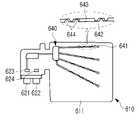
- the gas movement passage 640is formed on one surface 611 of the body 610 and communicates with the gas discharge passage 633 connected to the upper portion 631 of the accommodating portion 630, while the body ( A communication hole 641 passing through 610, a movement passage 642, a storage passage 643, and a passage pattern forming portion 644 are included.
- the passage pattern forming unit 644is configured to form a predetermined passage pattern in the moving passage 642 .
- the passage pattern forming part 644may have a semicircular shape, and the semicircular passage pattern forming part 644 is combined with the linear moving passage 642 to form a passage pattern as shown in FIG. 24 . this can be manufactured.
- the passage pattern forming unit 644may form the passage pattern shown in FIG. 24 while being alternately combined with the movement passages 642 on the left and right sides of the linear movement passage 642 .
- the combinationmeans that the empty space of the moving passage 642 is filled in the shape of the passage pattern forming part 644 so that the fluid does not pass through the filled space.
- the portion of the gas flow passage 640 combined with the passage pattern forming portion 644corresponds to the flow passage 642, and the portion of the gas flow passage 640 that is not combined corresponds to the storage passage 643. .
- the length of the gas movement passage 640increases in proportion to the number of passage pattern forming parts 644 combined and the number of storage passages 643, and the number of passage pattern forming parts ( 644) and a storage passage 643. Through this, mixing of the extract or amplification product accommodated in the receiving unit 630 can be prevented.
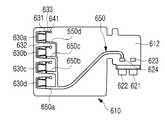
- the extract moving passage 650is formed on the opposite side 612 opposite to one side 611 of the body 610, and is configured to connect the inlet 622 and the lower portion 632 of the receiving part 630.
- the extract moving passage 650serves as a passage through which the extract pretreated in the dielectric extraction apparatus 1000 moves.
- the extract moving passage 650also prevents mixing of the extract or amplification products accommodated in the accommodating unit 630 or allows the same amount of extract to be injected into each accommodating unit 630. In case a plurality of accommodating units 630 are provided If the length of each extraction solution moving passage 650 is the same, or if the length is different, the thickness of each extract moving passage 650 may be different.
- the extract liquid moving passage 650is provided in a curved shape without an angled portion to minimize the generation of bubbles. do.
- the extract moving passage 650extends from the inlet 622 and then diverges at a point. From the point of divergence, the lower portion is thicker and the upper portion is thinner. As the thickness of the passage is thinner, the extraction solution passes through at a faster rate, so the same amount of the extraction solution can be injected regardless of the upper and lower receptacles.
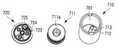
- the piston 700is inserted into the piston insertion part 108 of the outer chamber 100 and sucks reagents accommodated in the outer chamber 100 according to the lifting movement, or sucks the reagent into the outer chamber 100 or the amplification module 600. It is configured to discharge the reagent.
- the piston 700includes an upper piston 710 and a lower piston 720 .
- the top of the upper piston 710is open, and a fluid receiving portion 701 in which sucked fluids are accommodated is formed therein.
- a contact part 711is installed inside the upper piston 710 .
- the outer surface of the close contact portion 711is in close contact with the inner surface of the upper piston 710, so that fluid cannot enter or exit through the space between the outer surface of the close contact portion 711 and the inner surface of the upper piston 710.
- a driving unit installation part 711a to which a driving unit (not shown) of the diagnostic device is coupledis recessed.
- the driving unit (not shown) of the diagnostic deviceis coupled to the driving unit installation unit 711a and moves the contact unit 711 up and down inside the upper piston 710 to suck fluid into the fluid accommodation unit 701 or to the fluid accommodation unit ( 701) is discharged to the outside.
- a coupling structure that engages with the lower piston 720may be formed on the bottom surface of the upper piston 710, and the first hole 712 connected to the liquid port of the lower piston 720 and the filter port of the lower piston 720 A second hole 713 connected to is formed through.
- the second hole 713may be formed to have a smaller diameter than the filter seating space of the filter port to prevent separation of the support structure and the filter.
- the lower piston 720is engaged and fixed to a coupling structure formed on the lower surface of the upper piston 710 .
- the lower piston 720includes a disc-shaped body 721, a shaft 722 formed to protrude outward from the center of the body 721, and a liquid port 723 disposed at the same distance from the center of the body 721. ) and a filter port 724.
- the liquid port 723is used to suck, mix, and discharge samples and reagents into the piston 700, and the filter port 724 can be used to clean the dielectric collecting filter or separate the dielectric from the dielectric collecting filter. .
- a groove recessed toward the centermay be formed on the outer circumference of the body 721 of the lower piston 720 . This groove serves to remove the vacuum that may occur during liquid transfer inside the extraction device.
- the liquid port 723 and the filter port 724are disposed at an angle apart from each other on the same circumference.
- the two ports of the filter port 724 and the liquid port 723may be disposed apart from each other by 18 degrees to 36 degrees, and more specifically, the two ports may be disposed to form an interval of 22.5 degrees.
- the positions of the liquid port 723 and the filter port 724can be changed by one drive.
- the filter port 724 of the lower piston 720may include a filter seating space 725, and a filter and a support structure may be disposed in the filter seating space 725.
- Glass fiber filters having various particle sizesmay be used as a filter for dielectric collection, and the support structure serves to fix the filter for dielectric collection.
- the support structuremay be formed of a porous plastic material having a certain particle size to prevent separation of the filter and maintain a constant pressure when the fluid is discharged.
- the driving unit 800is connected to a driving unit (not shown) of the diagnostic device and serves as a medium for rotating the piston 700 at a predetermined angle.
- the drive unit 800may include a coupling groove formed at a central portion of one surface to be engaged with the shaft 722 and a drive groove formed at the other surface to be engaged with a driving unit (not shown) of a diagnostic device.
- the driving unit 800is combined with the piston 700 to move the liquid port 723 and the filter to the first outlet hole of the outer chamber 100 so that various chemical reactions required in the dielectric extraction step can be performed inside one device.
- Position port 724is combined with the piston 700 to move the liquid port 723 and the filter to the first outlet hole of the outer chamber 100 so that various chemical reactions required in the dielectric extraction step can be performed inside one device.
- the liquid port 723 and the filter port 724are spaced apart at a certain angle, and the driving unit 800 rotates the ports to positions suitable for each step during dielectric extraction.
- the bead chamber 900includes a first bead chamber 910, a second bead chamber 920, and a dehumidification chamber 930, which are formed by a first bead chamber partition wall 901 and a second bead chamber 902. compartmentalized
- the first bead chamber 910is inserted into the first space 106 of the outer chamber 100 and the second bead chamber 920 is inserted into the first space 107 of the outer chamber 100 .
- the upper opening of the bead chamber 900is also sealed by a third sealing member S3, and the cover 300 is coupled to the outer chamber 100 by the third sealing member S3.
- the cover 300is perforated by the third protruding members 316 and 317 formed on the bottom surface of the cover 300. Since the upper opening of the bead chamber 900 is opened by the third protruding members 316 and 317, even if fluid is subsequently introduced into the first bead chamber 910 and the second bead chamber 920, a corresponding amount of air It is possible for the to be expelled through the perforated part.
- the lower opening of the bead chamber 900is provided in an open form without being separately sealed by a sealing member. Dry beads (more specifically, freeze-dried beads) are stored in the bead chamber 900, and the dry beads have characteristics that are vulnerable to moisture.
- the lower opening of the bead chamber 900, the first space of the outer chamber 100, the flow cover 410, the pad 420, the flow path of the base plate 400, the amplification module ( 600)are in communication with each other, but form a closed type of flow path that is not exposed to the outside air, so that moisture inflow into the bead chamber 900 is minimized.
- a first bead holder 911is installed at the upper opening of the first bead chamber 910 so that the dry bead b1 is not discharged to the outside and is maintained inside, and the dehumidifying chamber 930 has a first bead chamber 910.
- a first dehumidifying unit 912 for dehumidifying the inner spaceis installed.
- dry beads required for dielectric amplificationmay be provided in the form of, for example, capsules, but are not particularly limited thereto.
- a second bead holder 921is installed in the upper opening of the second bead chamber 920 so that the dry bead b2 is not discharged to the outside and is maintained inside, and the second bead holder 921 is installed on the second bead holder 921.
- a second dehumidifying unit 922 for dehumidifying the inside of the chamber 920is installed.
- the third sealing member S3seals the second bead chamber 920 so that the dehumidifying chamber 930 and the first bead chamber 910 do not communicate with each other, but the first bead chamber 910 and the dehumidifying chamber 930 ) are sealed so that they communicate with each other. Referring to Figures 26 and 27, this will be described in detail.
- the above effectis achieved through a structure having a height difference between the first bead chamber partition wall 901 and the second bead chamber partition wall 902 .
- the second bead chamber partition wall 902 partitioning the second bead chamber 920 and the dehumidifying chamber 930partitions the first bead chamber 910 and the dehumidifying chamber 930. It has a height higher than that of the first bead chamber partition wall 901 .
- the upper part of the second bead chamber partition wall 902extends to the same height as the upper part of the outer partition wall forming the second bead chamber 920
- the upper part of the first bead chamber partition wall 901extends to the same height as the first bead chamber partition wall 901. It extends to a height lower than the top of the outer partition wall constituting the chamber 910 .
- the first bead chamber ( 910) and the dehumidifying chamber 930may communicate with each other. Accordingly, the first bead chamber 910 is dehumidified by the second dehumidifying unit 912 installed inside the dehumidifying chamber 930 .
- the lower opening 912 of the first bead chamber 910ie, the outlet of the first bead chamber
- the lower opening 922 of the second bead chamber 920ie, the outlet of the second bead chamber
- Dry beadsmay be accommodated in the discharge passages 911 and 921, and bead holders are installed on the discharge passages 911 and 921 to prevent the beads accommodated in the discharge passages 911 and 921 from leaking out.
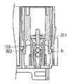
- the discharge passages 911 and 921may have a so-called tapered shape that becomes narrower toward the base plate 400 . Also, the diameters of the lower openings 912 and 922 located at the ends of the discharge passages 911 and 921 are smaller than the diameters of the dry beads, so that the beads cannot be discharged to the outside through the lower openings 912 and 922. .
- the fluidflows into the discharge passages 911 and 921 through the lower openings 912 and 922, the introduced fluid melts the dry beads, and only through the lower openings 912 and 922 through the shape of the fluid to the outside (of the piston). fluid receiving unit or amplification module).
- the discharge passage 911 of the first bead chamber 910 in which the dry beads necessary for dielectric amplification are storedhas a wider diameter than the discharge passage 921 of the second bead chamber 920, and the base plate 400 The further you go towards it, the narrower it can be.
- the first bead chamber 910corresponds to a configuration in which the last fluid is injected. Since the fluid injected into the first bead chamber 910 does not remain in the first bead chamber 910 as much as possible and must be injected into the accommodating part 630 of the amplification module 600, it is possible to obtain an accurate detection result.
- the discharge passage 911 of the first bead chamber 910has a wider diameter than the discharge passage 921 of the second bead chamber 920 and is narrowed, so that the fluid in the first bead chamber 910 Residual amount was minimized.
- the bead chamber 900has first locking protrusions 903 and 904 extending from bottom surfaces of outer partition walls of the first bead chamber 910 and the second bead chamber 920 . As shown in FIGS. 28 and 30 , the first locking protrusions 903 and 904 may extend toward the base plate 400 and then protrude outward.
- a second locking protrusion 109is formed on one side of an outer chamber partition wall partitioning a plurality of first spaces, and the bead chamber 900 is connected to the base plate 400.
- the first locking protrusions 903 and 904pass through the second locking protrusion 109 and are coupled to each other, so that the two components can be firmly coupled.
- the position of the bead chamber 900 relative to the outer chamber 100is fixed.
- the inner chamberis combined with the outer chamber through upper openings of the plurality of first spaces of the outer chamber.
- the fixing part of the inner chamberis coupled to the outer chamber in a state of being coupled with the inner chamber engaging part of the safety clip.
- the coveris pressed so that the first sealing member sealing the upper opening of the inner chamber is torn by the first protruding member formed on the bottom surface of the cover, and the second sealing member formed on the bottom surface of the plurality of first spaces of the outer chamber.
- the second sealing member sealing the lower opening of the inner chamberis torn by the protruding member, and the reagents contained in the inner chamber flow out into the plurality of first spaces, and (e) the reagents flow out into the plurality of first spaces by driving the driving unit.
- Step (e)may consist of a plurality of steps. Hereinafter, step (e) will be described in more detail below.
- a sample to be analyzedis introduced into one of a plurality of first spaces of the outer chamber through the sample input hole of the cover.
- the pistonrotates so that the liquid port of the piston communicates with the first discharge hole formed on the bottom surface of the first space accommodating the first reagent, the second reagent, and other reagents.
- the pistonrotates so that the filter port of the piston communicates with the first discharge hole formed on the bottom surface of the first space accommodating other reagents.
- the close contact partdescends, and the liquid mixture contained in the fluid accommodating part passes through the dielectric collecting filter and is discharged into the first space containing other reagents.
- the pistonrotates so that the liquid port of the piston communicates with the first discharge hole formed on the bottom surface of the first space accommodating the eluent.
- the pistonrotates so that the filter port of the piston communicates with the second discharge hole formed on the bottom of the first space accommodating beads necessary for dielectric amplification.
- (e17)a step in which the close contact part descends and the eluent accommodated in the fluid accommodating part passes through the dielectric collecting filter and is discharged to the first space accommodating beads necessary for dielectric amplification, wherein the dielectric collected in the dielectric collecting filter is passed through the dielectric collecting filter. It is separated from and discharged together into the first space.
- the extractis introduced into the receiving part of the amplification module through the extract passage of the amplification module.
- the amplification deviceapplies heat of a predetermined temperature or higher to the receiving part to amplify the dielectric.
Landscapes
- Chemical & Material Sciences (AREA)
- Health & Medical Sciences (AREA)
- Chemical Kinetics & Catalysis (AREA)
- Life Sciences & Earth Sciences (AREA)
- General Health & Medical Sciences (AREA)
- Clinical Laboratory Science (AREA)
- Molecular Biology (AREA)
- Organic Chemistry (AREA)
- Biochemistry (AREA)
- Analytical Chemistry (AREA)
- Engineering & Computer Science (AREA)
- Wood Science & Technology (AREA)
- Zoology (AREA)
- Proteomics, Peptides & Aminoacids (AREA)
- Hematology (AREA)
- Biotechnology (AREA)
- Bioinformatics & Cheminformatics (AREA)
- Microbiology (AREA)
- Genetics & Genomics (AREA)
- General Engineering & Computer Science (AREA)
- Physics & Mathematics (AREA)
- Biophysics (AREA)
- Immunology (AREA)
- Dispersion Chemistry (AREA)
- Apparatus Associated With Microorganisms And Enzymes (AREA)
- Sampling And Sample Adjustment (AREA)
- Cell Biology (AREA)
- Biomedical Technology (AREA)
- Sustainable Development (AREA)
Abstract
Description
Translated fromKorean본 발명은 기체 이동 통로와 추출액 이동 통로를 갖는 증폭 모듈에 관한 것이다.The present invention relates to an amplification module having a gas flow path and an extract liquid flow path.
현대에는 생명공학 기술의 발전에 따라 유전자 수준에서 질병의 원인을 해석하는 것이 가능해졌다. 그에 따라 인간의 질병을 치유하거나 예방하기 위한 생체 시료의 조작 및 생화학적 분석에 대한 요구가 점차 증가하고 있다.In modern times, with the development of biotechnology, it has become possible to interpret the causes of diseases at the genetic level. Accordingly, demands for manipulation and biochemical analysis of biological samples for curing or preventing human diseases are gradually increasing.
아울러, 질병의 진단 외에도 신약개발, 바이러스나 박테리아 감염 여부의 사전 검사 및 법의학 등의 다양한 분야에서 생체 시료나 세포가 포함된 시료로부터 핵산을 추출, 분석하는 기술이 요구된다.In addition, in addition to disease diagnosis, technology for extracting and analyzing nucleic acids from biological samples or samples containing cells is required in various fields such as new drug development, prior examination for viral or bacterial infection, and forensic medicine.
종래의 유전체 추출 장치는 처리 과정(농축, 정제) 별로 각각의 장치가 필요하며, 하나의 처리과정이 끝난 후 다른 장치로 이동시켜야 하므로 긴 시간을 필요로 한다.Conventional dielectric extraction devices require a separate device for each processing process (concentration, purification), and require a long time because they must be moved to another device after one processing process is finished.
이와 같은 긴 처리 과정으로 검출 효율성이 낮다는 종래의 문제점을 해결하기 위해 본 출원인에 의한 등록특허 제10-1989920호 등이 개발되어 사용되어 왔다.In order to solve the conventional problem of low detection efficiency due to such a long processing process, Patent Registration No. 10-1989920 by the present applicant has been developed and used.
상기 문헌에서는 버퍼 챔버 내부에 직접 버퍼를 분주하여 보관하지만, 장기 보관 시 버퍼 챔버 하부의 다양한 층 구조를 통해 미세 누수가 발생하고 추출 성능에 악영향을 미치는 문제점이 있었다.In the above document, the buffer is directly dispensed and stored inside the buffer chamber, but there is a problem in that micro-leakage occurs through various layer structures in the lower portion of the buffer chamber and adversely affects extraction performance during long-term storage.
또한, 상부 바디와 베이스 플레이트 사이에 배치되는 패드가 고무 재질로 이루어지는데, 패드가 상부 바디와 베이스 플레이트 사이에서 압착됨에 따라 패드에 관통 형성된 홀들의 직경이 감소하게 됨으로써 제품 설계 의도와 다른 용량의 추출액이 증폭 모듈로 이동하는 문제점이 있었다.In addition, the pad disposed between the upper body and the base plate is made of a rubber material, and as the pad is compressed between the upper body and the base plate, the diameter of the holes formed in the pad decreases, thereby extracting a capacity different from the product design intention. There was a problem moving to this amplification module.
뿐만 아니라, 제품의 생산 및 유통 중에 발생하는 진동에 의해 버퍼 챔버를 실링하는 밀봉 부재가 돌출 부재에 의해 천공되어 버퍼 챔부 내부에 보관된 시약이 유출 및 오염되는 문제점이 있었다.In addition, a sealing member sealing the buffer chamber is perforated by a protruding member due to vibration generated during production and distribution of the product, and reagents stored in the buffer chamber leak and become contaminated.
이에, 본 발명자들은 종래 유전체 추출 장치의 문제점을 해결하고자 본 발명을 착안하여 완성하기에 이르렀다.Accordingly, the present inventors have come to complete the present invention in order to solve the problems of the conventional dielectric extraction device.
(특허문헌 1) 한국등록특허문헌 제10-1989920호(2019.06.11.)(Patent Document 1) Korea Patent Document No. 10-1989920 (2019.06.11.)
(특허문헌 2) 한국등록특허문헌 제10-2065649호(2020.01.07.)(Patent Document 2) Korea Patent Document No. 10-2065649 (2020.01.07.)
(특허문헌 3) 한국등록특허문헌 제10-2065650호(2020.01.07.)(Patent Document 3) Korea Patent Document No. 10-2065650 (2020.01.07.)
(특허문헌 4) 한국등록특허문헌 제10-2076220호(2020.02.05.)(Patent Document 4) Korea Patent Document No. 10-2076220 (2020.02.05.)
본 발명에 따르면, 유전체 추출에 필요한 시약들이 수용된 내측 챔버가 외측 챔버와 별도로 구비되고, 내측 챔버의 상부와 하부가 밀봉됨에 따라, 종래의 유전체 추출 장치에서 단일 챔버에 수용된 시약이 외부로 유출되는 문제를 해결한 유전체 추출 장치를 제공하는 것에 그 목적이 있다.According to the present invention, the inner chamber accommodating reagents necessary for dielectric extraction is provided separately from the outer chamber, and as the upper and lower parts of the inner chamber are sealed, the reagents contained in a single chamber leak out to the outside in the conventional dielectric extraction device. Its purpose is to provide a dielectric extraction device that solves the problem.
또한, 제품의 생산 및 유통 과정 중에 발생하는 진동에 의해 이너 챔버가 상하로 이동함으로써, 커버 및 외측 챔버에 형성된 돌출 부재들에 의해 이너 챔버의 상부 개구와 하부 개구를 실링하는 밀봉 부재가 천공되는 것을 방지하기 위한 안전 클립을 포함하는 유전체 추출 장치를 제공하는 것에 그 목적이 있다.In addition, as the inner chamber moves up and down due to vibration generated during the production and distribution process of the product, the sealing member sealing the upper and lower openings of the inner chamber by the protruding members formed on the cover and the outer chamber is prevented from being perforated. Its purpose is to provide a dielectric extraction device including a safety clip to prevent.
또한, 이중 챔버 사이의 공간을 통해 발생하는 모세관 현상에 의해 시약 간의 교차 오염 문제를 특유의 내측 챔버 설계(하부 내측 챔버)를 통해 해결한 유전체 추출 장치를 제공하는 것에 그 목적이 있다.In addition, an object of the present invention is to provide a dielectric extraction device that solves the problem of cross-contamination between reagents due to the capillary phenomenon occurring through the space between the double chambers through a unique inner chamber design (lower inner chamber).
또한, 모세관 현상을 방지하기 위한 구조에서, 시약들이 외부로 유출되는 것을 방지하고자 특유의 내측 챔버 설계(상부 내측 챔버)를 통해 해결한 유전체 추출 장치를 제공하는 것에 그 목적이 있다.In addition, an object of the present invention is to provide a dielectric extraction device solved through a unique inner chamber design (upper inner chamber) to prevent reagents from leaking out in a structure for preventing capillarity.
또한, 외측 챔버 저면에 형성된 제1 돌출 부재의 구성으로 인해, 적은 힘으로도 밀봉 부재를 찢을 수 있고, 천공된 부분이 확장되어, 내측 챔버 내부에 수용된 시약이 외부로 원활히 유출되는 유전체 추출 장치를 제공하는 것에 그 목적이 있다.In addition, due to the configuration of the first protruding member formed on the bottom surface of the outer chamber, the sealing member can be torn with little force, and the perforated portion expands, so that the reagent contained in the inner chamber flows out smoothly to the outside. Its purpose is to provide
또한, 시약들이 배출되는 배출공 주변에 경사진 부분이 형성되어, 배출공을 통해 시약들이 원활히 배출되는 유전체 추출 장치를 제공하는 것에 그 목적이 있다.In addition, an object of the present invention is to provide a dielectric extraction device in which an inclined portion is formed around a discharge hole through which reagents are discharged so that reagents are smoothly discharged through the discharge hole.
또한, 외측 챔버와 베이스 플레이트 사이에 이중 구조의 플로우 커버 - 패드가 배치됨으로써, 종래 1개의 패드만이 배치되는 유전체 추출 장치 대비, 제조의 편의성이 향상되고 의도치 않게 유로가 좁아지는 문제가 해결된 유전체 추출 장치를 제공하는 것에 그 목적이 있다.In addition, by disposing a double structure flow cover-pad between the outer chamber and the base plate, compared to the conventional dielectric extraction device in which only one pad is disposed, the convenience of manufacturing is improved and the problem of unintentionally narrowing the flow path is solved. Its purpose is to provide a dielectric extraction device.
또한, 베이스 플레이트 - 플로우 커버 - 패드 - 외측 챔버 간의 견고한 결합이 달성됨으로써, 시약들이 이동하는 과정에서 중간에서 유출되는 현상 없이 밀폐된 유로들이 형성된 유전체 추출 장치를 제공하는 것에 그 목적이 있다.In addition, an object of the present invention is to provide a dielectric extraction device in which sealed flow channels are formed without a phenomenon in which reagents flow out of the middle in the course of moving reagents by achieving a strong coupling between the base plate - the flow cover - the pad - the outer chamber.
또한, 유전체 추출과 증폭에 필요한 비드들이 수용된 비드 챔버 역시 외측 챔버 - 비드 챔버의 이중 챔버 구조를 가짐으로써 수분에 취약한 비드의 성능을 오랜 시간 유지하는 것이 가능한 유전체 추출 장치를 제공하는 것에 그 목적이 있다.In addition, the bead chamber in which the beads necessary for dielectric extraction and amplification are accommodated also has a double chamber structure of an outer chamber and a bead chamber, thereby maintaining the performance of beads vulnerable to moisture for a long time. The purpose is to provide a dielectric extraction device. .
또한, 비드 챔버가 개방되더라도, 비드 챔버의 상부에 위치되는 제습부에 의해 비드의 성능이 유지되는 유전체 추출 장치를 제공하는 것에 그 목적이 있다.In addition, it is an object of the present invention to provide a dielectric extraction device in which performance of a bead is maintained by a dehumidifying unit located above the bead chamber even when the bead chamber is opened.
또한, 전처리 완료된 추출액이 투입됨에 따라 수용부 내부에 잔류하는 공기의 배출이 용이하게 이루어짐으로써, 충분한 용량의 추출액이 투입될 수 있는 증폭 모듈이 적용된 유전체 추출 장치를 제공하는 것에 그 목적이 있다.In addition, it is an object of the present invention to provide a dielectric extraction device to which an amplification module is applied, in which a sufficient amount of extract can be injected by easily discharging air remaining in the receiving unit as the pretreated extract is introduced.
또한, 증폭 모듈이 복수개의 수용부를 가지고, 각 수용부에는 서로 다른 유전체 증폭을 위한 프라이머 및 프로브들이 저장되어 있어서, 한번의 유전체 추출을 통해 여러 종류의 질병 진단이 가능한 유전체 추출 장치를 제공하는 것에 그 목적이 있다.In addition, the amplification module has a plurality of accommodation units, and primers and probes for amplifying different genomes are stored in each accommodation unit, thereby providing a genome extraction device capable of diagnosing various types of diseases through genome extraction once. There is a purpose.
또한, 연결되어 있는 수용부의 위치에 따라, 기체 이동 통로와 추출액 이동 통로의 길이나 두께, 패턴들이 서로 다르게 구비되어, 수용부 내에 투입된 추출액 또는 증폭 산물이 혼합되는 것이 방지되는 유전체 추출 장치를 제공하는 것에 그 목적이 있다.In addition, depending on the location of the connected accommodation unit, the length, thickness, and patterns of the gas flow passage and the extract flow passage are provided differently, so that the extraction liquid or amplification product introduced into the accommodation unit is prevented from mixing. To provide a dielectric extraction device that has its purpose.
또한, 본 발명은 전술한 유전체 추출 장치를 이용한 유전체 추출 방법을 제공하는 것에 그 목적이 있다.In addition, an object of the present invention is to provide a dielectric extraction method using the aforementioned dielectric extraction device.
상기와 같은 과제를 해결하기 위한 본 발명의 일 실시예는, 추출 장치에 결합되어, 상기 추출 장치에서 추출되는 추출액을 수용하는 증폭 모듈로서, 바디, 상기 바디의 일측에 형성되고, 상기 추출 장치의 배출공과 연통하는 하나 이상의 주입구, 상기 바디의 타측에 형성되고 상기 추출액을 수용하는 공간인 수용부, 상기 바디의 일면에 형성되고, 상기 하나 이상의 주입구 중 어느 하나의 주입구와 상기 수용부를 연결하는 기체 이동 통로 및 상기 바디의 일면의 반대면에 형성되고, 상기 하나 이상의 주입구 중 다른 하나의 주입구와 상기 수용부를 연결하는 추출액 이동 통로를 포함하는, 증폭 모듈을 제공한다.One embodiment of the present invention for solving the above problems is an amplification module coupled to an extraction device and accommodating an extract extracted from the extraction device, formed on a body, one side of the body, and of the extraction device. At least one inlet communicating with the discharge hole, an accommodating portion formed on the other side of the body and serving as a space for accommodating the extraction liquid, formed on one surface of the body, and gas movement connecting any one inlet of the one or more inlets to the receiving portion. It provides an amplification module including a passage and an extraction liquid passage formed on a surface opposite to one surface of the body and connecting the other one of the one or more inlets to the receiving part.
일 실시예에 있어서, 상기 기체 이동 통로는 상기 수용부의 상부와 연결되고,상기 추출액 이동 통로는 상기 수용부의 하부와 연결될 수 있다.In one embodiment, the gas flow passage may be connected to an upper portion of the accommodating part, and the extract liquid flow passage may be connected to a lower portion of the accommodating portion.
일 실시예에 있어서, 상기 수용부의 가장자리는 라운드 처리된 것일 수 있다.In one embodiment, the receiving portion may have a rounded edge.
일 실시예에 있어서, 상기 기체 이동 통로와 상기 추출액 이동 통로는 상기 주입구로부터 상기 수용부에 이르기까지 한번 이상 굽어지며, 굽어진 부분의 가장자리는 라운드 처리된 것일 수 있다.In one embodiment, the gas flow passage and the extract flow passage are bent one or more times from the inlet to the receiving portion, and edges of the bent portions may be rounded.
일 실시예에 있어서, 상기 수용부는 상기 기체 이동 통로와 상기 추출액 이동 통로로부터 멀어질수록 그 폭이 좁아지는 형상을 가질 수 있다.In one embodiment, the accommodating portion may have a shape in which a width becomes narrower as the distance from the gas flow passage and the extract flow passage increases.
일 실시예에 있어서, 상기 수용부는 복수개 구비되고, 상기 기체 이동 통로는 상기 복수개의 수용부에 일대일 대응되며 연결되도록 상기 어느 하나의 주입구로부터 연장 형성되고, 상기 추출액 이동 통로는 상기 복수개의 수용부에 일대일 대응되며 연결되도록 상기 다른 하나의 주입구로부터 연장 형성될 수 있다.In one embodiment, the accommodating part is provided with a plurality, the gas movement passage is formed to extend from any one of the injection ports so as to be connected to the plurality of accommodating parts in a one-to-one correspondence, and the extract liquid movement passage is formed in the plurality of accommodating parts. It may be formed extending from the other inlet so as to be connected in a one-to-one correspondence.
일 실시예에 있어서, 복수개의 기체 이동 통로는 그 길이가 서로 상이하게 형성될 수 있다.In one embodiment, the plurality of gas flow passages may be formed to have different lengths.
일 실시예에 있어서, 상기 기체 이동 통로는 상부에 위치한 수용부와 연결된 것일수록 그 길이가 짧을 수 있다.In one embodiment, the length of the gas flow passage may be shorter as it is connected to the receiving part located at the top.
일 실시예에 있어서, 상기 기체 이동 통로는, 상기 수용부와 연통하면서 상기 바디에 관통 형성된 연통공, 상기 연통공으로부터 연장되는 이동 통로, 소정 용량의 기체를 수용하는 저장 통로 및 상기 이동 통로의 일 지점 이상에 조합되어, 조합된 부분의 이동 통로를 폐쇄하는 통로 패턴 형성부를 포함하되, 상부에 위치한 수용부와 연결된 기체 이동 통로일수록 상기 저장 통로의 개수 및 상기 통로 패턴 형성부가 조합된 지점이 많을 수 있다.In one embodiment, the gas movement passage may include a communication hole formed through the body while communicating with the accommodating part, a movement passage extending from the communication hole, a storage passage accommodating a predetermined capacity of gas, and one of the movement passages. It includes a passage pattern forming part that is combined at more than one point and closes the movement passage of the combined part, but the number of the storage passages and the number of points where the passage pattern forming part is combined may increase as the gas movement passage is connected to the accommodation part located at the upper part. there is.
일 실시예에 있어서, 복수개의 추출액 이동 통로는 그 길이가 서로 상이하게 형성될 수 있다.In one embodiment, the plurality of extract moving passages may be formed to have different lengths from each other.
일 실시예에 있어서, 길이가 상이한 복수개의 추출액 이동 통로는 상부에 위치한 수용부에 연결된 추출액 이동 통로일수록 그 두께가 얇을 수 있다.In one embodiment, the plurality of extract moving passages having different lengths may have a thinner thickness than the extract moving passages connected to the receiving part located at the top.
일 실시예에 있어서, 상기 추출액 이동 통로는 상기 주입구로부터 일 지점까지 하나로 연장되다가, 상기 일 지점으로부터 각 수용부를 향해 분기될 수 있다.In one embodiment, the extract moving passage may be extended as one from the inlet to one point, then branched from the one point toward each receiving part.
일 실시예에 있어서, 상기 추출액 이동 통로는 분기된 상기 일 지점부터 그 두께가 상이해질 수 있다.In one embodiment, the extract moving passage may have a different thickness from the branched one point.
일 실시예에 있어서, 상기 수용부에는 추출액에 포함된 유전체를 증폭하기 위한 물질이 저장될 수 있다.In one embodiment, a material for amplifying the dielectric contained in the extract may be stored in the receiving unit.
일 실시예에 있어서, 상기 수용부는 복수개 구비되고, 상기 복수개의 수용부 각각에는 유전체를 증폭하기 위한 서로 다른 물질들이 저장될 수 있다.In one embodiment, a plurality of accommodating units may be provided, and different materials for amplifying a dielectric material may be stored in each of the plurality of accommodating units.
일 실시예에 있어서, 상기 바디의 상기 일면과 상기 반대면은 상기 일면과 상기 반대면에 부착되는 실링 부재에 의해 밀봉될 수 있다.In one embodiment, the one surface and the opposite surface of the body may be sealed by a sealing member attached to the one surface and the opposite surface.
본 발명에 따른 유전체 추출 장치는, 유전체 추출에 필요한 시약들이 수용된 내측 챔버가 외측 챔버와 별도로 구비되고, 내측 챔버의 상부와 하부가 밀봉됨에 따라, 종래의 유전체 추출 장치에서 단일 챔버에 수용된 시약이 외부로 유출되는 문제가 해결된다.In the dielectric extraction device according to the present invention, an inner chamber accommodating reagents necessary for dielectric extraction is provided separately from an outer chamber, and the upper and lower portions of the inner chamber are sealed, so that reagents accommodated in a single chamber in a conventional dielectric extraction device are removed from the outside. The leakage problem is solved.
또한, 제품의 생산 및 유통 과정 중에 발생하는 진동에 의해 이너 챔버가 상하로 이동함으로써, 커버 및 외측 챔버에 형성된 돌출 부재들에 의해 이너 챔버의 상부 개구와 하부 개구를 실링하는 밀봉 부재가 천공되는 것이 방지된다.In addition, as the inner chamber moves up and down due to vibrations generated during production and distribution of products, the sealing member sealing the upper and lower openings of the inner chamber is perforated by protruding members formed on the cover and the outer chamber. prevented
또한, 이중 챔버 사이의 공간을 통해 발생하는 모세관 현상에 의해 시약 간의 교차 오염 문제가 해결된다.In addition, the problem of cross-contamination between reagents is solved by the capillary action generated through the space between the double chambers.
또한, 모세관 현상을 방지하기 위한 구조에서, 시약들이 외부로 유출되는 것을 방지된다.In addition, in the structure for preventing the capillary phenomenon, reagents are prevented from leaking out.
또한, 외측 챔버 저면에 형성된 돌출 부재의 구성으로 인해, 적은 힘으로도 밀봉 부재를 찢을 수 있고, 천공된 부분이 확장되어, 내측 챔버 내부에 수용된 시약이 외부로 원활히 유출된다.In addition, due to the configuration of the protruding member formed on the lower surface of the outer chamber, the sealing member can be torn with little force, and the perforated portion expands, so that the reagent contained in the inner chamber flows out smoothly.
또한, 시약들이 배출되는 배출공 주변에 경사진 부분이 형성되어, 배출공을 통해 시약들이 원활히 배출된다.In addition, an inclined portion is formed around the discharge hole through which the reagents are discharged, so that the reagents are smoothly discharged through the discharge hole.
또한, 외측 챔버와 베이스 플레이트 사이에 이중 구조의 플로우 커버 - 패드가 배치됨으로써, 종래 1개의 패드만이 배치되는 유전체 추출 장치 대비, 제조의 편의성이 향상되고 의도치 않게 유로가 좁아지는 문제가 해결된다.In addition, by disposing a double structure flow cover-pad between the outer chamber and the base plate, compared to the conventional dielectric extraction device in which only one pad is disposed, manufacturing convenience is improved and the problem of unintentionally narrowing the flow path is solved. .
또한, 베이스 플레이트 - 플로우 커버 - 패드 - 외측 챔버 간의 견고한 결합이 달성됨으로써, 시약들이 이동하는 과정에서 중간에서 유출되는 현상 없이 밀폐된 유로들이 형성된다.In addition, since a solid coupling between the base plate - the flow cover - the pad - the outer chamber is achieved, sealed channels are formed without flowing out of the middle during the movement of the reagents.
또한, 유전체 추출과 증폭에 필요한 비드들이 수용된 비드 챔버 역시 외측 챔버 - 비드 챔버의 이중 챔버 구조를 가짐으로써 수분에 취약한 비드의 성능을 오랜 시간 유지하는 것이 가능하다.In addition, the bead chamber in which beads necessary for dielectric extraction and amplification are accommodated also has a double chamber structure of an outer chamber and a bead chamber, so that it is possible to maintain the performance of beads that are vulnerable to moisture for a long time.
또한, 비드 챔버가 개방되더라도, 비드 챔버의 상부에 위치되는 제습부에 의해 비드의 성능이 유지된다.Also, even if the bead chamber is opened, the performance of the bead is maintained by the dehumidifying unit located above the bead chamber.
또한, 전처리 완료된 추출액이 투입됨에 따라 수용부 내부에 잔류하는 공기의 배출이 용이하게 이루어짐으로써, 충분한 용량의 추출액이 증폭 모듈에 투입된다.In addition, as the pretreated extract is introduced, air remaining in the receiving unit is easily discharged, so that a sufficient amount of the extract is introduced into the amplification module.
또한, 증폭 모듈이 복수개의 수용부를 가지고, 각 수용부에는 서로 다른 유전체 증폭을 위한 프라이머 및 프로브들이 저장되어 있어서, 한번의 유전체 추출을 통해 여러 종류의 질병 진단이 가능하다.In addition, since the amplification module has a plurality of receptacles, and primers and probes for amplifying different genomes are stored in each receptacle, various types of diseases can be diagnosed through genome extraction once.
또한, 연결되어 있는 수용부의 위치에 따라, 기체 이동 통로와 추출액 이동 통로의 길이나 두께, 패턴들이 서로 다르게 구비되어, 수용부 내에 투입된 추출액 또는 증폭 산물이 혼합되는 것이 방지된다.In addition, the length, thickness, and patterns of the gas flow path and the extract flow path are provided differently depending on the location of the connected accommodation unit, so that the extraction liquid or amplification product introduced into the accommodation unit is prevented from being mixed.
도 1은 본 발명의 실시예에 따른 유전체 추출 장치의 전체적인 모습을 나타낸 사시도이다.1 is a perspective view showing the overall appearance of a dielectric extraction device according to an embodiment of the present invention.
도 2는 도 1의 유전체 추출 장치를 다른 측면에서 바라본 사시도이다.2 is a perspective view of the dielectric extraction device of FIG. 1 viewed from another side.
도 3은 도 1의 분해 사시도이다.Figure 3 is an exploded perspective view of Figure 1;
도 4는 외측 챔버와 내측 챔버의 결합 관계를 설명하기 위한 도면이다.4 is a view for explaining a coupling relationship between an outer chamber and an inner chamber.
도 5는 내측 챔버와 안전 클립의 결합 관계를 설명하기 위한 도면이다.5 is a view for explaining a coupling relationship between an inner chamber and a safety clip.
도 6은 외측 챔버의 평면도이다.6 is a plan view of the outer chamber.
도 7은 내측 챔버와 외측 챔버의 결합 관계를 설명하기 위한 일 단면도이다.7 is a cross-sectional view illustrating a coupling relationship between an inner chamber and an outer chamber.
도 8은 외측 챔버 저면에 형성된 돌출 부재를 설명하기 위한 확대 도면이다.8 is an enlarged view for explaining a protruding member formed on a lower surface of an outer chamber.
도 9는 내측 챔버를 보다 구체적으로 설명하기 위한 도면이다.9 is a view for explaining the inner chamber in more detail.
도 10은 커버를 보다 구체적으로 설명하기 위한 저면 사시도이다.10 is a bottom perspective view for explaining the cover in more detail.
도 11은 베이스 플레이트와 외측 챔버 사이에 배치되는 플로우 커버와 패드를 보다 구체적으로 설명하기 위한 분해 사시도이다.11 is an exploded perspective view illustrating a flow cover and a pad disposed between a base plate and an outer chamber in more detail.
도 12는 피스톤의 구성들을 구체적으로 설명하기 위한 분해 사시도이다.12 is an exploded perspective view for specifically explaining configurations of a piston.
도 13은 플로우 커버의 저면 사시도이다.13 is a bottom perspective view of the flow cover.
도 14는 베이스 플레이트를 보다 구체적으로 설명하기 위한 사시도이다.14 is a perspective view for explaining the base plate in more detail.
도 15는 본 발명의 실시예에 따른 유전체 추출 장치를 구체적으로 설명하기 위한 단면도이다.15 is a cross-sectional view for specifically explaining a dielectric extraction device according to an embodiment of the present invention.
도 16은 본 발명의 실시예에 따른 유전체 추출 장치를 구체적으로 설명하기 위한 다른 단면도이다.16 is another cross-sectional view for specifically explaining a dielectric extraction device according to an embodiment of the present invention.
도 17 내지 19는 본 발명의 제1 실시예에 따른 증폭 모듈을 설명하기 위한 도면이다.17 to 19 are views for explaining an amplification module according to a first embodiment of the present invention.
도 20 내지 22는 본 발명의 제2 실시예에 따른 증폭 모듈을 설명하기 위한 도면이다.20 to 22 are views for explaining an amplification module according to a second embodiment of the present invention.
도 23 내지 25는 본 발명의 제3 실시예에 따른 증폭 모듈을 설명하기 위한 도면이다.23 to 25 are views for explaining an amplification module according to a third embodiment of the present invention.
도 26은 비드 챔버의 평면도이다.26 is a plan view of a bead chamber.
도 27 및 28은 비드 챔버의 구성을 보다 구체적으로 설명하기 위한 사시도이다.27 and 28 are perspective views for explaining the configuration of the bead chamber in more detail.
도 29는 도 28의 비드 챔버의 횡단면도이다.29 is a cross-sectional view of the bead chamber of FIG. 28;
도 30은 도 28의 비드 챔버의 종단면도로서, 외측 챔버와 결합된 구조를 설명하기 위한 도면이다.FIG. 30 is a longitudinal cross-sectional view of the bead chamber of FIG. 28 for explaining a structure coupled with an outer chamber.
몇몇 경우, 본 발명의 개념이 모호해지는 것을 피하기 위하여 공지의 구조 및 장치는 생략되거나, 각 구조 및 장치의 핵심기능을 중심으로 한 블록도 형식으로 도시될 수 있다.In some cases, in order to avoid obscuring the concept of the present invention, well-known structures and devices may be omitted or may be shown in block diagram form centering on core functions of each structure and device.
명세서 전체에서, 어떤 부분이 어떤 구성요소를 "포함(comprising 또는 including)"한다고 할 때, 이는 특별히 반대되는 기재가 없는 한 다른 구성요소를 제외하는 것이 아니라 다른 구성요소를 더 포함할 수 있는 것을 의미한다. 또한, 명세서에 기재된 "…부", "…기", "모듈" 등의 용어는 적어도 하나의 기능이나 동작을 처리하는 단위를 의미하며, 이는 하드웨어나 소프트웨어 또는 하드웨어 및 소프트웨어의 결합으로 구현될 수 있다. 또한, "일(a 또는 an)", "하나(one)", "그(the)" 및 유사 관련어는 본 발명을 기술하는 문맥에 있어서(특히, 이하의 청구항의 문맥에서) 본 명세서에 달리 지시되거나 문맥에 의해 분명하게 반박되지 않는 한, 단수 및 복수 모두를 포함하는 의미로 사용될 수 있다.Throughout the specification, when a part is said to "comprising" or "including" a certain element, it means that it may further include other elements, not excluding other elements, unless otherwise stated. do. In addition, terms such as “… unit”, “… unit”, and “module” described in the specification mean a unit that processes at least one function or operation, which may be implemented as hardware or software or a combination of hardware and software. there is. Also, "a or an", "one", "the" and similar related words in the context of describing the invention (particularly in the context of the claims below) Unless indicated or otherwise clearly contradicted by context, both the singular and the plural can be used.
본 발명의 실시예들을 설명함에 있어서 공지 기능 또는 구성에 대한 구체적인 설명이 본 발명의 요지를 불필요하게 흐릴 수 있다고 판단되는 경우에는 그 상세한 설명을 생략할 것이다. 그리고 후술되는 용어들은 본 발명의 실시예에서의 기능을 고려하여 정의된 용어들로서 이는 사용자, 운용자의 의도 또는 관례 등에 따라 달라질 수 있다. 그러므로 그 정의는 본 명세서 전반에 걸친 내용을 토대로 내려져야 할 것이다.In describing the embodiments of the present invention, if it is determined that a detailed description of a known function or configuration may unnecessarily obscure the subject matter of the present invention, the detailed description will be omitted. In addition, terms to be described later are terms defined in consideration of functions in the embodiment of the present invention, which may vary according to the intention or custom of a user or operator. Therefore, the definition should be made based on the contents throughout this specification.
이하, 첨부된 도면을 참조하여 본 발명을 상세히 설명한다.Hereinafter, the present invention will be described in detail with reference to the accompanying drawings.
도 1 및 2를 참조하면, 본 발명의 실시예에 따른 유전체 추출 장치(1000)는 외측 챔버(100), 내측 챔버(200), 커버(300), 베이스 플레이트(400), 안전 클립(500), 증폭 모듈(600), 피스톤(700), 구동부(800) 및 비드 챔버(900)를 포함한다.1 and 2, the
외측 챔버(100)는 외측 챔버 격벽에 의해 복수의 제1 공간(101, 102, 103, 104, 105, 106, 107)으로 구획된다. 즉, 복수의 제1 공간(101, 102, 103, 104, 105, 106, 107)는 서로 독립적인 공간일 수 있다.The
복수의 제1 공간(101, 102, 103, 104, 105, 106, 107)은 상부가 개방되고, 하부는 폐쇄된 형태로 구비될 수 있다. 한편, 복수의 제1 공간(101, 102, 103, 104, 105)의 저면에는 외측 챔버(100)의 중앙부로부터 제1 거리만큼 이격되면서 원주 방향을 따라 형성되는 제1 배출공(121, 122, 123, 124, 125)들이 관통 형성되고, 나머지 제1 공간(106, 107)의 저면에는 외측 챔버(100)의 중앙부로부터 제2 거리만큼 이격되면서 원주 방향을 따라 형성되는 제2 배출공(126, 127)들이 관통 형성된다. 또한, 제1 공간(106, 107) 사이의 공간의 저면에는 증폭 모듈(600)과 연통하는 배출공(128, 129)들이 관통 형성된다. 여기에서, 제1 거리는 제2 거리보다 짧을 수 있으나, 다른 실시예에서는 제1 거리가 제2 거리보다 더 길수도 있다.The plurality of
복수의 제1 공간(101, 102, 103, 104, 105)에는 후술하는 내측 챔버(200)에 저장된 시약들이 투입되고, 나머지 복수의 제1 공간(106, 107)에는 비드 챔버(900)에 저장된 비드들이 투입된다.In the plurality of
복수의 제1 공간(101, 102, 103, 104, 105, 106, 107)의 중심부에는 피스톤(700)이 삽입되는 피스톤 삽입부(108)가 상하 관통 형성된다. 피스톤 삽입부(108)에 피스톤(700)이 삽입되고, 진단 기기의 구동부(미도시)가 피스톤(700)에 결합되어 피스톤(700)을 승강시킴으로써 제1 공간(101, 102, 103, 104, 105, 106, 107)의 시약(유체)가 피스톤(700) 내부의 유체 수용부(701)로 출입하는 것이 가능하다. 보다 구체적인 내용은 후술한다.Piston inserts 108 into which
도 4를 참조하면, 외측 챔버(100)의 외면 상부(100a)는 외면 하부(100b)의 상부에 연결되면서, 중앙부를 향해 함몰 형성된다. 안전 클립(500)은 외측 챔버(100)의 외면 상부(100a)에 결합되며, 외면 상부(100a)와 외면 하부(100b)의 경계가 안전 클립(500)의 단턱 역할을 수행함으로써, 안전 클립(500)이 외면 상부(100a)에 결합된 후 그 결합 위치가 유지될 수 있다. 안전 클립(500)은 외측 챔버(100)의 외면 상부(100a) 둘레를 적어도 일부 둘러싸는 길이를 가지며 연장되는 외측 챔버 결합부(510) 및 외측 챔버 결합부(510) 일측에 형성된 손잡이(520)를 포함한다.Referring to FIG. 4 , the upper
안전 클립(500)이 외측 챔버(100)에 결합됨에 따라, 커버(300)가 외측 챔버(100)에 결합된 내측 챔버(200)를 가압하여 내측 챔버(200)의 상부 개구와 하부 개구가 개방되는 것이 방지될 수 있다. 사용자는 손잡이(520)를 파지하여 안전 클립(500)을 외측 챔버(100)로부터 제거한 이후 추출 과정을 시작하는 것이 가능하다. 다시 말하면, 안전 클립(500)이 외측 챔버(100)에 결합되어 있을 때에는 내측 챔버(200)의 시약이 외측 챔버(100)로 투입되지 않으며, 안전 클립(500)이 외측 챔버(100)로부터 제거되어야만 내측 챔버(200)의 시약이 외측 챔버(100)로 투입되는 것이 가능하다.As the
도 3 내지 5를 참조하여, 안전 클립(500) 구성을 보다 구체적으로 설명한다.Referring to Figures 3 to 5, the configuration of the
안전 클립(500)은 외측 챔버 결합부(510), 손잡이(520), 상부 연장부(530) 및 측부 연장부(540)를 포함한다.The
외측 챔버 결합부(510)는 외측 챔버(100)의 외면(구체적으로, 외면 상부(100a)) 둘레를 적어도 일부 둘러싸면서 외측 챔버(100)에 결합된다. 보다 구체적으로, 외측 챔버 결합부(510)는 외측 챔버(100)의 4개의 외면을 둘러싸도록 외측 챔버(100)에 결합되되, 외측 챔버 결합부(510)의 연장 말단은 서로 이격되도록 구성될 수 있다. 도 1에 도시된 바와 같이, 안전 클립(500)이 외측 챔버(100)에 결합될 때, 외측 챔버 결합부(510)의 연장 말단이 외측 챔버(100)의 어느 하나의 외면에 걸리어서, 사용자가 안전 클립(500)을 파지하고 일 방향으로 외력을 인가하여야 안전 클립(500)이 외측 챔버(100)로부터 분리될 수 있다.The outer
손잡이(520)는 외측 챔버 결합부(510)로부터 외측을 향해 연장되는 부분으로, 안전 클립(500)을 외측 챔버(100)로부터 분리시키기 위해 사용자에 의해 파지되는 부분이다.The
상부 연장부(530)는 외측 챔버 결합부(510)의 일측에서 상측을 향해 연장되며, 측부 연장부(540)는 상부 연장부(530)로부터 외측 챔버(100) 중앙을 향해 연장된다.The
본 발명의 실시예에 따른 안전 클립(500)은, 측부 연장부(540)의 상면에 커버 지지 부재(541)가 돌출 형성되고, 측부 연장부(540)의 연장 말단에는 내측 챔버 결합부(542)가 돌출 형성되는 것이 특징이다.In the
커버 지지 부재(541)는, 안전 클립(500)이 외측 챔버(100)에 결합될 때 커버(300)의 저면에 형성된 돌출 부재(311, 312, 313, 314, 315, 316, 317)가 내측 챔버(200)의 복수의 제2 공간(201, 202, 203, 204, 205)의 상부 개구를 실링하는 제1 밀봉 부재(S1)와 비드 챔버(900)의 상부 개구를 실링하는 제3 밀봉 부재(S3)를 찢지 못하도록(천공하지 못하도록) 하는 역할을 수행한다.In the
커버 지지 부재(541)가 측부 연장부(540)의 상면으로부터 상측을 향해 돌출 형성됨에 따라, 도 15에 도시된 것처럼 안전 클립(500)이 외측 챔버(100) 및 내측 챔버(200)에 결합될 때, 돌출 부재(311, 312, 313, 314, 315, 316, 317)와 제1 밀봉 부재(S1), 제3 밀봉 부재(S3) 간의 접촉이 차단된다. 따라서, 안전 클립(500)이 외측 챔버(100) 및 내측 챔버(200)에 결합되어 있을 때는 내측 챔버(200)와 비드 챔버(900)의 천공이 방지됨에 따라, 내측 챔버(200)에 수용되어 있는 시약과 비드 챔버(900)에 수용되어 있는 비드들이 외측 챔버(100)로 유출되는 현상이 방지될 수 있다.As the
내측 챔버 결합부(542)는, 안전 클립(500)이 외측 챔버(100)에 결합될 때, 내측 챔버(200)의 고정부(230)에 결합되는 부분이다. 내측 챔버 결합부(542)가 고정부(230)에 결합되면, 내측 챔버(200)의 저면이 외측 챔버(100)의 저면으로부터 소정 거리 이격된 위치에 위치되고, 따라서 복수의 제2 공간(201, 202, 203, 204, 205)의 하부 개구를 실링하는 제2 실링 부재(S2)가 외측 챔버(100) 저면에 형성된 돌출 부재(111, 112, 113, 114, 115)에 의해 찢어지는 것이 방지된다(도 15 참조).The inner
첨부된 도면에서는, 내측 챔버 결합부(542)가 결합 돌기의 형태로, 고정부(230)가 상기 결합 돌기와 결합하는 결합 홈의 형태로 도시되나, 다른 실시예에서는 내측 챔버 결합부(542)가 결합 홈의 형태로, 그리고 고정부(230)가 상기 결합 홈과 결합하는 결합 돌기의 형태로 구비될 수도 있다.In the accompanying drawings, the inner
외측 챔버(100)(보다 구체적으로는, 외측 챔버 격벽)에는 내측 챔버(200)의 고정부(230)가 안착되는 공간을 제공하는 안착부(109)가 함몰 형성된다. 내측 챔버(200)는 안전 클립(100)과의 결합 구조를 통해 외측 챔버(100)의 저면으로부터 소정 거리 이격된 위치에 고정되나, 내측 챔버(200)의 고정부(230)가 안착부(109)에 안착 지지됨에 따라 고정력이 더욱 향상될 수 있다.A
도 7을 참조하면, 외측 챔버(100)의 내벽 상측에는 삽입 공간(130)이 함몰 형성되고, 상기 삽입 공간(130)에 내측 챔버(200)의 결합 후크(240)가 결합될 수 있다. 삽입 공간(130)의 상측에는 스토퍼(131)가 외측 챔버(100) 내측을 향해 돌출 형성된다. 따라서, 커버(300)에 의해 내측 챔버(200)가 가압되지 않을때는 내측 챔버(200)의 결합 후크(240)가 스토퍼(131) 상에 위치하나, 커버(300)에 의해 내측 챔버(200)가 가압되면 결합 후크(240)가 스토퍼(131)를 지나 삽입 공간(130)에 삽입될 수 있게 된다.Referring to FIG. 7 , an
도 15를 참조하여, 본 발명의 다른 실시예에 따른 외측 챔버 - 내측 챔버 결합 관계를 설명한다. 도 7에서, 내측 챔버(200)에 형성된 결합 후크(240) 대신, 내측 챔버(200)의 외벽으로부터 외측을 향해 돌출되는 걸림 돌기(250)가 마련되며, 걸림 돌기(250)가 외측 챔버(100) 내벽에 형성된 스토퍼(131)에 걸리어 내측 챔버(200)의 하방으로의 이동이 일부 제한된다. 안전 클립(500)이 외측 챔버(100)로부터 제거되고, 커버(300)에 의해 내측 챔버(200)가 가압되면 걸림 돌기(250)가 스토퍼(131)를 지나 삽입 공간(130)에 삽입되며, 이에 따라 외측 챔버(100)에 형성된 돌출 부재에 의해 내측 챔버(200) 복수의 제2 공간을 실링하는 제2 밀봉 부재(S2)가 천공된다.Referring to FIG. 15, an outer chamber-inner chamber coupling relationship according to another embodiment of the present invention will be described. In FIG. 7 , instead of the
내측 챔버(200)는 내측 챔버 격벽에 의해 복수의 제2 공간(201, 202, 203, 204, 205)로 구획된다. 즉, 복수의 제2 공간(201, 202, 203, 204, 205)는 서로 독립적인 공간일 수 있다.The
복수의 제2 공간(201, 202, 203, 204, 205)의 상부와 하부는 개방되어 있으며(즉, 복수의 제2 공간은 상부 개구와 하부 개구를 가짐), 상부는 제1 밀봉 부재(S1)에 의해 밀봉되고, 하부는 제2 밀봉 부재(S2)에 의해 밀봉된다. 제1 밀봉 부재(S1)와 제2 밀봉 부재(S2)는 일 예로 필름(film)일 수 있으며, 이에 제한되지 않고 유체가 통과하지 않는 임의의 재질로 제조된 필름이 적용될 수 있다.Upper and lower portions of the plurality of
복수의 제2 공간(201, 202, 203, 204, 205)에는 각기 다른 시약이 투입되며, 먼저, 제2 밀봉 부재(S2)가 복수의 제2 공간 하부를 밀봉한 후 시약이 투입되고, 제1 밀봉 부재(S1)가 복수의 제2 공간 상부를 밀봉함으로써 내측 챔버(200)에의 시약 투입이 완료될 수 있다.Different reagents are put into the plurality of
도 4를 참조하면, 내측 챔버(200)는 상부 내측 챔버(210)와 하부 내측 챔버(220)를 포함한다.Referring to FIG. 4 , the
상부 내측 챔버(210)는 일체로 형성되고, 외측 챔버(100)와 결합 시, 외측 챔버(100)의 내벽에 밀착되도록 구성된다.The upper
하부 내측 챔버(220)는 상부 내측 챔버(210)와 연결되면서, 외측 챔버(100)와 결합 시, 외측 챔버(100)의 내벽으로부터 이격되도록(반경 방향 내측을 향하도록) 굽어진 부분을 포함한다.The lower
본 발명에서는 내측 챔버 - 외측 챔버로 이루어진 이중 챔버 구조를 사용하기 때문에, 구동 시 내측 챔버(200)의 시약 간의 교차 오염 위험 문제가 있을 수 있다. 교차 오염은 내측 챔버 - 외측 챔버 사이의 미세 공간을 통해 모세관 현상이 발생하여 이루어질 수 있는데, 본 발명에서는 상기 교차 오염 문제를 방지하고자, 내측 챔버(200)가 외측 챔버(100)의 내벽으로부터 충분히 이격되도록 굽어진 구조를 채택하여 모세관 현상을 방지하였다.Since the present invention uses a double chamber structure consisting of an inner chamber and an outer chamber, there may be a risk of cross-contamination between reagents in the
또한, 모세관 현상 방지를 위한 외측 챔버(100)와 내측 챔버(200)의 이격 설계에 의해, 이격된 부분을 통해 시약이 외부로 유출되는 것을 방지하고자, 상부 내측 챔버(210)가 외측 챔버(100)의 내벽에 밀착되도록 구성하였다.In addition, the
한편, 복수의 제1 공간(101, 102, 103, 104, 105) 저면에는 내측 챔버(200)의 제2 밀봉 부재(S2)를 찢음으로써, 내측 챔버(200)에 수용된 시약이 복수의 제1 공간(101, 102, 103, 104, 105)으로 유출되도록 하는 제2 돌출 부재(111, 112, 113, 114, 115)들이 돌출 형성된다.On the other hand, by tearing the second sealing member (S2) of the
각각의 제2 돌출 부재(111, 112, 113, 114, 115)는 복수의 제1 공간(101, 102, 103, 104, 105)과 일대일 대응되도록 배치될 수 있으며, 예를 들어 도면 부호 111에 해당하는 제2 돌출 부재는 도면 부호 201에 해당하는 제2 공간 하부를 실링하는 제2 밀봉 부재(S2)를 찢고, 도면 부호 115에 해당하는 제2 돌출 부재는 도면 부호 205에 해당하는 제2 공간 하부를 실링하는 제2 밀봉 부재(S2)를 찢게 된다.Each of the second protruding
제2 돌출 부재(111, 112, 113, 114, 115)는 복수의 제1 공간(101, 102, 103, 104, 105) 저면으로부터 제1 높이(h1)만큼 돌출되는 돌출부(111a, 112a, 113a, 114a, 115a)와, 돌출부(111a, 112a, 113a, 114a, 115a)로부터 연장되며 상기 저면으로부터 제1 높이(h1)보다 낮은 제2 높이(h2)만큼 돌출되는 날개부(111b, 112b, 113b, 114b, 115b)를 포함한다. 여기에서, 날개부(111b, 112b, 113b, 114b, 115b)는 돌출부(111a, 112a, 113a, 114a, 115a)로부터 좌우 양방향으로 연장된 구조일 수 있다.The second protruding
돌출부는 제2 밀봉 부재(S2)를 천공하는 역할을 수행하고, 날개부는 제2 밀봉 부재(S2)의 천공 부분을 확장하는 역할을 수행한다. 본 발명에서, 돌출부의 높이가 날개부보다 더 높기 때문에, 내측 챔버(200)의 하부를 밀봉하는 제2 밀봉 부재(S2)와 돌출부 간 점 접촉(point-contanct)이 이루어지고, 점 접촉을 통해 제2 밀봉 부재(S2)가 찢겨질 때 압력이 최소화되는 효과를 갖게 된다. 따라서, 보다 적은 힘으로도 제2 밀봉 부재(S2)를 찢을 수 있다.The protruding portion serves to puncture the second sealing member S2, and the wing portion serves to expand the piercing portion of the second sealing member S2. In the present invention, since the height of the protrusion is higher than that of the wing, point-contact is made between the second sealing member S2 sealing the lower portion of the
돌출 부재(111, 112, 113, 114, 115)에 의해 제2 밀봉 부재(S2)가 찢기면, 내측 챔버(200)의 복수의 제2 공간(201, 202, 203, 204, 205)에 저장되어 있는 시약들이 외측 챔버(100)의 복수의 제1 공간(101, 102, 103, 104, 105)으로 유출된다. 그리고, 유출된 시약들이 제1 공간(101, 102, 103, 104, 105)의 저면에 형성된 제1 배출공(121, 122, 123, 124, 125)들을 통해 배출된다. 제1 배출공(121, 122, 123, 124, 125)으로의 시약 유출이 용이하도록, 제1 배출공(121, 122, 123, 124, 125)의 주변에는 제1 배출공(121, 122, 123, 124, 125)을 향해 하측으로 경사진 부분이 존재한다. 상기 경사진 부분은 3도 내지 10도의 각도를 가질 수 있으며, 이를 통해 제1 공간(101, 102, 103, 104, 105)으로 유출된 시약들이 제1 배출공(121, 122, 123, 124, 125)으로 빠져나가는 과정이 용이하게 이루어질 수 있다.When the second sealing member S2 is torn by the protruding
커버(300)는 외측 챔버(100)의 상부에 결합되어, 외측 챔버(100)와 내측 챔버(200)의 상부를 커버하도록 구성된다.The
도 10을 참조하면, 커버(300)는 커버 바디(301) 및 덮개(302)를 포함한다.Referring to FIG. 10 , a
커버 바디(301)에는 피스톤 삽입부(108)과 정렬되는 제1 삽입공(307)과, 검체가 투입되는 제1 검체 투입공(309)이 관통 형성되며(첨부된 도면에서는 제1 검체 투입공(309)은 제1 공간(105)과 정렬되어, 제1 검체 투입공(309)을 통해 검체가 제1 공간(105)으로 투입될 수 있음), 커버 바디(301)의 저면에는 제1 밀봉 부재(S1)를 찢는 제1 돌출 부재(311, 312, 313, 314, 315)와 제3 밀봉 부재(S3)를 찢는 제3 돌출 부재(316, 317)가 돌출 형성된다.The
제1 돌출 부재(311, 312, 313, 314, 315)는 복수의 제1 공간(101, 102, 103, 104, 105, 106, 107)과 일대일 대응되도록 배치될 수 있으며, 제3 돌출 부재(316, 317)는 복수의 제3 공간(910, 920)과 일대일 대응되도록 배치될 수 있다. 예를 들어 도면 부호 311에 해당하는 제1 돌출 부재는 도면 부호 201에 해당하는 제2 공간 상부를 실링하는 제1 밀봉 부재(S1)를 찢고, 도면 부호 315에 해당하는 제1 돌출 부재는 도면 부호 205에 해당하는 제2 공간 상부를 실링하는 제1 밀봉 부재(S1)를 찢게 된다.The first protruding
커버 바디(301)의 저면에는 제1 삽입공(307) 주위를 따라 이격 부재(320)가 형성된다. 이격 부재(320)는 안전 클립(500)이 외측 챔버(100)에 결합된 상태에서, 제1 돌출 부재와 제1 밀봉 부재가 서로 이격되도록 하는 부분이다. 즉, 이격 부재(320)가 커버 지지 부재(541)에 의해 지지됨에 따라, 커버(300)가 내측 챔버(100)로부터 소정 거리 이격되는 것이다.A
덮개(302)는 커버 바디(301)의 일측에 힌지 회전 가능하도록 연결된다. 덮개(302)의 중앙부에는 제1 삽입공(307)과 정렬되는 제2 삽입공(308)이 관통 형성된다.The
커버(300)가 외측 챔버(100)에 결합된 상태에서, 안전 클립(500)을 외측 챔버(100)로부터 분리한 후, 커버(300)를 아래를 향해 가압하면, 외측 챔버(100)에 결합되어 있는 내측 챔버(200)가 외측 챔버(100)의 내벽을 따라 하강하게 된다. 외측 챔버(100)의 저면에는 제2 돌출 부재(111, 112, 113, 114, 115, 116, 117)가 형성되어 있고, 커버(300)의 저면에는 제1 돌출 부재(311, 312, 313, 314, 315)와 제3 돌출 부재(316, 317)가 형성되는 바, 돌출 부재들에 의해 내측 챔버(200)의 상부와 하부 개구를 밀봉하는 제1 밀봉 부재(S1) 및 제2 밀봉 부재(S2), 그리고 비드 챔버(900)의 상부 개구를 밀봉하는 제3 밀봉 부재(S3)가 찢어지게 된다. 따라서, 내측 챔버(200)에 수용되어 있던 시약들이 외측 챔버(100)의 복수의 제1 공간(101, 102, 103, 104, 105)으로 유출되며, 내측 챔버(200)의 상부 개구를 밀봉하는 제2 밀봉 부재(S2)가 찢어짐으로써 시약들이 제1 공간으로 충분히 배출될 수 있도록 에어 벤트(air vent) 역할을 수행하게 된다.When the
베이스 플레이트(400)는 외측 챔버(100)의 하부에 결합되며, 시약들이 외측 챔버(100)의 제1 공간(101, 102, 103, 104, 105, 106, 107)과, 피스톤(700)의 유체 수용부 사이를 이동하는 경로를 가이드하는 복수의 유로를 포함한다.The
본 발명의 일 실시예에 따르면, 베이스 플레이트(400)에는 액체가 이동할 수 있는 액체 유로(401 내지 408)와 공기가 이동할 수 있는 공기 유로(409)가 존재할 수 있으며, 외측 챔버(100)와 베이스 플레이트(400) 사이에는 외측 챔버(100)와 결합 시 액체의 누수 방지를 위하여 베이스 플레이트(400) 상면에 배치되는 플로우 커버(410)와 패드(420)를 더 포함할 수 있다. 베이스 플레이트(400) - 플로우 커버(410) - 패드(420)가 결합되면 베이스 플레이트(400)의 액체 유로와 공기 유로가 플로우 커버(410) 및 패드(420)에 의해 상면이 막혀 공간을 형성하여 완벽한 유로가 완성된다.According to one embodiment of the present invention, the
액체 유로(401 내지 408)는 플로우 커버(410), 패드(420) 및 외측 챔버(100)와 연결되어 검체 및 시약이 이동, 혼합될 수 있는 공간을 제공한다.The
공기 유로(409)는 증폭 모듈(600)과 피스톤(700)의 진공 제어 부위를 연결하여, 증폭 모듈(600)로 추출된 유전체가 이동할 때 발생할 수 있는 진공을 제어하고, 유전체 증폭 시 발생할 수 있는 증폭 산물이 오염되는 것을 방지하는 역할을 수행한다.The
일 실시예에서, 공기 유로(409)의 일단이 피스톤(700)의 유체 수용부(701)와 연통되고 타단은 증폭 모듈(600)과 연통되어, 증폭 모듈(600)로부터 배출되는 공기가 공기 유로(409)를 통과하여 유체 수용부(701)로 배출될 수 있다.In one embodiment, one end of the
베이스 플레이트(400)의 상부에는 복수개의 유로(401, 402, 403, 404, 405, 406, 407, 408, 409)가 형성된다. 각각의 유로는 서로 교차하지 않으며, 하부 바디(400)의 중심부에서 외곽부로 연장되도록 형성된다. 여기에서, 액체 유로는 도면 부호 401 내지 408에 해당하는 구성이며, 공기 유로는 도면 부호 409에 해당하는 구성이다.A plurality of
도 14를 참조하면, 복수의 유로 중 일부의 유로는 일단이 동일한 원주상에 배치되고, 타단 또한 서로 동일한 원주상에 배치될 수 있다. 복수의 유로 중 공기 유로(409)의 일단은 다른 액체 유로(401 내지 408)의 일단과는 다른 원주 상에 위치되고, 타단 역시 다른 액체 유로(401 내지 408)의 타단과는 다른 원주 상에 위치되어, 진공을 제어하는 것이 가능하다.Referring to FIG. 14 , one end of some of the plurality of passages may be disposed on the same circumference, and the other ends may also be disposed on the same circumference. One end of the
베이스 플레이트(400)의 중심부에는 피스톤(700)을 회전시키는 피스톤 구동부(800)가 결합될 수 있도록 피스톤 구동부 삽입공(400a)이 관통 형성된다.A piston driving
베이스 플레이트(400) 상부의 안착 공간에는 플로우 커버(410)가 놓여진다. 플로우 커버(410)는 예를 들어, 플라스틱으로 제조될 수 있으며, 베이스 플레이트(400) 상부에 안착된 상태로 초음파 융착되어 베이스 플레이트(400)와 일체로 구비될 수 있다.A
플로우 커버(410)는 피스톤 구동부 삽입공(400a)과 정렬되는 제1 관통공(410a)을 가지며, 제1 관통공(410a)으로부터 제1 거리 떨어진 제1 원주 상으로 복수의 제1 플로우 커버 홀(411a, 412a, 413a, 414a, 415a, 416a, 417a, 418a)이 관통 형성되고, 제1 관통공(410a)으로부터 제2 거리 떨어진 제2 원주 상으로 복수의 제2 플로우 커버 홀(411b, 412b, 413b, 414b, 415b)이 관통 형성되며, 제1 관통공(410a)으로부터 제3 거리 떨어진 제3 원주 상으로 복수의 제3 플로우 커버 홀(416b, 417b, 418b)이 관통 형성되고, 공기 유로(409)의 일단과 타단에 연통하는 제4 플로우 커버 홀(419a, 419b)이 관통 형성된다. 여기에서, 제1 플로우 커버 홀은 하부 바디(400)에 형성된 유로의 내측 일단과 정렬되고, 제2 플로우 커버 홀과 제3 플로우 커버 홀은 유로의 외측 타단과 정렬되며, 제4 플로우 커버 홀은 공기 유로의 일단 및 타단과 연통된다. 상기 제2 거리는 제1 거리보다는 길고 제3 거리보다 짧을 수 있다.The
도 11을 참조하면, 제1 관통공(410a)의 외주 상으로 상하부를 향해 돌출되는 제1 결합 돌기(410b)가 더 형성될 수 있다.Referring to FIG. 11 ,
또한, 플로우 커버(410)의 저면에는 베이스 플레이트(400)의 복수의 유로 가장자리를 따라 결합하는 용융 돌기(410c)가 돌출 형성될 수 있다(도 12 참조). 플로우 커버(410)가 베이스 플레이트(400) 상면에 설치된 후 초음파 융착을 수행하는 경우, 용융 돌기(410c)는 용융되어 베이스 플레이트(400)와 일체화된다. 이를 통해, 베이스 플레이트(400) - 플로우 커버(410) 간의 밀착 결합이 가능하다.In addition, melting
플로우 커버(410) 상부에는 패드(420)가 놓여진다. 패드(420)는 예를 들어, 실리콘 재질로 제조될 수 있으나, 소정의 탄성력을 갖는 재질이면 특별히 이에 제한되지 않고 적용될 수 있다.A
플로우 커버(410)에는 복수의 제2 결합 돌기(410d)가 상면으로부터 돌출 형성되고, 제2 결합 돌기(410d)가 패드(420)의 결합 홈(420c)들에 결합됨으로써 플로우 커버(410) - 패드(420) 간 견고한 결합이 이루어진다. 또한, 플로우 커버(410)의 제1 결합 돌기(410b) 역시 패드(420)의 제2 관통공(420a)에 삽입 결함됨으로써 양 구성 간의 견고한 결합을 이룰 수 있다.A plurality of
패드(420)는 제1 관통공(410a)과 정렬되는 제2 관통공(420a)을 가지며, 제2 관통공(420a)으로부터 제1 거리 떨어진 제1 원주 상으로 복수의 제1 패드 홀(421a, 422a, 423a, 424a, 425a, 426a, 427a, 428a)이 관통 형성되고, 제2 관통공(420a)으로부터 제2 거리 떨어진 제2 원주 상으로 복수의 제2 패드 홀(421b, 422b, 423b, 424b, 425b)이 관통 형성되며, 제2 관통공(420a)으로부터 제3 거리 떨어진 제3 원주 상으로 복수의 제3 패드 홀(426b, 427b, 428b)이 관통 형성되고, 공기 유로(409)의 일단과 타단에 연통하는 제4 패드 홀(429a, 429b)이 관통 형성된다. 여기에서, 제1 패드 홀은 제1 플로우 커버 홀과 정렬되고, 제2 패드 홀은 제2 플로우 커버 홀과 정렬되며, 제3 패드 홀은 제3 플로우 커버 홀과 정렬되고, 제4 패드 홀은 제4 플로우 커버 홀과 정렬된다.The
패드(420)의 상면에는 복수의 제2 패드 홀(421b, 422b, 423b, 424b, 425b), 복수의 제3 패드 홀(426b, 427b, 428b), 그리고 공기 유로의 타단과 연통하는 제4 패드 홀(429b)이 형성된 부분으로부터 돌출되되, 상측을 향할수록 좁아지는 돌출부가 더 형성된다. 돌출부 형성을 통해 패드(420)가 외측 챔버(100)와 베이스 플레이트(400) 사이에 밀착 배치되더라도 패드 홀들의 직경이 의도된 바와 다르게 감소하는 문제점이 해결될 수 있다.On the upper surface of the
증폭 모듈(600)은 외측 챔버(100)에 결합되어, 전처리가 완료된 검체를 수용하도록 구성된다. 검체의 전처리가 완료되었다는 것은, 검체에 포함된 DNA, RNA 등의 유전체가 시약 내에 용출(lysis)되었다는 의미이다. 본 발명에 따른 유전체 추출 장치(1000)가 진단 기기(미도시)에 결합되면, 증폭 모듈(600)에 수용된 유전체의 증폭 과정(PCR 등)이 이루어질 수 있다.The
도 1 및 2를 참조하면, 증폭 모듈(600)은 수직한 방향으로 외측 챔버(100)에 결합된다. 다시 말하면, 증폭 모듈(600)의 수용부(630)의 상부(631)가 하부(632)보다 지면으로부터 더 멀어지도록 외측 챔버(100)에 결합된다.Referring to FIGS. 1 and 2 , the
도 17 내지 25를 참조하면, 증폭 모듈(600)은 바디(610), 주입구(621, 622), 수용부(630), 기체 이동 통로(640) 및 추출액 이동 통로(650)를 포함한다.Referring to FIGS. 17 to 25 , the
바디(610)는 증폭 모듈(600)의 외형을 이루는 부분이고, 바디(610)의 일측에는 외측 챔버(100)의 배출공(128, 129)에 결합하는 주입구(621, 622)가 형성된다.The
주입구(621, 622)는 배출공(128, 129)에 결합하여, 배출공(128, 129)으로부터 배출되는 추출액이 수용부(630)로 투입되기 위한 입구 역할을 수행한다.The injection holes 621 and 622 are coupled to the discharge holes 128 and 129, and serve as an inlet for the extract liquid discharged from the discharge holes 128 and 129 to be introduced into the receiving
본 발명의 실시예에 따른 증폭 모듈(600)은 2개의 주입구(621, 622)를 가질 수 있으나, 특별히 이에 제한되지 않고 2개보다 많은 개수의 주입구를 갖는 실시예도 본 발명의 범주에 포함될 수 있다.The
이하에서는, 본 발명의 실시예에 따른 증폭 모듈(600)이 2개의 주입구(621, 622)를 갖는 것으로 가정하여 구체적으로 설명한다.Hereinafter, it is assumed that the
2개의 주입구(621, 622) 중 어느 하나의 주입구(621)는 공기 유로(409)와 연통되고, 다른 하나의 주입구(622)는 액체 유로(408)와 연통된다. 즉, 다른 하나의 주입구(622)를 통해 전처리가 완료된 검체를 포함하는 추출액이 유입되고, 이 과정에서 수용부(630)의 공기가 어느 하나의 주입구(621)를 통해 공기 유로(409)로 배출될 수 있는 것이다.One of the two
바디(610)의 타측에는 주입구(621)를 통해 유입된 추출액을 수용하는 공간인 수용부(630)가 형성된다.The other side of the
일 예에서, 수용부(630)는 바디(610)의 일면과 반대면을 모두 관통하는 형태로 제조될 수 있으나, 다른 예에서는 일면만을 관통하고 반대면은 관통하지 않는 형태로 제조될 수도 있다. 상기 두 실시예 모두 개방된 부분이 실링 부재에 의해 실링된다는 점은 동일하다. 따라서, 수용부(630)에는 기체 이동 통로(640)와 추출액 이동 통로(650)를 통해서만 추출액과 공기가 투입되거나 배출된다.In one example, the receiving
본 발명의 실시예에 따른 수용부(630)는 하나의 증폭 모듈(600) 내에 1개 이상 구비될 수 있다. 도 17에는 1개의 수용부가 구비된 증폭 모듈, 도 20에는 2개의 수용부가 구비된 증폭 모듈, 그리고 도 23에는 4개의 수용부가 구비된 증폭 모듈이 도시된다.One or more
수용부(630)는 대략 사다리꼴 형태를 가질 수 있으며, 보다 구체적으로 가장자리가 라운드 처리된 사다리꼴 형태를 갖는 것이 바람직하다.The
여기에서, 사다리꼴 형태란 기체 이동 통로(640)와 추출액 이동 통로(650)로부터 멀어질수록 그 폭이 좁아지는 형태를 의미한다. 수용부(630)가 상기 형상을 가짐으로써, 추출액 이동 통로(650)를 통해 추출액이 주입되더라도 기포(bubble)가 발생하는 문제가 해결된다. 기포가 수용부(630) 내에 잔류한다면, 증폭 과정 이후 형광 검출 과정에서 발생할 수 있는 검출 실패의 문제가 발생하므로, 상기 수용부(630)의 형상을 통해 상기 문제점을 해결하는 것이 가능하다.Here, the trapezoid shape means a shape in which the width becomes narrower as the distance from the
수용부(630) 내에는 유전체 증폭에 필요한 프라이머 및 프로브 등이 구비된다. 본 발명의 실시예에 따른 증폭 모듈(600)은 1개 이상의 수용부(630)가 구비되되, 각 수용부(630)에는 서로 다른 종류의 프라이머 및 프로브가 구비되는 것도 가능하다. 따라서, 하나의 검체에서 추출된 유전체에서, 복수의 검출 과정을 동시에 수행할 수 있다는 장점을 갖는다. 일 예로, 하나의 수용부(630a)에서는 코로나 바이러스 증폭을 위한 프라이머 및 프로브가 구비되고, 다른 수용부(630b)에서는 인플루엔자 바이러스 증폭을 위한 프라이머 및 프로브가 구비되어, 하나의 증폭 모듈(600)에서 동시에 다양한 검출 과정을 수행하는 것이 가능하다.Primers and probes required for genome amplification are provided in the
기체 이동 통로(640)는 바디(610)의 일면(611)에 형성되고, 주입구(621)와 수용부(630)의 상부(631)를 연결하도록 구성된다. 이와 반대로, 추출액 이동 통로(650)는 상기 일면(611)과 반대되는 반대면(612)에 형성되고, 주입구(622)와 수용부(630)의 하부(632)를 연결하도록 구성된다.The
기체 이동 통로(640)는 수용부(630) 내의 기체가 이동하는 통로 역할을 수행한다. 증폭 모듈(600)의 유로는 유전체 추출 장치(100)와 연통되면서, 동시에 폐쇄 유로의 성격을 갖는다. 수용부(630)는 추출액이 주입되기 이전에 공기로 충진된 상태이기 때문에, 추출액이 주입된다면 그에 걸맞는 용량의 공기가 외부로 배출되어야 한다. 본 발명에서는, 기체 이동 통로(640)를 통해 수용부(630) 내부의 공기가 주입구(621)를 거쳐 공기 유로(409)로 배출됨으로써, 수용부(630) 내의 압력 저감과 함께 공기가 잔류함으로 인해 발생하는 기포 문제 역시 해결하였다. 기체 이동 통로(640) 역시 수용부(630)와 마찬가지로 각진 부분 없이 통로의 연결 부분들이 곡선 형태로 구비되어 기포 발생을 최소화한다.The
기체는 추출액과 같은 액체보다 가볍기에, 기체 이동 통로(640)는 수용부(630)의 상부(631) 말단에 연결된다.Since gas is lighter than liquid such as extract, the
수용부(630)가 복수개 구비될 경우, 각 수용부(630)에 연결되는 기체 이동 통로(640)의 길이는 서로 다른 것이 바람직하다.When a plurality of
수용부(630)가 복수개 구비되는 실시예의 경우, 하부에 위치한 수용부에서부터 추출액이 주입되며, 상부에 위치한 수용부일수록 더 지연된 시간에 추출액이 주입된다. 따라서, 수용부(630)의 형성 위치에 따라, 해당 수용부(630)로부터 공기가 배출되는 시간 역시 상이할 것이다. 다시 말하면, 하부에 위치한 수용부일수록 공기가 더 빨리 기체 이동 통로(640)를 통해 배출된다.In the case of an embodiment in which a plurality of
또한, 기체 이동 통로(640)를 통해서는 수용부(630) 내의 공기뿐만 아니라, 수용부(630)에 투입된 추출액이 같이 배출될 수도 있다. 복수의 기체 이동 통로(640)는 서로 연결되기에, 어느 하나의 기체 이동 통로(640)를 통해 배출된 추출액은 다른 기체 이동 통로(640)를 따라 다른 수용부로 투입되어 추출액 또는 증폭 산물이 혼합되는 문제가 발생할 수 있다. 상기한 문제점을 해결하기 위해, 본 발명에서는 하부에 위치한 수용부(630)에 연결된 기체 이동 통로(640)일수록 그 길이를 더 길게 형성하여, 추출액 또는 증폭 산물이 혼합되는 문제를 해결하였다.In addition, through the
기체 이동 통로(640)의 길이를 서로 다르게 하는 방법은 도 21에 도시된 바와 같이 구성하거나, 도 24에 도시된 바와 구성할 수 있다.A method of differentiating the lengths of the
도 24를 참조하면, 기체 이동 통로(640)는, 바디(610)의 일면(611)에 형성되고 수용부(630)의 상부(631)와 연결된 기체 배출 통로(633)와 연통하면서, 바디(610)를 관통하는 연통공(641), 이동 통로(642), 저장 통로(643) 및 통로 패턴 형성부(644)를 포함한다.Referring to FIG. 24, the
통로 패턴 형성부(644)는 이동 통로(642)에 소정의 통로 패턴이 형성되도록 구성된다. 도 24를 예로 들면, 통로 패턴 형성부(644)는 반원 형상을 가질 수 있으며, 반원의 통로 패턴 형성부(644)가 선형의 이동 통로(642)와 조합됨으로써 도 24에 도시된 바와 같은 통로 패턴이 제조될 수 있다. 통로 패턴 형성부(644)는 선형의 이동 통로(642)의 좌측과 우측에 번갈아가며서 이동 통로(642)와 조합되면서 도 24에 도시된 통로 패턴을 형성할 수 있다. 여기서, 조합이란 이동 통로(642)의 비워진 공간이 통로 패턴 형성부(644)의 형상으로 채워져서, 채워진 공간은 유체가 통과하지 못한다는 것을 의미한다.The passage
즉, 통로 패턴 형성부(644)와 조합된 기체 이동 통로(640)의 부분이 이동 통로(642)에 해당하고, 조합되지 않은 기체 이동 통로(640)의 부분이 저장 통로(643)에 해당된다.That is, the portion of the
기체 이동 통로(640)의 길이는, 통로 패턴 형성부(644)가 많이 조합될수록, 그리고 저장 통로(643)가 많을수록 이에 비례하여 길어지며, 하부에 위치한 수용부일수록 많은 개수의 통로 패턴 형성부(644)와 저장 통로(643)를 갖게 된다. 이를 통해, 수용부(630)에 수용된 추출액 또는 증폭 산물의 혼합을 방지할 수 있다.The length of the
추출액 이동 통로(650)는 바디(610)의 일면(611)과 반대되는 반대면(612)에 형성되고, 주입구(622)와 수용부(630)의 하부(632)를 연결하도록 구성된다. 추출액 이동 통로(650)는 유전체 추출 장치(1000)에서 전처리된 추출액이 이동하는 통로 역할을 수행한다.The
추출액 이동 통로(650) 역시 수용부(630)에 수용된 추출액 또는 증폭 산물의 혼합을 방지하거나, 동일한 양의 추출액이 각 수용부(630)에 투입되도록 하기 위해 수용부(630)가 복수개 구비되는 경우 각 추출액 이동 통로(650)의 길이가 동일하거나, 길이가 상이한 경우 각 추출액 이동 통로(650)의 두께가 상이할 수 있다.The
또한, 추출액 이동 통로(650)를 통해 추출액이 이동하는 과정에서 기포가 발생하는 현상을 방지하기 위해, 추출액 이동 통로(650)는 각진 부분 없이 통로의 연결 부분들이 곡선 형태로 구비되어 기포 발생을 최소화한다.In addition, in order to prevent bubbles from being generated during the movement of the extract liquid through the extract
도 25를 참조하면, 추출액 이동 통로(650)는 주입구(622)로부터 연장되다가 일 지점에서 분기되는데, 분기되는 시점부터는 하부에 위치한 수용부일수록 두껍고 상부에 위치한 수용부일수록 얇게 구비된다. 통로의 두께가 얇을수록 빠른 속도로 추출액이 통과하기 때문에 상부, 하부 수용부 불문 동일한 양의 추출액이 투입될 수 있다.Referring to FIG. 25, the
피스톤(700)은 외측 챔버(100)의 피스톤 삽입부(108)에 삽입되어 승강 이동에 따라 외측 챔버(100)에 수용된 시약을 흡입하거나, 외측 챔버(100) 또는 증폭 모듈(600)로 흡입된 시약을 배출하도록 구성된다.The
도 3 및 12를 참조하면, 피스톤(700)은 상부 피스톤(710) 및 하부 피스톤(720)을 포함한다.Referring to FIGS. 3 and 12 , the
상부 피스톤(710)은 상부가 개방되어 있으며, 흡입된 유체들이 수용되는 유체 수용부(701)가 내부에 형성된다. 상부 피스톤(710) 내부에는 밀착부(711)가 설치된다. 밀착부(711)의 외면은 상부 피스톤(710)의 내면과 밀착되어 밀착부(711)의 외면과 상부 피스톤(710)의 내면 사이의 공간을 통해서는 유체의 출입이 불가능하다. 밀착부(711)의 중앙에는 진단 기기의 구동부(미도시)가 결합되는 구동부 설치부(711a)가 함몰 형성된다. 진단 기기의 구동부(미도시)는 구동부 설치부(711a)에 결합되어, 밀착부(711)를 상부 피스톤(710) 내부에서 승강시킴으로써 유체 수용부(701)로 유체를 흡입하거나, 유체 수용부(701)에 수용된 유체를 외부로 배출시키게 된다.The top of the
상부 피스톤(710)의 저면에는 하부 피스톤(720)과 맞물리는 결합구조가 형성될 수 있으며, 하부 피스톤(720)의 액체 포트와 연결되는 제1 홀(712) 및 하부 피스톤(720)의 필터 포트와 연결되는 제2 홀(713)이 관통 형성된다. 제2 홀(713)은 지지구조체 및 필터의 이탈을 방지할 수 있도록 필터 포트의 필터 안착 공간보다 작은 직경을 갖도록 형성될 수 있다.A coupling structure that engages with the
하부 피스톤(720)은 상부 피스톤(710)의 저면에 형성된 결합구조에 맞물려 고정된다.The
하부 피스톤(720)은 원판 형태의 몸체(721)와, 몸체(721)의 중심에서 외부로 돌출되도록 형성되는 샤프트(722)와, 몸체(721)의 중심에서 동일한 거리 떨어져 배치되는 액체 포트(723) 및 필터 포트(724)를 포함할 수 있다.The
액체 포트(723)는 검체 및 시약을 피스톤(700) 내부로 흡입, 혼합 및 배출할 때 이용되고, 필터 포트(724)는 유전체 포집 필터를 세척하거나 유전체 포집 필터에서 유전체를 분리할 때 이용할 수 있다.The
또한, 하부 피스톤(720) 몸체(721)의 외주에는 중심 방향으로 리세스된 홈이 형성될 수 있다. 이 홈은 추출 장치 내부에서 액체 이동시 발생할 수 있는 진공을 제거하는 역할을 수행한다.In addition, a groove recessed toward the center may be formed on the outer circumference of the
액체 포트(723)와 필터 포트(724)는 동일 원주 상에서 서로 일정 각도 떨어져 배치된다. 에를 들어, 필터 포트(724)와 액체 포트(723)의 두 개의 포트는 18도 내지 36도만큼 서로 떨어져 배치될 수 있으며, 보다 구체적으로 두 포트는 22.5도 간격을 이루도록 배치될 수 있다. 16회로 분할하여 한바퀴 회전을 수행하는 스텝 모터를 이용할 경우 1번의 구동에 의해 액체 포트(723)와 필터 포트(724)의 위치를 변경할 수 있다.The
하부 피스톤(720)의 필터 포트(724)는 필터 안착 공간(725)을 포함할 수 있으며, 필터 안착 공간(725)에는 필터 및 지지구조체가 배치될 수 있다. 유전체 포집을 위한 필터는 다양한 입도를 갖는 글래스 파이버 필터가 사용될 수 있으며, 지지구조체는 유전체 포집을 위한 필터를 고정시키는 역할을 수행한다.The
지지구조체는 유체 배출 시 필터의 이탈을 방지하고 일정한 압력을 유지할 수 있도록 일정한 입도를 가진 다공성 플라스틱 재질로 형성될 수 있다.The support structure may be formed of a porous plastic material having a certain particle size to prevent separation of the filter and maintain a constant pressure when the fluid is discharged.
구동부(800)는 진단 기기의 구동부(미도시)와 연결되어 피스톤(700)을 일정 각도로 회전시키는 매개체 역할을 수행한다.The driving
구동부(800)는 일면의 중앙부에 샤프트(722)와 맞물리도록 형성되는 결합홈과, 타면에 진단 기기의 구동부(미도시)와 맞물리도록 형성되는 구동홈을 포함할 수 있다.The
구동부(800)는 피스톤(700)과 결합하여 유전체 추출 단계에서 필요한 다양한 화학적 반응을 하나의 장치 내부에서 수행할 수 있도록 적절한 외측 챔버(100)의 제1 배출공 위치로 액체 포트(723)와 필터 포트(724)를 위치시킨다.The driving
액체 포트(723)와 필터 포트(724)는 일정 각도 이격되어 있으며, 구동부(800)는 유전체 추출 시 상기 포트들을 각 단계에 적합한 위치로 회전시킨다.The
비드 챔버(900)는 제1 비드 챔버(910), 제2 비드 챔버(920) 및 제습 챔버(930)를 포함하며, 이들은 제1 비드 챔버 격벽(901)과 제2 비드 챔버(902)에 의해 구획된다. 제1 비드 챔버(910)는 외측 챔버(100)의 제1 공간(106)에 삽입되고, 제2 비드 챔버(920)는 외측 챔버(100)의 제1 공간(107)에 삽입된다.The
내측 챔버(200)와 마찬가지로, 비드 챔버(900)의 상부 개구 역시 제3 밀봉 부재(S3)에 의해 밀봉되어 있으며, 제3 밀봉 부재(S3)는 커버(300)가 외측 챔버(100)에 결합될 때, 커버(300)의 저면에 형성된 제3 돌출 부재(316, 317)들에 의해 천공된다. 제3 돌출 부재(316, 317)에 의해 비드 챔버(900)의 상부 개구가 개방됨으로써, 이후 제1 비드 챔버(910)와 제2 비드 챔버(920) 내로 유체가 투입되더라도 이에 대응하는 양의 공기가 천공된 부분을 통해 배출되는 것이 가능하다.Like the
비드 챔버(900)의 하부 개구는 별도로 밀봉 부재에 의해 밀봉되지 않고 개방된 형태로 구비된다. 비드 챔버(900)에는 건조 비드(보다 구체적으로는, 동결 건조 비드)들이 저장되는데, 건조 비드는 수분에 취약한 특성을 갖는다. 본 발명에 따른 유전체 추출 장치에서는, 비드 챔버(900)의 하부 개구, 외측 챔버(100)의 제1 공간, 플로우 커버(410), 패드(420), 베이스 플레이트(400)의 유로, 증폭 모듈(600)의 유로가 서로 연통되되, 외기에 노출되지 않는 폐쇄된(closed) 형태의 유로를 이룸으로써, 비드 챔버(900) 내부로의 수분 유입이 최소화된다.The lower opening of the
제1 비드 챔버(910)에는 유전체 추출에 필요한 여러 개의 건조 비드(b1)가 저장될 수 있으며, 제2 비드 챔버(920)에는 유전체 증폭에 필요한 여러 개의 건조 비드(b2)가 저장될 수 있다.Several dry beads b1 required for dielectric extraction may be stored in the
제1 비드 챔버(910)의 상부 개구에는 건조 비드(b1)가 외부로 배출되지 않고 내부에 유지되도록 구성된 제1 비드 홀더(911)가 설치되고, 제습 챔버(930)에는 제1 비드 챔버(910) 내부 공간의 제습을 위한 제1 제습부(912)가 설치된다. 여기에서, 유전체 증폭에 필요한 건조 비드는 예를 들어, 캡슐(capsule) 형태로 구비될 수 있으나, 특별히 이에 제한되는 것은 아니다.A
제2 비드 챔버(920)의 상부 개구에는 건조 비드(b2)가 외부로 배출되지 않고 내부에 유지되도록 구성된 제2 비드 홀더(921)가 설치되고, 제2 비드 홀더(921) 상부에는 제2 비드 챔버(920) 내부를 제습하는 제2 제습부(922)가 설치된다. 제3 밀봉 부재(S3)는 제2 비드 챔버(920)가, 제습 챔버(930) 및 제1 비드 챔버(910)와 서로 연통되지 않도록 밀봉하지만, 제1 비드 챔버(910)와 제습 챔버(930)는 서로 연통되도록 밀봉하게 된다. 도 26 및 27을 참조하여, 이를 구체적으로 설명한다.A
상기한 효과는 제1 비드 챔버 격벽(901)과 제2 비드 챔버 격벽(902)의 높이 차이 구성을 통해 달성된다. 도 26 및 27을 참조하면, 제2 비드 챔버(920)와 제습 챔버(930)를 구획하는 제2 비드 챔버 격벽(902)은, 제1 비드 챔버(910)와 제습 챔버(930)를 구획하는 제1 비드 챔버 격벽(901)보다 높은 높이를 갖는다.The above effect is achieved through a structure having a height difference between the first bead
다시 말하면, 제2 비드 챔버 격벽(902)의 상부는, 제2 비드 챔버(920)를 이루는 외측 격벽의 상부와 동일한 높이까지 연장되고, 제1 비드 챔버 격벽(901)의 상부는, 제1 비드 챔버(910)를 이루는 외측 격벽의 상부보다 낮은 높이까지 연장된다.In other words, the upper part of the second bead
따라서, 제3 밀봉 부재(S3)에 의해 비드 챔버(900)의 상부 개구가 밀봉되더라도, 제1 비드 챔버 격벽(901)과 제3 밀봉 부재(S3) 사이의 공간을 통해, 제1 비드 챔버(910)와 제습 챔버(930)가 서로 연통될 수 있다. 따라서, 제1 비드 챔버(910)는 제습 챔버(930) 내부에 설치된 제2 제습부(912)에 의해 제습된다.Therefore, even if the upper opening of the
제1 비드 챔버(910)의 하부 개구(912)(즉, 제1 비드 챔버의 배출구)와, 제2 비드 챔버(920)의 하부 개구(922)(즉, 제2 비드 챔버의 배출구)는, 비드 챔버(900)로부터 베이스 플레이트(400)를 향할수록 좁아지는 배출 통로(911, 921)의 말단에 형성된다.The
배출 통로(911, 921) 내부에 건조 비드들이 수용될 수 있으며, 배출 통로(911, 921) 상부에 비드 홀더들이 설치되어 배출 통로(911, 921)에 수용된 비드들의 외부 유출을 방지할 수 잇다.Dry beads may be accommodated in the
배출 통로(911, 921)는 베이스 플레이트(400)를 향할수록 좁아지는 이른바 테이퍼진 형상을 가질 수 있다. 그리고, 배출 통로(911, 921)의 말단에 위치하는 하부 개구(912, 922)의 직경은 건조 비드들의 직경보다 작게 구비되어, 하부 개구(912, 922)를 통해서는 비드들이 외부로 배출되지 못한다. 유체가 하부 개구(912, 922)를 통해 배출 통로(911, 921) 내부로 유입되고, 유입된 유체가 건조 비드들을 녹이고, 유체의 형태를 통해서만 하부 개구(912, 922)를 통해 외부(피스톤의 유체 수용부 또는 증폭 모듈)로 배출될 수 있다.The
여기에서, 유전체 증폭에 필요한 건조 비드들이 저장된 제1 비드 챔버(910)의 배출 통로(911)는, 제2 비드 챔버(920)의 배출 통로(921)보다 더 넓은 직경을 가지며 베이스 플레이트(400)를 향할수록 좁아질 수 있다.Here, the
증폭 모듈(600)을 향해 전처리된 추출액이 투입되기 이전에, 마지막 유체가 투입되는 구성이 제1 비드 챔버(910)에 해당한다. 제1 비드 챔버(910)에 투입된 유체가 제1 비드 챔버(910)내에 최대한 잔류하지 않고, 증폭 모듈(600)의 수용부(630)에 투입되어야만 정확한 검출 결과를 획득하는 것이 가능하므로, 본 발명에서는 제1 비드 챔버(910)의 배출 통로(911)가 제2 비드 챔버(920)의 배출 통로(921)보다 더 넓은 직경을 가지며 좁아지게 형성함으로써, 제1 비드 챔버(910) 내에서의 유체 잔류량을 최소화하였다.Before the pretreated extract is introduced toward the
또한, 본 발명에 따른 비드 챔버(900)는 제1 비드 챔버(910)와 제2 비드 챔버(920)의 외측 격벽의 저면으로부터 연장되는 제1 걸림 돌기(903, 904)를 갖는다. 도 28 및 30에 도시된 바와 같이, 제1 걸림 돌기(903, 904)는 베이스 플레이트(400)를 향해 연장되다가 외측을 향해 돌출된 구조로 형성될 수 있다.In addition, the
비드 챔버(900)와 결합하는 외측 챔버(100)에는, 복수의 제1 공간을 구획하는 외측 챔버 격벽의 일측에 제2 걸림 돌기(109)가 형성되고, 비드 챔버(900)를 베이스 플레이트(400) 방향으로 힘을 주면 제1 걸림 돌기(903, 904)가 제2 걸림 돌기(109)를 지나 서로가 결합됨으로써, 양 구성 간의 견고한 결합이 이루어질 수 있다. 제1 걸림 돌기(903, 904)가 제2 걸림 돌기(109)와 결합되는 경우, 비드 챔버(900)의 외측 챔버(100)에 대한 상대 위치가 고정된다.In the
이하에서는, 본 발명의 실시예에 따른 추출 방법을 구체적으로 설명한다.Hereinafter, an extraction method according to an embodiment of the present invention will be described in detail.
먼저, (a) 외측 챔버의 복수의 제1 공간의 상부 개구를 통해 내측 챔버가 외측 챔버와 결합된다. 여기에서, 내측 챔버의 고정부는 안전 클립의 내측 챔버 결합부와 결합된 상태에서 외측 챔버에 결합되는 것이 바람직하다.First, (a) the inner chamber is combined with the outer chamber through upper openings of the plurality of first spaces of the outer chamber. Here, it is preferable that the fixing part of the inner chamber is coupled to the outer chamber in a state of being coupled with the inner chamber engaging part of the safety clip.
다음, (b) 커버가 외측 챔버에 결합되고, (c) 안전 클립이 외측 챔버로부터 제거된다.Then (b) the cover is coupled to the outer chamber and (c) the safety clip is removed from the outer chamber.
다음, (d) 커버가 가압되어 커버의 저면에 형성된 제1 돌출 부재에 의해 내측 챔버의 상부 개구를 밀봉하는 제1 밀봉 부재가 찢끼고, 외측 챔버의 복수의 제1 공간의 저면에 형성된 제2 돌출 부재에 의해 내측 챔버의 하부 개구를 밀봉하는 제2 밀봉 부재가 찢어져서, 내측 챔버에 수용된 시약들이 복수의 제1 공간으로 유출되고, (e) 구동부의 구동에 의해, 복수의 제1 공간으로 유출된 시약들이 상부 피스톤 내부의 유체 수용부로 흡입 및 혼합된 후, 혼합된 시약들이 증폭 모듈로 배출된다.Next, (d) the cover is pressed so that the first sealing member sealing the upper opening of the inner chamber is torn by the first protruding member formed on the bottom surface of the cover, and the second sealing member formed on the bottom surface of the plurality of first spaces of the outer chamber. The second sealing member sealing the lower opening of the inner chamber is torn by the protruding member, and the reagents contained in the inner chamber flow out into the plurality of first spaces, and (e) the reagents flow out into the plurality of first spaces by driving the driving unit. After the mixed reagents are sucked and mixed into the fluid container inside the upper piston, the mixed reagents are discharged to the amplification module.
상기 (e) 단계는 복수의 단계로 이루어질 수 있다. 이하에서는, (e) 단계를 보다 구체적으로 후술한다.Step (e) may consist of a plurality of steps. Hereinafter, step (e) will be described in more detail below.
먼저, (e1) 커버의 검체 투입공을 통해 분석 대상 검체가 상기 외측 챔버의 복수의 제1 공간 중 어느 하나의 제1 공간에 투입된다.First, (e1), a sample to be analyzed is introduced into one of a plurality of first spaces of the outer chamber through the sample input hole of the cover.
다음, (e2) 외측 챔버의 피스톤 수용부에 설치된 피스톤이 회전하여, 피스톤의 액체 포트와 분석 대상 검체가 투입된 상기 어느 하나의 제1 공간의 저면에 형성된 제1 배출공이 연통된다.Next, (e2) the piston installed in the piston receiving part of the outer chamber rotates, so that the liquid port of the piston communicates with the first discharge hole formed on the bottom of any one of the first spaces into which the sample to be analyzed is injected.
다음, (e3) 상기 피스톤 내부 공간에 설치된 밀착부가 상승하여 상기 어느 하나의 제1 공간에 수용된 분석 대상 검체가 상기 외측 챔버 내부의 유체 수용부로 흡입된다.Next, (e3) the contact part installed in the inner space of the piston rises, and the sample to be analyzed accommodated in any one of the first spaces is sucked into the fluid receiving part inside the outer chamber.
다음, (e4) 피스톤이 회전하여, 피스톤의 액체 포트와 다른 하나의 제1 공간의 저면에 형성된 제1 배출공이 연통된다.Next, (e4) the piston rotates, so that the liquid port of the piston communicates with the first discharge hole formed on the bottom surface of the other first space.
다음, (e5) 밀착부가 상승하여 상기 다른 하나의 제1 공간에 수용된 제1 시약이 외측 챔버 내부의 유체 수용부로 흡입됨으로써, 분석 대상 검체와 제1 시약이 유체 수용부 내에서 혼합된다.Next, (e5) the contact part rises and the first reagent accommodated in the other first space is sucked into the fluid accommodating part inside the outer chamber, whereby the analyte and the first reagent are mixed in the fluid accommodating part.
다음, (e6) 피스톤이 회전하여, 피스톤의 액체 포트와 또 다른 하나의 제1 공간의 저면에 형성된 제1 배출공이 연통된다.Next, (e6) the piston rotates, so that the liquid port of the piston communicates with the first discharge hole formed on the bottom surface of the other first space.
다음, (e7) 밀착부가 상승하여 상기 또 다른 하나의 제1 공간에 수용된 제2시약이 외측 챔버 내부의 유체 수용부로 흡입됨으로써, 분석 대상 검체와 상기 제1 시약 및 상기 제2 시약이 혼합된다.Next, (e7) the contact part is raised and the second reagent stored in the first space is sucked into the fluid receiving part inside the outer chamber, whereby the analyte, the first reagent, and the second reagent are mixed.
다음, (e8) 피스톤이 회전하여, 피스톤의 필터 포트와 상기 또 다른 하나의 제1 공간의 저면에 형성된 제1 배출공이 연통된다.Next, (e8), the piston rotates so that the filter port of the piston communicates with the first discharge hole formed on the bottom surface of the another first space.
다음, (e9) 밀착부가 하강하여 유체 수용부에 수용된 혼합액이 필터 포트에 설치된 유전체 포집 필터를 통과하여 상기 또 다른 하나의 제1 공간으로 배출된다.Next, (e9) the close contact part descends, and the liquid mixture contained in the fluid accommodating part passes through the dielectric collecting filter installed in the filter port and is discharged into the other first space.
다음, (e10) 피스톤이 회전하여, 피스톤의 액체 포트와 제1 시약과 제2 시약과 다른 시약들이 수용된 제1 공간의 저면에 형성된 제1 배출공이 연통된다.Next, (e10), the piston rotates so that the liquid port of the piston communicates with the first discharge hole formed on the bottom surface of the first space accommodating the first reagent, the second reagent, and other reagents.
다음, (e11) 밀착부가 상승하여 다른 시약들이 유체 수용부 내로 흡입 및 혼합된다.Then, (e11) the contact part is raised so that other reagents are sucked into and mixed into the fluid receiving part.
다음, (e12) 피스톤이 회전하여, 피스톤의 필터 포트와 다른 시약들이 수용된 제1 공간의 저면에 형성된 제1 배출공이 연통된다.Next, (e12), the piston rotates so that the filter port of the piston communicates with the first discharge hole formed on the bottom surface of the first space accommodating other reagents.
다음, (e13) 밀착부가 하강하여 유체 수용부에 수용된 혼합액이 유전체 포집 필터를 통과하여 다른 시약들이 수용된 제1 공간으로 배출된다.Next, (e13), the close contact part descends, and the liquid mixture contained in the fluid accommodating part passes through the dielectric collecting filter and is discharged into the first space containing other reagents.
다음, (e14) 피스톤이 회전하여, 피스톤의 액체 포트와 용리액이 수용된 제1 공간의 저면에 형성된 제1 배출공이 연통된다.Next, (e14), the piston rotates so that the liquid port of the piston communicates with the first discharge hole formed on the bottom surface of the first space accommodating the eluent.
다음, (e15) 밀착부가 상승하여 용리액이 유체 수용부 내로 흡입된다.Then, (e15), the contact part rises and the eluent is sucked into the fluid receiving part.
다음, (e16) 피스톤이 회전하여, 피스톤의 필터 포트와 유전체 증폭에 필요한 비드들이 수용된 제1 공간의 저면에 형성된 제2 배출공이 연통된다.Next, (e16), the piston rotates so that the filter port of the piston communicates with the second discharge hole formed on the bottom of the first space accommodating beads necessary for dielectric amplification.
다음, (e17) 밀착부가 하강하여, 유체 수용부에 수용된 용리액이 유전체 포집 필터를 통과하여 유전체 증폭에 필요한 비드들이 수용된 제1 공간으로 배출되는 단계로서, 유전체 포집 필터에 포집된 유전체가 유전체 포집 필터로부터 분리되어 상기 제1 공간으로 함께 배출된다.Next, (e17) a step in which the close contact part descends and the eluent accommodated in the fluid accommodating part passes through the dielectric collecting filter and is discharged to the first space accommodating beads necessary for dielectric amplification, wherein the dielectric collected in the dielectric collecting filter is passed through the dielectric collecting filter. It is separated from and discharged together into the first space.
다음, (e18) 피스톤이 회전하여, 피스톤의 액체 포트와 유전체가 수용된 제1 공간의 저면에 형성된 제2 배출공이 연통된다.Next, (e18), the piston rotates so that the liquid port of the piston communicates with the second discharge hole formed on the bottom surface of the first space accommodating the dielectric.
다음, (e19) 밀착부가 상승하여 유전체를 포함하는 추출액이 유체 수용부 내로 흡입된다.Next, (e19), the close contact part rises, and the extraction liquid containing the dielectric material is sucked into the fluid receiving part.
다음, (e20) 피스톤이 회전하여, 피스톤의 액체 포트와 증폭 모듈이 연통된다.Next, (e20) the piston rotates, so that the liquid port of the piston and the amplification module communicate.
다음, (e21) 밀착부가 하강하여, 유체 수용부에 수용된 유전체를 포함하는 추출액이 상기 증폭 모듈로 배출된다.Next, (e21), the close contact part descends, and the extract containing the dielectric contained in the fluid accommodating part is discharged to the amplification module.
다음, (e22) 추출액이 증폭 모듈의 추출액 이동 통로를 통해 증폭 모듈의 수용부로 투입된다.Next, (e22) the extract is introduced into the receiving part of the amplification module through the extract passage of the amplification module.
다음, (e23) 수용부의 잔류하는 공기가 증폭 모듈의 기체 이동 통로를 통해 증폭 모듈 외부로 배출된다.Next, (e23) air remaining in the accommodating unit is discharged to the outside of the amplification module through the gas flow passage of the amplification module.
다음, (e24) 증폭 장치가 수용부에 소정 온도 이상의 열을 인가하여 상기 유전체의 증폭이 이루어진다.Next, (e24), the amplification device applies heat of a predetermined temperature or higher to the receiving part to amplify the dielectric.
다음, (e25) 상기 유전체의 증폭 산물의 형광 강도에 기초하여, 분석 대상 검체에 대한 질병 감염 여부가 판단된다.Next, (e25) based on the fluorescence intensity of the amplification product of the genome, whether or not the sample to be analyzed is infected with a disease is determined.
이상, 본 명세서에는 본 발명을 당업자가 용이하게 이해하고 재현할 수 있도록 도면에 도시한 실시예를 참고로 설명되었으나 이는 예시적인 것에 불과하며, 당업자라면 본 발명의 실시예로부터 다양한 변형 및 균등한 타 실시예가 가능하다는 점을 이해할 것이다. 따라서 본 발명의 보호범위는 청구범위에 의해서 정해져야 할 것이다.In the above, the present specification has been described with reference to the embodiments shown in the drawings so that those skilled in the art can easily understand and reproduce the present invention, but this is only exemplary, and those skilled in the art can make various modifications and equivalents from the embodiments of the present invention. It will be appreciated that embodiments are possible. Therefore, the protection scope of the present invention should be defined by the claims.
(부호의 설명)(Description of code)
S1: 제1 밀봉 부재S1: first sealing member
S2: 제2 밀봉 부재S2: second sealing member
S3: 제3 밀봉 부재S3: third sealing member
S4, S5: 실링 부재S4, S5: sealing member
100: 외측 챔버100: outer chamber
100a: 외면 상부100a: upper outer surface
100b: 외면 하부100b: lower outer surface
101, 102, 103, 104, 105, 106, 107: 제1 공간101, 102, 103, 104, 105, 106, 107: first space
108: 피스톤 삽입부108: piston insert
109: 안착부109: seating part
111, 112, 113, 114, 115: 제2 돌출 부재111, 112, 113, 114, 115: second protrusion member
111a, 112a, 113a, 114a, 115a: 돌출부111a, 112a, 113a, 114a, 115a: projections
111b, 112b, 113b, 114b, 115b: 날개부111b, 112b, 113b, 114b, 115b: Wings
119: 제2 걸림 돌기119: second stumbling protrusion
121, 122, 123, 124, 125: 제1 배출공121, 122, 123, 124, 125: first discharge hole
126, 127, 129: 제2 배출공126, 127, 129: second discharge hole
128: 공기 배출공128: air exhaust hole
130: 삽입 공간130: insertion space
131: 스토퍼131: stopper
200: 내측 챔버200: inner chamber
201, 202, 203, 204, 205: 제2 공간201, 202, 203, 204, 205: second space
210: 상부 내측 챔버210: upper inner chamber
220: 하부 내측 챔버220: lower inner chamber
230: 고정부230: fixing part
300: 커버300: cover
301: 커버 바디301: cover body
302: 덮개302: cover
307: 제1 삽입공307: first insertion hole
308: 제2 삽입공308: second insertion hole
311, 312, 313, 314, 315: 제1 돌출 부재311, 312, 313, 314, 315: first protrusion member
316, 317: 제3 돌출 부재316, 317: third protruding member
320: 이격 부재320: separation member
400: 베이스 플레이트400: base plate
400a: 피스톤 구동부 삽입공400a: piston driving unit insertion hole
401, 402, 403, 404, 405, 406, 407, 408: 액체 유로401, 402, 403, 404, 405, 406, 407, 408: liquid flow path
409: 공기 유로409 air flow path
410: 플로우 커버410: flow cover
410a: 제1 관통공410a: first through hole
410b: 제1 결합 돌기410b: first coupling protrusion
410c: 용융 돌기410c: melting projection
410d: 제2 결합 돌기410d: second coupling protrusion
411a, 412a, 413a, 414a, 415a, 416a, 417a, 418a: 제1 플로우 커버 홀411a, 412a, 413a, 414a, 415a, 416a, 417a, 418a: first flow cover hole
411b, 412b, 413b, 414b, 415b: 제2 플로우 커버 홀411b, 412b, 413b, 414b, 415b: second flow cover hole
416b, 417b, 418b: 제3 플로우 커버 홀416b, 417b, 418b: third flow cover hole
419a, 419b: 제4 플로우 커버 홀419a, 419b: fourth flow cover hole
420: 패드420: pad
420a: 제2 관통공420a: second through hole
421a, 422a, 423a, 424a, 425a, 426a, 427a, 428a: 제1 패드 홀421a, 422a, 423a, 424a, 425a, 426a, 427a, 428a: first pad hole
421b, 422b, 423b, 424b, 425b: 제2 패드 홀421b, 422b, 423b, 424b, 425b: second pad hole
426b, 427b, 428b: 제3 패드 홀426b, 427b, 428b: third pad hole
429a, 429b: 제4 패드 홀429a, 429b: fourth pad hole
420c: 결합 홈420c: coupling groove
500: 안전 클립500: safety clip
510: 외측 챔버 결합부510: outer chamber coupling part
520: 손잡이520: handle
530: 상부 연장부530: upper extension
540: 측부 연장부540: side extension
541: 커버 지지 부재541: cover support member
542: 내측 챔버 결합부542: inner chamber coupling part
600: 증폭 모듈600: amplification module
610: 바디610: body
611: 일면611: one side
612: 반대면612: reverse side
621, 622: 주입구621, 622: inlet
630: 수용부630: receiving unit
631: 상부631: upper part
632: 하부632: lower part
633: 기체 배출 통로633: gas discharge passage
640: 기체 이동 통로640: gas movement passage
641: 연통공641: communication hole
642: 이동 통로642 movement passage
643: 저장 통로643 storage aisle
644: 통로 패턴 형성부644: passage pattern forming unit
650: 추출액 이동 통로650: extract moving passage
700: 피스톤700: piston
701: 유체 수용부701: fluid accommodating part
710: 상부 피스톤710: upper piston
711: 밀착부711: close contact
711a: 구동부 설치부711a: drive unit installation unit
712: 제1 홀712: first hole
713: 제2 홀713: second hall
720: 하부 피스톤720: lower piston
721: 몸체721: body
722: 샤프트722: shaft
723: 액체 포트723: liquid port
724: 필터 포트724: filter port
800: 구동부800: driving unit
900: 비드 챔버900: bead chamber
910: 제1 비드 챔버910: first bead chamber
911: 제1 비드 홀더911: first bead holder
912: 제1 제습부912: first dehumidifying unit
920: 제2 비드 챔버920: second bead chamber
921: 제2 비드 홀더921: second bead holder
922: 제2 제습부922: second dehumidifying unit
930: 제습 챔버930: dehumidification chamber
1000: 유전체 추출 장치1000: dielectric extraction device
Claims (16)
Translated fromKoreanPriority Applications (2)
| Application Number | Priority Date | Filing Date | Title |
|---|---|---|---|
| JP2023580717AJP2024524419A (en) | 2021-06-29 | 2021-09-07 | Amplification module having a gas transfer path and an extract transfer path |
| CN202180101888.6ACN117881480A (en) | 2021-06-29 | 2021-09-07 | Amplification module with gas moving channel and extract moving channel |
Applications Claiming Priority (2)
| Application Number | Priority Date | Filing Date | Title |
|---|---|---|---|
| KR1020210084993AKR102416335B1 (en) | 2021-06-29 | 2021-06-29 | Amplification Module With a Gas Moving Passage and an Extract Moving Passage |
| KR10-2021-0084993 | 2021-06-29 |
Publications (1)
| Publication Number | Publication Date |
|---|---|
| WO2023277246A1true WO2023277246A1 (en) | 2023-01-05 |
Family
ID=78592615
Family Applications (1)
| Application Number | Title | Priority Date | Filing Date |
|---|---|---|---|
| PCT/KR2021/012126CeasedWO2023277246A1 (en) | 2021-06-29 | 2021-09-07 | Amplification module having gas moving passage and extract moving passage |
Country Status (6)
| Country | Link |
|---|---|
| US (1) | US12036545B2 (en) |
| EP (1) | EP4112173A1 (en) |
| JP (1) | JP2024524419A (en) |
| KR (2) | KR102416335B1 (en) |
| CN (1) | CN117881480A (en) |
| WO (1) | WO2023277246A1 (en) |
Families Citing this family (4)
| Publication number | Priority date | Publication date | Assignee | Title |
|---|---|---|---|---|
| KR102821200B1 (en) | 2022-09-28 | 2025-06-17 | 에스디바이오센서 주식회사 | Genome Amplification Module having a branch space adjacent to the extract inlet |
| KR102748148B1 (en)* | 2022-10-21 | 2024-12-31 | 고려대학교 산학협력단 | Device for point of care testing |
| KR102548277B1 (en)* | 2022-11-15 | 2023-06-29 | 주식회사 위즈바이오솔루션 | Molecular diagnostic cartridge and Molecular diagnostic device |
| KR20250109629A (en) | 2024-01-10 | 2025-07-17 | 에스디바이오센서 주식회사 | Optical System Comprising a Plurality of Light Sources |
Citations (5)
| Publication number | Priority date | Publication date | Assignee | Title |
|---|---|---|---|---|
| KR101429253B1 (en)* | 2014-05-22 | 2014-08-12 | (주) 굿모닝 바이오 | Platelet activation device with multi-channel blood passage |
| KR101989920B1 (en)* | 2017-12-28 | 2019-06-17 | 에스디 바이오센서 주식회사 | Cartridge for extracting nucleic acid |
| CN209680122U (en)* | 2019-01-09 | 2019-11-26 | 南京岚煜生物科技有限公司 | Multi objective micro-fluidic chip |
| KR20210002276A (en)* | 2019-06-28 | 2021-01-07 | 주식회사 엘지화학 | integrated cartridge |
| KR20210065460A (en)* | 2019-11-27 | 2021-06-04 | 주식회사 바이오티엔에스 | Micro-chip for analyzing fluids and method for amplification of genes using the same |
Family Cites Families (11)
| Publication number | Priority date | Publication date | Assignee | Title |
|---|---|---|---|---|
| US6153076A (en)* | 1998-01-12 | 2000-11-28 | The Regents Of The University Of California | Extended length microchannels for high density high throughput electrophoresis systems |
| WO2007028084A2 (en)* | 2005-09-01 | 2007-03-08 | Canon U.S. Life Sciences, Inc. | Method and molecular diagnostic device for detection, analysis and identification of genomic dna |
| JP6737791B2 (en)* | 2015-09-15 | 2020-08-12 | Phcホールディングス株式会社 | Analysis container |
| KR102065649B1 (en) | 2017-12-28 | 2020-01-13 | 에스디 바이오센서 주식회사 | Piston of cartridge for extracting nucleic acid |
| KR102076220B1 (en) | 2017-12-28 | 2020-02-11 | 에스디 바이오센서 주식회사 | Flow structure of cartridge for extracting nucleic acid |
| KR102065650B1 (en) | 2017-12-28 | 2020-02-11 | 에스디 바이오센서 주식회사 | Method for extracting nucleic acid using cartridge |
| KR102027101B1 (en)* | 2018-01-05 | 2019-10-02 | 성균관대학교산학협력단 | Microfluidic chip and pretreatment method for concentration and purification of samples |
| KR101893114B1 (en)* | 2018-01-19 | 2018-08-30 | 삼성전자 주식회사 | Micro-fluid supplying device having gas bubble trapping function |
| PL425107A1 (en)* | 2018-03-30 | 2019-10-07 | Bacteromic Spółka Z Ograniczoną Odpowiedzialnością | Incubation section |
| KR102076809B1 (en)* | 2018-11-26 | 2020-02-17 | 주식회사 토탈바이오센스 | Chip for Sample Analysis and Device for Sample Analysis containing the same, and Catridge Mounted on chip for Sample Analysis |
| KR101986464B1 (en) | 2018-11-26 | 2019-06-05 | 경희대학교 산학협력단 | Chip for Sample Analysis and Device for Sample Analysis containing the same, and Catridge Mounted on chip for Sample Analysis |
- 2021
- 2021-06-29KRKR1020210084993Apatent/KR102416335B1/enactiveActive
- 2021-09-07WOPCT/KR2021/012126patent/WO2023277246A1/ennot_activeCeased
- 2021-09-07CNCN202180101888.6Apatent/CN117881480A/enactivePending
- 2021-09-07JPJP2023580717Apatent/JP2024524419A/enactivePending
- 2021-11-09EPEP21207157.5Apatent/EP4112173A1/enactivePending
- 2021-11-18USUS17/455,577patent/US12036545B2/enactiveActive
- 2022
- 2022-03-28KRKR1020220038308Apatent/KR102486349B1/enactiveActive
Patent Citations (5)
| Publication number | Priority date | Publication date | Assignee | Title |
|---|---|---|---|---|
| KR101429253B1 (en)* | 2014-05-22 | 2014-08-12 | (주) 굿모닝 바이오 | Platelet activation device with multi-channel blood passage |
| KR101989920B1 (en)* | 2017-12-28 | 2019-06-17 | 에스디 바이오센서 주식회사 | Cartridge for extracting nucleic acid |
| CN209680122U (en)* | 2019-01-09 | 2019-11-26 | 南京岚煜生物科技有限公司 | Multi objective micro-fluidic chip |
| KR20210002276A (en)* | 2019-06-28 | 2021-01-07 | 주식회사 엘지화학 | integrated cartridge |
| KR20210065460A (en)* | 2019-11-27 | 2021-06-04 | 주식회사 바이오티엔에스 | Micro-chip for analyzing fluids and method for amplification of genes using the same |
Also Published As
| Publication number | Publication date |
|---|---|
| US20220410142A1 (en) | 2022-12-29 |
| KR102486349B1 (en) | 2023-01-09 |
| KR102416335B1 (en) | 2022-07-05 |
| EP4112173A1 (en) | 2023-01-04 |
| CN117881480A (en) | 2024-04-12 |
| JP2024524419A (en) | 2024-07-05 |
| KR20230002034A (en) | 2023-01-05 |
| US12036545B2 (en) | 2024-07-16 |
Similar Documents
| Publication | Publication Date | Title |
|---|---|---|
| WO2023277247A1 (en) | Genome extraction apparatus including flow cover | |
| WO2023017894A1 (en) | Genome extraction device including safety clip coupled to inner chamber | |
| WO2023277246A1 (en) | Amplification module having gas moving passage and extract moving passage | |
| WO2023277245A1 (en) | Genome extraction device having dual chamber structure in which outer chamber and inner chamber are combined | |
| WO2018212508A2 (en) | Cartridge for nucleic acid extraction and nucleic acid extraction method | |
| WO2011136624A2 (en) | Automatic biological sample purification device having a magnetic-field-applying unit, a method for extracting a target substance from a biological sample, and a protein expression and purification method | |
| WO2012057548A2 (en) | Automatic real-time pcr system for the various analysis of biological smaple | |
| WO2023277248A1 (en) | Genome extraction device having dual chamber structure in which outer chamber and bead chamber are combined | |
| WO2022270984A1 (en) | Automated analysis system using individually operated biological devices, analysis method and storage medium | |
| WO2020122631A1 (en) | Cleaning device comprising vacuum cleaner and docking station | |
| WO2019017726A2 (en) | Modules for transferring magnetic beads, automated system comprising the same and method for nucleic acid extraction using the same | |
| WO2020055216A1 (en) | Vacuum cleaner | |
| WO2021040469A1 (en) | Detergent storage container and method for manufacturing the same | |
| WO2021071348A1 (en) | Container cap and container having same coupled thereto | |
| WO2024071599A1 (en) | Genome amplification module having branch space adjacent to extract inlet | |
| WO2020027500A1 (en) | Modular fluid chip and fluid flow system comprising same | |
| WO2023282443A1 (en) | Food treatment apparatus | |
| WO2021220257A1 (en) | Microfluidic device including at least one microfluidic structure and method for analyzing sample supplied thereto | |
| WO2019031897A1 (en) | Cosmetic container | |
| WO2020055214A1 (en) | Vacuum cleaner | |
| WO2019022300A1 (en) | Integrated equipment for automatic gene identification | |
| WO2011096782A2 (en) | Liquid flow apparatus, fixed quantity liquid supply apparatus, and target substance extracting apparatus and target substance extracting method using the two apparatuses | |
| WO2019022299A9 (en) | Fully-automatic gene-reading integrated chip | |
| WO2023204430A1 (en) | Biosensor cartridge and test device therefor | |
| WO2023214843A1 (en) | Nucleic acid detection cartridge |
Legal Events
| Date | Code | Title | Description |
|---|---|---|---|
| 121 | Ep: the epo has been informed by wipo that ep was designated in this application | Ref document number:21948546 Country of ref document:EP Kind code of ref document:A1 | |
| ENP | Entry into the national phase | Ref document number:2023580717 Country of ref document:JP Kind code of ref document:A | |
| WWE | Wipo information: entry into national phase | Ref document number:202417001061 Country of ref document:IN | |
| NENP | Non-entry into the national phase | Ref country code:DE | |
| WWE | Wipo information: entry into national phase | Ref document number:202180101888.6 Country of ref document:CN | |
| 122 | Ep: pct application non-entry in european phase | Ref document number:21948546 Country of ref document:EP Kind code of ref document:A1 |