WO2023277165A1 - Camera and system - Google Patents
Camera and systemDownload PDFInfo
- Publication number
- WO2023277165A1 WO2023277165A1PCT/JP2022/026397JP2022026397WWO2023277165A1WO 2023277165 A1WO2023277165 A1WO 2023277165A1JP 2022026397 WJP2022026397 WJP 2022026397WWO 2023277165 A1WO2023277165 A1WO 2023277165A1
- Authority
- WO
- WIPO (PCT)
- Prior art keywords
- image
- camera
- detection area
- person
- detection
- Prior art date
- Legal status (The legal status is an assumption and is not a legal conclusion. Google has not performed a legal analysis and makes no representation as to the accuracy of the status listed.)
- Ceased
Links
Images


Classifications
- G—PHYSICS
- G08—SIGNALLING
- G08B—SIGNALLING OR CALLING SYSTEMS; ORDER TELEGRAPHS; ALARM SYSTEMS
- G08B25/00—Alarm systems in which the location of the alarm condition is signalled to a central station, e.g. fire or police telegraphic systems
- G08B25/006—Alarm destination chosen according to type of event, e.g. in case of fire phone the fire service, in case of medical emergency phone the ambulance
- G—PHYSICS
- G06—COMPUTING OR CALCULATING; COUNTING
- G06V—IMAGE OR VIDEO RECOGNITION OR UNDERSTANDING
- G06V10/00—Arrangements for image or video recognition or understanding
- G06V10/20—Image preprocessing
- G06V10/25—Determination of region of interest [ROI] or a volume of interest [VOI]
- G—PHYSICS
- G06—COMPUTING OR CALCULATING; COUNTING
- G06V—IMAGE OR VIDEO RECOGNITION OR UNDERSTANDING
- G06V20/00—Scenes; Scene-specific elements
- G06V20/50—Context or environment of the image
- G06V20/52—Surveillance or monitoring of activities, e.g. for recognising suspicious objects
- H—ELECTRICITY
- H04—ELECTRIC COMMUNICATION TECHNIQUE
- H04N—PICTORIAL COMMUNICATION, e.g. TELEVISION
- H04N7/00—Television systems
- H04N7/18—Closed-circuit television [CCTV] systems, i.e. systems in which the video signal is not broadcast
- H04N7/183—Closed-circuit television [CCTV] systems, i.e. systems in which the video signal is not broadcast for receiving images from a single remote source
- G—PHYSICS
- G08—SIGNALLING
- G08B—SIGNALLING OR CALLING SYSTEMS; ORDER TELEGRAPHS; ALARM SYSTEMS
- G08B13/00—Burglar, theft or intruder alarms
- G08B13/18—Actuation by interference with heat, light, or radiation of shorter wavelength; Actuation by intruding sources of heat, light, or radiation of shorter wavelength
- G08B13/189—Actuation by interference with heat, light, or radiation of shorter wavelength; Actuation by intruding sources of heat, light, or radiation of shorter wavelength using passive radiation detection systems
- G08B13/194—Actuation by interference with heat, light, or radiation of shorter wavelength; Actuation by intruding sources of heat, light, or radiation of shorter wavelength using passive radiation detection systems using image scanning and comparing systems
- G08B13/196—Actuation by interference with heat, light, or radiation of shorter wavelength; Actuation by intruding sources of heat, light, or radiation of shorter wavelength using passive radiation detection systems using image scanning and comparing systems using television cameras
- G08B13/19639—Details of the system layout
- G08B13/19652—Systems using zones in a single scene defined for different treatment, e.g. outer zone gives pre-alarm, inner zone gives alarm
- G—PHYSICS
- G08—SIGNALLING
- G08B—SIGNALLING OR CALLING SYSTEMS; ORDER TELEGRAPHS; ALARM SYSTEMS
- G08B7/00—Signalling systems according to more than one of groups G08B3/00 - G08B6/00; Personal calling systems according to more than one of groups G08B3/00 - G08B6/00
- G08B7/06—Signalling systems according to more than one of groups G08B3/00 - G08B6/00; Personal calling systems according to more than one of groups G08B3/00 - G08B6/00 using electric transmission, e.g. involving audible and visible signalling through the use of sound and light sources
Definitions
- the present inventionrelates to a camera and a system provided with the camera.
- the surveillance system described in Patent Literature 1includes multiple surveillance cameras and a central server having an image recognition section.
- the image recognition unitanalyzes the images acquired from each surveillance camera and detects the number of people present in the area where the surveillance camera is installed.
- a monitoring systemthat does not have a server and is configured with a plurality of monitoring cameras is also known.
- a plurality of surveillance camerascapture an area assigned to each and generate an image of the area.
- the surveillance camerathen extracts an object in the captured image and tracks the extracted object.
- JP 2011-134004A Japanese Patent No. 5686435
- the image recognition unit of the serveranalyzes the images of each surveillance camera, so the processing load on the server increases as the number of installed surveillance cameras increases.
- the system of Patent Document 2performs object detection processing in each surveillance camera, so the processing load does not increase as the number of installed surveillance cameras increases.
- each surveillance camera of Patent Document 2always needs to perform detection processing on the entire area of the image that is captured and generated.
- An object of the present inventionis to provide a camera and system that can detect an object in any part of an image that is captured and generated.
- the system of the present inventioncomprises a camera and a terminal capable of communicating with the camera, wherein the terminal defines a detection area in which an object should be detected in an image acquired from the camera.
- a designation unit that designates a camerawherein the camera includes a detection unit that detects an object within the detection area in the generated image, and a transmission that transmits a notification indicating that the object has been detected to another device. and a part.
- the other deviceis characterized by operating based on the notification received from the camera.
- the camerais characterized by not sending the notification when a condition other than the detection of the object is met.
- the camera of the present inventioncomprises an imaging unit that generates an image, and a setting unit that sets a detection area in which an object should be detected in the generated image by a communicable terminal. , a detection unit that detects an object within the detection area in the generated image; and a transmission unit that transmits a notification indicating that the object has been detected to another device.
- an objectcan be detected in any part of an image generated by imaging.
- the alarm system 100is a system that issues an alarm when an object such as a person or an object exists in a specific area.
- E1aan object such as a person or an object exists in a specific area.
- FIG. 3The alarm system 100 includes a surveillance camera 110 (camera) that monitors the restricted area E1a, an information terminal 120 (terminal) (FIG. 3) that sets the restricted area E1a, and an alarm device 130 (another device) that generates an alarm. ), and the alarm device 130 and the information terminal 120 are configured to be able to communicate with the surveillance camera 110 via a network.
- the surveillance camera 110is a camera that detects the existence of an object in an area E1 where an object should be detected (hereinafter referred to as "detection area E1").
- the monitoring camera 110 of this embodimentis a fixed-point camera having the restricted area E1a as the detection area E1, and captures an image of the imaging area E2 including the restricted area E1a so as to detect the presence of the person P in the restricted area E1a. It is installed on the ceiling etc. in the vicinity where it can be done.
- the surveillance camera 110includes an image sensor 111 that functions as an imaging unit 11 (FIG. 3) that captures an imaging area E2 including the detection area E1.
- the image sensor 111captures an image of the imaging area E2 and generates an image of the imaging area E2 (hereinafter referred to as an “imaging area image”).
- the imaging area image generated by the image sensor 111is input to the CPU 112 provided in the surveillance camera 110 .
- the CPU 112 of the surveillance camera 110controls the image sensor 111 by executing programs stored in the memory 113 .
- the CPU 112cooperates with the information terminal 120 and functions as the setting unit 12 that sets the detection area E1 based on the imaging area image acquired from the image sensor 111 . Further, the CPU 112 functions as the detection unit 13 that analyzes the acquired imaging area image every time it acquires the imaging area image from the image sensor 111 and detects the person P within the detection area E1.
- a network module 114is also connected to the CPU 112 .
- the network module 114 of the surveillance camera 110functions as a transmitting section that transmits the imaging area image to the information terminal 120 and a receiving section that receives information regarding the detection area E1 from the information terminal 120. Furthermore, the network module 114 also functions as a transmitter that transmits a notification to the alarm device 130 when the person P is detected within the detection area E1.
- the transmitting section and the receiving sectionare collectively referred to as a communication section 14 .
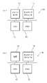
- the board on which electronic components such as the CPU 112, memory 113, and network module 114 are mountedis housed in the main body 110a of the surveillance camera 110, as shown in FIG.
- the main body 110ais installed via a support arm 110b.
- An imaging unit 110c containing the image sensor 111is provided on the front side of the main body 110a.
- the imaging unit 110 cincludes a lens that forms an image of the imaging area E 2 on the light receiving surface of the image sensor 111 .
- the information terminal 120is a known notebook-type or desktop-type personal computer, and as shown in FIG.
- a network modulefunctioning as a communication unit 24, a display (not shown) functioning as a display unit 21 for displaying an image received from the monitoring camera 110, and executing a program stored in a memory enables reception
- a CPU(not shown) that functions as a designation unit 22 that designates the detection area E1 based on the captured area image, and a mouse (not shown) that functions as a coordinate input unit (not shown) for inputting coordinates. ing.
- the alarm device 130is a device that alerts a person P who has entered the restricted area E1a by emitting a red light beam or the like. It is installed in a position that is easy to see.
- the alarm 130includes a red light source 131 (light source 31 in FIG. 3), a network module 134 functioning as a receiver 34 for receiving notifications from the monitoring camera 110, and a memory 133.
- a CPU 132that functions as a control unit 32 that controls the light source 131 according to a notification received from the surveillance camera 110 via the network module 134 by executing a program stored in the control unit 132 .
- FIG. 1The flow of the alarm system 100 according to this embodiment will be described below with reference to FIGS. 4 to 6.
- FIG. The alarm system 100first sets a detection area E1 in the imaging area E2, and issues an alarm by monitoring the set detection area E1.
- the setting process s10is a process for setting the detection area E1, and includes an imaging process s11, a transmission process s12, and a registration process s13, as shown in FIG.
- the image capturing process s11is a process of capturing an image of the image capturing area E2. Generate an image.
- the generated imaging area imageis input to the CPU 112 .
- the transmission process s12is a process of transmitting the imaging area image to the information terminal 120, and the CPU 112 of the surveillance camera 110 controls the network module 114 to transmit the image input from the image sensor 111 to the information terminal 120. do.
- the information terminal 120executes a reception process s21, a display process s22, and a designation process s23.
- the receiving process s21is a process of receiving the imaging area image from the surveillance camera 110, and the CPU of the information terminal 120 receives the imaging area image via the network module.
- the display processing s22is processing in which the CPU of the information terminal 120 displays the imaging area image on the display.
- the designation process s23is a process of designating the detection area E1 in which the object should be detected in the photographing area image for the surveillance camera 110.
- the detection area E1 in the imaging area imageis specified, for example, by the operator operating the mouse in the imaging area image displayed on the display.
- the CPU of the information terminal 120acquires click information of the mouse operated by the operator. When it is determined that the mouse has been clicked based on the acquired click information, the coordinate values of the mouse at that time are acquired. In this way, the CPU of the information terminal 120 acquires coordinate values each time the mouse is clicked. At least three coordinate values are acquired in this embodiment. Then, the CPU of the information terminal 120 converts the obtained multiple coordinate values into coordinate values in the imaging area image, and transmits the multiple coordinate values to the monitoring camera 110 as information regarding the detection area E1.
- the registration process s13is a process of registering coordinate values, which are information about the detection area E1. Memorize.
- the surveillance camera 110executes the confirmation process s30 after executing the setting process s10.
- the confirmation process s30is a process for confirming which of the setting process s40 and the monitoring process s50 is to be performed.
- the CPU 112 of the monitoring camera 110receives a setting request from the information terminal 120 (there is a request)
- the CPU 112 of the monitoring camera 110executes the setting process s40 similar to the setting process s10 described above to set the detection area E1 in the imaging area image. is set (updated).
- the monitoring process s50is executed at a predetermined frame rate.
- the monitoring process s50is a process for monitoring the presence of the person P in the detection area E1, and as shown in FIG. Including s54.
- the detection processing s52is processing for detecting an object within the detection area E1 in the imaging area image generated by the imaging processing s51.
- an image of the detection area E1(hereinafter referred to as a "detection area image") is extracted from the imaging area image, and the person P is detected in the extracted detection area image.
- the detection area imageis extracted based on the information regarding the detection area set in the setting processes s10 and s40.
- a polygon whose vertices are the plurality of coordinate values stored in the memory 113is partitioned in the coordinate system of the imaging area image, and the image included in the polygon is extracted as the detection area image.
- the detection of the person P in the detection area imagefor example, an image pattern including the characteristics of the person P is determined in advance, and if the detection area image includes an image pattern that matches or approximates the image pattern, the person P is detected. can be determined to have been detected.
- machine learningis performed in advance using the image of the person P as training data to generate a learned model, and the detection area image extracted in the extraction process is input to the learned model to determine the presence or absence of the person P. I don't mind if you let me.
- the monitoring process s50is ended and the confirmation process s30 (FIG. 4) is executed.
- the surveillance camera 110executes the notification process s54.
- the notification process s54is a process for notifying that the person P exists in the detection area E1. Then, the CPU 112 of the surveillance camera 110 ends the surveillance process and executes the confirmation process s30 (FIG. 4).
- the CPU 132 of the alarm device 130When the CPU 132 of the alarm device 130 receives the alarm command via the network module 134, it causes the red light source 131 to emit light.
- the information terminal 120designates a person in the detection area E1, which is an arbitrarily determined partial area instead of the entire imaging area E2 captured by the surveillance camera 110. Detection of P can be performed.
- the CPU 112 of the monitoring camera 110executes the object detection processing s52, but the monitoring camera 110 may include a GPU, and the GPU may execute the object detection processing s52. That is, the GPU may function as the detection unit 13 .
- the image sensor 111 included in the monitoring camera 110 of the above embodimentmay be a ToF camera sensor.
- the ToF camera sensoris typically a ToF distance image sensor that irradiates the imaging area E2 with light and detects distance information for each pixel.
- the presence or absence of an object within the detection area E1may be detected using such a ToF camera.
- the presence of the person P in the detection area E1may be detected by recognizing the body shape and motion of the person P based on the distance information for each pixel.
- one detection area E1is set within the imaging area image, but a plurality of detection areas E1 may be set within the imaging area E2.
- a plurality of coordinate values (a group of coordinate values) defining one detection area E1are transmitted to the monitoring camera 110 each time the specifying process s23 of the information terminal 120 is executed a plurality of times.
- surveillance camera 110registers the received group of coordinate values in memory 113 as information defining one detection area E1.
- a plurality of detection area images partitioned for each coordinate value groupare extracted, and the presence of the person P is detected for each of the extracted detection area images.
- a plurality of monitoring cameras 110may be provided in the above embodiment.
- each surveillance camera 110is identified by an IP address
- information terminal 120accesses surveillance camera 110 based on the IP address
- the detection area between surveillance camera 110 and information terminal 120is different. E1 is set.
- a plurality of alarm devices 130 provided in the above embodimentmay be provided.
- each of the alarms 130would be identified by an IP address, and the surveillance camera 110 would send notifications to the alarms 130 based on the IP address.
- the information terminal 120 and the alarm device 130communicate with the surveillance camera 110 via a network.
- a Bluetooth module or an IrDA modulemay be used as the communication units 14 and 24 and the reception unit 34 .
- wired communicationsuch as USB may be used.
- USB modulesmay be used as the communication units 14 and 24 and the reception unit 34 .
- a personal computeris used as an information terminal, but a mobile information terminal such as a smart phone or a tablet terminal may be used.
- the liquid crystal display of the portable information terminalfunctions as the display section 21 that displays the imaging area image by executing the display processing s22.
- the touch panel of the portable information terminalfunctions as a coordinate input unit (not shown) for specifying the detection area by executing the specifying process s23.
- the terminalis not limited to the above information terminal and portable information terminal, and may be a dedicated terminal provided with a designation unit for designating a detection area for surveillance camera 110 .
- the monitoring camera 110sends a notification to the alarm device 130 when the person P is detected within the detection area E1. You may control whether or not notifications are sent. For example, when the person P is detected, the image of the person P is analyzed. As a result of the analysis, if the name tag is not detected, a notification (alert command) is sent to the alarm device 130 . On the other hand, if the name tag is detected as a result of the analysis, the character string displayed on the name tag is recognized.
- the recognized character string (name)does not match the character string (name) registered in the memory or the like, a notification (alarm command) is sent to the alarm device 130, and the recognized character string (name) is If the character string (name) matches a pre-registered character string (name), it is determined that the person P is authorized to enter, and no notification is sent to the alarm device 130 .
- the face of the person Pmay be analyzed and the person P may be identified based on the feature amount of the face. By determining whether or not the identified person P is an entry permitter, the presence or absence of notification is controlled.
- the red light source 131is used as the alarm device 130 in the above embodiment, a speaker may be used as the alarm device 130 .
- the CPU 120 of the alarm device 130can generate a warning sound or voice from the speaker to call attention to the person P when receiving the notification from the monitoring camera 110 .
- both the red light source 131 and the speakermay be used.
- the alarm device 130 that can communicate with the monitoring camera 110is used, but a display device that can communicate with the monitoring camera 110 may be provided.
- the display deviceincludes a network module functioning as a receiving unit, a liquid crystal display functioning as a display unit, and a CPU functioning as a control unit for displaying an image calling attention on the liquid crystal display based on a notification received from the monitoring camera 110. and has.
- the alarm system of the above-described embodimentmay include an RFID reader provided so as to communicate with surveillance camera 110 .
- the RFID readerfor example, is provided near the restricted area E1a and reads an RF tag given to a person P who is permitted to enter the restricted area E1a.
- the RF tagstores an ID for identifying the person P who is permitted to enter.
- the RFID readerreads the ID from the RF tag possessed by the person P
- the RFID readertransmits the read ID to the surveillance camera 110 .
- the surveillance camera 110receives the ID from the RFID reader, it compares the received ID with an access permission ID pre-registered in a memory or the like, and if the IDs match, a notification is sent to the alarm device 130 in notification processing s54. do not.
- the readeris not limited to the RFID reader, and may be a reader that reads ID-encoded barcodes or QR codes (registered trademark).
- the system of the above embodimentmay include a fingerprint authentication device provided so as to be able to communicate with the surveillance camera 110 .
- the fingerprint authentication deviceis provided, for example, near the off-limits area E1a.
- the fingerprint authentication devicehas a memory in which the feature amount of the fingerprint of the person P who is permitted to enter is stored in advance, a fingerprint sensor that detects the feature amount of the fingerprint of the person P, and the detected feature amount of the fingerprint is stored in the memory. and a CPU for determining whether or not entry is permitted by comparing with the obtained feature amount.
- the CPUtransmits the determination result to the monitoring camera 110 via the network module.
- the monitoring camera 110receives the determination result from the fingerprint authentication device, and does not transmit the notification to the alarm device 130 in the notification processing s54 when the determination result indicates that entry is permitted. On the other hand, if the determination result is no access permission, a notification is sent to the alarm device 130 in notification processing s54.
- a fingerprint authentication devicethat authenticates a person's fingerprint is used in Modification 12 above, it is not limited to a fingerprint authentication device, and may be a vein authentication device or an iris authentication device. That is, a sensor for detecting the feature quantity of a person's body, a memory in which the feature quantity of the body of a person who is permitted to enter is stored in advance, and a comparison of the detected feature quantity with the feature quantity stored in the memory. , and a CPU for determining whether or not entry is permitted.
- the alarm system 100can be used, for example, as a system that issues an alarm when a person P enters a restricted area of a truck yard.
- the truck yardis provided with a truck movement area where trucks enter and stop after retreating, and a work stage where cargo is carried out from and loaded into the stopped truck.
- the work stageincludes a stage that is elevated with respect to the ground in the truck travel area to facilitate worker access to the truck bed.
- the monitoring camera 110 of the alarm system 100is installed on the ceiling above the truck movement area, captures an area including the work stage as an imaging area, and generates an imaging area image.
- the information terminal 120designates the work stage in the imaging area image received from the monitoring camera 110 as the detection area.
- the monitoring camera 110extracts a detection area image (image on the work stage) and detects the presence of the person P in the extracted detection area image.
- An alarm device 130is installed on the work stage of the truck yard.
- the alarm device 130When a person P is detected on the work stage by the surveillance camera 110, the alarm device 130 having received the notification causes the red light source 131 to emit light to detect the person. Alert P. Since a warning can be issued to the person P who has entered the work stage in this manner, it is possible to prevent the person P from falling off the work stage.
- the transmission of the notification to the alarm device 130may be interrupted when a condition other than the detection of the person P is satisfied.
- a symbolsuch as a one-dimensional code or a two-dimensional code is arranged at a position hidden (not included in the imaging area image) by a truck entering the truck movement area.
- Such a symbolis imaged by the image sensor 111 of the surveillance camera 110 when the truck is not stopped in the truck yard, and the symbol is included in the imaging area image.
- the CPU 112 of the monitoring camera 110acquires the imaging area image from the image sensor 111, it can determine that the truck is not stopped in the truck yard by detecting the symbols in the image. can.
- the monitoring camera 110detects the existence of the person P in the detection area (on the work stage) in the state determined in this way, a notification is sent to the alarm device 130 to cause the alarm device 130 to generate an alarm.
- the imaging area image generated by the image sensor 111 of the surveillance camera 110does not include the symbol.
- the CPU 112 of the monitoring camera 110detects no symbol in the imaging area image obtained from the image sensor 111, so it determines that the cargo is being loaded and unloaded from the stopped truck.
- the monitoring process s50is terminated without executing the detection process s52. That is, no notification is sent to the alarm device 130 while the truck is stopped.
- the symbolsare preferably provided within the detection area.
- the alarm system 100 of the first embodimentcan be used, for example, as a system that issues an alarm when a person P enters a braille block on a station platform.
- the monitoring camera 110 of the alarm system 100is installed on the ceiling of the home, captures an image of the entire home as an imaging area, and generates an imaging area image.
- the information terminal 120designates the part inside the braille block in the imaging area image received from the monitoring camera 110 as the detection area. Then, in the monitoring process s50, the monitoring camera 110 extracts the detection area image (the image inside the braille block) and detects the existence of the person P in the extracted detection area image. Then, when the person P is detected in the detection area image, the CPU 112 of the monitoring camera 110 transmits a notification to the alarm device 130 to generate an alarm.
- the train detection processis executed prior to the person detection process s52.
- the train detection processis a process of detecting a train in the imaging area image, and if an image pattern that matches or resembles a predetermined feature of the train exists in the imaging area image, the train is detected. becomes. In this case, passengers get on and off the train stopped at the platform, so the monitoring process s50 ends without executing the person detection process s52.
- the alarm system 100 of the first embodimentcan be used, for example, in a hospital as a system that issues an alarm when an inpatient enters a doorway during a period of time when inpatients are prohibited from going out, such as at night.
- the monitoring camera 110 of the alarm system 100is installed on the ceiling of the doorway, captures an image around the doorway as an imaging area, and generates an imaging area image.
- the information terminal 120designates the vicinity of the entrance in the imaging area image received from the monitoring camera 110 as the detection area. Then, in the detection process s52 of the monitoring process s50, a detection area (image near the entrance) is extracted from the imaging area image, and the presence of the person P in the extracted detection area image is detected s52. Then, when the person P is detected in the detection area image, the CPU 112 of the monitoring camera 110 transmits a notification to the alarm device 130 to generate an alarm.
- the alarm system in this usage examplemay be provided with an automatic door provided at the doorway so as to be able to communicate with the surveillance camera 110 .
- the automatic doorincludes a network module that functions as a receiver for receiving a notification from the surveillance camera 110, and a CPU that controls the door to close when the notification is received. This makes it possible to prevent the inpatient from going out during the curfew time.
- inpatientscan be identified based on differences in the clothing of hospitalized patients and the clothing of doctors and nurses.
- the alarm system 100may be installed not only at the entrance/exit but also in the corridor of the hospital. Specifically, an alarm system 100 is installed in a passage leading to an area where only hospital personnel are permitted to enter, and a monitoring camera 110 is installed on the ceiling of the passage. A part of the passage is set as a detection area by the information terminal 120, and the monitoring camera 110 detects a person P who has entered the part of the passage. Here, when the detected person P is identified as an inpatient, the monitoring camera 110 sends a notification to the alarm device 130, and the alarm device 130 generates an alarm.
- a gate devicecapable of communicating with the surveillance camera 110 may be provided in the passage.
- the gate deviceincludes a network module that functions as a receiving unit that receives a notification from the surveillance camera 110, and a CPU that controls an opening/closing bar that opens and closes the passage to a closed state when the notification is received.
- the alarm system 100 of the first embodimentcan be used for vehicles.
- the monitor camera 120 of the alarm system 110can set the rear side of a vehicle such as a forklift as an imaging area, and the vicinity of the rear side of the vehicle as a detection area.
Landscapes
- Engineering & Computer Science (AREA)
- Multimedia (AREA)
- Physics & Mathematics (AREA)
- General Physics & Mathematics (AREA)
- Theoretical Computer Science (AREA)
- Signal Processing (AREA)
- Health & Medical Sciences (AREA)
- Public Health (AREA)
- Business, Economics & Management (AREA)
- Emergency Management (AREA)
- Alarm Systems (AREA)
Abstract
Description
Translated fromJapanese本発明は、カメラ、及び当該カメラを備えるシステムに関する。The present invention relates to a camera and a system provided with the camera.
従来、カメラとサーバがネットワークを介して通信可能に接続されており、カメラによって生成された画像がサーバによって解析されるシステムが知られている。例えば、特許文献1に記載の監視システムは、複数の監視カメラと、画像認識部を有する中央サーバと、を備えている。画像認識部は各監視カメラから取得した画像を解析して、監視カメラが設置されているエリアに存在する人の多寡を検知する。Conventionally, there has been known a system in which a camera and a server are communicably connected via a network, and an image generated by the camera is analyzed by the server. For example, the surveillance system described in Patent Literature 1 includes multiple surveillance cameras and a central server having an image recognition section. The image recognition unit analyzes the images acquired from each surveillance camera and detects the number of people present in the area where the surveillance camera is installed.
また、例えば、特許文献2に記載されているように、サーバを有さず、複数の監視カメラによって構成される監視システムも知られている。複数の監視カメラは、各々に割り当てられたエリアを撮像し、当該エリアの画像を生成する。そして、監視カメラは、撮像した画像におけるオブジェクトを抽出し、抽出したオブジェクトを追跡する。当該追跡情報を複数の監視カメラが共有することで、広いエリア内におけるオブジェクトを追跡することが可能となっている。Also, for example, as described in Patent Document 2, a monitoring system that does not have a server and is configured with a plurality of monitoring cameras is also known. A plurality of surveillance cameras capture an area assigned to each and generate an image of the area. The surveillance camera then extracts an object in the captured image and tracks the extracted object. By sharing the tracking information with a plurality of surveillance cameras, it is possible to track objects in a wide area.
上記特許文献1のシステムでは、サーバの画像認識部が各監視カメラの画像を解析するため、監視カメラの設置台数が増加するにしたがってサーバの処理負荷が増大することとなってしまう。この点、特許文献2のシステムは、各監視カメラにおいてオブジェクトの検出処理を行っているので、監視カメラの設置台数の増加に伴う処理負荷の増大は生じない。しかしながら、特許文献2の各監視カメラは、常に、撮像して生成した画像の全域に対して検出処理を行う必要がある。In the system of Patent Document 1, the image recognition unit of the server analyzes the images of each surveillance camera, so the processing load on the server increases as the number of installed surveillance cameras increases. In this respect, the system of Patent Document 2 performs object detection processing in each surveillance camera, so the processing load does not increase as the number of installed surveillance cameras increases. However, each surveillance camera of Patent Document 2 always needs to perform detection processing on the entire area of the image that is captured and generated.
本発明は、撮像して生成した画像中の任意の部分について、オブジェクトを検出できるカメラおよびシステムを提供することを目的とする。An object of the present invention is to provide a camera and system that can detect an object in any part of an image that is captured and generated.
上記の目的を達成するため、本発明のシステムは、カメラ、及び当該カメラと通信可能な端末と、を備え、前記端末は、カメラから取得した画像中において、オブジェクトを検出すべき検出エリアを前記カメラに対して指定する指定部を備え、前記カメラは、生成した画像における前記検出エリア内のオブジェクトを検出する検出部と、前記オブジェクトが検出されたことを示す通知を他の機器に送信する送信部と、を備えることを特徴とする。In order to achieve the above object, the system of the present invention comprises a camera and a terminal capable of communicating with the camera, wherein the terminal defines a detection area in which an object should be detected in an image acquired from the camera. A designation unit that designates a camera, wherein the camera includes a detection unit that detects an object within the detection area in the generated image, and a transmission that transmits a notification indicating that the object has been detected to another device. and a part.
また、前記他の機器は、前記カメラから受信した通知に基づいて作動することを特徴とする。Also, the other device is characterized by operating based on the notification received from the camera.
さらに、前記カメラは、前記オブジェクトの検出とは異なる他の条件が満たされた場合に、前記通知を送信しないことを特徴とする。Furthermore, the camera is characterized by not sending the notification when a condition other than the detection of the object is met.
上記の目的を達成するため、本発明のカメラは、画像を生成する撮像部と、前記生成された画像中において、オブジェクトを検出すべき検出エリアが、通信可能な端末によって設定される設定部と、前記生成された画像における前記検出エリア内のオブジェクトを検出する検出部と、前記オブジェクトが検出されたことを示す通知を他の機器に送信する送信部と、を備えることを特徴とする。In order to achieve the above object, the camera of the present invention comprises an imaging unit that generates an image, and a setting unit that sets a detection area in which an object should be detected in the generated image by a communicable terminal. , a detection unit that detects an object within the detection area in the generated image; and a transmission unit that transmits a notification indicating that the object has been detected to another device.
本発明によれば、撮像して生成した画像中の任意の部分について、オブジェクトを検出することができる。According to the present invention, an object can be detected in any part of an image generated by imaging.
[第1実施形態][First embodiment]
以下、本発明の第1実施形態に係る警報システム100を図面に基づいて説明する。The
第1実施形態に係る警報システム100は、特定のエリアに人や物などのオブジェクトが存在する場合に警報を発生させるシステムであり、図1に示すように、例えば、立ち入りが禁止されているエリアE1a(以下、「立入禁止エリアE1a」という)に人Pが立ち入った場合に、その人Pに対して警報を発生させるシステムとして用いられる。当該警報システム100は、立入禁止エリアE1aを監視する監視カメラ110(カメラ)、立入禁止エリアE1aを設定する情報端末120(端末)(図3)、及び警報を発生させる警報器130(他の装置)を備えており、監視カメラ110に対して警報器130および情報端末120がネットワークを介して通信可能に構成されている。The
監視カメラ110は、オブジェクトを検出すべきエリアE1(以下、「検出エリアE1」という)におけるオブジェクトの存在を検出するカメラである。本実施形態の監視カメラ110は、立入禁止エリアE1aを検出エリアE1とする定点カメラであり、立入禁止エリアE1a内における人Pの存在を検出できるよう、立入禁止エリアE1aを含む撮像エリアE2を撮像できる近辺の天井などに設置されている。The
当該監視カメラ110は、図2に示すように、検出エリアE1を含む撮像エリアE2を撮像する撮像部11(図3)として機能するイメージセンサ111を備えている。イメージセンサ111は、撮像エリアE2を撮像して、当該撮像エリアE2の画像(以下、「撮像エリア画像」という)を生成する。イメージセンサ111によって生成された撮像エリア画像は、監視カメラ110が備えるCPU112へと入力される。As shown in FIG. 2, the
監視カメラ110のCPU112は、メモリ113に記憶されたプログラムを実行することにより、イメージセンサ111を制御する。そして、当該CPU112は、情報端末120と協働して、イメージセンサ111から取得した撮像エリア画像に基づいて検出エリアE1を設定する設定部12として機能する。また、当該CPU112は、イメージセンサ111から撮像エリア画像を取得する度に、取得した撮像エリア画像を解析して、検出エリアE1内における人Pを検出する検出部13として機能する。また、CPU112にはネットワークモジュール114が接続されている。The
監視カメラ110のネットワークモジュール114は、情報端末120に対して撮像エリア画像を送信する送信部、情報端末120から検出エリアE1に関する情報を受信する受信部として機能する。さらに、ネットワークモジュール114は、検出エリアE1内に人Pが検出された場合に、警報器130に対して通知を送信する送信部としても機能している。なお、上記送信部および受信部をまとめて通信部14という。The
上記CPU112、メモリ113、及びネットワークモジュール114などの電子部品が実装された基板は、図1に示すように、監視カメラ110の本体110a内に収納される。当該本体110aは支持アーム110bを介して設置されている。本体110aの正面側には上記のイメージセンサ111を収納した撮像ユニット110cが設けられている。撮像ユニット110cは、イメージセンサ111の受光面に対して撮像エリアE2の像を結像させるレンズを備えている。The board on which electronic components such as the
情報端末120は、ノート型やデスクトップ型の公知のパソコンであって、図3に示すように、ネットワークを介して監視カメラ110に対して情報(撮像エリア画像や検出エリアE1に関する情報)を送受信する通信部24として機能するネットワークモジュール(不図示)と、監視カメラ110から受信した画像を表示する表示部21として機能するディスプレイ(不図示)と、メモリに記憶されたプログラムを実行することにより、受信した撮像エリア画像に基づいて上記検出エリアE1を指定する指定部22として機能するCPU(不図示)と、座標を入力する座標入力部(不図示)として機能するマウス(不図示)と、を備えている。The
図1に示すように、警報器130は、赤色光線の発光などによって立入禁止エリアE1aに立ち入った人Pに対して注意を促す装置であり、本実施形態では立入禁止エリアに立ち入った人Pに視認しやすい位置に設置されている。図2および図3に示すように、当該警報器130は、赤色の光源131(図3において光源31)と、監視カメラ110から通知を受信する受信部34として機能するネットワークモジュール134と、メモリ133に記憶されたプログラムを実行することによって、ネットワークモジュール134を介して監視カメラ110から受信した通知に従って光源131を制御する制御部32として機能するCPU132と、を備えている。As shown in FIG. 1, the
以下、本実施形態に係る警報システム100のフローを図4乃至図6に基づいて説明する。当該警報システムは100は、先ず、撮像エリアE2における検出エリアE1を設定し、設定された検出エリアE1を監視することにより警報を発することとしている。The flow of the
図4に示すように、監視カメラ110のCPU112は、メモリ113に記憶されたプログラムを実行することにより、設定処理s10を実行する。設定処理s10は、検出エリアE1を設定する処理であって、図5に示すように、撮像処理s11、送信処理s12、及び登録処理s13を含む。As shown in FIG. 4, the
撮像処理s11は、撮像エリアE2を撮像する処理であって、監視カメラ110のCPU112がイメージセンサ111に対して撮像コマンドを入力し、イメージセンサ111が撮像コマンドに従って撮像エリアE2を撮像し、撮像エリア画像を生成する。生成された撮像エリア画像はCPU112へと入力される。The image capturing process s11 is a process of capturing an image of the image capturing area E2. Generate an image. The generated imaging area image is input to the
送信処理s12は、撮像エリア画像を情報端末120に送信する処理であり、監視カメラ110のCPU112は、ネットワークモジュール114を制御することにより、イメージセンサ111から入力された画像を情報端末120へと送信する。The transmission process s12 is a process of transmitting the imaging area image to the
情報端末120は、受信処理s21、表示処理s22、及び指定処理s23を実行する。受信処理s21は、監視カメラ110から撮像エリア画像を受信する処理であり、情報端末120のCPUがネットワークモジュールを介して撮像エリア画像を受信する。表示処理s22は、情報端末120のCPUが撮像エリア画像をディスプレイに表示する処理である。The
指定処理s23は、監視カメラ110に対して、撮影エリア画像においてオブジェクトを検出すべき検出エリアE1を指定する処理である。検出エリアE1は、例えば、ディスプレイに表示されている撮像エリア画像において、オペレータがマウスを操作することによって、撮像エリア画像における検出エリアE1が指定される。具体的には、情報端末120のCPUは、オペレータが操作するマウスのクリック情報を取得する。取得したクリック情報に基づいてマウスがクリックされたと判定された場合には、その時点におけるマウスの座標値を取得する。このように、情報端末120のCPUは、マウスがクリックされる度に座標値を取得する。本実施形態では少なくとも3つの座標値を取得する。そして、情報端末120のCPUは、取得した複数の座標値を撮像エリア画像における座標値へと変換し、当該複数の座標値を検出エリアE1に関する情報として監視カメラ110に送信する。The designation process s23 is a process of designating the detection area E1 in which the object should be detected in the photographing area image for the
情報端末120から座標値が送信されると、監視カメラ110は登録処理s13を実行する。登録処理s13は、検出エリアE1に関する情報である座標値を登録する処理であって、監視カメラ110のCPU112がネットワークモジュール114を介して座標値を受信し、受信した座標値の各々をメモリ113に記憶させる。When the coordinate values are transmitted from the
図4に戻り、監視カメラ110は、設定処理s10を実行した後に確認処理s30を実行する。確認処理s30は、設定処理s40と監視処理s50のどちらを行うかを確認する処理である。監視カメラ110のCPU112は、情報端末120からの設定リクエストを受信している場合(リクエストあり)には、上記の設定処理s10と同様の設定処理s40を実行して、撮像エリア画像における検出エリアE1を設定(更新)する。一方、設定リクエストを受信していない場合(リクエストなし)には、所定のフレームレートで監視処理s50を実行する。Returning to FIG. 4, the
監視処理s50は、検出エリアE1における人Pの存在を監視する処理であって、図6に示すように、上記設定処理s10の撮像処理s11と同様の撮像処理s51、検出処理s52、及び通知処理s54を含む。検出処理s52は、撮像処理s51によって生成された撮像エリア画像中において、検出エリアE1内のオブジェクトを検出する処理である。本実施形態では、撮像エリア画像から検出エリアE1の画像(以下、「検出エリア画像」という)を抽出し、抽出した検出エリア画像における人Pを検出する。ここで、検出エリア画像の抽出については、設定処理s10,s40において設定された検出エリアに関する情報に基づいて抽出される。すなわち、設定処理s10,s40においてメモリ113に記憶された複数の座標値を頂点とする多角形を撮像エリア画像の座標系において区画し、当該多角形に含まれる画像を検出エリア画像として抽出する。また、検出エリア画像における人Pの検出については、例えば、人Pの特徴を含む画像パターンを予め定めておき、当該画像パターンと一致または近似する画像パターンが検出エリア画像に含まれる場合に人Pが検出されたと判断することができる。他には、予め人Pの画像を教師データとする機械学習を実施して学習済みモデルを生成し、抽出処理において抽出した検出エリア画像を学習済みモデルに入力することで人Pの有無を判定させても構わない。The monitoring process s50 is a process for monitoring the presence of the person P in the detection area E1, and as shown in FIG. Including s54. The detection processing s52 is processing for detecting an object within the detection area E1 in the imaging area image generated by the imaging processing s51. In this embodiment, an image of the detection area E1 (hereinafter referred to as a "detection area image") is extracted from the imaging area image, and the person P is detected in the extracted detection area image. Here, the detection area image is extracted based on the information regarding the detection area set in the setting processes s10 and s40. That is, in the setting processes s10 and s40, a polygon whose vertices are the plurality of coordinate values stored in the
上記検出処理s52の結果、人Pが検出されなかった場合(s53:No)には、監視処理s50を終了し、上記確認処理s30(図4)を実行する。一方で、検出処理s52の結果、人Pが検出された場合(s53:Yes)には、監視カメラ110は通知処理s54を実行する。通知処理s54は、検出エリアE1に人Pが存在することを通知する処理であって、本実施形態では、監視カメラ110のCPU112は、警報器130に対して警報命令を送信する。そして、監視カメラ110のCPU112は監視処理を終了し、確認処理s30(図4)を実行する。When the person P is not detected as a result of the detection process s52 (s53: No), the monitoring process s50 is ended and the confirmation process s30 (FIG. 4) is executed. On the other hand, when the person P is detected as a result of the detection process s52 (s53: Yes), the
警報器130のCPU132は、ネットワークモジュール134を介して警報命令を受信すると、赤色光源131を発光させる。When the
本実施形態の警報システム100によれば、情報端末120からの指定によって、監視カメラ110が撮像している撮像エリアE2全域ではなく、任意に定められた部分的なエリアである検出エリアE1における人Pの検出を実施することができる。According to the
以上、本発明の実施形態を説明したが、本発明は上記の実施形態に限定されず、下記のような変形例であっても構わない。Although the embodiments of the present invention have been described above, the present invention is not limited to the above embodiments, and the following modifications are possible.
[変形例1]
上記の実施形態では、監視カメラ110が有するCPU112が、オブジェクトの検出処理s52を実行しているが、監視カメラ110はGPUを備え、当該GPUがオブジェクトの検出処理s52を実行しても構わない。すなわち、GPUが検出部13として機能しても構わない。[Modification 1]
In the above embodiment, the
[変形例2]
上記の実施形態の監視カメラ110が備えるイメージセンサ111はToFカメラセンサであっても構わない。ToFカメラセンサとしては、代表的には、撮像エリアE2に対して光を照射して画素ごとに距離情報を検出するToF方式距離画像センサである。このようなToFカメラを用いて検出エリアE1内におけるオブジェクトの有無を検出しても良い。例えば、画素ごとの距離情報に基づいて人Pの体形やモーションを認識することにより、検出エリアE1における人Pの存在を検出しても構わない。[Modification 2]
The
[変形例3]
上記の実施形態では、撮像エリア画像内に1つの検出エリアE1が設定されているが、撮像エリアE2内に複数の検出エリアE1が設定されても構わない。当該態様においては、情報端末120の指定処理s23が複数回実行されることにより、その都度、一の検出エリアE1を定める複数の座標値(座標値群)が監視カメラ110に送信される。監視カメラ110は、座標値群を受信する度に、受信した座標値群を一の検出エリアE1を定める情報としてメモリ113に登録する。そして、検出処理s52において、検出エリア画像を抽出する際には、座標値群ごとに区画される複数の検出エリア画像を抽出し、抽出した検出エリア画像の各々について人Pの存在を検出する。[Modification 3]
In the above embodiment, one detection area E1 is set within the imaging area image, but a plurality of detection areas E1 may be set within the imaging area E2. In this aspect, a plurality of coordinate values (a group of coordinate values) defining one detection area E1 are transmitted to the
[変形例4]
上記の実施形態が備える監視カメラ110は複数であっても構わない。このような態様においては、監視カメラ110の各々はIPアドレスによって識別され、情報端末120がIPアドレスに基づいて監視カメラ110にアクセスすることとなり、監視カメラ110と情報端末120との間で検出エリアE1の設定が行われることとなる。[Modification 4]
A plurality of
[変形例5]
上記の実施形態が備える警報器130は複数であっても構わない。このような態様においては、警報器130の各々はIPアドレスによって識別され、監視カメラ110がIPアドレスに基づいて警報器130に対して通知を送信することとなる。[Modification 5]
A plurality of
[変形例6]
上記の実施形態では、監視カメラ110に対して情報端末120および警報器130がネットワークを介して通信する態様であったが、通信態様は、Bluetooth(登録商標)やIrDAなどの無線通信であっても構わない。すなわち、通信部14,24および受信部34として、BluetoothモジュールやIrDAモジュールを用いても構わない。また、USBなどの有線通信であっても構わない。すなわち、通信部14,24および受信部34として、USBモジュールを用いても構わない。[Modification 6]
In the above embodiment, the
[変形例7]
上記の実施形態では、情報端末としてパソコンを用いているが、スマートフォンやタブレット端末などの携帯情報端末であっても構わない。このような態様において、携帯情報端末の液晶ディスプレイは、表示処理s22が実行されることにより、撮像エリア画像を表示する表示部21として機能する。また、携帯情報端末が有するタッチパネルは、指定処理s23が実行されることにより、検出エリアを指定するための座標入力部(不図示)として機能する。また、上記情報端末および携帯情報端末に限られず、監視カメラ110に対して、検出エリアを指定する指定部を備える専用端末であっても構わない。[Modification 7]
In the above embodiment, a personal computer is used as an information terminal, but a mobile information terminal such as a smart phone or a tablet terminal may be used. In such a mode, the liquid crystal display of the portable information terminal functions as the
[変形例8]
上記の実施形態では、監視カメラ110は、検出エリアE1内に人Pが検出された場合に通知を警報器130に送信しているが、人Pが備える名札などの目印を認識することにより、通知を送信するか否かを制御しても構わない。例えば、人Pが検出された場合において、その人Pの画像を解析する。解析した結果、名札が検出されなかった場合には通知(警報命令)を警報器130に送信する。一方、解析した結果、名札が検出された場合には、当該名札に表示されている文字列を認識する。そして、当該認識した文字列(氏名)がメモリなどに登録されている文字列(氏名)と一致しない場合には通知(警報命令)を警報器130に送信し、認識した文字列(氏名)が予め登録されている文字列(氏名)と一致する場合には、当該人Pは立入許諾者であると判定し、通知を警報器130に送信しない。[Modification 8]
In the above embodiment, the
なお、変形例8では、名札の文字列を認識しているが、人Pの顔を解析して、顔の特徴量に基づいて人Pを特定しても構わない。そして、特定された人Pが立入許諾者であるか否かを判定することで、通知の有無を制御する。Although the character string of the name tag is recognized in Modified Example 8, the face of the person P may be analyzed and the person P may be identified based on the feature amount of the face. By determining whether or not the identified person P is an entry permitter, the presence or absence of notification is controlled.
[変形例9]
上記の実施形態では、警報器130として赤色光源131を用いているが、警報器130としてスピーカーを用いても構わない。このような態様では、警報器130のCPU120は、監視カメラ110から通知を受信すると、スピーカーから警告音や音声を発生させて人Pに対して注意を促すことができる。また、赤色光源131とスピーカーの両方を用いても構わない。[Modification 9]
Although the
[変形例10]
上記実施形態では、監視カメラ110に対して通信可能な警報器130を用いているが、監視カメラ110に対して通信可能な表示装置を備えても構わない。当該表示装置は、受信部として機能するネットワークモジュールと、表示部として機能する液晶ディスプレイと、監視カメラ110から受信した通知に基づいて、液晶ディスプレイに注意を促す画像を表示させる制御部として機能するCPUと、を備えている。[Modification 10]
In the above embodiment, the
[変形例11]
上記の実施形態の警報システムは、監視カメラ110と通信可能に設けられたRFIDリーダを備えても構わない。RFIDリーダは、例えば、立入禁止エリアE1aの近くに設けられ、立入禁止エリアE1aに立ち入ることを許可された人Pに付与されたRFタグを読み取る。当該RFタグには立入許可された人Pを識別するためのIDが記憶されている。RFIDリーダは、人Pが有するRFタグからIDを読み取ると、読み取ったIDを監視カメラ110へと送信する。監視カメラ110はRFIDリーダからIDを受信すると、受信したIDをメモリなどに事前登録されている立入許可IDと照合し、IDが一致する場合には、通知処理s54において通知を警報器130に送信しない。なお、RFIDリーダに限られず、IDが符号化されたバーコードやQRコード(登録商標)を読み取るリーダであっても構わない。[Modification 11]
The alarm system of the above-described embodiment may include an RFID reader provided so as to communicate with
[変形例12]
上記の実施形態のシステムは、監視カメラ110と通信可能に設けられた指紋認証装置を備えても構わない。指紋認証装置は、例えば、立入禁止エリアE1aの近くに設けられる。指紋認証装置は、立入許可された人Pの指紋の特徴量が事前に記憶されたメモリと、人Pの指紋の特徴量を検出する指紋センサと、検出された指紋の特徴量をメモリに記憶された特徴量と照合して、立入許可の有無を判定するCPUと、を備えている。CPUは、ネットワークモジュールを介して、判定結果を監視カメラ110へと送信する。監視カメラ110は、指紋認証装置から判定結果を受信し、判定結果が立入許可ありの場合には、通知処理s54において通知を警報器130に送信しない。一方、判定結果が立入許可なしの場合には、通知処理s54において通知を警報器130に送信する。[Modification 12]
The system of the above embodiment may include a fingerprint authentication device provided so as to be able to communicate with the
上記変形例12では、人の指紋を認証する指紋認証装置を用いたが、指紋認証装置に限られず、静脈認証装置や虹彩認証装置であっても構わない。すなわち、人の身体の特徴量を検出するセンサと、立入許可された人の体の特徴量が事前に記憶されたメモリと、検出された特徴量をメモリに記憶された特徴量と照合して、立入許可の有無を判定するCPUと、を備え、CPUは、ネットワークモジュールを介して、判定結果を監視カメラ110へと送信する認証装置であればよい。Although a fingerprint authentication device that authenticates a person's fingerprint is used in
[使用例1][Usage example 1]
第1実施形態に係る警報システム100は、例えば、トラックヤードの立入禁止エリアに人Pが立ち入った場合に警報を発生させるシステムとして用いることができる。トラックヤードは、トラックが後退進入して停止するトラック移動エリアと、停止中のトラックから荷物を搬出したり、荷物を積み込こむ作業を行う作業ステージと、が設けられている。作業ステージは、作業者がトラックの荷台にアクセスしやすいように、トラック移動エリアの地面に対して高い位置に設けられたステージを備えている。The
当該トラックヤードにおいて、警報システム100の監視カメラ110は、トラック移動エリア上方に設けられた天井に設置されており、作業ステージを含むエリアを撮像エリアとして撮像し、撮像エリア画像を生成する。In the truck yard, the
このような警報システム100の設定処理s10,s40において、情報端末120は、当該監視カメラ110から受信した撮像エリア画像における作業ステージ上を検出エリアとして指定する。監視処理s50において、監視カメラ110は検出エリア画像(作業ステージ上の画像)を抽出し、抽出した検出エリア画像における人Pの存在を検出する。In the setting processes s10 and s40 of the
上記のトラックヤードの作業ステージには警報器130が設置されており、監視カメラ110によって作業ステージ上に人Pが検出されると、通知を受信した警報器130は赤色光源131を発光させて人Pに対して警報を発する。このように作業ステージ上に立ち入った人Pに対して警報を発することができるので、作業ステージからの転落を防止することができる。An
また、人Pの検出とは異なる他の条件が満たされた場合に、警報器130に対する通知の送信を中断しても構わない。例えば、トラックヤードの撮像エリア内に、一次元コードや二次元コードなどのシンボルを、トラック移動エリアに進入したトラックによって隠れる(撮像エリア画像に含まれない)位置に配置する。In addition, the transmission of the notification to the
このようなシンボルは、トラックヤードにトラックが停止していない状態においては、監視カメラ110のイメージセンサ111によって撮像されて、撮像エリア画像にシンボルが含まれることとなる。監視処理s50において、監視カメラ110のCPU112は、イメージセンサ111から撮像エリア画像を取得すると、当該画像におけるシンボルを検出することでトラックヤードにトラックが停止していない状態であることを判定することができる。このように判定した状態で、監視カメラ110が検出エリア(作業ステージ上)に人Pの存在を検出した場合には、通知を警報器130に送信し、警報器130に警報を発生させる。Such a symbol is imaged by the
一方で、トラックヤードにトラックが停止している状態においては、トラックによってシンボルが隠れるので、監視カメラ110のイメージセンサ111によって生成された撮像エリア画像にシンボルが含まれないこととなる。監視処理s50において、監視カメラ110のCPU112は、イメージセンサ111から取得した撮像エリア画像にシンボルが検出されないので、停止中のトラックに対して荷物の出し入れ作業を行っているものと判定し、オブジェクトの検出処理s52を実行せずに監視処理s50を終了する。すなわち、トラックが停止中は警報器130に対して通知が送信されないこととなる。なお、シンボルは検出エリア内に設けられるのが好ましい。On the other hand, when the truck is stopped in the truck yard, the symbol is hidden by the truck, so the imaging area image generated by the
[使用例2][Usage example 2]
第1実施形態の警報システム100は、例えば、駅のホームにおいて点字ブロック内に人Pが立ち入った場合に警報を発生させるシステムとして用いることができる。具体的には、警報システム100の監視カメラ110は、ホームの天井に設置されており、ホーム全体を撮像エリアとして撮像し、撮像エリア画像を生成する。The
この警報システム100の設定処理s10,s40では、情報端末120は、当該監視カメラ110から受信した撮像エリア画像における点字ブロックより内側部分を検出エリアとして指定する。そして、監視処理s50において、監視カメラ110は検出エリア画像(点字ブロックの内側の画像)を抽出し、抽出した検出エリア画像における人Pの存在を検出する。そして、監視カメラ110のCPU112は、検出エリア画像において人Pが検出された場合には、通知を警報器130に送信し、警報を発生させる。In the setting processes s10 and s40 of the
なお、監視処理s50では、人の検出処理s52に先立って、電車の検出処理が実行される。電車の検出処理は、撮像エリア画像中における電車を検出する処理であり、予め定めた電車の特徴に一致又は類似する画像パターンが撮像エリア画像中に存在する場合には、電車が検出されることとなる。この場合には、ホームに停車中の電車に対して乗客の乗り降りが発生するので、人の検出処理s52を実行することなく監視処理s50が終了される。Note that in the monitoring process s50, the train detection process is executed prior to the person detection process s52. The train detection process is a process of detecting a train in the imaging area image, and if an image pattern that matches or resembles a predetermined feature of the train exists in the imaging area image, the train is detected. becomes. In this case, passengers get on and off the train stopped at the platform, so the monitoring process s50 ends without executing the person detection process s52.
[使用例3][Usage example 3]
第1実施形態の警報システム100は、例えば、病院において、夜間など入院患者の外出が禁止されている時間帯において入院患者が出入口に立ち入った場合に警報を発生させるシステムとして用いることができる。具体的には、警報システム100の監視カメラ110は、出入口の天井に設置されており、出入口の周囲を撮像エリアとして撮像し、撮像エリア画像を生成する。The
警報システム100の設定処理s10,s40では、情報端末120は、監視カメラ110から受信した撮像エリア画像における出入口近辺を検出エリアとして指定する。そして、監視処理s50の検出処理s52において、撮像エリア画像から検出エリア(出入口近辺の画像)が抽出され、抽出された検出エリア画像における人Pの存在を検出するs52。そして、監視カメラ110のCPU112は、検出エリア画像において人Pが検出された場合には、通知を警報器130に送信し、警報を発生させる。In the setting processes s10 and s40 of the
本使用例における警報システムは、監視カメラ110と通信可能に設けられ、前記出入口に設けられた自動ドアを備えても構わない。当該自動ドアは、監視カメラ110が通知を受信する受信部として機能するネットワークモジュールと、通知を受信した場合にドアを閉状態に制御するCPUと、を備えている。これにより、外出禁止時間において入院患者が外出することを防止することが可能となる。The alarm system in this usage example may be provided with an automatic door provided at the doorway so as to be able to communicate with the
当該使用例の監視処理では、検出エリアにおける人Pが検出された場合に、さらに、入院患者、医師、看護師を識別し、入院患者を検出した場合にのみ警報を通知するものであっても構わない。例えば、入院患者の服装と医師や看護師の服装の差異に基づいて入院患者を識別することができる。In the monitoring process of this usage example, when the person P is detected in the detection area, the hospitalized patient, the doctor, and the nurse are further identified, and an alarm is notified only when the hospitalized patient is detected. I do not care. For example, inpatients can be identified based on differences in the clothing of hospitalized patients and the clothing of doctors and nurses.
また、出入口に限られず、病院の通路に警報システム100が設けられても構わない。具体的には、病院関係者のみに立入りが許可されたエリアに通じる通路に警報システム100を設け、当該通路の天井に監視カメラ110を設置する。この監視カメラ110は、情報端末120によって、通路の一部が検出エリアとして設定されており、通路の一部に進入した人Pを検出する。ここで、検出された人Pが入院患者であると識別された場合には、監視カメラ110は通知を警報器130に送信し、警報器130は警報を発生させる。Also, the
また、監視カメラ110と通信可能なゲート装置を上記の通路に設けても構わない。ゲート装置は、監視カメラ110から通知を受信する受信部として機能するネットワークモジュールと、通知を受信した場合に通路を開閉する開閉バーを閉状態に制御するCPUと、を備えている。このようなゲート装置を関係者以外立入禁止エリアに通じる通路に設けることで、患者が誤って当該立入禁止エリアに立ち入ることを物理的に防止することができる。Also, a gate device capable of communicating with the
[使用例4][Usage example 4]
第1実施形態の警報システム100は、乗り物に用いることができる。具体的には、警報システム110の監視カメラ120はフォークリフトなどの乗り物の後方を撮像エリアとし、乗り物の後方近辺を検出エリアと設定することができる。The
以上、本発明を説明したが、本発明は上記の実施形態や変形例、また使用例に限定されず、種々の変更が加えられた態様であっても構わない。Although the present invention has been described above, the present invention is not limited to the above-described embodiments, modifications, and usage examples, and may be modified in various ways.
13 検出部
14 通信部(送信部)
22 指定部
100 監視システム
110 監視カメラ(カメラ)
120 情報端末(端末)
130 警報器(他の機器)
E1 検出エリア
E2 撮像エリア
13
22
120 information terminal (terminal)
130 alarm (other equipment)
E1 Detection area E2 Imaging area
Claims (4)
Translated fromJapanese前記端末は、
カメラから取得した画像中において、オブジェクトを検出すべき検出エリアを前記カメラに対して指定する指定部を備え、
前記カメラは、
生成した画像における前記検出エリア内のオブジェクトを検出する検出部と、
前記オブジェクトが検出されたことを示す通知を他の機器に送信する送信部と、
を備えるシステム。comprising a camera and a terminal capable of communicating with the camera,
The terminal is
a designation unit for designating a detection area in which an object should be detected in an image acquired from the camera,
The camera is
a detection unit that detects an object within the detection area in the generated image;
a transmission unit that transmits a notification indicating that the object has been detected to another device;
A system with
前記生成された画像中において、オブジェクトを検出すべき検出エリアが、通信可能な端末によって設定される設定部と、
前記生成された画像における前記検出エリア内のオブジェクトを検出する検出部と、
前記オブジェクトが検出されたことを示す通知を他の機器に送信する送信部と、
を備えるカメラ。
an imaging unit that generates an image;
a setting unit in which a detection area in which an object should be detected in the generated image is set by a communicable terminal;
a detection unit that detects an object within the detection area in the generated image;
a transmission unit that transmits a notification indicating that the object has been detected to another device;
A camera with
Priority Applications (3)
| Application Number | Priority Date | Filing Date | Title |
|---|---|---|---|
| JP2023532080AJPWO2023277165A1 (en) | 2021-06-30 | 2022-06-30 | |
| US18/572,477US20240290196A1 (en) | 2021-06-30 | 2022-06-30 | Camera and system |
| EP22833311.8AEP4366299A4 (en) | 2021-06-30 | 2022-06-30 | Camera and system |
Applications Claiming Priority (2)
| Application Number | Priority Date | Filing Date | Title |
|---|---|---|---|
| JP2021109753 | 2021-06-30 | ||
| JP2021-109753 | 2021-06-30 |
Publications (1)
| Publication Number | Publication Date |
|---|---|
| WO2023277165A1true WO2023277165A1 (en) | 2023-01-05 |
Family
ID=84692751
Family Applications (1)
| Application Number | Title | Priority Date | Filing Date |
|---|---|---|---|
| PCT/JP2022/026397CeasedWO2023277165A1 (en) | 2021-06-30 | 2022-06-30 | Camera and system |
Country Status (4)
| Country | Link |
|---|---|
| US (1) | US20240290196A1 (en) |
| EP (1) | EP4366299A4 (en) |
| JP (1) | JPWO2023277165A1 (en) |
| WO (1) | WO2023277165A1 (en) |
Families Citing this family (1)
| Publication number | Priority date | Publication date | Assignee | Title |
|---|---|---|---|---|
| US20250095466A1 (en)* | 2023-09-20 | 2025-03-20 | SimpliSafe, Inc. | Security system application |
Citations (6)
| Publication number | Priority date | Publication date | Assignee | Title |
|---|---|---|---|---|
| JPH04311186A (en)* | 1991-04-10 | 1992-11-02 | Toshiba Corp | Image monitoring device |
| JP2000293773A (en)* | 1999-04-08 | 2000-10-20 | Toenec Corp | Device and method for alarming |
| JP2011134004A (en) | 2009-12-22 | 2011-07-07 | Panasonic Electric Works Co Ltd | Building situation monitoring system and monitor |
| JP5686435B2 (en) | 2011-03-14 | 2015-03-18 | オムロン株式会社 | Surveillance system, surveillance camera terminal, and operation mode control program |
| JP2015170141A (en)* | 2014-03-07 | 2015-09-28 | 株式会社中電工 | Specified range monitoring system |
| JP2019016836A (en)* | 2017-07-03 | 2019-01-31 | 沖電気工業株式会社 | Monitoring system, information processing unit, information processing method, and program |
Family Cites Families (3)
| Publication number | Priority date | Publication date | Assignee | Title |
|---|---|---|---|---|
| JP4318724B2 (en)* | 2007-02-14 | 2009-08-26 | パナソニック株式会社 | Surveillance camera and surveillance camera control method |
| JP6226538B2 (en)* | 2013-03-15 | 2017-11-08 | キヤノン株式会社 | Display control apparatus, display control method, and program |
| JP2019176306A (en)* | 2018-03-28 | 2019-10-10 | キヤノン株式会社 | Monitoring system and control method therefor, and program |
- 2022
- 2022-06-30USUS18/572,477patent/US20240290196A1/enactivePending
- 2022-06-30EPEP22833311.8Apatent/EP4366299A4/enactivePending
- 2022-06-30WOPCT/JP2022/026397patent/WO2023277165A1/ennot_activeCeased
- 2022-06-30JPJP2023532080Apatent/JPWO2023277165A1/jaactivePending
Patent Citations (6)
| Publication number | Priority date | Publication date | Assignee | Title |
|---|---|---|---|---|
| JPH04311186A (en)* | 1991-04-10 | 1992-11-02 | Toshiba Corp | Image monitoring device |
| JP2000293773A (en)* | 1999-04-08 | 2000-10-20 | Toenec Corp | Device and method for alarming |
| JP2011134004A (en) | 2009-12-22 | 2011-07-07 | Panasonic Electric Works Co Ltd | Building situation monitoring system and monitor |
| JP5686435B2 (en) | 2011-03-14 | 2015-03-18 | オムロン株式会社 | Surveillance system, surveillance camera terminal, and operation mode control program |
| JP2015170141A (en)* | 2014-03-07 | 2015-09-28 | 株式会社中電工 | Specified range monitoring system |
| JP2019016836A (en)* | 2017-07-03 | 2019-01-31 | 沖電気工業株式会社 | Monitoring system, information processing unit, information processing method, and program |
Non-Patent Citations (1)
| Title |
|---|
| See also references ofEP4366299A4 |
Also Published As
| Publication number | Publication date |
|---|---|
| JPWO2023277165A1 (en) | 2023-01-05 |
| EP4366299A1 (en) | 2024-05-08 |
| US20240290196A1 (en) | 2024-08-29 |
| EP4366299A4 (en) | 2025-05-14 |
Similar Documents
| Publication | Publication Date | Title |
|---|---|---|
| US11341794B2 (en) | Unattended touchless health-check screening systems incorporating biometrics and thermographic technologies | |
| AU2018312581B2 (en) | Supervising property access with portable camera | |
| US20100054546A1 (en) | Integrated resource management system | |
| US20230410519A1 (en) | Suspicious person alarm notification system and suspicious person alarm notification method | |
| US10930102B2 (en) | Method for employing a RFID walk-through gate | |
| JPWO2008152897A1 (en) | Monitoring system and monitoring method | |
| CN113507543A (en) | Doorbell, key management system and intercom system | |
| WO2020167155A1 (en) | Method and system for detecting troubling events during interaction with a self-service device | |
| JP2009110294A (en) | Visitor management system | |
| WO2023277165A1 (en) | Camera and system | |
| JP7145622B2 (en) | Information processing device, information processing device control method, subject detection system, and program | |
| CN117152871A (en) | Control method, system, electronic equipment and medium for combination of lamplight and access control | |
| JP2022151883A (en) | Elevator system and portable terminal | |
| CN207650858U (en) | A kind of electronic tag and electronic tag detector for authentication | |
| US20240320374A1 (en) | Multi-person access control | |
| US11887445B2 (en) | Information processing apparatus, information processing system, information processing method, and program | |
| US11586857B2 (en) | Building entry management system | |
| JP5363214B2 (en) | Security system and sensor terminal | |
| WO2019097680A1 (en) | Person display control device, person display control system and person display control method | |
| CN117292316A (en) | Special construction equipment operation safety control method, device and system | |
| US20210316961A1 (en) | Method and elevator control arrangement for controlling a maintenance mode of an elevator system | |
| JP7025609B2 (en) | Monitoring system and control device used for monitoring system | |
| WO2019142566A1 (en) | Monitored person monitoring support system and monitored person monitoring support method | |
| CN203415000U (en) | Integrated Security Host and Guard Attendance and Dispatch Management System Applying the Host | |
| EP4120211A1 (en) | Integrated security system for controlling accesses and transits in a restricted access area, and implementation method thereof |
Legal Events
| Date | Code | Title | Description |
|---|---|---|---|
| 121 | Ep: the epo has been informed by wipo that ep was designated in this application | Ref document number:22833311 Country of ref document:EP Kind code of ref document:A1 | |
| WWE | Wipo information: entry into national phase | Ref document number:2023532080 Country of ref document:JP | |
| WWE | Wipo information: entry into national phase | Ref document number:18572477 Country of ref document:US | |
| WWE | Wipo information: entry into national phase | Ref document number:2022833311 Country of ref document:EP | |
| NENP | Non-entry into the national phase | Ref country code:DE | |
| ENP | Entry into the national phase | Ref document number:2022833311 Country of ref document:EP Effective date:20240130 |