WO2023239027A1 - Hinge assembly and electronic device comprising same - Google Patents
Hinge assembly and electronic device comprising sameDownload PDFInfo
- Publication number
- WO2023239027A1 WO2023239027A1PCT/KR2023/004261KR2023004261WWO2023239027A1WO 2023239027 A1WO2023239027 A1WO 2023239027A1KR 2023004261 WKR2023004261 WKR 2023004261WWO 2023239027 A1WO2023239027 A1WO 2023239027A1
- Authority
- WO
- WIPO (PCT)
- Prior art keywords
- area
- hinge
- cam
- rotator
- electronic device
- Prior art date
- Legal status (The legal status is an assumption and is not a legal conclusion. Google has not performed a legal analysis and makes no representation as to the accuracy of the status listed.)
- Ceased
Links
Images


Classifications
- F—MECHANICAL ENGINEERING; LIGHTING; HEATING; WEAPONS; BLASTING
- F16—ENGINEERING ELEMENTS AND UNITS; GENERAL MEASURES FOR PRODUCING AND MAINTAINING EFFECTIVE FUNCTIONING OF MACHINES OR INSTALLATIONS; THERMAL INSULATION IN GENERAL
- F16C—SHAFTS; FLEXIBLE SHAFTS; ELEMENTS OR CRANKSHAFT MECHANISMS; ROTARY BODIES OTHER THAN GEARING ELEMENTS; BEARINGS
- F16C11/00—Pivots; Pivotal connections
- F16C11/04—Pivotal connections
- G—PHYSICS
- G06—COMPUTING OR CALCULATING; COUNTING
- G06F—ELECTRIC DIGITAL DATA PROCESSING
- G06F1/00—Details not covered by groups G06F3/00 - G06F13/00 and G06F21/00
- G06F1/16—Constructional details or arrangements
- H—ELECTRICITY
- H04—ELECTRIC COMMUNICATION TECHNIQUE
- H04M—TELEPHONIC COMMUNICATION
- H04M1/00—Substation equipment, e.g. for use by subscribers
- H04M1/02—Constructional features of telephone sets
Definitions
- Certain embodimentsrelate to hinge assemblies and/or electronic devices including the same.
- Flexible displayscan not only be used in a flat form, but can also be modified and used in a specific form.
- an electronic device including a flexible displaymay be implemented in a foldable form that can be folded or unfolded based on at least one folding axis.
- a hinge assemblyis provided between the first housing and the second housing.
- the hinge assemblyhas a structure that generates force to maintain a specific folding state of the electronic device.
- the electronic deviceincludes an interlocking assembly that interlocks the folding motion of the first housing and the folding motion of the second housing to synchronize the folding angles of the first housing and the second housing.
- hinge assembly and the interlocking assemblyare provided as separate components, the number of parts increases and the weight and/or unit cost of the electronic device may increase accordingly. Therefore, there may be a hinge assembly in which rotation, detent and interlocking functions are integrated into one assembly.
- the camoperates and implements a detent in conjunction with an elastic member such as a spring.
- an elastic membersuch as a spring.
- the electronic deviceincludes a display including a first area, a second area, and a third area between the first area and the second area, a first housing supporting the first area, and the second area.
- a second housing supporting and the first housing and the second housingare connected directly or indirectly, and the first region and the second region are in a folded state facing each other, and the first region and the second region are
- Thismay include a hinge assembly that operates between the visually open and unfolded states.
- the hinge assemblyincludes a hinge bracket defining a first hinge axis and a second hinge axis, connected directly or indirectly to the first housing, and centered about the first hinge axis with respect to the hinge bracket.
- a first rotatorrotatably, directly or indirectly, connected to the second housing, rotatably, directly, or rotatably about the second hinge axis relative to the hinge bracket; or indirectly, in conjunction with the rotation of the connected second rotator, the first rotator, and the second rotator, directly or indirectly, to enable sliding in the direction of the first hinge axis or a first axis parallel to the second hinge axis, It may include a connected slide bracket and a detent assembly that provides a detent force in a direction to resist movement of the slide bracket in the first axis direction.
- the detent assemblyincludes a cam that moves in a second axis direction perpendicular to the first axis in conjunction with the movement of the slide bracket, and an elastic force in the second axis direction in conjunction with the movement of the cam. It may include an elastic member that provides.
- a hinge assembly applied to a foldable electronic deviceincludes a hinge bracket defining a first hinge axis and a second hinge axis, and rotatable about the first hinge axis with respect to the hinge bracket, directly or indirectly.
- a slide bracketthat is slidably, directly or indirectly, connected to a first axis direction parallel to the hinge axis or a second hinge axis and coupled to the slide bracket to move in the first axis direction together with the slide bracket; and may include a detent assembly that provides a detent force in a direction to resist movement of the slide bracket in the first axis direction.
- the detent assemblyincludes a cam that moves in a second axis direction perpendicular to the first axis in conjunction with the movement of the slide bracket, and an elastic force in the second axis direction in conjunction with the movement of the cam. It may include an elastic member that provides.
- the slide bracketmay include a detent space that accommodates the detent assembly so that the cam can move in the second axis direction.
- a hinge assemblyincorporating rotation, detent, and/or interlocking functions through a slider, and an electronic device including the same may be provided, and the elastic member applies force in a direction perpendicular to the rotation axis of the hinge assembly. By arranging it to receive it, it can be advantageous for the lifespan and torque action of the elastic member.
- FIG. 1is a block diagram of an electronic device in a network environment, according to various embodiments.
- FIG. 2Ais a diagram illustrating an unfolded state of an electronic device, according to an embodiment.
- FIG. 2Bis a diagram illustrating a folded state of an electronic device, according to an embodiment.
- FIG. 2Cis a perspective view illustrating an example of an unfolded status of an electronic device, according to an embodiment.
- FIG. 2Dis a perspective view illustrating an example of an intermediate status of an electronic device, according to an embodiment.
- FIG. 3is a front view illustrating a state in which a hinge assembly is applied to an electronic device according to an embodiment.
- FIG. 4Ais a front view of a hinge assembly according to one embodiment.
- Figure 4bis an exploded perspective view of a hinge assembly according to one embodiment.
- Figure 5ais an enlarged perspective view of a slide bracket according to one embodiment.
- Figure 5bis an enlarged perspective view of a rotator according to one embodiment.
- Figure 5Cis an enlarged perspective view of the hinge assembly in an unfolded state according to one embodiment.
- Figure 5dis an enlarged perspective view of the hinge assembly in a folded state according to one embodiment.
- Figure 6Ais a perspective view of the hinge assembly in an unfolded state according to one embodiment.
- Figure 6bis a perspective view of the intermediate state of the hinge assembly according to one embodiment.
- Figure 6Cis a perspective view of the hinge assembly in a folded state according to one embodiment.
- FIG. 7Ais a partial cross-sectional view of the hinge assembly in an unfolded state according to one embodiment.
- FIG. 7Bis a partial cross-sectional view of the hinge assembly in an intermediate state according to one embodiment.
- 7Cis a partial cross-sectional view of the hinge assembly in a folded state according to one embodiment.
- FIG. 8Ais a partial cross-sectional view of a hinge assembly according to one embodiment.
- FIG. 8Bis a partial cross-sectional view of a hinge assembly according to one embodiment.
- FIG. 8Cis a partial cross-sectional view of a hinge assembly according to one embodiment.
- FIG. 8Dis a partial cross-sectional view of a hinge assembly according to one embodiment.
- FIG. 9is a front view illustrating a state in which a hinge assembly is applied to an electronic device according to an embodiment.
- 10Ais a front view of a hinge assembly according to one embodiment.
- Figure 10bis an exploded perspective view of a hinge assembly according to one embodiment.
- Figure 11ais an enlarged perspective view of a slide bracket according to one embodiment.
- Figure 11bis an enlarged perspective view of a rotator according to one embodiment.
- Figure 11Cis an enlarged perspective view of the hinge assembly in an unfolded state according to one embodiment.
- Figure 11dis an enlarged perspective view of the hinge assembly in a folded state according to one embodiment.
- Figure 12ais a perspective view of the hinge assembly in an unfolded state according to one embodiment.
- Figure 12bis a perspective view of the intermediate state of the hinge assembly according to one embodiment.
- Figure 12cis a perspective view of the hinge assembly in a folded state according to one embodiment.
- 13Ais a partial cross-sectional view of the hinge assembly in an unfolded state according to one embodiment.
- 13Bis a partial cross-sectional view of the hinge assembly in an intermediate state according to one embodiment.
- Figure 13Cis a partial cross-sectional view of the hinge assembly in a folded state according to one embodiment.
- Figure 14Ais a partial cross-sectional view of a hinge assembly according to one embodiment.
- 14Bis a partial cross-sectional view of a hinge assembly according to one embodiment.
- Figure 14Cis a partial cross-sectional view of a hinge assembly according to one embodiment.
- An electronic devicemay be of various types.
- Electronic devicesmay include, for example, portable communication devices (e.g., smartphones), computer devices, portable multimedia devices, portable medical devices, cameras, wearable devices, or home appliances.
- Electronic devices according to embodiments of this documentare not limited to the above-mentioned devices.
- first, second, or “first” or “second”may be used simply to distinguish one element from another, and may be used to distinguish such elements in other respects, such as importance or order) is not limited.
- One (e.g. first) componentis said to be “coupled” or “connected” to another (e.g. second) component, with or without the terms “functionally” or “communicatively”.
- a componentcan be connected to another component directly (e.g. wired), wirelessly, or at least through a third component.
- moduleused in one embodiment of this document may include a unit implemented in hardware, software, or firmware, and is interchangeable with terms such as logic, logic block, component, or circuit, for example.
- a modulemay be an integrated part or a minimum unit of parts or a part thereof that performs one or more functions.
- the modulemay be implemented in the form of an application-specific integrated circuit (ASIC). Accordingly, each “module” in this document may include a circuit.
- ASICapplication-specific integrated circuit
- An embodiment of the present documentis one or more instructions stored in a storage medium (e.g., built-in memory 136 or external memory 138) that can be read by a machine (e.g., electronic device 101). It may be implemented as software (e.g., program 140) including these.
- a processore.g., processor 120, including a processing circuit
- a devicee.g., electronic device 101
- One or more instructionsmay include code generated by a compiler or code that can be executed by an interpreter.
- a storage medium that can be read by a devicemay be provided in the form of a non-transitory storage medium.
- 'non-transitory'only means that the storage medium is a tangible device and does not contain signals (e.g. electromagnetic waves), and this term refers to cases where data is semi-permanently stored in the storage medium. There is no distinction between temporary storage cases.
- a method according to an embodiment disclosed in this documentmay be provided and included in a computer program product.
- Computer program productsare commodities and can be traded between sellers and buyers.
- the computer program productmay be distributed in the form of a machine-readable storage medium (e.g. compact disc read only memory (CD-ROM)) or through an application store (e.g. Play StoreTM) or on two user devices (e.g. It can be distributed (e.g. downloaded or uploaded) directly between smart phones) or online.
- a portion of the computer program productmay be at least temporarily stored or temporarily created in a machine-readable storage medium, such as the memory of a manufacturer's server, an application store's server, or a relay server.
- each component (eg, module or program) of the described componentsmay include a single or multiple entities, and some of the multiple entities may be separately placed in other components.
- one or more of the above-described corresponding components or operationsmay be omitted, or one or more other components or operations may be added.
- multiple componentseg, modules or programs
- the integrated componentmay perform one or more functions of each component of the plurality of components in the same or similar manner as that performed by the corresponding component of the plurality of components prior to integration.
- the operations performed by the module, program, or other componentmay be executed sequentially, in parallel, iteratively, or heuristically, or one or more of the operations may be executed in a different order, omitted, or Alternatively, one or more other operations may be added.
- FIG. 1is a block diagram of an electronic device 101 in a network environment 100, according to various embodiments.
- the electronic device 101communicates with the electronic device 102 through a first network 198 (e.g., a short-range wireless communication network) or a second network 199. It is possible to communicate with the electronic device 104 or the server 108 through (e.g., a long-distance wireless communication network). According to one embodiment, the electronic device 101 may communicate with the electronic device 104 through the server 108.
- a first network 198e.g., a short-range wireless communication network
- a second network 199e.g., a long-distance wireless communication network.
- the electronic device 101may communicate with the electronic device 104 through the server 108.
- the electronic device 101includes a processor 120, a memory 130, an input module 150, an audio output module 155, a display module 160, an audio module 170, and a sensor module ( 176), interface 177, connection terminal 178, haptic module 179, camera module 180, power management module 188, battery 189, communication module 190, subscriber identification module 196 , or may include an antenna module 197.
- at least one of these componentseg, the connection terminal 178) may be omitted or one or more other components may be added to the electronic device 101.
- some of these componentse.g., sensor module 176, camera module 180, or antenna module 197) are integrated into one component (e.g., display module 160). It can be.
- the processor 120for example, executes software (e.g., program 140) to operate at least one other component (e.g., hardware or software component) of the electronic device 101 connected to the processor 120. It can be controlled and various data processing or calculations can be performed. According to one embodiment, as at least part of data processing or computation, processor 120 stores commands or data received from another component (e.g., sensor module 176 or communication module 190) in volatile memory 132. The commands or data stored in the volatile memory 132 can be processed, and the resulting data can be stored in the non-volatile memory 134.
- softwaree.g., program 140
- processor 120stores commands or data received from another component (e.g., sensor module 176 or communication module 190) in volatile memory 132.
- the commands or data stored in the volatile memory 132can be processed, and the resulting data can be stored in the non-volatile memory 134.
- the processor 120includes the main processor 121 (e.g., a central processing unit or an application processor) or an auxiliary processor 123 that can operate independently or together (e.g., a graphics processing unit, a neural network processing unit ( It may include a neural processing unit (NPU), an image signal processor, a sensor hub processor, or a communication processor).
- the main processor 121e.g., a central processing unit or an application processor
- an auxiliary processor 123e.g., a graphics processing unit, a neural network processing unit ( It may include a neural processing unit (NPU), an image signal processor, a sensor hub processor, or a communication processor.
- the electronic device 101includes a main processor 121 and a secondary processor 123
- the secondary processor 123may be set to use lower power than the main processor 121 or be specialized for a designated function. You can.
- the auxiliary processor 123may be implemented separately from the main processor 121 or as part of it.
- the auxiliary processor 123may, for example, act on behalf of the main processor 121 while the main processor 121 is in an inactive (e.g., sleep) state, or while the main processor 121 is in an active (e.g., application execution) state. ), together with the main processor 121, at least one of the components of the electronic device 101 (e.g., the display module 160, the sensor module 176, or the communication module 190) At least some of the functions or states related to can be controlled.
- coprocessor 123e.g., image signal processor or communication processor
- may be implemented as part of another functionally related componente.g., camera module 180 or communication module 190. there is.
- the auxiliary processor 123may include a hardware structure specialized for processing artificial intelligence models.
- Artificial intelligence modelscan be created through machine learning. For example, such learning may be performed in the electronic device 101 itself, where artificial intelligence is performed, or may be performed through a separate server (e.g., server 108).
- Learning algorithmsmay include, for example, supervised learning, unsupervised learning, semi-supervised learning, or reinforcement learning, but It is not limited.
- An artificial intelligence modelmay include multiple artificial neural network layers.
- Artificial neural networksinclude deep neural network (DNN), convolutional neural network (CNN), recurrent neural network (RNN), restricted boltzmann machine (RBM), belief deep network (DBN), bidirectional recurrent deep neural network (BRDNN), It may be one of deep Q-networks or a combination of two or more of the above, but is not limited to the examples described above.
- artificial intelligence modelsmay additionally or alternatively include software structures.
- the memory 130may store various data used by at least one component (eg, the processor 120 or the sensor module 176) of the electronic device 101. Data may include, for example, input data or output data for software (e.g., program 140) and instructions related thereto.
- Memory 130may include volatile memory 132 or non-volatile memory 134.
- the program 140may be stored as software in the memory 130 and may include, for example, an operating system 142, middleware 144, or application 146.
- the input module 150may receive commands or data to be used in a component of the electronic device 101 (e.g., the processor 120) from outside the electronic device 101 (e.g., a user).
- the input module 150may include, for example, a microphone, mouse, keyboard, keys (eg, buttons), or digital pen (eg, stylus pen).
- the sound output module 155may output sound signals to the outside of the electronic device 101.
- the sound output module 155may include, for example, a speaker or a receiver. Speakers can be used for general purposes such as multimedia playback or recording playback.
- the receivercan be used to receive incoming calls. According to one embodiment, the receiver may be implemented separately from the speaker or as part of it.
- the display module 160can visually provide information to the outside of the electronic device 101 (eg, a user).
- the display module 160may include, for example, a display, a hologram device, or a projector, and a control circuit for controlling the device.
- the display module 160may include a touch sensor configured to detect a touch, or a pressure sensor configured to measure the intensity of force generated by the touch.
- the audio module 170can convert sound into an electrical signal or, conversely, convert an electrical signal into sound. According to one embodiment, the audio module 170 acquires sound through the input module 150, the sound output module 155, or an external electronic device (e.g., directly or wirelessly connected to the electronic device 101). Sound may be output through the electronic device 102 (e.g., speaker or headphone).
- the electronic device 102e.g., speaker or headphone
- the sensor module 176detects the operating state (e.g., power or temperature) of the electronic device 101 or the external environmental state (e.g., user state) and generates an electrical signal or data value corresponding to the detected state. can do.
- the sensor module 176includes, for example, a gesture sensor, a gyro sensor, an air pressure sensor, a magnetic sensor, an acceleration sensor, a grip sensor, a proximity sensor, a color sensor, an IR (infrared) sensor, a biometric sensor, It may include a temperature sensor, humidity sensor, or light sensor.
- the interface 177may support one or more designated protocols that can be used to connect the electronic device 101 directly or wirelessly with an external electronic device (eg, the electronic device 102).
- the interface 177may include, for example, a high definition multimedia interface (HDMI), a universal serial bus (USB) interface, an SD card interface, or an audio interface.
- HDMIhigh definition multimedia interface
- USBuniversal serial bus
- SD card interfaceSecure Digital Card interface
- audio interfaceaudio interface
- connection terminal 178may include a connector through which the electronic device 101 can be physically connected to an external electronic device (eg, the electronic device 102).
- the connection terminal 178may include, for example, an HDMI connector, a USB connector, an SD card connector, or an audio connector (eg, a headphone connector).
- the haptic module 179can convert electrical signals into mechanical stimulation (e.g., vibration or movement) or electrical stimulation that the user can perceive through tactile or kinesthetic senses.
- the haptic module 179may include, for example, a motor, a piezoelectric element, or an electrical stimulation device.
- the camera module 180can capture still images and moving images.
- the camera module 180may include one or more lenses, image sensors, image signal processors, or flashes.
- the power management module 188can manage power supplied to the electronic device 101.
- the power management module 188may be implemented as at least a part of, for example, a power management integrated circuit (PMIC).
- PMICpower management integrated circuit
- the battery 189may supply power to at least one component of the electronic device 101.
- the battery 189may include, for example, a non-rechargeable primary battery, a rechargeable secondary battery, or a fuel cell.
- Communication module 190is configured to provide a direct (e.g., wired) communication channel or wireless communication channel between electronic device 101 and an external electronic device (e.g., electronic device 102, electronic device 104, or server 108). It can support establishment and communication through established communication channels. Communication module 190 operates independently of processor 120 (e.g., an application processor) and may include one or more communication processors that support direct (e.g., wired) communication or wireless communication.
- processor 120e.g., an application processor
- the communication module 190is a wireless communication module 192 (e.g., a cellular communication module, a short-range wireless communication module, or a global navigation satellite system (GNSS) communication module) or a wired communication module 194 (e.g., : LAN (local area network) communication module, or power line communication module) may be included.
- a wireless communication module 192e.g., a cellular communication module, a short-range wireless communication module, or a global navigation satellite system (GNSS) communication module
- GNSSglobal navigation satellite system
- wired communication module 194e.g., : LAN (local area network) communication module, or power line communication module
- the corresponding communication moduleis a first network 198 (e.g., a short-range communication network such as Bluetooth, wireless fidelity (WiFi) direct, or infrared data association (IrDA)) or a second network 199 (e.g., legacy It may communicate with an external electronic device 104 through a telecommunication network such as a cellular network, a 5G network, a next-generation communication network, the Internet, or a computer network (e.g., LAN or WAN).
- a telecommunication networksuch as a cellular network, a 5G network, a next-generation communication network, the Internet, or a computer network (e.g., LAN or WAN).
- a telecommunication networksuch as a cellular network, a 5G network, a next-generation communication network, the Internet, or a computer network (e.g., LAN or WAN).
- a telecommunication networksuch as a cellular network, a 5G network, a next-generation communication network
- the wireless communication module 192uses subscriber information (e.g., International Mobile Subscriber Identifier (IMSI)) stored in the subscriber identification module 196 to communicate within a communication network such as the first network 198 or the second network 199.
- subscriber informatione.g., International Mobile Subscriber Identifier (IMSI)
- IMSIInternational Mobile Subscriber Identifier
- the wireless communication module 192may support 5G networks after 4G networks and next-generation communication technologies, such as new radio access technology (NR access technology).
- NR access technologyprovides high-speed transmission of high-capacity data (eMBB (enhanced mobile broadband)), minimization of terminal power and access to multiple terminals (mMTC (massive machine type communications)), or high reliability and low latency (URLLC (ultra-reliable and low latency). -latency communications)) can be supported.
- NR access technologyprovides high-speed transmission of high-capacity data (eMBB (enhanced mobile broadband)), minimization of terminal power and access to multiple terminals (mMTC (massive machine type communications)), or high reliability and low latency (URLLC (ultra-reliable and low latency). -latency communications)) can be supported.
- the wireless communication module 192may support high frequency bands (eg, mmWave bands), for example, to achieve high data rates.
- the wireless communication module 192uses various technologies to secure performance in high frequency bands, for example, beamforming, massive array multiple-input and multiple-output (MIMO), and full-dimensional multiplexing. It can support technologies such as input/output (FD-MIMO: full dimensional MIMO), array antenna, analog beam-forming, or large scale antenna.
- the wireless communication module 192may support various requirements specified in the electronic device 101, an external electronic device (e.g., electronic device 104), or a network system (e.g., second network 199).
- the wireless communication module 192supports peak data rate (e.g., 20 Gbps or more) for realizing eMBB, loss coverage (e.g., 164 dB or less) for realizing mmTC, or U-plane latency (e.g., 164 dB or less) for realizing URLLC.
- peak data ratee.g., 20 Gbps or more
- loss coveragee.g., 164 dB or less
- U-plane latencye.g., 164 dB or less
- the antenna module 197may transmit or receive signals or power to or from the outside (eg, an external electronic device).
- the antenna module 197may include an antenna including a radiator made of a conductor or a conductive pattern formed on a substrate (eg, PCB).
- the antenna module 197may include a plurality of antennas (eg, an array antenna). In this case, at least one antenna suitable for the communication method used in the communication network, such as the first network 198 or the second network 199, is connected to the plurality of antennas by, for example, the communication module 190. can be selected. Signals or power may be transmitted or received between the communication module 190 (including a communication circuit) and an external electronic device through the selected at least one antenna.
- other componentseg, radio frequency integrated circuit (RFIC) may be additionally formed as part of the antenna module 197.
- RFICradio frequency integrated circuit
- the antenna module 197may form a mmWave antenna module.
- a mmWave antenna moduleincludes a printed circuit board, an RFIC disposed on or adjacent to a first side (e.g., bottom side) of the printed circuit board and capable of supporting a designated high frequency band (e.g., mmWave band); And a plurality of antennas (e.g., array antennas) disposed on or adjacent to the second side (e.g., top or side) of the printed circuit board and capable of transmitting or receiving signals in the designated high frequency band. can do.
- a mmWave antenna moduleincludes a printed circuit board, an RFIC disposed on or adjacent to a first side (e.g., bottom side) of the printed circuit board and capable of supporting a designated high frequency band (e.g., mmWave band); And a plurality of antennas (e.g., array antennas) disposed on or adjacent to the second side (e.g., top or side) of the
- peripheral devicese.g., bus, general purpose input and output (GPIO), serial peripheral interface (SPI), or mobile industry processor interface (MIPI)
- signale.g. commands or data
- commands or datamay be transmitted or received between the electronic device 101 and the external electronic device 104 through the server 108 connected to the second network 199.
- Each of the external electronic devices 102 or 104may be of the same or different type as the electronic device 101.
- all or part of the operations performed in the electronic device 101may be executed in one or more of the external electronic devices 102, 104, or 108.
- the electronic device 101may perform the function or service instead of executing the function or service on its own.
- one or more external electronic devicesmay be requested to perform at least part of the function or service.
- One or more external electronic devices that have received the requestmay execute at least part of the requested function or service, or an additional function or service related to the request, and transmit the result of the execution to the electronic device 101.
- the electronic device 101may process the result as is or additionally and provide it as at least part of a response to the request.
- cloud computingdistributed computing, mobile edge computing (MEC), or client-server computing technology can be used.
- the electronic device 101may provide an ultra-low latency service using, for example, distributed computing or mobile edge computing.
- the external electronic device 104may include an Internet of Things (IoT) device.
- Server 108may be an intelligent server using machine learning and/or neural networks.
- the external electronic device 104 or server 108may be included in the second network 199.
- the electronic device 101may be applied to intelligent services (e.g., smart home, smart city, smart car, or healthcare) based on 5G communication technology and IoT-related technology.
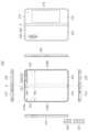
- FIG. 2Ais a diagram illustrating an unfolded state of the electronic device 200 (eg, the electronic device 101 of FIG. 1 ) according to an embodiment of the present disclosure.
- FIG. 2Bis a diagram illustrating a folded state of the electronic device 200 according to an embodiment of the present disclosure.
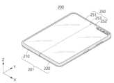
- FIG. 2Cis a perspective view illustrating an example of an unfolded state of the electronic device 200, according to an embodiment of the present disclosure
- FIG. 2Dis a perspective view illustrating an example of an intermediate status of the electronic device 200, according to an embodiment of the present disclosure.
- )is a perspective view showing an example.
- the electronic device 200 of FIGS. 2A to 2Dis an example of the electronic device 101 shown in FIG. 1 and may be a foldable or bendable electronic device.
- FIG. 2C and belowshow a spatial coordinate system defined by the X-axis, Y-axis, and Z-axis orthogonal to each other.
- the X-axismay represent the width direction of the electronic device
- the Y-axismay represent the length direction of the electronic device
- the Z-axismay represent the height (or thickness) direction of the electronic device.
- the 'first direction'may mean a direction parallel to the Z-axis.
- the electronic device 200includes a foldable housing 201 and a flexible or foldable device disposed in the space formed by the foldable housing 201.
- foldable) display 250hereinafter, “display” 250
- displaye.g., display module 160 of FIG. 1
- the surface on which the display 250 is placedmay be the front of the electronic device 200.
- the opposite side of the frontmay be the back of the electronic device 200.
- the surface surrounding the space between the front and backmay be the side of the electronic device 200.
- the foldable housing 201includes a first housing structure 210, a second housing structure 220 including a sensor area 222, a first rear cover 215, and a second rear cover. (225) and a hinge structure (230) may be included.
- the hinge structure 230may include a hinge cover that covers the foldable portion of the foldable housing 201.
- the foldable housing 201 of the electronic device 200is not limited to the shape and combination shown in FIGS. 2A and 2B, and may be implemented by other shapes or combinations and/or combinations of parts.
- the first housing structure 210 and the first rear cover 215may be integrally formed
- the second housing structure 220 and the second rear cover 225may be integrally formed. can be formed.
- the first housing structure 210is connected, directly or indirectly, to the hinge structure 230, has a first side facing in a first direction, and a second side facing in a second direction opposite to the first direction. It may include a second side facing.
- the second housing structure 220is connected, directly or indirectly, to the hinge structure 230 and includes a third side facing in a third direction and a fourth side facing in a fourth direction opposite the third direction. can do.
- the second housing structure 220can rotate relative to the first housing structure 210 about the hinge structure 230 .
- the electronic device 200can change to a folded status or an unfolded status.
- the first side of the electronic device 200may face the third side in a fully folded state, and the third direction is the same as the first direction in a fully unfolded state. can do.
- the first housing structure 210 and the second housing structure 220are disposed on both sides about the folding axis A, and may have an overall symmetrical shape with respect to the folding axis A. As will be described later, the first housing structure 210 and the second housing structure 220 determine whether the electronic device 200 is in an unfolded state, a folded state, or is partially unfolded ( The angle or distance between them may vary depending on whether they are in an intermediate state (or partially folded). According to one embodiment, the second housing structure 220, unlike the first housing structure 210, additionally includes a sensor area 222 where various sensors are arranged, but has a mutually symmetrical shape in other areas. You can have it.
- the first housing structure 210 and the second housing structure 220may together form a recess that accommodates the display 250.
- the recessmay have two or more different widths in a direction perpendicular to the folding axis (A).
- the recessis formed at the edge of the first portion 210a parallel to the folding axis A of the first housing structure 210 and the sensor area 222 of the second housing structure 220. It may have a first width w1 between the first portion 220a.
- the recessmay have a first width w1 between the second portion 210b of the first housing structure 210 and the sensor area 222 of the second housing structure 220.
- the second width w2may be formed to be longer than the first width w1.
- the first portion 220a and the second portion 220b of the second housing structure 220may have different distances from the folding axis A.
- the width of the recessis not limited to the example shown. In one embodiment, the recess may have multiple widths due to the shape of the sensor area 222 or the asymmetrically shaped portion of the first housing structure 210 and the second housing structure 220 .
- the sensor area 222may be formed to have a predetermined area adjacent to one corner of the second housing structure 220.
- sensor area 222may be provided at another corner of second housing structure 220 or any area between the top and bottom corners.
- components for performing various functions built into the electronic device 200are electronically transmitted through the sensor area 222 or through one or more openings provided in the sensor area 222. It may be exposed to the front of the device 200.
- componentsmay include various types of sensors.
- the sensormay include, for example, at least one of a front camera, a receiver, or a proximity sensor.
- the sensor area 222may be omitted from the second housing structure 220 or may be formed in a location different from that shown in the drawing.
- At least a portion of the first housing structure 210 and the second housing structure 220may be formed of a metallic material or a non-metallic material having a selected level of rigidity to support the display 250. At least a portion formed of a metal material may provide a ground plane of the electronic device 200 and may be electrically connected to a ground line formed on a printed circuit board disposed inside the foldable housing 201. You can.
- the first rear cover 215is disposed on one side of the folding axis A on the rear of the electronic device 200, and may have, for example, a substantially rectangular periphery, The edge may be wrapped by the first housing structure 210.
- the second rear cover 225may be disposed on the other side of the folding axis A at the rear of the electronic device 200, and its edge may be wrapped by the second housing structure 220.
- the first rear cover 215 and the second rear cover 225may have a substantially symmetrical shape about the folding axis (A).
- the first rear cover 215 and the second rear cover 225do not necessarily have symmetrical shapes, and in one embodiment, the electronic device 200 includes the first rear cover 215 and the second rear cover 225 of various shapes. It may include a second rear cover 225.
- the first back cover 215may be formed integrally with the first housing structure 210, and the second back cover 225 may be formed integrally with the second housing structure 220. .
- the first rear cover 215, the second rear cover 225, the first housing structure 210, and the second housing structure 220are various parts of the electronic device 200 (e.g. : Can form a space where a printed circuit board, or battery) can be placed.
- one or more componentsmay be placed or visually exposed on the rear of the electronic device 200.
- at least a portion of the sub-displaymay be visually exposed through the first rear area 216 of the first rear cover 215.
- one or more components or sensorsmay be visually exposed through the second rear area 226 of the second rear cover 225.
- the sensormay include a proximity sensor and/or a rear camera.
- the rear camera exposed through the rear cameramay include one or more lenses, an image sensor, and/or an image signal processor. Flashes may include, for example, light-emitting diodes or xenon lamps.
- two or more lenses (an infrared camera, a wide-angle lens, and a telephoto lens) and image sensorsmay be placed on one side of the electronic device 200.
- the hinge covermay be disposed between the first housing structure 210 and the second housing structure 220 and configured to cover internal components (eg, the hinge structure 230).
- the hinge structure 230is a first housing structure depending on the state of the electronic device 200 (unfolded status, intermediate status, or folded status). It may be obscured by part of 210 and the second housing structure 220, or may be exposed to the outside.
- the hinge structure 230when the electronic device 200 is in an unfolded state (e.g., fully unfolded state), the hinge structure 230 is a first housing structure ( 210) and may be obscured by the second housing structure 220 and not exposed.
- FIG. 2Bwhen the electronic device 200 is in a folded state (e.g., fully folded state), the hinge structure 230 is connected to the first housing structure 210 and the second housing structure 210. It may be exposed to the outside between the two housing structures 220.
- the first housing structure 210 and the second housing structure 220are in an intermediate state, folded with a certain angle, the hinge structure 230 is folded with a certain angle. A portion may be exposed to the outside between the structure 210 and the second housing structure 220. However, in this case, the exposed area may be less than in the fully folded state.
- hinge structure 230may include a curved surface.
- the display 250may be placed in the space formed by the foldable housing 201.
- the display 250is seated in a recess formed by the foldable housing 201 and can be viewed from the outside through the front of the electronic device 200.
- the display 250may constitute most of the front of the electronic device 200.
- the front of the electronic device 200may include the display 250 and a partial area of the first housing structure 210 adjacent to the display 250 and a partial area of the second housing structure 220.
- the rear of the electronic device 200includes a first rear cover 215, a partial area of the first housing structure 210 adjacent to the first rear cover 215, a second rear cover 225, and a second rear cover. It may include a portion of the second housing structure 220 adjacent to 225 .
- the display 250may refer to a display in which at least some areas can be transformed into a flat or curved surface.
- the display 250includes a third area 253, a first area disposed on one side of the third area 253 (e.g., the left side of the third area 253 shown in FIG. 2A). It may include 251 and a second area 252 disposed on the other side (e.g., to the right of the third area 253 shown in FIG. 2A).
- the division of the areas of the display 250 shown in FIG. 2Ais an example, and the display 250 may be divided into a plurality of areas (for example, four or more or two) depending on the structure or function.
- the area of the display 250may be divided by the third area 253 extending parallel to the folding axis A, but in one embodiment, the display 250 The region may be divided based on a different folding axis (e.g., a folding axis parallel to the width direction of the electronic device).
- the third area 253may be a foldable area. In one embodiment, the third area 253 may be an area that is curved or unfolded depending on the folded state of the display 250. For example, the third area 253 may be a 'folding area', a 'flexible area', or a 'foldable area', and the first area 251 and the second area 252 may be an 'inflexible area'. It may be an (inflexible) area. In one embodiment, the third area 253 may be an area corresponding to an area provided in a hinge assembly (e.g., the hinge assembly 400 of FIGS. 3 to 8D or the hinge assembly 500 of FIGS. 9 to 14C). there is.
- a hinge assemblye.g., the hinge assembly 400 of FIGS. 3 to 8D or the hinge assembly 500 of FIGS. 9 to 14C.
- the display 250may be combined with or disposed adjacent to a touch panel equipped with a touch detection circuit and a pressure sensor capable of measuring the intensity (pressure) of a touch.
- the display 250is an example of a touch panel and may be combined with or disposed adjacent to a touch panel that detects an electromagnetic resonance (EMR) type stylus pen.
- EMRelectromagnetic resonance
- the first area 251 and the second area 252may have an overall symmetrical shape with the third area 253 as the center.
- the second area 252unlike the first area 251, may include a notch cut depending on the presence of the sensor area 222, but in other areas, the first area 252 (251) and may have a symmetrical shape.
- the first region 251 and the second region 252may include a portion having a symmetrical shape and a portion having an asymmetrical shape.
- the edge thickness of the first area 251 and the second area 252may be formed to be different from the edge thickness of the third area 253.
- the edge thickness of the third area 253may be thinner than the thickness of the first area 251 and the second area 252 .
- the first region 251 and the second region 252may have an asymmetric shape when the first region 251 and the second region 252 are viewed in cross section.
- the edge of the first area 251may be formed to have a first radius of curvature
- the edge of the second area 252may be formed to have a second radius of curvature that is different from the first radius of curvature.
- the first region 251 and the second region 252may have a symmetrical shape in terms of thickness when the first region 251 and the second region 252 are viewed in cross section.
- first housing structure 210 and the second housing structureThe operation of 220 and each area of the display 250 will be described.
- the first housing structure 210 and the second housing structure 220when the electronic device 200 is in an unfolded state (e.g., FIG. 2A), the first housing structure 210 and the second housing structure 220 have an unfolding angle (e.g., It may be arranged to form an angle of about 180 degrees, or 170 degrees to 190 degrees, and face the same direction.
- the surface of the first area 251 and the surface of the second area 252 of the display 250form an angle of 180 degrees to each other and may face the same direction (eg, the front direction of the electronic device).
- the third area 253may form the same plane as the first area 251 and the second area 252.
- the first housing structure 210 and the second housing structure 220may be arranged to face each other.
- the surface of the first area 251 and the surface of the second area 252 of the display 250form a narrow folding angle (eg, between 0 degrees and 10 degrees) and may face each other.
- At least a portion of the third area 253may be formed as a curved surface with a predetermined curvature.
- the first housing structure 210 and the second housing structure 220are at a certain angle to each other (e.g., 10 degrees to 170 degrees).
- the surface of the first area 251 and the surface of the second area 252 of the display 250may form an angle that is larger than that in the folded state and smaller than that in the unfolded state.
- At least a portion of the third area 253may be formed of a curved surface with a predetermined curvature, and the curvature in this case may be smaller than that in the folded state.
- FIG. 2Cmay represent a completely unfolding state of the electronic device 200
- FIG. 2Dmay represent the electronic device 200 in an intermediate state.
- the electronic device 200can change to a folded status or an unfolded status.
- the electronic device 200is folded so that the front of the electronic device 200 forms an acute angle when viewed from the folding axis direction (e.g., A-axis in FIG. 2A). It can be folded in two ways: 'and 'out-folding', in which the front of the electronic device 200 is folded to form an obtuse angle.
- the electronic device 200may be in an in-folded state, with the first side of the first housing structure 210 facing the third side of the second housing structure 220, , in a fully unfolded state, the first side of the first housing structure 210 and the third side of the second housing structure 220 face the same direction (e.g., a direction parallel to the Z axis). You can.
- the electronic device 200may be folded in an out-folding manner, and the second side of the first housing structure 210 may face the fourth side of the second housing structure 220.
- the electronic device 200may include a plurality of hinge axes (e.g., two mutually parallel hinge axes including the A-axis in FIG. 2A and another axis parallel to the A-axis), in which case The electronic device 200 may be folded using a 'multi-folding' method that combines in-folding and out-folding methods.
- a plurality of hinge axese.g., two mutually parallel hinge axes including the A-axis in FIG. 2A and another axis parallel to the A-axis
- the electronic device 200may be folded using a 'multi-folding' method that combines in-folding and out-folding methods.
- the in folding typemay mean a state in which the display 250 is not exposed to the outside in a fully folded state.
- the out folding typemay mean a state in which the display 250 is exposed to the outside in a fully folded state.
- FIG. 2Dshows an intermediate status in the process of in-folding the electronic device 200.
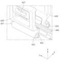
- FIG. 3is a front view illustrating a state in which the hinge assembly 400 is applied to an electronic device according to an embodiment.
- the electronic device 300(e.g., the electronic device 101 of FIG. 1 or the electronic device 200 of FIGS. 2A to 2D) according to an embodiment may be a foldable electronic device.
- the electronic device 300may be folded or unfolded around a pair of hinge axes H1 and H2.
- a pair of hinge axes H1 and H2may be substantially parallel to each other.
- FIG. 3is an example, and the size, shape, structure, and hinge axis of the electronic device 300 are not limited thereto.
- the electronic device 300 shown in FIG. 3includes a hinge axis (H1 or H2) in the long side direction (e.g., Y-axis direction), but is not limited thereto, and the electronic device according to one embodiment has It may also include a hinge axis along a short direction (e.g., along the X-axis).
- the electronic device 300includes a housing 310 (e.g., the foldable housing 201 of FIGS. 2A to 2D), a display (not shown) (e.g., the display module 160 of FIG. 1, or It may include a display 250 of FIGS. 2A to 2D) and a hinge assembly 400.
- a housing 310e.g., the foldable housing 201 of FIGS. 2A to 2D
- a displaynot shown
- Itmay include a display 250 of FIGS. 2A to 2D
- a hinge assembly 400e.g., the hinge assembly 400.
- the housing 310may form at least a portion of the exterior of the electronic device 300.
- the housing 310includes a first housing 311 (e.g., the first housing structure 210 in FIGS. 2A to 2D) and a second housing 312 (e.g., the second housing structure 220 in FIGS. 2A to 2D). )) and a hinge housing 313.
- first housing 311 and the second housing 312may be connected, directly or indirectly, to be foldable with respect to each other by the hinge assembly 400.
- the first housing 311 and the second housing 312determine whether the state of the electronic device 300 is a flat stage or unfolding state, a folding state, or an intermediate state. Depending on the presence, the angle or distance between them may vary.
- the above-mentioned intermediate statemay include all states between the unfolding state and the folding state.
- the hinge housing 313may be disposed between the first housing 311 and the second housing 312 to provide a space in which internal components (eg, the hinge assembly 400) are disposed.
- the hinge housing 313may be configured to cover the hinge assembly 400 so that the hinge assembly 400 is not exposed to the outside.
- the hinge housing 313may include at least one screw hole (not shown) for placing an internal component (eg, the hinge assembly 400).
- the first housing 311 and the second housing 312may provide a space where the display 250 is placed.
- the display 250may be a foldable flexible display.
- the display 250may include a first area (e.g., first area 251 in FIGS. 2C and/or 2D) and a second area (e.g., second area 252 in FIGS. 2C and/or 2D). )) and a third area between the first area 251 and the second area 252 (eg, the third area 253 in FIGS. 2C and/or 2D).
- the first housing 311may be disposed in a position corresponding to the first area 251 of the display 250 and support the first area 251 of the display 250.
- the second housing 312may be disposed in a position corresponding to the second area 252 of the display 250 and support the second area 252 of the display 250.
- the hinge housing 313may be disposed in a position corresponding to the third area of the display 250 (eg, the third area 253 in FIGS. 2C and/or 2D).
- the hinge assembly 400may be disposed between the first housing 311 and the second housing 312 to connect the first housing 311 and the second housing 312.
- the first housing 311 and the second housing 312each include a connection plate 315, and the hinge assembly 400 is fastened to the connection plate 315 to connect the first housing 311 and the second housing 312. 2
- Each of the housings 312can be connected.
- the hinge structure of the electronic device 300may include a plurality of hinge assemblies 400.
- the plurality of hinge assemblies 400may be spaced apart from each other along the hinge axis H1 or H2.
- two hinge assemblies 400may be spaced apart along the hinge axis (H1 or H2), and a sub-hinge 317 is provided between the two hinge assemblies 400. can be placed.
- the hinge assembly 400 and sub-hinge 317 on one sideare fastened to both ends of one connection plate 315
- the hinge assembly 400 and sub-hinge 317 on the other sideare fastened to both ends of one connection plate 315. It can be connected to both ends of the connection plate 315.
- the sub-hinge 317is simultaneously, directly or indirectly connected to the two connection plates 315, so that the two hinge assemblies 400 and the sub-hinge 317 can operate in conjunction with each other.
- the hinge assembly 400may implement a folding or unfolding operation of the electronic device 300.
- the hinge assembly 400is between a folded state in which the first region 251 and the second region 252 face each other and an unfolded state in which the first region 251 and the second region 252 do not face each other. It can work.
- the hinge assembly 400may generate a force (eg, friction force) that maintains a specific folded state of the electronic device 300.
- the hinge assembly 400may generate a force that maintains the electronic device 300 in the folded state.
- the hinge assembly 400may generate a force to maintain the electronic device 300 in the unfolded state.
- the hinge assembly 400may generate a force that maintains the electronic device 300 in the intermediate state.
- the hinge assembly 400may synchronize the folding angles of the first housing 311 and the second housing 312. For example, the hinge assembly 400 performs a folding operation of the first housing 311 and a folding operation of the second housing 312 so that the folding angles of the first housing 311 and the second housing 312 are synchronized. They can be linked to each other.
- FIG. 4Ais a front view of the hinge assembly 400 according to an embodiment
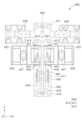
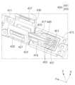
- FIG. 4Bis an exploded perspective view of the hinge assembly 400 according to an embodiment.
- the hinge assembly 400includes a hinge bracket 410, a first rotator 420, a second rotator 430, a slide bracket 440, and a detent assembly ( 450) may be included.
- FIGS. 4A and 4Bthe components and structure of the hinge assembly 400 of an embodiment will be described with reference to FIGS. 4A and 4B. However, this is an example, and the structure, number, shape, and/or structure of the components of the hinge assembly 400 will be described. The arrangement is not limited to this.
- the hinge bracket 410may be fixedly, directly or indirectly connected to a housing (e.g., the housing 310 in FIG. 3).
- the hinge bracket 410may be fixedly connected to a hinge housing (eg, the hinge housing 313 in FIG. 3).
- the hinge bracket 410may be formed to have a longitudinal direction (eg, Y-axis direction) parallel to the hinge axis (eg, hinge axis H1 or H2 in FIG. 3).
- the lower surface (eg, -Z direction surface) of the hinge bracket 410may be formed to substantially correspond to the inner shape of the hinge housing 313.
- the hinge bracket 410may include at least a portion of the first bracket 411, the second bracket 415, and the hinge cover 405.
- the first bracket 411 and the second bracket 415may be separated from each other and connected through other components (e.g., a slide bracket 440 or a plurality of rotators 420, 430).
- the hinge cover 405may be connected to one surface (eg, the upper surface in the Z direction) of the hinge assembly 400 and may cover and protect internal components of the hinge assembly 400.
- thisis an exemplary structure of the hinge assembly 400, and when actually implemented, it is not limited to this and may be implemented as a hinge bracket 410 composed of a single body.
- the first rotator 420may include a plurality of hinge bracket connection members 421 and 422.
- the plurality of hinge bracket connection members 421 and 422include a first hinge bracket connection member 421 and a second hinge bracket connection member 422 each facing in both directions (e.g., both Y-axis directions). It can be included.
- first hinge bracket connection member 421 and the second hinge bracket connection member 422may be formed integrally.
- first hinge bracket connection member 421 and the second hinge bracket connection member 422may be formed integrally with the first rotator 420 .
- first hinge bracket connection member 421 and the second hinge bracket connection member 422may be integrally formed and disposed on the first rotator 420 .
- the first rotator 420may include a first rotator pillar 423 for fastening to the slide bracket 440, and the first rotator pillar 423 may include a first hinge axis (e.g., FIG.
- a first spiral groove 424 formed in a spiral shape in one direction centered on the first hinge axis (H1) of 3may be formed.
- the first rotator 420may include a first fastening area 427 for fastening to another structure.
- the first fastening area 427may include at least one hole through which a fixing member (not shown) such as a screw is inserted.
- the first rotator 420may be connected to some area of the housing (e.g., first housing structure 210 of FIGS. 2A to 2D) and/or some area of the display (e.g., : Can be fastened to the first area 251 of the display 250 of FIGS. 2A to 2D.
- some area of the housinge.g., first housing structure 210 of FIGS. 2A to 2D
- some area of the displaye.g., : Can be fastened to the first area 251 of the display 250 of FIGS. 2A to 2D.
- the first housing structure ( 210) and/or the first area 251 of the display 250may rotate in conjunction with the first rotator 420.
- the second rotator 430may include a plurality of hinge bracket connection members 431 and 432.
- the plurality of hinge bracket connection members 431 and 432include a third hinge bracket connection member 431 and a fourth hinge bracket connection member 432 each facing in both directions (e.g., both Y-axis directions). It can be included.
- the second rotator 430may include a second rotator pillar 433 for fastening to the slide bracket 440, and the second rotator pillar 433 may include a second hinge axis (e.g., FIG.
- a second helical groove 434may be formed in a helical shape in one direction centered on the second hinge axis H2 of 3.
- the second rotator 430may include a second fastening area 437 for fastening to another structure.
- the second fastening area 437may include at least one hole through which a fixing member (not shown) such as a screw is inserted.
- the second rotator 430may be connected to some area of the housing (e.g., the second housing structure 220 of FIGS. 2A to 2D) and/or some area of the display (e.g., the second housing structure 220 of FIGS. 2A to 2D) through the second fastening area 437. : Can be fastened to the second area 252 of the display 250 of FIGS. 2A to 2D.
- the second housing structure ( 220) and/or the second area 252 of the display 250may rotate in conjunction with the second rotator 430.
- the hinge assembly 400may include a first sub-rotator 425 and a second sub-rotator 435.
- the first sub-rotator 425may be rotatably connected to the first bracket 411 about the first hinge axis H1
- the second sub-rotator 435may be connected to the second hinge axis H2.
- the first sub-rotator 425may be connected to a first housing (eg, the first housing 311 in FIG. 3).
- the first sub-rotator 425may rotate in conjunction with the first rotator 420 and assist the first rotator 420.
- the first sub-rotator 425may include a third fastening area 428 for fastening to another structure, and the third fastening area 428 may be connected to another structure to which the first fastening area 427 is fastened. It can be fastened to another area of the structure to help rotate the first fastening area 427 or to reinforce the hinge assembly 400 by distributing the force received by the first fastening area 427, and the first fastening area ( 427) can be assisted.
- the second sub-rotator 435may be connected to a second housing (eg, the second housing 312 in FIG. 3).
- the second sub-rotator 435may rotate in conjunction with the second rotator 430 and assist the second rotator 430.
- the second sub-rotator 435may include a fourth fastening area 438 for fastening to another structure, and the fourth fastening area 438 may be fastened to another structure to which the second fastening area 437 is fastened.
- the hinge assembly 400can be strengthened by assisting the rotation of the second fastening area 437 or by distributing the force received by the second fastening area 437. ) can assist.
- the hinge bracket 410may include at least a portion of the first rotator connection space 413, the second rotator connection space 418, and the sub-rotator connection space 414.
- the first bracket 411includes a plurality of first rotator connection spaces 413, and each of the plurality of first rotator connection spaces 413 includes a first hinge bracket connection member 421 and a third hinge bracket connection member 421.
- the hinge bracket connection member 431may be rotatably connected.
- the second bracket 415includes a plurality of second rotator connection spaces 418, and each of the plurality of second rotator connection spaces 418 includes a second hinge bracket connection member 422 and a fourth hinge bracket connection member 422.
- the hinge bracket connection member 432may be rotatably connected.
- the first bracket 411includes a plurality of sub-rotator connection spaces 414, and each of the plurality of sub-rotator connection spaces 414 includes a first sub-rotator 425 and a second sub-rotator 435. ) can be rotatably connected.
- the hinge bracket 410may include at least one slide connection space 412 and 419.
- the first bracket 411may include a first slide connection space 412
- the second bracket 415may include a second slider connection space 419.
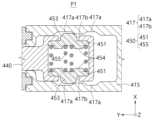
- the second bracket 415may include at least a partial area of the slide bracket 440 and/or a detent assembly accommodating space 416 that accommodates the detent assembly 450.
- a slide rail 417which is a side surface in contact with the detent assembly 450, may be formed in the detent assembly accommodation space 416, and the slide rail 417 may include a flat area 417a and a protruding area 417b. You can.
- the slide bracket 440may be connected between the first bracket 411 and the second bracket 415 to be slidable in a slide direction (eg, Y-axis direction).
- a slide directione.g, Y-axis direction
- both directions in which the slide bracket 440 slidesmay be the 'first axis direction'
- the direction perpendicular to the first axis directione.g., X-axis direction
- the slide bracket 440may include a first guide member 441 and a second guide member 442 formed in both directions facing the first axis direction.
- first guide member 441may be disposed in the first slide connection space 412
- second guide member 442may be disposed in the second slide connection space 419.
- Each of the first guide member 441 and the second guide member 442may slide in the slide direction within the first slide connection space 412 and the second slide connection space 419.
- the first guide member 441 and the second guide member 442may limit the slide range of the slide bracket 440 and prevent the slide bracket 440 from being separated.
- the slide bracket 440may include a first rotator connection space 443 to which the first rotator pillar 423 of the first rotator 420 is rotatably fastened.
- a first helical protrusion 444 interlocked with the first helical groove 424may be formed in the first rotator connection space 443.
- the slide bracket 440may include a second rotator connection space 445 to which the second rotator pillar 433 of the second rotator 430 is rotatably fastened.
- a second helical protrusion 446 interlocked with the second helical groove 434may be formed in the second rotator connection space 445.
- the slide bracket 440may include a detent space 447 that accommodates the detent assembly 450, and the cam 451 of the detent assembly 450 is located in the detent space 447.
- a protrusion opening 448may be formed such that a portion of the cam 451, for example, the protrusion area 453 of the cam 451, protrudes outward.
- the detent assembly 450may provide a detent force in a direction that resists movement of the slide bracket 440 in the first axis direction.
- the detent assembly 450is accommodated in the detent space 447 of the slide bracket 440 and can move in the first axis direction together with the slide bracket 440.
- the detent assembly 450may be disposed on the slide bracket 440 to provide a detent force in a direction perpendicular to the moving direction (eg, first axis direction) of the slide bracket 440.
- the detent assembly 450may be disposed in the placement space (eg, detent space 447) of the slide bracket 440.
- at least a portion of the detent assembly 450may be in contact with or connected to the slide bracket 440 in the placement space (eg, detent space 447) of the slide bracket 440.
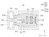
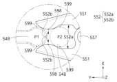
- the detent assembly 450may include a cam 451 and an elastic member 455.
- the cam 451may move in the second axis direction perpendicular to the first axis direction in conjunction with the movement of the slide bracket 440.
- a support protrusion 454 for supporting the elastic member 455may be formed on the side of the cam 451 facing the elastic member 455, and a protrusion area 453 may be formed on the opposite side.
- the elastic member 455may provide elastic force in the second axis direction in conjunction with the movement of the cam 451.
- the cam 451may be formed in plurality, and the plurality of cams 451 are centered around the elastic member 455 in both directions (for example, the X-axis direction, or the second axis direction) in which the elastic force acts. ) may include a first cam (451a) and a second cam (451b) arranged to be spaced apart from each other.
- the first cam 451amay include a first protrusion area 453a
- the second cam 451bmay include a second protrusion area 453b.
- the detent space 447may include a plurality of protrusion openings 448 formed in the second axis direction in pairs with the first cam 451a and the second cam 451b, and the plurality of protrusion openings 448 ), the first protrusion area 453a and the second protrusion area 453b may be retracted and withdrawn, respectively.
- the detent assembly 450provides a folding detent force and an unfolding detent force in response to the folding and unfolding operations of the hinge assembly 400 through the elastic force of the elastic member 455. You can.
- the detent assembly 450may include at least one cam 451 and/or at least one elastic member 455.
- the detent assembly 450may include one cam 451 and one elastic member 455.
- the detent assembly 450may include a cam and an elastic structure (eg, leaf spring) that acts as an elastic member.
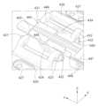
- FIG. 5Ais an enlarged perspective view of the slide bracket 440 according to an embodiment
- FIG. 5Bis an enlarged perspective view of the rotator 430 according to an embodiment
- FIG. 5Cis an enlarged perspective view of the hinge assembly 400 according to an embodiment
- 5Dis an enlarged perspective view of the hinge assembly 400 in a folded state according to an embodiment.
- the slide bracket 440may slide in conjunction with the rotation of the first rotator 420 and the second rotator 430.
- the content described in FIGS. 4A and 4Bwill be omitted.
- first rotator 420may be rotatably connected to the second bracket about the first hinge axis H1 with respect to the slide bracket 440 (or hinge bracket 410), and 2
- the rotator 430may be rotatably connected to the slide bracket 440 (or hinge bracket 410) about the second hinge axis H2.
- the first rotator 420 and the second rotator 430may be formed in a substantially symmetrical shape with respect to the first axis direction (eg, Y-axis direction) parallel to the hinge axis H1 or H2.
- the slide bracket 440is linked to the rotation of the first rotator 420 and the second rotator 430 and moves along a first axis parallel to the first hinge axis H1 or the second hinge axis H2. It can be connected to enable sliding in a direction (e.g., Y-axis direction).
- the slide bracket 440may be formed with a first rotator connection space 443 and a second rotator connection space 445 for rotatably connecting the first rotator 420 and the second rotator 430.
- the slide bracket 440may spiral-slide in conjunction with the rotation of the first rotator 420 and the second rotator 430.
- Spiral-slide(spiral-slide) is linked to the rotation of the first rotator 420 and the second rotator 430 and engages the spiral structure of the first rotator 420 and the second rotator 430, and includes a slide bracket ( 440) may refer to a sliding structure or operation.
- the first helical groove 424 of the first rotator 420 and the second helical groove 434 of the second rotator 430each have a first helical protrusion 444 and a second helical protrusion 446. It can operate in conjunction with .
- a first helical groove 424may be formed in the first rotator 420, and a first helical protrusion 444 may be formed in the first rotator connection space 443 of the slide bracket 440.
- the description of the first helical groove 424 and the first helical protrusion 444 belowrefers to the second helical groove 434 of the second rotator 430 and the second helical protrusion of the second rotator connection space 445. (446) may also be applied substantially the same or similarly.
- the first helical protrusion 444may include an arc shape, and the center of the arc shape of the first helical protrusion 444 may be the first hinge axis H1.
- the first spiral protrusion 444may include an arc shape centered on the first hinge axis H1.
- the first helical protrusion 444may be formed to protrude from two opposing surfaces of the first helical groove 424 in the direction of the first hinge axis H1.
- the first helical protrusion 444 and the second helical protrusion 446may be formed on both sides of the slide bracket 440 (eg, a pair of surfaces in the X-axis direction).
- the first spiral groove 424may be formed by being recessed in the outer peripheral surface of the first rotator pillar 423.
- the first spiral groove 424may include an arc shape centered on the first hinge axis H1.
- the first helical protrusion 444may be interlocked with the first helical groove 424.
- the first helical protrusion 444may be inserted into the first helical groove 424 and can slide along the helical shape of the first helical groove 424.
- the first helical protrusion 444may be formed in a direction corresponding to the helical direction of the first helical groove 424.
- the second helical protrusion 446may be interlocked with the second helical groove 434.
- the second helical protrusion 446may be inserted into the second helical groove 434 and can slide along the helical shape of the second helical groove 434.
- the second helical protrusion 446may be formed in a direction corresponding to the helical direction of the second helical groove 434.
- the first helical protrusion 444may be inserted into the first helical groove 424.
- the arc shape of the first helical protrusion 444may substantially correspond to the arc shape of the first helical groove 424.
- the width of the first helical protrusion 444may substantially correspond to the width of the first helical groove 424.
- the first helical groove 424may rotate about the first hinge axis H1 in a specified angle range along the first helical protrusion 444.
- the first rotator 420can be rotated about the first hinge axis H1 with respect to the slide bracket 440 in a specified angle range.
- the hinge assembly 400 of one embodimentis formed by recessing a structure (not shown) corresponding to the first helical protrusion 444, and a structure (not shown) corresponding to the first helical groove 424. Poetry) may be formed by protruding.
- the first helical protrusion 444may be formed in a clockwise spiral shape when facing from the lower side (e.g., -Y direction side) to the upper side (e.g., +Y direction side), and the second helical protrusion 444 may be formed in a clockwise spiral shape.
- 446may be formed in a counterclockwise spiral shape when heading from the lower side (e.g., -Y direction side) to the upper side (e.g., +Y direction side).
- the slide bracket 440is positioned along the first helical protrusion 444 and the second helical protrusion 446 in a first axis direction (e.g., Y-axis direction) parallel to the direction of the hinge axis (H1 or H2). Sliding may be possible. According to this structure, the slide bracket 440 can slide in the first axis direction with respect to the hinge bracket 410.
- the first helical groove ( 424) and the second spiral groove 434may also rotate along the first hinge axis H1 and the second hinge axis H2.
- the first helical protrusion 444 and the second helical protrusion 446are linked to the rotation of the first helical groove 424 and the second helical groove 434 in one direction of the first axis direction (e.g., -Y direction). ), and as a result, the slide bracket 440 may slide in one direction (eg, -Y direction) of the first axis direction (eg, Y axis direction).
- one slide bracket 440is drivingly connected to the first rotator 420 and the second rotator 430 through the first helical protrusion 444 and the second helical protrusion 446.
- the two rotators 420 and 430can be folded in conjunction with each other.
- the first rotator 420rotates, the first helical groove 424 pushes the first helical protrusion 444, and in conjunction with this, the second helical protrusion 446 pushes the second helical groove 434.
- the second rotator 430can rotate in conjunction with the rotation of the first rotator 420.
- FIG. 6Ais a perspective view of the hinge assembly 400 in an unfolded state according to an embodiment
- FIG. 6Bis a perspective view of the hinge assembly 400 in an intermediate state according to an embodiment
- FIG. 6Cis a perspective view of the hinge assembly 400 according to an embodiment
- FIG. 7Ais a perspective view of the folded state of the assembly 400
- FIG. 7Ais a partial cross-sectional view of the hinge assembly 400 in an unfolded state according to an embodiment
- FIG. 7Bis a view of the intermediate state of the hinge assembly 400 according to an embodiment. It is a partial cross-sectional view
- FIG. 7Cis a partial cross-sectional view of the hinge assembly 400 in a folded state according to one embodiment.
- the cross-sectional view of the hinge assembly 400 in FIG. 7Amay correspond to the state of the hinge assembly 400 in FIG. 6A
- the cross-sectional view of the hinge assembly 400 in FIG. 7Bmay correspond to the state of the hinge assembly 400 in FIG. 6B.
- the cross-sectional view of the hinge assembly 400 of FIG. 7Cmay correspond to the state of the hinge assembly 400 of FIG. 6C.
- the detent assembly 450in one embodiment may provide detent force in conjunction with the movement of the slide bracket 440.
- the hinge assembly 400is connected to the first housing (e.g., the first housing 311 in FIG. 3) and the second housing through the first rotator 420 and the second rotator 430. It may have a 'rotation structure' that rotates (e.g., the second housing 312 in FIG. 3).
- the hinge assembly 400is connected to the first rotator 420 and the second rotator 430 through a slide bracket 440 capable of spiral sliding, so that the first rotator 420 and the second rotator 430 can be substantially moved. It can have an 'interlocking structure' that allows it to rotate at the same angle.
- the hinge assembly 400may have a 'detent structure' through the detent assembly 450 that limits or assists the movement of the slide bracket 440.
- the rotation structure, interlocking structure, and detent structure implemented through various components of the hinge assembly 400will be described.
- the hinge assembly 400unfolds as the first rotator 420 and the second rotator 430 rotate about the first hinge axis H1 and the second hinge axis H2, respectively.
- statese.g., the state in FIG. 6A or the state at the first position (P1) in FIG. 7A
- intermediate statese.g., the state in FIG. 6B or the state at the intermediate position (P0) in FIG. 7B
- folding statese.g., FIG. It may have a state of 6c or a state of the second position (P2) of FIG. 7c.
- the first helical protrusion 444slides along the helical shape of the first helical groove 424.
- the bracket 440can move linearly with respect to the hinge bracket 410 by a pitch in the first axis direction (e.g., Y-axis direction) corresponding to the rotation angle of the spiral shape
- the second helical protrusion 446is the second helical protrusion 446.
- the slide bracket 440slides along the spiral shape of the groove 434, it can move linearly with respect to the hinge bracket 410 by a pitch in the first axis direction corresponding to the rotation angle of the spiral shape.
- the rotational operation of the first rotator 420 and the rotational operation of the second rotator 430may be interlocked with each other through the linear movement of the slide bracket 440.
- the rotational movement of one of the first rotator 420 and the second rotator 430may be linked to the rotational movement of the other through the linear movement of the slide bracket 440.
- the rotational movements of the first rotator 420 and the second rotator 430are linked to each other by the linear movement of the slide bracket 440, the rotation of the first rotator 420 and the second rotator 430 Angles can be synchronized.
- the detent assembly 450may be coupled to the slide bracket 440 to move in the first axis direction together with the slide bracket 440.
- the detent assembly 450is located inside the detent space (e.g., the detent space 447 in FIGS. 4B and/or 5C) of the slide bracket 440 so that the slide bracket 440 is positioned in the first As it slides in the axial direction, it can move in the first axis direction.
- the detent space 447may accommodate the detent assembly 450 so that the cam 451 of the detent assembly 450 can move in a second axis direction perpendicular to the first axis direction.
- the detent space 447may include a protrusion opening 448 that is open in the second axis direction, and the protrusion area 453 of the cam 451 may be a protrusion opening (e.g., the protrusion opening 448 in FIG. 4B). ) may protrude from the outer peripheral surface of the slide bracket 440.
- the elastic member 455may be a spring or elastic body that provides elastic force (eg, elastic force Fs in FIG. 7B) in the second axis direction with respect to the cam 451.
- the elastic member 455can form an elastic force (Fs) when the cam 451 is pressed and moved in the second axis direction, and the elastic force (Fs) of the elastic member 455 is generated by the hinge assembly ( 400) can provide a detent force.
- the elastic members 455may be provided as a pair.
- Each of the pair of elastic members 455may have cams 451 disposed on both sides (eg, in the second axis direction), or may have one cam 451 disposed on one side.
- the second bracket 415 of the hinge bracket 410includes a detent bracket receiving space (detent bracket receiving space 416 in FIGS. 4A and/or 4B) and a second slide connection space (e.g., FIG. A second slide connection space 419 of 4a and/or 4b may be formed.
- a slide rail 417which is a side surface in contact with the detent assembly 450, may be formed in the detent bracket receiving space 416.
- the slide rail 417guides the slide bracket 440 to move in the first axis direction between the first position (P1) and the second position (P2).
- the slide bracket 440may slide between a first position (P1) located on the slide rail 417 in the unfolded state and a second position (P2) located on the slide rail 417 in the folded state. You can.
- the slide bracket 440may be located at an intermediate position (P0) corresponding to the intermediate state, and the intermediate position (P0) may be a position between the first position (P1) and the second position (P2).
- the slide rail 417may include a flat area 417a and a protruding area 417b that protrudes from the flat area 417a in the second axis direction.
- the protruding area 417bmay face the cam 451, for example, the position of the slide rail 417 facing the protruding area 453 at the first position P1 and the second position P2. ) may be formed between the protruding area 453 and the position of the opposing slide rail 417.
- the slide bracket 440moves along the slide rail 417, and the cam 451 can move in the second axis direction by the protruding area 417b.
- the protruding area 417bpresses the cam 451 of the detent assembly 450 in the second axis direction. can do.
- the slide rail 417may be formed in a structure that presses the cam 451 in the second axis direction in at least some areas as the slide bracket 440 moves in the first axis direction.
- the slide rail 417may omit the flat area 417a and include a protruding area 417b that protrudes relatively from other areas, or a concave area (not shown) opposite to the protruding area 417b. ) and a protruding area 417b.
- the protruding area 453 of the cam 451may be formed to protrude in a direction facing the protruding area 417b, and the protruding area 453 may be an area that faces and touches the protruding area 417b. there is. As the protruding area 453 is pressed by the protruding area 417b, the cam 451 may move in the direction of the elastic member 455.
- a forcemay be required to overcome the elastic force Fs of the elastic member 455.
- the elastic member 455can provide an elastic force Fs in the opposite direction, and the detent assembly 450 is the elastic member A detent force can be provided to the slide bracket 440 through the elastic force (Fs) of (455).
- the hinge assembly 400may open detent while moving from an unfolded state (e.g., the state in FIGS. 6A and 7A) to an intermediate state (e.g., the state in FIGS. 6B and 7B). You can. Open detent may refer to a force (eg, friction force) or torque that maintains the hinge assembly 400 in an unfolded state.
- a forcee.g, friction force
- the slide bracket 440may slide in one direction (eg, -Y direction) in conjunction with the rotation of the first rotator 420 and/or the second rotator 430. While the slide bracket 440 moves from the first position P1 to the intermediate position P0, the cam 451 may be pressed by the protruding area 417b, and the elastic member 455 may be pressed by the cam 451. It is possible to form an elastic force (Fs) that pushes in the second axis direction. Due to the elastic force (Fs) of the elastic member 455, an open detent occurs, and the slide bracket 440 can be maintained in the first position (P1) within a range below the external force that can overcome the open detent. and the hinge assembly 400 may be maintained in an unfolded state.
- Fselastic force
- the hinge assembly 400may experience a closed detent while moving from a folded state (e.g., the state in FIGS. 6C and 7C) to an intermediate state (e.g., the state in FIGS. 6B and 7B). there is.
- Close detentmay refer to a force (eg, friction force) or torque that maintains the hinge assembly 400 in a folded state.
- the slide bracket 440may slide in one direction (eg, +Y direction) in conjunction with the rotation of the first rotator 420 and/or the second rotator 430. While the slide bracket 440 is moving from the second position (P2) to the intermediate position (P0), the cam 451 may be pressed by the protruding area 417b, and the elastic member 455 may be pressed against the cam 451. It is possible to form an elastic force (Fs) that pushes in the second axis direction. Due to the elastic force (Fs) of the elastic member 455, a close detent is generated, and the slide bracket 440 can be maintained in the second position (P2) within a range below the external force that can overcome the close detent. and the hinge assembly 400 may be maintained in a folded state.
- Fselastic force
- a free stopmay occur in the hinge assembly 400 in an intermediate state (eg, the state of FIGS. 6B and 7B).
- Free stopis a state in which the hinge assembly 400 is maintained in an intermediate state (e.g., a state between an unfolded state and a folded state) or a state in which it can be moved to another state (e.g., an unfolded state or a folded state) by a predetermined external force. It can mean.
- the elastic member 455can form a high elastic force (Fs), and there is a stop between the protruding area 453 and the protruding area 417b. Friction may be formed. A free stop state may be maintained due to static friction, and the hinge assembly 400 may be maintained in an intermediate state.
- a predetermined forceis provided to the slide bracket 440 at the intermediate position (P0) in one of the first axis directions (e.g., +Y axis or -Y axis direction)
- the static friction forceis overcome and the force is applied.
- the cam 451can move in any direction.
- the slide bracket 440which overcomes the static friction force, can relatively easily move to the first position (P1) or the second position (P2), and the hinge assembly 400 semi-automatically moves in the intermediate state. It can be moved to the folded or unfolded state. This will be explained with reference to FIGS. 8A, 8B, 8C, and 8D.
- the hinge assembly 400is connected to the first rotator 420 and the second rotator 430 by linking the first rotator 420, the second rotator 430, and the slide bracket 440. ) can be linked to each other, and by linking the slide bracket 440, the hinge bracket 410, and the detent assembly 450, an open detent, a free stop, and a closed detent can be generated. Since one hinge assembly 400 can perform all rotation, detent, and interlocking functions, a separate interlocking assembly may not be provided, and accordingly, the hinge assembly 400 or an electronic device including the same (e.g., FIG. The number of parts, thickness, weight, and/or unit cost of the electronic device 300 of 3) can be reduced.
- the detent assembly 450can easily secure the durability and elastic force (Fs) of the elastic member 455 through the above-described structural design, and can improve the lifespan of the elastic member 455.
- the elastic members 455may be arranged in plurality in the first axis direction to provide the elastic force Fs in the second axis direction.
- a cam 451 that is movable in the second axis direction in conjunction with the slide bracket 440 and an elastic member 455 that provides an elastic force (Fs) in the second axis direction to the cam 451 )may include.
- the hinge assembly 400arranges a plurality of elastic members 455 in the first axis direction to provide an elastic force Fs in the second axis direction, or the hinge assembly 400 includes a plurality of elastic members 455 in the first axis direction ( 455) or by having the cam 451 have a plate shape extending in the first axis direction, the contact area with the elastic member 455 can be improved. Accordingly, the hinge assembly 400 can improve the detent performance and durability of the detent assembly 450, and can be slimmed to advantage in internal structural design.
- FIGS. 8A, 8B, 8C, and 8Dare each partial cross-sectional views of the hinge assembly 400 according to one embodiment.
- the slide rail 417 and the protruding area 453may have various shapes and structures.
- the protruding area 417bmay include a first inclined surface 491 and a second inclined surface 492.
- Each of the first inclined surface 491 and the second inclined surface 492may be an area that rises from the flat area 417a in a direction toward the cam 451 at a predetermined angle.
- the protruding area 453may include a third inclined surface 493 and a fourth inclined surface 494.
- the third inclined surface 493 and the fourth inclined surface 494are formed in a direction facing the protruding area 417b from the protruding opening of the cam 451 or the slide bracket 440 (e.g., protruding opening 448 in FIG. 4B). It may be a protruding area.
- the first position P1may be the position of the protrusion area 453 of the hinge assembly 400 in the unfolded state
- the second position P2may be the protrusion of the hinge assembly 400 in the folded state. This may be the location of area 453.
- the protruding area 417bmay include a first plane 495 formed between the first inclined surface 491 and the second inclined surface 492, and the protruding area 453 may include a third inclined surface ( 493) and a second plane 496 formed between the fourth inclined surface 494 and substantially parallel to the first plane 495.
- the third inclined surface 493may be substantially parallel to the second inclined surface 492, and the fourth inclined surface 494 may be substantially parallel to the first inclined surface 491, but is limited thereto. It doesn't work.
- an open detentmay occur in the hinge assembly 400 when at least a portion of the first inclined surface 491 and the fourth inclined surface 494 are in contact (e.g., the unfolded state of FIG. 7A).
- the first inclined surface 491 of the protruding area 417bmay press the fourth inclined surface 494 of the cam 451.
- the cam 451moves in the second axis direction by the fourth inclined surface 494, and the elastic member 455 may be compressed, the elastic force of the elastic member 455 may increase, and an open detent may occur.
- a free stopmay occur in the hinge assembly 400 when at least a portion of the first plane 495 and the second plane 496 are in contact (eg, the middle state of FIG. 7B ).
- the elastic member 455presses the second plane 496 in a direction facing the first plane 495, and the static friction force between the first plane 495 and the second plane 496 may increase.
- a free stopmay occur in the hinge assembly 400 in a range below the static friction force of the first plane 495 and the second plane 496.
- a closed detentmay occur in the hinge assembly 400 when at least a portion of the second inclined surface 492 and the third inclined surface 493 are in contact (e.g., the folded state of FIG. 7C).
- the second inclined surface 492 of the protruding area 417bmay press the third inclined surface 493 of the cam 451.
- the cam 451moves in the second axis direction by the third inclined surface 493, and the elastic member 455 may be compressed, the elastic force of the elastic member 455 may increase, and a closed detent may occur.
- the protruding area 453may be formed to protrude into a curved structure having a predetermined curvature. Through the curved structure, the contact area between the protruding area 453 and the protruding area 417b can be reduced, and the movement of the cam 451 can be smoother.
- the protrusion area 453 of FIG. 8Bis in contact with the first inclined surface 491 or the second inclined surface 492 as the cam 451 moves in the first axis direction.
- the contact point of the protruding area 453continues to change, the direction of pressing the elastic member 455 changes, and the force pressing the elastic member 455 can increase relatively smoothly.
- the protruding area 453may slide and move relatively smoothly.
- the slide rail 417includes a plurality of protruding regions 417b and may further include a groove region 417c formed between the plurality of protruding regions 417b. You can.
- the plurality of protruding areas 417bmay include a first protruding area 417b-1 and a second protruding area 417b-2.
- the first protruding area 417b-1may be relatively closer to the protruding area 453 at the first position P1 than the second protruding area 417b-2, or the second protruding area ( 417b-2) may be relatively closer to the protruding area 453 at the second position P2 than the first protruding area 417b-1.
- a groove area 417cmay be formed between the first protruding area 417b-1 and the second protruding area 417b-2.
- the groove area 417cmay have a structure corresponding to the shape of the protrusion area 453, and an intermediate detent may be generated in the hinge assembly 400 by the groove area 417c.
- the elastic member 455may be compressed, and when the protruding area 453 reaches the groove area 417c, the elastic member 455 It can be stretched to a predetermined range.
- the elastic member 455is tensioned and provides elastic force, so that the protruding area 453 can be smoothly drawn into the groove area 417c.
- the protrusion area 453may be pressed by the protrusion area 417b as the protrusion area 453 slides.
- the cam 451moves in the second axis direction and the elastic member 455 may be compressed, the elastic force of the elastic member 455 may increase, and an intermediate detent may occur.
- the protruding area 417bmay be formed to protrude into a curved structure having a predetermined curvature, and/or the protruding area 453 may be formed to protrude into a curved structure having a predetermined curvature. It can be formed as a protrusion.
- the contact area between the protruding area 453 and the protruding area 417bcan be reduced, and the movement of the cam 451 can be smoother, Semi-automatic detent may occur.
- the protruding area 453 in FIG. 8Dhas a contact point between the protruding area 453 and the protruding area 417b as the cam 451 moves in the first axis direction. It continues to vary, the direction of pressing the elastic member 455 changes, and the force pressing the elastic member 455 can increase relatively more smoothly.
- the protruding area 417bhas a first central point 498, which is a contact point located substantially at the center of the curved structure, and the protruding area 453 has a second central point 499, which is located substantially at the center of the curved structure.
- first central point 498which is a contact point located substantially at the center of the curved structure
- second central point 499which is located substantially at the center of the curved structure.
- the contact point of the protruding area 417b and the protruding area 453 in the state in which the elastic member 455 is in the highest state of compression or the highest elastic force (or in an intermediate state)is the first central point 498 and the second It may be the center point (499).
- the slide bracket 440 located in the intermediate statemay leave the intermediate state by applying a relatively small force in order to move in the first axis direction.
- the protruding area 453may slide from the protruding area 417b and move to the flat area 417a due to the elastic force of the elastic member 455.
- the hinge assembly 400can be moved to the folded or unfolded state in a semi-automatic manner, and the user's convenience in moving can be improved.
- the detent operation of the hinge assembly 400includes the structure, arrangement, and It can be implemented in various ways depending on the shape or number, and through this, the desired detent operation can be freely implemented and the user's convenience can be improved.
- FIG. 9is a front view illustrating a state in which the hinge assembly 500 is applied to an electronic device according to an embodiment.
- the electronic device 300(e.g., the electronic device 101 of FIG. 1 or the electronic device 200 of FIGS. 2A to 2D) according to an embodiment may be a foldable electronic device.
- the electronic device 300 including the hinge assembly 500including the above-described hinge assembly (e.g., at least one hinge assembly 400 of FIGS. 3 to 8D) ) content that overlaps with or is not clearly understood will be omitted, and the explanation will focus on the hinge assembly 500.
- the above-described hinge assemblye.g., at least one hinge assembly 400 of FIGS. 3 to 8D
- the electronic device 300includes a housing 310 (e.g., the foldable housing 201 of FIGS. 2A to 2D), a display (not shown) (e.g., the display module 160 of FIG. 1, or It may include a display 250 of FIGS. 2A to 2D) and a hinge assembly 500.
- a housing 310e.g., the foldable housing 201 of FIGS. 2A to 2D
- a displaynot shown
- Itmay include a display 250 of FIGS. 2A to 2D
- a hinge assembly 500e.g., the hinge assembly 500.
- the hinge assembly 500may be disposed between the first housing 311 and the second housing 312 to connect the first housing 311 and the second housing 312.
- the first housing 311 and the second housing 312each include a connection plate 315, and the hinge assembly 500 is fastened to the connection plate 315 to connect the first housing 311 and the second housing 312. 2
- Each of the housings 312can be connected.
- the hinge structure of the electronic device 300may include a plurality of hinge assemblies 500.
- the plurality of hinge assemblies 500may be spaced apart from each other along the hinge axis H1 or H2.
- two hinge assemblies 500may be spaced apart along the hinge axis (H1 or H2), and a sub-hinge 317 is formed between the two hinge assemblies 500. can be placed.
- the hinge assembly 500 and sub-hinge 317 on one sideare fastened to both ends of one connection plate 315
- the hinge assembly 500 and sub-hinge 317 on the other sideare fastened to both ends of one connection plate 315. It can be connected to both ends of the connection plate 315.
- the sub-hinge 317is simultaneously connected to two connection plates 315, so that the two hinge assemblies 500 and the sub-hinge 317 can operate in conjunction with each other.
- the hinge assembly 500may implement a folding or unfolding operation of the electronic device 300.
- the hinge assembly 500has a first region (e.g., first region 251 in FIGS. 2C and/or 2D) and a second region (e.g., second region 252 in FIGS. 2C and/or 2D). It can operate between a folded state in which the first region 251 and the second region 252 do not face each other, and an unfolded state in which the first region 251 and the second region 252 do not face each other.
- the hinge assembly 500may generate a force (eg, friction force) that maintains a specific folded state of the electronic device 300.
- the hinge assembly 500may generate a force that maintains the electronic device 300 in the folded state.
- the hinge assembly 500may generate a force to maintain the electronic device 300 in the unfolded state.
- the hinge assembly 500may generate a force that maintains the electronic device 300 in the intermediate state.
- the hinge assembly 500may synchronize the folding angles of the first housing 311 and the second housing 312. For example, the hinge assembly 500 performs a folding operation of the first housing 311 and a folding operation of the second housing 312 so that the folding angles of the first housing 311 and the second housing 312 are synchronized. They can be linked to each other.
- FIG. 10Ais a front view of the hinge assembly 500 according to an embodiment
- FIG. 10Bis an exploded perspective view of the hinge assembly 500 according to an embodiment.
- the hinge assembly 500includes a hinge bracket 510, a first rotator 520, a second rotator 530, a slide bracket 540, and a detent assembly ( 550).
- FIGS. 10A and 10Bthe components and structure of the hinge assembly 500 of an embodiment will be described with reference to FIGS. 10A and 10B. However, this is an example, and the structure, number, shape, and/or structure of the components of the hinge assembly 500 will be described. The arrangement is not limited to this.
- the hinge bracket 510may be fixedly connected to a housing (eg, the housing 310 of FIG. 9).
- the hinge bracket 510may be fixedly connected to a hinge housing (eg, the hinge housing 313 in FIG. 9).
- the hinge bracket 510may be formed to have a longitudinal direction (eg, y-axis direction) parallel to the hinge axis (eg, hinge axis H1 or H2 in FIG. 9).
- the lower surface (eg, -Z direction surface) of the hinge bracket 510may be formed to substantially correspond to the inner shape of the hinge housing 313.
- the hinge bracket 510can be fastened to and support other components of the hinge assembly 500.
- the slide bracket 540may be slidably coupled to the hinge bracket 510
- the detent assembly 450may be pivotably coupled to the hinge bracket 510.
- a hinge cover(not shown) may be connected to one surface (eg, top surface in the Z direction) of the hinge assembly 500 and may cover and protect internal components.
- thisis an exemplary structure, and when actually implemented, it is not limited to this and may be implemented as a hinge bracket 510 composed of a single body.
- the first rotator 520may include a first connection member 523 for fastening to the slide bracket 540, and the first connection member 523 may include a first hinge axis (e.g., FIG. A first spiral groove 524 formed in a spiral shape in one direction centered on the first hinge axis H1 of 9 may be formed.
- the first rotator 520may include a first fastening area 527 for fastening to another structure.
- the first fastening area 527may include at least one hole through which a fixing member (not shown) such as a screw is inserted.
- the first rotator 520may be connected to some area of the housing (e.g., the first housing structure 210 of FIGS. 2A to 2D) and/or some area of the display (e.g., the first housing structure 210 of FIGS. 2A to 2D) through the first fastening area 527. : Can be fastened to the first area 251 of the display 250 of FIGS. 2A to 2D.
- the first housing structure ( 210) and/or the first area 251 of the display 250may rotate in conjunction with the first rotator 520.
- the second rotator 530may include a second connection member 533 for fastening to the slide bracket 540, and the second connection member 533 may include a second hinge axis (e.g., FIG. A second helical groove 534 formed in a unidirectional helical shape centered on the second hinge axis H2 of 9 may be formed.
- the second rotator 530may include a second fastening area 537 for fastening to another structure.
- the second fastening area 537may include at least one hole through which a fixing member (not shown) such as a screw is inserted.
- the second rotator 530may be connected to some area of the housing (e.g., the second housing structure 220 of FIGS. 2A to 2D) and/or some area of the display (e.g., the second housing structure 220 of FIGS. 2A to 2D) through the second fastening area 537.
- the second housing structure ( 220) and/or the second area 252 of the display 250may rotate in conjunction with the second rotator 530.
- the slide bracket 540includes a first rotator connection space 543
- the first connection member 523 of the first rotator 520includes a first hinge in the first rotator connection space 543. It can be connected to be rotatable about the axis H1.
- the slide bracket 540includes a second rotator connection space 545
- the second connection member 533 of the second rotator 530includes a second hinge in the second rotator connection space 545. It can be connected to be rotatable about the axis H2.
- the slide bracket 540may include at least one slide connection space 541 and 542.
- a plurality of slide connection spaces 541 and 542may be formed to be spaced apart from each other, and may include a first slide connection space 541 and a second slider connection space 542.
- the hinge bracket 510includes a first slide guide member 512 inserted into the first slide connection space 541 and a second slide guide member 513 inserted into the second slide connection space 542. may include.
- the hinge bracket 510may include a detent assembly accommodating space 516 that accommodates the detent assembly 550 . Adjacent to the detent assembly accommodation space 516, a pivot shaft fastening hole 517 into which the pivot shaft 557 of the detent assembly 550 is fastened may be formed. A support protrusion 559 for supporting the elastic member 555 may be formed on the surface of the cam 551 facing the elastic member 555.
- the cams 551may be formed in plurality, and the plurality of cams 551 may be formed around the elastic member 555 in both directions (e.g., the ) may include a first cam (551a) and a second cam (551b) arranged to be spaced apart from each other.
- the first cam 551amay include a first sub-cam area 553a and a third sub-cam area 554a
- the second cam 551bmay include a second sub-cam area 553b. and a fourth sub-cam area 554b.
- the first sub-cam area 553a and the second sub-cam area 553bmay constitute the first cam area 553, and the third sub-cam area 554a and the fourth sub-cam area 554b may constitute the first cam area 553.
- Two cam areas 554can be configured.
- the hinge bracket 510may include a guide groove 518 into which the guide member 558 of the detent assembly 550 is inserted.
- the hinge bracket 510may include a guide groove 518 in the hinge cover (not shown). Similar to the hinge bracket 510, a guide groove 518 into which the guide member 558 is inserted may be formed.
- the cam 551protrudes in at least one of two directions (e.g., +/-Z direction) facing the hinge bracket 510 and/or the hinge cover (not shown).
- the hinge bracket 510is illustrated as including a guide groove 518 into which the guide member 558 is inserted, the actual implementation is not limited to this.
- the hinge bracket 510 and/or the hinge cover (not shown)includes a guide member (not shown) protruding in a direction facing the cam 551, and the cam 551 includes a guide member (not shown). It may include a guide groove (not shown) into which (see) is introduced.
- the guide member 558may be formed in plurality.
- the plurality of guide members 558may include a first guide member 558a formed on the first cam 551a and a second cam It may include a second guide member 558b formed at 551b.
- At least one guide member 558 of the detent assembly 550may be formed in a direction parallel to the fitbot axis 557 of the detent assembly 550.
- the guide members 558may be formed in both directions parallel to the pivot axis 557 of the detent assembly 550.
- the slide bracket 540may be connected to the hinge bracket 510 to be slidable in a slide direction (eg, Y-axis direction).
- a slide directioneg, Y-axis direction
- both directions in which the slide bracket 540 slidesmay be the 'first axis direction'
- the direction perpendicular to the first axis directione.g., X-axis direction
- the 'second axis direction'e.g., X-axis direction
- the slide bracket 540may include a first slide connection space 541 and a second slide connection space 542.
- Each of the first slide guide member 512 and the second slide guide member 513may slide in the slide direction within the first slide connection space 541 and the second slide connection space 542.
- the first slide connection space 541 and the second slide connection space 542may limit the slide range of the slide bracket 540 and prevent the slide bracket 540 from being separated.
- the slide bracket 540may include a first rotator connection space 543 where the first connection member 523 of the first rotator 520 is rotatably coupled.
- a first helical protrusion 544 interlocked with the first helical groove 524may be formed in the first rotator connection space 543.
- the slide bracket 540may include a second rotator connection space 545 to which the second connection member 533 of the second rotator 530 is rotatably coupled.
- a second helical protrusion 546 interlocked with the second helical groove 534may be formed in the second rotator connection space 545.
- the slide bracket 540includes a pressing area 548 that forces the cam 551 of the detent assembly 550 to pivot about the pivot axis 557 as it moves in the first axis direction. can do.
- the detent assembly 550may provide a detent force in a direction that resists movement of the slide bracket 540 in the first axis direction.
- the detent assembly 550is fixed to the pivot shaft fastening hole 517 of the hinge bracket 510 and may include a pivot shaft 557 to which the cam 551 is connected.
- the detent assembly 550may include a cam 551 and an elastic member 555.
- the cam 551may pivot in a second axis direction perpendicular to the first axis direction in conjunction with the movement of the slide bracket 540.
- the elastic member 555may provide elastic force in the second axis direction in conjunction with the movement of the cam 551. For example, when the cam 551 is pressed by the pressing area 548 and pivots about the pivot axis 557, the elastic member 555 provides elastic force to the cam 551 in the second axis direction. You can.
- the cam 551may include a first cam area 553 and a second cam area 554.
- the first cam area 553may be formed with a pressing surface 552 facing the pressing area 548, and the pressing surface 552 may include a flat area 552a and a protruding area 552b.
- the second cam area 554is opposite to the first cam area 553 with respect to the pivot axis 557 and may be formed as one body with the first cam area 553.
- the second cam area 554may pivot about the pivot axis 557 in conjunction with the movement of the pressure area 548, and as the second cam area 554 pivots, the elastic force is exerted by the elastic member 555. can be provided.
- the detent assembly 550provides a folding detent force and an unfolding detent force corresponding to the folding and unfolding directions of the hinge assembly 500 through the elastic force of the elastic member 555. You can.
- the detent assembly 550may include at least one cam 551 and/or at least one elastic member 555.
- the detent assembly 550may include one cam 551 and one elastic member 555.
- the detent assembly 550may include a cam and an elastic structure (eg, leaf spring) that acts as an elastic member.
- FIG. 11Ais an enlarged perspective view of the slide bracket 540 according to an embodiment
- FIG. 11Bis an enlarged perspective view of the rotator 530 according to an embodiment
- FIG. 11Cis an enlarged perspective view of the hinge assembly 500 according to an embodiment.
- Thisis an enlarged perspective view of the hinge assembly 500 in a folded state
- FIG. 11Dis an enlarged perspective view of the hinge assembly 500 in a folded state according to an embodiment.
- the slide bracket 540may slide in conjunction with the rotation of the first rotator 520 and the second rotator 530.
- the content described in FIGS. 10A and 10Bwill be omitted.
- the slide bracket 540may spiral-slide in conjunction with the rotation of the first rotator 520 and the second rotator 530.
- Spiral-slide(spiral-slide) is linked to the rotation of the first rotator 520 and the second rotator 530 and engages the spiral structure of the first rotator 520 and the second rotator 530, and includes a slide bracket ( 540) may refer to a sliding structure or operation.
- the first helical groove 524 of the first rotator 520 and the second helical groove 534 of the second rotator 530have a first helical protrusion 544 and a second helical protrusion 546, respectively. It can operate in conjunction with .
- first rotator 520may be rotatably connected to the slide bracket 540 about the first hinge axis H1
- the second rotator 530may be rotatably connected to the slide bracket 540. It may be rotatably connected about the second hinge axis H2.
- the first rotator 520 and the second rotator 530may be formed in a substantially symmetrical shape with respect to the first axis direction (eg, Y-axis direction) parallel to the hinge axis H1 or H2.
- the slide bracket 540is linked to the rotation of the first rotator 520 and the second rotator 530 and moves along a first axis parallel to the first hinge axis H1 or the second hinge axis H2. It can be connected to the hinge bracket 510 so that it can slide in a direction (e.g., Y-axis direction).
- the slide bracket 540may be formed with a first rotator connection space 543 and a second rotator connection space 545 for rotatably connecting the first rotator 520 and the second rotator 530.
- a first helical groove 524may be formed in the first rotator 520, and a first helical protrusion 544 may be formed in the first rotator connection space 543 of the slide bracket 540.
- the description of the first helical groove 524 and the first helical protrusion 544 belowrefers to the second helical groove 534 of the second rotator 530 and the second helical protrusion of the second rotator connection space 545. (546) may also be applied substantially the same or similarly.
- the first helical protrusion 544may include an arc shape, and the center of the arc shape of the first helical protrusion 544 may be defined as the first hinge axis H1.
- the first spiral protrusion 544may include an arc shape centered on the first hinge axis H1.
- the first spiral groove 524may be formed on both sides (e.g., a pair of surfaces in the Y-axis direction) of the first connecting member 523, and the first spiral protrusion 544 may be formed on both sides of the first connecting member 523. 1 It may be formed to protrude from both sides of the spiral groove 524 facing each other in the direction of the first hinge axis H1.
- the first helical protrusion 544 and the second helical protrusion 546may be formed on both sides of the slide bracket 540 (eg, a pair of surfaces in the X-axis direction).
- the first spiral groove 524may be formed by being recessed on both sides of the first connecting member 523.
- the first spiral groove 524may include an arc shape centered on the first hinge axis H1.
- the first helical protrusion 544may be interlocked with the first helical groove 524 of the first rotator 520.
- the first helical protrusion 544may be inserted into the first helical groove 524 and can slide along the helical shape of the first helical groove 524.
- the first helical protrusion 544may be formed in a direction corresponding to the helical direction of the first helical groove 524.
- the second helical protrusion 546may be interlocked with the second helical groove 534 of the second rotator 530.
- the second helical protrusion 546may be inserted into the second helical groove 534 and can slide along the helical shape of the second helical groove 534.
- the second helical protrusion 546may be formed in a direction corresponding to the helical direction of the second helical groove 534.
- the first helical protrusion 544may be inserted into the first helical groove 524.
- the arc shape of the first helical protrusion 544may substantially correspond to the arc shape of the first helical groove 524.
- the width of the first helical protrusion 544may substantially correspond to the width of the first helical groove 524.
- the first helical groove 524may rotate about the first hinge axis H1 in a specified angle range along the first helical protrusion 544.
- the first rotator 520can be rotated about the first hinge axis H1 with respect to the slide bracket 540 in a specified angle range.
- the hinge assembly 500 of one embodimentis formed by recessing a structure (not shown) corresponding to the first helical protrusion 544, and a structure (not shown) corresponding to the first helical groove 524. Poetry) may be formed by protruding.
- the first helical protrusion 544 or the first helical groove 524is formed in a clockwise spiral shape when facing from the lower side (e.g., the -Y direction side) to the upper side (e.g., the +Y direction side). It may be, and the second helical protrusion 546 or the second helical groove 534 is formed in a counterclockwise spiral shape when heading from the lower side (e.g., -Y direction side) to the upper side (e.g., +Y direction side). It can be. However, it is not limited to this and can be formed in the opposite way.
- the slide bracket 540is positioned along the first helical protrusion 544 and the second helical protrusion 546 in a first axis direction (e.g., Y-axis direction) parallel to the direction of the hinge axis (H1 or H2). Sliding may be possible. According to this structure, the slide bracket 540 can slide in the first axis direction with respect to the hinge bracket 510.
- the first helical groove ( 524) and the second spiral groove 534may also rotate along the first hinge axis H1 and the second hinge axis H2.
- the first helical protrusion 544 and the second helical protrusion 546are linked to the rotation of the first helical groove 524 and the second helical groove 534 in one direction of the first axis direction (e.g., -Y direction). ), and as a result, the slide bracket 540 may slide in one direction (eg, -Y direction) of the first axis direction (eg, Y axis direction).
- one slide bracket 540is drivingly connected to the first rotator 520 and the second rotator 530 through the first helical protrusion 544 and the second helical protrusion 546.
- the two rotators 520 and 530can be folded in conjunction with each other. For example, as the first rotator 520 rotates, the first helical groove 524 pushes the first helical protrusion 544, and in conjunction with this, the second helical protrusion 546 pushes the second helical groove 534. ) can be pushed out, and as a result, the second rotator 530 can rotate in conjunction with the rotation of the first rotator 520.
- FIG. 12Ais a perspective view of the hinge assembly 500 in an unfolded state according to an embodiment
- FIG. 12Bis a perspective view of the hinge assembly 500 in an intermediate state according to an embodiment
- FIG. 12Cis a hinge according to an embodiment.
- FIG. 13Ais a partial cross-sectional view of the hinge assembly 500 in an unfolded state according to an embodiment
- FIG. 13Bis a perspective view of the hinge assembly 500 in an intermediate state according to an embodiment.
- Itis a partial cross-sectional view
- FIG. 13Cis a partial cross-sectional view of the hinge assembly 500 in a folded state according to one embodiment.
- the cross-sectional view of the hinge assembly 500 in FIG. 13Amay correspond to the state of the hinge assembly 500 in FIG. 12A
- the cross-sectional view of the hinge assembly 500 in FIG. 13Bmay correspond to the state of the hinge assembly 500 in FIG. 12B.
- the cross-sectional view of the hinge assembly 500 of FIG. 13Cmay correspond to the state of the hinge assembly 500 of FIG. 12C.
- the detent assembly 550in one embodiment may provide detent force in conjunction with the movement of the slide bracket 540.
- the hinge assembly 500is connected to the first housing (e.g., the first housing 311 in FIG. 9) and the second housing through the first rotator 520 and the second rotator 530. It may have a 'rotation structure' that rotates (e.g., the second housing 312 in FIG. 9). Alternatively, the hinge assembly 500 may be connected to the first rotator 520 and the second rotator 530 through a slide bracket 540 capable of spiral sliding, so that the first rotator 520 and the second rotator 530 can be substantially moved. It can have an 'interlocking structure' that allows it to rotate at the same angle.
- the hinge assembly 500may have a 'detent structure' through the detent assembly 550 that limits or assists the movement of the slide bracket 540.
- the rotation structure, interlocking structure, and detent structure implemented through various components of the hinge assembly 500will be described.
- the hinge assembly 500is configured to rotate the first rotator 520 and the second rotator 530 about the first hinge axis H1 and the second hinge axis H2, respectively (e.g. : the state of FIG. 12A or the state of the first position (P1) of FIG. 13A), the intermediate state (e.g., the state of FIG. 12b or the state of the middle position (P0) of FIG. 13B), and the folding state (e.g., the state of FIG. 12C) or the state of the second position (P2) in FIG. 13C).
- the first helical protrusione.g., the first helical projection of FIGS. 10B, 11A, 11C, and/or 11D
- the spiral protrusion 544slides along the spiral shape of the first spiral groove (e.g., the first spiral groove 524 in FIGS. 10B, 11B, 11C, and/or 11D)
- the slide bracket 540Can move linearly with respect to the hinge bracket 510 by a pitch in the first axis direction (e.g., Y-axis direction) corresponding to the rotation angle of the helical shape, and moves the second helical protrusion (e.g., FIGS.
- the slide bracket 540may move linearly with respect to the hinge bracket 510 by a pitch in the first axis direction corresponding to the rotation angle of the spiral shape.
- the rotational operation of the first rotator 520 and the rotational operation of the second rotator 530may be interlocked with each other through the linear movement of the slide bracket 540.
- the rotational movement of one of the first rotator 520 and the second rotator 530may be linked to the rotational movement of the other through the linear movement of the slide bracket 540.
- the rotational movements of the first rotator 520 and the second rotator 530are linked to each other by the linear movement of the slide bracket 540, the rotation of the first rotator 520 and the second rotator 530 Angles can be synchronized.
- the detent assembly 550may be coupled to the hinge bracket 510 so that the cam 551 pivots about the pivot axis 557 in conjunction with the slide bracket 540.
- the detent assembly 550is located inside the detent assembly receiving space 516 of the hinge bracket 510 and moves in the first axis direction as the slide bracket 540 slides in the first axis direction. You can.
- the cam 551is a guide member that protrudes toward the hinge bracket 510 and/or the hinge cover (not shown) from the surface facing the hinge bracket 510 and/or the hinge cover (not shown). It may include (558). As the cam 551 pivots, the guide member 558 moves inside the guide groove 518 of the hinge bracket 510 and/or the hinge cover (not shown), guides the movement of the cam 551, and guides the movement of the cam 551.
- the movement range of (551)can be limited.
- the elastic member 555may be a spring or elastic body that provides elastic force (eg, elastic force Fs in FIG. 13B) in the second axis direction with respect to the cam 551.
- elastic forceeg, elastic force Fs in FIG. 13B
- the elastic member 555may form an elastic force Fs, and the elastic force Fs of the elastic member 555 may provide a detent force to the hinge assembly 500 .
- the elastic members 555may be provided as a pair.
- Each of the pair of elastic members 555may have cams 551 disposed on both sides (eg, in the second axis direction), or may have one cam 551 disposed on one side.
- the first cam area 553 of at least one cam 551may include a pressing surface 552 facing the pressing area 548 .
- the pressure surface 552guides the slide bracket 540 to move in the first axis direction between the first position (P1) and the second position (P2).
- the slide bracket 540may slide between a first position (P1) located on the pressing surface 552 in the unfolded state and a second position (P2) located on the pressing surface 552 in the folded state. You can.
- the slide bracket 540may be located at an intermediate position (P0) corresponding to the intermediate state, and the intermediate position (P0) may be a position between the first position (P1) and the second position (P2).
- the pressing surface 552may include a flat area 552a and a protruding area 552b that protrudes from the flat area 552a in the second axis direction.
- the protruding area 552bmay face the pressing area 548, for example, in a position facing the pressing area 548 in the unfolded state or in the first position (P1) and in the folded state or in the second position ( It can be formed between the pressing area 548 in P2) and the opposing position.
- the cam 551moves the pressing area 548 by the structure and/or shape of the protruding area 552b. It is pressurized by and can pivot in the second axis direction around the pivot axis 557.
- the protruding area 552bmay be pressed in the second axis direction by the pressing area 548.
- the pressing area 548may be formed in a structure that presses the cam 551 in the second axis direction in at least some areas as the slide bracket 540 moves in the first axis direction.
- the pressing surface 552may omit the flat area 552a and include a protruding area 552b that protrudes relatively from other areas, or a concave area (not shown) opposite to the protruding area 552b. ) and a protruding area 552b.
- the pressing area 548may be formed to protrude in a direction facing the pressing surface 552 or the protruding area 552b, and the pressing area 548 may be an area facing and contacting the protruding area 552b. You can. As the pressing area 548 is pressed by the protruding area 552b, the cam 551 may move in the direction of the elastic member 555.
- a forcemay be required to overcome the elastic force Fs of the elastic member 555.
- the elastic member 555may provide an elastic force (Fs) in the opposite direction, and the detent assembly 550 may apply a detent force to the slide bracket 540 through the elastic force (Fs) of the elastic member 555. can be provided.
- the hinge assembly 500may open detent while moving from an unfolded state (e.g., the state in FIGS. 12A and 13A) to an intermediate state (e.g., the state in FIGS. 12B and 13B). You can. Open detent may refer to a force (eg, friction force) or torque that maintains the hinge assembly 500 in an unfolded state.
- a forcee.g, friction force
- the slide bracket 540may slide in one direction (eg, -Y direction) in conjunction with the rotation of the first rotator 520 and/or the second rotator 530. While the pressing area 548 of the slide bracket 540 moves from the first position (P1) to the middle position (P0), the protruding area 552b of the cam 551 may be pressed by the pressing area 548.
- the elastic member 555may form an elastic force Fs that pushes the second cam area 554 of the cam 551 in the second axis direction. Due to the elastic force (Fs) of the elastic member 555, the first cam area 553 of the cam 551 presses the pressing area 548 to generate an open detent, and the slide bracket 540 creates an open detent. It can be maintained in the first position P1 within a range of less than or equal to an external force that can be overcome, and the hinge assembly 500 can be maintained in an unfolded state.
- the hinge assembly 500may experience a closed detent while moving from a folded state (e.g., the state in FIGS. 12C and 13C) to an intermediate state (e.g., the state in FIGS. 12B and 13B). there is.
- Close detentmay refer to a force (eg, friction force) or torque that maintains the hinge assembly 500 in a folded state.
- the slide bracket 540may slide in one direction (eg, +Y direction) in conjunction with the rotation of the first rotator 520 and/or the second rotator 530. While the pressing area 548 of the slide bracket 540 moves from the second position (P2) to the middle position (P0), the protruding area 552b of the cam 551 may be pressed by the pressing area 548.
- the elastic member 555may form an elastic force Fs that pushes the second cam area 554 of the cam 551 in the second axis direction. Due to the elastic force (Fs) of the elastic member 555, the first cam area 553 of the cam 551 presses the pressing area 548 to generate a close detent, and the slide bracket 540 forms a close detent. It can be maintained in the second position P2 within a range of less than or equal to an external force that can be overcome, and the hinge assembly 500 can be maintained in a folded state.
- a free stopmay occur in the hinge assembly 500 in an intermediate state (eg, the state of FIGS. 12B and 13B).
- Free stopis a state in which the hinge assembly 500 is maintained in an intermediate state (e.g., a state between an unfolded state and a folded state) or a state in which it can be moved to another state (e.g., an unfolded state or a folded state) by a predetermined external force. It can mean.
- the cam 551is pivoted by the protruding area 552b and the elastic member 555 has a high elastic force (Fs).
- Fshigh elastic force
- a free stop statemay be maintained due to static friction, and the hinge assembly 500 may be maintained in an intermediate state.
- a predetermined forceis provided in one of the first axis directions (e.g., either the +Y axis or the -Y axis direction) with respect to the slide bracket 540 at the intermediate position (P0) with respect to the slide bracket 540 at the intermediate position (P0) with respect to the slide bracket 540 at the intermediate position (P0), the static friction force is overcome and the force The pressurized area 548 can move in this direction.
- the slide bracket 540which overcomes the static friction force, can relatively easily move to the first position (P1) or the second position (P2), and the hinge assembly 500 semi-automatically moves in the intermediate state. It can be moved to the folded or unfolded state. This will be explained with reference to FIGS. 14A, 14B, 14C, and 14D.
- the hinge assembly 500is connected to the first rotator 520 and the second rotator 530 by linking the first rotator 520, the second rotator 530, and the slide bracket 540. ) can be interlocked with each other, and by interlocking the slide bracket 540, the hinge bracket 510, and the detent assembly 550, an open detent, a free stop, and a closed detent can be generated. Since one hinge assembly 500 can perform all rotation, detent, and interlocking functions, a separate interlocking assembly may not be provided, and accordingly, the hinge assembly 500 or an electronic device including the same (e.g., FIG. The number of parts, thickness, weight, and/or unit cost of the electronic device 300 of 9 can be reduced.
- the detent assembly 550can easily secure the durability and elastic force (Fs) of the elastic member 555 through the above-described structural design, and can improve the lifespan of the elastic member 555.
- a plurality of elastic members 555may be arranged in the first axis direction to provide elastic force Fs in the second axis direction.
- a cam 551 that is movable in the second axis direction in conjunction with the slide bracket 540 and an elastic member 555 that provides an elastic force (Fs) in the second axis direction to the cam 551 )may include.
- the hinge assembly 500arranges a plurality of elastic members 555 in the first axis direction to provide an elastic force (Fs) in the second axis direction, or has a plate shape in which the cam 551 extends in the first axis direction.
- the contact area with the elastic member 555can be improved. Accordingly, the hinge assembly 500 can improve the detent performance and durability of the detent assembly 550, and can be slimmed to advantage in internal structural design.
- FIG. 14A, 14B, and 14Care partial cross-sectional views of the hinge assembly 500 according to one embodiment.
- the pressing surface 552 and the pressing area 548may have various shapes and structures.
- the protruding area 552bmay include a first inclined surface 591 and a second inclined surface 592, and the first inclined surface 591 and the second inclined surface 592 ) may include a first plane 595 formed between them.
- the first position P1may be the position of the pressing area 548 in the unfolded state of the hinge assembly 500
- the second position P2may be the position of the pressing area 548 in the folded state of the hinge assembly 500. This may be the location of area 548.
- the first inclined surface 591may be an area that is relatively inclined compared to the first plane 595, and the second inclined surface 592 may extend from the first plane 595 to the flat area 552a. It may be a connected area.
- the second inclined surface 592may be an area that rises in the direction facing the pressing area 548 at a predetermined angle based on the flat area 552a, and the first inclined surface 591 is located at the first plane 595. It may be an area that declines in the direction viewed from the pressurized area 548 at a predetermined angle as a reference.
- the pressing area 548may be formed to protrude into a curved structure having a predetermined curvature. Through the curved structure, the contact area between the pressing area 548 and the protruding area 552b can be reduced, and the pivot of the cam 551 and the movement of the pressing area 548 can be smoother.
- the pressing area 548is a pressing area in contact with the first inclined surface 591 or the second inclined surface 592 as the slide bracket 540 (or pressing area 548) moves in the first axis direction ( The contact point of 548 may continue to vary. Therefore, the magnitude of the force with which the pressing area 548 presses the elastic member 555 varies, and the force with which the elastic member 555 is pressed can be increased relatively smoothly. there is. Additionally, in the process of the pressurized area 548 entering the flat area 552a from the second inclined surface 592, it can slide and move relatively smoothly.
- an open detentmay occur in the hinge assembly 500 when the first inclined surface 591 and at least a portion of the pressing area 548 are in contact with each other (e.g., the unfolded state of FIG. 13A).
- the slide bracket 540slides in one direction (eg, -Y direction)
- the first inclined surface 591 of the protruding area 552bmay press the pressing area 548.
- the cam 551pivots in the second axis direction and the elastic member 555 may be compressed, the elastic force of the elastic member 555 may increase, and an open detent may occur.
- a free stopmay occur in the hinge assembly 500 when at least a portion of the first plane 595 and the pressing area 548 are in contact (eg, the middle state of FIG. 13B).
- the elastic member 555presses the second cam area 554, and the static friction force between the first plane 595 and the pressing area 548 may increase.
- a free stopmay occur in the hinge assembly 500 in a range below the static friction force of the first plane 595 and the pressing area 548.
- a closed detentmay occur in the hinge assembly 500 when at least a portion of the second inclined surface 592 and the pressing area 548 are in contact with each other (e.g., the folded state of FIG. 13C ).
- the second inclined surface 592 of the protruding area 552bmay press the pressing area 548.
- the cam 551pivots in the second axis direction and the elastic member 555 may be compressed, the elastic force of the elastic member 555 may increase, and a close detent may occur.
- the pressing surface 552includes a plurality of protruding areas 552b and further includes a groove area 552c formed between the plurality of protruding areas 552b. can do.
- the plurality of protruding areas 552bmay include a first protruding area 552b-1 and a second protruding area 552b-2.
- the first protruding area 552b-1may be relatively closer to the pressing area 548 at the first position P1 than the second protruding area 552b-2, or the second protruding area ( 552b-2) may be relatively closer to the pressing area 548 at the second position P2 than the first protruding area 552b-1.
- a groove area 552cmay be formed between the first protruding area 552b-1 and the second protruding area 552b-2.
- the groove area 552cmay have a structure corresponding to the shape of the pressing area 548, and an intermediate detent may be generated in the hinge assembly 500 by the groove area 552c.
- the elastic member 555may be compressed, and when the pressing area 548 reaches the groove area 552c, the elastic member 555 It can be stretched to a predetermined range.
- the elastic member 555is tensioned and provides an elastic force, so that the pressing area 548 can be smoothly drawn into the groove area 552c.
- the pressing area 548may be pressed by the protruding area 552b as the pressing area 548 slides.
- the cam 551moves in the second axis direction and the elastic member 555 may be compressed, the elastic force of the elastic member 555 may increase, and an intermediate detent may occur.
- the protruding area 552bmay be formed to protrude into a curved structure having a predetermined curvature.
- the contact area between the pressing area 548 and the protruding area 552bcan be reduced, and the movement of the cam 551 can be smoother, Semi-automatic detent may occur.
- the pressing area 548continuously changes the contact point of the pressing area 548 and the protruding area 552b as the slide bracket 540 (or pressing area 548) moves in the first axis direction.
- the magnitude of the force with which the pressing area 548 presses the elastic member 555changes, and the force with which the elastic member 555 is pressed can increase relatively more smoothly.
- the protruding area 552bhas a first center point 598, which is a contact point located substantially at the center of the curved structure, and the pressing area 548 has a second center point 599, which is located substantially at the center of the curved structure. ) may be included, respectively.
- the contact point of the protruding area 552b and the pressing area 548 in the state in which the elastic member 555 is in the highest state of compression or the highest elastic force (or in an intermediate state)is the first center point 598 and the second center point 598. It may be the center point (599).
- the slide bracket 540 located in the intermediate statemay leave the intermediate state by applying a relatively small force in order to move in the first axis direction.
- the pressing area 548may slide from the protruding area 552b and move to the outside of the protruding area 552b or to the flat area 552a due to the elastic force of the elastic member 555.
- the hinge assembly 500can be moved to the folded or unfolded state in a semi-automatic manner, and the user's convenience in moving can be improved.
- the detent operation of the hinge assembly 500includes the structure, arrangement, and protruding area 552b of the pressing surface 552 and the pressing surface 552 of the cam 551. It can be implemented in various ways depending on the shape or number, and through this, the desired detent operation can be freely implemented and the user's convenience can be improved.
- the electronic device 300includes a display ( 250), a first housing 311 supporting the first area 251, a second housing 312 supporting the second area 252, and connecting the first housing 311 and the second housing 312. and a hinge assembly ( 400, 500).
- the hinge assembly (400, 500)is connected to the first housing (311) and hinge brackets (410, 510) defining a first hinge axis (H1) and a second hinge axis (H2), A first rotator (420, 520) rotatably connected to the hinge brackets (410, 510) about a first hinge axis (H1), connected to the second housing (312), and the hinge brackets (410, 510)
- the first Slide brackets (440, 540)slidably connected in a first axis direction parallel to the hinge axi
- the detent assemblies 450 and 550may include detent assemblies 450 and 550 that provide a detent force in a direction to resist.
- the detent assemblies 450 and 550include cams 451 and 551 that move in a second axis direction perpendicular to the first axis in conjunction with the movement of the slide brackets 440 and 540, and a cam ( It may include elastic members 455 and 555 that provide elastic force in the second axis direction in conjunction with the movement of 451 and 551).
- the first rotator 420may include a first spiral groove 424 formed in a spiral shape in one direction centered on the first hinge axis H1.
- the second rotator 430may include a second spiral groove 434 formed in a spiral shape in one direction centered on the second hinge axis H2.
- the slide bracket 440may include a first helical protrusion 444 interlocked with the first helical groove 424 and a second helical protrusion 446 interlocked with the second helical groove 434. You can.
- the detent assembly 450may be coupled to the slide bracket 440 to move in the first axis direction together with the slide bracket 440.
- the slide bracket 440may include a detent space 447 that accommodates the detent assembly 450 so that the cam 451 can move in the second axis direction.
- the hinge bracket 410is positioned between at least the first position P1 where the slide bracket 440 is located in the unfolded state and the second position P2 where the slide bracket 440 is located in the folded state.
- the slide bracket 440may include a slide rail 417 that guides the slide bracket 440 to be movable in the first axis direction.
- the slide rail 417may include a protruding region 417b that protrudes to press the cam 451 in the second axis direction as the slide bracket 440 moves in the first axis direction.
- the elastic member 455may provide elastic force in a direction opposite to the direction in which the cam 451 is pressed by the protruding region 417b.
- the cam 451may include a protruding area 453 that protrudes in a direction facing the protruding area 417b.
- the protruding area 453may be formed to protrude into a curved structure having a predetermined curvature.
- the slide rail 417may include a plurality of protruding areas 417b. In one embodiment, the slide rail 417 may further include a groove region 417c formed between at least a plurality of protruding regions 417b.
- the protruding area 417bmay be formed to protrude into a curved structure having a predetermined curvature.
- the detent assembly 550is fixed to the hinge bracket 510 and may include a pivot axis 557 to which the cam 551 is connected.
- the slide bracket 540may include a pressing area 548 that presses the cam 551 to pivot as the slide bracket 540 moves in the first axis direction.
- the elastic member 555exerts an elastic force in the second axis direction with respect to the cam 551 when the cam 551 is pressed by the pressing area 548 and pivots about the pivot axis 557. can be provided.
- the cam 551includes a first cam region 553 including a pressure surface 552 facing the pressure region 548 and a first cam region 553 relative to the pivot axis 557. It is opposed to and may include a second cam area 554 that is provided with elastic force by the elastic member 555.
- the pressing surface 552is at least between the first position P1 where the pressing area 548 is located in the unfolded state and the second position P2 where the pressing area 548 is located in the folded state. It may include a protruding area 552b formed in . In one embodiment, the slide bracket 540 may pivot the cam 551 by pressing the protruding area 552b using the pressing area 548 as it moves in the first axis direction.
- the hinge bracket 510may include a guide groove 518.
- the cam 551may include a guide member 558 that moves at least within the guide groove 518 as the cam 551 pivots to limit the range of movement of the cam 551.
- the protruding area 552bmay protrude in a curved structure with a predetermined curvature from the first position P1 to the second position P2.
- the hinge assembly 400 applied to the foldable electronic device 300includes a hinge bracket 410 defining a first hinge axis H1 and a second hinge axis H2, and a hinge bracket 410. ) a first rotator 420 rotatably connected about a first hinge axis (H1), a second rotator rotatably connected about a second hinge axis (H2) with respect to the hinge bracket 410 (430), capable of sliding in a first axis direction parallel to the first hinge axis (H1) and/or the second hinge axis (H2) in conjunction with the rotation of the first rotator 420 and the second rotator 430.
- the slide bracket 440It is coupled to the slide bracket 440 to move in the first axis direction together with the connected slide bracket 440, and is rotated in a direction to resist movement of the slide bracket 440 in the first axis direction.
- Itmay include a detent assembly 450 that provides tent force.
- the detent assembly 450includes at least a cam 451 that moves in a second axis direction perpendicular to the first axis in conjunction with the movement of the slide bracket 440, and movement of at least the cam 451.
- Itmay include an elastic member 455 that provides elastic force in the second axis direction in conjunction with.
- the slide bracket 440may include a detent space 447 that accommodates the detent assembly 450 so that the cam 451 can move in the second axis direction.
- the hinge bracket 410may include a slide rail 417 that guides the slide bracket 440 to move in the first axis direction.
- the slide rail 417may include a protruding region 417b that protrudes to press the cam 451 in the second axis direction as the slide bracket 440 moves in the first axis direction.
- the elastic member 455may provide elastic force in a direction opposite to the direction in which the cam 451 is pressed by the protruding region 417b.
- the cam 451may include a protruding area 453 that protrudes in the second axis direction to contact the protruding area 417b.
- the protruding area 453may be formed to protrude into a curved structure having a predetermined curvature.
Landscapes
- Engineering & Computer Science (AREA)
- General Engineering & Computer Science (AREA)
- Theoretical Computer Science (AREA)
- Mechanical Engineering (AREA)
- Human Computer Interaction (AREA)
- Physics & Mathematics (AREA)
- General Physics & Mathematics (AREA)
- Signal Processing (AREA)
- Telephone Set Structure (AREA)
Abstract
Description
Translated fromKorean특정 실시 예는 힌지 어셈블리 및/또는 이를 포함하는 전자 장치에 관한 것이다.Certain embodiments relate to hinge assemblies and/or electronic devices including the same.
디스플레이 관련 기술의 발달과 함께, 최근에는 플렉서블(flexible) 디스플레이를 구비하는 전자 장치들이 개발되고 있다. 플렉서블 디스플레이는 평면의 형태로 사용될 수 있을 뿐만 아니라, 특정 형태로 변형되어 사용될 수도 있다. 예를 들어, 플렉서블 디스플레이를 포함하는 전자 장치는 적어도 하나의 폴딩 축을 기준으로 폴딩 또는 언폴딩될 수 있는 폴더블 형태로 구현될 수 있다.With the development of display-related technology, electronic devices equipped with flexible displays have recently been developed. Flexible displays can not only be used in a flat form, but can also be modified and used in a specific form. For example, an electronic device including a flexible display may be implemented in a foldable form that can be folded or unfolded based on at least one folding axis.
전자 장치의 폴딩 또는 언폴딩 동작을 구현하기 위하여, 제1 하우징 및 제2 하우징 사이에 힌지 어셈블리가 구비되게 된다. 힌지 어셈블리는 전자 장치의 특정 폴딩 상태를 유지시키기 위한 힘을 발생시키는 구조를 갖게 된다.In order to implement a folding or unfolding operation of the electronic device, a hinge assembly is provided between the first housing and the second housing. The hinge assembly has a structure that generates force to maintain a specific folding state of the electronic device.
단, 상술한 내용은 본 문서에 기재된 내용에 대한 선행 기술로 인정한 것으로 해석되어서는 안 되며, 본 문서에 기재된 범위에 관련된 기술(related art)로 해석되어야 한다.However, the above-mentioned content should not be construed as recognition as prior art to the content described in this document, but should be construed as related art within the scope described in this document.
전자 장치는 제1 하우징 및 제2 하우징의 폴딩 각도를 동기화시키기 위하여, 제1 하우징의 폴딩 동작과 제2 하우징의 폴딩 동작을 서로 연동시키는 연동 어셈블리를 구비한다.The electronic device includes an interlocking assembly that interlocks the folding motion of the first housing and the folding motion of the second housing to synchronize the folding angles of the first housing and the second housing.
힌지 어셈블리와 연동 어셈블리가 별도 구성으로 구비되는 경우, 부품의 수가 증가되고 이에 따라 전자 장치의 무게 및/또는 단가가 증가될 수 있다. 그러므로, 회전, 디텐트 및 연동 기능이 하나의 어셈블리에 통합된 힌지 어셈블리가 존재할 수 있다.If the hinge assembly and the interlocking assembly are provided as separate components, the number of parts increases and the weight and/or unit cost of the electronic device may increase accordingly. Therefore, there may be a hinge assembly in which rotation, detent and interlocking functions are integrated into one assembly.
예를 들면, 힌지 어셈블리의 축 회전을 통하여, 캠이 작동하고, 스프링과 같은 탄성 부재와 연동하여 디텐트를 구현한다. 그런데, 반복되는 폴딩 및 언폴딩 동작에 연동하여 디텐트를 구현함에 있어서, 탄성 부재의 수명과 토크의 한계를 극복하기 위한 기술적 요구가 존재하였다.For example, through rotation of the axis of the hinge assembly, the cam operates and implements a detent in conjunction with an elastic member such as a spring. However, when implementing a detent in conjunction with repeated folding and unfolding operations, there was a technical need to overcome the limitations of the lifespan and torque of the elastic member.
다만, 본 개시에서 해결하고자 하는 과제는 상기 언급된 과제에 한정되는 것이 아니며, 본 개시의 사상 및 영역으로부터 벗어나지 않는 범위에서 다양하게 확장될 수 있을 것이다.However, the problem to be solved by the present disclosure is not limited to the above-mentioned problems, and may be expanded in various ways without departing from the spirit and scope of the present disclosure.
일 실시 예에서, 전자 장치는, 제1 영역, 제2 영역 및 상기 제1 영역과 제2 영역 사이의 제3 영역을 포함하는 디스플레이, 상기 제1 영역을 지지하는 제1 하우징, 상기 제2 영역을 지지하는 제2 하우징 및 상기 제1 하우징 및 제2 하우징을, 직접적으로 또는 간접적으로 연결하고, 상기 제1 영역 및 상기 제2 영역이 서로 마주보는 폴딩 상태 및 상기 제1 영역 및 상기 제2 영역이 시각적으로 개방되는 언폴딩 상태 사이에서 동작하는 힌지 어셈블리를 포함할 수 있다. 일 실시 예에서, 상기 힌지 어셈블리는, 제1 힌지 축 및 제2 힌지 축을 정의하는 힌지 브라켓, 상기 제1 하우징에, 직접적으로 또는 간접적으로, 연결되고, 상기 힌지 브라켓에 대하여 상기 제1 힌지 축을 중심으로 회전 가능하게, 직접적으로 또는 간접적으로, 연결되는 제1 로테이터, 상기 제2 하우징에, 직접적으로 또는 간접적으로, 연결되고, 상기 힌지 브라켓에 대하여 상기 제2 힌지 축을 중심으로 회전 가능하게, 직접적으로 또는 간접적으로, 연결되는 제2 로테이터, 제1 로테이터 및 제2 로테이터의 회전에 연동하여 상기 제1 힌지 축 또는 제2 힌지 축에 평행한 제1 축 방향으로 슬라이딩 가능하게, 직접적으로 또는 간접적으로, 연결되는 슬라이드 브라켓 및 상기 슬라이드 브라켓의 상기 제1 축 방향의 이동을 저항하는 방향으로 디텐트 포스를 제공하는 디텐트 어셈블리를 포함할 수 있다. 일 실시 예에서, 상기 디텐트 어셈블리는, 상기 슬라이드 브라켓의 이동에 연동하여 상기 제1 축 방향에 수직한 제2 축 방향으로 이동하는 캠 및 상기 캠의 이동에 연동하여 상기 제2 축 방향으로 탄성력을 제공하는 탄성 부재를 포함할 수 있다.In one embodiment, the electronic device includes a display including a first area, a second area, and a third area between the first area and the second area, a first housing supporting the first area, and the second area. A second housing supporting and the first housing and the second housing are connected directly or indirectly, and the first region and the second region are in a folded state facing each other, and the first region and the second region are This may include a hinge assembly that operates between the visually open and unfolded states. In one embodiment, the hinge assembly includes a hinge bracket defining a first hinge axis and a second hinge axis, connected directly or indirectly to the first housing, and centered about the first hinge axis with respect to the hinge bracket. a first rotator rotatably, directly or indirectly, connected to the second housing, rotatably, directly, or rotatably about the second hinge axis relative to the hinge bracket; or indirectly, in conjunction with the rotation of the connected second rotator, the first rotator, and the second rotator, directly or indirectly, to enable sliding in the direction of the first hinge axis or a first axis parallel to the second hinge axis, It may include a connected slide bracket and a detent assembly that provides a detent force in a direction to resist movement of the slide bracket in the first axis direction. In one embodiment, the detent assembly includes a cam that moves in a second axis direction perpendicular to the first axis in conjunction with the movement of the slide bracket, and an elastic force in the second axis direction in conjunction with the movement of the cam. It may include an elastic member that provides.
일 실시 예에서, 폴더블 전자 장치에 적용되는 힌지 어셈블리는, 제1 힌지 축 및 제2 힌지 축을 정의하는 힌지 브라켓, 상기 힌지 브라켓에 대하여 상기 제1 힌지 축을 중심으로 회전 가능하게, 직접적으로 또는 간접적으로, 연결되는 제1 로테이터, 상기 힌지 브라켓에 대하여 상기 제2 힌지 축을 중심으로 회전 가능하게, 직접적으로 또는 간접적으로, 연결되는 제2 로테이터, 제1 로테이터 및 제2 로테이터의 회전에 연동하여 상기 제1 힌지 축 또는 제2 힌지 축에 평행한 제1 축 방향으로 슬라이딩 가능하게, 직접적으로 또는 간접적으로, 연결되는 슬라이드 브라켓 및 상기 슬라이드 브라켓과 함께 상기 제1 축 방향으로 이동하도록 상기 슬라이드 브라켓에 커플링되고, 상기 슬라이드 브라켓의 상기 제1 축 방향의 이동을 저항하는 방향으로 디텐트 포스를 제공하는 디텐트 어셈블리를 포함할 수 있다. 일 실시 예에서, 상기 디텐트 어셈블리는, 상기 슬라이드 브라켓의 이동에 연동하여 상기 제1 축 방향에 수직한 제2 축 방향으로 이동하는 캠 및 상기 캠의 이동에 연동하여 상기 제2 축 방향으로 탄성력을 제공하는 탄성 부재를 포함할 수 있다. 일 실시 예에서, 상기 슬라이드 브라켓은, 상기 캠이 상기 제2 축 방향으로 이동 가능하도록 상기 디텐트 어셈블리를 수용하는 디텐트 공간을 포함할 수 있다.In one embodiment, a hinge assembly applied to a foldable electronic device includes a hinge bracket defining a first hinge axis and a second hinge axis, and rotatable about the first hinge axis with respect to the hinge bracket, directly or indirectly. A first rotator connected, rotatable about the second hinge axis with respect to the hinge bracket, directly or indirectly, a second rotator connected, in conjunction with the rotation of the first rotator and the second rotator. 1 a slide bracket that is slidably, directly or indirectly, connected to a first axis direction parallel to the hinge axis or a second hinge axis and coupled to the slide bracket to move in the first axis direction together with the slide bracket; and may include a detent assembly that provides a detent force in a direction to resist movement of the slide bracket in the first axis direction. In one embodiment, the detent assembly includes a cam that moves in a second axis direction perpendicular to the first axis in conjunction with the movement of the slide bracket, and an elastic force in the second axis direction in conjunction with the movement of the cam. It may include an elastic member that provides. In one embodiment, the slide bracket may include a detent space that accommodates the detent assembly so that the cam can move in the second axis direction.
일 실시 예에 따르면, 슬라이더를 통하여 회전, 디텐트 및/또는 연동 기능이 통합된 힌지 어셈블리 및 이를 포함하는 전자 장치를 제공할 수 있고, 탄성 부재는 힌지 어셈블리의 회전 축과 수직한 방향으로 힘을 받도록 배치하여, 탄성 부재의 수명 및 토크 작용에 유리할 수 있다.According to one embodiment, a hinge assembly incorporating rotation, detent, and/or interlocking functions through a slider, and an electronic device including the same may be provided, and the elastic member applies force in a direction perpendicular to the rotation axis of the hinge assembly. By arranging it to receive it, it can be advantageous for the lifespan and torque action of the elastic member.
도 1은 다양한 실시 예들에 따른, 네트워크 환경 내의 전자 장치의 블록도이다.1 is a block diagram of an electronic device in a network environment, according to various embodiments.
도 2a는 일 실시 예에 따른, 전자 장치의 언폴딩 상태를 도시한 도면이다FIG. 2A is a diagram illustrating an unfolded state of an electronic device, according to an embodiment.
도 2b는 일 실시 예에 따른, 전자 장치의 폴딩 상태를 도시한 도면이다FIG. 2B is a diagram illustrating a folded state of an electronic device, according to an embodiment.
도 2c는 일 실시 예에 따른, 전자 장치의 언폴딩 상태(unfolded status)의 일 예를 나타내는 사시도이다.FIG. 2C is a perspective view illustrating an example of an unfolded status of an electronic device, according to an embodiment.
도 2d는 일 실시 예에 따른, 전자 장치의 중간 상태(intermediate status)의 일 예를 나타내는 사시도이다.FIG. 2D is a perspective view illustrating an example of an intermediate status of an electronic device, according to an embodiment.
도 3은 일 실시 예에 따른 전자 장치에서 힌지 어셈블리가 적용된 상태를 도시하는 정면도이다.FIG. 3 is a front view illustrating a state in which a hinge assembly is applied to an electronic device according to an embodiment.
도 4a는 일 실시 예에 따른 힌지 어셈블리의 정면도이다.4A is a front view of a hinge assembly according to one embodiment.
도 4b는 일 실시 예에 따른 힌지 어셈블리의 분해 사시도이다.Figure 4b is an exploded perspective view of a hinge assembly according to one embodiment.
도 5a는 일 실시 예에 따른 슬라이드 브라켓의 확대 사시도이다.Figure 5a is an enlarged perspective view of a slide bracket according to one embodiment.
도 5b는 일 실시 예에 따른 로테이터의 확대 사시도이다.Figure 5b is an enlarged perspective view of a rotator according to one embodiment.
도 5c는 일 실시 예에 따른 힌지 어셈블리의 언폴딩 상태의 확대 사시도이다.Figure 5C is an enlarged perspective view of the hinge assembly in an unfolded state according to one embodiment.
도 5d는 일 실시 예에 따른 힌지 어셈블리의 폴딩 상태의 확대 사시도이다.Figure 5d is an enlarged perspective view of the hinge assembly in a folded state according to one embodiment.
도 6a는 일 실시 예에 따른 힌지 어셈블리의 언폴딩 상태의 사시도이다.Figure 6A is a perspective view of the hinge assembly in an unfolded state according to one embodiment.
도 6b는 일 실시 예에 따른 힌지 어셈블리의 중간 상태의 사시도이다.Figure 6b is a perspective view of the intermediate state of the hinge assembly according to one embodiment.
도 6c은 일 실시 예에 따른 힌지 어셈블리의 폴딩 상태의 사시도이다.Figure 6C is a perspective view of the hinge assembly in a folded state according to one embodiment.
도 7a는 일 실시 예에 따른 힌지 어셈블리의 언폴딩 상태의 부분 단면도이다.7A is a partial cross-sectional view of the hinge assembly in an unfolded state according to one embodiment.
도 7b는 일 실시 예에 따른 힌지 어셈블리의 중간 상태의 부분 단면도이다.7B is a partial cross-sectional view of the hinge assembly in an intermediate state according to one embodiment.
도 7c은 일 실시 예에 따른 힌지 어셈블리의 폴딩 상태의 부분 단면도이다.7C is a partial cross-sectional view of the hinge assembly in a folded state according to one embodiment.
도 8a는 일 실시 예에 따른 힌지 어셈블리의 부분 단면도이다.8A is a partial cross-sectional view of a hinge assembly according to one embodiment.
도 8b는 일 실시 예에 따른 힌지 어셈블리의 부분 단면도이다.8B is a partial cross-sectional view of a hinge assembly according to one embodiment.
도 8c는 일 실시 예에 따른 힌지 어셈블리의 부분 단면도이다.8C is a partial cross-sectional view of a hinge assembly according to one embodiment.
도 8d는 일 실시 예에 따른 힌지 어셈블리의 부분 단면도이다.8D is a partial cross-sectional view of a hinge assembly according to one embodiment.
도 9은 일 실시 예에 따른 전자 장치에서 힌지 어셈블리가 적용된 상태를 도시하는 정면도이다.FIG. 9 is a front view illustrating a state in which a hinge assembly is applied to an electronic device according to an embodiment.
도 10a는 일 실시 예에 따른 힌지 어셈블리의 정면도이다.10A is a front view of a hinge assembly according to one embodiment.
도 10b는 일 실시 예에 따른 힌지 어셈블리의 분해 사시도이다.Figure 10b is an exploded perspective view of a hinge assembly according to one embodiment.
도 11a는 일 실시 예에 따른 슬라이드 브라켓의 확대 사시도이다.Figure 11a is an enlarged perspective view of a slide bracket according to one embodiment.
도 11b는 일 실시 예에 따른 로테이터의 확대 사시도이다.Figure 11b is an enlarged perspective view of a rotator according to one embodiment.
도 11c는 일 실시 예에 따른 힌지 어셈블리의 언폴딩 상태의 확대 사시도이다.Figure 11C is an enlarged perspective view of the hinge assembly in an unfolded state according to one embodiment.
도 11d는 일 실시 예에 따른 힌지 어셈블리의 폴딩 상태의 확대 사시도이다.Figure 11d is an enlarged perspective view of the hinge assembly in a folded state according to one embodiment.
도 12a는 일 실시 예에 따른 힌지 어셈블리의 언폴딩 상태의 사시도이다.Figure 12a is a perspective view of the hinge assembly in an unfolded state according to one embodiment.
도 12b는 일 실시 예에 따른 힌지 어셈블리의 중간 상태의 사시도이다.Figure 12b is a perspective view of the intermediate state of the hinge assembly according to one embodiment.
도 12c은 일 실시 예에 따른 힌지 어셈블리의 폴딩 상태의 사시도이다.Figure 12c is a perspective view of the hinge assembly in a folded state according to one embodiment.
도 13a는 일 실시 예에 따른 힌지 어셈블리의 언폴딩 상태의 부분 단면도이다.13A is a partial cross-sectional view of the hinge assembly in an unfolded state according to one embodiment.
도 13b는 일 실시 예에 따른 힌지 어셈블리의 중간 상태의 부분 단면도이다.13B is a partial cross-sectional view of the hinge assembly in an intermediate state according to one embodiment.
도 13c은 일 실시 예에 따른 힌지 어셈블리의 폴딩 상태의 부분 단면도이다.Figure 13C is a partial cross-sectional view of the hinge assembly in a folded state according to one embodiment.
도 14a는 일 실시 예에 따른 힌지 어셈블리의 부분 단면도이다.Figure 14A is a partial cross-sectional view of a hinge assembly according to one embodiment.
도 14b는 일 실시 예에 따른 힌지 어셈블리의 부분 단면도이다.14B is a partial cross-sectional view of a hinge assembly according to one embodiment.
도 14c는 일 실시 예에 따른 힌지 어셈블리의 부분 단면도이다.Figure 14C is a partial cross-sectional view of a hinge assembly according to one embodiment.
이하, 실시예들을 첨부된 도면들을 참조하여 상세하게 설명한다. 첨부 도면을 참조하여 설명함에 있어, 도면 부호에 관계없이 동일한 구성 요소는 동일한 참조 부호를 부여하고, 이에 대한 중복되는 설명은 생략하기로 한다.Hereinafter, embodiments will be described in detail with reference to the attached drawings. In the description with reference to the accompanying drawings, identical components will be assigned the same reference numerals regardless of the reference numerals, and overlapping descriptions thereof will be omitted.
본 문서에 개시된 일 실시 예에 따른 전자 장치는 다양한 형태의 장치가 될 수 있다. 전자 장치는, 예를 들면, 휴대용 통신 장치(예: 스마트폰), 컴퓨터 장치, 휴대용 멀티미디어 장치, 휴대용 의료 기기, 카메라, 웨어러블 장치, 또는 가전 장치를 포함할 수 있다. 본 문서의 실시 예에 따른 전자 장치는 전술한 기기들에 한정되지 않는다.An electronic device according to an embodiment disclosed in this document may be of various types. Electronic devices may include, for example, portable communication devices (e.g., smartphones), computer devices, portable multimedia devices, portable medical devices, cameras, wearable devices, or home appliances. Electronic devices according to embodiments of this document are not limited to the above-mentioned devices.
본 문서의 일 실시 예 및 이에 사용된 용어들은 본 문서에 기재된 기술적 특징들을 특정한 실시 예들로 한정하려는 것이 아니며, 해당 실시 예의 다양한 변경, 균등물, 또는 대체물을 포함하는 것으로 이해되어야 한다. 도면의 설명과 관련하여, 유사한 또는 관련된 구성요소에 대해서는 유사한 참조 부호가 사용될 수 있다. 아이템에 대응하는 명사의 단수 형은 관련된 문맥상 명백하게 다르게 지시하지 않는 한, 아이템 한 개 또는 복수 개를 포함할 수 있다. 본 문서에서, "A 또는 B", "A 및 B 중 적어도 하나", "A 또는 B 중 적어도 하나", "A, B 또는 C", "A, B 및 C 중 적어도 하나", 및 "A, B, 또는 C 중 적어도 하나"와 같은 문구들 각각은 그 문구들 중 해당하는 문구에 함께 나열된 항목들 중 어느 하나, 또는 그들의 모든 가능한 조합을 포함할 수 있다. "제1", "제2", 또는 "첫째" 또는 "둘째"와 같은 용어들은 단순히 해당 구성요소를 다른 해당 구성요소와 구분하기 위해 사용될 수 있으며, 해당 구성요소들을 다른 측면(예: 중요성 또는 순서)에서 한정하지 않는다. 어떤(예: 제1) 구성요소가 다른(예: 제2) 구성요소에, "기능적으로" 또는 "통신적으로"라는 용어와 함께 또는 이런 용어 없이, "커플드" 또는 "커넥티드"라고 언급된 경우, 그것은 어떤 구성요소가 다른 구성요소에 직접적으로(예: 유선으로), 무선으로, 또는 적어도 제3 구성요소를 통하여 연결될 수 있다는 것을 의미한다.An embodiment of this document and the terms used herein are not intended to limit the technical features described in this document to specific embodiments, and should be understood to include various changes, equivalents, or substitutes for the embodiment. In connection with the description of the drawings, similar reference numbers may be used for similar or related components. The singular form of a noun corresponding to an item may include a single item or a plurality of items, unless the relevant context clearly indicates otherwise. As used herein, “A or B”, “at least one of A and B”, “at least one of A or B”, “A, B or C”, “at least one of A, B and C”, and “A Each of phrases such as “at least one of , B, or C” may include any one of the items listed together in the corresponding phrase, or any possible combination thereof. Terms such as "first", "second", or "first" or "second" may be used simply to distinguish one element from another, and may be used to distinguish such elements in other respects, such as importance or order) is not limited. One (e.g. first) component is said to be "coupled" or "connected" to another (e.g. second) component, with or without the terms "functionally" or "communicatively". Where mentioned, it means that a component can be connected to another component directly (e.g. wired), wirelessly, or at least through a third component.
본 문서의 일 실시 예에서 사용된 용어 "모듈"은 하드웨어, 소프트웨어 또는 펌웨어로 구현된 유닛을 포함할 수 있으며, 예를 들면, 로직, 논리 블록, 부품, 또는 회로와 같은 용어와 상호 호환적으로 사용될 수 있다. 모듈은, 일체로 구성된 부품 또는 하나 또는 그 이상의 기능을 수행하는, 부품의 최소 단위 또는 그 일부가 될 수 있다. 예를 들면, 일 실시 예에 따르면, 모듈은 ASIC(application-specific integrated circuit)의 형태로 구현될 수 있다. 따라서, 본 문서에서 "모듈" 각각은 회로를 포함할 수 있다.The term “module” used in one embodiment of this document may include a unit implemented in hardware, software, or firmware, and is interchangeable with terms such as logic, logic block, component, or circuit, for example. can be used A module may be an integrated part or a minimum unit of parts or a part thereof that performs one or more functions. For example, according to one embodiment, the module may be implemented in the form of an application-specific integrated circuit (ASIC). Accordingly, each “module” in this document may include a circuit.
본 문서의 일 실시 예는 기기(machine)(예: 전자 장치(101)) 의해 읽을 수 있는 저장 매체(storage medium)(예: 내장 메모리(136) 또는 외장 메모리(138))에 저장된 하나 이상의 명령어들을 포함하는 소프트웨어(예: 프로그램(140))로서 구현될 수 있다. 예를 들면, 기기(예: 전자 장치(101))의 프로세서(예: 프로세싱 회로를 포함하는, 프로세서(120))는, 저장 매체로부터 저장된 하나 이상의 명령어들 중 적어도 하나의 명령을 호출하고, 그것을 실행할 수 있다. 이것은 기기가 호출된 적어도 하나의 명령어에 따라 적어도 하나의 기능을 수행하도록 운영되는 것을 가능하게 한다. 하나 이상의 명령어들은 컴파일러에 의해 생성된 코드 또는 인터프리터에 의해 실행될 수 있는 코드를 포함할 수 있다. 기기로 읽을 수 있는 저장 매체는, 비일시적(non-transitory) 저장 매체의 형태로 제공될 수 있다. 여기서, '비일시적'은 저장 매체가 실재(tangible)하는 장치이고, 신호(signal)(예: 전자기파)를 포함하지 않는다는 것을 의미할 뿐이며, 이 용어는 데이터가 저장 매체에 반영구적으로 저장되는 경우와 임시적으로 저장되는 경우를 구분하지 않는다.An embodiment of the present document is one or more instructions stored in a storage medium (e.g., built-in memory 136 or external memory 138) that can be read by a machine (e.g., electronic device 101). It may be implemented as software (e.g., program 140) including these. For example, a processor (e.g., processor 120, including a processing circuit) of a device (e.g., electronic device 101) calls at least one instruction among one or more instructions stored from a storage medium, and executes the It can be run. This allows the device to be operated to perform at least one function according to at least one instruction called. One or more instructions may include code generated by a compiler or code that can be executed by an interpreter. A storage medium that can be read by a device may be provided in the form of a non-transitory storage medium. Here, 'non-transitory' only means that the storage medium is a tangible device and does not contain signals (e.g. electromagnetic waves), and this term refers to cases where data is semi-permanently stored in the storage medium. There is no distinction between temporary storage cases.
일 실시 예에 따르면, 본 문서에 개시된 일 실시 예에 따른 방법은 컴퓨터 프로그램 제품(computer program product)에 포함되어 제공될 수 있다. 컴퓨터 프로그램 제품은 상품으로서 판매자 및 구매자 간에 거래될 수 있다. 컴퓨터 프로그램 제품은 기기로 읽을 수 있는 저장 매체(예: compact disc read only memory(CD-ROM))의 형태로 배포되거나, 또는 어플리케이션 스토어(예: 플레이 스토어TM)를 통해 또는 두 개의 사용자 장치들(예: 스마트 폰들) 간에 직접, 온라인으로 배포(예: 다운로드 또는 업로드)될 수 있다. 온라인 배포의 경우에, 컴퓨터 프로그램 제품의 적어도 일부는 제조사의 서버, 어플리케이션 스토어의 서버, 또는 중계 서버의 메모리와 같은 기기로 읽을 수 있는 저장 매체에 적어도 일시 저장되거나, 임시적으로 생성될 수 있다.According to one embodiment, a method according to an embodiment disclosed in this document may be provided and included in a computer program product. Computer program products are commodities and can be traded between sellers and buyers. The computer program product may be distributed in the form of a machine-readable storage medium (e.g. compact disc read only memory (CD-ROM)) or through an application store (e.g. Play StoreTM) or on two user devices (e.g. It can be distributed (e.g. downloaded or uploaded) directly between smart phones) or online. In the case of online distribution, at least a portion of the computer program product may be at least temporarily stored or temporarily created in a machine-readable storage medium, such as the memory of a manufacturer's server, an application store's server, or a relay server.
일 실시 예에 따르면, 기술한 구성요소들의 각각의 구성요소(예: 모듈 또는 프로그램)는 단수 또는 복수의 개체를 포함할 수 있으며, 복수의 개체 중 일부는 다른 구성요소에 분리 배치될 수도 있다. 일 실시 예에 따르면, 전술한 해당 구성요소들 중 하나 이상의 구성요소들 또는 동작들이 생략되거나, 또는 하나 이상의 다른 구성요소들 또는 동작들이 추가될 수 있다. 대체적으로 또는 추가적으로, 복수의 구성요소들(예: 모듈 또는 프로그램)은 하나의 구성요소로 통합될 수 있다. 이런 경우, 통합된 구성요소는 복수의 구성요소들 각각의 구성요소의 하나 이상의 기능들을 통합 이전에 복수의 구성요소들 중 해당 구성요소에 의해 수행되는 것과 동일 또는 유사하게 수행할 수 있다. 일 실시 예에 따르면, 모듈, 프로그램 또는 다른 구성요소에 의해 수행되는 동작들은 순차적으로, 병렬적으로, 반복적으로, 또는 휴리스틱하게 실행되거나, 동작들 중 하나 이상이 다른 순서로 실행되거나, 생략되거나, 또는 하나 이상의 다른 동작들이 추가될 수 있다.According to one embodiment, each component (eg, module or program) of the described components may include a single or multiple entities, and some of the multiple entities may be separately placed in other components. According to one embodiment, one or more of the above-described corresponding components or operations may be omitted, or one or more other components or operations may be added. Alternatively or additionally, multiple components (eg, modules or programs) may be integrated into a single component. In this case, the integrated component may perform one or more functions of each component of the plurality of components in the same or similar manner as that performed by the corresponding component of the plurality of components prior to integration. According to one embodiment, the operations performed by the module, program, or other component may be executed sequentially, in parallel, iteratively, or heuristically, or one or more of the operations may be executed in a different order, omitted, or Alternatively, one or more other operations may be added.
도 1은, 다양한 실시 예들에 따른, 네트워크 환경(100) 내의 전자 장치(101)의 블록도이다.FIG. 1 is a block diagram of an electronic device 101 in a
도 1을 참조하면, 네트워크 환경(100)에서 전자 장치(101)는 제1 네트워크(198)(예: 근거리 무선 통신 네트워크)를 통하여 전자 장치(102)와 통신하거나, 또는 제2 네트워크(199)(예: 원거리 무선 통신 네트워크)를 통하여 전자 장치(104) 또는 서버(108)와 통신할 수 있다. 일 실시 예에 따르면, 전자 장치(101)는 서버(108)를 통하여 전자 장치(104)와 통신할 수 있다. 일 실시 예에 따르면, 전자 장치(101)는 프로세서(120), 메모리(130), 입력 모듈(150), 음향 출력 모듈(155), 디스플레이 모듈(160), 오디오 모듈(170), 센서 모듈(176), 인터페이스(177), 연결 단자(178), 햅틱 모듈(179), 카메라 모듈(180), 전력 관리 모듈(188), 배터리(189), 통신 모듈(190), 가입자 식별 모듈(196), 또는 안테나 모듈(197)을 포함할 수 있다. 어떤 실시 예에서는, 전자 장치(101)에는, 이 구성요소들 중 적어도 하나(예: 연결 단자(178))가 생략되거나, 하나 이상의 다른 구성요소가 추가될 수 있다. 어떤 실시 예에서는, 이 구성요소들 중 일부들(예: 센서 모듈(176), 카메라 모듈(180), 또는 안테나 모듈(197))은 하나의 구성요소(예: 디스플레이 모듈(160))로 통합될 수 있다.Referring to FIG. 1, in the
프로세서(120)는, 예를 들면, 소프트웨어(예: 프로그램(140))를 실행하여 프로세서(120)에 연결된 전자 장치(101)의 적어도 하나의 다른 구성요소(예: 하드웨어 또는 소프트웨어 구성요소)를 제어할 수 있고, 다양한 데이터 처리 또는 연산을 수행할 수 있다. 일 실시 예에 따르면, 데이터 처리 또는 연산의 적어도 일부로서, 프로세서(120)는 다른 구성요소(예: 센서 모듈(176) 또는 통신 모듈(190))로부터 수신된 명령 또는 데이터를 휘발성 메모리(132)에 저장하고, 휘발성 메모리(132)에 저장된 명령 또는 데이터를 처리하고, 결과 데이터를 비휘발성 메모리(134)에 저장할 수 있다. 일 실시 예에 따르면, 프로세서(120)는 메인 프로세서(121)(예: 중앙 처리 장치 또는 어플리케이션 프로세서) 또는 이와는 독립적으로 또는 함께 운영 가능한 보조 프로세서(123)(예: 그래픽 처리 장치, 신경망 처리 장치(NPU: neural processing unit), 이미지 시그널 프로세서, 센서 허브 프로세서, 또는 커뮤니케이션 프로세서)를 포함할 수 있다. 예를 들어, 전자 장치(101)가 메인 프로세서(121) 및 보조 프로세서(123)를 포함하는 경우, 보조 프로세서(123)는 메인 프로세서(121)보다 저전력을 사용하거나, 지정된 기능에 특화되도록 설정될 수 있다. 보조 프로세서(123)는 메인 프로세서(121)와 별개로, 또는 그 일부로서 구현될 수 있다.The processor 120, for example, executes software (e.g., program 140) to operate at least one other component (e.g., hardware or software component) of the electronic device 101 connected to the processor 120. It can be controlled and various data processing or calculations can be performed. According to one embodiment, as at least part of data processing or computation, processor 120 stores commands or data received from another component (e.g., sensor module 176 or communication module 190) in volatile memory 132. The commands or data stored in the volatile memory 132 can be processed, and the resulting data can be stored in the non-volatile memory 134. According to one embodiment, the processor 120 includes the main processor 121 (e.g., a central processing unit or an application processor) or an auxiliary processor 123 that can operate independently or together (e.g., a graphics processing unit, a neural network processing unit ( It may include a neural processing unit (NPU), an image signal processor, a sensor hub processor, or a communication processor). For example, if the electronic device 101 includes a main processor 121 and a secondary processor 123, the secondary processor 123 may be set to use lower power than the main processor 121 or be specialized for a designated function. You can. The auxiliary processor 123 may be implemented separately from the main processor 121 or as part of it.
보조 프로세서(123)는, 예를 들면, 메인 프로세서(121)가 인액티브(예: 슬립) 상태에 있는 동안 메인 프로세서(121)를 대신하여, 또는 메인 프로세서(121)가 액티브(예: 어플리케이션 실행) 상태에 있는 동안 메인 프로세서(121)와 함께, 전자 장치(101)의 구성요소들 중 적어도 하나의 구성요소(예: 디스플레이 모듈(160), 센서 모듈(176), 또는 통신 모듈(190))와 관련된 기능 또는 상태들의 적어도 일부를 제어할 수 있다. 일 실시 예에 따르면, 보조 프로세서(123)(예: 이미지 시그널 프로세서 또는 커뮤니케이션 프로세서)는 기능적으로 관련 있는 다른 구성요소(예: 카메라 모듈(180) 또는 통신 모듈(190))의 일부로서 구현될 수 있다. 일 실시 예에 따르면, 보조 프로세서(123)(예: 신경망 처리 장치)는 인공지능 모델의 처리에 특화된 하드웨어 구조를 포함할 수 있다. 인공지능 모델은 기계 학습을 통해 생성될 수 있다. 이러한 학습은, 예를 들어, 인공지능이 수행되는 전자 장치(101) 자체에서 수행될 수 있고, 별도의 서버(예: 서버(108))를 통해 수행될 수도 있다. 학습 알고리즘은, 예를 들어, 지도형 학습(supervised learning), 비지도형 학습(unsupervised learning), 준지도형 학습(semi-supervised learning) 또는 강화 학습(reinforcement learning)을 포함할 수 있으나, 전술한 예에 한정되지 않는다. 인공지능 모델은, 복수의 인공 신경망 레이어들을 포함할 수 있다. 인공 신경망은 심층 신경망(DNN: deep neural network), CNN(convolutional neural network), RNN(recurrent neural network), RBM(restricted boltzmann machine), DBN(deep belief network), BRDNN(bidirectional recurrent deep neural network), 심층 Q-네트워크(deep Q-networks) 또는 상기 중 둘 이상의 조합 중 하나일 수 있으나, 전술한 예에 한정되지 않는다. 인공지능 모델은 하드웨어 구조 이외에, 추가적으로 또는 대체적으로, 소프트웨어 구조를 포함할 수 있다. The auxiliary processor 123 may, for example, act on behalf of the main processor 121 while the main processor 121 is in an inactive (e.g., sleep) state, or while the main processor 121 is in an active (e.g., application execution) state. ), together with the main processor 121, at least one of the components of the electronic device 101 (e.g., the
메모리(130)는, 전자 장치(101)의 적어도 하나의 구성요소(예: 프로세서(120) 또는 센서 모듈(176))에 의해 사용되는 다양한 데이터를 저장할 수 있다. 데이터는, 예를 들어, 소프트웨어(예: 프로그램(140)) 및, 이와 관련된 명령에 대한 입력 데이터 또는 출력 데이터를 포함할 수 있다. 메모리(130)는, 휘발성 메모리(132) 또는 비휘발성 메모리(134)를 포함할 수 있다.The memory 130 may store various data used by at least one component (eg, the processor 120 or the sensor module 176) of the electronic device 101. Data may include, for example, input data or output data for software (e.g., program 140) and instructions related thereto. Memory 130 may include volatile memory 132 or non-volatile memory 134.
프로그램(140)은 메모리(130)에 소프트웨어로서 저장될 수 있으며, 예를 들면, 운영 체제(142), 미들 웨어(144) 또는 어플리케이션(146)을 포함할 수 있다.The program 140 may be stored as software in the memory 130 and may include, for example, an operating system 142, middleware 144, or application 146.
입력 모듈(150)은, 전자 장치(101)의 구성요소(예: 프로세서(120))에 사용될 명령 또는 데이터를 전자 장치(101)의 외부(예: 사용자)로부터 수신할 수 있다. 입력 모듈(150)은, 예를 들면, 마이크, 마우스, 키보드, 키(예: 버튼), 또는 디지털 펜(예: 스타일러스 펜)을 포함할 수 있다.The input module 150 may receive commands or data to be used in a component of the electronic device 101 (e.g., the processor 120) from outside the electronic device 101 (e.g., a user). The input module 150 may include, for example, a microphone, mouse, keyboard, keys (eg, buttons), or digital pen (eg, stylus pen).
음향 출력 모듈(155)은 음향 신호를 전자 장치(101)의 외부로 출력할 수 있다. 음향 출력 모듈(155)은, 예를 들면, 스피커 또는 리시버를 포함할 수 있다. 스피커는 멀티미디어 재생 또는 녹음 재생과 같이 일반적인 용도로 사용될 수 있다. 리시버는 착신 전화를 수신하기 위해 사용될 수 있다. 일 실시 예에 따르면, 리시버는 스피커와 별개로, 또는 그 일부로서 구현될 수 있다.The
디스플레이 모듈(160)은 전자 장치(101)의 외부(예: 사용자)로 정보를 시각적으로 제공할 수 있다. 디스플레이 모듈(160)은, 예를 들면, 디스플레이, 홀로그램 장치, 또는 프로젝터 및 해당 장치를 제어하기 위한 제어 회로를 포함할 수 있다. 일 실시 예에 따르면, 디스플레이 모듈(160)은 터치를 감지하도록 설정된 터치 센서, 또는 상기 터치에 의해 발생되는 힘의 세기를 측정하도록 설정된 압력 센서를 포함할 수 있다.The
오디오 모듈(170)은 소리를 전기 신호로 변환시키거나, 반대로 전기 신호를 소리로 변환시킬 수 있다. 일 실시 예에 따르면, 오디오 모듈(170)은, 입력 모듈(150)을 통해 소리를 획득하거나, 음향 출력 모듈(155), 또는 전자 장치(101)와 직접 또는 무선으로 연결된 외부 전자 장치(예: 전자 장치(102))(예: 스피커 또는 헤드폰)를 통해 소리를 출력할 수 있다.The audio module 170 can convert sound into an electrical signal or, conversely, convert an electrical signal into sound. According to one embodiment, the audio module 170 acquires sound through the input module 150, the
센서 모듈(176)은 전자 장치(101)의 작동 상태(예: 전력 또는 온도), 또는 외부의 환경 상태(예: 사용자 상태)를 감지하고, 감지된 상태에 대응하는 전기 신호 또는 데이터 값을 생성할 수 있다. 일 실시 예에 따르면, 센서 모듈(176)은, 예를 들면, 제스처 센서, 자이로 센서, 기압 센서, 마그네틱 센서, 가속도 센서, 그립 센서, 근접 센서, 컬러 센서, IR(infrared) 센서, 생체 센서, 온도 센서, 습도 센서, 또는 조도 센서를 포함할 수 있다.The sensor module 176 detects the operating state (e.g., power or temperature) of the electronic device 101 or the external environmental state (e.g., user state) and generates an electrical signal or data value corresponding to the detected state. can do. According to one embodiment, the sensor module 176 includes, for example, a gesture sensor, a gyro sensor, an air pressure sensor, a magnetic sensor, an acceleration sensor, a grip sensor, a proximity sensor, a color sensor, an IR (infrared) sensor, a biometric sensor, It may include a temperature sensor, humidity sensor, or light sensor.
인터페이스(177)는 전자 장치(101)가 외부 전자 장치(예: 전자 장치(102))와 직접 또는 무선으로 연결되기 위해 사용될 수 있는 하나 이상의 지정된 프로토콜들을 지원할 수 있다. 일 실시 예에 따르면, 인터페이스(177)는, 예를 들면, HDMI(high definition multimedia interface), USB(universal serial bus) 인터페이스, SD카드 인터페이스, 또는 오디오 인터페이스를 포함할 수 있다.The
연결 단자(178)는, 그를 통해서 전자 장치(101)가 외부 전자 장치(예: 전자 장치(102))와 물리적으로 연결될 수 있는 커넥터를 포함할 수 있다. 일 실시 예에 따르면, 연결 단자(178)는, 예를 들면, HDMI 커넥터, USB 커넥터, SD 카드 커넥터, 또는 오디오 커넥터(예: 헤드폰 커넥터)를 포함할 수 있다.The
햅틱 모듈(179)은 전기적 신호를 사용자가 촉각 또는 운동 감각을 통해서 인지할 수 있는 기계적인 자극(예: 진동 또는 움직임) 또는 전기적인 자극으로 변환할 수 있다. 일 실시 예에 따르면, 햅틱 모듈(179)은, 예를 들면, 모터, 압전 소자, 또는 전기 자극 장치를 포함할 수 있다.The haptic module 179 can convert electrical signals into mechanical stimulation (e.g., vibration or movement) or electrical stimulation that the user can perceive through tactile or kinesthetic senses. According to one embodiment, the haptic module 179 may include, for example, a motor, a piezoelectric element, or an electrical stimulation device.
카메라 모듈(180)은 정지 영상 및 동영상을 촬영할 수 있다. 일 실시 예에 따르면, 카메라 모듈(180)은 하나 이상의 렌즈들, 이미지 센서들, 이미지 시그널 프로세서들, 또는 플래시들을 포함할 수 있다.The
전력 관리 모듈(188)은 전자 장치(101)에 공급되는 전력을 관리할 수 있다. 일 실시 예에 따르면, 전력 관리 모듈(188)은, 예를 들면, PMIC(power management integrated circuit)의 적어도 일부로서 구현될 수 있다.The power management module 188 can manage power supplied to the electronic device 101. According to one embodiment, the power management module 188 may be implemented as at least a part of, for example, a power management integrated circuit (PMIC).
배터리(189)는 전자 장치(101)의 적어도 하나의 구성요소에 전력을 공급할 수 있다. 일 실시 예에 따르면, 배터리(189)는, 예를 들면, 재충전 불가능한 1차 전지, 재충전 가능한 2차 전지 또는 연료 전지를 포함할 수 있다.The
통신 모듈(190)은 전자 장치(101)와 외부 전자 장치(예: 전자 장치(102), 전자 장치(104), 또는 서버(108)) 간의 직접(예: 유선) 통신 채널 또는 무선 통신 채널의 수립, 및 수립된 통신 채널을 통한 통신 수행을 지원할 수 있다. 통신 모듈(190)은 프로세서(120)(예: 어플리케이션 프로세서)와 독립적으로 운영되고, 직접(예: 유선) 통신 또는 무선 통신을 지원하는 하나 이상의 커뮤니케이션 프로세서를 포함할 수 있다. 일 실시 예에 따르면, 통신 모듈(190)은 무선 통신 모듈(192)(예: 셀룰러 통신 모듈, 근거리 무선 통신 모듈, 또는 GNSS(global navigation satellite system) 통신 모듈) 또는 유선 통신 모듈(194)(예: LAN(local area network) 통신 모듈, 또는 전력선 통신 모듈)을 포함할 수 있다. 이들 통신 모듈 중 해당하는 통신 모듈은 제1 네트워크(198)(예: 블루투스, WiFi(wireless fidelity) direct 또는 IrDA(infrared data association)와 같은 근거리 통신 네트워크) 또는 제2 네트워크(199)(예: 레거시 셀룰러 네트워크, 5G 네트워크, 차세대 통신 네트워크, 인터넷, 또는 컴퓨터 네트워크(예: LAN 또는 WAN)와 같은 원거리 통신 네트워크)를 통하여 외부의 전자 장치(104)와 통신할 수 있다. 이런 여러 종류의 통신 모듈들은 하나의 구성요소(예: 단일 칩)로 통합되거나, 또는 서로 별도의 복수의 구성요소들(예: 복수 칩들)로 구현될 수 있다. 무선 통신 모듈(192)은 가입자 식별 모듈(196)에 저장된 가입자 정보(예: 국제 모바일 가입자 식별자(IMSI))를 이용하여 제1 네트워크(198) 또는 제2 네트워크(199)와 같은 통신 네트워크 내에서 전자 장치(101)를 확인 또는 인증할 수 있다.Communication module 190 is configured to provide a direct (e.g., wired) communication channel or wireless communication channel between electronic device 101 and an external electronic device (e.g.,
무선 통신 회로를 포함하는, 무선 통신 모듈(192)은, 4G 네트워크 이후의 5G 네트워크 및 차세대 통신 기술, 예를 들어, NR 접속 기술(new radio access technology)을 지원할 수 있다. NR 접속 기술은 고용량 데이터의 고속 전송(eMBB(enhanced mobile broadband)), 단말 전력 최소화와 다수 단말의 접속(mMTC(massive machine type communications)), 또는 고신뢰도와 저지연(URLLC(ultra-reliable and low-latency communications))을 지원할 수 있다. 무선 통신 모듈(192)은, 예를 들어, 높은 데이터 전송률 달성을 위해, 고주파 대역(예: mmWave 대역)을 지원할 수 있다. 무선 통신 모듈(192)은 고주파 대역에서의 성능 확보를 위한 다양한 기술들, 예를 들어, 빔포밍(beamforming), 거대 배열 다중 입출력(massive MIMO(multiple-input and multiple-output)), 전차원 다중입출력(FD-MIMO: full dimensional MIMO), 어레이 안테나(array antenna), 아날로그 빔형성(analog beam-forming), 또는 대규모 안테나(large scale antenna)와 같은 기술들을 지원할 수 있다. 무선 통신 모듈(192)은 전자 장치(101), 외부 전자 장치(예: 전자 장치(104)) 또는 네트워크 시스템(예: 제2 네트워크(199))에 규정되는 다양한 요구사항을 지원할 수 있다. 일 실시 예에 따르면, 무선 통신 모듈(192)은 eMBB 실현을 위한 Peak data rate(예: 20Gbps 이상), mMTC 실현을 위한 손실 Coverage(예: 164dB 이하), 또는 URLLC 실현을 위한 U-plane latency(예: 다운링크(DL) 및 업링크(UL) 각각 0.5ms 이하, 또는 라운드 트립 1ms 이하)를 지원할 수 있다.The wireless communication module 192, including wireless communication circuitry, may support 5G networks after 4G networks and next-generation communication technologies, such as new radio access technology (NR access technology). NR access technology provides high-speed transmission of high-capacity data (eMBB (enhanced mobile broadband)), minimization of terminal power and access to multiple terminals (mMTC (massive machine type communications)), or high reliability and low latency (URLLC (ultra-reliable and low latency). -latency communications)) can be supported. The wireless communication module 192 may support high frequency bands (eg, mmWave bands), for example, to achieve high data rates. The wireless communication module 192 uses various technologies to secure performance in high frequency bands, for example, beamforming, massive array multiple-input and multiple-output (MIMO), and full-dimensional multiplexing. It can support technologies such as input/output (FD-MIMO: full dimensional MIMO), array antenna, analog beam-forming, or large scale antenna. The wireless communication module 192 may support various requirements specified in the electronic device 101, an external electronic device (e.g., electronic device 104), or a network system (e.g., second network 199). According to one embodiment, the wireless communication module 192 supports peak data rate (e.g., 20 Gbps or more) for realizing eMBB, loss coverage (e.g., 164 dB or less) for realizing mmTC, or U-plane latency (e.g., 164 dB or less) for realizing URLLC. Example: Downlink (DL) and uplink (UL) each of 0.5 ms or less, or
안테나 모듈(197)은 신호 또는 전력을 외부(예: 외부의 전자 장치)로 송신하거나 외부로부터 수신할 수 있다. 일 실시 예에 따르면, 안테나 모듈(197)은 기판(예: PCB) 위에 형성된 도전체 또는 도전성 패턴으로 이루어진 방사체를 포함하는 안테나를 포함할 수 있다. 일 실시 예에 따르면, 안테나 모듈(197)은 복수의 안테나들(예: 어레이 안테나)을 포함할 수 있다. 이런 경우, 제1 네트워크(198) 또는 제2 네트워크(199)와 같은 통신 네트워크에서 사용되는 통신 방식에 적합한 적어도 하나의 안테나가, 예를 들면, 통신 모듈(190)에 의하여 상기 복수의 안테나들로부터 선택될 수 있다. 신호 또는 전력은 상기 선택된 적어도 하나의 안테나를 통하여 (통신 회로를 포함하는) 통신 모듈(190)과 외부의 전자 장치 간에 송신되거나 수신될 수 있다. 어떤 실시 예에 따르면, 방사체 이외에 다른 부품(예: RFIC(radio frequency integrated circuit))이 추가로 안테나 모듈(197)의 일부로 형성될 수 있다.The
일 실시 예에 따르면, 안테나 모듈(197)은 mmWave 안테나 모듈을 형성할 수 있다. 일 실시 예에 따르면, mmWave 안테나 모듈은 인쇄 회로 기판, 상기 인쇄 회로 기판의 제1 면(예: 아래 면)에 또는 그에 인접하여 배치되고 지정된 고주파 대역(예: mmWave 대역)을 지원할 수 있는 RFIC, 및 상기 인쇄 회로 기판의 제2 면(예: 윗 면 또는 측 면)에 또는 그에 인접하여 배치되고 상기 지정된 고주파 대역의 신호를 송신 또는 수신할 수 있는 복수의 안테나들(예: 어레이 안테나)을 포함할 수 있다.According to one embodiment, the
상기 구성요소들 중 적어도 일부는 주변 기기들간 통신 방식(예: 버스, GPIO(general purpose input and output), SPI(serial peripheral interface), 또는 MIPI(mobile industry processor interface))을 통해 서로 연결되고 신호(예: 명령 또는 데이터)를 상호간에 교환할 수 있다.At least some of the components are connected to each other through a communication method between peripheral devices (e.g., bus, general purpose input and output (GPIO), serial peripheral interface (SPI), or mobile industry processor interface (MIPI)) and signal ( (e.g. commands or data) can be exchanged with each other.
일 실시 예에 따르면, 명령 또는 데이터는 제2 네트워크(199)에 연결된 서버(108)를 통해서 전자 장치(101)와 외부의 전자 장치(104)간에 송신 또는 수신될 수 있다. 외부의 전자 장치(102, 또는 104) 각각은 전자 장치(101)와 동일한 또는 다른 종류의 장치일 수 있다. 일 실시 예에 따르면, 전자 장치(101)에서 실행되는 동작들의 전부 또는 일부는 외부의 전자 장치들(102, 104, 또는 108) 중 하나 이상의 외부의 전자 장치들에서 실행될 수 있다. 예를 들면, 전자 장치(101)가 어떤 기능이나 서비스를 자동으로, 또는 사용자 또는 다른 장치로부터의 요청에 반응하여 수행해야 할 경우에, 전자 장치(101)는 기능 또는 서비스를 자체적으로 실행시키는 대신에 또는 추가적으로, 하나 이상의 외부의 전자 장치들에게 그 기능 또는 그 서비스의 적어도 일부를 수행하라고 요청할 수 있다. 상기 요청을 수신한 하나 이상의 외부의 전자 장치들은 요청된 기능 또는 서비스의 적어도 일부, 또는 상기 요청과 관련된 추가 기능 또는 서비스를 실행하고, 그 실행의 결과를 전자 장치(101)로 전달할 수 있다. 전자 장치(101)는 상기 결과를, 그대로 또는 추가적으로 처리하여, 상기 요청에 대한 응답의 적어도 일부로서 제공할 수 있다. 이를 위하여, 예를 들면, 클라우드 컴퓨팅, 분산 컴퓨팅, 모바일 에지 컴퓨팅(MEC: mobile edge computing), 또는 클라이언트-서버 컴퓨팅 기술이 이용될 수 있다. 전자 장치(101)는, 예를 들어, 분산 컴퓨팅 또는 모바일 에지 컴퓨팅을 이용하여 초저지연 서비스를 제공할 수 있다. 일 실시 예에 있어서, 외부의 전자 장치(104)는 IoT(internet of things) 기기를 포함할 수 있다. 서버(108)는 기계 학습 및/또는 신경망을 이용한 지능형 서버일 수 있다. 일 실시 예에 따르면, 외부의 전자 장치(104) 또는 서버(108)는 제2 네트워크(199) 내에 포함될 수 있다. 전자 장치(101)는 5G 통신 기술 및 IoT 관련 기술을 기반으로 지능형 서비스(예: 스마트 홈, 스마트 시티, 스마트 카, 또는 헬스 케어)에 적용될 수 있다. According to one embodiment, commands or data may be transmitted or received between the electronic device 101 and the external
도 2a는 본 개시의 일 실시 예에 따른, 전자 장치(200)(예: 도 1의 전자 장치(101))의 언폴딩 상태를 도시한 도면이다. 도 2b는 본 개시의 일 실시 예에 따른, 전자 장치(200)의 폴딩 상태를 도시한 도면이다. 도 2c는, 본 개시의 일 실시 예에 따른, 전자 장치(200)의 언폴딩 상태(unfolded status의 일 예를 나타내는 사시도이고, 도 2d는 일 실시 예에 따른, 전자 장치의 중간 상태(intermediate status)의 일 예를 나타내는 사시도이다.FIG. 2A is a diagram illustrating an unfolded state of the electronic device 200 (eg, the electronic device 101 of FIG. 1 ) according to an embodiment of the present disclosure. FIG. 2B is a diagram illustrating a folded state of the
도 2a 내지 도 2d의 전자 장치(200)는, 도 1에 도시된 전자 장치(101)의 일 예시로서, 접힘 가능한(foldable or bendable) 전자 장치일 수 있다.The
도 2c 이하의 도면에는 서로에 대하여 직교하는 X축, Y축 및 Z축으로 정의되는 공간 좌표계가 도시된다. 여기서 X축은 전자 장치의 폭 방향, Y축은 전자 장치의 길이 방향, Z축은 전자 장치의 높이(또는 두께) 방향을 나타낼 수 있다. 이하 후술하는 설명에서 '제1 방향'이라 함은 상기 Z축과 평행한 방향을 의미할 수 있다.The drawings of FIG. 2C and below show a spatial coordinate system defined by the X-axis, Y-axis, and Z-axis orthogonal to each other. Here, the X-axis may represent the width direction of the electronic device, the Y-axis may represent the length direction of the electronic device, and the Z-axis may represent the height (or thickness) direction of the electronic device. In the following description, the 'first direction' may mean a direction parallel to the Z-axis.
도 2a 및 도 2b를 참조하면, 일 실시 예에서, 전자 장치(200)는, 폴더블 하우징(201), 및 폴더블 하우징(201)에 의해 형성된 공간 내에 배치된 플렉서블(flexible) 또는 폴더블(foldable) 디스플레이(250)(이하, 줄여서, "디스플레이"(250))(예: 도 1의 디스플레이 모듈(160))를 포함할 수 있다.Referring to FIGS. 2A and 2B , in one embodiment, the
일 실시 예에 따르면, 디스플레이(250)가 배치된 면(또는 디스플레이(250)가 전자 장치(200)의 외부에서 보여지는 면)은 전자 장치(200)의 전면일 수 있다. 그리고, 전면의 반대 면은 전자 장치(200)의 후면일 수 있다. 또한, 전면과 후면 사이의 공간을 둘러싸는 면은 전자 장치(200)의 측면일 수 있다.According to one embodiment, the surface on which the
일 실시 예에 따르면, 폴더블 하우징(201)은, 제1 하우징 구조(210), 센서 영역(222)을 포함하는 제2 하우징 구조(220), 제1 후면 커버(215), 제2 후면 커버(225) 및 힌지 구조(230, hinge structure)를 포함할 수 있다. 여기서, 힌지 구조(230)는 폴더블 하우징(201)의 접힘 가능한 부분을 커버하는 힌지 커버를 포함할 수 있다. 전자 장치(200)의 폴더블 하우징(201)은 도 2a 및 도 2b에 도시된 형태 및 결합으로 제한되지 않으며, 다른 형상이나 부품의 조합 및/또는 결합에 의해 구현될 수 있다. 예를 들어, 일 실시 예에서는, 제1 하우징 구조(210)와 제1 후면 커버(215)가 일체로 형성될 수 있고, 제2 하우징 구조(220)와 제2 후면 커버(225)가 일체로 형성될 수 있다.According to one embodiment, the
일 실시 예에 따르면, 제1 하우징 구조(210)는 힌지 구조(230)에, 직접적으로 또는 간접적으로, 연결되며, 제1 방향으로 향하는 제1 면, 및 제1 방향과 반대인 제2 방향으로 향하는 제2 면을 포함할 수 있다. 제2 하우징 구조(220)는 힌지 구조(230)에, 직접적으로 또는 간접적으로, 연결되며, 제3 방향으로 향하는 제3 면, 및 제3 방향과 반대인 제4 방향으로 향하는 제4 면을 포함할 수 있다. 제2 하우징 구조(220)는 힌지 구조(230)를 중심으로 제1 하우징 구조(210)에 대해 회전할 수 있다. 전자 장치(200)는 폴딩 상태(folded status) 또는 언폴딩 상태(unfolded status)로 가변할 수 있다.According to one embodiment, the
일 실시 예에 따르면, 전자 장치(200)는 완전히 접힌(fully folded) 상태에서 제1 면이 제3 면에 대면할 수 있으며, 완전히 펼쳐진(fully unfolded) 상태에서 제3 방향이 제1 방향과 동일할 수 있다.According to one embodiment, the first side of the
일 실시 예에 따르면, 제1 하우징 구조(210)와 제2 하우징 구조(220)는 폴딩 축(A)을 중심으로 양측에 배치되고, 폴딩 축 A에 대하여 전체적으로 대칭인 형상을 가질 수 있다. 후술하는 바와 같이, 제1 하우징 구조(210) 및 제2 하우징 구조(220)는 전자 장치(200)의 상태가 언폴딩 상태(unfolded status)인지, 폴딩 상태(folded status)인지, 또는 일부 펼쳐진(또는 일부 접힌) 중간 상태(intermediate status)인지 여부에 따라 서로 이루는 각도나 거리가 달라질 수 있다. 일 실시 예에 따르면, 제2 하우징 구조(220)는, 제1 하우징 구조(210)와 달리, 다양한 센서들이 배치되는 센서 영역(222)을 추가로 포함하지만, 이외의 영역에서는 상호 대칭적인 형상을 가질 수 있다.According to one embodiment, the
일 실시 예에 따르면, 도 2a에 도시된 것과 같이, 제1 하우징 구조(210)와 제2 하우징 구조(220)는 디스플레이(250)를 수용하는 리세스를 함께 형성할 수 있다. 일 실시 예에 따르면, 센서 영역(222)으로 인해, 리세스는 폴딩 축(A)에 대해 수직한 방향으로 서로 다른 2개 이상의 폭을 가질 수 있다. 일 실시 예에 따르면, 리세스는 제1 하우징 구조(210) 중 폴딩 축(A)에 평행한 제1 부분(210a)과 제2 하우징 구조(220) 중 센서 영역(222)의 가장자리에 형성되는 제1 부분(220a) 사이의 제1 폭(w1)을 가질 수 있다, 리세스는, 제1 하우징 구조(210)의 제2 부분(210b)과 제2 하우징 구조(220) 중 센서 영역(222)에 해당하지 않으면서 폴딩 축 A에 평행한 제2 부분(220b)에 의해 형성되는 제2 폭(w2)을 가질 수 있다. 이 경우, 제2 폭(w2)은 제1 폭(w1)보다 길게 형성될 수 있다. 일 실시 예에 따르면, 제2 하우징 구조(220)의 제1 부분(220a) 및 제2 부분(220b)은 폴딩 축 A로부터의 거리가 서로 상이할 수 있다. 리세스의 폭은 도시된 예시로 한정되지 아니한다. 일 실시 예에서, 센서 영역(222)의 형태 또는 제1 하우징 구조(210) 및 제2 하우징 구조(220)의 비대칭 형상을 갖는 부분에 의해 리세스는 복수 개의 폭을 가질 수 있다. 일 실시 예에 따르면, 센서 영역(222)은 제2 하우징 구조(220)의 일 코너에 인접하여 소정 영역을 가지도록 형성될 수 있다. 다만 센서 영역(222)의 배치, 형상, 및 크기는 도시된 예시에 한정되지 아니한다. 예를 들어, 일 실시 예에서 센서 영역(222)은 제2 하우징 구조(220)의 다른 코너 혹은 상단 코너와 하단 코너 사이의 임의의 영역에 제공될 수 있다. 일 실시 예에서, 전자 장치(200)에 내장된 다양한 기능을 수행하기 위한 부품들(components)이 센서 영역(222)을 통해, 또는 센서 영역(222)에 마련된 하나 이상의 개구(opening)를 통해 전자 장치(200)의 전면에 노출될 수 있다. 일 실시 예에서, 부품들은 다양한 종류의 센서들을 포함할 수 있다. 센서는, 예를 들어, 전면 카메라, 리시버 또는 근접 센서 중 적어도 하나를 포함할 수 있다. 일 실시 예에 따르면 제2 하우징 구조(220)에서 센서 영역(222)은 생략되거나, 도면에 도시된 바와 다른 위치에 형성될 수도 있다.According to one embodiment, as shown in FIG. 2A, the
일 실시 예에 따르면, 제1 하우징 구조(210) 및 제2 하우징 구조(220)의 적어도 일부는 디스플레이(250)를 지지하기 위해 선택된 크기의 강성을 갖는 금속 재질이나 비금속 재질로 형성될 수 있다. 금속 재질로 형성된 적어도 일부분은 전자 장치(200)의 그라운드 면(ground plane)을 제공할 수 있으며, 폴더블 하우징(201) 내부에 배치된 인쇄 회로 기판에 형성된 그라운드 라인(ground line)과 전기적으로 연결될 수 있다.According to one embodiment, at least a portion of the
일 실시 예에 따르면, 제1 후면 커버(215)는 전자 장치(200)의 후면에 폴딩 축(A)의 일편에 배치되고, 예를 들어, 실질적으로 직사각형인 가장자리(periphery)를 가질 수 있으며, 제1 하우징 구조(210)에 의해 가장자리가 감싸질 수 있다. 유사하게, 제2 후면 커버(225)는 전자 장치(200)의 후면의 폴딩 축(A)의 다른편에 배치되고, 제2 하우징 구조(220)에 의해 그 가장자리가 감싸질 수 있다.According to one embodiment, the first
일 실시 예에 따르면, 제1 후면 커버(215) 및 제2 후면 커버(225)는 폴딩 축(A)을 중심으로 실질적으로 대칭적인 형상을 가질 수 있다. 다만, 제1 후면 커버(215) 및 제2 후면 커버(225)가 반드시 상호 대칭적인 형상을 가지는 것은 아니며, 일 실시 예에서, 전자 장치(200)는 다양한 형상의 제1 후면 커버(215) 및 제2 후면 커버(225)를 포함할 수 있다. 일 실시 예에서, 제1 후면 커버(215)는 제1 하우징 구조(210)와 일체로 형성될 수 있고, 제2 후면 커버(225)는 제2 하우징 구조(220)와 일체로 형성될 수 있다.According to one embodiment, the first
일 실시 예에 따르면, 제1 후면 커버(215), 제2 후면 커버(225), 제1 하우징 구조(210), 및 제2 하우징 구조(220)는 전자 장치(200)의 다양한 부품들(예: 인쇄 회로 기판, 또는 배터리)이 배치될 수 있는 공간을 형성할 수 있다. 일 실시 예에 따르면, 전자 장치(200)의 후면에는 하나 이상의 부품(components)이 배치되거나 시각적으로 노출될 수 있다. 예를 들어, 제1 후면 커버(215)의 제1 후면 영역(216)을 통해 서브 디스플레이의 적어도 일부가 시각적으로 노출될 수 있다. 일 실시 예에서, 제2 후면 커버(225)의 제2 후면 영역(226)을 통해 하나 이상의 부품 또는 센서가 시각적으로 노출될 수 있다. 일 실시 예에서 센서는 근접 센서 및/또는 후면 카메라를 포함할 수 있다.According to one embodiment, the first
일 실시 예에 따르면, 센서 영역(222)에 마련된 하나 이상의 개구(opening)를 통해 전자 장치(200)의 전면에 노출된 전면 카메라 또는 제2 후면 커버(225)의 제2 후면 영역(226)을 통해 노출된 후면 카메라는 하나 또는 복수의 렌즈들, 이미지 센서, 및/또는 이미지 시그널 프로세서를 포함할 수 있다. 플래시는, 예를 들어, 발광 다이오드 또는 제논 램프(xenon lamp)를 포함할 수 있다. 어떤 실시 예에서는, 2개 이상의 렌즈들 (적외선 카메라, 광각 및 망원 렌즈) 및 이미지 센서들이 전자 장치(200)의 한 면에 배치될 수 있다.According to one embodiment, the front camera exposed to the front of the
도 2b를 참조하면, 힌지 커버는, 제1 하우징 구조(210)와 제2 하우징 구조(220) 사이에 배치되어, 내부 부품(예: 힌지 구조(230))을 가릴 수 있도록 구성될 수 있다. 일 실시 예에 따르면, 힌지 구조(230)는, 전자 장치(200)의 상태(언폴딩 상태(unfolded status), 중간 상태(intermediate status) 또는 폴딩 상태(folded status))에 따라, 제1 하우징 구조(210) 및 제2 하우징 구조(220)의 일부에 의해 가려지거나, 외부로 노출될 수 있다.Referring to FIG. 2B, the hinge cover may be disposed between the
일 실시 예에 따르면, 도 2a에 도시된 바와 같이, 전자 장치(200)가 언폴딩 상태(예: 완전 언폴딩 상태(fully unfolded status))인 경우, 힌지 구조(230)는 제1 하우징 구조(210) 및 제2 하우징 구조(220)에 의해 가려져 노출되지 않을 수 있다. 또 다른 예로, 도 2b에 도시된 바와 같이, 전자 장치(200)가 폴딩 상태(예: 완전 폴딩 상태(fully folded status))인 경우, 힌지 구조(230)는 제1 하우징 구조(210) 및 제2 하우징 구조(220) 사이에서 외부로 노출될 수 있다. 또 다른 예로, 제1 하우징 구조(210) 및 제2 하우징 구조(220)가 소정의 각도를 이루는(folded with a certain angle) 중간 상태(intermediate status)인 경우, 힌지 구조(230)는 제1 하우징 구조(210) 및 제2 하우징 구조(220)의 사이에서 외부로 일부 노출될 수 있다. 다만 이 경우 노출되는 영역은 완전히 폴딩 상태보다 적을 수 있다. 일 실시 예에서, 힌지 구조(230)는 곡면을 포함할 수 있다.According to one embodiment, as shown in FIG. 2A, when the
일 실시 예에 따르면, 디스플레이(250)는, 폴더블 하우징(201)에 의해 형성된 공간 상에 배치될 수 있다. 예를 들어, 디스플레이(250)는 폴더블 하우징(201)에 의해 형성되는 리세스(recess) 상에 안착되며, 전자 장치(200)의 전면을 통해 외부에서 보여질 수 있다. 예를 들어 디스플레이(250)는 전자 장치(200)의 전면의 대부분을 구성할 수 있다. 따라서, 전자 장치(200)의 전면은 디스플레이(250) 및 디스플레이(250)에 인접한 제1 하우징 구조(210)의 일부 영역 및 제2 하우징 구조(220)의 일부 영역을 포함할 수 있다. 그리고, 전자 장치(200)의 후면은 제1 후면 커버(215), 제1 후면 커버(215)에 인접한 제1 하우징 구조(210)의 일부 영역, 제2 후면 커버(225) 및 제2 후면 커버(225)에 인접한 제2 하우징 구조(220)의 일부 영역을 포함할 수 있다.According to one embodiment, the
일 실시 예에 따르면, 디스플레이(250)는, 적어도 일부 영역이 평면 또는 곡면으로 변형될 수 있는 디스플레이를 의미할 수 있다. 일 실시 예예 따르면, 디스플레이(250)는 제3 영역(253), 제3 영역(253)을 기준으로 일측(예: 도 2a에 도시된 제3 영역(253)의 좌측)에 배치되는 제1 영역(251) 및 타측(예: 도 2a에 도시된 제3 영역(253)의 우측)에 배치되는 제2 영역(252)을 포함할 수 있다.According to one embodiment, the
다만, 도 2a에 도시된 디스플레이(250)의 영역 구분은 예시적인 것이며, 디스플레이(250)는 구조 또는 기능에 따라 복수 (예를 들어, 4 개 이상 혹은 2 개)의 영역으로 구분될 수도 있다. 예를 들어, 도 2a에 도시된 실시 예에서는 폴딩 축(A)에 평행하게 연장되는 제3 영역(253)에 의해 디스플레이(250)의 영역이 구분될 수 있으나, 일 실시 예에서 디스플레이(250)는 다른 폴딩 축(예: 전자 장치의 폭 방향에 평행한 폴딩 축)을 기준으로 영역이 구분될 수도 있다.However, the division of the areas of the
일 실시 예에서, 제3 영역(253)은 폴딩 가능한 영역일 수 있다. 일 실시 예에서, 제3 영역(253)은 디스플레이(250)의 폴딩 상태에 따라 굴곡지거나 펼쳐지는 영역일 수 있다. 예를 들면, 제3 영역(253)은 '폴딩 영역', '플렉서블(flexible) 영역' 또는 '폴더블 영역'일 수 있고, 제1 영역(251) 및 제2 영역(252)은 '인플렉서블(inflexible) 영역일 수 있다. 일 실시 예에서, 제3 영역(253)은 힌지 어셈블리(예:도 3 내지 도 8d의 힌지 어셈블리(400) 또는 도 9 내지 도 14c의 힌지 어셈블리(500)에 구비되는 영역에 대응하는 영역일 수 있다.In one embodiment, the
본 개시의 일 실시 예에 따르면, 디스플레이(250)는, 터치 감지 회로, 터치의 세기(압력)를 측정할 수 있는 압력 센서가 구비된 터치 패널과 결합되거나 인접하여 배치될 수 있다. 예를 들면, 디스플레이(250)는 터치 패널의 일 예시로서, 전자기 공진(electromagnetic resonance, EMR) 방식의 스타일러스 펜을 검출하는 터치 패널과 결합되거나 인접하여 배치될 수 있다.According to one embodiment of the present disclosure, the
일 실시 예에 따르면, 제1 영역(251)과 제2 영역(252)은 제3 영역(253)을 중심으로 전체적으로 대칭인 형상을 가질 수 있다. 다만, 제2 영역(252)은, 제1 영역(251)과 달리, 센서 영역(222)의 존재에 따라 컷(cut)된 노치(notch)를 포함할 수 있으나, 이외의 영역에서는 제1 영역(251)과 대칭적인 형상을 가질 수 있다. 예를 들어, 제1 영역(251)과 제2 영역(252)은 서로 대칭적인 형상을 갖는 부분과, 서로 비대칭적인 형상을 갖는 부분을 포함할 수 있다.According to one embodiment, the
일 실시 예에 따르면, 제1 영역(251)과 제2 영역(252)의 엣지 두께는 제3 영역(253)의 엣지 두께와 다르게 형성될 수 있다. 제3 영역(253)의 엣지 두께는 제1 영역(251) 및 제2 영역(252)의 두께보다 얇게 형성될 수 있다. 두께측면에서 제1 영역(251) 및 제2 영역(252)은 제1 영역(251) 및 제2 영역(252)을 그 단면에서 볼 때, 비대칭 형상을 가질 수 있다. 예를 들면, 제1 영역(251)의 엣지는 제1 곡률 반경을 갖도록 형성될 수 있으며, 제2 영역(252)의 엣지는 제1 곡률 반경과 다른 제2 곡률 반경을 갖도록 형성될 수 있다. 일 실시 예에서, 두께측면에서 제1 영역(251) 및 제2 영역(252)은 제1 영역(251) 및 제2 영역(252)을 그 단면에서 볼 때, 대칭 형상을 가질 수 있다.According to one embodiment, the edge thickness of the
이하, 전자 장치(200)의 상태(예: 폴딩 상태(folded status), 언폴딩 상태(unfolded status), 또는 중간 상태(intermediate status))에 따른 제1 하우징 구조(210) 및 제2 하우징 구조(220)의 동작과 디스플레이(250)의 각 영역을 설명한다.Hereinafter, the
일 실시 예에 따르면, 전자 장치(200)가 언폴딩 상태(unfolded status)(예: 도 2a)인 경우, 제1 하우징 구조(210) 및 제2 하우징 구조(220)는 언폴딩 각도(예: 약 180도, 또는 170 도 내지 190도)의 각도를 이루며 동일 방향을 향하도록 배치될 수 있다. 디스플레이(250)의 제1 영역(251)의 표면과 제2 영역(252)의 표면은 서로 180도를 형성하며, 동일한 방향(예: 전자 장치의 전면 방향)을 향할 수 있다. 제3 영역(253)은 제1 영역(251) 및 제2 영역(252)과 동일 평면을 형성할 수 있다.According to one embodiment, when the
일 실시 예에 따르면, 전자 장치(200)가 폴딩 상태(folded status)(예: 도 2b)인 경우, 제1 하우징 구조(210) 및 제2 하우징 구조(220)는 서로 마주보게 배치될 수 있다. 디스플레이(250)의 제1 영역(251)의 표면과 제2 영역(252)의 표면은 서로 좁은 각도인 폴딩 각도(예: 0도에서 10도 사이)를 형성하며, 서로 마주볼 수 있다. 제3 영역(253)은 적어도 일부가 소정의 곡률을 가지는 곡면으로 이루어질 수 있다.According to one embodiment, when the
일 실시 예에 따르면, 전자 장치(200)가 중간 상태(intermediate status)인 경우, 제1 하우징 구조(210) 및 제2 하우징 구조(220)는 서로 소정의 각도(a certain angle)(예: 10도 내지 170도)로 배치될 수 있다. 디스플레이(250)의 제1 영역(251)의 표면과 제2 영역(252)의 표면은 폴딩 상태보다 크고 언폴딩 상태보다 작은 각도를 형성할 수 있다. 제3 영역(253)은 적어도 일부가 소정의 곡률을 가지는 곡면으로 이루어질 수 있으며, 이 때의 곡률은 폴딩 상태(folded status)인 경우보다 작을 수 있다.According to one embodiment, when the
도 2c는 전자 장치(200)의 완전히 언폴딩 상태(unfolding status)를 나타내고, 도 2d는 전자 장치(200)가 중간 상태(intermediate status)를 나타낼 수 있다. 전술한 바와 같이 전자 장치(200)는 폴딩 상태(folded status) 또는 언폴딩 상태(unfolded status)로 가변할 수 있다. 일 실시 예에 따르면, 전자 장치(200)는, 폴딩축 방향(예: 도 2a의 A축)에서 볼 때, 전자 장치(200)의 전면이 예각을 이루도록 접히는 '인-폴딩(in-folding)'과 전자 장치(200)의 전면이 둔각을 이루도록 접히는 '아웃-폴딩(out-folding)'의 두 가지 방식으로 접힐 수 있다. 예를 들면, 전자 장치(200)는 인-폴딩 방식으로 폴딩 상태(folded status)에서 제1 하우징 구조(210)의 제1 면이 제2 하우징 구조(220)의 제3 면에 대면할 수 있으며, 완전히 언폴딩 상태(unfolded status)에서 제1 하우징 구조(210)의 제1 면과 제2 하우징 구조(220)의 제3 면은 동일한 방향(예: Z축과 평행한 방향을)을 바라볼 수 있다.FIG. 2C may represent a completely unfolding state of the
또한 예를 들면, 전자 장치(200)는 아웃-폴딩 방식으로 폴딩 상태에서 제1 하우징 구조(210)의 제2 면이 제2 하우징 구조(220)의 제4 면을 대면할 수 있다.Also, for example, the
또한, 전자 장치(200)는, 도면에 도시되진 않았으나 복수 개의 힌지축을 포함(예: 도 2a의 A축 및 A축과 평행한 다른 축을 포함한 두 개의 서로 평행한 힌지 축)할 수도 있으며, 이 경우 전자 장치(200)는 인-폴딩과 아웃-폴딩 방식이 조합된 '멀티 폴딩' 방식으로 접힐 수도 있다.In addition, the
인 폴딩 방식(in folding type)은 완전 폴딩 상태(fully folded status)에서 디스플레이(250)가 외부로 노출되지 않는 상태를 의미할 수 있다. 아웃 폴딩 방식(out folding type)은 완전 폴딩 상태(fully folded status)에서 디스플레이(250)가 외부로 노출된 상태를 의미할 수 있다. 도 2d는 전자 장치(200)가 인 폴딩되는 과정에서 중간 상태(intermediate status)를 나타낸다.The in folding type may mean a state in which the
이하에서는 편의상 전자 장치(200)가 인-폴딩(in-folding) 방식으로 폴딩 상태를 중심으로 설명하나, 이러한 설명들은 전자 장치(200)가 아웃-폴딩(out-folding) 방식으로 접히는 상태에도 준용될 수 있음을 유의해야 한다.Hereinafter, for convenience, the description will focus on the state in which the
도 3은 일 실시 예에 따른 전자 장치에서 힌지 어셈블리(400)가 적용된 상태를 도시하는 정면도이다.FIG. 3 is a front view illustrating a state in which the
도 3을 참조하면, 일 실시 예에 따른 전자 장치(300)(예: 도 1의 전자 장치(101) 또는 도 2a 내지 도 2d의 전자 장치(200))는 폴더블 전자 장치일 수 있다. 예를 들어, 전자 장치(300)는 한 쌍의 힌지 축(H1, H2)을 중심으로 접혀지거나 펴질 수 있다. 한 쌍의 힌지 축(H1, H2)은 실질적으로 서로 평행할 수 있다.Referring to FIG. 3 , the electronic device 300 (e.g., the electronic device 101 of FIG. 1 or the
다만, 도 3은 예시적인 것으로, 전자 장치(300)의 크기, 형상, 구조 및 힌지 축이 이에 한정되는 것은 아니다. 예를 들어, 도 3에 도시된 전자 장치(300)는 장변 방향(예: Y축 방향)의 힌지 축(H1 또는 H2)을 포함하고 있으나, 이에 한정되지 아니하고, 일 실시 예에 따른 전자 장치는 단변 방향(예: X축 방향)에 따른 힌지 축을 포함할 수도 있다.However, FIG. 3 is an example, and the size, shape, structure, and hinge axis of the
일 실시 예에 따른 전자 장치(300)는 하우징(310)(예: 도 2a 내지 도 2d의 폴더블 하우징(201)), 디스플레이(미도시)(예: 도 1의 디스플레이 모듈(160) 또는 도 2a 내지 도 2d의 디스플레이(250)) 및 힌지 어셈블리(400)를 포함할 수 있다.The
일 실시 예에서, 하우징(310)은 전자 장치(300)의 외관의 적어도 일부를 형성할 수 있다. 하우징(310)은 제1 하우징(311)(예: 도 2a 내지 도 2d의 제1 하우징 구조(210)), 제2 하우징(312)(예: 도 2a 내지 도 2d의 제2 하우징 구조(220)) 및 힌지 하우징(313)을 포함할 수 있다.In one embodiment, the
일 실시 예에서, 제1 하우징(311) 및 제2 하우징(312)은 힌지 어셈블리(400)에 의하여 서로에 대해 폴딩 가능하도록, 직접적으로 또는 간접적으로, 연결될 수 있다. 제1 하우징(311) 및 제2 하우징(312)은 전자 장치(300)의 상태가 언폴딩 상태(flat stage 또는 unfolding state)인지, 폴딩 상태(folding state)인지, 또는 중간 상태(intermediate state)인지 여부에 따라 서로 이루는 각도나 거리가 달라질 수 있다. 상술한 중간 상태는 언폴딩 상태와 폴딩 상태 사이의 모든 상태를 포함할 수 있다. In one embodiment, the
일 실시 예에서, 힌지 하우징(313)은 제1 하우징(311) 및 제2 하우징(312) 사이에 배치되어, 내부 부품(예: 힌지 어셈블리(400))이 배치되는 공간을 제공할 수 있다. 예를 들어, 힌지 어셈블리(400)가 외부로 노출되지 않게, 힌지 하우징(313)은 힌지 어셈블리(400)를 덮도록 구성될 수 있다. 예를 들어, 힌지 하우징(313)은 내부 부품(예: 힌지 어셈블리(400))을 배치하기위한 스크류 홀(미도시)을 적어도 하나 이상 포함할 수 있다.In one embodiment, the
일 실시 예에서, 제1 하우징(311) 및 제2 하우징(312)은 디스플레이(250)가 배치되는 공간을 제공할 수 있다. 디스플레이(250)는 폴딩 가능한 플렉서블 디스플레이일 수 있다. 예를 들어, 디스플레이(250)는 제1 영역(예: 도 2c 및/또는 도 2d의 제1 영역(251)), 제2 영역(예: 도 2c 및/또는 도 2d의 제2 영역(252)) 및 제1 영역(251)과 제2 영역(252) 사이의 제3 영역(예: 도 2c 및/또는 도 2d의 제3 영역(253))을 포함할 수 있다. 제1 하우징(311)은 디스플레이(250)의 제1 영역(251)과 대응되는 위치에 배치되어, 디스플레이(250)의 제1 영역(251)을 지지할 수 있다. 제2 하우징(312)은 디스플레이(250)의 제2 영역(252)과 대응되는 위치에 배치되어, 디스플레이(250)의 제2 영역(252)을 지지할 수 있다. 일 실시 예에서, 힌지 하우징(313)은 디스플레이(250)의 제3 영역(예: 도 2c 및/또는 도 2d의 제3 영역(253))과 대응되는 위치에 배치될 수 있다.In one embodiment, the
일 실시 예에서, 힌지 어셈블리(400)는 제1 하우징(311) 및 제2 하우징(312) 사이에 배치되어, 제1 하우징(311) 및 제2 하우징(312)을 연결할 수 있다. 예를 들면, 제1 하우징(311) 및 제2 하우징(312) 각각은 연결 플레이트(315)를 포함하고, 힌지 어셈블리(400)는 연결 플레이트(315)에 체결되어 제1 하우징(311) 및 제2 하우징(312) 각각을 연결할 수 있다.In one embodiment, the
일 실시 예에서, 전자 장치(300)의 힌지 구조(예: 도 2b의 힌지 구조(230))는 복수의 힌지 어셈블리(400)를 포함할 수 있다. 복수의 힌지 어셈블리(400)는 힌지 축(H1 또는 H2) 방향을 따라 이격 배치될 수 있다.In one embodiment, the hinge structure of the electronic device 300 (eg, the
일 실시 예에서, 도 3에 도시된 바와 같이, 2개의 힌지 어셈블리(400)가 힌지 축(H1 또는 H2)을 따라 이격 배치될 수 있고, 2개의 힌지 어셈블리(400) 사이에는 서브 힌지(317)가 배치될 수 있다. 예를 들면, 일 측의 힌지 어셈블리(400) 및 서브 힌지(317)는 하나의 연결 플레이트(315)의 양 단부에 체결되고, 타 측의 힌지 어셈블리(400) 및 서브 힌지(317)는 다른 하나의 연결 플레이트(315)의 양 단부에 연결될 수 있다. 서브 힌지(317)는 2개의 연결 플레이트(315)에 동시에, 직접적으로 또는 간접적으로, 연결되어, 2개의 힌지 어셈블리(400) 및 서브 힌지(317)는 서로 연동되어 동작할 수 있다. 다만, 이는 예시적인 것으로 힌지 어셈블리(400)의 개수가 이에 제한되는 것은 아니며, 서브 힌지(317)는 생략될 수도 있다.In one embodiment, as shown in FIG. 3, two
일 실시 예에서, 힌지 어셈블리(400)는 전자 장치(300)의 폴딩 또는 언폴딩 동작을 구현할 수 있다. 힌지 어셈블리(400)는 제1 영역(251) 및 제2 영역(252)이 서로 대면하는 폴딩 상태와, 제1 영역(251) 및 제2 영역(252)이 서로 대면하지 않는 언폴딩 상태 사이에서 동작할 수 있다. 힌지 어셈블리(400)는 전자 장치(300)의 특정 폴딩 상태가 유지되도록 하는 힘(예: 마찰력)을 발생시킬 수 있다.In one embodiment, the
예를 들어, 전자 장치(300)가 폴딩 상태인 경우, 힌지 어셈블리(400)는 전자 장치(300)가 폴딩 상태로 유지되도록 하는 힘을 발생시킬 수 있다. 전자 장치(300)가 언폴딩 상태인 경우, 힌지 어셈블리(400)는 전자 장치(300)가 언폴딩 상태로 유지되도록 하는 힘을 발생시킬 수 있다. 전자 장치(300)가 중간 상태인 경우, 힌지 어셈블리(400)는 전자 장치(300)가 중간 상태로 유지되도록 하는 힘을 발생시킬 수 있다. 또한, 힌지 어셈블리(400)는 제1 하우징(311) 및 제2 하우징(312)의 폴딩 각도를 동기화할 수 있다. 예를 들어, 힌지 어셈블리(400)는 제1 하우징(311) 및 제2 하우징(312)의 폴딩 각도가 동기화되도록, 제1 하우징(311)의 폴딩 동작과 제2 하우징(312)의 폴딩 동작을 서로 연동시킬 수 있다.For example, when the
도 4a는 일 실시 예에 따른 힌지 어셈블리(400)의 정면도이고, 도 4b는 일 실시 예에 따른 힌지 어셈블리(400)의 분해 사시도이다.FIG. 4A is a front view of the
도 4a 및 도 4b를 참조하면, 일 실시 예에 따른 힌지 어셈블리(400)는 힌지 브라켓(410), 제1 로테이터(420), 제2 로테이터(430), 슬라이드 브라켓(440) 및 디텐트 어셈블리(450)를 포함할 수 있다.Referring to FIGS. 4A and 4B, the
이하에서는, 도 4a 및 도 4b를 참고하여 일 실시 예의 힌지 어셈블리(400)의 구성 요소 및 구조를 설명하나, 이는 예시적인 것으로, 힌지 어셈블리(400)의 구성 요소의 구조, 개수, 형상 및/또는 배치가 이에 제한되는 것은 아니다.Hereinafter, the components and structure of the
일 실시 예에 따른 힌지 브라켓(410)은 하우징(예: 도 3의 하우징(310))에 고정적으로, 직접적으로 또는 간접적으로, 연결되는 구성일 수 있다. 예를 들어, 힌지 브라켓(410)은 힌지 하우징(예: 도 3의 힌지 하우징(313))에 고정적으로 연결될 수 있다. 힌지 브라켓(410)은 힌지 축(예: 도 3의 힌지 축(H1 또는 H2))에 평행한 길이 방향(예: Y축 방향)을 갖도록 형성될 수 있다. 일 실시 예에서, 힌지 브라켓(410)의 하부면(예: -Z 방향의 면)은 힌지 하우징(313)의 내측 형상에 실질적으로 대응되도록 형성될 수 있다.The
일 실시 예에서, 힌지 브라켓(410)은 제1 브라켓(411), 제2 브라켓(415) 및 힌지 커버(405) 중 적어도 일부를 포함할 수 있다. 예를 들면, 제1 브라켓(411) 및 제2 브라켓(415)은 상호 분리될 수 있고, 다른 구성 요소(예: 슬라이드 브라켓(440) 또는 복수의 로테이터(420, 430))을 통하여 연결될 수 있다. 힌지 커버(405)는 힌지 어셈블리(400)의 일 면(예: Z 방향의 상면)에 연결될 수 있고, 힌지 어셈블리(400)의 내부의 구성 요소를 커버하고 보호할 수 있다. 다만, 이는 힌지 어셈블리(400)의 예시적인 구조로, 실제 구현 시에는 이에 한정되지 아니하고 하나의 몸체로 이루어진 힌지 브라켓(410)으로 구현될 수 있다.In one embodiment, the
일 실시 예에서, 제1 로테이터(420)는 복수의 힌지 브라켓 연결 부재(421, 422)를 포함할 수 있다. 일 실시 예에서, 복수의 힌지 브라켓 연결 부재(421, 422)은 양 방향(예: Y 축 양 방향)을 각각 향하는 제1 힌지 브라켓 연결 부재(421) 및 제2 힌지 브라켓 연결 부재(422)를 포함할 수 있다.In one embodiment, the
일 실시 예에서, 제1 힌지 브라켓 연결 부재(421) 및 제2 힌지 브라켓 연결 부재(422)는 일체로 형성될 수 있다. 예를 들어, 제1 힌지 브라켓 연결 부재(421) 및 제2 힌지 브라켓 연결 부재(422)는 제1 로테이터(420)와 일체로 형성될 수 있다. 다른 예를 들어, 제1 힌지 브라켓 연결 부재(421) 및 제2 힌지 브라켓 연결 부재(422)는 일체로 형성되어 제1 로테이터(420)에 배치될 수 있다.In one embodiment, the first hinge
일 실시 예에서, 제1 로테이터(420)는 슬라이드 브라켓(440)에 체결되기 위한 제1 로테이터 기둥(423)을 포함할 수 있고, 제1 로테이터 기둥(423)에는 제1 힌지 축(예: 도 3의 제1 힌지 축(H1))을 중심으로 하는 일 방향의 나선 형상으로 형성된 제1 나선 홈(424)이 형성될 수 있다.In one embodiment, the
일 실시 예에서, 제1 로테이터(420)는 다른 구조물에 체결되기 위한 제1 체결 영역(427)을 포함할 수 있다. 일 실시 예에서, 제1 체결 영역(427)은 나사와 같은 고정 부재(미도시)가 인입되도록 적어도 하나의 홀을 포함할 수 있다.In one embodiment, the
예를 들면, 제1 로테이터(420)는 제1 체결 영역 (427)을 통하여 하우징의 일부 영역(예: 도 2a 내지 도 2d의 제1 하우징 구조(210)) 및/또는 디스플레이의 일부 영역(예: 도 2a 내지 도 2d의 디스플레이(250)의 제1 영역(251))에 체결될 수 있다.For example, the
일 실시 예에서, 제1 체결 영역(427)이 고정된 상태에서, 힌지 어셈블리(400)가 폴딩됨에 따라 제1 로테이터(420)가 제1 힌지 축(H1)으로 회전하면, 제1 하우징 구조(210) 및/또는 디스플레이(250)의 제1 영역(251)은 제1 로테이터(420)에 연동하여 회전할 수 있다.In one embodiment, when the
일 실시 예에서, 제2 로테이터(430)는 복수의 힌지 브라켓 연결 부재(431, 432)를 포함할 수 있다. 일 실시 예에서, 복수의 힌지 브라켓 연결 부재(431, 432)은 양 방향(예: Y 축 양 방향)을 각각 향하는 제3 힌지 브라켓 연결 부재(431) 및 제4 힌지 브라켓 연결 부재(432)를 포함할 수 있다.In one embodiment, the
일 실시 예에서, 제2 로테이터(430)는 슬라이드 브라켓(440)에 체결되기 위한 제2 로테이터 기둥(433)을 포함할 수 있고, 제2 로테이터 기둥(433)에는 제2 힌지 축(예: 도 3의 제2 힌지 축(H2))을 중심으로 하는 일 방향의 나선 형상으로 형성된 제2 나선 홈(434)이 형성될 수 있다.In one embodiment, the
일 실시 예에서, 제2 로테이터(430)는 다른 구조물에 체결되기 위한 제2 체결 영역(437)을 포함할 수 있다. 일 실시 예에서, 제2 체결 영역(437)은 나사와 같은 고정 부재(미도시)가 인입되도록 적어도 하나의 홀을 포함할 수 있다.In one embodiment, the
예를 들면, 제2 로테이터(430)는 제2 체결 영역 (437)을 통하여 하우징의 일부 영역(예: 도 2a 내지 도 2d의 제2 하우징 구조(220)) 및/또는 디스플레이의 일부 영역(예: 도 2a 내지 도 2d의 디스플레이(250)의 제2 영역(252))에 체결될 수 있다.For example, the
일 실시 예에서, 제2 체결 영역(437)이 고정된 상태에서, 힌지 어셈블리(400)가 폴딩됨에 따라 제2 로테이터(430)가 제2 힌지 축(H2)으로 회전하면, 제2 하우징 구조(220) 및/또는 디스플레이(250)의 제2 영역(252)은 제2 로테이터(430)에 연동하여 회전할 수 있다.In one embodiment, when the
일 실시 예에서, 힌지 어셈블리(400)는 제1 서브 로테이터(425) 및 제2 서브 로테이터(435)를 포함할 수 있다. 예를 들면, 제1 서브 로테이터(425)는 제1 힌지 축(H1)을 중심으로 회전 가능하게 제1 브라켓(411)에 연결될 수 있고, 제2 서브 로테이터(435)는 제2 힌지 축(H2)을 중심으로 회전 가능하게 제1 브라켓(411)에 연결될 수 있다.In one embodiment, the
일 실시 예에서, 제1 서브 로테이터(425)는 제1 하우징(예: 도 3의 제1 하우징(311))에 연결될 수 있다. 제1 서브 로테이터(425)는 제1 로테이터(420)와 연동하여 함께 회전할 수 있고, 제1 로테이터(420)를 보조할 수 있다. 예를 들면, 제1 서브 로테이터(425)는 다른 구조물에 체결되기 위한 제3 체결 영역(428)을 포함할 수 있고, 제3 체결 영역(428)은 제1 체결 영역(427)이 체결되는 다른 구조물의 다른 영역에 체결되어, 제1 체결 영역(427)의 회전을 돕거나, 제1 체결 영역(427)이 받는 힘을 분산하여 힌지 어셈블리(400)를 보강할 수 있고, 제1 체결 영역(427)을 보조할 수 있다.In one embodiment, the first sub-rotator 425 may be connected to a first housing (eg, the
본 문서의 각각의 실시 예는, 본 문서에 기재된 임의의 다른 실시예(들)과 조합하여 사용될 수 있다.Each embodiment of this document may be used in combination with any other embodiment(s) described in this document.
일 실시 예에서, 제2 서브 로테이터(435)는 제2 하우징(예: 도 3의 제2 하우징(312))에 연결될 수 있다. 제2 서브 로테이터(435)는 제2 로테이터(430)와 연동하여 함께 회전할 수 있고, 제2 로테이터(430)를 보조할 수 있다. 예를 들면, 제2 서브 로테이터(435)는 다른 구조물에 체결되기 위한 제4 체결 영역(438)을 포함할 수 있고, 제4 체결 영역(438)은 제2 체결 영역(437)이 체결되는 다른 구조물의 다른 영역에 체결되어, 제2 체결 영역(437)의 회전을 돕거나 제2 체결 영역(437)이 받는 힘을 분산하여 힌지 어셈블리(400)를 보강할 수 있고, 제2 체결 영역(437)을 보조할 수 있다.In one embodiment, the second sub-rotator 435 may be connected to a second housing (eg, the
일 실시 예에서, 힌지 브라켓(410)은 제1 로테이터 연결 공간(413), 제2 로테이터 연결 공간(418) 및 서브 로테이터 연결 공간(414) 중 적어도 일부를 포함할 수 있다.In one embodiment, the
일 실시 예에서, 제1 브라켓(411)은 복수의 제1 로테이터 연결 공간(413)을 포함하고, 복수의 제1 로테이터 연결 공간(413) 각각에는 제1 힌지 브라켓 연결 부재(421) 및 제3 힌지 브라켓 연결 부재(431)가 회전 가능하게 연결될 수 있다.In one embodiment, the
일 실시 예에서, 제2 브라켓(415)은 복수의 제2 로테이터 연결 공간(418)을 포함하고, 복수의 제2 로테이터 연결 공간(418) 각각에는 제2 힌지 브라켓 연결 부재(422) 및 제4 힌지 브라켓 연결 부재(432)가 회전 가능하게 연결될 수 있다.In one embodiment, the
일 실시 예에서, 제1 브라켓(411)은 복수의 서브 로테이터 연결 공간(414)을 포함하고, 복수의 서브 로테이터 연결 공간(414) 각각에는 제1 서브 로테이터(425) 및 제2 서브 로테이터(435)가 회전 가능하게 연결될 수 있다.In one embodiment, the
일 실시 예에서, 힌지 브라켓(410)은 적어도 하나의 슬라이드 연결 공간(412, 419)을 포함할 수 있다. 예를 들면, 제1 브라켓(411)은 제1 슬라이드 연결 공간(412)을 포함하고, 제2 브라켓(415)은 제2 슬라이더 연결 공간(419)을 포함할 수 있다.In one embodiment, the
일 실시 예에서, 제2 브라켓(415)은, 슬라이드 브라켓(440)의 적어도 일부 영역 및/또는 디텐트 어셈블리(450)를 수용하는 디텐트 어셈블리 수용 공간(416)을 포함할 수 있다. 디텐트 어셈블리 수용 공간(416)에는 디텐트 어셈블리(450)가 접하는 사이드 면인 슬라이드 레일(417)이 형성될 수 있고, 슬라이드 레일(417)은 플랫 영역(417a) 및 돌출 영역(417b)을 포함할 수 있다.In one embodiment, the
일 실시 예에서, 슬라이드 브라켓(440)은 제1 브라켓(411) 및 제2 브라켓(415) 사이에 슬라이드 방향(예: Y 축 방향)으로 슬라이드 가능하게 연결될 수 있다. 예를 들면, 슬라이드 브라켓(440)이 슬라이드되는 양 방향은 '제1 축 방향'일 수 있고, 제1 축 방향에 수직한 방향(예: X 축 방향)은 '제2 축 방향'일 수 있다. 슬라이드 브라켓(440)은 제1 축 방향을 향하는 양 방향에 형성되는 제1 가이드 부재(441) 및 제2 가이드 부재(442)를 포함할 수 있다.In one embodiment, the
일 실시 예에서, 제1 슬라이드 연결 공간(412)에는 제1 가이드 부재(441)가 배치될 수 있고, 제2 슬라이드 연결 공간(419)에는 및 제2 가이드 부재(442)가 배치될 수 있다. 제1 가이드 부재(441) 및 제2 가이드 부재(442) 각각은, 제1 슬라이드 연결 공간(412) 및 제2 슬라이드 연결 공간(419) 내부에서, 슬라이드 방향으로 슬라이드될 수 있다. 제1 가이드 부재(441) 및 제2 가이드 부재(442)는 슬라이드 브라켓(440)의 슬라이드 범위를 제한할 수 있고, 슬라이드 브라켓(440)의 이탈을 방지할 수 있다.In one embodiment, the
일 실시 예에서, 슬라이드 브라켓(440)은 제1 로테이터(420)의 제1 로테이터 기둥(423)이 회전 가능하게 체결되는 제1 로테이터 연결 공간(443)을 포함할 수 있다. 제1 로테이터 연결 공간(443)에는 제1 나선 홈(424)과 연동되는 제1 나선 돌기(444)가 형성될 수 있다.In one embodiment, the
일 실시 예에서, 슬라이드 브라켓(440)은 제2 로테이터(430)의 제2 로테이터 기둥(433)이 회전 가능하게 체결되는 제2 로테이터 연결 공간(445)을 포함할 수 있다. 제2 로테이터 연결 공간(445)에는 제2 나선 홈(434)과 연동되는 제2 나선 돌기(446)가 형성될 수 있다.In one embodiment, the
일 실시 예에서, 슬라이드 브라켓(440)은 디텐트 어셈블리(450)를 수용하는 디텐트 공간(447)을 포함할 수 있고, 디텐트 공간(447)에는 디텐트 어셈블리(450)의 캠(451)의 일부 영역, 예를 들면 캠(451)의 돌기 영역(453)이 외부로 돌출되도록 개방된 돌기 개구(448)가 형성될 수 있다.In one embodiment, the
일 실시 예에서, 디텐트 어셈블리(450)는 슬라이드 브라켓(440)의 제1 축 방향의 이동을 저항하는 방향으로 디텐트 포스를 제공할 수 있다. 디텐트 어셈블리(450)는 슬라이드 브라켓(440)의 디텐트 공간(447)에 수용되어 슬라이드 브라켓(440)과 함께 제1 축 방향으로 이동할 수 있다.In one embodiment, the
예를 들어, 디텐트 어셈블리(450)는 슬라이드 브라켓(440)의 이동 방향(예:제1 축 방향)과 수직한 방향으로 디텐트 포스를 제공하도록 슬라이드 브라켓(440)에 배치될 수 있다. 예를 들어, 디텐트 어셈블리(450)는 슬라이드 브라켓(440)의 배치 공간(예: 디텐트 공간(447))에 배치될 수 있다. 예를 들어, 디텐트 어셈블리(450)는 슬라이드 브라켓(440)의 배치 공간(예: 디텐트 공간(447))에서 슬라이드 브라켓(440)에 적어도 일부가 접촉 또는 연결될 수 있다.For example, the
일 실시 예에서, 디텐트 어셈블리(450)는 캠(451) 및 탄성 부재(455)를 포함할 수 있다. 캠(451)은 슬라이드 브라켓(440)의 이동에 연동하여 제1 축 방향에 수직한 제2 축 방향으로 이동할 수 있다. 캠(451)의 탄성 부재(455)를 바라보는 면에는 탄성 부재(455)를 지지하기 위한 지지 돌기(454)가 형성되고, 그 반대 면에는 돌기 영역(453)이 형성될 수 있다. 탄성 부재(455)는 캠(451)의 이동에 연동하여 제2 축 방향으로 탄성력을 제공할 수 있다.In one embodiment, the
일 실시 예에서, 캠(451)은 복수로 형성될 수 있고, 복수의 캠(451)은 탄성 부재(455)를 중심으로 탄성력이 작용하는 양 방향(예: X축 방향, 또는 제2 축 방향)으로 이격되도록 배치되는 제1 캠(451a) 및 제2 캠(451b)을 포함할 수 있다. 제1 캠(451a)은 제1 돌기 영역(453a)을 포함할 수 있고, 제2 캠(451b)은 제2 돌기 영역(453b)을 포함할 수 있다. 디텐트 공간(447)은, 제1 캠(451a) 및 제2 캠(451b)와 쌍으로 제2 축 방향으로 형성되는 복수의 돌기 개구(448)를 포함할 수 있고, 복수의 돌기 개구(448)는 제1 돌기 영역(453a) 및 제2 돌기 영역(453b)이 각각 인입 및 인출될 수 있다.In one embodiment, the
일 실시 예에서, 디텐트 어셈블리(450)는, 탄성 부재(455)의 탄성력을 통하여, 힌지 어셈블리(400)의 폴딩 및 언폴딩 동작에 대응하여 폴딩 디텐트 포스 및 언폴딩 디텐트 포스를 제공할 수 있다.In one embodiment, the
일 실시 예에서, 디텐트 어셈블리(450)는 적어도 하나 이상의 캠(451) 및/또는 적어도 하나 이상의 탄성 부재(455)를 포함할 수 있다. 예를 들어, 디텐트 어셈블리(450)는 하나의 캠(451) 및 하나의 탄성 부재(455)를 포함할 수 있다. 예를 들어, 디텐트 어셈블리(450)는 캠 및 탄성 부재의 역할을 하는 탄성 구조제(예: 판 스프링)를 포함할 수 있다.In one embodiment, the
도 5a는 일 실시 예에 따른 슬라이드 브라켓(440)의 확대 사시도이고, 도 5b는 일 실시 예에 따른 로테이터(430)의 확대 사시도이고, 도 5c는 일 실시 예에 따른 힌지 어셈블리(400)의 언폴딩 상태의 확대 사시도이고, 도 5d는 일 실시 예에 따른 힌지 어셈블리(400)의 폴딩 상태의 확대 사시도이다.FIG. 5A is an enlarged perspective view of the
도 5a, 도 5b, 도 5c 및 도 5d를 참고하면, 일 실시 예에 따른 슬라이드 브라켓(440)은 제1 로테이터(420) 및 제2 로테이터(430)의 회전에 연동하여 슬라이드될 수 있다. 이하에서는, 도 5a, 도 5b, 도 5c 및 도 5d를 설명함에 있어서, 도 4a 및 도 4b에서 상술한 내용은 생략하여 설명한다.Referring to FIGS. 5A, 5B, 5C, and 5D, the
일 실시 예에서, 제1 로테이터(420)는 슬라이드 브라켓(440)(또는, 힌지 브라켓(410))에 대하여 제1 힌지 축(H1)을 중심으로 회전 가능하게 제2 브라켓에 연결될 수 있고, 제2 로테이터(430)는 슬라이드 브라켓(440)(또는, 힌지 브라켓(410))에 대하여 제2 힌지 축(H2)을 중심으로 회전 가능하게 연결될 수 있다. 제1 로테이터(420) 및 제2 로테이터(430)는 힌지 축(H1 또는 H2)에 평행한 제1 축 방향(예: Y축 방향)을 기준으로 실질적으로 대칭인 형상으로 형성될 수 있다.In one embodiment, the
일 실시 예에서, 슬라이드 브라켓(440)은 제1 로테이터(420) 및 제2 로테이터(430)의 회전에 연동하여 제1 힌지 축(H1) 또는 제2 힌지 축(H2)에 평행한 제1 축 방향(예: Y축 방향)으로 슬라이딩 가능하게 연결될 수 있다. 슬라이드 브라켓(440)은 제1 로테이터(420) 및 제2 로테이터(430)가 회전 가능하게 연결되기 위한 제1 로테이터 연결 공간(443) 및 제2 로테이터 연결 공간(445)이 형성될 수 있다.In one embodiment, the
일 실시 예에서, 슬라이드 브라켓(440)은 제1 로테이터(420) 및 제2 로테이터(430)의 회전에 연동하여 스파이럴-슬라이드(spiral-slide)될 수 있다. 스파이럴-슬라이드(spiral-slide)란, 제1 로테이터(420) 및 제2 로테이터(430)의 회전에 연동하여 제1 로테이터(420) 및 제2 로테이터(430)의 나선 구조물에 맞물리며, 슬라이드 브라켓(440)이 슬라이드하는 구조 또는 동작을 지칭할 수 있다. 예를 들면, 제1 로테이터(420)의 제1 나선 홈(424) 및 제2 로테이터(430)의 제2 나선 홈(434) 각각이 제1 나선 돌기(444) 및 제2 나선 돌기(446)와 연동하여 동작할 수 있다.In one embodiment, the
일 실시 예에서, 제1 로테이터(420)에는 제1 나선 홈(424)이 형성될 수 있고, 슬라이드 브라켓(440)의 제1 로테이터 연결 공간(443)에는 제1 나선 돌기(444)가 형성될 수 있다. 이하에서의 제1 나선 홈(424) 및 제1 나선 돌기(444)의 설명은, 제2 로테이터(430)의 제2 나선 홈(434) 및 제2 로테이터 연결 공간(445)의 제2 나선 돌기(446)에 대하여도 실질적으로 동일하거나 유사하게 적용될 수 있다.In one embodiment, a first
일 실시 예에서, 제1 나선 돌기(444)는 호 형상을 포함할 수 있으며, 제1 나선 돌기(444)의 호 형상의 중심은 제1 힌지 축(H1)일 수 있다. 예를 들어, 제1 나선 돌기(444)는 제1 힌지 축(H1)을 중심으로 하는 호 형상을 포함할 수 있다. 제1 나선 돌기(444)는 제1 나선 홈(424)의 서로 마주보는 2개의 면으로부터 제1 힌지 축(H1) 방향으로 돌출되어 형성될 수 있다. 예를 들면, 제1 나선 돌기(444) 및 제2 나선 돌기(446)는 슬라이드 브라켓(440)의 양측면(예: X 축 방향의 한 쌍의 면)에 각각 형성될 수 있다.In one embodiment, the first
일 실시 예에서, 제1 나선 홈(424)은 제1 로테이터 기둥(423)의 외주면에 함몰되어 형성될 수 있다. 제1 나선 홈(424)은 제1 힌지 축(H1)을 중심으로 하는 호 형상을 포함할 수 있다.In one embodiment, the
일 실시 예에서, 제1 나선 돌기(444)는 제1 나선 홈(424)과 연동될 수 있다. 제1 나선 돌기(444)는 제1 나선 홈(424)에 삽입되어, 제1 나선 홈(424)의 나선 형상을 따라 슬라이딩 가능할 수 있다. 제1 나선 돌기(444)는 제1 나선 홈(424)의 나선 방향과 대응되는 방향으로 형성될 수 있다.In one embodiment, the first
일 실시 예에서, 제2 나선 돌기(446)는 제2 나선 홈(434)과 연동될 수 있다. 제2 나선 돌기(446)는 제2 나선 홈(434)에 삽입되어, 제2 나선 홈(434)의 나선 형상을 따라 슬라이딩 가능할 수 있다. 제2 나선 돌기(446)는 제2 나선 홈(434)의 나선 방향과 대응되는 방향으로 형성될 수 있다.In one embodiment, the second
예를 들면, 제1 나선 돌기(444)는 제1 나선 홈(424)에 삽입될 수 있다. 제1 나선 돌기(444)의 호 형상은 제1 나선 홈(424)의 호 형상과 실질적으로 대응될 수 있다. 제1 나선 돌기(444)의 폭은 제1 나선 홈(424)의 폭과 실질적으로 대응될 수 있다. 제1 나선 홈(424)은 제1 나선 돌기(444)를 따라 지정된 각도 범위에서 제1 힌지 축(H1)을 중심으로 회전할 수 있다. 이와 같은 구조에 의하면, 제1 로테이터(420)가 슬라이드 브라켓(440)에 대하여 제1 힌지 축(H1)을 중심으로 지정된 각도 범위에서 회전될 수 있다. 다만, 이는 예시적인 것으로, 일 실시 예의 힌지 어셈블리(400)는 제1 나선 돌기(444)에 대응되는 구조(미도시)가 함몰되어 형성되고, 제1 나선 홈(424)에 대응되는 구조(미도시)가 돌출되어 형성될 수도 있다.For example, the first
일 실시 예에서, 제1 나선 돌기(444)는 하측(예: -Y 방향 측)에서 상측(예: +Y 방향 측)을 향할 때 시계 방향의 나선 형상으로 형성될 수 있고, 제2 나선 돌기(446)는 하측(예: -Y 방향 측)에서 상측(예: +Y 방향 측)을 향할 때 반시계 방향의 나선 형상으로 형성될 수 있다. 다만, 이에 한정되지 아니하고 반대로 형성될 수 있다.In one embodiment, the first
일 실시 예에서, 슬라이드 브라켓(440)은 제1 나선 돌기(444) 및 제2 나선 돌기(446)를 따라 힌지 축(H1 또는 H2) 방향에 평행한 제1 축 방향(예: Y축 방향)으로 슬라이딩 가능할 수 있다. 이와 같은 구조에 의하면, 슬라이드 브라켓(440)은 힌지 브라켓(410)에 대하여 제1 축 방향으로 슬라이딩 가능할 수 있다.In one embodiment, the
일 실시 예에서, 제1 로테이터(420) 및 제2 로테이터(430)가 언폴딩 상태(예: 도 5c의 상태)에서 폴딩 상태(예: 도 5d의 상태)로 회전하면, 제1 나선 홈(424) 및 제2 나선 홈(434)도 제1 힌지 축(H1) 및 제2 힌지 축(H2)을 따라 회전할 수 있다. 제1 나선 돌기(444) 및 제2 나선 돌기(446)는 제1 나선 홈(424) 및 제2 나선 홈(434)의 회전에 연동하여, 제1 축 방향 중 한 방향(예: -Y 방향)으로 푸쉬될 수 있고, 결과적으로 슬라이드 브라켓(440)은 제1 축 방향(예: Y 축 방향) 중 한 방향(예: -Y 방향)으로 슬라이드될 수 있다.In one embodiment, when the
일 실시 예에서, 하나의 슬라이드 브라켓(440)은 제1 로테이터(420) 및 제2 로테이터(430)에 제1 나선 돌기(444) 및 제2 나선 돌기(446)를 통하여 구동적으로 연결되기에, 2개의 로테이터(420, 430)는 상호 연동하여 폴딩될 수 있다. 예를 들면, 제1 로테이터(420)가 회전함에 따라 제1 나선 홈(424)이 제1 나선 돌기(444)를 밀어내고, 이에 연동하여 제2 나선 돌기(446)가 제2 나선 홈(434)을 밀어낼 수 있고, 결과적으로 제1 로테이터(420)의 회전에 연동하여 제2 로테이터(430)가 회전할 수 있다.In one embodiment, one
도 6a는 일 실시 예에 따른 힌지 어셈블리(400)의 언폴딩 상태의 사시도이고, 도 6b는 일 실시 예에 따른 힌지 어셈블리(400)의 중간 상태의 사시도이고, 도 6c은 일 실시 예에 따른 힌지 어셈블리(400)의 폴딩 상태의 사시도이고, 도 7a는 일 실시 예에 따른 힌지 어셈블리(400)의 언폴딩 상태의 부분 단면도이고, 도 7b는 일 실시 예에 따른 힌지 어셈블리(400)의 중간 상태의 부분 단면도이고, 도 7c은 일 실시 예에 따른 힌지 어셈블리(400)의 폴딩 상태의 부분 단면도이다.FIG. 6A is a perspective view of the
예를 들면, 도 7a의 힌지 어셈블리(400)의 단면도는 도 6a의 힌지 어셈블리(400)의 상태에 대응될 수 있고, 도 7b의 힌지 어셈블리(400)의 단면도는 도 6b의 힌지 어셈블리(400)의 상태에 대응될 수 있고, 도 7c의 힌지 어셈블리(400)의 단면도는 도 6c의 힌지 어셈블리(400)의 상태에 대응될 수 있다.For example, the cross-sectional view of the
도 6a 내지 도 7c를 참조하면, 일 실시 예의 디텐트 어셈블리(450)는 슬라이드 브라켓(440)의 이동에 연동하여 디텐트 포스를 제공할 수 있다.Referring to FIGS. 6A to 7C , the
본 문서의 일 실시 예에서, 힌지 어셈블리(400)는 제1 로테이터(420) 및 제2 로테이터(430)를 통하여, 제1 하우징(예: 도 3의 제1 하우징(311)) 및 제2 하우징(예: 도 3의 제2 하우징(312))을 회전시키는 '회전 구조'를 가질 수 있다. 또는, 힌지 어셈블리(400)는 제1 로테이터(420) 및 제2 로테이터(430)에 연동하여 스파이럴 슬라이드 가능한 슬라이드 브라켓(440)을 통하여, 제1 로테이터(420) 및 제2 로테이터(430)가 실질적으로 동일한 각도로 회전하게 하는 '연동 구조'를 가질 수 있다. 또는, 힌지 어셈블리(400)는 슬라이드 브라켓(440)의 이동을 제한하거나 이동을 돕는 디텐트 어셈블리(450)를 통하여 '디텐트 구조'를 가질 수 있다. 이하에서는, 힌지 어셈블리(400)의 다양한 구성 요소를 통하여 구현되는 회전 구조, 연동 구조 및 디텐트 구조를 설명한다.In one embodiment of the present document, the
일 실시 예에 따른 힌지 어셈블리(400)는 제1 로테이터(420) 및 제2 로테이터(430)가 제1 힌지 축(H1) 및 제2 힌지 축(H2)을 중심으로 각각 회전됨에 따라, 언폴딩 상태(예: 도 6a의 상태 또는 도 7a의 제1 위치(P1)의 상태), 중간 상태(예: 도 6b의 상태 또는 도 7b의 중간 위치(P0)의 상태) 및 폴딩 상태(예: 도 6c의 상태 또는 도 7c의 제2 위치(P2)의 상태)를 가질 수 있다.The
일 실시 예에서, 제1 로테이터(420)가 제1 힌지 축(H1)을 중심으로 회전되는 경우, 제1 나선 돌기(444)가 제1 나선 홈(424)의 나선 형상을 따라 슬라이딩됨에 따라 슬라이드 브라켓(440)은 나선 형상의 회전 각에 대응하는 제1 축 방향(예: Y축 방향)의 피치만큼 힌지 브라켓(410)에 대하여 직선 이동할 수 있고, 제2 나선 돌기(446)가 제2 나선 홈(434)의 나선 형상을 따라 슬라이딩됨에 따라 슬라이드 브라켓(440)은 나선 형상의 회전 각에 대응하는 제1 축 방향의 피치만큼 힌지 브라켓(410)에 대하여 직선 이동할 수 있다.In one embodiment, when the
일 실시 예에서, 상술한 구조에 의하면, 제1 로테이터(420)의 회전 동작 및 제2 로테이터(430)의 회전 동작은 슬라이드 브라켓(440)의 직선 이동을 매개로 서로 연동될 수 있다. 예를 들어, 제1 로테이터(420) 및 제2 로테이터(430) 중 어느 하나의 회전 운동은 슬라이드 브라켓(440)의 직선 이동을 매개로 하여 다른 하나의 회전 운동과 연동될 수 있다. 결과적으로, 제1 로테이터(420) 및 제2 로테이터(430)의 회전 동작이 슬라이드 브라켓(440)의 직선 이동에 의하여 서로 연동됨에 따라, 제1 로테이터(420) 및 제2 로테이터(430)의 회전 각도가 동기화될 수 있다.In one embodiment, according to the above-described structure, the rotational operation of the
일 실시 예에서, 디텐트 어셈블리(450)는 슬라이드 브라켓(440)과 함께 제1 축 방향으로 이동하도록 슬라이드 브라켓(440)에 커플링될 수 있다. 예를 들면, 디텐트 어셈블리(450)는 슬라이드 브라켓(440)의 디텐트 공간(예: 도 4b 및/또는 도 5c의 디텐트 공간(447)) 내부에 위치하여 슬라이드 브라켓(440)이 제1 축 방향으로 슬라이드됨에 따라 함께 제1 축 방향으로 이동할 수 있다.In one embodiment, the
일 실시 예에서, 디텐트 공간(447)은 디텐트 어셈블리(450)의 캠(451)이 제1 축 방향에 수직한 제2 축 방향으로 이동 가능하도록 디텐트 어셈블리(450)를 수용할 수 있다. 디텐트 공간(447)은 제2 축 방향으로 개방 형성되는 돌기 개구(448)를 포함할 수 있고, 캠(451)의 돌기 영역(453)은 돌기 개구(예: 도 4b의 돌기 개구(448))를 관통하여 슬라이드 브라켓(440)의 외주면으로부터 돌출될 수 있다.In one embodiment, the
일 실시 예에서, 탄성 부재(455)는 캠(451)에 대하여 제2 축 방향으로 탄성력(예: 도 7b의 탄성력(Fs))을 제공하는 스프링 또는 탄성체일 수 있다. 예를 들면, 탄성 부재(455)는, 캠(451)이 제2 축 방향으로 가압되어 이동하면, 탄성력(Fs)을 형성할 수 있고, 탄성 부재(455)의 탄성력(Fs)은 힌지 어셈블리(400)에 대하여 디텐트 포스를 제공할 수 있다.In one embodiment, the
일 실시 예에서, 탄성 부재(455)는 한 쌍으로 구비될 수 있다. 한 쌍의 탄성 부재(455) 각각은 양 측(예: 제2 축 방향)에 각각 캠(451)이 배치될 수 있고, 또는 일 측에 하나의 캠(451)이 배치될 수 있다.In one embodiment, the
일 실시 예에서, 힌지 브라켓(410)의 제2 브라켓(415)은 디텐트 브라켓 수용 공간(도 4a 및/또는 4b의 디텐트 브라켓 수용 공간(416)) 및 제2 슬라이드 연결 공간(예: 도 4a 및/또는 4b의 제2 슬라이드 연결 공간(419))이 형성될 수 있다. 일 실시 예에서, 디텐트 브라켓 수용 공간(416)에는 디텐트 어셈블리(450)가 접하는 사이드 면인 슬라이드 레일(417)이 형성될 수 있다.In one embodiment, the
일 실시 예에서, 도 7a 내지 도 7c를 참고하면, 슬라이드 레일(417)은 슬라이드 브라켓(440)이 제1 위치(P1) 및 제2 위치(P2) 사이에서 제1 축 방향으로 이동 가능하게 가이드할 수 있다. 예를 들면, 슬라이드 브라켓(440)은 언폴딩 상태에서 슬라이드 레일(417)에 위치하는 제1 위치(P1) 및 폴딩 상태에서 슬라이드 레일(417)에 위치하는 제2 위치(P2) 사이에서 슬라이드할 수 있다. 슬라이드 브라켓(440)은 중간 상태에 대응되는 중간 위치(P0)에 위치할 수 있고, 중간 위치(P0)는 제1 위치(P1) 및 제2 위치(P2) 사이의 위치일 수 있다.In one embodiment, referring to FIGS. 7A to 7C, the
일 실시 예에서, 슬라이드 레일(417)은 플랫 영역(417a) 및 플랫 영역(417a)으로부터 제2 축 방향으로 돌출 형성되는 돌출 영역(417b)을 포함할 수 있다. 돌출 영역(417b)은, 캠(451)과 마주볼 수 있고, 예를 들면, 제1 위치(P1)에서의 돌기 영역(453)과 마주보는 슬라이드 레일(417)의 위치 및 제2 위치(P2)에서의 돌기 영역(453)과 마주보는 슬라이드 레일(417)의 위치 사이에 형성될 수 있다.In one embodiment, the
일 실시 예에서, 슬라이드 브라켓(440)이 슬라이드 레일(417)을 따라 이동하며, 캠(451)이 돌출 영역(417b)에 의하여 제2 축 방향으로 이동할 수 있다. 예를 들면, 슬라이드 브라켓(440) 및 디텐트 어셈블리(450)가 제1 축 방향으로 이동함에 따라, 돌출 영역(417b)은 디텐트 어셈블리(450)의 캠(451)을 제2 축 방향으로 가압할 수 있다. 다만, 이는 예시적인 것으로, 슬라이드 레일(417)은 제1 축 방향으로 슬라이드 브라켓(440)이 이동함에 따라 적어도 일부 영역에서 캠(451)을 제2 축 방향으로 가압하는 구조로 형성될 수 있다. 예를 들면, 슬라이드 레일(417)은 플랫 영역(417a)을 생략하고 다른 영역보다 상대적으로 돌출되는 돌출 영역(417b)을 포함할 수 있고, 또는 돌출 영역(417b)에 반대되는 오목 영역(미도시) 및 돌출 영역(417b)을 포함할 수 있다.In one embodiment, the
일 실시 예에서, 캠(451)의 돌기 영역(453)은 돌출 영역(417b)을 바라보는 방향으로 돌출 형성될 수 있고, 돌기 영역(453)은 돌출 영역(417b)과 마주보고 접하는 영역일 수 있다. 돌기 영역(453)이 돌출 영역(417b)에 의하여 가압됨에 따라 캠(451)은 탄성 부재(455) 방향으로 이동할 수 있다.In one embodiment, the protruding
일 실시 예에서, 언폴딩 상태 또는 폴딩 상태로부터 중간 상태로 이동하기 위하여는, 탄성 부재(455)의 탄성력(Fs)을 극복하기 위한 힘이 요구될 수 있다. 캠(451)이 돌출 영역(417b)에 의하여 제2 축 방향으로 가압되면, 탄성 부재(455)는 이에 반대되는 방향으로 탄성력(Fs)을 제공할 수 있고, 디텐트 어셈블리(450)는 탄성 부재(455)의 탄성력(Fs)을 통하여 슬라이드 브라켓(440)에 대하여 디텐트 포스를 제공할 수 있다.In one embodiment, in order to move from the unfolded state or the folded state to an intermediate state, a force may be required to overcome the elastic force Fs of the
일 실시 예에서, 힌지 어셈블리(400)는, 언폴딩 상태(예: 도 6a 및 도 7a의 상태)로부터 중간 상태(예: 도 6b 및 도 7b의 상태)로 이동하는 동안, 오픈 디텐트가 발생할 수 있다. 오픈 디텐트는 힌지 어셈블리(400)가 언폴딩 상태로 유지되도록 하는 힘(예: 마찰력) 또는 토크를 의미할 수 있다.In one embodiment, the
예를 들면, 슬라이드 브라켓(440)은 제1 로테이터(420) 및/또는 제2 로테이터(430)의 회전에 연동하여 일 방향(예: -Y 방향)으로 슬라이드될 수 있다. 슬라이드 브라켓(440)이 제1 위치(P1)에서 중간 위치(P0)로 이동하는 중에는, 캠(451)은 돌출 영역(417b)에 의하여 가압될 수 있고, 탄성 부재(455)는 캠(451)을 제2 축 방향으로 밀어내는 탄성력(Fs)을 형성할 수 있다. 탄성 부재(455)의 탄성력(Fs)에 의하여, 오픈 디텐트가 발생하고, 슬라이드 브라켓(440)은 오픈 디텐트를 극복할 수 있는 외력 이하의 범위 내에서 제1 위치(P1)에서 유지될 수 있고, 힌지 어셈블리(400)는 언폴딩 상태로 유지될 수 있다.For example, the
일 실시 예에서, 힌지 어셈블리(400)는, 폴딩 상태(예: 도 6c 및 도 7c의 상태)로부터 중간 상태(예: 도 6b 및 도 7b의 상태)로 이동하는 동안, 클로즈 디텐트가 발생할 수 있다. 클로즈 디텐트는 힌지 어셈블리(400)가 폴딩 상태로 유지되도록 하는 힘(예: 마찰력) 또는 토크를 의미할 수 있다.In one embodiment, the
예를 들면, 슬라이드 브라켓(440)은 제1 로테이터(420) 및/또는 제2 로테이터(430)의 회전에 연동하여 일 방향(예: +Y 방향)으로 슬라이드될 수 있다. 슬라이드 브라켓(440)이 제2 위치(P2)에서 중간 위치(P0)로 이동하는 중에는, 캠(451)은 돌출 영역(417b)에 의하여 가압될 수 있고, 탄성 부재(455)는 캠(451)을 제2 축 방향으로 밀어내는 탄성력(Fs)을 형성할 수 있다. 탄성 부재(455)의 탄성력(Fs)에 의하여, 클로즈 디텐트가 발생하고, 슬라이드 브라켓(440)은 클로즈 디텐트를 극복할 수 있는 외력 이하의 범위 내에서 제2 위치(P2)에서 유지될 수 있고, 힌지 어셈블리(400)는 폴딩 상태로 유지될 수 있다.For example, the
일 실시 예에서, 힌지 어셈블리(400)는 중간 상태(예: 도 6b 및 도 7b의 상태)에서 프리 스탑이 발생할 수 있다. 프리 스탑은 힌지 어셈블리(400)가 중간 상태(예: 언폴딩 상태 및 폴딩 상태 사이의 상태)로 유지되도록 하는 상태 또는 소정의 외력으로 다른 상태(예: 언폴딩 상태 또는 폴딩 상태)로 이동 가능한 상태를 의미할 수 있다.In one embodiment, a free stop may occur in the
예를 들면, 슬라이드 브라켓(440)이 중간 위치(P0)에 위치하면, 탄성 부재(455)는 높은 탄성력(Fs)을 형성할 수 있고, 돌기 영역(453) 및 돌출 영역(417b) 사이에는 정지 마찰력이 형성될 수 있다. 정지 마찰력에 의하여 프리 스탑 상태가 유지될 수 있고, 힌지 어셈블리(400)는 중간 상태를 유지할 수 있다. 중간 위치(P0)의 슬라이드 브라켓(440)에 대하여 제1 축 방향 중 어느 한 방향(예:+Y 축 또는 -Y 축 방향)으로 소정의 힘이 제공되면, 정지 마찰력을 극복하고, 힘이 작용되는 방향으로 캠(451)은 이동할 수 있다.For example, when the
일 실시 예에서, 정지 마찰력을 극복한 슬라이드 브라켓(440)은 상대적으로 용이하게 제1 위치(P1) 또는 제2 위치(P2)로 이동할 수 있고, 힌지 어셈블리(400)는 반자동적으로 중간 상태에서 폴딩 상태 또는 언폴딩 상태로 이동할 수 있다. 이에 대하여는 도 8a, 도 8b, 도 8c 및 도 8d를 참고하여 설명한다.In one embodiment, the
본 문서의 일 실시 예에서는, 힌지 어셈블리(400)는 제1 로테이터(420), 제2 로테이터(430) 및 슬라이드 브라켓(440)의 연동에 의하여, 제1 로테이터(420) 및 제2 로테이터(430)의 회전 동작을 서로 연동시킬 수 있고, 슬라이드 브라켓(440), 힌지 브라켓(410) 및 디텐트 어셈블리(450)의 연동에 의하여, 오픈 디텐트, 프리 스탑 및 클로즈 디텐트를 발생시킬 수 있다. 하나의 힌지 어셈블리(400)가 회전, 디텐트 및 연동 기능을 모두 수행할 수 있으므로, 별도의 연동 어셈블리를 구비하지 않을 수 있으며, 이에 따라 힌지 어셈블리(400) 또는 이를 포함하는 전자 장치(예: 도 3의 전자 장치(300))의 부품 수, 두께, 무게 및/또는 단가를 줄일 수 있다.In one embodiment of this document, the
본 문서의 일 실시 예에서, 디텐트 어셈블리(450)는 상술한 구조 설계를 통하여 탄성 부재(455)의 내구성 및 탄성력(Fs) 확보가 용이하고, 탄성 부재(455)의 수명을 향상시킬 수 있다. 예를 들면, 탄성 부재(455)는 제2 축 방향으로 탄성력(Fs)을 제공하도록 제1 축 방향으로 복수로 나열될 수 있다.In one embodiment of this document, the
예를 들면, 비교 실시 예에서, 탄성 부재(455) 및 캠(451)이 제1 축 방향으로 배열되어 탄성력(Fs)을 제공하는 경우, 복수의 탄성 부재(455)의 배열에 한계가 있을 수 있고, 이를 지지하기 위한 캠(451)의 사이즈도 커져야 하기에 디텐트 어셈블리(450)가 요구하는 면적이 증가할 수 있다.For example, in a comparative example, when the
본 문서의 일 실시 예에서는, 슬라이드 브라켓(440)에 연동하여 제2 축 방향으로 이동 가능한 캠(451) 및 캠(451)에 대하여 제2 축 방향으로 탄성력(Fs)을 제공하는 탄성 부재(455)를 포함할 수 있다. 힌지 어셈블리(400)는 제2 축 방향으로 탄성력(Fs)을 제공하도록 제1축 방향으로 복수의 탄성 부재(455)를 배열하거나, 힌지 어셈블리(400)는 제1 축 방향으로 복수의 탄성 부재(455)를 배열하거나, 또는, 캠(451)이 제1 축 방향으로 연장되는 플레이트 형상을 가짐으로써 탄성 부재(455)와의 접촉 면적을 향상시킬 수 있다. 이에 따라, 힌지 어셈블리(400)는 디텐트 어셈블리(450)의 디텐트 성능 및 내구성을 향상시킬 수 있고, 내부 구조 설계에 유리하여 슬림화될 수 있다.In one embodiment of the present document, a
도 8a, 도 8b, 도 8c 및 도 8d 각각은 일 실시 예에 따른 힌지 어셈블리(400)의 부분 단면도이다.FIGS. 8A, 8B, 8C, and 8D are each partial cross-sectional views of the
도 8a, 도 8b, 도 8c 및 도 8d을 참고하면, 슬라이드 레일(417) 및 돌기 영역(453)은 다양한 형상 및 구조를 가질 수 있다.Referring to FIGS. 8A, 8B, 8C, and 8D, the
일 실시 예에서, 도 8a에 도시된 바와 같이, 돌출 영역(417b)은 제1 경사면(491) 및 제2 경사면(492)을 포함할 수 있다. 제1 경사면(491) 및 제2 경사면(492) 각각은 플랫 영역(417a)으로부터 소정의 각도로 캠(451)을 바라보는 방향으로 상승하는 영역일 수 있다.In one embodiment, as shown in FIG. 8A, the protruding
일 실시 예에서, 돌기 영역(453)은 제3 경사면(493) 및 제4 경사면(494)을 포함할 수 있다. 제3 경사면(493) 및 제4 경사면(494)은 캠(451) 또는 슬라이드 브라켓(440)의 돌기 개구(예: 도 4b의 돌기 개구(448))로부터 돌출 영역(417b)을 바라보는 방향으로 돌출되는 영역일 수 있다.In one embodiment, the protruding
일 실시 예에서, 제1 위치(P1)는 힌지 어셈블리(400)의 언폴딩 상태의 돌기 영역(453)의 위치일 수 있고, 제2 위치(P2)는 힌지 어셈블리(400)의 폴딩 상태의 돌기 영역(453)의 위치일 수 있다.In one embodiment, the first position P1 may be the position of the
일 실시 예에서, 돌출 영역(417b)은 제1 경사면(491) 및 제2 경사면(492) 사이에 형성되는 제1 평면(495)을 포함할 수 있고, 돌기 영역(453)은 제3 경사면(493) 및 제4 경사면(494) 사이에 형성되고 제1 평면(495)과 실질적으로 평행한 제2 평면(496)을 포함할 수 있다.In one embodiment, the protruding
일 실시 예에서, 제3 경사면(493)은 제2 경사면(492)과 실질적으로 평행할 수 있고, 제4 경사면(494)은 제1 경사면(491)과 실질적으로 평행할 수 있으며, 다만 이에 한정되지 아니한다.In one embodiment, the third
일 실시 예에서, 제1 경사면(491) 및 제4 경사면(494)의 적어도 일부가 접하는 상태(예: 도 7a의 언폴딩 상태)에서, 힌지 어셈블리(400)에는 오픈 디텐트가 발생할 수 있다. 슬라이드 브라켓(440)이 일 방향(예: -Y 방향)으로 슬라이드됨에 따라, 돌출 영역(417b)의 제1 경사면(491)은 캠(451)의 제4 경사면(494)을 가압할 수 있다. 제4 경사면(494)에 의하여 캠(451)은 제2 축 방향으로 이동하며 탄성 부재(455)는 압축될 수 있고, 탄성 부재(455)는 탄성력이 커지며, 오픈 디텐트가 발생할 수 있다.In one embodiment, an open detent may occur in the
일 실시 예에서, 제1 평면(495) 및 제2 평면(496)의 적어도 일부가 접하는 상태(예: 도 7b의 중간 상태)에서, 힌지 어셈블리(400)에는 프리 스탑이 발생할 수 있다. 탄성 부재(455)는 제2 평면(496)을 제1 평면(495)을 바라보는 방향으로 가압하고, 제1 평면(495) 및 제2 평면(496) 사이에는 정지 마찰력이 커질 수 있다. 힌지 어셈블리(400)에는 제1 평면(495) 및 제2 평면(496)의 정지 마찰력 이하의 범위에서 프리 스탑이 발생할 수 있다.In one embodiment, a free stop may occur in the
일 실시 예에서, 제2 경사면(492) 및 제3 경사면(493)의 적어도 일부가 접하는 상태(예: 도 7c의 폴딩 상태)에서, 힌지 어셈블리(400)에는 클로즈 디텐트가 발생할 수 있다. 슬라이드 브라켓(440)이 일 방향(예: +Y 방향)으로 슬라이드됨에 따라, 돌출 영역(417b)의 제2 경사면(492)은 캠(451)의 제3 경사면(493)을 가압할 수 있다. 제3 경사면(493)에 의하여 캠(451)은 제2 축 방향으로 이동하며 탄성 부재(455)는 압축될 수 있고, 탄성 부재(455)는 탄성력이 커지며, 클로즈 디텐트가 발생할 수 있다.In one embodiment, a closed detent may occur in the
일 실시 예에서, 도 8b에 도시된 바와 같이, 돌기 영역(453)은 소정의 곡률을 갖는 곡선 구조로 돌출 형성될 수 있다. 곡선 구조를 통하여, 돌기 영역(453)과 돌출 영역(417b) 사이의 접촉 면적이 줄어들 수 있고, 캠(451)의 이동이 더 매끄러울 수 있다.In one embodiment, as shown in FIG. 8B, the protruding
예를 들면, 도 8a의 실시 예와 비교하면, 도 8b의 돌기 영역(453)은 캠(451)이 제1 축 방향으로 이동함에 따라 제1 경사면(491) 또는 제2 경사면(492)과 접하는 돌기 영역(453)의 접점이 계속하여 달라지며, 탄성 부재(455)를 가압하는 방향이 달라지고, 탄성 부재(455)를 가압하는 힘이 상대적으로 매끄럽게 증가할 수 있다. 또한, 돌기 영역(453)이 제1 경사면(491) 또는 제2 경사면(492)으로부터 플랫 영역(417a)으로 진입하는 과정에서, 상대적으로 매끄럽게 미끄러지며 이동할 수 있다.For example, compared to the embodiment of FIG. 8A, the
일 실시 예에서, 도 8c에 도시된 바와 같이, 슬라이드 레일(417)은 돌출 영역(417b)을 복수로 포함하고, 복수의 돌출 영역(417b) 사이에 형성되는 홈 영역(417c)을 더 포함할 수 있다.In one embodiment, as shown in FIG. 8C, the
일 실시 예에서, 복수의 돌출 영역(417b)은 제1 돌출 영역(417b-1) 및 제2 돌출 영역(417b-2)를 포함할 수 있다. 예를 들면, 제1 돌출 영역(417b-1)은 제2 돌출 영역(417b-2)보다 상대적으로 제1 위치(P1)의 돌기 영역(453)에 가까울 수 있고, 또는, 제2 돌출 영역(417b-2)은 제1 돌출 영역(417b-1)보다 상대적으로 제2 위치(P2)의 돌기 영역(453)에 가까울 수 있다. 제1 돌출 영역(417b-1) 및 제2 돌출 영역(417b-2) 사이에는 홈 영역(417c)이 형성될 수 있다.In one embodiment, the plurality of protruding
일 실시 예에서, 홈 영역(417c)은 돌기 영역(453)의 형상에 대응되는 구조를 가질 수 있고, 홈 영역(417c)에 의하여 힌지 어셈블리(400)에는 중간 디텐트가 발생할 수 있다. 돌기 영역(453)이 복수의 돌출 영역(417b) 중 하나를 통과함에 따라 탄성 부재(455)는 압축될 수 있고, 돌기 영역(453)이 홈 영역(417c)에 도달하면 탄성 부재(455)는 소정의 범위로 인장될 수 있다. 탄성 부재(455)는 인장되며 탄성력을 제공하여, 돌기 영역(453)은 매끄럽게 홈 영역(417c)에 인입될 수 있다. 홈 영역(417c)으로부터 벗어나기 위하여, 돌기 영역(453)이 슬라이드 됨에 따라 돌기 영역(453)은 돌출 영역(417b)에 의하여 가압될 수 있다. 돌출 영역(417b)에 의하여 캠(451)은 제2 축 방향으로 이동하며 탄성 부재(455)는 압축될 수 있고, 탄성 부재(455)는 탄성력이 커지며, 중간 디텐트가 발생할 수 있다.In one embodiment, the
일 실시 예에서, 도 8d에 도시된 바와 같이, 돌출 영역(417b)은 소정의 곡률을 갖는 곡선 구조로 돌출 형성될 수 있고, 및/또는, 돌기 영역(453)은 소정의 곡률을 갖는 곡선 구조로 돌출 형성될 수 있다. 돌출 영역(417b) 및 돌기 영역(453)의 곡선 구조를 통하여, 돌기 영역(453)과 돌출 영역(417b) 사이의 접촉 면적이 줄어들 수 있고, 캠(451)의 이동이 더 매끄러울 수 있고, 반자동 방식의 디텐트가 발생할 수 있다.In one embodiment, as shown in FIG. 8D, the protruding
일 실시 예에서, 도 8b의 실시 예와 비교하면, 도 8d의 돌기 영역(453)은 캠(451)이 제1 축 방향으로 이동함에 따라 돌기 영역(453) 및 돌출 영역(417b)의 접점이 계속하여 달라지며, 탄성 부재(455)를 가압하는 방향이 달라지고, 탄성 부재(455)를 가압하는 힘이 상대적으로 더 매끄럽게 증가할 수 있다.In one embodiment, compared to the embodiment of FIG. 8B, the protruding
예를 들면, 돌출 영역(417b) 곡선 구조에서 실질적으로 중심에 위치하는 접점인 제1 중심점(498)을, 돌기 영역(453)은 곡선 구조에서 실질적으로 중심에 위치하는 제2 중심점(499)을 각각 포함할 수 있다. 또는, 탄성 부재(455)의 압축이 가장 큰 상태, 또는 탄성력이 가장 높은 상태(또는, 중간 상태)의 돌출 영역(417b) 및 돌기 영역(453)의 접점이 제1 중심점(498) 및 제2 중심점(499)일 수 있다.For example, the protruding
일 실시 예에서, 중간 상태에 위치한 슬라이드 브라켓(440)이 제1 축 방향으로 이동하기 위하여, 상대적으로 작은 힘의 작용으로 중간 상태를 벗어날 수 있다. 중간 상태를 벗어나면, 탄성 부재(455)의 탄성력에 의하여, 돌기 영역(453)은 돌출 영역(417b)으로부터 미끄러지며 플랫 영역(417a)으로 이동할 수 있다. 이 경우, 반자동 방식으로 힌지 어셈블리(400)가 폴딩 상태 또는 언폴딩 상태로 이동할 수 있고, 사용자의 이동 편의가 향상될 수 있다.In one embodiment, the
상술한 바와 같이, 본 문서의 일 실시 예에 따른 힌지 어셈블리(400)의 디텐트 동작은 슬라이드 레일(417)의 돌출 영역(417b) 및 캠(451)의 돌기 영역(453)의 구조, 배치, 형상 또는 개수에 따라 다양하게 구현될 수 있고, 이를 통하여 목적하는 디텐트 동작을 자유롭게 구현할 수 있고, 사용자의 이용 편의를 향상시킬 수 있다.As described above, the detent operation of the
도 9은 일 실시 예에 따른 전자 장치에서 힌지 어셈블리(500)가 적용된 상태를 도시하는 정면도이다.FIG. 9 is a front view illustrating a state in which the
도 9을 참조하면, 일 실시 예에 따른 전자 장치(300)(예: 도 1의 전자 장치(101) 또는 도 2a 내지 도 2d의 전자 장치(200))는 폴더블 전자 장치일 수 있다.Referring to FIG. 9 , the electronic device 300 (e.g., the electronic device 101 of FIG. 1 or the
이하에서는, 힌지 어셈블리(500)를 포함하는 전자 장치(300)를 설명함에 있어서, 상술한 힌지 어셈블리(예: 도 3 내지 도 8d 중 적어도 하나의 힌지 어셈블리(400))를 포함하는 전자 장치(300)에 대한 내용과 중복되거나 명확하게 이해되는 내용은 생략하고, 힌지 어셈블리(500)를 중심으로 설명한다.Hereinafter, in describing the
일 실시 예에 따른 전자 장치(300)는 하우징(310)(예: 도 2a 내지 도 2d의 폴더블 하우징(201)), 디스플레이(미도시)(예: 도 1의 디스플레이 모듈(160) 또는 도 2a 내지 도 2d의 디스플레이(250)) 및 힌지 어셈블리(500)를 포함할 수 있다.The
일 실시 예에서, 힌지 어셈블리(500)는 제1 하우징(311) 및 제2 하우징(312) 사이에 배치되어, 제1 하우징(311) 및 제2 하우징(312)을 연결할 수 있다. 예를 들면, 제1 하우징(311) 및 제2 하우징(312) 각각은 연결 플레이트(315)를 포함하고, 힌지 어셈블리(500)는 연결 플레이트(315)에 체결되어 제1 하우징(311) 및 제2 하우징(312) 각각을 연결할 수 있다.In one embodiment, the
일 실시 예에서, 전자 장치(300)의 힌지 구조(예: 도 2b의 힌지 구조(230))는 복수의 힌지 어셈블리(500)를 포함할 수 있다. 복수의 힌지 어셈블리(500)는 힌지 축(H1 또는 H2) 방향을 따라 이격 배치될 수 있다.In one embodiment, the hinge structure of the electronic device 300 (eg, the
일 실시 예에서, 도 9에 도시된 바와 같이, 2개의 힌지 어셈블리(500)가 힌지 축(H1 또는 H2)을 따라 이격 배치될 수 있고, 2개의 힌지 어셈블리(500) 사이에는 서브 힌지(317)가 배치될 수 있다. 예를 들면, 일 측의 힌지 어셈블리(500) 및 서브 힌지(317)는 하나의 연결 플레이트(315)의 양 단부에 체결되고, 타 측의 힌지 어셈블리(500) 및 서브 힌지(317)는 다른 하나의 연결 플레이트(315)의 양 단부에 연결될 수 있다. 서브 힌지(317)는 2개의 연결 플레이트(315)에 동시에 연결되어, 2개의 힌지 어셈블리(500) 및 서브 힌지(317)는 서로 연동되어 동작할 수 있다. 다만, 이는 예시적인 것으로 힌지 어셈블리(500)의 개수가 이에 제한되는 것은 아니며, 서브 힌지(317)는 생략될 수도 있다.In one embodiment, as shown in FIG. 9, two
일 실시 예에서, 힌지 어셈블리(500)는 전자 장치(300)의 폴딩 또는 언폴딩 동작을 구현할 수 있다. 힌지 어셈블리(500)는 제1 영역 (예: 도 2c 및/또는 도 2d의 제1 영역(251)) 및 제2 영역(예: 도 2c및/또는 도 2d의 제2 영역(252))이 서로 대면하는 폴딩 상태와, 제1 영역(251) 및 제2 영역(252)이 서로 대면하지 않는 언폴딩 상태 사이에서 동작할 수 있다. 힌지 어셈블리(500)는 전자 장치(300)의 특정 폴딩 상태가 유지되도록 하는 힘(예: 마찰력)을 발생시킬 수 있다.In one embodiment, the
예를 들어, 전자 장치(300)가 폴딩 상태인 경우, 힌지 어셈블리(500)는 전자 장치(300)가 폴딩 상태로 유지되도록 하는 힘을 발생시킬 수 있다. 전자 장치(300)가 언폴딩 상태인 경우, 힌지 어셈블리(500)는 전자 장치(300)가 언폴딩 상태로 유지되도록 하는 힘을 발생시킬 수 있다. 전자 장치(300)가 중간 상태인 경우, 힌지 어셈블리(500)는 전자 장치(300)가 중간 상태로 유지되도록 하는 힘을 발생시킬 수 있다. 또한, 힌지 어셈블리(500)는 제1 하우징(311) 및 제2 하우징(312)의 폴딩 각도를 동기화할 수 있다. 예를 들어, 힌지 어셈블리(500)는 제1 하우징(311) 및 제2 하우징(312)의 폴딩 각도가 동기화되도록, 제1 하우징(311)의 폴딩 동작과 제2 하우징(312)의 폴딩 동작을 서로 연동시킬 수 있다.For example, when the
도 10a는 일 실시 예에 따른 힌지 어셈블리(500)의 정면도이고, 도 10b는 일 실시 예에 따른 힌지 어셈블리(500)의 분해 사시도이다.FIG. 10A is a front view of the
도 10a 및 도 10b를 참조하면, 일 실시 예에 따른 힌지 어셈블리(500)는 힌지 브라켓(510), 제1 로테이터(520), 제2 로테이터(530), 슬라이드 브라켓(540) 및 디텐트 어셈블리(550)를 포함할 수 있다.10A and 10B, the
이하에서는, 도 10a 및 도 10b를 참고하여 일 실시 예의 힌지 어셈블리(500)의 구성 요소 및 구조를 설명하나, 이는 예시적인 것으로, 힌지 어셈블리(500)의 구성 요소의 구조, 개수, 형상 및/또는 배치가 이에 제한되는 것은 아니다.Hereinafter, the components and structure of the
일 실시 예에 따른 힌지 브라켓(510)은 하우징(예: 도 9의 하우징(310))에 고정적으로 연결되는 구성일 수 있다. 예를 들어, 힌지 브라켓(510)은 힌지 하우징(예: 도 9의 힌지 하우징(313))에 고정적으로 연결될 수 있다. 힌지 브라켓(510)은 힌지 축(예: 도 9의 힌지 축(H1 또는 H2))에 평행한 길이 방향(예: y축 방향)을 갖도록 형성될 수 있다. 일 실시 예에서, 힌지 브라켓(510)의 하부면(예: -Z 방향의 면)은 힌지 하우징(313)의 내측 형상에 실질적으로 대응되도록 형성될 수 있다.The
일 실시 예에서, 힌지 브라켓(510)은 힌지 어셈블리(500)의 다른 부품이 체결되고 지지할 수 있다. 예를 들면, 힌지 브라켓(510)에는 슬라이드 브라켓(540)이 슬라이드 가능하게 결합될 수 있고, 디텐트 어셈블리(450)가 피봇 가능하게 결합될 수 있다.In one embodiment, the
일 실시 예에서, 힌지 커버(미도시)는 힌지 어셈블리(500)의 일 면(예: Z 방향의 상면)에 연결될 수 있고, 내부의 구성 요소를 커버하고 보호할 수 있다. 다만, 이는 예시적인 구조로, 실제 구현 시에는 이에 한정되지 아니하고 하나의 몸체로 이루어진 힌지 브라켓(510)으로 구현될 수 있다.In one embodiment, a hinge cover (not shown) may be connected to one surface (eg, top surface in the Z direction) of the
일 실시 예에서, 제1 로테이터(520)는 슬라이드 브라켓(540)에 체결되기 위한 제1 연결 부재(523)를 포함할 수 있고, 제1 연결 부재(523)에는 제1 힌지 축(예: 도 9의 제1 힌지 축(H1))을 중심으로 하는 일 방향의 나선 형상으로 형성된 제1 나선 홈(524)이 형성될 수 있다.In one embodiment, the
일 실시 예에서, 제1 로테이터(520)는 다른 구조물에 체결되기 위한 제1 체결 영역(527)을 포함할 수 있다. 일 실시 예에서, 제1 체결 영역(527)은 나사와 같은 고정 부재(미도시)가 인입되도록 적어도 하나의 홀을 포함할 수 있다.In one embodiment, the
예를 들면, 제1 로테이터(520)는 제1 체결 영역 (527)을 통하여 하우징의 일부 영역(예: 도 2a 내지 도 2d의 제1 하우징 구조(210)) 및/또는 디스플레이의 일부 영역(예: 도 2a 내지 도 2d의 디스플레이(250)의 제1 영역(251))에 체결될 수 있다.For example, the
일 실시 예에서, 제1 체결 영역(527)이 고정된 상태에서, 힌지 어셈블리(500)가 폴딩됨에 따라 제1 로테이터(520)가 제1 힌지 축(H1)으로 회전하면, 제1 하우징 구조(210) 및/또는 디스플레이(250)의 제1 영역(251)은 제1 로테이터(520)에 연동하여 회전할 수 있다.In one embodiment, when the
일 실시 예에서, 제2 로테이터(530)는 슬라이드 브라켓(540)에 체결되기 위한 제2 연결 부재(533)를 포함할 수 있고, 제2 연결 부재(533)에는 제2 힌지 축(예: 도 9의 제2 힌지 축(H2))을 중심으로 하는 일 방향의 나선 형상으로 형성된 제2 나선 홈(534)이 형성될 수 있다.In one embodiment, the
일 실시 예에서, 제2 로테이터(530)는 다른 구조물에 체결되기 위한 제2 체결 영역(537)을 포함할 수 있다. 일 실시 예에서, 제2 체결 영역(537)은 나사와 같은 고정 부재(미도시)가 인입되도록 적어도 하나의 홀을 포함할 수 있다.In one embodiment, the
예를 들면, 제2 로테이터(530)는 제2 체결 영역 (537)을 통하여 하우징의 일부 영역(예: 도 2a 내지 도 2d의 제2 하우징 구조(220)) 및/또는 디스플레이의 일부 영역(예: 도 2a 내지 도 2d의 디스플레이(250)의 제2 영역(252))에 체결될 수 있다.For example, the
일 실시 예에서, 제2 체결 영역(537)이 고정된 상태에서, 힌지 어셈블리(500)가 폴딩됨에 따라 제2 로테이터(530)가 제2 힌지 축(H2)으로 회전하면, 제2 하우징 구조(220) 및/또는 디스플레이(250)의 제2 영역(252)은 제2 로테이터(530)에 연동하여 회전할 수 있다.In one embodiment, when the
일 실시 예에서, 슬라이드 브라켓(540)은 제1 로테이터 연결 공간(543)을 포함하고, 제1 로테이터 연결 공간(543)에는 제1 로테이터(520)의 제1 연결 부재(523)가 제1 힌지 축(H1)을 중심으로 회전 가능하게 연결될 수 있다.In one embodiment, the
일 실시 예에서, 슬라이드 브라켓(540)은 제2 로테이터 연결 공간(545)을 포함하고, 제2 로테이터 연결 공간(545)에는 제2 로테이터(530)의 제2 연결 부재(533)가 제2 힌지 축(H2)을 중심으로 회전 가능하게 연결될 수 있다.In one embodiment, the
일 실시 예에서, 슬라이드 브라켓(540)은 적어도 하나의 슬라이드 연결 공간(541, 542)을 포함할 수 있다. 예를 들면, 슬라이드 연결 공간(541, 542)은 상호 이격 배치되도록 복수로 형성되고, 제1 슬라이드 연결 공간(541) 및 제2 슬라이더 연결 공간(542)을 포함할 수 있다.In one embodiment, the
일 실시 예에, 힌지 브라켓(510)은 제1 슬라이드 연결 공간(541)에 삽입되는 제1 슬라이드 가이드 부재(512) 및 제2 슬라이드 연결 공간(542)에 삽입되는 제2 슬라이드 가이드 부재(513)를 포함할 수 있다.In one embodiment, the
일 실시 예에서, 힌지 브라켓(510)은 디텐트 어셈블리(550)를 수용하는 디텐트 어셈블리 수용 공간(516)을 포함할 수 있다. 디텐트 어셈블리 수용 공간(516)에 인접하여, 디텐트 어셈블리(550)의 피봇 축(557)이 체결되는 피봇 축 체결 홀(517)이 형성될 수 있다. 캠(551)의 탄성 부재(555)를 바라보는 면에는 탄성 부재(555)를 지지하기 위한 지지 돌기(559)가 형성될 수 있다.In one embodiment, the
일 실시 예에서, 캠(551)은 복수로 형성될 수 있고, 복수의 캠(551)은 탄성 부재(555)를 중심으로 탄성력이 작용하는 양 방향(예: X축 방향, 또는 제2 축 방향)으로 이격되도록 배치되는 제1 캠(551a) 및 제2 캠(551b)을 포함할 수 있다.In one embodiment, the
일 실시 예에서, 제1 캠(551a)은 제1 서브 캠 영역(553a) 및 제3 서브 캠 영역(554a)를 포함할 수 있고, 제2 캠(551b)은 제2 서브 캠 영역(553b) 및 제4 서브 캠 영역(554b)을 포함할 수 있다. 제1 서브 캠 영역(553a) 및 제2 서브 캠 영역(553b)은 제1 캠 영역(553)을 구성할 수 있고, 제3 서브 캠 영역(554a) 및 제4 서브 캠 영역(554b)은 제2 캠 영역(554)을 구성할 수 있다.In one embodiment, the
일 실시 예에서, 힌지 브라켓(510)는 디텐트 어셈블리(550)의 가이드 부재(558)가 인입되는 가이드 홈(518)을 포함할 수 있고, 도면에는 도시되지 않았으나, 힌지 커버(미도시)에도 힌지 브라켓(510)과 유사하게 가이드 부재(558)가 인입되는 가이드 홈(518)이 형성될 수 있다.In one embodiment, the
도 10b 및 이하의 일부 도면에서는, 캠(551)이 힌지 브라켓(510) 및/또는 힌지 커버(미도시)를 바라보는 양 방향(예: +/-Z 방향) 중 적어도 하나의 방향으로 돌출 형성되는 가이드 부재(558)를 포함하고, 힌지 브라켓(510)가 가이드 부재(558)가 인입되는 가이드 홈(518)을 포함하는 것으로 도시되었으나, 실제 구현 시에는 이에 한정되지 아니한다. 예를 들면, 힌지 브라켓(510) 및/또는 힌지 커버(미도시)가 캠(551)을 바라보는 방향으로 돌출 형성되는 가이드 부재(미도시)를 포함하고, 캠(551)이 가이드 부재(미도시)가 인입되는 가이드 홈(미도시)을 포함할 수 있다.In FIG. 10B and some drawings below, the
일 실시 예에서, 가이드 부재(558)는 복수로 형성될 수 있고, 예를 들면, 복수의 가이드 부재(558)는 제1 캠(551a)에 형성되는 제1 가이드 부재(558a) 및 제2 캠(551b)에 형성되는 제2 가이드 부재(558b)를 포함할 수 있다.In one embodiment, the
일 실시 예에서, 디텐트 어셈블리(550)의 가이드 부재(558)는 디텐트 어셈블리(550)의 핏봇 축(557)에 평행한 방향으로 적어도 하나 이상 형성될 수 있다. 예를 들어, 가이드 부재(558)는 디텐트 어셈블리(550)의 피봇 축(557)에 평행한 양 방향으로 각각 형성될 수 있다.In one embodiment, at least one
일 실시 예에서, 슬라이드 브라켓(540)은 힌지 브라켓(510)에 슬라이드 방향(예: Y 축 방향)으로 슬라이드 가능하게 연결될 수 있다. 예를 들면, 슬라이드 브라켓(540)이 슬라이드되는 양 방향은 '제1 축 방향'일 수 있고, 제1 축 방향에 수직한 방향(예: X 축 방향)은 '제2 축 방향'일 수 있다.In one embodiment, the
일 실시 예에서, 슬라이드 브라켓(540)은 제1 슬라이드 연결 공간(541) 및 제2 슬라이드 연결 공간(542)을 포함할 수 있다. 제1 슬라이드 가이드 부재(512) 및 제2 슬라이드 가이드 부재(513) 각각은, 제1 슬라이드 연결 공간(541) 및 제2 슬라이드 연결 공간(542) 내부에서, 슬라이드 방향으로 슬라이드될 수 있다. 제1 슬라이드 연결 공간(541) 및 제2 슬라이드 연결 공간(542)은 슬라이드 브라켓(540)의 슬라이드 범위를 제한할 수 있고, 슬라이드 브라켓(540)의 이탈을 방지할 수 있다.In one embodiment, the
일 실시 예에서, 슬라이드 브라켓(540)은 제1 로테이터(520)의 제1 연결 부재(523)가 회전 가능하게 체결되는 제1 로테이터 연결 공간(543)을 포함할 수 있다. 제1 로테이터 연결 공간(543)에는 제1 나선 홈(524)과 연동되는 제1 나선 돌기(544)가 형성될 수 있다.In one embodiment, the
일 실시 예에서, 슬라이드 브라켓(540)은 제2 로테이터(530)의 제2 연결 부재(533)가 회전 가능하게 체결되는 제2 로테이터 연결 공간(545)을 포함할 수 있다. 제2 로테이터 연결 공간(545)에는 제2 나선 홈(534)과 연동되는 제2 나선 돌기(546)가 형성될 수 있다.In one embodiment, the
일 실시 예에서, 슬라이드 브라켓(540)은 제1 축 방향으로 이동함에 따라 디텐트 어셈블리(550)의 캠(551)이 피봇 축(557)을 기준으로 피봇하도록 가압하는 가압 영역(548)을 포함할 수 있다.In one embodiment, the
일 실시 예에서, 디텐트 어셈블리(550)는 슬라이드 브라켓(540)의 제1 축 방향의 이동을 저항하는 방향으로 디텐트 포스를 제공할 수 있다. 디텐트 어셈블리(550)는 힌지 브라켓(510)의 피봇 축 체결 홀(517)에 고정되고, 캠(551)이 연결되는 피봇 축(557)을 포함할 수 있다.In one embodiment, the
일 실시 예에서, 디텐트 어셈블리(550)은 캠(551) 및 탄성 부재(555)를 포함할 수 있다. 캠(551)은 슬라이드 브라켓(540)의 이동에 연동하여 제1 축 방향에 수직한 제2 축 방향으로 피봇할 수 있다.In one embodiment, the
일 실시 예에서, 탄성 부재(555)는 캠(551)의 이동에 연동하여 제2 축 방향으로 탄성력을 제공할 수 있다. 예를 들면, 탄성 부재(555)는 가압 영역(548)에 의하여 캠(551)이 가압되며 피봇 축(557)을 기준으로 피봇하면, 캠(551)에 대하여 제2 축 방향으로 탄성력을 제공할 수 있다.In one embodiment, the
일 실시 예에서, 캠(551)은 제1 캠 영역(553) 및 제2 캠 영역(554)을 포함할 수 있다. 제1 캠 영역(553)은 가압 영역(548)과 마주보는 가압면(552)이 형성될 수 있고, 가압면(552)은 플랫 영역(552a) 및 돌출 영역(552b)을 포함할 수 있다. 슬라이드 브라켓(540)의 가압 영역(548)이 제1 축 방향으로 이동하면, 가압면(552)은 제2 축 방향으로 밀리며 피봇 축(557)을 기준으로 피봇할 수 있다.In one embodiment, the
일 실시 예에서, 제2 캠 영역(554)은 피봇 축(557)을 기준으로 제1 캠 영역(553)에 반대되고, 제1 캠 영역(553)과 하나의 몸체로 이루어질 수 있다. 제2 캠 영역(554)은 가압 영역(548)의 이동에 연동하여 피봇 축(557)을 기준으로 피봇할 수 있고, 제2 캠 영역(554)이 피봇함에 따라 탄성 부재(555)에 의하여 탄성력을 제공받을 수 있다.In one embodiment, the
일 실시 예에서, 디텐트 어셈블리(550)는, 탄성 부재(555)의 탄성력을 통하여, 힌지 어셈블리(500)의 폴딩 및 언폴딩 방향에 대응하여 폴딩 디텐트 포스 및 언폴딩 디텐트 포스를 제공할 수 있다.In one embodiment, the
일 실시 예에서, 디텐트 어셈블리(550)는 적어도 하나 이상의 캠(551) 및/또는 적어도 하나 이상의 탄성 부재(555)를 포함할 수 있다. 예를 들어, 디텐트 어셈블리(550)는 하나의 캠(551) 및 하나의 탄성 부재(555)를 포함할 수 있다. 예를 들어, 디텐트 어셈블리(550)는 캠 및 탄성 부재의 역할을 하는 탄성 구조제(예: 판 스프링)를 포함할 수 있다.In one embodiment, the
도 11a는 일 실시 예에 따른 슬라이드 브라켓(540)의 확대 사시도이고, 도 11b는 일 실시 예에 따른 로테이터(530)의 확대 사시도이고, 도 11c는 일 실시 예에 따른 힌지 어셈블리(500)의 언폴딩 상태의 확대 사시도이고, 도 11d는 일 실시 예에 따른 힌지 어셈블리(500)의 폴딩 상태의 확대 사시도이다.FIG. 11A is an enlarged perspective view of the
도 11a, 도 11b, 도 11c 및 도 11d를 참고하면, 일 실시 예에 따른 슬라이드 브라켓(540)은 제1 로테이터(520) 및 제2 로테이터(530)의 회전에 연동하여 슬라이드될 수 있다. 이하에서는, 도 11a, 도 11b, 도 11c 및 도 11d를 설명함에 있어서, 도 10a 및 도 10b에서 상술한 내용은 생략하여 설명한다.Referring to FIGS. 11A, 11B, 11C, and 11D, the
일 실시 예에서, 슬라이드 브라켓(540)은 제1 로테이터(520) 및 제2 로테이터(530)의 회전에 연동하여 스파이럴-슬라이드(spiral-slide)될 수 있다. 스파이럴-슬라이드(spiral-slide)란, 제1 로테이터(520) 및 제2 로테이터(530)의 회전에 연동하여 제1 로테이터(520) 및 제2 로테이터(530)의 나선 구조물에 맞물리며, 슬라이드 브라켓(540)이 슬라이드하는 구조 또는 동작을 지칭할 수 있다. 예를 들면, 제1 로테이터(520)의 제1 나선 홈(524) 및 제2 로테이터(530)의 제2 나선 홈(534) 각각이 제1 나선 돌기(544) 및 제2 나선 돌기(546)와 연동하여 동작할 수 있다.In one embodiment, the
일 실시 예에서, 제1 로테이터(520)는 슬라이드 브라켓(540)에 대하여 제1 힌지 축(H1)을 중심으로 회전 가능하게 연결될 수 있고, 제2 로테이터(530)는 슬라이드 브라켓(540)에 대하여 제2 힌지 축(H2)을 중심으로 회전 가능하게 연결될 수 있다. 제1 로테이터(520) 및 제2 로테이터(530)는 힌지 축(H1 또는 H2)에 평행한 제1 축 방향(예: Y축 방향)을 기준으로 실질적으로 대칭인 형상으로 형성될 수 있다.In one embodiment, the
일 실시 예에서, 슬라이드 브라켓(540)은 제1 로테이터(520) 및 제2 로테이터(530)의 회전에 연동하여 제1 힌지 축(H1) 또는 제2 힌지 축(H2)에 평행한 제1 축 방향(예: Y 축 방향)으로 슬라이딩 가능하게 힌지 브라켓(510)에 연결될 수 있다. 슬라이드 브라켓(540)은 제1 로테이터(520) 및 제2 로테이터(530)가 회전 가능하게 연결되기 위한 제1 로테이터 연결 공간(543) 및 제2 로테이터 연결 공간(545)가 형성될 수 있다.In one embodiment, the
일 실시 예에서, 제1 로테이터(520)에는 제1 나선 홈(524)이 형성될 수 있고, 슬라이드 브라켓(540)의 제1 로테이터 연결 공간(543)에는 제1 나선 돌기(544)가 형성될 수 있다. 이하에서의 제1 나선 홈(524) 및 제1 나선 돌기(544)의 설명은, 제2 로테이터(530)의 제2 나선 홈(534) 및 제2 로테이터 연결 공간(545)의 제2 나선 돌기(546)에 대하여도 실질적으로 동일하거나 유사하게 적용될 수 있다.In one embodiment, a first
일 실시 예에서, 제1 나선 돌기(544)는 호 형상을 포함할 수 있으며, 제1 나선 돌기(544)의 호 형상의 중심은 제1 힌지 축(H1)으로 정의될 수 있다. 예를 들어, 제1 나선 돌기(544)는 제1 힌지 축(H1)을 중심으로 하는 호 형상을 포함할 수 있다.In one embodiment, the first
일 실시 예에서, 제1 나선 홈(524)은 제1 연결 부재(523)의 양 측면(예: Y축 방향의 한 쌍의 면)에 형성될 수 있고, 제1 나선 돌기(544)는 제1 나선 홈(524)의 서로 마주보는 양 측면으로부터 제1 힌지 축(H1) 방향으로 돌출되어 형성될 수 있다. 예를 들면, 제1 나선 돌기(544) 및 제2 나선 돌기(546)는 슬라이드 브라켓(540)의 양 측면(예: X 축 방향의 한 쌍의 면)에 각각 형성될 수 있다.In one embodiment, the
일 실시 예에서, 제1 나선 홈(524)은 제1 연결 부재(523)의 양 측면에 함몰되어 형성될 수 있다. 제1 나선 홈(524)은 제1 힌지 축(H1)을 중심으로 하는 호 형상을 포함할 수 있다.In one embodiment, the
일 실시 예에서, 제1 나선 돌기(544)는 제1 로테이터(520)의 제1 나선 홈(524)과 연동될 수 있다. 제1 나선 돌기(544)는 제1 나선 홈(524)에 삽입되어, 제1 나선 홈(524)의 나선 형상을 따라 슬라이딩 가능할 수 있다. 제1 나선 돌기(544)는 제1 나선 홈(524)의 나선 방향과 대응되는 방향으로 형성될 수 있다.In one embodiment, the first
일 실시 예에서, 제2 나선 돌기(546)는 제2 로테이터(530)의 제2 나선 홈(534)과 연동될 수 있다. 제2 나선 돌기(546)는 제2 나선 홈(534)에 삽입되어, 제2 나선 홈(534)의 나선 형상을 따라 슬라이딩 가능할 수 있다. 제2 나선 돌기(546)는 제2 나선 홈(534)의 나선 방향과 대응되는 방향으로 형성될 수 있다.In one embodiment, the second
예를 들면, 제1 나선 돌기(544)는 제1 나선 홈(524)에 삽입될 수 있다. 제1 나선 돌기(544)의 호 형상은 제1 나선 홈(524)의 호 형상과 실질적으로 대응될 수 있다. 제1 나선 돌기(544)의 폭은 제1 나선 홈(524)의 폭과 실질적으로 대응될 수 있다. 제1 나선 홈(524)은 제1 나선 돌기(544)를 따라 지정된 각도 범위에서 제1 힌지 축(H1)을 중심으로 회전할 수 있다. 이와 같은 구조에 의하면, 제1 로테이터(520)가 슬라이드 브라켓(540)에 대하여 제1 힌지 축(H1)을 중심으로 지정된 각도 범위에서 회전될 수 있다. 다만, 이는 예시적인 것으로, 일 실시 예의 힌지 어셈블리(500)는 제1 나선 돌기(544)에 대응되는 구조(미도시)가 함몰되어 형성되고, 제1 나선 홈(524)에 대응되는 구조(미도시)가 돌출되어 형성될 수도 있다.For example, the first
일 실시 예에서, 제1 나선 돌기(544) 또는 제1 나선 홈(524)은 하측(예: -Y 방향 측)에서 상측(예: +Y 방향 측)을 향할 때 시계 방향의 나선 형상으로 형성될 수 있고, 제2 나선 돌기(546) 또는 제2 나선 홈(534)은 하측(예: -Y 방향 측)에서 상측(예: +Y 방향 측)을 향할 때 반시계 방향의 나선 형상으로 형성될 수 있다. 다만, 이에 한정되지 아니하고 반대로 형성될 수 있다.In one embodiment, the first
일 실시 예에서, 슬라이드 브라켓(540)은 제1 나선 돌기(544) 및 제2 나선 돌기(546)를 따라 힌지 축(H1 또는 H2) 방향에 평행한 제1 축 방향(예: Y축 방향)으로 슬라이딩 가능할 수 있다. 이와 같은 구조에 의하면, 슬라이드 브라켓(540)은 힌지 브라켓(510)에 대하여 제1 축 방향으로 슬라이딩 가능할 수 있다.In one embodiment, the
일 실시 예에서, 제1 로테이터(520) 및 제2 로테이터(530)가 언폴딩 상태(예: 도 11c의 상태)에서 폴딩 상태(예: 도 11d의 상태)로 회전하면, 제1 나선 홈(524) 및 제2 나선 홈(534)도 제1 힌지 축(H1) 및 제2 힌지 축(H2)을 따라 회전할 수 있다. 제1 나선 돌기(544) 및 제2 나선 돌기(546)는 제1 나선 홈(524) 및 제2 나선 홈(534)의 회전에 연동하여, 제1 축 방향 중 한 방향(예: -Y 방향)으로 푸쉬될 수 있고, 결과적으로 슬라이드 브라켓(540)은 제1 축 방향(예: Y 축 방향) 중 한 방향(예: -Y 방향)으로 슬라이드될 수 있다.In one embodiment, when the
일 실시 예에서, 하나의 슬라이드 브라켓(540)은 제1 로테이터(520) 및 제2 로테이터(530)에 제1 나선 돌기(544) 및 제2 나선 돌기(546)를 통하여 구동적으로 연결되기에, 2개의 로테이터(520, 530)는 상호 연동하여 폴딩될 수 있다. 예를 들면, 제1 로테이터(520)가 회전함에 따라 제1 나선 홈(524)이 제1 나선 돌기(544)를 밀어내고, 이에 연동하여 제2 나선 돌기(546)가 제2 나선 홈(534)을 밀어낼 수 있고, 결과적으로 제1 로테이터(520)의 회전에 연동하여 제2 로테이터(530)가 회전할 수 있다.In one embodiment, one
도 12a는 일 실시 예에 따른 힌지 어셈블리(500)의 언폴딩 상태의 사시도이고, 도 12b는 일 실시 예에 따른 힌지 어셈블리(500)의 중간 상태의 사시도이고, 도 12c은 일 실시 예에 따른 힌지 어셈블리(500)의 폴딩 상태의 사시도이고, 도 13a는 일 실시 예에 따른 힌지 어셈블리(500)의 언폴딩 상태의 부분 단면도이고, 도 13b는 일 실시 예에 따른 힌지 어셈블리(500)의 중간 상태의 부분 단면도이고, 도 13c은 일 실시 예에 따른 힌지 어셈블리(500)의 폴딩 상태의 부분 단면도이다.FIG. 12A is a perspective view of the
예를 들면, 도 13a의 힌지 어셈블리(500)의 단면도는 도 12a의 힌지 어셈블리(500)의 상태에 대응될 수 있고, 도 13b의 힌지 어셈블리(500)의 단면도는 도 12b의 힌지 어셈블리(500)의 상태에 대응될 수 있고, 도 13c의 힌지 어셈블리(500)의 단면도는 도 12c의 힌지 어셈블리(500)의 상태에 대응될 수 있다.For example, the cross-sectional view of the
도 12a 내지 도 13c를 참조하면, 일 실시 예의 디텐트 어셈블리(550)는 슬라이드 브라켓(540)의 이동에 연동하여 디텐트 포스를 제공할 수 있다.Referring to FIGS. 12A to 13C , the
본 문서의 일 실시 예에서, 힌지 어셈블리(500)는 제1 로테이터(520) 및 제2 로테이터(530)를 통하여, 제1 하우징(예: 도 9의 제1 하우징(311)) 및 제2 하우징(예: 도 9의 제2 하우징(312))을 회전시키는 '회전 구조'를 가질 수 있다. 또는, 힌지 어셈블리(500)는 제1 로테이터(520) 및 제2 로테이터(530)에 연동하여 스파이럴 슬라이드 가능한 슬라이드 브라켓(540)을 통하여, 제1 로테이터(520) 및 제2 로테이터(530)가 실질적으로 동일한 각도로 회전하게 하는 '연동 구조'를 가질 수 있다. 또는, 힌지 어셈블리(500)는 슬라이드 브라켓(540)의 이동 제한하거나 이동을 돕는 디텐트 어셈블리(550)를 통하여 '디텐트 구조'를 가질 수 있다. 이하에서는, 힌지 어셈블리(500)의 다양한 구성 요소를 통하여 구현되는 회전 구조, 연동 구조 및 디텐트 구조를 설명한다.In one embodiment of the present document, the
일 실시 예에 따른 힌지 어셈블리(500)는 제1 로테이터(520) 및 제2 로테이터(530)가 제1 힌지 축(H1) 및 제2 힌지 축(H2)을 중심으로 각각 회전됨에 따라, (예: 도 12a의 상태 또는 도 13a의 제1 위치(P1)의 상태), 중간 상태(예: 도 12b의 상태 또는 도 13b의 중간 위치(P0)의 상태) 및 폴딩 상태(예: 도 12c의 상태 또는 도 13c의 제2 위치(P2)의 상태)를 가질 수 있다.The
일 실시 예에서, 제1 로테이터(520)가 제1 힌지 축(H1)을 중심으로 회전되는 경우, 제1 나선 돌기(예: 도 10b, 도 11a, 도 11c, 및/또는 도 11d의 제1 나선 돌기(544))가 제1 나선 홈(예: 도 10b, 도 11b, 도 11c, 및/또는 도 11d의 제1 나선 홈(524))의 나선 형상을 따라 슬라이딩됨에 따라 슬라이드 브라켓(540)은 나선 형상의 회전 각에 대응하는 제1 축 방향(예: Y축 방향)의 피치만큼 힌지 브라켓(510)에 대하여 직선 이동할 수 있고, 제2 나선 돌기(예: 도 10b, 도 11a, 도 11c, 및/또는 도 11d의 제2나선 돌기(546))가 제2 나선 홈(예: 도 10b, 도 11c, 및/또는 도 11d의 제2나선 홈(534)의 나선 형상을 따라 슬라이딩됨에 따라 슬라이드 브라켓(540)은 나선 형상의 회전 각에 대응하는 제1 축 방향의 피치만큼 힌지 브라켓(510)에 대하여 직선 이동할 수 있다.In one embodiment, when the
일 실시 예에서, 상술한 구조에 의하면, 제1 로테이터(520)의 회전 동작 및 제2 로테이터(530)의 회전 동작은 슬라이드 브라켓(540)의 직선 이동을 매개로 서로 연동될 수 있다. 예를 들어, 제1 로테이터(520) 및 제2 로테이터(530) 중 어느 하나의 회전 운동은 슬라이드 브라켓(540)의 직선 이동을 매개로 하여 다른 하나의 회전 운동과 연동될 수 있다. 결과적으로, 제1 로테이터(520) 및 제2 로테이터(530)의 회전 동작이 슬라이드 브라켓(540)의 직선 이동에 의하여 서로 연동됨에 따라, 제1 로테이터(520) 및 제2 로테이터(530)의 회전 각도가 동기화될 수 있다.In one embodiment, according to the above-described structure, the rotational operation of the
일 실시 예에서, 디텐트 어셈블리(550)는 슬라이드 브라켓(540)에 연동하여 캠(551)이 피봇 축(557)을 기준으로 피봇하도록 힌지 브라켓(510)에 커플링될 수 있다. 예를 들면, 디텐트 어셈블리(550)는 힌지 브라켓(510)의 디텐트 어셈블리 수용 공간(516) 내부에 위치하여 슬라이드 브라켓(540)이 제1 축 방향으로 슬라이드됨에 따라 함께 제1 축 방향으로 이동할 수 있다.In one embodiment, the
일 실시 예에서, 캠(551)은 힌지 브라켓(510) 및/또는 힌지 커버(미도시)를 바라보는 면으로부터 힌지 브라켓(510) 및/또는 힌지 커버(미도시)를 향하여 돌출 형성되는 가이드 부재(558)를 포함할 수 있다. 가이드 부재(558)는 캠(551)이 피봇함에 따라 힌지 브라켓(510) 및/또는 힌지 커버(미도시)의 가이드 홈(518) 내부에서 이동하여, 캠(551)의 이동을 가이드하고, 캠(551)의 이동 범위를 제한할 수 있다.In one embodiment, the
일 실시 예에서, 탄성 부재(555)는 캠(551)에 대하여 제2 축 방향으로 탄성력(예: 도 13b의 탄성력(Fs))을 제공하는 스프링 또는 탄성체일 수 있다. 예를 들면, 캠(551)의 제1 캠 영역(553)이 제2 축 방향으로 가압되어 피봇하면, 캠(551)의 제2 캠 영역(554)은 피봇하며 탄성 부재(555)를 가압할 수 있다. 탄성 부재(555)는 탄성력(Fs)을 형성할 수 있고, 탄성 부재(555)의 탄성력(Fs)은 힌지 어셈블리(500)에 대하여 디텐트 포스를 제공할 수 있다.In one embodiment, the
일 실시 예에서, 탄성 부재(555)는 한 쌍으로 구비될 수 있다. 한 쌍의 탄성 부재(555) 각각은 양 측(예: 제2 축 방향)에 각각 캠(551)이 배치될 수 있고, 또는 일 측에 하나의 캠(551)이 배치될 수 있다. 적어도 하나의 캠(551)의 제1 캠 영역(553)은, 가압 영역(548)과 마주보는 가압면(552)을 포함할 수 있다.In one embodiment, the
일 실시 예에서, 도 13a 내지 도 13c를 참고하면, 가압면(552)은 슬라이드 브라켓(540)이 제1 위치(P1) 및 제2 위치(P2) 사이에서 제1 축 방향으로 이동 가능하게 가이드할 수 있다. 예를 들면, 슬라이드 브라켓(540)은 언폴딩 상태에서 가압면(552)에 위치하는 제1 위치(P1) 및 폴딩 상태에서 가압면(552)에 위치하는 제2 위치(P2) 사이에서 슬라이드할 수 있다. 슬라이드 브라켓(540)은 중간 상태에 대응되는 중간 위치(P0)에 위치할 수 있고, 중간 위치(P0)는 제1 위치(P1) 및 제2 위치(P2) 사이의 위치일 수 있다.In one embodiment, referring to FIGS. 13A to 13C, the
일 실시 예에서, 가압면(552)은 플랫 영역(552a) 및 플랫 영역(552a)으로부터 제2 축 방향으로 돌출 형성되는 돌출 영역(552b)을 포함할 수 있다. 돌출 영역(552b)은 가압 영역(548)과 마주볼 수 있고, 예를 들면, 언폴딩 상태 또는 제1 위치(P1)에서의 가압 영역(548)과 마주보는 위치및 폴딩 상태 또는 제2 위치(P2)에서의 가압 영역(548)과 마주보는 위치사이에 형성될 수 있다.In one embodiment, the
일 실시 예에서, 슬라이드 브라켓(540)의 가압 영역(548)이 가압면(552)을 따라 이동하면, 캠(551)은 돌출 영역(552b)의 구조 및/또는 형상에 의하여 가압 영역(548)에 의하여 가압되며, 피봇 축(557)을 중심으로 제2 축 방향으로 피봇할 수 있다. 예를 들면, 슬라이드 브라켓(540)이 제1 축 방향으로 이동함에 따라, 돌출 영역(552b)은 가압 영역(548)에 의하여 제2 축 방향으로 가압될 수 있다. 다만, 이는 예시적인 것으로, 가압 영역(548)은 제1 축 방향으로 슬라이드 브라켓(540)이 이동함에 따라 적어도 일부 영역에서 캠(551)을 제2 축 방향으로 가압하는 구조로 형성될 수 있다. 예를 들면, 가압면(552)은 플랫 영역(552a)을 생략하고 다른 영역보다 상대적으로 돌출되는 돌출 영역(552b)을 포함할 수 있고, 또는 돌출 영역(552b)에 반대되는 오목 영역(미도시) 및 돌출 영역(552b)을 포함할 수 있다.In one embodiment, when the
일 실시 예에서, 가압 영역(548)은 가압면(552) 또는 돌출 영역(552b)을 바라보는 방향으로 돌출 형성될 수 있고, 가압 영역(548)은 돌출 영역(552b)과 마주보고 접하는 영역일 수 있다. 가압 영역(548)이 돌출 영역(552b)에 의하여 가압됨에 따라 캠(551)은 탄성 부재(555) 방향으로 이동할 수 있다.In one embodiment, the
일 실시 예에서, 언폴딩 상태 또는 폴딩 상태로부터 중간 상태로 이동하기 위하여는, 탄성 부재(555)의 탄성력(Fs)을 극복하기 위한 힘이 요구될 수 있다. 캠(551)이 가압 영역(548)에 의하여 제2 축 방향으로 가압되면, 제1 캠 영역(553)이 피봇되며 제2 캠 영역(554)이 탄성 부재(555)를 가압할 수 있다. 탄성 부재(555)는 이에 반대되는 방향으로 탄성력(Fs)을 제공할 수 있고, 디텐트 어셈블리(550)는 탄성 부재(555)의 탄성력(Fs)을 통하여 슬라이드 브라켓(540)에 대하여 디텐트 포스를 제공할 수 있다.In one embodiment, in order to move from the unfolded state or the folded state to an intermediate state, a force may be required to overcome the elastic force Fs of the
일 실시 예에서, 힌지 어셈블리(500)는, 언폴딩 상태(예: 도 12a 및 도 13a의 상태)로부터 중간 상태(예: 도 12b 및 도 13b의 상태)로 이동하는 동안, 오픈 디텐트가 발생할 수 있다. 오픈 디텐트는 힌지 어셈블리(500)가 언폴딩 상태로 유지되도록 하는 힘(예: 마찰력) 또는 토크를 의미할 수 있다.In one embodiment, the
예를 들면, 슬라이드 브라켓(540)은 제1 로테이터(520) 및/또는 제2 로테이터(530)의 회전에 연동하여 일 방향(예: -Y 방향)으로 슬라이드될 수 있다. 슬라이드 브라켓(540)의 가압 영역(548)이 제1 위치(P1)에서 중간 위치(P0)로 이동하는 중에는, 캠(551)의 돌출 영역(552b)은 가압 영역(548)에 의하여 가압될 수 있고, 탄성 부재(555)는 캠(551)의 제2 캠 영역(554)을 제2 축 방향으로 밀어내는 탄성력(Fs)을 형성할 수 있다. 탄성 부재(555)의 탄성력(Fs)에 의하여, 캠(551)의 제1 캠 영역(553)은 가압 영역(548)을 가압하여 오픈 디텐트가 발생하고, 슬라이드 브라켓(540)은 오픈 디텐트를 극복할 수 있는 외력 이하의 범위 내에서 제1 위치(P1)에서 유지될 수 있고, 힌지 어셈블리(500)는 언폴딩 상태로 유지될 수 있다.For example, the
일 실시 예에서, 힌지 어셈블리(500)는, 폴딩 상태(예: 도 12c 및 도 13c의 상태)로부터 중간 상태(예: 도 12b 및 도 13b의 상태)로 이동하는 동안, 클로즈 디텐트가 발생할 수 있다. 클로즈 디텐트는 힌지 어셈블리(500)가 폴딩 상태로 유지되도록 하는 힘(예: 마찰력) 또는 토크를 의미할 수 있다.In one embodiment, the
예를 들면, 슬라이드 브라켓(540)은 제1 로테이터(520) 및/또는 제2 로테이터(530)의 회전에 연동하여 일 방향(예: +Y 방향)으로 슬라이드될 수 있다. 슬라이드 브라켓(540)의 가압 영역(548)이 제2 위치(P2)에서 중간 위치(P0)로 이동하는 중에는, 캠(551)의 돌출 영역(552b)은 가압 영역(548)에 의하여 가압될 수 있고, 탄성 부재(555)는 캠(551)의 제2 캠 영역(554)을 제2 축 방향으로 밀어내는 탄성력(Fs)을 형성할 수 있다. 탄성 부재(555)의 탄성력(Fs)에 의하여, 캠(551)의 제1 캠 영역(553)은 가압 영역(548)을 가압하여 클로즈 디텐트가 발생하고, 슬라이드 브라켓(540)은 클로즈 디텐트를 극복할 수 있는 외력 이하의 범위 내에서 제2 위치(P2)에서 유지될 수 있고, 힌지 어셈블리(500)는 폴딩 상태로 유지될 수 있다.For example, the
일 실시 예에서, 힌지 어셈블리(500)는 중간 상태(예: 도 12b 및 도 13b의 상태)에서 프리 스탑이 발생할 수 있다. 프리 스탑은 힌지 어셈블리(500)가 중간 상태(예: 언폴딩 상태 및 폴딩 상태 사이의 상태)로 유지되도록 하는 상태 또는 소정의 외력으로 다른 상태(예: 언폴딩 상태 또는 폴딩 상태)로 이동 가능한 상태를 의미할 수 있다.In one embodiment, a free stop may occur in the
예를 들면, 슬라이드 브라켓(540)의 가압 영역(548)이 중간 위치(P0)에 위치하면, 돌출 영역(552b)에 의하여 캠(551)이 피봇되며 탄성 부재(555)는 높은 탄성력(Fs)을 형성할 수 있고, 가압 영역(548) 및 돌출 영역(552b) 사이에는 정지 마찰력이 형성될 수 있다. 정지 마찰력에 의하여 프리 스탑 상태가 유지될 수 있고, 힌지 어셈블리(500)는 중간 상태를 유지할 수 있다. 중간 위치(P0)의 슬라이드 브라켓(540)에 대하여 제1 축 방향 중 어느 한 방향(예: +Y 축 또는 -Y 축 방향중 어느 하나)으로 소정의 힘이 제공되면, 정지 마찰력을 극복하고 힘이 작용되는 방향으로 가압 영역(548)은 이동할 수 있다.For example, when the
일 실시 예에서, 정지 마찰력을 극복한 슬라이드 브라켓(540)은 상대적으로 용이하게 제1 위치(P1) 또는 제2 위치(P2)로 이동할 수 있고, 힌지 어셈블리(500)는 반자동적으로 중간 상태에서 폴딩 상태 또는 언폴딩 상태로 이동할 수 있다. 이에 대하여는 도 14a, 도 14b, 도 14c 및 도 14d를 참고하여 설명한다.In one embodiment, the
본 문서의 일 실시 예에서는, 힌지 어셈블리(500)는 제1 로테이터(520), 제2 로테이터(530) 및 슬라이드 브라켓(540)의 연동에 의하여, 제1 로테이터(520) 및 제2 로테이터(530)의 회전 동작을 서로 연동시킬 수 있고, 슬라이드 브라켓(540), 힌지 브라켓(510) 및 디텐트 어셈블리(550)의 연동에 의하여, 오픈 디텐트, 프리 스탑 및 클로즈 디텐트를 발생시킬 수 있다. 하나의 힌지 어셈블리(500)가 회전, 디텐트 및 연동 기능을 모두 수행할 수 있으므로, 별도의 연동 어셈블리를 구비하지 않을 수 있으며, 이에 따라 힌지 어셈블리(500) 또는 이를 포함하는 전자 장치(예: 도 9의 전자 장치(300))의 부품 수, 두께, 무게 및/또는 단가를 줄일 수 있다.In one embodiment of this document, the
본 문서의 일 실시 예에서, 디텐트 어셈블리(550)는 상술한 구조 설계를 통하여 탄성 부재(555)의 내구성 및 탄성력(Fs) 확보가 용이하고, 탄성 부재(555)의 수명을 향상시킬 수 있다. 예를 들면, 탄성 부재(555)는 제2 축 방향으로 탄성력(Fs)을 제공하도록 제1 축 방향으로 복수로 나열될 수 있다.In one embodiment of this document, the
예를 들면, 비교 실시 예에서, 탄성 부재(555) 및 캠(551)이 제1 축 방향으로 배열되어 탄성력(Fs)을 제공하는 경우, 복수의 탄성 부재(555)의 배열에 한계가 있을 수 있고, 이를 지지하기 위한 캠(551)의 사이즈도 커져야 하기에 디텐트 어셈블리(550)가 요구하는 면적이 증가할 수 있다.For example, in a comparative example, when the
본 문서의 일 실시 예에서는, 슬라이드 브라켓(540)에 연동하여 제2 축 방향으로 이동 가능한 캠(551) 및 캠(551)에 대하여 제2 축 방향으로 탄성력(Fs)을 제공하는 탄성 부재(555)를 포함할 수 있다. 힌지 어셈블리(500)는 제2 축 방향으로 탄성력(Fs)을 제공하도록 제1 축 방향으로 복수의 탄성 부재(555)를 배열하거나, 캠(551)이 제1 축 방향으로 연장되는 플레이트 형상을 가짐으로써 탄성 부재(555)와의 접촉 면적을 향상시킬 수 있다. 이에 따라, 힌지 어셈블리(500)는 디텐트 어셈블리(550)의 디텐트 성능 및 내구성을 향상시킬 수 있고, 내부 구조 설계에 유리하여 슬림화될 수 있다.In an embodiment of the present document, a
도 14a, 도 14b 및 도 14c각각은 일 실시 예에 따른 힌지 어셈블리(500)의 부분 단면도이다.14A, 14B, and 14C are partial cross-sectional views of the
도 14a, 도 14b 및 도 14c을 참고하면, 가압면(552) 및 가압 영역(548)은 다양한 형상 및 구조를 가질 수 있다.Referring to FIGS. 14A, 14B, and 14C, the
일 실시 예에서, 도 14a에 도시된 바와 같이, 돌출 영역(552b)은 제1 경사면(591) 및 제2 경사면(592)을 포함할 수 있고, 제1 경사면(591) 및 제2 경사면(592) 사이에 형성되는 제1 평면(595)을 포함할 수 있다.In one embodiment, as shown in FIG. 14A, the protruding
일 실시 예에서, 제1 위치(P1)는 힌지 어셈블리(500)의 언폴딩 상태의 가압 영역(548)의 위치일 수 있고, 제2 위치(P2)는 힌지 어셈블리(500)의 폴딩 상태의 가압 영역(548)의 위치일 수 있다.In one embodiment, the first position P1 may be the position of the
일 실시 예에서, 제1 경사면(591)은 제1 평면(595)과 비교하여 상대적으로 경사지는 영역일 수 있고, 제2 경사면(592)은 제1 평면(595)으로부터 플랫 영역(552a)으로 연결되는 영역일 수 있다. 제2 경사면(592)은 플랫 영역(552a)을 기준으로 소정의 각도로 가압 영역(548)을 바라보는 방향으로 상승하는 영역일 수 있고, 제1 경사면(591)은 제1 평면(595)을 기준으로 소정의 각도로 가압 영역(548)에서 바라보는 방향으로 하락하는 영역일 수 있다.In one embodiment, the first
일 실시 예에서, 가압 영역(548)은 소정의 곡률을 갖는 곡선 구조로 돌출 형성될 수 있다. 곡선 구조를 통하여, 가압 영역(548)과 돌출 영역(552b) 사이의 접촉 면적이 줄어들 수 있고, 캠(551)의 피봇 및 가압 영역(548)의 이동이 더 매끄러울 수 있다.In one embodiment, the
예를 들면, 가압 영역(548)은 슬라이드 브라켓(540)(또는 가압 영역(548))이 제1 축 방향으로 이동함에 따라 제1 경사면(591) 또는 제2 경사면(592)과 접하는 가압 영역(548)의 접점이 계속하여 달라질 수 있다.그러므로, 가압 영역(548)이 탄성 부재(555)를 가압하는 힘의 크기가 달라지고, 탄성 부재(555)를 가압하는 힘이 상대적으로 매끄럽게 증가할 수 있다. 또한, 가압 영역(548)이 제2 경사면(592)으로부터 플랫 영역(552a)으로 진입하는 과정에서, 상대적으로 매끄럽게 미끄러지며 이동할 수 있다.For example, the
일 실시 예에서, 제1 경사면(591)과 가압 영역(548)의 적어도 일부가 접하는 상태(예: 도 13a의 언폴딩 상태)에서, 힌지 어셈블리(500)에는 오픈 디텐트가 발생할 수 있다. 슬라이드 브라켓(540)이 일 방향(예: -Y 방향)으로 슬라이드됨에 따라, 돌출 영역(552b)의 제1 경사면(591)은 가압 영역(548)을 가압할 수 있다. 캠(551)은 제2 축 방향으로 피봇하며 탄성 부재(555)는 압축될 수 있고, 탄성 부재(555)는 탄성력이 커지며, 오픈 디텐트가 발생할 수 있다.In one embodiment, an open detent may occur in the
일 실시 예에서, 제1 평면(595) 및 가압 영역(548)의 적어도 일부가 접하는 상태(예: 도 13b의 중간 상태)에서, 힌지 어셈블리(500)에는 프리 스탑이 발생할 수 있다. 탄성 부재(555)는 제2 캠 영역(554)을 가압하고, 제1 평면(595) 및 가압 영역(548) 사이에는 정지 마찰력이 커질 수 있다. 힌지 어셈블리(500)에는 제1 평면(595) 및 가압 영역(548)의 정지 마찰력 이하의 범위에서 프리 스탑이 발생할 수 있다.In one embodiment, a free stop may occur in the
일 실시 예에서, 제2 경사면(592) 및 가압 영역(548)의 적어도 일부가 접하는 상태(예: 도 13c의 폴딩 상태)에서, 힌지 어셈블리(500)에는 클로즈 디텐트가 발생할 수 있다. 슬라이드 브라켓(540)이 일 방향(예: +Y 방향)으로 슬라이드됨에 따라, 돌출 영역(552b)의 제2 경사면(592)은 가압 영역(548)을 가압할 수 있다. 캠(551)은 제2 축 방향으로 피봇하며 탄성 부재(555)는 압축될 수 있고, 탄성 부재(555)는 탄성력이 커지며, 클로즈 디텐트가 발생할 수 있다.In one embodiment, a closed detent may occur in the
일 실시 예에서, 도 14b에 도시된 바와 같이, 가압면(552)은 돌출 영역(552b)은 복수로 포함하고, 복수의 돌출 영역(552b) 사이에 형성되는 홈 영역(552c))을 더 포함할 수 있다.In one embodiment, as shown in Figure 14b, the
일 실시 예에서, 복수의 돌출 영역(552b)은 제1 돌출 영역(552b-1) 및 제2 돌출 영역(552b-2)를 포함할 수 있다. 예를 들면, 제1 돌출 영역(552b-1)은 제2 돌출 영역(552b-2)보다 상대적으로 제1 위치(P1)의 가압 영역(548)에 가까울 수 있고, 또는, 제2 돌출 영역(552b-2)은 제1 돌출 영역(552b-1)보다 상대적으로 제2 위치(P2)의 가압 영역(548)에 가까울 수 있다. 제1 돌출 영역(552b-1) 및 제2 돌출 영역(552b-2) 사이에는 홈 영역(552c)이 형성될 수 있다.In one embodiment, the plurality of protruding
일 실시 예에서, 홈 영역(552c)은 가압 영역(548)의 형상에 대응되는 구조를 가질 수 있고, 홈 영역(552c)에 의하여 힌지 어셈블리(500)에는 중간 디텐트가 발생할 수 있다. 가압 영역(548)이 복수의 돌출 영역(552b) 중 하나를 통과함에 따라 탄성 부재(555)는 압축될 수 있고, 가압 영역(548)이 홈 영역(552c)에 도달하면 탄성 부재(555)는 소정의 범위로 인장될 수 있다. 탄성 부재(555)는 인장되며 탄성력을 제공하여, 가압 영역(548)은 매끄럽게 홈 영역(552c)에 인입될 수 있다. 홈 영역(552c)으로부터 벗어나기 위하여, 가압 영역(548)이 슬라이드 됨에 따라 가압 영역(548)은 돌출 영역(552b)에 의하여 가압될 수 있다. 돌출 영역(552b)에 의하여 캠(551)은 제2 축 방향으로 이동하며 탄성 부재(555)는 압축될 수 있고, 탄성 부재(555)는 탄성력이 커지며, 중간 디텐트가 발생할 수 있다.In one embodiment, the
일 실시 예에서, 도 14c에 도시된 바와 같이, 돌출 영역(552b)은 소정의 곡률을 갖는 곡선 구조로 돌출 형성될 수 있다. 돌출 영역(552b) 및 가압 영역(548)의 곡선 구조를 통하여, 가압 영역(548)과 돌출 영역(552b) 사이의 접촉 면적이 줄어들 수 있고, 캠(551)의 이동이 더 매끄러울 수 있고, 반자동 방식의 디텐트가 발생할 수 있다.In one embodiment, as shown in FIG. 14C, the protruding
일 실시 예에서, 가압 영역(548)은 슬라이드 브라켓(540)(또는 가압 영역(548))이 제1 축 방향으로 이동함에 따라 가압 영역(548) 및 돌출 영역(552b)의 접점이 계속하여 달라지며, 가압 영역(548)이 탄성 부재(555)를 가압하는 힘의 크기가 달라지고, 탄성 부재(555)를 가압하는 힘이 상대적으로 더 매끄럽게 증가할 수 있다.In one embodiment, the
예를 들면, 돌출 영역(552b)은 곡선 구조에서 실질적으로 중심에 위치하는 접점인 제1 중심점(598)을, 가압 영역(548)은 곡선 구조에서 실질적으로 중심에 위치하는 제2 중심점(599))을 각각 포함할 수 있다. 또는, 탄성 부재(555)의 압축이 가장 큰 상태, 또는 탄성력이 가장 높은 상태(또는, 중간 상태)의 돌출 영역(552b) 및 가압 영역(548)의 접점이 제1 중심점(598) 및 제2 중심점(599)일 수 있다.For example, the protruding
일 실시 예에서, 중간 상태에 위치한 슬라이드 브라켓(540)이 제1 축 방향으로 이동하기 위하여, 상대적으로 작은 힘의 작용으로 중간 상태를 벗어날 수 있다. 중간 상태를 벗어나면, 탄성 부재(555)의 탄성력에 의하여, 가압 영역(548)은 돌출 영역(552b)으로부터 미끄러지며 돌출 영역(552b)의 외부 또는 플랫 영역(552a)으로 이동할 수 있다. 이 경우, 반자동 방식으로 힌지 어셈블리(500)가 폴딩 상태 또는 언폴딩 상태로 이동할 수 있고, 사용자의 이동 편의가 향상될 수 있다.In one embodiment, the
상술한 바와 같이, 본 문서의 일 실시 예에 따른 힌지 어셈블리(500)의 디텐트 동작은 가압면(552)의 돌출 영역(552b) 및 캠(551)의 가압면(552)의 구조, 배치, 형상 또는 개수에 따라 다양하게 구현될 수 있고, 이를 통하여 목적하는 디텐트 동작을 자유롭게 구현할 수 있고, 사용자의 이용 편의를 향상시킬 수 있다.As described above, the detent operation of the
일 실시 예에서, 전자 장치(300)는, 제1 영역(251), 제2 영역(252) 및 적어도 제1 영역(251)과 제2 영역(252) 사이의 제3 영역을 포함하는 디스플레이(250), 제1 영역(251)을 지지하는 제1 하우징(311), 제2 영역(252)을 지지하는 제2 하우징(312) 및 제1 하우징(311) 및 제2 하우징(312)을 연결하고, 제1 영역(251) 및 제2 영역(252)이 서로 마주보는 폴딩 상태 및 제1 영역(251) 및 제2 영역(252)이 시각적으로 개방되는 언폴딩 상태 사이에서 동작하는 힌지 어셈블리(400, 500)를 포함할 수 있다. 일 실시 예에서, 힌지 어셈블리(400, 500)는, 제1 힌지 축(H1) 및 제2 힌지 축(H2)을 정의하는 힌지 브라켓(410, 510), 제1 하우징(311)에 연결되고, 힌지 브라켓(410, 510)에 대하여 제1 힌지 축(H1)을 중심으로 회전 가능하게 연결되는 제1 로테이터(420, 520), 제2 하우징(312)에 연결되고, 힌지 브라켓(410, 510)에 대하여 제2 힌지 축(H2)을 중심으로 회전 가능하게 연결되는 제2 로테이터(430, 530), 제1 로테이터(420, 520) 및 제2 로테이터(430, 530)의 회전에 연동하여 제1 힌지 축(H1) 및/또는 제2 힌지 축(H2)에 평행한 제1 축 방향으로 슬라이딩 가능하게 연결되는 슬라이드 브라켓(440, 540) 및 슬라이드 브라켓(440, 540)의 제1 축 방향의 이동을 저항하는 방향으로 디텐트 포스를 제공하는 디텐트 어셈블리(450, 550)를 포함할 수 있다. 일 실시 예에서, 디텐트 어셈블리(450, 550)는, 슬라이드 브라켓(440, 540)의 이동에 연동하여 제1 축 방향에 수직한 제2 축 방향으로 이동하는 캠(451, 551) 및 캠(451, 551)의 이동에 연동하여 제2 축 방향으로 탄성력을 제공하는 탄성 부재(455, 555)를 포함할 수 있다.In one embodiment, the
일 실시 예에서, 제1 로테이터(420)는, 제1 힌지 축(H1)을 중심으로 하는 일 방향의 나선 형상으로 형성된 제1 나선 홈(424)을 포함할 수 있다. 일 실시 예에서, 제2 로테이터(430)는, 제2 힌지 축(H2)을 중심으로 하는 일 방향의 나선 형상으로 형성된 제2 나선 홈(434)을 포함할 수 있다. 일 실시 예에서, 슬라이드 브라켓(440)은, 제1 나선 홈(424)과 연동되는 제1 나선 돌기(444) 및 제2 나선 홈(434)과 연동되는 제2 나선 돌기(446)를 포함할 수 있다.In one embodiment, the
일 실시 예에서, 디텐트 어셈블리(450)는, 슬라이드 브라켓(440)과 함께 제1 축 방향으로 이동하도록 슬라이드 브라켓(440)에 커플링될 수 있다. 일 실시 예에서, 슬라이드 브라켓(440)은, 캠(451)이 제2 축 방향으로 이동 가능하도록 디텐트 어셈블리(450)를 수용하는 디텐트 공간(447)을 포함할 수 있다.In one embodiment, the
일 실시 예에서, 힌지 브라켓(410)은, 언폴딩 상태에서 적어도 슬라이드 브라켓(440)이 위치하는 제1 위치(P1) 및 폴딩 상태에서 슬라이드 브라켓(440)이 위치하는 제2 위치(P2) 사이에서, 슬라이드 브라켓(440)이 제1 축 방향으로 이동 가능하게 가이드하는 슬라이드 레일(417)을 포함할 수 있다.In one embodiment, the
일 실시 예에서, 슬라이드 레일(417)은, 슬라이드 브라켓(440)이 제1 축 방향으로 이동함에 따라 캠(451)을 제2 축 방향으로 가압하도록 돌출되는 돌출 영역(417b)을 포함할 수 있다. 일 실시 예에서, 탄성 부재(455)는, 캠(451)이 돌출 영역(417b)에 의하여 가압되는 방향에 반대되는 방향으로 탄성력을 제공할 수 있다.In one embodiment, the
일 실시 예에서, 캠(451)은, 돌출 영역(417b)을 바라보는 방향으로 돌출 형성되는 돌기 영역(453)을 포함할 수 있다.In one embodiment, the
일 실시 예에서, 돌기 영역(453)은, 소정의 곡률을 갖는 곡선 구조로 돌출 형성될 수 있다.In one embodiment, the protruding
일 실시 예에서, 슬라이드 레일(417)은, 돌출 영역(417b)을 복수로 포함할 수 있다. 일 실시 예에서, 슬라이드 레일(417)은, 적어도 복수의 돌출 영역(417b) 사이에 형성되는 홈 영역(417c)을 더 포함할 수 있다.In one embodiment, the
일 실시 예에서, 돌출 영역(417b)은, 소정의 곡률을 갖는 곡선 구조로 돌출 형성될 수 있다.In one embodiment, the protruding
일 실시 예에서, 디텐트 어셈블리(550)는, 힌지 브라켓(510)에 고정되고, 캠(551)이 연결되는 피봇 축(557)을 포함할 수 있다. 일 실시 예에서, 슬라이드 브라켓(540)은, 슬라이드 브라켓(540)이 제1 축 방향으로 이동함에 따라 캠(551)이 피봇하도록 가압하는 가압 영역(548)을 포함할 수 있다.In one embodiment, the
일 실시 예에서, 탄성 부재(555)는, 가압 영역(548)에 의하여 캠(551)이 가압되며 피봇 축(557)을 기준으로 피봇하면, 캠(551)에 대하여 제2 축 방향으로 탄성력을 제공할 수 있다.In one embodiment, the
일 실시 예에서, 캠(551)은, 가압 영역(548)과 마주보는 가압면(552)을 포함하는 제1 캠 영역(553) 및 피봇 축(557)을 기준으로 제1 캠 영역(553)에 반대되고, 탄성 부재(555)에 의하여 탄성력을 제공받는 제2 캠 영역(554)을 포함할 수 있다.In one embodiment, the
일 실시 예에서, 가압면(552)은, 언폴딩 상태에서 적어도 가압 영역(548)이 위치하는 제1 위치(P1) 및 폴딩 상태에서 가압 영역(548)이 위치하는 제2 위치(P2) 사이에 형성되는 돌출 영역(552b)을 포함할 수 있다. 일 실시 예에서, 슬라이드 브라켓(540)은, 제1 축 방향으로 이동함에 따라 가압 영역(548)에 의하여 돌출 영역(552b)을 가압하여 캠(551)을 피봇시킬 수 있다.In one embodiment, the
일 실시 예에서, 힌지 브라켓(510)은, 가이드 홈(518)을 포함할 수 있다. 일 실시 예에서, 캠(551)은, 캠(551)이 피봇함에 따라 적어도 가이드 홈(518) 내부에서 이동하여 캠(551)의 이동 범위를 제한하는 가이드 부재(558)를 포함할 수 있다.In one embodiment, the
일 실시 예에서, 돌출 영역(552b)은 제1 위치(P1)로부터 제2 위치(P2) 방향으로 소정의 곡률을 갖는 곡선 구조로 돌출될 수 있다.In one embodiment, the protruding
일 실시 예에 따른 폴더블 전자 장치(300)에 적용되는 힌지 어셈블리(400)는, 제1 힌지 축(H1) 및 제2 힌지 축(H2)을 정의하는 힌지 브라켓(410), 힌지 브라켓(410)에 대하여 제1 힌지 축(H1)을 중심으로 회전 가능하게 연결되는 제1 로테이터(420), 힌지 브라켓(410)에 대하여 제2 힌지 축(H2)을 중심으로 회전 가능하게 연결되는 제2 로테이터(430), 제1 로테이터(420) 및 제2 로테이터(430)의 회전에 연동하여 제1 힌지 축(H1) 및/또는 제2 힌지 축(H2)에 평행한 제1 축 방향으로 슬라이딩 가능하게 연결되는 슬라이드 브라켓(440) 및 슬라이드 브라켓(440)과 함께 제1 축 방향으로 이동하도록 슬라이드 브라켓(440)에 커플링되고, 슬라이드 브라켓(440)의 제1 축 방향의 이동을 저항하는 방향으로 디텐트 포스를 제공하는 디텐트 어셈블리(450)를 포함할 수 있다. 일 실시 예에서, 디텐트 어셈블리(450)는, 적어도 슬라이드 브라켓(440)의 이동에 연동하여 제1 축 방향에 수직한 제2 축 방향으로 이동하는 캠(451) 및 적어도 캠(451)의 이동에 연동하여 제2 축 방향으로 탄성력을 제공하는 탄성 부재(455)를 포함할 수 있다. 일 실시 예에서, 슬라이드 브라켓(440)은, 캠(451)이 제2 축 방향으로 이동 가능하도록 디텐트 어셈블리(450)를 수용하는 디텐트 공간(447)을 포함할 수 있다.The
일 실시 예에서, 힌지 브라켓(410)은, 슬라이드 브라켓(440)이 제1 축 방향으로 이동 가능하게 가이드하는 슬라이드 레일(417)을 포함할 수 있다.In one embodiment, the
일 실시 예에서, 슬라이드 레일(417)은, 슬라이드 브라켓(440)이 제1 축 방향으로 이동함에 따라 캠(451)을 제2 축 방향으로 가압하도록 돌출되는 돌출 영역(417b)을 포함할 수 있다. 일 실시 예에서, 탄성 부재(455)는, 캠(451)이 돌출 영역(417b)에 의하여 가압되는 방향에 반대되는 방향으로 탄성력을 제공할 수 있다.In one embodiment, the
일 실시 예에서, 캠(451)은, 돌출 영역(417b)과 접하도록 제2 축 방향으로 돌출 형성되는 돌기 영역(453)을 포함할 수 있다.In one embodiment, the
일 실시 예에서, 돌기 영역(453)은, 소정의 곡률을 갖는 곡선 구조로 돌출 형성될 수 있다.In one embodiment, the protruding
이상에서는 바람직한 실시 예에 대하여 도시하고 설명하였지만, 본 개시는 상술한 특정의 실시 예에 한정되지 아니하며, 청구범위 상에서 청구하는 요지를 벗어남이 없이 본 개시가 속하는 기술 분야에서 통상의 지식을 가진 자에 의해 다양한 변형 실시가 가능한 것은 물론이고, 이러한 변형실시들은 기술적 사상이나 전망으로부터 개별적으로 이해되어서는 안 될 것이다.Although preferred embodiments have been shown and described above, the present disclosure is not limited to the specific embodiments described above, and is intended to be conveyed to those skilled in the art without departing from the scope of the claims. Of course, various modifications are possible, and these modifications should not be understood individually from technical ideas or perspectives.
Claims (15)
Translated fromKoreanPriority Applications (2)
| Application Number | Priority Date | Filing Date | Title |
|---|---|---|---|
| EP23819965.7AEP4478153A4 (en) | 2022-06-10 | 2023-03-30 | HINGE ASSEMBLY AND ELECTRONIC DEVICE COMPRISING IT |
| US18/322,877US20230400881A1 (en) | 2022-06-10 | 2023-05-24 | Hinge assembly and electronic device including the same |
Applications Claiming Priority (4)
| Application Number | Priority Date | Filing Date | Title |
|---|---|---|---|
| KR10-2022-0070864 | 2022-06-10 | ||
| KR20220070864 | 2022-06-10 | ||
| KR1020220097322AKR20230170530A (en) | 2022-06-10 | 2022-08-04 | Hinge assembly and electronic device comprising the same |
| KR10-2022-0097322 | 2022-08-04 |
Related Child Applications (1)
| Application Number | Title | Priority Date | Filing Date |
|---|---|---|---|
| US18/322,877ContinuationUS20230400881A1 (en) | 2022-06-10 | 2023-05-24 | Hinge assembly and electronic device including the same |
Publications (1)
| Publication Number | Publication Date |
|---|---|
| WO2023239027A1true WO2023239027A1 (en) | 2023-12-14 |
Family
ID=89118576
Family Applications (1)
| Application Number | Title | Priority Date | Filing Date |
|---|---|---|---|
| PCT/KR2023/004261CeasedWO2023239027A1 (en) | 2022-06-10 | 2023-03-30 | Hinge assembly and electronic device comprising same |
Country Status (1)
| Country | Link |
|---|---|
| WO (1) | WO2023239027A1 (en) |
Citations (5)
| Publication number | Priority date | Publication date | Assignee | Title |
|---|---|---|---|---|
| US20200323089A1 (en)* | 2011-07-06 | 2020-10-08 | Apple Inc. | Flexible Display Devices |
| KR20220028364A (en)* | 2020-08-28 | 2022-03-08 | 삼성전자주식회사 | Electronic device including flexible display |
| KR20220039675A (en)* | 2019-04-30 | 2022-03-29 | 삼성전자주식회사 | Structure of Hinge and electronic device including the same |
| KR102390038B1 (en)* | 2017-10-31 | 2022-04-25 | 엘지전자 주식회사 | Double Hinge Module and Mobile Terminal |
| KR20220050462A (en)* | 2020-10-16 | 2022-04-25 | 삼성전자주식회사 | Hinge structure and Electronic device including the same |
- 2023
- 2023-03-30WOPCT/KR2023/004261patent/WO2023239027A1/ennot_activeCeased
Patent Citations (5)
| Publication number | Priority date | Publication date | Assignee | Title |
|---|---|---|---|---|
| US20200323089A1 (en)* | 2011-07-06 | 2020-10-08 | Apple Inc. | Flexible Display Devices |
| KR102390038B1 (en)* | 2017-10-31 | 2022-04-25 | 엘지전자 주식회사 | Double Hinge Module and Mobile Terminal |
| KR20220039675A (en)* | 2019-04-30 | 2022-03-29 | 삼성전자주식회사 | Structure of Hinge and electronic device including the same |
| KR20220028364A (en)* | 2020-08-28 | 2022-03-08 | 삼성전자주식회사 | Electronic device including flexible display |
| KR20220050462A (en)* | 2020-10-16 | 2022-04-25 | 삼성전자주식회사 | Hinge structure and Electronic device including the same |
Similar Documents
| Publication | Publication Date | Title |
|---|---|---|
| WO2021162466A1 (en) | Foldable electronic device including hinge assembly | |
| WO2022015048A1 (en) | Electronic device comprising rollable display | |
| WO2022030970A1 (en) | Foldable electronic device and method for displaying information in foldable electronic device | |
| WO2021162290A1 (en) | Electronic device comprising antenna | |
| WO2022015011A1 (en) | Electronic apparatus comprising flexible display | |
| WO2022015012A1 (en) | Electronic device comprising flexible display | |
| WO2023219281A1 (en) | Electronic device comprising hinge structure | |
| WO2024005615A1 (en) | Electronic device, and method for controlling display of electronic device | |
| WO2023171932A1 (en) | Blocking member and electronic device comprising same | |
| WO2023018099A1 (en) | Electronic device comprising antenna | |
| WO2023027447A1 (en) | Electronic device comprising flexible display | |
| WO2023239027A1 (en) | Hinge assembly and electronic device comprising same | |
| WO2022050544A1 (en) | Slidable electronic apparatus and method for using transparent display in said electronic apparatus | |
| WO2025070999A1 (en) | Foldable electronic device comprising gears | |
| WO2024019410A1 (en) | Electronic apparatus comprising flexible printed circuit board | |
| WO2024048968A1 (en) | Hinge structure and electronic device comprising same | |
| WO2023068554A1 (en) | Electronic device comprising foldable display | |
| WO2023163352A1 (en) | Electronic device comprising foldable display | |
| WO2025058282A1 (en) | Electronic device including cover | |
| WO2025100727A1 (en) | Electronic device comprising hinge device | |
| WO2025053519A1 (en) | Electronic device including hinge | |
| WO2025018609A1 (en) | Electronic device comprising adhesive member and battery | |
| WO2025058387A1 (en) | Electronic device comprising antenna | |
| WO2025116413A1 (en) | Electronic device comprising antenna | |
| WO2024191127A1 (en) | Electronic device, docking device, and method for operating electronic device and docking device |
Legal Events
| Date | Code | Title | Description |
|---|---|---|---|
| 121 | Ep: the epo has been informed by wipo that ep was designated in this application | Ref document number:23819965 Country of ref document:EP Kind code of ref document:A1 | |
| WWE | Wipo information: entry into national phase | Ref document number:2023819965 Country of ref document:EP | |
| ENP | Entry into the national phase | Ref document number:2023819965 Country of ref document:EP Effective date:20240909 | |
| NENP | Non-entry into the national phase | Ref country code:DE |