WO2023229440A2 - Well-plate sealing apparatus - Google Patents
Well-plate sealing apparatusDownload PDFInfo
- Publication number
- WO2023229440A2 WO2023229440A2PCT/KR2023/007314KR2023007314WWO2023229440A2WO 2023229440 A2WO2023229440 A2WO 2023229440A2KR 2023007314 WKR2023007314 WKR 2023007314WWO 2023229440 A2WO2023229440 A2WO 2023229440A2
- Authority
- WO
- WIPO (PCT)
- Prior art keywords
- sheet
- well plate
- hand
- magazine
- unit
- Prior art date
- Legal status (The legal status is an assumption and is not a legal conclusion. Google has not performed a legal analysis and makes no representation as to the accuracy of the status listed.)
- Ceased
Links
Images


Classifications
- B—PERFORMING OPERATIONS; TRANSPORTING
- B65—CONVEYING; PACKING; STORING; HANDLING THIN OR FILAMENTARY MATERIAL
- B65B—MACHINES, APPARATUS OR DEVICES FOR, OR METHODS OF, PACKAGING ARTICLES OR MATERIALS; UNPACKING
- B65B7/00—Closing containers or receptacles after filling
- B65B7/16—Closing semi-rigid or rigid containers or receptacles not deformed by, or not taking-up shape of, contents, e.g. boxes or cartons
- B—PERFORMING OPERATIONS; TRANSPORTING
- B65—CONVEYING; PACKING; STORING; HANDLING THIN OR FILAMENTARY MATERIAL
- B65H—HANDLING THIN OR FILAMENTARY MATERIAL, e.g. SHEETS, WEBS, CABLES
- B65H3/00—Separating articles from piles
- B65H3/08—Separating articles from piles using pneumatic force
- B65H3/0808—Suction grippers
- B65H3/0816—Suction grippers separating from the top of pile
- B—PERFORMING OPERATIONS; TRANSPORTING
- B65—CONVEYING; PACKING; STORING; HANDLING THIN OR FILAMENTARY MATERIAL
- B65B—MACHINES, APPARATUS OR DEVICES FOR, OR METHODS OF, PACKAGING ARTICLES OR MATERIALS; UNPACKING
- B65B41/00—Supplying or feeding container-forming sheets or wrapping material
- B65B41/02—Feeding sheets or wrapper blanks
- B65B41/04—Feeding sheets or wrapper blanks by grippers
- B65B41/06—Feeding sheets or wrapper blanks by grippers by suction-operated grippers
- B—PERFORMING OPERATIONS; TRANSPORTING
- B65—CONVEYING; PACKING; STORING; HANDLING THIN OR FILAMENTARY MATERIAL
- B65B—MACHINES, APPARATUS OR DEVICES FOR, OR METHODS OF, PACKAGING ARTICLES OR MATERIALS; UNPACKING
- B65B57/00—Automatic control, checking, warning, or safety devices
- B65B57/02—Automatic control, checking, warning, or safety devices responsive to absence, presence, abnormal feed, or misplacement of binding or wrapping material, containers, or packages
- B65B57/04—Automatic control, checking, warning, or safety devices responsive to absence, presence, abnormal feed, or misplacement of binding or wrapping material, containers, or packages and operating to control, or to stop, the feed of such material, containers, or packages
- B—PERFORMING OPERATIONS; TRANSPORTING
- B65—CONVEYING; PACKING; STORING; HANDLING THIN OR FILAMENTARY MATERIAL
- B65B—MACHINES, APPARATUS OR DEVICES FOR, OR METHODS OF, PACKAGING ARTICLES OR MATERIALS; UNPACKING
- B65B7/00—Closing containers or receptacles after filling
- B65B7/16—Closing semi-rigid or rigid containers or receptacles not deformed by, or not taking-up shape of, contents, e.g. boxes or cartons
- B65B7/161—Sealing filled ampoules
- B—PERFORMING OPERATIONS; TRANSPORTING
- B65—CONVEYING; PACKING; STORING; HANDLING THIN OR FILAMENTARY MATERIAL
- B65B—MACHINES, APPARATUS OR DEVICES FOR, OR METHODS OF, PACKAGING ARTICLES OR MATERIALS; UNPACKING
- B65B7/00—Closing containers or receptacles after filling
- B65B7/16—Closing semi-rigid or rigid containers or receptacles not deformed by, or not taking-up shape of, contents, e.g. boxes or cartons
- B65B7/162—Closing semi-rigid or rigid containers or receptacles not deformed by, or not taking-up shape of, contents, e.g. boxes or cartons by feeding web material to securing means
- B65B7/164—Securing by heat-sealing
- B—PERFORMING OPERATIONS; TRANSPORTING
- B65—CONVEYING; PACKING; STORING; HANDLING THIN OR FILAMENTARY MATERIAL
- B65H—HANDLING THIN OR FILAMENTARY MATERIAL, e.g. SHEETS, WEBS, CABLES
- B65H3/00—Separating articles from piles
- B65H3/08—Separating articles from piles using pneumatic force
Definitions
- the present inventionrelates to a well plate sealing device.
- nucleic acid-based in vitro molecular diagnosisis performed by extracting nucleic acids from a specimen sample and then confirming the presence or absence of target nucleic acids among the extracted nucleic acids.
- PCRPolymerase chain reaction
- a liquid sampleis placed in a well plate with multiple wells, and the well plate is covered with a film to seal the inlet formed on the top of the well plate.
- the film used for sealingis prepared as a roll type that is continuously wound on a roller.
- Japanese Patent Publication No. 2000-335509discloses a method for sealing roll-type microplates and an automatic microplate sealing device.
- this roll-type sealing devicerequires a separate cutter to cut a continuous film and a plurality of guide rollers to flatten the rolled film. Therefore, there is a problem in that the device becomes larger and more expensive.
- a sheet type film containing a plurality of film sheets cut to fit the width of the platecan be used.
- the first to fourth embodiments of the present inventionprovide a well plate sealing device that can seal a plate through an automated process and prevent errors while using a sheet type film stack.
- the fifth and sixth embodiments of the present inventionprovide a sheet adsorption device that can adsorb the top sheet through an automated process while using a sheet type film stack and prevents adsorption errors. .
- the first embodiment of the present inventionincludes a magazine capable of accommodating stacked sheets; a pickup unit configured to pick up the uppermost sheet among the sheets of the magazine; a tray on which the well plate is placed; a sheet transport unit coupled to the pickup unit and configured to transport the picked sheet to a placing position; and a sealing unit configured to seal the wells of the well plate with the sheet, wherein the placing position is a position where the picked sheet is placed down on the well plate disposed on the tray.
- a sealing devicemay be provided.
- the wells of the well plateare arranged in rows and columns, and the sealing unit may be configured to seal all of the wells by attaching the sheet to the well plate.
- the sealing unitmay be provided with a heating unit that transfers heat to the sheet covered over the well plate.
- the trayis provided with a finger member movable between the outer and inner sides in the width direction of the well plate, and the finger member prevents the sheet on the well plate from curling while the sheet is covered on the well plate. It may be configured to move inward in the width direction of the well plate.
- the finger membercan avoid interference with the heating unit by moving outward in the width direction of the well plate before the heating unit approaches the sheet.
- the finger membermay include a first finger portion located outside the well plate in the width direction and a second finger portion extending from the first finger portion to the inside of the well plate in the width direction.
- itfurther includes a magazine guide rail that guides the magazine in a vertical and inclined direction, and the magazine can descend along the magazine guide rail by gravity and stop at a predetermined sheet pickup position.
- control unittransfers the tray on which the well plate is disposed to the placing position, the pickup unit picks up the uppermost sheet of the magazine, and places the picked sheet on the platter. Transfer to the lacing position, place the sheet on the well plate at the placing position, transfer the tray on which the well plate covered with the sheet is placed to the sealing position, and drive the sealing unit to move the tray to the sealing position.
- the well platemay be sealed, and the tray on which the well plate sealed with the sheet is disposed may be transported to the unloading location.
- the pickup unitmay be provided with a hand that adsorbs the sheet and one or more blowing fans (fan blades) located behind the hand.
- blowing fansfan blades
- control unitdrives the blower fan to generate positive pressure in the hand, and can control the hand to separate the adsorbed sheet and place it on the well plate.
- the pickup unitcan adsorb the top sheet from the magazine by driving the blowing fan to generate negative pressure in the hand.
- the blowing fanmay include a first blowing fan driven to generate positive pressure in the hand and a second blowing fan driven to generate negative pressure in the hand.
- the pickup unitis provided with a hand that picks up the sheet
- the sheet transfer unitincludes a rotation drive unit that drives the hand to rotate between the magazine and the well plate and a rotation drive unit that rotates the hand between the magazine and the well plate. It may include a translation driving unit that is driven to enable translational movement.
- the rotation driveris configured to rotate about the It can be included.
- the pickup unitis provided with a hand that picks up the sheet, and the hand can separate the top sheet from the sheet located below it and pick it up by performing a rubbing operation while in contact with the top sheet.
- the rubbing operationmay include one or more movements in the plane direction of the sheet.
- the rubbing actionmay include one or more movements in the plane direction of the sheet while lifting the sheet.
- the pickup unitis configured to pick up the top sheet among the sheets in the magazine, which can accommodate sheets in which film sheets and slip sheets are alternately stacked, and the film and A sheet sensor capable of detecting each of the above-mentioned sheets may be provided.
- the sheet sensormay include a first sensor for detecting the film and a second sensor for detecting the slip.
- the first sensor and the second sensormay be mounted to irradiate the sheet at different angles of incidence.
- a well plate loading areawhere well plates are loaded onto a tray and unloaded from the tray; a sheet supply area that adsorbs the top sheet among the stacked sheets of the magazine, transfers the adsorbed sheet, and supplies it to the well plate; a heating area that applies heat to a sheet covered over the well plate;
- a well plate sealing devicemay be provided, including a tray transfer unit that transfers the tray loaded with the well plate along the loading area, the sheet supply area, and the heating area.
- itmay include a pick-up unit that is provided with a hand that adsorbs the sheet and one or more blowing fans located behind the hand, and supplies the sheet adsorbed in the sheet supply area to the well plate.
- the pickup unithas a first operation of driving the blowing fan to generate positive pressure in the hand to separate the adsorbed sheet, and driving the blowing fan to generate negative pressure in the hand to adsorb the uppermost sheet.
- the second operationany one or more may be performed.
- the blowing fanincludes a first blowing fan driven to generate positive pressure in the hand and a second blowing fan driven to generate negative pressure in the hand, and the first blowing fan and the second blowing fan are It can be arranged side by side in a vertical direction with respect to the sheet.
- itmay further include one or more blowing fans that suck air from the sheet supply area and discharge it to the heating area.
- the magazinecapable of accommodating the stacked sheets, and a magazine guide rail that guides the magazine in a vertically inclined direction, and the magazine descends along the magazine guide rail by gravity to reach a predetermined level. It can stop at the seat pickup position.
- a rotation driving partthat drives the hand that picks up the sheet to be able to rotate between the magazine and the well plate and a translation driving part that drives the hand to be able to move in translation between the magazine and the well plate. It may further include a sheet transfer unit.
- the sheet supply areaincludes a placing position where, when the picked up sheet is a film, the pickup unit places the film down on the well plate disposed on the tray, and the sheet picked up by the pickup unit is the first If it is a sheet, the well plate moves to the placing position and the first sheet is placed on the well plate, and if the sheet picked up by the pickup unit is the second sheet, the well plate moves away from the placing position.
- the second sheetmay be placed outside the well plate.
- a tray transfer unitthat transfers the tray; A sheet sensor that detects the sheet accommodated in the magazine; a well plate sensor that detects whether the well plate is placed on the tray; and a control unit, wherein the control unit: a) receives a signal from the well plate sensor and, when it is determined that the well plate is placed in the tray, drives the tray transfer unit to move the tray to the placing position; transfer to, b) when it is determined that the sheet is accommodated in the magazine by receiving a signal from the sheet sensor, drive the pickup unit to pick up the sheet, and c) drive the sheet transfer unit to transporting the sheet to the placing position, d) driving the pickup unit to drop the sheet onto the well plate, e) after step d), driving the tray transport unit to transport the tray to the sheet sealing area.
- the sealing unitis driven to seal the wells of the well plate with the sheet
- the tray transfer unitis driven to seal the tray. It can be returned to the loading area.
- the pickup unitis configured to pick up the top sheet among the plurality of sheets in the magazine, which can accommodate sheets in which film sheets and slip sheets are alternately stacked, It further includes a sheet sensor capable of detecting the film and the slip sheet, respectively, and in step d), when d1) it is determined that the sheet picked up by the pickup unit is a film using a signal from the sheet sensor, Driving the pickup unit to place the film on the well plate waiting at the placing position, d2) If a signal from the sheet sensor is received and the sheet picked up by the pickup unit is determined to be a sheet, the tray is transferred. The unit can be driven to move the tray to a position away from the placing position, and the pick-up unit can be driven to drop the slip sheet at the placing position.
- the pickup unitincludes a hand that adsorbs the sheet, and one or more blowing fans located behind the hand, wherein the blowing fan includes a first blowing fan that is driven to generate positive pressure in the hand and the hand. It may include a second blowing fan that is driven to generate negative pressure.
- the magazineis provided with a sheet separation part that provides an external force to separate the uppermost sheet picked up by the pickup unit and the sheet below it among the sheets, and the sheet separation part is provided on one inner wall of the magazine. 1. It includes a friction member, and the hand picks up the uppermost sheet and rotates at a predetermined angle about a rotation axis parallel to the plane direction of the sheet to rub the picked up sheet against the first friction member.
- the first friction memberis provided on one side of the magazine in the longitudinal direction, and the hand rotates at a certain angle about a rotation axis parallel to the width direction of the sheet and rubs the picked up sheet against the first friction member. You can do it.
- the magazineis provided with a sheet separation part that provides an external force to separate the uppermost sheet picked up by the pickup unit among the sheets and the sheet below it, and the sheet separation part is provided on the inner surface of the side wall in the width direction of the magazine. It includes a second friction member, and while the hand picks up the uppermost sheet, it moves in a height direction at a predetermined angle to the plane direction of the sheet and rubs the picked up sheet against the second friction member.
- the pickup unitfurther includes a contact detection sensor that detects whether the hand is in contact with the sheet, and further includes a control unit, wherein a) the pickup surface of the hand is connected to the stacked sheets. approaches the sheet in a parallel state, b) picks up the top sheet when it is determined from a signal from the contact detection sensor that the pickup surface of the hand is in contact with the sheet, and c) the hand picks up the top sheet.
- the handis retreated a certain distance from the stacked sheets, d) the hand is rotated at a certain angle in one direction about a rotation axis parallel to the width direction of the sheet, and e) the hand is rotated around the rotation axis.
- the magazineis provided with a sheet separation part that provides an external force to separate the uppermost sheet picked up by the pickup unit and the sheet below it among the sheets, and the sheet separation part is provided on an inner wall on one side of the magazine in the longitudinal direction. and a first friction member, wherein the picked up sheet may rub against the first friction member as the hand rotates at a predetermined angle around the rotation axis.
- the sheet separation unitfurther includes a second friction member provided on one inner wall in the width direction of the magazine, and the control unit moves the hand at a predetermined distance from the stacked sheets after the hand picks up the uppermost sheet.
- the picked up sheetmay rub against the second friction member while performing one or more of the retracting and forward motions.
- the second embodiment of the present inventionincludes a magazine capable of accommodating stacked sheets; a pickup unit configured to pick up the uppermost sheet among the sheets of the magazine; A tray on which the target member is placed; a sheet transport unit coupled to the pickup unit and configured to transport the picked sheet to a placing position; and a control unit, wherein the placing position is a position where the picked up sheet is placed down on the target member disposed on the tray, and the pickup unit is located at a hand that suctions the sheet and a rear of the hand. It is provided with one or more blowing fans (fan blades), and the control unit controls the blowing fan to generate negative pressure in the hand, so that the hand adsorbs the uppermost sheet among the sheets in the magazine.
- Devicescan be provided.
- control unitmay drive the blower fan to generate positive pressure in the hand, and control the hand to separate the adsorbed sheet and place it on the target member.
- blowing fanmay be provided to rotate in both directions.
- the blowing fanmay include different first blowing fans and second blowing fans arranged in series in the blowing direction, and the first blowing fan and the second blowing fan may be arranged to rotate in different directions.
- the pickup unitfurther includes a contact detection sensor that detects whether the hand has contacted the sheet, and the control unit determines the information collected from the contact detection sensor and transmits a signal to drive the hand. .
- the handhas a sheet receiving surface facing the sheet, an air hole provided on the sheet receiving surface, and an airtight member provided on the sheet receiving surface and surrounding the air hole to include the air hole therein. can be provided.
- a plurality of semi-independent cells or independent cellsmay be formed in the airtight member.
- the airtight membermay be made of polymer foam.
- the airtight membermay be made of EPDM (ethylene propylene diene monomer) foam.
- the handmay further include a plurality of space-securing protrusions protruding forward from the sheet receiving surface where the air hole is formed.
- a plurality of air holesare arranged in the circumferential direction along the blade of the blowing fan, and the space securing protrusion is a central space securing protrusion located at the center of the circumferential air hole and a peripheral space located around the circumferential air hole. May include securing protrusions.
- the sheet transfer unitincludes a rotation drive unit that drives the hand to enable rotation between the magazine and the target member, and a translation drive unit that drives the hand to enable translation movement between the magazine and the target member. It can be included.
- the rotation drive unitis provided to rotate around the x-axis direction rotation axis
- the translation drive unitmay include a first translation drive unit that moves linearly in the y-axis direction and a second translation drive unit that moves linearly in the z-axis direction.
- the handmay perform a rubbing operation while in contact with the top sheet to separate the top sheet from the sheet located below it and pick it up.
- the rubbing operationmay include one or more movements in the plane direction of the sheet.
- the rubbing actionmay include one or more movements in the plane direction of the sheet while lifting the sheet.
- the pickup unitis configured to pick up the uppermost sheet among the plurality of sheets in the magazine, which can accommodate sheets in which film sheets and slip sheets are alternately stacked, It may further include a sheet sensor capable of detecting the film and the slip sheet, respectively.
- the sheet sensormay include a first sensor for detecting the film and a second sensor for detecting the slip.
- the first sensor and the second sensormay be mounted to irradiate the sheet at different angles of incidence.
- the target memberis a well plate in which a plurality of wells are formed, and may further include a sealing unit configured to seal the wells of the target member with the sheet.
- the sealing unitmay be configured to seal all of the wells by attaching the sheet to the target member.
- the sealing unitmay be provided with a heating unit that transfers heat to the sheet covered over the target member.
- control unitcan automatically execute the process of placing and sealing the sheet picked up from the magazine on the target member on the tray.
- a magazinecapable of accommodating stacked sheets; a pickup unit configured to pick up the uppermost sheet among the sheets of the magazine; a tray on which an object member covered by the sheet placed by the pickup unit is placed; A sheet transfer unit coupled to the pickup unit and configured to transfer the picked sheet; and a control unit, wherein the pickup unit includes a hand that adsorbs the sheet and at least one blowing fan located behind the hand, and the control unit drives the blowing fan to generate positive pressure in the hand,
- a sheet transfer devicemay be provided that controls a hand to separate the adsorbed sheet and place the sheet on the target member.
- the handis provided with an adhesive member and can pick up the top sheet among the sheets of the magazine by adhering to it.
- a third embodiment of the present inventionincludes a magazine capable of accommodating stacked sheets; a pickup unit configured to pick up the uppermost sheet among the sheets of the magazine; and a control unit, wherein the pickup unit includes a hand that picks up the sheet, and the control unit controls the hand to perform a rubbing operation while in contact with the top sheet, thereby removing the top sheet from the sheet located below it.
- a sheet transfer device that separates the sheetmay be provided.
- the pickup unitfurther includes a contact detection sensor that detects whether the hand has contacted the sheet, and the control unit determines the information collected from the contact detection sensor and transmits a signal to drive the hand. .
- the pickup unitgenerates negative pressure to adsorb the uppermost sheet among the sheets in the magazine, and the hand has a sheet receiving surface facing the sheet, an air hole provided on the sheet receiving surface, and the sheet receiving surface.
- An airtight membermay be provided on the surface and surround the air hole to include the air hole therein.
- a plurality of semi-independent cells or independent cellsmay be formed in the airtight member.
- the airtight membermay be made of polymer foam.
- the airtight membermay be made of EPDM (ethylene propylene diene monomer) foam.
- the pickup unitis provided with one or more blowing fans (fan blades) located at the rear of the hand, and the control unit drives the blowing fan to generate negative pressure in the hand, so that the hand moves from the magazine to the sheet. It can be controlled to adsorb the top sheet.
- blowing fansfan blades
- the air holesmay be provided in plural numbers arranged in a circle around the center of the blades of the blowing fan.
- the pickup unitgenerates negative pressure to adsorb the top sheet among the sheets in the magazine, and the hand is provided with a sheet receiving surface facing the sheet and a curve prevention member to prevent the picked sheet from curling. can do.
- the curve prevention memberis capable of elastic deformation, protrudes downward from the sheet receiving surface, and may extend to the outside of the sheet receiving surface.
- the magazinemay be provided with a sheet separation unit that provides an external force to separate the uppermost sheet picked up by the pickup unit and the sheet below it among the sheets.
- the sheet separation unitmay include a separation wing protruding inside one side wall of the magazine.
- the sheet separation unitmay include a friction member provided on the inside of one side wall of the magazine.
- the friction membermay be formed of a plurality of semi-independent cells or independent cells.
- the friction membermay be made of polymer foam.
- the friction membermay be made of EPDM (ethylene propylene diene monomer) foam.
- the magazinemay be provided with a cushioning member capable of elastic deformation on its bottom.
- the magazinemay be provided with an antistatic member or an antistatic member that absorbs or removes static electricity from the sheet.
- the rubbing operationmay include one or more movements in the plane direction of the sheet.
- the rubbing actionmay include one or more movements in the plane direction of the sheet while lifting the sheet.
- the magazineis provided with a sheet separation part that provides an external force to separate the uppermost sheet picked up by the pickup unit and the sheet below it among the sheets, and the sheet separation part is provided on one inner wall of the magazine. 1. It includes a friction member, and the hand picks up the uppermost sheet and rotates at a predetermined angle about a rotation axis parallel to the plane direction of the sheet to rub the picked up sheet against the first friction member.
- the first friction memberis provided on one side of the magazine in the longitudinal direction, and the hand rotates at a certain angle about a rotation axis parallel to the width direction of the sheet and rubs the picked up sheet against the first friction member. You can do it.
- the magazineis provided with a sheet separation part that provides an external force to separate the uppermost sheet picked up by the pickup unit among the sheets and the sheet below it, and the sheet separation part is provided on the inner surface of the side wall in the width direction of the magazine. It includes a second friction member, and while the hand picks up the uppermost sheet, it moves in a height direction at a predetermined angle to the plane direction of the sheet and rubs the picked up sheet against the second friction member.
- the pickup unitfurther includes a contact detection sensor that detects whether the hand is in contact with the sheet, and further includes a control unit, wherein a) the pickup surface of the hand is connected to the stacked sheets. approaches the sheet in a parallel state, b) picks up the top sheet when it is determined from a signal from the contact detection sensor that the pickup surface of the hand is in contact with the sheet, and c) the hand picks up the top sheet.
- the handis retreated a certain distance from the stacked sheets, d) the hand is rotated at a certain angle in one direction about a rotation axis parallel to the width direction of the sheet, and e) the hand is rotated around the rotation axis.
- the magazineis provided with a sheet separation part that provides an external force to separate the uppermost sheet picked up by the pickup unit and the sheet below it among the sheets, and the sheet separation part is provided on an inner wall on one side of the magazine in the longitudinal direction. and a first friction member, wherein the picked up sheet may rub against the first friction member as the hand rotates at a predetermined angle around the rotation axis.
- the sheet separation unitfurther includes a second friction member provided on an inner wall of one side in the width direction of the magazine, and the control unit moves the hand at a predetermined distance from the stacked sheets after the hand picks up the uppermost sheet.
- the picked up sheetmay rub against the second friction member while performing one or more of the retracting and forward motions.
- a fourth embodiment of the present inventionincludes a magazine capable of accommodating sheets in which film sheets and slip sheets are alternately stacked; a pickup unit configured to pick up the uppermost sheet among the sheets of the magazine; a sheet transport unit coupled to the pickup unit and configured to transport the picked sheet to a placing position; and a sealing unit configured to seal the wells of the well plate with the film, wherein the pickup unit includes a hand for picking up the sheet and a sheet sensor capable of detecting the film and the slip sheet, respectively.
- the placing positionmay be a position where the pickup unit places the film on the well plate disposed on the tray when the picked sheet is a film.
- the sheet sensormay include a first sensor for detecting the film and a second sensor for detecting the slip.
- the first sensor and the second sensormay be mounted to irradiate the sheet at different angles of incidence.
- the sheet sensorcan distinguish between the film and the sheet with a single sensor.
- the pickup unitmay further include a contact detection sensor that detects whether the hand is in contact with the sheet.
- the magazinemay be equipped with a sensor that detects whether the sheet has been accommodated.
- itmay further include a tray on which a well plate is placed, and may further include a well plate sensor that detects whether the well plate is placed on the tray.
- the trayfurther includes a tray transfer unit that transfers the tray, and a control unit, wherein the control unit receives a signal from the well plate sensor and drives the tray transfer unit when it is determined that the well plate is placed in the tray.
- the traycan be transferred to the placing position.
- the control unitdrives the pickup unit to pick up the sheet, drives the sheet transfer unit to transport the sheet to the placing position, and receives a signal from the sheet sensor to pick up the sheet in the pickup unit.
- the pickup unitis driven to drop the film on the well plate waiting at the placing position, and a signal from the sheet sensor is received to determine whether the sheet picked up by the pickup unit is a sheet. If it is determined that this is the case, the tray transfer unit can be driven to move the tray to a position away from the placing position, and the pick-up unit can be driven to drop the slip sheet at the placing position.
- the pickup unitis provided with one or more blowing fans (fan blades) located at the rear of the hand, and the blowing fan includes a first blowing fan that drives to generate positive pressure in the hand and generates negative pressure in the hand. It may include a second blowing fan driven to do so.
- blowing fansfan blades
- the sheet transfer unitincludes a rotation drive unit that drives the hand to rotate between the magazine and the well plate and a translation drive unit that drives the hand to enable translation movement between the magazine and the well plate. can do.
- the rotation driveris configured to rotate about the It can be included.
- the handmay perform a rubbing operation while in contact with the top sheet to separate the top sheet from the sheet located below it and pick it up.
- the rubbing operationmay include one or more movements in the plane direction of the sheet.
- the rubbing actionmay include one or more movements in the plane direction of the sheet while lifting the sheet.
- the fifth embodiment of the present inventionincludes a magazine capable of accommodating stacked sheets; a pickup unit configured to pick up the uppermost sheet among the sheets of the magazine; and a control unit, wherein the pickup unit includes a hand that adsorbs the sheet and a blowing fan (fan blade) located behind the hand, and the control unit drives the blowing fan to generate negative pressure in the hand.
- the handis controlled to adsorb the top sheet among the sheets in the magazine, and the control unit drives the blower fan and then receives a signal including driving information of the blower fan or pressure information at the rear of the hand.
- a sheet adsorption devicemay be provided that determines whether the sheet is adsorbed to the hand.
- control unitmay determine whether the blower fan rotates by detecting the speed electromotive force of the drive unit that rotates the blower fan.
- the pickup unitmay further include an adsorption detection sensor that detects whether the sheet is adsorbed on the hand.
- the blowing fanmay include different first blowing fans and second blowing fans arranged in series in the blowing direction, and the first blowing fan and the second blowing fan may be arranged to have different blowing directions.
- the first blowing fangenerates negative pressure in the hand
- the second blowing fangenerates positive pressure in the hand
- the adsorption detection sensormay be a rotation sensor that detects the rotation of the second blowing fan.
- control unitreceives information from the adsorption detection sensor and detects that the second blower fan rotates at a predetermined speed or more after a predetermined time has elapsed after driving the first blower fan, the hand It can be determined that the sheet is not adsorbed.
- control unitwhen the control unit receives information from the adsorption detection sensor and detects that the second blower fan does not rotate or rotates at less than a predetermined speed after a predetermined time has elapsed after driving the first blower fan, It can be determined that the sheet is adsorbed on the hand.
- the pickup unitfurther includes a pressure sensor that detects the pressure behind the hand, and the control unit receives information from the pressure sensor and places the sheet on the hand when the pressure behind the hand rises above a predetermined pressure. It can be judged that is adsorbed.
- the pickup unitfurther includes a pressure sensor that detects the pressure behind the hand, and the control unit receives information from the pressure sensor and detects that the pressure change behind the hand is outside a predetermined pressure range. It can be determined that the sheet is adsorbed on the hand.
- the blowing fanis provided to rotate in both directions, and the control unit rotates the blowing fan in one direction to generate negative pressure in the hand, and rotates the blowing fan in the opposite direction to generate positive pressure in the hand. You can.
- the pickup unitfurther includes a pressure sensor that detects pressure behind the hand, and the control unit can receive information from the pressure sensor to determine whether the sheet is adsorbed on the hand.
- the handmay perform a rubbing operation while in contact with the top sheet to separate the top sheet from the sheet located below it and pick it up.
- the rubbing operationmay include one or more movements in the plane direction of the sheet.
- control unitmay perform the rubbing operation when it is determined that the sheet is adsorbed to the hand.
- itmay further include a sheet transfer unit configured to transfer the sheet picked up in the pickup unit.
- control unitmay drive the blower fan to generate positive pressure in the hand, and control the hand to separate the adsorbed sheet and place it on the target member.
- the handmay be provided with one or more air holes and an airtight member surrounding the air holes to include the air holes inside.
- a plurality of semi-independent cells or independent cellsmay be formed in the airtight member.
- the handmay further include a plurality of space-securing protrusions that protrude forward from the sheet receiving surface where the air holes are formed.
- a plurality of air holesare arranged in the circumferential direction along the blades of the blowing fan, and the space securing protrusions are a central space securing protrusion located in the center of the circumferential air holes and located around the circumferential air holes. It may include surrounding space-securing protrusions.
- the sixth embodiment of the present inventionincludes a magazine capable of accommodating stacked sheets; a pickup unit configured to pick up the uppermost sheet among the sheets of the magazine; A sheet transfer unit coupled to the pickup unit and configured to transfer the picked sheet; a tray on which a well plate including a plurality of wells arranged in a first direction is disposed; a tray transport unit including a tray transport rail and a tray driver that guides the tray in the first direction; a sealing unit configured to seal the wells of the well plate with the sheet; and a control unit, wherein the pickup unit includes a hand that picks up the sheet and a sheet sensor capable of detecting whether the sheet exists on the well plate, and the control unit: i) drives the pickup unit to pick up the sheet Picking up, ii) driving the pickup unit and the sheet transfer unit to place the sheet on the well plate, iii) relatively moving the pickup unit and the tray in the first direction, iv) the tray detecting the presence of the sheet using the sheet sensor at a
- control unitdetects the sheet using the sheet sensor at each of a plurality of first sensing positions disposed apart from each other in the first direction, and detects the sheet at which the sheet is sensed. If the number of first sensing positions is more than a predetermined number, the sheet is judged to be in a normal state in a normal position, or if the number of first sensing positions where the sheet is not detected is more than a predetermined number. The sheet may be determined to be in an abnormal state in an abnormal position.
- control unitdrives the pickup unit in a second direction different from the first direction at the first sensing position and detects the sheet sensor at a plurality of sensing points with different sensing distances.
- the sheetcan be detected using .
- the control unitdetects the sheet at a second sensing point with a farther sensing distance.
- the pickup unit and the traycan be relatively moved to the next first sensing position without detecting.
- the first sensing locationis located between a first location and a second location in the first direction at at least one of a first end and a second end in the first direction of the expected well plate location, wherein the first sensing location is Position 1 corresponds to one edge of the well plate when the sheet is normally positioned on the well plate and one edge of the sheet is located outside the one edge of the well plate. This is the position, and when the sheet is normally positioned, when one edge of the sheet coincides with or is located inside one edge of the well plate, it is a position corresponding to one edge of the sheet, where the second position is It may be a position corresponding to the farthest edge of the well closest to the first position.
- control unitdetects the sheet using the sheet sensor at at least two first sensing positions between the first position and the second position at each of the first end and the second end of the expected well plate position. , and if the sheet is not sensed at two or more of the first sensing positions among the detection results of at least four or more of the first sensing positions, it may be determined to be in an abnormal state.
- control unitdetects the sheet using the sheet sensor between one edge of the well plate and the well closest to the first end and the second end in the first direction of the expected well plate position. can do.
- control unitmay sense the sheet using the sheet sensor at a second sensing position corresponding to at least one inspection well among the wells.
- the second sensing locationis the inside of the inspection well or the periphery of the inspection well
- the control unitdetects the sheet using the sheet sensor at each of the plurality of second sensing locations in the first direction. And, when the sheet is sensed at more than a predetermined number of second sensing positions, it may be determined that the sheet covers all wells.
- the pickup unitis configured to pick up the top sheet among the sheets in the magazine, which can accommodate sheets in which film sheets and slip sheets are alternately stacked, and the sheet sensor can detect the film and the slip sheet, respectively.
- the sheet sensorincludes a first sensor for detecting the film and a second sensor for detecting the slip, and the first sensor and the second sensor may be mounted to irradiate the sheet at different angles of incidence.
- the sheet sensorcan distinguish between the film and the sheet with a single sensor.
- the pickup unitmay further include a contact detection sensor that detects whether the hand is in contact with the sheet.
- itfurther includes a well plate sensor that detects whether the well plate is placed on the tray, and when the control unit receives a signal from the well plate sensor and determines that the well plate is placed on the tray,
- the traycan be transported by driving the tray transport unit.
- the control unitdrives the sheet transfer unit to transfer the sheet to a placing position, where the placing position is a position where the picked sheet is placed down on the well plate disposed on the tray,
- the pickup unitis driven to place the film on the well plate waiting at the placing position, and the signal from the sheet sensor is placed on the well plate.
- the tray transfer unitis driven to move the tray to a position away from the placing position, and the pickup unit is driven to move the tray to the placing position.
- the ganjacan be dropped.
- the sheet transfer unitincludes a rotation drive unit that drives the hand to rotate between the magazine and the well plate and a translation drive unit that drives the hand to enable translation movement between the magazine and the well plate. can do.
- the rotation driveris configured to rotate about the It can be included.
- the sheet-type sealing devicehas a problem in that process automation is interrupted because the operator must individually remove each sheet of film from the film stack and place it on the plate to be sealed.
- the process timecan be reduced and the occurrence of errors can be reduced by distinguishing the film from the slip sheet in the sheet-type film stack and placing only the film on the well plate.
- re-adsorptioncan be immediately performed to shorten the overall process time.
- the problem of the plate being abnormally sealedcan be prevented by checking whether the sheet is placed in the normal position after putting it down on the plate.
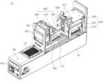
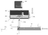
- FIG. 1is a perspective view showing the appearance of a plate sealing device according to an embodiment.
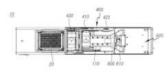
- Figure 2is a perspective view showing the tray positioned at the loading position.
- Figure 3is a right side view of Figure 2.
- Figure 4is a left side view of Figure 2.
- Figure 5is a plan view of Figure 2.
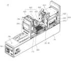
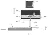
- Figure 6is a perspective view showing the tray positioned at the placing position.
- Figure 7is a plan view of Figure 6.
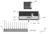
- Figure 8is a perspective view showing the tray positioned at the sealing position.
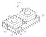
- Figure 9is a perspective view showing a magazine according to one embodiment.
- Figure 10shows the magazine being mounted on the plate sealing device.
- Figure 11is a perspective view showing a pickup unit according to one embodiment.
- Figure 12is a bottom view of Figure 11.
- Figure 13is a perspective view showing a pickup unit according to another embodiment.
- Figure 14is a perspective view showing a well plate and tray according to one embodiment.
- Figure 15is a perspective view showing a well plate coupled to a tray module.
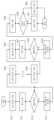
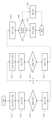
- Figure 16is a flowchart showing the operation of the pickup unit according to one embodiment.
- Figure 17is a plan view showing a state in which a sheet is placed on a well plate out of its normal position.
- Figure 18is a side view showing sensing the position of the sheet at the front end of the well plate.
- Figure 19is a side view showing sensing the position of the sheet at the rear end of the well plate.
- Figure 20is a flowchart showing the pre-sealing inspection sequence according to one embodiment.
- Figure 21is a side view showing inspection of the sealing state after sheet sealing is completed.
- Figure 22is a flowchart showing the inspection sequence after sealing according to one embodiment.
- Figure 23is a flowchart showing the drive shaft position calibration process.
- Figure 24is a flowchart showing the sensing position calibration process.
- Figure 25is a diagram showing the sheet separation process of the pickup unit according to one embodiment.
- first, second, A, B, (a), (b), (i), and (ii)may be used. These terms are only used to distinguish the component from other components, and the nature, order, or order of the component is not limited by the term.
- a componentis described as being “connected,” “coupled,” or “connected” to another component, that component may be directly connected or connected to the other component, but there is another component between each component. can be understood as being able to be “connected,” “coupled,” or “connected.”
- the present inventionrelates to a plate sealing device that can be used in a detection device for detecting target analytes in a sample.
- the platemay be a well plate in which a plurality of wells are arranged in rows and columns. And the plate may have a strip shape in which wells are arranged in a row.
- the plate sealing deviceincludes a well plate sealing device.
- sampleherein may include biological samples (e.g., cells, tissues, and fluids from biological sources) and non-biological samples (e.g., food, water, and soil).
- the biological samplemay include viruses, bacteria, tissues, cells, blood (e.g. whole blood, plasma, and serum), lymph, bone marrow fluid, saliva, sputum, swabs, aspiration, milk, It may be urine, feces, ocular fluid, semen, brain extract, spinal fluid, joint fluid, thymic fluid, bronchial lavage fluid, ascites, and amniotic fluid.
- the samplemay include natural and synthetic nucleic acid molecules isolated from biological sources. Samples herein may include additional substances such as water, deionized water, saline solution, pH buffer, acidic solution, and basic solution.
- a target analyterefers to an analyte that is subject to analysis.
- the analysismay mean, for example, obtaining information about the presence, content, concentration, sequence, activity, or characteristics of the analyte in the sample.
- Analytescan include a variety of substances (e.g., biological substances and non-biological substances such as compounds).
- the analytesmay include biological substances such as nucleic acid molecules (e.g., DNA and RNA), proteins, peptides, carbohydrates, lipids, amino acids, biological compounds, hormones, antibodies, antigens, metabolites, and cells. You can.
- the analyte hereinmay be a nucleic acid molecule.
- the sample hereinmay include an optical label.
- An optical labelrefers to a label that generates an optical signal depending on the presence of a target nucleic acid.
- the optical labelmay be a fluorescent label.
- the fluorescent labelmay include any molecule known in the art.
- the target analyte detection device of the present specificationmay be a target nucleic acid detection device.
- the target nucleic acid detection deviceallows the nucleic acid reaction in the sample to proceed and detects the target nucleic acid through this.
- Nucleic acid reactionrefers to a series of physical and chemical reactions that generate a signal depending on the presence or amount of nucleic acid of a specific sequence in a sample.
- the nucleic acid reactionmay be a reaction that includes binding of a nucleic acid of a specific sequence in a sample to another nucleic acid or substance, and replication, cleavage, or decomposition of a nucleic acid of a specific sequence in the sample.
- the nucleic acid reactionmay be a reaction involving a nucleic acid amplification reaction.
- the nucleic acid amplification reactionmay include amplification of a target nucleic acid.
- the nucleic acid amplification reactionmay be a reaction that specifically amplifies a target nucleic acid.
- the nucleic acid reactionmay be a signal-generating reaction, which is a reaction capable of generating a signal depending on the presence/absence or amount of the target nucleic acid in the sample.
- This signal-generating reactionmay be a genetic analysis process such as PCR, real-time PCR, or microarray.
- the target analyte detection devicemay be a nucleic acid detection device and can detect a signal that occurs depending on the presence of the target nucleic acid.
- a nucleic acid detection devicecan detect a signal by amplifying it along with nucleic acid amplification.
- the nucleic acid detection devicemay detect the signal by amplifying the signal without amplifying the nucleic acid.
- the signalis detected accompanied by nucleic acid amplification.
- a target analyte detection devicemay include a nucleic acid amplification device.
- a nucleic acid amplification devicerefers to a device that can perform a nucleic acid amplification reaction to amplify a nucleic acid having a specific nucleotide sequence.
- the target analyte detection devicemay be a device that performs a nucleic acid amplification reaction while changing temperature.
- a nucleic acid amplification devicecan perform a denaturing step, an annealing step, and an extension (or amplification) step. there is.
- the target analyte detection devicemay be a device that performs a nucleic acid amplification reaction and a reaction that generates an optical signal depending on the presence of the nucleic acid while accompanying a change in temperature and detects the generated optical signal.
- the reaction vessel containing the samplemay be made of a variety of materials, such as plastic, ceramic, glass, or metal.
- the reaction vesselis used to accommodate the sample to be analyzed, and may be of various types, such as a tube, a vial, a strip connected to a plurality of single tubes, or a plate connected to a plurality of tubes. Includes a plate, microcard, chip, cuvette, or cartridge. Below, a well plate in which a plurality of wells are arranged in rows and columns will be described as an example of a reaction vessel.
- the well plateis provided so that wells accommodating samples extend downward, and an opening of the well is provided at the top. And after the well of the well plate is loaded with a sample or reagent, the opening of the well plate can be sealed to prevent the internal fluid from leaking to the outside.
- the well platecan be sealed with a transparent film. Afterwards, in the process of detecting the target analyte, the excitation light from the detection module must be able to enter the inside of the well through the opening, and the reflected light emitted from the sample must be able to enter through the opening.
- the filmcan seal the well plate through heat sealing, or can seal the well plate using an adhesive or adhesive film.
- an embodiment of sealing the film to the well plate through thermal sealing or thermal fusionwill be described.
- the plate sealing devicemay be used after the process of loading a fluid containing a target analyte into a well plate is completed and before the process of detecting the target analyte through a detection module proceeds. That is, after the opening of the well plate loaded with the fluid containing the target analyte is sealed with a film through the plate sealing device, the well plate can be transferred to the next process, the target analyte detection process.
- the plate sealing deviceincludes a device that heats and fuses plastic films, etc. Heating methods include hot plate welders, impulse sealers, and hot air welders that heat from the outside, and high-frequency welders and ultrasonic welders that generate heat from the material itself.
- Heating methodsinclude hot plate welders, impulse sealers, and hot air welders that heat from the outside, and high-frequency welders and ultrasonic welders that generate heat from the material itself.
- a plate sealing device using a hot plate fusion machinewill be described as an example.
- FIG. 1is a perspective view showing the appearance of a plate sealing device according to an embodiment
- FIG. 2is a perspective view showing a tray positioned at a loading position.
- FIG. 3is a right side view of FIG. 2
- FIG. 4is a left side view of FIG. 2
- FIG. 5is a top view of FIG. 2.
- FIG. 1only shows one example of the plate sealing device 10, and the present invention includes various embodiments arranged or moved in different directions.
- the plate sealing device 10includes a loading area 11 where the well plate 20 containing the fluid is loaded, a sheet supply area 12 where a film sheet is placed on the well plate 20, and a well It may include a heating area 13 that applies heat to the film sheet on the plate 20 to seal it.
- the loading area 11, the sheet supply area 12, and the heating area 13are sequentially arranged in the y-axis direction to shorten the process time and narrow the width of the plate sealing device 10 to improve installation freedom.
- the loading positionrefers to the point at which the well plate 20 is loaded onto the tray 100 within the loading area 11
- the placing positionrefers to the point where the sheet is placed on the well plate 20 within the sheet supply area 12.
- the sealing positionrefers to the point where the sheet is sealed to the well plate 20 within the heating area 13.
- the tray 100may stop or wait for a certain period of time at the loading position, placing position, and sealing position.
- the tray 100 on which the well plate 20 is mountedcan linearly move back and forth along the tray transfer rail 110 connecting the loading area 11, the sheet supply area 12, and the heating area 13.
- the well plate 20 picked up by a gripper (not shown) in the loading area 11is seated on the tray 100, and the tray 100 supplies sheets in one direction along the tray transfer rail 110.
- the film sheetis covered over the well plate 20, and the tray 100 moves in one direction along the tray transfer rail 110 to the heating area 13 and then heats the film sheet.
- the grippercan pick up the well plate 20 and transfer it to the next process. there is.
- the loading area 11is exposed to the outside of the case 14, and the sheet supply area 12 and the heating area 13 can be accommodated inside the case 14.
- the loading area 11may be exposed to the outside of the case 14 to allow entry and exit of the gripper.
- the sheet supply area 12 and the heating area 13are accommodated inside the case 14 and can be safe from external shock or inflow of contaminants.
- the tray 100may be provided to be rotatable on the xy plane.
- the well plate 20may be transported with the long axis of the tray 100 disposed in the y-axis direction.
- the long axis of the well plate 20rotates as the tray 100 rotates y. It can be oriented in the axial direction.
- the plate sealing device 10may include a lower region 15 and an upper region 16.
- a tray 100, a tray transfer rail 110, and a tray driver (not shown)may be provided in the lower area 15. Additionally, a waist space (not shown) may be provided in the lower area 15 where slip sheets, which will be described later, can be discarded.
- a magazine 200, a magazine transfer rail, a pickup unit 300, a sheet transfer unit 400, and a sealing unit 500may be provided in the upper area 16. Additionally, the upper area 16 may have a smaller width in the xy plane direction than the lower area 15. Accordingly, the loading area 11 may be provided outside the upper area 16.
- the plate sealing device 10may be provided with a well plate detection sensor (not shown) that can detect whether the well plate 20 is placed on the tray 100. For example, when the well plate detection sensor detects the well plate 20, the next process may proceed.
- a well plate detection sensormay be provided on one side of the tray 100.
- the plate sealing device 10may be provided with gripper detection sensors 14a and 14b on the loading area 11.
- the gripper detection sensors 14a and 14bmay detect the gripper or the worker's hand picking up the well plate 20, or detect the well plate 20 being picked up.
- a transmitting unit (or receiving unit) 14bis provided on the upper part of the magazine 200 insertion slot of the upper case 14, and a receiving unit (or receiving unit) is provided in front of the loading area 11 of the lower case 14 in the y-axis direction.
- a transmitter) (14a)may be provided.
- a partition 600may be provided between the sheet supply area 12 and the heating area 13.
- the partition 600may prevent convection between the heater 510 and the sheet supply area 12, block contaminants, and block heat transfer.
- the partition wall 600may be provided on the upper part of the tray transfer rail 110. That is, the tray 100 can move between the sheet supply area 12 and the heating area 13 without being hindered by the partition wall 600.
- the sheet feeding area 12may be higher in the z-axis direction than the heating area 13. Additionally, an insulating plate 530 is provided at the top of the heating area 13 to block heat transfer to the top. That is, heat transfer in the heating area 13 to the sheet supply area 12 may be blocked by the partition wall 600 in the y-axis direction and by the insulation plate 530 in the z-axis direction.
- the degree of bending of the filmmay become severe, which may cause errors in the pickup or putting down operation, and may also occur during the sealing process. Errors may occur.
- the plate sealing device 10may further include an internal blowing fan 610 provided on the insulating plate 530.
- the internal blowing fan 610can expel contaminants such as dust generated within the sheet supply area 12 and simultaneously expel hot air within the sheet supply area 12.
- the plate sealing device 10may further include an external blowing fan 540 provided at the rear of the case 14.
- the external blowing fan 540can expel contaminants such as dust generated inside the case 14 and simultaneously expel hot air within the case 14.
- the film sheetmay be provided in a stack form in which a plurality of sheets are stacked on top of each other.
- the film sheetmay have a shape corresponding to the planar shape of the well plate 20, for example, a square shape.
- the width of the film sheetcan be set to a width that can cover all the wells of the well plate 20.
- the sheet stackmay be provided by alternately stacking film sheets and slip sheets.
- a gapmay be interposed between adjacent film sheets.
- the sheet stackmay be mounted on the plate sealing device 10 while being accommodated in the magazine 200.
- the magazine 200 containing the sheet stackmay be inserted through a slot at the top of the sheet supply area 12 and moved to the sheet pickup position along the magazine transfer rail.
- the sheet pickup positionrefers to the point where the pickup unit picks up the sheet in the magazine.
- the slot into which the magazine 200 is insertedis located above the sheet pickup position, and the magazine transfer rail may be provided to be inclined downward.
- the magazine transfer railmay be provided with a locking protrusion at the end. Therefore, the magazine 200 stops at the end of the magazine transfer rail.
- the magazine 200is automatically installed, when the user manually inserts the magazine 200, it may be important whether the magazine 200 can be accurately positioned at the sheet pickup position for each operation. If the magazine transfer rails are provided in parallel, an error will occur if the user fails to insert the magazine 200 to the sheet pickup position. However, as in the present embodiment, by providing a magazine transfer rail inclined downward, the magazine 200 is always positioned at a constant sheet pickup position due to the mass of the magazine 200 just by the user inserting the magazine 200 into the slot. It is reached.
- the plate sealing device 10includes a magazine 200 in which a plurality of sheets are stacked and accommodated, a pickup unit 300 that picks up the uppermost sheet among the plurality of sheets, and an object covered by the sheet.
- the tray transfer unitmay include a tray transfer rail 110 extending in the y-axis direction and a tray driver (not shown) that drives the tray 100.
- the tray transfer rail 110may extend to connect the loading area 11, the sheet supply area 12, and the heating area 13, and the tray drive unit may transfer the tray 100 in both directions of the y-axis. there is.
- Figure 6is a perspective view showing the tray positioned at the placing position
- Figure 7is a plan view of Figure 6.
- Figure 8is a perspective view showing the tray positioned at the sealing position.
- the tray transfer unittransfers the tray 100 to the well plate loading position within the loading area 11 and can receive the well plate 20 before sealing or return the well plate 20 after sealing.
- the tray transfer unitcan transfer the tray 100 to the placing position in the sheet supply area 12 and receive the film on the well plate 20 from the pickup unit 300.
- the tray transfer unitcan transfer the tray 100 to the sealing position within the heating area 13 and seal the film on the well plate 20.
- the tray transfer unitcan return the tray 100 to the loading position and transport the slip sheets placed on the tray transfer rail 110. The sheets are pulled out by the tray 100 and discarded in the waste space below the loading position.
- Figure 9is a perspective view showing a magazine according to one embodiment.
- the magazine 200forms a receiving space capable of accommodating a sheet stack therein, the top is open, the lower surface supports the lower part of the sheet stack, and at least three sides are adjacent to the side of the sheet stack. It can be arranged to support.
- a handlemay be provided in front of the y-axis of the magazine 200. The user can hold the handle and pull the magazine 200 to expose it to the outside of the case 14 and then load the sheet stack.
- a separation wing 201may be provided on the upper side of the magazine 200. And the separation wing 201 is provided to protrude from the upper side of the magazine 200 toward the inside of the magazine 200. At this time, the end of the separation wing 201 is provided to be positioned on the sheet. That is, when viewed from above the sheet, the end of the separation wing 201 is provided to come within the area of the sheet.
- separation wings 201may be provided on both sides of the magazine 200, respectively. At this time, the distance between the separation wings 201 on both sides is set to be smaller than the width of the sheet.
- the sheetWhen the hand 310 picks up the sheet, the sheet is lifted while grazing the separation wing 201. At this time, the uppermost sheet that is directly adsorbed to the hand 310 passes through the separation wing 201 and is lifted, but the lower sheet that is not directly adsorbed to the hand 310 falls down due to the resistance of the separation wing 201. do.
- a friction member 202may be provided on the inner wall of the magazine 200. Additionally, two or more friction members 202 may be provided on the inside of one side of the magazine 200 with a distance between them. The friction member 202 may be provided to contact the edge of the sheet when the sheet stack is mounted in the magazine 200. Therefore, when the hand 310 suctions and lifts the sheet, the edge of the sheet comes into contact with the friction member 202.
- the friction member 202may be provided to have surface friction. Therefore, when the hand 310 picks up the sheet, the sheet is lifted while grazing the friction member 202. The uppermost sheet that is directly adsorbed to the hand 310 is lifted past the friction member 202, but the lower sheet that is not directly adsorbed to the hand 310 falls down due to the frictional resistance of the friction member 202.
- the friction member 202may be made of an elastically deformable material. And the friction member 202 may be provided inside both sides of the magazine 200. Accordingly, the friction members 202 on both sides support both sides of the sheet and the sheet can be aligned in the normal position.
- friction member 202may include polymer foam.
- the polymer foammay include EPDM (ethylene propylene diene monomer) foam.
- an antistatic member 203may be provided on the inner wall of the magazine 200.
- the antistatic member 203may be provided on the inside of one side of the magazine 200 to contact the sheet. Static electricity generated on the sheet can be removed through the antistatic member 203.
- the static electricity eliminator 203may be an antistatic pad.
- a buffer member 204may be provided on the lower surface of the magazine 200.
- the buffer member 204may be made of an elastically deformable material. Accordingly, the buffer member 204 can support the lower part of the sheet stack and partially relieve the pressure applied when the hand 310 presses the sheet stack.
- the buffer member 204may be positioned in the middle of the sheet stack in the longitudinal direction and extended in the width direction of the sheet stack.
- friction member 202may include polymer foam.
- the polymer foammay include EPDM (ethylene propylene diene monomer) foam.
- Figure 10shows the magazine being mounted on the plate sealing device.
- the magazine transfer railmay extend in the y-axis direction. And at the same time, the magazine transfer rail can also be extended in the z-axis direction. That is, the magazine transfer rail may be provided to have a gradually decreasing slope in the y-axis direction. Therefore, when the user places the magazine 200 on the magazine transfer rail, the magazine 200 can move along the magazine transfer rail by its own weight. And the magazine 200 stops at the end of the magazine transfer rail, so it can always be located at the same point (sheet pickup position).
- the sheet transfer unit 400can transport the pickup unit 300 from the sheet pickup position where the magazine 200 is mounted to the position where the sheet is placed on the well plate 20 (placing position).
- the sheet transfer unit 400has a first translation drive unit 420 that transfers the pickup unit 300 in the y-axis direction (plane direction) and a first translation drive unit 420 that transfers the pickup unit 300 in the z-axis direction (height direction). It may include a second translation driver 430.
- the translational drive unitmay include a motor and a belt-pulley structure connected to the motor.
- the sheet transfer unit 400may include a rotation drive unit 410 that can rotate the pickup unit 300 according to the inclination of the magazine transfer rail.
- the rotation driver 410may rotate the pickup unit 300 about the x-axis direction rotation axis.
- the rotation drive unit 410may include a motor, a rotation shaft connected to the motor, and a reduction gear unit.
- the pickup unit 300may be directly connected to the rotation driver 410, and the rotation driver 410 may be connected to the first and second translation drivers 430.
- 11 to 13are views showing a pickup unit.
- the pickup unit 300can adsorb the top sheet among the sheets stacked in layers in the magazine 200 and remove the adsorbed sheet.
- 'adsorption'means that the top sheet sticks to the hand 310 of the pickup unit 300, and the sheet sticks to the hand 310 due to the negative pressure formed as the hand 310 sucks air.
- 'falling out'includes separation by gravity when the adsorbing external force is removed and falling off due to external force acting in a downward direction. For example, this includes the sheet being pulled away from the hand 310 by positive pressure generated while expelling air in a downward direction.
- the pickup unit 300may include a hand 310 that picks up the sheet in the magazine 200 and a blowing fan that provides pneumatic pressure to the sheet.
- the blowing fanmay be coupled to the rear of the hand 310.
- rearrefers to the direction opposite to the direction in which the hand 310 faces the magazine 200 (forward).
- the hand 310may be positioned to face the magazine 200 on one side (front) of the pickup unit 300, and the blowing fan may be positioned to face the hand 310 on the other side (rear). And the hand 310 may be provided with an air hole 311 that transmits pneumatic pressure provided from the blowing fan. That is, the air behind the hand passes through the air hole 311 and is delivered to the front of the hand by the positive pressure provided by the blowing fan, and the air in front of the hand passes through the air hole 311 by the negative pressure provided by the blowing fan. It can be delivered to the back of the hand.
- the air hole 311may include a plurality of air holes 311 arranged in a circle along the blade rotation trajectory of the blowing fan. And the air hole 311 may include an outer air hole 311a and an inner air hole 311b located inside the outer air hole 311a.
- the outer air hole 311amay be provided with a larger diameter than the inner air hole 311b.
- the outer air holes 311a and the inner air holes 311bmay be provided in the same number.
- the outer air hole 311amay be a hole through which a direct air flow due to the rotation of the blade of the blowing fan passes
- the inner air hole 311bmay be a hole through which turbulence or eddy currents occur on the adsorption surface of the sheet or the front surface of the hand 310. It may be a hole that reduces .
- each outer air hole 311a and the adjacent inner air hole 311bmay be arranged in the same radial direction from the center.
- each inner air hole 311bmay be located between two adjacent outer air holes 311a. In this case, the space between the outer air hole 311a and the inner air hole 311b can be minimized.
- the air hole 311-1may be in the shape of a long hole extending in the circumferential direction along the blade rotation trajectory of the blowing fan.
- the air hole 311-2may have a long hole shape extending along the radial direction of the blowing fan.
- the outer air hole and the inner air holemay be formed integrally.
- the hand 310may include a plurality of space securing protrusions 313 provided around the air hole 311.
- the space securing protrusion 313may protrude from the front of the hand 310 to the front of the air hole 311 to support the sheet. And the space securing protrusion 313 can prevent the sheet from blocking the air hole 311. If the sheet is adsorbed and blocks some of the air holes 311, damage such as crumpling of the sheet may occur as the air pressure generated in the unblocked air holes 311 increases.
- Space securing protrusions 313may be provided inside and outside the air hole 311, respectively.
- a space-securing protrusion 313may be provided at the center of the air hole 311 arranged in a circle, and a plurality of space-securing protrusions 313 may be provided outside the air hole 311.
- the pickup unit 300may include one or more sensors 316 used to detect the sheet.
- the sensor 316includes a first sensor 316a that detects a film sheet, a second sensor 316b that detects a slip, a third sensor 316c that detects whether the hand 310 is in contact with the sheet, and , may include a fourth sensor (not shown) that detects whether the magazine 200 is empty.
- the first to fourth sensorsmay be used as terms to distinguish sensing functions.
- one sensorhas two or more sensing functions, it can be expressed as first or second, etc.
- the first sensor 316a and the second sensor 316bmay be provided as one sensor.
- one sensorcan have the function of distinguishing different types of sheets.
- the first sensor 316a and the second sensor 316bmay be provided as independent sensors.
- the first sensor 316a and the second sensor 316bmay be installed at different angles of incidence with respect to the sheet plane on which the sheet is placed.
- the angle of incidencerefers to the angle formed by the direction of the sensor signal (wave) incident on the normal line of the sheet plane.
- the first sensor 316amay be installed by setting an incident angle corresponding to the film sheet
- the second sensor 316bmay be installed by setting an incident angle corresponding to the slip sheet. That is, because the film sheet and the slip sheet have different reflectances, the first sensor 316a cannot detect the slip sheet and the second sensor 316b cannot detect the film sheet.
- the fourth sensormay be a combination of the first sensor and the second sensor. For example, when both the first sensor 316a and the second sensor 316b fail to detect an object, it may be determined that the magazine 200 is empty. However, if an error occurs in the first sensor 316a or the second sensor 316b and the magazine 200 is empty, it may be incorrectly determined that there is an object. To prevent such errors, a fourth sensor that detects whether the magazine 200 is empty may be further included.
- the fourth sensormay be provided at an angle that can detect both the film sheet and the slip sheet. Additionally, a signal passage hole 205 may be formed at the bottom of the magazine 200 to allow the sensor signal of the fourth sensor to pass through. Therefore, when the magazine 200 is empty, the fourth sensor cannot detect the object.
- the fourth sensormay be provided in the pickup unit 300 or may be provided below the magazine 200.
- the drawingshows an embodiment in which a fourth sensor is provided below the magazine 200 and detects a sheet stored in the magazine 200 by passing through the signal passage hole 205. Accordingly, even when the hand 310 is not on the magazine 200, the fourth sensor can detect whether the magazine 200 is empty.
- the pickup unit 300may include sheet sensors 316a and 316b that detect the sheet.
- the sheet sensorcan detect film and slip sheet respectively.
- the sheet sensormay be provided so that one sensor can respectively detect the film and the slip sheet.
- the sheet sensormay include a film detection sensor or a first sensor 316a that detects a film, and a second sensor 316b or a film detection sensor that detects a slip sheet.
- a blowing fancan generate pneumatic pressure by rotating its blades.
- positive pressureis generated on one side and negative pressure is generated on the other side. Therefore, positive or negative pressure can be selectively used by changing the blade rotation direction or installation location of the blowing fan.
- the pickup unit 300may include a first blowing fan 320 that generates negative pressure and a second blowing fan 330 that generates positive pressure.
- the first blowing fan 320 and the second blowing fan 330may be provided as an integrated piece. That is, one blowing fan can be provided to change the direction of rotation.
- the first blowing fan 320 and the second blowing fan 330may be provided as independent structures. In this case, the first blowing fan 320 and the second blowing fan 330 may be installed so that their blade rotation directions are different from each other.
- the first blowing fan 320 and the second blowing fan 330may be arranged side by side in a direction to generate pneumatic pressure.
- the first blowing fan 320 that generates negative pressuremay be placed close to the sheet stack
- the second blowing fan 330 that generates positive pressuremay be placed behind the first blowing fan 320. .
- the intensity of sound pressurecan be increased and the sheet can be stably adsorbed.
- blowing fan stacksin which the first blowing fan 320 and the second blowing fan 330 are arranged to overlap each other may be arranged in the longitudinal direction of the sheet. Since the sheet is provided in a rectangular shape with different horizontal and vertical lengths, two blower fan stacks can be arranged in the vertical direction of the sheet.
- An air hole 311 corresponding to the blade of the blowing fanis formed on the front side of the hand 310 (the side facing the seat), and an airtight member 314 surrounding the air hole 311 may be provided. .
- the airtight member 314includes an air hole 311 and a space securing protrusion 313 inside, and the inside and outside of the airtight member 314 are fluidically blocked so that the pneumatic pressure formed through the air hole 311 is airtight. It is possible to prevent leakage to the outside of the member 314.
- the airtight member 314may be provided in a closed shape.
- a closed shaperefers to a shape that is continuous without a break in the middle and whose start and end points coincide.
- the airtight member 314may include a closed cell type and a semi-independent/semi-continuous cell type.
- the closed cell typeis flexible, but each bubble is independent and can block fluid. Also, in the case of the semi-closed/semi-continuous cell type, it can be compressed with a small amount of force, and since it becomes a closed cell after compression, it can be provided with an airtight performance that does not allow air or water to pass through.
- the airtight member 314may include polymer foam.
- the polymer foammay include EPDM (ethylene propylene diene monomer) foam.
- the airtight member 314may have a rectangular band shape including an air hole 311 and a space securing protrusion 313 therein. Alternatively, the airtight member 314 may have a circular band shape. In addition, when a plurality of blowing fan stacks are provided in the longitudinal direction of the sheet, a plurality of airtight members 314 may be provided corresponding to each blowing fan stack. For example, when two blower fan stacks are provided in the longitudinal direction of the sheet, two rectangular band-shaped airtight members 314 may be arranged to be spaced apart from each other.
- the hand 310can adsorb the sheet by driving the first blowing fan 320.
- the hand 310may adsorb the sheet while the airtight member 314 is in contact with or close to the sheet. More specifically, the air pressure formed by driving the first blowing fan 320 is transmitted to the front of the hand 310 through the air hole 311, and the sheet is moved by the negative pressure formed in the space surrounded by the airtight member 314. may be adsorbed.
- the hand 310can preserve the shape of the sheet by adsorbing the sheet using the rotational force of the blowing fan 320, compared to the case of using a vacuum pump. Since film sheets are a very thin and easily wrinkled material, damage to the sheets occurs when negative pressure is applied to a small area or when a vacuum pump that momentarily generates strong negative pressure is used. However, if negative pressure is generated inside the closed shape using the blowing fan 320 and the airtight member 314, stable adsorption can be achieved while minimizing deformation of the sheet.
- the hand 310may drive the second blowing fan 330 to separate the sheet.
- the hand 310can drop the received sheet onto the well plate 20. More specifically, the positive pressure formed by driving the second blowing fan 330 is transmitted to the front of the hand 310 through the air hole 311, and the sheet can be blown out and separated from the hand 310.
- electrostatic attractionmay occur between the hand 310 and the sheet during the process of the hand 310 adsorbing the sheet. Therefore, even when the first blowing fan 320 stops operating, the sheet may not be separated from the hand 310.
- the sheetcan be quickly separated by driving the second blowing fan 330 to provide positive pressure inside the airtight member 314.
- the process of the hand 310 separating the sheetmay be performed while the sheet is close to or in contact with the well plate 20. If the sheet is separated from the well plate 20, the sheet may move left and right under the influence of the surrounding air flow, and the moved sheet may form the well 21 on the upper surface of the well plate 20. Problems may arise such as not being able to cover the area or shrinking the adhesive area.
- the hand 310has a first sensor 316a and a second sensor 316b installed in the center, and a sensor hole 312 that opens the signal path of the first sensor 316a and the second sensor 316b.
- a sensor hole 312that opens the signal path of the first sensor 316a and the second sensor 316b.
- the first sensor 316a and the second sensor 316bCan be arranged to be spaced apart in the width direction of the sheet, and the sensor hole 312 can be formed between two adjacent airtight members 314.
- the sensor hole 312may have a long hole shape extending in the width direction of the sheet.
- a first sensor 316amay be placed on one side of the hand 310 in the width direction
- a second sensor 316bmay be placed on the other side of the hand 310 in the width direction.
- Each sensormay include a transmitter and a receiver.
- a third sensor 316cmay be disposed on one side of the hand 310 in the longitudinal direction.
- the third sensor 316cmay be a contact sensor that generates a signal when it contacts the sheet.
- the third sensor 316cmay be provided outside the airtight member 314.
- a fourth sensor(not shown) may be placed at the lower part of the magazine 200.
- the fourth sensormay be fixed to a separate frame so that it can transmit and receive a sensing signal toward the signal passage hole 205 when the magazine 200 is mounted.
- the fourth sensormay be provided to detect both the film and the slip sheet. However, when the magazine 200 is empty, the signal transmitted from the fourth sensor cannot detect any object.
- the hand 310may further include a curve prevention member 315.
- the curve prevention member 315can prevent the sheet adsorbed on the pickup unit 300 from bending upward.
- the hand 310may be provided smaller than the width of the sheet. Therefore, after the hand 310 adsorbs the sheet, the sheet may be rolled up around the hand 310. To prevent this, a curve prevention member 315 protruding outward of the hand 310 may be provided on one side of the hand 310 in the longitudinal direction.
- the curve prevention member 315may be made of an elastic material. Additionally, the curve prevention member 315 may extend forward (in the direction facing the seat) beyond the hand 310. Accordingly, when the hand 310 approaches the sheet, one side of the curve prevention member 315 may contact the sheet before one side of the hand 310. Alternatively, when the hand 310 approaches the sheet, one side of the curve prevention member 315 may first contact the sheet before the third sensor 316c detects the sheet. Alternatively, when the hand 310 approaches the sheet, one side of the curve prevention member 315 may first contact the sheet before the blowing fan 320 is driven.
- the curve prevention member 315is elastically deformed, and then the blowing fan 320 is driven so that the hand 310 can adsorb the sheet.
- curve prevention members 315may be provided on both edges of the hand 310 in the longitudinal direction.
- the curve prevention members 315-1may be provided at each of the four edges of the hand 310, or may be provided continuously along the four edges.
- Figure 13is a perspective view showing a pickup unit according to another embodiment.
- the airtight member and the curve prevention membermay be integrated into one member 315-1. That is, the curve prevention member 315-1 provided continuously along the four edges of the hand 310 can prevent the sheet from bending and at the same time block the airflow between the inside and outside of the curve prevention member 315-1. . Therefore, the negative pressure generated inside the curve prevention member 315-1 is maintained, and a separate airtight member (see 314 in FIG. 12) surrounding the air hole 311 can be omitted.
- the curve prevention member 315-1may be made of a material capable of elastic deformation.
- the curve prevention member 315-1may be made of a polymer compound, and more specifically, it may be made of a rubber material.
- Figure 14is a perspective view showing a well plate and tray according to one embodiment.
- the tray 100may have a well plate 20 seated on the seating surface.
- the tray 100may have a groove 101 formed on the seating surface to accommodate a plurality of wells 21 protruding from the lower portion of the well plate 20. That is, the grooves 101 formed on the seating surface of the tray 100 are provided to correspond to the wells 21 of the well plate 20, so that the wells 21 can be inserted into the grooves 101.
- Figure 15is a perspective view showing a well plate coupled to a tray module.
- the tray or tray module 100may further include a finger member 103.
- the tray module 100is used as a concept including a tray.
- the finger member 103can prevent the sheet placed on the well plate 20 from being bent upward or rolled up. If the sheet on the well plate 20 is bent or rolled upward beyond an appropriate level, problems may occur during the sealing process. For example, when the heater 510 of the sealing unit 500 is lowered, the curved edge of the sheet is pushed while contacting the heater 510 to change the position of the sheet, or the rolled edge of the sheet is moved by the heater 510. It can be folded by pressing .
- Finger members 103may be provided on both sides of the tray 100 in the width direction. And the finger members 103 may be located on both sides of the longitudinal edge of the tray 100. That is, the finger members 103 may be located at each of the four edges of the tray 100.
- the longitudinal directionmay be a direction in which one side of the tray 100 is longer or a direction in which the tray 100 is moved.
- the finger member 103includes a first finger part 103a connected to the tray 100, and a second finger part connected to the first finger part 103a and extending from the outside to the inside of the tray 100 when viewed from above. (103b).
- the first finger portion 103amay be located outside the edge of the sheet when viewed from above, and the second finger portion 103b may extend inward from the outside of the edge of the sheet when viewed from above.
- the finger member 103can move one end of the second finger portion 103b between the inner and outer edges of the sheet when viewed from above.
- the finger member 103may be capable of sliding movement.
- the first finger portion 103ais connected to the solenoid 103c or a motor and can move in both directions in a straight line.
- the finger member 103may be capable of pivot or hinge movement.
- the first finger portion 103amay be connected to a motor and rotate in both directions.
- the sealing unit 500includes a heater 510 that applies heat to the sheet, a heater rail 520 that guides the vertical movement of the heater 510, and a heater drive unit (not shown) that provides power to move the heater 510. ), an insulation plate 530 that insulates the heater 510 and the upper space, and an external blowing fan 540 that exhausts air warmed by the heater 510 to the outside of the device.
- sealing unit 500can use known products, detailed description will be omitted.
- the entire process of the plate sealing device 10consists of waiting for the loading position of the tray 100, waiting for the sheet picking position of the pickup unit 300, loading the well plate 20, moving the placing position of the tray 100, and separating each sheet. , sheet pickup and transfer, sheet placing, movement of the sealing position of the tray 100, sealing of the well plate 20, return to the loading position of the tray 100, and unloading of the well plate 20. Additionally, in the process of returning the tray 100 to the pickup position after sealing, a process of dragging the slip sheets and discarding them in the waste space below the loading position may be included.
- the plate sealing device 10may perform a process of checking the condition of the well plate 20 before proceeding with the loading process.
- the well plate detection sensor(not shown) detects whether the well plate 20 is placed on the tray 100, and the gripper detection sensors 14a and 14b detect a gripper or other device on the loading area 11. It can detect whether an object is present.
- the control unit of the plate sealing device 10sends a gripper driving signal to the central control unit to enable the gripper to perform a well plate loading operation.
- the control unit of the plate sealing device 10centrally controls a signal that the process is ready when the well plate detection sensor detects that the well plate 20 is placed and the gripper detection sensors 14a and 14b do not detect the object. You can send it to the device and perform the next process.
- the tray 100 loaded with the well plate 20can be moved to the placing position during the sheet separation and sheet pickup and transfer process.
- the sheet transfer unit 400moves the pickup unit 300 to the sheet pickup position where the magazine 200 is previously mounted.
- the control unitprovides a notification that the magazine 200 is empty and waits for the user to fill the magazine 200 with a sheet stack.
- the plate sealing device 10may include a sheet adsorption device.
- the sheet adsorption devicemay include a pickup unit 300 and a control unit that controls the pickup unit 300.
- the pickup unit 300may pick up the top sheet among the plurality of sheets from the magazine 200 in which the plurality of sheets are stacked and accommodated.
- the pickup unit 300may be provided with a hand 310 in contact with the seat, and blowing fans 320 and 330 located behind the hand 310 and generating negative pressure in the direction of the hand.
- the pickup unit 300may further include an adsorption detection sensor that detects whether the sheet is adsorbed on the hand 310.
- the control unitdrives the blowing fans (320, 330) to adsorb the sheet, and after driving the blowing fans (320, 330), it receives the driving information of the blowing fans (320, 330) or the pressure information at the rear of the hand to control the hand (310). ) can determine whether the sheet has been adsorbed.
- the adsorption detection sensormay include a rotation sensor that detects the rotation of the blowing fan and a pressure sensor that detects the pressure behind the hand.
- the control unitreceives information from an adsorption detection sensor, which is a rotation sensor, and drives the first blowing fan 320. After a predetermined time has elapsed, the second blowing fan 330 rotates at a predetermined speed or more. If it is detected that the sheet is not adsorbed on the hand 310, it can be determined that the sheet is not adsorbed.
- the control unitreceives information from the adsorption detection sensor and detects that the second blowing fan 330 does not rotate or rotates at less than a predetermined speed after a predetermined time has passed after driving the first blowing fan 320. In this case, it can be determined that the sheet is adsorbed on the hand 310.
- control unitmay receive information from the adsorption detection sensor, which is the pressure sensor, and determine that the sheet is adsorbed on the hand 310 when the pressure behind the hand rises above a predetermined pressure.
- control unitmay receive information from the adsorption detection sensor and determine that the sheet is adsorbed on the hand 310 when it detects that the pressure change at the rear of the hand is outside a predetermined pressure range.
- Figure 16is a flowchart showing the operation of the pickup unit according to one embodiment.
- the control unitcan drive the transfer unit 400 to move the hand 310 of the pickup unit 300 in a direction closer to the seat (S110).
- the hand 310may move in the y-axis and z-axis directions simultaneously or sequentially, advance in the y-axis direction, and then descend in the z-axis direction. This is because the magazine 200 supports the sheet in a diagonal direction with respect to the z-axis direction. If the magazine 200 supports the sheet in a direction parallel to the z-axis direction, the hand 310 can only descend in the z-axis direction.
- the control unitmay receive a signal from the third sensor 316c (contact detection sensor) (S120) and detect whether the hand 310 is in contact with the sheet (S130).
- the third sensor 316cmay use a pressure sensor or a distance sensor.
- the control unitmay receive distance information from the third sensor 316c and estimate that the hand 310 and the sheet are in contact when they are within a certain distance. At this time, the predetermined distance may be the distance from the third sensor 316c to the bottom of the hand 310.
- the control unitcan stop the hand 310 or retreat slightly.
- the hand 310may retract somewhat to prevent compression between two adjacent sheets. Specifically, the hand 310 retreats somewhat to form a space at the bottom of the sheet stack or between adjacent sheets, thereby preventing air compression between the film and the slip sheet during the hand 310's sheet separation operation.
- control unitmay further lower the hand 310 when the third sensor 316c detects that the hand 310 is not in contact with the sheet. That is, the control unit may lower the hand 310 until the third sensor 316c detects that the hand 310 is in contact with the sheet. This is because as the number of sheets accommodated in the magazine 200 decreases, the moving distance of the hand 310 required to contact the sheet increases.
- the control unitdrives the first blowing fan 320 to cause the hand 310 to adsorb the top sheet (S140). Specifically, as the hand 310 contacts the sheet, the airtight member 314 provided on the bottom of the hand 310 comes into close contact with the sheet. Then, the first blowing fan 320 is driven to form a negative pressure in the inner space of the airtight member 314, which forms a closed shape, and the sheet is adsorbed.
- the control unitmay receive changed information a certain period of time after driving the first blowing fan 320 (S150) and determine whether the sheet is adsorbed on the hand 310 (S160). For example, the control unit may determine whether the sheet is adsorbed to the hand 310 through rotation speed information of the second blowing fan 330.
- the first blowing fan 320 and the second blowing fan 330may be arranged in series with each other. Additionally, the first blowing fan 320 and the second blowing fan 330 may be arranged to have different blowing directions.
- the blowing fanis provided to be capable of rotating in both directions, and the blowing fan can be rotated in one direction to generate negative pressure in the hand direction, and the blowing fan can be rotated in the opposite direction to generate positive pressure in the hand direction.
- the pickup unit 300further includes a pressure sensor that detects the pressure behind the hand, and the control unit can receive information from the pressure sensor to determine whether the sheet is adsorbed on the hand 310.
- the pickup unit 300may be disposed close to the seat in the order of the hand 310, the first blowing fan 320, and the second blowing fan 330.
- the first blowing fan 320rotates to provide negative pressure in front of the hand 310 to adsorb the sheet
- the second blowing fan 330rotates to provide positive pressure in front of the hand 310 to remove the sheet. I order it.
- the second blower fan 330may be provided in a state in which it can rotate by external force even when driving power is not supplied.
- the second blowing fan 330may rotate as the outside air flow passes through the second blowing fan 330 at a certain speed or higher.
- the first blowing fan 320While the first blowing fan 320 is rotating, when a sheet is adsorbed on the suction surface of the hand 310, the front opening of the hand 310 is blocked from the outside air, so the air flow inside the hand 310 is reduced. . And, while the first blowing fan 320 is rotating, if the sheet is not adsorbed on the suction surface of the hand 310, outside air flows into the hand 310 through the gap between the sheet and the hand 310. (310) A rapid air flow occurs inside.
- the second blowing fan 330rotates below a certain speed, and in the latter case where a faster air flow is formed, the second blowing fan 330 rotates at a constant speed. It rotates beyond . At this time, if the rotation speed information of the second blowing fan 330 is known, it can be indirectly determined whether the sheet is adsorbed on the suction surface of the hand 310.
- control unitmay estimate the rotational speed of the second blowing fan 330 by detecting the speed electromotive force of the driving unit of the second blowing fan 330. This is because the speed electromotive force of the rotation drive unit is proportional to the rotation speed.
- control unitmay receive a signal from a separate rotation detection sensor capable of detecting the rotation speed of the second blowing fan 330 (S150).
- the rotation sensormay include a Hall sensor.
- control unitmay receive a signal from a pressure sensor capable of detecting pressure inside the hand 310.
- a pressure sensorcapable of detecting pressure inside the hand 310.
- control unitdetermines that the sheet is adsorbed to the hand 310 after a certain period of time has passed after driving the first blowing fan 320 (S161), the control unit proceeds to the next step and determines that the sheet is not adsorbed to the hand 310. If it is determined that this is the case (S162), the first blowing fan 320 can be continuously driven (S140), or the first blowing fan 320 can be stopped for a while and then driven again. Alternatively, if the control unit determines that the sheet is not adsorbed to the hand 310, the control unit may stop driving the first blowing fan 320 and transmit an error message.
- control unitmay perform a rubbing operation.
- the hand 310may perform a rubbing operation to separate the top sheet from the sheet located below it and pick it up. This rubbing motion may include one or more movements in the plane of the sheet.
- the control unitmay perform a movement of the hand 310 to separate a sheet (for example, a rubbing operation) (S170).
- a sheetfor example, a rubbing operation
- the hand 310adsorbs the top sheet
- another sheetmay be attached and brought under it.
- the top sheet and the sheet attached below itcan be separated using the separation wing 201 and the friction member 202 mounted on the magazine 200, but in order to separate them more clearly, the hand 310 is rubbed. can be performed.
- the sheet separation movement (S170)may include rubbing the hand 310 in the length direction of the sheet. While the hand 310 rubs the top sheet while adsorbing it, shear stress is generated between the top sheet and the sheet below it, and when the shear stress becomes greater than the electrostatic attraction, the sheets attached to each other are separated into single sheets.
- the rubbing motionincludes unidirectional and reciprocating movements.
- the hand 310may pick up the sheet after moving forward in the longitudinal direction of the sheet, or may pick up the sheet after moving back and forth one or more times in the longitudinal direction of the sheet.
- the rubbing motionincludes linear and curved movements. And the rubbing motion includes one-dimensional movement and two-dimensional movement. Two-dimensional movement includes movement in the plane of the sheet and movement in the direction perpendicular to it.
- the hand 310may move in an arc while moving in the length direction of the sheet and simultaneously moving in the height direction of the sheet.
- the rubbing actionmay include a combination of two different actions.
- the sheet transfer unit 400may move the pickup unit 300 from the sheet pickup position to the placing position where the sheet will be placed on the well plate 20 (S180).
- the sheet transfer unit 400can move the pickup unit 300 in the y-axis direction and the z-axis direction.
- the sheet transfer unit 400may include a y-axis direction drive unit, a y-axis direction transfer rail, and a z-axis direction drive unit and a z-axis direction transfer rail.
- the sheet transfer unit 400can rotate the pickup unit 300 about the x-axis direction rotation axis.
- the sheet transfer unit 400may rotate the pickup unit 300 about the x-axis direction rotation axis so that the hand 310 of the pickup unit 300 faces downward.
- the first sensor 316a and the second sensor 316b of the pickup unit 300can detect whether the adsorbed sheet is a film or a sheet.
- the tray driving unitmoves the tray 100 to the placing position. Then, the hand 310, which has moved to the placing position, stops the first blowing fan 320 and drives the second blowing fan 330 to place the film on the well plate 20 (S190). And before the hand 310 puts down the film, the hand 310 may descend in the z-axis direction and move to a position where the well plate 20 and the film are close to each other. If the film is separated while the hand 310 is close to the well plate 20, an error in which the film is placed on the well plate 20 in a shifted state can be prevented.
- the tray driving unitmoves the tray 100 to a position past the placing position. Then, the hand 310, which has moved to the placing position, stops the first blowing fan 320 and drives the second blowing fan 330 to place the slip sheet on the tray transfer rail 110. And before the hand 310 puts down the slip sheet, the hand 310 can descend in the z-axis direction and move to a position where the tray transfer rail 110 and the slip sheet are close to each other.
- the slipcan be discarded directly into the waste space or after the sealing process.
- the tray 100returns in the y-axis direction to push the slip sheet and discards the slip sheet in the waste space provided below the well plate loading area 11.
- the filmcan be placed on the well plate 20 and after sealing is completed, the tray 100 returns in the y-axis direction and the slip sheet can be pushed out and discarded in the waist space.
- the slip sheetcan be discarded through the slip sheet discharge port 14c provided in the case 14.
- a slide guidethat can support both sides of the slip may be provided on the trail transfer rail.
- the slide guideextends in the y-axis direction along the trail transport rail and can be provided in pairs on both sides.
- the slide guideguides the movement of the slip sheets and can prevent the slip sheets from getting caught in the gap of the tray transport rail 110 or being separated from the tray transport rail 110.
- the finger member 103 of the tray 100moves over the film to prevent the film from rolling upward.
- the finger member 103may be connected to the solenoid 103c and translate in the longitudinal direction (y-axis direction) of the sheet. At this time, the finger member 103 may not contact the film while moving.
- the tray 100moves the well plate 20 to the sealing area.
- the heater 510 of the sealing unit 500descends along the heater rail 520 to a point close to the finger member 103. And the finger member 103 can return to a position that does not restrict the film. And before the film is rolled up by the heat in the sealing area, the heater 510 is lowered and heat is applied while pressing the film on the well plate 20 to heat-seal or heat-press the film on the well plate 20. .
- the heater 510rises and the tray 100 returns to the well plate loading position.
- the slip sheets on the tray transfer rail 110are pushed by the tray 100 and move together with the tray 100, and are discarded in the waste space located outside the tray transfer rail 110. And the slip sheet can be discarded through the slip sheet discharge port 14c provided in the case 14.
- control unittransmits information that sealing has been completed to the central control device, and the gripper picks up the well plate 20 on which sealing has been completed and transfers it to the next process.
- control unitsatisfies the condition that the well plate detection sensor detects that there is no well plate 20 and the gripper detection sensors 14a and 14b do not detect the object, the control unit sends a signal that the process is ready to the central control unit. You can.
- Sealing errorscan occur in a variety of cases. For example, if the sheet placed on the well plate 20 is a sheet rather than a film, the film is placed in a shifted abnormal position rather than the normal position on the well plate 20. In this case, or if the film is placed on the well plate 20 and entered into the sealing unit 500 in a state where the heat-adhesive side of the film is turned upward instead of facing the well plate 20, a sealing error may occur.
- the sealing errorsif the sheet placed on the well plate 20 is a slip sheet rather than a film, it can be resolved by using the film detection sensor 316a and the slip sheet detection sensor 316b. Also, among sealing errors, if the film is placed in an abnormal position rather than the normal position on the well plate 20, it can be resolved by placing the sheet down on the well plate 20 and then detecting the position of the sheet. Lastly, among the sealing errors, if the film is placed on the well plate 20 and entered into the sealing unit 500 in a state where the heat-adhesive side of the film is turned over instead of facing the well plate 20, the sealing unit (500) is This can be resolved by checking whether a well open has occurred in the well plate 20 from step 500).
- Figure 17is a plan view showing a state in which a sheet is placed on a well plate out of its normal position.
- Figure 18is a side view showing the position of the sheet being detected at the front end of the well plate, and
- Figure 19is a side view showing the position of the sheet being detected at the rear end of the well plate.
- the sheetmust be provided to cover all of the plurality of wells 21 formed on the top of the well plate 20. And considering sealing stability after sealing, sufficient space must be secured between the outermost well and the edge of the sheet. This is because in order for the sheet to be stably sealed around the well, an adhesive area greater than the minimum area is required.
- the sheetis placed on the well plate 20 shifted to the right from its normal position.
- the wells in row 1are not open, there is a high possibility that well opening will occur when sealing in the sealing unit 500 because there is not enough space between the edge of the sheet and row 1, and even if this is not the case, there are concerns about sealing stability. .
- the drawingshows a state in which the sheet is shifted in the column direction (columns 1 to 12) of the well plate 20.
- the column direction of the well plate 20may be the longitudinal direction of the tray transfer rail 110, and may also be the transfer direction of the well plate 20.
- the finger member 103(FIG. 15) operates to move the sheet to the normal position.
- the finger member 103can push a sheet in an abnormal position in the row direction to a normal position while switching from an open state to a closed state.
- control unitmust be able to recognize an abnormal situation when the sheet is placed in a position that is deviated from the normal position in the row direction of the well 21 by more than a standard degree.
- the pickup unit 300can distinguish sheets using the sheet detection sensor 316a when picking up a sheet from the magazine 200, and uses the sheet detection sensor 316a even after placing the sheet down on the well plate 20. You can use this to detect whether the sheet is in the correct position.
- the sheet detection sensor 316amay be a film detection sensor (see FIG. 12) provided at the lower part of the hand 310.
- the sheet detection sensorcan be named a film detection sensor 316a
- the sheet detection sensorcan be named a slip sheet detection sensor 316b. .
- the sheet detection sensor 316amay be a detection sensor (for example, an optical sensor, etc.) capable of detecting an object within a certain detection distance (d). Therefore, in a state where a film sheet is placed on the well plate 20, the distance l1 from the sheet detection sensor 316a to the upper surface of the well plate 20 is greater than d, and the upper surface of the film sheet from the sheet detection sensor 316a When the distance l2 to the surface is smaller than d, the sheet detection sensor 316a can detect only the film sheet. That is, the sheet detection sensor 316a cannot detect the target object at a point where there is no sheet on the well plate 20 due to the film sheet being shifted, etc., and the control unit may determine that the sheet is missing or is abnormally positioned.
- ddetection distance
- the sheet detection sensor 316a of the pickup unit 300detects the front and rear ends in the column direction (first direction; tray transfer direction; y-axis direction) of the well plate 20. 1
- the position of the sheetcan be detected at the sensing position (S1).
- detecting the position of the sheetincludes distinguishing whether the sheet is sensed at the first sensing position S1 or not.
- the sheet detection sensor 316acan detect the presence or absence of a sheet at a first sensing position (S1) of two points at each of the front and rear ends of the well plate 20, and detects the presence or absence of a sheet in the first direction.
- the presence or absence of a sheetcan be detected at the first sensing position (S1) of a total of 4 points.
- the first sensing position (S1)is a first position (P1) and a second position in the first direction at least one of the first end (front end) and the second end (rear end) in the first direction of the expected well plate position. It can be located between positions (P2). According to one embodiment, the first sensing location (S1) is between the first location (P1) and the second location (P2) in the column direction at least one of the front end and the rear end in the column direction of the expected well plate position. can be located
- the first position P1is when one edge of the sheet 30 is located outside one edge of the well plate 20 when the sheet 30 is normally positioned on the well plate 20. This is a position corresponding to one edge of the well plate 20.
- the first position (P1)is when the sheet 30 is normally positioned on the well plate 20 and one edge of the sheet 30 coincides with or is located inside one edge of the well plate 20. This is the position corresponding to the edge of (30).
- the second position (P2)is a position corresponding to the shortest edge of the well closest to the first position (P1).
- the expected well plate positionrefers to the expected position of the well plate 20 seated on the tray 100 moving along the tray transfer rail 110, and is the position of the well plate 20 estimated through driving the tray driving unit. You can.
- the control unitcan estimate the expected position of the tray through the initial position information of the tray 100 and the driving information of the tray driver, and the well plate 20 through the previously known position information of the well plate 20 on the tray 100. ) can be estimated.
- the expected well plate positionincludes the placing position where the tray 100 receives the sheet 30 from the pickup unit 300. At this time, calibration may be performed periodically in order to maintain and improve the accuracy of the expected well plate position.
- the control unitmoves the pickup unit 300 after picking up the sheet from the magazine 200, places the sheet down on the well plate 20 at the placing position, and then moves the pickup unit 300 and the tray 100 in the first direction. Move it relatively, and when the expected well plate position is at a predetermined position, drive the sheet detection sensor 316a to determine whether the sheet is detected, and determine whether the sheet is in its normal position on the well plate 20 through the sensed information. You can determine whether it is within the range.
- the pickup unit 300 and the tray 100move relatively in the first direction, which means that when the pickup unit 300 moves in the first direction while the tray 100 is stopped, on the contrary, the pickup unit 300 ) includes a case where the tray 100 moves in the first direction while the tray 100 is stopped, or a case where the tray 100 and the pickup unit 300 move opposite to each other in the first direction.
- the control unitdetermines whether the sheet is sensed by driving the sheet detection sensor 316a at a plurality of first sensing positions (S1) arranged apart from each other in the first direction, and determines whether the sheet is detected. If the number of first sensing positions where the sheet is not detected is more than a predetermined number, the sheet is judged to be in a normal state in the normal position, or if the number of first sensing positions where the sheet is not detected is more than a predetermined number, the sheet is judged to be in a normal state. It can be judged as an abnormal state in an abnormal position.
- the control unitoperates between the first position (P1) and the second position (P2) at each of the first end (front end in the first direction) and the second end (rear end in the first direction) of the expected well plate position.
- the sheetis detected by driving the sheet detection sensor 316a at the first sensing positions S1 of at least two points, and among the detection results of the first sensing positions S1 of at least four points, the first sensing positions S1 of two points are detected. If the sheet is not detected beyond the sensing position, it can be judged to be in an abnormal state.
- the sheet detection sensor 316afails to detect the sheet at both the first sensing positions (S1) of the two points located at the front and rear ends of the first or second end of the expected well plate position. In this case, or the sheet detection sensor 316a does not detect the sheet at one of the first sensing positions S1 of the two points located at the first end of the expected well plate position, When the sheet detection sensor 316a fails to detect the sheet at one of the two first sensing positions S1 located at the second end, the control unit may determine an abnormal state.
- control unitdrives the pickup unit 300 in a second direction different from the first direction at one first sensing position (S1) and detects the sheet at a plurality of sensing points with different sensing distances. It is possible to determine whether a sheet is detected by driving the detection sensor 316a.
- the sensing pointrefers to the point of the maximum sensing distance at which the sheet detection sensor 316a can detect the sheet. Since the maximum sensing distance of the sheet detection sensor 316a is predetermined, the sensing point changes as the pickup unit 300 moves. You can. And the sensing point can be located between the shortest distance at which the sheet can be sensed and the distance at which the well plate 20 can be sensed, and is located on the well plate 20.
- the control unitdetects a sheet at a second sensing point (S12) with a farther sensing distance.
- the pickup unit 300 and the tray 100can be relatively moved to the next first sensing position (S1) without detecting.
- first and second sensing points S12 having different heightsmay be provided at one first sensing location S1.
- the pickup unit 300drives the sheet detection sensor 316a at the first sensing point (S11), which is higher among the two sensing points provided at the first sensing position (S1), and moves down the z-axis direction when the sheet is not detected. By moving to , the sheet detection sensor 316a can be driven at the second sensing point S12 with a low height.
- the pickup unit 300drives the sheet detection sensor 316a at the higher first sensing point (S11) of the two sensing points provided at the first sensing position (S1) and detects the sheet in the z-axis direction. Instead of moving down, it moves in the y-axis direction to the next first sensing position (S1).
- the first sensing point (S11) and the second sensing point (S12)are displayed at different positions in the first direction (y-axis direction), but this is for easy display in the drawings.
- the first sensing point S11 and the second sensing point S12may be on the first sensing position S1, which is the same position in the first direction.
- Figure 20is a flowchart showing the pre-sealing inspection sequence according to one embodiment.
- the control unitdetermines that the first point among the plurality of first sensing positions (S1) of the well plate 20 is located below the sheet detection sensor (S210)
- the control unitdetects the sheet through the sheet detection sensor. Do (S211, S212).
- the pickup unit 300is positioned so that the detection distance of the sheet detection sensor corresponds to the first sensing point (S11).
- the control unitmoves the well plate 20 or the pickup unit 300 to point 2 (S220), and if the sheet is not detected, moves the pickup unit 300 to the z axis. Move downward a certain distance and remeasure (S213). At this time, the pickup unit 300 moves downward so that the detection distance of the sheet detection sensor corresponds to the second sensing point (S12).
- the control unitdetermines that the sheet is detected at point 1. If the sheet is not detected at the second sensing point (S12), the control unit determines that the sheet is not detected at point 1. do.
- the control unitmoves the well plate 20 or the pickup unit 300 and repeats the operation process from point 1 to point 4.
- control unitdetermines that point 4 of the plurality of first sensing positions (S1) of the well plate 20 is located below the sheet detection sensor (S240), it detects the sheet through the sheet detection sensor (S241, S242). . At this time, the pickup unit 300 is positioned so that the detection distance of the sheet detection sensor corresponds to the first sensing point (S11).
- the control unitcompletes the operation when the sheet is detected at the first sensing point (S11), and if the sheet is not detected, the pickup unit 300 is moved down a certain distance in the z-axis and remeasured (S243). At this time, the pickup unit 300 moves downward so that the detection distance of the sheet detection sensor corresponds to the second sensing point (S12).
- the control unitdetermines that the sheet is detected at point 4. If the sheet is not detected at the second sensing point (S12), the control unit determines that the sheet is not detected at point 4. do.
- the control unitdetermines whether the sheet is in the normal position (S250, S260). Specifically, when the sheet is detected at two or more points among the first sensing positions (S1) of a total of four points, it is determined that the sheet is in the normal position (S262), and the first sensing positions of a total of four points ( If the sheet is detected at less than two points in S1), it is determined that the sheet is in an abnormal position (S261). And if it is determined that the sheet is in an abnormal position, an error alarm can be provided to the user.
- Figure 21is a side view showing inspection of the sealing state after sheet sealing is completed.
- the sheet detection sensor 316a of the pickup unit 300detects the presence or absence of a sheet at a plurality of second sensing positions S2 arranged in the column direction (first direction; tray transfer direction; y-axis direction) of the well plate 20. can be detected. According to one embodiment, the sheet detection sensor 316a may detect the presence or absence of a sheet at the second sensing position S2 of 12 points arranged in parallel in the column direction of the well plate 20.
- the second sensing location S2may be located between the first end (front end) and the second end (rear end) of the expected well plate position in the first direction. According to one embodiment, the second sensing location S2 may be arranged at equal intervals in the column direction of the expected well plate location.
- the second sensing position S2may be a position corresponding to a plurality of wells arranged in one column direction of the well plate 20.
- the positions corresponding to the plurality of wellsinclude not only inside the hole of the well, but also around the hole.
- the second sensing location S2may be around a hole that is the same distance away from a plurality of wells arranged in one column direction.
- the control unitreturns to the placing position after the well plate 20 on the tray 100 completes the sealing process in the sealing unit 500, and then returns to the placing position in advance based on the expected well plate position on the tray transfer rail 110. It is possible to determine whether a sheet is detected by driving the sheet detection sensor 316a at a predetermined position, and to determine whether the sheet is normally sealing the wells of the well plate 20 through the sensed information.
- the control unitdetermines whether the sheet is sensed by driving the sheet detection sensor 316a at a plurality of second sensing positions (S2) arranged apart from each other in the first direction, and determines whether the sheet is detected. If the number of second sensing positions (S2) is more than a predetermined number, the sheet is judged to be in a normal sealed normal state, or the number of second sensing positions (S2) where the sheet is not sensed is predetermined. If it is more than the number, it can be determined that the sheet is in an abnormal state, abnormally sealed.
- control unitdetects the sheet at a second sensing position (S2) of at least four points between the first end (front end in the first direction) and the second end (rear end in the first direction) of the expected well plate position.
- the sensor 316amay be driven to detect the sheet, and if the sheet is not detected at one second sensing position S2, it may be determined to be in an abnormal state.
- the control unitmay determine that it is in an abnormal state.
- the number and location of the second sensing locations S2may vary. For example, 12 wells arranged in the first direction can be detected by the sheet detection sensor 316a at the second sensing position S2 of 6 points while skipping one by one. And it can be detected by the sheet detection sensor 316a more than once at one second sensing position (S2). For example, if the film is not detected at the second sensing position S2, it can be detected once more at the same height, or the height of the pickup unit 300 can be lowered to detect it again. And the criteria for judging abnormal states may also vary. For example, when a sheet is not sensed at the adjacent second sensing position S2, the control unit may determine an abnormal state.
- Figure 22is a flowchart showing the inspection sequence after sealing according to one embodiment.
- the control unitdetermines that the first point among the plurality of second sensing positions (S2) of the well plate 20 is located below the sheet detection sensor (S310)
- the control unitdetects the sheet through the sheet detection sensor. Do (S320, S330). And the control unit stores the result of whether or not the sheet is detected at point 1 of the second sensing positions (S2) (S340).
- the control unitmoves the well plate 20 or the pickup unit 300 and repeats the operation process from point 1 to point 12.
- the control unitdetermines whether a well open has occurred in the sheet (S350, S360). Specifically, if the sheet is detected at all of the second sensing positions (S2) of a total of 12 points, it is determined that normal sealing is performed without well opening (S361), and one of the second sensing positions (S2) of a total of 12 points is determined (S361). If a well open is detected, it is determined that the well open has occurred in abnormal sealing (S362). And if it is determined that the sealing is abnormal, an error alarm can be provided to the user.
- Calibrationincludes a drive shaft position calibration process that adjusts the drive shaft position of the tray transfer unit that moves the tray 100 and the sheet transfer unit 400 that transfers the pickup unit 300, and a sensing position calibration process that adjusts the position of the sensor. Includes.
- Figure 23is a flowchart showing the drive shaft position calibration process.
- the drive shaftmay include a y-axis direction drive shaft that transports the tray 100 in the y-axis direction, and a z-axis direction drive shaft that transports the pickup unit 300 in the z-axis direction.
- the tray 100may include an origin measurement reference that can be detected by the sheet detection sensor 316a of the pickup unit 300.
- the origin measurement standardis provided adjacent to the area where the well plate 20 is mounted, and the height of the upper surface is equal to or higher than the height of the upper surface of the well plate 20 when the well plate 20 is mounted. It can be set somewhat high.
- the pickup unit 300is moved to a random z-axis position (S410). Then, a correction algorithm for the y-axis direction drive shaft is performed.
- the compensation algorithm for the Y-axis direction drive shaftis as follows.
- the pickup unit 300is moved to a random position on the tray transfer rail 110 (S420).
- the tray 100is moved in the y-axis direction until the sheet detection sensor 316a of the pickup unit 300 detects the origin measurement standard of the tray 100 (S421) (S420).
- the sheet detection sensor 316a of the pickup unit 300detects the origin measurement standard of the tray 100 (S421)
- the y-axis direction position of the tray 100 at that timeis stored (S422).
- the pickup unit 300is moved to a random location outside the tray transfer rail 110 (S423).
- the average of the three values excluding the maximum and minimum valuesis used as the primary correction value for the y-axis (S425). Then, the tray 100 is moved to the y-axis position according to the above y-axis first correction value (S426). Then, a correction algorithm for the z-axis direction drive shaft is performed.
- the compensation algorithm for the Z-axis direction drive shaftis as follows.
- the pickup unit 300is moved in the z-axis direction out of the detection range until the sheet detection sensor 316a of the pickup unit 300 cannot detect the origin measurement standard of the tray 100 (S430). Then, the pickup unit 300 is moved in the z-axis direction until the sheet detection sensor 316a of the pickup unit 300 detects the origin measurement standard of the tray 100 (S431) (S432). When the sheet detection sensor 316a of the pickup unit 300 detects the origin measurement standard of the tray 100 (S431), the z-axis direction position of the pickup unit 300 at that point is stored (S433).
- the pickup unit 300is moved to a position in the z-axis direction according to the above z-axis correction value (S436).
- the pickup unit 300is moved to a random position on the tray transfer rail 110 (S420). Then, the tray 100 is moved in the y-axis direction until the sheet detection sensor 316a of the pickup unit 300 detects the origin measurement standard of the tray 100 (S421) (S420). When the sheet detection sensor 316a of the pickup unit 300 detects the origin measurement standard of the tray 100 (S421), the y-axis direction position of the tray 100 at that time is stored (S422).
- the tray 100is moved to a position in the y-axis direction according to the above y-axis secondary correction value.
- Figure 24is a flowchart showing the sensing position calibration process.
- the sensing distancemay vary due to differences in the height or flatness of the tray 100.
- the sensing position calibrationmay be performed just before shipment of the equipment and when part movement or reassembly occurs, and may be performed while the well plate 20 is seated on the tray 100.
- the tray 100is moved a certain distance based on the y-axis direction position according to the y-axis secondary correction value obtained through the drive shaft position calibration algorithm (S510).
- the moving positionsare the first sensing positions (S1) of the four points used to detect the normal position of the sealing film.
- the correction algorithm for the Z-axis sensing positionis as follows.
- the pickup unit 300is moved to a random z-axis direction (S520). If the pickup unit 300 does not detect the well plate 20 (S521), it moves down the z-axis until it is detected (S522). When the well plate 20 is detected (S521), the pickup unit 300 moves up the z-axis until it is not detected (S523). When the well plate 20 is no longer detected (S521), the z-axis position of the pickup unit 300 at that point is stored (S524).
- Figure 25is a diagram showing the sheet separation process of the pickup unit according to one embodiment.
- the static electricity between the film and the slip sheetis less than 2kV, and in this case, it is possible to separate each sheet just by moving the hand in a straight direction.
- static electricity of around 3 kVmay be generated, and in this case, the attractive force between the film and the slip sheet may be strong, causing a sheet shift in which the sheet slips on the adsorption surface of the hand 310.
- the hand 310 of the pickup unit 300performs one or more of the following: a rubbing operation in the plane direction of the sheet, a rubbing operation in a direction perpendicular to the plane direction of the sheet, and a rubbing operation in a rotational direction rotating along a rotation axis parallel to the plane of the sheet. can be performed.
- the hand 310 of the pickup unit 300can perform a sheet separation movement only by rubbing in a planar direction or in a vertical direction.
- the hand 310 of the pickup unit 300may perform a sheet separation movement only by rubbing in the rotation direction.
- the sheet separation movementmay be performed using all of the rubbing motion in the planar direction, the rubbing motion in the vertical direction, and the rubbing motion in the rotational direction.
- the sheet adsorbed on the hand 310hits the inner wall of the magazine 200 or the friction member 202 ) or may be bent or bent while rubbing against the antistatic member 203. In this process, a space is created between the top sheet adsorbed on the hand 310 and the sheet stuck below it, and static electricity can be removed.
- the hand 310 of the pickup unit 300may repeat the same rubbing operation several times or may perform a sheet separation movement by combining different rubbing operations.
- the pickup unit 300lowers the hand 310 toward the sheet, and when the sheet contact sensor 316c detects that the hand 310 is in contact with the sheet, it drives the blower fan 320 to adsorb the uppermost sheet. . Then, it moves back a predetermined offset distance to relieve the pressure between the sheets.
- the pickup unit 300retreats the hand 310 a certain distance from the seat. This is to secure movement space for the hand 310 when performing a subsequent rubbing operation in the rotation direction. That is, the distance at which the hand 310 retreats from the seat may vary depending on the rotation angle of the hand 310.
- the pickup unit 300performs a sheet separation movement.
- the pickup unit 300rotates the hand 310 in one direction about a rotation axis parallel to the plane direction of the sheet. Specifically, as the hand 310 rotates in one direction, the front edge of the sheet adsorbed on the hand 310 rubs against the antistatic member 203 located in front of the magazine 200. In this process, static electricity can be removed as the sheets that stick to each other are separated from the front edge of the sheet.
- the pickup unit 300retracts the hand 310.
- the sheet adsorbed on the hand 310rubs against the friction member 202 formed on the inner wall of the side of the magazine 200, thereby removing static electricity from the side edge of the sheet.
- the pickup unit 300can rotate the hand 310 in the reverse direction so that the suction surface is parallel to the sheet surface.
- the pickup unit 300may advance the hand 310 toward the magazine 200. At this time, the moving distance by which the hand 310 moves forward may be smaller than the distance by which the hand 310 moves backward in FIG. 25(b).
- the pickup unit 300can separate the rear edge of the sheet by rotating the hand 310 in the reverse direction.
- the pickup unit 300can rotate the hand 310 in one direction so that the suction surface is parallel to the sheet surface.
- the above sheet separation movementcan be repeated. And as the operation is repeated, the distance between the hand 310 and the sheet stack increases, and the rotation angle of the hand 310 may increase accordingly.
- 103finger member, 103a: first finger portion,
- 103bsecond finger portion
- 103csolenoid
- 311air hole
- 312sensor hole
- 313Space-securing protrusion
- 314Airtight member
- curve prevention membercurve prevention member
- 316afirst sensor (film detection sensor)
- first translation driving unit(y-axis direction driving unit),
- sealing unitsealing unit
- 510heater
Landscapes
- Engineering & Computer Science (AREA)
- Mechanical Engineering (AREA)
- Sheets, Magazines, And Separation Thereof (AREA)
- Closing Of Containers (AREA)
Abstract
Description
Translated fromKorean본 발명은 웰 플레이트 실링 장치에 관한 것이다.The present invention relates to a well plate sealing device.
현대인의 건강에 대한 관심이 높아지고, 기대 수명이 연장되면서, 병원균의 정확한 분석 및 환자의 유전자 분석 등 핵산 기반의 체외 분자진단에 대한 중요성이 높아지고 있으며, 그 수요가 증가하고 있는 실정이다. 핵산 기반의 분자진단은 검체 샘플로부터 핵산을 추출한 후, 추출된 핵산 중 타깃 핵산의 존재 유무를 확인하는 방식으로 이루어진다.As modern people's interest in health increases and life expectancy extends, the importance of nucleic acid-based in vitro molecular diagnosis, such as accurate analysis of pathogens and genetic analysis of patients, is increasing, and the demand for it is increasing. Nucleic acid-based molecular diagnosis is performed by extracting nucleic acids from a specimen sample and then confirming the presence or absence of target nucleic acids among the extracted nucleic acids.
중합효소 연쇄반응(Polymerase chain reaction: PCR)은 가장 널리 사용되는 핵산 증폭 반응으로서, 이중가닥 DNA의 변성, DNA 주형으로의 올리고뉴클레오타이드 프라이머의 어닐링 및 DNA 중합효소에 의한 프라이머 연장의 반복된 사이클 과정을 포함한다(Mullis 등, 미국 특허 제4,683,195호, 제4,683,202호 및 제4,800,159호; Saiki et al., (1985) Science 230, 1350-1354).Polymerase chain reaction (PCR) is the most widely used nucleic acid amplification reaction, which involves repeated cycles of denaturation of double-stranded DNA, annealing of oligonucleotide primers to DNA templates, and primer extension by DNA polymerase. Includes (Mullis et al., US Pat. Nos. 4,683,195, 4,683,202 and 4,800,159; Saiki et al., (1985) Science 230, 1350-1354).
중합효소 연쇄반응 검출과정 중, 다수의 웰이 형성된 웰플레이트에 액상의 시료를 넣고, 웰플레이트의 상면에 형성된 입구를 밀봉하기 위해 웰플레이트 위에 필름을 덮어 밀봉하는 과정이 포함된다.During the polymerase chain reaction detection process, a liquid sample is placed in a well plate with multiple wells, and the well plate is covered with a film to seal the inlet formed on the top of the well plate.
일반적으로 밀봉에 사용되는 필름은 롤러에 연속적으로 감겨져 있는 롤 타입(Roll type)으로 마련된다. 일본 공개특허 제2000-335509호는 이러한 롤 타입의 마이크로 플레이트의 밀봉 방법 및 마이크로 플레이트의 자동 밀봉장치를 개시하고 있다.Generally, the film used for sealing is prepared as a roll type that is continuously wound on a roller. Japanese Patent Publication No. 2000-335509 discloses a method for sealing roll-type microplates and an automatic microplate sealing device.
그러나 이러한 롤 타입 실링 장치는 연속적인 필름을 자르기 위한 별도의 커터가 필요하고, 권취된 필름을 평편하게 펴주기 위한 복수의 가이드 롤러가 필요하다. 따라서, 장치가 커지고 가격이 비싸지는 문제가 있다.However, this roll-type sealing device requires a separate cutter to cut a continuous film and a plurality of guide rollers to flatten the rolled film. Therefore, there is a problem in that the device becomes larger and more expensive.
이러한 문제를 해결하기 위해 플레이트의 너비에 맞게 재단된 복수의 필름 시트가 적재된 시트 타입(Sheet type) 필름을 이용할 수 있다.To solve this problem, a sheet type film containing a plurality of film sheets cut to fit the width of the plate can be used.
이러한 배경에서, 본 발명의 제1 내지 제4 실시예는 시트 타입(Sheet type) 필름 스택을 이용하면서도 자동화 공정을 통해 플레이트를 실링할 수 있고 오류 발생을 방지하는 웰 플레이트 실링 장치를 제공한다.Against this background, the first to fourth embodiments of the present invention provide a well plate sealing device that can seal a plate through an automated process and prevent errors while using a sheet type film stack.
다른 측면에 따르면, 본 발명의 제5 및 제6 실시예는 시트 타입(Sheet type) 필름 스택을 이용하면서도 자동화 공정을 통해 최상부 시트를 흡착할 수 있고 흡착 오류 발생을 방지하는 시트 흡착 장치를 제공한다.According to another aspect, the fifth and sixth embodiments of the present invention provide a sheet adsorption device that can adsorb the top sheet through an automated process while using a sheet type film stack and prevents adsorption errors. .
i) 상기와 같은 목적을 달성하기 위해, 본 발명의 제1 실시예는 포개진 시트들을 수용할 수 있는 매거진; 상기 매거진의 상기 시트들 중 최상부 시트를 픽업하도록 구성되는 픽업유닛; 웰 플레이트가 배치되는 트레이; 상기 픽업유닛에 결합되고, 상기 픽업된 시트를 플레이싱 위치로 이송하도록 구성되는 시트 이송유닛; 및 상기 웰 플레이트의 웰들을 상기 시트로 밀봉하도록 구성되는 실링유닛;을 포함하고, 상기 플레이싱 위치는 상기 픽업된 시트가 상기 트레이 위에 배치된 상기 웰 플레이트 위에 아래로 내려 놓아지는 위치인, 웰 플레이트 실링 장치를 제공할 수 있다.i) In order to achieve the above object, the first embodiment of the present invention includes a magazine capable of accommodating stacked sheets; a pickup unit configured to pick up the uppermost sheet among the sheets of the magazine; a tray on which the well plate is placed; a sheet transport unit coupled to the pickup unit and configured to transport the picked sheet to a placing position; and a sealing unit configured to seal the wells of the well plate with the sheet, wherein the placing position is a position where the picked sheet is placed down on the well plate disposed on the tray. A sealing device may be provided.
여기서, 상기 웰 플레이트의 상기 웰들은 행과 열로 배치되고, 상기 실링유닛은 상기 시트를 상기 웰 플레이트에 부착하여 상기웰들 모두를 밀봉하도록 구성될 수 있다.Here, the wells of the well plate are arranged in rows and columns, and the sealing unit may be configured to seal all of the wells by attaching the sheet to the well plate.
여기서, 상기 실링유닛은 상기 웰 플레이트 위에 덮인 시트에 열을 전달하는 가열부를 구비할 수 있다.Here, the sealing unit may be provided with a heating unit that transfers heat to the sheet covered over the well plate.
여기서, 상기 트레이는 상기 웰 플레이트의 폭 방향 외측과 내측 사이에서 이동 가능한 핑거부재를 구비하고, 상기 핑거부재는 상기 웰 플레이트 위에 상기 시트가 덮인 상태에서 상기 웰 플레이트 위의 상기 시트가 말리는 것을 방지하도록 상기 웰 플레이트의 폭 방향 내측으로 이동하도록 구성될 수 있다.Here, the tray is provided with a finger member movable between the outer and inner sides in the width direction of the well plate, and the finger member prevents the sheet on the well plate from curling while the sheet is covered on the well plate. It may be configured to move inward in the width direction of the well plate.
여기서, 상기 핑거부재는 상기 가열부가 상기 시트에 근접하기 전에 상기 웰 플레이트의 폭 방향 외측으로 이동하여 상기 가열부와의 간섭을 피할 수 있다.Here, the finger member can avoid interference with the heating unit by moving outward in the width direction of the well plate before the heating unit approaches the sheet.
여기서, 상기 핑거부재는 상기 웰 플레이트의 폭 방향 외측에 위치하는 제1 핑거부와 상기 제1 핑거부에서 상기 웰 플레이트의 폭 방향 내측으로 연장되는 제2 핑거부를 포함할 수 있다.Here, the finger member may include a first finger portion located outside the well plate in the width direction and a second finger portion extending from the first finger portion to the inside of the well plate in the width direction.
여기서, 상기 매거진을 수직에 경사진 방향으로 안내하는 매거진 가이드레일을 더 포함하고, 상기 매거진은 중력에 의해 상기 매거진 가이드레일을 따라 하강하여 미리 정해진 시트 픽업 위치에 정지할 수 있다.Here, it further includes a magazine guide rail that guides the magazine in a vertical and inclined direction, and the magazine can descend along the magazine guide rail by gravity and stop at a predetermined sheet pickup position.
여기서, 제어부를 더 포함하고, 상기 제어부는, 상기 웰 플레이트가 배치된 상기 트레이를 상기 플레이싱 위치로 이송하고, 상기 픽업유닛이 상기 매거진의 상기 최상부 시트를 픽업하고, 상기 픽업한 시트를 상기 플레이싱 위치로 이송하고, 상기 플레이싱 위치에서 상기 웰 플레이트 위에 상기 시트를 내려 놓고, 상기 시트가 덮인 상기 웰 플레이트가 배치된 상기 트레이를 실링 위치로 이송하고, 상기 실링유닛을 구동하여 상기 실링 위치에서 상기 웰 플레이트를 밀봉하고, 상기 시트로 밀봉된 상기 웰 플레이트가 배치된 상기 트레이를 반출 위치로 이송할 수 있다.Here, it further includes a control unit, wherein the control unit transfers the tray on which the well plate is disposed to the placing position, the pickup unit picks up the uppermost sheet of the magazine, and places the picked sheet on the platter. Transfer to the lacing position, place the sheet on the well plate at the placing position, transfer the tray on which the well plate covered with the sheet is placed to the sealing position, and drive the sealing unit to move the tray to the sealing position. The well plate may be sealed, and the tray on which the well plate sealed with the sheet is disposed may be transported to the unloading location.
여기서, 상기 픽업유닛은 상기 시트를 흡착하는 핸드와 상기 핸드의 후방에 위치하는 하나 이상의 송풍팬(fan blade)을 구비할 수 있다.Here, the pickup unit may be provided with a hand that adsorbs the sheet and one or more blowing fans (fan blades) located behind the hand.
여기서, 제어부를 더 포함하고, 상기 제어부는 상기 핸드에 양압이 발생하도록 상기 송풍팬을 구동하여, 상기 핸드가 상기 흡착된 시트를 분리시켜 상기 웰 플레이트 위에 내려 놓도록 제어할 수 있다.Here, it further includes a control unit, wherein the control unit drives the blower fan to generate positive pressure in the hand, and can control the hand to separate the adsorbed sheet and place it on the well plate.
여기서, 상기 픽업유닛은 상기 핸드에 음압이 발생하도록 상기 송풍팬을 구동하여 상기 매거진에서 상기 최상부 시트를 흡착할 수 있다.Here, the pickup unit can adsorb the top sheet from the magazine by driving the blowing fan to generate negative pressure in the hand.
여기서, 상기 송풍팬은 상기 핸드에 양압이 발생하도록 구동하는 제1 송풍팬과 상기 핸드에 음압이 발생하도록 구동하는 제2 송풍팬을 포함할 수 있다.Here, the blowing fan may include a first blowing fan driven to generate positive pressure in the hand and a second blowing fan driven to generate negative pressure in the hand.
여기서, 상기 픽업유닛은 시트를 픽업하는 핸드를 구비하고, 상기 시트 이송유닛은 상기 핸드를 상기 매거진과 상기 웰 플레이트 사이에서 회전(rotation) 가능하게 구동하는 회전 구동부 및 상기 매거진과 상기 웰 플레이트 사이에서 병진(translation) 이동 가능하게 구동하는 병진 구동부를 포함할 수 있다.Here, the pickup unit is provided with a hand that picks up the sheet, and the sheet transfer unit includes a rotation drive unit that drives the hand to rotate between the magazine and the well plate and a rotation drive unit that rotates the hand between the magazine and the well plate. It may include a translation driving unit that is driven to enable translational movement.
여기서, 상기 회전 구동부는 x축 방향 회전축을 중심으로 회전하도록 구성되고, 상기 병진 구동부는 y축 방향으로 선형 이동하도록 구성되는 제1 병진 구동부와 z축 방향으로 선형 이동하도록 구성되는 제2 병진 구동부를 포함할 수 있다.Here, the rotation driver is configured to rotate about the It can be included.
여기서, 상기 픽업유닛은 시트를 픽업하는 핸드를 구비하고, 상기 핸드는 상기 최상부 시트에 접촉한 상태에서 문지름(rub) 동작을 하여 상기 최상부 시트를 그 아래 위치하는 시트로부터 분리시켜 픽업할 수 있다.Here, the pickup unit is provided with a hand that picks up the sheet, and the hand can separate the top sheet from the sheet located below it and pick it up by performing a rubbing operation while in contact with the top sheet.
여기서, 상기 문지름 동작은 상기 시트의 평면 방향으로의 1회 이상의 움직임을 포함할 수 있다.Here, the rubbing operation may include one or more movements in the plane direction of the sheet.
여기서, 상기 문지름 동작은 상기 시트를 들어 올리는 동안 상기 시트의 평면 방향으로의 1회 이상의 움직임을 포함할 수 있다.Here, the rubbing action may include one or more movements in the plane direction of the sheet while lifting the sheet.
여기서, 상기 픽업유닛은, 필름(film sheet)과 간지(slip sheet)가 서로 번갈아 포개진(stacked) 시트들을 수용할 수 있는 상기 매거진에서 상기 시트들 중 최상부 시트를 픽업하도록 구성되고, 상기 필름과 상기 간지를 각각 감지할 수 있는 시트 센서를 구비할 수 있다.Here, the pickup unit is configured to pick up the top sheet among the sheets in the magazine, which can accommodate sheets in which film sheets and slip sheets are alternately stacked, and the film and A sheet sensor capable of detecting each of the above-mentioned sheets may be provided.
여기서, 상기 시트 센서는 상기 필름을 감지하는 제1 센서와 상기 간지를 감지하는 제2 센서를 포함할 수 있다.Here, the sheet sensor may include a first sensor for detecting the film and a second sensor for detecting the slip.
여기서, 상기 제1 센서와 상기 제2 센서는 서로 다른 입사각으로 시트에 조사되도록 장착될 수 있다.Here, the first sensor and the second sensor may be mounted to irradiate the sheet at different angles of incidence.
다른 실시예에 따르면, 웰 플레이트가 트레이 위에 로딩되고 상기 트레이 위에서 언로딩되는 웰 플레이트 로딩 영역; 매거진의 포개진 시트들 중 최상부 시트를 흡착하고, 흡착된 시트를 이송하여 상기 웰 플레이트에 공급하는 시트 공급 영역; 상기 웰 플레이트 위에 덮인 시트에 열을 가하는 가열 영역; 및 상기 로딩 영역, 상기 시트 공급 영역, 및 상기 가열 영역을 따라 상기 웰 플레이트가 로딩된 트레이를 이송하는 트레이 이송유닛을 포함하는, 웰 플레이트 실링 장치가 제공될 수 있다.According to another embodiment, a well plate loading area where well plates are loaded onto a tray and unloaded from the tray; a sheet supply area that adsorbs the top sheet among the stacked sheets of the magazine, transfers the adsorbed sheet, and supplies it to the well plate; a heating area that applies heat to a sheet covered over the well plate; A well plate sealing device may be provided, including a tray transfer unit that transfers the tray loaded with the well plate along the loading area, the sheet supply area, and the heating area.
여기서, 상기 시트를 흡착하는 핸드와 상기 핸드의 후방에 위치하는 하나 이상의 송풍팬을 구비하고, 상기 시트 공급 영역에서 흡착된 시트를 상기 웰 플레이트에 공급하는 픽업유닛을 포함할 수 있다.Here, it may include a pick-up unit that is provided with a hand that adsorbs the sheet and one or more blowing fans located behind the hand, and supplies the sheet adsorbed in the sheet supply area to the well plate.
여기서, 상기 픽업유닛은 상기 핸드에 양압이 발생하도록 상기 송풍팬을 구동하여 상기 흡착된 시트를 분리시키는 제1 동작과, 상기 핸드에 음압이 발생하도록 상기 송풍팬을 구동하여 상기 최상부 시트를 흡착하는 제2 동작 중, 어느 하나 이상을 수행할 수 있다.Here, the pickup unit has a first operation of driving the blowing fan to generate positive pressure in the hand to separate the adsorbed sheet, and driving the blowing fan to generate negative pressure in the hand to adsorb the uppermost sheet. During the second operation, any one or more may be performed.
여기서, 상기 송풍팬은, 상기 핸드에 양압이 발생하도록 구동하는 제1 송풍팬과 상기 핸드에 음압이 발생하도록 구동하는 제2 송풍팬을 포함하고, 상기 제1 송풍팬과 상기 제2 송풍팬은 상기 시트에 대해 수직 방향으로 나란하게 배치될 수 있다.Here, the blowing fan includes a first blowing fan driven to generate positive pressure in the hand and a second blowing fan driven to generate negative pressure in the hand, and the first blowing fan and the second blowing fan are It can be arranged side by side in a vertical direction with respect to the sheet.
여기서, 상기 시트 공급 영역에서 공기를 흡입하여 상기 가열 영역에 배출하는 하나 이상의 송풍 팬을 더 포함할 수 있다.Here, it may further include one or more blowing fans that suck air from the sheet supply area and discharge it to the heating area.
여기서, 상기 포개진 시트들을 수용할 수 있는 상기 매거진과, 상기 매거진을 수직에 경사진 방향으로 안내하는 매거진 가이드레일을 더 포함하고, 상기 매거진은 중력에 의해 상기 매거진 가이드레일을 따라 하강하여 미리 정해진 시트 픽업 위치에 정지할 수 있다.Here, it further includes the magazine capable of accommodating the stacked sheets, and a magazine guide rail that guides the magazine in a vertically inclined direction, and the magazine descends along the magazine guide rail by gravity to reach a predetermined level. It can stop at the seat pickup position.
여기서, 상기 시트를 픽업하는 핸드를 상기 매거진과 상기 웰 플레이트 사이에서 회전(rotation) 가능하게 구동하는 회전 구동부 및 상기 매거진과 상기 웰 플레이트 사이에서 병진(translation) 이동 가능하게 구동하는 병진 구동부를 포함하는 시트 이송유닛을 더 포함할 수 있다.Here, a rotation driving part that drives the hand that picks up the sheet to be able to rotate between the magazine and the well plate and a translation driving part that drives the hand to be able to move in translation between the magazine and the well plate. It may further include a sheet transfer unit.
여기서, 필름(film sheet)과 간지(slip sheet)가 서로 번갈아 포개진(stacked) 시트들을 수용할 수 있는 매거진에서 상기 복수 매의 시트 중 최상부 시트를 픽업하도록 구성되는 픽업유닛을 더 포함하고, 상기 시트 공급 영역은 상기 픽업된 시트가 필름인 경우 상기 픽업유닛이 상기 필름을 상기 트레이 위에 배치된 상기 웰 플레이트 위에 아래로 내려 놓는 플레이싱 위치를 포함하고, 상기 픽업유닛에 픽업된 시트가 상기 제1 시트인 경우 상기 웰 플레이트가 플레이싱 위치로 이동하고 상기 웰 플레이트 위에 상기 제1 시트를 내려 놓고, 상기 픽업유닛에 픽업된 시트가 상기 제2 시트인 경우 상기 웰 플레이트가 플레이싱 위치에서 벗어나 이동하고 상기 웰 플레이트 외부에 상기 제2 시트를 내려 놓을 수 있다.Here, it further includes a pickup unit configured to pick up the uppermost sheet of the plurality of sheets in a magazine capable of receiving sheets in which film sheets and slip sheets are alternately stacked, The sheet supply area includes a placing position where, when the picked up sheet is a film, the pickup unit places the film down on the well plate disposed on the tray, and the sheet picked up by the pickup unit is the first If it is a sheet, the well plate moves to the placing position and the first sheet is placed on the well plate, and if the sheet picked up by the pickup unit is the second sheet, the well plate moves away from the placing position. The second sheet may be placed outside the well plate.
여기서, 상기 트레이를 이송하는 트레이 이송유닛; 상기 매거진에 수용된 상기 시트를 감지하는 시트 센서; 상기 트레이 위에 상기 웰 플레이트가 배치되었는지 여부를 감지하는 웰 플레이트 센서; 및 제어부를 더 포함하고, 상기 제어부는, a) 상기 웰 플레이트 센서의 신호를 수신하여 상기 트레이에 상기 웰 플레이트가 배치된 것으로 판단되는 경우, 상기 트레이 이송유닛을 구동하여 상기 트레이를 상기 플레이싱 위치로 이송하고, b) 상기 시트 센서의 신호를 수신하여 상기 매거진에 상기 시트가 수용되어 있는 것으로 판단되는 경우, 상기 픽업유닛을 구동하여 상기 시트를 픽업하고, c) 상기 시트 이송유닛을 구동하여 상기 시트를 상기 플레이싱 위치로 이송하고, d) 상기 픽업유닛을 구동하여 상기 웰 플레이트 위에 상기 시트를 떨어뜨리고, e) 상기 d) 단계 이후에, 상기 트레이 이송유닛을 구동하여 상기 트레이를 시트 실링 영역으로 이동하고, f) 상기 e) 단계 이후에, 상기 실링유닛을 구동하여 상기 웰 플레이트의 웰들을 상기 시트로 밀봉하고, g) 상기 f) 단계 이후에, 상기 트레이 이송유닛을 구동하여 상기 트레이를 상기 로딩 영역으로 반송할 수 있다.Here, a tray transfer unit that transfers the tray; A sheet sensor that detects the sheet accommodated in the magazine; a well plate sensor that detects whether the well plate is placed on the tray; and a control unit, wherein the control unit: a) receives a signal from the well plate sensor and, when it is determined that the well plate is placed in the tray, drives the tray transfer unit to move the tray to the placing position; transfer to, b) when it is determined that the sheet is accommodated in the magazine by receiving a signal from the sheet sensor, drive the pickup unit to pick up the sheet, and c) drive the sheet transfer unit to transporting the sheet to the placing position, d) driving the pickup unit to drop the sheet onto the well plate, e) after step d), driving the tray transport unit to transport the tray to the sheet sealing area. f) After step e), the sealing unit is driven to seal the wells of the well plate with the sheet, and g) after step f), the tray transfer unit is driven to seal the tray. It can be returned to the loading area.
여기서, 상기 픽업유닛은, 필름(film sheet)과 간지(slip sheet)가 서로 번갈아 포개진(stacked) 시트들을 수용할 수 있는 상기 매거진에서 상기 복수 매의 시트들 중 최상부 시트를 픽업하도록 구성되고, 상기 필름과 상기 간지를 각각 감지할 수 있는 시트 센서를 더 포함하고, 상기 d) 단계에서, d1) 상기 시트 센서의 신호를 이용하여 상기 픽업유닛에 픽업된 시트가 필름인 것으로 판단되는 경우, 상기 픽업유닛을 구동하여 상기 플레이싱 위치에 대기하는 상기 웰 플레이트 위에 상기 필름을 내려 놓고, d2) 상기 시트 센서의 신호를 수신하여 상기 픽업유닛에 픽업된 시트가 간지인 것으로 판단되는 경우, 상기 트레이 이송유닛을 구동하여 상기 트레이를 상기 플레이싱 위치에서 벗어난 위치로 이동하고, 상기 픽업유닛을 구동하여 상기 플레이싱 위치에 상기 간지를 떨어뜨릴 수 있다.Here, the pickup unit is configured to pick up the top sheet among the plurality of sheets in the magazine, which can accommodate sheets in which film sheets and slip sheets are alternately stacked, It further includes a sheet sensor capable of detecting the film and the slip sheet, respectively, and in step d), when d1) it is determined that the sheet picked up by the pickup unit is a film using a signal from the sheet sensor, Driving the pickup unit to place the film on the well plate waiting at the placing position, d2) If a signal from the sheet sensor is received and the sheet picked up by the pickup unit is determined to be a sheet, the tray is transferred. The unit can be driven to move the tray to a position away from the placing position, and the pick-up unit can be driven to drop the slip sheet at the placing position.
여기서, 상기 픽업유닛은, 시트를 흡착하는 핸드와, 상기 핸드의 후방에 위치하는 하나 이상의 송풍팬을 구비하고, 상기 송풍팬은, 상기 핸드에 양압이 발생하도록 구동하는 제1 송풍팬과 상기 핸드에 음압이 발생하도록 구동하는 제2 송풍팬을 포함할 수 있다.Here, the pickup unit includes a hand that adsorbs the sheet, and one or more blowing fans located behind the hand, wherein the blowing fan includes a first blowing fan that is driven to generate positive pressure in the hand and the hand. It may include a second blowing fan that is driven to generate negative pressure.
여기서, 상기 매거진은 상기 시트들 중 상기 픽업유닛에 픽업된 상기 최상부 시트와 그 아래의 시트를 분리하도록 외력을 제공하는 시트 분리부를 구비하고, 상기 시트 분리부는 상기 매거진의 일 측 내벽에 마련되는 제1 마찰부재를 포함하고, 상기 핸드는 상기 최상부 시트를 픽업한 상태에서 상기 시트의 평면 방향에 평행한 회전축을 중심으로 일정 각도 회전하면서 상기 픽업된 시트를 상기 제1 마찰부재에 마찰시킬 수 있다.Here, the magazine is provided with a sheet separation part that provides an external force to separate the uppermost sheet picked up by the pickup unit and the sheet below it among the sheets, and the sheet separation part is provided on one inner wall of the magazine. 1. It includes a friction member, and the hand picks up the uppermost sheet and rotates at a predetermined angle about a rotation axis parallel to the plane direction of the sheet to rub the picked up sheet against the first friction member.
여기서, 상기 제1 마찰부재는 상기 매거진의 길이 방향 일 측에 마련되고, 상기 핸드는 상기 시트의 너비 방향에 평행한 회전축을 중심으로 일정 각도 회전하면서 상기 픽업된 시트를 상기 제1 마찰부재에 마찰시킬 수 있다.Here, the first friction member is provided on one side of the magazine in the longitudinal direction, and the hand rotates at a certain angle about a rotation axis parallel to the width direction of the sheet and rubs the picked up sheet against the first friction member. You can do it.
여기서, 상기 매거진은 상기 시트들 중 상기 픽업유닛에 픽업된 상기 최상부 시트와 그 아래의 시트를 분리하도록 외력을 제공하는 시트 분리부를 구비하고, 상기 시트 분리부는 상기 매거진의 너비 방향 측벽 내면에 마련되는 제2 마찰부재를 포함하고, 상기 핸드는 상기 최상부 시트를 픽업한 상태에서 상기 시트의 평면 방향에 일정 각도를 가지는 높이 방향으로 이동하면서 상기 픽업된 시트를 상기 제2 마찰부재에 마찰시킬 수 있다.Here, the magazine is provided with a sheet separation part that provides an external force to separate the uppermost sheet picked up by the pickup unit among the sheets and the sheet below it, and the sheet separation part is provided on the inner surface of the side wall in the width direction of the magazine. It includes a second friction member, and while the hand picks up the uppermost sheet, it moves in a height direction at a predetermined angle to the plane direction of the sheet and rubs the picked up sheet against the second friction member.
여기서, 상기 픽업유닛은 상기 핸드가 상기 시트에 접촉했는지 여부를 감지하는 접촉 감지 센서를 더 포함하고, 제어부를 더 포함하고, 상기 제어부는, a) 상기 핸드의 픽업면이 상기 포개진 시트들에 평행한 상태에서 상기 시트를 향해 접근하고, b) 상기 접촉 감지 센서의 신호로부터 상기 핸드의 픽업면이 상기 시트에 접촉한 것으로 판단되면 상기 최상부 시트를 픽업하고, c) 상기 핸드가 상기 최상부 시트를 픽업한 후 상기 핸드를 상기 포개진 시트들로부터 일정 거리 후퇴시키고, d) 상기 핸드를 상기 시트의 너비 방향에 평행한 회전축을 중심으로 일 방향으로 일정 각도 회전시키고, e) 상기 핸드를 상기 회전축을 중심으로 역 방향으로 일정 각도 회전시켜 상기 픽업면이 상기 포개진 시트들에 평행하게 한 상태에서 상기 시트를 향해 접근하고, f) 상기 핸드를 상기 회전축을 중심으로 역 방향으로 일정 각도 회전시키고, g) 상기 핸드를 상기 회전축을 중심으로 일 방향으로 일정 각도 회전시켜 상기 픽업면이 상기 포개진 시트들에 평행하게 할 수 있다.Here, the pickup unit further includes a contact detection sensor that detects whether the hand is in contact with the sheet, and further includes a control unit, wherein a) the pickup surface of the hand is connected to the stacked sheets. approaches the sheet in a parallel state, b) picks up the top sheet when it is determined from a signal from the contact detection sensor that the pickup surface of the hand is in contact with the sheet, and c) the hand picks up the top sheet. After picking up, the hand is retreated a certain distance from the stacked sheets, d) the hand is rotated at a certain angle in one direction about a rotation axis parallel to the width direction of the sheet, and e) the hand is rotated around the rotation axis. Rotate the hand at a certain angle in the reverse direction about the center and approach the sheet with the pickup surface parallel to the stacked sheets, f) Rotate the hand at a certain angle in the reverse direction about the rotation axis, g ) The hand can be rotated at a certain angle in one direction about the rotation axis so that the pickup surface is parallel to the stacked sheets.
여기서, 상기 매거진은 상기 시트들 중 상기 픽업유닛에 픽업된 상기 최상부 시트와 그 아래의 시트를 분리하도록 외력을 제공하는 시트 분리부를 구비하고, 상기 시트 분리부는 상기 매거진의 길이 방향 일 측 내벽에 마련되는 제1 마찰부재를 포함하고, 상기 핸드가 상기 회전축을 중심으로 일정 각도 회전하면서 상기 픽업된 시트가 상기 제1 마찰부재에 마찰될 수 있다.Here, the magazine is provided with a sheet separation part that provides an external force to separate the uppermost sheet picked up by the pickup unit and the sheet below it among the sheets, and the sheet separation part is provided on an inner wall on one side of the magazine in the longitudinal direction. and a first friction member, wherein the picked up sheet may rub against the first friction member as the hand rotates at a predetermined angle around the rotation axis.
여기서, 상기 시트 분리부는 상기 매거진의 너비 방향 일 측 내벽에 마련되는 제2 마찰부재를 더 포함하고, 상기 제어부는 상기 핸드가 상기 최상부 시트를 픽업한 후 상기 핸드를 상기 포개진 시트들로부터 일정 거리 후퇴 및 전진 중 어느 하나 이상의 동작을 시키면서, 상기 픽업된 시트가 상기 제2 마찰부재에 마찰될 수 있다.Here, the sheet separation unit further includes a second friction member provided on one inner wall in the width direction of the magazine, and the control unit moves the hand at a predetermined distance from the stacked sheets after the hand picks up the uppermost sheet. The picked up sheet may rub against the second friction member while performing one or more of the retracting and forward motions.
ii) 상기와 같은 목적을 달성하기 위해, 본 발명의 제2 실시예는 포개진 시트들을 수용할 수 있는 매거진; 상기 매거진의 상기 시트들 중 최상부 시트를 픽업하도록 구성되는 픽업유닛; 대상부재가 배치되는 트레이; 상기 픽업유닛에 결합되고, 상기 픽업된 시트를 플레이싱 위치로 이송하도록 구성되는 시트 이송유닛; 및 제어부를 포함하고, 상기 플레이싱 위치는 상기 픽업된 시트가 상기 트레이 위에 배치된 상기 대상부재 위에 아래로 내려 놓아지는 위치이고, 상기 픽업유닛은 상기 시트를 흡착하는 핸드와 상기 핸드의 후방에 위치하는 하나 이상의 송풍팬(fan blade)을 구비하고, 상기 제어부는 상기 핸드에 음압이 발생하도록 상기 송풍팬을 구동하도록 제어하여, 상기 핸드가 상기 매거진에서 상기 시트들 중 최상부 시트를 흡착하는, 시트 이송 장치를 제공할 수 있다.ii) In order to achieve the above object, the second embodiment of the present invention includes a magazine capable of accommodating stacked sheets; a pickup unit configured to pick up the uppermost sheet among the sheets of the magazine; A tray on which the target member is placed; a sheet transport unit coupled to the pickup unit and configured to transport the picked sheet to a placing position; and a control unit, wherein the placing position is a position where the picked up sheet is placed down on the target member disposed on the tray, and the pickup unit is located at a hand that suctions the sheet and a rear of the hand. It is provided with one or more blowing fans (fan blades), and the control unit controls the blowing fan to generate negative pressure in the hand, so that the hand adsorbs the uppermost sheet among the sheets in the magazine. Devices can be provided.
여기서, 상기 제어부는 상기 핸드에 양압이 발생하도록 상기 송풍팬을 구동하여, 상기 핸드가 상기 흡착된 시트를 분리시켜 상기 대상부재 위에 내려 놓도록 제어할 수 있다.Here, the control unit may drive the blower fan to generate positive pressure in the hand, and control the hand to separate the adsorbed sheet and place it on the target member.
여기서, 상기 송풍팬은 양방향 회전이 가능하도록 마련될 수 있다.Here, the blowing fan may be provided to rotate in both directions.
여기서, 상기 송풍팬은 서로 다른 제1 송풍팬과 제2 송풍팬이 송풍 방향으로 직렬 배치되고, 상기 제1 송풍팬과 상기 제2 송풍팬은 서로 회전 방향을 달리하도록 마련될 수 있다.Here, the blowing fan may include different first blowing fans and second blowing fans arranged in series in the blowing direction, and the first blowing fan and the second blowing fan may be arranged to rotate in different directions.
여기서, 상기 픽업유닛은 상기 핸드가 상기 시트에 접촉했는지 여부를 감지하는 접촉 감지 센서를 더 포함하고, 상기 제어부는 상기 접촉 감지 센서로부터 수집된 정보를 판단하여 상기 핸드를 구동하는 신호를 전달할 수 있다.Here, the pickup unit further includes a contact detection sensor that detects whether the hand has contacted the sheet, and the control unit determines the information collected from the contact detection sensor and transmits a signal to drive the hand. .
여기서, 상기 핸드는 상기 시트를 마주보는 시트 수취면과, 상기 시트 수취면에 마련되는 에어 홀과, 상기 시트 수취면에 마련되고 상기 에어 홀을 내부에 포함하도록 상기 에어 홀의 주위를 둘러싸는 기밀부재를 구비할 수 있다.Here, the hand has a sheet receiving surface facing the sheet, an air hole provided on the sheet receiving surface, and an airtight member provided on the sheet receiving surface and surrounding the air hole to include the air hole therein. can be provided.
여기서, 상기 기밀부재는 다수의 반독립 기포 또는 독립 기포가 형성될 수 있다.Here, a plurality of semi-independent cells or independent cells may be formed in the airtight member.
여기서, 상기 기밀부재는 폴리머 발포체로 마련될 수 있다.Here, the airtight member may be made of polymer foam.
여기서, 상기 기밀부재는 EPDM(ethylene propylene diene monomer) 발포체로 마련될 수 있다.Here, the airtight member may be made of EPDM (ethylene propylene diene monomer) foam.
여기서, 상기 핸드는 상기 에어 홀이 형성되는 상기 시트 수취면 보다 전방으로 돌출되는 복수의 공간확보 돌기들을 더 구비할 수 있다.Here, the hand may further include a plurality of space-securing protrusions protruding forward from the sheet receiving surface where the air hole is formed.
여기서, 상기 에어 홀은 상기 송풍팬의 날개를 따라 원주 방향으로 복수 개 배치되고, 상기 공간확보 돌기는 상기 원주 방향 에어홀의 중앙에 위치하는 중앙 공간확보 돌기와 상기 원주 방향 에어 홀의 주변에 위치하는 주변 공간확보 돌기를 포함할 수 있다.Here, a plurality of air holes are arranged in the circumferential direction along the blade of the blowing fan, and the space securing protrusion is a central space securing protrusion located at the center of the circumferential air hole and a peripheral space located around the circumferential air hole. May include securing protrusions.
여기서, 상기 시트 이송유닛은, 상기 핸드를 상기 매거진과 상기 대상부재 사이에서 회전(rotation) 가능하게 구동하는 회전 구동부 및 상기 매거진과 상기 대상부재 사이에서 병진(translation) 이동 가능하게 구동하는 병진 구동부를 포함할 수 있다.Here, the sheet transfer unit includes a rotation drive unit that drives the hand to enable rotation between the magazine and the target member, and a translation drive unit that drives the hand to enable translation movement between the magazine and the target member. It can be included.
여기서, 상기 회전 구동부는 x축 방향 회전축을 중심으로 회전하도록 마련되고, 상기 병진 구동부는 y축 방향으로 선형 이동하는 제1 병진 구동부와 z축 방향으로 선형 이동하는 제2 병진 구동부를 포함할 수 있다.Here, the rotation drive unit is provided to rotate around the x-axis direction rotation axis, and the translation drive unit may include a first translation drive unit that moves linearly in the y-axis direction and a second translation drive unit that moves linearly in the z-axis direction. .
여기서, 상기 핸드는 상기 최상부 시트에 접촉한 상태에서 문지름(rub) 동작을 하여 상기 최상부 시트를 그 아래 위치하는 시트로부터 분리시켜 픽업할 수 있다.Here, the hand may perform a rubbing operation while in contact with the top sheet to separate the top sheet from the sheet located below it and pick it up.
여기서, 상기 문지름 동작은 상기 시트의 평면 방향으로의 1회 이상의 움직임을 포함할 수 있다.Here, the rubbing operation may include one or more movements in the plane direction of the sheet.
여기서, 상기 문지름 동작은 상기 시트를 들어 올리는 동안 상기 시트의 평면 방향으로의 1회 이상의 움직임을 포함할 수 있다.Here, the rubbing action may include one or more movements in the plane direction of the sheet while lifting the sheet.
여기서, 상기 픽업유닛은, 필름(film sheet)과 간지(slip sheet)가 서로 번갈아 포개진(stacked) 시트들을 수용할 수 있는 상기 매거진에서 상기 복수 매의 시트 중 최상부 시트를 픽업하도록 구성되고, 상기 필름과 상기 간지를 각각 감지할 수 있는 시트 센서를 더 포함할 수 있다.Here, the pickup unit is configured to pick up the uppermost sheet among the plurality of sheets in the magazine, which can accommodate sheets in which film sheets and slip sheets are alternately stacked, It may further include a sheet sensor capable of detecting the film and the slip sheet, respectively.
여기서, 상기 시트 센서는 상기 필름을 감지하는 제1 센서와 상기 간지를 감지하는 제2 센서를 포함할 수 있다.Here, the sheet sensor may include a first sensor for detecting the film and a second sensor for detecting the slip.
여기서, 상기 제1 센서와 상기 제2 센서는 서로 다른 입사각으로 시트에 조사되도록 장착될 수 있다.Here, the first sensor and the second sensor may be mounted to irradiate the sheet at different angles of incidence.
여기서, 상기 대상부재는 복수의 웰들이 형성되는 웰 플레이트이고, 상기 대상부재의 웰들을 상기 시트로 밀봉하도록 구성되는 실링유닛을 더 포함할 수 있다.Here, the target member is a well plate in which a plurality of wells are formed, and may further include a sealing unit configured to seal the wells of the target member with the sheet.
여기서, 상기 실링유닛은 상기 시트를 상기 대상부재에 부착하여 상기 웰들 모두를 밀봉하도록 구성될 수 있다.Here, the sealing unit may be configured to seal all of the wells by attaching the sheet to the target member.
여기서, 상기 실링유닛은 상기 대상부재 위에 덮인 시트에 열을 전달하는 가열부를 구비할 수 있다.Here, the sealing unit may be provided with a heating unit that transfers heat to the sheet covered over the target member.
여기서, 상기 제어부는 상기 트레이 상의 대상부재 위에 상기 매거진에서 픽업한 시트를 내려 놓고 밀봉하는 과정을 자동으로 실행할 수 있다.Here, the control unit can automatically execute the process of placing and sealing the sheet picked up from the magazine on the target member on the tray.
본 발명의 다른 실시예에 따르면, 포개진 시트들을 수용할 수 있는 매거진; 상기 매거진의 상기 시트들 중 최상부 시트를 픽업하도록 구성되는 픽업유닛; 상기 픽업유닛이 내려 놓은 상기 시트가 덮이는 대상부재가 배치되는 트레이; 상기 픽업유닛에 결합되고, 상기 픽업된 시트를 이송하도록 구성되는 시트 이송유닛; 및 제어부를 포함하고, 상기 픽업유닛은 상기 시트를 흡착하는 핸드와 상기 핸드의 후방에 위치하는 하나 이상의 송풍팬을 구비하고, 상기 제어부는 상기 핸드에 양압이 발생하도록 상기 송풍팬을 구동하여, 상기 핸드가 상기 흡착된 시트를 분리시켜 상기 대상부재 위에 상기 시트를 내려 놓도록 제어하는, 시트 이송 장치가 제공될 수 있다.According to another embodiment of the present invention, a magazine capable of accommodating stacked sheets; a pickup unit configured to pick up the uppermost sheet among the sheets of the magazine; a tray on which an object member covered by the sheet placed by the pickup unit is placed; A sheet transfer unit coupled to the pickup unit and configured to transfer the picked sheet; and a control unit, wherein the pickup unit includes a hand that adsorbs the sheet and at least one blowing fan located behind the hand, and the control unit drives the blowing fan to generate positive pressure in the hand, A sheet transfer device may be provided that controls a hand to separate the adsorbed sheet and place the sheet on the target member.
여기서, 상기 핸드는 접착부재를 구비하고, 상기 매거진의 시트들 중 최상부 시트를 접착하여 픽업할 수 있다.Here, the hand is provided with an adhesive member and can pick up the top sheet among the sheets of the magazine by adhering to it.
iii) 상기와 같은 목적을 달성하기 위해, 본 발명의 제3 실시예는 포개진 시트들을 수용할 수 있는 매거진; 상기 매거진의 상기 시트들 중 최상부 시트를 픽업하도록 구성되는 픽업유닛; 및 제어부를 포함하고, 상기 픽업유닛은 상기 시트를 픽업하는 핸드를 포함하고, 상기 제어부는 상기 핸드가 상기 최상부 시트에 접촉한 상태에서 문지름 동작하도록 제어하여, 상기 최상부 시트를 그 아래 위치하는 시트로부터 분리시키는, 시트 이송 장치를 제공할 수 있다.iii) In order to achieve the above object, a third embodiment of the present invention includes a magazine capable of accommodating stacked sheets; a pickup unit configured to pick up the uppermost sheet among the sheets of the magazine; and a control unit, wherein the pickup unit includes a hand that picks up the sheet, and the control unit controls the hand to perform a rubbing operation while in contact with the top sheet, thereby removing the top sheet from the sheet located below it. A sheet transfer device that separates the sheet may be provided.
여기서, 상기 픽업유닛은 상기 핸드가 상기 시트에 접촉했는지 여부를 감지하는 접촉 감지 센서를 더 포함하고, 상기 제어부는 상기 접촉 감지 센서로부터 수집된 정보를 판단하여 상기 핸드를 구동하는 신호를 전달할 수 있다.Here, the pickup unit further includes a contact detection sensor that detects whether the hand has contacted the sheet, and the control unit determines the information collected from the contact detection sensor and transmits a signal to drive the hand. .
여기서, 상기 픽업유닛은 음압을 발생시켜 상기 매거진에서 상기 시트들 중 최상부 시트를 흡착하고, 상기 핸드는 상기 시트를 마주보는 시트 수취면과, 상기 시트 수취면에 마련되는 에어 홀과, 상기 시트 수취면에 마련되고 상기 에어 홀을 내부에 포함하도록 상기 에어 홀의 주위를 둘러싸는 기밀부재를 구비할 수 있다.Here, the pickup unit generates negative pressure to adsorb the uppermost sheet among the sheets in the magazine, and the hand has a sheet receiving surface facing the sheet, an air hole provided on the sheet receiving surface, and the sheet receiving surface. An airtight member may be provided on the surface and surround the air hole to include the air hole therein.
여기서, 상기 기밀부재는 다수의 반독립 기포 또는 독립 기포가 형성될 수 있다.Here, a plurality of semi-independent cells or independent cells may be formed in the airtight member.
여기서, 상기 기밀부재는 폴리머 발포체로 마련될 수 있다.Here, the airtight member may be made of polymer foam.
여기서, 상기 기밀부재는 EPDM(ethylene propylene diene monomer) 발포체로 마련될 수 있다.Here, the airtight member may be made of EPDM (ethylene propylene diene monomer) foam.
여기서, 상기 픽업유닛은 상기 핸드의 후방에 위치하는 하나 이상의 송풍팬(fan blade)을 구비하고, 상기 제어부는 상기 핸드에 음압이 발생하도록 상기 송풍팬을 구동하여, 상기 핸드가 상기 매거진에서 상기 시트들 중 최상부 시트를 흡착하도록 제어할 수 있다.Here, the pickup unit is provided with one or more blowing fans (fan blades) located at the rear of the hand, and the control unit drives the blowing fan to generate negative pressure in the hand, so that the hand moves from the magazine to the sheet. It can be controlled to adsorb the top sheet.
여기서, 상기 에어 홀은 상기 송풍팬의 날개 중심을 기준으로 원형으로 배치되는 복수 개로 마련될 수 있다.Here, the air holes may be provided in plural numbers arranged in a circle around the center of the blades of the blowing fan.
여기서, 상기 픽업유닛은 음압을 발생시켜 상기 매거진에서 상기 시트들 중 최상부 시트를 흡착하고, 상기 핸드는 상기 시트를 마주보는 시트 수취면과, 상기 픽업된 시트의 말림을 방지하는 커브 방지부재를 구비할 수 있다.Here, the pickup unit generates negative pressure to adsorb the top sheet among the sheets in the magazine, and the hand is provided with a sheet receiving surface facing the sheet and a curve prevention member to prevent the picked sheet from curling. can do.
여기서, 상기 커브 방지부재는 탄성 변형이 가능하고, 상기 시트 수취면의 하방으로 돌출되고 상기 시트 수취면의 외측으로 연장될 수 있다.Here, the curve prevention member is capable of elastic deformation, protrudes downward from the sheet receiving surface, and may extend to the outside of the sheet receiving surface.
여기서, 상기 매거진은 상기 시트들 중 상기 픽업유닛에 픽업된 최상부 시트와 그 아래의 시트를 분리하도록 외력을 제공하는 시트 분리부를 구비할 수 있다.Here, the magazine may be provided with a sheet separation unit that provides an external force to separate the uppermost sheet picked up by the pickup unit and the sheet below it among the sheets.
여기서, 상기 시트 분리부는 상기 매거진의 일 측벽 내측으로 돌출되는 분리 날개를 포함할 수 있다.Here, the sheet separation unit may include a separation wing protruding inside one side wall of the magazine.
여기서, 상기 시트 분리부는 상기 매거진의 일 측벽 내측에 마련되는 마찰부재를 포함할 수 있다.Here, the sheet separation unit may include a friction member provided on the inside of one side wall of the magazine.
여기서, 상기 마찰부재는 다수의 반독립 기포 또는 독립 기포가 형성될 수 있다.Here, the friction member may be formed of a plurality of semi-independent cells or independent cells.
여기서, 상기 마찰부재는 폴리머 발포체로 마련될 수 있다.Here, the friction member may be made of polymer foam.
여기서, 상기 마찰부재는 EPDM(ethylene propylene diene monomer) 발포체로 마련될 수 있다.Here, the friction member may be made of EPDM (ethylene propylene diene monomer) foam.
여기서, 상기 매거진은 저면에 탄성 변형이 가능한 완충부재를 구비할 수 있다.Here, the magazine may be provided with a cushioning member capable of elastic deformation on its bottom.
여기서, 상기 매거진은 상기 시트의 정전기를 흡수 또는 제거하는 대전방지부재 또는 제전부재를 구비할 수 있다.Here, the magazine may be provided with an antistatic member or an antistatic member that absorbs or removes static electricity from the sheet.
여기서, 상기 문지름 동작은 상기 시트의 평면 방향으로의 1회 이상의 움직임을 포함할 수 있다.Here, the rubbing operation may include one or more movements in the plane direction of the sheet.
여기서, 상기 문지름 동작은 상기 시트를 들어 올리는 동안 상기 시트의 평면 방향으로의 1회 이상의 움직임을 포함할 수 있다.Here, the rubbing action may include one or more movements in the plane direction of the sheet while lifting the sheet.
여기서, 상기 매거진은 상기 시트들 중 상기 픽업유닛에 픽업된 상기 최상부 시트와 그 아래의 시트를 분리하도록 외력을 제공하는 시트 분리부를 구비하고, 상기 시트 분리부는 상기 매거진의 일 측 내벽에 마련되는 제1 마찰부재를 포함하고, 상기 핸드는 상기 최상부 시트를 픽업한 상태에서 상기 시트의 평면 방향에 평행한 회전축을 중심으로 일정 각도 회전하면서 상기 픽업된 시트를 상기 제1 마찰부재에 마찰시킬 수 있다.Here, the magazine is provided with a sheet separation part that provides an external force to separate the uppermost sheet picked up by the pickup unit and the sheet below it among the sheets, and the sheet separation part is provided on one inner wall of the magazine. 1. It includes a friction member, and the hand picks up the uppermost sheet and rotates at a predetermined angle about a rotation axis parallel to the plane direction of the sheet to rub the picked up sheet against the first friction member.
여기서, 상기 제1 마찰부재는 상기 매거진의 길이 방향 일 측에 마련되고, 상기 핸드는 상기 시트의 너비 방향에 평행한 회전축을 중심으로 일정 각도 회전하면서 상기 픽업된 시트를 상기 제1 마찰부재에 마찰시킬 수 있다.Here, the first friction member is provided on one side of the magazine in the longitudinal direction, and the hand rotates at a certain angle about a rotation axis parallel to the width direction of the sheet and rubs the picked up sheet against the first friction member. You can do it.
여기서, 상기 매거진은 상기 시트들 중 상기 픽업유닛에 픽업된 상기 최상부 시트와 그 아래의 시트를 분리하도록 외력을 제공하는 시트 분리부를 구비하고, 상기 시트 분리부는 상기 매거진의 너비 방향 측벽 내면에 마련되는 제2 마찰부재를 포함하고, 상기 핸드는 상기 최상부 시트를 픽업한 상태에서 상기 시트의 평면 방향에 일정 각도를 가지는 높이 방향으로 이동하면서 상기 픽업된 시트를 상기 제2 마찰부재에 마찰시킬 수 있다.Here, the magazine is provided with a sheet separation part that provides an external force to separate the uppermost sheet picked up by the pickup unit among the sheets and the sheet below it, and the sheet separation part is provided on the inner surface of the side wall in the width direction of the magazine. It includes a second friction member, and while the hand picks up the uppermost sheet, it moves in a height direction at a predetermined angle to the plane direction of the sheet and rubs the picked up sheet against the second friction member.
여기서, 상기 픽업유닛은 상기 핸드가 상기 시트에 접촉했는지 여부를 감지하는 접촉 감지 센서를 더 포함하고, 제어부를 더 포함하고, 상기 제어부는, a) 상기 핸드의 픽업면이 상기 포개진 시트들에 평행한 상태에서 상기 시트를 향해 접근하고, b) 상기 접촉 감지 센서의 신호로부터 상기 핸드의 픽업면이 상기 시트에 접촉한 것으로 판단되면 상기 최상부 시트를 픽업하고, c) 상기 핸드가 상기 최상부 시트를 픽업한 후 상기 핸드를 상기 포개진 시트들로부터 일정 거리 후퇴시키고, d) 상기 핸드를 상기 시트의 너비 방향에 평행한 회전축을 중심으로 일 방향으로 일정 각도 회전시키고, e) 상기 핸드를 상기 회전축을 중심으로 역 방향으로 일정 각도 회전시켜 상기 픽업면이 상기 포개진 시트들에 평행하게 한 상태에서 상기 시트를 향해 접근하고, f) 상기 핸드를 상기 회전축을 중심으로 역 방향으로 일정 각도 회전시키고, g) 상기 핸드를 상기 회전축을 중심으로 일 방향으로 일정 각도 회전시켜 상기 픽업면이 상기 포개진 시트들에 평행하게 할 수 있다.Here, the pickup unit further includes a contact detection sensor that detects whether the hand is in contact with the sheet, and further includes a control unit, wherein a) the pickup surface of the hand is connected to the stacked sheets. approaches the sheet in a parallel state, b) picks up the top sheet when it is determined from a signal from the contact detection sensor that the pickup surface of the hand is in contact with the sheet, and c) the hand picks up the top sheet. After picking up, the hand is retreated a certain distance from the stacked sheets, d) the hand is rotated at a certain angle in one direction about a rotation axis parallel to the width direction of the sheet, and e) the hand is rotated around the rotation axis. Rotate the hand at a certain angle in the reverse direction about the center and approach the sheet with the pickup surface parallel to the stacked sheets, f) Rotate the hand at a certain angle in the reverse direction about the rotation axis, g ) The hand can be rotated at a certain angle in one direction about the rotation axis so that the pickup surface is parallel to the stacked sheets.
여기서, 상기 매거진은 상기 시트들 중 상기 픽업유닛에 픽업된 상기 최상부 시트와 그 아래의 시트를 분리하도록 외력을 제공하는 시트 분리부를 구비하고, 상기 시트 분리부는 상기 매거진의 길이 방향 일 측 내벽에 마련되는 제1 마찰부재를 포함하고, 상기 핸드가 상기 회전축을 중심으로 일정 각도 회전하면서 상기 픽업된 시트가 상기 제1 마찰부재에 마찰될 수 있다.Here, the magazine is provided with a sheet separation part that provides an external force to separate the uppermost sheet picked up by the pickup unit and the sheet below it among the sheets, and the sheet separation part is provided on an inner wall on one side of the magazine in the longitudinal direction. and a first friction member, wherein the picked up sheet may rub against the first friction member as the hand rotates at a predetermined angle around the rotation axis.
여기서, 상기 시트 분리부는 상기 매거진의 너비 방향 일 측 내벽에 마련되는 제2 마찰부재를 더 포함하고, 상기 제어부는 상기 핸드가 상기 최상부 시트를 픽업한 후 상기 핸드를 상기 포개진 시트들로부터 일정 거리 후퇴 및 전진 중 어느 하나 이상의 동작을 시키면서, 상기 픽업된 시트가 상기 제2 마찰부재에 마찰될 수 있다.Here, the sheet separation unit further includes a second friction member provided on an inner wall of one side in the width direction of the magazine, and the control unit moves the hand at a predetermined distance from the stacked sheets after the hand picks up the uppermost sheet. The picked up sheet may rub against the second friction member while performing one or more of the retracting and forward motions.
iv) 상기와 같은 목적을 달성하기 위해, 본 발명의 제4 실시예는 필름(film sheet)과 간지(slip sheet)가 서로 번갈아 포개진(stacked) 시트들을 수용할 수 있는 매거진; 상기 매거진의 상기 시트들 중 최상부 시트를 픽업하도록 구성되는 픽업유닛; 상기 픽업유닛에 결합되고, 상기 픽업된 시트를 플레이싱 위치로 이송하도록 구성되는 시트 이송유닛; 및 상기 웰 플레이트의 웰들을 상기 필름으로 밀봉하도록 구성되는 실링유닛을 포함하고, 상기 픽업유닛은 상기 시트를 픽업하는 핸드와, 상기 필름과 상기 간지를 각각 감지할 수 있는 시트 센서를 포함하고, 상기 플레이싱 위치는 상기 픽업된 시트가 필름인 경우 상기 픽업유닛이 상기 트레이 위에 배치된 상기 웰 플레이트 위에 상기 필름을 내려 놓는 위치일 수 있다.iv) In order to achieve the above object, a fourth embodiment of the present invention includes a magazine capable of accommodating sheets in which film sheets and slip sheets are alternately stacked; a pickup unit configured to pick up the uppermost sheet among the sheets of the magazine; a sheet transport unit coupled to the pickup unit and configured to transport the picked sheet to a placing position; and a sealing unit configured to seal the wells of the well plate with the film, wherein the pickup unit includes a hand for picking up the sheet and a sheet sensor capable of detecting the film and the slip sheet, respectively. The placing position may be a position where the pickup unit places the film on the well plate disposed on the tray when the picked sheet is a film.
여기서, 상기 시트 센서는 상기 필름을 감지하는 제1 센서와 상기 간지를 감지하는 제2 센서를 포함할 수 있다.Here, the sheet sensor may include a first sensor for detecting the film and a second sensor for detecting the slip.
여기서, 상기 제1 센서와 상기 제2 센서는 서로 다른 입사각으로 시트에 조사되도록 장착될 수 있다.Here, the first sensor and the second sensor may be mounted to irradiate the sheet at different angles of incidence.
여기서, 상기 시트 센서는 하나의 센서로 상기 필름과 상기 간지를 구별할 수 있다.Here, the sheet sensor can distinguish between the film and the sheet with a single sensor.
여기서, 상기 픽업유닛은 상기 핸드가 상기 시트에 접촉했는지 여부를 감지하는 접촉 감지 센서를 더 포함할 수 있다.Here, the pickup unit may further include a contact detection sensor that detects whether the hand is in contact with the sheet.
여기서, 상기 매거진은 상기 시트가 수용되었는지 여부를 감지하는 센서를 구비할 수 있다.Here, the magazine may be equipped with a sensor that detects whether the sheet has been accommodated.
여기서, 웰 플레이트가 배치되는 트레이를 더 포함하고, 상기 트레이 위에 상기 웰 플레이트가 배치되었는지 여부를 감지하는 웰 플레이트 센서를 더 포함할 수 있다.Here, it may further include a tray on which a well plate is placed, and may further include a well plate sensor that detects whether the well plate is placed on the tray.
여기서, 상기 트레이를 이송하는 트레이 이송유닛, 및 제어부를 더 포함하고, 상기 제어부는 상기 웰 플레이트 센서의 신호를 수신하여 상기 트레이에 상기 웰 플레이트가 배치된 것으로 판단되는 경우, 상기 트레이 이송유닛을 구동하여 상기 트레이를 상기 플레이싱 위치로 이송할 수 있다.Here, it further includes a tray transfer unit that transfers the tray, and a control unit, wherein the control unit receives a signal from the well plate sensor and drives the tray transfer unit when it is determined that the well plate is placed in the tray. Thus, the tray can be transferred to the placing position.
여기서, 상기 제어부는, 상기 픽업유닛을 구동하여 상기 시트를 픽업하고, 상기 시트 이송유닛을 구동하여 상기 시트를 상기 플레이싱 위치로 이송하고, 상기 시트 센서의 신호를 수신하여 상기 픽업유닛에 픽업된 시트가 필름인 것으로 판단되는 경우, 상기 픽업유닛을 구동하여 상기 플레이싱 위치에 대기하는 상기 웰 플레이트 위에 상기 필름을 떨어뜨리고, 상기 시트 센서의 신호를 수신하여 상기 픽업유닛에 픽업된 시트가 간지인 것으로 판단되는 경우, 상기 트레이 이송유닛을 구동하여 상기 트레이를 상기 플레이싱 위치에서 벗어난 위치로 이동하고, 상기 픽업유닛을 구동하여 상기 플레이싱 위치에 상기 간지를 떨어뜨릴 수 있다.Here, the control unit drives the pickup unit to pick up the sheet, drives the sheet transfer unit to transport the sheet to the placing position, and receives a signal from the sheet sensor to pick up the sheet in the pickup unit. When it is determined that the sheet is a film, the pickup unit is driven to drop the film on the well plate waiting at the placing position, and a signal from the sheet sensor is received to determine whether the sheet picked up by the pickup unit is a sheet. If it is determined that this is the case, the tray transfer unit can be driven to move the tray to a position away from the placing position, and the pick-up unit can be driven to drop the slip sheet at the placing position.
여기서, 상기 픽업유닛은 상기 핸드의 후방에 위치하는 하나 이상의 송풍팬(fan blade)을 구비하고, 상기 송풍팬은, 상기 핸드에 양압이 발생하도록 구동하는 제1 송풍팬과 상기 핸드에 음압이 발생하도록 구동하는 제2 송풍팬을 포함할 수 있다.Here, the pickup unit is provided with one or more blowing fans (fan blades) located at the rear of the hand, and the blowing fan includes a first blowing fan that drives to generate positive pressure in the hand and generates negative pressure in the hand. It may include a second blowing fan driven to do so.
여기서, 상기 시트 이송유닛은 상기 핸드를 상기 매거진과 상기 웰 플레이트 사이에서 회전(rotation) 가능하게 구동하는 회전 구동부 및 상기 매거진과 상기 웰 플레이트 사이에서 병진(translation) 이동 가능하게 구동하는 병진 구동부를 포함할 수 있다.Here, the sheet transfer unit includes a rotation drive unit that drives the hand to rotate between the magazine and the well plate and a translation drive unit that drives the hand to enable translation movement between the magazine and the well plate. can do.
여기서, 상기 회전 구동부는 x축 방향 회전축을 중심으로 회전하도록 구성되고, 상기 병진 구동부는 y축 방향으로 선형 이동하도록 구성되는 제1 병진 구동부와 z축 방향으로 선형 이동하도록 구성되는 제2 병진 구동부를 포함할 수 있다.Here, the rotation driver is configured to rotate about the It can be included.
여기서, 상기 핸드는 상기 최상부 시트에 접촉한 상태에서 문지름(rub) 동작을 하여 상기 최상부 시트를 그 아래 위치하는 시트로부터 분리시켜 픽업할 수 있다.Here, the hand may perform a rubbing operation while in contact with the top sheet to separate the top sheet from the sheet located below it and pick it up.
여기서, 상기 문지름 동작은 상기 시트의 평면 방향으로의 1회 이상의 움직임을 포함할 수 있다.Here, the rubbing operation may include one or more movements in the plane direction of the sheet.
여기서, 상기 문지름 동작은 상기 시트를 들어 올리는 동안 상기 시트의 평면 방향으로의 1회 이상의 움직임을 포함할 수 있다.Here, the rubbing action may include one or more movements in the plane direction of the sheet while lifting the sheet.
v) 상기와 같은 목적을 달성하기 위해, 본 발명의 제5 실시예는 포개진 시트들을 수용할 수 있는 매거진; 상기 매거진의 상기 시트들 중 최상부 시트를 픽업하도록 구성되는 픽업유닛; 및 제어부를 포함하고, 상기 픽업유닛은 상기 시트를 흡착하는 핸드와, 상기 핸드의 후방에 위치하는 송풍팬(fan blade)을 구비하고, 상기 제어부는 상기 핸드에 음압이 발생하도록 상기 송풍팬을 구동하여, 상기 핸드가 상기 매거진에서 상기 시트들 중 최상부 시트를 흡착하도록 제어하되, 상기 제어부는 상기 송풍팬을 구동한 후 상기 송풍팬의 구동 정보 또는 상기 핸드 후방의 압력 정보를 포함하는 신호를 수신하여 상기 핸드에 상기 시트가 흡착되었는지 여부를 판단하는, 시트 흡착 장치를 제공할 수 있다.v) In order to achieve the above object, the fifth embodiment of the present invention includes a magazine capable of accommodating stacked sheets; a pickup unit configured to pick up the uppermost sheet among the sheets of the magazine; and a control unit, wherein the pickup unit includes a hand that adsorbs the sheet and a blowing fan (fan blade) located behind the hand, and the control unit drives the blowing fan to generate negative pressure in the hand. Thus, the hand is controlled to adsorb the top sheet among the sheets in the magazine, and the control unit drives the blower fan and then receives a signal including driving information of the blower fan or pressure information at the rear of the hand. A sheet adsorption device may be provided that determines whether the sheet is adsorbed to the hand.
여기서, 상기 제어부는 상기 송풍팬을 회전시키는 구동부의 속도 기전력(speed electromotive force)을 감지하여 상기 송풍팬의 회전 여부를 판단할 수 있다.Here, the control unit may determine whether the blower fan rotates by detecting the speed electromotive force of the drive unit that rotates the blower fan.
여기서, 상기 픽업유닛은 상기 핸드에 상기 시트가 흡착되었는지 여부를 감지하는 흡착 감지 센서를 더 포함할 수 있다.Here, the pickup unit may further include an adsorption detection sensor that detects whether the sheet is adsorbed on the hand.
여기서, 상기 송풍팬은 서로 다른 제1 송풍팬과 제2 송풍팬이 송풍 방향으로 직렬 배치되고, 상기 제1 송풍팬과 상기 제2 송풍팬은 서로 송풍 방향을 달리하도록 마련될 수 있다.Here, the blowing fan may include different first blowing fans and second blowing fans arranged in series in the blowing direction, and the first blowing fan and the second blowing fan may be arranged to have different blowing directions.
여기서, 상기 제1 송풍팬은 상기 핸드에 음압을 발생시키고, 상기 제2 송풍팬은 상기 핸드에 양압을 발생시키고, 상기 흡착 감지 센서는 상기 제2 송풍팬의 회전을 감지하는 회전 센서일 수 있다.Here, the first blowing fan generates negative pressure in the hand, the second blowing fan generates positive pressure in the hand, and the adsorption detection sensor may be a rotation sensor that detects the rotation of the second blowing fan. .
여기서, 상기 제어부는 상기 흡착 감지 센서의 정보를 수신하여 상기 제1 송풍팬을 구동한 후 미리 정해진 시간이 지난 후에 상기 제2 송풍팬이 미리 정해진 속도 이상으로 회전하는 것으로 감지하는 경우 상기 핸드에 상기 시트가 흡착되지 않은 것으로 판단할 수 있다.Here, when the control unit receives information from the adsorption detection sensor and detects that the second blower fan rotates at a predetermined speed or more after a predetermined time has elapsed after driving the first blower fan, the hand It can be determined that the sheet is not adsorbed.
여기서, 상기 제어부는 상기 흡착 감지 센서의 정보를 수신하여 상기 제1 송풍팬을 구동한 후 미리 정해진 시간이 지난 후에 상기 제2 송풍팬이 회전하지 않거나 미리 정해진 속도 미만으로 회전하는 것으로 감지하는 경우 상기 핸드에 상기 시트가 흡착된 것으로 판단할 수 있다.Here, when the control unit receives information from the adsorption detection sensor and detects that the second blower fan does not rotate or rotates at less than a predetermined speed after a predetermined time has elapsed after driving the first blower fan, It can be determined that the sheet is adsorbed on the hand.
여기서, 상기 픽업유닛은 상기 핸드 후방의 압력을 감지하는 압력 센서를 더 포함하고, 상기 제어부는 상기 압력 센서의 정보를 수신하여 상기 핸드 후방의 압력이 미리 정해진 압력 이상으로 올라가는 경우 상기 핸드에 상기 시트가 흡착된 것으로 판단할 수 있다.Here, the pickup unit further includes a pressure sensor that detects the pressure behind the hand, and the control unit receives information from the pressure sensor and places the sheet on the hand when the pressure behind the hand rises above a predetermined pressure. It can be judged that is adsorbed.
여기서, 상기 픽업유닛은 상기 핸드 후방의 압력을 감지하는 압력 센서를 더 포함하고, 상기 제어부는 상기 압력 센서의 정보를 수신하여 상기 핸드 후방의 압력 변화가 미리 정해진 압력 범위를 벗어나는 것으로 감지하는 경우 상기 핸드에 상기 시트가 흡착된 것으로 판단할 수 있다.Here, the pickup unit further includes a pressure sensor that detects the pressure behind the hand, and the control unit receives information from the pressure sensor and detects that the pressure change behind the hand is outside a predetermined pressure range. It can be determined that the sheet is adsorbed on the hand.
여기서, 상기 송풍팬은 양방향 회전이 가능하도록 마련되고, 상기 제어부는 상기 송풍팬을 일 방향으로 회전하여 상기 핸드에 음압을 발생시키고, 상기 송풍팬을 반대 방향으로 회전하여 상기 핸드에 양압을 발생시킬 수 있다.Here, the blowing fan is provided to rotate in both directions, and the control unit rotates the blowing fan in one direction to generate negative pressure in the hand, and rotates the blowing fan in the opposite direction to generate positive pressure in the hand. You can.
여기서, 상기 픽업유닛은 상기 핸드 후방의 압력을 감지하는 압력 센서를 더 포함하고, 상기 제어부는 상기 압력 센서의 정보를 수신하여 상기 핸드에 상기 시트가 흡착되었는지 여부를 판단할 수 있다.Here, the pickup unit further includes a pressure sensor that detects pressure behind the hand, and the control unit can receive information from the pressure sensor to determine whether the sheet is adsorbed on the hand.
여기서, 상기 핸드는 상기 최상부 시트에 접촉한 상태에서 문지름(rub) 동작을 하여 상기 최상부 시트를 그 아래 위치하는 시트로부터 분리시켜 픽업할 수 있다.Here, the hand may perform a rubbing operation while in contact with the top sheet to separate the top sheet from the sheet located below it and pick it up.
여기서, 상기 문지름 동작은 상기 시트의 평면 방향으로의 1회 이상의 움직임을 포함할 수 있다.Here, the rubbing operation may include one or more movements in the plane direction of the sheet.
여기서, 상기 제어부는 상기 핸드에 상기 시트가 흡착되었다고 판단되면 상기 문지름 동작을 수행할 수 있다.Here, the control unit may perform the rubbing operation when it is determined that the sheet is adsorbed to the hand.
여기서, 상기 픽업유닛에 픽업된 시트를 이송하도록 구성되는 시트 이송유닛을 더 포함할 수 있다.Here, it may further include a sheet transfer unit configured to transfer the sheet picked up in the pickup unit.
여기서, 상기 제어부는 상기 핸드에 양압이 발생하도록 상기 송풍팬을 구동하여, 상기 핸드가 상기 흡착된 시트를 분리시켜 대상부재 위에 내려 놓도록 제어할 수 있다.Here, the control unit may drive the blower fan to generate positive pressure in the hand, and control the hand to separate the adsorbed sheet and place it on the target member.
여기서, 상기 핸드는 하나 이상의 에어홀들과, 상기 에어홀들을 내부에 포함하도록 상기 에어홀들의 주위를 둘러싸는 기밀부재를 구비할 수 있다.Here, the hand may be provided with one or more air holes and an airtight member surrounding the air holes to include the air holes inside.
여기서, 상기 기밀부재는 다수의 반독립 기포 또는 독립 기포가 형성될 수 있다.Here, a plurality of semi-independent cells or independent cells may be formed in the airtight member.
여기서, 상기 핸드는 상기 에어홀들이 형성되는 시트 수취면 보다 전방으로 돌출되는 복수의 공간확보 돌기들을 더 구비할 수 있다.Here, the hand may further include a plurality of space-securing protrusions that protrude forward from the sheet receiving surface where the air holes are formed.
여기서, 상기 에어홀들은 상기 송풍팬의 날개를 따라 원주 방향으로 복수 개 배치되고, 상기 공간확보 돌기들은 상기 원주 방향 에어홀들의 중앙에 위치하는 중앙 공간확보 돌기와 상기 원주 방향 에어홀들의 주변에 위치하는 주변 공간확보 돌기를 포함할 수 있다.Here, a plurality of air holes are arranged in the circumferential direction along the blades of the blowing fan, and the space securing protrusions are a central space securing protrusion located in the center of the circumferential air holes and located around the circumferential air holes. It may include surrounding space-securing protrusions.
vi) 상기와 같은 목적을 달성하기 위해, 본 발명의 제6 실시예는 포개진 시트들을 수용할 수 있는 매거진; 상기 매거진의 상기 시트들 중 최상부 시트를 픽업하도록 구성되는 픽업유닛; 상기 픽업유닛에 결합되고, 상기 픽업된 시트를 이송하도록 구성되는 시트 이송유닛; 제1 방향으로 배열되는 복수의 웰들을 포함하는 웰 플레이트가 배치되는 트레이; 상기 트레이를 상기 제1 방향으로 안내하는 트레이 이송 레일과 트레이 구동부를 포함하는 트레이 이송유닛; 상기 웰 플레이트의 웰들을 상기 시트로 밀봉하도록 구성되는 실링유닛; 및 제어부를 포함하고, 상기 픽업유닛은 상기 시트를 픽업하는 핸드와 상기 웰 플레이트 위에 상기 시트가 존재하는지를 감지할 수 있는 시트 센서를 포함하고, 상기 제어부는, i) 상기 픽업유닛을 구동하여 상기 시트를 픽업하고, ii) 상기 픽업유닛과 상기 시트 이송유닛을 구동하여 상기 웰 플레이트 위에 상기 시트를 내려 놓고, iii) 상기 픽업유닛과 상기 트레이를 상기 제1 방향으로 상대적으로 이동시키고, iv) 상기 트레이 이송 레일 위의 예상 웰 플레이트 위치를 기준으로 하여 복수의 미리 정해진 위치들에서 상기 시트 센서를 이용하여 상기 시트가 존재하는지를 감지하고, v) 상기 시트 센서의 신호를 통해 상기 시트가 상기 제1 방향으로 상기 웰 플레이트 위에 정상 범위에 위치하는지를 판단하는, 웰 플레이트 실링 장치를 제공할 수 있다.vi) In order to achieve the above object, the sixth embodiment of the present invention includes a magazine capable of accommodating stacked sheets; a pickup unit configured to pick up the uppermost sheet among the sheets of the magazine; A sheet transfer unit coupled to the pickup unit and configured to transfer the picked sheet; a tray on which a well plate including a plurality of wells arranged in a first direction is disposed; a tray transport unit including a tray transport rail and a tray driver that guides the tray in the first direction; a sealing unit configured to seal the wells of the well plate with the sheet; and a control unit, wherein the pickup unit includes a hand that picks up the sheet and a sheet sensor capable of detecting whether the sheet exists on the well plate, and the control unit: i) drives the pickup unit to pick up the sheet Picking up, ii) driving the pickup unit and the sheet transfer unit to place the sheet on the well plate, iii) relatively moving the pickup unit and the tray in the first direction, iv) the tray detecting the presence of the sheet using the sheet sensor at a plurality of predetermined positions based on the expected well plate position on the transfer rail, and v) detecting the presence of the sheet in the first direction through a signal from the sheet sensor. A well plate sealing device can be provided that determines whether the well plate is located within a normal range.
여기서, 상기 제어부는, 상기 제1 방향으로 서로 떨어져 배치되는 복수의 제1 센싱 위치들(a plurality of first sensing positions)에서 각각 상기 시트 센서를 이용하여 상기 시트를 감지하고, 상기 시트가 감지되는 상기 제1 센싱 위치의 수가 미리 정해진 수 이상인 경우 상기 시트가 정상 위치(normal position)에 있는 정상 상태(normal state)로 판단하거나, 상기 시트가 감지되지 않는 상기 제1 센싱 위치의 수가 미리 정해진 수 이상인 경우 상기 시트가 비정상 위치(abnormal position)에 있는 비정상 상태(abnormal state)로 판단할 수 있다.Here, the control unit detects the sheet using the sheet sensor at each of a plurality of first sensing positions disposed apart from each other in the first direction, and detects the sheet at which the sheet is sensed. If the number of first sensing positions is more than a predetermined number, the sheet is judged to be in a normal state in a normal position, or if the number of first sensing positions where the sheet is not detected is more than a predetermined number. The sheet may be determined to be in an abnormal state in an abnormal position.
여기서, 상기 제어부는, 상기 픽업유닛을 상기 제1 센싱 위치에서 상기 제1 방향과 다른 제2 방향으로 구동하고 센싱 거리가 서로 다른 복수의 센싱점들(a plurality of sensing points)에서 각각 상기 시트 센서를 이용하여 상기 시트를 감지할 수 있다.Here, the control unit drives the pickup unit in a second direction different from the first direction at the first sensing position and detects the sheet sensor at a plurality of sensing points with different sensing distances. The sheet can be detected using .
여기서, 상기 제어부는, 어느 하나의 상기 제1 센싱 위치의 상기 복수의 센싱점들 중 보다 센싱 거리가 가까운 제1 센싱점에서 상기 시트가 감지되는 경우, 보다 센싱 거리가 먼 제2 센싱점에서 시트를 감지하지 않고 다음 차례의 상기 제1 센싱 위치로 상기 픽업유닛과 상기 트레이를 상대적으로 이동할 수 있다.Here, when the sheet is sensed at a first sensing point with a closer sensing distance among the plurality of sensing points at any one of the first sensing positions, the control unit detects the sheet at a second sensing point with a farther sensing distance. The pickup unit and the tray can be relatively moved to the next first sensing position without detecting.
여기서, 상기 제1 센싱 위치는 상기 예상 웰 플레이트 위치의 상기 제1 방향으로의 제1 단부 및 제2 단부 중 적어도 하나에서 상기 제1 방향 상의 제1 위치와 제2 위치 사이에 위치하고, 여기서 상기 제1 위치는, 상기 웰 플레이트 위에 상기 시트가 정상적으로 위치할 때 상기 시트의 일 가장자리(one edge)가 상기 웰 플레이트의 일 가장자리(one edge)의 외측에 위치하는 경우에는 상기 웰 플레이트의 일 가장자리에 대응하는 위치이고, 상기 시트가 정상적으로 위치할 때 상기 시트의 일 가장자리가 상기 웰 플레이트의 일 가장자리와 일치하거나 그 내측에 위치하는 경우에는 상기 시트의 일 가장자리에 대응하는 위치이며, 여기서 상기 제2 위치는 상기 제1 위치에 가장 근접한 웰의 최단 가장자리에 대응하는 위치일 수 있다.wherein the first sensing location is located between a first location and a second location in the first direction at at least one of a first end and a second end in the first direction of the expected well plate location, wherein the first sensing location is
여기서, 상기 제어부는, 상기 예상 웰 플레이트 위치의 상기 제1 단부 및 상기 제2 단부 각각에서 상기 제1 위치와 상기 제2 위치 사이의 적어도 두 제1 센싱 위치에서 각각 상기 시트 센서를 이용하여 상기 시트를 감지하고, 적어도 네 상기 제1 센싱 위치 이상의 감지 결과 중, 두 상기 제1 센싱 위치 이상에서 상기 시트가 감지되지 않은 경우에 비정상 상태로 판단할 수 있다.Here, the control unit detects the sheet using the sheet sensor at at least two first sensing positions between the first position and the second position at each of the first end and the second end of the expected well plate position. , and if the sheet is not sensed at two or more of the first sensing positions among the detection results of at least four or more of the first sensing positions, it may be determined to be in an abnormal state.
여기서, 상기 제어부는 상기 예상 웰 플레이트 위치의 상기 제1 방향으로의 제1 단부 및 제2 단부에서 상기 웰 플레이트의 일 가장자리와 이에 가장 근접한 웰의 사이에 각각 상기 시트 센서를 이용하여 상기 시트를 감지할 수 있다.Here, the control unit detects the sheet using the sheet sensor between one edge of the well plate and the well closest to the first end and the second end in the first direction of the expected well plate position. can do.
여기서, 상기 제어부는 상기 실링유닛의 실링 과정 후, 상기 웰들 중 적어도 하나의 검사웰에 대응하는 제2 센싱 위치(second sensing position)에 상기 시트 센서를 이용하여 상기 시트를 감지할 수 있다.Here, after the sealing process of the sealing unit, the control unit may sense the sheet using the sheet sensor at a second sensing position corresponding to at least one inspection well among the wells.
여기서, 상기 제2 센싱 위치는 상기 검사웰의 내부 또는 상기 검사웰의 주변부이고, 상기 제어부는, 상기 제1 방향으로 복수의 상기 제2 센싱 위치들에 각각 상기 시트 센서를 이용하여 상기 시트를 감지하고, 미리 정해진 수의 상기 제2 센싱 위치 이상에서 상기 시트가 감지되는 경우 상기 시트가 모든 웰들을 커버하는 것으로 판단할 수 있다.Here, the second sensing location is the inside of the inspection well or the periphery of the inspection well, and the control unit detects the sheet using the sheet sensor at each of the plurality of second sensing locations in the first direction. And, when the sheet is sensed at more than a predetermined number of second sensing positions, it may be determined that the sheet covers all wells.
여기서, 상기 픽업유닛은, 필름(film sheet)과 간지(slip sheet)가 서로 번갈아 포개진(stacked) 시트들을 수용할 수 있는 상기 매거진에서 상기 시트들 중 최상부 시트를 픽업하도록 구성되고, 상기 시트 센서는 상기 필름과 상기 간지를 각각 감지할 수 있다.Here, the pickup unit is configured to pick up the top sheet among the sheets in the magazine, which can accommodate sheets in which film sheets and slip sheets are alternately stacked, and the sheet sensor can detect the film and the slip sheet, respectively.
여기서, 상기 시트 센서는 상기 필름을 감지하는 제1 센서와 상기 간지를 감지하는 제2 센서를 포함하고, 상기 제1 센서와 상기 제2 센서는 서로 다른 입사각으로 시트에 조사되도록 장착될 수 있다.Here, the sheet sensor includes a first sensor for detecting the film and a second sensor for detecting the slip, and the first sensor and the second sensor may be mounted to irradiate the sheet at different angles of incidence.
여기서, 상기 시트 센서는 하나의 센서로 상기 필름과 상기 간지를 구별할 수 있다.Here, the sheet sensor can distinguish between the film and the sheet with a single sensor.
여기서, 상기 픽업유닛은 상기 핸드가 상기 시트에 접촉했는지 여부를 감지하는 접촉 감지센서를 더 포함할 수 있다.Here, the pickup unit may further include a contact detection sensor that detects whether the hand is in contact with the sheet.
여기서, 상기 트레이 위에 상기 웰 플레이트가 배치되었는지 여부를 감지하는 웰 플레이트 센서를 더 포함하고, 상기 제어부는 상기 웰 플레이트 센서의 신호를 수신하여 상기 트레이에 상기 웰 플레이트가 배치된 것으로 판단되는 경우, 상기 트레이 이송유닛을 구동하여 상기 트레이를 이송할 수 있다.Here, it further includes a well plate sensor that detects whether the well plate is placed on the tray, and when the control unit receives a signal from the well plate sensor and determines that the well plate is placed on the tray, The tray can be transported by driving the tray transport unit.
여기서, 상기 제어부는, 상기 시트 이송유닛을 구동하여 상기 시트를 플레이싱 위치로 이송하되, 여기서 플레이싱 위치는 상기 픽업된 시트를 상기 트레이 위에 배치된 상기 웰 플레이트 위에 아래로 내려 놓는 위치이고, 상기 시트 센서의 신호를 수신하여 상기 픽업유닛에 픽업된 시트가 필름인 것으로 판단되는 경우, 상기 픽업유닛을 구동하여 상기 플레이싱 위치에 대기하는 상기 웰 플레이트 위에 상기 필름을 내려 놓고, 상기 시트 센서의 신호를 수신하여 상기 픽업유닛에 픽업된 시트가 간지인 것으로 판단되는 경우, 상기 트레이 이송유닛을 구동하여 상기 트레이를 상기 플레이싱 위치에서 벗어난 위치로 이동하고, 상기 픽업유닛을 구동하여 상기 플레이싱 위치에 상기 간지를 떨어뜨릴 수 있다.Here, the control unit drives the sheet transfer unit to transfer the sheet to a placing position, where the placing position is a position where the picked sheet is placed down on the well plate disposed on the tray, When it is determined that the sheet picked up by the pickup unit is a film by receiving a signal from the sheet sensor, the pickup unit is driven to place the film on the well plate waiting at the placing position, and the signal from the sheet sensor is placed on the well plate. When it is determined that the sheet picked up in the pickup unit is a slip sheet, the tray transfer unit is driven to move the tray to a position away from the placing position, and the pickup unit is driven to move the tray to the placing position. The ganja can be dropped.
여기서, 상기 시트 이송유닛은 상기 핸드를 상기 매거진과 상기 웰 플레이트 사이에서 회전(rotation) 가능하게 구동하는 회전 구동부 및 상기 매거진과 상기 웰 플레이트 사이에서 병진(translation) 이동 가능하게 구동하는 병진 구동부를 포함할 수 있다.Here, the sheet transfer unit includes a rotation drive unit that drives the hand to rotate between the magazine and the well plate and a translation drive unit that drives the hand to enable translation movement between the magazine and the well plate. can do.
여기서, 상기 회전 구동부는 x 축 방향 회전축을 중심으로 회전하도록 구성되고, 상기 병진 구동부는 y 축 방향으로 선형 이동하도록 구성되는 제1 병진 구동부와 z 축 방향으로 선형 이동하도록 구성되는 제2 병진 구동부를 포함할 수 있다.Here, the rotation driver is configured to rotate about the It can be included.
종래 기술에 따른 시트 타입 실링 장치는 작업자가 일일이 필름 더미에서 낱장의 필름을 떼 내어 밀봉 대상이 되는 플레이트 위에 놓아주어야 하므로 공정 자동화가 중단되는 문제가 있다.The sheet-type sealing device according to the prior art has a problem in that process automation is interrupted because the operator must individually remove each sheet of film from the film stack and place it on the plate to be sealed.
i) 본 발명의 제1 실시예에 따르면, 시트 타입 필름 스택을 이용하면서도 웰 플레이트 실링 공정을 자동화하여 수작업에 따른 편차를 줄이고 인건비를 절약하며 공정 속도를 향상시킬 수 있다.i) According to the first embodiment of the present invention, it is possible to reduce variation due to manual work, save labor costs, and improve process speed by automating the well plate sealing process while using a sheet-type film stack.
ii) 본 발명의 제2 실시예에 따르면, 송풍팬을 이용한 음압으로 시트를 흡착하여 시트의 손상을 최소로 하면서 시트 이송이 가능할 수 있다.ii) According to the second embodiment of the present invention, it is possible to transfer the sheet while minimizing damage to the sheet by adsorbing the sheet with negative pressure using a blowing fan.
iii) 본 발명의 제3 실시예에 따르면, 핸드의 문지름 동작을 통해 최상부 시트만을 분리하여 수취 및 이송이 가능할 수 있다.iii) According to the third embodiment of the present invention, it is possible to separate only the top sheet and receive and transport it through a rubbing action of the hand.
iv) 본 발명의 제4 실시예에 따르면, 시트 타입 필름 스택에서 필름과 간지를 구별하여 필름만 웰 플레이트에 올려 놓음으로써 공정 시간을 줄이고 오류 발생을 줄일 수 있다.iv) According to the fourth embodiment of the present invention, the process time can be reduced and the occurrence of errors can be reduced by distinguishing the film from the slip sheet in the sheet-type film stack and placing only the film on the well plate.
v) 본 발명의 제5 실시예에 따르면, 송풍팬의 구동 이후 시트 흡착 여부를 판단하여 시트 스택에서 최상부 시트가 흡착되지 않은 상태로 다음 공정이 진행되는 문제를 방지할 수 있다.v) According to the fifth embodiment of the present invention, it is possible to prevent the problem of the next process proceeding without the uppermost sheet in the sheet stack being adsorbed by determining whether or not the sheet is adsorbed after the blowing fan is driven.
또한, 본 발명의 일 실시예에 따르면, 송풍팬의 구동 이후 시트가 흡착되지 않은 것으로 판단되면, 바로 재흡착을 실시하여 전체 공정 시간을 단축할 수 있다.Additionally, according to one embodiment of the present invention, if it is determined that the sheet is not adsorbed after driving the blowing fan, re-adsorption can be immediately performed to shorten the overall process time.
vi) 본 발명의 제6 실시예에 따르면, 플레이트 위에 시트를 내려 놓은 후 정상적인 위치에 놓여 졌는지 검사하여 플레이트가 비정상적으로 밀봉되는 문제를 방지할 수 있다.vi) According to the sixth embodiment of the present invention, the problem of the plate being abnormally sealed can be prevented by checking whether the sheet is placed in the normal position after putting it down on the plate.
또한, 본 발명의 일 실시예에 따르면, 플레이트 위에 시트를 실링한 후에 웰들이 모두 밀동되었는지를 검사하여 비정상 결과를 사용자에게 알려줄 수 있다.In addition, according to one embodiment of the present invention, after sealing the sheet on the plate, it is possible to check whether all the wells are sealed and inform the user of abnormal results.
본 발명의 효과는 상기한 효과로 한정되는 것은 아니며, 본 발명의 상세한 설명 또는 특허청구범위에 기재된 발명의 구성으로부터 추론 가능한 모든 효과를 포함하는 것으로 이해되어야 한다.The effects of the present invention are not limited to the effects described above, and should be understood to include all effects that can be inferred from the configuration of the invention described in the detailed description or claims of the present invention.
도 1은 일 실시예에 따른 플레이트 실링 장치의 외관을 나타내는 사시도이다.1 is a perspective view showing the appearance of a plate sealing device according to an embodiment.
도 2는 트레이가 로딩 위치에 위치하는 모습을 나타내는 사시도이다.Figure 2 is a perspective view showing the tray positioned at the loading position.
도 3은 도 2의 우측면도이다.Figure 3 is a right side view of Figure 2.
도 4는 도 2의 좌측면도이다.Figure 4 is a left side view of Figure 2.
도 5는 도 2의 평면도이다.Figure 5 is a plan view of Figure 2.
도 6은 트레이가 플레이싱 위치에 위치하는 모습을 나타내는 사시도이다.Figure 6 is a perspective view showing the tray positioned at the placing position.
도 7은 도 6의 평면도이다.Figure 7 is a plan view of Figure 6.
도 8은 트레이가 실링 위치에 위치하는 모습을 나타내는 사시도이다.Figure 8 is a perspective view showing the tray positioned at the sealing position.
도 9는 일 실시예에 따른 매거진을 나타내는 사시도이다.Figure 9 is a perspective view showing a magazine according to one embodiment.
도 10은 매거진을 플레이트 실링 장치에 장착하는 모습을 나타낸다.Figure 10 shows the magazine being mounted on the plate sealing device.
도 11은 일 실시예에 따른 픽업유닛을 나타내는 사시도이다.Figure 11 is a perspective view showing a pickup unit according to one embodiment.
도 12는 도 11의 저면도이다.Figure 12 is a bottom view of Figure 11.
도 13은 다른 실시예에 따른 픽업유닛을 나타내는 사시도이다.Figure 13 is a perspective view showing a pickup unit according to another embodiment.
도 14는 일 실시예에 따른 웰플레이트와 트레이를 나타내는 사시도이다.Figure 14 is a perspective view showing a well plate and tray according to one embodiment.
도 15는 트레이 모듈에 웰플레이트가 결합된 모습을 나타내는 사시도이다.Figure 15 is a perspective view showing a well plate coupled to a tray module.
도 16은 일 실시예에 따른 픽업유닛의 구동모습을 나타내는 순서도이다.Figure 16 is a flowchart showing the operation of the pickup unit according to one embodiment.
도 17은 웰플레이트에 시트가 정상 위치를 벗어나 놓인 상태를 나타내는 평면도이다.Figure 17 is a plan view showing a state in which a sheet is placed on a well plate out of its normal position.
도 18은 웰플레이트의 전단부에서 시트의 위치를 감지하는 모습을 나타내는 측면도이다.Figure 18 is a side view showing sensing the position of the sheet at the front end of the well plate.
도 19는 웰플레이트의 후단부에서 시트의 위치를 감지하는 모습을 나타내는 측면도이다.Figure 19 is a side view showing sensing the position of the sheet at the rear end of the well plate.
도 20은 일 실시예에 따른 실링 전 검사 순서를 나타내는 순서도이다.Figure 20 is a flowchart showing the pre-sealing inspection sequence according to one embodiment.
도 21은 시트 실링이 완료된 후에 실링 상태를 검사하는 모습을 나타내는 측면도이다.Figure 21 is a side view showing inspection of the sealing state after sheet sealing is completed.
도 22는 일 실시예에 따른 실링 후 검사 순서를 나타내는 순서도이다.Figure 22 is a flowchart showing the inspection sequence after sealing according to one embodiment.
도 23은 구동축 위치 캘리브레이션 과정을 나타내는 순서도이다.Figure 23 is a flowchart showing the drive shaft position calibration process.
도 24는 센싱 위치 캘리브레이션 과정을 나타내는 순서도이다.Figure 24 is a flowchart showing the sensing position calibration process.
도 25는 일 실시예에 따른 픽업유닛의 시트 낱장 분리 과정을 나타내는 그림이다.Figure 25 is a diagram showing the sheet separation process of the pickup unit according to one embodiment.
이하, 본 발명을 실시예와 예시적인 도면을 통해 상세하게 설명하고자 한다. 이들 실시예는 오로지 본 발명을 보다 구체적으로 설명하기 위한 것으로, 본 발명의 요지에 따라 본 발명의 범위가 이들 실시 예에 의해 제한되지 않는다는 것은 당업계에서 통상의 지식을 가진 자에 있어서 자명할 것이다.Hereinafter, the present invention will be described in detail through examples and illustrative drawings. These examples are only for illustrating the present invention in more detail, and it will be apparent to those skilled in the art that the scope of the present invention is not limited by these examples according to the gist of the present invention. .
또한, 각 도면의 구성요소들에 참조부호를 부가함에 있어서, 동일한 구성요소들에 대해서는 비록 다른 도면상에 표시되더라도 가능한 한 동일한 부호를 가지도록 하고 있음에 유의해야 한다. 또한, 본 발명을 설명함에 있어, 관련된 공지 구성 또는 기능에 대한 구체적인 설명이 본 발명의 요지를 흐릴 수 있다고 판단되는 경우에는 그 상세한 설명을 생략한다.Additionally, when adding reference numerals to components in each drawing, it should be noted that the same components are given the same reference numerals as much as possible even if they are shown in different drawings. Additionally, when describing the present invention, if it is determined that a detailed description of a related known configuration or function may obscure the gist of the present invention, the detailed description will be omitted.
또한, 본 발명의 구성요소를 설명하는 데 있어서, 제1, 제2, A, B, (a), (b), (i), 및 (ii) 등의 용어를 사용할 수 있다. 이러한 용어는 그 구성요소를 다른 구성요소와 구별하기 위한 것일 뿐, 그 용어에 의해 해당 구성요소의 본질이나 차례 또는 순서 등이 한정되지 않는다. 어떤 구성요소가 다른 구성요소에 "연결", "결합" 또는 "접속"된다고 기재된 경우, 그 구성요소는 다른 구성요소에 직접적으로 연결되거나 또는 접속될 수 있지만, 각 구성요소 사이에 또 다른 구성요소가 "연결", "결합" 또는 "접속"될 수 있는 것으로 이해될 수 있다.Additionally, in describing the components of the present invention, terms such as first, second, A, B, (a), (b), (i), and (ii) may be used. These terms are only used to distinguish the component from other components, and the nature, order, or order of the component is not limited by the term. When a component is described as being "connected," "coupled," or "connected" to another component, that component may be directly connected or connected to the other component, but there is another component between each component. can be understood as being able to be “connected,” “coupled,” or “connected.”
본 발명은 샘플 내 타깃 분석물질을 검출하기 위한 검출 장치에 사용될 수 있는 플레이트 실링 장치에 관한 것이다. 플레이트는 복수의 웰들이 행과 열로 배치되는 웰 플레이트일 수 있다. 그리고 플레이트는 웰들이 일열로 배치되는 스트립 형태를 포함할 수 있다. 이하, 플레이트 실링 장치는 웰 플레이트 실링 장치를 포함한다.The present invention relates to a plate sealing device that can be used in a detection device for detecting target analytes in a sample. The plate may be a well plate in which a plurality of wells are arranged in rows and columns. And the plate may have a strip shape in which wells are arranged in a row. Hereinafter, the plate sealing device includes a well plate sealing device.
본 명세서에서 "샘플"은 생물학적 샘플 (예를 들어, 세포, 조직, 및 생물학적 소스에서 나온 유체) 및 비생물학적 샘플 (예를 들어, 음식, 물, 및 토양)을 포함할 수 있다. 상기 생물학적 샘플은 바이러스, 세균, 조직, 세포, 혈액 (예를 들어 전혈, 혈장, 및 혈청), 림프, 골수액, 타액, 객담(sputum), 스왑(swab), 흡인액(aspiration), 젖, 소변, 분변, 안구액, 정액, 뇌 추출물, 척수액, 관절액, 흉선액, 기관지 세척액, 복수, 및 양막액일 수 있다. 또한, 샘플은 생물학적 공급원으로부터 단리된 자연 핵산 분자 및 합성 핵산 분자를 포함할 수 있다. 본 명세서에서 샘플은 물, 탈 이온수, 식염수, pH 완충액, 산성 용액, 및 염기성 용액과 같은 추가 물질을 포함할 수 있다.“Sample” herein may include biological samples (e.g., cells, tissues, and fluids from biological sources) and non-biological samples (e.g., food, water, and soil). The biological sample may include viruses, bacteria, tissues, cells, blood (e.g. whole blood, plasma, and serum), lymph, bone marrow fluid, saliva, sputum, swabs, aspiration, milk, It may be urine, feces, ocular fluid, semen, brain extract, spinal fluid, joint fluid, thymic fluid, bronchial lavage fluid, ascites, and amniotic fluid. Additionally, the sample may include natural and synthetic nucleic acid molecules isolated from biological sources. Samples herein may include additional substances such as water, deionized water, saline solution, pH buffer, acidic solution, and basic solution.
타깃 분석물질은 분석 대상이 되는 분석물질(analyte)을 말한다. 상기 분석은 예를 들어, 샘플 내 분석물질의 존부, 함량, 농도, 서열, 활성, 또는 특성에 대한 정보를 수득하는 것을 의미할 수 있다. 분석물질은 다양한 물질(예를 들어, 생물학적 물질 및 화합물과 같은 비생물학적 물질)을 포함할 수 있다. 구체적으로, 상기 분석물질은 핵산 분자(예를 들어, DNA 및 RNA), 단백질, 펩타이드, 탄수화물, 지질, 아미노산, 생물학적 화합물, 호르몬, 항체, 항원, 대사물질, 및 세포와 같은 생물학적 물질을 포함할 수 있다. 본 명세서에서 분석물질은 핵산 분자일 수 있다.A target analyte refers to an analyte that is subject to analysis. The analysis may mean, for example, obtaining information about the presence, content, concentration, sequence, activity, or characteristics of the analyte in the sample. Analytes can include a variety of substances (e.g., biological substances and non-biological substances such as compounds). Specifically, the analytes may include biological substances such as nucleic acid molecules (e.g., DNA and RNA), proteins, peptides, carbohydrates, lipids, amino acids, biological compounds, hormones, antibodies, antigens, metabolites, and cells. You can. The analyte herein may be a nucleic acid molecule.
또한, 본 명세서에서 샘플은 광학표지를 포함할 수 있다. 광학표지는 타깃 핵산의 존재에 따라 광학 신호를 발생시키는 표지를 의미한다. 광학표지는 형광표지일 수 있다. 본 명세서에서 형광표지는 당업계에 알려진 어떠한 분자도 포함할 수 있다.Additionally, the sample herein may include an optical label. An optical label refers to a label that generates an optical signal depending on the presence of a target nucleic acid. The optical label may be a fluorescent label. As used herein, the fluorescent label may include any molecule known in the art.
따라서 본 명세서의 타깃 분석물 검출 장치는 타깃 핵산 검출 장치일 수 있다. 타깃 핵산 검출 장치는 샘플 내 핵산 반응이 진행되도록 하며, 이를 통하여 타깃 핵산을 검출한다.Therefore, the target analyte detection device of the present specification may be a target nucleic acid detection device. The target nucleic acid detection device allows the nucleic acid reaction in the sample to proceed and detects the target nucleic acid through this.
핵산 반응은 샘플 내 특정 서열의 핵산의 존재여부 또는 그 양에 의존적으로 신호를 발생시키는 일련의 물리적, 화학적 반응을 의미한다. 상기 핵산 반응은 샘플 내 특정 서열의 핵산과 다른 핵산 또는 물질과의 결합, 그리고 상기 샘플 내 특정 서열의 핵산의 복제, 절단 또는 분해를 포함하는 반응일 수 있다. 상기 핵산 반응은 핵산 증폭 반응을 수반하는 반응일 수 있다. 상기 핵산 증폭 반응은 타깃 핵산의 증폭을 포함할 수 있다. 상기 핵산 증폭 반응은 타깃 핵산을 특이적으로 증폭하는 반응일 수 있다.Nucleic acid reaction refers to a series of physical and chemical reactions that generate a signal depending on the presence or amount of nucleic acid of a specific sequence in a sample. The nucleic acid reaction may be a reaction that includes binding of a nucleic acid of a specific sequence in a sample to another nucleic acid or substance, and replication, cleavage, or decomposition of a nucleic acid of a specific sequence in the sample. The nucleic acid reaction may be a reaction involving a nucleic acid amplification reaction. The nucleic acid amplification reaction may include amplification of a target nucleic acid. The nucleic acid amplification reaction may be a reaction that specifically amplifies a target nucleic acid.
상기 핵산 반응은 샘플 내 타깃 핵산의 존재/부존재 또는 양에 의존적으로 신호를 발생시킬 수 있는 반응인 신호-발생 반응일 수 있다. 이러한 신호-발생 반응은 PCR, 실시간 PCR, 또는 마이크로어레이와 같은 유전적 분석 과정일 수 있다.The nucleic acid reaction may be a signal-generating reaction, which is a reaction capable of generating a signal depending on the presence/absence or amount of the target nucleic acid in the sample. This signal-generating reaction may be a genetic analysis process such as PCR, real-time PCR, or microarray.
본 명세서의 일 실시예에 따른 타깃 분석물 검출장치는 핵산 검출장치일 수 있으며, 타깃 핵산 존재에 의존적으로 발생하는 신호를 검출할 수 있다. 핵산 검출장치는 핵산 증폭을 동반하여 신호를 증폭하여 검출할 수 있다. 또는 핵산 검출장치는 핵산 증폭을 동반하지 않고, 신호를 증폭하여 검출하는 것도 가능하다. 바람직하게는 핵산 증폭을 동반하여 신호를 검출한다.The target analyte detection device according to an embodiment of the present specification may be a nucleic acid detection device and can detect a signal that occurs depending on the presence of the target nucleic acid. A nucleic acid detection device can detect a signal by amplifying it along with nucleic acid amplification. Alternatively, the nucleic acid detection device may detect the signal by amplifying the signal without amplifying the nucleic acid. Preferably, the signal is detected accompanied by nucleic acid amplification.
본 명세서의 일 실시예에 따른 타깃 분석물 검출장치는 핵산 증폭장치를 포함할 수 있다. 핵산 증폭장치는 특정 뉴클레오타이드 서열을 갖는 핵산을 증폭하는 핵산 증폭 반응을 수행할 수 있는 장치를 의미한다.A target analyte detection device according to an embodiment of the present specification may include a nucleic acid amplification device. A nucleic acid amplification device refers to a device that can perform a nucleic acid amplification reaction to amplify a nucleic acid having a specific nucleotide sequence.
일 실시예에 따른 타깃 분석물 검출장치는 온도의 변화를 수반하면서 핵산 증폭 반응을 수행하는 장치일 수 있다. 예를 들어, 특정 염기 서열을 갖는 DNA(deoxyribonucleic acid)를 증폭하기 위해 핵산 증폭장치는 변성 단계(denaturing step), 어닐링 단계(annealing step), 연장 (혹은 증폭) 단계(extension step)를 실시할 수 있다.The target analyte detection device according to one embodiment may be a device that performs a nucleic acid amplification reaction while changing temperature. For example, to amplify DNA (deoxyribonucleic acid) with a specific base sequence, a nucleic acid amplification device can perform a denaturing step, an annealing step, and an extension (or amplification) step. there is.
특히, 일 실시예에 따른 타깃 분석물 검출장치는 온도의 변화를 수반하면서 핵산 증폭 반응 및 핵산의 존재에 의존적으로 광학 신호를 발생시키는 반응을 수행하고 발생되는 광학 신호를 검출하는 장치일 수 있다.In particular, the target analyte detection device according to one embodiment may be a device that performs a nucleic acid amplification reaction and a reaction that generates an optical signal depending on the presence of the nucleic acid while accompanying a change in temperature and detects the generated optical signal.
샘플을 수용하는 반응 용기는 다양한 소재, 예를 들어, 플라스틱, 세라믹, 유리, 또는 금속으로 제작될 수 있다.The reaction vessel containing the sample may be made of a variety of materials, such as plastic, ceramic, glass, or metal.
반응 용기는 분석하고자 하는 샘플을 수용하기 위하여 사용되며, 다양한 형태의 용기, 예를 들어, 튜브(tube), 바이알(vial), 복수 개의 단일 튜브가 연결된 스트립(strip), 복수 개의 튜브가 연결된 플레이트(plate), 마이크로카드(microcard), 칩(chip), 큐벳(cuvette) 또는 카트리지(cartridge)를 포함한다. 이하에서는, 반응 용기의 일 예로 복수의 웰들이 행과 열로 배열되는 웰플레이트를 설명한다.The reaction vessel is used to accommodate the sample to be analyzed, and may be of various types, such as a tube, a vial, a strip connected to a plurality of single tubes, or a plate connected to a plurality of tubes. Includes a plate, microcard, chip, cuvette, or cartridge. Below, a well plate in which a plurality of wells are arranged in rows and columns will be described as an example of a reaction vessel.
웰플레이트는 샘플을 수용하는 웰이 하방으로 연장되도록 마련되고, 상부에 웰의 개구가 마련된다. 그리고 웰플레이트의 웰이 샘플 또는 시약이 로딩된 후에 웰플레이트의 개구를 밀봉하여 내부의 유체가 외부로 누설되는 것을 방지할 수 있다.The well plate is provided so that wells accommodating samples extend downward, and an opening of the well is provided at the top. And after the well of the well plate is loaded with a sample or reagent, the opening of the well plate can be sealed to prevent the internal fluid from leaking to the outside.
그리고 웰플레이트는 투명한 필름으로 밀봉될 수 있다. 이후, 타깃 분석물 검출 과정에서 검출모듈의 여기광이 개구를 통해 웰 내부로 진입할 수 있어야 하고, 샘플에서 방출되는 반사광이 개구를 통해 진출할 수 있어야 한다.And the well plate can be sealed with a transparent film. Afterwards, in the process of detecting the target analyte, the excitation light from the detection module must be able to enter the inside of the well through the opening, and the reflected light emitted from the sample must be able to enter through the opening.
그리고 필름은 열접착을 통해 웰플레이트를 밀봉하거나, 접착제 또는 접착필름을 이용하여 웰플레이트를 밀봉할 수 있다. 이하에서는, 열접착 또는 열융착을 통해 웰플레이트에 필름을 밀봉하는 실시예에 대해서 설명하기로 한다.And the film can seal the well plate through heat sealing, or can seal the well plate using an adhesive or adhesive film. Hereinafter, an embodiment of sealing the film to the well plate through thermal sealing or thermal fusion will be described.
본 발명의 일 실시예에 따른 플레이트 실링 장치는 웰플레이트에 타깃 분석물을 포함하는 유체를 로딩하는 공정이 완료된 후, 검출모듈을 통해 타깃 분석물을 검출하는 공정이 진행되기 전에 사용될 수 있다. 즉, 플레이트 실링 장치를 통해 타깃 분석물을 포함하는 유체가 로딩된 웰플레이트의 개구를 필름으로 밀봉한 후, 다음 공정인 타깃 분석물 검출 공정으로 웰플레이트를 이송할 수 있다.The plate sealing device according to an embodiment of the present invention may be used after the process of loading a fluid containing a target analyte into a well plate is completed and before the process of detecting the target analyte through a detection module proceeds. That is, after the opening of the well plate loaded with the fluid containing the target analyte is sealed with a film through the plate sealing device, the well plate can be transferred to the next process, the target analyte detection process.
플레이트 실링 장치는 플라스틱 필름 등을 가열 융착시키는 장치를 포함한다. 가열 방식으로는, 외부에서 가열하는 방식인 열판 융착기, 임펄스 시일러(impulse sealer), 열풍융착기 등이 있고, 재료 자체를 발열시키는 방식인 고주파 융착기, 초음파 융착기 등이 있다. 이하에서는, 열판 융착기를 사용하는 플레이트 실링 장치를 예로 하여 설명하기로 한다.The plate sealing device includes a device that heats and fuses plastic films, etc. Heating methods include hot plate welders, impulse sealers, and hot air welders that heat from the outside, and high-frequency welders and ultrasonic welders that generate heat from the material itself. Hereinafter, a plate sealing device using a hot plate fusion machine will be described as an example.
이하, 도 1 내지 도 5를 참고하여 일 실시예에 따른 플레이트 실링 장치(10)에 대하여 설명하기로 한다.Hereinafter, the
도 1은 일 실시예에 따른 플레이트 실링 장치의 외관을 나타내는 사시도이고, 도 2는 트레이가 로딩 위치에 위치하는 모습을 나타내는 사시도이다. 그리고 도 3은 도 2의 우측면도이고, 도 4는 도 2의 좌측면도이며, 도 5는 도 2의 평면도이다.FIG. 1 is a perspective view showing the appearance of a plate sealing device according to an embodiment, and FIG. 2 is a perspective view showing a tray positioned at a loading position. And FIG. 3 is a right side view of FIG. 2, FIG. 4 is a left side view of FIG. 2, and FIG. 5 is a top view of FIG. 2.
그리고 이하, 도 1의 x 축, y 축, 및 z 축을 기준으로 방향을 설명하기로 한다. 다만, 도 1의 방향은 플레이트 실링 장치(10)의 일 예시를 나타낸 것일 뿐, 본 발명은 이와 다른 방향으로 배치되거나 이동하는 다양한 실시예를 포함한다.And hereinafter, directions will be described based on the x-axis, y-axis, and z-axis of FIG. 1. However, the direction in FIG. 1 only shows one example of the
일 실시예에 따른 플레이트 실링 장치(10)는 유체가 수용된 웰플레이트(20)가 로딩되는 로딩 영역(11)과, 웰플레이트(20) 위에 필름 시트를 내려 놓는 시트 공급 영역(12)과, 웰플레이트(20) 위의 필름 시트에 열을 가하여 밀봉하는 가열 영역(13)을 포함할 수 있다.The
그리고 로딩 영역(11)과 시트 공급 영역(12)과 가열 영역(13)은 차례로 y 축 방향으로 배치되어 공정 시간을 단축하면서도 플레이트 실링 장치(10)의 폭을 좁게 하여 설치 자유도를 향상시킬 수 있다.In addition, the
이하, 로딩 위치는 로딩 영역(11) 내에서 트레이(100)에 웰플레이트(20)가 로딩되는 지점을 말하고, 플레이싱 위치는 시트 공급 영역(12) 내에서 웰플레이트(20)에 시트가 올려지는 지점을 말하고, 실링 위치는 가열 영역(13) 내에서 웰플레이트(20)에 시트가 실링되는 지점을 말한다. 트레이(100)는 로딩 위치와 플레이싱 위치와 실링 위치에서 일정 시간 정지 또는 대기할 수 있다.Hereinafter, the loading position refers to the point at which the
웰플레이트(20)가 안착되는 트레이(100)는 로딩 영역(11), 시트 공급 영역(12), 가열 영역(13)을 연결하는 트레이 이송레일(110)을 따라 선형으로 왕복 이동할 수 있다. 예를 들어, 로딩 영역(11)에서 그립퍼(미도시)에 픽업된 웰플레이트(20)가 트레이(100) 위에 안착되고, 트레이(100)가 트레이 이송레일(110)을 따라 일 방향으로 시트 공급 영역(12)으로 이동한 후 필름 시트가 웰플레이트(20) 위에 덮이고, 트레이(100)가 트레이 이송레일(110)을 따라 일 방향으로 가열 영역(13)으로 이동한 후 필름 시트에 열을 가하여 웰플레이트(20)를 밀봉하고, 트레이(100)가 트레이 이송레일(110)을 따라 역방향으로 다시 로딩 영역(11)으로 이동한 후 그립퍼가 웰플레이트(20)를 픽업하여 다음 공정으로 이송할 수 있다.The
그리고 로딩 영역(11)은 케이스(14) 외부로 노출되고, 시트 공급 영역(12)과 가열 영역(13)은 케이스(14) 내부에 수용될 수 있다. 로딩 영역(11)은 케이스(14) 외부로 노출되어 그립퍼의 진출입이 허용될 수 있다. 그리고 시트 공급 영역(12)과 가열 영역(13)은 케이스(14) 내부에 수용되어 외부 충격이나 오염물질의 유입으로부터 안전할 수 있다.And the
한편, 로딩 영역(11)에서 트레이(100)는 xy 평면상에서 회전 가능하도록 마련될 수 있다. 일 실시예에 따른 플레이트 실링 장치(10)는 트레이(100)의 장축이 y 축 방향으로 배치된 상태에서 웰플레이트(20)가 이송될 수 있다. 트레이(100)가 로딩 영역(11)에서 xy 평면상에서 회전하도록 마련되면, 그립퍼가 웰플레이트(20)를 로딩하는 방향에 상관없이, 트레이(100)가 회전하면서 웰플레이트(20)의 장축이 y 축 방향으로 향하도록 할 수 있다.Meanwhile, in the
그리고 플레이트 실링 장치(10)는 하부 영역(15)과 상부 영역(16)을 포함할 수 있다. 하부 영역(15)에는 트레이(100), 트레이 이송레일(110), 및 트레이 구동부(미도시)가 마련될 수 있다. 그리고 하부 영역(15)에는 후술할 간지가 버려질 수 있는 웨이스트 공간(미도시)이 마련될 수 있다.And the
상부 영역(16)에는 매거진(200), 매거진 이송레일, 픽업유닛(300), 시트 이송유닛(400), 및 실링유닛(500)이 마련될 수 있다. 그리고 상부 영역(16)은 하부 영역(15) 보다 xy 평면 방향 너비가 작을 수 있다. 따라서 상부 영역(16) 외측에 로딩 영역(11)이 마련될 수 있다.A
또한, 플레이트 실링 장치(10)는 트레이(100) 위에 웰플레이트(20)가 올려져 있는지를 감지할 수 있는 웰플레이트 감지 센서(미도시)가 마련될 수 있다. 예를 들어, 웰플레이트 감지 센서가 웰플레이트(20)를 감지한 경우에 다음 공정이 진행될 수 있다. 예를 들어, 웰플레이트 감지 센서는 트레이(100)의 일 측에 마련될 수 있다.Additionally, the
그리고 플레이트 실링 장치(10)는 로딩 영역(11) 위에 그립퍼 감지 센서(14a, 14b)가 마련될 수 있다. 그립퍼 감지 센서(14a, 14b)는 웰플레이트(20)를 픽업하고 있는 그립퍼 또는 작업자의 손을 감지하거나, 픽업되어 있는 웰플레이트(20)를 감지할 수 있다. 예를 들어, 상부 케이스(14)의 매거진(200) 삽입 슬롯 상부에 발신부(또는 수신부)(14b)가 마련되고, 하부 케이스(14)의 로딩 영역(11)의 y 축 방향 전방에 수신부(또는 발신부)(14a)가 마련될 수 있다.And the
시트 공급 영역(12)과 가열 영역(13) 사이에는 격벽(600)이 마련될 수 있다. 격벽(600)은 히터(510)와 시트 공급 영역(12) 사이의 대류를 방지하고, 오염 물질을 차단하며, 열전달을 차단할 수 있다. 그리고 격벽(600)은 트레이 이송레일(110)의 상부에 마련될 수 있다. 즉, 트레이(100)는 격벽(600)의 방해 없이 시트 공급 영역(12)과 가열 영역(13) 사이를 이동할 수 있다.A
시트 공급 영역(12)은 가열 영역(13) 보다 z 축 방향으로 더 높을 수 있다. 그리고 가열 영역(13)은 상부에 단열플레이트(530)가 마련되어 상부로의 열전달이 차단될 수 있다. 즉, 가열 영역(13)은 y 축 방향으로는 격벽(600)에 의해서, 그리고 z 축 방향으로는 단열플레이트(530)에 의해서 시트 공급 영역(12)으로의 열전달이 차단될 수 있다.The
만일, 가열 영역(13)에서 발생되는 열이 시트 공급 영역(12)으로 전달되는 경우, 필름이 굽어지는 정도가 심해질 수 있어 픽업 동작 또는 내려 놓는 동작에서 오류가 발생할 수 있고, 그 밖에도 실링 과정에서 오류가 발생할 수 있다.If the heat generated in the
플레이트 실링 장치(10)는 단열플레이트(530) 상부에 마련되는 내부 송풍팬(610)을 더 포함할 수 있다. 내부 송풍팬(610)은 시트 공급 영역(12) 내에서 발생하는 먼지 등의 오염물을 방출시키는 동시에 시트 공급 영역(12) 내의 더운 공기를 내보낼 수 있다.The
또한, 플레이트 실링 장치(10)는 케이스(14) 후면에 마련되는 외부 송풍팬(540)을 더 포함할 수 있다. 외부 송풍팬(540)은 케이스(14) 내부에서 발생하는 먼지 등의 오염물을 방출시키는 동시에 케이스(14) 내의 더운 공기를 내보낼 수 있다.Additionally, the
한편, 필름 시트는 복수 매의 시트가 포개진 스택 형태로 제공될 수 있다. 필름 시트는 웰플레이트(20)의 평면 형상에 대응되는 형상일 수 있고, 예를 들어 사각형 형상일 수 있다. 그리고 필름 시트의 너비는 웰플레이트(20)의 웰을 모두 덮을 수 있는 너비로 마련될 수 있다.Meanwhile, the film sheet may be provided in a stack form in which a plurality of sheets are stacked on top of each other. The film sheet may have a shape corresponding to the planar shape of the
그리고 시트 스택은 필름 시트와 간지가 번갈아 포개어져 제공될 수 있다. 서로 포개지는 필름 시트 사이에 발생하는 정전기를 방지하고 필름 시트의 손상을 방지하기 위해 인접하는 필름 시트 사이에는 간지가 개재될 수 있다.And the sheet stack may be provided by alternately stacking film sheets and slip sheets. In order to prevent static electricity generated between film sheets that overlap each other and prevent damage to the film sheets, a gap may be interposed between adjacent film sheets.
시트 스택은 매거진(200)에 수용된 상태로 플레이트 실링 장치(10)에 장착될 수 있다. 예를 들어, 시트 스택이 수용된 매거진(200)은 시트 공급 영역(12)의 상부에서 슬롯을 통해 삽입될 수 있고, 매거진 이송레일을 따라 시트 픽업 위치로 이동할 수 있다. 여기서 시트 픽업 위치는 픽업유닛이 매거진의 시트를 픽업하는 지점을 의미한다.The sheet stack may be mounted on the
이 때, 매거진(200)이 삽입되는 슬롯은 시트 픽업 위치 보다 위에 위치하고, 매거진 이송레일은 아래로 경사지도록 마련될 수 있다. 사용자가 수동으로 매거진(200)을 슬롯에 삽입하면 매거진(200)의 질량에 의해 매거진(200)이 매거진 이송레일을 따라 아래로 이동하여 시트 픽업 위치에서 멈추게 된다. 매거진 이송레일은 엔드부에 걸림턱을 구비할 수 있다. 따라서 매거진(200)은 매거진 이송레일의 엔드부에서 멈추게 된다.At this time, the slot into which the
자동으로 매거진(200)이 장착되는 경우와 달리, 사용자가 수동으로 매거진(200)을 삽입하게 되면 매 작업 시마다 매거진(200)이 시트 픽업 위치에 정확히 위치할 수 있는지가 중요할 수 있다. 만일, 매거진 이송레일이 평행으로 마련된다면, 사용자가 시트 픽업 위치까지 매거진(200)을 삽입하지 못하는 경우 에러가 발생하게 된다. 그러나 본 실시예와 같이, 매거진 이송레일을 아래로 경사지게 마련함으로써, 사용자가 슬롯에 매거진(200)을 삽입하는 동작만으로, 매거진(200)의 질량에 의해 항상 일정한 시트 픽업 위치에 매거진(200)이 도달하게 된다.Unlike the case where the
일 실시예에 따른 플레이트 실링 장치(10)는 복수 매의 시트가 포개져 수용되는 매거진(200)과, 복수 매의 시트 중 최상부 시트를 픽업하는 픽업유닛(300)과, 시트가 덮이는 대상 플레이트가 안착되는 트레이(100)와, 트레이(100)를 이송하는 트레이 이송유닛과, 픽업유닛(300)에 결합되고, 수취된 시트를 트레이(100) 상부로 이송하는 시트 이송유닛(400)과, 대상 플레이트 상에 시트를 밀봉하는 실링유닛(500)을 포함할 수 있다. 그리고 픽업유닛(300), 시트 이송유닛(400), 실링유닛(500) 등을 제어하는 제어부를 더 포함할 수 있다.The
트레이 이송유닛은 y 축 방향으로 연장되는 트레이 이송레일(110)과, 트레이(100)를 구동하는 트레이 구동부(미도시)를 포함할 수 있다. 트레이 이송레일(110)은 로딩 영역(11), 시트 공급 영역(12), 및 가열 영역(13)을 연결하도록 연장될 수 있고, 트레이 구동부는 트레이(100)를 y 축의 양 방향으로 이송할 수 있다.The tray transfer unit may include a
도 6은 트레이가 플레이싱 위치에 위치하는 모습을 나타내는 사시도이고, 도 7은 도 6의 평면도이다. 그리고 도 8은 트레이가 실링 위치에 위치하는 모습을 나타내는 사시도이다.Figure 6 is a perspective view showing the tray positioned at the placing position, and Figure 7 is a plan view of Figure 6. And Figure 8 is a perspective view showing the tray positioned at the sealing position.
트레이 이송유닛은 트레이(100)를 로딩 영역(11) 내 웰플레이트 로딩 위치로 이송하여 실링 전 웰플레이트(20)를 공급받거나 실링 후 웰플레이트(20)를 반송할 수 있다.The tray transfer unit transfers the
그리고 트레이 이송유닛은 트레이(100)를 시트 공급 영역(12) 내 플레이싱 위치로 이송하여 픽업유닛(300)으로부터 웰플레이트(20) 위에 필름을 공급받을 수 있다.And the tray transfer unit can transfer the
그리고 트레이 이송유닛은 트레이(100)를 가열 영역(13) 내 실링 위치로 이송하여 웰플레이트(20) 위에 필름을 실링할 수 있다.And the tray transfer unit can transfer the
또한, 트레이 이송유닛은 트레이(100)를 로딩 위치로 복귀시키면서, 트레이 이송레일(110) 위에 놓여 있는 간지를 반송할 수 있다. 간지는 트레이(100)에 의해 끌려 나오게 되고, 로딩 위치 아래에 있는 웨이스트 공간에 버려지게 된다.Additionally, the tray transfer unit can return the
도 9는 일 실시예에 따른 매거진을 나타내는 사시도이다.Figure 9 is a perspective view showing a magazine according to one embodiment.
도 9를 참조하면, 매거진(200)은 시트 스택을 내부에 수용할 수 있는 수용 공간을 형성하고, 상부가 오픈되고, 하면이 시트 스택의 하부를 지지하고, 적어도 3 개의 측면이 시트 스택의 측부를 지지하도록 마련될 수 있다.Referring to FIG. 9, the
매거진(200)의 y 축 전방에는 손잡이가 마련될 수 있다. 사용자는 손잡이를 잡고 매거진(200)을 당겨 케이스(14) 외부로 노출시킨 후에 시트 스택을 로딩할 수 있다.A handle may be provided in front of the y-axis of the
매거진(200)의 측면 상부에는 분리 날개(201)가 마련될 수 있다. 그리고 분리 날개(201)는 매거진(200)의 측면 상부에서 매거진(200) 내측으로 돌출되도록 마련된다. 이 때, 분리 날개(201)의 단부는 시트 위에 위치하도록 마련된다. 즉, 시트의 위에서 바라보았을 때, 분리 날개(201)의 단부는 시트의 면적 내로 들어오게 마련된다.A
그리고 분리 날개(201)는 매거진(200)의 양 측면에 각각 마련될 수 있다. 이 때, 양 측의 분리 날개(201) 사이의 거리는 시트의 폭 보다 작게 마련된다.And
핸드(310)가 시트를 픽업할 때 시트는 분리 날개(201)를 스치면서 들어 올려진다. 이 때, 핸드(310)에 직접 흡착된 최상부 시트는 분리 날개(201)를 통과하여 들어 올려지지만, 핸드(310)에 직접 흡착되지 않은 아래 시트는 분리 날개(201)의 저항에 의해 아래로 떨어지게 된다.When the
또한, 매거진(200)의 내벽에는 마찰부재(202)가 마련될 수 있다. 그리고 마찰부재(202)는 매거진(200)의 일 측면 내측에 거리를 두고 2개 이상 마련될 수 있다. 마찰부재(202)는 매거진(200) 내에 시트 스택이 거치 되었을 때, 시트의 가장자리에 접촉하도록 마련될 수 있다. 따라서, 핸드(310)가 시트를 흡착하여 들어올릴 때, 시트의 가장자리가 마찰부재(202)에 접촉되게 된다.Additionally, a
그리고 마찰부재(202)는 표면마찰력을 구비하도록 마련될 수 있다. 따라서 핸드(310)가 시트를 픽업할 때 시트는 마찰부재(202)를 스치면서 들어 올려진다. 핸드(310)에 직접 흡착된 최상부 시트는 마찰부재(202)를 지나 들어 올려지지만, 핸드(310)에 직접 흡착되지 않은 아래 시트는 마찰부재(202)의 마찰저항에 의해 아래로 떨어지게 된다.And the
그리고 마찰부재(202)는 탄성 변형 가능한 소재로 마련될 수 있다. 그리고 마찰부재(202)는 매거진(200)의 양 측면 내측에 마련될 수 있다. 따라서, 양측의 마찰부재(202)가 시트의 양 측부를 지지하면서도 시트를 정상 위치에 정렬할 수 있다.Additionally, the
예를 들어, 마찰부재(202)는 폴리머 발포체를 포함할 수 있다. 그리고 폴리머 발포체는 EPDM(ethylene propylene diene monomer) 발포체를 포함할 수 있다.For example,
또한, 매거진(200)의 내벽에는 제전부재(203)가 마련될 수 있다. 제전부재(203)는 매거진(200)의 일 측면 내측에 시트와 접촉하도록 마련될 수 있다. 시트에서 발생한 정전기는 제전부재(203)를 통해 제거될 수 있다. 예를 들어, 제전부재(203)는 대전방지 패드일 수 있다.Additionally, an
또한, 매거진(200)의 하면에는 완충부재(204)가 마련될 수 있다. 완충부재(204)는 탄성 변형 가능한 소재로 마련될 수 있다. 따라서, 완충부재(204)는 시트 스택의 하부를 지지하면서도 핸드(310)가 시트 스택을 누를 때 가해지는 압력을 일부 해소할 수 있다. 예를 들어, 완충부재(204)는 시트 스택의 길이 방향으로 중간에 위치하고, 시트 스택의 너비 방향으로 연장되어 마련될 수 있다.Additionally, a
예를 들어, 마찰부재(202)는 폴리머 발포체를 포함할 수 있다. 그리고 폴리머 발포체는 EPDM(ethylene propylene diene monomer) 발포체를 포함할 수 있다.For example,
도 10은 매거진을 플레이트 실링 장치에 장착하는 모습을 나타낸다.Figure 10 shows the magazine being mounted on the plate sealing device.
도 10을 참조하면, 매거진 이송레일은 y 축 방향으로 연장될 수 있다. 그리고 동시에 매거진 이송레일은 z 축 방향으로도 연장될 수 있다. 즉, 매거진 이송레일은 y 축 방향으로 점점 낮아지는 경사를 가지도록 마련될 수 있다. 따라서 사용자가 매거진(200)을 매거진 이송레일에 올려놓으면, 매거진(200)의 자중에 의해 매거진 이송레일을 따라 스스로 이동할 수 있다. 그리고 매거진(200)은 매거진 이송레일은 엔드부에서 멈추게 되어, 항상 동일한 지점(시트 픽업 위치)에 위치할 수 있다.Referring to FIG. 10, the magazine transfer rail may extend in the y-axis direction. And at the same time, the magazine transfer rail can also be extended in the z-axis direction. That is, the magazine transfer rail may be provided to have a gradually decreasing slope in the y-axis direction. Therefore, when the user places the
시트 이송유닛(400)은 픽업유닛(300)을 매거진(200)이 장착되는 시트 픽업 위치에서 웰플레이트(20) 위에 시트를 내려 놓는 위치(플레이싱 위치)까지 이송할 수 있다. 예를 들어, 시트 이송유닛(400)은 y 축 방향(평면 방향)으로 픽업유닛(300)을 이송하는 제1 병진 구동부(420)와 z 축 방향(높이 방향)으로 픽업유닛(300)을 이송하는 제2 병진 구동부(430)를 포함할 수 있다. 예를 들어, 병진 구동부는 모터와, 모터에 연결된 벨트-풀리 구조체를 포함할 수 있다.The
그리고 매거진 이송레일이 경사지게 마련되기 때문에, 시트 이송유닛(400)은 매거진 이송레일의 경사에 맞추어 픽업유닛(300)을 회전시킬 수 있는 회전 구동부(410)를 포함할 수 있다. 회전 구동부(410)는 x축 방향 회전축을 중심으로 픽업유닛(300)을 회전시킬 수 있다. 예를 들어, 회전 구동부(410)는 모터와, 모터에 연결된 회전축과, 감속 기어부를 포함할 수 있다.And because the magazine transfer rail is provided to be inclined, the
그리고 픽업유닛(300)은 회전 구동부(410)에 직접 연결되고, 회전 구동부(410)는 제1 및 제2 병진 구동부(430)에 연결될 수 있다.Additionally, the
도 11 내지 도 13은 픽업유닛을 나타내는 도면이다.11 to 13 are views showing a pickup unit.
픽업유닛(300)은 매거진(200) 내 겹겹이 쌓인 시트들 중 최상부 시트를 흡착하고, 흡착된 시트를 탈락시킬 수 있다. 여기서 '흡착'은 최상부 시트가 픽업유닛(300)의 핸드(310)에 달라붙는 것을 의미하며, 핸드(310)가 공기를 빨아들이면서 형성되는 음압에 의해 시트가 핸드(310)에 달라붙는 것을 포함한다. 여기서 '탈락'은 흡착하는 외력이 제거되어 중력에 의해 분리되는 것과 아래 방향으로 외력이 작용하여 탈락되는 것을 포함한다. 예를 들어, 아래 방향으로 공기를 배출하면서 형성되는 양압에 의해 시트가 핸드(310)로부터 타락되는 것을 포함한다.The
픽업유닛(300)은 매거진(200) 내 시트를 픽업하는 핸드(310)와 시트에 공압을 제공하는 송풍팬을 포함할 수 있다. 송풍팬은 핸드(310)의 후방에 결합될 수 있다. 여기서 후방은 핸드(310)가 매거진(200)을 바라보는 방향(전방)의 반대 방향을 의미한다.The
픽업유닛(300)의 일 측(전방)에는 핸드(310)가 매거진(200)을 향하도록 위치하고, 타 측(후방)에는 송풍팬이 핸드(310)를 향하도록 위치할 수 있다. 그리고 핸드(310)는 송풍팬에서 제공되는 공압을 전달하는 에어홀(311)을 구비할 수 있다. 즉, 송풍팬에서 제공되는 양압에 의해 핸드 후방의 공기가 에어홀(311)을 통과하여 핸드 전방으로 전달되고, 송풍팬에서 제공되는 음압에 의해 핸드 전방의 공기가 에어홀(311)을 통과하여 핸드 후방으로 전달될 수 있다.The
도 12를 참조하면, 에어홀(311)은 송풍팬의 날개 회전 궤도를 따라 원형으로 배치되는 복수의 에어홀(311)을 포함할 수 있다. 그리고 에어홀(311)은 외측 에어홀(311a)과 상기 외측 에어홀(311a)의 내측에 위치하는 내측 에어홀(311b)을 포함할 수 있다. 외측 에어홀(311a)은 내측 에어홀(311b) 보다 지름이 크게 마련될 수 있다. 그리고 외측 에어홀(311a)과 내측 에어홀(311b)은 동일한 수로 마련될 수 있다.Referring to FIG. 12, the air hole 311 may include a plurality of air holes 311 arranged in a circle along the blade rotation trajectory of the blowing fan. And the air hole 311 may include an
외측 에어홀(311a)은 송풍팬의 날개 회전에 따른 직접적인 공기 흐름이 통과하는 구멍일 수 있고, 내측 에어홀(311b)은 시트의 흡착면 또는 핸드(310)의 전방면에서 발생하는 난류 또는 와류를 저감하는 구멍일 수 있다.The
그리고 도 12의 (a)를 참조하면, 각각의 외측 에어홀(311a)과 인접하는 내측 에어홀(311b)은 중심에서 동일한 반경 방향으로 배치될 수 있다. 또는, 각각의 내측 에어홀(311b)은 인접하는 두 외측 에어홀(311a)의 사이에 위치할 수 있다. 이 경우, 외측 에어홀(311a)과 내측 에어홀(311b) 사이의 공간이 최소화될 수 있다.And referring to (a) of FIG. 12, each
그리고 도 12의 (b)를 참조하면, 에어홀(311-1)은 송풍팬의 날개 회전 궤도를 따라 원주 방향으로 연장되는 장공 형상일 수 있다. 그리고 도 12의 (c)를 참조하면, 에어홀(311-2)은 송풍팬의 방사 방향을 따라 연장되는 장공 형상일 수도 있다. 이 경우, 외측 에어홀과 내측 에어홀은 일체로 형성될 수 있다.And referring to (b) of FIG. 12, the air hole 311-1 may be in the shape of a long hole extending in the circumferential direction along the blade rotation trajectory of the blowing fan. And referring to (c) of FIG. 12, the air hole 311-2 may have a long hole shape extending along the radial direction of the blowing fan. In this case, the outer air hole and the inner air hole may be formed integrally.
또한, 핸드(310)는 에어홀(311)의 주위에 마련되는 복수의 공간확보 돌기(313)를 포함할 수 있다. 공간확보 돌기(313)는 핸드(310)의 전면에서 에어홀(311)의 전방으로 돌출되어 시트를 지지할 수 있다. 그리고 공간확보 돌기(313)는 시트가 에어홀(311)을 막는 것을 방지할 수 있다. 만일, 시트가 흡착되면서 일부 에어홀(311)을 막게 되면, 막히지 않은 에어홀(311)에서 발생하는 공압이 커지면서 시트가 구겨지는 등 손상이 발생할 수 있다.Additionally, the
공간확보 돌기(313)는 에어홀(311)의 내부와 외부에 각각 마련될 수 있다. 예를 들어, 원형으로 배치되는 에어홀(311)의 중앙에 공간확보 돌기(313)가 마련되고, 에어홀(311)의 외부에 복수의 공간확보 돌기(313)가 마련될 수 있다.
또한, 픽업유닛(300)은 시트를 감지하는데 사용되는 하나 이상의 센서(316)를 포함할 수 있다. 센서(316)는 필름 시트를 감지하는 제1 센서(316a)와, 간지를 감지하는 제2 센서(316b)와, 핸드(310)가 시트에 접촉했는지 여부를 감지하는 제3 센서(316c)와, 매거진(200)이 비어 있는지 여부를 감지하는 제4 센서(미도시)를 포함할 수 있다.Additionally, the
이하, 제1 내지 제4 센서는 센싱 기능을 구분하는 용어로 사용될 수 있다. 예를 들어, 하나의 센서가 2가지 이상의 센싱 기능을 구비하는 경우 제1 또는 제2 등으로 표현할 수 있다. 예를 들어, 제1 센서(316a)와 제2 센서(316b)는 하나의 센서로 마련될 수 있다. 즉, 하나의 센서는 이종 시트를 구별할 수 있는 기능을 구비할 수 있다.Hereinafter, the first to fourth sensors may be used as terms to distinguish sensing functions. For example, if one sensor has two or more sensing functions, it can be expressed as first or second, etc. For example, the
또는, 제1 센서(316a)와 제2 센서(316b)는 독립적인 센서로 마련될 수 있다. 이 경우, 제1 센서(316a)와 제2 센서(316b)는 시트가 놓인 시트 평면에 대해 서로 입사각이 다르게 설치될 수 있다. 여기서 입사각은 시트 평면의 법선에 입사하는 센서 신호(파동)의 방향이 이루는 각도를 의미한다.Alternatively, the
제1 센서(316a)는 필름 시트에 대응하는 입사각을 설정하여 설치될 수 있고, 제2 센서(316b)는 간지에 대응하는 입사각을 설정하여 설치될 수 있다. 즉, 필름 시트와 간지는 서로 반사율이 다르기 때문에, 제1 센서(316a)는 간지를 감지할 수 없고, 제2 센서(316b)는 필름 시트를 감지할 수 없게 된다.The
그리고 제4 센서는 제1 센서와 제2 센서의 조합일 수 있다. 예를 들어, 제1 센서(316a)와 제2 센서(316b)가 모두 대상물을 감지하지 못한 경우, 매거진(200)이 비어 있는 것으로 판단할 수 있다. 그러나, 제1 센서(316a) 또는 제2 센서(316b)에 오류가 발생하여, 매거진(200)이 비어 있는 경우에 대상물이 있는 것으로 잘못 판단될 수 있다. 이러한 오류를 방지하기 위해, 매거진(200)이 비어 있는지 여부를 감지하는 제4 센서를 더 포함할 수 있다.And the fourth sensor may be a combination of the first sensor and the second sensor. For example, when both the
제4 센서는 필름 시트 및 간지를 모두 감지할 수 있는 각도로 마련될 수 있다. 그리고 매거진(200)의 바닥은 제4 센서의 센서신호를 통과시킬 수 있도록 신호 통과홀(205)이 형성될 수 있다. 따라서, 매거진(200)이 비어 있는 경우 제4 센서는 대상물을 감지하지 못하게 된다.The fourth sensor may be provided at an angle that can detect both the film sheet and the slip sheet. Additionally, a
그리고 제4 센서는 픽업유닛(300)에 마련될 수도 있고, 매거진(200)의 아래에 마련될 수도 있다. 도면에서는 제4 센서가 매거진(200)의 아래에 마련되어 신호 통과홀(205)을 통과하여 매거진(200)에 수납된 시트를 감지하는 실시예를 도시하였다. 따라서, 핸드(310)가 매거진(200) 위에 있지 않은 경우에도 제4 센서는 매거진(200)이 비어 있는지를 감지할 수 있다.And the fourth sensor may be provided in the
픽업유닛(300)은 시트를 감지하는 시트 센서(316a, 316b)를 포함할 수 있다. 일 예로, 시트 센서는 필름과 간지를 각각 감지할 수 있다. 시트 센서는 하나의 센서가 필름과 간지를 각각 감지할 수 있도록 마련될 수 있다. 또는, 시트 센서는 필름을 감지하는 필름 감지 센서 또는 제1 센서(316a)와, 간지를 감지하는 간지 감지 센서 또는 제2 센서(316b)를 포함할 수 있다.The
송풍팬은 날개가 회전하여 공압을 발생시킬 수 있다. 송풍팬의 날개가 회전하면 일 측에는 양압이 발생하고, 타 측에는 음압이 발생하게 된다. 따라서 송풍팬의 날개 회전 방향 또는 설치 위치를 변경함으로써 양압 또는 음압을 선택적으로 사용할 수 있다.A blowing fan can generate pneumatic pressure by rotating its blades. When the blades of the blower fan rotate, positive pressure is generated on one side and negative pressure is generated on the other side. Therefore, positive or negative pressure can be selectively used by changing the blade rotation direction or installation location of the blowing fan.
픽업유닛(300)은 음압을 발생시키는 제1 송풍팬(320)와 양압을 발생시키는 제2 송풍팬(330)을 포함할 수 있다. 제1 송풍팬(320)와 제2 송풍팬(330)은 일체형으로 마련될 수 있다. 즉, 하나의 송풍팬이 회전 방향을 바꿀 수 있도록 마련될 수 있다. 또는, 제1 송풍팬(320)와 제2 송풍팬(330)은 독립적인 구조체로 마련될 수 있다. 이 경우, 제1 송풍팬(320)와 제2 송풍팬(330)은 서로 날개 회전 방향이 다르도록 설치될 수 있다.The
제1 송풍팬(320)와 제2 송풍팬(330)은 공압을 발생시키는 방향으로 나란하게 배치될 수 있다. 예를 들어, 음압을 발생시키는 제1 송풍팬(320)은 시트 스택에 근접하게 배치되고, 양압을 발생시키는 제2 송풍팬(330)은 제1 송풍팬(320)의 후방에 배치될 수 있다. 제1 송풍팬(320)을 시트 스택에 근접하게 배치함으로써 음압의 세기를 증가시킬 있고, 시트를 안정적으로 흡착할 수 있다.The
그리고 제1 송풍팬(320)와 제2 송풍팬(330)이 겹쳐져 배치되는 송풍팬 스택은 시트의 길이 방향으로 복수로 배치될 수 있다. 시트는 가로와 세로 길이가 다른 직사각형으로 마련되기 때문에, 시트의 세로 길이 방향으로 2 개의 송풍팬 스택이 배치될 수 있다.Additionally, a plurality of blowing fan stacks in which the first blowing
핸드(310)의 전면(시트를 바라보는 면)에는 송풍팬의 날개에 대응하는 에어홀(311)이 형성되고, 에어홀(311)의 주위를 둘러싸는 기밀부재(314)가 마련될 수 있다.An air hole 311 corresponding to the blade of the blowing fan is formed on the front side of the hand 310 (the side facing the seat), and an
기밀부재(314)는 에어홀(311)과 공간확보 돌기(313)를 내부에 포함하고, 기밀부재(314) 내부와 외부를 유체적으로 차단하여 에어홀(311)을 통해 형성되는 공압이 기밀부재(314) 외부로 누설되지 않도록 할 수 있다. 그리고 기밀부재(314)는 닫힌 도형으로 마련될 수 있다. 닫힌 도형이라 함은, 중간에 끊기지 않고 연속적으로 이어져 시작점과 종료점이 일치하는 도형을 의미한다.The
그리고 기밀부재(314)는 독립 기포형과 반독립/반연속 기포형을 포함할 수 있다. 독립 기포형은 신축성이 있으면서도 각각의 기포들이 독립되어 유체를 차단할 수 있다. 그리고 반독립/반연속 기포형의 경우 적은 힘으로 압축할 수 있으며, 압축 후에는 독립 기포화하기 때문에 공기나 물을 통과시키지 않는 기밀성능을 구비할 수 있다.And the
예를 들어, 기밀부재(314)는 폴리머 발포체를 포함할 수 있다. 그리고 폴리머 발포체는 EPDM(ethylene propylene diene monomer) 발포체를 포함할 수 있다.For example, the
기밀부재(314)는 에어홀(311)과 공간확보 돌기(313)를 내부에 포함하는 직사각형 띠 형상일 수 있다. 또는, 기밀부재(314)는 원형 띠 형상일 수도 있다. 그리고 송풍팬 스택이 시트의 길이 방향으로 복수로 마련되는 경우, 기밀부재(314)는 각각의 송풍팬 스택에 대응되는 복수로 마련될 수 있다. 예를 들어, 송풍팬 스택이 시트의 길이 방향으로 2 개 마련되는 경우, 직사각형 띠 형상의 2 개의 기밀부재(314)가 서로 이격되어 배치될 수 있다.The
핸드(310)는 제1 송풍팬(320)을 구동하여 시트를 흡착할 수 있다. 구체적으로, 핸드(310)는 기밀부재(314)가 시트에 접촉하거나 근접한 상태에서 시트를 흡착할 수 있다. 보다 상세하게는, 제1 송풍팬(320)이 구동하여 형성된 공압이 에어홀(311)을 통해 핸드(310) 전방으로 전달되고, 기밀부재(314)로 둘러싸인 공간 내에 형성되는 음압에 의해 시트가 흡착될 수 있다.The
핸드(310)는 송풍팬(320)의 회전력으로 시트를 흡착함으로써 진공펌프를 이용하는 경우와 비교하여 시트의 형태를 보존할 수 있다. 필름 시트의 경우 매우 얇고 구김이 가기 쉬운 소재이기 때문에, 좁은 면적이 음압이 가해지거나, 순간적으로 강한 음압이 발생하는 진공펌프를 이용하는 경우 시트에 손상이 발생하게 된다. 그러나 송풍팬(320)와 기밀부재(314)를 이용하여 닫힌 도형 내부에 음압을 발생시키면 시트의 변형을 최소로 하면서도 안정적으로 흡착할 수 있다.The
또는, 핸드(310)는 제2 송풍팬(330)을 구동하여 시트를 분리할 수 있다. 구체적으로, 핸드(310)는 웰플레이트(20) 위에 수취한 시트를 떨어뜨릴 수 있다. 보다 상세하게는, 제2 송풍팬(330)이 구동하여 형성된 양압이 에어홀(311)을 통해 핸드(310) 전방으로 전달되고, 시트를 불어 내어 핸드(310)로부터 분리시킬 수 있다.Alternatively, the
핸드(310)가 시트를 흡착하는 과정에서 기밀부재(314) 내부에는 음압이 형성되고, 기밀부재(314)가 외부와 사이에 유체 유동을 차단하기 때문에 기밀부재(314) 내부의 음압은 어느 정도 유지될 수 있다. 따라서, 제1 송풍팬(320)의 구동을 멈추는 경우에도 시트는 핸드(310)로부터 분리되지 않을 수 있다.In the process of the
또는, 핸드(310)가 시트를 흡착하는 과정에서 핸드(310)와 시트 사이에 정전기 인력이 발생할 수 있다. 따라서, 제1 송풍팬(320)의 구동을 멈추는 경우에도 시트는 핸드(310)로부터 분리되지 않을 수 있다.Alternatively, electrostatic attraction may occur between the
이 경우, 제2 송풍팬(330)을 구동하여 기밀부재(314) 내부에 양압을 제공함으로써 시트를 신속하게 분리할 수 있다.In this case, the sheet can be quickly separated by driving the
그리고 핸드(310)가 시트를 분리시키는 과정은 시트가 웰플레이트(20)에 근접하거나 접촉한 상태에서 이루어질 수 있다. 만일, 시트가 웰플레이트(20)에서 떨어진 위치에서 분리되는 경우, 주위 공기 유동에 영향을 받아 시트가 좌우로 이동할 수 있고, 이동한 시트가 웰플레이트(20) 상부면에 형성되는 웰(21)을 덮지 못하거나 접착부위가 줄어드는 문제가 발생할 수 있다.And the process of the
또한, 핸드(310)는 중앙에 제1 센서(316a)와 제2 센서(316b)가 설치되고, 제1 센서(316a)와 제2 센서(316b)의 신호 경로를 개방하는 센서홀(312)을 포함할 수 있다. 예를 들어, 송풍팬 스택(제1 및 제2 송풍팬(320, 330)이 포개진 단위체)이 시트의 길이 방향으로 2 개 마련되는 경우, 제1 센서(316a)와 제2 센서(316b)는 시트의 너비 방향으로 이격되어 배치될 수 있고, 센서홀(312)은 인접하는 두 기밀부재(314)의 사이에 형성될 수 있다. 그리고 센서홀(312)은 시트의 너비 방향으로 연장되는 장공 형상일 수 있다. 예를 들어, 핸드(310)의 너비 방향 일 측에는 제1 센서(316a)가 배치되고, 핸드(310)의 너비 방향 타 측에는 제2 센서(316b)가 배치될 수 있다. 각각의 센서는 발신부와 수신부를 포함할 수 있다.In addition, the
그리고 핸드(310)의 길이 방향 일 측에는 제3 센서(316c)가 배치될 수 있다. 제3 센서(316c)는 시트와 접촉하면 신호를 발생시키는 접촉 센서일 수 있다. 제3 센서(316c)는 기밀부재(314) 외측에 마련될 수 있다.Additionally, a
그리고 매거진(200)의 하부에는 제4 센서(미도시)가 배치될 수 있다. 구체적으로, 제4 센서는 매거진(200)이 장착되었을 때 신호 통과홀(205)을 향해 센싱 신호를 송수신할 수 있도록 별도 프레임에 고정될 수 있다. 제4 센서는 필름과 간지를 모두 감지할 수 있도록 마련될 수 있다. 그러나 매거진(200)이 비어 있는 경우 제4 센서의 발신 신호는 어느 대상물도 감지할 수 없다.Additionally, a fourth sensor (not shown) may be placed at the lower part of the
또한, 핸드(310)는 커브 방지부재(315)를 더 포함할 수 있다. 커브 방지부재(315)는 픽업유닛(300)에 흡착된 시트가 위로 굽어지는 것을 방지할 수 있다.Additionally, the
핸드(310)는 시트의 너비 보다 작게 마련될 수 있다. 따라서 핸드(310)가 시트를 흡착한 후에 핸드(310)의 주변으로 시트가 말려 올라갈 수 있다. 이를 방지하기 위해, 핸드(310)의 길이 방향 일 측에 핸드(310)의 외측으로 돌출되는 커브 방지부재(315)가 마련될 수 있다.The
커브 방지부재(315)는 탄성 있는 소재로 마련될 수 있다. 그리고 커브 방지부재(315)는 핸드(310) 보다 전방(시트를 마주보는 방향)으로 연장될 수 있다. 따라서, 핸드(310)가 시트에 접근할 때, 핸드(310)의 일 면 보다 커브 방지부재(315)의 일 측이 먼저 시트에 접촉할 수 있다. 또는, 핸드(310)가 시트에 접근할 때, 제3 센서(316c)가 시트를 감지하기 전에 커브 방지부재(315)의 일 측이 먼저 시트에 접촉할 수 있다. 또는, 핸드(310)가 시트에 접근할 때, 송풍팬(320)이 구동하기 전에 커브 방지부재(315)의 일 측이 먼저 시트에 접촉할 수 있다.The
그 후, 핸드(310)가 시트에 계속 접근하면서 커브 방지부재(315)가 탄성 변형되고, 그 다음 송풍팬(320)을 구동하여 핸드(310)가 시트를 흡착할 수 있다.Thereafter, as the
예를 들어, 도 11을 참조하면, 커브 방지부재(315)는 핸드(310)의 길이 방향 양 측 가장자리에 마련될 수 있다. 또는, 도 13을 참조하면, 커브 방지부재(315-1)는 핸드(310)의 네 가장자리에 각각 마련되거나, 네 가장자리를 따라 연속적으로 마련될 수 있다.For example, referring to FIG. 11 ,
도 13은 다른 실시예에 따른 픽업유닛을 나타내는 사시도이다.Figure 13 is a perspective view showing a pickup unit according to another embodiment.
다른 실시예에 따른 픽업유닛(300-1)은 기밀부재와 커브 방지부재가 하나의 부재(315-1)로 통합될 수 있다. 즉, 핸드(310)의 네 가장자리를 따라 연속적으로 마련되는 커브 방지부재(315-1)는 시트의 굽어짐을 방지하는 동시에, 커브 방지부재(315-1) 내부와 외부 사이의 기류를 차단할 수 있다. 따라서 커브 방지부재(315-1) 내부에서 발생하는 음압이 유지되어 에어홀(311)의 주위를 둘러싸는 별도의 기밀부재(도 12의 314 참조)를 생략할 수 있다.In the pickup unit 300-1 according to another embodiment, the airtight member and the curve prevention member may be integrated into one member 315-1. That is, the curve prevention member 315-1 provided continuously along the four edges of the
커브 방지부재(315-1)는 탄성 변형이 가능한 소재로 마련될 수 있다. 예를 들어, 커브 방지부재(315-1)는 고분자 화합물로 마련될 수 있고, 보다 상세하게는 고무 소재로 마련될 수 있다.The curve prevention member 315-1 may be made of a material capable of elastic deformation. For example, the curve prevention member 315-1 may be made of a polymer compound, and more specifically, it may be made of a rubber material.
도 14는 일 실시예에 따른 웰플레이트와 트레이를 나타내는 사시도이다.Figure 14 is a perspective view showing a well plate and tray according to one embodiment.
도 14를 참조하면, 트레이(100)는 안착면에 웰플레이트(20)가 안착될 수 있다. 그리고 트레이(100)는 웰플레이트(20)의 하부에 돌출되는 복수의 웰(21)들을 수용할 수 있는 홈(101)이 안착면에 형성될 수 있다. 즉, 트레이(100)의 안착면에 형성되는 홈(101)들은 웰플레이트(20)의 웰(21)에 대응하도록 마련되어, 웰(21)이 홈(101)에 삽입될 수 있다.Referring to FIG. 14, the
도 15는 트레이 모듈에 웰플레이트가 결합된 모습을 나타내는 사시도이다.Figure 15 is a perspective view showing a well plate coupled to a tray module.
도 15를 참조하면, 트레이 또는 트레이 모듈(100)은 핑거부재(103)를 더 포함할 수 있다. 여기서 트레이 모듈(100)은 트레이를 포함하는 개념으로 사용된다.Referring to FIG. 15 , the tray or
핑거부재(103)는 웰플레이트(20) 위에 놓인 시트가 위로 굽어지거나 말리는 것을 방지할 수 있다. 웰플레이트(20) 위의 시트가 적정 수준 이상으로 위로 굽어지거나 말리는 경우, 실링 과정에서 문제가 발생할 수 있다. 예를 들어, 실링유닛(500)의 히터(510)가 내려오는 때에, 시트의 굽어진 가장자리가 히터(510)에 접촉하면서 밀려 시트의 위치를 변경시키거나, 시트의 말린 가장자리가 히터(510)에 눌러 접혀질 수 있다.The
핑거부재(103)는 트레이(100)의 너비 방향 양 측에 마련될 수 있다. 그리고 핑거부재(103)는 트레이(100)의 길이 방향 가장자리의 양 측에 위치할 수 있다. 즉, 핑거부재(103)는 트레이(100)의 네 가장자리에 각각 위치할 수 있다. 여기서 길이 방향은 트레이(100)의 한 변의 길이가 더 긴 방향 또는 트레이(100)의 이동 방향일 수 있다.
그리고 핑거부재(103)는 트레이(100)에 연결되는 제1 핑거부(103a)와, 제1 핑거부(103a)에 연결되고 위에서 보았을 때 트레이(100) 외측에서 내측으로 연장되는 제2 핑거부(103b)를 포함할 수 있다. 제1 핑거부(103a)는 위에서 보았을 때 시트의 가장자리 외측에 위치하고, 제2 핑거부(103b)는 위에서 보았을 때 시트의 가장자리 외측에서 내측으로 연장될 수 있다.And the
그리고 핑거부재(103)는 위에서 보았을 때 제2 핑거부(103b)의 일 단을 시트의 가장자리 내측과 외측 사이에서 이동시킬 수 있다. 예를 들어, 핑거부재(103)는 슬라이딩 이동이 가능할 수 있다. 제1 핑거부(103a)는 솔레노이드(103c) 또는 모터에 연결되어 직선 방향으로 양 방향 이동할 수 있다. 또는, 핑거부재(103)는 피벗 또는 힌지 이동이 가능할 수 있다. 또는, 제1 핑거부(103a)는 모터에 연결되어 양 방향 회전 이동할 수 있다.And the
실링유닛(500)은 시트에 열을 가하는 히터(510)와, 히터(510)의 상하 방향 이동을 가이드하는 히터 레일(520)과, 히터(510)를 이동시키는 동력을 제공하는 히터 구동부(미도시)와, 히터(510)와 상부 공간을 단열시키는 단열플레이트(530)와, 히터(510)에 의해 데워진 공기를 장치 외부로 배출시키는 외부 송풍팬(540)을 포함할 수 있다.The sealing
실링유닛(500)은 공지의 제품을 사용할 수 있어 상세한 설명은 생략하기로 한다.Since the
다음으로, 일 실시예에 따른 플레이트 실링 장치(10)의 작동 모습에 대하여 설명하기로 한다.Next, the operation of the
플레이트 실링 장치(10)의 전체 공정은 트레이(100)의 로딩 위치 대기, 픽업 유닛(300)의 시트 픽업 위치 대기, 웰플레이트(20) 로딩, 트레이(100)의 플레이싱 위치 이동, 시트 낱장 분리, 시트 픽업 및 이송, 시트 플레이싱, 트레이(100)의 실링 위치 이동, 웰플레이트(20) 실링, 트레이(100)의 로딩 위치 복귀, 및 웰플레이트(20) 언로딩 순서로 이루어질 수 있다. 그리고 실링 후 트레이(100)가 픽업 위치로 복귀하는 과정에서 간지를 끌고 와, 로딩 위치 아래의 웨이스트 공간에 버리는 공정을 포함할 수 있다.The entire process of the
플레이트 실링 장치(10)는 웰플레이트(20) 로딩 공정을 진행하기 전에 상태를 점검하는 과정을 수행할 수 있다. 예를 들어, 웰플레이트 감지 센서(미도시)는 트레이(100)에 웰플레이트(20)가 올려져 있는지 여부를 감지하고, 그립퍼 감지 센서(14a, 14b)는 로딩 영역(11) 위에 그립퍼 또는 다른 물체가 있는지를 감지할 수 있다.The
플레이트 실링 장치(10)의 제어부는 웰플레이트 감지 센서가 웰플레이트(20)가 없는 것으로 감지하면, 그립퍼 구동 신호를 중앙제어장치에 보내 그립퍼가 웰플레이트 로딩 동작을 수행할 수 있도록 한다. 그리고 플레이트 실링 장치(10)의 제어부는 웰플레이트 감지 센서가 웰플레이트(20)가 놓여 있는 것으로 감지하고 그립퍼 감지 센서(14a, 14b)가 대상체를 감지하지 못하는 경우, 공정이 준비되었다는 신호를 중앙제어장치에 보내고 다음 공정을 수행할 수 있다.When the well plate detection sensor detects that the
웰플레이트(20)가 로딩된 트레이(100)는 시트 낱장 분리 및 시트 픽업 및 이송 과정 동안에 플레이싱 위치로 이동할 수 있다.The
그 다음, 제4 센서가 매거진(200)이 비어 있지 않은 것으로 감지하면, 시트 이송유닛(400)은 픽업유닛(300)을 미리 매거진(200)이 장착되어 있는 시트 픽업 위치로 이동시킨다. 또는, 제4 센서가 매거진(200)이 비어 있는 것으로 감지하면, 제어부는 매거진(200)이 비어 있다는 알림을 제공하여 사용자가 매거진(200)에 시트 스택을 충전하기를 기다린다.Next, when the fourth sensor detects that the
본 명세서의 일 실시예에 따른 플레이트 실링 장치(10)는 시트 흡착 장치를 포함할 수 있다. 일 실시예에 따른 시트 흡착 장치는 픽업유닛(300)과, 픽업유닛(300)을 제어하는 제어부를 포함할 수 있다.The
픽업유닛(300)은 복수 매의 시트가 포개져 수용되는 매거진(200)에서 복수 매의 시트 중 최상부 시트를 픽업할 수 있다. 그리고 픽업유닛(300)은 시트에 접촉하는 핸드(310)와, 핸드(310)의 후방에 위치하고 핸드 방향으로 음압을 발생시키는 송풍팬(320, 330)을 구비할 수 있다. 그리고 픽업유닛(300)은 핸드(310)에 시트가 흡착되었는지를 감지하는 흡착 감지 센서를 더 포함할 수 있다.The
제어부는 송풍팬(320, 330)을 구동하여 시트를 흡착하되, 송풍팬(320, 330)을 구동한 후 송풍팬(320, 330)의 구동 정보 또는 핸드 후방의 압력 정보를 수신하여 핸드(310)에 시트가 흡착되었는지 여부를 판단할 수 있다. 예를 들어, 흡착 감지 센서는 송풍팬의 회전을 감지하는 회전 센서, 핸드 후방의 압력을 감지하는 압력 센서를 포함할 수 있다.The control unit drives the blowing fans (320, 330) to adsorb the sheet, and after driving the blowing fans (320, 330), it receives the driving information of the blowing fans (320, 330) or the pressure information at the rear of the hand to control the hand (310). ) can determine whether the sheet has been adsorbed. For example, the adsorption detection sensor may include a rotation sensor that detects the rotation of the blowing fan and a pressure sensor that detects the pressure behind the hand.
일 실시예에 따르면, 제어부는 회전 센서인 흡착 감지 센서의 정보를 수신하여 제1 송풍팬(320)을 구동한 후 미리 정해진 시간이 지난 후에 제2 송풍팬(330)이 미리 정해진 속도 이상으로 회전하는 것으로 감지하는 경우 핸드(310)에 시트가 흡착되지 않은 것으로 판단할 수 있다. 또는, 제어부는 흡착 감지 센서의 정보를 수신하여 제1 송풍팬(320)을 구동한 후 미리 정해진 시간이 지난 후에 제2 송풍팬(330)이 회전하지 않거나 미리 정해진 속도 미만으로 회전하는 것으로 감지하는 경우 핸드(310)에 시트가 흡착된 것으로 판단할 수 있다.According to one embodiment, the control unit receives information from an adsorption detection sensor, which is a rotation sensor, and drives the first blowing
다른 실시예에 따르면, 제어부는 상기 압력 센서인 흡착 감지 센서의 정보를 수신하여 핸드 후방의 압력이 미리 정해진 압력 이상으로 올라가는 경우 핸드(310)에 시트가 흡착된 것으로 판단할 수 있다. 또는, 제어부는 흡착 감지 센서의 정보를 수신하여 핸드 후방의 압력 변화가 미리 정해진 압력 범위를 벗어나는 것으로 감지하는 경우 핸드(310)에 시트가 흡착된 것으로 판단할 수 있다.According to another embodiment, the control unit may receive information from the adsorption detection sensor, which is the pressure sensor, and determine that the sheet is adsorbed on the
도 16은 일 실시예에 따른 픽업유닛의 구동모습을 나타내는 순서도이다.Figure 16 is a flowchart showing the operation of the pickup unit according to one embodiment.
도 16을 참고하면, 제어부는 이송유닛(400)을 구동하여 픽업유닛(300)의 핸드(310)를 시트에 근접하는 방향으로 이동할 수 있다(S110). 예를 들어, 핸드(310)는 y 축과 z 축 방향으로 동시에 또는 순차로 이동할 수 있고, y 축 방향으로 전진한 후 z 축 방향으로 하강할 수 있다. 이는, 매거진(200)이 z 축 방향에 대해 대각 방향으로 시트를 지지하고 있기 때문이다. 만일, 매거진(200)이 z 축 방향에 평행한 방향으로 시트를 지지하고 있는 경우에는 핸드(310)는 z 축 방향으로만 하강할 수 있다.Referring to FIG. 16, the control unit can drive the
제어부는 제3 센서(316c)(접촉 감지 센서)의 신호를 수신하여(S120) 핸드(310)가 시트에 접촉했는지를 감지할 수 있다(S130). 제3 센서(316c)는 압력센서 또는 거리센서 등을 이용할 수 있다. 예를 들어, 제어부는 제3 센서(316c)의 거리 정보를 수신하여 핸드(310)와 시트가 일정 거리 이내인 경우에 접촉한 것으로 추정할 수 있다. 이 때, 일정 거리는 제3 센서(316c)에서 핸드(310)의 최하단까지의 거리일 수 있다.The control unit may receive a signal from the
그리고 제어부는 제3 센서(316c)가 핸드(310)가 시트에 접촉한 것으로 감지하면 핸드(310)를 멈추거나 다소 후퇴할 수 있다. 핸드(310)는 인접하는 두 시트 사이의 압축현상을 방지하기 위해 다소 후퇴할 수 있다. 구체적으로, 핸드(310)가 다소 후퇴하여 시트 스택 하부 또는 인접하는 시트들 사이에 공간을 형성함으로써, 핸드(310)의 시트 낱장 분리 동작 중에 필름과 간지 사이의 공기 압축 현상을 방지할 수 있다.And when the
또는 제어부는 제3 센서(316c)가 핸드(310)가 시트에 접촉하지 않은 것으로 감지하면, 핸드(310)를 더 하강할 수 있다. 즉, 제어부는 제3 센서(316c)가 핸드(310)가 시트에 접촉한 것으로 감지할 때까지 핸드(310)를 하강시킬 수 있다. 이는, 매거진(200)에 수용된 시트의 수량이 감소함에 따라 시트에 접촉하는 데 필요한 핸드(310)의 이동 거리가 증가하기 때문이다.Alternatively, the control unit may further lower the
그 다음, 제어부는 제1 송풍팬(320)을 구동하여 핸드(310)가 최상부 시트를 흡착하도록 한다(S140). 구체적으로, 핸드(310)가 시트에 접촉하면서 핸드(310) 저면에 마련되는 기밀부재(314)가 시트에 밀착하게 된다. 그리고 제1 송풍팬(320)이 구동하여 닫힌 도형(폐도형)을 이루는 기밀부재(314) 내부 공간에 음압이 형성되어 시트가 흡착된다.Next, the control unit drives the first blowing
제어부는 제1 송풍팬(320)을 구동한 후 일정 시간이 지난 후에 변화된 정보를 수신하여(S150) 시트가 핸드(310)에 흡착되었는지를 판단할 수 있다(S160). 예를 들어, 제어부는 제2 송풍팬(330)의 회전 속도 정보를 통해 시트가 핸드(310)에 흡착되었는지를 판단할 수 있다.The control unit may receive changed information a certain period of time after driving the first blowing fan 320 (S150) and determine whether the sheet is adsorbed on the hand 310 (S160). For example, the control unit may determine whether the sheet is adsorbed to the
일 실시예에 따르면, 제1 송풍팬(320)과 제2 송풍팬(330)은 서로 직렬 배치될 수 있다. 그리고 제1 송풍팬(320)과 제2 송풍팬(330)은 서로 송풍 방향을 달리하도록 마련될 수 있다.According to one embodiment, the first blowing
다른 실시예에 따르면, 송풍팬은 양방향 회전이 가능하도록 마련되고, 송풍팬을 일 방향으로 회전하여 핸드 방향으로 음압을 발생시키고, 송풍팬을 반대 방향으로 회전하여 핸드 방향으로 양압을 발생시킬 수 있다. 이 경우, 픽업유닛(300)은 핸드 후방의 압력을 감지하는 압력 센서를 더 포함하고, 제어부는 압력 센서의 정보를 수신하여 핸드(310)에 시트가 흡착되었는지 여부를 판단할 수 있다.According to another embodiment, the blowing fan is provided to be capable of rotating in both directions, and the blowing fan can be rotated in one direction to generate negative pressure in the hand direction, and the blowing fan can be rotated in the opposite direction to generate positive pressure in the hand direction. . In this case, the
일 실시예에서, 픽업유닛(300)은 핸드(310), 제1 송풍팬(320), 및 제2 송풍팬(330)의 순서로 시트에 가깝게 배치될 수 있다. 제1 송풍팬(320)은 핸드(310)의 전방에 음압을 제공하도록 회전하여 시트를 흡착하고, 제2 송풍팬(330)은 핸드(310)의 전방에 양압을 제공하도록 회전하여 시트를 탈락시킨다.In one embodiment, the
그리고 제1 송풍팬(320)의 구동부가 구동하는 동안에 제2 송풍팬(330)에는 구동 전력이 공급되지 않을 수 있다. 그리고 제2 송풍팬(330)은 구동 전력이 공급되지 않는 때에도 외력에 의해 회전이 가능한 상태로 마련될 수 있다. 예를 들어, 외기의 공기 흐름이 제2 송풍팬(330)을 일정 속도 이상으로 지나가면서 제2 송풍팬(330)이 회전할 수 있다.And while the driving unit of the first blowing
제1 송풍팬(320)이 회전하고 있는 동안, 핸드(310)의 흡착면에 시트가 흡착된 경우에는 핸드(310)의 전방 개구가 외기로부터 차단되기 때문에 핸드(310) 내부에 공기 유동이 줄어든다. 그리고 제1 송풍팬(320)이 회전하고 있는 동안, 핸드(310)의 흡착면에 시트가 흡착되지 않은 경우에는 시트와 핸드(310) 사이의 틈으로 외기가 핸드(310) 내부로 유입되어 핸드(310) 내부에 빠른 공기 유동이 발생한다.While the first blowing
따라서, 보다 느린 공기 유동이 형성되는 전자의 경우에는 제2 송풍팬(330)이 일정 속도 이하로 회전하게 되고, 보다 빠른 공기 유동이 형성되는 후자의 경우에는 제2 송풍팬(330)이 일정 속도를 넘어 회전하게 된다. 이 때, 제2 송풍팬(330)의 회전 속도 정보를 알 수 있다면, 간접적으로 시트가 핸드(310)의 흡착면에 흡착되었는지를 판단할 수 있다.Therefore, in the former case where a slower air flow is formed, the
일 실시예로, 제어부는 제2 송풍팬(330)의 구동부의 속도 기전력(speed electromotive force)을 감지하여 제2 송풍팬(330)의 회전 속도를 추정할 수 있다. 회전 구동부의 속도 기전력은 회전 속도에 비례하기 때문이다.In one embodiment, the control unit may estimate the rotational speed of the
다른 실시예로, 제어부는 제2 송풍팬(330)의 회전 속도를 감지할 수 있는 별도의 회전 감지 센서로부터 신호를 수신할 수 있다(S150). 예를 들어, 회전 감지 센서는 홀 센서(Hall sensor)를 포함할 수 있다.In another embodiment, the control unit may receive a signal from a separate rotation detection sensor capable of detecting the rotation speed of the second blowing fan 330 (S150). For example, the rotation sensor may include a Hall sensor.
또 다른 실시예로, 제어부는 핸드(310) 내부의 압력을 감지할 수 있는 압력 센서로부터 신호를 수신할 수 있다. 시트가 핸드(310)의 흡착면에 흡착되면 핸드(310) 내부의 압력이 순간적으로 감소하게 되며, 압력 센서가 이 압력 변화를 감지할 수 있다.In another embodiment, the control unit may receive a signal from a pressure sensor capable of detecting pressure inside the
제어부는 제1 송풍팬(320)을 구동한 후 일정 시간이 지난 후에 시트가 핸드(310)에 흡착된 것으로 판단하는 경우(S161) 다음 순서를 진행하고, 시트가 핸드(310)에 흡착되지 않은 것으로 판단하는 경우(S162) 제1 송풍팬(320)을 계속적으로 구동하던지(S140), 제1 송풍팬(320)의 구동을 잠시 멈추었다가 재구동할 수 있다. 또는 제어부는 시트가 핸드(310)에 흡착되지 않은 것으로 판단하는 경우 제1 송풍팬(320)의 구동을 멈추고 오류 메시지를 송출할 수 있다.If the control unit determines that the sheet is adsorbed to the
제어부는 핸드(310)에 시트가 흡착되었다고 판단되면 문지름 동작을 수행할 수 있다. 핸드(310)는 문지름 동작을 수행하여 최상부 시트를 그 아래 위치하는 시트로부터 분리시켜 픽업할 수 있다. 이 문지름 동작은 시트의 평면 방향으로 1회 이상의 움직임을 포함할 수 있다.If the control unit determines that the sheet is adsorbed to the
일 실시예에 따르면, 시트가 핸드(310)에 정상적으로 흡착된 경우, 제어부는 핸드(310)의 시트 낱장 분리 움직임(예를 들어, 문지름 동작)을 수행할 수 있다(S170). 인접하는 시트 사이에는 정전기로 인한 인력이 작용할 수 있기 때문에, 핸드(310)가 최상부 시트를 흡착하면 그 아래에 다른 시트가 부착되어 딸려올 수 있다. 기본적으로 매거진(200)에 장착된 분리 날개(201)와 마찰부재(202)를 이용하여 최상부 시트와 그 아래에 붙은 시트를 분리할 수 있지만, 보다 확실하게 분리하기 위해서 핸드(310)를 문지르는 동작을 수행할 수 있다.According to one embodiment, when the sheet is normally adsorbed on the
시트 낱장 분리 움직임(S170)은 핸드(310)를 시트의 길이 방향으로 문지르는 동작을 포함할 수 있다. 핸드(310)가 최상부 시트를 흡착한 상태에서 문지르는 동안에 최상부 시트와 그 아래 시트 사이에는 전단 응력(shear stress)이 발생하게 되고, 전단 응력이 정전기 인력 보다 커지면 서로 붙어 있는 시트가 낱장으로 분리된다.The sheet separation movement (S170) may include rubbing the
문지르는 동작은 일 방향 움직임과 왕복 움직임을 포함한다. 예를 들어, 핸드(310)는 시트의 길이 방향으로 전진한 후 시트를 픽업하거나, 시트의 길이 방향으로 1회 이상 왕복한 후 시트를 픽업할 수 있다.The rubbing motion includes unidirectional and reciprocating movements. For example, the
그리고 문지르는 동작은 선형 움직임과 곡선 움직임을 포함한다. 그리고 문지르는 동작은 1차원 움직임과 2차원 움직임을 포함한다. 2차원 움직임은 시트의 평면 방향 움직임과 이에 수직한 방향 움직임을 포함한다. 예를 들어, 핸드(310)는 시트의 길이 방향으로 움직이는 동시에 시트의 높이 방향으로 움직이면서 호를 그리며 움직일 수 있다. 그리고 문지르는 동작은 서로 다른 두 동작의 조합을 포함할 수 있다.And the rubbing motion includes linear and curved movements. And the rubbing motion includes one-dimensional movement and two-dimensional movement. Two-dimensional movement includes movement in the plane of the sheet and movement in the direction perpendicular to it. For example, the
핸드(310)가 시트를 픽업 한 후, 시트 이송유닛(400)은 픽업유닛(300)을 시트 픽업 위치에서 웰플레이트(20) 위에 시트를 내려 놓을 플레이싱 위치까지 이동할 수 있다(S180). 시트 이송유닛(400)은 픽업유닛(300)을 y 축 방향과 z 축 방향으로 이동시킬 수 있다. 시트 이송유닛(400)은 y 축 방향 구동부와 y 축 방향 이송레일, 그리고 z 축 방향 구동부와 z 축 방향 이송레일을 포함할 수 있다.After the
그리고 시트 이송유닛(400)은 픽업유닛(300)을 x 축 방향 회전축을 중심으로 회전시킬 수 있다. 시트 이송유닛(400)은 픽업유닛(300)의 핸드(310)가 아래를 향하도록 x 축 방향 회전축을 중심으로 픽업유닛(300)을 회전시킬 수 있다.And the
한편, 픽업하는 동안 또는 픽업 후 이송하는 동안에 픽업유닛(300)의 제1 센서(316a)와 제2 센서(316b)는 흡착된 시트가 필름인지 간지인지 감지할 수 있다.Meanwhile, during pickup or during transfer after pickup, the
제1 센서(316a)가 흡착된 시트를 필름으로 감지하면 트레이 구동부는 트레이(100)를 플레이싱 위치로 이동시킨다. 그리고 플레이싱 위치로 이동한 핸드(310)는 제1 송풍팬(320)을 멈추고 제2 송풍팬(330)을 구동하여 필름을 웰플레이트(20) 위에 내려 놓는다(S190). 그리고 핸드(310)가 필름을 내려 놓기 전에 핸드(310)가 z 축 방향으로 하강하여 웰플레이트(20)와 필름이 근접하는 위치까지 이동할 수 있다. 핸드(310)가 웰플레이트(20)에 근접한 상태에서 필름을 분리시키면 필름이 쉬프트된 상태로 웰플레이트(20)에 안착되는 오류를 방지할 수 있다.When the
또는 제2 센서(316b)가 흡착된 시트를 간지를 감지하면 트레이 구동부는 트레이(100)를 플레이싱 위치를 지난 위치로 이동시킨다. 그리고 플레이싱 위치로 이동한 핸드(310)는 제1 송풍팬(320)을 멈추고 제2 송풍팬(330)을 구동하여 간지를 트레이 이송레일(110) 위에 내려 놓는다. 그리고 핸드(310)가 간지를 내려 놓기 전에 핸드(310)가 z 축 방향으로 하강하여 트레이 이송레일(110)과 간지가 근접하는 위치까지 이동할 수 있다.Alternatively, when the
그 후, 간지는 바로 웨이스트 공간으로 버려질 수 있고, 실링 공정 이후에 웨이스트 공간으로 버려질 수 있다. 간지를 바로 버리는 경우에는 트레이(100)가 y 축 방향으로 복귀하면서 간지를 밀어내고 웰플레이트 로딩 영역(11) 아래에 마련되는 웨이스트 공간에 간지를 버릴 수 있다. 또는 실링 공정 이후에 웨이스트 공간으로 이동하는 경우에는 웰플레이트(20) 위에 필름을 내려 놓고 실링이 완료된 후, 트레이(100)가 y 축 방향으로 복귀하면서 간지를 밀어내어 웨이스트 공간에 버릴 수 있다. 그리고 간지는 케이스(14)에 마련되는 간지 배출구(14c)를 통해 버려질 수 있다.Afterwards, the slip can be discarded directly into the waste space or after the sealing process. In the case of immediately discarding the slip sheet, the
그리고 트레일 이송레일 위에는 간지의 양 측면을 지지할 수 있는 슬라이드 가이드가 마련될 수 있다. 슬라이드 가이드는 트레일 이송레일을 따라 y 축 방향으로 연장되며 양 측부에 한 쌍으로 마련될 수 있다. 슬라이드 가이드는 간지의 이동을 안내하여 간지가 트레이 이송레일(110)의 틈에 끼어거나 트레이 이송레일(110)로부터 이탈하는 것을 방지할 수 있다.Additionally, a slide guide that can support both sides of the slip may be provided on the trail transfer rail. The slide guide extends in the y-axis direction along the trail transport rail and can be provided in pairs on both sides. The slide guide guides the movement of the slip sheets and can prevent the slip sheets from getting caught in the gap of the
플레이싱 위치에서 대기하고 있던 웰플레이트(20) 위에 핸드(310)가 필름을 내려 놓은 다음에는, 트레이(100)의 핑거부재(103)가 필름의 위로 움직여 필름이 위로 말리는 것을 방지할 수 있다. 예를 들어, 핑거부재(103)는 솔레노이드(103c)에 연결되어 시트의 길이 방향(y 축 방향)으로 병진 이동할 수 있다. 이 때, 핑거부재(103)는 움직이는 과정에서 필름에 접촉하지 않을 수 있다.After the
그 다음, 트레이(100)는 웰플레이트(20)를 실링 구역으로 이동시킨다.Next, the
실링유닛(500)의 히터(510)는 히터 레일(520)을 따라 핑거부재(103)에 근접하는 지점까지 하강한다. 그리고 핑거부재(103)는 필름을 구속하지 않는 위치로 복귀할 수 있다. 그리고 실링 영역 내의 열기에 의해 필름이 말려 올라가기 전에 히터(510)가 하강하고 필름을 웰플레이트(20) 위에 누른 상태에서 열을 가하여 웰플레이트(20) 위에 필름을 열접착 또는 열압착 할 수 있다.The
필름 실링이 완료된 후, 히터(510)가 상승하고 트레이(100)가 웰플레이트 로딩 위치로 복귀한다. 이 과정에서 트레이 이송레일(110)에 있는 간지는 트레이(100)에 의해 밀려 트레이(100)와 함께 이동하고, 트레이 이송레일(110) 외부에 위치하는 웨이스트 공간에 버려지게 된다. 그리고 간지는 케이스(14)에 마련되는 간지 배출구(14c)를 통해 버려질 수 있다.After film sealing is completed, the
그 다음, 제어부는 중앙제어장치에 실링이 완료되었다는 정보를 전달하고, 그립퍼는 실링이 완료된 웰플레이트(20)를 픽업하여 다음 공정으로 이송한다.Next, the control unit transmits information that sealing has been completed to the central control device, and the gripper picks up the
그 다음, 제어부는 웰플레이트 감지 센서가 웰플레이트(20)가 없는 것으로 감지하고 그립퍼 감지 센서(14a, 14b)가 대상체를 감지하지 못하는 조건을 만족하면, 공정이 준비되었다는 신호를 중앙제어장치에 보낼 수 있다.Next, if the control unit satisfies the condition that the well plate detection sensor detects that there is no
다음으로, 실링 오류를 방지하기 위한 작동 방법에 대해서 설명하기로 한다.Next, we will explain the operation method to prevent sealing errors.
실링 오류는 다양한 경우에 발생할 수 있다. 예를 들어, 웰플레이트(20) 위에 놓이는 시트가 필름이 아닌 간지인 경우, 필름이 웰플레이트(20) 위의 정상 위치(normal position)가 아닌 시프트(shift)된 비정상 위치(abnormal position)에 놓이는 경우, 또는 필름의 열접착면이 웰플레이트(20)를 향하지 않고 위를 향하도록 뒤집힌 상태에서 웰플레이트(20) 위에 올려져 실링유닛(500)에 들어간 경우 등에 실링 오류가 발생할 수 있다.Sealing errors can occur in a variety of cases. For example, if the sheet placed on the
실링 오류 중, 웰플레이트(20) 위에 놓이는 시트가 필름이 아닌 간지인 경우는 필름 감지 센서(316a)와 간지 감지 센서(316b)를 이용하여 해결할 수 있다. 그리고 실링 오류 중, 필름이 웰플레이트(20) 위의 정상 위치가 아닌 시프트(shift)된 비정상 위치에 놓이는 경우는 시트를 웰플레이트(20) 위에 내려 놓은 후 시트의 위치를 감지하여 해결할 수 있다. 마지막으로, 실링 오류 중, 필름의 열접착면이 웰플레이트(20)를 향하지 않고 위를 향하도록 뒤집힌 상태에서 웰플레이트(20) 위에 올려져 실링유닛(500)에 들어간 경우는 실링 후 실링유닛(500)에서 나온 웰플레이트(20)에 웰 오픈(well open)이 발생했는지를 검사하여 해결할 수 있다.Among the sealing errors, if the sheet placed on the
도 17은 웰플레이트에 시트가 정상 위치를 벗어나 놓인 상태를 나타내는 평면도이다. 그리고 도 18은 웰플레이트의 전단부에서 시트의 위치를 감지하는 모습을 나타내는 측면도이고, 도 19는 웰플레이트의 후단부에서 시트의 위치를 감지하는 모습을 나타내는 측면도이다.Figure 17 is a plan view showing a state in which a sheet is placed on a well plate out of its normal position. And Figure 18 is a side view showing the position of the sheet being detected at the front end of the well plate, and Figure 19 is a side view showing the position of the sheet being detected at the rear end of the well plate.
시트는 웰플레이트(20) 상부에 형성된 복수의 웰들(wells)(21)을 모두 덮도록 마련되어야 한다. 그리고 실링 후 밀봉 안정성을 고려하면 최외곽 웰과 시트의 모서리 사이에 충분한 공간이 확보되어야 한다. 웰의 주변에 시트가 안정적으로 밀봉되기 위해서는 최소 면적 이상의 접착 면적이 필요하기 때문이다.The sheet must be provided to cover all of the plurality of
도 17을 참고하면, 시트는 웰플레이트(20) 위에 정상 위치에서 오른쪽으로 치우쳐(shift) 놓여 있다. 비록 1번 열의 웰들이 오픈되지는 않았지만 시트의 모서리와 1번 열 사이에 공간이 충분하지 않아 실링유닛(500)에서 실링될 때 웰 오픈이 발생할 가능성이 높고, 그렇지 않다고 하여도 밀봉 안정성이 우려된다.Referring to FIG. 17, the sheet is placed on the
도면은 웰플레이트(20)의 열 방향(column direction)(1열 내지 12열)으로 시트가 시프트된 상태를 나타낸다. 여기서, 웰플레이트(20)의 열 방향은 트레이 이송레일(110)의 길이 방향일 수 있고, 동시에 웰플레이트(20)의 이송 방향일 수 있다. 이와 달리, 웰플레이트(20)의 행 방향(row direction)(A행 ~ H행)으로 시트가 시프트 되는 경우에는 핑거부재(103, 도 15)가 동작하면서 시트를 정상 위치로 이동시킬 수 있다. 핑거부재(103)는 열린 상태에서 닫힌 상태로 전환되면서 행 방향으로 비정상 위치에 있는 시트를 정상 위치로 밀어낼 수 있다.The drawing shows a state in which the sheet is shifted in the column direction (
따라서, 제어부는 시트가 웰(21)의 열 방향으로 정상 위치에서 기준 정도 보다 많이 치우쳐 위치하도록 놓이는 경우 비정상 상황으로 인식할 수 있어야 한다.Therefore, the control unit must be able to recognize an abnormal situation when the sheet is placed in a position that is deviated from the normal position in the row direction of the well 21 by more than a standard degree.
픽업유닛(300)은 매거진(200)에서 시트를 픽업할 때 시트 감지 센서(316a)를 이용하여 시트를 구별할 수 있고, 시트를 웰플레이트(20) 위에 내려 놓은 뒤에도 시트 감지 센서(316a)를 이용하여 시트가 정위치에 있는지 여부를 감지할 수 있다. 예를 들어, 시트 감지 센서(316a)는 핸드(310)의 하부에 마련되는 필름 감지 센서(도 12 참조)일 수 있다. 본 명세서에서는 감지 대상인 시트가 필름인 경우에는 시트 감지 센서를 필름 감지 센서(316a)로 명명할 수 있고, 감지 대상인 시트가 간지인 경우에는 시트 감지 센서를 간지 감지 센서(316b)로 명명할 수 있다.The
시트 감지 센서(316a)는 일정 감지거리(d) 내의 대상물체를 감지할 수 있는 감지 센서(예를 들어, 광 센서 등)일 수 있다. 따라서 웰플레이트(20) 위에 필름 시트가 놓인 상태에서, 시트 감지 센서(316a)에서 웰플레이트(20)의 상부면까지의 거리(l1)가 d 보다 크고, 시트 감지 센서(316a)에서 필름 시트 상부면까지의 거리(l2)가 d 보다 작은 경우, 시트 감지 센서(316a)는 필름 시트만을 감지할 수 있게 된다. 즉, 필름 시트가 시프트되는 등의 이유로 웰플레이트(20) 위에 시트가 없는 지점에서는 시트 감지 센서(316a)가 대상물체를 감지하지 못하고, 제어부는 시트가 없거나 비정상 위치하는 것으로 판단할 수 있다.The
도 17 내지 도 19를 참조하면, 픽업유닛(300)의 시트 감지 센서(316a)는 웰플레이트(20)의 열 방향(제1 방향; 트레이 이송 방향; y 축 방향)으로 전단부와 후단부의 제1 센싱 위치(S1)에서 시트의 위치를 감지할 수 있다. 여기서 시트의 위치를 감지한다는 의미는 제1 센싱 위치(S1)에서 시트가 감지되는지 그렇지 않는지를 구별한다는 의미를 포함한다.17 to 19, the
그리고 제1 센싱 위치(S1)는 웰플레이트(20)의 전단부와 후단부 각각에서 복수로 마련된다. 일 실시예에 따르면, 시트 감지 센서(316a)는 웰플레이트(20)의 전단부와 후단부 각각에서 2 개 포인트의 제1 센싱 위치(S1)에서 시트의 유무를 감지할 수 있으며, 제1 방향으로 총 4 개 포인트의 제1 센싱 위치(S1)에서 시트의 유무를 감지할 수 있다.And a plurality of first sensing positions S1 are provided at each of the front and rear ends of the
제1 센싱 위치(S1)는 예상 웰플레이트 위치의 제1 방향으로의 제1 단부(전단부) 및 제2 단부(후단부) 중 적어도 하나에서 제1 방향 상의 제1 위치(P1)와 제2 위치(P2) 사이에 위치할 수 있다. 일 실시예에 따르면, 제1 센싱 위치(S1)는 예상 웰플레이트 위치의 열 방향으로의 전단부 및 후단부 중 적어도 하나에서 열 방향 상의 제1 위치(P1)와 제2 위치(P2) 사이에 위치할 수 있다.The first sensing position (S1) is a first position (P1) and a second position in the first direction at least one of the first end (front end) and the second end (rear end) in the first direction of the expected well plate position. It can be located between positions (P2). According to one embodiment, the first sensing location (S1) is between the first location (P1) and the second location (P2) in the column direction at least one of the front end and the rear end in the column direction of the expected well plate position. can be located
여기서 제1 위치(P1)는 웰플레이트(20) 위에 시트(30)가 정상적으로 위치할 때 시트(30)의 일 가장자리(one edge)가 웰플레이트(20)의 일 가장자리의 외측에 위치하는 경우에는 웰플레이트(20)의 일 가장자리에 대응하는 위치이다. 그리고 제1 위치(P1)는 웰플레이트(20) 위에 시트(30)가 정상적으로 위치할 때 시트(30)의 일 가장자리가 웰플레이트(20)의 일 가장자리와 일치하거나 그 내측에 위치하는 경우에는 시트(30)의 일 가장자리에 대응하는 위치이다.Here, the first position P1 is when one edge of the
그리고 제2 위치(P2)는 제1 위치(P1)에 가장 근접한 웰의 최단 거리 가장자리에 대응하는 위치이다.And the second position (P2) is a position corresponding to the shortest edge of the well closest to the first position (P1).
여기서 예상 웰플레이트 위치는 트레이 이송레일(110)을 따라 움직이는 트레이(100) 위에 안착된 웰플레이트(20)의 예상 위치를 의미하고, 트레이 구동부의 구동을 통해 추정되는 웰플레이트(20)의 위치일 수 있다. 제어부는 트레이(100)의 초기 위치 정보와 트레이 구동부의 구동 정보를 통해 트레이의 예상 위치를 추정할 수 있고, 미리 알고 있는 트레이(100) 위의 웰플레이트(20) 위치 정보를 통해 웰플레이트(20)의 예상 위치를 추정할 수 있다.Here, the expected well plate position refers to the expected position of the
그리고 예상 웰플레이트 위치는 트레이(100)가 픽업유닛(300)으로부터 시트(30)를 공급받는 플레이싱 위치를 포함한다. 이 때, 예상 웰플레이트 위치의 정확성을 유지 및 향상시키기 위해서는 주기적으로 캘리브레이션을 진행할 수 있다.And the expected well plate position includes the placing position where the
제어부는 픽업유닛(300)이 매거진(200)에서 시트를 픽업한 후 이동하여 플레이싱 위치에서 웰플레이트(20) 위에 시트를 내려 놓은 후, 픽업유닛(300)과 트레이(100)를 제1 방향으로 상대적으로 이동시키고, 예상 웰플레이트 위치가 미리 정해진 위치에 있는 경우 시트 감지 센서(316a)를 구동하여 시트가 감지되는지를 판단하고, 감지된 정보들을 통해 시트가 웰플레이트(20) 상에 정상 위치 범위에 있는지 여부를 판단할 수 있다.The control unit moves the
여기서 픽업유닛(300)과 트레이(100)가 제1 방향으로 상대적으로 이동한다는 의미는 트레이(100)가 정지된 상태에서 픽업유닛(300)이 제1 방향으로 이동하는 경우, 반대로 픽업유닛(300)이 정지된 상태에서 트레이(100)가 제1 방향으로 이동하는 경우, 또는 트레이(100)와 픽업유닛(300)이 제1 방향으로 서로 반대로 이동하는 경우를 포함한다.Here, the
제어부는 제1 방향으로 서로 떨어져 배치되는 복수의 제1 센싱 위치들(a plurality of first sensing positions)(S1)에서 시트 감지 센서(316a)를 구동하여 시트가 감지되는지 여부를 판단하고, 시트가 감지되는 제1 센싱 위치의 수가 미리 정해진 수 이상인 경우 시트가 정상 위치(normal position)에 있는 정상 상태(normal state)로 판단하거나, 시트가 감지되지 않는 제1 센싱 위치의 수가 미리 정해진 수 이상인 경우 시트가 비정상 위치(abnormal position)에 있는 비정상 상태(abnormal state)로 판단할 수 있다.The control unit determines whether the sheet is sensed by driving the
구체적으로, 제어부는 예상 웰플레이트 위치의 제1 단부(제1 방향의 전방 단부) 및 제2 단부(제1 방향의 후방 단부) 각각에서 제1 위치(P1)와 제2 위치(P2) 사이의 적어도 2 개 포인트의 제1 센싱 위치(S1)에 시트 감지 센서(316a)를 구동하여 시트를 감지하고, 적어도 4 개 포인트의 제1 센싱 위치(S1) 이상의 감지 결과 중, 2 개 포인트의 제1 센싱 위치 이상에서 시트가 감지되지 않은 경우에 비정상 상태로 판단할 수 있다.Specifically, the control unit operates between the first position (P1) and the second position (P2) at each of the first end (front end in the first direction) and the second end (rear end in the first direction) of the expected well plate position. The sheet is detected by driving the
일 실시예에 따르면, 예상 웰플레이트 위치의 제1 단부 또는 제2 단부의 전단과 후단에 위치하는 2 개 포인트의 제1 센싱 위치(S1)에서 모두 시트 감지 센서(316a)가 시트를 감지하지 못한 경우, 또는 예상 웰플레이트 위치의 제1 단부에 위치하는 2 개 포인트의 제1 센싱 위치(S1) 중 하나의 제1 센싱 위치에서 시트 감지 센서(316a)가 시트를 감지하지 못하고 예상 웰플레이트 위치의 제2 단부에 위치하는 2 개 포인트의 제1 센싱 위치(S1) 중 하나의 제1 센싱 위치에서 시트 감지 센서(316a)가 시트를 감지하지 못한 경우에 제어부는 비정상 상태로 판단할 수 있다.According to one embodiment, the
또한, 제어부는 어느 하나의 제1 센싱 위치(S1)에서 픽업유닛(300)을 제1 방향과 다른 제2 방향으로 구동하고 서로 센싱 거리가 다른 복수의 센싱점(a plurality of sensing points)에서 시트 감지 센서(316a)를 구동하여 시트가 감지되는지 여부를 판단할 수 있다.In addition, the control unit drives the
센싱점은 시트 감지 센서(316a)가 시트를 감지할 수 있는 최대 감지 거리의 지점을 의미하며, 시트 감지 센서(316a)의 최대 감지 거리는 미리 정해져 있으므로, 픽업유닛(300)이 이동하면서 센싱점이 달라질 수 있다. 그리고 센싱점은 시트가 감지될 수 있는 최단 거리와 웰플레이트(20)가 감지되는 거리 사이에 위치할 수 있으며, 웰플레이트(20) 위에 위치하게 된다.The sensing point refers to the point of the maximum sensing distance at which the
제어부는 어느 하나의 제1 센싱 위치(S1)의 복수의 센싱점 중 보다 센싱 거리가 가까운 제1 센싱점(S11)에서 시트가 감지되는 경우 보다 센싱 거리가 먼 제2 센싱점(S12)에서 시트를 감지하지 않고 다음 차례의 제1 센싱 위치(S1)로 픽업유닛(300)과 트레이(100)를 상대적으로 이동시킬 수 있다.When a sheet is detected at a first sensing point (S11) with a closer sensing distance among a plurality of sensing points at a first sensing position (S1), the control unit detects a sheet at a second sensing point (S12) with a farther sensing distance. The
일 실시예에 따르면, 어느 하나의 제1 센싱 위치(S1)에서는 서로 높이가 다른 제1 및 제2 센싱점(S12)이 마련될 수 있다. 픽업유닛(300)은 제1 센싱 위치(S1)에 마련되는 두 센싱점 중 높이가 높은 제1 센싱점(S11)에서 시트 감지 센서(316a)를 구동하여 시트가 감지되지 않은 경우 z 축 방향 아래로 이동하여 높이가 낮은 제2 센싱점(S12)에서 시트 감지 센서(316a)를 구동할 수 있다. 또는, 픽업유닛(300)은 제1 센싱 위치(S1)에 마련되는 두 센싱점 중 높이가 높은 제1 센싱점(S11)에서 시트 감지 센서(316a)를 구동하여 시트가 감지된 경우 z 축 방향 아래로 이동하지 않고, y 축 방향으로 이동하여 다음 제1 센싱 위치(S1)로 이동한다.According to one embodiment, first and second sensing points S12 having different heights may be provided at one first sensing location S1. The
한편, 도 18과 도 19에서 제1 센싱점(S11)과 제2 센싱점(S12)이 제1 방향(y 축 방향)으로 서로 다른 위치에 표시되어 있지만, 이는 도면에 용이하게 표시하기 위한 것으로 제1 센싱점(S11)과 제2 센싱점(S12)은 제1 방향으로 동일한 위치인 제1 센싱 위치(S1) 위에 있을 수 있다.Meanwhile, in FIGS. 18 and 19, the first sensing point (S11) and the second sensing point (S12) are displayed at different positions in the first direction (y-axis direction), but this is for easy display in the drawings. The first sensing point S11 and the second sensing point S12 may be on the first sensing position S1, which is the same position in the first direction.
그리고 도 20은 일 실시예에 따른 실링 전 검사 순서를 나타내는 순서도이다.And Figure 20 is a flowchart showing the pre-sealing inspection sequence according to one embodiment.
도 20을 참고하면, 제어부는 웰플레이트(20)의 복수의 제1 센싱 위치(S1) 중 1번 포인트가 시트 감지 센서 아래에 위치하는 것으로 판단되면(S210), 시트 감지 센서를 통해 시트를 감지한다(S211, S212). 이 때, 픽업유닛(300)은 시트 감지 센서의 감지 거리가 제1 센싱점(S11)에 대응하도록 위치한다.Referring to FIG. 20, when the control unit determines that the first point among the plurality of first sensing positions (S1) of the
제어부는 제1 센싱점(S11)에서 시트가 감지되면 2번 포인트로 웰플레이트(20) 또는 픽업유닛(300)을 이동시키고(S220), 시트가 감지되지 않으면 픽업유닛(300)을 z 축으로 일정 거리 하향하여 재측정한다(S213). 이 때, 픽업유닛(300)은 시트 감지 센서의 감지 거리가 제2 센싱점(S12)에 대응하도록 아래로 이동한다.If a sheet is detected at the first sensing point (S11), the control unit moves the
제어부는 제2 센싱점(S12)에서 시트가 감지되면 1번 포인트에서 시트가 감지되는 것으로 판단하고, 제2 센싱점(S12)에서도 시트가 감지되지 않으면 1번 포인트에서 시트가 감지되지 않은 것으로 판단한다.If the sheet is detected at the second sensing point (S12), the control unit determines that the sheet is detected at
제어부는 웰플레이트(20) 또는 픽업유닛(300)을 이동시키면서 1번 포인트에서의 작동 과정을 4번 포인트까지 반복한다.The control unit moves the
제어부는 웰플레이트(20)의 복수의 제1 센싱 위치(S1) 중 4번 포인트가 시트 감지 센서 아래에 위치하는 것으로 판단되면(S240), 시트 감지 센서를 통해 시트를 감지한다(S241, S242). 이 때, 픽업유닛(300)은 시트 감지 센서의 감지 거리가 제1 센싱점(S11)에 대응하도록 위치한다.When the control unit determines that point 4 of the plurality of first sensing positions (S1) of the
제어부는 제1 센싱점(S11)에서 시트가 감지되면 작동을 완료하고, 시트가 감지되지 않으면 픽업유닛(300)을 z 축으로 일정 거리 하향하여 재측정한다(S243). 이 때, 픽업유닛(300)은 시트 감지 센서의 감지 거리가 제2 센싱점(S12)에 대응하도록 아래로 이동한다.The control unit completes the operation when the sheet is detected at the first sensing point (S11), and if the sheet is not detected, the
제어부는 제2 센싱점(S12)에서 시트가 감지되면 4번 포인트에서 시트가 감지되는 것으로 판단하고, 제2 센싱점(S12)에서도 시트가 감지되지 않으면 4번 포인트에서 시트가 감지되지 않은 것으로 판단한다.If the sheet is detected at the second sensing point (S12), the control unit determines that the sheet is detected at point 4. If the sheet is not detected at the second sensing point (S12), the control unit determines that the sheet is not detected at point 4. do.
제1 센싱 위치(S1)의 1번 포인트 내지 4번 포인트에서 시트 감지가 완료된 후, 제어부는 시트가 정상 위치에 있는지 여부를 판단한다(S250, S260). 구체적으로, 총 4 개 포인트의 제1 센싱 위치(S1) 중 2 개 포인트 이상에서 시트가 감지되는 경우, 시트가 정상 위치에 있는 것으로 판단하고(S262), 총 4 개 포인트의 제1 센싱 위치(S1) 중 2 개 포인트 미만에서 시트가 감지되는 경우, 시트가 비정상 위치에 있는 것으로 판단한다(S261). 그리고 시트가 비정상 위치에 있는 것으로 판단하는 경우 사용자에게 오류 알람을 제공할 수 있다.After sheet detection is completed at
도 21은 시트 실링이 완료된 후에 실링 상태를 검사하는 모습을 나타내는 측면도이다.Figure 21 is a side view showing inspection of the sealing state after sheet sealing is completed.
픽업유닛(300)의 시트 감지 센서(316a)는 웰플레이트(20)의 열 방향(제1 방향; 트레이 이송 방향; y 축 방향)으로 배열되는 복수의 제2 센싱 위치(S2)에서 시트의 유무를 감지할 수 있다. 일 실시예에 따르면, 시트 감지 센서(316a)는 웰플레이트(20)의 열 방향으로 나란하게 배열되는 12 개 포인트의 제2 센싱 위치(S2)에서 시트 유무를 감지할 수 있다.The
제2 센싱 위치(S2)는 예상 웰플레이트 위치의 제1 방향으로의 제1 단부(전단부) 및 제2 단부(후단부) 사이에 위치할 수 있다. 일 실시예에 따르면, 제2 센싱 위치(S2)는 예상 웰플레이트 위치의 열 방향으로 등간격으로 배치될 수 있다.The second sensing location S2 may be located between the first end (front end) and the second end (rear end) of the expected well plate position in the first direction. According to one embodiment, the second sensing location S2 may be arranged at equal intervals in the column direction of the expected well plate location.
제2 센싱 위치(S2)는 웰플레이트(20)의 어느 하나의 열 방향으로 배치되는 복수의 웰들에 대응되는 위치일 수 있다. 여기서 복수의 웰들에 대응되는 위치는 웰의 구멍 안 뿐만 아니라, 구멍 주변을 포함한다. 일 실시예에 따르면, 제2 센싱 위치(S2)는 어느 하나의 열 방향으로 배치되는 복수의 웰들에서 동일한 거리만큼 떨어진 구멍 주변일 수 있다.The second sensing position S2 may be a position corresponding to a plurality of wells arranged in one column direction of the
제어부는 트레이(100) 위의 웰플레이트(20)가 실링유닛(500)에서 실링 공정을 마치고 난 후 플레이싱 위치로 복귀한 후, 트레이 이송레일(110) 상의 예상 웰플레이트 위치를 기준으로 하여 미리 정해진 위치에서 시트 감지 센서(316a)를 구동하여 시트가 감지되는지를 판단하고, 감지된 정보들을 통해 시트가 웰플레이트(20)의 웰들을 정상적으로 밀봉하고 있는지 여부를 판단할 수 있다.The control unit returns to the placing position after the
제어부는 제1 방향으로 서로 떨어져 배치되는 복수의 제2 센싱 위치들(a plurality of second sensing positions)(S2)에서 시트 감지 센서(316a)를 구동하여 시트가 감지되는지 여부를 판단하고, 시트가 감지되는 제2 센싱 위치(S2)의 수가 미리 정해진 수 이상인 경우 시트가 정상 실링된(normal sealed) 정상 상태(normal state)로 판단하거나, 시트가 감지되지 않는 제2 센싱 위치(S2)의 수가 미리 정해진 수 이상인 경우 시트가 비정상 실링된(abnormal sealed) 비정상 상태(abnormal state)로 판단할 수 있다.The control unit determines whether the sheet is sensed by driving the
구체적으로, 제어부는 예상 웰플레이트 위치의 제1 단부(제1 방향의 전방 단부)와 제2 단부(제1 방향의 후방 단부) 사이에서 적어도 4 개 포인트 이상의 제2 센싱 위치(S2)에 시트 감지 센서(316a)를 구동하여 시트를 감지하고, 하나의 제2 센싱 위치(S2)에서 시트가 감지되지 않은 경우에 비정상 상태로 판단할 수 있다.Specifically, the control unit detects the sheet at a second sensing position (S2) of at least four points between the first end (front end in the first direction) and the second end (rear end in the first direction) of the expected well plate position. The
일 실시예에 따르면, 예상 웰플레이트 위치의 제1 단부와 제2 단부 사이에 위치하는 12 개 포인트의 제2 센싱 위치(S2) 중 하나에서라도 시트 감지 센서(316a)가 시트를 감지하지 못한 경우에 제어부는 비정상 상태로 판단할 수 있다.According to one embodiment, when the
제2 센싱 위치(S2)의 수와 위치는 달라질 수 있다. 예를 들어, 제1 방향으로 배치되는 12 개의 웰들을 하나씩 건너 뛰면서 6 개 포인트의 제2 센싱 위치(S2)에서 시트 감지 센서(316a)로 감지할 수 있다. 그리고 하나의 제2 센싱 위치(S2)에서 두 번 이상 시트 감지 센서(316a)로 감지할 수 있다. 예를 들어, 제2 센싱 위치(S2)에서 필름이 감지되지 않는 경우 같은 높이에서 한 번 더 감지하거나, 픽업유닛(300)의 높이를 낮춰 다시 감지할 수 있다. 그리고 비정상 상태의 판단 기준도 달라질 수 있다. 예를 들어, 서로 인접하는 제2 센싱 위치(S2)에서 시트가 감지되지 않는 경우 제어부는 비정상 상태로 판단할 수 있다.The number and location of the second sensing locations S2 may vary. For example, 12 wells arranged in the first direction can be detected by the
도 22는 일 실시예에 따른 실링 후 검사 순서를 나타내는 순서도이다.Figure 22 is a flowchart showing the inspection sequence after sealing according to one embodiment.
도 22를 참고하면, 제어부는 웰플레이트(20)의 복수의 제2 센싱 위치(S2) 중 1번 포인트가 시트 감지 센서 아래에 위치하는 것으로 판단되면(S310), 시트 감지 센서를 통해 시트를 감지한다(S320, S330). 그리고 제어부는 제2 센싱 위치(S2) 중 1번 포인트에서의 시트 감지여부 결과를 저장한다(S340).Referring to FIG. 22, when the control unit determines that the first point among the plurality of second sensing positions (S2) of the
제어부는 웰플레이트(20) 또는 픽업유닛(300)을 이동시키면서 1번 포인트에서의 작동 과정을 12번 포인트까지 반복한다.The control unit moves the
제2 센싱 위치(S2)의 1번 포인트 내지 12번 포인트에서 시트 감지가 완료된 후, 제어부는 시트에 웰 오픈(well open)이 발생했는지 여부를 판단한다(S350, S360). 구체적으로, 총 12 개 포인트의 제2 센싱 위치(S2) 모두에서 시트가 감지되는 경우, 웰 오픈 없이 정상 실링된 것으로 판단하고(S361), 총 12 개 포인트의 제2 센싱 위치(S2) 중 하나에서라도 웰 오픈이 감지되는 경우, 웰 오픈이 발생한 비정상 실링으로 판단한다(S362). 그리고 비정상 실링으로 판단하는 경우 사용자에게 오류 알람을 제공할 수 있다.After sheet detection is completed at
다음으로, 도 23과 도 24를 참조하여 감지 정확도를 향상시키기 위한 캘리브레이션 과정을 설명하기로 한다. 캘리브레이션은 트레이(100)를 이동시키는 트레이 이송유닛과 픽업유닛(300)을 이송시키는 시트 이송유닛(400)의 구동축 위치를 조정하는 구동축 위치 캘리브레이션 과정과, 센서의 위치를 조정하는 센싱 위치 캘리브레이션 과정을 포함한다.Next, the calibration process to improve detection accuracy will be described with reference to FIGS. 23 and 24. Calibration includes a drive shaft position calibration process that adjusts the drive shaft position of the tray transfer unit that moves the
도 23은 구동축 위치 캘리브레이션 과정을 나타내는 순서도이다.Figure 23 is a flowchart showing the drive shaft position calibration process.
필름 정상 위치 감지기능과 웰 오픈 감지기능을 안정적으로 수행하기 위해서는 센싱 위치에 대한 장비의 캘리브레이션 기능이 필요할 수 있다. 장비의 부품 공차 및 조립 편차에 의해 장비 간 측정 위치의 편차가 발생하기 때문에 구동축 위치의 캘리브레이션이 필요하다. 구동축은 트레이(100)를 y 축 방향으로 이송하는 y 축 방향 구동축과, 픽업유닛(300)을 z 축 방향으로 이송하는 z 축 방향 구동축을 포함할 수 있다.In order to reliably perform the film normal position detection function and the well open detection function, a calibration function of the equipment for the sensing position may be required. Calibration of the drive shaft position is necessary because differences in measurement positions between devices occur due to component tolerances and assembly deviations of the equipment. The drive shaft may include a y-axis direction drive shaft that transports the
일 실시예에 따르면, 트레이(100)는 픽업유닛(300)의 시트 감지 센서(316a)에 의해 감지될 수 있는 원점 측정 기준을 포함할 수 있다. 예를 들어, 원점 측정 기준은 웰플레이트(20)가 장착되는 영역에 인접하게 마련되고, 상부면의 높이는 웰플레이트(20)가 장착되었을 때 웰플레이트(20)의 상부면의 높이와 같거나 그보다 다소 높게 마련될 수 있다.According to one embodiment, the
사용자의 캘리브레이션 작동 입력이 있으면 픽업유닛(300)을 임의의 z 축 위치로 이동시킨다(S410). 그리고 y 축 방향 구동축의 보정 알고리즘을 수행한다.If there is a calibration operation input from the user, the
Y 축 방향 구동축의 보정 알고리즘은 다음과 같다. 픽업유닛(300)을 트레이 이송레일(110) 위의 임의의 위치로 이동시킨다(S420). 그리고 픽업유닛(300)의 시트 감지 센서(316a)가 트레이(100)의 원점 측정 기준을 감지할 때까지(S421) 트레이(100)를 y 축 방향으로 이동시킨다(S420). 픽업유닛(300)의 시트 감지 센서(316a)가 트레이(100)의 원점 측정 기준을 감지하면(S421) 해당 시점의 트레이(100)의 y 축 방향 위치를 저장한다(S422). 그리고 픽업유닛(300)을 트레이 이송레일(110) 밖의 임의의 위치로 이동시킨다(S423).The compensation algorithm for the Y-axis direction drive shaft is as follows. The
위 과정을 5회 반복한 후(S424), 최대값과 최소값을 제외한 3 개의 값의 평균을 y 축 1차 보정값으로 사용한다(S425). 그리고 트레이(100)를 위 y 축 1차 보정값에 따른 y 축 위치로 이동시킨다(S426). 그리고 z 축 방향 구동축의 보정 알고리즘을 수행한다.After repeating the above process 5 times (S424), the average of the three values excluding the maximum and minimum values is used as the primary correction value for the y-axis (S425). Then, the
Z 축 방향 구동축의 보정 알고리즘은 다음과 같다.The compensation algorithm for the Z-axis direction drive shaft is as follows.
픽업유닛(300)의 시트 감지 센서(316a)가 트레이(100)의 원점 측정 기준을 감지할 수 없을 때까지 감지거리 밖으로 픽업유닛(300)을 z 축 방향으로 이동시킨다(S430). 그리고 픽업유닛(300)의 시트 감지 센서(316a)가 트레이(100)의 원점 측정 기준을 감지(S431)할 때까지 픽업유닛(300)을 z 축 방향으로 이동시킨다(S432). 픽업유닛(300)의 시트 감지 센서(316a)가 트레이(100)의 원점 측정 기준을 감지하면(S431) 해당 시점의 픽업유닛(300)의 z 축 방향 위치를 저장한다(S433).The
위 과정을 5회 반복한 후(S434), 최대값과 최소값을 제외한 3 개의 값의 평균을 z 축 보정값으로 사용한다(S435). 그리고 픽업유닛(300)을 위 z 축 보정값에 따른 z 축 방향 위치로 이동시킨다(S436).After repeating the above process 5 times (S434), the average of the three values excluding the maximum and minimum values is used as the z-axis correction value (S435). Then, the
그리고 위 보정값을 바탕으로 y 축 방향 구동축의 보정 알고리즘을 다시 수행한다(S440).Then, the correction algorithm for the y-axis direction drive shaft is performed again based on the above correction value (S440).
픽업유닛(300)을 트레이 이송레일(110) 위의 임의의 위치로 이동시킨다(S420). 그리고 픽업유닛(300)의 시트 감지 센서(316a)가 트레이(100)의 원점 측정 기준을 감지할 때까지(S421) 트레이(100)를 y 축 방향으로 이동시킨다(S420). 픽업유닛(300)의 시트 감지 센서(316a)가 트레이(100)의 원점 측정 기준을 감지하면(S421) 해당 시점의 트레이(100)의 y 축 방향 위치를 저장한다(S422).The
위 과정을 5회 반복한 후(S424), 최대값과 최소값을 제외한 3 개의 값의 평균을 y 축 2차 보정값으로 사용한다. 그리고 트레이(100)를 위 y 축 2차 보정값에 따른 y 축 방향 위치로 이동시킨다.After repeating the above process 5 times (S424), the average of the three values excluding the maximum and minimum values is used as the y-axis secondary correction value. Then, the
도 24는 센싱 위치 캘리브레이션 과정을 나타내는 순서도이다.Figure 24 is a flowchart showing the sensing position calibration process.
구동축 위치의 캘리브레이션을 수행한 후에도 장비별 z 축 센싱 영역에 편차가 발생할 수 있다. 예를 들어, 트레이(100)의 높이 또는 평평도에 차이가 있어 센싱 거리가 달라질 수 있다.Even after calibration of the drive shaft position, deviations may occur in the z-axis sensing area for each device. For example, the sensing distance may vary due to differences in the height or flatness of the
일 실시예에 따르면, 센싱 위치 캘리브레이션은 장비의 출하 직전 및 부품 이동이 발생하거나 재조립한 경우에 수행될 수 있고, 웰플레이트(20)가 트레이(100)에 안착된 상태에서 수행될 수 있다.According to one embodiment, the sensing position calibration may be performed just before shipment of the equipment and when part movement or reassembly occurs, and may be performed while the
사용자의 캘리브레이션 작동 입력이 있으면 트레이(100)를 구동축 위치 캘리브레이션 알고리즘을 통해 얻은 y 축 2차 보정값에 따른 y 축 방향 위치를 기준으로 일정 거리만큼 이동시킨다(S510). 이 때, 이동하는 위치는 실링 필름 정상 위치 감지에 사용할 4 개 포인트의 제1 센싱 위치(S1)들이다.If there is a calibration operation input from the user, the
Z 축 방향 센싱 위치의 보정 알고리즘은 다음과 같다.The correction algorithm for the Z-axis sensing position is as follows.
픽업유닛(300)을 임의의 z 축 방향 위치로 이동시킨다(S520). 픽업유닛(300)은 웰플레이트(20)가 감지되지 않으면(S521), 감지될 때까지 z 축 아래로 이동한다(S522). 픽업유닛(300)은 웰플레이트(20)가 감지되면(S521), 감지되지 않을 때까지 z 축 위로 이동한다(S523). 더 이상 웰플레이트(20)가 감지되지 않으면(S521) 해당 시점의 픽업유닛(300)의 z 축 방향 위치를 저장한다(S524).The
위 과정을 5회 반복한 후(S525), 최대값과 최소값을 제외한 3 개의 값의 평균을 z 축 보정값으로 사용한다(S530).After repeating the above process 5 times (S525), the average of the three values excluding the maximum and minimum values is used as the z-axis correction value (S530).
그리고 위 알고리즘을 4 개 포인트의 제1 센싱 위치(S1)에서 각각 반복 수행한다.Then, the above algorithm is repeatedly performed at each of the four first sensing positions (S1).
도 25는 일 실시예에 따른 픽업유닛의 시트 낱장 분리 과정을 나타내는 그림이다.Figure 25 is a diagram showing the sheet separation process of the pickup unit according to one embodiment.
필름과 간지가 차례로 적층된 시트 스택(sheet stack)의 경우, 제조 및 보관 과정에서 필름과 간지 사이에 정전기가 발생할 수 있다. 필름과 간지 사이에 정전기가 발생한 경우 핸드(310)가 최상부 시트를 흡착하면 그 아래에 있는 이종 시트가 부착되어 딸려올 수 있다.In the case of a sheet stack in which the film and the interleaving paper are stacked sequentially, static electricity may occur between the film and the interleaving paper during the manufacturing and storage process. When static electricity is generated between the film and the slip sheet, the
이를 방지하기 위한 시트 낱장 분리 부재들(201, 202, 203)과 핸드(310)의 시트 낱장 분리 움직임에 대해서는 앞에서 설명한 바 있다. 이하에서는 시트 낱장 분리 움직임을 보다 상세히 설명하기로 한다.The sheet separation movement of the
일반적인 경우 필름과 간지 사이의 정전기는 2kV 미만으로 발생하고, 이 경우에는 핸드의 직선 방향 움직임 만으로도 시트 낱장 분리가 가능하다. 그러나 경우에 따라서는 3kV 내외의 정전기가 발생할 수 있고, 이 경우에는 필름과 간지 사이의 인력이 강하여 핸드(310)의 흡착면에서 시트가 미끄러지는 시트 시프트(shift)가 발생할 수 있다.In general, the static electricity between the film and the slip sheet is less than 2kV, and in this case, it is possible to separate each sheet just by moving the hand in a straight direction. However, in some cases, static electricity of around 3 kV may be generated, and in this case, the attractive force between the film and the slip sheet may be strong, causing a sheet shift in which the sheet slips on the adsorption surface of the
구체적으로, 핸드(310)가 최상부 시트를 흡착한 상태에서 시트의 평면 방향으로 움직일 때, 흡착된 최상부 시트와 그 아래 시트 사이의 정전기가 인력으로 작용하여 최상부 시트와 핸드(310)의 흡착면 사이에 미끄러짐이 발생하게 된다. 그 결과 핸드(310)에 흡착된 시트의 위치 정렬에 시프트가 발생하게 된다.Specifically, when the
핸드(310)에 시프트된 상태로 흡착된 시트가 플레이싱 위치에서 웰 플레이트(20) 위에 놓여 지면 시트와 웰 플레이트(20)의 상대적 위치에도 동일한 양만큼 시프트가 발생하게 된다. 이러한 상태에서 웰 플레이트(20)가 실링유닛(500)에서 실링되면 실링 불량이 발생할 수 있다.When the sheet adsorbed in a shifted state by the
픽업유닛(300)의 핸드(310)는 시트의 평면 방향의 문지름 동작과 시트의 평면 방향에 수직 방향의 문지름 동작과 시트의 평면에 평행한 회전축을 따라 회전하는 회전 방향의 문지름 동작 중 어느 하나 이상을 수행할 수 있다. 픽업유닛(300)의 핸드(310)는 평면 방향의 문지름 또는 수직 방향의 문지름 동작만으로 시트 낱장 분리 움직임을 수행할 수 있다. 또는, 픽업유닛(300)의 핸드(310)는 회전 방향의 문지름 동작만으로 시트 낱장 분리 움직임을 수행할 수 있다. 경우에 따라서는, 평면 방향의 문지름 동작과 수직 방향의 문지름 동작과 회전 방향의 문지름 동작을 모두 사용하여 시트 낱장 분리 움직임을 수행할 수 있다.The
핸드(310)가 시트의 평면 방향에 수직 방향으로 이동하거나 시트의 평면 방향에 평행한 회전축을 따라 회전하면서 핸드(310)에 흡착된 시트가 매거진(200)의 내벽에 부딪히거나 마찰부재(202) 또는 제전부재(203)에 마찰하면서 구부러지거나 휘어질 수 있다. 이 과정에서 핸드(310)에 흡착된 최상부 시트와 그 아래에 달라붙은 시트 사이에 공간이 발생하고 정전기가 제거될 수 있다.As the
그리고 픽업유닛(300)의 핸드(310)는 동일한 문지름 동작을 수회 반복하거나, 서로 다른 문지름 동작을 조합하여 시트 낱장 분리 움직임을 수행할 수 있다.Additionally, the
다음으로는 도 25를 참고하여 본 발명의 일 실시예에 따른 픽업유닛(300)의 시트 낱장 분리 과정을 설명하기로 한다.Next, the sheet separation process of the
픽업유닛(300)은 핸드(310)를 시트를 향해 하강시키고, 시트 접촉 센서(316c)가 핸드(310)가 시트에 접촉한 것으로 감지하면, 송풍팬(320)을 구동하여 최상부 시트를 흡착한다. 그리고 미리 정해진 오프셋(Offset) 거리만큼 물러나 시트들 사이의 압력을 해소한다.The
그 다음, 픽업유닛(300)은 핸드(310)를 시트로부터 일정 거리 후퇴시킨다. 이는 이후 회전 방향의 문지름 동작을 할 때 핸드(310)의 움직임 공간을 확보하기 위함이다. 즉, 핸드(310)가 시트로부터 후퇴하는 거리는 이후 핸드(310)의 회전 각도에 따라 달라질 수 있다.Next, the
그리고 픽업유닛(300)은 시트 낱장 분리 움직임을 수행한다.And the
도 25(a)를 참고하면, 픽업유닛(300)은 핸드(310)를 시트의 평면 방향에 평행한 회전축을 중심으로 일 방향으로 회전시킨다. 구체적으로, 핸드(310)가 일 방향으로 회전하면서 핸드(310)에 흡착된 시트의 전방 모서리가 매거진(200)의 전방에 위치하는 제전부재(203)에 마찰된다. 이 과정에서 시트의 전방 모서리 부분에서 서로 달라붙은 시트들이 분리되면서 정전기가 제거될 수 있다.Referring to FIG. 25(a), the
도 25(b)를 참고하면, 픽업유닛(300)은 핸드(310)를 후퇴시킨다. 핸드(310)가 후퇴하는 과정에서 핸드(310)에 흡착된 시트가 매거진(200)의 측면 내벽에 형성된 마찰부재(202)에 마찰되면서 시트의 측면 모서리의 정전기가 제거될 수 있다.Referring to FIG. 25(b), the
도 25(c)를 참고하면, 픽업유닛(300)은 핸드(310)를 역방향으로 회전시켜 흡착면이 시트면에 평행하게 할 수 있다.Referring to FIG. 25(c), the
도 25(d)를 참고하면, 픽업유닛(300)은 핸드(310)를 매거진(200)을 향해 전진시킬 수 있다. 이 때, 핸드(310)가 전진하는 이동 거리는 도 25(b)에서 핸드(310)가 후퇴하는 거리 보다 작을 수 있다.Referring to FIG. 25(d), the
도 25(e)를 참고하면, 픽업유닛(300)은 핸드(310)를 역방향으로 회전시켜 시트의 후방 모서리를 분리시킬 수 있다.Referring to FIG. 25(e), the
도 25(f)를 참고하면, 픽업유닛(300)은 핸드(310)를 일 방향으로 회전시켜 흡착면이 시트면에 평행하게 할 수 있다.Referring to FIG. 25(f), the
만일, 최상부 시트와 그 아래 달라붙은 시트가 분리되지 않은 경우 위의 낱장 분리 움직임을 반복 수행할 수 있다. 그리고 동작이 반복되면서 핸드(310)와 시트 스택 사이의 거리가 멀어지게 되고, 그만큼 핸드(310)의 회전 각도가 커질 수 있다.If the top sheet and the sheets stuck below it are not separated, the above sheet separation movement can be repeated. And as the operation is repeated, the distance between the
본 특허출원은 2022년 05월 27일 한국에 출원한 특허출원번호 제10-2022-0065508호, 제10-2022-0065486호, 제10-2022-0065493호, 및 제10-2022-0065502호, 그리고 2023년 02월 21일 한국에 출원한 특허출원번호 제10-2023-0022700호 및 제10-2023-0022709호에 대해 우선권을 주장하며, 그 모든 내용은 참고문헌으로 본 특허출원에 병합된다.This patent application is based on patent application numbers 10-2022-0065508, 10-2022-0065486, 10-2022-0065493, and 10-2022-0065502, filed in Korea on May 27, 2022. Priority is claimed on Patent Application No. 10-2023-0022700 and No. 10-2023-0022709 filed in Korea on February 21, 2023, the entire contents of which are incorporated into this patent application by reference.
이상의 설명은 본 발명의 기술 사상을 예시적으로 설명한 것에 불과한 것으로서, 본 발명이 속하는 기술 분야에서 통상의 지식을 가진 자라면 본 발명의 본질적인 품질에서 벗어나지 않는 범위에서 다양한 수정 및 변형이 가능할 것이다.The above description is merely an illustrative explanation of the technical idea of the present invention, and those skilled in the art will be able to make various modifications and variations without departing from the essential quality of the present invention.
따라서, 본 발명에 개시된 실시예들은 본 발명의 기술 사상을 한정하기 위한 것이 아니라 설명하기 위한 것이고, 이러한 실시예에 의하여 본 발명의 기술 사상의 범위가 한정되는 것은 아니다. 본 발명의 보호 범위는 아래의 청구범위에 의하여 해석되어야 하며, 그와 균등한 범위 내에 있는 모든 기술사상은 본 발명의 권리범위에 포함되는 것으로 해석되어야 할 것이다.Accordingly, the embodiments disclosed in the present invention are not intended to limit the technical idea of the present invention, but are for illustrative purposes, and the scope of the technical idea of the present invention is not limited by these embodiments. The scope of protection of the present invention shall be interpreted in accordance with the claims below, and all technical ideas within the scope equivalent thereto shall be construed as being included in the scope of rights of the present invention.
[부호의 설명][Explanation of symbols]
10: 플레이트 실링 장치,10: plate sealing device,
11: 로딩 영역, 12: 시트 공급 영역,11: loading area, 12: sheet feeding area,
13: 가열 영역, 14: 케이스,13: heating zone, 14: case,
15: 하부 영역, 16: 상부 영역,15: lower region, 16: upper region,
20: 웰 플레이트, 21: 웰,20: well plate, 21: well,
30: 시트,30: sheet,
100: 트레이, 101: 홈,100: tray, 101: groove,
103: 핑거부재, 103a: 제1 핑거부,103: finger member, 103a: first finger portion,
103b: 제2 핑거부, 103c: 솔레노이드,103b: second finger portion, 103c: solenoid,
110: 트레이 이송레일,110: Tray transfer rail,
200: 매거진, 201: 분리 날개,200: magazine, 201: separation wing,
202: 마찰부재, 203: 제전부재,202: friction member, 203: antistatic member,
204: 완충부재, 205: 신호 통과홀,204: buffer member, 205: signal passage hole,
300: 픽업유닛, 310: 핸드,300: pickup unit, 310: hand,
311: 에어홀, 312: 센서홀,311: air hole, 312: sensor hole,
313: 공간확보 돌기, 314: 기밀부재,313: Space-securing protrusion, 314: Airtight member,
315: 커브 방지부재, 316a: 제1 센서(필름 감지 센서),315: curve prevention member, 316a: first sensor (film detection sensor),
316b: 제2 센서(간지 감지 센서),316b: second sensor (interface detection sensor),
316c: 제3 센서(접촉 감지 센서),316c: third sensor (contact detection sensor),
320: 제1 송풍팬, 330: 제2 송풍팬,320: first blowing fan, 330: second blowing fan,
400: 시트 이송유닛, 410: 회전 구동부,400: sheet transfer unit, 410: rotation drive unit,
420: 제1 병진 구동부(y 축 방향 구동부),420: first translation driving unit (y-axis direction driving unit),
430: 제2 병진 구동부(z 축 방향 구동부),430: second translation driving unit (z-axis direction driving unit),
500: 실링유닛, 510: 히터,500: sealing unit, 510: heater,
520: 히터 레일, 530: 단열플레이트,520: heater rail, 530: insulation plate,
540: 외부 송풍팬,540: external blower fan,
600: 격벽, 610: 내부 송풍팬.600: Bulkhead, 610: Internal blower fan.
CROSS-REFERENCE TO RELATED APPLICATIONCROSS-REFERENCE TO RELATED APPLICATION
본 특허출원은 2022년 05월 27일 한국에 출원한 특허출원번호 제10-2022-0065486호 및 2022년 05월 27일 한국에 출원한 특허출원번호 제10-2022-0065493호 및 2022년 05월 27일 한국에 출원한 특허출원번호 제10-2022-0065502호 및 2022년 05월 27일 한국에 출원한 특허출원번호 제10-2022-0065508호 및 2023년 02월 21일 한국에 출원한 특허출원번호 제10-2023-0022700호 및 2023년 02월 21일 한국에 출원한 특허출원번호 제10-2023-0022709호에 대해 미국 특허법 119(a)조 (35 U.S.C §119(a))에 따라 우선권을 주장하며, 그 모든 내용은 참고문헌으로 본 특허출원에 병합된다. 아울러, 본 특허출원은 미국 이외의 국가에 대해서도 위와 동일한 이유로 우선권을 주장하며 그 모든 내용은 참고문헌으로 본 특허출원에 병합된다.This patent application is based on Patent Application No. 10-2022-0065486 filed in Korea on May 27, 2022, Patent Application No. 10-2022-0065493 filed in Korea on May 27, 2022, and May 2022. Patent Application No. 10-2022-0065502 filed in Korea on the 27th, Patent Application No. 10-2022-0065508 filed in Korea on May 27, 2022, and Patent Application filed in Korea on February 21, 2023 Priority rights under Article 119(a) of the U.S. Patent Act (35 U.S.C §119(a)) for Patent Application No. 10-2023-0022700 and Patent Application No. 10-2023-0022709 filed in Korea on February 21, 2023 , the entire contents of which are incorporated into this patent application by reference. In addition, this patent application claims priority for countries other than the United States for the same reasons as above, and the entire contents thereof are incorporated into this patent application by reference.
Claims (42)
Translated fromKoreanPriority Applications (2)
| Application Number | Priority Date | Filing Date | Title |
|---|---|---|---|
| EP23812214.7AEP4534425A2 (en) | 2022-05-27 | 2023-05-26 | Well-plate sealing apparatus |
| KR1020247039030AKR20250007599A (en) | 2022-05-27 | 2023-05-26 | Well plate sealing device |
Applications Claiming Priority (12)
| Application Number | Priority Date | Filing Date | Title |
|---|---|---|---|
| KR20220065493 | 2022-05-27 | ||
| KR10-2022-0065502 | 2022-05-27 | ||
| KR10-2022-0065493 | 2022-05-27 | ||
| KR10-2022-0065508 | 2022-05-27 | ||
| KR20220065508 | 2022-05-27 | ||
| KR10-2022-0065486 | 2022-05-27 | ||
| KR20220065486 | 2022-05-27 | ||
| KR20220065502 | 2022-05-27 | ||
| KR20230022709 | 2023-02-21 | ||
| KR20230022700 | 2023-02-21 | ||
| KR10-2023-0022700 | 2023-02-21 | ||
| KR10-2023-0022709 | 2023-02-21 |
Publications (2)
| Publication Number | Publication Date |
|---|---|
| WO2023229440A2true WO2023229440A2 (en) | 2023-11-30 |
| WO2023229440A3 WO2023229440A3 (en) | 2024-01-18 |
Family
ID=88919817
Family Applications (1)
| Application Number | Title | Priority Date | Filing Date |
|---|---|---|---|
| PCT/KR2023/007314CeasedWO2023229440A2 (en) | 2022-05-27 | 2023-05-26 | Well-plate sealing apparatus |
Country Status (3)
| Country | Link |
|---|---|
| EP (1) | EP4534425A2 (en) |
| KR (1) | KR20250007599A (en) |
| WO (1) | WO2023229440A2 (en) |
Citations (10)
| Publication number | Priority date | Publication date | Assignee | Title |
|---|---|---|---|---|
| US4683195A (en) | 1986-01-30 | 1987-07-28 | Cetus Corporation | Process for amplifying, detecting, and/or-cloning nucleic acid sequences |
| US4683202A (en) | 1985-03-28 | 1987-07-28 | Cetus Corporation | Process for amplifying nucleic acid sequences |
| US4800159A (en) | 1986-02-07 | 1989-01-24 | Cetus Corporation | Process for amplifying, detecting, and/or cloning nucleic acid sequences |
| JP2000335509A (en) | 1999-05-31 | 2000-12-05 | Micronics Kk | Method for sealing micro plate, and automatic sealing device for micro plate |
| KR20220065493A (en) | 2020-11-13 | 2022-05-20 | 철원코스메틱영농조합법인 | Scorched rice sandwich and preparation method thereof |
| KR20220065508A (en) | 2020-11-13 | 2022-05-20 | 엘지전자 주식회사 | Power plug and home appliance including the same |
| KR20220065502A (en) | 2020-11-13 | 2022-05-20 | 한국단자공업 주식회사 | Parts fastening apparatus and block for vehicle using the same |
| KR20220065486A (en) | 2020-11-13 | 2022-05-20 | 에스케이텔레콤 주식회사 | Edge configuration server, edge enable server, and control method thereof |
| KR20230022700A (en) | 2021-08-09 | 2023-02-16 | 주식회사 엘지화학 | Polycarbonate copolymer |
| KR20230022709A (en) | 2021-08-09 | 2023-02-16 | 에스케이쉴더스 주식회사 | Method for controlling sterilization of indoor zone and sterilization indoor zone sterilizing apparatus |
Family Cites Families (5)
| Publication number | Priority date | Publication date | Assignee | Title |
|---|---|---|---|---|
| JP5314892B2 (en)* | 2004-07-01 | 2013-10-16 | ウエスト・ファーマスーティカル・サービシーズ・インコーポレイテッド | Method for transferring vials for filling pharmaceutical products |
| KR101061135B1 (en)* | 2008-06-23 | 2011-08-31 | 안용우 | Packing device |
| JP5821043B2 (en)* | 2011-06-27 | 2015-11-24 | 株式会社東光機械 | Sealed tray food manufacturing method |
| KR101271456B1 (en)* | 2013-01-25 | 2013-06-05 | (주)대성후드텍 | Automatic sheet supply for wrap around packer |
| JP7126070B2 (en)* | 2018-02-07 | 2022-08-26 | 澁谷工業株式会社 | Sheet supply device for wrap round caser |
- 2023
- 2023-05-26WOPCT/KR2023/007314patent/WO2023229440A2/ennot_activeCeased
- 2023-05-26KRKR1020247039030Apatent/KR20250007599A/enactivePending
- 2023-05-26EPEP23812214.7Apatent/EP4534425A2/enactivePending
Patent Citations (12)
| Publication number | Priority date | Publication date | Assignee | Title |
|---|---|---|---|---|
| US4683202A (en) | 1985-03-28 | 1987-07-28 | Cetus Corporation | Process for amplifying nucleic acid sequences |
| US4683202B1 (en) | 1985-03-28 | 1990-11-27 | Cetus Corp | |
| US4683195A (en) | 1986-01-30 | 1987-07-28 | Cetus Corporation | Process for amplifying, detecting, and/or-cloning nucleic acid sequences |
| US4683195B1 (en) | 1986-01-30 | 1990-11-27 | Cetus Corp | |
| US4800159A (en) | 1986-02-07 | 1989-01-24 | Cetus Corporation | Process for amplifying, detecting, and/or cloning nucleic acid sequences |
| JP2000335509A (en) | 1999-05-31 | 2000-12-05 | Micronics Kk | Method for sealing micro plate, and automatic sealing device for micro plate |
| KR20220065493A (en) | 2020-11-13 | 2022-05-20 | 철원코스메틱영농조합법인 | Scorched rice sandwich and preparation method thereof |
| KR20220065508A (en) | 2020-11-13 | 2022-05-20 | 엘지전자 주식회사 | Power plug and home appliance including the same |
| KR20220065502A (en) | 2020-11-13 | 2022-05-20 | 한국단자공업 주식회사 | Parts fastening apparatus and block for vehicle using the same |
| KR20220065486A (en) | 2020-11-13 | 2022-05-20 | 에스케이텔레콤 주식회사 | Edge configuration server, edge enable server, and control method thereof |
| KR20230022700A (en) | 2021-08-09 | 2023-02-16 | 주식회사 엘지화학 | Polycarbonate copolymer |
| KR20230022709A (en) | 2021-08-09 | 2023-02-16 | 에스케이쉴더스 주식회사 | Method for controlling sterilization of indoor zone and sterilization indoor zone sterilizing apparatus |
Non-Patent Citations (1)
| Title |
|---|
| SAIKI, SCIENCE, vol. 230, 1985, pages 1350 - 1354 |
Also Published As
| Publication number | Publication date |
|---|---|
| EP4534425A2 (en) | 2025-04-09 |
| WO2023229440A3 (en) | 2024-01-18 |
| KR20250007599A (en) | 2025-01-14 |
Similar Documents
| Publication | Publication Date | Title |
|---|---|---|
| WO2023277247A1 (en) | Genome extraction apparatus including flow cover | |
| WO2022270984A1 (en) | Automated analysis system using individually operated biological devices, analysis method and storage medium | |
| WO2019017726A2 (en) | Modules for transferring magnetic beads, automated system comprising the same and method for nucleic acid extraction using the same | |
| WO2017126832A1 (en) | Image forming apparatus | |
| WO2018212508A2 (en) | Cartridge for nucleic acid extraction and nucleic acid extraction method | |
| WO2023277246A1 (en) | Amplification module having gas moving passage and extract moving passage | |
| WO2023229440A2 (en) | Well-plate sealing apparatus | |
| WO2022030767A1 (en) | Air purifier and method for controlling operation thereof | |
| WO2018070652A1 (en) | Kit for hemoglobin a1c quantitative analysis | |
| WO2023277245A1 (en) | Genome extraction device having dual chamber structure in which outer chamber and inner chamber are combined | |
| WO2022145985A1 (en) | Movable diagnosis structure | |
| WO2022270920A1 (en) | Aerosol-generating device | |
| EP3365731A1 (en) | Image forming apparatus | |
| WO2021040240A1 (en) | Cleaning unit having agitator | |
| WO2020122679A1 (en) | Method for detecting a target analyte in a sample using an s-shaped function for a slope data set | |
| WO2023282443A1 (en) | Food treatment apparatus | |
| WO2021137476A1 (en) | Charging station for robot cleaner | |
| WO2020027500A1 (en) | Modular fluid chip and fluid flow system comprising same | |
| WO2023204432A1 (en) | Biosensor cartridge and biosensor system comprising same | |
| WO2023054848A1 (en) | Method for processing and analyzing sample in molecular diagnostic system | |
| WO2019022300A1 (en) | Integrated equipment for automatic gene identification | |
| WO2020027499A1 (en) | Modular fluidic chip and fluidic flow system comprising same | |
| WO2023043159A1 (en) | Cleaner system and control method therefor | |
| WO2023214843A1 (en) | Nucleic acid detection cartridge | |
| WO2025127693A1 (en) | Thermal cycler |
Legal Events
| Date | Code | Title | Description |
|---|---|---|---|
| 121 | Ep: the epo has been informed by wipo that ep was designated in this application | Ref document number:23812214 Country of ref document:EP Kind code of ref document:A2 | |
| ENP | Entry into the national phase | Ref document number:20247039030 Country of ref document:KR Kind code of ref document:A | |
| NENP | Non-entry into the national phase | Ref country code:DE | |
| WWE | Wipo information: entry into national phase | Ref document number:2023812214 Country of ref document:EP | |
| ENP | Entry into the national phase | Ref document number:2023812214 Country of ref document:EP Effective date:20250102 | |
| WWP | Wipo information: published in national office | Ref document number:2023812214 Country of ref document:EP |