WO2023223887A1 - Information processing device, information processing method, display control device, display control method - Google Patents
Information processing device, information processing method, display control device, display control methodDownload PDFInfo
- Publication number
- WO2023223887A1 WO2023223887A1PCT/JP2023/017409JP2023017409WWO2023223887A1WO 2023223887 A1WO2023223887 A1WO 2023223887A1JP 2023017409 WJP2023017409 WJP 2023017409WWO 2023223887 A1WO2023223887 A1WO 2023223887A1
- Authority
- WO
- WIPO (PCT)
- Prior art keywords
- marker
- information
- range
- image
- captured image
- Prior art date
- Legal status (The legal status is an assumption and is not a legal conclusion. Google has not performed a legal analysis and makes no representation as to the accuracy of the status listed.)
- Ceased
Links
Images


Classifications
- G—PHYSICS
- G01—MEASURING; TESTING
- G01C—MEASURING DISTANCES, LEVELS OR BEARINGS; SURVEYING; NAVIGATION; GYROSCOPIC INSTRUMENTS; PHOTOGRAMMETRY OR VIDEOGRAMMETRY
- G01C11/00—Photogrammetry or videogrammetry, e.g. stereogrammetry; Photographic surveying
- G01C11/02—Picture taking arrangements specially adapted for photogrammetry or photographic surveying, e.g. controlling overlapping of pictures
- G—PHYSICS
- G01—MEASURING; TESTING
- G01C—MEASURING DISTANCES, LEVELS OR BEARINGS; SURVEYING; NAVIGATION; GYROSCOPIC INSTRUMENTS; PHOTOGRAMMETRY OR VIDEOGRAMMETRY
- G01C7/00—Tracing profiles
- G01C7/02—Tracing profiles of land surfaces
- G01C7/04—Tracing profiles of land surfaces involving a vehicle which moves along the profile to be traced
- G—PHYSICS
- G06—COMPUTING OR CALCULATING; COUNTING
- G06T—IMAGE DATA PROCESSING OR GENERATION, IN GENERAL
- G06T17/00—Three dimensional [3D] modelling, e.g. data description of 3D objects
- G06T17/05—Geographic models
Definitions
- the present technologyrelates to an information processing device and its method, and a display control device and its method, and in particular, the present technology relates to an information processing device and its method, and a display control device and its method.
- the present inventionrelates to information processing technology and display control technology suitable for performing.
- a mobile objectsuch as a drone.
- techniquesare known that generate a three-dimensional point cloud of a target area using a method such as SfM (Structure from Motion) based on a plurality of captured images taken while moving over the target area.
- GNSSGlobal Navigation Satellite System
- GPSGlobal Positioning System
- Patent Document 1discloses a calibration technique using markers whose placement positions are known.
- the task 2) aboveis currently performed by the user viewing multiple images obtained by capturing the target area on the screen and identifying which marker is in which position in which image. It is considered to be a work to do. Specifically, in this work, the user performs an operation on the device to specify, for each marker, the position within the image in which the marker appears. On the device side, based on the user's specified operation, processing is performed to generate data indicating the correspondence relationship of which image and which position (position in the image coordinate system) the marker appears in for each marker. This correspondence relationship data is used for the above-mentioned point cloud accuracy evaluation, absolute coordinate position calibration, and the like.
- marker detectionin which the user views multiple captured images obtained by capturing the target area as described above on the screen and specifies the marker position in the image for the image containing the marker. "Work”.
- the userviews a large number of images taken of the target area, and from there, identifies images that include markers, and identifies markers (which markers are included).
- This technologywas developed in view of the above circumstances, and its purpose is to improve the efficiency of marker detection work.
- the information processing deviceincludes imaging position information that is information indicating the imaging position of a captured image obtained by imaging a target area where a marker is placed, and imaging position information that is information indicating the imaging angle of the captured image. Projecting the position of the marker onto the image plane of the captured image based on angle information and marker position information that is information indicating the placement position of the marker, and including a marker projection position that is the projected position of the marker.
- the apparatusincludes a calculation unit that sets a range on the image plane as an estimated marker existing range and performs a process of associating information on the estimated marker existing range with the captured image.
- the information processing devicecollects imaging position information, which is information indicating the imaging position of a captured image obtained by imaging a target area in which a marker is placed, and an imaging position of the captured image.
- the position of the markeris projected onto the image plane of the captured image based on imaging angle information, which is information indicating the angle, and marker position information, which is information indicating the arrangement position of the marker, and the projected position of the marker is
- imaging angle informationwhich is information indicating the angle
- marker position informationwhich is information indicating the arrangement position of the marker
- the projected position of the markeris
- a range on the image plane including a marker projection positionis set as an estimated marker existing range, and information on the estimated marker existing range is associated with the captured image.
- Such an information processing methodalso provides the same effect as the information processing device according to the present technology described above.
- the display control devicealso provides a captured image obtained by capturing a target area in which a marker is placed, which is detected on the image plane by projecting the position of the marker onto the image plane.
- a captured imageobtained by capturing a target area in which a marker is placed, which is detected on the image plane by projecting the position of the marker onto the image plane.
- visualization information of the estimated marker existing rangeis displayed on a display unit together with the captured image. It is equipped with a display control section that performs display processing.
- the display control devicecaptures a captured image obtained by capturing an image of a target area in which markers are arranged, and projects the position of the marker on an image plane.
- the captured imageassociated with the information of the estimated marker existing range set as the range on the image plane including the marker projection position detected on the plane
- the visualization information of the estimated marker existing rangeis added to the captured image.
- FIG. 1is a diagram illustrating a configuration overview of a surveying system as an embodiment of the present technology.
- FIG. 2is an explanatory diagram of a three-dimensional surveying method based on the embodiment.
- FIG. 3is an explanatory diagram of markers placed in a target area.
- FIG. 1is a block diagram showing an example of the internal configuration of an information processing device according to an embodiment.
- FIG. 1is a block diagram showing an example of the internal configuration of a display control device as an embodiment.
- FIG. 3is an explanatory diagram of marker projection processing in the embodiment.
- FIG. 3is an explanatory diagram of a method for setting an estimated marker existence range in the embodiment.
- FIG. 3is an explanatory diagram of a method for setting the size of an estimated marker existing range in the embodiment.
- FIG. 3is an explanatory diagram of an example of a detection result of a marker projection position.
- FIG. 3is an explanatory diagram of a method for determining marker-containing candidate images in the embodiment.
- FIG. 3is an explanatory diagram of a method for associating information on estimated marker existence ranges in the embodiment.
- 2is a flowchart illustrating an example of processing on the information processing device side as an embodiment.
- 7is a flowchart illustrating an example of processing on the display control device side as an embodiment. It is a figure showing an example of a work screen in an embodiment.
- FIG. 7is a diagram illustrating an example of a work screen on which visualization information of an estimated marker existing range is displayed.
- FIG. 7is a diagram showing another example of the work screen on which visualization information of the estimated marker existing range is displayed.
- FIG. 7is a diagram showing still another example of a work screen on which visualization information of an estimated marker existing range is displayed.
- FIG. 1is a diagram illustrating an overview of the configuration of a surveying system as an embodiment of the present technology.
- the surveying system of the embodimentincludes at least an information processing device 1 as an embodiment of the information processing device according to the present technology, a user terminal 2 as an embodiment of the display control device according to the present technology, and an imaging device 3.
- the systemwill be configured with the necessary features.
- the information processing device 1 and the user terminal 2are configured as computer devices having a CPU (Central Processing Unit), a ROM (Read Only Memory), a RAM (Random Access Memory), and the like.
- CPUCentral Processing Unit
- ROMRead Only Memory
- RAMRandom Access Memory
- the imaging device 3is configured with an image sensor such as a CMOS (Complementary Metal Oxide Semiconductor) type or a CCD (Charge Coupled Device) type, and obtains a captured image of a subject.
- the imaging device 3has a color filter for individually receiving R (red) light, B (blue) light, and G (green) light, and receives light reception signals of these R, B, and G lights.
- the camerais configured as an RGB camera that obtains a color image as a captured image based on the following.
- the imaging device 3is mounted on a moving body M.
- the moving object Mbroadly refers to an object that can be moved while the imaging device 3 is mounted thereon.
- the mobile object Mis a flying object such as a drone, an airplane, or a helicopter.
- the moving body M equipped with the imaging device 3is moved over the target area At, such as a construction site, for example, while the imaging device 3 images the target area At.
- the imaging device 3divides the target area At into a plurality of areas and performs imaging for each area. That is, a plurality of captured images of different areas of the target area At are obtained as the captured images of the target area At.
- a specific three-dimensional surveying methodwill be explained with reference to FIG. 2.
- a plurality of imaging execution points Piare set in the target area At.
- a flight route Rf passing through a plurality of imaging execution points Pi set in the target area Atis determined as the flight route Rf of the mobile body M, and the mobile body M is guided along this flight route Rf.
- the imaging device 3images the ground side at each imaging execution point Pi, thereby generating a three-dimensional point group based on the captured image for each imaging execution point Pi.
- point cloud data indicating the three-dimensional structure of the entire target area Atis generated based on the three-dimensional point cloud information obtained for each imaging execution point Pi in this way. In other words, survey data indicating the three-dimensional survey results for the entire target area At is obtained.
- the information processing device 1inputs a plurality of captured images captured by the imaging device 3 and generates the three-dimensional point cloud based on the captured images.
- coordinate conversion processingis required between the coordinate system of the captured image (hereinafter referred to as "image coordinate system") and the absolute coordinate system (world coordinate system).
- This coordinate conversion processrequires information such as imaging position information, which is information indicating the imaging position of the captured image (position in the absolute coordinate system), imaging angle information, which is information indicating the imaging angle of the captured image, and the focal length and focal length at the time of imaging.
- Information on camera parameterssuch as the size and number of pixels of the image sensor is required.
- the imaging device 3adds the imaging position information, imaging angle information, and camera parameter information to the captured image as metadata.
- the information processing device 1can perform the above-described coordinate transformation process for generating a three-dimensional point group.
- the imaging device 3is equipped with a GNSS (Global Navigation Satellite System) sensor such as a GPS (Global Positioning System) sensor for acquiring imaging position information, and imaging angle information. It is equipped with a gyro sensor and azimuth sensor for acquisition.
- GNSSGlobal Navigation Satellite System
- GPSGlobal Positioning System
- the imaging position informationis information indicating a position in three-dimensional space, and also includes information on altitude (distance above ground).
- markers 4are markers that function as ground truths for evaluating the accuracy of the point cloud data described above and calibrating the detection error of the absolute coordinate position due to the accuracy of the GNSS sensor.
- the user terminal 2is a device different from the information processing device 1 that is expected to be used by a user, and in this example, it is a portable computer device.
- Specific device forms of the user terminal 2include, for example, a smartphone, a tablet terminal, a notebook personal computer, and the like.
- the device form of the user terminal 2may be smart glasses, a head mounted display, or the like.
- the user terminal 2performs a process of displaying to the user information that visualizes a three-dimensional point cloud about the target area At generated by the information processing device 1. Further, particularly in this embodiment, the user terminal 2 is used by the user for the marker detection work described above.
- marker detection workis a process in which a user views multiple captured images obtained by capturing the target area At on the screen, and determines the marker position in the image for the image in which the marker appears. It means the specified work.
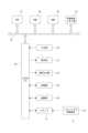
- FIG. 4is a block diagram showing an example of the internal configuration of the information processing device 1.
- the information processing device 1includes a memory section 10, a point cloud generation section 11, a control section 12, and a communication section 13, and these sections can perform data communication with each other via a bus 14. It is said that
- the memory unit 10is constituted by a nonvolatile memory such as an HDD (Hard Disk Drive) or an SDD (Solid State Drive), and is used to store various data handled by the information processing device 1.
- the memory unit 10stores a captured image obtained by the imaging device 3 capturing an image of the target area At. Specifically, these are a plurality of captured images obtained by capturing images of different areas within the target area At using the imaging device 3 mounted on the mobile body M.
- images captured by the imaging device 3are stored in the memory unit 10 via the communication unit 13.
- the imaging device 3sequentially transfers captured images to the information processing device 1 while imaging the target area At, and stores the captured images sequentially transferred in this way in the memory unit 10.
- information on the imaging position, imaging angle, and camera parametersis added to the captured image as metadata.
- the point cloud generation unit 11generates point cloud data indicating the three-dimensional structure of the target area At based on a plurality of captured images stored in the memory unit 10, which are captured images taken while moving over the target area At. generate.
- the point cloud generation unit 11generates point cloud data using SfM (Structure from Motion).
- SfMis a technique for determining the three-dimensional structure of an object and the camera position from a plurality of captured images captured while changing the viewpoint of the camera.
- point cloud data indicating the three-dimensional structure of an objectis generated based on the results of detecting corresponding points (same feature points) from a plurality of captured images captured while changing the camera viewpoint.
- the point cloud datahere includes coordinate information (X coordinate, Y coordinate, Z coordinate) in three-dimensional space and brightness values of R, G, and B for each recognized point (corresponding point above). It is generated as information that associates the
- the communication unit 13comprehensively represents a communication device that performs wired/wireless communication with various devices and communication processing via a transmission path such as the Internet.
- the information processing device 1is able to perform data communication with the imaging device 3 and the user terminal 2 via the communication unit 13.
- the control unit 12is configured with a microcomputer having, for example, a CPU, a ROM, a RAM, etc., and the CPU executes processing according to a program stored in the ROM or a program loaded in the RAM, so that information is stored. Performs overall control of the processing device 1. Specifically, the control unit 12 controls the point cloud data generation process by the point cloud generation unit 11, such as instructing execution of the process. Further, the control unit 12 performs data communication with the imaging device 3 and the user terminal 2 (CPU 21 described later) via the communication unit 13. In particular, in the case of the present embodiment, the control unit 12 indicates the imaging position information and imaging angle information included in the above-mentioned metadata and the arrangement position of the marker 4 for the plurality of captured images stored in the memory unit 10.
- Marker projection processing based on the marker position information, setting processing of the estimated marker existing range, processing of associating the information of the estimated marker existing range with the captured image, etc.are performed, but these processings performed by the control unit 12 are as follows. I will explain it again.
- FIG. 5is a block diagram showing an example of the internal configuration of the user terminal 2.
- the user terminal 2includes a CPU 21.
- the CPU 21executes various processes according to programs stored in the ROM 22 or a nonvolatile memory section 24 such as an EEP-ROM (Electrically Erasable Programmable Read-Only Memory), or a program loaded into the RAM 23 from the storage section 29. .
- the RAM 23also appropriately stores data necessary for the CPU 21 to execute various processes.
- the CPU 21, ROM 22, RAM 23, and nonvolatile memory section 24are interconnected via a bus 33.
- An input/output interface (I/F) 25is also connected to this bus 33 .
- the input/output interface 25is connected to an input section 26 consisting of an operator or an operating device.
- the input unit 26may be various operators or operating devices such as a keyboard, mouse, keys, dial, touch panel, touch pad, or remote controller.
- a user's operationis detected by the input unit 26, and a signal corresponding to the input operation is interpreted by the CPU 21.
- a display section 27made of an LCD (Liquid Crystal Display) or an organic EL (Electro-Luminescence) panel, and an audio output section 28 made of a speaker or the like, either integrally or separately.
- the display unit 27is used to display various information, and is configured by, for example, a display device provided in the housing of the computer device, a separate display device connected to the computer device, or the like.
- the display unit 27displays images for various image processing, moving images to be processed, etc. on the display screen based on instructions from the CPU 21. Further, the display unit 27 displays various operation menus, icons, messages, etc., ie, as a GUI (Graphical User Interface), based on instructions from the CPU 21.
- GUIGraphic User Interface
- the input/output interface 25may be connected to a storage section 29 made up of an HDD (Hard Disk Drive), a solid state memory, etc., and a communication section 30 made up of a modem or the like.
- a storage section 29made up of an HDD (Hard Disk Drive), a solid state memory, etc.
- a communication section 30made up of a modem or the like.
- the communication unit 30performs communication processing via a transmission path such as the Internet, and communicates with various devices by wired/wireless communication, bus communication, etc.
- a drive 31is also connected to the input/output interface 25 as necessary, and a removable storage medium 32 such as a magnetic disk, optical disk, magneto-optical disk, or semiconductor memory is appropriately installed.
- the drive 31can read data files such as programs used for each process from the removable storage medium 32.
- the read data fileis stored in the storage section 29, and images and sounds included in the data file are outputted on the display section 27 and the audio output section 28. Further, computer programs and the like read from the removable storage medium 32 are installed in the storage unit 29 as necessary.
- softwarefor the processing of this embodiment can be installed via network communication by the communication unit 30 or the removable storage medium 32.
- the softwaremay be stored in the ROM 22, storage unit 29, etc. in advance.
- the information processing device 1projects the position of the marker 4 onto the image plane of the captured image, and the marker projection which is the position of the projected marker 4 is performed.
- a processis performed in which the range on the image plane including the position is set as the estimated marker existing range, and the information on the estimated marker existing range is associated with the captured image.
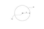
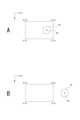
- FIG. 6is an explanatory diagram of marker projection processing.
- Pmrepresents the marker position (absolute coordinate position) of the marker 4 placed in the target area At.
- a marker position Pmis projected onto the image plane of each captured image, and marker projection on the image plane (that is, in the image coordinate system) is performed.
- Detect position Pm'is performed for each captured image for each marker 4.
- the marker projection processis performed using markers expressed as "N x M". This is performed for each combination of 4 and the captured image.
- the marker projection processis performed by the control unit 12. Specifically, the control unit 12 performs marker projection processing based on the imaging position information and imaging angle information given to the captured image, and the marker position information.
- the marker projection processmay be performed using the above-mentioned camera parameter information in addition to the imaging position information, imaging angle information, and marker position information.
- the marker position informationis known position information, and is stored in advance in a storage device such as the memory unit 10 that can be read by the control unit 12.
- the marker projection position Pm' of a plurality of markers 4may be displayed in one captured image as in the illustrated example. can be detected.
- control unit 12sets the range including the detected marker projection position Pm' on the image plane of the captured image as the estimated marker existing range Am.
- FIG. 7is an explanatory diagram of a method for setting the estimated marker existence range Am.
- the estimated marker existence range Amis a circular range.
- a range of a radius R from the marker projection position Pm'is set as the estimated marker existing range Am.
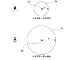
- control unit 12sets the size of the estimated marker existing range Am (that is, the radius R in this example) to the ground distance from the imaging position of the captured image for which the estimated marker existing range Am is set. Set variably depending on the situation.
- altitude information included in the imaging position information given to the captured imageis used as the ground distance from the imaging position of the captured image.
- the longer the distance from the groundthe larger the size of the estimated marker existing range Am, that is, the radius R, is set by the control unit 12.
- the control unit 12As explained above, marker projection onto the image plane of the captured image is performed based on the imaging angle information, but if there is an error in the imaging angle information, the longer the ground distance, the greater the error from the ideal position of the marker projection position. becomes larger. Therefore, as described above, the longer the distance from the ground, the larger the estimated marker existence range. As a result, it is possible to appropriately set the estimated marker existence range in consideration of the fact that the magnitude of the error in the marker projection position Pm' due to the error in the imaging angle information changes depending on the distance from the ground.
- the marker projection position Pm'is detected within the image frame range of the target captured image, as shown in FIG. 9A.
- the image coordinate system of the captured imagewill be expressed as a (u,v) coordinate system, as shown in FIGS. 9A and 9B.
- the image coordinate systemis assumed to be, for example, a coordinate system with the origin (0, 0) at the upper leftmost pixel of the captured image.
- the image frame range of the captured imageis (0, 0) (0, w) (h, 0) (h, w ) can be expressed as the range surrounded by the four points.
- a captured image in which the detected marker projection position Pm' is significantly away from the image frame rangeis an image in which the marker 4 is unlikely to be captured, and such an image It can be said that it is undesirable for the marker detection work to be displayed in order to improve work efficiency. Therefore, in the present embodiment, captured images in which the detected marker projection position Pm' is significantly away from the image frame range are excluded from the targets of association of the estimated marker existing range Am and the marker projection position Pm'.
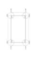
- FIG. 10illustrates the determination range set on the image plane of the captured image.
- the determination rangeis the image frame range of the captured image represented by the four points (0, 0) (0, w) (h, 0) (h, w) (the range indicated by the solid line in the figure).
- the first image frame rangeis expanded by 2R in the vertical direction using range (the dotted line range in the figure) and the four points (0, -2R) (0, w + 2R) (h, -2R) (h, w + 2R), which are the image frame range extended by 2R in the left and right directions.
- the second range represented(the range indicated by the dashed-dot line in the figure) and the third range, which is a range of radius 2R centered on the four corner points of the image frame range (the range indicated by the dashed-double line in the figure) Establish.
- the control unit 12determines, for each captured image, whether the detected marker projection position Pm' is located within any one of the first range, second range, and third range, and determines a positive result. If this is the case, a determination result is obtained that the captured image is a "marker-containing candidate image", which is an image in which the marker 4 is likely to be captured.
- control unit 12associates the information about the marker projection position Pm' detected for the captured image with the information about the estimated marker existing range Am for the captured image determined as a marker-containing candidate image. Specifically, information on the marker projection position Pm' detected for the captured image and information on the estimated marker existing range Am are associated only with the captured image determined as a marker-containing candidate image.
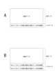
- FIG. 11Ashows an example of adding metadata when only the marker projection position Pm' and the estimated marker existence range Am for one marker 4 are obtained for the captured image of the target.
- FIG. 11Bshows an example of adding metadata when the marker projection position Pm' and the estimated marker existence range Am for the two markers 4 are obtained for the captured image of the target.
- the determination of whether or not the marker-containing candidate image is madeis not by determining whether the marker projection position Pm' is located within the image frame range, but by determining whether or not the marker projection position Pm' is located within the image frame range. It is determined whether or not the image plane is located within an image plane range that includes the image plane and a predetermined range outside the image frame range.
- the marker projection position Pm'may have an error from the ideal position, even if the marker projection position Pm' is calculated for the captured image in which the marker 4 actually appears, the marker projection position Pm' will not be the same as that of the captured image. It may be detected outside the image frame range. Therefore, by determining marker-containing candidate images based on the image plane range including the area outside the image frame range as described above, even if the marker 4 is actually shown, the marker projection position Pm' A captured image detected outside the image frame range can be correctly detected as a marker-containing candidate image. Therefore, the accuracy of determining marker-containing candidate images can be improved.
- the estimated marker existence range Amis a circular range
- the shape of the estimated marker existence range Amis not limited to a circle, and may be, for example, a triangle, a rectangle, a polygon, etc. It is possible to adopt the shape of
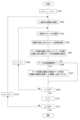
- FIG. 12is a flowchart showing an example of a specific processing procedure that should be executed by the control unit 12 (CPU) in order to realize the processing on the information processing device 1 side as the embodiment described above.
- the control unit 12resets the values of the image identifier m and the marker identifier n to 1 in step S101.
- the image identifier mis an identifier for identifying the captured image to be processed
- the marker identifier nis an identifier for identifying the marker 4 to be processed.
- step S102the control unit 12 performs a process of selecting the m-th captured image from among the plurality of captured images stored in the memory unit 10, as the process of selecting the m-th image.
- step S103the control unit 12 performs processing to select the n-th marker 4, and further in subsequent step S104, performs marker projection processing on the image plane. That is, based on the imaging position information and imaging angle information given to the selected captured image and the marker position information of the selected marker 4, the marker position Pm indicated by the marker position information is set on the image plane of the selected captured image. The marker projection position Pm' is detected.
- step S105 following step S104the control unit 12 sets an estimated marker existence range Am that includes the marker projection position Pm' determined by the marker projection process.
- the size of the estimated marker existence range Amis set according to the distance from the ground.
- step S106the control unit 12 determines whether the candidate image contains a marker. That is, as explained with reference to FIG. 10, the detected marker projection position Pm' is located within any of the first range, second range, and third range described above. Determine whether or not there is.
- step S106If it is determined in step S106 that the image is a marker-containing candidate image, the control unit 12 proceeds to step S107 and performs a process of associating information on the marker projection position Pm' and estimated marker existing range Am with the selected image. Specifically, in this example, as illustrated in FIG. 11, information on the marker projection position Pm' and the estimated marker existence range Am is added to the selected captured image as metadata, so that the captured image is The marker projection position Pm' and the information on the estimated marker existence range Am are associated with each other. In response to performing the association process in step S106, the control unit 12 advances the process to step S107.
- step S106determines whether the image is a marker-containing candidate image. If it is determined in step S106 that the image is not a marker-containing candidate image, the control unit 12 passes the process in step S106 and advances the process to step S107. That is, the information on the marker projection position Pm' and the estimated marker existing range Am is not associated with the captured image that is determined not to be a marker-containing candidate image.
- step S107the control unit 12 determines whether the value of the marker identifier n has reached N (the total number of markers 4). This includes setting the marker projection and estimated marker existence range Am for all markers 4, determining whether or not the image is a marker-containing candidate image, and determining whether the image is a marker-containing candidate image for the selected M-th captured image. This corresponds to determining whether or not the marker projection position Pm' and the estimated marker existing range Am have been associated.
- step S108If it is determined in step S108 that the value of the marker identifier n has not reached N, the control unit 12 proceeds to step S109, increments the value of the marker identifier n by 1, and returns to step S103.
- step S108determines whether the value of the marker identifier n has not reached N
- the control unit 12proceeds to step S110, resets the value of the marker identifier n to 1, and then proceeds to step S111 to reset the value of the image identifier m. It is determined whether the value has reached M (total number of captured images). If the value of the image identifier m has not reached M, the control unit 12 proceeds to step S112, increments the value of the image identifier m by 1, and returns to step S102.
- marker projection for all markers 4setting of estimated marker existence range Am, determination of whether the image is a marker-containing candidate image, and marker projection position in the case of a marker-containing candidate image.
- Pm' and the estimated marker existence range Amare associated with each other.
- step S111if it is determined in step S111 that the value of the image identifier m has reached M, the control unit 12 ends the series of processes shown in FIG.
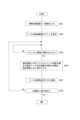
- FIG. 13is a flowchart showing the processing executed by the user terminal 2 as an embodiment. The process shown in FIG. 13 is executed by the CPU 21 in the user terminal 2 based on a program stored in a predetermined storage device such as the storage unit 29, for example.
- step S201the CPU 21 performs a process of inputting an image from the information processing device 1. That is, by data communication via the communication unit 30, the information processing device 1 performs a process of storing a plurality of captured images (M captured images) that have undergone the process shown in FIG. 12 in the storage unit 29.
- M captured imagesa plurality of captured images
- the captured image as the marker-containing candidate imagemay be associated with information about the marker projection position Pm' and the estimated marker existing range Am for a plurality of markers 4.
- step S202 following step S201the CPU 21 performs processing to display a list of marker-containing candidate images.
- FIG. 14shows an example of the work screen Gs displayed on the display screen 27a of the display unit 27.
- the work screen Gsis a screen displayed on the display screen 27a when the user performs marker detection work.
- the work screen Gsis provided with an image display area Ag.
- This image display area Agis an area for presenting the content of the captured image to the user during marker detection work.
- the CPU 21displays a list Ls of captured images as illustrated in FIG. 14 on this work screen Gs.
- This list Lsdisplays at least a list of image identification information such as file names of captured images as marker-containing candidate images.
- thumbnail images of captured imagesare displayed together with image identification information.
- the CPU 21performs a process of displaying a captured image selected by the user from the list of captured images displayed in the list Ls in the image display area Ag.
- the captured image as a marker-containing candidate imageis preferentially displayed on the work screen Gs (over the captured image that is not a marker-containing candidate image). (displayed with priority).
- a method for preferentially displaying marker-containing candidate imagesis not limited to this.
- a methodmay be considered in which a candidate image including a marker is automatically displayed in the image display area Ag without accepting the user's image selection operation. In this case, it is conceivable to display the next marker-containing candidate image in the image display area Ag in response to completion of designation of the position of the marker 4 in the currently displayed marker-containing candidate image.
- step S203the CPU 21 waits until an image is selected from the list Ls, and if an image is selected, in step S204, the CPU 21 moves to a marker projection position Pm' associated with the selected image. Then, a process is performed to display visualization information of the estimated marker existing range Am together with the selected image.
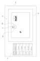
- FIG. 15shows an example of a display mode of a captured image and visualization information of the marker projection position Pm' and estimated marker existing range Am associated with the captured image.
- the captured image selected from the list Lsis displayed in the image display area Ag of the work screen Gs.
- marker position visualization information Vpm and marker range visualization informationas illustrated in the figure, respectively. Display Vam.
- the marker position visualization information Vpm and the marker range visualization information Vamare the positions in the image coordinate system indicated by the information of the marker projection position Pm' and the information of the estimated marker existing range Am, respectively, which are associated with the captured image. Display in the position according to the information.
- the marker projection position Pm'is not necessarily detected within the image frame range of the captured image, and the marker position visualization information Vpm is illustrated in FIG.
- the imagemay be displayed at a position outside the image frame of the captured image.
- at least a portion of the marker range visualization information Vammay be displayed extending outside the image frame range of the captured image.
- the marker position visualization information Vpmis displayed outside the image frame range of the captured image, or at least a part of the marker range visualization information Vam protrudes outside the image frame range of the captured image. Assuming this, the size of the image display area Ag is made larger than the image frame size of the captured image.
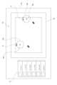
- information on the marker projection position Pm' and the estimated marker existence range Ammay be associated with a plurality of markers 4 depending on the captured image, so as illustrated in FIG. , on the work screen Gs, marker position visualization information Vpm and marker range visualization information Vam for a plurality of markers 4 may be displayed for displaying one captured image.
- the marker range visualization information Vamis displayed as visualization information including marker identification information Vr indicating which marker's estimated marker existence range Am belongs to (see FIG. 15). (See Figure 17). Specifically, in this example, information indicating the identification number of the marker 4 is displayed as the marker identification information Vr. This makes it possible to facilitate the task of identifying which marker 4 captured in the displayed captured image is.
- the method of displaying the visualization information of the estimated marker existence range in such a way as to indicate which marker the estimated marker existence range belongs tothere is a method of displaying the marker identification information Vr indicating the marker identification number as described above. It is not limited to.
- Vrindicating the marker identification number
- each marker 4define the color and shape of the marker range visualization information Vam corresponding to that marker 4, and display the marker range visualization information Vam with the color and shape corresponding to the marker 4. can also be considered.
- step S205 following step S204the CPU 21 executes marker position designation acceptance processing. That is, this is a process of accepting an operation for specifying the position of the marker 4 by the user in the display state of the captured image, the marker position visualization information Vpm, and the marker range visualization information Vam as illustrated in FIGS. 15 to 17.
- the operation of specifying the position of the marker 4may be, for example, an operation of specifying the position by dragging the displayed marker position visualization information Vpm.
- the CPU 21advances the process to step S206.
- step S206the CPU 21 determines whether the processing end condition is satisfied. That is, it is determined whether or not a predetermined condition, such as an operation to close the work screen Gs, which is determined in advance as a process end condition, is met.
- step S206If it is determined in step S206 that the processing end condition is not satisfied, the CPU 21 returns to step S203. This allows the user to select and display the next captured image (in this example, a marker-containing candidate image) from the list Ls, and to specify the marker position for the selected captured image.
- a marker-containing candidate imagein this example, a marker-containing candidate image
- step S206if it is determined in step S206 that the processing end condition is satisfied, the CPU 21 ends the series of processing shown in FIG.
- the present technologyis not limited to the above-described specific example, and can take configurations as various modified examples.
- an examplewas given in which information on the estimated marker existing range Am is added as metadata of the captured image.
- the information on the range Ammay be associated with other methods, such as by generating correspondence information indicating the correspondence between image identification information such as the file name of the captured image and the estimated marker existing range Am. can.
- the display control unitin this example, the CPU 21
- the display unit 27the display unit 27
- the display control unit 27the device including the display control section and the device including the display section are separate bodies.
- a devicethat performs marker projection processing on a captured image and a matching process of information on estimated marker existence range Am is separated from a device (user terminal 2) having the above-mentioned display control unit.
- a deviceuser terminal 2 having the above-mentioned display control unit.
- the device that performs the marker projection process on the captured image and the process of associating information on the estimated marker existing range Amis configured integrally with the imaging device that performs the image capture of the target area At.
- a flying objectwas cited as an example of the moving object M for moving the imaging device according to the present technology, but the moving object M is not limited to a flying object.
- a traveling objectsuch as a vehicle that supports a rod-shaped member (long object) with an imaging device attached to the tip, it is possible to move from a high place to the ground side, similar to when using a flying object. It is possible to take images while
- the information processing apparatus (1)uses information indicating the imaging position of the captured image obtained by imaging the target area (At) where the marker (4) is placed. Projecting the position of the marker on the image plane of the captured image based on certain imaging position information, imaging angle information that is information indicating the imaging angle of the captured image, and marker position information that is information indicating the arrangement position of the marker,
- the range on the image plane including the marker projection position (Pm'), which is the position of the projected markeris set as the estimated marker existence range (Am), and the process of associating the information of the estimated marker existence range with the captured image is performed. It is equipped with an arithmetic unit (control unit 12) that performs the calculation.
- the marker detection workmay be automated by, for example, performing a process of specifying the marker position within the image using image recognition processing of the captured image.
- performing image recognition processing for identifying marker positions individually for each marker on a large number of captured images of a target areaincreases the processing load and processing time on the information processing device.
- at least only marker projection processingneeds to be performed as image analysis for the captured image, and the processing load and processing time can be significantly reduced compared to the case where image recognition processing is performed. can.
- the information processing apparatusincludes a point cloud generation unit (11) that generates a three-dimensional point cloud of the target area based on a plurality of captured images obtained by capturing the target area from different positions. We are prepared. Thereby, it is possible to improve the efficiency of marker detection work that targets a plurality of captured images taken for three-dimensional surveying of a target area.
- the calculation unitselects a plurality of captured images obtained by capturing the target area from different positions within a predetermined image plane range based on the image frame range.
- a captured image in which a marker projection position is locatedis detected as a marker-containing candidate image, and information on an estimated marker existing range is associated with the marker-containing candidate image.
- the calculation unitdetermines whether the image is a marker-containing candidate image or not on an image plane in which the marker projection position includes an image frame range and a predetermined range outside the image frame range. It is determined whether the location is within the range (see FIG. 10). Since the marker projection position may have an error from the ideal position, even if the marker projection position is determined for a captured image in which the marker actually appears, the marker projection position may be outside the image frame range of the captured image. may be detected. Therefore, as described above, by determining marker-containing candidate images based on the image plane range that includes the area outside the image frame range, even if the marker is actually shown, the marker projection position is not within the image frame. It becomes possible to correctly detect a captured image detected outside the range as a marker-containing candidate image. Therefore, the accuracy of determining marker-containing candidate images can be improved.
- the calculation unitvariably sets the size of the estimated marker existence range for the captured image according to the ground distance from the imaging position of the captured image (FIG. 8 reference). Marker projection onto the image plane of the captured image is performed based on the imaging angle information, but if there is an error in the imaging angle information, the longer the ground distance, the greater the error from the ideal position of the marker projection position. Therefore, by variably setting the size of the estimated marker existing range according to the ground distance as described above, it becomes possible to increase the size of the estimated marker existing range as the ground distance becomes longer. Therefore, it is possible to appropriately set the estimated marker existence range in consideration of the fact that the magnitude of the error in the marker projection position due to the error in the imaging angle information changes depending on the distance from the ground.
- the estimated marker existing rangeis a circular range
- the calculation unitvariably sets the size of the radius of the estimated marker existing range according to the distance from the ground.
- the information processing apparatuscollects imaging position information, which is information indicating the imaging position of a captured image obtained by imaging a target area where a marker is placed, and an imaging angle of the captured image.
- the position of the markeris projected onto the image plane of the captured image based on the imaging angle information, which is information indicating the location of the marker, and the marker position information, which is information indicating the placement position of the marker, and the marker projection position, which is the position of the projected marker, is determined.
- Thisis an information processing method that sets a range on an image plane including the estimated marker existing range as an estimated marker existing range, and performs a process of associating information on the estimated marker existing range with a captured image. With such an information processing method, the same operations and effects as those of the information processing apparatus as the embodiment described above can be obtained.
- the display control devicedetects a captured image obtained by capturing a target area in which a marker is placed, on the image plane by projecting the position of the marker on the image plane.
- Itis equipped with a display control unit (CPU 21) that performs the following.
- the display control unitgives priority to the captured image to which the information of the estimated marker existence range is associated, over the captured image to which the information of the estimated marker existence range is not associated. It is controlled so that it is displayed. For example, by presenting a list of captured images associated with information on the estimated marker existing range to the user and having the user select a display image from the list, the captured image associated with the information on the estimated marker existing range is prioritized. to be displayed. Thereby, it is possible to prevent a captured image that is unlikely to include a marker from being displayed, and it is possible to improve the efficiency of marker detection work.
- a plurality of markersare arranged in the target area, and information on the estimated marker existence range is associated with each marker in the captured image, and the display control unit is configured to Visualization information of the estimated marker existing range is displayed on the display unit so as to indicate whether the estimated marker existing range is within the estimated marker existing range.
- the display control devicecaptures a captured image obtained by capturing a target area in which markers are arranged, and projects the position of the marker onto the image plane.
- Visualization information of the estimated marker existing rangeis displayed on the display unit along with the captured image for the captured image to which the information of the estimated marker existing range is associated, which is set as the range on the image plane including the marker projection position detected in
- Thisis a display control method that performs processing to Such a display control method also provides the same functions and effects as the display control device as the embodiment described above.
- Imaging position informationwhich is information indicating the imaging position of a captured image obtained by imaging the target area where the marker is placed
- imaging angle informationwhich is information indicating the imaging angle of the captured image
- placement position of the markerThe position of the marker is projected onto the image plane of the captured image based on the marker position information, which is information indicating the marker position, and the range on the image plane including the marker projection position, which is the projected position of the marker, is estimated.
- An information processing devicecomprising: a calculation unit that performs a process of setting information on the estimated marker existence range as an existence range and associating information of the estimated marker existence range with the captured image.
- the information processing devicefurther comprising a point cloud generation unit that generates a three-dimensional point group of the target area based on the plurality of captured images obtained by capturing the target area from different positions.
- the arithmetic unitis Among the plurality of captured images obtained by capturing the target area from different positions, captured images in which the marker projection position is located within a predetermined image plane range based on the image frame range are selected as marker-containing candidate images.
- the information processing deviceaccording to (1) or (2) above, wherein information about the estimated marker existing range is associated with the marker-containing candidate image.
- the arithmetic unitis In determining whether the image is a marker-containing candidate image, it is determined whether the marker projection position is located within an image plane range that includes the image frame range and a predetermined range outside the image frame range.
- the information processing deviceaccording to (3).
- the arithmetic unitis The information processing device according to any one of (1) to (4), wherein the size of the estimated marker existing range for the captured image is variably set according to the ground distance from the imaging position of the captured image.
- the estimated marker existence rangeis a circular range
- the arithmetic unitis The information processing device according to (5), wherein the size of the radius of the estimated marker existing range is variably set according to the distance from the ground.
- the information processing deviceImaging position information, which is information indicating the imaging position of a captured image obtained by imaging the target area where the marker is placed; imaging angle information, which is information indicating the imaging angle of the captured image; and the placement position of the marker.
- the position of the markeris projected onto the image plane of the captured image based on the marker position information, which is information indicating the marker position, and the range on the image plane including the marker projection position, which is the projected position of the marker, is estimated.
- An information processing methodcomprising: setting the estimated marker existing range as an existing range, and performing a process of associating information of the estimated marker existing range with the captured image.
- the display control unitincludes a display control unit that performs a process of displaying visualization information of the estimated marker existing range on a display unit together with the captured image, with respect to the captured image to which information of the estimated marker existing range set as a range is associated.
- Display control device.(9)
- the display control sectionincludes: In (8) above, controlling the captured image to which the information on the estimated marker existing range is associated is displayed preferentially over the captured image to which the information on the estimated marker existing range is not associated. The display control device described.
- the display control sectionincludes: The display control device according to (8) or (9), wherein visualization information of the estimated marker existing range is displayed on the display unit so as to indicate which marker is in the estimated marker existing range.
- the display control deviceis A captured image obtained by imaging a target area in which markers are arranged, the image including a marker projection position detected on the image plane by projecting the position of the marker onto the image plane.
- a display control methodthat performs a process of displaying visualization information of the estimated marker existing range on a display unit together with the captured image for the captured image to which information of the estimated marker existing range set as a range is associated.
- Information processing device 2User terminal 3 Imaging device 4 Marker M Mobile object At Target area Pi Imaging execution point Rf Flight route 10 Memory unit 11 Point cloud generation unit 12 Control unit 13 Communication unit 14 Bus 21 CPU 22 ROM 23 RAM 24 Nonvolatile memory section 25 Input/output interface 26 Input section 27 Display section 27a Display screen 28 Audio output section 29 Storage section 30 Communication section 31 Drive 32 Removable storage medium 33 Bus Pm Marker position Pm' Marker projection position Am Estimated marker existence range R Radius Gs Work screen Ag Image display area Ls List Vam Marker range visualization information Vpm Marker position visualization information Vr Marker identification information
Landscapes
- Engineering & Computer Science (AREA)
- Physics & Mathematics (AREA)
- General Physics & Mathematics (AREA)
- Remote Sensing (AREA)
- Multimedia (AREA)
- Radar, Positioning & Navigation (AREA)
- Geometry (AREA)
- Software Systems (AREA)
- Computer Graphics (AREA)
- Theoretical Computer Science (AREA)
- Processing Or Creating Images (AREA)
Abstract
Description
Translated fromJapanese本技術は、情報処理装置とその方法、表示制御装置とその方法とに関し、特には、マーカが配置された対象地域を撮像して得られた撮像画像の表示画像に基づいてユーザがマーカ検出作業を行う場合に好適な情報処理技術及び表示制御技術に関する。The present technology relates to an information processing device and its method, and a display control device and its method, and in particular, the present technology relates to an information processing device and its method, and a display control device and its method. The present invention relates to information processing technology and display control technology suitable for performing.
上空からドローン等の移動体を用いて地面側を撮像した複数の撮像画像に基づいて、対象地域の三次元構造を示す三次元点群を生成し、対象地域の三次元測量を実現する技術がある。具体的には、対象地域上を移動しながら撮像した複数の撮像画像に基づき、SfM(Structure from Motion)等の手法により対象地域の三次元点群を生成する技術等が知られている。A technology that realizes 3D surveying of a target area by generating a 3D point cloud showing the 3D structure of the target area based on multiple captured images of the ground side taken from above using a mobile object such as a drone. be. Specifically, techniques are known that generate a three-dimensional point cloud of a target area using a method such as SfM (Structure from Motion) based on a plurality of captured images taken while moving over the target area.
上記のような対象地域の三次元測量を行う場合には、GPS(Global Positioning System)センサ等のGNSS(Global Navigation Satellite System)センサによる位置検出精度とその不安定性に由来する不確かさが存在する。この不確かさを検証したりキャリブレーション(校正)したりするためには、Ground Truthとして絶対位置座標が既知の地上点が必要となる。このため、対象地域にGround Truthとして機能するマーカを配置するということが行われる。
マーカがどの撮像画像におけるどの位置に写されているかを特定することで、絶対座標系におけるマーカ位置と画像座標系におけるマーカ位置との対応関係が特定されるため、マーカ位置の理想位置からの誤差を求めることができる。そして、この誤差の情報に基づき、生成した点群データの精度を評価したり、また上記したGNSSセンサの精度に起因する絶対座標位置の検出誤差についてのキャリブレーション等を行うことが可能とされる。When performing a three-dimensional survey of a target area as described above, there is uncertainty due to the accuracy and instability of position detection by GNSS (Global Navigation Satellite System) sensors such as GPS (Global Positioning System) sensors. In order to verify or calibrate this uncertainty, a ground point whose absolute position coordinates are known is required as the ground truth. For this reason, markers that function as ground truth are placed in the target area.
By identifying the position of the marker in which captured image, the correspondence between the marker position in the absolute coordinate system and the marker position in the image coordinate system can be determined. can be found. Based on this error information, it is possible to evaluate the accuracy of the generated point cloud data and to calibrate the detection error of the absolute coordinate position due to the accuracy of the GNSS sensor mentioned above. .
なお、関連する従来技術については下記特許文献1を挙げることができる。この特許文献1には、配置位置が既知であるマーカを用いた校正技術が開示されている。Note that the following
ここで、実際にマーカを活用するためには、下記の二つの作業が必要とされている。
1)衛星測位やレーザ測距等により配置したマーカの絶対座標を測定する
2)撮像画像について、どの画像のどの位置にどのマーカが写っているかを特定するHere, in order to actually utilize the marker, the following two operations are required.
1) Measure the absolute coordinates of the placed marker using satellite positioning, laser ranging, etc. 2) Identify which marker is in which position in which image of the captured image
これらのうち、上記2)の作業は、現状では、対象地域を撮像して得られた複数の撮像画像をユーザが画面上で閲覧してどの画像のどの位置にどのマーカが写っているかを特定する作業とされている。具体的に、この作業においてユーザは、マーカごとに、そのマーカが写っている画像について画像内の位置を指定する操作を装置に対して行うようにされている。装置側では、このようなユーザの指定操作に基づき、マーカごとに、そのマーカがどの画像のどの位置(画像座標系における位置)に写っているかという対応関係を示すデータを生成する処理が行われ、この対応関係データが、上述した点群精度評価や絶対座標位置のキャリブレーション等に用いられる。
以下、上記のように対象地域を撮像して得られた複数の撮像画像をユーザが画面上で閲覧し、マーカが写っている画像について画像内のマーカ位置を指定する作業のことを「マーカ検出作業」と表記する。Among these, the task 2) above is currently performed by the user viewing multiple images obtained by capturing the target area on the screen and identifying which marker is in which position in which image. It is considered to be a work to do. Specifically, in this work, the user performs an operation on the device to specify, for each marker, the position within the image in which the marker appears. On the device side, based on the user's specified operation, processing is performed to generate data indicating the correspondence relationship of which image and which position (position in the image coordinate system) the marker appears in for each marker. This correspondence relationship data is used for the above-mentioned point cloud accuracy evaluation, absolute coordinate position calibration, and the like.
Hereinafter, we will refer to the task of "marker detection" in which the user views multiple captured images obtained by capturing the target area as described above on the screen and specifies the marker position in the image for the image containing the marker. "Work".
しかしながら、上記のようなマーカ検出作業では、ユーザは、対象地域を撮像した大量の撮像を閲覧してそこからマーカが写っている画像の特定や、写っているマーカの同定(どのマーカであるかの特定)、さらにそのマーカの画像内における位置の指定を行うことを要し、作業負担が膨大となる。However, in the above-mentioned marker detection work, the user views a large number of images taken of the target area, and from there, identifies images that include markers, and identifies markers (which markers are included). In addition, it is necessary to specify the position of the marker in the image, resulting in an enormous workload.
本技術は上記事情に鑑み為されたものであり、マーカ検出作業の効率化を図ることを目的とする。This technology was developed in view of the above circumstances, and its purpose is to improve the efficiency of marker detection work.
本技術に係る情報処理装置は、マーカが配置された対象地域を撮像して得られた撮像画像の撮像位置を示す情報である撮像位置情報と、前記撮像画像の撮像アングルを示す情報である撮像アングル情報と、前記マーカの配置位置を示す情報であるマーカ位置情報とに基づき、前記撮像画像の画像平面に前記マーカの位置を投影し、投影された前記マーカの位置であるマーカ投影位置を含む前記画像平面上の範囲を推定マーカ存在範囲として設定し、前記推定マーカ存在範囲の情報を前記撮像画像に対応づける処理を行う演算部を備えたものである。
上記のように撮像画像に推定マーカ存在範囲の情報を対応づけることで、撮像画像の表示時において、撮像画像と共に推定マーカ存在範囲の視覚化情報を表示することが可能となり、ユーザは、表示された推定マーカ存在範囲を元に、撮像画像内に写されたマーカの同定やマーカ位置の特定をし易くなる。The information processing device according to the present technology includes imaging position information that is information indicating the imaging position of a captured image obtained by imaging a target area where a marker is placed, and imaging position information that is information indicating the imaging angle of the captured image. Projecting the position of the marker onto the image plane of the captured image based on angle information and marker position information that is information indicating the placement position of the marker, and including a marker projection position that is the projected position of the marker. The apparatus includes a calculation unit that sets a range on the image plane as an estimated marker existing range and performs a process of associating information on the estimated marker existing range with the captured image.
By associating information about the estimated marker existing range with the captured image as described above, when displaying the captured image, it becomes possible to display visualization information about the estimated marker existing range together with the captured image, and the user can Based on the estimated marker existence range, it becomes easier to identify the marker captured in the captured image and to specify the marker position.
また、本技術に係る情報処理方法は、情報処理装置が、マーカが配置された対象地域を撮像して得られた撮像画像の撮像位置を示す情報である撮像位置情報と、前記撮像画像の撮像アングルを示す情報である撮像アングル情報と、前記マーカの配置位置を示す情報であるマーカ位置情報とに基づき、前記撮像画像の画像平面に前記マーカの位置を投影し、投影された前記マーカの位置であるマーカ投影位置を含む前記画像平面上の範囲を推定マーカ存在範囲として設定し、前記推定マーカ存在範囲の情報を前記撮像画像に対応づける処理を行う情報処理方法である。
このような情報処理方法によっても、上記した本技術に係る情報処理装置と同様の作用が得られる。Further, in the information processing method according to the present technology, the information processing device collects imaging position information, which is information indicating the imaging position of a captured image obtained by imaging a target area in which a marker is placed, and an imaging position of the captured image. The position of the marker is projected onto the image plane of the captured image based on imaging angle information, which is information indicating the angle, and marker position information, which is information indicating the arrangement position of the marker, and the projected position of the marker is In this information processing method, a range on the image plane including a marker projection position is set as an estimated marker existing range, and information on the estimated marker existing range is associated with the captured image.
Such an information processing method also provides the same effect as the information processing device according to the present technology described above.
また、本技術に係る表示制御装置は、マーカが配置された対象地域を撮像して得られた撮像画像であって、画像平面に前記マーカの位置を投影することによって前記画像平面上に検出されたマーカ投影位置を含む前記画像平面上の範囲として設定された推定マーカ存在範囲の情報が対応づけられた前記撮像画像について、前記推定マーカ存在範囲の視覚化情報を、前記撮像画像と共に表示部に表示させる処理を行う表示制御部を備えたものである。
これにより、マーカ検出作業のために撮像画像を表示する場合に対応して、撮像画像と共に、推定マーカ存在範囲の視覚化情報を表示することが可能となり、ユーザは、表示された推定マーカ存在範囲を元に、撮像画像内に写されたマーカの同定やマーカ位置の特定をし易くなる。The display control device according to the present technology also provides a captured image obtained by capturing a target area in which a marker is placed, which is detected on the image plane by projecting the position of the marker onto the image plane. With respect to the captured image to which information of the estimated marker existing range set as a range on the image plane including the projected marker projection position is associated, visualization information of the estimated marker existing range is displayed on a display unit together with the captured image. It is equipped with a display control section that performs display processing.
As a result, when displaying a captured image for marker detection work, it becomes possible to display visualization information of the estimated marker existing range along with the captured image, and the user can view the displayed estimated marker existing range. Based on this, it becomes easier to identify the marker captured in the captured image and to specify the marker position.
また、本技術に係る表示制御方法は、表示制御装置が、マーカが配置された対象地域を撮像して得られた撮像画像であって、画像平面に前記マーカの位置を投影することによって前記画像平面上に検出されたマーカ投影位置を含む前記画像平面上の範囲として設定された推定マーカ存在範囲の情報が対応づけられた前記撮像画像について、前記推定マーカ存在範囲の視覚化情報を、前記撮像画像と共に表示部に表示させる処理を行う表示制御方法である。
このような表示制御方法によっても、上記した本技術に係る表示制御装置と同様の作用が得られる。Further, in the display control method according to the present technology, the display control device captures a captured image obtained by capturing an image of a target area in which markers are arranged, and projects the position of the marker on an image plane. With respect to the captured image associated with the information of the estimated marker existing range set as the range on the image plane including the marker projection position detected on the plane, the visualization information of the estimated marker existing range is added to the captured image. This is a display control method that performs processing to display an image on a display unit.
Such a display control method also provides the same effect as the display control device according to the present technology described above.
以下、添付図面を参照し、本技術に係る実施形態を次の順序で説明する。
<1.実施形態としての測量システムの概要>
<2.装置構成>
(2-1.情報処理装置の構成)
(2-2.表示制御装置の構成)
<3.マーカ存在範囲の推定及び範囲情報の対応づけ処理>
<4.表示制御側の処理>
<5.変形例>
<6.実施形態のまとめ>
<7.本技術>
Hereinafter, embodiments of the present technology will be described in the following order with reference to the accompanying drawings.
<1. Overview of surveying system as an embodiment>
<2. Device configuration>
(2-1. Configuration of information processing device)
(2-2. Configuration of display control device)
<3. Estimation of marker existence range and matching process of range information>
<4. Display control side processing>
<5. Modified example>
<6. Summary of embodiments>
<7. This technology>
<1.実施形態としての測量システムの概要>
図1は、本技術に係る実施形態としての測量システムの構成概要を例示した図である。
実施形態の測量システムは、本技術に係る情報処理装置の一実施形態である情報処理装置1と、本技術に係る表示制御装置の一実施形態としてのユーザ端末2と、撮像装置3とを少なくとも備えて構成されるシステムとなる。
情報処理装置1、及びユーザ端末2は、CPU(Central Processing Unit)、ROM(Read Only Memory)、及びRAM( Random Access Memory)等を有するコンピュータ装置として構成されている。<1. Overview of surveying system as an embodiment>
FIG. 1 is a diagram illustrating an overview of the configuration of a surveying system as an embodiment of the present technology.
The surveying system of the embodiment includes at least an
The
撮像装置3は、例えばCMOS(Complementary Metal Oxide Semiconductor)型やCCD(Charge Coupled Device)型等のイメージセンサを備えて構成され、被写体を撮像した撮像画像を得る。本例において撮像装置3は、R(赤)光、B(青)光、G(緑)光を個別に受光するためのカラーフィルタを有し、これらR光、B光、G光の受光信号に基づいて撮像画像としてカラー画像を得るRGBカメラとして構成されている。The
本例において撮像装置3は、移動体Mに搭載されている。移動体Mは、撮像装置3を搭載したまま移動を行うことが可能とされた物体を広く意味する。本例では、移動体Mは、例えばドローンや飛行機、ヘリコプター等の飛行体とされる。In this example, the
実施形態の測量システムでは、撮像装置3を搭載した移動体Mを、例えば建設現場等の対象地域Atの上空で移動させながら、撮像装置3により対象地域Atを撮像させる。このとき、撮像装置3による撮像は、対象地域Atを複数の区域に区切って、区域ごとに行う。すなわち、対象地域Atの撮像画像として、対象地域Atのそれぞれ異なる区域を撮像した複数枚の撮像画像を得る。In the surveying system of the embodiment, the moving body M equipped with the
具体的な三次元測量の手法を、図2を参照して説明する。
図示のように本実施形態では、対象地域Atには複数の撮像実行地点Piが設定されている。本実施形態では、移動体Mの飛行ルートRfとして、このように対象地域Atに設定された複数の撮像実行地点Piを通る飛行ルートRfが定められており、移動体Mをこの飛行ルートRfに従って飛行させながら、撮像装置3が各撮像実行地点Piで地面側を撮像することで、撮像実行地点Piごとに、撮像画像に基づく三次元点群の生成を行う。そして、測量システムでは、このように撮像実行地点Piごとに得られた三次元点群の情報に基づき、対象地域At全体の三次元構造を示す点群データの生成が行われる。換言すれば、対象地域At全体についての三次元測量結果を示す測量データが得られる。A specific three-dimensional surveying method will be explained with reference to FIG. 2.
As shown in the figure, in this embodiment, a plurality of imaging execution points Pi are set in the target area At. In this embodiment, a flight route Rf passing through a plurality of imaging execution points Pi set in the target area At is determined as the flight route Rf of the mobile body M, and the mobile body M is guided along this flight route Rf. While flying, the
本例では、三次元点群の生成は、情報処理装置1が、撮像装置3により撮像された複数の撮像画像を入力し、それら撮像画像に基づいて行うことになるが、この三次元点群の生成にあたっては、撮像画像の座標系(以下「画像座標系」と表記する)と絶対座標系(ワールド座標系)との間での座標変換処理を要する。この座標変換処理には、撮像画像の撮像位置(絶対座標系における位置)を示す情報である撮像位置情報と、撮像画像の撮像アングルを示す情報である撮像アングル情報と、撮像時の焦点距離や撮像素子のサイズ、画素数等といったカメラパラメータの情報とを要する。
本例では、これら撮像位置情報、撮像アングル情報、及びカメラパラメータの情報は、撮像装置3が撮像画像に対しメタデータとして付与するものとされている。このメタデータ付きの撮像画像を情報処理装置1が入力することで、情報処理装置1は、三次元点群生成のための上記した座標変換処理を行うことが可能とされる。
なお、上記のメタデータ生成のために、撮像装置3には、撮像位置情報を取得するための例えばGPS(Global Positioning System)センサ等のGNSS(Global Navigation Satellite System)センサ、及び、撮像アングル情報を取得するためのジャイロセンサや方位角センサを備えている。ここで、本例において、撮像位置情報は、三次元空間上の位置を示す情報であり、高度(対地距離)の情報も含むものとされる。In this example, the
In this example, the
In order to generate the above metadata, the
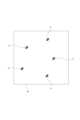
また、本例において、対象地域Atには、図3に示すように複数のマーカ4が配置されている。
これらマーカ4は、前述した点群データの精度評価やGNSSセンサの精度に起因する絶対座標位置の検出誤差についてのキャリブレーションを行うにあたってのGround Truthとして機能させるマーカである。Furthermore, in this example, a plurality of
These
図1において、ユーザ端末2は、ユーザによる使用が想定される、情報処理装置1とは別の装置であり、本例では、可搬性を有するコンピュータ装置とされる。ユーザ端末2の具体的な装置形態としては、例えばスマートフォンやタブレット端末、ノートブック型のパーソナルコンピュータ等を挙げることができる。或いは、ユーザ端末2の装置形態としては、スマートグラスやヘッドマウントディスプレイ等の形態も考えられ得る。In FIG. 1, the
本例において、ユーザ端末2は、情報処理装置1が生成した対象地域Atについての三次元点群を視覚化した情報をユーザに表示する処理を行う。
また、特に本実施形態において、ユーザ端末2は、前述したマーカ検出作業のためにユーザに用いられる。確認のため述べておくと、マーカ検出作業とは、対象地域Atを撮像して得られた複数の撮像画像をユーザが画面上で閲覧し、マーカが写っている画像について画像内のマーカ位置を指定する作業のことを意味する。
In this example, the
Further, particularly in this embodiment, the
<2.装置構成>
(2-1.情報処理装置の構成)
図4は、情報処理装置1の内部構成例を示したブロック図である。
図示のように情報処理装置1は、メモリ部10、点群生成部11、制御部12、及び通信部13を備えており、これら各部がバス14を介して相互にデータ通信を行うことが可能とされている。<2. Device configuration>
(2-1. Configuration of information processing device)
FIG. 4 is a block diagram showing an example of the internal configuration of the
As shown in the figure, the
メモリ部10は、例えばHDD(Hard Disk Drive)やSDD(Solid State Drive)等の不揮発性のメモリにより構成され、情報処理装置1で扱われる各種データの記憶に用いられる。
本例において、メモリ部10には、撮像装置3が対象地域Atを撮像して得られた撮像画像が記憶される。具体的には、移動体Mに搭載された撮像装置3により、対象地域At内のそれぞれ異なる区域を撮像した複数枚の撮像画像である。
本例において、撮像装置3による撮像画像は、通信部13を介してメモリ部10に記憶される。例えば、撮像装置3による対象地域At全体の撮像完了後に、撮像装置3から全撮像画像を情報処理装置1に転送させてメモリ部10に記憶させることが考えられる。或いは、撮像装置3が対象地域Atの撮像中に順次撮像済みの撮像画像を情報処理装置1に転送し、このように順次転送される撮像画像をメモリ部10に記憶させることも考えられる。The
In this example, the
In this example, images captured by the
また、前述のように、撮像画像には、メタデータとして、撮像位置情報、撮像アングル情報、及びカメラパラメータの情報が付与されている。Furthermore, as described above, information on the imaging position, imaging angle, and camera parameters is added to the captured image as metadata.
点群生成部11は、対象地域At上を移動しながら撮像した撮像画像である、メモリ部10に記憶された複数枚の撮像画像に基づき、対象地域Atの三次元構造を示す点群データを生成する。
本例において、点群生成部11は、SfM(Structure from Motion)により点群データを生成する。公知のようにSfMは、カメラの視点を変えながら撮像した複数の撮像画像から対象の三次元構造とカメラ位置とを求める技術である。SfMでは、カメラの視点を変えながら撮像した複数の撮像画像から、対応点(同一特徴点)を検出した結果に基づいて対象の三次元構造を示す点群データを生成する。
ここでの点群データは、認識された各点(上記の対応点)ごとに、三次元空間上の座標情報(X座標、Y座標、Z座標)と、R、G、Bの輝度値とを対応づけた情報として生成される。The point
In this example, the point
The point cloud data here includes coordinate information (X coordinate, Y coordinate, Z coordinate) in three-dimensional space and brightness values of R, G, and B for each recognized point (corresponding point above). It is generated as information that associates the
通信部13は、各種機器との有線/無線通信や、インターネット等の伝送路を介しての通信処理を行う通信用デバイスを包括的に表したものである。情報処理装置1は、この通信部13を介して、撮像装置3やユーザ端末2との間でデータ通信を行うことが可能とされる。The
制御部12は、例えばCPU、ROM、及びRAM等を有するマイクロコンピュータを備えて構成され、CPUが例えばROMに記憶されたプログラムやRAMにロードされたプログラムに従った処理を実行することで、情報処理装置1の全体制御を行う。
具体的に、制御部12は、点群生成部11による点群データの生成処理について、処理の実行指示等の制御を行う。また、制御部12は、通信部13を介して、撮像装置3やユーザ端末2(後述するCPU21)との間でデータ通信を行う。
また、特に本実施形態の場合、制御部12は、メモリ部10に記憶された複数の撮像画像について、前述したメタデータに含まれる撮像位置情報及び撮像アングル情報と、マーカ4の配置位置を示す情報であるマーカ位置情報とに基づくマーカ投影処理や推定マーカ存在範囲の設定処理、撮像画像に対する推定マーカ存在範囲の情報の対応づけ処理等を行うが、制御部12が行うこれら実施形態としての処理については改めて説明する。
The
Specifically, the
In particular, in the case of the present embodiment, the
(2-2.表示制御装置の構成)
図5は、ユーザ端末2の内部構成例を示したブロック図である。
図示のようにユーザ端末2は、CPU21を備えている。CPU21は、ROM22や例えばEEP-ROM(Electrically Erasable Programmable Read-Only Memory)等の不揮発性メモリ部24に記憶されているプログラム、又は記憶部29からRAM23にロードされたプログラムに従って各種の処理を実行する。RAM23にはまた、CPU21が各種の処理を実行する上において必要なデータなども適宜記憶される。(2-2. Configuration of display control device)
FIG. 5 is a block diagram showing an example of the internal configuration of the
As illustrated, the
CPU21、ROM22、RAM23、及び不揮発性メモリ部24は、バス33を介して相互に接続されている。このバス33にはまた、入出力インタフェース(I/F)25も接続されている。The
入出力インタフェース25には、操作子や操作デバイスよりなる入力部26が接続される。例えば、入力部26としては、キーボード、マウス、キー、ダイヤル、タッチパネル、タッチパッド、リモートコントローラ等の各種の操作子や操作デバイスが想定される。
入力部26によりユーザの操作が検知され、入力された操作に応じた信号はCPU21によって解釈される。The input/
A user's operation is detected by the
また入出力インタフェース25には、LCD(Liquid Crystal Display)或いは有機EL(Electro-Luminescence)パネルなどよりなる表示部27や、スピーカなどよりなる音声出力部28が一体又は別体として接続される。
表示部27は各種の情報表示に用いられ、例えばコンピュータ装置の筐体に設けられるディスプレイデバイスや、コンピュータ装置に接続される別体のディスプレイデバイス等により構成される。Also, connected to the input/
The
表示部27は、CPU21の指示に基づいて表示画面上に各種の画像処理のための画像や処理対象の動画等の表示を実行する。また表示部27はCPU21の指示に基づいて、各種操作メニュー、アイコン、メッセージ等、即ちGUI(Graphical User Interface)としての表示を行う。The
入出力インタフェース25には、HDD(Hard Disk Drive)や固体メモリなどより構成される記憶部29や、モデムなどより構成される通信部30が接続される場合もある。The input/
通信部30は、インターネット等の伝送路を介しての通信処理や、各種機器との有線/無線通信、バス通信などによる通信を行う。The
入出力インタフェース25にはまた、必要に応じてドライブ31が接続され、磁気ディスク、光ディスク、光磁気ディスク、或いは半導体メモリなどのリムーバブル記憶媒体32が適宜装着される。A
ドライブ31により、リムーバブル記憶媒体32から各処理に用いられるプログラム等のデータファイルなどを読み出すことができる。読み出されたデータファイルは記憶部29に記憶されたり、データファイルに含まれる画像や音声が表示部27や音声出力部28で出力されたりする。またリムーバブル記憶媒体32から読み出されたコンピュータプログラム等は必要に応じて記憶部29にインストールされる。The
上記のようなハードウェア構成を有するコンピュータ装置では、例えば本実施形態の処理のためのソフトウェア(プログラム)を、通信部30によるネットワーク通信やリムーバブル記憶媒体32を介してインストールすることができる。或いは、当該ソフトウェアは予めROM22や記憶部29等に記憶されていてもよい。
CPU21が各種のプログラムに基づいて処理動作を行うことで、ユーザ端末2としての必要な情報処理や通信処理が実行される。
In a computer device having the above-mentioned hardware configuration, for example, software (program) for the processing of this embodiment can be installed via network communication by the
By the
<3.マーカ存在範囲の推定及び範囲情報の対応づけ処理>
本実施形態では、ユーザによるマーカ検出作業についての効率化を図るために、情報処理装置1において、撮像画像の画像平面にマーカ4の位置を投影し、投影されたマーカ4の位置であるマーカ投影位置を含む画像平面上の範囲を推定マーカ存在範囲として設定し、推定マーカ存在範囲の情報を撮像画像に対応づける、という処理を行う。
このように撮像画像に推定マーカ存在範囲の情報を対応づけることで、マーカ検出作業における撮像画像の表示時において、撮像画像と共に推定マーカ存在範囲の視覚化情報を表示することが可能となり、ユーザは、表示された推定マーカ存在範囲を元に、撮像画像内に写されたマーカの同定やマーカ位置の特定をし易くなる。
従って、マーカ検出作業の効率化を図ることができる。<3. Estimation of marker existence range and matching process of range information>
In this embodiment, in order to improve the efficiency of marker detection work by the user, the
By associating the information on the estimated marker existing range with the captured image in this way, when displaying the captured image in marker detection work, it is possible to display visualization information on the estimated marker existing range together with the captured image, and the user can Based on the displayed estimated marker existence range, it becomes easier to identify the marker captured in the captured image and to specify the marker position.
Therefore, it is possible to improve the efficiency of marker detection work.
図6及び図7を参照し、推定マーカ存在範囲の設定手法について説明する。
図6は、マーカ投影処理の説明図である。
図中、「Pm」は対象地域Atに配置されたマーカ4のマーカ位置(絶対座標位置)を表している。
図示のように対象地域At上を移動しながら撮像された複数の撮像画像について、それぞれ、撮像画像の画像平面上にマーカ位置Pmを投影し、画像平面上における(つまり画像座標系における)マーカ投影位置Pm’を検出する。このマーカ投影処理は、マーカ4ごとに、各撮像画像について行う。すなわち、対象地域Atにおけるマーカ4の配置数をN、対象地域At上を移動しながら撮像した撮像画像の枚数をMとしたとき、マーカ投影処理は、「N×M」で表される、マーカ4と撮像画像との組み合わせごとに行われるものである。
マーカ投影処理は、制御部12が行う。具体的に制御部12は、マーカ投影処理を、撮像画像に付与された撮像位置情報及び撮像アングル情報と、マーカ位置情報とに基づいて行う。マーカ投影処理は、これら撮像位置情報、撮像アングル情報、マーカ位置情報と共に、前述したカメラパラメータの情報を用いて行うことも考えられる。
ここで、マーカ位置情報は既知の位置情報であり、例えばメモリ部10等、制御部12が読出可能な記憶装置に予め記憶されているとする。A method for setting the estimated marker existence range will be described with reference to FIGS. 6 and 7.
FIG. 6 is an explanatory diagram of marker projection processing.
In the figure, "Pm" represents the marker position (absolute coordinate position) of the
As shown in the figure, for a plurality of captured images captured while moving over the target area At, a marker position Pm is projected onto the image plane of each captured image, and marker projection on the image plane (that is, in the image coordinate system) is performed. Detect position Pm'. This marker projection process is performed for each captured image for each
The marker projection process is performed by the
Here, it is assumed that the marker position information is known position information, and is stored in advance in a storage device such as the
このとき、マーカ4の配置態様と撮像画像の撮像位置・撮像アングルの関係によっては、マーカ投影処理においては、図示の例のように一つの撮像画像に複数のマーカ4についてのマーカ投影位置Pm’が検出され得る。At this time, depending on the arrangement of the
制御部12は、マーカ投影処理を行ったことに応じ、撮像画像の画像平面上において、検出したマーカ投影位置Pm’を含む範囲を推定マーカ存在範囲Amとして設定する。In response to performing the marker projection process, the
図7は、推定マーカ存在範囲Amの設定手法についての説明図である。
本例では、推定マーカ存在範囲Amは円形の範囲としている。図示のようにマーカ投影位置Pm’を基準として、そこから半径Rの範囲を推定マーカ存在範囲Amとして設定する。FIG. 7 is an explanatory diagram of a method for setting the estimated marker existence range Am.
In this example, the estimated marker existence range Am is a circular range. As shown in the figure, a range of a radius R from the marker projection position Pm' is set as the estimated marker existing range Am.
ここで、本例において制御部12は、推定マーカ存在範囲Amの大きさ(つまり本例では半径R)を、該推定マーカ存在範囲Amの設定対象とする撮像画像の撮像位置からの対地距離に応じて可変的に設定する。撮像画像の撮像位置からの対地距離は、本例では、撮像画像に付与された撮像位置情報に含まれる高度の情報を用いる。Here, in this example, the
具体的に、制御部12は、図8Aと図8Bの対比として示すように、対地距離が長いほど推定マーカ存在範囲Amの大きさ、つまり半径Rを大きく設定する。
上記で説明した通り、撮像画像の画像平面に対するマーカ投影は、撮像アングル情報に基づき行われるが、撮像アングル情報に誤差がある場合には、対地距離が長いほどマーカ投影位置の理想位置からの誤差が大きくなる。そこで、上記のように対地距離が長いほど推定マーカ存在範囲の大きさを大きくするものとしている。
これにより、撮像アングル情報の誤差に起因したマーカ投影位置Pm’の誤差の大きさが対地距離に応じて変化することを考慮した適切な推定マーカ存在範囲の設定を行うことができる。Specifically, as shown in the comparison between FIGS. 8A and 8B, the longer the distance from the ground, the larger the size of the estimated marker existing range Am, that is, the radius R, is set by the
As explained above, marker projection onto the image plane of the captured image is performed based on the imaging angle information, but if there is an error in the imaging angle information, the longer the ground distance, the greater the error from the ideal position of the marker projection position. becomes larger. Therefore, as described above, the longer the distance from the ground, the larger the estimated marker existence range.
As a result, it is possible to appropriately set the estimated marker existence range in consideration of the fact that the magnitude of the error in the marker projection position Pm' due to the error in the imaging angle information changes depending on the distance from the ground.
ここで、マーカ4の配置態様と撮像画像の撮像位置・撮像アングルの関係によっては、図9Aに示すように、マーカ投影位置Pm’が、対象とする撮像画像の画枠範囲内に検出される場合と、図9Bに示すように対象とする撮像画像の画枠範囲外に検出される場合とが有り得る。
以下の説明では、これら図9A、図9Bに示すように、撮像画像の画像座標系を(u,v)座標系で表現する。この場合、画像座標系は、例えば撮像画像の最も左上となる画素を原点(0,0)とした座標系であるとする。撮像画像の水平方向画素数をw、垂直方向画素数をhとすると、撮像画像の画枠範囲は、図示のように(0,0)(0,w)(h,0)(h,w)の四点で囲われた範囲と表現することができる。Here, depending on the arrangement of the
In the following description, the image coordinate system of the captured image will be expressed as a (u,v) coordinate system, as shown in FIGS. 9A and 9B. In this case, the image coordinate system is assumed to be, for example, a coordinate system with the origin (0, 0) at the upper leftmost pixel of the captured image. Assuming that the number of pixels in the horizontal direction of the captured image is w and the number of pixels in the vertical direction is h, the image frame range of the captured image is (0, 0) (0, w) (h, 0) (h, w ) can be expressed as the range surrounded by the four points.
このとき、検出されたマーカ投影位置Pm’が画枠範囲から大幅に離れている撮像画像については、マーカ4が写されている可能性が低い画像であると言うことができ、そのような画像がマーカ検出作業において表示されることは、作業効率の向上を図る上で望ましくないと言える。
そこで、本実施形態では、検出されたマーカ投影位置Pm’が画枠範囲から大幅に離れている撮像画像については、推定マーカ存在範囲Amやマーカ投影位置Pm’の対応づけの対象から除外する。At this time, it can be said that a captured image in which the detected marker projection position Pm' is significantly away from the image frame range is an image in which the
Therefore, in the present embodiment, captured images in which the detected marker projection position Pm' is significantly away from the image frame range are excluded from the targets of association of the estimated marker existing range Am and the marker projection position Pm'.
具体的に、制御部12は、図10に示す手法により、マーカ4が写されている可能性が低い画像を除外する。
図10では、撮像画像の画像平面上に設定する判定範囲を例示している。
具体的に、判定範囲としては、(0,0)(0,w)(h,0)(h,w)の四点で表される撮像画像の画枠範囲(図中、実線の範囲)を基準として、この画枠範囲を上下方向にそれぞれ2R分だけ拡張した、(-2R,0)(-2R,w)(h+2R,0)(h+2R,w)の四点で表される第一範囲(図中、点線の範囲)と、画枠範囲を左右方向にそれぞれ2R分だけ拡張した(0,-2R)(0,w+2R)(h,-2R)(h,w+2R)の四点で表される第二範囲(図中、一点鎖線の範囲)と、画枠範囲のそれぞれ四隅の点を中心とした半径2Rの範囲である第三範囲(図中、それぞれ二点鎖線で示す範囲)とを定める。
制御部12は、撮像画像ごとに、検出したマーカ投影位置Pm’がこれら第一範囲、第二範囲、第三範囲のうちの何れかの範囲内に位置するか否かを判定し、肯定結果が得られた場合は、その撮像画像が、マーカ4が写されている可能性が高い画像としての「マーカ含候補画像」であるとの判定結果を得る。そして、本例において制御部12は、マーカ含候補画像として判定された撮像画像を対象として、その撮像画像について検出したマーカ投影位置Pm’の情報、及び推定マーカ存在範囲Amの情報を対応づける。具体的には、マーカ含候補画像として判定された撮像画像に対してのみ、その撮像画像について検出したマーカ投影位置Pm’の情報及び推定マーカ存在範囲Amの情報を対応づける。Specifically, the
FIG. 10 illustrates the determination range set on the image plane of the captured image.
Specifically, the determination range is the image frame range of the captured image represented by the four points (0, 0) (0, w) (h, 0) (h, w) (the range indicated by the solid line in the figure). The first image frame range is expanded by 2R in the vertical direction using range (the dotted line range in the figure) and the four points (0, -2R) (0, w + 2R) (h, -2R) (h, w + 2R), which are the image frame range extended by 2R in the left and right directions. The second range represented (the range indicated by the dashed-dot line in the figure) and the third range, which is a range of
The
このとき、撮像画像に対するマーカ投影位置Pm’の情報及び推定マーカ存在範囲Amの情報の対応づけは、例えば図11に例示するように、撮像画像の実データに対するメタデータの付与として行う。
図11Aでは、対象の撮像画像について、一つのマーカ4についてのマーカ投影位置Pm’及び推定マーカ存在範囲Amのみが得られた場合におけるメタデータの付与例を示している。図11Bでは、対象の撮像画像について、二つのマーカ4についてのマーカ投影位置Pm’及び推定マーカ存在範囲Amが得られた場合におけるメタデータの付与例を示している。At this time, the information on the marker projection position Pm' and the information on the estimated marker existing range Am with respect to the captured image are associated, for example, as metadata added to the actual data of the captured image, as illustrated in FIG.
FIG. 11A shows an example of adding metadata when only the marker projection position Pm' and the estimated marker existence range Am for one
ここで、図10で例示したように本実施形態では、マーカ含候補画像か否かの判定として、マーカ投影位置Pm’が画枠範囲内に位置するか否かの判定ではなく、画枠範囲と画枠範囲の外側の所定範囲とを含んだ画像平面範囲内に位置するか否かの判定を行うようにしている。Here, as illustrated in FIG. 10, in this embodiment, the determination of whether or not the marker-containing candidate image is made is not by determining whether the marker projection position Pm' is located within the image frame range, but by determining whether or not the marker projection position Pm' is located within the image frame range. It is determined whether or not the image plane is located within an image plane range that includes the image plane and a predetermined range outside the image frame range.
マーカ投影位置Pm’は、理想位置からの誤差が生じ得るものであるため、実際にマーカ4が写っている撮像画像についてマーカ投影位置Pm’を求めても、マーカ投影位置Pm’は、該撮像画像の画枠範囲の外側に検出される場合がある。そこで、上記のように画枠範囲の外側の範囲も含む画像平面範囲を基準としてマーカ含候補画像の判定を行うことで、そのように実際にはマーカ4が写っていてもマーカ投影位置Pm’が画枠範囲外に検出される撮像画像を、マーカ含候補画像として正しく検出することが可能となる。
従って、マーカ含候補画像の判定精度を高めることができる。Since the marker projection position Pm' may have an error from the ideal position, even if the marker projection position Pm' is calculated for the captured image in which the
Therefore, the accuracy of determining marker-containing candidate images can be improved.
なお、上記説明では、推定マーカ存在範囲Amを円形の範囲とする例を挙げたが、推定マーカ存在範囲Amの形状は円形に限定されるものではなく、例えば三角形や矩形、多角形等、他の形状を採用し得るものである。In the above description, an example is given in which the estimated marker existence range Am is a circular range, but the shape of the estimated marker existence range Am is not limited to a circle, and may be, for example, a triangle, a rectangle, a polygon, etc. It is possible to adopt the shape of
図12は、上記により説明した実施形態としての情報処理装置1側の処理を実現するために制御部12(CPU)が実行すべき具体的な処理手順例を示したフローチャートである。
先ず、制御部12はステップS101で、画像識別子m、マーカ識別子nの値を1にリセットする。ここで、画像識別子mは、処理対象とする撮像画像を識別するための識別子であり、マーカ識別子nは、対象とするマーカ4を識別するための識別子である。FIG. 12 is a flowchart showing an example of a specific processing procedure that should be executed by the control unit 12 (CPU) in order to realize the processing on the
First, the
ステップS101に続くステップS102で制御部12は、m番目の画像を選択する処理として、メモリ部10に記憶された複数の撮像画像のうちからm番目の撮像画像を選択する処理を行う。In step S102 following step S101, the
ステップS102に続くステップS103で制御部12は、n番目のマーカ4を選択する処理を行い、さらに続くステップS104で、画像平面に対するマーカ投影処理を行う。すなわち、選択した撮像画像に付与された撮像位置情報及び撮像アングル情報と、選択したマーカ4のマーカ位置情報とに基づき、該マーカ位置情報が示すマーカ位置Pmを、選択した撮像画像の画像平面上に投影してマーカ投影位置Pm’を検出する。In step S103 following step S102, the
ステップS104に続くステップS105で制御部12は、マーカ投影処理で求まったマーカ投影位置Pm’を含む推定マーカ存在範囲Amを設定する。前述のように本例では、推定マーカ存在範囲Amは、対地距離に応じてその大きさを設定する。In step S105 following step S104, the
ステップS105に続くステップS106で制御部12は、マーカ含候補画像か否かの判定を行う。すなわち先の図10を参照して説明したように、前述した第一範囲、第二範囲、第三範囲について、検出したマーカ投影位置Pm’がそれらの範囲の何れかの範囲内に位置しているか否かを判定する。In step S106 following step S105, the
ステップS106において、マーカ含候補画像であると判定した場合、制御部12はステップS107に進み、マーカ投影位置Pm’及び推定マーカ存在範囲Amの情報を選択した画像に対応づける処理を行う。具体的に本例では、先の図11に例示したように、選択した撮像画像に対し、マーカ投影位置Pm’及び推定マーカ存在範囲Amの情報をメタデータとして付与することで、撮像画像に対してマーカ投影位置Pm’及び推定マーカ存在範囲Amの情報を対応づける。
このステップS106の対応づけ処理を行ったことに応じ、制御部12はステップS107に処理を進める。If it is determined in step S106 that the image is a marker-containing candidate image, the
In response to performing the association process in step S106, the
一方、ステップS106でマーカ含候補画像でないと判定した場合、制御部12はステップS106の処理をパスしてステップS107に処理を進める。すなわち、マーカ含候補画像でないと判定された撮像画像に対しては、マーカ投影位置Pm’及び推定マーカ存在範囲Amの情報の対応づけは行われない。On the other hand, if it is determined in step S106 that the image is not a marker-containing candidate image, the
ステップS107で制御部12は、マーカ識別子nの値がN(マーカ4の総数)に達したか否かを判定する。これは、選択したM番目の撮像画像を対象として、全てのマーカ4についてのマーカ投影や推定マーカ存在範囲Amの設定、マーカ含候補画像か否かの判定、及びマーカ含候補画像である場合のマーカ投影位置Pm’及び推定マーカ存在範囲Amの対応づけが行われたか否かを判定していることに相当する。In step S107, the
ステップS108において、マーカ識別子nの値がNに達していないと判定した場合、制御部12はステップS109に進んでマーカ識別子nの値を1インクリメントし、ステップS103に戻る。If it is determined in step S108 that the value of the marker identifier n has not reached N, the
一方、ステップS108でマーカ識別子nの値がNに達していないと判定した場合、制御部12はステップS110に進んでマーカ識別子nの値を1にリセットした上で、ステップS111で画像識別子mの値がM(撮像画像の総数)に達したか否かを判定する。画像識別子mの値がMに達していなければ、制御部12はステップS112に進んで画像識別子mの値を1インクリメントし、ステップS102に戻る。これにより、次の撮像画像を対象として、全てのマーカ4についてのマーカ投影や推定マーカ存在範囲Amの設定、マーカ含候補画像か否かの判定、及びマーカ含候補画像である場合のマーカ投影位置Pm’及び推定マーカ存在範囲Amの対応づけが行われる。On the other hand, if it is determined in step S108 that the value of the marker identifier n has not reached N, the
一方、ステップS111で画像識別子mの値がMに達していると判定した場合、制御部12は図12に示す一連の処理を終える。
On the other hand, if it is determined in step S111 that the value of the image identifier m has reached M, the
<4.表示制御側の処理>
続いて、ユーザ端末2側の処理について説明する。
図13は、ユーザ端末2が実行する実施形態としての処理を示したフローチャートである。図13に示す処理は、ユーザ端末2におけるCPU21が例えば記憶部29等の所定の記憶装置に記憶されたプログラムに基づき実行する。<4. Display control side processing>
Next, processing on the
FIG. 13 is a flowchart showing the processing executed by the
先ず、CPU21はステップS201で、情報処理装置1より画像を入力する処理を行う。すなわち、通信部30を介したデータ通信によって、情報処理装置1より、先の図12の処理を経た複数の撮像画像(M枚の撮像画像)を記憶部29に記憶させる処理を行う。確認のため述べておくと、図12の処理を経ることで、M枚の撮像画像のうちマーカ含候補画像としての撮像画像には、マーカ投影位置Pm’及び推定マーカ存在範囲Amの情報が対応づけられている。また、マーカ含候補画像としての撮像画像には、複数のマーカ4についてのマーカ投影位置Pm’及び推定マーカ存在範囲Amの情報が対応づけられている場合もある。First, in step S201, the
ステップS201に続くステップS202でCPU21は、マーカ含候補画像のリストを表示する処理を行う。In step S202 following step S201, the
図14は、表示部27の表示画面27aに表示される作業画面Gsの例を示している。
作業画面Gsは、ユーザがマーカ検出作業を行う際に表示画面27aに表示される画面である。
図示のように作業画面Gsには、画像表示領域Agが設けられている。この画像表示領域Agは、マーカ検出作業においてユーザに撮像画像の内容を提示するための領域とされる。FIG. 14 shows an example of the work screen Gs displayed on the
The work screen Gs is a screen displayed on the
As shown in the figure, the work screen Gs is provided with an image display area Ag. This image display area Ag is an area for presenting the content of the captured image to the user during marker detection work.
ステップS202の処理において、CPU21は、この作業画面Gsにおいて、図14に例示するような撮像画像のリストLsを表示する。このリストLsには、少なくともマーカ含候補画像としての撮像画像のファイル名等の画像識別情報の一覧を表示する。図示の例では、画像識別情報と共に、撮像画像のサムネイル画像を表示するものとしている。
本例において、CPU21は、このリストLsに表示された撮像画像の一覧からユーザにより選択された撮像画像を、画像表示領域Agに表示させる処理を行う。
このような手法とすることで、対象地域Atを撮像したM枚の撮像画像のうち、マーカ含候補画像としての撮像画像が作業画面Gsにおいて優先的に表示(マーカ含候補画像でない撮像画像よりも優先して表示)されるようにしている。In the process of step S202, the
In this example, the
By adopting such a method, among the M captured images of the target area At, the captured image as a marker-containing candidate image is preferentially displayed on the work screen Gs (over the captured image that is not a marker-containing candidate image). (displayed with priority).
なお、ここではマーカ含候補画像が優先的に表示されるようにするにあたり、画像表示領域Agに表示する候補画像のリストLsにマーカ含候補画像のみを表示するという手法を採る例を挙げたが、マーカ含候補画像が優先的に表示されるようにするための手法はこれに限定されるものではない。
例えば、ユーザの画像選択操作は受け付けず、マーカ含候補画像を自動的に画像表示領域Agに表示するという手法も考えられる。この場合、表示中のマーカ含候補画像についてマーカ4の写っている位置の指定が完了したことに応じて、次のマーカ含候補画像を画像表示領域Agに表示することが考えられる。Note that in order to preferentially display marker-containing candidate images, an example has been given in which a method is adopted in which only marker-containing candidate images are displayed in the list Ls of candidate images displayed in the image display area Ag. However, the method for preferentially displaying marker-containing candidate images is not limited to this.
For example, a method may be considered in which a candidate image including a marker is automatically displayed in the image display area Ag without accepting the user's image selection operation. In this case, it is conceivable to display the next marker-containing candidate image in the image display area Ag in response to completion of designation of the position of the
図13において、ステップS202に続くステップS203でCPU21は、リストLsから画像が選択されるまで待機し、画像が選択された場合は、ステップS204で、選択画像に対応づけられたマーカ投影位置Pm’及び推定マーカ存在範囲Amの視覚化情報を選択画像と共に表示させる処理を行う。In FIG. 13, in step S203 following step S202, the
図15は、撮像画像、及び撮像画像に対応づけられたマーカ投影位置Pm’及び推定マーカ存在範囲Amの視覚化情報の表示態様例を示している。
ステップS203の表示処理では、この図15に例示するように、作業画面Gsの画像表示領域AgにおいてリストLsから選択された撮像画像を表示させる。
また、この選択された撮像画像に対応づけられたマーカ投影位置Pm’、推定マーカ存在範囲Amの視覚化情報として、それぞれ図中に例示するようなマーカ位置視覚化情報Vpm、マーカ範囲視覚化情報Vamを表示させる。
このとき、マーカ位置視覚化情報Vpm、マーカ範囲視覚化情報Vamとしては、それぞれ、撮像画像に対応づけられたマーカ投影位置Pm’の情報、推定マーカ存在範囲Amの情報が示す画像座標系の位置情報に従った位置に表示させる。FIG. 15 shows an example of a display mode of a captured image and visualization information of the marker projection position Pm' and estimated marker existing range Am associated with the captured image.
In the display process of step S203, as illustrated in FIG. 15, the captured image selected from the list Ls is displayed in the image display area Ag of the work screen Gs.
Furthermore, as visualization information of the marker projection position Pm' and estimated marker existence range Am associated with the selected captured image, marker position visualization information Vpm and marker range visualization information as illustrated in the figure, respectively. Display Vam.
At this time, the marker position visualization information Vpm and the marker range visualization information Vam are the positions in the image coordinate system indicated by the information of the marker projection position Pm' and the information of the estimated marker existing range Am, respectively, which are associated with the captured image. Display in the position according to the information.
ここで、前述もしたように、マーカ投影位置Pm’は、必ずしも撮像画像の画枠範囲内に検出されるとは限らないものであり、マーカ位置視覚化情報Vpmとしては、図16に例示するように、撮像画像の画枠範囲外となる位置に表示される場合もある。同様に、マーカ範囲視覚化情報Vamとしては、少なくとも一部が撮像画像の画枠範囲外にはみ出して表示される場合もある。
本例では、このようにマーカ位置視覚化情報Vpmが撮像画像の画枠範囲外に表示されたり、マーカ範囲視覚化情報Vamの少なくとも一部が撮像画像の画枠範囲外にはみ出したりすることを想定して、画像表示領域Agのサイズを、撮像画像の画枠サイズよりも大きくしている。Here, as mentioned above, the marker projection position Pm' is not necessarily detected within the image frame range of the captured image, and the marker position visualization information Vpm is illustrated in FIG. In some cases, the image may be displayed at a position outside the image frame of the captured image. Similarly, at least a portion of the marker range visualization information Vam may be displayed extending outside the image frame range of the captured image.
In this example, the marker position visualization information Vpm is displayed outside the image frame range of the captured image, or at least a part of the marker range visualization information Vam protrudes outside the image frame range of the captured image. Assuming this, the size of the image display area Ag is made larger than the image frame size of the captured image.
なお、確認のため述べておくと、撮像画像によっては複数のマーカ4についてマーカ投影位置Pm’及び推定マーカ存在範囲Amの情報が対応づけられている場合もあるため、図17に例示するように、作業画面Gsにおいては、1枚の撮像画像の表示に対して、複数のマーカ4についてのマーカ位置視覚化情報Vpm及びマーカ範囲視覚化情報Vamが表示され得る。For confirmation, information on the marker projection position Pm' and the estimated marker existence range Am may be associated with a plurality of
ここで、本実施形態では、マーカ範囲視覚化情報Vamについては、何れのマーカの推定マーカ存在範囲Amであるかを示すマーカ識別情報Vrを含む視覚化情報として表示させるものとしている(図15から図17参照)。具体的に本例では、マーカ識別情報Vrとしては、マーカ4の識別番号を示す情報を表示させるものとしている。
これにより、表示された撮像画像内に写されたマーカ4がどのマーカ4であるかを同定する作業について容易化を図ることが可能となる。Here, in this embodiment, the marker range visualization information Vam is displayed as visualization information including marker identification information Vr indicating which marker's estimated marker existence range Am belongs to (see FIG. 15). (See Figure 17). Specifically, in this example, information indicating the identification number of the
This makes it possible to facilitate the task of identifying which
なお、推定マーカ存在範囲の視覚化情報を何れのマーカの推定マーカ存在範囲であるかが示されるように表示させる手法については、上記のようなマーカ識別番号を示すマーカ識別情報Vrを表示させる手法に限定されるものではない。例えば、マーカ4ごとに、そのマーカ4に対応するマーカ範囲視覚化情報Vamの色や形状を定義しておき、マーカ4に応じた色、形状によるマーカ範囲視覚化情報Vamを表示させる等の手法も考えられる。As for the method of displaying the visualization information of the estimated marker existence range in such a way as to indicate which marker the estimated marker existence range belongs to, there is a method of displaying the marker identification information Vr indicating the marker identification number as described above. It is not limited to. For example, for each
図13において、ステップS204に続くステップS205でCPU21は、マーカ位置指定受け付け処理を実行する。すなわち、図15から図17で例示したような撮像画像、マーカ位置視覚化情報Vpm、及びマーカ範囲視覚化情報Vamの表示状態において、ユーザによるマーカ4の位置の指定操作を受け付ける処理である。
このとき、マーカ4の位置の指定操作は、例えば表示されたマーカ位置視覚化情報Vpmをドラッグして位置を指定する操作等とすることが考えられる。
ステップS204の受け付け処理において、ユーザによりマーカ4の位置を指定する操作が行われた場合、CPU21はステップS206に処理を進める。In FIG. 13, in step S205 following step S204, the
At this time, the operation of specifying the position of the
In the acceptance process of step S204, if the user performs an operation to specify the position of the
ステップS206でCPU21は、処理終了条件が成立したか否かを判定する。すなわち、例えば作業画面Gsを閉じる操作等、予め処理終了条件として定められた所定の条件の成立有無を判定する。In step S206, the
ステップS206において、処理終了条件が成立していないと判定した場合、CPU21はステップS203に戻る。これによりユーザは、次の撮像画像(本例ではマーカ含候補画像)をリストLsから選択して表示させ、該選択した撮像画像を対象としたマーカ位置の指定操作を行うことができる。If it is determined in step S206 that the processing end condition is not satisfied, the
一方、ステップS206で処理終了条件が成立したと判定した場合、CPU21は図13に示す一連の処理を終える。
On the other hand, if it is determined in step S206 that the processing end condition is satisfied, the
<5.変形例>
以上、本技術に係る実施形態について説明したが、本技術は、上記した具体例に限定されるものでなく、多様な変形例としての構成を採り得る。
例えば上記では、撮像画像に対して推定マーカ存在範囲Amの情報を対応づける例として、推定マーカ存在範囲Amの情報を撮像画像のメタデータとして付与する例を挙げたが、撮像画像に対する推定マーカ存在範囲Amの情報を対応づけは、例えば撮像画像のファイル名等の画像識別情報と推定マーカ存在範囲Amとの対応関係を示す対応関係情報を生成することで行う等、他の手法により行うこともできる。<5. Modified example>
Although the embodiments according to the present technology have been described above, the present technology is not limited to the above-described specific example, and can take configurations as various modified examples.
For example, in the above example, as an example of associating information on the estimated marker existing range Am with the captured image, an example was given in which information on the estimated marker existing range Am is added as metadata of the captured image. The information on the range Am may be associated with other methods, such as by generating correspondence information indicating the correspondence between image identification information such as the file name of the captured image and the estimated marker existing range Am. can.
また、上記では、マーカ範囲視覚化情報Vamを表示部(表示部27)に表示させる制御を行う表示制御部(本例ではCPU21)と表示部27とが同一装置内に設けられた例を示したが、表示制御部を備える装置と表示部を備える装置とを別体とする構成も考えられる。Furthermore, in the above example, the display control unit (in this example, the CPU 21) that controls displaying the marker range visualization information Vam on the display unit (display unit 27) and the
また、上記では、撮像画像に対するマーカ投影処理や推定マーカ存在範囲Amの情報の対応づけ処理を行う装置(情報処理装置1)と、上記の表示制御部を有する装置(ユーザ端末2)とが別体とされた例を挙げたが、これらの装置を一体に構成することも考えられる。
また、撮像画像に対するマーカ投影処理や推定マーカ存在範囲Amの情報の対応づけ処理を行う装置は、対象地域Atの撮像を行う撮像装置と一体に構成されることも考えられる。Furthermore, in the above, a device (information processing device 1) that performs marker projection processing on a captured image and a matching process of information on estimated marker existence range Am is separated from a device (user terminal 2) having the above-mentioned display control unit. Although we have given an example in which these devices are integrated, it is also possible to configure these devices in one piece.
Further, it is also conceivable that the device that performs the marker projection process on the captured image and the process of associating information on the estimated marker existing range Am is configured integrally with the imaging device that performs the image capture of the target area At.
また、上記では、本技術に係る撮像装置を移動させるための移動体Mの例として飛行体を挙げたが、移動体Mは飛行体に限定されるものではない。例えば、先端部に撮像装置が取り付けられた棒状部材(長尺物)を支持する車両等の走行体を走行させることで、飛行体を用いた場合と同様に、高所から地面側を移動しながら撮像することが可能である。
Further, in the above description, a flying object was cited as an example of the moving object M for moving the imaging device according to the present technology, but the moving object M is not limited to a flying object. For example, by running a traveling object such as a vehicle that supports a rod-shaped member (long object) with an imaging device attached to the tip, it is possible to move from a high place to the ground side, similar to when using a flying object. It is possible to take images while
<6.実施形態のまとめ>
以上で説明したように実施形態としての情報処理装置(同1)は、マーカ(同4)が配置された対象地域(同At)を撮像して得られた撮像画像の撮像位置を示す情報である撮像位置情報と、撮像画像の撮像アングルを示す情報である撮像アングル情報と、マーカの配置位置を示す情報であるマーカ位置情報とに基づき、撮像画像の画像平面にマーカの位置を投影し、投影されたマーカの位置であるマーカ投影位置(同Pm’)を含む画像平面上の範囲を推定マーカ存在範囲(同Am)として設定し、推定マーカ存在範囲の情報を撮像画像に対応づける処理を行う演算部(制御部12)を備えたものである。
上記のように撮像画像に推定マーカ存在範囲の情報を対応づけることで、撮像画像の表示時において、撮像画像と共に推定マーカ存在範囲の視覚化情報を表示することが可能となり、ユーザは、表示された推定マーカ存在範囲を元に、撮像画像内に写されたマーカの同定やマーカ位置の特定をし易くなる。
従って、マーカ検出作業の効率化を図ることができる。
ここで、マーカ検出作業は、例えば、撮像画像についての画像認識処理を用いて、画像内におけるマーカ位置を特定する処理を行うことで自動化することも考えられる。しかしながら、対象地域を撮像した大量の撮像画像について、個々にマーカ位置特定のための画像認識処理をマーカごとに行うことは情報処理装置の処理負担や処理時間の増大化を招く。
これに対し、本実施形態の手法によれば、撮像画像に対する画像解析として少なくともマーカ投影処理のみを行えばよく、画像認識処理を行う場合よりも大幅に処理負担や処理時間の軽減を図ることができる。<6. Summary of embodiments>
As explained above, the information processing apparatus (1) according to the embodiment uses information indicating the imaging position of the captured image obtained by imaging the target area (At) where the marker (4) is placed. Projecting the position of the marker on the image plane of the captured image based on certain imaging position information, imaging angle information that is information indicating the imaging angle of the captured image, and marker position information that is information indicating the arrangement position of the marker, The range on the image plane including the marker projection position (Pm'), which is the position of the projected marker, is set as the estimated marker existence range (Am), and the process of associating the information of the estimated marker existence range with the captured image is performed. It is equipped with an arithmetic unit (control unit 12) that performs the calculation.
By associating information about the estimated marker existing range with the captured image as described above, when displaying the captured image, it becomes possible to display visualization information about the estimated marker existing range together with the captured image, and the user can Based on the estimated marker existence range, it becomes easier to identify the marker captured in the captured image and to specify the marker position.
Therefore, it is possible to improve the efficiency of marker detection work.
Here, the marker detection work may be automated by, for example, performing a process of specifying the marker position within the image using image recognition processing of the captured image. However, performing image recognition processing for identifying marker positions individually for each marker on a large number of captured images of a target area increases the processing load and processing time on the information processing device.
In contrast, according to the method of this embodiment, at least only marker projection processing needs to be performed as image analysis for the captured image, and the processing load and processing time can be significantly reduced compared to the case where image recognition processing is performed. can.
また、実施形態としての情報処理装置においては、対象地域を異なる位置から撮像して得られた複数の撮像画像に基づいて対象地域の三次元点群を生成する点群生成部(同11)を備えている。
これにより、対象地域の三次元測量のために撮像された複数の撮像画像を対象としたマーカ検出作業について、作業の効率化を図ることができる。Furthermore, the information processing apparatus according to the embodiment includes a point cloud generation unit (11) that generates a three-dimensional point cloud of the target area based on a plurality of captured images obtained by capturing the target area from different positions. We are prepared.
Thereby, it is possible to improve the efficiency of marker detection work that targets a plurality of captured images taken for three-dimensional surveying of a target area.
さらに、実施形態としての情報処理装置においては、演算部は、対象地域を異なる位置から撮像して得られた複数の撮像画像のうちから、画枠範囲を基準とした所定の画像平面範囲内にマーカ投影位置が位置する撮像画像をマーカ含候補画像として検出し、マーカ含候補画像を対象として推定マーカ存在範囲の情報を対応づけている。
これにより、マーカ検出作業のために撮像画像を表示する際、推定マーカ存在範囲が対応づけられた撮像画像をマーカ含候補画像として認識することが可能となり、マーカ含候補画像が優先的に表示されるようにすることが可能となる。
従って、マーカ検出作業において、ユーザにマーカが写っている撮像画像を特定させる必要をなくすことが可能となり、その点でマーカ検出作業の効率化を図ることができる。Furthermore, in the information processing device according to the embodiment, the calculation unit selects a plurality of captured images obtained by capturing the target area from different positions within a predetermined image plane range based on the image frame range. A captured image in which a marker projection position is located is detected as a marker-containing candidate image, and information on an estimated marker existing range is associated with the marker-containing candidate image.
As a result, when displaying captured images for marker detection work, it is possible to recognize captured images associated with the estimated marker existence range as marker-containing candidate images, and marker-containing candidate images are displayed preferentially. It becomes possible to make it so that
Therefore, in the marker detection work, it is possible to eliminate the need for the user to specify the captured image in which the marker is shown, and in this respect, it is possible to improve the efficiency of the marker detection work.
さらにまた、実施形態としての情報処理装置においては、演算部は、マーカ含候補画像か否かの判定として、マーカ投影位置が画枠範囲と画枠範囲の外側の所定範囲とを含んだ画像平面範囲内に位置するか否かの判定を行っている(図10参照)。
マーカ投影位置は、理想位置からの誤差が生じ得るものであるため、実際にマーカが写っている撮像画像についてマーカ投影位置を求めても、マーカ投影位置は、該撮像画像の画枠範囲の外側に検出される場合がある。そこで、上記のように画枠範囲の外側の範囲も含む画像平面範囲を基準としてマーカ含候補画像の判定を行うことで、そのように実際にはマーカが写っていてもマーカ投影位置が画枠範囲外に検出される撮像画像を、マーカ含候補画像として正しく検出することが可能となる。
従って、マーカ含候補画像の判定精度を高めることができる。Furthermore, in the information processing apparatus according to the embodiment, the calculation unit determines whether the image is a marker-containing candidate image or not on an image plane in which the marker projection position includes an image frame range and a predetermined range outside the image frame range. It is determined whether the location is within the range (see FIG. 10).
Since the marker projection position may have an error from the ideal position, even if the marker projection position is determined for a captured image in which the marker actually appears, the marker projection position may be outside the image frame range of the captured image. may be detected. Therefore, as described above, by determining marker-containing candidate images based on the image plane range that includes the area outside the image frame range, even if the marker is actually shown, the marker projection position is not within the image frame. It becomes possible to correctly detect a captured image detected outside the range as a marker-containing candidate image.
Therefore, the accuracy of determining marker-containing candidate images can be improved.
また、実施形態としての情報処理装置においては、演算部は、撮像画像の撮像位置からの対地距離に応じて該撮像画像に対する推定マーカ存在範囲の大きさを可変的に設定している(図8参照)。
撮像画像の画像平面に対するマーカ投影は撮像アングル情報に基づき行われるが、撮像アングル情報に誤差がある場合には、対地距離が長いほどマーカ投影位置の理想位置からの誤差が大きくなる。そこで、上記のように対地距離に応じて推定マーカ存在範囲の大きさを可変的に設定することで、対地距離が長いほど推定マーカ存在範囲の大きさを大きくすることが可能となる。
従って、撮像アングル情報の誤差に起因したマーカ投影位置の誤差の大きさが対地距離に応じて変化することを考慮した適切な推定マーカ存在範囲の設定を行うことができる。Further, in the information processing device according to the embodiment, the calculation unit variably sets the size of the estimated marker existence range for the captured image according to the ground distance from the imaging position of the captured image (FIG. 8 reference).
Marker projection onto the image plane of the captured image is performed based on the imaging angle information, but if there is an error in the imaging angle information, the longer the ground distance, the greater the error from the ideal position of the marker projection position. Therefore, by variably setting the size of the estimated marker existing range according to the ground distance as described above, it becomes possible to increase the size of the estimated marker existing range as the ground distance becomes longer.
Therefore, it is possible to appropriately set the estimated marker existence range in consideration of the fact that the magnitude of the error in the marker projection position due to the error in the imaging angle information changes depending on the distance from the ground.
さらに、実施形態としての情報処理装置においては、推定マーカ存在範囲は円形の範囲とされ、演算部は、対地距離に応じて推定マーカ存在範囲の半径の大きさを可変的に設定している。
これにより、推定マーカ存在範囲が円形範囲である場合に対応して、対地距離に応じた適切な推定マーカ存在範囲の設定を行うことができる。Further, in the information processing device according to the embodiment, the estimated marker existing range is a circular range, and the calculation unit variably sets the size of the radius of the estimated marker existing range according to the distance from the ground.
Thereby, in response to the case where the estimated marker existing range is a circular range, it is possible to appropriately set the estimated marker existing range according to the distance from the ground.
また、実施形態としての情報処理方法は、情報処理装置が、マーカが配置された対象地域を撮像して得られた撮像画像の撮像位置を示す情報である撮像位置情報と、撮像画像の撮像アングルを示す情報である撮像アングル情報と、マーカの配置位置を示す情報であるマーカ位置情報とに基づき、撮像画像の画像平面にマーカの位置を投影し、投影されたマーカの位置であるマーカ投影位置を含む画像平面上の範囲を推定マーカ存在範囲として設定し、推定マーカ存在範囲の情報を撮像画像に対応づける処理を行う情報処理方法である。
このような情報処理方法によっても、上記した実施形態としての情報処理装置と同様の作用及び効果が得られる。Further, in the information processing method as an embodiment, the information processing apparatus collects imaging position information, which is information indicating the imaging position of a captured image obtained by imaging a target area where a marker is placed, and an imaging angle of the captured image. The position of the marker is projected onto the image plane of the captured image based on the imaging angle information, which is information indicating the location of the marker, and the marker position information, which is information indicating the placement position of the marker, and the marker projection position, which is the position of the projected marker, is determined. This is an information processing method that sets a range on an image plane including the estimated marker existing range as an estimated marker existing range, and performs a process of associating information on the estimated marker existing range with a captured image.
With such an information processing method, the same operations and effects as those of the information processing apparatus as the embodiment described above can be obtained.
実施形態としての表示制御装置(ユーザ端末2)は、マーカが配置された対象地域を撮像して得られた撮像画像であって、画像平面にマーカの位置を投影することによって画像平面上に検出されたマーカ投影位置を含む画像平面上の範囲として設定された推定マーカ存在範囲の情報が対応づけられた撮像画像について、推定マーカ存在範囲の視覚化情報を、撮像画像と共に表示部に表示させる処理を行う表示制御部(CPU21)を備えたものである。
これにより、マーカ検出作業のために撮像画像を表示する場合に対応して、撮像画像と共に、推定マーカ存在範囲の視覚化情報を表示することが可能となり、ユーザは、表示された推定マーカ存在範囲を元に、撮像画像内に写されたマーカの同定やマーカ位置の特定をし易くなる。
従って、マーカ検出作業の効率化を図ることができる。The display control device (user terminal 2) according to the embodiment detects a captured image obtained by capturing a target area in which a marker is placed, on the image plane by projecting the position of the marker on the image plane. A process of displaying visualization information of the estimated marker existing range on a display unit together with the captured image, with respect to the captured image associated with the information of the estimated marker existing range, which is set as a range on the image plane including the projected marker projection position. It is equipped with a display control unit (CPU 21) that performs the following.
As a result, when displaying a captured image for marker detection work, it becomes possible to display visualization information of the estimated marker existing range along with the captured image, and the user can view the displayed estimated marker existing range. Based on this, it becomes easier to identify the marker captured in the captured image and to specify the marker position.
Therefore, it is possible to improve the efficiency of marker detection work.
また、実施形態としての表示制御装置においては、表示制御部は、推定マーカ存在範囲の情報が対応づけられた撮像画像が、推定マーカ存在範囲の情報が対応づけられていない撮像画像よりも優先的に表示されるように制御している。
例えば、推定マーカ存在範囲の情報が対応づけられた撮像画像のリストをユーザに提示し、該リストから表示画像を選択させる等により、推定マーカ存在範囲の情報が対応づけられた撮像画像が優先的に表示されるようにする。
これにより、マーカが写っている可能性の低い撮像画像が表示されることの防止を図ることができ、マーカ検出作業の効率化を図ることができる。Further, in the display control device according to the embodiment, the display control unit gives priority to the captured image to which the information of the estimated marker existence range is associated, over the captured image to which the information of the estimated marker existence range is not associated. It is controlled so that it is displayed.
For example, by presenting a list of captured images associated with information on the estimated marker existing range to the user and having the user select a display image from the list, the captured image associated with the information on the estimated marker existing range is prioritized. to be displayed.
Thereby, it is possible to prevent a captured image that is unlikely to include a marker from being displayed, and it is possible to improve the efficiency of marker detection work.
さらに、実施形態としての表示制御装置においては、対象地域には複数のマーカが配置され、撮像画像には、マーカごとに推定マーカ存在範囲の情報が対応づけられ、表示制御部は、何れのマーカの推定マーカ存在範囲であるかが示されるように推定マーカ存在範囲の視覚化情報を表示部に表示させている。
これにより、表示された撮像画像内に写されたマーカがどのマーカであるかを同定する作業について容易化を図ることが可能となる。
従って、マーカ検出作業の効率化を図ることができる。Furthermore, in the display control device according to the embodiment, a plurality of markers are arranged in the target area, and information on the estimated marker existence range is associated with each marker in the captured image, and the display control unit is configured to Visualization information of the estimated marker existing range is displayed on the display unit so as to indicate whether the estimated marker existing range is within the estimated marker existing range.
This makes it possible to facilitate the task of identifying which marker is captured in the displayed captured image.
Therefore, it is possible to improve the efficiency of marker detection work.
また、実施形態としての表示制御方法は、表示制御装置が、マーカが配置された対象地域を撮像して得られた撮像画像であって、画像平面にマーカの位置を投影することによって画像平面上に検出されたマーカ投影位置を含む画像平面上の範囲として設定された推定マーカ存在範囲の情報が対応づけられた撮像画像について、推定マーカ存在範囲の視覚化情報を、撮像画像と共に表示部に表示させる処理を行う表示制御方法である。
このような表示制御方法によっても、上記した実施形態としての表示制御装置と同様の作用及び効果が得られる。Further, in the display control method according to the embodiment, the display control device captures a captured image obtained by capturing a target area in which markers are arranged, and projects the position of the marker onto the image plane. Visualization information of the estimated marker existing range is displayed on the display unit along with the captured image for the captured image to which the information of the estimated marker existing range is associated, which is set as the range on the image plane including the marker projection position detected in This is a display control method that performs processing to
Such a display control method also provides the same functions and effects as the display control device as the embodiment described above.
なお、本明細書に記載された効果はあくまでも例示であって限定されるものではなく、また他の効果があってもよい。
Note that the effects described in this specification are merely examples and are not limiting, and other effects may also exist.
<7.本技術>
本技術は以下のような構成を採ることもできる。
(1)
マーカが配置された対象地域を撮像して得られた撮像画像の撮像位置を示す情報である撮像位置情報と、前記撮像画像の撮像アングルを示す情報である撮像アングル情報と、前記マーカの配置位置を示す情報であるマーカ位置情報とに基づき、前記撮像画像の画像平面に前記マーカの位置を投影し、投影された前記マーカの位置であるマーカ投影位置を含む前記画像平面上の範囲を推定マーカ存在範囲として設定し、前記推定マーカ存在範囲の情報を前記撮像画像に対応づける処理を行う演算部を備えた
情報処理装置。
(2)
前記対象地域を異なる位置から撮像して得られた複数の前記撮像画像に基づいて前記対象地域の三次元点群を生成する点群生成部を備えた
前記(1)に記載の情報処理装置。
(3)
前記演算部は、
前記対象地域を異なる位置から撮像して得られた複数の前記撮像画像のうちから、画枠範囲を基準とした所定の画像平面範囲内に前記マーカ投影位置が位置する撮像画像をマーカ含候補画像として検出し、前記マーカ含候補画像を対象として前記推定マーカ存在範囲の情報を対応づける
前記(1)又は(2)に記載の情報処理装置。
(4)
前記演算部は、
前記マーカ含候補画像か否かの判定として、前記マーカ投影位置が前記画枠範囲と前記画枠範囲の外側の所定範囲とを含んだ画像平面範囲内に位置するか否かの判定を行う
前記(3)に記載の情報処理装置。
(5)
前記演算部は、
前記撮像画像の撮像位置からの対地距離に応じて該撮像画像に対する前記推定マーカ存在範囲の大きさを可変的に設定する
前記(1)から(4)の何れかに記載の情報処理装置。
(6)
前記推定マーカ存在範囲は円形の範囲とされ、
前記演算部は、
前記対地距離に応じて前記推定マーカ存在範囲の半径の大きさを可変的に設定する
前記(5)に記載の情報処理装置。
(7)
情報処理装置が、
マーカが配置された対象地域を撮像して得られた撮像画像の撮像位置を示す情報である撮像位置情報と、前記撮像画像の撮像アングルを示す情報である撮像アングル情報と、前記マーカの配置位置を示す情報であるマーカ位置情報とに基づき、前記撮像画像の画像平面に前記マーカの位置を投影し、投影された前記マーカの位置であるマーカ投影位置を含む前記画像平面上の範囲を推定マーカ存在範囲として設定し、前記推定マーカ存在範囲の情報を前記撮像画像に対応づける処理を行う
情報処理方法。
(8)
マーカが配置された対象地域を撮像して得られた撮像画像であって、画像平面に前記マーカの位置を投影することによって前記画像平面上に検出されたマーカ投影位置を含む前記画像平面上の範囲として設定された推定マーカ存在範囲の情報が対応づけられた前記撮像画像について、前記推定マーカ存在範囲の視覚化情報を、前記撮像画像と共に表示部に表示させる処理を行う表示制御部を備えた
表示制御装置。
(9)
前記表示制御部は、
前記推定マーカ存在範囲の情報が対応づけられた前記撮像画像が、前記推定マーカ存在範囲の情報が対応づけられていない前記撮像画像よりも優先的に表示されるように制御する
前記(8)に記載の表示制御装置。
(10)
前記対象地域には複数の前記マーカが配置され、
前記撮像画像には、前記マーカごとに前記推定マーカ存在範囲の情報が対応づけられ、
前記表示制御部は、
何れの前記マーカの前記推定マーカ存在範囲であるかが示されるように前記推定マーカ存在範囲の視覚化情報を前記表示部に表示させる
前記(8)又は(9)に記載の表示制御装置。
(11)
表示制御装置が、
マーカが配置された対象地域を撮像して得られた撮像画像であって、画像平面に前記マーカの位置を投影することによって前記画像平面上に検出されたマーカ投影位置を含む前記画像平面上の範囲として設定された推定マーカ存在範囲の情報が対応づけられた前記撮像画像について、前記推定マーカ存在範囲の視覚化情報を、前記撮像画像と共に表示部に表示させる処理を行う
表示制御方法。<7. This technology>
The present technology can also adopt the following configuration.
(1)
Imaging position information, which is information indicating the imaging position of a captured image obtained by imaging the target area where the marker is placed; imaging angle information, which is information indicating the imaging angle of the captured image; and the placement position of the marker. The position of the marker is projected onto the image plane of the captured image based on the marker position information, which is information indicating the marker position, and the range on the image plane including the marker projection position, which is the projected position of the marker, is estimated. An information processing device, comprising: a calculation unit that performs a process of setting information on the estimated marker existence range as an existence range and associating information of the estimated marker existence range with the captured image.
(2)
The information processing device according to (1), further comprising a point cloud generation unit that generates a three-dimensional point group of the target area based on the plurality of captured images obtained by capturing the target area from different positions.
(3)
The arithmetic unit is
Among the plurality of captured images obtained by capturing the target area from different positions, captured images in which the marker projection position is located within a predetermined image plane range based on the image frame range are selected as marker-containing candidate images. The information processing device according to (1) or (2) above, wherein information about the estimated marker existing range is associated with the marker-containing candidate image.
(4)
The arithmetic unit is
In determining whether the image is a marker-containing candidate image, it is determined whether the marker projection position is located within an image plane range that includes the image frame range and a predetermined range outside the image frame range. The information processing device according to (3).
(5)
The arithmetic unit is
The information processing device according to any one of (1) to (4), wherein the size of the estimated marker existing range for the captured image is variably set according to the ground distance from the imaging position of the captured image.
(6)
The estimated marker existence range is a circular range,
The arithmetic unit is
The information processing device according to (5), wherein the size of the radius of the estimated marker existing range is variably set according to the distance from the ground.
(7)
The information processing device
Imaging position information, which is information indicating the imaging position of a captured image obtained by imaging the target area where the marker is placed; imaging angle information, which is information indicating the imaging angle of the captured image; and the placement position of the marker. The position of the marker is projected onto the image plane of the captured image based on the marker position information, which is information indicating the marker position, and the range on the image plane including the marker projection position, which is the projected position of the marker, is estimated. An information processing method comprising: setting the estimated marker existing range as an existing range, and performing a process of associating information of the estimated marker existing range with the captured image.
(8)
A captured image obtained by imaging a target area in which markers are arranged, the image including a marker projection position detected on the image plane by projecting the position of the marker onto the image plane. The display control unit includes a display control unit that performs a process of displaying visualization information of the estimated marker existing range on a display unit together with the captured image, with respect to the captured image to which information of the estimated marker existing range set as a range is associated. Display control device.
(9)
The display control section includes:
In (8) above, controlling the captured image to which the information on the estimated marker existing range is associated is displayed preferentially over the captured image to which the information on the estimated marker existing range is not associated. The display control device described.
(10)
A plurality of the markers are arranged in the target area,
Information on the estimated marker existence range is associated with the captured image for each marker,
The display control section includes:
The display control device according to (8) or (9), wherein visualization information of the estimated marker existing range is displayed on the display unit so as to indicate which marker is in the estimated marker existing range.
(11)
The display control device is
A captured image obtained by imaging a target area in which markers are arranged, the image including a marker projection position detected on the image plane by projecting the position of the marker onto the image plane. A display control method that performs a process of displaying visualization information of the estimated marker existing range on a display unit together with the captured image for the captured image to which information of the estimated marker existing range set as a range is associated.
1 情報処理装置
2 ユーザ端末
3 撮像装置
4 マーカ
M 移動体
At 対象地域
Pi 撮像実行地点
Rf 飛行ルート
10 メモリ部
11 点群生成部
12 制御部
13 通信部
14 バス
21 CPU
22 ROM
23 RAM
24 不揮発性メモリ部
25 入出力インタフェース
26 入力部
27 表示部
27a 表示画面
28 音声出力部
29 記憶部
30 通信部
31 ドライブ
32 リムーバブル記憶媒体
33 バス
Pm マーカ位置
Pm’ マーカ投影位置
Am 推定マーカ存在範囲
R 半径
Gs 作業画面
Ag 画像表示領域
Ls リスト
Vam マーカ範囲視覚化情報
Vpm マーカ位置視覚化情報
Vr マーカ識別情報1
22 ROM
23 RAM
24
Claims (11)
Translated fromJapanese情報処理装置。Imaging position information, which is information indicating the imaging position of a captured image obtained by imaging the target area where the marker is placed; imaging angle information, which is information indicating the imaging angle of the captured image; and the placement position of the marker. The position of the marker is projected onto the image plane of the captured image based on the marker position information, which is information indicating the marker position, and the range on the image plane including the marker projection position, which is the projected position of the marker, is estimated. An information processing device, comprising: a calculation unit that performs a process of setting information on the estimated marker existence range as an existence range and associating information of the estimated marker existence range with the captured image.
請求項1に記載の情報処理装置。The information processing device according to claim 1, further comprising a point cloud generation unit that generates a three-dimensional point group of the target area based on a plurality of the captured images obtained by capturing the target area from different positions.
前記対象地域を異なる位置から撮像して得られた複数の前記撮像画像のうちから、画枠範囲を基準とした所定の画像平面範囲内に前記マーカ投影位置が位置する撮像画像をマーカ含候補画像として検出し、前記マーカ含候補画像を対象として前記推定マーカ存在範囲の情報を対応づける
請求項1に記載の情報処理装置。The arithmetic unit is
Among the plurality of captured images obtained by capturing the target area from different positions, captured images in which the marker projection position is located within a predetermined image plane range based on the image frame range are selected as marker-containing candidate images. The information processing apparatus according to claim 1, wherein information about the estimated marker existing range is associated with the marker-containing candidate image.
前記マーカ含候補画像か否かの判定として、前記マーカ投影位置が前記画枠範囲と前記画枠範囲の外側の所定範囲とを含んだ画像平面範囲内に位置するか否かの判定を行う
請求項3に記載の情報処理装置。The arithmetic unit is
In determining whether the image is a marker-containing candidate image, it is determined whether the marker projection position is located within an image plane range that includes the image frame range and a predetermined range outside the image frame range. The information processing device according to item 3.
前記撮像画像の撮像位置からの対地距離に応じて該撮像画像に対する前記推定マーカ存在範囲の大きさを可変的に設定する
請求項1に記載の情報処理装置。The arithmetic unit is
The information processing device according to claim 1, wherein the size of the estimated marker existing range for the captured image is variably set according to the ground distance from the imaging position of the captured image.
前記演算部は、
前記対地距離に応じて前記推定マーカ存在範囲の半径の大きさを可変的に設定する
請求項5に記載の情報処理装置。The estimated marker existence range is a circular range,
The arithmetic unit is
The information processing device according to claim 5, wherein the size of the radius of the estimated marker existing range is variably set according to the distance from the ground.
マーカが配置された対象地域を撮像して得られた撮像画像の撮像位置を示す情報である撮像位置情報と、前記撮像画像の撮像アングルを示す情報である撮像アングル情報と、前記マーカの配置位置を示す情報であるマーカ位置情報とに基づき、前記撮像画像の画像平面に前記マーカの位置を投影し、投影された前記マーカの位置であるマーカ投影位置を含む前記画像平面上の範囲を推定マーカ存在範囲として設定し、前記推定マーカ存在範囲の情報を前記撮像画像に対応づける処理を行う
情報処理方法。The information processing device
Imaging position information, which is information indicating the imaging position of a captured image obtained by imaging the target area where the marker is placed; imaging angle information, which is information indicating the imaging angle of the captured image; and the placement position of the marker. The position of the marker is projected onto the image plane of the captured image based on the marker position information, which is information indicating the marker position, and the range on the image plane including the marker projection position, which is the projected position of the marker, is estimated. An information processing method comprising: setting the estimated marker existing range as an existing range, and performing a process of associating information of the estimated marker existing range with the captured image.
表示制御装置。A captured image obtained by imaging a target area in which markers are arranged, the image including a marker projection position detected on the image plane by projecting the position of the marker onto the image plane. The display control unit includes a display control unit that performs a process of displaying visualization information of the estimated marker existing range on a display unit together with the captured image, with respect to the captured image to which information of the estimated marker existing range set as a range is associated. Display control device.
前記推定マーカ存在範囲の情報が対応づけられた前記撮像画像が、前記推定マーカ存在範囲の情報が対応づけられていない前記撮像画像よりも優先的に表示されるように制御する
請求項8に記載の表示制御装置。The display control section includes:
According to claim 8, the captured image with which the information on the estimated marker existing range is associated is displayed preferentially than the captured image with which the information on the estimated marker existing range is not associated. display control device.
前記撮像画像には、前記マーカごとに前記推定マーカ存在範囲の情報が対応づけられ、
前記表示制御部は、
何れの前記マーカの前記推定マーカ存在範囲であるかが示されるように前記推定マーカ存在範囲の視覚化情報を前記表示部に表示させる
請求項8に記載の表示制御装置。A plurality of the markers are arranged in the target area,
Information about the estimated marker existence range is associated with the captured image for each marker,
The display control section includes:
The display control device according to claim 8, wherein visualization information of the estimated marker existing range is displayed on the display unit so as to indicate which marker the estimated marker existing range is.
マーカが配置された対象地域を撮像して得られた撮像画像であって、画像平面に前記マーカの位置を投影することによって前記画像平面上に検出されたマーカ投影位置を含む前記画像平面上の範囲として設定された推定マーカ存在範囲の情報が対応づけられた前記撮像画像について、前記推定マーカ存在範囲の視覚化情報を、前記撮像画像と共に表示部に表示させる処理を行う
表示制御方法。The display control device is
A captured image obtained by imaging a target area in which markers are arranged, the image including a marker projection position detected on the image plane by projecting the position of the marker onto the image plane. A display control method that performs a process of displaying visualization information of the estimated marker existing range on a display unit together with the captured image for the captured image to which information of the estimated marker existing range set as a range is associated.
Priority Applications (1)
| Application Number | Priority Date | Filing Date | Title |
|---|---|---|---|
| JP2024521686AJPWO2023223887A1 (en) | 2022-05-18 | 2023-05-09 |
Applications Claiming Priority (2)
| Application Number | Priority Date | Filing Date | Title |
|---|---|---|---|
| JP2022-081698 | 2022-05-18 | ||
| JP2022081698 | 2022-05-18 |
Publications (1)
| Publication Number | Publication Date |
|---|---|
| WO2023223887A1true WO2023223887A1 (en) | 2023-11-23 |
Family
ID=88835249
Family Applications (1)
| Application Number | Title | Priority Date | Filing Date |
|---|---|---|---|
| PCT/JP2023/017409CeasedWO2023223887A1 (en) | 2022-05-18 | 2023-05-09 | Information processing device, information processing method, display control device, display control method |
Country Status (2)
| Country | Link |
|---|---|
| JP (1) | JPWO2023223887A1 (en) |
| WO (1) | WO2023223887A1 (en) |
Cited By (2)
| Publication number | Priority date | Publication date | Assignee | Title |
|---|---|---|---|---|
| JP7706037B1 (en)* | 2024-01-11 | 2025-07-10 | ソニーセミコンダクタソリューションズ株式会社 | Point cloud processing device and point cloud processing system |
| WO2025150362A1 (en)* | 2024-01-11 | 2025-07-17 | ソニーセミコンダクタソリューションズ株式会社 | Point cloud processing device and point cloud processing system |
Citations (3)
| Publication number | Priority date | Publication date | Assignee | Title |
|---|---|---|---|---|
| JP2011112556A (en)* | 2009-11-27 | 2011-06-09 | Nec Corp | Search target position locating device, method, and computer program |
| JP2016138788A (en)* | 2015-01-27 | 2016-08-04 | 株式会社トプコン | Survey data processing device, survey data processing method and program |
| JP2018163129A (en)* | 2017-03-28 | 2018-10-18 | コニカミノルタ株式会社 | Object detection method and object detection device |
- 2023
- 2023-05-09WOPCT/JP2023/017409patent/WO2023223887A1/ennot_activeCeased
- 2023-05-09JPJP2024521686Apatent/JPWO2023223887A1/jaactivePending
Patent Citations (3)
| Publication number | Priority date | Publication date | Assignee | Title |
|---|---|---|---|---|
| JP2011112556A (en)* | 2009-11-27 | 2011-06-09 | Nec Corp | Search target position locating device, method, and computer program |
| JP2016138788A (en)* | 2015-01-27 | 2016-08-04 | 株式会社トプコン | Survey data processing device, survey data processing method and program |
| JP2018163129A (en)* | 2017-03-28 | 2018-10-18 | コニカミノルタ株式会社 | Object detection method and object detection device |
Cited By (2)
| Publication number | Priority date | Publication date | Assignee | Title |
|---|---|---|---|---|
| JP7706037B1 (en)* | 2024-01-11 | 2025-07-10 | ソニーセミコンダクタソリューションズ株式会社 | Point cloud processing device and point cloud processing system |
| WO2025150362A1 (en)* | 2024-01-11 | 2025-07-17 | ソニーセミコンダクタソリューションズ株式会社 | Point cloud processing device and point cloud processing system |
Also Published As
| Publication number | Publication date |
|---|---|
| JPWO2023223887A1 (en) | 2023-11-23 |
Similar Documents
| Publication | Publication Date | Title |
|---|---|---|
| US9682777B2 (en) | System and method for controlling a remote aerial device for up-close inspection | |
| WO2023223887A1 (en) | Information processing device, information processing method, display control device, display control method | |
| CN108007344A (en) | Method for visually representing scanned data | |
| AU2022228212B2 (en) | Information processing apparatus, information processing method, and program | |
| US20230290055A1 (en) | Surveying assistance system, information display terminal, surveying assistance method, and storage medium storing surveying assistance program | |
| US20200023523A1 (en) | Robot control system, robot apparatus, and non-transitory computer readable medium | |
| CN112514366A (en) | Image processing method, image processing apparatus, and image processing system | |
| WO2019093297A1 (en) | Information processing device, control method, and program | |
| WO2019011205A1 (en) | A system and method for providing an annotated aerial image captured by an unmanned aerial vehicle | |
| JP6436461B2 (en) | Vertical axis calibration apparatus, method and program | |
| WO2020066711A1 (en) | Interior finishing material inspection system and interior finishing material inspection method | |
| US20180336696A1 (en) | Display control program, display control apparatus and display control method | |
| JP2016218626A (en) | Image management apparatus, image management method, and program | |
| KR102207719B1 (en) | Augmented reality display apparatus for non-destructive inspection of concrete structures and control method thereof | |
| US20240005517A1 (en) | Apparatus and method for monitoring moving target based on complementary gimbal control through displacement partitioning | |
| KR20190061791A (en) | Algorithm and tool development for side-image analysis captured by Unmanned Aerial Vehicle | |
| WO2021134715A1 (en) | Control method and device, unmanned aerial vehicle and storage medium | |
| JP2020010166A (en) | Image processing system and control method thereof, imaging apparatus, program | |
| KR20230070890A (en) | Region of interest visualization method of electronic apparatus | |
| JP2019002747A (en) | Destination specification system | |
| CN114449160A (en) | Information processing apparatus, information processing method, and storage medium | |
| WO2020234912A1 (en) | Mobile device, position display method, and position display program | |
| JP7743784B2 (en) | Augmented reality display device, method, and program | |
| CN115727873B (en) | Sensor information processing method, device, electronic device and storage medium | |
| US20240233168A1 (en) | Information processing apparatus, information processing method, and information processing program |
Legal Events
| Date | Code | Title | Description |
|---|---|---|---|
| 121 | Ep: the epo has been informed by wipo that ep was designated in this application | Ref document number:23807491 Country of ref document:EP Kind code of ref document:A1 | |
| WWE | Wipo information: entry into national phase | Ref document number:2024521686 Country of ref document:JP | |
| NENP | Non-entry into the national phase | Ref country code:DE | |
| 122 | Ep: pct application non-entry in european phase | Ref document number:23807491 Country of ref document:EP Kind code of ref document:A1 |