WO2023221449A1 - Potentiometer apparatus, and method for determining number of turned-on shifting switches - Google Patents
Potentiometer apparatus, and method for determining number of turned-on shifting switchesDownload PDFInfo
- Publication number
- WO2023221449A1 WO2023221449A1PCT/CN2022/134222CN2022134222WWO2023221449A1WO 2023221449 A1WO2023221449 A1WO 2023221449A1CN 2022134222 WCN2022134222 WCN 2022134222WWO 2023221449 A1WO2023221449 A1WO 2023221449A1
- Authority
- WO
- WIPO (PCT)
- Prior art keywords
- potentiometer
- branch
- dip switch
- endpoint
- fixed contact
- Prior art date
- Legal status (The legal status is an assumption and is not a legal conclusion. Google has not performed a legal analysis and makes no representation as to the accuracy of the status listed.)
- Ceased
Links
Images


Classifications
- H—ELECTRICITY
- H01—ELECTRIC ELEMENTS
- H01C—RESISTORS
- H01C10/00—Adjustable resistors
- H01C10/16—Adjustable resistors including plural resistive elements
- G—PHYSICS
- G01—MEASURING; TESTING
- G01R—MEASURING ELECTRIC VARIABLES; MEASURING MAGNETIC VARIABLES
- G01R31/00—Arrangements for testing electric properties; Arrangements for locating electric faults; Arrangements for electrical testing characterised by what is being tested not provided for elsewhere
- G01R31/327—Testing of circuit interrupters, switches or circuit-breakers
- G01R31/3277—Testing of circuit interrupters, switches or circuit-breakers of low voltage devices, e.g. domestic or industrial devices, such as motor protections, relays, rotation switches
- H—ELECTRICITY
- H01—ELECTRIC ELEMENTS
- H01C—RESISTORS
- H01C1/00—Details
- H01C1/16—Resistor networks not otherwise provided for
Definitions
- the present inventionrelates to the technical field of potentiometers, and in particular to a potentiometer device and a method for determining the closing number of a dip switch.
- a potentiometeris a resistive element with adjustable resistance for voltage division. It is also called a variable resistor or a variable resistor. It usually consists of a resistor and a movable brush.
- the potentiometerhas three contacts, two fixed contacts located at both ends of the resistor body, and a variable endpoint located at the brush. When the brush moves along the resistor, it changes the resistance of the resistor in the circuit, and forms a voltage between the brush and the end of the resistor that is related to the position of the brush.
- the schematic diagram of voltage divisionis shown in Figure 1.
- a and Care two fixed contacts respectively, and B is the variable endpoint brush.
- the brush Bis located in different positions, forming different voltages at the BC terminal, as shown in the figure 1 of u 1 and u 2 .
- potentiometers on the marketcan be divided into wirewound potentiometers, carbon film potentiometers, organic solid core potentiometers, etc. according to the material of the resistor. If potentiometers are classified according to resistance adjustment methods, they can be divided into direct sliding potentiometers and rotary potentiometers. In addition, there are digital potentiometers made by using MOS tubes to control resistors in series and combined with integrated circuit technology.
- the potentiometeradjusts the resistance, although the adjustable resistance range is large, it often needs to be used in conjunction with a voltmeter or ammeter to determine whether the desired resistance value is adjusted. The adjustment process is time-consuming and inconvenient to use;
- the brushwill be displaced due to instability in the external environment (such as bumps during transportation, shaking of the platform, etc.), causing the resistance of the potentiometer to change.
- the brush contactsmay be connected falsely or burned due to excessive current.
- the digital potentiometercan quickly and accurately control the resistance value through programming, its operating voltage is limited and the internal design is complex, resulting in high cost.
- the purpose of the present inventionis to provide a potentiometer device and a method for determining the closing number of a dial switch, so as to realize easy debugging of the potentiometer, stable performance and long-term durability.
- the present inventionprovides the following solutions:
- a potentiometer deviceincludes: a potentiometer and a plurality of dial switch structures;
- Each dial switch structureis connected in parallel with the potentiometer
- Each dip switch structureincludes at least one branch consisting of a dip switch and a resistor connected in series.
- the dip switch structureincludes: a first branch
- One end of the first branchis connected to the first fixed contact of the potentiometer, and the other end of the first branch is connected to the variable end of the potentiometer.
- the dip switch structureincludes: a second branch and a third branch;
- the second branch and the third branchare connected in series;
- the first endpoint of the second branch and the third branch connected in seriesis connected to the first fixed contact of the potentiometer, and the second endpoint of the second branch and the third branch connected in series is connected to the second fixed contact of the potentiometer. , the connection point of the second branch and the third branch is connected to the variable endpoint of the potentiometer.
- the dip switch structureincludes: a fourth branch and a fifth branch;
- One end of the fourth branchis connected to the first fixed contact of the potentiometer.
- the other end of the fourth branchis connected to the second fixed contact of the potentiometer and one end of the fifth branch.
- the other end of the fifth branchis connected to the second fixed contact of the potentiometer.
- One endpointis connected to the variable endpoint of the potentiometer.
- the dip switch structureincludes: a sixth branch and a seventh branch;
- One endpoint of the sixth branch and one endpoint of the seventh branchare both connected to the first fixed contact of the potentiometer.
- the other end of the sixth branchis connected to the second fixed contact of the potentiometer.
- the other end of the seventh branchis connected to the first fixed contact of the potentiometer.
- One endpointis connected to the variable endpoint of the potentiometer.
- the dip switch structureincludes: an eighth branch, a ninth branch and a tenth branch;
- the eighth branch, the ninth branch and the tenth branchare connected end to end in order to form a triangular three-terminal dial switch structure
- the first endpoint of the triangular three-terminal dial switch structureis connected to the first fixed contact of the potentiometer, and the second endpoint of the triangular three-terminal dial switch structure is connected to the second fixed contact of the potentiometer. connection, the third endpoint of the triangular three-terminal dial switch structure is connected to the variable endpoint of the potentiometer.
- the dial switch structureincludes: an eleventh branch, a twelfth branch and a thirteenth branch;
- An endpoint of the eleventh branch, an endpoint of the twelfth branch and an endpoint of the thirteenth branchare connected at the same point;
- the other end of the eleventh branchis connected to the first fixed contact of the potentiometer, the other end of the twelfth branch is connected to the second fixed contact of the potentiometer, and the other end of the thirteenth branch is connected to the potentiometer. variable endpoint connection.
- a method for determining the number of dip switch closurescharacterized in that the method for determining the number of dip switch closures is used in the aforementioned potentiometer device, and the method for determining the number of dip switch closures includes:
- the resistance between the variable endpoint and the second fixed contact of the potentiometeris used as the reference resistance, so that the resistance between the first fixed contact and the variable endpoint of the potentiometer is
- the resistance value between the resistors, the resistance value of the resistor in the eighth branch, the resistance value of the resistor in the ninth branch, and the resistance value of the resistor in the tenth branchare respectively the reference resistance values of different multiples;
- the number of dip switch closures in the potentiometer device to be adjustedis The dip switch is closed.
- the calculation formula for the voltage division ratio between the variable endpoint of the potentiometer device and the second fixed contactis:
- ⁇represents the voltage dividing ratio
- R BCrepresents the equivalent resistance between the variable endpoint of the potentiometer device and the second fixed contact
- RTrepresents the total resistance of the potentiometer device
- u, a, b, crepresent the first
- the resistance value between a fixed contact and the variable endpoint, the resistance value of the resistor in the eighth branch, the resistance value of the resistor in the ninth branch, and the resistance value of the resistor in the tenth branchare multiples of the reference resistance value
- h, l, and mrespectively represent the number of dial switch closures of all eighth branches, all ninth branches, and all tenth branches in the potentiometer device.
- determining the voltage dividing ratio between the variable endpoint of the potentiometer device and the second fixed contact according to the resistance value of the resistor connected in the potentiometer devicefurther includes:
- R ABrepresents the equivalent resistance between the first fixed contact and the variable end point of the potentiometer device
- R ACrepresents the equivalent resistance between the first fixed contact and the second fixed contact of the potentiometer device
- Rrepresents the reference resistance
- the present inventiondiscloses the following technical effects:
- the inventiondiscloses a potentiometer device and a method for determining the closing number of a dial switch.
- the dial switch structureis connected in parallel with the potentiometer.
- the dial switch structureat least includes a branch circuit composed of a dial switch and a resistor connected in series.
- the potentiometer design of the switchcontrols whether the resistor is connected to the circuit. Compared with wirewound potentiometers, carbon film potentiometers, direct sliding potentiometers and rotary potentiometers, the required points can be achieved only by closing the switch.
- the dial switchhas a certain stability and will not easily change the closed/open state and will not cause virtual connections. It has strong adaptability to humid and hot environments; compared with digital potentiometers containing control circuits, this potentiometer has a simple design, a large operating voltage range, and low cost.
- Figure 1is a schematic diagram of the potentiometer's voltage division in the prior art; (a) in Figure 1 is a schematic diagram of the first voltage division of the potentiometer, and (b) in Figure 1 is a schematic diagram of the first voltage division of the potentiometer;
- Figure 2is a schematic structural diagram of a dip switch provided in Embodiment 1 of the present invention.
- Figure 3is a schematic structural diagram of a 1-branch dip switch-resistor with a total of 2 terminals provided in Embodiment 1 of the present invention
- Figure 4is a schematic diagram of a 1-branch dip switch-resistor totaling 2-terminal circuit provided in Embodiment 1 of the present invention
- Figure 5is a schematic structural diagram of a 2-branch dip switch-resistor with a total of 3 terminals provided in Embodiment 1 of the present invention
- Figure 6is a schematic diagram of an AC type 2-branch dip switch-resistor with a total of 3 terminal points provided in Embodiment 1 of the present invention
- Figure 7is a schematic diagram of an AB-type 2-branch dip switch-resistor totaling 3-terminal circuit provided in Embodiment 1 of the present invention.
- Figure 8is a schematic diagram of a BC type 2-branch dip switch-resistor totaling 3-terminal circuit provided in Embodiment 1 of the present invention.
- Figure 9is a schematic structural diagram of a triangular 3-terminal type 3-branch dip switch provided in Embodiment 1 of the present invention.
- Figure 10is a schematic diagram of a triangular 3-terminal circuit of a 3-branch dip switch provided in Embodiment 1 of the present invention.
- Figure 11is a schematic structural diagram of a Y-type 3-end type 3-branch dip switch provided in Embodiment 1 of the present invention.
- Figure 12is a schematic diagram of a Y-type 3-terminal circuit of a 3-branch dip switch provided in Embodiment 1 of the present invention.
- Figure 13is a schematic diagram of the Y-shaped connection provided by Embodiment 1 of the present invention, which is equivalent to a triangular connection; (a) in Figure 13 is a schematic diagram of the Y-shaped connection, and (b) in Figure 13 is a schematic diagram of the triangular connection;
- Figure 14is a flow chart of a method for determining the number of dip switch closures provided in Embodiment 2 of the present invention.
- the purpose of the present inventionis to provide a potentiometer device and a method for determining the closing number of a dial switch, so as to realize easy debugging of the potentiometer, stable performance and long-term durability.
- An embodiment of the present inventionprovides a potentiometer device, which includes a potentiometer and a plurality of dial switch structures. Each dip switch structure is connected in parallel with the potentiometer, and each dip switch structure includes at least one branch consisting of a dip switch and a resistor connected in series.
- the dip switchis a single-pole single-throw switch.
- the characteristicis that the switch can only be in one of the closed or open states at the same time, that is, it is either closed to form a path or disconnected to form an open circuit.
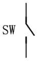
- the structure of the dip switchis shown in Figure 2, and its name is often represented by "SW".
- the dip switchwill only connect the components connected in series to the circuit when it is closed. Therefore, multiple dip switches can be connected in the potentiometer circuit and connected in series with different resistors, so that the dip switch can be closed and connected in series. Whether to control whether the corresponding resistor is connected to the potentiometer circuit, and then the potentiometer can be controlled to produce an appropriate voltage dividing ratio.
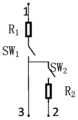
- the simplest structure composed of a dip switch and a resistoris a structure in which a dip switch and a resistor are connected in series.
- This structurehas only one branch with a dial switch connected in series with a resistor, and has two upper and lower connection endpoints. Therefore, the structure is called "1 branch dial switch - resistor with a total of 2 endpoints".
- the schematic diagramis shown in Figure 3.
- the dial switch structureincludes: a first branch, one end of the first branch is connected to the first fixed contact of the potentiometer, and the other end of the first branch is connected to the variable end of the potentiometer.
- R i SWaused in this manual means a resistor, where “i” means that the resistor is the i-th one from left to right among the N resistors connected, and “SW” means that the resistor is connected to the dial switch.
- “a”indicates that the resistor is connected to the A terminal of the potentiometer;
- SWa iindicates the dip switch, where “i” and “a” correspond to “i” and “a” in the connected resistor respectively;
- R uIndicates the protection resistor connected between potentiometers AB;
- R dindicates the protection resistor connected between potentiometers BC.
- a potentiometergenerally has three endpoints including both ends of the resistor and the brush. Therefore, based on Figure 3, a dial switch and a resistor can be added in series to make the structure have three connection endpoints.
- This structurehas two branches and three endpoints in which the dial switch and the resistor are connected in series, so it can be called the "2-branch dial switch-resistor with a total of 3 endpoints type".
- the schematic diagramis shown in Figure 5. The three endpoints of this structure can be connected to the A, B, and C terminals of the potentiometer respectively.
- the first access method:
- the structure of the dip switchincludes: a second branch and a third branch, the second branch and the third branch are connected in series, and the first endpoint of the second branch and the third branch connected in series is connected to the first fixed point of the potentiometer.
- Contact connection, the second end point of the second branch and the third branch connected in seriesis connected to the second fixed contact point of the potentiometer, and the connection point of the second branch and the third branch is connected to the variable end point of the potentiometer.
- FIG. 6is a schematic diagram of an AC type 2-branch dip switch-resistor with a total of 3 terminal points.
- the switch at SWa iis closed, and a corresponding resistor R i SWa is connected between AB.
- the switch at SWc iis closed.
- a corresponding resistor R i SWcis connected between BC.
- the dial switch structureincludes: the fourth branch and the fifth branch.
- One end of the fourth branchis connected to the first fixed contact of the potentiometer.
- the other end of the fourth branchis connected to the second fixed contact of the potentiometer and one end of the fifth branch.
- the other end of the fifth branchis connected to the second fixed contact of the potentiometer.
- One endpointis connected to the variable endpoint of the potentiometer.
- Figure 7is a schematic diagram of the AB type 2-branch dial switch-resistor with a total of 3 terminal points.
- the switch at SWa iis closed, and a corresponding resistor R i SWa is connected between AC.
- the switch at SWb iis closed.
- a corresponding resistor R i SWbis connected between BC.
- the third access methodis a third access method
- the structure of the dip switchincludes: the sixth branch and the seventh branch.
- One endpoint of the sixth branch and one endpoint of the seventh branchare both connected to the first fixed contact of the potentiometer.
- the other end of the sixth branchis connected to the second fixed contact of the potentiometer.
- the other end of the seventh branchis connected to the first fixed contact of the potentiometer.
- One endpointis connected to the variable endpoint of the potentiometer.
- Figure 8is a schematic diagram of a BC type 2-branch dip switch-resistor with a total of 3 terminal points.
- the switch at SWc iis closed, and a corresponding resistor R i SWc is connected between AC.
- the switch at SWb iis closed.
- a corresponding resistor R i SWbis connected between AB.
- connection between the dip switch and the resistorcan also use a delta connection, that is, each resistor is connected in series with a dip switch.
- Both structureshave 3 branches and 3 endpoints connected in series with dip switches and resistors, so they can be called "3-branch dip switch delta type 3 endpoint type”.
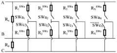
- the delta connection structureis shown in Figure 9.
- the dial switch structureincludes: the eighth branch, the ninth branch and the tenth branch.
- the eighth branch, the ninth branch and the tenth branchare connected end to end in order to form a triangular three-terminal dial switch structure.
- the first endpoint of the triangular three-terminal dial switch structureis connected to the first fixed contact of the potentiometer, and the second endpoint of the triangular three-terminal dial switch structure is connected to the second fixed contact of the potentiometer. connection, the third endpoint of the triangular three-terminal dial switch structure is connected to the variable endpoint of the potentiometer.
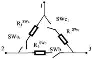
- connection between the dial switch and the resistorcan also use a Y-type connection, that is, each resistor is connected in series with a dial switch.
- Both structureshave 3 branches of dial switches and resistors connected in series and 3 endpoints, so they can be called "3-branch dial switch Y-type 3-terminal type".
- the Y-shaped connection structuresare shown in Figure 11 respectively.
- the structure of the dip switchincludes: the eleventh branch, the twelfth branch and the thirteenth branch.
- An endpoint of the eleventh branch, an endpoint of the twelfth branch, and an endpoint of the thirteenth branchare connected at the same point.
- the other end of the eleventh branchis connected to the first fixed contact of the potentiometer
- the other end of the twelfth branchis connected to the second fixed contact of the potentiometer
- the other end of the thirteenth branchis connected to the potentiometer. variable endpoint connection.
- the switches at SWa i and SWb iare closed at the same time, and R i SWa +R i SWb is connected between AB; the switches at SWa i and SWc i are closed at the same time, and R i SWa +R is connected between AC. i SWc ; the switches at SWb i and SWc i are closed at the same time, and R i SWb + R i SWc is connected between BC.
- the Y-shaped connectioncan be equivalent to a delta-shaped connection, as shown in Figure 13.
- the circuitcan be equivalent to the circuit shown in Figure 7 at this time; if the switch at SWb i in the circuit of Figure 10 is always turned off, then at this time This circuit can be equivalent to the circuit shown in Figure 8; if the switch at SWc i in the circuit of Figure 10 is always turned off, then the circuit can be equivalent to the circuit shown in Figure 6. If the switch at SWb i and SWc i in the circuit of Figure 10 is always open, then the circuit can be equivalent to the circuit shown in Figure 4 and the switch at SWc i in the circuit of Figure 12 is always open; if the switch at SWc i in the circuit of Figure 10 is always open.
- the switches at SWa i and SWc i in the circuitare always open, then the circuit can be equivalent to the situation where the switch at SWa i in the circuit of Figure 12 is always open; if the switches at SWa i and SWb i in the circuit of Figure 10 are made is always open, then the circuit at this time can be equivalent to the situation where the switch at SWb i in the circuit in Figure 12 is always open.
- the potentiometer designuses a dial switch to control whether the resistor is connected to the circuit.
- the controlcan be achieved only by closing the switch.
- the required voltage dividing ratiohas fast debugging speed and high efficiency, and there are no problems such as slide wear and resistor body wear; at the same time, the dial switch has a certain stability and will not easily change the closed/open state and will not cause In the case of virtual connection, it is also highly adaptable to humid and hot environments; compared with digital potentiometers containing control circuits, this potentiometer has a simple design, a large operating voltage range, and low cost.
- the embodiment of the present inventionprovides a method for determining the number of dip switch closures. As shown in Figure 14, the method for determining the number of dip switch closures is used in Embodiment 1 using a 3-branch dip switch triangle type 3-terminal type potentiometer. Device, the method for determining the number of dip switch closures includes:
- Step S1when the number of dial switch structures in the potentiometer device is N, the resistance between the variable endpoint of the potentiometer and the second fixed contact is used as the reference resistance, so that the first fixed contact of the potentiometer and the The resistance value between the variable end points, the resistance value of the resistor in the eighth branch, the resistance value of the resistor in the ninth branch, and the resistance value of the resistor in the tenth branch are respectively different multiples of the reference resistance value.
- Step S2Determine the number of dip switches in the potentiometer device based on the number of dip switch closures in all eighth branches, the number of dip switch closures in all ninth branches, and the number of dip switches in all tenth branches in the potentiometer device. input resistance.
- Step S3Determine the voltage dividing ratio between the variable endpoint of the potentiometer device and the second fixed contact according to the resistance value of the resistor connected to the potentiometer device.
- ⁇represents the voltage dividing ratio
- R BCrepresents the equivalent resistance between the variable endpoint of the potentiometer device and the second fixed contact
- RTrepresents the total resistance of the potentiometer device
- u, a, b, crepresent the first
- the resistance value between a fixed contact and the variable endpoint, the resistance value of the resistor in the eighth branch, the resistance value of the resistor in the ninth branch, and the resistance value of the resistor in the tenth branchare multiples of the reference resistance value
- h, l, and mrespectively represent the number of dial switch closures of all eighth branches, all ninth branches, and all tenth branches in the potentiometer device.
- the total resistance of the potentiometer devicecan also be determined.
- R ABrepresents the equivalent resistance between the first fixed contact and the variable end point of the potentiometer device
- R ACrepresents the equivalent resistance between the first fixed contact and the second fixed contact of the potentiometer device
- Rrepresents the reference resistance
- Step S4change the number of dip switch closures of all eighth branches, the number of dip switch closures of all ninth branches, or the number of dip switch closures of all tenth branches in the potentiometer device, and return to step "According to the potential
- the number of dip switch closures in all eighth branches of the potentiometer device, the number of dip switch closures in all ninth branches, and the number of dip switch closures in all tenth branches in the potentiometer deviceare used to determine the resistance connected to the potentiometer device.”
- the voltage dividing ratios corresponding to different combinations of the number of dial switch closuresare obtained, and a corresponding relationship table between the number of dial switch closures and the voltage division ratio is formed when the number of dial switch structures in the potentiometer device is N.
- Step S1change the number N of dip switch structures in the potentiometer device, and return to step "When the number of dip switch structures in the potentiometer device is N, use the variable endpoint of the potentiometer and the second fixed The resistance between the contacts is the reference resistance. Let the resistance between the first fixed contact and the variable endpoint of the potentiometer, the resistance in the eighth branch, the resistance in the ninth branch, the resistance in the tenth The resistance values of the resistors in the branches are different multiples of the reference resistor resistance values.” Obtain the corresponding relationship table between the number of dip switch closures and the voltage dividing ratio when the number of N is different.
- Step S5According to the number of dial switch structures and the target voltage dividing ratio in the potentiometer device to be adjusted, the number of dip switch closures of all eighth branches in the potentiometer device to be adjusted is obtained by querying the corresponding relationship table. The number of dip switch closures for all ninth branches and the number of dip switch closures for all tenth branches.
- Step S6According to the number of dip switch closures of all eighth branches, the number of dip switch closures of all ninth branches, and the number of dip switch closures of all tenth branches in the potentiometer device to be adjusted, the potentiometer to be adjusted is The dip switch in the device is closed.
- R AB , R AC , and R BCare respectively represented in the circuit of Figure 17 except R u and R d are connected to AB. Equivalent resistance between AC and BC ends, and assume that there are h switches closed at SWa, l switches closed at SWb, and m switches closed at SWc (h, l, m are all integers and not greater than N) ;
- H, L, and Mare respectively the subscript sets of resistances connected in parallel to AB, BC, and AC, then:
- R T(RA AB +R BC )//R AC
- all R i SWa resistorscan have the same resistance value
- all R i SWb resistance valuescan have the same resistance value
- all R i SWc resistance valuescan have the same resistance value
- one resistorcan be selected as the reference resistor.
- Each resistorcan be used as a reference resistor.
- R uR
- R ddR
- R i SWaaR
- R i SWbbR
- R i SWccR
- R ddR
- R uuR
- R i SWaaR
- R i SWbbR
- R i SWccR
- Table 1 ⁇corresponds to the values of h, l, m
- a potentiometerthat uses a dial switch to control whether a resistor is connected to a circuit needs to select the appropriate parameters such as u, a, b, c, resistor R and the total number of modules N during manufacturing, in order to obtain the total value of the potentiometer.
Landscapes
- Physics & Mathematics (AREA)
- General Physics & Mathematics (AREA)
- Engineering & Computer Science (AREA)
- Microelectronics & Electronic Packaging (AREA)
- Adjustable Resistors (AREA)
Abstract
Description
Translated fromChinese本申请要求于2022年05月18日提交中国专利局、申请号为202210550118.6、发明名称为“一种电位器装置及拨位开关闭合数确定方法”的中国专利申请的优先权,其全部内容通过引用结合在本申请中。This application requires the priority of the Chinese patent application submitted to the China Patent Office on May 18, 2022, with the application number 202210550118.6 and the invention title "A potentiometer device and a method for determining the number of closures of a dip switch", and its entire content is approved This reference is incorporated into this application.
本发明涉及电位器技术领域,特别是涉及一种电位器装置及拨位开关闭合数确定方法。The present invention relates to the technical field of potentiometers, and in particular to a potentiometer device and a method for determining the closing number of a dip switch.
电位器是一种阻值可调的、用于分压的电阻元件,又称作可变电阻器或可变电阻,通常由电阻体和可移动的电刷组成。电位器有三个接点,其中两个固定接点分别位于电阻体两端,一个可变端点位于电刷。当电刷沿电阻体移动时,便改变了电阻体接入电路中的电阻,在电刷与电阻体端点之间形成了一个与电刷位置有一定关系的电压。分压示意图如图1所示,图1中A,C分别为两个固定接点,B为可变端点电刷,电刷B位于不同的位置,便在BC端形成了不同的电压,如图1的u1和u2。A potentiometer is a resistive element with adjustable resistance for voltage division. It is also called a variable resistor or a variable resistor. It usually consists of a resistor and a movable brush. The potentiometer has three contacts, two fixed contacts located at both ends of the resistor body, and a variable endpoint located at the brush. When the brush moves along the resistor, it changes the resistance of the resistor in the circuit, and forms a voltage between the brush and the end of the resistor that is related to the position of the brush. The schematic diagram of voltage division is shown in Figure 1. In Figure 1, A and C are two fixed contacts respectively, and B is the variable endpoint brush. The brush B is located in different positions, forming different voltages at the BC terminal, as shown in the figure 1 of u1 and u2 .
市面上常见的电位器按电阻体的材质可分为线绕电位器、碳膜电位器、有机实芯电位器等。若电位器按电阻调节方式分类则可分为直滑式电位器和旋转式电位器等。此外还有使用MOS管控制电阻串联并且结合了集成电路技术制作的数字电位器。Common potentiometers on the market can be divided into wirewound potentiometers, carbon film potentiometers, organic solid core potentiometers, etc. according to the material of the resistor. If potentiometers are classified according to resistance adjustment methods, they can be divided into direct sliding potentiometers and rotary potentiometers. In addition, there are digital potentiometers made by using MOS tubes to control resistors in series and combined with integrated circuit technology.
现有的电位器在使用时有以下缺点:Existing potentiometers have the following shortcomings when used:
1.电位器调节电阻大小时,虽然可调节的阻值范围大,但往往需要配合电压表或电流表的使用来确定是否调节出想要的电阻值,调节过程耗费时间,使用起来不方便;1. When the potentiometer adjusts the resistance, although the adjustable resistance range is large, it often needs to be used in conjunction with a voltmeter or ammeter to determine whether the desired resistance value is adjusted. The adjustment process is time-consuming and inconvenient to use;
2.电刷会因为外部环境的不稳定(例如运输过程中的颠簸、平台的抖动等)产生位移,导致电位器阻值发生变化。2. The brush will be displaced due to instability in the external environment (such as bumps during transportation, shaking of the platform, etc.), causing the resistance of the potentiometer to change.
3.电刷触点处可能会虚接或者因为电流过大被烧毁。3. The brush contacts may be connected falsely or burned due to excessive current.
4.电位器反复使用时电刷和电阻体易磨损。4. When the potentiometer is used repeatedly, the brush and resistor body are easy to wear.
5.数字电位器虽然可以通过编程快速精确调控电阻值的大小,但工作 电压有限且内部设计复杂,成本较高。5. Although the digital potentiometer can quickly and accurately control the resistance value through programming, its operating voltage is limited and the internal design is complex, resulting in high cost.
综上所述,设计一款性能稳定,长久耐用,便于调试的新型电位器对工程实践有十分重要的意义。In summary, designing a new potentiometer with stable performance, long-lasting durability, and easy debugging is of great significance to engineering practice.
发明内容Contents of the invention
本发明的目的是提供一种电位器装置及拨位开关闭合数确定方法,以实现电位器的便于调试,性能稳定和长久耐用。The purpose of the present invention is to provide a potentiometer device and a method for determining the closing number of a dial switch, so as to realize easy debugging of the potentiometer, stable performance and long-term durability.
为实现上述目的,本发明提供了如下方案:In order to achieve the above objects, the present invention provides the following solutions:
一种电位器装置,所述电位器装置包括:电位器和多个拨位开关结构;A potentiometer device, the potentiometer device includes: a potentiometer and a plurality of dial switch structures;
每个拨位开关结构与电位器并联;Each dial switch structure is connected in parallel with the potentiometer;
每个拨位开关结构至少包括一条由一个拨位开关和一个电阻串联构成的支路。Each dip switch structure includes at least one branch consisting of a dip switch and a resistor connected in series.
可选的,所述拨位开关结构包括:第一支路;Optionally, the dip switch structure includes: a first branch;
第一支路的一个端点与电位器的第一固定接点连接,第一支路的另一个端点与电位器的可变端点连接。One end of the first branch is connected to the first fixed contact of the potentiometer, and the other end of the first branch is connected to the variable end of the potentiometer.
可选的,所述拨位开关结构包括:第二支路和第三支路;Optionally, the dip switch structure includes: a second branch and a third branch;
第二支路和第三支路串联;The second branch and the third branch are connected in series;
第二支路和第三支路串联后的第一端点与电位器的第一固定接点连接,第二支路和第三支路串联后的第二端点与电位器的第二固定接点连接,第二支路和第三支路的连接点与电位器的可变端点连接。The first endpoint of the second branch and the third branch connected in series is connected to the first fixed contact of the potentiometer, and the second endpoint of the second branch and the third branch connected in series is connected to the second fixed contact of the potentiometer. , the connection point of the second branch and the third branch is connected to the variable endpoint of the potentiometer.
可选的,所述拨位开关结构包括:第四支路和第五支路;Optionally, the dip switch structure includes: a fourth branch and a fifth branch;
第四支路的一个端点与电位器的第一固定接点连接,第四支路的另一个端点分别与电位器的第二固定接点、第五支路的一个端点连接,第五支路的另一个端点与电位器的可变端点连接。One end of the fourth branch is connected to the first fixed contact of the potentiometer. The other end of the fourth branch is connected to the second fixed contact of the potentiometer and one end of the fifth branch. The other end of the fifth branch is connected to the second fixed contact of the potentiometer. One endpoint is connected to the variable endpoint of the potentiometer.
可选的,所述拨位开关结构包括:第六支路和第七支路;Optionally, the dip switch structure includes: a sixth branch and a seventh branch;
第六支路的一个端点和第七支路的一个端点均与电位器的第一固定接点连接,第六支路的另一个端点与电位器的第二固定接点连接,第七支路的另一个端点与电位器的可变端点连接。One endpoint of the sixth branch and one endpoint of the seventh branch are both connected to the first fixed contact of the potentiometer. The other end of the sixth branch is connected to the second fixed contact of the potentiometer. The other end of the seventh branch is connected to the first fixed contact of the potentiometer. One endpoint is connected to the variable endpoint of the potentiometer.
可选的,所述拨位开关结构包括:第八支路、第九支路和第十支路;Optionally, the dip switch structure includes: an eighth branch, a ninth branch and a tenth branch;
第八支路、第九支路和第十支路依次首尾连接,形成三角型三端点型拨位开关结构;The eighth branch, the ninth branch and the tenth branch are connected end to end in order to form a triangular three-terminal dial switch structure;
所述三角型三端点型拨位开关结构的第一个端点与电位器的第一固定接点连接,所述三角型三端点型拨位开关结构的第二个端点与电位器的第二固定接点连接,所述三角型三端点型拨位开关结构的第三个端点与电位器的可变端点连接。The first endpoint of the triangular three-terminal dial switch structure is connected to the first fixed contact of the potentiometer, and the second endpoint of the triangular three-terminal dial switch structure is connected to the second fixed contact of the potentiometer. connection, the third endpoint of the triangular three-terminal dial switch structure is connected to the variable endpoint of the potentiometer.
可选的,所述拨位开关结构包括:第十一支路、第十二支路和第十三支路;Optionally, the dial switch structure includes: an eleventh branch, a twelfth branch and a thirteenth branch;
第十一支路的一个端点、第十二支路的一个端点和第十三支路的一个端点共点连接;An endpoint of the eleventh branch, an endpoint of the twelfth branch and an endpoint of the thirteenth branch are connected at the same point;
第十一支路的另一个端点与电位器的第一固定接点连接,第十二支路的另一个端点与电位器的第二固定接点连接,第十三支路的另一个端点与电位器的可变端点连接。The other end of the eleventh branch is connected to the first fixed contact of the potentiometer, the other end of the twelfth branch is connected to the second fixed contact of the potentiometer, and the other end of the thirteenth branch is connected to the potentiometer. variable endpoint connection.
一种拨位开关闭合数确定方法,其特征在于,所述拨位开关闭合数确定方法用于前述的电位器装置,所述拨位开关闭合数确定方法包括:A method for determining the number of dip switch closures, characterized in that the method for determining the number of dip switch closures is used in the aforementioned potentiometer device, and the method for determining the number of dip switch closures includes:
当所述电位器装置中拨位开关结构的数量为N时,以电位器的可变端点和第二固定接点之间的电阻为基准电阻,令电位器的第一固定接点和可变端点之间的电阻阻值、第八支路中的电阻阻值、第九支路中的电阻阻值、第十支路中的电阻阻值分别为不同倍数的基准电阻阻值;When the number of dial switch structures in the potentiometer device is N, the resistance between the variable endpoint and the second fixed contact of the potentiometer is used as the reference resistance, so that the resistance between the first fixed contact and the variable endpoint of the potentiometer is The resistance value between the resistors, the resistance value of the resistor in the eighth branch, the resistance value of the resistor in the ninth branch, and the resistance value of the resistor in the tenth branch are respectively the reference resistance values of different multiples;
根据电位器装置中所有第八支路的拨位开关闭合数、所有第九支路的拨位开关闭合数以及所有第十支路的拨位开关闭合数,确定电位器装置中接入的电阻;Determine the resistance connected to the potentiometer device based on the number of dip switch closures for all eighth branches, the number of dip switch closures for all ninth branches, and the number of dip switch closures for all tenth branches in the potentiometer device. ;
根据电位器装置中接入的电阻阻值,确定电位器装置的可变端点和第二固定接点之间的分压比;Determine the voltage dividing ratio between the variable endpoint of the potentiometer device and the second fixed contact according to the resistance value of the resistor connected to the potentiometer device;
改变电位器装置中所有第八支路的拨位开关闭合数、所有第九支路的拨位开关闭合数或所有第十支路的拨位开关闭合数,并返回步骤“根据电位器装置中所有第八支路的拨位开关闭合数、所有第九支路的拨位开关闭合数以及所有第十支路的拨位开关闭合数,确定电位器装置中接入的电阻”,获得不同拨位开关闭合数组合对应的分压比,形成所述电位器装置 中拨位开关结构的数量为N时的拨位开关闭合数与分压比的对应关系表;Change the number of dip switch closures for all eighth branches, the number of dip switch closures for all ninth branches, or the number of dip switch closures for all tenth branches in the potentiometer device, and return to step "According to the potentiometer device The number of dip switch closures in all eighth branches, the number of dip switch closures in all ninth branches, and the number of dip switch closures in all tenth branches are determined to determine the resistance connected to the potentiometer device," and different dial switches are obtained. The number of closed dip switches is combined with the corresponding voltage dividing ratio to form a corresponding relationship table between the number of closed dip switches and the voltage dividing ratio when the number of dip switch structures in the potentiometer device is N;
改变所述电位器装置中拨位开关结构的数量N,并返回步骤“当所述电位器装置中拨位开关结构的数量为N时,以电位器的可变端点和第二固定接点之间的电阻为基准电阻,令电位器的第一固定接点和可变端点之间的电阻阻值、第八支路中的电阻阻值、第九支路中的电阻阻值、第十支路中的电阻阻值分别为不同倍数的基准电阻阻值”,获得不同数量N时的拨位开关闭合数与分压比的对应关系表;Change the number N of dip switch structures in the potentiometer device, and return to step "When the number of dip switch structures in the potentiometer device is N, between the variable endpoint of the potentiometer and the second fixed contact The resistance of is the reference resistance, let the resistance value between the first fixed contact and the variable endpoint of the potentiometer, the resistance value of the resistor in the eighth branch, the resistance value of the resistor in the ninth branch, the resistance value of the resistor in the tenth branch The resistor values are "different multiples of the reference resistor resistance values", and the corresponding relationship table between the number of dip switch closures and the voltage dividing ratio for different numbers N is obtained;
根据待调节电位器装置中拨位开关结构的数量和目的分压比,通过查询对应数量的对应关系表,获得待调节电位器装置中所有第八支路的拨位开关闭合数、所有第九支路的拨位开关闭合数以及所有第十支路的拨位开关闭合数;According to the number of dial switch structures and the target voltage dividing ratio in the potentiometer device to be adjusted, by querying the corresponding relationship table of the corresponding quantities, the number of dip switch closures of all eighth branches in the potentiometer device to be adjusted, and the number of dip switch closures of all ninth branches in the potentiometer device to be adjusted are obtained The number of dip switch closures of the branch and the number of dip switch closures of all tenth branches;
根据待调节电位器装置中所有第八支路的拨位开关闭合数、所有第九支路的拨位开关闭合数以及所有第十支路的拨位开关闭合数,对待调节电位器装置中的拨位开关进行闭合。According to the number of dip switch closures in all eighth branches of the potentiometer device to be adjusted, the number of dip switch closures in all ninth branches, and the number of dip switch closures in all tenth branches, the number of dip switch closures in the potentiometer device to be adjusted is The dip switch is closed.
可选的,所述电位器装置的可变端点和第二固定接点之间的分压比的计算公式为Optionally, the calculation formula for the voltage division ratio between the variable endpoint of the potentiometer device and the second fixed contact is:

其中,γ表示分压比,RBC表示电位器装置的可变端点和第二固定接点之间的等效电阻,RT表示电位器装置的总电阻,u、a、b、c分别表示第一固定接点和可变端点之间的电阻阻值、第八支路中的电阻阻值、第九支路中的电阻阻值、第十支路中的电阻阻值为基准电阻阻值的倍数,h、l、m分别表示电位器装置中所有第八支路、所有第九支路、所有第十支路的拨位开关闭合数。Among them, γ represents the voltage dividing ratio, RBC represents the equivalent resistance between the variable endpoint of the potentiometer device and the second fixed contact,RT represents the total resistance of the potentiometer device, u, a, b, c represent the first The resistance value between a fixed contact and the variable endpoint, the resistance value of the resistor in the eighth branch, the resistance value of the resistor in the ninth branch, and the resistance value of the resistor in the tenth branch are multiples of the reference resistance value , h, l, and m respectively represent the number of dial switch closures of all eighth branches, all ninth branches, and all tenth branches in the potentiometer device.
可选的,所述根据电位器装置中接入的电阻阻值,确定电位器装置的 可变端点和第二固定接点之间的分压比,之后还包括:Optionally, determining the voltage dividing ratio between the variable endpoint of the potentiometer device and the second fixed contact according to the resistance value of the resistor connected in the potentiometer device, and then further includes:
根据电位器装置中接入的电阻阻值,确定电位器装置的总电阻为
其中,RAB表示电位器装置的第一固定接点和可变端点之间的等效电阻,RAC表示电位器装置的第一固定接点和第二固定接点之间的等效电阻,R表示基准电阻。Among them, RAB represents the equivalent resistance between the first fixed contact and the variable end point of the potentiometer device, RAC represents the equivalent resistance between the first fixed contact and the second fixed contact of the potentiometer device, and R represents the reference resistance.
根据本发明提供的具体实施例,本发明公开了以下技术效果:According to the specific embodiments provided by the present invention, the present invention discloses the following technical effects:
本发明公开一种电位器装置及拨位开关闭合数确定方法,拨位开关结构与电位器并联,拨位开关结构至少包括一条由一个拨位开关和一个电阻串联构成的支路,通过拨位开关控制电阻是否接入电路的电位器设计,与线绕电位器、碳膜电位器和直滑式电位器和旋转式电位器等电位器相比,仅通过开关的闭合就可达到所需分压比,调试速度快,效率高,而且不存在滑片磨损和电阻体磨损等问题;同时拨位开关具有一定的稳定性,不会轻易改变闭合/断开的状态,不会产生虚接的情况,对潮湿、炎热环境也有很强的适应性;与含有控制电路的数字电位器相比,该电位器设计简单,工作电压范围大,成本低廉。The invention discloses a potentiometer device and a method for determining the closing number of a dial switch. The dial switch structure is connected in parallel with the potentiometer. The dial switch structure at least includes a branch circuit composed of a dial switch and a resistor connected in series. The potentiometer design of the switch controls whether the resistor is connected to the circuit. Compared with wirewound potentiometers, carbon film potentiometers, direct sliding potentiometers and rotary potentiometers, the required points can be achieved only by closing the switch. pressure ratio, fast debugging speed, high efficiency, and there are no problems such as slide wear and resistor body wear; at the same time, the dial switch has a certain stability and will not easily change the closed/open state and will not cause virtual connections. It has strong adaptability to humid and hot environments; compared with digital potentiometers containing control circuits, this potentiometer has a simple design, a large operating voltage range, and low cost.
说明书附图Instructions with pictures
为了更清楚地说明本发明实施例或现有技术中的技术方案,下面将对实施例中所需要使用的附图作简单地介绍,显而易见地,下面描述中的附图仅仅是本发明的一些实施例,对于本领域普通技术人员来讲,在不付出创造性劳动性的前提下,还可以根据这些附图获得其他的附图。In order to explain the embodiments of the present invention or the technical solutions in the prior art more clearly, the drawings needed to be used in the embodiments will be briefly introduced below. Obviously, the drawings in the following description are only some of the drawings of the present invention. Embodiments, for those of ordinary skill in the art, other drawings can also be obtained based on these drawings without exerting creative efforts.
图1为现有技术的电位器分压示意图;图1中的(a)为电位器的第一分压示意图,图1中的(b)为电位器的第一分压示意图;Figure 1 is a schematic diagram of the potentiometer's voltage division in the prior art; (a) in Figure 1 is a schematic diagram of the first voltage division of the potentiometer, and (b) in Figure 1 is a schematic diagram of the first voltage division of the potentiometer;
图2为本发明实施例1提供的拨位开关的结构示意图;Figure 2 is a schematic structural diagram of a dip switch provided in
图3为本发明实施例1提供的1支路拨位开关-电阻共2端点型的结 构示意图;Figure 3 is a schematic structural diagram of a 1-branch dip switch-resistor with a total of 2 terminals provided in
图4为本发明实施例1提供的1支路拨位开关-电阻共2端点型电路示意图;Figure 4 is a schematic diagram of a 1-branch dip switch-resistor totaling 2-terminal circuit provided in
图5为本发明实施例1提供的2支路拨位开关-电阻共3端点型的结构示意图;Figure 5 is a schematic structural diagram of a 2-branch dip switch-resistor with a total of 3 terminals provided in
图6为本发明实施例1提供的AC型2支路拨位开关-电阻共3端点型电路示意图;Figure 6 is a schematic diagram of an AC type 2-branch dip switch-resistor with a total of 3 terminal points provided in
图7为本发明实施例1提供的AB型2支路拨位开关-电阻共3端点型电路示意图;Figure 7 is a schematic diagram of an AB-type 2-branch dip switch-resistor totaling 3-terminal circuit provided in
图8为本发明实施例1提供的BC型2支路拨位开关-电阻共3端点型电路示意图;Figure 8 is a schematic diagram of a BC type 2-branch dip switch-resistor totaling 3-terminal circuit provided in
图9为本发明实施例1提供的3支路拨位开关三角型3端点型的结构示意图;Figure 9 is a schematic structural diagram of a triangular 3-terminal type 3-branch dip switch provided in
图10为本发明实施例1提供的3支路拨位开关三角型3端点型电路示意图;Figure 10 is a schematic diagram of a triangular 3-terminal circuit of a 3-branch dip switch provided in
图11为本发明实施例1提供的3支路拨位开关Y型3端点型的结构示意图;Figure 11 is a schematic structural diagram of a Y-type 3-end type 3-branch dip switch provided in
图12为本发明实施例1提供的3支路拨位开关Y型3端点型电路示意图;Figure 12 is a schematic diagram of a Y-type 3-terminal circuit of a 3-branch dip switch provided in
图13为本发明实施例1提供的Y型连接等效为三角型连接的示意图;图13中的(a)为Y型连接示意图,图13中的(b)为三角型连接示意图;Figure 13 is a schematic diagram of the Y-shaped connection provided by
图14为本发明实施例2提供的拨位开关闭合数确定方法的流程图。Figure 14 is a flow chart of a method for determining the number of dip switch closures provided in
下面将结合本发明实施例中的附图,对本发明实施例中的技术方案进行清楚、完整地描述,显然,所描述的实施例仅仅是本发明一部分实施例,而不是全部的实施例。基于本发明中的实施例,本领域普通技术人员在没有做出创造性劳动前提下所获得的所有其他实施例,都属于本发明保护的 范围。The technical solutions in the embodiments of the present invention will be clearly and completely described below with reference to the accompanying drawings in the embodiments of the present invention. Obviously, the described embodiments are only some of the embodiments of the present invention, rather than all the embodiments. Based on the embodiments of the present invention, all other embodiments obtained by those of ordinary skill in the art without making creative efforts belong to the protection scope of the present invention.
本发明的目的是提供一种电位器装置及拨位开关闭合数确定方法,以实现电位器的便于调试,性能稳定和长久耐用。The purpose of the present invention is to provide a potentiometer device and a method for determining the closing number of a dial switch, so as to realize easy debugging of the potentiometer, stable performance and long-term durability.
为使本发明的上述目的、特征和优点能够更加明显易懂,下面结合附图和具体实施方式对本发明作进一步详细的说明。In order to make the above objects, features and advantages of the present invention more obvious and understandable, the present invention will be described in further detail below with reference to the accompanying drawings and specific embodiments.
实施例1Example 1
本发明实施例提供了一种电位器装置,包括:电位器和多个拨位开关结构。每个拨位开关结构与电位器并联,每个拨位开关结构至少包括一条由一个拨位开关和一个电阻串联构成的支路。An embodiment of the present invention provides a potentiometer device, which includes a potentiometer and a plurality of dial switch structures. Each dip switch structure is connected in parallel with the potentiometer, and each dip switch structure includes at least one branch consisting of a dip switch and a resistor connected in series.
拨位开关是一种单刀单掷开关,特点是同一时刻该开关只会处于闭合或者断开其中一种状态,即要么闭合形成通路,要么断开形成开路。拨位开关的结构如图2所示,其名称常用“SW”表示。The dip switch is a single-pole single-throw switch. The characteristic is that the switch can only be in one of the closed or open states at the same time, that is, it is either closed to form a path or disconnected to form an open circuit. The structure of the dip switch is shown in Figure 2, and its name is often represented by "SW".
拨位开关只有在闭合时才会将与其串联的元件接入到电路当中,因此可以在电位器电路中接入多个拨位开关并与不同的电阻串联,这样可通过拨位开关的闭合与否来控制相应电阻是否接入到电位器电路当中,进而可控制电位器产生合适的分压比。The dip switch will only connect the components connected in series to the circuit when it is closed. Therefore, multiple dip switches can be connected in the potentiometer circuit and connected in series with different resistors, so that the dip switch can be closed and connected in series. Whether to control whether the corresponding resistor is connected to the potentiometer circuit, and then the potentiometer can be controlled to produce an appropriate voltage dividing ratio.
拨位开关与电阻串联组成的结构有多种,不同结构并联到电位器上形成不同结构的电位器装置,具体结构如下:There are many structures composed of dial switches and resistors connected in series. Different structures are connected in parallel to the potentiometer to form potentiometer devices with different structures. The specific structures are as follows:
(1)1支路拨位开关-电阻共2端点型(1) 1-branch dip switch-resistor with 2 terminals in total
拨位开关与电阻组成的结构中最简单的就是一个拨位开关与一个电阻相串联的结构。该结构只有一条支路有拨位开关串联电阻,且有上下两个连接端点,因此称该结构为“1支路拨位开关-电阻共2端点型”,其示意图如图3所示。The simplest structure composed of a dip switch and a resistor is a structure in which a dip switch and a resistor are connected in series. This structure has only one branch with a dial switch connected in series with a resistor, and has two upper and lower connection endpoints. Therefore, the structure is called "1 branch dial switch - resistor with a total of 2 endpoints". The schematic diagram is shown in Figure 3.
拨位开关结构包括:第一支路,第一支路的一个端点与电位器的第一固定接点连接,第一支路的另一个端点与电位器的可变端点连接。The dial switch structure includes: a first branch, one end of the first branch is connected to the first fixed contact of the potentiometer, and the other end of the first branch is connected to the variable end of the potentiometer.
将N个图3所示“1支路拨位开关-电阻共2端点型”的结构并联到电位器AB端,通过控制拨位开关闭合的数量可将不同数目的电阻接入到电路当中,进而改变了该电位器的总电阻RT和BC端产生的分压比γ。使用 了该种结构的电路示意图如图4所示。Connect N structures of the "1-branch dip switch-resistor with 2 terminals type" shown in Figure 3 in parallel to the potentiometer AB end. By controlling the number of dip switch closures, different numbers of resistors can be connected to the circuit. This in turn changes the total resistanceRT of the potentiometer and the voltage division ratio γ generated by the BC terminal. The schematic diagram of the circuit using this structure is shown in Figure 4.
本说明书所使用的“RiSWa”表示电阻,其中“i”表示该电阻为接入的N个电阻中从左到右数的第i个,“SW”表示该电阻与拨位开关相连,“a”表示该电阻与电位器A端相接;“SWai”表示拨位开关,其中“i”和“a”分别与相连电阻中的“i”和“a”对应;“Ru”表示接在电位器AB间的保护电阻;“Rd”表示接在电位器BC间的保护电阻。“RiSWa ” used in this manual means a resistor, where “i” means that the resistor is the i-th one from left to right among the N resistors connected, and “SW” means that the resistor is connected to the dial switch. "a" indicates that the resistor is connected to the A terminal of the potentiometer; "SWai " indicates the dip switch, where "i" and "a" correspond to "i" and "a" in the connected resistor respectively; "Ru " Indicates the protection resistor connected between potentiometers AB; "Rd " indicates the protection resistor connected between potentiometers BC.
在图4中,只要SWai处开关闭合时,就在AB之间接入了RiSWa。In Figure 4, as long as the switch atSWai is closed, RiSWa is connected between AB.
(2)2支路拨位开关-电阻共3端点型(2) 2-branch dip switch - resistor with 3 terminals in total
电位器一般有包括电阻体两端及电刷在内的三个端点,因此可以在图3的基础上,再添加一路拨位开关和电阻串联,使该结构有3个连接端点。该种结构方式有两条拨位开关与电阻串联的支路和3个端点,因此可称为“2支路拨位开关-电阻共3端点型”,其示意图如图5所示。该结构的3个端点可分别接电位器的A、B、C三端。A potentiometer generally has three endpoints including both ends of the resistor and the brush. Therefore, based on Figure 3, a dial switch and a resistor can be added in series to make the structure have three connection endpoints. This structure has two branches and three endpoints in which the dial switch and the resistor are connected in series, so it can be called the "2-branch dial switch-resistor with a total of 3 endpoints type". The schematic diagram is shown in Figure 5. The three endpoints of this structure can be connected to the A, B, and C terminals of the potentiometer respectively.
将N个图5所示“2支路拨位开关-电阻共3端点型”结构并联到电位器中,也可通过闭合拨位开关数量的多少来控制总电阻RT和和BC端的分压比γ。因为图5所示结构有3个端点,每个端点可分别接电位器A、B、C端,因此图3所示结构有3种接入方法,具体电路结构有3种类型,分别如图6、图7和图8所示。Connect N pieces of the "2-branch dip switch - resistor with a total of 3 terminals type" structure shown in Figure 5 to the potentiometer in parallel. You can also control the total resistance RT and the voltage division of the BC terminal by closing the number of dip switches. Than γ. Because the structure shown in Figure 5 has 3 endpoints, each endpoint can be connected to the A, B, and C terminals of the potentiometer respectively, so the structure shown in Figure 3 has 3 access methods, and there are 3 types of specific circuit structures, as shown in the figure 6. As shown in Figure 7 and Figure 8.
第一种接入方法:The first access method:
拨位开关结构包括:第二支路和第三支路,第二支路和第三支路串联,第二支路和第三支路串联后的第一端点与电位器的第一固定接点连接,第二支路和第三支路串联后的第二端点与电位器的第二固定接点连接,第二支路和第三支路的连接点与电位器的可变端点连接。The structure of the dip switch includes: a second branch and a third branch, the second branch and the third branch are connected in series, and the first endpoint of the second branch and the third branch connected in series is connected to the first fixed point of the potentiometer. Contact connection, the second end point of the second branch and the third branch connected in series is connected to the second fixed contact point of the potentiometer, and the connection point of the second branch and the third branch is connected to the variable end point of the potentiometer.
图6为AC型2支路拨位开关-电阻共3端点型电路示意图,图中SWai处的开关闭合,就在AB间接入了一个对应的电阻RiSWa,SWci处的开关闭合,就在BC间接入了一个对应的电阻RiSWc。Figure 6 is a schematic diagram of an AC type 2-branch dip switch-resistor with a total of 3 terminal points. In the figure, the switch at SWai is closed, and a corresponding resistor RiSWa is connected between AB. The switch at SWci is closed. A corresponding resistor RiSWc is connected between BC.
第二种接入方法:Second access method:
拨位开关结构包括:第四支路和第五支路。第四支路的一个端点与电 位器的第一固定接点连接,第四支路的另一个端点分别与电位器的第二固定接点、第五支路的一个端点连接,第五支路的另一个端点与电位器的可变端点连接。The dial switch structure includes: the fourth branch and the fifth branch. One end of the fourth branch is connected to the first fixed contact of the potentiometer. The other end of the fourth branch is connected to the second fixed contact of the potentiometer and one end of the fifth branch. The other end of the fifth branch is connected to the second fixed contact of the potentiometer. One endpoint is connected to the variable endpoint of the potentiometer.
图7为AB型2支路拨位开关-电阻共3端点型电路示意图,图中SWai处的开关闭合,就在AC间接入了一个对应的电阻RiSWa,SWbi处的开关闭合,就在BC间接入了一个对应的电阻RiSWb。Figure 7 is a schematic diagram of the AB type 2-branch dial switch-resistor with a total of 3 terminal points. In the figure, the switch at SWai is closed, and a corresponding resistor RiSWa is connected between AC. The switch at SWbi is closed. A corresponding resistor RiSWb is connected between BC.
第三种接入方法:The third access method:
拨位开关结构包括:第六支路和第七支路。第六支路的一个端点和第七支路的一个端点均与电位器的第一固定接点连接,第六支路的另一个端点与电位器的第二固定接点连接,第七支路的另一个端点与电位器的可变端点连接。The structure of the dip switch includes: the sixth branch and the seventh branch. One endpoint of the sixth branch and one endpoint of the seventh branch are both connected to the first fixed contact of the potentiometer. The other end of the sixth branch is connected to the second fixed contact of the potentiometer. The other end of the seventh branch is connected to the first fixed contact of the potentiometer. One endpoint is connected to the variable endpoint of the potentiometer.
图8为BC型2支路拨位开关-电阻共3端点型电路示意图,图中SWci处的开关闭合,就在AC间接入了一个对应的电阻RiSWc,SWbi处的开关闭合,就在AB间接入了一个对应的电阻RiSWb。Figure 8 is a schematic diagram of a BC type 2-branch dip switch-resistor with a total of 3 terminal points. In the figure, the switch at SWci is closed, and a corresponding resistor RiSWc is connected between AC. The switch at SWbi is closed. A corresponding resistor RiSWb is connected between AB.
(3)3支路拨位开关三角型3端点型(3) 3-branch dip switch triangle type 3-terminal type
拨位开关和电阻的连接也可使用三角型连接,即每个电阻串联一个拨位开关。此两种结构均有3条拨位开关和电阻串联的支路和3个端点,因此可称为“3支路拨位开关三角型3端点型”,三角型连接结构如图9所示。The connection between the dip switch and the resistor can also use a delta connection, that is, each resistor is connected in series with a dip switch. Both structures have 3 branches and 3 endpoints connected in series with dip switches and resistors, so they can be called "3-branch dip
拨位开关结构包括:第八支路、第九支路和第十支路。第八支路、第九支路和第十支路依次首尾连接,形成三角型三端点型拨位开关结构。所述三角型三端点型拨位开关结构的第一个端点与电位器的第一固定接点连接,所述三角型三端点型拨位开关结构的第二个端点与电位器的第二固定接点连接,所述三角型三端点型拨位开关结构的第三个端点与电位器的可变端点连接。The dial switch structure includes: the eighth branch, the ninth branch and the tenth branch. The eighth branch, the ninth branch and the tenth branch are connected end to end in order to form a triangular three-terminal dial switch structure. The first endpoint of the triangular three-terminal dial switch structure is connected to the first fixed contact of the potentiometer, and the second endpoint of the triangular three-terminal dial switch structure is connected to the second fixed contact of the potentiometer. connection, the third endpoint of the triangular three-terminal dial switch structure is connected to the variable endpoint of the potentiometer.
N个“3支路拨位开关三角型3端点型”结构并联到电位器中的电路示意图分别如图10所示。The schematic diagram of the circuit of N "3-branch dip switch triangle type 3-terminal type" structures connected in parallel to the potentiometer is shown in Figure 10.
图10电路中,只要SWai处的开关闭合,就在AB间接入了RiSWa;只要SWbi处的开关闭合,就在BC间接入了RiSWb;只要SWci处的开关闭合,就在AC间接入了RiSWc。In the circuit of Figure 10, as long as the switch at SWai is closed, RiSWa is connected between AB; as long as the switch at SWbi is closed, RiSWb is connected between BC; as long as the switch at SWc i is closed, Ri SWb is connected between RiSWc is connected between AC.
(4)3支路拨位开关Y型3端点型(4) 3-branch dip switch Y-type 3-terminal type
拨位开关和电阻的连接也可使用Y型连接,即每个电阻串联一个拨位开关。此两种结构均有3条拨位开关和电阻串联的支路和3个端点,因此可称为“3支路拨位开关Y型3端点型”。Y型连接结构分别如图11所示。The connection between the dial switch and the resistor can also use a Y-type connection, that is, each resistor is connected in series with a dial switch. Both structures have 3 branches of dial switches and resistors connected in series and 3 endpoints, so they can be called "3-branch dial switch Y-type 3-terminal type". The Y-shaped connection structures are shown in Figure 11 respectively.
拨位开关结构包括:第十一支路、第十二支路和第十三支路。第十一支路的一个端点、第十二支路的一个端点和第十三支路的一个端点共点连接。第十一支路的另一个端点与电位器的第一固定接点连接,第十二支路的另一个端点与电位器的第二固定接点连接,第十三支路的另一个端点与电位器的可变端点连接。The structure of the dip switch includes: the eleventh branch, the twelfth branch and the thirteenth branch. An endpoint of the eleventh branch, an endpoint of the twelfth branch, and an endpoint of the thirteenth branch are connected at the same point. The other end of the eleventh branch is connected to the first fixed contact of the potentiometer, the other end of the twelfth branch is connected to the second fixed contact of the potentiometer, and the other end of the thirteenth branch is connected to the potentiometer. variable endpoint connection.
N个“3支路拨位开关Y型3端点型”结构并联到电位器中的电路示意图分别如图12所示。The schematic diagram of the circuit of N "3-branch dip switch Y-type 3-terminal type" structures connected in parallel to the potentiometer is shown in Figure 12.
图12电路中,SWai和SWbi处开关同时闭合,就在AB间接入了RiSWa+RiSWb;SWai和SWci处开关同时闭合,就在AC间接入了RiSWa+RiSWc;SWbi和SWci处开关同时闭合,就在BC间接入了RiSWb+RiSWc。Y型连接可等效为三角型连接,如图13所示,当SWai,SWbi,SWci处的拨位开关同时闭合时,等效计算公式为In the circuit of Figure 12, the switches at SWai and SWbi are closed at the same time, and RiSWa +RiSWb is connected between AB; the switches at SWai and SWci are closed at the same time, and RiSWa +R is connected between AC.iSWc ; the switches at SWbi and SWci are closed at the same time, and RiSWb + RiSWc is connected between BC. The Y-shaped connection can be equivalent to a delta-shaped connection, as shown in Figure 13. When the dip switches at SWai, SWbi, and SWci are closed at the same time, the equivalent calculation formula is:


同时,若使图10电路中的SWai处开关始终断开,则此时该电路可等效为图7所示电路;若使图10电路中的SWbi处开关始终断开,则此时该电路可等效为图8所示电路;若使图10电路中的SWci处开关始终断开,则此时该电路可等效为图6所示电路。若使图10电路中的SWbi和SWci处开关始终断开,则此时该电路可等效为图4所示电路和图12电路中SWci处开关始终断开情况;若使图10电路中的SWai和SWci处开关 始终断开,则此时该电路可等效为图12电路中SWai处开关始终断开情况;若使图10电路中的SWai和SWbi处开关始终断开,则此时该电路可等效为图12电路中SWbi处开关始终断开情况。At the same time, if the switch at SWai in the circuit of Figure 10 is always turned off, then the circuit can be equivalent to the circuit shown in Figure 7 at this time; if the switch at SWbi in the circuit of Figure 10 is always turned off, then at this time This circuit can be equivalent to the circuit shown in Figure 8; if the switch at SWci in the circuit of Figure 10 is always turned off, then the circuit can be equivalent to the circuit shown in Figure 6. If the switch at SWbi and SWci in the circuit of Figure 10 is always open, then the circuit can be equivalent to the circuit shown in Figure 4 and the switch at SWc i in the circuit of Figure 12 is always open; if the switch at SWci in the circuit of Figure 10 is always open. The switches at SWai and SWci in the circuit are always open, then the circuit can be equivalent to the situation where the switch at SWai in the circuit of Figure 12 is always open; if the switches at SWai and SWbi in the circuit of Figure 10 are made is always open, then the circuit at this time can be equivalent to the situation where the switch at SWbi in the circuit in Figure 12 is always open.
综上所述,图10所示的“3支路拨位开关三角型3端点型电路示意图”是一种较为综合的电路。To sum up, the "3-branch dip switch triangular 3-terminal circuit schematic" shown in Figure 10 is a relatively comprehensive circuit.
通过拨位开关控制电阻是否接入电路的电位器设计,与线绕电位器、碳膜电位器和直滑式电位器和旋转式电位器等电位器相比,仅通过开关的闭合就可达到所需分压比,调试速度快,效率高,而且不存在滑片磨损和电阻体磨损等问题;同时拨位开关具有一定的稳定性,不会轻易改变闭合/断开的状态,不会产生虚接的情况,对潮湿、炎热环境也有很强的适应性;与含有控制电路的数字电位器相比,该电位器设计简单,工作电压范围大,成本低廉。The potentiometer design uses a dial switch to control whether the resistor is connected to the circuit. Compared with potentiometers such as wirewound potentiometers, carbon film potentiometers, direct sliding potentiometers and rotary potentiometers, the control can be achieved only by closing the switch. The required voltage dividing ratio has fast debugging speed and high efficiency, and there are no problems such as slide wear and resistor body wear; at the same time, the dial switch has a certain stability and will not easily change the closed/open state and will not cause In the case of virtual connection, it is also highly adaptable to humid and hot environments; compared with digital potentiometers containing control circuits, this potentiometer has a simple design, a large operating voltage range, and low cost.
实施例2Example 2
本发明实施例提供了一种拨位开关闭合数确定方法,如图14所示,拨位开关闭合数确定方法用于实施例1中使用3支路拨位开关三角型3端点型的电位器装置,拨位开关闭合数确定方法包括:The embodiment of the present invention provides a method for determining the number of dip switch closures. As shown in Figure 14, the method for determining the number of dip switch closures is used in
步骤S1,当所述电位器装置中拨位开关结构的数量为N时,以电位器的可变端点和第二固定接点之间的电阻为基准电阻,令电位器的第一固定接点和可变端点之间的电阻阻值、第八支路中的电阻阻值、第九支路中的电阻阻值、第十支路中的电阻阻值分别为不同倍数的基准电阻阻值。Step S1, when the number of dial switch structures in the potentiometer device is N, the resistance between the variable endpoint of the potentiometer and the second fixed contact is used as the reference resistance, so that the first fixed contact of the potentiometer and the The resistance value between the variable end points, the resistance value of the resistor in the eighth branch, the resistance value of the resistor in the ninth branch, and the resistance value of the resistor in the tenth branch are respectively different multiples of the reference resistance value.
步骤S2,根据电位器装置中所有第八支路的拨位开关闭合数、所有第九支路的拨位开关闭合数以及所有第十支路的拨位开关闭合数,确定电位器装置中接入的电阻。Step S2: Determine the number of dip switches in the potentiometer device based on the number of dip switch closures in all eighth branches, the number of dip switch closures in all ninth branches, and the number of dip switches in all tenth branches in the potentiometer device. input resistance.
步骤S3,根据电位器装置中接入的电阻阻值,确定电位器装置的可变端点和第二固定接点之间的分压比。Step S3: Determine the voltage dividing ratio between the variable endpoint of the potentiometer device and the second fixed contact according to the resistance value of the resistor connected to the potentiometer device.
电位器装置的可变端点和第二固定接点之间的分压比的计算公式为The formula for calculating the voltage dividing ratio between the variable endpoint of the potentiometer device and the second fixed contact is:

其中,γ表示分压比,RBC表示电位器装置的可变端点和第二固定接点之间的等效电阻,RT表示电位器装置的总电阻,u、a、b、c分别表示第一固定接点和可变端点之间的电阻阻值、第八支路中的电阻阻值、第九支路中的电阻阻值、第十支路中的电阻阻值为基准电阻阻值的倍数,h、l、m分别表示电位器装置中所有第八支路、所有第九支路、所有第十支路的拨位开关闭合数。Among them, γ represents the voltage dividing ratio, RBC represents the equivalent resistance between the variable endpoint of the potentiometer device and the second fixed contact,RT represents the total resistance of the potentiometer device, u, a, b, c represent the first The resistance value between a fixed contact and the variable endpoint, the resistance value of the resistor in the eighth branch, the resistance value of the resistor in the ninth branch, and the resistance value of the resistor in the tenth branch are multiples of the reference resistance value , h, l, and m respectively represent the number of dial switch closures of all eighth branches, all ninth branches, and all tenth branches in the potentiometer device.
根据电位器装置中接入的电阻阻值,还可以确定电位器装置的总电阻According to the resistance value of the resistor connected to the potentiometer device, the total resistance of the potentiometer device can also be determined.

其中,RAB表示电位器装置的第一固定接点和可变端点之间的等效电阻,RAC表示电位器装置的第一固定接点和第二固定接点之间的等效电阻,R表示基准电阻。Among them, RAB represents the equivalent resistance between the first fixed contact and the variable end point of the potentiometer device, RAC represents the equivalent resistance between the first fixed contact and the second fixed contact of the potentiometer device, and R represents the reference resistance.
步骤S4,改变电位器装置中所有第八支路的拨位开关闭合数、所有第九支路的拨位开关闭合数或所有第十支路的拨位开关闭合数,并返回步骤“根据电位器装置中所有第八支路的拨位开关闭合数、所有第九支路的拨位开关闭合数以及所有第十支路的拨位开关闭合数,确定电位器装置中接入的电阻”,获得不同拨位开关闭合数组合对应的分压比,形成所述电位器装置中拨位开关结构的数量为N时的拨位开关闭合数与分压比的对应关系表。Step S4, change the number of dip switch closures of all eighth branches, the number of dip switch closures of all ninth branches, or the number of dip switch closures of all tenth branches in the potentiometer device, and return to step "According to the potential The number of dip switch closures in all eighth branches of the potentiometer device, the number of dip switch closures in all ninth branches, and the number of dip switch closures in all tenth branches in the potentiometer device are used to determine the resistance connected to the potentiometer device." The voltage dividing ratios corresponding to different combinations of the number of dial switch closures are obtained, and a corresponding relationship table between the number of dial switch closures and the voltage division ratio is formed when the number of dial switch structures in the potentiometer device is N.
步骤S1,改变所述电位器装置中拨位开关结构的数量N,并返回步骤“当所述电位器装置中拨位开关结构的数量为N时,以电位器的可变端 点和第二固定接点之间的电阻为基准电阻,令电位器的第一固定接点和可变端点之间的电阻阻值、第八支路中的电阻阻值、第九支路中的电阻阻值、第十支路中的电阻阻值分别为不同倍数的基准电阻阻值”,获得不同数量N时的拨位开关闭合数与分压比的对应关系表。Step S1, change the number N of dip switch structures in the potentiometer device, and return to step "When the number of dip switch structures in the potentiometer device is N, use the variable endpoint of the potentiometer and the second fixed The resistance between the contacts is the reference resistance. Let the resistance between the first fixed contact and the variable endpoint of the potentiometer, the resistance in the eighth branch, the resistance in the ninth branch, the resistance in the tenth The resistance values of the resistors in the branches are different multiples of the reference resistor resistance values." Obtain the corresponding relationship table between the number of dip switch closures and the voltage dividing ratio when the number of N is different.
步骤S5,根据待调节电位器装置中拨位开关结构的数量和目的分压比,通过查询对应数量的对应关系表,获得待调节电位器装置中所有第八支路的拨位开关闭合数、所有第九支路的拨位开关闭合数以及所有第十支路的拨位开关闭合数。Step S5: According to the number of dial switch structures and the target voltage dividing ratio in the potentiometer device to be adjusted, the number of dip switch closures of all eighth branches in the potentiometer device to be adjusted is obtained by querying the corresponding relationship table. The number of dip switch closures for all ninth branches and the number of dip switch closures for all tenth branches.
步骤S6,根据待调节电位器装置中所有第八支路的拨位开关闭合数、所有第九支路的拨位开关闭合数以及所有第十支路的拨位开关闭合数,对待调节电位器装置中的拨位开关进行闭合。Step S6: According to the number of dip switch closures of all eighth branches, the number of dip switch closures of all ninth branches, and the number of dip switch closures of all tenth branches in the potentiometer device to be adjusted, the potentiometer to be adjusted is The dip switch in the device is closed.
接下来以图10电路为例,说明电路中闭合不同位置的开关数和分压比γ之间的数学关系。Next, take the circuit in Figure 10 as an example to illustrate the mathematical relationship between the number of switches closed at different positions in the circuit and the voltage dividing ratio γ.
设图10所示电路当中有N个“3支路拨位开关三角型3端点型”模块,RAB,RAC,RBC分别表示在图17电路中除Ru和Rd外接在AB,AC,BC两端之间的等效电阻,并设总共有h个SWa处开关闭合,l个SWb处开关闭合,m个SWc处开关闭合(h,l,m均为整数且不大于N);Assume that there are N "3-branch dip switch triangle type 3-terminal type" modules in the circuit shown in Figure 10. RAB , RAC , and RBC are respectively represented in the circuit of Figure 17 except Ru and Rd are connected to AB. Equivalent resistance between AC and BC ends, and assume that there are h switches closed at SWa, l switches closed at SWb, and m switches closed at SWc (h, l, m are all integers and not greater than N) ;
H,L,M分别为并联到AB,BC,AC之间电阻的下标集合,则:H, L, and M are respectively the subscript sets of resistances connected in parallel to AB, BC, and AC, then:


该电路的总电阻:RT=(RAB+RBC)//RACThe total resistance of the circuit: RT =(RAAB +RBC )//RAC
该电路BC端的分压比:
为了计算方便,可令所有的RiSWa电阻阻值相等,所有的RiSWb阻值相等,所有的RiSWc阻值相等,并选定一个电阻为基准电阻。每个电阻都可做基准电阻,若选Ru为基准电阻,Ru=R,则可令Rd=dR,RiSWa=aR,RiSWb=bR,RiSWc=cR;若选Rd为基准电阻,Rd=R,则可令Ru=uR,RiSWa=aR,RiSWb=bR,RiSWc=cR;此处选Rd为基准电阻,u,a,b,c均为常数,则上述公式可简化为:For the convenience of calculation, all RiSWa resistors can have the same resistance value, all RiSWb resistance values can have the same resistance value, and all RiSWc resistance values can have the same resistance value, and one resistor can be selected as the reference resistor. Each resistor can be used as a reference resistor. If Ru is selected as the reference resistor, Ru =R, then Rd =dR, RiSWa =aR, RiSWb =bR, RiSWc =cR; if selected Rd is the reference resistance, Rd =R, then Ru =uR, RiSWa =aR, RiSWb =bR, RiSWc =cR; here Rd is selected as the reference resistance, u, a, b and c are both constants, then the above formula can be simplified to:


通过计算可知,总电阻RT与R有关,分压比γ与R无关,令a=100,b=1,c=1,u=100,可得部分分压比γ值与SWa处开关闭合数h,SWb处开关闭合数l,SWc处开关闭合数m的对应关系如下表:It can be seen from the calculation that the total resistance RT is related to R, and the voltage dividing ratio γ has nothing to do with R. Let a=100, b=1, c=1, u=100. It can be obtained that the partial voltage dividing ratio γ value is related to the switch closure at SWa. The corresponding relationship between the number h, the number of switch closures at SWb l, and the number of switch closures at SWc m is as follows:
表1γ与h,l,m的取值对应Table 1 γ corresponds to the values of h, l, m
综上所述,使用拨位开关控制电阻是否接入电路的电位器需要在制造时选定合适的u,a,b,c,电阻R和总模块数N等参数,以便得到电位器的总电阻RT及分压比γ和闭合开关数的取值对应表。该电位器接入到电路中使用时,可根据分压比γ和闭合开关数的取值对应关系,闭合一定数量的开关即可得到目的分压比γ。To sum up, a potentiometer that uses a dial switch to control whether a resistor is connected to a circuit needs to select the appropriate parameters such as u, a, b, c, resistor R and the total number of modules N during manufacturing, in order to obtain the total value of the potentiometer. The value correspondence table of resistance RT , voltage dividing ratio γ and number of closed switches. When the potentiometer is connected to the circuit and used, according to the corresponding relationship between the voltage dividing ratio γ and the number of closed switches, the target voltage dividing ratio γ can be obtained by closing a certain number of switches.
本说明书中各个实施例采用递进的方式描述,每个实施例重点说明的都是与其他实施例的不同之处,各个实施例之间相同相似部分互相参见即可。Each embodiment in this specification is described in a progressive manner. Each embodiment focuses on its differences from other embodiments. The same and similar parts between the various embodiments can be referred to each other.
本文中应用了具体个例对本发明的原理及实施方式进行了阐述,以上实施例的说明只是用于帮助理解本发明的方法及其核心思想;同时,对于本领域的一般技术人员,依据本发明的思想,在具体实施方式及应用范围上均会有改变之处。综上所述,本说明书内容不应理解为对本发明的限制。This article uses specific examples to illustrate the principles and implementation methods of the present invention. The description of the above embodiments is only used to help understand the method and the core idea of the present invention; at the same time, for those of ordinary skill in the art, according to the present invention There will be changes in the specific implementation methods and application scope of the ideas. In summary, the contents of this description should not be construed as limitations of the present invention.
Claims (10)
Translated fromChinese

Priority Applications (1)
| Application Number | Priority Date | Filing Date | Title |
|---|---|---|---|
| US18/271,746US20240410945A1 (en) | 2022-05-18 | 2022-11-25 | Potentiometer device and method for determining a number of closed dip switches |
Applications Claiming Priority (2)
| Application Number | Priority Date | Filing Date | Title |
|---|---|---|---|
| CN202210550118.6 | 2022-05-18 | ||
| CN202210550118 | 2022-05-18 |
Publications (1)
| Publication Number | Publication Date |
|---|---|
| WO2023221449A1true WO2023221449A1 (en) | 2023-11-23 |
Family
ID=83289155
Family Applications (1)
| Application Number | Title | Priority Date | Filing Date |
|---|---|---|---|
| PCT/CN2022/134222CeasedWO2023221449A1 (en) | 2022-05-18 | 2022-11-25 | Potentiometer apparatus, and method for determining number of turned-on shifting switches |
Country Status (3)
| Country | Link |
|---|---|
| US (1) | US20240410945A1 (en) |
| CN (1) | CN115101275B (en) |
| WO (1) | WO2023221449A1 (en) |
Families Citing this family (1)
| Publication number | Priority date | Publication date | Assignee | Title |
|---|---|---|---|---|
| CN115101275B (en)* | 2022-05-18 | 2023-07-14 | 北京石油化工学院 | A potentiometer device and a method for determining the closing number of a dial switch |
Citations (7)
| Publication number | Priority date | Publication date | Assignee | Title |
|---|---|---|---|---|
| US5089768A (en)* | 1989-03-22 | 1992-02-18 | Canon Kabushiki Kaisha | Power source device with control of voltage change speed |
| CN201178046Y (en)* | 2007-12-29 | 2009-01-07 | 深圳和而泰智能控制股份有限公司 | Press-key array |
| CN102721916A (en)* | 2012-06-29 | 2012-10-10 | 福建星网锐捷网络有限公司 | Power supply voltage-regulating testing device |
| CN104966596A (en)* | 2015-07-13 | 2015-10-07 | 广东欧珀移动通信有限公司 | Potentiometer, calibration method and calibration system of potentiometer as well as volume control device and electronic equipment |
| CN107797594A (en)* | 2016-09-07 | 2018-03-13 | 佛山市顺德区美的电热电器制造有限公司 | A control circuit and its working method |
| CN211014434U (en)* | 2019-11-13 | 2020-07-14 | 上海艾临科智能科技有限公司 | Shunt matching circuit and current sampling and conditioning device |
| CN115101275A (en)* | 2022-05-18 | 2022-09-23 | 北京石油化工学院 | A potentiometer device and a method for determining the closing number of a dial switch |
Family Cites Families (9)
| Publication number | Priority date | Publication date | Assignee | Title |
|---|---|---|---|---|
| CN2204451Y (en)* | 1993-12-29 | 1995-08-02 | 家电宝实业有限公司 | Switching Rheostat |
| CN2238475Y (en)* | 1994-06-15 | 1996-10-23 | 介国安 | Digital potentiometer |
| JP2005072300A (en)* | 2003-08-26 | 2005-03-17 | Matsushita Electric Ind Co Ltd | Variable resistor |
| US7602327B2 (en)* | 2007-05-08 | 2009-10-13 | Telefonaktiebolaget Lm Ericsson (Publ) | Digitally controllable on-chip resistors and methods |
| CN102435894B (en)* | 2011-11-15 | 2014-04-16 | 浙江大学 | Digital leakage protector tester and test method thereof |
| CN102693796B (en)* | 2012-05-28 | 2014-11-05 | 上海丽恒光微电子科技有限公司 | Digital adjustable resistor and adjusting method thereof |
| CN206834012U (en)* | 2017-04-11 | 2018-01-02 | 惠州市元泰电子有限公司 | A kind of Miniature single duplex switch potentiometer |
| US20200044438A1 (en)* | 2018-08-05 | 2020-02-06 | Shuguang He | Dc soft turn-off module |
| CN111857036A (en)* | 2020-08-13 | 2020-10-30 | 广东晶科电子股份有限公司 | High Precision Digital Potentiometer |
- 2022
- 2022-06-02CNCN202210625933.4Apatent/CN115101275B/enactiveActive
- 2022-11-25WOPCT/CN2022/134222patent/WO2023221449A1/ennot_activeCeased
- 2022-11-25USUS18/271,746patent/US20240410945A1/enactivePending
Patent Citations (7)
| Publication number | Priority date | Publication date | Assignee | Title |
|---|---|---|---|---|
| US5089768A (en)* | 1989-03-22 | 1992-02-18 | Canon Kabushiki Kaisha | Power source device with control of voltage change speed |
| CN201178046Y (en)* | 2007-12-29 | 2009-01-07 | 深圳和而泰智能控制股份有限公司 | Press-key array |
| CN102721916A (en)* | 2012-06-29 | 2012-10-10 | 福建星网锐捷网络有限公司 | Power supply voltage-regulating testing device |
| CN104966596A (en)* | 2015-07-13 | 2015-10-07 | 广东欧珀移动通信有限公司 | Potentiometer, calibration method and calibration system of potentiometer as well as volume control device and electronic equipment |
| CN107797594A (en)* | 2016-09-07 | 2018-03-13 | 佛山市顺德区美的电热电器制造有限公司 | A control circuit and its working method |
| CN211014434U (en)* | 2019-11-13 | 2020-07-14 | 上海艾临科智能科技有限公司 | Shunt matching circuit and current sampling and conditioning device |
| CN115101275A (en)* | 2022-05-18 | 2022-09-23 | 北京石油化工学院 | A potentiometer device and a method for determining the closing number of a dial switch |
Also Published As
| Publication number | Publication date |
|---|---|
| CN115101275A (en) | 2022-09-23 |
| CN115101275B (en) | 2023-07-14 |
| US20240410945A1 (en) | 2024-12-12 |
Similar Documents
| Publication | Publication Date | Title |
|---|---|---|
| WO2023221449A1 (en) | Potentiometer apparatus, and method for determining number of turned-on shifting switches | |
| CN106100598B (en) | A variable gain amplifier | |
| CN104811178A (en) | Multi-path switching value collection device based on AD sampling circuit and collecting method thereof | |
| CN109586725A (en) | Superhigh precision R-2R resistor network switch arrays | |
| CN207610796U (en) | Temperature sampling circuit controlled by multi-path voltage division | |
| CN106057388B (en) | A kind of metal plate type high power varying resistance | |
| CN105468068A (en) | Special constant current source for measurement of semiconducting material high-temperature thermoelectric property and control method for same | |
| CN110008652B (en) | Three-time nonlinear active magnetic control memristor simulator | |
| CN205406213U (en) | Variable resistance and contain this variable resistance's integrated circuit | |
| CN209895861U (en) | Combined sliding rheostat | |
| CN201112106Y (en) | Transformer interface connecting device | |
| CN211857325U (en) | Voltage Controlled Resistor Circuit | |
| CN108666059A (en) | A multi-ring adjustable electronic component | |
| US3443215A (en) | Impedance measuring bridge with voltage divider providing constant source impedance to bridge | |
| US7043386B2 (en) | Potentiometer providing a high resolution | |
| CN220604610U (en) | A device for electron beam current in an electron microscope | |
| CN108964063B (en) | A modeling method for non-standard ratio transformers in power flow calculation | |
| CN114974769A (en) | Definite value digital potentiometer | |
| CN112928208B (en) | High-voltage high-resistance polycrystalline silicon resistance model with asymmetric voltage bias effect | |
| CN120195602B (en) | Self-calibration circuit and method for voltage division proportion of resistive voltage divider | |
| CN110008651A (en) | A Quadratic Nonlinear Active Magnetron Memristive Simulator | |
| CN221748356U (en) | Gain adjustable operational amplifier circuit | |
| CN107799249A (en) | A kind of potentiometer | |
| CN117592415B (en) | Four-terminal resistor network structure and resistance value calculation method thereof | |
| CN207883419U (en) | Multistage adjustable type potentiometer |
Legal Events
| Date | Code | Title | Description |
|---|---|---|---|
| WWE | Wipo information: entry into national phase | Ref document number:18271746 Country of ref document:US | |
| 121 | Ep: the epo has been informed by wipo that ep was designated in this application | Ref document number:22942469 Country of ref document:EP Kind code of ref document:A1 | |
| NENP | Non-entry into the national phase | Ref country code:DE | |
| 122 | Ep: pct application non-entry in european phase | Ref document number:22942469 Country of ref document:EP Kind code of ref document:A1 |