WO2023219345A2 - Motion assist apparatus comprising mount receiving friction-reducing member - Google Patents
Motion assist apparatus comprising mount receiving friction-reducing memberDownload PDFInfo
- Publication number
- WO2023219345A2 WO2023219345A2PCT/KR2023/006183KR2023006183WWO2023219345A2WO 2023219345 A2WO2023219345 A2WO 2023219345A2KR 2023006183 WKR2023006183 WKR 2023006183WWO 2023219345 A2WO2023219345 A2WO 2023219345A2
- Authority
- WO
- WIPO (PCT)
- Prior art keywords
- slider
- mount
- head
- shaft
- friction reduction
- Prior art date
- Legal status (The legal status is an assumption and is not a legal conclusion. Google has not performed a legal analysis and makes no representation as to the accuracy of the status listed.)
- Ceased
Links
Images


Classifications
- A—HUMAN NECESSITIES
- A61—MEDICAL OR VETERINARY SCIENCE; HYGIENE
- A61H—PHYSICAL THERAPY APPARATUS, e.g. DEVICES FOR LOCATING OR STIMULATING REFLEX POINTS IN THE BODY; ARTIFICIAL RESPIRATION; MASSAGE; BATHING DEVICES FOR SPECIAL THERAPEUTIC OR HYGIENIC PURPOSES OR SPECIFIC PARTS OF THE BODY
- A61H1/00—Apparatus for passive exercising; Vibrating apparatus; Chiropractic devices, e.g. body impacting devices, external devices for briefly extending or aligning unbroken bones
- A61H1/02—Stretching or bending or torsioning apparatus for exercising
- A61H1/0237—Stretching or bending or torsioning apparatus for exercising for the lower limbs
- A61H1/0255—Both knee and hip of a patient, e.g. in supine or sitting position, the feet being moved together in a plane substantially parallel to the body-symmetrical plane
- A61H1/0262—Walking movement; Appliances for aiding disabled persons to walk
- A—HUMAN NECESSITIES
- A61—MEDICAL OR VETERINARY SCIENCE; HYGIENE
- A61H—PHYSICAL THERAPY APPARATUS, e.g. DEVICES FOR LOCATING OR STIMULATING REFLEX POINTS IN THE BODY; ARTIFICIAL RESPIRATION; MASSAGE; BATHING DEVICES FOR SPECIAL THERAPEUTIC OR HYGIENIC PURPOSES OR SPECIFIC PARTS OF THE BODY
- A61H1/00—Apparatus for passive exercising; Vibrating apparatus; Chiropractic devices, e.g. body impacting devices, external devices for briefly extending or aligning unbroken bones
- A61H1/02—Stretching or bending or torsioning apparatus for exercising
- A61H1/0237—Stretching or bending or torsioning apparatus for exercising for the lower limbs
- A61H1/024—Knee
- A—HUMAN NECESSITIES
- A61—MEDICAL OR VETERINARY SCIENCE; HYGIENE
- A61H—PHYSICAL THERAPY APPARATUS, e.g. DEVICES FOR LOCATING OR STIMULATING REFLEX POINTS IN THE BODY; ARTIFICIAL RESPIRATION; MASSAGE; BATHING DEVICES FOR SPECIAL THERAPEUTIC OR HYGIENIC PURPOSES OR SPECIFIC PARTS OF THE BODY
- A61H1/00—Apparatus for passive exercising; Vibrating apparatus; Chiropractic devices, e.g. body impacting devices, external devices for briefly extending or aligning unbroken bones
- A61H1/02—Stretching or bending or torsioning apparatus for exercising
- A61H1/0237—Stretching or bending or torsioning apparatus for exercising for the lower limbs
- A61H1/0266—Foot
- A—HUMAN NECESSITIES
- A61—MEDICAL OR VETERINARY SCIENCE; HYGIENE
- A61H—PHYSICAL THERAPY APPARATUS, e.g. DEVICES FOR LOCATING OR STIMULATING REFLEX POINTS IN THE BODY; ARTIFICIAL RESPIRATION; MASSAGE; BATHING DEVICES FOR SPECIAL THERAPEUTIC OR HYGIENIC PURPOSES OR SPECIFIC PARTS OF THE BODY
- A61H1/00—Apparatus for passive exercising; Vibrating apparatus; Chiropractic devices, e.g. body impacting devices, external devices for briefly extending or aligning unbroken bones
- A61H1/02—Stretching or bending or torsioning apparatus for exercising
- A61H1/0274—Stretching or bending or torsioning apparatus for exercising for the upper limbs
- A61H1/0277—Elbow
- A—HUMAN NECESSITIES
- A61—MEDICAL OR VETERINARY SCIENCE; HYGIENE
- A61H—PHYSICAL THERAPY APPARATUS, e.g. DEVICES FOR LOCATING OR STIMULATING REFLEX POINTS IN THE BODY; ARTIFICIAL RESPIRATION; MASSAGE; BATHING DEVICES FOR SPECIAL THERAPEUTIC OR HYGIENIC PURPOSES OR SPECIFIC PARTS OF THE BODY
- A61H1/00—Apparatus for passive exercising; Vibrating apparatus; Chiropractic devices, e.g. body impacting devices, external devices for briefly extending or aligning unbroken bones
- A61H1/02—Stretching or bending or torsioning apparatus for exercising
- A61H1/0274—Stretching or bending or torsioning apparatus for exercising for the upper limbs
- A61H1/0281—Shoulder
- A—HUMAN NECESSITIES
- A61—MEDICAL OR VETERINARY SCIENCE; HYGIENE
- A61H—PHYSICAL THERAPY APPARATUS, e.g. DEVICES FOR LOCATING OR STIMULATING REFLEX POINTS IN THE BODY; ARTIFICIAL RESPIRATION; MASSAGE; BATHING DEVICES FOR SPECIAL THERAPEUTIC OR HYGIENIC PURPOSES OR SPECIFIC PARTS OF THE BODY
- A61H3/00—Appliances for aiding patients or disabled persons to walk about
- A—HUMAN NECESSITIES
- A63—SPORTS; GAMES; AMUSEMENTS
- A63B—APPARATUS FOR PHYSICAL TRAINING, GYMNASTICS, SWIMMING, CLIMBING, OR FENCING; BALL GAMES; TRAINING EQUIPMENT
- A63B21/00—Exercising apparatus for developing or strengthening the muscles or joints of the body by working against a counterforce, with or without measuring devices
- A63B21/00181—Exercising apparatus for developing or strengthening the muscles or joints of the body by working against a counterforce, with or without measuring devices comprising additional means assisting the user to overcome part of the resisting force, i.e. assisted-active exercising
- A—HUMAN NECESSITIES
- A63—SPORTS; GAMES; AMUSEMENTS
- A63B—APPARATUS FOR PHYSICAL TRAINING, GYMNASTICS, SWIMMING, CLIMBING, OR FENCING; BALL GAMES; TRAINING EQUIPMENT
- A63B23/00—Exercising apparatus specially adapted for particular parts of the body
- A63B23/035—Exercising apparatus specially adapted for particular parts of the body for limbs, i.e. upper or lower limbs, e.g. simultaneously
- A63B23/04—Exercising apparatus specially adapted for particular parts of the body for limbs, i.e. upper or lower limbs, e.g. simultaneously for lower limbs
- A—HUMAN NECESSITIES
- A63—SPORTS; GAMES; AMUSEMENTS
- A63B—APPARATUS FOR PHYSICAL TRAINING, GYMNASTICS, SWIMMING, CLIMBING, OR FENCING; BALL GAMES; TRAINING EQUIPMENT
- A63B23/00—Exercising apparatus specially adapted for particular parts of the body
- A63B23/035—Exercising apparatus specially adapted for particular parts of the body for limbs, i.e. upper or lower limbs, e.g. simultaneously
- A63B23/12—Exercising apparatus specially adapted for particular parts of the body for limbs, i.e. upper or lower limbs, e.g. simultaneously for upper limbs or related muscles, e.g. chest, upper back or shoulder muscles
- A63B23/1245—Primarily by articulating the shoulder joint
- A—HUMAN NECESSITIES
- A61—MEDICAL OR VETERINARY SCIENCE; HYGIENE
- A61H—PHYSICAL THERAPY APPARATUS, e.g. DEVICES FOR LOCATING OR STIMULATING REFLEX POINTS IN THE BODY; ARTIFICIAL RESPIRATION; MASSAGE; BATHING DEVICES FOR SPECIAL THERAPEUTIC OR HYGIENIC PURPOSES OR SPECIFIC PARTS OF THE BODY
- A61H3/00—Appliances for aiding patients or disabled persons to walk about
- A61H2003/007—Appliances for aiding patients or disabled persons to walk about secured to the patient, e.g. with belts
- A—HUMAN NECESSITIES
- A61—MEDICAL OR VETERINARY SCIENCE; HYGIENE
- A61H—PHYSICAL THERAPY APPARATUS, e.g. DEVICES FOR LOCATING OR STIMULATING REFLEX POINTS IN THE BODY; ARTIFICIAL RESPIRATION; MASSAGE; BATHING DEVICES FOR SPECIAL THERAPEUTIC OR HYGIENIC PURPOSES OR SPECIFIC PARTS OF THE BODY
- A61H2201/00—Characteristics of apparatus not provided for in the preceding codes
- A61H2201/01—Constructive details
- A61H2201/0173—Means for preventing injuries
- A61H2201/018—By limiting the applied torque or force
- A—HUMAN NECESSITIES
- A61—MEDICAL OR VETERINARY SCIENCE; HYGIENE
- A61H—PHYSICAL THERAPY APPARATUS, e.g. DEVICES FOR LOCATING OR STIMULATING REFLEX POINTS IN THE BODY; ARTIFICIAL RESPIRATION; MASSAGE; BATHING DEVICES FOR SPECIAL THERAPEUTIC OR HYGIENIC PURPOSES OR SPECIFIC PARTS OF THE BODY
- A61H2201/00—Characteristics of apparatus not provided for in the preceding codes
- A61H2201/12—Driving means
- A61H2201/1207—Driving means with electric or magnetic drive
- A61H2201/1215—Rotary drive
- A—HUMAN NECESSITIES
- A61—MEDICAL OR VETERINARY SCIENCE; HYGIENE
- A61H—PHYSICAL THERAPY APPARATUS, e.g. DEVICES FOR LOCATING OR STIMULATING REFLEX POINTS IN THE BODY; ARTIFICIAL RESPIRATION; MASSAGE; BATHING DEVICES FOR SPECIAL THERAPEUTIC OR HYGIENIC PURPOSES OR SPECIFIC PARTS OF THE BODY
- A61H2201/00—Characteristics of apparatus not provided for in the preceding codes
- A61H2201/14—Special force transmission means, i.e. between the driving means and the interface with the user
- A61H2201/1454—Special bearing arrangements
- A—HUMAN NECESSITIES
- A61—MEDICAL OR VETERINARY SCIENCE; HYGIENE
- A61H—PHYSICAL THERAPY APPARATUS, e.g. DEVICES FOR LOCATING OR STIMULATING REFLEX POINTS IN THE BODY; ARTIFICIAL RESPIRATION; MASSAGE; BATHING DEVICES FOR SPECIAL THERAPEUTIC OR HYGIENIC PURPOSES OR SPECIFIC PARTS OF THE BODY
- A61H2201/00—Characteristics of apparatus not provided for in the preceding codes
- A61H2201/14—Special force transmission means, i.e. between the driving means and the interface with the user
- A61H2201/1463—Special speed variation means, i.e. speed reducer
- A—HUMAN NECESSITIES
- A61—MEDICAL OR VETERINARY SCIENCE; HYGIENE
- A61H—PHYSICAL THERAPY APPARATUS, e.g. DEVICES FOR LOCATING OR STIMULATING REFLEX POINTS IN THE BODY; ARTIFICIAL RESPIRATION; MASSAGE; BATHING DEVICES FOR SPECIAL THERAPEUTIC OR HYGIENIC PURPOSES OR SPECIFIC PARTS OF THE BODY
- A61H2201/00—Characteristics of apparatus not provided for in the preceding codes
- A61H2201/16—Physical interface with patient
- A61H2201/1602—Physical interface with patient kind of interface, e.g. head rest, knee support or lumbar support
- A61H2201/1614—Shoulder, e.g. for neck stretching
- A61H2201/1616—Holding means therefor
- A—HUMAN NECESSITIES
- A61—MEDICAL OR VETERINARY SCIENCE; HYGIENE
- A61H—PHYSICAL THERAPY APPARATUS, e.g. DEVICES FOR LOCATING OR STIMULATING REFLEX POINTS IN THE BODY; ARTIFICIAL RESPIRATION; MASSAGE; BATHING DEVICES FOR SPECIAL THERAPEUTIC OR HYGIENIC PURPOSES OR SPECIFIC PARTS OF THE BODY
- A61H2201/00—Characteristics of apparatus not provided for in the preceding codes
- A61H2201/16—Physical interface with patient
- A61H2201/1602—Physical interface with patient kind of interface, e.g. head rest, knee support or lumbar support
- A61H2201/1628—Pelvis
- A61H2201/163—Pelvis holding means therefor
- A—HUMAN NECESSITIES
- A61—MEDICAL OR VETERINARY SCIENCE; HYGIENE
- A61H—PHYSICAL THERAPY APPARATUS, e.g. DEVICES FOR LOCATING OR STIMULATING REFLEX POINTS IN THE BODY; ARTIFICIAL RESPIRATION; MASSAGE; BATHING DEVICES FOR SPECIAL THERAPEUTIC OR HYGIENIC PURPOSES OR SPECIFIC PARTS OF THE BODY
- A61H2201/00—Characteristics of apparatus not provided for in the preceding codes
- A61H2201/16—Physical interface with patient
- A61H2201/1602—Physical interface with patient kind of interface, e.g. head rest, knee support or lumbar support
- A61H2201/1635—Hand or arm, e.g. handle
- A61H2201/1638—Holding means therefor
- A—HUMAN NECESSITIES
- A61—MEDICAL OR VETERINARY SCIENCE; HYGIENE
- A61H—PHYSICAL THERAPY APPARATUS, e.g. DEVICES FOR LOCATING OR STIMULATING REFLEX POINTS IN THE BODY; ARTIFICIAL RESPIRATION; MASSAGE; BATHING DEVICES FOR SPECIAL THERAPEUTIC OR HYGIENIC PURPOSES OR SPECIFIC PARTS OF THE BODY
- A61H2201/00—Characteristics of apparatus not provided for in the preceding codes
- A61H2201/16—Physical interface with patient
- A61H2201/1602—Physical interface with patient kind of interface, e.g. head rest, knee support or lumbar support
- A61H2201/164—Feet or leg, e.g. pedal
- A61H2201/1642—Holding means therefor
- A—HUMAN NECESSITIES
- A61—MEDICAL OR VETERINARY SCIENCE; HYGIENE
- A61H—PHYSICAL THERAPY APPARATUS, e.g. DEVICES FOR LOCATING OR STIMULATING REFLEX POINTS IN THE BODY; ARTIFICIAL RESPIRATION; MASSAGE; BATHING DEVICES FOR SPECIAL THERAPEUTIC OR HYGIENIC PURPOSES OR SPECIFIC PARTS OF THE BODY
- A61H2201/00—Characteristics of apparatus not provided for in the preceding codes
- A61H2201/16—Physical interface with patient
- A61H2201/1602—Physical interface with patient kind of interface, e.g. head rest, knee support or lumbar support
- A61H2201/165—Wearable interfaces
Definitions
- the present inventionrelates to an exercise assistance device including a mount accommodating a friction reduction member.
- exercise assist devicescan also be worn for the purpose of strengthening muscles in specific areas.
- An exercise assistance device including a mount accommodating a friction reduction memberincludes a proximal support portion for supporting a proximal portion of a user, a distal support portion for supporting a distal portion of the user, and a power source connected to the proximal support portion.
- an actuatorthat generates an actuator
- a driving framethat transmits power from the actuator to the distal support
- a slider housingconnected to the distal support and having a sliding space
- a slider bodyprovided to be able to slide in the sliding space, and from the slider body
- a sliderincluding a protruding slider head and a head hole formed through the slider head, a mount connected to the driving frame and accommodating the slider head therein, penetrating the head hole and fixed to the slider head. It may include a shaft and a friction reduction member that supports the shaft and is accommodated in the mount.
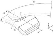
- Figure 1is a perspective view showing a user wearing an exercise assistance device according to an embodiment.
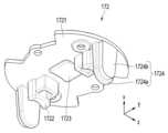
- Figure 2is a perspective view showing a driving frame, a mount, a slider, and a slider housing according to one embodiment.
- Figure 3is an exploded perspective view showing a driving frame, an upper mount, a lower mount, a friction reduction member, a shaft, a slider, and a slider housing according to an embodiment.
- Figure 4is a cross-sectional view taken along the cutting line IV-IV of Figure 2.
- Figure 5is a perspective view showing a lower mount according to one embodiment.
- Figure 6is a perspective view showing an upper mount according to one embodiment.
- Figure 7is a side view showing a friction reduction member supported by an upper holder and a lower groove according to an embodiment.
- Figure 8is a side view showing a shaft supported by a slider head according to one embodiment.
- Figure 9is a perspective view schematically showing an exercise assistance device worn on a user's upper arm according to an embodiment.
- first or secondmay be used to describe various components, but these terms should be interpreted only for the purpose of distinguishing one component from another component.
- a first componentmay be named a second component, and similarly, the second component may also be named a first component.
- Figure 1is a perspective view showing a user wearing an exercise assistance device according to an embodiment.
- Figure 2is a perspective view showing a driving frame, a mount, a slider, and a slider housing according to one embodiment.
- Figure 3is an exploded perspective view showing a driving frame, an upper mount, a lower mount, a friction reduction member, a shaft, a slider, and a slider housing according to an embodiment.
- Figure 4is a cross-sectional view taken along the cutting line IV-IV of Figure 2.
- an exercise assistance device 1may be worn by a user and assist the user's exercise.
- the usermay be a human body, an animal, or a robot, but is not limited thereto.
- the exercise assistance device 1can assist the movement of some joints of the lower body or upper body.
- the exercise assistance device 1may assist lower body exercise by assisting at least one joint of the hip joint, knee joint, and ankle joint.
- the exercise assistance device 1may assist upper body exercise by assisting at least one joint of the shoulder joint, elbow joint, and wrist joint.
- the exercise assistance device 1can assist walking by assisting the movement of some joints of the user's lower body.
- the exercise assistance device 1may include a proximal support 11, a distal support 12, an actuator 13, a drive frame 14, a slider housing 15, a slider 16, and a mount 17. .
- the proximal support 11 and the distal support 12are disposed on opposite sides of a portion of the user and may support the proximal part and the distal part, respectively.
- the proximal support 11may support the lower back and/or pelvis
- the distal support 12may support the thighs, knees, calves, and/or feet.
- the proximal support portion 11may include a detachable belt for overall support of the user's waist.
- Distal support 12may include a removable belt for overall support of the user's thighs.
- the proximal support 11 and the distal support 12may be disposed on opposite sides of the user's upper arm, and the proximal support 11 may be located on, for example, the shoulder and/or back ( back, etc., and the distal support 12 may support, for example, the forearm.
- the proximal support 11may include a detachable belt to generally support the user's shoulder
- the distal support 12may include a detachable belt to generally support the user's forearm or the forearm as a whole. May include an enclosing structure.
- the proximal support 11 and the distal support 12are capable of relative movement in the sagittal plane.
- the distal support 12rotates relative to the proximal support 11 in the sagittal plane. can do.
- the proximal support 11 and the distal support 12are capable of relative movement in the frontal plane.
- the distal support 12rotates relative to the proximal support 11 in the coronal plane. can do.
- drive frame 14 and distal support 12are capable of relative movement in a transverse plane.
- the distal support 12may rotate together with the thigh while being in close contact with the thigh.
- the distal support 12is rotatable relative to the drive frame 14. According to this structure, the user's wearing comfort can be improved.
- actuator 13is connected to proximal support 11 and can generate power.
- the actuator 13may include a motor and a reducer, for example.
- the motormay include at least one of a brush motor, a brushless motor, and a stepping motor.
- the motormay include at least one of an induction motor and a synchronous motor.
- the reducermay include, for example, a gear train.
- drive frame 14may transmit power generated by actuator 13 to distal support 12.
- the drive frame 14may assist the user's hip movements.
- the driving frame 14can receive power from the actuator 13 to assist the bending movement of the hip joint.
- the driving frame 14may receive power from the actuator 13 to assist the stretching movement of the hip joint.
- the driving frame 14is described as assisting hip joint movement, it should be noted that the function of the driving frame 14 is not limited thereto.
- the drive frame 14may assist the shoulder or elbow joint.
- slider housing 15is connected to distal support 12 and may face drive frame 14.
- the slider housing 15may have a shape that surrounds the distal portion of the user.
- the slider housing 15may rotate relative to the drive frame 14 in the sagittal plane.
- the slider housing 15may have a sliding space in which the slider 16 can move.
- the sliding spacemay be formed in the y-axis direction or the z-axis direction.
- the slider 16may be provided to be slidable within the slider housing 15.
- the slider 16may move along a rail provided within the slider housing 15.
- the slider 16may move by the elasticity of a spring provided within the slider housing 15.
- the slider 16can move along the sliding space.
- the slider 16may move in the y-axis direction or the z-axis direction with respect to the slider housing 15.
- the distal support 12is movable relative to the drive frame 14 .
- the slider 16may include a slider body 161, a slider head 162, and a head hole 163.
- the slider body 161may be provided to slide in a sliding space.
- the slider head 162may protrude from the slider body 161.
- the slider head 162may be formed at the center of the slider body 161.
- the slider head 162can be accommodated inside the mount 17.
- the slider head 162may have a convex shape in a direction away from the slider body 161.
- the head hole 163may be formed through the slider head 162.
- mount 17may connect drive frame 14 and slider 16.
- the mount 17may be disposed between the driving frame 14 and the slider 16.
- the slider 16may not be directly connected to the drive frame 14. The magnitude of the twisting, rotational or shear force transmitted from the drive frame 14 to the slider 16 can be reduced.
- a shaft 18 and a friction reduction member 19may be provided within the mount 17.
- the mount 17may include a lower mount 171 and an upper mount 172.
- the lower mount 171 and the upper mount 172are provided on opposite sides of the shaft 18 and can be coupled to each other.
- shaft 18may pass through head hole 163 and be secured to slider head 162.
- Slider 16may not rotate relative to shaft 18.
- the slider 16can rotate integrally with the shaft 18.
- the slider housing 15can rotate relative to the mount 17.
- the distal support 12is rotatable relative to the proximal support 11 .
- the friction reduction member 19may be supported by the lower mount 171 and the upper mount 172.
- the friction reduction member 19may be fixed inside the mount 17.
- the friction reduction member 19may support the shaft 18.
- the friction reduction member 19may be a bush into which the shaft 18 can be inserted.
- a plurality of friction reduction members 19may be provided.
- the friction reduction members 19may be provided as a pair.
- the slider head 162may be provided between a pair of friction reduction members 19.
- the friction reduction memberis shown as a bush, but it should be noted in advance that the type of friction reduction member is not necessarily limited thereto.
- the friction reducing membermay be a bearing.
- Figure 5is a perspective view showing a lower mount according to one embodiment.
- Figure 6is a perspective view showing an upper mount according to one embodiment.
- Figure 7is a side view showing a friction reduction member supported by an upper holder and a lower groove according to an embodiment.
- Figure 8is a side view showing a shaft supported by a slider head according to one embodiment.
- the mount 17may accommodate a slider head 162, a shaft 18, and a friction reduction member 19 therein.
- the lower mount 171may include a lower body 1711, a main hole 1712, a lower groove 1713, a mount rib 1714, and a lower wing 1715.
- lower body 1711can accommodate shaft 18.
- the main hole 1712is formed through the lower body 1711 and can accommodate the slider head 162.
- the main hole 1712may be formed at the center of the lower body 1711.
- lower groove 1713may accommodate friction reduction member 19.
- two lower grooves 1713may be provided on both sides of the main hole 1712.
- the lower groove 1713may be recessed in the lower body 1711.
- the lower groove 1713may have a U shape.
- the width D of the lower groove 1713may be equal to or larger than the outer diameter of the friction reduction member 19.
- the lower groove 1713may communicate with the main hole 1712.
- the lower groove 1713may also communicate with the outside of the lower body 1711.
- the shaft 18may pass through the width D of the lower groove 1713 and be supported by the friction reduction member 19 and the slider head 162.
- the mount rib 1714may be formed along the edge of the lower groove 1713.
- the mount rib 1714may be formed in a portion where the lower groove 1713 and the main hole 1712 communicate (1714a, hereinafter referred to as the “first rib”).
- the mount rib 1714may be formed in a portion where the lower groove 1713 and the outer side of the lower body 1711 communicate (1714b, hereinafter referred to as the “second rib”).
- a first rib 1714a and a second rib 1714bmay be formed in one lower groove 1713.
- the mount rib 1714may support the friction reduction member 19. Separation of the friction reduction member 19 from the lower groove 1713 can be reduced.
- the lower wing 1715may protrude from the lower body 1711 toward the driving frame.
- the lower wing 1715may be detachably connected to the drive frame.
- the lower wing 1715may be connected by rotation after being accommodated in the driving frame.
- the lower wing 1715may be screwed to the drive frame. Maintenance and repair of exercise assistance devices can be easy.
- the upper mount 172may include an upper plate 1721, an upper holder 1722, a support 1723, and an upper wing 1724.
- the upper plate 1721 and the driving framemay face each other.
- the upper plate 1721may be detachably coupled to the lower body 1711.
- the upper plate 1721may be screw-fastened to the lower body 1711. If the shaft 18 or the friction reduction member 19 is damaged or worn, the upper plate 1721 can be separated from the lower body 1711 and the damaged or worn component can be replaced. Maintenance and repair costs for exercise assistive devices can be reduced.
- the upper holder 1722may protrude from the upper plate 1721 toward the slider.
- the upper holders 1722may be provided as a pair.
- the friction reduction member 19may be supported by an upper holder 1722 and a lower body 1711 provided in opposite directions with respect to the shaft 18.
- the friction reduction member 19may be fixed inside the mount.
- the friction reduction member 19may not rotate relative to the mount.
- the surface of the upper holder 1722 that contacts the friction reduction member 19may have a curved shape.
- the upper holder 1722may cover a portion of the friction reduction member 19. The shaking of the friction reduction member 19 can be reduced. Stable rotation of the shaft 18 relative to the friction reduction member 19 may be possible.
- the support 1723may protrude from the upper plate 1721 toward the slider body 161.
- the support 1723may be provided in contact with the slider head 162.
- the slider head 162may not directly contact the upper plate 1721.
- the slider head 162can be stably supported by the support 1723.
- the surface of the support 1723 that contacts the slider head 162may have a curved shape.
- the curvature of the support 1723may be the same as the curvature of the slider head 162. Damage or wear of the slider head 162 may be reduced. Stable rotation of the slider relative to the mount may be possible.
- upper wing 1724may be received in lower groove 1713.
- the upper wing 1724may be formed to protrude from the upper plate 1721 toward the slider.
- the upper wings 1724may be provided as a pair facing each other along the longitudinal direction of the shaft 18.
- the upper wing 1724may be spaced apart from the upper holder 1722.
- the upper wing 1724may overlap the upper holder 1722 based on the longitudinal direction of the shaft 18.
- the friction reduction member 19may be provided between the slider head 162 and the upper wing 1724.
- the shaft 18may not fall out of the mount. In a state where the upper mount 172 is coupled to the lower mount 171, the upper mount 172 may not move with respect to the lower mount 171.
- the upper mount 172can be stably coupled to the lower mount 171.
- the upper wing 1724may include a wing body 1724a and a wing head 1724b.
- the wing body 1724amay be inserted into the lower groove 1713.
- the mount rib 1714may overlap the wing body 1724a based on the longitudinal direction of the shaft 18.
- the friction reduction member 19 and the wing body 1724amay be accommodated between the first rib 1714a and the second rib 1714b.
- the friction reduction member 19may be provided between the first rib 1714a and the wing body 1724a.
- the wing body 1724amay be provided between the friction reduction member 19 and the second rib 1714b.
- the range in which the friction reduction member 19 can move along the longitudinal direction of the shaft 18may be reduced. Noise and noise arising from the movement of the friction reduction member 19 can be reduced.
- the wing head 1724bprotrudes outward from the wing body 1724a and may be supported on the second rib 1714b.
- the outer edge of the lower body 1711may have a smooth shape without any outward protruding portion. The amount of foreign matter penetrating into the mount can be reduced. Damage or wear of the wing head 1724b due to chafing may be reduced.
- shaft 18may include a curved surface 181 and a cutting surface 182.
- the curved surface 181may contact the inner surface of the friction reduction member 19.
- the shaft 18can rotate relative to the friction reduction member 19.
- at least one cutting surface 182may contact the slider head 162.
- Shaft 18may not rotate relative to slider head 162.
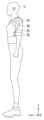
- Figure 9is a diagram schematically showing an exercise assistance device worn on a user's upper arm according to an embodiment.
- the exercise assistance devicemay be mounted on the upper arm of the user (U).
- the actuator 93 of the exercise assistance devicemay be provided near the shoulder of the user (U), and the driving frame 94 may be connected to the actuator 93 and disposed along the upper arm of the user (U). there is.
- the slider housing 95may be provided on the forearm of the user (U).
- the distal support portion 92may entirely surround and support the forearm of the user (U).
- the shaftmay be rotatable relative to the friction reduction member while supported by the slider head.
- the mountmay include an upper mount and a lower mount that are provided on opposite sides of the shaft and can be coupled to each other.
- the upper mountmay include an upper plate and an upper holder that protrudes from the upper plate and supports the friction reduction member.
- the upper mountmay further include a support bar that protrudes from the upper plate toward the slider body and is in contact with the slider head.
- the slider headmay have a convex shape in a direction away from the slider body.
- the lower mountincludes a lower body accommodating the shaft, a main hole formed through the lower body and accommodating the slider head, and accommodating the friction reduction member and communicating with the main hole. May include a lower home.
- the width of the lower groovemay be equal to or greater than the outer diameter of the friction reduction member.
- the upper mountmay further include an upper wing protruding from the upper plate toward the slider.
- the upper wingmay be spaced apart from the upper holder.
- the friction reduction membermay be provided between the slider head and the upper wing.
- the lower mountmay further include a mount rib formed along an edge of the lower groove.
- the mount ribmay cover at least a portion of the upper wing.
- the mount ribmay overlap the upper wing based on the longitudinal direction of the shaft.
- the upper wingmay include a wing body inserted into the lower groove, and a wing head that protrudes outward from the wing body and is supported by the mount rib.
- the shaftmay include a cutting surface that contacts the slider head.
- the friction reducing membermay be a bush.
- the friction reduction membermay be a bearing.
Landscapes
- Health & Medical Sciences (AREA)
- General Health & Medical Sciences (AREA)
- Physical Education & Sports Medicine (AREA)
- Life Sciences & Earth Sciences (AREA)
- Animal Behavior & Ethology (AREA)
- Rehabilitation Therapy (AREA)
- Pain & Pain Management (AREA)
- Epidemiology (AREA)
- Public Health (AREA)
- Veterinary Medicine (AREA)
- Orthopedic Medicine & Surgery (AREA)
- Biophysics (AREA)
- Rehabilitation Tools (AREA)
- Manipulator (AREA)
Abstract
Description
Translated fromKorean본 발명은 마찰 저감 부재가 수용된 마운트를 포함하는 운동 보조 장치에 관한 것이다.The present invention relates to an exercise assistance device including a mount accommodating a friction reduction member.
최근 고령화 사회가 심화됨에 따라서 관절에 문제가 있어서 이에 대한 고통과 불편을 호소하는 사람들이 증가하고 있으며, 관절이 불편한 노인이나 환자들이 보행을 원활하게 할 수 있는 보조 장치에 대한 관심이 높아지고 있다. 운동 보조 장치는, 특정 부위의 근력을 강화하는 목적으로도 착용될 수 있다.Recently, as the aging society intensifies, the number of people complaining of pain and discomfort due to joint problems is increasing, and interest in assistive devices that can help elderly people or patients with joint discomfort walk smoothly is increasing. Exercise assist devices can also be worn for the purpose of strengthening muscles in specific areas.
일 실시예에 따른 마찰 저감 부재가 수용된 마운트를 포함하는 운동 보조 장치는, 사용자의 근위 부분을 지지하기 위한 근위 지지부, 상기 사용자의 원위 부분을 지지하기 위한 원위 지지부, 상기 근위 지지부에 연결되고, 동력을 생성하는 액추에이터, 상기 액추에이터로부터 상기 원위 지지부로 동력을 전달하는 구동 프레임, 상기 원위 지지부에 연결되고 슬라이딩 공간을 구비하는 슬라이더 하우징, 상기 슬라이딩 공간에서 슬라이딩 가능하게 마련되는 슬라이더 바디와, 상기 슬라이더 바디로부터 돌출 형성되는 슬라이더 헤드와, 상기 슬라이더 헤드에 관통 형성되는 헤드 홀을 포함하는 슬라이더, 상기 구동 프레임에 연결되고, 상기 슬라이더 헤드를 내부에 수용하는 마운트, 상기 헤드 홀을 관통하고, 상기 슬라이더 헤드에 고정되는 샤프트 및 상기 샤프트를 지지하고, 상기 마운트에 수용되는 마찰 저감 부재를 포함할 수 있다.An exercise assistance device including a mount accommodating a friction reduction member according to one embodiment includes a proximal support portion for supporting a proximal portion of a user, a distal support portion for supporting a distal portion of the user, and a power source connected to the proximal support portion. an actuator that generates an actuator, a driving frame that transmits power from the actuator to the distal support, a slider housing connected to the distal support and having a sliding space, a slider body provided to be able to slide in the sliding space, and from the slider body A slider including a protruding slider head and a head hole formed through the slider head, a mount connected to the driving frame and accommodating the slider head therein, penetrating the head hole and fixed to the slider head. It may include a shaft and a friction reduction member that supports the shaft and is accommodated in the mount.
도 1은 일 실시예에 따른 운동 보조 장치를 착용한 사용자의 모습을 도시하는 사시도이다.Figure 1 is a perspective view showing a user wearing an exercise assistance device according to an embodiment.
도 2는 일 실시예에 따른 구동 프레임, 마운트, 슬라이더 및 슬라이더 하우징을 도시하는 사시도이다.Figure 2 is a perspective view showing a driving frame, a mount, a slider, and a slider housing according to one embodiment.
도 3은 일 실시예에 따른 구동 프레임, 어퍼 마운트, 로어 마운트, 마찰 저감 부재, 샤프트, 슬라이더 및 슬라이더 하우징을 도시하는 분해 사시도이다.Figure 3 is an exploded perspective view showing a driving frame, an upper mount, a lower mount, a friction reduction member, a shaft, a slider, and a slider housing according to an embodiment.
도 4는 도 2의 절개선 Ⅳ-Ⅳ를 따라 절개한 단면도이다.Figure 4 is a cross-sectional view taken along the cutting line IV-IV of Figure 2.
도 5는 일 실시예에 따른 로어 마운트를 도시하는 사시도이다.Figure 5 is a perspective view showing a lower mount according to one embodiment.
도 6은 일 실시예에 따른 어퍼 마운트를 도시하는 사시도이다.Figure 6 is a perspective view showing an upper mount according to one embodiment.
도 7은 일 실시예에 따른 마찰 저감 부재가 어퍼 홀더 및 로어 홈에 의해 지지되는 모습을 도시하는 측면도이다.Figure 7 is a side view showing a friction reduction member supported by an upper holder and a lower groove according to an embodiment.
도 8은 일 실시예에 따른 샤프트가 슬라이더 헤드에 의해 지지되는 모습을 도시하는 측면도이다.Figure 8 is a side view showing a shaft supported by a slider head according to one embodiment.
도 9는 일 실시예에 따른 운동 보조 장치가 사용자의 상박에 착용된 모습을 개략적으로 도시한 사시도이다.Figure 9 is a perspective view schematically showing an exercise assistance device worn on a user's upper arm according to an embodiment.
실시예들에 대한 특정한 구조적 또는 기능적 설명들은 단지 예시를 위한 목적으로 개시된 것으로서, 다양한 형태로 변경되어 구현될 수 있다. 따라서, 실제 구현되는 형태는 개시된 특정 실시예로만 한정되는 것이 아니며, 본 명세서의 범위는 실시예들로 설명한 기술적 사상에 포함되는 변경, 균등물, 또는 대체물을 포함한다.Specific structural or functional descriptions of the embodiments are disclosed for illustrative purposes only and may be changed and implemented in various forms. Accordingly, the actual implementation form is not limited to the specific disclosed embodiments, and the scope of the present specification includes changes, equivalents, or substitutes included in the technical idea described in the embodiments.
제 1 또는 제 2 등의 용어를 다양한 구성요소들을 설명하는데 사용될 수 있지만, 이런 용어들은 하나의 구성요소를 다른 구성요소로부터 구별하는 목적으로만 해석되어야 한다. 예를 들어, 제 1 구성요소는 제 2 구성요소로 명명될 수 있고, 유사하게 제 2 구성요소는 제 1 구성요소로도 명명될 수 있다.Terms such as first or second may be used to describe various components, but these terms should be interpreted only for the purpose of distinguishing one component from another component. For example, a first component may be named a second component, and similarly, the second component may also be named a first component.
어떤 구성요소가 다른 구성요소에 "연결되어" 있다고 언급된 때에는, 그 다른 구성요소에 직접적으로 연결되어 있거나 또는 접속되어 있을 수도 있지만, 중간에 다른 구성요소가 존재할 수도 있다고 이해되어야 할 것이다.When a component is referred to as being “connected” to another component, it should be understood that it may be directly connected or connected to the other component, but that other components may exist in between.
단수의 표현은 문맥상 명백하게 다르게 뜻하지 않는 한, 복수의 표현을 포함한다. 본 명세서에서, "포함하다" 또는 "가지다" 등의 용어는 설명된 특징, 숫자, 단계, 동작, 구성요소, 부분품 또는 이들을 조합한 것이 존재함으로 지정하려는 것이지, 하나 또는 그 이상의 다른 특징들이나 숫자, 단계, 동작, 구성요소, 부분품 또는 이들을 조합한 것들의 존재 또는 부가 가능성을 미리 배제하지 않는 것으로 이해되어야 한다.Singular expressions include plural expressions unless the context clearly dictates otherwise. In this specification, terms such as “comprise” or “have” are intended to designate the presence of the described features, numbers, steps, operations, components, parts, or combinations thereof, and are intended to indicate the presence of one or more other features or numbers, It should be understood that this does not exclude in advance the possibility of the presence or addition of steps, operations, components, parts, or combinations thereof.
어느 하나의 실시 예에 포함된 구성 요소와, 공동적인 기능을 포함하는 구성 요소는, 다른 실시 예에서 동일한 명칭을 사용하여 설명하기로 한다. 반대되는 기재가 없는 이상, 어느 하나의 실시 예에 기재한 설명은 다른 실시 예에도 적용될 수 있으며, 중복되는 범위에서 구체적인 설명은 생략하기로 한다.Components included in one embodiment and components including common functions will be described using the same names in other embodiments. Unless stated to the contrary, the description given in one embodiment may be applied to other embodiments, and detailed description will be omitted to the extent of overlap.
다르게 정의되지 않는 한, 기술적이거나 과학적인 용어를 포함해서 여기서 사용되는 모든 용어들은 해당 기술 분야에서 통상의 지식을 가진 자에 의해 일반적으로 이해되는 것과 동일한 의미를 가진다. 일반적으로 사용되는 사전에 정의되어 있는 것과 같은 용어들은 관련 기술의 문맥상 가지는 의미와 일치하는 의미를 갖는 것으로 해석되어야 하며, 본 명세서에서 명백하게 정의하지 않는 한, 이상적이거나 과도하게 형식적인 의미로 해석되지 않는다.Unless otherwise defined, all terms used herein, including technical or scientific terms, have the same meaning as commonly understood by a person of ordinary skill in the art. Terms as defined in commonly used dictionaries should be interpreted as having meanings consistent with the meanings they have in the context of the related technology, and unless clearly defined in this specification, should not be interpreted in an idealized or overly formal sense. No.
이하, 실시예들을 첨부된 도면들을 참조하여 상세하게 설명한다. 첨부 도면을 참조하여 설명함에 있어, 도면 부호에 관계없이 동일한 구성 요소는 동일한 참조 부호를 부여하고, 이에 대한 중복되는 설명은 생략하기로 한다.Hereinafter, embodiments will be described in detail with reference to the attached drawings. In the description with reference to the accompanying drawings, identical components will be assigned the same reference numerals regardless of the reference numerals, and overlapping descriptions thereof will be omitted.
도 1은 일 실시예에 따른 운동 보조 장치를 착용한 사용자의 모습을 도시하는 사시도이다. 도 2는 일 실시예에 따른 구동 프레임, 마운트, 슬라이더 및 슬라이더 하우징을 도시하는 사시도이다. 도 3은 일 실시예에 따른 구동 프레임, 어퍼 마운트, 로어 마운트, 마찰 저감 부재, 샤프트, 슬라이더 및 슬라이더 하우징을 도시하는 분해 사시도이다. 도 4는 도 2의 절개선 Ⅳ-Ⅳ를 따라 절개한 단면도이다.Figure 1 is a perspective view showing a user wearing an exercise assistance device according to an embodiment. Figure 2 is a perspective view showing a driving frame, a mount, a slider, and a slider housing according to one embodiment. Figure 3 is an exploded perspective view showing a driving frame, an upper mount, a lower mount, a friction reduction member, a shaft, a slider, and a slider housing according to an embodiment. Figure 4 is a cross-sectional view taken along the cutting line IV-IV of Figure 2.
도 1 내지 도 4를 참조하면, 일 실시예에 따른 운동 보조 장치(1)는, 사용자에 착용되어 사용자의 운동을 보조할 수 있다. 사용자는 인체, 동물 또는 로봇 등일 수도 있으며, 이에 제한되지 않는다. 운동 보조 장치(1)는 하체 또는 상체 중 일부 관절의 운동을 보조할 수 있다. 예를 들어, 운동 보조 장치(1)는 고관절, 무릎 관절 및 발목 관절 중 적어도 하나 이상의 관절을 보조하는 방식으로 하체 운동을 보조할 수 있다. 예를 들어, 운동 보조 장치(1)는 어깨 관절, 팔꿈치 관절 및 손목 관절 중 적어도 하나 이상의 관절을 보조하는 방식으로 상체 운동을 보조할 수 있다. 운동 보조 장치(1)는 사용자의 하체 중 일부 관절의 운동을 보조하는 방식으로, 보행을 보조할 수 있다. 이하, 운동 보조 장치(1)가 사용자의 고관절 운동을 보조함으로써 보행을 보조하는 것을 기준으로 설명하나, 운동 보조 장치(1)의 착용 부위 및 타겟 관절은 이에 제한되지 않음을 밝혀 둔다. 운동 보조 장치(1)는 근위 지지부(11), 원위 지지부(12), 액추에이터(13), 구동 프레임(14), 슬라이더 하우징(15), 슬라이더(16) 및 마운트(17)를 포함할 수 있다.Referring to FIGS. 1 to 4 , an exercise assistance device 1 according to an embodiment may be worn by a user and assist the user's exercise. The user may be a human body, an animal, or a robot, but is not limited thereto. The exercise assistance device 1 can assist the movement of some joints of the lower body or upper body. For example, the exercise assistance device 1 may assist lower body exercise by assisting at least one joint of the hip joint, knee joint, and ankle joint. For example, the exercise assistance device 1 may assist upper body exercise by assisting at least one joint of the shoulder joint, elbow joint, and wrist joint. The exercise assistance device 1 can assist walking by assisting the movement of some joints of the user's lower body. Hereinafter, the exercise assistance device 1 will be described on the basis that it assists walking by assisting the user's hip joint movement, but it should be noted that the wearing part and target joint of the exercise assistance device 1 are not limited thereto. The exercise assist device 1 may include a
일 실시예에서, 근위 지지부(11) 및 원위 지지부(12)는, 사용자의 일 부분을 기준으로 서로 반대편에 배치되어, 각각 근위 부분(proximal part) 및 원위 부분(distal part)을 지지할 수 있다. 예를 들어, 근위 지지부(11)는 허리 및/또는 골반 등을 지지할 수 있고, 원위 지지부(12)는 허벅지, 무릎, 종아리 및/또는 발 등을 지지할 수 있다. 근위 지지부(11)는 사용자의 허리를 전체적으로 지지하기 위한 탈부착식 벨트를 포함할 수 있다. 원위 지지부(12)는 사용자의 허벅지를 전체적으로 지지하기 위한 탈부착식 벨트를 포함할 수 있다.In one embodiment, the
다른 예로, 근위 지지부(11) 및 원위 지지부(12)는, 사용자의 상박(upper arm)을 중심으로 서로 반대편에 배치될 수 있으며, 근위 지지부(11)는, 예를 들어 어깨 및/또는 등(back) 등을 지지할 수 있고, 원위 지지부(12)는, 예를 들어, 팔뚝(forearm) 등을 지지할 수 있다. 예를 들어, 근위 지지부(11)는 사용자의 어깨를 전체적으로 지지하기 위한 탈부착식 벨트를 포함할 수 있고, 원위 지지부(12)는 사용자의 팔뚝을 전체적으로 지지하기 위한 탈부착식 벨트를 포함하거나 팔뚝을 전체적으로 둘러싸는 구조를 포함할 수 있다.As another example, the
일 실시예에서, 근위 지지부(11) 및 원위 지지부(12)는 시상면(sagittal plane) 상에서 상대적인 움직임이 가능하다. 예를 들어, 사용자가 운동 보조 장치(1)를 착용한 상태에서, 고관절 굽힘(flexion) 또는 신장(extension)할 때, 원위 지지부(12)는 시상면 상에서 근위 지지부(11)에 대해서 상대적으로 회전할 수 있다.In one embodiment, the
일 실시예에서, 근위 지지부(11) 및 원위 지지부(12)는 관상면(frontal plane) 상에서 상대적인 움직임이 가능하다. 예를 들어, 사용자가 운동 보조 장치(1)를 착용한 상태에서, 고관절 내전(adduction) 또는 외전(abduction)할 때, 원위 지지부(12)는 관상면 상에서 근위 지지부(11)에 대해서 상대적으로 회전할 수 있다.In one embodiment, the
일 실시예에서, 구동 프레임(14) 및 원위 지지부(12)는 횡단면(transverse plane) 상에서 상대적인 움직임이 가능하다. 예를 들어, 사용자가 운동 보조 장치(1)를 착용한 상태에서, 허벅지를 회전시킬 경우, 원위 지지부(12)는 허벅지에 밀착한 상태로 허벅지와 함께 회전할 수 있다. 다시 말하면, 원위 지지부(12)는 구동 프레임(14)에 대해서 상대적으로 회전 가능하다. 이와 같은 구조에 따르면, 사용자의 착용감은 향상될 수 있다.In one embodiment, drive
일 실시예에서, 액추에이터(13)는 근위 지지부(11)에 연결되고 동력을 생성할 수 있다. 액추에이터(13)는 예를 들어 모터 및 감속기를 포함할 수 있다. 모터는 브러시 모터(brush motor), 브러시리스 모터(brushless motor) 및 스테핑 모터(stepping motor) 중 적어도 하나를 포함할 수 있다. 모터는 유도 모터 및 동기 모터 중 적어도 하나를 포함할 수 있다. 감속기는 예를 들어 기어 트레인을 포함할 수 있다.In one embodiment,
일 실시예에서, 구동 프레임(14)은 액추에이터(13)에 의해 생성된 동력을 원위 지지부(12)로 전달할 수 있다. 예를 들어, 구동 프레임(14)은 사용자의 고관절 움직임을 보조할 수 있다. 액추에이터(13)의 출력단이 일방향으로 회전할 경우, 구동 프레임(14)은 액추에이터(13)로부터 동력을 전달받아 고관절의 굽힘 운동을 보조할 수 있다. 액추에이터(13)의 출력단이 일방향의 반대 방향으로 회전할 경우, 구동 프레임(14)은 액추에이터(13)로부터 동력을 전달받아 고관절의 신장 운동을 보조할 수 있다. 구동 프레임(14)이 고관절 운동을 보조하는 것으로 설명되나, 구동 프레임(14)의 기능은 이에 제한되지 않음을 밝혀 둔다. 예를 들어, 운동 보조 장치(1)가 상체 관절의 움직임을 보조하는데 사용될 경우, 구동 프레임(14)은 어깨 또는 팔꿈치 관절을 보조할 수 있다.In one embodiment,
일 실시예에서, 슬라이더 하우징(15)은 원위 지지부(12)에 연결되고 구동 프레임(14)을 마주할 수 있다. 예를 들어, 슬라이더 하우징(15)은 사용자의 원위 부분을 감싸는 형상을 가질 수 있다. 사용자가 운동 보조 장치(1)를 착용한 상태에서, 고관절 굽힘 또는 신장할 때, 슬라이더 하우징(15)은 시상면 상에서 구동 프레임(14)에 대해서 상대적으로 회전할 수 있다. 슬라이더 하우징(15)은 슬라이더(16)가 이동할 수 있는 슬라이딩 공간을 구비할 수 있다. 예를 들어, 슬라이딩 공간은 y축 방향 또는 z축 방향으로 형성될 수 있다.In one embodiment,
일 실시예에서, 슬라이더(16)는 슬라이더 하우징(15) 내에서 슬라이딩 가능하게 마련될 수 있다. 예를 들어, 슬라이더(16)는 슬라이더 하우징(15) 내에 마련된 레일을 따라 이동할 수 있다. 예를 들어, 슬라이더(16)는 슬라이더 하우징(15) 내에 마련된 스프링의 탄성에 의해 이동할 수 있다. 슬라이더(16)는 슬라이딩 공간을 따라 이동할 수 있다. 예를 들어, 슬라이더(16)는 슬라이더 하우징(15)에 대해 y축 방향 또는 z축 방향으로 이동할 수 있다. 원위 지지부(12)는 구동 프레임(14)에 대해 상대적으로 움직일 수 있다. 슬라이더(16)는 슬라이더 바디(161), 슬라이더 헤드(162) 및 헤드 홀(163)을 포함할 수 있다.In one embodiment, the
일 실시예에서, 슬라이더 바디(161)는 슬라이딩 공간에서 슬라이딩 가능하게 마련될 수 있다. 슬라이더 헤드(162)는 슬라이더 바디(161)로부터 돌출 형성될 수 있다. 예를 들어, 슬라이더 헤드(162)는 슬라이더 바디(161)의 중심에 형성될 수 있다. 슬라이더 헤드(162)는 마운트(17) 내부에 수용될 수 있다. 예를 들어, 슬라이더 헤드(162)는 슬라이더 바디(161)로부터 멀어지는 방향으로 볼록한 형상을 가질 수 있다. 헤드 홀(163)은 슬라이더 헤드(162)에 관통 형성될 수 있다.In one embodiment, the
일 실시예에서, 마운트(17)는 구동 프레임(14)과 슬라이더(16)를 연결할 수 있다. 마운트(17)는 구동 프레임(14)과 슬라이더(16) 사이에 배치될 수 있다. 슬라이더(16)는 구동 프레임(14)에 직접 연결되지 않을 수 있다. 구동 프레임(14)으로부터 슬라이더(16)로 전달되는 뒤틀림, 회전 또는 전단력의 크기는 감소할 수 있다.In one embodiment, mount 17 may connect
일 실시예에서, 마운트(17) 내에 샤프트(18) 및 마찰 저감 부재(19)가 마련될 수 있다. 마운트(17)는 로어 마운트(171) 및 어퍼 마운트(172)를 포함할 수 있다. 로어 마운트(171) 및 어퍼 마운트(172)는 샤프트(18)를 기준으로 반대편에 마련되고 서로 결합할 수 있다.In one embodiment, a
일 실시예에서, 샤프트(18)는 헤드 홀(163)을 통과하고, 슬라이더 헤드(162)에 고정될 수 있다. 슬라이더(16)는 샤프트(18)에 대해서 회전하지 않을 수 있다. 슬라이더(16)는 샤프트(18)와 일체로 회전할 수 있다. 슬라이더 하우징(15)은 마운트(17)에 대해서 회전할 수 있다. 원위 지지부(12)는 근위 지지부(11)에 대해서 회전할 수 있다.In one embodiment,
일 실시예에서, 마찰 저감 부재(19)는 로어 마운트(171) 및 어퍼 마운트(172)에 의해 지지될 수 있다. 마찰 저감 부재(19)는 마운트(17) 내부에 고정될 수 있다. 마찰 저감 부재(19)는 샤프트(18)를 지지할 수 있다. 예를 들어, 마찰 저감 부재(19)는 샤프트(18)가 삽입될 수 있는 부시(bush)일 수 있다. 샤프트(18)가 마찰 저감 부재(19)에 지지된 상태에서 회전하는 경우, 소음 또는 이음(squeak)은 감소할 수 있다. 샤프트(18)의 회전으로부터 발생하는 분진은 감소할 수 있다. 운동 보조 장치(1)의 착용감은 향상될 수 있다.In one embodiment, the
일 실시예에서, 마찰 저감 부재(19)는 복수 개로 마련될 수 있다. 예를 들어, 마찰 저감 부재(19)는 한 쌍으로 마련될 수 있다. 슬라이더 헤드(162)는 한 쌍의 마찰 저감 부재(19) 사이에 마련될 수 있다.In one embodiment, a plurality of
본 명세서의 도면에서는 마찰 저감 부재가 부시인 것으로 도시되었으나, 마찰 저감 부재의 종류는 반드시 이에 제한되지 않음을 미리 밝혀 둔다. 예를 들어, 마찰 저감 부재는 베어링일 수 있다.In the drawings of this specification, the friction reduction member is shown as a bush, but it should be noted in advance that the type of friction reduction member is not necessarily limited thereto. For example, the friction reducing member may be a bearing.
도 5는 일 실시예에 따른 로어 마운트를 도시하는 사시도이다. 도 6은 일 실시예에 따른 어퍼 마운트를 도시하는 사시도이다. 도 7은 일 실시예에 따른 마찰 저감 부재가 어퍼 홀더 및 로어 홈에 의해 지지되는 모습을 도시하는 측면도이다. 도 8은 일 실시예에 따른 샤프트가 슬라이더 헤드에 의해 지지되는 모습을 도시하는 측면도이다.Figure 5 is a perspective view showing a lower mount according to one embodiment. Figure 6 is a perspective view showing an upper mount according to one embodiment. Figure 7 is a side view showing a friction reduction member supported by an upper holder and a lower groove according to an embodiment. Figure 8 is a side view showing a shaft supported by a slider head according to one embodiment.
도 5내지 도 8을 참조하면, 일 실시예에 따른 마운트(17)는 내부에 슬라이더 헤드(162), 샤프트(18) 및 마찰 저감 부재(19)를 수용할 수 있다. 로어 마운트(171)는 로어 바디(1711), 메인 홀(1712), 로어 홈(1713), 마운트 리브(1714) 및 로어 날개(1715)를 포함할 수 있다.Referring to FIGS. 5 to 8 , the
일 실시예에서, 로어 바디(1711)는 샤프트(18)를 수용할 수 있다. 메인 홀(1712)은 로어 바디(1711)에 관통 형성되고 슬라이더 헤드(162)를 수용할 수 있다. 예를 들어, 메인 홀(1712)은 로어 바디(1711)의 중심에 형성될 수 있다.In one embodiment,
일 실시예에서, 로어 홈(1713)은 마찰 저감 부재(19)를 수용할 수 있다. 예를 들어, 로어 홈(1713)은 메인 홀(1712)의 양 측에 두 개로 마련될 수 있다. 로어 홈(1713)은 로어 바디(1711)에 함몰 형성될 수 있다. 예를 들어, 로어 홈(1713)은 U 형상을 가질 수 있다. 로어 홈(1713)의 폭(D)은 마찰 저감 부재(19)의 외경보다 같거나 클 수 있다.In one embodiment,
일 실시예에서, 로어 홈(1713)은 메인 홀(1712)에 연통될 수 있다. 예를 들어, 로어 홈(1713)은 로어 바디(1711)의 외측에도 연통될 수 있다. 샤프트(18)는 로어 홈(1713)의 폭(D)을 통과하여 마찰 저감 부재(19) 및 슬라이더 헤드(162)에 의해 지지될 수 있다.In one embodiment, the
일 실시예에서, 마운트 리브(1714)는 로어 홈(1713)의 테두리를 따라 형성될 수 있다. 마운트 리브(1714)는 로어 홈(1713)과 메인 홀(1712)이 연통된 부분에 형성될 수 있다(1714a, 이하, "제 1 리브"라고 함). 예를 들어, 마운트 리브(1714)는 로어 홈(1713)과 로어 바디(1711)의 외측이 연통된 부분에도 형성될 수 있다(1714b, 이하, "제 2 리브"라고 함). 하나의 로어 홈(1713)에 제 1 리브(1714a) 및 제 2 리브(1714b)가 형성될 수 있다. 마운트 리브(1714)는 마찰 저감 부재(19)를 지지할 수 있다. 로어 홈(1713)으로부터 마찰 저감 부재(19)의 이탈은 감소할 수 있다.In one embodiment, the mount rib 1714 may be formed along the edge of the
일 실시예에서, 로어 날개(1715)는 로어 바디(1711)로부터 구동 프레임을 향해 돌출 형성될 수 있다. 로어 날개(1715)는 구동 프레임에 분리 가능하게 연결될 수 있다. 예를 들어, 로어 날개(1715)는 구동 프레임에 수용된 뒤에 회전하여 연결될 수 있다. 예를 들어, 로어 날개(1715)는 구동 프레임에 스크류 체결될 수 있다. 운동 보조 장치의 유지, 보수가 용이할 수 있다.In one embodiment, the
일 실시예에서, 어퍼 마운트(172)는 어퍼 플레이트(1721), 어퍼 홀더(1722), 지지대(1723) 및 어퍼 날개(1724)를 포함할 수 있다. 어퍼 플레이트(1721) 및 구동 프레임은 서로 마주할 수 있다. 어퍼 플레이트(1721)는 로어 바디(1711)에 분리 가능하게 결합될 수 있다. 예를 들어, 어퍼 플레이트(1721)는 로어 바디(1711)에 스크류 체결될 수 있다. 샤프트(18) 또는 마찰 저감 부재(19)가 손상 또는 마모된 경우에, 로어 바디(1711)로부터 어퍼 플레이트(1721)를 분리하여 손상 또는 마모된 구성을 교체할 수 있다. 운동 보조 장치의 유지, 보수 비용은 감소할 수 있다.In one embodiment, the
일 실시예에서, 어퍼 홀더(1722)는 어퍼 플레이트(1721)로부터 슬라이더를 향해 돌출 형성될 수 있다. 예를 들어, 어퍼 홀더(1722)는 한 쌍으로 마련될 수 있다. 마찰 저감 부재(19)는 샤프트(18)를 기준으로 서로 반대 방향에 마련된 어퍼 홀더(1722) 및 로어 바디(1711)에 의해 지지될 수 있다. 마찰 저감 부재(19)는 마운트 내부에 고정될 수 있다. 마찰 저감 부재(19)는 마운트에 대해서 회전하지 않을 수 있다.In one embodiment, the
일 실시예에서, 마찰 저감 부재(19)에 접촉하는 어퍼 홀더(1722)의 면은 굴곡진 형상을 가질 수 있다. 예를 들어, 어퍼 홀더(1722)는 마찰 저감 부재(19)의 일부를 커버할 수 있다. 마찰 저감 부재(19)의 흔들림은 감소할 수 있다. 마찰 저감 부재(19)에 대한 샤프트(18)의 안정적인 회전이 가능할 수 있다.In one embodiment, the surface of the
일 실시예에서, 지지대(1723)는 어퍼 플레이트(1721)로부터 슬라이더 바디(161)를 향해 돌출 형성될 수 있다. 지지대(1723)는 슬라이더 헤드(162)에 접촉한 상태로 마련될 수 있다. 슬라이더 헤드(162)는 어퍼 플레이트(1721)에 직접 접촉하지 않을 수 있다. 슬라이더 헤드(162)는 지지대(1723)에 의해 안정적으로 지지될 수 있다. 슬라이더 헤드(162)에 접촉하는 지지대(1723)의 면은 굴곡진 형상을 가질 수 있다. 예를 들어, 지지대(1723)의 곡률은 슬라이더 헤드(162)의 곡률과 동일할 수 있다. 슬라이더 헤드(162)의 손상 또는 마모는 감소할 수 있다. 마운트에 대한 슬라이더의 안정적인 회전이 가능할 수 있다.In one embodiment, the
일 실시예에서, 어퍼 날개(1724)는 로어 홈(1713)에 수용될 수 있다. 어퍼 날개(1724)는 어퍼 플레이트(1721)로부터 슬라이더를 향해 돌출 형성될 수 있다. 예를 들어, 어퍼 날개(1724)는 샤프트(18)의 길이 방향을 따라 서로 마주보는 한 쌍으로 마련될 수 있다. 어퍼 날개(1724)는 어퍼 홀더(1722)로부터 이격되어 있을 수 있다. 어퍼 날개(1724)는 샤프트(18)의 길이 방향을 기준으로, 어퍼 홀더(1722)에 오버랩될 수 있다. 마찰 저감 부재(19)는 슬라이더 헤드(162) 및 어퍼 날개(1724) 사이에 마련될 수 있다. 샤프트(18)는 마운트의 외부로 이탈하지 않을 수 있다. 어퍼 마운트(172)가 로어 마운트(171)에 결합된 상태에서, 어퍼 마운트(172)는 로어 마운트(171)에 대해서 움직이지 않을 수 있다. 어퍼 마운트(172)는 로어 마운트(171)에 안정적으로 결합할 수 있다. 어퍼 날개(1724)는 날개 바디(1724a) 및 날개 헤드(1724b)를 포함할 수 있다.In one embodiment,
일 실시예에서, 날개 바디(1724a)는 로어 홈(1713)에 삽입될 수 있다. 마운트 리브(1714)는 샤프트(18)의 길이 방향을 기준으로 날개 바디(1724a)에 오버랩될 수 있다. 마찰 저감 부재(19) 및 날개 바디(1724a)는, 제 1 리브(1714a) 및 제 2 리브(1714b) 사이에 수용될 수 있다. 마찰 저감 부재(19)는, 제 1 리브(1714a) 및 날개 바디(1724a) 사이에 마련될 수 있다. 날개 바디(1724a)는, 마찰 저감 부재(19) 및 제 2 리브(1714b) 사이에 마련될 수 있다. 마찰 저감 부재(19)가 샤프트(18)의 길이 방향을 따라 움직일 수 있는 범위는 감소할 수 있다. 마찰 저감 부재(19)의 움직임으로부터 발생하는 소음 및 이음은 감소할 수 있다.In one embodiment, the
일 실시예에서, 날개 헤드(1724b)는 날개 바디(1724a)로부터 외측 방향으로 돌출 형성되고, 제 2 리브(1714b)에 지지될 수 있다. 예를 들어, 날개 헤드(1724b)가 제 2 리브(1714b)에 지지되는 상태에서, 로어 바디(1711)의 외측 테두리는 외측으로 돌출된 부분 없이 매끄러운 형상을 가질 수 있다. 마운트 내부로 침투하는 이물질의 양은 감소할 수 있다. 쓸림으로 인한 날개 헤드(1724b)의 손상 또는 마모는 감소할 수 있다.In one embodiment, the
일 실시예에서, 샤프트(18)는 커브면(181) 및 커팅면(182)을 포함할 수 있다. 커브면(181)은 마찰 저감 부재(19)의 내측면에 접촉할 수 있다. 샤프트(18)는 마찰 저감 부재(19)에 대해서 회전할 수 있다. 샤프트(18)가 헤드 홀(163)에 수용된 경우에, 적어도 하나의 커팅면(182)은 슬라이더 헤드(162)에 접촉할 수 있다. 샤프트(18)는 슬라이더 헤드(162)에 대해서 회전하지 않을 수 있다. 본 명세서의 도면에서는 커팅면이 세 개인 것으로 도시되었으나, 그 개수는 반드시 이에 제한되지 않음을 미리 밝혀 둔다.In one embodiment,
도 9는 일 실시예에 따른 운동 보조 장치가 사용자의 상박에 착용된 모습을 개략적으로 도시한 도면이다.Figure 9 is a diagram schematically showing an exercise assistance device worn on a user's upper arm according to an embodiment.
도 9를 참조하면, 운동 보조 장치는 사용자(U)의 상박에 장착될 수 있다. 예를 들어, 운동 보조 장치의 액추에이터(93)는 사용자(U)의 어깨 부근에 마련될 수 있고, 구동 프레임(94)은 액추에이터(93)에 연결되어 사용자(U)의 상박을 따라 배치될 수 있다. 슬라이더 하우징(95)은 사용자(U)의 팔뚝에 마련될 수 있다. 원위 지지부(92)는 사용자(U)의 팔뚝을 전체적으로 감싸고 지지할 수 있다.Referring to Figure 9, the exercise assistance device may be mounted on the upper arm of the user (U). For example, the
일 실시예에서, 상기 샤프트는 상기 슬라이더 헤드에 의해 지지되는 상태에서 상기 마찰 저감 부재에 대해 회전 가능할 수 있다.In one embodiment, the shaft may be rotatable relative to the friction reduction member while supported by the slider head.
일 실시예에서, 상기 마운트는, 상기 샤프트를 기준으로 서로 반대편에 마련되고 서로 결합 가능한 어퍼 마운트 및 로어 마운트를 포함할 수 있다.In one embodiment, the mount may include an upper mount and a lower mount that are provided on opposite sides of the shaft and can be coupled to each other.
일 실시예에서, 상기 어퍼 마운트는, 어퍼 플레이트와, 상기 어퍼 플레이트로부터 돌출 형성되고 상기 마찰 저감 부재를 지지하는 어퍼 홀더를 포함할 수 있다.In one embodiment, the upper mount may include an upper plate and an upper holder that protrudes from the upper plate and supports the friction reduction member.
일 실시예에서, 상기 어퍼 마운트는, 상기 어퍼 플레이트로부터 상기 슬라이더 바디를 향해 돌출되고, 상기 슬라이더 헤드에 접촉한 상태로 마련되는 지지대를 더 포함할 수 있다.In one embodiment, the upper mount may further include a support bar that protrudes from the upper plate toward the slider body and is in contact with the slider head.
일 실시예에서, 상기 슬라이더 헤드는 상기 슬라이더 바디로부터 멀어지는 방향으로 볼록한 형상을 가질 수 있다.In one embodiment, the slider head may have a convex shape in a direction away from the slider body.
일 실시예에서, 상기 로어 마운트는, 상기 샤프트를 수용하는 로어 바디와, 상기 로어 바디에 관통 형성되고 상기 슬라이더 헤드를 수용하는 메인 홀과, 상기 마찰 저감 부재를 수용하고 상기 메인 홀에 연통되어 있는 로어 홈을 포함할 수 있다.In one embodiment, the lower mount includes a lower body accommodating the shaft, a main hole formed through the lower body and accommodating the slider head, and accommodating the friction reduction member and communicating with the main hole. May include a lower home.
일 실시예에서, 상기 로어 홈의 폭은 상기 마찰 저감 부재의 외경보다 같거나 클 수 있다.In one embodiment, the width of the lower groove may be equal to or greater than the outer diameter of the friction reduction member.
일 실시예에서, 상기 어퍼 마운트는, 상기 어퍼 플레이트로부터 상기 슬라이더를 향해 돌출 형성되는 어퍼 날개를 더 포함할 수 있다.In one embodiment, the upper mount may further include an upper wing protruding from the upper plate toward the slider.
일 실시예에서, 상기 어퍼 날개는 상기 어퍼 홀더로부터 이격되어 있을 수 있다.In one embodiment, the upper wing may be spaced apart from the upper holder.
일 실시예에서, 상기 마찰 저감 부재는, 상기 슬라이더 헤드 및 어퍼 날개 사이에 마련될 수 있다.In one embodiment, the friction reduction member may be provided between the slider head and the upper wing.
일 실시예에서, 상기 로어 마운트는, 상기 로어 홈의 테두리를 따라 형성되는 마운트 리브를 더 포함할 수 있다.In one embodiment, the lower mount may further include a mount rib formed along an edge of the lower groove.
일 실시예에서, 상기 마운트 리브는, 상기 어퍼 날개의 적어도 일부를 커버할 수 있다.In one embodiment, the mount rib may cover at least a portion of the upper wing.
일 실시예에서, 상기 마운트 리브는, 상기 샤프트의 길이 방향을 기준으로 상기 어퍼 날개에 오버랩될 수 있다.In one embodiment, the mount rib may overlap the upper wing based on the longitudinal direction of the shaft.
일 실시예에서, 상기 어퍼 날개는, 상기 로어 홈에 삽입되는 날개 바디와, 상기 날개 바디로부터 외측 방향으로 돌출 형성되고 상기 마운트 리브에 지지되는 날개 헤드를 포함할 수 있다.In one embodiment, the upper wing may include a wing body inserted into the lower groove, and a wing head that protrudes outward from the wing body and is supported by the mount rib.
일 실시예에서, 상기 샤프트는 상기 슬라이더 헤드에 접촉되는 커팅면을 포함할 수 있다.In one embodiment, the shaft may include a cutting surface that contacts the slider head.
일 실시예에서, 상기 마찰 저감 부재는 부시일 수 있다.In one embodiment, the friction reducing member may be a bush.
일 실시예에서, 상기 마찰 저감 부재는 베어링일 수 있다.In one embodiment, the friction reduction member may be a bearing.
앞서 설명한 실시예들의 특징들은, 기술적으로 명백히 불가능하지 않는 한 결합될 수 있다.The features of the previously described embodiments can be combined unless clearly technically impossible.
이상과 같이 실시예들이 비록 한정된 도면에 의해 설명되었으나, 해당 기술분야에서 통상의 지식을 가진 자라면 상기를 기초로 다양한 기술적 수정 및 변형을 적용할 수 있다. 예를 들어, 설명된 기술들이 설명된 방법과 다른 순서로 수행되거나, 및/또는 설명된 시스템, 구조, 장치, 회로 등의 구성요소들이 설명된 방법과 다른 형태로 결합 또는 조합되거나, 다른 구성요소 또는 균등물에 의하여 대치되거나 치환되더라도 적절한 결과가 달성될 수 있다.Although the embodiments have been described with limited drawings as described above, those skilled in the art can apply various technical modifications and variations based on the above. For example, the described techniques are performed in a different order than the described method, and/or components of the described system, structure, device, circuit, etc. are combined or combined in a different form than the described method, or other components are used. Alternatively, appropriate results may be achieved even if substituted or substituted by an equivalent.
그러므로, 다른 구현들, 다른 실시예들 및 특허청구범위와 균등한 것들도 후술하는 청구범위의 범위에 속한다.Therefore, other implementations, other embodiments, and equivalents of the claims also fall within the scope of the following claims.
Claims (15)
Translated fromKoreanPriority Applications (3)
| Application Number | Priority Date | Filing Date | Title |
|---|---|---|---|
| CN202380017031.5ACN118475329A (en) | 2022-05-12 | 2023-05-08 | Sports assisting device including a mounting for receiving a friction reducing member |
| EP23803768.3AEP4417178A4 (en) | 2022-05-12 | 2023-05-08 | MOVEMENT AID DEVICE COMPRISING A SUPPORT RECEIVING A FRICTION REDUCING ELEMENT |
| US18/672,556US20240307247A1 (en) | 2022-05-12 | 2024-05-23 | Motion assist apparatus comprising mount with friction reducing member |
Applications Claiming Priority (4)
| Application Number | Priority Date | Filing Date | Title |
|---|---|---|---|
| KR20220058540 | 2022-05-12 | ||
| KR10-2022-0058540 | 2022-05-12 | ||
| KR10-2022-0112086 | 2022-09-05 | ||
| KR1020220112086AKR102643944B1 (en) | 2022-05-12 | 2022-09-05 | Motion assist apparatus comprising mount with friction reducing member |
Related Child Applications (1)
| Application Number | Title | Priority Date | Filing Date |
|---|---|---|---|
| US18/672,556ContinuationUS20240307247A1 (en) | 2022-05-12 | 2024-05-23 | Motion assist apparatus comprising mount with friction reducing member |
Publications (2)
| Publication Number | Publication Date |
|---|---|
| WO2023219345A2true WO2023219345A2 (en) | 2023-11-16 |
| WO2023219345A3 WO2023219345A3 (en) | 2024-02-01 |
Family
ID=88730654
Family Applications (1)
| Application Number | Title | Priority Date | Filing Date |
|---|---|---|---|
| PCT/KR2023/006183CeasedWO2023219345A2 (en) | 2022-05-12 | 2023-05-08 | Motion assist apparatus comprising mount receiving friction-reducing member |
Country Status (4)
| Country | Link |
|---|---|
| US (1) | US20240307247A1 (en) |
| EP (1) | EP4417178A4 (en) |
| KR (1) | KR20240031994A (en) |
| WO (1) | WO2023219345A2 (en) |
Family Cites Families (8)
| Publication number | Priority date | Publication date | Assignee | Title |
|---|---|---|---|---|
| WO1995001769A2 (en)* | 1993-07-09 | 1995-01-19 | Kinetecs, Inc. | Exercise apparatus and technique |
| KR101040631B1 (en)* | 2006-06-29 | 2011-06-10 | 혼다 기켄 고교 가부시키가이샤 | Walking aid |
| JP5161036B2 (en)* | 2008-11-06 | 2013-03-13 | 本田技研工業株式会社 | Walking assist device |
| US9022958B2 (en)* | 2011-06-10 | 2015-05-05 | Honda Motor Co., Ltd. | Walking assistance device |
| KR102352338B1 (en)* | 2014-07-17 | 2022-01-18 | 삼성전자주식회사 | A connecting module and a motion assist apparatus comprising thereof |
| KR102479563B1 (en)* | 2017-07-24 | 2022-12-20 | 삼성전자주식회사 | Motion assist apparatus |
| KR102449705B1 (en)* | 2017-08-23 | 2022-09-30 | 삼성전자주식회사 | exercise aids |
| JP7112969B2 (en)* | 2019-01-11 | 2022-08-04 | トヨフレックス株式会社 | movement aid |
- 2023
- 2023-05-08WOPCT/KR2023/006183patent/WO2023219345A2/ennot_activeCeased
- 2023-05-08EPEP23803768.3Apatent/EP4417178A4/enactivePending
- 2024
- 2024-02-26KRKR1020240027531Apatent/KR20240031994A/enactivePending
- 2024-05-23USUS18/672,556patent/US20240307247A1/enactivePending
Also Published As
| Publication number | Publication date |
|---|---|
| WO2023219345A3 (en) | 2024-02-01 |
| EP4417178A4 (en) | 2025-05-14 |
| US20240307247A1 (en) | 2024-09-19 |
| KR20240031994A (en) | 2024-03-08 |
| EP4417178A2 (en) | 2024-08-21 |
Similar Documents
| Publication | Publication Date | Title |
|---|---|---|
| WO2019039853A1 (en) | Motion assistance apparatus | |
| WO2016190598A1 (en) | Joint-assisting device | |
| WO2023043065A1 (en) | Driving assembly and motion assistance device comprising same | |
| WO2023219345A2 (en) | Motion assist apparatus comprising mount receiving friction-reducing member | |
| WO2023003208A1 (en) | Apparatus for assisting muscular strength of upper arm | |
| WO2022250319A1 (en) | Robotic exoskeleton and manual muscle strength support device therefor | |
| KR102598303B1 (en) | Motion assist apparatus comprising link having lock notification function | |
| KR20210055032A (en) | A connecting module and a motion assist apparatus comprising thereof | |
| WO2022191463A1 (en) | Wearing module and motion assistance apparatus comprising same | |
| KR102643944B1 (en) | Motion assist apparatus comprising mount with friction reducing member | |
| WO2023063574A1 (en) | Exercise assistance apparatus including magnet | |
| WO2024048963A1 (en) | Assembly-type structure for fixing motor and exercise assistance device including same | |
| WO2024063496A1 (en) | Exercise assisting apparatus comprising link having fastening notification function | |
| WO2022260338A1 (en) | Exercise assistance device including slider in which balls are accommodated | |
| WO2022255772A1 (en) | Motion assistance device comprising ball mount coupling structure | |
| WO2024029743A1 (en) | Attachable/detachable device for supporting band | |
| WO2023063699A1 (en) | Reconfigurable exercise assistance apparatus | |
| WO2022216231A1 (en) | An apparatus for upper –limb motion assistance | |
| WO2024185979A1 (en) | Exercise assistance apparatus | |
| WO2023219260A2 (en) | Sliding apparatus and motion assist apparatus comprising same | |
| WO2022255692A1 (en) | Exercise assisting device comprising clutch | |
| WO2022004984A1 (en) | Wearing module and motion assistance device comprising same | |
| WO2025095381A1 (en) | Wearable exercise apparatus comprising thigh belt having multiple elastic parts with different elastic coefficients | |
| WO2022004983A1 (en) | Supporter having bistable spring, and exercise assistance apparatus including same | |
| WO2024237570A1 (en) | Actuator and motion assistive device comprising same |
Legal Events
| Date | Code | Title | Description |
|---|---|---|---|
| 121 | Ep: the epo has been informed by wipo that ep was designated in this application | Ref document number:23803768 Country of ref document:EP Kind code of ref document:A2 | |
| WWE | Wipo information: entry into national phase | Ref document number:2023803768 Country of ref document:EP | |
| ENP | Entry into the national phase | Ref document number:2023803768 Country of ref document:EP Effective date:20240515 | |
| WWE | Wipo information: entry into national phase | Ref document number:202380017031.5 Country of ref document:CN | |
| NENP | Non-entry into the national phase | Ref country code:DE |