WO2023163348A1 - Probe-replaceable high-intensity focused ultrasound generation device - Google Patents
Probe-replaceable high-intensity focused ultrasound generation deviceDownload PDFInfo
- Publication number
- WO2023163348A1 WO2023163348A1PCT/KR2022/020529KR2022020529WWO2023163348A1WO 2023163348 A1WO2023163348 A1WO 2023163348A1KR 2022020529 WKR2022020529 WKR 2022020529WWO 2023163348 A1WO2023163348 A1WO 2023163348A1
- Authority
- WO
- WIPO (PCT)
- Prior art keywords
- probe
- radiation frame
- intensity focused
- focused ultrasound
- ultrasound generator
- Prior art date
- Legal status (The legal status is an assumption and is not a legal conclusion. Google has not performed a legal analysis and makes no representation as to the accuracy of the status listed.)
- Ceased
Links
Images


Classifications
- A—HUMAN NECESSITIES
- A61—MEDICAL OR VETERINARY SCIENCE; HYGIENE
- A61N—ELECTROTHERAPY; MAGNETOTHERAPY; RADIATION THERAPY; ULTRASOUND THERAPY
- A61N7/00—Ultrasound therapy
- A61N7/02—Localised ultrasound hyperthermia
- A—HUMAN NECESSITIES
- A61—MEDICAL OR VETERINARY SCIENCE; HYGIENE
- A61N—ELECTROTHERAPY; MAGNETOTHERAPY; RADIATION THERAPY; ULTRASOUND THERAPY
- A61N7/00—Ultrasound therapy
- A61N2007/0004—Applications of ultrasound therapy
- A61N2007/0021—Neural system treatment
- A—HUMAN NECESSITIES
- A61—MEDICAL OR VETERINARY SCIENCE; HYGIENE
- A61N—ELECTROTHERAPY; MAGNETOTHERAPY; RADIATION THERAPY; ULTRASOUND THERAPY
- A61N7/00—Ultrasound therapy
- A61N2007/0078—Ultrasound therapy with multiple treatment transducers
Definitions
- the present inventionrelates to a probe replaceable high-intensity focused ultrasound generator, and more particularly, a probe is detachably coupled to an ultrasonic radiation frame that emits high-intensity focused ultrasound, and is replaced with various probes according to the purpose of use and dynamic range. It relates to a replaceable probe type high-intensity focused ultrasound generator that can be used.
- a high-intensity focused ultrasound (HIFU) generating devicegenerates high-intensity ultrasonic energy by focusing ultrasonic waves generated from a transducer, and irradiates it to a patient's affected area to raise the temperature of the affected area for surgical operation. It is a device that can treat the affected area without it.
- HIFUhigh-intensity focused ultrasound
- a conventional high-intensity focused ultrasound generatorincludes a probe inserted into the center of an ultrasound radiation frame.
- the probeis also called a transducer, and various data necessary for treatment, such as the location and volume of a lesion, can be collected by precisely monitoring a lesion or treatment site through the probe.
- An object of the present inventionis to provide a probe replaceable high-intensity focused ultrasound generator compatible with various probes.
- a probe replaceable high-intensity focused ultrasound generatorincludes an ultrasonic radiation frame having a concave front surface; a plurality of transducers provided on the front surface of the ultrasonic radiation frame to generate ultrasonic waves;
- a probe adapteris detachably coupled to the penetrating portion formed in the ultrasonic radiation frame and has a probe mounting portion formed on an inner surface thereof to which a probe is detachably coupled.
- a probe replaceable high-intensity focused ultrasound generatorincludes an ultrasonic radiation frame having a concave front surface; It is provided on the front surface of the ultrasonic radiation frame and includes a plurality of transducers that generate ultrasonic waves, and a probe is detachably coupled to a through portion formed in the ultrasonic radiation frame to be replaceable with the ultrasonic radiation frame.
- a sealing portion provided between the ultrasound radiation frame and the probe adapter to prevent water leakageis further included.
- a sealing unit provided between the ultrasonic radiation frame and the probe to prevent water leakageis further included.
- a cross-sectional shape of the probe mounting portionis formed to correspond to a cross-sectional shape of the probe.
- a cross-sectional shape of the penetrating portionis formed to correspond to a cross-sectional shape of the probe.
- the sealing partincludes at least one of an O-ring, a gasket, a sealing tape, and a sealing pad.
- An inner circumferential surface of the penetrating portion and an outer circumferential surface of the probe adapterare screwed together.
- An inner circumferential surface of the penetrating portion and an outer circumferential surface of the probeare screwed together.
- the ultrasonic radiation frameis divided into a plurality of pieces around the through portion and coupled to be detachable.
- Coupling groovesare formed on one side of each of the pieces, and coupling protrusions are formed on the other side of each of the pieces, so that the coupling protrusion of any one of the plurality of pieces is coupled to the coupling groove of another piece.
- the probe adapterincludes a flange portion formed to face the front surface of the ultrasonic radiation frame, and an insertion portion extending from the flange portion and inserted into the penetrating portion to be screwed.
- the probeincludes a flange portion formed to face the front surface of the ultrasonic radiation frame, and an insertion portion extending from the flange portion and inserted into the through portion to be screwed.
- the probeis detachably coupled to the ultrasound radiation frame so that it can be replaced with a probe suitable for a lesion to be diagnosed or treated among various probes, so that it is more accurate and rapid. Diagnosis and treatment can be made.
- the ultrasound radiation framecan be used in common and only the probe or probe adapter can be replaced, cost can be reduced.
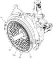
- FIG. 1is a perspective view schematically showing a high-intensity focused ultrasound generator according to a first embodiment of the present invention.
- FIG. 2is an exploded perspective view showing a coupling structure between an ultrasound radiation frame and a probe adapter according to a first embodiment of the present invention.
- FIG 3is a cross-sectional view showing a coupling structure between an ultrasonic radiation frame and a probe adapter according to a first embodiment of the present invention.
- FIG. 4is a cross-sectional view showing a coupling structure between an ultrasound radiation frame and a probe adapter according to a second embodiment of the present invention.
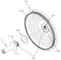
- FIG. 5is an exploded perspective view showing a coupling structure between an ultrasound radiation frame and a probe in a high-intensity focused ultrasound generator according to a third embodiment of the present invention.
- FIG. 6is a perspective view showing an ultrasound radiation frame in a high-intensity focused ultrasound generator according to a fourth embodiment of the present invention.
- a device for generating high-intensity focused ultrasoundis a device using high-intensity focused ultrasound (HIFU).
- the high-intensity focused ultrasound generatorincludes a transducer array in which tens or hundreds of transducers are radially arranged, and stimulates the brain to treat Alzheimer's or depression as well as to treat the affected area of a patient with a tumor. It can also be given, and it can also increase immunity by applying heat to a specific part.
- 1is a perspective view schematically showing a high-intensity focused ultrasound generator according to a first embodiment of the present invention.
- 2is an exploded perspective view showing a coupling structure between an ultrasound radiation frame and a probe adapter according to a first embodiment of the present invention.
- 3is a cross-sectional view showing a coupling structure between an ultrasonic radiation frame and a probe adapter according to a first embodiment of the present invention.
- the head module of the high-intensity focused ultrasound generatorincludes an ultrasound radiation frame 10, a probe 11, a plurality of transducers 20, and a plurality of transducer holders. (30), a probe adapter (40) and a sealing part (60).
- the ultrasonic radiation frame 10is formed in a dish shape with a concave front surface so that ultrasonic waves emitted from the plurality of transducers 20 can be focused and irradiated to one place.
- the probe 11is coupled to the center of the front surface 10a.
- a through portion 14is formed at the center of the ultrasonic radiation frame 10, and a plurality of coupling holes 12 are radially arranged around the through portion 14.
- the through-portion 14is a hole into which the probe adapter 40 is press-fitted and has a circular cross-sectional shape.
- the shape of the penetrating portion 14is not limited thereto, and any shape into which the probe adapter 40 can be inserted can be applied.
- the probe adapter 40 and the penetrating portion 14may have various cross-sectional shapes such as a semicircle, a sector, an ellipse, a triangle, and a polygon.
- the plurality of coupling holes 12are holes formed spaced apart from each other at a predetermined interval.
- the number of coupling holes 12is set according to the number of transducers 20 .
- the plurality of transducers 20may include piezoelectric elements.
- the transducer 20generates ultrasonic waves when power is applied.
- the transducer 20will be described as being formed in a disk shape as an example. Dozens or hundreds of the transducers 20 are radially arranged to form a transducer array. The number of the transducers 20 may be set according to the ultrasonic energy to be radiated.
- the transducer holder 30is detachably coupled to each of the plurality of coupling holes 12 .
- Each of the transducers 20is coupled to the transducer holder 30 .
- the probe 11is disposed at the center of the ultrasonic radiation frame 10 .
- the probe 11is provided to protrude toward the front of the ultrasound radiation frame 10 and irradiates ultrasound to monitor a lesion area in real time, and is also referred to as a transducer.
- the probe 11is formed with different specifications including shape, size, and structure according to the purpose of use or dynamic range, and a probe suitable for a diagnosis site or lesion should be selectively used.
- the probe 11is detachably coupled to the ultrasound radiation frame 10 through the probe adapter 40, so that it can be replaced.
- the probe adapter 40is an adapter that couples the probe 11 to the ultrasonic radiation frame 10 in a replaceable, detachable manner.
- the probe adapter 40is detachably coupled to the through portion 14 formed in the center of the ultrasound radiation frame 10 .
- the probe adapter 40is described as being separated or coupled from the front of the ultrasonic radiation frame 10, but is not limited thereto and may be separated from or coupled from the rear of the ultrasonic radiation frame 10.
- the probe adapter 40includes a flange portion 40a formed to face the front surface of the ultrasonic radiation frame 10 and extending rearward from the rear surface of the flange portion 40a to be inserted into the penetrating portion 14. It includes an insertion portion (40b) to be.
- a probe mounting portionis formed on an inner surface of the probe adapter 40, and the probe mounting portion is referred to as a probe mounting hole 40c hereinafter.
- the probe mounting hole 40chas a cross-sectional shape corresponding to that of the probe 11 .
- various cross-sectional shapes of the probe mounting hole 40c and the probe 11can be applied, such as a semicircle, a fan shape, an ellipse, a triangle, and a polygon.
- the flange portion 40ais seated in a seating groove 10b formed around the through portion 14 in the front surface 10a of the ultrasonic radiation frame 10 .
- the insertion portion 40bhas a cross-sectional shape corresponding to the shape of the through portion 14 so as to be inserted into the through portion 14 .
- the probe adapter 40is screwed to the through portion 14 of the ultrasonic radiation frame 10 in a detachable manner. That is, the insertion portion 40b of the probe adapter 40 and the penetrating portion 14 are detachably coupled by a screw coupling portion 70 .
- the screw coupling part 70includes a female screw thread formed on one of the outer circumferential surface of the insertion part 40b and the inner circumferential surface 14a of the through part 14 and a male screw thread formed on the other one.
- the screw coupling part 70may serve as a sealing part between the through part 14 and the probe 11 .
- a sealing partsuch as Teflon tape is additionally provided in the screw coupling part 70 .
- the probe adapter 40is inserted from the front to the rear of the ultrasonic radiation frame 10 and then fastened to the rear surface of the ultrasonic radiation frame 10 by a separate fastening member.
- a separate fastening memberit is possible.
- the sealing part 60is provided between the ultrasonic radiation frame 10 and the probe adapter 40 to further include sealing to prevent leakage.
- the sealing part 60is between the flange part 40a of the probe adapter 40 and the seating groove 10b of the ultrasonic radiation frame 10.
- itwill be described as being a gasket inserted into.
- the sealing unit 60may include at least one or a combination of an O-ring, a sealing tape, and a sealing pad, and the ultrasonic radiation frame 10 and the Any sealing member capable of sealing between the probe adapters 40 is applicable.
- the sealing part 60may use various materials such as metal, silicon, and rubber.
- the sealing part 60has been described as being provided only between the ultrasonic radiation frame 10 and the probe adapter 40 as an example, but is not limited thereto, and the probe adapter 40 It is of course also possible to be provided between the probe 11.
- probe adapter 40 and the probe 11may be screwed to each other, and the probe adapter 40 and the probe 11 may be sealed by a screw coupling part, and a sealant such as Teflon tape may be used.
- a sealantsuch as Teflon tape
- the probe 11can be used by replacing the ultrasound radiation frame 10
- the probeis suitable for the lesion to be diagnosed or treated. By applying, more accurate and rapid diagnosis or treatment can be made.
- the ultrasound radiation frame 10can be used as it is and only the probe 11 and the probe adapter 40 can be replaced, cost can be reduced.
- FIG. 4is a cross-sectional view showing a coupling structure between an ultrasound radiation frame and a probe adapter in a high-intensity focused ultrasound generator according to a second embodiment of the present invention.
- a probe adapter 140is coupled to the ultrasonic radiation frame 10 in a detachable manner so as to be replaceable, and the probe adapter 140 is different from that of the first embodiment in that it is press-fitted into the penetrating portion 14 of the ultrasonic radiation frame 10, and other configurations and actions are the same as those of the embodiment, so detailed descriptions of similar configurations are omitted. , and explain with a focus on the different points.
- the probe adapter 140includes a flange portion 140a formed to face the front surface of the ultrasonic radiation frame 10 and extending rearward from the rear surface of the flange portion 140a to be inserted into the penetrating portion 14. It includes an insertion portion (140b) to be.
- the sealing part 60includes a gasket 61 inserted between the flange part 140a of the probe adapter 140 and the seating groove 10b of the ultrasonic radiation frame 10, and the probe adapter.
- a gasket 61inserted between the flange part 140a of the probe adapter 140 and the seating groove 10b of the ultrasonic radiation frame 10, and the probe adapter.
- An example of including an O-ring 62 inserted between the insertion portion 140b of 140 and the through portion 14 of the ultrasonic radiation frame 10will be described.
- the sealing part 60may include at least one of a sealing tape and a sealing pad, or a combination thereof, and seals between the ultrasound radiation frame 10 and the probe adapter 140. Any sealing member that can be applied is applicable.
- the sealing part 60may use various materials such as metal, silicon, and rubber.
- the sealing part 60has been described as being provided only between the ultrasonic radiation frame 10 and the probe adapter 140, but is not limited thereto, and the probe adapter 140 It is of course also possible to be provided between the probe 11. Also, it is of course possible that the probe adapter 40 and the probe 11 may be screwed together to be sealed.
- FIG. 5is an exploded perspective view showing a coupling structure between an ultrasound radiation frame and a probe in a high-intensity focused ultrasound generator according to a third embodiment of the present invention.
- the probe 111is directly detachably coupled to the ultrasound radiation frame 110 so as to be replaceable, and the ultrasound radiation frame 110 ) and the probe 111, it is different from the first embodiment that the sealing part 160 is provided, and the rest of the configuration and operation are the same as those of the previous embodiment, so a detailed description of the similar configuration is omitted. , and explain with a focus on the different points.
- a through portion 114is formed at the center of the ultrasonic radiation frame 110 .
- the penetrating portion 114is a hole into which the probe 111 is press-fitted, and has a circular cross-sectional shape, which will be described as an example, but is not limited thereto, and is formed to correspond to the shape of the probe 111 so that the probe 111 ) can be applied to any shape as long as it can be press-fitted.
- various cross-sectional shapes of the probe 111 and the penetrating portion 114such as a semicircle, a fan shape, an ellipse, a triangle, and a polygon, can be applied.
- the probe 111is detachably coupled to the through part 114 .
- the probe 111includes a flange portion 111a formed to face the front surface of the ultrasonic radiation frame 110, and an insertion portion formed to extend rearward from the flange portion 111a and coupled to the through portion 114. (111b) will be described as an example.
- the flange portion 111ais seated in a seating groove 110b formed around the through portion 114 on the front surface 110a of the ultrasonic radiation frame 110.
- the insertion portion 110bhas a cross-sectional shape corresponding to the shape of the through portion 114 so as to be inserted into the through portion 114 .
- the insertion portion 110bis formed in a cylindrical shape and has a circular cross-sectional shape, but is described as an example, but is not limited thereto, and the size or shape can be variously changed.
- various shapessuch as a semicircle, a fan shape, an ellipse, a triangle, and a polygon may be applied to the cross-sectional shape of the insertion portion 110b.
- the screw coupling part 170includes a female screw thread formed on one of the outer circumferential surface of the insertion part 110b and the inner circumferential surface of the through part 114, and a male screw thread formed on the other one.
- the screw coupling part 170may serve as a sealing part between the through part 114 and the insertion part 110b.
- a sealing partsuch as Teflon tape is additionally provided in the screw coupling part 170.
- the probe 111is inserted from the front to the rear of the ultrasonic radiation frame 110 and then fastened by a separate fastening member on the rear surface of the ultrasonic radiation frame 110. possible.
- the sealing part 160is provided between the penetrating part 114 of the ultrasonic radiation frame 110 and the outer circumferential surface of the probe 111, and seals it to prevent water leakage.
- the sealing part 160is explained as an example as being a gasket inserted between the flange part 111a of the probe 111 and the seating groove 110b of the ultrasonic radiation frame 110. do.
- the sealing unit 160may include at least one or a combination of an O-ring, a sealing tape, and a sealing pad, and the ultrasonic radiation frame 110 and the Any sealing member capable of sealing between the probes 111 is applicable.
- various materialssuch as metal, silicon, and rubber may be used for the sealing part 160 .
- FIG. 6is a perspective view illustrating an ultrasonic radiation frame in a high-intensity focused ultrasonic generator according to a fourth embodiment of the present invention.
- the ultrasound radiation frame 200is divided into a plurality of pieces and combined, which is different from the second embodiment, and other Since the rest of the configuration and operation are the same as those of the second embodiment, detailed descriptions of similar configurations will be omitted and the different points will be mainly described.
- the ultrasonic radiation frame 200is described as being separated and combined into two first and second frames 201 and 202, but is not limited thereto, and the probe 111 can be inserted. If the structure can form the penetrating portion 114 that can be applied by changing the number or shape of the pieces in various ways.
- the first frame 201 and the second frame 202are integrally coupled by a coupling means.
- the coupling meansis coupled to the defective groove 200a formed on each side of the first and second frames 201 and 202 and formed on the other side to face the front surface of the coupling groove.
- An example of including a protrusion 200b and a fastening member (not shown) for fastening and fixing the first frame 201 and the second frame 202will be described.
- the coupling protrusion 201b of the first frame 201is seated in the coupling groove 202a of the second frame 202, and the coupling protrusion 202b of the second frame 202 is the first After being seated in the coupling groove 201a of the frame 201, it may be fastened and fixed by the fastening member (not shown) at the rear of the first and second frames 201 and 202.
- the fastening membernot shown
- the first frame 201 and the second frame 202may be coupled by various coupling methods.
- a sealing unit capable of sealing between the first frame 201 and the second frame 202may be further included.
- the probe 111can be replaced.
Landscapes
- Health & Medical Sciences (AREA)
- Engineering & Computer Science (AREA)
- Biomedical Technology (AREA)
- Nuclear Medicine, Radiotherapy & Molecular Imaging (AREA)
- Radiology & Medical Imaging (AREA)
- Life Sciences & Earth Sciences (AREA)
- Animal Behavior & Ethology (AREA)
- General Health & Medical Sciences (AREA)
- Public Health (AREA)
- Veterinary Medicine (AREA)
- Ultra Sonic Daignosis Equipment (AREA)
Abstract
Description
Translated fromKorean본 발명은 프로브 교체형 고강도 집속 초음파 발생 장치에 관한 것으로서, 보다 상세하게는 고강도 집속 초음파를 방사하는 초음파 방사 프레임에 프로브가 착탈가능하게 결합되어, 사용 목적과 동적 범위에 따라 다양한 프로브들로 교체하여 사용할 수 있는 프로브 교체형 고강도 집속 초음파 발생 장치에 관한 것이다.The present invention relates to a probe replaceable high-intensity focused ultrasound generator, and more particularly, a probe is detachably coupled to an ultrasonic radiation frame that emits high-intensity focused ultrasound, and is replaced with various probes according to the purpose of use and dynamic range. It relates to a replaceable probe type high-intensity focused ultrasound generator that can be used.
일반적으로 고강도 집속 초음파(HIFU, high-intensity focused ultrasound) 발생 장치는, 트랜스듀서에서 발생되는 초음파를 집속하여 고강도의 초음파 에너지를 발생시키고, 이를 환자의 환부에 조사하여 환부 온도를 상승시킴으로써 외과적 수술 없이 환부를 치료할 수 있는 장치이다.In general, a high-intensity focused ultrasound (HIFU) generating device generates high-intensity ultrasonic energy by focusing ultrasonic waves generated from a transducer, and irradiates it to a patient's affected area to raise the temperature of the affected area for surgical operation. It is a device that can treat the affected area without it.
종래의 고강도 집속 초음파 발생 장치는, 초음파 방사 프레임의 중앙에 삽입된 프로브를 포함한다. 상기 프로브는 탐촉자라고도 하며, 상기 프로브를 통해 병변이나 시술 부위를 정밀 감시하여 병변 위치 및 부피 등 치료에 필요한 각종 데이터를 수집할 수 있다.A conventional high-intensity focused ultrasound generator includes a probe inserted into the center of an ultrasound radiation frame. The probe is also called a transducer, and various data necessary for treatment, such as the location and volume of a lesion, can be collected by precisely monitoring a lesion or treatment site through the probe.
그러나, 종래에는 진단 또는 치료하고자 하는 병변에 따라 프로브만을 교체할 수 없는 문제점이 있으며, 병변에 관계없이 동일한 프로브를 사용할 경우 수집하는 데이터의 정확도가 낮아지는 문제점이 있다.However, conventionally, there is a problem in that only the probe cannot be replaced according to the lesion to be diagnosed or treated, and the accuracy of collected data is lowered when the same probe is used regardless of the lesion.
본 발명의 목적은, 다양한 프로브들과 호환이 가능한 프로브 교체형 고강도 집속 초음파 발생 장치를 제공하는 데 있다.An object of the present invention is to provide a probe replaceable high-intensity focused ultrasound generator compatible with various probes.
본 발명에 따른 프로브 교체형 고강도 집속 초음파 발생 장치는, 전면이 오목하게 형성된 초음파 방사 프레임과; 상기 초음파 방사 프레임의 전면에 구비되어, 초음파를 발생시키는 복수의 트랜스듀서들과; 상기 초음파 방사 프레임에 형성된 관통부에 착탈가능하도록 결합되고, 내측면에는 프로브가 착탈가능하도록 결합되는 프로브 장착부가 형성된 프로브 어댑터를 포함한다.A probe replaceable high-intensity focused ultrasound generator according to the present invention includes an ultrasonic radiation frame having a concave front surface; a plurality of transducers provided on the front surface of the ultrasonic radiation frame to generate ultrasonic waves; A probe adapter is detachably coupled to the penetrating portion formed in the ultrasonic radiation frame and has a probe mounting portion formed on an inner surface thereof to which a probe is detachably coupled.
본 발명의 다른 측면에 따른 프로브 교체형 고강도 집속 초음파 발생 장치는, 전면이 오목하게 형성된 초음파 방사 프레임과; 상기 초음파 방사 프레임의 전면에 구비되어, 초음파를 발생시키는 복수의 트랜스듀서들을 포함하고, 프로브가 상기 초음파 방사 프레임에 형성된 관통부에 착탈가능하도록 결합되어 상기 초음파 방사 프레임에 교체가능하다.A probe replaceable high-intensity focused ultrasound generator according to another aspect of the present invention includes an ultrasonic radiation frame having a concave front surface; It is provided on the front surface of the ultrasonic radiation frame and includes a plurality of transducers that generate ultrasonic waves, and a probe is detachably coupled to a through portion formed in the ultrasonic radiation frame to be replaceable with the ultrasonic radiation frame.
상기 초음파 방사 프레임과 상기 프로브 어댑터 사이에 구비되어, 누수를 방지하는 실링부를 더 포함한다.A sealing portion provided between the ultrasound radiation frame and the probe adapter to prevent water leakage is further included.
상기 초음파 방사 프레임과 상기 프로브 사이에 구비되어, 누수를 방지하는 실링부를 더 포함한다.A sealing unit provided between the ultrasonic radiation frame and the probe to prevent water leakage is further included.
상기 프로브 장착부의 단면 형상은, 상기 프로브의 단면 형상에 대응하는 형상으로 형성된다.A cross-sectional shape of the probe mounting portion is formed to correspond to a cross-sectional shape of the probe.
상기 관통부의 단면 형상은, 상기 프로브의 단면 형상에 대응하는 형상으로 형성된다.A cross-sectional shape of the penetrating portion is formed to correspond to a cross-sectional shape of the probe.
상기 실링부는, 오 링, 개스킷, 실링 테이프 및 실링 패드 중 적어도 하나를 포함한다.The sealing part includes at least one of an O-ring, a gasket, a sealing tape, and a sealing pad.
상기 관통부의 내둘레면과 상기 프로브 어댑터의 외둘레면은 나사결합된다.An inner circumferential surface of the penetrating portion and an outer circumferential surface of the probe adapter are screwed together.
상기 관통부의 내둘레면과 상기 프로브의 외둘레면은 나사결합된다.An inner circumferential surface of the penetrating portion and an outer circumferential surface of the probe are screwed together.
상기 초음파 방사 프레임은, 상기 관통부를 중심으로 복수의 조각들로 나누어져 착탈가능하도록 결합된다.The ultrasonic radiation frame is divided into a plurality of pieces around the through portion and coupled to be detachable.
상기 조각들의 각 일측면에는 결합 홈이 형성되고, 상기 조각들의 각 타측면에는 결합 돌기가 형성되어, 상기 복수의 조각들 중에서 어느 한 조각의 결합홈에 다른 조각의 결합돌기가 결합된다.Coupling grooves are formed on one side of each of the pieces, and coupling protrusions are formed on the other side of each of the pieces, so that the coupling protrusion of any one of the plurality of pieces is coupled to the coupling groove of another piece.
상기 프로브 어댑터는, 상기 초음파 방사 프레임의 전면에 맞대어지게 형성된 플랜지부와, 상기 플랜지부에서 연장되어 상기 관통부에 삽입되어 나사결합되도록 형성된 삽입부를 포함한다.The probe adapter includes a flange portion formed to face the front surface of the ultrasonic radiation frame, and an insertion portion extending from the flange portion and inserted into the penetrating portion to be screwed.
상기 프로브는, 상기 초음파 방사 프레임의 전면에 맞대어지게 형성된 플랜지부와, 상기 플랜지부에서 연장되어 상기 관통부에 삽입되어 나사결합되도록 형성된 삽입부를 포함한다.The probe includes a flange portion formed to face the front surface of the ultrasonic radiation frame, and an insertion portion extending from the flange portion and inserted into the through portion to be screwed.
본 발명에 따른 고강도 집속 초음파 발생장치는, 초음파 방사 프레임에 프로브가 교체가능하게 착탈가능하도록 결합됨으로써, 다양한 프로브들 중에서 진단 또는 치료하고자 하는 병변에 알맞은 프로브로 교체하여 사용할 수 있으므로, 보다 정확하고 신속한 진단 및 치료가 이루어질 수 있다.In the high-intensity focused ultrasound generator according to the present invention, the probe is detachably coupled to the ultrasound radiation frame so that it can be replaced with a probe suitable for a lesion to be diagnosed or treated among various probes, so that it is more accurate and rapid. Diagnosis and treatment can be made.
또한, 초음파 방사 프레임은 공용으로 그대로 사용하고 프로브 또는 프로브 어댑터만을 교체할 수 있으므로, 비용이 절감될 수 있다.In addition, since the ultrasound radiation frame can be used in common and only the probe or probe adapter can be replaced, cost can be reduced.
또한, 초음파 방사 프레임과 프로브 어댑터 사이 또는 초음파 방사 프레임과 프로브 사이를 실링하는 실링부를 구비함으로써, 프로브의 교체가 가능하면서도 누수를 방지할 수 있는 이점이 있다.In addition, by providing a sealing unit for sealing between the ultrasound radiation frame and the probe adapter or between the ultrasound radiation frame and the probe, there is an advantage in that the probe can be replaced and leakage can be prevented.
도 1은 본 발명의 제1실시예에 따른 고강도 집속 초음파 발생 장치를 개략적으로 나타낸 사시도이다.1 is a perspective view schematically showing a high-intensity focused ultrasound generator according to a first embodiment of the present invention.
도 2는 본 발명의 제1실시예에 따른 초음파 방사 프레임과 프로브 어댑터의 결합구조를 나타낸 분해 사시도이다.2 is an exploded perspective view showing a coupling structure between an ultrasound radiation frame and a probe adapter according to a first embodiment of the present invention.
도 3은 본 발명의 제1실시예에 따른 초음파 방사 프레임과 프로브 어댑터의 결합구조를 나타낸 단면도이다.3 is a cross-sectional view showing a coupling structure between an ultrasonic radiation frame and a probe adapter according to a first embodiment of the present invention.
도 4는 본 발명의 제2실시예에 따른 초음파 방사 프레임과 프로브 어댑터의 결합구조를 나타낸 단면도이다.4 is a cross-sectional view showing a coupling structure between an ultrasound radiation frame and a probe adapter according to a second embodiment of the present invention.
도 5는 본 발명의 제3실시예에 따른 고강도 집속 초음파 발생 장치에서 초음파 방사 프레임과 프로브의 결합구조를 나타낸 분해 사시도이다.5 is an exploded perspective view showing a coupling structure between an ultrasound radiation frame and a probe in a high-intensity focused ultrasound generator according to a third embodiment of the present invention.
도 6은 본 발명의 제4실시예에 따른 고강도 집속 초음파 발생 장치에서 초음파 방사 프레임을 나타낸 사시도이다.6 is a perspective view showing an ultrasound radiation frame in a high-intensity focused ultrasound generator according to a fourth embodiment of the present invention.
이하, 첨부된 도면을 참조하여 본 발명의 실시예에 대해 설명하면, 다음과 같다.Hereinafter, embodiments of the present invention will be described with reference to the accompanying drawings.
본 발명의 실시예에 따른 고강도 집속 초음파 발생 장치는, 고강도 집속 초음파(HIFU, high-intensity focused ultrasound)를 이용한 장치이다. 상기 고강도 집속 초음파 발생 장치는, 수십 또는 수백개의 트랜스듀서들이 방사형으로 배열된 트랜스듀서 어레이를 포함하여, 종양 등이 있는 환자의 환부를 치료할 뿐만 아니라, 알츠하이머나 우울증 등을 치료하기 위해 뇌에 자극을 줄 수도 있으며, 특정 부위에 열을 가하여 면역력을 높일 수도 있다.A device for generating high-intensity focused ultrasound according to an embodiment of the present invention is a device using high-intensity focused ultrasound (HIFU). The high-intensity focused ultrasound generator includes a transducer array in which tens or hundreds of transducers are radially arranged, and stimulates the brain to treat Alzheimer's or depression as well as to treat the affected area of a patient with a tumor. It can also be given, and it can also increase immunity by applying heat to a specific part.
도 1은 본 발명의 제1실시예에 따른 고강도 집속 초음파 발생 장치를 개략적으로 나타낸 사시도이다. 도 2는 본 발명의 제1실시예에 따른 초음파 방사 프레임과 프로브 어댑터의 결합구조를 나타낸 분해 사시도이다. 도 3은 본 발명의 제1실시예에 따른 초음파 방사 프레임과 프로브 어댑터의 결합구조를 나타낸 단면도이다.1 is a perspective view schematically showing a high-intensity focused ultrasound generator according to a first embodiment of the present invention. 2 is an exploded perspective view showing a coupling structure between an ultrasound radiation frame and a probe adapter according to a first embodiment of the present invention. 3 is a cross-sectional view showing a coupling structure between an ultrasonic radiation frame and a probe adapter according to a first embodiment of the present invention.
도 1 내지 도 3을 참조하면, 상기 고강도 집속 초음파 발생 장치의 헤드 모듈은, 초음파 방사 프레임(10), 프로브(11), 복수의 트랜스듀서들(transducer)(20), 복수의 트랜스듀서 홀더들(30), 프로브 어댑터(40) 및 실링부(60)를 포함한다.1 to 3, the head module of the high-intensity focused ultrasound generator includes an
상기 초음파 방사 프레임(10)은, 상기 복수의 트랜스듀서들(20)에서 방사하는 초음파들을 집속시켜 한 곳으로 조사할 수 있도록 전면이 오목하게 형성된 접시 형상으로 형성된다. 상기 초음파 방사 프레임(10)은, 전면(10a)의 중앙에 상기 프로브(11)가 결합된다. 상기 초음파 방사 프레임(10)의 중앙측에는 관통부(14)가 형성되고, 상기 관통부(14)를 중심으로 복수의 결합홀들(12)이 방사형으로 배열된다.The
상기 관통부(14)는 상기 프로브 어댑터(40)가 압입되는 홀이며, 단면 형상이 원형인 것으로 예를 들어 설명한다. 다만, 이에 한정되지 않고, 상기 관통부(14)의 형상은 상기 프로브 어댑터(40)가 삽입될 수 있는 형상이라면 어느 것이나 적용 가능하다. 예를 들어, 상기 프로브 어댑터(40)와 상기 관통부(14)의 단면 형상은, 반원, 부채꼴형, 타원형, 삼각형, 다각형 등 다양한 형상이 적용 가능하다.The through-
상기 복수의 결합홀들(12)은 서로 소정간격으로 이격되어 형성된 홀들이다. 상기 결합홀들(12)의 개수는 상기 트랜스듀서들(20)의 개수에 따라 설정된다.The plurality of
상기 복수의 트랜스듀서들(20)은 압전소자를 포함할 수 있다. 상기 트랜스듀서(20)는 전원을 인가받으면 초음파를 발생시킨다. 상기 트랜스듀서(20)는 원판 형상으로 형성된 것으로 예를 들어 설명한다. 상기 트랜스듀서들(20)은 수십 또는 수백개가 방사형으로 배열되어 트랜스듀서 어레이를 형성한다. 상기 트랜스듀서들(20)의 개수는 방사하고자 하는 초음파 에너지에 따라 설정될 수 있다.The plurality of
상기 트랜스듀서 홀더(30)는, 상기 복수의 결합홀들(12)마다 각각 착탈가능하도록 결합된다. 상기 트랜스듀서 홀더(30)에는 상기 트랜스듀서(20)가 각각 결합된다.The
상기 프로브(11)는, 상기 초음파 방사 프레임(10)의 중앙에 배치된다. 상기 프로브(11)는, 상기 초음파 방사 프레임(10)의 전방을 향해 돌출되게 구비되어 초음파를 조사하여, 병변 부위를 실시간으로 모니터링할 수 있으며, 탐촉자라고도 한다. 상기 프로브(11)는 사용 목적이나 동적 범위에 따라 모양, 크기 및 구조 등을 포함하는 사양이 다르게 형성되어, 진단 부위나 병변에 알맞은 프로브를 선택적으로 사용되어야 한다. 상기 프로브(11)는 상기 프로브 어댑터(40)를 통해 상기 초음파 방사 프레임(10)에 착탈가능토록 결합됨으로써, 교체가능하다.The
도 2 및 도 3을 참조하면, 상기 프로브 어댑터(40)는, 상기 초음파 방사 프레임(10)에 상기 프로브(11)를 교체가능하게 착탈가능하도록 결합시키는 어댑터이다. 상기 프로브 어댑터(40)는, 상기 초음파 방사 프레임(10)의 중앙에 형성된 관통부(14)에 착탈가능토록 결합된다. 상기 프로브 어댑터(40)는, 상기 초음파 방사 프레임(10)의 전방에서 분리 또는 결합되는 것으로 예를 들어 설명하나, 이에 한정되지 않고 상기 초음파 방사 프레임(10)의 후방에서 분리 또는 결합될 수도 있다.Referring to FIGS. 2 and 3 , the
상기 프로브 어댑터(40)는, 상기 초음파 방사 프레임(10)의 전면에 맞대어지게 형성된 플랜지부(40a)와, 상기 플랜지부(40a)의 후면에서 후방으로 연장 형성되어 상기 관통부(14)에 삽입되는 삽입부(40b)를 포함한다. 상기 프로브 어댑터(40)의 내측면에는 프로브 장착부가 형성되며, 이하, 상기 프로브 장착부는 프로브 장착홀(40c)이라 칭한다. 상기 프로브 장착홀(40c)은 단면 형상은 상기 프로브(11)의 단면 형상에 대응하는 형상으로 형성된다. 예를 들어, 상기 프로브 장착홀(40c)와 상기 프로브(11)의 단면 형상은, 반원, 부채꼴형, 타원형, 삼각형, 다각형 등 다양한 형상이 적용 가능하다.The
상기 플랜지부(40a)는, 상기 초음파 방사 프레임(10)의 전면(10a)에서 상기 관통부(14)의 주변에 형성된 안착홈(10b)에 안착된다.The
상기 삽입부(40b)의 단면 형상은, 상기 관통부(14)에 삽입가능하도록 상기 관통부(14)의 형상에 대응되는 형상으로 형성된다.The
상기 프로브 어댑터(40)는, 상기 초음파 방사 프레임(10)의 관통부(14)에 착탈가능하도록 나사결합된다. 즉, 상기 프로브 어댑터(40)의 삽입부(40b)와 상기 관통부(14)는 나사결합부(70)에 의해 착탈가능하도록 결합된다. 상기 나사결합부(70)는, 상기 삽입부(40b)의 외주면과 상기 관통부(14)의 내주면(14a) 중 어느 하나에는 형성된 암나사산과, 나머지 하나에 형성된 수나사산을 포함한다. 상기 나사결합부(70)는, 상기 관통부(14)와 상기 프로브(11)사이에서 실링부 역할을 할 수 있다. 또한, 상기 나사결합부(70)에는 테프론 테이프 등의 실링부가 추가로 구비되는 것도 물론 가능하다.The
다만, 이에 한정되지 않고, 상기 프로브 어댑터(40)는 상기 초음파 방사 프레임(10)의 전방에서 후방을 향해 삽입된 후, 상기 초음파 방사 프레임(10)의 후면에서 별도의 체결부재에 의해 체결되는 것도 물론 가능하다.However, it is not limited thereto, and the
상기 실링부(60)는, 상기 초음파 방사 프레임(10)과 상기 프로브 어댑터(40)사이에 구비되어, 누수를 방지하도록 실링하는 것을 더 포함한다.The sealing
도 2 및 도 3을 참조하면, 본 실시예에서는, 상기 실링부(60)는, 상기 프로브 어댑터(40)의 상기 플랜지부(40a)와 상기 초음파 방사 프레임(10)의 안착홈(10b)사이에 삽입된 개스킷인 것으로 예를 들어 설명한다.2 and 3, in this embodiment, the sealing
다만, 이에 한정되지 않고, 상기 실링부(60)는, 오 링(O-ring), 실링 테이프 및 실링 패드 중 적어도 하나 또는 이들의 조합을 포함할 수 있으며, 상기 초음파 방사 프레임(10)과 상기 프로브 어댑터(40)사이를 실링할 수 있는 실링 부재라면 어느 것이나 적용 가능하다. 또한, 상기 실링부(60)는, 메탈, 실리콘 및 고무 등 다양한 소재를 사용할 수 있다.However, it is not limited thereto, and the sealing
또한, 본 실시예에서는, 상기 실링부(60)는, 상기 초음파 방사 프레임(10)과 상기 프로브 어댑터(40) 사이에만 구비된 것으로 예를 들어 설명하였으나, 이에 한정되지 않고 상기 프로브 어댑터(40)와 상기 프로브(11)사이에 구비되는 것도 물론 가능하다.In addition, in this embodiment, the sealing
또한, 상기 프로브 어댑터(40)와 상기 프로브(11)는 서로 나사결합될 수 있으며, 상기 프로브 어댑터(40)와 상기 프로브(11)사이도 나사결합부에 의해 실링될 수 있으며 테프론 테이프 등의 실링부가 추가로 구비되는 것도 물론 가능하다.In addition, the
상기와 같이 구성된 본 발명의 제1실시예에 따른 고강도 집속 초음파 발생장치는, 상기 초음파 방사 프레임(10)에 상기 프로브(11)를 교체하여 사용할 수 있기 때문에, 진단 또는 치료하고자 하는 병변에 알맞은 프로브를 적용하여 보다 정확하고 신속한 진단 또는 치료가 이루어질 수 있다.In the high-intensity focused ultrasound generator according to the first embodiment of the present invention configured as described above, since the
또한, 상기 초음파 방사 프레임(10)은 그대로 사용하고 상기 프로브(11)와 상기 프로브 어댑터(40)만을 교체할 수 있으므로, 비용이 절감될 수 있다.In addition, since the
한편, 도 4는 본 발명의 제2실시예에 따른 고강도 집속 초음파 발생장치에서 초음파 방사 프레임과 프로브 어댑터의 결합구조를 나타낸 단면도이다.Meanwhile, FIG. 4 is a cross-sectional view showing a coupling structure between an ultrasound radiation frame and a probe adapter in a high-intensity focused ultrasound generator according to a second embodiment of the present invention.
도 4를 참조하면, 본 발명의 제2실시예에 따른 고강도 집속 초음파 발생 장치는, 초음파 방사 프레임(10)에 프로브 어댑터(140)가 교체가능하게 착탈가능하도록 결합되되, 상기 프로브 어댑터(140)는 상기 초음파 방사 프레임(10)의 관통부(14)에 압입되는 것이 상기 제1실시예와 상이하고, 그 외 나머지 구성 및 작용은 상기 일 실시예와 동일하므로 유사 구성에 대한 상세한 설명은 생략하고, 상이한 점을 중심으로 설명한다.Referring to FIG. 4 , in the high-intensity focused ultrasound generator according to the second embodiment of the present invention, a
상기 프로브 어댑터(140)는, 상기 초음파 방사 프레임(10)의 전면에 맞대어지게 형성된 플랜지부(140a)와, 상기 플랜지부(140a)의 후면에서 후방으로 연장 형성되어 상기 관통부(14)에 삽입되는 삽입부(140b)를 포함한다.The
또한, 상기 실링부(60)는, 상기 프로브 어댑터(140)의 상기 플랜지부(140a)와 상기 초음파 방사 프레임(10)의 안착홈(10b)사이에 삽입된 개스킷(61)과, 상기 프로브 어댑터(140)의 상기 삽입부(140b)와 상기 초음파 방사 프레임(10)의 관통부(14)사이에 삽입된 오 링(62)을 포함하는 것으로 예를 들어 설명한다.In addition, the sealing
다만, 이에 한정되지 않고, 상기 실링부(60)는, 실링 테이프 및 실링 패드 중 적어도 하나 또는 이들의 조합을 포함할 수 있으며, 상기 초음파 방사 프레임(10)과 상기 프로브 어댑터(140)사이를 실링할 수 있는 실링 부재라면 어느 것이나 적용 가능하다. 또한, 상기 실링부(60)는, 메탈, 실리콘 및 고무 등 다양한 소재를 사용할 수 있다.However, it is not limited thereto, and the sealing
또한, 본 실시예에서는, 상기 실링부(60)는, 상기 초음파 방사 프레임(10)과 상기 프로브 어댑터(140) 사이에만 구비된 것으로 예를 들어 설명하였으나, 이에 한정되지 않고 상기 프로브 어댑터(140)와 상기 프로브(11)사이에 구비되는 것도 물론 가능하다. 또한, 상기 프로브 어댑터(40)와 상기 프로브(11)는 서로 나사결합되어 실링될 수 있는 것도 물론 가능하다.In addition, in this embodiment, the sealing
한편, 도 5는 본 발명의 제3실시예에 따른 고강도 집속 초음파 발생 장치에서 초음파 방사 프레임과 프로브의 결합구조를 나타낸 분해 사시도이다.Meanwhile, FIG. 5 is an exploded perspective view showing a coupling structure between an ultrasound radiation frame and a probe in a high-intensity focused ultrasound generator according to a third embodiment of the present invention.
도 5를 참조하면, 본 발명의 제3실시예에 따른 고강도 집속 초음파 발생 장치는, 프로브(111)가 교체 가능하도록 초음파 방사 프레임(110)에 직접 착탈가능하도록 결합되고, 상기 초음파 방사 프레임(110)과 상기 프로브(111)사이에 실링부(160)가 구비된 것이 상기 제1실시예와 상이하고, 그 외 나머지 구성 및 작용은 상기 일 실시예와 동일하므로 유사 구성에 대한 상세한 설명은 생략하고, 상이한 점을 중심으로 설명한다.Referring to FIG. 5, in the high-intensity focused ultrasound generator according to the third embodiment of the present invention, the probe 111 is directly detachably coupled to the
상기 초음파 방사 프레임(110)의 중앙측에는 관통부(114)가 형성된다.A through
상기 관통부(114)는 상기 프로브(111)가 압입되는 홀이며, 단면 형상이 원형인 것으로 예를 들어 설명하나, 이에 한정되지 않고 상기 프로브(111)의 형상에 대응되게 형성되어 상기 프로브(111)가 압입될 수 있는 형상이라면 어느 것이나 적용 가능하다. 예를 들어, 상기 프로브(111)와 상기 관통부(114)의 단면 형상은, 반원, 부채꼴형, 타원형, 삼각형, 다각형 등 다양한 형상이 적용 가능하다.The penetrating
상기 프로브(111)는, 상기 관통부(114)에 착탈가능하도록 결합된다. 상기 프로브(111)는 상기 초음파 방사 프레임(110)의 전면에 맞대어지게 형성된 플랜지부(111a)와, 상기 플랜지부(111a)에서 후방으로 연장되게 형성되어 상기 관통부(114)에 결합되는 삽입부(111b)를 포함하는 것으로 예를 들어 설명한다.The probe 111 is detachably coupled to the through
상기 플랜지부(111a)는, 상기 초음파 방사 프레임(110)의 전면(110a)에서 상기 관통부(114)의 주변에 형성된 안착홈(110b)에 안착된다.The
상기 삽입부(110b)의 단면 형상은, 상기 관통부(114)에 삽입가능하도록 상기 관통부(114)의 형상에 대응되는 형상으로 형성된다. 본 실시예에서는, 상기 삽입부(110b)는 원통형상으로 형성되고, 단면 형상은 원형인 것으로 예를 들어 설명하나, 이에 한정되지 않고, 크기나 형상은 다양하게 변경 가능하다. 예를 들어, 상기 삽입부(110b)의 단면 형상은, 반원, 부채꼴형, 타원형, 삼각형, 다각형 등 다양한 형상이 적용 가능하다.The
상기 삽입부(110b)의 외주면 중 적어도 일부에 상기 관통부(114)에 착탈가능하도록 나사결합된다. 즉, 상기 삽입부(110b)와 상기 관통부(114)는 나사결합부(170)에 의해 착탈가능하도록 결합된다. 상기 나사결합부(170)는, 상기 삽입부(110b)의 외주면과 상기 관통부(114)의 내주면 중 어느 하나에는 형성된 암나사산과, 나머지 하나에 형성된 수나사산을 포함한다. 상기 나사결합부(170)는, 상기 관통부(114)와 상기 삽입부(110b)사이에서 실링부 역할을 할 수 있다. 또한, 상기 나사결합부(170)에는 테프론 테이프 등의 실링부가 추가로 구비되는 것도 물론 가능하다.At least a part of the outer circumferential surface of the
다만, 이에 한정되지 않고, 상기 프로브(111)는 상기 초음파 방사 프레임(110)의 전방에서 후방을 향해 삽입된 후, 상기 초음파 방사 프레임(110)의 후면에서 별도의 체결부재에 의해 체결되는 것도 물론 가능하다.However, it is not limited to this, and the probe 111 is inserted from the front to the rear of the
상기 실링부(160)는, 상기 초음파 방사 프레임(110)의 관통부(114)와 상기 프로브(111)의 외주면 사이에 구비되어, 누수를 방지하도록 실링한다.The sealing
본 실시예에서는, 상기 실링부(160)는, 상기 프로브(111)의 상기 플랜지부(111a)와 상기 초음파 방사 프레임(110)의 안착홈(110b)사이에 삽입된 개스킷인 것으로 예를 들어 설명한다.In this embodiment, the sealing
다만, 이에 한정되지 않고, 상기 실링부(160)는, 오 링(O-ring), 실링 테이프 및 실링 패드 중 적어도 하나 또는 이들의 조합을 포함할 수 있으며, 상기 초음파 방사 프레임(110)과 상기 프로브(111)사이를 실링할 수 있는 실링 부재라면 어느 것이나 적용 가능하다. 또한, 상기 실링부(160)는, 메탈, 실리콘 및 고무 등 다양한 소재를 사용할 수 있다.However, it is not limited thereto, and the
또한, 상기 관통부(114)와 상기 프로브(111)가 상기 나사결합부(170)에 의해 착탈가능하도록 결합됨으로써, 상기 나사결합부(170)에 의해 상기 관통부(114)와 상기 프로브(111)사이에 실링 효과를 얻을 수 있다. 상기 나사결합부에는 테프론 테이프 등의 실링부가 추가로 구비될 수 있다.In addition, since the through
한편, 도 6은 본 발명의 제4실시예에 따른 고강도 집속 초음파 발생 장치에서 초음파 방사 프레임을 나타낸 사시도이다.Meanwhile, FIG. 6 is a perspective view illustrating an ultrasonic radiation frame in a high-intensity focused ultrasonic generator according to a fourth embodiment of the present invention.
도 6을 참조하면, 본 발명의 제4실시예에 따른 고강도 집속 초음파 발생 장치에서는, 초음파 방사 프레임(200)이 복수의 조각들로 나누어져 결합된 것이 상기 제2실시예와 상이하고, 그 외 나머지 구성 및 작용은 상기 제2실시예와 동일하므로 유사 구성에 대한 상세한 설명은 생략하고, 상이한 점을 중심으로 설명한다.Referring to FIG. 6, in the high-intensity focused ultrasound generator according to the fourth embodiment of the present invention, the
본 실시예에서는, 상기 초음파 방사 프레임(200)은 2개의 제1,2프레임(201)(202)으로 분리되어 결합된 것으로 예를 들어 설명하나, 이에 한정되지 않고 상기 프로브(111)를 삽입할 수 있는 관통부(114)를 형성할 수 있는 구조라면 조각의 개수나 형태는 다양하게 변경하여 적용가능하다.In this embodiment, the
상기 제1프레임(201)과 상기 제2프레임(202)은 결합수단에 의해 일체로 결합된다.The
본 실시예에서는, 상기 결합수단은, 상기 제1,2프레임(201)(202)의 각 일측면에 형성된 결함홈(200a)과, 각 타측면에 형성되어 상기 결합홈의 전면에 맞대어지는 결합돌기(200b)와, 상기 제1프레임(201)과 상기 제2프레임(202)을 체결 고정시키는 체결부재(미도시)를 포함하는 것으로 예를 들어 설명한다. 따라서, 상기 제1프레임(201)의 결합돌기(201b)는 상기 제2프레임(202)의 결합홈(202a)에 안착되고, 상기 제2프레임(202)의 결합돌기(202b)는 상기 제1프레임(201)의 결합홈(201a)에 안착된 후, 상기 제1,2프레임(201)(202)의 후방에서 상기 체결부재(미도시)에 의해 체결 고정될 수 있다. 다만, 이에 한정되지 않고, 상기 제1프레임(201)과 상기 제2프레임(202)은 다양한 결합 방식에 의해 결합될 수 있다.In this embodiment, the coupling means is coupled to the
또한, 상기 제1프레임(201)과 상기 제2프레임(202)사이를 실링할 수 있는 실링부가 더 포함될 수 있다.In addition, a sealing unit capable of sealing between the
따라서, 상기 제1프레임(201)과 상기 제2프레임(202)을 분리시킨 후, 상기 프로브(111)를 교체할 수 있다.Therefore, after the
본 발명은 도면에 도시된 실시예를 참고로 설명되었으나 이는 예시적인 것에 불과하며, 본 기술 분야의 통상의 지식을 가진 자라면 이로부터 다양한 변형 및 균등한 다른 실시예가 가능하다는 점을 이해할 것이다. 따라서, 본 발명의 진정한 기술적 보호 범위는 첨부된 특허청구범위의 기술적 사상에 의하여 정해져야 할 것이다.Although the present invention has been described with reference to the embodiments shown in the drawings, this is only exemplary, and those skilled in the art will understand that various modifications and equivalent other embodiments are possible therefrom. Therefore, the true technical scope of protection of the present invention should be determined by the technical spirit of the appended claims.
본 발명에 따르면 프로브의 교체가 용이한 고강도 집속 초음파 발생장치를 제조할 수 있다.According to the present invention, it is possible to manufacture a high-intensity focused ultrasound generator in which a probe can be easily replaced.
Claims (16)
Translated fromKoreanPriority Applications (1)
| Application Number | Priority Date | Filing Date | Title |
|---|---|---|---|
| CN202280085515.9ACN118434474A (en) | 2022-02-23 | 2022-12-16 | Probe-replaceable high-intensity focused ultrasound generator |
Applications Claiming Priority (2)
| Application Number | Priority Date | Filing Date | Title |
|---|---|---|---|
| KR10-2022-0023835 | 2022-02-23 | ||
| KR1020220023835AKR20230126533A (en) | 2022-02-23 | 2022-02-23 | High-intensity focused ultrasound treatment device with interchangeable probe |
Publications (1)
| Publication Number | Publication Date |
|---|---|
| WO2023163348A1true WO2023163348A1 (en) | 2023-08-31 |
Family
ID=87766157
Family Applications (1)
| Application Number | Title | Priority Date | Filing Date |
|---|---|---|---|
| PCT/KR2022/020529CeasedWO2023163348A1 (en) | 2022-02-23 | 2022-12-16 | Probe-replaceable high-intensity focused ultrasound generation device |
Country Status (3)
| Country | Link |
|---|---|
| KR (1) | KR20230126533A (en) |
| CN (1) | CN118434474A (en) |
| WO (1) | WO2023163348A1 (en) |
Citations (5)
| Publication number | Priority date | Publication date | Assignee | Title |
|---|---|---|---|---|
| JPH07213529A (en)* | 1994-02-03 | 1995-08-15 | Toshiba Corp | Ultrasonic therapy equipment |
| US20090230822A1 (en)* | 2008-03-13 | 2009-09-17 | Leonid Kushculey | Patterned ultrasonic transducers |
| KR20110074326A (en)* | 2009-12-24 | 2011-06-30 | 주식회사 알디에스코리아 | High intensity focused ultrasound therapy system |
| KR20130055972A (en)* | 2011-11-21 | 2013-05-29 | 알피니언메디칼시스템 주식회사 | Transducer for hifu |
| KR101808835B1 (en)* | 2013-09-12 | 2017-12-13 | 알피니언메디칼시스템 주식회사 | High strength focused ultrasonic wave treatment head having improved sealing characteristic |
Family Cites Families (1)
| Publication number | Priority date | Publication date | Assignee | Title |
|---|---|---|---|---|
| KR101952588B1 (en) | 2018-08-24 | 2019-02-27 | 주식회사 이오브이울트라소닉스 | Transducer cartridge capable of focusing high intensity ultrasound simultaneously at multiple points in the skin |
- 2022
- 2022-02-23KRKR1020220023835Apatent/KR20230126533A/ennot_activeCeased
- 2022-12-16WOPCT/KR2022/020529patent/WO2023163348A1/ennot_activeCeased
- 2022-12-16CNCN202280085515.9Apatent/CN118434474A/enactivePending
Patent Citations (5)
| Publication number | Priority date | Publication date | Assignee | Title |
|---|---|---|---|---|
| JPH07213529A (en)* | 1994-02-03 | 1995-08-15 | Toshiba Corp | Ultrasonic therapy equipment |
| US20090230822A1 (en)* | 2008-03-13 | 2009-09-17 | Leonid Kushculey | Patterned ultrasonic transducers |
| KR20110074326A (en)* | 2009-12-24 | 2011-06-30 | 주식회사 알디에스코리아 | High intensity focused ultrasound therapy system |
| KR20130055972A (en)* | 2011-11-21 | 2013-05-29 | 알피니언메디칼시스템 주식회사 | Transducer for hifu |
| KR101808835B1 (en)* | 2013-09-12 | 2017-12-13 | 알피니언메디칼시스템 주식회사 | High strength focused ultrasonic wave treatment head having improved sealing characteristic |
Also Published As
| Publication number | Publication date |
|---|---|
| CN118434474A (en) | 2024-08-02 |
| KR20230126533A (en) | 2023-08-30 |
Similar Documents
| Publication | Publication Date | Title |
|---|---|---|
| WO2013077506A1 (en) | High intensity focused ultrasound transducer | |
| WO2010011034A1 (en) | Ultrasonic probe having heat sink | |
| CN103533896A (en) | Matrix ultrasound probe with passive heat dissipation | |
| WO2011087191A1 (en) | Ultrasound probe | |
| WO2021201355A1 (en) | Portable dental x-ray imaging device | |
| WO2020075892A1 (en) | Body cavity insertion-type ultrasonic device provided with separable hermetic cover | |
| WO2023163348A1 (en) | Probe-replaceable high-intensity focused ultrasound generation device | |
| US20230181158A1 (en) | Bimodal ultrasonic probe comprising an optical device for diagnosis | |
| WO2010126264A2 (en) | Method for generating transverse elastic waves, and method and apparatus for acquiring images using transverse elastic waves | |
| WO2015037752A1 (en) | High strength focused ultrasonic wave treatment head having improved sealing characteristic | |
| WO2023063601A1 (en) | Leakage-preventing coupling structure of transducer array of high-intensity focused ultrasound generator, and transducer array | |
| US20220223031A1 (en) | Transmission system for transmitting output unit signals and control signals to at least one interface connected with optical fiber | |
| WO2015194733A1 (en) | Ultrasonic wave-dissipation block and ultrasonic probe having same | |
| WO2014193012A1 (en) | Transducer structure for improving image quality | |
| WO2015147347A1 (en) | Membrane for ultrasound apparatus, and ultrasound apparatus having same | |
| WO2017007269A1 (en) | Cartridge having heat-dissipating member coupled thereto | |
| WO2021096082A1 (en) | Cover unit for ultrasonic transducer | |
| WO2015030562A1 (en) | Broadband image acquisition projection apparatus capable of simultaneously implementing visible light optical image and invisible light fluorescence image | |
| WO2014181966A1 (en) | Unit ultrasonic wave probe, ultrasonic wave probe module having same, and ultrasonic wave probe device having same | |
| CN109414253A (en) | Ultrasonic endoscope | |
| WO2023132515A1 (en) | Structure for maximizing output of vibration wave of transducer holder of high-intensity focused ultrasound generation device | |
| WO2015115709A1 (en) | Method, apparatus, and system for generating diagnostic image using photoacoustic material | |
| WO2016068374A1 (en) | Apparatus and method for removing strands of hair from near-infrared spectroscope | |
| CN114401662B (en) | Multipurpose ophthalmic measuring device | |
| WO2023054836A1 (en) | Patterned optical simulation device and method |
Legal Events
| Date | Code | Title | Description |
|---|---|---|---|
| 121 | Ep: the epo has been informed by wipo that ep was designated in this application | Ref document number:22929095 Country of ref document:EP Kind code of ref document:A1 | |
| WWE | Wipo information: entry into national phase | Ref document number:202280085515.9 Country of ref document:CN | |
| NENP | Non-entry into the national phase | Ref country code:DE | |
| 122 | Ep: pct application non-entry in european phase | Ref document number:22929095 Country of ref document:EP Kind code of ref document:A1 |