WO2023162494A1 - Gas analysis system - Google Patents
Gas analysis systemDownload PDFInfo
- Publication number
- WO2023162494A1 WO2023162494A1PCT/JP2023/000544JP2023000544WWO2023162494A1WO 2023162494 A1WO2023162494 A1WO 2023162494A1JP 2023000544 WJP2023000544 WJP 2023000544WWO 2023162494 A1WO2023162494 A1WO 2023162494A1
- Authority
- WO
- WIPO (PCT)
- Prior art keywords
- gas
- flow path
- sample
- carrier gas
- switching
- Prior art date
- Legal status (The legal status is an assumption and is not a legal conclusion. Google has not performed a legal analysis and makes no representation as to the accuracy of the status listed.)
- Ceased
Links
Images


Classifications
- G—PHYSICS
- G01—MEASURING; TESTING
- G01N—INVESTIGATING OR ANALYSING MATERIALS BY DETERMINING THEIR CHEMICAL OR PHYSICAL PROPERTIES
- G01N30/00—Investigating or analysing materials by separation into components using adsorption, absorption or similar phenomena or using ion-exchange, e.g. chromatography or field flow fractionation
- G01N30/02—Column chromatography
- G01N30/62—Detectors specially adapted therefor
- G01N30/64—Electrical detectors
- G01N30/66—Thermal conductivity detectors
- B—PERFORMING OPERATIONS; TRANSPORTING
- B01—PHYSICAL OR CHEMICAL PROCESSES OR APPARATUS IN GENERAL
- B01D—SEPARATION
- B01D53/00—Separation of gases or vapours; Recovering vapours of volatile solvents from gases; Chemical or biological purification of waste gases, e.g. engine exhaust gases, smoke, fumes, flue gases, aerosols
- B01D53/02—Separation of gases or vapours; Recovering vapours of volatile solvents from gases; Chemical or biological purification of waste gases, e.g. engine exhaust gases, smoke, fumes, flue gases, aerosols by adsorption, e.g. preparative gas chromatography
- B01D53/025—Separation of gases or vapours; Recovering vapours of volatile solvents from gases; Chemical or biological purification of waste gases, e.g. engine exhaust gases, smoke, fumes, flue gases, aerosols by adsorption, e.g. preparative gas chromatography with wetted adsorbents; Chromatography
- B—PERFORMING OPERATIONS; TRANSPORTING
- B01—PHYSICAL OR CHEMICAL PROCESSES OR APPARATUS IN GENERAL
- B01D—SEPARATION
- B01D53/00—Separation of gases or vapours; Recovering vapours of volatile solvents from gases; Chemical or biological purification of waste gases, e.g. engine exhaust gases, smoke, fumes, flue gases, aerosols
- B01D53/30—Controlling by gas-analysis apparatus
- G—PHYSICS
- G01—MEASURING; TESTING
- G01N—INVESTIGATING OR ANALYSING MATERIALS BY DETERMINING THEIR CHEMICAL OR PHYSICAL PROPERTIES
- G01N30/00—Investigating or analysing materials by separation into components using adsorption, absorption or similar phenomena or using ion-exchange, e.g. chromatography or field flow fractionation
- G01N30/02—Column chromatography
- G01N30/26—Conditioning of the fluid carrier; Flow patterns
- G01N30/38—Flow patterns
- G01N30/46—Flow patterns using more than one column
- G01N30/466—Flow patterns using more than one column with separation columns in parallel
- G—PHYSICS
- G01—MEASURING; TESTING
- G01N—INVESTIGATING OR ANALYSING MATERIALS BY DETERMINING THEIR CHEMICAL OR PHYSICAL PROPERTIES
- G01N30/00—Investigating or analysing materials by separation into components using adsorption, absorption or similar phenomena or using ion-exchange, e.g. chromatography or field flow fractionation
- G01N30/02—Column chromatography
- G01N30/26—Conditioning of the fluid carrier; Flow patterns
- G01N30/38—Flow patterns
- G01N30/46—Flow patterns using more than one column
- G01N30/468—Flow patterns using more than one column involving switching between different column configurations
- G—PHYSICS
- G01—MEASURING; TESTING
- G01N—INVESTIGATING OR ANALYSING MATERIALS BY DETERMINING THEIR CHEMICAL OR PHYSICAL PROPERTIES
- G01N30/00—Investigating or analysing materials by separation into components using adsorption, absorption or similar phenomena or using ion-exchange, e.g. chromatography or field flow fractionation
- G01N30/02—Column chromatography
- G01N2030/022—Column chromatography characterised by the kind of separation mechanism
- G01N2030/025—Gas chromatography
Definitions
- the present disclosurerelates to a gas analysis system (gas chromatograph system) equipped with a thermal conductivity detector (hereinafter also referred to as "TCD").
- a gas analysis systemgas chromatograph system
- TCDthermal conductivity detector
- the gas analysis systemsthere are those that detect components in the gas with TCD.
- a gas analysis system that detects a component in a gas with a TCDif the difference between the thermal conductivity of the component of the sample gas to be detected and the thermal conductivity of the carrier gas is small, a detection signal corresponding to the component of the sample gas is generated. becomes weaker and the sensitivity decreases.
- a first system including a separation column and a TCD through which a first carrier gas flows and a second system including a separation column and a TCD through which a second carrier gas having a component different from that of the first carrier gas flows.are provided separately, and for components with a small difference in thermal conductivity from the first carrier gas, there is a gas analysis system configured to detect with a second TCD in which the second carrier gas flows (non-patent Reference 1)
- Non-Patent Document 1In the conventional gas analysis system disclosed in Non-Patent Document 1 above, two TCDs are required for two types of carrier gases, respectively, so there is a problem that the entire system becomes large.
- the present disclosurehas been made to solve the above problems, and an object of the present disclosure is to identify components in a first carrier gas and components in a second carrier gas that are different in kind from the first carrier gas. , is to provide a gas analysis system which can be sequentially detected with one thermal conductivity detector.
- a gas analysis systemsupplies a first column and a second column, each of which separates gas components contained in a sample gas, and a first carrier gas and a second carrier gas, which are different from each other, for carrying the sample gas, respectively. a first flow path through which the sample gas that has passed through the first column by the first carrier gas flows; and a second flow path through which the sample gas that has passed through the second column by the second carrier gas flows.
- a thermal conductivity detectorArranged between the flow path, a thermal conductivity detector that detects the components in the gas using the difference in thermal conductivity of each component, and the first flow path, the second flow path, and the thermal conductivity detector
- a switching devicecapable of switching between a first state in which the thermal conductivity detector is connected to the first flow path and a second state in which the thermal conductivity detector is connected to the second flow path.
- the switching deviceis arranged between the first flow path, the second flow path, and the thermal conductivity detector.
- the connection destination of the thermal conductivity detectorcan be switched from one of the first flow path and the second flow path to the other. . Therefore, while maintaining the carrier gas flowing through the first column as the first carrier gas and maintaining the carrier gas flowing through the second column as the second carrier gas, the carrier gas supplied to the thermal conductivity detector is changed to the first carrier gas.
- One of the carrier gas and the second carrier gascan be switched to the other. As a result, the components in the first carrier gas and the components in the second carrier gas can be sequentially detected with one thermal conductivity detector.
- gas analysiscapable of sequentially detecting components in a first carrier gas and components in a second carrier gas different in type from the first carrier gas with a single thermal conductivity detector system can be provided.
- FIG. 4Bis a cross-sectional view of the microvalve when the microvalve is in an open state
- FIG. 4is a cross-sectional view of the microvalve when the microvalve is in a closed state
- FIG. 4is a diagram (part 1) showing the state of the switching valve and the flow of each gas
- FIG. 10is a diagram (part 2) showing the state of the switching valve and the flow of each gas
- FIG. 3is a diagram (part 3) showing the state of the switching valve and the flow of each gas
- FIG. 4is a diagram (part 4) showing the state of the switching valve and the flow of each gas
- FIG. 10is a diagram (No.
- FIG. 10is a diagram (No. 6) showing the state of the switching valve and the flow of each gas
- FIG. 11is a diagram (No. 7) showing the state of the switching valve and the flow of each gas
- FIG. 10is a diagram (No. 8) showing the state of the switching valve and the flow of each gas; It is a figure which shows an example of a structure of an analyzer typically.
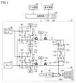
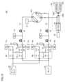
- FIG. 1is a diagram schematically showing an example of the configuration of a gas analysis system (gas chromatograph system) 1 according to this embodiment.
- the gas analysis system 1includes an analysis device 10, an input device 60, a display device 70, and a control device 100.
- the analyzer 10includes carrier gas supply devices 11a to 11c and 12a to 12c, a sample tank 20, a pump 21, vents 23 to 26, sampler modules M1 and M2, a switching module M3, and columns 41 to 44. , a first flow path L ⁇ b>1 , a second flow path L ⁇ b>2 , and a detection device 80 .
- Each of the carrier gas supply devices 11a to 11c and 12a to 12cadjusts the mobile phase called carrier gas to a predetermined pressure and outputs it.
- the carrier gas supply devices 11a to 11c and the carrier gas supply devices 12a to 12coutput carrier gases of different types.
- the carrier gas supply devices 11a to 11coutput helium gas (He) as the first type of carrier gas, and the carrier gas supply devices 12a to 12c output nitrogen gas (N2 ) shall be output.
- Hehelium gas
- N2nitrogen gas
- the sample tank 20is a device that stores a sample gas to be analyzed.
- a sample tank 20is connected to the sampler modules M1 and M2.
- the pump 21is a suction pump that is connected to the flow paths in the sampler modules M1 and M2 and sucks the air in the sampler modules M1 and M2 to create a negative pressure in the sampler modules M1 and M2.
- the negative pressurehere means a pressure lower than the atmospheric pressure on the basis of the atmospheric pressure.
- vents 23 to 26communicate the flow path inside the analyzer 10 to the outside, and discharge the gas inside the analyzer 10 to the outside.
- Each of the sampler modules M1 and M2 and the switching module M3is formed by mounting a plurality of switching valves on a channel plate (channel member) in which a channel pattern is formed.
- Each module M1 to M3is provided with a plurality of connectors (interfaces) for connecting external devices.
- the channels formed in each module M1 to M3are connected to the outside through these connectors.
- the sampler module M1is a device for supplying a constant amount of sample gas to the column 41 using helium gas (He) as a carrier gas.
- the sampler module M1includes connectors C1 to C6, a constant volume sample loop PL1, switching valves V1 to V6, and a plurality of flow paths connecting them.
- a sample tank 20, a pump 21, and a vent 23are connected to the connectors C1 to C3, respectively.
- Carrier gas supply devices 11a and 11bare connected to the connectors C4 and C5, respectively.
- a column 41is connected to the connector C6.
- the switching valves V1 and V4are arranged in this order in the flow path from the connector C1 to the connector C4.
- the switching valves V3, V5 and V6are arranged in this order in the flow path from the connector C2 to the connector C5.
- the switching valve V2is arranged in the flow path connecting the flow path between the switching valves V5 and V6 and the connector C3.
- the sample loop PL1is arranged in a channel that connects the channel between the switching valves V1 and V4 and the channel between the switching valves V3 and V5.
- the sample loop PL1has a function of temporarily holding the sample gas introduced from the sample tank 20 so as to supply it to the column 41 .
- the sampler module M1By appropriately switching the connection destination of the sample loop PL1 by controlling the switching valves V1 to V6, the sampler module M1 once fills the sample loop PL1 with the sample gas supplied from the sample tank 20, and then fills the sample loop PL1 with helium gas (He ) as a carrier gas, the sample gas filled in the sample loop PL1 is supplied to the column 41 .
- Hehelium gas
- the columns 41 and 42are arranged in series in this order between the connector C3 of the sampler module M1 and the first flow path L1.
- the columns 41 and 42separate and output various components contained in the sample gas in the direction of time while the supplied sample gas passes through each column along with the flow of the carrier gas.
- Column 41is a pre-column for primary separation
- column 42is a main column for secondary separation.
- a carrier gas supply device 11 cis connected to a channel between the columns 41 and 42 .
- the first flow path L1connects between the column 42 and the connector C13 of the switching module M3.
- the first flow path L1supplies the gas component flowing out of the column 42 using helium gas (He) as a carrier gas to the switching module M3.
- Hehelium gas
- the sampler module M2is a device for supplying a constant amount of sample gas to the column 43 using nitrogen gas (N2) as a carrier gas.
- the sampler module M2includes connectors C7 to C12, a constant volume sample loop PL2, switching valves V7 to V12, and a plurality of flow paths connecting them.
- a sample tank 20, a pump 21, and a vent 24are connected to the connectors C7 to C9, respectively.
- Carrier gas supply devices 12a and 12bare connected to the connectors C10 and C11, respectively.
- a column 43is connected to the connector C12.
- the switching valves V7 and V10are arranged in this order in the flow path from the connector C7 to the connector C10.
- the switching valves V9, V11, and V12are arranged in this order in the flow path from the connector C8 to the connector C11.
- the switching valve V8is arranged in a flow path connecting the flow path between the switching valves V11 and V12 and the connector C9.
- the sample loop PL2is arranged in a channel that connects the channel between the switching valves V7 and V10 and the channel between the switching valves V9 and V11.
- the sample loop PL2has a function of temporarily holding the sample gas introduced from the sample tank 20 so as to supply it to the column 41 .
- the sampler module M2By appropriately switching the connection destination of the sample loop PL2 by controlling the switching valves V7 to V12, the sampler module M2 once fills the sample loop PL2 with the sample gas supplied from the sample tank 20, and then supplies nitrogen gas (N2 ) as a carrier gas, the sample gas filled in the sample loop PL2 is supplied to the column 43 .
- the columns 43 and 44are arranged in series in this order between the connector C12 of the sampler module M2 and the second flow path L2.
- the columns 43 and 44separate and output various components contained in the sample gas in the direction of time while the supplied sample gas passes through each column along with the flow of the carrier gas.
- Column 43is a pre-column for primary separation
- column 44is a main column for secondary separation.
- the carrier gas supply device 12cis connected to the channel between the columns 43 and 44. As shown in FIG.
- the second flow path L2connects between the column 44 and the connector C14 of the switching module M3.
- the second flow path L2supplies the gas component flowing out of the column 44 using nitrogen gas (N2) as a carrier gas to the switching module M3.
- N2nitrogen gas
- the switching module M3is a device for switching between the gas component in the helium gas flowing through the first flow path L1 and the gas component in the nitrogen gas flowing through the second flow path L2 as the object to be detected by the detection device 80. be.
- the switching module M3includes connectors C13 to C16, switching valves V13 to V16, and a plurality of flow paths connecting them.
- the first flow path L1 and the second flow path L2are connected to the connectors C13 and C14, respectively.
- a vent 25is connected to the connector C15.
- a detection device 80is connected to the connector C16.
- the switching valve V13is arranged in a flow path that connects the flow path between the connector C15 and the switching valve V15 and the flow path between the connector C13 and the switching valve V16.
- the switching valve V14is arranged in a flow path that connects the flow path between the connector C16 and the switching valve V16 and the flow path between the connector C14 and the switching valve V15.
- the switching valve V15is arranged in the channel between the connector C14 and the connector C15.
- the switching valve V16is arranged in the channel between the connector C13 and the connector C16.
- the switching module M3is switched between the first state and the second state by switching the combination of the open/close states of the switching valves V13 to V16.
- the switching module M3is in the first state, the first flow path L1 and the detection device 80 are communicated so that the gas (helium gas) from the first flow path L1 is supplied to the detection device 80, and the second flow The passage L2 and the vent 25 are communicated to discharge the gas (nitrogen gas) from the second passage L2 to the outside.
- the switching module M3When the switching module M3 is in the second state, the second flow path L2 and the detection device 80 are communicated so that the gas (nitrogen gas) from the second flow path L2 is supplied to the detection device 80, and the first flow The passage L1 and the vent 25 are communicated to discharge the gas (helium gas) from the first passage L1 to the outside.
- switching valves V1 to V16can be controlled independently of each other according to commands from the control device 100.
- the detection device 80is connected to the connector C16 of the switching module M3 and detects gas components supplied from the switching module M3.
- the detection device 80includes automatic pressure controllers (hereinafter also referred to as "APC") 81, 82, switching valves SW1, SW2, and a TCD (Thermal Conductivity Detector) 90.
- APCautomatic pressure controllers
- SW1, SW2switching valves
- TCDThermal Conductivity Detector
- the APC 81outputs constant pressure helium gas as a reference gas for the TCD 90.
- the APC 82outputs constant pressure nitrogen gas as a reference gas for the TCD 90 .
- the switching valves SW1 and SW2switch the reference gas supplied to the TCD 90 between helium gas from the APC 81 and nitrogen gas from the APC 82 .
- the switching module M3When the switching module M3 is in the first state, the helium gas from the first flow path L1 is introduced into the TCD90 as a carrier gas.
- the switching valves SW1 and SW2are controlled so that the reference gas supplied to the TCD 90 is also helium gas.
- the switching module M3When the switching module M3 is in the second state, nitrogen gas from the second flow path L2 is introduced into the TCD 90 as carrier gas.
- the switching valves SW1 and SW2are controlled so that the reference gas supplied to the TCD 90 is also nitrogen gas.
- the TCD 90detects various components in the sample gas introduced from the switching module M3 using the difference in thermal conductivity of each component while using the reference gas as a comparison target. Since the component detection method using the difference in thermal conductivity is well known, detailed description thereof will be omitted.
- Nitrogen gasis used as a carrier gas at the timing of detecting hydrogen and helium in the sample gas. Hydrogen and helium are lighter than other components and are eluted faster than other components using any separation column. Therefore, the carrier gas is set to nitrogen gas at the beginning of the analysis, and the carrier gas is switched to helium gas immediately after the timing for detecting hydrogen and helium has passed. Components other than hydrogen and helium have much lower thermal conductivity than helium, so switching the carrier gas to helium gas can increase the detection sensitivity of components other than hydrogen and helium.
- the data indicating the detection results by the TCD 90are stored in the memory within the control device 100 and displayed on the display device 70 upon request from the user.
- the input device 60is, for example, a keyboard or a pointing device such as a mouse, and receives commands from the user.
- the display device 70is composed of, for example, a liquid crystal display (LCD) panel, and displays information to the user. When a touch panel is used as the user interface, the input device 60 and the display device 70 are integrally formed.
- the control device 100includes an arithmetic unit (Central Processing Unit) 110, a storage device 120, an interface, and the like.
- the control device 100centrally controls the analysis device 10 as a whole.
- the control device 100is wired or wirelessly connected to an input device 60 and a display device 70 which are user interfaces.
- FIG. 2is a cross-sectional view of the microvalve 200 when the microvalve 200 is in an open state.
- FIG. 3is a cross-sectional view of microvalve 200 when microvalve 200 is in a closed state.
- the microvalve 200includes a base layer 220, a diaphragm layer 230, and a cover layer 240, and has a laminated structure in which these are laminated in this order.
- Each layer of base layer 220, diaphragm layer 230, and cover layer 240is made of, for example, silicon oxide or monocrystalline silicon to achieve desired strength, flexibility, and low activity, and is made of MEMS (Micro Electric System). Microfabrication is applied by Mechanical Systems) technology.
- the thickness (dimension in the stacking direction) of the microvalve 200is approximately 1 to 2 mm.
- the direction from the base layer 220 to the cover layer 240may be referred to as the upward direction, and the direction from the cover layer 240 to the base layer 220 may be referred to as the downward direction.
- the base layer 220is arranged as the bottom layer of the microvalve 200 .
- the base layer 220is formed with a recess 221 and openings 222 to 224 penetrating through the base layer 220 .
- the concave portion 221has a substantially circular shape when the base layer 220 is viewed from above, and is formed near the substantially center of the base layer 220 .
- the concave portion 221is recessed from the upper surface side of the base layer 220 toward the lower surface side.
- the thickness of the base layer 220is approximately 150 ⁇ m. Also, the depth of the concave portion 221 is 5 to 20 ⁇ m, preferably about 10 ⁇ m.
- the openings 223 , 224are formed in the bottom 225 of the recess 221 . As will be described below, openings 223 and 224 respectively form an inlet and an outlet for the sample gas.
- the opening 222is formed in the outer edge of the base layer 220 around the recess 221 so as to be separated from the recess 221 .
- the opening 222forms a supply port for the control fluid (pneumatic fluid) of the microvalve 200 .
- the diaphragm layer 230is arranged on the upper surface side of the base layer 220 so as to face the base layer 220 .
- the diaphragm layer 230has an opening 232 penetrating through the diaphragm layer 230 , a rigid portion 234 , and a flexible portion 233 provided around the rigid portion 234 .
- the flexible portion 233is thinner than the rigid portion 234 and has flexibility. The elastic deformation of the flexible portion 233 displaces the rigid portion 234 in the vertical direction.
- the opening 232is formed apart from the flexible portion 233 and the rigid portion 234 .
- the opening 232is formed at a position overlapping the opening 222 of the base layer 220 when viewed from above, and forms a pneumatic fluid supply port together with the opening 222 .
- the microvalve 200is used by being connected to a channel member (channel plate) 250 . Openings 252 to 254 are formed in the channel member 250 at positions corresponding to the openings 222 to 224 of the base layer 220, respectively.
- the opening 252 of the channel member 250 , the opening 222 of the base layer 220 , and the opening 232 of the diaphragm layer 230communicate with each other to form a pneumatic fluid supply port 262 .
- Pneumatic fluidis supplied to the recess 241 of the cover layer 240 through the supply port 262 .
- the opening 253 of the channel member 250communicates with the opening 223 of the base layer 220 to form an inlet 263 for the sample gas.
- the opening 254 of the channel member 250communicates with the opening 224 of the base layer 220 to form an outlet 264 for the sample gas.
- the microvalve 200is in an open state (normal state) in which the pneumatic fluid is not supplied to the supply port 262 of the channel member 250, and the pneumatic fluid is supplied to the supply port 262 of the channel member 250. It is a so-called normally open type valve that is closed by
- the rigid part 234When the pneumatic fluid is supplied to the supply port 262 of the flow path member 250 , the rigid part 234 is pushed by the pneumatic fluid and displaced downward, so that the lower surface of the rigid part 234 becomes the concave portion 221 in the base layer 220 . As a result, the inlet 263 and the outlet 264 of the sample gas are in a closed state (closed state). Instead of driving (displacing) the rigid portion 234 with the pneumatic fluid, the rigid portion 234 may be electrically driven (displaced) using a piezo element or the like.
- the gas analysis system 1includes the first flow path L1 in which the components flowing out from the columns 41 and 42 using helium gas as the carrier gas flow, and the components flowing out from the columns 43 and 44 using nitrogen gas as the carrier gas.
- a switching module M3is arranged between the second flow path L2 and the detection device 80 .
- the gas analysis system 1can separate the elution component in the first flow path L1 and the elution component in the second flow path L2 without switching the carrier gas in each of the columns 41 to 44 during one analysis.
- the detection device 80can be fed sequentially.
- FIGS. 4 to 11An example of the analysis operation of the gas analysis system 1 will be described below with reference to FIGS.
- switching valves marked with a crossare in the closed state, and switching valves without a cross are in the open state.
- black arrowsindicate the flow of helium gas (He gas)
- white arrowsindicate the flow of nitrogen gas (N2 gas)
- hatched arrowsindicate the flow of the sample gas (sample). .
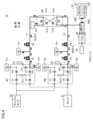
- FIG. 4is a diagram showing the states of the switching valves V1 to V16 and the flow of each gas during standby. During standby, the switching valves V6, V12, V13 and V14 are opened and the other switching valves are closed.
- the He gas from the carrier gas supply device 11bpasses through the columns 41 and 42 and is discharged from the vent 25 to the outside.
- the N2 gas from the carrier gas supply device 12bpasses through the columns 43 and 44, passes through the inside of the TCD 90, and is discharged from the vent 26 to the outside.
- the reference gas for TCD 90is N2 gas from APC 82 .
- FIG. 5is a diagram showing the states of the switching valves V1 to V16 and the flow of each gas when the sample gas is filled.
- the switching valves V1, V3, V6, V7, V9, V12, V13 and V14are opened and the other switching valves are closed.
- the pump 21is activated.
- the sample gas from the sample tank 20is filled into the sample loops PL1 and PL2.
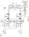
- FIG. 6is a diagram showing the states of the switching valves V1 to V16 and the flow of each gas when the pressure is balanced. At the time of pressure equilibrium, the switching valves V1, V6, V7, V12, V13 and V14 are opened and the other switching valves are closed.
- the gas pressure in the sample loops PL1 and PL2is stabilized at approximately atmospheric pressure, so that the amount of sample gas held in the sample loops PL1 and PL2 can be stabilized at a constant amount.
- the state of pressure equilibriumcontinues until the gas pressure in the sample loops PL1, PL2 stabilizes.
- sample gas filled in the sample loop PL1is also referred to as "He sample gas”
- sample gas filled in the sample loop PL2is also referred to as "N2 sample gas”.
- FIG. 7is a diagram showing the states of the switching valves V1 to V16 and the flow of each gas when injecting the N2 sample gas.
- the switching valves V6, V10, V11, V13 and V14are opened and the other switching valves are closed.
- the sample gas (N2 sample gas) in the sample loop PL2is pushed out by the N2 gas from the carrier gas supply device 12a and injected into the column 43.
- FIG. 7is a diagram showing the states of the switching valves V1 to V16 and the flow of each gas when injecting the N2 sample gas.
- FIG. 8is a diagram showing the states of the switching valves V1 to V16 and the flow of each gas during pre-separation of the N2 sample gas. During pre-separation of the N2 sample gas, the switching valves V4, V6, V10, V11, V13, and V14 are opened, and the other switching valves are closed.
- the N2 sample gas injected into the column 43is separated in the column 43 into the front end component S1 that elutes early and the rear end component S2 that elutes later, and the front end component S1 is supplied from the column 43 to the column 44.
- the front end component S1 of the N2 sample gasis secondarily separated in the column 43 .
- the He sample gas filled in the sample loop PL1is pushed out and injected into the column 41 by the He gas from the carrier gas supply device 11a.
- the timing of injecting the He sample gas into the column 41(the timing of closing the switching valve V6 and opening the switching valves V4 and V5) is determined by the time at which the front end component S1 of the N2 sample gas reaches the TCD 90 and the timing at which it is supplied to the TCD 90. It can be determined by the time from switching the carrier gas until the baseline detected by the TCD 90 stabilizes.
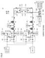
- FIG. 9is a diagram showing the states of the switching valves V1 to V16 and the flow of each gas when the N2 sample gas is detected.
- the switching valves V4, V5, V8, V13, and V14are opened, and the other switching valves are closed.
- the front end component S1 of the N2 sample gas secondary separated in the column 44is transported to the TCD 90 by the N2 gas from the carrier gas supply device 12c and detected.
- the trailing end component S2 of the N2 sample gas remaining in the column 43flows back through the column 43 with the N2 gas from the carrier gas supply device 12c and is discharged to the outside through the vent 24.
- the He sample gas injected into the column 41is primarily separated in the column 41 into a front-end component S3 that elutes early and a rear-end component S4 that elutes late, and the front-end component S3 is supplied from the column 41 to the column 42.
- FIG. 10is a diagram showing the states of the switching valves V1 to V16 and the flow of each gas when the gallia gas is switched. At the time of gallia gas switching, the switching valves V4, V5, V8, V15, and V16 are opened, and the other switching valves are closed.
- the state of the switching module M3is switched from the second state to the first state, and the gas supplied to the TCD 90 is switched from nitrogen gas from the second flow path L2 to helium gas from the first flow path L1. be done.
- the reference gas for the TCD 90was switched from the N2 gas from the APC82 to the He gas from the APC81.
- FIG. 11is a diagram showing the states of the switching valves V1 to V16 and the flow of each gas when the He sample gas is detected.
- the switching valves V2, V8, V15 and V16are opened and the other switching valves are closed.
- the front end component S3 of the He sample gas secondary separated in the column 42is transported to the TCD 90 by the He gas from the carrier gas supply device 11c and detected.
- the trailing end component S4 of the He sample gas remaining in the column 41flows back through the column 41 with the He gas from the carrier gas supply device 11c and is discharged to the outside through the vent 23.
- Step 9Return to standby state After that, the device is returned to the standby state shown in FIG.
- the gas analysis system 1includes the carrier gas supply devices 11a to 11c that supply helium gas as carrier gas, and the columns that separate gas components contained in the sample gas using helium gas as carrier gas. 41 and 42, carrier gas supply devices 12a to 12c for supplying nitrogen gas as carrier gas, columns 43 and 44 for separating gas components contained in the sample gas using nitrogen gas as carrier gas, and helium gas as carrier gas.
- the switching module M3is arranged between the first flow path L1, the second flow path L2, and the TCD 90, and has a "first state” in which the connection destination of the TCD 90 is the first flow path L1, and a “first state” in which the connection destination of the TCD 90 is the first state. It is configured to be switchable to a "second state” in which there are two flow paths L2.
- the carrier gas supplied to the TCD 90is selected from either helium gas or nitrogen gas. You can switch to the other. As a result, one TCD 90 can sequentially detect the sample gas component in the helium gas and the sample gas component in the nitrogen gas.
- the switching module M3includes a flow path that connects the first flow path L1, the second flow path L2, and the TCD 90, and a plurality of flow paths that are provided on the flow path and can be controlled independently of each other. It is composed of switching valves V13 to V16.
- carrier gas switchingcan be completed earlier than when a rotary valve having multiple ports is used as a carrier gas switching device. That is, when a rotary valve having a plurality of ports is used as a carrier gas switching device, when the valve is rotated to switch the flow path, half of the ports are interlocked and switched at the same time. As a result, the channel configuration becomes complicated, and the channel volume of the peripheral piping is large, so the carrier gas replacement time becomes long when switching the carrier gas, and it is difficult to stabilize the baseline of the TCD 90 in a short time. is difficult.
- the switching valves V1 to V10can be controlled independently, so the flow path configuration can be simplified, and the flow path volume of the peripheral piping can be reduced. can be made smaller. As a result, the replacement time of the carrier gas can be shortened and the baseline of the TCD 90 can be stabilized early, that is, the switching of the carrier gas can be completed early.
- each of the plurality of switching valves V13 to V16 in the switching module M3is a microvalve formed by microfabrication using MEMS technology.
- each of the switching valves V13 to V16is formed with an opening 223 for introducing gas thereinto and an opening 224 for discharging the gas introduced from the opening 223 to the outside. It includes a base layer 220 and a diaphragm layer 230 arranged to face the base layer 220 and elastically deformed to switch between flow and blockage of gas from the opening 223 to the opening 224 .
- the flow path in the switching module M3 and the dead volume inside the switching valves V13 to V16can be made extremely small, so the carrier gas replacement time can be further shortened, and the baseline of the TCD90 can be improved. It can be stabilized earlier.
- the switching valves V13 to V16 according to the present embodimentare made of silicon. Therefore, quantitative accuracy of analysis can be ensured.
- the inner walls and seals of the channelare made of metal, resin, or rubber, so that the highly adsorbable sample gas components do not adhere to the inner walls and seals of the channel. It tends to adhere to the surface, and as a result, the amount of sample gas introduced into the TCD 90 may decrease, leading to a decrease in quantitative accuracy of analysis.
- the channel walls of the switching valves V13 to V16 according to the present embodimentare all made of silicon oxide or single crystal silicon with low activity, the sample gas components are less likely to be adsorbed. As a result, quantitative accuracy of analysis can be ensured.
- FIG. 12is a diagram schematically showing an example of the configuration of the analysis device 10A according to Modification 1. As shown in FIG. The analyzer 10A is obtained by changing the switching module M3 of the analyzer 10A described above to a rotary valve RV1. Other configurations of the analyzer 10A are the same as those of the analyzer 10 described above.
- a gas analysis systemincludes a first column and a second column that separate gas components contained in a sample gas, and a first carrier gas and a second column that are different from each other for transporting the sample gas a first supply source and a second supply source that supply two carrier gases, respectively; a first channel through which the sample gas that has passed through the first column by the first carrier gas flows; and a sample gas that has passed through the second column by the second carrier gas A second flow path through which the sample gas flows, a thermal conductivity detector that detects the components in the gas by utilizing the difference in thermal conductivity of each component, and the first flow path, the second flow path, and thermal conductivity detection. and a first state in which the connection destination of the thermal conductivity detector is the first flow path, and a second state in which the connection destination of the thermal conductivity detector is the second flow path. and a switching device configured as follows.
- the switching deviceis arranged between the first flow path, the second flow path, and the thermal conductivity detector.
- the connection destination of the thermal conductivity detectorcan be switched from one of the first flow path and the second flow path to the other. . Therefore, while maintaining the carrier gas flowing through the first column as the first carrier gas and maintaining the carrier gas flowing through the second column as the second carrier gas, the carrier gas supplied to the thermal conductivity detector is changed to the first carrier gas.
- One of the carrier gas and the second carrier gascan be switched to the other. As a result, the components in the first carrier gas and the components in the second carrier gas can be sequentially detected with one thermal conductivity detector.
- the switching deviceis provided on the flow path connecting the first flow path, the second flow path, and the thermal conductivity detector, and on the flow path, may comprise a plurality of valves that can be controlled independently of each other.
- the flow pathmay be configured to be able to form a first state and a second state according to a combination of control states of a plurality of valves.
- the channel configurationcan be simplified, and the dead volume of the channel can be made smaller. Therefore, the replacement time of the carrier gas can be shortened, and the switching of the carrier gas can be completed early.
- each of the plurality of valveshas an inflow port for introducing gas into the interior and a A base portion having an outflow port formed thereon, and a diaphragm portion arranged opposite the base portion and elastically deformed to switch between flow and blockage of gas from the inflow port to the outflow port may be provided.
- the dead volume inside each valvecan be made very small, so that the carrier gas replacement time can be shortened and the carrier gas switching can be completed earlier. can be done.
- each of the plurality of valvesmay be made of silicon.
- each valvesince the channel wall surface of each valve is made of silicon with low activity, sample gas components are difficult to adsorb. As a result, quantitative accuracy of analysis can be ensured.
- the first carrier gasmay be helium gas and the second carrier gas may be nitrogen gas.
- the type of carrier gas supplied to the thermal conductivity detectoris switched between helium gas (first carrier gas) and nitrogen gas (second carrier gas) be able to.
Landscapes
- Chemical & Material Sciences (AREA)
- Analytical Chemistry (AREA)
- Immunology (AREA)
- Pathology (AREA)
- Health & Medical Sciences (AREA)
- Biochemistry (AREA)
- General Health & Medical Sciences (AREA)
- General Physics & Mathematics (AREA)
- Physics & Mathematics (AREA)
- Life Sciences & Earth Sciences (AREA)
- Engineering & Computer Science (AREA)
- General Chemical & Material Sciences (AREA)
- Oil, Petroleum & Natural Gas (AREA)
- Chemical Kinetics & Catalysis (AREA)
- Sampling And Sample Adjustment (AREA)
- Investigating Or Analyzing Materials By The Use Of Electric Means (AREA)
- Investigating Or Analyzing Materials Using Thermal Means (AREA)
Abstract
Description
Translated fromJapanese本開示は、熱伝導度検出器(Thermal Conductivity Detector、以下「TCD」ともいう)を備えるガス分析システム(ガスクロマトグラフシステム)に関する。The present disclosure relates to a gas analysis system (gas chromatograph system) equipped with a thermal conductivity detector (hereinafter also referred to as "TCD").
ガス分析システムのなかには、ガス中の成分をTCDで検出するものが存在する。ガス中の成分をTCDで検出するガス分析システムにおいて、検出対象である試料ガスの成分の熱伝導度と、キャリアガスの熱伝導度との差が小さいと、試料ガスの成分に対応する検出信号の強度が小さくなり感度が低下してしまう。Among the gas analysis systems, there are those that detect components in the gas with TCD. In a gas analysis system that detects a component in a gas with a TCD, if the difference between the thermal conductivity of the component of the sample gas to be detected and the thermal conductivity of the carrier gas is small, a detection signal corresponding to the component of the sample gas is generated. becomes weaker and the sensitivity decreases.
その対策として、従来においては、第1キャリアガスが流れる分離カラムおよびTCDを含む第1系統と、第1キャリアガスとは成分の異なる第2キャリアガスが流れる分離カラムおよびTCDを含む第2系統とを別々に設け、第1キャリアガスの熱伝導度との差が小さい成分については、第2キャリアガスが流れる第2系統のTCDで検出するように構成されたガス分析システムが存在する(非特許文献1参照)As a countermeasure, conventionally, a first system including a separation column and a TCD through which a first carrier gas flows and a second system including a separation column and a TCD through which a second carrier gas having a component different from that of the first carrier gas flows. are provided separately, and for components with a small difference in thermal conductivity from the first carrier gas, there is a gas analysis system configured to detect with a second TCD in which the second carrier gas flows (non-patent Reference 1)
上述の非特許文献1に開示された従来のガス分析システムにおいては、2種類のキャリアガスに対して2つのTCDがそれぞれ必要になるため、システム全体が大型化するという問題があった。In the conventional gas analysis system disclosed in
本開示は上記の問題を解決するためになされたものであり、本開示の目的は、第1キャリアガス中の成分と、第1キャリアガスとは種類の異なる第2キャリアガス中の成分とを、1つの熱伝導度検出器で順次検出することができるガス分析システムを提供することである。The present disclosure has been made to solve the above problems, and an object of the present disclosure is to identify components in a first carrier gas and components in a second carrier gas that are different in kind from the first carrier gas. , is to provide a gas analysis system which can be sequentially detected with one thermal conductivity detector.
本開示によるガス分析システムは、試料ガスに含まれるガス成分を各々が分離する第1カラムおよび第2カラムと、試料ガスを搬送するための互いに異なる第1キャリアガスおよび第2キャリアガスをそれぞれ供給する第1供給源および第2供給源と、第1キャリアガスによって第1カラムを通過した試料ガスが流れる第1流路と、第2キャリアガスによって第2カラムを通過した試料ガスが流れる第2流路と、ガス中の成分を各成分の熱伝導度の違いを利用して検出する熱伝導度検出器と、第1流路と第2流路と熱伝導度検出器との間に配置され、熱伝導度検出器の接続先を第1流路とする第1状態と、熱伝導度検出器の接続先を第2流路とする第2状態とに切替可能に構成された切替装置とを備える。A gas analysis system according to the present disclosure supplies a first column and a second column, each of which separates gas components contained in a sample gas, and a first carrier gas and a second carrier gas, which are different from each other, for carrying the sample gas, respectively. a first flow path through which the sample gas that has passed through the first column by the first carrier gas flows; and a second flow path through which the sample gas that has passed through the second column by the second carrier gas flows. Arranged between the flow path, a thermal conductivity detector that detects the components in the gas using the difference in thermal conductivity of each component, and the first flow path, the second flow path, and the thermal conductivity detector A switching device capable of switching between a first state in which the thermal conductivity detector is connected to the first flow path and a second state in which the thermal conductivity detector is connected to the second flow path. and
上記のガス分析システムによれば、第1流路と第2流路と熱伝導度検出器との間に、切替装置が配置される。そして、切替装置の状態を第1状態および第2状態の一方から他方に切り替えることによって、熱伝導度検出器の接続先を第1流路および第2流路の一方から他方に切り替えることができる。そのため、第1カラムを流れるキャリアガスを第1キャリアガスに維持し、かつ第2カラムを流れるキャリアガスを第2キャリアガスに維持したまま、熱伝導度検出器に供給されるキャリアガスを第1キャリアガスおよび第2キャリアガスの一方から他方に切り替えることができる。その結果、第1キャリアガス中の成分と第2キャリアガス中の成分とを1つの熱伝導度検出器で順次検出することができる。According to the above gas analysis system, the switching device is arranged between the first flow path, the second flow path, and the thermal conductivity detector. By switching the state of the switching device from one of the first state and the second state to the other, the connection destination of the thermal conductivity detector can be switched from one of the first flow path and the second flow path to the other. . Therefore, while maintaining the carrier gas flowing through the first column as the first carrier gas and maintaining the carrier gas flowing through the second column as the second carrier gas, the carrier gas supplied to the thermal conductivity detector is changed to the first carrier gas. One of the carrier gas and the second carrier gas can be switched to the other. As a result, the components in the first carrier gas and the components in the second carrier gas can be sequentially detected with one thermal conductivity detector.
本開示によれば、第1キャリアガス中の成分と、第1キャリアガスとは種類の異なる第2キャリアガス中の成分とを、1つの熱伝導度検出器で順次検出することができるガス分析システムを提供することができる。According to the present disclosure, gas analysis capable of sequentially detecting components in a first carrier gas and components in a second carrier gas different in type from the first carrier gas with a single thermal conductivity detector system can be provided.
以下に、本実施の形態について図面を参照して詳細に説明する。なお、以下では図中の同一または相当部分には同一符号を付してその説明は繰返さないものとする。The present embodiment will be described in detail below with reference to the drawings. In the following description, the same reference numerals are given to the same or corresponding parts in the drawings, and the description thereof will not be repeated.
[システムの全体構成]
図1は、本実施の形態によるガス分析システム(ガスクロマトグラフシステム)1の構成の一例を模式的に示す図である。[Overall system configuration]
FIG. 1 is a diagram schematically showing an example of the configuration of a gas analysis system (gas chromatograph system) 1 according to this embodiment.
ガス分析システム1は、分析装置10と、入力装置60と、表示装置70と、制御装置100とを備える。分析装置10は、キャリアガス供給装置11a~11c,12a~12cと、サンプルタンク20と、ポンプ21と、ベント23~26と、サンプラモジュールM1,M2と、切替モジュールM3と、カラム41~44と、第1流路L1と、第2流路L2と、検出装置80とを備える。The
キャリアガス供給装置11a~11c,12a~12cの各々は、キャリアガスと呼ばれる移動相を予め定められた圧力に調整して出力する。キャリアガス供給装置11a~11cとキャリアガス供給装置12a~12cとは、互いに異なる種類のキャリアガスを出力する。本実施の形態においては、キャリアガス供給装置11a~11cが第1種類のキャリアガスとしてヘリウムガス(He)を出力し、キャリアガス供給装置12a~12cが第2種類のキャリアガスとして窒素ガス(N2)を出力するものとする。Each of the carrier
サンプルタンク20は、分析対象である試料ガスを貯留する装置である。サンプルタンク20は、サンプラモジュールM1,M2に接続される。The
ポンプ21は、サンプラモジュールM1,M2内の流路に接続され、サンプラモジュールM1,M2内のエアを吸引してサンプラモジュールM1,M2内を負圧にするための吸引ポンプである。なお、ここでいう負圧とは、大気圧を基準として、大気圧よりも低い圧力を意味する。The
ベント23~26は、分析装置10内の流路を外部に連通し、分析装置10内のガスを外部に排出する。The
サンプラモジュールM1,M2および切替モジュールM3の各々は、流路パターンが形成された流路板(流路部材)に複数の切替バルブを実装することによって形成されている。各モジュールM1~M3には、外部機器を接続するための複数のコネクタ(インターフェース)が設けられる。各モジュールM1~M3に形成された流路は、これらのコネクタを介して外部に接続される。Each of the sampler modules M1 and M2 and the switching module M3 is formed by mounting a plurality of switching valves on a channel plate (channel member) in which a channel pattern is formed. Each module M1 to M3 is provided with a plurality of connectors (interfaces) for connecting external devices. The channels formed in each module M1 to M3 are connected to the outside through these connectors.
サンプラモジュールM1は、ヘリウムガス(He)をキャリアガスとして、試料ガスを一定量ずつカラム41に供給するための装置である。サンプラモジュールM1は、コネクタC1~C6と、一定容積のサンプルループPL1と、切替バルブV1~V6と、これらを接続する複数の流路とを備える。The sampler module M1 is a device for supplying a constant amount of sample gas to the
コネクタC1~C3には、サンプルタンク20、ポンプ21、ベント23がそれぞれ接続される。コネクタC4,C5には、キャリアガス供給装置11a,11bがそれぞれ接続される。コネクタC6には、カラム41が接続される。A
切替バルブV1,V4は、コネクタC1からコネクタC4までの流路に、この順に配置される。切替バルブV3,V5,V6は、コネクタC2からコネクタC5までの流路に、この順に配置される。切替バルブV2は、切替バルブV5,V6間の流路とコネクタC3とを接続する流路に配置される。The switching valves V1 and V4 are arranged in this order in the flow path from the connector C1 to the connector C4. The switching valves V3, V5 and V6 are arranged in this order in the flow path from the connector C2 to the connector C5. The switching valve V2 is arranged in the flow path connecting the flow path between the switching valves V5 and V6 and the connector C3.
サンプルループPL1は、切替バルブV1,V4間の流路と切替バルブV3,V5間の流路とを接続する流路に配置される。サンプルループPL1は、サンプルタンク20から導入される試料ガスを、カラム41に供給するために一時的に保持する機能を有する。切替バルブV1~V6の制御によってサンプルループPL1の接続先が適宜切り替えられることによって、サンプラモジュールM1は、サンプルタンク20から供給される試料ガスをサンプルループPL1に一旦充填し、その後、ヘリウムガス(He)をキャリアガスとして、サンプルループPL1内に充填された試料ガスをカラム41に供給する。The sample loop PL1 is arranged in a channel that connects the channel between the switching valves V1 and V4 and the channel between the switching valves V3 and V5. The sample loop PL1 has a function of temporarily holding the sample gas introduced from the
カラム41,42は、サンプラモジュールM1のコネクタC3から第1流路L1までの間に、この順に直列に配置される。カラム41,42は、供給された試料ガスがキャリアガスの流れに乗って各カラム中を通過する間に、当該試料ガス中に含まれる各種成分を時間方向に分離して出力する。カラム41は一次分離用のプレカラムであり、カラム42は二次分離用のメインカラムである。キャリアガス供給装置11cは、カラム41とカラム42との間の流路に接続される。The
第1流路L1は、カラム42と切替モジュールM3のコネクタC13との間を接続する。第1流路L1は、ヘリウムガス(He)をキャリアガスとしてカラム42から流出したガス成分を切替モジュールM3に供給する。The first flow path L1 connects between the
サンプラモジュールM2は、窒素ガス(N2)をキャリアガスとして、試料ガスを一定量ずつカラム43に供給するための装置である。サンプラモジュールM2は、コネクタC7~C12と、一定容積のサンプルループPL2と、切替バルブV7~V12と、これらを接続する複数の流路とを備える。The sampler module M2 is a device for supplying a constant amount of sample gas to the
コネクタC7~C9には、サンプルタンク20、ポンプ21、ベント24がそれぞれ接続される。コネクタC10,C11には、キャリアガス供給装置12a,12bがそれぞれ接続される。コネクタC12には、カラム43が接続される。A
切替バルブV7,V10は、コネクタC7からコネクタC10までの流路に、この順に配置される。切替バルブV9,V11,V12は、コネクタC8からコネクタC11までの流路に、この順に配置される。切替バルブV8は、切替バルブV11,V12間の流路とコネクタC9とを接続する流路に配置される。The switching valves V7 and V10 are arranged in this order in the flow path from the connector C7 to the connector C10. The switching valves V9, V11, and V12 are arranged in this order in the flow path from the connector C8 to the connector C11. The switching valve V8 is arranged in a flow path connecting the flow path between the switching valves V11 and V12 and the connector C9.
サンプルループPL2は、切替バルブV7,V10間の流路と切替バルブV9,V11間の流路とを接続する流路に配置される。サンプルループPL2は、サンプルタンク20から導入される試料ガスを、カラム41に供給するために一時的に保持する機能を有する。切替バルブV7~V12の制御によってサンプルループPL2の接続先が適宜切り替えられることによって、サンプラモジュールM2は、サンプルタンク20から供給される試料ガスをサンプルループPL2に一旦充填し、その後、窒素ガス(N2)をキャリアガスとして、サンプルループPL2内に充填された試料ガスをカラム43に供給する。The sample loop PL2 is arranged in a channel that connects the channel between the switching valves V7 and V10 and the channel between the switching valves V9 and V11. The sample loop PL2 has a function of temporarily holding the sample gas introduced from the
カラム43,44は、サンプラモジュールM2のコネクタC12から第2流路L2までの間に、この順に直列に配置される。カラム43,44は、供給された試料ガスがキャリアガスの流れに乗って各カラム中を通過する間に、当該試料ガス中に含まれる各種成分を時間方向に分離して出力する。カラム43は一次分離用のプレカラムであり、カラム44は二次分離用のメインカラムである。キャリアガス供給装置12cは、カラム43とカラム44との間の流路に接続される。The
第2流路L2は、カラム44と切替モジュールM3のコネクタC14との間を接続する。第2流路L2は、窒素ガス(N2)をキャリアガスとしてカラム44から流出したガス成分を切替モジュールM3に供給する。The second flow path L2 connects between the
切替モジュールM3は、検出装置80による検出対象を、第1流路L1を流れるヘリウムガス中のガス成分とするのか、第2流路L2を流れる窒素ガス中のガス成分とするのかを切り替える装置である。The switching module M3 is a device for switching between the gas component in the helium gas flowing through the first flow path L1 and the gas component in the nitrogen gas flowing through the second flow path L2 as the object to be detected by the
切替モジュールM3は、コネクタC13~C16と、切替バルブV13~V16と、これらを接続する複数の流路とを備える。コネクタC13,C14には、第1流路L1および第2流路L2がそれぞれ接続される。コネクタC15には、ベント25が接続される。コネクタC16には、検出装置80が接続される。The switching module M3 includes connectors C13 to C16, switching valves V13 to V16, and a plurality of flow paths connecting them. The first flow path L1 and the second flow path L2 are connected to the connectors C13 and C14, respectively. A
切替バルブV13は、コネクタC15と切替バルブV15との間の流路とコネクタC13と切替バルブV16との間の流路とを接続する流路に配置される。切替バルブV14は、コネクタC16と切替バルブV16との間の流路とコネクタC14と切替バルブV15との間の流路とを接続する流路に配置される。切替バルブV15は、コネクタC14とコネクタC15との間の流路に配置される。切替バルブV16は、コネクタC13とコネクタC16との間の流路に配置される。The switching valve V13 is arranged in a flow path that connects the flow path between the connector C15 and the switching valve V15 and the flow path between the connector C13 and the switching valve V16. The switching valve V14 is arranged in a flow path that connects the flow path between the connector C16 and the switching valve V16 and the flow path between the connector C14 and the switching valve V15. The switching valve V15 is arranged in the channel between the connector C14 and the connector C15. The switching valve V16 is arranged in the channel between the connector C13 and the connector C16.
切替モジュールM3は、切替バルブV13~V16の開閉状態の組合せを切り替えることによって、第1状態と第2状態とのどちらかに切り替えられる。切替モジュールM3が第1状態である場合、第1流路L1と検出装置80とが連通されて第1流路L1からのガス(ヘリウムガス)が検出装置80に供給されるとともに、第2流路L2とベント25とが連通されて第2流路L2からのガス(窒素ガス)が外部に排出される。切替モジュールM3が第2状態である場合、第2流路L2と検出装置80とが連通されて第2流路L2からのガス(窒素ガス)が検出装置80に供給されるとともに、第1流路L1とベント25とが連通されて第1流路L1からのガス(ヘリウムガス)が外部に排出される。The switching module M3 is switched between the first state and the second state by switching the combination of the open/close states of the switching valves V13 to V16. When the switching module M3 is in the first state, the first flow path L1 and the
なお、切替バルブV1~V16は、制御装置100からの指令に応じて、互いに独立して制御可能である。It should be noted that the switching valves V1 to V16 can be controlled independently of each other according to commands from the
検出装置80は、切替モジュールM3のコネクタC16に接続され、切替モジュールM3から供給されるガス成分を検出する。検出装置80は、自動圧力コントローラ(Automatic Pressure Controller、以下「APC」ともいう)81,82と、スイッチングバルブSW1,SW2と、TCD(Thermal Conductivity Detector、熱伝導度検出器)90とを備える。The
APC81は、TCD90の参照用ガスとして、一定圧のヘリウムガスを出力する。APC82は、TCD90の参照用ガスとして、一定圧の窒素ガスを出力する。スイッチングバルブSW1,SW2は、TCD90に供給される参照用ガスを、APC81からのヘリウムガスとする状態と、APC82からの窒素ガスとする状態とのどちらかに切り替えられる。The
切替モジュールM3が第1状態である場合、TCD90には、第1流路L1からのヘリウムガスがキャリアガスとしてTCD90に導入される。この場合、TCD90に供給される参照用ガスもヘリウムガスとなるように、スイッチングバルブSW1,SW2が制御される。When the switching module M3 is in the first state, the helium gas from the first flow path L1 is introduced into the TCD90 as a carrier gas. In this case, the switching valves SW1 and SW2 are controlled so that the reference gas supplied to the
切替モジュールM3が第2状態である場合、TCD90には、第2流路L2からの窒素ガスがキャリアガスとしてTCD90に導入される。この場合、TCD90に供給される参照用ガスも窒素ガスとなるように、スイッチングバルブSW1,SW2が制御される。When the switching module M3 is in the second state, nitrogen gas from the second flow path L2 is introduced into the
TCD90は、切替モジュールM3から導入された試料ガス中の各種成分を、各成分の熱伝導度の違いを利用して、参照用ガスを比較対象としながら検出する。熱伝導度の違いを利用した成分検出手法については公知であるため詳細な説明は省略する。The
なお、試料ガス中の水素およびヘリウムを検出するタイミングでは、キャリアガスとしての窒素ガスが用いられる。水素およびヘリウムは他の成分よりも軽くどのような分離カラムを用いても他の成分よりも早く溶出される。そのため、分析を開始した当初においては、キャリアガスを窒素ガスとしておき、水素およびヘリウムを検出するタイミングが経過した後は、直ぐにキャリアガスがヘリウムガスに切り替えられる。水素およびヘリウム以外の成分はヘリウムに比べて熱伝導率が非常に小さい値になるので、キャリアガスをヘリウムガスに切り替えることによって水素およびヘリウム以外の成分の検出感度を上げることができる。Nitrogen gas is used as a carrier gas at the timing of detecting hydrogen and helium in the sample gas. Hydrogen and helium are lighter than other components and are eluted faster than other components using any separation column. Therefore, the carrier gas is set to nitrogen gas at the beginning of the analysis, and the carrier gas is switched to helium gas immediately after the timing for detecting hydrogen and helium has passed. Components other than hydrogen and helium have much lower thermal conductivity than helium, so switching the carrier gas to helium gas can increase the detection sensitivity of components other than hydrogen and helium.
TCD90による検出結果を示すデータは、制御装置100内のメモリに記憶され、ユーザからの要求により表示装置70に表示される。The data indicating the detection results by the
入力装置60は、たとえばキーボードあるいはマウスなどのポインティングデバイスであり、ユーザからの指令を受け付ける。表示装置70は、たとえば液晶(LCD:Liquid Crystal Display)パネルで構成され、ユーザに情報を表示する。ユーザインターフェースとしてタッチパネルが用いられる場合には、入力装置60と表示装置70とが一体的に形成される。The
制御装置100は、演算装置(Central Processing Unit)110、および記憶装置120、インターフェースなどを含む。制御装置100は、分析装置10全体を統括的に制御する。制御装置100は、ユーザインターフェースである入力装置60および表示装置70と、有線あるいは無線で接続されている。The
[切替バルブV1~V16の構成]
図2および図3を用いて、本実施の形態による切替バルブV1~V16の構成の一例について説明する。なお、切替バルブV1~V16の基本構成は同じであるため、図2および図3においては、切替バルブV1~V16を区別することなくマイクロバルブ200として説明する。[Configuration of switching valves V1 to V16]
An example of the configuration of the switching valves V1 to V16 according to this embodiment will be described with reference to FIGS. 2 and 3. FIG. Since the basic configuration of the switching valves V1 to V16 is the same, the switching valves V1 to V16 will be described as a
図2は、マイクロバルブ200が開状態であるときのマイクロバルブ200の断面図である。図3は、マイクロバルブ200が閉状態であるときのマイクロバルブ200の断面図である。FIG. 2 is a cross-sectional view of the
マイクロバルブ200は、基台層220と、ダイヤフラム層230と、カバー層240とを含み、これらがこの順で積層された積層構造を有している。基台層220、ダイヤフラム層230、およびカバー層240の各層は、所望の強度、柔軟性ならびに低活性度を実現するために、たとえば酸化シリコンあるいは単結晶シリコンで形成されており、MEMS(Micro Electric Mechanical Systems)技術により微細加工が施されている。The
マイクロバルブ200の厚み(積層方向の寸法)は約1~2mmである。なお、以下では、便宜的に、基台層220からカバー層240に向かう方向を上方向、カバー層240から基台層220に向かう方向を下方向として説明する場合がある。The thickness (dimension in the stacking direction) of the
基台層220は、マイクロバルブ200の最下層に配置される。基台層220には、凹部221と、基台層220を貫通する開口部222~224が形成されている。凹部221は、基台層220を上方向から平面視した場合に略円形状を有しており、基台層220の略中心付近に形成されている。凹部221は、基台層220の上面側から下面側に向かって窪んでいる。基台層220の厚みは約150μmである。また、凹部221の深さは5~20μmであり、好ましくは約10μmである。The
開口部223,224は、凹部221の底部225に形成されている。後述するように、開口部223,224は、試料ガスの流入口および流出口をそれぞれ形成する。開口部222は、基台層220の凹部221の周辺の外縁部に、凹部221とは離隔して形成されている。開口部222は、マイクロバルブ200の制御用流体(ニューマチック流体)の供給口を形成する。The
ダイヤフラム層230は、基台層220の上面側に、基台層220に対向して配置される。ダイヤフラム層230は、ダイヤフラム層230を貫通する開口部232と、剛体部234と、剛体部234の周囲に設けられた可撓部233とを有する。可撓部233は、剛体部234の厚みよりも薄く、可撓性を有している。可撓部233が弾性変形することによって、剛体部234が上下方向に変位する。The
開口部232は、可撓部233および剛体部234から離隔して形成されている。開口部232は、上方向から平面視した場合に、基台層220の開口部222と重なる位置に形成されており、開口部222とともにニューマチック流体の供給口を形成する。The
マイクロバルブ200は、流路部材(流路板)250に接続されて使用される。流路部材250には、基台層220の開口部222~224にそれぞれ対応する位置に、開口部252~254が形成されている。流路部材250の開口部252、基台層220の開口部222、およびダイヤフラム層230の開口部232は連通しており、ニューマチック流体の供給口262を形成している。ニューマチック流体は、供給口262を通って、カバー層240の凹部241へと供給される。The
流路部材250の開口部253は、基台層220の開口部223と連通しており、試料ガスの流入口263を形成する。また、流路部材250の開口部254は、基台層220の開口部224と連通しており、試料ガスの流出口264を形成する。The
マイクロバルブ200は、流路部材250の供給口262にニューマチック流体が供給されていない初期状態(ノーマル状態)において開状態となり、流路部材250の供給口262にニューマチック流体が供給されることによって閉状態となる、いわゆるノーマルオープンタイプのバルブである。The
流路部材250の供給口262にニューマチック流体が供給されていない場合、図2に示すように、剛体部234が基台層220における凹部221の底部225から離れた状態で保持されるため、試料ガスの流入口263と流出口264とが連通される開状態(オープン状態)となる。When the pneumatic fluid is not supplied to the
流路部材250の供給口262にニューマチック流体が供給されると、ニューマチック流体に押されて剛体部234が下方向に変位することによって、剛体部234の下面が基台層220における凹部221の底部225と密着した状態となるため、試料ガスの流入口263と流出口264とが遮断される閉状態(クローズ状態)となる。なお、剛体部234をニューマチック流体で駆動(変位)させることに代えて、剛体部234をピエゾ素子などを用いて電気的に駆動(変位)させるようにしてもよい。When the pneumatic fluid is supplied to the
[システムの分析動作]
上述のように、ガス分析システム1は、ヘリウムガスをキャリアガスとしてカラム41,42から流出した成分が流れる第1流路L1と、窒素ガスをキャリアガスとしてカラム43,44から流出した成分が流れる第2流路L2と、検出装置80との間に、切替モジュールM3を配置している。これにより、ガス分析システム1は、1回の分析中において、各カラム41~44内のキャリヤガスを切り替えることなく、第1流路L1の溶出成分と、第2流路L2の溶出成分とを検出装置80に順次供給することができる。[Analysis behavior of the system]
As described above, the
以下、ガス分析システム1の分析動作の一例について図4~11を参照して説明する。なお、図4~図11において、×印が付された切替バルブが閉状態であり、×印が付されていない切替バルブが開状態である。また、図4~11において、黒塗り矢印がヘリウムガス(Heガス)の流れを示し、白抜き矢印が窒素ガス(N2ガス)の流れを示し、斜線矢印が試料ガス(サンプル)の流れを示す。An example of the analysis operation of the
分析動作中においては、以下のステップ1~ステップ9の動作がこの順で行なわれる。
(ステップ1) スタンバイ
図4は、スタンバイ時における切替バルブV1~V16の状態と各ガスの流れを示す図である。スタンバイ時においては、切替バルブV6,V12,V13,V14が開状態とされ、その他の切替バルブが閉状態とされる。During the analysis operation, the following
(Step 1) Standby FIG. 4 is a diagram showing the states of the switching valves V1 to V16 and the flow of each gas during standby. During standby, the switching valves V6, V12, V13 and V14 are opened and the other switching valves are closed.
これにより、キャリアガス供給装置11bからのHeガスがカラム41,42を通過してベント25から外部に排出される。また、キャリアガス供給装置12bからのN2ガスがカラム43,44を通過し、TCD90内部を通過してベント26から外部に排出される。これに合せて、TCD90のリファレンスガスは、APC82からのN2ガスとされる。As a result, the He gas from the carrier
(ステップ2) 試料ガス充填
図5は、試料ガス充填時における切替バルブV1~V16の状態と各ガスの流れを示す図である。試料ガス充填時においては、切替バルブV1,V3,V6,V7,V9,V12,V13,V14が開状態とされ、その他の切替バルブが閉状態とされる。また、ポンプ21が作動状態とされる。これにより、サンプルタンク20からの試料ガスがサンプルループPL1,PL2内に充填される。(Step 2) Sample Gas Filling FIG. 5 is a diagram showing the states of the switching valves V1 to V16 and the flow of each gas when the sample gas is filled. At the time of filling the sample gas, the switching valves V1, V3, V6, V7, V9, V12, V13 and V14 are opened and the other switching valves are closed. Also, the
(ステップ3) 圧力均衡
図6は、圧力均衡時における切替バルブV1~V16の状態と各ガスの流れを示す図である。圧力均衡時においては、切替バルブV1,V6,V7,V12,V13,V14が開状態とされ、その他の切替バルブが閉状態とされる。(Step 3) Pressure Balance FIG. 6 is a diagram showing the states of the switching valves V1 to V16 and the flow of each gas when the pressure is balanced. At the time of pressure equilibrium, the switching valves V1, V6, V7, V12, V13 and V14 are opened and the other switching valves are closed.
これにより、サンプルループPL1,PL2内のガス圧力がほぼ大気圧に安定する平衡状態となるため、サンプルループPL1,PL2に保持される試料ガス量を一定量に安定させることができる。圧力均衡の状態は、サンプルループPL1,PL2内のガス圧力が安定するまで継続される。As a result, the gas pressure in the sample loops PL1 and PL2 is stabilized at approximately atmospheric pressure, so that the amount of sample gas held in the sample loops PL1 and PL2 can be stabilized at a constant amount. The state of pressure equilibrium continues until the gas pressure in the sample loops PL1, PL2 stabilizes.
なお、以下では、説明の便宜上、サンプルループPL1内に充填された試料ガスを「He試料ガス」とも称し、サンプルループPL2内に充填された試料ガスを「N2試料ガス」とも称す。In the following, for convenience of explanation, the sample gas filled in the sample loop PL1 is also referred to as "He sample gas", and the sample gas filled in the sample loop PL2 is also referred to as "N2 sample gas".
(ステップ4) N2試料ガス注入
図7は、N2試料ガス注入時における切替バルブV1~V16の状態と各ガスの流れを示す図である。N2試料ガス注入時においては、切替バルブV6,V10,V11,V13,V14が開状態とされ、その他の切替バルブが閉状態とされる。これにより、キャリアガス供給装置12aからのN2ガスによってサンプルループPL2中の試料ガス(N2試料ガス)が押し出されてカラム43に注入される。(Step 4) Injection of N2 Sample Gas FIG. 7 is a diagram showing the states of the switching valves V1 to V16 and the flow of each gas when injecting the N2 sample gas. During the injection of the N2 sample gas, the switching valves V6, V10, V11, V13 and V14 are opened and the other switching valves are closed. As a result, the sample gas (N2 sample gas) in the sample loop PL2 is pushed out by the N2 gas from the carrier
(ステップ5) N2試料ガスのプレ分離
図8は、N2試料ガスのプレ分離時における切替バルブV1~V16の状態と各ガスの流れを示す図である。N2試料ガスプレ分離時においては、切替バルブV4,V6,V10,V11,V13,V14が開状態とされ、その他の切替バルブが閉状態とされる。(Step 5) Pre-Separation of N2 Sample Gas FIG. 8 is a diagram showing the states of the switching valves V1 to V16 and the flow of each gas during pre-separation of the N2 sample gas. During pre-separation of the N2 sample gas, the switching valves V4, V6, V10, V11, V13, and V14 are opened, and the other switching valves are closed.
これにより、カラム43に注入されたN2試料ガスがカラム43において早く溶出する前端成分S1と溶出の遅れる後端成分S2とに分離され、前端成分S1がカラム43からカラム44に供給される。これにより、N2試料ガスの前端成分S1はカラム43で二次分離される。As a result, the N2 sample gas injected into the
また、N2試料ガスのプレ分離と併行して、キャリアガス供給装置11aからのHeガスによってサンプルループPL1に充填されていたHe試料ガスが押し出されてカラム41に注入される。なお、He試料ガスをカラム41に注入するタイミング(切替バルブV6を閉じ、切替バルブV4,V5を開くタイミング)は、N2試料ガスの前端成分S1がTCD90に到達する時間と、TCD90に供給されるキャリアガスを切り替えてからTCD90が検出するベースラインが安定するまでの時間とによって決めることができる。In parallel with the pre-separation of the N2 sample gas, the He sample gas filled in the sample loop PL1 is pushed out and injected into the
(ステップ6) N2試料ガス成分検出
図9は、N2試料ガス検出時における切替バルブV1~V16の状態と各ガスの流れを示す図である。N2試料ガス検出時においては、切替バルブV4,V5,V8,V13,V14が開状態とされ、その他の切替バルブが閉状態とされる。(Step 6) N2 Sample Gas Component Detection FIG. 9 is a diagram showing the states of the switching valves V1 to V16 and the flow of each gas when the N2 sample gas is detected. When the N2 sample gas is detected, the switching valves V4, V5, V8, V13, and V14 are opened, and the other switching valves are closed.
これにより、カラム44で二次分離されたN2試料ガスの前端成分S1は、キャリアガス供給装置12cからのN2ガスでTCD90に輸送されて検出される。As a result, the front end component S1 of the N2 sample gas secondary separated in the
一方、カラム43に残留していたN2試料ガスの後端成分S2は、キャリアガス供給装置12cからのN2ガスでカラム43を逆流し、ベント24から外部に排出される。On the other hand, the trailing end component S2 of the N2 sample gas remaining in the
また、カラム41に注入されたHe試料ガスは、カラム41において早く溶出する前端成分S3と溶出の遅れる後端成分S4とに一次分離され、前端成分S3がカラム41からカラム42に供給される。In addition, the He sample gas injected into the
(ステップ7) キャリアガス切替
図10は、ギャリアガス切替時における切替バルブV1~V16の状態と各ガスの流れを示す図である。ギャリアガス切替時においては、切替バルブV4,V5,V8,V15,V16が開状態とされ、その他の切替バルブが閉状態とされる。(Step 7) Carrier Gas Switching FIG. 10 is a diagram showing the states of the switching valves V1 to V16 and the flow of each gas when the gallia gas is switched. At the time of gallia gas switching, the switching valves V4, V5, V8, V15, and V16 are opened, and the other switching valves are closed.
これにより、切替モジュールM3の状態が第2状態から第1状態に切り替えられ、TCD90に供給されるガスが、第2流路L2からの窒素ガスから、第1流路L1からのヘリウムガスに切り替えられる。これに合せて、TCD90の参照用ガスは、APC82からのN2ガスから、APC81からのHeガスに切り替えられ。As a result, the state of the switching module M3 is switched from the second state to the first state, and the gas supplied to the
(ステップ8) He試料ガス成分検出
図11は、He試料ガス検出時における切替バルブV1~V16の状態と各ガスの流れを示す図である。He試料ガス検出時においては、切替バルブV2,V8,V15,V16が開状態とされ、その他の切替バルブが閉状態とされる。(Step 8) Detection of He Sample Gas Component FIG. 11 is a diagram showing the states of the switching valves V1 to V16 and the flow of each gas when the He sample gas is detected. When the He sample gas is detected, the switching valves V2, V8, V15 and V16 are opened and the other switching valves are closed.
これにより、カラム42で二次分離されたHe試料ガスの前端成分S3は、キャリアガス供給装置11cからのHeガスでTCD90に輸送されて検出される。As a result, the front end component S3 of the He sample gas secondary separated in the
一方、カラム41に残留していたHe試料ガスの後端成分S4は、キャリアガス供給装置11cからのHeガスでカラム41を逆流し、ベント23から外部に排出される。On the other hand, the trailing end component S4 of the He sample gas remaining in the
(ステップ9) スタンバイ状態に戻る
その後、図4に示したスタンバイ状態に戻される。(Step 9) Return to standby state After that, the device is returned to the standby state shown in FIG.
以上のように、本実施の形態によるガス分析システム1は、キャリアガスとしてヘリウムガスを供給するキャリアガス供給装置11a~11cと、ヘリウムガスをキャリアガスとして試料ガスに含まれるガス成分を分離するカラム41,42と、キャリアガスとして窒素ガスを供給するキャリアガス供給装置12a~12cと、窒素ガスをキャリアガスとして試料ガスに含まれるガス成分を分離するカラム43,44と、ヘリウムガスをキャリアガスとしてカラム41,42を通過した試料ガスが流れる第1流路L1と、窒素ガスをキャリアガスとしてカラム43,44を通過した試料ガスが流れる第2流路L2と、ガス中の成分を各成分の熱伝導度の違いを利用して検出するTCD90と、切替モジュールM3とを備える。切替モジュールM3は、第1流路L1と第2流路L2とTCD90との間に配置され、TCD90の接続先を第1流路L1とする「第1状態」と、TCD90の接続先を第2流路L2とする「第2状態」とに切替可能に構成される。As described above, the
そのため、カラム41,42を流れるキャリアガスをヘリウムガスに維持し、かつカラム43,44を流れるキャリアガスを窒素ガスに維持したまま、TCD90に供給されるキャリアガスをヘリウムガスおよび窒素ガスの一方から他方に切り替えることができる。その結果、ヘリウムガス中の試料ガス成分と窒素ガス中の試料ガス成分とを1つのTCD90で順次検出することができる。Therefore, while maintaining the carrier gas flowing through the
さらに、本実施の形態による切替モジュールM3は、第1流路L1と第2流路L2とTCD90とを接続する流路と、その流路上に設けられ各々が互いに独立して制御可能な複数の切替バルブV13~V16とによって構成される。Further, the switching module M3 according to the present embodiment includes a flow path that connects the first flow path L1, the second flow path L2, and the
そのため、キャリアガスの切替装置として複数のポートを有するロータリ式バルブを使用する場合に比べて、キャリアガスの切替を早期に完了することができる。すなわち、キャリアガスの切替装置として複数のポートを有するロータリ式バルブを使用する場合には、バルブを回転して流路を切り替える際に、半数のポートが連動して同時に切り替わる。その結果、流路構成が煩雑になり、その周辺配管の流路ボリュームも大きいため、キャリアガスを切り替える場合にキャリアガスの置換時間が長くなってしまい、短時間でTCD90のベースラインを安定させることが難しい。これに対し、本実施の形態による切替モジュールM3においては、切替バルブV1~V10を独立して制御することができるため、流路構成を簡素化することができ、その周辺配管の流路ボリュームも小さくすることができる。その結果、キャリアガスの置換時間を短縮してTCD90のベースラインを早期に安定させる、すなわちキャリアガスの切替を早期に完了することができる。Therefore, carrier gas switching can be completed earlier than when a rotary valve having multiple ports is used as a carrier gas switching device. That is, when a rotary valve having a plurality of ports is used as a carrier gas switching device, when the valve is rotated to switch the flow path, half of the ports are interlocked and switched at the same time. As a result, the channel configuration becomes complicated, and the channel volume of the peripheral piping is large, so the carrier gas replacement time becomes long when switching the carrier gas, and it is difficult to stabilize the baseline of the
さらに、本実施の形態による切替モジュールM3内の複数の切替バルブV13~V16の各々は、MEMS技術により微細加工が施されて形成されたマイクロバルブである。具体的には、切替バルブV13~V16の各々は、内部へガスを導入するための開口部223、および、開口部223から導入されたガスを外部へ流出させるための開口部224が形成された基台層220と、基台層220に対向して配置され、弾性変形することによって開口部223から開口部224へのガスの流通と遮断とを切り替えるダイヤフラム層230とを備える。Furthermore, each of the plurality of switching valves V13 to V16 in the switching module M3 according to the present embodiment is a microvalve formed by microfabrication using MEMS technology. Specifically, each of the switching valves V13 to V16 is formed with an
このようにすることで、切替モジュールM3内の流路および各切替バルブV13~V16内部のデッドボリュームを非常に小さくすることができるため、キャリアガスの置換時間をより短縮してTCD90のベースラインをより早期に安定させることができる。By doing so, the flow path in the switching module M3 and the dead volume inside the switching valves V13 to V16 can be made extremely small, so the carrier gas replacement time can be further shortened, and the baseline of the TCD90 can be improved. It can be stabilized earlier.
さらに、本実施の形態による切替バルブV13~V16は、シリコン製である。そのため、分析の定量精度を確保できる。すなわち、ロータリーバルブあるいは一般的なの2ポートのオンオフバルブにおいては流路の内壁およびシール部が金属、樹脂あるいはゴムでできているため、吸着性の高い試料ガス成分が流路の内壁およびシール部の表面に付着し易く、その結果、TCD90に導入される試料ガス量が減少して分析の定量精度の低下を招くおそれがある。これに対し、本実施の形態による切替バルブV13~V16の流路壁面はすべて活性度の低い酸化シリコンや単結晶シリコンで形成されているため、試料ガス成分が吸着し難くなる。その結果、分析の定量精度を確保することができる。Furthermore, the switching valves V13 to V16 according to the present embodiment are made of silicon. Therefore, quantitative accuracy of analysis can be ensured. In other words, in a rotary valve or a general two-port on/off valve, the inner walls and seals of the channel are made of metal, resin, or rubber, so that the highly adsorbable sample gas components do not adhere to the inner walls and seals of the channel. It tends to adhere to the surface, and as a result, the amount of sample gas introduced into the
<変形例1>
図12は、本変形例1による分析装置10Aの構成の一例を模式的に示す図である。分析装置10Aは、上述の分析装置10Aの切替モジュールM3を、ロータリバルブRV1に変更したものである。分析装置10Aのその他の構成は上述の分析装置10と同じである。<
FIG. 12 is a diagram schematically showing an example of the configuration of the
このように変形しても、カラム41,42を流れるキャリアガスをヘリウムガスに維持し、かつカラム43,44を流れるキャリアガスを窒素ガスに維持したまま、TCD90に供給されるキャリアガスをヘリウムガスおよび窒素ガスの一方から他方に切り替えることができる。Even with this modification, while the carrier gas flowing through the
[態様]
上述した実施の形態およびその変形例は、以下の態様の具体例であることが当業者により理解される。[Aspect]
Those skilled in the art will understand that the above-described embodiments and modifications thereof are specific examples of the following aspects.
(第1項) 一態様に係るガス分析システムは、試料ガスに含まれるガス成分を各々が分離する第1カラムおよび第2カラムと、試料ガスを搬送するための互いに異なる第1キャリアガスおよび第2キャリアガスをそれぞれ供給する第1供給源および第2供給源と、第1キャリアガスによって第1カラムを通過した試料ガスが流れる第1流路と、第2キャリアガスによって第2カラムを通過した試料ガスが流れる第2流路と、ガス中の成分を各成分の熱伝導度の違いを利用して検出する熱伝導度検出器と、第1流路と第2流路と熱伝導度検出器との間に配置され、熱伝導度検出器の接続先を第1流路とする第1状態と、熱伝導度検出器の接続先を第2流路とする第2状態とに切替可能に構成された切替装置とを備える。(Section 1) A gas analysis system according to one aspect includes a first column and a second column that separate gas components contained in a sample gas, and a first carrier gas and a second column that are different from each other for transporting the sample gas a first supply source and a second supply source that supply two carrier gases, respectively; a first channel through which the sample gas that has passed through the first column by the first carrier gas flows; and a sample gas that has passed through the second column by the second carrier gas A second flow path through which the sample gas flows, a thermal conductivity detector that detects the components in the gas by utilizing the difference in thermal conductivity of each component, and the first flow path, the second flow path, and thermal conductivity detection. and a first state in which the connection destination of the thermal conductivity detector is the first flow path, and a second state in which the connection destination of the thermal conductivity detector is the second flow path. and a switching device configured as follows.
第1項に記載のガス分析システムによれば、第1流路と第2流路と熱伝導度検出器との間に、切替装置が配置される。そして、切替装置の状態を第1状態および第2状態の一方から他方に切り替えることによって、熱伝導度検出器の接続先を第1流路および第2流路の一方から他方に切り替えることができる。そのため、第1カラムを流れるキャリアガスを第1キャリアガスに維持し、かつ第2カラムを流れるキャリアガスを第2キャリアガスに維持したまま、熱伝導度検出器に供給されるキャリアガスを第1キャリアガスおよび第2キャリアガスの一方から他方に切り替えることができる。その結果、第1キャリアガス中の成分と第2キャリアガス中の成分とを1つの熱伝導度検出器で順次検出することができる。According to the gas analysis system described in
(第2項) 第1項に記載のガス分析システムにおいて、切替装置は、第1流路と第2流路と熱伝導度検出器とを接続する流路と、流路上に設けられ、各々が互いに独立して制御可能な複数のバルブとを備えてもよい。流路は、複数のバルブの制御状態の組合せに応じて第1状態と第2状態とを形成可能に構成されていてもよい。(Section 2) In the gas analysis system described in
第2項に記載のガス分析システムによれば、キャリアガスの切替装置として複数のポートを有するロータリ式バルブを使用する場合に比べて、流路構成を簡素化することができ流路のデッドボリュームを小さくすることができる。そのため、キャリアガスの置換時間を短縮してキャリアガスの切替を早期に完了することができる。According to the gas analysis system described in item 2, compared to the case where a rotary valve having a plurality of ports is used as a carrier gas switching device, the channel configuration can be simplified, and the dead volume of the channel can be made smaller. Therefore, the replacement time of the carrier gas can be shortened, and the switching of the carrier gas can be completed early.
(第3項) 第2項に記載のガス分析システムにおいて、複数のバルブの各々は、内部へガスを導入するための流入口、および、流入口から導入されたガスを外部へ流出させるための流出口が形成された基台部と、基台部に対向して配置され、弾性変形することによって流入口から流出口へのガスの流通と遮断とを切り替えるダイヤフラム部とを備えていてもよい。(Section 3) In the gas analysis system described in Section 2, each of the plurality of valves has an inflow port for introducing gas into the interior and a A base portion having an outflow port formed thereon, and a diaphragm portion arranged opposite the base portion and elastically deformed to switch between flow and blockage of gas from the inflow port to the outflow port may be provided. .
第3項に記載のガス分析システムによれば、各バルブ内部のデッドボリュームを非常に小さくすることができるため、キャリアガスの置換時間をより短縮してキャリアガスの切替をより早期に完了することができる。According to the gas analysis system of
(第4項) 第2項または第3項に記載のガス分析システムにおいて、複数のバルブの各々は、シリコン製であってもよい。(Section 4) In the gas analysis system described in
第4項に記載のガス分析システムによれば、各バルブの流路壁面が活性度の低いシリコン製であるため、試料ガス成分が吸着し難くなる。その結果、分析の定量精度を確保することができる。According to the gas analysis system described in item 4, since the channel wall surface of each valve is made of silicon with low activity, sample gas components are difficult to adsorb. As a result, quantitative accuracy of analysis can be ensured.
(第5項) 第1~4項のいずれかに記載のガス分析システムにおいて、第1キャリアガスはヘリウムガスであり、第2キャリアガスは、窒素ガスであってもよい。(Section 5) In the gas analysis system described in any one of
第5項に記載のガス分析システムによれば、熱伝導度検出器に供給されるキャリアガスの種類を、ヘリウムガス(第1キャリアガス)と窒素ガス(第2キャリアガス)との間で切り替えることができる。According to the gas analysis system described in item 5, the type of carrier gas supplied to the thermal conductivity detector is switched between helium gas (first carrier gas) and nitrogen gas (second carrier gas) be able to.
今回開示された実施の形態は、全ての点で例示であって制限的なものではないと考えられるべきである。本発明の範囲は、上記した実施の形態の説明ではなくて請求の範囲によって示され、請求の範囲と均等の意味および範囲内での全ての変更が含まれることが意図される。The embodiments disclosed this time should be considered illustrative in all respects and not restrictive. The scope of the present invention is indicated by the scope of the claims rather than the description of the above-described embodiments, and is intended to include all modifications within the meaning and scope equivalent to the scope of the claims.
1 ガス分析システム、10,10A 分析装置、11a~11c,12a~12c キャリアガス供給装置、20 サンプルタンク、21 ポンプ、23~26 ベント、41~44 カラム、60 入力装置、70 表示装置、80 検出装置、90 TCD、100 制御装置、120 記憶装置、200 マイクロバルブ、220 基台層、221,241 凹部、222~224,232,252~254 開口部、225 底部、230 ダイヤフラム層、233 可撓部部、234 剛体部、240 カバー層、250 流路部材、262 供給口、263 流入口、264 流出口、C1~C16 コネクタ、L1 第1流路、L2 第2流路、M1,M2 サンプラモジュール、M3 切替モジュール、PL1,PL2 サンプルループ、RV1 ロータリバルブ、SW1,SW2 スイッチングバルブ、V1~V16 切替バルブ。1 gas analysis system, 10, 10A analyzer, 11a to 11c, 12a to 12c carrier gas supply device, 20 sample tank, 21 pump, 23 to 26 vent, 41 to 44 column, 60 input device, 70 display device, 80 detection Device, 90 TCD, 100 control device, 120 storage device, 200 microvalve, 220 base layer, 221, 241 recess, 222 to 224, 232, 252 to 254 opening, 225 bottom, 230 diaphragm layer, 233 flexible part part, 234 rigid body part, 240 cover layer, 250 channel member, 262 supply port, 263 inlet, 264 outlet, C1 to C16 connector, L1 first channel, L2 second channel, M1, M2 sampler module, M3: switching module, PL1, PL2: sample loop, RV1: rotary valve, SW1, SW2: switching valve, V1 to V16: switching valve.
Claims (5)
Translated fromJapanese前記試料ガスを搬送するための互いに異なる第1キャリアガスおよび第2キャリアガスをそれぞれ供給する第1供給源および第2供給源と、
前記第1キャリアガスによって前記第1カラムを通過した試料ガスが流れる第1流路と、
前記第2キャリアガスによって前記第2カラムを通過した試料ガスが流れる第2流路と、
ガス中の成分を各成分の熱伝導度の違いを利用して検出する熱伝導度検出器と、
前記第1流路と前記第2流路と前記熱伝導度検出器との間に配置され、前記熱伝導度検出器の接続先を前記第1流路とする第1状態と、前記熱伝導度検出器の接続先を前記第2流路とする第2状態とに切替可能に構成された切替装置とを備える、ガス分析システム。a first column and a second column, each of which separates gas components contained in the sample gas;
a first supply source and a second supply source that respectively supply a first carrier gas and a second carrier gas that are different from each other for carrying the sample gas;
a first channel through which the sample gas passed through the first column by the first carrier gas flows;
a second channel through which the sample gas passed through the second column by the second carrier gas flows;
a thermal conductivity detector that detects the components in the gas using the difference in thermal conductivity of each component;
A first state in which the thermal conductivity detector is arranged between the first flow path, the second flow path, and the thermal conductivity detector, and the thermal conductivity detector is connected to the first flow path; and a switching device capable of switching between a second state and a second state in which the connection destination of the gas detector is the second flow path.
前記第1流路と前記第2流路と前記熱伝導度検出器とを接続する流路と、
前記流路上に設けられ、各々が互いに独立して制御可能な複数のバルブとを備え、
前記流路は、前記複数のバルブの制御状態の組合せに応じて前記第1状態と前記第2状態とを形成可能に構成されている、請求項1に記載のガス分析システム。The switching device
a flow path connecting the first flow path, the second flow path, and the thermal conductivity detector;
a plurality of valves provided on the flow path, each of which can be controlled independently of each other;
2. The gas analysis system according to claim 1, wherein said flow path is configured to be able to form said first state and said second state according to a combination of control states of said plurality of valves.
内部へガスを導入するための流入口、および、前記流入口から導入されたガスを外部へ流出させるための流出口が形成された基台部と、
前記基台部に対向して配置され、弾性変形することによって前記流入口から前記流出口へのガスの流通と遮断とを切り替えるダイヤフラム部とを備える、請求項2に記載のガス分析システム。each of the plurality of valves,
a base part formed with an inlet for introducing gas into the interior and an outlet for discharging the gas introduced from the inlet to the outside;
3. The gas analysis system according to claim 2, further comprising a diaphragm part arranged opposite to said base part and elastically deforming to switch between flow and shut-off of gas from said inlet to said outlet.
前記第2キャリアガスは、窒素ガスである、請求項1に記載のガス分析システム。The first carrier gas is helium gas,
2. The gas analysis system of claim 1, wherein said second carrier gas is nitrogen gas.
Priority Applications (4)
| Application Number | Priority Date | Filing Date | Title |
|---|---|---|---|
| EP23759500.4AEP4484945A1 (en) | 2022-02-24 | 2023-01-12 | Gas analysis system |
| US18/839,959US20250164454A1 (en) | 2022-02-24 | 2023-01-12 | Gas Analysis System |
| JP2024502893AJP7740498B2 (en) | 2022-02-24 | 2023-01-12 | Gas Analysis System |
| CN202380023084.8ACN118742809A (en) | 2022-02-24 | 2023-01-12 | Gas analysis system |
Applications Claiming Priority (2)
| Application Number | Priority Date | Filing Date | Title |
|---|---|---|---|
| JP2022026556 | 2022-02-24 | ||
| JP2022-026556 | 2022-02-24 |
Publications (1)
| Publication Number | Publication Date |
|---|---|
| WO2023162494A1true WO2023162494A1 (en) | 2023-08-31 |
Family
ID=87765390
Family Applications (1)
| Application Number | Title | Priority Date | Filing Date |
|---|---|---|---|
| PCT/JP2023/000544CeasedWO2023162494A1 (en) | 2022-02-24 | 2023-01-12 | Gas analysis system |
Country Status (5)
| Country | Link |
|---|---|
| US (1) | US20250164454A1 (en) |
| EP (1) | EP4484945A1 (en) |
| JP (1) | JP7740498B2 (en) |
| CN (1) | CN118742809A (en) |
| WO (1) | WO2023162494A1 (en) |
Cited By (1)
| Publication number | Priority date | Publication date | Assignee | Title |
|---|---|---|---|---|
| CN118067925A (en)* | 2024-02-26 | 2024-05-24 | 青岛市计量技术研究院 | Detection device capable of detecting different gases |
Citations (5)
| Publication number | Priority date | Publication date | Assignee | Title |
|---|---|---|---|---|
| JPH09505130A (en)* | 1993-09-24 | 1997-05-20 | ローズマウント アナリティカル インコーポレイテッド | Micromachined valve device |
| JPH11311620A (en)* | 1998-04-30 | 1999-11-09 | Shimadzu Corp | Pressure regulating valve and gas chromatograph using the same |
| WO2013125001A1 (en)* | 2012-02-23 | 2013-08-29 | 株式会社島津製作所 | Multi-dimensional chromatography apparatus |
| WO2020129136A1 (en)* | 2018-12-17 | 2020-06-25 | 株式会社島津製作所 | Gas chromatograph, maintenance switching mode setting method, and maintenance switching mode setting program |
| JP2022514284A (en)* | 2018-12-17 | 2022-02-10 | ネステ オサケ ユキチュア ユルキネン | Methods for Producing High Quality Ingredients from Renewable Ingredients |
Family Cites Families (1)
| Publication number | Priority date | Publication date | Assignee | Title |
|---|---|---|---|---|
| JPS6288959A (en)* | 1985-10-16 | 1987-04-23 | Showa Denko Kk | Method for inspecting carbonaceous material |
- 2023
- 2023-01-12WOPCT/JP2023/000544patent/WO2023162494A1/ennot_activeCeased
- 2023-01-12JPJP2024502893Apatent/JP7740498B2/enactiveActive
- 2023-01-12USUS18/839,959patent/US20250164454A1/enactivePending
- 2023-01-12EPEP23759500.4Apatent/EP4484945A1/enactivePending
- 2023-01-12CNCN202380023084.8Apatent/CN118742809A/enactivePending
Patent Citations (5)
| Publication number | Priority date | Publication date | Assignee | Title |
|---|---|---|---|---|
| JPH09505130A (en)* | 1993-09-24 | 1997-05-20 | ローズマウント アナリティカル インコーポレイテッド | Micromachined valve device |
| JPH11311620A (en)* | 1998-04-30 | 1999-11-09 | Shimadzu Corp | Pressure regulating valve and gas chromatograph using the same |
| WO2013125001A1 (en)* | 2012-02-23 | 2013-08-29 | 株式会社島津製作所 | Multi-dimensional chromatography apparatus |
| WO2020129136A1 (en)* | 2018-12-17 | 2020-06-25 | 株式会社島津製作所 | Gas chromatograph, maintenance switching mode setting method, and maintenance switching mode setting program |
| JP2022514284A (en)* | 2018-12-17 | 2022-02-10 | ネステ オサケ ユキチュア ユルキネン | Methods for Producing High Quality Ingredients from Renewable Ingredients |
Non-Patent Citations (1)
| Title |
|---|
| AGILENT TECHNOLOGIES: "Refinery Gas (RGA) by GC Analysis", APPLICATION NOTE PUB. NO. 5989-7438 JAJP |
Cited By (1)
| Publication number | Priority date | Publication date | Assignee | Title |
|---|---|---|---|---|
| CN118067925A (en)* | 2024-02-26 | 2024-05-24 | 青岛市计量技术研究院 | Detection device capable of detecting different gases |
Also Published As
| Publication number | Publication date |
|---|---|
| JP7740498B2 (en) | 2025-09-17 |
| US20250164454A1 (en) | 2025-05-22 |
| EP4484945A1 (en) | 2025-01-01 |
| JPWO2023162494A1 (en) | 2023-08-31 |
| CN118742809A (en) | 2024-10-01 |
Similar Documents
| Publication | Publication Date | Title |
|---|---|---|
| US8196603B2 (en) | Valve block assembly | |
| EP3546067B1 (en) | Microfluidic chip | |
| EP1441229B1 (en) | Method and automated microfluidic system for detecting proteins in biological samples | |
| EP2027924B1 (en) | Metering assembly and method of dispensing fluid | |
| WO2023162494A1 (en) | Gas analysis system | |
| JPH08240576A (en) | Planer manifold assembly and instrument for analysis | |
| CN103675166B (en) | Comprehensive two dimensional gas chromatography instrument and for this chromatographic modulator | |
| US10994272B2 (en) | Cardiac biomarker assay cartridge or card | |
| US20210205806A1 (en) | Microfluidic chip system and method for preparing droplets | |
| CN110168381A (en) | Automatic analysing apparatus, the waste liquid method of automatic analysing apparatus and three-way magnetic valve | |
| KR20110114560A (en) | Solvent Supply System for Chromatography System, Method of Making and Using Method | |
| EP1243922A1 (en) | Sample valve with integral sample shut off function for chromatograph | |
| CN113514570A (en) | Liquid chromatography system | |
| JP3782796B2 (en) | Liquid injection structure | |
| WO2023162348A1 (en) | Gas analysis system | |
| US11566976B2 (en) | Gas supply method and gas sampler | |
| US8459299B2 (en) | Fluid control apparatus | |
| US20240329015A1 (en) | Gas Analysis System | |
| WO2025150238A1 (en) | Gas analysis device and gas flow path switching device | |
| JPH09127074A (en) | Carrier gas flow controller for sample inlet for gas chromatograph | |
| JP7120471B2 (en) | Sample introduction device | |
| US20140093891A1 (en) | Device for performing a biochemical analysis, especially in outer space | |
| CN112629954A (en) | Gas sampler | |
| CN120778899A (en) | Gas chromatograph for detecting components of chromatographic sample | |
| JP2000321111A (en) | Liquid metering device |
Legal Events
| Date | Code | Title | Description |
|---|---|---|---|
| 121 | Ep: the epo has been informed by wipo that ep was designated in this application | Ref document number:23759500 Country of ref document:EP Kind code of ref document:A1 | |
| ENP | Entry into the national phase | Ref document number:2024502893 Country of ref document:JP Kind code of ref document:A | |
| WWE | Wipo information: entry into national phase | Ref document number:18839959 Country of ref document:US | |
| WWE | Wipo information: entry into national phase | Ref document number:202380023084.8 Country of ref document:CN | |
| WWE | Wipo information: entry into national phase | Ref document number:2023759500 Country of ref document:EP | |
| NENP | Non-entry into the national phase | Ref country code:DE | |
| ENP | Entry into the national phase | Ref document number:2023759500 Country of ref document:EP Effective date:20240924 | |
| WWP | Wipo information: published in national office | Ref document number:18839959 Country of ref document:US |