WO2023142788A1 - Phase shifter transmission device and antenna - Google Patents
Phase shifter transmission device and antennaDownload PDFInfo
- Publication number
- WO2023142788A1 WO2023142788A1PCT/CN2022/140548CN2022140548WWO2023142788A1WO 2023142788 A1WO2023142788 A1WO 2023142788A1CN 2022140548 WCN2022140548 WCN 2022140548WWO 2023142788 A1WO2023142788 A1WO 2023142788A1
- Authority
- WO
- WIPO (PCT)
- Prior art keywords
- worm
- main shaft
- phase shifter
- housing
- transmission device
- Prior art date
- Legal status (The legal status is an assumption and is not a legal conclusion. Google has not performed a legal analysis and makes no representation as to the accuracy of the status listed.)
- Ceased
Links
Images


Classifications
- H—ELECTRICITY
- H01—ELECTRIC ELEMENTS
- H01Q—ANTENNAS, i.e. RADIO AERIALS
- H01Q3/00—Arrangements for changing or varying the orientation or the shape of the directional pattern of the waves radiated from an antenna or antenna system
- H01Q3/26—Arrangements for changing or varying the orientation or the shape of the directional pattern of the waves radiated from an antenna or antenna system varying the relative phase or relative amplitude of energisation between two or more active radiating elements; varying the distribution of energy across a radiating aperture
- H01Q3/30—Arrangements for changing or varying the orientation or the shape of the directional pattern of the waves radiated from an antenna or antenna system varying the relative phase or relative amplitude of energisation between two or more active radiating elements; varying the distribution of energy across a radiating aperture varying the relative phase between the radiating elements of an array
- H01Q3/32—Arrangements for changing or varying the orientation or the shape of the directional pattern of the waves radiated from an antenna or antenna system varying the relative phase or relative amplitude of energisation between two or more active radiating elements; varying the distribution of energy across a radiating aperture varying the relative phase between the radiating elements of an array by mechanical means
- H—ELECTRICITY
- H01—ELECTRIC ELEMENTS
- H01Q—ANTENNAS, i.e. RADIO AERIALS
- H01Q3/00—Arrangements for changing or varying the orientation or the shape of the directional pattern of the waves radiated from an antenna or antenna system
- H01Q3/44—Arrangements for changing or varying the orientation or the shape of the directional pattern of the waves radiated from an antenna or antenna system varying the electric or magnetic characteristics of reflecting, refracting, or diffracting devices associated with the radiating element
Definitions
- the present disclosurerelates to the technical field of communication, and in particular to a phase shifter transmission device and an antenna including the phase shifter transmission device.
- phase shiftersAs many phase shifters as there are ordinary phase shifter transmissions, there are as many motors, circuit boards and corresponding transmission structures as there are. Under the trend of antenna miniaturization, these transmissions occupy a large space for the antenna. In addition, the required motors, electronic components and transmission structural parts are not only relatively large in size, but also high in cost.
- one rotation direction of the motorcontrols the output, and the other rotation direction controls the position selection.
- the finished productis cylindrical, which is difficult to spread out, which is not conducive to antenna layout, and requires additional sensors.
- the existing two-belt transmission deviceis driven by one motor, and one motor is responsible for position selection, which has high requirements for both motors.
- the first aspect of the present disclosurespecifically provides a phase shifter transmission comprising: a housing; a main shaft, the main shaft Set in the housing, the main shaft is provided with a first worm that can move along the axis of the main shaft; a shifting structure, the shifting structure is movably arranged in the housing, the The shifting structure is provided with a rack along the axis of the main shaft; the first power mechanism is arranged on the housing and coupled with the shifting structure, and is configured such that The first worm is switched between the gear selection mode and the driving mode; the second power mechanism is arranged on the housing and coupled with the main shaft; at least one output unit, The at least one output unit is arranged on the housing, and each output unit is configured to be capable of cooperating with the first worm, and when cooperating with the first worm, drives a corresponding The phase shifter moves; wherein, when the first worm is in the gear
- the phase shifter transmission device disclosed in the present disclosurecan drive multiple output units to drive multiple phase shifters to move, and the auxiliary power mechanism enables the first worm to switch between the gear selection mode and the drive mode. Switch between them, and the main power mechanism can drive the main shaft to rotate when the first worm is in the position selection mode or when the first worm is in the driving mode.
- the phase shifter transmission device provided by the disclosurecan effectively reduce the number of motors used, which is beneficial to reduce electromagnetic interference. Multiple sets of output units can be spread out in the same direction to save space.
- the equipmenthas strong versatility and the number of transmission stages Less makes the mechanical efficiency high.
- the shifting structurehas a first limit and a second limit, and when the first worm is at the first limit, the first worm is in the gear selection mode , when the first worm is at the second limit position, the first worm is in the driving mode.
- the shifting structurefurther includes a limiting component, and when the first worm is in the driving mode, the limiting component limits the relative movement of the first worm along the axial direction of the main shaft. Move in the shifting configuration.
- the first power mechanismincludes a first motor and a worm connected to the first motor, and the connection between the first motor and the shifting structure The connected worm cooperates with the switching rack provided on the shifting structure, so that when the first motor rotates, the first worm is driven to switch between the gear selection mode and the driving mode.
- an electromagnetic relayis arranged on the first power mechanism and the shifting structure, the electromagnet of the electromagnetic relay is arranged on the first power mechanism, and the armature of the electromagnetic relay is arranged on In the shifting structure, the first worm is switched between the shifting position selection mode and the driving mode through the electromagnetic relay.
- the second power mechanismincludes a second motor, the second motor is coupled to the main shaft through a spur gear and a worm gear or is coupled to the main shaft through a bevel gear, thereby driving the The spindle turns.
- the second power mechanismis a second motor, and the second motor directly drives the rotation of the main shaft.
- At least one transmission mechanismis further included, the at least one transmission mechanism is arranged on the housing, each transmission mechanism is configured to be capable of cooperating with the first worm, and when cooperating with the first worm, When a worm is engaged, the corresponding output unit of the at least one output unit is driven to move along with the rotation of the first worm.
- each transmission mechanism in the at least one transmission mechanismincludes a helical gear and a second worm coupled with the helical gear, the helical gear can cooperate with the first worm, and the The second worm meshes with the corresponding output unit, and when the first worm is in the driving mode and the first worm meshes with the helical gear corresponding to the target output unit, the corresponding helical gear follows the The rotation of the first worm makes the corresponding second worm rotate, thereby driving the target output unit to move.
- the shifting structureis further provided with an elastic auxiliary element to prevent the gear rack of the shifting structure from interfering with the first worm.
- the housingincludes a first sub-housing and a second sub-housing, the second sub-housing is adapted to the first sub-housing, and the main shaft is arranged on the second sub-housing. on the first sub-housing or the second sub-housing.
- the second aspect of the present disclosurefurther provides an antenna, the antenna comprising the phase shifter transmission device provided according to the first aspect of the present disclosure.
- the phase shifter transmission deviceprovided by the present disclosure can effectively reduce the number of motors used, which is beneficial to reduce electromagnetic interference.
- Spreading multiple sets of output units in the same directioncan save space, and the equipment has strong versatility ,
- the number of transmission stagesis small so that the mechanical efficiency is high.
- FIG. 1is a perspective view of a phase shifter transmission according to one embodiment of the present disclosure
- Fig. 2is an exploded schematic view of the phase shifter transmission of Fig. 1;
- Fig. 3ais a partial perspective view of the first worm of the phase-shifting transmission device in Fig. 2 when it is in the gear selection mode;
- Figure 3bis a top view of the components in Figure 3a;
- Fig. 3cis a top view when the worm on the main shaft in Fig. 3b moves to a target gear
- Fig. 3dis a top view of the shift structure in Fig. 3c when it is fully switched to the driving mode;
- FIG. 4is a schematic perspective view of a phase shifter transmission according to another embodiment of the present disclosure, wherein the housing is removed, the first worm is in a driving mode and one of the output units is moved by a certain distance;
- FIG. 5is a schematic perspective view of a phase shifter transmission according to another embodiment of the present disclosure, wherein the housing is removed, the first worm is in drive mode and some of the output units are removed;
- Fig. 6is a sectional view along A-A when the first worm in Fig. 1 is in the driving mode
- Fig. 7is a schematic diagram of the components of Fig. 3a at another viewing angle
- FIG. 8is a perspective view of a phase shifter transmission according to another embodiment of the present disclosure, wherein the housing is removed, part of the output unit is removed, and the first worm is in a gear selection mode;
- Fig. 9is a perspective view of the first worm in Fig. 8 when it is in drive mode.
- FIG. 10is an exploded schematic view of a phase shifter transmission according to another embodiment of the present disclosure.
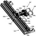
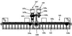
- the phase shifter transmission device 100includes a housing 101, a main shaft 103, a shifting structure 105, a first power mechanism (i.e. an auxiliary power mechanism) 107, a second power mechanism (i.e. a main power mechanism) 109.
- a first power mechanismi.e. an auxiliary power mechanism
- a second power mechanismi.e. a main power mechanism
- Helical gears 1130a-1130j, gears 113a-113j and output units 111a, 111b, 111c, 111d, 111e, 111f, 111g, 111h, 111i, 111j, and gears 113a-113jrespectively pass through transmission shafts (not marked in the figure)
- each output unitis provided with a rack meshed with the corresponding worm in the gears 113a-113j, so that the gears 113a-113j can drive the corresponding output unit to move when rotating, thereby driving the corresponding moving gear
- the phaserproduces motion.
- the housing 101includes a sub-housing 101a and a sub-housing 101b adapted to the sub-housing 101a, the main shaft 103 is arranged in the sub-housing 101b (it should be understood that the main shaft 103 can also be arranged on the sub-housing 101a ).
- the main shaft 103is provided with worms 104 a , 104 b that can move along the axial direction of the main shaft 103 .
- setting two worms 104a and 104bis only exemplary and not limiting, and one or more worms can be set as required.
- the main shaft 103is also provided with a worm gear 103g.
- the shifting structure 105is movably (eg, along a direction perpendicular to the axial direction of the main shaft 103 ) disposed inside the housing 101 . It should be understood that, although in the embodiment shown in the figure, the main shaft 103 is provided with two worms, in other embodiments, the main shaft 103 is provided with only one worm or more than three worms.
- the shifting structure 105is provided with a rack 105 a arranged in a direction parallel to the axial direction of the main shaft 103 .
- the shifting structure 105is in the first position, the worm 104a and the worm 104b are engaged with the rack 105a, and the driving of the second power mechanism 109 will make the worm 104a change the worm 104a and 104b on the main shaft 103 by means of the rack 105a. position, so as to realize the selection of different output units 111a, 111b, 111c, 111d, 111e, 111f, 111g, 111h, 111i, 111j, and then realize the selection of different phase shifters.
- the turbines 104a and 104bare not meshing with the helical gears 1130a-1130j above them.
- the shifting structure 105is in the second position different from the first position, the worm 104a and the worm 104b do not mesh with the rack 105a but mesh with the helical gears 1130a-1130j above it, and at this time the second power mechanism 109
- the driving of the worm 104awill make the worm 104a be meshed and transmitted to the corresponding output units 111a, 111b, 111c, 111d, 111e, 111f, 111g, 111h, 111i, 111j by means of the helical gears 1130a-1130j above it, and then realize the corresponding phase shift device driver.
- the shifting structure 105is also provided with a shifting rack 105b arranged along the axis direction perpendicular to the main shaft 103, and the shifting rack 105b on the shifting structure 105 has a limit A and a limit B (as shown in FIG. 7 ). .
- the shifting structure 105can realize switching between the above-mentioned first position and the second position by means of the switching rack 105b having a limit A and a limit B.
- the first power mechanism 107is arranged on the sub-housing 101b, and the first power mechanism 107 includes a motor 107a, a transmission shaft 107b and a worm 107c connected to the motor 107a through the transmission shaft 107b , the worm 107c meshes with the switching rack 105b, and the second power mechanism 109 is also arranged on the sub-housing 101b and is coupled with the main shaft 103.
- the second power mechanism 109includes a motor 109a, a transmission shaft 109b, a driving gear 109c, Driven gear 109d, transmission shaft 109e, worm 109f.
- the motor 107adrives the worm 107c to rotate through the transmission shaft 107b so that the worm 107c moves between the limit A and the limit B of the switching rack 105b.
- the shifting structure 105makes the worms 104a and 104b in the working state of the gear selection mode.
- the worms 104a, 104bmesh with the rack 105a, and the motor 109a drives the driving gear through the transmission shaft 109b 109c rotates, and the driven gear 109d follows the rotation of the driving gear 109c.
- the driven gear 109ddrives the worm 109f to rotate through the transmission shaft 109e, thereby driving the worm wheel 103g to rotate, and then driving the main shaft 103 to rotate, and the worms 104a, 104b can move to the target gear with the rotation of the main shaft 103 (that is, where the target output unit is located) stalls).
- the shifting structure 105makes the worms 104a and 104b in the driving mode.
- the worms 104a, 104bare respectively separated from the rack 105a, and are respectively meshed with, for example, helical gears 1130a, 1130f.
- 104bmoves with the rotation of the main shaft 103 (it should be understood that the moving direction depends on the rotation direction of the main shaft and the worm screw), and then drives the helical gears 1130a, 1130f to rotate.
- the gears 113a, 113fare driven to rotate, and further, the gears 113a, 113f drive the corresponding output units 111a, 111f to move through the gear racks meshed with them, thereby driving the phase shifters connected to the output units 111a, 111f to generate motion.
- the shifting structure 105is also provided with a number of limit portions (such as limit grooves 105c) corresponding to the number of gears to limit the freedom of the worms 104a, 104b along the axial direction, that is, to prevent the worms 104a, 104b from moving with the main shaft 103. It moves along the axial direction of the main shaft 103 while rotating.
- an electromagnetic relayis arranged on the first power mechanism 107 and the shifting structure 105, wherein the electromagnet of the electromagnetic relay is arranged on the first power mechanism, and the armature of the electromagnetic relay is arranged on the shifting structure, which can The switching of the first worm between the driving mode and the gear selection mode is realized through the electromagnetic relay.
- the number of output units 111a, 111b, 111c, 111d, 111e, 111f, 111g, 111h, 111i, 111jis 10, in another embodiment, the output units 111a, There can be any number of 111b, 111c, 111d, 111e, 111f, 111g, 111h, 111i, 111j.
- the first power structure 107 and the second power mechanism 109may not be limited to be arranged at the middle position of the phase shifter transmission, the first power structure 107 and the second power mechanism 109 can be set at any suitable position.
- the second power mechanism 109such as a main motor transmits power through a combination of spur gears and worm gears.
- the difference from the embodiment shown in FIGS. 1 to 7lies in that the shifting structure of the phase shifter transmission 200 is engaged with the rack gear of the first power mechanism 207 arranged in a direction parallel to the axial direction of the main shaft.
- the direction of the gear driven by the transmission shaft of the first power mechanism 207is also adjusted accordingly.
- the second power mechanism 209omits the transmission structure of the spur rack combined with the worm gear, and the rotation of the motor directly drives the rotation of the helical gear to drive the movement of the output unit.
- the second power mechanism 209can also transmit power through bevel gear engagement to drive the output unit to move.
- a plurality of elastic auxiliary elements (eg, springs) 301may also be provided on the shifting structure 105 to prevent the gear rack 105a on the shifting structure from interfering with the worms 104a, 104b.
- the main shaft 103may also be arranged on the sub-housing 101a.
- the sub-housing 101a and the sub-housing 101bcan be integrally formed.
- the second aspect of the present disclosurefurther provides an antenna, the antenna comprising the phase shifter transmission device provided according to the first aspect of the present disclosure.
- the phase shifter transmission device provided in the present disclosurecan drive multiple output units to drive multiple phase shifters to move.
- the auxiliary power mechanismenables the first worm to switch between the gear selection mode and the drive mode, while the main The power mechanism can drive the main shaft to rotate when the first worm is in the position selection mode or when the first worm is in the driving mode.
- the phase shifter transmission device provided by the disclosurecan effectively reduce the number of motors used, which is beneficial to reduce electromagnetic interference. Multiple sets of output units can be spread out in the same direction to save space.
- the equipmenthas strong versatility and the number of transmission stages Less makes the mechanical efficiency high.
Landscapes
- Transmission Devices (AREA)
Abstract
Description
Translated fromChinese本公开内容涉及通信技术领域,尤其涉及一种移相器传动装置和包括该移相器传动装置的天线。The present disclosure relates to the technical field of communication, and in particular to a phase shifter transmission device and an antenna including the phase shifter transmission device.
当前,普通移相器传动装置有多少移相器就需要多少电机、电路板以及相应的传动结构,在天线小型化的趋势下这些传动装置所占用天线空间较大。此外,所需的电机、电子元器件以及传动结构件不仅体积比较大,而且成本也较高。At present, as many phase shifters as there are ordinary phase shifter transmissions, there are as many motors, circuit boards and corresponding transmission structures as there are. Under the trend of antenna miniaturization, these transmissions occupy a large space for the antenna. In addition, the required motors, electronic components and transmission structural parts are not only relatively large in size, but also high in cost.
现有的一带多的传动装置由电机的一个旋向控制输出,另一个旋向控制选位,成品为圆柱型,难以平铺展开,不利于天线布局,而且需要额外传感器。In the existing multi-band transmission, one rotation direction of the motor controls the output, and the other rotation direction controls the position selection. The finished product is cylindrical, which is difficult to spread out, which is not conducive to antenna layout, and requires additional sensors.
现有的两带多的传动装置由一个电机负责驱动,一个电机负责选位置,对两电机都有较高要求。The existing two-belt transmission device is driven by one motor, and one motor is responsible for position selection, which has high requirements for both motors.
发明内容Contents of the invention
为了克服上述问题,即传统的移相器传动装置需要电机数量多,而且占用空间大,本公开内容的第一方面具体提供了一种移相器传动装置包括:壳体;主轴,所述主轴设置在所述壳体中,所述主轴上设有能够沿着所述主轴的轴线方向移动的第一蜗杆;换档结构,所述换档结构可移动地设置在所述壳体内,所述换档结构在沿所述主轴的轴线方向上设置有齿条;第一动力机构,所述第一动力机构设置在所述壳体上并与所述换档结构耦接,并且被配置为使得所述第一蜗杆在换档选位模式与驱动模式之间进行切换;第二动力机构,所述第二动力机构设置在所述壳体上并与所述主轴耦接;至少一个输出单元,所述至少一个输出单元设置在所述壳体上,每个输出单元被配置为能够与所述第一蜗杆配合,并且在与所述第一蜗杆配合时随着第一蜗杆的转动而驱动相应的移相器移动;其中,在所述第一蜗杆 处于所述换档选位模式时,所述第二动力机构被配置为驱动所述主轴转动,从而使得所述第一蜗杆通过与所述齿条的配合沿着所述主轴的轴线方向相对于所述换档结构移动;并且在所述第一蜗杆处于所述驱动模式时,所述第二动机机构还被配置为驱动所述主轴转动,从而使得所述第一蜗杆驱动所述至少一个输出单元中与所述第一蜗杆配合的输出单元运动。In order to overcome the above problems, that is, the traditional phase shifter transmission requires a large number of motors and occupies a large space, the first aspect of the present disclosure specifically provides a phase shifter transmission comprising: a housing; a main shaft, the main shaft Set in the housing, the main shaft is provided with a first worm that can move along the axis of the main shaft; a shifting structure, the shifting structure is movably arranged in the housing, the The shifting structure is provided with a rack along the axis of the main shaft; the first power mechanism is arranged on the housing and coupled with the shifting structure, and is configured such that The first worm is switched between the gear selection mode and the driving mode; the second power mechanism is arranged on the housing and coupled with the main shaft; at least one output unit, The at least one output unit is arranged on the housing, and each output unit is configured to be capable of cooperating with the first worm, and when cooperating with the first worm, drives a corresponding The phase shifter moves; wherein, when the first worm is in the gear selection mode, the second power mechanism is configured to drive the main shaft to rotate, so that the first worm passes through the a gear rack is engaged to move relative to the shifting structure along the axial direction of the main shaft; and when the first worm is in the drive mode, the second motor mechanism is also configured to drive the main shaft to rotate , so that the first worm drives the output unit of the at least one output unit that cooperates with the first worm to move.
以这样的方式,依据本公开内容所公开的移相器传动装置能够带动多个输出单元进而带动多个移相器移动,辅助动力机构使得第一蜗杆能够在换档选位模式与驱动模式之间进行切换,而主动力机构既可以在第一蜗杆处于选位模式时也可以在第一蜗杆处于驱动模式时驱动主轴转动。此外,本公开内容提供的移相器传动装置可以有效地减少电机的使用数量,有利于减小电磁干扰,多组输出单元于同一方向上铺开可以节省空间,设备通用性强,传动级数少使得机械效率高。In this way, the phase shifter transmission device disclosed in the present disclosure can drive multiple output units to drive multiple phase shifters to move, and the auxiliary power mechanism enables the first worm to switch between the gear selection mode and the drive mode. Switch between them, and the main power mechanism can drive the main shaft to rotate when the first worm is in the position selection mode or when the first worm is in the driving mode. In addition, the phase shifter transmission device provided by the disclosure can effectively reduce the number of motors used, which is beneficial to reduce electromagnetic interference. Multiple sets of output units can be spread out in the same direction to save space. The equipment has strong versatility and the number of transmission stages Less makes the mechanical efficiency high.
在一种实施方式中,所述换档结构具有第一限位和第二限位,所述第一蜗杆位于所述第一限位时,所述第一蜗杆处于所述换档选位模式,所述第一蜗杆位于所述第二限位时,所述第一蜗杆处于驱动模式。In one embodiment, the shifting structure has a first limit and a second limit, and when the first worm is at the first limit, the first worm is in the gear selection mode , when the first worm is at the second limit position, the first worm is in the driving mode.
在一种实施方式中,所述换档结构还包括限位部件,当所述第一蜗杆处于所述驱动模式时,所述限位部件限制所述第一蜗杆沿所述主轴的轴线方向相对于所述换档结构移动。In one embodiment, the shifting structure further includes a limiting component, and when the first worm is in the driving mode, the limiting component limits the relative movement of the first worm along the axial direction of the main shaft. Move in the shifting configuration.
在一种实施方式中,所述第一动力机构包括第一电机和与所述第一电机相连接的蜗杆,所述第一电机与所述换档结构之间通过与所述第一电机相连接的蜗杆与设置在所述换档结构上的切换齿条配合,从而使得所述第一电机转动时驱动所述第一蜗杆在所述换档选位模式与所述驱动模式之间切换。In one embodiment, the first power mechanism includes a first motor and a worm connected to the first motor, and the connection between the first motor and the shifting structure The connected worm cooperates with the switching rack provided on the shifting structure, so that when the first motor rotates, the first worm is driven to switch between the gear selection mode and the driving mode.
在一种实施方式中,所述第一动力机构与所述换档结构上配置有电磁继电器,所述电磁继电器的电磁铁设置在所述第一动力机构上,所述电磁继电器的衔铁设置在所述换档结构上,通过所述电磁继电器实现所述第一蜗杆在所述换档选位模式与所述驱动模式之间进行切换。In one embodiment, an electromagnetic relay is arranged on the first power mechanism and the shifting structure, the electromagnet of the electromagnetic relay is arranged on the first power mechanism, and the armature of the electromagnetic relay is arranged on In the shifting structure, the first worm is switched between the shifting position selection mode and the driving mode through the electromagnetic relay.
在一种实施方式中,所述第二动力机构包括第二电机,所述第二电机通过直齿轮和涡轮蜗杆与所述主轴耦接或者通过锥齿轮与所述主轴耦接, 从而驱动所述主轴转动。In one embodiment, the second power mechanism includes a second motor, the second motor is coupled to the main shaft through a spur gear and a worm gear or is coupled to the main shaft through a bevel gear, thereby driving the The spindle turns.
在一种实施方式中,所述第二动力机构为第二电机,所述第二电机直接驱动所述主轴转动。In one embodiment, the second power mechanism is a second motor, and the second motor directly drives the rotation of the main shaft.
在一种实施方式中,还包括至少一个传动机构,所述至少一个传动机构设置在所述壳体上,每个传动机构被配置为能够与所述第一蜗杆配合,并且在与所述第一蜗杆配合时随着所述第一蜗杆的转动而驱动所述至少一个输出单元中的相应输出单元运动。In one embodiment, at least one transmission mechanism is further included, the at least one transmission mechanism is arranged on the housing, each transmission mechanism is configured to be capable of cooperating with the first worm, and when cooperating with the first worm, When a worm is engaged, the corresponding output unit of the at least one output unit is driven to move along with the rotation of the first worm.
在一种实施方式中,所述至少一个传动机构中的每个传动机构包括斜齿轮和与所述斜齿轮耦接的第二蜗杆,所述斜齿轮能够与所述第一蜗杆配合,所述第二蜗杆与相应的输出单元啮合,当所述第一蜗杆处于所述驱动模式并且所述第一蜗杆和与目标输出单元相对应的斜齿轮啮合时,所述对应的斜齿轮随着所述第一蜗杆的转动而使相应的第二蜗杆转动,从而驱动所述目标输出单元运动。In one embodiment, each transmission mechanism in the at least one transmission mechanism includes a helical gear and a second worm coupled with the helical gear, the helical gear can cooperate with the first worm, and the The second worm meshes with the corresponding output unit, and when the first worm is in the driving mode and the first worm meshes with the helical gear corresponding to the target output unit, the corresponding helical gear follows the The rotation of the first worm makes the corresponding second worm rotate, thereby driving the target output unit to move.
在一种实施方式中,所述换档结构还设置有弹性辅助元件,以防止所述换档结构的所述齿条与所述第一蜗杆产生干涉。In one embodiment, the shifting structure is further provided with an elastic auxiliary element to prevent the gear rack of the shifting structure from interfering with the first worm.
在一种实施方式中,所述壳体包括第一子壳体和第二子壳体,所述第二子壳体与所述第一子壳体适配,所述主轴设置在所述第一子壳体或者所述第二子壳体上。In one embodiment, the housing includes a first sub-housing and a second sub-housing, the second sub-housing is adapted to the first sub-housing, and the main shaft is arranged on the second sub-housing. on the first sub-housing or the second sub-housing.
此外,本公开内容的第二方面还提供了一种天线,所述天线包括根据本公开内容的第一方面所提供的移相器传动装置。In addition, the second aspect of the present disclosure further provides an antenna, the antenna comprising the phase shifter transmission device provided according to the first aspect of the present disclosure.
综上所述,本公开内容所提供的移相器传动装置可以有效地减少电机的使用数量,有利于减小电磁干扰,多组输出单元于同一方向上铺开可以节省空间,设备通用性强,传动级数少使得机械效率高。To sum up, the phase shifter transmission device provided by the present disclosure can effectively reduce the number of motors used, which is beneficial to reduce electromagnetic interference. Spreading multiple sets of output units in the same direction can save space, and the equipment has strong versatility , The number of transmission stages is small so that the mechanical efficiency is high.
图1是根据本公开内容的一个实施例的移相器传动装置的立体视图;FIG. 1 is a perspective view of a phase shifter transmission according to one embodiment of the present disclosure;
图2是图1的移相器传动装置的分解示意图;Fig. 2 is an exploded schematic view of the phase shifter transmission of Fig. 1;
图3a是图2中的移相传动装置的第一蜗杆处于换档选位模式时的部分立体视图;Fig. 3a is a partial perspective view of the first worm of the phase-shifting transmission device in Fig. 2 when it is in the gear selection mode;
图3b是图3a中的部件的俯视图;Figure 3b is a top view of the components in Figure 3a;
图3c是图3b中主轴上的蜗杆移动到一个目标挡位时的俯视图;Fig. 3c is a top view when the worm on the main shaft in Fig. 3b moves to a target gear;
图3d是图3c中的换档结构完全切换到驱动模式时的俯视图;Fig. 3d is a top view of the shift structure in Fig. 3c when it is fully switched to the driving mode;
图4是根据本公开内容的另一个实施例的移相器传动装置的立体示意图,其中,壳体被移除,第一蜗杆处于驱动模式并且其中一个输出单元被移动一定距离;4 is a schematic perspective view of a phase shifter transmission according to another embodiment of the present disclosure, wherein the housing is removed, the first worm is in a driving mode and one of the output units is moved by a certain distance;
图5根据本公开内容的另一个实施例的移相器传动装置的立体示意图,其中,壳体被移除,第一蜗杆处于驱动模式并且其中一些输出单元被移除;5 is a schematic perspective view of a phase shifter transmission according to another embodiment of the present disclosure, wherein the housing is removed, the first worm is in drive mode and some of the output units are removed;
图6是图1中的第一蜗杆处于驱动模式时沿A-A的剖切视图;Fig. 6 is a sectional view along A-A when the first worm in Fig. 1 is in the driving mode;
图7是图3a的部件处于另一视角的示意图;Fig. 7 is a schematic diagram of the components of Fig. 3a at another viewing angle;
图8是根据本公开内容的另一个实施例的移相器传动装置的立体视图,其中,壳体被移除、部分输出单元被移除且第一蜗杆处于换档选位模式;8 is a perspective view of a phase shifter transmission according to another embodiment of the present disclosure, wherein the housing is removed, part of the output unit is removed, and the first worm is in a gear selection mode;
图9是图8中的第一蜗杆处于驱动模式时的立体视图;和Fig. 9 is a perspective view of the first worm in Fig. 8 when it is in drive mode; and
图10是根据本公开内容的另一个实施例的移相器传动装置的分解示意图。FIG. 10 is an exploded schematic view of a phase shifter transmission according to another embodiment of the present disclosure.
在以下优选的实施例的具体描述中,将参考构成本公开内容的一部分的所附的附图。所附的附图通过示例的方式示出了能够实现本公开内容的特定的实施例。示例性的实施例并不旨在穷尽根据本公开内容的所有实施例。在说明书中,相同或相似的附图标记指示相同或相似的部件。可以理解,在不偏离本公开内容的范围的前提下,可以利用其他实施例,也可以进行结构性的修改。因此,以下的具体描述并非限制性的,且本公开内容的范围由所附的权利要求所限定。In the following detailed description of the preferred embodiment, reference is made to the accompanying drawings which form a part hereof. The accompanying drawings show, by way of example, specific embodiments in which the disclosure can be practiced. The exemplary embodiments are not intended to be exhaustive of all embodiments according to the present disclosure. In the specification, the same or similar reference numerals designate the same or similar components. It is to be understood that other embodiments may be utilized and structural modifications may be made without departing from the scope of the present disclosure. Accordingly, the following detailed description is not limiting, and the scope of the present disclosure is defined by the appended claims.
本文所使用的术语“包括”、“包含”及类似术语应该被理解为是开放性的术语,即“包括/包含但不限于”,表示还可以包括其他内容。术语“一个实施例”表示“至少一个实施例”;术语“另一个实施例”表示“至少一 个另外的实施例”等等。The terms "including", "comprising" and similar terms used herein should be understood as open terms, that is, "including/including but not limited to", which means that other content can also be included. The term "one embodiment" means "at least one embodiment"; the term "another embodiment" means "at least one further embodiment" and so on.
以下结合附图对本公开内容的实施例进行详细阐述。Embodiments of the present disclosure will be described in detail below in conjunction with the accompanying drawings.
如图1至图7所示,移相器传动装置100包括壳体101、主轴103、换档结构105、第一动力机构(即辅助动力机构)107、第二动力机构(即主动力机构)109、斜齿轮1130a-1130j、齿轮113a-113j以及输出单元111a、111b、111c、111d、111e、111f、111g、111h、111i、111j,齿轮113a-113j分别通过传动轴(图中未标注出)与斜齿轮1130a-1130j相连接,每个输出单元设有与齿轮113a-113j中的相应的蜗杆啮合的齿条,使得齿轮113a-113j转动时能够带动相应的输出单元移动,从而驱动相应的移相器产生运动。其中,壳体101包括子壳体101a和与子壳体101a适配的子壳体101b,主轴103设置在子壳体101b中(应理解的是,主轴103也可以设置在子壳体101a上)。As shown in Figures 1 to 7, the phase
如图2、图3a和图7所示,主轴103上设有可沿主轴103的轴线方向移动的蜗杆104a、104b。在此,设置两个蜗杆104a和104b仅仅是示例性的而非限制性的,可以根据需要设置一个或者多个蜗杆。主轴103上还设有蜗轮103g,本领域的技术人员应当了解,此处的主轴103和涡轮103g通常固定连接,即不会发生相对转动。换档结构105可移动地(例如,沿着垂直于主轴103的轴线方向的方向上)设置在壳体101内。应理解的是,尽管图中所示的实施例中,主轴103上设有两个蜗杆,但是在另外的实施例中,主轴103上仅设有一个蜗杆或者三个以上的蜗杆。As shown in FIG. 2 , FIG. 3 a and FIG. 7 , the
继续如图3a和图7所示,换档结构105上设有沿平行于主轴103的轴线方向的方向布置的齿条105a。当换档结构105处于第一位置时,蜗杆104a和蜗杆104b与齿条105a啮合,此时通过第二动力机构109的驱动将使得蜗杆104a借助于齿条105a改变蜗杆104a和104b在主轴103上的位置,从而实现对于不同的输出单元111a、111b、111c、111d、111e、111f、111g、111h、111i、111j的选择,进而实现对于不同的移相器的选择。此时,涡轮104a和涡轮104b并不与其上方的斜齿轮1130a-1130j啮合。相应地,当换档结构105处于与第一位置不同的第二位置时,蜗杆104a和蜗杆104b不与齿条105a啮合而与其上方的斜齿轮1130a-1130j啮合,此时通过第二动 力机构109的驱动将使得蜗杆104a借助于其上方的斜齿轮1130a-1130j啮合传动至相应的输出单元111a、111b、111c、111d、111e、111f、111g、111h、111i、111j,进而实现对于相应的移相器的驱动。As shown in FIGS. 3 a and 7 , the shifting
此外,换档结构105上还设有沿垂直于主轴103的轴线方向布置的切换齿条105b,换档结构105上的切换齿条105b具有限位A和限位B(如图7所示)。以此,换档结构105能够借助于具有限位A和限位B的切换齿条105b实现在上述的第一位置和第二位置之间的切换。In addition, the shifting
再者,如图3a至图7所示,第一动力机构107设置在子壳体101b上,第一动力机构107包括电机107a、传动轴107b和通过传动轴107b与电机107a相连接的蜗杆107c,蜗杆107c与切换齿条105b啮合,第二动力机构109也设置在子壳体101b上并且与主轴103耦接,具体地,第二动力机构109包括电机109a、传动轴109b、主动齿轮109c、从动齿轮109d、传动轴109e、蜗杆109f。Furthermore, as shown in Figures 3a to 7, the
移相器传动装置100工作时,电机107a通过传动轴107b驱动蜗杆107c转动从而使得蜗杆107c在切换齿条105b的限位A与限位B之间移动。当蜗杆107c位于限位B时,换档结构105使得蜗杆104a和104b处于换档选位模式的工作状态,此时,蜗杆104a、104b与齿条105a啮合,电机109a通过传动轴109b驱动主动齿轮109c转动,从动齿轮109d跟随主动齿轮109c转动。进一步地,从动齿轮109d通过传动轴109e带动蜗杆109f转动,从而带动蜗轮103g转动,进而带动主轴103转动,蜗杆104a、104b可以随着主轴103的转动移动到目标档位(即目标输出单元所在的档位)。When the
当蜗杆107c位于限位A时,换档结构105使得蜗杆104a和104b处于驱动模式,此时,蜗杆104a、104b分别与齿条105a分离,并且分别与例如斜齿轮1130a、1130f啮合,蜗杆104a、104b随着主轴103的转动而移动(应理解的是,移动方向取决于主轴旋转方向及蜗杆旋向),进而带动斜齿轮1130a、1130f转动。相应地,带动齿轮113a、113f转动,进一步地,齿轮113a、113f通过与其啮合的齿条带动相应的输出单元111a、111f移动,从而驱动与输出单元111a、111f相连接的移相器产生运动。此外,换档结构105还设置有与档位数量相一致数量的限位部(例如限位槽105c),限制 蜗杆104a、104b沿轴线方向的自由度,即防止蜗杆104a、104b随着主轴103的转动而转动的同时沿着主轴103的轴线方向移动。When the
在另一个实施例中,第一动力机构107与换档结构105上配置有电磁继电器,其中,电磁继电器的电磁铁设置在第一动力机机构上,电磁继电器的衔铁设置在换档结构上,可以通过电磁继电器实现第一蜗杆在驱动模式与换档选位模式之间的切换。In another embodiment, an electromagnetic relay is arranged on the
应理解的是,尽管上述实施例中,输出单元111a、111b、111c、111d、111e、111f、111g、111h、111i、111j的数量为10个,但是在另外的实施例中,输出单元111a、111b、111c、111d、111e、111f、111g、111h、111i、111j可以有任意多个。此外,应理解的是,在另一个实施例中,第一动力结构107和第二动力机构109可以不局限于设置在移相器传动装置的中间位置,第一动力结构107和第二动力机构109可以设置在任意合适的位置。It should be understood that although in the above embodiment, the number of
在图1至图7所示的实施例中,诸如主电机的第二动力机构109通过直齿轮和蜗轮蜗杆的结合来传递动力。在图8和图9所示的实施例中,与图1至图7所示的实施例的不同之处在于,移相器传动装置200的换档结构与第一动力机构207啮合的齿条设置在平行于主轴的轴线方向的方向上。相应地,第一动力机构207通过传动轴带动的齿轮的方向也做了相应的调整。第二动力机构209略去了直齿条结合蜗轮蜗杆的传动结构,电机转动直接带动斜齿轮转动来驱动输出单元运动。在另一个实施例中,第二动力机构209也可以通过锥齿轮啮合传递动力来驱动输出单元运动。In the embodiment shown in FIGS. 1 to 7 , the
在图10所示的实施例中,换档结构105上还可以设置有多个弹性辅助元件(例如,弹簧)301,防止换档结构上的齿条105a与蜗杆104a、104b产生干涉。应理解的是,在另一个实施例中,主轴103也可以设置在子壳体101a上。另一个实施例中,子壳体101a和子壳体101b可以一体成型。In the embodiment shown in FIG. 10 , a plurality of elastic auxiliary elements (eg, springs) 301 may also be provided on the shifting
此外,本公开内容的第二方面还提供了一种天线,所述天线包括根据本公开内容的第一方面所提供的移相器传动装置。In addition, the second aspect of the present disclosure further provides an antenna, the antenna comprising the phase shifter transmission device provided according to the first aspect of the present disclosure.
本公开内容提供的移相器传动装置,可以带动多个输出单元进而带动多个移相器移动,辅助动力机构使得第一蜗杆能够在换档选位模式与驱动模式之间进行切换,而主动力机构既可以在第一蜗杆处于选位模式时也可 以在第一蜗杆处于驱动模式时驱动主轴转动。此外,本公开内容提供的移相器传动装置可以有效地减少电机的使用数量,有利于减小电磁干扰,多组输出单元于同一方向上铺开可以节省空间,设备通用性强,传动级数少使得机械效率高。The phase shifter transmission device provided in the present disclosure can drive multiple output units to drive multiple phase shifters to move. The auxiliary power mechanism enables the first worm to switch between the gear selection mode and the drive mode, while the main The power mechanism can drive the main shaft to rotate when the first worm is in the position selection mode or when the first worm is in the driving mode. In addition, the phase shifter transmission device provided by the disclosure can effectively reduce the number of motors used, which is beneficial to reduce electromagnetic interference. Multiple sets of output units can be spread out in the same direction to save space. The equipment has strong versatility and the number of transmission stages Less makes the mechanical efficiency high.
需要注意的是,以上列举的仅为本公开内容的具体实施例,显然本公开内容不限于以上实施例,随之有着许多的类似变化。本领域的技术人员如果从本公开内容公开的内容直接导出或联想到的所有变形,均应属于本公开内容的保护范围。It should be noted that what is listed above are only specific embodiments of the present disclosure, and obviously the present disclosure is not limited to the above embodiments, and there are many similar changes accordingly. All modifications directly derived or associated by those skilled in the art from the content disclosed in the present disclosure shall belong to the protection scope of the present disclosure.
Claims (12)
Translated fromChineseApplications Claiming Priority (2)
| Application Number | Priority Date | Filing Date | Title |
|---|---|---|---|
| CN202210092500.7ACN116544673A (en) | 2022-01-26 | 2022-01-26 | Phase shifter transmission device and antenna |
| CN202210092500.7 | 2022-01-26 |
Publications (1)
| Publication Number | Publication Date |
|---|---|
| WO2023142788A1true WO2023142788A1 (en) | 2023-08-03 |
Family
ID=87456594
Family Applications (1)
| Application Number | Title | Priority Date | Filing Date |
|---|---|---|---|
| PCT/CN2022/140548CeasedWO2023142788A1 (en) | 2022-01-26 | 2022-12-21 | Phase shifter transmission device and antenna |
Country Status (2)
| Country | Link |
|---|---|
| CN (1) | CN116544673A (en) |
| WO (1) | WO2023142788A1 (en) |
Cited By (1)
| Publication number | Priority date | Publication date | Assignee | Title |
|---|---|---|---|---|
| CN119812717A (en)* | 2025-03-12 | 2025-04-11 | 中兴通讯股份有限公司 | Antenna deployable mechanism, antenna device and base station |
Citations (6)
| Publication number | Priority date | Publication date | Assignee | Title |
|---|---|---|---|---|
| US20170365923A1 (en)* | 2016-06-15 | 2017-12-21 | Commscope Technologies Llc | Actuators for controlling multiple phase shifters of remote electronic downtilt base station antennas |
| CN108321538A (en)* | 2018-03-14 | 2018-07-24 | 武汉虹信通信技术有限责任公司 | Antenna azimuth converts regulating device |
| CN208535111U (en)* | 2018-03-26 | 2019-02-22 | 京信通信系统(中国)有限公司 | Phase adjustment system of phase shifter and its power transmission device |
| CN109755747A (en)* | 2017-11-07 | 2019-05-14 | 罗森伯格技术(昆山)有限公司 | An antenna phase shifter transmission device |
| CN110911841A (en)* | 2019-11-22 | 2020-03-24 | 京信通信技术(广州)有限公司 | Antenna, transmission device and switching mechanism |
| CN216563555U (en)* | 2022-01-26 | 2022-05-17 | 罗森伯格技术有限公司 | Phase shifter transmission device and antenna |
- 2022
- 2022-01-26CNCN202210092500.7Apatent/CN116544673A/enactivePending
- 2022-12-21WOPCT/CN2022/140548patent/WO2023142788A1/ennot_activeCeased
Patent Citations (6)
| Publication number | Priority date | Publication date | Assignee | Title |
|---|---|---|---|---|
| US20170365923A1 (en)* | 2016-06-15 | 2017-12-21 | Commscope Technologies Llc | Actuators for controlling multiple phase shifters of remote electronic downtilt base station antennas |
| CN109755747A (en)* | 2017-11-07 | 2019-05-14 | 罗森伯格技术(昆山)有限公司 | An antenna phase shifter transmission device |
| CN108321538A (en)* | 2018-03-14 | 2018-07-24 | 武汉虹信通信技术有限责任公司 | Antenna azimuth converts regulating device |
| CN208535111U (en)* | 2018-03-26 | 2019-02-22 | 京信通信系统(中国)有限公司 | Phase adjustment system of phase shifter and its power transmission device |
| CN110911841A (en)* | 2019-11-22 | 2020-03-24 | 京信通信技术(广州)有限公司 | Antenna, transmission device and switching mechanism |
| CN216563555U (en)* | 2022-01-26 | 2022-05-17 | 罗森伯格技术有限公司 | Phase shifter transmission device and antenna |
Cited By (1)
| Publication number | Priority date | Publication date | Assignee | Title |
|---|---|---|---|---|
| CN119812717A (en)* | 2025-03-12 | 2025-04-11 | 中兴通讯股份有限公司 | Antenna deployable mechanism, antenna device and base station |
Also Published As
| Publication number | Publication date |
|---|---|
| CN116544673A (en) | 2023-08-04 |
Similar Documents
| Publication | Publication Date | Title |
|---|---|---|
| US11303019B2 (en) | Transmission device for antenna phase shifter | |
| CN216563555U (en) | Phase shifter transmission device and antenna | |
| CN112821075B (en) | Multi-frequency antenna and phase modulation switching control mechanism thereof | |
| CN112864623B (en) | Multi-frequency antenna and frequency-selecting phase modulation device thereof | |
| WO2023142788A1 (en) | Phase shifter transmission device and antenna | |
| US20100197439A1 (en) | Transmission device having a variator | |
| CN202182174U (en) | Automobile electric gearshift mechanism | |
| CN107701716B (en) | Lifting knob electronic gear shifter | |
| CN112582766B (en) | Multi-frequency antenna and phase-shifting switching control mechanism thereof | |
| WO2016199521A1 (en) | Speed change mechanism | |
| CN1030844A (en) | switch operating device | |
| US20090091199A1 (en) | Handheld electric mixer | |
| US20180363730A1 (en) | Transmission for a Motor Vehicle | |
| WO2005057051A1 (en) | Electric actuator and control device thereof | |
| CN112563691B (en) | Multi-frequency antenna and frequency-selecting phase-shifting device thereof | |
| US6789440B2 (en) | Devices for the sequential control of gearboxes with hand-operated selection and engagement of gears for motor vehicles | |
| CN203026642U (en) | Control device for electronically tunable antenna and multi-band antenna | |
| CN209119365U (en) | Electrical tilt antenna transmission device | |
| CN113540796A (en) | Multi-frequency antenna, frequency-selecting phase-modulating mechanism and device | |
| CN109347247A (en) | ESC Antenna Drive | |
| CN113540795B (en) | Multi-frequency antenna and phase shift control mechanism thereof | |
| CN100458995C (en) | Device for actuating an electrical switchgear | |
| KR102704765B1 (en) | Power module and Dual clutch transmission | |
| CN211320344U (en) | Built-in dual-motor twelve-gear-shifting electric-tuning antenna driver | |
| CN219371389U (en) | Transmission device for antenna |
Legal Events
| Date | Code | Title | Description |
|---|---|---|---|
| 121 | Ep: the epo has been informed by wipo that ep was designated in this application | Ref document number:22923574 Country of ref document:EP Kind code of ref document:A1 | |
| NENP | Non-entry into the national phase | Ref country code:DE | |
| 122 | Ep: pct application non-entry in european phase | Ref document number:22923574 Country of ref document:EP Kind code of ref document:A1 |