WO2023139716A1 - Diesel engine - Google Patents
Diesel engineDownload PDFInfo
- Publication number
- WO2023139716A1 WO2023139716A1PCT/JP2022/001944JP2022001944WWO2023139716A1WO 2023139716 A1WO2023139716 A1WO 2023139716A1JP 2022001944 WJP2022001944 WJP 2022001944WWO 2023139716 A1WO2023139716 A1WO 2023139716A1
- Authority
- WO
- WIPO (PCT)
- Prior art keywords
- ammonia
- air
- diesel engine
- ratio value
- excess air
- Prior art date
- Legal status (The legal status is an assumption and is not a legal conclusion. Google has not performed a legal analysis and makes no representation as to the accuracy of the status listed.)
- Ceased
Links
Images


Classifications
- F—MECHANICAL ENGINEERING; LIGHTING; HEATING; WEAPONS; BLASTING
- F02—COMBUSTION ENGINES; HOT-GAS OR COMBUSTION-PRODUCT ENGINE PLANTS
- F02B—INTERNAL-COMBUSTION PISTON ENGINES; COMBUSTION ENGINES IN GENERAL
- F02B69/00—Internal-combustion engines convertible into other combustion-engine type, not provided for in F02B11/00; Internal-combustion engines of different types characterised by constructions facilitating use of same main engine-parts in different types
- F02B69/02—Internal-combustion engines convertible into other combustion-engine type, not provided for in F02B11/00; Internal-combustion engines of different types characterised by constructions facilitating use of same main engine-parts in different types for different fuel types, other than engines indifferent to fuel consumed, e.g. convertible from light to heavy fuel
- F02B69/04—Internal-combustion engines convertible into other combustion-engine type, not provided for in F02B11/00; Internal-combustion engines of different types characterised by constructions facilitating use of same main engine-parts in different types for different fuel types, other than engines indifferent to fuel consumed, e.g. convertible from light to heavy fuel for gaseous and non-gaseous fuels
- F—MECHANICAL ENGINEERING; LIGHTING; HEATING; WEAPONS; BLASTING
- F02—COMBUSTION ENGINES; HOT-GAS OR COMBUSTION-PRODUCT ENGINE PLANTS
- F02B—INTERNAL-COMBUSTION PISTON ENGINES; COMBUSTION ENGINES IN GENERAL
- F02B37/00—Engines characterised by provision of pumps driven at least for part of the time by exhaust
- F02B37/12—Control of the pumps
- F02B37/18—Control of the pumps by bypassing exhaust from the inlet to the outlet of turbine or to the atmosphere
- F—MECHANICAL ENGINEERING; LIGHTING; HEATING; WEAPONS; BLASTING
- F02—COMBUSTION ENGINES; HOT-GAS OR COMBUSTION-PRODUCT ENGINE PLANTS
- F02B—INTERNAL-COMBUSTION PISTON ENGINES; COMBUSTION ENGINES IN GENERAL
- F02B43/00—Engines characterised by operating on gaseous fuels; Plants including such engines
- F02B43/10—Engines or plants characterised by use of other specific gases, e.g. acetylene, oxyhydrogen
- F—MECHANICAL ENGINEERING; LIGHTING; HEATING; WEAPONS; BLASTING
- F02—COMBUSTION ENGINES; HOT-GAS OR COMBUSTION-PRODUCT ENGINE PLANTS
- F02D—CONTROLLING COMBUSTION ENGINES
- F02D19/00—Controlling engines characterised by their use of non-liquid fuels, pluralities of fuels, or non-fuel substances added to the combustible mixtures
- F02D19/06—Controlling engines characterised by their use of non-liquid fuels, pluralities of fuels, or non-fuel substances added to the combustible mixtures peculiar to engines working with pluralities of fuels, e.g. alternatively with light and heavy fuel oil, other than engines indifferent to the fuel consumed
- F02D19/0639—Controlling engines characterised by their use of non-liquid fuels, pluralities of fuels, or non-fuel substances added to the combustible mixtures peculiar to engines working with pluralities of fuels, e.g. alternatively with light and heavy fuel oil, other than engines indifferent to the fuel consumed characterised by the type of fuels
- F02D19/0642—Controlling engines characterised by their use of non-liquid fuels, pluralities of fuels, or non-fuel substances added to the combustible mixtures peculiar to engines working with pluralities of fuels, e.g. alternatively with light and heavy fuel oil, other than engines indifferent to the fuel consumed characterised by the type of fuels at least one fuel being gaseous, the other fuels being gaseous or liquid at standard conditions
- F02D19/0644—Controlling engines characterised by their use of non-liquid fuels, pluralities of fuels, or non-fuel substances added to the combustible mixtures peculiar to engines working with pluralities of fuels, e.g. alternatively with light and heavy fuel oil, other than engines indifferent to the fuel consumed characterised by the type of fuels at least one fuel being gaseous, the other fuels being gaseous or liquid at standard conditions the gaseous fuel being hydrogen, ammonia or carbon monoxide
- F—MECHANICAL ENGINEERING; LIGHTING; HEATING; WEAPONS; BLASTING
- F02—COMBUSTION ENGINES; HOT-GAS OR COMBUSTION-PRODUCT ENGINE PLANTS
- F02D—CONTROLLING COMBUSTION ENGINES
- F02D19/00—Controlling engines characterised by their use of non-liquid fuels, pluralities of fuels, or non-fuel substances added to the combustible mixtures
- F02D19/06—Controlling engines characterised by their use of non-liquid fuels, pluralities of fuels, or non-fuel substances added to the combustible mixtures peculiar to engines working with pluralities of fuels, e.g. alternatively with light and heavy fuel oil, other than engines indifferent to the fuel consumed
- F02D19/0639—Controlling engines characterised by their use of non-liquid fuels, pluralities of fuels, or non-fuel substances added to the combustible mixtures peculiar to engines working with pluralities of fuels, e.g. alternatively with light and heavy fuel oil, other than engines indifferent to the fuel consumed characterised by the type of fuels
- F02D19/0649—Liquid fuels having different boiling temperatures, volatilities, densities, viscosities, cetane or octane numbers
- F02D19/0657—Heavy or light fuel oils; Fuels characterised by their impurities such as sulfur content or differences in grade, e.g. for ships
- F—MECHANICAL ENGINEERING; LIGHTING; HEATING; WEAPONS; BLASTING
- F02—COMBUSTION ENGINES; HOT-GAS OR COMBUSTION-PRODUCT ENGINE PLANTS
- F02D—CONTROLLING COMBUSTION ENGINES
- F02D19/00—Controlling engines characterised by their use of non-liquid fuels, pluralities of fuels, or non-fuel substances added to the combustible mixtures
- F02D19/06—Controlling engines characterised by their use of non-liquid fuels, pluralities of fuels, or non-fuel substances added to the combustible mixtures peculiar to engines working with pluralities of fuels, e.g. alternatively with light and heavy fuel oil, other than engines indifferent to the fuel consumed
- F02D19/08—Controlling engines characterised by their use of non-liquid fuels, pluralities of fuels, or non-fuel substances added to the combustible mixtures peculiar to engines working with pluralities of fuels, e.g. alternatively with light and heavy fuel oil, other than engines indifferent to the fuel consumed simultaneously using pluralities of fuels
- F02D19/081—Adjusting the fuel composition or mixing ratio; Transitioning from one fuel to the other
- F—MECHANICAL ENGINEERING; LIGHTING; HEATING; WEAPONS; BLASTING
- F02—COMBUSTION ENGINES; HOT-GAS OR COMBUSTION-PRODUCT ENGINE PLANTS
- F02D—CONTROLLING COMBUSTION ENGINES
- F02D19/00—Controlling engines characterised by their use of non-liquid fuels, pluralities of fuels, or non-fuel substances added to the combustible mixtures
- F02D19/06—Controlling engines characterised by their use of non-liquid fuels, pluralities of fuels, or non-fuel substances added to the combustible mixtures peculiar to engines working with pluralities of fuels, e.g. alternatively with light and heavy fuel oil, other than engines indifferent to the fuel consumed
- F02D19/08—Controlling engines characterised by their use of non-liquid fuels, pluralities of fuels, or non-fuel substances added to the combustible mixtures peculiar to engines working with pluralities of fuels, e.g. alternatively with light and heavy fuel oil, other than engines indifferent to the fuel consumed simultaneously using pluralities of fuels
- F02D19/082—Premixed fuels, i.e. emulsions or blends
- F02D19/085—Control based on the fuel type or composition
- F02D19/087—Control based on the fuel type or composition with determination of densities, viscosities, composition, concentration or mixture ratios of fuels
- F02D19/088—Control based on the fuel type or composition with determination of densities, viscosities, composition, concentration or mixture ratios of fuels by estimation, i.e. without using direct measurements of a corresponding sensor
- F—MECHANICAL ENGINEERING; LIGHTING; HEATING; WEAPONS; BLASTING
- F02—COMBUSTION ENGINES; HOT-GAS OR COMBUSTION-PRODUCT ENGINE PLANTS
- F02D—CONTROLLING COMBUSTION ENGINES
- F02D41/00—Electrical control of supply of combustible mixture or its constituents
- F—MECHANICAL ENGINEERING; LIGHTING; HEATING; WEAPONS; BLASTING
- F02—COMBUSTION ENGINES; HOT-GAS OR COMBUSTION-PRODUCT ENGINE PLANTS
- F02D—CONTROLLING COMBUSTION ENGINES
- F02D41/00—Electrical control of supply of combustible mixture or its constituents
- F02D41/0002—Controlling intake air
- F02D41/0007—Controlling intake air for control of turbo-charged or super-charged engines
- F—MECHANICAL ENGINEERING; LIGHTING; HEATING; WEAPONS; BLASTING
- F02—COMBUSTION ENGINES; HOT-GAS OR COMBUSTION-PRODUCT ENGINE PLANTS
- F02D—CONTROLLING COMBUSTION ENGINES
- F02D41/00—Electrical control of supply of combustible mixture or its constituents
- F02D41/02—Circuit arrangements for generating control signals
- F02D41/04—Introducing corrections for particular operating conditions
- F—MECHANICAL ENGINEERING; LIGHTING; HEATING; WEAPONS; BLASTING
- F02—COMBUSTION ENGINES; HOT-GAS OR COMBUSTION-PRODUCT ENGINE PLANTS
- F02M—SUPPLYING COMBUSTION ENGINES IN GENERAL WITH COMBUSTIBLE MIXTURES OR CONSTITUENTS THEREOF
- F02M25/00—Engine-pertinent apparatus for adding non-fuel substances or small quantities of secondary fuel to combustion-air, main fuel or fuel-air mixture
- F—MECHANICAL ENGINEERING; LIGHTING; HEATING; WEAPONS; BLASTING
- F02—COMBUSTION ENGINES; HOT-GAS OR COMBUSTION-PRODUCT ENGINE PLANTS
- F02M—SUPPLYING COMBUSTION ENGINES IN GENERAL WITH COMBUSTIBLE MIXTURES OR CONSTITUENTS THEREOF
- F02M67/00—Apparatus in which fuel-injection is effected by means of high-pressure gas, the gas carrying the fuel into working cylinders of the engine, e.g. air-injection type
- F02M67/14—Apparatus in which fuel-injection is effected by means of high-pressure gas, the gas carrying the fuel into working cylinders of the engine, e.g. air-injection type characterised by provisions for injecting different fuels, e.g. main fuel and readily self-igniting starting fuel
- Y—GENERAL TAGGING OF NEW TECHNOLOGICAL DEVELOPMENTS; GENERAL TAGGING OF CROSS-SECTIONAL TECHNOLOGIES SPANNING OVER SEVERAL SECTIONS OF THE IPC; TECHNICAL SUBJECTS COVERED BY FORMER USPC CROSS-REFERENCE ART COLLECTIONS [XRACs] AND DIGESTS
- Y02—TECHNOLOGIES OR APPLICATIONS FOR MITIGATION OR ADAPTATION AGAINST CLIMATE CHANGE
- Y02T—CLIMATE CHANGE MITIGATION TECHNOLOGIES RELATED TO TRANSPORTATION
- Y02T10/00—Road transport of goods or passengers
- Y02T10/10—Internal combustion engine [ICE] based vehicles
- Y02T10/12—Improving ICE efficiencies
- Y—GENERAL TAGGING OF NEW TECHNOLOGICAL DEVELOPMENTS; GENERAL TAGGING OF CROSS-SECTIONAL TECHNOLOGIES SPANNING OVER SEVERAL SECTIONS OF THE IPC; TECHNICAL SUBJECTS COVERED BY FORMER USPC CROSS-REFERENCE ART COLLECTIONS [XRACs] AND DIGESTS
- Y02—TECHNOLOGIES OR APPLICATIONS FOR MITIGATION OR ADAPTATION AGAINST CLIMATE CHANGE
- Y02T—CLIMATE CHANGE MITIGATION TECHNOLOGIES RELATED TO TRANSPORTATION
- Y02T10/00—Road transport of goods or passengers
- Y02T10/10—Internal combustion engine [ICE] based vehicles
- Y02T10/30—Use of alternative fuels, e.g. biofuels
Definitions
- the present inventionrelates to a diesel engine, and in particular, it is suitable for use in a marine diesel engine that uses fuel oil such as heavy oil and light oil as the main fuel, and is particularly effective in reducing carbon dioxide CO2 , a greenhouse gas, by burning ammonia NH3 , which is carbon-free and does not contain carbon (C), which has not been used as fuel in the past.
- fuel oilsuch as heavy oil and light oil
- ammonia NH3which is carbon-free and does not contain carbon (C)
- ammoniaSince ammonia is carbon-free and does not produce CO2 when burned, it has been tried to burn in internal combustion engines, especially diesel engines. However, ammonia has a high ignition temperature of 651° C., for example, compared to 250 to 380° C. of heavy oil, and is flame-retardant.
- Patent Document 1in order to burn high-temperature hydrogen-rich ammonia and combustion air, urea water is supplied as a raw material for hydrogen-rich ammonia, high-temperature ammonia is generated from the urea water, and a part of the ammonia is added to hydrogen and nitrogen to generate high-temperature hydrogen-rich gas, thereby forming a carbon-free power plant. That is, the present invention relates to a hydrogen-rich ammonia production reactor that produces high-temperature ammonia from urea water and adds a portion of the ammonia to hydrogen and nitrogen to produce high-temperature hydrogen-rich gas.
- Patent Document 2ammonia is reformed to generate a reformed gas containing hydrogen, and the reformed gas is supplied to the combustion chamber of an ammonia-burning internal combustion engine in addition to ammonia.
- Patent Document 3describes a diesel engine that can suitably reduce CO 2 without co-firing hydrogen or the like by adjusting the ammonia concentration on the wall side to be higher than the central part in the combustion chamber space. It is described that the amount of ammonia input is adjusted to a predetermined ratio, specifically, 15% or more and 25% or less of the supply amount of fuel oil in terms of calorie ratio.
- the present inventionhas been devised to solve the conventional problems described above, and provides a diesel engine capable of reducing both the exhaust gas NOx value and unburned ammonia and reducing CO2 while making it possible to adjust the ammonia mixing ratio over a wide range.
- a first form of the present inventionis a diesel engine that has a combustion chamber and fuel injection means for introducing fuel oil and gaseous ammonia into the combustion chamber, wherein the fuel oil and gaseous ammonia injected into the combustion chamber by the fuel injection means form an ammonia premixed gas in the combustion chamber and mix and burn, setting means capable of setting a plurality of different ammonia mixture ratio values, and the fuel oil injected by the injection means based on the ammonia mixture ratio value set by the setting means. and a control means for adjusting the excess air ratio value in the summation of ammonia.
- the ammonia mixing ratio value set by the setting meansmay be settable between 15% and 85%.
- the control meansmay change the first excess air ratio value adjusted corresponding to the first value to a second excess air ratio value smaller than the first excess air ratio value.
- the excess air ratio valuemay be adjusted to 1.0 or less.
- the excess air ratio valuemay be adjusted to be 1.0 to 1.5 lower than the excess air ratio value during operation using only fuel oil.
- control of the excess air ratiomay be performed by adjusting the air amount by adjusting means provided in the exhaust bypass of the supercharger.
- the ammoniamay be introduced by injecting the ammonia into the intake port on the inlet side of the combustion chamber.
- the ammoniamay be introduced by directly injecting the ammonia into the combustion chamber.
- flow control meansfor controlling the flow rate of fuel oil and the flow rate of ammonia based on the ammonia mixture ratio value set by the setting means; flow rate calculation means for calculating or detecting the flow rate of fuel oil and the flow rate of ammonia respectively adjusted by the flow rate control means; mixing ratio calculation means for calculating the mixture ratio of ammonia from the calculation result of the flow rate calculation means; excess air ratio output means for outputting an excess air factor value corresponding to one of the ammonia mixture ratio values calculated by the calculation means; load factor detection means for detecting the load factor; table storage means having a plurality of tables in which the load factor detected by the load detection means and the supply air pressure value corresponding to the load factor are associated for each excess air factor; and means for adjusting the amount of air so as to achieve the supply pressure determined by the supply pressure determination means.
- the table stored in the table storage meansmay be a curve capable of determining the supply air pressure corresponding to an arbitrary load factor for each excess air factor.
- the table stored in the table storage meansmay be a lookup table that can determine the supply air pressure corresponding to a predetermined load factor for each excess air factor.
- Fig. 2shows a comparison of the state of the air-fuel mixture when the mixture ratio of ammonia is 20% and 80%.
- a diagram showing an example of data obtained as a result of the inventor's experimentA diagram showing an example of the relationship between the ammonia mixing ratio, excess air ratio, and unburned ammonia obtained from the data in FIG.
- BRIEF DESCRIPTION OF THE DRAWINGS Sectional drawingwhich shows the whole structure of 1st Embodiment of this invention A cross-sectional view showing an enlarged view of the periphery of the combustion chamber of the engine.
- the mixture ratio of ammoniais even higher, here the mixture ratio of ammonia is 80%.
- the target diesel engineis either of the type in which ammonia is injected into the intake port as shown in FIG. 6 or the type in which ammonia is directly injected into the engine combustion chamber as shown in FIG.
- the equipment conditions for the numerical analysiswere a cylinder diameter of 400 mm, a stroke of 500 mm, a stroke volume of 62.8 L, a compression ratio of 14.5, and a rotation speed of 600 rpm.
- parameterssuch as ammonia mixing ratio, excess air ratio, ammonia injection timing, period, injection position, oil fuel injection amount, injection timing, injection pressure, stratification degree of ammonia and air premixture, etc. were changed, and as outputs, indicated efficiency, unburned NH 3 , NOx, CO, THC, PM, Pmax (maximum combustion pressure), etc. were calculated.
- the evaluation criteria for the calculated valuesare: NOx concentrations of 900ppm or less based on the Tier II level of the IMO marine NOx regulations, and unburned ammonia ratios of 5% or less, which is the target value of the Cabinet Office National Project Strategic Innovation Promotion Program (SIP) "Energy Carrier” and research and development theme “Ammonia Direct Combustion", as ⁇ (excellent), and NOx concentrations of 1000ppm or less and unburned ammonia ratios of 7% or less, which are levels corresponding to these, as ⁇ (good). Those less than the above were marked as x (impossible).
- SIPStrategic Innovation Promotion Program
- Example 3Under the same device conditions as the above reference example, the fuel was 80% heavy oil and 20% ammonia, and the fuel adjusted to a mixing ratio of ammonia calorific value of 20% was injected into the air supply port shown in FIG. The injection timing of the fuel oil of each example was injected at -19.5, -19.0, and -18.0 with respect to the top dead center TDC in each example, and the excess air ratio was set to 2.0. The results were as shown in Examples 1 to 3 in FIG.
- Example 4Under the same apparatus conditions as those of the above reference example, the fuel was 50% heavy oil and 50% ammonia, and the fuel adjusted to a 50% ammonia calorie mixture ratio was injected into the air supply port shown in Fig. 6 in each of Examples 4 to 6.
- the resultswere as shown in Examples 4-6 in FIG.
- Example 7Under the same apparatus conditions as in the above reference example, the fuel was 40% heavy oil and 60% ammonia, and the fuel adjusted to the ammonia calorie mixture ratio of 60% was injected into the air supply port shown in FIG. Example 7: -19.0, Example 8: -16.0, and Example 9: -13.0 were injected with respect to the top dead center TDC of the fuel oil of each example, and the excess air ratio was lower than that of Examples 4 to 6.
- the air supply pressurewas set to be Example 7: 1.1, Example 8: 1.2, and Example 9: 1.3, and the NOx concentration and the unburned ammonia ratio were calculated in the same manner as in the Reference Example. The results were as shown in Examples 7-9 in FIG.
- Example 10Under the same device conditions as the above reference example, the fuel was 30% heavy oil and 70% ammonia, and the fuel adjusted to the ammonia calorie mixture ratio of 70% was injected into the air supply port shown in FIG. 6, as in Examples 4 to 6 described above.
- Example 10: -16.5, Example 11: -16.0, and Example 12: -15.0were injected with respect to the top dead center TDC of the fuel oil of each example, and the excess air ratio was further lowered from Examples 7-9. The results were as shown in Examples 10-12 in FIG.
- Example 13Under the same device conditions as the above reference example, the fuel was 20% heavy oil and 80% ammonia, and the fuel adjusted to an ammonia calorie mixture ratio of 80% was injected into the air supply port shown in FIG. Example 13: -17.0, Example 14: -16.0, and Example 15: -15.0, respectively, with respect to top dead center TDC, and the air excess ratio was set to be 0.8 in all examples 13 to 15.
- the NOx concentration and the unburned ammonia ratiowere calculated in the same manner. The results were as shown in Examples 10-12 in FIG.
- FIG. 3shows the optimum conditions for the excess air ratio ⁇ with respect to the mixture ratio of ammonia and fuel oil for reducing the NO x value to 900 ppm or less based on FIG. 2 obtained from Examples 1 to 15 simulated by the inventor.
- the vertical axisindicates the excess air ratio ⁇
- the horizontal axisindicates the ammonia calorie ratio mixing ratio.
- ammonia combustionis within the range where fuel oil burns normally up to about 50% ammonia mixture ratio, and it is desirable to gradually lower the excess air ratio in order to raise the temperature of the combustion field.
- thisis thought to vary slightly depending on the shape of the combustion chamber and flow conditions, and it is desirable that this curve relationship, for example, have a width of about ⁇ 5% in the ammonia mixing ratio, but it is preferable to control the excess air ratio along this curve in order to obtain a combustion rate of 95% or more.
- the necessary amount of aircan be calculated as the supply pressure value, and the supply pressure can be adjusted to the required amount by, for example, controlling the exhaust bypass amount of the supercharger.
- the diesel engine to which the present invention is directedcomprises a cylinder 10, a piston 12 that moves up and down within the cylinder 10, a cylinder head 14 mounted on the upper part of the cylinder 10, an air supply valve 16 mounted on the cylinder head 14 for supplying air to the engine combustion chamber 10A above the piston 12, an exhaust valve 18 for discharging exhaust gas after combustion from the engine combustion chamber 10A, and an air supply for supplying air to the cylinder head 14.
- a pipe 20an exhaust pipe 22 for discharging exhaust gas from the cylinder head 14, a fuel injection valve 24 for injecting fuel oil into the engine combustion chamber 10A, a fuel oil tank 32, a fuel supply pump 34 and a solenoid valve 36, which constitute the fuel oil line 30 for supplying fuel oil to the fuel injection valve 24, a fuel oil injection control device 38 for opening and closing the solenoid valve 36, a fuel oil injection control device 38 for opening and closing the solenoid valve 36, supplying air to the air supply pipe 20 and discharging air from the exhaust pipe 22.
- An air supply line 62that constitutes an exhaust gas exhaust system 60
- a supercharger 64that includes an air supply turbine 64B for compressing the air supplied to the air supply line 62 by an exhaust turbine 64A that is rotated by the exhaust gas
- an exhaust bypass valve 68that adjusts the amount of bypassing the exhaust gas supplied from the exhaust pipe 22 to the exhaust turbine 64A of the supercharger 64 through a bypass line 67.
- the diesel engineis further provided with an ammonia line 80 for burning ammonia.
- the ammonia line 80includes an ammonia tank 82, an ammonia gas cutoff valve 84, an ammonia gas pressure regulating valve 86, an ammonia gas injection valve (hereinafter simply referred to as a gas valve) 88 for injecting ammonia gas into the air supply port 20A in the air supply pipe 20, and an ammonia gas valve control device 90.
- the fuel oil injection control device 38 for the fuel oil line 30 , the exhaust bypass valve 68 for the supply/exhaust system 60 , and the ammonia gas valve control device 90 for the ammonia line 80are controlled by an integrated control device 100 .
- the fuel oil injection control device 38, the ammonia gas valve control device 90, the exhaust bypass valve 68, and the integrated control device 100constitute control means.
- the gas valve 88sprays ammonia from the ammonia gas injection valve 88, which is a gas valve, into the air supply port 20A in the air supply pipe 20, mixes it with the engine supply air to create an ammonia-air premixture (also simply referred to as premixture), and injects the main fuel such as heavy oil or light oil from the fuel injection valve 24.
- Fuel oilis used as an ignition source for mixed combustion.
- a spacer 92is provided between the air supply pipe 20 and the cylinder head 14 for mounting the gas valve 88 thereon.
- the spacer 92is provided with a gas valve mounting hole 92A and an interference plate 92B for preventing ammonia injected from the gas valve 88 from being injected directly into the air supply port 20A.
- a mixture of ammonia and air remaining in the air supply portcan be combined with unburned NH 3 in the combustion chamber during the exhaust stroke and discharged.
- the interference plate 92Bis provided in the mechanism that supplies NH 3 from the gas valve to the air supply port, so that NH 3 is prevented from remaining in the air supply port as much as possible.
- unburned NH 3is generally limited to that generated during the combustion process.
- the gas valve 88is opened and closed by an electromagnetic valve 88A as shown in FIG. 7C.
- Ammoniais stored in the ammonia tank 82 in a liquid state, but is vaporized and supplied in a gaseous state.
- the gas pressureis adjusted by the gas pressure regulating valve 86, the flow rate is adjusted by the gas valve 88, and the valve opening period is adjusted within the predetermined air supply timing illustrated in FIG. 8 before being supplied to the engine.
- An ammonia mixing ratio calculator 110that calculates the ammonia mixing ratio from the ammonia flow rate calculated by the calculator 108, and an air supply pressure calculator 120 that calculates the required air supply pressure based on the output of the ammonia mixture ratio calculator 110 and controls the exhaust bypass valve 68 so that the air supply pressure detected by an air supply pressure sensor 122 disposed in the air supply pipe 20 becomes a target value.
- the integrated control device 100compares the preset ratio value of the ammonia mixture ratio and the ratio value calculated by the ammonia mixture ratio calculator 110, and if it is out of the predetermined range, feedback-controls the fuel oil flow rate and/or the ammonia flow rate by the fuel oil injection control device 38 and the ammonia gas valve control device 90 so that the actual ratio (referred to as the actual ratio) falls within the predetermined range of the set ratio.
- step 1000a target value (set ratio) for the ammonia mixing ratio is set in the integrated control device 100, the fuel oil flow rate and ammonia flow rate corresponding to this set ratio are calculated, the engine load is detected, and the gas valve 88 and the fuel injection valve 24 are controlled.
- the ammonia mixing ratio to be setis configured to be changeable.
- step 1100the fuel flow rate, that is, the flow rate of fuel oil and ammonia is detected.
- the flow rate of fuel oilis detected from the output of oil flow meter 102 and the flow rate of ammonia is detected from the output of ammonia flow meter 106 .
- the ammonia mixing ratiois calculated in step 1200 from the flow rates of fuel oil and ammonia detected in step 1100 .
- the actual value (actual ratio) of the ammonia mixing ratio calculated in step 1200 and the ammonia mixing ratio value (set ratio) set in the initial settingare compared in step 1210, and if they are within a predetermined range, the calculated actual ratio is used in step 1300. On the other hand, if the difference exceeds the predetermined range, feedback control is performed at step 1220 so that the fuel oil flow rate and the ammonia flow rate are again within the predetermined range. For example, an adjustment is made so that the detected fuel oil flow rate and ammonia flow rate become a set ammonia mixing ratio such as 70% ammonia and 30% fuel oil.
- step 1210If it is determined that the fuel oil flow rate and the ammonia flow rate are within the predetermined range in step 1210, no further adjustment of the fuel oil flow rate and the ammonia flow rate is required, so the initially set ammonia mixing ratio value (set ratio) may be used.
- step 1300proceed to step 1300, and set the supply air pressure required for the excess air ratio ⁇ corresponding to the ammonia mixing ratio (actual ratio or set ratio) at that time calculated at step 1200 or set at step 1000 using the relationship shown in FIG. 10 according to the load factor at that time.
- the required air supply pressureis b.
- the required air supply pressureincreases as the load factor increases, when the excess air ratio ⁇ is the same.
- the required air supply pressuredecreases as indicated by arrow B in the figure. Data such as that shown in FIG.
- the air supply pressure calculator 120can be stored in the air supply pressure calculator 120 in advance as a table.
- the table stored heremay store curve data that can determine the supply air pressure corresponding to an arbitrary load factor for each excess air factor, or may store numerical values that can determine the supply air pressure corresponding to a predetermined load factor for each excess air factor in the form of a LUT (lookup table).
- LUTlookup table
- step 1400the opening of the exhaust bypass valve 68 is controlled to adjust the supply pressure detected by the supply pressure sensor 122 to the set value.
- the final set output and governing to maintain the rotation speedare performed by adjusting the fuel oil flow rate when the ammonia mixture ratio is low, and by adjusting the ammonia flow rate when the ammonia mixture ratio is high, and which fuel is used for final governance can be set arbitrarily.
- the ammonia gasis injected from the direction perpendicular to the air supply pipe 20, but as in the second embodiment shown in FIG. 11, when the ammonia gas is injected into the air supply port 20A, the ammonia gas is injected from the direction parallel to the air supply pipe 20 to generate and strengthen the swirling flow C in the engine combustion chamber 10A, thereby reducing the amount of ammonia remaining in the air supply port 20A.
- the flow rates of fuel oil and ammoniaare directly detected using the oil flow meter 102 and the ammonia flow meter 106, respectively.
- the ammonia flow rate calculator 108may calculate the ammonia flow rate according to the opening degree of the gas valve 88 input from .
- the fuel oil flow rate and the ammonia flow ratecan be calculated without providing a flow meter.
- ammonia gasis supplied to the air supply port 20A in all cases, but the method of supplying ammonia gas to the engine combustion chamber 10A is not limited to this.
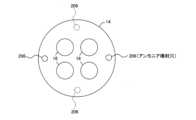
- the fourth embodiment shown in FIG.It is also possible to directly inject the vaporized ammonia gas into the engine combustion chamber 10A from the ammonia injection holes 206 formed at two locations shown in FIG.
- the gas valve 88 of this embodimentis installed in each cylinder 10, and the ammonia controlled by the gas valve 88 is distributed by the pipe 200 shown in FIGS.
- a check valve 202is provided at the connector 204 to prevent backflow of combustion gas during combustion.
- the present inventionis used in a marine diesel engine that uses heavy oil as fuel, but the scope of application of the present invention is not limited to this, and can be similarly applied to a diesel engine that uses light oil as fuel, or an engine that combines compression ignition such as a diesel engine and spark ignition such as a gasoline engine.
- the configurations of the fuel oil line, the ammonia line, and the air supply/exhaust systemare also not limited to those of the embodiment.
- SYMBOLS 10Cylinder 10A... Engine combustion chamber 12... Piston 14... Cylinder head 16... Air supply valve 18... Exhaust valve 20... Air supply pipe 20A... Air supply port 22... Exhaust pipe 24... Combustion injection valve 30... Fuel oil line 32... Fuel oil tank 34... Fuel supply pump 36... Solenoid valve 38... Fuel oil injection control device 60... Supply/exhaust system 62... Air supply line 64... Supercharger DESCRIPTION OF SYMBOLS 64A... Exhaust turbine 64B... Air supply turbine 66... Exhaust line 68... Exhaust bypass valve 80... Ammonia line 82... Ammonia tank 84... Gas cutoff valve 86... Gas pressure regulation valve 88...
- Gas valve (ammonia injection valve) 90Ammonia gas valve control device 100 -- Integrated control device 102 -- Oil flow meter 104 -- Oil flow calculator 106 -- Ammonia flow meter 108 -- Ammonia flow calculator 110 -- Ammonia mixture ratio calculator 120 -- Air supply pressure calculator 122 -- Air supply pressure sensor 130 -- Ammonia pressure sensor 132 -- Ammonia temperature sensor
Landscapes
- Engineering & Computer Science (AREA)
- Chemical & Material Sciences (AREA)
- Combustion & Propulsion (AREA)
- Mechanical Engineering (AREA)
- General Engineering & Computer Science (AREA)
- Oil, Petroleum & Natural Gas (AREA)
- Output Control And Ontrol Of Special Type Engine (AREA)
- Supercharger (AREA)
- Fuel-Injection Apparatus (AREA)
- Electrical Control Of Air Or Fuel Supplied To Internal-Combustion Engine (AREA)
Abstract
Description
Translated fromJapanese本発明は、ディーゼルエンジンに係り、特に、重油や軽油等の燃料油を主燃料とする船舶用ディーゼルエンジンに用いるのに好適な、従来、燃料として使用されなかった、炭素(C)を含まないカーボンフリーであるアンモニアNH3を燃焼させ、温室効果ガスである二酸化炭素CO2削減に特に有効なディーゼルエンジンに関する。The present invention relates to a diesel engine, and in particular, it is suitable for use in a marine diesel engine that uses fuel oil such as heavy oil and light oil as the main fuel, and is particularly effective in reducing carbon dioxideCO2 , a greenhouse gas, by burning ammoniaNH3 , which is carbon-free and does not contain carbon (C), which has not been used as fuel in the past.
アンモニアは燃焼させた場合、カーボンフリーであり、CO2の発生を伴わないため、内燃機関、特にディーゼルエンジンでの燃焼が試みられてきた。しかし、アンモニアは着火温度が例えば重油の250~380℃に比べて651℃と高く、難燃性であるため、燃焼率が悪く、投入アンモニアの20%以上が未燃分として排出されるのが現状であった。Since ammonia is carbon-free and does not produceCO2 when burned, it has been tried to burn in internal combustion engines, especially diesel engines. However, ammonia has a high ignition temperature of 651° C., for example, compared to 250 to 380° C. of heavy oil, and is flame-retardant.
これを解決するために、アンモニアの一部を触媒など用いて改質、水素とし、これをアンモニアと同時に燃焼室に投入し、燃焼性に優れる水素を着火源としてアンモニア燃焼効率を上げる試みがなされている。In order to solve this problem, attempts have been made to reform some of the ammonia into hydrogen by using a catalyst, etc., and put it into the combustion chamber at the same time as the ammonia to increase the ammonia combustion efficiency by using hydrogen, which has excellent combustibility, as an ignition source.
例えば、特許文献1では、高温水素リッチアンモニアと燃焼用空気を燃焼させるため、水素リッチアンモニアの原料として尿素水を供給し、尿素水から高温のアンモニアを生成すると共に、アンモニアの一部を水素と窒素に添加して、高温の水素リッチガスを生成することによりカーボンフリー動力装置を構成している。つまり尿素水から高温のアンモニアを生成すると共に、アンモニアの一部を水素と窒素に添加して高温の水素リッチガスを生成する水素リッチアンモニア生成リアクタに関するものである。For example, in Patent Document 1, in order to burn high-temperature hydrogen-rich ammonia and combustion air, urea water is supplied as a raw material for hydrogen-rich ammonia, high-temperature ammonia is generated from the urea water, and a part of the ammonia is added to hydrogen and nitrogen to generate high-temperature hydrogen-rich gas, thereby forming a carbon-free power plant. That is, the present invention relates to a hydrogen-rich ammonia production reactor that produces high-temperature ammonia from urea water and adds a portion of the ammonia to hydrogen and nitrogen to produce high-temperature hydrogen-rich gas.
また、特許文献2では、アンモニアを改質して水素を含む改質ガスを生成し、アンモニアに加え改質ガスをアンモニア燃焼内燃機関の燃焼室内に供給するようにしている。In addition, in Patent Document 2, ammonia is reformed to generate a reformed gas containing hydrogen, and the reformed gas is supplied to the combustion chamber of an ammonia-burning internal combustion engine in addition to ammonia.
更に、特許文献3には、燃焼室内空間で中心部より壁面側のアンモニア濃度が高くなるように調整することで水素等を混焼させることなく好適にCO2を削減可能なディーゼルエンジンが記載されており、アンモニアの投入量を所定比率に調整すること、具体的には、熱量比で燃料油の供給量の15%以上25%以下とすることが記載されている。Furthermore, Patent Document 3 describes a diesel engine that can suitably reduce CO2 without co-firing hydrogen or the like by adjusting the ammonia concentration on the wall side to be higher than the central part in the combustion chamber space. It is described that the amount of ammonia input is adjusted to a predetermined ratio, specifically, 15% or more and 25% or less of the supply amount of fuel oil in terms of calorie ratio.
近年、脱炭素がますます叫ばれており、よりアンモニア比率の高い燃料、例えばアンモニアを含む燃料全体に対するアンモニアの熱量比率が50%以上、更には80%もの燃料の混合比率を使ったディーゼルエンジンが期待される。In recent years, decarbonization has been increasingly called out, and diesel engines that use fuel with a higher ammonia ratio, for example, a fuel mixture ratio of 50% or more, or even 80%, are expected.
しかし、これには課題がある。例えば特許文献3記載の発明で上記のようにアンモニアの熱量比率(ここではアンモニア混合比率という)を高めていくと、未燃アンモニア排出が増加するという問題があり、また、アンモニア混合比率を高めていくと排ガスNOx値と未燃アンモニア排出とはトレードオフの関係で変化するため、両者を低く抑えるためには何等かの条件調整が必要となる可能性があることが分かってきた。However, there is a problem with this. For example, in the invention described in Patent Document 3, if the calorie ratio of ammonia (here, referred to as the ammonia mixing ratio) is increased as described above, there is a problem that unburned ammonia emissions increase, and as the ammonia mixing ratio is increased, the exhaust gas NOx value and unburned ammonia emissions change due to a trade-off relationship, so it has been found that there is a possibility that some kind of condition adjustment will be required to keep both low.
そして、このような条件設定は、アンモニア混合比率を可変に設定可能なディーゼルエンジンの場合、さらに困難を極める。And setting such conditions is even more difficult in the case of a diesel engine in which the ammonia mixing ratio can be set variably.
本発明は、前記従来の問題点を解決するべくなされたもので、アンモニア混合比率を広い範囲で調整可能としつつ、排ガスNOx値と未燃アンモニアの両方を低く抑え、CO2を削減することができるディーゼルエンジンを提供するものである。The present invention has been devised to solve the conventional problems described above, and provides a diesel engine capable of reducing both the exhaust gasNOx value and unburned ammonia and reducingCO2 while making it possible to adjust the ammonia mixing ratio over a wide range.
上記課題を解決するため本発明の第1の形態は、燃焼室と、前記燃焼室内に点火源となる燃料油とガス状のアンモニアとを投入する燃料投入手段とを有し、前記燃料投入手段により前記燃焼室内に投入される燃料油とガス状のアンモニアとにより前記燃焼室内でアンモニア予混合気を形成して混合燃焼させるディーゼルエンジンであって、複数の異なるアンモニア混合比率値を設定可能な設定手段と、前記設定手段で設定される前記アンモニア混合比率値に基づいて、前記投入手段で投入される燃料油及びアンモニアの総和における空気過剰率値を調整する制御手段を有することを特徴とするものである。In order to solve the above problems, a first form of the present invention is a diesel engine that has a combustion chamber and fuel injection means for introducing fuel oil and gaseous ammonia into the combustion chamber, wherein the fuel oil and gaseous ammonia injected into the combustion chamber by the fuel injection means form an ammonia premixed gas in the combustion chamber and mix and burn, setting means capable of setting a plurality of different ammonia mixture ratio values, and the fuel oil injected by the injection means based on the ammonia mixture ratio value set by the setting means. and a control means for adjusting the excess air ratio value in the summation of ammonia.
これにより、アンモニア混合比率の広い範囲で排ガスNOx値を抑えつつ、未燃アンモニアを減少させてCO2を削減することができる。As a result, it is possible to reduce the amount of unburned ammonia and reduce CO2 while suppressing the exhaust gas NOx value over a wide range of ammonia mixing ratios.
好ましくは、第2の形態として、前記設定手段で設定されるアンモニア混合比率値は、15%以上85%以下の間で設定可能であるようにしても良い。Preferably, as a second form, the ammonia mixing ratio value set by the setting means may be settable between 15% and 85%.
また好ましくは第3の形態として、前記第1又は第2の形態において、前記設定手段で設定される前記アンモニア混合比率値が、第1の値から前記第1の値よりアンモニア混合比率が高い第2の値に変更された場合、前記制御手段は、前記第1の値に対応して調整されている第1の前記空気過剰率値から、前記第1の前記空気過剰率値よりも小さい第2の前記空気過剰率値に変更するようにしても良い。Preferably, as a third mode, in the first or second mode, when the ammonia mixing ratio value set by the setting means is changed from a first value to a second value having a higher ammonia mixing ratio than the first value, the control means may change the first excess air ratio value adjusted corresponding to the first value to a second excess air ratio value smaller than the first excess air ratio value.
また好ましくは第4の形態として、前記第1乃至第3の形態において、前記設定手段で設定される前記アンモニア混合比率値が65%以上の値に設定された場合、前記空気過剰率値を1.0以下に調整するようにしても良い。Further, preferably as a fourth mode, in the first to third modes, when the ammonia mixture ratio value set by the setting means is set to a value of 65% or more, the excess air ratio value may be adjusted to 1.0 or less.
また好ましくは第5の形態として、前記第1乃至第4の形態において、前記制御手段は、前記設定手段で設定される前記アンモニア混合比率値が15%以上25%以下の値に設定された場合、前記空気過剰率値を燃料油のみによる運転時の空気過剰率値に対して1.0から1.5低くするよう調整するようにしても良い。Further, preferably as a fifth mode, in the first to fourth modes, when the ammonia mixture ratio value set by the setting means is set to a value of 15% or more and 25% or less, the excess air ratio value may be adjusted to be 1.0 to 1.5 lower than the excess air ratio value during operation using only fuel oil.
また好ましくは第6の形態として、前記第1乃至第5の形態のいずれかにおいて、前記空気過剰率の制御は、過給機の排気バイパスに設けられた調整手段による空気量の調整により行うようにしても良い。Further, preferably as a sixth mode, in any one of the first to fifth modes, the control of the excess air ratio may be performed by adjusting the air amount by adjusting means provided in the exhaust bypass of the supercharger.
また好ましくは第7の形態として、前記第1乃至第6の形態のいずかにおいて、前記アンモニアの投入は、燃焼室入側の給気ポートに対してアンモニアを噴射することにより行うようにしても良い。Further, preferably as a seventh mode, in any one of the first to sixth modes, the ammonia may be introduced by injecting the ammonia into the intake port on the inlet side of the combustion chamber.
また好ましくは第8の形態として、前記第1乃至第6の形態のいずかにおいて、前記アンモニアの投入は、燃焼室内にアンモニアを直接噴射することにより行うようにしても良い。Further, preferably, as an eighth mode, in any one of the first to sixth modes, the ammonia may be introduced by directly injecting the ammonia into the combustion chamber.
また、本発明の第9の形態によれば、前記第1乃至第8の形態のいずかにおいて、前記設定手段により設定されたアンモニア混合比率値に基づき、燃料油の流量及びアンモニアの流量をそれぞれ制御する流量制御手段と、前記流量制御手段で調整された燃料油の流量及びアンモニアの流量をそれぞれ演算又は検出する流量演算手段と、前記流量演算手段の演算結果からアンモニアの混合比率を演算する混合比率演算手段と、前記設定手段で設定されたアンモニア混合比率値もしくは前記混合比率演算手段で演算して得られた前記アンモニア混合比率値のいずれかに対応する空気過剰率値を出力する空気過剰率出力手段と、負荷率を検出する負荷率検出手段と、空気過剰率毎に、前記負荷検出手段で検出される負荷率と前記負荷率に対応する給気圧力値を対応付けたテーブルを複数有するテーブル記憶手段と、前記空気過剰率出力手段から出力される空気過剰率値に基づき前記テーブル記憶手段の中から選択されるテーブルを用いて、前記負荷率検出手段で検出された負荷率に対応する給気圧力を決定する給気圧力決定手段と、前記給気圧力決定手段で決定した給気圧力になるよう空気量を調整する手段と、を備えるものである。According to a ninth aspect of the present invention, in any one of the first to eighth aspects, flow control means for controlling the flow rate of fuel oil and the flow rate of ammonia based on the ammonia mixture ratio value set by the setting means; flow rate calculation means for calculating or detecting the flow rate of fuel oil and the flow rate of ammonia respectively adjusted by the flow rate control means; mixing ratio calculation means for calculating the mixture ratio of ammonia from the calculation result of the flow rate calculation means; excess air ratio output means for outputting an excess air factor value corresponding to one of the ammonia mixture ratio values calculated by the calculation means; load factor detection means for detecting the load factor; table storage means having a plurality of tables in which the load factor detected by the load detection means and the supply air pressure value corresponding to the load factor are associated for each excess air factor; and means for adjusting the amount of air so as to achieve the supply pressure determined by the supply pressure determination means.
また好ましくは第10の形態として、前記第9の形態において、前記テーブル記憶手段に記憶されるテーブルは、空気過剰率毎に任意の負荷率に対して対応する給気圧力を決定可能な曲線であるようにしても良い。Further, preferably, as a tenth form, in the ninth form, the table stored in the table storage means may be a curve capable of determining the supply air pressure corresponding to an arbitrary load factor for each excess air factor.
また好ましくは第11の形態として、前記第9の形態において、前記テーブル記憶手段に記憶されるテーブルは、空気過剰率毎に所定の負荷率に対して対応する給気圧力を決定可能なルックアップテーブルであるようにしても良い。Further, preferably, as the eleventh mode, in the ninth mode, the table stored in the table storage means may be a lookup table that can determine the supply air pressure corresponding to a predetermined load factor for each excess air factor.
以下、図面を参照して、本発明の実施の形態について詳細に説明する。なお、本発明は以下の実施形態及び実施例に記載した内容により限定されるものではない。また、以下に記載した実施形態及び実施例における構成要件には、当業者が容易に想定できるもの、実質的に同一のもの、いわゆる均等の範囲のものが含まれる。更に、以下に記載した実施形態及び実施例で開示した構成要素は適宜組み合わせてもよいし、適宜選択して用いてもよい。Hereinafter, embodiments of the present invention will be described in detail with reference to the drawings. In addition, the present invention is not limited by the contents described in the following embodiments and examples. In addition, the configuration requirements in the embodiments and examples described below include those that can be easily assumed by those skilled in the art, those that are substantially the same, and those that fall within the so-called equivalent range. Furthermore, the constituent elements disclosed in the embodiments and examples described below may be combined as appropriate, or may be selected and used as appropriate.
アンモニアを含む燃料ディーゼルエンジンにおいて、未燃アンモニアの排出を極力抑えるためには、アンモニアと空気の混合気を、アンモニアを点火源である油燃焼の行われる高温部になるべく集中させる必要がある。この点、特許文献3記載の発明では、高温部となる燃焼室壁面付近にアンモニアが集中するようにしている。In order to minimize the emission of unburned ammonia in a fuel diesel engine containing ammonia, it is necessary to concentrate the mixture of ammonia and air as much as possible in the high-temperature part where the ammonia is the ignition source, where the oil is burned. In this regard, in the invention described in Patent Document 3, ammonia is concentrated near the wall surface of the combustion chamber, which is a high-temperature portion.
しかしながら、このような方法では、アンモニア混合比率をさらに高めていった場合に未燃アンモニアの排出を抑制することは難しい。なぜなら図1に示すようにアンモニア混合比率が高まっていくと、アンモニア分布が変化してくるからである。図1左側はアンモニア混合比率20%の場合のアンモニア分布を示しているが、この場合、高温部が壁面付近に集中し、その壁面付近に+70%の層状にアンモニアを集中させることが可能であり、これにより未燃アンモニアの排出を抑制できる。However, with such a method, it is difficult to suppress the emission of unburned ammonia when the ammonia mixing ratio is further increased. This is because the ammonia distribution changes as the ammonia mixing ratio increases as shown in FIG. The left side of FIG. 1 shows the ammonia distribution when the ammonia mixture ratio is 20%. In this case, the high temperature part is concentrated near the wall surface, and it is possible to concentrate ammonia in a layer of +70% near the wall surface, thereby suppressing the emission of unburned ammonia.
ところが図1右側のようにアンモニア混合比率をさらに高い混合比率、ここではアンモニア混合比率80%の場合を示しているが、その場合、比率増加によりアンモニアの層状度が減少して均一混合気に近くなっている。However, as shown on the right side of Fig. 1, the mixture ratio of ammonia is even higher, here the mixture ratio of ammonia is 80%.
このことはアンモニアを高温部である壁面に集中させる割合が減少することを意味しており、その結果、未燃アンモニアが多く残る結果となる。This means that the rate at which ammonia is concentrated on the wall surface, which is the high-temperature part, is reduced, and as a result, a large amount of unburned ammonia remains.
つまり、アンモニア混合比率を増加させることで層状度が減少したアンモニアを含む燃料を用いる場合には、点火源となる燃料油を正常に燃焼させつつ、燃焼室の壁面部だけではなく燃焼室全体を高温化、つまりアンモニアと空気の混合気を熱分解促進に有効な温度レベル(約1500℃~約2000℃)に置くために適正な空気過剰率に調整する必要がある。In other words, when using fuel containing ammonia whose stratification has been reduced by increasing the ammonia mixture ratio, it is necessary to properly burn the fuel oil, which serves as the ignition source, while raising the temperature of not only the wall surface of the combustion chamber but also the entire combustion chamber.
本発明では、そのような燃料のアンモニア混合比率に適合した空気過剰率を実施例から検証した。以下にその実施例、比較例を説明する。In the present invention, the excess air ratio suitable for such a mixture ratio of ammonia in fuel was verified from examples. Examples and comparative examples will be described below.
なお、実施例、比較例共、対象となるディーゼルエンジンは、アンモニアを図6のように給気ポートに噴射する形式か、図13のようにアンモニアをエンジン燃焼室内に直接噴射する形式のいずれかであり、それぞれ以下の装置条件でアンモニア混合比率を変化させた場合の投入したアンモニアに対する未燃アンモニアの割合をシュミレーションし、図2のように評価した。In addition, in both the examples and the comparative examples, the target diesel engine is either of the type in which ammonia is injected into the intake port as shown in FIG. 6 or the type in which ammonia is directly injected into the engine combustion chamber as shown in FIG.
数値解析の装置条件としてはシリンダ径400mm、ストローク500mm、行程容積62.8L、圧縮比14.5、回転数600rpm、4ストロークエンジンの給排気系、燃焼室をモデル化し解析を実施した。The equipment conditions for the numerical analysis were a cylinder diameter of 400 mm, a stroke of 500 mm, a stroke volume of 62.8 L, a compression ratio of 14.5, and a rotation speed of 600 rpm.
又、シュミレーションではアンモニア混合比率、空気過剰率、アンモニア投入時期、期間、投入位置、油燃料噴射量、噴射時期、噴射圧力、アンモニアと空気予混合気の層状度、等のパラメータを変更し実施し、出力として、図示効率、未燃NH3、NOx、CO,THC、PM、Pmax(燃焼最高圧力)、等を算出した。In the simulation, parameters such as ammonia mixing ratio, excess air ratio, ammonia injection timing, period, injection position, oil fuel injection amount, injection timing, injection pressure, stratification degree of ammonia and air premixture, etc. were changed, and as outputs, indicated efficiency, unburned NH3 , NOx, CO, THC, PM, Pmax (maximum combustion pressure), etc. were calculated.
なお算出される値の評価基準は、NOxはIMO海洋NOx規制 TierIIレベルに基づき、濃度900ppm以下を、未燃アンモニア比率については、内閣府国家プロジェクトである戦略的イノベーション創造プログラム(SIP)の課題名「エネルギーキャリア」、研究開発テーマ「アンモニア直接燃焼」における目標値である5%以下を◎(優)とし、それに準ずるレベルであるNOx濃度が1000ppm以下、未燃アンモニア比率7%以下を〇(良)、これにも満たないものは×(不可)とした。The evaluation criteria for the calculated values are: NOx concentrations of 900ppm or less based on the Tier II level of the IMO marine NOx regulations, and unburned ammonia ratios of 5% or less, which is the target value of the Cabinet Office National Project Strategic Innovation Promotion Program (SIP) "Energy Carrier" and research and development theme "Ammonia Direct Combustion", as ◎ (excellent), and NOx concentrations of 1000ppm or less and unburned ammonia ratios of 7% or less, which are levels corresponding to these, as 〇 (good). Those less than the above were marked as x (impossible).
なおCO2については、アンモニアは燃料として用いる場合、炭素(C)を含まないカーボンフリーであるため、重油との混合比率に相当するCO2削減効果が得られるので、ここでの評価値算出は割愛した。つまりアンモニアを熱量比80%で重油と混焼させた場合、80%のCO2削減となり、アンモニア混合比率を高めれば高めるほどCO2削減効果が増大するためである。Regarding CO2 , when ammonia is used as a fuel, it is carbon-free and does not contain carbon (C), so a CO2 reduction effect equivalent to the mixing ratio with heavy oil can be obtained, so the evaluation value calculation here is omitted. In other words, if ammonia is co-fired with heavy oil at a calorific value ratio of 80%, CO2 reduction will be 80%, and the higher the ammonia mixing ratio, the greater the CO2 reduction effect.
<参考例、実施例1~15>
(参考例)上記装置条件の下、燃料として重油100%、すなわちアンモニアを混合させない燃料とし、燃料油の噴射時期を上死点TDCに対して-9.5、空気過剰率を3.2となるように給気圧力を設定し、その時のNOx濃度、未燃アンモニア比率を算出した。その結果は図2の表のとおりであった。<Reference Example, Examples 1 to 15>
(Reference example) Under the above device conditions, the fuel is 100% heavy oil, that is, a fuel not mixed with ammonia, the fuel oil injection timing is -9.5 with respect to the top dead center TDC, and the excess air ratio is 3.2. The results are shown in the table of FIG.
(実施例1~3)上記参考例と同一の装置条件の下、燃料として重油80%、アンモニア20%とし、アンモニア熱量混合比率20%に調製した燃料を実施例1、3では図6に示す給気ポートに噴射する形式で投入、実施例2では図13に示す燃焼室に直接噴射する形式で投入した。各実施例の燃料油の噴射時期を上死点TDCに対して、実施例1:-19.5、実施例2:-19.0、実施例3:-18.0でそれぞれ噴射し、空気過剰率を2.0となるように給気圧力を設定し、参考例と同様の方法でNOx濃度、未燃アンモニア比率を算出した。その結果は図2の実施例1~3の通りであった。(Examples 1 to 3) Under the same device conditions as the above reference example, the fuel was 80% heavy oil and 20% ammonia, and the fuel adjusted to a mixing ratio of ammonia calorific value of 20% was injected into the air supply port shown in FIG. The injection timing of the fuel oil of each example was injected at -19.5, -19.0, and -18.0 with respect to the top dead center TDC in each example, and the excess air ratio was set to 2.0. The results were as shown in Examples 1 to 3 in FIG.
(実施例4~6)上記参考例と同一の装置条件の下、燃料として重油50%、アンモニア50%とし、アンモニア熱量混合比率50%に調製した燃料を実施例4~6いずれも図6に示す給気ポートに噴射する形式で投入した。各実施例の燃料油の噴射時期を上死点TDCに対して、実施例4:-21.5、実施例5:-19.0、実施例6:-17.5でそれぞれ噴射し、空気過剰率を実施例1~3より下げた1.6となるように給気圧力を設定し、参考例と同様の方法でNOx濃度、未燃アンモニア比率を算出した。その結果は図2の実施例4~6の通りであった。(Examples 4 to 6) Under the same apparatus conditions as those of the above reference example, the fuel was 50% heavy oil and 50% ammonia, and the fuel adjusted to a 50% ammonia calorie mixture ratio was injected into the air supply port shown in Fig. 6 in each of Examples 4 to 6. Example 4: -21.5, Example 5: -19.0, and Example 6: -17.5, respectively, with respect to top dead center TDC. The results were as shown in Examples 4-6 in FIG.
(実施例7~9)上記参考例と同一の装置条件の下、燃料として重油40%、アンモニア60%とし、アンモニア熱量混合比率60%に調製した燃料を上述した実施例4~6と同様、いずれも図6に示す給気ポートに噴射する形式で投入した。各実施例の燃料油の噴射時期を上死点TDCに対して、実施例7:-19.0、実施例8:-16.0、実施例9:-13.0でそれぞれ噴射し、空気過剰率を実施例4~6より下げて実施例7:1.1、実施例8:1.2、実施例9:1.3となるように給気圧力を設定し、参考例と同様の方法でNOx濃度、未燃アンモニア比率を算出した。その結果は図2の実施例7~9の通りであった。(Examples 7 to 9) Under the same apparatus conditions as in the above reference example, the fuel was 40% heavy oil and 60% ammonia, and the fuel adjusted to the ammonia calorie mixture ratio of 60% was injected into the air supply port shown in FIG. Example 7: -19.0, Example 8: -16.0, and Example 9: -13.0 were injected with respect to the top dead center TDC of the fuel oil of each example, and the excess air ratio was lower than that of Examples 4 to 6. The air supply pressure was set to be Example 7: 1.1, Example 8: 1.2, and Example 9: 1.3, and the NOx concentration and the unburned ammonia ratio were calculated in the same manner as in the Reference Example. The results were as shown in Examples 7-9 in FIG.
(実施例10~12)上記参考例と同一の装置条件の下、燃料として重油30%、アンモニア70%とし、アンモニア熱量混合比率70%に調製した燃料を上述した実施例4~6と同様、いずれも図6に示す給気ポートに噴射する形式で投入した。各実施例の燃料油の噴射時期を上死点TDCに対して、実施例10:-16.5、実施例11:-16.0、実施例12:-15.0でそれぞれ噴射し、空気過剰率を実施例7~9より更に下げて実施例10:1.0、実施例11:0.9、実施例12:1.0となるように給気圧力を設定し同様の方法でNOx濃度、未燃アンモニア比率を算出した。その結果は図2の実施例10~12の通りであった。(Examples 10 to 12) Under the same device conditions as the above reference example, the fuel was 30% heavy oil and 70% ammonia, and the fuel adjusted to the ammonia calorie mixture ratio of 70% was injected into the air supply port shown in FIG. 6, as in Examples 4 to 6 described above. Example 10: -16.5, Example 11: -16.0, and Example 12: -15.0 were injected with respect to the top dead center TDC of the fuel oil of each example, and the excess air ratio was further lowered from Examples 7-9. The results were as shown in Examples 10-12 in FIG.
(実施例13~15)上記参考例と同一の装置条件の下、燃料として重油20%、アンモニア80%とし、アンモニア熱量混合比率80%に調製した燃料を上述した実施例4~6と同様、いずれも図6に示す給気ポートに噴射する形式で投入した。各実施例の燃料油の噴射時期を上死点TDCに対して、実施例13:-17.0、実施例14:-16.0、実施例15:-15.0でそれぞれ噴射し、空気過剰率を実施例10~12より更に下げて実施例13~15は全て0.8となるように給気圧力を設定し同様の方法でNOx濃度、未燃アンモニア比率を算出した。その結果は図2の実施例10~12の通りであった。(Examples 13 to 15) Under the same device conditions as the above reference example, the fuel was 20% heavy oil and 80% ammonia, and the fuel adjusted to an ammonia calorie mixture ratio of 80% was injected into the air supply port shown in FIG. Example 13: -17.0, Example 14: -16.0, and Example 15: -15.0, respectively, with respect to top dead center TDC, and the air excess ratio was set to be 0.8 in all examples 13 to 15. The NOx concentration and the unburned ammonia ratio were calculated in the same manner. The results were as shown in Examples 10-12 in FIG.
ちなみに、上記実施例1~6のようにアンモニアを含む燃料として、アンモニアの熱量混合比率を20%、50%に変更した場合でも、空気過剰率を2.0で固定とした場合、アンモニア混合比率20%では未燃NH3が0.7%、NOxが890ppmとなるのに対し、アンモニア混合比率50%では、未燃NH3が23%と上記評価基準を大きく下回る形となり、これではたとえNOxは350ppm程度まで低減できたとしてもエンジンを運転することはできない。Incidentally, even when the calorie mixture ratio of ammonia is changed to 20% or 50% as a fuel containing ammonia as in Examples 1 to 6 above, when the excess air ratio is fixed at2.0 , unburnedNH3 is 0.7% and NOx is 890 ppm at an ammonia mixture ratio of 20%. You cannot run the engine.
発明者がシュミレーションした実施例1~15により得られた図2に基づきNOx値を900ppm以下とするための、アンモニアと燃料油の混合比率に対する空気過剰率λの最適条件を図3に示す。図3の縦軸に空気過剰率λ、横軸にアンモニア熱量比混合比率を示す。FIG. 3 shows the optimum conditions for the excess air ratio λ with respect to the mixture ratio of ammonia and fuel oil for reducing the NOx value to 900 ppm or less based on FIG. 2 obtained from Examples 1 to 15 simulated by the inventor. In FIG. 3, the vertical axis indicates the excess air ratio λ, and the horizontal axis indicates the ammonia calorie ratio mixing ratio.
これによれば、アンモニアの燃焼は、図3に示すように、アンモニア混合比率50%程度までは燃料油が正常に燃焼する範疇で、燃焼場を高温にすべく空気過剰率は徐々に下げることが望ましい。According to this, as shown in Fig. 3, ammonia combustion is within the range where fuel oil burns normally up to about 50% ammonia mixture ratio, and it is desirable to gradually lower the excess air ratio in order to raise the temperature of the combustion field.
但し、アンモニア混合比率が50%を超える範囲より、95%以上の燃焼率を得るためには、アンモニアと空気の混合気を1500℃~2000℃レベルの高温環境に置いて、アンモニアの熱分解反応を優先させることが必要となり、アンモニア混合比率が65%以上では図4に示すように、空気過剰率を例えば1.0以下の過濃側とし、燃料油の点火及びその後の燃料油、アンモニアの燃焼による燃焼室温度を高温とする必要があることが分かった。However, in order to obtain a combustion rate of 95% or more from the range where the ammonia mixture ratio exceeds 50%, it is necessary to place the mixture of ammonia and air in a high temperature environment of 1500 ° C to 2000 ° C to give priority to the thermal decomposition reaction of ammonia, and when the ammonia mixture ratio is 65% or more, as shown in FIG. was
これは、すべてのアンモニアが完全燃焼である次式
4NH3+3O2=2N2+6H2O
を辿らず、素反応式上、中間生成物で留まるものでも、発熱反応によりエネルギは取り出せるためと考えられアンモニアが前式のように完全にすべて反応しなくても、熱分解反応で分解してアンモニアとして留まらず未燃アンモニアとならないことが推定される。つまり、アンモニアと燃料油との混合比率を可変とし、その比率に最適な空気過剰率になるよう制御を行うが、アンモニア混合比率を高めるほど空気過剰率を下げ、特にアンモニア混合比率が65%以上のものにおいては、通常は燃料油を完全燃焼させるのに必要な空気過剰率1.0より下げる、即ちアンモニアの熱分解反応の促進を優先させるために空気過剰率を1.0以下とすることが未燃アンモニアを抑制するためには必要な条件となる。This is due to the equation 4NH3 +3O2 =2N2 +6H2 O where all ammonia is completely combusted.
It is assumed that even if ammonia does not react completely as an intermediate product in the elementary reaction formula, energy can be taken out by the exothermic reaction, and even if ammonia does not completely react as in the previous equation, it is decomposed by the thermal decomposition reaction and does not remain as ammonia and does not become unburned ammonia. In other words, the mixture ratio of ammonia and fuel oil is variable, and control is performed so that the excess air ratio is optimal for that ratio, but the more the mixture ratio of ammonia is increased, the more the excess air ratio is lowered, especially when the mixture ratio of ammonia is 65% or more.
なお、これは、燃焼室形状や流動条件により若干差が出ると考えられ、この曲線関係には例えばアンモニア混合比率に±5%程度の幅を持たせることが望ましいが、この曲線に沿った空気過剰率の制御を行うことが燃焼率95%以上を得るために好ましい。It should be noted that this is thought to vary slightly depending on the shape of the combustion chamber and flow conditions, and it is desirable that this curve relationship, for example, have a width of about ±5% in the ammonia mixing ratio, but it is preferable to control the excess air ratio along this curve in order to obtain a combustion rate of 95% or more.
制御の手法としては、従来の燃焼では排ガス中残存O2濃度の監視で、空気過剰率の制御を行うことが可能であったが、本発明の燃焼方法ではアンモニアは熱分解の中間生成物で留まらせるので、理論的な排ガス中残存O2濃度にはならない。例えば空気過剰率0.8での燃焼においても、残存O2は存在する。As a control method, in conventional combustion, it was possible to control the excess air ratio by monitoring the residual O2 concentration in the exhaust gas, but in the combustion method of the present invention, ammonia remains as an intermediate product of thermal decomposition, so the theoretical residual O2 concentration in the exhaust gas is not achieved. For example, residual O2 is present even in combustion with excess air ratio of 0.8.
これより、必要な空気量を給気圧力値として割り出し、例えば過給機の排気バイパス量の制御により必要な給気圧力に調整することができる。From this, the necessary amount of air can be calculated as the supply pressure value, and the supply pressure can be adjusted to the required amount by, for example, controlling the exhaust bypass amount of the supercharger.
本発明が対象とするディーゼルエンジンは、図5に示す如く、シリンダ10と、該シリンダ10内を上下動するピストン12と、前記シリンダ10の上部に装着されるシリンダヘッド14と、該シリンダヘッド14に装着され、ピストン12上部のエンジン燃焼室10A内に給気を供給するための給気弁16と、エンジン燃焼室10Aから燃焼後の排ガスを排出するための排気弁18と、前記シリンダヘッド14に給気を供給するための給気管20と、前記シリンダヘッド14から排ガスを排出するための排気管22と、エンジン燃焼室10A内に燃料油を噴射するための燃料噴射弁24と、該燃料噴射弁24に燃料油を供給するための燃料油ライン30を構成する、燃料油タンク32、燃料供給ポンプ34及び電磁弁36と、該電磁弁36を開閉するための燃料油噴射制御装置38と、前記給気管20に給気を供給すると共に前記排気管22からの排ガスが排出される給排気系60を構成する、給気ライン62、排ガスにより回転される排気タービン64Aにより、該給気ライン62に供給される空気を圧縮するための給気タービン64Bを備えた過給機64及び前記排気管22から過給機64の排気タービン64Aに供給される排ガスをバイパスライン67を介してバイパスする量を調整するための排気バイパス弁68と、を主に備えている。As shown in FIG. 5, the diesel engine to which the present invention is directed comprises a cylinder 10, a piston 12 that moves up and down within the cylinder 10, a
前記ディーゼルエンジンには、更に、アンモニアを燃焼させるためのアンモニアライン80が設けられている。このアンモニアライン80には、アンモニアタンク82と、アンモニアガス遮断弁84と、アンモニアガス調圧弁86と、前記給気管20内の給気ポート20Aにアンモニアガスを噴射するためのアンモニアガス噴射弁(以下、単にガス弁とも称する)88と、アンモニアガス弁制御装置90が備えられている。The diesel engine is further provided with an
そして、前記燃料油ライン30の燃料油噴射制御装置38、前記給排気系60の排気バイパス弁68、及び前記アンモニアライン80のアンモニアガス弁制御装置90は、統括制御装置100によって制御されている。The fuel oil injection control device 38 for the fuel oil line 30 , the exhaust bypass valve 68 for the supply/
ここで、前記燃料油噴射制御装置38、前記アンモニアガス弁制御装置90、前記排気バイパス弁68、前記統括制御装置100により制御手段が構成される。Here, the fuel oil injection control device 38, the ammonia gas valve control device 90, the exhaust bypass valve 68, and the integrated control device 100 constitute control means.
前記ガス弁88は、図5に示した本発明の第1実施形態では、図6に詳細に示す如く、機械式または電子制御式燃料噴射装置を備えたディーゼルエンジンにおいて、アンモニアをガス弁であるアンモニアガス噴射弁88から給気管20内の給気ポート20Aに噴霧し、エンジン給気と混合させてアンモニア-空気予混合気(単に予混合気とも称する)を作り、燃料噴射弁24から噴射した主燃料である重油や軽油などの燃料油を点火源として混合燃焼させる。In the first embodiment of the present invention shown in FIG. 5, as shown in detail in FIG. 6, the gas valve 88 sprays ammonia from the ammonia gas injection valve 88, which is a gas valve, into the air supply port 20A in the
図7Aに示す如く、前記給気管20と前記シリンダヘッド14の間にはガス弁88を取り付けるためのスペーサ92が設けられている。このスペーサ92には、図7Bに示す如く、ガス弁取付穴92Aと、ガス弁88から噴射されたアンモニアが直接給気ポート20A内に噴射されないようにするための干渉板92Bが設けられている。従来のディーゼルエンジンでは給気ポート内に残留したアンモニアと空気の混合気が排気行程において燃焼室内の未燃NH3と合算され排出され得るが、本実施例では、ガス弁より給気ポートにNH3を供給する機構に干渉板92Bを設けているため、NH3を給気ポートに極力残留させないようにしている。これにより、未燃NH3は概ね燃焼行程において発生するものに限定される。As shown in FIG. 7A, a spacer 92 is provided between the
前記ガス弁88は、図7Cに示す如く、電磁弁88Aにより開閉されている。The gas valve 88 is opened and closed by an electromagnetic valve 88A as shown in FIG. 7C.
アンモニアは、アンモニアタンク82に液状で貯留されるが、気化され、ガス態にて供給される。ガス調圧弁86でガス圧が調整され、ガス弁88で流量調整され、図8に例示する所定の給気タイミング内にて開弁期間調整されエンジンに供給される。Ammonia is stored in the ammonia tank 82 in a liquid state, but is vaporized and supplied in a gaseous state. The gas pressure is adjusted by the gas pressure regulating valve 86, the flow rate is adjusted by the gas valve 88, and the valve opening period is adjusted within the predetermined air supply timing illustrated in FIG. 8 before being supplied to the engine.
本実施形態では、更に、前記燃料油ライン30の途中に配設された油流量計102と、該油流量計102の出力に基いて燃料油流量を演算する油流量演算器104と、前記アンモニアライン80の途中に配設されたアンモニア流量計106と、該アンモニア流量計106の出力に基いてアンモニア流量を演算するアンモニア流量演算器108と、前記油流量演算器104で演算された燃料油流量及び前記アンモニア流量演算器108で演算されたアンモニア流量からアンモニア混合比率を演算するアンモニア混合比率演算器110と、該アンモニア混合比率演算器110の出力に基いて必要な給気圧力を演算し、給気管20の途中に配設された給気圧力センサ122で検出される給気圧力が目標値となるように前記排気バイパス弁68を制御する給気圧力演算器120とを備えている。In this embodiment, furthermore, an oil flow meter 102 arranged in the middle of the fuel oil line 30, an oil flow calculator 104 that calculates the fuel oil flow rate based on the output of the oil flow meter 102, an ammonia flow meter 106 that is arranged in the middle of the
前記統括制御装置100は、予め設定されたアンモニア混合比率の設定比率値とアンモニア混合比率演算器110による演算比率値を比較して、所定範囲外であれば燃料油噴射制御装置38とアンモニアガス弁制御装置90により燃料油流量及び/又はアンモニア流量をフィードバック制御して、実際の比率(実比率と称する)が設定比率の所定範囲内に収まるようにする。The integrated control device 100 compares the preset ratio value of the ammonia mixture ratio and the ratio value calculated by the ammonia mixture ratio calculator 110, and if it is out of the predetermined range, feedback-controls the fuel oil flow rate and/or the ammonia flow rate by the fuel oil injection control device 38 and the ammonia gas valve control device 90 so that the actual ratio (referred to as the actual ratio) falls within the predetermined range of the set ratio.
以下、図9を参照して制御手順を説明する。The control procedure will be described below with reference to FIG.
まずステップ1000で統括制御装置100にアンモニア混合比率の目標値(設定比率)を設定し、この設定比率に対応する燃料油流量、アンモニア流量をそれぞれ算出すると共に、エンジン負荷を検出し、ガス弁88と燃料噴射弁24の制御を行う。なお設定するアンモニア混合比率は変更可能に構成されている。First, in
次いでステップ1100で、燃料流量、即ち燃料油とアンモニアの流量を検出する。ここで、燃料油の流量は油流量計102の出力から検出し、アンモニアの流量はアンモニア流量計106の出力から検出する。Next, in
ステップ1100で検出された燃料油とアンモニアの流量からステップ1200でアンモニア混合比率を算定する。The ammonia mixing ratio is calculated in
ステップ1200で演算して得られたアンモニア混合比率値の実際の値(実比率)と、最初の設定で設定したアンモニア混合比率値(設定比率)とをステップ1210で比較し、所定範囲内であれば演算した実比率をステップ1300で用いる。一方、所定範囲を超える差が生じているようであれば、ステップ1220で再度燃料油流量とアンモニア流量を所定範囲内に収めるようにフィードバック制御する。例えば検出した燃料油流量とアンモニア流量が設定したアンモニア70%、燃料油30%などのアンモニア混合比率となるような調整を行う。なお、ステップ1210で所定範囲内と判断された場合、燃料油流量とアンモニア流量の更なる調整は不要のため、最初に設定したアンモニア混合比率値(設定比率)を用いても良いが、実測演算値(実比率)の方がより正確と考えられるため、演算比率値(実比率)の方がより好ましい。The actual value (actual ratio) of the ammonia mixing ratio calculated in
次いでステップ1300に進み、その時の負荷率に応じて、図10のような関係を用いて、ステップ1200で算定されるか、ステップ1000で設定された、その時のアンモニア混合比率(実比率又は設定比率)に対応する空気過剰率λに必要な給気圧力を設定する。例えば負荷率がaの場合で空気過剰率λが1.0の場合、必要な給気圧力はbとなる。なお、図中に矢印Aで示す如く、負荷率上昇に伴い、同一空気過剰率λをとる場合、必要な給気圧力は上昇する。一方、空気量減、空気過剰率λ減に伴い、図中に矢印Bで示す如く、必要な給気圧力は下降する。制御に必要な図10のようなデータは、予めテーブルとして給気圧力演算器120に記憶しておくことができる。なおここで記憶されるテーブルは、空気過剰率毎に任意の負荷率に対して対応する給気圧力を決定可能な曲線データを記憶するものであっても良いし、空気過剰率毎に所定の負荷率に対して対応する給気圧力を決定可能な数値をLUT(ルックアップテーブル)の形で記憶しておくものであっても良い。前者の場合、曲線データであるため、任意の負荷率に対して対応する空気過剰率を決定することができる点で好ましく、後者はある程度決められた離散的な負荷率に対して対応する空気過剰率を記憶手段の記憶容量を節約しながら決定できる点で好ましい。Next, proceed to step 1300, and set the supply air pressure required for the excess air ratio λ corresponding to the ammonia mixing ratio (actual ratio or set ratio) at that time calculated at
そして、ステップ1400に進み、排気バイパス弁68の開度を制御して、給気圧力センサ122で検出される給気圧力が設定値となるように調整する。Then, in
最終的な設定出力、回転数維持のガバニングは、アンモニア混合比率の低い時には燃料油流量の調整にて、またアンモニア混合比率の高い時にはアンモニア流量の調整にて行い、どちらの燃料にて最終ガバニングするかは任意に設定することができる。The final set output and governing to maintain the rotation speed are performed by adjusting the fuel oil flow rate when the ammonia mixture ratio is low, and by adjusting the ammonia flow rate when the ammonia mixture ratio is high, and which fuel is used for final governance can be set arbitrarily.
なお、前記第1実施形態においては、給気管20に直交する方向からアンモニアガスを噴射していたが、図11に示す第2実施形態のように、給気ポート20Aへアンモニアガスを噴射する際に給気管20と平行な方向からアンモニアガスを噴射して、エンジン燃焼室10A内に旋回流Cを発生強化させるようにして、給気ポート20A内へのアンモニア残留を削減することができる。In the first embodiment, the ammonia gas is injected from the direction perpendicular to the
また、前記第1実施形態では、燃料油とアンモニアの流量を油流量計102とアンモニア流量計106を用いて、それぞれ直接検出していたが、図12に示す第3実施形態のように、油流量演算器104で燃料油噴射制御装置38の出力の燃料噴射信号を積算して燃料油流量を計算したり、アンモニアライン80に設けたアンモニアの圧力を検出するアンモニア圧力センサ130及びアンモニア温度センサ132と、アンモニアガス弁制御装置90から入力されるガス弁88の開度に応じてアンモニア流量演算器108でアンモニア流量を演算してもよい。Also, in the first embodiment, the flow rates of fuel oil and ammonia are directly detected using the oil flow meter 102 and the ammonia flow meter 106, respectively. However, as in the third embodiment shown in FIG. The ammonia flow rate calculator 108 may calculate the ammonia flow rate according to the opening degree of the gas valve 88 input from .
この第3実施形態によれば、流量計を設けることなく燃料油流量とアンモニア流量を演算することができる。なお、いずれか一方のラインに第1実施形態と同様の流量計102又は106を設けて、一方の流量を直接検出するように構成することも可能である。According to this third embodiment, the fuel oil flow rate and the ammonia flow rate can be calculated without providing a flow meter. In addition, it is also possible to provide a flowmeter 102 or 106 similar to that of the first embodiment to one of the lines so as to directly detect the flow rate of one of the lines.
また、前記実施形態においては、いずれもアンモニアガスが給気ポート20Aに供給されていたが、アンモニアガスをエンジン燃焼室10Aに供給する方法はこれに限定されず、特許文献3と同様の図13に示す第4実施形態のように、アンモニアライン80の出側に図14A、図14Bに示すようなパイプ200、逆止弁202、コネクタ204を設けて、エンジン燃焼室10Aの内側壁面側の複数個所(実施形態では図15に示す2箇所)に形成したアンモニア噴射穴206から気化したアンモニアガスをエンジン燃焼室10A内に直接投入することもできる。In addition, in the above-described embodiments, ammonia gas is supplied to the air supply port 20A in all cases, but the method of supplying ammonia gas to the engine combustion chamber 10A is not limited to this. As in the fourth embodiment shown in FIG. It is also possible to directly inject the vaporized ammonia gas into the engine combustion chamber 10A from the ammonia injection holes 206 formed at two locations shown in FIG.
本実施形態のガス弁88は各シリンダ10に装備され、該ガス弁88により制御されるアンモニアは、図14A、図14Bに示すパイプ200で分配され、コネクタ204を通って複数の噴射穴206に送られる。該コネクタ204の部分には、燃焼時に燃焼ガスが逆流しないように逆止弁202が設けられている。The gas valve 88 of this embodiment is installed in each cylinder 10, and the ammonia controlled by the gas valve 88 is distributed by the pipe 200 shown in FIGS. A check valve 202 is provided at the connector 204 to prevent backflow of combustion gas during combustion.
なお、前記実施形態においては、本発明が重油を燃料とする船舶用のディーゼルエンジンに用いられていたが、本発明の適用対象はこれに限定されず、軽油を燃料とするディーゼルエンジンや、ディーゼルエンジンのような圧縮着火と、ガソリンエンジンのような火花着火を組み合わせたエンジンにも同様に適用できる。燃料油ライン、アンモニアライン、給排気系の構成も実施形態に限定されない。In the above-described embodiment, the present invention is used in a marine diesel engine that uses heavy oil as fuel, but the scope of application of the present invention is not limited to this, and can be similarly applied to a diesel engine that uses light oil as fuel, or an engine that combines compression ignition such as a diesel engine and spark ignition such as a gasoline engine. The configurations of the fuel oil line, the ammonia line, and the air supply/exhaust system are also not limited to those of the embodiment.
アンモニアを輸送するアンモニアタンカーのエンジンとして用いるのに特に有効であるが、適用対象はこれに限定されない。 It is particularly effective for use as an engine for an ammonia tanker that transports ammonia, but its application is not limited to this.
10…シリンダ
10A…エンジン燃焼室
12…ピストン
14…シリンダヘッド
16…給気弁
18…排気弁
20…給気管
20A…給気ポート
22…排気管
24…燃焼噴射弁
30…燃料油ライン
32…燃料油タンク
34…燃料供給ポンプ
36…電磁弁
38…燃料油噴射制御装置
60…給排気系
62…給気ライン
64…過給機
64A…排気タービン
64B…給気タービン
66…排気ライン
68…排気バイパス弁
80…アンモニアライン
82…アンモニアタンク
84…ガス遮断弁
86…ガス調圧弁
88…ガス弁(アンモニア噴射弁)
90…アンモニアガス弁制御装置
100…統括制御装置
102…油流量計
104…油流量演算器
106…アンモニア流量計
108…アンモニア流量演算器
110…アンモニア混合比率演算器
120…給気圧力演算器
122…給気圧力センサ
130…アンモニア圧力センサ
132…アンモニア温度センサDESCRIPTION OF SYMBOLS 10... Cylinder 10A... Engine combustion chamber 12...
90 -- Ammonia gas valve control device 100 -- Integrated control device 102 -- Oil flow meter 104 -- Oil flow calculator 106 -- Ammonia flow meter 108 -- Ammonia flow calculator 110 -- Ammonia mixture ratio calculator 120 -- Air supply pressure calculator 122 -- Air supply pressure sensor 130 -- Ammonia pressure sensor 132 -- Ammonia temperature sensor
Claims (11)
Translated fromJapanese複数の異なるアンモニア混合比率値を設定可能な設定手段と、
前記設定手段で設定される前記アンモニア混合比率値に基づいて、前記投入手段で投入される燃料油及びアンモニアの総和における空気過剰率値を調整する制御手段を有することを特徴とするディーゼルエンジン。A diesel engine having a combustion chamber and a fuel injection means for introducing fuel oil as an ignition source and gaseous ammonia into the combustion chamber, wherein the fuel oil and gaseous ammonia introduced into the combustion chamber by the fuel injection means form an ammonia premixture in the combustion chamber and mix and burn,
setting means capable of setting a plurality of different ammonia mixing ratio values;
A diesel engine, comprising control means for adjusting an excess air ratio value in the sum of the fuel oil and ammonia injected by the injection means based on the ammonia mixture ratio value set by the setting means.
前記流量制御手段で調整された燃料油の流量及びアンモニアの流量をそれぞれ演算又は検出する流量演算手段と、
前記流量演算手段の演算結果からアンモニアの混合比率を演算する混合比率演算手段と、
前記設定手段で設定されたアンモニア混合比率値もしくは前記混合比率演算手段で演算して得られた前記アンモニア混合比率値のいずれかに対応する空気過剰率値を出力する空気過剰率出力手段と、
負荷率を検出する負荷率検出手段と、
空気過剰率毎に、前記負荷検出手段で検出される負荷率と前記負荷率に対応する給気圧力値を対応付けたテーブルを複数有するテーブル記憶手段と、
前記空気過剰率出力手段から出力される空気過剰率値に基づき前記テーブル記憶手段の中から選択されるテーブルを用いて、前記負荷率検出手段で検出された負荷率に対応する給気圧力を決定する給気圧力決定手段と、
前記給気圧力決定手段で決定した給気圧力になるよう空気量を調整する手段と、
を備えたことを特徴とする請求項1乃至8のいずれかに記載のディーゼルエンジン。flow control means for controlling the flow rate of fuel oil and the flow rate of ammonia based on the ammonia mixing ratio value set by the setting means;
flow rate calculation means for calculating or detecting the flow rate of fuel oil and the flow rate of ammonia adjusted by the flow rate control means;
A mixing ratio calculation means for calculating a mixing ratio of ammonia from the calculation result of the flow rate calculation means;
excess air ratio output means for outputting an excess air ratio value corresponding to either the ammonia mixture ratio value set by the setting means or the ammonia mixture ratio value calculated by the mixture ratio calculation means;
load factor detection means for detecting the load factor;
table storage means having a plurality of tables in which the load factor detected by the load detection means and the supply air pressure value corresponding to the load factor are associated with each excess air factor;
air supply pressure determination means for determining an air supply pressure corresponding to the load factor detected by the load factor detection means using a table selected from the table storage means based on the air excess ratio value output from the air excess ratio output means;
Means for adjusting the amount of air so that the air supply pressure determined by the air supply pressure determination means is obtained;
A diesel engine according to any one of claims 1 to 8, characterized in that it comprises a
Priority Applications (5)
| Application Number | Priority Date | Filing Date | Title |
|---|---|---|---|
| JP2022504561AJP7160226B1 (en) | 2022-01-20 | 2022-01-20 | diesel engine |
| PCT/JP2022/001944WO2023139716A1 (en) | 2022-01-20 | 2022-01-20 | Diesel engine |
| KR1020237004518AKR102548535B1 (en) | 2022-01-20 | 2022-01-20 | diesel engine |
| EP22847109.0AEP4253748B1 (en) | 2022-01-20 | 2022-01-20 | Diesel engine |
| CN202280006462.7ACN116324141B (en) | 2022-01-20 | 2022-01-20 | Diesel engines |
Applications Claiming Priority (1)
| Application Number | Priority Date | Filing Date | Title |
|---|---|---|---|
| PCT/JP2022/001944WO2023139716A1 (en) | 2022-01-20 | 2022-01-20 | Diesel engine |
Publications (1)
| Publication Number | Publication Date |
|---|---|
| WO2023139716A1true WO2023139716A1 (en) | 2023-07-27 |
Family
ID=83742515
Family Applications (1)
| Application Number | Title | Priority Date | Filing Date |
|---|---|---|---|
| PCT/JP2022/001944CeasedWO2023139716A1 (en) | 2022-01-20 | 2022-01-20 | Diesel engine |
Country Status (5)
| Country | Link |
|---|---|
| EP (1) | EP4253748B1 (en) |
| JP (1) | JP7160226B1 (en) |
| KR (1) | KR102548535B1 (en) |
| CN (1) | CN116324141B (en) |
| WO (1) | WO2023139716A1 (en) |
Cited By (1)
| Publication number | Priority date | Publication date | Assignee | Title |
|---|---|---|---|---|
| JP7635443B1 (en) | 2024-02-16 | 2025-02-25 | 三菱重工エンジン&ターボチャージャ株式会社 | Control device, power generation system and control method |
Families Citing this family (3)
| Publication number | Priority date | Publication date | Assignee | Title |
|---|---|---|---|---|
| WO2024260549A1 (en)* | 2023-06-21 | 2024-12-26 | Wärtsilä Finland Oy | A method of operating a four-stroke multi-cylinder piston engine and a four-stroke internal combustion piston engine |
| JP2025093524A (en)* | 2023-12-12 | 2025-06-24 | 三菱重工エンジン&ターボチャージャ株式会社 | Control device for internal combustion engine and control method for internal combustion engine |
| EP4621205A1 (en)* | 2024-03-18 | 2025-09-24 | Yanmar Holdings Co., Ltd. | Ammonia mixed combustion engine |
Citations (7)
| Publication number | Priority date | Publication date | Assignee | Title |
|---|---|---|---|---|
| JPH042475B2 (en) | 1983-10-06 | 1992-01-17 | ||
| JP2002004917A (en)* | 2000-06-21 | 2002-01-09 | Toyota Motor Corp | Control device for in-vehicle internal combustion engine |
| JP2004027861A (en)* | 2002-06-21 | 2004-01-29 | Toyota Motor Corp | Setting method of calculation formula used for calculating engine load of internal combustion engine |
| WO2011136151A1 (en)* | 2010-04-26 | 2011-11-03 | トヨタ自動車株式会社 | Ammonia-burning internal combustion engine |
| JP5310945B2 (en) | 2010-05-21 | 2013-10-09 | トヨタ自動車株式会社 | Ammonia combustion internal combustion engine |
| JP5315493B1 (en) | 2012-06-13 | 2013-10-16 | 武史 畑中 | Next-generation carbon-free power unit and next-generation carbon-free moving body using the same |
| JP2020148198A (en)* | 2019-03-08 | 2020-09-17 | Jfeエンジニアリング株式会社 | diesel engine |
Family Cites Families (10)
| Publication number | Priority date | Publication date | Assignee | Title |
|---|---|---|---|---|
| JPS5310945U (en) | 1976-06-29 | 1978-01-30 | ||
| JPS5315493U (en) | 1976-07-22 | 1978-02-08 | ||
| JP2012520421A (en)* | 2009-03-10 | 2012-09-06 | スターマン・デジタル・システムズ・エルエルシイ | Dual fuel compression ignition engine and method |
| BRPI0924757A2 (en)* | 2009-03-25 | 2016-01-26 | Toyota Motor Co Ltd | internal combustion engine controller |
| US8495974B2 (en)* | 2009-05-18 | 2013-07-30 | Vito Agosta | Fuel system and method for burning liquid ammonia in engines and boilers |
| US8534237B2 (en)* | 2010-04-22 | 2013-09-17 | Toyota Jidosha Kabushiki Kaisha | Control system of internal combustion engine |
| US8423265B2 (en)* | 2010-05-21 | 2013-04-16 | Toyota Jidosha Kabushiki Kaisha | Control system of internal combustion engine |
| US8370049B1 (en)* | 2010-05-21 | 2013-02-05 | Toyota Jidosha Kabushiki Kaisha | Control system of internal combustion engine |
| JPWO2020183522A1 (en)* | 2019-03-08 | 2020-09-17 | ||
| US11731750B2 (en)* | 2019-05-14 | 2023-08-22 | Daewoo Shipbuilding & Marine Engineering Co., Ltd. | Fuel supply system for eco-friendly ship |
- 2022
- 2022-01-20WOPCT/JP2022/001944patent/WO2023139716A1/ennot_activeCeased
- 2022-01-20CNCN202280006462.7Apatent/CN116324141B/enactiveActive
- 2022-01-20JPJP2022504561Apatent/JP7160226B1/enactiveActive
- 2022-01-20KRKR1020237004518Apatent/KR102548535B1/enactiveActive
- 2022-01-20EPEP22847109.0Apatent/EP4253748B1/enactiveActive
Patent Citations (7)
| Publication number | Priority date | Publication date | Assignee | Title |
|---|---|---|---|---|
| JPH042475B2 (en) | 1983-10-06 | 1992-01-17 | ||
| JP2002004917A (en)* | 2000-06-21 | 2002-01-09 | Toyota Motor Corp | Control device for in-vehicle internal combustion engine |
| JP2004027861A (en)* | 2002-06-21 | 2004-01-29 | Toyota Motor Corp | Setting method of calculation formula used for calculating engine load of internal combustion engine |
| WO2011136151A1 (en)* | 2010-04-26 | 2011-11-03 | トヨタ自動車株式会社 | Ammonia-burning internal combustion engine |
| JP5310945B2 (en) | 2010-05-21 | 2013-10-09 | トヨタ自動車株式会社 | Ammonia combustion internal combustion engine |
| JP5315493B1 (en) | 2012-06-13 | 2013-10-16 | 武史 畑中 | Next-generation carbon-free power unit and next-generation carbon-free moving body using the same |
| JP2020148198A (en)* | 2019-03-08 | 2020-09-17 | Jfeエンジニアリング株式会社 | diesel engine |
Non-Patent Citations (1)
| Title |
|---|
| See also references ofEP4253748A4 |
Cited By (1)
| Publication number | Priority date | Publication date | Assignee | Title |
|---|---|---|---|---|
| JP7635443B1 (en) | 2024-02-16 | 2025-02-25 | 三菱重工エンジン&ターボチャージャ株式会社 | Control device, power generation system and control method |
Also Published As
| Publication number | Publication date |
|---|---|
| CN116324141A (en) | 2023-06-23 |
| EP4253748A1 (en) | 2023-10-04 |
| CN116324141B (en) | 2024-03-15 |
| KR102548535B1 (en) | 2023-06-29 |
| JP7160226B1 (en) | 2022-10-25 |
| EP4253748B1 (en) | 2025-06-25 |
| JPWO2023139716A1 (en) | 2023-07-27 |
| EP4253748A4 (en) | 2023-12-20 |
Similar Documents
| Publication | Publication Date | Title |
|---|---|---|
| KR102480585B1 (en) | diesel engine | |
| WO2023139716A1 (en) | Diesel engine | |
| JP6702475B1 (en) | diesel engine | |
| Zheng et al. | Diesel engine exhaust gas recirculation––a review on advanced and novel concepts | |
| US20240018897A1 (en) | Ammonia-hydrogen blended fuel control system based on reactivity regulation | |
| EP2246546B1 (en) | Control device for internal combustion engine | |
| US10989088B2 (en) | Reductant generation systems and methods | |
| US20140196702A1 (en) | Ignition and Knock Tolerance in Internal Combustion Engine by Controlling EGR Composition | |
| KR101745005B1 (en) | Diesel - Gasoline Complex Engine | |
| JP7331784B2 (en) | diesel engine | |
| US20100275891A1 (en) | Internal combustion engine | |
| CN106837619B (en) | Combine the low temp fuel reformer of external reformer based on engine | |
| JP6789907B2 (en) | Internal combustion engine | |
| CN118934219A (en) | Engine system and method based on pre-combustion chamber diesel jet flame ignition of ammonia fuel | |
| Chiera et al. | Method to reach high substitution of an ammonia fueled engine using dual fuel RCCI and active combustion control | |
| Liu et al. | Numerical Study on Combustion and Emission Characteristics of a Liquid Ammonia Direct Injection Ammonia-Diesel Engine | |
| KR20120064214A (en) | Internal combustion engine using hydrogen and oxygen mixture for higher engine efficiency and lower exhaust gas emission | |
| CN111108281B (en) | Internal combustion engine | |
| JP2017514060A (en) | Internal combustion engine with split fuel intake mechanism and individual combustion process | |
| US20250290466A1 (en) | Engine device | |
| EP4621205A1 (en) | Ammonia mixed combustion engine | |
| Togawa et al. | Analysis of Supercharged HCCI Combustion Using Low-Carbon Alternative Fuels | |
| Yu et al. | Effects of ammonia supply distribution rate and cracking degree on combustion-emission in ammonia-hydrogen combination engine with IJI | |
| CN116146341A (en) | An ammonia fuel engine and its gas supply control method | |
| CN117685137A (en) | Marine double-direct injection engine system and control method thereof |
Legal Events
| Date | Code | Title | Description |
|---|---|---|---|
| WWE | Wipo information: entry into national phase | Ref document number:2022504561 Country of ref document:JP | |
| ENP | Entry into the national phase | Ref document number:2022847109 Country of ref document:EP Effective date:20230131 | |
| 121 | Ep: the epo has been informed by wipo that ep was designated in this application | Ref document number:22847109 Country of ref document:EP Kind code of ref document:A1 | |
| NENP | Non-entry into the national phase | Ref country code:DE | |
| WWG | Wipo information: grant in national office | Ref document number:2022847109 Country of ref document:EP |