WO2023138313A1 - Rotating shaft mechanism and terminal device - Google Patents
Rotating shaft mechanism and terminal deviceDownload PDFInfo
- Publication number
- WO2023138313A1 WO2023138313A1PCT/CN2022/141975CN2022141975WWO2023138313A1WO 2023138313 A1WO2023138313 A1WO 2023138313A1CN 2022141975 WCN2022141975 WCN 2022141975WWO 2023138313 A1WO2023138313 A1WO 2023138313A1
- Authority
- WO
- WIPO (PCT)
- Prior art keywords
- swing arm
- base
- shaft cover
- rotating shaft
- shaft
- Prior art date
- Legal status (The legal status is an assumption and is not a legal conclusion. Google has not performed a legal analysis and makes no representation as to the accuracy of the status listed.)
- Ceased
Links
Images


Classifications
- F—MECHANICAL ENGINEERING; LIGHTING; HEATING; WEAPONS; BLASTING
- F16—ENGINEERING ELEMENTS AND UNITS; GENERAL MEASURES FOR PRODUCING AND MAINTAINING EFFECTIVE FUNCTIONING OF MACHINES OR INSTALLATIONS; THERMAL INSULATION IN GENERAL
- F16C—SHAFTS; FLEXIBLE SHAFTS; ELEMENTS OR CRANKSHAFT MECHANISMS; ROTARY BODIES OTHER THAN GEARING ELEMENTS; BEARINGS
- F16C11/00—Pivots; Pivotal connections
- F16C11/04—Pivotal connections
- H—ELECTRICITY
- H04—ELECTRIC COMMUNICATION TECHNIQUE
- H04M—TELEPHONIC COMMUNICATION
- H04M1/00—Substation equipment, e.g. for use by subscribers
- H04M1/02—Constructional features of telephone sets
- H04M1/0202—Portable telephone sets, e.g. cordless phones, mobile phones or bar type handsets
- H04M1/0206—Portable telephones comprising a plurality of mechanically joined movable body parts, e.g. hinged housings
- H04M1/0208—Portable telephones comprising a plurality of mechanically joined movable body parts, e.g. hinged housings characterized by the relative motions of the body parts
- H04M1/0214—Foldable telephones, i.e. with body parts pivoting to an open position around an axis parallel to the plane they define in closed position
- H04M1/0216—Foldable in one direction, i.e. using a one degree of freedom hinge
- H04M1/022—The hinge comprising two parallel pivoting axes
- F—MECHANICAL ENGINEERING; LIGHTING; HEATING; WEAPONS; BLASTING
- F16—ENGINEERING ELEMENTS AND UNITS; GENERAL MEASURES FOR PRODUCING AND MAINTAINING EFFECTIVE FUNCTIONING OF MACHINES OR INSTALLATIONS; THERMAL INSULATION IN GENERAL
- F16C—SHAFTS; FLEXIBLE SHAFTS; ELEMENTS OR CRANKSHAFT MECHANISMS; ROTARY BODIES OTHER THAN GEARING ELEMENTS; BEARINGS
- F16C11/00—Pivots; Pivotal connections
- F16C11/02—Trunnions; Crank-pins
- G—PHYSICS
- G06—COMPUTING OR CALCULATING; COUNTING
- G06F—ELECTRIC DIGITAL DATA PROCESSING
- G06F1/00—Details not covered by groups G06F3/00 - G06F13/00 and G06F21/00
- G06F1/16—Constructional details or arrangements
- G06F1/1613—Constructional details or arrangements for portable computers
- G06F1/1615—Constructional details or arrangements for portable computers with several enclosures having relative motions, each enclosure supporting at least one I/O or computing function
- G06F1/1616—Constructional details or arrangements for portable computers with several enclosures having relative motions, each enclosure supporting at least one I/O or computing function with folding flat displays, e.g. laptop computers or notebooks having a clamshell configuration, with body parts pivoting to an open position around an axis parallel to the plane they define in closed position
- G06F1/1618—Constructional details or arrangements for portable computers with several enclosures having relative motions, each enclosure supporting at least one I/O or computing function with folding flat displays, e.g. laptop computers or notebooks having a clamshell configuration, with body parts pivoting to an open position around an axis parallel to the plane they define in closed position the display being foldable up to the back of the other housing with a single degree of freedom, e.g. by 360° rotation over the axis defined by the rear edge of the base enclosure
- G—PHYSICS
- G06—COMPUTING OR CALCULATING; COUNTING
- G06F—ELECTRIC DIGITAL DATA PROCESSING
- G06F1/00—Details not covered by groups G06F3/00 - G06F13/00 and G06F21/00
- G06F1/16—Constructional details or arrangements
- G06F1/1613—Constructional details or arrangements for portable computers
- G06F1/1633—Constructional details or arrangements of portable computers not specific to the type of enclosures covered by groups G06F1/1615 - G06F1/1626
- G06F1/1637—Details related to the display arrangement, including those related to the mounting of the display in the housing
- G06F1/1652—Details related to the display arrangement, including those related to the mounting of the display in the housing the display being flexible, e.g. mimicking a sheet of paper, or rollable
- G—PHYSICS
- G06—COMPUTING OR CALCULATING; COUNTING
- G06F—ELECTRIC DIGITAL DATA PROCESSING
- G06F1/00—Details not covered by groups G06F3/00 - G06F13/00 and G06F21/00
- G06F1/16—Constructional details or arrangements
- G06F1/1613—Constructional details or arrangements for portable computers
- G06F1/1633—Constructional details or arrangements of portable computers not specific to the type of enclosures covered by groups G06F1/1615 - G06F1/1626
- G06F1/1656—Details related to functional adaptations of the enclosure, e.g. to provide protection against EMI, shock, water, or to host detachable peripherals like a mouse or removable expansions units like PCMCIA cards, or to provide access to internal components for maintenance or to removable storage supports like CDs or DVDs, or to mechanically mount accessories
- G—PHYSICS
- G06—COMPUTING OR CALCULATING; COUNTING
- G06F—ELECTRIC DIGITAL DATA PROCESSING
- G06F1/00—Details not covered by groups G06F3/00 - G06F13/00 and G06F21/00
- G06F1/16—Constructional details or arrangements
- G06F1/1613—Constructional details or arrangements for portable computers
- G06F1/1633—Constructional details or arrangements of portable computers not specific to the type of enclosures covered by groups G06F1/1615 - G06F1/1626
- G06F1/1675—Miscellaneous details related to the relative movement between the different enclosures or enclosure parts
- G06F1/1681—Details related solely to hinges
- H—ELECTRICITY
- H04—ELECTRIC COMMUNICATION TECHNIQUE
- H04M—TELEPHONIC COMMUNICATION
- H04M1/00—Substation equipment, e.g. for use by subscribers
- H04M1/02—Constructional features of telephone sets
- H04M1/0202—Portable telephone sets, e.g. cordless phones, mobile phones or bar type handsets
- H04M1/026—Details of the structure or mounting of specific components
- H04M1/0266—Details of the structure or mounting of specific components for a display module assembly
- H04M1/0268—Details of the structure or mounting of specific components for a display module assembly including a flexible display panel
- H—ELECTRICITY
- H04—ELECTRIC COMMUNICATION TECHNIQUE
- H04M—TELEPHONIC COMMUNICATION
- H04M1/00—Substation equipment, e.g. for use by subscribers
- H04M1/02—Constructional features of telephone sets
- H04M1/18—Telephone sets specially adapted for use in ships, mines, or other places exposed to adverse environment
- H—ELECTRICITY
- H05—ELECTRIC TECHNIQUES NOT OTHERWISE PROVIDED FOR
- H05K—PRINTED CIRCUITS; CASINGS OR CONSTRUCTIONAL DETAILS OF ELECTRIC APPARATUS; MANUFACTURE OF ASSEMBLAGES OF ELECTRICAL COMPONENTS
- H05K5/00—Casings, cabinets or drawers for electric apparatus
- H05K5/02—Details
- H05K5/0217—Mechanical details of casings
- H05K5/0226—Hinges
- F—MECHANICAL ENGINEERING; LIGHTING; HEATING; WEAPONS; BLASTING
- F16—ENGINEERING ELEMENTS AND UNITS; GENERAL MEASURES FOR PRODUCING AND MAINTAINING EFFECTIVE FUNCTIONING OF MACHINES OR INSTALLATIONS; THERMAL INSULATION IN GENERAL
- F16C—SHAFTS; FLEXIBLE SHAFTS; ELEMENTS OR CRANKSHAFT MECHANISMS; ROTARY BODIES OTHER THAN GEARING ELEMENTS; BEARINGS
- F16C2370/00—Apparatus relating to physics, e.g. instruments
- F—MECHANICAL ENGINEERING; LIGHTING; HEATING; WEAPONS; BLASTING
- F16—ENGINEERING ELEMENTS AND UNITS; GENERAL MEASURES FOR PRODUCING AND MAINTAINING EFFECTIVE FUNCTIONING OF MACHINES OR INSTALLATIONS; THERMAL INSULATION IN GENERAL
- F16C—SHAFTS; FLEXIBLE SHAFTS; ELEMENTS OR CRANKSHAFT MECHANISMS; ROTARY BODIES OTHER THAN GEARING ELEMENTS; BEARINGS
- F16C2380/00—Electrical apparatus
Definitions
- the present applicationrelates to the technical field of terminal equipment, in particular to a rotating shaft mechanism and terminal equipment.
- Folding screen mobile phonesare currently a hot field of electronic products, and the hinge mechanism is one of the core components, which is used to realize the function of folding and unfolding the display screen.
- a rotating shaft mechanism in the related artincludes a swing arm and a shaft cover.
- the two sub-body of the terminal deviceare used to carry the display screen.
- the shaft coverplays the role of covering the internal structure to beautify the appearance of the joint position of the two sub-body.
- Embodiments of the present applicationprovide a rotating shaft mechanism and a terminal device, which are used to solve the problem in the related art that the shaft cover in the rotating shaft mechanism cannot well cover the internal space of the terminal device.
- an embodiment of the present applicationprovides a shaft mechanism, which includes a base, a swing arm, a connection assembly, and a shaft cover;
- the shaft coverhas an accommodation space, at least a part of the base is disposed in the accommodation space, the swing arm is rotatably connected to the base, so that the swing arm can rotate between an unfolded position and a folded position relative to the base;
- the connection assemblyis connected between the swing arm and the shaft cover, and when the swing arm rotates from the unfolded position to the folded position, the swing arm drives the shaft cover to move in a direction close to the base through the connection assembly.
- the shaft coveris driven by the connecting assembly to move in a direction close to the base, so as to realize the "lifting" of the shaft cover, so that the shaft cover can extend into the gap formed between the two sub-body when the terminal device is in the folded state, thereby increasing the overlap between the shaft cover and the sub-body, so that the shaft cover can well cover the internal components of the terminal device, thereby better preventing external water, dust, etc. from entering the interior of the terminal device, so as to ensure the internal components of the terminal device work normally.
- connection assemblyincludes a toggle member, and when the swing arm rotates from the unfolded position to the folded position, the toggle member rotates with the swing arm to drive the shaft cover to move toward the base.
- the number of parts of the connecting assemblycan be relatively small, which not only helps to reduce the cost, but also helps to improve the reliability of the connection between the connecting assembly and the shaft cover.
- the toggle memberincludes a rotating shaft and an eccentric portion arranged eccentrically relative to the rotating shaft, the swing arm is rotatably connected to the base through the rotating shaft, the rotating shaft is relatively fixed to the swing arm in the circumferential direction, and when the swing arm rotates from the unfolded position to the folded position, the eccentric portion abuts against the shaft cover to drive the shaft cover to move toward the base.
- the shaft coveris provided with a concave cavity, and the eccentric part extends into the concave cavity.
- the eccentric partcan move in the concave cavity and abut against the inner wall of the concave cavity, so as to drive the shaft cover to move toward the base.
- the concave cavitycan limit the position of the eccentric part, and the eccentric part can smoothly drive the shaft cover to move without being easily separated from the shaft cover, thereby improving the connection reliability between the toggle member and the shaft cover.
- the eccentric partcan move in the concave cavity along the width direction of the shaft cover; along a first direction, the concave cavity has a first inner wall and a second inner wall opposite to each other, the first inner wall and the second inner wall abut against the eccentric part, and the first direction is perpendicular to the length direction of the shaft cover and the width direction of the shaft cover.
- the eccentric partcan not only “lift” the shaft cover, but also “lower” the shaft cover, so there is no need to set springs or the like to reset the shaft cover, so that the structure of the connecting assembly is simpler and there are fewer parts.
- the eccentric partcan keep in contact with the first inner wall and the second inner wall of the concave cavity, so as to avoid the shaking or noise of the shaft cover caused by the collision between the eccentric part and the first inner wall or the second inner wall at the initial stage or the end stage of the swing arm rotation.
- the shaft coverincludes a shaft cover wall and a shaft cover connector, the shaft cover wall encloses the accommodation space, at least a part of the shaft cover connector is disposed in the accommodation space and is detachably connected to the shaft cover wall, and the concave cavity is disposed on the shaft cover connector.
- one end of the shaft cover connecting memberis provided with an opening communicating with the concave cavity, and the opening allows the eccentric part to extend into the concave cavity.
- a limiting flangeis provided on the wall of the shaft cover, and the limiting flange is disposed opposite to the opening, so as to limit at least a part of the eccentric portion in the concave cavity.
- the eccentric portionis a cylindrical structure protruding relative to the rotating shaft, and the central axis of the eccentric portion is parallel to but not coaxial with the central axis of the rotating shaft.
- the space occupied by the movement track of the eccentric partcan be relatively smaller.
- the rotating shaftincludes a flat section and a cylindrical section, the eccentric part, the flat section and the cylindrical section are connected in sequence; the swing arm is provided with a flat hole matching with the flat section, so that the rotating shaft is fixed relative to the swing arm in the circumferential direction; the swing arm is also provided with a swing arm hole matching with the cylindrical section; The shaft sections of the holes respectively penetrate into the corresponding holes of the base.
- the structure of the toggle memberis simple and compact, and while the swing arm and the base are rotationally connected, the swing arm drives the rotating shaft to rotate to drive the eccentric part to rotate without driving the base to move.
- the eccentric portionis integrated with the rotating shaft.
- connection strength between the toggle part and the rotating shaftcan be improved, and the number of parts of the rotating shaft mechanism can be reduced.
- the shaft coveris slidably connected to the base along a first direction, so that the shaft cover can approach the accommodating space along the first direction, and the first direction is perpendicular to the length direction of the shaft cover and the width direction of the shaft cover.
- the swing armwhen the swing arm rotates from the folded position to the unfolded position, the swing arm can drive the shaft cover to move away from the base through the connecting assembly.
- the swing armcan drive the shaft cover through the connection assembly to realize bidirectional movement, so that the connection structure between the connection assembly and the shaft cover is relatively simple, and the number of parts of the connection assembly is relatively small.
- the swing armincludes a first swing arm and a second swing arm, the first swing arm and the second swing arm are rotatably connected to the base, the second swing arm has the unfolded position and the folded position, the second swing arm is connected to the shaft cover through the connecting assembly; the first swing arm is connected to the second swing arm through a first connection structure, so that the first swing arm drives the second swing arm to rotate between the unfolded position and the folded position.
- the sub-bodydoes not need to be provided with a sliding connection structure connected with the swing arm, thereby simplifying the connection between the swing arm and the sub-body, thereby improving the reliability of the connection between the swing arm and the sub-body.
- the first connection structureincludes a sliding groove and a sliding part, the sliding groove is arranged on one of the first swing arm and the second swing arm, and the sliding part is arranged on the other of the first swing arm and the second swing arm; one end of the sliding groove is arranged close to the base, the other end of the sliding groove is arranged away from the base, and the sliding part is slidingly fitted with the sliding groove.
- the structure of the first connection structureis simple and the occupied space is small.
- first swing arm and the second swing armare arranged side by side along the length direction of the shaft cover.
- an escape notchis provided on the first swing arm, and the second swing arm extends into the avoidance notch.
- the design of the second swing arm and the first swing armcan be made more compact, reducing the overall occupied space of the second swing arm and the first swing arm.
- the baseis provided with a first arc-shaped slot
- the first swing armis provided with a first arc-shaped piece
- the first arc-shaped pieceis slidably fitted with the first arc-shaped groove so that the first swing arm is rotatably connected to the base.
- the contact area between the first arc-shaped piece and the first arc-shaped grooveis larger, and the first arc-shaped piece is not easy to shake when the first arc-shaped piece slides relative to the first arc-shaped groove.
- the shaft mechanismincludes a support, the front of the support is used to set the display screen, the back of the support is rotatably connected to the swing arm, and the support is rotatably connected to the base through a second connection structure, so that the support can swing relative to the base driven by the swing arm.
- the bending portion of the display screencan be well supported and protected.
- the second connection structureincludes a third swing arm and a matching groove
- the third swing armis rotatably connected to the base
- the matching grooveis arranged on the support member, and one end of the matching groove is arranged close to the base, the other end of the matching groove is arranged away from the base, and the third swing arm is slidingly fitted with the matching groove.
- the third swing arm and the supportcan be connected more compactly, effectively utilizing the space in the thickness direction of the support, and the gap between the support and the base can be reduced when the two sub-units are switched to the unfolded state, so that the support and the base can better support the display screen; when the two sub-units are switched to the folded state, the two supports can be in the shape of a "eight" to better accommodate the bending part of the display.
- one of the support member and the swing armis provided with a second arc-shaped slot
- the other of the support member and the swing armis provided with a second arc-shaped piece
- the second arc-shaped pieceis slidably fitted with the second arc-shaped groove, so that the support member and the swing arm are rotatably connected.
- the contact area between the second arc-shaped piece and the second arc-shaped grooveis larger, and the second arc-shaped piece is not easy to shake when the second arc-shaped piece slides relative to the second arc-shaped groove.
- an embodiment of the present applicationprovides a terminal device, including a display screen, at least two adjacent sub-housings, and the hinge mechanism described in the first aspect, the sub-body is used to carry the display screen, and the hinge mechanism is located at the joint of the sub-body.
- the technical effect achieved by the terminal deviceis the same as that achieved by the rotating shaft mechanism in the first aspect, and will not be repeated here.
- the swing arm of the hinge mechanismis connected to the sub-body, and when the sub-body is in a folded state, the swing arm is at the folded position; when the sub-body is in an unfolded state, the swing arm is at the unfolded position.
- the sub-bodycan drive the swing arm to swing during the process of folding or unfolding, thereby "lifting" the shaft cover, and the swing arm does not need to be provided with other driving mechanisms.
- FIG. 1is a schematic structural diagram of a terminal device in an unfolded state in some embodiments of the present application
- FIG. 2is a schematic structural diagram of the terminal device in FIG. 1 after the display screen is removed;
- FIG. 3is a schematic structural diagram of the back side of the terminal device in FIG. 2;
- FIG. 4is a schematic structural diagram of the terminal device in FIG. 2 in a folded state
- Fig. 5ais a schematic structural diagram of the two sub-body of the terminal device in the unfolded state in some embodiments of the present application;
- Fig. 5bis a schematic structural diagram of the two sub-body of the terminal device in a folded state in some embodiments of the present application;
- FIG. 6ais a schematic diagram of a terminal device in the first embodiment of the present application.
- FIG. 6bis a schematic diagram of a terminal device in a second embodiment of the present application.
- FIG. 6cis a schematic diagram of a terminal device in a third embodiment of the present application.
- FIG. 6dis a schematic diagram of a terminal device in a fourth embodiment of the present application.
- FIG. 6eis a schematic diagram of a terminal device in a fifth embodiment of the present application.
- FIG. 6fis a schematic diagram of a terminal device in a sixth embodiment of the present application.
- FIG. 6gis a schematic diagram of a terminal device in a seventh embodiment of the present application.
- FIG. 6his a schematic diagram of a terminal device in an eighth embodiment of the present application.
- FIG. 6iis a schematic diagram of a terminal device in a ninth embodiment of the present application.
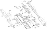
- FIG. 7is an exploded view of the terminal device shown in FIG. 2 at a viewing angle (observed from the side where the display screen is set);
- FIG. 8is an exploded view of the terminal device shown in FIG. 2 at another viewing angle (observed from the side where the shaft cover is provided);
- Fig. 9is an exploded view of a base and a shaft cover in some embodiments of the present application.
- Fig. 10is a partial view of the base and shaft cover shown in Fig. 9;
- Fig. 11is an A-A sectional view of the terminal device in Fig. 2;
- Fig. 12is an A-A sectional view of the terminal device in Fig. 2 in a folded state
- Fig. 13is a schematic structural view of the rotating shaft mechanism in some embodiments of the present application at a viewing angle (observed from the side where the display screen is installed) when it is in an unfolded state;
- Fig. 14is a structural schematic view from another angle of view (observed from the side where the shaft cover is installed) when the shaft mechanism in some embodiments of the present application is in the unfolded state;
- Fig. 15is a schematic structural view of the hinge mechanism in some embodiments of the present application when it is in a folded state (with a pair of first swing arm and second swing arm removed);
- Fig. 16ais a structural schematic diagram of the rotating shaft mechanism in Fig. 15 under another viewing angle
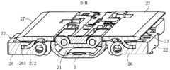
- Fig. 16bis a B-B sectional view of the shaft mechanism in Fig. 14 when the shaft cover is not removed;
- Fig. 16cis a B-B cross-sectional view of the shaft mechanism in Fig. 14 when it is in a folded state and the shaft cover is not removed;
- Fig. 17is a partial view at one end (upper left end) of the rotating shaft mechanism in Fig. 13;
- Fig. 18is a partial view at one end (upper left end) of the rotating shaft mechanism in Fig. 14;
- Fig. 19is a partial view at one end (upper left end) of the rotating shaft mechanism in Fig. 15;
- Figure 20ais an exploded view of the first swing arm, the second swing arm, the base and the shaft cover in Figure 17;
- Figure 20bis an exploded view of the second swing arm and base in Figure 17;
- Fig. 20cis a C-C sectional view of the shaft mechanism in Fig. 14 when the shaft cover is not removed;
- Fig. 20dis a C-C cross-sectional view of the shaft mechanism in Fig. 14 in the folded state and without removing the shaft cover;
- Fig. 21is a schematic diagram of the connection between the toggle member and the shaft cover in some embodiments of the present application.
- Fig. 22is a schematic structural diagram of the connection between the toggle and the rotating shaft in some embodiments of the present application.
- Fig. 23is a cross-sectional view of the connection relationship between the base, the shaft cover and the toggle in some embodiments of the present application;
- Fig. 24is a cross-sectional view of the connection between the rotating shaft and the first swing arm in some embodiments of the present application.
- Fig. 25is a schematic diagram showing changes in the positional relationship of the shaft cover driven by the toggle part during the rotation of the shaft in some embodiments of the present application;
- Fig. 26is a schematic diagram of the relationship between the rotation angle of the first swing arm and the lifting amount of the shaft cover in some embodiments of the present application;
- Fig. 27is a schematic diagram when the concave cavity is a round hole in some embodiments of the present application.
- Fig. 28is a schematic diagram of the installation relationship between the toggle member and the shaft cover in some embodiments of the present application.
- Fig. 29is a schematic diagram of the installation relationship between the toggle member and the shaft cover in other embodiments of the present application.
- Fig. 30is a partial view of the middle part of the rotating shaft mechanism in Fig. 13;
- Fig. 31is a partial view of the middle part of the rotating shaft mechanism in Fig. 14;
- Fig. 32is a partial view of the middle part of the rotating shaft mechanism in Fig. 15;
- Figure 33is an exploded view of the first swing arm, the second swing arm, the base and the shaft cover in Figure 30;
- Figure 34is an exploded view of the second swing arm and the base in Figure 17;
- Fig. 35is a schematic diagram of a toggle member in some embodiments of the present application.
- Fig. 36is an exploded view of the first swing arm and base in Fig. 30 .
- first and secondare used for description purposes only, and cannot be understood as indicating or implying relative importance or implicitly indicating the quantity of indicated technical features.
- a feature defined as “first” and “second”may explicitly or implicitly include one or more of these features.
- the terminal device in this embodiment of the present applicationmay be a foldable terminal device such as a mobile phone, a tablet computer, or a notebook computer.
- a mobile phoneas an example to illustrate the specific structure of the folding mechanism in the terminal device.
- Other terminal devicescan be configured with reference to the folding mechanism in the mobile phone embodiment, and details will not be repeated here.
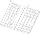
- Figure 1is a schematic structural diagram of a terminal device (mobile phone) in an unfolded state in some embodiments of the present application
- Figure 2is a schematic structural diagram of the terminal device in Figure 1 after the display screen 200 is removed
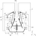
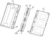
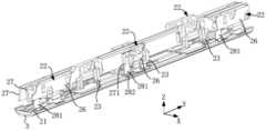
- the terminal deviceincludes a hinge mechanism 120, a body, and a display screen 200.
- the bodyincludes more than two sub-frames 11 arranged adjacently.
- the sub-body 11is used to carry the display screen 200.
- the hinge mechanism 120is arranged at the junction of the two sub-frames 11, so that the two sub-frames 11 can be switched between an unfolded state (as shown in FIG. 2 ) and a folded state (as shown in FIG. 4 ).
- the whole formed by the hinge mechanism 120 and the sub-body 11may also be referred to as a “folding mechanism 100 ”, that is, the terminal device includes a folding mechanism 100 and a display screen 200 .
- the outer contour of the terminal deviceis roughly rectangular when the two sub-body 11 are in the unfolded state.
- an XYZ coordinate systemis established for the terminal device with the two sub-body 11 in the unfolded state. direction"
- the above-mentioned X directionis not limited to the single direction indicated by the X-axis arrow in Figure 1, and should be understood as positive and negative directions parallel to the X-axis, that is, including the positive direction of the X-axis and the negative direction of the X-axis, and the same for the Y and Z directions.
- the setting of the coordinate system of the terminal devicecan be flexibly set according to actual needs, which is not specifically limited here.
- each sub-body 11is a shell structure.
- the sub-body 11can be a middle frame.
- the sub-body 11includes a bottom wall 12 (also called a "cover") and a side wall 13 arranged on the edge of the bottom wall 12.
- the bottom wall 12 and the side wall 13 of the two sub-body 11together form an installation space 10.
- the display screen 200is arranged in the installation space 10.
- the display screen 200when the two sub-body 11 are in the unfolded state, the display screen 200 is unfolded, and the display area of the display screen 200 is exposed to display image information to the user.
- the display screen 200includes a first display area 210 , a second display area 220 and a third display area 230 .
- the first display area 210covers the body bottom wall 12 of one sub-body 11
- the second display area 220covers the body bottom wall 12 of the other sub-body 11
- the third display area 230covers the hinge mechanism 120 .
- the above-mentioned display screen 200may all have a flexible screen structure.
- the first display area 210, the second display area 220, and the third display area 230 of the display screen 200are all of a flexible screen structure;
- the two sub-body 11when the two sub-body 11 is in the folded state, the two sub-body 11 are stacked, and the display screen 200 is folded between the two sub-body 11 at this time, which can facilitate the portability of the terminal device.
- the first display area 210 and the second display area 220 of the display screen 200are stacked.
- "stacked"means that the thickness directions of the first display area 210 and the second display area 220 are parallel or roughly parallel (for example, the deviation is within 30°), wherein the first display area 210 and the second display area 220 can be pasted together, or there may be a gap between the first display area 210 and the second display area 220, which is not specifically limited here.
- the third display area 230When the two sub-body 11 are in the folded state, the third display area 230 is folded into a water drop shape.
- the third display area 230includes an arc segment 233 , a first transition segment 231 and a second transition segment 232 .
- the first transition section 231is connected between the arc section 133 and the first display area 210 .
- the second transition section 232is connected between the arc section 233 and the second display area 220 . As shown in FIG.
- the first transition section 231 and the second transition section 232are in a figure-eight shape, that is, the distance between the end of the first transition section 231 connected to the first display area 210 and the end of the second transition section 232 connected to the second display area 220 is the third distance, the distance between the end of the first transition section 231 connected to the arc section 233 and the end of the second transition section 232 connected to the arc section 233 is the fourth distance, and the fourth distance is greater than the third distance.
- the third display area 230 of the display screen 200can also be folded into other shapes according to actual needs, which is not limited in the present application.
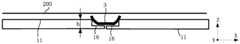
- the hinge mechanism 120includes a shaft cover 3.
- the shaft cover 3is used as an appearance part (that is, an externally visible part) of the hinge mechanism 120 to cover the moving parts in the hinge mechanism 120 (not shown in the figure), so as to ensure the appearance of the folding screen device and prevent the movement of the moving parts in the hinge mechanism 120 from being disturbed by the outside.
- both sub-body 11have an overlapping portion 16.
- FIG.There is a certain amount of overlap h (also referred to as an overlap amount) between the overlapping portion 16 and the shaft cover 3.
- the overlap amount hgradually decreases; when the two sub-frames 11 move from the folded state to the unfolded state, the overlap amount h gradually increases.
- the minimum overlap amountis the overlap amount when the two sub-body bodies 11 are in the folded state.
- the minimum overlap amountshould be greater than or equal to 0 millimeters (mm). If the overlapping amount h of the lap joint 16 and the shaft cover 3 is insufficient, it will cause the lap joint 16 to separate from the shaft cover 3 when the two sub-body 11 is in the folded state, that is, the shaft cover 3 is located outside the gap 14 formed by the two lap joints 16. It is easy to fall on the moving parts inside the shaft cover 3 to affect its normal work.
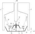
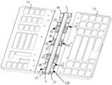
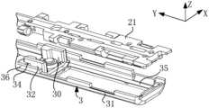
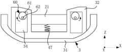
- the shaft mechanism 120includes a shaft cover 3, a base 21 (also called a “rotation shaft base”), a swing arm 22 and a connection assembly 6 (also referred to as a "connection mechanism” or a “transmission mechanism”).
- the swing arm 22 of the shaft mechanism 120drives the shaft cover 3 to move relative to the base 21 through the connection assembly 6 to "lift" the shaft cover 3, so that when the terminal device is in the folded state, the overlap between the shaft cover 3 and the sub-body 11 is increased, thereby reducing the gap between the shaft cover 3 and the sub-body 11, so that the shaft cover 3 can effectively prevent external water, dust, etc. from entering the interior of the terminal device.
- the shaft cover 3includes a shaft cover wall 31, and the shaft cover wall 31 encloses an accommodating space 35.
- the cross section of the shaft cover wall 31can also be U-shaped, semi-circular, arc-shaped, etc., which can be set according to actual conditions.
- the base 21is used to support part of the display screen 200, specifically, the base 21 is used to support the third display area 230 of the display screen 200 of the terminal device shown in FIG.
- a part of base 21(or all of it, of course) is arranged in accommodating space 35, and swing arm 22 is rotatably connected to base 21, and swing arm 22 is also directly or indirectly movably connected to sub-body 11, so that when folding or unfolding display screen 200, swing arm 22 can rotate relative to the base with the rotation of sub-body 11, and simultaneously drive shaft cover 3 to "lift" along a direction close to base 21 during the rotation.
- the swing arm 22is slidably connected to the sub-body 11.
- the swing arm 22is provided with a sliding fitting part b
- the sub-body 11is provided with a groove a
- the sliding fitting part bis slidably fitting with the groove a.
- the sliding fitting part bcan be in the shape of a plate, a column, a ball, etc., and is not specifically limited here.
- the sliding connection between the swing arm 22 and the sub-body 11is to make the degree of freedom of the mechanism formed by the sub-body 11, the base 21, and the swing arm 22 be 1, that is, to rotate within the plane defined by the X direction and the Z direction, so as to ensure that the two sub-body 11 can be unfolded and folded smoothly, and avoid problems such as display screen distortion during folding and unfolding.
- the two swing arms 22are symmetrically arranged on opposite sides of the base 21, and the two swing arms 22 are slidably connected to the two sub-body 11 respectively, and the two swing arms 22 can be rotatably connected to the base 21.
- the two swing arms 22are both in the unfolded position, as shown in FIG. 6 a , and when the two sub-body 11 are in the folded state, the two swing arms 22 are both in the folded position.
- the swing arm 22rotates correspondingly to the folded position relative to the base 21, and when the two sub-body 11 switches to the unfolded state, the swing arm 22 rotates correspondingly to the unfolded position relative to the base 21.
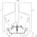
- the connecting assembly 6is connected between the swing arm 22 and the shaft cover 3 , and is the main component for the swing arm 22 to drive the shaft cover 3 to move.
- the connecting assembly 6includes a winding roller 642 , a connecting wire 641 and a rotating shaft 625 .
- the swing arm 22is rotatably connected to the base 21 through the rotating shaft 625, the winding roller 642 is sleeved on the rotating shaft 625, the end of the connecting wire 641 close to the base 21 is wound on the winding roller 642, and the end of the connecting wire 641 away from the base 21 is connected to the shaft cover 3.
- a reset member 47is provided between the base 4 and the shaft cover 3, and the reset member 47 is used to apply to the shaft cover 3 a reset force that can make the shaft cover 3 move relative to the base 4 in a direction away from the base 21 (downward direction in the figure).
- the reset member 47is a spring, and the spring is in a compressed state, one end of the spring abuts against the base 21 , and the other end of the spring abuts against the shaft cover 3 .
- "abutting”here refers to point contact, line contact or surface contact between two components, for example, point contact, line contact or surface contact between the spring and the base 21 and shaft cover 3 .
- the above-mentioned reset member 47may be provided with one or more than one, which is not specifically limited here.
- reset member 47is also suitable for use in conjunction with the connection assembly 6 of other structures.
- the reset member 47 in FIG. 6acan be used.
- the swing arm 22rotates clockwise with the sub-body 11 (that is, rotates to the folded position relative to the base 21), and the rotating shaft 625 drives the winding roller 642 to rotate clockwise, so that the connecting wire 641 is gradually wound on the winding roller 642, so as to drive the shaft cover 3 to move in a direction close to the base 21 (the upward direction in the figure is also the positive direction of the Z axis), so as to realize the "lifting" of the shaft cover 3.
- the swing arm 22swings counterclockwise with the sub-body 11 (that is, rotates relative to the base 21 to the unfolded position), and drives the winding roller 642 to rotate counterclockwise through the rotating shaft 625 to loosen the connecting wire 641 wound on the winding roller 642. fall".
- the movement of the shaft cover 3 in a direction close to the base 21means that the movement of the shaft cover 3 causes the base 21 to protrude into the accommodation space 35 relative to the shaft cover 3 .
- the movement of the shaft cover 3 away from the base 21means that the movement of the shaft cover 3 makes the base 21 protrude out of the receiving space 35 relative to the shaft cover 3 .
- the base 21as a position reference, based on the azimuth relationship shown in FIG. 6 a , the shaft cover 3 moves in a direction close to the base 21 , that is, moves upward.
- the movement of the shaft cover 3 in a direction away from the base 21is a downward movement.
- the upward movement and the downward movement of the shaft cover 3can be a movement along a first direction (the Z-axis direction in the figure), and the first direction is perpendicular to the width direction of the shaft cover 3 (the X-axis direction in the figure) and the length direction of the shaft cover 3 (the Y-axis direction in the figure).
- the trajectory of the upward movement or downward movement of the shaft cover 3is not limited to being parallel to the first direction, and may also be inclined at a certain angle relative to the first direction, such as within 10°. It should be noted that when the upward or downward trajectory of the shaft cover 3 is inclined at an angle less than 5° relative to the first direction, it can be considered that the shaft cover 3 moves along the first direction.
- each swing arm 22is connected to the shaft cover 3 through a connecting assembly 6, which increases the number of connection points between the shaft cover 3 and the swing arm 22.
- the two swing arms 22are respectively connected to the shaft cover 3 through the connecting assembly 6, so as to drive the shaft cover 3 to move upward. In this way, the force of the shaft cover 3 is relatively balanced when it moves, so that the upward movement of the shaft cover 3 is relatively stable.
- connection assembly 6can also be provided, and the connection assembly 6 is connected between a swing arm 22 and the shaft cover 3, so that when the swing arm 22 rotates from the unfolded position to the folded position, the shaft cover 3 can also be driven to move upward through a connection assembly 6.
- the shaft cover 3in order to make the shaft cover 3 move more smoothly driven by the connecting assembly 6, the shaft cover 3 is slidingly connected with the base 3 along the Z-axis direction (that is, there is a sliding constraint between the shaft cover 3 and the base 21 in the Z-axis direction).
- the shaft cover 3is provided with a slide bar (shown by the symbol c1 in the figure), and the base 21 is provided with a slide hole (shown by the label c2 in the figure), and the slide bar is slidably matched with the slide hole.
- a designcan avoid shaking when the swing arm 22 drives the shaft cover 3 close to the base 21 , so that the movement of the shaft cover 3 is more stable.
- FIG. 6bis a schematic diagram of the terminal device in the second embodiment of the present application.
- the connecting assembly 6includes a connecting rod 65 , one end of the connecting rod 65 is rotatably connected to the swing arm 22 , and the other end of the connecting rod 65 is rotatably connected to the shaft cover 3 .
- the connecting rod 65 and the sub-body 11as an example to illustrate the folding and unfolding process of the terminal device in the embodiment of the present application: during the switching process of the two sub-body 11 to the folded state, the swing arm 22 rotates counterclockwise relative to the base 21, and drives the shaft cover 3 to move in a direction close to the base 21 through the connecting rod 65 (the upward direction in the figure), so as to realize the "lifting" of the shaft cover 3;
- the base 21rotates, and while the swing arm 22 rotates clockwise, the connecting rod 65 drives the shaft cover 3 to move away from the base 21 (downward direction in the figure), so as to realize the "falling" of the shaft cover 3.
- FIG. 6cis a schematic diagram of the terminal device in the third embodiment of the present application.
- the connecting assembly 6includes a rotating shaft 625 , a gear 661 and a rack 662 .
- the swing arm 22is rotatably connected to the base 21 through the rotation shaft 625.
- the swing arm 22is relatively fixed to the rotation shaft 625 in the circumferential direction of the rotation shaft 625.
- the gear 661is sleeved on the rotation shaft 625.
- the rack 662is fixedly connected to the shaft cover 3. One end of the rack 662 is set close to the base 21, and the other end of the rack 662 is set away from the base 21.
- the gear 661 and the rack 662are meshed. Exemplarily, the rack 662 extends along the Z axis.
- the swing arm 22swings clockwise with the sub-body 11, and drives the gear 661 to rotate clockwise through the rotating shaft 625, and then the gear 661 drives the shaft cover 3 to move in a direction close to the base 21 through the rack 662 (the upward direction in the figure), so as to realize the "lifting" of the shaft cover 3.
- the swing arm 22swings counterclockwise with the sub-body 11, and drives the gear 661 to rotate counterclockwise through the rotating shaft 625, and then the gear 661 drives the shaft cover 3 to move away from the base 21 (downward direction in the figure) through the rack 662, so as to realize the "falling" of the shaft cover 3.
- FIG. 6dis a schematic diagram of the terminal device in the fourth embodiment of the present application.
- the swing arm 22is rotatably connected to the base 21 through a rotating shaft 625
- the connection assembly 6includes a toggle member 60 .
- the toggle 60is connected to the position where the swing arm 22 deviates from the axis O1 of the rotating shaft 625, and the toggle 60 is connected to the upper limit of the shaft cover 3 in the Z-axis direction (that is, the first direction), that is, the toggle 60 can drive the shaft cover 3 to move in the Z-axis direction.
- a part of the toggle 60is connected to the swing arm 22, and the other part is connected to the shaft cover 3.
- the toggle 60is driven to rotate, and the part where the toggle 60 is connected to the shaft cover 3 can realize the conversion of rotation and translation, so that it can directly or indirectly drive the shaft cover 3 to move in the Z direction during the rotation.
- the toggle member 60is a convex structure, and the toggle member 60 is columnar and parallel or approximately parallel to the rotation axis 625 (the deviation is within 5°).
- the shaft cover 3is provided with a groove c3, which extends along the X-axis direction (that is, the width direction of the shaft cover 3), and the toggle member 60 extends into the groove c3, so that the toggle member 60 can slide relative to the groove c3 along the X-axis direction.
- the toggle member 60may be directly connected to the swing arm 22 , and the toggle member 60 is connected to the swing arm 22 through clamping, screwing, bonding, plugging and the like.
- the toggle member 60may also be indirectly connected to the swing arm 22, as shown in FIG. 6e, which is a schematic diagram of the terminal device in the fifth embodiment of the present application.
- the toggle member 60is connected to the swing arm 22 through a swing arm link 69.
- One end of the swing arm link 69is fixedly connected to the swing arm 22, and the other end of the swing arm link 69 is connected to the toggle member 60.
- the toggle piece 60can be connected to the end of the swing arm connecting rod 69 by clamping, screwing, bonding, inserting and other means.
- the swing arm link 69 and the swing arm 22are integrally structured, but it is not limited thereto.
- the swing arm link 69 and the swing arm 22can also be arranged separately and fixedly connected by fasteners such as screws.
- FIG. 6fis a schematic diagram of the terminal device in the sixth embodiment of the present application.
- the main difference between this embodiment and the embodiments shown in FIG. 6d and FIG. 6eis that the structure of the toggle member 60 is different.
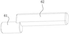
- the toggle member 60includes a rotating shaft 62 and an eccentric portion 61 arranged eccentrically relative to the rotating shaft 62.
- the eccentric portion 61is columnar, and the central axis of the eccentric portion 61 is not coaxially arranged with the central axis of the rotating shaft 62.
- the above-mentioned eccentric part 61may be an eccentric mass, an eccentric column, an eccentric wheel, etc., and is not specifically limited here.
- the sub-body 11rotates counterclockwise relative to the base 4, thereby driving the swing arm 22 to rotate counterclockwise, and the rotating shaft 62 also rotates counterclockwise to drive the eccentric part 61 to move downward to the left.
- the downward movement component of the eccentric part 61drives the shaft cover 3 to move in a direction away from the base 21 (that is, the downward direction in the figure), so as to realize the "downward" movement of the shaft cover 3.
- the toggle member 60rotates with the swing arm 22 to drive the shaft cover 3 to move towards the base 21 .
- the eccentric part 61 and the rotating shaft 62are arranged eccentrically, so that when the swing arm 22 drives the rotating shaft 62 to rotate, the movement track of the eccentric part 61 occupies a relatively small space and is not likely to interfere with other components.
- FIG. 6gwhich is a schematic diagram of the terminal device in the seventh embodiment of the present application
- the main difference between the embodiment shown in FIG. 6g and the embodiment shown in FIG. 6flies in the structure of the swing arm 22 .
- the swing arm 22includes a first swing arm 26 (also called a master swing arm) and a second swing arm 23 (also called a slave swing arm) both rotatably connected to the base 21.
- the first swing arm 26is fixedly connected to the sub-body 11, and the first swing arm 26 is also slidingly connected to the second swing arm 23.
- the second swing arm 23is connected to the shaft cover 3 through the connecting assembly 6 , the second swing arm 23 has an unfolded position and a folded position, and the first swing arm 26 can drive the second swing arm 23 to rotate relative to the base 21 between the unfolded position and the folded position.
- the first swing arm 26can drive the second swing arm 23 to rotate relative to the base 21 between the unfolded position and the folded position.
- the first swing arm 26swings counterclockwise with the sub-body 11 , and through the sliding constraint between the first swing arm 26 and the second swing arm 23 , the first swing arm 26 drives the second swing arm 23 to swing counterclockwise while swinging, and then drives the shaft cover 3 to move relative to the base 21 in a direction away from the base 21 through the toggle member 60 to realize the "down" of the shaft cover 3 .
- the first swing arm 26is fixedly connected to the sub-body 11, and the first swing arm 26 and the second swing arm 23 are slidably connected, so that the degree of freedom of the mechanism formed by the sub-body 11, the first swing arm 26, the second swing arm 23, and the base 21 is 1, thereby ensuring that the two sub-body 11 can be unfolded and folded smoothly, and that the base and the shaft cover move relatively along the first direction to prevent the shaft cover from shaking relative to the base.
- the sub-body 11does not need to be provided with a sliding connection structure connected to the swing arm 22, thereby simplifying the connection between the swing arm 22 and the sub-body 11, thereby improving the reliability of the connection between the swing arm 22 and the sub-body 11.
- FIG. 6dis a schematic diagram of the terminal device in the eighth embodiment of the present application.
- connection relationship between the first swing arm 26, the base 21, and the second swing arm 23it can be set with reference to the method in FIG. 6g , and will not be repeated here.
- the swing arm 22drives the toggle member 60 to move, and then the toggle member 60 drives the shaft cover 3 to "lift", so that the connection structure between the connecting assembly 6 and the shaft cover 3 is relatively simple, and the number of parts of the connecting assembly 6 is relatively small, which not only helps reduce costs, but also improves the reliability of the connection between the connecting assembly 6 and the shaft cover 3.
- the connecting assembly 6can not only drive the shaft cover 3 to move relative to the base 21 in a direction close to the base 21 to achieve "lifting" of the shaft cover 3, but also drive the shaft cover 3 to move relative to the base 21 in a direction away from the base 21 to achieve "down" of the shaft cover 3, so that the movement of the shaft cover 3 can be better controlled, and there is no need for an additional reset member to reset the shaft cover 3, which is conducive to improving the reliability of the movement of the shaft cover 3.
- the angle deviationranges from 0 to 20 degrees, and within this angle deviation range, it can still be regarded as synchronous motion.
- other synchronization mechanismscan be set to achieve corresponding synchronization effects.
- FIG. 6iis a schematic diagram of the terminal device in the ninth embodiment of the present application.
- the hinge mechanism 120 shown in FIG. 6iadds a support member 27 and a third swing arm 281 on the basis of the hinge mechanism 120 shown in FIG. 6g.
- the rotating shaft mechanism 120further includes a support 27 and a third swing arm 281.
- One side of the support 27has an installation space 10 for setting the display screen 200.
- the swing arm 22is arranged on the side of the support 27 away from the installation space 10.
- the support 27is rotatably connected to the swing arm 22, specifically, the support 27 is rotatably connected to the first swing arm 26.
- the third swing arm 281is rotatably connected to the base 21 , and the third swing arm 281 is also slidably connected to the support member 27 .
- the support member 27is provided with a fitting groove 271 , and the third swing arm 281 is slidingly engaged with the fitting groove 271 .
- the first swing arm 26can drive the support member 27 to swing relative to the base 21, so that the support member 27 can well support and protect the bending portion of the display screen 200 (the third display area 230 in FIG. 1 ).
- the degree of freedom of the mechanism formed by the sub-body 11, the first swing arm 26, the support member 27, the third swing arm 281 and the base 21is 1, thereby ensuring that the first swing arm 26 can smoothly drive the support member 27 to swing when the two sub-body bodies 11 are switched between folded states.
- the shape of the support member 27may be a plate structure, or a frame structure, etc., which is not specifically limited here.
- the support member 27may also be called a door panel, and correspondingly, the third swing arm 281 may also be called a door panel swing arm.
- connection assembly 6is connected between the swing arm 22 and the shaft cover 3.
- the swing arm 22rotates from the unfolded position to the folded position, the swing arm 22 can drive the shaft cover 3 to move in a direction close to the base 21 through the connection assembly 6, so as to "lift” the shaft cover 3, so as to increase the overlap between the shaft cover 3 and the sub-body 11 when the two sub-body 11 is in a folded state, thereby reducing the gap between the shaft cover 3 and the sub-body 11, so that the shaft cover 3 can be effectively Prevent external water, dust, etc. from entering the interior of the terminal equipment.
- FIGS. 6d to 6iThe principle diagram of the rotating shaft mechanism 120 shown in FIGS. 6d to 6i will be specifically described below in conjunction with the product structure diagram of the terminal device.
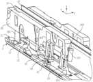
- FIG. 7is an exploded view of the terminal device shown in FIG. 2
- FIG. 8is an exploded view of the terminal device shown in FIG. 2 at another viewing angle (back view)
- FIG. 9is an exploded view of the base 21 and the shaft cover 3 in some embodiments of the present application
- FIG. 10is a partial view of the base 21 and the shaft cover 3 shown in FIG. 9
- FIG. 11is an A-A sectional view of the terminal device shown in FIG. 2
- FIG. viewis an exploded view of the terminal device shown in FIG. 2
- FIG. 8is an exploded view of the terminal device shown in FIG. 2 at another viewing angle (back view)
- FIG. 9is an exploded view of the base 21 and the shaft cover 3 in some embodiments of the present application
- FIG. 10is a partial view of the base 21 and the shaft cover 3 shown in FIG. 9
- FIG. 11is an A-A sectional view of the terminal device shown in FIG. 2
- FIG. viewis an A-A sectional view of the terminal device shown
- the shaft cover 3is slidably connected with the base 21 along the first direction (Z-axis direction in the figure).
- the first directionis perpendicular to the longitudinal direction of the shaft cover 3 (the Y-axis direction in the figure) and the width direction of the shaft cover 3 (the X-axis direction in the figure).
- the first directionis perpendicular to the length direction of the shaft cover 3 and the width direction of the shaft cover 3 , which can be absolutely vertical or approximately vertical, for example, the deviation is within plus or minus 5 degrees.
- the Z-axis directionis used to represent the first direction
- the width direction of the shaft cover 3is represented by the X-axis direction
- the length direction of the shaft cover 3is represented by the Y-axis direction.
- the shaft cover 3is provided with a limiting groove 30 that slides with the base 21.
- the groove depth direction of the limiting groove 30is parallel to the Z-axis direction. In this way, relative sliding can occur between the base 21 and the limiting groove 30 in the groove depth direction of the limiting groove 30, thereby realizing the sliding connection between the shaft cover 3 and the base 21 in the Z-axis direction in FIG. 6i.
- the groove depth direction of the limiting groove 30is parallel to the Z-axis direction, which can be understood as that the groove wall 30a of the limiting groove 30 along the groove width direction is parallel to the Z-axis direction, and the groove wall 30a and the Z-axis direction can be absolutely parallel or approximately parallel, for example, the deviation is within plus or minus 5 degrees.
- the limit groove 30By setting the limit groove 30 to cooperate with the base 21, when the shaft cover 3 is moving, the limit groove 30 can play a better guiding role for the shaft cover 3, so that the shaft cover 3 can move more smoothly along the Z-axis direction.
- the structure of the limiting groove 30is relatively strong, the structure of the limiting groove 30 of the shaft cover 3 is not easy to be damaged under the action of external force, thereby helping to improve the connection reliability between the shaft cover 3 and the base 21 .
- the sliding connectioncan also be realized through the cooperation of the holes and shafts.
- the base 21is provided with a sliding hole, and the sliding hole extends along the Z-axis direction.
- the shaft cover 3includes a shaft cover wall 31 and a shaft cover connector 32.
- the shaft cover wall 31encloses an accommodation space 35.
- a part (or all) of the shaft cover connector 32is arranged in the accommodation space 35.
- the shaft cover connector 32is detachably connected to the shaft cover wall 31.
- the shaft cover connector 32is slidably connected to the base 21 along the Z-axis direction. 30 slip fit.
- the shaft cover connector 32is detachably connected to the shaft cover wall 31 through fasteners (such as screws), but it is not limited thereto.
- the cross-section of the shaft cover wall 31is U-shaped, but it is not limited thereto, and the cross-section of the shaft cover wall 31 may also be arc-shaped or other shapes.
- there are multiple shaft cover connectors 32such as three, and the plurality of shaft cover connectors 32 are arranged at intervals along the Y-axis direction.
- Such a designcan make there are multiple connection points between the shaft cover 3 and the base 21.
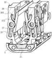
- Figure 13is a schematic structural view of the rotating shaft mechanism 120 in some embodiments of the present application (remove the support member 27 on one side) in an unfolded state at one viewing angle (observed from the side where the display screen 200 is installed)
- Figure 14is a structural schematic diagram of the rotating shaft mechanism 120 in some embodiments of the present application when it is in an unfolded state at another viewing angle (observed from the side where the shaft cover 3 is installed)
- Figure 15is a schematic structural view of the rotating shaft mechanism 120 in some embodiments of the present application when it is in a folded state.
- Fig. 16ais a schematic structural view of the rotating shaft mechanism 120 in Fig. 15 at another viewing angle.
- swing arms 22are respectively provided at the two side edges of the shaft cover 3 .
- the number of connection points between the shaft cover 3 and the connecting assembly 6 in the width direction Xcan be increased, and the force on the shaft cover 3 in the width direction X can be more balanced, so that the movement of the shaft cover 3 driven by the connecting assembly 6 is more stable.
- the swing arm 22includes a first swing arm 26 and a second swing arm 23. Both the first swing arm 26 and the second swing arm 23 are rotatably connected to the base 21.
- the first swing arm 26is used to be fixedly connected to the sub-body 11.
- the first swing arm 26can be fixedly connected to the sub-body 11 by fasteners such as screws.
- the shaft cover 3can have multiple connection points with the connecting assembly 6 in its length direction Y, and the force on the shaft cover 3 in its length direction Y is relatively uniform, so that the movement of the shaft cover 3 driven by the connection assembly 6 is more stable.
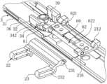
- FIG. 15 and FIG. 16 athere are three swing arms 22 located at the same side edge of the shaft cover 3 , and the three swing arms 22 are respectively arranged at the two ends and the middle of the shaft cover 3 .
- the number of the swing arm 22 located at the same side edge of the shaft cover 3may also be one, and the swing arm 22 is arranged at the middle position of the shaft cover 3 along the longitudinal direction Y thereof.
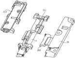
- FIG. 17is a partial view at one end (upper left end) of the rotating shaft mechanism 120 in FIG. 13
- FIG. 18is a partial view at one end (upper left end) of the rotating shaft mechanism 120 in FIG. 14
- FIG. 19is a partial view at one end (upper left end) of the rotating shaft mechanism 120 in FIG. 15 .
- Figure 20bis an exploded view of the first swing arm 26 and the base 21 in Figure 17
- Figure 21is a schematic diagram of the connection between the toggle part 61 and the shaft cover 3 in some embodiments of the present application
- Figure 22is a schematic structural view of the toggle 60 in some embodiments of the present application
- Figure 23is a cross-sectional view of the connection relationship between the base 21, the shaft cover 3 and the toggle 60 in some embodiments of the present application.
- the swing arm 22includes a first swing arm 26 and a second swing arm 23, the first swing arm 26 is fixedly connected to the sub-body 11, the first swing arm 26 and the second swing arm 23 are rotatably connected to the base 21, the second swing arm 23 has an unfolded position and a folded position, the first swing arm 26 is connected to the second swing arm 23 through the first connection structure 24, so that the first swing arm 26 drives the second swing arm 23 in the unfolded position (as shown in Figure 17 and Figure 18 ) and the folded position (As shown in FIG. 19 ) rotate relative to the base 21.
- first swing arm 26can be fixedly connected to the sub-body 11 by fasteners (such as screws), but it is not limited thereto.
- the first swing arm 26 and the sub-body 11can also be fixedly connected by clipping, plugging, etc.
- the first swing arm 26can be rotatably connected to the base 21 through the following structure.
- FIG. 20cis a C-C sectional view of the rotating shaft mechanism 120 in FIG.
- the base 21is provided with a first arc-shaped groove 210
- the first swing arm 26is provided with a first arc-shaped piece 263 . Due to the sliding fit between the first arc-shaped piece 263 and the first arc-shaped groove 210, the contact area between the first arc-shaped piece 263 and the first arc-shaped groove 210 is larger.
- the base 21includes a base body 211 and a base connector 214 detachably connected to the base body 211 , the base body 211 and the base connector 214 enclose a first arc-shaped groove 210 .
- the first arc-shaped slot 210can be easily disassembled, thereby facilitating the cleaning inside the first arc-shaped slot 210 and the installation and disassembly of the first swing arm 26 .
- the first arc-shaped groove 210can be formed by the following structure, as shown in Figure 20a and Figure 20b, the base body 211 is provided with an arc-shaped convex surface a, the base connector 214 is provided with a cavity, and the cavity has an arc-shaped wall b, when the base 21 connector is installed on the base body 211, the first arc-shaped groove 210 is formed between the arc-shaped convex surface a and the arc-shaped wall b of the cavity.
- the base body 211 and the base connector 214are detachably connected by fasteners (such as screws), but it is not limited thereto.
- the base body 211 and the base connector 214can also be detachably connected by clamping, plugging, etc.
- the first connection structure 24is not unique.
- the first connection structure 24includes a sliding groove 232 and a sliding portion 261.
- the sliding groove 232is arranged on the second swing arm 23, and the sliding portion 261 is arranged on the first swing arm 26; one end of the sliding groove 232 is arranged close to the base 21, and the other end of the sliding groove 232 is arranged away from the base 21. 23 Slide to connect.
- the sliding portion 261may be columnar, block-shaped, etc., and is not specifically limited here.
- the sliding portion 261may be disposed on the first swing arm 26 through a mounting hole.
- the setting positions of the above-mentioned chute 232 and the sliding portion 261can also be mutually reversed, that is: the second swing arm 23 is provided with a sliding portion 261, and the first swing arm 26 is provided with a chute 232, and this design can also realize the sliding connection between the second swing arm 23 and the first swing arm 26.
- first connecting structure 24is not limited to the chute 232 and the sliding portion 261, and may also be a transmission link, one end of the transmission link is hinged to the first swing arm 26, and the other end of the drive link is hinged to the second swing arm 23, so that the first swing arm 26 can drive the second swing arm 23 to rotate relative to the base 21 in the unfolded position and the folded position.
- the first swing arm 26is provided with an avoidance opening 262 , and the second swing arm 23 extends into the avoidance opening 262 .
- Such a designcan make the second swing arm 23 and the first swing arm 26 more compact, reducing the overall occupied space of the second swing arm 23 and the first swing arm 26 .
- the connection assembly 6includes a toggle member 60.
- the toggle member 60(also referred to as a crank toggle member) includes a rotating shaft 62 and an eccentric portion 61 arranged eccentrically with the rotating shaft 62.
- the swing arm 22is rotatably connected to the base 21 through the rotating shaft 62.
- the eccentric portion 61is arranged eccentrically with respect to the rotating shaft 62, and the rotating shaft 62 is relatively fixed to the swing arm 22 in its circumferential direction.
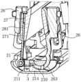
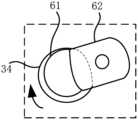
- the shaft cover 3is provided with a concave cavity 34, and the eccentric portion 61 extends into the concave cavity 34, and the eccentric portion 61 can move in the concave cavity 34 along the X-axis direction.
- the second swing arm 23is connected to the rotating shaft 62 .
- the concave cavity 34has a first inner wall 341 and a second inner wall 343 opposite to each other, and both the first inner wall 341 and the second inner wall 343 abut against the eccentric portion 61 .
- the second swing arm 23 on the leftrotates counterclockwise (that is, when it rotates to the unfolded position)
- the second swing arm 23drives the rotating shaft 62 to rotate counterclockwise, and the eccentric part 61 moves downward to the left under the drive of the rotating shaft 62, and is pressed against the second inner wall 343 on the lower side, so that the eccentric part 61 drives the shaft cover 3 to move downward to move away from the base 21, so as to realize the "falling" of the shaft cover 3.
- first inner wall 341 and the second inner wall 343 of the concave cavity 34are arranged oppositely, and the first inner wall 341 and the second inner wall 343 may be arranged in parallel or non-parallel.
- first inner wall 341 and the second inner wall 343are not limited to flat surfaces.
- the abutment of the first inner wall 341, the second inner wall 343 and the eccentric part 61is specifically that there is point contact, line contact or surface contact between the first inner wall 341, the second inner wall 343 and the eccentric part 61.
- an acting forcecan be generated between the eccentric part 61 and the first inner wall 341 or the second inner wall 343.
- the eccentric part 61 and the first inner wall 341 or the second inner wall 3There can be no force between 43. It can be understood that due to the existence of manufacturing tolerances, there is a certain deviation between the actual size of the eccentric portion 61 and the ideal size, so that at least one of the first inner wall 341 and the second inner wall 343 may be separated from the eccentric portion 61 (that is, not in contact).
- the eccentric part 61By abutting the first inner wall 341 and the second inner wall 343 with the eccentric part 61, when the rotating shaft 61 drives the eccentric part 61 to rotate, the eccentric part 61 can drive the shaft cover 3 to move toward the direction close to the base 21 to "lift” the shaft cover, and can also drive the shaft cover 3 to move in a direction away from the base 21 to "fall” the shaft cover 3, that is, the eccentric part 61 can apply force to the shaft cover 3 in "two directions".
- Assembly 6has a simpler structure and fewer parts.
- the degree of freedom of the mechanism formed between the second swing arm 23, the toggle piece 60 and the shaft cover 3can be 1, so that the toggle piece 60 can drive the shaft cover 3 to "lift” while rotating.
- the eccentric department 61can keep contact with the first inner wall 341 and the second inner wall 342 of the Caval 34. Try to avoid the starting stage or end of the swing arm 22. The movement of the arm 33 rises or decreases behind, and then moves the shaft cover 3 in the process of folding and expanding the display screen smoothly and smoothly.
- the eccentric portion 61is a cylindrical structure protruding relative to the rotating shaft 62 , and the central axis of the eccentric portion 61 is parallel to but not coaxial with the central axis of the rotating shaft 62 .
- the movement track of the eccentric part 61takes up less space, so that the eccentric part 61 is less likely to interfere with the movement of surrounding components.
- the eccentric portion 61is a columnar convex structure, but it is not limited thereto, the eccentric portion 61 can also be designed as a conical convex structure, a conical convex structure, a spherical convex structure, etc., which can be determined according to actual conditions.
- the eccentric portion 61 and the rotating shaft 62are integrated. Such a design can not only improve the connection strength between the eccentric part 61 and the rotating shaft 62, so that the eccentric part 61 and the rotating shaft 62 are not easy to break, but also can reduce the number of parts of the rotating shaft mechanism 120, so as to facilitate the assembly of the rotating shaft mechanism 120.
- the eccentric part 61 and the rotating shaft 62can also be designed separately, and the eccentric part 61 and the rotating shaft 62 are connected together by means of screw connection, clip connection and the like.
- FIG. 25is a schematic diagram showing changes in the positional relationship of the shaft cover 3 driven by the eccentric portion 61 during the rotation of the shaft 62 in some embodiments of the present application. It can be seen from (a) to (d) in Figure 25 that during the clockwise rotation of the rotating shaft 62, the position of the eccentric portion 61 relative to the axis O1 of the rotating shaft 62 is gradually raised, and the eccentric portion 61 squeezes the inner wall of the cavity 34 during the gradual raising process, thereby raising the position of the shaft cover 3.
- FIG. 26shows the relationship between the rotation angle of the second swing arm 23 and the lifting amount of the shaft cover 3 in some embodiments of the present application.
- the rotation angle of the second swing arm 23is ⁇
- the eccentric distance between the axis O1 of the rotating shaft 62 and the axis O2 of the eccentric portion 61 (the eccentric portion 61 is cylindrical)is L
- the initial included angle between the axis O1 of the rotating shaft 62 and the axis O2 of the eccentric portion 61 (also called “crank”) and the horizontal planeis ⁇
- the elevation value of the shaft cover 3can be properly designed by properly designing the angle and length parameters.
- one end of the shaft cover connector 32is provided with an opening 342 communicating with the cavity 34 , and the opening 342 allows the eccentric portion 61 to extend into the cavity 34 .
- the eccentric portion 61can extend into the concave cavity 34 from the side of the concave cavity 34 , which can facilitate the eccentric portion 61 to extend into the concave cavity 34 , thereby improving the installation efficiency of the toggle member 60 .
- a limiting flange 36is provided on the shaft cover wall 31 , and the limiting flange 36 is disposed opposite to the opening 342 .
- the limiting flange 36acts as a stopper to restrict the eccentric portion 61 partially or completely in the cavity 34 , thereby preventing the eccentric portion 61 from completely moving out of the cavity 34 from the opening 342 during the rotation of the rotating shaft 62 .
- One concave cavity 34may be provided on the above-mentioned shaft cover connecting member 32, or a plurality of concave cavities 34 may be provided, which may be determined according to the arrangement position of the second swing arm 23. For example, as shown in FIG.
- FIG. 24is a cross-sectional view of the connection between the rotating shaft 62 and the second swing arm 23 in some embodiments of the present application.
- the rotating shaft 62includes a flat section 621 and a cylindrical section 622.
- the eccentric part 61, the flat section 621 and the cylindrical section 622are sequentially connected.
- the second swing arm 23is provided with a flat hole 235 matching the flat section 621, so that the rotating shaft 62 is relatively fixed to the second swing arm 23 in the circumferential direction.
- the second swing arm 23is also provided with a swing arm hole 231 matched with the cylindrical section 622;
- the base 21is provided with a base hole 216 for the flat section 621 and the cylindrical section 622 to pass through, and the shaft section of the flat section 621 exposed in the flat hole 235 and the shaft section of the cylindrical section 622 exposed in the swing arm hole 231 respectively penetrate into the corresponding base hole 216.
- the base holecan be a round hole, and the two base holes are close to the two sides of the second swing arm 23 , and the base 21 protrudes and defines the base hole at the position close to the two sides of the second swing arm 23 .
- Such a designmakes the structure of the toggle member 60 simple and compact, and takes up less space. While realizing the rotational connection between the second swing arm 23 and the base 21, the purpose of the second swing arm 23 driving the rotating shaft 23 to rotate to drive the eccentric portion 61 to rotate is also realized. Specifically, referring to FIG. 21 , due to the cooperation between the flat section 621 and the flat hole 235, the second swing arm 23 drives the eccentric part 61 to rotate. Due to the cooperation between the cylindrical section 622 and the base hole 216, especially when the base hole 216 is circular, the smooth rotation of the swing arm 22 based on the base 21 is realized. Moreover, the base hole 216 matched with the flat section 621 does not interfere with the flat section. .
- the side of the flat section 621has flat surfaces.
- the flat surfacesare arranged on opposite sides of the flat shaft section 621 .
- the flat surfacecan also be disposed on one, three or four sides of the flat shaft section 621 in the circumferential direction, which is not specifically limited here.
- the rotating shaft 62can also be fixed relatively to the second swing arm 23 in the circumferential direction of the rotating shaft 62 through a key connection.
- the above-mentioned eccentric portion 61can also be connected to a position on the second swing arm 23 that deviates from the axis of the rotating shaft 62 (as shown in FIG.
- the base 21includes a base body 211 and a shaft seat 212 detachably disposed on the base body 211 , and the rotating shaft 62 is rotatably disposed on the shaft seat 212 .
- the base hole 216is disposed on the shaft seat 212 .
- the shaft seat 212 and the base body 211are detachably connected together by fasteners (such as screws), but it is not limited thereto, and the shaft seat 212 and the base body 211 can also be detachably connected by clamping, plugging, etc.
- the cavity 34is disposed on the shaft cover connecting member 32 .
- the structure of the cavity 34can be repaired only by disassembling and replacing the shaft cover connector 32 , without replacing the entire shaft cover 3 , thereby reducing maintenance costs.
- the connecting position of the base 21 and the shaft cover 3is also on the shaft cover connector 32 , one thing can be used for multiple purposes, saving parts and design space.
- the above-mentioned concave cavity 34may be a groove or a hole, and the hole may be a round hole or a track hole, which is not specifically limited here.
- Fig. 27shows a schematic diagram of the cavity 34 in some embodiments of the present application when it is a circular hole.
- the shape of the cavity 34 in Fig. 23 and Fig. 25is designed as a circle, and other structures remain unchanged.
- the eccentric part 61can be in contact with the inner wall of the concave cavity 34, and the eccentric part 61 is pressed against the inner wall of the upper half of the concave cavity 34 to drive the shaft cover 3 to move in a direction close to the base 21, thereby realizing "lifting" of the shaft cover 3;
- the rotating shaft 62rotates counterclockwise under the drive of the second swing arm 23, and the eccentric part 61 abuts and squeezes against the inner wall of the lower half of the cavity 34, so as to drive the shaft cover 3 to move away from the base 21, thereby realizing the "dropping" of the shaft cover 3.
- the eccentric part 61can be an eccentric wheel in addition to the above-mentioned convex structure, as shown in Figure 28, and Figure 26 shows a schematic diagram of the installation relationship between the toggle member 60 and the shaft cover 3 in some embodiments of the present application.
- the cavity 34is a groove extending along the Z-axis direction.
- a reset member 47is provided between the base 21 and the shaft cover connecting member 32. The reset member 47 is used to apply a reset force to the shaft cover 3 to move the shaft cover 3 away from the base 21, so that the eccentric wheel contacts the upper inner wall of the cavity 34.
- the return member 47is a spring, and the spring is in a compressed state, one end of the spring is in contact with the shaft cover connecting member 32 , and the other end of the spring is in contact with the base 21 .
- the eccentric portion 61extends into the concave cavity 34 on the shaft cover 3 .
- the eccentric portion 61can move in the concave cavity 34 and abut against the inner wall of the concave cavity 34 to drive the shaft cover 3 to move toward the base 21 to “lift” the shaft cover 3 .
- the concave cavity 34acts as a limiter for the eccentric part 61, and the eccentric part 61 is not easy to disengage from the shaft cover 3, thereby improving the reliability of connection between the dial 60 and the shaft cover 3.
- the toggle member 60can also set the eccentric portion 61 of the aforementioned toggle member 60 as a cam, as shown in Figure 29.
- Figure 29shows a schematic diagram of the installation relationship between the toggle member 60 and the shaft cover 3 in other embodiments of the present application.
- the central axis of shaft 61is not coaxial.
- the shaft cover 3further includes an abutment flange 37 , which is arranged on the shaft cover wall 31 at one side edge of the shaft cover 3 along the width direction X of the shaft cover 3 .
- a reset member 47is provided between the base 21 and the shaft cover connector 32 , and the reset member 47 is used to apply a reset force to the shaft cover 3 to move the shaft cover 3 away from the base 21 , so that the cam abuts against the abutting flange 37 .
- the return member 47is a spring, and the spring is in a compressed state. One end of the spring abuts against the shaft cover wall 31 , and the other end of the spring abuts against the base 21 .
- the toggle member 60includes a rotating shaft 62 and an eccentric portion 61 eccentrically arranged relative to the rotating shaft 62 .
- the swing arm 22is rotatably connected to the base 21 through the rotating shaft 62 .
- the toggle member 60when the second swing arm 23 rotates from the unfolded position to the folded position, the toggle member 60 can rotate with the swing arm 22 to drive the shaft cover 3 to move in a direction close to the base 21, thereby realizing the "lifting" of the shaft cover 3.
- FIG. 30 to 36are schematic diagrams showing the structure and installation method of the swing arm 22 located in the middle of the shaft cover 3 along its longitudinal direction Y, wherein FIG. 30 is a partial view of the middle of the shaft mechanism 120 in FIG. 13 , FIG. 31 is a partial view of the middle of the shaft mechanism 120 in FIG. 6.
- FIG. 34is an exploded view of the first swing arm 26 and the base 21 in FIG. 17.
- FIG. 35is a schematic diagram of the connection between the eccentric portion 61 and the shaft cover 3 in some embodiments of the present application.
- FIG. 36is an exploded view of the first swing arm 26 and the base 21 in FIG. 30.
- the main difference between the structure of the swing arm 22 shown in FIGS. 30 to 36 and the structure of the swing arm 22 shown in FIGS. 17 to 23is that the positional relationship between the first swing arm 26 and the second swing arm 23 is different, and the structure of the rotating shaft 62 is different.
- the first swing arm 26 and the second swing arm 23are arranged side by side, that is, the first swing arm 26 is located on one side of the second swing arm 23 .
- This designcan facilitate the installation and disassembly between the first swing arm 26 and the second swing arm 23, and there is no need to design an escape port on the first swing arm 26, so that the structure of the first swing arm 26 is simpler.
- the shaft mechanism 120further includes a support 27 , the front of which is used to set the display screen 200 ;
- each support member 27is provided with a swing arm 22 on a side facing away from the installation space 10 .
- the supporting member 27is used to support part of the display screen 200 , specifically, the supporting member 27 is used to support the third display area 230 in the display screen 200 shown in FIG. 1 .
- the surface on the sub-body 11 for setting the display screen 200, the surface on the support member 27 for setting the display screen 200, and the surface on the base 21 for setting the display screen 200are approximately coplanar (as shown in FIG. 11 ).
- the first swing arm 26can drive the support member 27 to swing relative to the base 21, so that the support member 27 can well support and protect the bending portion of the display screen 200 (the third display area 230 in FIG. 1 ).
- the rotation angle of the support member 27 relative to the base 21is greater than the rotation angle of the sub-unit 11 relative to the base 21, and since the first swing arm 26 is fixed on the sub-unit 11, the rotation angle of the sub-unit 11 relative to the base 21 is equal to the rotation angle of the first swing arm 26 relative to the base 21.
- the rotation angle of the support member 27 relative to the base 21is greater than the rotation angle of the first swing arm 26 relative to the base 21 .
- the rotation angle of the support member 27is greater than 90°, such as 100°, 110°, etc., which are not specifically limited here.
- the support member 27is a plate-shaped structure, and at this time the support member 27 can also be called a “door panel”. Such a design can increase the contact area between the support member 27 and the display screen 200 , so that the two support members 27 can better support the display screen 200 .
- the supporting member 27may also be set as a frame structure in addition to a plate-like structure.
- the structure of the second connection structure 29is not unique.
- the arm 281is slidably engaged with the matching groove 271 .
- the third swing arm 281slides relative to the support member 27, so that the support member 27 is close to the base 21, so that the gap between the support member 27 and the base 21 can be reduced, so that the support member 27 and the base 21 can better support the display screen 200.
- the two sub -fuselage 11is switched to the folding state (from the process from Figure 14 to Figure 15).
- the two supporting parts 27are closer to each other, and the third swing arm 281 and the support parts 27 are relatively slid, so that the support parts 27 is far from the base seat 21, which can make the two support parts 27 overall "eight" to better accommodate the display screen 200.
- the bending partcan avoid the normal work of the bending part of the display 200 to affect the normal work of the display 200.
- the second connection structure 29is simple in structure, requires fewer components, and has high connection reliability.
- the second connecting structure 29can also be other structures besides the above-mentioned structure, such as a structure that can be slidably fitted through a shaft hole.
- the third swing arm 281is arranged in a rod shape, and the support member 27 is provided with a slide hole.
- the support member 27can be rotatably connected to the first swing arm 26 through the following structure.
- FIG. 16bis a B-B sectional view of the rotating shaft mechanism 120 in FIG. 14 without removing the shaft cover
- FIG. 16cis a B-B sectional view of the rotating shaft mechanism 120 in FIG.
- the second swing arm 26is provided with a second arc-shaped slot 265
- the support member 27is provided with a second arc-shaped piece 272 .
- the second arc-shaped piece 272slides and fits with the second arc-shaped groove 265 so that the support member 27 and the second swing arm 26 are rotatably connected.
- the positions of the second arc-shaped groove 265 and the second arc-shaped piece 272can also be reversed, that is, the second arc-shaped groove 265 is arranged on the support member 27, and the second arc-shaped piece 272 is arranged on the second swing arm 26, so that the support member 27 can rotate more smoothly relative to the second swing arm 26.
- the base 21has a support surface 213 for supporting the display screen 200 , and the shaft cover 3 does not protrude from the support surface 213 when the two sub-body 11 are in an unfolded state.
- Such a designcan prevent the shaft cover 3 from pushing against the display screen 200 to cause damage to the display screen 200 , thereby ensuring the normal operation of the display screen 200 .
- the shaft cover 3protrudes from the support surface 213 and has a safety gap (not shown in the figure) between the shaft cover 3 and the display screen 200 .
- a safety gap(not shown in the figure) between the shaft cover 3 and the display screen 200 .
- the number of sub-body 11 in the terminal device in the embodiment of the present applicationis not limited to two, and may be three or more.
- Two adjacent sub-body 11are connected by the above-mentioned rotating shaft mechanism 120, that is, the rotating shaft mechanism 120 is arranged at the joint of the sub-body 11.
- the terminal devicecan fold the display screen more than 200 times, which is more conducive to reducing the size of the terminal device and making it easy to carry.
Landscapes
- Engineering & Computer Science (AREA)
- Computer Hardware Design (AREA)
- Theoretical Computer Science (AREA)
- General Engineering & Computer Science (AREA)
- Physics & Mathematics (AREA)
- Human Computer Interaction (AREA)
- General Physics & Mathematics (AREA)
- Signal Processing (AREA)
- Mechanical Engineering (AREA)
- Mathematical Physics (AREA)
- Microelectronics & Electronic Packaging (AREA)
- Telephone Set Structure (AREA)
Abstract
Description
Translated fromChinese本申请要求于2022年1月18日提交国家知识产权局、申请号为202210064711.X、申请名称为“一种终端设备折叠机构及终端设备”;以及于2022年1月20日提交国家知识产权局、申请号为202210071650.X、申请名称为“一种终端设备折叠机构及终端设备”;以及于2022年4月8日提交国家知识产权局、申请号为202210371279.9、申请名称为“一种转轴机构及终端设备”的中国专利申请的优先权,其全部内容通过引用结合在本申请中。This application is required to be submitted to the State Intellectual Property Office on January 18, 2022, with the application number 202210064711.X, and the application name is "A Terminal Equipment Folding Mechanism and Terminal Equipment"; and submitted to the State Intellectual Property Office on January 20, 2022, with the application number 202210071650.X, and the application name is "A Terminal Equipment Folding Mechanism and Terminal Equipment"; and submitted to the State Intellectual Property Office on April 8, 2022, the application number is 202 210371279.9, the priority of the Chinese patent application titled "A Shaft Mechanism and Terminal Equipment", the entire content of which is incorporated in this application by reference.
本申请涉及终端设备技术领域,尤其涉及一种转轴机构及终端设备。The present application relates to the technical field of terminal equipment, in particular to a rotating shaft mechanism and terminal equipment.
折叠屏手机(或其它具有折叠屏的终端设备)是目前电子产品的热点领域,其中转轴机构是其一大核心部件,用以实现折叠与展开显示屏的功能。相关技术中的一种转轴机构,包括摆臂以及轴盖,终端设备的两个子机身用于承载显示屏,轴盖起到遮挡内部结构的作用,以美化两个子机身相接位置的外观,摆臂分别与子机身和轴盖连接,摆臂能够随子机身相对轴盖摆动,使两个子机身可在折叠态和展开态之间切换。Folding screen mobile phones (or other terminal devices with folding screens) are currently a hot field of electronic products, and the hinge mechanism is one of the core components, which is used to realize the function of folding and unfolding the display screen. A rotating shaft mechanism in the related art includes a swing arm and a shaft cover. The two sub-body of the terminal device are used to carry the display screen. The shaft cover plays the role of covering the internal structure to beautify the appearance of the joint position of the two sub-body.
上述终端设备,在两个子机身折叠显示屏的过程中,由于两个子机身相接处结构空间限制,在两个子机身处于折叠态时,轴盖与子机身之间存在较大缝隙,终端设备的内部元件容易从上述轴盖与子机身之间的缝隙露出,这样使得外界的水、灰尘等容易进入到终端设备的内部,对内部元件的正常工作造成不利影响。In the process of folding the display screen of the above-mentioned terminal device, due to the limitation of the structural space at the junction of the two sub-frames, when the two sub-frames are in the folded state, there is a large gap between the shaft cover and the sub-body, and the internal components of the terminal device are easily exposed from the gap between the above-mentioned shaft cover and the sub-body, which makes it easy for external water and dust to enter the interior of the terminal device, which adversely affects the normal operation of the internal components.
发明内容Contents of the invention
本申请的实施例提供一种转轴机构及终端设备,用于解决相关技术中的转轴机构中的轴盖不能够很好地遮盖终端设备的内部空间的问题。Embodiments of the present application provide a rotating shaft mechanism and a terminal device, which are used to solve the problem in the related art that the shaft cover in the rotating shaft mechanism cannot well cover the internal space of the terminal device.
为达到上述目的,本申请的实施例采用如下技术方案:In order to achieve the above object, the embodiments of the present application adopt the following technical solutions:
第一方面,本申请实施例提供了一种转轴机构,包括基座、摆臂、连接组件以及轴盖;所述轴盖具有容纳空间,所述基座至少一部分设置于所述容纳空间中,所述摆臂可转动连接于所述基座上,使所述摆臂可相对于所述基座在展开位置与折叠位置之间转动;所述连接组件连接于所述摆臂与所述轴盖之间,在所述摆臂由所述展开位置向所述折叠位置转动时,所述摆臂通过所述连接组件带动所述轴盖沿靠近所述基座的方向运动。In a first aspect, an embodiment of the present application provides a shaft mechanism, which includes a base, a swing arm, a connection assembly, and a shaft cover; the shaft cover has an accommodation space, at least a part of the base is disposed in the accommodation space, the swing arm is rotatably connected to the base, so that the swing arm can rotate between an unfolded position and a folded position relative to the base; the connection assembly is connected between the swing arm and the shaft cover, and when the swing arm rotates from the unfolded position to the folded position, the swing arm drives the shaft cover to move in a direction close to the base through the connection assembly.
通过采用上述技术方案,摆臂在由展开位置向折叠位置转动时,轴盖在连接组件的带动下沿靠近基座的方向运动,以实现对轴盖的“抬升”,这样可以使轴盖在终端设备处于折叠态时伸入两个子机身之间形成的间隙中,从而提高轴盖与子机身之间的重叠量,这样可以使轴盖可以对终端设备的内部元件进行很好地遮盖,从而可以更好地阻挡外界的水、灰尘等进入到终端设备的内部,以保证终端设备内部的元件正常工作。By adopting the above technical solution, when the swing arm rotates from the unfolded position to the folded position, the shaft cover is driven by the connecting assembly to move in a direction close to the base, so as to realize the "lifting" of the shaft cover, so that the shaft cover can extend into the gap formed between the two sub-body when the terminal device is in the folded state, thereby increasing the overlap between the shaft cover and the sub-body, so that the shaft cover can well cover the internal components of the terminal device, thereby better preventing external water, dust, etc. from entering the interior of the terminal device, so as to ensure the internal components of the terminal device work normally.
在一些实施例中,所述连接组件包括拨动件,在所述摆臂由所述展开位置向所述折叠位置转动时,所述拨动件随所述摆臂转动以带动所述轴盖向靠近所述基座的方向运动。In some embodiments, the connection assembly includes a toggle member, and when the swing arm rotates from the unfolded position to the folded position, the toggle member rotates with the swing arm to drive the shaft cover to move toward the base.
通过采用上述技术方案,可以使连接组件的零部件的数目相对较少,不但有利于降低成本,还有利于提高连接组件与轴盖之间的连接可靠性。By adopting the above technical solution, the number of parts of the connecting assembly can be relatively small, which not only helps to reduce the cost, but also helps to improve the reliability of the connection between the connecting assembly and the shaft cover.
在一些实施例中,所述拨动件包括转轴、以及相对所述转轴偏心设置的偏心部,所述摆臂通过所述转轴与所述基座可转动连接,所述转轴在周向上与所述摆臂相对固定,在所述摆臂由所述展开位置向所述折叠位置转动时,所述偏心部与所述轴盖相抵接,以带动所述轴盖向靠近所述基座的方向运动。In some embodiments, the toggle member includes a rotating shaft and an eccentric portion arranged eccentrically relative to the rotating shaft, the swing arm is rotatably connected to the base through the rotating shaft, the rotating shaft is relatively fixed to the swing arm in the circumferential direction, and when the swing arm rotates from the unfolded position to the folded position, the eccentric portion abuts against the shaft cover to drive the shaft cover to move toward the base.
通过采用上述技术方案,通过设置相对转轴偏心设置的偏心部,这样在摆臂转动时,偏心部的运动轨迹所占用的空间较小,不容易与周围的部件发生干涉。By adopting the above-mentioned technical solution, by providing the eccentric part arranged eccentrically with respect to the rotating shaft, when the swing arm rotates, the movement track of the eccentric part takes up less space and is less likely to interfere with surrounding components.
在一些实施例中,所述轴盖上设有凹腔,所述偏心部伸入所述凹腔中,在所述摆臂相对所述基座向所述折叠位置转动时,所述偏心部可在所述凹腔内运动并与所述凹腔的内壁相抵接,以带动所述轴盖向靠近所述基座的方向运动。In some embodiments, the shaft cover is provided with a concave cavity, and the eccentric part extends into the concave cavity. When the swing arm rotates relative to the base to the folded position, the eccentric part can move in the concave cavity and abut against the inner wall of the concave cavity, so as to drive the shaft cover to move toward the base.
通过采用上述技术方案,凹腔可对偏心部起到限位的作用,偏心部能够顺利带动轴盖移动且不容易与轴盖相脱离,从而提高了拨动件与轴盖之间的连接可靠性。By adopting the above technical solution, the concave cavity can limit the position of the eccentric part, and the eccentric part can smoothly drive the shaft cover to move without being easily separated from the shaft cover, thereby improving the connection reliability between the toggle member and the shaft cover.
在一些实施例中,所述偏心部可在所述凹腔内沿所述轴盖的宽度方向运动;沿第一方向,所述凹腔具有相对的第一内壁和第二内壁,所述第一内壁和所述第二内壁与所述偏心部抵接,所述第一方向与所述轴盖的长度方向、所述轴盖的宽度方向均相垂直。In some embodiments, the eccentric part can move in the concave cavity along the width direction of the shaft cover; along a first direction, the concave cavity has a first inner wall and a second inner wall opposite to each other, the first inner wall and the second inner wall abut against the eccentric part, and the first direction is perpendicular to the length direction of the shaft cover and the width direction of the shaft cover.
通过采用上述技术方案,可使偏心部既能够“抬升”轴盖,也能够“下降”轴盖,那么就不需要设置弹簧等使轴盖的复位件,从而使得连接组件的结构更简单,零部件更少。并且,摆臂在转动过程中,偏心部能够和凹腔的第一内壁、第二内壁保持接触,尽量避免在摆臂转动的起始阶段或结束阶段,偏心部和第一内壁或第二内壁碰撞而产生轴盖晃动或者噪音,也能尽量避免轴盖随摆臂抬升或者下降的动作滞后,进而使轴盖在折叠与展开显示屏的过程平稳流畅地移动。By adopting the above technical solution, the eccentric part can not only "lift" the shaft cover, but also "lower" the shaft cover, so there is no need to set springs or the like to reset the shaft cover, so that the structure of the connecting assembly is simpler and there are fewer parts. Moreover, during the rotation of the swing arm, the eccentric part can keep in contact with the first inner wall and the second inner wall of the concave cavity, so as to avoid the shaking or noise of the shaft cover caused by the collision between the eccentric part and the first inner wall or the second inner wall at the initial stage or the end stage of the swing arm rotation.
在一些实施例中,所述轴盖包括轴盖壁和轴盖连接件,所述轴盖壁围成所述容纳空间,所述轴盖连接件至少一部分设置于所述容纳空间中且与所述轴盖壁可拆卸连接,所述凹腔设置于所述轴盖连接件上。In some embodiments, the shaft cover includes a shaft cover wall and a shaft cover connector, the shaft cover wall encloses the accommodation space, at least a part of the shaft cover connector is disposed in the accommodation space and is detachably connected to the shaft cover wall, and the concave cavity is disposed on the shaft cover connector.
通过采用上述技术方案,在凹腔的结构发生损坏时,无需对整个轴盖进行更换,从而有利于降低维修成本。By adopting the above technical solution, when the structure of the concave cavity is damaged, the entire shaft cover does not need to be replaced, which is beneficial to reduce the maintenance cost.
在一些实施例中,沿所述轴盖的宽度方向,所述轴盖连接件的一端设有与所述凹腔连通的开口,所述开口可供所述偏心部伸入至所述凹腔中。In some embodiments, along the width direction of the shaft cover, one end of the shaft cover connecting member is provided with an opening communicating with the concave cavity, and the opening allows the eccentric part to extend into the concave cavity.
通过采用上述技术方案,可以方便偏心部伸入凹腔中,从而有利于提高拨动件的安装效率。By adopting the above technical solution, it is convenient for the eccentric part to extend into the concave cavity, thereby improving the installation efficiency of the toggle member.
在一些实施例中,所述轴盖壁上设有限位凸缘,所述限位凸缘与所述开口相对设置,以将所述偏心部的至少一部分限制在所述凹腔中。In some embodiments, a limiting flange is provided on the wall of the shaft cover, and the limiting flange is disposed opposite to the opening, so as to limit at least a part of the eccentric portion in the concave cavity.
通过采用上述技术方案,可以防止转轴在转动过程中,偏心部从开口完全运动出凹腔之外。By adopting the above technical solution, it is possible to prevent the eccentric part from completely moving out of the cavity from the opening during the rotation of the rotating shaft.
在一些实施例中,所述偏心部为相对所述转轴凸起设置的柱状结构,所述偏心部的中心轴与所述转轴的中心轴平行且不同轴。In some embodiments, the eccentric portion is a cylindrical structure protruding relative to the rotating shaft, and the central axis of the eccentric portion is parallel to but not coaxial with the central axis of the rotating shaft.
通过采用上述技术方案,可以使偏心部的运动轨迹所占用的空间相对更小。By adopting the above technical solution, the space occupied by the movement track of the eccentric part can be relatively smaller.
在一些实施例中,所述转轴包括扁位段和圆柱段,所述偏心部、所述扁位段和所述圆柱段顺次连接;所述摆臂设有与所述扁位段配合的扁位孔,使所述转轴在周向上与所述摆臂相对固定;所述摆臂还设有与所述圆柱段配合的摆臂孔;所述基座开设有供所述扁位段 和所述圆柱段穿设的基座孔,所述扁位段外露于所述扁位孔的轴段和所述圆柱段外露于所述摆臂孔的轴段分别穿入对应的所述基座孔。In some embodiments, the rotating shaft includes a flat section and a cylindrical section, the eccentric part, the flat section and the cylindrical section are connected in sequence; the swing arm is provided with a flat hole matching with the flat section, so that the rotating shaft is fixed relative to the swing arm in the circumferential direction; the swing arm is also provided with a swing arm hole matching with the cylindrical section; The shaft sections of the holes respectively penetrate into the corresponding holes of the base.
通过采用上述技术方案,使得拨动件的结构简单,紧凑,能够在实现摆臂与基座转动连接的同时,也实现了摆臂带动转轴转动,以带动偏心部转动的目的,同时不会带动基座运动。By adopting the above technical solution, the structure of the toggle member is simple and compact, and while the swing arm and the base are rotationally connected, the swing arm drives the rotating shaft to rotate to drive the eccentric part to rotate without driving the base to move.
在一些实施例中,所述偏心部与所述转轴为一体结构。In some embodiments, the eccentric portion is integrated with the rotating shaft.
通过采用上述技术方案,可以提高拨动部与转轴的连接强度,减少转轴机构的零部件的数目。By adopting the above technical solution, the connection strength between the toggle part and the rotating shaft can be improved, and the number of parts of the rotating shaft mechanism can be reduced.
在一些实施例中,所述轴盖沿第一方向与所述基座滑动连接,使所述轴盖可沿所述第一方向靠近所述容纳空间,所述第一方向与所述轴盖的长度方向、所述轴盖的宽度方向均相垂直。In some embodiments, the shaft cover is slidably connected to the base along a first direction, so that the shaft cover can approach the accommodating space along the first direction, and the first direction is perpendicular to the length direction of the shaft cover and the width direction of the shaft cover.
通过采用上述技术方案,可以避免摆臂带动轴盖靠近或远离容纳空间的过程中发生晃动,从而使得轴盖的运动更加平稳。By adopting the above technical solution, shaking can be avoided when the swing arm drives the shaft cover to approach or move away from the accommodating space, thereby making the movement of the shaft cover more stable.
在一些实施例中,在所述摆臂在由所述折叠位置向所述展开位置转动时,所述摆臂可通过所述连接组件带动所述轴盖沿远离所述基座的方向运动。In some embodiments, when the swing arm rotates from the folded position to the unfolded position, the swing arm can drive the shaft cover to move away from the base through the connecting assembly.
通过采用上述技术方案,使摆臂能通过连接组件带动轴盖实现双向运动,使得连接组件与轴盖的连接结构较为简单,连接组件的零部件的数目相对较少。By adopting the above technical solution, the swing arm can drive the shaft cover through the connection assembly to realize bidirectional movement, so that the connection structure between the connection assembly and the shaft cover is relatively simple, and the number of parts of the connection assembly is relatively small.
在一些实施例中,所述摆臂包括第一摆臂和第二摆臂,所述第一摆臂和所述第二摆臂均与所述基座可转动连接,所述第二摆臂具有所述展开位置和所述折叠位置,所述第二摆臂通过所述连接组件与所述轴盖连接;所述第一摆臂通过第一连接结构与所述第二摆臂连接,使所述第一摆臂带动所述第二摆臂在所述展开位置和所述折叠位置之间转动。In some embodiments, the swing arm includes a first swing arm and a second swing arm, the first swing arm and the second swing arm are rotatably connected to the base, the second swing arm has the unfolded position and the folded position, the second swing arm is connected to the shaft cover through the connecting assembly; the first swing arm is connected to the second swing arm through a first connection structure, so that the first swing arm drives the second swing arm to rotate between the unfolded position and the folded position.
通过采用上述技术方案,子机身上就无需设置与摆臂连接的滑动连接结构,从而可以简化摆臂与子机身之间的连接,从而提高了摆臂与子机身之间的连接可靠性。By adopting the above technical solution, the sub-body does not need to be provided with a sliding connection structure connected with the swing arm, thereby simplifying the connection between the swing arm and the sub-body, thereby improving the reliability of the connection between the swing arm and the sub-body.
在一些实施例中,所述第一连接结构包括滑槽和滑动部,所述滑槽设置于所述第一摆臂、所述第二摆臂二者中的一个上,所述滑动部设置于所述第一摆臂、所述第二摆臂二者中的另一个上;所述滑槽的一端靠近所述基座设置,所述滑槽的另一端远离所述基座设置,所述滑动部与所述滑槽滑动配合。In some embodiments, the first connection structure includes a sliding groove and a sliding part, the sliding groove is arranged on one of the first swing arm and the second swing arm, and the sliding part is arranged on the other of the first swing arm and the second swing arm; one end of the sliding groove is arranged close to the base, the other end of the sliding groove is arranged away from the base, and the sliding part is slidingly fitted with the sliding groove.
通过采用上述技术方案,这样使得第一连接结构的结构简单,占用空间小。By adopting the above technical solution, the structure of the first connection structure is simple and the occupied space is small.
在一些实施例中,所述第一摆臂与所述第二摆臂沿所述轴盖的长度方向并排设置。In some embodiments, the first swing arm and the second swing arm are arranged side by side along the length direction of the shaft cover.
通过采用上述技术方案,可以方便第一摆臂与第二摆臂之间的安装和拆卸。By adopting the above technical solution, the installation and disassembly between the first swing arm and the second swing arm can be facilitated.
在一些实施例中,所述第一摆臂上设有避让缺口,所述第二摆臂伸入至所述避让缺口中。In some embodiments, an escape notch is provided on the first swing arm, and the second swing arm extends into the avoidance notch.
通过采用上述技术方案,可以使得第二摆臂和第一摆臂设计得更加紧凑,减小了第二摆臂和第一摆臂的整体的占用空间。By adopting the above technical solution, the design of the second swing arm and the first swing arm can be made more compact, reducing the overall occupied space of the second swing arm and the first swing arm.
在一些实施例中,所述基座上设有第一弧形槽,所述第一摆臂上设有第一弧形片,所述第一弧形片与所述第一弧形槽滑动配合,以使所述第一摆臂与所述基座可转动连接。In some embodiments, the base is provided with a first arc-shaped slot, the first swing arm is provided with a first arc-shaped piece, and the first arc-shaped piece is slidably fitted with the first arc-shaped groove so that the first swing arm is rotatably connected to the base.
通过采用上述技术方案,使得第一弧形片与第一弧形槽之间的接触面积更大,在第一弧形片相对第一弧形槽滑动时第一弧形片不容易发生晃动。By adopting the above technical solution, the contact area between the first arc-shaped piece and the first arc-shaped groove is larger, and the first arc-shaped piece is not easy to shake when the first arc-shaped piece slides relative to the first arc-shaped groove.
在一些实施例中,所述转轴机构包括支撑件,所述支撑件的正面用于设置显示屏,所 述支撑件的背面与所述摆臂可转动连接,所述支撑件通过第二连接结构与所述基座可转动连接,使所述支撑件可在所述摆臂的带动下相对所述基座摆动。In some embodiments, the shaft mechanism includes a support, the front of the support is used to set the display screen, the back of the support is rotatably connected to the swing arm, and the support is rotatably connected to the base through a second connection structure, so that the support can swing relative to the base driven by the swing arm.
通过采用上述技术方案,可以对显示屏的弯折部进行很好的支撑保护。By adopting the above technical solution, the bending portion of the display screen can be well supported and protected.
在一些实施例中,所述第二连接结构包括第三摆臂和配合槽,所述第三摆臂可转动连接于所述基座上,所述配合槽设置在所述支撑件上,且所述配合槽的一端靠近所述基座设置,所述配合槽的另一端远离所述基座设置,所述第三摆臂与所述配合槽滑动配合。In some embodiments, the second connection structure includes a third swing arm and a matching groove, the third swing arm is rotatably connected to the base, the matching groove is arranged on the support member, and one end of the matching groove is arranged close to the base, the other end of the matching groove is arranged away from the base, and the third swing arm is slidingly fitted with the matching groove.
通过采用上述技术方案,使第三摆臂和支撑件能够连接的更加紧凑,有效地利用了支撑件厚度方向的空间,并且,两个子机身在切换至展开态的过程中,可以减小支撑件与基座之间的缝隙,以使支撑件和基座对显示屏进行更好的支撑;两个子机身在切换至折叠态的过程中,可以使两个支撑件整体呈“八”字形,以更好地容纳显示屏的弯折部。By adopting the above technical solution, the third swing arm and the support can be connected more compactly, effectively utilizing the space in the thickness direction of the support, and the gap between the support and the base can be reduced when the two sub-units are switched to the unfolded state, so that the support and the base can better support the display screen; when the two sub-units are switched to the folded state, the two supports can be in the shape of a "eight" to better accommodate the bending part of the display.
在一些实施例中,所述支撑件、所述摆臂二者中的一个上设有第二弧形槽,所述支撑件、所述摆臂二者中的另一个上设有第二弧形片,所述第二弧形片与所述第二弧形槽滑动配合,以使所述支撑件与所述摆臂可转动连接。In some embodiments, one of the support member and the swing arm is provided with a second arc-shaped slot, and the other of the support member and the swing arm is provided with a second arc-shaped piece, and the second arc-shaped piece is slidably fitted with the second arc-shaped groove, so that the support member and the swing arm are rotatably connected.
通过采用上述技术方案,使得第二弧形片与第二弧形槽之间的接触面积更大,在第二弧形片相对第二弧形槽滑动时第二弧形片不容易发生晃动。By adopting the above technical solution, the contact area between the second arc-shaped piece and the second arc-shaped groove is larger, and the second arc-shaped piece is not easy to shake when the second arc-shaped piece slides relative to the second arc-shaped groove.
第二方面,本申请实施例提供了一种终端设备,包括显示屏、至少两个相邻设置的子机身、以及第一方面中所述的转轴机构,所述子机身用于承载所述显示屏,所述转轴机构位于所述子机身的相接处。In a second aspect, an embodiment of the present application provides a terminal device, including a display screen, at least two adjacent sub-housings, and the hinge mechanism described in the first aspect, the sub-body is used to carry the display screen, and the hinge mechanism is located at the joint of the sub-body.
该终端设备与第一方面中的转轴机构所取得的技术效果相同,在此不再赘述。The technical effect achieved by the terminal device is the same as that achieved by the rotating shaft mechanism in the first aspect, and will not be repeated here.
在一些实施例中,所述转轴机构的摆臂与所述子机身相连接,当所述子机身处于折叠态时,所述摆臂位于所述折叠位置;当所述子机身处于展开态时,所述摆臂位于所述展开位置。In some embodiments, the swing arm of the hinge mechanism is connected to the sub-body, and when the sub-body is in a folded state, the swing arm is at the folded position; when the sub-body is in an unfolded state, the swing arm is at the unfolded position.
通过采用上述技术方案,子机身在折叠或展开的过程中就可以带动摆臂摆动,从而对轴盖“抬升”,摆臂就无需设置其它驱动机构。By adopting the above technical solution, the sub-body can drive the swing arm to swing during the process of folding or unfolding, thereby "lifting" the shaft cover, and the swing arm does not need to be provided with other driving mechanisms.
图1为本申请一些实施例中终端设备处于展开态的结构示意图;FIG. 1 is a schematic structural diagram of a terminal device in an unfolded state in some embodiments of the present application;
图2为图1中的终端设备拆去显示屏后的结构示意图;FIG. 2 is a schematic structural diagram of the terminal device in FIG. 1 after the display screen is removed;
图3为图2中的终端设备背侧的结构示意图;FIG. 3 is a schematic structural diagram of the back side of the terminal device in FIG. 2;
图4为图2中的终端设备处于折叠态的结构示意图;FIG. 4 is a schematic structural diagram of the terminal device in FIG. 2 in a folded state;
图5a为本申请一些实施例中的终端设备的两个子机身在展开态时的结构简图;Fig. 5a is a schematic structural diagram of the two sub-body of the terminal device in the unfolded state in some embodiments of the present application;
图5b为本申请一些实施例中的终端设备的两个子机身在折叠态时的结构简图;Fig. 5b is a schematic structural diagram of the two sub-body of the terminal device in a folded state in some embodiments of the present application;
图6a为本申请第一实施例中的终端设备的原理图;FIG. 6a is a schematic diagram of a terminal device in the first embodiment of the present application;
图6b为本申请第二实施例中的终端设备的原理图;FIG. 6b is a schematic diagram of a terminal device in a second embodiment of the present application;
图6c为本申请第三实施例中的终端设备的原理图;FIG. 6c is a schematic diagram of a terminal device in a third embodiment of the present application;
图6d为本申请第四实施例中的终端设备的原理图;FIG. 6d is a schematic diagram of a terminal device in a fourth embodiment of the present application;
图6e为本申请第五实施例中的终端设备的原理图;FIG. 6e is a schematic diagram of a terminal device in a fifth embodiment of the present application;
图6f为本申请第六实施例中的终端设备的原理图;FIG. 6f is a schematic diagram of a terminal device in a sixth embodiment of the present application;
图6g为本申请第七实施例中的终端设备的原理图;FIG. 6g is a schematic diagram of a terminal device in a seventh embodiment of the present application;
图6h为本申请第八实施例中的终端设备的原理图;FIG. 6h is a schematic diagram of a terminal device in an eighth embodiment of the present application;
图6i为本申请第九实施例中的终端设备的原理图;FIG. 6i is a schematic diagram of a terminal device in a ninth embodiment of the present application;
图7为图2中所示的终端设备在一个视角(从设置显示屏的一侧观察)下的爆炸图;FIG. 7 is an exploded view of the terminal device shown in FIG. 2 at a viewing angle (observed from the side where the display screen is set);
图8为图2中所示的终端设备在另一视角(从设置轴盖的一侧观察)下的爆炸图;FIG. 8 is an exploded view of the terminal device shown in FIG. 2 at another viewing angle (observed from the side where the shaft cover is provided);
图9为本申请一些实施例中的基座与轴盖的爆炸图;Fig. 9 is an exploded view of a base and a shaft cover in some embodiments of the present application;
图10为图9中所示的基座、轴盖的局部视图;Fig. 10 is a partial view of the base and shaft cover shown in Fig. 9;
图11为图2中的终端设备的A-A截面视图;Fig. 11 is an A-A sectional view of the terminal device in Fig. 2;
图12为图2中的终端设备在折叠态时的A-A截面视图;Fig. 12 is an A-A sectional view of the terminal device in Fig. 2 in a folded state;
图13为本申请一些实施例中的转轴机构处于展开态时在一视角下(从设置显示屏的一侧观察)的结构示意图;Fig. 13 is a schematic structural view of the rotating shaft mechanism in some embodiments of the present application at a viewing angle (observed from the side where the display screen is installed) when it is in an unfolded state;
图14为本申请一些实施例中的转轴机构处于展开态时在另一视角下(从设置轴盖的一侧观察)的结构示意图;Fig. 14 is a structural schematic view from another angle of view (observed from the side where the shaft cover is installed) when the shaft mechanism in some embodiments of the present application is in the unfolded state;
图15为本申请一些实施例中的转轴机构处于折叠态时的结构示意图(拆去了一对第一摆臂和第二摆臂);Fig. 15 is a schematic structural view of the hinge mechanism in some embodiments of the present application when it is in a folded state (with a pair of first swing arm and second swing arm removed);
图16a为图15中的转轴机构在另一视角下的结构示意图;Fig. 16a is a structural schematic diagram of the rotating shaft mechanism in Fig. 15 under another viewing angle;
图16b为图14中的转轴机构在未拆轴盖时的B-B截面视图;Fig. 16b is a B-B sectional view of the shaft mechanism in Fig. 14 when the shaft cover is not removed;
图16c为图14中的转轴机构在折叠态且未拆轴盖时的B-B截面视图;Fig. 16c is a B-B cross-sectional view of the shaft mechanism in Fig. 14 when it is in a folded state and the shaft cover is not removed;
图17为图13中转轴机构的一个端部(左上端)处的局部视图;Fig. 17 is a partial view at one end (upper left end) of the rotating shaft mechanism in Fig. 13;
图18为图14中转轴机构的一个端部(左上端)处的局部视图;Fig. 18 is a partial view at one end (upper left end) of the rotating shaft mechanism in Fig. 14;
图19为图15中转轴机构的一个端部(左上端)处的局部视图;Fig. 19 is a partial view at one end (upper left end) of the rotating shaft mechanism in Fig. 15;
图20a为图17中的第一摆臂、第二摆臂、基座和轴盖的爆炸图;Figure 20a is an exploded view of the first swing arm, the second swing arm, the base and the shaft cover in Figure 17;
图20b为图17中的第二摆臂、基座的爆炸图;Figure 20b is an exploded view of the second swing arm and base in Figure 17;
图20c为图14中的转轴机构在未拆轴盖时的C-C截面视图;Fig. 20c is a C-C sectional view of the shaft mechanism in Fig. 14 when the shaft cover is not removed;
图20d为图14中的转轴机构在折叠态且未拆轴盖时的C-C截面视图;Fig. 20d is a C-C cross-sectional view of the shaft mechanism in Fig. 14 in the folded state and without removing the shaft cover;
图21为本申请一些实施例中的拨动件与轴盖连接的示意图;Fig. 21 is a schematic diagram of the connection between the toggle member and the shaft cover in some embodiments of the present application;
图22为本申请一些实施例中拨动件与转轴连接的结构示意图;Fig. 22 is a schematic structural diagram of the connection between the toggle and the rotating shaft in some embodiments of the present application;
图23为本申请一些实施例中基座、轴盖以及拨动件的连接关系截面图;Fig. 23 is a cross-sectional view of the connection relationship between the base, the shaft cover and the toggle in some embodiments of the present application;
图24为本申请一些实施例中转轴与第一摆臂连接的截面图;Fig. 24 is a cross-sectional view of the connection between the rotating shaft and the first swing arm in some embodiments of the present application;
图25为本申请一些实施例中的转轴在转动过程中轴盖在拨动部的带动下的位置关系的变化示意图;Fig. 25 is a schematic diagram showing changes in the positional relationship of the shaft cover driven by the toggle part during the rotation of the shaft in some embodiments of the present application;
图26为本申请一些实施例中第一摆臂的转动角度与轴盖的抬升量的关系原理图;Fig. 26 is a schematic diagram of the relationship between the rotation angle of the first swing arm and the lifting amount of the shaft cover in some embodiments of the present application;
图27为本申请一些实施例中的凹腔为圆孔时的示意图;Fig. 27 is a schematic diagram when the concave cavity is a round hole in some embodiments of the present application;
图28为本申请一些实施例中拨动件与轴盖的安装关系示意图;Fig. 28 is a schematic diagram of the installation relationship between the toggle member and the shaft cover in some embodiments of the present application;
图29为本申请另一些实施例中的拨动件与轴盖的安装关系示意图;Fig. 29 is a schematic diagram of the installation relationship between the toggle member and the shaft cover in other embodiments of the present application;
图30为图13中转轴机构的中部处的局部视图;Fig. 30 is a partial view of the middle part of the rotating shaft mechanism in Fig. 13;
图31为图14中转轴机构的中部处的局部视图;Fig. 31 is a partial view of the middle part of the rotating shaft mechanism in Fig. 14;
图32为图15中转轴机构的中部处的局部视图;Fig. 32 is a partial view of the middle part of the rotating shaft mechanism in Fig. 15;
图33为图30中的第一摆臂、第二摆臂、基座和轴盖的爆炸图;Figure 33 is an exploded view of the first swing arm, the second swing arm, the base and the shaft cover in Figure 30;
图34为图17中的第二摆臂、基座的爆炸图;Figure 34 is an exploded view of the second swing arm and the base in Figure 17;
图35为本申请一些实施例中的拨动件的示意图;Fig. 35 is a schematic diagram of a toggle member in some embodiments of the present application;
图36为图30中的第一摆臂、基座的爆炸图。Fig. 36 is an exploded view of the first swing arm and base in Fig. 30 .
在本申请实施例中,术语“第一”、“第二”仅用于描述目的,而不能理解为指示或暗示相对重要性或者隐含指明所指示的技术特征的数量。由此,限定有“第一”、“第二”的特征可以明示或者隐含地包括一个或者更多个该特征。In the embodiments of the present application, the terms "first" and "second" are used for description purposes only, and cannot be understood as indicating or implying relative importance or implicitly indicating the quantity of indicated technical features. Thus, a feature defined as "first" and "second" may explicitly or implicitly include one or more of these features.
本申请实施例中的终端设备可以是手机、平板电脑、笔记本电脑等可折叠式的终端设备。下面以手机为例来说明终端设备中折叠机构的具体结构,其它终端设备具体可参照手机实施例中的折叠机构来设置,在此不再一一赘述。The terminal device in this embodiment of the present application may be a foldable terminal device such as a mobile phone, a tablet computer, or a notebook computer. The following uses a mobile phone as an example to illustrate the specific structure of the folding mechanism in the terminal device. Other terminal devices can be configured with reference to the folding mechanism in the mobile phone embodiment, and details will not be repeated here.
如图1~图4、图5a和图5b所示,图1为本申请一些实施例中终端设备(手机)处于展开态的结构示意图,图2为图1中的终端设备拆去显示屏200后的结构示意图,图3为图2中的终端设备背侧的结构示意图,图4为图2中的终端设备处于折叠态的结构示意图,图5a为本申请一些实施例中的终端设备的两个子机身11在展开态时的结构简图,图5b为本申请一些实施例中的终端设备的两个子机身11在折叠态时的结构简图。As shown in Figures 1 to 4, Figures 5a and 5b, Figure 1 is a schematic structural diagram of a terminal device (mobile phone) in an unfolded state in some embodiments of the present application; Figure 2 is a schematic structural diagram of the terminal device in Figure 1 after the
该终端设备包括转轴机构120、机身以及显示屏200,机身包括两个以上相邻设置的子机身11,子机身11用于承载显示屏200,转轴机构120设置于两个子机身11的相接处,以使两个子机身11可在展开态(如图2所示)和折叠态(如图4所示)之间切换。在一些终端设备中,也可以将转轴机构120和子机身11构成的整体称为“折叠机构100”,即该终端设备包括折叠机构100和显示屏200。The terminal device includes a
如图1所示,终端设备在两个子机身11处于展开态时外轮廓大致呈矩形,为了方便后文各实施例的描述,针对两个子机身11处于展开态下的终端设备,建立XYZ坐标系,定义终端设备的长度方向为X轴方向(也可以称为“方向X”或“X方向”),终端设备的宽度方向为Y轴方向(也可以称为“方向Y”或“Y方向”),终端设备的厚度方向为Z轴方向(也可以称为“方向Z”或“Z方向”),上述的X方向不限于图1中X轴箭头所指的单一方向,应理解为与X轴平行的正反两方向,即包括了X轴正方向和X轴负方向,Y方向、Z方向同理。可以理解的是,终端设备的坐标系设置可以根据实际需要进行灵活设置,在此不做具体限定。当然,终端设备的轮廓形状也不限于为矩形,可以为方形、圆形、椭圆形等,具体可根据实际情况而定。当终端设备的轮廓形状为非矩形时,上述Z方向依然为终端设备的厚度方向,而X方向和Y方向所限定的面与终端设备处于展开态时显示屏的显示面基本平行。如图2所示,每个子机身11均为壳体结构,比如子机身11可以是中框,子机身11包括机身底壁12(也称“盖板”)以及设置于机身底壁12的边缘处的机身侧壁13,两个子机身11的机身底壁12与机身侧壁13共同围成设置空间10,显示屏200设置于设置空间10中,显示屏200自身具有可折弯性能,受外力作用后可以发生弯折变形。As shown in Figure 1, the outer contour of the terminal device is roughly rectangular when the two sub-body 11 are in the unfolded state. In order to facilitate the description of the embodiments below, an XYZ coordinate system is established for the terminal device with the two sub-body 11 in the unfolded state. direction"), the above-mentioned X direction is not limited to the single direction indicated by the X-axis arrow in Figure 1, and should be understood as positive and negative directions parallel to the X-axis, that is, including the positive direction of the X-axis and the negative direction of the X-axis, and the same for the Y and Z directions. It can be understood that the setting of the coordinate system of the terminal device can be flexibly set according to actual needs, which is not specifically limited here. Certainly, the outline shape of the terminal device is not limited to being a rectangle, and may be a square, a circle, an ellipse, etc., which may be determined according to actual conditions. When the outline shape of the terminal device is non-rectangular, the Z direction is still the thickness direction of the terminal device, and the surface defined by the X direction and the Y direction is basically parallel to the display surface of the display screen when the terminal device is in the unfolded state. As shown in FIG. 2 , each sub-body 11 is a shell structure. For example, the sub-body 11 can be a middle frame. The sub-body 11 includes a bottom wall 12 (also called a "cover") and a
如图1、图2和图5a所示,当两个子机身11在处于展开态时,显示屏200展开,显示屏200的显示区域外露以便于向用户显示图像信息。显示屏200包括第一显示区域210、第二显示区域220和第三显示区域230。第一显示区域210覆盖于一个子机身11的机身底壁12上,第二显示区域220覆盖于另一个子机身11的机身底壁12上,第三显示区域230覆盖于转轴机构120上。As shown in FIG. 1 , FIG. 2 and FIG. 5 a , when the two sub-body 11 are in the unfolded state, the
上述显示屏200可以是全部为柔性屏结构,比如显示屏200的第一显示区域210、第 二显示区域220以及第三显示区域230均为柔性屏结构;显示屏200可以是中间折叠部分为柔性屏结构,而两边是硬屏结构,比如显示屏200的第一显示区域210和第二显示区域220为硬屏结构,第三显示区域230为柔性屏结构。The above-mentioned
如图4和图5b所示,当两个子机身11在处于折叠态时,两个子机身11相层叠,显示屏200此时被折叠于两个子机身11之间,此时可以方便该终端设备的携带。显示屏200的第一显示区域210与第二显示区域220相层叠,这里的“相层叠”是指第一显示区域210、第二显示区域220的厚度方向相平行或者大致平行(比如偏差在30°之内),其中,第一显示区域210与第二显示区域220可以贴在一起,也可以是第一显示区域210与第二显示区域220之间具有空隙,在此不做具体限定。As shown in Figure 4 and Figure 5b, when the two sub-body 11 is in the folded state, the two sub-body 11 are stacked, and the
当两个子机身11在处于折叠态时,第三显示区域230被折叠成水滴形态,在此形态下,第三显示区域230包括圆弧段233、第一过渡段231和第二过渡段232。第一过渡段231连接于圆弧段133与第一显示区域210之间。第二过渡段232连接于圆弧段233与第二显示区域220之间。如图5b所示,第一过渡段231、第二过渡段232呈八字形,也就是:第一过渡段231连接第一显示区域210的一端与第二过渡段232连接第二显示区域220的一端之间的距离为第三距离,第一过渡段231连接圆弧段233的一端与第二过渡段232连接圆弧段233的一端之间的距离为第四距离,第四距离大于第三距离。可以理解的是,当两个子机身11处于折叠态时,显示屏200的第三显示区域230根据实际需要,也可以折叠成其它形状,本申请对此不作限制。When the two sub-body 11 are in the folded state, the
如图5a和图5b所示,转轴机构120包括轴盖3,轴盖3作为转轴机构120的外观件(即外部可见的部件),用于包覆转轴机构120中的运动部件(图中未示出),以保证折叠屏设备的外观,避免转轴机构120内运动部件的运动受到外界的干扰。为了保证折叠屏设备在展开状态与折叠状态之间运动过程中的外观,如图5a和图5b所示,两个子机身11均具有搭接部16,如图5a中所示,该搭接部16可以是形成于两个子机身11的机身底壁12上的台阶。该搭接部16与轴盖3之间具有一定的重叠量h(也可以称为搭接量),当两个子机身11由展开态向折叠态运动时,该重叠量h逐渐减小;当两个子机身11由折叠态向展开态运动时,该重叠量h逐渐增大。两个子机身11在展开态与折叠态之间运动的过程中,最小重叠量为两个子机身11处于折叠态时的重叠量,该最小重叠量应大于或者等于0毫米(mm),如果搭接部16与轴盖3的重叠量h不足,则会导致两个子机身11处于折叠态时,搭接部16与轴盖3分离,也就是轴盖3位于两个搭接部16形成的间隙14之外,轴盖3内侧的运动部件裸露在外,外界的灰尘等容易落到轴盖3内侧的运动部件上以影响其正常工作。As shown in Figures 5a and 5b, the
为此,本申请实施例提供了一种转轴机构来解决上述问题,如图6a所示,图6a为本申请第一实施例中的终端设备的原理图。转轴机构120包括轴盖3、基座21(也称“转轴基座”)、摆臂22和连接组件6(也可称为“连接机构”、“传动机构”),轴盖3具有容纳空间35,基座21至少一部分设置于容纳空间35中,连接组件6连接于摆臂22与轴盖3之间,在摆臂22由展开位置向折叠位置转动时,摆臂22通过连接组件6带动轴盖3沿靠近基座21的方向运动。如此设置,在折叠的过程中,转轴机构120的摆臂22通过连接组件6带动轴盖3相对基座21运动来“抬升”轴盖3,以在终端设备处于折叠态时,增加轴盖3与子机身11的重叠量,从而可以减小轴盖3与子机身11之间的缝隙,使轴盖3可以有 效地阻挡外界的水、灰尘等进入到终端设备的内部。To this end, the embodiment of the present application provides a rotating shaft mechanism to solve the above problem, as shown in FIG. 6a, which is a schematic diagram of the terminal device in the first embodiment of the present application. The
在一些实施例中,轴盖3包括轴盖壁31、轴盖壁31围成容纳空间35,示例的,如图6a所示,轴盖壁31包括轴盖底壁、以及设置于轴盖底壁周缘处的轴盖侧壁,轴盖底壁与轴盖侧壁围成容纳空间35,该容纳空间35为梯形槽。除了上述结构之外,轴盖壁31的横截面也可以呈U形、半圆形、弧形等,具体可根据实际情况设置。In some embodiments, the
基座21用于支撑部分显示屏200,具体的,基座21用于支撑图1所示终端设备的显示屏200的第三显示区域230,也就是:基座21的一侧(图6a中的基座21的上侧)具有容纳显示屏200的设置空间10。The
基座21的一部分(当然也可以是全部)设置于容纳空间35中,摆臂22与基座21可转动连接,并且摆臂22还与子机身11直接或者间接地活动连接,这样在折叠或者展开显示屏200时,摆臂22能够随子机身11的转动而相对基座转动,同时在转动的过程中带动轴盖3沿着靠近基座21的方向“抬升”。A part of base 21 (or all of it, of course) is arranged in accommodating
在一些实施例中,摆臂22与子机身11滑动连接,比如摆臂22上设有滑动配合部b,子机身11上设有槽a,滑动配合部b与槽a滑动配合,滑动配合部b可以呈板状、柱状、球状等,在此不做具体限定。摆臂22与子机身11之间滑动连接是为了使子机身11、基座21、摆臂22形成的机构的自由度为1,即在X方向和Z方向限定的面内转动,以保证两个子机身11能够顺利地展开与折叠,避免折叠与展开的过程中发生显示屏歪斜等问题。In some embodiments, the
在一些实施例中,摆臂22的数量为两个,沿轴盖3的宽度方向(图中X轴方向),两个摆臂22对称设置于基座21的相对两侧,两个摆臂22分别与两个子机身11滑动连接,并且两个摆臂22均可转动连接于基座21上。In some embodiments, there are two
当两个子机身11处于展开态时,两个摆臂22均位于展开位置,如图6a所示,当两个子机身11处于折叠态时,两个摆臂22均位于折叠位置。当两个子机身11向折叠态切换时,摆臂22对应向折叠位置相对基座21转动,当两个子机身11向展开态切换时,摆臂22对应向展开位置相对基座21转动。When the two sub-body 11 is in the unfolded state, the two
连接组件6连接于摆臂22与轴盖3之间,是摆臂22带动轴盖3移动的主要部件。如图6a所示,其示意了终端设备的第一实施例(也称“第一种结构”),连接组件6包括绕线辊642、连接线641和旋转轴625。摆臂22通过旋转轴625与基座21可转动连接,绕线辊642套设于旋转轴625上,连接线641靠近基座21的一端缠绕于绕线辊642上,连接线641远离基座21的一端与轴盖3相连接。The connecting
进一步参考图6a,在采用图中的连接组件6的情况下,基座4和轴盖3之间设有复位件47,复位件47用于向轴盖3施加可使轴盖3向远离基座21的方向(图中向下的方向)相对基座4运动的复位力。示例的,复位件47为弹簧,弹簧处于压缩状态,弹簧的一端与基座21相抵接,弹簧的另一端与轴盖3相抵接。其中,这里的“相抵接”是指两个部件之间存在点接触、线接触或面接触,例如弹簧与基座21、轴盖3存在点接触、线接触或面接触。Referring further to Fig. 6a, in the case of using the
上述复位件47可以设置一个,也可以设置多个,在此不做具体限定。The above-mentioned
可以理解,上述复位件47也适用于与其他结构的连接组件6配合使用,在轴盖3需要另设复位机构时,均可采用图6a中的复位件47。It can be understood that the above-mentioned
以下,以图6a中的位于左侧的摆臂22以及子机身11为例说明本申请的终端设备折 叠和展开的过程:In the following, the folding and unfolding process of the terminal device of the present application will be described by taking the
在两个子机身11向折叠态切换的过程中,摆臂22随子机身11顺时针转动(也就是向折叠位置相对基座21转动),并且旋转轴625带动绕线辊642顺时针转动,使连接线641逐渐缠绕于绕线辊642上,以带动轴盖3沿靠近基座21的方向运动(图中向上的方向,也是Z轴正方向),以实现对轴盖3的“抬升”。在两个子机身11向展开态切换的过程中,摆臂22随子机身11逆时针摆动(也就是向展开位置相对基座21转动),并且通过旋转轴625带动绕线辊642逆时针转动,以松开缠绕在绕线辊642上的连接线641,此时轴盖3在复位件47的复位力的作用下向远离基座21的方向(图中向下的方向,也是Z轴负方向)运动,以实现轴盖3的“下降”。During the switching process of the two sub-body 11 to the folded state, the
其中,轴盖3沿靠近基座21的方向运动是指轴盖3的运动使基座21相对轴盖3向容纳空间35内伸入。轴盖3向远离基座21的方向运动是指轴盖3的运动使基座21相对轴盖3向容纳空间35外伸出。以基座21为位置参考基准,基于图6a所示方位关系,轴盖3沿靠近基座21的方向运动也即是上升运动。轴盖3向远离基座21的方向运动也即是下降运动。其中,轴盖3的上升运动以及下降运动可以为沿第一方向(图中的Z轴方向)的运动,第一方向与轴盖3的宽度方向(图中的X轴方向)、轴盖3的长度方向(图中的Y轴方向)均相垂直,Z方向也可以视为容纳空间的深度方向,也即,当显示屏200展开为平面时,垂直于显示屏200显示面的方向。Wherein, the movement of the
当然,轴盖3的上升运动或下降运动的轨迹也不限于与第一方向平行,也可以相对于第一方向倾斜一定角度,比如倾斜在10°以内。需要说明的是,当轴盖3的上升运动或下降运动的轨迹相对于第一方向倾斜角度小于5°时,均可以认为该轴盖3沿第一方向运动。Of course, the trajectory of the upward movement or downward movement of the
在一些实施例中,如图6a所示,连接组件6的数量为两个,每个摆臂22分别通过一个连接组件6与轴盖3相连接,增加了轴盖3与摆臂22之间的连接点的数量,两个子机身11在向折叠态切换的过程中,两个摆臂22分别通过连接组件6与轴盖3相连接,以带动轴盖3上升运动。这样,轴盖3的在运动时受力比较平衡,从而使轴盖3的上升运动比较平稳。此外,在另一些实施例中,连接组件6也可以设置一个,该连接组件6连接于一个摆臂22与轴盖3之间,这样在摆臂22由展开位置向折叠位置转动时,通过一个连接组件6也可以带动轴盖3上升运动。In some embodiments, as shown in FIG. 6a, there are two connecting
在一些实施例中,为了使轴盖3在连接组件6的带动下运动的更加平稳,轴盖3沿Z轴方向与基座3滑动连接(也就是轴盖3与基座21之间在Z轴方向上具有滑动约束)。作为该滑动连接的一种实现方式,如图6a所示,比如轴盖3上设有滑杆(图中标号c1所示),基座21上设有滑孔(图中标号c2所示),滑杆与滑孔滑动配合。如此设计,可以避免摆臂22带动轴盖3靠近基座21的过程中发生晃动,从而使得轴盖3的运动更加平稳。In some embodiments, in order to make the
如图6b所示,图6b为本申请第二实施例中的终端设备的原理图,图6b所示的实施例与图6a所示的实施例的主要区别在于连接组件6的结构不同。在图6b所示的实施例中,连接组件6包括连接杆65,连接杆65的一端与摆臂22可转动连接,连接杆65的另一端与轴盖3可转动连接。As shown in FIG. 6b, FIG. 6b is a schematic diagram of the terminal device in the second embodiment of the present application. The main difference between the embodiment shown in FIG. 6b and the embodiment shown in FIG. 6a lies in the structure of the connecting
以左侧的摆臂22、连接杆65以及子机身11为例说明本申请实施例中的终端设备折叠和展开的过程:在两个子机身11向折叠态切换的过程中,摆臂22逆时针相对基座21转动,并通过连接杆65带动轴盖3沿靠近基座21的方向运动(图中向上的方向),以实 现对轴盖3的“抬升”;在两个子机身11向展开态切换的过程中,摆臂22顺时针相对基座21转动,在摆臂22顺时针转动的同时,通过连接杆65带动轴盖3向远离基座21的方向运动(图中向下的方向),以实现对轴盖3的“下降”。Taking the
如图6c所示,图6c为本申请第三实施例中的终端设备的原理图,图6c所示的实施例与图6a所示的实施例的主要区别在于连接组件6的结构不同。在图6c所示的实施例中,连接组件6包括旋转轴625、齿轮661和齿条662。As shown in FIG. 6c, FIG. 6c is a schematic diagram of the terminal device in the third embodiment of the present application. The main difference between the embodiment shown in FIG. 6c and the embodiment shown in FIG. 6a lies in the structure of the connecting
摆臂22通过旋转轴625与基座21可转动连接,摆臂22在旋转轴625的周向上与旋转轴625相对固定,齿轮661套设于旋转轴625上,齿条662与轴盖3固定连接,齿条662的一端靠近基座21设置,齿条662的另一端远离基座21设置,齿轮661与齿条662相啮合。示例的,齿条662沿Z轴方向延伸。The
以图6c中位于左侧的摆臂22、以及子机身11为例说明本申请实施例中的终端设备折叠和展开的过程:Taking the
在两个子机身11向折叠态切换的过程中,摆臂22随子机身11顺时针摆动,并通过旋转轴625带动齿轮661顺时针转动,然后齿轮661通过齿条662带动轴盖3沿靠近基座21的方向运动(图中向上的方向),以实现对轴盖3的“抬升”。在两个子机身11向展开态切换的过程中,摆臂22随子机身11逆时针摆动,并且通过旋转轴625带动齿轮661逆时针转动,然后齿轮661通过齿条662带动轴盖3向远离基座21的方向(图中向下的方向)运动,以实现对轴盖3的“下降”。In the process of switching the two sub-body 11 to the folded state, the
如图6d所示,图6d为本申请第四实施例中的终端设备的原理图,图6d所示的实施例与图6a所示的实施例的主要区别在于连接组件6的结构不同。在图6d所示的实施例中,摆臂22通过旋转轴625与基座21可转动连接,连接组件6包括拨动件60,摆臂22由展开位置向折叠位置转动时,拨动件60随摆臂22转动以带动轴盖3沿靠近基座21的方向运动。拨动件60与摆臂22偏离旋转轴625的轴心O1的位置相连接,拨动件60与轴盖3在Z轴方向(也就是第一方向)上限位连接,也就是说,拨动件60能够带动轴盖3在Z轴方向上移动。As shown in FIG. 6d, FIG. 6d is a schematic diagram of the terminal device in the fourth embodiment of the present application. The main difference between the embodiment shown in FIG. 6d and the embodiment shown in FIG. 6a lies in the structure of the connecting
可以理解为,拨动件60的一部分与摆臂22连接,另一部分与轴盖3连接,摆臂22转动时带动拨动件60转动,拨动件60与轴盖3连接的部位又能够实现转动和平动的转化,使其在转动过程中能直接或者间接地带动轴盖3在Z方向移动。It can be understood that a part of the
示例的,拨动件60为凸起结构,该拨动件60呈柱状且与旋转轴625平行或近似平行(偏差在5°之内),轴盖3上设有槽c3,槽c3沿X轴方向(也就是轴盖3的宽度方向)延伸,拨动件60伸入至槽c3中,以使拨动件60可沿X轴方向相对槽c3滑动。Exemplarily, the
其中,如图6d所示,拨动件60可以与摆臂22直接连接,拨动件60通过卡接、螺接、粘接、插接等方式与摆臂22相连接。此外,拨动件60也可以与摆臂22间接连接,比如图6e所示,图6e为本申请第五实施例中的终端设备的原理图,拨动件60通过摆臂连杆69与摆臂22连接,摆臂连杆69的一端与摆臂22固定连接,摆臂连杆69的另一端与拨动件60连接。拨动件60可以通过卡接、螺接、粘接、插接等方式与摆臂连杆69的端部相连接。Wherein, as shown in FIG. 6 d , the
如图6e所示,摆臂连杆69与摆臂22为一体结构,但也不限于此,摆臂连杆69与摆臂22之间也可以分体设置,并且通过螺钉等紧固件固定连接。As shown in FIG. 6e , the
以图6d和图6e中位于左侧的摆臂22以及子机身11为例说明本申请实施例中终端设备的折叠和展开的运动过程:Taking the
如图6d和图6e所示,在两个子机身11向折叠态切换的过程中,摆臂22随子机身11顺时针摆动,摆臂22所连接的拨动件60此时向右上方运动并与轴盖3相抵接,比如摆臂22与轴盖3中槽c3的上侧槽壁相抵接,通过拨动件60与轴盖3之间的限位约束,拨动件60向上的运动分量带动轴盖3沿靠近基座21的方向(图中的向上方向)运动,以实现对轴盖3的“抬升”。在两个子机身11向展开态切换的过程中,摆臂22随子机身11逆时针摆动,摆臂22所连接的拨动件60此时向左下方运动并与轴盖3相抵接,比如摆臂22与轴盖3中槽c3的下侧槽壁相抵接,通过拨动件60与轴盖3之间的限位约束,拨动件60向下的运动分量带动轴盖3向远离基座21的方向(图中的向下方向)运动,以实现对轴盖3的“下降”。As shown in Figure 6d and Figure 6e, during the switching process of the two sub-body 11 to the folded state, the
如图6f所示,图6f为本申请第六实施例中的终端设备的原理图,该实施例与图6d、图6e中所示实施例的主要区别在于拨动件60的结构不同。As shown in FIG. 6f, FIG. 6f is a schematic diagram of the terminal device in the sixth embodiment of the present application. The main difference between this embodiment and the embodiments shown in FIG. 6d and FIG. 6e is that the structure of the
在图6f所示的实施例中,拨动件60包括转轴62以及相对转轴62偏心设置的偏心部61,比如偏心部61为柱状,偏心部61的中心轴与转轴62的中心轴不同轴设置。In the embodiment shown in FIG. 6f, the
上述偏心部61可以是偏心块、偏心柱、偏心轮等,在此不做具体限定。The above-mentioned
接下来以图6f中位于左侧的摆臂22、子机身11为例说明本申请的终端设备折叠与展开的过程:在两个子机身11向折叠态切换的过程中,子机身11相对于基座4顺时针旋转,从而带动摆臂22顺时针旋转,转轴62也顺时针转动,以带动偏心部61向右上方运动,通过偏心部61与轴盖3之间的限位约束,偏心部61向上的运动分量带动轴盖3沿靠近基座21的方向(也就是图中向上的方向)运动,以实现对轴盖3的“抬升”。在两个子机身11向展开态切换的过程中,子机身11相对于基座4逆时针旋转,从而带动摆臂22逆时针旋转,转轴62也逆时针转动,以带动偏心部61向左下方运动,通过偏心部61与轴盖3之间的限位约束,偏心部61向下的运动分量带动轴盖3向远离基座21的方向(也就是图中向下的方向)运动,实现对轴盖3的“下降”。Next, take the
由此,在摆臂22由展开位置向折叠位置转动时,拨动件60随摆臂22转动以带动轴盖3沿靠近基座21的方向运动。Thus, when the
在该连接组件6中,偏心部61与转轴62偏心设置,这样在摆臂22带动转轴62转动时,偏心部61的运动轨迹占用的空间相对较小,不容易与其它部件发生干涉。In the connecting
如图6g所示,图6g为本申请第七实施例中的终端设备的原理图,图6g所示的实施例与图6f所示的实施例的主要区别在于摆臂22的结构不同。As shown in FIG. 6g , which is a schematic diagram of the terminal device in the seventh embodiment of the present application, the main difference between the embodiment shown in FIG. 6g and the embodiment shown in FIG. 6f lies in the structure of the
在图6g所示的实施例中,摆臂22包括均与基座21可转动连接的第一摆臂26(也可以称为主摆臂)和第二摆臂23(也可称为从摆臂),第一摆臂26与子机身11固定连接,并且第一摆臂26还与第二摆臂23滑动连接,比如第二摆臂23上设有槽m1,第一摆臂26上设有滑动配合部m2,滑动配合部m2与槽m1滑动配合。In the embodiment shown in FIG. 6g , the
第二摆臂23通过连接组件6与轴盖3连接,第二摆臂23具有展开位置和折叠位置,第一摆臂26可带动第二摆臂23在展开位置和折叠位置之间相对基座21转动。第二摆臂23位于展开位置时,两个子机身11处于展开态,第二摆臂23位于折叠位置时,两个子机身11处于折叠态(如图6g所示)。The
以图6g中位于左侧的第二摆臂23、第一摆臂26以及子机身11为例说明本申请实施例中的终端设备的折叠和展开的过程:在两个子机身11向折叠态切换的过程中,第一摆臂26随子机身11顺时针摆动,通过第一摆臂26与第二摆臂23之间的滑动约束,第一摆臂26在摆动的同时带动第二摆臂23顺时针摆动,然后通过拨动件60带动轴盖3沿靠近基座21的方向运动,以实现对轴盖3的“抬升”。在两个子机身11向展开态切换的过程中,第一摆臂26随子机身11逆时针摆动,通过第一摆臂26与第二摆臂23之间的滑动约束,第一摆臂26在摆动的同时带动第二摆臂23逆时针摆动,然后通过拨动件60带动轴盖3向远离基座21的方向相对基座21运动,以实现对轴盖3的“下降”。Taking the
通过将摆臂22设置为第一摆臂26和第二摆臂23,第一摆臂26与子机身11固定连接,并且第一摆臂26、第二摆臂23之间滑动连接,这样可以使子机身11、第一摆臂26、第二摆臂23以及基座21形成的机构的自由度为1,从而保证两个子机身11能够顺利地展开与折叠,且实现基座和轴盖沿第一方向相对移动,避免轴盖相对基座晃动。同时,这样设计,子机身11上就无需设置与摆臂22连接的滑动连接结构,从而可以简化摆臂22与子机身11之间的连接,从而提高了摆臂22与子机身11之间的连接可靠性。By setting the
当然,也可以将图6d中摆臂22设置为第一摆臂26和第二摆臂23,具体如图6h所示,图6h为本申请第八实施例中的终端设备的原理图,至于第一摆臂26与基座21、第二摆臂23之间的连接关系具体可参照图6g中的方式来设置,在此不再赘述。Of course, the
上述图6d~图6h所示的实施例中,通过摆臂22带动拨动件60运动,进而使拨动件60带动轴盖3“抬升”,这样使得连接组件6与轴盖3的连接结构较为简单,连接组件6的零部件的数目相对较少,不但有利于降低成本,还有利于提高连接组件6与轴盖3之间的连接可靠性。In the above-mentioned embodiments shown in FIGS. 6d to 6h, the
上述图6b~图6h所示的实施例中,连接组件6既能够带动轴盖3沿靠近基座21的方向相对基座21运动,以实现对轴盖3的“抬升”,也能够带动轴盖3向远离基座21的方向相对基座21运动,以实现对轴盖3的“下降”,这样可以更好地控制轴盖3的运动,无需额外设置使轴盖3复位的复位件,从而有利于提高轴盖3运动的可靠性。In the above-mentioned embodiments shown in FIGS. 6b to 6h , the connecting
上述图6a~图6h所示,通过约束轴盖3沿Z轴方向相对基座21滑动,这样轴盖3在沿Z轴方向移动时可分别通过连接组件6带动两侧的摆臂22实现同步运动进而使两侧的子机身11实现同步运动的功能。6a to 6h above, by constraining the
可以理解,由于制造或装配公差,两侧摆臂22(可以是第一摆臂26,也可以是第二摆臂23)在旋转过程中可能存在一定的角度偏差。通常上述角度偏差的范围可以是0~20度,在该角度偏差范围内仍可视为同步运动。可选的,实际使用中能通过设置其它的同步机构来取得相应的同步效果。It can be understood that, due to manufacturing or assembly tolerances, there may be a certain angle deviation during the rotation of the
如图6i所示,图6i为本申请第九实施例中的终端设备的原理图,图6i所示转轴机构120在图6g所示的转轴机构120的基础之上增加了支撑件27和第三摆臂281。As shown in FIG. 6i, FIG. 6i is a schematic diagram of the terminal device in the ninth embodiment of the present application. The
在图6i所示的实施例中,转轴机构120还包括支撑件27和第三摆臂281,支撑件27的一侧具有设置显示屏200的设置空间10,摆臂22设置于支撑件27背离设置空间10的一侧,支撑件27与摆臂22可转动连接,具体地,支撑件27与第一摆臂26可转动连接。In the embodiment shown in FIG. 6i, the
第三摆臂281与基座21可转动连接,并且第三摆臂281还与支撑件27滑动连接,比如支撑件27上设有配合槽271,第三摆臂281与配合槽271滑动配合。The
两个子机身11在向折叠态之间切换的过程中,第一摆臂26可带动支撑件27相对基座21摆动,从而使支撑件27可以对显示屏200的弯折部(图1中的第三显示区域230)进行很好的支撑保护。When the two sub-body 11 are switched between the folded states, the
通过将支撑件27与第三摆臂281滑动连接,与第一摆臂26可转动连接,这样可以使子机身11、第一摆臂26、支撑件27、第三摆臂281以及基座21形成的机构的自由度为1,从而保证在两个子机身11在向折叠态之间切换的过程中,第一摆臂26能够顺利地带动支撑件27摆动。By slidingly connecting the
上述支撑件27的形状可以是板状结构,也可以是框架结构等,在此不做具体限定。当支撑件27为板状结构时,支撑件27也可以称为门板,对应地第三摆臂281也可以称为门板摆臂。The shape of the
通过上述图6a~图6i所述实施例,连接组件6连接于摆臂22和轴盖3之间,在摆臂22由展开位置向折叠位置转动时,摆臂22可通过连接组件6带动轴盖3沿靠近基座21的方向运动,以对轴盖3进行“抬升”,以在两个子机身11处于折叠态时,增加轴盖3与子机身11的重叠量,从而可以减小轴盖3与子机身11之间的缝隙,使轴盖3可以有效地阻挡外界的水、灰尘等进入到终端设备的内部。6a to 6i, the
下面结合终端设备的产品结构图来对图6d~图6i中所示转轴机构120的原理图进行具体的描述。The principle diagram of the
如图7~图12所示,图7为图2中所示的终端设备的爆炸图,图8为图2中所示的终端设备在另一视角(背侧视角)下的爆炸图,图9为本申请一些实施例中的基座21与轴盖3的爆炸图,图10为图9中所示的基座21、轴盖3的局部视图,图11为图2所示的终端设备的A-A截面视图,图12为图2中的终端设备在折叠态时的A-A截面视图。As shown in FIGS. 7 to 12 , FIG. 7 is an exploded view of the terminal device shown in FIG. 2 , FIG. 8 is an exploded view of the terminal device shown in FIG. 2 at another viewing angle (back view), FIG. 9 is an exploded view of the
如图11和图12所示,轴盖3沿第一方向(图中的Z轴方向)与基座21滑动连接。该第一方向与轴盖3的长度方向(图中的Y轴方向)、轴盖3的宽度方向(图中的X轴方向)均相垂直。如此设计,轴盖3的在连接组件6的带动下运动时受力比较平衡,不易产生歪斜,防止出现卡死等问题。As shown in FIG. 11 and FIG. 12 , the
其中,第一方向与轴盖3的长度方向、轴盖3的宽度方向均相垂直,既可以是绝对垂直,也可以是近似垂直,比如偏差在正负5度之内。Wherein, the first direction is perpendicular to the length direction of the
为了方便描述,后文均用Z轴方向来表示第一方向,将轴盖3的宽度方向用X轴方向来表示,将轴盖3的长度方向用Y轴方向来表示。For convenience of description, the Z-axis direction is used to represent the first direction, the width direction of the
轴盖3与基座21在Z轴方向上实现滑动连接的方式有多种,在一些实施例中,轴盖3上设有与基座21滑动配合的限位槽30,限位槽30的槽深方向与Z轴方向相平行,这样基座21与限位槽30之间可以在限位槽30的槽深方向发生相对滑动,从而实现图6i中轴盖3与基座21之间在Z轴方向的滑动连接。There are many ways to realize the sliding connection between the
结合图12,其中,限位槽30的槽深方向Z轴方向相平行可理解为限位槽30沿其槽宽方向的一侧槽壁30a与Z轴方向相平行,槽壁30a与Z轴方向可以是绝对平行,也可以近似平行,比如偏差在正负5度之内。Referring to Fig. 12 , wherein, the groove depth direction of the limiting
通过设置限位槽30与基座21配合,在轴盖3在运动时,限位槽30可以对轴盖3起到更好的导向的作用,使得轴盖3可以沿Z轴方向运动的更加平稳的运动。同时,由于限位槽30的结构相对较牢固,轴盖3在外力作用下限位槽30的结构不容易发生损坏,从而 有利于提高轴盖3与基座21之间的连接可靠性。By setting the
当然,轴盖3与基座21之间除了通过限位槽30实现滑动连接之外,也可以通过孔轴配合的方式实现滑动连接,比如基座21上设有滑孔,滑孔沿Z轴方向延伸,轴盖连接件32上设有滑柱,滑柱与滑孔滑动配合。Of course, in addition to realizing the sliding connection between the
在一些实施例中,如图9和图10所示,轴盖3包括轴盖壁31和轴盖连接件32,轴盖壁31围成容纳空间35,轴盖连接件32的一部分(当然也可以是全部)设置于容纳空间35中,轴盖连接件32与轴盖壁31可拆卸连接,轴盖连接件32沿Z轴方向与基座21滑动连接,比如限位槽30设置在轴盖连接件32上,基座21与限位槽30滑动配合。如此设计,在轴盖3与基座21之间的滑动连接结构发生损坏时,通过将轴盖连接件32拆卸更换就可以实现对滑动连接结构进行的修复,无需对整个轴盖3进行更换,从而有利于降低维修成本。同时将轴盖连接件32设置于容纳空间35中,这样可以减小盖连接件32对其它空间的占用。In some embodiments, as shown in FIG. 9 and FIG. 10 , the
其中,如图10所示,轴盖连接件32通过紧固件(比如螺钉)与轴盖壁31实现可拆卸连接,但也不限于此,轴盖连接件32也可以通过卡接、插接等方式实现与轴盖壁31可拆卸连接。如图10所示,轴盖壁31的横截面呈U形,但也不限于此,轴盖壁31的横截面也可以呈弧形等其它形状。Wherein, as shown in FIG. 10 , the
在一些实施例中,如图9所示,轴盖连接件32设置多个,比如三个,多个轴盖连接件32沿Y轴方向相隔排布。如此设计,可以使得轴盖3与基座21之间有多处连接点,在轴盖3沿Z轴方向相对基座21滑动时,有利于轴盖3在其长度方向Y上受力平衡,从而使得轴盖3运动得更加平稳。In some embodiments, as shown in FIG. 9 , there are multiple
如图13~图15以及图16a所示,图13为本申请一些实施例中的转轴机构120(拆去一侧的支撑件27)处于展开态时在一视角下(从设置显示屏200的一侧观察)的结构示意图,图14为本申请一些实施例中的转轴机构120处于展开态时在另一视角下(从设置轴盖3的一侧观察)的结构示意图,图15为本申请一些实施例中的转轴机构120处于折叠态时的结构示意图(拆去了一对第二摆臂23和第一摆臂26),图16a为图15中的转轴机构120在另一视角下的结构示意图。As shown in Figures 13 to 15 and Figure 16a, Figure 13 is a schematic structural view of the
沿轴盖3的宽度方向X,轴盖3的两侧边缘处分别设有摆臂22。这样可以增加轴盖3在其宽度方向X上与连接组件6的连接点的数目,使轴盖3在其宽度方向X上的受力更加平衡,从而使轴盖3在连接组件6带动下的运动的更加平稳。Along the width direction X of the
在一些实施例中,摆臂22包括第一摆臂26和第二摆臂23,第一摆臂26和第二摆臂23均与基座21可转动连接,第一摆臂26用于与子机身11固定连接,比如第一摆臂26可通过螺钉等紧固件与子机身11固定连接。In some embodiments, the
在一些实施例中,如图15和图16a所示,位于轴盖3同一侧边缘处的摆臂22的数目为多个,多个摆臂22沿Y轴方向排布。如此设计,轴盖3在其长度方向Y上就可以与连接组件6有多个连接点,轴盖3在其长度方向Y上受力就比较均匀,从而使得轴盖3在连接组件6带动下的运动更加平稳。In some embodiments, as shown in FIG. 15 and FIG. 16 a , there are
示例的,如图15和图16a所示,位于轴盖3同一侧边缘处的摆臂22的数目为三个,三个摆臂22分别对应设置于轴盖3的两个端部以及中部的位置处。For example, as shown in FIG. 15 and FIG. 16 a , there are three
当然,在另一些实施例中,位于轴盖3同一侧边缘处的摆臂22的数目也可以是一个, 该摆臂22设置于轴盖3沿其长度方向Y的中部位置处。Certainly, in some other embodiments, the number of the
下面对图13~图15以及图16a中设置于轴盖3的一个端部处的摆臂22的结构以及安装方式进行具体地介绍:The structure and installation method of the
如图17~图23所示,图17为图13中转轴机构120的一个端部(左上端)处的局部视图,图18为图14中转轴机构120的一个端部(左上端)处的局部视图,图19为图15中转轴机构120的一个端部(左上端)处的局部视图,图20a为图17中的第二摆臂23、第一摆臂26、基座21和轴盖3的爆炸图,图20b为图17中的第一摆臂26、基座21的爆炸图,图21为本申请一些实施例中的拨动部61与轴盖3连接的示意图,图22为本申请一些实施例中拨动件60的结构示意图,图23为本申请一些实施例中基座21、轴盖3以及拨动件60的连接关系截面图。As shown in FIGS. 17 to 23 , FIG. 17 is a partial view at one end (upper left end) of the
如图17、图18和图19所示,摆臂22包括第一摆臂26和第二摆臂23,第一摆臂26与子机身11固定连接,第一摆臂26、第二摆臂23均与基座21可转动连接,第二摆臂23具有展开位置和折叠位置,第一摆臂26通过第一连接结构24与第二摆臂23连接,使第一摆臂26带动第二摆臂23在展开位置(如图17和图18所示)和折叠位置(如图19所示)相对基座21转动。As shown in Figure 17, Figure 18 and Figure 19, the
其中,第一摆臂26可以通过紧固件(比如螺钉)与子机身11固定连接,但也不限于此,第一摆臂26与子机身11也可以通过卡接、插接等方式实现固定连接。Wherein, the
第一摆臂26可以通过以下结构实现与基座21可转动连接,在一些实施例中,如图20b、图20c以及图20d所示,图20c为图14中的转轴机构120在未拆轴盖3时的C-C截面视图,图20d为图14中的转轴机构120在折叠态且未拆轴盖3时的C-C截面视图。基座21上设有第一弧形槽210,第一摆臂26上设有第一弧形片263,第一弧形片263与第一弧形槽210滑动配合,以使第一摆臂26与基座21可转动连接。由于第一弧形片263与第一弧形槽210的滑动配合,这样使得第一弧形片263与第一弧形槽210之间的接触面积更大,在第一弧形片263相对第一弧形槽210滑动时第一弧形片263不容易发生晃动,从而使第一摆臂26相对基座21转动的更加平稳。The
在一些实施例中,如图20a以及图20b所示,基座21包括基座本体211、以及与基座本体211可拆卸连接的基座连接件214,基座本体211与基座连接件214围成第一弧形槽210。In some embodiments, as shown in FIG. 20a and FIG. 20b , the
如此设计,可以方便将第一弧形槽210拆开,从而可以方便第一弧形槽210内部的清理以及第一摆臂26的安装和拆卸。With such a design, the first arc-shaped
其中,第一弧形槽210可以通过以下结构形成,如图20a以及图20b所示,基座本体211上设有弧形凸起面a,基座连接件214上设有凹腔,凹腔具有弧形壁b,在基座21连接件安装于基座本体211上时,弧形凸起面a与凹腔的弧形壁b之间形成第一弧形槽210。Wherein, the first arc-shaped
如图18和图20a所示,基座本体211与基座连接件214之间通过紧固件(比如螺钉)实现可拆卸连接,但也不限于此,基座本体211与基座连接件214之间也可以通过卡接、插接等方式实现可拆卸连接。As shown in FIG. 18 and FIG. 20a, the
第一连接结构24不唯一,在一些实施例中,如图17和图18所示,第一连接结构24包括滑槽232和滑动部261,滑槽232设置于第二摆臂23上,滑动部261设置于第一摆臂26上;滑槽232的一端靠近基座21设置,滑槽232的另一端远离基座21设置,滑动 部261与滑槽232滑动配合,以使第一摆臂26与第二摆臂23滑动连接。通过将第一连接结构24设置为滑动部261与滑槽232配合的结构,这样使得第一连接结构24的结构简单,占用空间小。The
其中,滑动部261可以是柱状、块状等,在此不做具体限定,当滑动部261为柱状时,滑动部261可以通过安装孔设置在第一摆臂26上。Wherein, the sliding
上述滑槽232、滑动部261的设置位置也可以相互对调,也就是:第二摆臂23上设有滑动部261,第一摆臂26上设有滑槽232,这样设计也能够实现第二摆臂23和第一摆臂26之间的滑动连接。The setting positions of the above-mentioned
当然,第一连接结构24也不限于滑槽232和滑动部261,也可以为传动连杆,传动连杆的一端与第一摆臂26铰接,传动连杆的另一端与第二摆臂23铰接,这样也可以够使第一摆臂26带动第二摆臂23在展开位置和折叠位置相对基座21转动。Of course, the first connecting
在一些实施例中,如图18和图19所示,第一摆臂26上设有避让口262,第二摆臂23伸入避让口262中。如此设计可以使得第二摆臂23和第一摆臂26设计得更加紧凑,减小了第二摆臂23和第一摆臂26的整体的占用空间。In some embodiments, as shown in FIG. 18 and FIG. 19 , the
在一些实施例中,如图6f、图6g,图6i,图21~图23所示,连接组件6包括拨动件60,拨动件60(也可以称为曲柄拨动件)包括转轴62以及与转轴62偏心设置的偏心部61,摆臂22通过转轴62与基座21可转动连接,偏心部61相对于转轴62偏心设置,转轴62在其周向上与摆臂22相对固定。轴盖3上设有凹腔34,偏心部61伸入凹腔34中,偏心部61可在凹腔34中沿X轴方向移动,同时,由于轴盖3在X方向和Y方向与基座21的限位连接,以及凹腔34在Z方向对偏心部61的限位作用,使偏心部61随转轴62同步转动时能够带动轴盖3在Z方向移动,而不在X方向和Y方向移动。In some embodiments, as shown in Fig. 6f, Fig. 6g, Fig. 6i, and Fig. 21-23, the
具体地,图21~图23中,第二摆臂23与转轴62连接。Specifically, in FIGS. 21 to 23 , the
在一些实施例中,如图23所示,沿Z轴方向,凹腔34具有相对的第一内壁341和第二内壁343,第一内壁341和第二内壁343均与偏心部61相抵接。In some embodiments, as shown in FIG. 23 , along the Z-axis direction, the
如图6i和图23所示,以位于6i以及图23中左侧的第二摆臂23为例说明下运动过程:由于转轴62在其周向上与第二摆臂23相对固定,这样,左侧的第二摆臂23在第一摆臂26的带动下顺时针转动时(也就是向折叠位置转动时),第二摆臂23带动转轴62顺时针转动,偏心部61在转轴62的带动下在向右上方运动,并与位于上侧的第一内壁341相挤压,使偏心部61带动轴盖3向上方运动,以沿靠近基座21的方向运动,以实现对轴盖3的抬升。As shown in Figure 6i and Figure 23, take the
左侧的第二摆臂23逆时针转动时(也就是向展开位置转动时),第二摆臂23带动转轴62逆时针转动,偏心部61在转轴62的带动下向左下方运动,并与位于下侧的第二内壁343相挤压,使偏心部61带动轴盖3向下方运动,以向远离基座21的方向运动,以实现对轴盖3的“下降”。When the
需要说明的是:凹腔34的第一内壁341和第二内壁343相对设置,可以是第一内壁341和第二内壁343平行设置,也可以是不平行设置,比如第一内壁341和第二内壁343之间的夹角在20度之内,均可认为第一内壁341和第二内壁343相对设置。另外,第一内壁341、第二内壁343也不局限于平整表面。第一内壁341、第二内壁343与偏心部61相抵接具体是第一内壁341、第二内壁343与偏心部61之间存在点接触、线接触或面接 触,在偏心部61随转轴61转动的过程中,偏心部61与第一内壁341或第二内壁343之间可产生作用力,在显示屏不转动的状态下,偏心部61与第一内壁341或第二内壁343之间可以没有作用力。可理解的是由于制造公差的存在,偏心部61的实际尺寸与理想尺寸存在一定的偏差,这样可能会出现第一内壁341、第二内壁343中的至少一个与偏心部61分离(也就是不接触)现象。It should be noted that: the first
通过将第一内壁341、第二内壁343与偏心部61相抵接,这样转轴61带动偏心部61转动时,偏心部61既可以带动轴盖3向靠近基座21的方向运动以“抬升”轴盖,也可以带动轴盖3向远离基座21的方向运动以“下降”轴盖3,也就是偏心部61能够对轴盖3“双向”施力,那么就不需要设置弹簧等使轴盖3的复位件,从而使得连接组件6的结构更简单,零部件更少。通过将偏心部61设置为可X轴方向沿凹腔34滑动,这样可以使第二摆臂23、拨动件60与轴盖3之间形成的机构的自由度为1,从而能够使拨动件60在转动的同时可以带动轴盖3“升降”。并且,摆臂22在转动过程中,偏心部61能够和凹腔34的第一内壁341、第二内壁342保持接触,尽量避免在摆臂22转动的起始阶段或结束阶段,偏心部61和第一内壁341或第二内壁342碰撞而产生轴盖晃动或者噪音,也能尽量避免轴盖3随摆臂33抬升或者下降的动作滞后,进而使轴盖3在折叠与展开显示屏的过程平稳流畅地移动。By abutting the first
在一些实施例中,如图21和图22所示,偏心部61为相对转轴62凸起设置的柱状结构,偏心部61的中心轴与转轴62的中心轴平行且不同轴。如此设计,在转轴62转动时,偏心部61的运动轨迹所占用的空间更小,从而使偏心部61不容易与周围的部件发生运动干涉。In some embodiments, as shown in FIG. 21 and FIG. 22 , the
其中,如图21和图22所示,偏心部61为柱状凸起结构,但也不限于此,偏心部61也可以设计成锥状凸起结构、圆台状凸起结构、球状凸起结构等,具体可根据实际情况而定。Wherein, as shown in Fig. 21 and Fig. 22, the
在一些实施例中,如图22所示,偏心部61与转轴62为一体结构。如此设计,不仅可以提高偏心部61与转轴62的连接强度,使偏心部61与转轴62不容易发生断裂,而且还可以减少转轴机构120的零部件的数目,以方便该转轴机构120的组装。In some embodiments, as shown in FIG. 22 , the
当然,在另一些实施例中,偏心部61与转轴62也可以分体设计,偏心部61与转轴62通过螺接、卡接等方式连接在一起。Of course, in some other embodiments, the
如图25所示,图25为本申请一些实施例中的转轴62在转动过程中轴盖3在偏心部61的带动下的位置关系的变化示意图。从图25中的(a)到(d)中可以看出,转轴62在沿顺时针转动过程中,偏心部61相对转轴62的轴心O1的位置逐渐抬高,偏心部61在逐渐抬高的过程中挤压凹腔34的内壁,从而将轴盖3的位置抬高。图中的h1、h2、h3、h4的变化反应出转轴62的轴心O到轴盖3下表面的距离变化,h4要明显小于h1,由此可以看出,转轴62在转动过程中抬升轴盖3的距离比较显著,在两个子机身11处于折叠态时可以显著增加轴盖3与子机身11的重叠量。As shown in FIG. 25 , FIG. 25 is a schematic diagram showing changes in the positional relationship of the
如图26所示,图26为本申请一些实施例中第二摆臂23的转动角度与轴盖3的抬升量的关系。如果第二摆臂23的转动角度为θ,转轴62的轴心O1与偏心部61的轴心O2(该偏心部61呈圆柱状)的偏心距为L,转轴62的轴心O1与偏心部61的轴心O2的连线(也可称为“曲柄”)与水平面初始夹角为α,可得此机构带来的轴盖3与子机身11的重 叠量h收益为:h=2Lsin(θ/2)cos(α-θ/2),可以通过适当设计角度及长度参数,恰当地设计出轴盖3的抬高值。As shown in FIG. 26 , FIG. 26 shows the relationship between the rotation angle of the
在一些实施例中,如图21和图23所示,沿X轴方向,轴盖连接件32的一端设有与凹腔34连通的开口342,开口342可供偏心部61伸入至凹腔34中。如此设计,偏心部61就可以从凹腔34的侧向伸入至凹腔34中,可以方便偏心部61伸入凹腔34中,从而有利于提高拨动件60的安装效率。In some embodiments, as shown in FIG. 21 and FIG. 23 , along the X-axis direction, one end of the
在一些实施例中,如图21和图23所示,轴盖壁31上设有限位凸缘36,限位凸缘36与开口342相对设置。如此设计,限位凸缘36起到止挡的作用,以将偏心部61部分或者全部限制在凹腔34中,从而可以防止转轴62在转动过程中,偏心部61从开口342完全运动出凹腔34之外。并且,由于限位凸缘36与凹腔34的开口之间存在一定的间隙,为偏心部61的移动提供了空间,如此凹腔在X方向的尺寸不必过大即可满足偏心部在X方向的移动空间要求,提升了X方向的结构紧凑性。In some embodiments, as shown in FIG. 21 and FIG. 23 , a limiting
上述轴盖连接件32上可设置一个凹腔34,也可以设置多个凹腔34,具体可根据第二摆臂23的布置位置来确定,示例的,如图21所示,轴盖连接件32上设置两个凹腔34,且分别位于轴盖连接件32沿轴盖3的宽度方向的两端处。One
在一些实施例中,如图21、图22和图24所示,图24为本申请一些实施例中转轴62与第二摆臂23连接的截面图。转轴62包括扁位段621和圆柱段622,偏心部61、扁位段621和圆柱段622顺次连接,第二摆臂23上设有与扁位段621配合的扁位孔235,使转轴62在周向上与第二摆臂23相对固定。In some embodiments, as shown in FIG. 21 , FIG. 22 and FIG. 24 , FIG. 24 is a cross-sectional view of the connection between the
第二摆臂23还设有与圆柱段622配合的摆臂孔231;基座21开设有供扁位段621和圆柱段622穿设的基座孔216,扁位段621外露于扁位孔235的轴段、和圆柱段622外露于摆臂孔231的轴段分别穿入对应的基座孔216。其中,基座孔可以为圆孔,两个基座孔靠近第二摆臂23的两侧面,基座21在靠近第二摆臂23的两侧面的位置凸起并开设基座孔。The
如此设计,使得拨动件60的结构简单,紧凑,占用空间较小,能够在实现第二摆臂23与基座21转动连接的同时,也实现了第二摆臂23带动转轴23转动,以带动偏心部61转动的目的。具体地,结合图21,由于扁位段621和扁位孔235的配合,实现了第二摆臂23带动偏心部61转动,由于圆柱段622和基座孔216的配合,特别是基座孔216为圆形时,实现了摆臂22基于基座21的顺畅转动,并且,与扁位段621配合的基座孔216与扁位段不相干涉,不会限制拨动件60的转动,也不会带动基座21移动。Such a design makes the structure of the
其中,扁位段621的侧面上具有扁位面,在一些实施例中,如图24所示,扁位面设置于扁位轴段621的相对两侧侧面。在另一些实施例中,扁位面也可以设置于扁位轴段621的周向一侧、三侧或者四侧,在此不做具体限定。Wherein, the side of the
当然,除了通过扁位段621和扁位孔235相配合以实现转轴62在周向上与第二摆臂23相对固定之外,转轴62也可以通过键连接的方式与第二摆臂23实现在转轴62的周向上相对固定。上述偏心部61除了可以与转轴62相连接之外,也可以与第二摆臂23上偏离转轴62的轴心的位置连接(如图6d所示),这样在两个子机身11向折叠态切换的过程中,偏心部61同样能够带动轴盖3沿靠近基座21的方向运动。Of course, in addition to the cooperation between the
在一些实施例中,如图18、图20a和图21所示,基座21包括基座本体211、以及可 拆卸地设置于基座本体211上的轴座212,转轴62可转动地设置于轴座212上。具体地,基座孔216设置于轴座212上。In some embodiments, as shown in FIG. 18 , FIG. 20 a and FIG. 21 , the
如此设计,当转轴62连接处发生损坏时,只需将轴座212拆卸更换就可以实现对损坏处结构的修复,无需对整个基座21进行更换,从而有利于降低维修成本。With such a design, when the joint of the
其中,如图18和图20a所示,轴座212与基座本体211之间通过紧固件(比如螺钉)可拆卸连接在一起,但也不限于此,轴座212与基座本体211之间也可以通过卡接、插接等方式实现可拆卸连接。Wherein, as shown in FIG. 18 and FIG. 20a, the
在一些实施例中,如图20a和图21所示,凹腔34设置于轴盖连接件32上。如此设计,在凹腔34的结构发生损坏时,只需将轴盖连接件32拆卸更换就可以实现对凹腔34结构的修复,无需对整个轴盖3进行更换,从而有利于降低维修成本。另一方面,当基座21和轴盖3的连接位置也在轴盖连接件32上时,可以实现一物多用,节省部件和设计空间。In some embodiments, as shown in FIG. 20 a and FIG. 21 , the
上述凹腔34可以为槽,也可以为孔,该孔可以是圆孔,也可以是跑道孔,在此不做具体限定。如图27所示,图27示出了本申请一些实施例中的凹腔34为圆孔时的示意图,该实施例是将图23和图25中的凹腔34的形状设计成圆形,其它的结构保持不变。偏心部61与凹腔34的内壁之间具有活动间隙,在第二摆臂23相对基座向折叠位置转动时,转轴62在第二摆臂23的带动下顺时针转动,偏心部61可与凹腔34的内壁相抵接,并且偏心部61与凹腔34的上半侧内壁相挤压,以带动轴盖3向靠近基座21的方向运动,从而实现对轴盖3的“抬升”;在第二摆臂23相对基座向展开位置转动时,转轴62在第二摆臂23的带动下逆时针转动,偏心部61与凹腔34的下半侧的内壁抵接并相挤压,以带动轴盖3向远离基座21的方向运动,从而实现对轴盖3的“下降”。The above-mentioned
偏心部61除了可以为前文所述的凸起结构之外,也可以为偏心轮,如图28所示,图26示出了本申请一些实施例中拨动件60与轴盖3的安装关系示意图,该实施例中,偏心部61为偏心轮,转轴62偏离偏心轮的中心设置,以使偏心轮相对转轴62偏心设置,转轴62在周向上与第二摆臂23相对固定。凹腔34为槽,该槽沿Z轴方向延伸。基座21与轴盖连接件32之间设有复位件47,复位件47用于对轴盖3施加使轴盖3相远离基座21的方向运动的复位力,使偏心轮与凹腔34的上侧内壁相抵接。示例的,复位件47为弹簧,该弹簧处于压缩状态,弹簧的一端与轴盖连接件32相抵接,弹簧的另一端与基座21相抵接。The
以位于左侧的拨动件60为例说明下运动的过程:当转轴62顺时针转动时(也就是第二摆臂23向折叠位置转动时)随着偏心轮上与凹腔34的上侧内壁的抵接点到转轴62轴心的距离增大,偏心轮与凹腔34的上侧内壁相挤压,偏心轮带动轴盖3沿靠近基座21的方向(图中向上的方向)运动,以将轴盖3“抬升”;当转轴62逆时针转动时(也就是第二摆臂23向展开位置转动时),随着偏心轮上与凹腔34的上侧内壁的抵接点到转轴62的轴心的距离减小,此时偏心轮对与凹腔34的上侧的内壁不产生挤压力,轴盖3在复位件47的复位力的作用下向远离基座21的方向(图中向下的方向)运动,以将轴盖3“下降”。Take the
在上述图21~图28所示的实施例中,偏心部61伸入轴盖3上的凹腔34中,在摆臂22相对基座21向折叠位置转动时,偏心部61可在凹腔34内运动并与凹腔34的内壁相抵接,以带动轴盖3向靠近基座21的方向运动,以“抬升”轴盖3。通过将偏心部61设置 在凹腔34中,这样凹腔34对偏心部61起到限位的作用,偏心部61不容易与轴盖3相脱离,从而提高了拨动件60与轴盖3之间的连接可靠性。In the above-mentioned embodiments shown in FIGS. 21 to 28 , the
拨动件60除了前文所示的结构之外,也可以将前文所述拨动件60的偏心部61设置为凸轮,如图29所示,图29示出了本申请另一些实施例中的拨动件60与轴盖3的安装关系示意图,该实施例中,偏心部61为凸轮,转轴62在周向上与凸轮相对固定,凸轮轮廓呈椭圆形,凸轮与转轴61偏心设置,也就是凸轮的几何中心轴与转轴61的中心轴不同轴。轴盖3还包括抵接凸缘37,沿轴盖3的宽度方向X,抵接凸缘37设置于位于轴盖3的一侧边缘的轴盖壁31上。基座21与轴盖连接件32之间设有复位件47,复位件47用于对轴盖3施加使轴盖3相远离基座21的方向运动的复位力,使凸轮与抵接凸缘37相抵接。示例的,复位件47为弹簧,该弹簧处于压缩状态,弹簧的一端与轴盖壁31相抵接,弹簧的另一端与基座21相抵接。In addition to the structure shown above, the
以位于左侧的拨动件60为例说明下运动的过程:当转轴62顺时针转动时(也就是第二摆臂23向折叠位置转动时),随着凸轮上与抵接凸缘37的抵接点到转轴62轴心的距离增大,凸轮与抵接凸缘37相挤压,凸轮带动轴盖3沿靠近基座21的方向运动,以将轴盖3“抬升”;当转轴62逆时针转动时(也就是第二摆臂23向展开位置转动时),随着凸轮上与抵接凸缘37的抵接点到转轴62轴心的距离减小,此时凸轮对与抵接凸缘37不产生挤压力,轴盖3在复位件47的复位力的作用下向远离基座21的方向运动,以将轴盖3“下降”。Take the
在图21~图29所示的实施例中,拨动件60包括转轴62、以及相对转轴62偏心设置的偏心部61,摆臂22通过转轴62与基座21可转动连接,转轴62在周向上与摆臂22相对固定,偏心部61与轴盖3相抵接,在摆臂22由展开位置向折叠位置转动时,偏心部61带动轴盖3向靠近基座21的方向运动。通过设置相对转轴62偏心设置的偏心部61,这样在摆臂22转动时,偏心部61的运动轨迹所占用的空间较小,不容易与周围的部件发生干涉。In the embodiment shown in FIGS. 21 to 29 , the
通过上述任一实施例中的拨动件60的设计,在第二摆臂23由展开位置向折叠位置转动时,拨动件60可随摆臂22转动以带动轴盖3沿靠近基座21的方向运动,从而实现对轴盖3的“抬升”。这样使得连接组件6与轴盖3的连接结构较为简单,连接组件6的零部件的数目相对较少,不但有利于降低成本,还有利于提高连接组件6与轴盖3之间的连接可靠性。Through the design of the
图30~图36所示为位于轴盖3沿其长度方向Y的中部处的摆臂22的结构以及安装方式的示意图,其中,图30为图13中转轴机构120的中部处的局部视图,图31为图14中转轴机构120的中部处的局部视图,图32为图15中转轴机构120的中部处的局部视图,图33为图30中的第二摆臂23、第一摆臂26、基座21和轴盖3的爆炸图,图34为图17中的第一摆臂26、基座21的爆炸图,图35为本申请一些实施例中的偏心部61与轴盖3连接的示意图,图36为图30中的第一摆臂26、基座21的爆炸图。30 to 36 are schematic diagrams showing the structure and installation method of the
图30~图36所示的摆臂22的结构与图17~图23所示的摆臂22结构的主要不同之处在于:第一摆臂26与第二摆臂23之间的位置关系不同、以及转轴62的结构不同。The main difference between the structure of the
如图31和图32所示,沿Y轴方向,第一摆臂26与第二摆臂23并排设置,也就是第一摆臂26位于第二摆臂23的一侧。如此设计可以方便第一摆臂26与第二摆臂23之间的 安装和拆卸,而且第一摆臂26上就无需设计避让口,从而使得第一摆臂26的结构更加简单。As shown in FIG. 31 and FIG. 32 , along the Y-axis direction, the
如图33、图34和图35所示,转轴62在其长度方向Y上的所有部分均为扁位轴(图22所示的转轴62的一部分轴段为扁位轴),如此设计,可以简化转轴62的结构,更加方便转轴62的加工。As shown in Figure 33, Figure 34 and Figure 35, all parts of the
至于该实施例中第二摆臂23、第一摆臂26、基座21以及轴盖3的相互连接的具体结构可参照图17~图23所示实施例中的描述设置,在此不再赘述。As for the specific structure of the interconnection of the
在一些实施例中,如图6i、图11和图12所示,转轴机构120还包括支撑件27,支撑件27的正面用于设置显示屏200;支撑件27的背面与摆臂22可转动连接,并且支撑件27还通过第二连接结构29与基座21可转动连接,使支撑件27可在摆臂22的带动下相对基座21摆动。In some embodiments, as shown in FIG. 6i , FIG. 11 and FIG. 12 , the
如图11和图12所示,支撑件27的数目为两个,每个支撑件27背离设置空间10的一侧均设有摆臂22。As shown in FIG. 11 and FIG. 12 , there are two
支撑件27用于支撑部分显示屏200,具体的,支撑件27用于支撑图1所示显示屏200中第三显示区域230。当终端设备的两个子机身11处于展开态时,子机身11上用于设置显示屏200的表面、支撑件27上用于设置显示屏200的表面以及基座21上用于设置显示屏200的表面近似共面设置(如图11所示)。The supporting
两个子机身11在向折叠态切换的过程中,第一摆臂26可带动支撑件27相对基座21摆动,从而使支撑件27可以对显示屏200的弯折部(图1中的第三显示区域230)进行很好的支撑保护。当两个子机身11处于折叠态时,如图6i和图12所示,支撑件27相对于基座21的转动角度大于子机身11相对于基座21的转动角度,由于第一摆臂26固定于子机身11上,因此子机身11相对于基座21的转动角度与第一摆臂26相对于基座21的转动角度相等。也就是说,支撑件27相对于基座21的转动角度大于第一摆臂26相对于基座21的转动角度。在第一摆臂26的转动角度为90°的前提下,支撑件27的转动角度则大于90°,比如可以为100°、110°等等,在此不作具体限定,此时,两个支撑件27整体呈“八”字形(如图12所示),以更好地容纳显示屏200的弯折部(图1中的第三显示区域230),以避免显示屏200的弯折部过度挤压影响显示屏200的正常工作。When the two sub-body 11 are switched to the folded state, the
其中,如图11和图12所示,支撑件27为板状结构,此时支撑件27还可以称为“门板”。如此设计,可以增加支撑件27与显示屏200之间的接触面积,使两个支撑件27可以更好地对显示屏200进行支撑。当然,支撑件27除了为板状结构之外,也可以设置成框架结构。Wherein, as shown in FIG. 11 and FIG. 12 , the
第二连接结构29的结构不唯一,在一些实施例中,如图14、图15以及图16a所示,第二连接结构29包括第三摆臂281和配合槽271,第三摆臂281通过转动轴282与基座21可转动连接,支撑件27上设有配合槽271,配合槽271的一端靠近转动轴282设置,配合槽271的另一端远离转动轴282设置(如图16a所示),第三摆臂281与配合槽271滑动配合。如此设计,两个子机身11在切换至展开态的过程中(由图15到图14的过程),在第一摆臂26的带动下,两个支撑件27在张开的同时,第三摆臂281与支撑件27之间相对滑动,以使支撑件27靠近基座21,从而可以减小支撑件27与基座21之间的缝隙,以使支撑件27和基座21对显示屏200进行更好的支撑。The structure of the
两个子机身11在切换至折叠态的过程中(由图14到图15的过程),在第一摆臂26的带动下,两个支撑件27在靠拢的同时,第三摆臂281与支撑件27之间相对滑动,以使支撑件27远离基座21,从而可以使两个支撑件27整体呈“八”字形,以更好地容纳显示屏200的弯折部,以避免显示屏200的弯折部过度挤压影响显示屏200的正常工作。该第二连接结构29结构简单,所需要的零部件较少,连接可靠性较高。The two sub -
当然,第二连接结构29除了为上述结构之外也可以为其它结构,比如可以通过轴孔滑动配合的结构,第三摆臂281设置成杆状,支撑件27上设有滑孔,滑孔的一端靠近转动轴282设置,另一端远离转动轴282设置,第三摆臂281与滑孔滑动配合。Of course, the second connecting
支撑件27可以通过以下结构实现与第一摆臂26可转动连接,在一些实施例中,如图16b、图16c、图19以及图20a所示,图16b为图14中的转轴机构120在未拆轴盖时的B-B截面视图,图16c为图14中的转轴机构120在折叠态且未拆轴盖时的B-B截面视图。第二摆臂26上设有第二弧形槽265,支撑件27上设有第二弧形片272,第二弧形片272与第二弧形槽265滑动配合,以使支撑件27与第二摆臂26可转动连接。这样使得第二弧形片272与第二弧形槽265之间的接触面积更大,在第二弧形片272相对第二弧形槽265滑动时第二弧形片272不容易发生晃动,从而使支撑件27相对第二摆臂26转动的更加平稳。The
当然,第二弧形槽265、以及第二弧形片272的设置位置也可以相互对调,也就是第二弧形槽265设置于支撑件27上,第二弧形片272设置于第二摆臂26上,这样也能够使支撑件27相对第二摆臂26转动的更加平稳。Of course, the positions of the second arc-shaped
在一些实施例中,如图11所示,基座21具有用于支撑显示屏200的支撑面213,在两个子机身11处于展开态时,轴盖3不凸出于支撑面213。如此设计可以避免轴盖3顶到显示屏200以对显示屏200造成损坏,从而保证显示屏200的正常工作。In some embodiments, as shown in FIG. 11 , the
在一些实施例中,如图11和图12所示,在两个子机身11处于折叠态时,轴盖3凸出于支撑面213设置,并且轴盖3与显示屏200具有安全间隙(图中未示出)。通过将轴盖3凸出于支撑面213设置,这样可以保证轴盖3相对基座21有足够的“抬升量”,从而有利于增加轴盖3与子机身11的重叠量。同时轴盖3与显示屏200具有安全间隙,这样可以避免轴盖3顶到显示屏200以对显示屏200造成损坏,从而保证显示屏200的正常工作。In some embodiments, as shown in FIG. 11 and FIG. 12 , when the two sub-body 11 are in the folded state, the
本申请实施例中的终端设备中子机身11的数目也不限于两个,也可以三个或三个以上,相邻的两个子机身11通过上述转轴机构120连接,也就是转轴机构120设置在子机身11的相接处。该终端设备可以将显示屏200多次折叠,更加有利于缩小终端设备的体积,以方便携带。The number of
在本说明书的描述中,具体特征、结构、材料或者特点可以在任何的一个或多个实施例或示例中以合适的方式结合。In the description of this specification, specific features, structures, materials or characteristics may be combined in any one or more embodiments or examples in an appropriate manner.
最后应说明的是:以上实施例仅用以说明本申请的技术方案,而非对其限制;尽管参照前述实施例对本申请进行了详细的说明,本领域的普通技术人员应当理解:其依然可以对前述各实施例所记载的技术方案进行修改,或者对其中部分技术特征进行等同替换;而这些修改或者替换,并不使相应技术方案的本质脱离本申请各实施例技术方案的精神和范围。Finally, it should be noted that the above embodiments are only used to illustrate the technical solutions of the present application, but not to limit them; although the present application has been described in detail with reference to the foregoing embodiments, those skilled in the art should understand that: it can still modify the technical solutions described in the foregoing embodiments, or perform equivalent replacements to some of the technical features; and these modifications or replacements do not make the essence of the corresponding technical solutions deviate from the spirit and scope of the technical solutions of the various embodiments of the application.
Claims (24)
Translated fromChinesePriority Applications (2)
| Application Number | Priority Date | Filing Date | Title |
|---|---|---|---|
| US18/576,854US20240291913A1 (en) | 2022-01-18 | 2022-12-26 | Rotating shaft mechanism and terminal device |
| EP22921734.4AEP4343162A4 (en) | 2022-01-18 | 2022-12-26 | ROTARY SHAFT MECHANISM AND TERMINAL DEVICE |
Applications Claiming Priority (6)
| Application Number | Priority Date | Filing Date | Title |
|---|---|---|---|
| CN202210064711 | 2022-01-18 | ||
| CN202210064711.X | 2022-01-18 | ||
| CN202210071650.X | 2022-01-20 | ||
| CN202210071650 | 2022-01-20 | ||
| CN202210371279.9ACN116498643A (en) | 2022-01-18 | 2022-04-08 | A rotating shaft mechanism and terminal equipment |
| CN202210371279.9 | 2022-04-08 |
Publications (1)
| Publication Number | Publication Date |
|---|---|
| WO2023138313A1true WO2023138313A1 (en) | 2023-07-27 |
Family
ID=87325451
Family Applications (1)
| Application Number | Title | Priority Date | Filing Date |
|---|---|---|---|
| PCT/CN2022/141975CeasedWO2023138313A1 (en) | 2022-01-18 | 2022-12-26 | Rotating shaft mechanism and terminal device |
Country Status (4)
| Country | Link |
|---|---|
| US (1) | US20240291913A1 (en) |
| EP (1) | EP4343162A4 (en) |
| CN (1) | CN116498643A (en) |
| WO (1) | WO2023138313A1 (en) |
Cited By (1)
| Publication number | Priority date | Publication date | Assignee | Title |
|---|---|---|---|---|
| CN116781814A (en)* | 2023-08-23 | 2023-09-19 | 荣耀终端有限公司 | Door plate assembly, manufacturing method thereof, rotating shaft mechanism and electronic equipment |
Families Citing this family (3)
| Publication number | Priority date | Publication date | Assignee | Title |
|---|---|---|---|---|
| KR20230097763A (en)* | 2021-12-24 | 2023-07-03 | 엘지디스플레이 주식회사 | Foldable display apparatus |
| CN221170370U (en)* | 2023-11-23 | 2024-06-18 | 华为技术有限公司 | Rotating shaft mechanism and foldable electronic equipment |
| CN221443069U (en)* | 2023-11-24 | 2024-07-30 | 华为技术有限公司 | Rotating shaft mechanism and foldable electronic device |
Citations (6)
| Publication number | Priority date | Publication date | Assignee | Title |
|---|---|---|---|---|
| CN209358590U (en)* | 2019-02-28 | 2019-09-06 | Oppo广东移动通信有限公司 | Foldable mobile terminal |
| JP2020125791A (en)* | 2019-02-04 | 2020-08-20 | スガツネ工業株式会社 | Hinge device and foldable display device |
| CN111692196A (en)* | 2019-03-15 | 2020-09-22 | 华为技术有限公司 | Rotating shaft mechanism and mobile terminal |
| CN113067923A (en)* | 2021-03-19 | 2021-07-02 | 维沃移动通信有限公司 | Folding mechanism and electronic equipment |
| CN113315860A (en)* | 2021-06-11 | 2021-08-27 | 维沃移动通信有限公司 | Folding mechanism and electronic equipment |
| CN113870692A (en)* | 2020-06-30 | 2021-12-31 | 比亚迪股份有限公司 | Folding device for flexible screen and mobile terminal |
Family Cites Families (2)
| Publication number | Priority date | Publication date | Assignee | Title |
|---|---|---|---|---|
| CN111615277B (en)* | 2019-02-25 | 2021-11-05 | Oppo广东移动通信有限公司 | Rotating device, shell and electronic device |
| CN113905113B (en)* | 2021-05-27 | 2022-11-04 | 荣耀终端有限公司 | A rotating mechanism, support device and electronic equipment |
- 2022
- 2022-04-08CNCN202210371279.9Apatent/CN116498643A/enactivePending
- 2022-12-26USUS18/576,854patent/US20240291913A1/enactivePending
- 2022-12-26EPEP22921734.4Apatent/EP4343162A4/enactivePending
- 2022-12-26WOPCT/CN2022/141975patent/WO2023138313A1/ennot_activeCeased
Patent Citations (6)
| Publication number | Priority date | Publication date | Assignee | Title |
|---|---|---|---|---|
| JP2020125791A (en)* | 2019-02-04 | 2020-08-20 | スガツネ工業株式会社 | Hinge device and foldable display device |
| CN209358590U (en)* | 2019-02-28 | 2019-09-06 | Oppo广东移动通信有限公司 | Foldable mobile terminal |
| CN111692196A (en)* | 2019-03-15 | 2020-09-22 | 华为技术有限公司 | Rotating shaft mechanism and mobile terminal |
| CN113870692A (en)* | 2020-06-30 | 2021-12-31 | 比亚迪股份有限公司 | Folding device for flexible screen and mobile terminal |
| CN113067923A (en)* | 2021-03-19 | 2021-07-02 | 维沃移动通信有限公司 | Folding mechanism and electronic equipment |
| CN113315860A (en)* | 2021-06-11 | 2021-08-27 | 维沃移动通信有限公司 | Folding mechanism and electronic equipment |
Non-Patent Citations (1)
| Title |
|---|
| See also references ofEP4343162A4 |
Cited By (2)
| Publication number | Priority date | Publication date | Assignee | Title |
|---|---|---|---|---|
| CN116781814A (en)* | 2023-08-23 | 2023-09-19 | 荣耀终端有限公司 | Door plate assembly, manufacturing method thereof, rotating shaft mechanism and electronic equipment |
| CN116781814B (en)* | 2023-08-23 | 2023-10-27 | 荣耀终端有限公司 | Door plate assembly, manufacturing method thereof, rotating shaft mechanism and electronic equipment |
Also Published As
| Publication number | Publication date |
|---|---|
| EP4343162A1 (en) | 2024-03-27 |
| US20240291913A1 (en) | 2024-08-29 |
| CN116498643A (en) | 2023-07-28 |
| EP4343162A4 (en) | 2024-09-18 |
Similar Documents
| Publication | Publication Date | Title |
|---|---|---|
| WO2023138313A1 (en) | Rotating shaft mechanism and terminal device | |
| US12332695B2 (en) | Foldable apparatus and electronic device | |
| CN113898665B (en) | Hinge components and electronics | |
| CN113067926B (en) | Folding mechanism, support structure and electronic equipment | |
| US9870031B2 (en) | Hinge device applicable to soft display screen | |
| CN115665292A (en) | Housing device and electronic equipment | |
| WO2020258887A1 (en) | Support apparatus for flexible screen, foldable display module, and display device | |
| CN115370655A (en) | Turning modules and electronics | |
| US20240028085A1 (en) | Liquid crystal display panel and alignment method thereof | |
| WO2023273574A1 (en) | Rotating mechanism, support device, and folding screen terminal | |
| CN116658513B (en) | Folding assembly, folding device and terminal equipment | |
| WO2023143339A1 (en) | Rotating shaft mechanism and electronic device | |
| EP4485908A1 (en) | Rotating shaft mechanism and foldable device | |
| US20240419221A1 (en) | Rotating shaft apparatus, foldable housing and electronic device | |
| JP2025519999A (en) | Hinge mechanism and electronic device | |
| WO2024193093A1 (en) | Rotating shaft mechanism and terminal device | |
| CN217814513U (en) | Rotary hinge, folding machine shell and electronic equipment | |
| CN119011710A (en) | Electronic equipment | |
| JP7709613B2 (en) | Rotating shaft mechanism and electronic device | |
| CN117662600B (en) | Rotating shaft device and folding screen equipment | |
| WO2023193592A1 (en) | Coaxial contra-rotating connecting mechanism | |
| CN221443069U (en) | Rotating shaft mechanism and foldable electronic device | |
| CN120273973A (en) | Rotating shaft mechanism and foldable electronic equipment | |
| CN116052536A (en) | A display module and a folding display device | |
| WO2025015935A1 (en) | Rotating shaft mechanism and electronic device |
Legal Events
| Date | Code | Title | Description |
|---|---|---|---|
| 121 | Ep: the epo has been informed by wipo that ep was designated in this application | Ref document number:22921734 Country of ref document:EP Kind code of ref document:A1 | |
| WWE | Wipo information: entry into national phase | Ref document number:2022921734 Country of ref document:EP Ref document number:22921734.4 Country of ref document:EP | |
| WWE | Wipo information: entry into national phase | Ref document number:18576854 Country of ref document:US | |
| ENP | Entry into the national phase | Ref document number:2022921734 Country of ref document:EP Effective date:20231221 | |
| NENP | Non-entry into the national phase | Ref country code:DE |