WO2023135674A1 - Processing system, processing device, processing method, and program - Google Patents
Processing system, processing device, processing method, and programDownload PDFInfo
- Publication number
- WO2023135674A1 WO2023135674A1PCT/JP2022/000663JP2022000663WWO2023135674A1WO 2023135674 A1WO2023135674 A1WO 2023135674A1JP 2022000663 WJP2022000663 WJP 2022000663WWO 2023135674 A1WO2023135674 A1WO 2023135674A1
- Authority
- WO
- WIPO (PCT)
- Prior art keywords
- remote
- transmission packet
- remote terminal
- rdma transmission
- control unit
- Prior art date
- Legal status (The legal status is an assumption and is not a legal conclusion. Google has not performed a legal analysis and makes no representation as to the accuracy of the status listed.)
- Ceased
Links
Images


Classifications
- G—PHYSICS
- G06—COMPUTING OR CALCULATING; COUNTING
- G06F—ELECTRIC DIGITAL DATA PROCESSING
- G06F13/00—Interconnection of, or transfer of information or other signals between, memories, input/output devices or central processing units
- G06F13/14—Handling requests for interconnection or transfer
- G06F13/20—Handling requests for interconnection or transfer for access to input/output bus
- G06F13/28—Handling requests for interconnection or transfer for access to input/output bus using burst mode transfer, e.g. direct memory access DMA, cycle steal
- H—ELECTRICITY
- H04—ELECTRIC COMMUNICATION TECHNIQUE
- H04L—TRANSMISSION OF DIGITAL INFORMATION, e.g. TELEGRAPHIC COMMUNICATION
- H04L12/00—Data switching networks
- H04L12/28—Data switching networks characterised by path configuration, e.g. LAN [Local Area Networks] or WAN [Wide Area Networks]
- H—ELECTRICITY
- H04—ELECTRIC COMMUNICATION TECHNIQUE
- H04L—TRANSMISSION OF DIGITAL INFORMATION, e.g. TELEGRAPHIC COMMUNICATION
- H04L69/00—Network arrangements, protocols or services independent of the application payload and not provided for in the other groups of this subclass
- H04L69/22—Parsing or analysis of headers
Definitions
- the present inventionrelates to a processing system, a processing device, a processing method and a program.
- Acceleratorsare hardware specialized for specific operations, such as GPUs (Graphics Processing Units) and TPUs (Tensor Processing Units).
- This communication systemdirectly connects the network and computing, and realizes high-speed and low-delay data reception and calculation.
- RDMAis known as a protocol that can transfer data directly to the memory of the accelerator (Non-Patent Document 1).
- the SEND operation method of the RDMA protocolenables high-speed inter-memory communication by connecting local terminals and remote terminals with P2P (Peer to Peer) in the RC (Reliable Connection) service type.
- P2PPeer to Peer
- RCReliable Connection
- the local terminalcreates an SQ (Send Queue) for the remote terminal that is the destination of the SEND operation, and transfers data without going through the operating systems of both computers.
- the local terminalmay be burdened. Since the local terminal creates an SQ for each remote terminal, there is a processing load on the local terminal. Also, since each SQ is transmitted from the local terminal to each remote terminal, the transmission flow rate in the local terminal becomes enormous.
- the present inventionhas been made in view of the above circumstances, and an object of the present invention is to provide a technology that can reduce the burden on local terminals that transfer data to a plurality of remote terminals.
- a processing systemincludes a local terminal, a first remote terminal, a second remote terminal, and a processing device.
- the local terminaltransmits to the processing device an RDMA transmission packet in which processing data to be transferred to the memory of the accelerator of each of the first remote terminal and the second remote terminal is set.
- the processing deviceestablishes a connection with the local terminal, establishes a connection between the local side control unit that receives the RDMA transmission packet from the local terminal, and the first remote terminal.
- a second remote control unitfor establishing a connection between one remote control unit and the second remote terminal; and transmitting the RDMA transmission packet between the first remote control unit and the second remote terminal.
- a duplication unitis provided for input to the remote control unit.
- the first remote-side control unitacquires a QPN from the first remote terminal when establishing a connection, and transmits a Destination QP of a BTH (Base Transport Header) of the RDMA transmission packet from the first remote terminal. Converting to the obtained QPN, and transmitting the converted RDMA transmission packet to the first remote terminal.
- the second remote-side control unitacquires a QPN from the second remote terminal when establishing a connection, and converts the Destination QP of BTH of the RDMA transmission packet to the QPN acquired from the second remote terminal. and transmitting the converted RDMA transmission packet to the second remote terminal.
- the first remote terminalreceives the converted RDMA transmission packet and transfers the processed data to an accelerator memory.
- the second remote terminalreceives the converted RDMA transmission packet and transfers the processed data to an accelerator memory.
- a processing deviceestablishes a connection with a local terminal, and processes data transferred from the local terminal to the memories of the accelerators of the first remote terminal and the second remote terminal.
- a connectionis established between a local control unit that receives the set RDMA transmission packet, a first remote control unit that establishes a connection with the first remote terminal, and the second remote terminal. and a replicating unit for inputting the RDMA transmission packet to the first remote control unit and the second remote control unit.
- the first remote-side control unitacquires a QPN from the first remote terminal when establishing a connection, and converts the Destination QP of BTH of the RDMA transmission packet to the QPN acquired from the first remote terminal.
- the second remote-side control unitacquires a QPN from the second remote terminal when establishing a connection, and converts the Destination QP of BTH of the RDMA transmission packet to the QPN acquired from the second remote terminal. and transmitting the converted RDMA transmission packet to the second remote terminal.
- the local terminaltransmits to the processing device an RDMA transmission packet in which processing data to be transferred to the memory of the accelerator of each of the first remote terminal and the second remote terminal is set. and the processing device establishes a connection with the local terminal, receives the RDMA transmission packet from the local terminal, and the first remote-side control unit of the processing device communicates with the first remote A connection is established with a terminal, a second remote-side control unit of the processing device establishes a connection with the second remote terminal, and the processing device transmits the RDMA transmission packet to the input to the first remote-side control unit and the second remote-side control unit, and the first remote-side control unit of the processing device acquires the QPN from the first remote terminal when establishing a connection , converting a Destination QP of a BTH (Base Transport Header) of the RDMA transmission packet into a QPN obtained from the first remote terminal, transmitting the converted RDMA transmission packet to the first remote terminal;
- BTHBase Transport Header
- the convert to QPNtransmit the converted RDMA transmission packet to the second remote terminal
- the first remote terminalreceives the converted RDMA transmission packet, stores the processed data in the memory of an accelerator
- the second remote terminalreceives the converted RDMA transmission packet and transfers the processed data to a memory of an accelerator.
- One aspect of the present inventionis a program that causes a computer to function as the processing device.
- FIG. 1is a diagram illustrating the system configuration of a processing system according to an embodiment of the present invention.
- FIG. 2is a diagram illustrating processing for transmitting a general RDMA transmission packet by P2P.
- FIG. 3is a diagram illustrating functional blocks of the processing device according to the embodiment of the present invention.
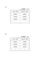
- FIG. 4is a diagram illustrating an example of the data structure and data of a conversion table in the processing device.
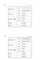
- FIG. 5is a diagram illustrating an example of the data structure and data of a history table in the processing device.
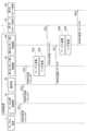
- FIG. 6is a sequence diagram (part 1) explaining the process of establishing a connection in the processing system according to the embodiment of the present invention.
- FIG. 1is a diagram illustrating the system configuration of a processing system according to an embodiment of the present invention.
- FIG. 2is a diagram illustrating processing for transmitting a general RDMA transmission packet by P2P.
- FIG. 3is a diagram illustrating functional blocks of the processing device according to the embodiment of the present invention
- FIG. 7is a sequence diagram illustrating the process of establishing a connection in the processing system according to the embodiment of the present invention (Part 2).
- FIG. 8is a sequence diagram illustrating processing for transferring processing data in the processing system according to the embodiment of the present invention.
- FIG. 9is a diagram explaining an RDMA transmission packet transmitted by the local terminal and an RDMA transmission packet transmitted to the first remote terminal.
- FIG. 10is a flowchart for explaining establishment processing by the establishment unit of the processing device.
- FIG. 11is a diagram for explaining settings in the establishment process.
- FIG. 12is a flowchart for explaining conversion processing by the conversion unit of the processing device.
- FIG. 13is a diagram for explaining settings in conversion processing.
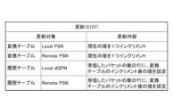
- FIG. 14is a diagram for explaining updating in conversion processing.
- FIG. 15is a diagram for explaining the hardware configuration of a computer used in the processing device.
- the processing system 5comprises a processing device 1, a local terminal L, a first remote terminal R1 and a second remote terminal R2.
- the first remote terminal R1 and the second remote terminal R2are not particularly distinguished, they may be referred to as remote terminals R in some cases.
- remote terminals RIn the embodiment of the present invention, a case in which processing data is transferred from a local terminal L to two remote terminals R will be described, but the present invention is not limited to this.
- the number of remote terminals Rshould be two or more.
- an RDMA transmission packet Pis transmitted by a local terminal L using the SEND mode of operation (RC) of the RDMA protocol. Processing data to be transferred to the memory of the accelerator of the remote terminal R is set in the RDMA transmission packet P.
- An RDMA transmission packet P1is transmitted from the processing device 1 to the first remote terminal R1.
- the RDMA transmission packet P1is generated by converting the header of the RDMA transmission packet P by the processing device 1 .
- the RDMA transmission packet P2is transmitted from the processing device 1 to the second remote terminal R2.
- the RDMA transmission packet P2is generated by converting the header of the RDMA transmission packet P by the processing device 1 .
- the local terminal Ltransmits to the processing device 1 an RDMA transmission packet P in which processing data to be transferred to the memories of the accelerators of the first remote terminal R1 and the second remote terminal R2 is set. do.
- the processing device 1converts the header of the received RDMA transmission packet P to generate RDMA transmission packets P1/P2.
- the processing device 1transmits the converted RDMA transmission packet P1/P2 to each of the first remote terminal R1 and the second remote terminal R2.
- Each of the first remote terminal R1 and the second remote terminal R2receives the RDMA transmission packet P1/P2 from the processing device 1 and transfers the processed data to the memory of the accelerator.
- the replication unit 20 of the processing device 1is implemented in a computer physically or virtually different from the local terminal L, the first remote terminal R1 and the second remote terminal R2.
- the processing device 1In such a processing system 5, the processing device 1 generates an RDMA transmission packet Pn corresponding to each of the plurality of remote terminals R from the RDMA transmission packet P received from the local terminal L, and the plurality of remote terminals R. Transfer the processed data to each of the R's. Since the local terminal L needs only to generate one RDMA transmission packet P regardless of the number of remote terminals R that are transfer destinations, the processing load is reduced compared to the case of generating an RDMA transmission packet for each remote terminal R. can be mitigated. Also, since the processing device 1 generates and transmits a plurality of packets corresponding to each remote terminal R, the local terminal L only needs to transmit one RDMA transmission packet P regardless of the number of remote terminals R to which it is transferred. Therefore, the amount of data to be sent can be reduced.
- Local terminal Lholds SQ and remote terminal R holds RQ.
- a connectionis established between the local terminal L and the remote terminal R before the transmission of the RDMA transmission packet.
- the local terminal Lsets the values of Local QPN and Starting PSN of SQ in the CM header of REQ and notifies the remote terminal R of them.
- Remote terminal Rsets the values of Local QPN and Starting PSN of RQ in the CM header of REP and notifies local terminal L of them.
- Local QPNidentifies the QP at the local terminal L or remote terminal R.
- the PSNidentifies bytes that have been sent and received at the local terminal L or remote terminal R in the process data identified in the byte stream.
- the local terminal Lloads a WQE designating the address of the memory area in which the processed data is stored in the SQ.
- the remote terminal Rloads WQE specifying the address of the memory area in which the processing data is to be stored in RQ.
- the local terminal Ltransmits to the remote terminal R an RDMA transmission packet with processing data set in the payload.
- the RQ QPN obtained from the remote terminal R at the time of connection establishmentis set in the BTH Destination QP field of the RDMA transmission packet that is first transmitted after connection establishment.
- the PSN fieldis set with the Starting PSN value obtained from the remote terminal R when the connection is established.
- the remote terminal RWhen the remote terminal R receives the RDMA transmission packet transmission packet and successfully receives the processing data, it loads the CQE into the CQ and transmits an ACK packet to the local terminal L.
- the QPN of SQis set in the Destination QP field of BTH of the ACK packet.
- the value of Starting PSN sent to the remote terminal R at the time of connection establishmentis set in the PSN field.
- local terminal LWhen local terminal L receives an ACK packet from remote terminal R, it adds CQE to CQ. At this time, WQE is released from SQ.
- the value incremented from the Starting PSNis set in the PSN set in the second and subsequent RDMA transmission packets.
- FIG. 1A processing apparatus 1 according to an embodiment of the present invention will be described with reference to FIGS. 1 and 3.
- FIG. 1A processing apparatus 1 according to an embodiment of the present invention will be described with reference to FIGS. 1 and 3.
- FIG. 1A processing apparatus 1 according to an embodiment of the present invention will be described with reference to FIGS. 1 and 3.
- the processing device 1includes a local control unit 10, a replication unit 20, a first remote control unit 30 and a second remote control unit 40.
- the first remote-side control unit 30 and the second remote-side control unit 40have the same functions, although the remote terminals that are transfer destinations are different.
- the processing device 1includes as many remote control units as the remote terminals R to which processing data is transferred.
- each processing unitmay be distributed and implemented in a plurality of computers.
- the local terminal Lhas an SQ.
- a first remote terminal R1 and a second remote terminal R2each have an RQ.
- the local side control unit 10functions as a pseudo RQ for the local terminal L's SQ.
- the first remote control unit 30functions as a pseudo SQ for the RQ of the first remote terminal R1.
- the second remote control unit 40functions as a pseudo SQ for the RQ of the second remote terminal R2.
- the copying unit 20inputs the RDMA transmission packet P received by the local control unit 10 to the first remote control unit 30 and the second remote control unit 40 respectively.
- the local-side control unit 10establishes a connection with the local terminal L and receives an RDMA transmission packet P from the local terminal L.
- the duplication unit 20duplicates the RDMA transmission packet P received from the local terminal L and inputs it to the first remote control unit 30 and the second remote control unit 40 .
- the first remote-side control unit 30generates an RDMA transmission packet P1 by converting the header of the input RDMA transmission packet P, and transmits the RDMA transmission packet P1 to the first remote terminal R1.
- the first remote-side control unit 30includes data of a conversion table 31 and a history table 32, and functions of an establishment unit 33 and a conversion unit .
- Each datais stored in a storage device such as memory 902 or storage 903 .
- Each functionis implemented in the CPU 901 .
- the conversion table 31, as shown in FIG. 4(a),includes data items for Local dQPN, IP address, MAC address, dQPN, Local PSN and Remote PSN.
- each item in the conversion table 31is set with a NULL value.
- Local dQPNis the QPN opposite to the local terminal L.
- Local dQPNis Destination QP included in BTH of RDMA transmission packet P transmitted by local terminal L.
- Local dQPNis set when the local terminal L and the local side control unit 10 first receive the RDMA transmission packet P after establishing a connection.
- the IP addressis the IP address of the first remote terminal R1.
- the IP addressis set to the Source IP address included in the REP received from the first remote terminal R1.
- the MAC addressis the MAC address of the first remote terminal R1.
- the Source MAC address included in the REP received from the first remote terminal R1is set as the MAC address.
- dQPNis the QPN of the first remote terminal R1.
- the Local QPN included in the REP received from the first remote terminal R1is set in dQPN.
- Local PSNis the PSN of the RDMA transmission packet P transmitted from the local terminal L. After the connection is established, when the RDMA transmission packet P is received for the first time, the PSN included in the BTH of the RDMA transmission packet P is set as the Local PSN. After that, the value of Local PSN is incremented by one each time an RDMA transmission packet P is received. Generally, the Local PSN value in the conversion table 31 matches the PSN included in the BTH of the RDMA transmission packet P transmitted from the local terminal L.
- Remote PSNis the PSN of the RDMA transmission packet P1 to be transferred to the first remote terminal R1.
- the Starting PSN included in the REP received from the first remote terminal R1is set to the Remote PSN.
- the value of Remote PSNis incremented by one.
- the history table 32is data of the history of the Local PSN and Remote PSN values in the conversion table 31.
- the history table 32includes Local PSN and Remote PSN, as shown in FIG. 5(a).
- the Local PSN and Remote PSN at the time of registrationare set in the first row.
- the value of the conversion table 31is updated, specifically, each time an RDMA transmission packet P is received from the local terminal L, the updated Local PSN and Remote PSN are set in a new row.
- the history table 32is referred to when the first remote-side control unit 30 detects packet loss of the RDMA transmission packet P1 and specifies the RDMA transmission packet P for which retransmission processing is requested.
- the establishment unit 33establishes a connection with the first remote terminal R1.
- the establishing unit 33acquires QPN and Starting PSN from the first remote terminal R1 when establishing a connection.
- the establishing unit 33sets the acquired QPN to dQPN of the conversion table 31 .
- the establishing unit 33sets the Starting PSN to the Remote PSN of the conversion table 31 and the Remote PSN of the first row of the history table 32 .
- the establishment unit 33sets the Source IP address and Source MAC address of the first remote terminal R1 to the IP address and MAC address of the conversion table 31 .
- the conversion unit 34converts the BTH Destination QP and PSN of the RDMA transmission packet P input from the duplication unit 20 .
- the conversion unit 34converts the Source IP address and Source MAC address into the IP address and MAC address of the first remote control unit 30 .
- the conversion unit 34converts the Destination IP address and Destination MAC address into the IP address and MAC address registered in the conversion table 31, specifically the IP address and MAC address of the first remote terminal R1.
- the conversion unit 34transmits the converted RDMA transmission packet P1 to the first remote terminal R1.
- the conversion unit 34converts the Destination QP of the BTH of the RDMA transmission packet P input from the duplication unit 20 into the QPN obtained from the first remote terminal R1. At this time, the conversion unit 34 sets the value of Destination QP of BTH of the RDMA transmission packet P input from the duplication unit 20 to the value of dQPN of the conversion table 31 .
- the conversion unit 34will explain PSN conversion.
- the conversion method of PSNdiffers between the first RDMA transmission packet P received first after connection establishment and the RDMA transmission packet P received thereafter.
- the conversion unit 34converts the PSN of BTH of the first RDMA transmission packet P into the Local PSN of the conversion table 31 and the Set to Local PSN on the first line.
- the conversion unit 34converts the BTH PSN value of the first RDMA transmission packet P into the Remote PSN value of the conversion table 31, specifically, the Starting PSN value obtained from the first remote terminal R1. .
- the conversion unit 34sets the Destination QP of BTH of the RDMA transmission packet P to Local dQPN of the conversion table 31 .
- the conversion unit 34increments each of Local PSN and Remote PSN in the conversion table 31 when the second RDMA transmission packet P is input. Then, each incremented value is set to the Local PSN and Remote PSN on the second row of the history table 32 .
- the conversion unit 34converts the PSN value of the BTH of the second RDMA transmission packet P to the Remote PSN value of the conversion table 31, specifically, the PSN obtained by incrementing the Starting PSN acquired from the first remote terminal R1. Convert to value.
- the conversion unit 34updates the Local PSN in the conversion table 31 to a value incremented according to the number of RDMA transmission packets P input after connection establishment.
- the conversion unit 34sets the updated Local PSN to the Local PSN in the row of the number of RDMA transmission packets P input after connection establishment in the history table 32 .
- 0X4444which is the BTH PSN of the first RDMA transmission packet P
- 0X4445obtained by incrementing 0X4444 is set in the Local PSN on the second line.
- 0X4446obtained by incrementing 0X4445 is set in the Local PSN on the third line.
- the conversion unit 34updates the Remote PSN in the conversion table 31 to a value incremented according to the number of RDMA transmission packets P input after connection establishment.
- the conversion unit 34sets the updated Remote PSN to the Remote PSN in the row corresponding to the number of RDMA transmission packets P input after connection establishment in the history table 32 .
- the Remote PSN in the first row of the history table 32is set to 0X2222, which is the Starting PSN obtained by REP from the remote terminal R when the connection with the first remote terminal R1 is established. be.
- 0X2222is the Starting PSN obtained by REP from the remote terminal R when the connection with the first remote terminal R1 is established.
- the conversion unit 34may refer to the Destination QP of the BTH of the RDMA transmission packet input from the duplication unit 20 to determine whether to process the RDMA transmission packet. If the BTH Destination QP of the second RDMA transmission packet P matches the BTH Destination QP of the first RDMA transmission packet P, the conversion unit 44 sends the converted second RDMA transmission packet to the first remote Send to terminal. The converter 34 discards the second RDMA transmission packet P if they do not match. If the Destination QP of the BTH of the newly received RDMA send packet P is set to the same value as the previously received RDMA send packet P, the newly received RDMA send packet P is the same as the previously received RDMA send packet P. It is judged as a legitimate packet sent from the same source. If a different value is set, the newly received RDMA transmission packet P is determined as an illegal packet transmitted from a different transmission source than the previously received RDMA transmission packet P, and is discarded.
- the second remote control unit 40generates an RDMA transmission packet P2 by converting the header of the input RDMA transmission packet P, and transmits the RDMA transmission packet P2 to the second remote terminal R2.
- the second remote control unit 40includes a conversion table 41, a history table 42, an establishment unit 43 and a conversion unit 44, as shown in FIG. Each data is stored in a storage device such as memory 902 or storage 903 . Each function is implemented in the CPU 901 .
- the conversion table 41has the same data configuration as the conversion table 31 of the first remote control unit 30, as shown in FIG. 4(b).
- the history table 42has the same data structure as the history table 32 of the first remote control unit 30, as shown in FIG. 5(b).
- the establishing unit 43 and the converting unit 44have functions similar to those of the establishing unit 33 and the converting unit 34 of the first remote control unit 30, respectively.
- the establishment unit 43establishes a connection with the second remote terminal R2.
- the establishing unit 43acquires QPN and Starting PSN from the second remote terminal R2 when establishing a connection.
- the establishing unit 43sets the acquired QPN to dQPN in the conversion table 41 .
- the establishing unit 43sets the Starting PSN to the Remote PSN of the conversion table 41 and the Remote PSN of the first row of the history table 42 .
- the establishing unit 43sets the Source IP address and Source MAC address of the first remote terminal R1 to the IP address and MAC address of the conversion table 41 .
- the conversion unit 44converts the BTH Destination QP and PSN of the RDMA transmission packet P input from the duplication unit 20 .
- the conversion unit 44converts the Source IP address and Source MAC address into the IP address and MAC address of the second remote control unit 40 .
- the conversion unit 44converts the Destination IP address and Destination MAC address into the IP address and MAC address registered in the conversion table 41, specifically the IP address and MAC address of the second remote terminal R2.
- the conversion unit 44transmits the converted RDMA transmission packet P2 to the second remote terminal R2.
- the conversion unit 44converts the Destination QP value of the BTH of the RDMA transmission packet P input from the duplication unit 20 into the dQPN value of the conversion table 41, specifically, the QPN obtained from the second remote terminal R2. do. At this time, the conversion unit 44 sets the value of Destination QP of BTH of the RDMA transmission packet P input from the duplication unit 20 to the value of dQPN of the conversion table 41 .
- the conversion unit 44converts the PSN of BTH of the first RDMA transmission packet P into the Local PSN of the conversion table 41 and the Set to Local PSN on the first line.
- the conversion unit 44converts the BTH PSN value of the first RDMA transmission packet P to the Remote PSN value in the conversion table 41, specifically, the Starting PSN value obtained from the second remote terminal R2. .
- the conversion unit 44sets the Destination QP of BTH of the RDMA transmission packet P to Local dQPN of the conversion table 41 .
- the conversion unit 44increments each of Local PSN and Remote PSN in the conversion table 41 when the second RDMA transmission packet P is input. Then, each incremented value is set to the Local PSN and Remote PSN on the second row of the history table 42 .
- the conversion unit 44converts the PSN value of the BTH of the second RDMA transmission packet P to the value of the Remote PSN in the conversion table 41, specifically, the PSN obtained by incrementing the Starting PSN acquired from the second remote terminal R2. Convert to value.
- the conversion unit 44updates the Local PSN and Remote PSN in the conversion table 41 to values incremented according to the number of RDMA transmission packets P input after connection establishment.
- the conversion unit 44sets the updated Local PSN and Remote PSN to the Local PSN and Remote PSN in the row of the number of RDMA transmission packets P input after connection establishment in the history table 42 .
- connection establishmentThe connection establishment process in the processing system 5 will be described with reference to FIGS. 6 and 7.
- FIG. 6The connection establishment process in the processing system 5 will be described with reference to FIGS. 6 and 7.
- a connectionis established between the local terminal L and the local side control unit 10 .
- the local terminal Ltransmits REQ to the local side control unit 10 .
- the REQcontains the Local QPN and Starting PSN of the local terminal L.
- the local control unit 10transmits REP.
- REPincludes the Local QPN and Starting PSN of the local side control unit 10 .
- the local terminal Ltransmits RTU.
- a connectionis established between the local terminal L and the local side control unit 10.
- step S21the first remote control unit 30 transmits REQ to the first remote terminal R1.
- the REQcontains the Local QPN and Starting PSN of the first remote control unit 30 .
- step S22the first remote terminal R1 transmits REP.
- REPcontains the Local QPN and Starting PSN of the first remote terminal R1.
- step S23the first remote control unit 30 updates the conversion table 31 and history table 32 using the Local QPN and Starting PSN included in REP.
- the first remote-side control unit 30registers the Local QPN received in step S22 in the dQPN of the conversion table 31.
- FIG.The first remote-side control unit 30 registers the Starting PSN received in step S22 in the Remote PSN of the conversion table 31 and the Remote PSN in the first row of the history table 32 .
- the first remote-side control unit 30further sets the Source IP address and Source MAC address included in REP to the IP address and MAC address of the conversion table 31 .
- step S24the first remote control unit 30 transmits RTU.
- step S25a connection is established between the first remote control unit 30 and the first remote terminal R1.
- step S31the second remote controller 40 transmits REQ to the second remote terminal R2.
- the REQcontains the Local QPN and Starting PSN of the second remote control unit 40 .
- step S32the second remote terminal R2 sends REP.
- REPcontains the Local QPN and Starting PSN of the second remote terminal R2.
- step S33the second remote control unit 40 updates the conversion table 41 and the history table 42 using the Local QPN and Starting PSN included in REP.
- the second remote-side control unit 40registers the Local QPN received in step S32 in the dQPN of the conversion table 41.
- the second remote-side control unit 40registers the Starting PSN received in step S32 in the Remote PSN of the conversion table 41 and the Remote PSN in the first row of the history table .
- step S34the first remote control unit 30 transmits RTU.
- step S35a connection is established between the second remote controller 40 and the second remote terminal R2.
- step S51When the local terminal L transmits the RDMA transmission packet P in step S51, the local side control unit 10 receives it. In step S ⁇ b>52 , the local controller 10 transmits the RDMA transmission packet P to the duplicator 20 .
- the duplicating unit 20transmits the received RDMA transmission packet P to the first remote control unit 30 in step S53, and transmits it to the second remote control unit 40 in step S57.
- the first remote-side control unit 30Upon receiving the RDMA transmission packet P, the first remote-side control unit 30 updates the conversion table 31 and the history table 32 in step S54. The first remote-side control unit 30 sets the Destination QP of BTH of the RDMA transmission packet P input from the duplication unit 20 to Local dQPN of the conversion table 31 . If the received RDMA transmission packet P is the first RDMA transmission packet received after connection establishment, the first remote-side control unit 30 converts the BTH PSN of the received RDMA transmission packet P to the Local PSN of the conversion table 31. , is set to Local PSN in the first row of the history table 32 .
- the first remote side control unit 30inputs the Local PSN and Remote PSN of the conversion table 31 after the connection is established. incremented according to the number of RDMA transmission packets P received. The first remote-side control unit 30 sets the updated Local PSN and Remote PSN to the Local PSN and Remote PSN in the row of the number of RDMA transmission packets P input after connection establishment in the history table 32.
- the first remote control unit 30refers to the updated conversion table 31, converts the header of the input RDMA transmission packet P, and generates the RDMA transmission packet P1.
- the first remote-side control unit 30sets the Destination QP of BTH of the RDMA transmission packet P input from the duplication unit 20 to Local dQPN of the conversion table 31 .
- the first remote-side control unit 30converts the BTH PSN value of the RDMA transmission packet P into the Remote PSN value of the conversion table 31 .
- the first remote controller 30converts the Source IP address and Source MAC address into the IP address and MAC address of the first remote controller 30 .
- the first remote-side control unit 30converts the Destination IP address and Destination MAC address into the IP address and MAC address registered in the conversion table 31, specifically the IP address and MAC address of the first remote terminal R1. do.
- step S56the first remote control unit 30 transmits the RDMA transmission packet P1 whose header has been converted in step S55 to the first remote terminal R1.
- steps S58 through S60processing similar to that of steps S54 through S56 is performed.
- the second remote-side control unit 40Upon receiving the RDMA transmission packet P, the second remote-side control unit 40 updates the conversion table 41 and the history table 42 in step S58.
- the second remote control unit 40refers to the updated conversion table 41, converts the header of the input RDMA transmission packet P, and generates the RDMA transmission packet P2.
- the second remote control unit 40transmits the RDMA transmission packet P2 whose header has been converted in step S59 to the second remote terminal R2.
- FIG. 9(a)is an example of the header of the RDMA transmission packet P transmitted from the local terminal L.
- the MAC address, IP address and UDP port number of the local terminal Lare set to the MAC address, IP address and UDP port number of Src (Source).
- the MAC address, IP address and UDP port number of Dst (Destination)are set to the MAC address, IP address and UDP port number of the local control unit 10 .
- the QPN of the local side control unit 10is set in dQPN.
- the PSN of the local terminal Lis set in PSN.
- FIG. 9(b)is an example of the header of the RDMA transmission packet P1 whose header has been converted by the first remote control unit 30.
- the MAC address, IP address and UDP port number of the first remote side control unit 30are set as the MAC address, IP address and UDP port number of Src (Source).
- the MAC address, IP address and UDP port number of Dst (Destination)are set to the MAC address, IP address and UDP port number of the first remote terminal R1.
- dQPNis set to the QPN of the first remote terminal R1.
- the PSN of the first remote control unit 30is set in PSN.
- a randomly determined numberis set as the Source UDP port number.
- a fixed fixed numberis set in the Destination UDP port number when establishing an RDMA connection using the RoCEv2 mechanism. Therefore, in the RDMA transmission packet P2, the Source UDP port number is set to the number assigned to the first remote side control unit 30, and the Destination UDP port number is set to the same number "4791" as the RDMA transmission packet P1. be.
- step S101the establishing unit 33 transmits REQ to the first remote terminal R1.
- step S102the establishing unit 33 receives REP from the first remote terminal R1.
- step S103the establishing unit 33 sets the value obtained from the REP header in the conversion table 31 and the history table 32. Specifically, as shown in FIG. 11 , the establishment unit 33 sets the Source IP address of the IP header of REP to the IP address of the conversion table 31 . The establishing unit 33 sets the Source MAC address of the Eth header to the MAC address of the conversion table 31 . The establishment unit 33 sets Local QPN of the RDMACM header to dQPN of the conversion table 31 . The establishing unit 33 sets the Starting PSN of the RDMACM header to the Remote PSN of the conversion table, and further sets it to the Remote PSN of the first row of the history table 32 .
- the establishing unit 33transmits the RTU to the first remote terminal R1 in step S104.
- step S ⁇ b>151the conversion unit 34 receives the RDMA transmission packet P from the duplication unit 20 .
- step S152the conversion unit 34 determines whether or not it is the first RDMA transmission packet received after establishment of the connection.
- step S152If it is determined to be the first reception in step S152, the process proceeds to step S153.
- step S ⁇ b>153the conversion unit 34 sets the conversion table 31 and the history table 32 . Specifically, as shown in FIG. 13 , the conversion unit 34 sets the Destination QP of BTH of the RDMA transmission packet P to Local dQPN of the conversion table 31 . The conversion unit 34 sets the PSN of BTH as the PSN of the conversion table, and further sets it as the Local PSN in the first row of the history table 32 . After setting, the process proceeds to step S158.
- step S152If it is determined in step S152 that it is not the first reception, the process proceeds to step S154.
- step S154the conversion unit 34 compares the Destination QP of BTH of the received packet and the Local dQPN in the conversion table 31, and determines whether or not they match in step S155. If they do not match, the conversion unit 34 determines in step S156 that the source of the received packet is not the local terminal L, drops the packet, and terminates the process.
- step S155If it is determined in step S155 that the Destination QP of the BTH of the received packet matches the Local dQPN of the conversion table 31 instead of the first reception in step S152, the conversion unit 34 converts the conversion table 31 and the history table in step S157. Update 32. Specifically, as shown in FIG. 14, the conversion unit 34 increments and updates the current value of Local PSN in the conversion table 31 by one. The conversion unit 34 increments the current value of Remote PSN in the conversion table 31 by one and updates it. The conversion unit 34 sets the incremented Local PSN and Remote PSN of the conversion table 31 to the Local dQPN and Remote PSN in the row of the number of packets received after connection establishment in the history table 32, respectively.
- step S158the conversion unit 34 converts the header of the received RDMA transmission packet P to generate the RDMA transmission packet P1.
- the conversion unit 34sets the Destination QP of the BTH of the RDMA transmission packet P input from the duplication unit 20 to the Local dQPN of the conversion table 31 .
- the conversion unit 34converts the BTH PSN value of the RDMA transmission packet P into the Remote PSN value of the conversion table 31 .
- the conversion unit 34converts the Source IP address and Source MAC address into the IP address and MAC address of the first remote control unit 30 .
- the conversion unit 34converts the Destination IP address and Destination MAC address into the IP address and MAC address registered in the conversion table 31, specifically the IP address and MAC address of the first remote terminal R1.
- step S159the conversion unit 34 transmits the converted RDMA transmission packet P1 to the first remote terminal R1.
- the processing device 1converts the RDMA transmission packet P transmitted from the local terminal L into the RDMA transmission packet P1 addressed to the first remote terminal R1 and the second generates and transmits an RDMA transmission packet P2 addressed to the remote terminal R2.
- the local terminal Lcan generate and transmit the RDMA transmission packet P to the processing device 1 regardless of the number of remote terminals R, so the load on the local terminal L can be reduced.
- the processing system 5implements the local terminal L, the processing device 1, the first remote terminal R1, and the second remote terminal R2 by physically different computers, respectively, so that a plurality of This has the effect of reducing the load on the local terminal that transfers data to the remote terminal. More specifically, the processing system 5 implements the replication unit 20 in a computer that is physically or virtually different from the local terminal L, the first remote terminal R1, and the second remote terminal R2. The load on the local terminal L that transfers data to the remote terminal R can be reduced.
- the functions of the local control unit 10, the replication unit 20, the first remote control unit 30, and the second remote control unit 40 of the processing device 1may be implemented on different computers. Also, each function may be implemented on a computer having other functions.
- the local-side control unit 10 of the processing device 1is the NIC (Network Interface Card) of the local terminal L
- the first remote-side control unit 30is the NIC of the first remote terminal R1
- the second remote-side control The unit 40may be implemented in the NIC of the second remote terminal R2.
- the replication unit 20may be implemented as one function of the communication control device.
- the packetsmay be duplicated by electrical or optical processing.
- devicessuch as the multicast function of IP routers, packet brokers, network taps, and port mirroring of L2 switches electrically convert signals to data and replicate the electrically converted data.
- devicessuch as optical splitters and optical taps demultiplex signals based on the physical phenomenon of light.
- the processing device 1 of the present embodiment described aboveincludes, for example, a CPU (Central Processing Unit, processor) 901, a memory 902, a storage 903 (HDD: Hard Disk Drive, SSD: Solid State Drive), and a communication device 904 , an input device 905 and an output device 906 are used.
- a CPUCentral Processing Unit
- processorCentral Processing Unit
- memory 902a storage 903
- HDDHard Disk Drive
- SSDSolid State Drive
- communication device 904an input device 905 and an output device 906 are used.
- each function of the processing device 1is realized by the CPU 901 executing a program loaded on the memory 902 .
- processing device 1may be implemented by one computer, or may be implemented by a plurality of computers. Also, the processing device 1 may be a virtual machine implemented in a computer.
- the program of the processing device 1can be stored in a computer-readable recording medium such as HDD, SSD, USB (Universal Serial Bus) memory, CD (Compact Disc), DVD (Digital Versatile Disc), or distributed via a network. You can also
- processing device 5processing system 10 local control unit 20 duplication unit 30, 40 remote control unit 31, 41 conversion table 32, 42 history table 33, 43 establishment unit 34, 44 conversion unit 901 CPU 902 memory 903 storage 904 communication device 905 input device 906 output device L local terminal R remote terminal
Landscapes
- Engineering & Computer Science (AREA)
- Theoretical Computer Science (AREA)
- Physics & Mathematics (AREA)
- General Engineering & Computer Science (AREA)
- General Physics & Mathematics (AREA)
- Computer Networks & Wireless Communication (AREA)
- Signal Processing (AREA)
- Computer Security & Cryptography (AREA)
- Data Exchanges In Wide-Area Networks (AREA)
Abstract
Description
Translated fromJapanese本発明は、処理システム、処理装置、処理方法およびプログラムに関する。The present invention relates to a processing system, a processing device, a processing method and a program.
近年、コンテンツが高品質化するとともに、ストリーミング配信、ビデオ会議、オンラインゲームなど、同じデータを多数の端末に対して配信する通信方式が、普及している。このような通信方式は、大容量のデータの受信から演算処理までを、高速かつ低遅延に行う必要がある。In recent years, as the quality of content has improved, communication methods that distribute the same data to multiple terminals, such as streaming distribution, video conferencing, and online games, have become popular. In such a communication system, it is necessary to perform processing from reception of a large amount of data to arithmetic processing at high speed and with low delay.
CPUを介すことなく、アクセラレータのメモリに直接データを転送する通信方式がある。アクセラレータは、例えば、GPU(Graphics Processing Unit)、TPU(Tensor Processing Unit)などの、特定の演算に特化したハードウエアである。この通信方式は、ネットワークとコンピューティングが直接つながり、データの受信および演算の高速性かつ低遅延性を実現する。There is a communication method that transfers data directly to the accelerator's memory without going through the CPU. Accelerators are hardware specialized for specific operations, such as GPUs (Graphics Processing Units) and TPUs (Tensor Processing Units). This communication system directly connects the network and computing, and realizes high-speed and low-delay data reception and calculation.
アクセラレータのメモリに直接データを転送できるプロトコルとして、RDMAが知られている(非特許文献1)。RDMAプロトコルのSEND動作方式は、RC(Reliable Connection)のサービスタイプにおいて、ローカル端末およびリモート端末間をP2P(Peer to Peer)で接続し、高速なメモリ間通信を可能とする。ローカル端末は、SEND動作の送信先となるリモート端末のSQ(Send Queue)を作成して、両コンピュータのオペレーティングシステムを経由せずに、データ転送を行う。RDMA is known as a protocol that can transfer data directly to the memory of the accelerator (Non-Patent Document 1). The SEND operation method of the RDMA protocol enables high-speed inter-memory communication by connecting local terminals and remote terminals with P2P (Peer to Peer) in the RC (Reliable Connection) service type. The local terminal creates an SQ (Send Queue) for the remote terminal that is the destination of the SEND operation, and transfers data without going through the operating systems of both computers.
しかしながら、RDMAを用いてローカル端末から複数のリモート端末にメモリ間通信をする場合、ローカル端末に負担がかかる場合がある。ローカル端末は、各リモート端末のそれぞれに対してSQを作成するので、ローカル端末における処理負担が発生する。またローカル端末から各リモート端末のそれぞれに、各SQが送信されるので、ローカル端末における送信流量が膨大になる。However, when performing memory-to-memory communication from a local terminal to multiple remote terminals using RDMA, the local terminal may be burdened. Since the local terminal creates an SQ for each remote terminal, there is a processing load on the local terminal. Also, since each SQ is transmitted from the local terminal to each remote terminal, the transmission flow rate in the local terminal becomes enormous.
本発明は、上記事情に鑑みてなされたものであり、本発明の目的は、複数のリモート端末にデータを転送するローカル端末の負担を軽減可能な技術を提供することである。The present invention has been made in view of the above circumstances, and an object of the present invention is to provide a technology that can reduce the burden on local terminals that transfer data to a plurality of remote terminals.
本発明の一態様の処理システムは、ローカル端末と、第1のリモート端末と、第2のリモート端末と、処理装置を備える。前記ローカル端末は、前記第1のリモート端末および前記第2のリモート端末のそれぞれのアクセラレータのメモリに転送される処理データが設定されたRDMA送信パケットを、前記処理装置に送信する。前記処理装置は、前記ローカル端末との間でコネクションを確立し、前記ローカル端末から、前記RDMA送信パケットを受信するローカル側制御部と、前記第1のリモート端末との間でコネクションを確立する第1のリモート側制御部と、前記第2のリモート端末との間でコネクションを確立する第2のリモート側制御部と、前記RDMA送信パケットを、前記第1のリモート側制御部と前記第2のリモート側制御部に入力する複製部を備える。前記第1のリモート側制御部は、コネクションの確立時に、前記第1のリモート端末からQPNを取得し、前記RDMA送信パケットのBTH(Base Transport Header)のDestination QPを、前記第1のリモート端末から取得したQPNに変換し、変換されたRDMA送信パケットを、前記第1のリモート端末に送信する。前記第2のリモート側制御部は、コネクションの確立時に、前記第2のリモート端末からQPNを取得し、前記RDMA送信パケットのBTHのDestination QPを、前記第2のリモート端末から取得したQPNに変換し、変換されたRDMA送信パケットを、前記第2のリモート端末に送信する。前記第1のリモート端末は、前記変換されたRDMA送信パケットを受信し、前記処理データをアクセラレータのメモリに転送する。前記第2のリモート端末は、前記変換されたRDMA送信パケットを受信し、前記処理データをアクセラレータのメモリに転送する。A processing system according to one aspect of the present invention includes a local terminal, a first remote terminal, a second remote terminal, and a processing device. The local terminal transmits to the processing device an RDMA transmission packet in which processing data to be transferred to the memory of the accelerator of each of the first remote terminal and the second remote terminal is set. The processing device establishes a connection with the local terminal, establishes a connection between the local side control unit that receives the RDMA transmission packet from the local terminal, and the first remote terminal. a second remote control unit for establishing a connection between one remote control unit and the second remote terminal; and transmitting the RDMA transmission packet between the first remote control unit and the second remote terminal. A duplication unit is provided for input to the remote control unit. The first remote-side control unit acquires a QPN from the first remote terminal when establishing a connection, and transmits a Destination QP of a BTH (Base Transport Header) of the RDMA transmission packet from the first remote terminal. Converting to the obtained QPN, and transmitting the converted RDMA transmission packet to the first remote terminal. The second remote-side control unit acquires a QPN from the second remote terminal when establishing a connection, and converts the Destination QP of BTH of the RDMA transmission packet to the QPN acquired from the second remote terminal. and transmitting the converted RDMA transmission packet to the second remote terminal. The first remote terminal receives the converted RDMA transmission packet and transfers the processed data to an accelerator memory. The second remote terminal receives the converted RDMA transmission packet and transfers the processed data to an accelerator memory.
本発明の一態様の処理装置は、ローカル端末との間でコネクションを確立し、前記ローカル端末から、第1のリモート端末および第2のリモート端末のそれぞれのアクセラレータのメモリに転送される処理データが設定されたRDMA送信パケットを、受信するローカル側制御部と、前記第1のリモート端末との間でコネクションを確立する第1のリモート側制御部と、前記第2のリモート端末との間でコネクションを確立する第2のリモート側制御部と、前記RDMA送信パケットを、前記第1のリモート側制御部と前記第2のリモート側制御部に入力する複製部を備える。前記第1のリモート側制御部は、コネクションの確立時に、前記第1のリモート端末からQPNを取得し、前記RDMA送信パケットのBTHのDestination QPを、前記第1のリモート端末から取得したQPNに変換し、変換されたRDMA送信パケットを、前記第1のリモート端末に送信する。前記第2のリモート側制御部は、コネクションの確立時に、前記第2のリモート端末からQPNを取得し、前記RDMA送信パケットのBTHのDestination QPを、前記第2のリモート端末から取得したQPNに変換し、変換されたRDMA送信パケットを、前記第2のリモート端末に送信する。A processing device according to one aspect of the present invention establishes a connection with a local terminal, and processes data transferred from the local terminal to the memories of the accelerators of the first remote terminal and the second remote terminal. A connection is established between a local control unit that receives the set RDMA transmission packet, a first remote control unit that establishes a connection with the first remote terminal, and the second remote terminal. and a replicating unit for inputting the RDMA transmission packet to the first remote control unit and the second remote control unit. The first remote-side control unit acquires a QPN from the first remote terminal when establishing a connection, and converts the Destination QP of BTH of the RDMA transmission packet to the QPN acquired from the first remote terminal. and transmitting the converted RDMA transmission packet to the first remote terminal. The second remote-side control unit acquires a QPN from the second remote terminal when establishing a connection, and converts the Destination QP of BTH of the RDMA transmission packet to the QPN acquired from the second remote terminal. and transmitting the converted RDMA transmission packet to the second remote terminal.
本発明の一態様の処理方法は、ローカル端末が、第1のリモート端末および第2のリモート端末のそれぞれのアクセラレータのメモリに転送される処理データが設定されたRDMA送信パケットを、処理装置に送信し、前記処理装置が、前記ローカル端末との間でコネクションを確立し、前記ローカル端末から、前記RDMA送信パケットを受信し、前記処理装置の第1のリモート側制御部が、前記第1のリモート端末との間でコネクションを確立し、前記処理装置の第2のリモート側制御部が、前記第2のリモート端末との間でコネクションを確立し、前記処理装置が、前記RDMA送信パケットを、前記第1のリモート側制御部と前記第2のリモート側制御部に入力し、前記処理装置の前記第1のリモート側制御部が、コネクションの確立時に、前記第1のリモート端末からQPNを取得し、前記RDMA送信パケットのBTH(Base Transport Header)のDestination QPを、前記第1のリモート端末から取得したQPNに変換し、変換されたRDMA送信パケットを、前記第1のリモート端末に送信し、前記処理装置の前記第2のリモート側制御部が、コネクションの確立時に、前記第2のリモート端末からQPNを取得し、前記RDMA送信パケットのBTHのDestination QPを、前記第2のリモート端末から取得したQPNに変換し、変換されたRDMA送信パケットを、前記第2のリモート端末に送信し、前記第1のリモート端末が、前記変換されたRDMA送信パケットを受信し、前記処理データをアクセラレータのメモリに転送し、前記第2のリモート端末が、前記変換されたRDMA送信パケットを受信し、前記処理データをアクセラレータのメモリに転送する。In the processing method of one aspect of the present invention, the local terminal transmits to the processing device an RDMA transmission packet in which processing data to be transferred to the memory of the accelerator of each of the first remote terminal and the second remote terminal is set. and the processing device establishes a connection with the local terminal, receives the RDMA transmission packet from the local terminal, and the first remote-side control unit of the processing device communicates with the first remote A connection is established with a terminal, a second remote-side control unit of the processing device establishes a connection with the second remote terminal, and the processing device transmits the RDMA transmission packet to the input to the first remote-side control unit and the second remote-side control unit, and the first remote-side control unit of the processing device acquires the QPN from the first remote terminal when establishing a connection , converting a Destination QP of a BTH (Base Transport Header) of the RDMA transmission packet into a QPN obtained from the first remote terminal, transmitting the converted RDMA transmission packet to the first remote terminal; The second remote-side control unit of the processing device acquires the QPN from the second remote terminal and acquires the Destination QP of the BTH of the RDMA transmission packet from the second remote terminal when the connection is established. convert to QPN, transmit the converted RDMA transmission packet to the second remote terminal, the first remote terminal receives the converted RDMA transmission packet, stores the processed data in the memory of an accelerator; and the second remote terminal receives the converted RDMA transmission packet and transfers the processed data to a memory of an accelerator.
本発明の一態様は、上記処理装置として、コンピュータを機能させるプログラムである。One aspect of the present invention is a program that causes a computer to function as the processing device.
本発明によれば、複数のリモート端末にデータを転送するローカル端末の負担を軽減可能な技術を提供することができる。According to the present invention, it is possible to provide a technology that can reduce the burden on local terminals that transfer data to a plurality of remote terminals.
以下、図面を参照して、本発明の実施形態を説明する。図面の記載において同一部分には同一符号を付し説明を省略する。Hereinafter, embodiments of the present invention will be described with reference to the drawings. In the description of the drawings, the same parts are denoted by the same reference numerals, and the description thereof is omitted.
本発明の実施の形態において、下記の略語を用いる。
RDMA Remote Direct Memory Access
QP Queue Pair
SQ Send Queue
RQ Receive Queue
CQ Completion Queue
CM Communication Management
BTH Base Transport Header
RC Reliable Connection
QPN QP Number
PSN Packet Sequence Number
WQE Work Queue Element
CQE Completion Queue Element
RC Reliable Connection
REQ Connect Request
REP Connect Reply
RTU Ready To UseIn the embodiments of the present invention, the following abbreviations are used.
RDMA Remote Direct Memory Access
QP Queue Pair
SQ Send Queue
RQ Receive Queue
CQ Completion Queue
CM Communication Management
BTH Base Transport Header
RC Reliable Connection
QPN QP Number
PSN Packet Sequence Number
WQE Work Queue Element
CQE Completion Queue Element
RC Reliable Connection
REQ Connect Request
REP Connect Reply
RTU Ready To Use
(処理システム)
図1を参照して、本発明の実施の形態に係る処理システム5を説明する。処理システム5は、処理装置1、ローカル端末L、第1のリモート端末R1および第2のリモート端末R2を備える。第1のリモート端末R1および第2のリモート端末R2を特に区別しない場合、リモート端末Rと称する場合がある。本発明の実施の形態において、ローカル端末Lから2つのリモート端末Rに処理データが転送される場合を説明するが、これに限らない。リモート端末Rの数は2以上であれば良い。(processing system)
A processing system 5 according to an embodiment of the present invention will be described with reference to FIG. The processing system 5 comprises a
本発明の実施の形態において、RDMA送信パケットPは、RDMAプロトコルのSEND動作方式(RC)を用いて、ローカル端末Lによって送信される。RDMA送信パケットPに、リモート端末Rのアクセラレータのメモリに転送される処理データが設定される。RDMA送信パケットP1は、処理装置1から第1のリモート端末R1に送信される。RDMA送信パケットP1は、処理装置1によってRDMA送信パケットPのヘッダが変換されて生成される。RDMA送信パケットP2は、処理装置1から第2のリモート端末R2に送信される。RDMA送信パケットP2は、処理装置1によってRDMA送信パケットPのヘッダが変換されて生成される。In the embodiment of the present invention, an RDMA transmission packet P is transmitted by a local terminal L using the SEND mode of operation (RC) of the RDMA protocol. Processing data to be transferred to the memory of the accelerator of the remote terminal R is set in the RDMA transmission packet P. An RDMA transmission packet P1 is transmitted from the
処理システム5において、ローカル端末Lは、第1のリモート端末R1および第2のリモート端末R2のそれぞれのアクセラレータのメモリに転送される処理データが設定されたRDMA送信パケットPを、処理装置1に送信する。処理装置1は、受信したRDMA送信パケットPのヘッダを変換して、RDMA送信パケットP1/P2を生成する。処理装置1は、変換後のRDMA送信パケットP1/P2を、第1のリモート端末R1および第2のリモート端末R2のそれぞれに送信する。第1のリモート端末R1および第2のリモート端末R2のそれぞれは、処理装置1からRDMA送信パケットP1/P2を受信し、処理データをアクセラレータのメモリに転送する。ここで、処理装置1の複製部20は、ローカル端末L、第1のリモート端末R1および第2のリモート端末R2と、物理的にまたは仮想的に異なるコンピュータに実装される。In the processing system 5, the local terminal L transmits to the
このような処理システム5において処理装置1は、ローカル端末Lから受信したRDMA送信パケットPから、処理装置1が複数のリモート端末Rのそれぞれに対応するRDMA送信パケットPnを生成し、複数のリモート端末Rのそれぞれに処理データを転送する。ローカル端末Lは、転送先のリモート端末Rの数にかかわらず、1つのRDMA送信パケットPを生成すれば良いので、各リモート端末RについてのRDMA送信パケットを作成する場合に比べて、処理負担を軽減することができる。また処理装置1が各リモート端末Rに対応する複数のパケットを生成し送信するので、ローカル端末Lは、転送先のリモート端末Rの数にかかわらず、1つのRDMA送信パケットPを送信すれば良いので、送出するデータ量を、軽減することができる。In such a processing system 5, the
図2を参照して、一般的なRDMA送信パケットを、P2Pで送信する処理について説明する。ローカル端末Lは、SQを保持し、リモート端末Rは、RQを保持する。ローカル端末LのSQとリモート端末RのRQは、QPを形成する。With reference to FIG. 2, the process of transmitting general RDMA transmission packets by P2P will be described. Local terminal L holds SQ and remote terminal R holds RQ. The SQ of the local terminal L and the RQ of the remote terminal R form a QP.
RDMA送信パケットの送信の前に、ローカル端末Lおよびリモート端末R間でコネクションが確立される。コネクション確立時に、ローカル端末Lは、REQのCMヘッダに、SQのLocal QPNとStarting PSNの各値を設定して、リモート端末Rに通知する。リモート端末Rは、REPのCMヘッダに、RQのLocal QPNとStarting PSNの各値を設定して、ローカル端末Lに通知する。Local QPNは、ローカル端末Lまたはリモート端末RにおいてQPを識別する。PSNは、ローカル端末Lまたはリモート端末Rにおいて、バイトストリームで特定される処理データにおいて、送受信済のバイトを特定する。A connection is established between the local terminal L and the remote terminal R before the transmission of the RDMA transmission packet. At the time of connection establishment, the local terminal L sets the values of Local QPN and Starting PSN of SQ in the CM header of REQ and notifies the remote terminal R of them. Remote terminal R sets the values of Local QPN and Starting PSN of RQ in the CM header of REP and notifies local terminal L of them. Local QPN identifies the QP at the local terminal L or remote terminal R. The PSN identifies bytes that have been sent and received at the local terminal L or remote terminal R in the process data identified in the byte stream.
コネクションが確立されると、処理データが転送される。RDMAプロトコルのSEND動作方式(RC)によるデータ転送を説明する。ローカル端末Lは、処理データが格納されたメモリ領域のアドレスを指定したWQEを、SQに積む。リモート端末Rは、処理データを格納予定のメモリ領域のアドレスを指定したWQEを、RQに積む。When the connection is established, the processed data is transferred. Data transfer by the SEND operation method (RC) of the RDMA protocol is described. The local terminal L loads a WQE designating the address of the memory area in which the processed data is stored in the SQ. The remote terminal R loads WQE specifying the address of the memory area in which the processing data is to be stored in RQ.
ローカル端末Lは、処理データをペイロードに設定したRDMA送信パケットをリモート端末Rに送信する。コネクション確立後に最初に送信するRDMA送信パケットのBTHのDestination QPフィールドに、コネクション確立時にリモート端末Rから取得した、RQのQPNが設定される。PSNフィールドに、コネクション確立時にリモート端末Rから取得したStarting PSNの値が設定される。The local terminal L transmits to the remote terminal R an RDMA transmission packet with processing data set in the payload. The RQ QPN obtained from the remote terminal R at the time of connection establishment is set in the BTH Destination QP field of the RDMA transmission packet that is first transmitted after connection establishment. The PSN field is set with the Starting PSN value obtained from the remote terminal R when the connection is established.
リモート端末Rは、RDMA送信パケット送信パケットを受信し、処理データの受信に成功すると、CQEをCQに積み、ACKパケットをローカル端末Lに送信する。ACKパケットのBTHのDestination QPフィールドに、SQのQPNが設定される。PSNフィールドに、コネクション確立時に、リモート端末Rに送信したStarting PSNの値が設定される。When the remote terminal R receives the RDMA transmission packet transmission packet and successfully receives the processing data, it loads the CQE into the CQ and transmits an ACK packet to the local terminal L. The QPN of SQ is set in the Destination QP field of BTH of the ACK packet. The value of Starting PSN sent to the remote terminal R at the time of connection establishment is set in the PSN field.
ローカル端末Lは、リモート端末RからACKパケットを受信すると、CQEをCQに積む。このときSQからWQEが開放される。When local terminal L receives an ACK packet from remote terminal R, it adds CQE to CQ. At this time, WQE is released from SQ.
コネクション確立後、2つ目以降のRDMA送信パケットに設定されるPSNに、Starting PSNからインクリメントされた値が設定される。After the connection is established, the value incremented from the Starting PSN is set in the PSN set in the second and subsequent RDMA transmission packets.
(処理装置)
図1および図3を参照して、本発明の実施の形態に係る処理装置1を説明する。(Processing device)
A
処理装置1は、ローカル側制御部10、複製部20、第1のリモート側制御部30および第2のリモート側制御部40を備える。第1のリモート側制御部30および第2のリモート側制御部40は、転送先のリモート端末が異なるものの、同様の機能を有する。処理装置1は、処理データの転送先のリモート端末Rの数のリモート側制御部を備える。The
本発明の実施の形態において、1つのコンピュータが、ローカル側制御部10、複製部20、第1のリモート側制御部30および第2のリモート側制御部40の各処理部を実装する場合を説明するが、これに限らない。各処理部は、複数のコンピュータに分散して実装されても良い。In the embodiment of the present invention, a case where one computer implements each of the
図1に示すように、処理システム5において、ローカル端末LはSQを有する。第1のリモート端末R1および第2のリモート端末R2は、それぞれRQを有する。ローカル側制御部10は、ローカル端末LのSQに対する疑似RQとして機能する。第1のリモート側制御部30は、第1のリモート端末R1のRQに対する疑似SQとして機能する。第2のリモート側制御部40は、第2のリモート端末R2のRQに対する疑似SQとして機能する。複製部20は、ローカル側制御部10が受信したRDMA送信パケットPを、第1のリモート側制御部30および第2のリモート側制御部40にそれぞれ入力する。As shown in FIG. 1, in the processing system 5, the local terminal L has an SQ. A first remote terminal R1 and a second remote terminal R2 each have an RQ. The local
ローカル側制御部10は、ローカル端末Lとの間でコネクションを確立し、ローカル端末Lから、RDMA送信パケットPを受信する。The local-
複製部20は、ローカル端末Lから受信したRDMA送信パケットPを複製して、第1のリモート側制御部30と第2のリモート側制御部40に入力する。The
第1のリモート側制御部30は、入力されたRDMA送信パケットPのヘッダを変換したRDMA送信パケットP1を生成し、RDMA送信パケットP1を第1のリモート端末R1に送信する。第1のリモート側制御部30は、図3に示すように、変換テーブル31および履歴テーブル32の各データと、確立部33および変換部34の各機能を備える。各データは、メモリ902またはストレージ903等の記憶装置に記憶される。各機能は、CPU901に実装される。The first remote-
変換テーブル31は、図4(a)に示すように、Local dQPN、IPアドレス、MACアドレス、dQPN、Local PSNおよびRemote PSNの各データ項目を備える。第1のリモート側制御部30が第1のリモート端末R1とコネクションを確立する前、変換テーブル31の各項目は、NULL値が設定される。The conversion table 31, as shown in FIG. 4(a), includes data items for Local dQPN, IP address, MAC address, dQPN, Local PSN and Remote PSN. Before the first remote-
Local dQPNは、ローカル端末Lの対向のQPNである。Local dQPNは、ローカル端末Lが送信したRDMA送信パケットPのBTHに含まれるDestination QPである。Local dQPNは、ローカル端末Lとローカル側制御部10がコネクションを確立した後に最初にRDMA送信パケットPを受信した際に設定される。 Local dQPN is the QPN opposite to the local terminal L. Local dQPN is Destination QP included in BTH of RDMA transmission packet P transmitted by local terminal L. Local dQPN is set when the local terminal L and the local
IPアドレスは、第1のリモート端末R1のIPアドレスである。コネクション確立時、第1のリモート端末R1から受信したREPに含まれるSource IPアドレスが、IPアドレスに、設定される。The IP address is the IP address of the first remote terminal R1. When the connection is established, the IP address is set to the Source IP address included in the REP received from the first remote terminal R1.
MACアドレスは、第1のリモート端末R1のMACアドレスである。コネクション確立時、第1のリモート端末R1から受信したREPに含まれるSource MACアドレスが、MACアドレスに、設定される。The MAC address is the MAC address of the first remote terminal R1. When the connection is established, the Source MAC address included in the REP received from the first remote terminal R1 is set as the MAC address.
dQPNは、第1のリモート端末R1のQPNである。コネクション確立時、第1のリモート端末R1から受信したREPに含まれるLocal QPNが、dQPNに、設定される。 dQPN is the QPN of the first remote terminal R1. When the connection is established, the Local QPN included in the REP received from the first remote terminal R1 is set in dQPN.
Local PSNは、ローカル端末Lから送信されたRDMA送信パケットPのPSNである。コネクション確立後、最初にRDMA送信パケットPを受信すると、そのRDMA送信パケットPのBTHに含まれるPSNが、Local PSNに設定される。その後、Local PSNの値は、RDMA送信パケットPを受信する度に、1つずつインクリメントされる。一般的に、変換テーブル31のLocal PSNの値は、ローカル端末Lから送信されたRDMA送信パケットPのBTHに含まれるPSNに一致する。 Local PSN is the PSN of the RDMA transmission packet P transmitted from the local terminal L. After the connection is established, when the RDMA transmission packet P is received for the first time, the PSN included in the BTH of the RDMA transmission packet P is set as the Local PSN. After that, the value of Local PSN is incremented by one each time an RDMA transmission packet P is received. Generally, the Local PSN value in the conversion table 31 matches the PSN included in the BTH of the RDMA transmission packet P transmitted from the local terminal L.
Remote PSNは、第1のリモート端末R1へ転送するRDMA送信パケットP1のPSNである。コネクション確立時、第1のリモート端末R1から受信したREPに含まれるStarting PSNが、Remote PSNに設定される。その後、ローカル端末LからRDMA送信パケットPを受信する度に、Remote PSNの値は、1つずつインクリメントされる。 Remote PSN is the PSN of the RDMA transmission packet P1 to be transferred to the first remote terminal R1. When the connection is established, the Starting PSN included in the REP received from the first remote terminal R1 is set to the Remote PSN. After that, each time an RDMA transmission packet P is received from the local terminal L, the value of Remote PSN is incremented by one.
履歴テーブル32は、変換テーブル31のLocal PSNとRemote PSNの値の履歴のデータである。履歴テーブル32は、図5(a)に示すように、Local PSNとRemote PSNを備える。変換テーブル31の値が登録されたときに、1行目に、登録時のLocal PSNとRemote PSNが設定される。変換テーブル31の値が更新されたとき、具体的にはローカル端末LからRDMA送信パケットPを受信する度に、新たな行に、更新後のLocal PSNとRemote PSNが設定される。履歴テーブル32は、第1のリモート側制御部30が、RDMA送信パケットP1のパケットの損失を検知した場合、再送処理を依頼するRDMA送信パケットPを特定する場合に、参照される。The history table 32 is data of the history of the Local PSN and Remote PSN values in the conversion table 31. The history table 32 includes Local PSN and Remote PSN, as shown in FIG. 5(a). When the values in the conversion table 31 are registered, the Local PSN and Remote PSN at the time of registration are set in the first row. When the value of the conversion table 31 is updated, specifically, each time an RDMA transmission packet P is received from the local terminal L, the updated Local PSN and Remote PSN are set in a new row. The history table 32 is referred to when the first remote-
確立部33は、第1のリモート端末R1との間でコネクションを確立する。確立部33は、コネクションの確立時に、第1のリモート端末R1からQPNとStarting PSNを取得する。確立部33は、取得したQPNを変換テーブル31のdQPNに設定する。確立部33は、Starting PSNを、変換テーブル31のRemote PSNおよび履歴テーブル32の1行目のRemote PSNに設定する。確立部33は、第1のリモート端末R1のSource IPアドレスおよびSource MACアドレスを、変換テーブル31のIPアドレスおよびMACアドレスに設定する。The
変換部34は、複製部20から入力されたRDMA送信パケットPのBTHのDestination QPとPSNを変換する。変換部34は、Source IPアドレスおよびSource MACアドレスを、第1のリモート側制御部30のIPアドレスおよびMACアドレスに変換する。変換部34は、Destination IPアドレスおよびDestination MACアドレスを、変換テーブル31に登録されたIPアドレスおよびMACアドレス、具体的には第1のリモート端末R1のIPアドレスおよびMACアドレスに変換する。変換部34は、変換したRDMA送信パケットP1を、第1のリモート端末R1に送信する。The
まず、Destination QPの変換を説明する。変換部34は、複製部20から入力されたRDMA送信パケットPのBTHのDestination QPを、第1のリモート端末R1から取得したQPNに変換する。このとき変換部34は、複製部20から入力されたRDMA送信パケットPのBTHのDestination QPの値を、変換テーブル31のdQPNの値に設定する。First, I will explain the conversion of Destination QP. The
次に、変換部34は、PSNの変換を説明する。PSNの変換は、コネクション確立後最初に受信した第1のRDMA送信パケットPと、その後受信するRDMA送信パケットPとで変換方法が異なる。Next, the
コネクションの確立後に、最初に第1のRDMA送信パケットPが入力されると、変換部34は、第1のRDMA送信パケットPのBTHのPSNを、変換テーブル31のLocal PSNと、履歴テーブル32の1行目のLocal PSNに設定する。変換部34は、第1のRDMA送信パケットPのBTHのPSNの値を、変換テーブル31のRemote PSNの値、具体的には、第1のリモート端末R1から取得したStarting PSNの値に変換する。このとき変換部34は、RDMA送信パケットPのBTHのDestination QPを、変換テーブル31のLocal dQPNに設定する。After the connection is established, when the first RDMA transmission packet P is input for the first time, the
コネクションを確立して第1のRDMA送信パケットPが入力された後、第2のRDMA送信パケットPが入力されると、変換部34は、変換テーブル31のLocal PSNとRemote PSNの各をインクリメントして、インクリメントした各値を、履歴テーブル32の2行目のLocal PSNとRemote PSNに設定する。変換部34は、第2のRDMA送信パケットPのBTHのPSNの値を、変換テーブル31のRemote PSNの値、具体的には、第1のリモート端末R1から取得したStarting PSNをインクリメントしたPSNの値に変換する。After the connection is established and the first RDMA transmission packet P is input, the
変換部34は、変換テーブル31のLocal PSNを、コネクション確立後に入力されたRDMA送信パケットPの数に応じてインクリメントした値に更新する。変換部34は、更新されたLocal PSNを、履歴テーブル32の、コネクション確立後に入力されたRDMA送信パケットPの数の行のLocal PSNに設定する。図5(a)に示すように、コネクション確立後に1番目のRDMA送信パケットPが入力されると、1行目のLocal PSNに、第1のRDMA送信パケットPのBTHのPSNである0X4444が設定される。コネクション確立後に2番目のRDMA送信パケットPが入力されると、2行目のLocal PSNに、0X4444をインクリメントした0X4445が設定される。3番目のRDMA送信パケットPが入力されると、3行目のLocal PSNに、0X4445をインクリメントした0X4446が設定される。The
変換部34は、変換テーブル31のRemote PSNを、コネクション確立後に入力されたRDMA送信パケットPの数に応じてインクリメントした値に更新する。変換部34は、更新されたRemote PSNを、履歴テーブル32の、コネクション確立後に入力されたRDMA送信パケットPの数の行のRemote PSNに設定する。図5(a)に示すように、履歴テーブル32の1行目のRemote PSNに、第1のリモート端末R1とのコネクション確立時に、リモート端末RからREPで取得したStarting PSNである0X2222が設定される。コネクション確立後に1番目のRDMA送信パケットPが入力される時点で、履歴テーブル32のRemote PSNに、既に値が設定される。コネクション確立後に2番目のRDMA送信パケットPが入力されると、2行目のRemote PSNに、0X2222をインクリメントした0X2223が設定される。3番目のRDMA送信パケットPが入力されると、3行目のRemote PSNに、0X2223をインクリメントした0X2224が設定される。The
変換部34は、複製部20から入力されたRDMA送信パケットのBTHのDestination QPを参照して、RDMA送信パケットを処理するか否かを決定しても良い。変換部44は、第2のRDMA送信パケットPのBTHのDestination QPが、第1のRDMA送信パケットPのBTHのDestination QPと一致する場合、変換した第2のRDMA送信パケットを、第1のリモート端末に送信する。変換部34は、一致しない場合、第2のRDMA送信パケットPを破棄する。新たに受信したRDMA送信パケットPのBTHのDestination QPに、以前受信したRDMA送信パケットPと同じ値が設定される場合、新たに受信したRDMA送信パケットPは、その以前受信したRDMA送信パケットPと同じ送信元から送信された正当なパケットと判断される。異なる値が設定される場合、新たに受信したRDMA送信パケットPは、その以前受信したRDMA送信パケットPとは異なる送信元から送信された不当なパケットと判断され、破棄される。The
第2のリモート側制御部40は、入力されたRDMA送信パケットPのヘッダを変換したRDMA送信パケットP2を生成し、RDMA送信パケットP2を第2のリモート端末R2に送信する。第2のリモート側制御部40は、図3に示すように、変換テーブル41、履歴テーブル42、確立部43および変換部44を備える。各データは、メモリ902またはストレージ903等の記憶装置に記憶される。各機能は、CPU901に実装される。The second
変換テーブル41は、図4(b)に示すように、第1のリモート側制御部30の変換テーブル31と同様のデータ構成を備える。履歴テーブル42は、図5(b)に示すように、第1のリモート側制御部30の履歴テーブル32と同様のデータ構成を備える。確立部43および変換部44は、それぞれ、第1のリモート側制御部30の確立部33および変換部34と同様の機能を備える。The conversion table 41 has the same data configuration as the conversion table 31 of the first
確立部43は、第2のリモート端末R2との間でコネクションを確立する。確立部43は、コネクションの確立時に、第2のリモート端末R2からQPNとStarting PSNを取得する。確立部43は、取得したQPNを変換テーブル41のdQPNに設定する。確立部43は、Starting PSNを、変換テーブル41のRemote PSNおよび履歴テーブル42の1行目のRemote PSNに設定する。確立部43は、第1のリモート端末R1のSource IPアドレスおよびSource MACアドレスを、変換テーブル41のIPアドレスおよびMACアドレスに設定する。The
変換部44は、複製部20から入力されたRDMA送信パケットPのBTHのDestination QPとPSNを変換する。変換部44は、Source IPアドレスおよびSource MACアドレスを、第2のリモート側制御部40のIPアドレスおよびMACアドレスに変換する。変換部44は、Destination IPアドレスおよびDestination MACアドレスを、変換テーブル41に登録されたIPアドレスおよびMACアドレス、具体的には第2のリモート端末R2のIPアドレスおよびMACアドレスに変換する。変換部44は、変換したRDMA送信パケットP2を、第2のリモート端末R2に送信する。The
RDMA送信パケットPのBTHのDestination QPとPSNの変換を説明する。Explain conversion of BTH Destination QP and PSN of RDMA transmission packet P.
変換部44は、複製部20から入力されたRDMA送信パケットPのBTHのDestination QPの値を、変換テーブル41のdQPNの値、具体的には、第2のリモート端末R2から取得したQPNに変換する。このとき変換部44は、複製部20から入力されたRDMA送信パケットPのBTHのDestination QPの値を、変換テーブル41のdQPNの値に設定する。The
コネクションの確立後に、最初に第1のRDMA送信パケットPが入力されると、変換部44は、第1のRDMA送信パケットPのBTHのPSNを、変換テーブル41のLocal PSNと、履歴テーブル42の1行目のLocal PSNに設定する。変換部44は、第1のRDMA送信パケットPのBTHのPSNの値を、変換テーブル41のRemote PSNの値、具体的には、第2のリモート端末R2から取得したStarting PSNの値に変換する。このとき変換部44は、RDMA送信パケットPのBTHのDestination QPを、変換テーブル41のLocal dQPNに設定する。After the connection is established, when the first RDMA transmission packet P is first input, the
コネクションを確立して第1のRDMA送信パケットPが入力された後、第2のRDMA送信パケットPが入力されると、変換部44は、変換テーブル41のLocal PSNとRemote PSNの各をインクリメントして、インクリメントした各値を、履歴テーブル42の2行目のLocal PSNとRemote PSNに設定する。変換部44は、第2のRDMA送信パケットPのBTHのPSNの値を、変換テーブル41のRemote PSNの値、具体的には、第2のリモート端末R2から取得したStarting PSNをインクリメントしたPSNの値に変換する。After the connection is established and the first RDMA transmission packet P is input, the
変換部44は、変換テーブル41のLocal PSNおよびRemote PSNを、コネクション確立後に入力されたRDMA送信パケットPの数に応じてインクリメントした値に更新する。変換部44は、更新されたLocal PSNおよびRemote PSNを、履歴テーブル42の、コネクション確立後に入力されたRDMA送信パケットPの数の行のLocal PSNおよびRemote PSNに設定する。The
(コネクション確立)
図6および図7を参照して、処理システム5におけるコネクション確立処理を説明する。(connection establishment)
The connection establishment process in the processing system 5 will be described with reference to FIGS. 6 and 7. FIG.
まず、ローカル端末Lとローカル側制御部10間で、コネクションを確立する。ステップS11においてローカル端末Lがローカル側制御部10にREQを送信する。REQは、ローカル端末LのLocal QPNとStarting PSNを含む。ステップS12においてローカル側制御部10は、REPを送信する。REPは、ローカル側制御部10のLocal QPNとStarting PSNを含む。ステップS13においてローカル端末Lは、RTUを送信する。ステップS14において、ローカル端末Lおよびローカル側制御部10間でコネクションが確立する。First, a connection is established between the local terminal L and the local
次に、第1のリモート側制御部30と第1のリモート端末R1間で、コネクションを確立する。ステップS21において第1のリモート側制御部30が第1のリモート端末R1にREQを送信する。REQは、第1のリモート側制御部30のLocal QPNとStarting PSNを含む。ステップS22において第1のリモート端末R1は、REPを送信する。REPは、第1のリモート端末R1のLocal QPNとStarting PSNを含む。Next, a connection is established between the first
ステップS23において第1のリモート側制御部30は、REPに含まれるLocal QPNとStarting PSNを用いて、変換テーブル31および履歴テーブル32を更新する。第1のリモート側制御部30は、ステップS22で受信したLocal QPNを、変換テーブル31のdQPNに登録する。第1のリモート側制御部30は、ステップS22で受信したStarting PSNを、変換テーブル31のRemote PSNと、履歴テーブル32の1行目のRemote PSNに登録する。第1のリモート側制御部30はさらに、REPに含まれるSource IPアドレスおよびSource MACアドレスを、変換テーブル31のIPアドレスおよびMACアドレスに設定する。In step S23, the first
ステップS24において第1のリモート側制御部30は、RTUを送信する。ステップS25において、第1のリモート側制御部30および第1のリモート端末R1間でコネクションが確立する。In step S24, the first
また第2のリモート側制御部40と第2のリモート端末R2間で、コネクションを確立する。ステップS31において第2のリモート側制御部40が第2のリモート端末R2にREQを送信する。REQは、第2のリモート側制御部40のLocal QPNとStarting PSNを含む。ステップS32において第2のリモート端末R2は、REPを送信する。REPは、第2のリモート端末R2のLocal QPNとStarting PSNを含む。Also, a connection is established between the second
ステップS33において第2のリモート側制御部40は、REPに含まれるLocal QPNとStarting PSNを用いて、変換テーブル41および履歴テーブル42を更新する。第2のリモート側制御部40は、ステップS32で受信したLocal QPNを、変換テーブル41のdQPNに登録する。第2のリモート側制御部40は、ステップS32で受信したStarting PSNを、変換テーブル41のRemote PSNと、履歴テーブル42の1行目のRemote PSNに登録する。In step S33, the second
ステップS34において第1のリモート側制御部30は、RTUを送信する。ステップS35において、第2のリモート側制御部40および第2のリモート端末R2間でコネクションが確立する。In step S34, the first
(データ転送)
図8を参照して、処理システム5におけるデータ転送処理を説明する。(data transfer)
Data transfer processing in the processing system 5 will be described with reference to FIG.
ステップS51においてローカル端末LがRDMA送信パケットPを送信すると、ローカル側制御部10が受信する。ステップS52においてローカル側制御部10は、RDMA送信パケットPを複製部20に送信する。When the local terminal L transmits the RDMA transmission packet P in step S51, the local
複製部20は、受信したRDMA送信パケットPを、ステップS53において第1のリモート側制御部30に送信し、ステップS57において第2のリモート側制御部40に送信する。The duplicating
第1のリモート側制御部30は、RDMA送信パケットPを受信すると、ステップS54において変換テーブル31および履歴テーブル32を更新する。第1のリモート側制御部30は、複製部20から入力されたRDMA送信パケットPのBTHのDestination QPを、変換テーブル31のLocal dQPNに設定する。受信したRDMA送信パケットPが、コネクションの確立後に最初に受信したRDMA送信パケットの場合、第1のリモート側制御部30は、受信したRDMA送信パケットPのBTHのPSNを、変換テーブル31のLocal PSNと、履歴テーブル32の1行目のLocal PSNに設定する。受信したRDMA送信パケットPが、コネクションの確立後に2番目以降に受信したRDMA送信パケットPの場合、第1のリモート側制御部30は、変換テーブル31のLocal PSNおよびRemote PSNを、コネクション確立後に入力されたRDMA送信パケットPの数に応じてインクリメントした値に更新する。第1のリモート側制御部30は、更新されたLocal PSNおよびRemote PSNを、履歴テーブル32の、コネクション確立後に入力されたRDMA送信パケットPの数の行のLocal PSNおよびRemote PSNに設定する。Upon receiving the RDMA transmission packet P, the first remote-
ステップS55において第1のリモート側制御部30は、更新された変換テーブル31を参照して、入力されたRDMA送信パケットPのヘッダを変換して、RDMA送信パケットP1を生成する。第1のリモート側制御部30は、複製部20から入力されたRDMA送信パケットPのBTHのDestination QPを、変換テーブル31のLocal dQPNに設定する。第1のリモート側制御部30は、RDMA送信パケットPのBTHのPSNの値を、変換テーブル31のRemote PSNの値に変換する。第1のリモート側制御部30は、Source IPアドレスおよびSource MACアドレスを、第1のリモート側制御部30のIPアドレスおよびMACアドレスに変換する。第1のリモート側制御部30は、Destination IPアドレスおよびDestination MACアドレスを、変換テーブル31に登録されたIPアドレスおよびMACアドレス、具体的には第1のリモート端末R1のIPアドレスおよびMACアドレスに変換する。In step S55, the first
ステップS56において第1のリモート側制御部30は、ステップS55でヘッダが変換されたRDMA送信パケットP1を、第1のリモート端末R1に送信する。In step S56, the first
ステップS58ないしステップS60において、ステップS54ないしステップS56と同様の処理が行われる。第2のリモート側制御部40は、RDMA送信パケットPを受信すると、ステップS58において変換テーブル41および履歴テーブル42を更新する。ステップS59において第2のリモート側制御部40は、更新された変換テーブル41を参照して、入力されたRDMA送信パケットPのヘッダを変換して、RDMA送信パケットP2を生成する。ステップS60において第2のリモート側制御部40は、ステップS59でヘッダが変換されたRDMA送信パケットP2を、第2のリモート端末R2に送信する。In steps S58 through S60, processing similar to that of steps S54 through S56 is performed. Upon receiving the RDMA transmission packet P, the second remote-
図9を参照して、図8のステップS51でローカル端末Lから送信されたRDMA送信パケットPのヘッダと、ステップS55で第1のリモート側制御部30でヘッダが変換されたRDMA送信パケットP1のヘッダの一例を説明する。9, the header of the RDMA transmission packet P transmitted from the local terminal L in step S51 of FIG. An example of the header will be explained.
図9(a)は、ローカル端末Lから送信されたRDMA送信パケットPのヘッダの一例である。RDMA送信パケットPにおいて、Src(Source)のMACアドレス、IPアドレスおよびUDPポート番号に、ローカル端末LのMACアドレス、IPアドレスおよびUDPポート番号が設定される。Dst(Destination)のMACアドレス、IPアドレスおよびUDPポート番号に、ローカル側制御部10のMACアドレス、IPアドレスおよびUDPポート番号が設定される。dQPNに、ローカル側制御部10のQPNが設定される。PSNに、ローカル端末LのPSNが設定される。9(a) is an example of the header of the RDMA transmission packet P transmitted from the local terminal L. FIG. In the RDMA transmission packet P, the MAC address, IP address and UDP port number of the local terminal L are set to the MAC address, IP address and UDP port number of Src (Source). The MAC address, IP address and UDP port number of Dst (Destination) are set to the MAC address, IP address and UDP port number of the
図9(b)は、第1のリモート側制御部30でヘッダが変換されたRDMA送信パケットP1のヘッダの一例である。RDMA送信パケットP1において、Src(Source)のMACアドレス、IPアドレスおよびUDPポート番号に、第1のリモート側制御部30のMACアドレス、IPアドレスおよびUDPポート番号が設定される。Dst(Destination)のMACアドレス、IPアドレスおよびUDPポート番号に、第1のリモート端末R1のMACアドレス、IPアドレスおよびUDPポート番号が設定される。dQPNに、第1のリモート端末R1のQPNが設定される。PSNに、第1のリモート側制御部30のPSNが設定される。FIG. 9(b) is an example of the header of the RDMA transmission packet P1 whose header has been converted by the first
なお、図9(a)および(b)において、Source UDPポート番号に、ランダムで決められる番号が設定される。Destination UDPポート番号に、RoCEv2の仕組みを使ってRDMAのコネクションを張る場合に、固定で決められた番号が設定される。従って、RDMA送信パケットP2において、Source UDPポート番号に、第1のリモート側制御部30に割り当てられた番号が設定され、Destination UDPポート番号に、RDMA送信パケットP1と同じ番号“4791”が設定される。In addition, in FIGS. 9(a) and (b), a randomly determined number is set as the Source UDP port number. A fixed fixed number is set in the Destination UDP port number when establishing an RDMA connection using the RoCEv2 mechanism. Therefore, in the RDMA transmission packet P2, the Source UDP port number is set to the number assigned to the first remote
図10を参照して、第1のリモート側制御部30の確立部33の処理を説明する。The processing of the establishing
ステップS101において確立部33は、REQを第1のリモート端末R1に送信する。ステップS102において確立部33は、REPを第1のリモート端末R1から受信する。In step S101, the establishing
ステップS103において確立部33は、REPのヘッダから取得した値を、変換テーブル31および履歴テーブル32に設定する。具体的には図11に示すように、確立部33は、REPのIPヘッダのSource IPアドレスを、変換テーブル31のIPアドレスに設定する。確立部33は、EthヘッダのSource MACアドレスを、変換テーブル31のMACアドレスに設定する。確立部33は、RDMACMヘッダのLocal QPNを、変換テーブル31のdQPNに設定する。確立部33は、RDMACMヘッダのStarting PSNを、変換テーブルのRemote PSNに設定し、さらに履歴テーブル32の1行目のRemote PSNに設定する。In step S103, the establishing
変換テーブル31および履歴テーブルの設定が完了すると、ステップS104において確立部33は、RTUを第1のリモート端末R1に送信する。When the setting of the conversion table 31 and the history table is completed, the establishing
図12を参照して、第1のリモート側制御部30の変換部34の処理を説明する。The processing of the
ステップS151において変換部34は、RDMA送信パケットPを複製部20から受信する。ステップS152において変換部34は、コネクション確立後に最初に受信したRDMA送信パケットであるか否かを判定する。In step S<b>151 , the
ステップS152において最初の受信と判定された場合、ステップS153に進む。ステップS153において変換部34は、変換テーブル31および履歴テーブル32を設定する。具体的には図13に示すように、変換部34は、RDMA送信パケットPのBTHのDestination QPを、変換テーブル31のLocal dQPNに設定する。変換部34は、BTHのPSNを、変換テーブルのPSNに設定し、さらに履歴テーブル32の1行目のLocal PSNに設定する。設定後に、ステップS158に進む。If it is determined to be the first reception in step S152, the process proceeds to step S153. In step S<b>153 , the
ステップS152において最初の受信でないと判定された場合、ステップS154に進む。ステップS154において変換部34は、受信パケットのBTHのDestination QPと、変換テーブル31のLocal dQPNを比較し、ステップS155において一致するか否かを判定する。一致しない場合、ステップS156において変換部34は、受信したパケットの送信元がローカル端末Lでないと判定し、パケットをドロップして、処理を終了する。If it is determined in step S152 that it is not the first reception, the process proceeds to step S154. In step S154, the
ステップS152において最初の受信でなく、ステップS155において、受信パケットのBTHのDestination QPと、変換テーブル31のLocal dQPNが一致すると判定された場合、ステップS157において変換部34は、変換テーブル31および履歴テーブル32を更新する。具体的には図14に示すように、変換部34は、変換テーブル31のLocal PSNの現在の値を1つインクリメントして更新する。変換部34は、変換テーブル31のRemote PSNの現在の値を1つインクリメントして更新する。変換部34は、履歴テーブル32の、コネクション確立後に受診したパケットの数の行のLocal dQPNとRemote PSNのそれぞれに、変換テーブル31のインクリメントされたLocal PSNとRemote PSNを設定する。If it is determined in step S155 that the Destination QP of the BTH of the received packet matches the Local dQPN of the conversion table 31 instead of the first reception in step S152, the
ステップS158において変換部34は、受信したRDMA送信パケットPのヘッダを変換して、RDMA送信パケットP1を生成する。変換部34は、複製部20から入力されたRDMA送信パケットPのBTHのDestination QPを、変換テーブル31のLocal dQPNに設定する。変換部34は、RDMA送信パケットPのBTHのPSNの値を、変換テーブル31のRemote PSNの値に変換する。変換部34は、Source IPアドレスおよびSource MACアドレスを、第1のリモート側制御部30のIPアドレスおよびMACアドレスに変換する。変換部34は、Destination IPアドレスおよびDestination MACアドレスを、変換テーブル31に登録されたIPアドレスおよびMACアドレス、具体的には第1のリモート端末R1のIPアドレスおよびMACアドレスに変換する。In step S158, the
ステップS159において変換部34は、変換後のRDMA送信パケットP1を、第1のリモート端末R1に送信する。In step S159, the
このような本発明の実施の形態に係る処理システム5において、処理装置1が、ローカル端末Lから送信されたRDMA送信パケットPから、第1のリモート端末R1宛のRDMA送信パケットP1と、第2のリモート端末R2宛のRDMA送信パケットP2を生成し、送信する。ローカル端末Lは、リモート端末Rの数に関わらず、処理装置1宛に、RDMA送信パケットPを生成し送信すれば良いので、ローカル端末Lの負担を軽減することができる。In the processing system 5 according to the embodiment of the present invention, the
(変形例)
本発明の実施の形態に係る処理システム5は、ローカル端末L、処理装置1、第1のリモート端末R1および第2のリモート端末R2を、それぞれ物理的に異なるコンピュータで実装することにより、複数のリモート端末にデータを転送するローカル端末の負担を軽減する効果が得られる。より具体的には、処理システム5は、複製部20を、ローカル端末L、第1のリモート端末R1および第2のリモート端末R2と、物理的にまたは仮想的に異なるコンピュータに実装するので、複数のリモート端末Rにデータを転送するローカル端末Lの負担を軽減することができる。(Modification)
The processing system 5 according to the embodiment of the present invention implements the local terminal L, the
処理装置1の、ローカル側制御部10、複製部20、第1のリモート側制御部30および第2のリモート側制御部40の各機能を、それぞれ異なるコンピュータ上に実装されても良い。また各機能は、他の機能を有するコンピュータ上に実装されても良い。例えば、処理装置1のローカル側制御部10をローカル端末LのNIC(Network Interface Card)に、第1のリモート側制御部30を第1のリモート端末R1のNICに、または第2のリモート側制御部40を第2のリモート端末R2のNICに実装しても良い。The functions of the
また本発明の実施の形態において複製部20は、コンピュータの一機能として実装される場合を説明するが、これに限らない。複製部20は、通信制御装置の一機能として実装されても良い。その場合、電気処理または光処理によって、パケットが複製されても良い。電気処理による複製において、IPルータのマルチキャスト機能、パケットブローカー、ネットワークタップ、L2スイッチのポートミラーリングなどの装置が、信号を電気的にデータへ変換し、電気的に変換されたデータを複製する。光処理による複製において、光スプリッタ、光タップなどの装置が、光の物理現象のまま信号を分波する。Also, in the embodiment of the present invention, a case where the duplicating
このように、処理システム5の実装は、様々な形態が考えられる。In this way, various forms of implementation of the processing system 5 are conceivable.
上記説明した本実施形態の処理装置1は、例えば、CPU(Central Processing Unit、プロセッサ)901と、メモリ902と、ストレージ903(HDD:Hard Disk Drive、SSD:Solid State Drive)と、通信装置904と、入力装置905と、出力装置906とを備える汎用的なコンピュータシステムが用いられる。このコンピュータシステムにおいて、CPU901がメモリ902上にロードされたプログラムを実行することにより、処理装置1の各機能が実現される。The
なお、処理装置1は、1つのコンピュータで実装されてもよく、あるいは複数のコンピュータで実装されても良い。また処理装置1は、コンピュータに実装される仮想マシンであっても良い。It should be noted that the
処理装置1のプログラムは、HDD、SSD、USB(Universal Serial Bus)メモリ、CD (Compact Disc)、DVD (Digital Versatile Disc)などのコンピュータ読取り可能な記録媒体に記憶することも、ネットワークを介して配信することもできる。The program of the
なお、本発明は上記実施形態に限定されるものではなく、その要旨の範囲内で数々の変形が可能である。It should be noted that the present invention is not limited to the above embodiments, and many modifications are possible within the scope of the gist.
1 処理装置
5 処理システム
10 ローカル側制御部
20 複製部
30,40 リモート側制御部
31,41 変換テーブル
32,42 履歴テーブル
33,43 確立部
34,44 変換部
901 CPU
902 メモリ
903 ストレージ
904 通信装置
905 入力装置
906 出力装置
L ローカル端末
R リモート端末1 processing device 5
902
Claims (7)
Translated fromJapanese前記ローカル端末は、
前記第1のリモート端末および前記第2のリモート端末のそれぞれのアクセラレータのメモリに転送される処理データが設定されたRDMA送信パケットを、前記処理装置に送信し、
前記処理装置は、
前記ローカル端末との間でコネクションを確立し、前記ローカル端末から、前記RDMA送信パケットを受信するローカル側制御部と、
前記第1のリモート端末との間でコネクションを確立する第1のリモート側制御部と、
前記第2のリモート端末との間でコネクションを確立する第2のリモート側制御部と、
前記RDMA送信パケットを、前記第1のリモート側制御部と前記第2のリモート側制御部に入力する複製部を備え、
前記第1のリモート側制御部は、
コネクションの確立時に、前記第1のリモート端末からQPNを取得し、
前記RDMA送信パケットのBTH(Base Transport Header)のDestination QPを、前記第1のリモート端末から取得したQPNに変換し、変換されたRDMA送信パケットを、前記第1のリモート端末に送信し、
前記第2のリモート側制御部は、
コネクションの確立時に、前記第2のリモート端末からQPNを取得し、
前記RDMA送信パケットのBTHのDestination QPを、前記第2のリモート端末から取得したQPNに変換し、変換されたRDMA送信パケットを、前記第2のリモート端末に送信し、
前記第1のリモート端末は、
前記変換されたRDMA送信パケットを受信し、前記処理データをアクセラレータのメモリに転送し、
前記第2のリモート端末は、
前記変換されたRDMA送信パケットを受信し、前記処理データをアクセラレータのメモリに転送する
処理システム。comprising a local terminal, a first remote terminal, a second remote terminal, and a processing device;
The local terminal is
transmitting to the processing device an RDMA transmission packet in which processing data to be transferred to the memory of the accelerator of each of the first remote terminal and the second remote terminal is set;
The processing device is
a local-side control unit that establishes a connection with the local terminal and receives the RDMA transmission packet from the local terminal;
a first remote control unit that establishes a connection with the first remote terminal;
a second remote control unit that establishes a connection with the second remote terminal;
a duplication unit that inputs the RDMA transmission packet to the first remote control unit and the second remote control unit;
The first remote side control unit
Obtaining a QPN from the first remote terminal when establishing a connection;
converting a Destination QP of a BTH (Base Transport Header) of the RDMA transmission packet into a QPN obtained from the first remote terminal, and transmitting the converted RDMA transmission packet to the first remote terminal;
The second remote side control unit
obtaining a QPN from the second remote terminal when establishing a connection;
converting the BTH Destination QP of the RDMA transmission packet into a QPN obtained from the second remote terminal, and transmitting the converted RDMA transmission packet to the second remote terminal;
The first remote terminal,
receiving the converted RDMA transmit packet and transferring the processed data to a memory of an accelerator;
The second remote terminal,
A processing system that receives the converted RDMA transmit packet and transfers the processed data to a memory of an accelerator.
前記第1のリモート端末との間でコネクションを確立する第1のリモート側制御部と、
前記第2のリモート端末との間でコネクションを確立する第2のリモート側制御部と、
前記RDMA送信パケットを、前記第1のリモート側制御部と前記第2のリモート側制御部に入力する複製部を備え、
前記第1のリモート側制御部は、
コネクションの確立時に、前記第1のリモート端末からQPNを取得し、
前記RDMA送信パケットのBTHのDestination QPを、前記第1のリモート端末から取得したQPNに変換し、変換されたRDMA送信パケットを、前記第1のリモート端末に送信し、
前記第2のリモート側制御部は、
コネクションの確立時に、前記第2のリモート端末からQPNを取得し、
前記RDMA送信パケットのBTHのDestination QPを、前記第2のリモート端末から取得したQPNに変換し、変換されたRDMA送信パケットを、前記第2のリモート端末に送信する
処理装置。establishing a connection with a local terminal, and receiving from the local terminal an RDMA transmission packet in which processing data to be transferred to the memory of the accelerator of each of the first remote terminal and the second remote terminal is set; a local control unit;
a first remote control unit that establishes a connection with the first remote terminal;
a second remote control unit that establishes a connection with the second remote terminal;
a duplication unit that inputs the RDMA transmission packet to the first remote control unit and the second remote control unit;
The first remote side control unit
Obtaining a QPN from the first remote terminal when establishing a connection;
converting the BTH Destination QP of the RDMA transmission packet into a QPN obtained from the first remote terminal, and transmitting the converted RDMA transmission packet to the first remote terminal;
The second remote side control unit
obtaining a QPN from the second remote terminal when establishing a connection;
A processing device that converts a BTH Destination QP of the RDMA transmission packet into a QPN obtained from the second remote terminal, and transmits the converted RDMA transmission packet to the second remote terminal.
コネクションの確立時に、前記第1のリモート端末からStarting PSNを取得し、
前記コネクションの確立後に、第1のRDMA送信パケットが入力されると、前記第1のRDMA送信パケットのBTHのPSNを、前記第1のリモート端末から取得したStarting PSNに変換し、変換した第1のRDMA送信パケットを、前記第1のリモート端末に送信する
請求項2に記載の処理装置。The first remote side control unit
Obtaining a Starting PSN from the first remote terminal when establishing a connection;
After the connection is established, when the first RDMA transmission packet is input, the BTH PSN of the first RDMA transmission packet is converted to the Starting PSN obtained from the first remote terminal, and the converted first to the first remote terminal.
前記コネクションを確立して前記第1のRDMA送信パケットが入力された後、第2のRDMA送信パケットが入力されると、前記第2のRDMA送信パケットのBTHのPSNを、前記第1のリモート端末から取得したStarting PSNをインクリメントしたPSNに変換し、変換した第2のRDMA送信パケットを、前記第1のリモート端末に送信する
請求項3に記載の処理装置。The first remote side control unit
After the connection is established and the first RDMA transmission packet is input, when a second RDMA transmission packet is input, the PSN of the BTH of the second RDMA transmission packet is transferred to the first remote terminal. 4. The processing device according to claim 3, converting the Starting PSN obtained from to an incremented PSN, and transmitting the converted second RDMA transmission packet to the first remote terminal.
前記第2のRDMA送信パケットのBTHのDestination QPが、前記第1のRDMA送信パケットのBTHのDestination QPと一致する場合、前記変換した第2のRDMA送信パケットを、前記第1のリモート端末に送信し、
一致しない場合、前記第2のRDMA送信パケットを破棄する
請求項4に記載の処理装置。The first remote side control unit
If the BTH Destination QP of the second RDMA transmission packet matches the BTH Destination QP of the first RDMA transmission packet, the converted second RDMA transmission packet is transmitted to the first remote terminal. death,
5. The processing device according to claim 4, wherein if there is no match, the second RDMA transmission packet is discarded.
前記処理装置が、前記ローカル端末との間でコネクションを確立し、前記ローカル端末から、前記RDMA送信パケットを受信し、
前記処理装置の第1のリモート側制御部が、前記第1のリモート端末との間でコネクションを確立し、
前記処理装置の第2のリモート側制御部が、前記第2のリモート端末との間でコネクションを確立し、
前記処理装置が、前記RDMA送信パケットを、前記第1のリモート側制御部と前記第2のリモート側制御部に入力し、
前記処理装置の前記第1のリモート側制御部が、コネクションの確立時に、前記第1のリモート端末からQPNを取得し、前記RDMA送信パケットのBTH(Base Transport Header)のDestination QPを、前記第1のリモート端末から取得したQPNに変換し、変換されたRDMA送信パケットを、前記第1のリモート端末に送信し、
前記処理装置の前記第2のリモート側制御部が、コネクションの確立時に、前記第2のリモート端末からQPNを取得し、前記RDMA送信パケットのBTHのDestination QPを、前記第2のリモート端末から取得したQPNに変換し、変換されたRDMA送信パケットを、前記第2のリモート端末に送信し、
前記第1のリモート端末が、前記変換されたRDMA送信パケットを受信し、前記処理データをアクセラレータのメモリに転送し、
前記第2のリモート端末が、前記変換されたRDMA送信パケットを受信し、前記処理データをアクセラレータのメモリに転送する
処理方法。the local terminal transmitting to the processing device an RDMA transmission packet containing processing data to be transferred to the memory of the accelerator of each of the first remote terminal and the second remote terminal;
the processing device establishes a connection with the local terminal and receives the RDMA transmission packet from the local terminal;
A first remote-side control unit of the processing device establishes a connection with the first remote terminal,
A second remote-side control unit of the processing device establishes a connection with the second remote terminal,
the processing device inputs the RDMA transmission packet to the first remote control unit and the second remote control unit;
The first remote-side control unit of the processing device acquires QPN from the first remote terminal when establishing a connection, and sets Destination QP of BTH (Base Transport Header) of the RDMA transmission packet to the first converted to QPN obtained from the remote terminal, and transmits the converted RDMA transmission packet to the first remote terminal;
The second remote-side control unit of the processing device acquires a QPN from the second remote terminal when establishing a connection, and acquires a Destination QP of BTH of the RDMA transmission packet from the second remote terminal. converted to a QPN, and transmits the converted RDMA transmission packet to the second remote terminal;
said first remote terminal receiving said converted RDMA transmission packet and transferring said processed data to a memory of an accelerator;
The processing method, wherein the second remote terminal receives the converted RDMA transmission packet and transfers the processed data to a memory of an accelerator.
Priority Applications (3)
| Application Number | Priority Date | Filing Date | Title |
|---|---|---|---|
| JP2023573688AJP7720519B2 (en) | 2022-01-12 | 2022-01-12 | Processing system, processing device, processing method, and program |
| PCT/JP2022/000663WO2023135674A1 (en) | 2022-01-12 | 2022-01-12 | Processing system, processing device, processing method, and program |
| US18/726,624US20250094371A1 (en) | 2022-01-12 | 2022-01-12 | Processing system, processing apparatus, processing method and program |
Applications Claiming Priority (1)
| Application Number | Priority Date | Filing Date | Title |
|---|---|---|---|
| PCT/JP2022/000663WO2023135674A1 (en) | 2022-01-12 | 2022-01-12 | Processing system, processing device, processing method, and program |
Publications (1)
| Publication Number | Publication Date |
|---|---|
| WO2023135674A1true WO2023135674A1 (en) | 2023-07-20 |
Family
ID=87278617
Family Applications (1)
| Application Number | Title | Priority Date | Filing Date |
|---|---|---|---|
| PCT/JP2022/000663CeasedWO2023135674A1 (en) | 2022-01-12 | 2022-01-12 | Processing system, processing device, processing method, and program |
Country Status (3)
| Country | Link |
|---|---|
| US (1) | US20250094371A1 (en) |
| JP (1) | JP7720519B2 (en) |
| WO (1) | WO2023135674A1 (en) |
Cited By (1)
| Publication number | Priority date | Publication date | Assignee | Title |
|---|---|---|---|---|
| WO2025032713A1 (en)* | 2023-08-08 | 2025-02-13 | 日本電信電話株式会社 | Data processing device |
Citations (3)
| Publication number | Priority date | Publication date | Assignee | Title |
|---|---|---|---|---|
| CN103441937A (en)* | 2013-08-21 | 2013-12-11 | 曙光信息产业(北京)有限公司 | Sending method and receiving method of multicast data |
| JP2020515188A (en)* | 2017-03-24 | 2020-05-21 | オラクル・インターナショナル・コーポレイション | System and method for providing multicast group membership defined in relation to partition membership in a high performance computing environment |
| US20200177513A1 (en)* | 2017-08-11 | 2020-06-04 | Huawei Technologies Co., Ltd. | Network Congestion Notification Method, Agent Node, and Computer Device |
Family Cites Families (8)
| Publication number | Priority date | Publication date | Assignee | Title |
|---|---|---|---|---|
| US9525734B2 (en)* | 2013-10-30 | 2016-12-20 | Annapurna Labs Ltd. | Hybrid remote direct memory access |
| US9925492B2 (en)* | 2014-03-24 | 2018-03-27 | Mellanox Technologies, Ltd. | Remote transactional memory |
| US12212495B2 (en)* | 2017-09-29 | 2025-01-28 | Microsoft Technology Licensing, Llc | Reliable fabric control protocol extensions for data center networks with unsolicited packet spraying over multiple alternate data paths |
| US12278763B2 (en)* | 2017-09-29 | 2025-04-15 | Microsoft Technology Licensing, Llc | Fabric control protocol with congestion control for data center networks |
| CN115941616B (en)* | 2017-12-15 | 2025-02-25 | 微软技术许可有限责任公司 | Multipath RDMA transmission |
| CN109691039B (en)* | 2018-01-16 | 2020-04-28 | 华为技术有限公司 | Message transmission method and device |
| US10944660B2 (en)* | 2019-02-08 | 2021-03-09 | Intel Corporation | Managing congestion in a network |
| US12212502B2 (en)* | 2019-10-31 | 2025-01-28 | Intel Corporation | Reliable transport architecture |
- 2022
- 2022-01-12WOPCT/JP2022/000663patent/WO2023135674A1/ennot_activeCeased
- 2022-01-12USUS18/726,624patent/US20250094371A1/enactivePending
- 2022-01-12JPJP2023573688Apatent/JP7720519B2/enactiveActive
Patent Citations (3)
| Publication number | Priority date | Publication date | Assignee | Title |
|---|---|---|---|---|
| CN103441937A (en)* | 2013-08-21 | 2013-12-11 | 曙光信息产业(北京)有限公司 | Sending method and receiving method of multicast data |
| JP2020515188A (en)* | 2017-03-24 | 2020-05-21 | オラクル・インターナショナル・コーポレイション | System and method for providing multicast group membership defined in relation to partition membership in a high performance computing environment |
| US20200177513A1 (en)* | 2017-08-11 | 2020-06-04 | Huawei Technologies Co., Ltd. | Network Congestion Notification Method, Agent Node, and Computer Device |
Non-Patent Citations (1)
| Title |
|---|
| VENKATESH A.; SUBRAMONI H.; HAMIDOUCHE K.; PANDA DHABALESWAR K.: "A high performance broadcast design with hardware multicast and GPUDirect RDMA for streaming applications on Infiniband clusters", 2014 21ST INTERNATIONAL CONFERENCE ON HIGH PERFORMANCE COMPUTING (HIPC), IEEE, 17 December 2014 (2014-12-17), pages 1 - 10, XP032782454, DOI: 10.1109/HiPC.2014.7116875* |
Cited By (1)
| Publication number | Priority date | Publication date | Assignee | Title |
|---|---|---|---|---|
| WO2025032713A1 (en)* | 2023-08-08 | 2025-02-13 | 日本電信電話株式会社 | Data processing device |
Also Published As
| Publication number | Publication date |
|---|---|
| JPWO2023135674A1 (en) | 2023-07-20 |
| US20250094371A1 (en) | 2025-03-20 |
| JP7720519B2 (en) | 2025-08-08 |
Similar Documents
| Publication | Publication Date | Title |
|---|---|---|
| US11184439B2 (en) | Communication with accelerator via RDMA-based network adapter | |
| US11979340B2 (en) | Direct data placement | |
| US10536561B2 (en) | Data stream pipelining and replication at a delivery node of a content delivery network | |
| CN109842567B (en) | Data distribution method and distribution server | |
| CN103370911A (en) | Flow communication system | |
| US9130957B2 (en) | Data communication apparatus and method | |
| CN104094243B (en) | Information processor and information processing method | |
| CN109257620B (en) | Network live broadcast method and system based on multipath transmission | |
| WO2023135674A1 (en) | Processing system, processing device, processing method, and program | |
| US9948473B2 (en) | Seamless connection handshake for a reliable multicast session | |
| CN112398754B (en) | Data transmission method, device, medium, electronic equipment and network access equipment | |
| WO2016095510A1 (en) | Path selection method, device and system | |
| US20250112872A1 (en) | Establishing connections in a computer network supporting a remote direct memory access (rdma) protocol | |
| CN107483628B (en) | One-way proxy method and system based on DPDK | |
| CN102792638A (en) | Network controller circuitry to issue at least one portion of packet payload to device in manner that by-passes communication protocol stack involvement | |
| US9467419B2 (en) | System and method for N port ID virtualization (NPIV) login limit intimation to converged network adaptor (CNA) in NPIV proxy gateway (NPG) mode | |
| KR101755620B1 (en) | Network device and control method of the same | |
| CN112217735A (en) | Information synchronization method and load balancing system | |
| CN117579555A (en) | Data transmission method, computing device and system | |
| WO2023035779A1 (en) | Data transmission method, data processing method, sending end device, receiving end device, conference terminal, and computer-readable storage medium | |
| US12323490B2 (en) | Fragmented transfer of data over networks | |
| CN117545011A (en) | Message transmission method and device based on DPDK technology and electronic equipment | |
| CN107508757B (en) | Multi-process load balancing method and device | |
| JP6371321B2 (en) | COMMUNICATION SYSTEM AND PACKET TRANSFER METHOD | |
| CN113132248A (en) | Load balancing method, equipment and system |
Legal Events
| Date | Code | Title | Description |
|---|---|---|---|
| 121 | Ep: the epo has been informed by wipo that ep was designated in this application | Ref document number:22920200 Country of ref document:EP Kind code of ref document:A1 | |
| ENP | Entry into the national phase | Ref document number:2023573688 Country of ref document:JP Kind code of ref document:A | |
| WWE | Wipo information: entry into national phase | Ref document number:18726624 Country of ref document:US | |
| NENP | Non-entry into the national phase | Ref country code:DE | |
| 122 | Ep: pct application non-entry in european phase | Ref document number:22920200 Country of ref document:EP Kind code of ref document:A1 | |
| WWP | Wipo information: published in national office | Ref document number:18726624 Country of ref document:US |