WO2023132732A1 - Cleaner system and control method thereof - Google Patents
Cleaner system and control method thereofDownload PDFInfo
- Publication number
- WO2023132732A1 WO2023132732A1PCT/KR2023/000420KR2023000420WWO2023132732A1WO 2023132732 A1WO2023132732 A1WO 2023132732A1KR 2023000420 WKR2023000420 WKR 2023000420WWO 2023132732 A1WO2023132732 A1WO 2023132732A1
- Authority
- WO
- WIPO (PCT)
- Prior art keywords
- dust
- cleaner
- motor
- door
- unit
- Prior art date
- Legal status (The legal status is an assumption and is not a legal conclusion. Google has not performed a legal analysis and makes no representation as to the accuracy of the status listed.)
- Ceased
Links
Images


Classifications
- A—HUMAN NECESSITIES
- A47—FURNITURE; DOMESTIC ARTICLES OR APPLIANCES; COFFEE MILLS; SPICE MILLS; SUCTION CLEANERS IN GENERAL
- A47L—DOMESTIC WASHING OR CLEANING; SUCTION CLEANERS IN GENERAL
- A47L9/00—Details or accessories of suction cleaners, e.g. mechanical means for controlling the suction or for effecting pulsating action; Storing devices specially adapted to suction cleaners or parts thereof; Carrying-vehicles specially adapted for suction cleaners
- A47L9/10—Filters; Dust separators; Dust removal; Automatic exchange of filters
- A47L9/14—Bags or the like; Rigid filtering receptacles; Attachment of, or closures for, bags or receptacles
- A47L9/149—Emptying means; Reusable bags
- A—HUMAN NECESSITIES
- A47—FURNITURE; DOMESTIC ARTICLES OR APPLIANCES; COFFEE MILLS; SPICE MILLS; SUCTION CLEANERS IN GENERAL
- A47L—DOMESTIC WASHING OR CLEANING; SUCTION CLEANERS IN GENERAL
- A47L7/00—Suction cleaners adapted for additional purposes; Tables with suction openings for cleaning purposes; Containers for cleaning articles by suction; Suction cleaners adapted to cleaning of brushes; Suction cleaners adapted to taking-up liquids
- A—HUMAN NECESSITIES
- A47—FURNITURE; DOMESTIC ARTICLES OR APPLIANCES; COFFEE MILLS; SPICE MILLS; SUCTION CLEANERS IN GENERAL
- A47L—DOMESTIC WASHING OR CLEANING; SUCTION CLEANERS IN GENERAL
- A47L9/00—Details or accessories of suction cleaners, e.g. mechanical means for controlling the suction or for effecting pulsating action; Storing devices specially adapted to suction cleaners or parts thereof; Carrying-vehicles specially adapted for suction cleaners
- A47L9/0009—Storing devices ; Supports, stands or holders
- A47L9/0063—External storing devices; Stands, casings or the like for the storage of suction cleaners
- A—HUMAN NECESSITIES
- A47—FURNITURE; DOMESTIC ARTICLES OR APPLIANCES; COFFEE MILLS; SPICE MILLS; SUCTION CLEANERS IN GENERAL
- A47L—DOMESTIC WASHING OR CLEANING; SUCTION CLEANERS IN GENERAL
- A47L9/00—Details or accessories of suction cleaners, e.g. mechanical means for controlling the suction or for effecting pulsating action; Storing devices specially adapted to suction cleaners or parts thereof; Carrying-vehicles specially adapted for suction cleaners
- A47L9/10—Filters; Dust separators; Dust removal; Automatic exchange of filters
- A47L9/106—Dust removal
- A—HUMAN NECESSITIES
- A47—FURNITURE; DOMESTIC ARTICLES OR APPLIANCES; COFFEE MILLS; SPICE MILLS; SUCTION CLEANERS IN GENERAL
- A47L—DOMESTIC WASHING OR CLEANING; SUCTION CLEANERS IN GENERAL
- A47L9/00—Details or accessories of suction cleaners, e.g. mechanical means for controlling the suction or for effecting pulsating action; Storing devices specially adapted to suction cleaners or parts thereof; Carrying-vehicles specially adapted for suction cleaners
- A47L9/20—Means for cleaning filters
- A—HUMAN NECESSITIES
- A47—FURNITURE; DOMESTIC ARTICLES OR APPLIANCES; COFFEE MILLS; SPICE MILLS; SUCTION CLEANERS IN GENERAL
- A47L—DOMESTIC WASHING OR CLEANING; SUCTION CLEANERS IN GENERAL
- A47L9/00—Details or accessories of suction cleaners, e.g. mechanical means for controlling the suction or for effecting pulsating action; Storing devices specially adapted to suction cleaners or parts thereof; Carrying-vehicles specially adapted for suction cleaners
- A47L9/28—Installation of the electric equipment, e.g. adaptation or attachment to the suction cleaner; Controlling suction cleaners by electric means
- A47L9/2868—Arrangements for power supply of vacuum cleaners or the accessories thereof
- A47L9/2873—Docking units or charging stations
- F—MECHANICAL ENGINEERING; LIGHTING; HEATING; WEAPONS; BLASTING
- F26—DRYING
- F26B—DRYING SOLID MATERIALS OR OBJECTS BY REMOVING LIQUID THEREFROM
- F26B21/00—Arrangements or duct systems, e.g. in combination with pallet boxes, for supplying and controlling air or gases for drying solid materials or objects
- F26B21/001—Drying-air generating units, e.g. movable, independent of drying enclosure
- F—MECHANICAL ENGINEERING; LIGHTING; HEATING; WEAPONS; BLASTING
- F26—DRYING
- F26B—DRYING SOLID MATERIALS OR OBJECTS BY REMOVING LIQUID THEREFROM
- F26B21/00—Arrangements or duct systems, e.g. in combination with pallet boxes, for supplying and controlling air or gases for drying solid materials or objects
- F26B21/006—Arrangements or duct systems, e.g. in combination with pallet boxes, for supplying and controlling air or gases for drying solid materials or objects the gas supply or exhaust being effected through hollow spaces or cores in the materials or objects, e.g. tubes, pipes, bottles
- F—MECHANICAL ENGINEERING; LIGHTING; HEATING; WEAPONS; BLASTING
- F26—DRYING
- F26B—DRYING SOLID MATERIALS OR OBJECTS BY REMOVING LIQUID THEREFROM
- F26B21/00—Arrangements or duct systems, e.g. in combination with pallet boxes, for supplying and controlling air or gases for drying solid materials or objects
- F26B21/06—Controlling, e.g. regulating, parameters of gas supply
- F26B21/12—Velocity of flow; Quantity of flow, e.g. by varying fan speed, by modifying cross flow area
- F—MECHANICAL ENGINEERING; LIGHTING; HEATING; WEAPONS; BLASTING
- F26—DRYING
- F26B—DRYING SOLID MATERIALS OR OBJECTS BY REMOVING LIQUID THEREFROM
- F26B3/00—Drying solid materials or objects by processes involving the application of heat
- F26B3/02—Drying solid materials or objects by processes involving the application of heat by convection, i.e. heat being conveyed from a heat source to the materials or objects to be dried by a gas or vapour, e.g. air
- F26B3/04—Drying solid materials or objects by processes involving the application of heat by convection, i.e. heat being conveyed from a heat source to the materials or objects to be dried by a gas or vapour, e.g. air the gas or vapour circulating over or surrounding the materials or objects to be dried
Definitions
- the present inventionrelates to a cleaner system and a control method thereof, and more particularly, to a cleaner system for maintaining a clean sanitary condition by drying a dust collection unit of a cleaner station and a control method thereof.
- a vacuum cleaneris a home appliance that sucks up small garbage or dust by sucking air using electricity and fills a dust bin in the product, and is commonly referred to as a vacuum cleaner.
- Such cleanersmay be classified into manual cleaners for cleaning while a user directly moves the cleaner, and automatic cleaners for performing cleaning while driving by itself.
- Manual cleanersmay be classified into canister-type cleaners, upright cleaners, handheld cleaners, and stick-type cleaners according to the shape of the cleaner.
- canister-type vacuum cleanershave been widely used in the past, but recently, handheld vacuum cleaners and stick vacuum cleaners, which provide convenience in use by integrally providing a dust bin and a cleaner body, have been widely used.
- a canister-type vacuum cleanerhas a main body and a suction port connected by a rubber hose or pipe, and in some cases, a brush can be inserted into the suction port to be used.
- the Hand Vacuum Cleanermaximizes portability and is light in weight, but has a short length, so the cleaning area may be limited while sitting. Thus, it is used to clean localized areas, such as on a desk or sofa, or in a car.
- the stick vacuum cleanercan be used standing up, so you can clean without bending your back. Therefore, it is advantageous to clean while moving a large area. If the handheld vacuum cleaner cleans a narrow space, the stick type cleaner can clean a wider space and can clean high places that are out of reach. Recently, a stick cleaner is provided in a module type, and the cleaner type is actively changed and used for various objects.
- Korean Patent Registration No. 10-2315412B1discloses a cleaning device including a vacuum cleaner and a docking station and a control method thereof.
- the prior patent documentincludes a vacuum cleaner including a dust collection box and a docking station connected to the dust collection box, wherein the dust collection box is provided to be docked to the docking station, and the docking station includes a suction airflow supplied to the dust collection box. It is configured to include a control unit that changes irregularly.
- mitessuch as grain mites are microorganisms that are parasitic on grains that are not sufficiently dried, and can easily propagate when grains are collected in the collecting unit in a high temperature and high humidity environment. There are problems that can come out.
- a flow control devicemay be provided.
- the flow control deviceis configured to increase the flow rate in the dust collection box by additionally supplying air to the dust collection box of the vacuum cleaner to enhance dust collection power, and does not have the effect of maintaining a clean sanitary condition by drying the inside of the dust collection section.
- the present inventionwas created to improve the problems of the conventional vacuum cleaner system and its control method as described above, and a vacuum cleaner system and control thereof capable of providing user convenience by removing dust in a dust bin without a user's separate manipulation. Its purpose is to provide a method.
- Another object of the present inventionis to provide a cleaner system capable of maintaining a clean and sanitary state by drying the inside of a dust collecting unit in which dust is collected, and a control method thereof.
- an object of the present inventionis to provide a cleaner system and a control method thereof capable of preventing the generation of bad smell due to corruption of foreign substances in the dust collecting unit.
- Another object of the present inventionis to provide a cleaner system capable of preventing insects and microorganisms such as dust mites from proliferating inside a dust collecting unit and a control method thereof.
- a vacuum cleaner systemincludes a vacuum cleaner including a dust bin and a suction unit for guiding external air containing dust into the dust bin;
- a housingin which a coupling portion to which the cleaner is seated and coupled is disposed, a dust collection portion accommodated inside the housing, disposed below the coupling portion, and collecting dust inside the dust bin, and a dust passing hole formed in the coupling portion;
- a flow path partconnecting the dust collecting part, a dust collecting motor disposed below the dust collecting part and generating a suction force so that dust flows into the dust collecting part through the flow part, and air discharged from the dust collecting motor is passed through the housing.
- a cleaner stationincluding an exhaust unit guiding it to the outside; and a hot air supply unit supplying hot air to the suction unit.
- the heat supply unitmay include a heater coupled to the intake unit and heating external air flowing into the intake unit.
- the heatermay heat external air introduced into the suction unit in a state in which the dust collecting motor is driven.
- the heatermay heat external air introduced into the suction unit in a state in which the door of the cleaner station is rotated and the dust passage hole is opened.
- the hot air supply unitmay include a circulation flow path module having one end in communication with the intake unit and the other end in communication with the exhaust unit to guide at least a portion of the air discharged to the outside of the housing through the exhaust unit to the intake unit. there is.
- a control method of a cleaner systemincludes a door opening step of opening a dust passage hole by rotating a door of a cleaner station to which a cleaner is coupled; and a drying step of introducing air into the dust collection unit by driving a dust collecting motor of the cleaner station in a state in which the dust passage hole is open so that the dust collection unit in a state in which dust is collected in the cleaner station is dried.
- An operating time of the dust collecting motor in the drying stepmay be set longer than an operating time of the dust collecting motor in the dust collecting step of collecting dust inside the dust bin of the cleaner.
- the rotation speed of the dust collection motor in the drying stepmay be set to be the same as the rotation speed of the dust collection motor in the dust collection step of collecting dust inside the dust bin of the cleaner.
- a heater for heating external air introduced into the suction unit of the cleanermay be operated in a state in which the dust collection motor is driven.
- a control method of a cleaner systemincludes a dust container fixing step of fixing a dust container of the cleaner when the cleaner is coupled to a cleaner station; a door opening step of opening a dust passage hole by rotating a door of the cleaner station in a forward direction when the dust bin is fixed; a drying step of introducing air into the dust collection unit by driving a dust collection motor of the cleaner station while the dust passage hole is open, so that the dust collection unit in a state in which dust is collected is dried; a door closing step of closing the dust passage hole by rotating the door in a reverse direction after the dust collecting motor is driven for a predetermined time and then terminated; and a fixation release step of releasing the fixation of the dust container when the door is closed.
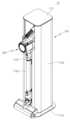
- FIG. 1is a perspective view of a cleaner system including a cleaner station and a cleaner according to an embodiment of the present invention.
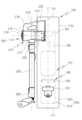
- FIG. 2is a schematic diagram of a configuration of a cleaner system according to an embodiment of the present invention.
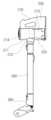
- 3 and 4are diagrams for explaining a cleaner in a cleaner system according to an embodiment of the present invention.
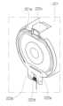
- FIG. 5is a view for explaining a lower surface of a dust bin of a vacuum cleaner according to an embodiment of the present invention.
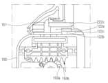
- FIG. 6is a diagram for explaining a coupling part in a cleaner station according to an embodiment of the present invention.
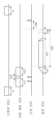
- FIG. 7is an exploded perspective view illustrating a fixing unit in a cleaner station according to an embodiment of the present invention.
- FIG 8 and 9are views for explaining a relationship between a cleaner and a door unit in a cleaner station according to an embodiment of the present invention.
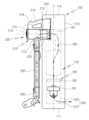
- FIG. 10is a diagram for explaining a relationship between a cleaner and a cover opening unit in a cleaner station according to an embodiment of the present invention.
- FIG. 11is a diagram for explaining a cleaner system according to a first embodiment of the present invention.
- FIG. 12is a diagram for explaining a cleaner system according to a second embodiment of the present invention.
- FIG. 13is a block diagram for explaining a control configuration in a vacuum cleaner system according to an embodiment of the present invention.
- FIG. 14is a flowchart illustrating a process of drying a dust collecting unit in a control method of a vacuum cleaner system according to an embodiment of the present invention.
- 15is a diagram for explaining the operation of each motor in the control method of the cleaner system according to the embodiment of the present invention.
- 16is a diagram for explaining an air flow in a drying step of a control method of a cleaner system according to an embodiment of the present invention.
- FIGS. 2 to 4are schematic views of the configuration of the cleaner system according to various embodiments of the present invention. .
- a cleaner system 10may include a cleaner station 100 and a cleaner 200 .
- the cleaner system 10may include a cleaner station 100 .
- the cleaner 200may be coupled to the cleaner station 100 .
- the main body of the cleaner 200may be coupled to the side of the cleaner station 100 .
- the cleaner station 100may remove dust from the dust bin 220 of the cleaner 200 .
- FIGS. 3 and 4show drawings for explaining the cleaner in the cleaner system according to the embodiment of the present invention
- FIG. 7shows drawings for explaining the lower side of the dust box of the cleaner according to the embodiment of the present invention.
- the cleaner 200may refer to a cleaner manually operated by a user.
- the cleaner 200may mean a handheld cleaner or a stick cleaner.
- the cleaner 200may be mounted on the cleaner station 100 .
- the cleaner 200may be supported by the cleaner station 100 .
- the cleaner 200may be coupled to the cleaner station 100 .
- the direction of the cleaner 200may be defined based on when the dust bin 220 and the bottom surface (lower surface) of the battery housing 230 are placed on the ground.
- the frontmay mean a direction in which the suction unit 212 is disposed relative to the suction motor 214
- the rearmay mean a direction in which the handle 216 is disposed relative to the suction motor 214.
- a direction disposed on the right side of the suction motor 214 when looking at the suction part 212may be referred to as a right side
- a direction disposed on the left sidemay be referred to as a left side.
- the upper and lower sidesmay be defined along a direction perpendicular to the ground based on when the dust bin 220 and the bottom surface (lower surface) of the battery housing 230 are placed on the ground. .
- the cleaner 200may include a main body 210 .
- the body 210may include a body housing 211, a suction part 212, a dust separator 213, a suction motor 214, an air discharge cover 215, a handle 216, and a control unit 218. there is.
- the body housing 211may form the exterior of the cleaner 200 .
- the body housing 211may provide a space capable of accommodating the suction motor 214 and a filter (not shown) therein.
- the body housing 211may be configured in a shape similar to a cylinder.
- the suction part 212may protrude outward from the body housing 211 .
- the inlet 212may be formed in a cylindrical shape with an open interior.
- the suction part 212may be coupled with the extension tube 250 .
- the suction unit 212may provide a suction passage 2121 through which air containing dust may flow.
- an imaginary line passing through the inside of the suction unit 212 having a cylindrical shapemay be formed.
- the dust separation unit 213may communicate with the suction unit 212 .
- the dust separation unit 213may separate dust sucked into the inside through the suction unit 212 .
- the space inside the dust separator 213may communicate with the space inside the dust container 220 .
- the dust separation unit 213may include at least one cyclone unit capable of separating dust by cyclone flow. Also, a space inside the dust separator 213 may communicate with the suction passage 2121 . Accordingly, air and dust sucked through the suction unit 212 spirally flow along the inner circumferential surface of the dust separation unit 213 . Thus, a cyclone flow may occur in the inner space of the dust separator 213 .
- the dust separation unit 213communicates with the suction unit 212 and has a configuration in which the principle of a dust collector using centrifugal force is applied to separate dust sucked into the body 210 through the suction unit 212 .
- the dust separator 213may further include a secondary cyclone that separates dust from the air discharged from the cyclone again.
- the secondary cyclonemay be located inside the cyclone so that the size of the dust separator is minimized.
- the secondary cyclonemay include a plurality of cyclone bodies arranged in parallel. The air discharged from the cyclone can pass through divided into a plurality of cyclone bodies.
- the axis of the cyclone flow of the secondary cyclonemay also extend in the vertical direction, and the axis of the cyclone flow of the cyclone and the axis of the cyclone flow of the secondary cyclone may form a coaxial axis in the vertical direction, This may be collectively referred to as an axis of the cyclone flow of the dust separator 213 .
- the suction motor 214may generate a suction force for sucking air.
- the suction motor 214may be housed in the body housing 211 .
- the suction motor 214may generate suction force by rotation.
- the suction motor 214may be provided similarly to a cylindrical shape.
- a virtual suction motor axismay be formed by extending the rotation axis of the suction motor 214 .
- the air discharge cover 215may be disposed on one side of the body housing 211 in the axial direction.
- a filter for filtering airmay be accommodated in the air discharge cover 215 .
- a HEPA filtermay be accommodated in the air discharge cover 215 .
- An air discharge port 215amay be formed in the air discharge cover 215 to discharge air sucked in by the suction force of the suction motor 214 .
- a flow guidemay be disposed on the air discharge cover 215 .
- the flow guidemay guide the flow of air discharged through the air outlet 215a.
- the handle 216can be grasped by a user.
- a handle 216may be disposed behind the suction motor 214 .
- the handle 216may be formed to resemble a cylindrical shape.
- the handle 216may be formed in a bent cylindrical shape.
- the handle 216may be disposed at a predetermined angle with the body housing 211 or the suction motor 214 or the dust separator 213 .
- the handle 216is a gripping part formed in a column shape so that a user can hold it, a first extension part connected to one end of the gripping part in the longitudinal direction (axial direction) and extending toward the suction motor 214, and a length of the gripping part.
- a second extension portion connected to the other end in the direction (axial direction) and extending toward the dust container 220may be included.
- a virtual gripping part penetration line extending along the length direction of the gripping part (axial direction of the column) and penetrating the gripping partmay be formed.
- the gripping part penetration linemay be a virtual line formed inside the cylindrical handle 216 or may be a virtual line formed parallel to at least a part of an outer surface (outer circumferential surface) of the gripping part.
- the upper surface of the handle 216may form part of the outer appearance of the upper surface of the cleaner 200 . Through this, when the user grips the handle 216, a component of the cleaner 200 may be prevented from coming into contact with the user's arm.
- the first extension partmay extend toward the body housing 211 or the suction motor 214 from the gripping part. At least a portion of the first extension portion may extend in a horizontal direction.
- the second extension partmay extend toward the dust bin 220 from the gripping part. At least a portion of the second extension portion may extend in a horizontal direction.
- Manipulator 218may be disposed on handle 216 .
- the control unit 218may be disposed on an inclined surface formed in an upper region of the handle 216 .
- a usermay input an operation or stop command of the cleaner 200 through the control unit 218 .
- the cleaner 200may include a dust container 220 .
- the dust container 220may communicate with the dust separator 213 .
- the dust container 220may store the dust separated by the dust separator 213 .
- the dust bin 220may include a dust bin body 221, a discharge cover 222, a dust bin compression lever 223, and a compressor (not shown).
- the dust container body 221may provide a space for storing the dust separated by the dust separator 213 .
- the dust container body 221may be formed similarly to a cylindrical shape.
- the dust box body 221passes through the inside (inner space) and is formed extending along the longitudinal direction of the dust box body 221 (meaning the axial direction in the cylindrical dust box body 221). It is possible to form a line through the dust box.
- a lower surface (bottom surface) of the dust box body 221may be partially opened.
- a lower surface extension 221amay be formed on a lower surface (bottom surface) of the dust box body 221 .
- the lower surface extension 221amay be formed to partially block the lower surface of the dust container body 221 .
- the dust bin 220may include a discharge cover 222 .
- the discharge cover 222may be disposed on the lower side of the dust bin 220 .
- the discharge cover 222may be provided to open and close one end of the dust container body 221 in the longitudinal direction. Specifically, the discharge cover 222 may selectively open and close the lower part of the dust bin 220 that opens downward.
- the discharge cover 222may include a cover body 222a and a hinge portion 222b.
- the cover body 222amay be formed to partially cover the lower surface of the dust container body 221 .
- the cover body 222amay rotate downward based on the hinge portion 222b.
- the hinge part 222bmay be disposed adjacent to the battery housing 230 .
- a torsion spring 222dmay be provided at the hinge portion 222b. Therefore, when the discharge cover 222 is separated from the dust box body 221, the cover body 222a moves through the dust box body 221 with the hinge part 222b as an axis by the elastic force of the torsion spring 222d. It can be supported in a rotated state more than an angle.
- the discharge cover 222may be coupled to the dust container 220 through hook coupling. Meanwhile, the discharge cover 222 may be separated from the dust bin 220 through the coupling lever 222c.
- the coupling lever 222cmay be disposed in front of the dust bin. Specifically, the coupling lever 222c may be disposed on an outer surface of the front side of the dust bin 220 . When an external force is applied, the coupling lever 222c may elastically deform the hook extending from the cover body 222a to release the hook coupling between the cover body 222a and the dust container body 221 .
- the discharge cover 222When the discharge cover 222 is closed, the lower surface of the dust bin 220 may be blocked (sealed) by the discharge cover 222 and the lower surface extension portion 221a.
- the dust bin 220may include a dust bin compression lever 223 (see FIG. 4 ).
- the dust bin compression lever 223may be disposed outside the dust bin 220 or the dust separator 213 .
- the dust bin compression lever 223may be disposed outside the dust bin 220 or the dust separator 213 to move up and down.
- the dust box compression lever 223may be connected to a compressor (not shown).
- a compressorWhen the dust box compression lever 223 moves downward by an external force, a compressor (not shown) may also move downward. Through this, it is possible to provide user convenience.
- the compressor (not shown) and the dust container compression lever 223may be returned to their original positions by an elastic member (not shown). Specifically, when the external force applied to the dust box compression lever 223 is removed, the elastic member may move the dust box compression lever 223 and the compressor (not shown) upward.
- a compressor(not shown) may be disposed inside the dust box body 221 .
- the compressormay move the inner space of the dust container body 221 .
- the compressormay move up and down within the dust container body 221 . Through this, the compressor may compress the dust in the dust container body 221 downward.
- the compressormoves from the top to the bottom of the dust bin 220 to remove foreign substances such as remaining dust in the dust bin 220. can be removed. Through this, it is possible to improve suction power of the cleaner by preventing residual dust from remaining in the dust bin 220 . In addition, residual dust is prevented from remaining in the dust bin 220 to remove odors caused by the residue.
- the cleaner 200may include a battery housing 230 .
- a battery 240may be accommodated in the battery housing 230 .
- the battery housing 230may be disposed below the handle 216 .
- the battery housing 230may have a hexahedral shape with an open bottom.
- a rear surface of the battery housing 230may be connected to the handle 216 .
- the battery housing 230may include a receiving portion that opens downward.
- the battery 240may be detachable through the receiving portion of the battery housing 230 .
- the cleaner 200may include a battery 240 .
- the battery 240may be detachably coupled to the cleaner 200 .
- the battery 240may be detachably coupled to the battery housing 230 .
- the battery 240may be inserted into the battery housing 230 from below the battery housing 230 . With such a configuration, the portability of the cleaner 200 can be improved.
- the battery 240may be integrally provided inside the battery housing 230 . At this time, the lower surface of the battery 240 is not exposed to the outside.
- the battery 240may supply power to the suction motor 214 of the cleaner 200 .
- Battery 240may be disposed under handle 216 .
- the battery 240may be disposed behind the dust container 220 .
- the lower surface of the battery 240when the battery 240 is coupled to the battery housing 230, the lower surface of the battery 240 may be exposed to the outside. Since the battery 240 may be placed on the floor when the cleaner 200 is placed on the floor, the battery 240 may be directly separated from the battery housing 230 . In addition, since the lower surface of the battery 240 is exposed to the outside and directly contacts the outside air of the battery 240 , cooling performance of the battery 240 may be improved.
- the structure for attaching and detaching the battery 240 and the battery housing 230may be reduced, and thus the overall size of the cleaner 200 may be reduced. Yes, and it is possible to reduce weight.
- the cleaner 200may include an extension tube 250 .
- the extension pipe 250may communicate with the cleaning module 260 .
- the extension pipe 250may communicate with the main body 210 .
- the extension pipe 250may communicate with the suction part 212 of the main body 210 .
- the extension pipe 250may be formed in a long cylindrical shape.
- the main body 210may be connected to the extension pipe 250 .
- the main body 210may be connected to the cleaning module 260 through an extension tube 250 .
- the body 210may generate suction force through the suction motor 214 and provide suction force to the cleaning module 260 through the extension pipe 250 .
- External dustmay be introduced into the body 210 through the cleaning module 260 and the extension pipe 250 .
- the cleaner 200may include a cleaning module 260 .
- the cleaning module 260may communicate with the extension pipe 250 . Accordingly, external air may flow into the main body 210 of the cleaner 200 through the cleaning module 260 and the extension tube 250 by the suction force generated in the main body 210 of the cleaner 200 .
- Dust in the dust bin 220 of the cleaner 200may be collected by the dust collector 170 of the cleaner station 100 by gravity and the suction force of the dust collection motor 191 .
- the usercan eliminate the hassle of having to empty the dust bin every time.
- the dust binis emptied, it is possible to prevent dust from scattering.
- the cleaner 200may be coupled to the side of the housing 110 .
- the main body 210 of the cleaner 200may be mounted on the coupling part 120 .
- the dust bin 220 and the battery housing 230 of the cleaner 200may be coupled to the coupling surface 121, and the outer circumferential surface of the dust bin body 221 may be coupled to the dust bin guide surface 122, ,
- the suction part 212may be coupled to the suction part guide surface 126 of the coupling part 120.
- the central axis of the dust bin 220may be disposed in a direction parallel to the ground, and the extension pipe 250 may be disposed along a direction perpendicular to the ground.
- a cleaner 200may be disposed in the cleaner station 100 .
- the cleaner 200may be coupled to a side surface of the cleaner station 100 .
- the main body of the cleaner 200may be coupled to the side of the cleaner station 100 .
- the cleaner station 100may remove dust from the dust bin 220 of the cleaner 200 .
- the cleaner station 100may include a housing 110 .
- the housing 110may form the appearance of the cleaner station 100 .
- the housing 110may be formed in a columnar shape including at least one outer wall surface.
- the housing 110may be formed in a shape similar to a square pillar.
- the housing 110may have a space capable of accommodating the dust collecting unit 170 that stores dust and the dust suction module 190 that generates a flow force by which the dust is collected by the dust collecting unit 170 .
- the housing 110may include a bottom surface 111 , an outer wall surface 112 , and an upper surface 113 .
- the bottom surface 111may support the lower side of the dust suction module 190 in the direction of gravity. That is, the bottom surface 111 may support the lower side of the dust collecting motor 171 of the dust suction module 190 .
- the bottom surface 111may be disposed toward the ground.
- the bottom surface 111may be disposed parallel to the ground or inclined at a predetermined angle with the ground.
- the floor surface 111may further include a ground support 111a to increase a contact area with the ground in order to prevent the cleaner station 100 from falling over and to maintain balance.
- the ground support partmay be in the form of a plate extending from the bottom surface 111, and one or more frames may protrude and extend from the bottom surface 111 along the direction of the ground.
- the outer wall surface 112may mean a surface formed along the direction of gravity, and may mean a surface connected to the bottom surface 111 .
- the outer wall surface 112may refer to a surface vertically connected to the bottom surface 111 .
- the outer wall surface 112may also be disposed inclined at a predetermined angle with the bottom surface 111 .
- the outer wall surface 112may include at least one surface.
- the outer wall surface 112may include a first outer wall surface 112a, a second outer wall surface 112b, a third outer wall surface 112c, and a fourth outer wall surface 112d.
- the first outer wall surface 112amay be disposed on the front of the cleaner station 100 .
- the front sidemay refer to a surface where the cleaner 200 is exposed in a state in which the cleaner 200 is coupled to the cleaner station 100 . Accordingly, the first outer wall surface 112a may form a front appearance of the cleaner station 100 .
- a directionmay be defined while the cleaner 200 is mounted on the cleaner station 100 .
- a direction in which the cleaner 200 is exposed to the outside of the cleaner station 100may be referred to as a front.
- a direction in which the suction motor 214 of the cleaner 200 is disposedmay be referred to as a forward direction.
- a direction opposite to the direction in which the suction motor 214 is disposed in the cleaner station 100may be referred to as a rear direction.
- a surface facing the front of the housing 110 based on the inner spacemay be referred to as a rear surface of the cleaner station 100 . Accordingly, the rear surface may refer to a direction in which the second outer wall surface 112b is formed.
- the left surfacewhen looking at the front with respect to the inner space of the housing 110, the left surface may be referred to as a left surface, and the right surface may be referred to as a right surface. Accordingly, the left surface may mean a direction in which the third outer wall surface 112c is formed, and the right surface may mean a direction in which the fourth outer wall surface 112d is formed.
- the first outer wall surface 112amay be formed in a flat shape, as well as in a curved shape as a whole, or may include a curved surface in a portion thereof.
- the first outer wall surface 112amay have an appearance corresponding to the shape of the cleaner 200 .
- the coupling part 120may be disposed on the first outer wall surface 112a. With this configuration, the cleaner 200 can be coupled to the cleaner station 100 and supported by the cleaner station 100 . A detailed configuration of the coupler 120 will be described later.
- a structure for holding various types of cleaning modules 260 used in the cleaner 200may be added to the first outer wall surface 112a.
- the second outer wall surface 112bmay be a surface facing the first outer wall surface 112a. That is, the second outer wall surface 112b may be disposed on the rear surface of the cleaner station 100 .
- the rear surfacemay be a surface facing the surface to which the cleaner 200 is coupled. Accordingly, the second outer wall surface 112b may form the outer appearance of the rear surface of the cleaner station 100 .
- the second outer wall surface 112bmay be formed in a planar shape.
- the cleaner station 100can be brought into close contact with an indoor wall, and the cleaner station 100 can be stably supported.
- a structure for holding various types of cleaning modules 260 used in the cleaner 200may be added to the second outer wall surface 112b.
- the third outer wall surface 112c and the fourth outer wall surface 112dmay mean surfaces connecting the first outer wall surface 112a and the second outer wall surface 112b.
- the third outer wall surface 112cmay be disposed on the left surface of the station 100
- the fourth outer wall surface 112dmay be disposed on the right surface of the cleaner station 100.
- the third outer wall surface 112cmay be disposed on the right surface of the cleaner station 100
- the fourth outer wall surface 112dmay be disposed on the left surface of the cleaner station 100 .
- the third outer wall surface 112c or the fourth outer wall surface 112dmay be formed in a flat shape, as well as in a curved shape as a whole, or may include a curved surface in a portion thereof.
- a structure for holding various types of cleaning modules 260 used in the cleaner 200may be added to the third outer wall surface 112c or the fourth outer wall surface 112d.
- the upper surface 113may form the top appearance of the cleaner station. That is, the upper surface 113 may refer to a surface exposed to the outside by being disposed on the uppermost side in the direction of gravity in the cleaner station.
- the upper and lower sidesmay respectively mean upper and lower sides along a direction of gravity (a direction perpendicular to the ground) in a state where the cleaner station 100 is installed on the ground.
- the upper surface 113may be disposed parallel to the ground or inclined at a predetermined angle with the ground.
- a display unit 410may be disposed on the upper surface 113 .
- the display unit 410may display the status of the cleaner station 100 and the vacuum cleaner 200, and may display other information such as a cleaning progress status and a map of a cleaning area.
- the upper surface 113may be detachably provided from the outer wall surface 112 .
- the battery separated from the cleaner 200can be accommodated in the inner space surrounded by the outer wall surface 112, and a terminal (not shown) capable of charging the separated battery is provided. It can be.
- FIG. 6is a drawing for explaining a coupling part in a cleaner station according to an embodiment of the present invention
- FIG. 7is a drawing for explaining a fixing unit in a cleaner station according to an embodiment of the present invention.
- FIG. 9shows a diagram for explaining the relationship between a cleaner and a door unit in a cleaner station according to an embodiment of the present invention
- FIG. 10shows a relationship between a cleaner and a cover opening unit in a cleaner station according to an embodiment of the present invention.
- a drawing for explanationis disclosed.
- the coupling part 120 of the cleaner station 100 according to the present inventionwill be described with reference to FIGS. 2 and 6 .
- the cleaner station 100may include a coupling part 120 to which the cleaner 200 is coupled.
- the coupling part 120may be disposed on the first outer wall surface 112a, and the body 210 of the cleaner 200, the dust bin 220, and the battery housing 230 may be coupled thereto.
- the coupling part 120may include a coupling surface 121 .
- the coupling surface 121may be disposed on a side surface of the housing 110 .
- the coupling surface 121may refer to a surface concavely formed in a groove shape from the first outer wall surface 112a toward the inside of the cleaner station 100 . That is, the coupling surface 121 may mean a surface formed by forming a step with the first outer wall surface 112a.
- the cleaner 200may be coupled to the coupling surface 121 .
- the coupling surface 121may contact the lower surface of the dust bin 220 and the battery housing 230 of the cleaner 200 .
- the lower sidemay refer to a side facing the ground when the user uses the cleaner 200 or places it on the ground.
- an angle between the coupling surface 121 and the groundmay be a right angle.
- the coupling surface 121may be disposed inclined at a predetermined angle with the ground. Through this, when the cleaner 200 is coupled to the coupling surface 121, the cleaner station 100 can be stably supported.
- a dust passage hole 121amay be formed in the coupling part 120 so that air outside the housing 110 may flow into the inside.
- a dust passage hole 121amay be formed on the coupling surface 121 of the coupling portion 120 to allow air outside the housing 110 to flow into the inside.
- the dust passing hole 121amay be formed in a hole shape corresponding to the shape of the dust bin 220 so that dust in the dust bin 220 flows into the dust collection unit 170 .
- the dust passage hole 121amay be formed to correspond to the shape of the discharge cover 222 of the dust bin 220 .
- the dust passage hole 121amay be formed to communicate with a passage part 180 to be described later.
- the coupling part 120may include a dust box guide surface 122 .
- the dust box guide surface 122may be disposed on the first outer wall surface 112a.
- the dust box guide surface 122may be connected to the first outer wall surface 112a.
- the dust box guide surface 122may be connected to the coupling surface 121 .
- the dust bin guide surface 122may be formed in a shape corresponding to the outer surface of the dust bin 220 .
- a front outer surface of the dust bin 220may be coupled to the dust bin guide surface 122 . Through this, convenience in coupling the cleaner 200 to the coupling surface 121 may be provided.
- a protrusion movement hole 122amay be formed in the dust container guide surface 122 , and a push protrusion 151 to be described later may linearly move along the projection movement hole 122a.
- a gear box 155 accommodating a gear of the cover opening unit 150 to be described latermay be provided below the dust box guide surface 122 in the direction of gravity.
- a guide space 122b in which the push protrusion 151 can movemay be formed between the lower surface of the dust box guide surface 122 and the upper surface of the gear box 155 .
- the guide space 122bmay communicate with the flow path 180 through the bypass hole 122c.
- the protrusion movement hole 122a, the guide space 122b, the bypass hole 122c, and the flow path 180may form one bypass flow path (see FIG. 10).
- the coupling part 120may include a guide protrusion 123 .
- the guide protrusion 123may be disposed on the coupling surface 121 .
- the guide protrusion 123may protrude upward from the coupling surface 121 .
- Two guide protrusions 123may be disposed spaced apart from each other. A distance between the two guide protrusions 123 spaced apart from each other may correspond to a width of the battery housing 230 of the cleaner 200 . Through this, convenience in coupling the cleaner 200 to the coupling surface 121 may be provided.
- Coupling part 120may include a side wall 124 .
- the side wall 124may refer to a wall surface disposed on both sides of the coupling surface 121 and may be connected perpendicularly to the coupling surface 121 .
- the side wall 124may be connected to the first outer wall surface 112a.
- the side wall 124may form a surface connected to the dust box guide surface 122 . Through this, the cleaner 200 can be stably accommodated.
- the coupling unit 120may include a coupling sensor 125 .
- the coupling sensor 125may detect whether the cleaner 200 is coupled to the coupling unit 120 .
- the coupling sensor 125may include a contact sensor.
- the coupling sensor 125may include a micro switch.
- the coupling sensor 125may be disposed on the guide protrusion 123 . Therefore, when the battery housing 230 or the battery 240 of the cleaner 200 is coupled between the pair of guide protrusions 123, the coupled sensor 125 comes into contact with the coupled sensor 125. ) can be detected.
- the combined sensor 125may also include a non-contact sensor.
- the combined sensor 125may include an infrared sensor unit (IR sensor).
- the combined sensor 125may be disposed on the side wall 124 . Therefore, when the dust bin 220 or main body 210 of the cleaner 200 passes through the side wall 124 and reaches the coupling surface 121, the coupling sensor 125 detects the presence of the dust bin 220 or the main body 210. can detect
- the combination sensor 125may face the dust bin 220 or the battery housing 230 of the cleaner 200 .
- the coupling sensor 125may be a means for determining whether the cleaner 200 is coupled with power being applied to the battery 240 of the cleaner 200 .
- the coupling part 120may include an inlet guide surface 126 .
- the inlet guide surface 126may be disposed on the first outer wall surface 112a.
- the inlet guide surface 126may be connected to the dust box guide surface 122 .
- the suction part 212may be coupled to the suction part guide surface 126 .
- the shape of the suction part guide surface 126may be formed to correspond to the shape of the suction part 212 .
- the coupling part 120may further include a fixing member access hole 127 .
- the fixing member access hole 127may be formed in a long hole shape along the side wall 124 so that the fixing member 131 can enter and exit.
- the dust box guide surface 122, the guide protrusion 123, and the suction part guide surface 126act as a vacuum cleaner.
- the body 210 of the body 200may be stably disposed on the coupling part 120. Through this, convenience in coupling the dust bin 220 and the battery housing 230 of the cleaner 200 to the coupling surface 121 may be provided.
- the fixing unit 130according to the present invention is described as follows.
- the cleaner station 100 of the present inventionmay include a fixing unit 130 .
- the fixing unit 130may be disposed on the side wall 124 .
- at least a portion of the fixing unit 130may be disposed on the back surface of the coupling surface 121 .
- the fixing unit 130may fix the cleaner 200 coupled to the coupling surface 121 .
- the fixing unit 130may fix the dust container 220 and the battery housing 230 of the cleaner 200 coupled to the coupling surface 121 .
- the fixing unit 130may include a fixing member 131 fixing the dust bin 220 and the battery housing 230 of the cleaner 200, and a fixing motor 133 driving the fixing member 131.
- the fixing unit 130may further include a fixing part link 135 that transmits power of the fixing part motor 133 to the fixing member 131 .
- the fixing member 131may be disposed on the sidewall 124 of the coupling part 120 and may be reciprocally movable on the sidewall 124 to fix the dust container 220 . Specifically, the fixing member 131 may be accommodated inside the fixing member access hole 127 .
- the fixing member 131may be disposed on both sides of the coupling part 120, respectively.
- two fixing members 131may be symmetrically arranged in pairs around the coupling surface 121 .
- the fixing motor 133may provide power for moving the fixing member 131 .
- the fixing part link 135may convert the rotational force of the fixing part motor 133 into reciprocating movement of the fixing member 131 .
- the fixed sealer 136When the cleaner 200 is coupled, the fixed sealer 136 may be disposed on the dust container guide surface 122 so that the dust container 220 is airtight. With this configuration, when the dust bin 220 of the vacuum cleaner 200 is coupled, the fixed sealer 136 can be pressed by the weight of the vacuum cleaner 200, and the dust bin 220 and the dust bin guide surface 122 are sealed. It can be.
- the fixing sealer 136may be disposed on a virtual extension line of the fixing member 131 . With this configuration, when the fixing part motor 133 is operated and the fixing member 131 presses the dust container 220 , the circumference of the dust container 220 on the same height may be sealed.
- the fixed sealer 136may be disposed on the dust box guide surface 122 in a bent line shape corresponding to the arrangement of the cover opening unit 150 to be described later.
- the fixing unit 130may fix the main body 210 of the cleaner 200.
- the coupling sensor 125detects that the main body 210 of the cleaner 200 is coupled to the coupling portion 120 of the cleaner station 100
- the fixing motor 133moves the fixing member 131.
- the main body 210 of the cleaner 200may be fixed by moving it.
- the door unit 140 of the present inventionwill be described with reference to FIGS. 2, 8, 9 and 13.
- the cleaner station 100 of the present inventionmay include a door unit 140 .
- the door unit 140may be configured to open and close the dust passage hole 121a.
- the door unit 140may include a door 141 , a door motor 142 and a door arm 143 .
- the door 141is hinged to the coupling surface 121 and can open and close the dust passage hole 121a.
- the door 141may include a door body 141a.
- the door body 141amay be formed in a form capable of blocking the dust passage hole 121a.
- the door body 141amay be formed similarly to a disc shape.
- a hinge unitis disposed on the upper side of the door body 141a, and an arm coupling unit 141b is disposed on the lower side of the door body 141a.
- the door body 141amay be formed in a form capable of sealing the dust passage hole 121a.
- an outer surface of the door body 141a exposed to the outside of the cleaner station 100is formed to have a diameter corresponding to the diameter of the dust passage hole 121a, and an inner surface disposed inside the cleaner station 100.
- the side surfaceis formed to have a larger diameter than the diameter of the dust passage hole 121a.
- a stepmay be generated between the outer surface and the inner surface.
- at least one reinforcing rib for connecting the hinge portion and the arm coupling portion 141b and reinforcing the bearing capacity of the door body 141amay protrude from an inner surface of the door body 141a.
- the hinge partmay be a means for hinge-coupled the door 141 to the coupling surface 121 .
- the hinge partmay be disposed at an upper end of the door body 141a and coupled to the coupling surface 121 .
- the arm coupling part 141bmay be a means by which the door arm 143 is rotatably coupled.
- the arm coupling portion 141bmay be disposed below the door body 141a, rotatably coupled with the door body 141a, and rotatably coupled to the door arm 143.
- the door arm 143pulls the door body 141a in a state where the door 141 closes the dust passing hole 121a, the door body 141a pivots on the hinge portion to move the cleaner station 100 ), and the dust passage hole 121a may be opened. Meanwhile, when the door arm 143 pushes the door body 141a while the dust passage hole 121a is open, the door body 141a moves along the outside of the cleaner station 100 with the hinge portion 141b as an axis. It rotates and moves toward, and the dust passage hole 121a may be blocked.
- the door 141may come into contact with the discharge cover 222.
- the discharge cover 222may rotate in conjunction with the door 141 .
- the door motor 142may provide power for rotating the door 141 .
- the door motor 142may rotate the door arm 143 forward or reverse.
- the forward directionmay mean a direction in which the door arm 143 pulls the door 141 . Accordingly, when the door arm 143 rotates in the forward direction, the dust passage hole 121a may be opened.
- the reverse directionmay mean a direction in which the door arm 143 pushes the door 141 . Accordingly, when the door arm 143 rotates in the reverse direction, the dust passage hole 121a may be at least partially closed.
- the forward directionmay be the reverse direction and the opposite direction.
- the door arm 143connects the door 141 and the door motor 142 and can open and close the door 141 using power generated by the door motor 142 .
- the door arm 143may include a first door arm 143a and a second door arm 143b.
- One end of the first door arm 143amay be coupled to the door motor 142 .
- the first door arm 143amay rotate by power of the door motor 142 .
- the other end of the first door arm 143amay be rotatably coupled to the second door arm 143b.
- the first door arm 143amay transfer the force transmitted from the door motor 142 to the second door arm 143b.
- One end of the second door arm 143bmay be coupled to the first door arm 143a.
- the other end of the second door arm 143bmay be coupled to the door 141 .
- the second door arm 143bmay push or pull the door 141 to open and close the dust passage hole 121a.
- the door unit 140may further include a door open/close detector 144 .
- the door open/close detector 144may be provided inside the housing 110 and may detect whether the door 141 is open.
- the door open/close detector 144may be disposed at both ends of the rotational movement area of the door arm 143 .
- the door open/close detector 144may be disposed at both ends of the movement area of the door 141 .
- the door open/close detection unit 144may detect that the door is open.
- the door open/close detection unit 144may detect that the door is opened.
- the door open/close sensor 144may also include a contact sensor.
- the door open/close sensor 144may include a micro switch.
- the door open/close sensor 144may also include a non-contact sensor.
- the door opening/closing detector 144may include an infrared sensor (IR sensor).
- the door unit 140can selectively open and close at least a portion of the coupling surface 121 to communicate the outside of the first outer wall surface 112a with the flow path 180 and/or the dust collection unit 170. there is.
- the door unit 140may be opened when the discharge cover 222 of the cleaner 200 is opened. In addition, when the door unit 140 is closed, the discharge cover 222 of the cleaner 200 may be closed together in conjunction therewith.
- the door motor 142rotates the door 141 to couple the discharge cover 222 to the dust bin body 221 .
- the door motor 142rotates the door 141 by rotating the door 141 , and the rotating door 141 may push the discharge cover 222 toward the dust box body 221 .
- the cover opening unit 150 of the present inventionwill be described with reference to FIGS. 2, 10 and 13.
- the cleaner station 100 of the present inventionmay include a cover opening unit 150 .
- the cover opening unit 150is disposed on the coupling part 120 and can open the discharge cover 222 of the cleaner 200 .
- the cover opening unit 150may include a push protrusion 151 , a cover opening motor 152 , a cover opening gear 153 , a support plate 154 , and a gear box 155 .
- the push protrusion 151may move to press the coupling lever 222c when the cleaner 200 is coupled.
- the push protrusion 151may be disposed on the dust box guide surface 122 . Specifically, a protrusion movement hole may be formed in the dust container guide surface 122 , and the push protrusion 151 may pass through the projection movement hole and be exposed to the outside.
- the push protrusion 151may be disposed at a position where the coupling lever 222c can be pressed when the cleaner 200 is coupled. That is, the coupling lever 222c may be disposed on the protrusion movement hole. Also, the coupling lever 222c may be disposed on the moving area of the push protrusion 151 .
- the push protrusion 151may linearly reciprocate to press the coupling lever 222c. Specifically, the push protrusion 151 is coupled to the gear box 155 so that linear movement may be guided. The push protrusion 151 is coupled to the cover opening gear 153 and may be moved together by the movement of the cover opening gear 153 .
- the cover opening motor 152may provide power to move the push protrusion 151 .
- the cover opening motor 152may rotate a motor shaft (not shown) in a forward or reverse direction.
- the forward directionmay mean a direction in which the push protrusion 151 presses the coupling lever 222c.
- the reverse directionmay refer to a direction in which the push protrusion 151, which presses the coupling lever 222c, returns to its original position.
- the forward directionmay be the reverse direction and the opposite direction.
- the cover opening gear 153is coupled to the cover opening motor 152 and may move the push protrusion 151 using power of the cover opening motor 152 .
- the cover opening gear 153may be accommodated inside the gear box 155 .
- the drive gear 153a of the cover opening gear 153may be coupled to the motor shaft of the cover opening motor 152 to receive power.
- the driven gear 153b of the cover opening gear 153may be coupled with the push protrusion 151 to move the push protrusion 151 .
- the driven gear 153bis provided in the form of a rack gear, meshes with the driving gear 153a, and can receive power from the driving gear 153a.
- the discharge cover 222may be provided with a torsion spring 222d.
- the discharge cover 222can be rotated more than a predetermined angle and supported in the rotated position. Accordingly, the discharge cover 222 may be opened, and the dust passage hole 121a may communicate with the inside of the dust container 220 .
- the gearbox 155is provided inside the housing 110, is disposed below the coupling part 120 in the gravitational direction, and the cover opening gear 153 may be accommodated therein.
- a cover opening detection unit 155fmay be provided in the gear box 155 .
- the cover opening detector 155fmay include a contact sensor.
- the cover opening detector 155fmay include a micro switch.
- the cover opening detector 155fmay also include a non-contact sensor.
- the cover opening detection unit 155fmay include an infrared sensor unit (IR sensor).
- At least one cover opening detector 155fmay be disposed on an inner surface or an outer surface of the gear box 155 .
- one cover opening detector 155fmay be disposed on an inner surface of the gearbox 155.
- the cover opening detection unit 155fmay detect that the push protrusion 151 is in an initial position.
- two cover opening detectors 155fmay be disposed on the outer surface of the gearbox 155. At this time, the cover opening detection unit 155f may detect the initial position and the cover opening position of the push protrusion 151 .
- the usercan open the dust bin 220 without separately opening the discharge cover 222 of the cleaner by using the cover opening unit 150, thereby improving convenience.
- the dust collector 170will be described as follows.
- the cleaner station 100may include a dust collecting unit 170 .
- the dust collecting unit 170may be disposed inside the housing 110 .
- the dust collection unit 170may be disposed below the coupling unit 120 in the gravitational direction.
- the dust collecting unit 170may refer to a dust bag that collects dust sucked from the inside of the dust bin 220 of the cleaner 200 by the dust collecting motor 191 .
- the dust collecting unit 170may be detachably coupled to the housing 110 .
- the dust collecting unit 170may be separated from the housing 110 and discarded, and a new dust collecting unit 170 may be coupled to the housing 110 . That is, the dust collector 170 may be defined as a consumable part.
- the dust bagWhen a suction force is generated by the dust collecting motor 171, the dust bag may increase in volume and accommodate dust therein.
- the dust bagmay be made of a material that transmits air but does not transmit foreign substances such as dust.
- the dust bagmay be made of a non-woven fabric material and may have a hexahedral shape based on when the volume is increased.
- the dust bagmay be formed of an impervious material.
- the dust bagmay include roll vinyl (not shown). With this configuration, when the dust bag is sealed or bonded, dust or odor collected inside the dust bag can be prevented from escaping to the outside of the dust bag. At this time, the dust bag may be mounted on the housing 110 through a dust bag cartridge (not shown). If necessary, the dust bag can be replaced through a dust bag cartridge.
- a temperature sensor 175may be provided in the dust collector 170 .
- the temperature sensor 175may measure the internal temperature of the dust collector 170 . Temperature information measured by the temperature sensor 175 may be received by the controller 400 .
- the temperature sensor 175may be provided in the dust suction module 190 according to embodiments.
- the temperature of the dust collecting motor 191 or the temperature of the air discharged from the dust collecting motor 191is measured to measure the temperature of the air flowing into the circulation passage module 320. temperature can be calculated.
- the cleaner station 100may include a flow path part 180 .
- the passage part 180may connect the dust bin 220 of the cleaner 200 and the dust collecting part 170 .
- the passage part 180may communicate the dust container 220 of the cleaner 200 and the dust collecting part 170 .
- the passage part 180may be disposed on the rear side of the coupling surface 121 .
- the passage part 180may refer to a space between the dust bin 220 of the cleaner 200 and the dust collecting part 170 .
- the passage part 180may be a space formed rearward from the dust passage hole 121a, and may be a passage formed bent downward in the dust passage hole 121a to allow dust and air to flow.
- the first flow path 181communicating with the inner space of the dust bin 220 and the first flow path 181
- a second flow path 182 communicating between internal spaces of the dust collecting unit 170may be included.
- the first flow path 181may be disposed substantially parallel to an axis of the suction motor 214 or a virtual through line passing through the dust bin 220 .
- the axis of the suction motor 214 or the through line of the dust bin 220may pass through the first flow path 181 .
- the second flow path 182may be formed at a predetermined angle with the first flow path 181 .
- the first flow path 181 and the second flow path 182may be formed at right angles.
- the length of the first flow path 181may be equal to or smaller than the length of the second flow path.
- Dust in the dust bin 220 of the cleaner 200may move to the dust collection unit 170 through the flow passage 180 .
- the cleaner station 100may include a dust suction module 190 .
- the dust suction module 190may include a dust collection motor 191, a first filter 192, and a second filter (not shown).
- the dust collecting motor 191may be disposed below the dust collecting part 170 .
- the dust collecting motor 191may generate a suction force to the flow path part 180 . Through this, the dust collecting motor 191 may provide a suction force capable of sucking dust in the dust bin 220 of the cleaner 200 .
- the dust collecting motor 191may generate suction force by rotation.
- the dust collecting motor 191may be formed in a shape similar to a cylinder.
- a virtual dust collection motor axis C extending the rotational axis of the dust collection motor 191may be formed.
- the first filter 192may be disposed between the dust collecting unit 170 and the dust collecting motor 191 .
- the first filter 192may be a pre-filter.
- a second filtermay be disposed between the dust collecting motor 191 and the outer wall surface 112 .
- the second filtermay be a HEPA filter.
- the cleaner station 100may further include a charging unit 128 .
- the charging unitmay be disposed on the coupling unit 120 .
- the charging unit 128may be electrically connected to the cleaner 200 coupled to the coupling unit 120 .
- the charging unit 128may supply power to the battery of the cleaner 200 coupled to the coupling unit 120 .
- the cleaner station 100may further include a side door (not shown). Side doors may be disposed on the housing 110 . The side door may selectively expose the dust collection unit 170 to the outside. Through this, the user can easily remove the dust collector 170 from the cleaner station 100 .
- the cleaner station 100may further include an exhaust port 520 .
- the exhaust port 520may be formed in the housing 110 .
- the exhaust port 520may be formed on the lower side of the housing 110 and connected to the dust collecting motor 191 in a flow path. Thus, air passing through the dust collection motor 191 may be discharged to the outside of the housing 110 through the exhaust port 520 .
- the cleaner station 100may further include an exhaust unit 500 .
- the exhaust unit 500may guide air discharged from the dust collection motor 191 to the outside of the housing 110 through the exhaust passage 510 . That is, the air discharged from the dust collecting motor 191 may flow through the exhaust passage 510 and be discharged to the outside of the housing 110 .
- the exhaust passage 510may provide a passage through which air discharged from the dust collecting motor 191 flows. Specifically, one end of the exhaust passage 510 may communicate with an inner space in which the dust collection motor 191 is accommodated in the dust suction module 190, and the other end of the exhaust passage 510 may communicate with the exhaust port 520. .
- the exhaust passage 510may be a passage formed along a horizontal direction inside the housing 110, and one end of the exhaust passage 510 communicates with the dust suction module 190, and the exhaust passage 510 The other end may communicate with the exhaust port 520 .
- the cleaner system 10may include a hot air supply unit 300 .
- the heat supply unit 300may supply heat to the suction unit 212 .
- the intake unit 212may receive heat from the heat supply unit 300 through the intake passage 2121 inside the intake unit 212 .
- External heat supplied from the hot air supply unit 300is supplied to the suction unit 212, the dust bin 220, the flow path unit 180, the dust collection unit 170, and the exhaust unit 500 by the suction force generated by the dust collecting motor 191.
- the heat introduced through the suction unit 212may dry the dust collecting unit 170 in a state in which dust is collected while passing through the inside of the dust collecting unit 170 .
- FIG. 11a cleaner system according to a first embodiment of the present invention will be described.
- the heat supply unit 300 of the cleaner system according to the first embodiment of the present inventionmay include a heater 310 .
- a heater 310may be coupled to the suction unit 212 .
- the heater 310may heat external air introduced into the intake unit 212 .
- the heater 310may be connected to the suction side of the suction part 212 , but may be disposed in the suction passage 2121 inside the suction part 212 . That is, as long as the air introduced into the suction unit 212 can be heated, the specific shape or arrangement is not limited.
- the heater 310When the heater 310 is connected to the suction side of the suction part 212 , the heater 310 may include a heater housing 311 and a heating element 312 .
- the heater housing 311is detachably coupled to the suction side of the suction part 212, and a space through which air can flow may be formed therein.
- the heater housing 311may be formed similarly to a tubular shape in which a flow path through which air flows is formed.
- the heating element 312may be provided along the inner circumferential surface of the heater housing 311 .
- the heating element 312may be formed in an annular shape along an inner circumferential surface of the heater housing 311 .
- the heating element 312may heat external air introduced into the heater housing 311 . Therefore, the air heated by the heating element 312 flows inside the dust bin 220 and the dust collecting part 170 to reduce the humidity inside the vacuum cleaner system 10 including the dust bin 220 and the dust collecting part 170.
- the heater 310may receive power from the battery 240 .
- the battery 240may supply power to the heater 310 .
- the battery 240may supply power to the heating element 312 that heats external air introduced into the heater housing 311 .
- Hot air heated by the heater 310 and introduced into the suction unit 212may be sucked into the dust collection unit 170 via the dust container 220 by the suction force generated by the dust collecting motor 191 .
- the heater 310may heat air introduced into the suction unit 212 while the dust collection motor 191 is operated. When suction force is provided to the suction part 212 while the dust collecting motor 191 is operated, the heater 310 may heat air introduced into the suction part 212 .
- the heater 310may be driven after a predetermined time elapses after the dust collection motor 191 starts driving. After the dust collecting motor 191 is driven for 7 seconds or more and 8 seconds or less, the heater 310 may be driven, but is not limited thereto, and the output of the dust collecting motor 191 and the humidity inside the dust collecting part 170 are not limited thereto. It can be changed and set according to.
- the heater 310may be driven at the same time as the dust collection motor 191 starts driving.
- the dust collecting motor 191may be driven. After the heater 310 is driven for 7 seconds or more and 8 seconds or less, the dust collecting motor 191 may be driven, but is not limited thereto, and the air temperature and It may be changed and set according to the humidity inside the dust collector 170 .
- the heater 310may heat air introduced into the suction unit 212 in a state in which the door 141 of the cleaner station 100 rotates and the dust passage hole 121a is opened.
- the heater 310may heat air introduced into the suction part 212 .
- FIG. 12a cleaner system according to a second embodiment of the present invention will be described.
- the hot air supply unit 300 of the cleaner system according to the second embodiment of the present inventionmay include a circulation passage module 320 .
- the circulation passage module 320may continuously circulate the hot air discharged from the dust collecting motor 191 between the cleaner 200 and the cleaner station 100 by guiding it to the suction unit 212 without discharging it to the outside.
- the circulation passage module 320may connect the suction part 212 of the cleaner 200 and the exhaust part 500 of the cleaner station 100 . Specifically, the circulation flow path module 320 may have one end communicated with the suction part 212 and the other end communicated with the exhaust part 500 .
- the circulation passage module 320may provide a passage through which air discharged through the exhaust unit 500 flows (hereinafter, may be referred to as a 'circulation passage'). Specifically, one end of the circulation passage may communicate with the suction passage 2121 formed inside the suction part 212 and the other end may communicate with the exhaust passage 510 formed inside the exhaust part 500 .
- the dust collecting motor 191When the dust collecting motor 191 is driven, heat may be generated in the dust collecting motor 191 , and air discharged from the dust collecting motor 191 may be heated by heat generated by the dust collecting motor 191 .
- the air heated by the dust collection motor 191flows through the exhaust unit 500, the circulation flow path module 320, the suction unit 212, the dust bin 220, the coupling unit 120, the flow path unit 180, and the dust collection unit ( 170) may be introduced into the dust collection unit 170 again, and may be repeatedly heated while passing through the dust collection motor 191 again. Therefore, the air discharged from the dust collection motor 191 is heated while being continuously circulated without being discharged to the outside, so that the temperature may gradually rise.
- Air discharged from the dust collecting motor 191may flow through the exhaust passage 510 and be introduced into the circulation passage module 320 .
- the air introduced into the circulation passage module 320may be introduced into the suction passage 2121 by the air flow discharged from the dust collecting motor 191 .
- Air introduced into the circulation passage module 320may be introduced into the suction passage 2121 by a suction force provided to the dust container 220 by the dust collection motor 191 .
- the air introduced into the circulation passage module 320may flow into the suction passage 2121 by the airflow discharged by the dust collection motor 191 and the suction force provided to the dust container 220 by the dust collection motor 191 .
- the air flowing through the circulation passage module 320is introduced into the suction part 212 by the suction force generated by the dust collecting motor 191, and then passes through the dust bin 220, the coupling part 120, and the passage part 180 in order. After passing through the street, it may flow into the dust collecting unit 170.
- the air flowing through the circulation passage module 320passes through the dust container 220, the coupling part 120, and the passage part 180 by the air flow discharged from the dust collection motor 191, and then enters the dust collection part 170. can be infiltrated.
- the air flowing through the circulation passage module 320moves through the dust bin 220, the coupling part 120, and the passage part 180 by the suction force generated by the dust collecting motor 191 and the air flow discharged from the dust collecting motor 191. After passing through, the dust may flow into the dust collector 170 .
- the hot air flowing through the circulation passage and introduced into the suction passage 2121passes through the dust bin 220, the coupling part 120, the first passage 181, and the second passage 182 in order, and then the dust It may flow into the dust collection unit 170.
- the heat introduced into the dust collecting unit 170may dry the dust collecting unit 170 in a state in which dust is collected while passing through the inside of the dust collecting unit 170 .
- the hot air circulating between the cleaner 200 and the cleaner station 100 through the circulation passage module 320is introduced into the dust collection unit 170 to reduce the humidity inside the cleaner system 10 including the dust collection unit 170.
- the hot air circulating between the cleaner 200 and the cleaner station 100 through the circulation passage module 320is introduced into the dust collection unit 170 to reduce the humidity inside the cleaner system 10 including the dust collection unit 170.
- heatis introduced into the dust collection unit 170 through the circulation passage module 320 and the inside of the dust collection unit 170 is dried, foreign substances collected in the dust collection unit 170 are left in the dust collection unit 170 for a long time. It has the effect of removing possible contamination or odor.
- the circulation passage module 320may include a first circulation passage 321 , a second circulation passage 322 , and a third circulation passage 323 .
- Air discharged through the exhaust passage 510may flow in the first circulation passage 321 .
- the first circulation passage 321may be disposed in a direction parallel to the longitudinal direction of the exhaust passage 510 .
- the first circulation passage 321may be disposed substantially parallel to a virtual through-line passing through the exhaust passage 510 .
- the first circulation passage 321may be formed to be bent by a predetermined angle in the horizontal direction on the exhaust side of the exhaust passage 510 .
- the first circulation passage 321may be formed in an upwardly inclined direction from the exhaust side of the exhaust passage 510 .
- the second circulation passage 322communicates with the first circulation passage 321 so that air discharged from the first circulation passage 321 may flow.
- the second circulation passage 322may be connected to the first circulation passage 321 at a predetermined angle.
- the second circulation passage 322may be formed in an upwardly inclined direction from the exhaust side of the first circulation passage 321 .
- the second circulation passage 322may be formed in a direction inclined downward from the suction side of the third circulation passage 323 .
- the second circulation passage 322may be formed perpendicular to the first circulation passage 321 .
- the second circulation passage 322may be formed at right angles to the third circulation passage 323 . Meanwhile, the second circulation passage 322 may connect the first circulation passage 321 and the third circulation passage 323 in a bent shape at least once.
- the third circulation passage 323communicates with the second circulation passage 322 so that air discharged from the second circulation passage 322 may flow.
- the third circulation passage 323may be disposed in a direction parallel to the longitudinal direction of the suction passage 2121 .
- the third circulation passage 323may be disposed substantially parallel to an imaginary through line penetrating the suction passage 2121 .
- the third circulation passage 323may be formed in a shape bent by a predetermined angle in a horizontal direction on the suction side of the suction passage 2121 .
- the third circulation passage 323may be formed in a direction inclined downward from the suction side of the suction passage 2121 .
- FIG. 13is a block diagram for explaining a control configuration in a vacuum cleaner system according to an embodiment of the present invention.
- the cleaner system 10includes a coupling part 120, a fixing unit 130, a door unit 140, a cover opening unit 150, a dust collecting part 170, a flow path part 180, A controller 400 controlling the dust suction module 190, the suction motor 214, the control unit 218, the battery 240, and the heater 310 may be further included.
- the control unit 400may be composed of a printed circuit board and elements mounted on the printed circuit board.
- the controller 400may be divided into a station controller 401 that controls the cleaner station 100 and a cleaner controller 402 that controls the cleaner 200 .
- the station controller 401 and the cleaner controller 402may exchange information or process data by communicating with each other.
- the station controller 401 and the vacuum cleaner controller 402are collectively referred to as the controller 400 unless otherwise specified.
- the coupling sensor 125When the coupling sensor 125 detects coupling of the cleaner 200 , the coupling sensor 125 may transmit a signal indicating that the cleaner 200 is coupled to the coupling unit 120 . At this time, the control unit 400 may receive a signal from the coupling sensor 125 and determine that the cleaner 200 is coupled to the coupling unit 120 .
- the controller 400may determine that the cleaner 200 is coupled to the coupling unit 120 .
- the controller 400may operate the fixing motor 133 to fix the cleaner 200.
- the fixation detecting unit 137may transmit a signal indicating that the cleaner 200 is fixed.
- the station control unit 400may receive a signal indicating that the cleaner 200 is fixed from the fixation detecting unit 137 and determine that the cleaner 200 is fixed. When it is determined that the cleaner 200 is fixed, the station control unit 400 may stop the operation of the motor 133 of the fixing part.
- control unit 400may release the fixation of the cleaner 200 by rotating the motor 133 in the reverse direction.
- the controller 400may operate the door motor 142 to open the door 141 of the cleaner station 100.
- the door open/close detection unit 144may transmit a signal indicating that the door 141 is open when the door 141 or the door arm 143 reaches a predetermined open position DP1.
- the controller 400may receive a signal indicating that the door 141 is open from the door open/close detector 137 and determine that the door 141 is open. When it is determined that the door 141 is opened, the controller 400 may stop the operation of the door motor 142 .
- the controller 400may close the door 141 by rotating the door motor 142 in a reverse direction.
- the controller 400may open the discharge cover 222 of the cleaner 200 by operating the cover opening motor 152 .
- the cover opening detection unit 155fmay transmit a signal indicating that the discharge cover 222 is opened when the guide frame 151e reaches a predetermined cover opening position CP1.
- the control unit 400may receive a signal indicating that the discharge cover 222 is open from the cover open detection unit 155f and determine that the discharge cover 222 is open. When it is determined that the discharge cover 222 is opened, the controller 400 may stop the operation of the cover opening motor 152 .
- the control unit 400may receive temperature information of the inside of the dust collecting unit 170 .
- the controller 400may receive temperature information of the inside of the dust collector 170 through the temperature sensor 175 .
- the controller 400may control the internal temperature of the dust collector 170 based on the temperature information received from the temperature sensor 175 .
- the controller 400may drive the dust collecting motor 191 to suck dust inside the dust bin 220 .
- the controller 400may drive the dust collecting motor 191 to increase the temperature inside the dust collecting part 170 by using heat generated by the dust collecting motor 191 .
- the controller 400may drive the heater 310 to heat external air introduced into the suction unit 212 .
- the controller 400may heat the air introduced into the suction unit 212 by driving the heater 310 while the dust collecting motor 191 is driven.
- the controller 400may drive the heater 310 after a predetermined time elapses after the dust collecting motor 191 starts driving.
- the controller 400may drive the heater 310 after driving the dust collecting motor 191 for a period of 7 seconds or more and 8 seconds or less, but is not limited thereto, and the output of the dust collection motor 191 and the dust collection unit 170 ) can be changed and set according to the internal humidity.
- control unit 400may drive the heater 310 at the same time as the dust collecting motor 191 starts driving.
- the controller 400may drive the heater 310 for a predetermined time to preheat the suction unit 212 and then drive the dust collection motor 191 .
- the controller 400may drive the dust collecting motor 191 after driving the heater 310 for 7 seconds or more and 8 seconds or less, but is not limited thereto, and the suction part 212 preheated by the heater 310 is not limited thereto. ) may be changed and set according to the internal air temperature and humidity of the dust collector 170 .
- the controller 400may heat air introduced into the suction unit 212 in a state in which the dust passage hole 121a is opened by rotating the door 141 of the cleaner station 100 . Meanwhile, the controller 400 may control the internal temperature of the dust collector 170 by driving the heater 310 based on the temperature information received from the temperature sensor 175 .
- the control unit 400may operate the display unit 410 to display the emptying and charging status of the dust bin for the cleaner 200 .
- the cleaner station 100 of the present inventionmay include a display unit 410 .
- the display unit 410may be disposed in the housing 110, as well as in a separate display device, and may be provided in a terminal including a mobile phone.
- the display unit 410may include at least one of a display panel capable of outputting characters and/or figures, and a speaker capable of outputting voice signals and sounds. The user can easily grasp the status of the current administration, the remaining time, etc. through the information output through the display unit.
- the cleaner station 100may include a memory 430 .
- the memory 430may include various data for driving and operating the cleaner station 100 .
- the cleaner station 100may include an input unit 440 .
- the input unit 440generates key input data input by the user to control the operation of the cleaner station 100 .
- the input unit 440may include a key pad, a dome switch, and a touch pad (static pressure/capacitance).
- a touch padstatic pressure/capacitance
- the touch pad and the display unit 410form a mutual layer structure, this may be referred to as a touch screen.
- the dust collecting stepis a step of introducing dust inside the dust bin 220 into the dust collecting unit 170.
- the dust collection motor 191may be operated to collect dust inside the dust container 220 .
- the controller 400may operate the dust collection motor 191 when a preset waiting time tw for dust collection elapses after the dust container 220 is fixed.
- the controller 400may start the dust collection motor 191 when a time of 6 seconds or more and 7 seconds or less has elapsed after the dust bin is fixed. At this time, the control unit 400 may gradually increase the rotation speed of the dust collecting motor 191 up to the preset dust collection speed Ws for a preset suction increase time tsi. For example, the control unit 400 may gradually increase the rotational speed of the dust collecting motor 191 up to the dust collecting speed Ws for a period of 3 seconds or more and 5 seconds or less. This has the advantage of increasing the lifespan of the dust collecting motor 191 by protecting the dust collecting motor 191 (S51).
- the controller 400may start the dust collection motor 191 when a time of 10 seconds or more and 11 seconds or less has elapsed after the dust bin is fixed. At this time, the control unit 400 may increase the suction power by increasing the rotational speed of the dust collecting motor 191 up to a preset dust collecting speed Ws. This has the advantage of minimizing the operation time of the dust collecting motor 191 to increase energy efficiency and minimize noise generation.
- the control unit 400may operate the dust collection motor 191 to rotate at the dust collection speed Ws for a preset dust collection time ts1.
- the control unit 400may operate the dust collecting motor 191 to rotate at the dust collecting speed Ws for a period of 14 seconds or more and 16 seconds or less, but is not limited thereto, and the dust collecting motor 191 ) and the amount of dust stored in the dust bin 220, the dust collection time ts1 may be changed and set.
- the dust inside the dust container 220may pass through the dust passage hole 121a and the flow passage 180 to be collected in the dust collection part 170 . Therefore, since the user can remove the dust in the dust bin 220 without a separate manipulation, user convenience can be provided.
- FIG. 14is a flow chart for explaining a process of drying the dust collecting unit in the control method of the vacuum cleaner system according to an embodiment of the present invention
- FIG. A drawing for explaining an operationis disclosed
- FIG. 16is a drawing for explaining an air flow in a drying step of a control method of a vacuum cleaner system according to an embodiment of the present invention.
- a control method of a cleaner station according to an embodiment of the present inventionwill be described with reference to FIGS. 14 to 16 .
- the control method of the vacuum cleaner station according to the present inventionincludes a connection check step (S10), a dust box fixing step (S20), a cover opening step (S30), a door opening step (S40), a drying step (S50), a drying end step (S60), A door closing step (S70) and a fixing release step (S80) are included.
- the coupling confirmation step ( S10 )it may be checked whether the cleaner 200 is coupled to the coupling part 120 of the cleaner station 100 .
- the coupling sensor 125 disposed on the guide protrusion 123may come into contact with the battery housing 230, and coupling The sensor 125 may transmit a signal indicating that the cleaner 200 is coupled to the coupler 120 .
- the combination sensor 125 of the non-contact sensor type disposed on the side wall 124may detect the presence of the dust bin 220, and the combination sensor 125 may be connected to the coupling part 120 by the cleaner 200. It can transmit a signal that it is coupled to.
- the control unit 400may determine that the cleaner 200 is coupled to the coupling unit 120 by receiving the signal generated by the coupling sensor 125 .
- the controller 400determines whether the cleaner 200 is properly coupled through whether or not the charging unit 128 supplies power to the battery 240 of the cleaner 200. can check whether
- the controller 400receives a signal from the coupling sensor 125 that the cleaner 200 is coupled, and checks whether power is supplied to the battery 240 through the charging unit 128. Thus, it is possible to check whether the cleaner 200 is coupled to the coupling part 120 of the cleaner station 100.
- the fixing member 131may catch and fix the dust container 220 .
- the control unit 400may operate the fixing unit motor 133 forward so that the fixing member 131 fixes the dust container 220. .
- the fixation detecting unit 137may transmit a signal indicating that the cleaner 200 is fixed.
- the control unit 400may receive a signal indicating that the cleaner 200 is fixed from the fixation detecting unit 137 and determine that the cleaner 200 is fixed.
- the control unit 400may stop the operation of the motor 133 of the fixing unit.
- control unit 400may stop the operation of the fixed motor 133 after operating the fixed motor 133 in the forward direction for a preset fixed time tf.
- control unit 400may stop the operation of the fixed motor 133 after operating the fixed motor 133 in the forward direction for a period of 4 seconds or more and 5 seconds or less.
- the controller 400may open the discharge cover 222 of the cleaner 200 .
- control unit 400may open the discharge cover 222 by operating the cover opening motor 152 in a forward direction (S31).
- the controller 400may drive the cover opening motor 152 in a forward direction.
- the push protrusion 151can move out of its initial position to a position where it presses the coupling lever 222c. Therefore, the coupling of the hook between the discharge cover 222 and the dust box body 221 is released by the movement of the coupling lever 222c, and the discharge cover 222 is removed from the dust box body 221 by the restoring force of the torsion spring 222d. It can be separated while rotating in the direction away from it.
- the cover opening detecting unit 155fmay transmit a signal indicating that the push protrusion 151 is at an initial position.
- the cover opening detector 155freceives a signal indicating that the push protrusion 151 is out of its initial position. can be sent Then, the control unit 400 may receive this signal and determine that the cover opening unit 150 is normally operated.
- the controller 400may measure the time after driving the cover opening motor 152 in the forward direction through a timer (not shown) or measure the time after the push protrusion 151 moves out of the initial position. .
- the controller 400has the push protrusion 151 start from the initial position based on the rotational speed of the cover opening motor 152 and the moving distance of the push protrusion 151 until the coupling lever 222c is pressed.
- the time to becan be set in advance and stored. Accordingly, the control unit 400 may drive the cover opening motor 152 in the forward direction for a cover opening time tc1 equal to or longer than the time required until the coupling lever 222c is pressed. For example, the controller 400 may drive the cover opening motor 152 forward for a period of 4 seconds or more and 5 seconds or less.
- the controller 400can change the rotation direction of the cover opening motor 152 for a preset rotation direction change time tc2 (S32).
- control unit 400may drive the cover opening motor 152 in the reverse direction after the rotation direction change time tc2 has elapsed. As a result, the push protrusion 151 may return to the initial position (S33).
- the controller 400may drive the cover opening motor 152 until the cover opening detection unit 155f detects that the push protrusion 151 has returned to its initial position.
- the protrusion return time tc3 required until the push protrusion 151 returns to the initial position after pressing the coupling lever 222cmay be previously set and stored in the control unit 400 .
- the controller 400may drive the cover opening motor 152 in the reverse direction during the projection return time tc3.
- the controller 400may drive the cover opening motor 152 in a reverse direction for a period of 4 seconds or more and 5 seconds or less.
- control unit 400may terminate driving of the cover opening motor 152 when receiving a signal indicating that the push protrusion 151 has returned to the initial position from the cover opening detection unit 155f.
- the controller 400may open the door 141 when the dust container 220 is fixed to the cleaner station 100 . Meanwhile, the door opening step (S40) may be performed simultaneously with the cover opening step (S30).
- the controller 400when receiving a signal that the dust bin 220 is fixed from the fixation detection unit 137, the controller 400 operates the door motor 142 in the forward direction so that the door 141 rotates in the forward direction and the dust passage hole ( 121a) can be opened. That is, in the door opening step (S30), the control unit 400 may rotate the door 141 to open the dust passage hole 121a.
- control unit 400may operate the door motor 142 in the forward direction after a preset time has elapsed after receiving a signal that the dust bin 220 is fixed from the fixation detection unit 137. there is.
- the controller 400may operate the door motor 142 after 0.5 seconds or more and 1.5 seconds or less have elapsed after the dust container 220 is fixed.
- the door 141can be opened, and the discharge cover 222 ) and the door 141 may be opened at a similar time. Therefore, when the door 141 rotates first and the dust passage hole 121a is opened, the discharge cover 222 is suddenly opened by the restoring force of the torsion spring 222d, and the door 141 and the discharge cover 222 are strongly moved. It is possible to prevent a collision or a failure to separate the discharge cover 222 and the dust box body 221 because the door 141 is not opened even though the hook coupling between the discharge cover 222 and the dust box body 221 is released. .
- the controller 400may open the dust passage hole 121a by rotating the door 141 in stages. Specifically, the controller 400 may rotate the door 141 by a preset first opening angle ⁇ 1 (S41) and then stop the rotation of the door 141 for a preset time (S42). For example, after rotating the door 141 by 25 degrees or more and 35 degrees or less, the control unit 400 may stop the rotation of the door 141 for a period of 4 seconds or more and 5 seconds or less.
- the rotation angle of the door 141is based on the position when the door 141 blocks the dust passage hole 121a, and the door 141 is hinged to the housing 110. It may mean a rotation angle.
- the controller 400may further rotate the door 141 by a preset second opening angle ⁇ 2.
- the controller 400may further rotate the door 141 by 45 degrees or more and 55 degrees or less (S43).
- the discharge cover 222 of the dust bin 220rotates to open the inner space of the dust box body 221, and the door 141 opens. While rotating, the dust passage hole 121a is opened, so that the inner space of the dust bin 220 and the flow path 180 (specifically, the first flow path 181) of the cleaner station 100 may communicate with each other.
- the door open/close detection unit 144may detect this and transmit a signal accordingly. Accordingly, the controller 400 may determine that the door 141 is opened and may stop the operation of the door motor 142 .
- control unit 400may detect that the door 141 has sufficiently rotated through the current value applied to the door motor 142, and determine that the door 141 is opened based on this. and stop the operation of the door motor 142.
- the drying step (S50)when the discharge cover 222 is opened and the door 141 is rotated to open the dust passage hole 121a, the dust collection motor 191 is dried so that the dust collection unit 170 in a state in which dust is collected is dried. ) is operated to allow air to flow into the dust collector 170 .
- the control unit 400drives the dust collection motor 191 for longer than the time for the control unit 400 to drive the dust collection motor 191 to suck the dust inside the dust bin 220 in the dust collection step. By doing so, external air can be introduced into the dust collector 170 to be dried.
- control unit 400may operate the dust collection motor 191 when a preset dust collection standby time (tw) elapses after the dust container 220 is fixed.
- the controller 400may control the driving time ts2 of the dust collecting motor 191 in the drying step S50 to be set longer than the driving time ts1 of the dust collecting motor 191 in the dust collecting step. .
- the control unit 400 in the drying step (S50) )may drive the dust collecting motor 191 rotating at the dust collecting speed Ws for a period of 28 seconds or more and 30 seconds or less.
- the driving time (ts2) of the dust collecting motor 191 rotating at the dust collecting speed (Ws) in the drying step (S50)is the driving time (ts2) of the dust collecting motor 191 rotating at the dust collecting speed (Ws) in the dust collecting step ( ts1) can be set longer.
- the control unit 400may drive the dust collection motor 191 rotating at the dust collection speed Ws for a period of 56 seconds or more and 60 seconds or less, but is not limited thereto, and the output of the dust collection motor 191 and the dust collection unit ( 170)
- the drying time (ts2)may be changed and set according to the internal humidity.
- the control unit 400may set the rotational speed of the dust collecting motor 191 to be the same as the rotational speed of the dust collecting motor 191 in the dust collecting step. That is, when the dust collecting motor 191 is operated in the drying step (S50), the rotational speed of the dust collecting motor 191 may be operated while maintaining the dust collecting speed Ws. Therefore, the dust collection motor 191 in the drying step (S50) may be set to rotate at the same speed as the dust collection speed (Ws) in the dust collection step. In addition, the operating time of the dust collecting motor 191 in the drying step (S50) may be set longer than the operating time in the dust collecting step.
- the control unit 400operates the dust collecting motor 191 while maintaining the dust collecting speed Ws of the dust collecting motor 191 in the dust collecting step for sucking the dust inside the dust bin 220.
- Time (ts2)can be controlled.
- the control unit 400may control the rotational speed of the dust collecting motor 191 so that the same rotational speed as that of the dust collecting motor 191 in the dust collecting step is maintained.
- the flow rate ofmay also be maintained equal to the flow rate of air passing through the dust passage hole 121a in the dust collection step.
- control unit 400determines the flow rate of the air inside the dust bin 220 passing through the dust passage hole 121a in the dust collection step. It can be controlled to be set equal to the flow rate to be set.
- the control unit 400determines that the time for the air inside the dust bin 220 to pass through the dust passage hole 121a is greater than the time for the air inside the dust bin to pass through the dust passage hole 121a in the dust collection step. It can be controlled to be set long.
- the drying step of the control method of the cleaner systemmay be the drying step of the control method of the cleaner system including the heat supply unit 300 .
- the control unit 400drives the dust collection motor 191 to transfer the hot air supplied from the hot air supply unit 300 to a state in which dust is collected. It may flow into the dust collecting unit 170 .
- the control unit 400may drive the dust collection motor 191 to introduce hot air introduced into the suction unit 212 into the dust collection unit 170 in which dust is collected. Specifically, the heat introduced through the suction part 212 passes through the dust container 220, the coupling part 120, the flow path part 180, and the dust collecting part 170 in order, while the dust collecting part 170 is included in the vacuum cleaner system. Humidity inside can be reduced.
- the cleaner system according to the first embodiment of the present invention or the cleaner system according to the second embodiment of the present inventionis provided.
- the cleaner system according to the first embodiment of the present inventionmay include a heater 310 .
- the heater 310is coupled to the inlet 212 and may heat air introduced into the inlet 212 .
- the control unit 400may drive the heater 310 to heat air introduced into the suction unit 212.
- the hot air heated by the heater 310flows into the suction part 212 and passes through the dust container 220, the coupling part 120, the flow path part 180, and the dust collecting part 170, including the dust collecting part 170. Humidity inside the vacuum cleaner system may be reduced.
- the controller 400may heat the air introduced into the suction unit 212 by driving the heater 310 while the dust collecting motor 191 is driven. Specifically, the heater 310 may heat air introduced into the suction unit 212 in a state in which the dust collection motor 191 is operated and suction power is provided to the suction unit 212 .
- the control unit 400may drive the heater 310 after a predetermined time elapses after the dust collecting motor 191 starts driving.
- the controller 400may drive the heater 310 after driving the dust collecting motor 191 for a period of 7 seconds or more and 8 seconds or less, but is not limited thereto, and the output of the dust collection motor 191 and the dust collection unit 170 ) can be changed and set according to the internal humidity.
- control unit 400may drive the heater 310 at the same time as the dust collecting motor 191 starts driving.
- the control unit 400may drive the heater 310 for a predetermined time to preheat the suction unit 212, and then drive the dust collecting motor 191.
- the controller 400may drive the dust collecting motor 191 after driving the heater 310 for 7 seconds or more and 8 seconds or less, but is not limited thereto, and the suction part 212 preheated by the heater 310 is not limited thereto. ) may be changed and set according to the internal air temperature and humidity of the dust collector 170 .
- control unit 400may heat air introduced into the suction unit 212 in a state in which the dust passage hole 121a is opened by rotating the door 141 .
- the heater 310may heat air introduced into the suction unit 212 in a state in which the dust passage hole 121a is opened by rotating the door 141 .
- the cleaner system according to the second embodiment of the present inventionmay include a circulation passage module 320 .
- the circulation flow path module 320has one end in communication with the intake unit 212 and the other end in communication with the exhaust unit 500 to transfer at least a portion of the air discharged to the outside of the housing 110 through the exhaust unit 500 to the intake unit. (212).
- the control unit 400may drive the dust collecting motor 191 to heat the air flowing inside the cleaner station 100.
- the dust collecting motor 191When the dust collecting motor 191 is operated, heat may be generated in the dust collecting motor 191 , and air discharged from the dust collecting motor 191 may be heated by heat generated by the dust collecting motor 191 .
- the air heated by the dust collecting motor 191passes through the exhaust unit 500, the circulation flow path module 320, the suction unit 212, the dust bin 220, the coupling unit 120, and the flow path unit 180 in order.
- the dustmay be introduced into the dust collecting unit 170 again, and may be repeatedly heated while passing through the dust collecting motor 191 again. Therefore, in the drying step (S50), the air discharged from the dust collection motor 191 is heated while being continuously circulated without being discharged to the outside, so that the temperature may gradually rise.
- drying termination step (S60)when the dust collecting motor 191 is driven for a predetermined time, driving of the dust collecting motor 191 may be terminated.
- the controller 400may gradually decrease the rotational speed of the dust collecting motor 191 from the dust collecting speed Ws for a preset suction reduction time tsd.
- the control unit 400may gradually decrease the rotational speed of the dust collecting motor 191 from the dust collecting speed Ws for a period of 1 second or more and 3 seconds or less. This has the advantage of increasing the lifetime of the dust collecting motor 191 by protecting the dust collecting motor 191 .
- control unit 400may immediately cut off the power applied to the dust collecting motor 191 . This has the advantage of minimizing the operation time of the dust collecting motor 191 to increase energy efficiency and minimize noise generation.
- the control unit 400may embed a timer (not shown), and may terminate the operation of the dust collecting motor 191 when it is determined that a predetermined time has elapsed.
- the operating time of the dust collecting motor 191may be set in advance, or may be input by a user through an input unit (not described), and humidity inside the dust collecting unit 170 may be detected through a sensor or the like to control the controller 400. ) can be set automatically.
- the doormay be closed after the drying end step (S60).
- the control unit 400operates the door motor 142 in the reverse direction when a preset drying end time tse has elapsed after the operation of the dust collection motor 191 is terminated, thereby opening at least the dust passage hole 121a. Some may be closed. That is, in the door closing step ( S70 ), after the drying of the dust collecting unit 170 is finished, the dust passage hole 121a may be closed by rotating the door 141 in a reverse direction.
- the door 141 and the discharge cover 222 supported by each othermay be rotated by the door 141 and engaged with the dust box body 221, and the lower surface of the dust box body 221 may be closed.
- the door open/close detector 144may transmit a signal indicating that the door 141 is closed.
- the controller 400may receive a signal indicating that the door 141 is closed from the door open/close sensor 144 and determine that the door 141 is closed.
- the controller 400may stop the operation of the door motor 142 .
- the cleaner station 100may automatically close the door 141 of the cleaner station 100 after drying of the dust collector 170 is finished.
- the fixing part motor 133is operated to release the fixing of the dust container 220 by the fixing member 131.
- control unit 400may release the fixation of the dust bin 220 when receiving a signal from the door opening/closing detection unit 144 that the door 141 blocks the dust passing hole 121a.
- the door opening/closing detection unit 144may detect this and transmit a signal for this. Accordingly, the control unit 400 may determine that the door 141 blocks the dust passage hole 121a and may operate the fixing unit motor 133 in a reverse direction to release the fixation of the dust container 220 .
- control unit 400may detect that the door 141 has rotated sufficiently to block the dust passage hole 121a through the current value applied to the door motor 142, based on this. It may be determined that the furnace door 141 blocks the dust passage hole 121a, and the fixing part motor 133 may be operated in a reverse direction to release the fixation of the dust container 220.
- the fixing detecting unit 137may transmit a signal indicating that the fixing of the cleaner 200 is released.
- control unit 400may receive a signal indicating that the fixation of the cleaner 200 is released from the fixation detection unit 137 and determine that the fixation of the cleaner 200 is released.
- control unit 400may stop the operation of the motor 133 of the fixing unit.
- the dust passage hole 121ais closed by the door 141 of the cleaner station 100, and the discharge cover 222 of the dust bin 220 is closed to close the flow path portion 180 of the cleaner station 100. ) and the inner space of the dust bin 220 are blocked, the dust bin 220 is unfixed and the user can separate the cleaner 200 from the cleaner station 100 .
- heat from outside airis introduced into the dust collection unit 170 through the drying step (S50), so that foreign substances collected in the dust collection unit 170 are left in the dust collection unit 170 for a long time. It has the effect of removing possible contamination or odor.
Landscapes
- Engineering & Computer Science (AREA)
- Mechanical Engineering (AREA)
- General Engineering & Computer Science (AREA)
- Life Sciences & Earth Sciences (AREA)
- Microbiology (AREA)
- Robotics (AREA)
- Electric Vacuum Cleaner (AREA)
Abstract
Description
Translated fromKorean본 발명은 청소기 시스템 및 그 제어방법에 관한 것으로, 보다 상세하게는 청소기 스테이션의 먼지 집진부를 건조시켜 위생 상태를 청결하게 유지하는 청소기 시스템 및 그 제어방법에 관한 것이다.The present invention relates to a cleaner system and a control method thereof, and more particularly, to a cleaner system for maintaining a clean sanitary condition by drying a dust collection unit of a cleaner station and a control method thereof.
일반적으로 청소기는 전기를 이용하여 공기를 흡입하는 방식으로 작은 쓰레기나 먼지를 빨아들여 제품 속에 있는 먼지통에 채우는 가전기기로, 진공 청소기로 불리는 것이 일반적이다.BACKGROUND ART In general, a vacuum cleaner is a home appliance that sucks up small garbage or dust by sucking air using electricity and fills a dust bin in the product, and is commonly referred to as a vacuum cleaner.
이러한 청소기는 사용자가 직접 청소기를 이동시키면서 청소를 수행하기 위한 수동 청소기와, 스스로 주행하면서 청소를 수행하는 자동 청소기로 구분될 수 있다. 수동 청소기는 청소기의 형태에 따라, 캐니스터형 청소기, 업라이트 청소기, 핸디형 청소기 및 스틱형 청소기 등으로 구분될 수 있다.Such cleaners may be classified into manual cleaners for cleaning while a user directly moves the cleaner, and automatic cleaners for performing cleaning while driving by itself. Manual cleaners may be classified into canister-type cleaners, upright cleaners, handheld cleaners, and stick-type cleaners according to the shape of the cleaner.
가정용 청소기에서는 과거 캐니스터형 청소기가 많이 사용되었지만, 최근에는 먼지통과 청소기 본체를 일체로 제공하여 사용 편의성이 좋아진 핸디형 청소기와 스틱 청소기가 많이 사용되는 추세이다.In household cleaners, canister-type vacuum cleaners have been widely used in the past, but recently, handheld vacuum cleaners and stick vacuum cleaners, which provide convenience in use by integrally providing a dust bin and a cleaner body, have been widely used.
캐니스터형 청소기는 본체와 흡입구가 고무호스나 파이프로 연결되어 있고 경우에 따라 흡입구에 솔을 끼어서 사용 가능하다.A canister-type vacuum cleaner has a main body and a suction port connected by a rubber hose or pipe, and in some cases, a brush can be inserted into the suction port to be used.
핸디형 청소기(Hand Vacuum Cleaner)는 휴대성을 극대화시킨 것으로, 무게가 가볍지만 길이가 짧기 때문에 앉아서 청소 영역에 제한이 있을 수 있다. 따라서, 책상 또는 소파 위나, 자동차 안과 같이 국부적인 장소를 청소하는데 사용된다.The Hand Vacuum Cleaner maximizes portability and is light in weight, but has a short length, so the cleaning area may be limited while sitting. Thus, it is used to clean localized areas, such as on a desk or sofa, or in a car.
스틱 청소기는 서서 사용할 수 있어 허리를 숙이지 않고도 청소가 가능하다. 따라서 넓은 영역을 이동하면서 청소하는데 유리하다. 핸디형 청소기가 좁은 공간의 청소를 한다면, 스틱형은 그보다는 넓은 공간 청소를 할 수 있고 손에 닿지 않는 높은 곳의 청소를 할 수 있다. 최근에는 스틱 청소기를 모듈 타입으로 제공하여 다양한 대상에 능동적으로 청소기 타입을 변경하여 사용하기도 한다.The stick vacuum cleaner can be used standing up, so you can clean without bending your back. Therefore, it is advantageous to clean while moving a large area. If the handheld vacuum cleaner cleans a narrow space, the stick type cleaner can clean a wider space and can clean high places that are out of reach. Recently, a stick cleaner is provided in a module type, and the cleaner type is actively changed and used for various objects.
그러나, 종래의 핸디형 청소기와, 스틱 청소기는 집진된 먼지를 저장하는 먼지통의 용량이 작아 사용자가 매번 먼지통을 비워야 하는 번거로움이 있었다.However, conventional handheld vacuum cleaners and stick vacuum cleaners have a small capacity of dust bins for storing the collected dust, so that users have to empty the dust bins every time, which is inconvenient.
또한, 먼지통을 비우게 되는 경우 먼지가 비산하여 사용자의 건강상 해로운 영향을 주는 문제가 있었다.In addition, when the dust bin is emptied, dust is scattered, which has a harmful effect on the user's health.
또한, 먼지통의 잔존 먼지가 제거되지 않는 경우 청소기의 흡입력을 저하하는 문제가 있었다.In addition, when remaining dust in the dust bin is not removed, there is a problem in that the suction power of the vacuum cleaner is reduced.
또한, 먼지통의 잔존 먼지가 제거되지 않는 경우 잔여물로 인한 악취가 발생하는 문제가 있었다.In addition, if the remaining dust in the dust bin is not removed, there is a problem in that a bad smell is generated due to the residue.
선행특허문헌으로서 한국 등록특허공보 제10-2315412B1호에는 진공 청소기와 도킹 스테이션을 포함하는 청소 장치 및 그 제어 방법을 개시하고 있다.As a prior patent document, Korean Patent Registration No. 10-2315412B1 discloses a cleaning device including a vacuum cleaner and a docking station and a control method thereof.
상기 선행특허문헌은, 집진통을 포함하는 진공 청소기와 상기 집진통에 연결되는 도킹 스테이션을 포함하고 상기 집진통이 상기 도킹 스테이션에 도킹되도록 마련되며 상기 도킹 스테이션에는 상기 집진통에 공급되는 흡입 기류를 변칙적으로 변경하는 제어부를 포함하도록 구성되어 있다.The prior patent document includes a vacuum cleaner including a dust collection box and a docking station connected to the dust collection box, wherein the dust collection box is provided to be docked to the docking station, and the docking station includes a suction airflow supplied to the dust collection box. It is configured to include a control unit that changes irregularly.
그러나, 상기 선행특허문헌은, 포집부에 이물질이 포집된 상태에서 오랜 시간이 경과될 수 있고, 벌레 및 미생물 등이 증식될 수 있다. 특히, 가루응애(Grain Mite) 등의 진드기는 건조가 불충분한 곡물에 기생하는 미생물로, 고온다습한 환경에서 곡물류가 포집부에 포집되어 있으면 쉽게 번식할 수 있고, 도킹 스테이션의 유로를 따라 이동하여 외부로 나올 수 있는 문제가 있다.However, in the prior patent document, a long time may elapse in a state in which foreign substances are collected in the collecting unit, and insects and microorganisms may proliferate. In particular, mites such as grain mites are microorganisms that are parasitic on grains that are not sufficiently dried, and can easily propagate when grains are collected in the collecting unit in a high temperature and high humidity environment. There are problems that can come out.
한편, 상기 선행특허문헌에는 유량 조절 장치가 구비될 수 있다. 그러나, 유량 조절 장치는 청소기의 집진통에 공기를 추가적으로 공급하여 집진통 내부의 유량을 증가시켜 집진력을 강화시키기 위한 구성이며 먼지 집진부의 내부를 건조시켜 위생 상태를 청결하게 유지하는 효과는 없다.On the other hand, in the prior patent document, a flow control device may be provided. However, the flow control device is configured to increase the flow rate in the dust collection box by additionally supplying air to the dust collection box of the vacuum cleaner to enhance dust collection power, and does not have the effect of maintaining a clean sanitary condition by drying the inside of the dust collection section.
본 발명은 상기한 바와 같은 종래 청소기 시스템 및 그 제어방법이 가지는 문제점들을 개선하기 위해 창출된 것으로 사용자의 별도의 조작 없이도 먼지통 안의 먼지를 제거할 수 있으므로 사용자 편의성을 제공할 수 있는 청소기 시스템 및 그 제어방법을 제공함에 그 목적이 있다.The present invention was created to improve the problems of the conventional vacuum cleaner system and its control method as described above, and a vacuum cleaner system and control thereof capable of providing user convenience by removing dust in a dust bin without a user's separate manipulation. Its purpose is to provide a method.
또한, 먼지가 포집된 먼지 집진부 내부를 건조시켜 청결한 위생 상태를 유지할 수 있는 청소기 시스템 및 그 제어방법을 제공함에 그 목적이 있다.Another object of the present invention is to provide a cleaner system capable of maintaining a clean and sanitary state by drying the inside of a dust collecting unit in which dust is collected, and a control method thereof.
또한, 먼지 집진부 내부의 이물질 등이 부패하여 악취가 발생하는 것을 방지할 수 있는 청소기 시스템 및 그 제어방법을 제공함에 그 목적이 있다.In addition, an object of the present invention is to provide a cleaner system and a control method thereof capable of preventing the generation of bad smell due to corruption of foreign substances in the dust collecting unit.
또한, 먼지 집진부의 내부에서 가루응애 등의 벌레 및 미생물이 증식되는 것을 방지할 수 있는 청소기 시스템 및 그 제어방법을 제공함에 그 목적이 있다.Another object of the present invention is to provide a cleaner system capable of preventing insects and microorganisms such as dust mites from proliferating inside a dust collecting unit and a control method thereof.
상기한 바와 같은 목적을 달성하기 위하여 본 발명에 의한 청소기 시스템은, 먼지통과, 먼지가 포함된 외부의 공기를 상기 먼지통의 내부로 안내하는 흡입부를 포함하는 청소기; 상기 청소기가 안착하여 결합되는 결합부가 배치되는 하우징과, 상기 하우징의 내부에 수용되고 상기 결합부의 하측에 배치되며 상기 먼지통 내부의 먼지를 포집하는 먼지 집진부와, 상기 결합부에 형성되는 먼지 통과 홀과 상기 먼지 집진부를 연결시키는 유로부와, 상기 먼지 집진부의 하측에 배치되며 상기 유로부를 통해 상기 먼지 집진부 내부로 먼지가 유입되도록 흡입력을 발생시키는 집진 모터와, 상기 집진 모터에서 토출되는 공기를 상기 하우징의 외부로 안내하는 배기부를 포함하는 청소기 스테이션; 및 상기 흡입부로 열기를 공급시키는 열기 공급부;를 포함할 수 있다.In order to achieve the above object, a vacuum cleaner system according to the present invention includes a vacuum cleaner including a dust bin and a suction unit for guiding external air containing dust into the dust bin; A housing in which a coupling portion to which the cleaner is seated and coupled is disposed, a dust collection portion accommodated inside the housing, disposed below the coupling portion, and collecting dust inside the dust bin, and a dust passing hole formed in the coupling portion; A flow path part connecting the dust collecting part, a dust collecting motor disposed below the dust collecting part and generating a suction force so that dust flows into the dust collecting part through the flow part, and air discharged from the dust collecting motor is passed through the housing. a cleaner station including an exhaust unit guiding it to the outside; and a hot air supply unit supplying hot air to the suction unit.
상기 열기 공급부는, 상기 흡입부에 결합되며, 상기 흡입부로 유입되는 외부의 공기를 가열시키는 히터;를 포함할 수 있다.The heat supply unit may include a heater coupled to the intake unit and heating external air flowing into the intake unit.
상기 히터는, 상기 집진 모터가 구동된 상태에서 상기 흡입부로 유입되는 외부의 공기를 가열시킬 수 있다.The heater may heat external air introduced into the suction unit in a state in which the dust collecting motor is driven.
상기 히터는, 상기 청소기 스테이션의 도어가 회전하여 상기 먼지 통과 홀이 개방된 상태에서 상기 흡입부로 유입되는 외부의 공기를 가열시킬 수 있다.The heater may heat external air introduced into the suction unit in a state in which the door of the cleaner station is rotated and the dust passage hole is opened.
상기 열기 공급부는, 일단이 상기 흡입부와 연통되고 타단이 상기 배기부와 연통되어 상기 배기부를 통해 상기 하우징의 외부로 배출되는 공기의 적어도 일부를 상기 흡입부로 안내하는 순환 유로 모듈;을 포함할 수 있다.The hot air supply unit may include a circulation flow path module having one end in communication with the intake unit and the other end in communication with the exhaust unit to guide at least a portion of the air discharged to the outside of the housing through the exhaust unit to the intake unit. there is.
상기한 바와 같은 목적을 달성하기 위하여 본 발명에 의한 청소기 시스템의 제어방법은, 청소기가 결합된 청소기 스테이션의 도어를 회전시켜 먼지 통과 홀을 개방시키는 도어 개방 단계; 및 상기 청소기 스테이션의 먼지가 포집된 상태인 먼지 집진부가 건조되도록, 상기 먼지 통과 홀이 개방된 상태에서 상기 청소기 스테이션의 집진 모터를 구동시켜 상기 먼지 집진부로 공기를 유입시키는 건조 단계;를 포함할 수 있다.In order to achieve the above object, a control method of a cleaner system according to the present invention includes a door opening step of opening a dust passage hole by rotating a door of a cleaner station to which a cleaner is coupled; and a drying step of introducing air into the dust collection unit by driving a dust collecting motor of the cleaner station in a state in which the dust passage hole is open so that the dust collection unit in a state in which dust is collected in the cleaner station is dried. there is.
상기 건조 단계에서 상기 집진 모터가 작동되는 시간은, 상기 청소기의 먼지통 내부의 먼지를 집진시키는 집진 단계에서 상기 집진 모터가 작동되는 시간보다 길게 설정될 수 있다.An operating time of the dust collecting motor in the drying step may be set longer than an operating time of the dust collecting motor in the dust collecting step of collecting dust inside the dust bin of the cleaner.
상기 건조 단계에서의 상기 집진 모터의 회전 속도는 상기 청소기의 먼지통 내부의 먼지를 집진시키는 집진 단계에서의 상기 집진 모터의 회전 속도와 동일하게 설정될 수 있다.The rotation speed of the dust collection motor in the drying step may be set to be the same as the rotation speed of the dust collection motor in the dust collection step of collecting dust inside the dust bin of the cleaner.
상기 건조 단계에서는, 상기 집진 모터가 구동된 상태에서 상기 청소기의 흡입부로 유입되는 외부의 공기를 가열시키는 히터가 구동될 수 있다.In the drying step, a heater for heating external air introduced into the suction unit of the cleaner may be operated in a state in which the dust collection motor is driven.
상기한 바와 같은 목적을 달성하기 위하여 본 발명에 의한 청소기 시스템의 제어방법은, 청소기가 청소기 스테이션에 결합되면, 상기 청소기의 먼지통을 고정시키는 먼지통 고정 단계; 상기 먼지통이 고정되면, 상기 청소기 스테이션의 도어를 정방향으로 회전시켜 먼지 통과 홀을 개방시키는 도어 개방 단계; 상기 청소기 스테이션의 먼지가 포집된 상태인 먼지 집진부가 건조되도록, 상기 먼지 통과 홀이 개방된 상태에서 상기 청소기 스테이션의 집진 모터를 구동시켜 상기 먼지 집진부로 공기를 유입시키는 건조 단계; 상기 집진 모터가 소정 시간 동안 구동되어 종료된 후, 상기 도어를 역방향으로 회전시켜 상기 먼지 통과 홀을 폐쇄시키는 도어 폐쇄 단계; 및 상기 도어가 닫히면, 상기 먼지통의 고정을 해제시키는 고정 해제 단계;를 포함할 수 있다.In order to achieve the above object, a control method of a cleaner system according to the present invention includes a dust container fixing step of fixing a dust container of the cleaner when the cleaner is coupled to a cleaner station; a door opening step of opening a dust passage hole by rotating a door of the cleaner station in a forward direction when the dust bin is fixed; a drying step of introducing air into the dust collection unit by driving a dust collection motor of the cleaner station while the dust passage hole is open, so that the dust collection unit in a state in which dust is collected is dried; a door closing step of closing the dust passage hole by rotating the door in a reverse direction after the dust collecting motor is driven for a predetermined time and then terminated; and a fixation release step of releasing the fixation of the dust container when the door is closed.
이상에서 설명한 바와 같이 본 발명에 따른 청소기 시스템 및 그 제어방법에 의하면, 사용자가 매번 먼지통을 비워야 하는 번거로움을 제거할 수 있는 효과가 있다.As described above, according to the cleaner system and the control method according to the present invention, there is an effect that the user can eliminate the hassle of emptying the dust bin every time.
또한, 열기 공급부를 통과하면서 가열된 공기를 먼지가 포집된 먼지 집진부로 유입시켜 먼지 집진부 내부의 위생 상태를 청결하게 유지할 수 있는 효과가 있다.In addition, there is an effect of maintaining a clean sanitary condition inside the dust collection unit by introducing air heated while passing through the heat supply unit into the dust collection unit where dust is collected.
또한, 집진 모터를 통과하면서 가열된 공기를 먼지가 포집된 먼지 집진부로 유입시켜 먼지 집진부 내부의 청결한 위생 상태를 유지할 수 있는 효과가 있다.In addition, there is an effect of maintaining a clean and sanitary state inside the dust collection unit by introducing air heated while passing through the dust collection motor into the dust collection unit where dust is collected.
또한, 먼지가 포집된 먼지 집진부의 내부를 건조시켜 악취가 발생하는 것을 방지할 수 있는 효과가 있다.In addition, there is an effect of preventing odor by drying the inside of the dust collection unit in which dust is collected.
또한, 먼지가 포집된 먼지 집진부 내부를 건조시켜 벌레 및 미생물을 살균할 수 있는 효과가 있다.In addition, there is an effect of sterilizing insects and microorganisms by drying the inside of the dust collection unit in which dust is collected.
도 1은 본 발명의 실시예에 따른 청소기 스테이션과 청소기로 구성된 청소기 시스템에 대한 사시도이다.1 is a perspective view of a cleaner system including a cleaner station and a cleaner according to an embodiment of the present invention.
도 2는 본 발명의 실시예에 따른 청소기 시스템의 구성에 대한 개략도이다.2 is a schematic diagram of a configuration of a cleaner system according to an embodiment of the present invention.
도 3 및 도 4는 본 발명의 실시예에 따른 청소기 시스템에서 청소기를 설명하기 위한 도면이다.3 and 4 are diagrams for explaining a cleaner in a cleaner system according to an embodiment of the present invention.
도 5는 본 발명의 실시예에 따른 청소기의 먼지통 하측 면을 설명하기 위한 도면이다.5 is a view for explaining a lower surface of a dust bin of a vacuum cleaner according to an embodiment of the present invention.
도 6은 본 발명의 실시예에 따른 청소기 스테이션에서 결합부를 설명하기 위한 도면이다.6 is a diagram for explaining a coupling part in a cleaner station according to an embodiment of the present invention.
도 7은 본 발명의 실시예에 따른 청소기 스테이션에서 고정 유닛을 설명하기 위한 분해 사시도이다.7 is an exploded perspective view illustrating a fixing unit in a cleaner station according to an embodiment of the present invention.
도 8 및 도 9는 본 발명의 실시예에 따른 청소기 스테이션에서 청소기와 도어 유닛의 관계를 설명하기 위한 도면이다.8 and 9 are views for explaining a relationship between a cleaner and a door unit in a cleaner station according to an embodiment of the present invention.
도 10은 본 발명의 실시예에 따른 청소기 스테이션에서 청소기와 커버 개방 유닛의 관계를 설명하기 위한 도면이다.10 is a diagram for explaining a relationship between a cleaner and a cover opening unit in a cleaner station according to an embodiment of the present invention.
도 11은 본 발명의 제1 실시예에 따른 청소기 시스템을 설명하기 위한 도면이다.11 is a diagram for explaining a cleaner system according to a first embodiment of the present invention.
도 12는 본 발명의 제2 실시예에 따른 청소기 시스템을 설명하기 위한 도면이다.12 is a diagram for explaining a cleaner system according to a second embodiment of the present invention.
도 13은 본 발명의 실시예에 따른 청소기 시스템에서 제어 구성을 설명하기 위한 블록도이다.13 is a block diagram for explaining a control configuration in a vacuum cleaner system according to an embodiment of the present invention.
도 14는 본 발명의 실시예에 따른 청소기 시스템의 제어방법에서 먼지 집진부가 건조되는 과정을 설명하기 위한 순서도이다.14 is a flowchart illustrating a process of drying a dust collecting unit in a control method of a vacuum cleaner system according to an embodiment of the present invention.
도 15는 본 발명의 실시예에 따른 청소기 시스템의 제어방법에서 모터 각각의 작동을 설명하기 위한 도면이다.15 is a diagram for explaining the operation of each motor in the control method of the cleaner system according to the embodiment of the present invention.
도 16은 본 발명의 실시예에 따른 청소기 시스템의 제어방법의 건조 단계에서의 공기 흐름을 설명하기 위한 도면이다.16 is a diagram for explaining an air flow in a drying step of a control method of a cleaner system according to an embodiment of the present invention.
이하 첨부된 도면을 참조하여 본 발명의 바람직한 실시예를 상세히 설명하기로 한다.Hereinafter, preferred embodiments of the present invention will be described in detail with reference to the accompanying drawings.
본 발명은 다양한 변경을 가할 수 있고 여러 가지 실시예를 가질 수 있는 바, 특정 실시예들을 도면에 예시하고 상세한 설명에 구체적으로 설명하고자 한다. 이는 본 발명을 특정한 실시 형태에 대해 한정하려는 의도는 아니며, 본 발명의 사상 및 기술 범위에 포함되는 모든 변경, 균등물 내지 대체물을 포함하는 것으로 해석되어야 한다.Since the present invention can make various changes and have various embodiments, specific embodiments will be illustrated in the drawings and described in detail in the detailed description. This is not intended to limit the present invention to specific embodiments, and should be construed as including all changes, equivalents, or substitutes included in the spirit and technical scope of the present invention.
본 출원에서 사용한 용어는 단지 특정한 실시예를 설명하기 위해 사용된 것으로, 본 발명을 한정하려는 의도가 아니다. 단수의 표현은 문맥상 명백하게 다르게 뜻하지 않는 한, 복수의 표현을 포함할 수 있다.Terms used in this application are only used to describe specific embodiments, and are not intended to limit the present invention. Singular expressions may include plural expressions unless the context clearly dictates otherwise.
다르게 정의되지 않는 한, 기술적이거나 과학적인 용어를 포함해서 여기서 사용되는 모든 용어들은 본 발명이 속하는 기술 분야에서 통상의 지식을 가진 자에 의해 일반적으로 이해되는 것과 동일한 의미를 가질 수 있다. 일반적으로 사용되는 사전에 정의되어 있는 것과 같은 용어들은 관련 기술의 문맥상 가지는 의미와 일치하는 의미를 가지는 것으로 해석될 수 있으며, 본 출원에서 명백하게 정의하지 않는 한, 이상적이거나 과도하게 형식적인 의미로 해석되지 않을 수 있다.Unless defined otherwise, all terms used herein, including technical or scientific terms, may have the same meaning as commonly understood by a person of ordinary skill in the art to which the present invention belongs. Terms such as those defined in commonly used dictionaries may be interpreted as having a meaning consistent with the meaning in the context of the related art, and unless explicitly defined in the present application, interpreted in an ideal or excessively formal meaning. It may not be.
도 1에는 본 발명의 실시예에 따른 청소기 스테이션과 청소기로 구성된 청소기 시스템에 대한 사시도가 개시되고, 도 2 내지 도 4에는 본 발명의 다양한 실시예에 따른 청소기 시스템의 구성에 대한 개략도가 개시되어 있다.1 is a perspective view of a cleaner system including a cleaner station and a cleaner according to an embodiment of the present invention, and FIGS. 2 to 4 are schematic views of the configuration of the cleaner system according to various embodiments of the present invention. .
도 1 및 도 2를 참조하면, 발명의 일 실시예에 따른 청소기 시스템(10)은 청소기 스테이션(100)과, 청소기(200)를 포함할 수 있다.Referring to FIGS. 1 and 2 , a
청소기 시스템(10)은 청소기 스테이션(100)을 포함할 수 있다. 청소기 스테이션(100)에는 청소기(200)가 결합될 수 있다. 구체적으로, 청소기 스테이션(100)의 측면에는 청소기(200)의 본체가 결합될 수 있다. 청소기 스테이션(100)은 청소기(200)의 먼지통(220)의 먼지를 제거할 수 있다.The
한편, 도 3 및 도 4에는 본 발명의 실시예에 따른 청소기 시스템에서 청소기를 설명하기 위한 도면이 개시되고, 도 7에는 본 발명의 실시예에 따른 청소기의 먼지통 하측 면을 설명하기 위한 도면이 개시되어 있다.Meanwhile, FIGS. 3 and 4 show drawings for explaining the cleaner in the cleaner system according to the embodiment of the present invention, and FIG. 7 shows drawings for explaining the lower side of the dust box of the cleaner according to the embodiment of the present invention. has been
먼저, 도 1 내지 도 5를 참조하여 청소기(200)의 구조를 설명하면 다음과 같다.First, the structure of the cleaner 200 will be described with reference to FIGS. 1 to 5 .
청소기(200)는 사용자가 수동으로 조작하는 청소기를 의미할 수 있다. 예를 들어, 청소기(200)는 핸디형 청소기나, 스틱 청소기를 의미할 수 있다.The cleaner 200 may refer to a cleaner manually operated by a user. For example, the cleaner 200 may mean a handheld cleaner or a stick cleaner.
청소기(200)는 청소기 스테이션(100)에 거치될 수 있다. 청소기(200)는 청소기 스테이션(100)에 의해 지지될 수 있다. 청소기(200)는 청소기 스테이션(100)에 결합될 수 있다.The cleaner 200 may be mounted on the
한편, 본 발명의 일 실시예에서는 지면 위에 먼지통(220) 및 배터리 하우징(230)의 바닥면(하측 면)을 놓았을 때를 기준으로 청소기(200)의 방향을 정의할 수 있다.On the other hand, in one embodiment of the present invention, the direction of the cleaner 200 may be defined based on when the
이때, 전방이란 흡입 모터(214)를 기준으로 흡입부(212)가 배치되는 방향이고, 후방이란 흡입 모터(214)를 기준으로 핸들(216)이 배치되는 방향을 의미할 수 있다. 그리고, 흡입 모터(214)에서 흡입부(212)를 바라볼 때를 기준으로 오른쪽에 배치되는 방향을 우측이라 부를 수 있고, 왼쪽에 배치되는 방향을 좌측이라 부를 수 있다. 또한, 본 발명의 일 실시예에서는 지면 위에 먼지통(220) 및 배터리 하우징(230)의 바닥면(하측 면)을 놓았을 때를 기준으로 지면과 수직한 방향을 따라 상측 및 하측을 정의할 수 있다.In this case, the front may mean a direction in which the
청소기(200)는 본체(210)를 포함할 수 있다. 본체(210)는 본체 하우징(211), 흡입부(212), 먼지 분리부(213), 흡입 모터(214), 공기 배출 커버(215), 핸들(216) 및 조작부(218)를 포함할 수 있다.The cleaner 200 may include a
본체 하우징(211)은 청소기(200)의 외관을 이룰 수 있다. 본체 하우징(211)은 흡입 모터(214)와 필터(미도시)를 내부에 수용할 수 있는 공간을 제공할 수 있다. 본체 하우징(211)은 원통에 유사한 형태로 구성될 수 있다.The
흡입부(212)는 본체 하우징(211)에서 외측으로 돌출될 수 있다. 일 예로, 흡입부(212)는 내부가 개구된 원통 형상으로 형성될 수 있다. 흡입부(212)는 연장관(250)과 결합될 수 있다. 흡입부(212)는 먼지를 포함하는 공기가 유동할 수 있는 흡입 유로(2121)를 제공할 수 있다.The
한편, 본 실시예에서는 원통 형상으로 구성된 흡입부(212)의 내부를 관통하는 가상의 선을 형성할 수 있다.Meanwhile, in the present embodiment, an imaginary line passing through the inside of the
먼지 분리부(213)는 흡입부(212)와 연통될 수 있다. 먼지 분리부(213)는 흡입부(212)를 통해 내부로 흡입된 먼지를 분리할 수 있다. 먼지 분리부(213) 내부의 공간은 먼지통(220) 내부의 공간과 연통될 수 있다.The
예를 들어, 먼지 분리부(213)는 싸이클론 유동에 의해 먼지를 분리할 수 있는 싸이클론부를 적어도 하나 이상 구비할 수 있다. 그리고, 먼지 분리부(213) 내부의 공간은 흡입 유로(2121)와 연통될 수 있다. 따라서, 흡입부(212)를 통하여 흡입되는 공기와 먼지는 먼지 분리부(213)의 내주면을 따라 나선 유동하게 된다. 따라서, 먼지 분리부(213)의 내부 공간에서 싸이클론 유동이 발생할 수 있다.For example, the
먼지 분리부(213)는 흡입부(212)와 연통되며, 흡입부(212)를 통해 본체(210)의 내부로 흡입된 먼지를 분리하기 위해, 원심력을 이용하는 집진기의 원리를 적용한 구성이다.The
먼지 분리부(213)는 싸이클론에서 배출된 공기에서 먼지를 재차 분리하는 2차 싸이클론을 더 포함할 수 있다. 이때, 먼지 분리부의 크기가 최소화되도록 2차 싸이클론은 싸이클론의 내부에 위치될 수 있다. 2차 싸이클론은 병렬로 배치되는 다수의 싸이클론 바디를 포함할 수 있다. 싸이클론에서 배출된 공기는 다수의 싸이클론 바디로 나뉘어 통과될 수 있다.The
이때, 2차 싸이클론의 싸이클론 유동의 축 또한 상하 방향으로 연장될 수 있으며, 싸이클론의 싸이클론 유동의 축과 2차 싸이클론의 싸이클론 유동의 축은 상하 방향으로 동축을 형성할 수 있으며, 이는 먼지 분리부(213)의 싸이클론 유동의 축으로 통칭될 수 있다.At this time, the axis of the cyclone flow of the secondary cyclone may also extend in the vertical direction, and the axis of the cyclone flow of the cyclone and the axis of the cyclone flow of the secondary cyclone may form a coaxial axis in the vertical direction, This may be collectively referred to as an axis of the cyclone flow of the
흡입 모터(214)는 공기를 흡입시키는 흡입력을 발생시킬 수 있다. 흡입 모터(214)는 본체 하우징(211) 내에 수용될 수 있다. 흡입 모터(214)는 회전에 의하여 흡입력을 발생시킬 수 있다. 일 예로, 흡입 모터(214)는 원통 형태와 유사하게 구비될 수 있다.The
한편, 본 실시예에서는 흡입 모터(214)의 회전축을 연장한 가상의 흡입 모터 축선을 형성할 수 있다.Meanwhile, in the present embodiment, a virtual suction motor axis may be formed by extending the rotation axis of the
공기 배출 커버(215)는 본체 하우징(211)의 축 방향 일측에 배치될 수 있다. 공기 배출 커버(215)에는 공기를 필터링하기 위한 필터가 수용될 수 있다. 일 예로, 공기 배출 커버(215)에는 헤파(HEPA) 필터가 수용될 수 있다.The
공기 배출 커버(215)에는 흡입 모터(214)의 흡입력에 의하여 흡입된 공기를 배출시키는 공기 배출구(215a)가 형성될 수 있다.An air discharge port 215a may be formed in the
공기 배출 커버(215)에는 유동 가이드가 배치될 수 있다. 유동 가이드는 공기 배출구(215a)를 통하여 배출되는 공기의 유동을 가이드할 수 있다.A flow guide may be disposed on the
핸들(216)은 사용자에 의해 파지될 수 있다. 핸들(216)은 흡입 모터(214)의 후방에 배치될 수 있다. 일 예로, 핸들(216)은 원기둥 형태와 유사하게 형성될 수 있다. 또는, 핸들(216)은 구부러진 원기둥 형태로 형성될 수 있다. 핸들(216)은 본체 하우징(211) 또는 흡입 모터(214) 또는 먼지 분리부(213)와 소정 각도를 이루어 배치될 수 있다.The
핸들(216)은 사용자가 잡을 수 있도록 기둥 형태로 형성된 파지부, 파지부의 길이 방향(축 방향) 일측 단부에 연결되고 흡입 모터(214)를 향하여 연장 형성되는 제1 연장부 및 파지부의 길이 방향(축 방향) 타측 단부에 연결되고, 먼지통(220)을 향하여 연장 형성되는 제2 연장부를 포함할 수 있다.The
한편, 본 실시예에서는 파지부의 길이 방향(기둥의 축 방향)을 따라 연장 형성되고, 파지부를 관통하는 가상의 파지부 관통선을 형성할 수 있다.Meanwhile, in the present embodiment, a virtual gripping part penetration line extending along the length direction of the gripping part (axial direction of the column) and penetrating the gripping part may be formed.
일 예로, 파지부 관통선은 원기둥 형태의 핸들(216) 내부에 형성된 가상의 선일 수 있고, 파지부의 외측면(외주면) 중 적어도 일부와 평행하게 형성된 가상의 선일 수 있다.For example, the gripping part penetration line may be a virtual line formed inside the
핸들(216)의 상면은 청소기(200)의 상면의 일부 외관을 형성할 수 있다. 이를 통해, 사용자가 핸들(216)을 파지하는 경우 청소기(200)의 일 구성이 사용자의 팔에 접촉되는 것을 방지할 수 있다.The upper surface of the
제1 연장부는 파지부에서 본체 하우징(211) 또는 흡입 모터(214)를 향해 연장될 수 있다. 제1 연장부의 적어도 일부는 수평 방향으로 연장될 수 있다.The first extension part may extend toward the
제2 연장부는 파지부에서 먼지통(220)을 향해 연장될 수 있다. 제2 연장부의 적어도 일부는 수평 방향으로 연장될 수 있다.The second extension part may extend toward the
조작부(218)는 핸들(216)에 배치될 수 있다. 조작부(218)는 핸들(216)의 상부 영역에 형성되는 경사면에 배치될 수 있다. 사용자는 조작부(218)를 통하여 청소기(200)의 동작이나 정지 명령을 입력할 수 있다.
청소기(200)는 먼지통(220)을 포함할 수 있다. 먼지통(220)은 먼지 분리부(213)와 연통될 수 있다. 먼지통(220)은 먼지 분리부(213)에서 분리된 먼지를 저장할 수 있다.The cleaner 200 may include a
먼지통(220)은 먼지통 본체(221), 배출 커버(222), 먼지통 압축 레버(223) 및 압축자(미도시)를 포함할 수 있다.The
먼지통 본체(221)는 먼지 분리부(213)에서 분리된 먼지를 저장할 수 있는 공간을 제공할 수 있다. 일 예로, 먼지통 본체(221)는 원통 형태와 유사하게 형성될 수 있다.The
한편, 본 실시예에서는 먼지통 본체(221)의 내부(내부 공간)를 관통하고, 먼지통 본체(221)의 길이 방향(원통 형태의 먼지통 본체(221)에서 축 방향을 의미함)을 따라 연장 형성된 가상의 먼지통 관통선을 형성할 수 있다.On the other hand, in the present embodiment, the
먼지통 본체(221)의 하측 면(바닥면)은 일부가 개방될 수 있다. 또한, 먼지통 본체(221)의 하측 면(바닥면)에는 하면 연장부(221a)가 형성될 수 있다. 하면 연장부(221a)는 먼지통 본체(221)의 하측 면 일부를 막도록 형성될 수 있다.A lower surface (bottom surface) of the
먼지통(220)은 배출 커버(222)를 포함할 수 있다. 배출 커버(222)는 먼지통(220)의 하측 면에 배치될 수 있다.The
배출 커버(222)는 먼지통 본체(221)의 길이 방향 일측 단부를 개폐하도록 구비될 수 있다. 구체적으로 배출 커버(222)는 하방으로 개구되는 먼지통(220)의 하부를 선택적으로 개폐시킬 수 있다.The discharge cover 222 may be provided to open and close one end of the
배출 커버(222)는 커버 본체(222a) 및 힌지부(222b)를 포함할 수 있다. 커버 본체(222a)는 먼지통 본체(221)의 하측 면 일부를 막도록 형성될 수 있다. 커버 본체(222a)는 힌지부(222b)를 기준으로 하방으로 회전할 수 있다. 힌지부(222b)는 배터리 하우징(230)과 인접하게 배치될 수 있다. 힌지부(222b)에는 토션스프링(222d)이 구비될 수 있다. 따라서, 배출 커버(222)가 먼지통 본체(221)에서 분리될 경우, 토션스프링(222d)의 탄성력에 의하여, 커버 본체(222a)는 먼지통 본체(221)에서 힌지부(222b)를 축으로 하여 소정 각도 이상 회전한 상태로 지지될 수 있다.The discharge cover 222 may include a
배출 커버(222)는 후크 결합을 통해 먼지통(220)과 결합될 수 있다. 한편, 배출 커버(222)는 결합 레버(222c)를 통해 먼지통(220)에서 분리될 수 있다. 결합 레버(222c)는 먼지통의 전방에 배치될 수 있다. 구체적으로, 결합 레버(222c)는 먼지통(220)의 전방 측 외측면에 배치될 수 있다. 외력 인가 시, 결합 레버(222c)는 커버 본체(222a)와 먼지통 본체(221)의 후크 결합을 해제시키도록 커버 본체(222a)에서 연장 형성된 후크를 탄성 변형시킬 수 있다.The discharge cover 222 may be coupled to the
배출 커버(222)가 닫혀있는 경우, 먼지통(220)의 하측 면은 배출 커버(222) 및 하면 연장부(221a)에 의하여 막힐(실링될) 수 있다.When the discharge cover 222 is closed, the lower surface of the
먼지통(220)은 먼지통 압축 레버(223)를 포함할 수 있다(도 4 참조). 먼지통 압축 레버(223)는 먼지통(220) 또는 먼지 분리부(213)의 외부에 배치될 수 있다. 먼지통 압축 레버(223)는 먼지통(220) 또는 먼지 분리부(213)의 외부에 상하로 이동하게 배치될 수 있다. 먼지통 압축 레버(223)는 압축자(미도시)와 연결될 수 있다. 외력에 의해 먼지통 압축 레버(223)가 아래로 이동하는 경우 압축자(미도시)도 같이 아래로 이동할 수 있다. 이를 통해, 사용자의 편의성을 제공할 수 있다. 압축자(미도시)와 먼지통 압축 레버(223)는 탄성 부재(미도시)에 의해 원위치로 복귀할 수 있다. 구체적으로, 먼지통 압축 레버(223)에 가해지는 외력이 제거되는 경우, 탄성 부재는 먼지통 압축 레버(223)와 압축자(미도시)를 위로 이동시킬 수 있다.The
압축자(미도시)는 먼지통 본체(221)의 내부에 배치될 수 있다. 압축자는 먼지통 본체(221)의 내부 공간을 이동할 수 있다. 구체적으로, 압축자는 먼지통 본체(221) 내에서 상하로 이동할 수 있다. 이를 통해, 압축자는 먼지통 본체(221) 내의 먼지를 하방으로 압축할 수 있다. 또한, 배출 커버(222)가 먼지통 본체(221)로부터 분리되어 먼지통(220)의 하부가 개방되는 경우, 압축자는 먼지통(220)의 상부에서 하부로 이동하여 먼지통(220) 내의 잔여 먼지 등의 이물질을 제거할 수 있다. 이를 통해, 먼지통(220) 내에 잔여 먼지가 잔존하지 않도록 하여 청소기의 흡입력을 향상시킬 수 있다. 더불어, 먼지통(220) 내에 잔여 먼지가 잔존하지 않도록 하여 잔여물로 인해 발생하는 악취를 제거할 수 있다. A compressor (not shown) may be disposed inside the
청소기(200)는 배터리 하우징(230)을 포함할 수 있다. 배터리 하우징(230)에는 배터리(240)가 수용될 수 있다. 배터리 하우징(230)은 핸들(216)의 하측에 배치될 수 있다. 일 예로, 배터리 하우징(230)은 하부가 개방된 육면체 형상일 수 있다. 배터리 하우징(230)의 후면은 핸들(216)과 연결될 수 있다.The cleaner 200 may include a
배터리 하우징(230)은 하방으로 개방되는 수용부를 포함할 수 있다. 배터리 하우징(230)의 수용부를 통하여 배터리(240)가 탈착될 수 있다.The
청소기(200)는 배터리(240)를 포함할 수 있다.The cleaner 200 may include a
예를 들어, 배터리(240)는 청소기(200)에 분리 가능하게 결합될 수 있다. 배터리(240)는 배터리 하우징(230)에 분리 가능하게 결합될 수 있다. 일 예로, 배터리(240)는 배터리 하우징(230)의 하방에서 배터리 하우징(230)의 내부로 삽입될 수 있다. 이와 같은 구성으로 청소기(200)의 휴대성이 향상될 수 있다.For example, the
이와는 달리, 배터리(240)는 배터리 하우징(230) 내부에 일체로 구비될 수 있다. 이때, 배터리(240)의 하면은 외부에 노출되지 않는다.Alternatively, the
배터리(240)는 청소기(200)의 흡입 모터(214)에 전원을 공급할 수 있다. 배터리(240)는 핸들(216)의 하부에 배치될 수 있다. 배터리(240)는 먼지통(220)의 후방에 배치될 수 있다.The
실시예에 따라 배터리(240)가 배터리 하우징(230)에 결합된 경우, 배터리(240)의 하면은 외부로 노출될 수 있다. 청소기(200)를 바닥에 내려 놓을 때 배터리(240)가 바닥에 놓일 수 있으므로, 배터리(240)를 배터리 하우징(230)에서 바로 분리할 수 있다. 또한, 배터리(240)의 하면이 외부로 노출되어 배터리(240)의 외부 공기와 직접 접촉하므로, 배터리(240)의 냉각 성능이 향상될 수 있다.According to the embodiment, when the
한편, 배터리(240)가 배터리 하우징(230)에 일체로 고정되는 경우에는, 배터리(240)와 배터리 하우징(230)의 착탈을 위한 구조를 줄일 수 있으므로, 청소기(200)의 전체적인 크기를 줄일 수 있고, 경량화가 가능하다.Meanwhile, when the
청소기(200)는 연장관(250)을 포함할 수 있다. 연장관(250)은 청소 모듈(260)과 연통될 수 있다. 연장관(250)은 본체(210)와 연통될 수 있다. 연장관(250)은 본체(210)의 흡입부(212)와 연통될 수 있다. 연장관(250)은 긴 원통 형상으로 형성될 수 있다.The cleaner 200 may include an
본체(210)는 연장관(250)과 연결될 수 있다. 본체(210)는 연장관(250)을 통해 청소 모듈(260)과 연결될 수 있다. 본체(210)는 흡입 모터(214)를 통해 흡입력을 발생시키고, 연장관(250)을 통해 청소 모듈(260)에 흡입력을 제공할 수 있다. 본체(210)에는 청소 모듈(260)과, 연장관(250)을 통해 외부의 먼지가 유입될 수 있다.The
청소기(200)는 청소 모듈(260)을 포함할 수 있다. 청소 모듈(260)은 연장관(250)과 연통될 수 있다. 따라서, 외부의 공기는 청소기(200)의 본체(210)에서 발생한 흡입력에 의해 청소 모듈(260)과 연장관(250)을 지나 청소기(200)의 본체(210)로 유입될 수 있다.The cleaner 200 may include a
청소기(200)의 먼지통(220) 내의 먼지는 중력 및 집진 모터(191)의 흡입력에 의하여 청소기 스테이션(100)의 먼지 집진부(170)로 포집될 수 있다. 이를 통해, 사용자의 별도의 조작 없이도 먼지통 안의 먼지를 제거할 수 있으므로 사용자 편의성을 제공할 수 있다. 또한, 사용자가 매번 먼지통을 비워야 하는 번거로움을 제거할 수 있다. 또한, 먼지통을 비우게 되는 경우 먼지가 비산하는 것을 방지할 수 있다.Dust in the
청소기(200)는 하우징(110)의 측면에 결합될 수 있다. 구체적으로, 청소기(200)의 본체(210)는 결합부(120)에 거치될 수 있다. 더욱 구체적으로, 청소기(200)의 먼지통(220) 및 배터리 하우징(230)은 결합면(121)에 결합될 수 있고, 먼지통 본체(221)의 외주면은 먼지통 가이드면(122)에 결합될 수 있으며, 흡입부(212)는 결합부(120)의 흡입부 가이드면(126)에 결합될 수 있다. 이 경우, 먼지통(220)의 중심축은 지면과 나란한 방향으로 배치되고, 연장관(250)은 지면과 수직한 방향을 따라 배치될 수 있다.The cleaner 200 may be coupled to the side of the
도 1 및 도 2를 참조하여, 본 발명의 청소기 스테이션(100)을 설명하면 다음과 같다.Referring to FIGS. 1 and 2 , the
청소기 스테이션(100)에는 청소기(200)가 배치될 수 있다. 청소기 스테이션(100)의 측면에는 청소기(200)가 결합될 수 있다. 구체적으로, 청소기 스테이션(100)의 측면에는 청소기(200)의 본체가 결합될 수 있다. 청소기 스테이션(100)은 청소기(200)의 먼지통(220)의 먼지를 제거할 수 있다.A cleaner 200 may be disposed in the
청소기 스테이션(100)은 하우징(110)을 포함할 수 있다. 하우징(110)은 청소기 스테이션(100)의 외관을 형성할 수 있다. 구체적으로, 하우징(110)은 적어도 하나 이상의 외벽면을 포함하는 기둥 형태로 형성될 수 있다. 일 예로, 하우징(110)은 사각 기둥과 유사한 형태로 형성될 수 있다.The
하우징(110)은 내부에 먼지를 저장하는 먼지 집진부(170) 및 먼지 집진부(170)로 먼지가 집진되는 유동력을 발생시키는 먼지 흡입 모듈(190)을 수용할 수 있는 공간이 형성될 수 있다.The
하우징(110)은 바닥면(111), 외벽면(112) 및 상부면(113)을 포함할 수 있다.The
바닥면(111)은 먼지 흡입 모듈(190)의 중력 방향 하측을 지지할 수 있다. 즉, 바닥면(111)은 먼지 흡입 모듈(190)의 집진 모터(171)의 하측을 지지할 수 있다.The
이때, 바닥면(111)은 지면을 향하여 배치될 수 있다. 바닥면(111)은 지면과 평행하게 배치되는 것은 물론, 지면과 소정 각도로 경사지게 배치되는 것도 가능하다. 이와 같은 구성으로 집진 모터(171)를 안정적으로 지지할 수 있고, 청소기(200)가 결합된 경우에도 전체적인 무게의 균형을 잡을 수 있는 장점이 있다.At this time, the
한편, 실시예에 따라 바닥면(111)은 청소기 스테이션(100)이 쓰러지는 것을 방지하고 균형을 유지하기 위하여 지면과 접촉되는 면적을 증가시키는 지면지지부(111a)를 더 포함할 수 있다. 일 예로, 지면지지부는 바닥면(111)에서 연장 형성된 판 형태일 수 있고, 바닥면(111)에서 하나 이상의 프레임이 지면 방향을 따라 돌출 연장 형성될 수도 있다.Meanwhile, according to an embodiment, the
외벽면(112)은 중력 방향을 따라 형성된 면을 의미할 수 있고, 바닥면(111)과 연결된 면을 의미할 수 있다. 예를 들어, 외벽면(112)은 바닥면(111)과 수직하게 연결된 면을 의미할 수 있다. 이와 다른 실시예로, 외벽면(112)은 바닥면(111)과 소정 각도로 경사지게 배치되는 것도 가능하다.The outer wall surface 112 may mean a surface formed along the direction of gravity, and may mean a surface connected to the
외벽면(112)은 적어도 하나의 면을 포함하여 구성될 수 있다. 일 예로, 외벽면(112)은 제1 외벽면(112a), 제2 외벽면(112b), 제3 외벽면(112c) 및 제4 외벽면(112d)을 포함할 수 있다.The outer wall surface 112 may include at least one surface. For example, the outer wall surface 112 may include a first
이때, 본 실시예에서 제1 외벽면(112a)은 청소기 스테이션(100)의 정면에 배치될 수 있다. 여기서 정면이라 함은, 청소기(200)가 청소기 스테이션(100)에 결합된 상태에서, 청소기(200)가 노출된 면을 의미할 수 있다. 따라서 제1 외벽면(112a)은 청소기 스테이션(100)의 정면의 외관을 형성할 수 있다.In this case, in this embodiment, the first
한편, 본 실시예의 이해를 위하여 방향에 대하여 정의하면 다음과 같다. 본 실시예에서는 청소기(200)가 청소기 스테이션(100)에 거치된 상태에서 방향을 정의할 수 있다.Meanwhile, for understanding of the present embodiment, directions are defined as follows. In this embodiment, a direction may be defined while the cleaner 200 is mounted on the
청소기(200)가 청소기 스테이션(100)에 거치되었을 때, 청소기(200)가 청소기 스테이션(100)의 외부로 노출되는 방향을 전방이라고 부를 수 있다.When the cleaner 200 is mounted on the
다른 관점에서, 청소기(200)가 청소기 스테이션(100)에 거치되었을 때, 청소기(200)의 흡입 모터(214)가 배치된 방향을 전방이라고 부를 수 있다. 그리고 청소기 스테이션(100)에서 흡입 모터(214)가 배치된 방향의 반대 방향을 후방이라고 부를 수 있다.From another point of view, when the cleaner 200 is mounted on the
그리고, 하우징(110)의 내부 공간을 기준으로 정면과 마주보는 방향의 면을 청소기 스테이션(100)의 후면이라고 부를 수 있다. 따라서, 후면은 제2 외벽면(112b)이 형성된 방향을 의미할 수 있다.Also, a surface facing the front of the
그리고, 하우징(110)의 내부 공간을 기준으로 하여 상기 정면을 바라보았을 때 좌측의 면을 좌면이라 부를 수 있고, 우측의 면을 우면이라 부를 수 있다. 따라서, 좌면은 제3 외벽면(112c)이 형성된 방향을 의미할 수 있고, 우면은 제4 외벽면(112d)이 형성된 방향을 의미할 수 있다.In addition, when looking at the front with respect to the inner space of the
제1 외벽면(112a)은 평면 형태로 형성되는 것은 물론, 전체적으로 곡면 형태로 형성될 수도 있으며, 일부분에 곡면을 포함하여 형성될 수 있다.The first
제1 외벽면(112a)은 청소기(200)의 형상에 대응한 외관을 가질 수 있다. 상세하게는, 제1 외벽면(112a)에는 결합부(120)가 배치될 수 있다. 이러한 구성에 의하여, 청소기(200)는 청소기 스테이션(100)에 결합될 수 있고, 청소기 스테이션(100)에 의하여 지지될 수 있다. 결합부(120)의 구체적인 구성에 대해서는 후술하기로 한다.The first
한편, 제1 외벽면(112a)에는 청소기(200)에 사용되는 다양한 형태의 청소 모듈(260)을 거치하는 구조가 추가되는 것도 가능하다.Meanwhile, a structure for holding various types of cleaning
본 실시예에서 제2 외벽면(112b)은 제1 외벽면(112a)과 마주보는 면일 수 있다. 즉, 제2 외벽면(112b)은 청소기 스테이션(100)의 후면에 배치될 수 있다. 여기서 후면이라 함은, 청소기(200)가 결합되는 면과 마주보는 면일 수 있다. 따라서 제2 외벽면(112b)은 청소기 스테이션(100)의 후면의 외관을 형성할 수 있다.In this embodiment, the second outer wall surface 112b may be a surface facing the first
일 예로, 제2 외벽면(112b)은 평면 형태로 형성될 수 있다. 이러한 구성에 의하여, 청소기 스테이션(100)을 실내의 벽에 밀착시킬 수 있고, 청소기 스테이션(100)을 안정적으로 지지할 수 있다.For example, the second outer wall surface 112b may be formed in a planar shape. With this configuration, the
다른 예로, 제2 외벽면(112b)에는 청소기(200)에 사용되는 다양한 형태의 청소 모듈(260)을 거치하는 구조가 추가되는 것도 가능하다.As another example, a structure for holding various types of cleaning
본 실시예에서 제3 외벽면(112c) 및 제4 외벽면(112d)은 제1 외벽면(112a)과 제2 외벽면(112b)을 연결시키는 면을 의미할 수 있다. 이때, 제3 외벽면(112c)이 스테이션(100)의 좌면에 배치되고, 제4 외벽면(112d)이 청소기 스테이션(100)의 우면에 배치될 수 있다. 이와는 달리, 제3 외벽면(112c)이 청소기 스테이션(100)의 우면에 배치되고, 제4 외벽면(112d)이 청소기 스테이션(100)의 좌면에 배치되는 것도 가능하다.In this embodiment, the third
제3 외벽면(112c) 또는 제4 외벽면(112d)은 평면 형태로 형성되는 것은 물론, 전체적으로 곡면 형태로 형성될 수도 있으며, 일부분에 곡면을 포함하여 형성될 수 있다.The third
한편, 제3 외벽면(112c) 또는 제4 외벽면(112d)에는 청소기(200)에 사용되는 다양한 형태의 청소 모듈(260)을 거치하는 구조가 추가되는 것도 가능하다.Meanwhile, a structure for holding various types of cleaning
상부면(113)은 청소기 스테이션의 상측 외관을 형성할 수 있다. 즉, 상부면(113)은 청소기 스테이션에서 중력 방향 가장 상측에 배치되어 외부로 노출된 면을 의미할 수 있다.The
참고로, 본 실시예에서 상측 및 하측이라 함은 청소기 스테이션(100)이 지면에 설치된 상태에서 중력 방향(지면과 수직한 방향)을 따라 상측 및 하측을 각각 의미할 수 있다.For reference, in this embodiment, the upper and lower sides may respectively mean upper and lower sides along a direction of gravity (a direction perpendicular to the ground) in a state where the
이때, 상부면(113)은 지면과 평행하게 배치되는 것은 물론, 지면과 소정 각도로 경사지게 배치되는 것도 가능하다.At this time, the
상부면(113)에는 표시부(410)가 배치될 수 있다. 일 예로, 표시부(410)에는 청소기 스테이션(100)의 상태, 청소기(200)의 상태를 표시할 수 있고, 그 외에 청소 진행 상황, 청소 구역에 대한 지도 등의 정보를 표시할 수 있다.A
한편, 실시예에 따라 상부면(113)은 외벽면(112)에서 분리 가능하게 구비될 수 있다. 이때, 상부면(113)이 분리되면, 외벽면(112)으로 둘러싸인 내부 공간에는 청소기(200)에서 분리된 배터리가 수용될 수 있고, 분리된 배터리를 충전할 수 있는 단자(미도시)가 구비될 수 있다.Meanwhile, according to the embodiment, the
도 6에는 본 발명의 실시예에 따른 청소기 스테이션에서 결합부를 설명하기 위한 도면이 개시되고, 도 7에는 본 발명의 실시예에 따른 청소기 스테이션에서 고정 유닛을 설명하기 위한 도면이 개시되며, 도 8 및 도 9에는 본 발명의 실시예에 따른 청소기 스테이션에서 청소기와 도어 유닛의 관계를 대하여 설명하기 위한 도면이 개시되고, 도 10에는 본 발명의 실시예에 따른 청소기 스테이션에서 청소기와 커버 개방 유닛의 관계를 대하여 설명하기 위한 도면이 개시되어 있다.6 is a drawing for explaining a coupling part in a cleaner station according to an embodiment of the present invention, and FIG. 7 is a drawing for explaining a fixing unit in a cleaner station according to an embodiment of the present invention. FIG. 9 shows a diagram for explaining the relationship between a cleaner and a door unit in a cleaner station according to an embodiment of the present invention, and FIG. 10 shows a relationship between a cleaner and a cover opening unit in a cleaner station according to an embodiment of the present invention. A drawing for explanation is disclosed.
도 2 및 도 6을 참고하여 본 발명의 청소기 스테이션(100)의 결합부(120)를 설명하면 다음과 같다.The
청소기 스테이션(100)은 청소기(200)가 결합되기 위한 결합부(120)를 포함할 수 있다. 구체적으로, 결합부(120)는 제1 외벽면(112a)에 배치되고, 청소기(200)의 본체(210), 먼지통(220) 및 배터리 하우징(230)이 결합될 수 있다.The
결합부(120)는 결합면(121)을 포함할 수 있다. 결합면(121)은 하우징(110)의 측면에 배치될 수 있다. 일 예로, 결합면(121)은 제1 외벽면(112a)에서 청소기 스테이션(100)의 내측을 향하여 오목하게 홈 형태로 형성된 면을 의미할 수 있다. 즉, 결합면(121)은 제1 외벽면(112a)과 단을 이루어 형성된 면을 의미할 수 있다.The
결합면(121)에는 청소기(200)가 결합될 수 있다. 일 예로, 결합면(121)은 청소기(200)의 먼지통(220) 및 배터리 하우징(230)의 하측 면과 접촉될 수 있다. 여기서 하측 면은 사용자가 청소기(200)를 사용하거나 지면에 놓았을 때, 지면을 향하는 면을 의미할 수 있다.The cleaner 200 may be coupled to the
일 예로, 결합면(121)이 지면과 이루는 각도는 직각일 수 있다. 이를 통해, 청소기(200)가 결합면(121)에 결합될 경우 청소기 스테이션(100)의 공간을 최소화할 수 있다.For example, an angle between the
다른 예로, 결합면(121)은 지면과 소정 각도로 경사를 이루어 배치될 수 있다. 이를 통해, 청소기(200)가 결합면(121)에 결합될 경우 청소기 스테이션(100)이 안정적으로 지지될 수 있다.As another example, the
결합부(120)에는 하우징(110) 외부의 공기가 내부로 유입 가능하도록 먼지 통과 홀(121a)이 형성될 수 있다. 구체적으로, 결합부(120)의 결합면(121)에는 하우징(110) 외부의 공기가 내부로 유입 가능하도록 먼지 통과 홀(121a)이 형성될 수 있다. 먼지 통과 홀(121a)은 먼지통(220)의 먼지가 먼지 집진부(170)로 유입되도록 먼지통(220)의 형태에 대응하여 홀 형태로 형성될 수 있다. 먼지 통과 홀(121a)은 먼지통(220)의 배출 커버(222)의 형태에 대응하여 형성될 수 있다. 먼지 통과 홀(121a)은 후술할 유로부(180)와 연통되도록 형성될 수 있다.A
결합부(120)는 먼지통 가이드면(122)을 포함할 수 있다. 먼지통 가이드면(122)은 제1 외벽면(112a)에 배치될 수 있다. 먼지통 가이드면(122)은 제1 외벽면(112a)과 연결될 수 있다. 또한, 먼지통 가이드면(122)은 결합면(121)과 연결될 수 있다.The
먼지통 가이드면(122)은 먼지통(220)의 외측면과 대응되는 형상으로 형성될 수 있다. 먼지통 가이드면(122)에는 먼지통(220)의 전방 외측면이 결합될 수 있다. 이를 통해, 청소기(200)가 결합면(121)에 결합되는 편의성을 제공할 수 있다.The dust
한편, 먼지통 가이드면(122)에는 돌기 이동 홀(122a)이 형성될 수 있고, 돌기 이동 홀(122a)을 따라 후술할 푸쉬 돌기(151)가 직선 이동될 수 있다. 또한, 먼지통 가이드면(122)의 중력 방향 하측에는 후술할 커버 개방 유닛(150)의 기어 등이 수용되는 기어 박스(155)가 구비될 수 있다. 이때, 먼지통 가이드면(122)과 하측 면과 기어 박스(155)의 상측 면 사이에는 푸쉬 돌기(151)가 이동할 수 있는 가이드 공간(122b)이 형성될 수 있다. 그리고 상기 가이드 공간(122b)은 바이패스 홀(122c)을 통하여 유로부(180)와 연통될 수 있다. 즉, 돌기 이동 홀(122a), 가이드 공간(122b), 바이패스 홀(122c) 및 유로부(180)는 하나의 바이패스 유로를 형성할 수 있다(도 10 참조). 이와 같은 구성으로, 먼지통(220)이 결합부(120)에 결합된 상태에서 집진 모터(191)가 작동되면, 바이패스 유로를 통하여 먼지통(220)과 먼지통 가이드면(122)에 잔존하는 먼지 등을 흡입할 수 있는 장점이 있다.Meanwhile, a
결합부(120)는 가이드 돌기(123)를 포함할 수 있다. 가이드 돌기(123)는 결합면(121)에 배치될 수 있다. 가이드 돌기(123)는 결합면(121)에서 상부로 돌출될 수 있다. 가이드 돌기(123)는 서로 이격되어 2개 배치될 수 있다. 서로 이격되는 2개의 가이드 돌기(123) 사이의 거리는 청소기(200)의 배터리 하우징(230)의 폭에 대응될 수 있다. 이를 통해, 청소기(200)가 결합면(121)에 결합되는 편의성을 제공할 수 있다.The
결합부(120)는 측벽(124)을 포함할 수 있다. 측벽(124)은 결합면(121)의 양 측면에 배치되는 벽면을 의미할 수 있고, 결합면(121)과 수직하게 연결될 수 있다. 측벽(124)은 제1 외벽면(112a)과 연결될 수 있다. 또한, 측벽(124)은 먼지통 가이드면(122)과 연결되는 면을 이룰 수 있다. 이를 통해, 청소기(200)를 안정적으로 수용할 수 있다.Coupling
결합부(120)는 결합 센서(125)를 포함할 수 있다. 결합 센서(125)는 청소기(200)가 결합부(120)에 결합되는지 여부를 감지할 수 있다.The
결합 센서(125)는 접촉 센서를 포함할 수도 있다. 일 예로, 결합 센서(125)는 마이크로 스위치(micro switch)를 포함할 수 있다. 이때, 결합 센서(125)는 가이드 돌기(123)에 배치될 수 있다. 따라서, 청소기(200)의 배터리 하우징(230) 또는 배터리(240)가 한 쌍의 가이드 돌기(123) 사이에 결합되면, 결합 센서(125)를 접촉하게 되고, 결합 센서(125)는 청소기(200)가 결합되었음을 감지할 수 있다.The
한편, 결합 센서(125)는 비접촉 센서를 포함하는 것도 가능하다. 일 예로, 결합 센서(125)는 적외선 센서부(IR sensor)를 포함할 수 있다. 이때, 결합 센서(125)는 측벽(124)에 배치될 수 있다. 따라서, 청소기(200)의 먼지통(220) 또는 본체(210)가 측벽(124)을 지나 결합면(121)에 도달하면, 결합 센서(125)는 먼지통(220) 또는 본체(210)의 존재를 감지할 수 있다.Meanwhile, the combined
결합 센서(125)는 청소기(200)의 먼지통(220) 또는 배터리 하우징(230)과 대향할 수 있다.The
결합 센서(125)는 청소기(200)의 배터리(240)에 전원이 인가되는 것과 함께 청소기(200)가 결합되었는지 여부에 대하여 판단하는 수단이 될 수 있다.The
결합부(120)는 흡입부 가이드면(126)을 포함할 수 있다. 흡입부 가이드면(126)은 제1 외벽면(112a)에 배치될 수 있다. 흡입부 가이드면(126)은 먼지통 가이드면(122)과 연결될 수 있다. 흡입부 가이드면(126)에는 흡입부(212)가 결합될 수 있다. 흡입부 가이드면(126)의 형상은 흡입부(212)의 형상과 대응되는 형상으로 형성될 수 있다.The
결합부(120)는 고정부재 출입홀(127)을 더 포함할 수 있다. 고정부재 출입홀(127)은 고정부재(131)가 출입 가능하도록 측벽(124)을 따라 장홀 형태로 형성될 수 있다.The
이러한 구성으로, 사용자가 청소기(200)를 청소기 스테이션(100)의 결합부(120)에 결합시키는 경우, 먼지통 가이드면(122), 가이드 돌기(123) 및 흡입부 가이드면(126)에 의해 청소기(200)의 본체(210)가 안정적으로 결합부(120)에 배치될 수 있다. 이를 통해, 청소기(200)의 먼지통(220) 및 배터리 하우징(230)이 결합면(121)에 결합되는 편의성을 제공할 수 있다.With this configuration, when the user couples the cleaner 200 to the
도 2 및 도 7을 참조하여, 본 발명에 따른 고정 유닛(130)을 설명하면 다음과 같다.Referring to FIGS. 2 and 7, the fixing
본 발명의 청소기 스테이션(100)은 고정 유닛(130)을 포함할 수 있다. 고정 유닛(130)은 측벽(124)에 배치될 수 있다. 또한, 고정 유닛(130)의 적어도 일부는 결합면(121)의 이면에 배치될 수 있다. 고정 유닛(130)은 결합면(121)에 결합되는 청소기(200)를 고정시킬 수 있다. 구체적으로, 고정 유닛(130)은 결합면(121)에 결합되는 청소기(200)의 먼지통(220) 및 배터리 하우징(230)을 고정시킬 수 있다.The
고정 유닛(130)은 청소기(200)의 먼지통(220) 및 배터리 하우징(230)을 고정시키는 고정부재(131)와, 고정부재(131)를 구동시키는 고정부 모터(133)를 포함할 수 있다. 또한 고정 유닛(130)은 고정부 모터(133)의 동력을 고정부재(131)에 전달하는 고정부 링크(135)를 더 포함할 수 있다.The fixing
고정부재(131)는 결합부(120)의 측벽(124)에 배치되고, 먼지통(220)을 고정시키도록 측벽(124)에서 왕복 이동 가능하게 구비될 수 있다. 구체적으로, 고정부재(131)는 고정부재 출입홀(127)의 내부에 수용될 수 있다.The fixing
고정부재(131)는 결합부(120)의 양 측에 각각 배치될 수 있다. 일 예로, 고정부재(131)는 결합면(121)을 중심으로 2개가 대칭적으로 쌍을 이루어 배치될 수 있다.The fixing
고정부 모터(133)는 고정부재(131)를 이동시키는 동력을 제공할 수 있다.The fixing
고정부 링크(135)는 고정부 모터(133)의 회전력을 고정부재(131)의 왕복 이동으로 변환시킬 수 있다.The fixing
고정 실러(136)는 청소기(200)가 결합될 경우, 먼지통(220)을 기밀하도록 먼지통 가이드면(122)에 배치될 수 있다. 이와 같은 구성으로, 청소기(200)의 먼지통(220)이 결합되면, 청소기(200)의 자중에 의하여 고정 실러(136)를 가압할 수 있고, 먼지통(220)과 먼지통 가이드면(122)이 밀봉될 수 있다.When the cleaner 200 is coupled, the fixed
고정 실러(136)는 고정부재(131)의 가상의 연장선 상에 배치될 수 있다. 이와 같은 구성으로, 고정부 모터(133)가 작동되어 고정부재(131)가 먼지통(220)을 가압하면, 먼지통(220)의 동일한 높이 상의 둘레를 밀봉할 수 있다.The fixing
실시예에 따라, 고정 실러(136)는 후술할 커버 개방 유닛(150)의 배치에 대응하여 꺾인 선 형태로 먼지통 가이드면(122) 상에 배치될 수 있다.Depending on the embodiment, the fixed
따라서, 결합부(120)에 청소기(200)의 본체(210)가 배치되는 경우, 고정 유닛(130)은 청소기(200)의 본체(210)를 고정시킬 수 있다. 구체적으로, 결합 센서(125)가 청소기(200)의 본체(210)가 청소기 스테이션(100)의 결합부(120)에 결합됨을 감지하는 경우, 고정부 모터(133)는 고정부재(131)를 이동시켜 청소기(200)의 본체(210)를 고정시킬 수 있다.Accordingly, when the
이를 통해, 먼지통 내에 잔여 먼지가 잔존하지 않도록 하여 청소기의 흡입력을 향상시킬 수 있다. 더불어, 먼지통 내에 잔여 먼지가 잔존하지 않도록 하여 잔여물로 인해 발생하는 악취를 제거할 수 있다.Through this, it is possible to improve suction power of the vacuum cleaner by preventing residual dust from remaining in the dust bin. In addition, residual dust is prevented from remaining in the dust bin so that odors caused by the residue can be removed.
도 2, 도 8, 도 9 및 도 13을 참조하여 본 발명의 도어 유닛(140)을 설명하면 다음과 같다.The
본 발명의 청소기 스테이션(100)은 도어 유닛(140)을 포함할 수 있다. 도어 유닛(140)은 먼지 통과 홀(121a)을 개폐할 수 있도록 구성될 수 있다.The
도어 유닛(140)은 도어(141), 도어 모터(142) 및 도어 암(143)을 포함할 수 있다.The
도어(141)는 결합면(121)에 힌지 결합되고, 먼지 통과 홀(121a)을 개폐할 수 있다. 도어(141)는 도어 본체(141a)를 포함할 수 있다.The
도어 본체(141a)는 먼지 통과 홀(121a)을 막을 수 있는 형태로 형성될 수 있다. 일 예로, 도어 본체(141a)는 원판 형태와 유사하게 형성될 수 있다.The
도어 본체(141a)가 먼지 통과 홀(121a)을 막고 있는 상태를 기준으로, 도어 본체(141a)의 상측에는 힌지부가 배치되고, 도어 본체(141a)의 하측에는 암 결합부(141b)가 배치될 수 있다.Based on the state in which the
도어 본체(141a)는 먼지 통과 홀(121a)을 기밀할 수 있는 형태로 형성될 수 있다. 일 예로, 도어 본체(141a)에서 청소기 스테이션(100)의 외부에 노출되는 외측면은 먼지 통과 홀(121a)의 직경에 대응하는 직경을 갖도록 형성되고, 청소기 스테이션(100)의 내부에 배치된 내측면은 먼지 통과 홀(121a)의 직경보다 큰 직경을 갖도록 형성된다. 또한, 외측면와 내측면 사이에는 단차가 발생될 수 있다. 한편, 도어 본체(141a)의 내측면에는 힌지부와 암 결합부(141b)를 연결시키고, 도어 본체(141a)의 지지력 강화를 위한 보강 리브가 적어도 하나 이상 돌출 형성될 수 있다.The
힌지부는 도어(141)를 결합면(121)에 힌지 결합시키는 수단일 수 있다. 힌지부는 도어 본체(141a)의 상측 단부에 배치되고, 결합면(121)과 결합될 수 있다.The hinge part may be a means for hinge-coupled the
암 결합부(141b)는 도어 암(143)이 회전 가능하게 결합되는 수단일 수 있다. 암 결합부(141b)는 도어 본체(141a)의 하측에 배치되고, 도어 본체(141a)와 회전 가능하게 결합되며, 도어 암(143)이 회전 가능하게 결합될 수 있다.The
이와 같은 구성으로, 도어(141)가 먼지 통과 홀(121a)을 닫고 있는 상태에서, 도어 암(143)이 도어 본체(141a)를 당기면, 힌지부를 축으로 도어 본체(141a)가 청소기 스테이션(100)의 내측을 향하여 회전 이동하고, 먼지 통과 홀(121a)이 개방될 수 있다. 한편, 먼지 통과 홀(121a)이 개방된 상태에서, 도어 암(143)이 도어 본체(141a)를 밀면, 힌지부(141b)를 축으로 도어 본체(141a)가 청소기 스테이션(100)의 외측을 향하여 회전 이동하고, 먼지 통과 홀(121a)이 막힐 수 있다.With this configuration, when the
한편, 청소기(200)가 청소기 스테이션(100)에 결합되고 배출 커버(222)가 먼지통 본체(210)에서 분리된 상태에서, 도어(141)는 배출 커버(222)와 접촉될 수 있다. 그리고, 도어(141)의 회전에 따라 배출 커버(222)는 도어(141)와 연동하여 회전될 수 있다.Meanwhile, in a state in which the cleaner 200 is coupled to the
도어 모터(142)는 도어(141)를 회전시키는 동력을 제공할 수 있다. 구체적으로, 도어 모터(142)는 도어 암(143)을 정방향 또는 역방향으로 회전시킬 수 있다. 여기서 정방향이라 함은, 도어 암(143)이 도어(141)를 당기는 방향을 의미할 수 있다. 따라서, 도어 암(143)이 정방향으로 회전하면, 먼지 통과 홀(121a)이 개방될 수 있다. 또한 역방향이라 함은, 도어 암(143)이 도어(141)를 미는 방향을 의미할 수 있다. 따라서, 도어 암(143)이 역방향으로 회전하면, 먼지 통과 홀(121a)이 적어도 일부 폐쇄될 수 있다. 정방향은 역방향과 반대 방향일 수 있다.The
도어 암(143)은 도어(141)와 도어 모터(142)를 연결시키고, 도어 모터(142)에서 발생한 동력을 이용하여 도어(141)를 개폐시킬 수 있다.The
일 예로, 도어 암(143)은 제1 도어 암(143a)과 제2 도어 암(143b)을 포함할 수 있다. 제1 도어 암(143a)의 일측 단부는 도어 모터(142)와 결합될 수 있다. 제1 도어 암(143a)은 도어 모터(142)의 동력에 의하여 회전할 수 있다. 제1 도어 암(143a)의 타측 단부는 제2 도어 암(143b)과 회전 가능하게 결합될 수 있다. 제1 도어 암(143a)은 도어 모터(142)로부터 전달된 힘을 제2 도어 암(143b)으로 전달할 수 있다. 제2 도어 암(143b)의 일측 단부는 제1 도어 암(143a)과 결합될 수 있다. 제2 도어 암(143b)의 타측 단부는 도어(141)와 결합될 수 있다. 제2 도어 암(143b)은 도어(141)를 밀거나 당겨 먼지 통과 홀(121a)을 개폐시킬 수 있다.For example, the
도어 유닛(140)은 도어 개폐 감지부(144)를 더 포함할 수 있다. 도어 개폐 감지부(144)는 하우징(110) 내부에 구비될 수 있고, 도어(141)가 개방 상태인지 여부를 감지할 수 있다.The
일 예로, 도어 개폐 감지부(144)는 도어 암(143)의 회전 이동 영역의 양측 단부에 각각 배치될 수 있다. 다른 예로, 도어 개폐 감지부(144)는 도어(141)의 이동 영역의 양측 단부에 각각 배치될 수 있다.For example, the door open/
따라서, 도어 암(143)이 미리 설정된 도어 개방 위치(DP1)까지 이동하거나, 도어(141)가 소정 위치까지 열리게되면, 도어 개폐 감지부(144)가 도어가 열렸음을 감지할 수 있다. 또한, 도어 암(143)이 미리 설정된 도어 폐쇄 위치(DP2)까지 이동하거나, 도어(141)가 소정 위치까지 열리게되면, 도어 개폐 감지부(144)가 도어가 열렸음을 감지할 수 있다.Accordingly, when the
도어 개폐 감지부(144)는 접촉 센서를 포함할 수도 있다. 일 예로, 도어 개폐 감지부(144)는 마이크로 스위치(micro switch)를 포함할 수 있다.The door open/
한편, 도어 개폐 감지부(144)는 비접촉 센서를 포함하는 것도 가능하다. 일 예로, 도어 개폐 감지부(144)는 적외선 센서부(IR sensor)를 포함할 수 있다.Meanwhile, the door open/
이러한 구성으로, 도어 유닛(140)은 결합면(121)의 적어도 일부를 선택적으로 개폐하여 제1 외벽면(112a)의 외측과 유로부(180) 및/또는 먼지 집진부(170)를 연통시킬 수 있다.With this configuration, the
도어 유닛(140)은 청소기(200)의 배출 커버(222)가 열리는 경우 같이 열릴 수 있다. 또한, 도어 유닛(140)이 닫히면, 청소기(200)의 배출 커버(222)가 이와 연동하여 같이 닫힐 수 있다.The
청소기(200)의 먼지통(220)의 먼지가 제거되는 경우, 도어 모터(142)는 도어(141)를 회전시킴으로써 배출 커버(222)를 먼지통 본체(221)에 결합시킬 수 있다. 구체적으로, 도어 모터(142)는 도어(141)를 회전시킴으로써 도어(141)를 회전시키고, 회전하는 도어(141)는 배출 커버(222)를 먼지통 본체(221)를 향하여 밀 수 있다.When the dust in the
도 2, 도 10 및 도 13을 참조하여 본 발명의 커버 개방 유닛(150)을 설명하면 다음과 같다.The
본 발명의 청소기 스테이션(100)은 커버 개방 유닛(150)을 포함할 수 있다. 커버 개방 유닛(150)은 결합부(120)에 배치되고, 청소기(200)의 배출 커버(222)를 개방시킬 수 있다.The
커버 개방 유닛(150)은 푸쉬 돌기(151), 커버 개방 모터(152), 커버 개방 기어(153), 지지판(154) 및 기어 박스(155)를 포함할 수 있다.The
푸쉬 돌기(151)는 청소기(200) 결합 시, 결합 레버(222c)를 가압하도록 이동할 수 있다.The
푸쉬 돌기(151)는 먼지통 가이드면(122)에 배치될 수 있다. 구체적으로, 먼지통 가이드면(122)에는 돌기 이동 홀이 형성될 수 있고, 푸쉬 돌기(151)가 돌기 이동 홀을 통과하여 외부에 노출될 수 있다.The
푸쉬 돌기(151)는 청소기(200)가 결합될 경우, 결합 레버(222c)를 누를 수 있는 위치에 배치될 수 있다. 즉, 결합 레버(222c)는 돌기 이동 홀 상에 배치될 수 있다. 또한, 결합 레버(222c)는 푸쉬 돌기(151)의 이동 영역 상에 배치될 수 있다.The
푸쉬 돌기(151)는 결합 레버(222c)를 가압하도록 직선 왕복운동할 수 있다. 구체적으로, 푸쉬 돌기(151)는 기어 박스(155)에 결합되어 직선 이동이 가이드될 수 있다. 푸쉬 돌기(151)는 커버 개방 기어(153)와 결합되어, 커버 개방 기어(153)의 이동에 의하여 함께 이동될 수 있다.The
커버 개방 모터(152)는 푸쉬 돌기(151)를 이동시키는 동력을 제공할 수 있다. 구체적으로, 커버 개방 모터(152)는 모터 샤프트(미도시)를 정방향 또는 역방향으로 회전시킬 수 있다. 여기서 정방향이라 함은, 푸쉬 돌기(151)가 결합 레버(222c)를 누르는 방향을 의미할 수 있다. 또한 역방향이라 함은, 결합 레버(222c)를 누른 푸쉬 돌기(151)를 원위치로 복귀시키는 방향을 의미할 수 있다. 정방향은 역방향과 반대 방향일 수 있다.The
커버 개방 기어(153)는 커버 개방 모터(152)와 결합되고, 커버 개방 모터(152)의 동력을 이용하여 푸쉬 돌기(151)를 이동시킬 수 있다. 구체적으로, 커버 개방 기어(153)는 기어 박스(155)의 내부에 수용될 수 있다. 커버 개방 기어(153)의 구동기어(153a)는 커버 개방 모터(152)의 모터 샤프트와 결합되어 동력을 전달받을 수 있다. 커버 개방 기어(153)의 피동기어(153b)는 푸쉬 돌기(151)와 결합되어 푸쉬 돌기(151)를 이동시킬 수 있다. 일 예로, 피동기어(153b)는 렉 기어 형태로 구비되어 구동기어(153a)와 치합되고, 구동기어(153a)로부터 동력을 전달받을 수 있다.The cover opening gear 153 is coupled to the
이때, 배출 커버(222)에는 토션스프링(222d)이 구비될 수 있다. 토션스프링(222d)의 탄성력에 의하여 배출 커버(222)는 소정 각도 이상 회전될 수 있고, 회전된 위치에서 지지될 수 있다. 따라서, 배출 커버(222)는 개방될 수 있고, 먼지 통과 홀(121a)과 먼지통(220) 내부를 연통시킬 수 있다.At this time, the discharge cover 222 may be provided with a
기어 박스(155)는 하우징(110)의 내부에 구비되고, 결합부(120)의 중력 방향 하측에 배치되며, 커버 개방 기어(153)가 내부에 수용될 수 있다.The
기어 박스(155)에는 커버 개방 감지부(155f)가 구비될 수 있다. 이때, 커버 개방 감지부(155f)는 접촉 센서를 포함할 수도 있다. 일 예로, 커버 개방 감지부(155f)는 마이크로 스위치(micro switch)를 포함할 수 있다. 한편, 커버 개방 감지부(155f)는 비접촉 센서를 포함하는 것도 가능하다. 일 예로, 커버 개방 감지부(155f)는 적외선 센서부(IR sensor)를 포함할 수 있다.A cover
커버 개방 감지부(155f)는 기어 박스(155)의 내측 면 또는 외측 면에 적어도 하나 배치될 수 있다. 일 예로, 커버 개방 감지부(155f)는 기어 박스(155)의 내측면에 한 개 배치될 수 있다. 이때, 커버 개방 감지부(155f)는 푸쉬 돌기(151)가 초기 위치에 있는 것을 감지할 수 있다.At least one
다른 예로, 커버 개방 감지부(155f)는 기어 박스(155)의 외측 면에 두 개 배치되는 것도 가능하다. 이때, 커버 개방 감지부(155f)는 푸쉬 돌기(151)의 초기 위치 및 커버 개방 위치를 감지할 수 있다.As another example, two
따라서, 본 발명에 의하면, 커버 개방 유닛(150)에 의하여 사용자가 별도로 청소기의 배출 커버(222)를 열지 않고도 먼지통(220)을 개방시킬 수 있어 편의성을 향상시킬 수 있다.Therefore, according to the present invention, the user can open the
또한, 청소기(200)가 청소기 스테이션(100)에 결합된 상태에서 배출 커버(222)가 열리므로, 먼지가 비산하는 것을 방지할 수 있는 효과가 있다.In addition, since the discharge cover 222 is opened while the cleaner 200 is coupled to the
한편, 도 2 및 도 13을 참조하여 먼지 집진부(170)를 설명하면 다음과 같다.Meanwhile, referring to FIGS. 2 and 13 , the
청소기 스테이션(100)은 먼지 집진부(170)를 포함할 수 있다. 먼지 집진부(170)는 하우징(110)의 내부에 배치될 수 있다. 먼지 집진부(170)는 결합부(120)의 중력 방향 하측에 배치될 수 있다.The
일 예로, 먼지 집진부(170)는 집진 모터(191)에 의해 청소기(200)의 먼지통(220) 내부로부터 흡입되는 먼지를 수집하는 먼지 봉투를 의미할 수 있다.For example, the
먼지 집진부(170)는 하우징(110)에 탈착 가능하게 결합될 수 있다.The
따라서, 먼지 집진부(170)는 하우징(110)으로부터 분리되어 폐기될 수 있고, 새로운 먼지 집진부(170)가 하우징(110)에 결합될 수 있다. 즉, 먼지 집진부(170)는 소모성 부품으로 정의될 수 있다.Accordingly, the
먼지 봉투는 집진 모터(171)에 의해 흡입력이 발생되면 부피가 늘어나면서 먼지가 내부로 수용되도록 구비될 수 있다.When a suction force is generated by the dust collecting motor 171, the dust bag may increase in volume and accommodate dust therein.
이를 위해, 먼지 봉투는 공기는 투과되지만 먼지와 같은 이물질은 투과되지 않는 재질로 마련될 수 있다. 일 예로, 먼지 봉투는 부직포 재질로 이루어질 수 있고, 부피가 늘어났을 때를 기준으로 육면체 형태를 가질 수 있다.To this end, the dust bag may be made of a material that transmits air but does not transmit foreign substances such as dust. For example, the dust bag may be made of a non-woven fabric material and may have a hexahedral shape based on when the volume is increased.
이와는 달리, 먼지 봉투는 비투과성 소재로 형성될 수 있다. 예를 들어, 먼지 봉투는 롤 비닐(미도시)을 포함할 수 있다. 이와 같은 구성으로, 먼지 봉투가 밀봉 또는 접합되면 먼지 봉투 내부에 포집된 먼지 또는 악취가 먼지 봉투 바깥으로 새어 나오는 것을 방지할 수 있다. 이때, 먼지 봉투는 먼지 봉투 카트리지(미도시)를 통하여 하우징(110)에 장착될 수 있다. 필요에 따라, 먼지 봉투는 먼지 봉투 카트리지를 통하여 교체될 수 있다.Alternatively, the dust bag may be formed of an impervious material. For example, the dust bag may include roll vinyl (not shown). With this configuration, when the dust bag is sealed or bonded, dust or odor collected inside the dust bag can be prevented from escaping to the outside of the dust bag. At this time, the dust bag may be mounted on the
한편, 먼지 집진부(170)에는 온도 센서(175)가 구비될 수 있다. 온도 센서(175)는 먼지 집진부(170) 내부의 온도를 측정할 수 있다. 온도 센서(175)에서 측정된 온도 정보는 제어부(400)에서 수신할 수 있다.Meanwhile, a
한편, 실시예에 따라 온도 센서(175)는 먼지 흡입 모듈(190)에 구비되는 것도 가능하다. 온도 센서(175)가 먼지 흡입 모듈(190)에 구비될 경우, 집진 모터(191)의 온도 또는 집진 모터(191)에서 토출되는 공기의 온도를 측정하여 순환 유로 모듈(320)로 유동하는 공기의 온도를 연산할 수 있다.Meanwhile, the
한편, 도 2 및 도 9를 참조하여 유로부(180)를 설명하면 다음과 같다.Meanwhile, referring to FIGS. 2 and 9 , the flow path unit 180 will be described as follows.
청소기 스테이션(100)은 유로부(180)를 포함할 수 있다.The
유로부(180)는 청소기(200)의 먼지통(220)과 먼지 집진부(170)를 연결할 수 있다. 유로부(180)는 청소기(200)의 먼지통(220)과 먼지 집진부(170)를 연통시킬 수 있다. 유로부(180)는 결합면(121)의 후측에 배치될 수 있다. 유로부(180)는 청소기(200)의 먼지통(220)과 먼지 집진부(170) 사이의 공간을 의미할 수 있다. 유로부(180)는 먼지 통과 홀(121a)에서 후측으로 형성된 공간일 수 있고, 먼지 통과 홀(121a)에서 하방을 향하여 절곡 형성되어 먼지 및 공기가 유동할 수 있는 유로일 수 있다.The passage part 180 may connect the
구체적으로, 청소기(200)가 청소기 스테이션(100)에 결합되어 먼지 통과 홀(121a)이 개방되면, 먼지통(220)의 내부 공간과 연통되는 제1 유로(181) 및 제1 유로(181)와 먼지 집진부(170)의 내부 공간 사이를 연통시키는 제2 유로(182)를 포함할 수 있다.Specifically, when the cleaner 200 is coupled to the
일 예로, 제1 유로(181)는 흡입 모터(214)의 축선 또는 먼지통(220)을 관통하는 가상의 관통선과 실질적으로 평행하게 배치될 수 있다. 이때, 흡입 모터(214)의 축선 또는 먼지통(220)의 관통선은 제1 유로(181)를 관통할 수 있다.For example, the
이때, 제2 유로(182)는 제1 유로(181)와 소정 각도를 이루어 형성될 수 있다. 일 예로, 제1 유로(181)와 제2 유로(182)는 직각으로 형성될 수 있다. 이와 같은 구성으로, 청소기 스테이션(100)의 전체적인 부피를 최소화시킬 수 있다.In this case, the
한편, 제1 유로(181)의 길이는 제2 유로의 길이보다 작거나 같을 수 있다. 이와 같은 구성으로 먼지 제거를 위한 전체적인 유로가 1회 꺾인 형태이더라도 집진 모터(191)의 흡입력이 먼지통(220) 내부의 공간까지 전달될 수 있다.Meanwhile, the length of the
유로부(180)를 통해 청소기(200)의 먼지통(220) 내의 먼지가 먼지 집진부(170)로 이동할 수 있다.Dust in the
한편, 도 2 및 도 13을 참조하여 먼지 흡입 모듈(190)을 설명하면 다음과 같다.Meanwhile, the
청소기 스테이션(100)은 먼지 흡입 모듈(190)을 포함할 수 있다. 먼지 흡입 모듈(190)은 집진 모터(191), 제1 필터(192) 및 제2 필터(미도시)를 포함할 수 있다.The
집진 모터(191)는 먼지 집진부(170)의 하부에 배치될 수 있다. 집진 모터(191)는 유로부(180)에 흡입력을 발생시킬 수 있다. 이를 통해, 집진 모터(191)는 청소기(200)의 먼지통(220) 내의 먼지를 흡입할 수 있는 흡입력을 제공할 수 있다.The
집진 모터(191)는 회전에 의하여 흡입력을 발생시킬 수 있다. 일 예로, 집진 모터(191)는 원기둥과 유사한 형태로 형성될 수 있다.The
한편, 본 실시예에서는 집진 모터(191)의 회전축을 연장한 가상의 집진 모터 축선(C)을 형성할 수 있다.Meanwhile, in the present embodiment, a virtual dust collection motor axis C extending the rotational axis of the
제1 필터(192)는 먼지 집진부(170)와 집진 모터(191) 사이에 배치될 수 있다. 제1 필터(192)는 프리 필터일 수 있다.The
제2 필터(미도시)는 집진 모터(191)와 외벽면(112) 사이에 배치될 수 있다. 제2 필터(미도시)는 헤파(HEPA) 필터일 수 있다.A second filter (not shown) may be disposed between the
한편, 청소기 스테이션(100)은 충전부(128)를 더 포함할 수 있다. 충전부는 결합부(120)에 배치될 수 있다. 충전부(128)는 결합부(120)에 결합되는 청소기(200)와 전기적으로 연결될 수 있다. 충전부(128)는 결합부(120)에 결합되는 청소기(200)의 배터리에 전력을 공급할 수 있다.Meanwhile, the
또한, 청소기 스테이션(100)은 측면 도어(미도시)를 더 포함할 수 있다. 측면 도어는 하우징(110)에 배치될 수 있다. 측면 도어는 먼지 집진부(170)를 선택적으로 외부로 노출시킬 수 있다. 이를 통해, 사용자가 먼지 집진부(170)를 청소기 스테이션(100)으로부터 손쉽게 제거할 수 있게 한다.In addition, the
또한, 청소기 스테이션(100)은 배기구(520)를 더 포함할 수 있다. 배기구(520)는 하우징(110)에 형성될 수 있다. 예를 들어, 배기구(520)는 하우징(110)의 하측에 형성되고, 집진 모터(191)와 유로적으로 연결될 수 있다. 따라서, 집진 모터(191)를 통과한 공기는 배기구(520)를 통하여 하우징(110)의 외부로 배출될 수 있다.Also, the
한편, 도 2를 참고하면, 청소기 스테이션(100)은 배기부(500)를 더 포함할 수 있다.Meanwhile, referring to FIG. 2 , the
배기부(500)는 집진 모터(191)에서 토출되는 공기를 배기 유로(510)를 통해 하우징(110)의 외부로 안내할 수 있다. 즉, 집진 모터(191)에서 토출되는 공기는 배기 유로(510)를 유동하여 하우징(110)의 외부로 배출될 수 있다.The
배기 유로(510)는 집진 모터(191)에서 토출되는 공기가 유동하는 유로를 제공할 수 있다. 구체적으로, 배기 유로(510)의 일단은 먼지 흡입 모듈(190)에서 집진 모터(191)가 수용된 내부 공간과 연통될 수 있고, 배기 유로(510)의 타단은 배기구(520)와 연통될 수 있다. 일 예로, 배기 유로(510)는 하우징(110) 내부에서 수평 방향을 따라 형성된 유로일 수 있고, 배기 유로(510)의 일측 단부는 먼지 흡입 모듈(190)과 연통되며, 배기 유로(510)의 타측 단부는 배기구(520)와 연통될 수 있다.The
한편, 도 11 및 도 12를 참고하면, 청소기 시스템(10)은 열기 공급부(300)를 포함할 수 있다.Meanwhile, referring to FIGS. 11 and 12 , the
열기 공급부(300)는 흡입부(212)에 열기를 공급할 수 있다. 흡입부(212)는 흡입부(212) 내부의 흡입 유로(2121)를 통해 열기 공급부(300)로부터 열기를 공급받을 수 있다. 열기 공급부(300)에서 공급된 외부의 열기는 집진 모터(191)에서 발생된 흡입력에 의해 흡입부(212), 먼지통(220), 유로부(180), 먼지 집진부(170) 및 배기부(500)를 순서대로 유동하여 하우징(110)의 외부로 배출될 수 있다. 따라서, 흡입부(212)를 통해 유입된 열기는 먼지 집진부(170) 내부를 통과하면서 먼지가 포집된 상태인 먼지 집진부(170)를 건조시킬 수 있다.The heat supply unit 300 may supply heat to the
한편, 도 11을 참고하여, 본 발명의 제1 실시예에 따른 청소기 시스템에 대하여 설명한다.Meanwhile, referring to FIG. 11 , a cleaner system according to a first embodiment of the present invention will be described.
본 발명의 제1 실시예에 따른 청소기 시스템의 열기 공급부(300)는 히터(310)를 포함할 수 있다.The heat supply unit 300 of the cleaner system according to the first embodiment of the present invention may include a
히터(310)는 흡입부(212)에 결합될 수 있다. 히터(310)는 흡입부(212)로 유입되는 외부의 공기를 가열시킬 수 있다. 히터(310)는 흡입부(212)의 흡입 측과 연결될 수 있지만 이와 달리 흡입부(212) 내부의 흡입 유로(2121)에 배치될 수도 있다. 즉, 흡입부(212)로 유입되는 공기를 가열시킬 수 있다면, 구체적인 형태 또는 배치는 제약을 받지 않는다.A
히터(310)가 흡입부(212)의 흡입 측에 연결되는 경우 히터(310)는 히터 하우징(311) 및 가열 소자(312)를 포함할 수 있다.When the
히터 하우징(311)은 흡입부(212)의 흡입 측에 분리 가능하게 결합되며, 내부에 공기가 유동할 수 있는 공간이 형성될 수 있다. 일 예로, 히터 하우징(311)은 내부에 공기가 유동하는 유로가 형성된 관 형태와 유사하게 형성될 수 있다.The
가열 소자(312)는 히터 하우징(311)의 내주면을 따라 마련될 수 있다. 일 예로, 가열 소자(312)는 히터 하우징(311)의 내주면을 따라 환 형상으로 형성될 수 있다. 가열 소자(312)는 히터 하우징(311) 내부로 유입되는 외부의 공기를 가열시킬 수 있다. 따라서, 가열 소자(312)에 의해 가열된 공기는 먼지통(220) 및 먼지 집진부(170) 내부를 유동하면서 먼지통(220) 및 먼지 집진부(170)를 포함한 청소기 시스템(10) 내부의 습도를 감소시킬 수 있다.The
히터(310)는 배터리(240)에 의해 전원을 공급받을 수 있다. 배터리(240)는 히터(310)에 전원을 공급할 수 있다. 구체적으로, 배터리(240)는 히터 하우징(311) 내부로 유입되는 외부의 공기를 가열하는 가열 소자(312)에 전원을 공급할 수 있다.The
히터(310)에 의해 가열되어 흡입부(212)로 유입된 열기는 집진 모터(191)에서 발생된 흡입력에 의해 먼지통(220)을 경유하여 먼지 집진부(170) 내부로 흡입될 수 있다.Hot air heated by the
히터(310)는 집진 모터(191)가 작동된 상태에서 흡입부(212)로 유입되는 공기를 가열시킬 수 있다. 집진 모터(191)가 작동된 상태에서 흡입부(212)에 흡입력이 제공되면 히터(310)는 흡입부(212)로 유입되는 공기를 가열시킬 수 있다.The
일 예로, 히터(310)는 집진 모터(191)가 구동을 시작하고 소정 시간이 경과한 이후 구동될 수 있다. 7초 이상 8초 이하의 시간 동안 집진 모터(191)가 구동된 이후, 히터(310)가 구동될 수 있으나 이에 한정되는 것은 아니고, 집진 모터(191)의 출력 및 먼지 집진부(170) 내부의 습도에 따라 변경되어 설정될 수 있다.For example, the
다른 예로, 히터(310)는 집진 모터(191)가 구동을 시작하는 것과 동시에 구동될 수 있다.As another example, the
또 다른 예로, 히터(310)가 소정 시간 동안 구동되어 흡입부(212)가 예열된 이후, 집진 모터(191)가 구동될 수 있다. 히터(310)가 7초 이상 8초 이하의 시간 동안 구동된 이후 집진 모터(191)가 구동될 수 있으나 이에 한정되는 것은 아니고, 히터(310)에 의해 예열된 흡입부(212) 내부의 기온 및 먼지 집진부(170) 내부의 습도에 따라 변경되어 설정될 수 있다.As another example, after the
히터(310)는 청소기 스테이션(100)의 도어(141)가 회전하여 먼지 통과 홀(121a)이 개방된 상태에서 흡입부(212)로 유입되는 공기를 가열시킬 수 있다. 도어(141)가 회전하여 먼지 통과 홀(121a)이 개방된 상태에서 흡입부(212)에 흡입력이 제공되면 히터(310)는 흡입부(212)로 유입되는 공기를 가열시킬 수 있다.The
한편, 도 12를 참고하여, 본 발명의 제2 실시예에 따른 청소기 시스템에 대하여 설명한다.Meanwhile, referring to FIG. 12 , a cleaner system according to a second embodiment of the present invention will be described.
본 발명의 제2 실시예에 따른 청소기 시스템의 열기 공급부(300)는 순환 유로 모듈(320)을 포함할 수 있다.The hot air supply unit 300 of the cleaner system according to the second embodiment of the present invention may include a circulation passage module 320 .
순환 유로 모듈(320)은 집진 모터(191)에서 토출되는 열기를 외부로 배출시키지 않고 흡입부(212)로 안내하여 청소기(200)와 청소기 스테이션(100) 사이를 계속적으로 순환시킬 수 있다.The circulation passage module 320 may continuously circulate the hot air discharged from the
순환 유로 모듈(320)은 청소기(200)의 흡입부(212)와 청소기 스테이션(100)의 배기부(500)를 연결할 수 있다. 구체적으로, 순환 유로 모듈(320)은 일단이 흡입부(212)와 연통되고 타단이 배기부(500)와 연통될 수 있다.The circulation passage module 320 may connect the
순환 유로 모듈(320)은 배기부(500)를 통해 배출되는 공기가 유동할 수 있는 유로(이하, '순환 유로'라고 부를 수 있다.)를 제공할 수 있다. 구체적으로, 순환 유로의 일단은 흡입부(212) 내부에 형성된 흡입 유로(2121)와 연통될 수 있고, 타단은 배기부(500) 내부에 형성된 배기 유로(510)와 연통될 수 있다.The circulation passage module 320 may provide a passage through which air discharged through the
집진 모터(191)가 구동되면, 집진 모터(191)에서 열이 발생할 수 있고, 집진 모터(191)에서 토출되는 공기는 집진 모터(191)의 발열에 의하여 가열될 수 있다. 집진 모터(191)에 의하여 가열된 공기는 배기부(500), 순환 유로 모듈(320), 흡입부(212), 먼지통(220), 결합부(120), 유로부(180) 및 먼지 집진부(170)를 순서대로 경유하여 다시 먼지 집진부(170)의 내부로 유입될 수 있고, 다시 집진 모터(191)를 통과하면서 반복적으로 가열될 수 있다. 따라서, 집진 모터(191)에서 토출되는 공기는 외부로 배출되지 않고 계속적으로 순환되면서 가열되어 온도가 점차 상승될 수 있다.When the
집진 모터(191)에서 토출되는 공기는 배기 유로(510)를 유동하여 순환 유로 모듈(320)로 유입될 수 있다. 순환 유로 모듈(320)로 유입된 공기는 집진 모터(191)에서 토출되는 기류에 의해 흡입 유로(2121)로 유입될 수 있다. 순환 유로 모듈(320)로 유입된 공기는 집진 모터(191)가 먼지통(220)에 제공하는 흡입력에 의해 흡입 유로(2121)로 유입될 수 있다. 순환 유로 모듈(320)로 유입된 공기는 집진 모터(191)에 의해 토출되는 기류 및 집진 모터(191)가 먼지통(220)에 제공하는 흡입력에 의해 흡입 유로(2121)로 유입될 수 있다.Air discharged from the
순환 유로 모듈(320)을 유동하는 공기는 집진 모터(191)에 의해 발생된 흡입력에 의해 흡입부(212)로 유입된 후 먼지통(220), 결합부(120) 및 유로부(180)를 순서대로 경유한 후, 먼지 집진부(170) 내부로 유입될 수 있다. 순환 유로 모듈(320)을 유동하는 공기는 집진 모터(191)에서 토출되는 기류에 의해 먼지통(220), 결합부(120) 및 유로부(180)를 경유한 후, 먼지 집진부(170) 내부로 유입될 수 있다. 순환 유로 모듈(320)을 유동하는 공기는 집진 모터(191)에 의해 발생된 흡입력 및 집진 모터(191)에서 토출되는 기류에 의해 먼지통(220), 결합부(120) 및 유로부(180)를 경유한 후, 먼지 집진부(170) 내부로 유입될 수 있다.The air flowing through the circulation passage module 320 is introduced into the
구체적으로, 순환 유로를 유동하여 흡입 유로(2121)로 유입된 열기는 먼지통(220), 결합부(120), 제1 유로(181) 및 제2 유로(182)를 순서대로 경유한 후, 먼지 집진부(170) 내부로 유입될 수 있다.Specifically, the hot air flowing through the circulation passage and introduced into the
먼지 집진부(170) 내부로 유입된 열기는 먼지 집진부(170) 내부를 통과하면서 먼지가 포집된 상태인 먼지 집진부(170)를 건조시킬 수 있다.The heat introduced into the
순환 유로 모듈(320)을 통해 청소기(200)와 청소기 스테이션(100) 사이를 순환하는 열기는 먼지 집진부(170)로 유입되어 먼지 집진부(170)를 포함한 청소기 시스템(10) 내부의 습도를 감소시킬 수 있다. 한편, 순환 유로 모듈(320)을 통해 먼지 집진부(170)에 열기를 유입되어 먼지 집진부(170) 내부가 건조됨으로써 먼지 집진부(170)에 포집된 이물질 등이 먼지 집진부(170)에 장시간 방치될 경우 발생할 수 있는 오염이나 악취를 제거할 수 있는 효과가 있다.The hot air circulating between the cleaner 200 and the
순환 유로 모듈(320)은 제1 순환 유로(321), 제2 순환 유로(322) 및 제3 순환 유로(323)를 포함할 수 있다.The circulation passage module 320 may include a
제1 순환 유로(321)는 배기 유로(510)를 통해 배출되는 공기가 유동할 수 있다. 일 예로, 제1 순환 유로(321)는 배기 유로(510)의 길이 방향과 나란한 방향으로 배치될 수 있다. 제1 순환 유로(321)는 배기 유로(510)를 관통하는 가상의 관통선과 실질적으로 평행하게 배치될 수 있다. 다른 예로, 제1 순환 유로(321)는 배기 유로(510)의 배기 측에서 수평 방향으로 소정 각도만큼 꺾이는 형태로 형성될 수 있다. 또 다른 예로, 제1 순환 유로(321)는 배기 유로(510)의 배기 측에서 상향 경사지는 방향으로 형성될 수 있다.Air discharged through the
제2 순환 유로(322)는 제1 순환 유로(321)와 연통되어 제1 순환 유로(321)에서 배출되는 공기가 유동할 수 있다. 제2 순환 유로(322)는 제1 순환 유로(321)와 소정 각도를 이루어 연결될 수 있다. 일 예로, 제 2 순환 유로(322)는 제1 순환 유로(321)의 배기 측에서 상향 경사지는 방향으로 형성될 수 있다. 제2 순환 유로(322)는 제3 순환 유로(323)의 흡입 측에서 하향 경사지는 방향으로 형성될 수 있다. 다른 예로, 제2 순환 유로(322)는 제1 순환 유로(321)와 직각으로 형성될 수 있다. 제2 순환 유로(322)는 제3 순환 유로(323)와 직각으로 형성될 수 있다. 한편, 제2 순환 유로(322)는 제1 순환 유로(321)와 제3 순환 유로(323)를 적어도 1회 꺾인 형태로 연결할 수 있다.The
제3 순환 유로(323)는 제2 순환 유로(322)와 연통되어 제2 순환 유로(322)에서 배출되는 공기가 유동할 수 있다. 일 예로, 제3 순환 유로(323)는 흡입 유로(2121)의 길이 방향과 나란한 방향으로 배치될 수 있다. 제3 순환 유로(323)는 흡입 유로(2121)를 관통하는 가상의 관통선과 실질적으로 평행하게 배치될 수 있다. 다른 예로, 제3 순환 유로(323)는 흡입 유로(2121)의 흡입 측에서 수평 방향으로 소정 각도만큼 꺾이는 형태로 형성될 수 있다. 또 다른 예로, 제 3 순환 유로(323)는 흡입 유로(2121)의 흡입 측에서 하향 경사지는 방향으로 형성될 수 있다. 이와 같은 구성으로, 집진 모터(191)의 흡입력 및 집진 모터(191)에서 토출되는 기류가 제 1순환 유로(321), 제2 순환 유로(322) 및 제3 순환 유로(323)에서 감소되는 것을 최소화할 수 있다.The
한편, 도 13에는 본 발명의 실시예에 따른 청소기 시스템에서 제어 구성을 설명하기 위한 블록도가 개시되어 있다.Meanwhile, FIG. 13 is a block diagram for explaining a control configuration in a vacuum cleaner system according to an embodiment of the present invention.
도 13을 참조하여, 본 발명의 청소기 시스템의 제어 구성을 설명하면 다음과 같다.Referring to FIG. 13, the control configuration of the vacuum cleaner system according to the present invention will be described.
본 발명의 실시예에 따른 청소기 시스템(10)은 결합부(120), 고정 유닛(130), 도어 유닛(140), 커버 개방 유닛(150), 먼지 집진부(170), 유로부(180), 먼지 흡입 모듈(190), 흡입 모터(214), 조작부(218), 배터리(240) 및 히터(310)를 제어하는 제어부(400)를 더 포함할 수 있다.The
제어부(400)는 인쇄회로기판과 상기 인쇄회로기판에 실장된 소자들로 구성될 수 있다.The control unit 400 may be composed of a printed circuit board and elements mounted on the printed circuit board.
제어부(400)는 청소기 스테이션(100)을 제어하는 스테이션 제어부(401)와, 청소기(200)를 제어하는 청소기 제어부(402)로 구분될 수 있다. 스테이션 제어부(401)와 청소기 제어부(402)는 서로 통신하여 정보를 교환하거나 데이터를 처리할 수 있다. 이하, 특별한 제한이 없는 한 스테이션 제어부(401)와 청소기 제어부(402)는 제어부(400)로 통칭한다.The controller 400 may be divided into a station controller 401 that controls the
결합 센서(125)가 청소기(200)의 결합을 감지하면, 결합 센서(125)는 청소기(200)가 결합부(120)에 결합되었다는 신호를 송신할 수 있다. 이때, 제어부(400)는 결합 센서(125)의 신호를 수신하여 청소기(200)가 결합부(120)에 결합되었다고 판단할 수 있다.When the
또한, 충전부(128)에서 청소기(200)의 배터리(240)에 전원을 공급하면, 제어부(400)는 청소기(200)가 결합부(120)에 결합되었다고 판단할 수 있다.Also, when power is supplied to the
제어부(400)는, 청소기(200)가 결합부(120)에 결합되었다고 판단되면 고정부 모터(133)를 작동시켜, 청소기(200)를 고정시킬 수 있다.When it is determined that the cleaner 200 is coupled to the
고정부재(131) 또는 고정부 링크(135)가 먼지통 고정 위치(FP1)까지 이동하면, 고정 감지부(137)가 청소기(200)가 고정되었다는 신호를 송신할 수 있다. 스테이션 제어부(400)는 고정 감지부(137)로부터 청소기(200)가 고정되었다는 신호를 수신하여 청소기(200)가 고정되었다고 판단할 수 있다. 스테이션 제어부(400)는 청소기(200)가 고정되었다고 판단되면 고정부 모터(133)의 작동을 중단시킬 수 있다.When the fixing
한편, 제어부(400)는 먼지통(220)의 비움이 종료되면, 고정부 모터(133)를 역방향으로 회전시켜 청소기(200)의 고정을 해제시킬 수 있다.Meanwhile, when the emptying of the
제어부(400)는, 청소기(200)가 결합부(120)에 고정되었다고 판단되면 도어 모터(142)를 작동시켜, 청소기 스테이션(100)의 도어(141)를 개방시킬 수 있다.When it is determined that the cleaner 200 is fixed to the
도어 개폐 감지부(144)는 도어(141) 또는 도어 암(143)이 소정 개방 위치(DP1)에 도달하면 도어(141)가 열렸다는 신호를 송신할 수 있다. 제어부(400)는 도어 개폐 감지부(137)로부터 도어(141)가 열렸다는 신호를 수신하여 도어(141)가 열렸다고 판단할 수 있다. 제어부(400)는 도어(141)가 열렸다고 판단되면 도어 모터(142)의 작동을 중단시킬 수 있다.The door open/
한편, 제어부(400)는 먼지통(220)의 비움이 종료되면, 도어 모터(142)를 역방향으로 회전시켜 도어(141)를 폐쇄시킬 수 있다.Meanwhile, when the emptying of the
제어부(400)는, 도어(141)가 열렸다고 판단되면 커버 개방 모터(152)를 작동시켜, 청소기(200)의 배출 커버(222)를 개방시킬 수 있다.When it is determined that the
커버 개방 감지부(155f)는 가이드 프레임(151e)이 소정 커버 개방 위치(CP1)에 도달하면 배출 커버(222)가 열렸다는 신호를 송신할 수 있다. 제어부(400)는 커버 개방 감지부(155f)로부터 배출 커버(222)가 열렸다는 신호를 수신하여 배출 커버(222)가 열렸다고 판단할 수 있다. 제어부(400)는 배출 커버(222)가 열렸다고 판단되면 커버 개방 모터(152)의 작동을 중단시킬 수 있다.The cover
제어부(400)는 먼지 집진부(170) 내부의 온도 정보를 수신할 수 있다. 일 예로, 제어부(400)는 온도 센서(175)를 통하여 먼지 집진부(170) 내부의 온도 정보를 수신할 수 있다. 제어부(400)는 온도 센서(175)로부터 수신한 온도 정보를 기초로 먼지 집진부(170) 내부의 온도를 제어할 수 있다.The control unit 400 may receive temperature information of the inside of the
제어부(400)는 집진 모터(191)를 구동시켜 먼지통(220) 내부의 먼지를 흡입시킬 수 있다. 또한, 제어부(400)는 집진 모터(191)를 구동시켜 집진 모터(191)에서 발생되는 열을 이용하여 먼지 집진부(170) 내부의 온도를 상승시킬 수 있다.The controller 400 may drive the
제어부(400)는 히터(310)를 구동시켜 흡입부(212)로 유입되는 외부의 공기를 가열시킬 수 있다. 제어부(400)는 집진 모터(191)가 구동된 상태에서 히터(310)를 구동시켜 흡입부(212)로 유입되는 공기를 가열시킬 수 있다.The controller 400 may drive the
일 예로, 제어부(400)는 집진 모터(191)가 구동을 시작하고 소정 시간이 경과한 이후 히터(310)를 구동시킬 수 있다. 제어부(400)는 7초 이상 8초 이하의 시간 동안 집진 모터(191)를 구동시킨 이후 히터(310)를 구동시킬 수 있으나 이에 한정되는 것은 아니고, 집진 모터(191)의 출력 및 먼지 집진부(170) 내부의 습도에 따라 변경되어 설정될 수 있다.For example, the controller 400 may drive the
다른 예로, 제어부(400)는 집진 모터(191)가 구동을 시작하는 것과 동시에 히터(310)를 구동시킬 수 있다.As another example, the control unit 400 may drive the
또 다른 예로, 제어부(400)는 히터(310)를 소정 시간 동안 구동시켜 흡입부(212)를 예열한 이후, 집진 모터(191)를 구동시킬 수 있다. 제어부(400)는 7초 이상 8초 이하의 시간 동안 히터(310)를 구동시킨 이후 집진 모터(191)를 구동시킬 수 있으나 이에 한정되는 것은 아니고, 히터(310)에 의해 예열된 흡입부(212) 내부의 기온 및 먼지 집진부(170) 내부의 습도에 따라 변경되어 설정될 수 있다.As another example, the controller 400 may drive the
또한, 제어부(400)는 청소기 스테이션(100)의 도어(141)가 회전하여 먼지 통과 홀(121a)이 개방된 상태에서 흡입부(212)로 유입되는 공기를 가열시킬 수 있다. 한편, 제어부(400)는 온도 센서(175)로부터 수신한 온도 정보를 기초로 히터(310)를 구동시켜 먼지 집진부(170) 내부의 온도를 제어할 수 있다.In addition, the controller 400 may heat air introduced into the
제어부(400)는 표시부(410)를 작동시켜 청소기(200)에 대한 먼지통 비움 상황 및 충전 상황에 대하여 표시할 수 있다.The control unit 400 may operate the
한편, 본 발명의 청소기 스테이션(100)은 표시부(410)를 포함할 수 있다.Meanwhile, the
표시부(410)는 하우징(110)에 배치되는 것은 물론, 별도의 표시 장치에 배치될 수 있고, 휴대 전화를 포함한 단말기에 구비될 수 있다.The
표시부(410)는 문자 및/또는 도형의 출력이 가능한 디스플레이 패널, 및 음성신호 및 음향의 출력이 가능한 스피커 중 적어도 어느 하나를 포함하도록 구성될 수 있다. 사용자는 표시부를 통해서 출력되는 정보를 통해 현재 진행 중인 행정의 상황, 잔여 시간 등을 용이하게 파악할 수 있다.The
한편, 본 발명의 실시예에 따른 청소기 스테이션(100)은 메모리(430)를 포함할 수 있다. 메모리(430)는, 청소기 스테이션(100)의 구동 및 동작을 위한 다양한 데이터들을 포함할 수 있다.Meanwhile, the
한편, 본 발명의 실시예에 따른 청소기 스테이션(100)은 입력부(440)를 포함할 수 있다. 입력부(440)는 사용자가 청소기 스테이션(100)의 동작 제어를 위하여 입력하는 키 입력 데이터를 발생시킨다. 이를 위해, 입력부(440)는, 키 패드(key pad), 돔 스위치(dome switch), 터치 패드(정압/정전) 등으로 구성될 수 있다. 특히, 터치 패드가 표시부(410)와 상호 레이어 구조를 이룰 경우, 이를 터치스크린(touch screen)이라 부를 수 있다.Meanwhile, the
이하에서는, 본 발명의 실시예에 따른 청소기 시스템의 제어방법을 설명하기에 앞서 청소기(200)의 먼지통(220) 내부의 먼지를 집진시키는 집진 단계에 대하여 먼저 설명한다.Hereinafter, a dust collection step of collecting dust inside the
집진 단계는 먼지통(220) 내부의 먼지를 먼지 집진부(170)로 유입시키는 단계로서, 집진 단계에서는 배출 커버(222)가 개방되고, 도어(141)가 회전하여 먼지 통과 홀(121a)이 개방되면, 집진 모터(191)를 작동시켜, 먼지통(220) 내부의 먼지를 집진시킬 수 있다.The dust collecting step is a step of introducing dust inside the
제어부(400)는 먼지통(220)이 고정된 후, 미리 설정된 집진 대기 시간(tw)이 경과하면, 집진 모터(191)를 작동시킬 수 있다.The controller 400 may operate the
일 예로, 제어부(400)는 먼지통이 고정된 후, 6초 이상 7초 이하의 시간이 경과하면, 집진 모터(191)의 작동을 시작할 수 있다. 이때, 제어부(400)는 미리 설정된 흡입 증가 시간(tsi)동안 집진 모터(191)의 회전 속도를 미리 설정된 집진 속도(Ws)까지 점차 증가시킬 수 있다. 예를 들어, 제어부(400)는 3초 이상 5초 이하의 시간동안 집진 모터(191)의 회전 속도를 상기 집진 속도(Ws)까지 점차 증가시킬 수 있다. 이는, 집진 모터(191)를 보호하여 집진 모터(191)의 수명을 증가시킬 수 있는 장점이 있다(S51).For example, the controller 400 may start the
다른 예로, 제어부(400)는 먼지통이 고정된 후, 10초 이상 11초 이하의 시간이 경과하면, 집진 모터(191)의 작동을 시작할 수 있다. 이때, 제어부(400)는 집진 모터(191)의 회전 속도를 미리 설정된 집진 속도(Ws)까지 증가시켜 흡입력을 증가시킬 수 있다. 이는, 집진 모터(191)의 작동 시간을 최소화하여 에너지 효율을 높이고, 소음 발생을 최소화하는 장점이 있다.As another example, the controller 400 may start the
집진 단계에서 제어부(400)는 미리 설정된 집진 시간(ts1)동안 집진 모터(191)를 상기 집진 속도(Ws)로 회전시키도록 작동시킬 수 있다. 일 예로, 집진 단계에서 제어부(400)는 14초 이상 16초 이하의 시간동안 집진 모터(191)를 상기 집진 속도(Ws)로 회전시키도록 작동시킬 수 있으나 이에 한정되는 것은 아니고, 집진 모터(191)의 출력 및 먼지통(220) 내부에 저장된 먼지의 양에 따라 집진 시간(ts1)이 변경되어 설정될 수 있다.In the dust collection step, the control unit 400 may operate the
집진 단계에 의하면, 먼지통(220) 내부의 먼지는 먼지 통과 홀(121a)) 및 유로부(180)를 통과하여 먼지 집진부(170)에 집진될 수 있다. 따라서, 사용자는 별도의 조작 없이도 먼지통(220) 안의 먼지를 제거할 수 있으므로 사용자 편의성을 제공할 수 있는 효과가 있다.According to the dust collecting step, the dust inside the
도 14에는 본 발명의 실시예에 따른 청소기 시스템의 제어방법에서 먼지 집진부가 건조되는 과정을 설명하기 위한 순서도가 개시되고, 도 15에는 본 발명의 실시예에 따른 청소기 시스템의 제어방법에서 모터 각각의 작동을 설명하기 위한 도면이 개시되고, 도 16에는 본 발명의 실시예에 따른 청소기 시스템의 제어방법의 건조 단계에서의 공기 흐름을 설명하기 위한 도면이 개시된다.14 is a flow chart for explaining a process of drying the dust collecting unit in the control method of the vacuum cleaner system according to an embodiment of the present invention, and FIG. A drawing for explaining an operation is disclosed, and FIG. 16 is a drawing for explaining an air flow in a drying step of a control method of a vacuum cleaner system according to an embodiment of the present invention.
도 14 내지 도 16을 참고하여, 본 발명의 실시예에 따른 청소기 스테이션의 제어방법을 설명하면 다음과 같다.A control method of a cleaner station according to an embodiment of the present invention will be described with reference to FIGS. 14 to 16 .
본 발명의 청소기 스테이션의 제어 방법은 결합 확인 단계(S10), 먼지통 고정 단계(S20), 커버 개방 단계(S30), 도어 개방 단계(S40), 건조 단계(S50), 건조 종료 단계(S60), 도어 폐쇄 단계(S70) 및 고정 해제 단계(S80)를 포함한다.The control method of the vacuum cleaner station according to the present invention includes a connection check step (S10), a dust box fixing step (S20), a cover opening step (S30), a door opening step (S40), a drying step (S50), a drying end step (S60), A door closing step (S70) and a fixing release step (S80) are included.
결합 확인 단계(S10)에서는 청소기(200)가 청소기 스테이션(100)의 결합부(120)에 결합되었는지 여부를 확인할 수 있다.In the coupling confirmation step ( S10 ), it may be checked whether the cleaner 200 is coupled to the
구체적으로, 결합 확인 단계(S10)에서는 청소기(200)가 결합부(120)에 결합되면, 가이드 돌기(123)에 배치된 결합 센서(125)가 배터리 하우징(230)과 접촉할 수 있고, 결합 센서(125)는 청소기(200)가 결합부(120)에 결합되었다는 신호를 송신할 수 있다. 또는 실시예에 따라 측벽(124)에 배치된 비접촉 센서 타입의 결합 센서(125)가 먼지통(220)의 존재를 감지할 수 있고, 결합 센서(125)는 청소기(200)가 결합부(120)에 결합되었다는 신호를 송신할 수 있다.Specifically, in the coupling confirmation step (S10), when the cleaner 200 is coupled to the
따라서, 결합 확인 단계(S10)에서 제어부(400)는 결합 센서(125)에서 발생한 신호를 수신하여 청소기(200)가 결합부(120)에 결합되었음을 판단할 수 있다.Accordingly, in the coupling confirmation step ( S10 ), the control unit 400 may determine that the cleaner 200 is coupled to the
한편, 본 발명의 결합 확인 단계(S10)에서 제어부(400)는 충전부(128)가 청소기(200)의 배터리(240)에 전력을 공급하는지 여부를 통하여 청소기(200)가 정위치에 결합되었는지를 여부를 확인할 수 있다.Meanwhile, in the coupling confirmation step (S10) of the present invention, the controller 400 determines whether the cleaner 200 is properly coupled through whether or not the charging
그러므로, 결합 확인 단계(S10)에서 제어부(400)는 결합 센서(125)로부터 청소기(200)가 결합되었다는 신호를 수신하고, 충전부(128)를 통하여 배터리(240)에 전력이 공급되는지 여부를 확인하여 청소기(200)가 청소기 스테이션(100)의 결합부(120)에 결합되었는지 여부를 확인할 수 있다.Therefore, in the coupling confirmation step (S10), the controller 400 receives a signal from the
먼지통 고정 단계(S20)에서는 청소기(200)가 청소기 스테이션(100)에 결합되면, 고정부재(131)가 먼지통(220)을 잡아 고정시킬 수 있다.In the dust container fixing step ( S20 ), when the cleaner 200 is coupled to the
구체적으로, 제어부(400)는 결합 센서(125)로부터 청소기가 결합되었다는 신호를 수신하면, 고정부재(131)가 먼지통(220)을 고정시키도록 고정부 모터(133)를 정방향으로 작동시킬 수 있다. 이때, 고정부재(131) 또는 고정부 링크(135)가 먼지통 고정 위치(FP1)까지 이동하면, 고정 감지부(137)는 청소기(200)가 고정되었다는 신호를 송신할 수 있다. 따라서, 제어부(400)는 고정 감지부(137)로부터 청소기(200)가 고정되었다는 신호를 수신하여 청소기(200)가 고정되었다고 판단할 수 있다. 제어부(400)는 청소기(200)가 고정되었다고 판단되면, 고정부 모터(133)의 작동을 중단시킬 수 있다.Specifically, when receiving a signal indicating that the cleaner is coupled from the
이와는 달리, 제어부(400)는 미리 설정된 고정 시간(tf)동안 고정부 모터(133)를 정방향으로 작동시킨 후 고정부 모터(133)의 작동을 중단시킬 수 있다. 일 예로, 제어부(400)는 4초 이상 5초 이하의 시간 동안 고정부 모터(133)를 정방향으로 작동시킨 후 고정부 모터(133)의 작동을 중단시킬 수 있다.Unlike this, the control unit 400 may stop the operation of the fixed
커버 개방 단계(S30)에서 제어부(400)는, 먼지통(220)이 청소기 스테이션(100)에 고정되면, 청소기(200)의 배출 커버(222)를 개방시킬 수 있다.In the cover opening step ( S30 ), when the
제어부(400)는, 고정 감지부(137)로부터 먼지통(220)이 고정되었다는 신호를 수신하면, 커버 개방 모터(152)를 정방향으로 작동시켜 배출 커버(222)를 개방시킬 수 있다(S31).When receiving a signal indicating that the
구체적으로, 제어부(400)는 커버 개방 모터(152)를 정방향으로 구동시킬 수 있다. 그 결과, 푸쉬 돌기(151)는 초기 위치에서 벗어나 결합 레버(222c)를 가압하는 위치까지 이동될 수 있다. 따라서, 결합 레버(222c)의 이동에 의하여 배출 커버(222)와 먼지통 본체(221)의 후크 결합이 해제되고, 토션스프링(222d)의 복원력에 의하여 배출 커버(222)가 먼지통 본체(221)로부터 멀어지는 방향으로 회전하면서 분리될 수 있다.Specifically, the controller 400 may drive the
한편, 푸쉬 돌기(151)가 결합 레버(222c)를 가압하기 전에는, 커버 개방 감지부(155f)는 푸쉬 돌기(151)가 초기 위치에 있다는 신호를 송신할 수 있다.Meanwhile, before the
커버 개방 모터(152)가 구동되어 푸쉬 돌기(151)가 결합 레버(222c)를 가압하도록 이동하기 시작하면, 커버 개방 감지부(155f)는 푸쉬 돌기(151)가 초기 위치에서 벗어났다는 신호를 송신할 수 있다. 그리고, 제어부(400)는 이러한 신호를 수신하고 커버 개방 유닛(150)이 정상적으로 작동되었다고 판단할 수 있다.When the
이때, 제어부(400)는 타이머(미도시)를 통하여 커버 개방 모터(152)를 정방향으로 구동시킨 이후의 시간을 측정하거나, 푸쉬 돌기(151)가 초기 위치에서 벗어난 이후의 시간을 측정할 수 있다.At this time, the controller 400 may measure the time after driving the
이때, 제어부(400)에는 커버 개방 모터(152)의 회전 속도 및 푸쉬 돌기(151)의 이동 거리를 기초로 하여 푸쉬 돌기(151)가 초기 위치에서 출발하여 결합 레버(222c)를 누를 때까지 소요되는 시간이 미리 설정 및 저장될 수 있다. 따라서, 제어부(400)는 상기의 결합 레버(222c)를 누를 때까지 소요되는 시간 이상의 커버 개방 시간(tc1)동안 커버 개방 모터(152)를 정방향으로 구동시킬 수 있다. 일 예로, 제어부(400)는 4초 이상, 5초 이하의 시간동안 커버 개방 모터(152)를 정방향으로 구동시킬 수 있다.At this time, the controller 400 has the
그리고, 제어부(400)는 상기 커버 개방 시간(tc1)이 경과한 후, 미리 설정된 회전 방향 전환 시간(tc2)동안 커버 개방 모터(152)의 회전 방향을 전환시킬 수 있다(S32).After the cover opening time tc1 has elapsed, the controller 400 can change the rotation direction of the
그리고, 제어부(400)는 상기 회전 방향 전환 시간(tc2)이 경과한 후, 커버 개방 모터(152)를 역방향으로 구동시킬 수 있다. 그 결과, 푸쉬 돌기(151)는 다시 초기 위치까지 복귀할 수 있다(S33).In addition, the control unit 400 may drive the
제어부(400)는, 커버 개방 감지부(155f)가 푸쉬 돌기(151)가 초기 위치로 돌아왔음을 감지할 때까지 커버 개방 모터(152)를 구동시킬 수 있다. 이때, 제어부(400)에는 푸쉬 돌기(151)가 결합 레버(222c)를 누른 후, 다시 초기 위치로 복귀할 때까지 소요되는 돌기 복귀 시간(tc3)이 미리 설정 및 저장될 수 있다. 따라서, 제어부(400)는 돌기 복귀 시간(tc3)동안 커버 개방 모터(152)를 역방향으로 구동시킬 수 있다. 일 예로, 제어부(400)는 4초 이상, 5초 이하의 시간동안 커버 개방 모터(152)를 역방향으로 구동시킬 수 있다.The controller 400 may drive the
한편, 제어부(400)는 커버 개방 감지부(155f)로부터 푸쉬 돌기(151)가 초기 위치로 복귀하였다는 신호를 수신하면, 커버 개방 모터(152)의 구동을 종료시킬 수 있다.Meanwhile, the control unit 400 may terminate driving of the
도어 개방 단계(S40)에서 제어부(400)는, 먼지통(220)이 청소기 스테이션(100)에 고정되면, 도어(141)를 개방시킬 수 있다. 한편, 도어 개방 단계(S40)는 커버 개방 단계(S30)와 동시에 수행될 수 있다.In the door opening step ( S40 ), the controller 400 may open the
구체적으로 제어부(400)는, 고정 감지부(137)로부터 먼지통(220)이 고정되었다는 신호를 수신하면, 도어 모터(142)를 정방향으로 작동시켜 도어(141)가 정방향으로 회전하면서 먼지 통과 홀(121a)을 개방시킬 수 있다. 즉, 도어 개방 단계(S30)에서 제어부(400)는 도어(141)를 회전시켜 먼지 통과 홀(121a)을 개방시킬 수 있다.Specifically, when receiving a signal that the
한편, 본 실시예에서 제어부(400)는, 고정 감지부(137)로부터 먼지통(220)이 고정되었다는 신호를 수신한 다음 미리 설정된 시간이 경과한 후, 도어 모터(142)를 정방향으로 작동시킬 수 있다. 일 예로, 제어부(400)는 먼지통(220)이 고정된 다음 0.5초 이상, 1.5초 이하의 시간이 경과한 후 도어 모터(142)를 작동시킬 수 있다.Meanwhile, in the present embodiment, the control unit 400 may operate the
이와 같은 구성으로, 커버 개방 단계(S30)에서 푸쉬 돌기(151)가 결합 레버(222c)를 가압하기 시작하는 데에 필요한 시간을 기다린 후, 도어(141)를 개방시킬 수 있고, 배출 커버(222)와 도어(141)가 비슷한 시기에 개방될 수 있다. 따라서, 도어(141)가 먼저 회전하여 먼지 통과 홀(121a)이 개방된 상태에서 배출 커버(222)가 토션스프링(222d)의 복원력에 의하여 갑자기 열리면서 도어(141)와 배출 커버(222)가 강하게 충돌하거나, 배출 커버(222)와 먼지통 본체(221) 사이의 후크 결합이 해제되었음에도 도어(141)가 열리지 않아 배출 커버(222)와 먼지통 본체(221)의 분리가 이루어 지지 않는 것을 방지할 수 있다.With this configuration, after waiting for the time required for the
한편, 제어부(400)는 단계를 나누어 도어(141)를 회전시켜 먼지 통과 홀(121a)을 개방시킬 수 있다. 구체적으로, 제어부(400)는 미리 설정된 제1 개방 각도(θ1)만큼 도어(141)를 회전시킨 후(S41), 미리 설정된 시간동안 도어(141)의 회전을 정지시킬 수 있다(S42). 일 예로, 제어부(400)는 25도 이상 35도 이하만큼 도어(141)를 회전시킨 후, 4초 이상 5초 이하의 시간동안 도어(141)의 회전을 정지시킬 수 있다.Meanwhile, the controller 400 may open the
이때, 도어(141)의 회전 각도는, 도어(141)가 먼지 통과 홀(121a)을 막았을 때의 위치를 기준으로 하여, 도어(141)가 하우징(110)에 힌지 결합된 힌지 축을 중심으로 회전한 각도를 의미할 수 있다.At this time, the rotation angle of the
도어(141)의 회전이 미리 설정된 시간동안 정지한 후, 제어부(400)는 미리 설정된 제2 개방 각도(θ2)만큼 도어(141)를 더 회전시킬 수 있다. 일 예로, 제어부(400)는 45도 이상 55도 이하만큼 도어(141)를 더 회전시킬 수 있다(S43).After the rotation of the
결과적으로, 커버 개방 단계(S30) 및 도어 개방 단계(S40)가 진행되면, 먼지통(220)의 배출 커버(222)가 회전하면서 먼지통 본체(221) 내부의 공간이 개방되고, 도어(141)가 회전하면서 먼지 통과 홀(121a)이 개방되어, 먼지통(220)의 내부 공간과 청소기 스테이션(100)의 유로부(180)(구체적으로, 제1 유로(181))가 연통될 수 있다.As a result, when the cover opening step (S30) and the door opening step (S40) proceed, the discharge cover 222 of the
한편, 도어 암(143)이 미리 설정된 도어 개방 위치(DP1)까지 이동하면, 도어 개폐 감지부(144)가 이를 감지하고, 이에 대한 신호를 송신할 수 있다. 따라서, 제어부(400)는 도어(141)가 열렸다고 판단할 수 있고, 도어 모터(142)의 작동을 정지시킬 수 있다.Meanwhile, when the
또는, 실시예에 따라 제어부(400)는 도어 모터(142)에 인가되는 전류값 등을 통하여 도어(141)가 충분히 회전하였다는 것을 감지할 수 있고, 이를 기초로 도어(141)가 열렸다고 판단할 수 있으며, 도어 모터(142)의 작동을 정지시킬 수 있다.Alternatively, according to the embodiment, the control unit 400 may detect that the
건조 단계(S50)에서는 배출 커버(222)가 개방되고, 도어(141)가 회전하여 먼지 통과 홀(121a)이 개방되면, 먼지가 포집된 상태인 먼지 집진부(170)가 건조되도록 집진 모터(191)가 작동하여 먼지 집진부(170)로 공기가 유입될 수 있다.In the drying step (S50), when the discharge cover 222 is opened and the
건조 단계(S50)에서 제어부(400)는, 집진 단계에서의 제어부(400)가 먼지통(220) 내부의 먼지를 흡입하기 위해 집진 모터(191)를 구동시키는 시간보다 길게 집진 모터(191)를 구동시킴으로써 외부의 공기를 먼지 집진부(170)로 유입하여 건조시킬 수 있다.In the drying step (S50), the control unit 400 drives the
건조 단계(S50)에서 제어부(400)는, 먼지통(220)이 고정된 후, 미리 설정된 집진 대기 시간(tw)이 경과하면, 집진 모터(191)를 작동시킬 수 있다.In the drying step (S50), the control unit 400 may operate the
이 때, 제어부(400)는 건조 단계(S50)에서 집진 모터(191)가 구동되는 시간(ts2)이 집진 단계에서 집진 모터(191)가 구동되는 시간(ts1)보다 길게 설정되도록 제어할 수 있다. 예를 들어, 집진 단계에서 제어부(400)가, 집진 속도(Ws)로 회전하는 상태의 집진 모터(191)를 14초 이상 16초 이하의 시간 동안 구동시킨다면, 건조 단계(S50)에서 제어부(400)는, 상기 집진 속도(Ws)로 회전하는 상태의 집진 모터(191)를 28초 이상 30초 이하의 시간 동안 구동시킬 수 있다. 즉, 건조 단계(S50)에서 집진 속도(Ws)로 회전하는 집진 모터(191)가 구동하는 시간(ts2)은 집진 단계에서 집진 속도(Ws)로 회전하는 집진 모터(191)가 구동하는 시간(ts1)보다 길게 설정될 수 있다.At this time, the controller 400 may control the driving time ts2 of the
다른 예로, 집진 단계에서 제어부(400)가, 집진 속도(Ws)로 회전하는 상태의 집진 모터(191)를 28초 이상 30초 이하의 시간 동안 구동시킨다면, 건조 단계(S50)에서 제어부(400)는, 상기 집진 속도(Ws)로 회전하는 상태의 집진 모터(191)를 56초 이상 60초 이하의 시간 동안 구동시킬 수 있으나, 이에 한정되는 것은 아니고, 집진 모터(191)의 출력 및 먼지 집진부(170) 내부의 습도에 따라 건조 시간(ts2)이 변경되어 설정될 수 있다.As another example, if the control unit 400 drives the
이는, 흡입부(212)로 유입되어 먼지 집진부(170)를 통과하는 공기의 유동 시간이 증가되도록 집진 모터(191)의 작동 시간을 증가시킴으로써 먼지 집진부(170) 내부를 효율적으로 건조시키기 위함이다.This is to efficiently dry the inside of the
건조 단계(S50)에서 제어부(400)는, 집진 모터(191)가 회전하는 속도를 집진 단계에서 집진 모터(191)가 회전하는 속도와 동일하게 설정할 수 있다. 즉, 건조 단계(S50)에서 집진 모터(191)가 작동될 때, 집진 모터(191)의 회전 속도는 상기 집진 속도(Ws)를 유지하면서 작동될 수 있다. 따라서, 건조 단계(S50)에서의 집진 모터(191)는 집진 단계에서의 집진 속도(Ws)와 동일한 속도로 회전하도록 설정될 수 있다. 또한, 건조 단계(S50)에서의 집진 모터(191)의 작동 시간은 집진 단계에서의 작동 시간보다 길게 설정될 수 있다.In the drying step (S50), the control unit 400 may set the rotational speed of the
건조 단계(S50)에서 제어부(400)는, 먼지통(220) 내부의 먼지를 흡입하기 위한 집진 단계에서의 집진 모터(191)의 집진 속도(Ws)를 그대로 유지한 채 집진 모터(191)의 작동 시간(ts2)을 제어할 수 있다. 건조 단계(S50)에서 제어부(400)는, 집진 단계에서의 집진 모터(191)와 동일한 회전 속도가 유지되도록 집진 모터(191)의 회전 속도를 제어할 수 있다.In the drying step (S50), the control unit 400 operates the
건조 단계(S50)에서 집진 모터(191)가 회전하는 속도가 집진 단계에서 집진 모터(191)가 회전하는 속도와 동일하게 유지되므로, 건조 단계(S50)에서 먼지 통과 홀(121a)을 통과하는 공기의 유량도 집진 단계에서 먼지 통과 홀(121a)을 통과하는 공기의 유량과 동일하게 유지될 수 있다.Since the rotational speed of the
이는, 집진 모터(191)의 회전 속도를 그대로 유지하여 에너지 효율을 높이고, 먼지 집진부(170)를 건조시키기 위한 별도의 건조 장치를 마련할 필요가 없으므로 제조 비용을 절감할 수 있다는 장점이 있다.This has the advantage of maintaining the rotational speed of the
건조 단계(S50)에서 제어부(400)는, 먼지통(220) 내부의 공기가 먼지 통과 홀(121a)을 통과하는 유속이 집진 단계에서 먼지통(220) 내부의 공기가 먼지 통과 홀(121a)을 통과하는 유속과 동일하게 설정되도록 제어할 수 있다.In the drying step (S50), the control unit 400 determines the flow rate of the air inside the
건조 단계(S50)에서 제어부(400)는, 먼지통(220) 내부의 공기가 먼지 통과 홀(121a)을 통과하는 시간이 집진 단계에서 먼지통 내부의 공기가 먼지 통과 홀(121a)을 통과하는 시간보다 길게 설정되도록 제어할 수 있다.In the drying step (S50), the control unit 400 determines that the time for the air inside the
한편, 본 발명의 실시예에 따른 청소기 시스템의 제어방법의 건조 단계는, 열기 공급부(300)를 구비하는 청소기 시스템의 제어방법의 건조 단계일 수 있다.Meanwhile, the drying step of the control method of the cleaner system according to the embodiment of the present invention may be the drying step of the control method of the cleaner system including the heat supply unit 300 .
열기 공급부(300)를 구비하는 청소기 시스템의 제어방법의 건조 단계(S50)에서 제어부(400)는, 집진 모터(191)를 구동시켜 열기 공급부(300)에서 공급된 열기를 먼지가 포집된 상태인 먼지 집진부(170)로 유입시킬 수 있다. 건조 단계(S50)에서 제어부(400)는, 집진 모터(191)를 구동시켜 흡입부(212)로 유입된 열기를 먼지가 포집된 상태인 먼지 집진부(170)로 유입시킬 수 있다. 구체적으로, 흡입부(212)를 통해 유입된 열기는 먼지통(220), 결합부(120), 유로부(180) 및 먼지 집진부(170)를 순서대로 경유하면서 먼지 집진부(170)를 포함한 청소기 시스템 내부의 습도를 감소시킬 수 있다.In the drying step (S50) of the control method of the vacuum cleaner system having the hot air supply unit 300, the control unit 400 drives the
한편, 본 발명의 실시예에 따른 열기 공급부(300)를 포함하는 청소기 시스템의 제어방법은, 본 발명의 제1 실시예에 따른 청소기 시스템 또는 본 발명의 제2 실시예에 따른 청소기 시스템을 구비할 수 있다.Meanwhile, in the control method of a cleaner system including the hot air supply unit 300 according to an embodiment of the present invention, the cleaner system according to the first embodiment of the present invention or the cleaner system according to the second embodiment of the present invention is provided. can
이하에서는, 도 11을 참고하여, 본 발명의 제1 실시예에 따른 청소기 시스템의 제어방법에 대하여 설명한다.Hereinafter, referring to FIG. 11 , a control method of a cleaner system according to a first embodiment of the present invention will be described.
본 발명의 제1 실시예에 따른 청소기 시스템은, 히터(310)를 포함할 수 있다. 히터(310)는 흡입부(212)에 결합되며, 흡입부(212)로 유입되는 공기를 가열시킬 수 있다.The cleaner system according to the first embodiment of the present invention may include a
본 발명의 제1 실시예에 따른 청소기 시스템의 제어방법의 건조 단계(S50)에서 제어부(400)는, 히터(310)를 구동시켜 흡입부(212)로 유입되는 공기를 가열시킬 수 있다. 히터(310)에 의해 가열된 열기는 흡입부(212)로 유입되어 먼지통(220), 결합부(120), 유로부(180) 및 먼지 집진부(170)를 경유하면서 먼지 집진부(170)를 포함한 청소기 시스템 내부의 습도를 감소시킬 수 있다.In the drying step (S50) of the control method of the vacuum cleaner system according to the first embodiment of the present invention, the control unit 400 may drive the
건조 단계(S50)에서 제어부(400)는, 집진 모터(191)가 구동된 상태에서 히터(310)를 구동시켜 흡입부(212)로 유입되는 공기를 가열시킬 수 있다. 구체적으로, 집진 모터(191)가 작동되어 흡입부(212)에 흡입력이 제공된 상태에서 히터(310)가 흡입부(212)로 유입되는 공기를 가열시킬 수 있다.In the drying step (S50), the controller 400 may heat the air introduced into the
일 예로, 건조 단계(S50)에서 제어부(400)는, 집진 모터(191)가 구동을 시작하고 소정 시간이 경과한 이후 히터(310)를 구동시킬 수 있다. 제어부(400)는 7초 이상 8초 이하의 시간 동안 집진 모터(191)를 구동시킨 이후 히터(310)를 구동시킬 수 있으나 이에 한정되는 것은 아니고, 집진 모터(191)의 출력 및 먼지 집진부(170) 내부의 습도에 따라 변경되어 설정될 수 있다.For example, in the drying step (S50), the control unit 400 may drive the
다른 예로, 건조 단계(S50)에서 제어부(400)는, 집진 모터(191)가 구동을 시작하는 것과 동시에 히터(310)를 구동시킬 수 있다.As another example, in the drying step (S50), the control unit 400 may drive the
또 다른 예로, 건조 단계(S50)에서 제어부(400)는, 히터(310)를 소정 시간 동안 구동시켜 흡입부(212)를 예열한 이후, 집진 모터(191)를 구동시킬 수 있다. 제어부(400)는 7초 이상 8초 이하의 시간 동안 히터(310)를 구동시킨 이후 집진 모터(191)를 구동시킬 수 있으나 이에 한정되는 것은 아니고, 히터(310)에 의해 예열된 흡입부(212) 내부의 기온 및 먼지 집진부(170) 내부의 습도에 따라 변경되어 설정될 수 있다.As another example, in the drying step (S50), the control unit 400 may drive the
한편, 건조 단계(S50)에서 제어부(400)는, 도어(141)가 회전하여 먼지 통과 홀(121a)이 개방된 상태에서 흡입부(212)로 유입되는 공기를 가열시킬 수 있다. 구체적으로, 도어(141)가 회전하여 먼지 통과 홀(121a)이 개방된 상태에서 히터(310)가 흡입부(212)로 유입되는 공기를 가열시킬 수 있다.Meanwhile, in the drying step (S50), the control unit 400 may heat air introduced into the
이하에서는, 도 12를 참고하여, 본 발명의 제2 실시예에 따른 청소기 시스템의 제어방법에 대하여 설명한다.Hereinafter, a control method of a cleaner system according to a second embodiment of the present invention will be described with reference to FIG. 12 .
본 발명의 제2 실시예에 따른 청소기 시스템은, 순환 유로 모듈(320)을 포함할 수 있다. 순환 유로 모듈(320)은 일단이 흡입부(212)와 연통되고 타단이 배기부(500)와 연통되어 배기부(500)를 통해 하우징(110)의 외부로 배출되는 공기의 적어도 일부를 흡입부(212)로 안내할 수 있다.The cleaner system according to the second embodiment of the present invention may include a circulation passage module 320 . The circulation flow path module 320 has one end in communication with the
본 발명의 제2 실시예에 따른 청소기 시스템)의 제어방법의 건조 단계(S50)에서 제어부(400)는, 집진 모터(191)를 구동시켜 청소기 스테이션(100) 내부를 유동하는 공기를 가열시킬 수 있다. 집진 모터(191)가 작동되면, 집진 모터(191)에서 열이 발생할 수 있고, 집진 모터(191)에서 토출되는 공기는 집진 모터(191)의 발열에 의하여 가열될 수 있다. 집진 모터(191)에 의하여 가열된 공기는 배기부(500), 순환 유로 모듈(320), 흡입부(212), 먼지통(220), 결합부(120) 및 유로부(180)를 순서대로 경유하여 다시 먼지 집진부(170)의 내부로 유입될 수 있고, 다시 집진 모터(191)를 통과하면서 반복적으로 가열될 수 있다. 따라서, 건조 단계(S50)에서는, 집진 모터(191)에서 토출되는 공기가 외부로 배출되지 않고 계속적으로 순환되면서 가열되어 온도가 점차 상승될 수 있다.In the drying step (S50) of the control method of the cleaner system according to the second embodiment of the present invention, the control unit 400 may drive the
따라서, 본 발명의 실시예에 따른 청소기 시스템의 제어방법에 따르면 건조 단계(S50)를 통해 먼지 집진부(170)로 상온의 외부 공기 또는 열기를 유입하여 건조시킴으로써 먼지 집진부(170)에 포집된 이물질 등이 먼지 집진부(170)에 장시간 방치될 경우 발생할 수 있는 오염이나 악취를 제거할 수 있는 효과가 있다.Therefore, according to the control method of the vacuum cleaner system according to the embodiment of the present invention, external air or hot air at room temperature is introduced into the
또한, 먼지 집진부(170) 내부에 포집된 먼지에 포함된 벌레 및 미생물을 살균할 수 있는 효과가 있다.In addition, there is an effect of sterilizing insects and microorganisms included in the dust collected in the
또한, 먼지 집진부(170) 내부에 포집된 이물질이 부패하여 악취가 발생하는 것을 방지할 수 있다.In addition, it is possible to prevent foreign substances collected in the
건조 종료 단계(S60)에서는 집진 모터(191)가 소정 시간 동안 구동되면 집진 모터(191)의 구동을 종료시킬 수 있다.In the drying termination step (S60), when the
건조 종료 단계(S60)에서 제어부(400)는 미리 설정된 흡입 감소 시간(tsd)동안 집진 모터(191)의 회전 속도를 상기 집진 속도(Ws)에서 점차 감소시킬 수 있다. 예를 들어, 제어부(400)는 1초 이상 3초 이하의 시간동안 집진 모터(191)의 회전 속도를 상기 집진 속도(Ws)에서 점차 감소시킬 수 있다. 이는, 집진 모터(191)를 보호하여 집진 모터(191)의 수명을 증가시킬 수 있는 장점이 있다.In the drying end step (S60), the controller 400 may gradually decrease the rotational speed of the
이와는 달리, 제어부(400)는 집진 모터(191)에 인가되던 전원을 즉시 차단하는 것도 가능하다. 이는, 집진 모터(191)의 작동 시간을 최소화하여 에너지 효율을 높이고, 소음 발생을 최소화하는 장점이 있다.Alternatively, the control unit 400 may immediately cut off the power applied to the
제어부(400)는 타이머(미도시)를 내장할 수 있고, 소정 시간이 경과되었다고 판단되면 집진 모터(191)의 작동을 종료시킬 수 있다.The control unit 400 may embed a timer (not shown), and may terminate the operation of the
이때, 집진 모터(191)의 작동 시간은 미리 설정되는 것도 가능하고, 사용자가 입력부(미기재)를 통하여 입력하는 것도 가능하며, 센서 등을 통하여 먼지 집진부(170) 내부의 습도를 감지하여 제어부(400)가 자동으로 설정하는 것도 가능하다.At this time, the operating time of the
도어 폐쇄 단계(S70)에서는 건조 종료 단계(S60) 후, 도어를 닫을 수 있다.In the door closing step (S70), the door may be closed after the drying end step (S60).
구체적으로 제어부(400)는, 집진 모터(191)의 작동을 종료시킨 후, 미리 설정된 건조 종료 시간(tse)이 경과하면, 도어 모터(142)를 역방향으로 작동시켜 먼지 통과 홀(121a)을 적어도 일부 폐쇄시킬 수 있다. 즉, 도어 폐쇄 단계(S70)에서는 먼지 집진부(170)에 대한 건조를 종료한 후, 도어(141)를 역방향으로 회전시켜 먼지 통과 홀(121a)을 폐쇄시킬 수 있다.Specifically, the control unit 400 operates the
이때, 도어(141)와 서로 지지되고 있는 배출 커버(222)는 도어(141)에 의하여 회전되어 먼지통 본체(221)와 체결될 수 있고, 먼지통 본체(221)의 하측면은 닫힐 수 있다.At this time, the
이때, 도어 암(143)이 도어 개폐 감지부(144)가 배치된 도어 폐쇄 위치(DP2)까지 이동하면, 도어 개폐 감지부(144)는 도어(141)가 닫혔다는 신호를 송신할 수 있다.At this time, when the
따라서, 제어부(400)는 도어 개폐 감지부(144)로부터 도어 (141)가 닫혔다는 신호를 수신하여 도어(141)가 닫혔다고 판단할 수 있다.Accordingly, the controller 400 may receive a signal indicating that the
제어부(400)는 도어(141)가 닫혔다고 판단되면, 도어 모터(142)의 작동을 정지시킬 수 있다. 이와 같은 구성으로, 청소기 스테이션(100)은 먼지 집진부(170)에 대한 건조가 종료된 후, 자동으로 청소기 스테이션(100)의 도어(141)를 폐쇄시킬 수 있다.When it is determined that the
고정 해제 단계(S80)에서는 도어 폐쇄 단계(S70)에서 도어(141)가 닫히면, 고정부 모터(133)를 작동시켜 고정부재(131)가 먼지통(220)의 고정을 해제시킬 수 있다.In the fixing releasing step (S80), when the
구체적으로, 제어부(400)는 도어 개폐 감지부(144)로부터 도어(141)가 먼지 통과 홀(121a)을 막았다는 신호를 수신하면, 먼지통(220)의 고정을 해제시킬 수 있다.In detail, the control unit 400 may release the fixation of the
즉, 도어 암(143)이 미리 설정된 도어 폐쇄 위치(DP2)까지 이동하면, 도어 개폐 감지부(144)가 이를 감지하고, 이에 대한 신호를 송신할 수 있다. 따라서, 제어부(400)는 도어(141)가 먼지 통과 홀(121a)을 막았다고 판단할 수 있고, 먼지통(220)의 고정을 해제시키도록 고정부 모터(133)를 역방향으로 작동시킬 수 있다.That is, when the
또는, 실시예에 따라 제어부(400)는 도어 모터(142)에 인가되는 전류값 등을 통하여 도어(141)가 먼지 통과 홀(121a)을 막기에 충분히 회전하였다는 것을 감지할 수 있고, 이를 기초로 도어(141)가 먼지 통과 홀(121a)을 막았다고 판단할 수 있으며, 먼지통(220)의 고정을 해제시키도록 고정부 모터(133)를 역방향으로 작동시킬 수 있다.Alternatively, according to the embodiment, the control unit 400 may detect that the
이때, 고정부재(131) 또는 고정부 링크(135)가 고정 해제 위치(FP2)까지 이동하면, 고정 감지부(137)가 청소기(200)의 고정이 해제되었다는 신호를 송신할 수 있다. In this case, when the fixing
따라서, 제어부(400)는 고정 감지부(137)로부터 청소기(200)의 고정이 해제되었다는 신호를 수신하여 청소기(200)의 고정이 해제되었다고 판단할 수 있다.Accordingly, the control unit 400 may receive a signal indicating that the fixation of the cleaner 200 is released from the
제어부(400)는 청소기(200)의 고정이 해제되었다고 판단되면, 고정부 모터(133)의 작동을 중단시킬 수 있다.When it is determined that the fixation of the cleaner 200 is released, the control unit 400 may stop the operation of the
이와 같은 구성으로, 청소기 스테이션(100)의 도어(141)에 의해 먼지 통과 홀(121a)이 폐쇄되고, 먼지통(220)의 배출 커버(222)가 폐쇄되어 청소기 스테이션(100)의 유로부(180)와 먼지통(220)의 내부 공간의 유로적 연결이 차단되면, 먼지통(220)의 고정이 해제되어 사용자가 청소기(200)를 청소기 스테이션(100)으로부터 분리할 수 있는 상태가 될 수 있다.With this configuration, the
본 발명의 실시예에 의하면, 건조 단계(S50)를 통해 먼지 집진부(170)에 외부의 공기 똗는 열기를 유입시킴으로써 먼지 집진부(170)에 포집된 이물질 등이 먼지 집진부(170)에 장시간 방치될 경우 발생할 수 있는 오염이나 악취를 제거할 수 있는 효과가 있다.According to the embodiment of the present invention, heat from outside air is introduced into the
이상 본 발명을 구체적인 실시예를 통하여 상세히 설명하였으나, 이는 본 발명을 구체적으로 설명하기 위한 것으로, 본 발명은 이에 한정되지 않으며, 본 발명은 본 발명의 기술적 사상 내에서 당해 분야의 통상의 지식을 가진 자에 의해 그 변형이나 개량이 가능함은 명백하다.Although the present invention has been described in detail through specific examples, this is for explaining the present invention in detail, the present invention is not limited thereto, and the present invention is within the technical spirit of the present invention. It is clear that modification or improvement is possible by the person.
본 발명의 단순한 변형 내지 변경은 모두 본 발명의 영역에 속하는 것으로 본 발명의 구체적인 보호 범위는 첨부된 특허청구범위에 의하여 명확해질 것이다. All simple modifications or changes of the present invention fall within the scope of the present invention, and the specific protection scope of the present invention will be clarified by the appended claims.
Claims (10)
Translated fromKoreanPriority Applications (1)
| Application Number | Priority Date | Filing Date | Title |
|---|---|---|---|
| US18/727,896US20250089961A1 (en) | 2022-01-10 | 2023-01-10 | Cleaner system and control method thereof |
Applications Claiming Priority (4)
| Application Number | Priority Date | Filing Date | Title |
|---|---|---|---|
| US202263297872P | 2022-01-10 | 2022-01-10 | |
| US63/297,872 | 2022-01-10 | ||
| KR10-2022-0062891 | 2022-05-23 | ||
| KR1020220062891AKR102787917B1 (en) | 2022-01-10 | 2022-05-23 | Cleaner system and controlling method thereof |
Publications (1)
| Publication Number | Publication Date |
|---|---|
| WO2023132732A1true WO2023132732A1 (en) | 2023-07-13 |
Family
ID=87074047
Family Applications (1)
| Application Number | Title | Priority Date | Filing Date |
|---|---|---|---|
| PCT/KR2023/000420CeasedWO2023132732A1 (en) | 2022-01-10 | 2023-01-10 | Cleaner system and control method thereof |
Country Status (2)
| Country | Link |
|---|---|
| US (1) | US20250089961A1 (en) |
| WO (1) | WO2023132732A1 (en) |
Citations (5)
| Publication number | Priority date | Publication date | Assignee | Title |
|---|---|---|---|---|
| KR20060004514A (en)* | 2004-07-09 | 2006-01-12 | 엘지전자 주식회사 | Internal drying device of water cleaner |
| US20090049640A1 (en)* | 2007-08-24 | 2009-02-26 | Samsung Electronics Co., Ltd. | Robot cleaner system having robot cleaner and docking station |
| KR20130025320A (en)* | 2011-09-01 | 2013-03-11 | 삼성전자주식회사 | Cleaning system and maintenance station thereof |
| KR101496913B1 (en)* | 2010-11-03 | 2015-03-02 | 삼성전자 주식회사 | Robot cleaner, automatic exhaust station and robot cleaner system having the same |
| KR20210019940A (en)* | 2020-06-22 | 2021-02-23 | 엘지전자 주식회사 | Station for cleaner and controlling method thereof |
- 2023
- 2023-01-10WOPCT/KR2023/000420patent/WO2023132732A1/ennot_activeCeased
- 2023-01-10USUS18/727,896patent/US20250089961A1/enactivePending
Patent Citations (5)
| Publication number | Priority date | Publication date | Assignee | Title |
|---|---|---|---|---|
| KR20060004514A (en)* | 2004-07-09 | 2006-01-12 | 엘지전자 주식회사 | Internal drying device of water cleaner |
| US20090049640A1 (en)* | 2007-08-24 | 2009-02-26 | Samsung Electronics Co., Ltd. | Robot cleaner system having robot cleaner and docking station |
| KR101496913B1 (en)* | 2010-11-03 | 2015-03-02 | 삼성전자 주식회사 | Robot cleaner, automatic exhaust station and robot cleaner system having the same |
| KR20130025320A (en)* | 2011-09-01 | 2013-03-11 | 삼성전자주식회사 | Cleaning system and maintenance station thereof |
| KR20210019940A (en)* | 2020-06-22 | 2021-02-23 | 엘지전자 주식회사 | Station for cleaner and controlling method thereof |
Also Published As
| Publication number | Publication date |
|---|---|
| US20250089961A1 (en) | 2025-03-20 |
Similar Documents
| Publication | Publication Date | Title |
|---|---|---|
| WO2021261811A1 (en) | Vacuum cleaner station and method for controlling vacuum cleaner station | |
| WO2021177699A1 (en) | Vacuum cleaner station, vacuum cleaner system, and method for controlling vacuum cleaner station | |
| WO2022010198A1 (en) | Cleaner station | |
| WO2022154507A1 (en) | Cleaner station, cleaner system, and control method therefor | |
| WO2023153793A1 (en) | Cleaner station and method for controlling cleaner station | |
| WO2022075718A1 (en) | Cleaner station | |
| WO2022265426A1 (en) | Cleaner station and cleaner system | |
| WO2022182202A1 (en) | Cleaner | |
| WO2023101494A1 (en) | Vacuum cleaner station, vacuum cleaner system, and control method therefor | |
| WO2022182201A1 (en) | Cleaner | |
| WO2022010335A1 (en) | Cleaner station | |
| WO2022114636A1 (en) | Cleaning apparatus including vacuum cleaner and docking station, and control method therefor | |
| WO2023014136A1 (en) | Dust collecting device, cleaner, and cleaner station | |
| WO2023043056A1 (en) | Cleaner, cleaner system, and control method of cleaner system | |
| WO2023043159A1 (en) | Cleaner system and control method therefor | |
| WO2024043441A1 (en) | Cleaner station and cleaner station dust collection method | |
| WO2023132732A1 (en) | Cleaner system and control method thereof | |
| WO2023132733A1 (en) | Cleaner station | |
| WO2024181809A1 (en) | Vacuum cleaner station | |
| WO2024172442A1 (en) | Vacuum cleaner station | |
| WO2023043160A1 (en) | Cleaner system and control method therefor | |
| WO2024117842A1 (en) | Vacuum cleaner station | |
| WO2023171941A1 (en) | Vacuum cleaner station | |
| WO2024010228A1 (en) | Vacuum cleaner station and vacuum cleaner station control method | |
| WO2025023556A1 (en) | Cleaner system |
Legal Events
| Date | Code | Title | Description |
|---|---|---|---|
| 121 | Ep: the epo has been informed by wipo that ep was designated in this application | Ref document number:23737480 Country of ref document:EP Kind code of ref document:A1 | |
| WWE | Wipo information: entry into national phase | Ref document number:18727896 Country of ref document:US | |
| NENP | Non-entry into the national phase | Ref country code:DE | |
| 122 | Ep: pct application non-entry in european phase | Ref document number:23737480 Country of ref document:EP Kind code of ref document:A1 | |
| WWP | Wipo information: published in national office | Ref document number:18727896 Country of ref document:US |